Embed Size (px)
Citation preview
CCNASecond Edition
Jeremy Cioara, David Minutella, Heather Stevenson
CCNA Exam Prep, Second EditionCopyright © 2008 by Pearson Education, Inc.All rights reserved. No part of this book shall be reproduced, stored in a retrieval system, or trans-mitted by any means, electronic, mechanical, photocopying, recording, or otherwise, without writ-ten permission from the publisher. No patent liability is assumed with respect to the use of theinformation contained herein. Although every precaution has been taken in the preparation of thisbook, the publisher and author assume no responsibility for errors or omissions. Nor is any liabilityassumed for damages resulting from the use of the information contained herein.ISBN-13: 978-0-7897-3713-7ISBN-10: 0-7897-3713-2Library of Congress Cataloging-in-Publication DataCioara, Jeremy.
CCNA exam prep : (exam 640-802) / Jeremy Cioara, David Minutella,Heather Stevenson. -- 2nd ed.
p. cm.ISBN 978-0-7897-3713-7 (pbk. w/cd)
1. Electronic data processing personnel--Certification. 2. Computernetworks--Examinations--Study guides. I. Minutella, David. II.Stevenson, Heather. III. Title.
QA76.3.C4779 2007004.6076--dc22
2007044227Printed in the United States on AmericaFirst Printing: December 2007
TrademarksAll terms mentioned in this book that are known to be trademarks or service marks have been appro-priately capitalized. Pearson Education Inc. cannot attest to the accuracy of this information. Use of aterm in this book should not be regarded as affecting the validity of any trademark or service mark.Cisco, Cisco Systems, CCENT, and CCNA are registered trademarks of Cisco Systems, Inc. or itsaffiliates in the U.S. and certain other countries. All other trademarks mentioned in this book are theproperty of their respective owners.
Warning and DisclaimerEvery effort has been made to make this book as complete and as accurate as possible, but no war-ranty or fitness is implied. The information provided is on an “as is” basis. The authors and thepublisher shall have neither liability nor responsibility to any person or entity with respect to anyloss or damages arising from the information contained in this book or from the use of the CD orprograms accompanying it.
Bulk SalesQue Publishing offers excellent discounts on this book when ordered in quantity for bulk purchasesor special sales. For more information, please contact
U.S. Corporate and Government [email protected]
For sales outside of the U.S., please contactInternational [email protected]
Associate PublisherDavid Dusthimer
Executive EditorBrett Bartow
Senior DevelopmentEditorChristopher Cleveland
Technical EditorsDavid Camardella
Steve Kalman
Managing EditorPatrick Kanouse
Project EditorMandie Frank
Copy EditorGayle Johnson
IndexerKen Johnson
ProofreaderWilliams WoodsPublishing Services, LLC
Publishing CoordinatorVanessa Evans
DesignerGary Adair
Page LayoutTnT Design, Inc.
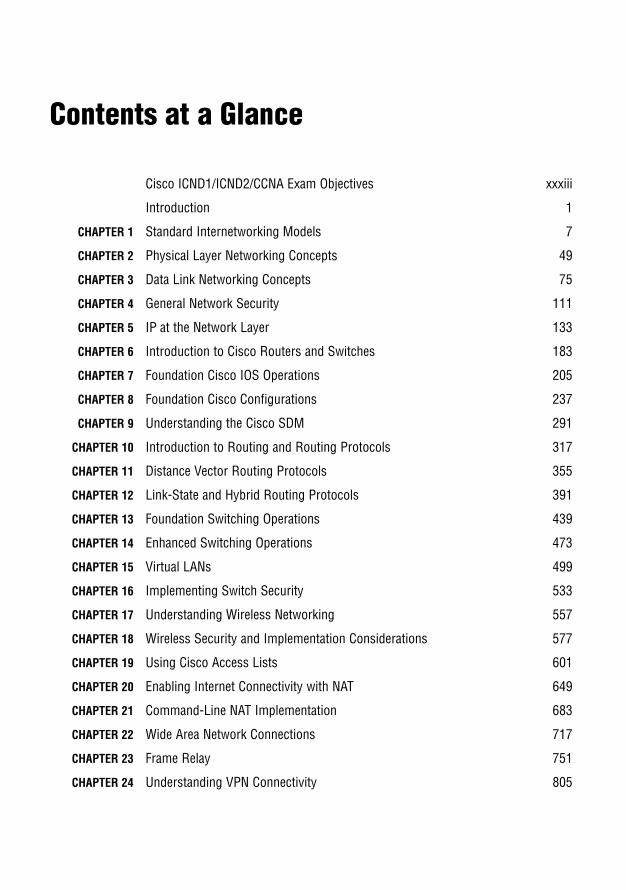
Contents at a Glance
Cisco ICND1/ICND2/CCNA Exam Objectives xxxiii
Introduction 1
CHAPTER 1 Standard Internetworking Models 7
CHAPTER 2 Physical Layer Networking Concepts 49
CHAPTER 3 Data Link Networking Concepts 75
CHAPTER 4 General Network Security 111
CHAPTER 5 IP at the Network Layer 133
CHAPTER 6 Introduction to Cisco Routers and Switches 183
CHAPTER 7 Foundation Cisco IOS Operations 205
CHAPTER 8 Foundation Cisco Configurations 237
CHAPTER 9 Understanding the Cisco SDM 291
CHAPTER 10 Introduction to Routing and Routing Protocols 317
CHAPTER 11 Distance Vector Routing Protocols 355
CHAPTER 12 Link-State and Hybrid Routing Protocols 391
CHAPTER 13 Foundation Switching Operations 439
CHAPTER 14 Enhanced Switching Operations 473
CHAPTER 15 Virtual LANs 499
CHAPTER 16 Implementing Switch Security 533
CHAPTER 17 Understanding Wireless Networking 557
CHAPTER 18 Wireless Security and Implementation Considerations 577
CHAPTER 19 Using Cisco Access Lists 601
CHAPTER 20 Enabling Internet Connectivity with NAT 649
CHAPTER 21 Command-Line NAT Implementation 683
CHAPTER 22 Wide Area Network Connections 717
CHAPTER 23 Frame Relay 751
CHAPTER 24 Understanding VPN Connectivity 805

Fast Facts 829
Practice Exam 881
Answers to Practice Exam 901
APPENDIX What’s on the CD-ROM 911
Glossary 915
Index 943
Table of Contents
Introduction . . . . . . . . . . . . . . . . . . . . . . . . . . . . . . . . . . . . . . . . . . . . . . . . . . . . . . . . . . . . . . . . . . . . . 1
How This Book Helps You . . . . . . . . . . . . . . . . . . . . . . . . . . . . . . . . . . . . . . . . . . . . . . . . . . 1Network Hardware and Software Requirements . . . . . . . . . . . . . . . . . . . . . . . . . . . . . . . . 3Advice on Taking the Exam . . . . . . . . . . . . . . . . . . . . . . . . . . . . . . . . . . . . . . . . . . . . . . . . . . 5
CHAPTER 1:Standard Internetworking Models . . . . . . . . . . . . . . . . . . . . . . . . . . . . . . . . . . . . . . . . . . . . . . . . . . . 7
Introduction . . . . . . . . . . . . . . . . . . . . . . . . . . . . . . . . . . . . . . . . . . . . . . . . . . . . . . . . . . . . . . 10What Is an Internetwork? . . . . . . . . . . . . . . . . . . . . . . . . . . . . . . . . . . . . . . . . . . . . . . . . . . 10Types of Internetworks . . . . . . . . . . . . . . . . . . . . . . . . . . . . . . . . . . . . . . . . . . . . . . . . . . . . . 11
Local Area Network (LAN) . . . . . . . . . . . . . . . . . . . . . . . . . . . . . . . . . . . . . . . . . . . . 11Metropolitan Area Network (MAN). . . . . . . . . . . . . . . . . . . . . . . . . . . . . . . . . . . . . 12Wide Area Network (WAN) . . . . . . . . . . . . . . . . . . . . . . . . . . . . . . . . . . . . . . . . . . . 12Storage Area Network (SAN) . . . . . . . . . . . . . . . . . . . . . . . . . . . . . . . . . . . . . . . . . . 14Virtual Private Network (VPN) . . . . . . . . . . . . . . . . . . . . . . . . . . . . . . . . . . . . . . . . 14
Open Systems Interconnection (OSI) Model . . . . . . . . . . . . . . . . . . . . . . . . . . . . . . . . . . 14Upper Layers . . . . . . . . . . . . . . . . . . . . . . . . . . . . . . . . . . . . . . . . . . . . . . . . . . . . . . . . 15Application Layer . . . . . . . . . . . . . . . . . . . . . . . . . . . . . . . . . . . . . . . . . . . . . . . . . . . . 16Presentation Layer . . . . . . . . . . . . . . . . . . . . . . . . . . . . . . . . . . . . . . . . . . . . . . . . . . . 17Session Layer . . . . . . . . . . . . . . . . . . . . . . . . . . . . . . . . . . . . . . . . . . . . . . . . . . . . . . . . 18Lower Layers . . . . . . . . . . . . . . . . . . . . . . . . . . . . . . . . . . . . . . . . . . . . . . . . . . . . . . . . 18Transport Layer . . . . . . . . . . . . . . . . . . . . . . . . . . . . . . . . . . . . . . . . . . . . . . . . . . . . . . 19Network Layer . . . . . . . . . . . . . . . . . . . . . . . . . . . . . . . . . . . . . . . . . . . . . . . . . . . . . . . 20Data Link Layer . . . . . . . . . . . . . . . . . . . . . . . . . . . . . . . . . . . . . . . . . . . . . . . . . . . . . 21Physical Layer . . . . . . . . . . . . . . . . . . . . . . . . . . . . . . . . . . . . . . . . . . . . . . . . . . . . . . . 23OSI Layered Communications . . . . . . . . . . . . . . . . . . . . . . . . . . . . . . . . . . . . . . . . . 24
TCP/IP Model . . . . . . . . . . . . . . . . . . . . . . . . . . . . . . . . . . . . . . . . . . . . . . . . . . . . . . . . . . . 26Application Layer . . . . . . . . . . . . . . . . . . . . . . . . . . . . . . . . . . . . . . . . . . . . . . . . . . . . 26Transport Layer . . . . . . . . . . . . . . . . . . . . . . . . . . . . . . . . . . . . . . . . . . . . . . . . . . . . . . 27Internet Layer . . . . . . . . . . . . . . . . . . . . . . . . . . . . . . . . . . . . . . . . . . . . . . . . . . . . . . . 31Network Interface Layer . . . . . . . . . . . . . . . . . . . . . . . . . . . . . . . . . . . . . . . . . . . . . . 33
vi
Cisco 3-Layer Hierarchical Model . . . . . . . . . . . . . . . . . . . . . . . . . . . . . . . . . . . . . . . . . . . 33Access Layer . . . . . . . . . . . . . . . . . . . . . . . . . . . . . . . . . . . . . . . . . . . . . . . . . . . . . . . . . 34Distribution Layer . . . . . . . . . . . . . . . . . . . . . . . . . . . . . . . . . . . . . . . . . . . . . . . . . . . . 35Core Layer . . . . . . . . . . . . . . . . . . . . . . . . . . . . . . . . . . . . . . . . . . . . . . . . . . . . . . . . . . 35
Chapter Summary . . . . . . . . . . . . . . . . . . . . . . . . . . . . . . . . . . . . . . . . . . . . . . . . . . . . . . . . . 37Key Terms. . . . . . . . . . . . . . . . . . . . . . . . . . . . . . . . . . . . . . . . . . . . . . . . . . . . . . . . . . . 38
Apply Your Knowledge . . . . . . . . . . . . . . . . . . . . . . . . . . . . . . . . . . . . . . . . . . . . . . . . . . . . . 39Exercise . . . . . . . . . . . . . . . . . . . . . . . . . . . . . . . . . . . . . . . . . . . . . . . . . . . . . . . . . . . . . 39Review Questions . . . . . . . . . . . . . . . . . . . . . . . . . . . . . . . . . . . . . . . . . . . . . . . . . . . . 40Exam Questions . . . . . . . . . . . . . . . . . . . . . . . . . . . . . . . . . . . . . . . . . . . . . . . . . . . . . . 40Answers to Review Questions . . . . . . . . . . . . . . . . . . . . . . . . . . . . . . . . . . . . . . . . . . 44Answers to Exam Questions. . . . . . . . . . . . . . . . . . . . . . . . . . . . . . . . . . . . . . . . . . . . 47Suggested Readings and Resources . . . . . . . . . . . . . . . . . . . . . . . . . . . . . . . . . . . . . . 48
CHAPTER 2:Physical Layer Networking Concepts . . . . . . . . . . . . . . . . . . . . . . . . . . . . . . . . . . . . . . . . . . . . . . . 49
Introduction . . . . . . . . . . . . . . . . . . . . . . . . . . . . . . . . . . . . . . . . . . . . . . . . . . . . . . . . . . . . . . 52Network Topologies . . . . . . . . . . . . . . . . . . . . . . . . . . . . . . . . . . . . . . . . . . . . . . . . . . . . . . . 52
The Bus Topology . . . . . . . . . . . . . . . . . . . . . . . . . . . . . . . . . . . . . . . . . . . . . . . . . . . . 52The Ring Topology . . . . . . . . . . . . . . . . . . . . . . . . . . . . . . . . . . . . . . . . . . . . . . . . . . . 53The Star Topology . . . . . . . . . . . . . . . . . . . . . . . . . . . . . . . . . . . . . . . . . . . . . . . . . . . 54The Mesh Topology . . . . . . . . . . . . . . . . . . . . . . . . . . . . . . . . . . . . . . . . . . . . . . . . . . 55
Cabling . . . . . . . . . . . . . . . . . . . . . . . . . . . . . . . . . . . . . . . . . . . . . . . . . . . . . . . . . . . . . . . . . . 56Coaxial Cable . . . . . . . . . . . . . . . . . . . . . . . . . . . . . . . . . . . . . . . . . . . . . . . . . . . . . . . . 57Twisted-Pair Cable . . . . . . . . . . . . . . . . . . . . . . . . . . . . . . . . . . . . . . . . . . . . . . . . . . . 58Fiber-Optic Cable . . . . . . . . . . . . . . . . . . . . . . . . . . . . . . . . . . . . . . . . . . . . . . . . . . . . 62
Wireless . . . . . . . . . . . . . . . . . . . . . . . . . . . . . . . . . . . . . . . . . . . . . . . . . . . . . . . . . . . . . . . . . 62Wireless Fidelity (Wi-Fi) . . . . . . . . . . . . . . . . . . . . . . . . . . . . . . . . . . . . . . . . . . . . . . 63Infrared . . . . . . . . . . . . . . . . . . . . . . . . . . . . . . . . . . . . . . . . . . . . . . . . . . . . . . . . . . . . . 64Bluetooth . . . . . . . . . . . . . . . . . . . . . . . . . . . . . . . . . . . . . . . . . . . . . . . . . . . . . . . . . . . 64
Physical Layer Devices . . . . . . . . . . . . . . . . . . . . . . . . . . . . . . . . . . . . . . . . . . . . . . . . . . . . . 64Repeaters. . . . . . . . . . . . . . . . . . . . . . . . . . . . . . . . . . . . . . . . . . . . . . . . . . . . . . . . . . . . 64Hubs . . . . . . . . . . . . . . . . . . . . . . . . . . . . . . . . . . . . . . . . . . . . . . . . . . . . . . . . . . . . . . . 65Network Interfaces . . . . . . . . . . . . . . . . . . . . . . . . . . . . . . . . . . . . . . . . . . . . . . . . . . . 65
Chapter Summary . . . . . . . . . . . . . . . . . . . . . . . . . . . . . . . . . . . . . . . . . . . . . . . . . . . . . . . . . 66Key Terms. . . . . . . . . . . . . . . . . . . . . . . . . . . . . . . . . . . . . . . . . . . . . . . . . . . . . . . . . . . 66
CCNA Exam Prep
Contentsvii
Apply Your Knowledge . . . . . . . . . . . . . . . . . . . . . . . . . . . . . . . . . . . . . . . . . . . . . . . . . . . . . 66Exercise . . . . . . . . . . . . . . . . . . . . . . . . . . . . . . . . . . . . . . . . . . . . . . . . . . . . . . . . . . . . . 66Review Questions . . . . . . . . . . . . . . . . . . . . . . . . . . . . . . . . . . . . . . . . . . . . . . . . . . . . 67Exam Questions . . . . . . . . . . . . . . . . . . . . . . . . . . . . . . . . . . . . . . . . . . . . . . . . . . . . . . 67Answers to Review Questions . . . . . . . . . . . . . . . . . . . . . . . . . . . . . . . . . . . . . . . . . . 73Answers to Exam Questions. . . . . . . . . . . . . . . . . . . . . . . . . . . . . . . . . . . . . . . . . . . . 73
Suggested Readings and Resources. . . . . . . . . . . . . . . . . . . . . . . . . . . . . . . . . . . . . . . . . . . 74
CHAPTER 3:Data Link Networking Concepts . . . . . . . . . . . . . . . . . . . . . . . . . . . . . . . . . . . . . . . . . . . . . . . . . . . . 75
Introduction . . . . . . . . . . . . . . . . . . . . . . . . . . . . . . . . . . . . . . . . . . . . . . . . . . . . . . . . . . . . . . 78Data Link Protocols . . . . . . . . . . . . . . . . . . . . . . . . . . . . . . . . . . . . . . . . . . . . . . . . . . . . . . . 78
Token Ring . . . . . . . . . . . . . . . . . . . . . . . . . . . . . . . . . . . . . . . . . . . . . . . . . . . . . . . . . . 78FDDI. . . . . . . . . . . . . . . . . . . . . . . . . . . . . . . . . . . . . . . . . . . . . . . . . . . . . . . . . . . . . . . 80Ethernet at the Data Link Layer . . . . . . . . . . . . . . . . . . . . . . . . . . . . . . . . . . . . . . . . 81
Physical Ethernet Standards . . . . . . . . . . . . . . . . . . . . . . . . . . . . . . . . . . . . . . . . . . . . . . . . 87Ethernet . . . . . . . . . . . . . . . . . . . . . . . . . . . . . . . . . . . . . . . . . . . . . . . . . . . . . . . . . . . . 87Fast Ethernet . . . . . . . . . . . . . . . . . . . . . . . . . . . . . . . . . . . . . . . . . . . . . . . . . . . . . . . . 90Gigabit Ethernet . . . . . . . . . . . . . . . . . . . . . . . . . . . . . . . . . . . . . . . . . . . . . . . . . . . . . 9110-Gigabit Ethernet (10GbE) . . . . . . . . . . . . . . . . . . . . . . . . . . . . . . . . . . . . . . . . . . 93Long Reach Ethernet . . . . . . . . . . . . . . . . . . . . . . . . . . . . . . . . . . . . . . . . . . . . . . . . . 93
Data Link Layer Devices . . . . . . . . . . . . . . . . . . . . . . . . . . . . . . . . . . . . . . . . . . . . . . . . . . . 94Bridges . . . . . . . . . . . . . . . . . . . . . . . . . . . . . . . . . . . . . . . . . . . . . . . . . . . . . . . . . . . . . 95Switches . . . . . . . . . . . . . . . . . . . . . . . . . . . . . . . . . . . . . . . . . . . . . . . . . . . . . . . . . . . . 98
Duplex. . . . . . . . . . . . . . . . . . . . . . . . . . . . . . . . . . . . . . . . . . . . . . . . . . . . . . . . . . . . . . . . . . . 99Microsegmentation . . . . . . . . . . . . . . . . . . . . . . . . . . . . . . . . . . . . . . . . . . . . . . . . . . . . . . . 100Chapter Summary . . . . . . . . . . . . . . . . . . . . . . . . . . . . . . . . . . . . . . . . . . . . . . . . . . . . . . . . 101
Key Terms . . . . . . . . . . . . . . . . . . . . . . . . . . . . . . . . . . . . . . . . . . . . . . . . . . . . . . . . . 101Apply Your Knowledge . . . . . . . . . . . . . . . . . . . . . . . . . . . . . . . . . . . . . . . . . . . . . . . . . . . . 102
Exercise . . . . . . . . . . . . . . . . . . . . . . . . . . . . . . . . . . . . . . . . . . . . . . . . . . . . . . . . . . . . 102Review Questions . . . . . . . . . . . . . . . . . . . . . . . . . . . . . . . . . . . . . . . . . . . . . . . . . . . 103Exam Questions . . . . . . . . . . . . . . . . . . . . . . . . . . . . . . . . . . . . . . . . . . . . . . . . . . . . . 103Answers to Review Questions . . . . . . . . . . . . . . . . . . . . . . . . . . . . . . . . . . . . . . . . . 107Answers to Exam Questions. . . . . . . . . . . . . . . . . . . . . . . . . . . . . . . . . . . . . . . . . . . 108Suggested Readings and Resources. . . . . . . . . . . . . . . . . . . . . . . . . . . . . . . . . . . . . 110
viii
CHAPTER 4:General Network Security. . . . . . . . . . . . . . . . . . . . . . . . . . . . . . . . . . . . . . . . . . . . . . . . . . . . . . . . 111
Introduction . . . . . . . . . . . . . . . . . . . . . . . . . . . . . . . . . . . . . . . . . . . . . . . . . . . . . . . . . . . . . 114Classes of Attack . . . . . . . . . . . . . . . . . . . . . . . . . . . . . . . . . . . . . . . . . . . . . . . . . . . . . . . . . 114
Access Attacks . . . . . . . . . . . . . . . . . . . . . . . . . . . . . . . . . . . . . . . . . . . . . . . . . . . . . . 115Reconnaissance Attacks . . . . . . . . . . . . . . . . . . . . . . . . . . . . . . . . . . . . . . . . . . . . . . 117Denial of Service (DoS) Attacks . . . . . . . . . . . . . . . . . . . . . . . . . . . . . . . . . . . . . . . 119
Mitigating Network Threats . . . . . . . . . . . . . . . . . . . . . . . . . . . . . . . . . . . . . . . . . . . . . . . 122AAA . . . . . . . . . . . . . . . . . . . . . . . . . . . . . . . . . . . . . . . . . . . . . . . . . . . . . . . . . . . . . . . 122Cisco ACLs . . . . . . . . . . . . . . . . . . . . . . . . . . . . . . . . . . . . . . . . . . . . . . . . . . . . . . . . 123Cisco IOS Secure Management Features. . . . . . . . . . . . . . . . . . . . . . . . . . . . . . . . 123Encryption Protocols . . . . . . . . . . . . . . . . . . . . . . . . . . . . . . . . . . . . . . . . . . . . . . . . 124Security Appliances and Applications . . . . . . . . . . . . . . . . . . . . . . . . . . . . . . . . . . . 125
Chapter Summary . . . . . . . . . . . . . . . . . . . . . . . . . . . . . . . . . . . . . . . . . . . . . . . . . . . . . . . . 127Key Terms . . . . . . . . . . . . . . . . . . . . . . . . . . . . . . . . . . . . . . . . . . . . . . . . . . . . . . . . . 127
Apply Your Knowledge . . . . . . . . . . . . . . . . . . . . . . . . . . . . . . . . . . . . . . . . . . . . . . . . . . . . 128Exercise . . . . . . . . . . . . . . . . . . . . . . . . . . . . . . . . . . . . . . . . . . . . . . . . . . . . . . . . . . . . 128Review Questions . . . . . . . . . . . . . . . . . . . . . . . . . . . . . . . . . . . . . . . . . . . . . . . . . . . 128Exam Questions . . . . . . . . . . . . . . . . . . . . . . . . . . . . . . . . . . . . . . . . . . . . . . . . . . . . . 129Answers to Review Questions . . . . . . . . . . . . . . . . . . . . . . . . . . . . . . . . . . . . . . . . . 131Answers to Exam Questions. . . . . . . . . . . . . . . . . . . . . . . . . . . . . . . . . . . . . . . . . . . 131Suggested Readings and Resources. . . . . . . . . . . . . . . . . . . . . . . . . . . . . . . . . . . . . 132
CHAPTER 5:IP at the Network Layer . . . . . . . . . . . . . . . . . . . . . . . . . . . . . . . . . . . . . . . . . . . . . . . . . . . . . . . . . 133
Introduction . . . . . . . . . . . . . . . . . . . . . . . . . . . . . . . . . . . . . . . . . . . . . . . . . . . . . . . . . . . . . 136Network Layer Functions . . . . . . . . . . . . . . . . . . . . . . . . . . . . . . . . . . . . . . . . . . . . . . . . . 136IP Addressing and Formats . . . . . . . . . . . . . . . . . . . . . . . . . . . . . . . . . . . . . . . . . . . . . . . . 137
Binary . . . . . . . . . . . . . . . . . . . . . . . . . . . . . . . . . . . . . . . . . . . . . . . . . . . . . . . . . . . . . 137Hexadecimal . . . . . . . . . . . . . . . . . . . . . . . . . . . . . . . . . . . . . . . . . . . . . . . . . . . . . . . . 142IP Address Classes . . . . . . . . . . . . . . . . . . . . . . . . . . . . . . . . . . . . . . . . . . . . . . . . . . . 143Subnet Masks . . . . . . . . . . . . . . . . . . . . . . . . . . . . . . . . . . . . . . . . . . . . . . . . . . . . . . . 146Private (RFC 1918) Addressing . . . . . . . . . . . . . . . . . . . . . . . . . . . . . . . . . . . . . . . . 148
Subnetting IP . . . . . . . . . . . . . . . . . . . . . . . . . . . . . . . . . . . . . . . . . . . . . . . . . . . . . . . . . . . . 149Calculating Hosts in a Subnet . . . . . . . . . . . . . . . . . . . . . . . . . . . . . . . . . . . . . . . . . 152Calculating Networks in a Subnet . . . . . . . . . . . . . . . . . . . . . . . . . . . . . . . . . . . . . 153
CCNA Exam Prep
Contentsix
The Increment . . . . . . . . . . . . . . . . . . . . . . . . . . . . . . . . . . . . . . . . . . . . . . . . . . . . . . 155Determining the Range of Valid IPs. . . . . . . . . . . . . . . . . . . . . . . . . . . . . . . . . . . . 158
IPv6 . . . . . . . . . . . . . . . . . . . . . . . . . . . . . . . . . . . . . . . . . . . . . . . . . . . . . . . . . . . . . . . . . . . . 159IPv6 Communications . . . . . . . . . . . . . . . . . . . . . . . . . . . . . . . . . . . . . . . . . . . . . . . 160IPv6 Address Format . . . . . . . . . . . . . . . . . . . . . . . . . . . . . . . . . . . . . . . . . . . . . . . . 160Types of IPv6 Addresses . . . . . . . . . . . . . . . . . . . . . . . . . . . . . . . . . . . . . . . . . . . . . . 161Autoconfiguration . . . . . . . . . . . . . . . . . . . . . . . . . . . . . . . . . . . . . . . . . . . . . . . . . . . 164Integrating IPv4 and IPv6 . . . . . . . . . . . . . . . . . . . . . . . . . . . . . . . . . . . . . . . . . . . . 164ICMPv6 . . . . . . . . . . . . . . . . . . . . . . . . . . . . . . . . . . . . . . . . . . . . . . . . . . . . . . . . . . . 165
Network Layer Devices . . . . . . . . . . . . . . . . . . . . . . . . . . . . . . . . . . . . . . . . . . . . . . . . . . . 165Routers . . . . . . . . . . . . . . . . . . . . . . . . . . . . . . . . . . . . . . . . . . . . . . . . . . . . . . . . . . . . 165Layer 3 Switches . . . . . . . . . . . . . . . . . . . . . . . . . . . . . . . . . . . . . . . . . . . . . . . . . . . . 168
Chapter Summary . . . . . . . . . . . . . . . . . . . . . . . . . . . . . . . . . . . . . . . . . . . . . . . . . . . . . . . . 169Key Terms . . . . . . . . . . . . . . . . . . . . . . . . . . . . . . . . . . . . . . . . . . . . . . . . . . . . . . . . . 169
Apply Your Knowledge . . . . . . . . . . . . . . . . . . . . . . . . . . . . . . . . . . . . . . . . . . . . . . . . . . . . 170Exercises . . . . . . . . . . . . . . . . . . . . . . . . . . . . . . . . . . . . . . . . . . . . . . . . . . . . . . . . . . . 170Review Questions . . . . . . . . . . . . . . . . . . . . . . . . . . . . . . . . . . . . . . . . . . . . . . . . . . . 173Exam Questions . . . . . . . . . . . . . . . . . . . . . . . . . . . . . . . . . . . . . . . . . . . . . . . . . . . . . 173Answers to Review Questions . . . . . . . . . . . . . . . . . . . . . . . . . . . . . . . . . . . . . . . . . 178Answers to Exam Questions. . . . . . . . . . . . . . . . . . . . . . . . . . . . . . . . . . . . . . . . . . . 180Suggested Readings and Resources. . . . . . . . . . . . . . . . . . . . . . . . . . . . . . . . . . . . . 182
CHAPTER 6Introduction to Cisco Routers and Switches . . . . . . . . . . . . . . . . . . . . . . . . . . . . . . . . . . . . . . . . . 183
Introduction . . . . . . . . . . . . . . . . . . . . . . . . . . . . . . . . . . . . . . . . . . . . . . . . . . . . . . . . . . . . . 186Interfaces and Modules. . . . . . . . . . . . . . . . . . . . . . . . . . . . . . . . . . . . . . . . . . . . . . . . . . . . 186
LAN Interfaces . . . . . . . . . . . . . . . . . . . . . . . . . . . . . . . . . . . . . . . . . . . . . . . . . . . . . 186WAN Interfaces . . . . . . . . . . . . . . . . . . . . . . . . . . . . . . . . . . . . . . . . . . . . . . . . . . . . . 187
Cisco Memory Components . . . . . . . . . . . . . . . . . . . . . . . . . . . . . . . . . . . . . . . . . . . . . . . 190ROM . . . . . . . . . . . . . . . . . . . . . . . . . . . . . . . . . . . . . . . . . . . . . . . . . . . . . . . . . . . . . . 191Flash . . . . . . . . . . . . . . . . . . . . . . . . . . . . . . . . . . . . . . . . . . . . . . . . . . . . . . . . . . . . . . 191RAM . . . . . . . . . . . . . . . . . . . . . . . . . . . . . . . . . . . . . . . . . . . . . . . . . . . . . . . . . . . . . . 191NVRAM . . . . . . . . . . . . . . . . . . . . . . . . . . . . . . . . . . . . . . . . . . . . . . . . . . . . . . . . . . . 191
Cisco Internetworking Operating System . . . . . . . . . . . . . . . . . . . . . . . . . . . . . . . . . . . . 191Feature Sets . . . . . . . . . . . . . . . . . . . . . . . . . . . . . . . . . . . . . . . . . . . . . . . . . . . . . . . . 192IOS Image File Naming . . . . . . . . . . . . . . . . . . . . . . . . . . . . . . . . . . . . . . . . . . . . . . 193
x
Cisco Router Models and Features. . . . . . . . . . . . . . . . . . . . . . . . . . . . . . . . . . . . . . . . . . 194Cisco Switch Models and Features . . . . . . . . . . . . . . . . . . . . . . . . . . . . . . . . . . . . . . . . . . 195Chapter Summary . . . . . . . . . . . . . . . . . . . . . . . . . . . . . . . . . . . . . . . . . . . . . . . . . . . . . . . . 197
Key Terms . . . . . . . . . . . . . . . . . . . . . . . . . . . . . . . . . . . . . . . . . . . . . . . . . . . . . . . . . 197Apply Your Knowledge . . . . . . . . . . . . . . . . . . . . . . . . . . . . . . . . . . . . . . . . . . . . . . . . . . . . 198
Exercise . . . . . . . . . . . . . . . . . . . . . . . . . . . . . . . . . . . . . . . . . . . . . . . . . . . . . . . . . . . . 198Review Questions . . . . . . . . . . . . . . . . . . . . . . . . . . . . . . . . . . . . . . . . . . . . . . . . . . . 198Exam Questions . . . . . . . . . . . . . . . . . . . . . . . . . . . . . . . . . . . . . . . . . . . . . . . . . . . . . 198Answers to Review Questions . . . . . . . . . . . . . . . . . . . . . . . . . . . . . . . . . . . . . . . . . 200Answers to Exam Questions. . . . . . . . . . . . . . . . . . . . . . . . . . . . . . . . . . . . . . . . . . . 201Suggested Readings and Resources. . . . . . . . . . . . . . . . . . . . . . . . . . . . . . . . . . . . . 203
CHAPTER 7:Foundation Cisco IOS Operations . . . . . . . . . . . . . . . . . . . . . . . . . . . . . . . . . . . . . . . . . . . . . . . . . 205
Introduction . . . . . . . . . . . . . . . . . . . . . . . . . . . . . . . . . . . . . . . . . . . . . . . . . . . . . . . . . . . . . 208Terminal Options . . . . . . . . . . . . . . . . . . . . . . . . . . . . . . . . . . . . . . . . . . . . . . . . . . . . . . . . 208
Console Port . . . . . . . . . . . . . . . . . . . . . . . . . . . . . . . . . . . . . . . . . . . . . . . . . . . . . . . 208Auxiliary Port . . . . . . . . . . . . . . . . . . . . . . . . . . . . . . . . . . . . . . . . . . . . . . . . . . . . . . . 210Telnet . . . . . . . . . . . . . . . . . . . . . . . . . . . . . . . . . . . . . . . . . . . . . . . . . . . . . . . . . . . . . 210HTTP and HTTPS . . . . . . . . . . . . . . . . . . . . . . . . . . . . . . . . . . . . . . . . . . . . . . . . . 210SSH . . . . . . . . . . . . . . . . . . . . . . . . . . . . . . . . . . . . . . . . . . . . . . . . . . . . . . . . . . . . . . . 211
Router/Switch Startup Procedures . . . . . . . . . . . . . . . . . . . . . . . . . . . . . . . . . . . . . . . . . . 212POST . . . . . . . . . . . . . . . . . . . . . . . . . . . . . . . . . . . . . . . . . . . . . . . . . . . . . . . . . . . . . 212Bootstrap. . . . . . . . . . . . . . . . . . . . . . . . . . . . . . . . . . . . . . . . . . . . . . . . . . . . . . . . . . . 213IOS Loading. . . . . . . . . . . . . . . . . . . . . . . . . . . . . . . . . . . . . . . . . . . . . . . . . . . . . . . . 213Configuration Loading . . . . . . . . . . . . . . . . . . . . . . . . . . . . . . . . . . . . . . . . . . . . . . . 215
Navigating the IOS . . . . . . . . . . . . . . . . . . . . . . . . . . . . . . . . . . . . . . . . . . . . . . . . . . . . . . . 219User EXEC . . . . . . . . . . . . . . . . . . . . . . . . . . . . . . . . . . . . . . . . . . . . . . . . . . . . . . . . 219Privileged EXEC . . . . . . . . . . . . . . . . . . . . . . . . . . . . . . . . . . . . . . . . . . . . . . . . . . . . 220Global Configuration . . . . . . . . . . . . . . . . . . . . . . . . . . . . . . . . . . . . . . . . . . . . . . . . 221Context-Sensitive Help . . . . . . . . . . . . . . . . . . . . . . . . . . . . . . . . . . . . . . . . . . . . . . 223Abbreviations . . . . . . . . . . . . . . . . . . . . . . . . . . . . . . . . . . . . . . . . . . . . . . . . . . . . . . . 224Shortcut Keys. . . . . . . . . . . . . . . . . . . . . . . . . . . . . . . . . . . . . . . . . . . . . . . . . . . . . . . 225Common Syntax Errors . . . . . . . . . . . . . . . . . . . . . . . . . . . . . . . . . . . . . . . . . . . . . . 226
Chapter Summary . . . . . . . . . . . . . . . . . . . . . . . . . . . . . . . . . . . . . . . . . . . . . . . . . . . . . . . . 228Key Terms . . . . . . . . . . . . . . . . . . . . . . . . . . . . . . . . . . . . . . . . . . . . . . . . . . . . . . . . . 229
CCNA Exam Prep
Contentsxi
Apply Your Knowledge . . . . . . . . . . . . . . . . . . . . . . . . . . . . . . . . . . . . . . . . . . . . . . . . . . . . 229Exercise . . . . . . . . . . . . . . . . . . . . . . . . . . . . . . . . . . . . . . . . . . . . . . . . . . . . . . . . . . . . 229Review Questions . . . . . . . . . . . . . . . . . . . . . . . . . . . . . . . . . . . . . . . . . . . . . . . . . . . 231Exam Questions . . . . . . . . . . . . . . . . . . . . . . . . . . . . . . . . . . . . . . . . . . . . . . . . . . . . . 231Answers to Review Questions . . . . . . . . . . . . . . . . . . . . . . . . . . . . . . . . . . . . . . . . . 233Answers to Exam Questions. . . . . . . . . . . . . . . . . . . . . . . . . . . . . . . . . . . . . . . . . . . 234Suggested Readings and Resources. . . . . . . . . . . . . . . . . . . . . . . . . . . . . . . . . . . . . 235
CHAPTER 8:Foundation Cisco Configurations . . . . . . . . . . . . . . . . . . . . . . . . . . . . . . . . . . . . . . . . . . . . . . . . . . 237
Introduction . . . . . . . . . . . . . . . . . . . . . . . . . . . . . . . . . . . . . . . . . . . . . . . . . . . . . . . . . . . . . 240Global Configuration . . . . . . . . . . . . . . . . . . . . . . . . . . . . . . . . . . . . . . . . . . . . . . . . . . . . . 240
Altering the Boot Sequence . . . . . . . . . . . . . . . . . . . . . . . . . . . . . . . . . . . . . . . . . . . 240Changing the Hostname . . . . . . . . . . . . . . . . . . . . . . . . . . . . . . . . . . . . . . . . . . . . . 242Creating a Login Banner . . . . . . . . . . . . . . . . . . . . . . . . . . . . . . . . . . . . . . . . . . . . . 242Assigning a Password for Privileged EXEC Mode . . . . . . . . . . . . . . . . . . . . . . . . 243Domain Name–Specific Commands. . . . . . . . . . . . . . . . . . . . . . . . . . . . . . . . . . . . 244Enabling SSH . . . . . . . . . . . . . . . . . . . . . . . . . . . . . . . . . . . . . . . . . . . . . . . . . . . . . . 245
Line Configurations . . . . . . . . . . . . . . . . . . . . . . . . . . . . . . . . . . . . . . . . . . . . . . . . . . . . . . 246Securing Console Access to User EXEC . . . . . . . . . . . . . . . . . . . . . . . . . . . . . . . . 246Securing Auxiliary Access to User EXEC . . . . . . . . . . . . . . . . . . . . . . . . . . . . . . . 248Securing Telnet and SSH Access to User EXEC . . . . . . . . . . . . . . . . . . . . . . . . . 248
Router Interface Configurations . . . . . . . . . . . . . . . . . . . . . . . . . . . . . . . . . . . . . . . . . . . . 251Assigning an IP Address . . . . . . . . . . . . . . . . . . . . . . . . . . . . . . . . . . . . . . . . . . . . . . 252Enabling the Interface . . . . . . . . . . . . . . . . . . . . . . . . . . . . . . . . . . . . . . . . . . . . . . . 253LAN-Specific Commands . . . . . . . . . . . . . . . . . . . . . . . . . . . . . . . . . . . . . . . . . . . . 253WAN-Specific Commands. . . . . . . . . . . . . . . . . . . . . . . . . . . . . . . . . . . . . . . . . . . . 254
Saving Configurations . . . . . . . . . . . . . . . . . . . . . . . . . . . . . . . . . . . . . . . . . . . . . . . . . . . . 254Using the show Command to Get Information . . . . . . . . . . . . . . . . . . . . . . . . . . . . . . . 256
Verifying Your Configurations. . . . . . . . . . . . . . . . . . . . . . . . . . . . . . . . . . . . . . . . . 257Viewing Interface Statuses and Statistics . . . . . . . . . . . . . . . . . . . . . . . . . . . . . . . . 258IOS File Version show Commands . . . . . . . . . . . . . . . . . . . . . . . . . . . . . . . . . . . . . 261
Troubleshooting Commands . . . . . . . . . . . . . . . . . . . . . . . . . . . . . . . . . . . . . . . . . . . . . . . 264Backing Up and Restoring Configurations and IOS Using TFTP . . . . . . . . . . . . . . . 267Neighbor Discovery with CDP. . . . . . . . . . . . . . . . . . . . . . . . . . . . . . . . . . . . . . . . . . . . . 270Using Telnet for Virtual Terminal Access . . . . . . . . . . . . . . . . . . . . . . . . . . . . . . . . . . . . 274
Terminal Monitor . . . . . . . . . . . . . . . . . . . . . . . . . . . . . . . . . . . . . . . . . . . . . . . . . . . 275
xii
IOS DHCP . . . . . . . . . . . . . . . . . . . . . . . . . . . . . . . . . . . . . . . . . . . . . . . . . . . . . . . . . . . . . 276Chapter Summary . . . . . . . . . . . . . . . . . . . . . . . . . . . . . . . . . . . . . . . . . . . . . . . . . . . . . . . . 279
Key Terms . . . . . . . . . . . . . . . . . . . . . . . . . . . . . . . . . . . . . . . . . . . . . . . . . . . . . . . . . 280Apply Your Knowledge . . . . . . . . . . . . . . . . . . . . . . . . . . . . . . . . . . . . . . . . . . . . . . . . . . . . 281
Exercise . . . . . . . . . . . . . . . . . . . . . . . . . . . . . . . . . . . . . . . . . . . . . . . . . . . . . . . . . . . . 281Review Questions . . . . . . . . . . . . . . . . . . . . . . . . . . . . . . . . . . . . . . . . . . . . . . . . . . . 283Exam Questions . . . . . . . . . . . . . . . . . . . . . . . . . . . . . . . . . . . . . . . . . . . . . . . . . . . . . 283Answers to Review Questions . . . . . . . . . . . . . . . . . . . . . . . . . . . . . . . . . . . . . . . . . 287Answers to Exam Questions. . . . . . . . . . . . . . . . . . . . . . . . . . . . . . . . . . . . . . . . . . . 288Suggested Readings and Resources. . . . . . . . . . . . . . . . . . . . . . . . . . . . . . . . . . . . . 289
CHAPTER 9:Understanding the Cisco SDM . . . . . . . . . . . . . . . . . . . . . . . . . . . . . . . . . . . . . . . . . . . . . . . . . . . . 291
Introduction . . . . . . . . . . . . . . . . . . . . . . . . . . . . . . . . . . . . . . . . . . . . . . . . . . . . . . . . . . . . . 294Getting Started . . . . . . . . . . . . . . . . . . . . . . . . . . . . . . . . . . . . . . . . . . . . . . . . . . . . . . . . . . 294Global Configurations . . . . . . . . . . . . . . . . . . . . . . . . . . . . . . . . . . . . . . . . . . . . . . . . . . . . 296
Changing the Hostname, Banner, Domain Name, and Secret Password . . . . . 297Router Access . . . . . . . . . . . . . . . . . . . . . . . . . . . . . . . . . . . . . . . . . . . . . . . . . . . . . . . 301DNS . . . . . . . . . . . . . . . . . . . . . . . . . . . . . . . . . . . . . . . . . . . . . . . . . . . . . . . . . . . . . . 302DHCP . . . . . . . . . . . . . . . . . . . . . . . . . . . . . . . . . . . . . . . . . . . . . . . . . . . . . . . . . . . . . 304
Router Interface Configurations . . . . . . . . . . . . . . . . . . . . . . . . . . . . . . . . . . . . . . . . . . . . 306Assigning an IP Address . . . . . . . . . . . . . . . . . . . . . . . . . . . . . . . . . . . . . . . . . . . . . . 306Enabling the Interface . . . . . . . . . . . . . . . . . . . . . . . . . . . . . . . . . . . . . . . . . . . . . . . 307Saving and Verifying Your Configurations . . . . . . . . . . . . . . . . . . . . . . . . . . . . . . 308
Monitoring . . . . . . . . . . . . . . . . . . . . . . . . . . . . . . . . . . . . . . . . . . . . . . . . . . . . . . . . . . . . . . 309Chapter Summary . . . . . . . . . . . . . . . . . . . . . . . . . . . . . . . . . . . . . . . . . . . . . . . . . . . . . . . . 311
Key Terms . . . . . . . . . . . . . . . . . . . . . . . . . . . . . . . . . . . . . . . . . . . . . . . . . . . . . . . . . 311Apply Your Knowledge . . . . . . . . . . . . . . . . . . . . . . . . . . . . . . . . . . . . . . . . . . . . . . . . . . . . 311
Exercise . . . . . . . . . . . . . . . . . . . . . . . . . . . . . . . . . . . . . . . . . . . . . . . . . . . . . . . . . . . . 311Review Questions . . . . . . . . . . . . . . . . . . . . . . . . . . . . . . . . . . . . . . . . . . . . . . . . . . . 311Exam Questions . . . . . . . . . . . . . . . . . . . . . . . . . . . . . . . . . . . . . . . . . . . . . . . . . . . . . 312Answers to Review Questions . . . . . . . . . . . . . . . . . . . . . . . . . . . . . . . . . . . . . . . . . 314Answers to Exam Questions. . . . . . . . . . . . . . . . . . . . . . . . . . . . . . . . . . . . . . . . . . . 315Suggested Readings and Resources. . . . . . . . . . . . . . . . . . . . . . . . . . . . . . . . . . . . . 316
CCNA Exam Prep
Contentsxiii
CHAPTER 10:Introduction to Routing and Routing Protocols. . . . . . . . . . . . . . . . . . . . . . . . . . . . . . . . . . . . . . . 317
Introduction . . . . . . . . . . . . . . . . . . . . . . . . . . . . . . . . . . . . . . . . . . . . . . . . . . . . . . . . . . . . . 320The Default Gateway . . . . . . . . . . . . . . . . . . . . . . . . . . . . . . . . . . . . . . . . . . . . . . . . . . . . . 320
Verifying and Troubleshooting the Default Gateway. . . . . . . . . . . . . . . . . . . . . . 322Routing Sources . . . . . . . . . . . . . . . . . . . . . . . . . . . . . . . . . . . . . . . . . . . . . . . . . . . . . . . . . 323
Administrative Distance . . . . . . . . . . . . . . . . . . . . . . . . . . . . . . . . . . . . . . . . . . . . . . 324Static Routes . . . . . . . . . . . . . . . . . . . . . . . . . . . . . . . . . . . . . . . . . . . . . . . . . . . . . . . . . . . . 325
Configuring Static Routes . . . . . . . . . . . . . . . . . . . . . . . . . . . . . . . . . . . . . . . . . . . . 326Floating Static Routes. . . . . . . . . . . . . . . . . . . . . . . . . . . . . . . . . . . . . . . . . . . . . . . . 327
Default Routes . . . . . . . . . . . . . . . . . . . . . . . . . . . . . . . . . . . . . . . . . . . . . . . . . . . . . . . . . . . 328Configuring Static and Default Routes with SDM . . . . . . . . . . . . . . . . . . . . . . . . . . . . 329Verifying Static and Default Routes . . . . . . . . . . . . . . . . . . . . . . . . . . . . . . . . . . . . . . . . . 330
Dynamic Routing Protocols . . . . . . . . . . . . . . . . . . . . . . . . . . . . . . . . . . . . . . . . . . 331Routing Metrics . . . . . . . . . . . . . . . . . . . . . . . . . . . . . . . . . . . . . . . . . . . . . . . . . . . . . 332Classful and Classless Routing Updates . . . . . . . . . . . . . . . . . . . . . . . . . . . . . . . . . 333VLSM . . . . . . . . . . . . . . . . . . . . . . . . . . . . . . . . . . . . . . . . . . . . . . . . . . . . . . . . . . . . . 336Interior and Exterior Gateway Routing Protocols . . . . . . . . . . . . . . . . . . . . . . . . 339Distance Vector Routing Protocols . . . . . . . . . . . . . . . . . . . . . . . . . . . . . . . . . . . . 340Link-State Routing Protocols . . . . . . . . . . . . . . . . . . . . . . . . . . . . . . . . . . . . . . . . . 340Advanced Distance Vector/Hybrid Routing Protocols . . . . . . . . . . . . . . . . . . . . 341
The Routing Table Revisited. . . . . . . . . . . . . . . . . . . . . . . . . . . . . . . . . . . . . . . . . . . . . . . 341Routing Redistribution . . . . . . . . . . . . . . . . . . . . . . . . . . . . . . . . . . . . . . . . . . . . . . . . . . . . 343Chapter Summary . . . . . . . . . . . . . . . . . . . . . . . . . . . . . . . . . . . . . . . . . . . . . . . . . . . . . . . . 345
Key Terms . . . . . . . . . . . . . . . . . . . . . . . . . . . . . . . . . . . . . . . . . . . . . . . . . . . . . . . . . 346Apply Your Knowledge . . . . . . . . . . . . . . . . . . . . . . . . . . . . . . . . . . . . . . . . . . . . . . . . . . . . 346
Exercises . . . . . . . . . . . . . . . . . . . . . . . . . . . . . . . . . . . . . . . . . . . . . . . . . . . . . . . . . . . 346Review Questions . . . . . . . . . . . . . . . . . . . . . . . . . . . . . . . . . . . . . . . . . . . . . . . . . . . 347Exam Questions . . . . . . . . . . . . . . . . . . . . . . . . . . . . . . . . . . . . . . . . . . . . . . . . . . . . . 347Answers to Review Questions . . . . . . . . . . . . . . . . . . . . . . . . . . . . . . . . . . . . . . . . . 351Answers to Exam Questions. . . . . . . . . . . . . . . . . . . . . . . . . . . . . . . . . . . . . . . . . . . 351Suggested Readings and Resources. . . . . . . . . . . . . . . . . . . . . . . . . . . . . . . . . . . . . 353
CHAPTER 11:Distance Vector Routing Protocols . . . . . . . . . . . . . . . . . . . . . . . . . . . . . . . . . . . . . . . . . . . . . . . . 355
Introduction . . . . . . . . . . . . . . . . . . . . . . . . . . . . . . . . . . . . . . . . . . . . . . . . . . . . . . . . . . . . . 358Distance Vector Operations . . . . . . . . . . . . . . . . . . . . . . . . . . . . . . . . . . . . . . . . . . . . . . . . 358
Routing Loops . . . . . . . . . . . . . . . . . . . . . . . . . . . . . . . . . . . . . . . . . . . . . . . . . . . . . . 360
xiv
Routing Loop Mitigation . . . . . . . . . . . . . . . . . . . . . . . . . . . . . . . . . . . . . . . . . . . . . . . . . . 362Counting to Infinity . . . . . . . . . . . . . . . . . . . . . . . . . . . . . . . . . . . . . . . . . . . . . . . . . 363Split Horizon . . . . . . . . . . . . . . . . . . . . . . . . . . . . . . . . . . . . . . . . . . . . . . . . . . . . . . . 363Route Poison, Poison Reverse, and Hold-Down Timers . . . . . . . . . . . . . . . . . . 365Triggered Updates. . . . . . . . . . . . . . . . . . . . . . . . . . . . . . . . . . . . . . . . . . . . . . . . . . . 367Invalid/Dead Timers . . . . . . . . . . . . . . . . . . . . . . . . . . . . . . . . . . . . . . . . . . . . . . . . . 367
RIP . . . . . . . . . . . . . . . . . . . . . . . . . . . . . . . . . . . . . . . . . . . . . . . . . . . . . . . . . . . . . . . . . . . . 367RIP Characteristics . . . . . . . . . . . . . . . . . . . . . . . . . . . . . . . . . . . . . . . . . . . . . . . . . . 367RIP Configuration. . . . . . . . . . . . . . . . . . . . . . . . . . . . . . . . . . . . . . . . . . . . . . . . . . . 368Passive Interfaces . . . . . . . . . . . . . . . . . . . . . . . . . . . . . . . . . . . . . . . . . . . . . . . . . . . . 371RIPv2 Characteristics . . . . . . . . . . . . . . . . . . . . . . . . . . . . . . . . . . . . . . . . . . . . . . . . 372RIPv2 Configuration. . . . . . . . . . . . . . . . . . . . . . . . . . . . . . . . . . . . . . . . . . . . . . . . . 373RIPv2 Update Authentication . . . . . . . . . . . . . . . . . . . . . . . . . . . . . . . . . . . . . . . . . 374Configuring RIP with SDM . . . . . . . . . . . . . . . . . . . . . . . . . . . . . . . . . . . . . . . . . . 374RIP Verification . . . . . . . . . . . . . . . . . . . . . . . . . . . . . . . . . . . . . . . . . . . . . . . . . . . . . 375Troubleshooting RIP . . . . . . . . . . . . . . . . . . . . . . . . . . . . . . . . . . . . . . . . . . . . . . . . 377
Chapter Summary . . . . . . . . . . . . . . . . . . . . . . . . . . . . . . . . . . . . . . . . . . . . . . . . . . . . . . . . 381Key Terms . . . . . . . . . . . . . . . . . . . . . . . . . . . . . . . . . . . . . . . . . . . . . . . . . . . . . . . . . 382
Apply Your Knowledge . . . . . . . . . . . . . . . . . . . . . . . . . . . . . . . . . . . . . . . . . . . . . . . . . . . . 382Exercises . . . . . . . . . . . . . . . . . . . . . . . . . . . . . . . . . . . . . . . . . . . . . . . . . . . . . . . . . . . 382Review Questions . . . . . . . . . . . . . . . . . . . . . . . . . . . . . . . . . . . . . . . . . . . . . . . . . . . 384Exam Questions . . . . . . . . . . . . . . . . . . . . . . . . . . . . . . . . . . . . . . . . . . . . . . . . . . . . . 384Answers to Review Questions . . . . . . . . . . . . . . . . . . . . . . . . . . . . . . . . . . . . . . . . . 388Answers to Exam Questions. . . . . . . . . . . . . . . . . . . . . . . . . . . . . . . . . . . . . . . . . . . 388Suggested Readings and Resources. . . . . . . . . . . . . . . . . . . . . . . . . . . . . . . . . . . . . 389
CHAPTER 12:Link-State and Hybrid Routing Protocols . . . . . . . . . . . . . . . . . . . . . . . . . . . . . . . . . . . . . . . . . . . 391
Introduction . . . . . . . . . . . . . . . . . . . . . . . . . . . . . . . . . . . . . . . . . . . . . . . . . . . . . . . . . . . . . 394Link-State Operations . . . . . . . . . . . . . . . . . . . . . . . . . . . . . . . . . . . . . . . . . . . . . . . . . . . . 394OSPF. . . . . . . . . . . . . . . . . . . . . . . . . . . . . . . . . . . . . . . . . . . . . . . . . . . . . . . . . . . . . . . . . . . 396
OSPF Characteristics . . . . . . . . . . . . . . . . . . . . . . . . . . . . . . . . . . . . . . . . . . . . . . . . 396OSPF Initialization . . . . . . . . . . . . . . . . . . . . . . . . . . . . . . . . . . . . . . . . . . . . . . . . . . 404Introduction to Configuring OSPF . . . . . . . . . . . . . . . . . . . . . . . . . . . . . . . . . . . . 404OSPF Network Configuration . . . . . . . . . . . . . . . . . . . . . . . . . . . . . . . . . . . . . . . . 407Additional OSPF Commands . . . . . . . . . . . . . . . . . . . . . . . . . . . . . . . . . . . . . . . . . 409
CCNA Exam Prep
Contentsxv
Configuring OSPF with SDM . . . . . . . . . . . . . . . . . . . . . . . . . . . . . . . . . . . . . . . . 410Verifying OSPF . . . . . . . . . . . . . . . . . . . . . . . . . . . . . . . . . . . . . . . . . . . . . . . . . . . . . 412Troubleshooting OSPF. . . . . . . . . . . . . . . . . . . . . . . . . . . . . . . . . . . . . . . . . . . . . . . 415
Balanced Hybrid Operations . . . . . . . . . . . . . . . . . . . . . . . . . . . . . . . . . . . . . . . . . . . . . . . 416EIGRP . . . . . . . . . . . . . . . . . . . . . . . . . . . . . . . . . . . . . . . . . . . . . . . . . . . . . . . . . . . . . . . . . 417
EIGRP Characteristics . . . . . . . . . . . . . . . . . . . . . . . . . . . . . . . . . . . . . . . . . . . . . . . 417EIGRP Stub Routing . . . . . . . . . . . . . . . . . . . . . . . . . . . . . . . . . . . . . . . . . . . . . . . . 421EIGRP Configuration . . . . . . . . . . . . . . . . . . . . . . . . . . . . . . . . . . . . . . . . . . . . . . . 422EIGRP Verification . . . . . . . . . . . . . . . . . . . . . . . . . . . . . . . . . . . . . . . . . . . . . . . . . . 425EIGRP Troubleshooting . . . . . . . . . . . . . . . . . . . . . . . . . . . . . . . . . . . . . . . . . . . . . 427
Chapter Summary . . . . . . . . . . . . . . . . . . . . . . . . . . . . . . . . . . . . . . . . . . . . . . . . . . . . . . . . 428Key Terms . . . . . . . . . . . . . . . . . . . . . . . . . . . . . . . . . . . . . . . . . . . . . . . . . . . . . . . . . 429
Apply Your Knowledge . . . . . . . . . . . . . . . . . . . . . . . . . . . . . . . . . . . . . . . . . . . . . . . . . . . . 430Exercises . . . . . . . . . . . . . . . . . . . . . . . . . . . . . . . . . . . . . . . . . . . . . . . . . . . . . . . . . . . 430Review Questions . . . . . . . . . . . . . . . . . . . . . . . . . . . . . . . . . . . . . . . . . . . . . . . . . . . 431Exam Questions . . . . . . . . . . . . . . . . . . . . . . . . . . . . . . . . . . . . . . . . . . . . . . . . . . . . . 431Answers to Review Questions . . . . . . . . . . . . . . . . . . . . . . . . . . . . . . . . . . . . . . . . . 435Answers to Exam Questions. . . . . . . . . . . . . . . . . . . . . . . . . . . . . . . . . . . . . . . . . . . 436Suggested Readings and Resources. . . . . . . . . . . . . . . . . . . . . . . . . . . . . . . . . . . . . 437
CHAPTER 13:Foundation Switching Operations . . . . . . . . . . . . . . . . . . . . . . . . . . . . . . . . . . . . . . . . . . . . . . . . . 439
Introduction . . . . . . . . . . . . . . . . . . . . . . . . . . . . . . . . . . . . . . . . . . . . . . . . . . . . . . . . . . . . . 442Switching Functionality . . . . . . . . . . . . . . . . . . . . . . . . . . . . . . . . . . . . . . . . . . . . . . 442
Frame Transmission Methods . . . . . . . . . . . . . . . . . . . . . . . . . . . . . . . . . . . . . . . . . . . . . . 443Store-and-Forward . . . . . . . . . . . . . . . . . . . . . . . . . . . . . . . . . . . . . . . . . . . . . . . . . . 444Cut-Through . . . . . . . . . . . . . . . . . . . . . . . . . . . . . . . . . . . . . . . . . . . . . . . . . . . . . . . 444Fragment-Free . . . . . . . . . . . . . . . . . . . . . . . . . . . . . . . . . . . . . . . . . . . . . . . . . . . . . . 444
Half- and Full-Duplex Connections . . . . . . . . . . . . . . . . . . . . . . . . . . . . . . . . . . . . . . . . . 445Switching Design . . . . . . . . . . . . . . . . . . . . . . . . . . . . . . . . . . . . . . . . . . . . . . . . . . . . . . . . 446Spanning Tree Protocol . . . . . . . . . . . . . . . . . . . . . . . . . . . . . . . . . . . . . . . . . . . . . . . . . . . 446
Root Bridge . . . . . . . . . . . . . . . . . . . . . . . . . . . . . . . . . . . . . . . . . . . . . . . . . . . . . . . . 447Root Ports . . . . . . . . . . . . . . . . . . . . . . . . . . . . . . . . . . . . . . . . . . . . . . . . . . . . . . . . . 448Designated Ports . . . . . . . . . . . . . . . . . . . . . . . . . . . . . . . . . . . . . . . . . . . . . . . . . . . . 450Blocked Ports . . . . . . . . . . . . . . . . . . . . . . . . . . . . . . . . . . . . . . . . . . . . . . . . . . . . . . . 451
Port State Transitions . . . . . . . . . . . . . . . . . . . . . . . . . . . . . . . . . . . . . . . . . . . . . . . . . . . . . 453
xvi
Initial Switch Configurations. . . . . . . . . . . . . . . . . . . . . . . . . . . . . . . . . . . . . . . . . . . . . . . 454Assigning a Management IP Address to a Switch . . . . . . . . . . . . . . . . . . . . . . . . . 455Defining a Default Gateway . . . . . . . . . . . . . . . . . . . . . . . . . . . . . . . . . . . . . . . . . . 455IP Assignment Using DHCP . . . . . . . . . . . . . . . . . . . . . . . . . . . . . . . . . . . . . . . . . 456Configuring Multiple Switch Interfaces. . . . . . . . . . . . . . . . . . . . . . . . . . . . . . . . . 457
Configuring and Verifying Spanning Tree Protocol . . . . . . . . . . . . . . . . . . . . . . . . . . . 458Changing Priority and Port Cost . . . . . . . . . . . . . . . . . . . . . . . . . . . . . . . . . . . . . . 458Verifying Spanning Tree Protocol . . . . . . . . . . . . . . . . . . . . . . . . . . . . . . . . . . . . . 459
Troubleshooting Basic Switch Connectivity . . . . . . . . . . . . . . . . . . . . . . . . . . . . . . . . . . 460Chapter Summary . . . . . . . . . . . . . . . . . . . . . . . . . . . . . . . . . . . . . . . . . . . . . . . . . . . . . . . . 462
Key Terms . . . . . . . . . . . . . . . . . . . . . . . . . . . . . . . . . . . . . . . . . . . . . . . . . . . . . . . . . 462Apply Your Knowledge . . . . . . . . . . . . . . . . . . . . . . . . . . . . . . . . . . . . . . . . . . . . . . . . . . . . 463
Exercises . . . . . . . . . . . . . . . . . . . . . . . . . . . . . . . . . . . . . . . . . . . . . . . . . . . . . . . . . . . 463Review Questions . . . . . . . . . . . . . . . . . . . . . . . . . . . . . . . . . . . . . . . . . . . . . . . . . . . 466Exam Questions . . . . . . . . . . . . . . . . . . . . . . . . . . . . . . . . . . . . . . . . . . . . . . . . . . . . . 466Answers to Review Questions . . . . . . . . . . . . . . . . . . . . . . . . . . . . . . . . . . . . . . . . . 470Answers to Exam Questions. . . . . . . . . . . . . . . . . . . . . . . . . . . . . . . . . . . . . . . . . . . 470Suggested Readings and Resources. . . . . . . . . . . . . . . . . . . . . . . . . . . . . . . . . . . . . 471
CHAPTER 14:Enhanced Switching Operations . . . . . . . . . . . . . . . . . . . . . . . . . . . . . . . . . . . . . . . . . . . . . . . . . . 473
Introduction . . . . . . . . . . . . . . . . . . . . . . . . . . . . . . . . . . . . . . . . . . . . . . . . . . . . . . . . . . . . . 476Cisco Enhancements to Spanning Tree Protocol . . . . . . . . . . . . . . . . . . . . . . . . . . . . . . 476
PortFast and BPDU Guard . . . . . . . . . . . . . . . . . . . . . . . . . . . . . . . . . . . . . . . . . . . 476UplinkFast . . . . . . . . . . . . . . . . . . . . . . . . . . . . . . . . . . . . . . . . . . . . . . . . . . . . . . . . . 477BackboneFast . . . . . . . . . . . . . . . . . . . . . . . . . . . . . . . . . . . . . . . . . . . . . . . . . . . . . . . 478Configuring Cisco STP Enhancements . . . . . . . . . . . . . . . . . . . . . . . . . . . . . . . . . 478EtherChannel. . . . . . . . . . . . . . . . . . . . . . . . . . . . . . . . . . . . . . . . . . . . . . . . . . . . . . . 479
Rapid Spanning Tree Protocol . . . . . . . . . . . . . . . . . . . . . . . . . . . . . . . . . . . . . . . . . . . . . 481Spanning Tree Similarities . . . . . . . . . . . . . . . . . . . . . . . . . . . . . . . . . . . . . . . . . . . . 481RSTP Port States and Roles . . . . . . . . . . . . . . . . . . . . . . . . . . . . . . . . . . . . . . . . . . 482RSTP Link and Edge Types . . . . . . . . . . . . . . . . . . . . . . . . . . . . . . . . . . . . . . . . . . 485BPDUs and Topology Changes. . . . . . . . . . . . . . . . . . . . . . . . . . . . . . . . . . . . . . . . 485Rapid Transition . . . . . . . . . . . . . . . . . . . . . . . . . . . . . . . . . . . . . . . . . . . . . . . . . . . . 486
Chapter Summary . . . . . . . . . . . . . . . . . . . . . . . . . . . . . . . . . . . . . . . . . . . . . . . . . . . . . . . . 491Key Terms . . . . . . . . . . . . . . . . . . . . . . . . . . . . . . . . . . . . . . . . . . . . . . . . . . . . . . . . . 491
CCNA Exam Prep
Contentsxvii
Apply Your Knowledge . . . . . . . . . . . . . . . . . . . . . . . . . . . . . . . . . . . . . . . . . . . . . . . . . . . . 492Exercises . . . . . . . . . . . . . . . . . . . . . . . . . . . . . . . . . . . . . . . . . . . . . . . . . . . . . . . . . . . 492Review Questions . . . . . . . . . . . . . . . . . . . . . . . . . . . . . . . . . . . . . . . . . . . . . . . . . . . 493Exam Questions . . . . . . . . . . . . . . . . . . . . . . . . . . . . . . . . . . . . . . . . . . . . . . . . . . . . . 493Answers to Review Questions . . . . . . . . . . . . . . . . . . . . . . . . . . . . . . . . . . . . . . . . . 496Answers to Exam Questions. . . . . . . . . . . . . . . . . . . . . . . . . . . . . . . . . . . . . . . . . . . 497Suggested Readings and Resources. . . . . . . . . . . . . . . . . . . . . . . . . . . . . . . . . . . . . 498
CHAPTER 15:Virtual LANs . . . . . . . . . . . . . . . . . . . . . . . . . . . . . . . . . . . . . . . . . . . . . . . . . . . . . . . . . . . . . . . . . . 499
Introduction . . . . . . . . . . . . . . . . . . . . . . . . . . . . . . . . . . . . . . . . . . . . . . . . . . . . . . . . . . . . . 502Overview of VLANs . . . . . . . . . . . . . . . . . . . . . . . . . . . . . . . . . . . . . . . . . . . . . . . . . . . . . . 502
VLAN Membership Methods . . . . . . . . . . . . . . . . . . . . . . . . . . . . . . . . . . . . . . . . . 503The Management VLAN . . . . . . . . . . . . . . . . . . . . . . . . . . . . . . . . . . . . . . . . . . . . . 504Configuring and Verifying VLANs . . . . . . . . . . . . . . . . . . . . . . . . . . . . . . . . . . . . 505
VLAN Trunking . . . . . . . . . . . . . . . . . . . . . . . . . . . . . . . . . . . . . . . . . . . . . . . . . . . . . . . . . 506ISL Trunks . . . . . . . . . . . . . . . . . . . . . . . . . . . . . . . . . . . . . . . . . . . . . . . . . . . . . . . . . 508802.1q Trunks . . . . . . . . . . . . . . . . . . . . . . . . . . . . . . . . . . . . . . . . . . . . . . . . . . . . . . 508Configuring and Verifying ISL and 802.1Q Trunks . . . . . . . . . . . . . . . . . . . . . . 509
VLAN Trunking Protocol . . . . . . . . . . . . . . . . . . . . . . . . . . . . . . . . . . . . . . . . . . . . . . . . . 511VTP Modes . . . . . . . . . . . . . . . . . . . . . . . . . . . . . . . . . . . . . . . . . . . . . . . . . . . . . . . . 511VTP Pruning . . . . . . . . . . . . . . . . . . . . . . . . . . . . . . . . . . . . . . . . . . . . . . . . . . . . . . . 514
Configuring and Verifying VTP . . . . . . . . . . . . . . . . . . . . . . . . . . . . . . . . . . . . . . . . . . . . 514InterVLAN Routing . . . . . . . . . . . . . . . . . . . . . . . . . . . . . . . . . . . . . . . . . . . . . . . . . . . . . . 517
Router on a Stick . . . . . . . . . . . . . . . . . . . . . . . . . . . . . . . . . . . . . . . . . . . . . . . . . . . . 517Switched Virtual Interfaces . . . . . . . . . . . . . . . . . . . . . . . . . . . . . . . . . . . . . . . . . . . 519
Voice VLANs . . . . . . . . . . . . . . . . . . . . . . . . . . . . . . . . . . . . . . . . . . . . . . . . . . . . . . . . . . . . 520Troubleshooting VLAN . . . . . . . . . . . . . . . . . . . . . . . . . . . . . . . . . . . . . . . . . . . . . . . . . . . 522Chapter Summary . . . . . . . . . . . . . . . . . . . . . . . . . . . . . . . . . . . . . . . . . . . . . . . . . . . . . . . . 524
Key Terms . . . . . . . . . . . . . . . . . . . . . . . . . . . . . . . . . . . . . . . . . . . . . . . . . . . . . . . . . 525Apply Your Knowledge . . . . . . . . . . . . . . . . . . . . . . . . . . . . . . . . . . . . . . . . . . . . . . . . . . . . 526
Exercises . . . . . . . . . . . . . . . . . . . . . . . . . . . . . . . . . . . . . . . . . . . . . . . . . . . . . . . . . . . 526Review Questions . . . . . . . . . . . . . . . . . . . . . . . . . . . . . . . . . . . . . . . . . . . . . . . . . . . 527Exam Questions . . . . . . . . . . . . . . . . . . . . . . . . . . . . . . . . . . . . . . . . . . . . . . . . . . . . . 528Answers to Review Questions . . . . . . . . . . . . . . . . . . . . . . . . . . . . . . . . . . . . . . . . . 531Answers to Exam Questions. . . . . . . . . . . . . . . . . . . . . . . . . . . . . . . . . . . . . . . . . . . 531Suggested Readings and Resources. . . . . . . . . . . . . . . . . . . . . . . . . . . . . . . . . . . . . 532
xviii
CHAPTER 16:Implementing Switch Security . . . . . . . . . . . . . . . . . . . . . . . . . . . . . . . . . . . . . . . . . . . . . . . . . . . . 533
Introduction . . . . . . . . . . . . . . . . . . . . . . . . . . . . . . . . . . . . . . . . . . . . . . . . . . . . . . . . . . . . . 536Securing Physical Access to the Catalyst Switch . . . . . . . . . . . . . . . . . . . . . . . . . . . . . . 536Securing Terminal Access to the Catalyst Switch . . . . . . . . . . . . . . . . . . . . . . . . . . . . . . 536
To Telnet or Not to Telnet . . . . . . . . . . . . . . . . . . . . . . . . . . . . . . . . . . . . . . . . . . . 538Additional IOS Security Practices. . . . . . . . . . . . . . . . . . . . . . . . . . . . . . . . . . . . . . 539
Layer 2 Security . . . . . . . . . . . . . . . . . . . . . . . . . . . . . . . . . . . . . . . . . . . . . . . . . . . . . . . . . 540Port Security . . . . . . . . . . . . . . . . . . . . . . . . . . . . . . . . . . . . . . . . . . . . . . . . . . . . . . . 540VLAN Security . . . . . . . . . . . . . . . . . . . . . . . . . . . . . . . . . . . . . . . . . . . . . . . . . . . . . 543VTP Passwords . . . . . . . . . . . . . . . . . . . . . . . . . . . . . . . . . . . . . . . . . . . . . . . . . . . . . 546“See”DP . . . . . . . . . . . . . . . . . . . . . . . . . . . . . . . . . . . . . . . . . . . . . . . . . . . . . . . . . . . 546
Chapter Summary . . . . . . . . . . . . . . . . . . . . . . . . . . . . . . . . . . . . . . . . . . . . . . . . . . . . . . . . 547Key Terms . . . . . . . . . . . . . . . . . . . . . . . . . . . . . . . . . . . . . . . . . . . . . . . . . . . . . . . . . 547
Apply Your Knowledge . . . . . . . . . . . . . . . . . . . . . . . . . . . . . . . . . . . . . . . . . . . . . . . . . . . . 548Exercises . . . . . . . . . . . . . . . . . . . . . . . . . . . . . . . . . . . . . . . . . . . . . . . . . . . . . . . . . . . 548Review Questions . . . . . . . . . . . . . . . . . . . . . . . . . . . . . . . . . . . . . . . . . . . . . . . . . . . 550Exam Questions . . . . . . . . . . . . . . . . . . . . . . . . . . . . . . . . . . . . . . . . . . . . . . . . . . . . . 550Answers to Review Questions . . . . . . . . . . . . . . . . . . . . . . . . . . . . . . . . . . . . . . . . . 554Answers to Exam Questions. . . . . . . . . . . . . . . . . . . . . . . . . . . . . . . . . . . . . . . . . . . 554Suggested Readings and Resources. . . . . . . . . . . . . . . . . . . . . . . . . . . . . . . . . . . . . 556
CHAPTER 17:Understanding Wireless Networking . . . . . . . . . . . . . . . . . . . . . . . . . . . . . . . . . . . . . . . . . . . . . . . 557
Introduction . . . . . . . . . . . . . . . . . . . . . . . . . . . . . . . . . . . . . . . . . . . . . . . . . . . . . . . . . . . . . 560The Business Case. . . . . . . . . . . . . . . . . . . . . . . . . . . . . . . . . . . . . . . . . . . . . . . . . . . . . . . . 560The Players in the 802.11 Market . . . . . . . . . . . . . . . . . . . . . . . . . . . . . . . . . . . . . . . . . . 561Entering the Radio Frequency World . . . . . . . . . . . . . . . . . . . . . . . . . . . . . . . . . . . . . . . 562
Understanding Wireless Transmission . . . . . . . . . . . . . . . . . . . . . . . . . . . . . . . . . . 562Unlicensed RF Bands . . . . . . . . . . . . . . . . . . . . . . . . . . . . . . . . . . . . . . . . . . . . . . . . 563The Key to Successful Wireless: Channel Surfing . . . . . . . . . . . . . . . . . . . . . . . . 564
The 802.11 Standards Family . . . . . . . . . . . . . . . . . . . . . . . . . . . . . . . . . . . . . . . . . . . . . . 567Party Like It’s 1999: 802.11a and 802.11b . . . . . . . . . . . . . . . . . . . . . . . . . . . . . . . 5672003 Delivers: 802.11g . . . . . . . . . . . . . . . . . . . . . . . . . . . . . . . . . . . . . . . . . . . . . . . 567The Next Generation: 802.11n . . . . . . . . . . . . . . . . . . . . . . . . . . . . . . . . . . . . . . . . 568
Chapter Summary . . . . . . . . . . . . . . . . . . . . . . . . . . . . . . . . . . . . . . . . . . . . . . . . . . . . . . . . 569Key Terms . . . . . . . . . . . . . . . . . . . . . . . . . . . . . . . . . . . . . . . . . . . . . . . . . . . . . . . . . 569
CCNA Exam Prep
Contentsxix
Apply Your Knowledge . . . . . . . . . . . . . . . . . . . . . . . . . . . . . . . . . . . . . . . . . . . . . . . . . . . . 570Exercise . . . . . . . . . . . . . . . . . . . . . . . . . . . . . . . . . . . . . . . . . . . . . . . . . . . . . . . . . . . . 570Review Questions . . . . . . . . . . . . . . . . . . . . . . . . . . . . . . . . . . . . . . . . . . . . . . . . . . . 571Exam Questions . . . . . . . . . . . . . . . . . . . . . . . . . . . . . . . . . . . . . . . . . . . . . . . . . . . . . 571Answers to Review Questions . . . . . . . . . . . . . . . . . . . . . . . . . . . . . . . . . . . . . . . . . 573Answers to Exam Questions. . . . . . . . . . . . . . . . . . . . . . . . . . . . . . . . . . . . . . . . . . . 574Suggested Readings and Resources. . . . . . . . . . . . . . . . . . . . . . . . . . . . . . . . . . . . . 575
CHAPTER 18:Wireless Security and Implementation Considerations . . . . . . . . . . . . . . . . . . . . . . . . . . . . . . . . 577
Introduction . . . . . . . . . . . . . . . . . . . . . . . . . . . . . . . . . . . . . . . . . . . . . . . . . . . . . . . . . . . . . 580Understanding the Threats . . . . . . . . . . . . . . . . . . . . . . . . . . . . . . . . . . . . . . . . . . . . . . . . 580
War Driving . . . . . . . . . . . . . . . . . . . . . . . . . . . . . . . . . . . . . . . . . . . . . . . . . . . . . . . . 580Direct Hacking . . . . . . . . . . . . . . . . . . . . . . . . . . . . . . . . . . . . . . . . . . . . . . . . . . . . . 581Employee Ignorance . . . . . . . . . . . . . . . . . . . . . . . . . . . . . . . . . . . . . . . . . . . . . . . . . 581
Deploying a Secure Wireless Network . . . . . . . . . . . . . . . . . . . . . . . . . . . . . . . . . . . . . . 582Wireless Encryption . . . . . . . . . . . . . . . . . . . . . . . . . . . . . . . . . . . . . . . . . . . . . . . . . 582Wireless Authentication (802.1x) . . . . . . . . . . . . . . . . . . . . . . . . . . . . . . . . . . . . . . 585Wireless Intrusion Prevention System (IPS) . . . . . . . . . . . . . . . . . . . . . . . . . . . . . 586
Wireless Implementation Guidelines . . . . . . . . . . . . . . . . . . . . . . . . . . . . . . . . . . . . . . . . 587Understanding Wireless Topologies . . . . . . . . . . . . . . . . . . . . . . . . . . . . . . . . . . . . 587Understanding Wireless Data Rates . . . . . . . . . . . . . . . . . . . . . . . . . . . . . . . . . . . . 590General Wireless Implementation Steps . . . . . . . . . . . . . . . . . . . . . . . . . . . . . . . . 592Wireless Troubleshooting . . . . . . . . . . . . . . . . . . . . . . . . . . . . . . . . . . . . . . . . . . . . 592
Chapter Summary . . . . . . . . . . . . . . . . . . . . . . . . . . . . . . . . . . . . . . . . . . . . . . . . . . . . . . . . 594Key Terms . . . . . . . . . . . . . . . . . . . . . . . . . . . . . . . . . . . . . . . . . . . . . . . . . . . . . . . . . 594
Apply Your Knowledge . . . . . . . . . . . . . . . . . . . . . . . . . . . . . . . . . . . . . . . . . . . . . . . . . . . . 595Review Questions . . . . . . . . . . . . . . . . . . . . . . . . . . . . . . . . . . . . . . . . . . . . . . . . . . . 595Exam Questions . . . . . . . . . . . . . . . . . . . . . . . . . . . . . . . . . . . . . . . . . . . . . . . . . . . . . 595Answers to Review Questions . . . . . . . . . . . . . . . . . . . . . . . . . . . . . . . . . . . . . . . . . 597Answers to Exam Questions. . . . . . . . . . . . . . . . . . . . . . . . . . . . . . . . . . . . . . . . . . . 598Suggested Readings and Resources. . . . . . . . . . . . . . . . . . . . . . . . . . . . . . . . . . . . . 599
CHAPTER 19:Using Cisco Access Lists . . . . . . . . . . . . . . . . . . . . . . . . . . . . . . . . . . . . . . . . . . . . . . . . . . . . . . . . 601
Introduction . . . . . . . . . . . . . . . . . . . . . . . . . . . . . . . . . . . . . . . . . . . . . . . . . . . . . . . . . . . . . 604Access List Concepts . . . . . . . . . . . . . . . . . . . . . . . . . . . . . . . . . . . . . . . . . . . . . . . . . . . . . 604
xx
Functions of an Access List . . . . . . . . . . . . . . . . . . . . . . . . . . . . . . . . . . . . . . . . . . . . . . . . 607Packet Filtering . . . . . . . . . . . . . . . . . . . . . . . . . . . . . . . . . . . . . . . . . . . . . . . . . . . . . 607Quality of Service . . . . . . . . . . . . . . . . . . . . . . . . . . . . . . . . . . . . . . . . . . . . . . . . . . . 608Dial-on-Demand Routing . . . . . . . . . . . . . . . . . . . . . . . . . . . . . . . . . . . . . . . . . . . . 608Network Address Translation . . . . . . . . . . . . . . . . . . . . . . . . . . . . . . . . . . . . . . . . . 609Route Filtering. . . . . . . . . . . . . . . . . . . . . . . . . . . . . . . . . . . . . . . . . . . . . . . . . . . . . . 609
Standard Access Lists . . . . . . . . . . . . . . . . . . . . . . . . . . . . . . . . . . . . . . . . . . . . . . . . . . . . . 610Configuration of Standard Access Lists . . . . . . . . . . . . . . . . . . . . . . . . . . . . . . . . . 610Placement of Standard Access Lists . . . . . . . . . . . . . . . . . . . . . . . . . . . . . . . . . . . . 614Standard Access List Examples . . . . . . . . . . . . . . . . . . . . . . . . . . . . . . . . . . . . . . . . 616
Extended Access Lists . . . . . . . . . . . . . . . . . . . . . . . . . . . . . . . . . . . . . . . . . . . . . . . . . . . . . 620Configuration of Extended Access Lists . . . . . . . . . . . . . . . . . . . . . . . . . . . . . . . . 620Practical Extended Access List Examples. . . . . . . . . . . . . . . . . . . . . . . . . . . . . . . . 626
Named Access List . . . . . . . . . . . . . . . . . . . . . . . . . . . . . . . . . . . . . . . . . . . . . . . . . . . . . . . 632Verifying Access Lists . . . . . . . . . . . . . . . . . . . . . . . . . . . . . . . . . . . . . . . . . . . . . . . . . . . . . 634
show running-config . . . . . . . . . . . . . . . . . . . . . . . . . . . . . . . . . . . . . . . . . . . . . . . . . 634show ip interface . . . . . . . . . . . . . . . . . . . . . . . . . . . . . . . . . . . . . . . . . . . . . . . . . . . . 635show ip access-lists . . . . . . . . . . . . . . . . . . . . . . . . . . . . . . . . . . . . . . . . . . . . . . . . . . 636
Chapter Summary . . . . . . . . . . . . . . . . . . . . . . . . . . . . . . . . . . . . . . . . . . . . . . . . . . . . . . . . 637Key Terms . . . . . . . . . . . . . . . . . . . . . . . . . . . . . . . . . . . . . . . . . . . . . . . . . . . . . . . . . 637
Apply Your Knowledge . . . . . . . . . . . . . . . . . . . . . . . . . . . . . . . . . . . . . . . . . . . . . . . . . . . . 638Exercises . . . . . . . . . . . . . . . . . . . . . . . . . . . . . . . . . . . . . . . . . . . . . . . . . . . . . . . . . . . 638Review Questions . . . . . . . . . . . . . . . . . . . . . . . . . . . . . . . . . . . . . . . . . . . . . . . . . . . 643Exam Questions . . . . . . . . . . . . . . . . . . . . . . . . . . . . . . . . . . . . . . . . . . . . . . . . . . . . . 644Answers to Review Questions . . . . . . . . . . . . . . . . . . . . . . . . . . . . . . . . . . . . . . . . . 646Answers to Exam Questions. . . . . . . . . . . . . . . . . . . . . . . . . . . . . . . . . . . . . . . . . . . 646Suggested Reading and Resources . . . . . . . . . . . . . . . . . . . . . . . . . . . . . . . . . . . . . 647
CHAPTER 20:Enabling Internet Connectivity with NAT . . . . . . . . . . . . . . . . . . . . . . . . . . . . . . . . . . . . . . . . . . . . 649
Introduction . . . . . . . . . . . . . . . . . . . . . . . . . . . . . . . . . . . . . . . . . . . . . . . . . . . . . . . . . . . . . 652NAT Concepts. . . . . . . . . . . . . . . . . . . . . . . . . . . . . . . . . . . . . . . . . . . . . . . . . . . . . . . . . . . 653
Static NAT . . . . . . . . . . . . . . . . . . . . . . . . . . . . . . . . . . . . . . . . . . . . . . . . . . . . . . . . . 654Dynamic NAT . . . . . . . . . . . . . . . . . . . . . . . . . . . . . . . . . . . . . . . . . . . . . . . . . . . . . . 655NAT Overload and Port Address Translation . . . . . . . . . . . . . . . . . . . . . . . . . . . . 656
NAT Terminology. . . . . . . . . . . . . . . . . . . . . . . . . . . . . . . . . . . . . . . . . . . . . . . . . . . . . . . . 657
CCNA Exam Prep
Contentsxxi
Configuring NAT Using Cisco SDM . . . . . . . . . . . . . . . . . . . . . . . . . . . . . . . . . . . . . . . 659Configuring NAT Overload . . . . . . . . . . . . . . . . . . . . . . . . . . . . . . . . . . . . . . . . . . 659
Verifying NAT Configuration . . . . . . . . . . . . . . . . . . . . . . . . . . . . . . . . . . . . . . . . . . . . . . 672Troubleshooting NAT . . . . . . . . . . . . . . . . . . . . . . . . . . . . . . . . . . . . . . . . . . . . . . . . . . . . 675Chapter Summary . . . . . . . . . . . . . . . . . . . . . . . . . . . . . . . . . . . . . . . . . . . . . . . . . . . . . . . . 677
Key Terms . . . . . . . . . . . . . . . . . . . . . . . . . . . . . . . . . . . . . . . . . . . . . . . . . . . . . . . . . 677Apply Your Knowledge . . . . . . . . . . . . . . . . . . . . . . . . . . . . . . . . . . . . . . . . . . . . . . . . . . . . 678
Review Questions . . . . . . . . . . . . . . . . . . . . . . . . . . . . . . . . . . . . . . . . . . . . . . . . . . . 678Exam Questions . . . . . . . . . . . . . . . . . . . . . . . . . . . . . . . . . . . . . . . . . . . . . . . . . . . . . 678Answers to Review Questions . . . . . . . . . . . . . . . . . . . . . . . . . . . . . . . . . . . . . . . . . 681Answers to Exam Questions. . . . . . . . . . . . . . . . . . . . . . . . . . . . . . . . . . . . . . . . . . . 681Suggested Reading and Resources . . . . . . . . . . . . . . . . . . . . . . . . . . . . . . . . . . . . . 682
CHAPTER 21:Command-Line NAT Implementation. . . . . . . . . . . . . . . . . . . . . . . . . . . . . . . . . . . . . . . . . . . . . . . 683
Introduction . . . . . . . . . . . . . . . . . . . . . . . . . . . . . . . . . . . . . . . . . . . . . . . . . . . . . . . . . . . . . 686Reviewing NAT Concepts . . . . . . . . . . . . . . . . . . . . . . . . . . . . . . . . . . . . . . . . . . . . . . . . . 686NAT Configurations . . . . . . . . . . . . . . . . . . . . . . . . . . . . . . . . . . . . . . . . . . . . . . . . . . . . . . 689
Static NAT . . . . . . . . . . . . . . . . . . . . . . . . . . . . . . . . . . . . . . . . . . . . . . . . . . . . . . . . . 689Dynamic Pool Translations . . . . . . . . . . . . . . . . . . . . . . . . . . . . . . . . . . . . . . . . . . . 695NAT Overload . . . . . . . . . . . . . . . . . . . . . . . . . . . . . . . . . . . . . . . . . . . . . . . . . . . . . . 699
Verifying NAT Operation . . . . . . . . . . . . . . . . . . . . . . . . . . . . . . . . . . . . . . . . . . . . . . . . . 704Troubleshooting NAT Operation . . . . . . . . . . . . . . . . . . . . . . . . . . . . . . . . . . . . . . . . . . . 705Chapter Summary . . . . . . . . . . . . . . . . . . . . . . . . . . . . . . . . . . . . . . . . . . . . . . . . . . . . . . . . 708
Key Terms . . . . . . . . . . . . . . . . . . . . . . . . . . . . . . . . . . . . . . . . . . . . . . . . . . . . . . . . . 708Apply Your Knowledge . . . . . . . . . . . . . . . . . . . . . . . . . . . . . . . . . . . . . . . . . . . . . . . . . . . . 709
Exercise . . . . . . . . . . . . . . . . . . . . . . . . . . . . . . . . . . . . . . . . . . . . . . . . . . . . . . . . . . . . 709Exam Questions . . . . . . . . . . . . . . . . . . . . . . . . . . . . . . . . . . . . . . . . . . . . . . . . . . . . . 712Answers to Exam Questions. . . . . . . . . . . . . . . . . . . . . . . . . . . . . . . . . . . . . . . . . . . 714Suggested Readings and Resources. . . . . . . . . . . . . . . . . . . . . . . . . . . . . . . . . . . . . 715
CHAPTER 22:Wide Area Network Connections . . . . . . . . . . . . . . . . . . . . . . . . . . . . . . . . . . . . . . . . . . . . . . . . . . 717
Introduction . . . . . . . . . . . . . . . . . . . . . . . . . . . . . . . . . . . . . . . . . . . . . . . . . . . . . . . . . . . . . 720WAN Connection Types . . . . . . . . . . . . . . . . . . . . . . . . . . . . . . . . . . . . . . . . . . . . . . . . . . 720
Leased Lines. . . . . . . . . . . . . . . . . . . . . . . . . . . . . . . . . . . . . . . . . . . . . . . . . . . . . . . . 721Circuit-Switched Networks . . . . . . . . . . . . . . . . . . . . . . . . . . . . . . . . . . . . . . . . . . . 721
xxii
Packet-Switched Networks . . . . . . . . . . . . . . . . . . . . . . . . . . . . . . . . . . . . . . . . . . . 722Broadband . . . . . . . . . . . . . . . . . . . . . . . . . . . . . . . . . . . . . . . . . . . . . . . . . . . . . . . . . 722Virtual Private Networks (VPNs) . . . . . . . . . . . . . . . . . . . . . . . . . . . . . . . . . . . . . . 723Metropolitan Ethernet (Metro Ethernet) . . . . . . . . . . . . . . . . . . . . . . . . . . . . . . . 723
The WAN Physical Layer . . . . . . . . . . . . . . . . . . . . . . . . . . . . . . . . . . . . . . . . . . . . . . . . . 724WAN Data Link Encapsulations. . . . . . . . . . . . . . . . . . . . . . . . . . . . . . . . . . . . . . . . . . . . 725
Serial Line Internet Protocol (SLIP) . . . . . . . . . . . . . . . . . . . . . . . . . . . . . . . . . . . 725Point-to-Point Protocol (PPP) . . . . . . . . . . . . . . . . . . . . . . . . . . . . . . . . . . . . . . . . 726Cisco High-Level Data Link Control (HDLC) . . . . . . . . . . . . . . . . . . . . . . . . . . 726X.25 Link Access Procedure, Balanced (LAPB) . . . . . . . . . . . . . . . . . . . . . . . . . . 726Frame Relay . . . . . . . . . . . . . . . . . . . . . . . . . . . . . . . . . . . . . . . . . . . . . . . . . . . . . . . . 726Asynchronous Transfer Mode (ATM). . . . . . . . . . . . . . . . . . . . . . . . . . . . . . . . . . . 726PPP over Ethernet (PPPoE) and PPP over ATM (PPPoA) . . . . . . . . . . . . . . . . 727
Cisco HDLC . . . . . . . . . . . . . . . . . . . . . . . . . . . . . . . . . . . . . . . . . . . . . . . . . . . . . . . . . . . . 727PPP . . . . . . . . . . . . . . . . . . . . . . . . . . . . . . . . . . . . . . . . . . . . . . . . . . . . . . . . . . . . . . . . . . . . 727
Sub-Layer 1: ISO HDLC . . . . . . . . . . . . . . . . . . . . . . . . . . . . . . . . . . . . . . . . . . . . 729Sub-Layer 2: Link Control Protocol (LCP) . . . . . . . . . . . . . . . . . . . . . . . . . . . . . 729Sub-Layer 3: Network Control Protocol. . . . . . . . . . . . . . . . . . . . . . . . . . . . . . . . 733
Configuring PPP . . . . . . . . . . . . . . . . . . . . . . . . . . . . . . . . . . . . . . . . . . . . . . . . . . . . . . . . . 734Authentication . . . . . . . . . . . . . . . . . . . . . . . . . . . . . . . . . . . . . . . . . . . . . . . . . . . . . . 734Compression . . . . . . . . . . . . . . . . . . . . . . . . . . . . . . . . . . . . . . . . . . . . . . . . . . . . . . . 736
Verifying PPP . . . . . . . . . . . . . . . . . . . . . . . . . . . . . . . . . . . . . . . . . . . . . . . . . . . . . . . . . . . 737Troubleshooting PPP . . . . . . . . . . . . . . . . . . . . . . . . . . . . . . . . . . . . . . . . . . . . . . . . . . . . . 738Chapter Summary . . . . . . . . . . . . . . . . . . . . . . . . . . . . . . . . . . . . . . . . . . . . . . . . . . . . . . . . 741
Key Terms . . . . . . . . . . . . . . . . . . . . . . . . . . . . . . . . . . . . . . . . . . . . . . . . . . . . . . . . . 741Apply Your Knowledge . . . . . . . . . . . . . . . . . . . . . . . . . . . . . . . . . . . . . . . . . . . . . . . . . . . . 742
Exercises . . . . . . . . . . . . . . . . . . . . . . . . . . . . . . . . . . . . . . . . . . . . . . . . . . . . . . . . . . . 742Review Questions . . . . . . . . . . . . . . . . . . . . . . . . . . . . . . . . . . . . . . . . . . . . . . . . . . . 745Exam Questions . . . . . . . . . . . . . . . . . . . . . . . . . . . . . . . . . . . . . . . . . . . . . . . . . . . . . 745Answers to Review Questions . . . . . . . . . . . . . . . . . . . . . . . . . . . . . . . . . . . . . . . . . 747Answers to Exam Questions. . . . . . . . . . . . . . . . . . . . . . . . . . . . . . . . . . . . . . . . . . . 748Suggested Reading and Resources . . . . . . . . . . . . . . . . . . . . . . . . . . . . . . . . . . . . . 749
CHAPTER 23:Frame Relay . . . . . . . . . . . . . . . . . . . . . . . . . . . . . . . . . . . . . . . . . . . . . . . . . . . . . . . . . . . . . . . . . . 751
Introduction . . . . . . . . . . . . . . . . . . . . . . . . . . . . . . . . . . . . . . . . . . . . . . . . . . . . . . . . . . . . . 754Frame Relay Overview . . . . . . . . . . . . . . . . . . . . . . . . . . . . . . . . . . . . . . . . . . . . . . . . . . . . 754
CCNA Exam Prep
Contentsxxiii
Virtual Circuits . . . . . . . . . . . . . . . . . . . . . . . . . . . . . . . . . . . . . . . . . . . . . . . . . . . . . . . . . . 755Hub and Spoke Design. . . . . . . . . . . . . . . . . . . . . . . . . . . . . . . . . . . . . . . . . . . . . . . 756Partial Mesh Design . . . . . . . . . . . . . . . . . . . . . . . . . . . . . . . . . . . . . . . . . . . . . . . . . 757Full Mesh Design . . . . . . . . . . . . . . . . . . . . . . . . . . . . . . . . . . . . . . . . . . . . . . . . . . . 757
Frame Relay Terminology . . . . . . . . . . . . . . . . . . . . . . . . . . . . . . . . . . . . . . . . . . . . . . . . . 758Permanent Virtual Circuit . . . . . . . . . . . . . . . . . . . . . . . . . . . . . . . . . . . . . . . . . . . . 758Switched Virtual Circuit . . . . . . . . . . . . . . . . . . . . . . . . . . . . . . . . . . . . . . . . . . . . . . 758Local Management Interface . . . . . . . . . . . . . . . . . . . . . . . . . . . . . . . . . . . . . . . . . . 759Data Link Connection Identifier . . . . . . . . . . . . . . . . . . . . . . . . . . . . . . . . . . . . . . 759Local Access Rate . . . . . . . . . . . . . . . . . . . . . . . . . . . . . . . . . . . . . . . . . . . . . . . . . . . 760Committed Information Rate . . . . . . . . . . . . . . . . . . . . . . . . . . . . . . . . . . . . . . . . . 760Backwards Explicit Congestion Notification . . . . . . . . . . . . . . . . . . . . . . . . . . . . . 761Forward Explicit Congestion Notification . . . . . . . . . . . . . . . . . . . . . . . . . . . . . . 762Discard Eligible . . . . . . . . . . . . . . . . . . . . . . . . . . . . . . . . . . . . . . . . . . . . . . . . . . . . . 762
The Nature of NBMA Networks . . . . . . . . . . . . . . . . . . . . . . . . . . . . . . . . . . . . . . . . . . . 763Subinterfaces . . . . . . . . . . . . . . . . . . . . . . . . . . . . . . . . . . . . . . . . . . . . . . . . . . . . . . . . . . . . 764
Multipoint Subinterfaces . . . . . . . . . . . . . . . . . . . . . . . . . . . . . . . . . . . . . . . . . . . . . 764Point-to-Point Subinterfaces . . . . . . . . . . . . . . . . . . . . . . . . . . . . . . . . . . . . . . . . . . 765
Address Mapping in Frame Relay . . . . . . . . . . . . . . . . . . . . . . . . . . . . . . . . . . . . . . . . . . . 765Inverse ARP . . . . . . . . . . . . . . . . . . . . . . . . . . . . . . . . . . . . . . . . . . . . . . . . . . . . . . . . 765Static Mappings . . . . . . . . . . . . . . . . . . . . . . . . . . . . . . . . . . . . . . . . . . . . . . . . . . . . . 766
Configuring Frame Relay. . . . . . . . . . . . . . . . . . . . . . . . . . . . . . . . . . . . . . . . . . . . . . . . . . 766Configuring Frame Relay for a Single Neighbor . . . . . . . . . . . . . . . . . . . . . . . . . 767Configuring Frame Relay That Uses a Multipoint Interface . . . . . . . . . . . . . . . 773Configuring Frame Relay That Uses Point-to-Point Interfaces . . . . . . . . . . . . 780
Verifying Frame Relay . . . . . . . . . . . . . . . . . . . . . . . . . . . . . . . . . . . . . . . . . . . . . . . . . . . . 785show frame-relay lmi. . . . . . . . . . . . . . . . . . . . . . . . . . . . . . . . . . . . . . . . . . . . . . . . . 785show frame-relay pvc . . . . . . . . . . . . . . . . . . . . . . . . . . . . . . . . . . . . . . . . . . . . . . . . 785show frame-relay map . . . . . . . . . . . . . . . . . . . . . . . . . . . . . . . . . . . . . . . . . . . . . . . . 786
Troubleshooting Frame Relay . . . . . . . . . . . . . . . . . . . . . . . . . . . . . . . . . . . . . . . . . . . . . . 786Chapter Summary . . . . . . . . . . . . . . . . . . . . . . . . . . . . . . . . . . . . . . . . . . . . . . . . . . . . . . . . 790
Key Terms . . . . . . . . . . . . . . . . . . . . . . . . . . . . . . . . . . . . . . . . . . . . . . . . . . . . . . . . . 791Apply Your Knowledge . . . . . . . . . . . . . . . . . . . . . . . . . . . . . . . . . . . . . . . . . . . . . . . . . . . . 792
Exercises . . . . . . . . . . . . . . . . . . . . . . . . . . . . . . . . . . . . . . . . . . . . . . . . . . . . . . . . . . . 792Review Questions . . . . . . . . . . . . . . . . . . . . . . . . . . . . . . . . . . . . . . . . . . . . . . . . . . . 799Exam Questions . . . . . . . . . . . . . . . . . . . . . . . . . . . . . . . . . . . . . . . . . . . . . . . . . . . . . 799
xxiv
Answers to Review Questions . . . . . . . . . . . . . . . . . . . . . . . . . . . . . . . . . . . . . . . . . 802Answers to Exam Questions. . . . . . . . . . . . . . . . . . . . . . . . . . . . . . . . . . . . . . . . . . . 803Suggested Reading and Resources . . . . . . . . . . . . . . . . . . . . . . . . . . . . . . . . . . . . . 804
CHAPTER 24:Understanding VPN Connectivity . . . . . . . . . . . . . . . . . . . . . . . . . . . . . . . . . . . . . . . . . . . . . . . . . . 805
Introduction . . . . . . . . . . . . . . . . . . . . . . . . . . . . . . . . . . . . . . . . . . . . . . . . . . . . . . . . . . . . . 808Understanding VPN Connectivity . . . . . . . . . . . . . . . . . . . . . . . . . . . . . . . . . . . . . . . . . . 808
VPN Benefits and Considerations . . . . . . . . . . . . . . . . . . . . . . . . . . . . . . . . . . . . . 809Types of VPNs . . . . . . . . . . . . . . . . . . . . . . . . . . . . . . . . . . . . . . . . . . . . . . . . . . . . . . 810
The Pieces That Make a VPN Tick. . . . . . . . . . . . . . . . . . . . . . . . . . . . . . . . . . . . . . . . . 814Understanding IPsec. . . . . . . . . . . . . . . . . . . . . . . . . . . . . . . . . . . . . . . . . . . . . . . . . . . . . . 815
Encryption . . . . . . . . . . . . . . . . . . . . . . . . . . . . . . . . . . . . . . . . . . . . . . . . . . . . . . . . . 816Diffie-Hellman . . . . . . . . . . . . . . . . . . . . . . . . . . . . . . . . . . . . . . . . . . . . . . . . . . . . . 818Secure Socket Layer (SSL). . . . . . . . . . . . . . . . . . . . . . . . . . . . . . . . . . . . . . . . . . . . 819Authentication/Data Integrity . . . . . . . . . . . . . . . . . . . . . . . . . . . . . . . . . . . . . . . . . 820IPsec Protocols . . . . . . . . . . . . . . . . . . . . . . . . . . . . . . . . . . . . . . . . . . . . . . . . . . . . . 821
Chapter Summary . . . . . . . . . . . . . . . . . . . . . . . . . . . . . . . . . . . . . . . . . . . . . . . . . . . . . . . . 823Key Terms . . . . . . . . . . . . . . . . . . . . . . . . . . . . . . . . . . . . . . . . . . . . . . . . . . . . . . . . . 823
Apply Your Knowledge . . . . . . . . . . . . . . . . . . . . . . . . . . . . . . . . . . . . . . . . . . . . . . . . . . . . 824Review Questions . . . . . . . . . . . . . . . . . . . . . . . . . . . . . . . . . . . . . . . . . . . . . . . . . . . 824Exam Questions . . . . . . . . . . . . . . . . . . . . . . . . . . . . . . . . . . . . . . . . . . . . . . . . . . . . . 824Answers to Review Questions . . . . . . . . . . . . . . . . . . . . . . . . . . . . . . . . . . . . . . . . . 826Answers to Exam Questions. . . . . . . . . . . . . . . . . . . . . . . . . . . . . . . . . . . . . . . . . . . 827Suggested Readings and Resources. . . . . . . . . . . . . . . . . . . . . . . . . . . . . . . . . . . . . 828
Fast Facts . . . . . . . . . . . . . . . . . . . . . . . . . . . . . . . . . . . . . . . . . . . . . . . . . . . . . . . . . . . . . . . . . . . . 829
OSI Model in Review . . . . . . . . . . . . . . . . . . . . . . . . . . . . . . . . . . . . . . . . . . . . . . . . . . . . . 829Application Protocols Supported by the Application Layer . . . . . . . . . . . . . . . . 830
Network Domains . . . . . . . . . . . . . . . . . . . . . . . . . . . . . . . . . . . . . . . . . . . . . . . . . . . . . . . . 832Cabling, Lines, and Services . . . . . . . . . . . . . . . . . . . . . . . . . . . . . . . . . . . . . . . . . . . . . . . 833MAC Addressing . . . . . . . . . . . . . . . . . . . . . . . . . . . . . . . . . . . . . . . . . . . . . . . . . . . . . . . . . 834Framing and Duplex Types . . . . . . . . . . . . . . . . . . . . . . . . . . . . . . . . . . . . . . . . . . . . . . . . 835WAN Interfaces. . . . . . . . . . . . . . . . . . . . . . . . . . . . . . . . . . . . . . . . . . . . . . . . . . . . . . . . . . 835Memory Types . . . . . . . . . . . . . . . . . . . . . . . . . . . . . . . . . . . . . . . . . . . . . . . . . . . . . . . . . . . 836IOS File Naming Conventions . . . . . . . . . . . . . . . . . . . . . . . . . . . . . . . . . . . . . . . . . . . . . 836Utilities Using ICMP . . . . . . . . . . . . . . . . . . . . . . . . . . . . . . . . . . . . . . . . . . . . . . . . . . . . . 837
CCNA Exam Prep
Contentsxxv
Network Security . . . . . . . . . . . . . . . . . . . . . . . . . . . . . . . . . . . . . . . . . . . . . . . . . . . . . . . . 837Access Attacks . . . . . . . . . . . . . . . . . . . . . . . . . . . . . . . . . . . . . . . . . . . . . . . . . . . . . . 837Reconnaissance Attacks . . . . . . . . . . . . . . . . . . . . . . . . . . . . . . . . . . . . . . . . . . . . . . 838Denial of Service (DoS) Attacks . . . . . . . . . . . . . . . . . . . . . . . . . . . . . . . . . . . . . . . 838
Mitigating Network Threats . . . . . . . . . . . . . . . . . . . . . . . . . . . . . . . . . . . . . . . . . . . . . . . 838IP Addressing . . . . . . . . . . . . . . . . . . . . . . . . . . . . . . . . . . . . . . . . . . . . . . . . . . . . . . . . . . . . 838
Classless Addressing . . . . . . . . . . . . . . . . . . . . . . . . . . . . . . . . . . . . . . . . . . . . . . . . . 840Private Ranges . . . . . . . . . . . . . . . . . . . . . . . . . . . . . . . . . . . . . . . . . . . . . . . . . . . . . . 840Subnetting . . . . . . . . . . . . . . . . . . . . . . . . . . . . . . . . . . . . . . . . . . . . . . . . . . . . . . . . . 840
IPv6 . . . . . . . . . . . . . . . . . . . . . . . . . . . . . . . . . . . . . . . . . . . . . . . . . . . . . . . . . . . . . . . . . . . . 841Types of IPv6 Addresses . . . . . . . . . . . . . . . . . . . . . . . . . . . . . . . . . . . . . . . . . . . . . . 842Integrating IPv4 and IPv6 . . . . . . . . . . . . . . . . . . . . . . . . . . . . . . . . . . . . . . . . . . . . 842
Layer 3 Functions . . . . . . . . . . . . . . . . . . . . . . . . . . . . . . . . . . . . . . . . . . . . . . . . . . . . . . . . 842IOS Terminal Access Methodologies . . . . . . . . . . . . . . . . . . . . . . . . . . . . . . . . . . . . . . . . 843IOS Boot Processes . . . . . . . . . . . . . . . . . . . . . . . . . . . . . . . . . . . . . . . . . . . . . . . . . . . . . . . 843IOS Navigation . . . . . . . . . . . . . . . . . . . . . . . . . . . . . . . . . . . . . . . . . . . . . . . . . . . . . . . . . . 844
Context-Sensitive Help . . . . . . . . . . . . . . . . . . . . . . . . . . . . . . . . . . . . . . . . . . . . . . 844Terminal Editing Keys . . . . . . . . . . . . . . . . . . . . . . . . . . . . . . . . . . . . . . . . . . . . . . . 844Syntax Errors . . . . . . . . . . . . . . . . . . . . . . . . . . . . . . . . . . . . . . . . . . . . . . . . . . . . . . . 845
Global Configuration Commands . . . . . . . . . . . . . . . . . . . . . . . . . . . . . . . . . . . . . . . . . . 845Securing the IOS . . . . . . . . . . . . . . . . . . . . . . . . . . . . . . . . . . . . . . . . . . . . . . . . . . . . . . . . . 845
SSH . . . . . . . . . . . . . . . . . . . . . . . . . . . . . . . . . . . . . . . . . . . . . . . . . . . . . . . . . . . . . . . 846Interface Configuration Commands . . . . . . . . . . . . . . . . . . . . . . . . . . . . . . . . . . . . . . . . . 847Switch Commands . . . . . . . . . . . . . . . . . . . . . . . . . . . . . . . . . . . . . . . . . . . . . . . . . . . . . . . 847The copy Command . . . . . . . . . . . . . . . . . . . . . . . . . . . . . . . . . . . . . . . . . . . . . . . . . . . . . . 847The show Command . . . . . . . . . . . . . . . . . . . . . . . . . . . . . . . . . . . . . . . . . . . . . . . . . . . . . 848
Interface Status . . . . . . . . . . . . . . . . . . . . . . . . . . . . . . . . . . . . . . . . . . . . . . . . . . . . . 848Cisco Discovery Protocol. . . . . . . . . . . . . . . . . . . . . . . . . . . . . . . . . . . . . . . . . . . . . . . . . . 849Telnet . . . . . . . . . . . . . . . . . . . . . . . . . . . . . . . . . . . . . . . . . . . . . . . . . . . . . . . . . . . . . . . . . . 849DHCP. . . . . . . . . . . . . . . . . . . . . . . . . . . . . . . . . . . . . . . . . . . . . . . . . . . . . . . . . . . . . . . . . . 850Switches . . . . . . . . . . . . . . . . . . . . . . . . . . . . . . . . . . . . . . . . . . . . . . . . . . . . . . . . . . . . . . . . 850
Duplex Connections . . . . . . . . . . . . . . . . . . . . . . . . . . . . . . . . . . . . . . . . . . . . . . . . . 851Spanning Tree Protocol IEEE 802.1d . . . . . . . . . . . . . . . . . . . . . . . . . . . . . . . . . . 851
Rapid Spanning Tree Protocol . . . . . . . . . . . . . . . . . . . . . . . . . . . . . . . . . . . . . . . . . . . . . 853RSTP Convergence . . . . . . . . . . . . . . . . . . . . . . . . . . . . . . . . . . . . . . . . . . . . . . . . . 854
xxvi
Virtual LANs (VLANs) . . . . . . . . . . . . . . . . . . . . . . . . . . . . . . . . . . . . . . . . . . . . . . . . . . . 854VLAN Configuration . . . . . . . . . . . . . . . . . . . . . . . . . . . . . . . . . . . . . . . . . . . . . . . . 854Voice VLANs . . . . . . . . . . . . . . . . . . . . . . . . . . . . . . . . . . . . . . . . . . . . . . . . . . . . . . . 855
Trunks . . . . . . . . . . . . . . . . . . . . . . . . . . . . . . . . . . . . . . . . . . . . . . . . . . . . . . . . . . . . . . . . . . 855Trunk Configuration . . . . . . . . . . . . . . . . . . . . . . . . . . . . . . . . . . . . . . . . . . . . . . . . . 855
VLAN Trunking Protocol . . . . . . . . . . . . . . . . . . . . . . . . . . . . . . . . . . . . . . . . . . . . . . . . . 855VTP Configuration. . . . . . . . . . . . . . . . . . . . . . . . . . . . . . . . . . . . . . . . . . . . . . . . . . 856
InterVLAN Routing . . . . . . . . . . . . . . . . . . . . . . . . . . . . . . . . . . . . . . . . . . . . . . . . . . . . . . 856Port Security . . . . . . . . . . . . . . . . . . . . . . . . . . . . . . . . . . . . . . . . . . . . . . . . . . . . . . . 857
Routing Characteristics . . . . . . . . . . . . . . . . . . . . . . . . . . . . . . . . . . . . . . . . . . . . . . . . . . . 857Routing Sources. . . . . . . . . . . . . . . . . . . . . . . . . . . . . . . . . . . . . . . . . . . . . . . . . . . . . 857Static and Default Routes. . . . . . . . . . . . . . . . . . . . . . . . . . . . . . . . . . . . . . . . . . . . . 858
Dynamic Routing Protocols . . . . . . . . . . . . . . . . . . . . . . . . . . . . . . . . . . . . . . . . . . . . . . . 858Routing Metrics . . . . . . . . . . . . . . . . . . . . . . . . . . . . . . . . . . . . . . . . . . . . . . . . . . . . . 859Interior and Exterior Gateway Routing Protocols . . . . . . . . . . . . . . . . . . . . . . . . 859Classful and Classless Routing Updates . . . . . . . . . . . . . . . . . . . . . . . . . . . . . . . . . 859Routing Protocol Classes . . . . . . . . . . . . . . . . . . . . . . . . . . . . . . . . . . . . . . . . . . . . . 860Redistribution . . . . . . . . . . . . . . . . . . . . . . . . . . . . . . . . . . . . . . . . . . . . . . . . . . . . . . 860
Distance Vector Routing Loop Mitigation . . . . . . . . . . . . . . . . . . . . . . . . . . . . . . . . . . . 860RIP and RIPv2. . . . . . . . . . . . . . . . . . . . . . . . . . . . . . . . . . . . . . . . . . . . . . . . . . . . . . . . . . . 861
RIP Configuration. . . . . . . . . . . . . . . . . . . . . . . . . . . . . . . . . . . . . . . . . . . . . . . . . . . 862Verifying and Troubleshooting RIP . . . . . . . . . . . . . . . . . . . . . . . . . . . . . . . . . . . . 862
OSPF Characteristics . . . . . . . . . . . . . . . . . . . . . . . . . . . . . . . . . . . . . . . . . . . . . . . . . . . . . 862OSPF Configuration . . . . . . . . . . . . . . . . . . . . . . . . . . . . . . . . . . . . . . . . . . . . . . . . . 864Verifying and Troubleshooting OSPF . . . . . . . . . . . . . . . . . . . . . . . . . . . . . . . . . . 865
EIGRP Characteristics . . . . . . . . . . . . . . . . . . . . . . . . . . . . . . . . . . . . . . . . . . . . . . . . . . . . 865EIGRP Configuration . . . . . . . . . . . . . . . . . . . . . . . . . . . . . . . . . . . . . . . . . . . . . . . 866Verifying and Troubleshooting EIGRP . . . . . . . . . . . . . . . . . . . . . . . . . . . . . . . . . 866
Passive Interfaces. . . . . . . . . . . . . . . . . . . . . . . . . . . . . . . . . . . . . . . . . . . . . . . . . . . . . . . . . 866Wireless Networking . . . . . . . . . . . . . . . . . . . . . . . . . . . . . . . . . . . . . . . . . . . . . . . . . . . . . 867Wireless Security and Implementation . . . . . . . . . . . . . . . . . . . . . . . . . . . . . . . . . . . . . . 867Cisco Access Lists . . . . . . . . . . . . . . . . . . . . . . . . . . . . . . . . . . . . . . . . . . . . . . . . . . . . . . . . 869
TCP Ports . . . . . . . . . . . . . . . . . . . . . . . . . . . . . . . . . . . . . . . . . . . . . . . . . . . . . . . . . 871UDP Ports . . . . . . . . . . . . . . . . . . . . . . . . . . . . . . . . . . . . . . . . . . . . . . . . . . . . . . . . . 871
CCNA Exam Prep
Contentsxxvii
Network Address Translation (NAT) . . . . . . . . . . . . . . . . . . . . . . . . . . . . . . . . . . . . . . . . 872Wide-Area Networks . . . . . . . . . . . . . . . . . . . . . . . . . . . . . . . . . . . . . . . . . . . . . . . . . . . . . 874Frame Relay . . . . . . . . . . . . . . . . . . . . . . . . . . . . . . . . . . . . . . . . . . . . . . . . . . . . . . . . . . . . . 876VPN Connectivity . . . . . . . . . . . . . . . . . . . . . . . . . . . . . . . . . . . . . . . . . . . . . . . . . . . . . . . 879
Practice Exam . . . . . . . . . . . . . . . . . . . . . . . . . . . . . . . . . . . . . . . . . . . . . . . . . . . . . . . . . . . . . . . . . 881
Answers to Practice Exam . . . . . . . . . . . . . . . . . . . . . . . . . . . . . . . . . . . . . . . . . . . . . . . . . . . . . . . 901
Answers at a Glance . . . . . . . . . . . . . . . . . . . . . . . . . . . . . . . . . . . . . . . . . . . . . . . . . . . . . . 901Answers with Explanations. . . . . . . . . . . . . . . . . . . . . . . . . . . . . . . . . . . . . . . . . . . . . . . . . 902
APPENDIXWhat’s on the CD-ROM . . . . . . . . . . . . . . . . . . . . . . . . . . . . . . . . . . . . . . . . . . . . . . . . . . . . . . . . . . 911
Multiple Test Modes . . . . . . . . . . . . . . . . . . . . . . . . . . . . . . . . . . . . . . . . . . . . . . . . . . . . . . 911Study Mode . . . . . . . . . . . . . . . . . . . . . . . . . . . . . . . . . . . . . . . . . . . . . . . . . . . . . . . . 911Certification Mode . . . . . . . . . . . . . . . . . . . . . . . . . . . . . . . . . . . . . . . . . . . . . . . . . . 911Custom Mode . . . . . . . . . . . . . . . . . . . . . . . . . . . . . . . . . . . . . . . . . . . . . . . . . . . . . . 911
Attention to Exam Objectives . . . . . . . . . . . . . . . . . . . . . . . . . . . . . . . . . . . . . . . . . . . . . . 912Installing the CD. . . . . . . . . . . . . . . . . . . . . . . . . . . . . . . . . . . . . . . . . . . . . . . . . . . . . . . . . 912Creating a Shortcut to the MeasureUp Practice Tests. . . . . . . . . . . . . . . . . . . . . . . . . . 913Technical Support . . . . . . . . . . . . . . . . . . . . . . . . . . . . . . . . . . . . . . . . . . . . . . . . . . . . . . . . 913
Glossary. . . . . . . . . . . . . . . . . . . . . . . . . . . . . . . . . . . . . . . . . . . . . . . . . . . . . . . . . . . . . . . . . . . . . . 915
Index ..........................................................................................................943

This page intentionally left blank
About the Authors
Jeremy Cioara (CCIE, CCVP, CCSP) works in many facets of the Cisco networking realm. Asan author, he has written multiple books for Cisco Press and Exam Cram. As an instructor, heteaches at Interface Technical Training (www.interfacett.com) in Phoenix, Arizona. Likewise,Jeremy has recorded many E-Learning titles at CBTNuggets (www.cbtnuggets.com). Finally,Jeremy is the CIO of AdTEC Networks and works as a network consultant focusing on Cisconetwork and Voice over IP (VoIP) implementations. What’s more? Jeremy also runs the CiscoBlog (www.ciscoblog.com) in his “free time.” Thankfully, he is married to the Certified BestWife in the World (CBWW) who helps him manage his time and priorities and prevents himfrom getting an enormous Cisco-logo tattooed across his chest.
Dave Minutella (CCNP, CCDP, INFOSEC, CISSP, CTP, MCSA, MCDST, Security+,Network+, A+) has been working in the IT and telecom industry for over 14 years. He cur-rently serves as Vice President of Educational Services for Training Camp. Before that, he wasthe lead Cisco instructor, primarily teaching CCNA, CCDA, and CCNP courses. Dave is alsothe technical author of CSVPN Exam Cram 2 from Que Publishing and is the present Ciscocertifications expert for SearchNetworking.com’s Ask the Networking Expert panel.
Heather Stevenson (CCNP) has over 7 years of experience in the IT industry and is currentlya senior network engineer at a global manufacturing company. She has written a number oftechnical training guides and mentored fellow IT professionals throughout her career. Whenshe is not working, Heather still loves spending time with her network of friends and family.

Dedications
From Jeremy: I’d like to dedicate this book to my newest daughter, Isabella. She’s currently sixmonths old and is staring at me right now from a soft blanket on the floor. By the time she’s old
enough to read this, this book will probably be outdated as we will all have Ethernet ports implantedin our skull (I’m opting for a wireless connection, myself). Hopefully, if we remember to pull this bookoff the shelf and read this dedication I can tell her what amazing joy she has brought me. This tiny,
arm flailing, cooing, cheesy-grinning, soft, delicate, playful, yet scandalously sly, giggling little girl hasbecome my addiction. I hope I can always help her know how incredibly special she is to me.
From Dave: This book is dedicated to my soon-to-be daughter, Chloe. By the time this book is print-ed, you will be born and your exquisite mother and I can have longwinded debates about which eventwas more distressing. I very well may have written books about Cisco technology and whatnot, but as
for incredible blessings, it’s you who wrote the book.
From Heather: I would like to dedicate this book to anyone and everyone who has ever helped me inmy pursuit to learn. I have been fortunate enough to have many wonderful teachers in my life. Not
just school teachers, but family and friends who have given me their hand along the way.

Acknowledgments
From Jeremy: My number one acknowledgment always goes to God who has blessed me inmore ways than I even realize. Thank you for granting me the talent to be successful in therealm of Cisco networking. Please allow me to use these talents to accomplish more for Yourkingdom than an Ethernet cable ever could. Thanks to my darling wife, Susan. You are myeyes and ears that help me to see what is REALLY going on around me. I love you! And last,but not least: Thank you fish swimming in the big fish tank next to me. You bring me muchpeace and serenity as I sit here typing these acknowledgments. Especially the big yellowButterfly fish that swims this way and that. Swish, swish, swish. Swish, swish.
From Dave: As always, I would like to put to paper yet again my undying gratitude and loveto my wife, Marsha. Your beautiful spirit outshines the sun even on the brightest of days. I alsowould like to thank my family and family-in-laws for your unwavering support. I especiallywant to honor my mother-in-law, Pattie, who touched so many throughout her life. Wordscannot fill the sorrow in our hearts, but your memories and spirit give us strength. We willmiss you.
From Heather: I would like to send out a huge hug and thank you to my parents and myDustin. Dustin has been by my side for as long as I have been working in this industry. He eventook me to my junior prom many, many years ago. His support is immeasurable. I am so luckyto have amazing people around me to keep me sane. Finally, DYB Bear and Grumpy Nigel alsodeserve a special hello. Hello!

We Want to Hear from You!
As the reader of this book, you are our most important critic and commentator. We value youropinion and want to know what we’re doing right, what we could do better, what areas you’dlike to see us publish in, and any other words of wisdom you’re willing to pass our way.
As an associate publisher for Que Publishing, I welcome your comments. You can email orwrite me directly to let me know what you did or didn’t like about this book—as well as whatwe can do to make our books better.
Please note that I cannot help you with technical problems related to the topic of this book. We do havea User Services group, however, where I will forward specific technical questions related to the book.
When you write, please be sure to include this book’s title and author as well as your name,email address, and phone number. I will carefully review your comments and share them withthe author and editors who worked on the book.
Email: [email protected]
Mail: Dave DusthimerAssociate Publisher Que Publishing800 East 96th StreetIndianapolis, IN 46240 USA
Reader Services
Visit our website and register this book at www.examcram.com/title/9780789737137 for convenient access to any updates, downloads, or errata that might be available for this book.
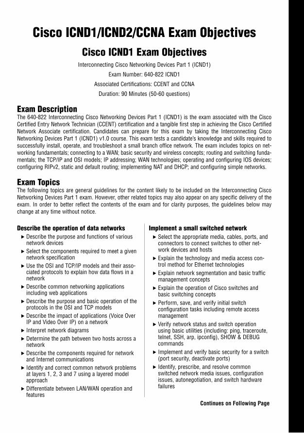
Cisco ICND1/ICND2/CCNA Exam ObjectivesCisco ICND1 Exam Objectives
Interconnecting Cisco Networking Devices Part 1 (ICND1)
Exam Number: 640-822 ICND1
Associated Certifications: CCENT and CCNA
Duration: 90 Minutes (50-60 questions)
Exam DescriptionThe 640-822 Interconnecting Cisco Networking Devices Part 1 (ICND1) is the exam associated with the CiscoCertified Entry Network Technician (CCENT) certification and a tangible first step in achieving the Cisco CertifiedNetwork Associate certification. Candidates can prepare for this exam by taking the Interconnecting CiscoNetworking Devices Part 1 (ICND1) v1.0 course. This exam tests a candidate’s knowledge and skills required tosuccessfully install, operate, and troubleshoot a small branch office network. The exam includes topics on net-working fundamentals; connecting to a WAN; basic security and wireless concepts; routing and switching funda-mentals; the TCP/IP and OSI models; IP addressing; WAN technologies; operating and configuring IOS devices;configuring RIPv2, static and default routing; implementing NAT and DHCP; and configuring simple networks.
Exam TopicsThe following topics are general guidelines for the content likely to be included on the Interconnecting CiscoNetworking Devices Part 1 exam. However, other related topics may also appear on any specific delivery of theexam. In order to better reflect the contents of the exam and for clarity purposes, the guidelines below maychange at any time without notice.
Describe the operation of data networks. Describe the purpose and functions of various
network devices. Select the components required to meet a given
network specification. Use the OSI and TCP/IP models and their asso-
ciated protocols to explain how data flows in anetwork
. Describe common networking applicationsincluding web applications
. Describe the purpose and basic operation of theprotocols in the OSI and TCP models
. Describe the impact of applications (Voice OverIP and Video Over IP) on a network
. Interpret network diagrams
. Determine the path between two hosts across anetwork
. Describe the components required for networkand Internet communications
. Identify and correct common network problemsat layers 1, 2, 3 and 7 using a layered modelapproach
. Differentiate between LAN/WAN operation andfeatures
Implement a small switched network. Select the appropriate media, cables, ports, and
connectors to connect switches to other net-work devices and hosts
. Explain the technology and media access con-trol method for Ethernet technologies
. Explain network segmentation and basic trafficmanagement concepts
. Explain the operation of Cisco switches andbasic switching concepts
. Perform, save, and verify initial switch configuration tasks including remote accessmanagement
. Verify network status and switch operationusing basic utilities (including: ping, traceroute,telnet, SSH, arp, ipconfig), SHOW & DEBUGcommands
. Implement and verify basic security for a switch(port security, deactivate ports)
. Identify, prescribe, and resolve commonswitched network media issues, configurationissues, autonegotiation, and switch hardwarefailures
Continues on Following Page
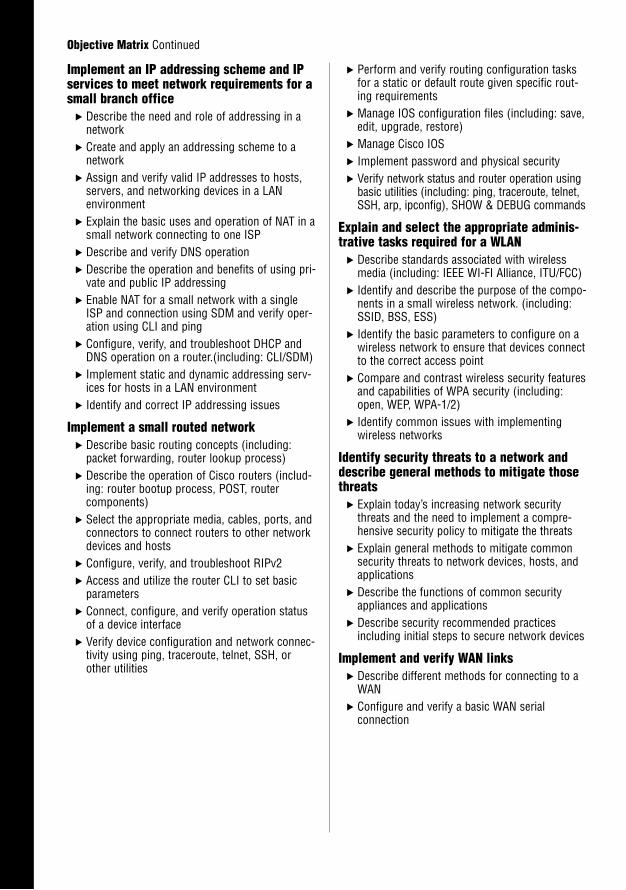
Implement an IP addressing scheme and IPservices to meet network requirements for asmall branch office
. Describe the need and role of addressing in anetwork
. Create and apply an addressing scheme to anetwork
. Assign and verify valid IP addresses to hosts,servers, and networking devices in a LAN environment
. Explain the basic uses and operation of NAT in asmall network connecting to one ISP
. Describe and verify DNS operation
. Describe the operation and benefits of using pri-vate and public IP addressing
. Enable NAT for a small network with a singleISP and connection using SDM and verify oper-ation using CLI and ping
. Configure, verify, and troubleshoot DHCP andDNS operation on a router.(including: CLI/SDM)
. Implement static and dynamic addressing serv-ices for hosts in a LAN environment
. Identify and correct IP addressing issues
Implement a small routed network. Describe basic routing concepts (including:
packet forwarding, router lookup process). Describe the operation of Cisco routers (includ-
ing: router bootup process, POST, router components)
. Select the appropriate media, cables, ports, andconnectors to connect routers to other networkdevices and hosts
. Configure, verify, and troubleshoot RIPv2
. Access and utilize the router CLI to set basicparameters
. Connect, configure, and verify operation statusof a device interface
. Verify device configuration and network connec-tivity using ping, traceroute, telnet, SSH, orother utilities
. Perform and verify routing configuration tasksfor a static or default route given specific rout-ing requirements
. Manage IOS configuration files (including: save,edit, upgrade, restore)
. Manage Cisco IOS
. Implement password and physical security
. Verify network status and router operation usingbasic utilities (including: ping, traceroute, telnet,SSH, arp, ipconfig), SHOW & DEBUG commands
Explain and select the appropriate adminis-trative tasks required for a WLAN
. Describe standards associated with wirelessmedia (including: IEEE WI-FI Alliance, ITU/FCC)
. Identify and describe the purpose of the compo-nents in a small wireless network. (including:SSID, BSS, ESS)
. Identify the basic parameters to configure on awireless network to ensure that devices connectto the correct access point
. Compare and contrast wireless security featuresand capabilities of WPA security (including:open, WEP, WPA-1/2)
. Identify common issues with implementingwireless networks
Identify security threats to a network anddescribe general methods to mitigate thosethreats
. Explain today’s increasing network securitythreats and the need to implement a compre-hensive security policy to mitigate the threats
. Explain general methods to mitigate commonsecurity threats to network devices, hosts, andapplications
. Describe the functions of common securityappliances and applications
. Describe security recommended practicesincluding initial steps to secure network devices
Implement and verify WAN links. Describe different methods for connecting to a
WAN. Configure and verify a basic WAN serial
connection
Objective Matrix Continued
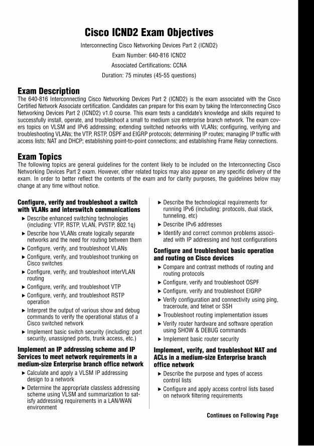
Cisco ICND2 Exam ObjectivesInterconnecting Cisco Networking Devices Part 2 (ICND2)
Exam Number: 640-816 ICND2
Associated Certifications: CCNA
Duration: 75 minutes (45-55 questions)
Exam DescriptionThe 640-816 Interconnecting Cisco Networking Devices Part 2 (ICND2) is the exam associated with the CiscoCertified Network Associate certification. Candidates can prepare for this exam by taking the Interconnecting CiscoNetworking Devices Part 2 (ICND2) v1.0 course. This exam tests a candidate’s knowledge and skills required tosuccessfully install, operate, and troubleshoot a small to medium size enterprise branch network. The exam cov-ers topics on VLSM and IPv6 addressing; extending switched networks with VLANs; configuring, verifying andtroubleshooting VLANs; the VTP, RSTP, OSPF and EIGRP protocols; determining IP routes; managing IP traffic withaccess lists; NAT and DHCP; establishing point-to-point connections; and establishing Frame Relay connections.
Exam TopicsThe following topics are general guidelines for the content likely to be included on the Interconnecting CiscoNetworking Devices Part 2 exam. However, other related topics may also appear on any specific delivery of theexam. In order to better reflect the contents of the exam and for clarity purposes, the guidelines below maychange at any time without notice.
Continues on Following Page
Configure, verify and troubleshoot a switchwith VLANs and interswitch communications
. Describe enhanced switching technologies(including: VTP, RSTP, VLAN, PVSTP, 802.1q)
. Describe how VLANs create logically separatenetworks and the need for routing between them
. Configure, verify, and troubleshoot VLANs
. Configure, verify, and troubleshoot trunking onCisco switches
. Configure, verify, and troubleshoot interVLANrouting
. Configure, verify, and troubleshoot VTP
. Configure, verify, and troubleshoot RSTP operation
. Interpret the output of various show and debugcommands to verify the operational status of aCisco switched network
. Implement basic switch security (including: portsecurity, unassigned ports, trunk access, etc.)
Implement an IP addressing scheme and IPServices to meet network requirements in amedium-size Enterprise branch office network
. Calculate and apply a VLSM IP addressingdesign to a network
. Determine the appropriate classless addressingscheme using VLSM and summarization to sat-isfy addressing requirements in a LAN/WANenvironment
. Describe the technological requirements forrunning IPv6 (including: protocols, dual stack,tunneling, etc)
. Describe IPv6 addresses
. Identify and correct common problems associ-ated with IP addressing and host configurations
Configure and troubleshoot basic operationand routing on Cisco devices
. Compare and contrast methods of routing androuting protocols
. Configure, verify and troubleshoot OSPF
. Configure, verify and troubleshoot EIGRP
. Verify configuration and connectivity using ping,traceroute, and telnet or SSH
. Troubleshoot routing implementation issues
. Verify router hardware and software operationusing SHOW & DEBUG commands
. Implement basic router security
Implement, verify, and troubleshoot NAT andACLs in a medium-size Enterprise branchoffice network
. Describe the purpose and types of access control lists
. Configure and apply access control lists basedon network filtering requirements
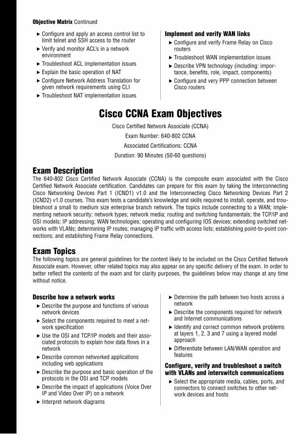
Describe how a network works. Describe the purpose and functions of various
network devices. Select the components required to meet a net-
work specification. Use the OSI and TCP/IP models and their asso-
ciated protocols to explain how data flows in anetwork
. Describe common networked applicationsincluding web applications
. Describe the purpose and basic operation of theprotocols in the OSI and TCP models
. Describe the impact of applications (Voice OverIP and Video Over IP) on a network
. Interpret network diagrams
Objective Matrix Continued
. Configure and apply an access control list tolimit telnet and SSH access to the router
. Verify and monitor ACL’s in a network environment
. Troubleshoot ACL implementation issues
. Explain the basic operation of NAT
. Configure Network Address Translation forgiven network requirements using CLI
. Troubleshoot NAT implementation issues
Implement and verify WAN links. Configure and verify Frame Relay on Cisco
routers. Troubleshoot WAN implementation issues. Describe VPN technology (including: impor-
tance, benefits, role, impact, components). Configure and very PPP connection between
Cisco routers
Cisco CCNA Exam ObjectivesCisco Certified Network Associate (CCNA)
Exam Number: 640-802 CCNA
Associated Certifications: CCNA
Duration: 90 Minutes (50-60 questions)
Exam DescriptionThe 640-802 Cisco Certified Network Associate (CCNA) is the composite exam associated with the CiscoCertified Network Associate certification. Candidates can prepare for this exam by taking the InterconnectingCisco Networking Devices Part 1 (ICND1) v1.0 and the Interconnecting Cisco Networking Devices Part 2(ICND2) v1.0 courses. This exam tests a candidate’s knowledge and skills required to install, operate, and trou-bleshoot a small to medium size enterprise branch network. The topics include connecting to a WAN; imple-menting network security; network types; network media; routing and switching fundamentals; the TCP/IP andOSI models; IP addressing; WAN technologies; operating and configuring IOS devices; extending switched net-works with VLANs; determining IP routes; managing IP traffic with access lists; establishing point-to-point con-nections; and establishing Frame Relay connections.
Exam TopicsThe following topics are general guidelines for the content likely to be included on the Cisco Certified NetworkAssociate exam. However, other related topics may also appear on any specific delivery of the exam. In order tobetter reflect the contents of the exam and for clarity purposes, the guidelines below may change at any timewithout notice.
. Determine the path between two hosts across anetwork
. Describe the components required for networkand Internet communications
. Identify and correct common network problemsat layers 1, 2, 3 and 7 using a layered modelapproach
. Differentiate between LAN/WAN operation andfeatures
Configure, verify and troubleshoot a switchwith VLANs and interswitch communications
. Select the appropriate media, cables, ports, andconnectors to connect switches to other net-work devices and hosts
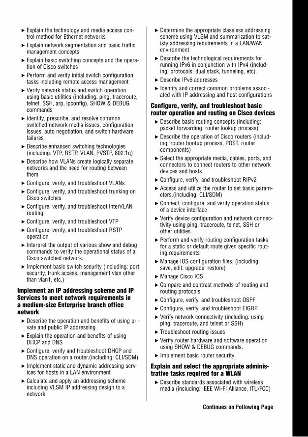
. Explain the technology and media access con-trol method for Ethernet networks
. Explain network segmentation and basic trafficmanagement concepts
. Explain basic switching concepts and the opera-tion of Cisco switches
. Perform and verify initial switch configurationtasks including remote access management
. Verify network status and switch operationusing basic utilities (including: ping, traceroute,telnet, SSH, arp, ipconfig), SHOW & DEBUGcommands
. Identify, prescribe, and resolve commonswitched network media issues, configurationissues, auto negotiation, and switch hardwarefailures
. Describe enhanced switching technologies(including: VTP, RSTP, VLAN, PVSTP, 802.1q)
. Describe how VLANs create logically separatenetworks and the need for routing betweenthem
. Configure, verify, and troubleshoot VLANs
. Configure, verify, and troubleshoot trunking onCisco switches
. Configure, verify, and troubleshoot interVLANrouting
. Configure, verify, and troubleshoot VTP
. Configure, verify, and troubleshoot RSTP operation
. Interpret the output of various show and debugcommands to verify the operational status of aCisco switched network.
. Implement basic switch security (including: portsecurity, trunk access, management vlan otherthan vlan1, etc.)
Implement an IP addressing scheme and IPServices to meet network requirements in a medium-size Enterprise branch office network
. Describe the operation and benefits of using pri-vate and public IP addressing
. Explain the operation and benefits of usingDHCP and DNS
. Configure, verify and troubleshoot DHCP andDNS operation on a router.(including: CLI/SDM)
. Implement static and dynamic addressing serv-ices for hosts in a LAN environment
. Calculate and apply an addressing schemeincluding VLSM IP addressing design to a network
. Determine the appropriate classless addressingscheme using VLSM and summarization to sat-isfy addressing requirements in a LAN/WANenvironment
. Describe the technological requirements forrunning IPv6 in conjunction with IPv4 (includ-ing: protocols, dual stack, tunneling, etc).
. Describe IPv6 addresses
. Identify and correct common problems associ-ated with IP addressing and host configurations
Configure, verify, and troubleshoot basicrouter operation and routing on Cisco devices
. Describe basic routing concepts (including:packet forwarding, router lookup process)
. Describe the operation of Cisco routers (includ-ing: router bootup process, POST, router components)
. Select the appropriate media, cables, ports, andconnectors to connect routers to other networkdevices and hosts
. Configure, verify, and troubleshoot RIPv2
. Access and utilize the router to set basic param-eters.(including: CLI/SDM)
. Connect, configure, and verify operation statusof a device interface
. Verify device configuration and network connec-tivity using ping, traceroute, telnet, SSH orother utilities
. Perform and verify routing configuration tasksfor a static or default route given specific rout-ing requirements
. Manage IOS configuration files. (including:save, edit, upgrade, restore)
. Manage Cisco IOS
. Compare and contrast methods of routing androuting protocols
. Configure, verify, and troubleshoot OSPF
. Configure, verify, and troubleshoot EIGRP
. Verify network connectivity (including: usingping, traceroute, and telnet or SSH)
. Troubleshoot routing issues
. Verify router hardware and software operationusing SHOW & DEBUG commands.
. Implement basic router security
Explain and select the appropriate adminis-trative tasks required for a WLAN
. Describe standards associated with wirelessmedia (including: IEEE WI-FI Alliance, ITU/FCC)
Continues on Following Page
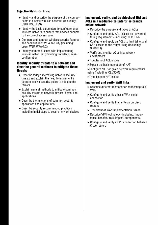
. Identify and describe the purpose of the compo-nents in a small wireless network. (Including:SSID, BSS, ESS)
. Identify the basic parameters to configure on awireless network to ensure that devices connectto the correct access point
. Compare and contrast wireless security featuresand capabilities of WPA security (including:open, WEP, WPA-1/2)
. Identify common issues with implementingwireless networks. (Including: Interface, miss-configuration)
Identify security threats to a network anddescribe general methods to mitigate thosethreats
. Describe today’s increasing network securitythreats and explain the need to implement acomprehensive security policy to mitigate thethreats
. Explain general methods to mitigate commonsecurity threats to network devices, hosts, andapplications
. Describe the functions of common securityappliances and applications
. Describe security recommended practicesincluding initial steps to secure network devices
Implement, verify, and troubleshoot NAT andACLs in a medium-size Enterprise branchoffice network
. Describe the purpose and types of ACLs
. Configure and apply ACLs based on network fil-tering requirements.(including: CLI/SDM)
. Configure and apply an ACLs to limit telnet andSSH access to the router using (including:SDM/CLI)
. Verify and monitor ACLs in a network environment
.Troubleshoot ACL issues
.Explain the basic operation of NAT
.Configure NAT for given network requirementsusing (including: CLI/SDM).Troubleshoot NAT issues
Implement and verify WAN links. Describe different methods for connecting to a
WAN. Configure and verify a basic WAN serial
connection. Configure and verify Frame Relay on Cisco
routers. Troubleshoot WAN implementation issues. Describe VPN technology (including: impor-
tance, benefits, role, impact, components). Configure and verify a PPP connection between
Cisco routers
Objective Matrix Continued
Introduction
The Cisco Certified Network Associate (CCNA) accreditation has become the leading intro-ductory-level network certification available today. The CCNA certification is recognized byemployers as providing candidates with a solid foundation of Cisco networking concepts, ter-minology, and skills. The CCNA exam covers a broad range of networking concepts to preparecandidates for the technologies they are likely to work with in today’s network environments.
This book is your one-stop shop. Everything you need to know to pass the exam is in here.You do not have to take a class in addition to buying this book to pass the exam. However,depending on your personal study habits or learning style, you might benefit from buying thisbook and taking a class. Taking a CCNA certification class gives you dedicated study time andprecious hands-on experience with live Cisco equipment.
Exam Preps are meticulously crafted to give you the best possible learning experience for theparticular characteristics of the technology covered and the actual certification exam. Theinstructional design implemented in the Exam Preps reflects the task- and experience-basednature of Cisco certification exams. The Exam Preps provide the factual knowledge base youneed for the exams and then take it to the next level, with exercises and exam questions thatare required in the CCNA certification.
Cisco has split the single CCNA test into two separate exams, ICND1 and ICND2. Althoughthe single CCNA exam still remains, Cisco recommends that only those who are recertifyingan existing CCNA certification take this exam. This CCNA Exam Prep title prepares you forboth the ICND1 exam, which covers the foundational Cisco network concepts andconfigurations, and the ICND2 exam, which covers the more advanced network concepts andconfigurations. Personally, we recommend that you follow Cisco’s advice on taking the two-exam path rather than the single CCNA exam. Although it may be tempting to go after theone-test “fast-track,” this single exam is extremely difficult and has discouraged many poten-tial CCNA candidates from continuing on their Cisco certification journey.
How This Book Helps YouThis book takes you on a self-guided tour of all the areas covered by the CCNA exam andteaches you the specific skills you need to achieve your certification. This book also containshelpful hints, tips, real-world examples, and exercises, as well as references to additional studymaterials. Specifically, this book is set up to help you in the following ways:
2
. Organization: This book is organized by individual exam objectives. Every objectiveyou need to know for the CCNA exam is covered in this book. It presents the objec-tives in an order as close as possible to that listed by Cisco. However, we did not hesi-tate to reorganize them where needed to make the material as easy as possible for youto learn. We also make the information accessible in the following ways:
. The full list of exam units and objectives is included.
. Each chapter begins with an outline that provides an overview of the material andthe pages on which particular topics can be found.
. The objectives are repeated where the material most directly relevant to them iscovered.
. Instructional features: This book provides multiple ways to learn and reinforce theexam material. Following are some of the helpful methods:
. Exam Alerts: These provide specific exam-related advice. Such tips might addresswhat material is covered (or not covered) on the exam, how it is covered, mnemon-ic devices, or particular quirks of that exam.
. Review breaks and summaries: Crucial information is summarized at variouspoints in the book in lists or tables. Each chapter ends with a summary as well.
. Key terms: A list of key terms appears at the end of each chapter.
. Notes: Notes contain various kinds of useful or practical information, such as tipson technology or administrative practices, historical background on terms andtechnologies, or side commentary on industry issues.
. Warnings: When using sophisticated information technology, there is always thepotential for mistakes or even catastrophes because of improper application of thetechnology. Warnings alert you to such potential problems.
. In the Field sidebars: These relatively extensive discussions cover material thatmight not be directly relevant to the exam but that is useful as reference materialor in everyday practice. In the Field sidebars also provide useful background orcontextual information necessary for understanding the larger topic underconsideration.
. Exercises: Found at the end of the chapters in the “Apply Your Knowledge” sec-tion and in the Challenges found throughout chapters, exercises are performance-based opportunities for you to learn and assess your knowledge.
CCNA Exam Prep
Introduction3
. Extensive practice test options: This book provides numerous opportunities for youto assess your knowledge and practice for the exam. The practice options include thefollowing:
. Exam questions: These questions appear in the “Apply Your Knowledge” section.You can use them to help determine what you know and what you need to reviewor study further. Answers and explanations for these questions are provided in aseparate section, titled “Answers to Exam Questions.”
. Practice Exam: A practice exam is included in the “Final Review” section of thebook.
. Final Review: This part of the book provides two valuable tools for preparing for theexam:
. Fast Facts: This condensed version of the information contained in the book isuseful for last-minute review.
. Practice Exam: A practice test is included. Questions on this practice exam arewritten in styles similar to those used on the actual exam. Use the practice exam toassess your readiness for the real thing. Use the extensive answer explanations toimprove your retention and understanding of the material.
This book includes several other features, such as a “Suggested Readings and Resources” section at the end of each chapter. It directs you to additional information that can aid you inyour exam preparation and your real-life work. Also included are a glossary and an appendixdescribing what is on the CD-ROM.
For more information about the exam or the certification process, refer to the Cisco websiteat www.cisco.com/certification.
Network Hardware and SoftwareRequirementsAs a self-paced study guide, CCNA Exam Prep is meant to help you understand concepts thatmust be refined through hands-on experience. To make the most of your studying, you needto have as much background in and experience with both common operating systems and net-work environments as possible. The best way to do this is to combine studying with work onactual networks. These networks need not be complex. The concepts involved in configuringa network with only a couple of routers and a switch follow the same principles as thoseinvolved in configuring a network that has hundreds of connected systems. This sectiondescribes the recommended equipment for a solid practice environment.
4
To fully practice some of the exam objectives, you need to create a network with two (or more)routers networked together with one (or more) Cisco switches. We recognize that yourfinances may be limited, so we suggest purchasing routers from the Cisco 800 or 3600 series(primarily the 851W, 3620, and 3640 routers). These can commonly be found for between$100 and $500 through a used-equipment vendor or online auction. A Catalyst 1912 or 1924switch can typically be found for less than $50. Some of the syntax on the 1900 series switch-es may be slightly different from Cisco’s mainline switches, but most of the commands are sim-ilar. Remember that Cisco has strict restrictions about using used or remanufactured equip-ment in production networks. Although Cisco hardware can be resold, the software that runsit (Cisco IOS software) cannot. Before used or remanufactured equipment can be used in aproduction environment, Cisco IOS software must be relicensed through Cisco or an author-ized reseller. Be sure to verify these regulations before using your lab equipment in a produc-tion network.
If you are looking to build a lab environment, the following is a more detailed list of the mini-mum equipment you need. Keep in mind that this is the minimum equipment that we suggestfor the CCNA. If you plan on moving into the CCNP, CCVP, or CCSP programs, you maywant to look into the more advanced (and expensive) Cisco equipment such as the 2800 routers.
. At least one Cisco 851W router, which has four 10/100Mbps Ethernet ports to testconfigurations such as NAT, one fixed port to simulate WAN connectivity, wirelessLAN with a detachable antenna, up to five VPN tunnels, and SDM capabilities.
. One additional Cisco router, such as the 2501, with one Ethernet port and two serialports to create and test WAN connectivity.
. A DB-60 DTE to DB-60 DCE cross-over serial cable.
. At least one Cisco switch, ideally a 2900XL or 2950; however, a 1900 series switch willalso suffice. If you decide to use a 1900 series switch, be sure it is equipped with theEnterprise IOS version, which includes the command-line interface. The Standard IOSfor the 1900 allows only a menu-driven configuration.
. At least one rollover console cable.
. Multiple straight-through and cross-over network cables.
. Optionally, adding one or more PCs to the network can add realism and troubleshoot-ing advantages. These PCs can be connected to the switch and act as network clients inyour scenarios.
It’s easy to get access to the necessary computer hardware and software in a corporate businessenvironment. It can be difficult, however, to allocate enough time within the busy workday tocomplete a self-study program. Most of your study time will occur after normal working hours,away from the everyday interruptions and pressures of your regular job.
CCNA Exam Prep
Introduction5
Advice on Taking the ExamKeep this advice in mind as you study:
. Read all the material: Cisco has been known to include material that is not expresslyspecified in the objectives. This book includes additional information that is notreflected in the objectives in an effort to give you the best possible preparation for theexamination—and for your real-world experiences to come.
. Complete the exercises in each chapter: They will help you gain experience inusing the specified methodology or approach. Cisco exams require task- and experi-enced-based knowledge and require you to understand how certain network proceduresare accomplished.
. Use the exam questions to assess your knowledge: Don’t just read the chapter con-tent; use the exam questions to find out what you know and what you don’t know. Ifyou are struggling, study some more, review, and then reassess your knowledge.
. Review the objectives: Develop your own questions and examples for each objectivelisted. If you can develop and answer several questions for each objective, you shouldnot find it difficult to pass the exam.
Exam-Taking Advice Although this book is designed to prepare you to take and pass the Cisco certifica-tion exam, there are no guarantees. Read this book, work through the questions and exercises, and whenyou feel confident, take the practice exam. Your results should tell you whether you are ready for the realthing. Keep in mind that lots of capable, intelligent people fail these exams one or more times. Ciscoexams are some of the most difficult in the industry; if you do fail the exam, use it as a tool to help youfocus your studies in the areas where you felt weak. As overused as this guidance is, we still need to sayit: Don’t give up. Every author writing this book has hit his or her own low points in the certification jour-ney. Trust us—after you pass the CCNA exam, the benefits far outweigh the cost.
When taking the actual certification exam, be sure that you answer all the questions before the time limitexpires. Do not spend too much time on any one question. If you are unsure about a question, answer itas best you can and move on. This especially applies to simulation-based questions. Partial credit is givenon these questions if you have completed the majority of the steps, so don’t get hung up on any one simu-lation objective for an extended time.
NOTE
Remember that the primary objective is not to pass the exam but to understand the material.When you understand the material, passing the exam should be simple. Knowledge is a pyra-mid; to build upward, you need a solid foundation. This book and the CCNA certification aredesigned to ensure that you have that solid foundation.
Good luck!

This page intentionally left blank
1C H A P T E R O N E
Standard InternetworkingModels
ObjectivesThis chapter covers the following Cisco-specific objectives for the “Describe how a networkworks” section 640-802 CCNA exam:
. Use the OSI and TCP/IP models and their associated protocols to explain howdata flows in a network
. Describe common networked applications including web applications
. Describe the purpose and basic operation of the protocols in the OSI and TCPmodels
. Determine the path between two hosts across a network
OutlineIntroduction 10
What Is an Internetwork? 10
Types of Internetworks 11
Local Area Network (LAN) 11
Metropolitan Area Network (MAN) 12
Wide Area Network (WAN) 12
Storage Area Network (SAN) 14
Virtual Private Network (VPN) 14
Open Systems Interconnection (OSI) Model 14
Upper Layers 15
Application Layer 16
Presentation Layer 17
Session Layer 18
Lower Layers 18
Transport Layer 19
Network Layer 20
Data Link Layer 21
Media Access Control (MAC) 22
Logical Link Control (LLC) 22
Physical Layer 23
OSI Layered Communications 24
TCP/IP Model 26
Application Layer 26
Transport Layer 27
TCP 27
UDP 29
Internet Layer 31
IP 31
ICMP 32
ARP, RARP, and Proxy ARP 33
Network Interface Layer 33
Cisco 3-Layer Hierarchical Model 33
Access Layer 34
Distribution Layer 35
Core Layer 35
Chapter Summary 37
Key Terms 38
Apply Your Knowledge 39
Exercise 39
Review Questions 40
Exam Questions 40
Answers to Review Questions 44
Answers to Exam Questions 47
Suggested Readings and Resources 48

Study Strategies. Read through the exam objectives at the beginning of the chapter.
. Review the characteristics of each internetwork and keep in mind which network would beappropriate based on a given company and its individual requirements.
. Identify the names and primary functions of each OSI model layer. Create a mnemonicdevice to help you remember the seven layers.
. Identify the protocols and standards that are used at each layer of the OSI model. Payclose attention to the application protocols used at the Application layer.
. Review and memorize associated UDP and TCP port assignments for several well-knownprotocols.
10
IntroductionWhether you already work in the computer technology industry, or you are trying to enter thefield as a newcomer, it is important in this day and age to back up your resume with a vendor-specific certification. If you search job postings on the Internet, it is commonplace for hiring com-panies today to require or recommend that an applicant have at least one vendor certification.Other companies ask that their current employees obtain certifications as a way to meet goals foradvancement. Regardless of the underlying reason, studying for the CCNA is a smart move.
The CCNA certification was developed by Cisco to test your knowledge of networking at abeginner’s level. Cisco wants to identify individuals capable of installing, configuring, andmaintaining small-scale networks, which include Local Area Networks (LANs) and Wide AreaNetworks (WANs).
The purpose of this first chapter is to provide a general overview of the concepts that will ulti-mately be the foundation for the rest of this book. To start this chapter, the first step is todefine the term internetwork. It then reviews the general concepts that pertain to LAN andWAN internetworks, as well as the Metropolitan Area Network (MAN), Storage AreaNetwork (SAN), and Virtual Private Network (VPN). Later chapters go into more detailregarding the technologies that are related to both LAN and WAN.
This chapter also gives an in-depth look at the three networking reference models that arelikely to be tested on the CCNA exam. These are the Open Systems Interconnection (OSI),Transmission Control Protocol/Internet Protocol (TCP/IP), and Cisco 3-Layer Hierarchicalmodels. Being familiar with these models is fundamental to understanding how networks oper-ate, as well as how various devices and protocols fit into their structure. By using these mod-els, you can design an infrastructure based on a given organization’s specific requirements.
What Is an Internetwork?Simply put, an internetwork is the connection of more than one network. These networks arelinked together by an internetworking device to provide communication between the net-works. Internetworks may also be referred to as an internet. Notice the lower case i at thebeginning of the word internet—this differentiates it from the Internet. The Internet is con-sidered to be the largest internet in the world. I know the phrase sounds odd, but it is a greatexample of how thousands of smaller networks are joined together to form one large globalinternetwork. Another example of an internet would be the connection of individual LANs toform a WAN.
The term internetworking signifies the industry, products, and processes that are required tohandle the challenges of network interoperability. Such issues can be quite complex because ofthe existence of multiple vendors and protocols.
Chapter 1: Standard Internetworking Models
Types of Internetworks11
Types of InternetworksThere are various types of internetworks discussed in greater detail. I already mentioned LANand WANs, which are the most common types of internetworks. Other important internet-works include MANs, SANs, and VPNs, which are also reviewed in this section.
Local Area Network (LAN)Like the name suggests, LANs are limited to a local or small geographical area. An example ofa LAN would be a network of individual computers or workstations that are connected in asingle department. These users have shared access to resources such as data and networkdevices. Users on a LAN segment can share a network printer and communicate with oneanother via email. Also, they are governed by one authoritative administrator.
LAN is the smallest network in geographical size.
NOTE
Given the size constraints, downsides of a LAN network are limited distance that data cantravel and a limited number of computers that can be connected. An upside of a LAN is fastdata transfer with data speed that can reach up to 10Gbps.
Xerox Corporation worked in collaboration with DEC and Intel to create ethernet, which isthe most pervasive LAN architecture used today. Ethernet has evolved and has seen significantimprovements in regard to speed and efficiency.
Other significant LAN technologies are Fiber Distributed Data Interface (FDDI) and tokenring.
EXAM ALERTAn understanding of LAN technology is required for the CCNA exam. Each ethernet version is discussedin detail in Chapter 3, “Data Link Networking Concepts.”
Local area networking uses switches, bridges and/or repeaters, and hubs to interconnect LANsand increase overall size. Routers are used to connect a LAN to a WAN or MAN. Both ofthese scenarios form an internetwork.
Figure 1.1 provides an example of a LAN. A single switch connects to all the peripheral net-work devices in this example.
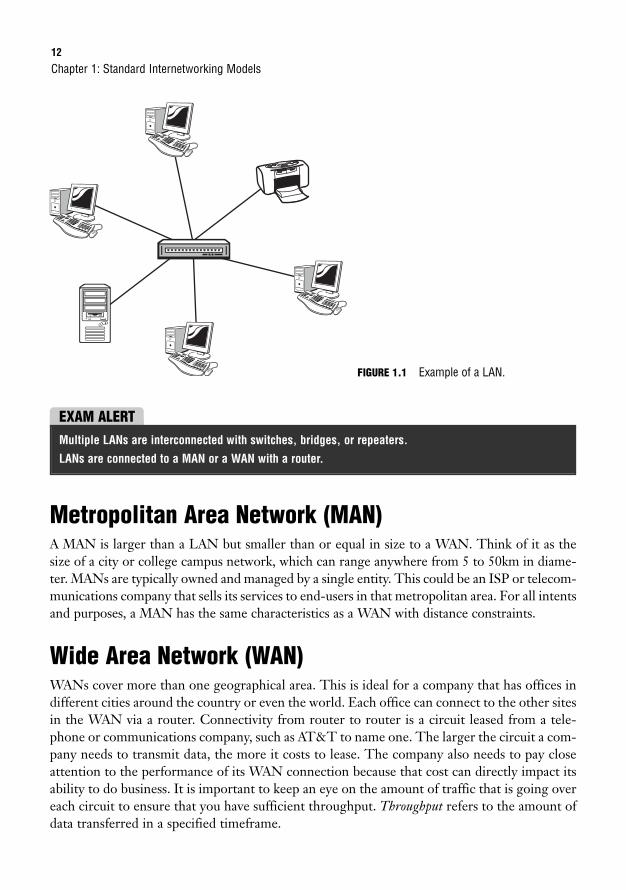
12
Metropolitan Area Network (MAN)A MAN is larger than a LAN but smaller than or equal in size to a WAN. Think of it as thesize of a city or college campus network, which can range anywhere from 5 to 50km in diame-ter. MANs are typically owned and managed by a single entity. This could be an ISP or telecom-munications company that sells its services to end-users in that metropolitan area. For all intentsand purposes, a MAN has the same characteristics as a WAN with distance constraints.
Wide Area Network (WAN)WANs cover more than one geographical area. This is ideal for a company that has offices indifferent cities around the country or even the world. Each office can connect to the other sitesin the WAN via a router. Connectivity from router to router is a circuit leased from a tele-phone or communications company, such as AT&T to name one. The larger the circuit a com-pany needs to transmit data, the more it costs to lease. The company also needs to pay closeattention to the performance of its WAN connection because that cost can directly impact itsability to do business. It is important to keep an eye on the amount of traffic that is going overeach circuit to ensure that you have sufficient throughput. Throughput refers to the amount ofdata transferred in a specified timeframe.
Chapter 1: Standard Internetworking Models
FIGURE 1.1 Example of a LAN.
EXAM ALERTMultiple LANs are interconnected with switches, bridges, or repeaters.
LANs are connected to a MAN or a WAN with a router.
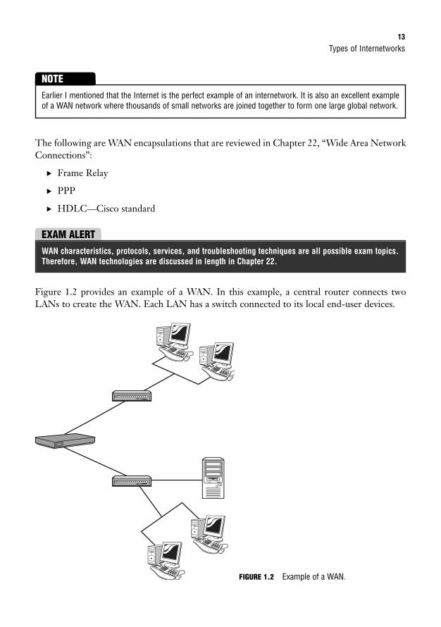
Types of Internetworks13
The following are WAN encapsulations that are reviewed in Chapter 22, “Wide Area NetworkConnections”:
. Frame Relay
. PPP
. HDLC—Cisco standard
Earlier I mentioned that the Internet is the perfect example of an internetwork. It is also an excellent exampleof a WAN network where thousands of small networks are joined together to form one large global network.
NOTE
EXAM ALERTWAN characteristics, protocols, services, and troubleshooting techniques are all possible exam topics.Therefore, WAN technologies are discussed in length in Chapter 22.
Figure 1.2 provides an example of a WAN. In this example, a central router connects twoLANs to create the WAN. Each LAN has a switch connected to its local end-user devices.
FIGURE 1.2 Example of a WAN.
14
Storage Area Network (SAN)SAN may be referred to as a subnetwork or special purpose network. Its special purpose is toallow users on a larger network to connect various data storage devices with clusters of dataservers. Cisco offers this service with its Cisco MDS 9000 Series Multilayer SAN Switches.These switches provide scalable storage solutions for the end user.
Virtual Private Network (VPN)VPN is a private network that can access public networks remotely. VPN uses encryption andsecurity protocols to retain privacy while it accesses outside resources. When employed on anetwork, VPN enables an end user to create a virtual tunnel to a remote location. Typically,telecommuters use VPN to log in to their company networks from home.
Open Systems Interconnection (OSI) ModelObjectives:
. Use the OSI and TCP/IP models and their associated protocols to explain how data flows in a network
. Describe common networked applications including web applications
. Describe the purpose and basic operation of the protocols in the OSI and TCP models
By now you understand the concept of an internetwork. Now the OSI model will help you seejust how an internetwork operates by using a layered architecture.
The International Organization for Standardization (ISO) created the OSI model as the firstmajor attempt to internetwork various vendor-specific networks, the ultimate goal being thatthese different vendor networks could work together in harmony. This model consists of sevenlayers. Although it is not widely used today, the terminology is prevalent in the networkingcommunity. The OSI model may also be helpful when troubleshooting a network issue.
First of all, it is important to know the name of each layer and its corresponding layer num-ber. This will help you remember where the layers reside in the OSI model. You may also hearthe layers referred to by number, so knowing them will also help in that respect. Table 1.1 pro-vides a list of all seven layers.
Chapter 1: Standard Internetworking Models
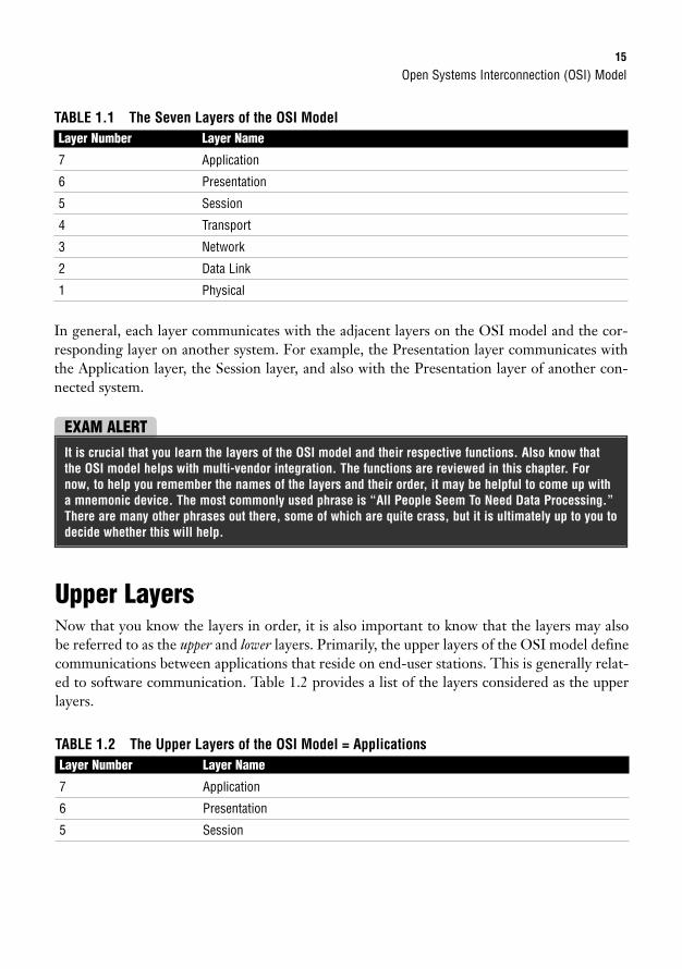
Open Systems Interconnection (OSI) Model15
TABLE 1.1 The Seven Layers of the OSI ModelLayer Number Layer Name
7 Application
6 Presentation
5 Session
4 Transport
3 Network
2 Data Link
1 Physical
In general, each layer communicates with the adjacent layers on the OSI model and the cor-responding layer on another system. For example, the Presentation layer communicates withthe Application layer, the Session layer, and also with the Presentation layer of another con-nected system.
EXAM ALERTIt is crucial that you learn the layers of the OSI model and their respective functions. Also know thatthe OSI model helps with multi-vendor integration. The functions are reviewed in this chapter. Fornow, to help you remember the names of the layers and their order, it may be helpful to come up witha mnemonic device. The most commonly used phrase is “All People Seem To Need Data Processing.”There are many other phrases out there, some of which are quite crass, but it is ultimately up to you todecide whether this will help.
Upper LayersNow that you know the layers in order, it is also important to know that the layers may alsobe referred to as the upper and lower layers. Primarily, the upper layers of the OSI model definecommunications between applications that reside on end-user stations. This is generally relat-ed to software communication. Table 1.2 provides a list of the layers considered as the upperlayers.
TABLE 1.2 The Upper Layers of the OSI Model = ApplicationsLayer Number Layer Name
7 Application
6 Presentation
5 Session
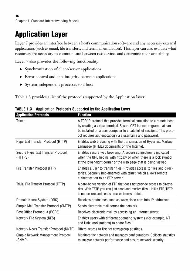
16
Application LayerLayer 7 provides an interface between a host’s communication software and any necessary externalapplications (such as email, file transfers, and terminal emulation). This layer can also evaluate whatresources are necessary to communicate between two devices and determine their availability.
Layer 7 also provides the following functionality:
. Synchronization of client/server applications
. Error control and data integrity between applications
. System-independent processes to a host
Table 1.3 provides a list of the protocols supported by the Application layer.
TABLE 1.3 Application Protocols Supported by the Application LayerApplication Protocols Function
Telnet A TCP/IP protocol that provides terminal emulation to a remote hostby creating a virtual terminal. Secure CRT is one program that canbe installed on a user computer to create telnet sessions. This proto-col requires authentication via a username and password.
Hypertext Transfer Protocol (HTTP) Enables web browsing with the transmission of Hypertext MarkupLanguage (HTML) documents on the Internet.
Secure Hypertext Transfer Protocol Enables secure web browsing. A secure connection is indicated (HTTPS) when the URL begins with https:// or when there is a lock symbol
at the lower-right corner of the web page that is being viewed.
File Transfer Protocol (FTP) Enables a user to transfer files. Provides access to files and direc-tories. Securely implemented with telnet, which allows remoteauthentication to an FTP server.
Trivial File Transfer Protocol (TFTP) A bare-bones version of FTP that does not provide access to directo-ries. With TFTP you can just send and receive files. Unlike FTP, TFTPis not secure and sends smaller blocks of data.
Domain Name System (DNS) Resolves hostnames such as www.cisco.com into IP addresses.
Simple Mail Transfer Protocol (SMTP) Sends electronic mail across the network.
Post Office Protocol 3 (POP3) Receives electronic mail by accessing an Internet server.
Network File System (NFS) Enables users with different operating systems (for example, NTand Unix workstations) to share files.
Network News Transfer Protocol (NNTP) Offers access to Usenet newsgroup postings.
Simple Network Management Protocol Monitors the network and manages configurations. Collects statistics(SNMP) to analyze network performance and ensure network security.
Chapter 1: Standard Internetworking Models
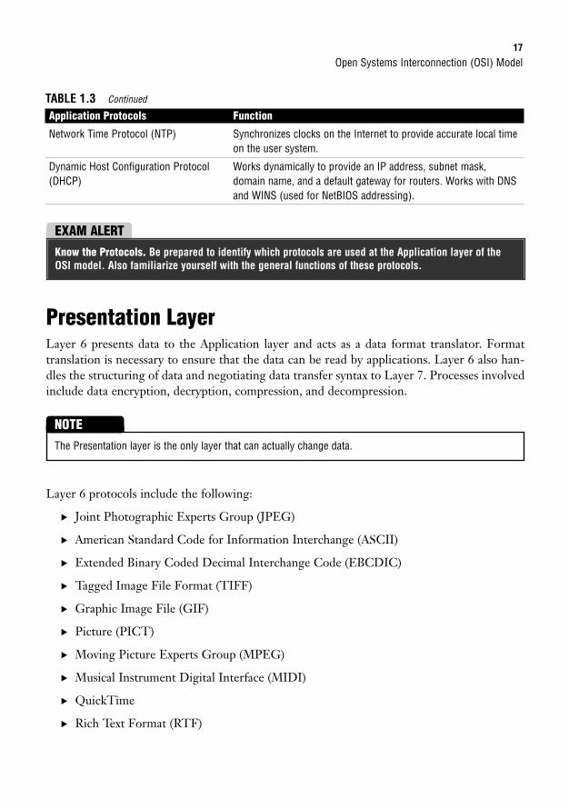
Open Systems Interconnection (OSI) Model17
Network Time Protocol (NTP) Synchronizes clocks on the Internet to provide accurate local timeon the user system.
Dynamic Host Configuration Protocol Works dynamically to provide an IP address, subnet mask, (DHCP) domain name, and a default gateway for routers. Works with DNS
and WINS (used for NetBIOS addressing).
TABLE 1.3 Continued
Application Protocols Function
EXAM ALERTKnow the Protocols. Be prepared to identify which protocols are used at the Application layer of theOSI model. Also familiarize yourself with the general functions of these protocols.
Presentation LayerLayer 6 presents data to the Application layer and acts as a data format translator. Formattranslation is necessary to ensure that the data can be read by applications. Layer 6 also han-dles the structuring of data and negotiating data transfer syntax to Layer 7. Processes involvedinclude data encryption, decryption, compression, and decompression.
The Presentation layer is the only layer that can actually change data.
NOTE
Layer 6 protocols include the following:
. Joint Photographic Experts Group (JPEG)
. American Standard Code for Information Interchange (ASCII)
. Extended Binary Coded Decimal Interchange Code (EBCDIC)
. Tagged Image File Format (TIFF)
. Graphic Image File (GIF)
. Picture (PICT)
. Moving Picture Experts Group (MPEG)
. Musical Instrument Digital Interface (MIDI)
. QuickTime
. Rich Text Format (RTF)
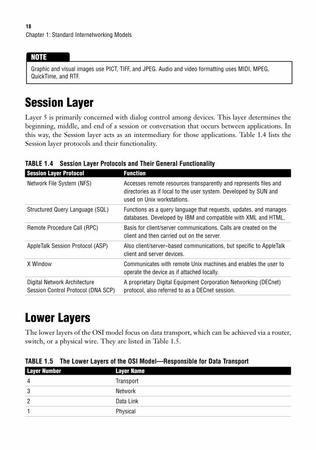
18
Session LayerLayer 5 is primarily concerned with dialog control among devices. This layer determines thebeginning, middle, and end of a session or conversation that occurs between applications. Inthis way, the Session layer acts as an intermediary for those applications. Table 1.4 lists theSession layer protocols and their functionality.
TABLE 1.4 Session Layer Protocols and Their General FunctionalitySession Layer Protocol Function
Network File System (NFS) Accesses remote resources transparently and represents files anddirectories as if local to the user system. Developed by SUN andused on Unix workstations.
Structured Query Language (SQL) Functions as a query language that requests, updates, and managesdatabases. Developed by IBM and compatible with XML and HTML.
Remote Procedure Call (RPC) Basis for client/server communications. Calls are created on theclient and then carried out on the server.
AppleTalk Session Protocol (ASP) Also client/server–based communications, but specific to AppleTalkclient and server devices.
X Window Communicates with remote Unix machines and enables the user tooperate the device as if attached locally.
Digital Network Architecture A proprietary Digital Equipment Corporation Networking (DECnet)Session Control Protocol (DNA SCP) protocol, also referred to as a DECnet session.
Lower LayersThe lower layers of the OSI model focus on data transport, which can be achieved via a router,switch, or a physical wire. They are listed in Table 1.5.
TABLE 1.5 The Lower Layers of the OSI Model—Responsible for Data TransportLayer Number Layer Name
4 Transport
3 Network
2 Data Link
1 Physical
Chapter 1: Standard Internetworking Models
Graphic and visual images use PICT, TIFF, and JPEG. Audio and video formatting uses MIDI, MPEG,QuickTime, and RTF.
NOTE
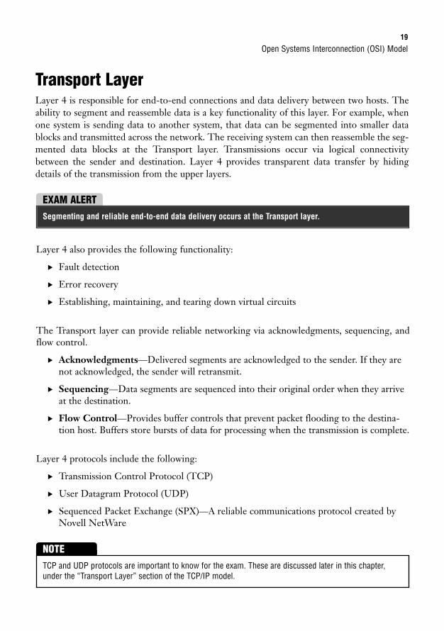
Open Systems Interconnection (OSI) Model19
Transport LayerLayer 4 is responsible for end-to-end connections and data delivery between two hosts. Theability to segment and reassemble data is a key functionality of this layer. For example, whenone system is sending data to another system, that data can be segmented into smaller datablocks and transmitted across the network. The receiving system can then reassemble the seg-mented data blocks at the Transport layer. Transmissions occur via logical connectivitybetween the sender and destination. Layer 4 provides transparent data transfer by hidingdetails of the transmission from the upper layers.
EXAM ALERTSegmenting and reliable end-to-end data delivery occurs at the Transport layer.
Layer 4 also provides the following functionality:
. Fault detection
. Error recovery
. Establishing, maintaining, and tearing down virtual circuits
The Transport layer can provide reliable networking via acknowledgments, sequencing, andflow control.
. Acknowledgments—Delivered segments are acknowledged to the sender. If they arenot acknowledged, the sender will retransmit.
. Sequencing—Data segments are sequenced into their original order when they arriveat the destination.
. Flow Control—Provides buffer controls that prevent packet flooding to the destina-tion host. Buffers store bursts of data for processing when the transmission is complete.
Layer 4 protocols include the following:
. Transmission Control Protocol (TCP)
. User Datagram Protocol (UDP)
. Sequenced Packet Exchange (SPX)—A reliable communications protocol created byNovell NetWare
TCP and UDP protocols are important to know for the exam. These are discussed later in this chapter,under the “Transport Layer” section of the TCP/IP model.
NOTE
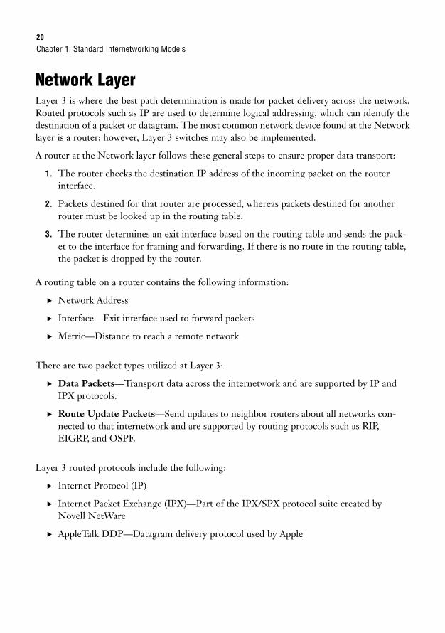
20
Network LayerLayer 3 is where the best path determination is made for packet delivery across the network.Routed protocols such as IP are used to determine logical addressing, which can identify thedestination of a packet or datagram. The most common network device found at the Networklayer is a router; however, Layer 3 switches may also be implemented.
A router at the Network layer follows these general steps to ensure proper data transport:
1. The router checks the destination IP address of the incoming packet on the routerinterface.
2. Packets destined for that router are processed, whereas packets destined for anotherrouter must be looked up in the routing table.
3. The router determines an exit interface based on the routing table and sends the pack-et to the interface for framing and forwarding. If there is no route in the routing table,the packet is dropped by the router.
A routing table on a router contains the following information:
. Network Address
. Interface—Exit interface used to forward packets
. Metric—Distance to reach a remote network
There are two packet types utilized at Layer 3:
. Data Packets—Transport data across the internetwork and are supported by IP andIPX protocols.
. Route Update Packets—Send updates to neighbor routers about all networks con-nected to that internetwork and are supported by routing protocols such as RIP,EIGRP, and OSPF.
Layer 3 routed protocols include the following:
. Internet Protocol (IP)
. Internet Packet Exchange (IPX)—Part of the IPX/SPX protocol suite created byNovell NetWare
. AppleTalk DDP—Datagram delivery protocol used by Apple
Chapter 1: Standard Internetworking Models
Open Systems Interconnection (OSI) Model21
Data Link LayerLayer 2 ensures reliable data transfer from the Network layer to the Physical layer for trans-mission across the network.
Two domains determine data transport reliability:
. Broadcast Domain—A group of nodes that can receive each other’s broadcast mes-sages and are segmented by routers.
. Collision Domain—A group of nodes that share the same media and are segmentedby switches. A collision occurs if two nodes attempt a simultaneous transmission.Carrier Sense Multiple Access Collision Detection (CSMA/CD) is an access method thatsends a jam signal to notify the devices that there has been a collision. The devicesthen halt transmission for a random back-off time.
EXAM ALERTFor the exam, this book focuses on IP, which is reviewed in Chapter 5, “Implementing IP Addressing.”
Routers and logical addressing (that is, IP addresses) are used at Layer 3. Data at Layer 3 is in the form ofpackets or a datagram.
NOTE
EXAM ALERTRouters segment broadcast domains, whereas switches segment collision domains.
Data received from the Network layer is formatted into frames to be transmitted to thePhysical layer. Physical addressing or hardware addressing (rather than logical addressing)ensures that data is delivered to the appropriate node on the LAN. This layer is also respon-sible for error notification (not correction), network topology, and flow control.
This is the only layer of the OSI model that has sublayers. The two sublayers in questiondefine the IEEE Ethernet 802.3 frame, which in turn provides physical addressing and flowcontrol. Also, routed protocol information (IP, IPX, AppleTalk, and so on) is provided to theupper layers.
The IEEE Ethernet 802.3 sublayers are Media Access Control (MAC) and Logical LinkControl (LLC), and are described in the following sections.
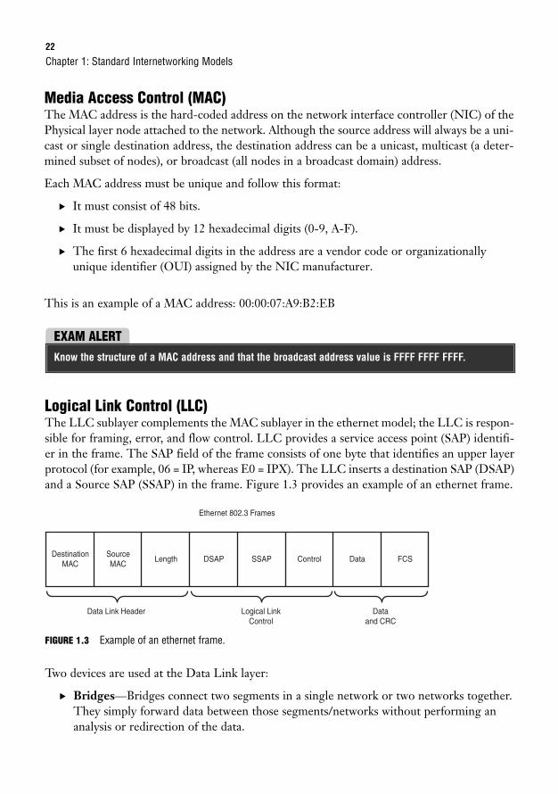
22
Media Access Control (MAC)The MAC address is the hard-coded address on the network interface controller (NIC) of thePhysical layer node attached to the network. Although the source address will always be a uni-cast or single destination address, the destination address can be a unicast, multicast (a deter-mined subset of nodes), or broadcast (all nodes in a broadcast domain) address.
Each MAC address must be unique and follow this format:
. It must consist of 48 bits.
. It must be displayed by 12 hexadecimal digits (0-9, A-F).
. The first 6 hexadecimal digits in the address are a vendor code or organizationallyunique identifier (OUI) assigned by the NIC manufacturer.
This is an example of a MAC address: 00:00:07:A9:B2:EB
Chapter 1: Standard Internetworking Models
EXAM ALERTKnow the structure of a MAC address and that the broadcast address value is FFFF FFFF FFFF.
Logical Link Control (LLC)The LLC sublayer complements the MAC sublayer in the ethernet model; the LLC is respon-sible for framing, error, and flow control. LLC provides a service access point (SAP) identifi-er in the frame. The SAP field of the frame consists of one byte that identifies an upper layerprotocol (for example, 06 = IP, whereas E0 = IPX). The LLC inserts a destination SAP (DSAP)and a Source SAP (SSAP) in the frame. Figure 1.3 provides an example of an ethernet frame.
DestinationMAC
SourceMAC
Length DSAP SSAP
Ethernet 802.3 Frames
Data Link Header
Control Data FCS
Logical Link Control
Dataand CRC
FIGURE 1.3 Example of an ethernet frame.
Two devices are used at the Data Link layer:
. Bridges—Bridges connect two segments in a single network or two networks together.They simply forward data between those segments/networks without performing ananalysis or redirection of the data.
Open Systems Interconnection (OSI) Model23
. Switches—At Layer 2, switches are multi-port bridges that utilize Application SpecificIntegrated Circuit (ASIC) to forward frames. Each port of the switch has a dedicatedbandwidth.
EXAM ALERTDedicated bandwidth enables the switch port to guarantee the speed assigned to that port. For exam-ple, 100Mbps port connections get 100Mbps transmission rates.
Although both devices create a separate collision domain for each connected device, all thedevices connected to either are a part of the same broadcast domain. Remember that broad-cast domains are segmented at the Network layer by routers.
Switches and bridges identify MAC addresses by scanning for the source MAC address of eachframe received.
Bridging and switching are discussed in more detail in Chapter 3.
NOTE
Physical LayerLayer 1 moves bits between nodes. Electrical, mechanical, procedural, and functional requirements are defined at the Physical layer to assist with the activation, maintenance, anddeactivation of physical connectivity between devices.
Other attributes of Layer 1 include the following:
. Specification of voltage, wire speed, and pin-out cables
. Capability to receive and transmit a data signal
. Identification of the interface that is set up between the data terminal equipment(DTE) and the data communication equipment (DCE)
Although DTE is the locally attached device, DCE is typically found at the service provider. DTE servicescan be accessed with either a model or a channel service unit/data service unit (CSU/DSU). For additionalinformation on associated Layer 1 technologies, continue on to Chapter 2, “Physical Layer NetworkingConcepts.”
NOTE
24
Devices at the Physical layer include hubs and repeaters. Hubs and repeaters extend a network,whereas Layer 2 and Layer 3 devices segment a network.
OSI Layered CommunicationsNow that you have reviewed all seven layers of the OSI model, it is a good time to see howthose layers communicate with each other. Each layer passes information to adjacent layers byusing Protocol Data Units (PDUs). The PDU includes both the message and theprotocol/control information from the forwarding layer. That control information can be inthe form of a header or trailer. The process of adding a header or trailer to the PDU at eachlayer of the OSI is called encapsulation.
Each layer has an associated control information name, which is listed in Table 1.6.
TABLE 1.6 OSI Model Layers and Their Control Information NamesOSI Layer Control Information Name
Application DataPresentationSession
Transport Segment
Network Packet
Data Link Frame
Physical Bit
Based on this chart, you can see how information is encapsulated as it travels down throughthe various layers. The correct order for data encapsulation is data, segment, packet, frame,and bit.
Chapter 1: Standard Internetworking Models
EXAM ALERTIt is important to know the control information name for the OSI layers and the correct order for dataencapsulation.
REVIEW BREAKLet’s take a few minutes to go over the OSI model. Table 1.7 lists the seven layers and signif-icant aspects of each layer.
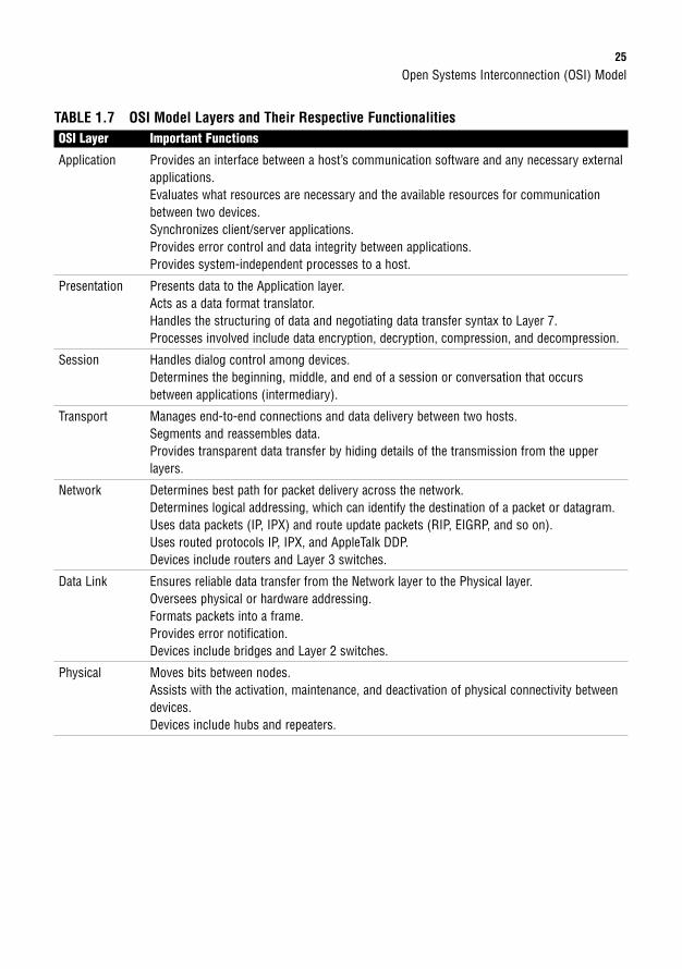
Open Systems Interconnection (OSI) Model25
TABLE 1.7 OSI Model Layers and Their Respective FunctionalitiesOSI Layer Important Functions
Application Provides an interface between a host’s communication software and any necessary externalapplications.Evaluates what resources are necessary and the available resources for communicationbetween two devices.Synchronizes client/server applications.Provides error control and data integrity between applications.Provides system-independent processes to a host.
Presentation Presents data to the Application layer.Acts as a data format translator.Handles the structuring of data and negotiating data transfer syntax to Layer 7.Processes involved include data encryption, decryption, compression, and decompression.
Session Handles dialog control among devices.Determines the beginning, middle, and end of a session or conversation that occursbetween applications (intermediary).
Transport Manages end-to-end connections and data delivery between two hosts.Segments and reassembles data.Provides transparent data transfer by hiding details of the transmission from the upper layers.
Network Determines best path for packet delivery across the network.Determines logical addressing, which can identify the destination of a packet or datagram.Uses data packets (IP, IPX) and route update packets (RIP, EIGRP, and so on).Uses routed protocols IP, IPX, and AppleTalk DDP.Devices include routers and Layer 3 switches.
Data Link Ensures reliable data transfer from the Network layer to the Physical layer.Oversees physical or hardware addressing.Formats packets into a frame.Provides error notification.Devices include bridges and Layer 2 switches.
Physical Moves bits between nodes.Assists with the activation, maintenance, and deactivation of physical connectivity betweendevices.Devices include hubs and repeaters.
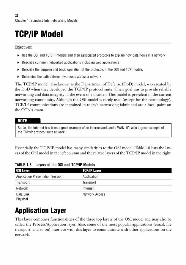
26
TCP/IP ModelObjectives:
. Use the OSI and TCP/IP models and their associated protocols to explain how data flows in a network
. Describe common networked applications including web applications
. Describe the purpose and basic operation of the protocols in the OSI and TCP models
. Determine the path between two hosts across a network
The TCP/IP model, also known as the Department of Defense (DoD) model, was created bythe DoD when they developed the TCP/IP protocol suite. Their goal was to provide reliablenetworking and data integrity in the event of a disaster. This model is prevalent in the currentnetworking community. Although the OSI model is rarely used (except for the terminology),TCP/IP communications are ingrained in today’s networking fabric and are a focal point onthe CCNA exam.
Chapter 1: Standard Internetworking Models
So far, the Internet has been a great example of an internetwork and a WAN. It’s also a great example ofthe TCP/IP protocol suite at work.
NOTE
Essentially the TCP/IP model has many similarities to the OSI model. Table 1.8 lists the lay-ers of the OSI model in the left column and the related layers of the TCP/IP model in the right.
TABLE 1.8 Layers of the OSI and TCP/IP ModelsOSI Layer TCP/IP Layer
Application Presentation Session Application
Transport Transport
Network Internet
Data Link Network AccessPhysical
Application LayerThis layer combines functionalities of the three top layers of the OSI model and may also becalled the Process/Application layer. Also, some of the most popular applications (email, filetransport, and so on) interface with this layer to communicate with other applications on thenetwork.
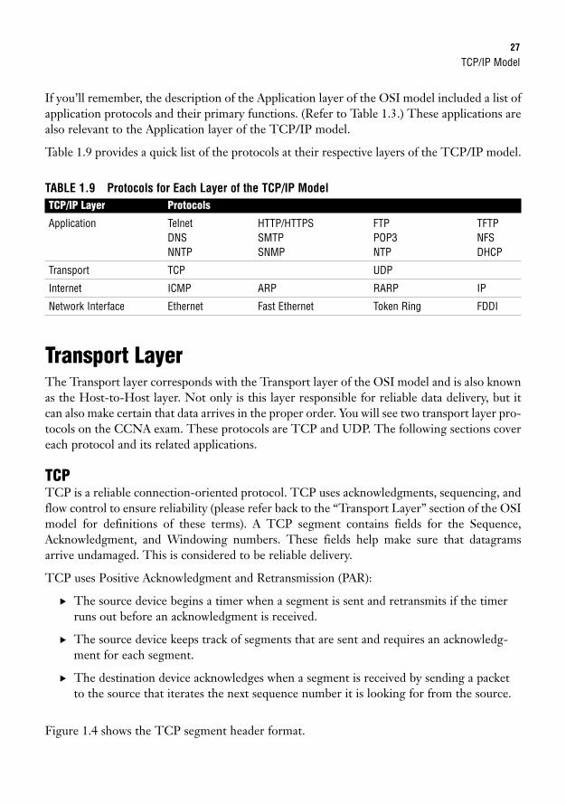
TCP/IP Model27
If you’ll remember, the description of the Application layer of the OSI model included a list ofapplication protocols and their primary functions. (Refer to Table 1.3.) These applications arealso relevant to the Application layer of the TCP/IP model.
Table 1.9 provides a quick list of the protocols at their respective layers of the TCP/IP model.
TABLE 1.9 Protocols for Each Layer of the TCP/IP ModelTCP/IP Layer Protocols
Application Telnet HTTP/HTTPS FTP TFTPDNS SMTP POP3 NFSNNTP SNMP NTP DHCP
Transport TCP UDP
Internet ICMP ARP RARP IP
Network Interface Ethernet Fast Ethernet Token Ring FDDI
Transport LayerThe Transport layer corresponds with the Transport layer of the OSI model and is also knownas the Host-to-Host layer. Not only is this layer responsible for reliable data delivery, but itcan also make certain that data arrives in the proper order. You will see two transport layer pro-tocols on the CCNA exam. These protocols are TCP and UDP. The following sections covereach protocol and its related applications.
TCPTCP is a reliable connection-oriented protocol. TCP uses acknowledgments, sequencing, andflow control to ensure reliability (please refer back to the “Transport Layer” section of the OSImodel for definitions of these terms). A TCP segment contains fields for the Sequence,Acknowledgment, and Windowing numbers. These fields help make sure that datagramsarrive undamaged. This is considered to be reliable delivery.
TCP uses Positive Acknowledgment and Retransmission (PAR):
. The source device begins a timer when a segment is sent and retransmits if the timerruns out before an acknowledgment is received.
. The source device keeps track of segments that are sent and requires an acknowledg-ment for each segment.
. The destination device acknowledges when a segment is received by sending a packetto the source that iterates the next sequence number it is looking for from the source.
Figure 1.4 shows the TCP segment header format.
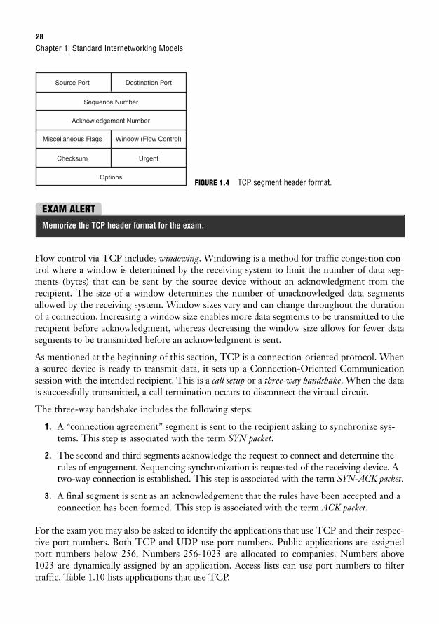
28
Flow control via TCP includes windowing. Windowing is a method for traffic congestion con-trol where a window is determined by the receiving system to limit the number of data seg-ments (bytes) that can be sent by the source device without an acknowledgment from therecipient. The size of a window determines the number of unacknowledged data segmentsallowed by the receiving system. Window sizes vary and can change throughout the durationof a connection. Increasing a window size enables more data segments to be transmitted to therecipient before acknowledgment, whereas decreasing the window size allows for fewer datasegments to be transmitted before an acknowledgment is sent.
As mentioned at the beginning of this section, TCP is a connection-oriented protocol. Whena source device is ready to transmit data, it sets up a Connection-Oriented Communicationsession with the intended recipient. This is a call setup or a three-way handshake. When the datais successfully transmitted, a call termination occurs to disconnect the virtual circuit.
The three-way handshake includes the following steps:
1. A “connection agreement” segment is sent to the recipient asking to synchronize sys-tems. This step is associated with the term SYN packet.
2. The second and third segments acknowledge the request to connect and determine therules of engagement. Sequencing synchronization is requested of the receiving device. Atwo-way connection is established. This step is associated with the term SYN-ACK packet.
3. A final segment is sent as an acknowledgement that the rules have been accepted and aconnection has been formed. This step is associated with the term ACK packet.
For the exam you may also be asked to identify the applications that use TCP and their respec-tive port numbers. Both TCP and UDP use port numbers. Public applications are assignedport numbers below 256. Numbers 256-1023 are allocated to companies. Numbers above1023 are dynamically assigned by an application. Access lists can use port numbers to filtertraffic. Table 1.10 lists applications that use TCP.
Chapter 1: Standard Internetworking Models
Source Port
Sequence Number
Options
Acknowledgement Number
Destination Port
Miscellaneous Flags Window (Flow Control)
Checksum Urgent
FIGURE 1.4 TCP segment header format.
EXAM ALERTMemorize the TCP header format for the exam.
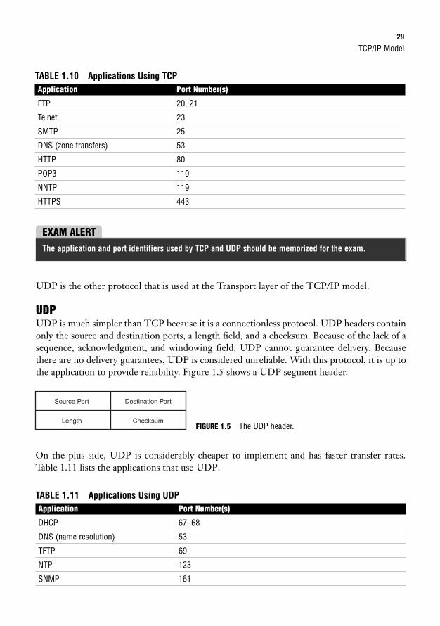
TCP/IP Model29
TABLE 1.10 Applications Using TCPApplication Port Number(s)
FTP 20, 21
Telnet 23
SMTP 25
DNS (zone transfers) 53
HTTP 80
POP3 110
NNTP 119
HTTPS 443
EXAM ALERTThe application and port identifiers used by TCP and UDP should be memorized for the exam.
UDP is the other protocol that is used at the Transport layer of the TCP/IP model.
UDPUDP is much simpler than TCP because it is a connectionless protocol. UDP headers containonly the source and destination ports, a length field, and a checksum. Because of the lack of asequence, acknowledgment, and windowing field, UDP cannot guarantee delivery. Becausethere are no delivery guarantees, UDP is considered unreliable. With this protocol, it is up tothe application to provide reliability. Figure 1.5 shows a UDP segment header.
Source Port Destination Port
Length Checksum
On the plus side, UDP is considerably cheaper to implement and has faster transfer rates.Table 1.11 lists the applications that use UDP.
TABLE 1.11 Applications Using UDPApplication Port Number(s)
DHCP 67, 68
DNS (name resolution) 53
TFTP 69
NTP 123
SNMP 161
FIGURE 1.5 The UDP header.

30
Chapter 1: Standard Internetworking Models
DHCP uses UDP as its transport layer protocol. UDP port number 67 identifies the DHCP server port, whileUDP port number 68 identifies the DHCP client port.
NOTE
EXAM ALERTNote that DNS is listed for both TCP and UDP because it can be used with both protocols. With TCP,DNS is used for zone transfers and with UDP, it is used for name resolution.
ChallengeAs mentioned in the TCP section of this chapter, knowing the applications that use TCP and UDP is impor-tant for the CCNA exam. It is also important that you know which port number is assigned to each applica-tion. Fill in the blanks that are given in each of the following tables. You may reference Tables 1.10 and1.11, but I strongly suggest that you keep using these charts until you have this information memorized.
Applications Using TCPApplication Port Number(s)
Applications Using UDPApplication Port Number(s)
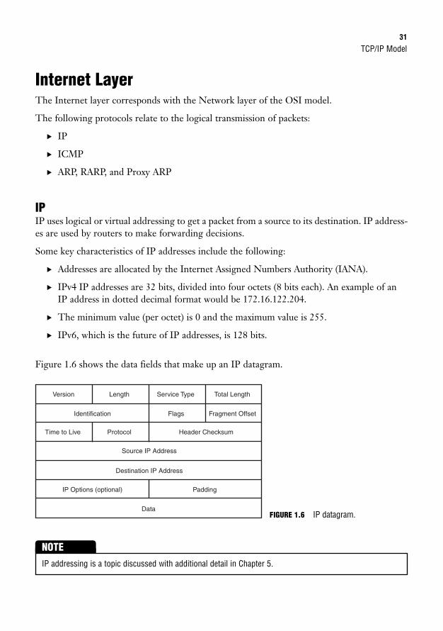
TCP/IP Model31
Internet LayerThe Internet layer corresponds with the Network layer of the OSI model.
The following protocols relate to the logical transmission of packets:
. IP
. ICMP
. ARP, RARP, and Proxy ARP
IPIP uses logical or virtual addressing to get a packet from a source to its destination. IP address-es are used by routers to make forwarding decisions.
Some key characteristics of IP addresses include the following:
. Addresses are allocated by the Internet Assigned Numbers Authority (IANA).
. IPv4 IP addresses are 32 bits, divided into four octets (8 bits each). An example of anIP address in dotted decimal format would be 172.16.122.204.
. The minimum value (per octet) is 0 and the maximum value is 255.
. IPv6, which is the future of IP addresses, is 128 bits.
Figure 1.6 shows the data fields that make up an IP datagram.
Version Length
Source IP Address
Destination IP Address
Protocol
Identification
IP Options (optional) Padding
Flags Fragment Offset
Service Type Total Length
Time to Live Header Checksum
DataFIGURE 1.6 IP datagram.
IP addressing is a topic discussed with additional detail in Chapter 5.
NOTE
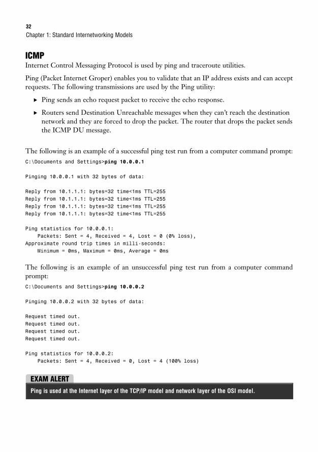
32
ICMPInternet Control Messaging Protocol is used by ping and traceroute utilities.
Ping (Packet Internet Groper) enables you to validate that an IP address exists and can acceptrequests. The following transmissions are used by the Ping utility:
. Ping sends an echo request packet to receive the echo response.
. Routers send Destination Unreachable messages when they can’t reach the destinationnetwork and they are forced to drop the packet. The router that drops the packet sendsthe ICMP DU message.
The following is an example of a successful ping test run from a computer command prompt:C:\Documents and Settings>ping 10.0.0.1
Pinging 10.0.0.1 with 32 bytes of data:
Reply from 10.1.1.1: bytes=32 time<1ms TTL=255Reply from 10.1.1.1: bytes=32 time<1ms TTL=255Reply from 10.1.1.1: bytes=32 time<1ms TTL=255Reply from 10.1.1.1: bytes=32 time<1ms TTL=255
Ping statistics for 10.0.0.1:Packets: Sent = 4, Received = 4, Lost = 0 (0% loss),
Approximate round trip times in milli-seconds:Minimum = 0ms, Maximum = 0ms, Average = 0ms
The following is an example of an unsuccessful ping test run from a computer commandprompt:C:\Documents and Settings>ping 10.0.0.2
Pinging 10.0.0.2 with 32 bytes of data:
Request timed out.Request timed out.Request timed out.Request timed out.
Ping statistics for 10.0.0.2:Packets: Sent = 4, Received = 0, Lost = 4 (100% loss)
Chapter 1: Standard Internetworking Models
EXAM ALERTPing is used at the Internet layer of the TCP/IP model and network layer of the OSI model.
Cisco 3-Layer Hierarchical Model33
Traceroute traces the route or path taken from a client to a remote host. Traceroute alsoreports the IP addresses of the routers at each next hop on the way to the destination. This isespecially useful when you suspect that a router on the route to an unreachable network isresponsible for dropping the packet.
Extended ping enables you to select a datagram size and a timeout.
NOTE
ARP, RARP, and Proxy ARPThe Address Resolution Protocol (ARP), Reverse Address Resolution Protocol (RARP), andProxy Address Resolution Protocol (Proxy ARP) are all protocols used at the TCP/IP model’sInternet layer.
ARP maps a known IP address to a MAC address by sending a broadcast ARP. When the des-tination IP address is on another subnet, the sender broadcasts ARP for the router’s ethernetport or default gateway, so the MAC address sent back is that of the router’s ethernet port.
RARP maps a known MAC address to an IP address.
Proxy ARP enables a router to respond to an ARP request that has been sent to a remote host.Some Unix machines (especially Solaris) rely on Proxy ARP versus default gateways.
Network Interface LayerThis layer corresponds with the Data Link and Physical layers of the OSI model. As mentionedearlier in the chapter, this layer manages hardware addressing and physical data transfer.
Cisco 3-Layer Hierarchical ModelWhen I think of the word hierarchy outside the realm of networking, I think of the military.Each branch of the military has a list of ranks that is assigned to each soldier. In the Army forexample, the ranks range from an enlisted private all the way up to the General of the Army.Each soldier reports to a higher-ranking soldier, and each rank has its own group of functionsand responsibilities, much like the layers of the Cisco hierarchical model.
The term hierarchy as it pertains to this model is the classification of a group of functions orresponsibilities into a logical layer where each layer is subordinate to the layer above it in thehierarchy. This model is most effective when you plan to implement a small- to moderate-sized network.
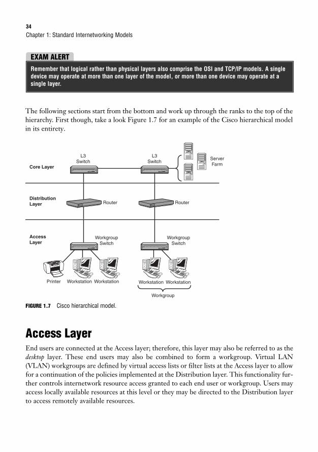
34
The following sections start from the bottom and work up through the ranks to the top of thehierarchy. First though, take a look Figure 1.7 for an example of the Cisco hierarchical modelin its entirety.
Chapter 1: Standard Internetworking Models
EXAM ALERTRemember that logical rather than physical layers also comprise the OSI and TCP/IP models. A singledevice may operate at more than one layer of the model, or more than one device may operate at asingle layer.
Core Layer
Distribution Layer
AccessLayer
L3Switch
Router Router
Workgroup Switch
Printer Workstation Workstation Workstation Workstation
Workgroup Switch
L3Switch
ServerFarm
Workgroup
FIGURE 1.7 Cisco hierarchical model.
Access LayerEnd users are connected at the Access layer; therefore, this layer may also be referred to as thedesktop layer. These end users may also be combined to form a workgroup. Virtual LAN(VLAN) workgroups are defined by virtual access lists or filter lists at the Access layer to allowfor a continuation of the policies implemented at the Distribution layer. This functionality fur-ther controls internetwork resource access granted to each end user or workgroup. Users mayaccess locally available resources at this level or they may be directed to the Distribution layerto access remotely available resources.
Cisco 3-Layer Hierarchical Model35
Distribution LayerIn the hierarchy, the Distribution layer is the middle man between the access and core layers.You may also hear this layer called the workgroup layer. Although the Distribution layer acts as a gathering point for the Access layer devices, it also uses a router or Layer 3 switch whenever necessary to determine how to traverse packets to the core layer.
You achieve traffic control at this layer by using various policies that ultimately provide net-work management and security.
Primary functions of the Distribution layer include the following:
. Routing (best path determination)
. Routing between VLANs
. Filtering—Access lists provide packet filtering, Quality of Service (QoS), networkaddress translation (NAT), and route filtering
. Accessing WAN
. Defining broadcast and multicast domains
. Translating between different types of media (for example, ethernet and token ring)
EXAM ALERTChapter 15, “Virtual LANs,” discusses Virtual LANs in depth. Configuring and troubleshooting VLANsare both CCNA exam topics.
EXAM ALERTDesign and implementation of access lists are CCNA exam topics. Given their importance, Chapter 19,“Using Cisco Access Lists,” is devoted to access lists. Chapter 6, “Introduction to Cisco Routers andSwitches,” reviews Cisco routers and switches that may be used at the Distribution layer. The 2600series Cisco routers and 4000 series Cisco switches are included in that chapter.
Core LayerThe Core layer is the foundation or backbone of the network. Much like a building would fal-ter without its foundation, a network would fall apart without the structure provided by thecore layer. As mentioned before, the Distribution layer manages access to the core. Thisenables the core to focus on speed and reliability. The goal is to provide high-speed switchingas quickly and efficiently as possible. Any latency or delay can affect everyone on that network.Because speed is of the essence, the policies implemented at the Distribution layer (for exam-ple, filtering, access lists, and so on) should not occur at the Core layer.
36
Redundancy and fault tolerance are also important to the successful design of a core. If a net-work is set up with full redundancy, any failures should be transparent to the end user, whichis the definition of a fault tolerant network.
Chapter 1: Standard Internetworking Models
You might see Enterprise servers (server farms) connected to the core. Devices used at the Core layer mayinclude the Catalyst 6500 series switch or the 7000 series routers. These devices also are reviewed in Chapter 6.
NOTE
If you were tasked with the design of a new network, would you select a Layer 2 core or a Layer3 core? Although the Layer 2 core consists of a switched hierarchical setup, a Layer 3 core con-sists of a routed hierarchical setup.
The answer depends upon the individual requirements of the company in question. If the primaryrequirement is speed, perhaps a Layer 2 core is appropriate. If a stated desire is the additional net-work control that is available with a routed solution, then a Layer 3 core would fit the bill.
EXAM ALERTRemember that routers segment broadcast domains (Layer 3 core) while switches segment collisiondomains (Layer 2 core).
ChallengeThis chapter discusses three different layered models, including the Cisco 3-Layer Hierarchical model. Toenhance your understanding of network communications with a layered architecture, please list eachlayer of the hierarchical model in the correct order and also list its primary responsibilities.
Layer Name Layer Responsibilities
Although the hierarchical model is typically mentioned in published reviews for the CCNAexamination, Cisco also created the Enterprise Composite Network Model (ECNM) for larger-scale network implementations.
The hierarchical model can assist in the implementation of a small- to moderate-sized net-work. The composite model goes a step further and provides a guide for creating a larger net-work. Because Cisco has a group of topics listed as “Planning and Designing,” it is importantto have a general knowledge of their models for network design.
Chapter Summary37
Chapter SummaryThe term internetworking signifies the industry, products, and processes that are required tohandle the challenges of interconnecting networks. Various internetworks can be used,depending on the user’s specific needs. For example, a LAN is a small network that is confinedto a local geographical area. A LAN can connect to another LAN via a switch, bridge, orrepeater. If a LAN attempts to connect to a MAN or WAN, it needs to interconnect via arouter. WANs are much larger in scope. WANs are good for a company that has offices in mul-tiple cities around the country. LAN and WAN technology are discussed in greater detail inlater chapters of this book.
This chapter also discusses the importance of layered reference models such as the OSI model,TCP/IP model, and the Cisco 3-Layer Hierarchical model. The OSI model is important todiscussions of internetworking because the terminology related to each layer has endured thetest of time. Seven layers essentially map out the transmission of data from one end-user sys-tem to another. Multiple protocols relate to the interoperation of each layer. Special focus isplaced on the Application layer protocols and their primary functions.
The TCP/IP model is implemented in a large portion of the networks that are set up today.The model is a condensed version of the OSI model with four related layers. The two mostimportant protocols discussed in the TCP/IP suite for this first chapter are TCP and UDP.TCP is a connection-oriented protocol that provides for reliable data transport. UDP is a con-nectionless protocol that is considered unreliable. There are advantages and disadvantages toeach protocol. Although TCP is reliable, it also costs more to implement on a network.
Overall, this chapter was designed to provide a general overview of standard internetworks andthe layered architecture that was designed to represent network interactions. Now that youhave gone over all of the internetworking models that are relevant to the exam, you are readyto move on to Chapter 2 and review the concepts related to networking at the Physical layer.
38
Key Terms
Chapter 1: Standard Internetworking Models
. internetwork
. LAN
. MAN
. WAN
. SAN
. VPN
. OSI model
. Application layer
. Telnet
. HTTP
. HTTPS
. FTP
. TFTP
. DNS
. SMTP
. POP3
. NFS
. NNTP
. SNMP
. NTP
. DHCP
. Presentation layer
. Session layer
. NFS
. SQL
. RPC
. ASP
. X Window
. DNA SCP
. Transport layer
. segment
. acknowledgment
. sequencing
. flow control
. buffers
. Network layer
. packet
. datagram
. data packets
. route update packets
. Data Link layer
. broadcast domain
. collision domain
. CSMA/CD
. grame
. MAC
. MAC address
. LLC
. ridge
. switch
. Physical layer
. hub
. repeater
. bit
. DCE
. DTE
. CSU/DSU
. encapsulation
. PDU
. TCP/IP model
. TCP/IP
. TCP
. PAR
. windowing
. UDP
. IP
. ICMP
. ARP
. RARP
. proxy ARP
. Cisco 3-LayerHierarchical model
. VLAN
. routing
. filtering
. packet filtering
. route filtering
. QoS
. NAT

Apply Your Knowledge39
Apply Your Knowledge
Exercise
1.1 OSI Layered Model Identification
This has been mentioned throughout the chapter, but it is extremely important for the CCNA exam toknow the seven layers of the OSI model and their general functions. If you have not decided on amnemonic device that you like, you may want to take another look because most people find them to bevery helpful with this type of exercise.
Estimated Time: 10 minutes
List the name of the appropriate layer next to the number listed and then identify two primary functionsof that layer. Refer to Table 1.7 to check your responses.
1. _____________________Layer
Functions: ________________________________________________________
2. _____________________Layer
Functions: ________________________________________________________
3. _____________________Layer
Functions: ________________________________________________________
4. _____________________Layer
Functions: ________________________________________________________
5. _____________________Layer
Functions: ________________________________________________________
6. _____________________Layer
Functions: ________________________________________________________
7. _____________________Layer
Functions: ________________________________________________________
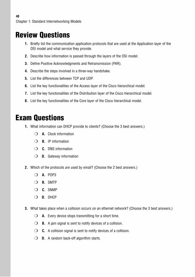
40
Review Questions1. Briefly list the communication application protocols that are used at the Application layer of the
OSI model and what service they provide.
2. Describe how information is passed through the layers of the OSI model.
3. Define Positive Acknowledgments and Retransmission (PAR).
4. Describe the steps involved in a three-way handshake.
5. List the differences between TCP and UDP.
6. List the key functionalities of the Access layer of the Cisco hierarchical model.
7. List the key functionalities of the Distribution layer of the Cisco hierarchical model.
8. List the key functionalities of the Core layer of the Cisco hierarchical model.
Exam Questions1. What information can DHCP provide to clients? (Choose the 3 best answers.)
❍ A. Clock information
❍ B. IP information
❍ C. DNS information
❍ D. Gateway information
2. Which of the protocols are used by email? (Choose the 2 best answers.)
❍ A. POP3
❍ B. SMTP
❍ C. SNMP
❍ D. DHCP
3. What takes place when a collision occurs on an ethernet network? (Choose the 3 best answers.)
❍ A. Every device stops transmitting for a short time.
❍ B. A jam signal is sent to notify devices of a collision.
❍ C. A collision signal is sent to notify devices of a collision.
❍ D. A random back-off algorithm starts.
Chapter 1: Standard Internetworking Models
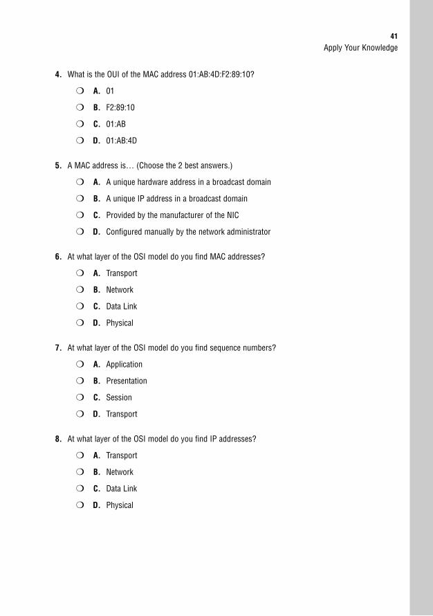
Apply Your Knowledge41
4. What is the OUI of the MAC address 01:AB:4D:F2:89:10?
❍ A. 01
❍ B. F2:89:10
❍ C. 01:AB
❍ D. 01:AB:4D
5. A MAC address is… (Choose the 2 best answers.)
❍ A. A unique hardware address in a broadcast domain
❍ B. A unique IP address in a broadcast domain
❍ C. Provided by the manufacturer of the NIC
❍ D. Configured manually by the network administrator
6. At what layer of the OSI model do you find MAC addresses?
❍ A. Transport
❍ B. Network
❍ C. Data Link
❍ D. Physical
7. At what layer of the OSI model do you find sequence numbers?
❍ A. Application
❍ B. Presentation
❍ C. Session
❍ D. Transport
8. At what layer of the OSI model do you find IP addresses?
❍ A. Transport
❍ B. Network
❍ C. Data Link
❍ D. Physical
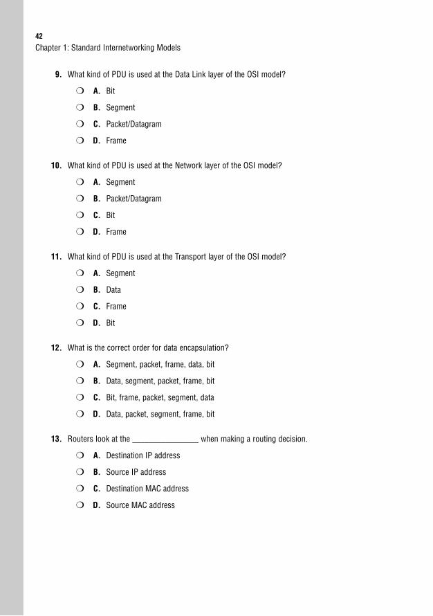
42
9. What kind of PDU is used at the Data Link layer of the OSI model?
❍ A. Bit
❍ B. Segment
❍ C. Packet/Datagram
❍ D. Frame
10. What kind of PDU is used at the Network layer of the OSI model?
❍ A. Segment
❍ B. Packet/Datagram
❍ C. Bit
❍ D. Frame
11. What kind of PDU is used at the Transport layer of the OSI model?
❍ A. Segment
❍ B. Data
❍ C. Frame
❍ D. Bit
12. What is the correct order for data encapsulation?
❍ A. Segment, packet, frame, data, bit
❍ B. Data, segment, packet, frame, bit
❍ C. Bit, frame, packet, segment, data
❍ D. Data, packet, segment, frame, bit
13. Routers look at the ________________ when making a routing decision.
❍ A. Destination IP address
❍ B. Source IP address
❍ C. Destination MAC address
❍ D. Source MAC address
Chapter 1: Standard Internetworking Models
Apply Your Knowledge43
14. What protocol is assigned to port numbers 20 and 21?
❍ A. DNS
❍ B. Telnet
❍ C. FTP
❍ D. SMTP
15. What protocol is assigned to port number 80?
❍ A. SNMP
❍ B. HTTP
❍ C. POP3
❍ D. DHCP
16. Which of the following are TCP? (Choose the 2 best answers.)
❍ A. Telnet
❍ B. HTTP
❍ C. TFTP
❍ D. NTP
17. Which of the following are UDP? (Choose the 2 best answers.)
❍ A. DHCP
❍ B. SMTP
❍ C. SNMP
❍ D. POP3
18. What commands use ICMP? (Choose the 2 best answers.)
❍ A. Show cdp neighbor
❍ B. traceroute
❍ C. Telnet
❍ D. ping
44
19. What protocol maps a known MAC address to an IP address?
❍ A. RARP
❍ B. ARP
❍ C. ICMP
❍ D. Proxy ARP
20. What TCP/IP protocol provides terminal emulation to a remote host?
❍ A. HTTP
❍ B. VPN
❍ C. Telnet
❍ D. SNMP
Answers to Review Questions1. The following is a list of the protocols utilized at the Application layer of the OSI model and the
functionality of each protocol.
Telnet—Terminal emulation to a remote host
HTTP—Web-browsing service
HTTPS—Secure web browsing
FTP—File transfer
TFTP—Bare-bones file transfer
DNS—Name management
SMTP—Send emails
POP3—Receive emails
NFS—File sharing
NNTP—Usenet newsgroups
SNMP—Network management
NTP—Time management
DHCP—Dynamic host configuration
Chapter 1: Standard Internetworking Models
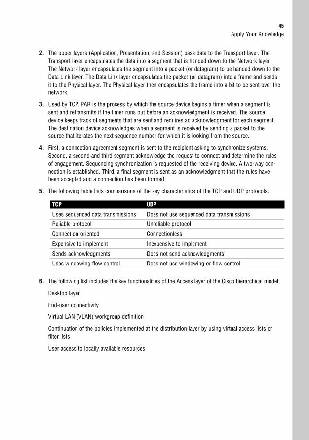
Apply Your Knowledge45
2. The upper layers (Application, Presentation, and Session) pass data to the Transport layer. TheTransport layer encapsulates the data into a segment that is handed down to the Network layer.The Network layer encapsulates the segment into a packet (or datagram) to be handed down to theData Link layer. The Data Link layer encapsulates the packet (or datagram) into a frame and sendsit to the Physical layer. The Physical layer then encapsulates the frame into a bit to be sent over thenetwork.
3. Used by TCP, PAR is the process by which the source device begins a timer when a segment issent and retransmits if the timer runs out before an acknowledgment is received. The sourcedevice keeps track of segments that are sent and requires an acknowledgment for each segment.The destination device acknowledges when a segment is received by sending a packet to thesource that iterates the next sequence number for which it is looking from the source.
4. First, a connection agreement segment is sent to the recipient asking to synchronize systems.Second, a second and third segment acknowledge the request to connect and determine the rulesof engagement. Sequencing synchronization is requested of the receiving device. A two-way con-nection is established. Third, a final segment is sent as an acknowledgment that the rules havebeen accepted and a connection has been formed.
5. The following table lists comparisons of the key characteristics of the TCP and UDP protocols.
TCP UDP
Uses sequenced data transmissions Does not use sequenced data transmissions
Reliable protocol Unreliable protocol
Connection-oriented Connectionless
Expensive to implement Inexpensive to implement
Sends acknowledgments Does not send acknowledgments
Uses windowing flow control Does not use windowing or flow control
6. The following list includes the key functionalities of the Access layer of the Cisco hierarchical model:
Desktop layer
End-user connectivity
Virtual LAN (VLAN) workgroup definition
Continuation of the policies implemented at the distribution layer by using virtual access lists or filter lists
User access to locally available resources
46
7. The following list includes the key functionalities of the Distribution layer of the Cisco hierarchicalmodel:
Control layer
Middleman between the access and core layers
Acts as an aggregation point for access layer devices
Determines how and when to traverse packets to the core layer
Policy implementation
Network security
Routing (best path determination)
Routing between VLANs
Filtering
Access lists
Packet filtering
Quality of Service (QoS)
Network address translation (NAT)
Route filtering
WAN access
Defines broadcast and multicast domains
Translates between different types of media (i.e. ethernet and token ring)
8. The following list includes the key functionalities of the Core layer of the Cisco hierarchical model:
Backbone layer
The Distribution layer manages access to the core.
High-speed switching
Reliability
Redundancy
Fault tolerance
Low latency
Enterprise servers (server farms)
Chapter 1: Standard Internetworking Models
Apply Your Knowledge47
Answers to Exam Questions1. B, C, D. DHCP works dynamically to provide IP address, DNS, and default gateway information.
Answer A is incorrect because the Network Time Protocol (NTP) provides clock information.
2. A, B. POP3 receives email on an Internet server and SMTP sends email across a network. AnswerC is incorrect because SNMP is a network management protocol and answer D is incorrectbecause DHCP is the dynamic host configuration protocol.
3. A, B, D. When a collision occurs on an ethernet network a jam signal is sent to notify devices of acollision and a random back-off algorithm starts while every device stops transmitting for a shorttime. Answer C is incorrect because a jam signal is sent rather than a collision signal.
4. D. The OUI of a MAC address is the organizationally unique identifier that is assigned by the manu-facturer of the network interface card (NIC). The OUI consists of the first 6 hexadecimal digits.Answer A is incorrect because it only consists of 2 hexadecimal digits. Answer B is incorrectbecause it is not the first 6 hexadecimal digits of the MAC address 01:AB:4D:F2:89:10. Answer C isincorrect because it only consists of 4 hexadecimal digits.
5. A, C. The MAC address is a unique hardware address in the broadcast domain and the manufac-turer of the NIC provides MAC addresses. Answer B is incorrect because IP addresses are logicaladdresses used by the Network layer. Answer D is incorrect because a MAC address is not config-ured manually by a network administrator.
6. C. MAC addresses are found at the Data Link layer of the OSI model. Answers A, B, and D areincorrect because MAC addresses are not found at the Transport, Network, or Physical layer of theOSI model.
7. D. The Transport layer uses sequence numbers. Data segments are sequenced into their originalorder when they arrive at the destination. Answers A, B, and C are incorrect because sequencenumbers are not found at the Application, Presentation, or Session layer of the OSI model.
8. B. Answer B is correct because IP addresses are found at the Network layer of the OSI model. IPaddresses are logical or virtual addresses that are assigned at Layer 3 to identify the destination ofa packet or datagram. Answers A, C, and D are incorrect because IP addresses are not found at theTransport, Data Link, or Physical layer of the OSI model.
9. D. The Data Link layer uses frame PDUs to encapsulate data. Answers A, B, and C are incorrectbecause segments are used at the Transport layer, whereas packet/datagrams are used at theNetwork layer and bits are used by the Physical layer of the OSI model.
10. B. The Network layer of the OSI model uses packets/datagrams. Answers A, C, and D are incorrectbecause the Application, Presentation, and Session layers of the OSI model transmit data.
11. A. Segments are used at the Transport layer of the OSI model. Answer B is incorrect because thethree upper layers of the OSI model transmit data. Answer C is incorrect because the Data Linklayer transmits frames, and answer D is incorrect because the Physical layer transmits bits.
48
12. B. Encapsulation occurs from the Application layer and then is passed down through the lower layersof the OSI model. The PDUs are sent by the Application layer as data and then they are encapsulatedwith a segment at the Transport layer. At the Network layer the segment is encapsulated into a pack-et/datagram that is passed down to the Data Link layer, which encapsulates a frame and hands it offto the Physical layer, which uses bits.
13. A. Routers look at the destination IP address to determine where to forward the packet. Answers B,C, and D are incorrect because a router does not examine the source IP address, destination MACaddress, or source MAC address to make forwarding decisions.
14. C. FTP is assigned to port numbers 20 and 21. Answers A, B, and D are incorrect because Telnet isassigned port number 23, DNS is assigned port number 53, and SMTP is assigned port number 25.
15. B. HTTP is assigned port number 80. Answers A, C, and D are incorrect because SNMP is assignedport number 161, POP3 is port number 110, and DHCP is assigned ports 67 and 68.
16. A, B. Telnet and HTTP are both protocols that use TCP. Answers C and D are incorrect because TFTPand NTP use UDP.
17. A, C. DHCP and SNMP use UDP, whereas answers B and D are incorrect because SMTP and POP3use TCP.
18. B, D. Traceroute and ping are both commands that use ICMP. Traceroute traces the route or pathtaken from a client to a remote host. Ping enables you to validate that an IP address exists and canaccept requests. Answers A and C are incorrect because neither show cdp neighbor nor Telnetuse ICMP.
19. A. RARP maps MAC addresses to an IP address, whereas answer B is incorrect because ARP mapsan IP address to a MAC address. Answer C is incorrect because ICMP sends messages across thenetwork via ping, and traceroute enables a router to respond to an ARP request that has been sent toa remote host. Answer D is also incorrect because some Unix machines (especially Solaris) rely onProxy ARP rather than default gateways.
20. C. Telnet provides for terminal emulation to a remote host. Answers A, B, and D are incorrectbecause HTTP is a web-browsing application, VPN is a private network that can access public net-works remotely, and SNMP is a network management application.
Suggested Readings and ResourcesThe following are some recommended readings on the subject of standard internetworking models:
1. “Open Systems Interconnection Protocols,”http://www.cisco.com/univercd/cc/td/doc/cisintwk/ito_doc/osi_prot.htm.
2. “OSI Model,” http://en.wikipedia.org/wiki/OSI_model.
3. “TCP/IP Overview,”http://www.cisco.com/univercd/cc/td/doc/cisintwk/ito_doc/osi_prot.htm.
4. “TechEncyclopedia,” www.techweb.com/encyclopedia.
Chapter 1: Standard Internetworking Models
2C H A P T E R T W O
Physical Layer NetworkingConcepts
ObjectivesThis chapter covers the following Cisco-specified objectives from the “Describe how a networkworks” and “Configure, verify and troubleshoot a switch with VLANs and interswitch communi-cations” sections of the 640-802 CCNA exam:
. Interpret network diagrams
. Select the appropriate media, cables, ports, and connectors to connectswitches to other network devices and hosts
. Describe the purpose and functions of various network devices
OutlineIntroduction 52
Network Topologies 52
The Bus Topology 52
The Ring Topology 53
The Star Topology 54
The Mesh Topology 55
Cabling 56
Coaxial Cable 57
Twisted-Pair Cable 58
Straight-Through Cable 59
Cross-Over Cable 60
Rolled Cable 61
Fiber-Optic Cable 62
Wireless 62
Wireless Fidelity (Wi-Fi) 63
Infrared 64
Bluetooth 64
Physical Layer Devices 64
Repeaters 64
Hubs 65
Network Interfaces 65
Chapter Summary 66
Key Terms 66
Apply Your Knowledge 66
Exercise 66
Review Questions 67
Exam Questions 67
Answers to Review Questions 73
Answers to Exam Questions 73
Suggested Readings and Resources 74

Study Strategies. Identify the four physical network topologies discussed in this chapter.
. Know the different types of network cables and the characteristics that differentiate themfrom one another.
. Review the wireless technology standards.
. Be able to identify devices that are used at the Physical layer.
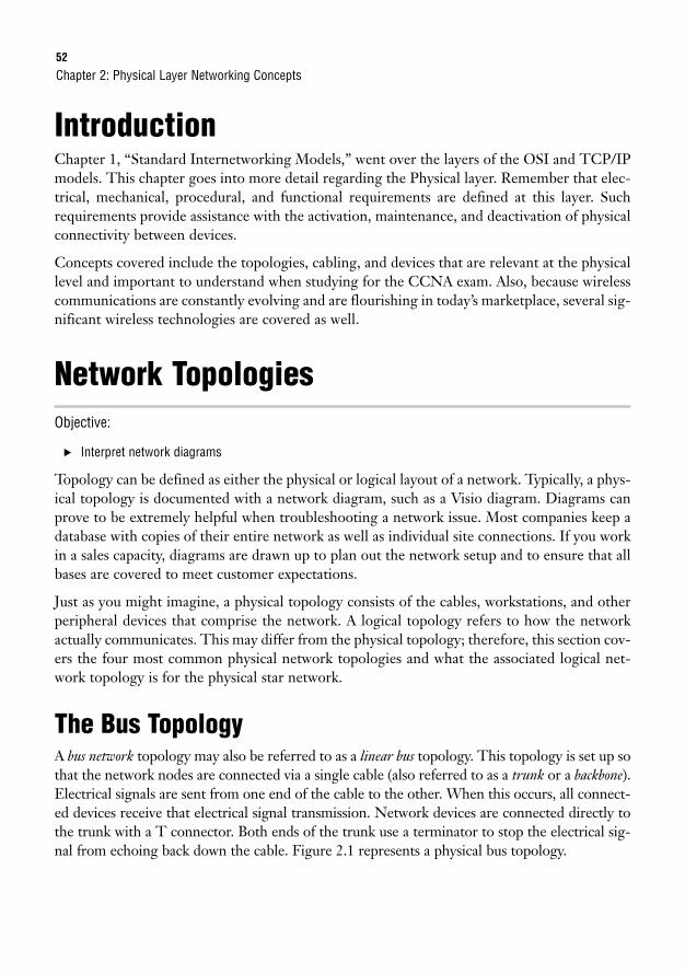
52
IntroductionChapter 1, “Standard Internetworking Models,” went over the layers of the OSI and TCP/IPmodels. This chapter goes into more detail regarding the Physical layer. Remember that elec-trical, mechanical, procedural, and functional requirements are defined at this layer. Suchrequirements provide assistance with the activation, maintenance, and deactivation of physicalconnectivity between devices.
Concepts covered include the topologies, cabling, and devices that are relevant at the physicallevel and important to understand when studying for the CCNA exam. Also, because wirelesscommunications are constantly evolving and are flourishing in today’s marketplace, several sig-nificant wireless technologies are covered as well.
Network TopologiesObjective:
. Interpret network diagrams
Topology can be defined as either the physical or logical layout of a network. Typically, a phys-ical topology is documented with a network diagram, such as a Visio diagram. Diagrams canprove to be extremely helpful when troubleshooting a network issue. Most companies keep adatabase with copies of their entire network as well as individual site connections. If you workin a sales capacity, diagrams are drawn up to plan out the network setup and to ensure that allbases are covered to meet customer expectations.
Just as you might imagine, a physical topology consists of the cables, workstations, and otherperipheral devices that comprise the network. A logical topology refers to how the networkactually communicates. This may differ from the physical topology; therefore, this section cov-ers the four most common physical network topologies and what the associated logical net-work topology is for the physical star network.
The Bus TopologyA bus network topology may also be referred to as a linear bus topology. This topology is set up sothat the network nodes are connected via a single cable (also referred to as a trunk or a backbone).Electrical signals are sent from one end of the cable to the other. When this occurs, all connect-ed devices receive that electrical signal transmission. Network devices are connected directly tothe trunk with a T connector. Both ends of the trunk use a terminator to stop the electrical sig-nal from echoing back down the cable. Figure 2.1 represents a physical bus topology.
Chapter 2: Physical Layer Networking Concepts
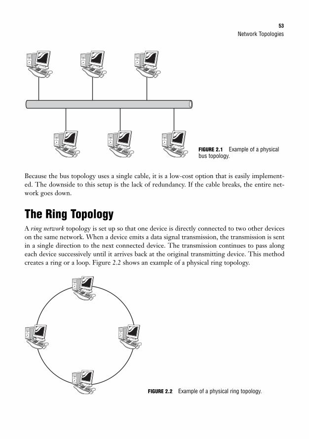
Network Topologies53
Because the bus topology uses a single cable, it is a low-cost option that is easily implement-ed. The downside to this setup is the lack of redundancy. If the cable breaks, the entire net-work goes down.
The Ring TopologyA ring network topology is set up so that one device is directly connected to two other deviceson the same network. When a device emits a data signal transmission, the transmission is sentin a single direction to the next connected device. The transmission continues to pass alongeach device successively until it arrives back at the original transmitting device. This methodcreates a ring or a loop. Figure 2.2 shows an example of a physical ring topology.
FIGURE 2.1 Example of a physicalbus topology.
FIGURE 2.2 Example of a physical ring topology.
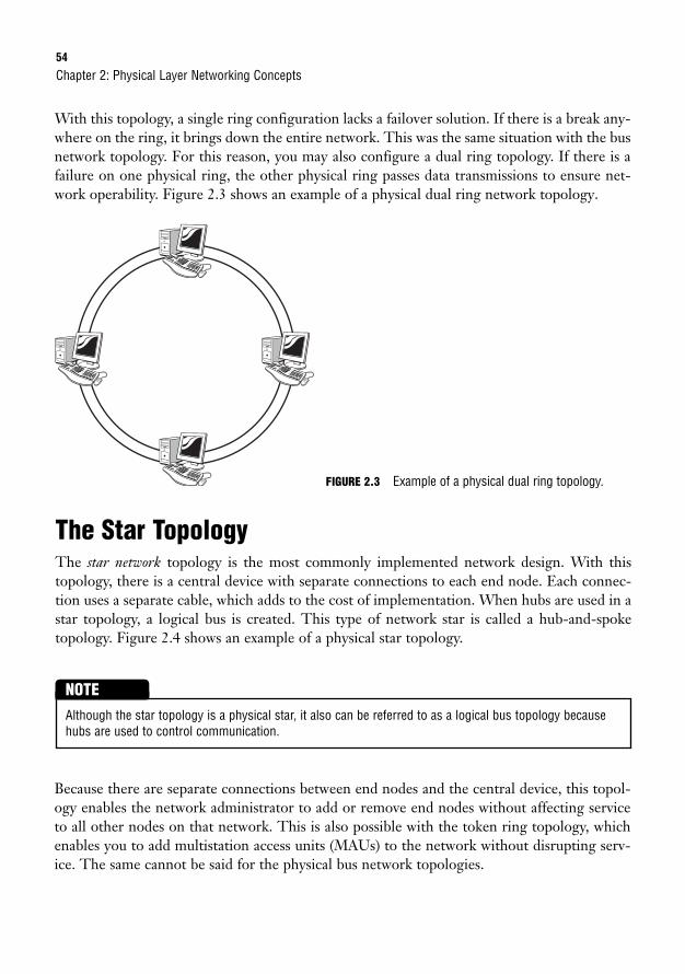
54
With this topology, a single ring configuration lacks a failover solution. If there is a break any-where on the ring, it brings down the entire network. This was the same situation with the busnetwork topology. For this reason, you may also configure a dual ring topology. If there is afailure on one physical ring, the other physical ring passes data transmissions to ensure net-work operability. Figure 2.3 shows an example of a physical dual ring network topology.
Chapter 2: Physical Layer Networking Concepts
The Star TopologyThe star network topology is the most commonly implemented network design. With thistopology, there is a central device with separate connections to each end node. Each connec-tion uses a separate cable, which adds to the cost of implementation. When hubs are used in astar topology, a logical bus is created. This type of network star is called a hub-and-spoketopology. Figure 2.4 shows an example of a physical star topology.
FIGURE 2.3 Example of a physical dual ring topology.
Although the star topology is a physical star, it also can be referred to as a logical bus topology becausehubs are used to control communication.
NOTE
Because there are separate connections between end nodes and the central device, this topol-ogy enables the network administrator to add or remove end nodes without affecting serviceto all other nodes on that network. This is also possible with the token ring topology, whichenables you to add multistation access units (MAUs) to the network without disrupting serv-ice. The same cannot be said for the physical bus network topologies.
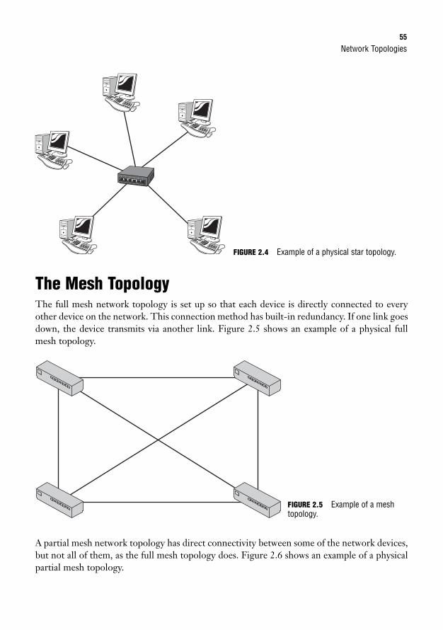
Network Topologies55
The Mesh TopologyThe full mesh network topology is set up so that each device is directly connected to everyother device on the network. This connection method has built-in redundancy. If one link goesdown, the device transmits via another link. Figure 2.5 shows an example of a physical fullmesh topology.
6
FIGURE 2.4 Example of a physical star topology.
A partial mesh network topology has direct connectivity between some of the network devices,but not all of them, as the full mesh topology does. Figure 2.6 shows an example of a physicalpartial mesh topology.
FIGURE 2.5 Example of a meshtopology.
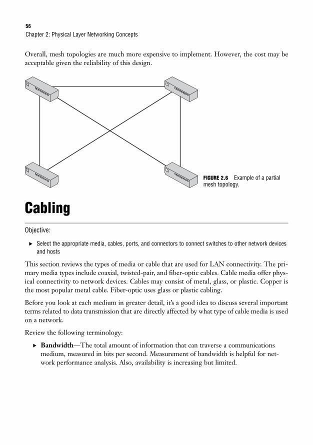
56
Overall, mesh topologies are much more expensive to implement. However, the cost may beacceptable given the reliability of this design.
Chapter 2: Physical Layer Networking Concepts
CablingObjective:
. Select the appropriate media, cables, ports, and connectors to connect switches to other network devicesand hosts
This section reviews the types of media or cable that are used for LAN connectivity. The pri-mary media types include coaxial, twisted-pair, and fiber-optic cables. Cable media offer phys-ical connectivity to network devices. Cables may consist of metal, glass, or plastic. Copper isthe most popular metal cable. Fiber-optic uses glass or plastic cabling.
Before you look at each medium in greater detail, it’s a good idea to discuss several importantterms related to data transmission that are directly affected by what type of cable media is usedon a network.
Review the following terminology:
. Bandwidth—The total amount of information that can traverse a communicationsmedium, measured in bits per second. Measurement of bandwidth is helpful for net-work performance analysis. Also, availability is increasing but limited.
FIGURE 2.6 Example of a partialmesh topology.
Cabling57
. Attenuation—Occurs over long distances as a signal loses strength.
. Electromagnetic Interference (EMI)—Interference or noise caused by electromag-netic signals, which can decrease data integrity.
. Crosstalk—An electrical or magnetic field originating from one communications sig-nal that can affect the signal in a nearby circuit.
. Near-end Crosstalk (NEXT)—Crosstalk measured at the transmitting end of acable.
. Far-end Crosstalk (FEXT)—Crosstalk measured at the far end of the cable fromwhere the transmission was sent.
EXAM ALERTFor the exam, remember that bandwidth is used to analyze network performance and that althoughavailability is increasing, it is also limited.
EXAM ALERTKnow the terms NEXT and FEXT and what they represent for the CCNA exam.
Coaxial CableCoaxial cables for data consist of a single copper wire surrounded by a plastic insulation coverand a braided copper shield. Primarily, two types of coaxial cables are used in conjunction withEthernet LAN networks. They are called thin and thick coax.
Thin coax has the following characteristics:
. Also called thinnet
. .25 inches in diameter
. Maximum cable length = 185 meters
. Uses Bayonet Neill Concelman connectors (BNCs)
. 10BASE-2 ethernet standard
The Institute for Electrical and Electronics Engineers (IEEE) ethernet standards are reviewed in Chapter 3,“Data Link Networking Concepts.”
NOTE
58
Thick coax has the following characteristics:
. Also called thicknet
. Maximum cable length = 500 meters
. Uses vampire taps (where the tap goes through the shield to touch the copper wire)
. Uses attachment unit interface (AUI) adapters
. 10BASE-5 ethernet standard
The coaxial cable media is not nearly as popular as twisted pair or fiber optic. It is not as flexi-ble or cost effective as other options. You may see this cable implemented on an older network.
Twisted-Pair CableJust as the name indicates, twisted-pair cables twist two wires together to form a pair. Thissolution helps to reduce interference and attenuation. There are two types of twisted-paircabling defined by the Telecommunications Information Association (TIA). Those types areunshielded twisted pair (UTP) and shielded twisted pair (STP). UTP is the more common andcost-effective solution. STP has an additional shield, which provides additional reduction ofinterference and attenuation, but also makes it the more expensive solution. For the exam,UTP is reviewed in greater detail.
UTP key characteristics include the following:
. Eight color-coded wires
. Four pairs
. Uses an RJ-45 connector
. Vulnerable to EMI
. Maximum, practical length is 100 meters
. 10BASE-T, 100BaseT, and 1000BaseT ethernet standards
Chapter 2: Physical Layer Networking Concepts
When reviewing for the exam, note that UTP is vulnerable to EMI and uses an RJ-45 connector.
TIP
EXAM ALERTBecause attenuation causes a signal to lose strength as the length of a cable increases, the maximum,practical length of a UTP cable is 100 meters.
Cabling59
UTP can be broken down into six more categories. You may have heard someone talk about a Cat5cable. They are referring to a Category 5 UTP cable. Each category has different characteristics:
. Category 1—Telephone cable that is not used for data transmission.
. Category 2—Data cable that can handle speeds up to 4Mbps. This is no longer fastenough for networks today.
. Category 3—Data cable that can handle speeds up to 10Mbps. It is faster than theCat2 cable, and this was quite popular until network speeds surpassed the 10Mbpsthreshold.
. Category 4—Data cable that can handle speeds up to 16Mbps. Meant to be used withtoken ring.
. Category 5—Data cable that can handle speeds up to 100Mbps. This is currently themost popular cable selection.
. Category 5e—Data cable that can handle speeds up to 1Gbps. This is a popular choicefor Gigabit Ethernet networks.
. Category 6—This cable was created to exceed speeds of 1Gbps.
It is also important to know the pinouts for twisted-pair cables. The term pinout is used in theelectronic industry to describe the purpose of each pin in a connector. When choosing yourcable, you need to know which pinout is appropriate to connect the devices on your network.The following sections cover the straight-through and cross-over cables.
Straight-Through CableStraight-through cables use four wires and pins 1, 2, 3, and 6. Given those pins, pin 1 is con-nected on one end of the cable to pin 1 on the opposite end of the cable. Pin 2 at one end isconnected to pin 2 on the far end, and so on. Figure 2.7 shows an example of a straight-throughcable pinout.
These cables are meant only for interface to interface connections on ethernet networks, so youcannot use them with token ring, ISDN, and so on.
Use a straight-through cable for the following connection types:
. From a PC to a switch or a hub
. From a router to a switch or a hub
For the CCNA exam, you need to know which devices can be connected with a straight-through cable.Remember that straight-through cables are used to connect unlike device interfaces. Different devices =straight-through cable.
TIP
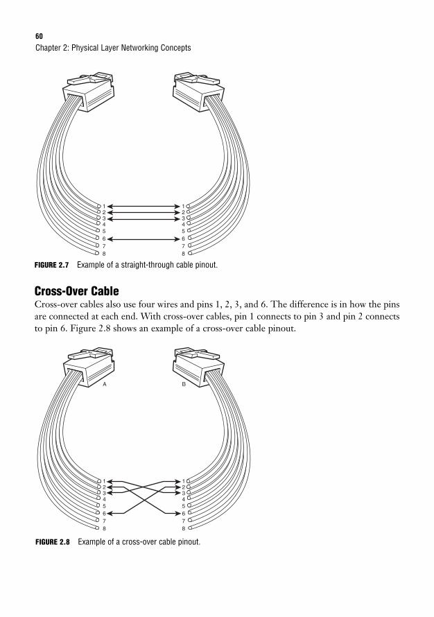
FIGURE 2.8 Example of a cross-over cable pinout.
60
FIGURE 2.7 Example of a straight-through cable pinout.
Cross-Over CableCross-over cables also use four wires and pins 1, 2, 3, and 6. The difference is in how the pinsare connected at each end. With cross-over cables, pin 1 connects to pin 3 and pin 2 connectsto pin 6. Figure 2.8 shows an example of a cross-over cable pinout.
Chapter 2: Physical Layer Networking Concepts
12345678
12345678
12345678
1
A B
2345678
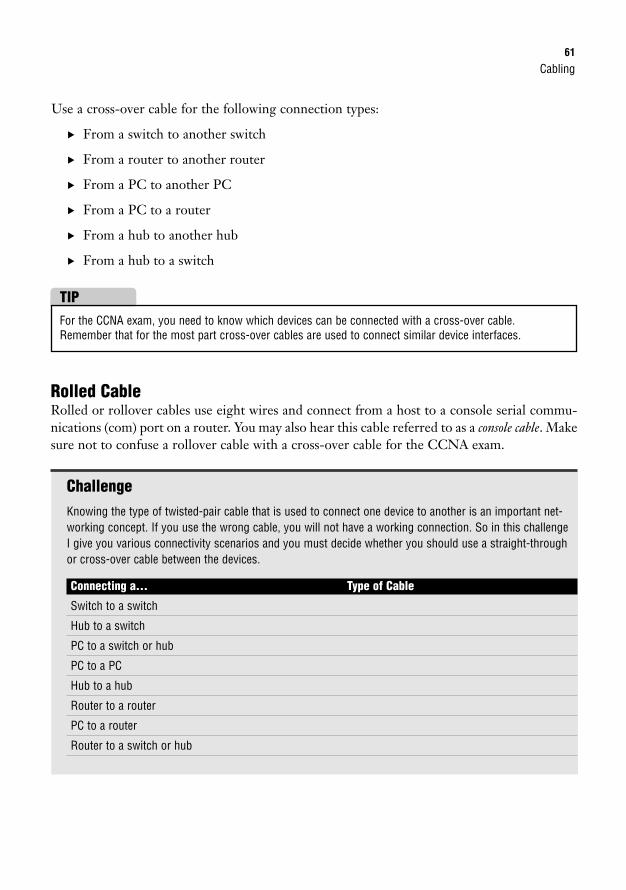
Cabling61
For the CCNA exam, you need to know which devices can be connected with a cross-over cable.Remember that for the most part cross-over cables are used to connect similar device interfaces.
TIP
Rolled CableRolled or rollover cables use eight wires and connect from a host to a console serial commu-nications (com) port on a router. You may also hear this cable referred to as a console cable. Makesure not to confuse a rollover cable with a cross-over cable for the CCNA exam.
ChallengeKnowing the type of twisted-pair cable that is used to connect one device to another is an important net-working concept. If you use the wrong cable, you will not have a working connection. So in this challengeI give you various connectivity scenarios and you must decide whether you should use a straight-throughor cross-over cable between the devices.
Connecting a… Type of Cable
Switch to a switch
Hub to a switch
PC to a switch or hub
PC to a PC
Hub to a hub
Router to a router
PC to a router
Router to a switch or hub
Use a cross-over cable for the following connection types:
. From a switch to another switch
. From a router to another router
. From a PC to another PC
. From a PC to a router
. From a hub to another hub
. From a hub to a switch
62
Fiber-Optic CableFiber-optic cables use light rather than electric signals to send data transmissions. These opti-cal light signals travel a fiberglass core and you may hear this technology referred to as fiberoptics or optical cabling.
Two categories of fiber-optic cabling are
. Multimode (MM)—This is generally used for shorter distances and is ideal for a cam-pus-sized network. MM also has a larger diameter of optical fiber than SM fiber.
. Single-mode (SM)—This mode is used to span longer distances. SM also allows for ahigher data rate than MM and faster data transmission speeds.
Fiber-optic cables may use a subscriber connector (SC), straight tip (ST), or MegaTransfer-Registered Jack (MT-RJ) connector. There are several Layer 2 ethernet protocols that can passdata over fiber-optic cables. Those Layer 2 ethernet standards are 10BASE-FL, 100Base FX,1000BaseSX, 1000BaseLX, and 1000BaseZX.
All in all, fiber is the best choice for a secure connection over longer distances. Because fiberuses optical light signals for data transmission, it is not as easy to “eavesdrop” on communica-tions as it is with copper cabling using electrical signals. Fiber is not susceptible to EMI andcrosstalk, as coaxial and twisted-pair cables are. It also offers the highest maximum speed of thedifferent cable types. You may have already guessed, but fiber is also the most expensive option.
Chapter 2: Physical Layer Networking Concepts
Fiber-optic cables are not susceptible to EMI.
On the CCNA exam, you may see the terms Main Distribution Frame (MDF) and an IntermediateDistribution Frame (IDF). A distribution frame is a physical rack that allows for the termination and inter-connection of cables. This process creates network cross-connects. With that in mind, the MDF provides apoint of interconnection between external telecommunications cabling and internal cabling in a facility. TheIDF is the point of interconnection for cabling between the MDF and end-user devices.
TIP
WirelessWireless technology uses radio transmissions rather than data transmissions over copper wireor fiber-optic media. With wireless LANs (WLANs), a physical connection is no longer nec-essary. Electromagnetic energy, whose existence was proven way back in 1867, passes throughthe atmosphere in varied wavelengths. Different wavelengths are differentiated by their dif-ferent names. Spread Spectrum WLANs determine how data traverses the Radio Frequency(RF) media. The most common applications for wireless technology are Wireless Fidelity,Infrared, and Bluetooth technologies. Because of the widespread popularity of wireless tech-nology in business today, an entire section of this book is now devoted to wireless networking.
Wireless63
Wireless Fidelity (Wi-Fi)IEEE created the 802.11 designation as the standard for wireless networking. IEEE 802.11may be further defined by three more specific standards: 802.11a, 802.11b, and 802.11g. Thespeed, distance, and features of 802.11 specifications are variable. The most common of thesespecifications is the 802.11b standard, which may also be referred to as Wireless Fidelity (Wi-Fi) or High Rate 802.11. IEEE 802.11b can allow for transmission speeds of up to 1–2Mbps.It also uses a Radio Frequency (RF) of 2.4GHz.
Keep in mind that Spread Spectrum WLANs allow for high-speed transmissions over short distances.There are two types of spread spectrum radio: Direct Sequencing Spread Spectrum (DSSS) andFrequency-Hopping Spread Spectrum (FHSS).
TIP
For the CCNA exam, remember that the 802.11b standard is also known as Wi-Fi or High Rate 802.11.
TIP
802.11 can also be broken down again into the following wireless standards:
. 802.11a
. RF is 5GHz.
. Speed up to 54Mbps.
. Range of transmission is generally lower than that of 802.11g.
. 802.11b
. RF is 2.4GHz.
. Uses different channels to cover subfrequencies in the 2.4Ghz band.
. Speed up to 11Mbps.
. Range of transmission is generally greater than that of 802.11a and 802.11g.
. 802.11g
. RF is 2.4GHz.
. Speed up to 54Mbps.
. Range of transmission is generally lower than that of 802.11b.
64
Based on these summarizations, you can see the similarities and differences of each standard.Please note that only 802.11a uses a different RF. This means that 802.11a is not compatiblewith either 802.11b or 802.11g.
InfraredInfrared resides in a region of the electromagnetic spectrum just beyond the red end of our vis-ible spectrum. Infrared wireless technology uses infrared beams to pass data across a network.Your television remote uses infrared technology to send requests to the television set. Speedscan reach a maximum of 16Mbps and signals are used for short-distance communications.
Infrared can eliminate the need for those pesky cables that connect your keyboard or mouseto your PC and cause clutter in your workspace. On the other hand, infrared may be easilyrefracted or reflected so it should not be used near windows or glass objects.
BluetoothBluetooth technology utilizes a short-range wireless radio connection to enable various devicesto interconnect. Such devices include cell phones, PCs, and Personal Digital Assistants(PDAs). The only requirement to establish connectivity is a 10-meter range (approximately 33feet) between communicating devices. When in range, Bluetooth uses an RF link in the2.4GHz range that has a 720Kbps per channel capacity to transfer voice or data. TheBluetooth specification also has two power levels defined; a lower power level that covers theshorter personal area within a room, and a higher power level that can cover a medium rangelike the range within a home.
Physical Layer DevicesObjective:
. Describe the purpose and functions of various network devices
The discussion so far of physical layer networking concepts has gone over the physical networktopologies, cables, and wireless technology standards. Several network devices also are utilizedat the Physical layer. Those include repeaters, hubs, and network interfaces.
RepeatersChapter 1, with its discussion of the Physical layer, mentioned that repeaters and hubs extenda network rather than segment a network. In fact, repeaters were introduced to increase orextend the distance between end nodes. A repeater consists of a transmitter and a receiver.
Chapter 2: Physical Layer Networking Concepts
Physical Layer Devices65
When a signal is received by the repeater, it amplifies the signal and then retransmits. Thiseffectively enables the signal to travel over a greater distance.
Please note that repeaters are an outdated technology. A separate device is no longer neededto perform this functionality. Both active hubs and switches can be used in place of a repeater.
HubsA hub can be defined as a multiple port repeater. A hub consists of 2 to 24 ports and may becalled a workgroup hub. When data is received, the hub then retransmits that data out on all theother ports. Physical connectivity is achieved via a twisted-pair cable.
There are active and passive hubs. Active hubs have a separate power supply to assist with thegain of a signal before it is forwarded out all connected ports. Gain is an electrical term usedto identify the ratio of signal output to signal input of a system. A power signal increased by afactor of 10 would indicate a gain of 10. Passive hubs do not regenerate the incoming signal.
Although they are very inexpensive, hubs may not be the best solution if you require a moreefficient use of bandwidth and its distribution among ports. Traffic may become congestedbecause of collisions on the network. Traffic is being forwarded out on all ports of a single col-lision domain. To decrease congestion, the network administrator might consider replacingthe hub with a switch.
Know that a viable solution to decrease network congestion is replacing a hub with a switch. A switch cre-ates a separate collision domain for each network segment, therefore increasing the number of collisiondomains.
TIP
EXAM ALERTHubs and repeaters are Layer 1 devices that can be used to increase the size of a single LAN segment.
Network InterfacesA network interface provides connectivity from an end-user PC or laptop to the public net-work. Depending on the interface, you might see up to three light-emitting diodes (LEDs)that help to determine the connection’s status. The link light LED should light up if you haveconnectivity. The activity light LED should flicker if there is activity on the line. There mayalso be a speed light LED that is used to verify the connection speed in a 10/100/1000Mbpsnetwork. Blinking lights and colors other than green can indicate error conditions that can beinvestigated by a technician.
66
Chapter SummaryChapter 2 has taken the Physical layer and expanded the discussion to include physical networktopologies and various network components. All these concepts are relevant when mapping out thedesign of a new network. Many of the topics in this chapter also touch upon ethernet technolo-gies, which Chapter 3 continues to discuss, along with devices that are used at the Data Link layer.
Key Terms
Chapter 2: Physical Layer Networking Concepts
. physical topology
. logical topology
. bus topology
. ring topology
. dual ring topology
. star topology
. full mesh topology
. partial mesh topology
. bandwidth
. attenuation
. EMI
. crosstalk
. NEXT
. FEXT
. coaxial cable
. twisted-pair cable
. unshielded twisted-paircable
. shielded twisted-paircable
. straight-through cable
. cross-over cable
. fiber-optic cable
. multimode
. single-mode
. wireless fidelity
. 802.11
. 802.11a
. 802.11b
. 802.11g
. infrared
. Bluetooth
. repeaters
. hubs
. network interface
Apply Your Knowledge
Exercise
2.1 UTP Cable Categories
Each category of UTP cabling has different characteristics. In this exercise, please list the characteristicsof each category of UTP cable.
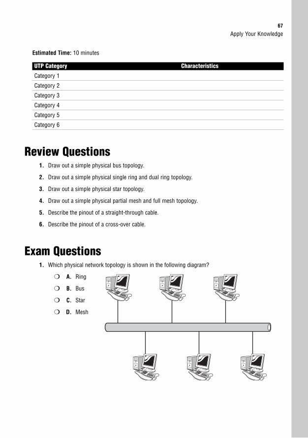
Apply Your Knowledge67
Estimated Time: 10 minutes
UTP Category Characteristics
Category 1
Category 2
Category 3
Category 4
Category 5
Category 6
Review Questions1. Draw out a simple physical bus topology.
2. Draw out a simple physical single ring and dual ring topology.
3. Draw out a simple physical star topology.
4. Draw out a simple physical partial mesh and full mesh topology.
5. Describe the pinout of a straight-through cable.
6. Describe the pinout of a cross-over cable.
Exam Questions1. Which physical network topology is shown in the following diagram?
❍ A. Ring
❍ B. Bus
❍ C. Star
❍ D. Mesh
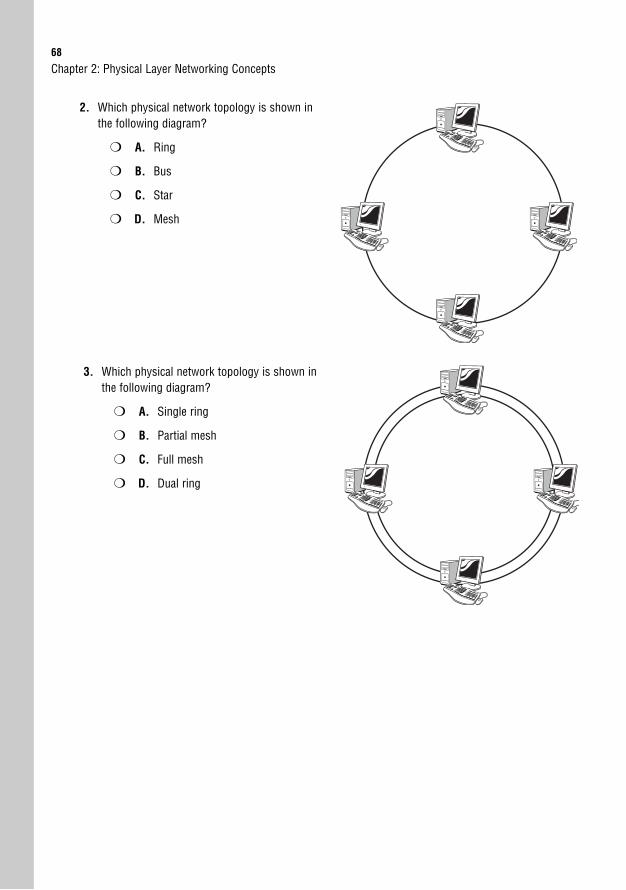
68
2. Which physical network topology is shown inthe following diagram?
❍ A. Ring
❍ B. Bus
❍ C. Star
❍ D. Mesh
Chapter 2: Physical Layer Networking Concepts
3. Which physical network topology is shown inthe following diagram?
❍ A. Single ring
❍ B. Partial mesh
❍ C. Full mesh
❍ D. Dual ring
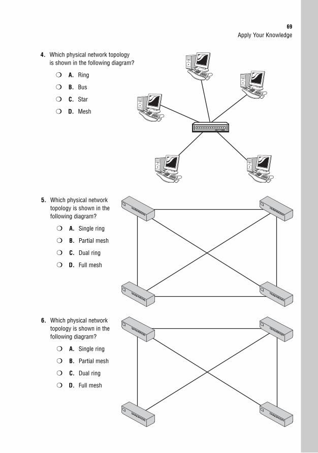
Apply Your Knowledge69
4. Which physical network topologyis shown in the following diagram?
❍ A. Ring
❍ B. Bus
❍ C. Star
❍ D. Mesh
5. Which physical networktopology is shown in thefollowing diagram?
❍ A. Single ring
❍ B. Partial mesh
❍ C. Dual ring
❍ D. Full mesh
6. Which physical networktopology is shown in thefollowing diagram?
❍ A. Single ring
❍ B. Partial mesh
❍ C. Dual ring
❍ D. Full mesh
70
7. Which of the following is not susceptible to EMI?
❍ A. Fiber
❍ B. Thin coaxial cable
❍ C. Category 3 UTP cable
❍ D. Category 5 UTP cable
8. Which connector does a UTP cable use?
❍ A. MT-RJ
❍ B. SC
❍ C. ST
❍ D. RJ-45
9. Because of attenuation, the maximum, practical length of a UTP cable is _________________.
❍ A. 10 meters
❍ B. 100 meters
❍ C. 200 meters
❍ D. 500 meters
10. The total flow of information over a certain time period on a communications medium measured inbits per second is called _______________.
❍ A. Bandwidth
❍ B. Crosstalk
❍ C. Attenuation
❍ D. Electromagnetic interference
11. Which cable consists of a single copper wire surrounded by a plastic insulation cover and a braid-ed copper shield?
❍ A. Coaxial cable
❍ B. UTP
❍ C. STP
❍ D. Category 5 cable
Chapter 2: Physical Layer Networking Concepts
Apply Your Knowledge71
12. What type of UTP cable would you use to connect a switch to a router?
❍ A. Coaxial cable
❍ B. Straight-through cable
❍ C. Cross-over cable
❍ D. Thin coax
13. What type of UTP cable would you use to connect a PC directly to another PC?
❍ A. Coaxial cable
❍ B. Straight-through cable
❍ C. Cross-over cable
❍ D. Thick coax
14. If you have a network that is connected through a hub and experiencing congestion, which of thefollowing is the best solution to decrease congestion on your network?
❍ A. Install a second hub.
❍ B. Replace the hub with a repeater.
❍ C. Replace the hub with a switch.
❍ D. Replace the hub with a network interface.
15. What is the IEEE standard for wi-fi?
❍ A. 802.1q
❍ B. 802.11b
❍ C. 802.3u
❍ D. 802.3ab
16. Which IEEE wireless standard uses a 5GHz radio frequency and is not compatible with other wire-less standards?
❍ A. 802.11
❍ B. 802.11a
❍ C. 802.11b
❍ D. 802.11g
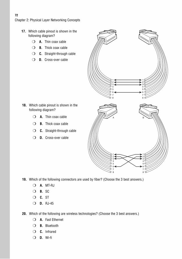
72
17. Which cable pinout is shown in the following diagram?
❍ A. Thin coax cable
❍ B. Thick coax cable
❍ C. Straight-through cable
❍ D. Cross-over cable
Chapter 2: Physical Layer Networking Concepts
12345678
12345678
18. Which cable pinout is shown in the following diagram?
❍ A. Thin coax cable
❍ B. Thick coax cable
❍ C. Straight-through cable
❍ D. Cross-over cable
12345678
1
A B
2345678
19. Which of the following connectors are used by fiber? (Choose the 3 best answers.)
❍ A. MT-RJ
❍ B. SC
❍ C. ST
❍ D. RJ-45
20. Which of the following are wireless technologies? (Choose the 3 best answers.)
❍ A. Fast Ethernet
❍ B. Bluetooth
❍ C. Infrared
❍ D. Wi-fi

Apply Your Knowledge73
Answers to Review Questions1. Refer to Figure 2.1 to check your design of a physical bus topology.
2. Refer to Figure 2.2 to check your design of a physical single ring topology and Figure 2.3 to checkyour design of a physical dual ring topology.
3. Refer to Figure 2.4 to check your design of a physical star topology.
4. Refer to Figure 2.6 to check your design of a physical partial mesh topology and Figure 2.5 tocheck your design of a physical full mesh topology.
5. Straight-through cables use four wires and pins 1, 2, 3, and 6. Given those pins, pin 1 is connect-ed on one end of the cable to pin 1 on the opposite end of the cable. Pin 2 at one end is connectedto pin 2 on the far end. Pin 3 is connected to pin 3 and pin 6 is connected to pin 6.
6. Cross-over cables also use four wires and pins 1, 2, 3, and 6. The difference is in how the pins areconnected at each end. With cross-over cables, pin 1 connects to pin 3 and pin 2 connects to pin 6.
Answers to Exam Questions1. B. This diagram represents the physical bus topology or the linear bus topology. This topology
uses one cable as the trunk or backbone.
2. A. This diagram represents the physical ring topology. Each device is connected to two otherdevices on the network. Data traverses the network and creates a ring or loop.
3. D. This diagram represents the physical dual ring topology. Unlike a single ring topology, thisdesign offers redundancy if either ring breaks.
4. C. This diagram represents the physical star topology. It may also be referred to as a hub-and-spoke topology.
5. D. This diagram represents the full mesh topology. All the devices on the network are directly con-nected to every other device on that same network.
6. B. This diagram represents the partial mesh topology. Some but not all of the devices are connect-ed to all of the other devices on the network.
7. A. Fiber is not susceptible to EMI. Answers B, C, and D are all incorrect because thin coaxial cable,category 3 UTP, and category 5 UTP are all susceptible to EMI.
8. D. UTP cables use RJ-45 connectors. Answers A, B, and C are incorrect because fiber uses ST, SC,or MT-RJ connectors.
9. B. Because of attenuation, the maximum, practical length of a UTP cable is 100 meters.
10. A. The total flow of information over a certain time period on a communications medium measuredin bits per second is called bandwidth. Answer B is incorrect because crosstalk is an electrical ormagnetic field that is a result of one communications signal affecting the signal in a nearby circuit.Answer C is incorrect because attenuation occurs over long distances as a signal loses strength.Answer D is incorrect because EMI is the interference caused by electromagnetic signals.
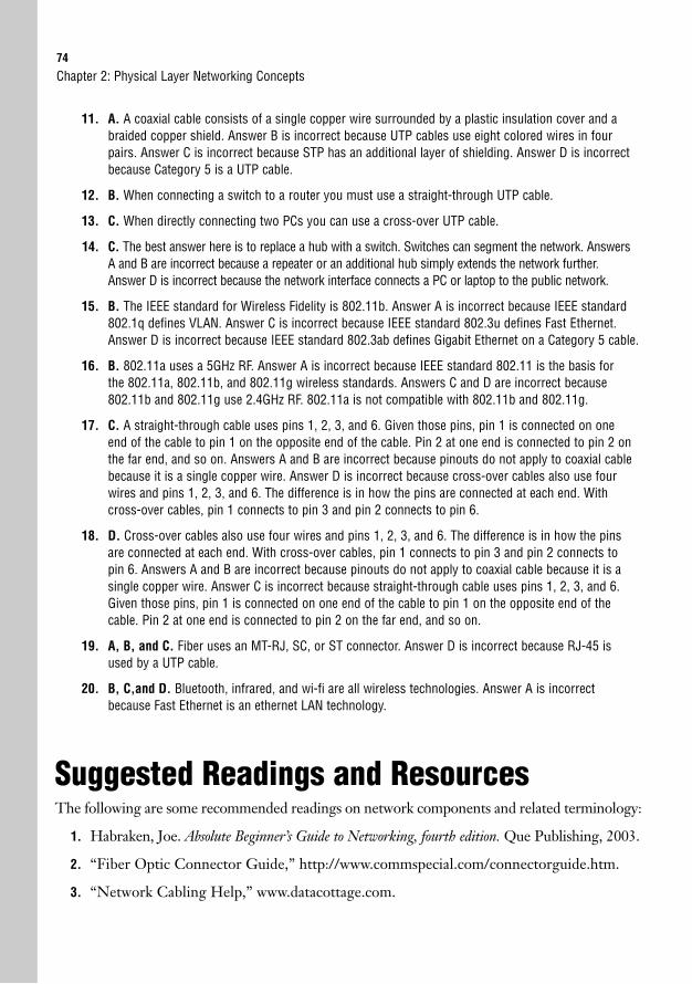
74
11. A. A coaxial cable consists of a single copper wire surrounded by a plastic insulation cover and abraided copper shield. Answer B is incorrect because UTP cables use eight colored wires in fourpairs. Answer C is incorrect because STP has an additional layer of shielding. Answer D is incorrectbecause Category 5 is a UTP cable.
12. B. When connecting a switch to a router you must use a straight-through UTP cable.
13. C. When directly connecting two PCs you can use a cross-over UTP cable.
14. C. The best answer here is to replace a hub with a switch. Switches can segment the network. AnswersA and B are incorrect because a repeater or an additional hub simply extends the network further.Answer D is incorrect because the network interface connects a PC or laptop to the public network.
15. B. The IEEE standard for Wireless Fidelity is 802.11b. Answer A is incorrect because IEEE standard802.1q defines VLAN. Answer C is incorrect because IEEE standard 802.3u defines Fast Ethernet.Answer D is incorrect because IEEE standard 802.3ab defines Gigabit Ethernet on a Category 5 cable.
16. B. 802.11a uses a 5GHz RF. Answer A is incorrect because IEEE standard 802.11 is the basis forthe 802.11a, 802.11b, and 802.11g wireless standards. Answers C and D are incorrect because802.11b and 802.11g use 2.4GHz RF. 802.11a is not compatible with 802.11b and 802.11g.
17. C. A straight-through cable uses pins 1, 2, 3, and 6. Given those pins, pin 1 is connected on oneend of the cable to pin 1 on the opposite end of the cable. Pin 2 at one end is connected to pin 2 onthe far end, and so on. Answers A and B are incorrect because pinouts do not apply to coaxial cablebecause it is a single copper wire. Answer D is incorrect because cross-over cables also use fourwires and pins 1, 2, 3, and 6. The difference is in how the pins are connected at each end. Withcross-over cables, pin 1 connects to pin 3 and pin 2 connects to pin 6.
18. D. Cross-over cables also use four wires and pins 1, 2, 3, and 6. The difference is in how the pinsare connected at each end. With cross-over cables, pin 1 connects to pin 3 and pin 2 connects topin 6. Answers A and B are incorrect because pinouts do not apply to coaxial cable because it is asingle copper wire. Answer C is incorrect because straight-through cable uses pins 1, 2, 3, and 6.Given those pins, pin 1 is connected on one end of the cable to pin 1 on the opposite end of thecable. Pin 2 at one end is connected to pin 2 on the far end, and so on.
19. A, B, and C. Fiber uses an MT-RJ, SC, or ST connector. Answer D is incorrect because RJ-45 isused by a UTP cable.
20. B, C,and D. Bluetooth, infrared, and wi-fi are all wireless technologies. Answer A is incorrectbecause Fast Ethernet is an ethernet LAN technology.
Suggested Readings and ResourcesThe following are some recommended readings on network components and related terminology:
1. Habraken, Joe. Absolute Beginner’s Guide to Networking, fourth edition. Que Publishing, 2003.
2. “Fiber Optic Connector Guide,” http://www.commspecial.com/connectorguide.htm.
3. “Network Cabling Help,” www.datacottage.com.
Chapter 2: Physical Layer Networking Concepts
3C H A P T E R T H R E E
Data Link Networking Concepts
ObjectivesThis chapter covers the following Cisco-specified objectives for the “Describe how a networkworks” and “Configure, verify and troubleshoot a switch with VLANs and interswitch communi-cations” sections of the 640-802 CCNA exam:
. Describe the purpose and functions of various network devices
. Select the components required to meet a network specification
. Use the OSI and TCP/IP models and their associated protocols to explain howdata flows in a network
. Interpret network diagrams
. Explain the technology and media access control method for Ethernet networks
OutlineIntroduction 78
Data Link Protocols 78
Token Ring 78
FDDI 80
Ethernet at the Data Link Layer 81
Ethernet Addressing 81
Ethernet Framing 85
Physical Ethernet Standards 87
Ethernet 87
10BASE2 88
10BASE5 89
10BASE-T 89
10BASE-FL 89
Fast Ethernet 90
100BASE-T4 90
100BASE-TX 90
100BASE-FX 90
Gigabit Ethernet 91
1000BASE-T 802.3ab 91
1000BASE-X 802.3z 92
10-Gigabit Ethernet (10GbE) 93
Long Reach Ethernet 93
Data Link Layer Devices 94
Bridges 95
Switches 98
Duplex 99
Microsegmentation 100
Chapter Summary 101
Key Terms 101
Apply Your Knowledge 102
Exercise 102
Review Questions 103
Exam Questions 103
Answers to Review Questions 107
Answers to Exam Questions 108
Suggested Readings and Resources 110

Study Strategies. Read the objectives at the beginning of the chapter.
. Familiarize yourself with token ring and FDDI protocols.
. Define the IEEE MAC unicast, broadcast, and multicast addresses.
. Review the ethernet family of protocols and be able to identify the char-acteristics of each protocol.
. Name the devices that are used at the Data Link layer and importanttraits of each device.
. Define duplex.
. Describe microsegmentation.
78
IntroductionSeveral data link networking concepts were first introduced in the discussion of the Data Linklayer or Layer 2 of the OSI model in Chapter 1, “Standard Internetworking Models.” Again,it is important to understand the layered architecture of the OSI model to grasp the funda-mentals of how a network operates. Although Chapter 2, “Physical Layer NetworkingConcepts,” went over concepts that define the Physical layer of the OSI model, this chaptergoes over concepts that define how a network operates at the Data Link layer specifically.
Important Data Link LAN topics to understand for the CCNA exam include the protocols,addressing, and devices that are used at Layer 2. Cisco specified several objectives related toLAN technologies, which are prevalent at Layer 1 and Layer 2. Let’s begin with three DataLink layer protocols: token ring, FDDI, and ethernet.
Chapter 3: Data Link Networking Concepts
Remember that the Physical and Data Link layers are combined in the TCP/IP model to form the NetworkInterface layer.
NOTE
Data Link ProtocolsObjectives:
. Explain the technology and media access control method for Ethernet networks
. Interpret network diagrams
. Use the OSI and TCP/IP models and their associated protocols to explain how data flows in a network
In this section, you will learn about network protocols that can be utilized at the Data Linklayer of the OSI model. These protocols include token ring, FDDI, and ethernet. EthernetData Link protocols are broken out into addressing and framing standards.
Token RingToken ring is a LAN protocol that utilizes a token-passing media access technology in a phys-ical ring or physical star topology, which creates a logical ring topology. This protocol was firstdeveloped by IBM but then standardized by IEEE with the 802.5 specification. With token-passing, a three-byte token (or special bit pattern) is inserted in a frame and passed in a singledirection from one node to another until it forms a complete loop. The node that has posses-sion of the token is the only one that can send data at any given time on that LAN. Becauseonly one node can send data at a time, collisions are avoided.
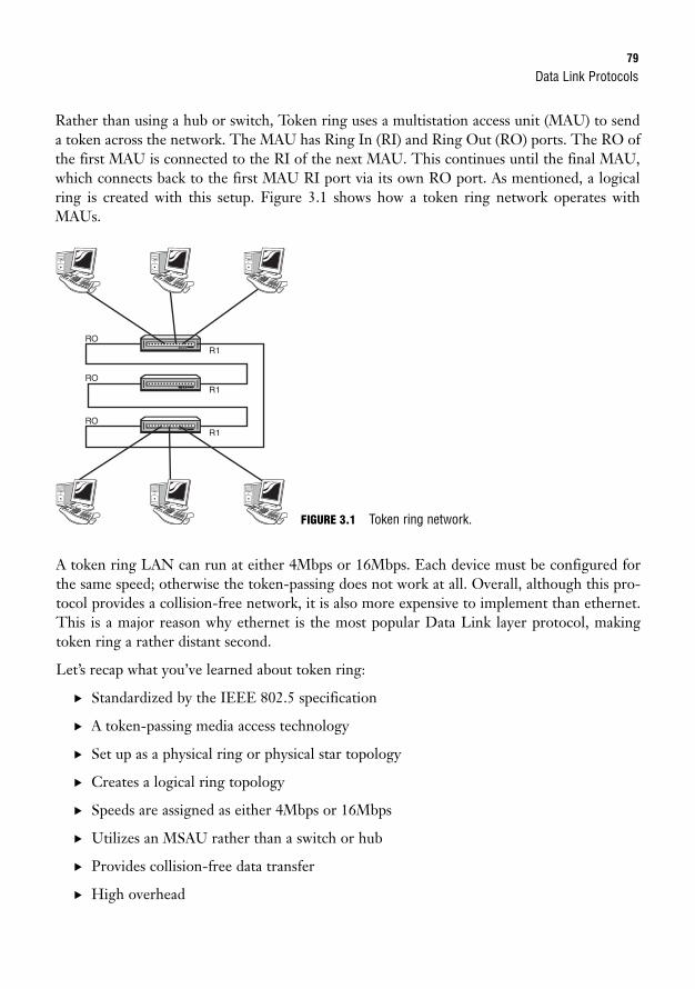
Data Link Protocols79
Rather than using a hub or switch, Token ring uses a multistation access unit (MAU) to senda token across the network. The MAU has Ring In (RI) and Ring Out (RO) ports. The RO ofthe first MAU is connected to the RI of the next MAU. This continues until the final MAU,which connects back to the first MAU RI port via its own RO port. As mentioned, a logicalring is created with this setup. Figure 3.1 shows how a token ring network operates withMAUs.
RO R1
RO R1
RO R1
A token ring LAN can run at either 4Mbps or 16Mbps. Each device must be configured forthe same speed; otherwise the token-passing does not work at all. Overall, although this pro-tocol provides a collision-free network, it is also more expensive to implement than ethernet.This is a major reason why ethernet is the most popular Data Link layer protocol, makingtoken ring a rather distant second.
Let’s recap what you’ve learned about token ring:
. Standardized by the IEEE 802.5 specification
. A token-passing media access technology
. Set up as a physical ring or physical star topology
. Creates a logical ring topology
. Speeds are assigned as either 4Mbps or 16Mbps
. Utilizes an MSAU rather than a switch or hub
. Provides collision-free data transfer
. High overhead
FIGURE 3.1 Token ring network.
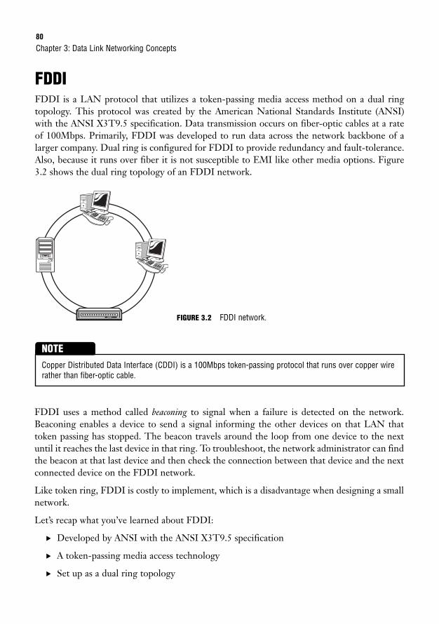
80
FDDIFDDI is a LAN protocol that utilizes a token-passing media access method on a dual ringtopology. This protocol was created by the American National Standards Institute (ANSI)with the ANSI X3T9.5 specification. Data transmission occurs on fiber-optic cables at a rateof 100Mbps. Primarily, FDDI was developed to run data across the network backbone of alarger company. Dual ring is configured for FDDI to provide redundancy and fault-tolerance.Also, because it runs over fiber it is not susceptible to EMI like other media options. Figure3.2 shows the dual ring topology of an FDDI network.
Chapter 3: Data Link Networking Concepts
Copper Distributed Data Interface (CDDI) is a 100Mbps token-passing protocol that runs over copper wirerather than fiber-optic cable.
NOTE
FIGURE 3.2 FDDI network.
FDDI uses a method called beaconing to signal when a failure is detected on the network.Beaconing enables a device to send a signal informing the other devices on that LAN thattoken passing has stopped. The beacon travels around the loop from one device to the nextuntil it reaches the last device in that ring. To troubleshoot, the network administrator can findthe beacon at that last device and then check the connection between that device and the nextconnected device on the FDDI network.
Like token ring, FDDI is costly to implement, which is a disadvantage when designing a smallnetwork.
Let’s recap what you’ve learned about FDDI:
. Developed by ANSI with the ANSI X3T9.5 specification
. A token-passing media access technology
. Set up as a dual ring topology
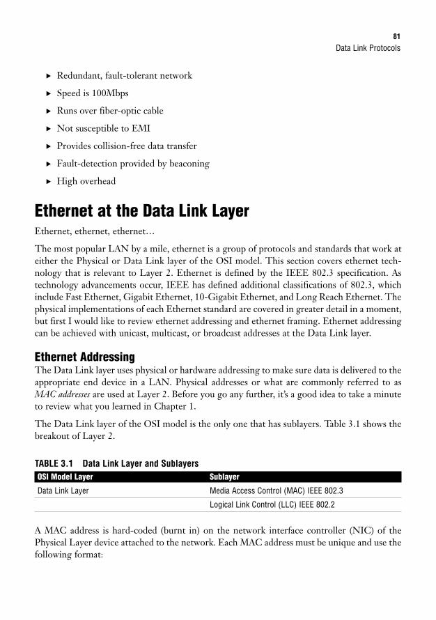
Data Link Protocols81
. Redundant, fault-tolerant network
. Speed is 100Mbps
. Runs over fiber-optic cable
. Not susceptible to EMI
. Provides collision-free data transfer
. Fault-detection provided by beaconing
. High overhead
Ethernet at the Data Link LayerEthernet, ethernet, ethernet…
The most popular LAN by a mile, ethernet is a group of protocols and standards that work ateither the Physical or Data Link layer of the OSI model. This section covers ethernet tech-nology that is relevant to Layer 2. Ethernet is defined by the IEEE 802.3 specification. Astechnology advancements occur, IEEE has defined additional classifications of 802.3, whichinclude Fast Ethernet, Gigabit Ethernet, 10-Gigabit Ethernet, and Long Reach Ethernet. Thephysical implementations of each Ethernet standard are covered in greater detail in a moment,but first I would like to review ethernet addressing and ethernet framing. Ethernet addressingcan be achieved with unicast, multicast, or broadcast addresses at the Data Link layer.
Ethernet AddressingThe Data Link layer uses physical or hardware addressing to make sure data is delivered to theappropriate end device in a LAN. Physical addresses or what are commonly referred to asMAC addresses are used at Layer 2. Before you go any further, it’s a good idea to take a minuteto review what you learned in Chapter 1.
The Data Link layer of the OSI model is the only one that has sublayers. Table 3.1 shows thebreakout of Layer 2.
TABLE 3.1 Data Link Layer and SublayersOSI Model Layer Sublayer
Data Link Layer Media Access Control (MAC) IEEE 802.3
Logical Link Control (LLC) IEEE 802.2
A MAC address is hard-coded (burnt in) on the network interface controller (NIC) of thePhysical Layer device attached to the network. Each MAC address must be unique and use thefollowing format:
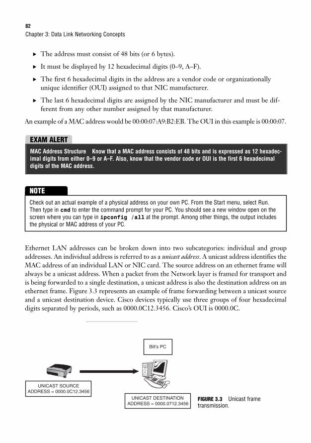
82
. The address must consist of 48 bits (or 6 bytes).
. It must be displayed by 12 hexadecimal digits (0–9, A–F).
. The first 6 hexadecimal digits in the address are a vendor code or organizationallyunique identifier (OUI) assigned to that NIC manufacturer.
. The last 6 hexadecimal digits are assigned by the NIC manufacturer and must be dif-ferent from any other number assigned by that manufacturer.
An example of a MAC address would be 00:00:07:A9:B2:EB. The OUI in this example is 00:00:07.
Chapter 3: Data Link Networking Concepts
EXAM ALERTMAC Address Structure Know that a MAC address consists of 48 bits and is expressed as 12 hexadec-imal digits from either 0–9 or A–F. Also, know that the vendor code or OUI is the first 6 hexadecimaldigits of the MAC address.
Check out an actual example of a physical address on your own PC. From the Start menu, select Run.Then type in cmd to enter the command prompt for your PC. You should see a new window open on thescreen where you can type in ipconfig /all at the prompt. Among other things, the output includesthe physical or MAC address of your PC.
NOTE
Ethernet LAN addresses can be broken down into two subcategories: individual and groupaddresses. An individual address is referred to as a unicast address. A unicast address identifies theMAC address of an individual LAN or NIC card. The source address on an ethernet frame willalways be a unicast address. When a packet from the Network layer is framed for transport andis being forwarded to a single destination, a unicast address is also the destination address on anethernet frame. Figure 3.3 represents an example of frame forwarding between a unicast sourceand a unicast destination device. Cisco devices typically use three groups of four hexadecimaldigits separated by periods, such as 0000.0C12.3456. Cisco’s OUI is 0000.0C.
Bill’s PC
UNICAST SOURCE ADDRESS = 0000.0C12.3456
UNICAST DESTINATION ADDRESS = 0000.0712.3456
FIGURE 3.3 Unicast frame transmission.
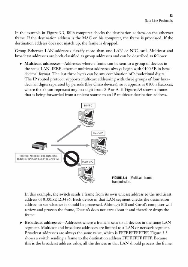
Data Link Protocols83
In the example in Figure 3.3, Bill’s computer checks the destination address on the ethernetframe. If the destination address is the MAC on his computer, the frame is processed. If thedestination address does not match up, the frame is dropped.
Group Ethernet LAN addresses classify more than one LAN or NIC card. Multicast andbroadcast addresses are both classified as group addresses and can be described as follows:
. Multicast addresses—Addresses where a frame can be sent to a group of devices inthe same LAN. IEEE ethernet multicast addresses always begin with 0100.5E in hexa-decimal format. The last three bytes can be any combination of hexadecimal digits.The IP routed protocol supports multicast addressing with three groups of four hexa-decimal digits separated by periods (like Cisco devices), so it appears as 0100.5Exx.xxxx,where the x’s can represent any hex digit from 0–9 or A–F. Figure 3.4 shows a framethat is being forwarded from a unicast source to an IP multicast destination address.
Carol’s PC
SOURCE ADDRESS 0000.0C12.3456 DESTINATION ADDRESS 0100.5E12.3456
Bill’s PC
Dustin’s PC
In this example, the switch sends a frame from its own unicast address to the multicastaddress of 0100.5E12.3456. Each device in that LAN segment checks the destinationaddress to see whether it should be processed. Although Bill and Carol’s computer willreview and process the frame, Dustin’s does not care about it and therefore drops theframe.
. Broadcast addresses—Addresses where a frame is sent to all devices in the same LANsegment. Multicast and broadcast addresses are limited to a LAN or network segment.Broadcast addresses are always the same value, which is FFFF.FFFF.FFFF. Figure 3.5shows a switch sending a frame to the destination address FFFF.FFFF.FFFF. Becausethis is the broadcast address value, all the devices in that LAN should process the frame.
FIGURE 3.4 Multicast frame transmission.
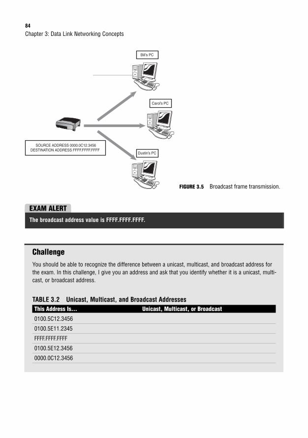
84
ChallengeYou should be able to recognize the difference between a unicast, multicast, and broadcast address forthe exam. In this challenge, I give you an address and ask that you identify whether it is a unicast, multi-cast, or broadcast address.
TABLE 3.2 Unicast, Multicast, and Broadcast AddressesThis Address Is… Unicast, Multicast, or Broadcast
0100.5C12.3456
0100.5E11.2345
FFFF.FFFF.FFFF
0100.5E12.3456
0000.0C12.3456
Chapter 3: Data Link Networking Concepts
Carol’s PC
SOURCE ADDRESS 0000.0C12.3456 DESTINATION ADDRESS FFFF.FFFF.FFFF
Bill’s PC
Dustin’s PC
FIGURE 3.5 Broadcast frame transmission.
EXAM ALERTThe broadcast address value is FFFF.FFFF.FFFF.
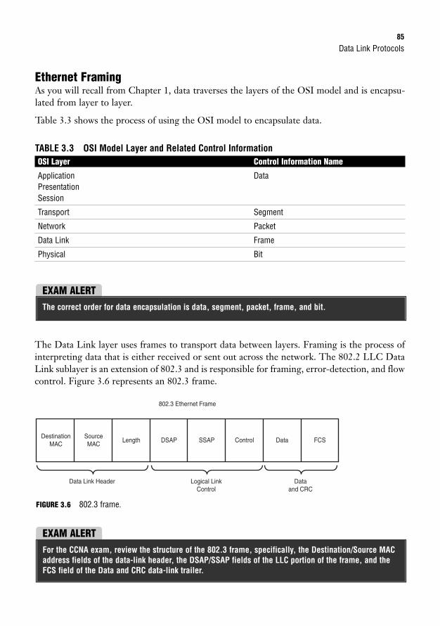
Data Link Protocols85
Ethernet FramingAs you will recall from Chapter 1, data traverses the layers of the OSI model and is encapsu-lated from layer to layer.
Table 3.3 shows the process of using the OSI model to encapsulate data.
TABLE 3.3 OSI Model Layer and Related Control InformationOSI Layer Control Information Name
Application DataPresentationSession
Transport Segment
Network Packet
Data Link Frame
Physical Bit
EXAM ALERTThe correct order for data encapsulation is data, segment, packet, frame, and bit.
The Data Link layer uses frames to transport data between layers. Framing is the process ofinterpreting data that is either received or sent out across the network. The 802.2 LLC DataLink sublayer is an extension of 802.3 and is responsible for framing, error-detection, and flowcontrol. Figure 3.6 represents an 802.3 frame.
DestinationMAC
SourceMAC
Length DSAP SSAP
802.3 Ethernet Frame
Data Link Header
Control Data FCS
Logical LinkControl
Dataand CRC
FIGURE 3.6 802.3 frame.
EXAM ALERTFor the CCNA exam, review the structure of the 802.3 frame, specifically, the Destination/Source MACaddress fields of the data-link header, the DSAP/SSAP fields of the LLC portion of the frame, and theFCS field of the Data and CRC data-link trailer.
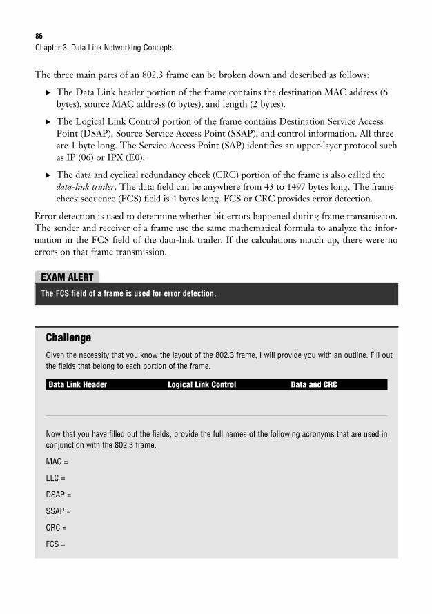
86
The three main parts of an 802.3 frame can be broken down and described as follows:
. The Data Link header portion of the frame contains the destination MAC address (6bytes), source MAC address (6 bytes), and length (2 bytes).
. The Logical Link Control portion of the frame contains Destination Service AccessPoint (DSAP), Source Service Access Point (SSAP), and control information. All threeare 1 byte long. The Service Access Point (SAP) identifies an upper-layer protocol suchas IP (06) or IPX (E0).
. The data and cyclical redundancy check (CRC) portion of the frame is also called thedata-link trailer. The data field can be anywhere from 43 to 1497 bytes long. The framecheck sequence (FCS) field is 4 bytes long. FCS or CRC provides error detection.
Error detection is used to determine whether bit errors happened during frame transmission.The sender and receiver of a frame use the same mathematical formula to analyze the infor-mation in the FCS field of the data-link trailer. If the calculations match up, there were noerrors on that frame transmission.
Chapter 3: Data Link Networking Concepts
EXAM ALERTThe FCS field of a frame is used for error detection.
ChallengeGiven the necessity that you know the layout of the 802.3 frame, I will provide you with an outline. Fill outthe fields that belong to each portion of the frame.
Data Link Header Logical Link Control Data and CRC
Now that you have filled out the fields, provide the full names of the following acronyms that are used inconjunction with the 802.3 frame.
MAC =
LLC =
DSAP =
SSAP =
CRC =
FCS =
Physical Ethernet Standards87
I mentioned how the SAP in the 802.3 frame identifies an upper-layer protocol with 1 byte or2 hexadecimal digits. The IP SAP is 06. Well, it turns out that 1 byte was insufficient for thenumber of protocols that need to be recognized by an 802.3 frame. To accommodate the influxof protocols, IEEE permitted for an additional header in the 802.3 frame called a SubnetworkAccess Protocol (SNAP) header.
The SNAP header serves the same purpose as the DSAP field; however, it consists of 2 bytes.For example, 0800 is the hexadecimal format assigned to IP with SNAP. RFC 1700 identifiesall the values that are associated with SAP and SNAP.
Physical Ethernet StandardsObjective:
. Select the components required to meet a network specification
Have I said that ethernet is the most popular LAN protocol? Ethernet started in the 1970swhen Xerox needed a networking system to connect personal computers. Xerox joined forceswith Digital Equipment Corp. (DEC) and Intel to develop the protocol, which is why the veryfirst ethernet standards were referred to as DIX Ethernet. This section covers the progressionof ethernet standards from the earlier 10Mbps connections to the more recent 10 gigabit eth-ernet connections.
Each standard has a maximum connection length and speed. Individual ethernet standards alsospecify which cables and connectors can be used for network connectivity. You will be intro-duced to each group of standards starting with the 10Mbps ethernet connections, then the100Mbps Fast Ethernet connections, 1Gbps ethernet, and 10Gbps ethernet connections.
EthernetThe IEEE 802.3 ethernet standards are covered in the following sections. The following listcontains all the ethernet standards that are covered in this chapter, in order.
. 10BASE2
. 10BASE5
. 10BASE-T
. 10BASE-FL
. 100BASE-T4
. 100BASE-TX
88
. 100BASE-FX
. 1000BASE-T
. 1000BASE-TX
. 1000BASE-CX
. 1000BASE-SX
. 1000BASE-LX
. 10GbE
10BASE210BASE2 networks are connected with RG-58 coaxial cables that use Bayonet NeillConcelman (BNC) connectors. There are no other hardware devices such as hubs or switchesto connect devices, just the coaxial cables. This creates a physical bus topology. An electricalsignal is sent by each device that wants to transmit data on that network. If more than onedevice sends a signal at the same time, this causes a collision and the signal is lost. To preventloss of data transmissions, an algorithm called Carrier Sense Multiple Access Collision Detection(CSMA/CD) was defined. This algorithm sends a jam signal to notify the devices that there hasbeen a collision. The devices then halt transmission for a random back-off time. CSMA/CDmust be activated for 10Base ethernet LANs that are connected with a hub.
Chapter 3: Data Link Networking Concepts
EXAM ALERTFor the exam, know the definition of CSMA/CD and its capability to act as an arbitrator for devices inan ethernet LAN.
The name 10BASE2 breaks down as follows:
10—10Mbps data transmission speed
BASE—Represents baseband, the signaling mode where the media can only send one signalper wire at a time
2—Actually refers to 185m or the maximum segment length (where 185 is rounded up to 200and 2 is a multiple of 100m)
So what you can see from the naming scheme is that the first number represents the speed, the wordbase means the baseband signaling mode, and the last helps you determine the type of cable used.
NOTE
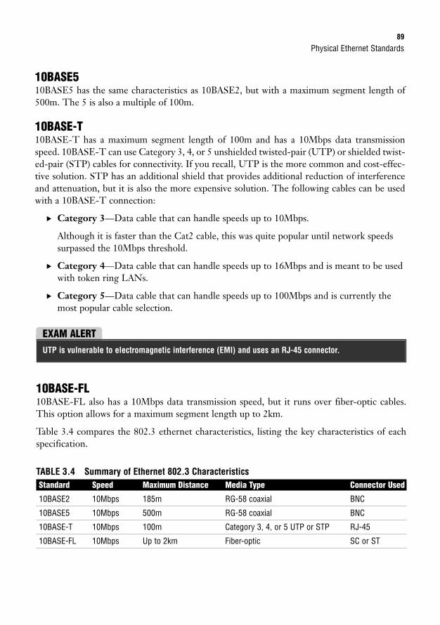
Physical Ethernet Standards89
10BASE510BASE5 has the same characteristics as 10BASE2, but with a maximum segment length of500m. The 5 is also a multiple of 100m.
10BASE-T10BASE-T has a maximum segment length of 100m and has a 10Mbps data transmissionspeed. 10BASE-T can use Category 3, 4, or 5 unshielded twisted-pair (UTP) or shielded twist-ed-pair (STP) cables for connectivity. If you recall, UTP is the more common and cost-effec-tive solution. STP has an additional shield that provides additional reduction of interferenceand attenuation, but it is also the more expensive solution. The following cables can be usedwith a 10BASE-T connection:
. Category 3—Data cable that can handle speeds up to 10Mbps.
Although it is faster than the Cat2 cable, this was quite popular until network speedssurpassed the 10Mbps threshold.
. Category 4—Data cable that can handle speeds up to 16Mbps and is meant to be usedwith token ring LANs.
. Category 5—Data cable that can handle speeds up to 100Mbps and is currently themost popular cable selection.
EXAM ALERTUTP is vulnerable to electromagnetic interference (EMI) and uses an RJ-45 connector.
10BASE-FL10BASE-FL also has a 10Mbps data transmission speed, but it runs over fiber-optic cables.This option allows for a maximum segment length up to 2km.
Table 3.4 compares the 802.3 ethernet characteristics, listing the key characteristics of eachspecification.
TABLE 3.4 Summary of Ethernet 802.3 CharacteristicsStandard Speed Maximum Distance Media Type Connector Used
10BASE2 10Mbps 185m RG-58 coaxial BNC
10BASE5 10Mbps 500m RG-58 coaxial BNC
10BASE-T 10Mbps 100m Category 3, 4, or 5 UTP or STP RJ-45
10BASE-FL 10Mbps Up to 2km Fiber-optic SC or ST
90
As you can see, the early standards are all limited to 10Mbps. More recent ethernet specifica-tions allow for faster data transmission speeds and are more popular for today’s networks.
Fast EthernetFast Ethernet was derived for networks that needed speeds in excess of 10Mbps. The IEEE802.3u defines standards for 100BASE-T4, 100BASE-TX, and 100BASE-FX. You may alsohear them collectively referred to as 100BASE-X. Based on what you learned from the 10Basenaming scheme, you would be correct to infer that the 100 represents 100Mbps. Also, all threestandards are baseband like the 10Mbps family of protocols.
Chapter 3: Data Link Networking Concepts
Fast Ethernet is defined in the IEEE 802.3u standard.
NOTE
100BASE-T4100BASE-T4 has the same characteristics as 100BASE-TX except that it can use Category 3,4, or 5 UTP or STP cables.
100BASE-TX100BASE-TX, like 10BASE-T, uses either UTP or STP. Category 5 UTP cable is used withthis implementation. 10BASE-T has a maximum segment length of 100m.
100BASE-FX100BASE-FX uses either single-mode or multimode fiber-optic cables to connect. Multimode(MM) fiber set for half-duplex can reach a distance of 412m. Single-mode (SM) fiber set forfull-duplex can reach a distance of 10,000m. SC or ST connectors can be used. The drawback,as mentioned before with fiber implementations, is the high overhead.
. Multimode (MM) fiber—This is generally used for shorter distances and is ideal for acampus-sized network. MM also has a larger diameter of optical fiber than SM fiber.
. Single-mode (SM) fiber—This mode is used to span longer distances. SM also allowsfor a higher data rate than MM and faster data transmission speeds.
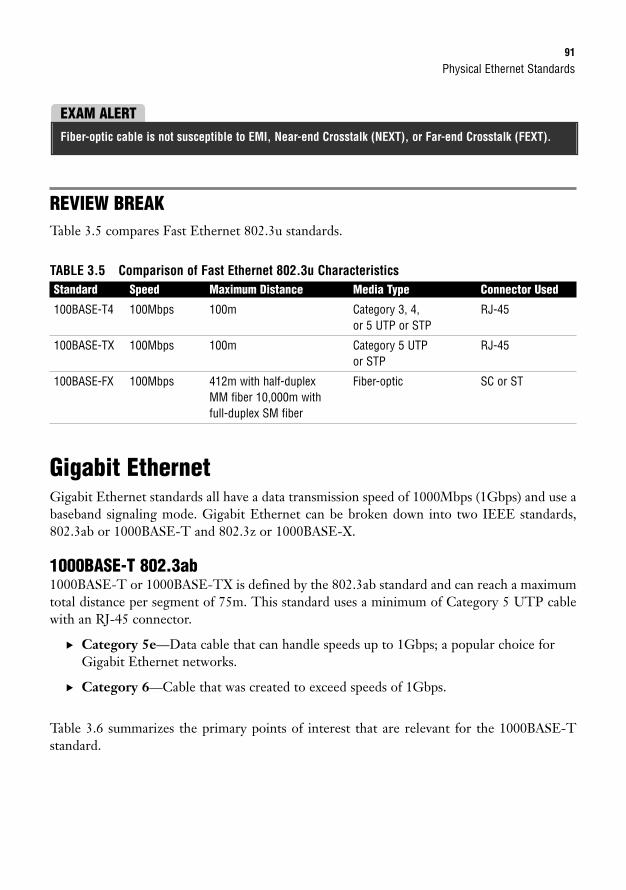
Physical Ethernet Standards91
REVIEW BREAKTable 3.5 compares Fast Ethernet 802.3u standards.
TABLE 3.5 Comparison of Fast Ethernet 802.3u CharacteristicsStandard Speed Maximum Distance Media Type Connector Used
100BASE-T4 100Mbps 100m Category 3, 4, RJ-45or 5 UTP or STP
100BASE-TX 100Mbps 100m Category 5 UTP RJ-45or STP
100BASE-FX 100Mbps 412m with half-duplex Fiber-optic SC or STMM fiber 10,000m withfull-duplex SM fiber
Gigabit EthernetGigabit Ethernet standards all have a data transmission speed of 1000Mbps (1Gbps) and use abaseband signaling mode. Gigabit Ethernet can be broken down into two IEEE standards,802.3ab or 1000BASE-T and 802.3z or 1000BASE-X.
1000BASE-T 802.3ab1000BASE-T or 1000BASE-TX is defined by the 802.3ab standard and can reach a maximumtotal distance per segment of 75m. This standard uses a minimum of Category 5 UTP cablewith an RJ-45 connector.
. Category 5e—Data cable that can handle speeds up to 1Gbps; a popular choice forGigabit Ethernet networks.
. Category 6—Cable that was created to exceed speeds of 1Gbps.
Table 3.6 summarizes the primary points of interest that are relevant for the 1000BASE-Tstandard.
EXAM ALERTFiber-optic cable is not susceptible to EMI, Near-end Crosstalk (NEXT), or Far-end Crosstalk (FEXT).
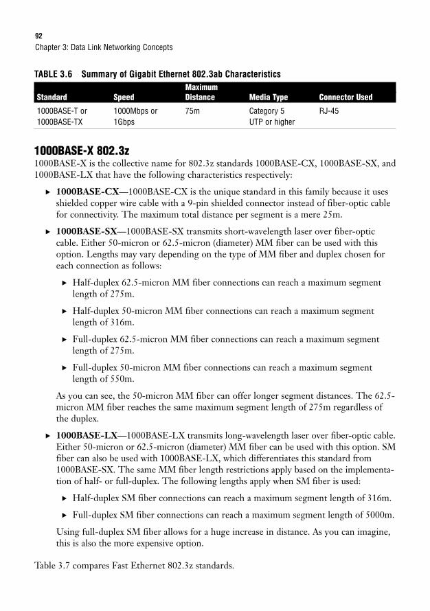
92
TABLE 3.6 Summary of Gigabit Ethernet 802.3ab CharacteristicsMaximum
Standard Speed Distance Media Type Connector Used
1000BASE-T or 1000Mbps or 75m Category 5 RJ-451000BASE-TX 1Gbps UTP or higher
1000BASE-X 802.3z1000BASE-X is the collective name for 802.3z standards 1000BASE-CX, 1000BASE-SX, and1000BASE-LX that have the following characteristics respectively:
. 1000BASE-CX—1000BASE-CX is the unique standard in this family because it usesshielded copper wire cable with a 9-pin shielded connector instead of fiber-optic cablefor connectivity. The maximum total distance per segment is a mere 25m.
. 1000BASE-SX—1000BASE-SX transmits short-wavelength laser over fiber-opticcable. Either 50-micron or 62.5-micron (diameter) MM fiber can be used with thisoption. Lengths may vary depending on the type of MM fiber and duplex chosen foreach connection as follows:
. Half-duplex 62.5-micron MM fiber connections can reach a maximum segmentlength of 275m.
. Half-duplex 50-micron MM fiber connections can reach a maximum segmentlength of 316m.
. Full-duplex 62.5-micron MM fiber connections can reach a maximum segmentlength of 275m.
. Full-duplex 50-micron MM fiber connections can reach a maximum segmentlength of 550m.
As you can see, the 50-micron MM fiber can offer longer segment distances. The 62.5-micron MM fiber reaches the same maximum segment length of 275m regardless ofthe duplex.
. 1000BASE-LX—1000BASE-LX transmits long-wavelength laser over fiber-optic cable.Either 50-micron or 62.5-micron (diameter) MM fiber can be used with this option. SMfiber can also be used with 1000BASE-LX, which differentiates this standard from1000BASE-SX. The same MM fiber length restrictions apply based on the implementa-tion of half- or full-duplex. The following lengths apply when SM fiber is used:
. Half-duplex SM fiber connections can reach a maximum segment length of 316m.
. Full-duplex SM fiber connections can reach a maximum segment length of 5000m.
Using full-duplex SM fiber allows for a huge increase in distance. As you can imagine,this is also the more expensive option.
Table 3.7 compares Fast Ethernet 802.3z standards.
Chapter 3: Data Link Networking Concepts
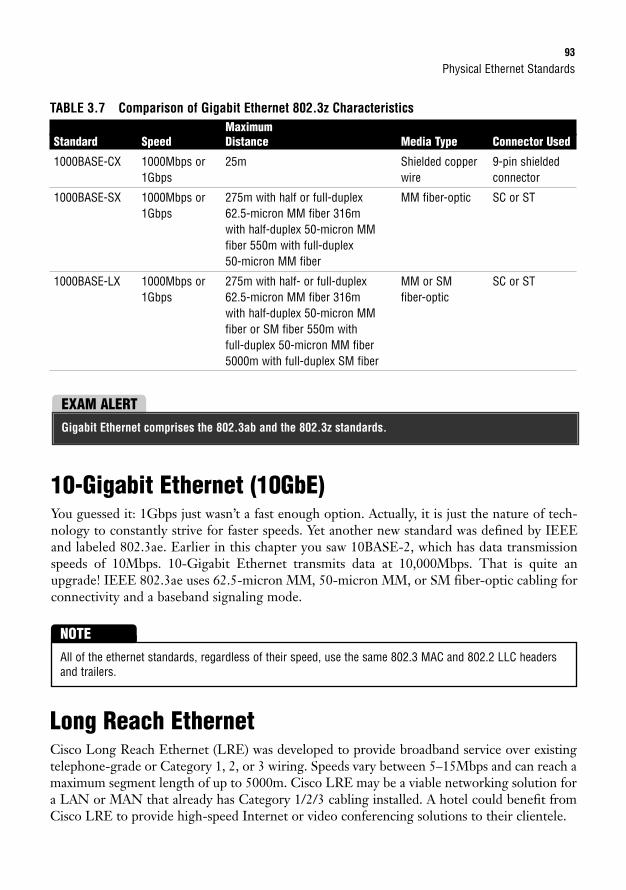
Physical Ethernet Standards93
TABLE 3.7 Comparison of Gigabit Ethernet 802.3z CharacteristicsMaximum
Standard Speed Distance Media Type Connector Used
1000BASE-CX 1000Mbps or 25m Shielded copper 9-pin shielded1Gbps wire connector
1000BASE-SX 1000Mbps or 275m with half or full-duplex MM fiber-optic SC or ST1Gbps 62.5-micron MM fiber 316m
with half-duplex 50-micron MM fiber 550m with full-duplex50-micron MM fiber
1000BASE-LX 1000Mbps or 275m with half- or full-duplex MM or SM SC or ST1Gbps 62.5-micron MM fiber 316m fiber-optic
with half-duplex 50-micron MM fiber or SM fiber 550m with full-duplex 50-micron MM fiber5000m with full-duplex SM fiber
EXAM ALERTGigabit Ethernet comprises the 802.3ab and the 802.3z standards.
10-Gigabit Ethernet (10GbE)You guessed it: 1Gbps just wasn’t a fast enough option. Actually, it is just the nature of tech-nology to constantly strive for faster speeds. Yet another new standard was defined by IEEEand labeled 802.3ae. Earlier in this chapter you saw 10BASE-2, which has data transmissionspeeds of 10Mbps. 10-Gigabit Ethernet transmits data at 10,000Mbps. That is quite anupgrade! IEEE 802.3ae uses 62.5-micron MM, 50-micron MM, or SM fiber-optic cabling forconnectivity and a baseband signaling mode.
All of the ethernet standards, regardless of their speed, use the same 802.3 MAC and 802.2 LLC headersand trailers.
NOTE
Long Reach EthernetCisco Long Reach Ethernet (LRE) was developed to provide broadband service over existingtelephone-grade or Category 1, 2, or 3 wiring. Speeds vary between 5–15Mbps and can reach amaximum segment length of up to 5000m. Cisco LRE may be a viable networking solution fora LAN or MAN that already has Category 1/2/3 cabling installed. A hotel could benefit fromCisco LRE to provide high-speed Internet or video conferencing solutions to their clientele.
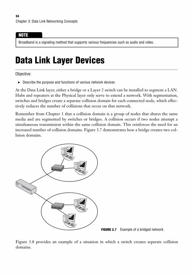
Figure 3.8 provides an example of a situation in which a switch creates separate collisiondomains.
94
Data Link Layer DevicesObjective:
. Describe the purpose and functions of various network devices
At the Data Link layer, either a bridge or a Layer 2 switch can be installed to segment a LAN.Hubs and repeaters at the Physical layer only serve to extend a network. With segmentation,switches and bridges create a separate collision domain for each connected node, which effec-tively reduces the number of collisions that occur on that network.
Remember from Chapter 1 that a collision domain is a group of nodes that shares the samemedia and are segmented by switches or bridges. A collision occurs if two nodes attempt asimultaneous transmission within the same collision domain. This reinforces the need for anincreased number of collision domains. Figure 3.7 demonstrates how a bridge creates two col-lision domains.
Chapter 3: Data Link Networking Concepts
Broadband is a signaling method that supports various frequencies such as audio and video.
NOTE
6
6
FIGURE 3.7 Example of a bridged network.
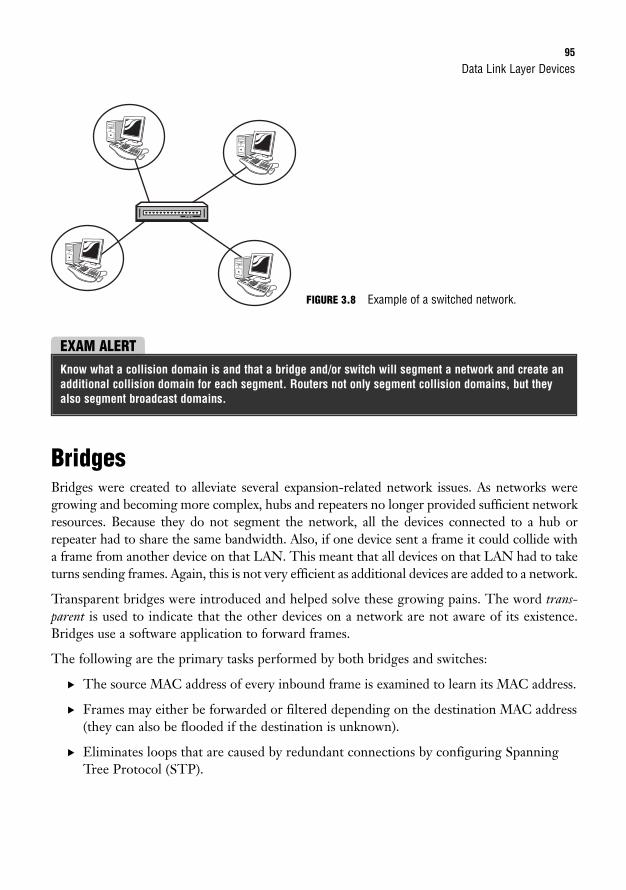
Data Link Layer Devices95
BridgesBridges were created to alleviate several expansion-related network issues. As networks weregrowing and becoming more complex, hubs and repeaters no longer provided sufficient networkresources. Because they do not segment the network, all the devices connected to a hub orrepeater had to share the same bandwidth. Also, if one device sent a frame it could collide witha frame from another device on that LAN. This meant that all devices on that LAN had to taketurns sending frames. Again, this is not very efficient as additional devices are added to a network.
Transparent bridges were introduced and helped solve these growing pains. The word trans-parent is used to indicate that the other devices on a network are not aware of its existence.Bridges use a software application to forward frames.
The following are the primary tasks performed by both bridges and switches:
. The source MAC address of every inbound frame is examined to learn its MAC address.
. Frames may either be forwarded or filtered depending on the destination MAC address(they can also be flooded if the destination is unknown).
. Eliminates loops that are caused by redundant connections by configuring SpanningTree Protocol (STP).
FIGURE 3.8 Example of a switched network.
EXAM ALERTKnow what a collision domain is and that a bridge and/or switch will segment a network and create anadditional collision domain for each segment. Routers not only segment collision domains, but theyalso segment broadcast domains.
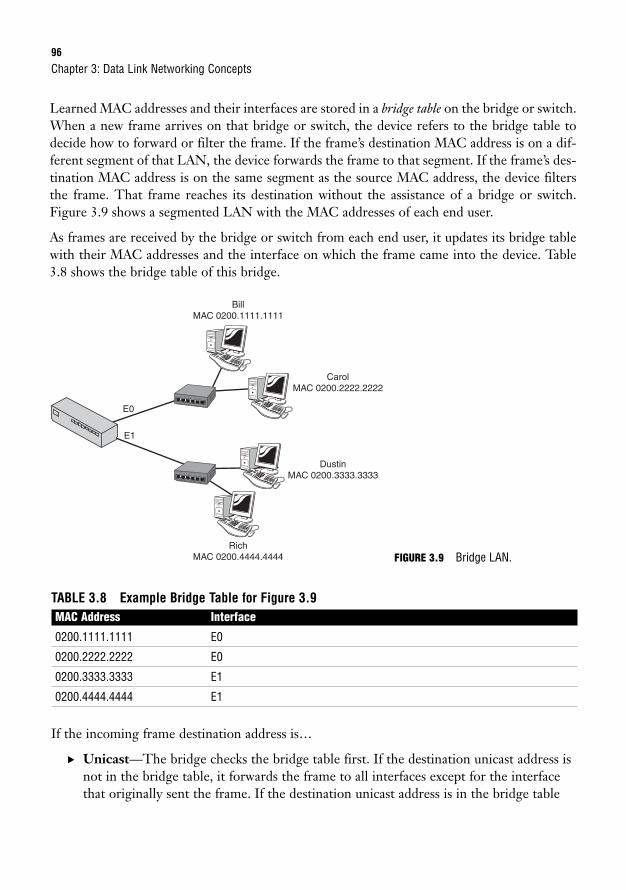
96
Learned MAC addresses and their interfaces are stored in a bridge table on the bridge or switch.When a new frame arrives on that bridge or switch, the device refers to the bridge table todecide how to forward or filter the frame. If the frame’s destination MAC address is on a dif-ferent segment of that LAN, the device forwards the frame to that segment. If the frame’s des-tination MAC address is on the same segment as the source MAC address, the device filtersthe frame. That frame reaches its destination without the assistance of a bridge or switch.Figure 3.9 shows a segmented LAN with the MAC addresses of each end user.
As frames are received by the bridge or switch from each end user, it updates its bridge tablewith their MAC addresses and the interface on which the frame came into the device. Table3.8 shows the bridge table of this bridge.
Chapter 3: Data Link Networking Concepts
E0
E1
BillMAC 0200.1111.1111
RichMAC 0200.4444.4444
CarolMAC 0200.2222.2222
DustinMAC 0200.3333.3333
6
6
FIGURE 3.9 Bridge LAN.
TABLE 3.8 Example Bridge Table for Figure 3.9MAC Address Interface
0200.1111.1111 E0
0200.2222.2222 E0
0200.3333.3333 E1
0200.4444.4444 E1
If the incoming frame destination address is…
. Unicast—The bridge checks the bridge table first. If the destination unicast address isnot in the bridge table, it forwards the frame to all interfaces except for the interfacethat originally sent the frame. If the destination unicast address is in the bridge table
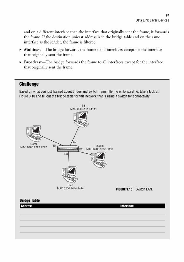
Data Link Layer Devices97
and on a different interface than the interface that originally sent the frame, it forwardsthe frame. If the destination unicast address is in the bridge table and on the sameinterface as the sender, the frame is filtered.
. Multicast—The bridge forwards the frame to all interfaces except for the interfacethat originally sent the frame.
. Broadcast—The bridge forwards the frame to all interfaces except for the interfacethat originally sent the frame.
ChallengeBased on what you just learned about bridge and switch frame filtering or forwarding, take a look atFigure 3.10 and fill out the bridge table for this network that is using a switch for connectivity.
E0E1
E3
E2
RichMAC 0200.4444.4444
CarolMAC 0200.2222.2222
BillMAC 0200.1111.1111
DustinMAC 0200.3333.3333
Bridge TableAddress Interface
FIGURE 3.10 Switch LAN.
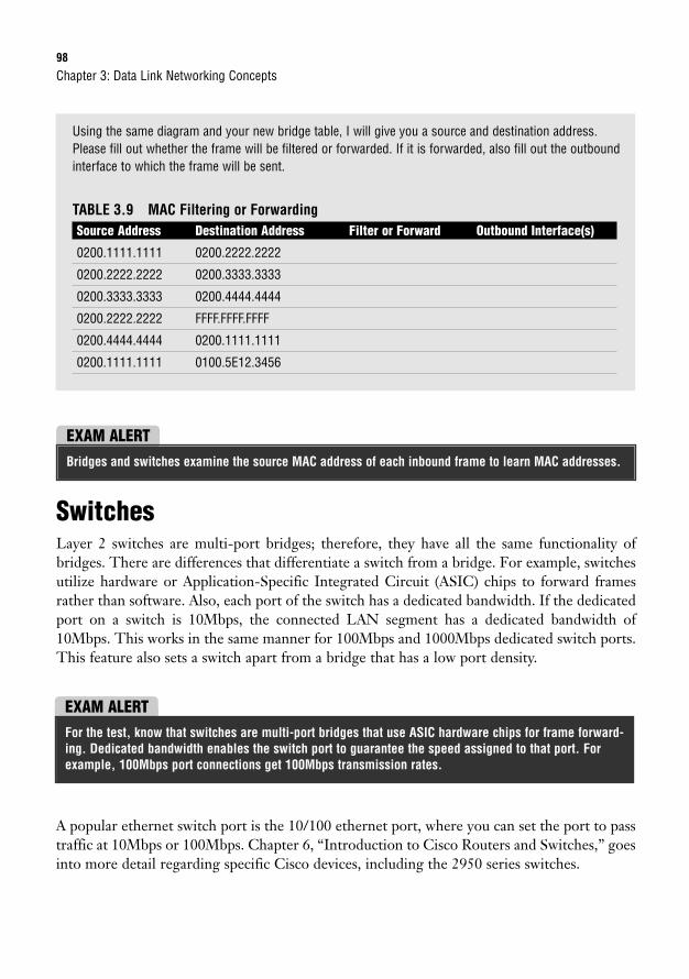
98
Using the same diagram and your new bridge table, I will give you a source and destination address.Please fill out whether the frame will be filtered or forwarded. If it is forwarded, also fill out the outboundinterface to which the frame will be sent.
TABLE 3.9 MAC Filtering or ForwardingSource Address Destination Address Filter or Forward Outbound Interface(s)
0200.1111.1111 0200.2222.2222
0200.2222.2222 0200.3333.3333
0200.3333.3333 0200.4444.4444
0200.2222.2222 FFFF.FFFF.FFFF
0200.4444.4444 0200.1111.1111
0200.1111.1111 0100.5E12.3456
Chapter 3: Data Link Networking Concepts
EXAM ALERTBridges and switches examine the source MAC address of each inbound frame to learn MAC addresses.
SwitchesLayer 2 switches are multi-port bridges; therefore, they have all the same functionality ofbridges. There are differences that differentiate a switch from a bridge. For example, switchesutilize hardware or Application-Specific Integrated Circuit (ASIC) chips to forward framesrather than software. Also, each port of the switch has a dedicated bandwidth. If the dedicatedport on a switch is 10Mbps, the connected LAN segment has a dedicated bandwidth of10Mbps. This works in the same manner for 100Mbps and 1000Mbps dedicated switch ports.This feature also sets a switch apart from a bridge that has a low port density.
EXAM ALERTFor the test, know that switches are multi-port bridges that use ASIC hardware chips for frame forward-ing. Dedicated bandwidth enables the switch port to guarantee the speed assigned to that port. Forexample, 100Mbps port connections get 100Mbps transmission rates.
A popular ethernet switch port is the 10/100 ethernet port, where you can set the port to passtraffic at 10Mbps or 100Mbps. Chapter 6, “Introduction to Cisco Routers and Switches,” goesinto more detail regarding specific Cisco devices, including the 2950 series switches.
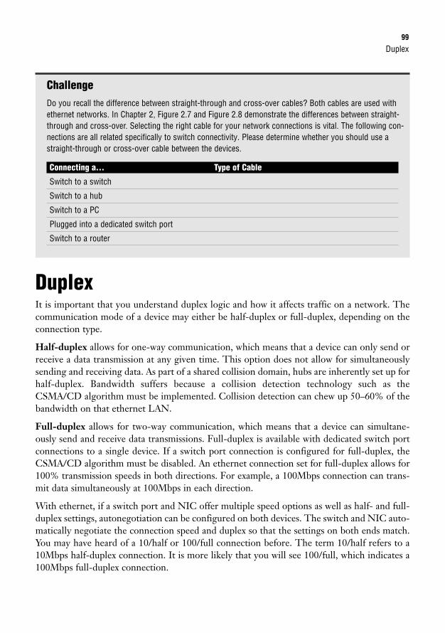
Duplex99
ChallengeDo you recall the difference between straight-through and cross-over cables? Both cables are used withethernet networks. In Chapter 2, Figure 2.7 and Figure 2.8 demonstrate the differences between straight-through and cross-over. Selecting the right cable for your network connections is vital. The following con-nections are all related specifically to switch connectivity. Please determine whether you should use astraight-through or cross-over cable between the devices.
Connecting a… Type of Cable
Switch to a switch
Switch to a hub
Switch to a PC
Plugged into a dedicated switch port
Switch to a router
DuplexIt is important that you understand duplex logic and how it affects traffic on a network. Thecommunication mode of a device may either be half-duplex or full-duplex, depending on theconnection type.
Half-duplex allows for one-way communication, which means that a device can only send orreceive a data transmission at any given time. This option does not allow for simultaneouslysending and receiving data. As part of a shared collision domain, hubs are inherently set up forhalf-duplex. Bandwidth suffers because a collision detection technology such as theCSMA/CD algorithm must be implemented. Collision detection can chew up 50–60% of thebandwidth on that ethernet LAN.
Full-duplex allows for two-way communication, which means that a device can simultane-ously send and receive data transmissions. Full-duplex is available with dedicated switch portconnections to a single device. If a switch port connection is configured for full-duplex, theCSMA/CD algorithm must be disabled. An ethernet connection set for full-duplex allows for100% transmission speeds in both directions. For example, a 100Mbps connection can trans-mit data simultaneously at 100Mbps in each direction.
With ethernet, if a switch port and NIC offer multiple speed options as well as half- and full-duplex settings, autonegotiation can be configured on both devices. The switch and NIC auto-matically negotiate the connection speed and duplex so that the settings on both ends match.You may have heard of a 10/half or 100/full connection before. The term 10/half refers to a10Mbps half-duplex connection. It is more likely that you will see 100/full, which indicates a100Mbps full-duplex connection.
100
MicrosegmentationMicrosegmentation occurs when a switch creates a dedicated path for sending and receivingtransmissions with each connected host. Each host then has a separate collision domain and adedicated bandwidth.
Chapter 3: Data Link Networking Concepts
Autonegotiation may not always be a reliable option. There have been some instances where the switchport goes into error disable mode because of massive errors. Configuring or “hard coding” the port andNIC to the appropriate speed and duplex settings may resolve the issue when the port is reactivated.
NOTE
EXAM ALERTHubs use half-duplex technology. Switches can be set up for full-duplex.
Chapter Summary101
Chapter SummaryMany important functions occur at the Data Link layer of the OSI model. Different tech-nologies can be implemented at Layer 2 to transmit data across the network. Token ring andFDDI networks use token-passing to send frames, whereas ethernet uses the 802.3 frame stan-dard with 802.2 LLC specifications. Ethernet framing and ethernet addressing are both sig-nificant topics for the CCNA exam. Other key ethernet functions include error detection andarbitration. Although the FCS field of the 802.3 frame detects errors on a LAN, theCSMA/CD algorithm arbitrates how data is transmitted on a LAN.
Data Link layer devices include bridges and switches. Switches are really multi-port bridges,so they share the same general functionalities. New networks are most likely to use a Layer 2switch in place of a bridge. Switches have been improved upon over the years and offer moreoptions for the consumer, such as dedicated bandwidth and full-duplex communications.
Although the Data Link layer uses frames to transmit data, the Network layer uses InternetProtocol or IP addresses to route traffic. Chapter 5 discusses IP addressing and subnetting atlength. Both topics are imperative for the CCNA exam.
Key Terms. token-passing
. token ring
. 802.5
. MSAU
. RI
. RO
. FDDI
. ANSI X3T9.5
. unicast
. multicast
. broadcast
. frame
. 802.2
. MAC
. LLC
. SAP
. DSAP
. SSAP
. SNAP
. 802.3
. 10BASE-2
. 10BASE-5
. 10BASE-T
. 10BASE-FL
. 802.3u
. 100BASE-T4
. 100BASE-TX
. 100BASE-FX
. 802.3ab
. 1000BASE-T
. 802.3z
. 1000BASE-CX
. 1000BASE-SX
. 1000BASE-LX
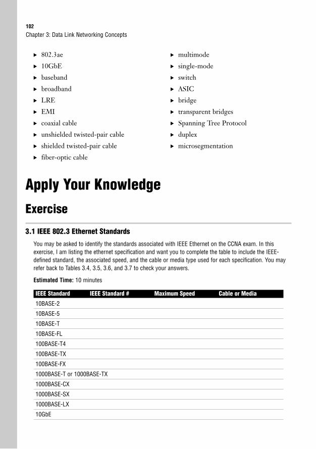
102
. 802.3ae
. 10GbE
. baseband
. broadband
. LRE
. EMI
. coaxial cable
. unshielded twisted-pair cable
. shielded twisted-pair cable
. fiber-optic cable
. multimode
. single-mode
. switch
. ASIC
. bridge
. transparent bridges
. Spanning Tree Protocol
. duplex
. microsegmentation
Chapter 3: Data Link Networking Concepts
Apply Your Knowledge
Exercise
3.1 IEEE 802.3 Ethernet Standards
You may be asked to identify the standards associated with IEEE Ethernet on the CCNA exam. In thisexercise, I am listing the ethernet specification and want you to complete the table to include the IEEE-defined standard, the associated speed, and the cable or media type used for each specification. You mayrefer back to Tables 3.4, 3.5, 3.6, and 3.7 to check your answers.
Estimated Time: 10 minutes
IEEE Standard IEEE Standard # Maximum Speed Cable or Media
10BASE-2
10BASE-5
10BASE-T
10BASE-FL
100BASE-T4
100BASE-TX
100BASE-FX
1000BASE-T or 1000BASE-TX
1000BASE-CX
1000BASE-SX
1000BASE-LX
10GbE
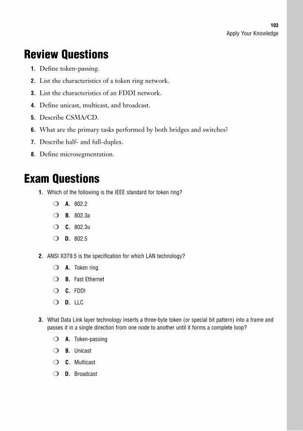
Apply Your Knowledge103
Review Questions1. Define token-passing.
2. List the characteristics of a token ring network.
3. List the characteristics of an FDDI network.
4. Define unicast, multicast, and broadcast.
5. Describe CSMA/CD.
6. What are the primary tasks performed by both bridges and switches?
7. Describe half- and full-duplex.
8. Define microsegmentation.
Exam Questions1. Which of the following is the IEEE standard for token ring?
❍ A. 802.2
❍ B. 802.3a
❍ C. 802.3u
❍ D. 802.5
2. ANSI X3T9.5 is the specification for which LAN technology?
❍ A. Token ring
❍ B. Fast Ethernet
❍ C. FDDI
❍ D. LLC
3. What Data Link layer technology inserts a three-byte token (or special bit pattern) into a frame andpasses it in a single direction from one node to another until it forms a complete loop?
❍ A. Token-passing
❍ B. Unicast
❍ C. Multicast
❍ D. Broadcast
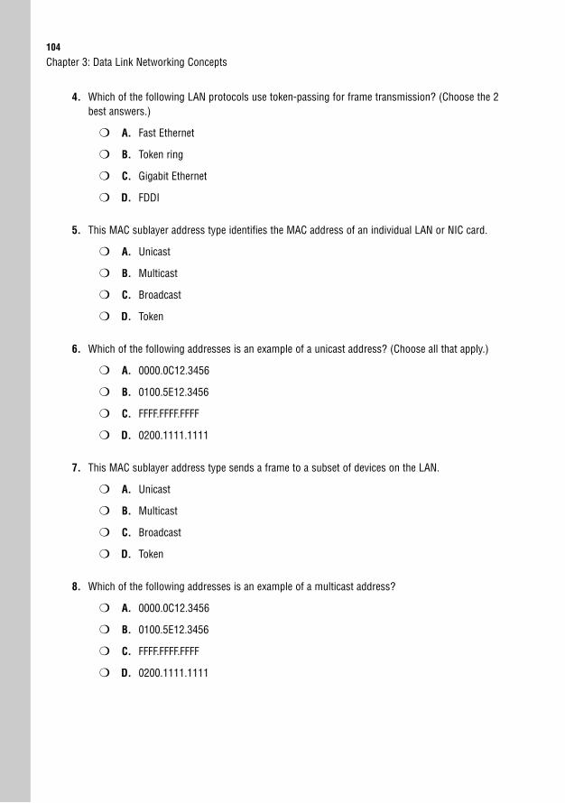
104
4. Which of the following LAN protocols use token-passing for frame transmission? (Choose the 2best answers.)
❍ A. Fast Ethernet
❍ B. Token ring
❍ C. Gigabit Ethernet
❍ D. FDDI
5. This MAC sublayer address type identifies the MAC address of an individual LAN or NIC card.
❍ A. Unicast
❍ B. Multicast
❍ C. Broadcast
❍ D. Token
6. Which of the following addresses is an example of a unicast address? (Choose all that apply.)
❍ A. 0000.0C12.3456
❍ B. 0100.5E12.3456
❍ C. FFFF.FFFF.FFFF
❍ D. 0200.1111.1111
7. This MAC sublayer address type sends a frame to a subset of devices on the LAN.
❍ A. Unicast
❍ B. Multicast
❍ C. Broadcast
❍ D. Token
8. Which of the following addresses is an example of a multicast address?
❍ A. 0000.0C12.3456
❍ B. 0100.5E12.3456
❍ C. FFFF.FFFF.FFFF
❍ D. 0200.1111.1111
Chapter 3: Data Link Networking Concepts
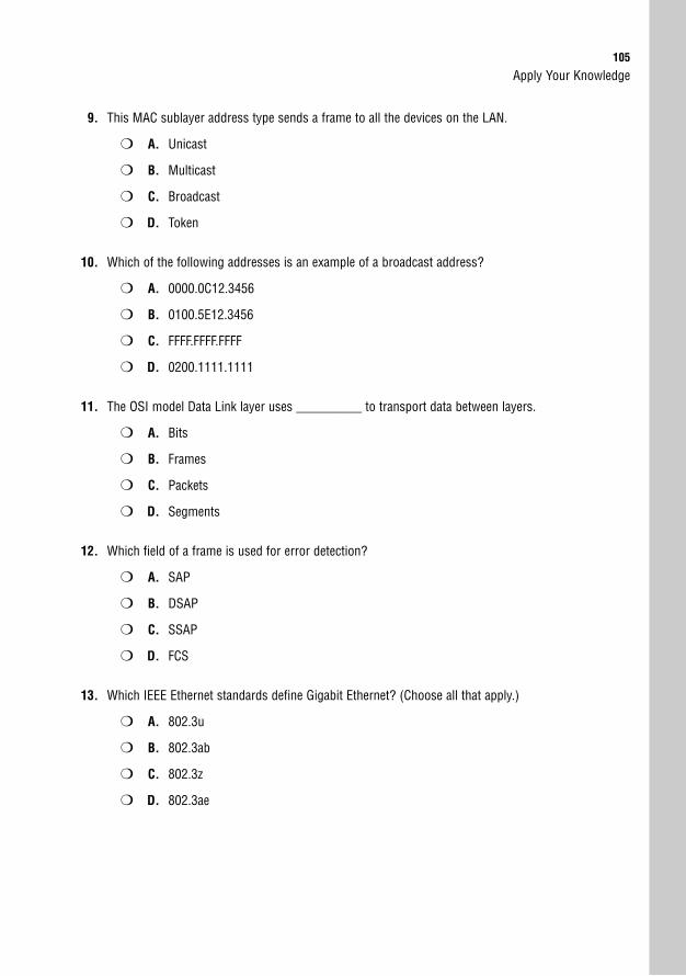
Apply Your Knowledge105
9. This MAC sublayer address type sends a frame to all the devices on the LAN.
❍ A. Unicast
❍ B. Multicast
❍ C. Broadcast
❍ D. Token
10. Which of the following addresses is an example of a broadcast address?
❍ A. 0000.0C12.3456
❍ B. 0100.5E12.3456
❍ C. FFFF.FFFF.FFFF
❍ D. 0200.1111.1111
11. The OSI model Data Link layer uses __________ to transport data between layers.
❍ A. Bits
❍ B. Frames
❍ C. Packets
❍ D. Segments
12. Which field of a frame is used for error detection?
❍ A. SAP
❍ B. DSAP
❍ C. SSAP
❍ D. FCS
13. Which IEEE Ethernet standards define Gigabit Ethernet? (Choose all that apply.)
❍ A. 802.3u
❍ B. 802.3ab
❍ C. 802.3z
❍ D. 802.3ae
106
14. Bridges and switches segment a network and create an additional _______________ domain foreach segment.
❍ A. Collision
❍ B. Broadcast
❍ C. Unicast
❍ D. Multicast
15. Bridges and switches examine the __________________ of each inbound frame to learn MACaddresses.
❍ A. Multicast MAC address
❍ B. Broadcast MAC address
❍ C. Source MAC address
❍ D. Destination MAC address
16. Which device uses ASIC hardware chips for frame forwarding?
❍ A. Hub
❍ B. Repeater
❍ C. Bridge
❍ D. Switch
17. With a 10Mbps ethernet LAN, dedicated bandwidth enables a switch port to guarantee what datatransmission speed?
❍ A. 10Mbps
❍ B. 100Mbps
❍ C. 1000Mbps
❍ D. 10,000Mbps
18. This Data Link protocol eliminates loops that are caused by redundant connections.
❍ A. CRC
❍ B. FCS
❍ C. CSMA/CD
❍ D. STP
Chapter 3: Data Link Networking Concepts
Apply Your Knowledge107
19. This communication mode allows for only one-way data transmissions at any time.
❍ A. 10Mbps
❍ B. 100Mbps
❍ C. Half-duplex
❍ D. Full-duplex
20. This communication mode allows for simultaneous two-way data transmissions.
❍ A. 10Mbps
❍ B. 100Mbps
❍ C. Half-duplex
❍ D. Full-duplex
Answers to Review Questions1. Token-passing is a Data Link protocol that inserts a three-byte token (or special bit pattern) into a
frame and passes it around the network in a single direction from one node to another until it formsa complete loop. The node that has possession of the token is the only one that can send data atany given time on that LAN. Because only one node can send data at a time, collisions are avoided.
2. Standardized by the IEEE 802.5 specification
A token-passing media access technology
Set up as a physical ring or physical star topology
Creates a logical ring topology
Speeds are assigned as either 4Mbps or 16Mbps
Utilizes an MSAU rather than a switch or hub
Provides collision-free data transfer
High overhead
3. Developed by ANSI with the ANSI X3T9.5 specification
A token-passing media access technology
Set up as a dual ring topology
Redundant, fault-tolerant network
Speed is 100Mbps
Runs over fiber-optic cable
108
Not susceptible to EMI
Provides collision-free data transfer
Fault-detection provided by beaconing
High overhead
4. A unicast address identifies the MAC address of an individual LAN or NIC card.
A multicast address forwards a frame to a subset of devices in the same LAN. IEEE ethernet multi-cast addresses always begin with 0100.5E in hexadecimal format. The last three bytes can be anycombination.
A broadcast address sends a frame to all devices in the same LAN. Broadcast addresses arealways the same value, which is FFFF.FFFF.FFFF.
5. CSMA/CD or Carrier Sense Multiple Access Collision Detection is an algorithm that sends a jamsignal to notify the devices that there has been a collision. The devices then halt transmission for arandom back-off time.
6. The primary tasks performed by both bridges and switches are as follows:
The source MAC address of every inbound frame is examined to learn its MAC address.
You can decide whether to forward or filter a frame based on the destination MAC address.
Eliminate loops that are caused by redundant connections by configuring Spanning Tree Protocol(STP).
7. Half-duplex allows for one-way communication, which means that a device can only send orreceive a data transmission at any given time. As a part of a shared collision domain, hubs mustuse half-duplex.
Full-duplex allows for two-way communication, which means that a device can simultaneouslysend and receive data transmissions. Full-duplex is available with dedicated switch port connec-tions to a single device. If a switch port connection is configured for full-duplex, the CSMA/CDalgorithm must be disabled. Also, an ethernet connection set for full-duplex allows for 100% trans-mission speeds in both directions.
8. Microsegmentation occurs when a switch creates a dedicated path for sending and receiving transmissions with each connected host. Each host then has a separate collision domain and adedicated bandwidth.
Answers to Exam Questions1. D. IEEE 802.5 defines token ring. Answers A, B, and C are incorrect because IEEE 802.2 defines
LLC, 802.3a defines ethernet, and 802.3u defines Fast Ethernet.
2. C. ANSI X3T9.5 defines FDDI. Answers A, B, and D are incorrect because they are all IEEE stan-dards. IEEE 802.5 defines token ring, 802.3u defines Fast Ethernet, and 802.2 defines LLC.
Chapter 3: Data Link Networking Concepts
Apply Your Knowledge109
3. A. Token-passing inserts a three-byte token (or special bit pattern) into a frame and passes it in asingle direction from one node to another until it forms a complete loop. Answers B, C, and D areall incorrect because unicast, multicast, and broadcast are all types of ethernet addresses.
4. B, D. Token ring and FDDI use token-passing to send frames. Answers A and C are incorrectbecause Fast Ethernet and Gigabit Ethernet both use 802.3 MAC and 802.2 LLC headers and trail-ers for framing.
5. A. Unicast addresses identify the MAC address of an individual LAN or NIC card. Answer B isincorrect because multicast addresses send a frame to a group of devices in the same LAN.Answer C is incorrect because broadcast addresses send a frame to all the devices in the sameLAN. Answer D is incorrect because a token is a special bit pattern used with token-passing networks.
6. A, D. Both 0000.0C12.3456 and 0200.1111.1111 are unicast addresses. 0000.0C is Cisco’s OUI.Answers B and C are incorrect because 0100.5E12.3456 is a multicast address and FFFF.FFFF.FFFFis a broadcast address.
7. B. Multicast addresses send a frame to a subset of devices in the same LAN. Answer A is incorrectbecause unicast addresses identify the MAC address of an individual LAN or NIC card. Answer C isincorrect because broadcast addresses send a frame to all the devices in the same LAN. Answer Dis incorrect because a token is a special bit pattern used with token-passing networks.
8. B. 0100.5E12.3456 is a multicast address. Multicast addresses always start with 0100.5E.Answers A and D are incorrect because both 0000.0C12.3456 and 0200.1111.1111 are unicastaddresses. Answer C is incorrect because FFFF.FFFF.FFFF is a broadcast address.
9. C. Broadcast addresses send a frame to all the devices in the same LAN. Answer A is incorrectbecause unicast addresses identify the MAC address of an individual LAN or NIC card. Answer B isincorrect because multicast addresses send a frame to a subset of devices in the same LAN.Answer D is incorrect because a token is a special bit pattern used with token-passing networks.
10. C. Broadcast addresses are always represented as FFFF.FFFF.FFFF. Answers A and D are incorrectbecause both 0000.0C12.3456 and 0200.1111.1111 are unicast addresses. Answer B is incorrectbecause 0100.5E12.3456 is a multicast address.
11. B. Frames are used by the Data Link layer to transport data between the Network and Physicallayer. Framing is the process of interpreting data that is either received or sent out across the net-work. Answers A, C, and D are incorrect because bits are used at the Physical layer, packets areused at the Network layer, and segments are used at the Transport layer of the OSI model.
12. D. The frame check sequence (FCS) field of a frame uses a mathematical formula to determinewhether any bit errors occurred during data transmission. Answer A is incorrect because ServiceAccess Point (SAP) identifies the upper-layer protocol such as IP. Answer B is incorrect becauseDSAP is the destination SAP or destination upper-layer protocol. Answer C is incorrect becauseSSAP is the source SAP or the source upper-layer protocol.
13. B, C. IEEE 802.3ab and 802.3z define Gigabit Ethernet standards. Answers A and D are incorrectbecause 802.3u defines the Fast Ethernet standard, and 802.3ae defines the 10 Gigabit Ethernetstandard.
110
14. A. Collision domains are increased with the addition of bridges or switches on a network. AnswerB is incorrect because routers create additional broadcast domains. Answers C and D are incorrectbecause unicast and multicast are both addresses used by ethernet.
15. C. The source MAC address of an incoming frame is examined by a bridge or switch to learn theMAC address for the bridge table. Answers A and B are incorrect because multicast and broadcastaddresses can never be the source MAC address. Answer D is incorrect because the destinationMAC address is not used by a bridge or switch to create the bridge table.
16. D. Switches use ASIC hardware chips for frame forwarding. Answers A and B are incorrectbecause hubs and repeaters do not forward frames because they are Physical layer or Layer 1devices. Answer C is incorrect because bridges use software for frame forwarding.
17. A. 10Mbps is guaranteed with dedicated bandwidth on a 10Mbps ethernet LAN. Answers B, C, andD are incorrect because other speeds of 100, 1000, and 10,000Mbps are all faster speeds thatrequire a different ethernet LAN standard.
18. D. Spanning Tree Protocol (STP) is a Data Link protocol that eliminates loops caused by redundantconnections on a LAN. Answers A and B are incorrect because cyclical redundancy check (CRC)and frame check sequence (FCS) both provide error detection. Answer C is incorrect becauseCSMA/CD is an algorithm that is used for arbitration on an ethernet network.
19. C. Half-duplex allows for only one-way data transmissions at any time. Answers A and B are incor-rect because 10Mbps and 100Mbps are speed classifications primarily associated with ethernetLANs. Answer D is incorrect because full-duplex allows for two-way data transmissions.
20. D. Full-duplex allows for simultaneous two-way data transmissions. Answers A and B are incorrectbecause 10Mbps and 100Mbps are speed classifications primarily associated with ethernet LANs.Answer C is incorrect because half-duplex allows for only one-way data transmissions at any time.
Suggested Readings and ResourcesThe following are some recommended readings for LAN networking and related terminology:
1. “TechEncyclopedia,” www.techweb.com/encyclopedia.
2. “RFC 1700,” www.isi.edu/in-notes/rfc1700.txt.
3. “Layer 1 & 2,” www.hojmark.net/layer1-2.html#lan.
4. “Cisco Long-Reach Ethernet,” www.cisco.com/warp/public/779/servpro/solutions/long_ethernet/.
5. Barnes, David and Sakandar, Basir. Cisco LAN Switching Fundamentals. Cisco Press, 2004.
Chapter 3: Data Link Networking Concepts
4C H A P T E R F O U R
General Network Security
ObjectivesThis chapter covers the following Cisco-specific objectives for the “Identify security threats to anetwork and describe general methods to mitigate those threats” section of both the 640-802CCNA and 640-822 ICND1 exams:
. Describe today’s increasing network security threats and explain the need toimplement a comprehensive security policy to mitigate the threats
. Explain general methods to mitigate common security threats to networkdevices, hosts, and applications
. Describe the functions of common security appliances and applications
. Describe security recommended practices including initial steps to securenetwork devices
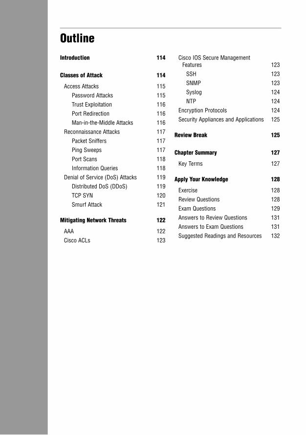
OutlineIntroduction 114
Classes of Attack 114
Access Attacks 115
Password Attacks 115
Trust Exploitation 116
Port Redirection 116
Man-in-the-Middle Attacks 116
Reconnaissance Attacks 117
Packet Sniffers 117
Ping Sweeps 117
Port Scans 118
Information Queries 118
Denial of Service (DoS) Attacks 119
Distributed DoS (DDoS) 119
TCP SYN 120
Smurf Attack 121
Mitigating Network Threats 122
AAA 122
Cisco ACLs 123
Cisco IOS Secure Management Features 123
SSH 123
SNMP 123
Syslog 124
NTP 124
Encryption Protocols 124
Security Appliances and Applications 125
Review Break 125
Chapter Summary 127
Key Terms 127
Apply Your Knowledge 128
Exercise 128
Review Questions 128
Exam Questions 129
Answers to Review Questions 131
Answers to Exam Questions 131
Suggested Readings and Resources 132

Study Strategies. Read the information presented in this chapter, paying special attention to tables, Notes,
and Exam Alerts.
. Read the objectives at the beginning of the chapter.
. Review each class of attack.
. Name the specific attacks that comprise each class.
. Describe security threat mitigation techniques.
. Familiarize yourself with the Cisco devices that assist with general network security.
. Complete the Challenges and the Exercises at the end of the chapter.
114
IntroductionInformation technology has evolved and provides countless resources for everyday people tocreate, maintain, and utilize data. If you have ever seen or read Spiderman, you have likelyheard the quote “With great power comes great responsibility.” Information is power, so it isvitally important to implement safeguards on your LAN and WAN to protect data from hack-ers. Everyone with a computer is susceptible and should be cautious with important privatedetails such as credit card information. I have worked in the networking department at sever-al types of companies, including a health-care company. Imagine if a hacker were to obtainpatient medical records or a list of social security numbers from the human resources database.A company must follow special guidelines to ensure data privacy, which ties directly to networksecurity. To make sure that companies adhere to security guidelines, annual audits are per-formed on their networks to identify potential weaknesses.
Even though network security has been a hot topic since the advent of computer networking,it is a new set of objectives on the CCENT and CCNA exams. To prepare yourself for theexams, you must know what classes of attack are common today, how to mitigate those attacks,and what features or hardware Cisco offers to assist in protecting your network. This chapterbegins with a discussion of prevalent classes of attack.
Classes of AttackObjective:
. Describe today’s increasing network security threats and explain the need to implement a comprehensivesecurity policy to mitigate the threats
Any number of motives could inspire an attacker; two motives that we touched on already arefinancial gain and gathering intelligence. A hacker may also simply enjoy the thrill of success-fully breaking into someone’s network. There are documented cases of hackers who inten-tionally attacked government systems simply to prove that it could be done and therefore gainnotoriety.
This section discusses three classes of attack that are commonly found in today’s network environment:
. Access attacks
. Reconnaissance attacks
. Denial of service (DoS) attacks
Chapter 4: General Network Security
Classes of Attack115
Each class has various more-specific subcategories of attack methods that will be covered ingreater detail.
The three common classes of attack are access, reconnaissance, and DoS.
TIP
Access AttacksAn access attack is just what it sounds like: an attempt to access another user account or net-work device through improper means. If proper security measures are not in place, the net-work may be left vulnerable to intrusion. A network administrator is responsible for ensuringthat only authorized users access the network. Unauthorized attacks are attempted via fourmeans, all of which try to bypass some facet of the authentication process: password attacks,trust exploitation, port redirection, and man-in-the-middle attacks.
The four types of access attacks are password attacks, trust exploitation, port redirection, and man-in-the-middle attacks.
TIP
Password AttacksNowadays, it seems as if you need a password for everything. I have so many passwords that Ifind it hard to keep track. Although it might sound like a good idea to keep your passwordssimple or to write them down, both practices are highly discouraged. The goal is to make itharder for someone to find or guess your password; therefore, password integrity is necessary.That being said, an attacker might attempt a login with false credentials. It is also importantto note that not all attackers are external users. Many recorded instances of attempted and/orsuccessful attacks have come from internal company employees.
There are alternatives to passwords, such as Terminal Access Controller Access ControlSystem (TACACS) or Remote Authentication Dial-In User Service (RADIUS), both of whichmanage access to network hardware. Passwords are fast becoming as obsolete as rabbit-earantennas or dialup Internet connections.
Cisco equipment is shipped from the factory with a standard configuration. When the deviceis turned on, the setup program prompts for a password and leaves all but the enable secretpassword in plain text. It is the responsibility of the recipient to update the password informa-tion before deploying the device on a network. Changing passwords every time an employeeleaves the company or in a given time period (every 90 days) would also help protect login credentials.
116
Trust ExploitationTrust exploitation can occur in one of two ways:
. Reliance on the trust a client has in a server
. Reliance on the trust the server has in the client
For example, most companies have a part of their network that lies between the wide-openInternet and the corporate internal network. This in-between part of the network is called thedemilitarized zone (DMZ). Servers that communicate from the DMZ and the internal networkmay have a trust relationship established. The internal devices may be set up to trust informa-tion that is received from a DMZ server. An attacker can then compromise the DMZ serverand initiate a connection to the internal network. This is an example of phishing. When thetrust that the server has in a client is exploited, this is an example of session hijacking.
Port RedirectionPort redirection is a form of trust exploitation in which the untrustworthy source uses amachine with access to the internal network to pass traffic through a port on the firewall oraccess control list (ACL). The port in question normally denies traffic, but with redirection theattacker can bypass security measures and open a tunnel for communication.
Man-in-the-Middle AttacksA man-in-the-middle attack happens when a hacker eavesdrops or listens for network trafficand intercepts a data transmission. After the transmission is intercepted, the untrustworthyhost can position itself between the two communicating hosts, interpret the data, and stealinformation from the packets sent. The hacker can also take over the session and reformat thepackets to send information to either or both communicating parties. In this situation it is pos-sible for the hacker to capture credentials, hijack a session, or instigate a DoS attack.
Data sessions are more vulnerable when the packets are left in clear-text format and can beread without additional decryption by the human eye. Proper data encryption, with the use ofan encryption protocol, makes the captured data useless.
ChallengeIn this challenge, write down the four types of access attacks.
1.
2.
3.
4.
Chapter 4: General Network Security
Classes of Attack117
Reconnaissance AttacksWhen I hear the word reconnaissance, I think of a military reconnaissance mission. The sol-dier is sent out to gather important information about an area of interest. The same holds truefor a reconnaissance attack on a computer network. The hacker surveys a network and collectsdata for a future attack. Important information that can be compiled during a reconnaissanceattack includes the following:
. Ports open on a server
. Ports open on a firewall
. IP addresses on the host network
. Hostnames associated with the IP addresses
As with access attacks, there are four main subcategories or methods for gathering networkdata:
. Packet sniffers (also known as network monitors)
. Ping sweeps
. Port scans
. Information queries
The four common tools used for reconnaissance attacks are packet sniffers, ping sweeps, port scans, andinformation queries.
TIP
Packet SniffersA packet sniffer may also be called a network analyzer, packet analyzer, or Ethernet sniffer.The packet sniffer may be either a software program or a piece of hardware with softwareinstalled in it that captures traffic sent over the network, which is then decoded and analyzedby the sniffer. Network administrators install monitors on dedicated machines or on theirworkstations when needed. A common software program available today is Wireshark, for-merly known as Ethereal.
Ping SweepsAs you may recall, ping enables you to validate that an IP address exists and can accept requestsby sending an echo request and then waiting for an echo reply. A ping sweep tool can send anecho request to numerous host IP addresses at the same time to see which host(s) respond(s)with an echo reply.
118
Port ScansA port scanner is a software program that surveys a host network for open ports. Because portsare associated with applications, the hacker can use the port and application information todetermine a way to attack the network. As mentioned, these programs can be used by a thirdparty to audit a network as well as being used by a hacker for malicious intent.
As mentioned in Chapter 1, it is extremely important that you know the prevalent applicationsand their matching port numbers. Table 4.1 reviews the applications that use TCP, and Table4.2 reviews UDP-based applications.
TABLE 4.1 Applications Using TCPApplication Port Number(s)
FTP 20, 21
Telnet 23
SMTP 25
DNS (zone transfers) 53
HTTP 80
POP3 110
NNTP 119
HTTPS 443
TABLE 4.2 Applications Using UDPApplication Port Number(s)
DHCP 67, 68
DNS (name resolution) 53
TFTP 69
NTP 123
SNMP 161
Information QueriesInformation queries can be sent via the Internet to resolve hostnames from IP addresses or viceversa. One of the most commonly used queries is nslookup. You can use nslookup by openinga Windows or Linux command prompt (CMD) window on your computer and enteringnslookup followed by the IP address or hostname that you are attempting to resolve.
Chapter 4: General Network Security
Refer to Chapter 1, “Standard Internetworking Models,” for a review of ping, which uses ICMP.
NOTE
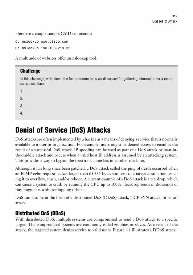
Classes of Attack119
Here are a couple sample CMD commands:
C: nslookup www.cisco.com
C: nslookup 198.133.219.25
A multitude of websites offer an nslookup tool.
ChallengeIn this challenge, write down the four common tools we discussed for gathering information for a recon-naissance attack.
1.
2.
3.
4.
Denial of Service (DoS) AttacksDoS attacks are often implemented by a hacker as a means of denying a service that is normallyavailable to a user or organization. For example, users might be denied access to email as theresult of a successful DoS attack. IP spoofing can be used as part of a DoS attack or man-in-the-middle attack and occurs when a valid host IP address is assumed by an attacking system.This provides a way to bypass the trust a machine has in another machine.
Although it has long since been patched, a DoS attack called the ping of death occurred whenan ICMP echo request packet larger than 65,535 bytes was sent to a target destination, caus-ing it to overflow, crash, and/or reboot. A current example of a DoS attack is a teardrop, whichcan cause a system to crash by running the CPU up to 100%. Teardrop sends in thousands oftiny fragments with overlapping offsets.
DoS can also be in the form of a distributed DoS (DDoS) attack, TCP SYN attack, or smurfattack.
Distributed DoS (DDoS)With distributed DoS, multiple systems are compromised to send a DoS attack to a specifictarget. The compromised systems are commonly called zombies or slaves. As a result of theattack, the targeted system denies service to valid users. Figure 4.1 illustrates a DDoS attack.
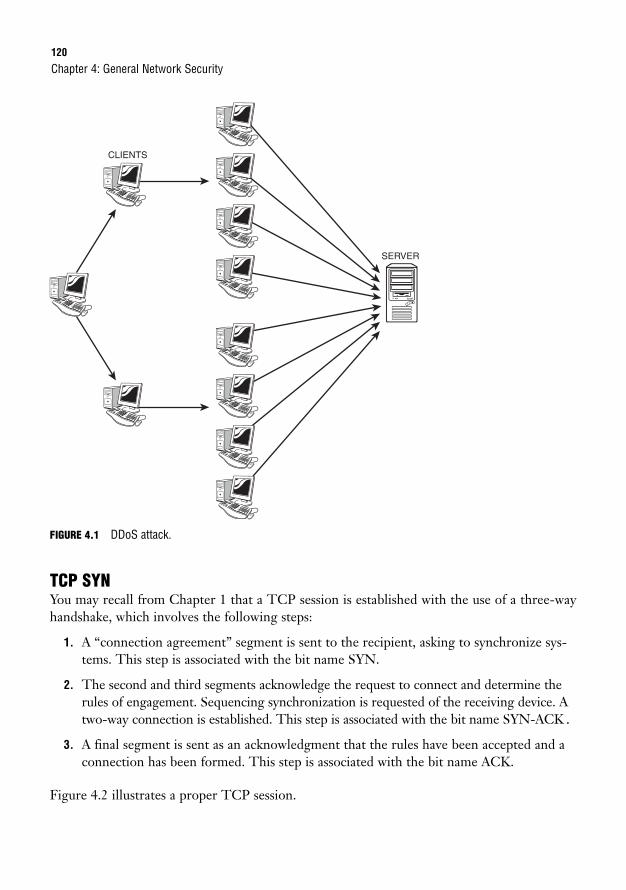
120
FIGURE 4.1 DDoS attack.
TCP SYNYou may recall from Chapter 1 that a TCP session is established with the use of a three-wayhandshake, which involves the following steps:
1. A “connection agreement” segment is sent to the recipient, asking to synchronize sys-tems. This step is associated with the bit name SYN.
2. The second and third segments acknowledge the request to connect and determine therules of engagement. Sequencing synchronization is requested of the receiving device. Atwo-way connection is established. This step is associated with the bit name SYN-ACK.
3. A final segment is sent as an acknowledgment that the rules have been accepted and aconnection has been formed. This step is associated with the bit name ACK.
Figure 4.2 illustrates a proper TCP session.
Chapter 4: General Network Security
CLIENTS
SERVER
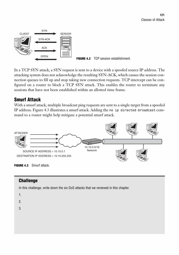
Classes of Attack121
In a TCP SYN attack, a SYN request is sent to a device with a spoofed source IP address. Theattacking system does not acknowledge the resulting SYN-ACK, which causes the session con-nection queues to fill up and stop taking new connection requests. TCP intercept can be con-figured on a router to block a TCP SYN attack. This enables the router to terminate anysessions that have not been established within an allotted time frame.
Smurf AttackWith a smurf attack, multiple broadcast ping requests are sent to a single target from a spoofedIP address. Figure 4.3 illustrates a smurf attack. Adding the no ip directed-broadcast com-mand to a router might help mitigate a potential smurf attack.
CLIENT SERVERSYN
SYN-ACK
ACK
OPENFIGURE 4.2 TCP session establishment.
ATTACKER
SOURCE IP ADDRESS = 10.10.0.1
DESTINATION IP ADDRESS = 10.10.255.255
10.10.0.0/16Network
FIGURE 4.3 Smurf attack.
ChallengeIn this challenge, write down the six DoS attacks that we reviewed in this chapter.
1.
2.
3.
122
Mitigating Network ThreatsObjectives:
. Explain general methods to mitigate common security threats to network devices, hosts, and applications
. Describe the functions of common security appliances and applications
. Describe security recommended practices including initial steps to secure network devices
By definition, to mitigate is to lessen in force or intensity. Now that you are familiar with thevarious classes of attack, let’s discuss what actions you can take to lessen the impact of an attackon a network. Keep in mind that we already went over some common mitigation techniques,such as password integrity, password encryption, TCP intercept, and no ip directed-broad-
cast. We will continue this chapter with a general overview of additional recommended prac-tices and security measures. Our discussion includes the following mitigation techniques:
. Authentication, Authorization, and Accounting (AAA)
. Cisco access control lists (ACLs)
. Cisco Internetwork Operating System (IOS) secure management features
. Encryption protocols
. Security appliances and applications
AAACommonly called “triple A,” AAA is a group of three services that are used to increase networksecurity:
. Authentication: Identifies a user by login and password.
. Authorization: Determines what a user is allowed to do.
. Accounting: Assembles and sends usage information (such as logging).
AAA works in conjunction with TACACS or RADIUS to provide a secure network connec-tion with a record of user activities.
Chapter 4: General Network Security
Mitigating Network Threats123
Cisco ACLsAn access list is an ordered list of permit and deny statements that can be applied on a Ciscodevice to effectively determine whether a packet will be permitted or denied access to the net-work. A properly configured access list can help block most of the attack methods described inthis chapter:
. IP spoofing
. TCP SYN attacks
. Smurf attacks
. ICMP and traceroute
Chapter 19, “Using Cisco Access Lists,” provides a detailed explanation of ACLs and their functionality.
NOTE
Cisco IOS Secure Management FeaturesI mentioned earlier that it is the responsibility of the network administrator to configure Ciscoequipment with a new password before deployment. You can take this a step further by per-forming some initial steps to secure Cisco equipment within the IOS. Configuring the fol-lowing features on your Cisco device helps create a secure network environment:
. Secure Shell (SSH)
. Simple Network Management Protocol (SNMP)
. Syslog
. Network Time Protocol (NTP)
SSHSSH is a data transmission protocol that uses strong authentication and an encrypted tunnelto ensure secure communications between an SSH client and the SSH server. SSH uses TCPport number 22 for connectivity.
SNMPSNMP is a management protocol that monitors the network and manages configurations bycollecting statistics to analyze network performance and ensure network security. It is best touse SNMP version 3, which provides cryptographic authentication and management trafficencryption. SNMP uses UDP port number 161 for connectivity.
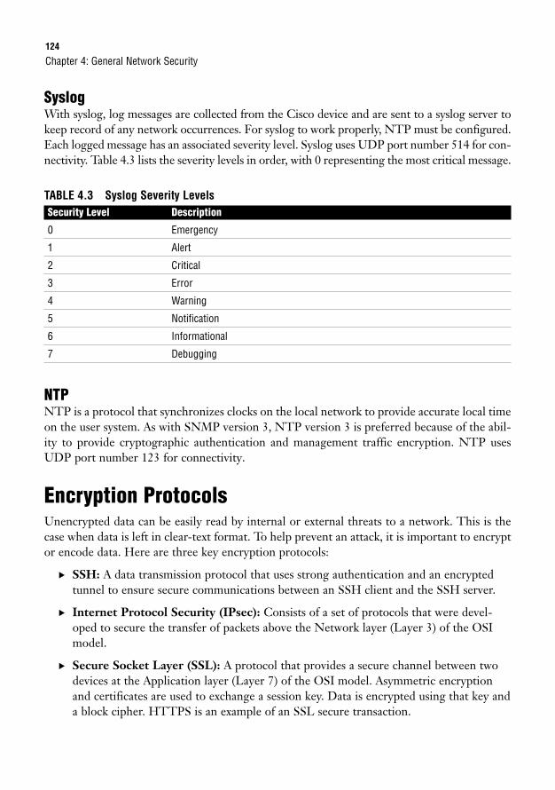
124
SyslogWith syslog, log messages are collected from the Cisco device and are sent to a syslog server tokeep record of any network occurrences. For syslog to work properly, NTP must be configured.Each logged message has an associated severity level. Syslog uses UDP port number 514 for con-nectivity. Table 4.3 lists the severity levels in order, with 0 representing the most critical message.
TABLE 4.3 Syslog Severity LevelsSecurity Level Description
0 Emergency
1 Alert
2 Critical
3 Error
4 Warning
5 Notification
6 Informational
7 Debugging
NTPNTP is a protocol that synchronizes clocks on the local network to provide accurate local timeon the user system. As with SNMP version 3, NTP version 3 is preferred because of the abil-ity to provide cryptographic authentication and management traffic encryption. NTP usesUDP port number 123 for connectivity.
Encryption ProtocolsUnencrypted data can be easily read by internal or external threats to a network. This is thecase when data is left in clear-text format. To help prevent an attack, it is important to encryptor encode data. Here are three key encryption protocols:
. SSH: A data transmission protocol that uses strong authentication and an encryptedtunnel to ensure secure communications between an SSH client and the SSH server.
. Internet Protocol Security (IPsec): Consists of a set of protocols that were devel-oped to secure the transfer of packets above the Network layer (Layer 3) of the OSImodel.
. Secure Socket Layer (SSL): A protocol that provides a secure channel between twodevices at the Application layer (Layer 7) of the OSI model. Asymmetric encryptionand certificates are used to exchange a session key. Data is encrypted using that key anda block cipher. HTTPS is an example of an SSL secure transaction.
Chapter 4: General Network Security
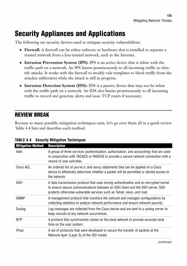
Mitigating Network Threats125
Security Appliances and ApplicationsThe following are security devices used to mitigate security vulnerabilities:
. Firewall: A firewall can be either software or hardware that is installed to separate atrusted network from a less-trusted network, such as the Internet.
. Intrusion Prevention System (IPS): IPS is an active device that is inline with thetraffic path on a network. An IPS listens promiscuously to all incoming traffic to iden-tify attacks. It works with the firewall to modify rule templates to block traffic from theattacker address(es) while the attack is still in progress.
. Intrusion Detection System (IDS): IDS is a passive device that may not be inlinewith the traffic path on a network. An IDS also listens promiscuously to all incomingtraffic to record and generate alerts and issue TCP resets if necessary.
REVIEW BREAKBecause so many possible mitigation techniques exist, let’s go over them all in a quick review.Table 4.4 lists and describes each method.
TABLE 4.4 Security Mitigation TechniquesMitigation Method Description
AAA A group of three services (authentication, authorization, and accounting) that are usedin conjunction with TACACS or RADIUS to provide a secure network connection with arecord of user activities.
Cisco ACL An ordered list of permit and deny statements that can be applied on a Ciscodevice to effectively determine whether a packet will be permitted or denied access tothe network.
SSH A data transmission protocol that uses strong authentication and an encrypted tunnelto ensure secure communications between an SSH client and the SSH server. SSHprotects otherwise-vulnerable services such as Telnet, news, and mail.
SNMP A management protocol that monitors the network and manages configurations bycollecting statistics to analyze network performance and ensure network security.
Syslog Log messages are collected from the Cisco device and are sent to a syslog server tokeep records of any network occurrences.
NTP A protocol that synchronizes clocks on the local network to provide accurate localtime on the user system.
IPsec A set of protocols that were developed to secure the transfer of packets at theNetwork layer (Layer 3) of the OSI model.
(continues)
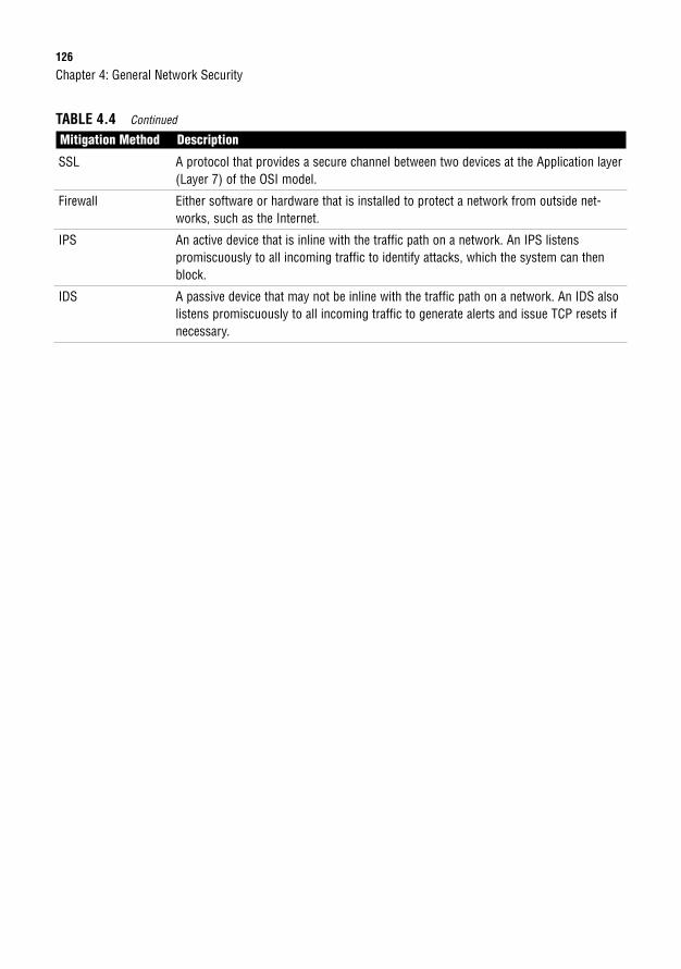
126
SSL A protocol that provides a secure channel between two devices at the Application layer(Layer 7) of the OSI model.
Firewall Either software or hardware that is installed to protect a network from outside net-works, such as the Internet.
IPS An active device that is inline with the traffic path on a network. An IPS listenspromiscuously to all incoming traffic to identify attacks, which the system can thenblock.
IDS A passive device that may not be inline with the traffic path on a network. An IDS alsolistens promiscuously to all incoming traffic to generate alerts and issue TCP resets ifnecessary.
Chapter 4: General Network Security
TABLE 4.4 Continued
Mitigation Method Description
Chapter Summary127
Chapter SummaryAfter reading through this chapter, you should have a general understanding of the types ofsecurity threats that are prevalent in our high-tech, information-driven society and variousways to mitigate those threats. A responsible network administrator must be aware of thesepossible attacks to protect the network from any form of security breach. Cisco offers built-insecurity management features that can be configured before the equipment is installed on thelocal network. It is also possible to purchase additional hardware and software to enhance over-all security. The Cisco catalog includes IOS versions of firewall, IPS, IPsec VPN, and SSLVPN. You also have a variety of network security appliances to choose from, depending on thesize and needs of your particular company.
Key Terms. Access attack
. Reconnaissance attack
. Denial of service (DoS) attack
. Password attack
. Trust exploitation
. Port redirection
. Man-in-the-middle attack
. Packet sniffer
. Port scan
. Ping sweep
. Information query
. IP spoofing
. Ping of death
. Teardrop attack
. Distributed DoS attack
. TCP SYN attack
. Smurf attack
. Authentication, Authorization, andAccounting (AAA)
. Access control list (ACL)
. Secure Shell (SSH)
. Simple Network ManagementProtocol (SNMP)
. SYSLOG
. Network Time Protocol (NTP)
. Internet Protocol Security (IPsec)
. Secure Socket Layer (SSL)
. Firewall
. Intrusion Prevention System (IPS)
. Intrusion Detection System (IDS)

128
Chapter 4: General Network Security
Apply Your Knowledge
Exercise
4.1 Mitigation Methods
Based on the Cisco-provided exam objectives, you may need to “explain general methods to mitigatecommon security threats to network devices, hosts, and applications” on the CCNA exam. In this exer-cise, list the eleven mitigation methods that were covered in this chapter, and write a brief description ofeach one. You may refer to Table 4.4 to check your answers.
Estimated Time: 20 minutes
1. ___________ _______________________________________________
2. ___________ _______________________________________________
3. ___________ _______________________________________________
4. ___________ _______________________________________________
5. ___________ _______________________________________________
6. ___________ _______________________________________________
7. ___________ _______________________________________________
8. ___________ _______________________________________________
9. ___________ _______________________________________________
10. __________ _______________________________________________
11. __________ _______________________________________________
Review Questions1. Define trust exploitation.
2. Describe a TCP SYN attack.
3. What are the three services that make up AAA?
4. What can a Cisco ACL help mitigate?
5. List the similarities and differences between an IPS and IDS.
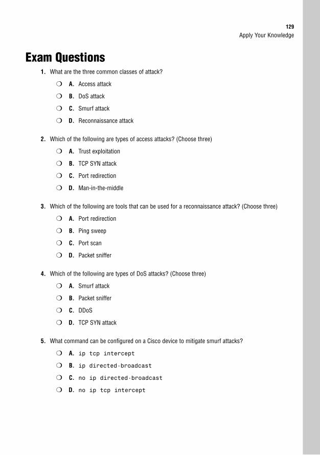
129
Apply Your Knowledge
Exam Questions1. What are the three common classes of attack?
❍ A. Access attack
❍ B. DoS attack
❍ C. Smurf attack
❍ D. Reconnaissance attack
2. Which of the following are types of access attacks? (Choose three)
❍ A. Trust exploitation
❍ B. TCP SYN attack
❍ C. Port redirection
❍ D. Man-in-the-middle
3. Which of the following are tools that can be used for a reconnaissance attack? (Choose three)
❍ A. Port redirection
❍ B. Ping sweep
❍ C. Port scan
❍ D. Packet sniffer
4. Which of the following are types of DoS attacks? (Choose three)
❍ A. Smurf attack
❍ B. Packet sniffer
❍ C. DDoS
❍ D. TCP SYN attack
5. What command can be configured on a Cisco device to mitigate smurf attacks?
❍ A. ip tcp intercept
❍ B. ip directed-broadcast
❍ C. no ip directed-broadcast
❍ D. no ip tcp intercept
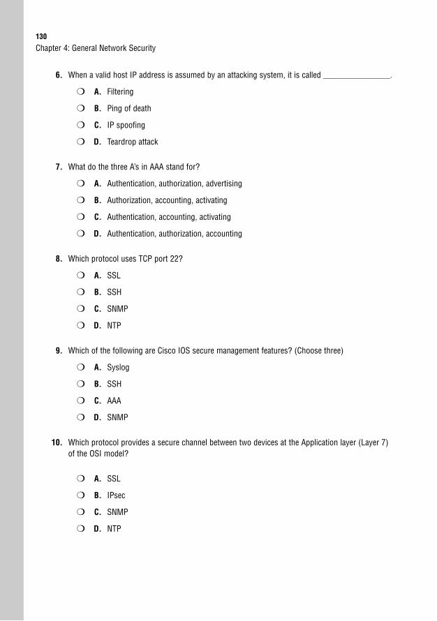
130
6. When a valid host IP address is assumed by an attacking system, it is called ________________.
❍ A. Filtering
❍ B. Ping of death
❍ C. IP spoofing
❍ D. Teardrop attack
7. What do the three A’s in AAA stand for?
❍ A. Authentication, authorization, advertising
❍ B. Authorization, accounting, activating
❍ C. Authentication, accounting, activating
❍ D. Authentication, authorization, accounting
8. Which protocol uses TCP port 22?
❍ A. SSL
❍ B. SSH
❍ C. SNMP
❍ D. NTP
9. Which of the following are Cisco IOS secure management features? (Choose three)
❍ A. Syslog
❍ B. SSH
❍ C. AAA
❍ D. SNMP
10. Which protocol provides a secure channel between two devices at the Application layer (Layer 7)of the OSI model?
❍ A. SSL
❍ B. IPsec
❍ C. SNMP
❍ D. NTP
Chapter 4: General Network Security
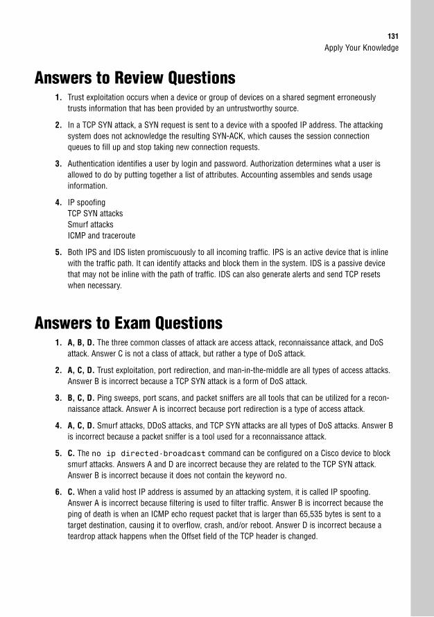
Apply Your Knowledge131
Answers to Review Questions1. Trust exploitation occurs when a device or group of devices on a shared segment erroneously
trusts information that has been provided by an untrustworthy source.
2. In a TCP SYN attack, a SYN request is sent to a device with a spoofed IP address. The attackingsystem does not acknowledge the resulting SYN-ACK, which causes the session connectionqueues to fill up and stop taking new connection requests.
3. Authentication identifies a user by login and password. Authorization determines what a user isallowed to do by putting together a list of attributes. Accounting assembles and sends usage information.
4. IP spoofingTCP SYN attacksSmurf attacksICMP and traceroute
5. Both IPS and IDS listen promiscuously to all incoming traffic. IPS is an active device that is inlinewith the traffic path. It can identify attacks and block them in the system. IDS is a passive devicethat may not be inline with the path of traffic. IDS can also generate alerts and send TCP resetswhen necessary.
Answers to Exam Questions1. A, B, D. The three common classes of attack are access attack, reconnaissance attack, and DoS
attack. Answer C is not a class of attack, but rather a type of DoS attack.
2. A, C, D. Trust exploitation, port redirection, and man-in-the-middle are all types of access attacks.Answer B is incorrect because a TCP SYN attack is a form of DoS attack.
3. B, C, D. Ping sweeps, port scans, and packet sniffers are all tools that can be utilized for a recon-naissance attack. Answer A is incorrect because port redirection is a type of access attack.
4. A, C, D. Smurf attacks, DDoS attacks, and TCP SYN attacks are all types of DoS attacks. Answer Bis incorrect because a packet sniffer is a tool used for a reconnaissance attack.
5. C. The no ip directed-broadcast command can be configured on a Cisco device to blocksmurf attacks. Answers A and D are incorrect because they are related to the TCP SYN attack.Answer B is incorrect because it does not contain the keyword no.
6. C. When a valid host IP address is assumed by an attacking system, it is called IP spoofing.Answer A is incorrect because filtering is used to filter traffic. Answer B is incorrect because theping of death is when an ICMP echo request packet that is larger than 65,535 bytes is sent to atarget destination, causing it to overflow, crash, and/or reboot. Answer D is incorrect because ateardrop attack happens when the Offset field of the TCP header is changed.
132
7. D. AAA stands for authentication, authorization, and accounting. Answer A is incorrect becauseadvertising is not a service of AAA. Answers B and C are incorrect because activating is not a service of AAA.
8. B. SSH uses TCP port 22. Answer A is incorrect because SSL uses TCP port 443. Answer C isincorrect because SNMP uses UDP port 161. Answer D is incorrect because NTP uses UDP port 123.
9. A, B, D. Syslog, SSH, and SNMP are all Cisco IOS secure management features. Answer C isincorrect because AAA consists of a group of three services that are used in conjunction with anauthentication server and a software service such as TACACS or RADIUS to provide a secure net-work connection with a record of user activities.
10. A. SSL is a protocol that provides a secure channel between two devices at the Application layer(Layer 7) of the OSI model. Answer B is incorrect because IPsec functions at Layer 3 of the OSImodel. Answer C is incorrect because SNMP is a management protocol that monitors the networkand manages configurations. Answer D is incorrect because NTP is a protocol that synchronizesclocks on the local network to provide accurate local time on the user system.
Suggested Readings and Resources1. “A Beginner’s Guide to Network Security,”
http://www.cisco.com/warp/public/cc/so/neso/sqso/beggu_pl.pdf
2. List of Cisco Security products,http://www.cisco.com/en/US/products/hw/vpndevc/index.html
Chapter 4: General Network Security
5C H A P T E R F I V E
IP at the Network Layer
ObjectivesThis chapter covers the following Cisco-specific objectives for the “Implement an IP address-ing scheme and IP Services to meet network requirements in a medium-size Enterprise branchoffice network” section of the 640-802 CCNA exam:
. Describe the operation and benefits of using private and public addressing
. Calculate and apply an addressing scheme including VLSM IP addressingdesign to a network
. Determine the appropriate classless addressing scheme using VLSM andsummarization to satisfy addressing requirements in a LAN/WAN environment
. Describe the technological requirements for running IPv6 in conjunction withIPv4 (including: protocols, dual stack, tunneling, etc.)
. Describe IPv6 addresses
OutlineIntroduction 136
Network Layer Functions 136
IP Addressing and Formats 137
Binary 137
Converting Binary to Decimal 138
Converting Decimal to Binary 141
Hexadecimal 142
Converting Decimal to Hexadecimal 142
IP Address Classes 143
Subnet Masks 146
Private (RFC 1918) Addressing 148
Subnetting IP 149
Calculating Hosts in a Subnet 152
Calculating Networks in a Subnet 153
Zero Subnet Rule 155
The Increment 155
Determining the Range of Valid IPs 158
IPv6 159
IPv6 Communications 160
IPv6 Address Format 160
Types of IPv6 Addresses 161
Link-Local Address 161
Unique/Site-Local Address 162
Global Address 162
Multicast Address 163
Autoconfiguration 164
Integrating IPv4 and IPv6 164
ICMPv6 165
Network Layer Devices 165
Routers 165
Layer 3 Switches 168
Chapter Summary 169
Key Terms 169
Apply Your Knowledge 170
Exercises 170
Review Questions 173
Exam Questions 173
Answers to Review Questions 178
Answers to Exam Questions 180
Suggested Readings and Resources 182

Study Strategies. List the characteristics of IPv4.
. Make sure you know how to convert binary to decimal.
. Make sure you know how to convert decimal to binary.
. Make sure you know how to convert decimal to hexadecimal.
. Identify IP address classes, including their networks and hosts, and the IP range value ofthe first octet of each class.
. Define subnet masks and the IP subnet mask format.
. Describe CIDR notations and how to determine the CIDR notation based on the subnetmask.
. Define RFC 1918, NAT, and PAT.
. Make sure you know how to calculate hosts and networks in a subnet.
. Determine the Network ID, Broadcast IP, and valid IP range of a subnet.
. Name the devices that are used at the Network layer and important traits of each device.
136
IntroductionThis chapter elaborates on the fundamental concepts that you learned about the Networklayer or Layer 3 of the OSI model in Chapter 1, “Standard Internetworking Models.” Itreviews the primary functions of the Network layer and then moves right into IP addressingand formats. After you are familiar with address formats and how to convert between them, itreviews subnetting. No matter whether you decide to take the one- or two-test approach tothe CCNA certification, you have to know IP address formats and subnetting. They are inte-gral concepts to any Cisco certification. Finally, this chapter discusses network devices that areused at the Network layer, which are routers and Layer 3 switches.
Network Layer FunctionsThe Network layer of the OSI model serves two primary functions:
. Determines the best path selection for a packet based on a logical or virtual address onthe network (routing)
. Handles ICMP, ARP, and Proxy ARP requests
First, best path determination is made at the Network layer for packet delivery across the net-work. Routed protocols such as IP are used to define logical addressing, which can identify thedestination of a packet or datagram. Logical addresses used for routing consist of network andhost bits. Routers also must determine the path through the internetwork for packet trans-mission. This is similar to how switches use a MAC address and interface for frame delivery.Routers also use an interface along with the logical or IP address.
Second, the Network layer also handles ICMP, ARP, and Proxy ARP requests on the inter-network. Remember the function of each protocol for the CCNA exam.
Internet Control Messaging Protocol (ICMP) is used by ping and traceroute utilities. PacketInternet Groper (ping) enables you to validate that an IP address exists and can accept requests.
. Ping is an echo and the response is an echo response.
. Routers send Destination Unreachable messages when they can’t reach the destinationnetwork and they are forced to drop the packet. The router that drops the packet sendsthe ICMP DU message.
A traceroute traces the route or path taken from a client to a remote host. Traceroute alsoreports the IP addresses of the routers at each next hop on the way to the destination. This isespecially useful when you suspect that a router on the route to an unreachable network isresponsible for dropping the packet.
Chapter 5: IP at the Network Layer
IP Addressing and Formats137
Address Resolution Protocol (ARP) maps a known IP address to a MAC address by sending abroadcast ARP. When the destination IP address is on another subnet, the sender broadcastsARP for the router’s Ethernet port or default gateway, so the MAC address sent back will bethat of the router’s Ethernet port.
Reverse ARP (RARP) maps a known MAC address to an IP address.
Proxy ARP enables a router to respond to an ARP request that has been sent to a remote host.Some Unix machines (especially Solaris) rely on Proxy ARP versus default gateways.
IP Addressing and FormatsInternet Protocol (IP) uses logical or virtual addressing to get a packet from a source to its des-tination. At the Network layer, routers use IP addresses to make best path forwarding deci-sions. Public IP addresses are used for packets destined for the outside world, whereas privateaddresses can be used if the packet needs to traverse only an internal network. The CCNAcourse focuses on IP version 4 (IPv4). The addresses themselves are assigned by the InternetAssigned Numbers Authority (IANA) to individual organizations based on a request for IPaddress space. Because the total number of IPv4 addresses is not infinite, strict guidelines areplaced on IP space requests to ensure that they are justifiable.
IPv4 addresses
. Consist of 32 bits.
. Are broken into four octets (8 bits each).
. Use dotted-decimal format, such as 172.16.122.204.
. Have a minimum value (per octet) of 0 and a maximum value of 255.
. Have a Network ID of 0.0.0.0.
. Have a Broadcast IP of 255.255.255.255.
Another IP version was created in the event that the IP space from IPv4 is exhausted. That ver-sion is called IP version 6 (IPv6). IPv6 has emerged in the Cisco professional-level exams andmay appear on a future CCNA exam. For this reason, IPv6 is introduced later in this chapter.
BinaryTo understand IP addressing, you must first understand binary. Binary is a computer languagethat is represented by a bit value of 0 or 1. A 32-bit binary address would resemble10101010101010101010101010101010. Those 32 bits can be grouped into four octets, or
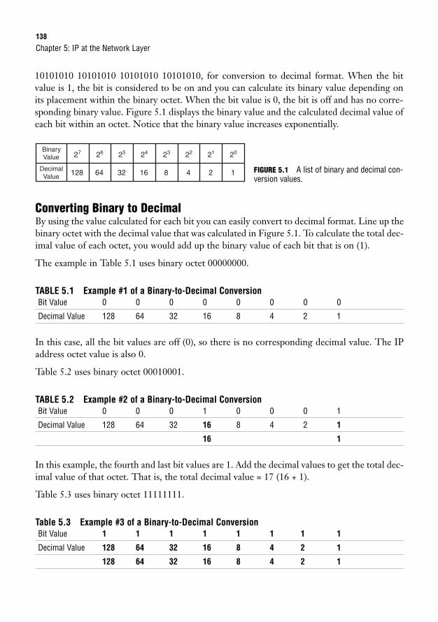
138
10101010 10101010 10101010 10101010, for conversion to decimal format. When the bitvalue is 1, the bit is considered to be on and you can calculate its binary value depending onits placement within the binary octet. When the bit value is 0, the bit is off and has no corre-sponding binary value. Figure 5.1 displays the binary value and the calculated decimal value ofeach bit within an octet. Notice that the binary value increases exponentially.
Chapter 5: IP at the Network Layer
Binary Value
DecimalValue
27
128
26
64
25
32
24
16
23
8
22
4
21
2
20
1 FIGURE 5.1 A list of binary and decimal con-version values.
Converting Binary to DecimalBy using the value calculated for each bit you can easily convert to decimal format. Line up thebinary octet with the decimal value that was calculated in Figure 5.1. To calculate the total dec-imal value of each octet, you would add up the binary value of each bit that is on (1).
The example in Table 5.1 uses binary octet 00000000.
TABLE 5.1 Example #1 of a Binary-to-Decimal ConversionBit Value 0 0 0 0 0 0 0 0
Decimal Value 128 64 32 16 8 4 2 1
In this case, all the bit values are off (0), so there is no corresponding decimal value. The IPaddress octet value is also 0.
Table 5.2 uses binary octet 00010001.
TABLE 5.2 Example #2 of a Binary-to-Decimal ConversionBit Value 0 0 0 1 0 0 0 1
Decimal Value 128 64 32 16 8 4 2 1
16 1
In this example, the fourth and last bit values are 1. Add the decimal values to get the total dec-imal value of that octet. That is, the total decimal value = 17 (16 + 1).
Table 5.3 uses binary octet 11111111.
Table 5.3 Example #3 of a Binary-to-Decimal ConversionBit Value 1 1 1 1 1 1 1 1
Decimal Value 128 64 32 16 8 4 2 1
128 64 32 16 8 4 2 1
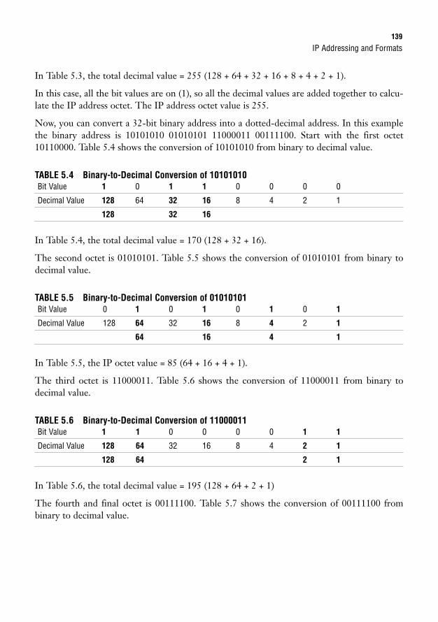
IP Addressing and Formats139
In Table 5.3, the total decimal value = 255 (128 + 64 + 32 + 16 + 8 + 4 + 2 + 1).
In this case, all the bit values are on (1), so all the decimal values are added together to calcu-late the IP address octet. The IP address octet value is 255.
Now, you can convert a 32-bit binary address into a dotted-decimal address. In this examplethe binary address is 10101010 01010101 11000011 00111100. Start with the first octet10110000. Table 5.4 shows the conversion of 10101010 from binary to decimal value.
TABLE 5.4 Binary-to-Decimal Conversion of 10101010Bit Value 1 0 1 1 0 0 0 0
Decimal Value 128 64 32 16 8 4 2 1
128 32 16
In Table 5.4, the total decimal value = 170 (128 + 32 + 16).
The second octet is 01010101. Table 5.5 shows the conversion of 01010101 from binary todecimal value.
TABLE 5.5 Binary-to-Decimal Conversion of 01010101Bit Value 0 1 0 1 0 1 0 1
Decimal Value 128 64 32 16 8 4 2 1
64 16 4 1
In Table 5.5, the IP octet value = 85 (64 + 16 + 4 + 1).
The third octet is 11000011. Table 5.6 shows the conversion of 11000011 from binary to decimal value.
TABLE 5.6 Binary-to-Decimal Conversion of 11000011Bit Value 1 1 0 0 0 0 1 1
Decimal Value 128 64 32 16 8 4 2 1
128 64 2 1
In Table 5.6, the total decimal value = 195 (128 + 64 + 2 + 1)
The fourth and final octet is 00111100. Table 5.7 shows the conversion of 00111100 frombinary to decimal value.
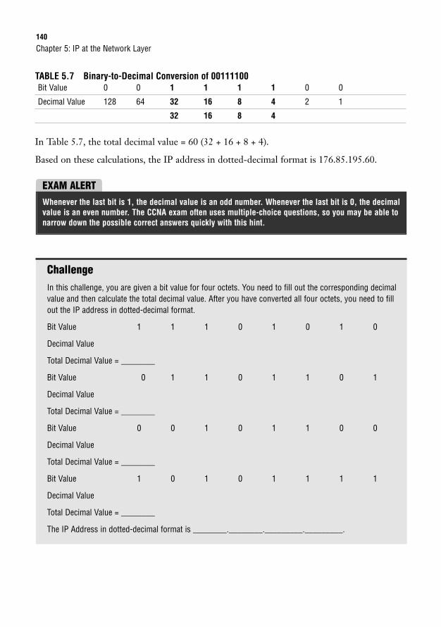
140
TABLE 5.7 Binary-to-Decimal Conversion of 00111100Bit Value 0 0 1 1 1 1 0 0
Decimal Value 128 64 32 16 8 4 2 1
32 16 8 4
In Table 5.7, the total decimal value = 60 (32 + 16 + 8 + 4).
Based on these calculations, the IP address in dotted-decimal format is 176.85.195.60.
Chapter 5: IP at the Network Layer
EXAM ALERTWhenever the last bit is 1, the decimal value is an odd number. Whenever the last bit is 0, the decimalvalue is an even number. The CCNA exam often uses multiple-choice questions, so you may be able tonarrow down the possible correct answers quickly with this hint.
ChallengeIn this challenge, you are given a bit value for four octets. You need to fill out the corresponding decimalvalue and then calculate the total decimal value. After you have converted all four octets, you need to fillout the IP address in dotted-decimal format.
Bit Value 1 1 1 0 1 0 1 0
Decimal Value
Total Decimal Value = ________
Bit Value 0 1 1 0 1 1 0 1
Decimal Value
Total Decimal Value = ________
Bit Value 0 0 1 0 1 1 0 0
Decimal Value
Total Decimal Value = ________
Bit Value 1 0 1 0 1 1 1 1
Decimal Value
Total Decimal Value = ________
The IP Address in dotted-decimal format is ________.________._________._________.

IP Addressing and Formats141
Converting Decimal to BinaryYou must also be able to convert an IP address from dotted-decimal format into binary. It helpsto work from left to right when converting to binary.
Example IP address = 206.110.28.62
The first octet of 206 can be broken down as follows:
128 64 32 16 8 4 2 1
1 1 0 0 1 1 1 0
The octet value is greater than 128, so the first bit is on. Subtract 128 from 206.
206 – 128 = 78
The remainder 78 is greater than 64, so the second bit is also on.
78 – 64 = 14
The remainder 14 is less than 32 and 16, so the third and fourth bits are off. However, 14 isgreater than 8, so the fifth bit is on.
14 – 8 = 6
The remainder 6 is greater than 4, so the sixth bit is on.
6 – 4 = 2
The remainder 2 is equal to the seventh bit value, so that bit is also on.
2 – 2 = 0
The last bit value is off because the remainder is 0. Remember that it is an even number, sothe last bit will always be 0!
ChallengeYou’ve already converted the first octet of 206.110.28.62 into binary. Determine the appropriate bit valuefor the remaining three octets.
Second octet 110:
128 64 32 16 8 4 2 1
___ ___ ___ ___ ___ ___ ___ ___
Third octet 28:
128 64 32 16 8 4 2 1
___ ___ ___ ___ ___ ___ ___ ___
Fourth octet 62:
128 64 32 16 8 4 2 1
___ ___ ___ ___ ___ ___ ___ ___
Now that you all four quartets have been converted, the binary equivalent of 216.110.28.62 is 11001110__________ __________ __________.
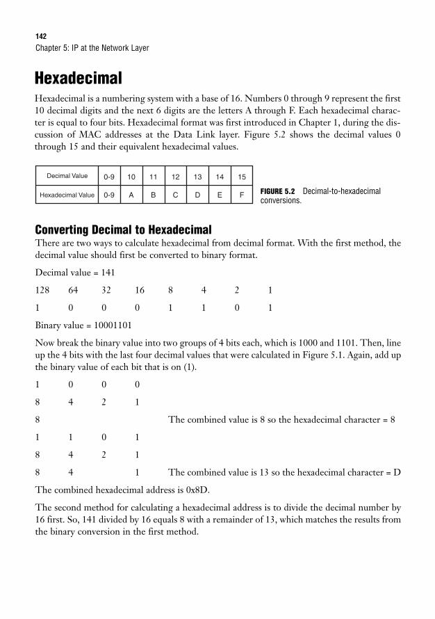
142
HexadecimalHexadecimal is a numbering system with a base of 16. Numbers 0 through 9 represent the first10 decimal digits and the next 6 digits are the letters A through F. Each hexadecimal charac-ter is equal to four bits. Hexadecimal format was first introduced in Chapter 1, during the dis-cussion of MAC addresses at the Data Link layer. Figure 5.2 shows the decimal values 0through 15 and their equivalent hexadecimal values.
Chapter 5: IP at the Network Layer
Decimal Value
Hexadecimal Value
0-9 10 11 12 13 14 15
0-9 A B C D E F
Converting Decimal to HexadecimalThere are two ways to calculate hexadecimal from decimal format. With the first method, thedecimal value should first be converted to binary format.
Decimal value = 141
128 64 32 16 8 4 2 1
1 0 0 0 1 1 0 1
Binary value = 10001101
Now break the binary value into two groups of 4 bits each, which is 1000 and 1101. Then, lineup the 4 bits with the last four decimal values that were calculated in Figure 5.1. Again, add upthe binary value of each bit that is on (1).
1 0 0 0
8 4 2 1
8 The combined value is 8 so the hexadecimal character = 8
1 1 0 1
8 4 2 1
8 4 1 The combined value is 13 so the hexadecimal character = D
The combined hexadecimal address is 0x8D.
The second method for calculating a hexadecimal address is to divide the decimal number by16 first. So, 141 divided by 16 equals 8 with a remainder of 13, which matches the results fromthe binary conversion in the first method.
FIGURE 5.2 Decimal-to-hexadecimalconversions.
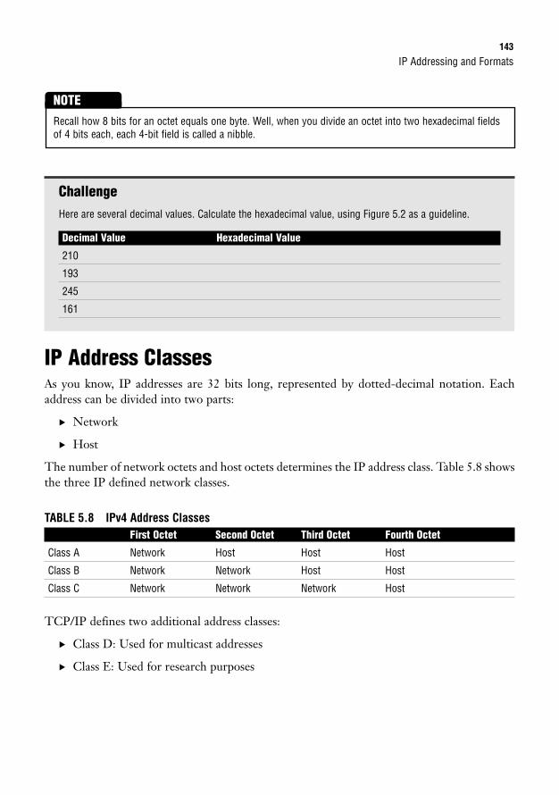
IP Addressing and Formats143
ChallengeHere are several decimal values. Calculate the hexadecimal value, using Figure 5.2 as a guideline.
Decimal Value Hexadecimal Value
210
193
245
161
IP Address ClassesAs you know, IP addresses are 32 bits long, represented by dotted-decimal notation. Eachaddress can be divided into two parts:
. Network
. Host
The number of network octets and host octets determines the IP address class. Table 5.8 showsthe three IP defined network classes.
TABLE 5.8 IPv4 Address ClassesFirst Octet Second Octet Third Octet Fourth Octet
Class A Network Host Host Host
Class B Network Network Host Host
Class C Network Network Network Host
TCP/IP defines two additional address classes:
. Class D: Used for multicast addresses
. Class E: Used for research purposes
Recall how 8 bits for an octet equals one byte. Well, when you divide an octet into two hexadecimal fieldsof 4 bits each, each 4-bit field is called a nibble.
NOTE
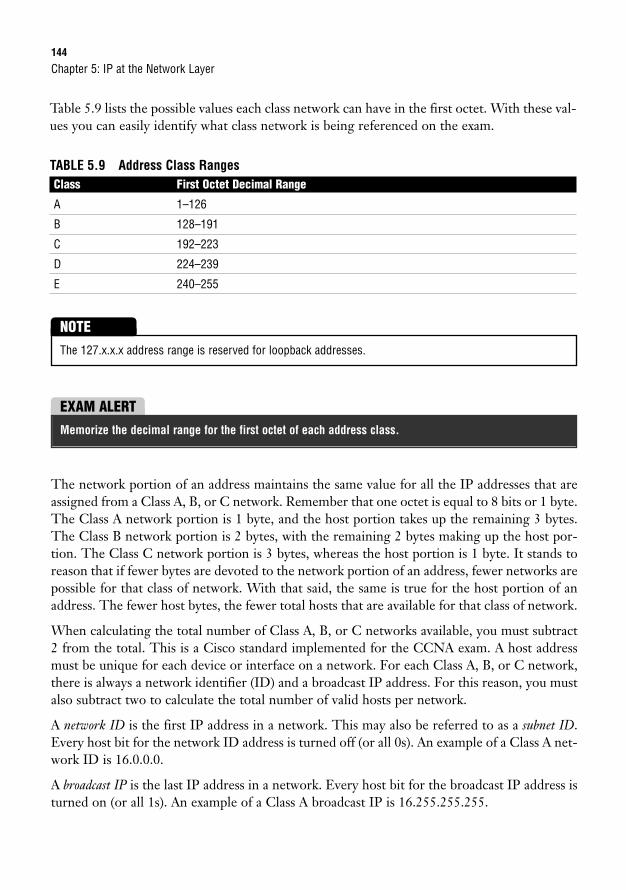
144
Table 5.9 lists the possible values each class network can have in the first octet. With these val-ues you can easily identify what class network is being referenced on the exam.
TABLE 5.9 Address Class RangesClass First Octet Decimal Range
A 1–126
B 128–191
C 192–223
D 224–239
E 240–255
Chapter 5: IP at the Network Layer
The 127.x.x.x address range is reserved for loopback addresses.
NOTE
EXAM ALERTMemorize the decimal range for the first octet of each address class.
The network portion of an address maintains the same value for all the IP addresses that areassigned from a Class A, B, or C network. Remember that one octet is equal to 8 bits or 1 byte.The Class A network portion is 1 byte, and the host portion takes up the remaining 3 bytes.The Class B network portion is 2 bytes, with the remaining 2 bytes making up the host por-tion. The Class C network portion is 3 bytes, whereas the host portion is 1 byte. It stands toreason that if fewer bytes are devoted to the network portion of an address, fewer networks arepossible for that class of network. With that said, the same is true for the host portion of anaddress. The fewer host bytes, the fewer total hosts that are available for that class of network.
When calculating the total number of Class A, B, or C networks available, you must subtract2 from the total. This is a Cisco standard implemented for the CCNA exam. A host addressmust be unique for each device or interface on a network. For each Class A, B, or C network,there is always a network identifier (ID) and a broadcast IP address. For this reason, you mustalso subtract two to calculate the total number of valid hosts per network.
A network ID is the first IP address in a network. This may also be referred to as a subnet ID.Every host bit for the network ID address is turned off (or all 0s). An example of a Class A net-work ID is 16.0.0.0.
A broadcast IP is the last IP address in a network. Every host bit for the broadcast IP address isturned on (or all 1s). An example of a Class A broadcast IP is 16.255.255.255.
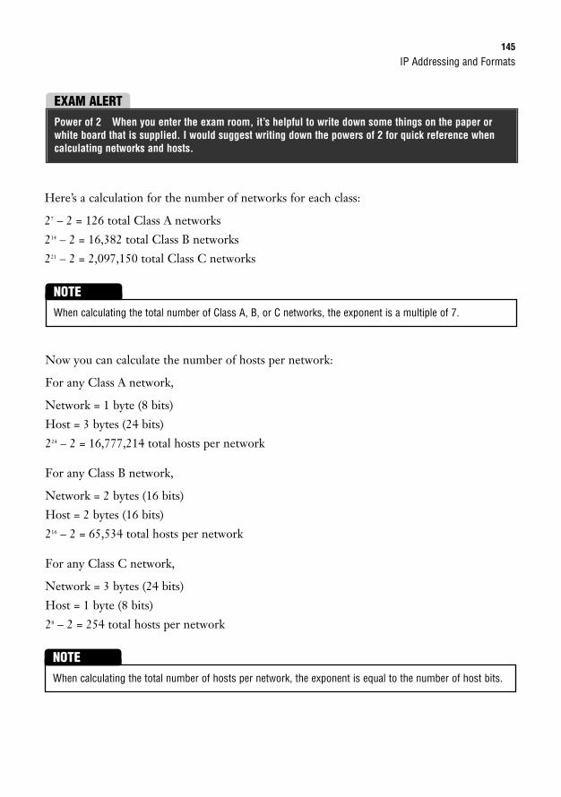
IP Addressing and Formats145
Here’s a calculation for the number of networks for each class:
27 – 2 = 126 total Class A networks
214 – 2 = 16,382 total Class B networks
221 – 2 = 2,097,150 total Class C networks
EXAM ALERTPower of 2 When you enter the exam room, it’s helpful to write down some things on the paper orwhite board that is supplied. I would suggest writing down the powers of 2 for quick reference whencalculating networks and hosts.
Now you can calculate the number of hosts per network:
For any Class A network,
Network = 1 byte (8 bits)
Host = 3 bytes (24 bits)
224 – 2 = 16,777,214 total hosts per network
For any Class B network,
Network = 2 bytes (16 bits)
Host = 2 bytes (16 bits)
216 – 2 = 65,534 total hosts per network
For any Class C network,
Network = 3 bytes (24 bits)
Host = 1 byte (8 bits)
28 – 2 = 254 total hosts per network
When calculating the total number of Class A, B, or C networks, the exponent is a multiple of 7.
NOTE
When calculating the total number of hosts per network, the exponent is equal to the number of host bits.
NOTE
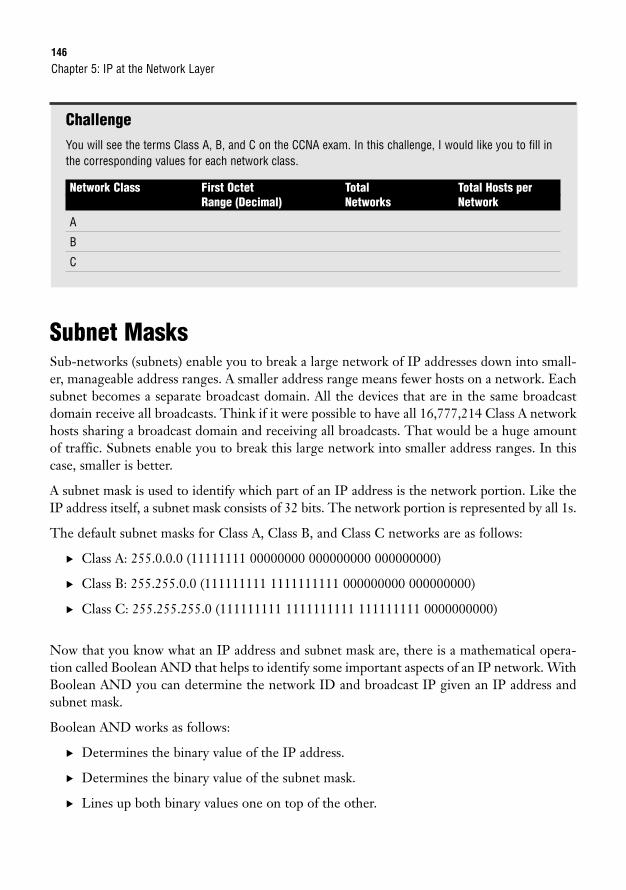
146
ChallengeYou will see the terms Class A, B, and C on the CCNA exam. In this challenge, I would like you to fill inthe corresponding values for each network class.
Network Class First Octet Total Total Hosts perRange (Decimal) Networks Network
A
B
C
Subnet MasksSub-networks (subnets) enable you to break a large network of IP addresses down into small-er, manageable address ranges. A smaller address range means fewer hosts on a network. Eachsubnet becomes a separate broadcast domain. All the devices that are in the same broadcastdomain receive all broadcasts. Think if it were possible to have all 16,777,214 Class A networkhosts sharing a broadcast domain and receiving all broadcasts. That would be a huge amountof traffic. Subnets enable you to break this large network into smaller address ranges. In thiscase, smaller is better.
A subnet mask is used to identify which part of an IP address is the network portion. Like theIP address itself, a subnet mask consists of 32 bits. The network portion is represented by all 1s.
The default subnet masks for Class A, Class B, and Class C networks are as follows:
. Class A: 255.0.0.0 (11111111 00000000 000000000 000000000)
. Class B: 255.255.0.0 (111111111 1111111111 000000000 000000000)
. Class C: 255.255.255.0 (111111111 1111111111 111111111 0000000000)
Now that you know what an IP address and subnet mask are, there is a mathematical opera-tion called Boolean AND that helps to identify some important aspects of an IP network. WithBoolean AND you can determine the network ID and broadcast IP given an IP address andsubnet mask.
Boolean AND works as follows:
. Determines the binary value of the IP address.
. Determines the binary value of the subnet mask.
. Lines up both binary values one on top of the other.
Chapter 5: IP at the Network Layer
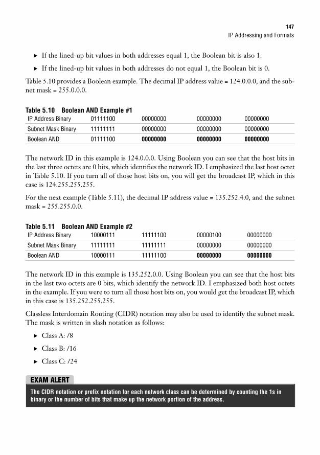
IP Addressing and Formats147
. If the lined-up bit values in both addresses equal 1, the Boolean bit is also 1.
. If the lined-up bit values in both addresses do not equal 1, the Boolean bit is 0.
Table 5.10 provides a Boolean example. The decimal IP address value = 124.0.0.0, and the sub-net mask = 255.0.0.0.
Table 5.10 Boolean AND Example #1IP Address Binary 01111100 00000000 00000000 00000000
Subnet Mask Binary 11111111 00000000 00000000 00000000
Boolean AND 01111100 00000000 00000000 00000000
The network ID in this example is 124.0.0.0. Using Boolean you can see that the host bits inthe last three octets are 0 bits, which identifies the network ID. I emphasized the last host octetin Table 5.10. If you turn all of those host bits on, you will get the broadcast IP, which in thiscase is 124.255.255.255.
For the next example (Table 5.11), the decimal IP address value = 135.252.4.0, and the subnetmask = 255.255.0.0.
Table 5.11 Boolean AND Example #2IP Address Binary 10000111 11111100 00000100 00000000
Subnet Mask Binary 11111111 11111111 00000000 00000000
Boolean AND 10000111 11111100 00000000 00000000
The network ID in this example is 135.252.0.0. Using Boolean you can see that the host bitsin the last two octets are 0 bits, which identify the network ID. I emphasized both host octetsin the example. If you were to turn all those host bits on, you would get the broadcast IP, whichin this case is 135.252.255.255.
Classless Interdomain Routing (CIDR) notation may also be used to identify the subnet mask.The mask is written in slash notation as follows:
. Class A: /8
. Class B: /16
. Class C: /24
EXAM ALERTThe CIDR notation or prefix notation for each network class can be determined by counting the 1s inbinary or the number of bits that make up the network portion of the address.
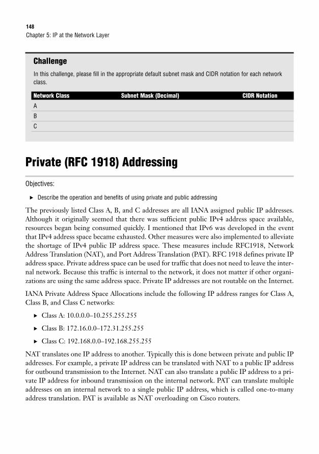
148
ChallengeIn this challenge, please fill in the appropriate default subnet mask and CIDR notation for each networkclass.
Network Class Subnet Mask (Decimal) CIDR Notation
A
B
C
Private (RFC 1918) Addressing
Objectives:
. Describe the operation and benefits of using private and public addressing
The previously listed Class A, B, and C addresses are all IANA assigned public IP addresses.Although it originally seemed that there was sufficient public IPv4 address space available,resources began being consumed quickly. I mentioned that IPv6 was developed in the eventthat IPv4 address space became exhausted. Other measures were also implemented to alleviatethe shortage of IPv4 public IP address space. These measures include RFC1918, NetworkAddress Translation (NAT), and Port Address Translation (PAT). RFC 1918 defines private IPaddress space. Private address space can be used for traffic that does not need to leave the inter-nal network. Because this traffic is internal to the network, it does not matter if other organi-zations are using the same address space. Private IP addresses are not routable on the Internet.
IANA Private Address Space Allocations include the following IP address ranges for Class A,Class B, and Class C networks:
. Class A: 10.0.0.0–10.255.255.255
. Class B: 172.16.0.0–172.31.255.255
. Class C: 192.168.0.0–192.168.255.255
NAT translates one IP address to another. Typically this is done between private and public IPaddresses. For example, a private IP address can be translated with NAT to a public IP addressfor outbound transmission to the Internet. NAT can also translate a public IP address to a pri-vate IP address for inbound transmission on the internal network. PAT can translate multipleaddresses on an internal network to a single public IP address, which is called one-to-manyaddress translation. PAT is available as NAT overloading on Cisco routers.
Chapter 5: IP at the Network Layer
EXAM ALERT
Subnetting IP149
Subnetting IPObjectives:
. Calculate and apply an addressing scheme including VLSM IP addressing design to a network
. Determine the appropriate classless addressing scheme using VLSM and summarization to satisfyaddressing requirements in a LAN/WAN environment
So far, we have focused on the network classes and key characteristics of each one. As I men-tioned, each network class can also be broken down into smaller groups of IP address rangesor subnets, which may also be referred to as variable-length subnet masking (VLSM).Subnetting is the process of breaking down those larger IP networks into smaller sub-networks.At first, subnetting IP might seem like a daunting task, but it’s not that bad after you get thehang of it. In this section you need to pull together all the knowledge that you have learned sofar about binary, decimal, and subnets.
First, let’s get the easy subnetting out of the way.
For an IP address that has a 255.255.0.0 or 255.255.255.0 subnet mask, you can copy the octetsthat have a subnet mask value of 255 from the original IP address. For the remaining octets,you will put down a 0. Here’s an example:
IP address = 139.42.6.0
Subnet Mask = 255.255.0.0
The Network ID is 139.42.0.0.
To determine the Broadcast IP of this IP address and subnet mask, just replace the 0 octetsfrom the Network ID with 255.
The Broadcast IP is 139.42.255.255.
Chapter 21, “Command-Line NAT Implementation,” covers NAT terminology and configurations in detail.
NOTE
When a subnet mask has a value of 255.255.0.0 or 255.255.255.0, you can copy the original IP octetsthat match the 255 value subnet octets and then use 0 for any remaining octets to determine yourNetwork ID. The Broadcast IP is the same original IP octets that match the 255 value subnet octets andthe number 255 rather than 0 for the remaining octet(s).
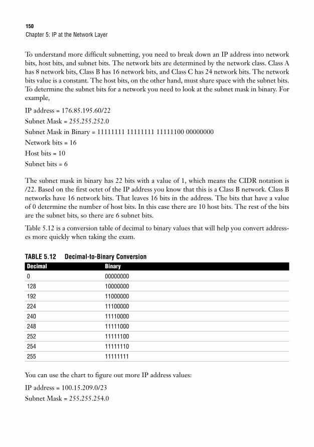
150
To understand more difficult subnetting, you need to break down an IP address into networkbits, host bits, and subnet bits. The network bits are determined by the network class. Class Ahas 8 network bits, Class B has 16 network bits, and Class C has 24 network bits. The networkbits value is a constant. The host bits, on the other hand, must share space with the subnet bits.To determine the subnet bits for a network you need to look at the subnet mask in binary. Forexample,
IP address = 176.85.195.60/22
Subnet Mask = 255.255.252.0
Subnet Mask in Binary = 11111111 11111111 11111100 00000000
Network bits = 16
Host bits = 10
Subnet bits = 6
The subnet mask in binary has 22 bits with a value of 1, which means the CIDR notation is/22. Based on the first octet of the IP address you know that this is a Class B network. Class Bnetworks have 16 network bits. That leaves 16 bits in the address. The bits that have a valueof 0 determine the number of host bits. In this case there are 10 host bits. The rest of the bitsare the subnet bits, so there are 6 subnet bits.
Table 5.12 is a conversion table of decimal to binary values that will help you convert address-es more quickly when taking the exam.
TABLE 5.12 Decimal-to-Binary ConversionDecimal Binary
0 00000000
128 10000000
192 11000000
224 11100000
240 11110000
248 11111000
252 11111100
254 11111110
255 11111111
You can use the chart to figure out more IP address values:
IP address = 100.15.209.0/23
Subnet Mask = 255.255.254.0
Chapter 5: IP at the Network Layer

Subnetting IP151
Subnet Mask in Binary = 11111111 11111111 11111110 00000000
Network bits = 8
Host bits = 9
Subnet bits = 15
IP address = 128.216.55.0/24
Subnet Mask = 255.255.255.0
Subnet Mask in Binary = 11111111 11111111 11111111 00000000
Network bits = 16
Host bits = 8
Subnet bits = 8
IP address = 222.110.8.61/28
Subnet Mask = 255.255.255.240
Subnet Mask in Binary = 11111111 11111111 11111111 11110000
Network bits = 24
Host bits = 4
Subnet bits = 4
ChallengeIn this challenge, I supply you with the IP address and subnet mask. From there, you need to convert thesubnet mask to binary and determine the number of network bits, host bits, and subnet bits for each network.
IP address = 193.216.0.0
Subnet Mask = 255.255.255.248
Subnet Mask in Binary = ___________ ___________ ___________ ___________
Network bits = _______
Host bits = _______
Subnet bits = _______
IP address = 130.101.2.0
Subnet Mask = 255.255.255.128
Subnet Mask in Binary = ___________ ___________ ___________ ___________
Network bits = _______
Host bits = _______
Subnet bits = _______
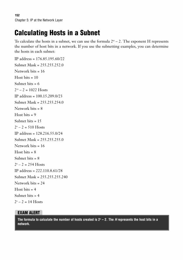
152
Calculating Hosts in a SubnetTo calculate the hosts in a subnet, we can use the formula 2H – 2. The exponent H representsthe number of host bits in a network. If you use the subnetting examples, you can determinethe hosts in each subnet:
IP address = 176.85.195.60/22
Subnet Mask = 255.255.252.0
Network bits = 16
Host bits = 10
Subnet bits = 6
210 – 2 = 1022 Hosts
IP address = 100.15.209.0/23
Subnet Mask = 255.255.254.0
Network bits = 8
Host bits = 9
Subnet bits = 15
29 – 2 = 510 Hosts
IP address = 128.216.55.0/24
Subnet Mask = 255.255.255.0
Network bits = 16
Host bits = 8
Subnet bits = 8
28 – 2 = 254 Hosts
IP address = 222.110.8.61/28
Subnet Mask = 255.255.255.240
Network bits = 24
Host bits = 4
Subnet bits = 4
24 – 2 = 14 Hosts
Chapter 5: IP at the Network Layer
EXAM ALERTThe formula to calculate the number of hosts created is 2H – 2. The H represents the host bits in a network.
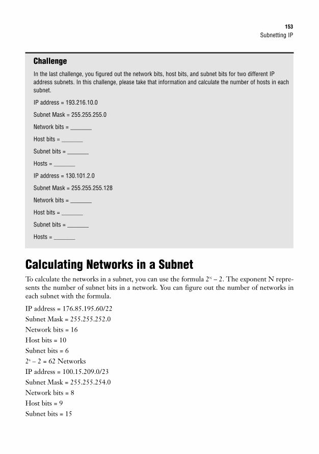
Subnetting IP153
ChallengeIn the last challenge, you figured out the network bits, host bits, and subnet bits for two different IPaddress subnets. In this challenge, please take that information and calculate the number of hosts in eachsubnet.
IP address = 193.216.10.0
Subnet Mask = 255.255.255.0
Network bits = _______
Host bits = _______
Subnet bits = _______
Hosts = _______
IP address = 130.101.2.0
Subnet Mask = 255.255.255.128
Network bits = _______
Host bits = _______
Subnet bits = _______
Hosts = _______
Calculating Networks in a SubnetTo calculate the networks in a subnet, you can use the formula 2N – 2. The exponent N repre-sents the number of subnet bits in a network. You can figure out the number of networks ineach subnet with the formula.
IP address = 176.85.195.60/22Subnet Mask = 255.255.252.0Network bits = 16Host bits = 10Subnet bits = 626 – 2 = 62 NetworksIP address = 100.15.209.0/23Subnet Mask = 255.255.254.0Network bits = 8Host bits = 9Subnet bits = 15
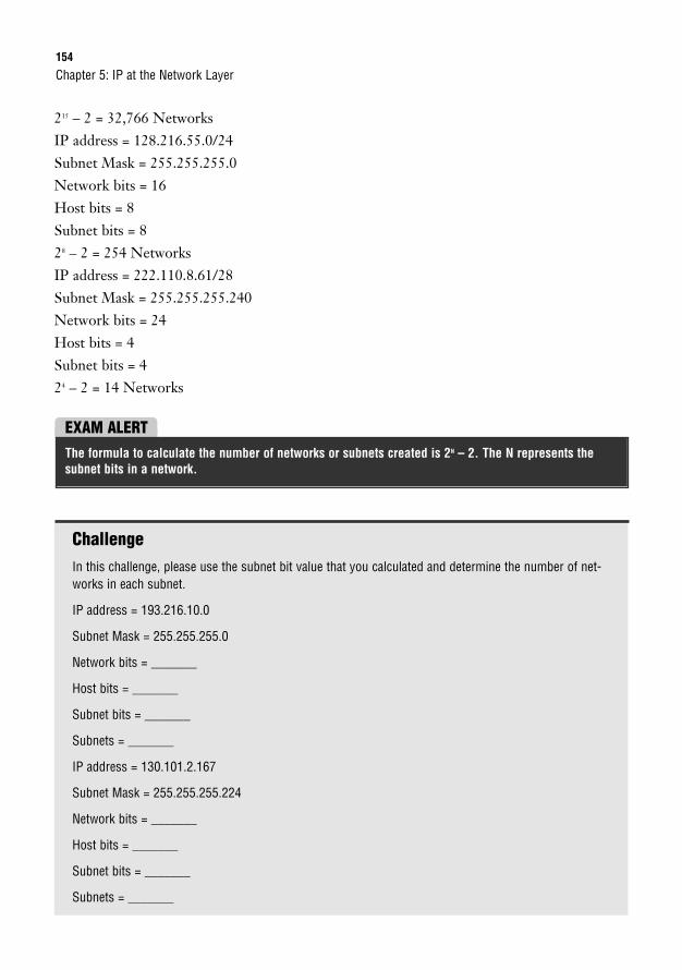
154
215 – 2 = 32,766 NetworksIP address = 128.216.55.0/24Subnet Mask = 255.255.255.0Network bits = 16Host bits = 8Subnet bits = 828 – 2 = 254 NetworksIP address = 222.110.8.61/28Subnet Mask = 255.255.255.240Network bits = 24Host bits = 4Subnet bits = 424 – 2 = 14 Networks
Chapter 5: IP at the Network Layer
EXAM ALERTThe formula to calculate the number of networks or subnets created is 2N – 2. The N represents thesubnet bits in a network.
ChallengeIn this challenge, please use the subnet bit value that you calculated and determine the number of net-works in each subnet.
IP address = 193.216.10.0
Subnet Mask = 255.255.255.0
Network bits = _______
Host bits = _______
Subnet bits = _______
Subnets = _______
IP address = 130.101.2.167
Subnet Mask = 255.255.255.224
Network bits = _______
Host bits = _______
Subnet bits = _______
Subnets = _______
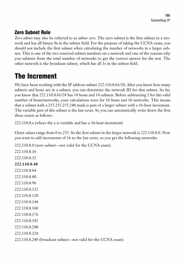
Subnetting IP155
Zero Subnet RuleZero subnet may also be referred to as subnet zero. The zero subnet is the first subnet in a net-work and has all binary 0s in the subnet field. For the purpose of taking the CCNA exam, youshould not include the first subnet when calculating the number of networks in a larger sub-net. This is one of the two reserved subnet numbers on a network and one of the reasons whyyou subtract from the total number of networks to get the correct answer for the test. Theother network is the broadcast subnet, which has all 1s in the subnet field.
The IncrementWe have been working with the IP address subnet 222.110.8.61/28. After you know how manysubnets and hosts are in a subnet, you can determine the network ID for that subnet. So far,you know that 222.110.8.61/28 has 14 hosts and 14 subnets. Before subtracting 2 for the validnumber of hosts/networks, your calculations were for 16 hosts and 16 networks. This meansthat a subnet with a 255.255.255.240 mask is part of a larger subnet with a 16-host increment.The variable part of this subnet is the last octet. So you can automatically write down the firstthree octets as follows:
222.110.8.x (where the x is variable and has a 16-host increment)
Octet values range from 0 to 255. So the first subnet in the larger network is 222.110.8.0. Nowyou want to add increments of 16 to the last octet, so you get the following networks:
222.110.8.0 (zero subnet—not valid for the CCNA exam)
222.110.8.16
222.110.8.32
222.110.8.48
222.110.8.64
222.110.8.80
222.110.8.96
222.110.8.112
222.110.8.128
222.110.8.144
222.110.8.160
222.110.8.176
222.110.8.192
222.110.8.208
222.110.8.224
222.110.8.240 (broadcast subnet—not valid for the CCNA exam)
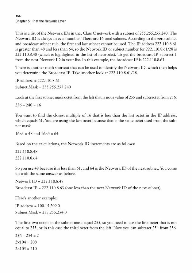
156
This is a list of the Network IDs in that Class C network with a subnet of 255.255.255.240. TheNetwork ID is always an even number. There are 16 total subnets. According to the zero subnetand broadcast subnet rule, the first and last subnet cannot be used. The IP address 222.110.8.61is greater than 48 and less than 64, so the Network ID or subnet number for 222.110.8.61/28 is222.110.8.48 (which is highlighted in the list of networks). To get the broadcast IP, subtract 1from the next Network ID in your list. In this example, the broadcast IP is 222.110.8.63.
There is another math shortcut that can be used to identify the Network ID, which then helpsyou determine the Broadcast IP. Take another look at 222.110.8.61/28.
IP address = 222.110.8.61
Subnet Mask = 255.255.255.240
Look at the first subnet mask octet from the left that is not a value of 255 and subtract it from 256.
256 – 240 = 16
You want to find the closest multiple of 16 that is less than the last octet in the IP address,which equals 61. You are using the last octet because that is the same octet used from the sub-net mask.
16×3 = 48 and 16×4 = 64
Based on the calculations, the Network ID increments are as follows:
222.110.8.48
222.110.8.64
So you use 48 because it is less than 61, and 64 is the Network ID of the next subnet. You comeup with the same answer as before.
Network ID = 222.110.8.48
Broadcast IP = 222.110.8.63 (one less than the next Network ID of the next subnet)
Here’s another example:
IP address = 100.15.209.0
Subnet Mask = 255.255.254.0
The first two octets in the subnet mask equal 255, so you need to use the first octet that is notequal to 255, or in this case the third octet from the left. Now you can subtract 254 from 256.
256 – 254 = 2
2×104 = 208
2×105 = 210
Chapter 5: IP at the Network Layer
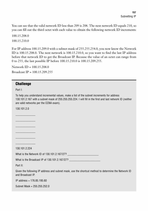
Subnetting IP157
You can see that the valid network ID less than 209 is 208. The next network ID equals 210, soyou can fill out the third octet with each value to obtain the following network ID increments:
100.15.208.0
100.15.210.0
For IP address 100.15.209.0 with a subnet mask of 255.255.254.0, you now know the NetworkID is 100.15.208.0. The next network is 100.15.210.0, so you want to find the last IP addressbefore that network ID to get the Broadcast IP. Because the value of an octet can range from0 to 255, the last possible IP before 100.15.210.0 is 100.15.209.255.
Network ID = 100.15.208.0
Broadcast IP = 100.15.209.255
ChallengePart I:
To help you understand incremental values, make a list of the subnet increments for address130.101.2.167 with a subnet mask of 255.255.255.224. I will fill in the first and last network ID (neitherare valid networks per the CCNA exam).
130.101.2.0
______________
______________
______________
______________
______________
______________
130.101.2.224
What is the Network ID of 130.101.2.167/27? ______________________
What is the Broadcast IP of 130.101.2.167/27? ______________________
Part II:
Given the following IP address and subnet mask, use the shortcut method to determine the Network IDand Broadcast IP.
IP address = 176.85.195.60
Subnet Mask = 255.255.252.0
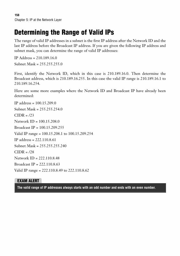
158
Determining the Range of Valid IPsThe range of valid IP addresses in a subnet is the first IP address after the Network ID and thelast IP address before the Broadcast IP address. If you are given the following IP address andsubnet mask, you can determine the range of valid IP addresses:
IP Address = 210.189.16.0
Subnet Mask = 255.255.255.0
First, identify the Network ID, which in this case is 210.189.16.0. Then determine theBroadcast address, which is 210.189.16.255. In this case the valid IP range is 210.189.16.1 to210.189.16.254.
Here are some more examples where the Network ID and Broadcast IP have already beendetermined:
IP address = 100.15.209.0
Subnet Mask = 255.255.254.0
CIDR = /23
Network ID = 100.15.208.0
Broadcast IP = 100.15.209.255
Valid IP range = 100.15.208.1 to 100.15.209.254
IP address = 222.110.8.61
Subnet Mask = 255.255.255.240
CIDR = /28
Network ID = 222.110.8.48
Broadcast IP = 222.110.8.63
Valid IP range = 222.110.8.49 to 222.110.8.62
Chapter 5: IP at the Network Layer
EXAM ALERTThe valid range of IP addresses always starts with an odd number and ends with an even number.
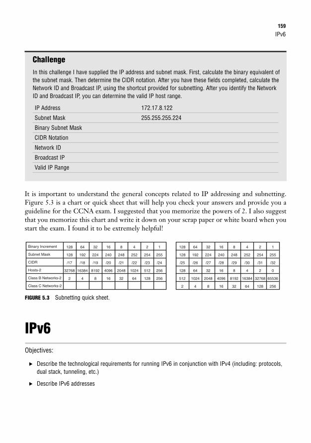
IPv6159
ChallengeIn this challenge I have supplied the IP address and subnet mask. First, calculate the binary equivalent ofthe subnet mask. Then determine the CIDR notation. After you have these fields completed, calculate theNetwork ID and Broadcast IP, using the shortcut provided for subnetting. After you identify the NetworkID and Broadcast IP, you can determine the valid IP host range.
IP Address 172.17.8.122
Subnet Mask 255.255.255.224
Binary Subnet Mask
CIDR Notation
Network ID
Broadcast IP
Valid IP Range
It is important to understand the general concepts related to IP addressing and subnetting.Figure 5.3 is a chart or quick sheet that will help you check your answers and provide you aguideline for the CCNA exam. I suggested that you memorize the powers of 2. I also suggestthat you memorize this chart and write it down on your scrap paper or white board when youstart the exam. I found it to be extremely helpful!
Binary Increment
Subnet Mask
CIDR
Hosts-2
Class B Networks-2
Class C Networks-2
128
128
/17
32768
2
64
192
/18
16384
4
32
224
/19
8192
8
16
240
/20
4096
16
8
248
/21
2048
32
4
252
/22
1024
64
2
254
/23
512
128
1
255
/24
256
256
128
128
/25
128
512
2
64
192
/26
64
1024
4
32
224
/27
32
2048
8
16
240
/28
16
4096
16
8
248
/29
8
8192
32
4
252
/30
4
16384
64
2
254
/31
2
32768
128
1
255
/32
0
65536
256
FIGURE 5.3 Subnetting quick sheet.
IPv6Objectives:
. Describe the technological requirements for running IPv6 in conjunction with IPv4 (including: protocols,dual stack, tunneling, etc.)
. Describe IPv6 addresses
160
IPv6 is a workable IP version that was created in anticipation of the inevitable exhaustion of IPv4addresses. Cisco routers are capable of routing IPv4 and IPv6 traffic in the event that networksstart to use IPv6 addressing on a regular basis. At this point, organizations are primarily request-ing small IPv6 networks from IANA for testing purposes to make sure they are prepared for theday when IPv4 addresses are no longer available. IPv6 provides the same functionality as IPv4.Like IPv4, IPv6 also manages Network layer packet addressing and routing. The sheer size ofassignable IPv6 addresses is astounding. The format of this version offers trillions of available IPaddresses. For this reason, IPv6 should never experience a shortage of address space.
IPv6 CommunicationsThere are three different types of IPv6 communications: unicast, multicast, and anycast. Asyou know, these terms also exist in the world of IPv4. Whereas unicast means a one-to-onecommunication, just as it does with IPv4, multicast and anycast take on new meaning.
With IPv6, multicast refers to one-to-many communication. Multicast can be on a local link,a local site, an organization, or even the entire Internet.
Anycast can be described as one-to-closest communication. With anycast, you assign the sameIP address to multiple devices. So, when a packet is destined for this IP address, the path tothe closest destination device is chosen. This can also offer redundancy. For example, if twoservers have the same IP address and one of the servers goes offline, the other server is chosenas the destination.
IPv6 Address FormatThis may be an understatement, but IPv6 addresses are much longer than their 32-bit IPv4address counterparts. Each address is 128 bits long and is represented by 32 hexadecimal dig-its. I guess it’s a good thing that we covered hexadecimal earlier in this chapter.
As you will recall, IPv4 is represented by dotted-decimal notation. Because hexadecimal digitsare used, IPv6 is also written differently. First, IPv6 addresses consist of two parts:
. A 64-bit network prefix
. A 64-bit local identifier
Here is a sample IPv6 address:
2001:0BD2:0200:08F1:0000:0000:0000:16AB
As you can see, each address is broken into eight smaller groups of four hexadecimal digits thatare separated by colons. In this example, the network prefix is 2001:0BD2:0200:08F1, and thelocal identifier is 0000:0000:0000:16AB.
Chapter 5: IP at the Network Layer
IPv6161
IPv6 address format summary:
. Defined by RFC 2373 and RFC 2374.
. Consists of 128 bits with a 64-bit network prefix and a 64-bit local identifier.
. Represented by 32 hexadecimal digits broken into eight smaller groups of four.
. Uses CIDR notation (slash notation) to discern a subnet range. So you might see the sameIP address subnetted and written out as 2001:0BD2:0200:08F1:0000:0000:0000:16AB/16.
As you can see, IPv6 addresses are quite long and complex-looking. To help make IPv6 nota-tion a bit easier, leading zeros in a group may be removed when the address is written. Also, ifthere is a four-digit group of all 0s or contiguous groups of all 0s, the group or groups can beremoved from the address and replaced with ::. Don’t go too crazy, though. Keep in mind thatthe :: can be used only once in the address.
To demonstrate, the same IPv6 IP address can be written in all of the following ways:
2001:0BD2:0200:08F1:0000:0000:0000:16AB
2001:BD2:200:8F1:0:0:0:16AB
2001:BD2:200:8F1::16AB
EXAM ALERTFor the exam, know that leading 0s can be omitted from an IPv6 address and that four-digit groups ofall 0s can be omitted and replaced with ::.
Types of IPv6 AddressesIPv6 has four types of IPv6 addresses: link-local, unique/site-local, global, and multicast.
Link-Local AddressLink-local addresses have the shortest reach of the IP address types. They can go only as faras the Layer 2 domain. These addresses are autogenerated with or without the use of a DHCPserver. So, when an IPv6 node goes online, this address is assigned automatically.
Link-local addresses always start with FE80. This means that the first 16 bits of this IPv6 addressalways begin with 1111 1110 0100 0000, followed by all 0 bits to equal the 64-bit network prefix.
The 64-bit local identifier of a link-local address is interesting, to say the least. The last 64 bitsare generated using the MAC address of an interface. Remember, though, that MAC address-es consist of only 48 bits, so there is a discrepancy of 16 bits. The solution to this issue is toadd FFFE to the 24th bit of the MAC address. Basically, FFFE is squeezed right into the mid-dle of the MAC address.
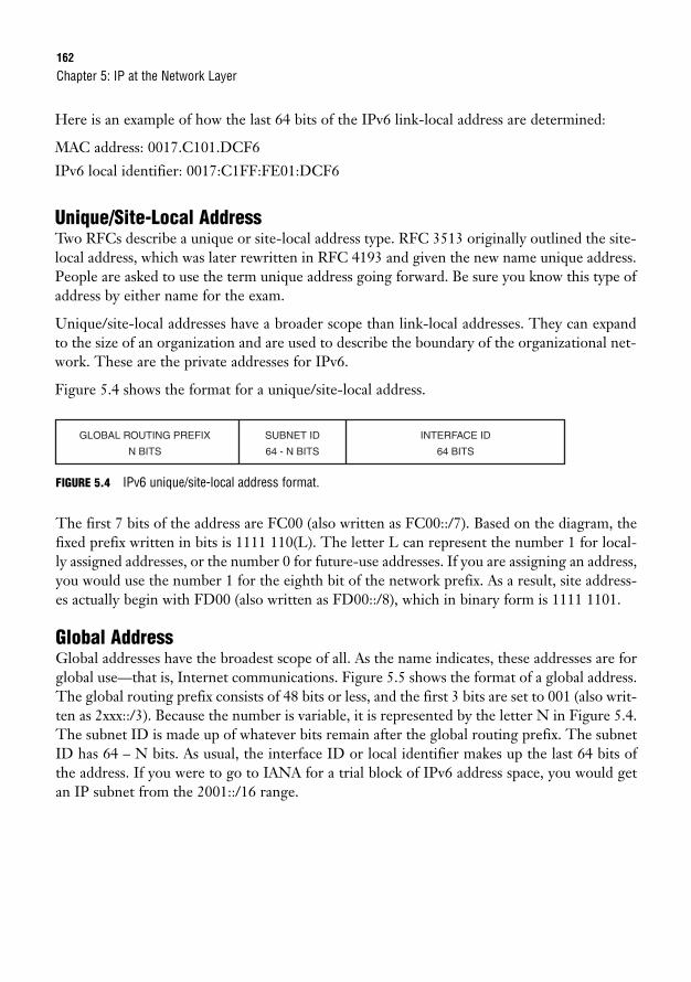
162
Here is an example of how the last 64 bits of the IPv6 link-local address are determined:
MAC address: 0017.C101.DCF6
IPv6 local identifier: 0017:C1FF:FE01:DCF6
Unique/Site-Local AddressTwo RFCs describe a unique or site-local address type. RFC 3513 originally outlined the site-local address, which was later rewritten in RFC 4193 and given the new name unique address.People are asked to use the term unique address going forward. Be sure you know this type ofaddress by either name for the exam.
Unique/site-local addresses have a broader scope than link-local addresses. They can expandto the size of an organization and are used to describe the boundary of the organizational net-work. These are the private addresses for IPv6.
Figure 5.4 shows the format for a unique/site-local address.
Chapter 5: IP at the Network Layer
GLOBAL ROUTING PREFIX
N BITS
SUBNET ID
64 - N BITS
INTERFACE ID
64 BITS
FIGURE 5.4 IPv6 unique/site-local address format.
The first 7 bits of the address are FC00 (also written as FC00::/7). Based on the diagram, thefixed prefix written in bits is 1111 110(L). The letter L can represent the number 1 for local-ly assigned addresses, or the number 0 for future-use addresses. If you are assigning an address,you would use the number 1 for the eighth bit of the network prefix. As a result, site address-es actually begin with FD00 (also written as FD00::/8), which in binary form is 1111 1101.
Global AddressGlobal addresses have the broadest scope of all. As the name indicates, these addresses are forglobal use—that is, Internet communications. Figure 5.5 shows the format of a global address.The global routing prefix consists of 48 bits or less, and the first 3 bits are set to 001 (also writ-ten as 2xxx::/3). Because the number is variable, it is represented by the letter N in Figure 5.4.The subnet ID is made up of whatever bits remain after the global routing prefix. The subnetID has 64 – N bits. As usual, the interface ID or local identifier makes up the last 64 bits ofthe address. If you were to go to IANA for a trial block of IPv6 address space, you would getan IP subnet from the 2001::/16 range.
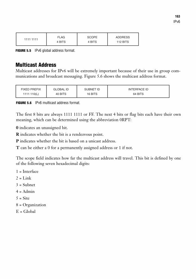
IPv6163
FIGURE 5.5 IPv6 global address format.
Multicast AddressMulticast addresses for IPv6 will be extremely important because of their use in group com-munications and broadcast messaging. Figure 5.6 shows the multicast address format.
1111 1111SCOPE
4 BITS
FLAG
4 BITS
ADDRESS
112 BITS
FIXED PREFIX
1111 110(L)
SUBNET ID
16 BITS
GLOBAL ID
40 BITS
INTERFACE ID
64 BITS
FIGURE 5.6 IPv6 multicast address format.
The first 8 bits are always 1111 1111 or FF. The next 4 bits or flag bits each have their ownmeaning, which can be determined using the abbreviation 0RPT:
0 indicates an unassigned bit.
R indicates whether the bit is a rendezvous point.
P indicates whether the bit is based on a unicast address.
T can be either a 0 for a permanently assigned address or 1 if not.
The scope field indicates how far the multicast address will travel. This bit is defined by oneof the following seven hexadecimal digits:
1 = Interface
2 = Link
3 = Subnet
4 = Admin
5 = Site
8 = Organization
E = Global
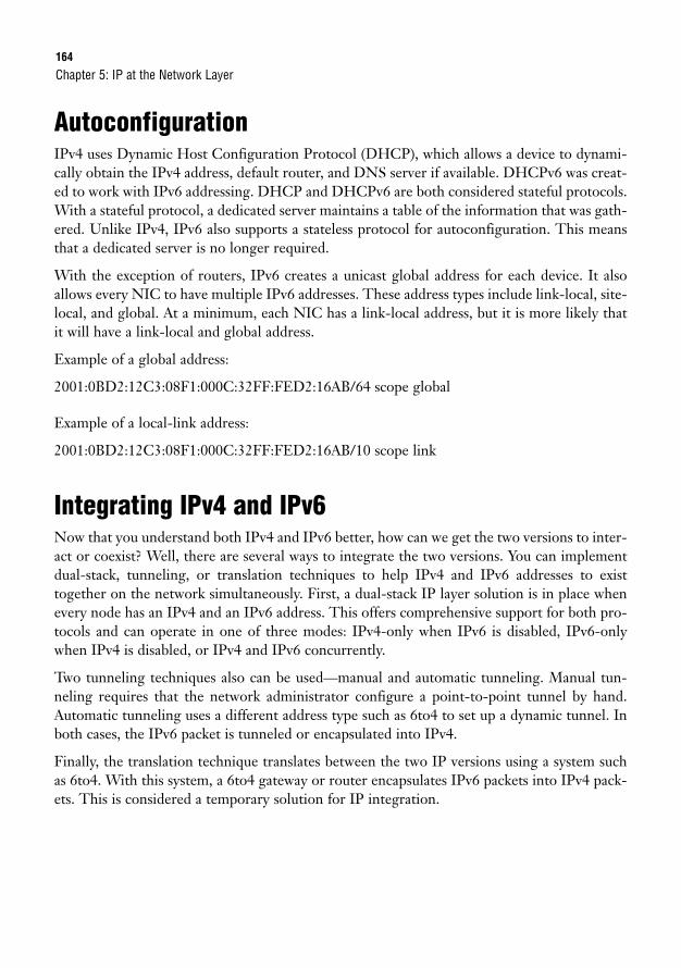
164
AutoconfigurationIPv4 uses Dynamic Host Configuration Protocol (DHCP), which allows a device to dynami-cally obtain the IPv4 address, default router, and DNS server if available. DHCPv6 was creat-ed to work with IPv6 addressing. DHCP and DHCPv6 are both considered stateful protocols.With a stateful protocol, a dedicated server maintains a table of the information that was gath-ered. Unlike IPv4, IPv6 also supports a stateless protocol for autoconfiguration. This meansthat a dedicated server is no longer required.
With the exception of routers, IPv6 creates a unicast global address for each device. It alsoallows every NIC to have multiple IPv6 addresses. These address types include link-local, site-local, and global. At a minimum, each NIC has a link-local address, but it is more likely thatit will have a link-local and global address.
Example of a global address:
2001:0BD2:12C3:08F1:000C:32FF:FED2:16AB/64 scope global
Example of a local-link address:
2001:0BD2:12C3:08F1:000C:32FF:FED2:16AB/10 scope link
Integrating IPv4 and IPv6Now that you understand both IPv4 and IPv6 better, how can we get the two versions to inter-act or coexist? Well, there are several ways to integrate the two versions. You can implementdual-stack, tunneling, or translation techniques to help IPv4 and IPv6 addresses to existtogether on the network simultaneously. First, a dual-stack IP layer solution is in place whenevery node has an IPv4 and an IPv6 address. This offers comprehensive support for both pro-tocols and can operate in one of three modes: IPv4-only when IPv6 is disabled, IPv6-onlywhen IPv4 is disabled, or IPv4 and IPv6 concurrently.
Two tunneling techniques also can be used—manual and automatic tunneling. Manual tun-neling requires that the network administrator configure a point-to-point tunnel by hand.Automatic tunneling uses a different address type such as 6to4 to set up a dynamic tunnel. Inboth cases, the IPv6 packet is tunneled or encapsulated into IPv4.
Finally, the translation technique translates between the two IP versions using a system suchas 6to4. With this system, a 6to4 gateway or router encapsulates IPv6 packets into IPv4 pack-ets. This is considered a temporary solution for IP integration.
Chapter 5: IP at the Network Layer
Network Layer Devices165
ICMPv6In addition to DHCPv6, ICMPv6 has been created to help manage IPv6 addressing. AlthoughICMPv6 builds on the same functionality as ICMP with ping, ARP, and RARP, there are alsoenhancements such as neighbor discovery (ND). ND can identify neighboring link layerdevices, whether they are reachable, and if the link layer address changes. ND can also discoverrouters. The caveat is that ICMPv6 must be set up on all IPv6 devices.
Network Layer DevicesThe most common network device found at the Network layer is a router; however, Layer 3switches may also be implemented to create a WAN.
Both routers and Layer 3 switches can carry out these functions:
. Suppress broadcasts or multicasts
. Determine the best path for data transfer (routing)
. Strip down and add to Data Link layer frames
. Implement access lists for packet filtering (permit/deny statements)
. Set up quality of service (QoS) qualifiers to measure network performance
It is important to know that both these devices can be used at the Network layer. However, forthe purpose of the CCNA exam, routers are more widely recognized and, therefore, arereferred to when discussing Layer 3 functions.
RoutersRouters join a minimum of two networks together to create an internetwork or WAN. So far,we have discussed devices that are used at the Physical layer (hubs and repeaters) and the DataLink layer (Layer 2 switches and bridges). Layer 2 switches and bridges create a separate col-lision domain for each segment of the LAN. Routers and Layer 3 switches create a separatebroadcast domain for each segment of a WAN. A broadcast domain is a group of nodes thatcan receive one another’s broadcast messages. Figure 5.7 demonstrates how a router createsbroadcast domains whereas the connected switches create collision domains.
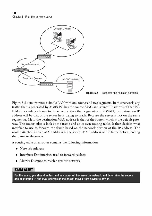
166
Figure 5.8 demonstrates a simple LAN with one router and two segments. In this network, anytraffic that is generated by Matt’s PC has the source MAC and source IP address of that PC.If Matt is sending a frame to the server on the other segment of that WAN, the destination IPaddress will be that of the server he is trying to reach. Because the server is not on the samesegment as Matt, the destination MAC address is that of the router, which is the default gate-way. The router takes a look at the frame and at its own routing table. It then decides whatinterface to use to forward the frame based on the network portion of the IP address. Therouter attaches its own MAC address as the source MAC address of the frame before sendingthe frame to the server.
A routing table on a router contains the following information:
. Network Address
. Interface: Exit interface used to forward packets
. Metric: Distance to reach a remote network
Chapter 5: IP at the Network Layer
Collision Domain
Collision Domain
Broadcast Domain
Broadcast Domain
FIGURE 5.7 Broadcast and collision domains.
EXAM ALERTFor the exam, you should understand how a packet traverses the network and determine the sourceand destination IP and MAC address as the packet moves from device to device.
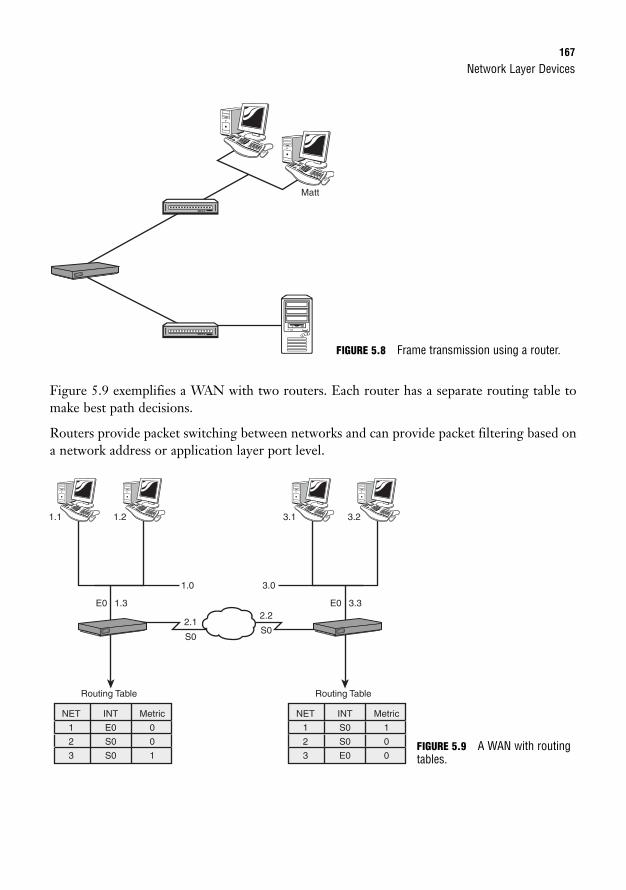
Network Layer Devices167
Figure 5.9 exemplifies a WAN with two routers. Each router has a separate routing table tomake best path decisions.
Routers provide packet switching between networks and can provide packet filtering based ona network address or application layer port level.
Matt
FIGURE 5.8 Frame transmission using a router.
E02.2
S02.1
S0
3.3
3.0
3.1 3.2
Routing Table
NET
1
2
3
INT
S0
S0
E0
Metric
1
0
0
E0 1.3
1.0
1.1 1.2
Routing Table
NET
1
2
3
INT
E0
S0
S0
Metric
0
0
1FIGURE 5.9 A WAN with routingtables.
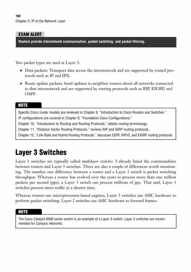
168
Two packet types are used at Layer 3:
. Data packets: Transport data across the internetwork and are supported by routed pro-tocols such as IP and IPX.
. Route update packets: Send updates to neighbor routers about all networks connectedto that internetwork and are supported by routing protocols such as RIP, EIGRP, andOSPF.
Chapter 5: IP at the Network Layer
EXAM ALERTRouters provide internetwork communication, packet switching, and packet filtering.
Specific Cisco router models are reviewed in Chapter 6, “Introduction to Cisco Routers and Switches.”
IP configurations are covered in Chapter 8, “Foundation Cisco Configurations.”
Chapter 10, “Introduction to Routing and Routing Protocols,” details routing terminology.
Chapter 11, “Distance Vector Routing Protocols,” reviews RIP and IGRP routing protocols.
Chapter 12, “Link-State and Hybrid Routing Protocols,” discusses OSPF, RIPv2, and EIGRP routing protocols.
NOTE
Layer 3 SwitchesLayer 3 switches are typically called multilayer switches. I already listed the commonalitiesbetween routers and Layer 3 switches. There are also a couple of differences worth mention-ing. The number one difference between a router and a Layer 3 switch is packet switchingthroughput. Whereas a router has evolved over the years to process more than one millionpackets per second (pps), a Layer 3 switch can process millions of pps. That said, Layer 3switches process more traffic in a shorter time.
Whereas routers use microprocessor-based engines, Layer 3 switches use ASIC hardware toperform packet switching. Layer 2 switches use ASIC hardware to forward frames.
The Cisco Catalyst 8500 series switch is an example of a Layer 3 switch. Layer 3 switches are recom-mended for Campus networks.
NOTE
Chapter Summary169
Chapter SummaryTake a deep breath. That was a lot to cover! IP addressing and IP subnetting are vital to study-ing for the CCNA exam. In fact, they are integral to understanding networking in general.This chapter touched on many of the concepts that are elaborated later in this book. A lot ofdevice configurations are in upcoming chapters. Knowing your IP format and subnet masks isthe first big hurdle when working with IP routing protocols such as OSPF and EIGRP. Inaddition, for the latest release of the CCNA exam, you will need to understand IPv6. The nextchapter introduces Cisco routers and switches as well as other important Cisco network com-ponents. You will also be introduced to Cisco IOS Software, which you will need to understandto configure a Cisco device.
Key Terms. IPv4 (IP version 4)
. Binary
. Network ID
. Broadcast IP
. Subnet
. Subnetting
. Subnet mask
. CIDR (Classless Interdomain Routing)
. Boolean AND
. NAT
. PAT
. Zero subnet rule
. Broadcast subnet
. IPv6
. Link-local address
. Unique/site-local address
. Global address
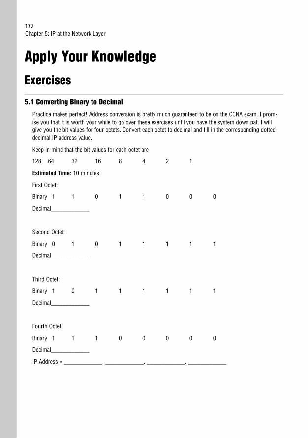
170
Apply Your Knowledge
Exercises
5.1 Converting Binary to Decimal
Practice makes perfect! Address conversion is pretty much guaranteed to be on the CCNA exam. I prom-ise you that it is worth your while to go over these exercises until you have the system down pat. I willgive you the bit values for four octets. Convert each octet to decimal and fill in the corresponding dotted-decimal IP address value.
Keep in mind that the bit values for each octet are
128 64 32 16 8 4 2 1
Estimated Time: 10 minutes
First Octet:
Binary 1 1 0 1 1 0 0 0
Decimal_____________
Second Octet:
Binary 0 1 0 1 1 1 1 1
Decimal_____________
Third Octet:
Binary 1 0 1 1 1 1 1 1
Decimal_____________
Fourth Octet:
Binary 1 1 1 0 0 0 0 0
Decimal_____________
IP Address = _____________. _____________. _____________. _____________
Chapter 5: IP at the Network Layer
Apply Your Knowledge171
5.2 Converting Decimal to Binary
Conversions go both ways. Now, I will give you the decimal values for four octets. Convert each octet tobinary and fill in the corresponding binary address value.
Estimated Time: 10 minutes
First Octet:
Decimal 224
Binary __________________
Second Octet:
Decimal 137
Binary __________________
Third Octet:
Decimal 15
Binary __________________
Fourth Octet:
Decimal 253
Binary __________________
Binary Address = _____________ _____________ _____________ _____________
5.3 Converting Decimal to Hexadecimal
You may be asked to determine a hexadecimal value given a decimal value. In this challenge I have givenyou the decimal value. You need to convert that to binary and then break the binary octet into two 4-bitgroups.
Keep in mind that the bit values for each 4-bit group are
8 4 2 1
Also, Figure 5.2 has the decimal-to-hexadecimal values.
172
Estimated Time: 10 minutes
Decimal = 105
Binary = ____ ____ ____ ____ ____ ____ ____ ____
First 4 bits of the binary octet:
____ ____ ____ ____ = Decimal _______ Hexadecimal_______
Last 4 bits of the binary octet:
____ ____ ____ ____ = Decimal _______ Hexadecimal_______
The combined hexadecimal value is 0x_________.
5.4 Binary Chart
There are several useful memorization tools for the IP subnetting questions on the CCNA exam. Fill in thebinary equivalent (one octet) for each of the following decimal values.
Estimated Time: 5 minutes
Decimal Binary
0
128
192
224
240
248
252
254
255
Chapter 5: IP at the Network Layer
Apply Your Knowledge173
5.5 Identify the Network ID
In this exercise, please use Boolean AND to determine the Network ID, given the IP address134.141.7.130 and subnet mask 255.255.255.0.
Estimated Time: 5 minutes
IP Address Binary
Subnet Mask Binary
Boolean AND
Network ID = _____________. _____________. _____________. _____________
Review Questions1. Convert binary 00101010 00111111 11011100 11111111 to decimal format.
2. Convert decimal 150.193.6.100 to binary format.
3. What is hexadecimal 0x5F in decimal format?
4. Perform Boolean AND to define the Network ID of IP address 200.62.183.26 255.255.255.0.
5. Given the IP address 32.116.5.0 and subnet mask 255.255.255.0, what is the Network ID?
6. Given the IP address 213.50.201.0 and subnet mask 255.255.255.0, what is the Broadcast IP?
7. What is the valid IP range for 220.9.3.0/24?
8. Define the zero subnet and broadcast subnet rules.
9. Describe the process of routing.
10. List the functions performed by a router or Layer 3 switch.
Exam Questions1. What is the decimal equivalent of 10010111 00000110 10101100 01110111?
❍ A. 151.6.172.119
❍ B. 151.6.172.120
❍ C. 151.6.172.121
❍ D. 151.6.172.122
174
2. What is the first octet range for Class B addresses?
❍ A. 1 to 126
❍ B. 128 to 191
❍ C. 192 to 223
❍ D. 224 to 239
3. What is the first octet range for Class C addresses?
❍ A. 1 to 126
❍ B. 128 to 191
❍ C. 192 to 223
❍ D. 224 to 239
4. How many hosts are available with a Class C network?
❍ A. 253
❍ B. 254
❍ C. 255
❍ D. 256
5. What is the network ID for a host with the IP address 124.199.7.18/28?
❍ A. 124.199.7.0
❍ B. 124.199.7.16
❍ C. 124.199.7.32
❍ D. 124.199.7.48
6. You have been assigned a Class C network address. A coworker has requested that you create 10networks that can support 10 hosts per network. What subnet mask should you use?
❍ A. 255.255.255.0
❍ B. 255.255.255.224
❍ C. 255.255.255.240
❍ D. 255.255.255.248
Chapter 5: IP at the Network Layer
Apply Your Knowledge175
7. Which of the following are valid host addresses in the 208.62.15.0 network with a255.255.255.224 subnet mask? (Choose the two best answers.)
❍ A. 208.62.15.0
❍ B. 208.62.15.1
❍ C. 208.62.15.30
❍ D. 208.62.15.32
8. Given the network address 192.131.10.0 and subnet mask 255.255.255.0, what is the total numberof networks and the total number of hosts per network?
❍ A. 1 network / 255 hosts
❍ B. 1 network / 254 hosts
❍ C. 2 networks / 62 hosts
❍ D. 6 networks / 30 hosts
9. How many valid host IP addresses are available with a network address of 218.41.99.24 and asubnet mask of 255.255.255.252?
❍ A. 2
❍ B. 6
❍ C. 14
❍ D. 30
10. If you need at least five subnetworks with a Class C network and you want to have as many hostsas possible on each network, what subnet mask would you use?
❍ A. 255.255.255.252
❍ B. 255.255.255.240
❍ C. 255.255.255.248
❍ D. 255.255.255.224
11. How many hosts are available with a Class B network?
❍ A. 254
❍ B. 64,000
❍ C. 65,534
❍ D. 16,777,214
176
12. What is the Broadcast IP for 196.23.250.32/27?
❍ A. 196.23.250.32
❍ B. 196.23.250.33
❍ C. 196.23.250.63
❍ D. 196.23.250.64
13. What subnet mask would you use if you had a Class B address and you would like 250 networks?
❍ A. 255.255.255.0
❍ B. 255.255.254.0
❍ C. 255.255.252.0
❍ D. 255.255.248.0
14. How many subnets can you have with subnet mask of 255.255.240 on a Class B network?
❍ A. 6
❍ B. 14
❍ C. 16
❍ D. 30
15. How many hosts are available if you have a Class B network with a subnet mask of255.255.255.128?
❍ A. 254
❍ B. 256
❍ C. 128
❍ D. 126
16. Which of the following are considered private addresses per RFC 1918? (Choose the three bestanswers.)
❍ A. 1.0.0.0
❍ B. 10.10.10.20
❍ C. 172.30.255.10
❍ D. 192.168.128.128
Chapter 5: IP at the Network Layer
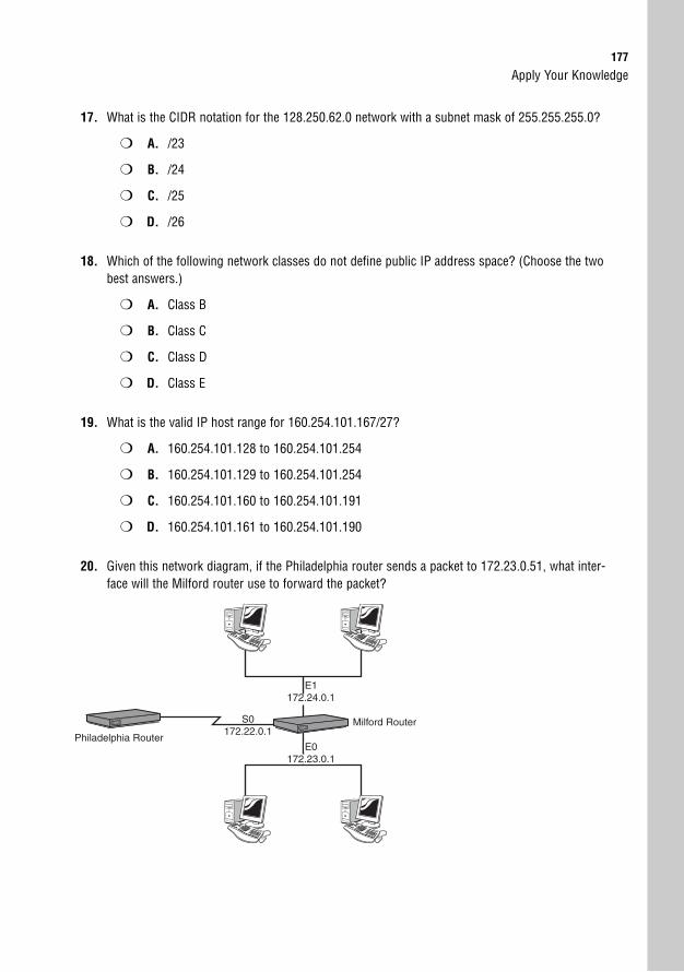
Apply Your Knowledge177
17. What is the CIDR notation for the 128.250.62.0 network with a subnet mask of 255.255.255.0?
❍ A. /23
❍ B. /24
❍ C. /25
❍ D. /26
18. Which of the following network classes do not define public IP address space? (Choose the twobest answers.)
❍ A. Class B
❍ B. Class C
❍ C. Class D
❍ D. Class E
19. What is the valid IP host range for 160.254.101.167/27?
❍ A. 160.254.101.128 to 160.254.101.254
❍ B. 160.254.101.129 to 160.254.101.254
❍ C. 160.254.101.160 to 160.254.101.191
❍ D. 160.254.101.161 to 160.254.101.190
20. Given this network diagram, if the Philadelphia router sends a packet to 172.23.0.51, what inter-face will the Milford router use to forward the packet?
E1E1172.24.0.1172.24.0.1
E1172.24.0.1
Milford RouterS0172.22.0.1
Philadelphia RouterE0E0
172.23.0.1172.23.0.1E0E0
172.23.0.1172.23.0.1E0
172.23.0.1
178
❍ A. E0
❍ B. E1
❍ C. S0
❍ D. S1
21. Given the IPv6 address of 2001:0A20:D201:0000:0000:DC3F:0000:011D, which of the followingare valid ways to write the same address? (Choose two)
❍ A. 2001:A20:D201:0:0:DC3F:0:11D
❍ B. 2001:A20:D201::DC3F:0:11D
❍ C. 2001:A2:D201::DC3F:0:11D
❍ D. 2001:A20::DC3F::11D
Answers to Review Questions1. 128 64 32 16 8 4 2 1
0 0 1 0 1 0 1 0
32+8+2 = 42
128 64 32 16 8 4 2 1
0 0 1 1 1 1 1 1
32+16+8+4+2+1 = 63
128 64 32 16 8 4 2 1
1 1 0 1 1 1 0 0
128+64+16+8+4 = 220
128 64 32 16 8 4 2 1
1 1 1 1 1 1 1 1
128+64+32+16+8+4+2+1 = 255
The correct answer is 42.63.220.255.
2. 128 64 32 16 8 4 2 1
1 0 0 1 0 1 1 0
128 64 32 16 8 4 2 1
1 1 0 0 0 0 0 1
Chapter 5: IP at the Network Layer

Apply Your Knowledge179
128 64 32 16 8 4 2 1
0 0 0 0 0 1 1 0
128 64 32 16 8 4 2 1
0 1 1 0 0 1 0 0
The correct answer is 10010110 11000001 00000110 01100100.
3. The first hexadecimal character is 5, which is the same as the decimal value.
8 4 2 1
0 1 0 1
The second hexadecimal character is F, which is 15 in decimal.
8 4 2 1
1 1 1 1
Now you can combine the two 4-bit groups to get 01011111, which converts to 95 in decimal.
4. IP Address Binary = 11001000 00111110 10110111 00011010
Subnet Mask Binary= 11111111 11111111 11111111 00000000
Boolean AND = 11001000 00111110 10110111 00000000
The correct answer is 200.62.183.0.
5. This is considered an easy mask. You just write down the original octets with a subnet mask valueof 255 and a 0 for each octet with a 0 value in the subnet mask.
The correct answer is 32.116.5.0.
6. Because this has an easy subnet mask, you can copy the first three octets and then replace the lastoctet with 255.
The correct answer is 213.50.201.255.
7. This IP address subnet mask is 255.255.255.0, so the network ID is 220.9.3.0. The broadcast IP is220.9.3.255.
The correct answer is 220.9.3.1 to 220.9.3.254.
8. Zero subnet may also be referred to as subnet zero. The zero subnet is the first subnet in a net-work and has all binary 0s in the subnet field. For the purpose of taking the CCNA exam, youshould not include the first subnet when calculating the number of networks in a larger subnet.This is one of the two reserved subnet numbers on a network and one of the reasons why yousubtract from the total number of networks to get the correct answer for the test. The other net-work is the broadcast subnet, which has all 1s in the subnet field.
180
9. Traffic that is generated by a device has the source MAC and source IP address of that device. If aframe is sent to a server on another segment of a WAN, the destination IP address is that of theserver the frame is trying to reach. Because the server is not on the same segment, the destinationMAC address is that of the router, which is the default gateway. The router takes a look at theframe and at its own routing table. It then decides what interface to use to forward the frame,based on the network portion of the IP address. The router attaches its own MAC address as thesource MAC address of the frame before the frame is sent to the server.
10. Suppress broadcasts or multicasts.
Determine the best path for data transfer (routing).
Strip down and add to Data Link layer frames.
Implement access lists for packet filtering (permit/deny statements).
Set up quality of service (QoS) qualifiers to measure network performance.
Answers to Exam Questions1. A. The decimal equivalent of 10010111 00000110 10101100 01110111 is 151.6.172.119. Answers
B and D can be eliminated right away because both IP addresses end with an even number.
2. B. The first octet range for Class B addresses is 128 to 191. Answers A, C, and D are incorrectbecause the range of 1 to 126 is Class A, 192 to 223 is Class C, and 224 to 239 is reserved formulticast.
3. C. Answer C is correct because the first octet range for Class C addresses is 192 to 223. AnswersA, B, and D are incorrect because the first octet range for Class A addresses is 1 to 126, for ClassB is 128 to 191, and 224 to 239 is reserved for multicast.
4. B. There are 254 hosts per Class C network. For any Class C network there are 24 network bitsand 8 host bits: 28 – 2 = 254.
5. B. The Network ID of 124.199.7.18/28 is 124.199.7.16. If you write out the subnet mask it is255.255.255.240. Subtract 240 from 256 and you have 16; 16×1 = 16, which is the first validincrement that can be the network ID. The next network ID is 124.199.7.32.
6. C. Subnet mask 255.255.255.240 allows for 14 networks and 14 hosts. Answer A is incorrectbecause subnet mask 255.255.255.0 allows for only one network with 254 hosts. Answer B isincorrect because subnet mask 255.255.255.224 allows for 6 networks and 30 hosts, and answerD is incorrect because subnet mask 255.255.255.248 allows for 30 networks and 6 hosts.
7. B, C. 208.62.15.1 and 208.62.15.30 are valid host addresses in the 208.62.15.0 network with a255.255.255.224 subnet mask. Answer A is incorrect because 208.62.15.0 is the network ID andtherefore is not a valid host address. Answer D is incorrect because 208.62.15.32 is the networkID of the next network and is not valid.
8. B. The network address 192.131.10.0 and subnet mask 255.255.255.0 has one network with 254hosts.
Chapter 5: IP at the Network Layer

Apply Your Knowledge181
9. A. With a network address of 218.41.99.24 and a subnet mask of 255.255.255.252, 2 valid hostaddresses are available. Answer B is incorrect because subnet mask 255.255.255.248 has 6 avail-able hosts. Answers C and D are incorrect because subnet mask 255.255.255.240 has 14 availablehosts, and subnet mask 255.255.255.224 has 30 available hosts.
10. D. Subnet mask 255.255.255.224 would allow for 6 networks with 30 available hosts per network.Answer A is incorrect because subnet mask 255.255.255.252 allows for 62 networks but only 2hosts per network. Answers B and C are incorrect because subnet mask 255.255.255.240 allowsfor 14 networks with only 14 hosts per network, and subnet mask 255.255.255.248 allows for 30networks with only 8 hosts per network.
11. C. There are 65,534 hosts available for a Class B network. Answers A and D are incorrect becausea Class C network has 254 possible hosts, and a Class A has 16,777,214 possible hosts.
12. C. The broadcast IP for 196.23.250.32/27 is 196.23.250.63. Answer A is incorrect because196.23.250.32 is the Network ID of 196.23.250.32/27. Answers B and D are incorrect because196.23.250.33 is the first valid IP in the /27 network and 196.23.250.64 is the Network ID of thenext network.
13. A. The only subnet that allows for 250 networks is 255.255.255.0. Subnet mask 255.255.255.0can create 254 subnets. Answer B is incorrect because subnet mask 255.255.254.0 can create 126subnets. Answer C is incorrect because subnet mask 255.255.252.0 can create 62 subnets.Answer D is incorrect because subnet mask 255.255.248.0 can create 30 subnets.
14. B. You can have 14 subnetworks with a Class B network that has a subnet mask of 255.255.240.0.
15. D. Answer D is correct because there are 126 possible hosts for a Class B network with a subnetmask of 255.255.255.128. Answer A is incorrect because a Class B network with a subnet mask of255.255.255.0 has 254 possible hosts. Answers B and C are incorrect because the Network ID andBroadcast IP addresses were not subtracted from the total number of IPs in each subnet.
16. B, C, D. RFC 1918 defines the following private IP address ranges: 10.0.0.0 to 10.255.255.255,172.16.0.0–172.31.255.255, and 192.168.0.0 to 192.168.255.255. Answer A is incorrect becausethe address 1.0.0.0 is a Class A public address.
17. B. /24 is the correct CIDR notation for the 128.250.62.0 network with a subnet mask of255.255.255.0. Answer A is incorrect because /23 is the CIDR notation for 255.255.254.0. AnswerC is incorrect because /25 is the CIDR notation for 255.255.255.128, and answer D is incorrectbecause /26 is the CIDR notation for 255.255.255.192.
18. C, D. Class D defines multicast address space and Class E defines IP address space reserved forresearch. Answers A and B are incorrect because Classes B and C are both defined for public use.
19. D. The valid host range for 160.254.101.167/27 is 160.254.101.161 to 160.254.101.190. AnswersA and B are incorrect because both 160.254.101.128 to 160.254.101.254 and 160.254.101.129 to160.254.101.254 are part of a 255.255.255.128 subnet. Answer C is incorrect because with therange 160.254.101.160 to 160.254.101.191, the first IP is the Network ID and it is not a valid hostIP address.
182
20. A. The Milford router forwards the packet through the E0 interface because the network matchesthe 172.23.0.0 network. Answer B is incorrect because interface E1 is going to the 172.24.0.0 net-work, and answer C is incorrect because interface S0 is going to the Philadelphia router via the172.22.0.0 network. Answer D is incorrect because interface S1 does not exist in this scenario.
21. A, B. Leading zeros and contiguous groups of zeros can be taken out of the IPv6 address andreplaced with “::” when written. Answer C is incorrect because a trailing zero was removed fromthe second group. Answer D is incorrect because there are two sets of “::”, which is not a validformat.
Suggested Readings and ResourcesThe following are some recommended readings on IPv4, private and public IP addressing,subnetting, and routing:
1. “IPv4,” http://en.wikipedia.org/wiki/IPv4
2. “RFC 1918,” http://www.faqs.org/rfcs/rfc1918.html
3. “IP Addressing and Subnetting for New Users,” http://www.cisco.com/warp/public/701/3.html
4. “IP Address Subnetting Tutorial,” http://www.ralphb.net/IPSubnet/
5. “Network Calculators,” http://www.subnetmask.info/
6. Andrew Colton. Cisco IOS for IP Routing. Rocket Science Press, Inc., 2002.
Chapter 5: IP at the Network Layer
6C H A P T E R S I X
Introduction to Cisco Routersand Switches
ObjectivesThis chapter covers the following Cisco-specified objectives for the “Describe how a networkworks” section of the 640-802 CCNA exam:
. Select the components required to meet a network specification
. Describe the purpose and functions of various network devices
OutlineIntroduction 186
Interfaces and Modules 186
LAN Interfaces 186
WAN Interfaces 187
BRI 187
Synchronous Serial 188
Asynchronous Serial 188
HSSI 188
T1 Controller Card 188
Data Communications Equipment (DCE) 188
Data Terminal Equipment (DTE) 189
Cisco Memory Components 190
ROM 191
Flash 191
RAM 191
NVRAM 191
Cisco Internetworking Operating System 191
Feature Sets 192
IOS Image File Naming 193
Cisco Router Models and Features 194
Cisco Switch Models and Features 195
Chapter Summary 197
Key Terms 197
Apply Your Knowledge 198
Exercise 198
Review Questions 198
Exam Questions 198
Answers to Review Questions 200
Answers to Exam Questions 201
Suggested Readings and Resources 203

Study Strategies. Identify the interfaces and modules used with Cisco devices.
. Describe the Cisco memory components ROM, Flash, RAM, andNVRAM.
. Familiarize yourself with Cisco Internetworking Operating System (IOS)feature sets.
. Review the IOS image file structure.
. Identify the Cisco Router models and their features.
. Identify the Cisco Switch models and their features.
186
IntroductionUp to this point, we have discussed general internetworking technologies and devices to providea background of the material relevant to the CCNA exam. Now the scope of the discussion widensto include Cisco technology. This chapter reviews internetworking devices (routers and switches)that were developed by Cisco for network implementations. It also discusses the individual hard-ware components that make up a router and switch, which you must thoroughly understandbefore the configuration of these devices is explained. This introduction to Cisco technology leadsup to Chapter 9, “Understanding the Cisco SDM,” and Chapter 7, “Foundation Cisco IOSOperations,” where you will delve into hands-on device operations and configurations.
Interfaces and ModulesObjectives:
. Select the components required to meet a network specification
. Describe the purpose and functions of various network devices
Networks can be connected to Cisco hardware in a variety of ways. Communication lines canbe terminated to a Cisco device via hardware interfaces and modules. Interfaces provide aphysical point of interaction between two networks. That hardware interface includes thecable, plug, socket, and signal that sync up together to communicate among devices.
Certain Cisco routers are built as fixed-port routers or fixed configuration routers and do notallow for additional network module installations. Cisco also offers modular-port routers.Modular-port routers allow for future system upgrades by mounting network modules in avail-able spaces to accommodate changing network environments. A module is a self-containedcomponent. A Cisco network module has built-in hardware interfaces to add alternate con-nection options on a network. Because they are modular components, Cisco routers can beupgraded easily and with minimal expense to the company. This chapter reviews the variety ofphysical connection types on LAN and WAN devices.
LAN InterfacesLocal area network (LAN) interfaces are used to provide a point of interconnection betweenCisco switches and other network devices. Cisco provides a wide selection of switches that canbe implemented on a LAN and offer end-user connectivity. In Chapter 3, “Data LinkNetworking Concepts,” Layer 2 switches were introduced. The Cisco 2950 series switch fam-ily includes various models with different interface options, such as the Cisco 2950-12 and theCisco 2950-24. The 2950-12 has 12 built-in ethernet ports, whereas the 2950-24 has 24 built-in ethernet ports. Certain models also have Gigabit Ethernet slots.
Chapter 6: Introduction to Cisco Routers and Switches
Interfaces and Modules187
If Gigabit Ethernet ports are included, the front panel of a 2950 model has 10/100 ethernetports on the left side of the switch and 2 Gigabit Ethernet slots that accommodate LAN inter-face modules on the right. The 10/100 ports allow for either a 10Mbps or 100Mbps connec-tion speed. Media connects to an ethernet switch port via an RJ-45 connector. As far as theswitch is concerned, each ethernet port is designated as a numbered interface for identifica-tion. The top left port is labeled 1 by the switch. Each interface begins with a 0/#, where the# sign equals the port number on the switch. The top left port is then named 0/1 on thatswitch. Given this formula, the bottom left port is labeled 0/2.
The Gigabit Ethernet slots are available for Gigabit Interface Converters (GBICs). A GBICinterface module can be inserted into the Gigabit Ethernet slot to allow for different mediaconnections to that port. The physical media can range from copper to single-mode fiber. AGBIC is also hot swappable, so you can remove and replace it without shutting off power tothe switch. This helps to avoid interruption of service to that switch.
The back panel of the 2950 includes power input and the switch’s console port. The consoleport has an RJ-45 connector and is connected to a terminal with a rollover cable for initialswitch configuration.
WAN InterfacesWide area network (WAN) interfaces are also used to provide a point of interconnectionbetween Cisco routers and other network devices. Types of WAN interfaces include
. Basic Rate Interface (BRI)
. Synchronous Serial
. Asynchronous Serial
. High-Speed Serial Interface (HSSI)
. T1 Controller Card
BRIBRI is an Integrated Services Digital Network (ISDN) service that consists of two 64Kbpsbearer (B) channels and one 16Kbps data channel. Voice, video, and data traffic can be carried
EXAM ALERTFor the CCNA exam, know how the interfaces are labeled for an ethernet port. This information is nec-essary for any switch configuration exercises.
188
over the B-channels. Signals between telephone company switches use the D-channel. Ciscooffers an 8-port ISDN-BRI with a built-in Network Termination Type 1 (NT-1) NetworkModule for router installation.
Chapter 6: Introduction to Cisco Routers and Switches
EXAM ALERTFor the exam you should know that BRI is an ISDN line that consists of two 64Kbps bearer (B) channelsand one 16Kbps data (D) channel.
The NT-1 is a telephone company requirement for an ISDN line connection. This networkmodule has a BRI U interface, which means that the NT-1 is built in on the network moduleand does not require a separate NT-1 device.
Synchronous SerialA synchronous serial interface synchronizes clocks for the bit stream of both the sending andreceiving end of a serial link. This allows for the data rate to be adjusted if necessary to ensurethat both ends of a serial link are functioning at the same speed.
Asynchronous SerialAn asynchronous serial interface does the opposite of a synchronous serial interface. It doesnot synchronize the clocks for the bit stream of the sending and receiving end of a serial link.Cisco offers a 4-port asynchronous/synchronous serial network module.
With the asynchronous/synchronous serial network module, each port can be configured indi-vidually as either asynchronous or synchronous, depending on your network setup.
HSSIHigh-speed serial interfaces offer up to 52Mbps transmission rates to the WAN from a Ciscorouter. The higher speed capacity is relevant if the corporate backbone requires high-speedInternet access and VPN connectivity. Cisco offers a 2-port HSSI port adapter.
T1 Controller CardAlso referred to as a digital signal level 1 (DS1) service, a T1 is a connecting line that offers a1.544Mbps data transmission speed. A single T1 line consists of 24 digital signal level 0 (DS0)channels that are 64Kbps each and an additional 8Kbps that is reserved for management over-head. A T1 controller card can be installed in a router’s T1 slot to communicate with and con-trol the 24 DS0 channels.
Data Communications Equipment (DCE)Data Communications Equipment (DCE) or Data Circuit-Terminating Equipment (DCE) isthe term used to identify a device that connects the Data Terminal Equipment (DTE) to a
Interfaces and Modules189
service provider’s communications line. The DCE side of a connection sets the clock speed fora serial connection.
DCE equipment may consist of a
. Modem
. Channel Service Unit/Data Service Unit (CSU/DSU)
. Basic Rate Interface Network Termination Type 1 (BRI NT-1)
Modems convert a digital signal into an analog signal for transmission over a telephone line.The signal is converted back into a digital format when it reaches the device on the other endof that telephone line.
A Channel Service Unit/Data Service Unit (CSU/DSU) serves as the intermediary betweenthe service provider and the WAN router. In most cases, the CSU/DSU provides the clockspeed for the router. A CSU/DSU may be a separate unit or it could be incorporated into aWAN interface card (WIC).
If it is not built in on a Cisco router via a BRI-U (Basic Rate Interface-User) interface, theservice provider requires separate BRI NT-1 hardware as a termination point for the commu-nications line. The BRI NT-1 then connects to the Cisco router.
EXAM ALERTA modem, CSU/DSU, or BRI NT-1 can be used to connect a WAN router at the customer premise to aservice provider.
Data Terminal Equipment (DTE)Data Terminal Equipment is the term used to identify a device at the user end of a networkand is connected to the service provider via the DCE device.
DTE equipment may consist of a
. Router
. PC
. Server
In Figure 6.1, the service provider, whom you will most likely hear called a telco, brings a com-munication line from its central office (CO) to the customer and terminates its line to theCSU/DSU. The CSU/DSU is then connected to the customer router. The point at which thetelco terminates its line to the customer is called a demarcation point or demarc. Customer-owned equipment, such as the router and typically the CSU/DSU, is referred to as customerpremise equipment (CPE).
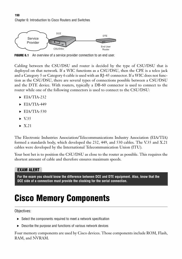
190
FIGURE 6.1 An overview of a service provider connection to an end user.
Cabling between the CSU/DSU and router is decided by the type of CSU/DSU that isdeployed on that network. If a WIC functions as a CSU/DSU, then the CPE is a telco jackand a Category 5 or Category 6 cable is used with an RJ-45 connector. If a WIC does not func-tion as the CSU/DSU, there are several types of connections possible between a CSU/DSUand the DTE device. With routers, typically a DB-60 connector is used to connect to therouter while one of the following connectors is used to connect to the CSU/DSU:
. EIA/TIA-232
. EIA/TIA-449
. EIA/TIA-530
. V.35
. X.21
The Electronic Industries Association/Telecommunications Industry Association (EIA/TIA)formed a standards body, which developed the 232, 449, and 530 cables. The V.35 and X.21cables were developed by the International Telecommunication Union (ITU).
Your best bet is to position the CSU/DSU as close to the router as possible. This requires theshortest amount of cable and therefore ensures maximum speeds.
Chapter 6: Introduction to Cisco Routers and Switches
CSU/DSUEnd User
Router
DCEDTE
Service Provider
EXAM ALERTFor the exam you should know the difference between DCE and DTE equipment. Also, know that theDCE side of a connection must provide the clocking for the serial connection.
Cisco Memory ComponentsObjectives:
. Select the components required to meet a network specification
. Describe the purpose and functions of various network devices
Four memory components are used by Cisco devices. Those components include ROM, Flash,RAM, and NVRAM.
Cisco Internetworking Operating System191
ROMRead-only memory (ROM) contains the basic code for booting a device and maintainingPower on Self Test (POST), ROM Monitor (ROMmon), bootstrap, and RXBOOT. Becausethis type of memory is read-only, it cannot be changed by any configuration done at the net-working device. ROM is nonvolatile, so data is not lost when the device is powered off.
FlashFlash is installed on either an electrically erasable, programmable, read-only memory (EEP-ROM) or Personal Computer Memory Card International Association (PCMCIA) card. Flashmemory contains the Cisco Internetworking Operating System (IOS) image. The router usesFlash by default to locate the IOS when it is booted. Configuration files may also be stored ona Flash card. Like ROM, Flash is also nonvolatile memory.
RAMRandom-access memory (RAM) is used for short-term storage of a machine’s running IOS andrunning configuration. The IOS is copied from Flash to RAM. This is the only type of systemmemory that is not permanent. At times, you may hear RAM also referred to as dynamic ran-dom-access memory (DRAM). Because this type of memory is volatile, it is lost whenever themachine is shut down.
EXAM ALERTRAM contains the running IOS, with the exception of Run-From-Flash (RFF) routers. RAM also containsthe running configuration or the active configuration that is used after a machine is booted.
NVRAMNonvolatile random-access memory (NVRAM) stores the startup configuration. This is theconfiguration that is loaded when the machine is booted.
Cisco Internetworking Operating SystemCisco IOS software is developed and maintained by Cisco to support a full array of systemfunctions, applications (including Internet applications), and network hardware in a singlesoftware package. IOS software is installed on each Cisco router or switch and can accommo-date network growth and provide for secure data transfers. The command-line interface (CLI)for routers and switches defines the commands that are used to communicate with the IOS.Future chapters demonstrate the use of CLI commands on both network devices.
192
Cisco releases IOS software using what they call trains. Each release can be further defined bytrain identifiers. A train identifier determines whether a release is a Technology (T),Enterprise, or Service Provider (SP) release. When the IOS version has no train identifier, itis the mainline train. With so many features and applications being offered with each release,a train identifier can further define a specific subset of features. For example, if you have arelease named 12.3(1)T, the IOS version number breaks down as follows:
. 12.3 refers to the mainline train that will not be added to but will be subject to IOSbug fixes.
. (1) represents the release number, which increments with each new release of themainline train.
. T identifies the type of train release where T stands for Technology. This may also bean S (Service Provider) or E (Enterprise) train.
Feature SetsA feature set is a package of the features that is offered in addition to the basic IOS functionsof an IOS software release. You can select more than one feature set per release. Feature setsmay be identified as standard, enhanced, or advanced, depending on the services that are sup-ported. To give you an idea of the latest features available with Cisco IOS, current releasesoffer the following software functionality:
. IP Base—The base IOS image.
. IP Voice—Features include Voice over IP (VoIP), and Voice over Frame (VoFR).
. Advanced Security—Offers advanced protection via firewall, Intrusion DetectionSystem (IDS), Secure Shell (SSH), and IP Security (IPSec).
. SP Services—Includes service provider services such as IPv6, Netflow SSH, ATM,Voice over ATM (VoATM), and Frame Relay.
. Enterprise Base—Consists of Enterprise Layer 3 routed protocols, and IBM support.
. Advanced IP Services—Offers a combination of the Advanced Security and ServiceProvider Services feature sets.
. Enterprise Services—Combines the Enterprise Base and Service Provider Services fea-ture sets with full IBM support.
. Advanced Enterprise Services—Incorporates all the Cisco IOS feature sets.
Chapter 6: Introduction to Cisco Routers and Switches
A Cisco Catalyst switch may use either a Cat OS or Cisco IOS. The major difference with Cat OS is the CLIcommands that are used in conjunction with the operating system software.
NOTE
Cisco Internetworking Operating System193
IOS Image File NamingThe IOS image file represents the name of the system image on a Cisco router or switch. Thehardware platform, feature set, compression format, IOS version, and train information are allfound in the name of an IOS image file. An IOS image filename can be broken out to identify morespecific information about the IOS in use by a device. This is helpful if you are troubleshooting asystem issue and need to verify what version is currently in use. Cisco may be aware of an IOS bug,or the version may simply be outdated and an IOS upgrade might be the solution to your trouble.To find the IOS image filename, use the show version command from the command prompt.
Given the example filename c2600-ipbase-1.122-1.T.bin (.bin indicates binary format),from left to right, each portion of the filename represents the following:
. c2600—Hardware platform (Cisco 2600 router)
. ipbase—Feature set
. 1—File format (compressed re-locatable)
. 122—IOS version number
. 1—Maintenance release number
. T—Train identifier
EXAM ALERTRemember the IOS image file structure. If given a filename, you should be able to break down eachpart of the file and what it represents.
ChallengeUnderstanding Cisco IOS is necessary for the maintenance and troubleshooting of Cisco routers andswitches. I will provide an IOS image filename and would like you to identify the hardware platform, fea-ture set, compression format, IOS version, and train information for that file.
IOS Image filename—c1700-entbase-1.121-1.E.bin
Maintenance Release Number _______________
File Format _____________
Hardware Platform _______________
Train Identifier ______________________
Feature Set _______________________
IOS version number ____________________
194
Cisco Router Models and FeaturesObjective:
. Describe the purpose and functions of various network devices
Cisco offers a wide selection of router models for network implementations. The Cisco fami-ly of routers can accommodate networks that range in size and require various network inter-faces for WAN connectivity. As mentioned, some router models are fixed port and fixedconfiguration, whereas others are modular-port routers. To help you prepare for the CCNAexam, a Cisco 2500 series router model can perform a broad range of the basic routing func-tions. This router can provide you with sufficient functionality to practice initial router setupand configurations.
The 2500 series hardware can support CSU/DSU, ethernet, token ring, asynchronous or syn-chronous serial, and ISDN connections. The 2500 series routers coupled with Cisco IOS soft-ware can support routed protocols such as IP, Novell IPX, and AppleTalk. They can alsosupport a wide array of routing protocols. Although most of the 2500 family routers are fixedport, the 2524 and 2525 models are both modular-port routers.
In addition to the 2500 series routers, Cisco also offers the following router series:
. 800 Series—Fixed-port and fixed-configuration routers that support AsymmetricDigital Subscriber Line (ADSL), ADSL over ISDN, Single-pair High-Speed DSL(G.SHDSL), Serial, and ethernet to an external cable modem or DSL connections.They can also support a small office or a home office for a telecommuter.
. 1600 Series—Fixed-port routers that support ISDN, asynchronous serial, or synchro-nous serial connections and can support a small- to moderately-sized business.
. 1700 Series—Modular-port routers that support built-in Fast Ethernet LAN portsand WAN/Voice modular slots, and can support a small- to moderately-sized business.
. 1800 Series—Fixed-port and modular-port routers that build on the 1700 Seriesrouter functionality with integrated services such as IPSec VPN, firewall security,inline intrusion prevention (IPS), Network Admission Control (NAC), and URL filter-ing to small offices.
. 2600 Series—Modular multiservice access routers that support built-in ethernet LANports, built-in Fast Ethernet LAN ports, and WAN/voice modular slots. They can sup-port a small to medium office.
. 2800 Series—Integrated service routers that support built-in Fast Ethernet LANports, built-in Gigabit Ethernet LAN ports, and WAN/voice modular slots. They cansupport a small to medium office, its telecommuters, and Wi-Fi connections.
Chapter 6: Introduction to Cisco Routers and Switches
Cisco Switch Models and Features195
. 3600 Series—Modular multiservice access routers that support data, voice, video, andVPN. They can support a medium to large office or a small Internet Service Provider(ISP).
. 3700 Series—Modular multiservice access routers that support built-in Fast EthernetLAN ports and WAN/voice modular slots. They can support branch offices.
. 3800 Series—Modular multiservice access routers that support built-in dual GigabitEthernet LAN ports and enhanced network module slots. They can support a mediumto large business with integrated services.
. 7200 Series—Can be used with an Enterprise Edge or Service Provider Edge environ-ment and support links that range in size from a DS0 (64Kbps) all the way up to anOC12 (655Mbps). They can support Fast Ethernet, Gigabit Ethernet, and Packet overSonet connections. Chassis slots are open for installation of more than 70 networkinterfaces.
. 7600 Series—Are likely to be found in a main office of an enterprise business or at asmall service provider’s point-of-presence (POP) site. Each chassis can support a maxi-mum of 4 slots. Each slot has either a 40Gbps or 720Gbps capacity with advancedoptical service modules.
Cisco Switch Models and FeaturesObjective:
. Describe the purpose and functions of various network devices
The Cisco family of switches includes the Catalyst switch models, which as you learned earli-er in this chapter might use the Cat OS rather than the IOS. As with Cisco routers, the switchmodel numbers increase as they are upgraded for enhanced overall operability. Various switch-es have been developed over the years to accommodate the size and functionality requirementsof LANs around the world. You may have a Cisco 1900, 2800, 2900, or 2924 switch to helpyou study for the Cisco Certified Network Associate exam. These models should be easy tofind and affordable, and they cover all the features necessary for the exam when coupled withCisco IOS.
In addition to the 1900, 2800, 2900, and 2924 series switches, Cisco also offers the followingswitch series:
. 2950 Series—Includes a fixed-configuration switch that can support both FastEthernet and Gigabit Ethernet connections.

196
. 3500 Series—Are stackable switches that can employ Cisco Switch Clustering tech-nology and GigaStack GBICs, and support Layer 3 functionality.
. 4000 Series—Can support high-density copper, fiber-based interfaces, Fast Ethernet,Gigabit Ethernet connections, and Layer 3 functionality.
. 6500 Series—Can support Power over Ethernet (PoE) devices, 10/100Mbps ethernetports, 10/100/1000Mbps ethernet ports, 10Gbps ethernet ports, and Layer 3 functionality.
Cisco switches may also support PoE. PoE enables an end device to receive power over a cop-per ethernet cable. End devices that might use PoE include wireless access points, IP tele-phones, video cameras, and card scanners. This technology was originally developed by Ciscoand called “inline power.” IEEE has since standardized PoE with 802.3af.
Chapter 6: Introduction to Cisco Routers and Switches
Chapter Summary197
Chapter SummaryA general knowledge of Cisco hardware and IOS is integral to your preparation for the CCNAexam. Chapter 7, “Foundation Cisco IOS Operations,” shows you how to correctly navigatethrough the Cisco IOS. Also, Cisco router and switch configurations are presented through-out the remainder of this book.
Key Terms. interface
. module
. GBIC
. BRI
. synchronous
. asynchronous
. HSSI
. T1 controller card
. DS0
. DS1
. T1
. BRI
. ISDN
. NT-1
. HSSI
. DTE
. modem
. CSU/DSU
. CO
. demarc
. CPE
. ROM
. Flash
. RAM
. NVRAM
. IOS
. train
. CLI
. PoE
198
Apply Your Knowledge
Exercise
6.1 Cisco Memory Components
You may be asked to identify the memory components that are used on Cisco devices. In this exercise,please list the four types of memory and their respective functions.
Estimated Time: 10 minutes
Memory Component Memory Component Functionality
Review Questions1. Describe a GBIC.
2. List the WAN interfaces and their descriptions.
3. Define DCE and DTE.
4. What is the Cisco IOS?
5. Define PoE.
Exam Questions1. Which WAN interface is an ISDN line that consists of two 64Kbps bearer (B) channels and one
16Kbps data (D) channel?
❍ A. BRI
❍ B. Synchronous serial
❍ C. Asynchronous serial
❍ D. HSSI
Chapter 6: Introduction to Cisco Routers and Switches
Apply Your Knowledge199
2. Which WAN interface synchronizes clocks for the bit stream of both the sending and receiving endof a serial link?
❍ A. BRI
❍ B. Synchronous serial
❍ C. Asynchronous serial
❍ D. HSSI
3. Which WAN interface offers up to 52Mbps transmission rates to the WAN from a Cisco router?
❍ A. BRI
❍ B. Synchronous serial
❍ C. Asynchronous serial
❍ D. HSSI
4. Which of the following devices can be labeled Data Circuit-Terminating Equipment (DCE)? (Choosethe 3 best answers.)
❍ A. Router
❍ B. Modem
❍ C. CSU/DSU
❍ D. BRI NT-1
5. Which of the following devices can be labeled Data Terminal Equipment (DTE)? (Choose the 3 bestanswers.)
❍ A. Router
❍ B. Modem
❍ C. PC
❍ D. Server
6. What type of memory contains the basic code for booting a device and maintaining POST,ROMmon, bootstrap, and RXBOOT?
❍ A. ROM
❍ B. Flash
❍ C. RAM
❍ D. NVRAM
200
7. What type of memory is nonvolatile and contains the Cisco IOS image?
❍ A. ROM
❍ B. Flash
❍ C. RAM
❍ D. NVRAM
8. This type of memory contains the running IOS and the running configuration (active configuration)that is used after a machine is booted.
❍ A. ROM
❍ B. Flash
❍ C. RAM
❍ D. NVRAM
9. This type of memory stores the startup configuration.
❍ A. ROM
❍ B. Flash
❍ C. RAM
❍ D. NVRAM
10. What does the ipbase portion of the Cisco IOS file named c2600-ipbase-1.122-1.T.bin represent?
❍ A. Hardware platform
❍ B. Feature set
❍ C. Train identifier
❍ D. IOS version
Answers to Review Questions1. A GBIC interface module can be inserted into the Gigabit Ethernet slot to allow for different media
connections to that port. The physical media can range from copper to single-mode fiber. A GBICis also hot swappable, so it can be installed without interrupting service to that switch.
2. Basic Rate Interface (BRI)
BRI is an ISDN line that consists of two 64Kbps bearer (B) channels and one 16Kbps data (D)channel. Voice, video, and data traffic can be carried over the B-channels. Signals between tele-phone company switches use the D-channel.
Chapter 6: Introduction to Cisco Routers and Switches
Apply Your Knowledge201
Synchronous serial
A synchronous serial interface synchronizes clocks for the bit stream of both the sending andreceiving end of a serial link. This enables the data rate to be adjusted if necessary to ensure thatboth ends of a serial link are functioning at the same speed.
Asynchronous serial
An asynchronous serial interface does the opposite of a synchronous serial interface. It does notsynchronize the clocks for the bit stream of the sending and receiving end of a serial link.
High-Speed Serial Interface (HSSI)
High Speed Serial Interfaces offer up to 52Mbps transmission rates to the WAN from a Ciscorouter.
T1 controller card
A T1 controller card can be installed in a router’s T1 slot to communicate with and control the 24DS0 channels.
3. Data Circuit-Terminating Equipment (DCE) or Data Communications Equipment is the term used toidentify a device that connects the Data Terminal Equipment (DTE) to a service provider’s commu-nications line. DCE equipment may consist of a modem, CSU/DSU, or BRI NT-1.
DTE is the term used to identify a device at the user end of a network and is connected to the serv-ice provider via the DCE device. DTE equipment may consist of a router, PC, or server.
4. Cisco IOS software is developed and maintained by Cisco to support a full array of system func-tions, applications (including Internet applications), and network hardware in a single softwarepackage. IOS software is installed on each Cisco router or switch and can accommodate networkgrowth and provide for secure data transfers. The command-line interface (CLI) for routers andswitches defines the commands that are used to communicate with the IOS.
5. Power over Ethernet (PoE) enables an end device to receive power over a copper ethernet cable.End devices that might use PoE include IP telephones, video cameras, and card scanners. Thistechnology was originally developed by Cisco and called “inline power.” IEEE has since standard-ized PoE with 802.3af.
Answers to Exam Questions1. A. BRI consists of two 64Kbps B channels and one 16Kbps D channel. Answer B is incorrect
because synchronous serial synchronizes clocks for the bit stream of both the sending and receiv-ing end of a serial link. Answer C is incorrect because asynchronous serial does not synchronizethe clocks for the bit stream of the sending and receiving end of a serial link. Answer D is incorrectbecause HSSI offers up to 52Mbps transmission rates to the WAN from a Cisco router.
202
2. B. Synchronous serial synchronizes clocks for the bit stream of both the sending and receivingend of a serial link. Answer A is incorrect because BRI consists of two 64Kbps B channels and one16Kbps D channel. Answer C is incorrect because asynchronous serial does not synchronize theclocks for the bit stream of the sending and receiving end of a serial link. Answer D is incorrectbecause HSSI offers up to 52Mbps transmission rates to the WAN from a Cisco router.
3. D. HSSI offers up to 52Mbps transmission rates to the WAN from a Cisco router. Answer A isincorrect because BRI consists of two 64Kbps B channels and one 16Kbps D channel. Answer B isincorrect because synchronous serial synchronizes clocks for the bit stream of both the sendingand receiving end of a serial link. Answer C is incorrect because asynchronous serial does not syn-chronize the clocks for the bit stream of the sending and receiving end of a serial link.
4. B, C, D. Modems, CSU/DSUs, and BRI NT-1s are all Data Circuit-Terminating Equipment. Answer Ais incorrect because routers are considered Data Terminal Equipment.
5. A, C, D. Answers A, C, and D are correct because routers, PCs, and servers are all Data TerminalEquipment. Answer B is incorrect because modems are Data Circuit-Terminating Equipment.
6. A. ROM contains the basic code for booting a device and maintaining POST, ROMmon, bootstrap,and RXBOOT. Answer B is incorrect because Flash memory contains the Cisco IOS image. AnswerC is incorrect because RAM is used for short-term storage of a machine’s running IOS and runningconfiguration. Answer D is incorrect because NVRAM stores the startup configuration.
7. B. Flash memory is nonvolatile and contains the Cisco IOS image. Answer A is incorrect becauseROM contains the basic code for booting a device and maintaining POST, ROMmon, bootstrap, andRXBOOT. Answer C is incorrect because RAM is used for short-term storage of a machine’s run-ning IOS and running configuration. Answer D is incorrect because NVRAM stores the startup configuration.
8. C. RAM contains the running IOS and the running configuration (active configuration) that is usedafter a machine is booted. Answer A is incorrect because ROM contains the basic code for bootinga device and maintaining POST, ROMmon, bootstrap, and RXBOOT. Answer B is incorrect becauseFlash memory contains the Cisco IOS image. Answer D is incorrect because NVRAM stores thestartup configuration.
9. D. NVRAM stores the startup configuration. Answer A is incorrect because ROM contains the basiccode for booting a device and maintaining POST, ROMmon, bootstrap, and RXBOOT. Answer B isincorrect because Flash memory contains the Cisco IOS image. Answer C is incorrect becauseRAM is used for short-term storage of a machine’s running IOS and running configuration.
10. B. The term ipbase refers to the IP Base feature set. Answer A is incorrect because the hardwareplatform is c2600 or the Cisco 2600 router. Answer C is incorrect because the train identifier is Tfor Technical. Answer D is incorrect because the IOS version is represented by 122 or version12.2.
Chapter 6: Introduction to Cisco Routers and Switches
Apply Your Knowledge203
Suggested Readings and ResourcesThe following are some recommended readings on network components, Cisco devices, andterminology:
1. “Serial Connectivity Network Modules,” http://www.cisco.com/en/US/products/hw/routers/ps274/products_data_sheet09186a0080091b8b.html.
2. “White Paper: Cisco IOS Reference Guide,” http://www.cisco.com/warp/pub-lic/620/1.html.
3. Boney, James. Cisco IOS in a Nutshell, first edition. O’Reilly, 2001.
4. “Loading and Maintaining System Images,”http://www.cisco.com/en/US/products/sw/iosswrel/ps1835/1026071.
5. “Cisco Router Guide,” http://www.cisco.com/application/pdf/en/us/guest/products/ps5855/c1031/cdccont_0900aecd8019dc1f.pdf.

This page intentionally left blank
7C H A P T E R S E V E N
Foundation Cisco IOSOperations
ObjectivesThis chapter covers the following Cisco-specified objectives for the “Configure, verify, andtroubleshoot basic router operation and routing on Cisco devices” section of the CCNA 640-802 exam:
. Manage Cisco IOS
. Describe the operation of Cisco routers (including: router bootup process,POST, router components)
OutlineIntroduction 208
Terminal Options 208
Console Port 208
Auxiliary Port 210
Telnet 210
HTTP and HTTPS 210
SSH 211
Router/Switch Startup Procedures 212
POST 212
Bootstrap 213
ROMmon 213
IOS Loading 213
Configuration Loading 215
Setup Mode 216
Password Recovery 216
Navigating the IOS 219
User EXEC 219
Privileged EXEC 220
Global Configuration 221
Interface Configuration 222
Line Configuration 222
Context-Sensitive Help 223
Abbreviations 224
Shortcut Keys 225
Common Syntax Errors 226
Chapter Summary 228
Key Terms 229
Apply Your Knowledge 229
Exercise 229
Review Questions 231
Exam Questions 231
Answers to Review Questions 233
Answers to Exam Questions 234
Suggested Readings and Resources 235
Study Strategies. Read the information presented in the chapter, paying special attention to tables, Notes,
and Exam Alerts.
. This chapter serves as a foundation for all configurations that are to come. It is notenough to just grasp these concepts. You should feel completely comfortable with thenavigation of the IOS before tackling advanced configurations in future chapters.
. If possible, practice the syntax of every command discussed throughout this chapter (andbook) with real or simulated Cisco equipment.
. Complete the Challenge Exercises and the Exercises at the end of the chapter. These exer-cises are designed to give you practical experience using the utilities discussed.
. Complete the Exam Questions at the end of the chapter. They are designed to simulate thetype of questions you will be asked in the CCNA exam.
208
IntroductionUnfortunately, Cisco devices are not yet at the point where they can automatically configurethemselves. With that being said, each Cisco device that contains an IOS (internetwork oper-ating system) must have some interface in which you, the expert Cisco administrator, can inter-act with the operating system to perform any administration, configuration, andtroubleshooting services.
This chapter explores the options available for interacting with Cisco IOS using the com-mand-line interface (CLI). In Chapter 9, “Understanding the Cisco SDM,” you will see thatCisco has simplified some Cisco device administration by creating a graphical user interface(GUI) in which many configuration and verification commands can be performed using a webbrowser. Granted this is a great tool for many tasks; however, you will inevitably need to accessthe CLI of Cisco IOS to perform tasks outside of the GUI’s capabilities. As a consequence, youwill need to understand the command hierarchy of the IOS CLI to accurately navigate yourway around to achieve your administrative goal.
This chapter also looks into the multiple boot-up steps that occur when a Cisco router orswitch is powered on, and how you can manipulate that startup sequence.
Terminal OptionsAfter starting a router configuration using the Console Port or Auxiliary Port, you can choosefrom among several options to gain access to Cisco IOS Software. These access methodolo-gies are commonly referred to as EXEC sessions. Assuming that the device model and IOSsupports them, certain Cisco devices can support up to five means of gaining an EXEC sessionto the IOS, which are discussed in the following subsections.
Console PortSeveral Cisco devices do not have a default IP address that can be utilized to gain access to theIOS. Therefore, administrators gain initial out-of-band terminal access to Cisco devices via theconsole port. After an EXEC access is gained, you can configure the device via the CLI of IOS.
Chapter 7: Foundation Cisco IOS Operations
The term out-of-band simply refers to the fact that the console is a management port that is separate frominterfaces that are used for networking data transmissions. Conversely, in-band management signals tra-verse over the same networking paths and interfaces as the data stream. This implies that you have IPconnectivity to the devices that you are managing.
NOTE
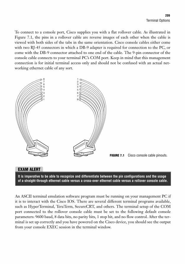
Terminal Options209
To connect to a console port, Cisco supplies you with a flat rollover cable. As illustrated inFigure 7.1, the pins in a rollover cable are reverse images of each other when the cable isviewed with both sides of the tabs in the same orientation. Cisco console cables either comewith two RJ-45 connectors in which a DB-9 adapter is required for connection to the PC, orcome with the DB-9 connector attached to one end of the cable. The 9-pin connector of theconsole cable connects to your terminal PC’s COM port. Keep in mind that this managementconnection is for initial terminal access only and should not be confused with an actual net-working ethernet cable of any sort.
12
12345678
345678
FIGURE 7.1 Cisco console cable pinouts.
EXAM ALERTIt is imperative to be able to recognize and differentiate between the pin configurations and the usageof a straight-through ethernet cable versus a cross-over ethernet cable versus a rollover console cable.
An ASCII terminal emulation software program must be running on your management PC ifit is to interact with the Cisco IOS. There are several different terminal programs available,such as HyperTerminal, TeraTerm, SecureCRT, and others. The terminal setup of the COMport connected to the rollover console cable must be set to the following default consoleparameters: 9600 baud, 8 data bits, no parity bits, 1 stop bit, and no flow control. After the ter-minal is set up correctly and you have powered on the Cisco device, you should see the outputfrom your console EXEC session in the terminal window.
210
Auxiliary PortCertain Cisco models may contain another out-of-band management port called an auxiliary(AUX) port. This port is very similar to the console port in that it uses a rollover cable and hasan RJ-45 connection to the Cisco device. The difference between the auxiliary and the con-sole port is that the auxiliary port has flow control capability, which is useful for analog modemconnectivity. By connecting an external modem to this management port, you can dial into themodem remotely and gain an EXEC session without being physically next to the Cisco device.
TelnetAs discussed in Chapter 1, “Standard Internetworking Models,” Telnet is an Application layerprotocol of the TCP/IP protocol suite that uses TCP port 23 to gain virtual terminal emula-tion to a device. Telnet is considered in-band management because it is required to have IPconnectivity to the Cisco device into which you are trying to Telnet. Most Cisco devices allowat least 5 Telnet EXEC sessions to be connected for remote terminal access. For the sake ofsecurity, there is some configuration involved to allow Telnet access into the Cisco devices.Telnet is discussed in further detail in Chapter 8, “Foundation Cisco Configurations.”
HTTP and HTTPSSimilar to Telnet, HTTP and HTTPS are also Application layer protocols of the TCP/IP pro-tocol suite. HTTP uses TCP port 80 to establish a management connection to the Ciscodevice. HTTPS is a secure version of HTTP over Secure Socket Layer (SSL) and uses TCPport 443. HTTP and HTTPS terminal sessions require IP connectivity to the Cisco device,making it an in-band management communication methodology. The key difference betweenHTTP/HTTPS and Telnet is that when you use HTTP or HTTPS, you can have a graphi-cal interface to the configuration and administration features of the Cisco IOS.
The HTTP EXEC session is made possible by an HTTP server service that can run if con-figured on the Cisco device. For security purposes, some Cisco routers do not have this func-tionality enabled by default. If this functionality is not going to be utilized, it is recommendedthat you disable this service to avoid any security vulnerabilities.
Chapter 7: Foundation Cisco IOS Operations
HTTP and HTTPS are utilized in the Security Device Manager (SDM) configuration utility which will be dis-cussed in greater detail in Chapter 9, “Understanding the Cisco SDM.”
NOTE
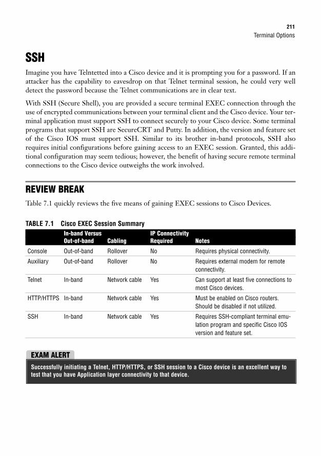
Terminal Options211
SSHImagine you have Telntetted into a Cisco device and it is prompting you for a password. If anattacker has the capability to eavesdrop on that Telnet terminal session, he could very welldetect the password because the Telnet communications are in clear text.
With SSH (Secure Shell), you are provided a secure terminal EXEC connection through theuse of encrypted communications between your terminal client and the Cisco device. Your ter-minal application must support SSH to connect securely to your Cisco device. Some terminalprograms that support SSH are SecureCRT and Putty. In addition, the version and feature setof the Cisco IOS must support SSH. Similar to its brother in-band protocols, SSH alsorequires initial configurations before gaining access to an EXEC session. Granted, this addi-tional configuration may seem tedious; however, the benefit of having secure remote terminalconnections to the Cisco device outweighs the work involved.
REVIEW BREAKTable 7.1 quickly reviews the five means of gaining EXEC sessions to Cisco Devices.
TABLE 7.1 Cisco EXEC Session SummaryIn-band Versus IP ConnectivityOut-of-band Cabling Required Notes
Console Out-of-band Rollover No Requires physical connectivity.
Auxiliary Out-of-band Rollover No Requires external modem for remoteconnectivity.
Telnet In-band Network cable Yes Can support at least five connections tomost Cisco devices.
HTTP/HTTPS In-band Network cable Yes Must be enabled on Cisco routers.Should be disabled if not utilized.
SSH In-band Network cable Yes Requires SSH-compliant terminal emu-lation program and specific Cisco IOSversion and feature set.
EXAM ALERTSuccessfully initiating a Telnet, HTTP/HTTPS, or SSH session to a Cisco device is an excellent way totest that you have Application layer connectivity to that device.
212
Router/Switch Startup ProceduresObjective:
. Describe the operation of Cisco routers (including: router bootup process, POST, router components)
Now that you have an understanding of how to connect to the Cisco IOS, you can now lookat the startup procedures for a Cisco router or switch to determine how the IOS is loaded andrunning in the first place when you power on those devices. Additionally, these devices wouldbe doing us a huge administrative injustice if they did not load the configurations that you havetoiled over in previous EXEC sessions (despite the obvious level of job security). Thus, youalso need to look into how a saved configuration is applied after the IOS is loaded. As you willsee, each of the memory components that were discussed in Chapter 6, “Introduction to CiscoRouters and Switches,” performs a pivotal part in the storing, loading, and running of the IOSand the configuration.
Router and switch startup procedures are extremely similar to a computer’s boot-up process.For instance, when you turn on a computer, the computer utilizes ROM (read-only memory)chips to perform a POST (power-on self-test) to check the critical hardware initially for start-up. Then it consults the BIOS (basic input/output system) settings to determine the order inwhich to search the hard drives, floppy drives, or CD drives to locate the operating system.After the operating system is loaded, it applies any custom configurations you have made inthe past and utilizes those settings toward its normal operation.
Similarly, when you turn on a Cisco router and a switch, ROM chips perform a POST andthen load the IOS process. You can manipulate the location sources of the IOS similar to spec-ifying the boot drive in the BIOS settings on a computer. After the IOS is loaded, your savedconfiguration is loaded and applied to the device’s operating functions. The next sections delvefurther into the specific processes that are occurring at each stage.
POSTWhen you first apply power to a Cisco router or switch, a specialized ROM performs a seriesof tests of the critical hardware components that are pertinent for startup and basic operationsuch as Flash memory, CPU, and interfaces. It makes sense to utilize ROM chips for this serv-ice because they are already hard-coded with their programs and they do not require constantpower to keep those programs stored in the memory. If a failure occurs during this stage of thestartup process, you may encounter one of several outcomes, ranging from a non-functioninginterface all the way to complete device failure. In any case, your equipment should be underwarranty or you have an active support contract in place to fix the failing hardware.
Chapter 7: Foundation Cisco IOS Operations
Router/Switch Startup Procedures213
BootstrapAfter the hardware passes all its tests (if only the CCNA was that easy), another ROM seeksout the operating system in accordance to its programming routines. The code that is run inthe ROM is commonly referred to as the bootstrap code. If a failure occurs at this stage of theboot-up process, your Cisco device could very likely enter what is known as ROM Monitor orcommonly called ROMmon.
ROMmonIn your travels, if you or someone else has ever coined the phrase “hit rock bottom” you havea general idea of what purpose ROMmon serves. The ROM Monitor is a very limited codesetthat enables you to perform elementary functions to manually get the router or switch back toa functioning state. You can perform low-level diagnostics and even copy a new IOS file to theCisco device over the console port or configure TFTP information so the device can down-load the IOS image off of a TFTP server.
Keep in mind that your default console speed is 9600bps, and a typical IOS file exceeds 16 megabytes. Ifyou need to re-copy a working IOS to the Cisco device in ROMmon mode over the console, I recommendchanging the default console speed in ROMmon to a higher speed or taking a long lunch or dinner break.
TIP
ROMmon is also utilized during password recovery on a Cisco router to make it possible totell the device manually to ignore any saved configurations (including the passwords). It is pos-sible to force your Cisco device to go directly to ROMmon on boot by sending a breaksequence in your terminal session in the first 60 seconds of bootup. You can tell you are inROMmon mode if you are presented with a command prompt that looks like rommon 1 >. Any time you type a command in ROMmon, the number at the prompt increments by one(rommon 2 >, rommon 3 >, and so on) .
IOS LoadingUp to this point, the Cisco router or switch has performed only initial diagnostics. With thatbeing said, the IOS itself still has not been located or loaded. The bootstrap’s programminghas a specific search order which it typically follows to locate and load the IOS. I say ”typical-ly” because you can alter the natural order of things with the router or switch’s startup processif you manipulate something called the configuration register.
214
Located in NVRAM, the configuration register is a 16-bit (4 hexadecimal characters) value thatspecifies how the router or switch should operate during initialization. For instance, 0x2102 (0xsignifies all characters that follow are hexadecimal) is a common configuration register thatspecifies that the router or switch should boot in its typical fashion. However, if you manipu-late certain characters in the configuration register, you can manually modify the startup processto load the IOS from locations other than the default. Specifically, the last hexadecimal charac-ter in the configuration register, known as the boot field, is the value that dictates where thebootstrap code can find the IOS. The possible boot field values are as follows:
. 0x2100—When the boot field is a zero, the configuration register instructs the boot-strap to boot directly into ROM and load ROMmon.
. 0x2101-0x210F—When the last field in the configuration register is 1-F, the router orswitch boots normally.
Chapter 7: Foundation Cisco IOS Operations
In older router and switch models, a configuration register of 0x2101 (if the boot field has a value of one),the router or switch would boot a mini IOS located in ROM and commonly referred to as RxBoot. RxBootlooks very similar to the normal IOS; however, it does not provide the majority of the IOS’s services. Thismini IOS provides just enough functionality to reach a TFTP server and download a working IOS to theCisco device. You can easily determine you are in RxBoot if the prompt looks like Router(boot)> in a routeror Switch(boot)> in a switch.
TIP
Assuming the configuration register is 0x2102 (the default configuration register), the nextstep for initialization is to have the bootstrap search the configuration located in NVRAM tosee whether the Cisco administrator has placed a command telling the router or switch specif-ically where to boot. The tools to do this are known as boot system commands. For example,if you have previously configured your device and put in the boot system tftp c2600-do3s-mz.123-5.T1 172.16.1.1 command, you have instructed the bootstrap to load the IOS filec2600-do3s-mz.123-5.T1 from a TFTP server located at 172.16.1.1.
Do not confuse this step with loading the configuration. This is just a step in the IOS loading process thatenables the bootstrap code to implement any configuration specifications you previously saved that toldthe device where to boot. The configuration itself is not loaded until after the IOS is located and running.
NOTE
If the default configuration register is utilized and you have not configured the device with anyboot system commands, the default action of the bootstrap is to load the first IOS file in Flashmemory. After the file is found, it is decompressed and loaded into RAM. At this point, theIOS is successfully loaded and running on your Cisco device.
Router/Switch Startup Procedures215
What would happen if the IOS image were corrupted or missing? As with many functions ofCisco devices, a couple of failsafes are put in place to keep the device in an operating state ora mode in which you can get it back to an operating state. Specifically, if the Cisco router orswitch cannot locate a working IOS file, it broadcasts out all interfaces in the hopes that abackup IOS file is stored on a TFTP server on its connected segments. If there isn’t a TFTPserver or the TFTP server does not contain a valid IOS file, the next failsafe for the IOS is toboot to ROMmon where you can copy the IOS over via the console or TFTP.
Configuration LoadingWith the IOS loaded, the router or switch is now able to apply any saved configuration param-eters. NVRAM is the first location where the device searches for the configuration. Here, afile called startup-config contains all the previous configurations that were present the lasttime an administrator saved the configuration. As the name states, this is the configuration thatis loaded each time the Cisco device starts up. Similar to the IOS, after this configuration fileis found, it is loaded into RAM as well. After the configuration is loaded and running at thispoint, it is conveniently referred to as running-config.
EXAM ALERTThe running-config is the active configuration running in RAM.
Cisco devices do not ship with a complete startup configuration, which is why you might haveto initially configure your Cisco device through some means of out-of-band management suchas the console or auxiliary port. So the question begs, what happens when you initially turn ona new Cisco router or switch, or if someone erases the startup configuration?
Many Cisco devices attempt to do an autoinstall by downloading a configuration file from anactive TFTP server (similarly to the IOS) when they detect that the startup-config is notlocated in NVRAM. Typically, these files contain enough configuration parameters (such as IPaddresses for interfaces) for you to Telnet into the device and configure the remaining param-eters. If the Cisco device finds an autoinstall configuration file from a TFTP server, the deviceloads the file and makes that the running-config. On the chance that you were not proactiveenough to have an autoinstall configuration on your TFTP server, the router or switchprompts you for something called Setup Mode.
EXAM ALERTIt is imperative that you can identify the steps that a switch or router follows during initialization, thememory or device architectures where these steps occur, and the fallback sequences when a failurehas occurred in the boot-up sequence.
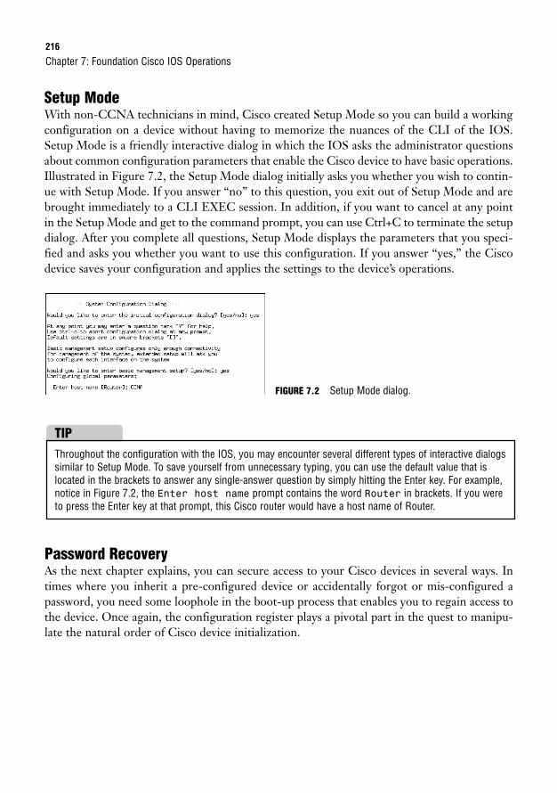
216
Setup ModeWith non-CCNA technicians in mind, Cisco created Setup Mode so you can build a workingconfiguration on a device without having to memorize the nuances of the CLI of the IOS.Setup Mode is a friendly interactive dialog in which the IOS asks the administrator questionsabout common configuration parameters that enable the Cisco device to have basic operations.Illustrated in Figure 7.2, the Setup Mode dialog initially asks you whether you wish to contin-ue with Setup Mode. If you answer “no” to this question, you exit out of Setup Mode and arebrought immediately to a CLI EXEC session. In addition, if you want to cancel at any pointin the Setup Mode and get to the command prompt, you can use Ctrl+C to terminate the setupdialog. After you complete all questions, Setup Mode displays the parameters that you speci-fied and asks you whether you want to use this configuration. If you answer “yes,” the Ciscodevice saves your configuration and applies the settings to the device’s operations.
Chapter 7: Foundation Cisco IOS Operations
Password RecoveryAs the next chapter explains, you can secure access to your Cisco devices in several ways. Intimes where you inherit a pre-configured device or accidentally forgot or mis-configured apassword, you need some loophole in the boot-up process that enables you to regain access tothe device. Once again, the configuration register plays a pivotal part in the quest to manipu-late the natural order of Cisco device initialization.
FIGURE 7.2 Setup Mode dialog.
Throughout the configuration with the IOS, you may encounter several different types of interactive dialogssimilar to Setup Mode. To save yourself from unnecessary typing, you can use the default value that islocated in the brackets to answer any single-answer question by simply hitting the Enter key. For example,notice in Figure 7.2, the Enter host name prompt contains the word Router in brackets. If you wereto press the Enter key at that prompt, this Cisco router would have a host name of Router.
TIP
Router/Switch Startup Procedures217
REVIEW BREAKTo solidify the startup process, the following is a recap of the stages of the boot-up, any fall-back procedures, and the memory locations involved:
1. POST, located in ROM, tests hardware.
2. Bootstrap, located in ROM, looks at the boot field in the configuration register tolocate IOS. 0x2100 boots to ROMMON located in ROM.
3. 0x2101-0x210F prompts bootstrap to parse startup-config in NVRAM for any bootsystem commands. If it finds any commands, it does what they say.
4. If no boot system commands are found, the first file in Flash is loaded. If no file isfound in Flash, TFTP boots. If no IOS file is found from TFTP, the device goes toROMmon in ROM.
5. After IOS is loaded, the configuration register is checked. If it is 0x2142, ignorestartup-config in NVRAM. If it is 0x2102, load startup-config in NVRAM. Ifthere is no startup-config, TFTP autoinstall. If no TFTP autoinstall configurationis found, enter Setup Mode.
Don’t Forget the Natural Order Do not forget when performing password recovery to set your configura-tion register back to 0x2102. Failing to do so forces your router to constantly ignore your configurations,causing your router or switch to repeatedly enter Setup Mode.
CAUTION
EXAM ALERTBe sure to recognize that a configuration register of 0x2142 is a typical setting for performing pass-word recovery.
The third character in the configuration register enables you to tell the device to ignore anyconfigurations that might be saved in NVRAM. If this field is changed from a 0 to a 4, thedevice inevitably boots into Setup Mode because the router or switch is fooled that there is nostartup configuration. Now, with the configuration register changed to 0x2142, you can recon-figure the Cisco device creating your own unique passwords and save that configuration forfuture device startups.
218
ChallengeAs you read in this chapter, be aware that many operations are occurring behind the scenes when yougain access to a Cisco device and turn it on. In this challenge, I want you to logically think through whatis occurring at each stage of the boot-up process and identify the memory architectures that are involvedgiven the following scenario:
Your night administrator planned to upgrade the IOS on your company’s router last night. When youcame in to work the next morning, you saw a written note from the night admin frantically explaining howhe began the IOS upgrade, but he accidentally kicked out the power cord mid-upgrade and does not knowwhat to do. Unfortunately, the IOS upgrade had to erase the IOS image file in Flash memory to makeroom for the new IOS. You do not have any TFTP servers on your network.
1. You must initially gain access to the device. Because the IOS cannot be loaded, what is the mostlogical way to gain an EXEC session?
2. When you turn on the device, what is the first thing your router will do and what memory isinvolved?
3. The default configuration register is configured, so where will the bootstrap look first to locate theIOS?
4. If you have not made any previous configurations telling the router how to boot, where will it looknext?
5. Because the file isn’t complete here, what is the first fallback failsafe?
6. Knowing that will fail, in what mode will you be and in what part of memory is that located?
7. What will the prompt look like?
Challenge AnswerTo gain access to a non-functioning device, you will need to use some means of out-of-band manage-ment such as the console or the auxiliary port. When the device is powered on, the POST in ROM teststhe hardware. Because the configuration register is 0x2102 (the default), the router searches for bootsystem commands in the startup-config. Because there are no configurations stating where toboot, the router looks into Flash. Unfortunately, the Flash memory does not have a complete IOS becausethe upgrade process was interrupted. With that being said, the router tries to locate an IOS file on a TFTPserver. Because the scenario mentioned that there are no TFTP servers on the network, the router fallsback to ROMmon in ROM, which displays a prompt similar to rommon 1 >.
Chapter 7: Foundation Cisco IOS Operations
Navigating the IOS219
Navigating the IOSObjective:
. Manage Cisco IOS
By now, you have a new-found love and respect for your Cisco equipment after knowing allthe work that occurs when you turn on your router or switch. What better way to prove thatlove and respect but by mastering the IOS that the Cisco devices have so painstakingly foundand loaded for your administration and configuration pleasure? This section looks at the hier-archical levels of the IOS and what type of interactivity you can encounter at each level.
EXAM ALERTYou will be able to eliminate several distracting incorrect answers in the exam by recognizing the levelof the IOS hierarchy the commands will be found.
User EXECAt your organization, you may have Level 1 technicians who are not strong in Cisco funda-mentals; thus, you want to ensure only that they have access to basic troubleshooting and sta-tistics without worrying that they might change the configuration or cause some othernetwork catastrophe. Because a multitude of administrators might need to gain access to theseCisco devices, it makes sense to ensure that the first level of IOS hierarchy they encounter issomewhat limited in the extent of what can be done. This is the nature of User EXEC.
In User EXEC, you are limited in the number and type of commands that are available to you.For instance, the majority of show commands are available at this level of the IOS hierarchybecause they do not detrimentally affect the router or the switch to perform these commands.In addition, you can test IP connectivity to other devices with ping as well as remotely admin-ister other devices or troubleshoot all the way up to Layer 7 with Telnet. The Cisco IOSprompt for User EXEC is signified by the greater than sign (>) following the hostname of theCisco device. For example, a Cisco router and switch with their default hostnames would looklike Router> and Switch>, respectively. Figure 7.3 displays the commands that you have avail-able at User EXEC.
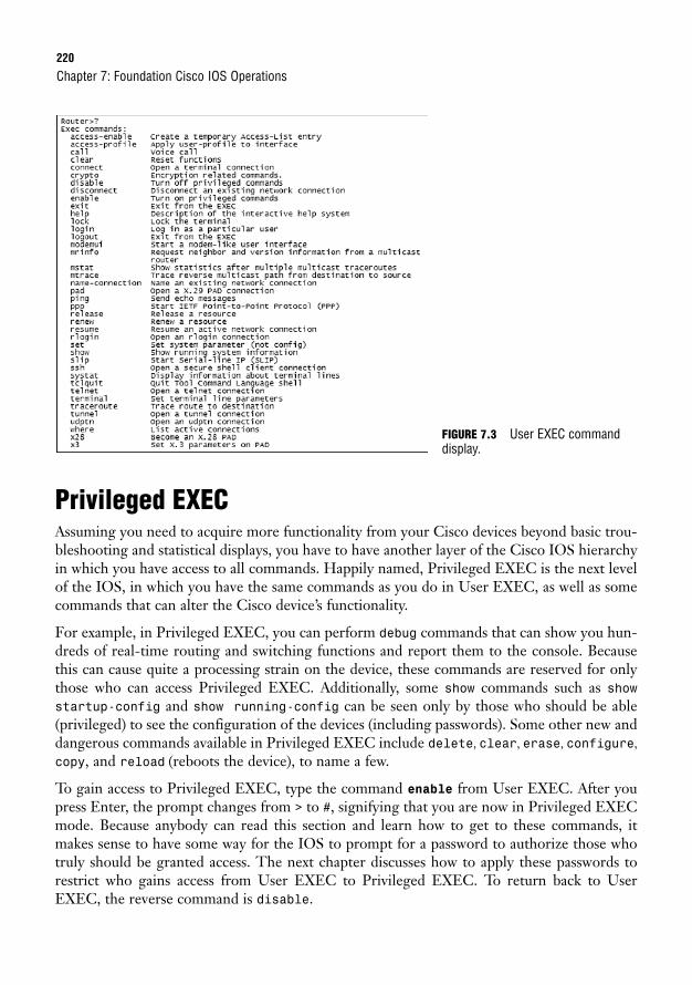
220
Privileged EXECAssuming you need to acquire more functionality from your Cisco devices beyond basic trou-bleshooting and statistical displays, you have to have another layer of the Cisco IOS hierarchyin which you have access to all commands. Happily named, Privileged EXEC is the next levelof the IOS, in which you have the same commands as you do in User EXEC, as well as somecommands that can alter the Cisco device’s functionality.
For example, in Privileged EXEC, you can perform debug commands that can show you hun-dreds of real-time routing and switching functions and report them to the console. Becausethis can cause quite a processing strain on the device, these commands are reserved for onlythose who can access Privileged EXEC. Additionally, some show commands such as showstartup-config and show running-config can be seen only by those who should be able(privileged) to see the configuration of the devices (including passwords). Some other new anddangerous commands available in Privileged EXEC include delete, clear, erase, configure,copy, and reload (reboots the device), to name a few.
To gain access to Privileged EXEC, type the command enable from User EXEC. After youpress Enter, the prompt changes from > to #, signifying that you are now in Privileged EXECmode. Because anybody can read this section and learn how to get to these commands, itmakes sense to have some way for the IOS to prompt for a password to authorize those whotruly should be granted access. The next chapter discusses how to apply these passwords torestrict who gains access from User EXEC to Privileged EXEC. To return back to UserEXEC, the reverse command is disable.
Chapter 7: Foundation Cisco IOS Operations
FIGURE 7.3 User EXEC commanddisplay.
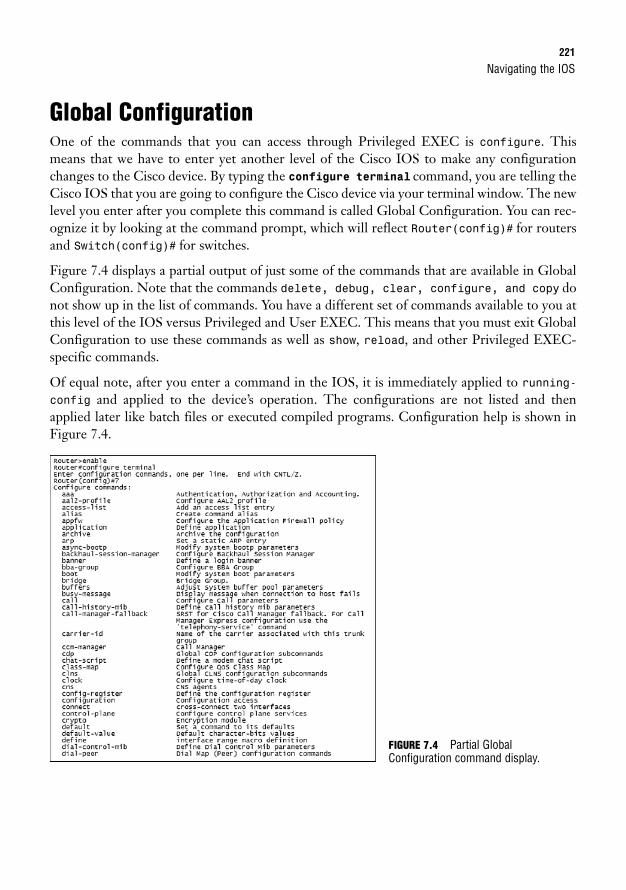
Navigating the IOS221
Global ConfigurationOne of the commands that you can access through Privileged EXEC is configure. Thismeans that we have to enter yet another level of the Cisco IOS to make any configurationchanges to the Cisco device. By typing the configure terminal command, you are telling theCisco IOS that you are going to configure the Cisco device via your terminal window. The newlevel you enter after you complete this command is called Global Configuration. You can rec-ognize it by looking at the command prompt, which will reflect Router(config)# for routersand Switch(config)# for switches.
Figure 7.4 displays a partial output of just some of the commands that are available in GlobalConfiguration. Note that the commands delete, debug, clear, configure, and copy donot show up in the list of commands. You have a different set of commands available to you atthis level of the IOS versus Privileged and User EXEC. This means that you must exit GlobalConfiguration to use these commands as well as show, reload, and other Privileged EXEC-specific commands.
Of equal note, after you enter a command in the IOS, it is immediately applied to running-config and applied to the device’s operation. The configurations are not listed and thenapplied later like batch files or executed compiled programs. Configuration help is shown inFigure 7.4.
FIGURE 7.4 Partial GlobalConfiguration command display.
222
As the name states, any configuration that is applied in this level applies globally to the Ciscorouter or switch. Here we can perform configuration tasks such as changing the hostname ofthe router or switch, creating a login banner, creating a password to prompt users trying togain access to Privileged EXEC, and many others. It is also at this level of the Cisco IOS hier-archy that you can enter several different sub-configuration modes to apply specific configu-rations for things such as interfaces, routing protocols, and EXEC lines (which are discussedthroughout this book).
Interface ConfigurationDirectly from Global Configuration, you can configure interface-specific commands thatapply only to interfaces specified in the configuration. Now you can enable the interfaces,assign IP addresses, set speeds, and configure other interface commands. Once again, the com-mands that are available at this sub-configuration level of the IOS are not applicable at GlobalConfiguration or Privileged EXEC and User EXEC.
To configure an interface, you must specify the interface you want to configure. If the devicehas fixed (non-modular) interfaces, you simply specify the type of interface followed by theinterface number (and remember Cisco routers start their numbering schema with 0). Forexample, the 1600 series router has a fixed ethernet interface that cannot be removed from therouter. To configure that interface, you type interface Ethernet 0 from GlobalConfiguration. Most devices today utilize the modular configuration in which you have tospecify the module number as well as the interface number because these devices can changefunctionality depending on the type of module inserted into them. For example, to configurethe second WAN serial interface on the first module on a 2800 series router, you would inputinterface serial 0/1 where 0 is the module number (first module starts with 0) and 1 is theinterface. The prompt in Interface Configuration Mode is displayed as Router(config-if)#,regardless of the interface type. This means you must keep track of what interface you are con-figuring because the prompt does not specify the type.
Line ConfigurationAlso accessed from Global Configuration, line configurations are specific to those EXEC linesthrough which a user can gain access to the Cisco device. Specifically, you can configureoptions such as logins and passwords for a user trying to gain User EXEC access to the con-sole and auxiliary ports, as well as the 5 vty (virtual teletype) Telnet lines into a router orswitch. From Global Configuration, you must utilize the keyword, line, followed by the
Chapter 7: Foundation Cisco IOS Operations
EXAM ALERTNewer releases of Cisco IOS are making it possible to utilize some of these commands across the lev-els of the Cisco IOS hierarchies. However, for exam purposes, put on a pair of Cisco horse blinders tothis new functionality and focus on the original levels and syntaxes described throughout this book.
Navigating the IOS223
EXEC line you want to configure. For example, to configure console-specific commands, youwould type line console 0 from Global Configuration. The prompt changes toRouter(config-line)#, regardless of the line you are configuring.
Context-Sensitive HelpEven though the Cisco IOS is a command-line interface, it is not without its help features tohelp you through your navigation of the IOS. Specifically, to see what commands are availableat any level of the IOS, you can use the help feature of the IOS, the question mark. By typing? (no Enter keystroke necessary) at any level of the IOS, you get a listing of all the commandsavailable and a brief description of the command, such as you saw in Figures 7.3 and 7.4.
Quite often, the list of available commands may extend beyond one terminal screen. This isapparent because the string —More— is displayed at the bottom of the list on the screen. Tosee the next page of listed commands, you can press the space bar and the command list scrollsanother terminal screen’s length. If you prefer to see the commands line by line, you can keephitting the Enter key and it displays only the next command each time you press it. On thechance that you have found the command you were looking for in the list, you can hit any key(pause for inevitable “where’s the any key?” joke) to get back to the command prompt.
In some instances, you may not recall the command that you are looking for, but you doremember the first letter of the command. Let’s say, for example, the command is in GlobalConfiguration and starts with the letter l. You could use the question mark and scroll throughall the commands; however, the IOS enables you to see the commands starting with l if youtype the letter, followed immediately by the question mark (no space in between), as demon-strated below. Similarly, if you remembered that the command started with log, you can typethose characters, followed immediately by the question mark, to see the commands loggingand login-string.Router>enableRouter#configure terminalEnter configuration commands, one per line. End with CNTL/Z.Router(config)#l?l2tp-class lane li-view linelogging login login-stringRouter(config)#l
Keep in mind that many commands in the IOS require a string of keywords to comprehendwhat you are trying to achieve with the command. For instance, if I was searching for the com-mand logging and hit the Enter key, the IOS would report back an error to the terminalscreen that the command was incomplete because it does not understand where I want to sendmy logging information. If you are unsure of the commands available, once again, you use thequestion mark for command help. In this case, you must put a space after the first keyword fol-lowed by the question mark. The IOS then displays a list of commands that are valid after thekeyword logging, as displayed here:
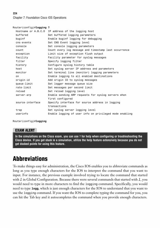
224
Router(config)#logging ?Hostname or A.B.C.D IP address of the logging hostbuffered Set buffered logging parametersbuginf Enable buginf logging for debuggingcns-events Set CNS Event logging levelconsole Set console logging parameterscount Count every log message and timestamp last occurrenceexception Limit size of exception flush outputfacility Facility parameter for syslog messagesfilter Specify logging filterhistory Configure syslog history tablehost Set syslog server IP address and parametersmonitor Set terminal line (monitor) logging parameterson Enable logging to all enabled destinationsorigin-id Add origin ID to syslog messagesqueue-limit Set logger message queue sizerate-limit Set messages per second limitreload Set reload logging levelserver-arp Enable sending ARP requests for syslog servers when
first configuredsource-interface Specify interface for source address in logging
transactionstrap Set syslog server logging leveluserinfo Enable logging of user info on privileged mode enabling
Router(config)#logging
Chapter 7: Foundation Cisco IOS Operations
EXAM ALERTIn the simulations on the Cisco exam, you can use ? for help when configuring or troubleshooting theCisco device. If you get stuck in a simulation, utilize the help feature extensively because you do notget docked points for using this feature.
AbbreviationsTo make things easy for administration, the Cisco IOS enables you to abbreviate commands aslong as you type enough characters for the IOS to interpret the command that you want toinput. For instance, the previous example involved trying to locate the command that startedwith l in Global Configuration. Because there were several commands that started with l, youwould need to type in more characters to find the logging command. Specifically, you wouldneed to type logg, which is just enough characters for the IOS to understand that you want touse the logging command. If you want the IOS to complete typing the command for you, youcan hit the Tab key and it autocompletes the command when you provide enough characters.
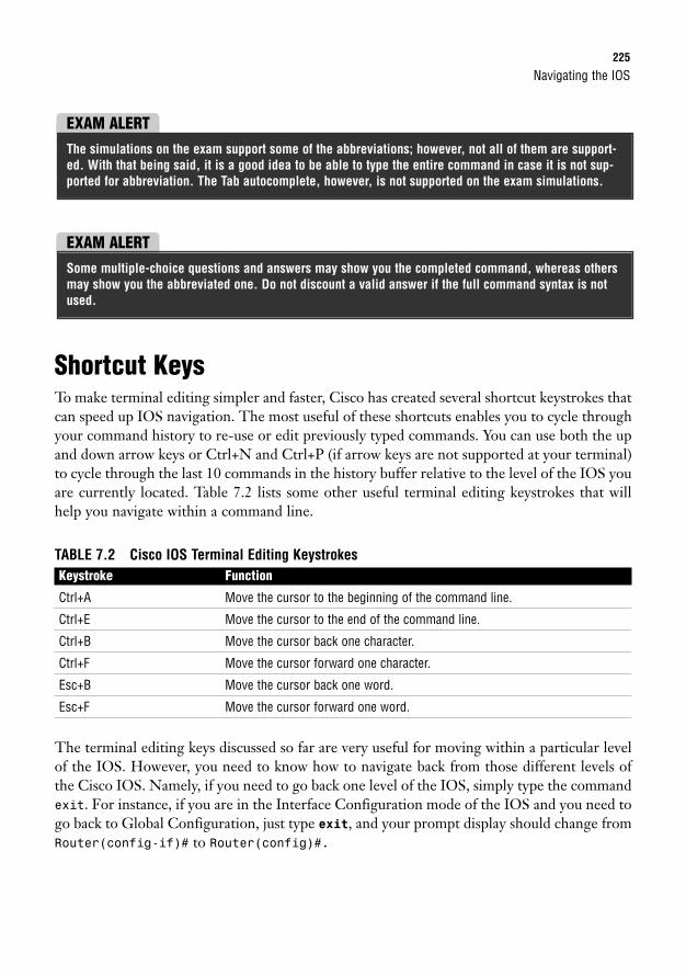
Navigating the IOS225
Shortcut KeysTo make terminal editing simpler and faster, Cisco has created several shortcut keystrokes thatcan speed up IOS navigation. The most useful of these shortcuts enables you to cycle throughyour command history to re-use or edit previously typed commands. You can use both the upand down arrow keys or Ctrl+N and Ctrl+P (if arrow keys are not supported at your terminal)to cycle through the last 10 commands in the history buffer relative to the level of the IOS youare currently located. Table 7.2 lists some other useful terminal editing keystrokes that willhelp you navigate within a command line.
TABLE 7.2 Cisco IOS Terminal Editing KeystrokesKeystroke Function
Ctrl+A Move the cursor to the beginning of the command line.
Ctrl+E Move the cursor to the end of the command line.
Ctrl+B Move the cursor back one character.
Ctrl+F Move the cursor forward one character.
Esc+B Move the cursor back one word.
Esc+F Move the cursor forward one word.
The terminal editing keys discussed so far are very useful for moving within a particular levelof the IOS. However, you need to know how to navigate back from those different levels ofthe Cisco IOS. Namely, if you need to go back one level of the IOS, simply type the commandexit. For instance, if you are in the Interface Configuration mode of the IOS and you need togo back to Global Configuration, just type exit, and your prompt display should change fromRouter(config-if)# to Router(config)#.
EXAM ALERTThe simulations on the exam support some of the abbreviations; however, not all of them are support-ed. With that being said, it is a good idea to be able to type the entire command in case it is not sup-ported for abbreviation. The Tab autocomplete, however, is not supported on the exam simulations.
EXAM ALERTSome multiple-choice questions and answers may show you the completed command, whereas othersmay show you the abbreviated one. Do not discount a valid answer if the full command syntax is notused.
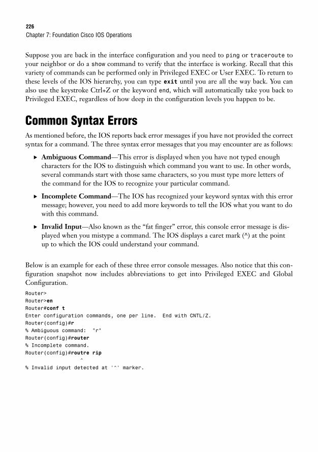
226
Suppose you are back in the interface configuration and you need to ping or traceroute toyour neighbor or do a show command to verify that the interface is working. Recall that thisvariety of commands can be performed only in Privileged EXEC or User EXEC. To return tothese levels of the IOS hierarchy, you can type exit until you are all the way back. You canalso use the keystroke Ctrl+Z or the keyword end, which will automatically take you back toPrivileged EXEC, regardless of how deep in the configuration levels you happen to be.
Common Syntax ErrorsAs mentioned before, the IOS reports back error messages if you have not provided the correctsyntax for a command. The three syntax error messages that you may encounter are as follows:
. Ambiguous Command—This error is displayed when you have not typed enoughcharacters for the IOS to distinguish which command you want to use. In other words,several commands start with those same characters, so you must type more letters ofthe command for the IOS to recognize your particular command.
. Incomplete Command—The IOS has recognized your keyword syntax with this errormessage; however, you need to add more keywords to tell the IOS what you want to dowith this command.
. Invalid Input—Also known as the “fat finger” error, this console error message is dis-played when you mistype a command. The IOS displays a caret mark (^) at the pointup to which the IOS could understand your command.
Below is an example for each of these three error console messages. Also notice that this con-figuration snapshot now includes abbreviations to get into Privileged EXEC and GlobalConfiguration.Router>Router>enRouter#conf tEnter configuration commands, one per line. End with CNTL/Z.Router(config)#r% Ambiguous command: “r”Router(config)#router% Incomplete command.Router(config)#routre rip
^% Invalid input detected at ‘^’ marker.
Chapter 7: Foundation Cisco IOS Operations
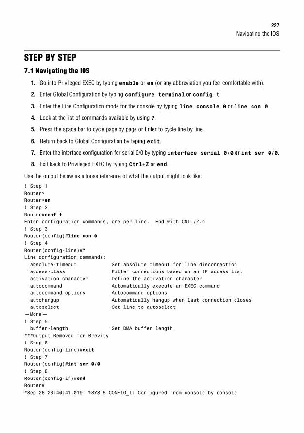
Navigating the IOS227
STEP BY STEP7.1 Navigating the IOS
1. Go into Privileged EXEC by typing enable or en (or any abbreviation you feel comfortable with).
2. Enter Global Configuration by typing configure terminal or config t.
3. Enter the Line Configuration mode for the console by typing line console 0 or line con 0.
4. Look at the list of commands available by using ?.
5. Press the space bar to cycle page by page or Enter to cycle line by line.
6. Return back to Global Configuration by typing exit.
7. Enter the interface configuration for serial 0/0 by typing interface serial 0/0 or int ser 0/0.
8. Exit back to Privileged EXEC by typing Ctrl+Z or end.
Use the output below as a loose reference of what the output might look like:
! Step 1Router>Router>en! Step 2Router#conf tEnter configuration commands, one per line. End with CNTL/Z.o! Step 3Router(config)#line con 0! Step 4Router(config-line)#?Line configuration commands:absolute-timeout Set absolute timeout for line disconnectionaccess-class Filter connections based on an IP access listactivation-character Define the activation characterautocommand Automatically execute an EXEC commandautocommand-options Autocommand optionsautohangup Automatically hangup when last connection closesautoselect Set line to autoselect
—More—! Step 5buffer-length Set DMA buffer length
***Output Removed for Brevity! Step 6Router(config-line)#exit! Step 7Router(config)#int ser 0/0! Step 8Router(config-if)#endRouter#*Sep 26 23:40:41.019: %SYS-5-CONFIG_I: Configured from console by console
228
Chapter SummaryThis chapter delved into the many intricacies surrounding the Cisco internetwork operatingsystem. Specifically, you learned at least five ways to gain access to IOS. The two out-of-bandmethods are through the console and auxiliary interface. In-band methods such as Telnet,HTTP, HTTPS, and SSH require some level of configuration of the Cisco devices before youcan remotely manage them.
To load the IOS, Cisco routers and switches have to complete a series of systematic stages.Initially, the device tests the hardware and loads the bootstrap code, both located in ROM. Ifthe configuration register boot field has not been manipulated (values 0x1-0xF), then the boot-strap queries the startup-config in NVRAM for any boot system commands. If no com-mands are present, the first file in Flash memory is loaded into RAM. If the file in Flash ismissing or corrupt, the Cisco router or switch broadcasts for help to any local TFTP servers.If that fallback fails, the router or switch returns back to ROM and loads ROMmon. After theIOS is loaded, the Cisco device can load the startup configuration in NVRAM (assuming youdidn’t change the configuration register to 0x2142 for password recovery). If the startup con-figuration is not present, the router or switch tries to autoinstall from a TFTP server. If thatfails, the device enters the configuration dialog, Setup Mode.
If you were to cancel out of Setup Mode by answering “no” or typing Ctrl+C, you would giveyourself the opportunity to conquer the mighty mountain of the Cisco IOS navigation hierar-chy because you would immediately enter into User EXEC mode. In User EXEC, you havelimited functionality (the majority of show commands, ping, traceroute, Telnet, and so on)and would need to use the command enable to enter Privileged EXEC to gain access to all thecommands at that particular level. From here, you can enter Global Configuration by typingconfigure terminal to configure parameters that apply to the entire device. GlobalConfiguration can then be utilized as a jumping-off point to enter sub-configuration modes,such as for interfaces, EXEC lines, routing protocols, and many other sub-configuration modes.
At any point in IOS, you can see the commands available by using ? at the command prompt.If you were to get an ambiguous command error, Cisco IOS requires that you enter more char-acters to a keyword because multiple commands might share those beginning characters. Youcan easily discover the commands that start with certain characters by immediately typing ?after those letters. Incomplete Command errors signify that the command string requiredmore keywords to know what to do with the command keyword. To see the commands avail-able after a specific keyword, you can also use the ? preceded by a space to see what commandsare valid. Invalid input errors indicate that the command was mistyped somewhere. In thesesituations, you can cycle through the previous commands by using the up and down arrows orCtrl+P and Ctrl+N. After you find the mistyped command, you can use other terminal editingkeys to navigate the cursor to the point where the mistake was made. To exit configurationmodes, you can type exit to go back a level at a time. To go directly to Privileged EXEC, typeCtrl+Z or end.
Chapter 7: Foundation Cisco IOS Operations
Apply Your Knowledge229
Key Terms. configuration register
. boot field
. POST
. ROMmon
. console port
. auxiliary port
. SSH
. bootstrap
. User EXEC
. Privileged EXEC
. Setup Mode
. running-config
. startup-config
. interface configuration
. line configuration
. terminal editing keys
. in-band
. out-of-band
Apply Your Knowledge
Exercise
7.1 Navigating a New Router
You have just received a new router that you will have to install at a customer’s location in two days. Toensure you appear confident in your installation, you decide to take the router out for a test drive so youcan be comfortable with the IOS navigation before arriving onsite.
This exercise assumes you have a router to utilize that is not in production.
If you do not have an actual router, you can always follow along by using simulated software such asSemSim (www.semsim.com) or Boson’s NetSim (www.boson.com). If your budget is tight, open upNotepad and type the commands as you would if you were in the router itself. Practicing these commandsand understanding the level of IOS at which they should be typed are critical to your success in the CCNAexam and as a CCNA technician.
NOTE
Estimated Time: 15 minutes
1. Plug the router into the power outlet and connect your console cable between your PC’s COM portand the console port on the router.
2. Open your terminal program and set the settings for 9600 baud, 8 data bits, no parity bits, 1 stopbit, and no flow control.
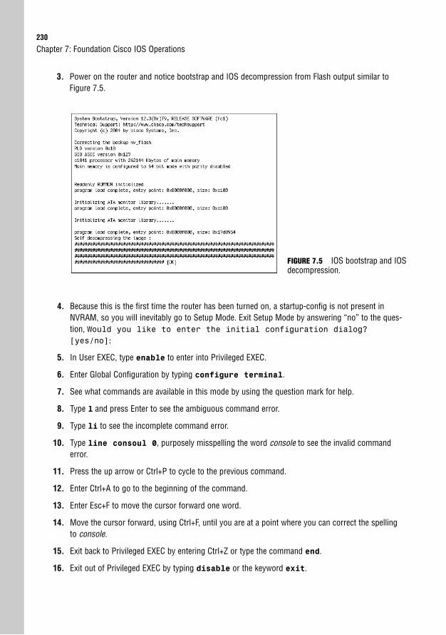
230
3. Power on the router and notice bootstrap and IOS decompression from Flash output similar toFigure 7.5.
Chapter 7: Foundation Cisco IOS Operations
FIGURE 7.5 IOS bootstrap and IOSdecompression.
4. Because this is the first time the router has been turned on, a startup-config is not present inNVRAM, so you will inevitably go to Setup Mode. Exit Setup Mode by answering “no” to the ques-tion, Would you like to enter the initial configuration dialog?[yes/no]:
5. In User EXEC, type enable to enter into Privileged EXEC.
6. Enter Global Configuration by typing configure terminal.
7. See what commands are available in this mode by using the question mark for help.
8. Type l and press Enter to see the ambiguous command error.
9. Type li to see the incomplete command error.
10. Type line consoul 0, purposely misspelling the word console to see the invalid commanderror.
11. Press the up arrow or Ctrl+P to cycle to the previous command.
12. Enter Ctrl+A to go to the beginning of the command.
13. Enter Esc+F to move the cursor forward one word.
14. Move the cursor forward, using Ctrl+F, until you are at a point where you can correct the spellingto console.
15. Exit back to Privileged EXEC by entering Ctrl+Z or type the command end.
16. Exit out of Privileged EXEC by typing disable or the keyword exit.

Apply Your Knowledge231
Review Questions1. What is the effect of changing the configuration register?
2. Why would a Cisco administrator use boot system commands?
3. What are the memory components in a router and what purpose do they have in the bootingprocess?
4. What cabling and terminal settings are required for out-of-band management?
5. What is the significance of having User EXEC mode in addition to Privileged EXEC mode?
Exam Questions1. What type of cable would you connect to manage your Cisco device from the COM port of
your PC?
❍ A. Cross-over cable
❍ B. Straight-through cable
❍ C. Patch cable
❍ D. Rollover cable
2. Which are two methods of exiting out of Setup Mode? (Choose 2.)
❍ A. Ctrl+C
❍ B. Ctrl+Z
❍ C. Answer no
❍ D. Type end
3. You have just been given a router that will not save its configuration. As you boot up the router,you confirm that despite saving the configurations several times, the router enters Setup Modeconsistently. What might be a possible cause?
❍ A. Flash memory is corrupt.
❍ B. TFTP Server is down.
❍ C. The configuration register is 0x2100.
❍ D. The configuration register is 0x2142.
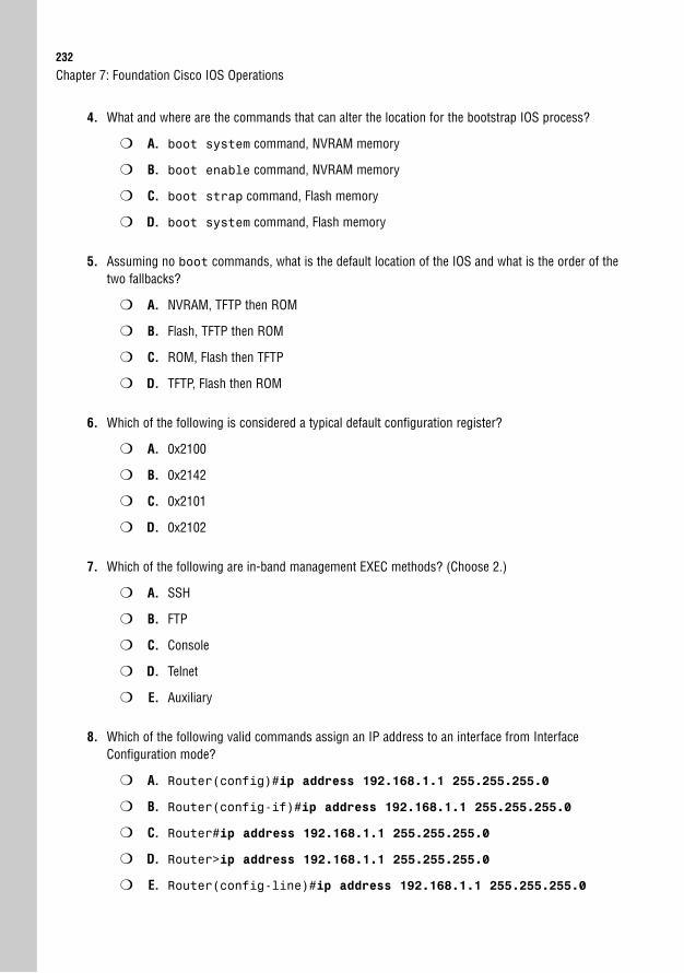
232
4. What and where are the commands that can alter the location for the bootstrap IOS process?
❍ A. boot system command, NVRAM memory
❍ B. boot enable command, NVRAM memory
❍ C. boot strap command, Flash memory
❍ D. boot system command, Flash memory
5. Assuming no boot commands, what is the default location of the IOS and what is the order of thetwo fallbacks?
❍ A. NVRAM, TFTP then ROM
❍ B. Flash, TFTP then ROM
❍ C. ROM, Flash then TFTP
❍ D. TFTP, Flash then ROM
6. Which of the following is considered a typical default configuration register?
❍ A. 0x2100
❍ B. 0x2142
❍ C. 0x2101
❍ D. 0x2102
7. Which of the following are in-band management EXEC methods? (Choose 2.)
❍ A. SSH
❍ B. FTP
❍ C. Console
❍ D. Telnet
❍ E. Auxiliary
8. Which of the following valid commands assign an IP address to an interface from InterfaceConfiguration mode?
❍ A. Router(config)#ip address 192.168.1.1 255.255.255.0
❍ B. Router(config-if)#ip address 192.168.1.1 255.255.255.0
❍ C. Router#ip address 192.168.1.1 255.255.255.0
❍ D. Router>ip address 192.168.1.1 255.255.255.0
❍ E. Router(config-line)#ip address 192.168.1.1 255.255.255.0
Chapter 7: Foundation Cisco IOS Operations
Apply Your Knowledge233
9. If your network does not have a TFTP server and your router’s configuration was erased, what willthe prompt look like when you reboot?
❍ A. rommon 1 >
❍ B. Router(boot)>
❍ C. Would you like to enter the initial configuration dialog?[yes/no]:
❍ D. The router would not be able to boot.
10. Which two commands will return you to Privileged EXEC? (Choose 2.)
❍ A. Ctrl+Z
❍ B. end
❍ C. disable
❍ D. Ctrl+C
11. Which three components are located in ROM? (Choose 3.)
❍ A. bootstrap
❍ B. POST
❍ C. startup-config
❍ D. IOS file
❍ E. ROMmon
❍ F. running-config
Answers to Review Questions1. By changing any of the values in the configuration register from its default value of 0x2102, you
are altering how the router or switch operates during initialization. The last hexadecimal field in theconfiguration register is the boot field. This value determines whether the device boots to ROMand loads ROMmon (0x0). Values of 0x1-0xF indicate that the device parses the startup configura-tion in NVRAM for any boot system commands. If the third hexadecimal character in the con-figuration register is a 0x4, the device ignores the startup configuration in NVRAM and enters theSetup Mode dialog.
2. The boot system commands provide flexible means of specifying from where to load an IOS.This is especially useful if you require specifying a specific IOS file to load in Flash (if multiple filesexist) or on a TFTP server.
234
3. ROM contains the POST program and the bootstrap code for the initial stages of the bootingprocess. Flash memory stores the IOS files. The configuration register is stored in NVRAM alongwith the startup configuration that contains any boot system commands.
4. The console and AUX ports both use the rollover cable. The terminal settings should reflect the fol-lowing parameters: 9600 baud, 8 data bits, no parity bits, 1 stop bit, and no flow control.
5. User EXEC is useful if you have to give access to technicians who need rights to basic verificationcommands. Privileged EXEC enables access to the remaining command modes, including thosecommands that can affect the router or switch’s operations.
Answers to Exam Questions1. D. The cable to connect your terminal to the Cisco device’s console or auxiliary port is a rollover
cable. Answers A, B, and C are cables that are used for ethernet networking.
2. A, C. To exit out of Setup Mode, you must answer “no” to the Would you like to enterthe initial configuration dialog? [yes/no]: question, or enter Ctrl+C at anyprompt. Ctrl+Z and the End key are shortcuts to exit back to Privileged EXEC.
3. D. When the third hexadecimal character in the configuration register is a 4, the startup-con-fig is ignored. This is a useful utility if you are doing password recovery; however, it is importantthat you remember to change it back to 0x2102. A is incorrect because the configuration is notstored in Flash. B is not viable because the Cisco device looks for a config on the TFTP only if thestartup-config is missing. C will force the router or switch into ROMmon mode, whichmeans the configuration never gets loaded because the IOS needs to be loaded first.
4. A. The boot system commands located in the startup-config in NVRAM can manuallyforce the router or switch to boot the IOS from somewhere other than its default locations.
5. B. When no boot system commands are used, the bootstrap loads the first file in Flash memo-ry. If that file is missing or corrupt, it tries to load an IOS from a TFTP server first. If there is nonetwork connectivity or TFTP server present, the device enters ROMmon in ROM.
6. D. A normal configuration register is 0x2102. A forces the router or switch into ROMmon. Bignores the startup-config. C would load the first file in Flash; however, it is not the defaultconfiguration register.
7. A, D. The three in-band management session methods are SSH, Telnet, and HTTP. Answers C andE are out-of-band; B is not a management session method.
8. B. Without even discussing the actual configuration of the command, the question stated that itmust be in Interface Configuration mode, which means the command prompt will look likeRouter(config-if)# or Switch(config-if)#.
Chapter 7: Foundation Cisco IOS Operations
Apply Your Knowledge235
9. C. Without a TFTP for autoinstall and with the startup-config missing, the router or switch entersSetup mode, which prompts you with Would you like to enter the initial con-figuration dialog? [yes/no]:. Answer A is the ROMmon prompt and D is the prompt forRxBoot mode.
10. A, B. Ctrl+Z and End return you to Privileged EXEC, no matter in which level of the configurationhierarchy you are. C returns you to User EXEC from Privileged EXEC mode. D is used to exit out ofSetup Mode.
11. A, B, E. POST, bootstrap code, and ROMmon all reside in ROM. Startup-config is located inNVRAM, and running-config is located in RAM. The IOS file is typically located in Flash memory.
Suggested Readings and Resources1. Boney, James. Cisco IOS in a Nutshell. O’Reilly Publishing, 2001.
2. “Using the Command-Line Interface,” www.cisco.com.
3. “Rebooting” for an explanation of the booting process, www.cisco.com.

This page intentionally left blank
8C H A P T E R E I G H T
Foundation CiscoConfigurations
ObjectivesThis chapter covers the following Cisco-specified objectives for the “Configure, verify, andtroubleshoot basic router operation and routing on Cisco devices” section of the 640-802CCNA exam:
. Access and utilize the router to set basic parameters (including: CLI/SDM)
. Connect, configure, and verify operation status of a device interface
. Verify device configuration and network connectivity using ping, traceroute,telnet, SSH or other utilities
. Manage IOS configuration files. (including: save, edit, upgrade, restore)
. Manage Cisco IOS
. Verify router hardware and software operation using SHOW & DEBUG commands.
. Implement basic router security
. Configure, verify and troubleshoot DHCP and DNS operation on a router(including: CLI/SDM)
. Implement static and dynamic addressing services for hosts in a LAN envi-ronment
OutlineIntroduction 240
Global Configuration 240
Altering the Boot Sequence 240
Changing the Hostname 242
Creating a Login Banner 242
Assigning a Password for Privileged EXEC Mode 243
Domain Name–Specific Commands 244
Enabling SSH 245
Line Configurations 246
Securing Console Access to User EXEC 246
Securing Auxiliary Access to User EXEC 248
Securing Telnet and SSH Access to User EXEC 248
Router Interface Configurations 251
Assigning an IP Address 252
Enabling the Interface 253
LAN-Specific Commands 253
WAN-Specific Commands 254
Saving Configurations 254
Using the show Command to GetInformation 256
Verifying Your Configurations 257
Viewing Interface Statuses and Statistics 258
show interfaces Command 259
show ip interface brief Command 261
show controller Command 261
IOS File Version show Commands 261
Troubleshooting Commands 264
Backing Up and Restoring Configurations and IOS Using TFTP 267
Neighbor Discovery with CDP 270
Using Telnet for Virtual Terminal Access 274
Terminal Monitor 275
IOS DHCP 276
Chapter Summary 279
Key Terms 280
Apply Your Knowledge 281
Exercise 281
Review Questions 283
Exam Questions 283
Answers to Review Questions 287
Answers to Exam Questions 288
Suggested Readings and Resources 289

Study Strategies. Read the information presented in the chapter, paying special attention to tables, Notes,
and Exam Alerts.
. As you are reading through each section, keep in mind on which level of Cisco IOSSoftware these commands exist.
. If possible, practice the syntax of every command discussed throughout this chapter (andbook) with real or simulated Cisco equipment.
. Pay close attention to the functionality associated with these commands. It is tempting tofocus too hard on the command syntax itself, which ultimately makes you lose focus onthe reason you are learning about the command in the first place. The CCNA, ICND1, andICND2 exams test you on both why you are typing the command and how to type it.
. Complete the Challenge Exercises throughout the chapter and the Exercises at the end ofthe chapter. The exercises will solidify the concepts that you have learned in the previoussections.
. Complete the Exam Questions at the end of the chapter. They are designed to simulate thetype of questions you will be asked in the CCNA, ICND1, and ICND2 exams.
240
IntroductionNow that you have a firm understanding how to navigate Cisco IOS Software, it is time to putthat knowledge to the test by exposing yourself to the huge number of commands that areavailable for configuration and verification. This chapter is specifically arranged to ensure thatyou understand on which layer of Cisco IOS navigation hierarchy each command resides.With the chapter divided into these sections, you will learn to apply these commands correct-ly if presented with a Cisco configuration objective for the exam and the real world.Additionally, you should notice similarities and form an association between the syntax andfunctionality of the commands and the level of IOS to which they can be applied and utilized.Having this knowledge at your fingertips will prove invaluable when configuring simulationsor eliminating distracting answers on the CCNA, ICND1, and ICND2 exams.
Global ConfigurationObjectives:
. Access and utilize the router to set basic parameters (including: CLI/SDM)
. Manage Cisco IOS
As mentioned in Chapter 7, “Foundation Cisco IOS Operations,” Global Configuration com-mands affect the entire router or switch’s operations. Recall also that you enter GlobalConfiguration by typing configure terminal from Privileged EXEC, which changes theprompt to Router(config)#. This section looks at the syntax and functions of some basic GlobalConfiguration parameters that you can configure in a switch or a router.
Chapter 8: Foundation Cisco Configurations
The majority of configuration commands discussed throughout this entire book can be negated orremoved if you type the keyword no, followed by the command again. The same syntax rules must applywhen removing the command (you must type the command correctly and you must be in the correct levelof the IOS hierarchy where the original command exists).
NOTE
Altering the Boot SequenceThe previous chapter discussed two means of altering the default boot sequence of a router.Namely, you learned that by changing certain fields in the configuration register, you can forcethe Cisco device to perform actions such as booting from ROM and ignoring the startup con-figuration. In Global Configuration, the config-register command enables you to manipulatethose fields and ultimately change the normal default operations of the router or switch.
Global Configuration241
For example, if you wanted to manipulate the configuration register to enter ROMmon on thenext reboot, the Global Configuration command would look like this on a router:Router(config)#config-register 0x2100
On the next boot, this router instructs the bootstrap to immediately boot into ROMmon inROM. The prompt displays rommon 1 >, signifying that the manipulation was successful andyou are indeed in the mini-IOS.
The second Global Configuration command to globally affect the startup sequence that wasmentioned in the previous chapter is the boot system command. With this command, youcan optionally instruct the bootstrap to boot from specific locations, and even tell it which fileto load if there are multiple IOS files at that location. Two different examples of the boot sys-tem commands are as follows:Router(config)#boot system tftp c2600-do3s-mz.120-5.T1 172.16.1.1Router(config)#boot system flash c2600-do3s-mz.120-5.T1
The first command instructs the bootstrap to locate the IOS on the TFTP server located at172.16.1.1. The second boot system command configures the bootstrap to specifically loadthe IOS file c2600-do3s-mz.120-5.T1 in the possible event that Flash has multiple IOS imagefiles on it. In examples where you have multiple boot system commands in a sequence, such asthe example just given, the bootstrap tests each command in successive order until it success-fully locates and loads an IOS.
Don’t Change Configuration Register Fields Unless Necessary In this book, we mention only a coupleof the boot field values and the configuration field values. Do not randomly experiment with the configura-tion register to see the outcome. You could very well change a configuration parameter that will cause therouter or switch to boot abnormally, change the console speed (leaving you guessing what speed you needto use to get terminal connectivity), or not boot at all.
If you accidentally change these settings, you can try to change the configuration register back by forcingthe device to go directly to ROMmon mode on boot-up. From a console connection, turn on the device andsend a break sequence (Ctrl+Break Key in HyperTerminal) from your terminal window in the first 60 sec-onds. You see the rommon 1 > prompt, indicating that you are in ROM Monitor. From here, enter the fol-lowing command:
rommon 1 >confreg 0x2102
You should see a response similar to the following:You must reset or power cycle for new config to take effectrommon 2 >
At this point, you can recycle the power on the device or type the ROMmon-specific command, reset, toreboot the device because you have restored the default configuration register to ensure normal operations.
CAUTION
242
Changing the HostnameThroughout this and the last chapter, you saw that the default prompt for a router starts with thehostname Router. You should change the hostname to uniquely identify the Cisco device in yourinternetwork. This is especially useful if you are using Telnet to remotely manage multipledevices and you need to identify to which device you are connected. The syntax for the commandto change the hostname of the Cisco device is hostname, followed by the name you have chosen(up to 25 characters) as illustrated here:Router(config)#hostname CCNA2811CCNA2811(config)#
Notice that once we type the hostname command, the prompt immediately is changed to itsnew hostname (in this case, CCNA2811).
Creating a Login BannerIt is advisable to display a login banner as a means to provide notice of acceptable use or as awarning to anyone attempting to gain unauthorized access to your Cisco device. In Ciscoterms, this is known as the message of the day. This message is displayed to any user attempt-ing to gain an EXEC session on all terminal lines in the IOS. An example configuration forthe message of the day is as follows:CCNA2811(config)#banner motd # This is a private system and may be accessed only byauthorized users. Unauthorized access is strictly prohibited and will be enforced to
the full extent of the law.#
Notice that the banner motd (message of the day) command example contains a # characterbefore and after the message. This is known as a delimiting character and is used to inform theIOS where your banner begins and ends. This can be any character, so it makes sense to use acharacter that is not present in the banner itself. For instance, if the delimiting character were“v”, the banner would be displayed as This is a pri.
Chapter 8: Foundation Cisco Configurations
EXAM ALERTRemember that the command to configure a login banner is banner motd.
No Need for a Warm Welcome Be extremely careful of the message that you choose in your login ban-ner. A login banner can be useful if you need to seek legal action against an intruder to your Cisco device.On the flip side, however, the wrong login banner can work against you. For example, if your login con-tains the word “welcome” or similar inviting words, this can be used as grounds for defense for an unauthorized user to gain access because it can be considered as invitation to your device.
CAUTION
Global Configuration243
Assigning a Password for Privileged EXEC Mode
Objective:
. Implement basic router security
Gaining access to Privileged EXEC essentially means you have access to all the functionalityof the IOS, including those commands that can detrimentally affect the router or switch. Withthat being said, it makes sense to secure access to Privileged EXEC to ensure those who gainaccess are indeed skilled and authorized to do so. This is achieved in Global Configurationwith the creation of an enable password, which prompts anyone attempting to accessPrivileged EXEC with a password that is known only by those who truly are privileged.
The command to assign a password to gain access to Privileged EXEC can be achieved withone of the following two commands:CCNA2811(config)#enable password myenablepasswordCCNA2811(config)#enable secret mysecretpassword
So what is the difference between the two commands? The enable secret password is securebecause it utilizes a non-reversible one-way MD5 (Message Digest 5) cryptographic hash ofthe password so it cannot be deciphered by anybody who can see the configuration. On theother hand, the enable password command is in clear text and can be seen by anyone thatgains access to that configuration. In practice, it is customary to utilize the enable secretcommand for the security that it provides over the enable password command. The follow-ing configuration demonstrates a secure enable password configuration, and the resultingprompt that occurs when you try to re-enter Privileged EXEC:CCNA1841>enableCCNA1841#configure terminalEnter configuration commands, one per line. End with CNTL/Z.CCNA1841(config)#enable secret giforgotCCNA1841(config)#endCCNA1841#*Aug 12 21:46:38.055: %SYS-5-CONFIG_I: Configured from console by consoleCCNA1841#disableCCNA1841>enablePassword:
Be careful not to accidentally put the additional keyword password after the enable secret command.Otherwise, your secret password would be “password,” followed by your actual password. In addition, thecommands are case sensitive, so make sure you don’t accidentally put the wrong case in the command.
TIP
244
It is possible to encrypt the password used in the enable password command by using the fol-lowing Global Configuration command:CCNA2811(config)#service password-encryption
This command actually encrypts all clear text passwords in your configuration, including pass-words you assign to the EXEC lines (discussed later). This is useful in case anyone happens toactually see your configuration because the password cannot be distinguished visually uponinitial sight. Be advised, however, that the encryption used is a Cisco proprietary encryption,which is easily broken to reveal the actual password. When choosing between this method andthe enable secret method for secure Privileged EXEC, use enable secret because itsencryption is exponentially stronger.
Chapter 8: Foundation Cisco Configurations
EXAM ALERTWhen the enable password command and the enable secret password command are used inthe same configuration, the enable secret command overrides the enable password com-mand. For example, using the preceding configuration examples above, the password would be“mysecretpassword” to enter Privileged EXEC.
EXAM ALERTThe service password-encryption command encrypts all clear text passwords in the configura-tion with a Cisco proprietary encryption.
Domain Name–Specific Commands
Objective:
. Configure, verify and troubleshoot DHCP and DNS operation on a router (including: CLI/SDM)
Quite often, you have to test connectivity or connect to a multitude of devices from yourrouter or switch. Unless you have all their IP addresses memorized or you have a trusty topol-ogy map with you wherever you go, you might find it difficult to accurately recall their IPaddress information. To assist you when such challenges arise, the Cisco IOS can statically ordynamically support domain name resolution on the Cisco device. This way, you can refer tothe devices by a recognizable hostname versus an IP address.
The command to create a static entry in the IOS configuration file is ip host. For example,given the following command:CCNA2811(config)#ip host corerouter 172.16.1.1
Global Configuration245
The IOS automatically forms a name-to-IP association in a host table so that every time yourefer to corerouter, it translates that hostname to the IP of 172.16.1.1.
In instances where there are far too many devices to create individual static host entries, youmight be better suited to have a DNS server keep the hostname-to-IP records. With that infra-structure in place, you can have your Cisco device use these servers for the name translation. Thecommand to specify the DNS sever(s) (up to 6) is the ip name-server command as shown here:CCNA2811(config)#ip name-server 172.16.1.254 172.16.1.100 172.16.1.2
Given the previous ip name-server command, when referencing a device by its hostname,the router will query the DNS servers with the IP addresses of 172.16.1.254, 172.16.1.100, and172.16.1.2 to resolve that hostname to an IP address.
Domain resolution is automatically enabled on your Cisco device. If you have not configureda DNS server, it tries to resolve hostnames by sending a broadcast out all its active interfaces.This can be irksome when you accidentally type a command in User or Privileged EXEC andthe IOS attempts to resolve the command thinking that it is a hostname. To disable this fea-ture, use the following command:CCNA2811(config)#no ip domain lookup
One final domain-specific command is to assign your Cisco device to an IP domain. This com-mand has several purposes in a Cisco networking environment; however for our purposes, itwill be crucial in enabling SSH connectivity to our Cisco device as discussed in the next sec-tion. The command to assign a default domain name to a Cisco device is ip domain-name asdemonstrated here:CCNA2811(config)#ip domain-name examprep.com
Enabling SSH
Objective:
. Implement basic router security
As mentioned in Chapter 7, SSH is a secure (and Cisco preferred) method of remote access toCisco devices because of the terminal connection which uses RSA public key cryptography forauthentication and encryption of the data sent over the terminal connection. Because this ter-minal connection utilizes encryption, two prerequisites for configuring SSH are to have IPsec(DES or 3DES) IOS feature-set on the Cisco device and have an SSH-supported terminalclient such as Putty and SecureCRT.
Assuming your Cisco device meets the prerequisites for SSH, the first step in enabling SSHconnectivity to the Cisco IOS is to configure a hostname (other than its default) and assign thedevice to a domain as previously discussed. The only remaining step in the SSH process is to
246
generate an RSA key for the encryption. The default key length is 512 bits, however, it is rec-ommended to have a key of at least 1024 bits in length for additional security strength. Thecommand to generate this key is crypto key generate rsa as demonstrated here:CCNA2811(config)#crypto key generate rsaThe name for the keys will be: CCNA2811.examprep.comChoose the size of the key modulus in the range of 360 to 2048 for your General PurposeKeys. Choosing a key modulus greater than 512 may take a few minutes.
How many bits in the modulus [512]: 1024Generating RSA keys ...[OK]7w1d: %SSH-5-ENABLED: SSH 1.5 has been enabled
Notice how the key generating process uses the hostname and domain name of the devicewhen generating the key; therefore, those configuration steps must be performed first. Alsonotice that at the completion of the key generation, SSH is automatically enabled.
Chapter 8: Foundation Cisco Configurations
Starting with Cisco IOS Software Release 12.3(4)T, Cisco IOS devices support SSH version 2. Version 2 ismore flexible and addressed some active attack vulnerabilities from version 1.
NOTE
One final element to the SSH configuration is to define a username and password for authentica-tion. This username/password pair will be used when you configure your SSH client to connect tothe IOS. The command to define this username and password pair is username username pass-word password in Global Configuration. For instance, if you want to use SSHusername as yourusername and SSHpassword as our password, the configuration would look like the following:CCNA2811(config)#username SSHusername password SSHpassword
Line ConfigurationsThis chapter previously discussed how to secure access to Privileged EXEC by using the enablepassword or enable secret command. However, this assumes that any administrators can stillgain User EXEC to the Cisco device. The problem with this configuration is that you can sendexcessive pings or Telnet to another device from your router or switch in User EXEC. Becausethe ping and Telnet traffic are coming from your private router or switch, they might not beblocked by a security device such as a firewall. This section looks into how to secure access to theUser EXEC by assigning a password on the EXEC lines into the Cisco device.
Securing Console Access to User EXECObjective:
. Implement basic router security
Line Configurations247
Console access necessitates that an admin have physical access to the device itself. If your Ciscorouter or switch is physically accessible to non-authorized personnel (not highly recommend-ed), you should take preventative measures to add another level of security by having thedevices prompt anybody trying to get to User EXEC via the console port for a password. Thefollowing three commands ultimately achieve that goal:CCNA2811(config)#line console 0CCNA2811(config-line)#loginCCNA2811(config-line)#password myconsolepassword
The first command navigates the IOS to a sub-configuration mode for the console port. Thesecond command instructs the IOS to prompt anybody connecting to this EXEC line for alogin, using the password chosen in the third command.
To add yet another additional level of security comfort, it is also advisable to have the IOS closethe console session after so much time of inactivity (no typing) in the session. After the EXECsession is closed, the admin has to enter the console password (assuming the above console con-figuration was in place) to get into User EXEC again. This is generally useful for those emer-gency bathroom breaks that arise after a couple cups of coffee or those unscheduled fire drills.
By default, the console session closes after 10 minutes of inactivity which, unfortunately, isplenty of time for someone to jump on to your terminal and change passwords and lock youout if you are not present. To change that setting, use the exec-timeout command followedby the number of minutes and seconds the IOS should wait to time out. For example, if youwant the console to close after 1 minute and 30 seconds of inactivity, the command shouldreflect the following:CCNA2811(config-line)#exec-timeout 1 30
It does not matter if you type the password command before the login command. The important factoris that both commands are configured.
TIP
EXAM ALERTThe exec-timeout command identifies how long the EXEC terminal session will remain active whenno commands are being typed. The syntax specifies the minutes followed by the seconds.
The IOS sends all alerts and notification messages to the console port by default. Unfortunately, this some-times interrupts the command you are typing. To make your Cisco device more polite and stop interruptingyou, use the logging synchronous command. After it is configured, IOS still send a notification to theterminal session, but returns a new line to the user with the information already entered.
TIP
248
Securing Auxiliary Access to User EXEC
Objective:
. Implement basic router security
If your organization has decided to allow remote terminal access to your Cisco device throughan external modem or terminal server connected to the auxiliary port, you have added anoth-er means of getting to User EXEC that you must secure. The auxiliary port is slightly easierto connect than the console port because physical access is no longer a mandate. As long as youknow the phone number to dial into the modem, you can gain access to a User EXEC session.This ease of access should be counterbalanced with security measures to ensure authorizedusers are connecting to this EXEC line.
Conveniently, the commands are practically identical to those used to secure a console connec-tion. The only major difference is the navigation to the auxiliary port as opposed to the console:CCNA2811(config)#line auxiliary 0CCNA2811(config-line)#loginCCNA2811(config-line)#password myauxpasswordCCNA2811(config-line)#exec-timeout 1 30
Securing Telnet and SSH Access to User EXEC
Objectives:
. Implement basic router security
. Verify device configuration and network connectivity using ping, traceroute, telnet, SSH or other utilities
Telnet and SSH are by far the most insecure methods of establishing an EXEC session becauseany user with IP connectivity to the device can initiate a Telnet or SSH session to it. For thisreason, the default state of these lines is to require that a vty password be set for anyone toachieve access to User EXEC. Otherwise, you will receive an error similar to the following:Password required, but none set
In addition, if you do not have an enable password set on the device, you are not able to enterPrivileged EXEC mode. The error you receive in this situation is the following:% No password set
Chapter 8: Foundation Cisco Configurations
EXAM ALERTRemember, by default a password must be set on the vty lines to give SSH and Telnet access to thisdevice. An enable password must be set to access Privileged EXEC over a Telnet or SSH session.
Line Configurations249
Once again, the configuration is similar to those of the console and the auxiliary port; however,the navigation of the Telnet lines is slightly different than what you find with the rest. To assigna login password to all the vty lines into the device, you must specify the range of those vty linesin your navigation. For instance, most routers allow five Telnet or SSH sessions into them. Toencompass all the vty lines, you have to identify them starting with the first line (rememberingthat numbering begins with 0), followed by the last (0-4 is a total of 5 lines), as shown here:CCNA2811(config)#line vty 0 4CCNA2811(config-line)#loginCCNA2811(config-line)#password mytelnetpasswordCCNA2811(config-line)#exec-timeout 1 30
The question usually begs, “What would happen if you configured only line vty 0 or you puta different password on each vty line?” To answer the first part of the question, if you configureonly line vty 0, the router prompts the first user for a password. If another user tries to con-nect with that first Telnet session still running, he cannot log in to the router (remembering thatthe default state is that a password must be set as mentioned in the earlier Exam Tip).
On the other hand, if you assign different passwords to each of the vty lines, you can connect onall the lines; however, you have no means of choosing or knowing to which vty line you are con-nected. You would have to guess the password within three tries (IOS only allows three attempts).
EXAM ALERTBe sure you are easily able to supply a configuration to any number of the EXEC lines depending on thescenario given.
ChallengeSecuring access to your router or switch is an inevitable challenge that you will face on the exam as wellas throughout your Cisco career. In this challenge, you apply the configurations you just learned toensure that you also secure access from User EXEC to Privileged EXEC.
1. Through your console, connect an EXEC session and enter into Privileged EXEC, followed by GlobalConfiguration.
2. Configure your console port to prompt for a login and use the password captnstubing.
3. Reduce the default inactivity console session timeout to 2 minutes and 10 seconds.
4. Configure your auxiliary port to prompt for a login and use the password bartenderisaac.
5. Reduce the default inactivity console session timeout to 3 minutes.
6. Configure all five Telnet lines to prompt for a login and use the password yeomangopher.
7. Change the default hostname to TheLoveRouter.
(continues)
250
8. Configure the default IP domain to be comeaboard.com.
9. Enable SSH by generating a 1024-bit RSA key.
10. Create a username jmcoy and password cruisedirector for SSH.
11. Secure Privileged EXEC by using a command that displays the password theloveboat in clear text.
12. Secure Privileged EXEC by using a command that performs the strongest encryption on the enablepassword, something4every1.
13. Which command will allow you to enter Privileged EXEC with them both configured?
14. Encrypt all the clear text passwords in the configuration using a Cisco proprietary encryption.
Your configuration should look like the following (with possible variation on the abbreviationof the commands):! Step 1Router>enableRouter#configure terminalEnter configuration commands, one per line. End with CNTL/Z! Step 2Router(config)#line console 0Router(config-line)#loginRouter(config-line)#password captnstubing! Step 3Router(config-line)#exec-timeout 2 10Router(config-line)#exit! Step 4Router(config)#line aux 0Router(config-line)#loginRouter(config-line)#password bartenderisaac! Step 5Router(config-line)#exec-timeout 3 0Router(config-line)#exit! Step 6Router(config)#line vty 0 4Router(config-line)#loginRouter(config-line)#password yeomangopherRouter(config-line)#exit! Step 7Router(config)#hostname TheLoveRouter! Step 8TheLoveRouter(config)#ip domain-name comeaboard.com! Step 9TheLoveRouter(config)#crypto key generate rsaThe name for the keys will be: TheLoveRouter.comeaboard.com
Chapter 8: Foundation Cisco Configurations
(continued)
Router Interface Configurations251
Choose the size of the key modulus in the range of 360 to 2048 for your General PurposeKeys. Choosing a key modulus greater than 512 may take a few minutes.How many bits in the modulus [512]: 1024Generating RSA keys ...[OK]7w1d: %SSH-5-ENABLED: SSH 1.5 has been enabled! Step 10TheLoveRouter(config)#username jmcoy password cruisedirector! Step 11TheLoveRouter(config)#enable password theloveboat! Step 12TheLoveRouter(config)#enable secret something4every1! Step 14TheLoveRouter(config)#service password-encryption
In this configuration, anyone connecting to the console port needs to enter the passwordcaptnstubing before gaining an EXEC session via the console port. After 2 minutes and 10 sec-onds of inactivity, the sessions close and users have to enter in the password again to return toUser EXEC. Likewise, anyone accessing the router from the auxiliary port needs to enter thepassword bartenderisaac at the login prompt and has to re-enter that password after 3 minutesof inactivity. Up to five administrators can Telnet or SSH into this router, at which point theyall have to enter the password yeomangopher at the login prompt. RSA was enabled by using thecrypto key generate rsa command and specifying the key length as 1024. The key gener-ated used our configured IP domain, comeaboard.com, and the default hostname of Router(since that was unchanged).
Because the enable password command and the enable secret command are used in thisconfiguration, the password something4every1 inevitably will be used to enter Privileged EXECbecause the enable secret command overrides the enable password. The final command,service password-encryption, encrypts the enable, vty, aux, and console passwords so theyare not visible to anyone who can see the configuration.
Router Interface ConfigurationsObjective:
. Connect, configure, and verify operation status of a device interface
Because a primary purpose of Cisco routers and switches is to transfer data between theirinterfaces, the configuration parameters that you apply to these interfaces dramatically affecthow these devices operate in an internetwork. These interface configurations vary dependingon the type of interface you are configuring and even which Layer 2 frame encapsulation youare utilizing for WAN interfaces. This section looks specifically at some of the basic configu-rations that you can apply to LAN and WAN interfaces on a router.
252
Assigning an IP AddressRecall from Chapter 1, “Standard Internetworking Models,” that the basic functionality of arouter is to forward packets from one network to another, using logical addressing. If you con-figure an IP address on an interface, that router systematically assumes that all packets that aredestined for that IP address’s network should be routed out that specific interface. Forinstance, if you assign the IP address of 192.168.1.1 with a subnet mask of 255.255.255.0 on aserial interface, the router automatically assumes when that interface is enabled that all pack-ets destined for 192.168.1.x are to be sent out the WAN serial interface.
As you can see, assigning an IP address to an interface plays a pivotal role in a router’s primaryrouting operation. The command to help fulfill that role on a given interface is ip address,followed by the assigned IP address for that interface and the subnet mask. For instance, if youwanted to assign the IP address of 192.168.1.1 with a subnet mask of 255.255.255.0 to the seri-al 0/0 interface of the 2600 modular router, the configuration would look like this:Router(config)#interface serial 0/0Router(config-if)#ip address 192.168.1.1 255.255.255.0
Chapter 8: Foundation Cisco Configurations
Remember, if this was a router with a fixed interface (not modular), the command might look somethinglike this:Router(config)#interface serial 0Router(config-if)#ip address 192.168.1.1 255.255.255.0
NOTE
The first line in the configuration navigates you to the appropriate interface that you wish toconfigure. In this case, it is the first serial interface in the first module on the 2600 router (seri-al 0/0). The second command assigns the IP address of 192.168.1.1 to this interface. After thisinterface is enabled (discussed in next section), this router forwards any packets destined for192.168.1.x 255.255.255.0 out its serial 0/0 interface.
Because a router needs to forward packets between networks, you cannot configure two interfaces with IPaddresses that are part of the same subnet. For example, you cannot configure serial 0 for 192.168.1.1255.255.255.0 and interface ethernet 0 with an IP of 192.168.1.2 255.255.255.0. Because both IPs existon the 192.168.1.0 network, the router cannot distinguish to which interface to send packets destined for192.168.1.x. When a configuration error such as this is attempted, the router informs you that the IP net-work overlaps with another interface and does not let you assign the second IP address.
TIP
Router Interface Configurations253
For documentation and reference, you can assign a description to this interface by using thedescription command on the interface:Router(config-if)#description This is my first interface description.
Enabling the InterfaceAll router interfaces are in a disabled (shutdown) state by default. It is the duty of the config-uring administrator to enable the interface by using the no shutdown command. If properlyconfigured and connected to the network, the interface comes up and begins routing data inand out that interface. An example of administratively enabling the interface with the noshutdown command is as follows:Router(config)#interface serial 0/0Router(config-if)#no shutdown
EXAM ALERTThe description interface command assigns a description to a specific interface.
EXAM ALERTYou should be able to seamlessly assign an IP address on any interface and administratively enable itfor the exam.
LAN-Specific CommandsMany of the LAN interfaces on a router have auto-sensing capabilities such as duplex andspeed. For instance, a Fast Ethernet interface can run at speeds of 10mbps or 100mbps at half-or full-duplex. It is generally a good idea to manually assign an interface’s duplex and speed incase your connected device does not support auto negotiation. The configuration to manual-ly set the speed and duplex on an interface is fairly straightforward, as follows:Router(config)#interface FastEthernet 0/0Router(config-if)#speed 100Router(config-if)#duplex full
If your interface is not connected to any other devices to communicate at Layer 2, you can use the nokeepalives command on the interface to keep your interface active. A keepalive is a mechanism thatthe IOS uses to send messages to itself or to the other end to ensure a network interface is alive.
TIP
254
WAN-Specific CommandsWhen configuring synchronous serial interfaces, you may discover that you have to configuresome additional parameters to ensure proper functionality of your Wide Area Network (WAN)interfaces. For instance, when you have a serial cross-over cable between two routers’ serial inter-faces in a lab environment, the serial interface with the DCE cable attached to it has to providetiming for the network for data to be recognized on this link. The command to provide this syn-chronous timing on the network is clock rate, followed by the speed in bits per second.
Additionally, WAN serial interfaces automatically assume that the circuit connected to them isof T1 speed (1.54mbps). In instances where you have set a lower clock rate or you are con-necting to a WAN service that is using sub-T1 speeds or virtual circuits (discussed later inChapter 22, “Wide Area Network Connection”), it is imperative to redefine the bandwidththat is connected to the interface for accurate operation of routing decisions. You can achievethis redefinition by using the bandwidth command followed by the speed of the circuit in kilo-bits per second.
The following configuration demonstrates both of these commands in action for a router in alab simulating a 64kbps circuit:Router(config)#interface Serial 0/0Router(config-if)#clock rate 64000Router(config-if)#bandwidth 64
Saving ConfigurationsObjective:
. Manage IOS configuration files (including: save, edit, upgrade, restore)
If you are like me, you like living on the edge by configuring your devices during scheduledbrown-outs in a room full of people with size 15 feet who are prone to accidentally kick thepower cord out of your Cisco device. The problem with that lifestyle is that when the powerreturns to your router or switch, the hard work you put into your configuration is gonebecause all your configurations were made to the running configuration stored in volatileRAM. This is unfortunately true, unless of course, you save your configuration file intoNVRAM and make that your startup configuration.
The versatile command that deserves all this credit for saving your hides is the copy command.With this command, you are telling the IOS to copy a file from one file system to another.Some options you have after the copy command are running-config, startup-config,flash, and tftp. The last two are discussed later in this chapter; the Global Configurationcommand to save the configuration in a switch or router IOS is as follows:Router(config)#copy running-config startup-config
Chapter 8: Foundation Cisco Configurations
Saving Configurations255
STEP BY STEP8.1 Configuring Router Interfaces
1. Go into Privileged EXEC by typing enable.
2. Enter Global Configuration by typing configure terminal.
3. Go into the Fast Ethernet interface 0/0 and configure the IP address of 172.16.1.1 /16 by typing ipaddress 172.16.1.1 255.255.0.0.
4. Enable the interface using the no shutdown command.
5. Type exit and go into the Serial interface 0/0 and configure the IP address of 192.168.1.1 /24 by typing ip address 192.168.1.1 255.255.255.0.
6. Enable the interface by using the no shutdown command.
7. Type end or press Ctrl+Z to go back to Privileged EXEC, and save the configuration by using copyrunning-config startup-config.
THE RESULT SHOULD LOOK SIMILAR THE FOLLOWING:! Step 1Router>enable! Step 2
EXAM ALERTCisco advises that you do not need to save the configuration in a simulation. Despite my danger-seek-ing lifestyle, I highly recommend you err on the safe side by saving your configuration in case this pol-icy changes in the future.
After performing the copy running-config startup-config, later IOSs ask you for the filenamethat you want to call the configuration file with [startup-config] in brackets. If you hit the Enter key,it saves it as the startup-config that will be loaded on next reboot. Saving it with a different filename savesthe configuration, but that configuration will not be the one that is loaded.
TIP
EXAM ALERTIf you want to return your router or switch to its default configuration, you can use the Privileged EXECcommand, erase startup-config, and reboot the device with the reload command. After therouter or switch reboots, you should enter into Setup Mode because the configuration in NVRAM waserased.
256
Router# configure terminalEnter configuration commands, one per line. End with CNTL/Z! Step 3Router(config)# interface fastethernet 0/0Router(config-if)# ip address 172.16.1.1 255.255.0.0! Step 4Router(config-if)# no shutdown! Step 5Router(config-if) #exitRouter(config)# interface serial 0/0Router(config-if)# ip address 192.168.1.1 255.255.255.0! Step 6Router(config-if)# no shutdown! Step 7Router(config-if)# Router(config-if)#end00:04:48: %SYS-5-CONFIG_I: Configured from console by consoleRouter# copy running-config startup-configDestination filename [startup-config]?
Using the show Command to GetInformationObjective:
. Verify router hardware and software operation using SHOW & DEBUG commands.
As an administrator of Cisco routers and switches, it is inevitable that you will have to getinformation and statistics to verify the functionality of those devices and the networks that areconnected to them. The crux of every command to view these statistics is the show keyword.This section explains what information you can gain from several of these show commands andtells you how to interpret outputs of those commands.
Chapter 8: Foundation Cisco Configurations
Some of the show commands will have quite a lot of extraneous output that may not be pertinent to whatyou are trying to discover. In some extreme cases, this can go on for pages and pages of output and youcould spend quite a bit of time weeding through all the information. To assist you finding specific informa-tion, the Cisco IOS now gives you the ability to filter the output by adding a pipe symbol (|) followed by thekeyword include, exclude, or begin and the expression you want to filter. Include will only showyou outputs that include the expression that you define in the command. Exclude provides the exactopposite service in that it will show you all the output except for the expression you specify. Finally,begin will show you the full output beginning at the point the expression is found.
TIP
Using the show Command to Get Information257
Verifying Your ConfigurationsWithout a doubt, verifying your configurations is one of the most widely used show functionsin the Cisco IOS. What better way to double-check or troubleshoot your configuration couldthere be besides seeing it displayed right in front of you? One caveat to these particular showcommands, however, is that you must be in Privileged EXEC to see the configurations. Thismakes logical sense because you don’t want anybody from User EXEC to see your passwordsin the configurations.
To see the active configuration that is running in RAM (that is, running-config), simply typeshow running-config. Similarly, the command show startup-config displays the configu-ration that will be loaded after you reboot the router or switch. The following example showsthe show running-config command, and the output of some of the router configurations dis-cussed in this chapter, performed on an 1720 router with a fixed Fast Ethernet interface:CCNA1720#show running-configBuilding configuration...Current configuration:!version 12.4service timestamps debug uptimeservice timestamps log uptimeservice password-encryption!hostname CCNA1720!enable secret 5 $1$nLCr$gNidpLSZvMnm2wFW6ACLm0enable password 7 14120A0A0107382A29!boot-start-markerboot-end-marker!!memory-size iomem 15no aaa new-modelip subnet-zeroip host corerouter 172.16.1.1ip name-server 172.16.1.254!!ip cef!interface FastEthernet0ip address 172.16.1.1 255.255.0.0no ip directed-broadcastfull-duplex!interface Serial0/0
258
bandwidth 64ip address 192.168.1.1 255.255.255.0no ip directed-broadcastno fair-queue!ip classlessip http server!banner motd ^C This is a private system and may be accessed only by authorized users.3Unauthorized access is strictly prohibited and will be enforced to the full3 extent of the law.^C!line con 0exec-timeout 1 30password 7 045802150C2Eloginline vty 0 4exec-timeout 1 30password 7 02050D480809login!End
Chapter 8: Foundation Cisco Configurations
Notice that in the output of the show running-config command there are commands such as service timestamps debug uptime, ip subnet-zero, and so on that have not been dis-cussed. These are all configurations that are created by default by the IOS, and may vary depending on theversion of the IOS that is loaded. On that same note, some configurations do not even show up in the IOSconfiguration even though they are configured on the router or switch. For instance, both interfaces wereadministratively enabled in this configuration despite the lack of the command no shutdown being dis-played on each interface configuration.
NOTE
EXAM ALERTOne of your best resources on a simulation that has a troubleshooting scenario is the show running-config command. By looking at the configuration and recognizing incorrect or missing entries, you candetermine what items must be fixed in a particular device to regain connectivity in the simulated network.
Viewing Interface Statuses and StatisticsBeyond a doubt, the next four show commands will serve as the most useful tools in deter-mining interface functionality and the performance of the network connected to those inter-faces. Some of the outputs for these interface-specific show commands display similar statistics;nevertheless, each command serves a unique purpose depending on what facet of the interfacesyou are trying to investigate.
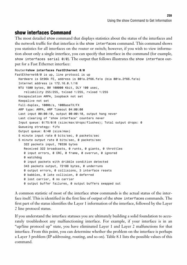
Using the show Command to Get Information259
show interfaces CommandThe most detailed show command that displays statistics about the status of the interfaces andthe network traffic for that interface is the show interfaces command. This command showsyou statistics for all interfaces on the router or switch; however, if you wish to view informa-tion about only a single interface, you can specify that interface in the command (for example,show interfaces serial 0/0). The output that follows illustrates the show interface out-put for a Fast Ethernet interface:Router#show interfaces FastEthernet 0/0FastEthernet0/0 is up, line protocol is upHardware is Gt96k FE, address is 001a.2f66.fa1a (bia 001a.2f66.fa1a)Internet address is 172.16.0.1/16MTU 1500 bytes, BW 100000 Kbit, DLY 100 usec,
reliability 255/255, txload 1/255, rxload 1/255Encapsulation ARPA, loopback not setKeepalive not setFull-duplex, 100Mb/s, 100BaseTX/FXARP type: ARPA, ARP Timeout 04:00:00Last input 00:00:10, output 00:00:10, output hang neverLast clearing of “show interface” counters neverInput queue: 0/75/0/0 (size/max/drops/flushes); Total output drops: 0Queueing strategy: fifoOutput queue: 0/40 (size/max)5 minute input rate 0 bits/sec, 0 packets/sec5 minute output rate 0 bits/sec, 0 packets/sec
322 packets input, 70336 bytesReceived 322 broadcasts, 0 runts, 0 giants, 0 throttles0 input errors, 0 CRC, 0 frame, 0 overrun, 0 ignored0 watchdog0 input packets with dribble condition detected343 packets output, 72188 bytes, 0 underruns0 output errors, 0 collisions, 3 interface resets0 babbles, 0 late collision, 0 deferred0 lost carrier, 0 no carrier0 output buffer failures, 0 output buffers swapped out
A common statistic of most of the interface show commands is the actual status of the inter-face itself. This is identified in the first line of output of the show interfaces commands. Thefirst part of the status identifies the Layer 1 information of the interface, followed by the Layer2 line protocol status.
If you understand the interface statuses you are ultimately building a solid foundation to accu-rately troubleshoot any malfunctioning interface. For example, if your interface is in an“up/line protocol up” state, you have eliminated Layer 1 and Layer 2 malfunctions for thatinterface. From this point, you can determine whether the problem on the interface is perhapsa Layer 3 problem (IP addressing, routing, and so on). Table 8.1 lists the possible values of thiscommand.
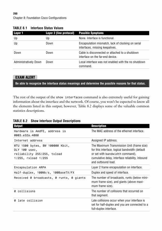
260
TABLE 8.1 Interface Status ValuesLayer 1 Layer 2 (line protocol) Possible Symptoms
Up Up None. Interface is functional.
Up Down Encapsulation mismatch, lack of clocking on serialinterfaces, missing keepalives.
Down Down Cable is disconnected or attached to a shutdown interface on the far-end device.
Administratively Down Down Local interface was not enabled with the no shutdowncommand.
Chapter 8: Foundation Cisco Configurations
EXAM ALERTBe able to recognize the interface status meanings and determine the possible reasons for that status.
The rest of the output of the show interfaces command is also extremely useful for gaininginformation about the interface and the network. Of course, you won’t be expected to know allthe elements listed in this output; however, Table 8.2 displays some of the valuable commonstatistics descriptions.
TABLE 8.2 Show Interface Output DescriptionsOutput Description
Hardware is AmdFE, address is The MAC address of the ethernet interface.0003.e32a.4080
Internet address Assigned IP address.
MTU 1500 bytes, BW 100000 Kbit, The Maximum Transmission Unit (frame size) DLY 100 usec, for this interface, logical bandwidth (default reliability 255/255, txload or set with bandwidth command),1/255, rxload 1/255 cumulative delay, interface reliability, inbound
and outbound load.
Encapsulation ARPA Layer 2 frame encapsulation on interface.
Half-duplex, 100Mb/s, 100BaseTX/FX Duplex and speed of interface.
Received 0 broadcasts, 0 runts, 0 giants The number of broadcasts, runts (below mini-mum frame size), and giants (above maxi-mum frame size).
0 collisions The number of collisions that occurred onthat segment.
0 late collision Late collisions occur when your interface isset for half-duplex and you are connected to afull-duplex interface.
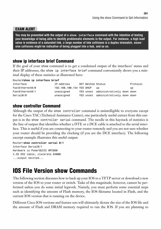
Using the show Command to Get Information261
show ip interface brief CommandIf the goal of your show command is to get a condensed output of the interfaces’ status andtheir IP addresses, the show ip interface brief command conveniently shows you a min-imal display of these statistics as illustrated here:Router#show ip interface briefInterface IP-Address OK? Method Status ProtocolFastEthernet0/0 192.168.100.154 YES DHCP up upFastEthernet0/1 unassigned YES unset administratively down downSerial0/0 unassigned YES unset administratively down down
show controller CommandAlthough the output of the show controller command is unintelligible to everyone exceptfor the Cisco TAC (Technical Assistance Center), one particularly useful extract from this out-put is in the show controller serial command. The needle in this haystack of statistics isthe line of output that identifies whether a DTE or a DCE cable is attached to the serial inter-face. This is useful if you are connecting to your router remotely and you are not sure whetheryour router should be providing the clocking (if you are the DCE interface). The followingexcerpt example illustrates this useful output:Router>show controller serial 0/1Interface Serial0/1Hardware is PowerQUICC MPC860V.35 DCE cable, clockrate 64000...output omitted...
IOS File Version show CommandsThe following section discusses how to back up your IOS to a TFTP server or download a newversion of the IOS to your router or switch. Tasks of this magnitude, however, cannot be per-formed unless you do some initial legwork. Namely, you must perform some essential stepssuch as identifying the amount of Flash memory, the IOS filename located in Flash, and thecurrent IOS version that is running on the device.
Different Cisco IOS versions and feature sets will ultimately dictate the size of the IOS file andthe amount of Flash and DRAM memory required to run the IOS. If you are planning to
EXAM ALERTYou may be presented with the output of a show interface command with the intention of testingyour knowledge of being able to identify problematic elements in the output. For instance, a high loadvalue is evidence of a saturated link, a large number of late collisions is a duplex mismatch, exces-sive collisions might be indicative of being plugged into a hub, and so on.
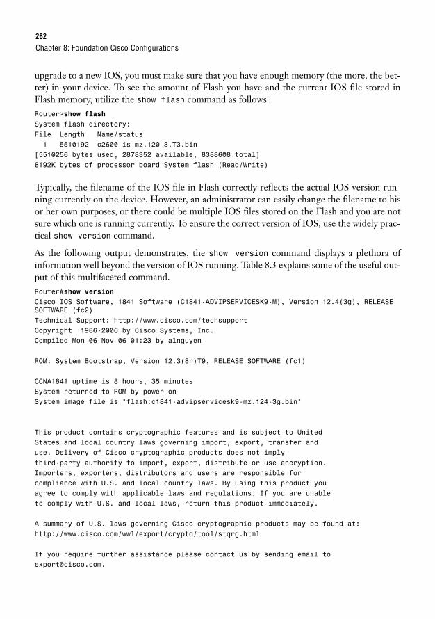
262
upgrade to a new IOS, you must make sure that you have enough memory (the more, the bet-ter) in your device. To see the amount of Flash you have and the current IOS file stored inFlash memory, utilize the show flash command as follows:Router>show flashSystem flash directory:File Length Name/status1 5510192 c2600-is-mz.120-3.T3.bin
[5510256 bytes used, 2878352 available, 8388608 total]8192K bytes of processor board System flash (Read/Write)
Typically, the filename of the IOS file in Flash correctly reflects the actual IOS version run-ning currently on the device. However, an administrator can easily change the filename to hisor her own purposes, or there could be multiple IOS files stored on the Flash and you are notsure which one is running currently. To ensure the correct version of IOS, use the widely prac-tical show version command.
As the following output demonstrates, the show version command displays a plethora ofinformation well beyond the version of IOS running. Table 8.3 explains some of the useful out-put of this multifaceted command.Router#show versionCisco IOS Software, 1841 Software (C1841-ADVIPSERVICESK9-M), Version 12.4(3g), RELEASESOFTWARE (fc2)Technical Support: http://www.cisco.com/techsupportCopyright 1986-2006 by Cisco Systems, Inc.Compiled Mon 06-Nov-06 01:23 by alnguyen
ROM: System Bootstrap, Version 12.3(8r)T9, RELEASE SOFTWARE (fc1)
CCNA1841 uptime is 8 hours, 35 minutesSystem returned to ROM by power-onSystem image file is “flash:c1841-advipservicesk9-mz.124-3g.bin”
This product contains cryptographic features and is subject to UnitedStates and local country laws governing import, export, transfer anduse. Delivery of Cisco cryptographic products does not implythird-party authority to import, export, distribute or use encryption.Importers, exporters, distributors and users are responsible forcompliance with U.S. and local country laws. By using this product youagree to comply with applicable laws and regulations. If you are unableto comply with U.S. and local laws, return this product immediately.
A summary of U.S. laws governing Cisco cryptographic products may be found at:http://www.cisco.com/wwl/export/crypto/tool/stqrg.html
If you require further assistance please contact us by sending email [email protected].
Chapter 8: Foundation Cisco Configurations
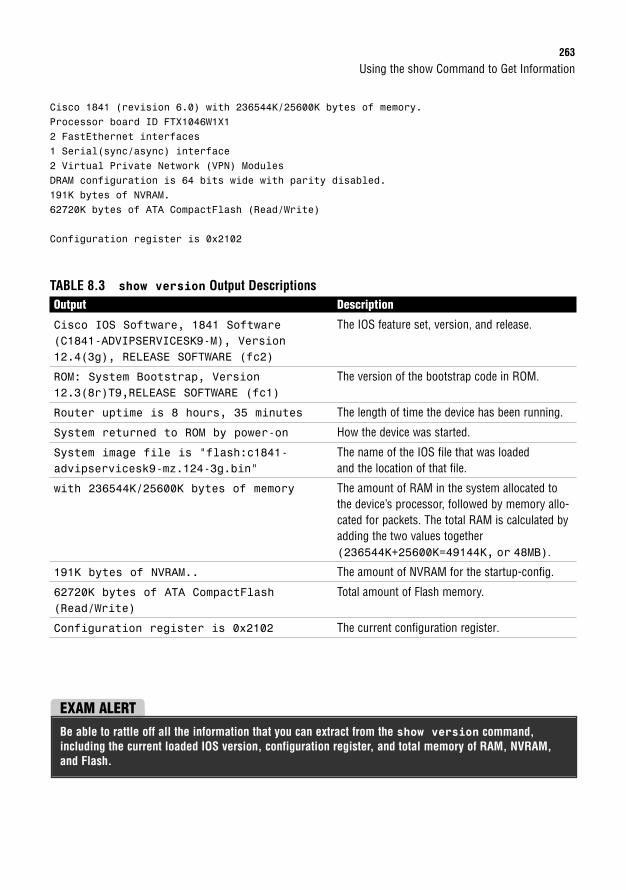
Using the show Command to Get Information263
Cisco 1841 (revision 6.0) with 236544K/25600K bytes of memory.Processor board ID FTX1046W1X12 FastEthernet interfaces1 Serial(sync/async) interface2 Virtual Private Network (VPN) ModulesDRAM configuration is 64 bits wide with parity disabled.191K bytes of NVRAM.62720K bytes of ATA CompactFlash (Read/Write)
Configuration register is 0x2102
TABLE 8.3 show version Output DescriptionsOutput Description
Cisco IOS Software, 1841 Software The IOS feature set, version, and release.(C1841-ADVIPSERVICESK9-M), Version12.4(3g), RELEASE SOFTWARE (fc2)
ROM: System Bootstrap, Version The version of the bootstrap code in ROM.12.3(8r)T9,RELEASE SOFTWARE (fc1)
Router uptime is 8 hours, 35 minutes The length of time the device has been running.
System returned to ROM by power-on How the device was started.
System image file is “flash:c1841- The name of the IOS file that was loaded advipservicesk9-mz.124-3g.bin” and the location of that file.
with 236544K/25600K bytes of memory The amount of RAM in the system allocated tothe device’s processor, followed by memory allo-cated for packets. The total RAM is calculated byadding the two values together(236544K+25600K=49144K, or 48MB).
191K bytes of NVRAM.. The amount of NVRAM for the startup-config.
62720K bytes of ATA CompactFlash Total amount of Flash memory.(Read/Write)
Configuration register is 0x2102 The current configuration register.
EXAM ALERTBe able to rattle off all the information that you can extract from the show version command,including the current loaded IOS version, configuration register, and total memory of RAM, NVRAM,and Flash.
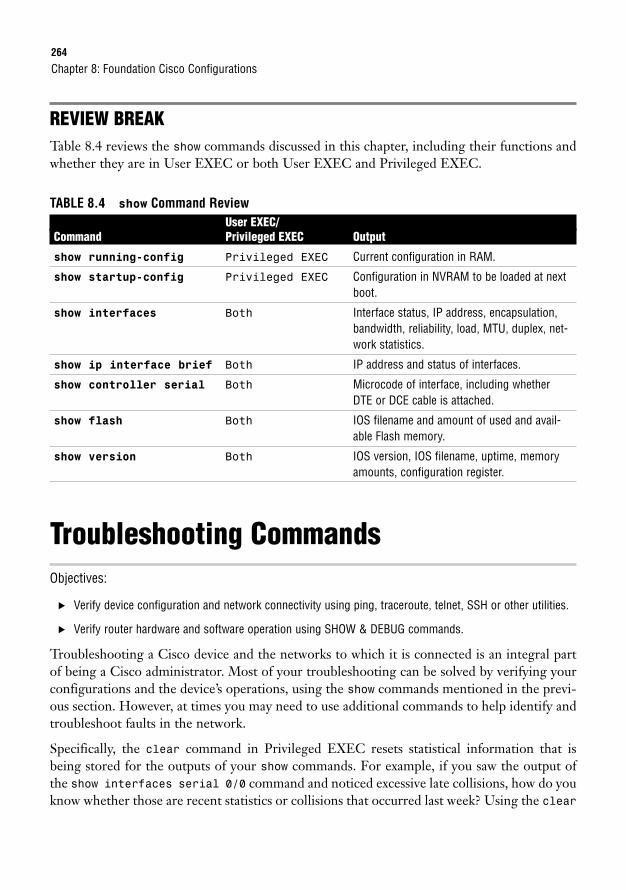
264
REVIEW BREAKTable 8.4 reviews the show commands discussed in this chapter, including their functions andwhether they are in User EXEC or both User EXEC and Privileged EXEC.
TABLE 8.4 show Command ReviewUser EXEC/
Command Privileged EXEC Output
show running-config Privileged EXEC Current configuration in RAM.
show startup-config Privileged EXEC Configuration in NVRAM to be loaded at nextboot.
show interfaces Both Interface status, IP address, encapsulation,bandwidth, reliability, load, MTU, duplex, net-work statistics.
show ip interface brief Both IP address and status of interfaces.
show controller serial Both Microcode of interface, including whetherDTE or DCE cable is attached.
show flash Both IOS filename and amount of used and avail-able Flash memory.
show version Both IOS version, IOS filename, uptime, memoryamounts, configuration register.
Troubleshooting CommandsObjectives:
. Verify device configuration and network connectivity using ping, traceroute, telnet, SSH or other utilities.
. Verify router hardware and software operation using SHOW & DEBUG commands.
Troubleshooting a Cisco device and the networks to which it is connected is an integral partof being a Cisco administrator. Most of your troubleshooting can be solved by verifying yourconfigurations and the device’s operations, using the show commands mentioned in the previ-ous section. However, at times you may need to use additional commands to help identify andtroubleshoot faults in the network.
Specifically, the clear command in Privileged EXEC resets statistical information that isbeing stored for the outputs of your show commands. For example, if you saw the output ofthe show interfaces serial 0/0 command and noticed excessive late collisions, how do youknow whether those are recent statistics or collisions that occurred last week? Using the clear
Chapter 8: Foundation Cisco Configurations
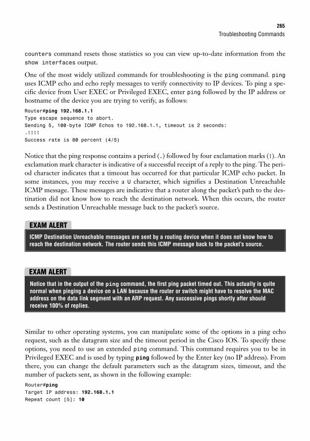
EXAM ALERT
Troubleshooting Commands265
counters command resets those statistics so you can view up-to-date information from theshow interfaces output.
One of the most widely utilized commands for troubleshooting is the ping command. pinguses ICMP echo and echo reply messages to verify connectivity to IP devices. To ping a spe-cific device from User EXEC or Privileged EXEC, enter ping followed by the IP address orhostname of the device you are trying to verify, as follows:Router#ping 192.168.1.1Type escape sequence to abort.Sending 5, 100-byte ICMP Echos to 192.168.1.1, timeout is 2 seconds:.!!!!Success rate is 80 percent (4/5)
Notice that the ping response contains a period (.) followed by four exclamation marks (!). Anexclamation mark character is indicative of a successful receipt of a reply to the ping. The peri-od character indicates that a timeout has occurred for that particular ICMP echo packet. Insome instances, you may receive a U character, which signifies a Destination UnreachableICMP message. These messages are indicative that a router along the packet’s path to the des-tination did not know how to reach the destination network. When this occurs, the routersends a Destination Unreachable message back to the packet’s source.
EXAM ALERTICMP Destination Unreachable messages are sent by a routing device when it does not know how toreach the destination network. The router sends this ICMP message back to the packet’s source.
Similar to other operating systems, you can manipulate some of the options in a ping echorequest, such as the datagram size and the timeout period in the Cisco IOS. To specify theseoptions, you need to use an extended ping command. This command requires you to be inPrivileged EXEC and is used by typing ping followed by the Enter key (no IP address). Fromthere, you can change the default parameters such as the datagram sizes, timeout, and thenumber of packets sent, as shown in the following example:Router#pingTarget IP address: 192.168.1.1Repeat count [5]: 10
Notice that in the output of the ping command, the first ping packet timed out. This actually is quitenormal when pinging a device on a LAN because the router or switch might have to resolve the MACaddress on the data link segment with an ARP request. Any successive pings shortly after shouldreceive 100% of replies.
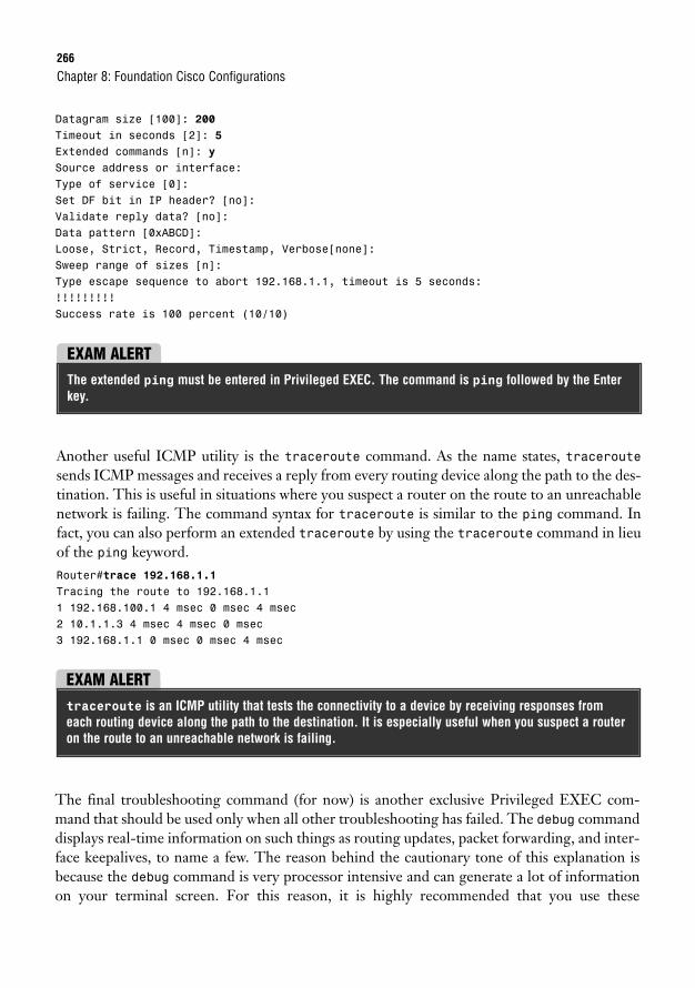
266
Datagram size [100]: 200Timeout in seconds [2]: 5Extended commands [n]: ySource address or interface:Type of service [0]:Set DF bit in IP header? [no]:Validate reply data? [no]:Data pattern [0xABCD]:Loose, Strict, Record, Timestamp, Verbose[none]:Sweep range of sizes [n]:Type escape sequence to abort 192.168.1.1, timeout is 5 seconds:!!!!!!!!!Success rate is 100 percent (10/10)
Chapter 8: Foundation Cisco Configurations
EXAM ALERTThe extended ping must be entered in Privileged EXEC. The command is ping followed by the Enterkey.
Another useful ICMP utility is the traceroute command. As the name states, traceroutesends ICMP messages and receives a reply from every routing device along the path to the des-tination. This is useful in situations where you suspect a router on the route to an unreachablenetwork is failing. The command syntax for traceroute is similar to the ping command. Infact, you can also perform an extended traceroute by using the traceroute command in lieuof the ping keyword.Router#trace 192.168.1.1Tracing the route to 192.168.1.11 192.168.100.1 4 msec 0 msec 4 msec2 10.1.1.3 4 msec 4 msec 0 msec3 192.168.1.1 0 msec 0 msec 4 msec
EXAM ALERTtraceroute is an ICMP utility that tests the connectivity to a device by receiving responses fromeach routing device along the path to the destination. It is especially useful when you suspect a routeron the route to an unreachable network is failing.
The final troubleshooting command (for now) is another exclusive Privileged EXEC com-mand that should be used only when all other troubleshooting has failed. The debug commanddisplays real-time information on such things as routing updates, packet forwarding, and inter-face keepalives, to name a few. The reason behind the cautionary tone of this explanation isbecause the debug command is very processor intensive and can generate a lot of informationon your terminal screen. For this reason, it is highly recommended that you use these
Backing Up and Restoring Configurations and IOS Using TFTP267
commands only in emergency situations or in a lab environment. If you must troubleshoot ona production router, be sure to issue the show processes command as follows:RouterA#show processesCPU utilization for five seconds: 0%/0%; one minute: 0%; five minutes: 0%...Output Omitted...
The majority of the output will not make sense; however, the top of the output lists the CPUutilization up to the last 5 minutes. If any of these values exceeds 60%, do not use the debugcommands. If you do, your router is likely to seize up from over-utilization.
EXAM ALERTIt is recommended to use the show processes command before using any debug commands to veri-fy the router’s current CPU utilization.
When you are finished troubleshooting, you can turn off debugging by putting a no in frontof the command, or you can turn off all debugging by typing no debug all or undebug all.Specific debugging commands are discussed throughout the course of this book.
EXAM ALERTIf your device is seizing up from too much debug processing, turn it off by using the no debug allor undebug all commands.
Backing Up and Restoring Configurationsand IOS Using TFTPObjective:
Manage IOS configuration files. (including: save, edit, upgrade, restore)
Recall from the “Saving Configurations” section that you used the copy command to copy therunning config in RAM to the startup config in NVRAM. By using this command, you are
To see accurate timestamps for your debug messages, it is highly recommended that you configure theclock to reflect the correct date and time by using the clock command in Privileged EXEC. In addition, toadd a timestamp to the debug output, use the service timestamp command in Global Configuration.
TIP
268
basically copying this configuration file from one filesystem component to another. Such is thecase if you want to back up and restore configurations and IOSs to and from a TFTP server.
Chapter 8: Foundation Cisco Configurations
EXAM ALERTThe TFTP server is used to back up and restore configurations and IOS images.
A fair amount of setup and preparation is required to achieve this functionality, but the rewardsof being able to back up and restore these files are well worth it. Specifically, the followingpreparations need to be in place for your switch or router to transfer these files to and from aTFTP server:
1. The TFTP server must have the TFTP service running. You can search the Internetfor evaluation TFTP servers from companies such as SolarWinds and FutureSoft.
2. Your device must be cabled correctly. If you’re using a switch, plug the TFTP serverinto the switch with a straight-through ethernet cable. If you’re going directly betweena router and the TFTP server, use a cross-over cable.
3. You must have IP connectivity to the server. In other words, your interface should beon the same subnet as the server.
4. There must be enough room on the TFTP server and your device’s memory to storethese files. If your Flash memory cannot store two files, the IOS erases the old filefrom Flash memory before copying the new one.
After all the preparations are in place, and you have verified connectivity between the TFTPserver and your Cisco router or switch, you can use the copy command again to transfer files.Remember, the copy command instructs the IOS to copy from somewhere to somewhere. Theavailable keywords, once again, are startup-config, running-config, tftp, and flash.When the tftp keyword is used, the IOS follows up with a few subsequent questions to help theIOS identify the IP address of the server, and the filenames of the source and destination files.
For example, to copy the IOS from a TFTP server to the Flash memory of the router, yourcommand would look something like the following:Router#copy tftp flashAddress or name of remote host []? 172.16.1.254Source filename []? c2600-is-mz.120-3.T3.binDestination filename [c2800-is-mz.123-3.T3.bin]?Copy ‘c2800-is-mz.123-3.T3.bin’ from Flash to serveras ‘c2800-is-mz.123-3.T3.bin’? [yes/no]y!!!!!!!!!!!!!!!!!!!!!!!!!!!!!!!!!!!!!!!!!!!!!!!!!!!!!!!!!!!!!!!!!!!!!!!!!!!...output omitted...Upload to server doneFlash device copy took 00:01:24 [hh:mm:ss]
Backing Up and Restoring Configurations and IOS Using TFTP269
Similarly, if you wanted to upgrade your IOS to a new version or you want to restore a previ-ously backed up IOS from your TFTP server, the command would be copy tftp flash.Remember, if your flash memory does not have enough space for your current IOS file andthe new one, the process erases your old IOS file to make room for the new one. If you acci-dentally lose power during the file transfer, you inevitably end up in ROMmon. At that point,you can download the IOS again from the TFTP server or copy the image over the console.
After the IOS image is loaded to your Flash memory, you have to reboot the device for thatIOS to run (because your current IOS is still decompressed and running in RAM). To reboota Cisco device, use the reload command from Privileged EXEC. Do not forget to save anyconfiguration changes that you made with the copy running-config startup-config com-mand before rebooting the device because the router or switch uses the contents of your start-up configuration when it reinitializes. In many current IOS versions, the IOS reminds you thatyour configuration has modified and asks you whether you want to save it. Answering “yes” tothis prompt saves your configuration to NVRAM.Router#reloadSystem configuration has been modified. Save? [yes/no]: yesBuilding configuration...[OK]Proceed with reload? [confirm]04:31:02: %SYS-5-RELOAD: Reload requested
Similar to utilities such as ping and traceroute, successful copying of files to and from a TFTP server isdisplayed with an exclamation mark (!).
NOTE
EXAM ALERTThe reload Privileged EXEC command reinitializes the router or switch. The content in the startupconfiguration is loaded on boot-up.
The copy command can also be used to back up and restore your configurations. For example,to back up your current configuration, you can type copy running-config flash.Alternatively, you can always save your configuration to a text file by capturing the text outputof your terminal program and doing the show running-config command. If you want to pastethe configuration back into the Cisco device, just go into Global Configuration and paste thetext back into the terminal program window.
270
Cisco Integrated File SystemWith DOS and UNIX command navigation in mind, the Cisco IOS has adopted a command structure that canbe used regardless of what router platform you are on. These Integrated File System (IFS) commands useURL syntax to specify files in either the device’s local memory or on network servers that you would like tosee or copy. The commands such as show and copy are still the same; however, when specifying file loca-tions, you use a URL to indicate the location and file name. This syntax also helps you perform commands likein our TFTP section without requiring the IOS to ask us questions because we are indicating all the informa-tion in the command line. For instance, in the previous section, we used the copy tftp flash commandto download a new IOS to our router. This was followed by a subset of questions to identify the file names andIP address of the TFP server. With the IFS, we could do all that in one command such as the following:
Router# copy tftp://172.16.1.254/c2600-is-mz.120-3.T3.bin flash:c2600-is-mz.120-3.T3.bin
Table 8.5 shows some of the keywords we recently learned and shows what they would be using the IFS.
TABLE 8.5 Integrated File System KeywordsTraditional Command Keyword Integrated File System Keyword
flash flash:filename
tftp tftp://tftp_IP/filename
running-config system:running-config
startup-config nvram:starup-config
Neighbor Discovery with CDPImagine it is your first day at work and your boss wants you to create a topology map of the net-work, including model numbers, IPs, and IOS versions of all the Cisco equipment. Eager toimpress the boss, you want to get this task done as soon as possible. The problem is that the equip-ment isn’t allocated in the same building and your security badge won’t allow you into other build-ings. Thus, console access isn’t possible and you don’t know the IP addresses of the other devicesto use SSH or Telnet into them. Instead of spending that free time looking in the want ads becauseyou are afraid you are going to get fired, you can call upon a very useful protocol called CiscoDiscovery Protocol (CDP) to gather information of directly connected Cisco neighbors.
Chapter 8: Foundation Cisco Configurations
EXAM ALERTThe show running-config command does not show commands such as no shutdown. If youpaste the configuration into a new configuration, the interfaces remain shut down unless you edit thetext file and place the no shutdown command in the interface configurations or enter the commandsin the configuration afterward.
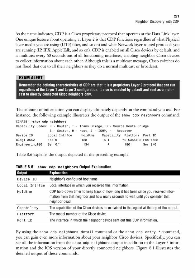
Neighbor Discovery with CDP271
As the name indicates, CDP is a Cisco proprietary protocol that operates at the Data Link layer.One unique feature about operating at Layer 2 is that CDP functions regardless of what Physicallayer media you are using (UTP, fiber, and so on) and what Network layer routed protocols youare running (IP, IPX, AppleTalk, and so on). CDP is enabled on all Cisco devices by default, andis multicast every 60 seconds out of all functioning interfaces, enabling neighbor Cisco devicesto collect information about each other. Although this is a multicast message, Cisco switches donot flood that out to all their neighbors as they do a normal multicast or broadcast.
EXAM ALERTRemember the defining characteristics of CDP are that it is a proprietary Layer 2 protocol that can runregardless of the Layer 1 and Layer 3 configuration. It also is enabled by default and sent as a multi-cast to directly connected Cisco neighbors only.
The amount of information you can display ultimately depends on the command you use. Forinstance, the following example illustrates the output of the show cdp neighbors command:CCNA2811>show cdp neighborsCapability Codes: R - Router, T - Trans Bridge, B - Source Route Bridge
S - Switch, H - Host, I - IGMP, r - RepeaterDevice ID Local Intrfce Holdtme Capability Platform Port IDBldg1-3550 Fas 0 128 S I WS-C3550-2 Fas 0/22Engineering1801 Ser 0/1 134 R 1801 Ser 0/0
Table 8.6 explains the output depicted in the preceding example.
TABLE 8.6 show cdp neighbors Output ExplanationOutput Explanation
Device ID Neighbor’s configured hostname.
Local Intrfce Local interface in which you received this information.
Holdtme CDP hold-down timer to keep track of how long it has been since you received infor-mation from that neighbor and how many seconds to wait until you consider thatneighbor dead.
Capability The capabilities of the Cisco devices as explained in the legend at the top of the output.
Platform The model number of the Cisco device.
Port ID The interface in which the neighbor device sent out this CDP information.
By using the show cdp neighbors detail command or the show cdp entry * command,you can gain even more information about your neighbor Cisco devices. Specifically, you cansee all the information from the show cdp neighbors output in addition to the Layer 3 infor-mation and the IOS version of your directly connected neighbors. Figure 8.1 illustrates thedetailed output of these commands.
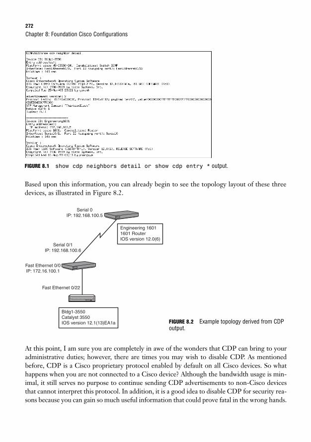
272
FIGURE 8.1 show cdp neighbors detail or show cdp entry * output.
Based upon this information, you can already begin to see the topology layout of these threedevices, as illustrated in Figure 8.2.
Chapter 8: Foundation Cisco Configurations
Serial 0IP: 192.168.100.5
Serial 0/1IP: 192.168.100.6
Fast Ethernet 0/0IP: 172.16.100.1
Fast Ethernet 0/22
Engineering 16011601 RouterIOS version 12.0(6)
Bldg1-3550Catalyst 3550IOS version 12.1(13)EA1a
At this point, I am sure you are completely in awe of the wonders that CDP can bring to youradministrative duties; however, there are times you may wish to disable CDP. As mentionedbefore, CDP is a Cisco proprietary protocol enabled by default on all Cisco devices. So whathappens when you are not connected to a Cisco device? Although the bandwidth usage is min-imal, it still serves no purpose to continue sending CDP advertisements to non-Cisco devicesthat cannot interpret this protocol. In addition, it is a good idea to disable CDP for security rea-sons because you can gain so much useful information that could prove fatal in the wrong hands.
FIGURE 8.2 Example topology derived from CDPoutput.
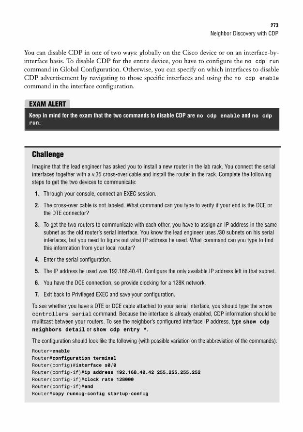
Neighbor Discovery with CDP273
You can disable CDP in one of two ways: globally on the Cisco device or on an interface-by-interface basis. To disable CDP for the entire device, you have to configure the no cdp runcommand in Global Configuration. Otherwise, you can specify on which interfaces to disableCDP advertisement by navigating to those specific interfaces and using the no cdp enablecommand in the interface configuration.
EXAM ALERTKeep in mind for the exam that the two commands to disable CDP are no cdp enable and no cdp
run.
ChallengeImagine that the lead engineer has asked you to install a new router in the lab rack. You connect the serialinterfaces together with a v.35 cross-over cable and install the router in the rack. Complete the followingsteps to get the two devices to communicate:
1. Through your console, connect an EXEC session.
2. The cross-over cable is not labeled. What command can you type to verify if your end is the DCE orthe DTE connector?
3. To get the two routers to communicate with each other, you have to assign an IP address in the samesubnet as the old router’s serial interface. You know the lead engineer uses /30 subnets on his serialinterfaces, but you need to figure out what IP address he used. What command can you type to findthis information from your local router?
4. Enter the serial configuration.
5. The IP address he used was 192.168.40.41. Configure the only available IP address left in that subnet.
6. You have the DCE connection, so provide clocking for a 128K network.
7. Exit back to Privileged EXEC and save your configuration.
To see whether you have a DTE or DCE cable attached to your serial interface, you should type the showcontrollers serial command. Because the interface is already enabled, CDP information should bemulitcast between your routers. To see the neighbor’s configured interface IP address, type show cdpneighbors detail or show cdp entry *.
The configuration should look like the following (with possible variation on the abbreviation of the commands):
Router>enableRouter#configuration terminalRouter(config)#interface s0/0Router(config-if)#ip address 192.168.40.42 255.255.255.252Router(config-if)#clock rate 128000Router(config-if)#endRouter#copy runnig-config startup-config
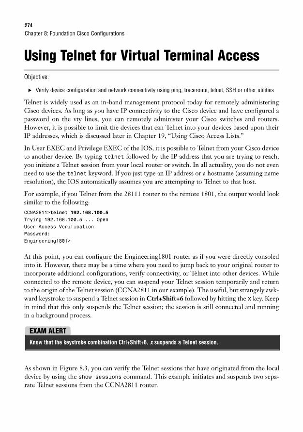
274
Using Telnet for Virtual Terminal AccessObjective:
. Verify device configuration and network connectivity using ping, traceroute, telnet, SSH or other utilities
Telnet is widely used as an in-band management protocol today for remotely administeringCisco devices. As long as you have IP connectivity to the Cisco device and have configured apassword on the vty lines, you can remotely administer your Cisco switches and routers.However, it is possible to limit the devices that can Telnet into your devices based upon theirIP addresses, which is discussed later in Chapter 19, “Using Cisco Access Lists.”
In User EXEC and Privilege EXEC of the IOS, it is possible to Telnet from your Cisco deviceto another device. By typing telnet followed by the IP address that you are trying to reach,you initiate a Telnet session from your local router or switch. In all actuality, you do not evenneed to use the telnet keyword. If you just type an IP address or a hostname (assuming nameresolution), the IOS automatically assumes you are attempting to Telnet to that host.
For example, if you Telnet from the 28111 router to the remote 1801, the output would looksimilar to the following:CCNA2811>telnet 192.168.100.5Trying 192.168.100.5 ... OpenUser Access VerificationPassword:Engineering1801>
At this point, you can configure the Engineering1801 router as if you were directly consoledinto it. However, there may be a time where you need to jump back to your original router toincorporate additional configurations, verify connectivity, or Telnet into other devices. Whileconnected to the remote device, you can suspend your Telnet session temporarily and returnto the origin of the Telnet session (CCNA2811 in our example). The useful, but strangely awk-ward keystroke to suspend a Telnet session in Ctrl+Shift+6 followed by hitting the x key. Keepin mind that this only suspends the Telnet session; the session is still connected and runningin a background process.
Chapter 8: Foundation Cisco Configurations
EXAM ALERTKnow that the keystroke combination Ctrl+Shift+6, x suspends a Telnet session.
As shown in Figure 8.3, you can verify the Telnet sessions that have originated from the localdevice by using the show sessions command. This example initiates and suspends two sepa-rate Telnet sessions from the CCNA2811 router.
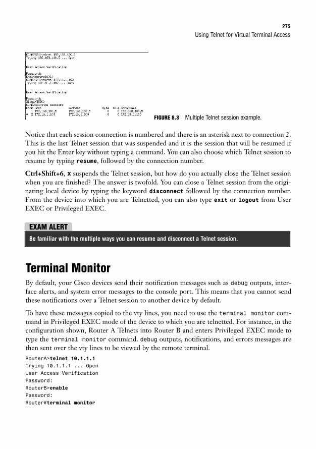
Using Telnet for Virtual Terminal Access275
Notice that each session connection is numbered and there is an asterisk next to connection 2.This is the last Telnet session that was suspended and it is the session that will be resumed ifyou hit the Enter key without typing a command. You can also choose which Telnet session toresume by typing resume, followed by the connection number.
Ctrl+Shift+6, x suspends the Telnet session, but how do you actually close the Telnet sessionwhen you are finished? The answer is twofold. You can close a Telnet session from the origi-nating local device by typing the keyword disconnect followed by the connection number.From the device into which you are Telnetted, you can also type exit or logout from UserEXEC or Privileged EXEC.
FIGURE 8.3 Multiple Telnet session example.
EXAM ALERTBe familiar with the multiple ways you can resume and disconnect a Telnet session.
Terminal MonitorBy default, your Cisco devices send their notification messages such as debug outputs, inter-face alerts, and system error messages to the console port. This means that you cannot sendthese notifications over a Telnet session to another device by default.
To have these messages copied to the vty lines, you need to use the terminal monitor com-mand in Privileged EXEC mode of the device to which you are telnetted. For instance, in theconfiguration shown, Router A Telnets into Router B and enters Privileged EXEC mode totype the terminal monitor command. debug outputs, notifications, and errors messages arethen sent over the vty lines to be viewed by the remote terminal.RouterA>telnet 10.1.1.1Trying 10.1.1.1 ... OpenUser Access VerificationPassword:RouterB>enablePassword:Router#terminal monitor
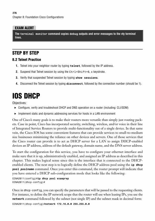
276
STEP BY STEP8.2 Telnet Practice
1. Telnet into your neighbor router by typing telnet, followed by the IP address.
2. Suspend that Telnet session by using the Ctrl+Shift+6, x keystroke.
3. Verify that suspended Telnet session by typing show sessions.
4. Disconnect the Telnet session by typing disconnect, followed by the connection number (should be 1).
IOS DHCPObjectives:
. Configure, verify and troubleshoot DHCP and DNS operation on a router (including: CLI/SDM)
. Implement static and dynamic addressing services for hosts in a LAN environment
One of Cisco’s many goals is to make their routers more versatile than simply just routing pack-ets. Case in point, Cisco has incorporated security, switching, wireless, and/or voice in their lineof Integrated Service Routers to provide multi-functionality out of a single device. In that samevein, the Cisco IOS has some convenient features that can provide services to small-to-mediumsize businesses minimizing the reliance on other devices and servers. One of those services thatthe Cisco router can provide is to act as DHCP server for a LAN to assign DHCP-enableddevices an IP address, address of the default gateway, domain name, and the DNS server address.
To start the configuration for this service, you have to configure your ethernet interface andmake sure that it is up, administratively enabled, and assigned an IP address as described in thischapter. This makes logical sense since this is the interface that is connected to the DHCP-enabled clients. The next step is to logically define the DHCP address pool using the ip dhcp
pool poolname command. Once you enter this command, the router prompt will indicate thatyou have entered a DHCP sub-configuration mode that looks like the following:CCNA2811(config)#ip dhcp pool examprepCCNA2811(dhcp-config)#
Once in dhcp-config, you can specify the parameters that will be passed to the requesting clients.For instance, to define the IP network scope that the router will use when leasing IPs, you use thenetwork command followed by the subnet (not single IP) and the subnet mask in decimal form:CCNA2811(dhcp-config)#network 172.16.0.0 255.255.0.0
Chapter 8: Foundation Cisco Configurations
EXAM ALERTThe terminal monitor command copies debug outputs and error messages to the vty terminallines.
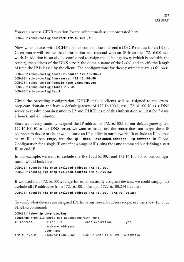
IOS DHCP277
You can also use CIDR notation for the subnet mask as demonstrated here:CCNA2811(dhcp-config)#network 172.16.0.0 /16
Now, when devices with DCHP enabled come online and send a DHCP request for an IP, theCisco router will receive that information and respond with an IP from the 172.16.0.0 net-work. In addition it can also be configured to assign the default gateway (which is probably therouter), the address of the DNS server, the domain name of the LAN, and specify the lengthof time the IP is leased by the client. The configurations for these parameters are as follows:CCNA2811(dhcp-config)#default-router 172.16.100.1CCNA2811(dhcp-config)#dns-server 172.16.100.50CCNA2811(dhcp-config)#domain-name examprep.comCCNA2811(dhcp-config)#lease 7 2 45CCNA2811(dhcp-config)#exit
Given the preceding configuration, DHCP-enabled clients will be assigned to the exam-prep.com domain and have a default gateway of 172.16.100.1, use 172.16.100.50 as a DNSserver to resolve domain names to IP, and DHCP lease of this information will last for 7 days,2 hours, and 45 minutes.
Since we already statically assigned the IP address of 172.16.100.1 to our default gateway and172.16.100.50 to our DNS server, we want to make sure the router does not assign these IPaddresses to device or else it would cause an IP conflict in our network. To exclude an IP addressor an IP address range, use the ip dhcp excluded-address ip-address in GlobalConfiguration for a single IP or define a range of IPs using the same command but defining a startIP an end IP.
In our example, we want to exclude the IP’s 172.16.100.1 and 172.16.100.50, so our configu-ration would look like:CCNA2811(config)#ip dhcp excluded-address 172.16.100.1CCNA2811(config)#ip dhcp excluded-address 172.16.100.50
If we used that 172.16.100.x range for other statically assigned devices, we could simply justexclude all IP addresses from 172.16.100.1 through 172.16.100.254 like this:CCNA2811(config)#ip dhcp excluded-address 172.16.100.1 172.16.100.254
To verify what devices are assigned IP’s from our router’s address scope, use the show ip dhcpbinding command:CCNA2811#show ip dhcp bindingBindings from all pools not associated with VRF:IP address Client-ID/ Lease expiration Type
Hardware address/User name
172.16.100.2 01e0.041f.a632.a2 Dec 27 2007 11:59 PM Automatic
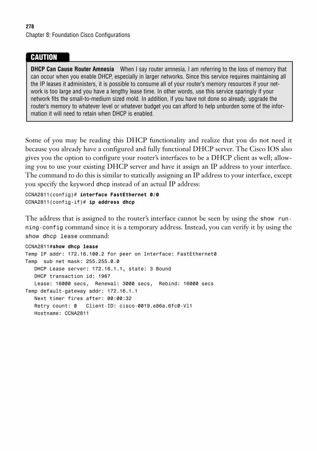
278
Some of you may be reading this DHCP functionality and realize that you do not need itbecause you already have a configured and fully functional DHCP server. The Cisco IOS alsogives you the option to configure your router’s interfaces to be a DHCP client as well; allow-ing you to use your existing DHCP server and have it assign an IP address to your interface.The command to do this is similar to statically assigning an IP address to your interface, exceptyou specify the keyword dhcp instead of an actual IP address:CCNA2811(config)# interface FastEthernet 0/0CCNA2811(config-if)# ip address dhcp
The address that is assigned to the router’s interface cannot be seen by using the show run-ning-config command since it is a temporary address. Instead, you can verify it by using theshow dhcp lease command:CCNA2811#show dhcp leaseTemp IP addr: 172.16.100.2 for peer on Interface: FastEthernet0Temp sub net mask: 255.255.0.0
DHCP Lease server: 172.16.1.1, state: 3 BoundDHCP transaction id: 1967Lease: 16000 secs, Renewal: 3000 secs, Rebind: 16000 secs
Temp default-gateway addr: 172.16.1.1Next timer fires after: 00:00:32Retry count: 0 Client-ID: cisco-0019.e86a.6fc0-Vl1Hostname: CCNA2811
Chapter 8: Foundation Cisco Configurations
DHCP Can Cause Router Amnesia When I say router amnesia, I am referring to the loss of memory thatcan occur when you enable DHCP, especially in larger networks. Since this service requires maintaining allthe IP leases it administers, it is possible to consume all of your router’s memory resources if your net-work is too large and you have a lengthy lease time. In other words, use this service sparingly if your network fits the small-to-medium sized mold. In addition, if you have not done so already, upgrade therouter’s memory to whatever level or whatever budget you can afford to help unburden some of the infor-mation it will need to retain when DHCP is enabled.
CAUTION
Chapter Summary279
Chapter SummaryThis chapter dealt with a plethora of commands and their respective syntaxes and outputs. InGlobal Configuration, you learned how to manipulate the startup process using either theconfig-register or boot system commands. Additionally, you saw how to use the hostnamecommand to name your router or switch and how to create a message-of-the-day login ban-ner with the banner motd command. To secure Privileged EXEC, you saw that the enablepassword command displays the password in clear text; however, the enable secret com-mand encrypts the password using a one-way MD5 hash and overrides the enable passwordcommand if both are configured. For DNS-specific functions, you discovered that you cancreate static DNS entries with the ip host command or specify DNS servers using the ipname-server command.
In the line configuration for console, Telnet, and the aux port, you saw that you can configurea layer of security by having administrators enter a password to get into User EXEC. This wasachieved by using the login and the password combo in the line configuration of each EXECline. Additionally, you saw the utility of the exec-timeout command for changing the defaulttimeout for an inactive EXEC session. Because these passwords are all in clear text, you canencrypt them in Global Configuration, using the service password-encryption command.
The configuration of interfaces entails assigning an IP address to a physical interface using theip address command followed by the IP address and subnet mask or the keyword dhcp fordynamically assigned IPs by a DHCP server. One final imperative interface configuration stepentails using the no shutdown command to administratively enable the interface.
You know from this chapter that the copy command can be used to meet several objectivessuch as saving the configuration, backing up and upgrading your IOS from a TFTP server, andbacking up and restoring your configurations. You learned that the syntax of the copy com-mand is copy from a source to a destination. The keywords you can use to identify the sourceand destination are startup-config, running-config, tftp, and flash.
To see your configurations, you now know that the show running-config command can showyou the active configuration in RAM, and that show startup-config displays the configura-tion booted from NVRAM that you saved with the copy running-config startup-configcommand. For verification and viewing statistics of interfaces, you discovered that the showinterfaces or the show ip interface brief command show you that the interface status-es can be one of the following: up/line protocol up (active), up/line protocol down (Layer 2down), down/line protocol down (Layer 1 down), administratively down/line protocol down(interface requires no shutdown command). What’s more, the show controller serial com-mand can show you whether the interface has the DTE or the DCE cable connected to it ina lab environment with a cross-over serial cable.
You can sleep better at night knowing now that your Cisco devices, by default, receive Layer2 proprietary CDP multicast messages from directly connected Cisco devices that advertise
280
the hostname, local and remote interfaces, capabilities, device model, and its hold-down time.You saw these statistics by using the show cdp neighbors command; however, you also sawthe IOS revision and the Layer 3 address of your neighbors by using the show cdp neighborsdetail or show cdp entry * command. Disabling this useful utility was demonstrated withthe no cdp run command in Global Configuration or no cdp enable in the interface configuration.
In this chapter, you also learned that you can Telnet into other devices from your Cisco routeror switch. You suspended the Telnet session by using the Ctrl+Shift+6, x keystroke and ver-ified that Telnet session by typing show sessions. Closing the Telnet session was achieved bytyping exit or logout while in the active Telnet session, or disconnect followed by the connection number in the device where the Telnet originated.
Finally, we saw how Cisco routers have expanded their functionality beyond routing packets toinclude providing DHCP services for small-to-medium sized LANs. When DHCP-enabledclients send a DHCP request to the router, it responds with an IP address from its configuredscope of IPs. In addition, the router can provide the address of the DNS server, default gateway,and the domain name of the LAN. To configure these parameters, you have to define the logicalDHCP pool using the ip dhcp pool pool_name command which will take you into a dhcp-con-fig mode where you define the network and other parameters that will be passed to the clients.
Key Terms
Chapter 8: Foundation Cisco Configurations
. config-register register
. boot system location filename
. hostname hostname
. banner motd delimiting_char ban-
ner delimiting_char
. enable password password
. enable secret password
. service password-encryption
. ip host hostname IP
. ip name-server dns_server_IP
. ip domain-lookup
. login
. password password
. exec-timeout minutes seconds
. ip address address subnet_mask
. clock rate speed(bps)
. bandwidth speed(kbps)
. no shutdown
. copy from to
. erase startup-config
. show interfaces
. show ip interface brief
. show controller
. show flash
. show version
. show cdp neighbors
. show cdp neighbors detail
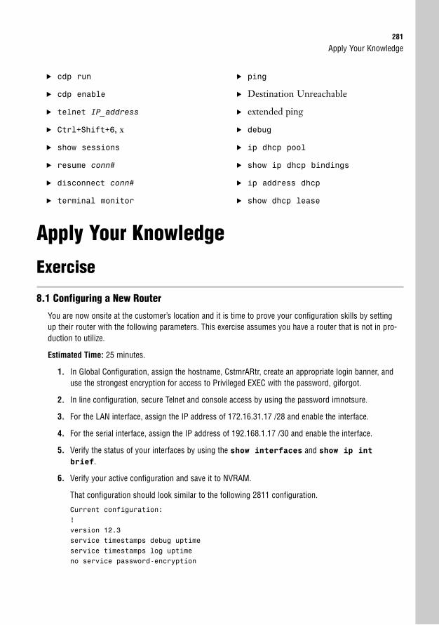
Apply Your Knowledge281
. cdp run
. cdp enable
. telnet IP_address
. Ctrl+Shift+6, x
. show sessions
. resume conn#
. disconnect conn#
. terminal monitor
. ping
. Destination Unreachable
. extended ping
. debug
. ip dhcp pool
. show ip dhcp bindings
. ip address dhcp
. show dhcp lease
Apply Your Knowledge
Exercise
8.1 Configuring a New Router
You are now onsite at the customer’s location and it is time to prove your configuration skills by settingup their router with the following parameters. This exercise assumes you have a router that is not in pro-duction to utilize.
Estimated Time: 25 minutes.
1. In Global Configuration, assign the hostname, CstmrARtr, create an appropriate login banner, anduse the strongest encryption for access to Privileged EXEC with the password, giforgot.
2. In line configuration, secure Telnet and console access by using the password imnotsure.
3. For the LAN interface, assign the IP address of 172.16.31.17 /28 and enable the interface.
4. For the serial interface, assign the IP address of 192.168.1.17 /30 and enable the interface.
5. Verify the status of your interfaces by using the show interfaces and show ip int
brief.
6. Verify your active configuration and save it to NVRAM.
That configuration should look similar to the following 2811 configuration.
Current configuration:!version 12.3service timestamps debug uptimeservice timestamps log uptimeno service password-encryption
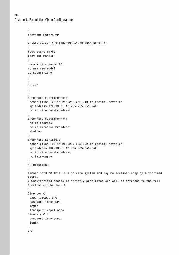
282
!hostname CstmrARtr!enable secret 5 $1$PHvQ$Gouu3MIDqY9G5d9hq9tr7/!boot-start-markerboot-end-marker!memory-size iomem 15no aaa new-modelip subnet-zero!!ip cef!!interface FastEthernet0description /28 is 255.255.255.240 in decimal notationip address 172.16.31.17 255.255.255.240no ip directed-broadcast!interface FastEthernet1no ip addressno ip directed-broadcastshutdown!interface Serial0/0description /30 is 255.255.255.252 in decimal notationip address 192.168.1.17 255.255.255.252no ip directed-broadcastno fair-queue!ip classless!banner motd ^C This is a private system and may be accessed only by authorizedusers.3 Unauthorized access is strictly prohibited and will be enforced to the full3 extent of the law.^C!line con 0exec-timeout 0 0password imnotsurelogintransport input noneline vty 0 4password imnotsurelogin!end
Chapter 8: Foundation Cisco Configurations
Apply Your Knowledge283
Review Questions1. What is the purpose of configuring passwords on the line configurations?
2. What are the available keywords for the copy command?
3. How is CDP useful to a Cisco administrator?
4. What ICMP protocol commands can help you determine whether you have IP connectivity to adevice?
5. What is the significance of x and y in the output of the show interfaces stats output: x/line protocolis y?
Exam Questions1. You wish to assign the password Cisco to only the first Telnet line. What series of commands will
achieve this?
❍ A. line vty 0 4, login, password Cisco
❍ B. line vty 0, login, password cisco
❍ C. line telnet 0, login, password Cisco
❍ D. line vty 0, login, password Cisco
2. You just issued the show ip interface brief command. You noticed that interface serial 0is down/line protocol is up. What can be determined by this output?
❍ A. Physical layer is up.
❍ B. Data Link layer is down.
❍ C. You cannot have a down/line protocol is up status.
❍ D. The interface is active.
3. What are two commands that you can use to encrypt the password that allows you access intoPrivileged EXEC? (Choose 2.)
❍ A. service password-encryption
❍ B. enable secret password
❍ C. enable password password
❍ D. encrypt enable password
284
4. You copied and pasted a known working configuration from a text file into your new router via theterminal window; however, you do not have connectivity out all your interfaces. Why?
❍ A. You have to use TFTP to copy a configuration.
❍ B. The font in your text file was not Courier New.
❍ C. You have to do a no shutdown on the interfaces.
❍ D. The baud rate of your terminal program needs to be set to 38800.
5. What command shows you the configuration register?
❍ A. show version
❍ B. show config-register
❍ C. show interfaces
❍ D. show flash
6. You entered the following configuration in global config:
Router(config)#enable password ciscoRouter(config)#enable secret giforgotRouter(config)#no enable secret giforgot
What will happen when you log out and try to re-enter Privileged EXEC?
❍ A. There will be no password.
❍ B. The password will be cisco.
❍ C. The password will be giforgot.
❍ D. Both passwords will work.
7. Which of the following commands does not close a Telnet session?
❍ A. exit
❍ B. disconnect
❍ C. Ctrl+Shift+6, x
❍ D. logout
8. Given the partial configuration output,
interface FastEthernet0description /28 is 255.255.255.240 in decimal notationip address 172.16.31.17 255.255.255.240shutdown
Chapter 8: Foundation Cisco Configurations

Apply Your Knowledge285
Which of the following would you see when you issue the show ip interface briefcommand?
❍ A. FastEthernet 0 172.16.31.17... up up
❍ B. FastEthernet 0 172.16.31.17... up down
❍ C. FastEthernet 0 172.16.31.17... down up
❍ D. FastEthernet 0 172.16.31.17... administratively down down
9. Given the following output, what can be determined about this interface? (Choose 2.)
FastEthernet0/0 is up, line protocol is upHardware is AmdFE, address is 0003.e32a.4080 (bia 0003.e32a.4080)Internet address is 172.16.1.1/16MTU 1500 bytes, BW 100000 Kbit, DLY 100 usec,
reliablility 255/255, txload 235/255, rxload 235/255Encapsulation ARPA, loopback not setKeepalive set (10 sec)Half-duplex, 100Mb/s, 100BaseTX/FXARP type: ARPA, ARP Timeout 04:00:00Last input never, output 00:00:10, output hang neverLast clearing of “show interface” counters neverQueueing strategy: fifoOutput queue 0/40, 0 drops; input queue 0/75, 0 drops5 minute input rate 0 bits/sec, 0 packets/sec5 minute output rate 0 bits/sec, 0 packets/sec
0 packets input, 0 bytesReceived 0 broadcasts, 0 runts, 0 giants, 0 throttles0 input errors, 0 CRC, 0 frame, 0 overrun, 0 ignored0 watchdog, 0 multicast0 input packets with dribble condition detected31 packets output, 2673 bytes, 0 underruns0 output errors, 0 collisions, 1 interface resets0 babbles, 156848 late collision, 0 deferred0 lost carrier, 0 no carrier0 output buffer failures, 0 output buffers swapped out
❍ A. There is a duplex mismatch.
❍ B. The administrator needs to do a no shutdown on this interface.
❍ C. The bandwidth is incorrect.
❍ D. This link is congested.
286
10. Given the following output, how can you reconnect to Telnet session 2? (Choose 2.)
CCNA2811#show sessionsConn Host Address Idle Conn Name1 131.108.100.152 131.108.100.152 0 131.108.100.152*2 126.102.57.63 126.102.57.63 0 126.102.57.63
❍ A. disconnect 2
❍ B. Enter
❍ C. Ctrl+Shift+6, x
❍ D. resume 2
❍ E. logout
11. Which of the following is not a necessary step in copying configuration and IOS files to and fromyour Cisco router and switch and a local TFTP server?
❍ A. The TFTP server software must be running.
❍ B. Your router should be directly connected with a straight-through cable.
❍ C. Your interface must be on the same subnet as the TFTP server.
❍ D. You should test whether you have IP connectivity by pinging the server from yourrouter.
12. What command assigns the last IP address in the 10th subnet of the network 192.168.100.0/29?Zero subnets are allowed.
❍ A. ip address 192.168.100.80 255.255.255.240
❍ B. ip address 192.168.100.79 255.255.255.248
❍ C. ip address 192.168.100.70 255.255.255.240
❍ D. ip address 192.168.100.73 255.255.255.248
❍ E. ip address 192.168.100.78 255.255.255.248
Chapter 8: Foundation Cisco Configurations
Apply Your Knowledge287
13. Given the following output,
Router>show flashSystem flash directory:File Length Name/status1 5510192 c2800-is-mz.123-3.T3.bin
[5510256 bytes used, 2878352 available, 8388608 total]8192K bytes of processor board System flash (Read/Write)
What is the command used and what will be the outcome of upgrading to a 7KB IOS file from aTFTP server?
❍ A. copy tftp ios, the current IOS file will be erased.
❍ B. copy flash tftp, the current IOS will be unchanged.
❍ C. copy tftp flash, the current IOS file will be erased.
❍ D. copy tftp flash, the new IOS file is too large and it will go into ROMmom.
Answers to Review Questions1. The password configurations on the terminal lines serve as a way to protect your router or switch
from anyone gaining access to User EXEC.
2. The copy command tells the Cisco device to copy a file from somewhere to somewhere. Theavailable keyword options for the copy command are startup-config, running-config,tftp, and flash.
3. CDP enables Cisco administrators to gain information from directly connected Cisco devices with-out requiring that they be connected with a terminal session. The show cdp neighborsdetail or show cdp entry * command displays the Layer 3 address and the IOS version ofthe neighbors.
4. ping and traceroute use ICMP to test IP connectivity. ping tests if one device has connectiv-ity to another device. traceroute displays the path the packets take to reach the destination.traceroute is useful for determining faulty routers along the path to the destination.
5. Given the show interfaces output x/line protocol is y, x represents the Physical layer status ofthe interface. y represents the Data Link layer status.
288
Answers to Exam Questions1. D. To assign a login prompt and password for only the first vty line, you have to navigate to line
vty 0. Answer A is incorrect because line vty 0 4 is configuring all 5 vty lines. B has the cor-rect navigation; however, the password is case sensitive. C is incorrect because the navigation toenter the Telnet lines is line vty 0.
2. C. The first part of the show ip interface brief command represents the status of thePhysical layer, followed by the Data Link layer status. It is impossible to have this output becauseyou cannot have Layer 2 without Layer 1 functionality. Answer A is incorrect because the Physicallayer represented on the left side of the forward slash is down. B is also false because the DataLink layer represented on the right side of the forward slash is up. D is incorrect because an activeinterface is up/line protocol is up.
3. A, B. The enable secret command encrypts the password with a one-way MD5 hash. Theservice password-encryption encrypts the enable password command and all otherclear text passwords. C is incorrect because the command does not encrypt the password. D isnot a valid command.
4. C. The configuration was saved to Notepad through the use of the show running-configcommand and copied from the terminal window into the file. The problem that occurs is that theno shutdown command does not display in the configuration, which means when the configura-tion is pasted back into a new router, the interfaces are still administratively shut. A is incorrectbecause you do not require TFTP to copy configurations that are saved in a text file on your com-puter. B is false because the font is not essential. D is incorrect because the baud rate does notneed to be changed.
5. A. show version displays the current configuration at the bottom of the command output.Answer B is incorrect because the command does not exist. Answers C and D are valid com-mands, but they will not display the configuration register.
6. B. If the enable secret and enable password command are in the same configuration,enable secret overrides enable password. However, the example removed the enablesecret command, leaving only enable password left in the configuration. Thus, the pass-word to get into Privileged EXEC is cisco. A is incorrect because the enable password com-mand was not removed. C and D are incorrect because the enable secret password wasremoved from the configuration.
7. C. Ctrl+Shift+6, x suspends the Telnet session. Answers A, B, and D are incorrect becausethose commands will actually disconnect the Telnet session.
8. D. Because the interface configuration is configured in a shutdown state, the interface statusshould report the fast ethernet interface as administratively down/line protocol is down. AnswersA, B, and C are incorrect because a shutdown interface does not have the Physical layer or theData Link layer in an up state.
Chapter 8: Foundation Cisco Configurations
Apply Your Knowledge289
9. A, D. Because there is an excessive number of late collisions in the output, it is safe to assumethat there is a duplex mismatch. Also, the link is 92% congested as indicated by the load state-ments (235/255). B is incorrect because the interface status is up/line protocol is up. C is incorrectbecause the bandwidth is accurate for a FastEthernet interface.
10. B, D. You can resume the suspended Telnet sessions in this device by hitting the Enter key or typ-ing the keyword, resume. Answers A and E disconnect the Telnet session and C suspends it.
11. B. If connecting directly to a TFTP server from a router, you must use a cross-over cable. AnswersA, C, and D are necessary steps to copy files to and from a TFTP server.
12. E. With a /29 or 255.255.255.248 subnet, the increment of these subnets is 8. Starting with 0,counting 10 networks gives you a Network/Subnet identifier of 192.168.100.72(0,8,16,24,32,40,48,56,64,72). The last IP address in that subnet is 192.168.100.78. Answer A is anetwork ID and the wrong subnet mask. Answer B is the broadcast address for that subnet.Answer C is that last IP address in ninth subnet with the wrong subnet mask. D is the first valid IPaddress in that subnet.
13. C. The command to upload your IOS from a TFTP server is copy tftp flash. Given the showflash output, there is not enough space for another 7KB file, so the current IOS file will beerased during the copy process, after which the actual download of the new IOS will occur. AnswerA is incorrect because the ios keyword does not exist. B is false because there is not enoughroom in Flash for both files, so the current IOS is will be erased.
Suggested Readings and Resources1. Odom, Wendell. CCENT/CCNA ICND1 Official Exam Certification Guide (CCENT
Exam 640-822 and CCNA Exam 640-802), 2nd Edition, Cisco Press Publishing, 2007.
2. Boney, James. Cisco IOS in a Nutshell, O’Reilly Publishing, 2001.
3. “Configuration Fundamentals Command Reference,” www.cisco.com.

This page intentionally left blank
9C H A P T E R N I N E
Understanding the Cisco SDM
ObjectiveThis chapter covers the following Cisco-specified objective for the “Configure, verify, and trou-bleshoot basic router operation and routing on Cisco devices” section of the 640-802 CCNAexam:
. Access and utilize the router to set basic parameters (including: CLI/SDM)
OutlineIntroduction 294
Getting Started 294
Global Configurations 296
Changing the Hostname, Banner, DomainName, and Secret Password 297
Router Access 301
DNS 302
DHCP 304
Router Interface Configurations 306
Assigning an IP Address 306
Enabling the Interface 307
Saving and Verifying Your Configurations 308
Monitoring 309
Chapter Summary 311
Key Terms 311
Apply Your Knowledge 311
Exercise 311
Review Questions 311
Exam Questions 312
Answers to Review Questions 314
Answers to Exam Questions 315
Suggested Readings and Resources 316

Study Strategies. Practice using the SDM in a lab environment.
. Learn how to set up basic router operation on an SDM-capable device.
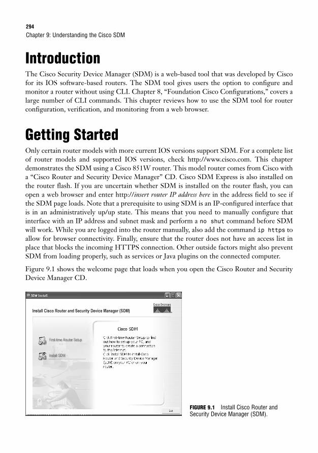
294
IntroductionThe Cisco Security Device Manager (SDM) is a web-based tool that was developed by Ciscofor its IOS software-based routers. The SDM tool gives users the option to configure andmonitor a router without using CLI. Chapter 8, “Foundation Cisco Configurations,” covers alarge number of CLI commands. This chapter reviews how to use the SDM tool for routerconfiguration, verification, and monitoring from a web browser.
Getting StartedOnly certain router models with more current IOS versions support SDM. For a complete listof router models and supported IOS versions, check http://www.cisco.com. This chapterdemonstrates the SDM using a Cisco 851W router. This model router comes from Cisco witha “Cisco Router and Security Device Manager” CD. Cisco SDM Express is also installed onthe router flash. If you are uncertain whether SDM is installed on the router flash, you canopen a web browser and enter http://insert router IP address here in the address field to see ifthe SDM page loads. Note that a prerequisite to using SDM is an IP-configured interface thatis in an administratively up/up state. This means that you need to manually configure thatinterface with an IP address and subnet mask and perform a no shut command before SDMwill work. While you are logged into the router manually, also add the command ip https toallow for browser connectivity. Finally, ensure that the router does not have an access list inplace that blocks the incoming HTTPS connection. Other outside factors might also preventSDM from loading properly, such as services or Java plugins on the connected computer.
Figure 9.1 shows the welcome page that loads when you open the Cisco Router and SecurityDevice Manager CD.
Chapter 9: Understanding the Cisco SDM
FIGURE 9.1 Install Cisco Router andSecurity Device Manager (SDM).
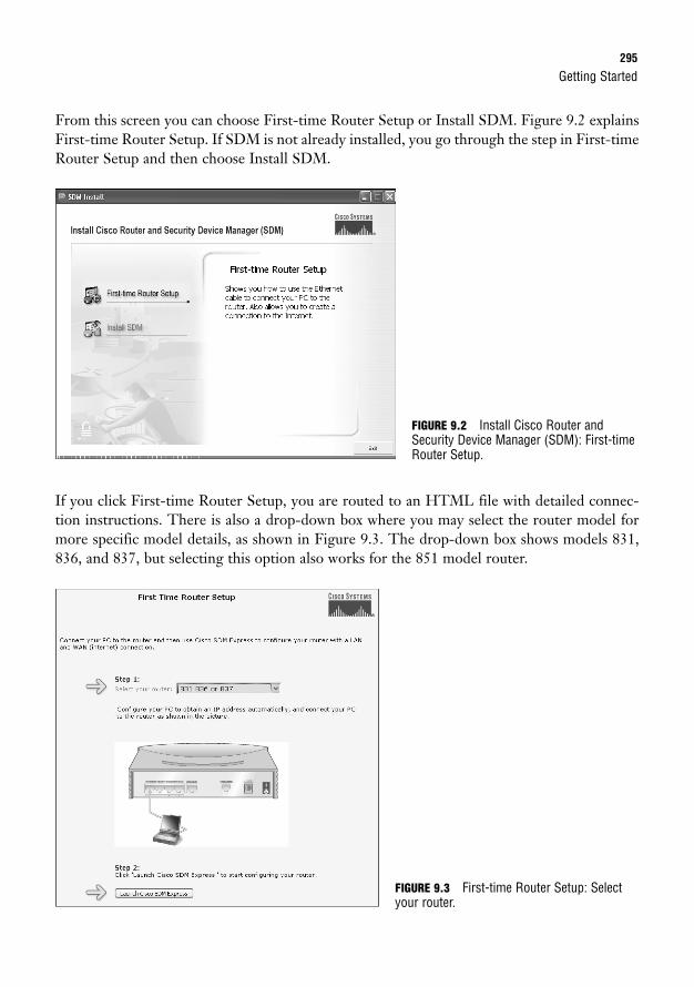
Getting Started295
From this screen you can choose First-time Router Setup or Install SDM. Figure 9.2 explainsFirst-time Router Setup. If SDM is not already installed, you go through the step in First-timeRouter Setup and then choose Install SDM.
If you click First-time Router Setup, you are routed to an HTML file with detailed connec-tion instructions. There is also a drop-down box where you may select the router model formore specific model details, as shown in Figure 9.3. The drop-down box shows models 831,836, and 837, but selecting this option also works for the 851 model router.
FIGURE 9.2 Install Cisco Router andSecurity Device Manager (SDM): First-timeRouter Setup.
FIGURE 9.3 First-time Router Setup: Selectyour router.
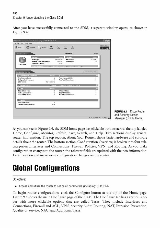
296
After you have successfully connected to the SDM, a separate window opens, as shown inFigure 9.4.
Chapter 9: Understanding the Cisco SDM
As you can see in Figure 9.4, the SDM home page has clickable buttons across the top labeledHome, Configure, Monitor, Refresh, Save, Search, and Help. Two sections display generalrouter information. The top section, About Your Router, shows basic hardware and softwaredetails about the router. The bottom section, Configuration Overview, is broken into four sub-categories: Interfaces and Connections, Firewall Policies, VPN, and Routing. As you makeconfiguration changes to the router, the relevant fields are updated with the new information.Let’s move on and make some configuration changes on the router.
Global ConfigurationsObjective:
. Access and utilize the router to set basic parameters (including: CLI/SDM)
To begin router configurations, click the Configure button at the top of the Home page.Figure 9.5 shows the main Configure page of the SDM. The Configure tab has a vertical side-bar with more clickable options that are called Tasks. They include Interfaces andConnections, Firewall and ACL, VPN, Security Audit, Routing, NAT, Intrusion Prevention,Quality of Service, NAC, and Additional Tasks.
FIGURE 9.4 Cisco Routerand Security DeviceManager (SDM): Home.
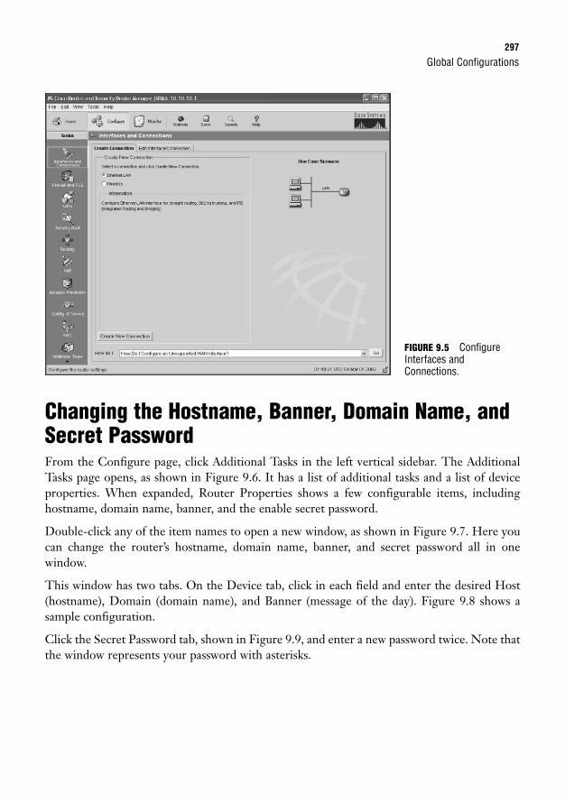
Global Configurations297
Changing the Hostname, Banner, Domain Name, andSecret PasswordFrom the Configure page, click Additional Tasks in the left vertical sidebar. The AdditionalTasks page opens, as shown in Figure 9.6. It has a list of additional tasks and a list of deviceproperties. When expanded, Router Properties shows a few configurable items, includinghostname, domain name, banner, and the enable secret password.
Double-click any of the item names to open a new window, as shown in Figure 9.7. Here youcan change the router’s hostname, domain name, banner, and secret password all in one window.
This window has two tabs. On the Device tab, click in each field and enter the desired Host(hostname), Domain (domain name), and Banner (message of the day). Figure 9.8 shows asample configuration.
Click the Secret Password tab, shown in Figure 9.9, and enter a new password twice. Note thatthe window represents your password with asterisks.
FIGURE 9.5 ConfigureInterfaces andConnections.
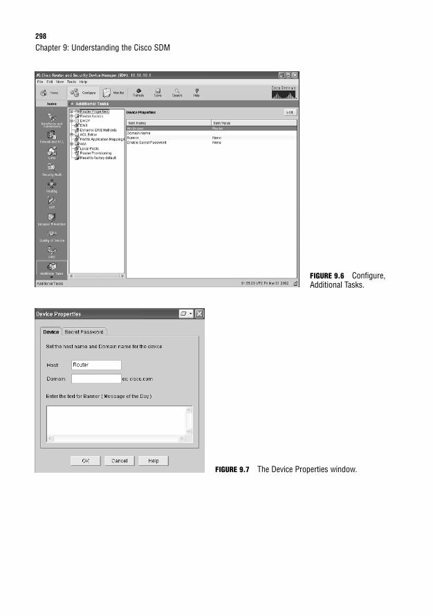
298
FIGURE 9.7 The Device Properties window.
Chapter 9: Understanding the Cisco SDM
FIGURE 9.6 Configure,Additional Tasks.
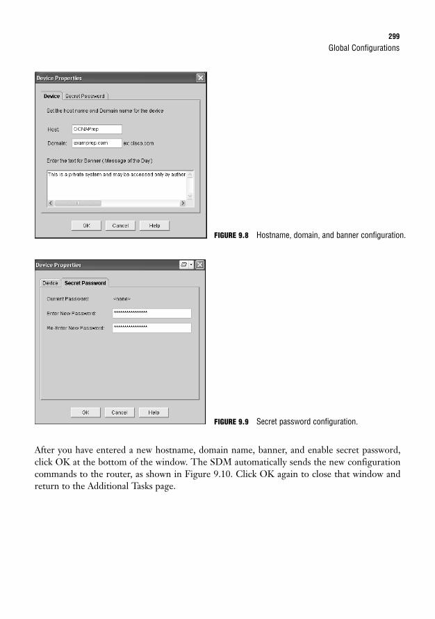
Global Configurations299
After you have entered a new hostname, domain name, banner, and enable secret password,click OK at the bottom of the window. The SDM automatically sends the new configurationcommands to the router, as shown in Figure 9.10. Click OK again to close that window andreturn to the Additional Tasks page.
FIGURE 9.8 Hostname, domain, and banner configuration.
FIGURE 9.9 Secret password configuration.
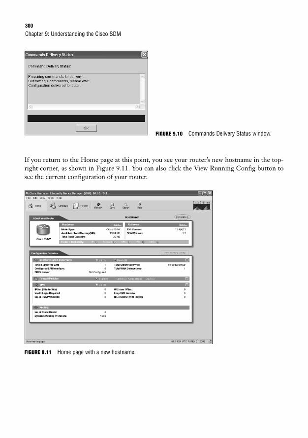
300
FIGURE 9.10 Commands Delivery Status window.
Chapter 9: Understanding the Cisco SDM
If you return to the Home page at this point, you see your router’s new hostname in the top-right corner, as shown in Figure 9.11. You can also click the View Running Config button tosee the current configuration of your router.
FIGURE 9.11 Home page with a new hostname.

Global Configurations301
ChallengeFrom the Cisco SDM, configure the following information on the router:
Host: CCNAPrep
Domain: examprep.com
Banner: This is a private system and may be accessed only by authorized users. Unauthorized access isstrictly prohibited and will be enforced to the full extent of the law.
Secret Password: mysecretpassword
After you click OK, the router prompts you to enter the new secret password information. Leave the user-name field blank, and enter your secret password to keep the SDM session connected.
NOTE
Router AccessThere is another way to configure username and password information using the SDM. Onthe Additional Tasks page, click Router Access to see what options can be configured using thistool, as shown in Figure 9.12.
FIGURE 9.12 Configure,Additional Tasks, RouterAccess.
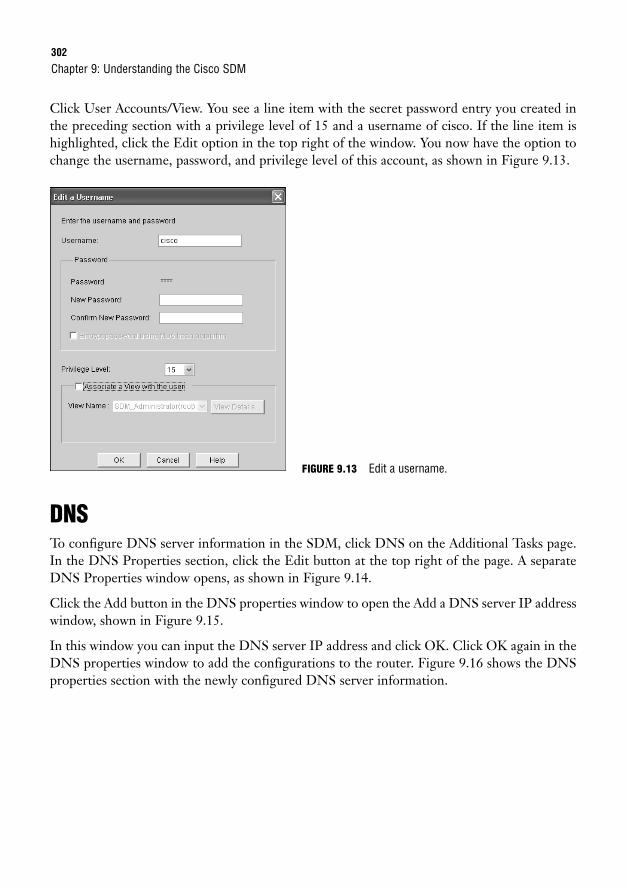
302
Click User Accounts/View. You see a line item with the secret password entry you created inthe preceding section with a privilege level of 15 and a username of cisco. If the line item ishighlighted, click the Edit option in the top right of the window. You now have the option tochange the username, password, and privilege level of this account, as shown in Figure 9.13.
Chapter 9: Understanding the Cisco SDM
DNSTo configure DNS server information in the SDM, click DNS on the Additional Tasks page.In the DNS Properties section, click the Edit button at the top right of the page. A separateDNS Properties window opens, as shown in Figure 9.14.
Click the Add button in the DNS properties window to open the Add a DNS server IP addresswindow, shown in Figure 9.15.
In this window you can input the DNS server IP address and click OK. Click OK again in theDNS properties window to add the configurations to the router. Figure 9.16 shows the DNSproperties section with the newly configured DNS server information.
FIGURE 9.13 Edit a username.
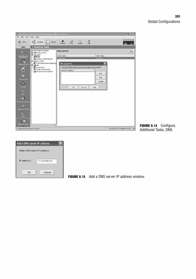
Global Configurations303
FIGURE 9.14 Configure,Additional Tasks, DNS.
FIGURE 9.15 Add a DNS server IP address window.
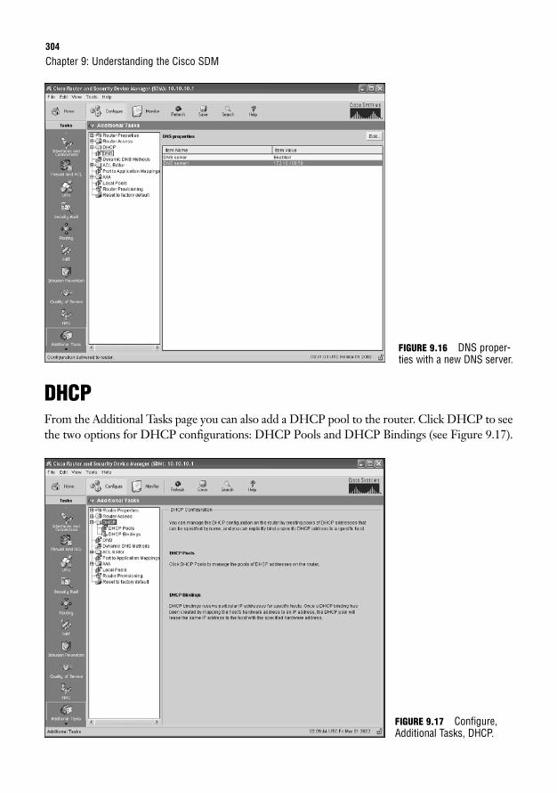
304
DHCPFrom the Additional Tasks page you can also add a DHCP pool to the router. Click DHCP to seethe two options for DHCP configurations: DHCP Pools and DHCP Bindings (see Figure 9.17).
Chapter 9: Understanding the Cisco SDM
FIGURE 9.16 DNS proper-ties with a new DNS server.
FIGURE 9.17 Configure,Additional Tasks, DHCP.
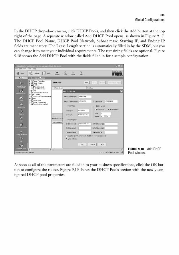
Global Configurations305
In the DHCP drop-down menu, click DHCP Pools, and then click the Add button at the topright of the page. A separate window called Add DHCP Pool opens, as shown in Figure 9.17.The DHCP Pool Name, DHCP Pool Network, Subnet mask, Starting IP, and Ending IPfields are mandatory. The Lease Length section is automatically filled in by the SDM, but youcan change it to meet your individual requirements. The remaining fields are optional. Figure9.18 shows the Add DHCP Pool with the fields filled in for a sample configuration.
As soon as all of the parameters are filled in to your business specifications, click the OK but-ton to configure the router. Figure 9.19 shows the DHCP Pools section with the newly con-figured DHCP pool properties.
FIGURE 9.18 Add DHCPPool window.
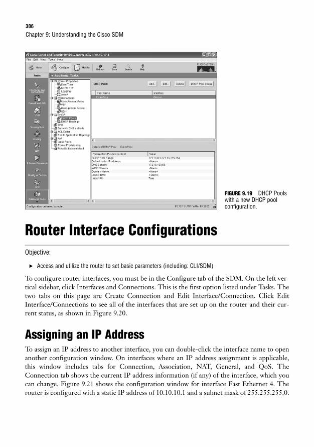
306
Router Interface ConfigurationsObjective:
. Access and utilize the router to set basic parameters (including: CLI/SDM)
To configure router interfaces, you must be in the Configure tab of the SDM. On the left ver-tical sidebar, click Interfaces and Connections. This is the first option listed under Tasks. Thetwo tabs on this page are Create Connection and Edit Interface/Connection. Click EditInterface/Connections to see all of the interfaces that are set up on the router and their cur-rent status, as shown in Figure 9.20.
Assigning an IP AddressTo assign an IP address to another interface, you can double-click the interface name to openanother configuration window. On interfaces where an IP address assignment is applicable,this window includes tabs for Connection, Association, NAT, General, and QoS. TheConnection tab shows the current IP address information (if any) of the interface, which youcan change. Figure 9.21 shows the configuration window for interface Fast Ethernet 4. Therouter is configured with a static IP address of 10.10.10.1 and a subnet mask of 255.255.255.0.
Chapter 9: Understanding the Cisco SDM
FIGURE 9.19 DHCP Poolswith a new DHCP poolconfiguration.
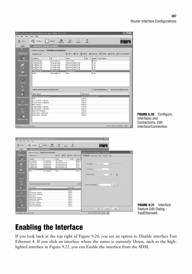
Router Interface Configurations307
Enabling the InterfaceIf you look back at the top right of Figure 9.20, you see an option to Disable interface FastEthernet 4. If you click an interface where the status is currently Down, such as the high-lighted interface in Figure 9.22, you can Enable the interface from the SDM.
FIGURE 9.20 Configure,Interfaces andConnections, EditInterface/Connection.
FIGURE 9.21 InterfaceFeature Edit Dialog -FastEthernet4.
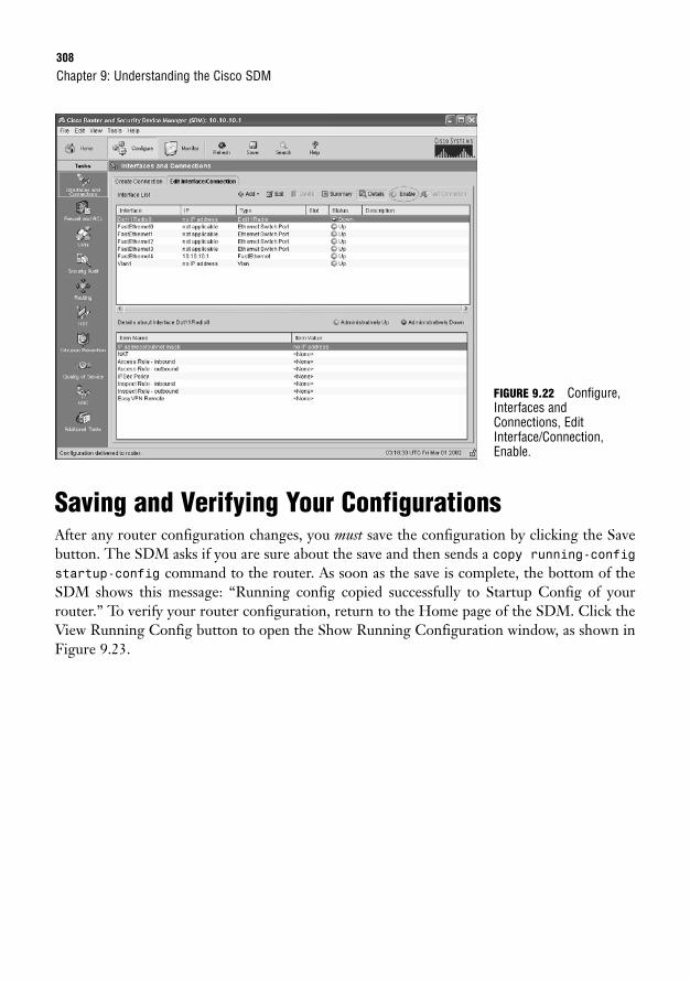
308
Saving and Verifying Your ConfigurationsAfter any router configuration changes, you must save the configuration by clicking the Savebutton. The SDM asks if you are sure about the save and then sends a copy running-configstartup-config command to the router. As soon as the save is complete, the bottom of theSDM shows this message: “Running config copied successfully to Startup Config of yourrouter.” To verify your router configuration, return to the Home page of the SDM. Click theView Running Config button to open the Show Running Configuration window, as shown inFigure 9.23.
Chapter 9: Understanding the Cisco SDM
FIGURE 9.22 Configure,Interfaces andConnections, EditInterface/Connection,Enable.
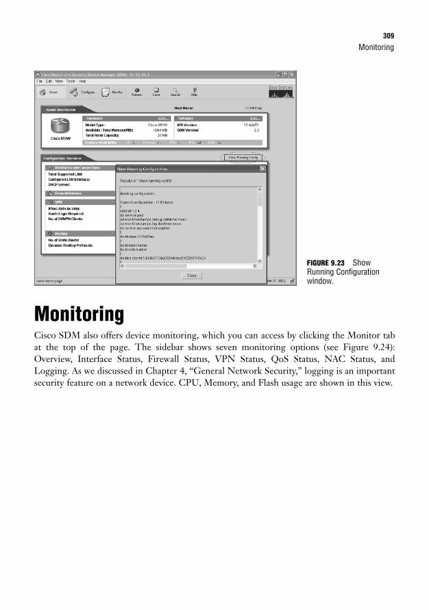
Monitoring309
MonitoringCisco SDM also offers device monitoring, which you can access by clicking the Monitor tabat the top of the page. The sidebar shows seven monitoring options (see Figure 9.24):Overview, Interface Status, Firewall Status, VPN Status, QoS Status, NAC Status, andLogging. As we discussed in Chapter 4, “General Network Security,” logging is an importantsecurity feature on a network device. CPU, Memory, and Flash usage are shown in this view.
FIGURE 9.23 ShowRunning Configurationwindow.
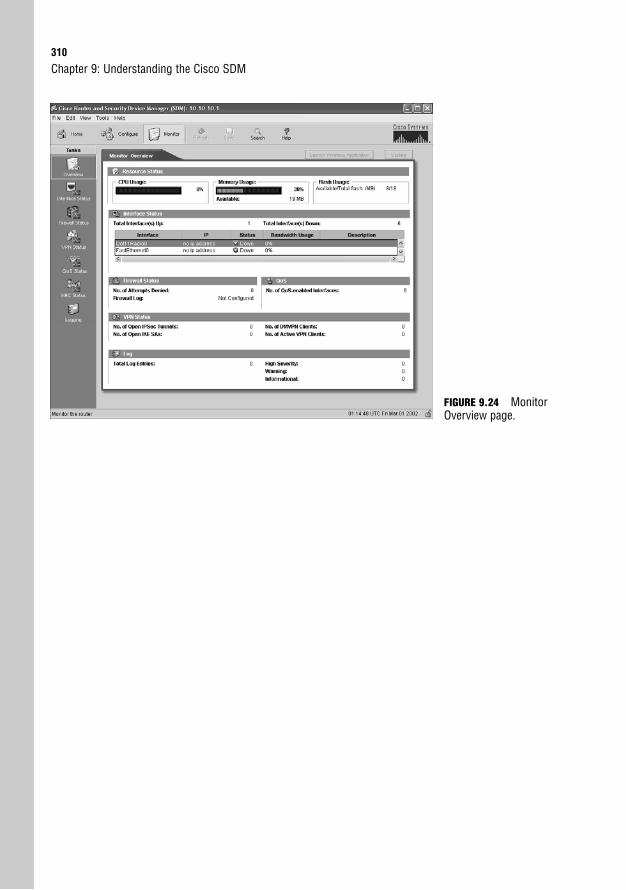
310
Chapter 9: Understanding the Cisco SDM
FIGURE 9.24 MonitorOverview page.
Apply Your Knowledge311
Chapter SummaryNow that you’ve seen a general overview of the Cisco SDM, for supported router models youcan choose to use the SDM versus Cisco CLI. In my opinion, and for the CCNA exam, youshould know both CLI and SDM configuration and verification methods. I encourage you tocontinue navigating the different pages and Tasks in the SDM to familiarize yourself with allavailable tools. If you are uncertain how to use an SDM Task, try the Help button for addi-tional details and tutorials.
Key Terms. Security Device Manager (SDM)
. Command-line interface (CLI)
Apply Your Knowledge
Exercise
9.1 SDM Configuration
The best way to learn SDM is to keep practicing the configurations on a test router. In this Exercise, con-figure the WAN interface on your router for the following IP address and subnet mask:
IP address: 192.168.1.1
Subnet mask: 255.255.255.0
Be sure to log back into the SDM with your new IP address!
Estimated Time: 5 minutes
Review Questions1. What is the Cisco SDM?
2. What are the ten tasks listed in the vertical sidebar of the SDM?
3. What four properties can be configured in the Router Properties section of the SDM?
4. What options can be configured in the Router Access portion of the SDM?
5. What steps would you take to configure the WAN IP address on a router using SDM?
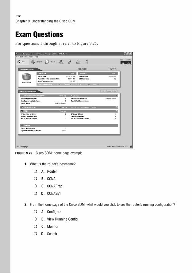
312
Exam QuestionsFor questions 1 through 5, refer to Figure 9.25.
Chapter 9: Understanding the Cisco SDM
FIGURE 9.25 Cisco SDM: home page example.
1. What is the router’s hostname?
❍ A. Router
❍ B. CCNA
❍ C. CCNAPrep
❍ D. CCNA851
2. From the home page of the Cisco SDM, what would you click to see the router’s running configuration?
❍ A. Configure
❍ B. View Running Config
❍ C. Monitor
❍ D. Search
Apply Your Knowledge313
3. Which feature is not available on the router shown in Figure 9.25?
❍ A. IP
❍ B. Firewall
❍ C. VPN
❍ D. IPS
4. From the home page of the Cisco SDM, what would you click to configure the router’s hostname?
❍ A. Configure
❍ B. View Running Config
❍ C. Monitor
❍ D. Search
5. To send a copy running-config startup-config command to the router with the SDM,which button would you click?
❍ A. Configure
❍ B. Monitor
❍ C. Refresh
❍ D. Save
6. How would you navigate the SDM to find and enable an interface?
❍ A. Configure, Interfaces and Connections
❍ B. Configure, Additional Tasks, Router Properties
❍ C. Configure, Additional Tasks, Router Access
❍ D. Configure, Interfaces and Connections, Edit Interface Connections
7. The Monitor screen on the SDM gives statistics for what three types of usage?
❍ A. Memory
❍ B. CPU
❍ C. Disk Activity
❍ D. Flash
314
8. Which of the following is configured from Router Properties?
❍ A. IP Address
❍ B. DHCP
❍ C. SNMP
❍ D. Secret Password
9. What privilege level is assigned to an account that is given a secret password?
❍ A. 15
❍ B. 10
❍ C. 5
❍ D. 0
10. User accounts can be added and edited in which section of the SDM?
❍ A. Router Properties
❍ B. Router Access
❍ C. ACL Editor
❍ D. DHCP
Answers to Review Questions1. The Cisco Security Device Manager (SDM) is a web-based tool that Cisco developed for its IOS
software-based routers. SDM allows users to configure and monitor a router without using CLI.
2. Interfaces and ConnectionsFirewall and ACLVPNSecurity AuditRoutingNATIntrusion PreventionQuality of ServiceNACAdditional Tasks
Chapter 9: Understanding the Cisco SDM
Apply Your Knowledge315
3. Host NameDomain NameBanner (Message of the Day)Secret Password
4. User AccountsVTY Line ConfigurationSSHManagement Access
5. From the Home page, select Configure, Interfaces and Connections, Edit Interface/Connection andthen double-click the WAN interface. On the Connection tab, select static or dynamic IP addressand enter the IP address and subnet mask.
Answers to Exam Questions1. C. The hostname of the router shown is CCNAPrep.
2. B. To see the running configuration of your router, click View Running Config.
3. D. IPS has a red circle with an X next to it, indicating that it is unavailable on this router. AnswersA, B, and C are incorrect because they have a green circle with a check mark, indicating that theseare available features on the router.
4. A. To get to router configuration options, the best answer to this question is to click the Configurebutton. Answer B is incorrect because it shows the router’s running configuration. Answers C andD are incorrect because they do not allow for device configuration.
5. D. With SDM, you click the Save button to send a copy running-config startup-con-fig command to the router.
6. D. To find and enable an interface, you need to select Configure, Interfaces and Connections, EditInterface Connections. Answer A is incorrect because it does not continue to the Edit InterfaceConnections tab. Answers B and C are incorrect because they refer to sections of the SDM that areused for general router properties or router access configurations.
7. A, B, D. The Monitor screen gives statistics on memory, CPU, and flash usage.
8. D. The secret password is configured in the Router Properties section of the SDM. Answer A isincorrect because the IP address is configured in the Interfaces and Connections section. AnswersB and C are incorrect because they are not configured from Router Properties.
9. A. A secret password is given a privilege level of 15.
10. B. User accounts can be added and edited in the Router Access section of the SDM. Answer A isincorrect because it can only be used to add a secret password on the router. Answers C and D arealso incorrect because they are not used to configure user accounts.

316
Suggested Readings and ResourcesThe following is recommended reading for general network security and related terminology:
1. “Cisco Router and Security Device Manager Q&A,” http://www.cisco.com/en/US/products/sw/secursw/ps5318/products_qanda_item0900aecd800fd11b.shtml
Chapter 9: Understanding the Cisco SDM
10C H A P T E R T E N
Introduction to Routing andRouting Protocols
ObjectivesThis chapter covers the following Cisco-specified objectives for the “Describe how a networkworks,” and “Configure, verify, and troubleshoot basic router operation and routing on Ciscodevices” sections of the 640-802 CCNA exam:
. Determine the path between two hosts across a network
. Describe basic routing concepts (including: packet forwarding, router lookupprocess)
. Perform and verify routing configuration tasks for a static or default routegiven specific routing requirements
. Compare and contrast methods of routing and routing protocols
. Verify device configuration and network connectivity using ping, traceroute,telnet, SSH or other utilities
. Verify network connectivity (including: using ping, traceroute, and telnet or SSH)
. Verify router hardware and software operation using SHOW & DEBUG commands
OutlineIntroduction 320
The Default Gateway 320
Verifying and Troubleshooting the Default Gateway 322
Routing Sources 323
Administrative Distance 324
Static Routes 325
Configuring Static Routes 326
Floating Static Routes 327
Default Routes 328
Configuring Static and Default Routes with SDM 329
Verifying Static and Default Routes 330
Dynamic Routing Protocols 331
Routing Metrics 332
Classful and Classless Routing Updates 333
VLSM 336
Route Summarization 338
Interior and Exterior Gateway RoutingProtocols 339
Distance Vector Routing Protocols 340
Link-State Routing Protocols 340
Advanced Distance Vector/Hybrid Routing Protocols 341
The Routing Table Revisited 341
Routing Redistribution 343
Chapter Summary 345
Key Terms 346
Apply Your Knowledge 346
Exercises 346
Review Questions 347
Exam Questions 347
Answers to Review Questions 351
Answers to Exam Questions 351
Suggested Readings and Resources 353

Study Strategies. Read the information presented in the chapter, paying special attention to tables, Notes,
and Exam Alerts.
. Because routing is a method of passing IP packets along to Layer 3 forwarding devices,take the perspective of the routing devices as it receives the packet and try to determinethe information required to send it on to the next forwarding device.
. Complete the Challenge and the Exercises at the end of the chapter. The exercises willsolidify the concepts that you have learned in the previous sections.
. This chapter involves several mathematical challenges that are based on the subnettingfoundations learned in Chapter 5, “Implementing IP Addressing.” If necessary, reviewthose concepts before tackling this chapter.
. Complete the Exam Questions at the end of the chapter. They are designed to simulate thetypes of questions you will be asked on the CCNA, ICND1, and ICND2 exams.
320
IntroductionSo far, we have delved into many configurations of our routers that cover the administrativeaspects of managing the device and providing basic connectivity. Don’t forget, however, thatthe routers were originally designed and created to do one main function. To give you a hint,the function is in its name.
Recall that Layer 3 is responsible for determining the best path to a network, using logicaladdressing such as IP addresses. This chapter discusses the fundamentals of how Layer 3devices such as routers and Layer 3 switches develop the routing logic to determine where toforward IP packets to reach a destination network.
The Default GatewayObjective:
. Determine the path between two hosts across a network
To fully comprehend the routing of data, it helps to start where much of the data in a networkoriginates: the computer. As application data is sent down the protocol stack, the source anddestination IP addresses are added to the IP header. If the destination IP address is located onthe same IP subnet as that on which the computer is, the computer adds the destination MACaddress of that device at Layer 2 and sends it on the wire.
In instances where the destination IP address is on a remote network, it must send that trafficto a router on its segment that can forward the packet toward the destination network.Although you will forward traffic to this default gateway, the destination IP address remainsunchanged. However, at Layer 2, the destination MAC address of the Ethernet frame reflectsthe default gateway’s MAC address because this is the forwarding device on the local data linksegment.
In the example illustrated in Figure 10.1, the PC sends traffic to the server on the remote10.1.34.0 network. The source IP address and MAC address are those matching the PC. Onthe other hand, the Layer 3 destination IP address of the IP packet reflects the IP address ofthe server (10.1.34.101). Because the destination IP address does not exist on the PC’s localsubnet of 192.168.1.0, the PC encapsulates the router’s Fast Ethernet 0/0 MAC at Layer 2because that is the configured default gateway for this segment. The switch in this scenario isoperating as only a Layer 2 switch. Thus, despite having an IP address for management, thisis not the default gateway for this segment because it is only forwarding frames at Layer 2.
Chapter 10: Introduction to Routing and Routing Protocols
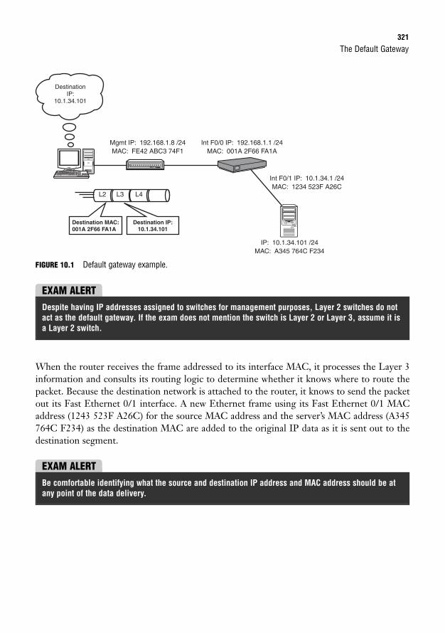
The Default Gateway321
FIGURE 10.1 Default gateway example.
DestinationIP:
10.1.34.101
Mgmt IP: 192.168.1.8 /24MAC: FE42 ABC3 74F1
Int F0/0 IP: 192.168.1.1 /24MAC: 001A 2F66 FA1A
Int F0/1 IP: 10.1.34.1 /24MAC: 1234 523F A26C
IP: 10.1.34.101 /24MAC: A345 764C F234
Destination MAC:001A 2F66 FA1A
Destination IP:10.1.34.101
L2 L3 L4
EXAM ALERTDespite having IP addresses assigned to switches for management purposes, Layer 2 switches do notact as the default gateway. If the exam does not mention the switch is Layer 2 or Layer 3, assume it isa Layer 2 switch.
When the router receives the frame addressed to its interface MAC, it processes the Layer 3information and consults its routing logic to determine whether it knows where to route thepacket. Because the destination network is attached to the router, it knows to send the packetout its Fast Ethernet 0/1 interface. A new Ethernet frame using its Fast Ethernet 0/1 MACaddress (1243 523F A26C) for the source MAC address and the server’s MAC address (A345764C F234) as the destination MAC are added to the original IP data as it is sent out to thedestination segment.
EXAM ALERTBe comfortable identifying what the source and destination IP address and MAC address should be atany point of the data delivery.
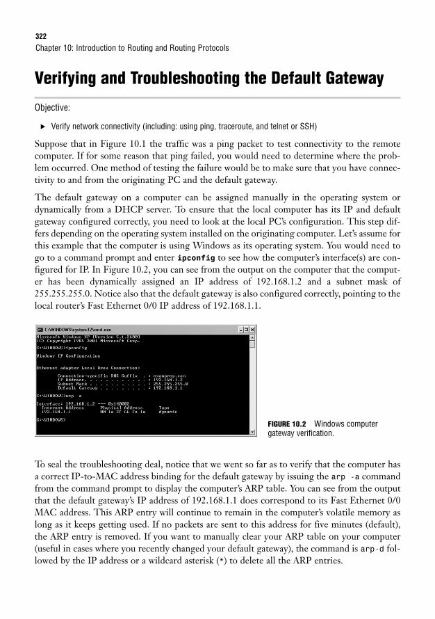
322
Verifying and Troubleshooting the Default Gateway
Objective:
. Verify network connectivity (including: using ping, traceroute, and telnet or SSH)
Suppose that in Figure 10.1 the traffic was a ping packet to test connectivity to the remotecomputer. If for some reason that ping failed, you would need to determine where the prob-lem occurred. One method of testing the failure would be to make sure that you have connec-tivity to and from the originating PC and the default gateway.
The default gateway on a computer can be assigned manually in the operating system ordynamically from a DHCP server. To ensure that the local computer has its IP and defaultgateway configured correctly, you need to look at the local PC’s configuration. This step dif-fers depending on the operating system installed on the originating computer. Let’s assume forthis example that the computer is using Windows as its operating system. You would need togo to a command prompt and enter ipconfig to see how the computer’s interface(s) are con-figured for IP. In Figure 10.2, you can see from the output on the computer that the comput-er has been dynamically assigned an IP address of 192.168.1.2 and a subnet mask of255.255.255.0. Notice also that the default gateway is also configured correctly, pointing to thelocal router’s Fast Ethernet 0/0 IP address of 192.168.1.1.
Chapter 10: Introduction to Routing and Routing Protocols
To seal the troubleshooting deal, notice that we went so far as to verify that the computer hasa correct IP-to-MAC address binding for the default gateway by issuing the arp -a commandfrom the command prompt to display the computer’s ARP table. You can see from the outputthat the default gateway’s IP address of 192.168.1.1 does correspond to its Fast Ethernet 0/0MAC address. This ARP entry will continue to remain in the computer’s volatile memory aslong as it keeps getting used. If no packets are sent to this address for five minutes (default),the ARP entry is removed. If you want to manually clear your ARP table on your computer(useful in cases where you recently changed your default gateway), the command is arp-d fol-lowed by the IP address or a wildcard asterisk (*) to delete all the ARP entries.
FIGURE 10.2 Windows computer gateway verification.
Routing Sources323
Seeing that the configuration of the originating PC is correct, next we should see if we haveIP connectivity to the router’s Fast Ethernet interfaces. Because this is a small network, we cansimply ping those IP addresses. In larger networks with many routers in between, it might beadministratively easier to do a traceroute (the tracert command in Windows) to discover atwhat point along the routed path the ICMP packet fails.
So what happens if we can ping the two interfaces? At this point, we know that a packet cantraverse our network, reach the default gateway, and exit the router’s remote network interface.The only culprit left is the remote PC. It is a pretty sure bet that the remote computer musthave an interface problem or configuration error. Keep in mind that it too must return thatpacket to our network. Therefore, the remote computer must also have a default gateway con-figured so that it can return that packet to its remote network. Using the same steps as we usedfor the originating computer, we should be able to determine exactly what is causing this com-puter to not successfully return packets to our computer.
Routing SourcesObjective:
. Describe basic routing concepts (including: packet forwarding, router lookup process)
Routers are methodical, tactless devices in that they do not necessarily care about the individ-ual IP addresses that exist on a subnet. Their sole obsession is to maintain their routing logicby keeping track of the networks that exist and which interfaces to use to send the traffic if anIP packet is destined for that network. By using routing devices to relay packets out of theirinterfaces to other forwarding devices or the destination network, the IP packet eventuallyreaches the destination.
At the heart of the routing logic for Layer 3 devices is the routing table. This table, located involatile RAM, contains a mapping of all the best routes to networks that the router is aware ofand the interfaces to exit to reach those networks. So how is the router aware of these net-works? Generally, three routing sources can feed the routing table with this information:
. Connected interfaces: As soon as you assign an IP address to a working (up/line pro-tocol up) interface, the router associates the entire subnet of the interface’s IP addressin the routing table.
. Static routes: These are manual entries that an administrator enters into the configu-ration to specify the destination network and the next hop (router along the destinationpath).
. Routing protocols: Protocols exchanged between routing devices to dynamicallyadvertise networks.
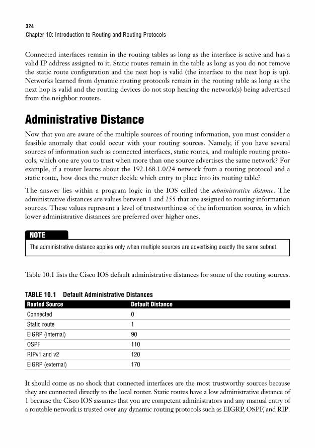
324
Connected interfaces remain in the routing tables as long as the interface is active and has avalid IP address assigned to it. Static routes remain in the table as long as you do not removethe static route configuration and the next hop is valid (the interface to the next hop is up).Networks learned from dynamic routing protocols remain in the routing table as long as thenext hop is valid and the routing devices do not stop hearing the network(s) being advertisedfrom the neighbor routers.
Administrative DistanceNow that you are aware of the multiple sources of routing information, you must consider afeasible anomaly that could occur with your routing sources. Namely, if you have severalsources of information such as connected interfaces, static routes, and multiple routing proto-cols, which one are you to trust when more than one source advertises the same network? Forexample, if a router learns about the 192.168.1.0/24 network from a routing protocol and astatic route, how does the router decide which entry to place into its routing table?
The answer lies within a program logic in the IOS called the administrative distance. Theadministrative distances are values between 1 and 255 that are assigned to routing informationsources. These values represent a level of trustworthiness of the information source, in whichlower administrative distances are preferred over higher ones.
Chapter 10: Introduction to Routing and Routing Protocols
The administrative distance applies only when multiple sources are advertising exactly the same subnet.
NOTE
Table 10.1 lists the Cisco IOS default administrative distances for some of the routing sources.
TABLE 10.1 Default Administrative DistancesRouted Source Default Distance
Connected 0
Static route 1
EIGRP (internal) 90
OSPF 110
RIPv1 and v2 120
EIGRP (external) 170
It should come as no shock that connected interfaces are the most trustworthy sources becausethey are connected directly to the local router. Static routes have a low administrative distance of1 because the Cisco IOS assumes that you are competent administrators and any manual entry ofa routable network is trusted over any dynamic routing protocols such as EIGRP, OSPF, and RIP.
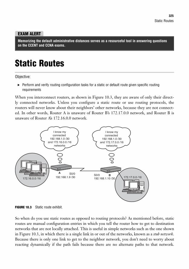
Static Routes325
Static RoutesObjective:
. Perform and verify routing configuration tasks for a static or default route given specific routing requirements
When you interconnect routers, as shown in Figure 10.3, they are aware of only their direct-ly connected networks. Unless you configure a static route or use routing protocols, therouters will never know about their neighbors’ other networks, because they are not connect-ed. In other words, Router A is unaware of Router B’s 172.17.0.0 network, and Router B isunaware of Router A’s 172.16.0.0 network.
EXAM ALERTMemorizing the default administrative distances serves as a resourceful tool in answering questionson the CCENT and CCNA exams.
172.17.0.0 /16
I know myconnected
192.168.1.0 /30and 172.16.0.0 /16
networks
I know myconnected
192.168.1.0 /30and 172.17.0.0 /16
networks
172.16.0.0 /16B
A S0/0192.168.1.9 /30
S0/0192.168.1.10 /30
FIGURE 10.3 Static route exhibit.
So when do you use static routes as opposed to routing protocols? As mentioned before, staticroutes are manual configuration entries in which you tell the router how to get to destinationnetworks that are not locally attached. This is useful in simple networks such as the one shownin Figure 10.3, in which there is a single link in or out of the networks, known as a stub network.Because there is only one link to get to the neighbor network, you don’t need to worry aboutreacting dynamically if the path fails because there are no alternate paths to that network.
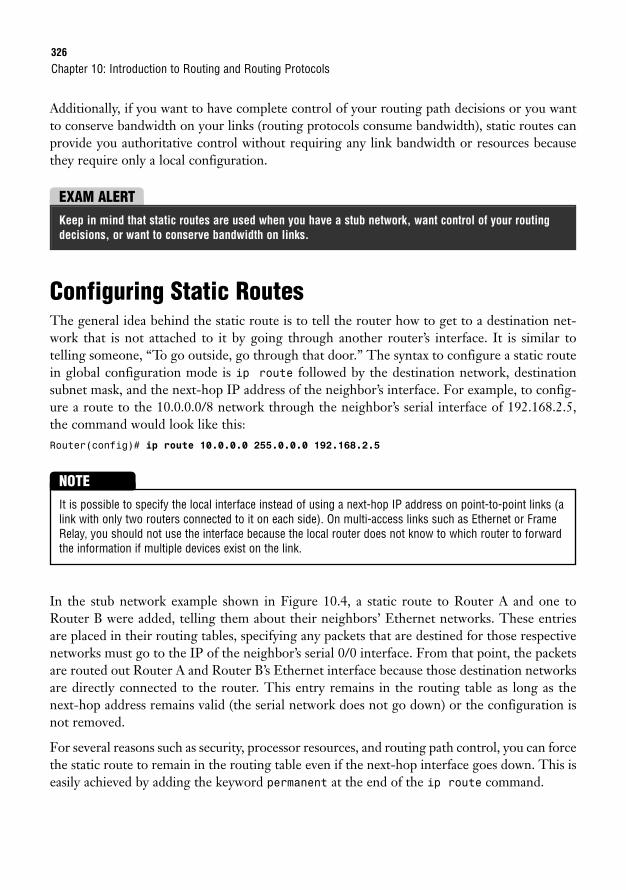
326
Additionally, if you want to have complete control of your routing path decisions or you wantto conserve bandwidth on your links (routing protocols consume bandwidth), static routes canprovide you authoritative control without requiring any link bandwidth or resources becausethey require only a local configuration.
Chapter 10: Introduction to Routing and Routing Protocols
EXAM ALERTKeep in mind that static routes are used when you have a stub network, want control of your routingdecisions, or want to conserve bandwidth on links.
Configuring Static RoutesThe general idea behind the static route is to tell the router how to get to a destination net-work that is not attached to it by going through another router’s interface. It is similar totelling someone, “To go outside, go through that door.” The syntax to configure a static routein global configuration mode is ip route followed by the destination network, destinationsubnet mask, and the next-hop IP address of the neighbor’s interface. For example, to config-ure a route to the 10.0.0.0/8 network through the neighbor’s serial interface of 192.168.2.5,the command would look like this:Router(config)# ip route 10.0.0.0 255.0.0.0 192.168.2.5
It is possible to specify the local interface instead of using a next-hop IP address on point-to-point links (alink with only two routers connected to it on each side). On multi-access links such as Ethernet or FrameRelay, you should not use the interface because the local router does not know to which router to forwardthe information if multiple devices exist on the link.
NOTE
In the stub network example shown in Figure 10.4, a static route to Router A and one toRouter B were added, telling them about their neighbors’ Ethernet networks. These entriesare placed in their routing tables, specifying any packets that are destined for those respectivenetworks must go to the IP of the neighbor’s serial 0/0 interface. From that point, the packetsare routed out Router A and Router B’s Ethernet interface because those destination networksare directly connected to the router. This entry remains in the routing table as long as thenext-hop address remains valid (the serial network does not go down) or the configuration isnot removed.
For several reasons such as security, processor resources, and routing path control, you can forcethe static route to remain in the routing table even if the next-hop interface goes down. This iseasily achieved by adding the keyword permanent at the end of the ip route command.
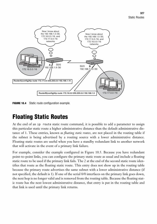
Static Routes327
FIGURE 10.4 Static route configuration example.
Floating Static RoutesAt the end of an ip route static route command, it is possible to add a parameter to assignthis particular static route a higher administrative distance than the default administrative dis-tance of 1. These entries, known as floating static routes, are not placed in the routing table ifthe subnet is being advertised by a routing source with a lower administrative distance.Floating static routes are useful when you have a standby redundant link to another networkthat will activate in the event of a primary link failure.
For example, consider the example configured in Figure 10.5. Because you have redundantpoint-to-point links, you can configure the primary static route as usual and include a floatingstatic route to be used if the primary link fails. The 2 at the end of the second static route iden-tifies that route as the floating static route. This entry does not show up in the routing tablebecause the primary route advertises the same subnet with a lower administrative distance (ifnot specified, the default is 1). If one of the serial 0/0 interfaces on the primary link goes down,the next hop is no longer valid and is removed from the routing table. Because the floating stat-ic route has the next lowest administrative distance, that entry is put in the routing table andthat link is used until the primary link returns.
Now I know aboutthe 192.168.1.0 /30,172.16.0.0 /16, and
172.17.0.0 /16networks
Now I know aboutthe 192.168.1.0 /30,172.17.0.0 /16, and
172.16.0.0 /16networks
172.16.0.0 /16B
A
172.17.0.0 /16
RouterA(config)#ip route 172.17.0.0 255.255.0.0 192.168.1.10
RouterB(config)#ip route 172.16.0.0 255.255.0.0 192.168.1.9
S0/0S0/0192.168.1.9 /30192.168.1.9 /30 S0/0S0/0
192.168.1.10 /30192.168.1.10 /30
S0/0192.168.1.9 /30 S0/0
192.168.1.10 /30
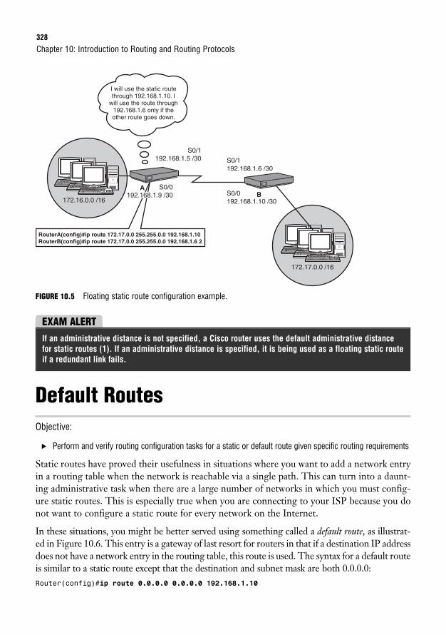
328
FIGURE 10.5 Floating static route configuration example.
Chapter 10: Introduction to Routing and Routing Protocols
I will use the static routethrough 192.168.1.10. I
will use the route through192.168.1.6 only if theother route goes down.
172.16.0.0 /16B
A
172.17.0.0 /16
RouterA(config)#ip route 172.17.0.0 255.255.0.0 192.168.1.10RouterB(config)#ip route 172.17.0.0 255.255.0.0 192.168.1.6 2
S0/0S0/0192.168.1.9 /30192.168.1.9 /30 S0/0S0/0
192.168.1.10 /30192.168.1.10 /30
S0/0192.168.1.9 /30
S0/1192.168.1.5 /30
S0/0192.168.1.10 /30
S0/1192.168.1.6 /30
EXAM ALERTIf an administrative distance is not specified, a Cisco router uses the default administrative distancefor static routes (1). If an administrative distance is specified, it is being used as a floating static routeif a redundant link fails.
Default RoutesObjective:
. Perform and verify routing configuration tasks for a static or default route given specific routing requirements
Static routes have proved their usefulness in situations where you want to add a network entryin a routing table when the network is reachable via a single path. This can turn into a daunt-ing administrative task when there are a large number of networks in which you must config-ure static routes. This is especially true when you are connecting to your ISP because you donot want to configure a static route for every network on the Internet.
In these situations, you might be better served using something called a default route, as illustrat-ed in Figure 10.6. This entry is a gateway of last resort for routers in that if a destination IP addressdoes not have a network entry in the routing table, this route is used. The syntax for a default routeis similar to a static route except that the destination and subnet mask are both 0.0.0.0:Router(config)#ip route 0.0.0.0 0.0.0.0 192.168.1.10
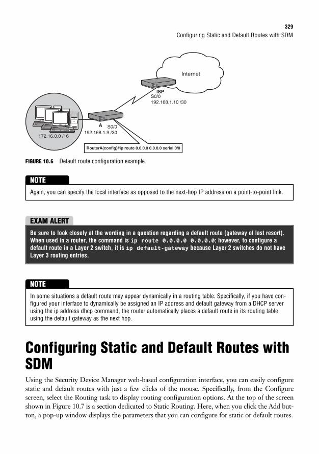
Configuring Static and Default Routes with SDM329
FIGURE 10.6 Default route configuration example.
Internet
172.16.0.0 /16
ISP
A S0/0192.168.1.9 /30
S0/0192.168.1.10 /30
RouterA(config)#ip route 0.0.0.0 0.0.0.0 serial 0/0
Again, you can specify the local interface as opposed to the next-hop IP address on a point-to-point link.
NOTE
EXAM ALERTBe sure to look closely at the wording in a question regarding a default route (gateway of last resort).When used in a router, the command is ip route 0.0.0.0 0.0.0.0; however, to configure adefault route in a Layer 2 switch, it is ip default-gateway because Layer 2 switches do not haveLayer 3 routing entries.
Configuring Static and Default Routes withSDMUsing the Security Device Manager web-based configuration interface, you can easily configurestatic and default routes with just a few clicks of the mouse. Specifically, from the Configurescreen, select the Routing task to display routing configuration options. At the top of the screenshown in Figure 10.7 is a section dedicated to Static Routing. Here, when you click the Add but-ton, a pop-up window displays the parameters that you can configure for static or default routes.
In some situations a default route may appear dynamically in a routing table. Specifically, if you have con-figured your interface to dynamically be assigned an IP address and default gateway from a DHCP serverusing the ip address dhcp command, the router automatically places a default route in its routing tableusing the default gateway as the next hop.
NOTE
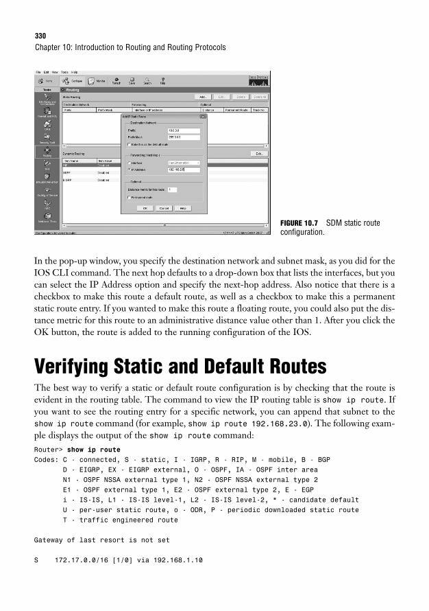
330
In the pop-up window, you specify the destination network and subnet mask, as you did for theIOS CLI command. The next hop defaults to a drop-down box that lists the interfaces, but youcan select the IP Address option and specify the next-hop address. Also notice that there is acheckbox to make this route a default route, as well as a checkbox to make this a permanentstatic route entry. If you wanted to make this route a floating route, you could also put the dis-tance metric for this route to an administrative distance value other than 1. After you click theOK button, the route is added to the running configuration of the IOS.
Verifying Static and Default RoutesThe best way to verify a static or default route configuration is by checking that the route isevident in the routing table. The command to view the IP routing table is show ip route. Ifyou want to see the routing entry for a specific network, you can append that subnet to theshow ip route command (for example, show ip route 192.168.23.0). The following exam-ple displays the output of the show ip route command:Router> show ip routeCodes: C - connected, S - static, I - IGRP, R - RIP, M - mobile, B - BGP
D - EIGRP, EX - EIGRP external, O - OSPF, IA - OSPF inter areaN1 - OSPF NSSA external type 1, N2 - OSPF NSSA external type 2E1 - OSPF external type 1, E2 - OSPF external type 2, E - EGPi - IS-IS, L1 - IS-IS level-1, L2 - IS-IS level-2, * - candidate defaultU - per-user static route, o - ODR, P - periodic downloaded static routeT - traffic engineered route
Gateway of last resort is not set
S 172.17.0.0/16 [1/0] via 192.168.1.10
Chapter 10: Introduction to Routing and Routing Protocols
FIGURE 10.7 SDM static routeconfiguration.
Verifying Static and Default Routes331
C 172.16.0.0/16 is directly connected, FastEthernet0/0192.168.1.0/30 is subnetted, 1 subnets
C 192.168.1.8 is directly connected, Serial0/0/0S* 0.0.0.0/0 [1/0] via 192.168.1.10
Notice that the beginning of the output has a legend identifying the possible codes that can belisted in the routing table. In the table itself, you can see the two directly connected networkssignified by the letter C. In addition, you can also see the static route to 172.17.0.0 and thestatic default route entries (indicated by the letter S), using 192.168.1.10 as the next hop. Alsonotice that the routing table identifies that the gateway of last resort (192.168.1.10) is set onthis router because a default route was configured with the next hop to that address.
You can clear out an entry in your routing table by using the clear command followed by the network or* for all networks in privileged EXEC mode. For example, to clear the 192.168.1.0 network from your rout-ing table, you would enter the following:
Router# clear ip route 192.168.1.0
NOTE
Dynamic Routing Protocols
Objective:
. Compare and contrast methods of routing and routing protocols
When complex networks contain multiple interconnections, static routes are no longer a prac-tical solution because they cannot adapt or react to changes in the topology. Not to mention,the configuration complexity can grow exponentially as you add more devices to the network.
EXAM ALERTDo not confuse routing protocols with routed protocols on the exam. Routed protocols are protocols suchas those in the IP protocol suite that are used to carry the data across our network. Routing protocolsare exchanged between routing devices to determine the optimal path to route the routed protocols.
For example, given the network design shown in Figure 10.8, Router A knows only the threedirectly connected networks attached to the router. For IP packets to reach the 172.17.0.0 net-work via static routes, you would have to configure Router A to go through one of its neigh-bor routers, such as Router B. However, Router B also requires a static route to 172.17.0.0because that network is not directly connected to it. Supposing that the router is using RouterF as its next hop, that router does not require a static route because it is directly connected.Unfortunately, our configuration undertaking does not stop there because we have to config-ure a static route in Router F and Router B back to the 172.16.0.0 network.
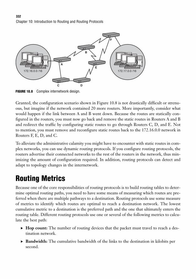
332
FIGURE 10.8 Complex internetwork design.
Granted, the configuration scenario shown in Figure 10.8 is not drastically difficult or strenu-ous, but imagine if the network contained 20 more routers. More importantly, consider whatwould happen if the link between A and B went down. Because the routes are statically con-figured in the routers, you must now go back and remove the static routes in Routers A and Band redirect the traffic by configuring static routes to go through Routers C, D, and E. Notto mention, you must remove and reconfigure static routes back to the 172.16.0.0 network inRouters F, E, D, and C.
To alleviate the administrative calamity you might have to encounter with static routes in com-plex networks, you can use dynamic routing protocols. If you configure routing protocols, therouters advertise their connected networks to the rest of the routers in the network, thus min-imizing the amount of configuration required. In addition, routing protocols can detect andadapt to topology changes in the internetwork.
Routing MetricsBecause one of the core responsibilities of routing protocols is to build routing tables to deter-mine optimal routing paths, you need to have some means of measuring which routes are pre-ferred when there are multiple pathways to a destination. Routing protocols use some measureof metrics to identify which routes are optimal to reach a destination network. The lowestcumulative metric to a destination is the preferred path and the one that ultimately enters therouting table. Different routing protocols use one or several of the following metrics to calcu-late the best path:
. Hop count: The number of routing devices that the packet must travel to reach a des-tination network.
. Bandwidth: The cumulative bandwidth of the links to the destination in kilobits persecond.
Chapter 10: Introduction to Routing and Routing Protocols
172.16.0.0 /16
A
B
E
DC
F
172.17.0.0 /16
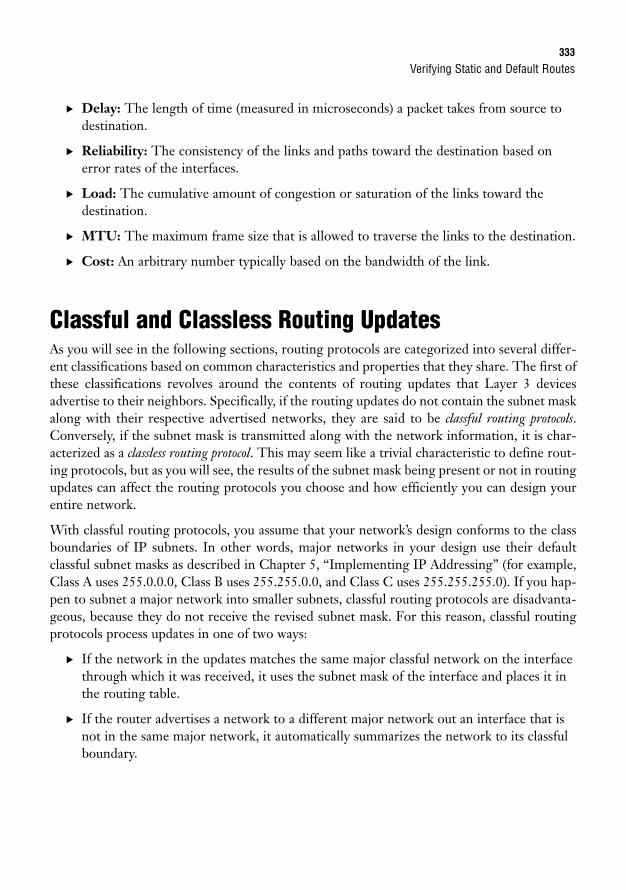
Verifying Static and Default Routes333
. Delay: The length of time (measured in microseconds) a packet takes from source todestination.
. Reliability: The consistency of the links and paths toward the destination based onerror rates of the interfaces.
. Load: The cumulative amount of congestion or saturation of the links toward the destination.
. MTU: The maximum frame size that is allowed to traverse the links to the destination.
. Cost: An arbitrary number typically based on the bandwidth of the link.
Classful and Classless Routing UpdatesAs you will see in the following sections, routing protocols are categorized into several differ-ent classifications based on common characteristics and properties that they share. The first ofthese classifications revolves around the contents of routing updates that Layer 3 devicesadvertise to their neighbors. Specifically, if the routing updates do not contain the subnet maskalong with their respective advertised networks, they are said to be classful routing protocols.Conversely, if the subnet mask is transmitted along with the network information, it is char-acterized as a classless routing protocol. This may seem like a trivial characteristic to define rout-ing protocols, but as you will see, the results of the subnet mask being present or not in routingupdates can affect the routing protocols you choose and how efficiently you can design yourentire network.
With classful routing protocols, you assume that your network’s design conforms to the classboundaries of IP subnets. In other words, major networks in your design use their defaultclassful subnet masks as described in Chapter 5, “Implementing IP Addressing” (for example,Class A uses 255.0.0.0, Class B uses 255.255.0.0, and Class C uses 255.255.255.0). If you hap-pen to subnet a major network into smaller subnets, classful routing protocols are disadvanta-geous, because they do not receive the revised subnet mask. For this reason, classful routingprotocols process updates in one of two ways:
. If the network in the updates matches the same major classful network on the interfacethrough which it was received, it uses the subnet mask of the interface and places it inthe routing table.
. If the router advertises a network to a different major network out an interface that isnot in the same major network, it automatically summarizes the network to its classfulboundary.
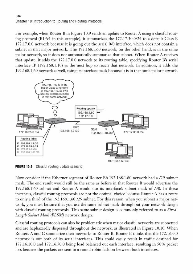
334
For example, when Router B in Figure 10.9 sends an update to Router A using a classful rout-ing protocol (RIPv1 in this example), it summarizes the 172.17.30.0/24 to a default Class B172.17.0.0 network because it is going out the serial 0/0 interface, which does not contain asubnet in that major network. The 192.168.1.60 network, on the other hand, is in the samemajor network, so it does not automatically summarize that subnet. When Router A receivesthat update, it adds the 172.17.0.0 network to its routing table, specifying Router B’s serialinterface IP (192.168.1.10) as the next hop to reach that network. In addition, it adds the192.168.1.60 network as well, using its interface mask because it is in that same major network.
Chapter 10: Introduction to Routing and Routing Protocols
192.168.1.60 is in themajor Class C networkof 192.168.1.0, so I willuse my interface’s mask
in that same network.
172.16.25.0 /24B
A S0/0192.168.1.9 /30 S0/0
192.168.1.10 /30 172.17.30.0 /24
192.168.1.60 /30
Routing Table
Routing Update
C 192.168.1.9 /30 C 172.16.25.0 /24 R 172.17.0.0 /16 R 192.168.1.60 /30
192.168.1.60172.17.0.0
FIGURE 10.9 Classful routing update scenario.
Now consider if the Ethernet segment of Router B’s 192.168.1.60 network had a /29 subnetmask. The end result would still be the same as before in that Router B would advertise the192.168.1.60 subnet and Router A would use its interface’s subnet mask of /30. In theseinstances, classful routing protocols are not the optimal choice because Router A has a routeto only a third of the 192.168.1.60 /29 subnet. For this reason, when you subnet a major net-work, you must be sure that you use the same subnet mask throughout your network designwith classful routing protocols. This same subnet design is commonly referred to as a Fixed-Length Subnet Mask (FLSM) network design.
Classful routing protocols can also be problematic when major classful networks are subnettedand are haphazardly dispersed throughout the network, as illustrated in Figure 10.10. WhenRouters A and C summarize their networks to Router B, Router B thinks that the 172.16.0.0network is out both of its serial interfaces. This could easily result in traffic destined for172.16.10.0 and 172.16.50.0 being load balanced out each interface, resulting in 50% packetloss because the packets are sent in a round robin fashion between both interfaces.
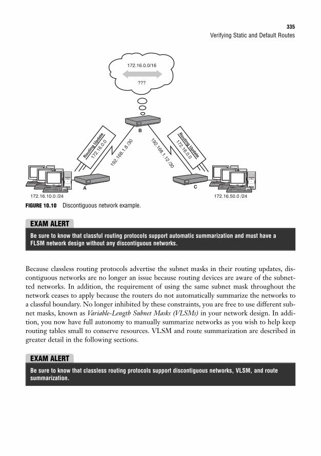
Verifying Static and Default Routes335
FIGURE 10.10 Discontiguous network example.
A
B
C
Routing Update
172.16.0.0Routin
g Upd
ate
172.
16.0
.0
172.16.0.0/16
???
172.16.10.0 /24 172.16.50.0 /24
192.
168.
1.8
/30
192.168.1.12 /30
EXAM ALERTBe sure to know that classful routing protocols support automatic summarization and must have aFLSM network design without any discontiguous networks.
Because classless routing protocols advertise the subnet masks in their routing updates, dis-contiguous networks are no longer an issue because routing devices are aware of the subnet-ted networks. In addition, the requirement of using the same subnet mask throughout thenetwork ceases to apply because the routers do not automatically summarize the networks toa classful boundary. No longer inhibited by these constraints, you are free to use different sub-net masks, known as Variable-Length Subnet Masks (VLSMs) in your network design. In addi-tion, you now have full autonomy to manually summarize networks as you wish to help keeprouting tables small to conserve resources. VLSM and route summarization are described ingreater detail in the following sections.
EXAM ALERTBe sure to know that classless routing protocols support discontiguous networks, VLSM, and routesummarization.
ChallengeGiven the design shown in Figure 10.11, determine how you can use VLSM to ensure that you are usingthe appropriate subnets given a design scenario. In this example, the zero subnets are available for use.
1. Remember to add 2 to each network to accommodate the network ID and broadcast address.
2. Calculate the network and subnet mask for Network D (the largest network).
3. Given the remaining IP addresses, calculate the network and subnet mask for Network C.
4. Given the remaining IP addresses, calculate the network and subnet mask for Network B.
5. Given the remaining IP addresses, calculate the network and subnet mask for Network E.
6. Given the remaining IP addresses, calculate the network and subnet mask for the four point-to-pointlinks.
336
VLSMUsing classless routing protocols affords you the luxury of having support for a VLSM net-work design. This is advantageous in your network planning because you can allot the appro-priate number of IP addresses required for each link. Not to mention, by assigning theminimal number of IP addresses required for a given link, you conserve IP addresses. Forexample, you can use a /30 subnet mask for point-to-point links because you need only twoavailable IP addresses and a /27 subnet mask on an Ethernet segment to accommodate 30hosts. If you were using classless routing protocols, you would have to use a /27 for all links,which would inevitably waste 28 IP addresses on the point-to-point links.
Chapter 10: Introduction to Routing and Routing Protocols
EXAM ALERTRemember that point-to-point links require only a /30 (255.255.255.252) subnet mask because youneed only two usable IP addresses for the router’s interfaces on each side of the link.
Throughout your certification and career, it is quite possible you will have to design your net-work given a usable subnet and host requirements for all your links. When tackling thisdesigning task, be sure to adhere to the following guidelines:
1. If possible, start with the larger subnets first.
2. Write out the ranges that you have assigned to ensure that you do not accidentallyoverlap subnets.
3. Make sure your networks start on incremental boundaries (128, 64, 32, and so on).
EXAM ALERTBe prepared to use VLSM to assign subnets to links given the subnettable network and host requirements.
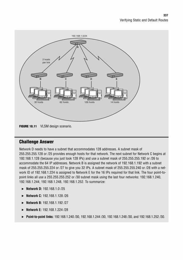
Verifying Static and Default Routes337
B
30 hosts
2 hostsper link
192.168.1.0/24
C
62 hosts
A
D
126 hosts
E
14 hosts
FIGURE 10.11 VLSM design scenario.
Challenge AnswerNetwork D needs to have a subnet that accommodates 128 addresses. A subnet mask of255.255.255.128 or /25 provides enough hosts for that network. The next subnet for Network C begins at192.168.1.128 (because you just took 128 IPs) and use a subnet mask of 255.255.255.192 or /26 toaccommodate the 64 IP addresses. Network B is assigned the network of 192.168.1.192 with a subnetmask of 255.255.255.224 or /27 to give you 32 IPs. A subnet mask of 255.255.255.240 or /28 with a net-work ID of 192.168.1.224 is assigned to Network E for the 16 IPs required for that link. The four point-to-point links all use a 255.255.255.252 or /30 subnet mask using the last four networks: 192.168.1.240,192.168.1.244, 192.168.1.248, 192.168.1.252. To summarize:
. Network D: 192.168.1.0 /25
. Network C: 192.168.1.128 /26
. Network B: 192.168.1.192 /27
. Network E: 192.168.1.224 /28
. Point-to-point links: 192.168.1.240 /30, 192.168.1.244 /30, 192.168.1.248 /30, and 192.168.1.252 /30.
338
Route SummarizationAs already mentioned, classful routing protocols automatically summarize advertised networksto the classful subnet boundaries. Classless routing protocols, on the other hand, require you tomanually control the networks being summarized to your neighbors in the router configuration.By aggregating a contiguous set of networks into an advertised summarized route, you keep thesize of the routing tables to a minimum. Neighbors that receive the summarized route do notneed to know about the individual subnets you create behind your router because theyinevitably have to go through your router to get to them. The additional offshoot of this sum-marized picture is that your classless routing protocols do not need to notify those neighbors ifone of those subnets goes down because they do not even have that subnet in their routingtables. Thus, you can isolate topology changes to be contained behind that summarizing router.
Because you are required to manually specify the networks you are to advertise, you must learnhow to accurately summarize smaller subnets into one or several larger networks, or supernets.The rules for supernetting are similar to subnetting, except in this case, you are stealing bitsfrom the network portion of an IP network to create a larger network. The rules for super-netting are as follows:
1. Be sure that the networks are contiguous (otherwise you would be summarizing net-works that you do not have behind the router).
2. Count the number of networks you want to summarize.
3. Determine an increment that is equal to or less than the number of networks.
4. Make sure your base networks start on incremental boundaries (128, 64, 32, and so on)for the number of networks you are summarizing.
5. Calculate the subnet mask by the number of bits you need to steal from the originalsubnet to equal that incremental value.
The beauty of supernetting is that the resultant network and subnet mask will designate manyIP address networks in a single entry. The fact that you are stealing bits from the network por-tion of an IP address could quite easily violate the traditional barriers of classful addressing,known as Classless Interdomain Routing (CIDR).
For instance, it would not be uncommon to see a summary entry look like the following:192.168.16.0 /20. This single entry used to be a Class C (/24), but four bits were stolen fromthe network portion to represent 16 networks (24 = 16). When you advertise this supernet toneighbors, they know that they must go through your router to get to networks 192.168.16.0through 192.168.31.0 (16 total networks).
Chapter 10: Introduction to Routing and Routing Protocols
EXAM ALERTBe prepared to determine the networks being advertised in a given supernet or determine the summarynetwork, given the networks to be summarized.
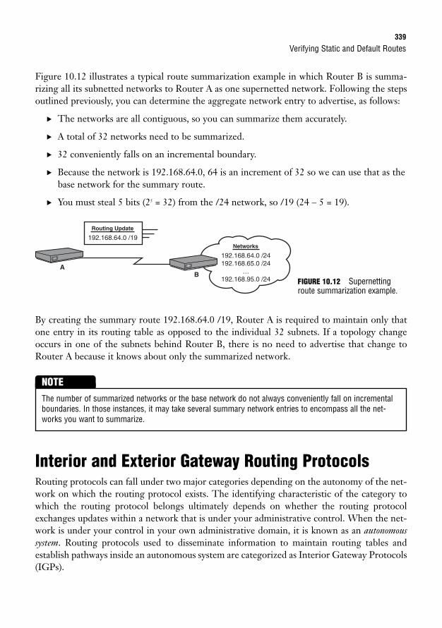
Verifying Static and Default Routes339
Figure 10.12 illustrates a typical route summarization example in which Router B is summa-rizing all its subnetted networks to Router A as one supernetted network. Following the stepsoutlined previously, you can determine the aggregate network entry to advertise, as follows:
. The networks are all contiguous, so you can summarize them accurately.
. A total of 32 networks need to be summarized.
. 32 conveniently falls on an incremental boundary.
. Because the network is 192.168.64.0, 64 is an increment of 32 so we can use that as thebase network for the summary route.
. You must steal 5 bits (25 = 32) from the /24 network, so /19 (24 – 5 = 19).
Networks
192.168.64.0 /24192.168.65.0 /24
…192.168.95.0 /24
BA
Routing Update
192.168.64.0 /19
By creating the summary route 192.168.64.0 /19, Router A is required to maintain only thatone entry in its routing table as opposed to the individual 32 subnets. If a topology changeoccurs in one of the subnets behind Router B, there is no need to advertise that change toRouter A because it knows about only the summarized network.
FIGURE 10.12 Supernettingroute summarization example.
The number of summarized networks or the base network do not always conveniently fall on incrementalboundaries. In those instances, it may take several summary network entries to encompass all the net-works you want to summarize.
NOTE
Interior and Exterior Gateway Routing ProtocolsRouting protocols can fall under two major categories depending on the autonomy of the net-work on which the routing protocol exists. The identifying characteristic of the category towhich the routing protocol belongs ultimately depends on whether the routing protocolexchanges updates within a network that is under your administrative control. When the net-work is under your control in your own administrative domain, it is known as an autonomoussystem. Routing protocols used to disseminate information to maintain routing tables andestablish pathways inside an autonomous system are categorized as Interior Gateway Protocols(IGPs).
340
Conversely, the other category of routing protocols is designed to route in between theseautonomous systems. For instance, Border Gateway Protocol (BGP) is a routing protocol thatis used by ISPs for routing traffic over the Internet. Because the Internet comprises thousandsof networks, each under different administrative control, you need to use an Exterior GatewayProtocol such as BGP to route in between these autonomous systems.
Distance Vector Routing ProtocolsIn addition to being an IGP/EGP or classful/classless, routing protocols can also fall into oneof three classes. Again, the functionality and characteristics of the routing protocol dictateunder which class it falls. The most long-standing of these classes is distance vector routing protocols.
Distance vector routing protocols concern themselves with the direction (vector) in which thedestination lies and some means of measurement (metric) it takes to reach that destination.Distance vector routing protocols inform their directly connected neighbors of all the con-nected and learned networks they know about in their routing tables. In fact, they broadcastthe contents of the entire routing table to their neighbors periodically, regardless of whetherthere is a change in the network topology. When the neighbors receive that routing informa-tion, they identify and add any new networks to their routing tables and update the metricbefore eventually passing it on to their neighbors. Because the routing table information isupdated before it is sent on to neighbors, downstream routers do not learn that informationfirst hand. For this reason, distance vector routing protocol update processing is often referredto as “routing by rumor.” Distance vector routing protocols are discussed in greater detail inChapter 11, “Distance Vector Routing Protocols.”
Link-State Routing ProtocolsAs the name states, link-state routing protocols advertise the state of the links in the network. Infact, they advertise the states and metrics (cost) of all the links they know about for the entiretopology to their neighbors, as opposed to just the best routes in your routing table. Thisdetailed overview of the entire routing domain enables each router to calculate and make adecision on the best route from this first-hand information, rather than listen to what itsneighbor believes is the best route. In fact, link-state routing protocols keep three tables: aneighbor table of all discovered neighbors, a topology table of all the possible routes to reach-able networks learned, and a routing table that contains the best route based on the lowestmetric calculated from the topology table.
At first, this may sound like a lot of information to be exchanged between routers; however,link-state routing protocols initially discover their neighbors when they first boot up and syn-chronize their topology tables. After the neighbor discovery and topology synchronization,they send only periodic hello messages to let their neighbors know they are still functioning.
Chapter 10: Introduction to Routing and Routing Protocols
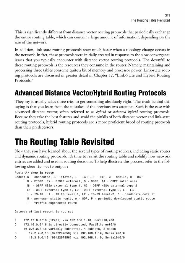
The Routing Table Revisited341
This is significantly different from distance vector routing protocols that periodically exchangethe entire routing table, which can contain a large amount of information, depending on thesize of the network.
In addition, link-state routing protocols react much faster when a topology change occurs inthe network. In fact, these protocols were initially created in response to the slow convergenceissues that you typically encounter with distance vector routing protocols. The downfall tothese routing protocols is the resources they consume in the router. Namely, maintaining andprocessing three tables consume quite a bit of memory and processor power. Link-state rout-ing protocols are discussed in greater detail in Chapter 12, “Link-State and Hybrid RoutingProtocols.”
Advanced Distance Vector/Hybrid Routing ProtocolsThey say it usually takes three tries to get something absolutely right. The truth behind thissaying is that you learn from the mistakes of the previous two attempts. Such is the case withadvanced distance vector, often referred to as hybrid or balanced hybrid routing protocols.Because they take the best features and avoid the pitfalls of both distance vector and link-staterouting protocols, hybrid routing protocols are a more proficient breed of routing protocolsthan their predecessors.
The Routing Table RevisitedNow that you have learned about the several types of routing sources, including static routesand dynamic routing protocols, it’s time to revisit the routing table and solidify how networkentries are added and used in routing decisions. To help illustrate this process, refer to the fol-lowing show ip route output :RouterA> show ip routeCodes: C - connected, S - static, I - IGRP, R - RIP, M - mobile, B - BGP
D - EIGRP, EX - EIGRP external, O - OSPF, IA - OSPF inter areaN1 - OSPF NSSA external type 1, N2 - OSPF NSSA external type 2E1 - OSPF external type 1, E2 - OSPF external type 2, E - EGPi - IS-IS, L1 - IS-IS level-1, L2 - IS-IS level-2, * - candidate defaultU - per-user static route, o - ODR, P - periodic downloaded static routeT - traffic engineered route
Gateway of last resort is not set
R 172.17.0.0/16 [120/1] via 192.168.1.10, Serial0/0/0C 172.16.0.0/16 is directly connected, FastEthernet0/0
10.0.0.0/8 is variably subnetted, 4 subnets, 3 masksD 10.2.0.0/16 [90/2297856] via 192.168.1.10, Serial0/0/0D 10.3.0.0/16 [90/2297856] via 192.168.1.10, Serial0/0/0
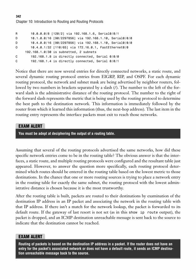
342
R 10.0.0.0/8 [120/2] via 192.168.1.6, Serial0/0/1D 10.1.0.0/16 [90/2297856] via 192.168.1.10, Serial0/0/0D 10.4.0.0/16 [90/2297856] via 192.168.1.10, Serial0/0/0O 10.4.0.1/32 [110/65] via 172.16.0.1, FastEthernet0/0
192.168.1.0/30 is subnetted, 2 subnetsC 192.168.1.8 is directly connected, Serial 0/0/0C 192.168.1.4 is directly connected, Serial 0/0/1
Notice that there are now several entries for directly connected networks, a static route, andseveral dynamic routing protocol entries from EIGRP, RIP, and OSPF. For each dynamicrouting protocol, the network and subnet mask are being advertised by neighbor routers, fol-lowed by two numbers in brackets separated by a slash (/). The number to the left of the for-ward slash is the administrative distance of the routing protocol. The number to the right ofthe forward slash represents the metric that is being used by the routing protocol to determinethe best path to the destination network. This information is immediately followed by therouter from which it learned this information (thus, the next-hop address). The last item in therouting entry represents the interface packets must exit to reach those networks.
Chapter 10: Introduction to Routing and Routing Protocols
EXAM ALERTYou must be adept at deciphering the output of a routing table.
Assuming that several of the routing protocols advertised the same networks, how did thesespecific network entries come to be in the routing table? The obvious answer is that the inter-faces, a static route, and multiple routing protocols were configured and the resultant table justappeared. However, to answer the question more specifically, each routing protocol deter-mined which routes should be entered in the routing table based on the lowest metric to thosedestinations. In the chance that one or more routing sources is trying to place a network entryin the routing table for exactly the same subnet, the routing protocol with the lowest admin-istrative distance is chosen because it is the most trustworthy.
After the routing table is built, packets are routed to their destinations by examination of thedestination IP address in an IP packet and associating the network in the routing table withthat IP address. If there isn’t a match for the network lookup, the packet is forwarded to itsdefault route. If the gateway of last resort is not set (as in this show ip route output), thepacket is dropped, and an ICMP destination unreachable message is sent back to the source toindicate that the destination cannot be reached.
EXAM ALERTRouting of packets is based on the destination IP address in a packet. If the router does not have anentry for the packet’s associated network or does not have a default route, it sends an ICMP destina-tion unreachable message back to the source.
Routing Redistribution343
In the show ip route output, several entries for the 10.0.0.0 network are listed in the rout-ing table. Interestingly, there is a RIP entry for the 10.0.0.0 /8 network to go out serial 0/0/1and four EIGRP-learned networks for 10.1.0.0 /16, 10.2.0.0 /16, 10.3.0.0 /16, and 10.4.0.0/16, all destined for interface serial 0/0/0. Because the EIGRP networks are subnets of themajor 10.0.0.0 network, which interface will the router use to route a packet destined, forexample, for 10.1.0.3?
Cisco’s routing logic answers this question by using a rule called the longest match. The longestmatch rule states that when a packet has multiple possible network entries to use, the more spe-cific subnet is used over the less specific. In other words, the longer the number of bits in thesubnet mask (thus the smaller subnet), the more chance it has of being the chosen network. Inthe routing table example, a packet destined for 10.1.0.3 would use the subnet with the longestprefix (subnet mask), which is the EIGRP route for 10.1.0.0/16 exiting interface Serial 0/0/0.
Routing RedistributionYou are likely to encounter in your Cisco travels certain situations in which you must run mul-tiple routing protocols in your network. For instance, your company is in the process of merg-ing with another company’s network, and their routers are running a different routing protocolthan yours. In addition, you may have to connect your Cisco router network to a non-Ciscorouting infrastructure and you are using Cisco proprietary routing protocols.
In instances where you are running multiple routing protocols, it may be necessary to havenetworks advertised in one routing protocol injected into the other. Unfortunately, becauserouting protocols are so diverse in nature, they do not inherently interact or exchange infor-mation with each other when multiple routing protocols are running in the network. Thetransferal of network information from one routing protocol into another is a manual config-uration called redistribution.
The redistribution configuration is typically done at one or a couple of routers that sit on theboundary between each routing protocol, as illustrated in Figure 10.13. These devices runboth routing protocols and must be manually configured to inject the networks learned fromone routing protocol into the next. Redistribution can occur in one of two fashions:
. One-way redistribution: Networks from an edge protocol are injected into a morerobust core routing protocol, but not the other way around. This method is the safestway to perform redistribution.
. Two-way redistribution: Networks from each routing protocol are injected into theother. This is the least preferred method because it is possible that suboptimal routingor routing loops may occur because of the network design or the difference in conver-gence times when a topology change occurs. Figure 10.13 is an example of two-wayredistribution.
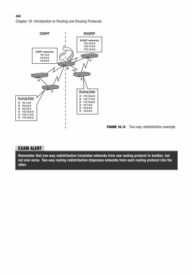
344
Chapter 10: Introduction to Routing and Routing Protocols
A
B
E
C
F
Routing Table
O 10.1.0.0O 10.2.0.0 O 10.3.0.0 O 172.16.0.0 O 172.17.0.0 O 172.18.0.0
OSPF networks10.1.0.010.2.0.010.3.0.0
OSPF EIGRP
Routing Table
D 172.16.0.0D 172.17.0.0D 172.18.0.0D 10.1.0.0D 10.2.0.0D 10.3.0.0
EIGRP networks172.16.0.0172.17.0.0172.18.0.0
FIGURE 10.13 Two-way redistribution example.
EXAM ALERTRemember that one-way redistribution translates networks from one routing protocol in another, butnot vice versa. Two-way routing redistribution dispenses networks from each routing protocol into theother.
Chapter Summary345
Chapter SummaryThis chapter looked more closely at the operations involved in routing packets with Layer 3devices such as routers and Layer 3 switches. You send packets from workstations on the localnetwork to routing devices by configuring those devices with a default gateway IP address thatmatches the IP of your router. When the packet arrives at the router, it consults its routingtable to determine whether the destination IP address in the IP packet has a match for the des-tination’s network. If it does not have a matching entry, it looks to see whether the routingtable has a default route. If no gateway of last resort is set, it drops the packet and sends anICMP destination unreachable message back to the source. In instances where there are sev-eral matches for the destination network, it uses the entry that has the longest match.
The entries in the routing table can come from several routing sources. When the interface isoperational and an IP address is assigned, they show up in the routing table as connected inter-faces. Manual static route entries that were manually configured show up as an S. Routing pro-tocols choose their best network paths by calculating the lowest metric for their respectiverouting protocols. If multiple routing sources advertise the same subnet, the source with thelowest administrative distance is placed in the routing table.
The routing protocols can fall into several categories, based on the characteristics that the proto-cols utilize. For instance, if a routing protocol does not advertise the subnet mask in its routingupdates, it is a classful routing protocol. Classful routing protocols require the network design tohave the same subnet mask in the design known as FLSM. In addition, these routing protocolscannot support discontiguous networks and automatically summarize network entries to the class-ful boundary when crossing interfaces in other major networks. When subnet masks include therouting advertisements, these updates are said to be classless. Classless routing protocols supportVLSM network designs, discontiguous networks, and require manual summarization of networks.
If the routing protocol is designed to route inside an autonomous system, that routing proto-col is an IGP. EGP routing protocols, on the other hand, are designed to route betweenautonomous systems.
Finally, routing protocols can belong to one of the following three classifications:
. Distance vector: The entire routing table is periodically sent to directly connectedneighbors regardless of a topology change. These routing protocols manipulate therouting table updates before sending that information to their neighbors and are slowto converge when a topology change occurs.
. Link-state: All possible link states are stored in an independent topology table in whichthe best routes are calculated and put into the routing table. The topology table is ini-tially synchronized with discovered neighbors followed by frequent hello messages.These routing protocols are faster to converge than distance vector routing protocols.
. Hybrid: By using the best characteristics from both link-state and routing protocols,these advanced routing protocols efficiently and quickly build their routing informa-tion and converge when topology changes occur.
346
Key Terms
Chapter 10: Introduction to Routing and Routing Protocols
. Default gateway
. Routing table
. Connected interface
. Hop
. Routing protocols
. Administrative distance
. Static routes
. Stub networks
. Floating routes
. Default route
. Classful routing protocols
. Classless routing protocols
. FLSM
. Discontiguous networks
. VLSM
. Route summarization
. Supernet
. CIDR
. Autonomous system
. IGP
. EGP
. Distance vector routing protocols
. Link-state routing protocols
. Advanced distance vector/hybrid routing protocols
. Longest match rule
. Redistribution
Apply Your Knowledge
Exercises
10.1 Create a Static and Default Route
This exercise tests your configuration skills in configuring a static and default route.
Estimated Time: 5 minutes
1. Enter privileged EXEC mode.
2. Enter global configuration mode.
3. Configure a static route for the 10.23.5.0/24 network using 192.168.64.2 as the next-hop address.
4. Configure a floating static route for the 10.23.5.0/24 network using 192.168.60.3.
5. Configure a default route to exit out of your serial interface.
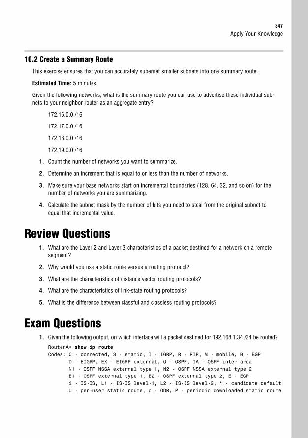
Apply Your Knowledge347
10.2 Create a Summary Route
This exercise ensures that you can accurately supernet smaller subnets into one summary route.
Estimated Time: 5 minutes
Given the following networks, what is the summary route you can use to advertise these individual sub-nets to your neighbor router as an aggregate entry?
172.16.0.0 /16
172.17.0.0 /16
172.18.0.0 /16
172.19.0.0 /16
1. Count the number of networks you want to summarize.
2. Determine an increment that is equal to or less than the number of networks.
3. Make sure your base networks start on incremental boundaries (128, 64, 32, and so on) for thenumber of networks you are summarizing.
4. Calculate the subnet mask by the number of bits you need to steal from the original subnet toequal that incremental value.
Review Questions1. What are the Layer 2 and Layer 3 characteristics of a packet destined for a network on a remote
segment?
2. Why would you use a static route versus a routing protocol?
3. What are the characteristics of distance vector routing protocols?
4. What are the characteristics of link-state routing protocols?
5. What is the difference between classful and classless routing protocols?
Exam Questions1. Given the following output, on which interface will a packet destined for 192.168.1.34 /24 be routed?
RouterA> show ip routeCodes: C - connected, S - static, I - IGRP, R - RIP, M - mobile, B - BGP
D - EIGRP, EX - EIGRP external, O - OSPF, IA - OSPF inter areaN1 - OSPF NSSA external type 1, N2 - OSPF NSSA external type 2E1 - OSPF external type 1, E2 - OSPF external type 2, E - EGPi - IS-IS, L1 - IS-IS level-1, L2 - IS-IS level-2, * - candidate defaultU - per-user static route, o - ODR, P - periodic downloaded static route
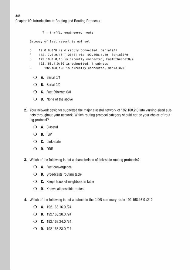
348
T - traffic engineered route
Gateway of last resort is not set
C 10.0.0.0/8 is directly connected, Serial0/1R 172.17.0.0/16 [120/1] via 192.168.1.10, Serial0/0C 172.16.0.0/16 is directly connected, FastEthernet0/0
192.168.1.0/30 is subnetted, 1 subnetsC 192.168.1.8 is directly connected, Serial0/0
❍ A. Serial 0/1
❍ B. Serial 0/0
❍ C. Fast Ethernet 0/0
❍ D. None of the above
2. Your network designer subnetted the major classful network of 192.168.2.0 into varying-sized sub-nets throughout your network. Which routing protocol category should not be your choice of rout-ing protocol?
❍ A. Classful
❍ B. IGP
❍ C. Link-state
❍ D. ODR
3. Which of the following is not a characteristic of link-state routing protocols?
❍ A. Fast convergence
❍ B. Broadcasts routing table
❍ C. Keeps track of neighbors in table
❍ D. Knows all possible routes
4. Which of the following is not a subnet in the CIDR summary route 192.168.16.0 /21?
❍ A. 192.168.16.0 /24
❍ B. 192.168.20.0 /24
❍ C. 192.168.24.0 /24
❍ D. 192.168.23.0 /24
Chapter 10: Introduction to Routing and Routing Protocols
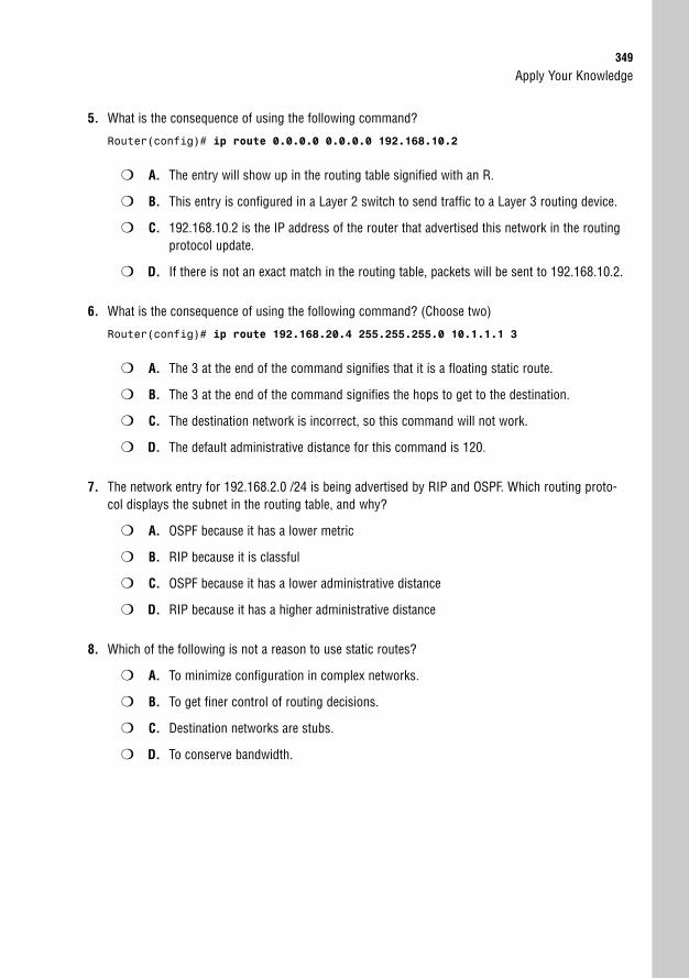
Apply Your Knowledge349
5. What is the consequence of using the following command?
Router(config)# ip route 0.0.0.0 0.0.0.0 192.168.10.2
❍ A. The entry will show up in the routing table signified with an R.
❍ B. This entry is configured in a Layer 2 switch to send traffic to a Layer 3 routing device.
❍ C. 192.168.10.2 is the IP address of the router that advertised this network in the routingprotocol update.
❍ D. If there is not an exact match in the routing table, packets will be sent to 192.168.10.2.
6. What is the consequence of using the following command? (Choose two)
Router(config)# ip route 192.168.20.4 255.255.255.0 10.1.1.1 3
❍ A. The 3 at the end of the command signifies that it is a floating static route.
❍ B. The 3 at the end of the command signifies the hops to get to the destination.
❍ C. The destination network is incorrect, so this command will not work.
❍ D. The default administrative distance for this command is 120.
7. The network entry for 192.168.2.0 /24 is being advertised by RIP and OSPF. Which routing proto-col displays the subnet in the routing table, and why?
❍ A. OSPF because it has a lower metric
❍ B. RIP because it is classful
❍ C. OSPF because it has a lower administrative distance
❍ D. RIP because it has a higher administrative distance
8. Which of the following is not a reason to use static routes?
❍ A. To minimize configuration in complex networks.
❍ B. To get finer control of routing decisions.
❍ C. Destination networks are stubs.
❍ D. To conserve bandwidth.
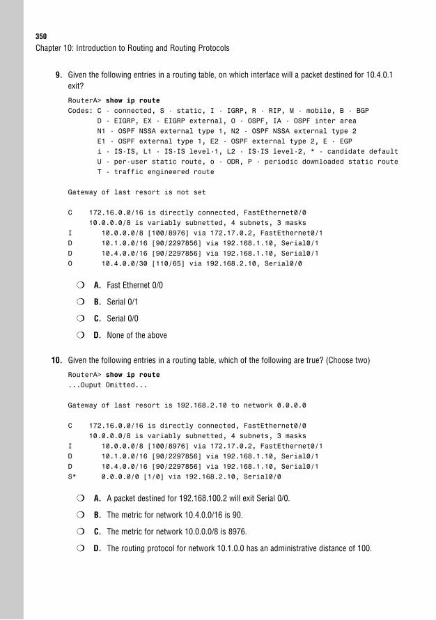
350
9. Given the following entries in a routing table, on which interface will a packet destined for 10.4.0.1exit?
RouterA> show ip routeCodes: C - connected, S - static, I - IGRP, R - RIP, M - mobile, B - BGP
D - EIGRP, EX - EIGRP external, O - OSPF, IA - OSPF inter areaN1 - OSPF NSSA external type 1, N2 - OSPF NSSA external type 2E1 - OSPF external type 1, E2 - OSPF external type 2, E - EGPi - IS-IS, L1 - IS-IS level-1, L2 - IS-IS level-2, * - candidate defaultU - per-user static route, o - ODR, P - periodic downloaded static routeT - traffic engineered route
Gateway of last resort is not set
C 172.16.0.0/16 is directly connected, FastEthernet0/010.0.0.0/8 is variably subnetted, 4 subnets, 3 masks
I 10.0.0.0/8 [100/8976] via 172.17.0.2, FastEthernet0/1D 10.1.0.0/16 [90/2297856] via 192.168.1.10, Serial0/1D 10.4.0.0/16 [90/2297856] via 192.168.1.10, Serial0/1O 10.4.0.0/30 [110/65] via 192.168.2.10, Serial0/0
❍ A. Fast Ethernet 0/0
❍ B. Serial 0/1
❍ C. Serial 0/0
❍ D. None of the above
10. Given the following entries in a routing table, which of the following are true? (Choose two)
RouterA> show ip route...Ouput Omitted...
Gateway of last resort is 192.168.2.10 to network 0.0.0.0
C 172.16.0.0/16 is directly connected, FastEthernet0/010.0.0.0/8 is variably subnetted, 4 subnets, 3 masks
I 10.0.0.0/8 [100/8976] via 172.17.0.2, FastEthernet0/1D 10.1.0.0/16 [90/2297856] via 192.168.1.10, Serial0/1D 10.4.0.0/16 [90/2297856] via 192.168.1.10, Serial0/1S* 0.0.0.0/0 [1/0] via 192.168.2.10, Serial0/0
❍ A. A packet destined for 192.168.100.2 will exit Serial 0/0.
❍ B. The metric for network 10.4.0.0/16 is 90.
❍ C. The metric for network 10.0.0.0/8 is 8976.
❍ D. The routing protocol for network 10.1.0.0 has an administrative distance of 100.
Chapter 10: Introduction to Routing and Routing Protocols
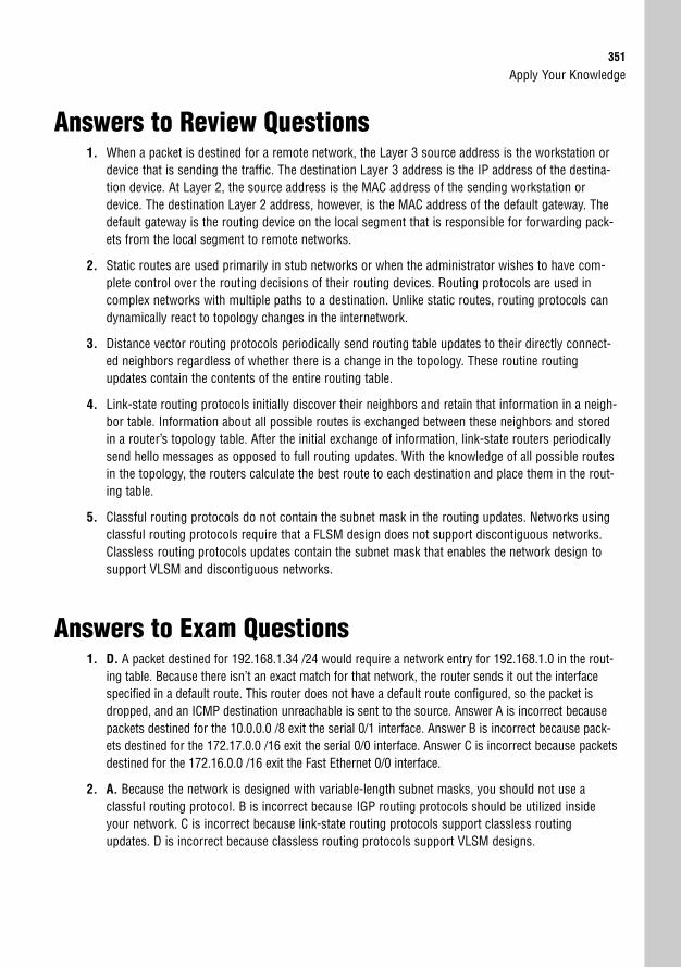
Apply Your Knowledge351
Answers to Review Questions1. When a packet is destined for a remote network, the Layer 3 source address is the workstation or
device that is sending the traffic. The destination Layer 3 address is the IP address of the destina-tion device. At Layer 2, the source address is the MAC address of the sending workstation ordevice. The destination Layer 2 address, however, is the MAC address of the default gateway. Thedefault gateway is the routing device on the local segment that is responsible for forwarding pack-ets from the local segment to remote networks.
2. Static routes are used primarily in stub networks or when the administrator wishes to have com-plete control over the routing decisions of their routing devices. Routing protocols are used incomplex networks with multiple paths to a destination. Unlike static routes, routing protocols candynamically react to topology changes in the internetwork.
3. Distance vector routing protocols periodically send routing table updates to their directly connect-ed neighbors regardless of whether there is a change in the topology. These routine routingupdates contain the contents of the entire routing table.
4. Link-state routing protocols initially discover their neighbors and retain that information in a neigh-bor table. Information about all possible routes is exchanged between these neighbors and storedin a router’s topology table. After the initial exchange of information, link-state routers periodicallysend hello messages as opposed to full routing updates. With the knowledge of all possible routesin the topology, the routers calculate the best route to each destination and place them in the rout-ing table.
5. Classful routing protocols do not contain the subnet mask in the routing updates. Networks usingclassful routing protocols require that a FLSM design does not support discontiguous networks.Classless routing protocols updates contain the subnet mask that enables the network design tosupport VLSM and discontiguous networks.
Answers to Exam Questions1. D. A packet destined for 192.168.1.34 /24 would require a network entry for 192.168.1.0 in the rout-
ing table. Because there isn’t an exact match for that network, the router sends it out the interfacespecified in a default route. This router does not have a default route configured, so the packet isdropped, and an ICMP destination unreachable is sent to the source. Answer A is incorrect becausepackets destined for the 10.0.0.0 /8 exit the serial 0/1 interface. Answer B is incorrect because pack-ets destined for the 172.17.0.0 /16 exit the serial 0/0 interface. Answer C is incorrect because packetsdestined for the 172.16.0.0 /16 exit the Fast Ethernet 0/0 interface.
2. A. Because the network is designed with variable-length subnet masks, you should not use aclassful routing protocol. B is incorrect because IGP routing protocols should be utilized insideyour network. C is incorrect because link-state routing protocols support classless routingupdates. D is incorrect because classless routing protocols support VLSM designs.
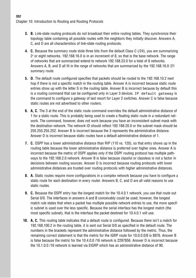
352
3. B. Link-state routing protocols do not broadcast their entire routing tables. They synchronize theirtopology table containing all possible routes with the neighbors they initially discover. Answers A,C, and D are all characteristics of link-state routing protocols.
4. C. Because the summary route stole three bits from the default Class C (/24), you are summarizing23 or eight networks. 192.168.16.0 is in an increment of 8, so that is the base network. The rangeof networks that are summarized extend to network 192.168.23.0 for a total of 8 networks.Answers A, B, and D all fit in the range of networks that are summarized by the 192.168.16.0 /21summary route.
5. D. The default route configured specifies that packets should be routed to the 192.168.10.2 nexthop if there is not a specific match in the routing table. Answer A is incorrect because static routeentries show up with the letter S in the routing table. Answer B is incorrect because by default thisis a routing command that can be configured only in Layer 3 devices. IP default gateway isthe command to configure a gateway of last resort for Layer 2 switches. Answer C is false becausestatic routes are not advertised to other routers.
6. A, C. The 3 at the end of the static route command overrides the default administrative distance of1 for a static route. This is probably being used to create a floating static route in a redundant net-work. The command, however, does not work because you have an inconsistent subnet mask withthe destination network. The network ID should reflect 192.168.20.0 or the subnet mask should be255.255.255.252. Answer B is incorrect because the 3 represents the administrative distance.Answer D is incorrect because static routes have a default administrative distance of 1.
7. C. OSPF has a lower administrative distance than RIP (110 vs. 120), so that entry shows up in therouting table because the lower administrative distance is preferred over higher ones. Answer A isincorrect because the metric of OSPF applies only if the OSPF routing protocol has multiple path-ways to the 192.168.2.0 network. Answer B is false because classful or classless is not a factor indecisions between routing sources. Answer D is incorrect because routing protocols with loweradministrative distances are trusted over routing protocols with higher administrative distances.
8. A. Static routes require more configurations in a complex network because you have to configure astatic route for each destination in every router. Answers B, C, and D are all valid reasons to usestatic routes.
9. C. Because the OSPF entry has the longest match for the 10.4.0.1 network, you use that route outSerial 0/0. The interfaces in answers A and B conceivably could be used; however, the longestmatch rule states that when a packet has multiple possible network entries to use, the more specif-ic subnet is used over the less specific. Because the serial interface has the longest match (themost specific subnet), that is the interface the packet destined for 10.4.0.1 will use.
10. A, C. This routing table indicates that a default route is configured. Because there isn’t a match for192.168.100.2 in the routing table, it is sent out Serial 0/0 as specified in the default route. Thenumbers in the brackets represent the administrative distance followed by the metric. Thus, theremaining correct statement is that the metric for the IGRP route for 10.0.0.0/8 is 8976. Answer Bis false because the metric for the 10.4.0.0 /16 network is 2297856. Answer D is incorrect becausethe 10.1.0.0 /16 network is learned via EIGRP which has an administrative distance of 90.
Chapter 10: Introduction to Routing and Routing Protocols

Apply Your Knowledge353
Suggested Readings and Resources1. Alex Zinn. IP Routing: Packet Forwarding and Intra-domain Routing Protocols. Addison
Wesley Professional, 2002.
2. Keith Kruepke, Paul Cernick, and Mark Degner. Cisco IP Routing Handbook. HungryMinds, 2000.
3. “Routing Protocols,” www.firewall.cx.
4. “IP Routing,” technology support on www.cisco.com.

This page intentionally left blank
11C H A P T E R E L E V E N
Distance Vector RoutingProtocols
ObjectivesThis chapter covers the following Cisco-specified objectives for the “Describe how a networkworks,” and “Configure, verify, and troubleshoot basic router operation and routing on Ciscodevices” sections of the 640-802 CCNA exam:
. Configure, verify, and troubleshoot RIPv2
. Compare and contrast methods of routing and routing protocols
. Troubleshoot routing issues
. Verify router hardware and software operation using SHOW & DEBUG commands
OutlineIntroduction 358
Distance Vector Operations 358
Routing Loops 360
Routing Loop Mitigation 362
Counting to Infinity 363
Split Horizon 363
Route Poison, Poison Reverse, and Hold-Down Timers 365
Triggered Updates 367
Invalid/Dead Timers 367
RIP 367
RIP Characteristics 367
RIP Configuration 368
Passive Interfaces 371
RIPv2 Characteristics 372
RIPv2 Configuration 373
RIPv2 Update Authentication 374
Configuring RIP with SDM 374
RIP Verification 375
Troubleshooting RIP 377
Chapter Summary 381
Key Terms 382
Apply Your Knowledge 382
Exercises 382
Review Questions 384
Exam Questions 384
Answers to Review Questions 388
Answers to Exam Questions 388
Suggested Readings and Resources 389

Study Strategies. Read the information presented in the chapter, paying special attention to tables, Notes,
and Exam Alerts.
. Keep in mind the characteristics of distance vector routing protocols and how those char-acteristics apply to RIP and RIPv2.
. Complete the Challenges and the Exercises at the end of the chapter. The exercises willsolidify the concepts that you have learned in the previous sections.
. This chapter builds on the concepts discussed in Chapter 10, “Introduction to Routingand Routing Protocols.” If you are not completely confident in your comfort with the fun-damentals of routing protocols and their metrics, review Chapter 10 before proceedingwith this chapter.
. Complete the Exam Questions at the end of the chapter. They are designed to simulate thetypes of questions you will be asked on the CCNA, ICND1, and ICND2 exams.
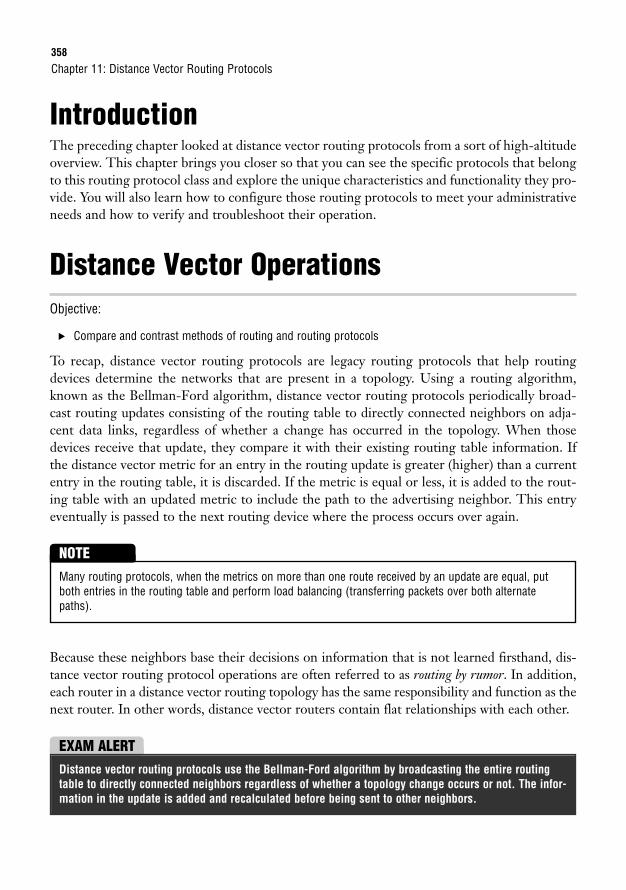
358
IntroductionThe preceding chapter looked at distance vector routing protocols from a sort of high-altitudeoverview. This chapter brings you closer so that you can see the specific protocols that belongto this routing protocol class and explore the unique characteristics and functionality they pro-vide. You will also learn how to configure those routing protocols to meet your administrativeneeds and how to verify and troubleshoot their operation.
Distance Vector OperationsObjective:
. Compare and contrast methods of routing and routing protocols
To recap, distance vector routing protocols are legacy routing protocols that help routingdevices determine the networks that are present in a topology. Using a routing algorithm,known as the Bellman-Ford algorithm, distance vector routing protocols periodically broad-cast routing updates consisting of the routing table to directly connected neighbors on adja-cent data links, regardless of whether a change has occurred in the topology. When thosedevices receive that update, they compare it with their existing routing table information. Ifthe distance vector metric for an entry in the routing update is greater (higher) than a currententry in the routing table, it is discarded. If the metric is equal or less, it is added to the rout-ing table with an updated metric to include the path to the advertising neighbor. This entryeventually is passed to the next routing device where the process occurs over again.
Chapter 11: Distance Vector Routing Protocols
Many routing protocols, when the metrics on more than one route received by an update are equal, putboth entries in the routing table and perform load balancing (transferring packets over both alternatepaths).
NOTE
Because these neighbors base their decisions on information that is not learned firsthand, dis-tance vector routing protocol operations are often referred to as routing by rumor. In addition,each router in a distance vector routing topology has the same responsibility and function as thenext router. In other words, distance vector routers contain flat relationships with each other.
EXAM ALERTDistance vector routing protocols use the Bellman-Ford algorithm by broadcasting the entire routingtable to directly connected neighbors regardless of whether a topology change occurs or not. The infor-mation in the update is added and recalculated before being sent to other neighbors.
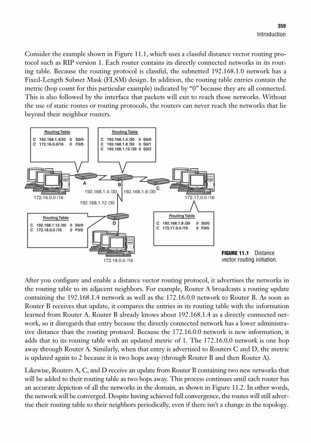
Introduction359
Consider the example shown in Figure 11.1, which uses a classful distance vector routing pro-tocol such as RIP version 1. Each router contains its directly connected networks in its rout-ing table. Because the routing protocol is classful, the subnetted 192.168.1.0 network has aFixed-Length Subnet Mask (FLSM) design. In addition, the routing table entries contain themetric (hop count for this particular example) indicated by “0” because they are all connected.This is also followed by the interface that packets will exit to reach those networks. Withoutthe use of static routes or routing protocols, the routers can never reach the networks that liebeyond their neighbor routers.
172.17.0.0 /16172.16.0.0 /16192.168.1.8 /30192.168.1.4 /30
192.168.1.12 /30
172.18.0.0 /16
Routing Table
C 192.168.1.4/30 0 S0/0C 172.16.0.0/16 0 F0/0
Routing Table
C 192.168.1.12 /30 0 S0/0C 172.18.0.0 /16 0 F0/0
Routing Table
C 192.168.1.4 /30 0 S0/0C 192.168.1.8 /30 0 S0/1C 192.168.1.12 /30 0 S0/2
Routing Table
C 192.168.1.8 /30 0 S0/0C 172.17.0.0 /16 0 F0/0
A B
D
C
After you configure and enable a distance vector routing protocol, it advertises the networks inthe routing table to its adjacent neighbors. For example, Router A broadcasts a routing updatecontaining the 192.168.1.4 network as well as the 172.16.0.0 network to Router B. As soon asRouter B receives that update, it compares the entries in its routing table with the informationlearned from Router A. Router B already knows about 192.168.1.4 as a directly connected net-work, so it disregards that entry because the directly connected network has a lower administra-tive distance than the routing protocol. Because the 172.16.0.0 network is new information, itadds that to its routing table with an updated metric of 1. The 172.16.0.0 network is one hopaway through Router A. Similarly, when that entry is advertised to Routers C and D, the metricis updated again to 2 because it is two hops away (through Router B and then Router A).
Likewise, Routers A, C, and D receive an update from Router B containing two new networks thatwill be added to their routing table as two hops away. This process continues until each router hasan accurate depiction of all the networks in the domain, as shown in Figure 11.2. In other words,the network will be converged. Despite having achieved full convergence, the routes will still adver-tise their routing table to their neighbors periodically, even if there isn’t a change in the topology.
FIGURE 11.1 Distancevector routing initiation.
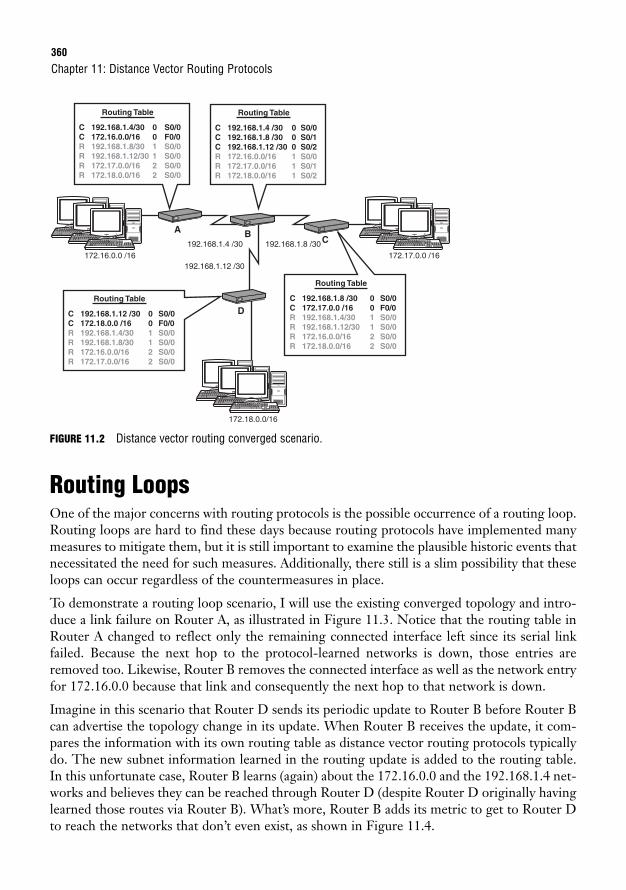
360
FIGURE 11.2 Distance vector routing converged scenario.
Routing LoopsOne of the major concerns with routing protocols is the possible occurrence of a routing loop.Routing loops are hard to find these days because routing protocols have implemented manymeasures to mitigate them, but it is still important to examine the plausible historic events thatnecessitated the need for such measures. Additionally, there still is a slim possibility that theseloops can occur regardless of the countermeasures in place.
To demonstrate a routing loop scenario, I will use the existing converged topology and intro-duce a link failure on Router A, as illustrated in Figure 11.3. Notice that the routing table inRouter A changed to reflect only the remaining connected interface left since its serial linkfailed. Because the next hop to the protocol-learned networks is down, those entries areremoved too. Likewise, Router B removes the connected interface as well as the network entryfor 172.16.0.0 because that link and consequently the next hop to that network is down.
Imagine in this scenario that Router D sends its periodic update to Router B before Router Bcan advertise the topology change in its update. When Router B receives the update, it com-pares the information with its own routing table as distance vector routing protocols typicallydo. The new subnet information learned in the routing update is added to the routing table.In this unfortunate case, Router B learns (again) about the 172.16.0.0 and the 192.168.1.4 net-works and believes they can be reached through Router D (despite Router D originally havinglearned those routes via Router B). What’s more, Router B adds its metric to get to Router Dto reach the networks that don’t even exist, as shown in Figure 11.4.
Chapter 11: Distance Vector Routing Protocols
172.17.0.0 /16172.16.0.0 /16192.168.1.8 /30192.168.1.4 /30
192.168.1.12 /30
172.18.0.0/16
Routing Table
C 192.168.1.4/30 0 S0/0C 172.16.0.0/16 0 F0/0R 192.168.1.8/30 1 S0/0R 192.168.1.12/30 1 S0/0R 172.17.0.0/16 2 S0/0R 172.18.0.0/16 2 S0/0
Routing Table
C 192.168.1.12 /30 0 S0/0C 172.18.0.0 /16 0 F0/0R 192.168.1.4/30 1 S0/0R 192.168.1.8/30 1 S0/0R 172.16.0.0/16 2 S0/0R 172.17.0.0/16 2 S0/0
Routing Table
C 192.168.1.4 /30 0 S0/0C 192.168.1.8 /30 0 S0/1C 192.168.1.12 /30 0 S0/2R 172.16.0.0/16 1 S0/0R 172.17.0.0/16 1 S0/1R 172.18.0.0/16 1 S0/2
Routing Table
C 192.168.1.8 /30 0 S0/0C 172.17.0.0 /16 0 F0/0R 192.168.1.4/30 1 S0/0R 192.168.1.12/30 1 S0/0R 172.16.0.0/16 2 S0/0R 172.18.0.0/16 2 S0/0
A BC
D
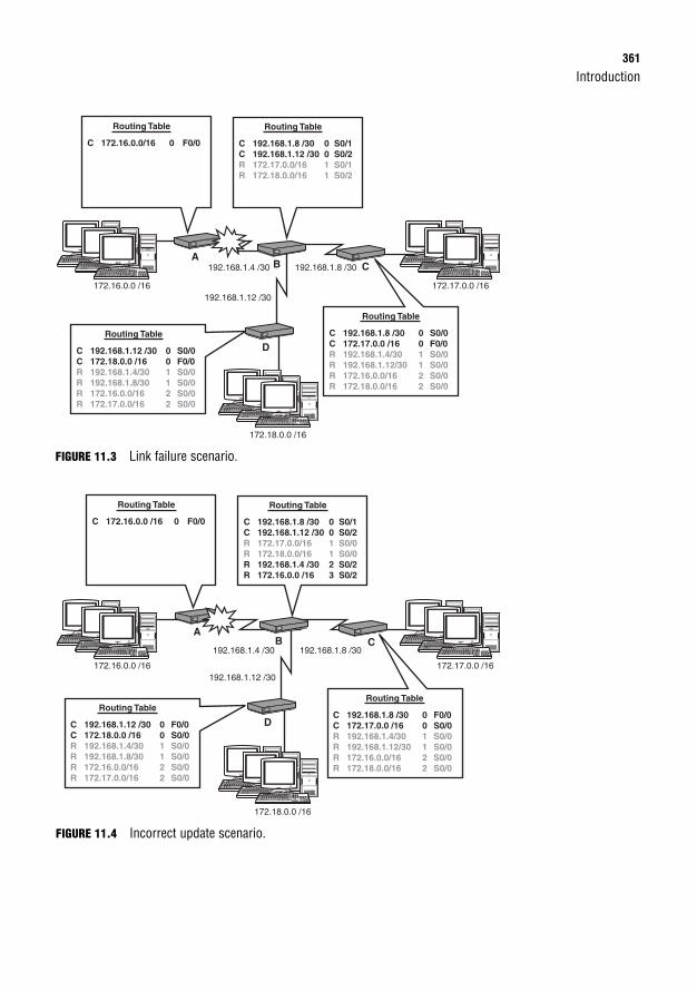
Introduction361
FIGURE 11.3 Link failure scenario.
172.17.0.0 /16172.16.0.0 /16
192.168.1.8 /30192.168.1.4 /30
192.168.1.12 /30
172.18.0.0 /16
Routing Table
C 172.16.0.0/16 0 F0/0
Routing Table
C 192.168.1.12 /30 0 S0/0C 172.18.0.0 /16 0 F0/0R 192.168.1.4/30 1 S0/0R 192.168.1.8/30 1 S0/0R 172.16.0.0/16 2 S0/0R 172.17.0.0/16 2 S0/0
Routing Table
C 192.168.1.8 /30 0 S0/1C 192.168.1.12 /30 0 S0/2R 172.17.0.0/16 1 S0/1R 172.18.0.0/16 1 S0/2
Routing Table
C 192.168.1.8 /30 0 S0/0C 172.17.0.0 /16 0 F0/0R 192.168.1.4/30 1 S0/0R 192.168.1.12/30 1 S0/0R 172.16.0.0/16 2 S0/0R 172.18.0.0/16 2 S0/0
AB C
D
172.17.0.0 /16172.16.0.0 /16
192.168.1.8 /30192.168.1.4 /30
192.168.1.12 /30
172.18.0.0 /16
Routing Table
C 172.16.0.0 /16 0 F0/0
Routing Table
C 192.168.1.12 /30 0 F0/0C 172.18.0.0 /16 0 S0/0R 192.168.1.4/30 1 S0/0R 192.168.1.8/30 1 S0/0R 172.16.0.0/16 2 S0/0R 172.17.0.0/16 2 S0/0
Routing Table
C 192.168.1.8 /30 0 S0/1C 192.168.1.12 /30 0 S0/2R 172.17.0.0/16 1 S0/0R 172.18.0.0/16 1 S0/0R 192.168.1.4 /30 2 S0/2R 172.16.0.0 /16 3 S0/2
Routing Table
C 192.168.1.8 /30 0 F0/0C 172.17.0.0 /16 0 S0/0R 192.168.1.4/30 1 S0/0R 192.168.1.12/30 1 S0/0R 172.16.0.0/16 2 S0/0R 172.18.0.0/16 2 S0/0
AB C
D
FIGURE 11.4 Incorrect update scenario.
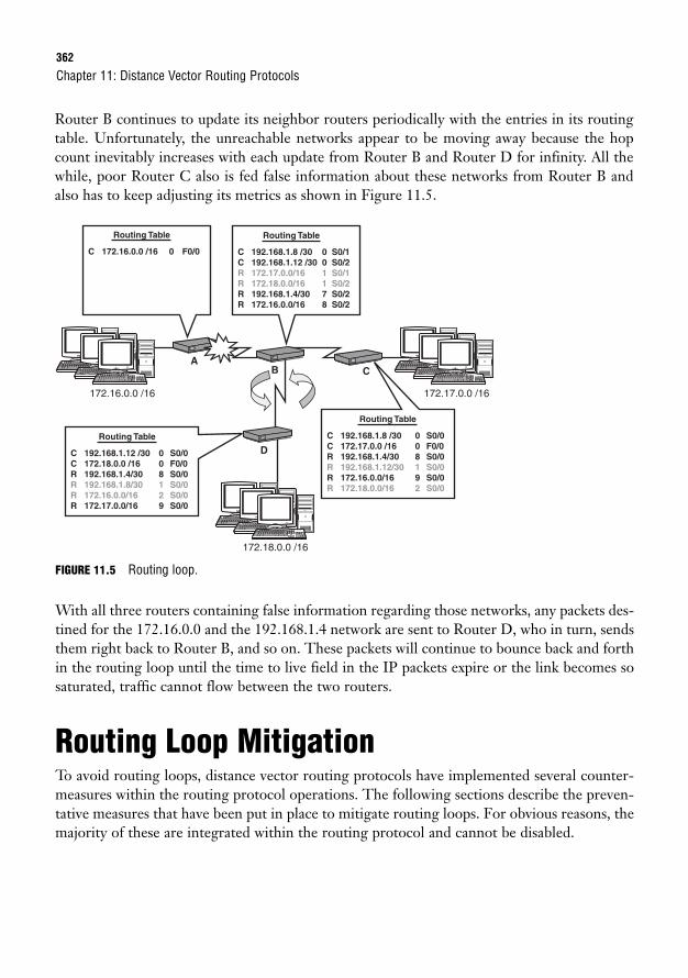
362
Router B continues to update its neighbor routers periodically with the entries in its routingtable. Unfortunately, the unreachable networks appear to be moving away because the hopcount inevitably increases with each update from Router B and Router D for infinity. All thewhile, poor Router C also is fed false information about these networks from Router B andalso has to keep adjusting its metrics as shown in Figure 11.5.
Chapter 11: Distance Vector Routing Protocols
172.17.0.0 /16172.16.0.0 /16
172.18.0.0 /16
Routing Table
C 172.16.0.0 /16 0 F0/0
Routing Table
C 192.168.1.12 /30 0 S0/0C 172.18.0.0 /16 0 F0/0R 192.168.1.4/30 8 S0/0R 192.168.1.8/30 1 S0/0R 172.16.0.0/16 2 S0/0R 172.17.0.0/16 9 S0/0
Routing Table
C 192.168.1.8 /30 0 S0/1C 192.168.1.12 /30 0 S0/2R 172.17.0.0/16 1 S0/1R 172.18.0.0/16 1 S0/2R 192.168.1.4/30 7 S0/2R 172.16.0.0/16 8 S0/2
Routing Table
C 192.168.1.8 /30 0 S0/0C 172.17.0.0 /16 0 F0/0R 192.168.1.4/30 8 S0/0R 192.168.1.12/30 1 S0/0R 172.16.0.0/16 9 S0/0R 172.18.0.0/16 2 S0/0
AB C
D
FIGURE 11.5 Routing loop.
With all three routers containing false information regarding those networks, any packets des-tined for the 172.16.0.0 and the 192.168.1.4 network are sent to Router D, who in turn, sendsthem right back to Router B, and so on. These packets will continue to bounce back and forthin the routing loop until the time to live field in the IP packets expire or the link becomes sosaturated, traffic cannot flow between the two routers.
Routing Loop MitigationTo avoid routing loops, distance vector routing protocols have implemented several counter-measures within the routing protocol operations. The following sections describe the preven-tative measures that have been put in place to mitigate routing loops. For obvious reasons, themajority of these are integrated within the routing protocol and cannot be disabled.
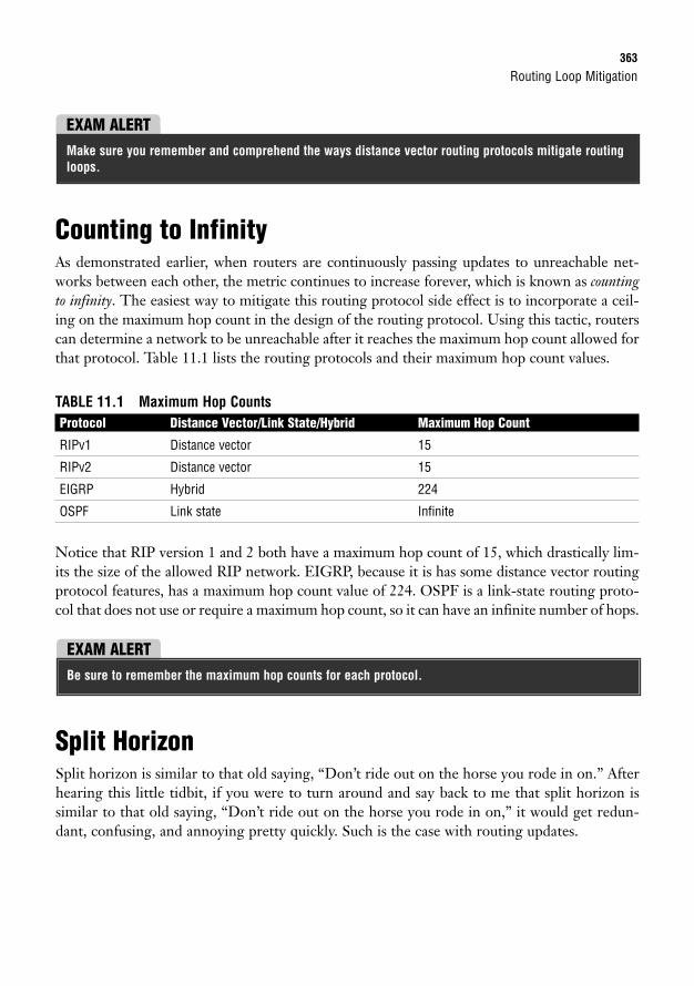
Routing Loop Mitigation363
Counting to InfinityAs demonstrated earlier, when routers are continuously passing updates to unreachable net-works between each other, the metric continues to increase forever, which is known as countingto infinity. The easiest way to mitigate this routing protocol side effect is to incorporate a ceil-ing on the maximum hop count in the design of the routing protocol. Using this tactic, routerscan determine a network to be unreachable after it reaches the maximum hop count allowed forthat protocol. Table 11.1 lists the routing protocols and their maximum hop count values.
TABLE 11.1 Maximum Hop CountsProtocol Distance Vector/Link State/Hybrid Maximum Hop Count
RIPv1 Distance vector 15
RIPv2 Distance vector 15
EIGRP Hybrid 224
OSPF Link state Infinite
Notice that RIP version 1 and 2 both have a maximum hop count of 15, which drastically lim-its the size of the allowed RIP network. EIGRP, because it is has some distance vector routingprotocol features, has a maximum hop count value of 224. OSPF is a link-state routing proto-col that does not use or require a maximum hop count, so it can have an infinite number of hops.
EXAM ALERTMake sure you remember and comprehend the ways distance vector routing protocols mitigate routingloops.
EXAM ALERTBe sure to remember the maximum hop counts for each protocol.
Split HorizonSplit horizon is similar to that old saying, “Don’t ride out on the horse you rode in on.” Afterhearing this little tidbit, if you were to turn around and say back to me that split horizon issimilar to that old saying, “Don’t ride out on the horse you rode in on,” it would get redun-dant, confusing, and annoying pretty quickly. Such is the case with routing updates.
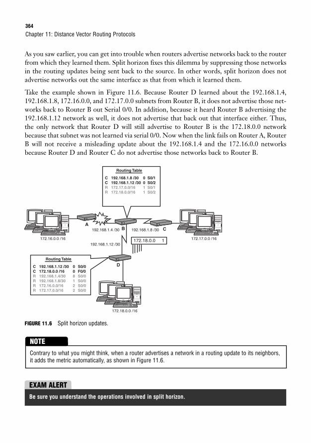
364
As you saw earlier, you can get into trouble when routers advertise networks back to the routerfrom which they learned them. Split horizon fixes this dilemma by suppressing those networksin the routing updates being sent back to the source. In other words, split horizon does notadvertise networks out the same interface as that from which it learned them.
Take the example shown in Figure 11.6. Because Router D learned about the 192.168.1.4,192.168.1.8, 172.16.0.0, and 172.17.0.0 subnets from Router B, it does not advertise those net-works back to Router B out Serial 0/0. In addition, because it heard Router B advertising the192.168.1.12 network as well, it does not advertise that back out that interface either. Thus,the only network that Router D will still advertise to Router B is the 172.18.0.0 networkbecause that subnet was not learned via serial 0/0. Now when the link fails on Router A, RouterB will not receive a misleading update about the 192.168.1.4 and the 172.16.0.0 networksbecause Router D and Router C do not advertise those networks back to Router B.
Chapter 11: Distance Vector Routing Protocols
172.17.0.0 /16172.16.0.0 /16
192.168.1.4 /30
192.168.1.12 /30
192.168.1.8 /30
172.18.0.0 /16
Routing Table
C 192.168.1.12 /30 0 S0/0C 172.18.0.0 /16 0 F0/0R 192.168.1.4/30 8 S0/0R 192.168.1.8/30 1 S0/0R 172.16.0.0/16 2 S0/0R 172.17.0.0/16 2 S0/0
Routing Table
C 192.168.1.8 /30 0 S0/1C 192.168.1.12 /30 0 S0/2R 172.17.0.0/16 1 S0/1R 172.18.0.0/16 1 S0/2
172.18.0.0 1
AB C
D
FIGURE 11.6 Split horizon updates.
Contrary to what you might think, when a router advertises a network in a routing update to its neighbors,it adds the metric automatically, as shown in Figure 11.6.
NOTE
EXAM ALERTBe sure you understand the operations involved in split horizon.
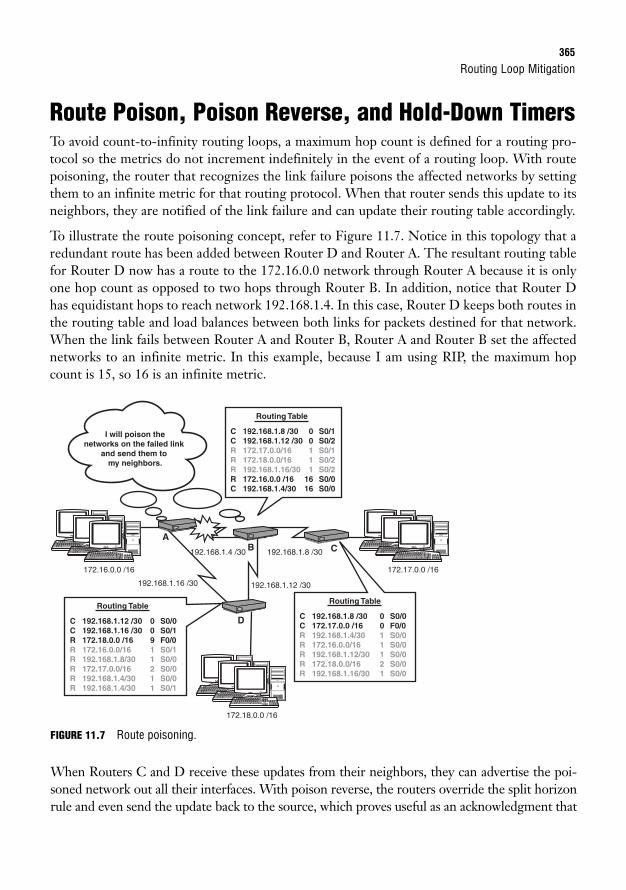
Routing Loop Mitigation365
Route Poison, Poison Reverse, and Hold-Down TimersTo avoid count-to-infinity routing loops, a maximum hop count is defined for a routing pro-tocol so the metrics do not increment indefinitely in the event of a routing loop. With routepoisoning, the router that recognizes the link failure poisons the affected networks by settingthem to an infinite metric for that routing protocol. When that router sends this update to itsneighbors, they are notified of the link failure and can update their routing table accordingly.
To illustrate the route poisoning concept, refer to Figure 11.7. Notice in this topology that aredundant route has been added between Router D and Router A. The resultant routing tablefor Router D now has a route to the 172.16.0.0 network through Router A because it is onlyone hop count as opposed to two hops through Router B. In addition, notice that Router Dhas equidistant hops to reach network 192.168.1.4. In this case, Router D keeps both routes inthe routing table and load balances between both links for packets destined for that network.When the link fails between Router A and Router B, Router A and Router B set the affectednetworks to an infinite metric. In this example, because I am using RIP, the maximum hopcount is 15, so 16 is an infinite metric.
172.17.0.0 /16172.16.0.0 /16
192.168.1.4 /30 192.168.1.8 /30
192.168.1.12 /30192.168.1.16 /30
172.18.0.0 /16
Routing Table
C 192.168.1.12 /30 0 S0/0C 192.168.1.16 /30 0 S0/1R 172.18.0.0 /16 9 F0/0R 172.16.0.0/16 1 S0/1R 192.168.1.8/30 1 S0/0R 172.17.0.0/16 2 S0/0R 192.168.1.4/30 1 S0/0R 192.168.1.4/30 1 S0/1
Routing Table
C 192.168.1.8 /30 0 S0/1C 192.168.1.12 /30 0 S0/2R 172.17.0.0/16 1 S0/1R 172.18.0.0/16 1 S0/2R 192.168.1.16/30 1 S0/2R 172.16.0.0 /16 16 S0/0C 192.168.1.4/30 16 S0/0
Routing Table
C 192.168.1.8 /30 0 S0/0C 172.17.0.0 /16 0 F0/0R 192.168.1.4/30 1 S0/0R 172.16.0.0/16 1 S0/0R 192.168.1.12/30 1 S0/0R 172.18.0.0/16 2 S0/0R 192.168.1.16/30 1 S0/0
I will poison thenetworks on the failed link
and send them to my neighbors.
AB C
D
FIGURE 11.7 Route poisoning.
When Routers C and D receive these updates from their neighbors, they can advertise the poi-soned network out all their interfaces. With poison reverse, the routers override the split horizonrule and even send the update back to the source, which proves useful as an acknowledgment that
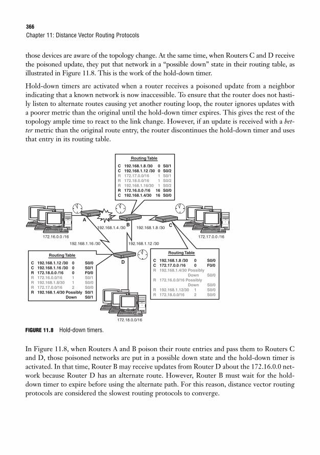
366
those devices are aware of the topology change. At the same time, when Routers C and D receivethe poisoned update, they put that network in a “possible down” state in their routing table, asillustrated in Figure 11.8. This is the work of the hold-down timer.
Hold-down timers are activated when a router receives a poisoned update from a neighborindicating that a known network is now inaccessible. To ensure that the router does not hasti-ly listen to alternate routes causing yet another routing loop, the router ignores updates witha poorer metric than the original until the hold-down timer expires. This gives the rest of thetopology ample time to react to the link change. However, if an update is received with a bet-ter metric than the original route entry, the router discontinues the hold-down timer and usesthat entry in its routing table.
Chapter 11: Distance Vector Routing Protocols
172.17.0.0 /16172.16.0.0 /16
192.168.1.4 /30 192.168.1.8 /30
192.168.1.12 /30192.168.1.16 /30
172.18.0.0/16
Routing Table
C 192.168.1.12 /30 0 S0/0C 192.168.1.16 /30 0 S0/1R 172.18.0.0 /16 0 F0/0R 172.16.0.0/16 1 S0/1R 192.168.1.8/30 1 S0/0R 172.17.0.0/16 2 S0/0R 192.168.1.4/30 Possibly S0/1 Down S0/1
Routing Table
C 192.168.1.8 /30 0 S0/1C 192.168.1.12 /30 0 S0/2R 172.17.0.0/16 1 S0/1R 172.18.0.0/16 1 S0/2R 192.168.1.16/30 1 S0/2R 172.16.0.0 /16 16 S0/0C 192.168.1.4/30 16 S0/0
Routing Table
C 192.168.1.8 /30 0 S0/0C 172.17.0.0 /16 0 F0/0R 192.168.1.4/30 Possibly Down S0/0R 172.16.0.0/16 Possibly Down S0/0R 192.168.1.12/30 1 S0/0R 172.18.0.0/16 2 S0/0
12 12 12
12
AB C
D
FIGURE 11.8 Hold-down timers.
In Figure 11.8, when Routers A and B poison their route entries and pass them to Routers Cand D, those poisoned networks are put in a possible down state and the hold-down timer isactivated. In that time, Router B may receive updates from Router D about the 172.16.0.0 net-work because Router D has an alternate route. However, Router B must wait for the hold-down timer to expire before using the alternate path. For this reason, distance vector routingprotocols are considered the slowest routing protocols to converge.
RIP367
Triggered UpdatesOne way distance vector routing protocols speed up their convergence while helping avoidrouting loops at the same time is something called flash or triggered updates. Because one of thecontributing causes of routing loops is the lack of update information reaching all devicesquickly enough, triggered updates enable the router to send the update immediately after alink fails, as opposed to waiting for its periodic update time.
Invalid/Dead TimersIn place of a link failure, what do you suppose would happen if Router A had some operationalfailures or you removed or changed the routing protocol configuration or networks? Otherrouters in the domain would not be aware of this change because it isn’t a link failure that theycan detect and react to. To ensure that these networks are not circulating indefinitely in a rout-ing system, routing protocols have invalid, or dead, timers. If a router stops receiving updatesfrom a router after a set amount of time, that router is considered to be dead and the networksthat learned from that router are invalid. Likewise, if a particular network stops advertisingwith a routing protocol, that entry becomes invalid after the dead timer ages out. This timeris reset every time an update is received from a neighbor for each network in the routing table.When the timer expires, the router poisons the route and advertises that topology change toits neighbors.
You can clear out aged entries in the routing table quickly by using the clear ip route command fol-lowed by the network you want to remove, or use the wildcard, *, to remove all entries.
TIP
RIPThe first distance vector routing protocol that is discussed here is coincidentally one of theoldest routing protocols that is still used today. Circa 1988, Routing Information Protocol(RIP) for IP was defined in RFC 1058; however, its roots stem back to the 1970s at XeroxCorporation’s Palo Alto Research Center. The following sections look at the characteristicsand configurations involved with this resolute routing protocol.
RIP CharacteristicsRIP is a fairly simple routing protocol in both characteristics and implementation. You alreadyknow that RIP uses hop count as its only metric, in which it can support up to 15 as a maxi-mum. In instances where the metric is identical (for example, equal hop count) for a subnet, it
368
load balances up to six equal paths (four by default). Like other distance vector routing proto-cols, RIP sends the contents of its routing table to its directly connected neighbors, regardlessof whether there is a change in the topology. Particularly, RIP’s update interval is every 30 sec-onds and its invalid timer is for 180 seconds. Thus, RIP (version 1) broadcasts its routing tableevery 30 seconds and considers a neighbor or a network to be dead after six missed updates.
Because RIP does not advertise subnet masks in its routing updates, it is also a classful routingprotocol. Recall that this requires every subnet of a major network to have the same (fixed-length) subnet masks. In addition, RIP automatically summarizes subnetted networks to theirdefault classful boundaries when sending the update over a different major network which, inturn, nullifies any support for a discontiguous network design.
As with many routing protocols, RIP requires manual redistribution if you want to advertisenetworks from a different routing source other than connected interfaces and other RIP-learned networks. This is also the case for default routes. If you configure a static default routein a router that is running RIP, you must use the default-information originate commandin the routing process to redistribute that default route in its routing updates to its neighborswithout any additional configuration. The neighbors receive these updates and set that routeras their gateway of last resort, assuming that a static default route is not configured with alower administrative distance. The routing table subsequently displays the learned 0.0.0.0/0subnet as a RIP-learned network.
Chapter 11: Distance Vector Routing Protocols
EXAM ALERTAlthough version 1 of RIP is considered outdated by the CCNA, ICND1, and ICND2 exams, it is impor-tant to know its characteristics and configuration because RIPv2 shares many characteristics and issimilar in configuration.
RIP ConfigurationThe configuration for RIP is seamless as long as you remember these two simple rules:
. Advertise only your directly connected networks.
. Advertise only the classful network.
The first rule is imperative to keep in mind when configuring routing protocols. Rememberthat the point of the routing protocols is to advertise their known networks to each other sothey can build their routing tables. With that being said, do not confuse the configuration ofrouting protocols with static routes. You do not specify a destination network with routingprotocols as you would a static route. Instead, you specify local networks and let the routingprotocols advertise them to each other.
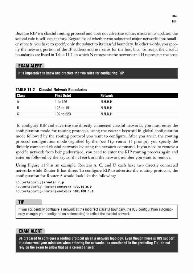
RIP369
Because RIP is a classful routing protocol and does not advertise subnet masks in its updates, thesecond rule is self-explanatory. Regardless of whether you subnetted major networks into small-er subnets, you have to specify only the subnet to its classful boundary. In other words, you spec-ify the network portion of the IP address and use zeros for the host bits. To recap, the classfulboundaries are listed in Table 11.2, in which N represents the network and H represents the host.
EXAM ALERTIt is imperative to know and practice the two rules for configuring RIP.
TABLE 11.2 Classful Network BoundariesClass First Octet Network
A 1 to 126 N.H.H.H
B 128 to 191 N.N.H.H
C 192 to 223 N.N.N.H
To configure RIP and advertise the directly connected classful networks, you must enter theconfiguration mode for routing protocols, using the router keyword in global configurationmode followed by the routing protocol you want to configure. After you are in the routingprotocol configuration mode (signified by the (config-router)# prompt), you specify thedirectly connected classful networks by using the network command. If you need to remove aspecific network from being advertised, you need to enter the RIP routing process again andenter no followed by the keyword network and the network number you want to remove.
Using Figure 11.9 as an example, Routers A, C, and D each have two directly connected networks while Router B has three. To configure RIP to advertise the routing protocols, theconfiguration for Router A would look like the following:RouterA(config)#router ripRouterA(config-router)#network 172.16.0.0RouterA(config-router)#network 192.168.1.0
If you accidentally configure a network at the incorrect classful boundary, the IOS configuration automati-cally changes your configuration statement(s) to reflect the classful network.
TIP
EXAM ALERTBe prepared to configure a routing protocol given a network topology. Even though there is IOS supportto autocorrect your mistakes when entering the networks, as mentioned in the preceding Tip, do notrely on the exam to allow that as a correct answer.
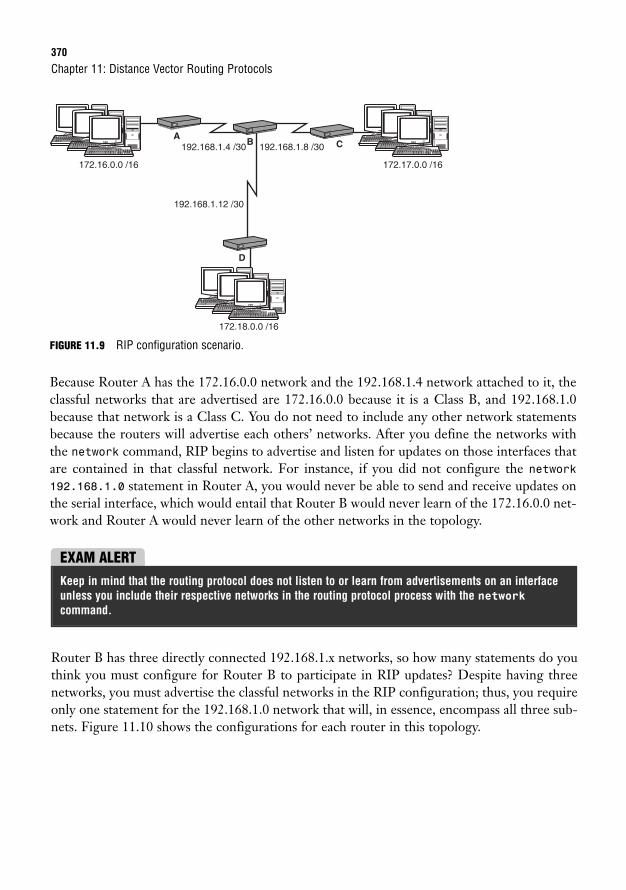
370
FIGURE 11.9 RIP configuration scenario.
Because Router A has the 172.16.0.0 network and the 192.168.1.4 network attached to it, theclassful networks that are advertised are 172.16.0.0 because it is a Class B, and 192.168.1.0because that network is a Class C. You do not need to include any other network statementsbecause the routers will advertise each others’ networks. After you define the networks withthe network command, RIP begins to advertise and listen for updates on those interfaces thatare contained in that classful network. For instance, if you did not configure the network192.168.1.0 statement in Router A, you would never be able to send and receive updates onthe serial interface, which would entail that Router B would never learn of the 172.16.0.0 net-work and Router A would never learn of the other networks in the topology.
Chapter 11: Distance Vector Routing Protocols
172.17.0.0 /16172.16.0.0 /16
192.168.1.8 /30192.168.1.4 /30
192.168.1.12 /30
172.18.0.0 /16
AB C
D
EXAM ALERTKeep in mind that the routing protocol does not listen to or learn from advertisements on an interfaceunless you include their respective networks in the routing protocol process with the networkcommand.
Router B has three directly connected 192.168.1.x networks, so how many statements do youthink you must configure for Router B to participate in RIP updates? Despite having threenetworks, you must advertise the classful networks in the RIP configuration; thus, you requireonly one statement for the 192.168.1.0 network that will, in essence, encompass all three sub-nets. Figure 11.10 shows the configurations for each router in this topology.
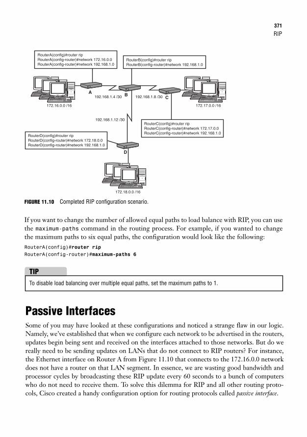
RIP371
FIGURE 11.10 Completed RIP configuration scenario.
If you want to change the number of allowed equal paths to load balance with RIP, you can usethe maximum-paths command in the routing process. For example, if you wanted to changethe maximum paths to six equal paths, the configuration would look like the following:RouterA(config)#router ripRouterA(config-router)#maximum-paths 6
172.17.0.0 /16172.16.0.0 /16
192.168.1.8 /30192.168.1.4 /30
192.168.1.12 /30
172.18.0.0 /16
RouterA(config)#router ripRouterA(config-router)#network 172.16.0.0RouterA(config-router)#network 192.168.1.0
RouterC(config)#router ripRouterC(config-router)#network 172.17.0.0RouterC(config-router)#network 192.168.1.0
RouterB(config)#router ripRouterB(config-router)#network 192.168.1.0
RouterD(config)#router ripRouterD(config-router)#network 172.18.0.0RouterD(config-router)#network 192.168.1.0
A B C
D
To disable load balancing over multiple equal paths, set the maximum paths to 1.
TIP
Passive InterfacesSome of you may have looked at these configurations and noticed a strange flaw in our logic.Namely, we’ve established that when we configure each network to be advertised in the routers,updates begin being sent and received on the interfaces attached to those networks. But do wereally need to be sending updates on LANs that do not connect to RIP routers? For instance,the Ethernet interface on Router A from Figure 11.10 that connects to the 172.16.0.0 networkdoes not have a router on that LAN segment. In essence, we are wasting good bandwidth andprocessor cycles by broadcasting these RIP update every 60 seconds to a bunch of computerswho do not need to receive them. To solve this dilemma for RIP and all other routing proto-cols, Cisco created a handy configuration option for routing protocols called passive interface.
372
With this additional configuration command, you specify an interface or interfaces to the rout-ing protocol process that will no longer send routing updates. What is interesting, however, isthat the interfaces will still receive and process updates on that interface. As a result, passiveinterfaces are useful not only for saving bandwidth, but also can be used to manipulate ourrouting policies by allowing us to determine whether or not we send routing updates to cer-tain routers. The command to achieve this marvelous feat is passive-interface interfacein the routing process configuration, such as shown here for RIP:RouterA(config)#router ripRouterA(config-router)#passive-interface fastethernet 0/0
With this command in place, updates are no longer sent out of Fast Ethernet 0/0. However, iffor some reason an update was received on that interface, it would still process it and put it inits routing table.
RIPv2 CharacteristicsIn an attempt to keep up with modern needs from a routing protocol, RIP version 2 was cre-ated in 1994 to address many of the shortcomings of its predecessor. Many of the characteris-tics are similar to RIPv1; nonetheless, RIPv2 had some significant improvements:
. Multicast updates: Rather than broadcast its routing updates, RIPv2 uses a reservedmulticast address of 224.0.0.9 to communicate with other RIPv2 neighbors. By using amulticast address, it does not waste the processing resources of non-RIP devicesbecause only RIPv2 devices process messages to that address.
. Classful or classless support: RIPv2 is classful by default, but can be configured as aclassless routing protocol, which allows for subnet masks to be sent in the routingupdates. The implication of this enhancement entails that RIPv2 can support VLSMand discontiguous network designs.
. Authenticated updates: To ensure the origin of the routing update and protect fromattackers spoofing routing updates, RIPv2 allows update authentication in which thepasswords must match in all routers to validate the routing update.
Chapter 11: Distance Vector Routing Protocols
EXAM ALERTBe sure to remember the enhancements that RIPv2 holds over RIPv1.
RIP373
RIPv2 Configuration
Objective:
. Configure, verify, and troubleshoot RIPv2
The configuration for RIPv2 is practically identical to RIPv1. In other words, you still mustenter the RIP routing process with the router rip command and still must advertise thedirectly connected classful networks. To enable RIPv2, you have to enter the command version 2 in the routing process:RouterA(config)#router ripRouterA(config-router)#version 2RouterA(config-router)#network 172.16.0.0RouterA(config-router)#network 192.168.1.0
By default, RIPv2 is classful. To configure this enhanced routing protocol to support classlessrouting updates, the only entry you need to configure is the no auto-summary command inthe routing process:RouterA(config)#router ripRouterA(config-router)#no auto-summary
After you configure this command, the RIP version 2 updates being multicast to 224.0.0.9 areno longer be considered classful, because the subnet mask is advertised in the updates alongwith the network.
By default, RIP is configured to send version 1 and accept version 1 and 2 received updates. This meansthat routers that have not been changed to version 2 will still accept version 2 updates but will processthem as version 1 (ignoring any subnet mask or authentication). Be sure to keep this in mind if you decideto revert your RIP configuration to version 1 by using the version 1 command. This commandinstructs the router to receive only version 1 updates, which causes version 2 updates to be treated as anillegal version and be ignored. To revert to the default RIP configuration, a better command to use isdefault version in the RIP routing process.
TIP
EXAM ALERTIf a router is explicitly configured to run as version 1, RIP version 2 updates are considered an illegalversion and are ignored.
374
RIPv2 Update AuthenticationAs previously mentioned, RIPv2 provides update authentication to help protect from roguedevices or attackers injecting false routing information into your routing table by authenticatingthe routing updates. This authentication is achieved by defining a key and attaching a key string(password) to it. This key string must match on both routers, or the updates will be rejected.
To define the authentication key, use the key chain command followed by a name for the keychain in global configuration mode. After you enter that command, you are put into config-keychain subconfiguration mode:RouterA(config)#key chain luckyrabbitsfootRouterA(config-keychain)#
Here you can configure several keys if you want, with different key string passwords. To cre-ate a key, use the key keyword and a number identifier for that key. You are put into anothersubconfiguration mode for that specific key, as shown by the config-keychain-key prompt:RouterA(config-keychain)#key 1RouterA(config-keychain-key)#
Now we finally get to define our password, using the key-string command followed by thepassword that will match on each side:RouterA(config-keychain-key)#key-string whataRIPoff
With our key chain defined, we have to apply it to interfaces that connect to neighboringRIPv2 routers with matching authentication configurations. The command to assign the keychain to the interface is ip rip authentication key-chain followed by the key chain youdefined a moment ago:RouterA(config-keychain-key)#exitRouterA(config-keychain)#exitRouterA(config)#interface serial 0/0/0RouterA(config-if)#ip rip authentication key-chain luckyrabbitsfoot
This key chain is sent over the link in clear text by default. This defeats the point of securinglinks, because the key chain can be seen if the link is being eavesdropped. To secure the keyusing an MD5 hash of the password, use the following command:RouterA(config-if)#ip rip authentication mode md5
Configuring RIP with SDMRIP configurations using SDM are relatively similar and just as easy as configuring default andstatic routes. Select Configuration, Routing. Focus on the bottom of the screen for our dynam-ic routing protocols. When you click the Edit button, you see the pop-up window shown in
Chapter 11: Distance Vector Routing Protocols
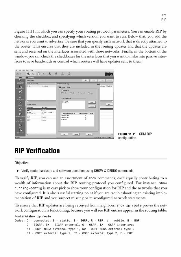
RIP375
Figure 11.11, in which you can specify your routing protocol parameters. You can enable RIP bychecking the checkbox and specifying which version you want to run. Below that, you add thenetworks you want to advertise. Be sure that you specify each network that is directly attached tothe router. This ensures that they are included in the routing updates and that the updates aresent and received on the interfaces associated with those networks. Finally, in the bottom of thewindow, you can check the checkboxes for the interfaces that you want to make into passive inter-faces to save bandwidth or control which routers will have updates sent to them.
RIP Verification
Objective:
. Verify router hardware and software operation using SHOW & DEBUG commands
To verify RIP, you can use an assortment of show commands, each equally contributing to awealth of information about the RIP routing protocol you configured. For instance, showrunning-config is an easy pick to show your configuration for RIP and the networks that youhave configured. It is also a useful starting point if you are troubleshooting an existing imple-mentation of RIP and you suspect missing or misconfigured network statements.
To ensure that RIP updates are being received from neighbors, show ip route proves the net-work configuration is functioning, because you will see RIP entries appear in the routing table:RouterA#show ip routeCodes: C - connected, S - static, I - IGRP, R - RIP, M - mobile, B - BGP
D - EIGRP, EX - EIGRP external, O - OSPF, IA - OSPF inter areaN1 - OSPF NSSA external type 1, N2 - OSPF NSSA external type 2E1 - OSPF external type 1, E2 - OSPF external type 2, E - EGP
FIGURE 11.11 SDM RIP configuration.
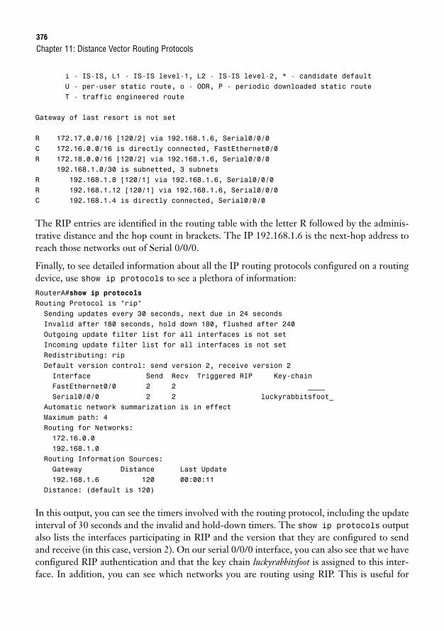
376
i - IS-IS, L1 - IS-IS level-1, L2 - IS-IS level-2, * - candidate defaultU - per-user static route, o - ODR, P - periodic downloaded static routeT - traffic engineered route
Gateway of last resort is not set
R 172.17.0.0/16 [120/2] via 192.168.1.6, Serial0/0/0C 172.16.0.0/16 is directly connected, FastEthernet0/0R 172.18.0.0/16 [120/2] via 192.168.1.6, Serial0/0/0
192.168.1.0/30 is subnetted, 3 subnetsR 192.168.1.8 [120/1] via 192.168.1.6, Serial0/0/0R 192.168.1.12 [120/1] via 192.168.1.6, Serial0/0/0C 192.168.1.4 is directly connected, Serial0/0/0
The RIP entries are identified in the routing table with the letter R followed by the adminis-trative distance and the hop count in brackets. The IP 192.168.1.6 is the next-hop address toreach those networks out of Serial 0/0/0.
Finally, to see detailed information about all the IP routing protocols configured on a routingdevice, use show ip protocols to see a plethora of information:RouterA#show ip protocolsRouting Protocol is “rip”Sending updates every 30 seconds, next due in 24 secondsInvalid after 180 seconds, hold down 180, flushed after 240Outgoing update filter list for all interfaces is not setIncoming update filter list for all interfaces is not setRedistributing: ripDefault version control: send version 2, receive version 2Interface Send Recv Triggered RIP Key-chainFastEthernet0/0 2 2 ____Serial0/0/0 2 2 luckyrabbitsfoot_
Automatic network summarization is in effectMaximum path: 4Routing for Networks:172.16.0.0192.168.1.0
Routing Information Sources:Gateway Distance Last Update192.168.1.6 120 00:00:11
Distance: (default is 120)
In this output, you can see the timers involved with the routing protocol, including the updateinterval of 30 seconds and the invalid and hold-down timers. The show ip protocols outputalso lists the interfaces participating in RIP and the version that they are configured to sendand receive (in this case, version 2). On our serial 0/0/0 interface, you can also see that we haveconfigured RIP authentication and that the key chain luckyrabbitsfoot is assigned to this inter-face. In addition, you can see which networks you are routing using RIP. This is useful for
Chapter 11: Distance Vector Routing Protocols
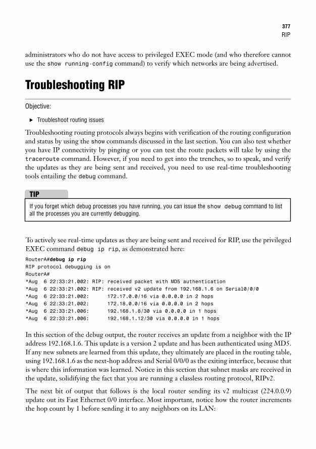
RIP377
administrators who do not have access to privileged EXEC mode (and who therefore cannotuse the show running-config command) to verify which networks are being advertised.
Troubleshooting RIP
Objective:
. Troubleshoot routing issues
Troubleshooting routing protocols always begins with verification of the routing configurationand status by using the show commands discussed in the last section. You can also test whetheryou have IP connectivity by pinging or you can test the route packets will take by using thetraceroute command. However, if you need to get into the trenches, so to speak, and verifythe updates as they are being sent and received, you need to use real-time troubleshootingtools entailing the debug command.
If you forget which debug processes you have running, you can issue the show debug command to listall the processes you are currently debugging.
TIP
To actively see real-time updates as they are being sent and received for RIP, use the privilegedEXEC command debug ip rip, as demonstrated here:RouterA#debug ip ripRIP protocol debugging is onRouterA#*Aug 6 22:33:21.002: RIP: received packet with MD5 authentication*Aug 6 22:33:21.002: RIP: received v2 update from 192.168.1.6 on Serial0/0/0*Aug 6 22:33:21.002: 172.17.0.0/16 via 0.0.0.0 in 2 hops*Aug 6 22:33:21.002: 172.18.0.0/16 via 0.0.0.0 in 2 hops*Aug 6 22:33:21.006: 192.168.1.8/30 via 0.0.0.0 in 1 hops*Aug 6 22:33:21.006: 192.168.1.12/30 via 0.0.0.0 in 1 hops
In this section of the debug output, the router receives an update from a neighbor with the IPaddress 192.168.1.6. This update is a version 2 update and has been authenticated using MD5.If any new subnets are learned from this update, they ultimately are placed in the routing table,using 192.168.1.6 as the next-hop address and Serial 0/0/0 as the exiting interface, because thatis where this information was learned. Notice in this section that subnet masks are received inthe update, solidifying the fact that you are running a classless routing protocol, RIPv2.
The next bit of output that follows is the local router sending its v2 multicast (224.0.0.9)update out its Fast Ethernet 0/0 interface. Most important, notice how the router incrementsthe hop count by 1 before sending it to any neighbors on its LAN:
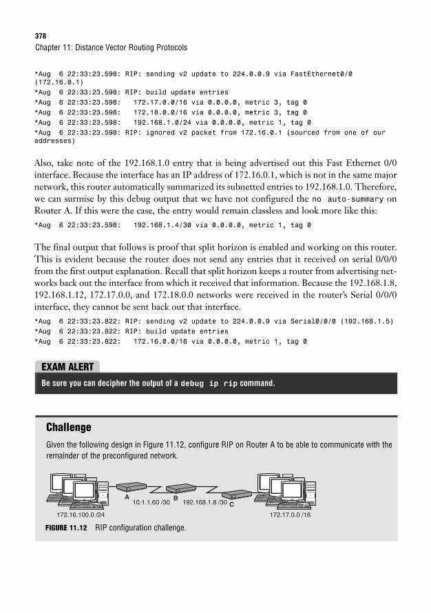
378
*Aug 6 22:33:23.598: RIP: sending v2 update to 224.0.0.9 via FastEthernet0/0(172.16.0.1)*Aug 6 22:33:23.598: RIP: build update entries*Aug 6 22:33:23.598: 172.17.0.0/16 via 0.0.0.0, metric 3, tag 0*Aug 6 22:33:23.598: 172.18.0.0/16 via 0.0.0.0, metric 3, tag 0*Aug 6 22:33:23.598: 192.168.1.0/24 via 0.0.0.0, metric 1, tag 0*Aug 6 22:33:23.598: RIP: ignored v2 packet from 172.16.0.1 (sourced from one of ouraddresses)
Also, take note of the 192.168.1.0 entry that is being advertised out this Fast Ethernet 0/0interface. Because the interface has an IP address of 172.16.0.1, which is not in the same majornetwork, this router automatically summarized its subnetted entries to 192.168.1.0. Therefore,we can surmise by this debug output that we have not configured the no auto-summary onRouter A. If this were the case, the entry would remain classless and look more like this:*Aug 6 22:33:23.598: 192.168.1.4/30 via 0.0.0.0, metric 1, tag 0
The final output that follows is proof that split horizon is enabled and working on this router.This is evident because the router does not send any entries that it received on serial 0/0/0from the first output explanation. Recall that split horizon keeps a router from advertising net-works back out the interface from which it received that information. Because the 192.168.1.8,192.168.1.12, 172.17.0.0, and 172.18.0.0 networks were received in the router’s Serial 0/0/0interface, they cannot be sent back out that interface.*Aug 6 22:33:23.822: RIP: sending v2 update to 224.0.0.9 via Serial0/0/0 (192.168.1.5)*Aug 6 22:33:23.822: RIP: build update entries*Aug 6 22:33:23.822: 172.16.0.0/16 via 0.0.0.0, metric 1, tag 0
Chapter 11: Distance Vector Routing Protocols
EXAM ALERTBe sure you can decipher the output of a debug ip rip command.
ChallengeGiven the following design in Figure 11.12, configure RIP on Router A to be able to communicate with theremainder of the preconfigured network.
172.17.0.0 /16172.16.100.0 /24
192.168.1.8 /3010.1.1.60 /30A B
C
FIGURE 11.12 RIP configuration challenge.
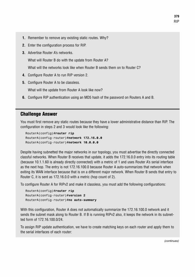
RIP379
1. Remember to remove any existing static routes. Why?
2. Enter the configuration process for RIP.
3. Advertise Router A’s networks.
What will Router B do with the update from Router A?
What will the networks look like when Router B sends them on to Router C?
4. Configure Router A to run RIP version 2.
5. Configure Router A to be classless.
What will the update from Router A look like now?
6. Configure RIP authentication using an MD5 hash of the password on Routers A and B.
Challenge AnswerYou must first remove any static routes because they have a lower administrative distance than RIP. Theconfiguration in steps 2 and 3 would look like the following:
RouterA(config)#router ripRouterA(config-router)#network 172.16.0.0RouterA(config-router)#network 10.0.0.0
Despite having subnetted the major networks in our topology, you must advertise the directly connectedclassful networks. When Router B receives that update, it adds the 172.16.0.0 entry into its routing table(because 10.1.1.60 is already directly connected) with a metric of 1 and uses Router A’s serial interfaceas the next hop. The entry is not 172.16.100.0 because Router A auto-summarizes that network whenexiting its WAN interface because that is on a different major network. When Router B sends that entry toRouter C, it is sent as 172.16.0.0 with a metric (hop count of 2).
To configure Router A for RIPv2 and make it classless, you must add the following configurations:
RouterA(config)#router ripRouterA(config-router)#version 2RouterA(config-router)#no auto-summary
With this configuration, Router A does not automatically summarize the 172.16.100.0 network and itsends the subnet mask along to Router B. If B is running RIPv2 also, it keeps the network in its subnet-ted form of 172.16.100.0/24.
To assign RIP update authentication, we have to create matching keys on each router and apply them tothe serial interfaces of each router:
(continues)
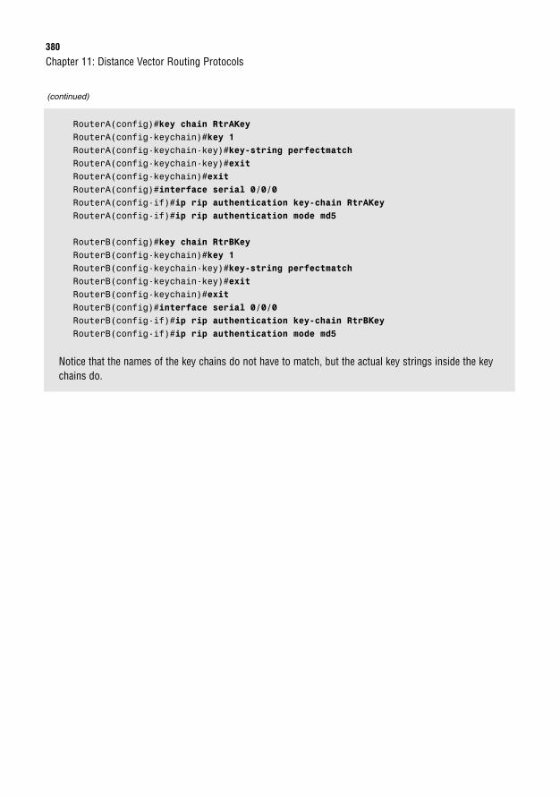
380
Chapter 11: Distance Vector Routing Protocols
(continued)
RouterA(config)#key chain RtrAKeyRouterA(config-keychain)#key 1RouterA(config-keychain-key)#key-string perfectmatchRouterA(config-keychain-key)#exitRouterA(config-keychain)#exitRouterA(config)#interface serial 0/0/0RouterA(config-if)#ip rip authentication key-chain RtrAKeyRouterA(config-if)#ip rip authentication mode md5
RouterB(config)#key chain RtrBKeyRouterB(config-keychain)#key 1RouterB(config-keychain-key)#key-string perfectmatchRouterB(config-keychain-key)#exitRouterB(config-keychain)#exitRouterB(config)#interface serial 0/0/0RouterB(config-if)#ip rip authentication key-chain RtrBKeyRouterB(config-if)#ip rip authentication mode md5
Notice that the names of the key chains do not have to match, but the actual key strings inside the keychains do.
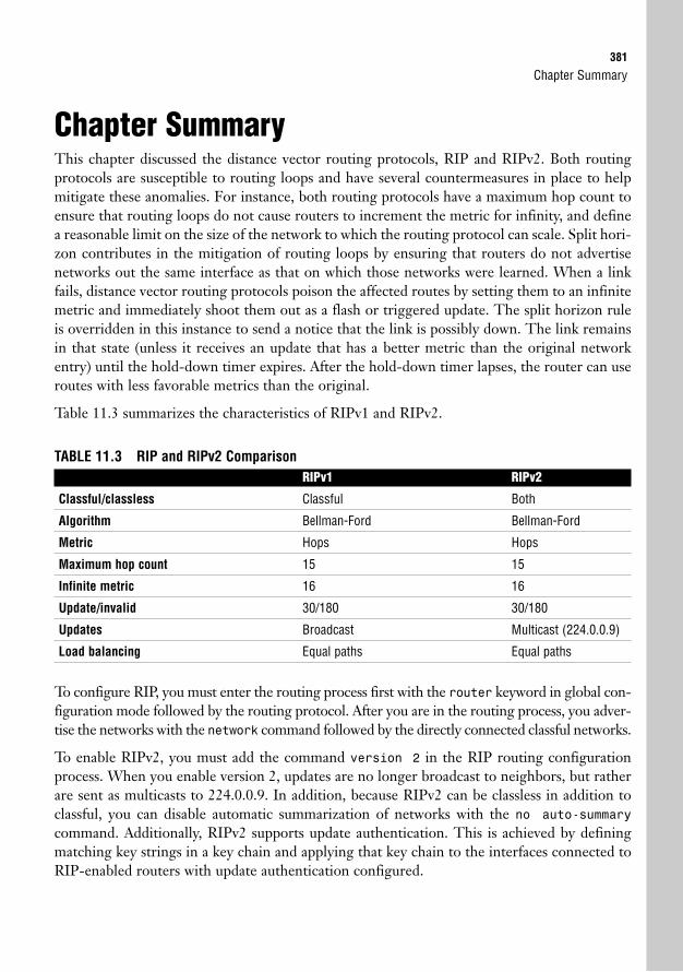
Chapter Summary381
Chapter SummaryThis chapter discussed the distance vector routing protocols, RIP and RIPv2. Both routingprotocols are susceptible to routing loops and have several countermeasures in place to helpmitigate these anomalies. For instance, both routing protocols have a maximum hop count toensure that routing loops do not cause routers to increment the metric for infinity, and definea reasonable limit on the size of the network to which the routing protocol can scale. Split hori-zon contributes in the mitigation of routing loops by ensuring that routers do not advertisenetworks out the same interface as that on which those networks were learned. When a linkfails, distance vector routing protocols poison the affected routes by setting them to an infinitemetric and immediately shoot them out as a flash or triggered update. The split horizon ruleis overridden in this instance to send a notice that the link is possibly down. The link remainsin that state (unless it receives an update that has a better metric than the original networkentry) until the hold-down timer expires. After the hold-down timer lapses, the router can useroutes with less favorable metrics than the original.
Table 11.3 summarizes the characteristics of RIPv1 and RIPv2.
TABLE 11.3 RIP and RIPv2 ComparisonRIPv1 RIPv2
Classful/classless Classful Both
Algorithm Bellman-Ford Bellman-Ford
Metric Hops Hops
Maximum hop count 15 15
Infinite metric 16 16
Update/invalid 30/180 30/180
Updates Broadcast Multicast (224.0.0.9)
Load balancing Equal paths Equal paths
To configure RIP, you must enter the routing process first with the router keyword in global con-figuration mode followed by the routing protocol. After you are in the routing process, you adver-tise the networks with the network command followed by the directly connected classful networks.
To enable RIPv2, you must add the command version 2 in the RIP routing configurationprocess. When you enable version 2, updates are no longer broadcast to neighbors, but ratherare sent as multicasts to 224.0.0.9. In addition, because RIPv2 can be classless in addition toclassful, you can disable automatic summarization of networks with the no auto-summary
command. Additionally, RIPv2 supports update authentication. This is achieved by definingmatching key strings in a key chain and applying that key chain to the interfaces connected toRIP-enabled routers with update authentication configured.
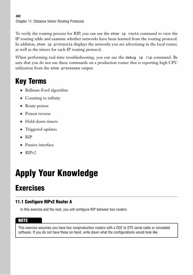
382
To verify the routing process for RIP, you can use the show ip route command to view theIP routing table and examine whether networks have been learned from the routing protocol.In addition, show ip protocols displays the networks you are advertising in the local router,as well as the timers for each IP routing protocol.
When performing real-time troubleshooting, you can use the debug ip rip command. Besure that you do not use these commands on a production router that is reporting high CPUutilization from the show processes output.
Key Terms. Bellman-Ford algorithm
. Counting to infinity
. Route poison
. Poison reverse
. Hold-down timers
. Triggered updates
. RIP
. Passive interface
. RIPv2
Apply Your Knowledge
Exercises
11.1 Configure RIPv2 Router A
In this exercise and the next, you will configure RIP between two routers.
Chapter 11: Distance Vector Routing Protocols
This exercise assumes you have two nonproduction routers with a DCE to DTE serial cable or simulatedsoftware. If you do not have these on hand, write down what the configurations would look like.
NOTE
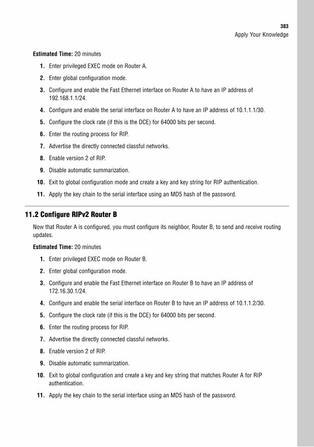
Apply Your Knowledge383
Estimated Time: 20 minutes
1. Enter privileged EXEC mode on Router A.
2. Enter global configuration mode.
3. Configure and enable the Fast Ethernet interface on Router A to have an IP address of192.168.1.1/24.
4. Configure and enable the serial interface on Router A to have an IP address of 10.1.1.1/30.
5. Configure the clock rate (if this is the DCE) for 64000 bits per second.
6. Enter the routing process for RIP.
7. Advertise the directly connected classful networks.
8. Enable version 2 of RIP.
9. Disable automatic summarization.
10. Exit to global configuration mode and create a key and key string for RIP authentication.
11. Apply the key chain to the serial interface using an MD5 hash of the password.
11.2 Configure RIPv2 Router B
Now that Router A is configured, you must configure its neighbor, Router B, to send and receive routingupdates.
Estimated Time: 20 minutes
1. Enter privileged EXEC mode on Router B.
2. Enter global configuration mode.
3. Configure and enable the Fast Ethernet interface on Router B to have an IP address of172.16.30.1/24.
4. Configure and enable the serial interface on Router B to have an IP address of 10.1.1.2/30.
5. Configure the clock rate (if this is the DCE) for 64000 bits per second.
6. Enter the routing process for RIP.
7. Advertise the directly connected classful networks.
8. Enable version 2 of RIP.
9. Disable automatic summarization.
10. Exit to global configuration and create a key and key string that matches Router A for RIP authentication.
11. Apply the key chain to the serial interface using an MD5 hash of the password.
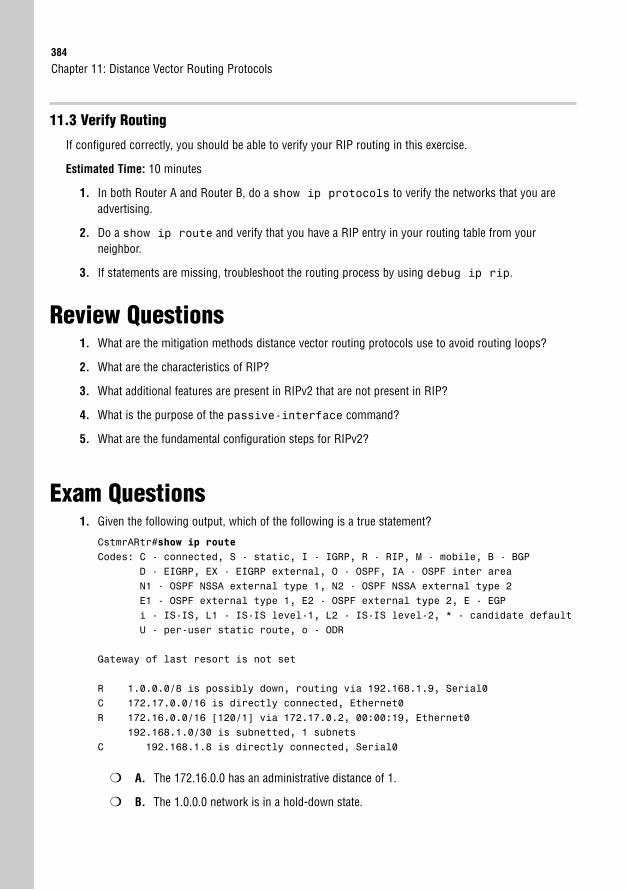
384
11.3 Verify Routing
If configured correctly, you should be able to verify your RIP routing in this exercise.
Estimated Time: 10 minutes
1. In both Router A and Router B, do a show ip protocols to verify the networks that you areadvertising.
2. Do a show ip route and verify that you have a RIP entry in your routing table from yourneighbor.
3. If statements are missing, troubleshoot the routing process by using debug ip rip.
Review Questions1. What are the mitigation methods distance vector routing protocols use to avoid routing loops?
2. What are the characteristics of RIP?
3. What additional features are present in RIPv2 that are not present in RIP?
4. What is the purpose of the passive-interface command?
5. What are the fundamental configuration steps for RIPv2?
Exam Questions1. Given the following output, which of the following is a true statement?
CstmrARtr#show ip routeCodes: C - connected, S - static, I - IGRP, R - RIP, M - mobile, B - BGP
D - EIGRP, EX - EIGRP external, O - OSPF, IA - OSPF inter areaN1 - OSPF NSSA external type 1, N2 - OSPF NSSA external type 2E1 - OSPF external type 1, E2 - OSPF external type 2, E - EGPi - IS-IS, L1 - IS-IS level-1, L2 - IS-IS level-2, * - candidate defaultU - per-user static route, o - ODR
Gateway of last resort is not set
R 1.0.0.0/8 is possibly down, routing via 192.168.1.9, Serial0C 172.17.0.0/16 is directly connected, Ethernet0R 172.16.0.0/16 [120/1] via 172.17.0.2, 00:00:19, Ethernet0
192.168.1.0/30 is subnetted, 1 subnetsC 192.168.1.8 is directly connected, Serial0
❍ A. The 172.16.0.0 has an administrative distance of 1.
❍ B. The 1.0.0.0 network is in a hold-down state.
Chapter 11: Distance Vector Routing Protocols
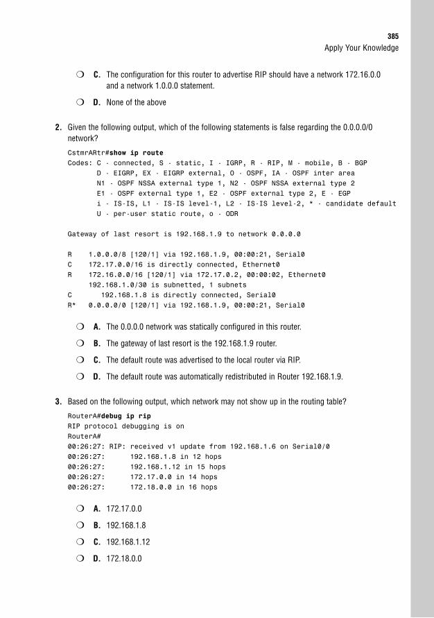
Apply Your Knowledge385
❍ C. The configuration for this router to advertise RIP should have a network 172.16.0.0and a network 1.0.0.0 statement.
❍ D. None of the above
2. Given the following output, which of the following statements is false regarding the 0.0.0.0/0 network?
CstmrARtr#show ip routeCodes: C - connected, S - static, I - IGRP, R - RIP, M - mobile, B - BGP
D - EIGRP, EX - EIGRP external, O - OSPF, IA - OSPF inter areaN1 - OSPF NSSA external type 1, N2 - OSPF NSSA external type 2E1 - OSPF external type 1, E2 - OSPF external type 2, E - EGPi - IS-IS, L1 - IS-IS level-1, L2 - IS-IS level-2, * - candidate defaultU - per-user static route, o - ODR
Gateway of last resort is 192.168.1.9 to network 0.0.0.0
R 1.0.0.0/8 [120/1] via 192.168.1.9, 00:00:21, Serial0C 172.17.0.0/16 is directly connected, Ethernet0R 172.16.0.0/16 [120/1] via 172.17.0.2, 00:00:02, Ethernet0
192.168.1.0/30 is subnetted, 1 subnetsC 192.168.1.8 is directly connected, Serial0R* 0.0.0.0/0 [120/1] via 192.168.1.9, 00:00:21, Serial0
❍ A. The 0.0.0.0 network was statically configured in this router.
❍ B. The gateway of last resort is the 192.168.1.9 router.
❍ C. The default route was advertised to the local router via RIP.
❍ D. The default route was automatically redistributed in Router 192.168.1.9.
3. Based on the following output, which network may not show up in the routing table?
RouterA#debug ip ripRIP protocol debugging is onRouterA#00:26:27: RIP: received v1 update from 192.168.1.6 on Serial0/000:26:27: 192.168.1.8 in 12 hops00:26:27: 192.168.1.12 in 15 hops00:26:27: 172.17.0.0 in 14 hops00:26:27: 172.18.0.0 in 16 hops
❍ A. 172.17.0.0
❍ B. 192.168.1.8
❍ C. 192.168.1.12
❍ D. 172.18.0.0
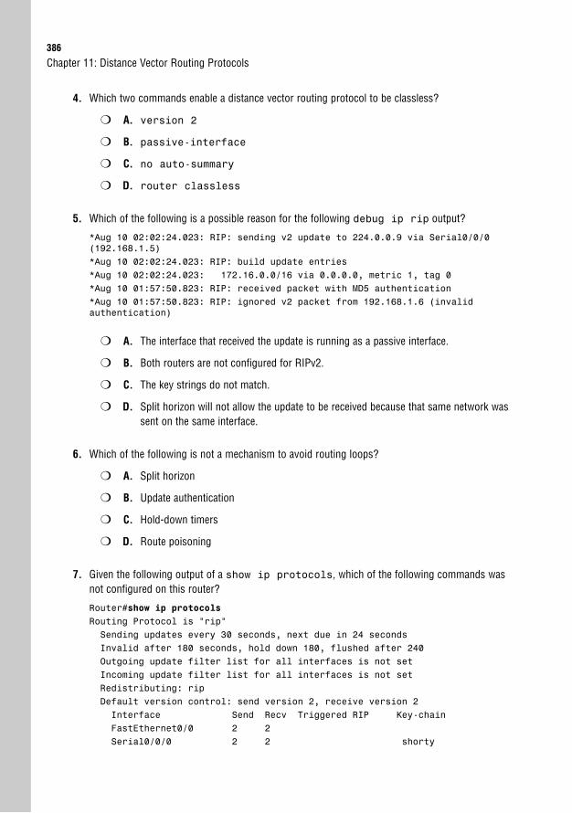
386
4. Which two commands enable a distance vector routing protocol to be classless?
❍ A. version 2
❍ B. passive-interface
❍ C. no auto-summary
❍ D. router classless
5. Which of the following is a possible reason for the following debug ip rip output?
*Aug 10 02:02:24.023: RIP: sending v2 update to 224.0.0.9 via Serial0/0/0(192.168.1.5)*Aug 10 02:02:24.023: RIP: build update entries*Aug 10 02:02:24.023: 172.16.0.0/16 via 0.0.0.0, metric 1, tag 0*Aug 10 01:57:50.823: RIP: received packet with MD5 authentication*Aug 10 01:57:50.823: RIP: ignored v2 packet from 192.168.1.6 (invalid authentication)
❍ A. The interface that received the update is running as a passive interface.
❍ B. Both routers are not configured for RIPv2.
❍ C. The key strings do not match.
❍ D. Split horizon will not allow the update to be received because that same network wassent on the same interface.
6. Which of the following is not a mechanism to avoid routing loops?
❍ A. Split horizon
❍ B. Update authentication
❍ C. Hold-down timers
❍ D. Route poisoning
7. Given the following output of a show ip protocols, which of the following commands wasnot configured on this router?
Router#show ip protocolsRouting Protocol is “rip”Sending updates every 30 seconds, next due in 24 secondsInvalid after 180 seconds, hold down 180, flushed after 240Outgoing update filter list for all interfaces is not setIncoming update filter list for all interfaces is not setRedistributing: ripDefault version control: send version 2, receive version 2Interface Send Recv Triggered RIP Key-chainFastEthernet0/0 2 2Serial0/0/0 2 2 shorty
Chapter 11: Distance Vector Routing Protocols
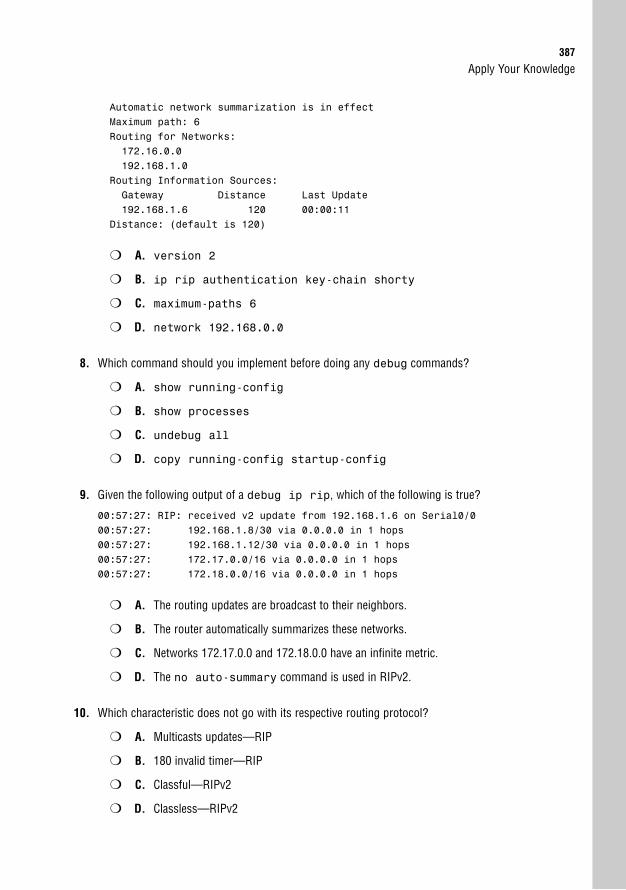
Apply Your Knowledge387
Automatic network summarization is in effectMaximum path: 6Routing for Networks:172.16.0.0192.168.1.0
Routing Information Sources:Gateway Distance Last Update192.168.1.6 120 00:00:11
Distance: (default is 120)
❍ A. version 2
❍ B. ip rip authentication key-chain shorty
❍ C. maximum-paths 6
❍ D. network 192.168.0.0
8. Which command should you implement before doing any debug commands?
❍ A. show running-config
❍ B. show processes
❍ C. undebug all
❍ D. copy running-config startup-config
9. Given the following output of a debug ip rip, which of the following is true?
00:57:27: RIP: received v2 update from 192.168.1.6 on Serial0/000:57:27: 192.168.1.8/30 via 0.0.0.0 in 1 hops00:57:27: 192.168.1.12/30 via 0.0.0.0 in 1 hops00:57:27: 172.17.0.0/16 via 0.0.0.0 in 1 hops00:57:27: 172.18.0.0/16 via 0.0.0.0 in 1 hops
❍ A. The routing updates are broadcast to their neighbors.
❍ B. The router automatically summarizes these networks.
❍ C. Networks 172.17.0.0 and 172.18.0.0 have an infinite metric.
❍ D. The no auto-summary command is used in RIPv2.
10. Which characteristic does not go with its respective routing protocol?
❍ A. Multicasts updates—RIP
❍ B. 180 invalid timer—RIP
❍ C. Classful—RIPv2
❍ D. Classless—RIPv2
388
Answers to Review Questions1. Because distance vector routing protocols are susceptible to routing loops, they have incorporated
several countermeasures to help mitigate any routing loop anomalies. For instance, all distancevector routing protocols have a maximum hop count to avoid counting to infinity. In addition, splithorizon prevents routers from advertising networks out the same interface in which they werelearned. Upon learning about a failing network, routers poison the route by setting it to an infinitemetric and send a triggered update to the router’s neighbors. The router will not process new infe-rior information about the failed network until the hold-down timer expires to ensure that the failednetwork does not get accidentally reinstated.
2. RIP is a classful distance vector routing protocol that uses hop count as its metric (maximum of15). RIP broadcasts the contents of the routing table to its directly connected neighbors every 30seconds.
3. RIPv2 supports classless routing updates if the no auto-summary command is used. In addi-tion, RIPv2 updates are sent as multicasts and can be authenticated using an MD5 password.
4. The passive-interface command indicates that the specified interface will not send routingupdates; however, the interface can still receive and process updates. This is useful to controlwhich routers are sent updates and to save wasted bandwidth and processing of broadcasts ormulticasts on LAN segments.
5. To enable RIP, you must enter the routing process by using the keyword router followed by therouting protocol. When you are in the routing configuration process, you must advertise the direct-ly connected classful networks attached to the router by using the network command followedby the classful network. To enable RIPv2, you have to add the command version 2 in the rout-ing configuration.
Answers to Exam Questions1. B. Because the routing table update shows the 1.0.0.0/8 network as possibly down, it is currently
in a hold-down state and waiting for the hold-down timer to expire before accepting a route with ahigher metric. Answer A is incorrect because the AD is 120 and the hip count is 1. C is falsebecause those network entries were learned via RIP, not advertised. D is incorrect, because B iscorrect.
2. A. Because the default route has an R statement next to it, it was redistributed automatically by theneighbor at 192.168.1.9. If it was statically configured, it would have an S indication next to theroute. Answers B, C, and D are true because the 0.0.0.0 route was redistributed and advertised viaRIP by the router with the IP address of 192.168.1.9.
3. D. Because the 172.18.0.0 has an infinite metric for RIP being advertised, it is most likely a poisonedroute or a router that is not showing up in the routing table. Answers A, B, and C will show up in therouting table because their hop count does not exceed the maximum hop count for RIP (15).
Chapter 11: Distance Vector Routing Protocols
Apply Your Knowledge389
4. A, C. The only distance vector routing protocol that can be classless is RIPv2. The command toenable RIPv2 is version 2. To make it classless, you use the no auto-summary command.Answer B is incorrect because the passive-interface command is used to keep updatesfrom being sent out that specific interface. Answer D is not a valid command.
5. C. Because the output indicated that the update that was received was ignored because of authen-tication failure, the logical choice is that the key strings in the update authentication are not match-ing. Answer A is incorrect because a passive interface would not ignore incoming updates since itsuppressed only outgoing updates. Answer B is incorrect because the output shows the updatesas version 2 and only version 2 uses authentication. Answer D is incorrect because split horizondoes not ignore incoming updates.
6. B. Update authentication is not a mechanism to avoid routing loops. Split horizon, hold-downtimers, and router poisoning are all mechanisms to avoid routing loops so answers A, C, and D areincorrect.
7. D. The network statement is incorrect. The correct network command would be network192.168.1.0. Answer A is incorrect because the output shows that version 2 is being sent andreceived. Answer B is incorrect because the output shows that the shorty key chain is applied. AnswerC is incorrect because the output shows that the maximum paths have been increased from 4 to 6.
8. B. Before running any debug commands, you should check your router’s current and past utiliza-tion with the show processes command. Answer A does not have any effect on the debugprocess. Answer C will turn off any debugging after the debugging process has been initiated.Answer D does not have any effect on the debugging process.
9. D. The update is indicative of a RIPv2 update that has been configured as classless with the noauto-summary command. This is true because the updates contain the subnet masks. Answer A isfalse because RIPv2 multicasts its updates to 224.0.0.9. B is false because the no auto-summarycommand disables automatic summarization. C is incorrect because an infinite metric for RIPv2 is 16.
10. A. RIPv2 sends its updates as multicasts, not version 1. Answer B is true because RIP has aninvalid timer of 180 seconds. Answers C and D are also true because RIPv2 is classful by defaultbut can be configured as classless.
Suggested Readings and Resources1. Alex Zinn. IP Routing: Packet Forwarding and Intra-domain Routing Protocols. Addison
Wesley Professional, 2002.
2. Keith Kruepke, Paul Cernick, and Mark Degner. Cisco IP Routing Handbook. HungryMinds, 2000.
3. Anthony Bruno and Jacqueline Kim. CCDA Exam Certification Guide. Cisco Press, 2004.
4. “Routing Protocols,” www.firewall.cx.
5. RIP and RIPv2 technology support on www.cisco.com.

This page intentionally left blank
12C H A P T E R T W E L V E
Link-State and Hybrid RoutingProtocols
ObjectivesThis chapter covers the following Cisco-specified objectives for the “Configure, verify, andtroubleshoot basic router operation and routing on Cisco devices” section of the 640-802CCNA exam:
. Configure, verify, and troubleshoot OSPF
. Configure, verify, and troubleshoot EIGRP
. Compare and contrast methods of routing and routing protocols
. Troubleshoot routing issues
. Verify router hardware and software operation using SHOW & DEBUG commands
OutlineIntroduction 394
Link-State Operations 394
OSPF 396
OSPF Characteristics 396
OSPF Areas 396
OSPF Metrics 399
Router ID 399
OSPF Topologies 400
OSPF Initialization 404
Introduction to Configuring OSPF 404
Wildcard Masks 405
OSPF Network Configuration 407
Additional OSPF Commands 409
Configuring OSPF with SDM 410
Verifying OSPF 412
Troubleshooting OSPF 415
Balanced Hybrid Operations 416
EIGRP 417
EIGRP Characteristics 417
Successor and Feasible Successor Routes 419
DUAL Algorithm in Action 419
EIGRP Stub Routing 421
EIGRP Configuration 422
The Bandwidth Bandwagon 423
Unequal-Path Load Balancing 423
IP Default Network 424
EIGRP Stub Routing Configuration 424
EIGRP Configuration Using SDM 425
EIGRP Verification 425
EIGRP Troubleshooting 427
Chapter Summary 428
Key Terms 429
Apply Your Knowledge 430
Exercises 430
Review Questions 431
Exam Questions 431
Answers to Review Questions 435
Answers to Exam Questions 436
Suggested Readings and Resources 437

Study Strategies. Read the information presented in the chapter, paying special attention to tables, Notes,
and Exam Alerts.
. The concepts mentioned in this chapter are the essentials to understand for the CCNA andICND2 exams. Additional features and configurations entailed with these routing protocolsare covered in the Building Scalable Cisco Internetworks exam for the CCNP. If you’reresearching them in other information sources, be sure not to get too engrossed in theseadditional features.
. This chapter requires a firm understanding of subnetting. Review Chapter 5, “IP at theNetwork Layer,” and ensure that you have mastered this topic before tackling wildcardmasks in this chapter.
. Complete the Challenges and the Exercises at the end of the chapter. The exercises willsolidify the concepts that you have learned in the previous sections.
. This chapter makes mention of the concepts discussed in Chapter 10, “Introduction toRouting and Routing Protocols.” If you are not completely comfortable with the funda-mentals of routing protocols and their metrics, review Chapter 10 before proceeding withthis chapter.
. This chapter revisits route summarization, which was discussed in Chapter 10. Be sureyou are familiar with supernetting before reading this chapter.
. Complete the Exam Questions at the end of the chapter. They are designed to simulate thetypes of questions you will be asked on the CCNA and ICND2 exams.
394
IntroductionDistance vector routing protocols are ideal for small networks that have routers with slow pro-cessing power and limited memory resources. Today’s enterprises require significantly largernetworks that can scale way beyond the limits of distance vector routing protocols. As net-works grow larger, routing protocols must also be able to react to topology changes faster toensure that all devices are aware of a change in a reasonable amount of time. Link-state andbalanced hybrid/advanced distance vector routing protocols were designed to overcome thescalability and convergence speed restrictions that hindered distance vector routing protocols.This chapter looks at how the innovators of these two classes of routing protocols, OSPF andEIGRP, achieve these feats and shows you how to implement and customize them in your configurations.
Link-State OperationsObjective:
. Compare and contrast methods of routing and routing protocols
Recall that distance vector routing protocols use the Bellman-Ford algorithm, which entailsrouting devices advertising directly connected networks that are sent to any neighbor listen-ing on adjacent segments. When they receive the updates, they manipulate their routing tablesand advertise the subsequent information to their directly connected neighbors. One of themajor downfalls of this algorithm is that the updates contain secondhand information fromother routers, and the best pathway is chosen according to another device’s perception of thenetwork. This is similar to following directions to a destination based on your friend’s sister’sboyfriend’s recollection of getting to that destination over his preferred roads and highways.
Link-state routing protocols use the Dijkstra Shortest Path First (SPF) algorithm, which is acomplex and processor-intensive mathematical calculation for determining optimal paths. It’sdifferent from distance vector routing algorithms because the calculations are actually donebased on all possible routes to a destination that link-state routing protocols store in theirtopology tables. The best route that is chosen from the topology table for any given networkis placed in the router’s routing table.
Routers receive this topology information from the neighbors they discovered by listening forLink-State Advertisements (LSAs) from other routers. In fact, link-state routing protocolsestablish a relationship with these neighbors and track them in yet another table, called theneighbor table, before even sending update information.
Chapter 12: Link-State and Hybrid Routing Protocols
Link-State Operations395
The updates that are exchanged between the routers contain not only the subnets that theirneighbors know about, but all the information about their link states, including the status ofthe links and the metrics for each subnet they are aware of. Knowing all the possible links andtheir associated metrics to reach them, the router can make firsthand decisions about which isthe best path for it to take to reach each destination. Returning to the preceding analogy, nowyou would learn about all the possible paths to the destination from your friend, your friend’ssister, her boyfriend, MapQuest, and so on. You would base your decision on the best pathusing all that information.
After a router sends that topology information to its neighbors, it does not need to continu-ously send them that information repeatedly, as distance vector routing protocols require.Instead, link-state routing protocols send small hello LSAs every so often just to reassureneighbors that the router is still alive and ticking.
In the event of a topology change, a link-state update (LSU) is flooded to all routers, immedi-ately alerting them of the topology change. In fact, link-state routers that receive this topolo-gy change notification flood the link-state update to their neighbors before processing andrecalculating the change to update their own routing tables with the new information. Thus,there is no need for loop-prevention measures, as you witnessed with distance vector routingprotocols, because link-state routing protocols propagate this information and converge expo-nentially faster.
Because link-state routing protocols can scale to such large sizes, they can segment the rout-ing domain into smaller systems, known as areas, so that devices do not have to maintain anexcessive amount of information in their topology tables. What’s more, the routers that sendinformation between these divisions summarize the subnets located inside the area connectedto them to the rest of the autonomous system (AS). By minimizing the routing update trafficand overhead, you can speed up convergence and confine instability to a single area. Becausethe routers that perform this route summarization have a special function over the rest of therouters in the autonomous system, link-state routing protocols are hierarchical by design.
EXAM ALERTRemember that link-state routing protocols have to maintain three tables: the topology table, theneighbor table (sometimes called an adjacency table), and the routing table.
EXAM ALERTKnow that areas are used in link-state routing protocols to speed up convergence and confine instabili-ty by route summarization.
396
OSPFObjective:
. Configure, verify, and troubleshoot OSPF
The most widely used link-state routing protocol today is an IETF standard routing protocolcalled Open Shortest Path First (OSPF). Developed in 1988, this routing protocol was createdto overcome the limitations that RIP presented for large-scale networks. The following sectionslook at the fundamentals of OSPF and show you how to apply them in your configuration.
OSPF CharacteristicsOSPF is unique among the routing protocols that are discussed in this book. This is true fromits operations all the way down to the configuration. Notably, one of the more intriguingaspects of this routing protocol is that it is completely classless. With the subnet masks accom-panying the networks in the routing updates, routers are aware of all the individual subnetsthat exist. The upside of this knowledge is that you do not have to concern yourself too muchwith discontiguous network designs, and you can implement VLSM addressing throughoutthe topology. The downside of knowing all the subnets is that the topology database can growto be quite large, depending on the size of the autonomous system. Not only does this knowl-edge exhaust the memory resources in your routers, but any change in the links associated withthose subnets causes a flood of updates, consequently causing each router to run the SPF algo-rithm again. If your autonomous system consists of 1,000 routers, each one has to expend theprocessing resources to flood the update and rerun its algorithmic calculations based on theresidual topology. If the link is continuously going up and then down (known as flapping), eachof the 1,000 routers continually floods updates and reruns its Dijkstra SPF algorithm, whichcould exhaust a router’s resources and detrimentally affect the router’s capacity to function.
OSPF AreasOSPF mitigates the need for excessive topology databases and update traffic overhead by seg-menting an OSPF autonomous system into smaller areas. As mentioned before, routers thattransmit information from one area to another can be configured to summarize the subnetsbeing advertised to other areas. In this situation, routers in other areas need to keep only sum-marized entries in their topology table, minimizing the amount of memory required. If a linkgoes down within the area, only devices within that area need to be notified, because the restof the OSPF autonomous system is aware of only the summarized route. With that updateconfined within that area, other routers in different areas do not receive an update and do nothave to flood and recalculate the information in the update.
For instance, Figure 12.1 shows an OSPF autonomous system in which you have created threeareas. Routers C and E have the responsibility of summarizing the subnets in their areas to the
Chapter 12: Link-State and Hybrid Routing Protocols
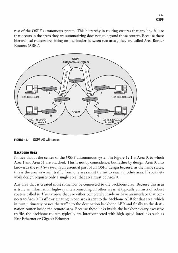
OSPF397
rest of the OSPF autonomous system. This hierarchy in routing ensures that any link failurethat occurs in the areas they are summarizing does not go beyond those routers. Because thesehierarchical routers are sitting on the border between two areas, they are called Area BorderRouters (ABRs).
OSPFAutonomous System
Area 0
Area 1 Area 51
A192.168.3.0/24 192.168.101.0/24
192.168.2.0/24 192.168.100.0/24
C E
GB
192.
168.
2.0/
23
192.168.100.0/23
F
D
FIGURE 12.1 OSPF AS with areas.
Backbone AreaNotice that at the center of the OSPF autonomous system in Figure 12.1 is Area 0, to whichArea 1 and Area 51 are attached. This is not by coincidence, but rather by design. Area 0, alsoknown as the backbone area, is an essential part of an OSPF design because, as the name states,this is the area in which traffic from one area must transit to reach another area. If your net-work design requires only a single area, that area must be Area 0.
Any area that is created must somehow be connected to the backbone area. Because this areais truly an information highway interconnecting all other areas, it typically consists of robustrouters called backbone routers that are either completely inside or have an interface that con-nects to Area 0. Traffic originating in one area is sent to the backbone ABR for that area, whichin turn ultimately passes the traffic to the destination backbone ABR and finally to the desti-nation router inside the remote area. Because these links inside the backbone carry excessivetraffic, the backbone routers typically are interconnected with high-speed interlinks such asFast Ethernet or Gigabit Ethernet.
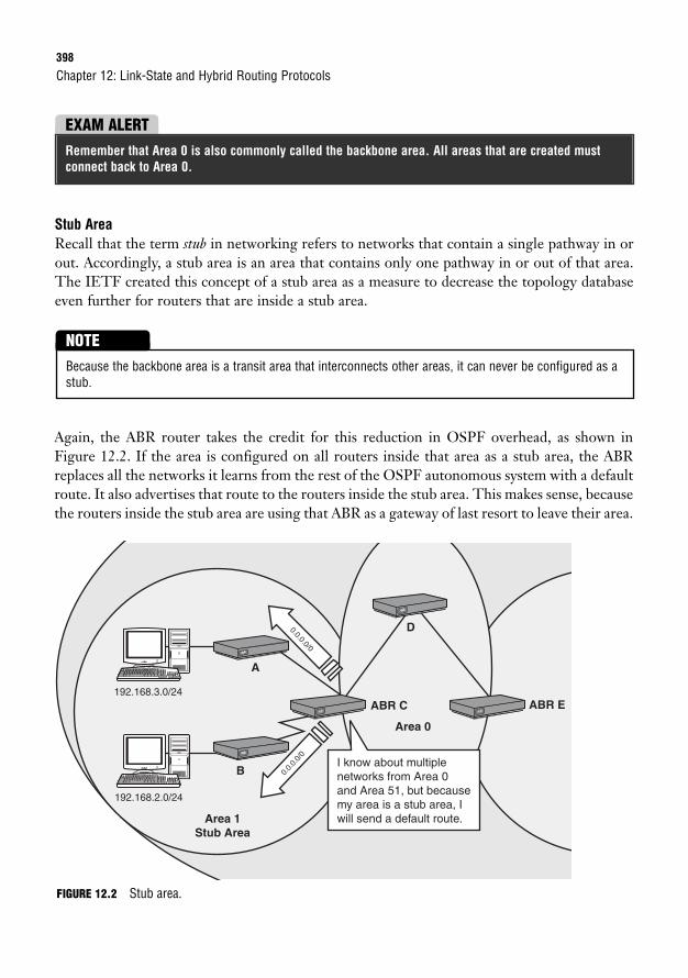
398
Stub AreaRecall that the term stub in networking refers to networks that contain a single pathway in orout. Accordingly, a stub area is an area that contains only one pathway in or out of that area.The IETF created this concept of a stub area as a measure to decrease the topology databaseeven further for routers that are inside a stub area.
Chapter 12: Link-State and Hybrid Routing Protocols
EXAM ALERTRemember that Area 0 is also commonly called the backbone area. All areas that are created mustconnect back to Area 0.
Because the backbone area is a transit area that interconnects other areas, it can never be configured as astub.
NOTE
Again, the ABR router takes the credit for this reduction in OSPF overhead, as shown inFigure 12.2. If the area is configured on all routers inside that area as a stub area, the ABRreplaces all the networks it learns from the rest of the OSPF autonomous system with a defaultroute. It also advertises that route to the routers inside the stub area. This makes sense, becausethe routers inside the stub area are using that ABR as a gateway of last resort to leave their area.
Area 0
Area 1 Stub Area
192.168.3.0/24
192.168.2.0/24
A
B
0.0.0.0/0
0.0.
0.0/
0
I know about multiple networks from Area 0 and Area 51, but because my area is a stub area, I will send a default route.
ABR C ABR E
D
FIGURE 12.2 Stub area.
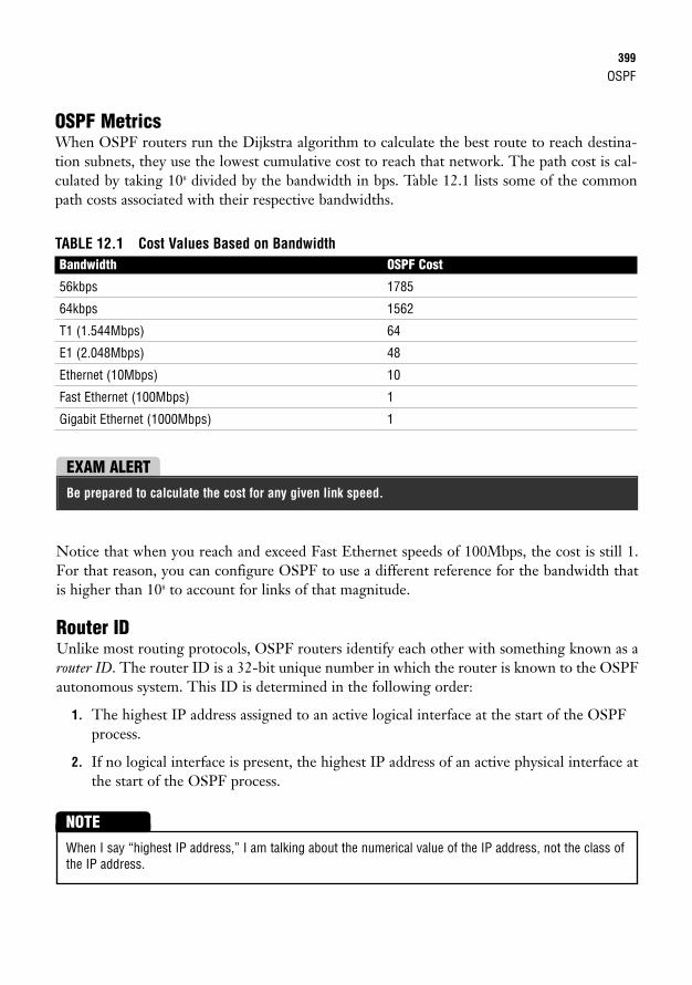
OSPF399
OSPF MetricsWhen OSPF routers run the Dijkstra algorithm to calculate the best route to reach destina-tion subnets, they use the lowest cumulative cost to reach that network. The path cost is cal-culated by taking 108 divided by the bandwidth in bps. Table 12.1 lists some of the commonpath costs associated with their respective bandwidths.
TABLE 12.1 Cost Values Based on BandwidthBandwidth OSPF Cost
56kbps 1785
64kbps 1562
T1 (1.544Mbps) 64
E1 (2.048Mbps) 48
Ethernet (10Mbps) 10
Fast Ethernet (100Mbps) 1
Gigabit Ethernet (1000Mbps) 1
EXAM ALERTBe prepared to calculate the cost for any given link speed.
Notice that when you reach and exceed Fast Ethernet speeds of 100Mbps, the cost is still 1.For that reason, you can configure OSPF to use a different reference for the bandwidth thatis higher than 108 to account for links of that magnitude.
Router IDUnlike most routing protocols, OSPF routers identify each other with something known as arouter ID. The router ID is a 32-bit unique number in which the router is known to the OSPFautonomous system. This ID is determined in the following order:
1. The highest IP address assigned to an active logical interface at the start of the OSPFprocess.
2. If no logical interface is present, the highest IP address of an active physical interface atthe start of the OSPF process.
When I say “highest IP address,” I am talking about the numerical value of the IP address, not the class ofthe IP address.
NOTE
400
Note that if there is a logical interface, the IP address overrides any physical IP address for therouter ID, even if it is a lower value. What do I mean by a logical interface? Cisco routers letyou create logical or virtual interfaces called loopback interfaces. The advantage of using thesevirtual interfaces is that, unlike physical interfaces, loopback interfaces cannot go down unlessthe router is malfunctioning or turned off.
Chapter 12: Link-State and Hybrid Routing Protocols
EXAM ALERTBe sure to know how to determine a router’s router ID based on the IP addresses of the router’s interfaces.
EXAM ALERTFor the exam, keep in mind that loopback interfaces are logical interfaces that cannot go down unlessthe router is malfunctioning or turned off.
OSPF TopologiesThe environment in which OSPF operates varies greatly depending on the type of topologyto which an OSPF interface is connected. Such operations as hello and dead timers, neighbordiscovery methods, and OSPF update overhead reduction ultimately are dictated by the OSPFinterface’s topology. Here are the three main types of topologies:
. Broadcast multiaccess: These topologies denote multiple devices accessing a mediumin which broadcasts and multicasts are heard by all devices sharing that medium (suchas Ethernet).
. Nonbroadcast multiaccess: NBMA topologies are similar to broadcast multiaccesstopologies (multiple devices accessing a medium), except that devices cannot hear eachothers’ broadcasts because the medium is separated by other routers, such as withFrame Relay.
. Point-to-point: A point-to-point link has only two devices on a shared network link.
To demonstrate the point, consider how OSPF timers operate in different topologies. Forinstance, in broadcast multiaccess and point-to-point links, the hello and dead intervals are 10and 40 seconds, respectively. Remember, these hello messages are not full routing updates likedistance vector routing protocols. The hello messages contain minimal information to identi-fy the sending device to other neighbor routers to ensure that their dead timers do not expireand cause a topology change.
Because NBMA network topologies such as Frame Relay typically comprise slower links, thedefault timers for these topologies are 30 seconds for hello messages and 120 seconds for thedead timer. The hello messages are not sent as often in NBMA topologies to ensure that OSPFrouters do not needlessly consume bandwidth on the WAN links.
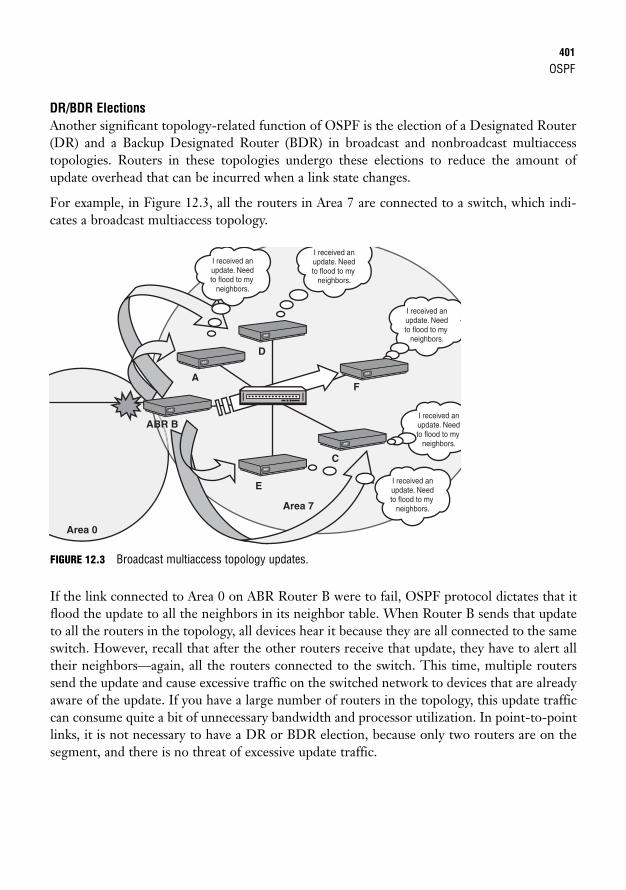
OSPF401
DR/BDR ElectionsAnother significant topology-related function of OSPF is the election of a Designated Router(DR) and a Backup Designated Router (BDR) in broadcast and nonbroadcast multiaccesstopologies. Routers in these topologies undergo these elections to reduce the amount ofupdate overhead that can be incurred when a link state changes.
For example, in Figure 12.3, all the routers in Area 7 are connected to a switch, which indi-cates a broadcast multiaccess topology.
Area 0
I received an update. Need to flood to my
neighbors.
I received an update. Need to flood to my
neighbors.
I received an update. Need to flood to my
neighbors.
I received an update. Need to flood to my
neighbors.
I received an update. Need to flood to my
neighbors.
F
ABR B
A
E
C
Area 7
D
FIGURE 12.3 Broadcast multiaccess topology updates.
If the link connected to Area 0 on ABR Router B were to fail, OSPF protocol dictates that itflood the update to all the neighbors in its neighbor table. When Router B sends that updateto all the routers in the topology, all devices hear it because they are all connected to the sameswitch. However, recall that after the other routers receive that update, they have to alert alltheir neighbors—again, all the routers connected to the switch. This time, multiple routerssend the update and cause excessive traffic on the switched network to devices that are alreadyaware of the update. If you have a large number of routers in the topology, this update trafficcan consume quite a bit of unnecessary bandwidth and processor utilization. In point-to-pointlinks, it is not necessary to have a DR or BDR election, because only two routers are on thesegment, and there is no threat of excessive update traffic.
402
When a DR and BDR are elected (in case the DR fails), routing updates are minimized,because the update is sent only to the DR and the BDR. The DR then is responsible for updat-ing the rest of the topology. The election is determined by the following:
1. Highest interface priority: An arbitrary number you can configure on an interface-by-interface basis. The default is 1. A value of 0 renders the device ineligible for DRand BDR election.
2. Highest router ID: In the event of a tie, the highest router ID is the tiebreaker.
Chapter 12: Link-State and Hybrid Routing Protocols
EXAM ALERTRemember that DRs and BDRs are elected only on broadcast and nonbroadcast multiaccess networks.
EXAM ALERTRemember that a 0 value for an interface priority makes it ineligible to become a DR or BDR for thatsegment.
Figure 12.4 shows the election process between several routers in a broadcast multiaccesstopology. Because Router D’s interface priority is highest, that router becomes the DR for thatsegment. Router F, with the second-highest priority, becomes the BDR if Router D is turnedoff or crashes. Now if a link fails, the update is sent to Router D, which in turn updates therest of the topology.
This election is based on the assumption that all devices start the OSPF process at the same time.Realistically, the first router that comes online is the DR, and the second is the BDR. If you need to setanother router as the DR, you must take the current DR and BDR offline or restart the OSPF process toforce the election.
TIP
EXAM ALERTBe able to determine which routers will be elected the DR and BDR on each segment (decided by thehighest interface priority, followed by the highest Router ID in the event of a tie). Also, keep in mindthat DR and BDR elections can vary on an interface-by-interface basis. In other words, a router may bea DR on one segment and a BDR or neither on another interface segment.
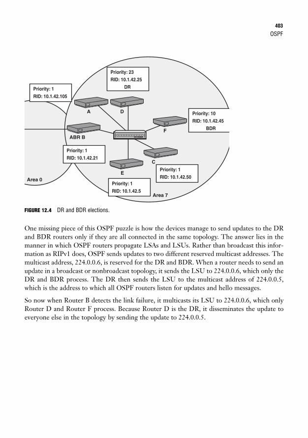
OSPF403
FIGURE 12.4 DR and BDR elections.
One missing piece of this OSPF puzzle is how the devices manage to send updates to the DRand BDR routers only if they are all connected in the same topology. The answer lies in themanner in which OSPF routers propagate LSAs and LSUs. Rather than broadcast this infor-mation as RIPv1 does, OSPF sends updates to two different reserved multicast addresses. Themulticast address, 224.0.0.6, is reserved for the DR and BDR. When a router needs to send anupdate in a broadcast or nonbroadcast topology, it sends the LSU to 224.0.0.6, which only theDR and BDR process. The DR then sends the LSU to the multicast address of 224.0.0.5,which is the address to which all OSPF routers listen for updates and hello messages.
So now when Router B detects the link failure, it multicasts its LSU to 224.0.0.6, which onlyRouter D and Router F process. Because Router D is the DR, it disseminates the update toeveryone else in the topology by sending the update to 224.0.0.5.
Area 0
Priority: 23
RID: 10.1.42.25
DR
Priority: 10
RID: 10.1.42.45
BDR
Priority: 1
RID: 10.1.42.50 Priority: 1
RID: 10.1.42.5
Priority: 1
RID: 10.1.42.21
Priority: 1
RID: 10.1.42.105
Area 7
DA
ABR BF
C
E
404
OSPF InitializationRecall that link-state routing protocols establish who the router’s neighbors are beforeexchanging updates. This process is actually quite intricate and depends on several factors. Toclarify, let’s look at what happens when an OSPF router comes online.
After the OSPF process is started in a router, it sends a hello message out all interfaces that areconfigured to participate in OSPF. The hello LSAs are sent to the multicast address of224.0.0.5 so that all devices running OSPF process it. Information contained in the hello mes-sages includes the following: router ID, hello/dead intervals, known neighbors, area ID, pri-ority, DR address, BDR address, authentication password (similar to RIPv2), and stub areaflags (if the area is configured as a stub area).
A router that receives this hello message adds that neighbor to its neighbor table only if thehello/dead intervals, area ID, authentication password, and stub flag match its configuration.If these values match, the router sends back a hello message, which includes the Router ID ofthe new router in the neighbor list. At that point, the original router adds that router to itsneighbor table. This process occurs until the router discovers all the neighbors on its links.
Chapter 12: Link-State and Hybrid Routing Protocols
EXAM ALERTRemember that the hello/dead intervals, authentication password, stub flag, and area ID must matchin the hello LSAs to form a neighbor relationship.
It is important to note that no update information has been exchanged at this point. If the topol-ogy has a DR elected (indicated in the hello messages it received), it synchronizes its topologytable with that router because the DR always has the most current information. If the topologyis a point-to-point connection, the two routers synchronize with the neighbor on the other sideof the link. After the topology tables are synchronized, it is said that the devices have formed anadjacency. Now that the router has all possible routes in the topology table, it can run theDijkstra algorithm to calculate the best routes to each subnet.
Introduction to Configuring OSPFOne of the first steps you should take when configuring OSPF is to configure loopback inter-faces to ensure that your Router ID matches the IP address of the loopback interface when theOSPF routing process is started. To create a virtual loopback interface, you configure it like anormal interface:Router(config)#interface loopback 0Router(config-if)#ip address 10.1.42.1 255.255.255.255
OSPF405
The interface number for the loopback interface is arbitrary because the interface is virtual.Also, notice that the subnet mask used in the loopback interface is 255.255.255.255 or a /32.This is known as a host mask. Typically it is used on loopback interfaces because there is noneed to use an entire subnet on a virtual interface that doesn’t connect to anything.
EXAM ALERTKeep in mind for the exam that loopback interfaces typically have a subnet mask of 255.255.255.255,known as a host mask.
To start the OSPF process for configuration, you use the router keyword followed by ospf,just as you have in the past with other routing protocols. In the case of OSPF, however, youmust specify a process ID after the router ospf keywords. The process ID is an arbitrarynumber ranging from 1 to 65535, in which the router can track whether you have multipleinstances of OSPF running in your router. Because this process ID is only known on the localrouter that you configure, the process ID does not need to match in all router configurations.
EXAM ALERTRemember that the process ID is a locally significant number between 1 and 65535 that is used totrack multiple instances of OSPF that might be running on the router. It does not have to match in allother router configurations.
Wildcard MasksBefore we go further with the explanation of the OSPF configuration, you need to understandthe means by which OSPF advertises the classless networks in the configuration. Because youno longer have the luxury of putting a classful subnet in the network statement, you need tohave some way of telling the router what specific IP subnets are to be applied to the OSPFrouting process. OSPF (as well as EIGRP and access lists) uses something called a wildcardmask to tell the IOS how much of an IP address should be applied to a criteria in a configura-tion statement. That criteria differs depending on which configuration statements the wildcardmask is using.
Wildcard masks are revisited with access lists in Chapter 19, “Using Cisco Access Lists.”
NOTE
In the case of OSPF, the wildcard mask is used to define what portion of the IP in a network state-ment is to be associated with the routing process. If the IP addresses assigned to interfaces matchthe scope of the addresses defined with the IP address and wildcard mask criteria in the networkentry, OSPF is enabled on those interfaces, and their subnets are advertised in routing updates.
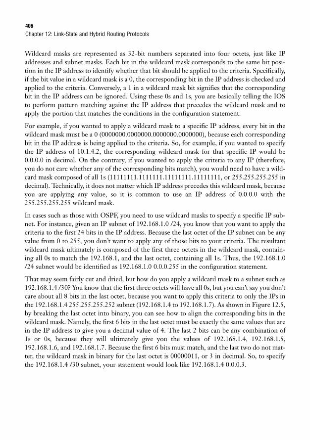
406
Wildcard masks are represented as 32-bit numbers separated into four octets, just like IPaddresses and subnet masks. Each bit in the wildcard mask corresponds to the same bit posi-tion in the IP address to identify whether that bit should be applied to the criteria. Specifically,if the bit value in a wildcard mask is a 0, the corresponding bit in the IP address is checked andapplied to the criteria. Conversely, a 1 in a wildcard mask bit signifies that the correspondingbit in the IP address can be ignored. Using these 0s and 1s, you are basically telling the IOSto perform pattern matching against the IP address that precedes the wildcard mask and toapply the portion that matches the conditions in the configuration statement.
For example, if you wanted to apply a wildcard mask to a specific IP address, every bit in thewildcard mask must be a 0 (0000000.0000000.0000000.0000000), because each correspondingbit in the IP address is being applied to the criteria. So, for example, if you wanted to specifythe IP address of 10.1.4.2, the corresponding wildcard mask for that specific IP would be0.0.0.0 in decimal. On the contrary, if you wanted to apply the criteria to any IP (therefore,you do not care whether any of the corresponding bits match), you would need to have a wild-card mask composed of all 1s (11111111.1111111.11111111.11111111, or 255.255.255.255 indecimal). Technically, it does not matter which IP address precedes this wildcard mask, becauseyou are applying any value, so it is common to use an IP address of 0.0.0.0 with the255.255.255.255 wildcard mask.
In cases such as those with OSPF, you need to use wildcard masks to specify a specific IP sub-net. For instance, given an IP subnet of 192.168.1.0 /24, you know that you want to apply thecriteria to the first 24 bits in the IP address. Because the last octet of the IP subnet can be anyvalue from 0 to 255, you don’t want to apply any of those bits to your criteria. The resultantwildcard mask ultimately is composed of the first three octets in the wildcard mask, contain-ing all 0s to match the 192.168.1, and the last octet, containing all 1s. Thus, the 192.168.1.0/24 subnet would be identified as 192.168.1.0 0.0.0.255 in the configuration statement.
That may seem fairly cut and dried, but how do you apply a wildcard mask to a subnet such as192.168.1.4 /30? You know that the first three octets will have all 0s, but you can’t say you don’tcare about all 8 bits in the last octet, because you want to apply this criteria to only the IPs inthe 192.168.1.4 255.255.255.252 subnet (192.168.1.4 to 192.168.1.7). As shown in Figure 12.5,by breaking the last octet into binary, you can see how to align the corresponding bits in thewildcard mask. Namely, the first 6 bits in the last octet must be exactly the same values that arein the IP address to give you a decimal value of 4. The last 2 bits can be any combination of1s or 0s, because they will ultimately give you the values of 192.168.1.4, 192.168.1.5,192.168.1.6, and 192.168.1.7. Because the first 6 bits must match, and the last two do not mat-ter, the wildcard mask in binary for the last octet is 00000011, or 3 in decimal. So, to specifythe 192.168.1.4 /30 subnet, your statement would look like 192.168.1.4 0.0.0.3.
Chapter 12: Link-State and Hybrid Routing Protocols
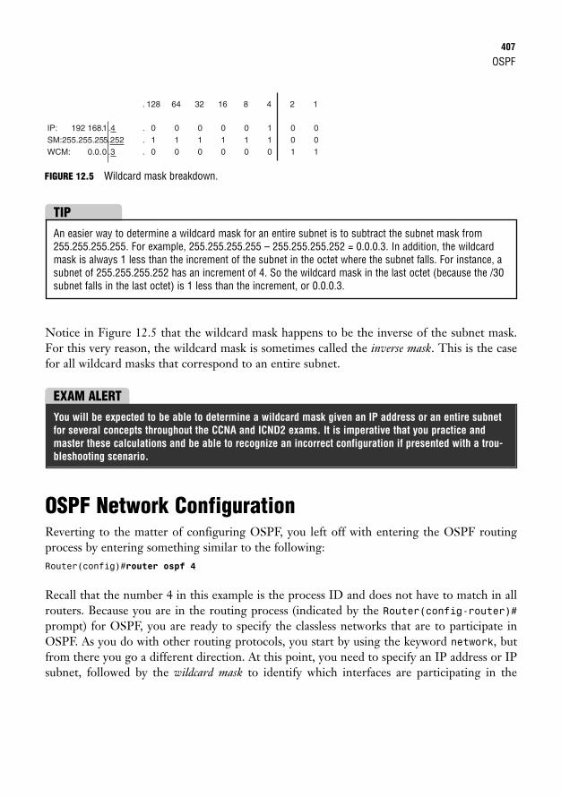
OSPF407
FIGURE 12.5 Wildcard mask breakdown.
IP: 192 168.1 .4SM:255.255.255.252WCM: 0.0.0 .3
. 128
. 0 . 1 . 0
64
0 1 0
32
0 1 0
16
0 1 0
8
0 1 0
4
1 1 0
2
0 0 1
1
0 0 1
An easier way to determine a wildcard mask for an entire subnet is to subtract the subnet mask from255.255.255.255. For example, 255.255.255.255 – 255.255.255.252 = 0.0.0.3. In addition, the wildcardmask is always 1 less than the increment of the subnet in the octet where the subnet falls. For instance, asubnet of 255.255.255.252 has an increment of 4. So the wildcard mask in the last octet (because the /30subnet falls in the last octet) is 1 less than the increment, or 0.0.0.3.
TIP
Notice in Figure 12.5 that the wildcard mask happens to be the inverse of the subnet mask.For this very reason, the wildcard mask is sometimes called the inverse mask. This is the casefor all wildcard masks that correspond to an entire subnet.
EXAM ALERTYou will be expected to be able to determine a wildcard mask given an IP address or an entire subnetfor several concepts throughout the CCNA and ICND2 exams. It is imperative that you practice andmaster these calculations and be able to recognize an incorrect configuration if presented with a trou-bleshooting scenario.
OSPF Network ConfigurationReverting to the matter of configuring OSPF, you left off with entering the OSPF routingprocess by entering something similar to the following:Router(config)#router ospf 4
Recall that the number 4 in this example is the process ID and does not have to match in allrouters. Because you are in the routing process (indicated by the Router(config-router)#prompt) for OSPF, you are ready to specify the classless networks that are to participate inOSPF. As you do with other routing protocols, you start by using the keyword network, butfrom there you go a different direction. At this point, you need to specify an IP address or IPsubnet, followed by the wildcard mask to identify which interfaces are participating in the
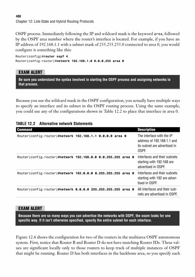
408
OSPF process. Immediately following the IP and wildcard mask is the keyword area, followedby the OSPF area number where the router’s interface is located. For example, if you have anIP address of 192.168.1.1 with a subnet mask of 255.255.255.0 connected to area 0, you wouldconfigure it something like this:Router(config)#router ospf 4Router(config-router)#network 192.168.1.0 0.0.0.255 area 0
Chapter 12: Link-State and Hybrid Routing Protocols
EXAM ALERTBe sure you understand the syntax involved in starting the OSPF process and assigning networks tothat process.
Because you use the wildcard mask in the OSPF configuration, you actually have multiple waysto specify an interface and its subnet in the OSPF routing process. Using the same example,you could use any of the configurations shown in Table 12.2 to place that interface in area 0.
TABLE 12.2 Alternative network StatementsCommand Description
Router(config-router)#network 192.168.1.1 0.0.0.0 area 0 The interface with the IPaddress of 192.168.1.1 andits subnet are advertised inOSPF.
Router(config-router)#network 192.168.0.0 0.0.255.255 area 0 Interfaces and their subnetsstarting with 192.168 areadvertised in OSPF.
Router(config-router)#network 192.0.0.0 0.255.255.255 area 0 Interfaces and their subnetsstarting with 192 are adver-tised in OSPF.
Router(config-router)#network 0.0.0.0 255.255.255.255 area 0 All interfaces and their sub-nets are advertised in OSPF.
EXAM ALERTBecause there are so many ways you can advertise the networks with OSPF, the exam looks for onespecific way. If it isn’t otherwise specified, specify the entire subnet for each interface.
Figure 12.6 shows the configuration for two of the routers in the multiarea OSPF autonomoussystem. First, notice that Router B and Router D do not have matching Router IDs. These val-ues are significant locally only to those routers to keep track of multiple instances of OSPFthat might be running. Router D has both interfaces in the backbone area, so you specify each
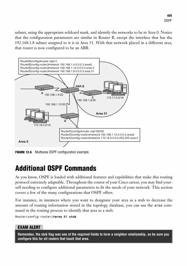
OSPF409
subnet, using the appropriate wildcard mask, and identify the networks to be in Area 0. Noticethat the configuration parameters are similar in Router B, except the interface that has the192.168.1.8 subnet assigned to it is in Area 51. With that network placed in a different area,that router is now configured to be an ABR.
172.18.0.0/16
192.168.1.8/30
192.168.1.4/30
192.168.1.12/30
172.17.0.0/16
RouterD(config)#router ospf 65535 RouterD(config-router)#network 192.168.1.12.0.0.0.3 area0 RouterD(config-router)#network 172.16.0.0.0.0.255.255 area 0
RouterB(config)#router ospf 2 RouterB(config-router)#network 192.168.1.4.0.0.0.3 area0 RouterB(config-router)#network 192.168.1.12.0.0.0.3 area 0 RouterB(config-router)#network 192.168.1.8.0.0.0.3 area 51
Area 51
Area 0
A
ABR B
D
C
FIGURE 12.6 Multiarea OSPF configuration example.
Additional OSPF CommandsAs you know, OSPF is loaded with additional features and capabilities that make this routingprotocol extremely adaptable. Throughout the course of your Cisco career, you may find your-self needing to configure additional parameters to fit the needs of your network. This sectioncovers a few of the many configurations that OSPF offers.
For instance, in instances where you want to designate your area as a stub to decrease theamount of routing information stored in the topology database, you can use the area com-mand in the routing process to identify that area as a stub:Router(config-router)#area 51 stub
EXAM ALERTRemember, the stub flag was one of the required fields to form a neighbor relationship, so be sure youconfigure this for all routers that touch that area.
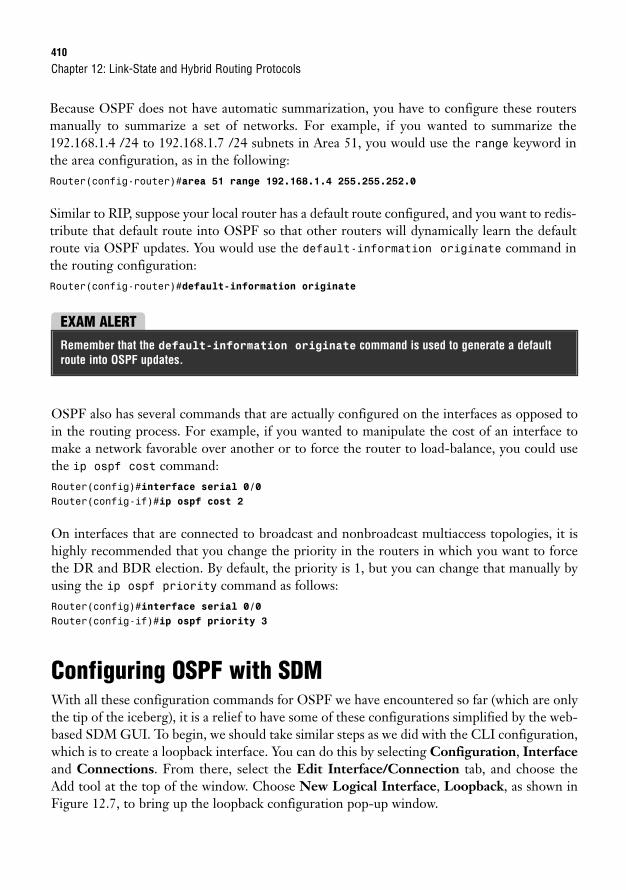
410
Because OSPF does not have automatic summarization, you have to configure these routersmanually to summarize a set of networks. For example, if you wanted to summarize the192.168.1.4 /24 to 192.168.1.7 /24 subnets in Area 51, you would use the range keyword inthe area configuration, as in the following:Router(config-router)#area 51 range 192.168.1.4 255.255.252.0
Similar to RIP, suppose your local router has a default route configured, and you want to redis-tribute that default route into OSPF so that other routers will dynamically learn the defaultroute via OSPF updates. You would use the default-information originate command inthe routing configuration:Router(config-router)#default-information originate
Chapter 12: Link-State and Hybrid Routing Protocols
EXAM ALERTRemember that the default-information originate command is used to generate a defaultroute into OSPF updates.
OSPF also has several commands that are actually configured on the interfaces as opposed toin the routing process. For example, if you wanted to manipulate the cost of an interface tomake a network favorable over another or to force the router to load-balance, you could usethe ip ospf cost command:Router(config)#interface serial 0/0Router(config-if)#ip ospf cost 2
On interfaces that are connected to broadcast and nonbroadcast multiaccess topologies, it ishighly recommended that you change the priority in the routers in which you want to forcethe DR and BDR election. By default, the priority is 1, but you can change that manually byusing the ip ospf priority command as follows:Router(config)#interface serial 0/0Router(config-if)#ip ospf priority 3
Configuring OSPF with SDMWith all these configuration commands for OSPF we have encountered so far (which are onlythe tip of the iceberg), it is a relief to have some of these configurations simplified by the web-based SDM GUI. To begin, we should take similar steps as we did with the CLI configuration,which is to create a loopback interface. You can do this by selecting Configuration, Interfaceand Connections. From there, select the Edit Interface/Connection tab, and choose theAdd tool at the top of the window. Choose New Logical Interface, Loopback, as shown inFigure 12.7, to bring up the loopback configuration pop-up window.
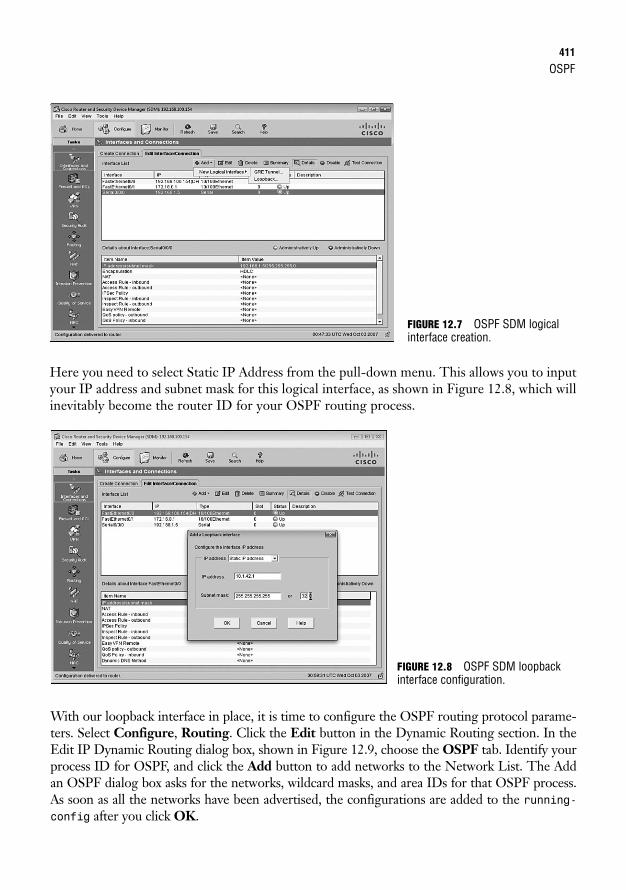
OSPF411
Here you need to select Static IP Address from the pull-down menu. This allows you to inputyour IP address and subnet mask for this logical interface, as shown in Figure 12.8, which willinevitably become the router ID for your OSPF routing process.
FIGURE 12.7 OSPF SDM logicalinterface creation.
With our loopback interface in place, it is time to configure the OSPF routing protocol parame-ters. Select Configure, Routing. Click the Edit button in the Dynamic Routing section. In theEdit IP Dynamic Routing dialog box, shown in Figure 12.9, choose the OSPF tab. Identify yourprocess ID for OSPF, and click the Add button to add networks to the Network List. The Addan OSPF dialog box asks for the networks, wildcard masks, and area IDs for that OSPF process.As soon as all the networks have been advertised, the configurations are added to the running-config after you click OK.
FIGURE 12.8 OSPF SDM loopbackinterface configuration.
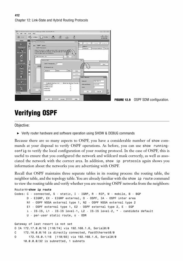
412
Verifying OSPF
Objective:
. Verify router hardware and software operation using SHOW & DEBUG commands
Because there are so many aspects to OSPF, you have a considerable number of show com-mands at your disposal to verify OSPF operations. As before, you can use show running-
config to verify the local configuration of your routing protocol. In the case of OSPF, this isuseful to ensure that you configured the network and wildcard mask correctly, as well as asso-ciated the network with the correct area. In addition, show ip protocols again shows youinformation about the networks you are advertising with OSPF.
Recall that OSPF maintains three separate tables in its routing process: the routing table, theneighbor table, and the topology table. You are already familiar with the show ip route commandto view the routing table and verify whether you are receiving OSPF networks from the neighbors:RouterA>show ip routeCodes: C - connected, S - static, I - IGRP, R - RIP, M - mobile, B - BGP
D - EIGRP, EX - EIGRP external, O - OSPF, IA - OSPF inter areaN1 - OSPF NSSA external type 1, N2 - OSPF NSSA external type 2E1 - OSPF external type 1, E2 - OSPF external type 2, E - EGPi - IS-IS, L1 - IS-IS level-1, L2 - IS-IS level-2, * - candidate defaultU - per-user static route, o - ODR
Gateway of last resort is not setO IA 172.17.0.0/16 [110/74] via 192.168.1.6, Serial0/0C 172.16.0.0/16 is directly connected, FastEthernet0/0O 172.18.0.1/16 [110/65] via 192.168.1.6, Serial0/0
10.0.0.0/32 is subnetted, 1 subnets
Chapter 12: Link-State and Hybrid Routing Protocols
FIGURE 12.9 OSPF SDM configuration.
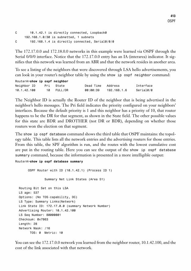
OSPF413
C 10.1.42.1 is directly connected, Loopback0192.168.1.0/30 is subnetted, 1 subnets
C 192.168.1.4 is directly connected, Serial0/0/0
The 172.17.0.0 and 172.18.0.0 networks in this example were learned via OSPF through theSerial 0/0/0 interface. Notice that the 172.17.0.0 entry has an IA (interarea) indicator. It sig-nifies that this network was learned from an ABR and that the network resides in another area.
To see a listing of the neighbors that were discovered through LSA hello advertisements, youcan look in your router’s neighbor table by using the show ip ospf neighbor command:RouterA>show ip ospf neighborNeighbor ID Pri State Dead Time Address Interface10.1.42.100 10 FULL/DR 00:00:39 192.168.1.6 Serial0/0
The Neighbor ID is actually the Router ID of the neighbor that is being advertised in theneighbor’s hello messages. The Pri field indicates the priority configured on your neighbors’interfaces. Because the default priority is 1 and this neighbor has a priority of 10, that routerhappens to be the DR for that segment, as shown in the State field. The other possible valuesfor this state are BDR and DROTHER (not DR or BDR), depending on whether thoserouters won the election on that segment.
The show ip ospf database command shows the third table that OSPF maintains: the topol-ogy table. This table lists all the network entries and the advertising routers for those entries.From this table, the SPF algorithm is run, and the routes with the lowest cumulative cost are put in the routing table. Here you can see the output of the show ip ospf database summary command, because the information is presented in a more intelligible output:RouterA>show ip ospf database summary
OSPF Router with ID (10.1.42.1) (Process ID 1)
Summary Net Link States (Area 51)
Routing Bit Set on this LSALS age: 537Options: (No TOS-capability, DC)LS Type: Summary Links(Network)Link State ID: 172.17.0.0 (summary Network Number)Advertising Router: 10.1.42.100LS Seq Number: 80000001Checksum: 0x7863Length: 28Network Mask: /16
TOS: 0 Metric: 10
You can see the 172.17.0.0 network you learned from the neighbor router, 10.1.42.100, and thecost of the link associated with that network.
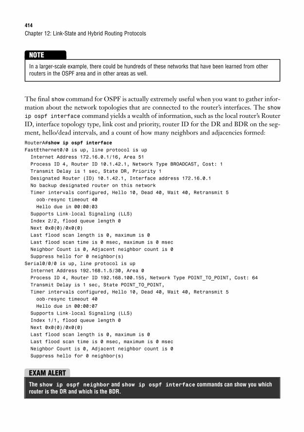
414
Chapter 12: Link-State and Hybrid Routing Protocols
In a larger-scale example, there could be hundreds of these networks that have been learned from otherrouters in the OSPF area and in other areas as well.
NOTE
The final show command for OSPF is actually extremely useful when you want to gather infor-mation about the network topologies that are connected to the router’s interfaces. The showip ospf interface command yields a wealth of information, such as the local router’s RouterID, interface topology type, link cost and priority, router ID for the DR and BDR on the seg-ment, hello/dead intervals, and a count of how many neighbors and adjacencies formed:RouterA#show ip ospf interfaceFastEthernet0/0 is up, line protocol is upInternet Address 172.16.0.1/16, Area 51Process ID 4, Router ID 10.1.42.1, Network Type BROADCAST, Cost: 1Transmit Delay is 1 sec, State DR, Priority 1Designated Router (ID) 10.1.42.1, Interface address 172.16.0.1No backup designated router on this networkTimer intervals configured, Hello 10, Dead 40, Wait 40, Retransmit 5oob-resync timeout 40Hello due in 00:00:03
Supports Link-local Signaling (LLS)Index 2/2, flood queue length 0Next 0x0(0)/0x0(0)Last flood scan length is 0, maximum is 0Last flood scan time is 0 msec, maximum is 0 msecNeighbor Count is 0, Adjacent neighbor count is 0Suppress hello for 0 neighbor(s)
Serial0/0/0 is up, line protocol is upInternet Address 192.168.1.5/30, Area 0Process ID 4, Router ID 192.168.100.155, Network Type POINT_TO_POINT, Cost: 64Transmit Delay is 1 sec, State POINT_TO_POINT,Timer intervals configured, Hello 10, Dead 40, Wait 40, Retransmit 5oob-resync timeout 40Hello due in 00:00:07
Supports Link-local Signaling (LLS)Index 1/1, flood queue length 0Next 0x0(0)/0x0(0)Last flood scan length is 0, maximum is 0Last flood scan time is 0 msec, maximum is 0 msecNeighbor Count is 0, Adjacent neighbor count is 0Suppress hello for 0 neighbor(s)
EXAM ALERTThe show ip ospf neighbor and show ip ospf interface commands can show you whichrouter is the DR and which is the BDR.
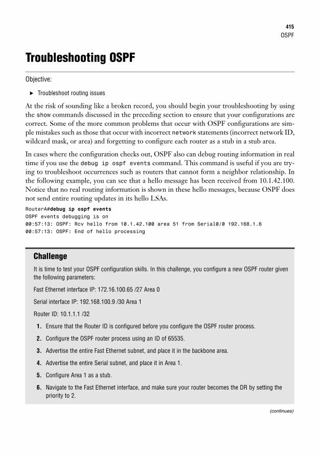
OSPF415
Troubleshooting OSPF
Objective:
. Troubleshoot routing issues
At the risk of sounding like a broken record, you should begin your troubleshooting by usingthe show commands discussed in the preceding section to ensure that your configurations arecorrect. Some of the more common problems that occur with OSPF configurations are sim-ple mistakes such as those that occur with incorrect network statements (incorrect network ID,wildcard mask, or area) and forgetting to configure each router as a stub in a stub area.
In cases where the configuration checks out, OSPF also can debug routing information in realtime if you use the debug ip ospf events command. This command is useful if you are try-ing to troubleshoot occurrences such as routers that cannot form a neighbor relationship. Inthe following example, you can see that a hello message has been received from 10.1.42.100.Notice that no real routing information is shown in these hello messages, because OSPF doesnot send entire routing updates in its hello LSAs.RouterA#debug ip ospf eventsOSPF events debugging is on00:57:13: OSPF: Rcv hello from 10.1.42.100 area 51 from Serial0/0 192.168.1.600:57:13: OSPF: End of hello processing
ChallengeIt is time to test your OSPF configuration skills. In this challenge, you configure a new OSPF router giventhe following parameters:
Fast Ethernet interface IP: 172.16.100.65 /27 Area 0
Serial interface IP: 192.168.100.9 /30 Area 1
Router ID: 10.1.1.1 /32
1. Ensure that the Router ID is configured before you configure the OSPF router process.
2. Configure the OSPF router process using an ID of 65535.
3. Advertise the entire Fast Ethernet subnet, and place it in the backbone area.
4. Advertise the entire Serial subnet, and place it in Area 1.
5. Configure Area 1 as a stub.
6. Navigate to the Fast Ethernet interface, and make sure your router becomes the DR by setting thepriority to 2.
(continues)
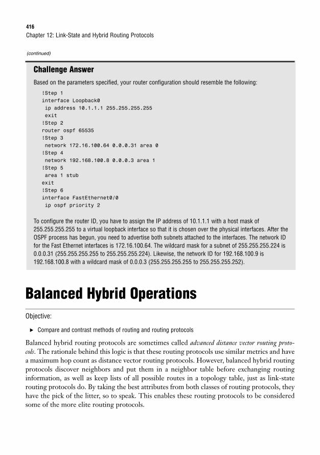
416
Chapter 12: Link-State and Hybrid Routing Protocols
Challenge AnswerBased on the parameters specified, your router configuration should resemble the following:
!Step 1interface Loopback0ip address 10.1.1.1 255.255.255.255exit!Step 2router ospf 65535!Step 3network 172.16.100.64 0.0.0.31 area 0!Step 4network 192.168.100.8 0.0.0.3 area 1!Step 5area 1 stubexit!Step 6interface FastEthernet0/0ip ospf priority 2
To configure the router ID, you have to assign the IP address of 10.1.1.1 with a host mask of255.255.255.255 to a virtual loopback interface so that it is chosen over the physical interfaces. After theOSPF process has begun, you need to advertise both subnets attached to the interfaces. The network IDfor the Fast Ethernet interfaces is 172.16.100.64. The wildcard mask for a subnet of 255.255.255.224 is0.0.0.31 (255.255.255.255 to 255.255.255.224). Likewise, the network ID for 192.168.100.9 is192.168.100.8 with a wildcard mask of 0.0.0.3 (255.255.255.255 to 255.255.255.252).
Balanced Hybrid OperationsObjective:
. Compare and contrast methods of routing and routing protocols
Balanced hybrid routing protocols are sometimes called advanced distance vector routing proto-cols. The rationale behind this logic is that these routing protocols use similar metrics and havea maximum hop count as distance vector routing protocols. However, balanced hybrid routingprotocols discover neighbors and put them in a neighbor table before exchanging routinginformation, as well as keep lists of all possible routes in a topology table, just as link-staterouting protocols do. By taking the best attributes from both classes of routing protocols, theyhave the pick of the litter, so to speak. This enables these routing protocols to be consideredsome of the more elite routing protocols.
(continued)
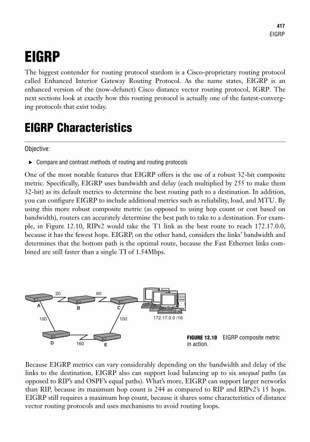
EIGRP417
EIGRPThe biggest contender for routing protocol stardom is a Cisco-proprietary routing protocolcalled Enhanced Interior Gateway Routing Protocol. As the name states, EIGRP is anenhanced version of the (now-defunct) Cisco distance vector routing protocol, IGRP. Thenext sections look at exactly how this routing protocol is actually one of the fastest-converg-ing protocols that exist today.
EIGRP Characteristics
Objective:
. Compare and contrast methods of routing and routing protocols
One of the most notable features that EIGRP offers is the use of a robust 32-bit compositemetric. Specifically, EIGRP uses bandwidth and delay (each multiplied by 255 to make them32-bit) as its default metrics to determine the best routing path to a destination. In addition,you can configure EIGRP to include additional metrics such as reliability, load, and MTU. Byusing this more robust composite metric (as opposed to using hop count or cost based onbandwidth), routers can accurately determine the best path to take to a destination. For exam-ple, in Figure 12.10, RIPv2 would take the T1 link as the best route to reach 172.17.0.0,because it has the fewest hops. EIGRP, on the other hand, considers the links’ bandwidth anddetermines that the bottom path is the optimal route, because the Fast Ethernet links com-bined are still faster than a single TI of 1.54Mbps.
172.17.0.0 /16
20
100 100
160
60
A
D E
B C
FIGURE 12.10 EIGRP composite metricin action.
Because EIGRP metrics can vary considerably depending on the bandwidth and delay of thelinks to the destination, EIGRP also can support load balancing up to six unequal paths (asopposed to RIP’s and OSPF’s equal paths). What’s more, EIGRP can support larger networksthan RIP, because its maximum hop count is 244 as compared to RIP and RIPv2’s 15 hops.EIGRP still requires a maximum hop count, because it shares some characteristics of distancevector routing protocols and uses mechanisms to avoid routing loops.
418
Because EIGRP is a true hybrid routing protocol, it has taken some of the best features of link-state routing protocols too. For instance, EIGRP discovers its neighbors and builds a topologytable by sending hello messages as a multicast to the reserved multicast address of 224.0.0.10.After the neighbors are discovered, they synchronize their topology databases and send hellomessages afterwards to keep their dead timers from expiring. The timers differ depending onthe topology, just as you saw with OSPF. Specifically, point-to-point and broadcast topologieshave a 5-second hello interval and 15-second dead timer, whereas nonbroadcast multiaccesstopologies such as Frame Relay have a 60-second hello interval and 180-second dead timer.
Cisco, however, did not stop there with the features of this balanced hybrid routing protocol.It developed a new routing algorithm called the Diffusing Update Algorithm (DUAL) thatensures a 100% loop-free routing environment that can converge in the face of a topologychange in a split second. EIGRP also can route not only IP, but also IPX and AppleTalk rout-ed protocols in your network if you have an older Novell or Macintosh environment.
Chapter 12: Link-State and Hybrid Routing Protocols
EXAM ALERTIt is important to remember that EIGRP can route IP, IPX, and AppleTalk routed protocols.
If you are routing IP, IPX, and AppleTalk with EIGRP, it keeps a routing, neighbor, and topology table foreach routed protocol. This means it has to maintain nine tables, which consumes a lot of memory andprocessor resources.
NOTE
Another additional useful characteristic of EIGRP is its capability to distinguish betweeninternally learned networks and networks that were redistributed into EIGRP. External net-works get tagged when being redistributed, so EIGRP knows not to trust those networks overnative EIGRP networks. EIGRP assigns the external networks an administrative distance (AD)of 170 and the internal networks an administrative distance of 90.
EXAM ALERTBe sure to remember that internal networks have an AD of 90 and that external networks have an AD of 170.
Last but not least, EIGRP is classful by default but can be configured to be classless, similar toRIPv2. By disabling automatic summarization, you can support VLSM designs and discon-tiguous networks, as well as manually summarize networks at any bit boundary you want.
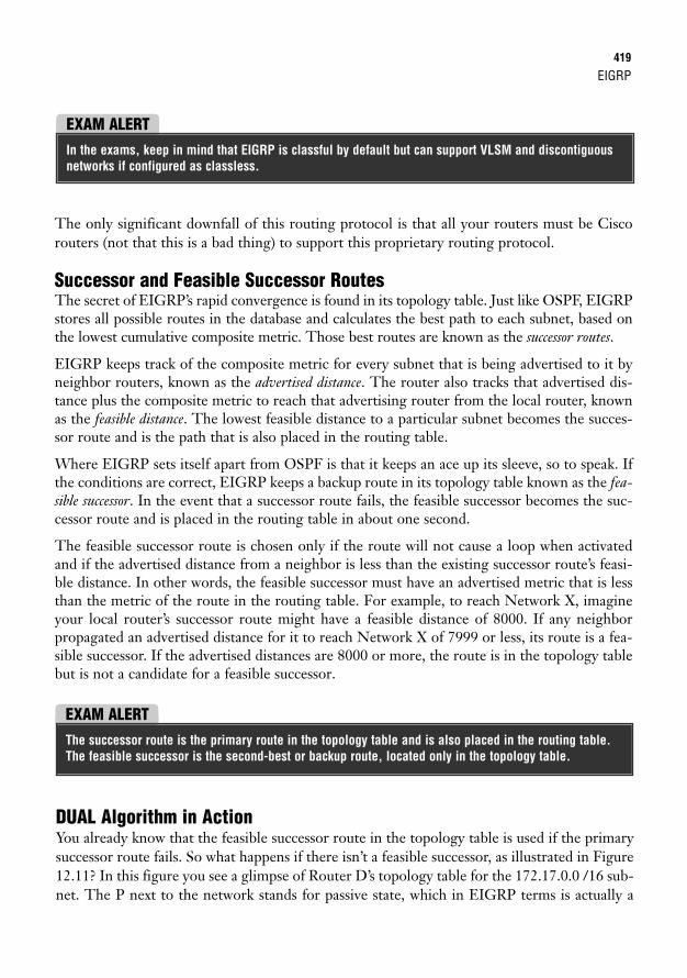
EIGRP419
The only significant downfall of this routing protocol is that all your routers must be Ciscorouters (not that this is a bad thing) to support this proprietary routing protocol.
Successor and Feasible Successor RoutesThe secret of EIGRP’s rapid convergence is found in its topology table. Just like OSPF, EIGRPstores all possible routes in the database and calculates the best path to each subnet, based onthe lowest cumulative composite metric. Those best routes are known as the successor routes.
EIGRP keeps track of the composite metric for every subnet that is being advertised to it byneighbor routers, known as the advertised distance. The router also tracks that advertised dis-tance plus the composite metric to reach that advertising router from the local router, knownas the feasible distance. The lowest feasible distance to a particular subnet becomes the succes-sor route and is the path that is also placed in the routing table.
Where EIGRP sets itself apart from OSPF is that it keeps an ace up its sleeve, so to speak. Ifthe conditions are correct, EIGRP keeps a backup route in its topology table known as the fea-sible successor. In the event that a successor route fails, the feasible successor becomes the suc-cessor route and is placed in the routing table in about one second.
The feasible successor route is chosen only if the route will not cause a loop when activatedand if the advertised distance from a neighbor is less than the existing successor route’s feasi-ble distance. In other words, the feasible successor must have an advertised metric that is lessthan the metric of the route in the routing table. For example, to reach Network X, imagineyour local router’s successor route might have a feasible distance of 8000. If any neighborpropagated an advertised distance for it to reach Network X of 7999 or less, its route is a fea-sible successor. If the advertised distances are 8000 or more, the route is in the topology tablebut is not a candidate for a feasible successor.
EXAM ALERTIn the exams, keep in mind that EIGRP is classful by default but can support VLSM and discontiguousnetworks if configured as classless.
EXAM ALERTThe successor route is the primary route in the topology table and is also placed in the routing table.The feasible successor is the second-best or backup route, located only in the topology table.
DUAL Algorithm in ActionYou already know that the feasible successor route in the topology table is used if the primarysuccessor route fails. So what happens if there isn’t a feasible successor, as illustrated in Figure12.11? In this figure you see a glimpse of Router D’s topology table for the 172.17.0.0 /16 sub-net. The P next to the network stands for passive state, which in EIGRP terms is actually a
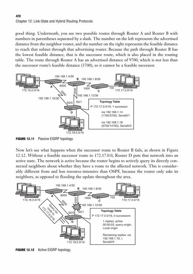
420
good thing. Underneath, you see two possible routes through Router A and Router B withnumbers in parentheses separated by a slash. The number on the left represents the advertiseddistance from the neighbor router, and the number on the right represents the feasible distanceto reach that subnet through that advertising router. Because the path through Router B hasthe lowest feasible distance, that is the successor route, which is also placed in the routingtable. The route through Router A has an advertised distance of 9700, which is not less thanthe successor route’s feasible distance (3700), so it cannot be a feasible successor.
Chapter 12: Link-State and Hybrid Routing Protocols
172.16.0.0/16
192.168.1.16/30192.168.1.12/30
192.168.1.4/30192.168.1.8/30
172.17.0.0/16
172.18.0.0/16
S0/1
1000 7008000
20005000
S0/0P 172.17.0.0/16, 1 successor
Topology Table
via 192.168.1.14(1700/3700), Serial0/1
via 192.168.1.18(9700/14700), Serial0/0
A
B
C
D
FIGURE 12.11 Passive EIGRP topology.
Now let’s see what happens when the successor route to Router B fails, as shown in Figure12.12. Without a feasible successor route to 172.17.0.0, Router D puts that network into anactive state. The network is active because the router begins to actively query its directly con-nected neighbors about whether they have a route to the affected network. This is consider-ably different from and less resource-intensive than OSPF, because the router only asks itsneighbors, as opposed to flooding the update throughout the area.
172.16.0.0/16
192.168.1.12/30
192.168.1.4/30192.168.1.8/30
172.17.0.0/16
172.18.0.0/16
S0/1
1000 7008000
5000
S0/0P 172.17.0.0/16, 0 successors
Topology Table
1 replies, active00:00:03, query-origin:Local origin
Remaining replies: via192.168.1.18, r,Serial0/0
2000
Query for
route to
172.17.0.0/16
A
B
C
D
FIGURE 12.12 Active EIGRP topology.
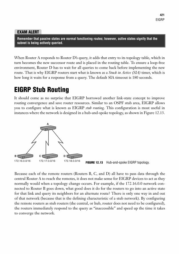
EIGRP421
When Router A responds to Router D’s query, it adds that entry to its topology table, which inturn becomes the new successor route and is placed in the routing table. To ensure a loop-freeenvironment, Router D has to wait for all queries to come back before implementing the newroute. That is why EIGRP routers start what is known as a Stuck in Active (SIA) timer, which ishow long it waits for a response from a query. The default SIA timeout is 180 seconds.
EIGRP Stub RoutingIt should come as no surprise that EIGRP borrowed another link-state concept to improverouting convergence and save router resources. Similar to an OSPF stub area, EIGRP allowsyou to configure what is known as EIGRP stub routing. This configuration is most useful ininstances where the network is designed in a hub-and-spoke topology, as shown in Figure 12.13.
EXAM ALERTRemember that passive states are normal functioning routes; however, active states signify that thesubnet is being actively queried.
172.16.0.0/16 172.17.0.0/16 172.18.0.0/16
B C
A
D
Because each of the remote routers (Routers B, C, and D) all have to pass data through thecentral Router A to reach the remotes, it does not make sense for EIGRP devices to act as theynormally would when a topology change occurs. For example, if the 172.16.0.0 network con-nected to Router B goes down, what good does it do for the routers to go into an active statefor that link and query its neighbors for an alternate route? There is only one way in and outof that network (because that is the defining characteristic of a stub network). By configuringthe remote routers as stub routers (the central, or hub, router does not need to be configured),the routers immediately respond to the query as “inaccessible” and speed up the time it takesto converge the network.
FIGURE 12.13 Hub-and-spoke EIGRP topology.
422
EIGRP Configuration
Objective:
. Configure, verify, and troubleshoot EIGRP
One of the greatest aspects of EIGRP is that you get all this advanced functionality with min-imal configuration effort. EIGRP essentially follows the same configuration guidelines asRIPv2. Namely, it must advertise the directly connected networks. Because EIGRP is alsoclassful by default, the networks configured must be at a default classful boundary. A key ele-ment that differs in the RIPv2 configuration is the inclusion of an AS number in the routingprocess configuration. This AS number is an arbitrary number between 1 and 65535 that youor your network administrator assigns to your network. It is imperative that you make thisnumber match in all your router configurations, or the routers will ignore the routing updates.
Chapter 12: Link-State and Hybrid Routing Protocols
EXAM ALERTDo not confuse the autonomous system number with OSPF’s process ID. Autonomous system numberswith EIGRP must match in every router that you configure, or the updates are ignored.
In the routing process, you use the network keyword followed by the directly connected class-ful networks, because EIGRP is classful by default. The following sample configurationdemonstrates adding the 172.16.0.0 and 10.0.0.0 networks to the EIGRP process forautonomous system 100:Router(config)#router eigrp 100Router(config-router)#network 172.16.0.0Router(config-router)#network 10.0.0.0
You can change EIGRP into a classless routing protocol by entering the no auto-summarycommand, just as you did with RIPv2. And to round out EIGRP’s hybrid configuration char-acteristics, you can also specify the wildcard mask after the network ID, as you did with OSPF,to indicate specific subnets such as this configuration:Router(config)#router eigrp 100Router(config-router)#no auto-summaryRouter(config-router)#network 172.16.30.0 0.0.0.255Router(config-router)#network 10.100.0.0 0.0.255.255
EIGRP423
After you configure the routing protocol to be classless, you can support VLSM, discontigu-ous networks, and route summarization at any bit level. With automatic summarization turnedoff, however, you must manually configure EIGRP route summaries. The command to do thisis ip summary-address eigrp, which is actually configured on the interface on which thesummarized route will be advertised:Router(config)#interface serial 0/0/0Router(config-if)#ip summary-address eigrp 192.168.4.0 255.255.254.0
The Bandwidth BandwagonBecause EIGRP uses bandwidth as one of its metrics to determine the best path to a destina-tion, it is imperative that the routers accurately depict the bandwidth that is currently on theirinterfaces. Because Fast Ethernet and Gigabit interfaces automatically define the bandwidth oftheir interfaces, you do not have to worry about any additional configurations on the LANinterfaces.
WAN interfaces, such as serial, asynchronous serial, and HSSI, can have varying speeds,depending on the WAN circuits to which they are connected. For instance, it is possible tohave a 64kbps link connected to one serial interface and T1 connected to another. By default,Cisco IOS software automatically assumes that any circuit connected to a serial interface is T1(1544kbps) speed, so how can you tell EIGRP about a link speed that is less than T1? Theanswer is by using the bandwidth interface command followed by the bandwidth in kbps, asdiscussed in Chapter 8, “Foundation Cisco Configurations.” By specifying the actual band-width on the interface, EIGRP incorporates that information in its metrics and can make accu-rate routing decisions based on the proper speeds of the links.
Unequal-Path Load BalancingOne of the outstanding features of EIGRP is its capability to load-balance up to six unequalpaths (four by default). To achieve this remarkable feat, you must configure a multiplier basedon the lowest composite metric to a destination. The command for this multiplier is variance,which is configured in the EIGRP routing process.
For instance, Figure 12.14 illustrates a simplified topology with the composite metrics to reach172.17.0.0. In its default state, EIGRP chooses the router through Router B because it has thelowest cumulative composite metric to reach the destination network. Because the paththrough B and C has a metric of 80, and the path through D and E has a metric of 110, youcan specify a variance of 2, which acts as a multiplier of the lowest metric (80 in this case). Theconfiguration for this would look like the following:RouterA(config)#router eigrp 100RouterA(config-router)#variance 2
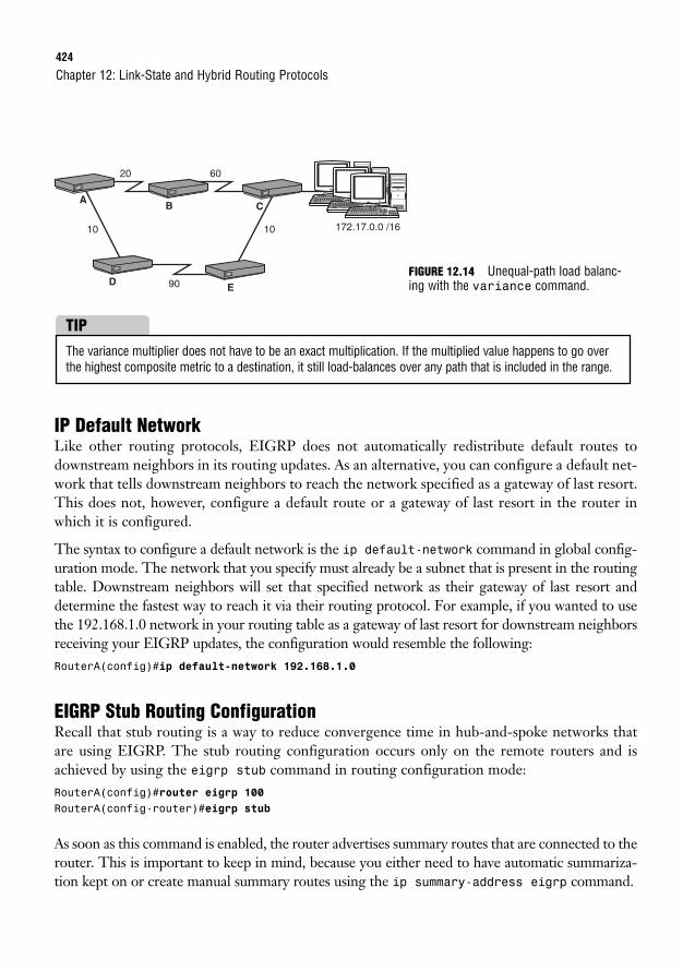
424
IP Default NetworkLike other routing protocols, EIGRP does not automatically redistribute default routes todownstream neighbors in its routing updates. As an alternative, you can configure a default net-work that tells downstream neighbors to reach the network specified as a gateway of last resort.This does not, however, configure a default route or a gateway of last resort in the router inwhich it is configured.
The syntax to configure a default network is the ip default-network command in global config-uration mode. The network that you specify must already be a subnet that is present in the routingtable. Downstream neighbors will set that specified network as their gateway of last resort anddetermine the fastest way to reach it via their routing protocol. For example, if you wanted to usethe 192.168.1.0 network in your routing table as a gateway of last resort for downstream neighborsreceiving your EIGRP updates, the configuration would resemble the following:RouterA(config)#ip default-network 192.168.1.0
EIGRP Stub Routing ConfigurationRecall that stub routing is a way to reduce convergence time in hub-and-spoke networks thatare using EIGRP. The stub routing configuration occurs only on the remote routers and isachieved by using the eigrp stub command in routing configuration mode:RouterA(config)#router eigrp 100RouterA(config-router)#eigrp stub
As soon as this command is enabled, the router advertises summary routes that are connected to therouter. This is important to keep in mind, because you either need to have automatic summariza-tion kept on or create manual summary routes using the ip summary-address eigrp command.
Chapter 12: Link-State and Hybrid Routing Protocols
172.17.0.0 /16
20
10 10
90
60
A
D E
B C
FIGURE 12.14 Unequal-path load balanc-ing with the variance command.
The variance multiplier does not have to be an exact multiplication. If the multiplied value happens to go overthe highest composite metric to a destination, it still load-balances over any path that is included in the range.
TIP
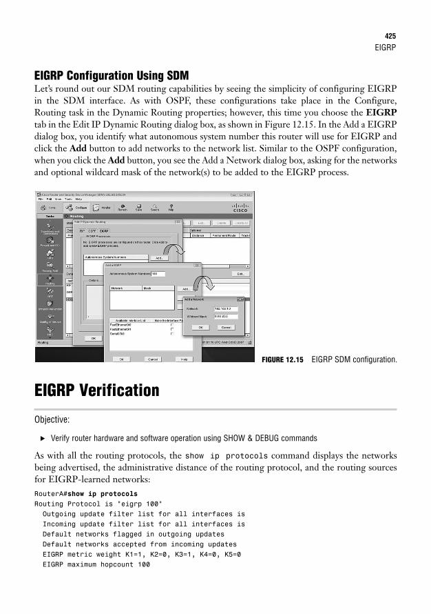
EIGRP425
EIGRP Configuration Using SDMLet’s round out our SDM routing capabilities by seeing the simplicity of configuring EIGRPin the SDM interface. As with OSPF, these configurations take place in the Configure,Routing task in the Dynamic Routing properties; however, this time you choose the EIGRPtab in the Edit IP Dynamic Routing dialog box, as shown in Figure 12.15. In the Add a EIGRPdialog box, you identify what autonomous system number this router will use for EIGRP andclick the Add button to add networks to the network list. Similar to the OSPF configuration,when you click the Add button, you see the Add a Network dialog box, asking for the networksand optional wildcard mask of the network(s) to be added to the EIGRP process.
EIGRP Verification
Objective:
. Verify router hardware and software operation using SHOW & DEBUG commands
As with all the routing protocols, the show ip protocols command displays the networksbeing advertised, the administrative distance of the routing protocol, and the routing sourcesfor EIGRP-learned networks:RouterA#show ip protocolsRouting Protocol is “eigrp 100”Outgoing update filter list for all interfaces isIncoming update filter list for all interfaces isDefault networks flagged in outgoing updatesDefault networks accepted from incoming updatesEIGRP metric weight K1=1, K2=0, K3=1, K4=0, K5=0EIGRP maximum hopcount 100
FIGURE 12.15 EIGRP SDM configuration.
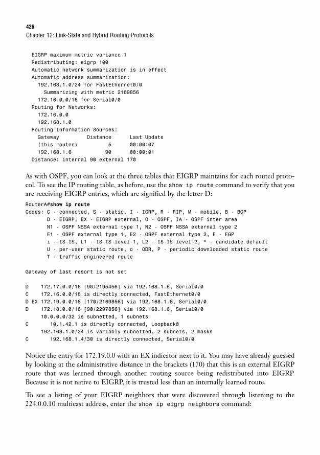
426
EIGRP maximum metric variance 1Redistributing: eigrp 100Automatic network summarization is in effectAutomatic address summarization:192.168.1.0/24 for FastEthernet0/0Summarizing with metric 2169856
172.16.0.0/16 for Serial0/0Routing for Networks:172.16.0.0192.168.1.0
Routing Information Sources:Gateway Distance Last Update(this router) 5 00:00:07192.168.1.6 90 00:00:01
Distance: internal 90 external 170
As with OSPF, you can look at the three tables that EIGRP maintains for each routed proto-col. To see the IP routing table, as before, use the show ip route command to verify that youare receiving EIGRP entries, which are signified by the letter D:RouterA#show ip routeCodes: C - connected, S - static, I - IGRP, R - RIP, M - mobile, B - BGP
D - EIGRP, EX - EIGRP external, O - OSPF, IA - OSPF inter areaN1 - OSPF NSSA external type 1, N2 - OSPF NSSA external type 2E1 - OSPF external type 1, E2 - OSPF external type 2, E - EGPi - IS-IS, L1 - IS-IS level-1, L2 - IS-IS level-2, * - candidate defaultU - per-user static route, o - ODR, P - periodic downloaded static routeT - traffic engineered route
Gateway of last resort is not set
D 172.17.0.0/16 [90/2195456] via 192.168.1.6, Serial0/0C 172.16.0.0/16 is directly connected, FastEthernet0/0D EX 172.19.0.0/16 [170/2169856] via 192.168.1.6, Serial0/0D 172.18.0.0/16 [90/2297856] via 192.168.1.6, Serial0/0
10.0.0.0/32 is subnetted, 1 subnetsC 10.1.42.1 is directly connected, Loopback0
192.168.1.0/24 is variably subnetted, 2 subnets, 2 masksC 192.168.1.4/30 is directly connected, Serial0/0
Notice the entry for 172.19.0.0 with an EX indicator next to it. You may have already guessedby looking at the administrative distance in the brackets (170) that this is an external EIGRProute that was learned through another routing source being redistributed into EIGRP.Because it is not native to EIGRP, it is trusted less than an internally learned route.
To see a listing of your EIGRP neighbors that were discovered through listening to the224.0.0.10 multicast address, enter the show ip eigrp neighbors command:
Chapter 12: Link-State and Hybrid Routing Protocols
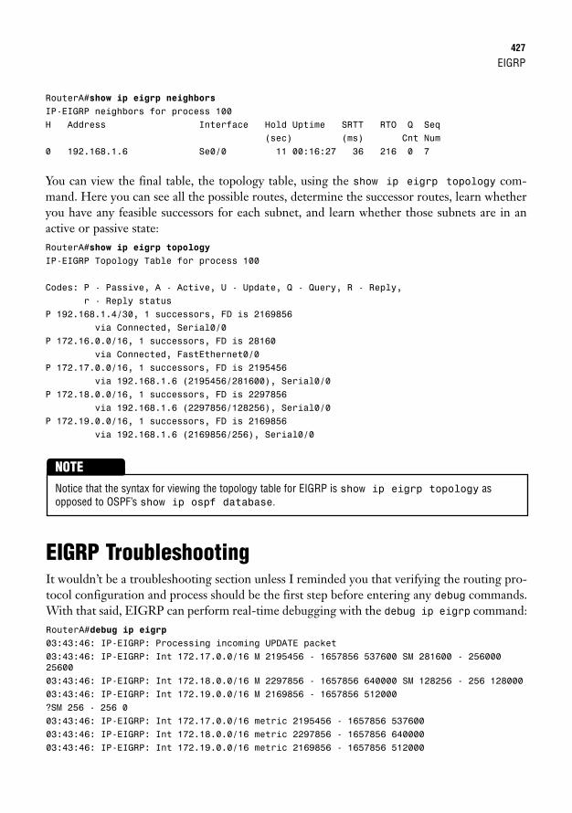
EIGRP427
RouterA#show ip eigrp neighborsIP-EIGRP neighbors for process 100H Address Interface Hold Uptime SRTT RTO Q Seq
(sec) (ms) Cnt Num0 192.168.1.6 Se0/0 11 00:16:27 36 216 0 7
You can view the final table, the topology table, using the show ip eigrp topology com-mand. Here you can see all the possible routes, determine the successor routes, learn whetheryou have any feasible successors for each subnet, and learn whether those subnets are in anactive or passive state:RouterA#show ip eigrp topologyIP-EIGRP Topology Table for process 100
Codes: P - Passive, A - Active, U - Update, Q - Query, R - Reply,r - Reply status
P 192.168.1.4/30, 1 successors, FD is 2169856via Connected, Serial0/0
P 172.16.0.0/16, 1 successors, FD is 28160via Connected, FastEthernet0/0
P 172.17.0.0/16, 1 successors, FD is 2195456via 192.168.1.6 (2195456/281600), Serial0/0
P 172.18.0.0/16, 1 successors, FD is 2297856via 192.168.1.6 (2297856/128256), Serial0/0
P 172.19.0.0/16, 1 successors, FD is 2169856via 192.168.1.6 (2169856/256), Serial0/0
Notice that the syntax for viewing the topology table for EIGRP is show ip eigrp topology asopposed to OSPF’s show ip ospf database.
NOTE
EIGRP TroubleshootingIt wouldn’t be a troubleshooting section unless I reminded you that verifying the routing pro-tocol configuration and process should be the first step before entering any debug commands.With that said, EIGRP can perform real-time debugging with the debug ip eigrp command:RouterA#debug ip eigrp03:43:46: IP-EIGRP: Processing incoming UPDATE packet03:43:46: IP-EIGRP: Int 172.17.0.0/16 M 2195456 - 1657856 537600 SM 281600 - 2560002560003:43:46: IP-EIGRP: Int 172.18.0.0/16 M 2297856 - 1657856 640000 SM 128256 - 256 12800003:43:46: IP-EIGRP: Int 172.19.0.0/16 M 2169856 - 1657856 512000?SM 256 - 256 003:43:46: IP-EIGRP: Int 172.17.0.0/16 metric 2195456 - 1657856 53760003:43:46: IP-EIGRP: Int 172.18.0.0/16 metric 2297856 - 1657856 64000003:43:46: IP-EIGRP: Int 172.19.0.0/16 metric 2169856 - 1657856 512000
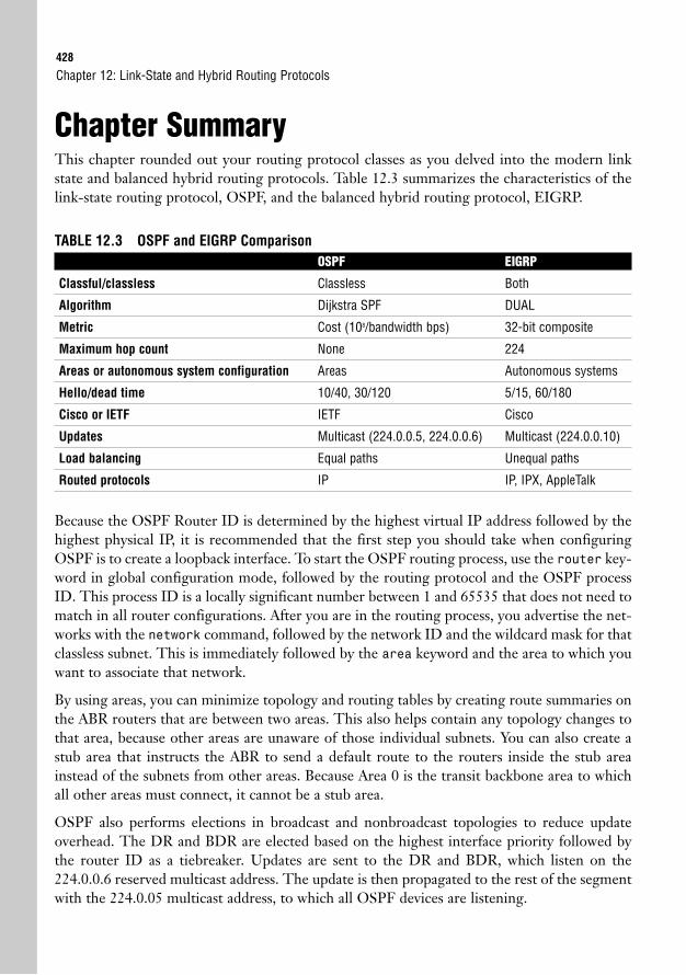
428
Chapter SummaryThis chapter rounded out your routing protocol classes as you delved into the modern linkstate and balanced hybrid routing protocols. Table 12.3 summarizes the characteristics of thelink-state routing protocol, OSPF, and the balanced hybrid routing protocol, EIGRP.
TABLE 12.3 OSPF and EIGRP ComparisonOSPF EIGRP
Classful/classless Classless Both
Algorithm Dijkstra SPF DUAL
Metric Cost (108/bandwidth bps) 32-bit composite
Maximum hop count None 224
Areas or autonomous system configuration Areas Autonomous systems
Hello/dead time 10/40, 30/120 5/15, 60/180
Cisco or IETF IETF Cisco
Updates Multicast (224.0.0.5, 224.0.0.6) Multicast (224.0.0.10)
Load balancing Equal paths Unequal paths
Routed protocols IP IP, IPX, AppleTalk
Because the OSPF Router ID is determined by the highest virtual IP address followed by thehighest physical IP, it is recommended that the first step you should take when configuringOSPF is to create a loopback interface. To start the OSPF routing process, use the router key-word in global configuration mode, followed by the routing protocol and the OSPF processID. This process ID is a locally significant number between 1 and 65535 that does not need tomatch in all router configurations. After you are in the routing process, you advertise the net-works with the network command, followed by the network ID and the wildcard mask for thatclassless subnet. This is immediately followed by the area keyword and the area to which youwant to associate that network.
By using areas, you can minimize topology and routing tables by creating route summaries onthe ABR routers that are between two areas. This also helps contain any topology changes tothat area, because other areas are unaware of those individual subnets. You can also create astub area that instructs the ABR to send a default route to the routers inside the stub areainstead of the subnets from other areas. Because Area 0 is the transit backbone area to whichall other areas must connect, it cannot be a stub area.
OSPF also performs elections in broadcast and nonbroadcast topologies to reduce updateoverhead. The DR and BDR are elected based on the highest interface priority followed bythe router ID as a tiebreaker. Updates are sent to the DR and BDR, which listen on the224.0.0.6 reserved multicast address. The update is then propagated to the rest of the segmentwith the 224.0.05 multicast address, to which all OSPF devices are listening.
Chapter 12: Link-State and Hybrid Routing Protocols
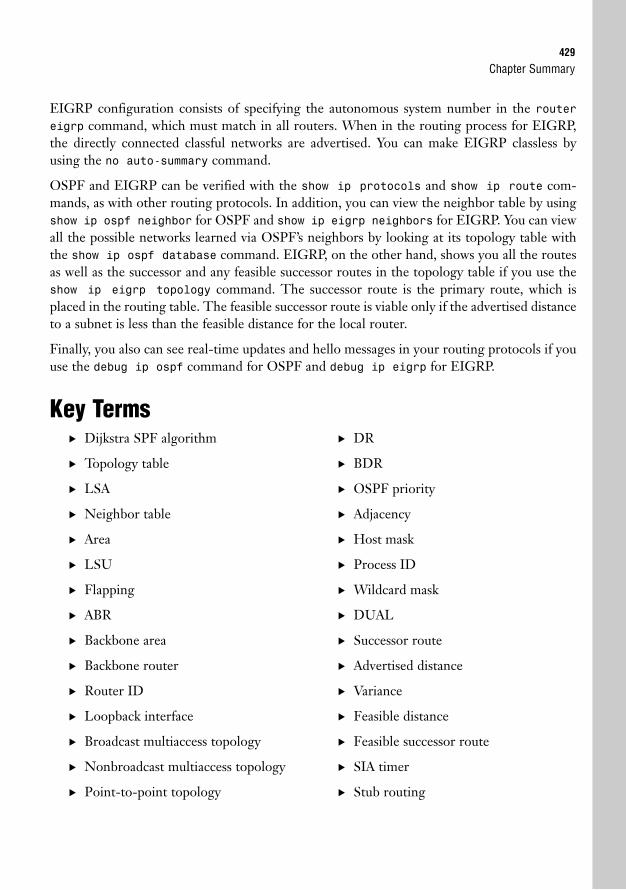
Chapter Summary429
EIGRP configuration consists of specifying the autonomous system number in the routereigrp command, which must match in all routers. When in the routing process for EIGRP,the directly connected classful networks are advertised. You can make EIGRP classless byusing the no auto-summary command.
OSPF and EIGRP can be verified with the show ip protocols and show ip route com-mands, as with other routing protocols. In addition, you can view the neighbor table by usingshow ip ospf neighbor for OSPF and show ip eigrp neighbors for EIGRP. You can viewall the possible networks learned via OSPF’s neighbors by looking at its topology table withthe show ip ospf database command. EIGRP, on the other hand, shows you all the routesas well as the successor and any feasible successor routes in the topology table if you use theshow ip eigrp topology command. The successor route is the primary route, which isplaced in the routing table. The feasible successor route is viable only if the advertised distanceto a subnet is less than the feasible distance for the local router.
Finally, you also can see real-time updates and hello messages in your routing protocols if youuse the debug ip ospf command for OSPF and debug ip eigrp for EIGRP.
Key Terms. Dijkstra SPF algorithm
. Topology table
. LSA
. Neighbor table
. Area
. LSU
. Flapping
. ABR
. Backbone area
. Backbone router
. Router ID
. Loopback interface
. Broadcast multiaccess topology
. Nonbroadcast multiaccess topology
. Point-to-point topology
. DR
. BDR
. OSPF priority
. Adjacency
. Host mask
. Process ID
. Wildcard mask
. DUAL
. Successor route
. Advertised distance
. Variance
. Feasible distance
. Feasible successor route
. SIA timer
. Stub routing
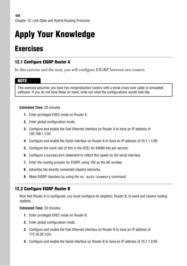
430
Apply Your Knowledge
Exercises
12.1 Configure EIGRP Router A
In this exercise and the next, you will configure EIGRP between two routers.
Chapter 12: Link-State and Hybrid Routing Protocols
This exercise assumes you have two nonproduction routers with a serial cross-over cable or simulatedsoftware. If you do not have these on hand, write out what the configurations would look like.
NOTE
Estimated Time: 20 minutes
1. Enter privileged EXEC mode on Router A.
2. Enter global configuration mode.
3. Configure and enable the Fast Ethernet interface on Router A to have an IP address of192.168.1.1/24.
4. Configure and enable the Serial interface on Router A to have an IP address of 10.1.1.1/30.
5. Configure the clock rate (if this is the DCE) for 64000 bits per second.
6. Configure a bandwidth statement to reflect this speed on the serial interface.
7. Enter the routing process for EIGRP, using 102 as the AS number.
8. Advertise the directly connected classful networks.
9. Make EIGRP classless by using the no auto-summary command.
12.2 Configure EIGRP Router B
Now that Router A is configured, you must configure its neighbor, Router B, to send and receive routingupdates.
Estimated Time: 20 minutes
1. Enter privileged EXEC mode on Router B.
2. Enter global configuration mode.
3. Configure and enable the Fast Ethernet interface on Router B to have an IP address of172.16.30.1/24.
4. Configure and enable the Serial interface on Router B to have an IP address of 10.1.1.2/30.
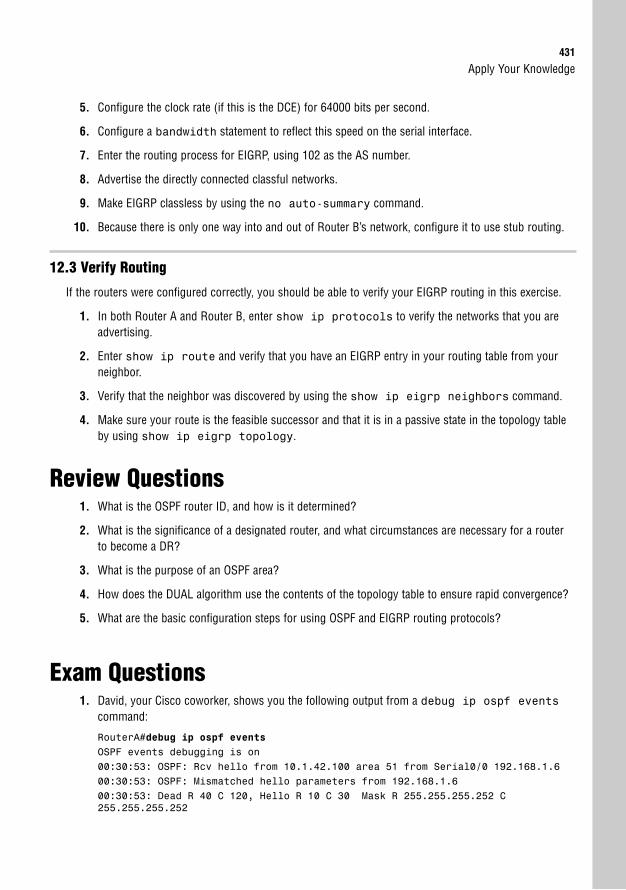
Apply Your Knowledge431
5. Configure the clock rate (if this is the DCE) for 64000 bits per second.
6. Configure a bandwidth statement to reflect this speed on the serial interface.
7. Enter the routing process for EIGRP, using 102 as the AS number.
8. Advertise the directly connected classful networks.
9. Make EIGRP classless by using the no auto-summary command.
10. Because there is only one way into and out of Router B’s network, configure it to use stub routing.
12.3 Verify Routing
If the routers were configured correctly, you should be able to verify your EIGRP routing in this exercise.
1. In both Router A and Router B, enter show ip protocols to verify the networks that you areadvertising.
2. Enter show ip route and verify that you have an EIGRP entry in your routing table from yourneighbor.
3. Verify that the neighbor was discovered by using the show ip eigrp neighbors command.
4. Make sure your route is the feasible successor and that it is in a passive state in the topology tableby using show ip eigrp topology.
Review Questions1. What is the OSPF router ID, and how is it determined?
2. What is the significance of a designated router, and what circumstances are necessary for a routerto become a DR?
3. What is the purpose of an OSPF area?
4. How does the DUAL algorithm use the contents of the topology table to ensure rapid convergence?
5. What are the basic configuration steps for using OSPF and EIGRP routing protocols?
Exam Questions1. David, your Cisco coworker, shows you the following output from a debug ip ospf events
command:
RouterA#debug ip ospf eventsOSPF events debugging is on00:30:53: OSPF: Rcv hello from 10.1.42.100 area 51 from Serial0/0 192.168.1.600:30:53: OSPF: Mismatched hello parameters from 192.168.1.600:30:53: Dead R 40 C 120, Hello R 10 C 30 Mask R 255.255.255.252 C255.255.255.252
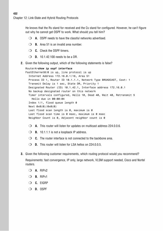
432
He knows that the Rs stand for received and the Cs stand for configured. However, he can’t figureout why he cannot get OSPF to work. What should you tell him?
❍ A. OSPF needs to have the classful networks advertised.
❍ B. Area 51 is an invalid area number.
❍ C. Check the OSPF timers.
❍ D. 10.1.42.100 needs to be a DR.
2. Given the following output, which of the following statements is false?
RouterA>show ip ospf interfaceFastEthernet0/0 is up, line protocol is upInternet Address 172.16.0.1/16, Area 51Process ID 1, Router ID 10.1.1.1, Network Type BROADCAST, Cost: 1Transmit Delay is 1 sec, State DR, Priority 1Designated Router (ID) 10.1.42.1, Interface address 172.16.0.1No backup designated router on this networkTimer intervals configured, Hello 10, Dead 40, Wait 40, Retransmit 5Hello due in 00:00:04
Index 1/1, flood queue length 0Next 0x0(0)/0x0(0)Last flood scan length is 0, maximum is 0Last flood scan time is 0 msec, maximum is 0 msecNeighbor Count is 0, Adjacent neighbor count is 0
❍ A. This router will listen for updates on multicast address 224.0.0.6.
❍ B. 10.1.1.1 is not a loopback IP address.
❍ C. The router interface is not connected to the backbone area.
❍ D. This router will listen for LSA hellos on 224.0.0.5.
3. Given the following customer requirements, which routing protocol would you recommend?
Requirements: fast convergence, IP only, large network, VLSM support needed, Cisco and Nortelrouters.
❍ A. RIPv2
❍ B. RIPv1
❍ C. EIGRP
❍ D. OSPF
Chapter 12: Link-State and Hybrid Routing Protocols
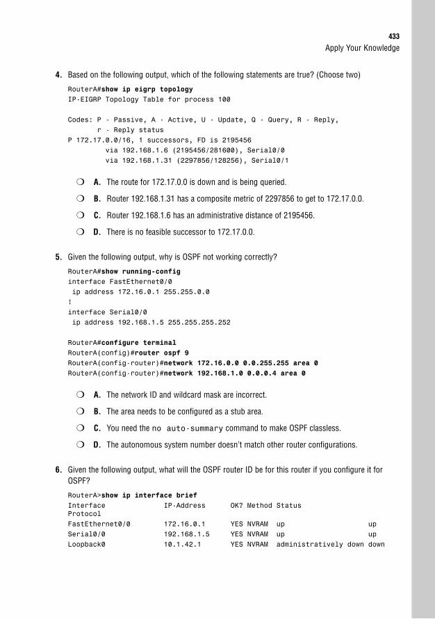
Apply Your Knowledge433
4. Based on the following output, which of the following statements are true? (Choose two)
RouterA#show ip eigrp topologyIP-EIGRP Topology Table for process 100
Codes: P - Passive, A - Active, U - Update, Q - Query, R - Reply,r - Reply status
P 172.17.0.0/16, 1 successors, FD is 2195456via 192.168.1.6 (2195456/281600), Serial0/0via 192.168.1.31 (2297856/128256), Serial0/1
❍ A. The route for 172.17.0.0 is down and is being queried.
❍ B. Router 192.168.1.31 has a composite metric of 2297856 to get to 172.17.0.0.
❍ C. Router 192.168.1.6 has an administrative distance of 2195456.
❍ D. There is no feasible successor to 172.17.0.0.
5. Given the following output, why is OSPF not working correctly?
RouterA#show running-configinterface FastEthernet0/0ip address 172.16.0.1 255.255.0.0!interface Serial0/0ip address 192.168.1.5 255.255.255.252
RouterA#configure terminalRouterA(config)#router ospf 9RouterA(config-router)#network 172.16.0.0 0.0.255.255 area 0RouterA(config-router)#network 192.168.1.0 0.0.0.4 area 0
❍ A. The network ID and wildcard mask are incorrect.
❍ B. The area needs to be configured as a stub area.
❍ C. You need the no auto-summary command to make OSPF classless.
❍ D. The autonomous system number doesn’t match other router configurations.
6. Given the following output, what will the OSPF router ID be for this router if you configure it forOSPF?
RouterA>show ip interface briefInterface IP-Address OK? Method StatusProtocolFastEthernet0/0 172.16.0.1 YES NVRAM up upSerial0/0 192.168.1.5 YES NVRAM up upLoopback0 10.1.42.1 YES NVRAM administratively down down
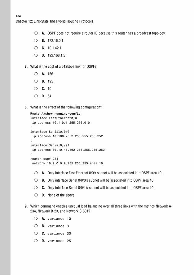
434
❍ A. OSPF does not require a router ID because this router has a broadcast topology.
❍ B. 172.16.0.1
❍ C. 10.1.42.1
❍ D. 192.168.1.5
7. What is the cost of a 512kbps link for OSPF?
❍ A. 156
❍ B. 195
❍ C. 10
❍ D. 64
8. What is the effect of the following configuration?
RouterA#show running-configinterface FastEthernet0/0ip address 10.1.0.1 255.255.0.0!interface Serial0/0/0ip address 10.100.25.2 255.255.255.252!interface Serial0//01ip address 10.10.45.102 255.255.255.252!router ospf 234network 10.0.0.0 0.255.255.255 area 10
❍ A. Only interface Fast Ethernet 0/0’s subnet will be associated into OSPF area 10.
❍ B. Only interface Serial 0/0/0’s subnet will be associated into OSPF area 10.
❍ C. Only interface Serial 0/0/1’s subnet will be associated into OSPF area 10.
❍ D. None of the above
9. Which command enables unequal load balancing over all three links with the metrics Network A-234, Network B-23, and Network C-601?
❍ A. variance 10
❍ B. variance 3
❍ C. variance 30
❍ D. variance 25
Chapter 12: Link-State and Hybrid Routing Protocols
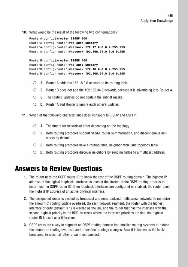
Apply Your Knowledge435
10. What would be the result of the following two configurations?
RouterA(config)#router EIGRP 200RouterA(config-router)#no auto-summaryRouterA(config-router)#network 172.17.0.0 0.0.255.255RouterA(config-router)#network 192.168.34.0 0.0.0.255
RouterB(config)#router EIGRP 100RouterB(config-router)#no auto-summaryRouterB(config-router)#network 172.18.0.0 0.0.255.255RouterB(config-router)#network 192.168.34.0 0.0.0.255
❍ A. Router A adds the 172.18.0.0 network to its routing table.
❍ B. Router B does not add the 192.168.34.0 network, because it is advertising it to Router A.
❍ C. The routing updates do not contain the subnet masks.
❍ D. Router A and Router B ignore each other’s updates.
11. Which of the following characteristics does not apply to EIGRP and OSPF?
❍ A. The timers for hello/dead differ depending on the topology.
❍ B. Both routing protocols support VLSM, router summarization, and discontiguous net-works by default.
❍ C. Both routing protocols have a routing table, neighbor table, and topology table.
❍ D. Both routing protocols discover neighbors by sending hellos to a multicast address.
Answers to Review Questions1. The router uses the OSPF router ID to know the rest of the OSPF routing domain. The highest IP
address of the logical loopback interfaces is used at the startup of the OSPF routing process todetermine the OSPF router ID. If no loopback interfaces are configured or enabled, the router usesthe highest IP address of an active physical interface.
2. The designated router is elected by broadcast and nonbroadcast multiaccess networks to minimizethe amount of routing update overhead. On each network segment, the router with the highestinterface priority (default is 1) is elected as the DR, and the router that has the interface with thesecond-highest priority is the BDR. In cases where the interface priorities are tied, the highestrouter ID is used as a tiebreaker.
3. OSPF areas are a way to segment an OSPF routing domain into smaller routing systems to reducethe amount of routing overhead and to confine topology changes. Area 0 is known as the back-bone area, to which all other areas must connect.
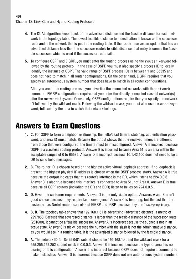
436
4. The DUAL algorithm keeps track of the advertised distance and the feasible distance for each net-work in the topology table. The lowest feasible distance to a destination is known as the successorroute and is the network that is put in the routing table. If the router receives an update that has anadvertised distance less than the successor route’s feasible distance, that entry becomes the feasi-ble successor, which is used if the successor route fails.
5. To configure OSPF and EIGRP, you must enter the routing process using the router keyword fol-lowed by the routing protocol. In the case of OSPF, you must also specify a process ID to locallyidentify the instance of OSPF. The valid range of OSPF process IDs is between 1 and 65535 anddoes not need to match in all router configurations. On the other hand, EIGRP requires that youspecify an autonomous system number that does have to match in all router configurations.
After you are in the routing process, you advertise the connected networks with the networkcommand. EIGRP configurations require that you enter the directly connected classful network(s)after the network keyword. Conversely, OSPF configurations require that you specify the networkID followed by the wildcard mask. Following the wildcard mask, you must also use the area key-word, followed by the area to which that network belongs.
Answers to Exam Questions1. C. For OSPF to form a neighbor relationship, the hello/dead timers, stub flag, authentication pass-
word, and area ID must match. Because the output shows that the received timers are differentfrom those that were configured, the timers must be misconfigured. Answer A is incorrect becauseOSPF is a classless routing protocol. Answer B is incorrect because Area 51 is an area within theacceptable ranges of 0 to 65535. Answer D is incorrect because 10.1.42.100 does not need to be aDR to send hello messages.
2. B. The router ID is chosen based on the highest active virtual loopback address. If no loopback ispresent, the highest physical IP address is chosen when the OSPF process starts. Answer A is truebecause the output indicates that this router’s interface is the DR, which listens to 224.0.0.6.Answer C is also true because this interface is connected to Area 51, not Area 0. Answer D is truebecause all OSPF routers (including the DR and BDR) listen to hellos on 224.0.0.5.
3. D. Given the customer requirements, Answer D is the only viable option. Answers A and B aren’tgood choices because they require fast convergence. Answer C is tempting, but the fact that thecustomer has Nortel routers cancels out EIGRP and IGRP, because they are Cisco-proprietary.
4. B, D. The topology table shows that 192.168.1.31 is advertising (advertised distance) a metric of2297856. Because that advertised distance is larger than the feasible distance of the successor route(281600), it cannot be a feasible successor. Answer A is incorrect because the subnet is not in anactive state. Answer C is tricky, because the number with the slash is not the administrative distance,as you would see in a routing table. It is the advertised distance followed by the feasible distance.
5. A. The network ID for Serial 0/0’s subnet should be 192.168.1.4, and the wildcard mask for a255.255.255.252 subnet mask is 0.0.0.3. Answer B is incorrect because the type of area has nobearing on this configuration. Answer C is incorrect because OSPF does not require a command tomake it classless. Answer D is incorrect because OSPF does not use autonomous system numbers.
Chapter 12: Link-State and Hybrid Routing Protocols
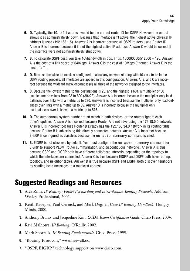
Apply Your Knowledge437
6. D. Typically, the 10.1.42.1 address would be the correct router ID for OSPF. However, the outputshows it as administratively down. Because that interface isn’t active, the highest active physical IPaddress is used (192.168.1.5). Answer A is incorrect because all OSPF routers use a Router ID.Answer B is incorrect because it is not the highest active IP address. Answer C would be correct ifthe interface were not administratively shut down.
7. B. To calculate OSPF cost, you take 108/bandwidth in bps. Thus, 100000000/512000 = 195. AnswerA is the cost of a link speed of 640kbps. Answer C is the cost of 10Mbps Ethernet. Answer D is thecost of a T1.
8. D. Because the wildcard mask is configured to allow any network starting with 10.x.x.x to be in theOSPF routing process, all interfaces are applied in this configuration. Answers A, B, and C are incor-rect because the wildcard mask encompasses all three of the networks assigned to the interfaces.
9. C. Because the lowest metric to the destinations is 23, and the highest is 601, a multiplier of 30enables metric values from 23 to 690 (30×23). Answer A is incorrect because the multiplier only load-balances over links with a metric up to 230. Answer B is incorrect because the multiplier only load-bal-ances over links with a metric up to 69. Answer D is incorrect because the multiplier onlyload-balances over links with a metric up to 575.
10. D. The autonomous system number must match in both devices, or the routers ignore eachother’s updates. Answer A is incorrect because Router A is not advertising the 172.18.0.0 network.Answer B is incorrect because Router B already has the 192.168.34.0 network in its routing tablebecause Router B is advertising this directly connected network. Answer C is incorrect becauseEIGRP is configured as classless because the no auto-summary command is used.
11. B. EIGRP is not classless by default. You must configure the no auto-summary command forEIGRP to support VLSM, router summarization, and discontiguous networks. Answer A is truebecause OSPF and EIGRP both have different hello/dead intervals, depending on the topology towhich the interfaces are connected. Answer C is true because EIGRP and OSPF both have routing,topology, and neighbor tables. Answer D is true because OSPF and EIGRP both discover neighborsby sending hello messages to a multicast address.
Suggested Readings and Resources1. Alex Zinn. IP Routing: Packet Forwarding and Intra-domain Routing Protocols. Addison
Wesley Professional, 2002.
2. Keith Kruepke, Paul Cernick, and Mark Degner. Cisco IP Routing Handbook. HungryMinds, 2000.
3. Anthony Bruno and Jacqueline Kim. CCDA Exam Certification Guide. Cisco Press, 2004.
4. Ravi Malhotra. IP Routing. O’Reilly, 2002.
5. Mark Sportack. IP Routing Fundamentals. Cisco Press, 1999.
6. “Routing Protocols,” www.firewall.cx.
7. “OSPF, EIGRP,” technology support on www.cisco.com.

This page intentionally left blank
13C H A P T E R T H I R T E E N
Foundation SwitchingOperations
ObjectivesThis chapter covers the following Cisco-specific objectives for the “Configure, verify and trou-bleshoot a switch with VLANs and interswitch communications” and “Implement a smallswitched network”:
. Explain basic switching concepts and the operation of Cisco switches
. Perform and verify initial switch configuration tasks including remote accessmanagement
. Verify network status and switch operation using basic utilities (including:ping, traceroute, telnet, SSH, arp, ipconfig), SHOW & DEBUG commands
. Identify, prescribe, and resolve common switched network media issues,configuration issues, auto negotiation, and switch hardware failures
. Interpret the output of various show and debug commands to verify the operational status of a Cisco switched network
Introduction 442
Switching Functionality 442
Frame Transmission Methods 443
Store-and-Forward 444
Cut-Through 444
Fragment-Free 444
Half- and Full-Duplex Connections 445
Switching Design 446
Spanning Tree Protocol 446
Root Bridge 447
Root Ports 448
Designated Ports 450
Blocked Ports 451
Port State Transitions 453
Initial Switch Configurations 454
Assigning a Management IP Address to a Switch 455
Defining a Default Gateway 455
IP Assignment Using DHCP 456
Configuring Multiple Switch Interfaces 457
Configuring and Verifying Spanning Tree Protocol 458
Changing Priority and Port Cost 458
Verifying Spanning Tree Protocol 459
Troubleshooting Basic Switch Connectivity 460
Chapter Summary 462
Key Terms 462
Apply Your Knowledge 463
Exercises 463
Review Questions 466
Exam Questions 466
Answers to Review Questions 470
Answers to Exam Questions 470
Suggested Readings and Resources 471
Outline

Study Strategies. Read the information presented in the chapter, paying special attention to tables, Notes,
and Exam Alerts.
. One of the best practices when reading about switching functions is to visualize the infor-mation contained in the Ethernet frames and imagine how a switch uses that informationto build its forwarding table and forward frames to other network segments.
. Complete the Challenge and the Exercises at the end of the chapter. They will solidify theconcepts that you have learned in the previous sections.
. After you have read about and understood Spanning Tree Protocol, try to draw your ownLAN design and determine the STP elections and port roles that will result from yourdesign.
. Complete the Exam Questions at the end of the chapter. They are designed to simulate thetypes of questions you will be asked on the CCNA and ICND1 exams.
442
IntroductionYou have already learned in Chapter 3, “Data Link Networking Concepts,” that you can usebridges and switches to segment a LAN into smaller collision domains. This chapter looks inclose detail at the operations of bridges and switches. Specifically, you will investigate the trans-parent functionality that occurs when a switch is building and utilizing its frame forwarding logic,as well as the peculiar nature of Spanning Tree Protocol (STP) in redundant switched networks.
Switching Functionality
Objective:
. Explain basic switching concepts and the operation of Cisco switches
Switches forward frames based on the Layer 2 Ethernet MAC addresses. These devices receiveEthernet frames transmitted from other devices and dynamically build a MAC address tablebased on the source MAC address inside those frames. This MAC address table is commonlyreferred to as a Content Addressable Memory (CAM) table.
These dynamic entries in the CAM table are not permanent, however. After the switch orbridge stops receiving frames from a certain MAC address (this varies, but it’s typically fiveminutes), the entry is removed from the CAM table to save memory and processor resources.The exceptions to this are static MAC entries that have been manually configured on a port-by-port basis for security and control purposes.
When deciding to which port to forward the Ethernet frame, a switch consults this CAM tableand forwards the Ethernet frame based on the destination MAC address of the Ethernet head-er. In instances where the destination MAC address is not in the table, it copies and forwardsthe frame out every port except the one at which it was received. This action is commonlyknown as flooding.
Chapter 13: Foundation Switching Operations
EXAM ALERTIt is important to remember that switches build their MAC address tables using the source address inan Ethernet frame header. In addition, they base their forwarding decisions on the destination MACaddress in an Ethernet frame header.
Recall that switches segment LANs into collision domains; however, they still are in a singlebroadcast domain. Switches do not have entries for broadcast addresses (FFFF.FFFF.FFFF) ormulticast addresses (0100.5E00.000-0100.5E7F.FFFF) in their CAM tables. As previouslymentioned, when a bridge or a switch receives a frame with a destination MAC address not inits table, it floods that frame out every port.
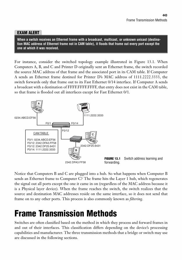
Frame Transmission Methods443
For instance, consider the switched topology example illustrated in Figure 13.1. WhenComputers A, B, and C and Printer D originally sent an Ethernet frame, the switch recordedthe source MAC address of that frame and the associated port in its CAM table. If ComputerA sends an Ethernet frame destined for Printer D’s MAC address of 1111.2222.3333, theswitch forwards only that frame out to its Fast Ethernet 0/14 interface. If Computer A sendsa broadcast with a destination of FFFF.FFFF.FFFF, that entry does not exist in the CAM table,so that frame is flooded out all interfaces except for Fast Ethernet 0/1.
EXAM ALERTWhen a switch receives an Ethernet frame with a broadcast, multicast, or unknown unicast (destina-tion MAC address of Ethernet frame not in CAM table), it floods that frame out every port except theone at which it was received.
F0/1 F0/14
F0/12
0234.ABCD.EF561111.2222.3333
2342.DF25.6431
2342.DFA3.FF58
CAM TABLE
F0/1: 0234.ABCD.EF56F0/12: 2342.DFA3.FF58F0/12: 2342.DF25.6431F0/14: 1111.2222.3333
6
A
C
B
Notice that Computers B and C are plugged into a hub. So what happens when Computer Bsends an Ethernet frame to Computer C? The frame hits the Layer 1 hub, which regeneratesthe signal out all ports except the one it came in on (regardless of the MAC address because itis a Physical layer device). When the frame reaches the switch, the switch realizes that thesource and destination MAC addresses reside on the same interface, so it does not send thatframe on to any other ports. This process is also commonly known as filtering.
Frame Transmission MethodsSwitches are often classified based on the method in which they process and forward frames inand out of their interfaces. This classification differs depending on the device’s processingcapabilities and manufacturer. The three transmission methods that a bridge or switch may useare discussed in the following sections.
FIGURE 13.1 Switch address learning andforwarding.
444
Store-and-ForwardProperly named, the store-and-forward method of frame transmission involves the switch,which buffers (stores temporarily in a small memory location) the entire Ethernet frame andperforms a cyclic redundancy check (CRC) of that frame to make sure it is not a corruptedframe (damaged or abnormally changed in the frame’s transmission). If the frame calculationdetects a bad frame, it is dropped at that point. Thus, the frame is forwarded only if the CRCcalculation results in a normal frame.
Because the entire frame is checked, store-and-forward switching is said to be latency (delay)varying. In other words, depending on the payload inside the frame, the switch takes varyingprocessing times to buffer the entire frame and perform the CRC before sending it to its des-tination. Although this method sounds like a lengthy process, this is the most widely usedmethod of switching in Cisco Catalyst switches because the hardware processors for the inter-faces are so advanced and robust that the switch hardly works up a sweat.
Cut-ThroughCut-through transmissions are practically the antithesis of store-and-forward frame transmis-sion. In fact, instead of processing the entire frame, cut-through switching entails the switchbuffering just enough information to know where to forward the frame before sending it on toanother segment. In other words, it looks only up to the destination MAC address in theEthernet header and sends it on regardless of whether the frame contains errors.
This hot-potato method of frame transmission was once appealing for devices with low pro-cessing power. Because it has to inspect only the beginning of an Ethernet frame header, laten-cy is not a factor with this method. The downside of cut-through switching, however, is thatit still passes bad frames on to other segments because it does not perform CRC calculationsof any kind.
Fragment-FreeIn a true Goldilocks fashion, if cut-through is too hot and store-and-forward is too cold, frag-ment-free may be just right for you. Fragment-free is a hybrid of the two transmission meth-ods because it buffers up to the first 64 bytes of a frame (all collisions occur within the first 64bytes). This obviously is not as fast as cut-through; nevertheless, it ensures that many of theinvalid frames in the LAN are not transmitted on to other segments. Figure 13.2 illustrateshow much of an Ethernet frame is buffered and processed with each of the three transmissionmethods discussed.
Chapter 13: Foundation Switching Operations
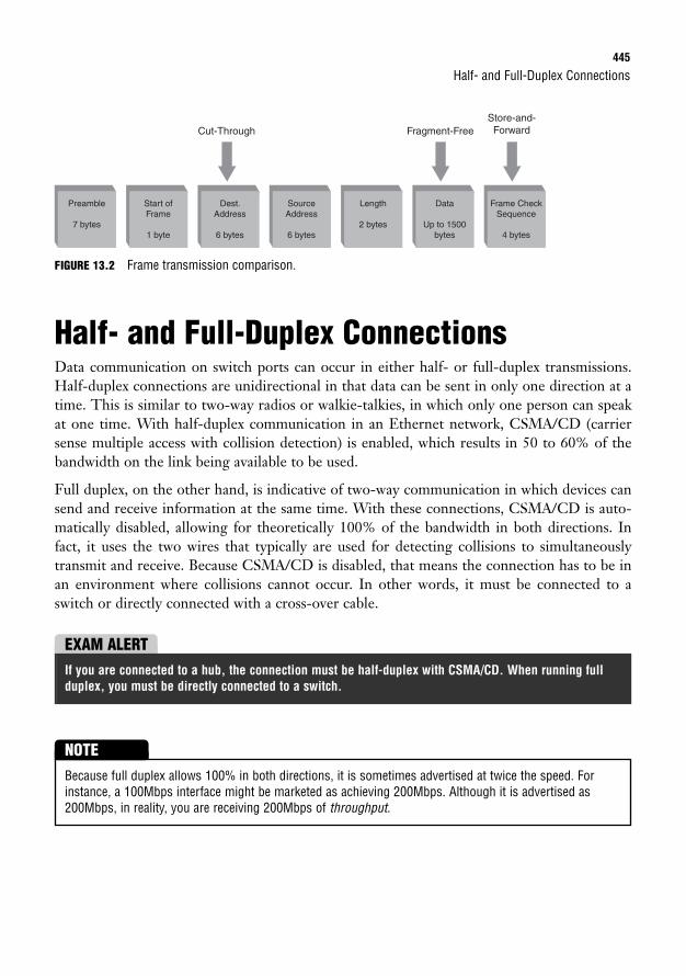
Half- and Full-Duplex Connections445
FIGURE 13.2 Frame transmission comparison.
Half- and Full-Duplex ConnectionsData communication on switch ports can occur in either half- or full-duplex transmissions.Half-duplex connections are unidirectional in that data can be sent in only one direction at atime. This is similar to two-way radios or walkie-talkies, in which only one person can speakat one time. With half-duplex communication in an Ethernet network, CSMA/CD (carriersense multiple access with collision detection) is enabled, which results in 50 to 60% of thebandwidth on the link being available to be used.
Full duplex, on the other hand, is indicative of two-way communication in which devices cansend and receive information at the same time. With these connections, CSMA/CD is auto-matically disabled, allowing for theoretically 100% of the bandwidth in both directions. Infact, it uses the two wires that typically are used for detecting collisions to simultaneouslytransmit and receive. Because CSMA/CD is disabled, that means the connection has to be inan environment where collisions cannot occur. In other words, it must be connected to aswitch or directly connected with a cross-over cable.
Preamble
7 bytes
Start ofFrame
1 byte
Dest.Address
6 bytes
Cut-Through Fragment-FreeStore-and-Forward
SourceAddress
6 bytes
Length
2 bytes
Data
Up to 1500bytes
Frame CheckSequence
4 bytes
EXAM ALERTIf you are connected to a hub, the connection must be half-duplex with CSMA/CD. When running fullduplex, you must be directly connected to a switch.
Because full duplex allows 100% in both directions, it is sometimes advertised at twice the speed. Forinstance, a 100Mbps interface might be marketed as achieving 200Mbps. Although it is advertised as200Mbps, in reality, you are receiving 200Mbps of throughput.
NOTE
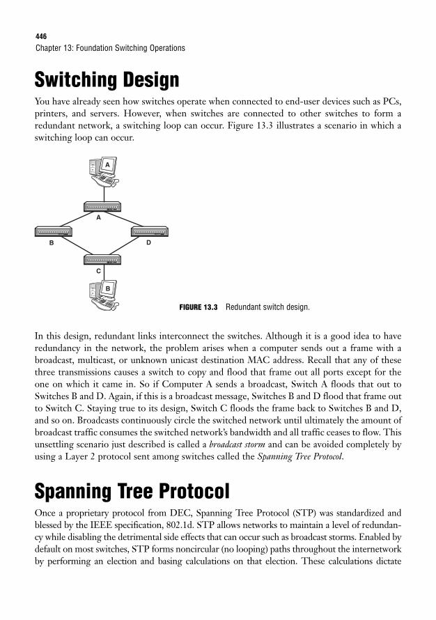
446
Switching DesignYou have already seen how switches operate when connected to end-user devices such as PCs,printers, and servers. However, when switches are connected to other switches to form aredundant network, a switching loop can occur. Figure 13.3 illustrates a scenario in which aswitching loop can occur.
Chapter 13: Foundation Switching Operations
C
A
B D
B
A
FIGURE 13.3 Redundant switch design.
In this design, redundant links interconnect the switches. Although it is a good idea to haveredundancy in the network, the problem arises when a computer sends out a frame with abroadcast, multicast, or unknown unicast destination MAC address. Recall that any of thesethree transmissions causes a switch to copy and flood that frame out all ports except for theone on which it came in. So if Computer A sends a broadcast, Switch A floods that out toSwitches B and D. Again, if this is a broadcast message, Switches B and D flood that frame outto Switch C. Staying true to its design, Switch C floods the frame back to Switches B and D,and so on. Broadcasts continuously circle the switched network until ultimately the amount ofbroadcast traffic consumes the switched network’s bandwidth and all traffic ceases to flow. Thisunsettling scenario just described is called a broadcast storm and can be avoided completely byusing a Layer 2 protocol sent among switches called the Spanning Tree Protocol.
Spanning Tree ProtocolOnce a proprietary protocol from DEC, Spanning Tree Protocol (STP) was standardized andblessed by the IEEE specification, 802.1d. STP allows networks to maintain a level of redundan-cy while disabling the detrimental side effects that can occur such as broadcast storms. Enabled bydefault on most switches, STP forms noncircular (no looping) paths throughout the internetworkby performing an election and basing calculations on that election. These calculations dictate
Spanning Tree Protocol447
which ports should remain in a nonforwarding (known as blocking) state to eliminate redundantloops that can cause broadcast storms. STP also can react to changes in the switched network toensure that the redundant links may be used in the event of a topology change such as a link goingdown. The following sections explain exactly how this remarkable protocol operates behind thescenes in a LAN.
EXAM ALERTRemember that STP is standardized by the IEEE 802.1d specification and is used to prevent switchingloops in a switched network.
Root BridgeAs previously mentioned, STP performs an election in the switched topology. The winner ofthis election serves as the base of all calculations and ultimately becomes the root to the span-ning tree. Conveniently, this elected bridge or switch is called the root bridge. From the rootbridge, noncircular branches extend throughout the switched network like those of a tree—aspanning tree.
Don’t let the term “root bridge” confuse you. When the 802.1d specification was drafted for STP, it wasreferred to as a “root bridge” because bridges were the prominent devices at the time. In modern times, itcan just as easily be a switch.
NOTE
So how does this election take place? You can rule out voting because each bridge or switchbelieves itself to be the root bridge at startup. The deciding factor on who becomes the rootbridge is something referred to as the Bridge ID. The Bridge ID comprises two components:
. Priority: This is an arbitrary number from 0 to 61440, which can be administrativelyset in increments of 4096. The default value for priority is 32768, or 8000 in hex.
. MAC address: The 48-bit MAC address of the switch itself.
The device with the lowest Bridge ID becomes the root bridge. If a new switch or bridge isadded with a lower Bridge ID to the switched network, a new election takes place, and thatswitch ultimately becomes the new root bridge for the switched network.
Consider the example shown in Figure 13.4. Notice that all switches have their default prior-ity value of 32768 in their Bridge IDs. Thus, the lowest MAC address ultimately dictates whowill win the election. Because Switch A has the lowest MAC address in the switched network,it will be the root bridge.
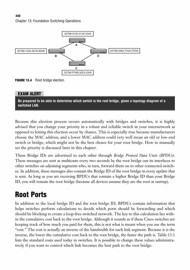
448
FIGURE 13.4 Root bridge election.
Chapter 13: Foundation Switching Operations
32768:0100.0134.5342
32768:FFAB.3253.2349
32768:3462.F234.FEDA32768:1234.5678.90AB
C
A
B D
EXAM ALERTBe prepared to be able to determine which switch is the root bridge, given a topology diagram of aswitched LAN.
Because this election process occurs automatically with bridges and switches, it is highlyadvised that you change your priority in a robust and reliable switch in your internetwork asopposed to letting this election occur by chance. This is especially true because manufacturerschoose the MAC address, and a lower MAC address could very well mean an old or low-endswitch or bridge, which might not be the best choice for your root bridge. How to manuallyset the priority is discussed later in this chapter.
These Bridge IDs are advertised to each other through Bridge Protocol Data Units (BPDUs).These messages are sent as multicasts every two seconds by the root bridge out its interfaces toother switches on adjoining segments who, in turn, forward them on to other connected switch-es. In addition, these messages also contain the Bridge ID of the root bridge in every update thatis sent. As long as you are receiving BPDUs that contain a higher Bridge ID than your BridgeID, you will remain the root bridge (because all devices assume they are the root at startup).
Root PortsIn addition to the local bridge ID and the root bridge ID, BPDUs contain information thathelps switches perform calculations to decide which ports should be forwarding and whichshould be blocking to create a loop-free switched network. The key to this calculation lies with-in the cumulative cost back to the root bridge. Although it sounds as if these Cisco switches arekeeping track of how much you paid for them, this is not what is meant when you use the term“cost.” The cost is actually an inverse of the bandwidth for each link segment. Because it is theinverse, the lower the cumulative cost back to the root bridge, the faster the path is. Table 13.1lists the standard costs used today in switches. It is possible to change these values administra-tively if you want to control which link becomes the best path to the root bridge.
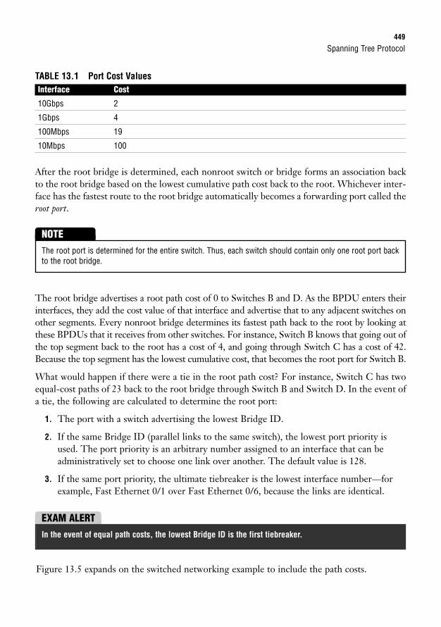
Spanning Tree Protocol449
TABLE 13.1 Port Cost ValuesInterface Cost
10Gbps 2
1Gbps 4
100Mbps 19
10Mbps 100
After the root bridge is determined, each nonroot switch or bridge forms an association backto the root bridge based on the lowest cumulative path cost back to the root. Whichever inter-face has the fastest route to the root bridge automatically becomes a forwarding port called theroot port.
The root port is determined for the entire switch. Thus, each switch should contain only one root port backto the root bridge.
NOTE
The root bridge advertises a root path cost of 0 to Switches B and D. As the BPDU enters theirinterfaces, they add the cost value of that interface and advertise that to any adjacent switches onother segments. Every nonroot bridge determines its fastest path back to the root by looking atthese BPDUs that it receives from other switches. For instance, Switch B knows that going out ofthe top segment back to the root has a cost of 4, and going through Switch C has a cost of 42.Because the top segment has the lowest cumulative cost, that becomes the root port for Switch B.
What would happen if there were a tie in the root path cost? For instance, Switch C has twoequal-cost paths of 23 back to the root bridge through Switch B and Switch D. In the event ofa tie, the following are calculated to determine the root port:
1. The port with a switch advertising the lowest Bridge ID.
2. If the same Bridge ID (parallel links to the same switch), the lowest port priority isused. The port priority is an arbitrary number assigned to an interface that can beadministratively set to choose one link over another. The default value is 128.
3. If the same port priority, the ultimate tiebreaker is the lowest interface number—forexample, Fast Ethernet 0/1 over Fast Ethernet 0/6, because the links are identical.
EXAM ALERTIn the event of equal path costs, the lowest Bridge ID is the first tiebreaker.
Figure 13.5 expands on the switched networking example to include the path costs.
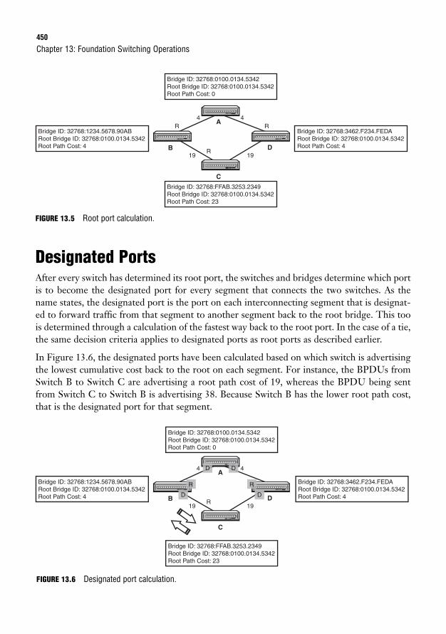
450
FIGURE 13.5 Root port calculation.
Designated PortsAfter every switch has determined its root port, the switches and bridges determine which portis to become the designated port for every segment that connects the two switches. As thename states, the designated port is the port on each interconnecting segment that is designat-ed to forward traffic from that segment to another segment back to the root bridge. This toois determined through a calculation of the fastest way back to the root port. In the case of a tie,the same decision criteria applies to designated ports as root ports as described earlier.
In Figure 13.6, the designated ports have been calculated based on which switch is advertisingthe lowest cumulative cost back to the root on each segment. For instance, the BPDUs fromSwitch B to Switch C are advertising a root path cost of 19, whereas the BPDU being sentfrom Switch C to Switch B is advertising 38. Because Switch B has the lower root path cost,that is the designated port for that segment.
Chapter 13: Foundation Switching Operations
Bridge ID: 32768:0100.0134.5342Root Bridge ID: 32768:0100.0134.5342Root Path Cost: 0
Bridge ID: 32768:FFAB.3253.2349Root Bridge ID: 32768:0100.0134.5342Root Path Cost: 23
Bridge ID: 32768:3462.F234.FEDARoot Bridge ID: 32768:0100.0134.5342Root Path Cost: 4
Bridge ID: 32768:1234.5678.90ABRoot Bridge ID: 32768:0100.0134.5342Root Path Cost: 4
R
19R
R
19
4 4
C
A
B D
19R
19
4 4
C
A
B D
Bridge ID: 32768:0100.0134.5342Root Bridge ID: 32768:0100.0134.5342Root Path Cost: 0
Bridge ID: 32768:FFAB.3253.2349Root Bridge ID: 32768:0100.0134.5342Root Path Cost: 23
Bridge ID: 32768:3462.F234.FEDARoot Bridge ID: 32768:0100.0134.5342Root Path Cost: 4
Bridge ID: 32768:1234.5678.90ABRoot Bridge ID: 32768:0100.0134.5342Root Path Cost: 4 D D
D D
R R
FIGURE 13.6 Designated port calculation.
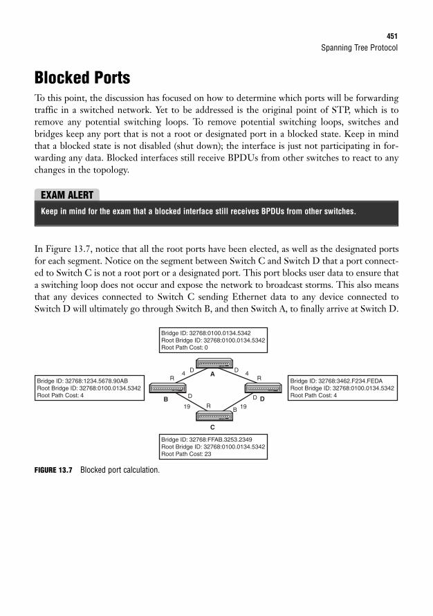
Spanning Tree Protocol451
Blocked PortsTo this point, the discussion has focused on how to determine which ports will be forwardingtraffic in a switched network. Yet to be addressed is the original point of STP, which is toremove any potential switching loops. To remove potential switching loops, switches andbridges keep any port that is not a root or designated port in a blocked state. Keep in mindthat a blocked state is not disabled (shut down); the interface is just not participating in for-warding any data. Blocked interfaces still receive BPDUs from other switches to react to anychanges in the topology.
EXAM ALERTKeep in mind for the exam that a blocked interface still receives BPDUs from other switches.
In Figure 13.7, notice that all the root ports have been elected, as well as the designated portsfor each segment. Notice on the segment between Switch C and Switch D that a port connect-ed to Switch C is not a root port or a designated port. This port blocks user data to ensure thata switching loop does not occur and expose the network to broadcast storms. This also meansthat any devices connected to Switch C sending Ethernet data to any device connected toSwitch D will ultimately go through Switch B, and then Switch A, to finally arrive at Switch D.
Bridge ID: 32768:0100.0134.5342Root Bridge ID: 32768:0100.0134.5342Root Path Cost: 0
Bridge ID: 32768:FFAB.3253.2349Root Bridge ID: 32768:0100.0134.5342Root Path Cost: 23
Bridge ID: 32768:3462.F234.FEDARoot Bridge ID: 32768:0100.0134.5342Root Path Cost: 4
Bridge ID: 32768:1234.5678.90ABRoot Bridge ID: 32768:0100.0134.5342Root Path Cost: 4
R
19 R
R
19
D
D
4 D
D
B
4
C
A
B D
FIGURE 13.7 Blocked port calculation.
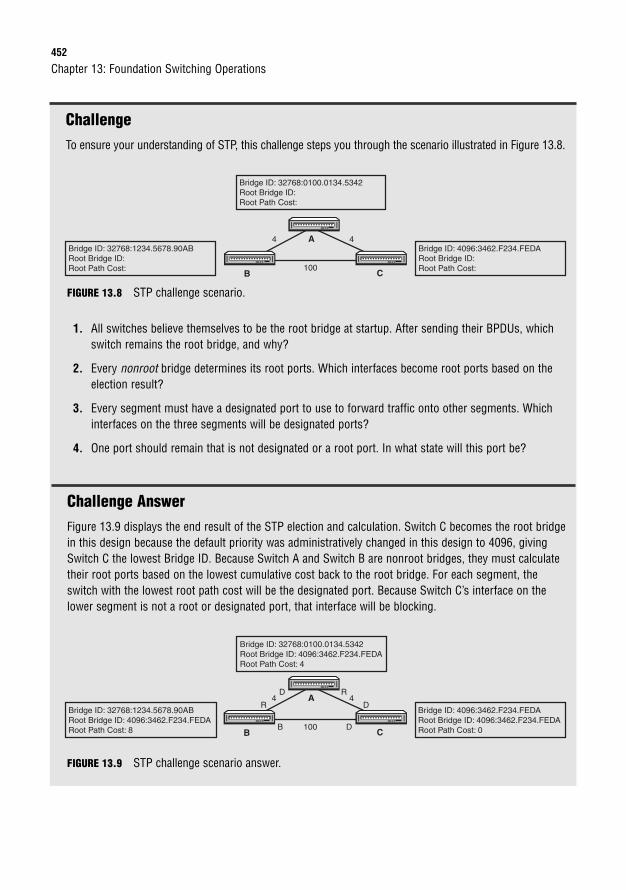
452
ChallengeTo ensure your understanding of STP, this challenge steps you through the scenario illustrated in Figure 13.8.
Chapter 13: Foundation Switching Operations
Bridge ID: 32768:0100.0134.5342Root Bridge ID: Root Path Cost:
Bridge ID: 4096:3462.F234.FEDARoot Bridge ID: Root Path Cost:
Bridge ID: 32768:1234.5678.90ABRoot Bridge ID: Root Path Cost: 100
4 4A
B C
FIGURE 13.8 STP challenge scenario.
1. All switches believe themselves to be the root bridge at startup. After sending their BPDUs, whichswitch remains the root bridge, and why?
2. Every nonroot bridge determines its root ports. Which interfaces become root ports based on theelection result?
3. Every segment must have a designated port to use to forward traffic onto other segments. Whichinterfaces on the three segments will be designated ports?
4. One port should remain that is not designated or a root port. In what state will this port be?
Challenge AnswerFigure 13.9 displays the end result of the STP election and calculation. Switch C becomes the root bridgein this design because the default priority was administratively changed in this design to 4096, givingSwitch C the lowest Bridge ID. Because Switch A and Switch B are nonroot bridges, they must calculatetheir root ports based on the lowest cumulative cost back to the root bridge. For each segment, theswitch with the lowest root path cost will be the designated port. Because Switch C’s interface on thelower segment is not a root or designated port, that interface will be blocking.
Bridge ID: 32768:0100.0134.5342Root Bridge ID: 4096:3462.F234.FEDA Root Path Cost: 4
Bridge ID: 4096:3462.F234.FEDARoot Bridge ID: 4096:3462.F234.FEDA Root Path Cost: 0
Bridge ID: 32768:1234.5678.90ABRoot Bridge ID: 4096:3462.F234.FEDA Root Path Cost: 8 100B D
4D
R D
R4A
B C
FIGURE 13.9 STP challenge scenario answer.
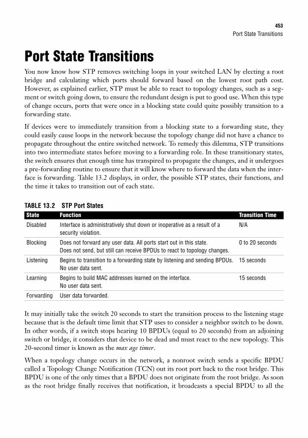
Port State Transitions453
Port State TransitionsYou now know how STP removes switching loops in your switched LAN by electing a rootbridge and calculating which ports should forward based on the lowest root path cost.However, as explained earlier, STP must be able to react to topology changes, such as a seg-ment or switch going down, to ensure the redundant design is put to good use. When this typeof change occurs, ports that were once in a blocking state could quite possibly transition to aforwarding state.
If devices were to immediately transition from a blocking state to a forwarding state, theycould easily cause loops in the network because the topology change did not have a chance topropagate throughout the entire switched network. To remedy this dilemma, STP transitionsinto two intermediate states before moving to a forwarding role. In these transitionary states,the switch ensures that enough time has transpired to propagate the changes, and it undergoesa pre-forwarding routine to ensure that it will know where to forward the data when the inter-face is forwarding. Table 13.2 displays, in order, the possible STP states, their functions, andthe time it takes to transition out of each state.
TABLE 13.2 STP Port StatesState Function Transition Time
Disabled Interface is administratively shut down or inoperative as a result of a N/Asecurity violation.
Blocking Does not forward any user data. All ports start out in this state. 0 to 20 secondsDoes not send, but still can receive BPDUs to react to topology changes.
Listening Begins to transition to a forwarding state by listening and sending BPDUs. 15 secondsNo user data sent.
Learning Begins to build MAC addresses learned on the interface. 15 secondsNo user data sent.
Forwarding User data forwarded.
It may initially take the switch 20 seconds to start the transition process to the listening stagebecause that is the default time limit that STP uses to consider a neighbor switch to be down.In other words, if a switch stops hearing 10 BPDUs (equal to 20 seconds) from an adjoiningswitch or bridge, it considers that device to be dead and must react to the new topology. This20-second timer is known as the max age timer.
When a topology change occurs in the network, a nonroot switch sends a specific BPDUcalled a Topology Change Notification (TCN) out its root port back to the root bridge. ThisBPDU is one of the only times that a BPDU does not originate from the root bridge. As soonas the root bridge finally receives that notification, it broadcasts a special BPDU to all the
454
switches in the network to start aging out old MAC entries in their CAM tables after abouteight times faster (default is 300 seconds). At that point, the switches start rebuilding theirCAM tables to reflect the new topology and forward frames accordingly.
The listening and learning states wait 15 seconds each by default, but can be administrativelychanged if you have a relatively small switched network. These 15-second intervals are common-ly referred to as forward delays because they delay the transition to a forwarding state. It is impor-tant to consider that it could take up to 50 seconds for an interface to transition to a forwardingstate when the topology changes. Consequently, no data is transferred in those 50 seconds—whichin the networking world is about 10 phone calls of complaining end users.
Chapter 13: Foundation Switching Operations
EXAM ALERTAn STP topology change could take up to 50 seconds.
The max age and forward delay timers are based on a default network diameter of sevenswitches including the root bridge. Diameter (in switching terms) refers to the number ofbridge or switches between any two hosts. If your network is, for instance, only a diameter of2, you can decrease these timers because it doesn’t take as long to propagate a change in thetopology. Another benefit of STP is that these timers are ultimately dictated by the rootbridge. Thus, to change the timers, you have to configure the change on only the root bridge,and it gets propagated to the other switches. This change could possibly backfire and causeswitching loops in instances when you add more switches to the network and forget to changethe timers. The next section discusses some safer alternatives to speed up the convergence timeof STP when a topology change occurs.
Initial Switch ConfigurationsObjective:
. Perform and verify initial switch configuration tasks including remote access management
Catalyst switches, for the most part, are designed so that the default state of the switch allowsfor basic Layer 2 functionality without requiring any configuration from the administrator.For example, the physical interfaces on the switch are already enabled, which means that youcan plug a cable in the switch and the interface operates without requiring you to perform ano shutdown on that interface. Does that mean you don’t have to learn about Catalyst switchcommands? No such luck.
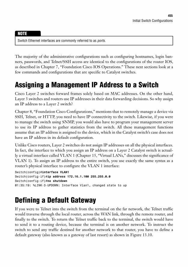
Initial Switch Configurations455
The majority of the administrative configurations such as configuring hostnames, login ban-ners, passwords, and Telnet/SSH access are identical to the configurations of the router IOS,as described in Chapter 7, “Foundation Cisco IOS Operations.” These next sections look at afew commands and configurations that are specific to Catalyst switches.
Assigning a Management IP Address to a SwitchCisco Layer 2 switches forward frames solely based on MAC addresses. On the other hand,Layer 3 switches and routers use IP addresses in their data forwarding decisions. So why assignan IP address to a Layer 2 switch?
Chapter 8, “Foundation Cisco Configurations,” mentions that to remotely manage a device viaSSH, Telnet, or HTTP, you need to have IP connectivity to the switch. Likewise, if you wereto manage the switch using SNMP, you would also have to program your management serverto use its IP address to gather statistics from the switch. All these management functionsassume that an IP address is assigned to the device, which in the Catalyst switch’s case does nothave an IP address in its default configuration.
Unlike Cisco routers, Layer 2 switches do not assign IP addresses on all the physical interfaces.In fact, the interface to which you assign an IP address on a Layer 2 Catalyst switch is actual-ly a virtual interface called VLAN 1 (Chapter 15, “Virtual LANs,” discusses the significance ofVLAN 1). To assign an IP address to the entire switch, you use exactly the same syntax as arouter’s physical interface to configure the VLAN 1 interface:Switch(config)#interface VLAN1Switch(config-if)#ip address 172.16.1.100 255.255.0.0Switch(config-if)#no shutdown01:35:19: %LINK-3-UPDOWN: Interface Vlan1, changed state to up
Defining a Default GatewayIf you were to Telnet into the switch from the terminal on the far network, the Telnet trafficwould traverse through the local router, across the WAN link, through the remote router, andfinally to the switch. To return the Telnet traffic back to the terminal, the switch would haveto send it to a routing device, because the terminal is on another network. To instruct theswitch to send any traffic destined for another network to that router, you have to define adefault gateway (also known as a gateway of last resort) as shown in Figure 13.10.
Switch Ethernet interfaces are commonly referred to as ports.
NOTE
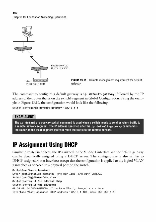
456
The command to configure a default gateway is ip default-gateway, followed by the IPaddress of the router that is on the switch’s segment in Global Configuration. Using the exam-ple in Figure 13.10, the configuration would look like the following:Switch(config)#ip default-gateway 172.16.1.1
Chapter 13: Foundation Switching Operations
Vlan1IP:172.16.1.100/16
FastEthernet 0/0IP:172.16.1.1/16
A
B
FIGURE 13.10 Remote management requirement for defaultgateway.
EXAM ALERTThe ip default-gateway switch command is used when a switch needs to send or return traffic toa remote network segment. The IP address specified after the ip default-gateway command isthe router on the local segment that will route the traffic to the remote network.
IP Assignment Using DHCPSimilar to router interfaces, the IP assigned to the VLAN 1 interface and the default gatewaycan be dynamically assigned using a DHCP server. The configuration is also similar toDHCP-assigned router interfaces except that the configuration is applied to the logical VLAN1 interface as opposed to a physical port on the switch:Switch#configure terminalEnter configuration commands, one per line. End with CNTL/Z.Switch(config)#interface vlan 1Switch(config-if)#ip address dhcpSwitch(config-if)#no shutdown00:58:49: %LINK-3-UPDOWN: Interface Vlan1, changed state to upInterface Vlan1 assigned DHCP address 172.16.1.100, mask 255.255.0.0
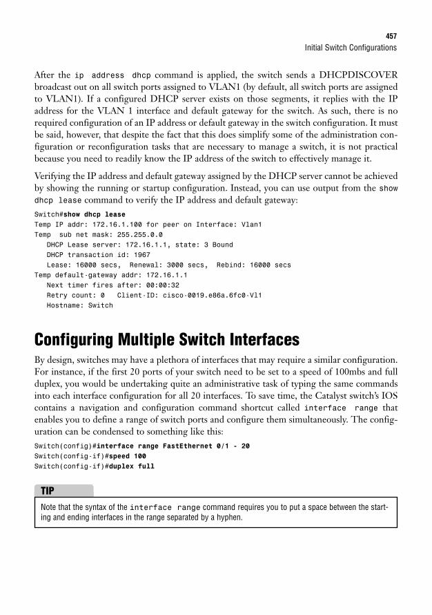
Initial Switch Configurations457
After the ip address dhcp command is applied, the switch sends a DHCPDISCOVERbroadcast out on all switch ports assigned to VLAN1 (by default, all switch ports are assignedto VLAN1). If a configured DHCP server exists on those segments, it replies with the IPaddress for the VLAN 1 interface and default gateway for the switch. As such, there is norequired configuration of an IP address or default gateway in the switch configuration. It mustbe said, however, that despite the fact that this does simplify some of the administration con-figuration or reconfiguration tasks that are necessary to manage a switch, it is not practicalbecause you need to readily know the IP address of the switch to effectively manage it.
Verifying the IP address and default gateway assigned by the DHCP server cannot be achievedby showing the running or startup configuration. Instead, you can use output from the showdhcp lease command to verify the IP address and default gateway:Switch#show dhcp leaseTemp IP addr: 172.16.1.100 for peer on Interface: Vlan1Temp sub net mask: 255.255.0.0
DHCP Lease server: 172.16.1.1, state: 3 BoundDHCP transaction id: 1967Lease: 16000 secs, Renewal: 3000 secs, Rebind: 16000 secs
Temp default-gateway addr: 172.16.1.1Next timer fires after: 00:00:32Retry count: 0 Client-ID: cisco-0019.e86a.6fc0-Vl1Hostname: Switch
Configuring Multiple Switch InterfacesBy design, switches may have a plethora of interfaces that may require a similar configuration.For instance, if the first 20 ports of your switch need to be set to a speed of 100mbs and fullduplex, you would be undertaking quite an administrative task of typing the same commandsinto each interface configuration for all 20 interfaces. To save time, the Catalyst switch’s IOScontains a navigation and configuration command shortcut called interface range thatenables you to define a range of switch ports and configure them simultaneously. The config-uration can be condensed to something like this:Switch(config)#interface range FastEthernet 0/1 - 20Switch(config-if)#speed 100Switch(config-if)#duplex full
Note that the syntax of the interface range command requires you to put a space between the start-ing and ending interfaces in the range separated by a hyphen.
TIP
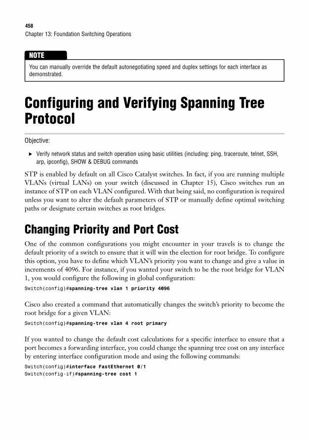
458
Configuring and Verifying Spanning TreeProtocolObjective:
. Verify network status and switch operation using basic utilities (including: ping, traceroute, telnet, SSH,arp, ipconfig), SHOW & DEBUG commands
STP is enabled by default on all Cisco Catalyst switches. In fact, if you are running multipleVLANs (virtual LANs) on your switch (discussed in Chapter 15), Cisco switches run aninstance of STP on each VLAN configured. With that being said, no configuration is requiredunless you want to alter the default parameters of STP or manually define optimal switchingpaths or designate certain switches as root bridges.
Changing Priority and Port CostOne of the common configurations you might encounter in your travels is to change thedefault priority of a switch to ensure that it will win the election for root bridge. To configurethis option, you have to define which VLAN’s priority you want to change and give a value inincrements of 4096. For instance, if you wanted your switch to be the root bridge for VLAN1, you would configure the following in global configuration:Switch(config)#spanning-tree vlan 1 priority 4096
Cisco also created a command that automatically changes the switch’s priority to become theroot bridge for a given VLAN:Switch(config)#spanning-tree vlan 4 root primary
If you wanted to change the default cost calculations for a specific interface to ensure that aport becomes a forwarding interface, you could change the spanning tree cost on any interfaceby entering interface configuration mode and using the following commands:Switch(config)#interface FastEthernet 0/1Switch(config-if)#spanning-tree cost 1
Chapter 13: Foundation Switching Operations
You can manually override the default autonegotiating speed and duplex settings for each interface asdemonstrated.
NOTE
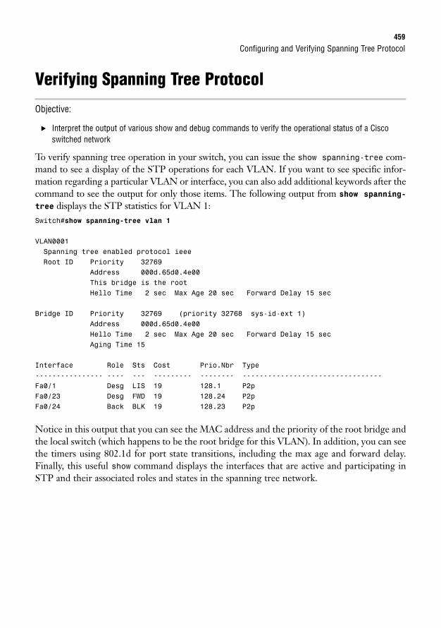
Configuring and Verifying Spanning Tree Protocol459
Verifying Spanning Tree Protocol
Objective:
. Interpret the output of various show and debug commands to verify the operational status of a Ciscoswitched network
To verify spanning tree operation in your switch, you can issue the show spanning-tree com-mand to see a display of the STP operations for each VLAN. If you want to see specific infor-mation regarding a particular VLAN or interface, you can also add additional keywords after thecommand to see the output for only those items. The following output from show spanning-tree displays the STP statistics for VLAN 1:Switch#show spanning-tree vlan 1
VLAN0001Spanning tree enabled protocol ieeeRoot ID Priority 32769
Address 000d.65d0.4e00This bridge is the rootHello Time 2 sec Max Age 20 sec Forward Delay 15 sec
Bridge ID Priority 32769 (priority 32768 sys-id-ext 1)Address 000d.65d0.4e00Hello Time 2 sec Max Age 20 sec Forward Delay 15 secAging Time 15
Interface Role Sts Cost Prio.Nbr Type---------------- ---- --- --------- -------- ---------------------------------Fa0/1 Desg LIS 19 128.1 P2pFa0/23 Desg FWD 19 128.24 P2pFa0/24 Back BLK 19 128.23 P2p
Notice in this output that you can see the MAC address and the priority of the root bridge andthe local switch (which happens to be the root bridge for this VLAN). In addition, you can seethe timers using 802.1d for port state transitions, including the max age and forward delay.Finally, this useful show command displays the interfaces that are active and participating inSTP and their associated roles and states in the spanning tree network.
460
Troubleshooting Basic Switch ConnectivityObjectives:
. Verify network status and switch operation using basic utilities (including: ping, traceroute, telnet, SSH,arp, ipconfig), SHOW & DEBUG commands
. Identify, prescribe, and resolve common switched network media issues, configuration issues, auto nego-tiation, and switch hardware failures
As always, when troubleshooting connectivity issues, use a layered approach and eliminate pos-sibilities at each layer to home in on the possible cause of the problem. Over time, you willbegin to develop a sixth sense about these problems and decrease the amount of effort it takesto accurately pinpoint a connectivity problem. In the meantime, let’s look at some possibleconnectivity scenarios and walk through some possible deductions as to what might cause theproblem.
In instances where you cannot gain console connectivity to the switch, you should ask the fol-lowing questions:
1. Is the switch powered on and running? Although this seems like common sense, it isstill valid to check to make sure the switch is powered on and successfully completed itsbootup process. Catalyst switches all have LEDs (light-emitting diodes) on the switchface to signify that it is operating correctly. The system and status lights for the switchshould both be a steady green if the device is powered on and operating normally.
2. Are your terminal connections correct? Verify that you have configured your terminalapplication correctly by setting the speed, flow control, and start and stop bits and ensurethat you have the console (rollover) cable connected between your PC and the switch.
3. Did you or someone else change the console password? If you are gaining access toIOS but cannot log in, you may need to perform password recovery on the switch.Consult the switches’ manual or look online at cisco.com for switch-specific steps torecover your password.
In instances where you cannot gain remote connectivity to the switch, you should ask the fol-lowing questions:
1. Is the switch powered on and running? If possible, console into the switch or have some-one check that the switch is powered on and successfully completed its bootup process.
2. Do you have IP connectivity to the switch? You can utilize troubleshooting commandsfrom the switch such as ping to test connectivity between the switch and the managementcomputer you are remotely connecting from. If your pings fail, verify that you have con-figured the default gateway for the switch and continue troubleshooting using the tracer-oute command to identify where along the forwarding data path the packets are failing.
Chapter 13: Foundation Switching Operations
Troubleshooting Basic Switch Connectivity461
3. Did you or someone else change the vty password or SSH login and password? If you aregaining access to IOS but cannot log in, you may need to reconfigure the SSH andTelnet passwords via the console to regain access to these remote management protocols.
In instances where the switch is not forwarding frames, you should ask yourself these questions:
1. Is the switch powered on and running? This would be fairly evident because all devicesconnected to the switch would be unable to communicate with each other. If possible,check that the switch is powered on and successfully completed its bootup process.
2. Does the switch have Layer 1 connectivity to the device(s)? The LEDs above the portmay give you a quick indication if there is a problem with that port.
To verify your cabling, ensure you are using a straight through Ethernet cable if con-necting to a PC, router, or other end device. If connecting to another switch, youshould have a cross-over Ethernet cable attached to those interfaces. What’s more, youcan also verify that the interfaces are not administratively shut down and are in anup/up state using the show interfaces interface-id command.
Keep in mind that if you just connected the end device to the switch, it will take at least30 seconds to transition to a forwarding state, as dictated by spanning tree protocol.
3. Does the output of the show interfaces interface-id command show you incor-rect speed or duplex? An interface that does not become active or is constantly bounc-ing up and down may indicate duplex and/or speed mismatches from autonegotiation.This will be evident if the show interfaces interface-id output is displaying exces-sive collisions or the interface is in an up/down state. To remedy this problem, ensurethat the switch and the end device are set for autonegotiation. To eliminate all doubt,manually set the speed and duplex parameters on the switch port(s) and the end device.
4. Does your switched internetwork intermittently stop forwarding frames? Recall thatwhen new switches are added to a switched internetwork, it may take up to 50 secondsto have the switches converge to the new STP topology. If you are not adding switchesto the network, verify that there isn’t a faulty switch causing re-elections of the STPtopology by using the debug spanning-tree command. This command shows real-time events of the spanning tree process and indicates whether a switch might have aninterface that is going up and down causing re-elections in the STP topology.
462
Chapter SummaryThis chapter has explored the mysteries behind Ethernet switching. Namely, it showed howswitches build their MAC address table (also known as a CAM table), using the source MACaddress of Ethernet frames, and forward, filter, or flood those frames based on the destinationMAC. The method in which it forwards the frames differs from switch to switch. Specifically,the switch might use the latency varying store-and-forward transmission method, whichbuffers the entire frame and calculates the CRC before forwarding the frame. Cut-throughswitching looks at only the destination MAC address in an Ethernet frame, whereas fragment-free looks at up to the first 64 bytes, in which most collisions occur.
Switch connections can communicate in half duplex or full duplex, depending on the device towhich they are connected. For instance, half-duplex connections are unidirectional and mustbe used when connecting to a hub because collisions must be detected. Full duplex can be usedonly when no possibility of collision exists, because it disables the collision detection circuitryto allow simultaneous bidirectional traffic. To ensure a collision-free environment for full-duplex connections, you must be directly connected to a switch.
When multiple switches are connected in a redundant design, STP (IEEE 802.1d) removes thepossibility of switching loops, which can cause broadcast storms. It achieves this by electing aroot bridge based on the lowest Bridge ID (priority + MAC) being advertised in BPDUs. Afterthe root bridge is elected, every nonroot bridge forms an association to the root bridge bydetermining the port with the best path (lowest cumulative cost), which becomes the root port.For every segment, a designated port is also elected based on the fastest route back to the rootbridge. In the event of a tie, the Bridge ID is used, followed by the lowest port priority, andfinally the lowest port ID.
STP ports start in a blocking state, in which no data or BPDUs are being sent. If the port canforward frames, it transitions to a listening state for 15 seconds (forward delay), where it beginsto exchange BPDUs. The learning stage follows for another 15 seconds to learn the MACaddress on the interface and then finally transitions to a forwarding state.
Key Terms. CAM table
. Store-and-forward
. Cut-through
. Fragment-free
. Half duplex
. Full duplex
Chapter 13: Foundation Switching Operations
Apply Your Knowledge463
. STP
. Root bridge
. BPDUs
. Bridge ID
. Root port
. Cost
. Designated port
. Blocking
. Listening
. Learning
. Forwarding
. Max-age timer
. Forward-delay timer
. ip default-gateway gateway_IP
. interface range media port_range
Apply Your Knowledge
Exercises
13.1 Basic Switch Configuration
This exercise reinforces the configurations involved in an initial setup of a Catalyst Switch. You may needto look back to Chapter 7 as a reference for some of the commands.
Estimated Time: 5 minutes
1. Power on your switch and enter user EXEC mode through the console.
2. In global configuration, assign the hostname, CstmrASwtch, create an appropriate login banner,and use the strongest encryption for access to privileged EXEC, using the password, giforgot.
3. Create a username of ccent with ssh4me as the password for SSH connectivity (requires crypto-graphic software image from Cisco.com).
4. In line configuration, specify Telnet and SSH as valid transport input protocols and to use the localusername and password as the login on the first five vty lines.
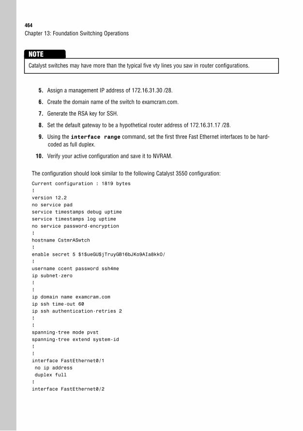
464
5. Assign a management IP address of 172.16.31.30 /28.
6. Create the domain name of the switch to examcram.com.
7. Generate the RSA key for SSH.
8. Set the default gateway to be a hypothetical router address of 172.16.31.17 /28.
9. Using the interface range command, set the first three Fast Ethernet interfaces to be hard-coded as full duplex.
10. Verify your active configuration and save it to NVRAM.
The configuration should look similar to the following Catalyst 3550 configuration:
Current configuration : 1819 bytes!version 12.2no service padservice timestamps debug uptimeservice timestamps log uptimeno service password-encryption!hostname CstmrASwtch!enable secret 5 $1$ueGU$jTruyGB16bJKo9AIa8kkO/!username ccent password ssh4meip subnet-zero!!ip domain name examcram.comip ssh time-out 60ip ssh authentication-retries 2!!spanning-tree mode pvstspanning-tree extend system-id!!interface FastEthernet0/1no ip addressduplex full!interface FastEthernet0/2
Chapter 13: Foundation Switching Operations
Catalyst switches may have more than the typical five vty lines you saw in router configurations.
NOTE
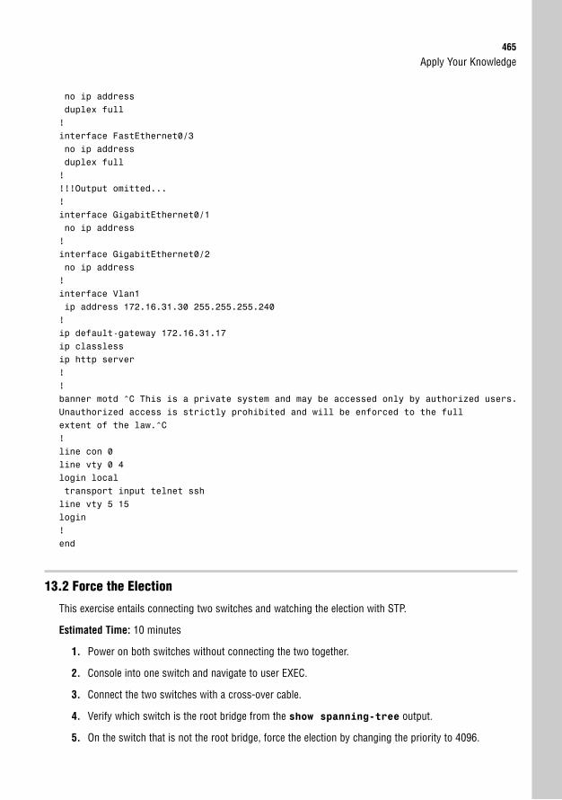
Apply Your Knowledge465
no ip addressduplex full!interface FastEthernet0/3no ip addressduplex full!!!!Output omitted...!interface GigabitEthernet0/1no ip address!interface GigabitEthernet0/2no ip address!interface Vlan1ip address 172.16.31.30 255.255.255.240!ip default-gateway 172.16.31.17ip classlessip http server!!banner motd ^C This is a private system and may be accessed only by authorized users.Unauthorized access is strictly prohibited and will be enforced to the fullextent of the law.^C!line con 0line vty 0 4login localtransport input telnet sshline vty 5 15login!end
13.2 Force the Election
This exercise entails connecting two switches and watching the election with STP.
Estimated Time: 10 minutes
1. Power on both switches without connecting the two together.
2. Console into one switch and navigate to user EXEC.
3. Connect the two switches with a cross-over cable.
4. Verify which switch is the root bridge from the show spanning-tree output.
5. On the switch that is not the root bridge, force the election by changing the priority to 4096.
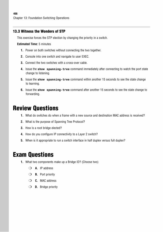
466
13.3 Witness the Wonders of STP
This exercise forces the STP election by changing the priority in a switch.
Estimated Time: 5 minutes
1. Power on both switches without connecting the two together.
2. Console into one switch and navigate to user EXEC.
3. Connect the two switches with a cross-over cable.
4. Issue the show spanning-tree command immediately after connecting to watch the port statechange to listening.
5. Issue the show spanning-tree command within another 15 seconds to see the state changeto learning.
6. Issue the show spanning-tree command after another 15 seconds to see the state change toforwarding.
Review Questions1. What do switches do when a frame with a new source and destination MAC address is received?
2. What is the purpose of Spanning Tree Protocol?
3. How is a root bridge elected?
4. How do you configure IP connectivity to a Layer 2 switch?
5. When is it appropriate to run a switch interface in half duplex versus full duplex?
Exam Questions1. What two components make up a Bridge ID? (Choose two)
❍ A. IP address
❍ B. Port priority
❍ C. MAC address
❍ D. Bridge priority
Chapter 13: Foundation Switching Operations
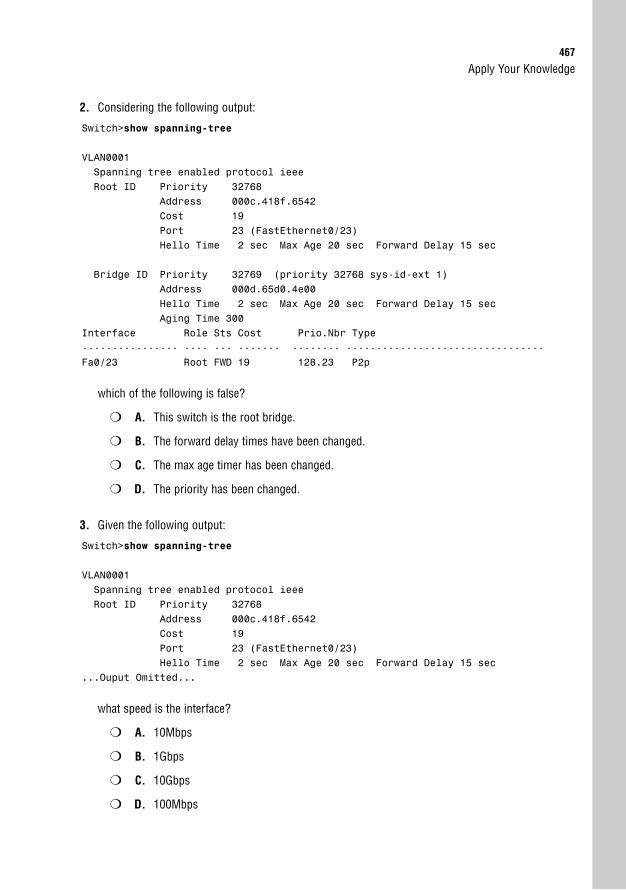
Apply Your Knowledge467
2. Considering the following output:
Switch>show spanning-tree
VLAN0001Spanning tree enabled protocol ieeeRoot ID Priority 32768
Address 000c.418f.6542Cost 19Port 23 (FastEthernet0/23)Hello Time 2 sec Max Age 20 sec Forward Delay 15 sec
Bridge ID Priority 32769 (priority 32768 sys-id-ext 1)Address 000d.65d0.4e00Hello Time 2 sec Max Age 20 sec Forward Delay 15 secAging Time 300
Interface Role Sts Cost Prio.Nbr Type---------------- ---- --- ------- -------- ---------------------------------Fa0/23 Root FWD 19 128.23 P2p
which of the following is false?
❍ A. This switch is the root bridge.
❍ B. The forward delay times have been changed.
❍ C. The max age timer has been changed.
❍ D. The priority has been changed.
3. Given the following output:
Switch>show spanning-tree
VLAN0001Spanning tree enabled protocol ieeeRoot ID Priority 32768
Address 000c.418f.6542Cost 19Port 23 (FastEthernet0/23)Hello Time 2 sec Max Age 20 sec Forward Delay 15 sec
...Ouput Omitted...
what speed is the interface?
❍ A. 10Mbps
❍ B. 1Gbps
❍ C. 10Gbps
❍ D. 100Mbps
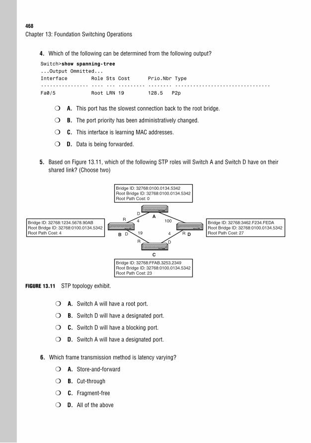
468
4. Which of the following can be determined from the following output?
Switch>show spanning-tree...Output Ommitted...Interface Role Sts Cost Prio.Nbr Type---------------- ---- --- --------- -------- --------------------------------Fa0/5 Root LRN 19 128.5 P2p
❍ A. This port has the slowest connection back to the root bridge.
❍ B. The port priority has been administratively changed.
❍ C. This interface is learning MAC addresses.
❍ D. Data is being forwarded.
5. Based on Figure 13.11, which of the following STP roles will Switch A and Switch D have on theirshared link? (Choose two)
Chapter 13: Foundation Switching Operations
Bridge ID: 32768:0100.0134.5342Root Bridge ID: 32768:0100.0134.5342Root Path Cost: 0
Bridge ID: 32768:FFAB.3253.2349Root Bridge ID: 32768:0100.0134.5342Root Path Cost: 23
Bridge ID: 32768:3462.F234.FEDARoot Bridge ID: 32768:0100.0134.5342Root Path Cost: 27
Bridge ID: 32768:1234.5678.90ABRoot Bridge ID: 32768:0100.0134.5342Root Path Cost: 4
R
19
R
4
4 100
D
D R
D
C
A
B D
FIGURE 13.11 STP topology exhibit.
❍ A. Switch A will have a root port.
❍ B. Switch D will have a designated port.
❍ C. Switch D will have a blocking port.
❍ D. Switch A will have a designated port.
6. Which frame transmission method is latency varying?
❍ A. Store-and-forward
❍ B. Cut-through
❍ C. Fragment-free
❍ D. All of the above

Apply Your Knowledge469
7. Why is the following output false?
Switch#show mac-address-tableMac Address Table
-------------------------------------------
Vlan Mac Address Type Ports---- ----------- -------- -----...Output Omitted...
1 0300.3E9E.07E9 DYNAMIC Fa0/31 FFFF.FFFF.FFFF DYNAMIC Fa0/11 0300.3E3E.531A DYNAMIC Fa0/3
❍ A. There are no static MAC address entries.
❍ B. There cannot be two MAC addresses learned on the same interface.
❍ C. No multicast entries are shown.
❍ D. A broadcast address should not be present in the CAM table.
8. What is the purpose of configuring a default gateway in a Catalyst switch?
❍ A. To have the switch act as the default gateway for end devices connected to it.
❍ B. To enforce all STP ports to a forwarding state so all switching traffic goes through the switch.
❍ C. To enable Layer 3 routing in the switch.
❍ D. To specify the IP address of the router that will forward requests made to the manage-ment IP address of the switch from devices on other subnets.
9. Which of the following are likely to occur when a switch with a higher Bridge ID is added to theswitched topology? (Choose two)
❍ A. A re-election will occur, and the new switch will become the root bridge.
❍ B. The new switch will determine the fastest path back to the root bridge and make that itsroot port.
❍ C. If the added switch creates a redundant path, at least one switch port in all of the inter-connected switches will be in a blocking state.
❍ D. The switch will immediately begin forwarding frames sent to it by end devices connectedto it.
10. You just connected your interface to a hub. Which of the following must be true?
❍ A. Your speed must be 10Mbps.
❍ B. Your duplex must be full.
❍ C. Your duplex must be half.
❍ D. CSMA/CD must be disabled.
470
Answers to Review Questions1. When a switch receives an Ethernet frame that contains an unknown source MAC address, it asso-
ciates that MAC address with the receiving interface in the CAM table. When the switch receives anEthernet frame with an unknown unicast destination MAC address, the switch floods that frame outevery port except the one on which it was received.
2. Spanning Tree Protocol eliminates switching loops in environments when multiple switches areconnected in a redundant design.
3. The root bridge is elected based on the switch that has the lowest advertised Bridge ID in theswitches’ BPDUs. The Bridge ID is composed of the priority plus the switch’s MAC address. Ifanother switch with a lower Bridge ID is added to the STP topology, a re-election occurs, and thatswitch becomes the new root bridge.
4. To gain IP connectivity to a Layer 2 switch, you must configure its management VLAN1 interfaceeither manually with ip address ip-address mask command or dynamically using the ipaddress dhcp command. If you are connecting to the device remotely from another network,the switch must also have a gateway of last resort configured statically using the ip default-gateway ip-address command or dynamically from a DHCP server.
5. When you connect to a hub, collision detection must be enabled; thus, you must run the interfaceas half duplex. Full-duplex interfaces have collision detection disabled and can be enabled onlywhen the switch port is connected to another switch or an end device.
Answers to Exam Questions1. C, D. The Bridge ID comprises the bridge priority plus the MAC address of the switch. Answer A is
incorrect because Layer 2 switches do not use IP addresses for Bridge IDs. Answer B is incorrectbecause the port priority is used as a tiebreaker only when determining the root or designatedports.
2. A. The output displays the Root Bridge ID with a different MAC address than the local switch. So,this switch is not the root bridge. The timers and priority are all still their default values. B is incor-rect because the forward delay timers are at their default value of 15 seconds. Answer C is incor-rect because the max age timer is at its default value of 20 seconds. D is incorrect because theswitch’s priority is at its default value of 32768.
3. D. A port cost of 19 is 100Mbps. Answers A, B, and C are incorrect because 10Gbps has a portcost of 2, 1Gbps has a port cost of 4, and 10Mbps has a port cost of 100.
4. C. Because the interface is in the learning state, it is beginning to learn the MAC addresses on thatinterface. Answer A is incorrect because the port is the root port, indicating that it is the fastestback to the root bridge. Answer B is incorrect because the port priority has not changed from itsdefault value of 128. Answer D is false because the port is in the learning state; it still is not able toforward traffic.
Chapter 13: Foundation Switching Operations
Apply Your Knowledge471
5. C, D. Switch A has the fastest way back to the root (itself) on that segment, so it will be designat-ed. Because Switch D’s interface is not a root or a designated port, it must be blocking. Answer Ais incorrect because only nonroot switches and bridges have root ports. Answer B is incorrectbecause Answer D has the slowest path back to the root for that particular segment.
6. A. Only the store-and-forward are latency varying because they have to buffer frames of differentsizes. Answers B, C, and D are incorrect because cut-through looks at only the destination MACaddress, and fragment-free looks at the first 64 bytes, so their latency will not vary.
7. D. The source MAC address in an Ethernet frame should not be a broadcast (only destinationaddresses), so a switch should never have that entry in its CAM table. Answer A is insignificantbecause static entries are not mandatory. Answer B is incorrect because a switch can learn multi-ple MAC addresses on a single interface. Answer C is incorrect because multicast addressesshould not be present in a CAM table by default.
8. D. The default gateway is the IP address of the Layer 3 routing device that is used when devicesare issuing Telnet, SSH, HTTP, and SNMP requests to the switch. To respond to these requests, theswitch must send the responses to the router who in turn will route them back to the end device.Answer A is false because the switch itself is not the Layer 3 gateway for other devices despite thefact that the Layer 2 frames are switched through it. The default gateway for end devices is still therouter of the LAN. Answer B is incorrect because the default gateway is not related to STP. AnswerC is incorrect because the ip default-gateway command does not enable Layer 3 routing inswitches. The command to achieve Layer 3 routing is ip routing and is useful only if you havea Layer 3 switch.
9. B, C. Because this switch has a higher Bridge ID, it does not become the root bridge. It elects thefastest port back to the root bridge as its root port. If the added switch creates a redundant loop inthe switched network, STP blocks one of the ports to avoid broadcast storms. Answer A is incor-rect because the BridgeID must be lower than the current root bridge to force an election. AnswerD is incorrect because the switch will still transition into the listening and learning states beforeforwarding frames.
10. C. When connecting to a hub, you have to be able to detect collisions; thus, you must be runninghalf duplex. The speed doesn’t matter, so Answer A is incorrect. Answers B and D are incorrectbecause setting the port to full duplex disables CSMA/CD.
Suggested Readings and Resources1. David Barnes and Basir Sakandar. Cisco LAN Switching Fundamentals. Cisco Press,
2004.
2. Matthew J. Castelli. LAN Switching First-Step. Cisco Press, 2004.
3. “Spanning-Tree Protocol,” www.cisco.com.

This page intentionally left blank
14C H A P T E R F O U R T E E N
Enhanced Switching Operations
ObjectivesThis chapter covers the following Cisco-specific objectives for the “Configure, verify and trou-bleshoot a switch with VLANs and interswitch communications” section of the 640-802 CCNAexam:
. Describe enhanced switching technologies (including: VTP, RSTP, VLAN,PVSTP, 802.1q)
. Interpret the output of various show and debug commands to verify the operational status of a Cisco switched network
Introduction 476
Cisco Enhancements to Spanning TreeProtocol 476
PortFast and BPDU Guard 476
UplinkFast 477
BackboneFast 478
Configuring Cisco STP Enhancements 478
EtherChannel 479
Rapid Spanning Tree Protocol 481
Spanning Tree Similarities 481
RSTP Port States and Roles 482
RSTP Link and Edge Types 485
BPDUs and Topology Changes 485
Rapid Transition 486
Chapter Summary 491
Key Terms 491
Apply Your Knowledge 492
Exercises 492
Review Questions 493
Exam Questions 493
Answers to Review Questions 496
Answers to Exam Questions 497
Suggested Readings and Resources 498
Outline
Study Strategies. Read the information presented in the chapter, paying special attention to tables, Notes,
and Exam Alerts.
. Rapid Spanning Tree Protocol requires a solid understanding of Spanning Tree Protocol. Ifyou do not feel like you have a firm grasp of Spanning Tree Protocol, reread those sec-tions from Chapter 13, “Foundation Switching Operations.”
. Complete the Challenge and the Exercises at the end of the chapter. These exercises willsolidify the concepts you have learned in the previous sections.
. As with most technologies discussed in this book, it is always beneficial to visualize thedata’s path and how the Cisco devices respond to the data depending on the technologyin use and the device’s configuration.
. Complete the Exam Questions at the end of the chapter. They are designed to simulate thetypes of questions you will be asked on the CCNA and ICND1 exams.
476
IntroductionThe 802.1d Spanning Tree Protocol was created with very few design flaws; however, as withmost great things, there is always room for improvement. The biggest grievance the network-ing community had with Spanning Tree Protocol was the slow convergence when a topologychange occurred in the network. Recall that it could take up to 50 seconds for the switchedinternetwork to converge and forward data frames again when a topology change occurred.What’s more, it took roughly 30 seconds for an individual access port to become active whenyou plugged a device into it, because it had to transition from the listening and learning STPstates before forwarding frames.
Cisco found several proprietary ways to improve the convergence lag of traditional SpanningTree Protocol. In addition, the IEEE adopted many of the ideas from Cisco and created amuch faster converging Spanning Tree Protocol which is happily named Rapid Spanning TreeProtocol (RSTP). As these switching technologies evolved and improved over the years, theybecame more and more adopted in switched internetworks. With this in mind, you too mustevolve and improve your understanding of these enhanced switching technologies. This chap-ter looks at the creative enhancements that were created over the years and demonstrates howthey improve the speed limitation of Spanning Tree Protocol.
Cisco Enhancements to Spanning TreeProtocolThe steps to transition to a forwarding state in STP are critical to ensure that the switched net-work has enough time to propagate a change in the topology. However, in the networkingworld, 50 seconds is a lot of downtime. In some instances, this 50 seconds may be detrimentalbecause of the disruption of data traffic and should be avoided if it is safe to do so. In light ofthese scenarios, Cisco has created some enhancements to normal STP operation that candecrease the time it takes for the switched network to converge (have a consistent perspectiveof network), as discussed in the next sections.
PortFast and BPDU GuardImagine you just plugged your server, IP phone, or just a normal PC into your switch. BecauseSTP is running on all ports on the Catalyst switches by default, the interface into which youplug your server transitions from a blocking state to the listening state, followed by the learn-ing, and finally the forwarding. In that 30 seconds, devices such as IP phones and computerscannot use those services that the server provides because no data transfer can occur until span-ning tree is in a forwarding state.
Chapter 14: Enhanced Switching Operations
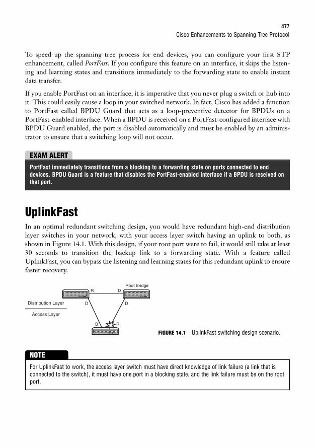
Cisco Enhancements to Spanning Tree Protocol477
To speed up the spanning tree process for end devices, you can configure your first STPenhancement, called PortFast. If you configure this feature on an interface, it skips the listen-ing and learning states and transitions immediately to the forwarding state to enable instantdata transfer.
If you enable PortFast on an interface, it is imperative that you never plug a switch or hub intoit. This could easily cause a loop in your switched network. In fact, Cisco has added a functionto PortFast called BPDU Guard that acts as a loop-preventive detector for BPDUs on aPortFast-enabled interface. When a BPDU is received on a PortFast-configured interface withBPDU Guard enabled, the port is disabled automatically and must be enabled by an adminis-trator to ensure that a switching loop will not occur.
UplinkFastIn an optimal redundant switching design, you would have redundant high-end distributionlayer switches in your network, with your access layer switch having an uplink to both, asshown in Figure 14.1. With this design, if your root port were to fail, it would still take at least30 seconds to transition the backup link to a forwarding state. With a feature calledUplinkFast, you can bypass the listening and learning states for this redundant uplink to ensurefaster recovery.
EXAM ALERTPortFast immediately transitions from a blocking to a forwarding state on ports connected to enddevices. BPDU Guard is a feature that disables the PortFast-enabled interface if a BPDU is received onthat port.
Root BridgeR D
DD
B R
Distribution Layer
Access Layer
FIGURE 14.1 UplinkFast switching design scenario.
For UplinkFast to work, the access layer switch must have direct knowledge of link failure (a link that isconnected to the switch), it must have one port in a blocking state, and the link failure must be on the rootport.
NOTE
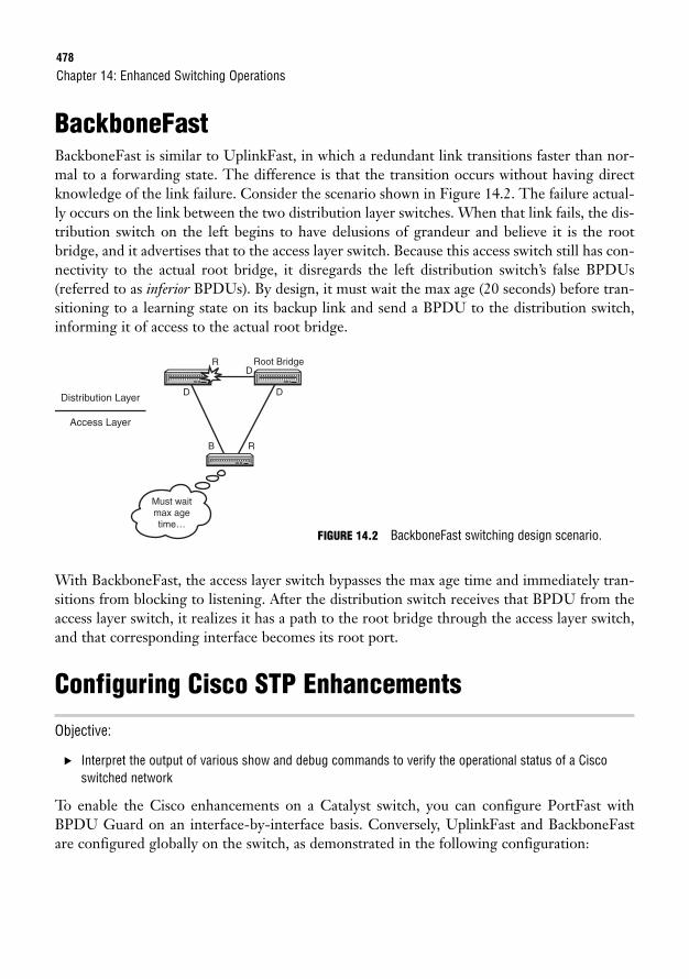
478
BackboneFastBackboneFast is similar to UplinkFast, in which a redundant link transitions faster than nor-mal to a forwarding state. The difference is that the transition occurs without having directknowledge of the link failure. Consider the scenario shown in Figure 14.2. The failure actual-ly occurs on the link between the two distribution layer switches. When that link fails, the dis-tribution switch on the left begins to have delusions of grandeur and believe it is the rootbridge, and it advertises that to the access layer switch. Because this access switch still has con-nectivity to the actual root bridge, it disregards the left distribution switch’s false BPDUs(referred to as inferior BPDUs). By design, it must wait the max age (20 seconds) before tran-sitioning to a learning state on its backup link and send a BPDU to the distribution switch,informing it of access to the actual root bridge.
Chapter 14: Enhanced Switching Operations
Root Bridge
Must waitmax agetime…
RD
DD
B R
Distribution Layer
Access Layer
With BackboneFast, the access layer switch bypasses the max age time and immediately tran-sitions from blocking to listening. After the distribution switch receives that BPDU from theaccess layer switch, it realizes it has a path to the root bridge through the access layer switch,and that corresponding interface becomes its root port.
Configuring Cisco STP Enhancements
Objective:
. Interpret the output of various show and debug commands to verify the operational status of a Ciscoswitched network
To enable the Cisco enhancements on a Catalyst switch, you can configure PortFast withBPDU Guard on an interface-by-interface basis. Conversely, UplinkFast and BackboneFastare configured globally on the switch, as demonstrated in the following configuration:
FIGURE 14.2 BackboneFast switching design scenario.
Cisco Enhancements to Spanning Tree Protocol479
Switch(config)#interface FastEthernet 0/3Switch(config-if)#spanning-tree portfast%Warning: PortFast should only be enabled on ports connected to a singlehost. Connecting hubs, concentrators, switches, bridges, etc... to thisinterface when PortFast is enabled, can cause temporary bridging loops.Use with CAUTIONSwitch(config-if)#spanning-tree bpduguard enableSwitch(config-if)#exitSwitch(config)#spanning-tree uplinkfastSwitch(config)#spanning-tree backbonefast
You can also enable BPDU Guard globally as opposed to on a port-by-port basis by using the spanning-tree portfast bpduguard default command in global configuration mode:
Switch(config)# spanning-tree portfast bpduguard default
NOTE
To verify that PortFast, UplinkFast, and BackboneFast are enabled on your switch, use theshow spanning-tree summary command:Switch#show spanning-tree summaryRoot bridge for: none.PortFast BPDU Guard is enabledUplinkFast is enabledBackboneFast is enabledSpanning tree default pathcost method used is short
Name Blocking Listening Learning Forwarding STP Active-------------------- -------- --------- -------- ---------- ----------1 VLAN 0 0 0 1 1
EtherChannel
Objective:
. Interpret the output of various show and debug commands to verify the operational status of a Ciscoswitched network
Although it isn’t an actual enhancement to Spanning Tree Protocol, EtherChannel proves tobe a useful feature in Cisco switches to help overcome wasted bandwidth that might resultfrom STP. For instance, consider the two switches illustrated in Figure 14.3. Because theseswitches have multiple redundant links between them, Spanning Tree Protocol ultimatelyblocks three of the links to avoid a loop. If these were Gigabit Ethernet interfaces, 3 gigabitsof throughput would be wasted.
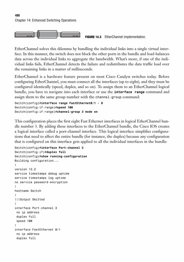
480
EtherChannel solves this dilemma by bundling the individual links into a single virtual inter-face. In this manner, the switch does not block the other ports in the bundle and load-balancesdata across the individual links to aggregate the bandwidth. What’s more, if one of the indi-vidual links fails, EtherChannel detects the failure and redistributes the data traffic load overthe remaining links in a matter of milliseconds.
EtherChannel is a hardware feature present on most Cisco Catalyst switches today. Beforeconfiguring EtherChannel, you must connect all the interfaces (up to eight), and they must beconfigured identically (speed, duplex, and so on). To assign them to an EtherChannel logicalbundle, you have to navigate into each interface or use the interface range command andassign them to the same group number with the channel-group command:Switch(config)#interface range FastEthernet0/1 - 8Switch(config-if-range)#speed 100Switch(config-if-range)#channel-group 3 mode on
This configuration places the first eight Fast Ethernet interfaces in logical EtherChannel bun-dle number 3. By adding these interfaces to the EtherChannel bundle, the Cisco IOS createsa logical interface called a port-channel interface. This logical interface simplifies configura-tions that need to affect the entire bundle (for instance, the duplex) because any configurationthat is configured on this interface gets applied to all the individual interfaces in the bundle:Switch(config)#interface Port-channel 3Switch(config-if)#duplex fullSwitch(config)#show running-configurationBuilding configuration...!version 12.2service timestamps debug uptimeservice timestamps log uptimeno service password-encryption!hostname Switch!!!!Output Omitted!interface Port-channel 3no ip addressduplex fullspeed 100!interface FastEthernet 0/1no ip addressduplex full
Chapter 14: Enhanced Switching Operations
FIGURE 14.3 EtherChannel implementation.
Rapid Spanning Tree Protocol481
speed 100channel-group 3 mode on!interface FastEthernet 0/2no ip addressduplex fullspeed 100channel-group 3 mode on!interface FastEthernet 0/3no ip addressduplex fullspeed 100channel-group 3 mode on!!!!Output Omitted
Rapid Spanning Tree ProtocolObjective:
. Describe enhanced switching technologies (including: VTP, RSTP, VLAN, PVSTP, 802.1q)
One of the greatest drawbacks of PortFast, UplinkFast, and BackboneFast is that they requirean all-Cisco network because they are Cisco-proprietary functions. Luckily, the IEEE made itsown revised version of Spanning Tree Protocol to incorporate these functions while incorpo-rating an updated algorithm for faster topology convergence. Enter Rapid Spanning TreeProtocol (RSTP), IEEE specification 802.1w.
To help remember that the 802.11w designation is for RSTP, think of Elmer Fudd: The wascally wabbitwuvs Wapid STP (802.1w).
TIP
Spanning Tree SimilaritiesAside from the fact that 802.1w Rapid Spanning Tree Protocol and 802.1d Spanning TreeProtocol are both defined by an IEEE 802.1 specification, RSTP shares some core functionalprinciples with STP, making them similar in several ways. Namely, RSTP adopts the sameswitch and port election process in determining the root bridge, root ports, and designatedports. In other words, the switch with the lowest Bridge ID advertised in its BPDUs becomesthe root bridge, and every nonroot switch chooses its root port back to that root bridge based
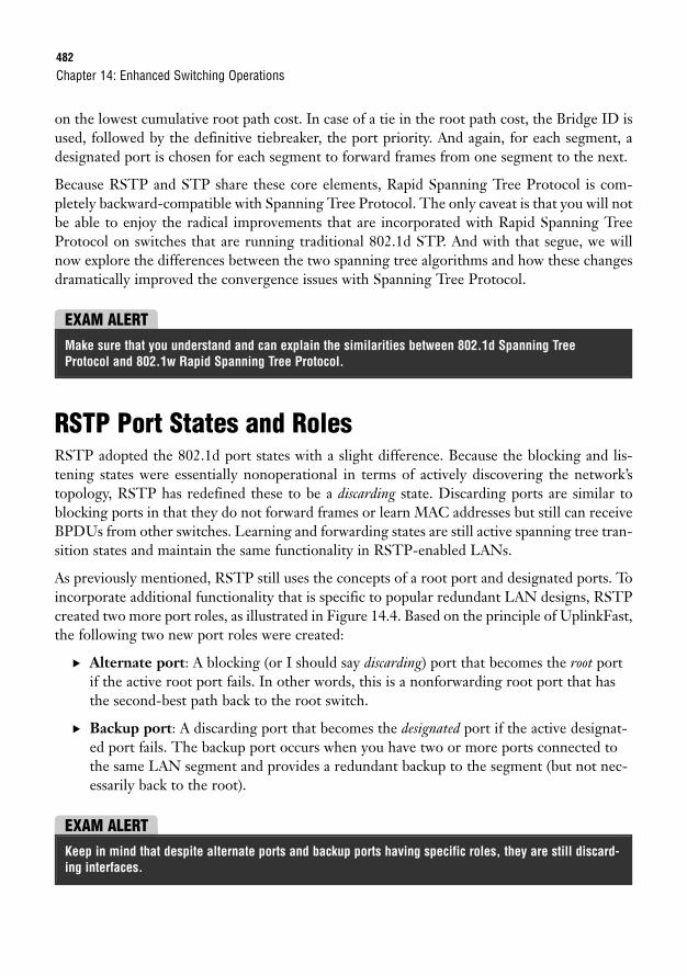
482
on the lowest cumulative root path cost. In case of a tie in the root path cost, the Bridge ID isused, followed by the definitive tiebreaker, the port priority. And again, for each segment, adesignated port is chosen for each segment to forward frames from one segment to the next.
Because RSTP and STP share these core elements, Rapid Spanning Tree Protocol is com-pletely backward-compatible with Spanning Tree Protocol. The only caveat is that you will notbe able to enjoy the radical improvements that are incorporated with Rapid Spanning TreeProtocol on switches that are running traditional 802.1d STP. And with that segue, we willnow explore the differences between the two spanning tree algorithms and how these changesdramatically improved the convergence issues with Spanning Tree Protocol.
Chapter 14: Enhanced Switching Operations
EXAM ALERTMake sure that you understand and can explain the similarities between 802.1d Spanning TreeProtocol and 802.1w Rapid Spanning Tree Protocol.
RSTP Port States and RolesRSTP adopted the 802.1d port states with a slight difference. Because the blocking and lis-tening states were essentially nonoperational in terms of actively discovering the network’stopology, RSTP has redefined these to be a discarding state. Discarding ports are similar toblocking ports in that they do not forward frames or learn MAC addresses but still can receiveBPDUs from other switches. Learning and forwarding states are still active spanning tree tran-sition states and maintain the same functionality in RSTP-enabled LANs.
As previously mentioned, RSTP still uses the concepts of a root port and designated ports. Toincorporate additional functionality that is specific to popular redundant LAN designs, RSTPcreated two more port roles, as illustrated in Figure 14.4. Based on the principle of UplinkFast,the following two new port roles were created:
. Alternate port: A blocking (or I should say discarding) port that becomes the root portif the active root port fails. In other words, this is a nonforwarding root port that hasthe second-best path back to the root switch.
. Backup port: A discarding port that becomes the designated port if the active designat-ed port fails. The backup port occurs when you have two or more ports connected tothe same LAN segment and provides a redundant backup to the segment (but not nec-essarily back to the root).
EXAM ALERTKeep in mind that despite alternate ports and backup ports having specific roles, they are still discard-ing interfaces.
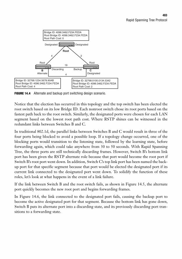
Rapid Spanning Tree Protocol483
FIGURE 14.4 Alternate and backup port switching design scenario.
Notice that the election has occurred in this topology and the top switch has been elected theroot switch based on its low Bridge ID. Each nonroot switch chose its root ports based on thefastest path back to the root switch. Similarly, the designated ports were chosen for each LANsegment based on the lowest root path cost. Where RSTP shines can be witnessed in theredundant links between Switches B and C.
In traditional 802.1d, the parallel links between Switches B and C would result in three of thefour ports being blocked to avoid a possible loop. If a topology change occurred, one of theblocking ports would transition to the listening state, followed by the learning state, beforeforwarding again, which could take anywhere from 30 to 50 seconds. With Rapid SpanningTree, the three ports are still technically discarding frames. However, Switch B’s bottom linkport has been given the RSTP alternate role because that port would become the root port ifSwitch B’s root port went down. In addition, Switch C’s top link port has been named the back-up port for that specific segment because that port would be elected the designated port if itscurrent link connected to the designated port went down. To solidify the function of theseroles, let’s look at what happens in the event of a link failure.
If the link between Switch B and the root switch fails, as shown in Figure 14.5, the alternateport quickly becomes the new root port and begins forwarding frames.
In Figure 14.6, the link connected to the designated port fails, causing the backup port tobecome the active designated port for that segment. Because the bottom link has gone down,Switch B puts its alternate port into a discarding state, and its previously discarding port tran-sitions to a forwarding state.
Bridge ID: 4096:3462.F234.FEDARoot Bridge ID: 4096:3462.F234.FEDA Root Path Cost: 0
Bridge ID: 32768:0100.0134.5342Root Bridge ID: 4096:3462.F234.FEDA Root Path Cost: 2
Bridge ID: 32768:1234.5678.90ABRoot Bridge ID: 4096:3462.F234.FEDA Root Path Cost: 4
4
19
4
Designated
Discarding Backup
Root
Alternate Designated
Root
Designated
2
Root
B C
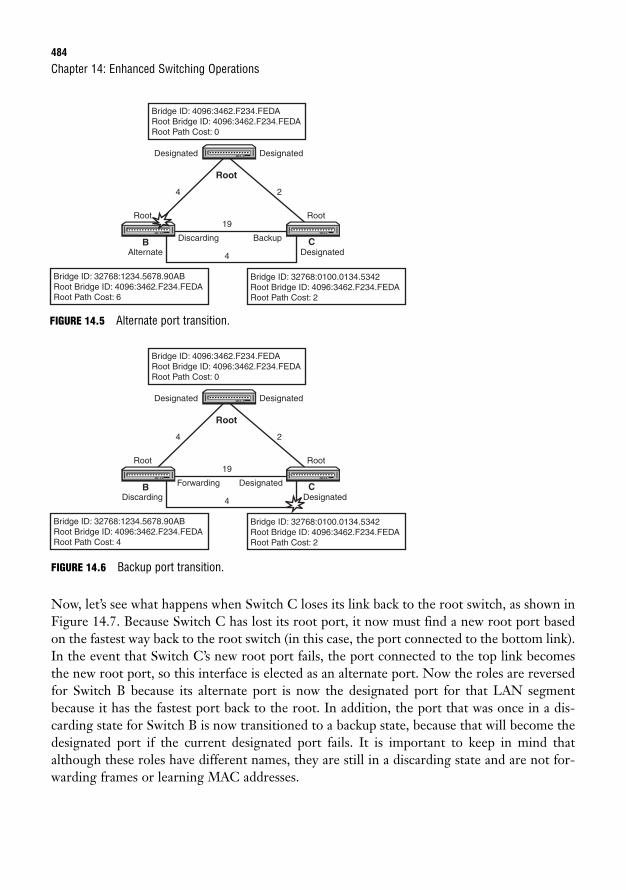
484
FIGURE 14.5 Alternate port transition.
Chapter 14: Enhanced Switching Operations
Bridge ID: 4096:3462.F234.FEDARoot Bridge ID: 4096:3462.F234.FEDA Root Path Cost: 0
Bridge ID: 32768:0100.0134.5342Root Bridge ID: 4096:3462.F234.FEDA Root Path Cost: 2
Bridge ID: 32768:1234.5678.90ABRoot Bridge ID: 4096:3462.F234.FEDA Root Path Cost: 6
4
19
4
Designated
Discarding Backup
Root
Alternate Designated
Root
Designated
2
Root
B C
Bridge ID: 4096:3462.F234.FEDARoot Bridge ID: 4096:3462.F234.FEDA Root Path Cost: 0
Bridge ID: 32768:0100.0134.5342Root Bridge ID: 4096:3462.F234.FEDA Root Path Cost: 2
Bridge ID: 32768:1234.5678.90ABRoot Bridge ID: 4096:3462.F234.FEDA Root Path Cost: 4
4
19
4
Designated
Forwarding Designated
Root
Discarding Designated
Root
Designated
2
Root
B C
FIGURE 14.6 Backup port transition.
Now, let’s see what happens when Switch C loses its link back to the root switch, as shown inFigure 14.7. Because Switch C has lost its root port, it now must find a new root port basedon the fastest way back to the root switch (in this case, the port connected to the bottom link).In the event that Switch C’s new root port fails, the port connected to the top link becomesthe new root port, so this interface is elected as an alternate port. Now the roles are reversedfor Switch B because its alternate port is now the designated port for that LAN segmentbecause it has the fastest port back to the root. In addition, the port that was once in a dis-carding state for Switch B is now transitioned to a backup state, because that will become thedesignated port if the current designated port fails. It is important to keep in mind thatalthough these roles have different names, they are still in a discarding state and are not for-warding frames or learning MAC addresses.
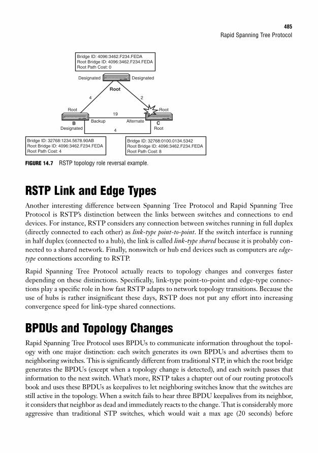
Rapid Spanning Tree Protocol485
FIGURE 14.7 RSTP topology role reversal example.
RSTP Link and Edge TypesAnother interesting difference between Spanning Tree Protocol and Rapid Spanning TreeProtocol is RSTP’s distinction between the links between switches and connections to enddevices. For instance, RSTP considers any connection between switches running in full duplex(directly connected to each other) as link-type point-to-point. If the switch interface is runningin half duplex (connected to a hub), the link is called link-type shared because it is probably con-nected to a shared network. Finally, nonswitch or hub end devices such as computers are edge-type connections according to RSTP.
Rapid Spanning Tree Protocol actually reacts to topology changes and converges fasterdepending on these distinctions. Specifically, link-type point-to-point and edge-type connec-tions play a specific role in how fast RSTP adapts to network topology transitions. Because theuse of hubs is rather insignificant these days, RSTP does not put any effort into increasingconvergence speed for link-type shared connections.
BPDUs and Topology ChangesRapid Spanning Tree Protocol uses BPDUs to communicate information throughout the topol-ogy with one major distinction: each switch generates its own BPDUs and advertises them toneighboring switches. This is significantly different from traditional STP, in which the root bridgegenerates the BPDUs (except when a topology change is detected), and each switch passes thatinformation to the next switch. What’s more, RSTP takes a chapter out of our routing protocol’sbook and uses these BPDUs as keepalives to let neighboring switches know that the switches arestill active in the topology. When a switch fails to hear three BPDU keepalives from its neighbor,it considers that neighbor as dead and immediately reacts to the change. That is considerably moreaggressive than traditional STP switches, which would wait a max age (20 seconds) before
Bridge ID: 4096:3462.F234.FEDARoot Bridge ID: 4096:3462.F234.FEDA Root Path Cost: 0
Bridge ID: 32768:0100.0134.5342Root Bridge ID: 4096:3462.F234.FEDA Root Path Cost: 8
Bridge ID: 32768:1234.5678.90ABRoot Bridge ID: 4096:3462.F234.FEDA Root Path Cost: 4
4
19
4
Designated
Backup Alternate
Root
Designated Root
Root
Designated
2
Root
B C
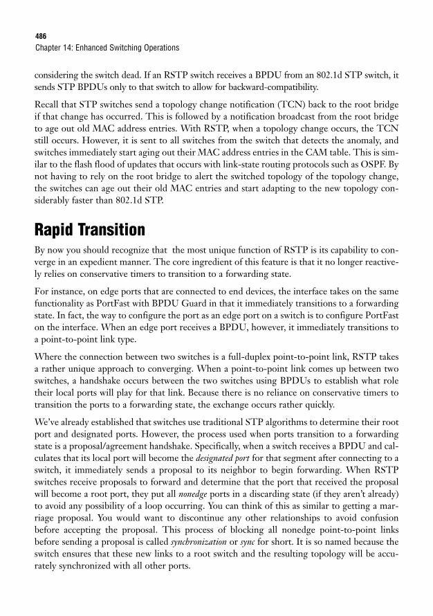
486
considering the switch dead. If an RSTP switch receives a BPDU from an 802.1d STP switch, itsends STP BPDUs only to that switch to allow for backward-compatibility.
Recall that STP switches send a topology change notification (TCN) back to the root bridgeif that change has occurred. This is followed by a notification broadcast from the root bridgeto age out old MAC address entries. With RSTP, when a topology change occurs, the TCNstill occurs. However, it is sent to all switches from the switch that detects the anomaly, andswitches immediately start aging out their MAC address entries in the CAM table. This is sim-ilar to the flash flood of updates that occurs with link-state routing protocols such as OSPF. Bynot having to rely on the root bridge to alert the switched topology of the topology change,the switches can age out their old MAC entries and start adapting to the new topology con-siderably faster than 802.1d STP.
Rapid TransitionBy now you should recognize that the most unique function of RSTP is its capability to con-verge in an expedient manner. The core ingredient of this feature is that it no longer reactive-ly relies on conservative timers to transition to a forwarding state.
For instance, on edge ports that are connected to end devices, the interface takes on the samefunctionality as PortFast with BPDU Guard in that it immediately transitions to a forwardingstate. In fact, the way to configure the port as an edge port on a switch is to configure PortFaston the interface. When an edge port receives a BPDU, however, it immediately transitions toa point-to-point link type.
Where the connection between two switches is a full-duplex point-to-point link, RSTP takesa rather unique approach to converging. When a point-to-point link comes up between twoswitches, a handshake occurs between the two switches using BPDUs to establish what roletheir local ports will play for that link. Because there is no reliance on conservative timers totransition the ports to a forwarding state, the exchange occurs rather quickly.
We’ve already established that switches use traditional STP algorithms to determine their rootport and designated ports. However, the process used when ports transition to a forwardingstate is a proposal/agreement handshake. Specifically, when a switch receives a BPDU and cal-culates that its local port will become the designated port for that segment after connecting to aswitch, it immediately sends a proposal to its neighbor to begin forwarding. When RSTPswitches receive proposals to forward and determine that the port that received the proposalwill become a root port, they put all nonedge ports in a discarding state (if they aren’t already)to avoid any possibility of a loop occurring. You can think of this as similar to getting a mar-riage proposal. You would want to discontinue any other relationships to avoid confusionbefore accepting the proposal. This process of blocking all nonedge point-to-point linksbefore sending a proposal is called synchronization or sync for short. It is so named because theswitch ensures that these new links to a root switch and the resulting topology will be accu-rately synchronized with all other ports.
Chapter 14: Enhanced Switching Operations
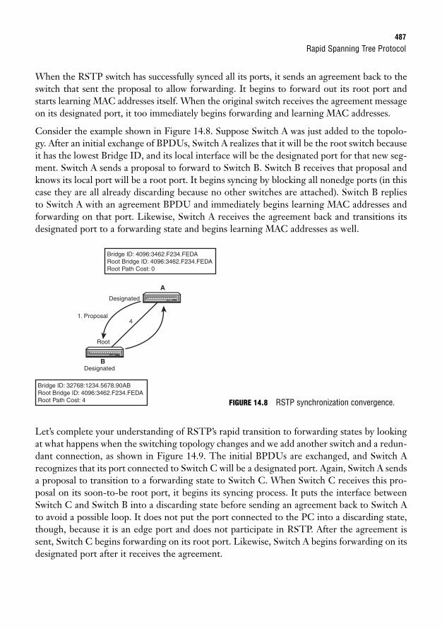
Rapid Spanning Tree Protocol487
When the RSTP switch has successfully synced all its ports, it sends an agreement back to theswitch that sent the proposal to allow forwarding. It begins to forward out its root port andstarts learning MAC addresses itself. When the original switch receives the agreement messageon its designated port, it too immediately begins forwarding and learning MAC addresses.
Consider the example shown in Figure 14.8. Suppose Switch A was just added to the topolo-gy. After an initial exchange of BPDUs, Switch A realizes that it will be the root switch becauseit has the lowest Bridge ID, and its local interface will be the designated port for that new seg-ment. Switch A sends a proposal to forward to Switch B. Switch B receives that proposal andknows its local port will be a root port. It begins syncing by blocking all nonedge ports (in thiscase they are all already discarding because no other switches are attached). Switch B repliesto Switch A with an agreement BPDU and immediately begins learning MAC addresses andforwarding on that port. Likewise, Switch A receives the agreement back and transitions itsdesignated port to a forwarding state and begins learning MAC addresses as well.
Bridge ID: 4096:3462.F234.FEDARoot Bridge ID: 4096:3462.F234.FEDA Root Path Cost: 0
Bridge ID: 32768:1234.5678.90ABRoot Bridge ID: 4096:3462.F234.FEDA Root Path Cost: 4
41. Proposal
Designated
Root
Designated
A
B
Let’s complete your understanding of RSTP’s rapid transition to forwarding states by lookingat what happens when the switching topology changes and we add another switch and a redun-dant connection, as shown in Figure 14.9. The initial BPDUs are exchanged, and Switch Arecognizes that its port connected to Switch C will be a designated port. Again, Switch A sendsa proposal to transition to a forwarding state to Switch C. When Switch C receives this pro-posal on its soon-to-be root port, it begins its syncing process. It puts the interface betweenSwitch C and Switch B into a discarding state before sending an agreement back to Switch Ato avoid a possible loop. It does not put the port connected to the PC into a discarding state,though, because it is an edge port and does not participate in RSTP. After the agreement issent, Switch C begins forwarding on its root port. Likewise, Switch A begins forwarding on itsdesignated port after it receives the agreement.
FIGURE 14.8 RSTP synchronization convergence.
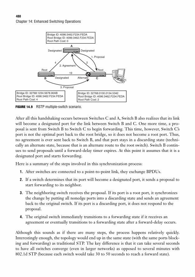
488
FIGURE 14.9 RSTP multiple-switch scenario.
After all this handshaking occurs between Switches C and A, Switch B also realizes that its linkwill become a designated port for the link between Switch B and C. One more time, a pro-posal is sent from Switch B to Switch C to begin forwarding. This time, however, Switch C’sport is not the optimal port back to the root bridge, so it does not become a root port. Thus,no agreement is ever sent back to Switch B, and that port stays in a discarding state (techni-cally an alternate state, because that is an alternate route to the root switch). Switch B contin-ues to send proposals until a forward-delay timer expires. At this point it assumes that it is adesignated port and starts forwarding.
Here is a summary of the steps involved in this synchronization process:
1. After switches are connected to a point-to-point link, they exchange BPDUs.
2. If a switch determines that its port will become a designated port, it sends a proposal tostart forwarding to its neighbor.
3. The neighboring switch receives the proposal. If its port is a root port, it synchronizesthe change by putting all nonedge ports into a discarding state and sends an agreementback to the original switch. If its port is a discarding port, it does not respond to theproposal.
4. The original switch immediately transitions to a forwarding state if it receives anagreement or eventually transitions to a forwarding state after a forward-delay occurs.
Although this sounds as if there are many steps, the process happens relatively quickly.Interestingly enough, the topology would end up in the same state (with the same ports block-ing and forwarding) as traditional STP. The key difference is that it can take several secondsto have all switches converge (even in larger networks) as opposed to several minutes with802.1d STP (because each switch would take 30 to 50 seconds to reach a forward state).
Chapter 14: Enhanced Switching Operations
Bridge ID: 4096:3462.F234.FEDARoot Bridge ID: 4096:3462.F234.FEDA Root Path Cost: 0
Bridge ID: 32768:0100.0134.5342Root Bridge ID: 4096:3462.F234.FEDA Root Path Cost: 2
Bridge ID: 32768:1234.5678.90ABRoot Bridge ID: 4096:3462.F234.FEDA Root Path Cost: 4
4
19
2. Agreement
3. Proposal
1. Proposal
Designated
Designated Alternate
Root Root
Designated
2
B
A
C
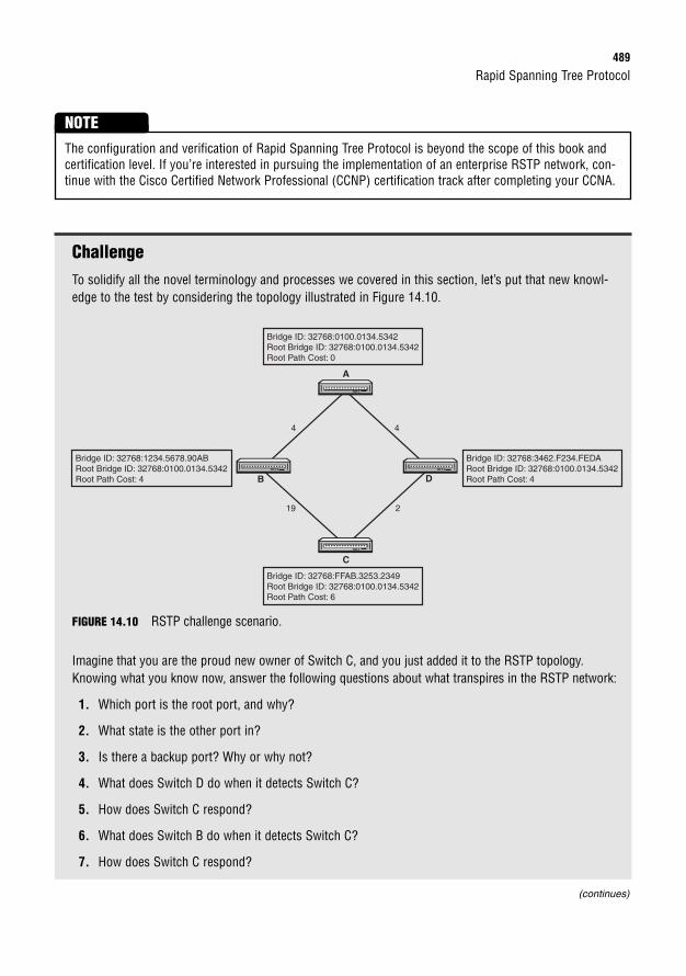
Rapid Spanning Tree Protocol489
ChallengeTo solidify all the novel terminology and processes we covered in this section, let’s put that new knowl-edge to the test by considering the topology illustrated in Figure 14.10.
The configuration and verification of Rapid Spanning Tree Protocol is beyond the scope of this book andcertification level. If you’re interested in pursuing the implementation of an enterprise RSTP network, con-tinue with the Cisco Certified Network Professional (CCNP) certification track after completing your CCNA.
NOTE
Bridge ID: 32768:0100.0134.5342Root Bridge ID: 32768:0100.0134.5342Root Path Cost: 0
Bridge ID: 32768:FFAB.3253.2349Root Bridge ID: 32768:0100.0134.5342Root Path Cost: 6
Bridge ID: 32768:3462.F234.FEDARoot Bridge ID: 32768:0100.0134.5342Root Path Cost: 4
Bridge ID: 32768:1234.5678.90ABRoot Bridge ID: 32768:0100.0134.5342Root Path Cost: 4
4 4
219
B
A
C
D
FIGURE 14.10 RSTP challenge scenario.
Imagine that you are the proud new owner of Switch C, and you just added it to the RSTP topology.Knowing what you know now, answer the following questions about what transpires in the RSTP network:
1. Which port is the root port, and why?
2. What state is the other port in?
3. Is there a backup port? Why or why not?
4. What does Switch D do when it detects Switch C?
5. How does Switch C respond?
6. What does Switch B do when it detects Switch C?
7. How does Switch C respond?
(continues)
490
Challenge AnswerThe port connected to Switch D is the root port because it has the fastest path back to the root switch.Switch C’s other port gets put into a discarding state because it has the least optimal path to the root.Specifically, RSTP puts this port into an alternate state because that port will become the root if its cur-rent root goes down. There is no backup port in this scenario because there are no parallel links in thedesign to the same LAN segment.
When Switch D detects Switch C, it discovers that its port will become a designated port and sends aproposal to forward to Switch C. When Switch C receives that proposal, it immediately begins syncing byblocking all nonedge ports. It then sends an agreement back to Switch D and begins forwarding andlearning MAC addresses. When Switch D receives that agreement, it too begins forwarding frames on itsdesignated port and starts learning MAC addresses.
When Switch B detects the new link to Switch C, it too realizes that its port will be a designated port andsends a proposal to Switch C. Because Switch C’s port is a suboptimal port, it remains discarding anddoes not reply to Switch B’s proposal. After a forward delay occurs, Switch B transitions its designatedport to a forwarding state and begins forwarding and learning MAC addresses.
Chapter 14: Enhanced Switching Operations
(continued)
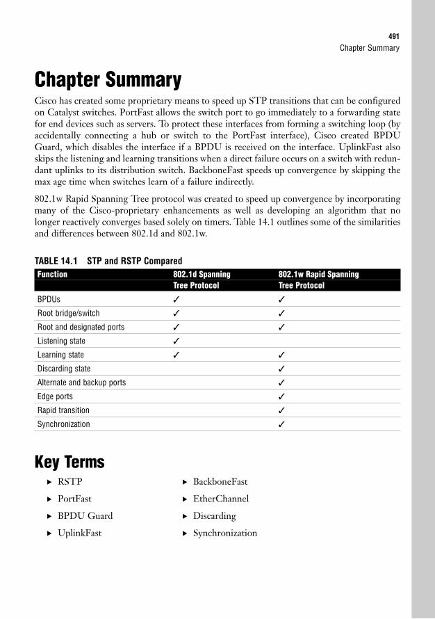
Chapter Summary491
Chapter SummaryCisco has created some proprietary means to speed up STP transitions that can be configuredon Catalyst switches. PortFast allows the switch port to go immediately to a forwarding statefor end devices such as servers. To protect these interfaces from forming a switching loop (byaccidentally connecting a hub or switch to the PortFast interface), Cisco created BPDUGuard, which disables the interface if a BPDU is received on the interface. UplinkFast alsoskips the listening and learning transitions when a direct failure occurs on a switch with redun-dant uplinks to its distribution switch. BackboneFast speeds up convergence by skipping themax age time when switches learn of a failure indirectly.
802.1w Rapid Spanning Tree protocol was created to speed up convergence by incorporatingmany of the Cisco-proprietary enhancements as well as developing an algorithm that nolonger reactively converges based solely on timers. Table 14.1 outlines some of the similaritiesand differences between 802.1d and 802.1w.
TABLE 14.1 STP and RSTP ComparedFunction 802.1d Spanning 802.1w Rapid Spanning
Tree Protocol Tree Protocol
BPDUs ✓ ✓
Root bridge/switch ✓ ✓
Root and designated ports ✓ ✓
Listening state ✓
Learning state ✓ ✓
Discarding state ✓
Alternate and backup ports ✓
Edge ports ✓
Rapid transition ✓
Synchronization ✓
Key Terms. RSTP
. PortFast
. BPDU Guard
. UplinkFast
. BackboneFast
. EtherChannel
. Discarding
. Synchronization
492
Apply Your Knowledge
Exercises
14.1 Time Flies with PortFast
This exercise forces the STP election by changing the priority in a switch.
Estimated Time: 5 minutes
1. Power on your switch.
2. Console into one switch, and navigate to user EXEC.
3. Configure an interface for PortFast.
4. Plug a device into that interface.
5. Issue the show spanning-tree command within 15 seconds to see the state change immedi-ately to forwarding.
14.2 Imagine the Wonders of RSTP
In this exercise, you draw your existing switched network and imagine what transpires when it runsRSTP. If you do not have a switched network, create or design your own topology, and draw how youimagine the switches would be implemented and what links should exist between the switches.
Estimated Time: 10 minutes
1. Draw a new or your existing STP switched topology.
2. Imagine that you are running RSTP in the network, and determine the root switch, root ports, des-ignated ports, and discarding ports (they should be the same as the STP topology now).
3. Identify any switch ports that might be an alternate or backup port.
4. Consider the proposal/agreement exchanges that occur in each switch and if syncing occurs inthem.
5. For the ultimate practice exercise, add a switch to your design with a lower Bridge ID so that itbecomes the root switch. Determine how this change gets propagated to other switches in theRSTP design.
Chapter 14: Enhanced Switching Operations
Apply Your Knowledge493
Review Questions1. Why would you use PortFast with BPDU Guard?
2. What is the advantage of using UplinkFast?
3. What is the advantage of using BackboneFast?
4. In what circumstances would you have a backup or alternate port state in RSTP?
5. What is the primary purpose of synchronization?
Exam Questions1. You’ve connected your switches together with a crossover cable. What would be a possible reason
for a switching loop to occur?
❍ A. Because STP is disabled by default, you need to enable it on both switches.
❍ B. You configured one of the interfaces as PortFast.
❍ C. You need to use a straight-through cable.
❍ D. The forward delay timers were set to 15 seconds.
2. Which of the following is actively participating (forwarding frames) in the RSTP topology?
❍ A. Ports in a learning state
❍ B. Alternate ports
❍ C. Connected edge ports
❍ D. Backup ports
3. Which of the following is not a similarity between STP and RSTP?
❍ A. Root bridge elections
❍ B. Use of BPDUs to communicate topology information to other switches
❍ C. Learning state
❍ D. BPDUs originate only from the root switch.
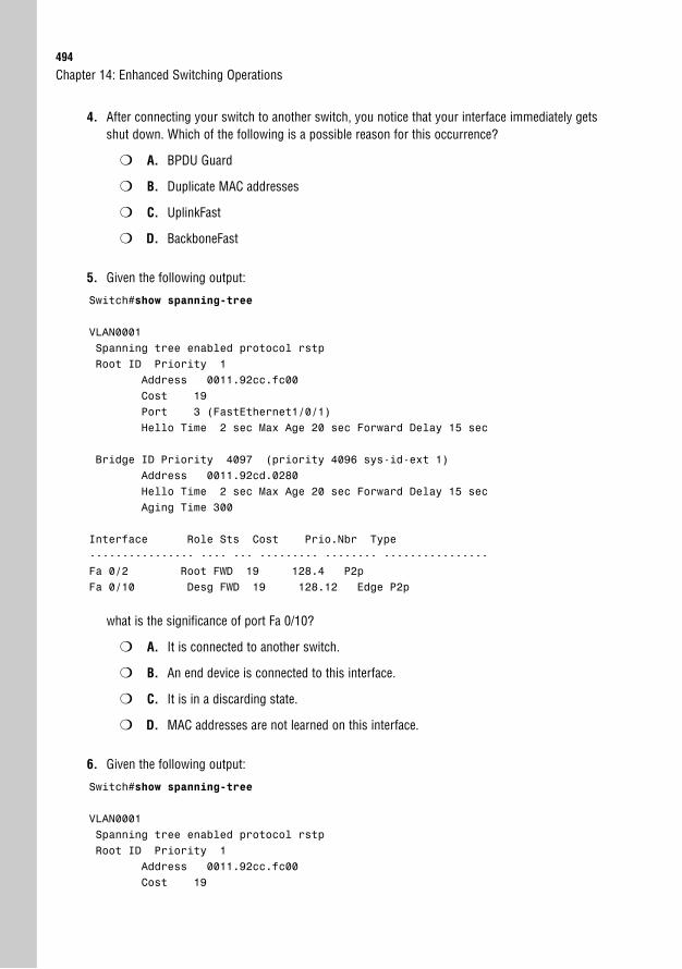
494
4. After connecting your switch to another switch, you notice that your interface immediately getsshut down. Which of the following is a possible reason for this occurrence?
❍ A. BPDU Guard
❍ B. Duplicate MAC addresses
❍ C. UplinkFast
❍ D. BackboneFast
5. Given the following output:
Switch#show spanning-tree
VLAN0001Spanning tree enabled protocol rstpRoot ID Priority 1
Address 0011.92cc.fc00Cost 19Port 3 (FastEthernet1/0/1)Hello Time 2 sec Max Age 20 sec Forward Delay 15 sec
Bridge ID Priority 4097 (priority 4096 sys-id-ext 1)Address 0011.92cd.0280Hello Time 2 sec Max Age 20 sec Forward Delay 15 secAging Time 300
Interface Role Sts Cost Prio.Nbr Type---------------- ---- --- --------- -------- ----------------Fa 0/2 Root FWD 19 128.4 P2pFa 0/10 Desg FWD 19 128.12 Edge P2p
what is the significance of port Fa 0/10?
❍ A. It is connected to another switch.
❍ B. An end device is connected to this interface.
❍ C. It is in a discarding state.
❍ D. MAC addresses are not learned on this interface.
6. Given the following output:
Switch#show spanning-tree
VLAN0001Spanning tree enabled protocol rstpRoot ID Priority 1
Address 0011.92cc.fc00Cost 19
Chapter 14: Enhanced Switching Operations
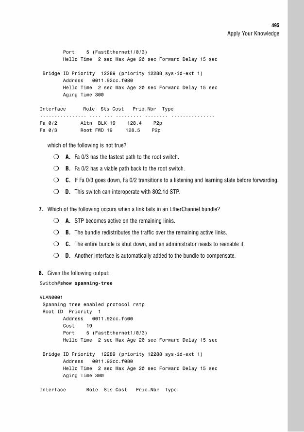
Apply Your Knowledge495
Port 5 (FastEthernet1/0/3)Hello Time 2 sec Max Age 20 sec Forward Delay 15 sec
Bridge ID Priority 12289 (priority 12288 sys-id-ext 1)Address 0011.92cc.f080Hello Time 2 sec Max Age 20 sec Forward Delay 15 secAging Time 300
Interface Role Sts Cost Prio.Nbr Type---------------- ---- --- --------- -------- ---------------Fa 0/2 Altn BLK 19 128.4 P2pFa 0/3 Root FWD 19 128.5 P2p
which of the following is not true?
❍ A. Fa 0/3 has the fastest path to the root switch.
❍ B. Fa 0/2 has a viable path back to the root switch.
❍ C. If Fa 0/3 goes down, Fa 0/2 transitions to a listening and learning state before forwarding.
❍ D. This switch can interoperate with 802.1d STP.
7. Which of the following occurs when a link fails in an EtherChannel bundle?
❍ A. STP becomes active on the remaining links.
❍ B. The bundle redistributes the traffic over the remaining active links.
❍ C. The entire bundle is shut down, and an administrator needs to reenable it.
❍ D. Another interface is automatically added to the bundle to compensate.
8. Given the following output:
Switch#show spanning-tree
VLAN0001Spanning tree enabled protocol rstpRoot ID Priority 1
Address 0011.92cc.fc00Cost 19Port 5 (FastEthernet1/0/3)Hello Time 2 sec Max Age 20 sec Forward Delay 15 sec
Bridge ID Priority 12289 (priority 12288 sys-id-ext 1)Address 0011.92cc.f080Hello Time 2 sec Max Age 20 sec Forward Delay 15 secAging Time 300
Interface Role Sts Cost Prio.Nbr Type
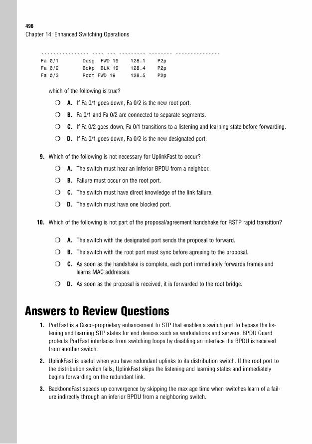
496
---------------- ---- --- --------- -------- ---------------Fa 0/1 Desg FWD 19 128.1 P2pFa 0/2 Bckp BLK 19 128.4 P2pFa 0/3 Root FWD 19 128.5 P2p
which of the following is true?
❍ A. If Fa 0/1 goes down, Fa 0/2 is the new root port.
❍ B. Fa 0/1 and Fa 0/2 are connected to separate segments.
❍ C. If Fa 0/2 goes down, Fa 0/1 transitions to a listening and learning state before forwarding.
❍ D. If Fa 0/1 goes down, Fa 0/2 is the new designated port.
9. Which of the following is not necessary for UplinkFast to occur?
❍ A. The switch must hear an inferior BPDU from a neighbor.
❍ B. Failure must occur on the root port.
❍ C. The switch must have direct knowledge of the link failure.
❍ D. The switch must have one blocked port.
10. Which of the following is not part of the proposal/agreement handshake for RSTP rapid transition?
❍ A. The switch with the designated port sends the proposal to forward.
❍ B. The switch with the root port must sync before agreeing to the proposal.
❍ C. As soon as the handshake is complete, each port immediately forwards frames andlearns MAC addresses.
❍ D. As soon as the proposal is received, it is forwarded to the root bridge.
Answers to Review Questions1. PortFast is a Cisco-proprietary enhancement to STP that enables a switch port to bypass the lis-
tening and learning STP states for end devices such as workstations and servers. BPDU Guardprotects PortFast interfaces from switching loops by disabling an interface if a BPDU is receivedfrom another switch.
2. UplinkFast is useful when you have redundant uplinks to its distribution switch. If the root port tothe distribution switch fails, UplinkFast skips the listening and learning states and immediatelybegins forwarding on the redundant link.
3. BackboneFast speeds up convergence by skipping the max age time when switches learn of a fail-ure indirectly through an inferior BPDU from a neighboring switch.
Chapter 14: Enhanced Switching Operations
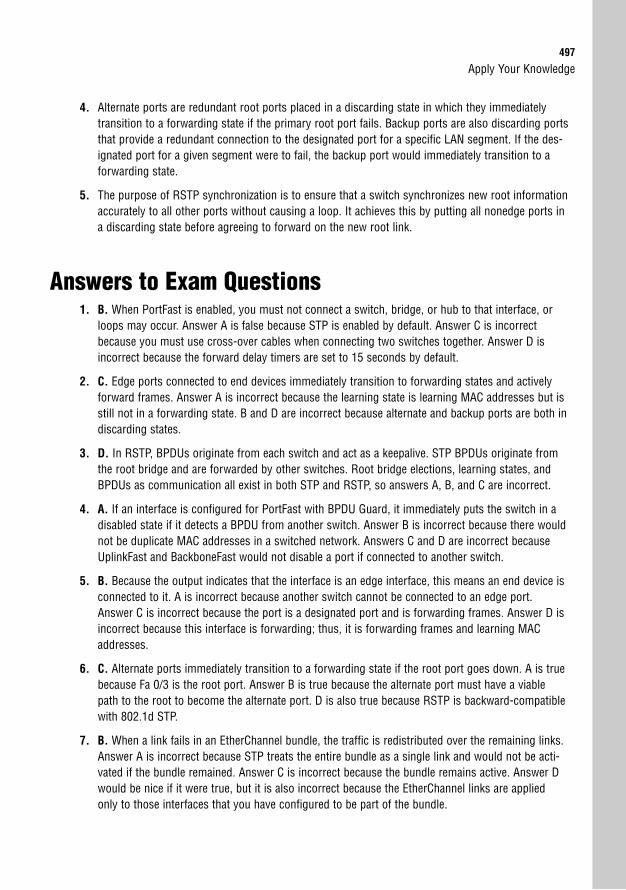
Apply Your Knowledge497
4. Alternate ports are redundant root ports placed in a discarding state in which they immediatelytransition to a forwarding state if the primary root port fails. Backup ports are also discarding portsthat provide a redundant connection to the designated port for a specific LAN segment. If the des-ignated port for a given segment were to fail, the backup port would immediately transition to aforwarding state.
5. The purpose of RSTP synchronization is to ensure that a switch synchronizes new root informationaccurately to all other ports without causing a loop. It achieves this by putting all nonedge ports ina discarding state before agreeing to forward on the new root link.
Answers to Exam Questions1. B. When PortFast is enabled, you must not connect a switch, bridge, or hub to that interface, or
loops may occur. Answer A is false because STP is enabled by default. Answer C is incorrectbecause you must use cross-over cables when connecting two switches together. Answer D isincorrect because the forward delay timers are set to 15 seconds by default.
2. C. Edge ports connected to end devices immediately transition to forwarding states and activelyforward frames. Answer A is incorrect because the learning state is learning MAC addresses but isstill not in a forwarding state. B and D are incorrect because alternate and backup ports are both indiscarding states.
3. D. In RSTP, BPDUs originate from each switch and act as a keepalive. STP BPDUs originate fromthe root bridge and are forwarded by other switches. Root bridge elections, learning states, andBPDUs as communication all exist in both STP and RSTP, so answers A, B, and C are incorrect.
4. A. If an interface is configured for PortFast with BPDU Guard, it immediately puts the switch in adisabled state if it detects a BPDU from another switch. Answer B is incorrect because there wouldnot be duplicate MAC addresses in a switched network. Answers C and D are incorrect becauseUplinkFast and BackboneFast would not disable a port if connected to another switch.
5. B. Because the output indicates that the interface is an edge interface, this means an end device isconnected to it. A is incorrect because another switch cannot be connected to an edge port.Answer C is incorrect because the port is a designated port and is forwarding frames. Answer D isincorrect because this interface is forwarding; thus, it is forwarding frames and learning MACaddresses.
6. C. Alternate ports immediately transition to a forwarding state if the root port goes down. A is truebecause Fa 0/3 is the root port. Answer B is true because the alternate port must have a viablepath to the root to become the alternate port. D is also true because RSTP is backward-compatiblewith 802.1d STP.
7. B. When a link fails in an EtherChannel bundle, the traffic is redistributed over the remaining links.Answer A is incorrect because STP treats the entire bundle as a single link and would not be acti-vated if the bundle remained. Answer C is incorrect because the bundle remains active. Answer Dwould be nice if it were true, but it is also incorrect because the EtherChannel links are appliedonly to those interfaces that you have configured to be part of the bundle.
498
8. D. The backup port automatically starts to forward and becomes the new designated port if thecurrent designated port fails. Answer A is incorrect because it will not become a root port. AnswerB is incorrect because a backup port exists only if two ports are connected to the same segment.Answer C is incorrect because the link immediately transitions to a forwarding state.
9. A. Inferior BPDUs are not necessary for UplinkFast to work; they are specific to BackboneFast.Answers B, C, and D are true because a switch must have one blocked port, a failure on the rootport, and direct knowledge of that failure for UplinkFast to work correctly.
10. D. It is not necessary for RSTP switches to forward any notifications back to the root switch likeSTP. Answer A, B, and C are true because the handshake entails the designated switch sending aproposal. The other switch receives the proposal, blocks all ports connected to point-to-point links,and sends an agreement. When the switches are finished with the handshake, they immediatelybegin forwarding frames.
Suggested Readings and Resources1. Richard Froom, Balaji Sivasubramanian, and Erum Frahim. Building Cisco Multilayer
Switched Networks (BCMSN) (Authorized Self-Study Guide), 4th Edition. Cisco Press,2007.
2. “Spanning Tree Enhancements,” www.cisco.com.
3. “Rapid Spanning-Tree Protocol,” www.cisco.com.
Chapter 14: Enhanced Switching Operations
15C H A P T E R F I F T E E N
Virtual LANs
ObjectivesThis chapter covers the following Cisco-specified objective for the “Configure, verify and trou-bleshoot a switch with VLANs and interswitch communications” section of the 640-802 CCNAexam:
. Describe enhanced switching technologies (including: VTP, RSTP, VLAN,PVSTP, 802.1q)
. Describe how VLANs create logically separate networks and the need forrouting between them
. Configure, verify, and troubleshoot VLANs
. Configure, verify, and troubleshoot trunking on Cisco switches
. Configure, verify, and troubleshoot interVLAN routing
. Configure, verify, and troubleshoot VTP
Introduction 502
Overview of VLANs 502
VLAN Membership Methods 503
The Management VLAN 504
Configuring and Verifying VLANs 505
VLAN Trunking 506
ISL Trunks 508
802.1q Trunks 508
Native VLANs 508
Configuring and Verifying ISL and 802.1Q Trunks 509
Dynamic Trunking with DTP 510
VLAN Trunking Protocol 511
VTP Modes 511
Server Mode 511
Client Mode 512
Transparent Mode 512
VTP Pruning 514
Configuring and Verifying VTP 514
InterVLAN Routing 517
Router on a Stick 517
Switched Virtual Interfaces 519
Voice VLANs 520
Troubleshooting VLAN 522
Chapter Summary 524
Key Terms 525
Apply Your Knowledge 526
Exercises 526
Review Questions 527
Exam Questions 528
Answers to Review Questions 531
Answers to Exam Questions 531
Suggested Readings and Resources 532
Outline

Study Strategies. Read the information presented in the chapter, paying special attention to tables, Notes,
and Exam Alerts.
. Complete the Challenge Exercises and the Exercises at the end of the chapter. The exercis-es will solidify the concepts that you have learned in the previous sections.
. Complete the Exam Questions at the end of the chapter. They are designed to simulate thetype of questions you will be asked in the CCNA exam.
502
IntroductionOne of the underlying problems with Layer 2 switches is that excessive broadcast and multi-cast traffic can affect other devices in a switched network because bridges and switches floodthese types of messages. If you are a receiver of all this excessive traffic, you have to waste processing utilization and endure wasted bandwidth even if those devices are not in yourdepartment. This chapter explores how VLANs solve your broadcast concerns by segmentingbroadcast domains at Layer 2 and how they affect your switched network design.
Overview of VLANsObjectives:
. Describe enhanced switching technologies (including: VTP, RSTP, VLAN, PVSTP, 802.1q)
. Describe how VLANs create logically separate networks and the need for routing between them
In your company, you may have several departments connected to the same Layer 2 switch orswitched network. Quite often, departments may be running applications and protocols thatare unique to users within their own group. Unfortunately, if this traffic consists of multicastsand broadcasts (or unknown unicasts, for that matter), that traffic hits all users connected tothat switched network.
For instance, imagine that the Not-So-Human Resources department is running a developedprogram that helps them track employee lunch break times. Unfortunately, this traffic reliesheavily on broadcasts to communicate with other applications being used by personnel in thatdepartment. The broadcast and multicast traffic from the Not-So-Human Resources depart-ment continues to be flooded out to everyone else in the network because they are all con-nected to the same switched network. Because this is the only department that uses this soft-ware, ideally it would be convenient to separate the Not-So-Human Resources group intotheir own separate switched LAN so their traffic doesn’t affect any other department.
To this point, the only way you could segment this network into smaller broadcast domains isby using a router because routers do not forward broadcasts or multicasts by default. Theproblem with this solution is that routers can be expensive, considering you need an interfacefor each department to keep the traffic separate. In addition, because routers have to processall the way into the Layer 3 information of a packet before sending the traffic to a differentsegment, throughput is considerably slower than that of a switch. Not to mention, if you haveusers within departments physically dispersed all throughout your network, the broadcast andmulticast traffic would never reach them because the router does not forward them onto otherinterfaces.
Chapter 15: Virtual LANs
Overview of VLANs503
The answer to all these problems lies within the magic of virtual LANs (VLANs). VLANsenable you to segment broadcast domains at Layer 2 without a router. Each VLAN created ina switch represents a logical grouping of devices into their own broadcast domain. Thus, eachdepartment can have its own VLAN that separates traffic from one department from that ofother departments. In fact, devices in one VLAN cannot communicate with other devices inanother VLAN without the help of a router, even if those devices are plugged into the sameswitch. What’s more, VLANs can span multiple switches, so the geographic location of thedevices is no longer a limiting factor. As members of a specific department are added or moved,you simply need to assign their switch interface to the department’s VLAN.
What is also remarkable about VLANs is that because each VLAN represents a broadcastdomain in which devices can communicate only with other devices in that same VLAN, theremust be a separate instance of Spanning Tree Protocol (STP) running for each VLAN. Inother words, if you have 20 VLANs running in your switched network, you will have 20instances of STP running, each with its own root bridge. The term for this ability to have aseparate instance of Spanning Tree Protocol for each VLAN is called PVST (per VLANSpanning Tree). It is for this very reason that the configuration for the STP priority (discussedin Chapter 13, “Foundation Switching Operations”) required that the VLAN be specified inthe command syntax.
EXAM ALERTUnless VLANs are specifically mentioned in an exam question or answer choices, routers segmentbroadcast domains and switches segment collision domains.
VLAN Membership MethodsAfter the VLANs are created, they have to be associated with the users or departments con-nected to the switches. The most common way to associate VLANs is statically on a port-by-port basis. When the VLAN is associated with the switch port, it is referred to as an access port.When a single VLAN is assigned on the interface, traffic is sent to and received by only devicesconnected to interfaces with the same VLAN.
For instance, consider the typical single-switch VLAN configuration exhibited in Figure 15.1.All these switches are access ports that have a single VLAN assigned to them. On Fast Ethernetinterfaces 0/1 and 0/3, they are assigned to VLAN 1. Our Not-So-Human Resources VLAN(VLAN 3) has been assigned to Fast Ethernet interfaces 0/2, 0/4, and 0/5. The devices connect-ed to these interfaces can communicate only with other interfaces that also contain that VLAN.So in the example, the printer and the computer on the right can communicate with each otherand the computer connected to interface Fast Ethernet 0/2. Even though they are connected tothe same switch, these devices cannot communicate with the computers connected to interfacesassigned to VLAN 1 because they are in a completely different broadcast domain.
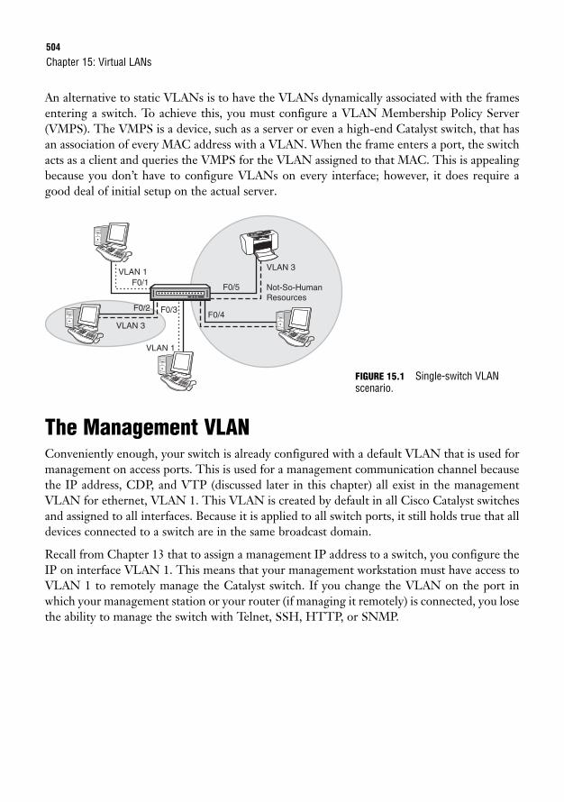
504
An alternative to static VLANs is to have the VLANs dynamically associated with the framesentering a switch. To achieve this, you must configure a VLAN Membership Policy Server(VMPS). The VMPS is a device, such as a server or even a high-end Catalyst switch, that hasan association of every MAC address with a VLAN. When the frame enters a port, the switchacts as a client and queries the VMPS for the VLAN assigned to that MAC. This is appealingbecause you don’t have to configure VLANs on every interface; however, it does require agood deal of initial setup on the actual server.
Chapter 15: Virtual LANs
F0/1
F0/2 F0/3F0/4
F0/5
VLAN 1
VLAN 3
VLAN 1
VLAN 3
Not-So-HumanResources
FIGURE 15.1 Single-switch VLANscenario.
The Management VLANConveniently enough, your switch is already configured with a default VLAN that is used formanagement on access ports. This is used for a management communication channel becausethe IP address, CDP, and VTP (discussed later in this chapter) all exist in the managementVLAN for ethernet, VLAN 1. This VLAN is created by default in all Cisco Catalyst switchesand assigned to all interfaces. Because it is applied to all switch ports, it still holds true that alldevices connected to a switch are in the same broadcast domain.
Recall from Chapter 13 that to assign a management IP address to a switch, you configure theIP on interface VLAN 1. This means that your management workstation must have access toVLAN 1 to remotely manage the Catalyst switch. If you change the VLAN on the port inwhich your management station or your router (if managing it remotely) is connected, you losethe ability to manage the switch with Telnet, SSH, HTTP, or SNMP.
Overview of VLANs505
Configuring and Verifying VLANs
Objective:
. Configure, verify, and troubleshoot VLANs
All interfaces are already assigned to VLAN 1. To create smaller broadcast domains in yourswitch, you must create those VLANs for each department you want to segment and assign themto their respective interfaces. Specifically, the configuration steps for VLANs are as follows:
1. Create the VLAN, using a number between 2 and 1001.
2. Name the VLAN. If you do not assign it a name, it uses VLANxxxx, where xxxx is theVLAN number.
3. Assign it to a switch port.
VLAN-specific configurations are permanently stored in Flash memory in a special file calledthe VLAN database (vlan.dat). To configure VLANs on the Catalyst switch, you must navigateto a VLAN configuration mode from global configuration referred to as config-VLAN Mode.
To navigate to this configuration mode, you type the command vlan followed by the VLANID you want to create. At this point, the prompt changes to Switch(config-vlan)#, signify-ing that you are in the config-VLAN mode. At this stage of the VLAN configuration, you havethe option to assign a unique name to the VLAN you just created by typing the keyword namefollowed by the custom name of your VLAN. If you do not specify a name, the switch willautomatically assign the name using the VLAN ID. For instance, if you chose the number 4for the VLAN ID, the VLAN name defaults to VLAN0004.
In the following example, we are creating two VLANS; one we named NSHR and the otherwe left to its default VLAN name based on the VLAN ID:Switch#configure terminalEnter configuration commands, one per line. End with CNTL/Z.Switch(config)#vlan 3Switch(config-vlan)#name NSHRSwitch(config-vlan)#exitSwitch(config)#vlan 4Switch(config-vlan)#exitSwitch(config) #
EXAM ALERTKnow the three steps involved in configuring VLANs.
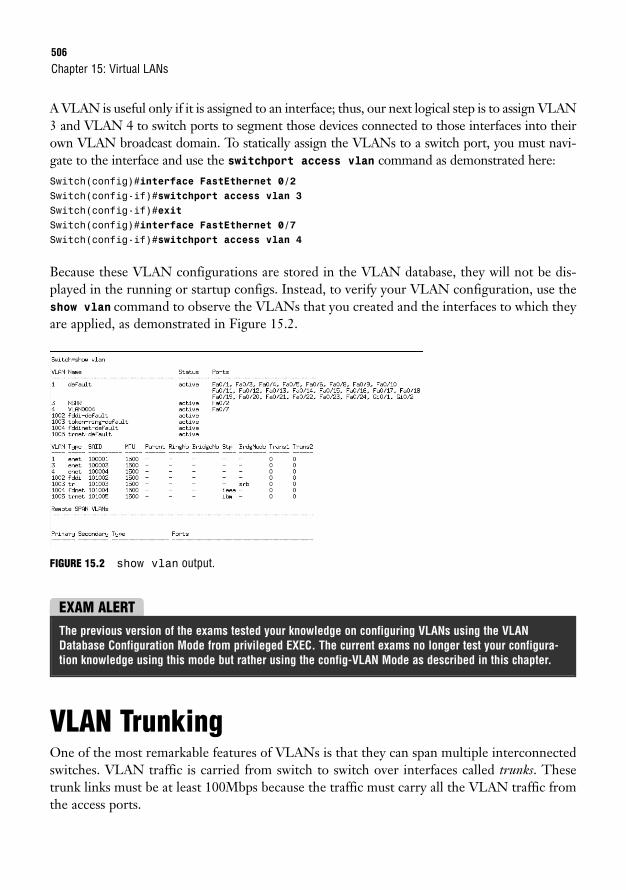
506
A VLAN is useful only if it is assigned to an interface; thus, our next logical step is to assign VLAN3 and VLAN 4 to switch ports to segment those devices connected to those interfaces into theirown VLAN broadcast domain. To statically assign the VLANs to a switch port, you must navi-gate to the interface and use the switchport access vlan command as demonstrated here:Switch(config)#interface FastEthernet 0/2Switch(config-if)#switchport access vlan 3Switch(config-if)#exitSwitch(config)#interface FastEthernet 0/7Switch(config-if)#switchport access vlan 4
Because these VLAN configurations are stored in the VLAN database, they will not be dis-played in the running or startup configs. Instead, to verify your VLAN configuration, use theshow vlan command to observe the VLANs that you created and the interfaces to which theyare applied, as demonstrated in Figure 15.2.
Chapter 15: Virtual LANs
FIGURE 15.2 show vlan output.
EXAM ALERTThe previous version of the exams tested your knowledge on configuring VLANs using the VLANDatabase Configuration Mode from privileged EXEC. The current exams no longer test your configura-tion knowledge using this mode but rather using the config-VLAN Mode as described in this chapter.
VLAN TrunkingOne of the most remarkable features of VLANs is that they can span multiple interconnectedswitches. VLAN traffic is carried from switch to switch over interfaces called trunks. Thesetrunk links must be at least 100Mbps because the traffic must carry all the VLAN traffic fromthe access ports.
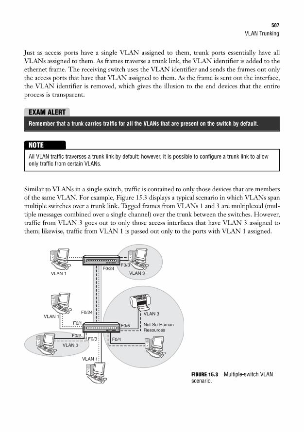
VLAN Trunking507
Just as access ports have a single VLAN assigned to them, trunk ports essentially have allVLANs assigned to them. As frames traverse a trunk link, the VLAN identifier is added to theethernet frame. The receiving switch uses the VLAN identifier and sends the frames out onlythe access ports that have that VLAN assigned to them. As the frame is sent out the interface,the VLAN identifier is removed, which gives the illusion to the end devices that the entireprocess is transparent.
EXAM ALERTRemember that a trunk carries traffic for all the VLANs that are present on the switch by default.
Similar to VLANs in a single switch, traffic is contained to only those devices that are membersof the same VLAN. For example, Figure 15.3 displays a typical scenario in which VLANs spanmultiple switches over a trunk link. Tagged frames from VLANs 1 and 3 are multiplexed (mul-tiple messages combined over a single channel) over the trunk between the switches. However,traffic from VLAN 3 goes out to only those access interfaces that have VLAN 3 assigned tothem; likewise, traffic from VLAN 1 is passed out only to the ports with VLAN 1 assigned.
All VLAN traffic traverses a trunk link by default; however, it is possible to configure a trunk link to allowonly traffic from certain VLANs.
NOTE
F0/1
F0/2F0/3
F0/24
F0/24
F0/3
F0/4
F0/5
VLAN 1
VLAN 1 VLAN 3
VLAN 3
VLAN 1
VLAN 3
Not-So-HumanResources
FIGURE 15.3 Multiple-switch VLANscenario.
508
ISL TrunksThe VLAN identification is added to Layer 2 ethernet frames differently, depending on thetype of trunk that is configured. Cisco’s proprietary method of adding VLAN IDs to an eth-ernet frame is called Inter Switch Link (ISL). ISL trunking entails the original ethernet framebeing encapsulated by ASIC chips with the VLAN information. The ISL encapsulation has a26-byte header and an additional 4-byte CRC trailer at the end. Because an additional 30 bytesare added to the ethernet frame, the size of the frame can exceed a typical ethernet frame sizeof 1518 bytes. If the interface isn’t configured as an ISL trunk, it drops the giant frame becauseit violates the MTU limit of a typical ethernet frame. For this reason, ISL requires a directpoint-to-point (no intermediate devices) trunk connection between the switches.
802.1q TrunksThe IEEE created its own standard VLAN tagging method standardized as 802.1q. 802.1q dif-fers from ISL because the VLAN ID is not encapsulated, but actually inserted in the original-ly ethernet frame. The VLAN identifier is contained within the four extra bytes inserted in theethernet frame after the source address. Because the original frame size is manipulated whenthese four bytes are added to the frame, a new CRC must be calculated for the original ether-net Frame Check Sequence (FCS) field. Because only four bytes are added to the ethernetframe, these frames are known as baby giant frames and may be passed by other intermediaryLayer 2 devices that are not configured as a trunk.
Native VLANsAnother unique feature of 802.1q trunks is the concept of a native VLAN. Traffic originatingfrom access ports that shares the same VLAN as the trunk’s native VLAN goes untagged overthe trunk link. Similarly, any untagged frame that is received on an 802.1q trunk port is con-sidered destined for the native VLAN assigned to the trunk port. For this reason, it is imper-ative that each side of the IEEE 802.1q link be configured with the same native VLAN, or thetraffic from one VLAN leaks into another VLAN as illustrated in Figure 15.4. By default, thenative VLAN for trunk ports is the same as the management VLAN, VLAN 1.
Chapter 15: Virtual LANs
EXAM ALERTBe prepared to identify which devices can communicate with each other given a VLAN configuration inone or several switches.
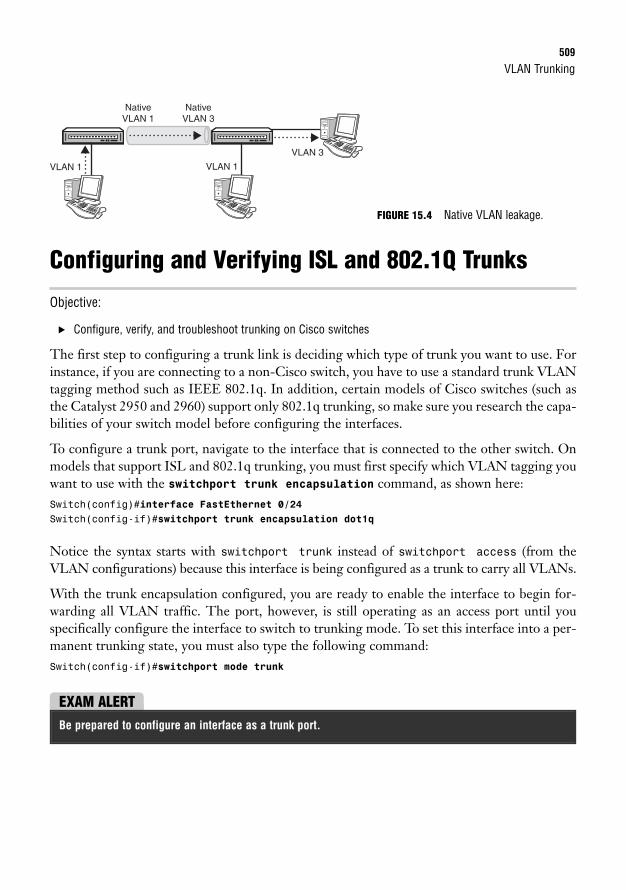
VLAN Trunking509
Configuring and Verifying ISL and 802.1Q Trunks
Objective:
. Configure, verify, and troubleshoot trunking on Cisco switches
The first step to configuring a trunk link is deciding which type of trunk you want to use. Forinstance, if you are connecting to a non-Cisco switch, you have to use a standard trunk VLANtagging method such as IEEE 802.1q. In addition, certain models of Cisco switches (such asthe Catalyst 2950 and 2960) support only 802.1q trunking, so make sure you research the capa-bilities of your switch model before configuring the interfaces.
To configure a trunk port, navigate to the interface that is connected to the other switch. Onmodels that support ISL and 802.1q trunking, you must first specify which VLAN tagging youwant to use with the switchport trunk encapsulation command, as shown here:Switch(config)#interface FastEthernet 0/24Switch(config-if)#switchport trunk encapsulation dot1q
Notice the syntax starts with switchport trunk instead of switchport access (from theVLAN configurations) because this interface is being configured as a trunk to carry all VLANs.
With the trunk encapsulation configured, you are ready to enable the interface to begin for-warding all VLAN traffic. The port, however, is still operating as an access port until youspecifically configure the interface to switch to trunking mode. To set this interface into a per-manent trunking state, you must also type the following command:Switch(config-if)#switchport mode trunk
VLAN 1
VLAN 3
VLAN 1
NativeVLAN 1
NativeVLAN 3
FIGURE 15.4 Native VLAN leakage.
EXAM ALERTBe prepared to configure an interface as a trunk port.
510
Dynamic Trunking with DTPCisco switches can dynamically enable trunking on an interface through the use of a Cisco pro-prietary protocol called Dynamic Trunking Protocol (DTP). For instance, the default dynam-ic trunking state is called desirable, which actively tries to negotiate trunking as long as theother side of the trunk uses a compatible DTP condition.
The possible trunking modes are as follows:
. Access—The port does not trunk because it is an access port with a single VLAN.
. Trunk—The port permanently trunks and tries to negotiate the far-end to trunk withDTP.
. Dynamic Desirable—The port negotiates to trunk if the other side is set to trunk,desirable, or auto.
. Dynamic Auto—The port negotiates to trunk if the other side is set to trunk or desirable.
. Nonegotiate—The port permanently trunks, but disables DTP negotiation (for connecting to non-Cisco switches).
To verify the trunk configuration and status, use the show interface trunk command:Switch>show interface trunkPort Mode Encapsulation Status Native vlanFa0/24 on 802.1q trunking 1
Port Vlans allowed on trunkFa0/24 1-4094
Port Vlans allowed and active in management domainFa0/24 1-4
Port Vlans in spanning tree forwarding state and not prunedFa0/24 1-4
The output lists the ports that are configured to trunk and the encapsulation and VLANs thatare allowed to traverse the trunk (all VLANs by default). In addition, because the interface isnow set up as a trunk, you no longer see interface Fast Ethernet 0/24 listed in the show vlanoutput because it is no longer an access port.
Chapter 15: Virtual LANs
EXAM ALERTIf the output of the show vlan command is displayed, know that missing interfaces are set up as aVLAN trunk and are not listed.
VLAN Trunking Protocol511
VLAN Trunking ProtocolImagine you just configured 50 VLANs in your local switch. If you want to have these VLANsspan your five switches in your network, you have to configure each switch with those exactVLANs. That is at least 200 more configurations that you have to perform before you can evenbegin to assign the VLANs to their respective ports.
To minimize the administrative overhead involved in replicating VLAN configurations on theremaining switches in your internetwork, Cisco has created a proprietary protocol calledVLAN Trunking Protocol (VTP). With VTP, you have to make the initial VLAN configura-tion on only a single switch. This switch has a special role to propagate any VLAN revisions(additions, changes, or deletions) to the rest of the switches that want to receive these updates,known collectively as a VTP domain. These messages are sent as multicasts to a unique MACaddress that only Cisco devices participating in VTP will hear (01-00-0C-CC-CC-CC).
VTP ModesA VTP domain is similar to a large corporation in that there are specific job responsibilities andfunctions that everyone must perform in accordance to a job role. The switches inside a VTPdomain also have a hierarchy in the roles that they can perform and the responsibilities of theswitches that result from that role. These roles are dictated by the VTP mode in which they oper-ate and ultimately define the level of VLAN configuration allowed on the switches and whetherthe VLAN information is stored and propagated. The three VTP modes in which a switch canoperate are server, client, and transparent mode, which are discussed in the following sections.
VTP only advertises the VLANs that are configured. It does not advertise the VLAN interface assignmentsbecause switches can contain different hardware.
NOTE
Server ModeIn the corporation analogy, a switch operating in server mode would be considered the CEO ofthe network. It is responsible for maintaining the VLAN information for the rest of the networkby telling everyone else what to do. In server mode, you have complete autonomy and are able tomake any additions, deletions, or changes to the VLAN configurations. Because this functionalityseems to be a reasonable function of all switches, server is the default VTP mode of all switches.
After you make a revision to the VLAN information in the VLAN database, the changes arepropagated across trunk links to other switches in the VTP domain to synchronize their VLANdatabases with the server’s configuration. Each VTP advertisement from the VTP server containsa revision number in the message. When other switches receive this information, they comparethe revision number of the new message to the last revision received. If the information is new(higher revision number), the switches apply those changes to their VLAN configurations. If the
512
revision number is the same as the advertisement, the switches know that they have the latestinformation and ignore the update. In instances when the revision number advertised is lowerthan the current one in the database, they send an update to the sender because the sender’sinformation is older than what they contain in their VLAN databases.
Client ModeImagine the chaos your company would have if everyone in the organization was the CEO.You would have everybody trying to tell each other what to do and nothing would ultimatelyget done. At some point, you need to have faithful workers who follow every word that theCEO tells them. In other words, you need yes-men.
The yes-men in the VTP domain are those switches that operate in client mode. Their solepurpose is to take the configuration revision from server switches and incorporate them intotheir operations. These switches also propagate those changes to other switches to ensure thatthe advertisement is heard across the entire VTP domain. Unlike switches in server mode,however, client mode switches do not permanently store their VLAN information in theVLAN database. Thus if switches in client mode reboot, they do not contain any VLAN infor-mation until they receive an update from the VTP server.
Because they receive their configuration from the VTP server, switches in VTP client mode can-not add, change, or delete VLANs. In fact, the IOS reports back an error similar to the following:VTP VLAN configuration not allowed when device is in CLIENT mode.
This lack of functionality is actually quite useful when new switches are added to an existingVTP domain so they do not accidentally advertise incorrect VLAN information to switches inthe VTP domain (assuming their revision number is higher).
Transparent ModeTo round out the corporation analogy, the inevitable third type of worker in large corporationsis the disgruntled employee. These employees believe they know how to run the company bet-ter than the CEO, so they do things their way. However, to ensure that they keep their jobs,they don’t let anyone know about their delusions.
Similarly, switches running in transparent mode also do their own thing in the sense that theyare allowed to add, change, and remove VLAN configurations. In addition, they store thoseVLAN configurations in their VLAN database so they are present when the switch reboots.The key difference between server and transparent mode switches is that transparent modeswitches do not advertise their configurations to other switches. In addition, they also do notuse any configuration revisions being advertised by server switches. They do, however, sendthose advertisements out their trunk ports to other switches in case there are client modeswitches downstream from them. In other words, the switch is transparent because the adver-tisements from the server seem to pass right through them.
So why have transparent mode in the first place? Basically, transparent mode enables you to cre-ate your own VLAN configurations that are contained within a single switch. This is useful ifyou have VLANs connected to that switch that are not used by any other switches in the domain.
Chapter 15: Virtual LANs
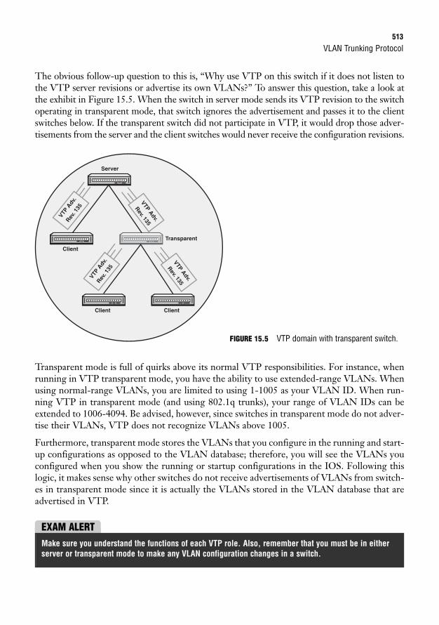
VLAN Trunking Protocol513
The obvious follow-up question to this is, “Why use VTP on this switch if it does not listen tothe VTP server revisions or advertise its own VLANs?” To answer this question, take a look atthe exhibit in Figure 15.5. When the switch in server mode sends its VTP revision to the switchoperating in transparent mode, that switch ignores the advertisement and passes it to the clientswitches below. If the transparent switch did not participate in VTP, it would drop those adver-tisements from the server and the client switches would never receive the configuration revisions.
Transparent
Client
Server
VTP A
dv.
Rev. 1
35
VTP A
dv.
Rev. 1
35
VTP Adv.
Rev. 135
VTP Adv.
Rev. 135
Client Client
Transparent mode is full of quirks above its normal VTP responsibilities. For instance, whenrunning in VTP transparent mode, you have the ability to use extended-range VLANs. Whenusing normal-range VLANs, you are limited to using 1-1005 as your VLAN ID. When run-ning VTP in transparent mode (and using 802.1q trunks), your range of VLAN IDs can beextended to 1006-4094. Be advised, however, since switches in transparent mode do not adver-tise their VLANs, VTP does not recognize VLANs above 1005.
Furthermore, transparent mode stores the VLANs that you configure in the running and start-up configurations as opposed to the VLAN database; therefore, you will see the VLANs youconfigured when you show the running or startup configurations in the IOS. Following thislogic, it makes sense why other switches do not receive advertisements of VLANs from switch-es in transparent mode since it is actually the VLANs stored in the VLAN database that areadvertised in VTP.
FIGURE 15.5 VTP domain with transparent switch.
EXAM ALERTMake sure you understand the functions of each VTP role. Also, remember that you must be in eitherserver or transparent mode to make any VLAN configuration changes in a switch.
514
VTP PruningVLAN traffic is being sent over trunk links to other switches no matter whether or not theVLAN is active on an interface. In other words, if a user connected to VLAN 2 sends a broad-cast, that message is replicated to all switches in the domain regardless of whether VLAN 2 isassigned to a switch port. This could consume unnecessary bandwidth on the trunk links con-necting the switches.
To minimize the traffic overhead, you can configure VTP pruning on the VTP server of thedomain. When enabled, switches advertise to each other which VLANs are active. With thisinformation, the switch can limit VLAN traffic to other switches that do not have the VLANactive on an interface, minimizing the amount of unnecessary traffic that is sent to otherswitches on the trunk link.
Configuring and Verifying VTPObjective:
. Configure, verify, and troubleshoot VTP
Similar to the VLAN configurations, VTP is stored in the VLAN database. From global con-figuration mode, you can easily change the VTP mode of the switch from server to transpar-ent or client mode. In addition, you can define your VTP domain name as well as assign anMD5 password for VTP updates. The domain name (and password if configured) are case sen-sitive and must match in all switches in the VTP domain or the VTP updates will be ignoredfrom other switches and VTP will not function.
To configure VTP-specific properties, use the vtp command followed by the VTP parameteryou want to configure as illustrated in the following configuration example:
Chapter 15: Virtual LANs
VTP Revision Mayhem Recall that when adding a new switch to an existing VTP domain, it is highly rec-ommended that you put the switch in client mode. If you left your switch in the default server mode, youcould possibly have a higher revision number than the existing server of the domain. If you add thatswitch to the domain and you do not have any VLANs configured, when you advertise that to the rest ofthe VTP domain, the client and the other server use that configuration because it has a higher number.That would cause all the VLANs to be removed in all switches because your VLAN database does not con-tain any VLAN configurations.
To reset your revision number, you can either change the name of your VTP domain to a bogus domainname and set it back to the existing domain name or set your switch to transparent mode followed byreturning it to server or client mode.
CAUTION
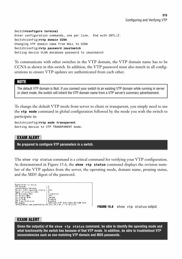
Configuring and Verifying VTP515
Switch#configure terminalEnter configuration commands, one per line. End with CNTL/Z.Switch(config)#vtp domain CCNAChanging VTP domain name from NULL to CCNASwitch(config)#vtp password imustmatchSetting device VLAN database password to imustmatch
To communicate with other switches in the VTP domain, the VTP domain name has to beCCNA as shown in this switch. In addition, the VTP password must also match in all config-urations to ensure VTP updates are authenticated from each other.
The default VTP domain is Null. If you connect your switch to an existing VTP domain while running in serveror client mode, the switch will inherit the VTP domain name from a VTP server’s summary advertisement.
NOTE
EXAM ALERTBe prepared to configure VTP parameters in a switch.
The show vtp status command is a critical command for verifying your VTP configuration.As demonstrated in Figure 15.6, the show vtp status command displays the revision num-ber of the VTP updates from the server, the operating mode, domain name, pruning status,and the MD5 digest of the password.
To change the default VTP mode from server to client or transparent, you simply need to usethe vtp mode command in global configuration followed by the mode you wish the switch toparticipate in:Switch(config)#vtp mode transparentSetting device to VTP TRANSPARENT mode.
FIGURE 15.6 show vtp status output.
EXAM ALERTGiven the output(s) of the show vtp status command, be able to identify the operating mode andwhat functionality the switch has because of that VTP mode. In addition, be able to troubleshoot VTPinconsistencies such as non-matching VTP domain and MD5 passwords.
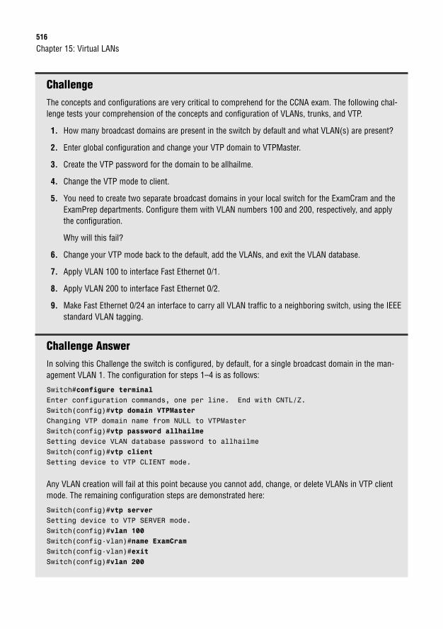
516
ChallengeThe concepts and configurations are very critical to comprehend for the CCNA exam. The following chal-lenge tests your comprehension of the concepts and configuration of VLANs, trunks, and VTP.
1. How many broadcast domains are present in the switch by default and what VLAN(s) are present?
2. Enter global configuration and change your VTP domain to VTPMaster.
3. Create the VTP password for the domain to be allhailme.
4. Change the VTP mode to client.
5. You need to create two separate broadcast domains in your local switch for the ExamCram and theExamPrep departments. Configure them with VLAN numbers 100 and 200, respectively, and applythe configuration.
Why will this fail?
6. Change your VTP mode back to the default, add the VLANs, and exit the VLAN database.
7. Apply VLAN 100 to interface Fast Ethernet 0/1.
8. Apply VLAN 200 to interface Fast Ethernet 0/2.
9. Make Fast Ethernet 0/24 an interface to carry all VLAN traffic to a neighboring switch, using the IEEEstandard VLAN tagging.
Challenge AnswerIn solving this Challenge the switch is configured, by default, for a single broadcast domain in the man-agement VLAN 1. The configuration for steps 1–4 is as follows:
Switch#configure terminalEnter configuration commands, one per line. End with CNTL/Z.Switch(config)#vtp domain VTPMasterChanging VTP domain name from NULL to VTPMasterSwitch(config)#vtp password allhailmeSetting device VLAN database password to allhailmeSwitch(config)#vtp clientSetting device to VTP CLIENT mode.
Any VLAN creation will fail at this point because you cannot add, change, or delete VLANs in VTP clientmode. The remaining configuration steps are demonstrated here:
Switch(config)#vtp serverSetting device to VTP SERVER mode.Switch(config)#vlan 100Switch(config-vlan)#name ExamCramSwitch(config-vlan)#exitSwitch(config)#vlan 200
Chapter 15: Virtual LANs
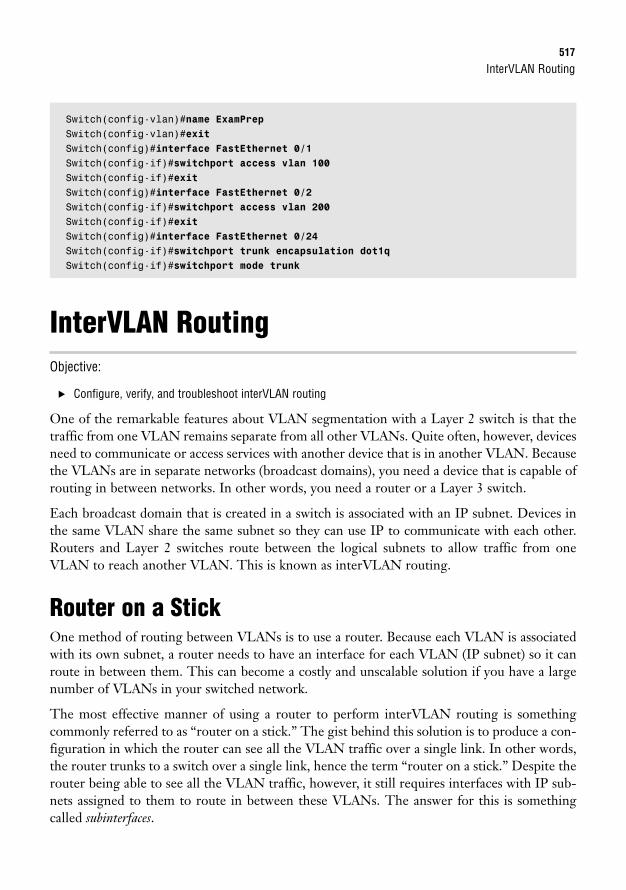
InterVLAN Routing517
Switch(config-vlan)#name ExamPrepSwitch(config-vlan)#exitSwitch(config)#interface FastEthernet 0/1Switch(config-if)#switchport access vlan 100Switch(config-if)#exitSwitch(config)#interface FastEthernet 0/2Switch(config-if)#switchport access vlan 200Switch(config-if)#exitSwitch(config)#interface FastEthernet 0/24Switch(config-if)#switchport trunk encapsulation dot1qSwitch(config-if)#switchport mode trunk
InterVLAN RoutingObjective:
. Configure, verify, and troubleshoot interVLAN routing
One of the remarkable features about VLAN segmentation with a Layer 2 switch is that thetraffic from one VLAN remains separate from all other VLANs. Quite often, however, devicesneed to communicate or access services with another device that is in another VLAN. Becausethe VLANs are in separate networks (broadcast domains), you need a device that is capable ofrouting in between networks. In other words, you need a router or a Layer 3 switch.
Each broadcast domain that is created in a switch is associated with an IP subnet. Devices inthe same VLAN share the same subnet so they can use IP to communicate with each other.Routers and Layer 2 switches route between the logical subnets to allow traffic from oneVLAN to reach another VLAN. This is known as interVLAN routing.
Router on a StickOne method of routing between VLANs is to use a router. Because each VLAN is associatedwith its own subnet, a router needs to have an interface for each VLAN (IP subnet) so it canroute in between them. This can become a costly and unscalable solution if you have a largenumber of VLANs in your switched network.
The most effective manner of using a router to perform interVLAN routing is somethingcommonly referred to as “router on a stick.” The gist behind this solution is to produce a con-figuration in which the router can see all the VLAN traffic over a single link. In other words,the router trunks to a switch over a single link, hence the term “router on a stick.” Despite therouter being able to see all the VLAN traffic, however, it still requires interfaces with IP sub-nets assigned to them to route in between these VLANs. The answer for this is somethingcalled subinterfaces.
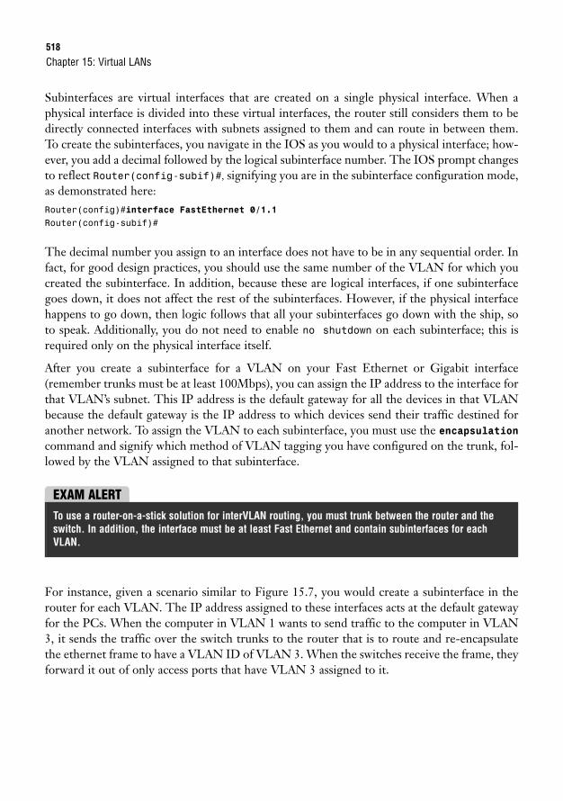
518
Subinterfaces are virtual interfaces that are created on a single physical interface. When aphysical interface is divided into these virtual interfaces, the router still considers them to bedirectly connected interfaces with subnets assigned to them and can route in between them.To create the subinterfaces, you navigate in the IOS as you would to a physical interface; how-ever, you add a decimal followed by the logical subinterface number. The IOS prompt changesto reflect Router(config-subif)#, signifying you are in the subinterface configuration mode,as demonstrated here:Router(config)#interface FastEthernet 0/1.1Router(config-subif)#
The decimal number you assign to an interface does not have to be in any sequential order. Infact, for good design practices, you should use the same number of the VLAN for which youcreated the subinterface. In addition, because these are logical interfaces, if one subinterfacegoes down, it does not affect the rest of the subinterfaces. However, if the physical interfacehappens to go down, then logic follows that all your subinterfaces go down with the ship, soto speak. Additionally, you do not need to enable no shutdown on each subinterface; this isrequired only on the physical interface itself.
After you create a subinterface for a VLAN on your Fast Ethernet or Gigabit interface(remember trunks must be at least 100Mbps), you can assign the IP address to the interface forthat VLAN’s subnet. This IP address is the default gateway for all the devices in that VLANbecause the default gateway is the IP address to which devices send their traffic destined foranother network. To assign the VLAN to each subinterface, you must use the encapsulationcommand and signify which method of VLAN tagging you have configured on the trunk, fol-lowed by the VLAN assigned to that subinterface.
Chapter 15: Virtual LANs
EXAM ALERTTo use a router-on-a-stick solution for interVLAN routing, you must trunk between the router and theswitch. In addition, the interface must be at least Fast Ethernet and contain subinterfaces for eachVLAN.
For instance, given a scenario similar to Figure 15.7, you would create a subinterface in therouter for each VLAN. The IP address assigned to these interfaces acts at the default gatewayfor the PCs. When the computer in VLAN 1 wants to send traffic to the computer in VLAN3, it sends the traffic over the switch trunks to the router that is to route and re-encapsulatethe ethernet frame to have a VLAN ID of VLAN 3. When the switches receive the frame, theyforward it out of only access ports that have VLAN 3 assigned to it.
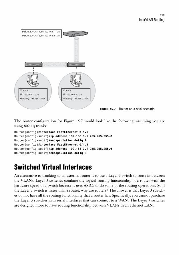
InterVLAN Routing519
The router configuration for Figure 15.7 would look like the following, assuming you areusing 802.1q trunks:Router(config)#interface FastEthernet 0/1.1Router(config-subif)#ip address 192.168.1.1 255.255.255.0Router(config-subif)#encapsulation dot1q 1Router(config)#interface FastEthernet 0/1.3Router(config-subif)#ip address 192.168.3.1 255.255.255.0Router(config-subif)#encapsulation dot1q 3
Switched Virtual InterfacesAn alternative to trunking to an external router is to use a Layer 3 switch to route in betweenthe VLANs. Layer 3 switches combine the logical routing functionality of a router with thehardware speed of a switch because it uses ASICs to do some of the routing operations. So ifthe Layer 3 switch is faster than a router, why use routers? The answer is that Layer 3 switch-es do not have all the routing functionality that a router has. Specifically, you cannot purchasethe Layer 3 switches with serial interfaces that can connect to a WAN. The Layer 3 switchesare designed more to have routing functionality between VLANs in an ethernet LAN.
VLAN 1
IP: 192.168.1.2/24
Gateway: 192.168.1.1/24
VLAN 3
IP: 192.168.3.2/24
Gateway: 192.168.3.1/24
Int f0/1.1, VLAN 1, IP: 192.168.1.1/24
Int f0/1.3, VLAN 3, IP: 192.168.3.1/24
FIGURE 15.7 Router-on-a-stick scenario.
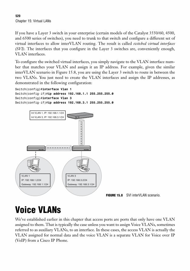
520
If you have a Layer 3 switch in your enterprise (certain models of the Catalyst 3550/60, 4500,and 6500 series of switches), you need to trunk to that switch and configure a different set ofvirtual interfaces to allow interVLAN routing. The result is called switched virtual interfaces(SVI). The interfaces that you configure in the Layer 3 switches are, conveniently enough,VLAN interfaces.
To configure the switched virtual interfaces, you simply navigate to the VLAN interface num-ber that matches your VLAN and assign it an IP address. For example, given the similarinterVLAN scenario in Figure 15.8, you are using the Layer 3 switch to route in between thetwo VLANs. You just need to create the VLAN interfaces and assign the IP addresses, asdemonstrated in the following configuration:Switch(config)#interface Vlan 1Switch(config-if)#ip address 192.168.1.1 255.255.255.0Switch(config)#interface Vlan 3Switch(config-if)#ip address 192.168.3.1 255.255.255.0
Chapter 15: Virtual LANs
VLAN 1
IP: 192.168.1.2/24
Gateway: 192.168.1.1/24
VLAN 3
IP: 192.168.3.2/24
Gateway: 192.168.3.1/24
Int VLAN 1, IP: 192.168.1.1/24
Int VLAN 3, IP: 192.168.3.1/24
FIGURE 15.8 SVI interVLAN scenario.
Voice VLANsWe’ve established earlier in this chapter that access ports are ports that only have one VLANassigned to them. That is typically the case unless you want to assign Voice VLANs, sometimesreferred to as auxiliary VLANs, to an interface. In these cases, the access VLAN is actually theVLAN assigned for normal data and the voice VLAN is a separate VLAN for Voice over IP(VoIP) from a Cisco IP Phone.
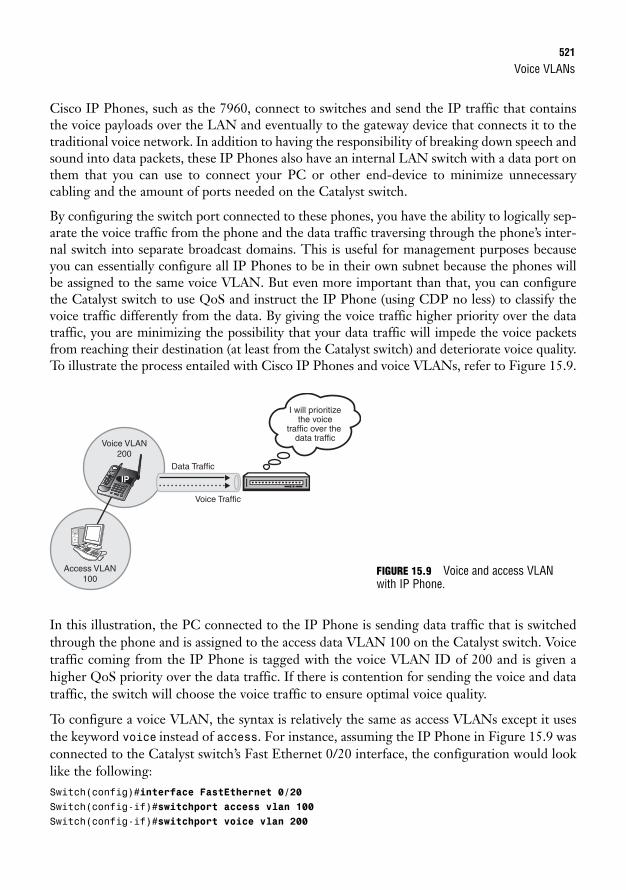
Voice VLANs521
Cisco IP Phones, such as the 7960, connect to switches and send the IP traffic that containsthe voice payloads over the LAN and eventually to the gateway device that connects it to thetraditional voice network. In addition to having the responsibility of breaking down speech andsound into data packets, these IP Phones also have an internal LAN switch with a data port onthem that you can use to connect your PC or other end-device to minimize unnecessarycabling and the amount of ports needed on the Catalyst switch.
By configuring the switch port connected to these phones, you have the ability to logically sep-arate the voice traffic from the phone and the data traffic traversing through the phone’s inter-nal switch into separate broadcast domains. This is useful for management purposes becauseyou can essentially configure all IP Phones to be in their own subnet because the phones willbe assigned to the same voice VLAN. But even more important than that, you can configurethe Catalyst switch to use QoS and instruct the IP Phone (using CDP no less) to classify thevoice traffic differently from the data. By giving the voice traffic higher priority over the datatraffic, you are minimizing the possibility that your data traffic will impede the voice packetsfrom reaching their destination (at least from the Catalyst switch) and deteriorate voice quality.To illustrate the process entailed with Cisco IP Phones and voice VLANs, refer to Figure 15.9.
I will prioritizethe voice
traffic over the data traffic
Data Traffic
Voice Traffic
Voice VLAN200
Access VLAN100
IP
In this illustration, the PC connected to the IP Phone is sending data traffic that is switchedthrough the phone and is assigned to the access data VLAN 100 on the Catalyst switch. Voicetraffic coming from the IP Phone is tagged with the voice VLAN ID of 200 and is given ahigher QoS priority over the data traffic. If there is contention for sending the voice and datatraffic, the switch will choose the voice traffic to ensure optimal voice quality.
To configure a voice VLAN, the syntax is relatively the same as access VLANs except it usesthe keyword voice instead of access. For instance, assuming the IP Phone in Figure 15.9 wasconnected to the Catalyst switch’s Fast Ethernet 0/20 interface, the configuration would looklike the following:Switch(config)#interface FastEthernet 0/20Switch(config-if)#switchport access vlan 100Switch(config-if)#switchport voice vlan 200
FIGURE 15.9 Voice and access VLANwith IP Phone.
522
Troubleshooting VLANObjectives:
. Configure, verify, and troubleshoot VLANs
. Configure, verify, and troubleshoot trunking on Cisco switches
. Configure, verify, and troubleshoot interVLAN routing
. Configure, verify, and troubleshoot VTP
I am sure by this point you recognize the usefulness of segmenting your LAN into separatebroadcast domains using VLANs. Unfortunately, this valuable Layer 2 technology is not with-out its share of problems that can (and typically do) arise when implementing VLANs in aswitched environment. By logically narrowing down the possible causes based upon the symp-toms and using the verification commands learned in this chapter, you should be able to tacklethe majority of anomalies that occur in a small-to-medium sized switched network with VLANs.
One of the most common symptoms that may arise when implementing VLANs is the inabil-ity to have end-devices able to communicate with each other. The list of possible causes forthis can be endless; however, the following questions and solutions will address the most preva-lent problems:
1. Is this one of the design requirements of implementing VLANs in the first place? Recallthat a major benefit of VLANs is to logically separate traffic into separate broadcastdomains. If devices are in separate VLANs and do not have a router or Layer 3 switchto route in between the VLANs, then this is the result that is supposed to occur.
2. Are the trunks operating correctly between the switches? Assuming that you have mul-tiple switches, verify the configuration and the status of the switch trunks by using theshow interfaces trunk command. If the trunk link is not operating correctly, use theOSI model as a guide and begin with the Physical layer by verifying the cable betweenthe switches is a cross-over ethernet cable. Once that is verified, move up to the DataLink layer and check your trunk configuration. Specifically, make sure trunk negotia-tion was successful, especially if your network is not an all-Cisco switched network.When in doubt, manually configure each side of the link to trunk by using the switchport mode trunk command.
3. Are the end-devices assigned to the correct VLANs? If they are designed to be in thesame VLAN, verify the VLAN names match and they are assigned to the correct inter-faces by using the show vlans command. If they are on separate VLANs, verify yourconfiguration and the status of the interfaces on your router or your Layer 3 switch. Inaddition, ensure that the end-devices are utilizing the IP address of the subinterface orswitched virtual interface as their default gateway.
Chapter 15: Virtual LANs
Troubleshooting VLAN523
4. If using 802.1q trunks, are both switches sharing the trunk using the same nativeVLAN? Recall that VLAN leakage can occur if both sides of the trunk are not config-ured with the same VLAN. Verify the native VLAN on both switches by utilizing theshow interfaces trunk command.
The next troubleshooting scenario we will look at revolves around the possibility that outputof the show vlan command reveals that your VLANs in your switch are missing or are incon-sistent with what you originally configured in the rest of your switches:
1. Is your switch in VTP transparent mode? Mismatched VLANs is not only possible intransparent mode, but it is actually one of the reasons to use transparent mode. In addi-tion, it might also explain why you do not see your VLANs since they will not show upin the VLAN database, but they can be found in your running or startup configuration.
2. Are the VTP configuration revision numbers incrementing along with the otherswitches in the network? It is plausible that the switch has lost a connection to the restof the switched network. Verify the trunk is configured and operating as mentioned inthe first scenario. Secondly, it may be possible that the management VLAN (VLAN 1by default) is being blocked from propagating between the trunks (we will look intohow to change the management VLAN and only allow certain VLANs over trunks inChapter 16, “Implementing Switch Security.”) Recall that the management IP, CDP,and VTP advertisements all are advertised using the management VLAN betweenswitches. As a result, if the management VLAN is being blocked, VTP advertisementsare consequently being blocked as well. Finally, there may be a switch that was addedto your network between you and the VTP server that is configured for a differentVTP domain. When the VTP server sends its VTP advertisements to the interjectorswitch, it will discard the VTP advertisement because it is not in the same VTPdomain. The end result is that your switch never receives those VTP advertisementsand your VTP configuration revisions will not increase.
3. Is there another VTP server in your switched internetwork? It is common to have sev-eral VTP servers in a network for redundancy; however, if another administrator isadding, changing, and/or removing VLANs on other VTP server switches, it willincrement its configuration revision and all other switches in client and server modewill follow suit. If a VTP server is added and does not have any VLANs configured,that would explain it if all of your configured VLANs have suddenly disappeared aswell. You can verify this by issuing the show vtp status command which will showyou the IP address of the last VTP updater if known.
4. Has there been any configuration changes to the VTP domain or VTP passwords? Ifyour switch does not have matching VTP domain names or VTP passwords, the switchwill not accept VTP advertisements. This can be verified using the show vtp statuscommand on each switch. If you suspect the password is not matching, use the showvtp password command from privileged EXEC.
524
Chapter SummaryVLANs are convenient for segmenting broadcast domains at Layer 2. The departments of anenterprise can be assigned their own logical VLAN to ensure traffic in one VLAN does notaffect other VLANs. In fact, VLAN traffic cannot go from one VLAN to another VLAN with-out the assistance of an external router or a Layer 3 switch.
VLANs can be statically assigned to switch access ports, or a VMPS can be used to assign themdynamically. By default, all interfaces are assigned to the management VLAN, VLAN 1. Toconfigure a VLAN, enter global configuration and create the VLAN and name it. After theVLANs are created, you must assign them to your switch ports by using the switchportaccess vlan command.
VLANs can span multiple switches by using ISL or 802.1q trunks. This makes it simple to moveusers throughout a switched network with no geographic restrictions. ISL is a Cisco proprietaryVLAN tagging that encapsulates the original ethernet frame with a 26-byte header and a 4-byteCRC. Because this exceeds a typical frame MTU, the trunk must be point-to-point (directlyconnected). 802.1q is an IEEE standard of frame tagging that inserts the VLAN ID in the orig-inal ethernet frame and calculates a new CRC. 802.1q also uses the concept of native VLANs,which are VLANs that are not tagged as they traverse a trunk. To configure a trunk, you mustfirst define the encapsulation method with the switchport trunk encapsulation command,and then set the interface to trunk with the switchport mode trunk command.
To minimize the amount of VLAN administration in switches, Cisco created VTP, whichentails a VTP server sending advertisements with revision numbers containing the VLANs inthe VTP domain. VTP clients use that information from the server; however, they cannot cre-ate, modify, or delete any VLANs. Transparent mode does not use the information sent fromVTP servers; conversely, they can create, modify, or delete (but not advertise) their VLANs.VTP configuration also transpires from global configuration, in which you can switch theswitch’s operating mode, define the domain name, and assign a VTP password for updateauthentication.
To allow traffic from one VLAN to another, you must configure interVLAN routing. If youuse an external router (router on stick), you must trunk to the interface and configure subin-terfaces to route in between the VLANs. If your switched network has a Layer 3 switch, youcan use that as the routing device between VLANs by creating a switched virtual interface(SVI) and assigning an IP to it.
Chapter 15: Virtual LANs
Chapter Summary525
Key Terms. VLANs
. access ports
. PVST
. VMPS
. management VLAN
. trunk
. multiplexing
. ISL
. 802.1q
. native VLANs
. DTP
. VTP
. VTP Domains
. server mode
. client mode
. transparent mode
. VTP pruning
. port security
. interVLAN routing
. router on a stick
. subinterfaces
. SVI
. Voice VLAN
526
Apply Your Knowledge
Exercises
15.1 Create Your VTP Domain
In this exercise you establish your own VTP domain and ensure that your switch propagates the VLANsyou will create in Exercise 15.2.
Chapter 15: Virtual LANs
These exercises assume that you have two Cisco Catalyst switches. As always, if you do not have theequipment, mentally go through the configuration and practice typing the commands as you would if youwere configuring the switches.
NOTE
Estimated Time: 10 minutes
1. Enter global configuration.
2. Configure your switch for VTP server mode (default, but for redundancy’s sake).
3. Name the VTP domain GoldiLocks (remember domain name is case-sensitive).
4. Create a VTP password for VTP updates to be 3Bears (remember password is case-sensitive).
5. Exit global configuration and verify the configuration with the show vtp status command.
15.2 VLAN Creation and Assignment
In this exercise you create the VLANs that will be propagated by the VTP domain created in Exercise 15.1and forwarded by the trunks in Exercise 15.3.
Estimated Time: 15 minutes
1. Enter global configuration.
2. Create VLAN 100 with the name 2hot.
3. Create VLAN 200 with the name 2cold.
4. Create VLAN 300 with the name justright.
5. Exit global configuration.
6. Assign VLAN 100 to interface Fast Ethernet 0/1.
7. Assign VLAN 200 to interface Fast Ethernet 0/2.
8. Assign VLAN 300 to interface Fast Ethernet 0/3
9. Verify VLAN configuration with the show vlan command.
Apply Your Knowledge527
15.3 802.1q Trunking
This exercise enables the VLAN traffic to span multiple switches with IEEE 802.1q trunking.
Estimated Time: 5 minutes
1. Connect the switches together with a cross-over ethernet cable using interface 0/12.
2. Configure Fast Ethernet 0/12 to 802.1q encapsulation.
3. Set the interface mode to trunking.
4. Verify your trunk with the show interface trunk command.
15.4 InterVLAN Routing
This exercise enables traffic to be routed from one VLAN to another with an external router.
Estimated Time: 15 minutes
1. Connect the switch to the router’s Fast Ethernet interface with a straight-through cable.
2. Configure the switch port to become an 802.1q trunk (see Exercise 15.3).
3. Configure a subinterface for VLAN 100, 200, and 300 (set their encapsulation to dot1q and assigntheir respective VLANs).
4. Assign an IP address to each subinterface (from different subnets).
Review Questions1. What are the characteristics of VLANs?
2. What are trunks and how do they work?
3. What is the purpose of VTP?
4. What are the characteristics of the three VTP modes?
5. Why is router-on-a-stick sometimes necessary in switched environments?
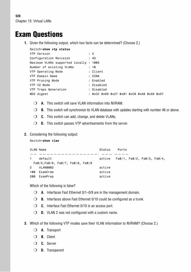
528
Exam Questions1. Given the following output, which two facts can be determined? (Choose 2.)
Switch>show vtp statusVTP Version : 2Configuration Revision : 45Maximum VLANs supported locally : 1005Number of existing VLANs : 10VTP Operating Mode : ClientVTP Domain Name : CCNAVTP Pruning Mode : EnabledVTP V2 Mode : DisabledVTP Traps Generation : DisabledMD5 digest : 0xCC 0x69 0x27 0x01 0xC8 0xA8 0x59 0xD7
❍ A. This switch will save VLAN information into NVRAM.
❍ B. This switch will synchronize its VLAN database with updates starting with number 46 or above.
❍ C. This switch can add, change, and delete VLANs.
❍ D. This switch passes VTP advertisements from the server.
2. Considering the following output:
Switch>show vlan
VLAN Name Status Ports—— ————————————————- ——— ————1 default active Fa0/1, Fa0/2, Fa0/3, Fa0/4,Fa0/5,Fa0/6, Fa0/7, Fa0/8, Fa0/9
2 VLAN0002 active100 ExamCram active200 ExamPrep active
Which of the following is false?
❍ A. Interfaces Fast Ethernet 0/1–0/9 are in the management domain.
❍ B. Interfaces above Fast Ethernet 0/10 could be configured as a trunk.
❍ C. Interface Fast Ethernet 0/10 is an access port.
❍ D. VLAN 2 was not configured with a custom name.
3. Which of the following VTP modes save their VLAN information to NVRAM? (Choose 2.)
❍ A. Transport
❍ B. Client
❍ C. Server
❍ D. Transparent
Chapter 15: Virtual LANs
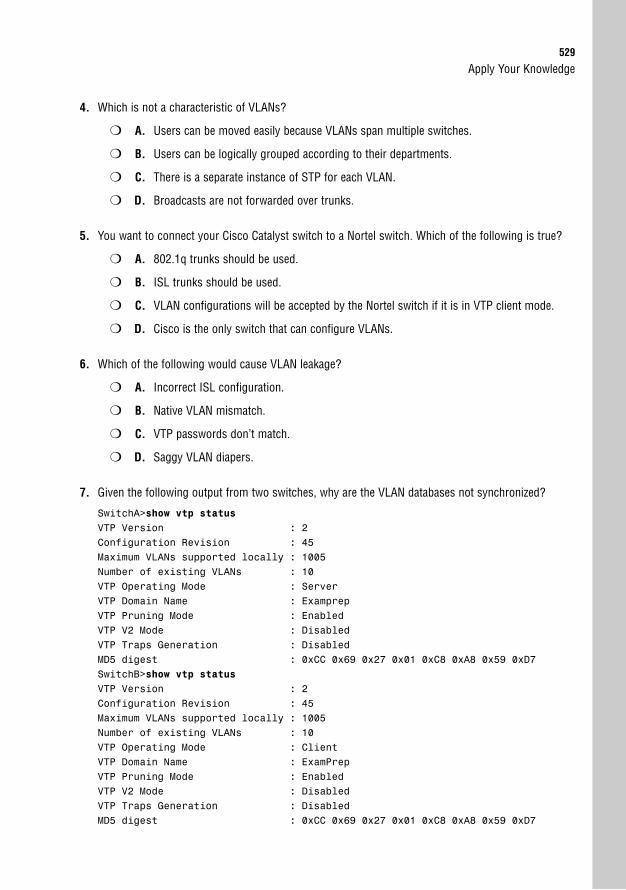
Apply Your Knowledge529
4. Which is not a characteristic of VLANs?
❍ A. Users can be moved easily because VLANs span multiple switches.
❍ B. Users can be logically grouped according to their departments.
❍ C. There is a separate instance of STP for each VLAN.
❍ D. Broadcasts are not forwarded over trunks.
5. You want to connect your Cisco Catalyst switch to a Nortel switch. Which of the following is true?
❍ A. 802.1q trunks should be used.
❍ B. ISL trunks should be used.
❍ C. VLAN configurations will be accepted by the Nortel switch if it is in VTP client mode.
❍ D. Cisco is the only switch that can configure VLANs.
6. Which of the following would cause VLAN leakage?
❍ A. Incorrect ISL configuration.
❍ B. Native VLAN mismatch.
❍ C. VTP passwords don’t match.
❍ D. Saggy VLAN diapers.
7. Given the following output from two switches, why are the VLAN databases not synchronized?
SwitchA>show vtp statusVTP Version : 2Configuration Revision : 45Maximum VLANs supported locally : 1005Number of existing VLANs : 10VTP Operating Mode : ServerVTP Domain Name : ExamprepVTP Pruning Mode : EnabledVTP V2 Mode : DisabledVTP Traps Generation : DisabledMD5 digest : 0xCC 0x69 0x27 0x01 0xC8 0xA8 0x59 0xD7SwitchB>show vtp statusVTP Version : 2Configuration Revision : 45Maximum VLANs supported locally : 1005Number of existing VLANs : 10VTP Operating Mode : ClientVTP Domain Name : ExamPrepVTP Pruning Mode : EnabledVTP V2 Mode : DisabledVTP Traps Generation : DisabledMD5 digest : 0xCC 0x69 0x27 0x01 0xC8 0xA8 0x59 0xD7
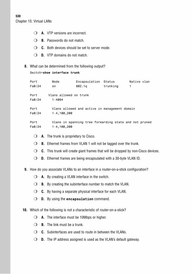
530
❍ A. VTP versions are incorrect.
❍ B. Passwords do not match.
❍ C. Both devices should be set to server mode.
❍ D. VTP domains do not match.
8. What can be determined from the following output?
Switch>show interface trunk
Port Mode Encapsulation Status Native vlanFa0/24 on 802.1q trunking 1
Port Vlans allowed on trunkFa0/24 1-4094
Port Vlans allowed and active in management domainFa0/24 1-4,100,200
Port Vlans in spanning tree forwarding state and not prunedFa0/24 1-4,100,200
❍ A. The trunk is proprietary to Cisco.
❍ B. Ethernet frames from VLAN 1 will not be tagged over the trunk.
❍ C. This trunk will create giant frames that will be dropped by non-Cisco devices.
❍ D. Ethernet frames are being encapsulated with a 30-byte VLAN ID.
9. How do you associate VLANs to an interface in a router-on-a-stick configuration?
❍ A. By creating a VLAN interface in the switch.
❍ B. By creating the subinterface number to match the VLAN.
❍ C. By having a separate physical interface for each VLAN.
❍ D. By using the encapsulation command.
10. Which of the following is not a characteristic of router-on-a-stick?
❍ A. The interface must be 10Mbps or higher.
❍ B. The link must be a trunk.
❍ C. Subinterfaces are used to route in between the VLANs.
❍ D. The IP address assigned is used as the VLAN’s default gateway.
Chapter 15: Virtual LANs
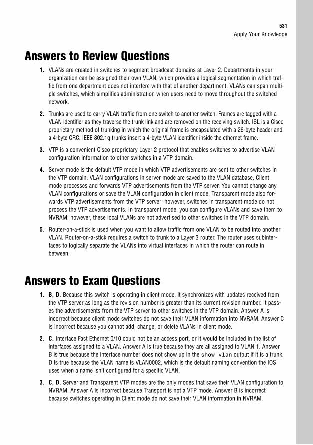
Apply Your Knowledge531
Answers to Review Questions1. VLANs are created in switches to segment broadcast domains at Layer 2. Departments in your
organization can be assigned their own VLAN, which provides a logical segmentation in which traf-fic from one department does not interfere with that of another department. VLANs can span multi-ple switches, which simplifies administration when users need to move throughout the switchednetwork.
2. Trunks are used to carry VLAN traffic from one switch to another switch. Frames are tagged with aVLAN identifier as they traverse the trunk link and are removed on the receiving switch. ISL is a Ciscoproprietary method of trunking in which the original frame is encapsulated with a 26-byte header anda 4-byte CRC. IEEE 802.1q trunks insert a 4-byte VLAN identifier inside the ethernet frame.
3. VTP is a convenient Cisco proprietary Layer 2 protocol that enables switches to advertise VLANconfiguration information to other switches in a VTP domain.
4. Server mode is the default VTP mode in which VTP advertisements are sent to other switches inthe VTP domain. VLAN configurations in server mode are saved to the VLAN database. Clientmode processes and forwards VTP advertisements from the VTP server. You cannot change anyVLAN configurations or save the VLAN configuration in client mode. Transparent mode also for-wards VTP advertisements from the VTP server; however, switches in transparent mode do notprocess the VTP advertisements. In transparent mode, you can configure VLANs and save them toNVRAM; however, these local VLANs are not advertised to other switches in the VTP domain.
5. Router-on-a-stick is used when you want to allow traffic from one VLAN to be routed into anotherVLAN. Router-on-a-stick requires a switch to trunk to a Layer 3 router. The router uses subinter-faces to logically separate the VLANs into virtual interfaces in which the router can route inbetween.
Answers to Exam Questions1. B, D. Because this switch is operating in client mode, it synchronizes with updates received from
the VTP server as long as the revision number is greater than its current revision number. It pass-es the advertisements from the VTP server to other switches in the VTP domain. Answer A isincorrect because client mode switches do not save their VLAN information into NVRAM. Answer Cis incorrect because you cannot add, change, or delete VLANs in client mode.
2. C. Interface Fast Ethernet 0/10 could not be an access port, or it would be included in the list ofinterfaces assigned to a VLAN. Answer A is true because they are all assigned to VLAN 1. AnswerB is true because the interface number does not show up in the show vlan output if it is a trunk.D is true because the VLAN name is VLAN0002, which is the default naming convention the IOSuses when a name isn’t configured for a specific VLAN.
3. C, D. Server and Transparent VTP modes are the only modes that save their VLAN configuration toNVRAM. Answer A is incorrect because Transport is not a VTP mode. Answer B is incorrectbecause switches operating in Client mode do not save their VLAN information in NVRAM.
532
4. D. Broadcasts will still be forwarded over trunks to other switches in the same VLAN. Broadcastsin one VLAN, however, do not affect other VLANs. Answers A, B, and C are all characteristics thatapply to VLANs.
5. A. Because you are connecting to a Nortel switch, you must use a standard method of trunking(IEEE 802.1q). ISL and VTP are Cisco proprietary functions. Answer B is incorrect because ISL is aCisco proprietary trunk encapsulation. Answer C is incorrect because VTP is a Cisco proprietaryprotocol. Answer D is false because other switch manufacturers support VLAN configurations.
6. B. VLAN leakage occurs when there is a VLAN mismatch on a trunk link with 802.1q. Answer A isincorrect because ISL does not use native VLANs. Answer C is incorrect because VTP does notaffect VLAN leakage. Answer D is incorrect because switches don’t wear diapers.
7. D. The domain names are case sensitive. If they do not match, the switches cannot synchronizetheir VLAN database information. Answer A is incorrect because both switches are operating in thesame VPT version. Based upon the fact that the MD5 digest of the VTP password is identical,Answer B is incorrect. Answer C is incorrect because both switches do not need to be in servermode in order for the switches to exchange VLAN configurations via VTP.
8. B. Because the trunk is 802.1q with a native VLAN of 1, ethernet frames originating from VLAN 1going over this trunk are not tagged. Answers A, C, and D are incorrect because they are charac-teristics of ISL.
9. D. The encapsulation command is used to assign VLANs to a subinterface. Answer A is incorrect because SVIs are in Layer 3 switches, not external routers. Answer B is a good designpractice, but does not assign the VLANs to the subinterface. Answer C is incorrect because router-on-a-stick is over one interface.
10. A. Because the interface must be a trunk, the speed of the link should be 100Mbps or greater.Answers B, C, and D are all characteristics of router-on-a-stick.
Suggested Readings and Resources1. Barnes, David and Sakandar, Basir. Cisco LAN Switching Fundamentals. Cisco Press,
2004.
2. Castelli, Matthew J. LAN Switching first-step. Cisco Press, 2004.
3. “Virtual Local Area Networks,” www.firewall.cx.
4. “Configuring VLANs,” Catalyst 3560 Configuration Guide on www.cisco.com.
Chapter 15: Virtual LANs
16C H A P T E R S I X T E E N
Implementing Switch Security
ObjectivesThis chapter covers the following Cisco-specific objectives for the “Configure, verify and trou-bleshoot a switch with VLANs and interswitch communications” section of the 640-802 CCNAexam:
. Implement basic switch security (including: port security, unassigned ports,trunk access, management vlan other than vlan1, etc.)
. Interpret the output of various show and debug commands to verify the operational status of a Cisco switched network
OutlineIntroduction 536
Securing Physical Access to the Catalyst Switch 536
Securing Terminal Access to the Catalyst Switch 536
To Telnet or Not to Telnet 538
Additional IOS Security Practices 539
Layer 2 Security 540
Port Security 540
Static MAC with Port Security 541
Verifying Port Security 542
VLAN Security 543
VTP Passwords 546
“See”DP 546
Chapter Summary 547
Key Terms 547
Apply Your Knowledge 548
Exercises 548
Review Questions 550
Exam Questions 550
Answers to Review Questions 554
Answers to Exam Questions 554
Suggested Readings and Resources 556
Study Strategies. Part of being thorough in securing your switched network is to think like an attacker. With
that in mind, try to consider ways in which your network is vulnerable and how you wouldgo about gaining access if you were the attacker.
. Many of the topics discussed in this chapter can also be applied to securing your router.Keep that in mind when reading these topics as a refresher on how to secure your Ciscodevices.
. Read the information presented in this chapter, paying special attention to tables, Notes,and Exam Alerts.
. Complete the Challenge and the Exercises at the end of the chapter. The exercises willsolidify the concepts that you have learned in the previous sections.
. Complete the Exam Questions at the end of the chapter. They are designed to simulate thetypes of questions you will be asked on the ICND1, ICND2, and CCNA exams.
536
IntroductionSecuring a network is an endless task. Every day there are new scripts and exploits, new vul-nerabilities, and new methods to gain access to your network. Our job as Cisco administratorsis to stay ahead of the game as much as possible and make it as difficult as possible to gain access.
As discussed in Chapter 4, ”General Network Security,” the basis of any good security imple-mentation is a thorough security policy. Switched networks must be a pivotal piece of that secu-rity policy; however, they are typically the most overlooked. The fact that the LAN is tuckedaway inside your network provides a false sense of security, especially because some of yourbiggest threats might be the users attached to the switched network. This chapter examines howto secure access to the Cisco devices in your LAN as well as the traffic that flows through it.
Securing Physical Access to the CatalystSwitchSimilar to troubleshooting, our first layer of defense for securing the switched network shouldstart at the Physical layer. Specifically, we need to secure access to the physical switch itself andthe cables that are connected to it. It doesn’t take a skilled attacker to physically destroy aswitched network to which he or she has complete access.
With that being said, the first and probably most critical step of securing your network is toensure that the switches themselves are secured in a cool room in which only you or thoseauthorized have access. If users have physical access to the switches, they can easily console intothe switch and perform a password-recovery exercise (easily found on the Internet) just byrepowering the switch and holding down a button during power-up. Even unintentional attackssuch as custodial staff unplugging your switches to run the vacuum can occur easily if not securedcorrectly. If you can, also make sure that the Ethernet cabling between the switches and enddevices is not in plain sight and therefore can’t be easily damaged. You don’t want the last act bya fired employee to be taking down your entire network by ripping out your existing wiring.
Chapter 16: Implementing Switch Security
EXAM ALERTPhysically securing Cisco devices is an integral step in implementing a secure Cisco network.
Securing Terminal Access to the CatalystSwitchAfter we have ensured that the switch is physically secured, the next layer of defense to imple-ment is securing terminal access to the switch so that attackers cannot perform reconnaissanceor manipulate configurations. Because there are several ways to gain access to the Cisco IOS,due diligence is required to ensure that all terminal connections are secured.
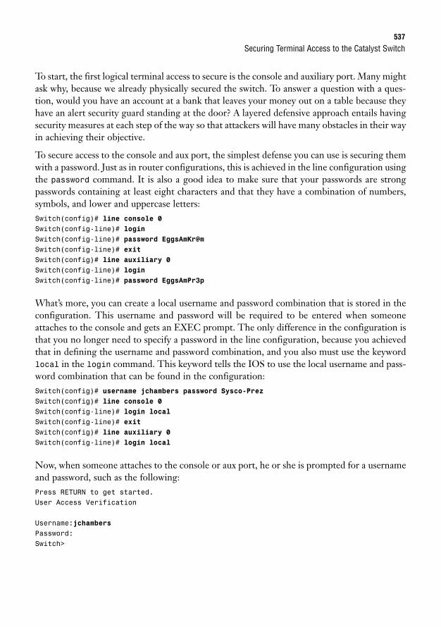
Securing Terminal Access to the Catalyst Switch537
To start, the first logical terminal access to secure is the console and auxiliary port. Many mightask why, because we already physically secured the switch. To answer a question with a ques-tion, would you have an account at a bank that leaves your money out on a table because theyhave an alert security guard standing at the door? A layered defensive approach entails havingsecurity measures at each step of the way so that attackers will have many obstacles in their wayin achieving their objective.
To secure access to the console and aux port, the simplest defense you can use is securing themwith a password. Just as in router configurations, this is achieved in the line configuration usingthe password command. It is also a good idea to make sure that your passwords are strongpasswords containing at least eight characters and that they have a combination of numbers,symbols, and lower and uppercase letters:Switch(config)# line console 0Switch(config-line)# loginSwitch(config-line)# password EggsAmKr@mSwitch(config-line)# exitSwitch(config)# line auxiliary 0Switch(config-line)# loginSwitch(config-line)# password EggsAmPr3p
What’s more, you can create a local username and password combination that is stored in theconfiguration. This username and password will be required to be entered when someoneattaches to the console and gets an EXEC prompt. The only difference in the configuration isthat you no longer need to specify a password in the line configuration, because you achievedthat in defining the username and password combination, and you also must use the keywordlocal in the login command. This keyword tells the IOS to use the local username and pass-word combination that can be found in the configuration:Switch(config)# username jchambers password Sysco-PrezSwitch(config)# line console 0Switch(config-line)# login localSwitch(config-line)# exitSwitch(config)# line auxiliary 0Switch(config-line)# login local
Now, when someone attaches to the console or aux port, he or she is prompted for a usernameand password, such as the following:Press RETURN to get started.User Access Verification
Username:jchambersPassword:Switch>
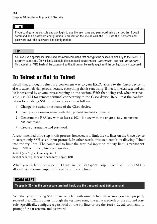
538
To Telnet or Not to TelnetRecall that although Telnet is a convenient way to gain EXEC access to the Cisco device, italso is extremely dangerous, because everything that is sent using Telnet is in clear text and canbe intercepted by anyone eavesdropping on the session. With that being said, whenever pos-sible, use SSH for remote terminal connectivity to the Cisco device. Recall that the configu-ration for enabling SSH on a Cisco device is as follows:
1. Change the default hostname of the Cisco device.
2. Configure a domain name with the ip domain-name command.
3. Generate the RSA key with at least a 1024-bit key with the crypto key generatersa command.
4. Create a username and password.
A recommended third step in this process, however, is to limit the vty lines on the Cisco deviceto accept only SSH as an input protocol. In other words, this step entails disallowing Telnetinto the vty lines. The command to limit the terminal input on the vty lines is transportinput SSH on the vty line configuration:Switch(config)# line vty 0 15Switch(config-line)# transport input SSH
When you exclude the keyword telnet in the transport input command, only SSH isallowed as a terminal input protocol on all the vty lines.
Chapter 16: Implementing Switch Security
If you configure the console and aux login to use the username and password using the login localcommand and a password configuration is present on the line as well, the IOS uses the username andpassword over the password line configuration.
NOTE
You can use a special username and password command that encrypts the password similarly to the enablesecret command. Conveniently enough, the command is username username secret password.This applies an MD5 hash of the password so that it cannot be easily acquired if the configuration is accessed.
TIP
EXAM ALERTTo specify SSH as the only secure terminal input, use the transport input SSH command.
Whether you are using SSH or are only left with using Telnet, make sure you have properlysecured user EXEC access through the vty lines using the same methods as the aux and con-sole. Specifically, configure a password on the vty lines or use the login local command toprompt for a username and password.
Securing Terminal Access to the Catalyst Switch539
As a final defensive measure on these vty lines, you can also specify an IP or IP subnet that ispermitted to gain access to these vty lines. If the source IP address of the Telnet or SSH sessionis not from the permitted IP(s), the session will not be allowed to connect. This command is theaccess-class command; it is discussed in detail in Chapter 19, “Using Cisco Access Lists.”
Additional IOS Security PracticesIn addition to securing access to Cisco IOS, it is also a good idea to secure the contents of theconfiguration using some practical and simple configuration steps that we have discussed. Thislist is not exhaustive by any means, but it is a good beginning point:
. Encrypt your enable password to privileged EXEC using the enable secretcommand.
. Encrypt all other clear-text passwords in the configuration using service password-encryption.
. Create a login banner that warns against unauthorized access attempts to the EXECprompt.
. Disable EXEC access on unused terminal access ports (such as aux ports) using the noexec command in the line configuration.
. Limit how long the terminal session stays idle to not exceed one minute with theexec-timeout command (exec-timeout 1 0).
ChallengeNow that you have a basic checklist of security dos and don’ts for physical security and connectivity to aswitch, it is time to evaluate your existing switched network and consider if your switches are secured. Ifyou do not have a switch network, imagine that you just received a switch, and think about what youshould do to secure it. Then check yourself with the following questions:
1. Are the switch and its cables physically secured?
2. Are the console and auxiliary port secured?
3. If your switch has a supported IOS, are you running SSH for remote management?
4. If you do not have SSH, have you fully secured your vty lines for Telnet?
5. Are all passwords encrypted?
540
Layer 2 SecurityFeeling satisfied with securing access to the physical switch and cables as well as access to theCatalyst switch IOS, our next step on our secure ladder is to get to the core of our switchingfunctions and secure the possible vulnerabilities that occur at the Data Link layer.
The transparent functions that our switches perform, such as MAC address learning and for-warding, as well as VLAN broadcast domain segmentation, are taken for granted because theyare just that: transparent. Consequently, these are the most overlooked aspects of switch secu-rity today, because we naturally assume that the default behavior of the switch’s design is howit should be. Any thought of securing that behavior goes against the switch’s basic operations.In the following sections, you will see that although the extra configuration steps might involveslightly more work, the end result is that you won’t lose sleep wondering when the next attackmight cause your cell phone to go off.
Port Security
Objective:
. Implement basic switch security (including: port security, unassigned ports, trunk access, managementvlan other than vlan1, etc.)
Anybody who has physical access to the ports of your switches can easily attach another switchor hub to enable more devices to be on the switched network. If you want to limit the numberof MAC addresses that can be dynamically learned on a switch port (for environments such ascollege campuses and hotels), you can enable the port security feature on your switch ports thatare accessible to end users. With the switchport port-security commands, you can definethe maximum number of MAC addresses to be learned on an access port. If this maximumnumber is exceeded, the switch port is put in an error-disabled state (by default) in which youhave to reenable the interface by administratively shutting it down (with the shutdown com-mand) and reenabling the port with the no shutdown command. Although this is a bit drastic,it is a surefire way to ensure that switch administrators know where the violation occurred andhelp identify the users who might be responsible.
To configure this port security functionality, you must enable this port security on each inter-face, followed by the maximum MAC count allowed on the interface (the default is 1). Forexample, if you wanted to restrict the number of MAC addresses allowed to 10, you would usethe following configuration on the port:Switch(config-if)# switchport port-securitySwitch(config-if)# switchport port-security maximum 10
Chapter 16: Implementing Switch Security
Layer 2 Security541
Furthermore, you can change the default action when a violation occurs on the secured portwith the switchport port-security violation command:Switch(config-if)# switchport port-security violation {protect | restrict | shutdown}
The default action is shutdown, which puts the port in the error-disabled state, as mentionedearlier. You can also choose to have the port increase a violation counter and alert an admin-istrator using an SNMP trap with the restrict keyword. The protect keyword only allowstraffic from the secure port; it drops packets from other MAC addresses until the number ofMAC addresses drops below the maximum.
EXAM ALERTThe switchport port-security maximum command restricts how many MAC addresses can belearned on a switch interface. The switchport port-security violation shutdown com-mand instructs the switch to disable the port when a violation occurs.
Static MAC with Port SecurityThe default state of Cisco Catalyst switches is to learn MAC addresses dynamically. For secu-rity purposes, you can assign static MAC addresses to an interface to ensure that a MACaddress is recognized on only a specific interface. For instance, if you want to make sure thatno one tries to connect to your switch and spoof (falsely assume the identity of) your server’sMAC address of FA23.239B.2349, you could use the following port security command to stat-ically assign that MAC address to the Fast Ethernet 0/2 interface:Switch(config)# interface fastethernet 0/2Switch(config-if)# switchport port-securitySwitch(config-if)# switchport port-security mac-address FA23.239B.2349
This configuration leaves the maximum secure MAC address at its default of 1. If the switchreceives another MAC address on Fast Ethernet 0/2, or the MAC address FA23.239B.2349 isseen entering a port other than Fast Ethernet 0/2, the port is disabled.
Port security also can save you some configuration by learning sticky secure MAC addresses. Withthe command switchport port-security mac-address sticky, the switch automatically con-figures the addresses already dynamically learned on the interface, as well as any new MACaddresses (up to the maximum) to be secure MAC addresses. These sticky addresses actually getadded as sticky secure MAC configuration line entries in the running configuration. If you savethe configuration and reboot the switch, those secure MAC addresses won’t need to be relearned.
EXAM ALERTSticky addresses are secure MAC addresses that are dynamically learned on the interface.
542
Verifying Port Security
Objective:
. Interpret the output of various show and debug commands to verify the operational status of a Ciscoswitched network
To verify the port security configuration parameters on the interface, as well as the number ofsecurity violations that have occurred on that interface, use the show port-security inter-face interface command:Switch# show port-security interface fa0/2Port Security : EnabledPort Status : Secure-upViolation Mode : ShutdownAging Time : 0 minsAging Type : AbsoluteSecureStatic Address Aging : DisabledMaximum MAC Addresses : 1Total MAC Addresses : 1Configured MAC Addresses : 1Sticky MAC Addresses : 0Last Source Address : fa23.239b.2349Security Violation Count : 0
Based on this output, you can see that port security is enabled and is not in a disabled state.The default actions for violations (shutdown) and maximum MAC addresses are configured onFast Ethernet 0/2, with a configured MAC address of fa23.239b.2349.
To verify your configured port security addresses, use the show port-security address
command:Switch# show port-security address
Secure Mac Address Table-------------------------------------------------------------------Vlan Mac Address Type Ports Remaining Age
(mins)---- ----------- ---- ----- -------------
1 fa23.239b.2349 SecureConfigured Fa0/2 --------------------------------------------------------------------Total Addresses in System (excluding one mac per port) : 0Max Addresses limit in System (excluding one mac per port) : 1024
Here you can see that your statically configured secure MAC address is configured on FastEthernet 0/2. Compare that output to a dynamically learned sticky MAC address, which showsthe type as SecureDynamic as opposed to SecureConfigured:
Chapter 16: Implementing Switch Security
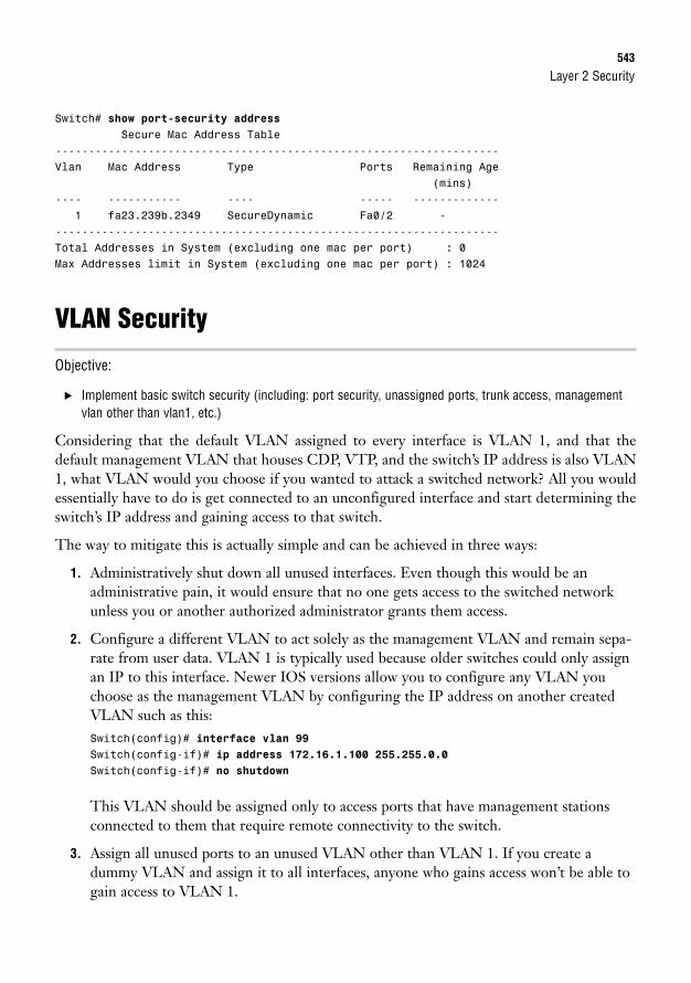
Layer 2 Security543
Switch# show port-security addressSecure Mac Address Table
-------------------------------------------------------------------Vlan Mac Address Type Ports Remaining Age
(mins)---- ----------- ---- ----- -------------
1 fa23.239b.2349 SecureDynamic Fa0/2 --------------------------------------------------------------------Total Addresses in System (excluding one mac per port) : 0Max Addresses limit in System (excluding one mac per port) : 1024
VLAN Security
Objective:
. Implement basic switch security (including: port security, unassigned ports, trunk access, managementvlan other than vlan1, etc.)
Considering that the default VLAN assigned to every interface is VLAN 1, and that thedefault management VLAN that houses CDP, VTP, and the switch’s IP address is also VLAN1, what VLAN would you choose if you wanted to attack a switched network? All you wouldessentially have to do is get connected to an unconfigured interface and start determining theswitch’s IP address and gaining access to that switch.
The way to mitigate this is actually simple and can be achieved in three ways:
1. Administratively shut down all unused interfaces. Even though this would be anadministrative pain, it would ensure that no one gets access to the switched networkunless you or another authorized administrator grants them access.
2. Configure a different VLAN to act solely as the management VLAN and remain sepa-rate from user data. VLAN 1 is typically used because older switches could only assignan IP to this interface. Newer IOS versions allow you to configure any VLAN youchoose as the management VLAN by configuring the IP address on another createdVLAN such as this:Switch(config)# interface vlan 99Switch(config-if)# ip address 172.16.1.100 255.255.0.0Switch(config-if)# no shutdown
This VLAN should be assigned only to access ports that have management stationsconnected to them that require remote connectivity to the switch.
3. Assign all unused ports to an unused VLAN other than VLAN 1. If you create adummy VLAN and assign it to all interfaces, anyone who gains access won’t be able togain access to VLAN 1.
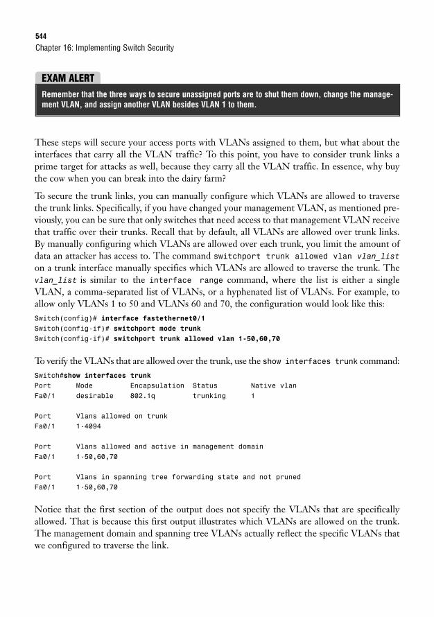
544
These steps will secure your access ports with VLANs assigned to them, but what about theinterfaces that carry all the VLAN traffic? To this point, you have to consider trunk links aprime target for attacks as well, because they carry all the VLAN traffic. In essence, why buythe cow when you can break into the dairy farm?
To secure the trunk links, you can manually configure which VLANs are allowed to traversethe trunk links. Specifically, if you have changed your management VLAN, as mentioned pre-viously, you can be sure that only switches that need access to that management VLAN receivethat traffic over their trunks. Recall that by default, all VLANs are allowed over trunk links.By manually configuring which VLANs are allowed over each trunk, you limit the amount ofdata an attacker has access to. The command switchport trunk allowed vlan vlan_liston a trunk interface manually specifies which VLANs are allowed to traverse the trunk. Thevlan_list is similar to the interface range command, where the list is either a singleVLAN, a comma-separated list of VLANs, or a hyphenated list of VLANs. For example, toallow only VLANs 1 to 50 and VLANs 60 and 70, the configuration would look like this:Switch(config)# interface fastethernet0/1Switch(config-if)# switchport mode trunkSwitch(config-if)# switchport trunk allowed vlan 1-50,60,70
To verify the VLANs that are allowed over the trunk, use the show interfaces trunk command:Switch#show interfaces trunkPort Mode Encapsulation Status Native vlanFa0/1 desirable 802.1q trunking 1
Port Vlans allowed on trunkFa0/1 1-4094
Port Vlans allowed and active in management domainFa0/1 1-50,60,70
Port Vlans in spanning tree forwarding state and not prunedFa0/1 1-50,60,70
Notice that the first section of the output does not specify the VLANs that are specificallyallowed. That is because this first output illustrates which VLANs are allowed on the trunk.The management domain and spanning tree VLANs actually reflect the specific VLANs thatwe configured to traverse the link.
Chapter 16: Implementing Switch Security
EXAM ALERTRemember that the three ways to secure unassigned ports are to shut them down, change the manage-ment VLAN, and assign another VLAN besides VLAN 1 to them.
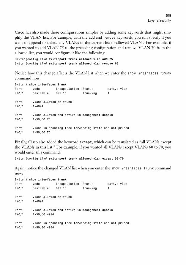
Layer 2 Security545
Cisco has also made these configurations simpler by adding some keywords that might sim-plify the VLAN list. For example, with the add and remove keywords, you can specify if youwant to append or delete any VLANs in the current list of allowed VLANs. For example, ifyou wanted to add VLAN 75 to the preceding configuration and remove VLAN 70 from theallowed list, you would configure it like the following:Switch(config-if)# switchport trunk allowed vlan add 75Switch(config-if)# switchport trunk allowed vlan remove 70
Notice how this change affects the VLAN list when we enter the show interfaces trunkcommand now:Switch# show interfaces trunkPort Mode Encapsulation Status Native vlanFa0/1 desirable 802.1q trunking 1
Port Vlans allowed on trunkFa0/1 1-4094
Port Vlans allowed and active in management domainFa0/1 1-50,60,75
Port Vlans in spanning tree forwarding state and not prunedFa0/1 1-50,60,75
Finally, Cisco also added the keyword except, which can be translated as “all VLANs exceptthe VLANs in this list.” For example, if you wanted all VLANs except VLANs 60 to 70, youwould enter this command:Switch(config-if)# switchport trunk allowed vlan except 60-70
Again, notice the changed VLAN list when you enter the show interfaces trunk commandnow:Switch# show interfaces trunkPort Mode Encapsulation Status Native vlanFa0/1 desirable 802.1q trunking 1
Port Vlans allowed on trunkFa0/1 1-4094
Port Vlans allowed and active in management domainFa0/1 1-59,80-4094
Port Vlans in spanning tree forwarding state and not prunedFa0/1 1-59,80-4094
546
VTP PasswordsIn our discussions of routing protocols in earlier chapters, we discussed how to authenticatethe updates sent by other routers so that attackers cannot inject false routes into a routing tableand hijack traffic or disrupt normal routing. This is just as important with VTP updatesbetween switches. An attacker can inject false VLAN information in VTP updates and bringdown a switched network quite easily as long as he or she knows the VTP domain and has thehighest revision number in the VTP update. To keep this from happening, be sure you takethe extra step and configure passwords for switches participating in the VTP domain with thevtp password command:Switch(config)# vtp password examprepSetting device VLAN database password to examprep
“See”DPThis might sound like Cisco sacrilege, but you should consider disabling CDP on switch inter-faces that do not need it, such as edge ports connected to end devices. If you consider the infor-mation someone can learn from CDP, you’ll realize the major security liability it can be. Fromjust a single CDP multicast, an attacker could learn the hostname, the local port on the switchthat sent the CDP message, and the switch’s IP address. With this information and strongmotivation, it is only a matter of time before your switch and its networks are infiltrated.
Recall that to disable CDP on individual interfaces, you must configure no cdp enable oneach interface. If you have no need for CDP, disable it globally on the switch with the no cdprun command.
Chapter 16: Implementing Switch Security
Chapter Summary547
Chapter SummarySecuring a switched network entails trying to protect all Layer 1 aspects of the switch, includ-ing access to the IOS itself. In addition, it is imperative to secure the switch’s Layer 2 opera-tions so that an attacker doesn’t interrupt or damage the switched network.
Securing the Physical layer entails ensuring that the switch and its cables are in a secure envi-ronment where users cannot inflict damage on them. This step also gives added protectionfrom users gaining console access to the switch to gain information to attack the network orattack or manipulate the switch itself. Leveraging the IOS’s internal security measures such aslogins and passwords for terminal access is also ideal in building a layered defense. When pos-sible, it is also recommended that you use SSH instead of Telnet for remote access to the IOS,because the communications between the management computer and the switch are secured.
Data Link layer security involves securing individual ports using port security. Port securityprotects ports by defining a maximum number of MAC addresses that are allowed to bedynamically learned on an individual port. You can also manually specify the MAC address(es)that are allowed to be present in the source address of the Ethernet frame when entering thatport. This can be a single static configured MAC address, or you can configure sticky learn-ing, and the addresses will be dynamically added to the configuration. When a port securityviolation occurs, the default action is to disable the interface. When this occurs, you have toshut down the interface and administratively bring it back up. You can configure the switchport to just report the violation (restrict), or you can reject frames from nonsecure MACaddresses until the number of MAC addresses falls under the limit (protect).
You should also secure unassigned ports that are automatically assigned to the default man-agement VLAN (VLAN 1) by either administratively shutting down the interface, changingthe management VLAN, or assigning a dummy VLAN to the unused interfaces. Trunks canbe secured by allowing only specific VLANs (such as the management VLAN) to traverse toswitches that specifically require access to those VLANs.
VTP should be secured using VTP passwords so that switches that receive the VTP update canauthenticate it. In addition, CDP reveals potentially dangerous information in its multicasts;thus, it is recommended that you disable CDP globally or on interfaces that do not require it.
Key Terms. Port security
. Error-disabled
. Restrict
. Protect
. Sticky secure MAC addresses
. switchport trunk allowed vlan
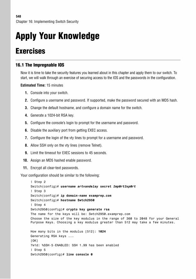
548
Apply Your Knowledge
Exercises
16.1 The Impregnable IOS
Now it is time to take the security features you learned about in this chapter and apply them to our switch. Tostart, we will walk through an exercise of securing access to the IOS and the passwords in the configuration.
Estimated Time: 15 minutes
1. Console into your switch.
2. Configure a username and password. If supported, make the password secured with an MD5 hash.
3. Change the default hostname, and configure a domain name for the switch.
4. Generate a 1024-bit RSA key.
5. Configure the console’s login to prompt for the username and password.
6. Disable the auxiliary port from getting EXEC access.
7. Configure the login of the vty lines to prompt for a username and password.
8. Allow SSH only on the vty lines (remove Telnet).
9. Limit the timeout for EXEC sessions to 45 seconds.
10. Assign an MD5 hashed enable password.
11. Encrypt all clear-text passwords.
Your configuration should be similar to the following:
! Step 2Switch(config)# username artvandelay secret Imp0rt3xp0rt! Step 3Switch(config)# ip domain-name examprep.comSwitch(config)# hostname Swtch2950! Step 4Swtch2950(config)# crypto key generate rsaThe name for the keys will be: Swtch2950.examprep.comChoose the size of the key modulus in the range of 360 to 2048 for your GeneralPurpose Keys. Choosing a key modulus greater than 512 may take a few minutes.
How many bits in the modulus [512]: 1024Generating RSA keys ...[OK]7w1d: %SSH-5-ENABLED: SSH 1.99 has been enabled! Step 5Swtch2950(config)# line console 0
Chapter 16: Implementing Switch Security
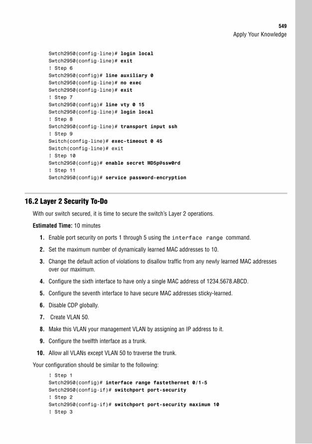
Apply Your Knowledge549
Swtch2950(config-line)# login localSwtch2950(config-line)# exit! Step 6Swtch2950(config)# line auxiliary 0Swtch2950(config-line)# no execSwtch2950(config-line)# exit! Step 7Swtch2950(config)# line vty 0 15Swtch2950(config-line)# login local! Step 8Swtch2950(config-line)# transport input ssh! Step 9Switch(config-line)# exec-timeout 0 45Switch(config-line)# exit! Step 10Swtch2950(config)# enable secret MD5p@ssw0rd! Step 11Swtch2950(config)# service password-encryption
16.2 Layer 2 Security To-Do
With our switch secured, it is time to secure the switch’s Layer 2 operations.
Estimated Time: 10 minutes
1. Enable port security on ports 1 through 5 using the interface range command.
2. Set the maximum number of dynamically learned MAC addresses to 10.
3. Change the default action of violations to disallow traffic from any newly learned MAC addressesover our maximum.
4. Configure the sixth interface to have only a single MAC address of 1234.5678.ABCD.
5. Configure the seventh interface to have secure MAC addresses sticky-learned.
6. Disable CDP globally.
7. Create VLAN 50.
8. Make this VLAN your management VLAN by assigning an IP address to it.
9. Configure the twelfth interface as a trunk.
10. Allow all VLANs except VLAN 50 to traverse the trunk.
Your configuration should be similar to the following:
! Step 1Swtch2950(config)# interface range fastethernet 0/1-5Swtch2950(config-if)# switchport port-security! Step 2Swtch2950(config-if)# switchport port-security maximum 10! Step 3
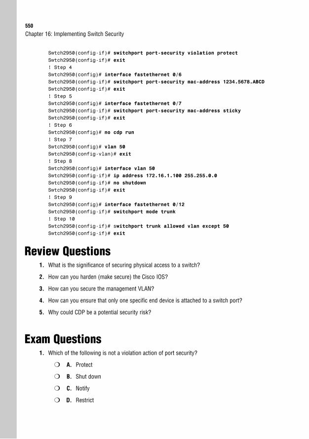
550
Swtch2950(config-if)# switchport port-security violation protectSwtch2950(config-if)# exit! Step 4Swtch2950(config)# interface fastethernet 0/6Swtch2950(config-if)# switchport port-security mac-address 1234.5678.ABCD
Swtch2950(config-if)# exit! Step 5Swtch2950(config)# interface fastethernet 0/7Swtch2950(config-if)# switchport port-security mac-address sticky
Swtch2950(config-if)# exit! Step 6Swtch2950(config)# no cdp run! Step 7Swtch2950(config)# vlan 50Swtch2950(config-vlan)# exit! Step 8Swtch2950(config)# interface vlan 50Swtch2950(config-if)# ip address 172.16.1.100 255.255.0.0Swtch2950(config-if)# no shutdownSwtch2950(config-if)# exit! Step 9Swtch2950(config)# interface fastethernet 0/12Swtch2950(config-if)# switchport mode trunk! Step 10Swtch2950(config-if)# switchport trunk allowed vlan except 50Swtch2950(config-if)# exit
Review Questions1. What is the significance of securing physical access to a switch?
2. How can you harden (make secure) the Cisco IOS?
3. How can you secure the management VLAN?
4. How can you ensure that only one specific end device is attached to a switch port?
5. Why could CDP be a potential security risk?
Exam Questions1. Which of the following is not a violation action of port security?
❍ A. Protect
❍ B. Shut down
❍ C. Notify
❍ D. Restrict
Chapter 16: Implementing Switch Security
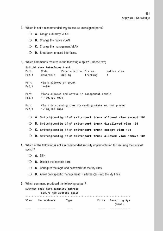
Apply Your Knowledge551
2. Which is not a recommended way to secure unassigned ports?
❍ A. Assign a dummy VLAN.
❍ B. Change the native VLAN.
❍ C. Change the management VLAN.
❍ D. Shut down unused interfaces.
3. Which commands resulted in the following output? (Choose two)
Switch# show interfaces trunkPort Mode Encapsulation Status Native vlanFa0/1 desirable 802.1q trunking 1
Port Vlans allowed on trunkFa0/1 1-4094
Port Vlans allowed and active in management domainFa0/1 1-100,102-4094
Port Vlans in spanning tree forwarding state and not prunedFa0/1 1-100,102-4094
❍ A. Switch(config-if)# switchport trunk allowed vlan except 101
❍ B. Switch(config-if)# switchport trunk disallowed vlan 101
❍ C. Switch(config-if)# switchport trunk except vlan 101
❍ D. Switch(config-if)# switchport trunk allowed vlan remove 101
4. Which of the following is not a recommended security implementation for securing the Catalystswitch?
❍ A. SSH
❍ B. Disable the console port.
❍ C. Configure the login and password for the vty lines.
❍ D. Allow only specific management IP address(es) into the vty lines.
5. Which command produced the following output?
Switch# show port-security addressSecure Mac Address Table
-------------------------------------------------------------------Vlan Mac Address Type Ports Remaining Age
(mins)---- ----------- ---- ----- -------------
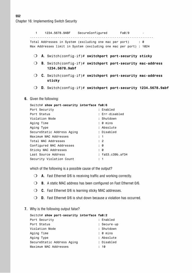
552
1 1234.5678.9ABF SecureConfigured Fa0/9 --------------------------------------------------------------------Total Addresses in System (excluding one mac per port) : 0Max Addresses limit in System (excluding one mac per port) : 1024
❍ A. Switch(config-if)# switchport port-security sticky
❍ B. Switch(config-if)# switchport port-security mac-address1234.5678.9abf
❍ C. Switch(config-if)# switchport port-security mac-addresssticky
❍ D. Switch(config-if)# switchport port-security 1234.5678.9abf
6. Given the following:
Switch# show port-security interface fa0/6Port Security : EnabledPort Status : Err-disabledViolation Mode : ShutdownAging Time : 0 minsAging Type : AbsoluteSecureStatic Address Aging : DisabledMaximum MAC Addresses : 1Total MAC Addresses : 2Configured MAC Addresses : 0Sticky MAC Addresses : 0Last Source Address : fa53.c39b.af34Security Violation Count : 1
which of the following is a possible cause of the output?
❍ A. Fast Ethernet 0/6 is receiving traffic and working correctly.
❍ B. A static MAC address has been configured on Fast Ethernet 0/6.
❍ C. Fast Ethernet 0/6 is learning sticky MAC addresses.
❍ D. Fast Ethernet 0/6 is shut down because a violation has occurred.
7. Why is the following output false?
Switch# show port-security interface fa0/2Port Security : EnabledPort Status : Secure-upViolation Mode : ShutdownAging Time : 0 minsAging Type : AbsoluteSecureStatic Address Aging : DisabledMaximum MAC Addresses : 10
Chapter 16: Implementing Switch Security
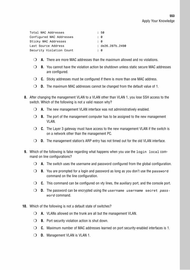
Apply Your Knowledge553
Total MAC Addresses : 50Configured MAC Addresses : 0Sticky MAC Addresses : 0Last Source Address : de26.287b.2490Security Violation Count : 0
❍ A. There are more MAC addresses than the maximum allowed and no violations.
❍ B. You cannot have the violation action be shutdown unless static secure MAC addressesare configured.
❍ C. Sticky addresses must be configured if there is more than one MAC address.
❍ D. The maximum MAC addresses cannot be changed from the default value of 1.
8. After changing the management VLAN to a VLAN other than VLAN 1, you lose SSH access to theswitch. Which of the following is not a valid reason why?
❍ A. The new management VLAN interface was not administratively enabled.
❍ B. The port of the management computer has to be assigned to the new managementVLAN.
❍ C. The Layer 3 gateway must have access to the new management VLAN if the switch ison a network other than the management PC.
❍ D. The management station’s ARP entry has not timed out for the old VLAN interface.
9. Which of the following is false regarding what happens when you use the login local com-mand on line configurations?
❍ A. The switch uses the username and password configured from the global configuration.
❍ B. You are prompted for a login and password as long as you don’t use the passwordcommand on the line configuration.
❍ C. This command can be configured on vty lines, the auxiliary port, and the console port.
❍ D. The password can be encrypted using the username username secret pass-word command.
10. Which of the following is not a default state of switches?
❍ A. VLANs allowed on the trunk are all but the management VLAN.
❍ B. Port security violation action is shut down.
❍ C. Maximum number of MAC addresses learned on port security-enabled interfaces is 1.
❍ D. Management VLAN is VLAN 1.
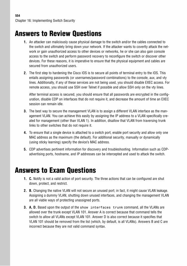
554
Answers to Review Questions1. An attacker can maliciously cause physical damage to the switch and/or the cables connected to
the switch and ultimately bring down your network. If the attacker wants to covertly attack the net-work or gain unauthorized access to other devices or networks, he or she can also gain consoleaccess to the switch and perform password recovery to reconfigure the switch or discover otherdevices. For these reasons, it is imperative to ensure that the physical equipment and cables aresecured from unauthorized users.
2. The first step to hardening the Cisco IOS is to secure all points of terminal entry to the IOS. Thisentails assigning passwords (or usernames/password combinations) to the console, aux, and vtylines. Additionally, if any of these services are not being used, you should disable EXEC access. Forremote access, you should use SSH over Telnet if possible and allow SSH only on the vty lines.
After terminal access is secured, you should ensure that all passwords are encrypted in the config-uration, disable CDP on interfaces that do not require it, and decrease the amount of time an EXECsession can remain idle.
3. The best way to secure the management VLAN is to assign a different VLAN interface as the man-agement VLAN. You can achieve this easily by assigning the IP address to a VLAN specifically cre-ated for management (other than VLAN 1). In addition, disallow that VLAN from traversing trunklinks to other switches that do not require it.
4. To ensure that a single device is attached to a switch port, enable port security and allow only oneMAC address as the maximum (the default). For additional security, manually or dynamically(using sticky learning) specify the device’s MAC address.
5. CDP advertises pertinent information for discovery and troubleshooting. Information such as CDP-advertising ports, hostname, and IP addresses can be intercepted and used to attack the switch.
Answers to Exam Questions1. C. Notify is not a valid action of port security. The three actions that can be configured are shut
down, protect, and restrict.
2. B. Changing the native VLAN will not secure an unused port; in fact, it might cause VLAN leakage.Assigning a dummy VLAN, shutting down unused interfaces, and changing the management VLANare all viable ways of protecting unassigned ports.
3. A, D. Based upon the output of the show interfaces trunk command, all the VLANs areallowed over the trunk except VLAN 101. Answer A is correct because that command tells theswitch to allow all VLANs except VLAN 101. Answer D is also correct because it specifies thatVLAN 101 should be removed from the list (which, by default, is all VLANs). Answers B and C areincorrect because they are not valid command syntax.
Chapter 16: Implementing Switch Security
Apply Your Knowledge555
4. B. Answer B is not a recommended security implementation because you will always require con-sole access as a failsafe to gain access to Cisco devices. SSH, login/passwords for vty lines, andspecifying management IP address(es) of management station(s) are all recommended securityimplementations.
5. B. Because the output indicates that the MAC address is SecureConfigured, it must have beenmanually configured using the switchport port-security mac-address1234.5678.9abf command. Answers A and D are not valid command syntax for port security.Answer C is valid syntax, but the output for the MAC address would show up as SecureDynamic.
6. D. The port status of the output indicates that it is in an error-disabled state, which means that aviolation has occurred and that the default action (shutdown) has disabled the port. Because themaximum MAC addresses is configured as 1, and it has learned two MAC addresses, it is safe tosay that this is the cause of the violation. Answer A is incorrect because the port is not in aSecure-Up (active) state. Answer B is incorrect because the count of configured MAC addresses is0. Answer C is incorrect as well because the output indicates that the sticky MAC address count isalso 0.
7. A. If the number of MAC addresses is exceeded, security violations should increase, and the con-figured action should take place (in this case, shutdown). Answer B is incorrect because you canhave the violation be shutdown on dynamic, sticky-learned, or static MAC addresses. Answer C isincorrect because it is not required (although it might be more practical) to configure stickyaddresses when there is more than one secure MAC address. Answer D is incorrect because themaximum MAC addresses can be configured to be more than 1.
8. D. Changing the management VLAN does not change the switch’s MAC address. Thus, any devicethat has an ARP entry tying the IP address of the switch to its MAC address will not be differentwhen moving that IP to another management VLAN, and SSH should still work. Answer A is incor-rect because the new management VLAN must be administratively enabled. Answer B is incorrectbecause devices connected to the switch must have access to the new management VLAN. If theport connected to the management station is not in that VLAN, the port will not be able to reachthe VLAN because it is in a separate broadcast domain. Similarly, answer C is incorrect becausethe router or Layer 3 switch must have access to the new management VLAN to route the SSHtraffic between the remote network and the local switch.
9. B. You will still be prompted for a login and password, regardless of whether a password is con-figured. The switch uses the local username and password (which can be encrypted using theusername username secret password command) and can be assigned to console, aux,and vty lines, so answers A, C, and D are incorrect.
10. A. By default, all VLANs (including the management VLAN) are allowed to traverse trunks. Thedefault port security violation state is to shut down, so answer B is incorrect. Answer C is incorrectbecause the maximum number of MAC addresses for port security is 1. Answer D is also incorrectbecause the default management VLAN is 1.

556
Suggested Readings and Resources1. Richard Froom, Balaji Sivasubramanian, and Erum Frahim. Building Cisco Multilayer
Switched Networks (BCMSN) (Authorized Self-Study Guide), 4th Edition. Cisco Press,2007.
2. Wendell Odom. CCNA ICND2 Official Exam Certification Guide (CCNA Exams 640-816and 640-802), 2nd Edition. Cisco Press, 2007.
3. “Port Security,” www.cisco.com.
Chapter 16: Implementing Switch Security
17C H A P T E R S E V E N T E E N
Understanding WirelessNetworking
ObjectiveThis chapter covers the following Cisco-specific objective for the “Explain and select the appropriate administrative tasks required for a WLAN” section of the 640-802 CCNA exam:
. Describe standards associated with wireless media (including: IEEE WI-FIAlliance, ITU/FCC)
OutlineIntroduction 560
The Business Case 560
The Players in the 802.11 Market 561
Entering the Radio Frequency World 562
Understanding Wireless Transmission 562
Unlicensed RF Bands 563
The Key to Successful Wireless: Channel Surfing 564
The 802.11 Standards Family 567
Party Like It’s 1999: 802.11a and 802.11b 567
2003 Delivers: 802.11g 567
The Next Generation: 802.11n 568
Chapter Summary 569
Key Terms 569
Apply Your Knowledge 570
Exercise 570
Review Questions 571
Exam Questions 571
Answers to Review Questions 573
Answers to Exam Questions 574
Suggested Readings and Resources 574

Study Strategies. Read the information presented in this chapter, paying special attention to tables, Notes,
and Exam Alerts.
. Spend some time soaking up how Wireless Radio Frequency operates. This understand-ing is key to an optimized wireless network deployment.
. The ICND1 and CCNA exams focus only on the concepts behind wireless technologyrather than the configuration. The Exam Alerts in this chapter and Chapter 18, “WirelessSecurity and Implementation Considerations,” will guide you to specific areas of study.
560
IntroductionIt was one of those moments I’ll never forget. I (Jeremy) had just installed my brand-new D-Link 802.11b wireless access point in my home and slid the new PCMCIA wireless cardinto my laptop. I sat on the couch in another room, held my breath, and opened InternetExplorer. I was so excited to see my home page appear, I jumped up off the couch and yelledto my wife, “Sue! I’m on the Internet! Look!” I held my laptop high in the air to show thatthere were no wires attached. “Wow…” came the not-as-excited reply (she had become usedto my ultra-geekdom by this point). I then proceeded to run around the house, laptop in hand,yelling, “I’m still on the Internet! I’m still on the Internet!” as I went in and out of each room.Amazing. Network connectivity without wires!
Fast-forward two years from that monumental moment. I am standing in an office talking tothe VP of Sales for the organization. “What do you mean the wireless is down?” he says to me.“The wireless access point went bad. We have one on order. It should be here early next week,”I reply. “So what am I supposed to do until then?” he counters. He follows my gaze to theEthernet wall jack, about three feet from the desk. “You’re going to have to plug in,” I mutteras I pull an Ethernet cable from my bag. From the look of utter annoyance on his face, I mightas well have told him that he’ll have to walk five miles, uphill, in the snow before he will gethis Internet access back.
What happened to the excited people running through companies screaming, “I haveInternet!” with their laptops held high above their heads? Convenience happened—and theultimate convenience at that: solid network connectivity without wires. Yes, 802.11 wirelessnetworking has taken over the world faster than nearly any other network technology ever cre-ated. It is now rare to find even a small business without a wireless access point sitting on ashelf somewhere. It doesn’t matter if users are sitting at home, at work, or at Starbucks; they’veall come to expect that they will always be connected to the great network power of the sky.
The Business CaseThe funny thing about wireless LANs (WLANs) is that the technology was just so cool thatnetwork administrators started deploying it and making up the business case as they wentalong. Wireless networks were a new way of looking at infrastructure, and within a few yearsof mainstream deployment, the applications that used this infrastructure began to emerge.One of the first changes businesses began to realize was the increased use of laptops within theorganization rather than their stationary desktop counterparts. In 2005, laptops outsold desk-tops for the first time, accounting for 53% of all PC sales. That figure continued to increasein the following years as vendors began including embedded wireless network cards in thedevices. Companies are now purchasing laptops for their employees for two reasons.
Chapter 17: Understanding Wireless Networking
The Players in the 802.11 Market561
Employees love laptops, because they get a “new computer” they can use at home, on vaca-tion, and at the office. The companies love the laptop because the employee can now workwhile they are at home, on vacation, and at the office. Along with laptops, personal digitalassistants (PDAs) began to support 802.11 wireless standards. These devices now allowemployees to check email, voice mail, and the company intranet over a virtual private network(VPN), all while walking to a flight.
While a host of new wireless networking devices continue to emerge (including wireless VoIPphones), the most tangible benefit of wireless is found simply in not having wires. The IT costof moving an employee from one cubicle to another ranges from $175 to $375, depending onthe equipment present. When you realize that an average of 10 to 15% of staff moves everyyear, you can begin adding up the numbers for your organization. Likewise, eliminating cableruns in new or existing buildings can always provide traceable cost savings provided by wire-less technology.
Finally, realize that wireless technology has moved to the point where even someone whoknows nothing about networking can drive to a local electronics store and pick up a wirelessaccess point requiring zero setup and configuration. Some users are so desperate to have wire-less access at work that they bring in their own wireless network devices and build “mini-WLANs” in their cubicles, knowingly or unknowingly violating company policy. This can sub-ject your organization to an enormous security risk that could have been minimized by usinga centrally managed WLAN system.
The Players in the 802.11 MarketObjective:
. Describe standards associated with wireless media (including: IEEE WI-FI Alliance, ITU/FCC)
802.11 holds a host of standards that every vendor is scrambling to implement and every net-work admin is trying to keep straight. Three organizations play key roles in managing thiswireless world:
. International Telecommunication Union-Radiocommunication Sector (ITU-R):Regulates the radio frequencies (RF) used for wireless transmission
. Institute of Electrical and Electronic Engineers (IEEE): Maintains the 802.11wireless transmission standards
. Wi-Fi Alliance: Ensures certified interoperability between 802.11 wireless vendors
562
Entering the Radio Frequency WorldObjective:
. Describe standards associated with wireless media (including: IEEE WI-FI Alliance, ITU/FCC)
Because of the simplicity associated with setting up 802.11 wireless networks in smalloffice/home office (SOHO) environments, it can be easy to underestimate the task of deploy-ing a wireless network on a corporate scale. Wireless access points (WAPs) use radio frequen-cies that are subject to interference and distortion. Likewise, when we move into the wirelessnetwork world, we take a step backward in our switch-based mind-set to the days of networkhubs. Only one device attached to a wireless access point can send or receive at a time (halfduplex). Understanding these facts is key to a successful WLAN deployment.
Understanding Wireless TransmissionBack in the day, the two competing LAN technologies were Ethernet and Token Ring. Manyargued that Token Ring was the better technology because the users would never experience acollision of data on the network. This is because only one user could transmit data at a timedue to the token-passing mechanism. Ethernet ended up winning the competition because itsmethod of collision detection (CSMA/CD) allowed for higher transmission speeds.
When we move into the WLAN environment, we move our transmission methods to a colli-sion avoidance (CSMA/CA) strategy because wireless devices have no collision detectionmechanism. Likewise, because a wireless device that is sending data cannot receive data at thesame time, WLAN devices run at half duplex as a rule. When you combine this limitation withsignal degradation due to wireless range and interference, you’ll find that wireless devicesrarely run at the advertised speed (11Mbps for 802.11b, 54Mbps for 802.11b and 802.11a).Most of the time, the actual speed you are receiving is less than half of the maximum data rate!
Much of the wireless signal degradation is due to the nature of RF. Most of us are used to theland of Ethernet, where data signals travel cozily through a padded copper wire, free frommost interference. Wireless RF signals are sent through the air using an antenna, and unfor-tunately, the air is an ugly place. The first challenge that the wireless signal faces is physicalobjects. Every object the signal must pass through can degrade the signal in some way.Reflective surfaces, such as metal or glass, cause RF waves to bounce off, shooting in a differ-ent direction. Uneven surfaces, such as a gravel road, piles of merchandise in a warehouse, adesk, or a cubicle can cause the signal to reflect and scatter in many directions. Finally, as wire-less signals pass through physical objects, they are absorbed. This absorption rate differsdepending on the type of material the signal passes through.
As if physical objects weren’t enough, the wireless signal is also subject to interference. All802.11 technology uses unlicensed wireless bands (discussed further in a moment). This means
Chapter 17: Understanding Wireless Networking
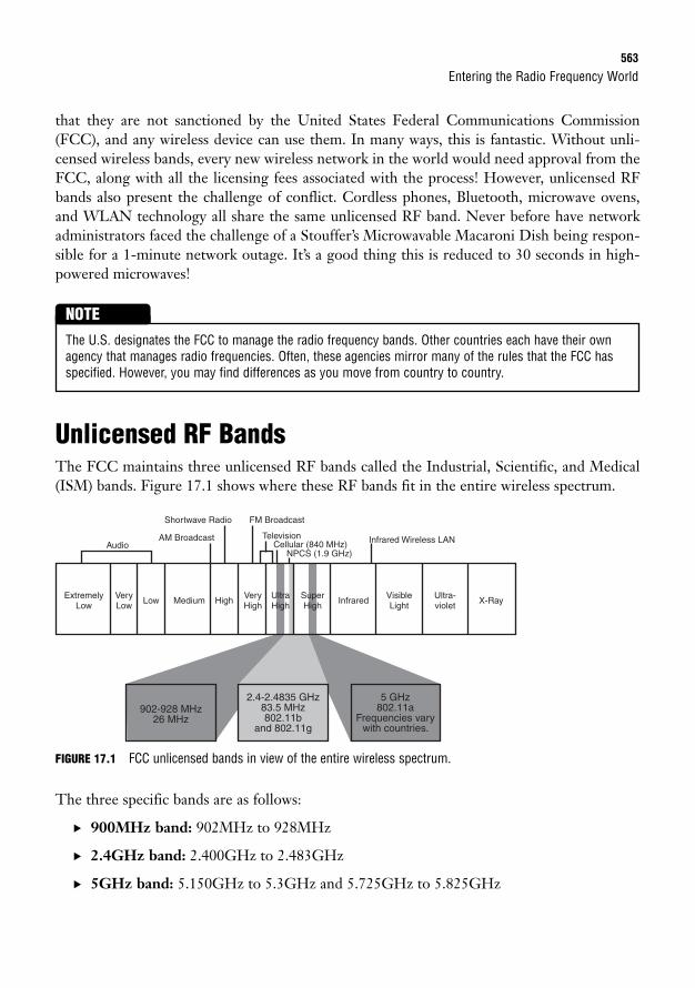
Entering the Radio Frequency World563
that they are not sanctioned by the United States Federal Communications Commission(FCC), and any wireless device can use them. In many ways, this is fantastic. Without unli-censed wireless bands, every new wireless network in the world would need approval from theFCC, along with all the licensing fees associated with the process! However, unlicensed RFbands also present the challenge of conflict. Cordless phones, Bluetooth, microwave ovens,and WLAN technology all share the same unlicensed RF band. Never before have networkadministrators faced the challenge of a Stouffer’s Microwavable Macaroni Dish being respon-sible for a 1-minute network outage. It’s a good thing this is reduced to 30 seconds in high-powered microwaves!
The U.S. designates the FCC to manage the radio frequency bands. Other countries each have their ownagency that manages radio frequencies. Often, these agencies mirror many of the rules that the FCC hasspecified. However, you may find differences as you move from country to country.
NOTE
Unlicensed RF BandsThe FCC maintains three unlicensed RF bands called the Industrial, Scientific, and Medical(ISM) bands. Figure 17.1 shows where these RF bands fit in the entire wireless spectrum.
FIGURE 17.1 FCC unlicensed bands in view of the entire wireless spectrum.
The three specific bands are as follows:
. 900MHz band: 902MHz to 928MHz
. 2.4GHz band: 2.400GHz to 2.483GHz
. 5GHz band: 5.150GHz to 5.3GHz and 5.725GHz to 5.825GHz
902-928 MHz26 MHz
2.4-2.4835 GHz83.5 MHz802.11b
and 802.11g
5 GHz802.11a
Frequencies varywith countries.
ExtremelyLow
VeryLow
Low
AudioAM Broadcast
Shortwave Radio FM Broadcast
TelevisionCellular (840 MHz) Infrared Wireless LAN
NPCS (1.9 GHz)
Medium HighVeryHigh
UltraHigh
SuperHigh
InfraredVisibleLight
Ultra-violet
X-Ray
564
Keep in mind that these ranges of frequency are for the U.S. Other countries may supportmore frequencies, and others support fewer. Some countries may not allow unlicensed wire-less transmission at all!
Every company that manufactures equipment that transmits wirelessly and that does not wantto license frequencies from the FCC is forced to share these unlicensed bands. Combining dif-ferent devices in the same area that are sharing the same frequencies results in interference.For our WLAN, that means impaired performance or potentially a completely unusable net-work, depending on the severity of the interference.
By far, more equipment uses the 2.4GHz band, making it more difficult to keep the airwavesfree from interference. The more popular 802.11b, 802.11g, and 802.11n standards fit into thisRF band. The 5GHz band is home to the 802.11a standard. On that note, let’s also discusssome key facts about RF:
. Fact #1: The higher frequencies allow for higher data rates.
. Fact #2: The higher frequencies have shorter transmission distances (range).
. Fact #3: Shorter distances can be compensated for by using high-powered antennas.
. Fact #4: Every country has its own restrictions on how powerful your radio transmis-sion can be for the unlicensed bands.
So, building a 500-foot-high tower on top of your company building powered by a smallnuclear generator most likely is not an option for achieving campus-wide network coverage.The alternative solution requires you to purchase many small transmitters and strategicallyplace them throughout your network.
The Key to Successful Wireless: Channel SurfingBecause government restrictions keep us from saturating our campus network with an ultra-powerful wireless signal, we are forced to deploy many transmitters (WAPs) that have a muchsmaller coverage radius. The problem with this solution is that these transmitters all use thesame RF band. Because a good wireless design requires overlapping signals, we are stuck witha problem: the adjacent transmitters will interfere with each other.
Having a 10 to 15% overlap in signals, as shown in Figure 17.2, is a good design. With theright configuration, this overlap can allow clients to roam seamlessly between transmitters.However, the client will experience heavy interference and performance degradation withinthe overlapping coverage areas.
Chapter 17: Understanding Wireless Networking
EXAM ALERTYou will want to know the two primary unlicensed RF bands used for wireless networking: 2.4GHz and5GHz.
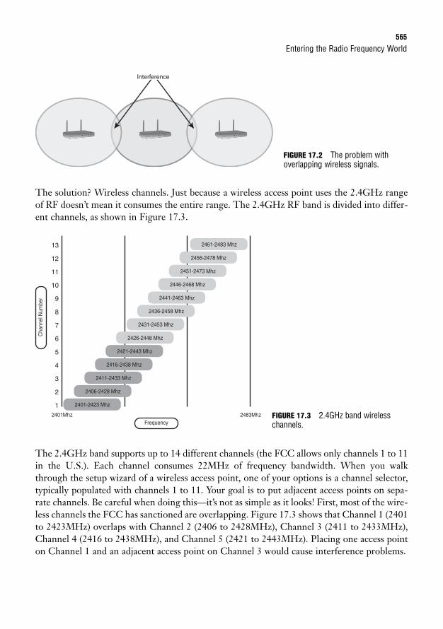
Entering the Radio Frequency World565
The solution? Wireless channels. Just because a wireless access point uses the 2.4GHz rangeof RF doesn’t mean it consumes the entire range. The 2.4GHz RF band is divided into differ-ent channels, as shown in Figure 17.3.
InterfaceInterfaceInterference
FIGURE 17.2 The problem withoverlapping wireless signals.
13
12
11
10
9
8
7
6
5
4
3
2
1 2401-2423 Mhz
2406-2428 Mhz
2411-2433 Mhz
2416-2438 Mhz
2421-2443 Mhz
2426-2448 Mhz
2431-2453 Mhz
2436-2458 Mhz
2441-2463 Mhz
2446-2468 Mhz
2451-2473 Mhz
2456-2478 Mhz
2461-2483 Mhz
2401Mhz 2483MhzFrequency
Cha
nnel
Num
ber
The 2.4GHz band supports up to 14 different channels (the FCC allows only channels 1 to 11in the U.S.). Each channel consumes 22MHz of frequency bandwidth. When you walkthrough the setup wizard of a wireless access point, one of your options is a channel selector,typically populated with channels 1 to 11. Your goal is to put adjacent access points on sepa-rate channels. Be careful when doing this—it’s not as simple as it looks! First, most of the wire-less channels the FCC has sanctioned are overlapping. Figure 17.3 shows that Channel 1 (2401to 2423MHz) overlaps with Channel 2 (2406 to 2428MHz), Channel 3 (2411 to 2433MHz),Channel 4 (2416 to 2438MHz), and Channel 5 (2421 to 2443MHz). Placing one access pointon Channel 1 and an adjacent access point on Channel 3 would cause interference problems.
FIGURE 17.3 2.4GHz band wirelesschannels.
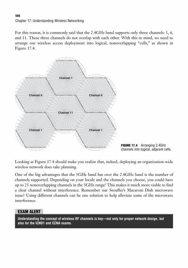
566
For this reason, it is commonly said that the 2.4GHz band supports only three channels: 1, 6,and 11. These three channels do not overlap with each other. With this in mind, we need toarrange our wireless access deployment into logical, nonoverlapping “cells,” as shown inFigure 17.4.
Chapter 17: Understanding Wireless Networking
Channel 6
Channel 1
Channel 11
Channel 1
Channel 6
Channel 1
Looking at Figure 17.4 should make you realize that, indeed, deploying an organization-widewireless network does take planning.
One of the big advantages that the 5GHz band has over the 2.4GHz band is the number ofchannels supported. Depending on your locale and the channels you choose, you could haveup to 23 nonoverlapping channels in the 5GHz range! This makes it much more viable to finda clear channel without interference. Remember our Stouffer’s Macaroni Dish microwaveissue? Using different channels can be one solution to help alleviate some of the microwaveinterference.
FIGURE 17.4 Arranging 2.4GHzchannels into logical, adjacent cells.
EXAM ALERTUnderstanding the concept of wireless RF channels is key—not only for proper network design, butalso for the ICND1 and CCNA exams.

The 802.11 Standards Family567
The 802.11 Standards FamilyNow that you have a foundational understanding of RF signaling, we can move to the 802.11standard. When many network administrators hear of 802.11 technology, their mind immedi-ately equates this with the three or four popular wireless networking standards: 802.11a,802.11b, 802.11g, and the prestandard (at the time of this writing) 802.11n. However, 802.11describes much more than this when dealing with wireless networks. For example, 802.11edescribes quality of service (QoS) standards for 802.11, and 802.11i is an enhanced wirelesssecurity standard, to name just a couple. In a way, 802.11 is similar to TCP/IP in that it depictsa suite of protocols and standards.
Of course, in this suite of standards, the most popular are the common 802.11a, 802.11b,802.11g, and 802.11n. Let’s look at the evolution of these standards.
Party Like It’s 1999: 802.11a and 802.11bIn 1999, two competing standards were released: 802.11a and 802.11b. As with most brand-new standards, vendors did not really begin implementing and releasing equipment that used802.11a or 802.11b until about 2002. The two standards offered the following features:
802.11a 802.11b
RF Band 5GHz 2.4GHz
Bandwidth 54Mbps 11Mbps
Channels Up to 23 3 (nonoverlapping)
Outdoor Range Approximately 75 meters Approximately 100 meters
Indoor Range Approximately 25 meters Approximately 45 meters
It’s an interesting story how these two standards competed. 802.11a was clearly the better stan-dard. It offered faster speeds (54Mbps versus 11Mbps), more channels (23 versus 3), and anoverall cleaner RF band (nowhere near as many devices use the 5GHz band as the 2.4GHzband). Alas, the 802.11b standard won the competition (for now) just because it was moreavailable. The silicon used to make the 802.11a chips was in short supply, and the industry washungry for wireless, so it gobbled up 802.11b instead.
2003 Delivers: 802.11gAfter the newness of the 802.11b standard wore off, users and administrators alike demandedmore speed. The IEEE answered with the 802.11g standard. This standard borrowed much ofthe 802.11a technology and implemented it in the 2.4GHz RF band. One of the major hurdles
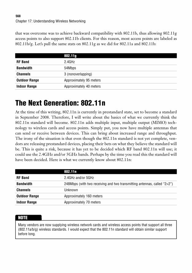
568
that was overcome was to achieve backward compatibility with 802.11b, thus allowing 802.11gaccess points to also support 802.11b clients. For this reason, most access points are labeled as802.11b/g. Let’s pull the same stats on 802.11g as we did for 802.11a and 802.11b:
802.11g
RF Band 2.4GHz
Bandwidth 54Mbps
Channels 3 (nonoverlapping)
Outdoor Range Approximately 95 meters
Indoor Range Approximately 40 meters
The Next Generation: 802.11nAt the time of this writing, 802.11n is currently in prestandard state, set to become a standardin September 2008. Therefore, I will write about the basics of what we currently think the802.11n standard will become. 802.11n adds multiple input, multiple output (MIMO) tech-nology to wireless cards and access points. Simply put, you now have multiple antennas thatcan send or receive between devices. This can bring about increased range and throughput.The irony of the situation is that even though the 802.11n standard is not yet complete, ven-dors are releasing prestandard devices, placing their bets on what they believe the standard willbe. This is quite a risk, because it has yet to be decided which RF band 802.11n will use; itcould use the 2.4GHz and/or 5GHz bands. Perhaps by the time you read this the standard willhave been decided. Here is what we currently know about 802.11n:
802.11n
RF Band 2.4GHz and/or 5GHz
Bandwidth 248Mbps (with two receiving and two transmitting antennas, called “2×2”)
Channels Unknown
Outdoor Range Approximately 160 meters
Indoor Range Approximately 70 meters
Chapter 17: Understanding Wireless Networking
Many vendors are now supplying wireless network cards and wireless access points that support all three(802.11a/b/g) wireless standards. I would expect that the 802.11n standard will obtain similar supportbefore long.
NOTE
Chapter Summary569
Chapter SummaryIn less than a decade, 802.11 wireless technology has changed everything we thought a LANenvironment to be. Many people believe that someday networks will become “a world withoutwires” as wireless technology becomes more developed and deployed. To successfully deploy awireless network, it is essential to understand the basics of radio frequency (RF). The 802.11wireless networking standards are designed to operate in the unlicensed bands of 2.4GHz(802.11b/g) and 5GHz (802.11a). These bands are subject to interference from a variety ofdevices, so care must be taken to choose the correct location, number of access points, andchannels when deploying wireless networking devices. Many wireless spectrum analysis toolsare available from the general market that can help with this process.
Because of interference and half-duplex operation, the actual throughput of a wireless deviceis typically half of the maximum specified by the standard. As new standards develop, thethroughput and range of wireless technology will continue to increase.
Key Terms. 802.11a, b, g, n
. Radio frequency (RF)
. ITU-R
. IEEE
. Wi-Fi Alliance
. 2.4GHz band
. 5GHz band
. Wireless channels
. CSMA/CA
. Multiple input, multiple output (MIMO)
. Wireless cells
. Wireless roaming
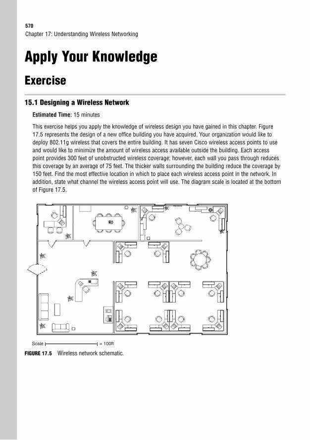
570
Apply Your Knowledge
Exercise
15.1 Designing a Wireless Network
Estimated Time: 15 minutes
This exercise helps you apply the knowledge of wireless design you have gained in this chapter. Figure17.5 represents the design of a new office building you have acquired. Your organization would like todeploy 802.11g wireless that covers the entire building. It has seven Cisco wireless access points to useand would like to minimize the amount of wireless access available outside the building. Each accesspoint provides 300 feet of unobstructed wireless coverage; however, each wall you pass through reducesthis coverage by an average of 75 feet. The thicker walls surrounding the building reduce the coverage by150 feet. Find the most effective location in which to place each wireless access point in the network. Inaddition, state what channel the wireless access point will use. The diagram scale is located at the bottomof Figure 17.5.
Chapter 17: Understanding Wireless Networking
Scale = 100ft
FIGURE 17.5 Wireless network schematic.
Apply Your Knowledge571
Review Questions1. Three agencies manage the standards and frequencies of wireless networks. List the names of
these agencies and briefly describe their functions.
2. 802.11b/g is the more popular wireless standard worldwide. One of your fellow network adminis-trators on staff states that 11 separate RF channels are available for use across your corporate net-work. Is this true? Should you use all 11 channels? Justify your response.
3. List the three RF spectrums that are considered unlicensed bands. Which wireless standards areassociated with each?
4. Higher and lower frequencies on the RF spectrum provide different benefits. What are the benefitsof higher frequencies (such as 2.4GHz and 5GHz) over lower frequencies?
5. List at least three business benefits of using wireless networking.
Exam Questions1. What Cisco-founded organization ensures compatibility between all 802.11 wireless vendor equipment?
❍ A. 802.11
❍ B. IEEE
❍ C. ITU-R
❍ D. Wi-Fi Alliance
2. Which of the following wireless standards use the 2.4GHz RF band? (Choose two)
❍ A. 802.11a
❍ B. 802.11b
❍ C. 802.11g
❍ D. 802.11i
3. 802.11 wireless standards use which of the following transmission methods?
❍ A. CSMA/CD, half duplex
❍ B. CSMA/CD, full duplex
❍ C. CSMA/CA, half duplex
❍ D. CSMA/CA, full duplex
572
4. How many wireless channels are available in the U.S.A. for the 2.4GHz band without overlapping frequencies?
❍ A. 1
❍ B. 3
❍ C. 11
❍ D. 23
5. When wireless technology uses a higher frequency, what factors must you consider? (Choose two)
❍ A. The higher frequency will allow for higher throughput
❍ B. The higher frequency will restrict throughput
❍ C. The higher frequency has more range
❍ D. The higher frequency has limited range
6. You are the network administrator for Widgets, Inc., a worldwide distributing organization. You areplanning on setting up a new wireless network for the organization. Which of the following areconsiderations for the new wireless network?
❍ A. The geographic location of the office
❍ B. The radio frequencies currently in use at the office locations
❍ C. The radio channels currently in use at the office locations
❍ D. The wireless cell configuration on the access point
7. To provide for successful client roaming, how should wireless cells be configured?
❍ A. Wireless cells should use the same RF band and channel
❍ B. Wireless cells should use the same RF band but different channels
❍ C. Wireless cells should use different RF bands but the same channel
❍ D. Wireless cells should use different RF bands and channels
8. Which of the following are advantages of 802.11a over 802.11b? (Choose two)
❍ A. Increased throughput
❍ B. Increased range
❍ C. More channel diversity
❍ D. Support for more clients
Chapter 17: Understanding Wireless Networking
Apply Your Knowledge573
9. You are deploying a wireless network at a new office location. The office happens to be locatednext to an apartment complex with many existing wireless access points using all available chan-nels in the RF band. Which agency would handle this situation?
❍ A. ITU-R
❍ B. IEEE
❍ C. Wi-Fi Alliance
❍ D. None of the above
10. What is the largest cost savings that organizations typically find with wireless technology?
❍ A. Elimination of stationary equipment
❍ B. Minimized office space due to roaming users
❍ C. Access to new cost-savings applications
❍ D. Cable installation and management cost
Answers to Review Questions1. The agencies that govern wireless networks are as follows:
The International Telecommunication Union-Radiocommunication Sector (ITU-R) regulates theradio frequencies used for wireless transmission.
The Institute of Electrical and Electronic Engineers (IEEE) maintains the 802.11 wireless transmis-sion standards.
The Wi-Fi Alliance ensures certified interoperability between 802.11 wireless vendors.
2. The short answer to this question is that yes, 11 channels are available for use. However, it is not agood idea to use all 11 channels, because many of them overlap RF signals. In the U.S., youshould use only channels 1, 6, and 11, because these channels have no overlap in RF signal.
3. The three unlicensed RF bands are as follows:
900MHz: No mainstream wireless network technologies use this spectrum.
2.4GHz: 802.11b and 802.11g use this spectrum.
5GHz: 802.11a uses this spectrum.
4. Higher frequencies provide more bandwidth than the lower frequencies, but they also have a morelimited range.
574
5. There are many reasons why a business may be interested in wireless networking. Here are four:
Elimination of stationary equipment
Minimized office space due to roaming users
Access to new cost-savings applications
Cable installation and management cost
Answers to Exam Questions1. D. The Wi-Fi Alliance was founded by Cisco to ensure vendor interoperability on the 802.11 wire-
less standard. A vendor can obtain Wi-Fi certification, which assures customers that the equipmentwill interoperate with any other Wi-Fi certified device. Answer A is incorrect because 802.11 repre-sents the wireless standard. Answer B is incorrect because the IEEE only manages and approvesthe wireless standards. Answer C is incorrect because the ITU-R is focused on regulating the802.11 RF bands.
2. B, C. 802.11b and 802.11g share the 2.4GHz band. This allows the newer 802.11g standard to bebackward-compatible with 802.11b. 802.11a uses the 5GHz band, and 802.11i is a security stan-dard that does not use a specific band.
3. C. 802.11 uses CSMA/CA (collision avoidance) with half-duplex transmission. Because of this, the maximum rate of transmission is rarely attained when communicating on an 802.11 wirelessnetwork.
4. B. In the U.S., only three nonoverlapping channels are available for the 2.4GHz band. Europe hasfour nonoverlapping channels, because access to other unlicensed RF bands is available. Themoral of the story? If you’re having trouble finding a free wireless channel in your area, move toEurope.
5. A, D. The benefit of using a higher frequency is the ability to obtain more bandwidth (throughput).The drawback is the limited range of the higher frequencies.
6. A, B, C. When deploying a new wireless network, you must take into account the geographicregion, because government regulations dictate what unlicensed RF bands and channels are avail-able for public use. Likewise, you must also see what wireless RF bands and channels are free (notin use) in your location to get a clean signal. Answer D is incorrect because wireless cells are notconfigured on access points; rather, they are a design concept.
7. B. To provide for client roaming, wireless cells should use the same RF band but different chan-nels. This allows a client to move between wireless access points without interference caused byoverlapping signals.
8. A, C. 802.11a has more bandwidth (54Mbps) compared to 802.11b (11Mbps) and more wirelesschannels available (up to 23). 802.11b does have more range than 802.11a because it uses thelower-frequency 2.4GHz band. Neither standard has any advantage as far as client support.
Chapter 17: Understanding Wireless Networking
Apply Your Knowledge575
9. D. Although the ITU-R does manage the RF bands, it would not handle this specific situation. Boththe 2.4GHz and 5GHz bands are considered unlicensed for a reason: no entity will manage them.The solution to the apartment situation would be to find out if the apartment wireless devices aretransmitting at a higher-than-legal power or to change your company to the less-congested 5GHzband.
10. D. Although wireless provides many conveniences for businesses, the primary cost savings can befound in the elimination of cable installation and management.
Suggested Readings and Resources1. Wikipedia 802.11 definitions, http://en.wikipedia.org/wiki/802.11
2. How WiFi Works, http://computer.howstuffworks.com/wireless-network3.htm
3. Chris Ward and Jeremy Cioara. Exam Cram 2 CCNA Practice Questions. QuePublishing, 2004.
4. Toby Velte and Anthony Velte. Cisco 802.11 Wireless Networking Quick Reference. CiscoPress, 2005.

This page intentionally left blank
18C H A P T E R E I G H T E E N
Wireless Security andImplementation Considerations
ObjectivesThis chapter covers the following Cisco-specified objectives for the “Explain and select theappropriate administrative tasks required for a WLAN” section of the 640-802 CCNA exam:
. Identify and describe the purpose of the components in a small wireless network (including: SSID, BSS, ESS)
. Identify the basic parameters to configure on a wireless network to ensurethat devices connect to the correct access point
. Compare and contrast wireless security features and capabilities of WPAsecurity (including: open, WEP, WPA-1/2)
. Identify common issues with implementing wireless networks
OutlineIntroduction 580
Understanding the Threats 580
War Driving 580
Direct Hacking 581
Employee Ignorance 581
Deploying a Secure Wireless Network 582
Wireless Encryption 582
Wired Equivalent Privacy (WEP) 582
Wi-Fi Protected Access (WPA) 584
Wi-Fi Protected Access, Reloaded(WPA2 and 802.11i) 584
Wireless Authentication (802.1x) 585
Wireless Intrusion Prevention System (IPS) 586
Wireless Implementation Guidelines 587
Understanding Wireless Topologies 587
Understanding Wireless Data Rates 590
General Wireless Implementation Steps 592
Wireless Troubleshooting 592
Client Troubleshooting 593
Wireless Access Point Troubleshooting 593
Chapter Summary 594
Key Terms 594
Apply Your Knowledge 595
Review Questions 595
Exam Questions 595
Answers to Review Questions 597
Answers to Exam Questions 598
Suggested Readings and Resources 599

Study Strategies. The ICND2 and CCNA exams are designed to test on a general understanding of wireless
concepts rather than hands-on configuration of wireless devices
. Be sure to have an in-depth understanding of the different wireless security standards(WEP, WPA, and WPA2). Cisco considers these important since this represents the coreof your wireless network security architecture
. When focusing on implementation, be sure to understand how to deploy close proximity802.11b/g wireless access points without causing them to interfere with each other
580
IntroductionOkay. I admit it. I (Jeremy) drove to a friend’s house and arrived a bit early, so I decided tospend a few minutes in the car checking my email. I pulled my laptop out of the back and dida quick wireless scan of the neighborhood. Two SSIDs appeared: Linksys and Netgear, bothwithout security. I joined the Linksys network and checked my online web mail. (I prefer tothink of this as “borrowing” the Internet connection rather than “stealing” wireless.) That’swhen a bearded man with a tattered shirt and loaded shotgun came out the front door. Sorry;I just needed a dramatic twist.
Harmless enough, right? Wrong! Imagine a strange individual walking into your front office witha laptop and saying, “Would you mind if I plugged into that wall jack over there?” Yes, I wouldmind. That would undermine every written security standard we have in our organization. Butthat’s exactly what happens when you fail to properly understand and implement the securitystandards available for wireless networks. Keep in mind that not all wireless security is createdequal. Some security standards (such as WEP) may give you a false sense of security, becausemany network intruders eat WEP security keys for breakfast. This is why a good comprehensionof wireless security is absolutely necessary, even for the novice network administrator.
Understanding the ThreatsIntroducing wireless networking into your organization opens the door to three new types ofattacks on your network: war driving, direct hacking, and employee ignorance. Let me explaineach of these in detail.
War DrivingYou know you’ve entered a new realm of network security when “driving” becomes one of theintrusion efforts. This term actually originated from the days of old, when a similar methodknown as war dialing was in place. In the 1980s, most businesses connected offices throughdialup connections, typically using modems. War dialing would consist of a hacker randomlydialing through the phone number range in his local area (for example, setting up his modemto dial numbers 100-0000 through 999-9999 in the U.S.). The dialing itself was not the hack-ing attempt; rather, it was a scan for phone numbers responding to modem signals.
War driving uses a similar concept. An intruder mounts an 802.11-compatible wireless anten-na on his vehicle and drives through the city, identifying available wireless networks. Whencombined with a Global Positioning System (GPS) device, war-driving software (such asKisMet or KisMac) can be very accurate in pinpointing the available wireless networks on amap of the city. When the intruder returns home, he can analyze the available networks andplot his next steps of attack.
Chapter 18: Wireless Security and Implementation Considerations
Understanding the Threats581
Keep in mind that war driving can discover wireless networks even if they are encrypted,authenticated, and/or using a “hidden” (nonbroadcast) SSID.
Direct HackingThe direct hacking effort typically begins after the war-driving scan of the area is complete.The intruder then identifies what network(s) he wants to attack. The hacking effort can comein many forms:
. Breaking into the WLAN: As soon as the intruder has identified available wirelessnetworks, he can try to break the encryption and/or authentication system. Althoughthis can be accomplished (with much effort) from the attacker’s home, it is usuallyattempted within range of the wireless signal. For example, the attacker can sit in theparking lot and attempt to break into the building’s wireless network. If he is success-ful, he joins the wireless network and begins scanning the internal network of yourorganization to find available resources.
. Decrypting data: Because wireless network communication is transmitted into the air,anything that your users access from a wireless device has the potential to be capturedby an intruder’s wireless sniffer software. If this data is sent unencrypted, the intrudercan simply reassemble the packets to regenerate the original file (such as a MicrosoftWord document, an Adobe Acrobat PDF file, or even a VoIP conversation). If the data is encrypted, the intruder captures the data and returns home to attempt to breakthe encryption keys. If he is successful, he can reassemble the original files and stealcorporate data.
. Attempting a wireless DoS attack: The final effort that can be accomplished bydirect hacking methods is to unleash a denial of service (DoS) attack on the wirelessnetwork. If the intruder is successful, the wireless access point that he attacks is ren-dered inoperable to your company. This type of attack is not as common in a WLANenvironment, because most companies have not yet moved critical network services tothe wireless network. The hacker’s efforts would be seen as more of a temporary incon-venience than a major network issue.
Employee IgnoranceEmployee ignorance was the best term I could come up with for this category of securitythreat. Depending on the individual employee, I suppose you could substitute “insolence,”“rebellion,” or “stupidity” for the word “ignorance.” Here’s the concept: Your company poli-cy dictates that you will not run wireless networking because of security threats. However, the“ignorant” employee has a laptop he really wants to use with wireless technology, which giveshim the freedom to roam between areas while remaining connected to the network. The
582
employee takes networking into his own hands and connects a low-end wireless access pointto the network jack in his cubicle. With the click of a Cat 5 cable, your network security hasbeen reduced to nothing, and a gaping hole into the network is now broadcast to the outsideworld. This same issue can occur even if your company provides a WLAN network and theuser is just outside the range of the wireless signal. If appropriate detection measures are nottaken, this massive hole in your network security can go undiscovered for months!
Deploying a Secure Wireless NetworkAlthough volumes could be (and have been) written on wireless security, I would just like todiscuss the 10,000-foot view of wireless security. This will give you an idea of the areas of focuswhen you are considering using wireless networking technology in your organization. As soonas you understand these areas, you can begin digging deeper into the technology to find theright fit for your wireless design.
Chapter 18: Wireless Security and Implementation Considerations
The CCENT and CCNA certifications require only a foundational understanding of wireless security topics,which are discussed in this book.
TIP
Wireless security can be broken into three major categories: encryption, authentication, anddetection.
Wireless Encryption
Objective:
. Compare and contrast wireless security features and capabilities of WPA security (including: open, WEP,WPA-1/2)
When you’re ready for a technology roller coaster ride, begin studying the history of wirelessencryption standards. I mentioned in the preceding chapter that wireless networking technol-ogy is so amazing that companies began using it long before the security standards were heav-ily tested and proven to withstand attacks. So, fasten your seat belt, and let’s ride through theevolution of wireless encryption standards, starting where it all began: with WEP.
Wired Equivalent Privacy (WEP)The WEP standard was the first measure of security released for wireless networking. Thisencryption method was based on the simple concept of using preshared keys (PSKs) to gener-ate an encryption algorithm. Here’s an overview of how the WEP encryption algorithm works:
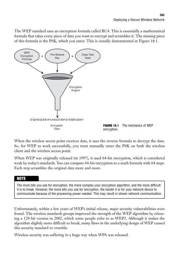
Deploying a Secure Wireless Network583
The WEP standard uses an encryption formula called RC4. This is essentially a mathematicalformula that takes every piece of data you want to encrypt and scrambles it. The missing pieceof this formula is the PSK, which you enter. This is visually demonstrated in Figure 18.1.
WEPEncryptionFormula
Pre-SharedKey
EncryptionEngine
Clear-TextData
+ +
$*(&#@(&@81#%#@23746#*&^349$%83#(^
Encrypted Data
When the wireless access point receives data, it uses the reverse formula to decrypt the data.So, for WEP to work successfully, you must manually enter the PSK on both the wirelessclient and the wireless access point.
When WEP was originally released (in 1997), it used 64-bit encryption, which is consideredweak by today’s standards. You can compare 64-bit encryption to a math formula with 64 steps.Each step scrambles the original data more and more.
FIGURE 18.1 The mechanics of WEP encryption.
The more bits you use for encryption, the more complex your encryption algorithm, and the more difficultit is to break. However, the more bits you use for encryption, the harder it is for your network device tocommunicate because of the processing power needed. This may result in slower network communication.
NOTE
Unfortunately, within a few years of WEP’s initial release, major security vulnerabilities werefound. The wireless standards groups improved the strength of the WEP algorithm by releas-ing a 128-bit version in 2002, which some people refer to as WEP2. Although it makes thealgorithm slightly more difficult to break, many flaws in the underlying design of WEP causedthis security standard to crumble.
Wireless security was suffering in a huge way when WPA was released.
584
Wi-Fi Protected Access (WPA)The wireless networking industry faced a major issue. A newer encryption algorithm was need-ed to combat the weaknesses of WEP, but the more complex encryption algorithms wouldrequire more-powerful 802.11-compatible wireless hardware to process the algorithm. By thispoint, the industry had already purchased millions of wireless access points and wireless cards,so simply saying, “Sorry! Go ahead and scrap all that equipment and buy new stuff.” was notan option. In 2003 the Wi-Fi Alliance (a group of extremely smart people sponsored by manyorganizations) stepped forward and proposed WPA. WPA used a new encryption algorithmcalled Temporal Key Integrity Protocol (TKIP). TKIP ran on the same wireless hardware thatwas originally created, and it used a 128-bit encryption algorithm. It was engineered to dra-matically increase the number of encryption keys that could be used and virtually eliminatedthe attacks that were successful on WEP keys. Although WPA was not flawless, it was atremendous step forward from the original WEP standard.
Wi-Fi Protected Access, Reloaded (WPA2 and 802.11i)WPA was never meant to solve the world’s wireless security problems. Although it was muchmore secure than WEP, it did have the weakness of using the same old hardware that WEPused. Inherent in that hardware were a few security weaknesses that simply could not be over-come by changing the encryption formula. For that reason, the Wi-Fi Alliance quickly (in2004) proposed an alternative standard casually called WPA2 and officially called 802.11i.
WPA2 uses a completely different encryption standard known as Advanced EncryptionStandard (AES). This encryption standard was standardized by the U.S. government and hasbeen extensively analyzed and tested. The WPA2 standard left behind the old hardware andrequired that users purchase new wireless hardware (both cards and access points).
To ease the transition, WPA2 hardware can run in backward-compatibility mode to support theoriginal WPA and even WEP standards. This allows an organization to upgrade its wirelessaccess points to the new hardware and still support the older WEP- and WPA-compliant clients.As the clients upgrade to newer wireless devices, WPA2 (and thus AES encryption) can be used.
Chapter 18: Wireless Security and Implementation Considerations
Remember that WEP offers 64-bit and 128-bit encryption strengths. Also, keep in mind that the WEP stan-dard allows only static, preshared keys.
TIP
WPA uses TKIP encryption, and WPA2 uses AES.
TIP
Deploying a Secure Wireless Network585
Wireless Authentication (802.1x)The wireless encryption we’ve discussed so far does indeed secure the data, but it has a coupleof weaknesses. First, using a preshared key system means that you must go to every wirelessdevice and accurately enter the PSK before the device can communicate on the network.Likewise, keeping the same PSK for an extended amount of time increases the chances of theencryption algorithm’s being hacked, so it’s a good idea to change the PSK on a regular basis.In a small network of 10 or so wireless devices, this may not be a big deal, but in a large net-work with hundreds or even thousands of wireless devices, this can be a full-time job. The sec-ond issue presented by a PSK system is the inability to remove access. For example, if you areusing a PSK among your 50 laptop users on the network, and one of the users leaves the com-pany, you must change the PSK for the 49 other wireless users to eliminate the security vul-nerability from the former employee.
Simply relying on a shared PSK among all devices is not a secure or scalable solution for busi-ness. What was needed was a method of wireless authentication. This would allow you to havea system of granting or restricting access based on a variety of criteria, such as usernames andpasswords or certificates. The industry responded with the ultimate authentication method,which we now know as 802.1x.
Usually when we think of network authentication, we think of accessing an operating system.For example, when you log into a Microsoft Windows domain, you must authenticate using ausername and password to gain access to shared resources on the Windows-based servers.When you Telnet to a Cisco device, you must authenticate to gain access to manage the deviceusing the Cisco IOS. 802.1x takes authentication to an entirely new level. Now, you mustauthenticate to gain access to the Layer 2 LAN network fabric. Now, to access the wirelessaccess point and use the 802.11 network, you must authenticate. You can also apply 802.1x toLAN network switches. When a device plugs into an Ethernet port, it must authenticatebefore it gains access to that port and, thus, the network.
Think of the possibilities as soon as you begin using network authentication! When a userleaves the company, you can negate her user account on a Microsoft Windows server. This willcause her to lose the ability to log on to the Windows workstation and, at the same time, losethe ability to even plug into a switch port or attach to the wireless network! Talk about cuttingoff a user! Now, let me give you the basics of how this works.
802.1x designates three network devices that participate in network authentication: the sup-plicant, the authenticator, and the authentication server. Figure 18.2 shows the placement ofthese devices.
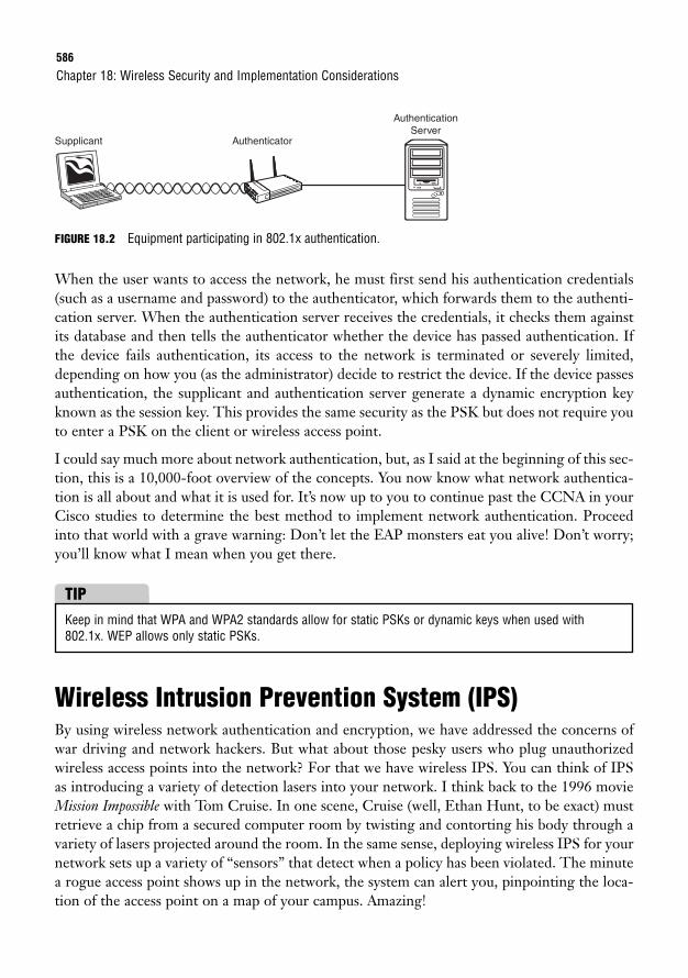
586
FIGURE 18.2 Equipment participating in 802.1x authentication.
When the user wants to access the network, he must first send his authentication credentials(such as a username and password) to the authenticator, which forwards them to the authenti-cation server. When the authentication server receives the credentials, it checks them againstits database and then tells the authenticator whether the device has passed authentication. Ifthe device fails authentication, its access to the network is terminated or severely limited,depending on how you (as the administrator) decide to restrict the device. If the device passesauthentication, the supplicant and authentication server generate a dynamic encryption keyknown as the session key. This provides the same security as the PSK but does not require youto enter a PSK on the client or wireless access point.
I could say much more about network authentication, but, as I said at the beginning of this sec-tion, this is a 10,000-foot overview of the concepts. You now know what network authentica-tion is all about and what it is used for. It’s now up to you to continue past the CCNA in yourCisco studies to determine the best method to implement network authentication. Proceedinto that world with a grave warning: Don’t let the EAP monsters eat you alive! Don’t worry;you’ll know what I mean when you get there.
Chapter 18: Wireless Security and Implementation Considerations
Supplicant Authenticator
AuthenticationServer
Keep in mind that WPA and WPA2 standards allow for static PSKs or dynamic keys when used with802.1x. WEP allows only static PSKs.
TIP
Wireless Intrusion Prevention System (IPS)By using wireless network authentication and encryption, we have addressed the concerns ofwar driving and network hackers. But what about those pesky users who plug unauthorizedwireless access points into the network? For that we have wireless IPS. You can think of IPSas introducing a variety of detection lasers into your network. I think back to the 1996 movieMission Impossible with Tom Cruise. In one scene, Cruise (well, Ethan Hunt, to be exact) mustretrieve a chip from a secured computer room by twisting and contorting his body through avariety of lasers projected around the room. In the same sense, deploying wireless IPS for yournetwork sets up a variety of “sensors” that detect when a policy has been violated. The minutea rogue access point shows up in the network, the system can alert you, pinpointing the loca-tion of the access point on a map of your campus. Amazing!
Wireless Implementation Guidelines587
Network-wide IPS can detect a variety of additional suspicious movements around the net-work, in both the wired and wireless worlds. However, discussing the rest of those detectionsis part of the Cisco Certified Security Professional (CCSP) certification.
Wireless Implementation GuidelinesObjectives:
. Identify and describe the purpose of the components in a small wireless network. (Including: SSID, BSS,ESS)
. Identify the basic parameters to configure on a wireless network to ensure that devices connect to thecorrect access point
Now that you’ve read an overview of the wireless security considerations, let’s talk about plan-ning to implement wireless technology. There’s much more to planning a wireless LANdeployment than putting a few wireless access points in place. You need to understand how thetopology, distance, and placement of wireless access points can affect the efficiency of yourwireless LAN.
Understanding Wireless TopologiesWebster’s Dictionary defines “topology” as a branch of mathematics concerned with proper-ties of geometric configurations (such as point sets) that are unaltered by elastic deformations(as stretching or twisting) that are homeomorphisms. The CCENT and CCNA exams stopshort of requiring a full understanding of homeomorphism (or elastic deformation, for thatmatter). However, the exams do require you to have some knowledge of the placement of wire-less access points in your corporate network. The first piece to understand is that anyone candeploy a wireless network in one of two forms: ad hoc or infrastructure.
Ad hoc wireless networks technically use an Independent Basic Service Set (IBSS) topology.This means that each wireless device independently manages the wireless network. This typeof wireless network originates from and includes the wireless device, as shown in Figure 18.3.
This type of network can be created by users on-the-fly to share files or services with others.For example, someone on an airplane might want to share a folder of files with the person nextto her. She can create an ad hoc wireless network and allow the other person to join and accessthe shared files over a network connection.
Ad hoc networks typically are very limited in range and security capabilities. You may want toconsider restricting laptops in your corporation from starting ad hoc wireless networks,because they could be considered a potential security vulnerability.
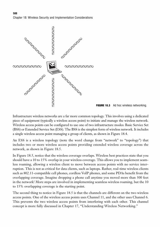
588
Infrastructure wireless networks are a far more common topology. This involves using a dedicatedpiece of equipment (typically a wireless access point) to initiate and manage the wireless network.Wireless access points can be configured to use one of two infrastructure modes: Basic Service Set(BSS) or Extended Service Set (ESS). The BSS is the simplest form of wireless network. It includesa single wireless access point managing a group of clients, as shown in Figure 18.4.
An ESS is a wireless topology (note the word change from “network” to “topology”) thatincludes two or more wireless access points providing extended wireless coverage across thenetwork, as shown in Figure 18.5.
In Figure 18.5, notice that the wireless coverage overlaps. Wireless best practices state that youshould have a 10 to 15% overlap in your wireless coverage. This allows you to implement seam-less roaming, allowing a wireless client to move between access points with no service inter-ruption. This is not as critical for data clients, such as laptops. Rather, real-time wireless clientssuch as 802.11-compatible cell phones, cordless VoIP phones, and some PDAs benefit from theoverlapping coverage. Imagine dropping a phone call anytime you moved more than 300 feetin the network! More steps are involved in implementing seamless wireless roaming, but the 10to 15% overlapping coverage is the starting point.
The second thing to notice in Figure 18.5 is that the channels are different on the two wirelessaccess points. One of the wireless access points uses Channel 11, and the other uses Channel 6.This prevents the two wireless access points from interfering with each other. This channelconcept is more fully discussed in Chapter 17, “Understanding Wireless Networking.”
Chapter 18: Wireless Security and Implementation Considerations
FIGURE 18.3 Ad hoc wireless networking.
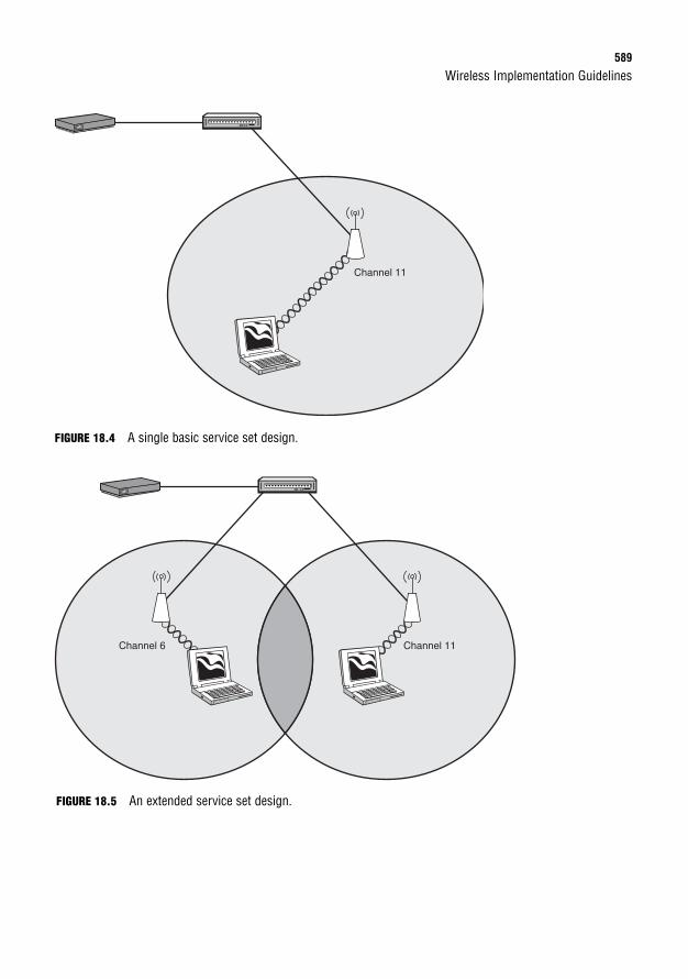
Wireless Implementation Guidelines589
FIGURE 18.4 A single basic service set design.
Channel 11
Channel 6 Channel 11
FIGURE 18.5 An extended service set design.
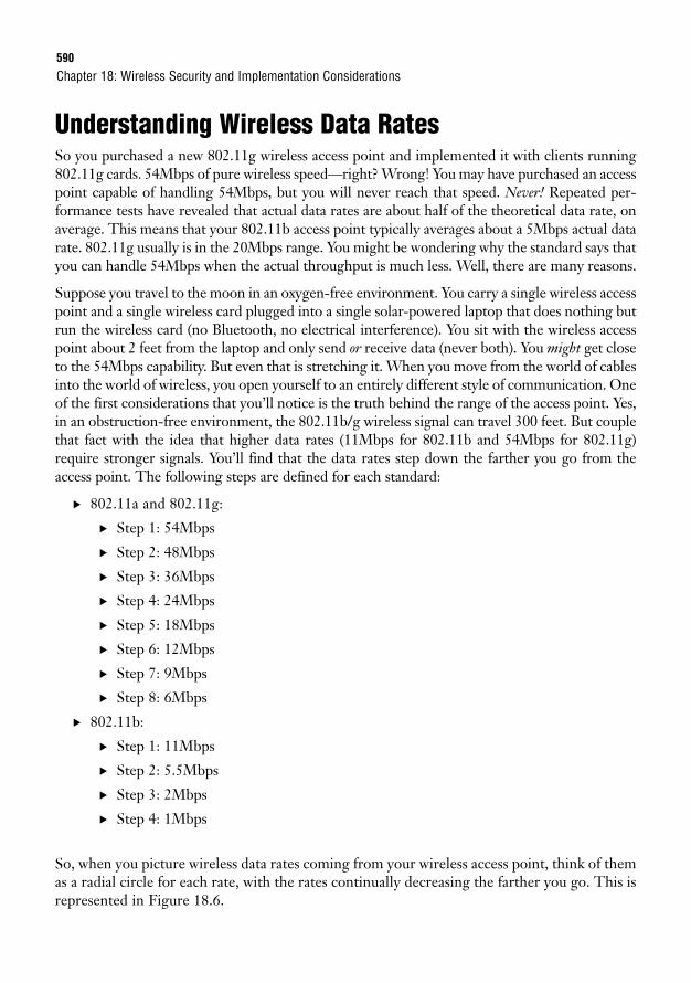
590
Understanding Wireless Data RatesSo you purchased a new 802.11g wireless access point and implemented it with clients running802.11g cards. 54Mbps of pure wireless speed—right? Wrong! You may have purchased an accesspoint capable of handling 54Mbps, but you will never reach that speed. Never! Repeated per-formance tests have revealed that actual data rates are about half of the theoretical data rate, onaverage. This means that your 802.11b access point typically averages about a 5Mbps actual datarate. 802.11g usually is in the 20Mbps range. You might be wondering why the standard says thatyou can handle 54Mbps when the actual throughput is much less. Well, there are many reasons.
Suppose you travel to the moon in an oxygen-free environment. You carry a single wireless accesspoint and a single wireless card plugged into a single solar-powered laptop that does nothing butrun the wireless card (no Bluetooth, no electrical interference). You sit with the wireless accesspoint about 2 feet from the laptop and only send or receive data (never both). You might get closeto the 54Mbps capability. But even that is stretching it. When you move from the world of cablesinto the world of wireless, you open yourself to an entirely different style of communication. Oneof the first considerations that you’ll notice is the truth behind the range of the access point. Yes,in an obstruction-free environment, the 802.11b/g wireless signal can travel 300 feet. But couplethat fact with the idea that higher data rates (11Mbps for 802.11b and 54Mbps for 802.11g)require stronger signals. You’ll find that the data rates step down the farther you go from theaccess point. The following steps are defined for each standard:
. 802.11a and 802.11g:
. Step 1: 54Mbps
. Step 2: 48Mbps
. Step 3: 36Mbps
. Step 4: 24Mbps
. Step 5: 18Mbps
. Step 6: 12Mbps
. Step 7: 9Mbps
. Step 8: 6Mbps
. 802.11b:
. Step 1: 11Mbps
. Step 2: 5.5Mbps
. Step 3: 2Mbps
. Step 4: 1Mbps
So, when you picture wireless data rates coming from your wireless access point, think of themas a radial circle for each rate, with the rates continually decreasing the farther you go. This isrepresented in Figure 18.6.
Chapter 18: Wireless Security and Implementation Considerations
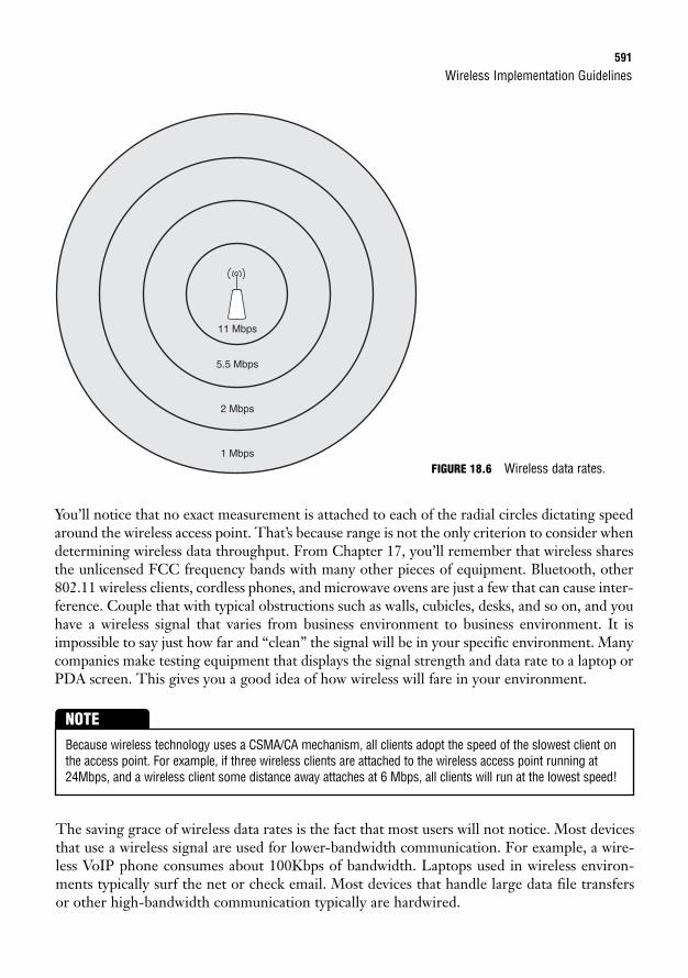
Wireless Implementation Guidelines591
11 Mbps
5.5 Mbps
2 Mbps
1 Mbps
You’ll notice that no exact measurement is attached to each of the radial circles dictating speedaround the wireless access point. That’s because range is not the only criterion to consider whendetermining wireless data throughput. From Chapter 17, you’ll remember that wireless sharesthe unlicensed FCC frequency bands with many other pieces of equipment. Bluetooth, other802.11 wireless clients, cordless phones, and microwave ovens are just a few that can cause inter-ference. Couple that with typical obstructions such as walls, cubicles, desks, and so on, and youhave a wireless signal that varies from business environment to business environment. It isimpossible to say just how far and “clean” the signal will be in your specific environment. Manycompanies make testing equipment that displays the signal strength and data rate to a laptop orPDA screen. This gives you a good idea of how wireless will fare in your environment.
FIGURE 18.6 Wireless data rates.
Because wireless technology uses a CSMA/CA mechanism, all clients adopt the speed of the slowest client onthe access point. For example, if three wireless clients are attached to the wireless access point running at24Mbps, and a wireless client some distance away attaches at 6 Mbps, all clients will run at the lowest speed!
NOTE
The saving grace of wireless data rates is the fact that most users will not notice. Most devicesthat use a wireless signal are used for lower-bandwidth communication. For example, a wire-less VoIP phone consumes about 100Kbps of bandwidth. Laptops used in wireless environ-ments typically surf the net or check email. Most devices that handle large data file transfersor other high-bandwidth communication typically are hardwired.
592
General Wireless Implementation StepsWith all those considerations floating around your mind, here are the general steps to imple-ment wireless:
1. Ensure hardwired operation: Before adding any wireless to the network, connect adevice (such as a laptop) to the same switch port where you plan to connect your wire-less access point. Ensure that it operates as expected, verifying VLAN assignment,DHCP operation, and Internet connectivity (if applicable).
2. Install the wireless access point in your tested switch port: Some access points willconnect using straight-through Ethernet cabling, and others may require a cross-overcable.
3. Configure a basic wireless network and test: Keep this initial test extremely simple.Just implement a wireless SSID with no security. After it is configured, join the wire-less network from a client, and test your connectivity. Ensure that the client obtains anIP address and can perform the same actions as when you use a hardwired connection.
4. Add wireless security and test: Implement the wireless security standard chosen foryour network. It’s usually best to begin with a preshared key system of security to keep itsimple. After you have added the security, reconfigure the wireless client, and test again.
Working through these four steps, you have established a baseline for your wireless network.As you add more features or security standards on top of the existing foundation, you canreturn to a “last known good” configuration if something goes wrong.
Wireless Troubleshooting
Objective:
. Identify common issues with implementing wireless networks.
Wireless troubleshooting is far more complex than typical wired troubleshooting. Physicalproblems are much more elusive, because they deal primarily with interference rather than asimple cable break or failing switch port. For example, I recently deployed in a business a wire-less network that worked great until 4 in the afternoon. As soon as we crossed the 4 p.m. bar-rier, all wireless connectivity was lost. After doing some spectrum analysis, we found that anearby airport was using a device (we still aren’t sure what it was) that completely flooded the2.4GHz frequency range. The company decided to move to 802.11a (which was a fairly largenetwork upgrade) to avoid this interference.
Likewise, wireless technology is fairly new to the industry. You may find that firmware for youraccess point has bugs and needs to be upgraded to a newer version to avoid persistent crash-ing (this happens far more often than you may realize). The following wireless troubleshoot-ing checklist may be helpful as you attempt to diagnose the issue.
Chapter 18: Wireless Security and Implementation Considerations
Wireless Implementation Guidelines593
Client TroubleshootingMost wireless issues are related to the client:
. Verify that the wireless card is enabled: Most new laptops have a button or switchthat disables the wireless card to save battery life.
. Move to a “known good” region of the building: Do your testing in an area knownto have a strong wireless signal. This may require using multiple wireless devices.
. Verify that the client can identify the wireless network using the installed wire-less utility: If you are unable to identify wireless SSID(s) in your vicinity, the client’swireless card may be disabled, or the wireless access point may not be working.
. Ensure that the wireless client has the correct wireless security information andsupports your security standards: You may need to re-enter the preshared key toensure that you entered it correctly. Likewise, the wireless card may not support thewireless security on your network. Try connecting to an SSID that does not use securi-ty from the wireless device.
Wireless Access Point TroubleshootingMost troubleshooting that deals with the wireless access point focuses on physical considerations:
. Verify that the wireless access point is running the latest firmware version:Nothing is worse than spending hours on a problem that is related to a bug in thewireless firmware.
. Test the wireless reception radius at different times of the day: Because of thevarying degrees of interference that may occur over time, it is best to run multiple testson your signal strength. You can do this simply and inexpensively by carrying around alaptop and observing the reception at differing locations.
. Verify your wireless channel configuration: If you have multiple wireless accesspoints or are in an area where other access points may interfere, verify (using wirelesssoftware) the most saturated and unsaturated channels. For 802.11b/g, use channels 1,6, or 11 in the U.S. For 802.11a, many more channels are available, and you shouldtest for the cleanest frequency.
. Consider the materials around and close to the access point: Try to avoidinstalling the access point near metal objects, which reflect the signal. Realize that aconcrete block wall will absorb much more signal than a drywall barrier.
594
Chapter SummaryAll in all, deploying a wireless network is not for the fainthearted. Installing a wireless accesspoint in the network essentially broadcasts and extends your network beyond the walls of yourorganization into treacherous territory. Wireless intruders can begin capturing data and break-ing into the network without your ever knowing an attack is happening. This is why it is socritical to understand the security considerations before you attach wireless equipment in yourenvironment.
When securing your wireless network, not all security standards are created equal. The initialWEP system of security offered only 64-bit encryption. It was easily broken because of the keystrength as well as a number of flaws that plagued the initial WEP deployment. WEP2increased the key strength to 128-bit encryption, but it still suffered many of the other weak-nesses of WEP. WPA was released to address many of those weaknesses, but it was consideredan interim solution while network users began migrating to new hardware. Modern networksemploy WPA2 (aka 802.11i) to ensure up-to-date security standards in the world of wireless.
In addition to locking down the wireless network, many implementation considerations mustbe taken into account. Wireless is susceptible to RF interference. This adds many physical lay-ers of troubleshooting that did not exist in the wired environment. Ensuring that your wire-less cells include an acceptable amount of overlap and differing channels lays the foundationfor ensuring adequate wireless coverage for your organization.
Key Terms
Chapter 18: Wireless Security and Implementation Considerations
. 802.11a/b/g/n
. WEP 64-bit
. WEP 128-bit
. WPA
. WPA2 (802.11i)
. 802.1x
. Wireless Intrusion Prevention System(IPS)
. Basic Service Set (BSS)
. Extended Service Set (ESS)
. Radio Frequency (RF)
. 2.4GHz band
. 5GHz band
. Wireless channels
. Wireless cells
. Wireless roaming
. Wireless data rate
Apply Your Knowledge595
Apply Your Knowledge
Review Questions1. List the three encryption standards you can currently use with wireless networking.
2. Describe the differences between WEP, WPA, and WPA2. What type of encryption does each use?What are their strengths and weaknesses?
3. List three potential vulnerabilities of a wireless network.
4. Because a wireless access point forces all clients to use the speed of the slowest client, how doyou think you should ideally deploy your wireless access points?
5. What is the process for successfully installing a wireless access point?
Exam Questions1. What is a rogue access point?
❍ A. An unauthorized access point that has been placed on your LAN
❍ B. An access point configured to broadcast the corporate SSID
❍ C. An access point using WEP or WEP2 security
❍ D. An access point that has been compromised by an intruder
2. When designing a wireless ESS system, how much cell overlap is recommended?
❍ A. None. Cell overlap can cause interference.
❍ B. 5 to 10%
❍ C. 10 to 15%
❍ D. 15 to 20%
3. What scenario would be an ideal case to implement WEP security?
❍ A. You are running a small business network environment implementing the 802.11awireless standard
❍ B. You would like to implement the 802.1x security standard using a Windows RADIUSserver to authenticate users
❍ C. You would like to implement increased security instead of or in addition to the typicalWPA or 802.11i standards
❍ D. You are required to implement wireless using older equipment that does not supportWPA or WPA2
596
4. You are sitting in a library and would like to share files with a coworker sitting across the table. Toaccomplish this, the coworker connects to a wireless SSID managed by your laptop. What type ofnetwork topology is this?
❍ A. Unsecure
❍ B. Ad hoc
❍ C. Basic Service Set
❍ D. Extended Service Set
5. You are using a Cisco 7921 wireless VoIP device. While speaking to your coworker on the phone,you are walking through multiple wireless cells. What type of network topology is this?
❍ A. Unsecure
❍ B. Ad hoc
❍ C. Basic Service Set
❍ D. Extended Service Set
6. Your organization uses a wireless security standard that requires people to authenticate to a back-end server with a valid active directory username and password before they are granted access tothe wireless network. Upon successful authentication, the dynamic encryption keys are generatedfor use during the wireless session. What type of network security is in use?
❍ A. WEP
❍ B. WEP2
❍ C. WPA
❍ D. 802.11i
❍ E. 802.1x (EAPOL)
7. Which of the following accurately describes the difference between WPA and WPA2?
❍ A. WPA integrates with WEP encryption standards, whereas WPA2 is not backward-compatible.
❍ B. WPA uses TKIP encryption, and WPA2 uses AES.
❍ C. WPA uses preshared keys, and WPA2 allows for back-end user authentication.
❍ D. WPA is used on 802.11a networks, whereas WPA2 is compatible with 802.11a/b/g networks.
Chapter 18: Wireless Security and Implementation Considerations
Apply Your Knowledge597
8. You are troubleshooting a wireless laptop for a user in your organization. The wireless laptop can-not identify any available wireless SSIDs in the region. Your personal laptop can identify threeSSIDs from the same location. The user has previously connected to the corporate network with-out issue. You have noticed increased interference from a neighboring company during differenttimes of the day. What is the most likely cause of this issue?
❍ A. The client wireless network card is disabled.
❍ B. The RF interference has become too heavy for the client to view the available SSIDs.
❍ C. The client wireless card is using the wrong frequency.
❍ D. The signal is being absorbed before reaching the client laptop.
9. You suspect that one of your network users has violated the corporate security policy by pluggingin a personal wireless access point in his cubicle. What Cisco security solution would allow you todetect this issue?
❍ A. Cisco ACS Server
❍ B. Cisco wireless IPS
❍ C. Cisco wireless 802.1x
❍ D. MAC address security
10. A network user has issued a trouble ticket stating that she is experiencing file transfers well belowthe 54Mbps speed that her wireless laptop claims to achieve. What are three valid reasons for this?
❍ A. RF interference
❍ B. CSMA/CA transmission method
❍ C. Proximity to the access point
❍ D. The duplex setting on the client’s laptop
❍ E. The client has not implemented 802.1x
Answers to Review Questions1. The three encryption standards are WEP, WPA, and WPA2.
2. WEP uses the RC4 encryption algorithm. WPA uses the TKIP encryption method, which is moresecure than WEP but not as secure as the WPA2 standard, which uses AES encryption. WEP doesnot have many strengths other than compatibility; all wireless devices can support the WEP stan-dard. WPA has the strength of being interoperable with older WEP-compatible hardware, but it stillhas a few security weaknesses. WPA2 supports extremely strong encryption, but it is not backward-compatible with older wireless hardware.
598
3. Wireless networks are vulnerable to war driving, direct hacking, and employee ignorance.
4. Wireless access points should be deployed in a “tight configuration.” This means that you shouldhave many access points broadcasting smaller, more high-speed signals rather than a few accesspoints broadcasting weaker signals that reach a larger radius.
5. First, ensure hardwire operation. Then, install the access point and test a basic network SSID withno security. Finally, add security and perform a final test.
Answers to Exam Questions1. A. Rogue access points typically are brought in by internal corporate users with nonmalicious or
malicious intent. Regardless of the intent, the rogue access point adds an enormous security liabil-ity to your network.
2. C. Wireless best practices recommend a 10 to 15% overlap of wireless cells. This allows for seam-less roaming by wireless devices. Answer A is true only if the wireless access points are config-ured to use the same channel (frequency range). Because of this, you should never have adjacentaccess points using the same channel.
3. D. Both WEP (64-bit) and WEP2 (128-bit) encryption methods have been found to be insecure.The only time they should be used is in a network environment that uses older equipment and isunable to support the newer security standards.
4. B. Ad hoc networks are wireless networks generated from a participating device in the network,such as a laptop. These laptops can use many of the same security methods as BSS or ESS wire-less topologies.
5. D. An Extended Service Set (ESS) wireless topology is the combination of two or more BasicService Set (BSS) networks. This allows client roaming (between wireless cells) without serviceinterruption.
6. E. 802.1x (less commonly known as Extensible Authentication Protocol over LAN [EAPOL]) adds asecure authentication system to a LAN environment. This technology can be used to secure bothwired and wireless LAN connections. The other answers represent varying encryption standards.
7. B. WPA was released as an interim solution to improve the security of WEP. It uses an encryptionmethod known as TKIP, which is more secure than WEP but not as secure as the WPA2 standard,which uses AES encryption.
8. A. The most likely cause of this issue is that the client wireless card is turned off. This happensfrequently with laptops, because manufacturers commonly put a switch or button on the case ofthe laptop that easily turns the laptop on or off. The fact that it could not see any wireless net-works while your personal laptop sat next to it reveals that wireless networks are reaching thelocation through the interference. The card cannot be the wrong frequency, because it previouslyconnected to the corporate network without issue.
Chapter 18: Wireless Security and Implementation Considerations
Apply Your Knowledge599
9. B. The Cisco wireless IPS system identifies rogue wireless access points added to the network.The 802.1x and the Cisco ACS Server are primarily responsible for user authentication and privi-leges. MAC address security can help disable a port with a rogue wireless access point, but it can-not detect the rogue’s existence.
10. A, B, C. Wireless is susceptible to many types of RF interference. Likewise, the farther the client isfrom the access point, the lower her speed becomes. Finally, wireless uses a CSMA/CA transmis-sion method, which causes the amount of bandwidth to diminish the more clients you add to theaccess point.
Suggested Readings and Resources1. Wikipedia 802.11 definitions, http://en.wikipedia.org/wiki/802.11
2. How WiFi Works, http://computer.howstuffworks.com/wireless-network3.htm
3. Chris Ward and Jeremy Cioara. CCNA Practice Questions. Que Publishing, 2008.
4. Toby Velte and Anthony Velte. Cisco 802.11 Wireless Networking Quick Reference. CiscoPress, 2005.

This page intentionally left blank
19C H A P T E R N I N E T E E N
Using Cisco Access Lists
ObjectivesThis chapter covers the following Cisco-specific objectives for the “Implement, verify, and trou-bleshoot NAT and ACLs in a medium-size Enterprise branch office network” sections of the640-802 CCNA:
. Describe the purpose and types of ACLs
. Configure and apply ACLs based on network filtering requirements (including:CLI/SDM)
. Configure and apply ACLs to limit telnet and SSH access to the router(including: SDM/CLI)
. Verify and monitor ACLs in a network environment
. Troubleshoot ACL issues
OutlineIntroduction 604
Access List Concepts 604
Functions of an Access List 607
Packet Filtering 607
Quality of Service 607
Dial-on-Demand Routing 608
Network Address Translation 609
Route Filtering 609
Standard Access Lists 610
Configuration of Standard Access Lists 610
Placement of Standard Access Lists 614
Standard Access List Examples 616
Isolating Networks 616
Isolating a Network from Specific Hosts 617
Isolating the Internal Network from the Internet 618
Restricting VTY Access 619
Extended Access Lists 620
Configuration of Extended Access Lists 620
Practical Extended Access List Examples 626
Blocking a Subnet 626
Restricting by Protocol 630
Restricting by Network 631
Named Access List 632
Verifying Access Lists 634
show running-config 634
show ip interface 635
show ip access-lists 636
Chapter Summary 637
Key Terms 637
Apply Your Knowledge 638
Exercises 638
Review Questions 643
Exam Questions 644
Answers to Review Questions 646
Answers to Exam Questions 646
Suggested Reading and Resources 647

Study Strategies. Read the information presented in the chapter, paying special attention to
tables, Notes, and Exam Alerts.
. Spend plenty of time looking over the configuration examples.Understanding the configuration of access lists is paramount to understanding many of the upcoming chapters and exam objectives.
604
IntroductionA packet slides smoothly across the ethernet cable, gliding through a switch as it heads to itsfinal destination: the company accounting server. Nobody in the network suspects that this isno normal packet. Behind all the source and destination header information lies a speciallyengineered code designed to unleash a denial of service attack when processed by the unsus-pecting Windows 2003 Server platform. Just one more router to pass through and the deedwill be done. Let’s pick up the dialog here:
Incoming router Ethernet interface: bang, bang! (a loud knock is heard)
Router processor (yelling): “Source and destination please!”
Malicious packet (in a scandalous voice): “Yeah, I’m 10.6.9.2 headed to 10.56.100.10 on port137…make it snappy.”
* gunshot rings out, malicious packet falls to the ground *
Router processor (scraping the crumpled bits into a bucket): “Your type isn’t welcome in theseparts…punk.”
You have just been witness to one of the most well-known uses of an access list: network traf-fic control. This function enables you to turn a common router into a fairly sophisticated fire-wall (the Dirty Harry dialog does require an IOS upgrade, however). As you might imagine, acornerstone function like this is not only relevant for the CCNA exam, but also for Cisco net-work deployments worldwide.
Access List ConceptsObjective:
. Describe the purpose and types of ACLs
When you look at the term access list, the only word that stands out is access. Of course, thisimmediately causes any technology-minded person to conjure thoughts of controlling traffic,firewalls, and intrusion detection. Although this may have been Cisco’s initial intention whenthey created the concept of access lists, nowadays access lists are used for a plethora of func-tions on any Cisco device. When you hear the term access list, don’t focus on the word access;rather, focus on the word list.
An access list is nothing more than an ordered list of permit and deny statements. Every timethe router needs to refer to the list for some reason, it reads it at the top and works its waydown. You can picture it like a bouncer at an upscale drinking establishment. He may have thefollowing list in his hand:
Chapter 19: Using Cisco Access Lists
Access List Concepts605
Deny Joshua Smith
Deny Benjamin Newport
Permit people with brown hair
The bouncer is then told to screen people as they attempt to enter the establishment. Now,when the first patron attempts to enter the building, the following transcript occurs:
Bouncer: “Is your name Joshua Smith?”
Patron: “No.”
Bouncer: “Is your name Benjamin Newport?”
Patron: “No.”
Bouncer: “Do you have brown hair?”
Patron: “Yes.”
Bouncer: “You may enter our establishment.”
The next person that attempts to enter the building is subjected to exactly the same list ofquestions in exactly the same order. Now this leads to a major question about this story: Whatif someone attempted to enter the building who did not have the name Joshua Smith orBenjamin Newport, but also did not have brown hair? That person is denied. No questionsasked. This is one of the cornerstone facts of access lists on a Cisco device: If you have not beenexplicitly permitted, you are implicitly denied.
EXAM ALERTAccess lists always have an implicit deny statement at the end of the list. This statement is never displayed and cannot be seen through any show command. In an access list, if you have not beenexplicitly permitted, you are implicitly denied.
The implicit deny statement is hidden at the end of all access lists, and its order cannot bechanged. However, the ordering of access lists elsewhere is of great importance. It can affecteverything about your access list. For example, what if the question, “Do you have brownhair?” was listed first in the bouncer’s access list? In that case, Joshua Smith or BenjaminNewport may have been permitted because they had brown hair, even though they wereexplicitly denied elsewhere in the list. A router stops processing an access list after an initialmatch statement is found. Let’s leave the bouncer example behind for now and begin applyingthese concepts to networking.
Suppose you had defined the following access list (this is not correct syntax; rather, it is a conceptual view):
606
Permit host 192.168.1.50
Deny network 192.168.1.0/24
Permit host 192.168.1.100
<implicit deny>
This list would permit the host 192.168.1.50, as it intended. However, the host 192.168.1.100would never be permitted because it is listed after the second statement in the list, whichdenies the entire Class C 192.168.1.0/24 subnet.
Chapter 19: Using Cisco Access Lists
Depending on the IOS version you are using, there may be different ways the IOS formats access lists. Inolder IOS versions, the access list is arranged exactly as you enter it into the command line and cannot bereordered unless you completely erase the access list and re-create it. In modern IOS versions, the Ciscorouter can automatically reorder the list if you make an obvious mistake, as shown in the prior access list.In the newest versions of the IOS, the Cisco router assigns sequence numbers to each entry, allowing theaddition, removal, and reordering of any line in the access list. (This is an awesome feature, which is cov-ered later in the chapter during the discussion of named access lists.)
CAUTION
Throughout the rest of this chapter, it is assumed that the IOS version is the same as it is onthe CCNA exam. This means there is no automatic reordering of the list, lines cannot be indi-vidually removed, and the only additions that can be made are lines that are inserted at the endof the access list (this is the default when configuring the access list).
After all this, keep in mind that these are only the guidelines for creating an access list.Remember: An access list is just a list of permit and deny statements. The way in which youapply the access list defines the function of the access list. If you apply the access list inboundor outbound on a router interface, then the router begins to filter packets according to theinstructions in the access list. If you apply the access list to your Network Address Translation(NAT) configuration, then the access list defines what IP addresses are permitted to be trans-lated to an Internet-valid address. If you apply the access list to a dial-on-demand configura-tion, then the access list defines what devices or network traffic types are allowed to bring upa dial-up interface (such as a modem). I hope I am getting the point across: An access list is noth-ing more than a list of permit and deny statements. How you apply it dictates what function the accesslist really serves.
EXAM ALERTFor the CCNA exam, assume that the router is using an older version of the IOS that is arranged exact-ly as you enter it into the command line and cannot be reordered unless you completely erase theaccess list and re-create it.
Functions of an Access List607
Functions of an Access ListObjective:
. Describe the purpose and types of ACLs
At this point, we have discussed a few access list uses in passing; however, the truth is that youwill rarely encounter a major function of a Cisco router that does not require an access list insome way. For the CCNA exam, you should be aware of the following access list functions:
. Packet filtering
. Quality of service (QoS)
. Dial-on-demand routing (DDR)
. Network Address Translation (NAT)
. Route filtering
Packet FilteringOf course, packet filtering is the most well-known application of access lists. This access listapplication enables you to turn your router into a basic firewall. By using these foundation IOSfeatures, you can begin filtering traffic inbound or outbound from any interface on yourrouter. Depending on the type of access list you use, you can filter traffic based on the sourceaddress (standard access list) or based on the source and destination address, along with pro-tocol and port number (extended access list).
EXAM ALERTAlthough you may be required to understand some of the common applications of access lists on theCCNA exam, you will be required only to demonstrate proficiency in configuring access lists for packetfiltering and NAT.
As soon as you apply an access list for packet filtering inbound or outbound on an interface, the routermust begin comparing every packet against the access list. Depending on the size and matching criteria ofyour access list, this can cause significant processor load.
CAUTION
608
Quality of ServiceWith the emerging technology of Voice over IP (VoIP), it has become necessary to giveunequal treatment to network traffic. For example, if a router is receiving a considerableamount of Web surfing traffic (HTTP) and a VoIP telephone call attempts to come through,the VoIP conversation should receive prioritization over the HTTP traffic to ensure high-quality voice conversations; even if it means dropping a few of the HTTP packets. This is theconcept of Quality of Service (QoS). The QoS matching methods rely extensively on accesslists to define what types of traffic are prioritized over others. In this case, you see access listsin the view that they are permitting traffic to be prioritized and denying others from gaining net-work priority.
Now, not all QoS methods seek the good of the traffic they match. There is a QoS methodcalled traffic policing that limits the bandwidth available to a certain application. For example,a network may have problems with users using peer-to-peer file sharing applications, such asNapster, Kazaa, or Morpheus, and depleting the Internet connection bandwidth. In this case,a QoS policing policy can be defined to limit the bandwidth available to these applicationtypes. Here’s where the access list irony can be seen: The access list matches these applications(permits) and then restricts the amount of bandwidth they can use. The applications that arenot matched (denied) do not have any bandwidth restrictions placed on them. In this access listfunction, from the application’s point of view, it is better to be denied than permitted. Are youbeginning to see that an access list is just a list of statements? How you apply that access listdetermines the effect it has on the network traffic.
Dial-on-Demand RoutingDial-on-demand routing encompasses any type of temporary (not always on) connection.Despite their “legacy” stereotype, dial-up connections are here to stay because no other con-nection type has proved to be as reliable as the circuit switched technology. Although manypeople immediately think of modem connections, ISDN BRI and PRI services also fit this pro-file. In recent years in the United States, the number of ISDN BRI connections has droppeddrastically because of the emergence of cheaper connections that use DSL and cable modemtechnology. However, the number of ISDN connections overseas is enormous.
Now you might wonder…what does dial-on-demand routing have to do with access lists? Well,in this case, access lists do not define what traffic is permitted across the dial-on-demand con-nection; rather, it defines what traffic is interesting enough to bring up the line. If you ever sawthe movie Wayne’s World in the early 90s, there is a moment where the singer Alice Cooper walksby Wayne and Garth. Immediately, they fall to the ground yelling, “We’re not worthy!” In thesame sense, you will create an access list that defines traffic that is “worthy” to dial the connec-tion. Some ISDN connections charge a per-minute cost for being connected, so it may pay offto limit dial-up connections to certain traffic sources or packet types before the line is engaged.
Chapter 19: Using Cisco Access Lists
Functions of an Access List609
Network Address TranslationNetwork Address Translation (NAT) has been in widespread use for over a decade, and yet stillnever ceases to amaze me. There is perhaps no other configuration that gives you as much sat-isfaction in “beating the system” as NAT (other than using your neighbor’s wireless accesspoint, of course). NAT theoretically allows more than 60,000 internal hosts to share a single,registered, public IP address to access the Internet. This has overcome the current public IPaddress shortage and extended the life of TCP/IP version four for years beyond what manythought possible.
EXAM ALERTBecause of the overwhelming popularity of NAT deployments, it is one of the newest topics to beadded to the CCNA exam. You will be expected to configure NAT using the Cisco SDM for CCENT-levelcertification (covered in Chapter 20, “Enabling Internet Connectivity with NAT”). Configuring NAT fromthe command-line interface is required for CCNA-level certification (covered in Chapter 21,“Command-Line NAT Implementation”).
The way access lists are used in NAT is similar to the way they were used in dial-on-demandrouting. The access lists define what source addresses are “worthy enough” to be transmitted. Apermit statement in the access list applied to a NAT configuration says, “This host (or subnet)is permitted to be translated with NAT.” A deny statement in the same access list says, “This host(or subnet) is not permitted to be translated with NAT.” A deny statement does not prevent traf-fic from being sent; rather, it denies it from being translated with NAT before it is sent.
Route FilteringThe final access list application covered in this text is route filtering. The routing protocolsdiscussed so far, such as RIP, IGRP, EIGRP, and OSPF, all make it their mission to pass allknown network routes to neighboring routers. In some network situations, this could cause aproblem. Perhaps you don’t want the router to pass all routes to every router on your network.For example, you might have some edge routers that connect to a partner company or anInternet-based peer. You could protect your network by using an access list to filter the routesthat are sent and received to and from this peer.
A configuration known as a distribute list is used most often to apply the access list used for thisfunction. In order to set this up, you would configure an access list permitting only the net-works you would like to send or receive (or denying the networks you would not like to sendor receive, depending on your strategy). As discussed before, creating the access list doesabsolutely nothing, functionally speaking; it must be applied to take action. In the case of routefiltering, you would apply the access list under router configuration mode, Router(config-router), for the routing protocol you would like to filter, by using the distribute-list
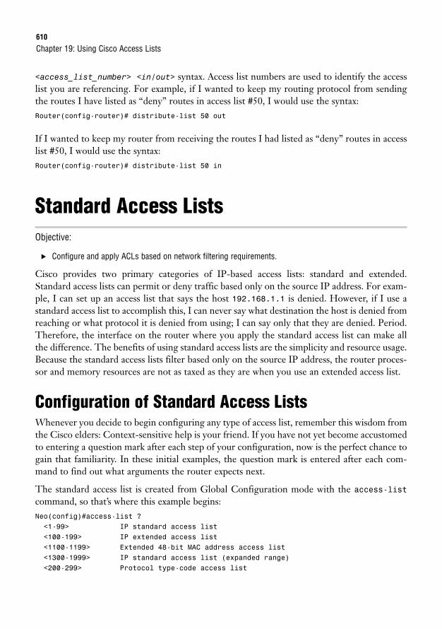
610
<access_list_number> <in/out> syntax. Access list numbers are used to identify the accesslist you are referencing. For example, if I wanted to keep my routing protocol from sendingthe routes I have listed as “deny” routes in access list #50, I would use the syntax:Router(config-router)# distribute-list 50 out
If I wanted to keep my router from receiving the routes I had listed as “deny” routes in accesslist #50, I would use the syntax:Router(config-router)# distribute-list 50 in
Standard Access ListsObjective:
. Configure and apply ACLs based on network filtering requirements.
Cisco provides two primary categories of IP-based access lists: standard and extended.Standard access lists can permit or deny traffic based only on the source IP address. For exam-ple, I can set up an access list that says the host 192.168.1.1 is denied. However, if I use astandard access list to accomplish this, I can never say what destination the host is denied fromreaching or what protocol it is denied from using; I can say only that they are denied. Period.Therefore, the interface on the router where you apply the standard access list can make allthe difference. The benefits of using standard access lists are the simplicity and resource usage.Because the standard access lists filter based only on the source IP address, the router proces-sor and memory resources are not as taxed as they are when you use an extended access list.
Configuration of Standard Access ListsWhenever you decide to begin configuring any type of access list, remember this wisdom fromthe Cisco elders: Context-sensitive help is your friend. If you have not yet become accustomedto entering a question mark after each step of your configuration, now is the perfect chance togain that familiarity. In these initial examples, the question mark is entered after each com-mand to find out what arguments the router expects next.
The standard access list is created from Global Configuration mode with the access-listcommand, so that’s where this example begins:Neo(config)#access-list ?<1-99> IP standard access list<100-199> IP extended access list<1100-1199> Extended 48-bit MAC address access list<1300-1999> IP standard access list (expanded range)<200-299> Protocol type-code access list
Chapter 19: Using Cisco Access Lists
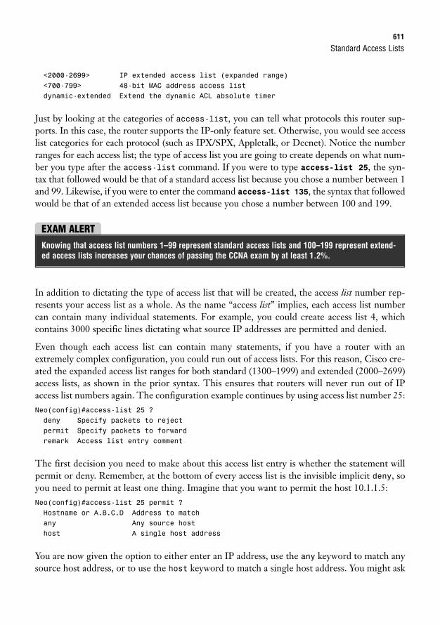
Standard Access Lists611
<2000-2699> IP extended access list (expanded range)<700-799> 48-bit MAC address access listdynamic-extended Extend the dynamic ACL absolute timer
Just by looking at the categories of access-list, you can tell what protocols this router sup-ports. In this case, the router supports the IP-only feature set. Otherwise, you would see accesslist categories for each protocol (such as IPX/SPX, Appletalk, or Decnet). Notice the numberranges for each access list; the type of access list you are going to create depends on what num-ber you type after the access-list command. If you were to type access-list 25, the syn-tax that followed would be that of a standard access list because you chose a number between 1and 99. Likewise, if you were to enter the command access-list 135, the syntax that followedwould be that of an extended access list because you chose a number between 100 and 199.
EXAM ALERTKnowing that access list numbers 1–99 represent standard access lists and 100–199 represent extend-ed access lists increases your chances of passing the CCNA exam by at least 1.2%.
In addition to dictating the type of access list that will be created, the access list number rep-resents your access list as a whole. As the name “access list” implies, each access list numbercan contain many individual statements. For example, you could create access list 4, whichcontains 3000 specific lines dictating what source IP addresses are permitted and denied.
Even though each access list can contain many statements, if you have a router with anextremely complex configuration, you could run out of access lists. For this reason, Cisco cre-ated the expanded access list ranges for both standard (1300–1999) and extended (2000–2699)access lists, as shown in the prior syntax. This ensures that routers will never run out of IPaccess list numbers again. The configuration example continues by using access list number 25:Neo(config)#access-list 25 ?deny Specify packets to rejectpermit Specify packets to forwardremark Access list entry comment
The first decision you need to make about this access list entry is whether the statement willpermit or deny. Remember, at the bottom of every access list is the invisible implicit deny, soyou need to permit at least one thing. Imagine that you want to permit the host 10.1.1.5:Neo(config)#access-list 25 permit ?Hostname or A.B.C.D Address to matchany Any source hosthost A single host address
You are now given the option to either enter an IP address, use the any keyword to match anysource host address, or to use the host keyword to match a single host address. You might ask
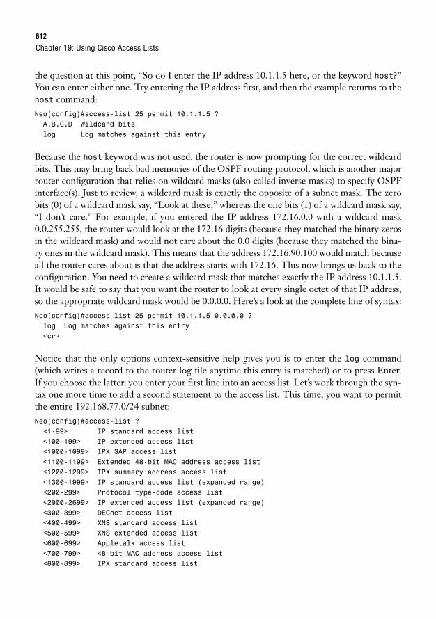
612
the question at this point, “So do I enter the IP address 10.1.1.5 here, or the keyword host?”You can enter either one. Try entering the IP address first, and then the example returns to thehost command:Neo(config)#access-list 25 permit 10.1.1.5 ?A.B.C.D Wildcard bitslog Log matches against this entry
Because the host keyword was not used, the router is now prompting for the correct wildcardbits. This may bring back bad memories of the OSPF routing protocol, which is another majorrouter configuration that relies on wildcard masks (also called inverse masks) to specify OSPFinterface(s). Just to review, a wildcard mask is exactly the opposite of a subnet mask. The zerobits (0) of a wildcard mask say, “Look at these,” whereas the one bits (1) of a wildcard mask say,“I don’t care.” For example, if you entered the IP address 172.16.0.0 with a wildcard mask0.0.255.255, the router would look at the 172.16 digits (because they matched the binary zerosin the wildcard mask) and would not care about the 0.0 digits (because they matched the bina-ry ones in the wildcard mask). This means that the address 172.16.90.100 would match becauseall the router cares about is that the address starts with 172.16. This now brings us back to theconfiguration. You need to create a wildcard mask that matches exactly the IP address 10.1.1.5.It would be safe to say that you want the router to look at every single octet of that IP address,so the appropriate wildcard mask would be 0.0.0.0. Here’s a look at the complete line of syntax:Neo(config)#access-list 25 permit 10.1.1.5 0.0.0.0 ?log Log matches against this entry<cr>
Notice that the only options context-sensitive help gives you is to enter the log command(which writes a record to the router log file anytime this entry is matched) or to press Enter.If you choose the latter, you enter your first line into an access list. Let’s work through the syn-tax one more time to add a second statement to the access list. This time, you want to permitthe entire 192.168.77.0/24 subnet:Neo(config)#access-list ?<1-99> IP standard access list<100-199> IP extended access list<1000-1099> IPX SAP access list<1100-1199> Extended 48-bit MAC address access list<1200-1299> IPX summary address access list<1300-1999> IP standard access list (expanded range)<200-299> Protocol type-code access list<2000-2699> IP extended access list (expanded range)<300-399> DECnet access list<400-499> XNS standard access list<500-599> XNS extended access list<600-699> Appletalk access list<700-799> 48-bit MAC address access list<800-899> IPX standard access list
Chapter 19: Using Cisco Access Lists
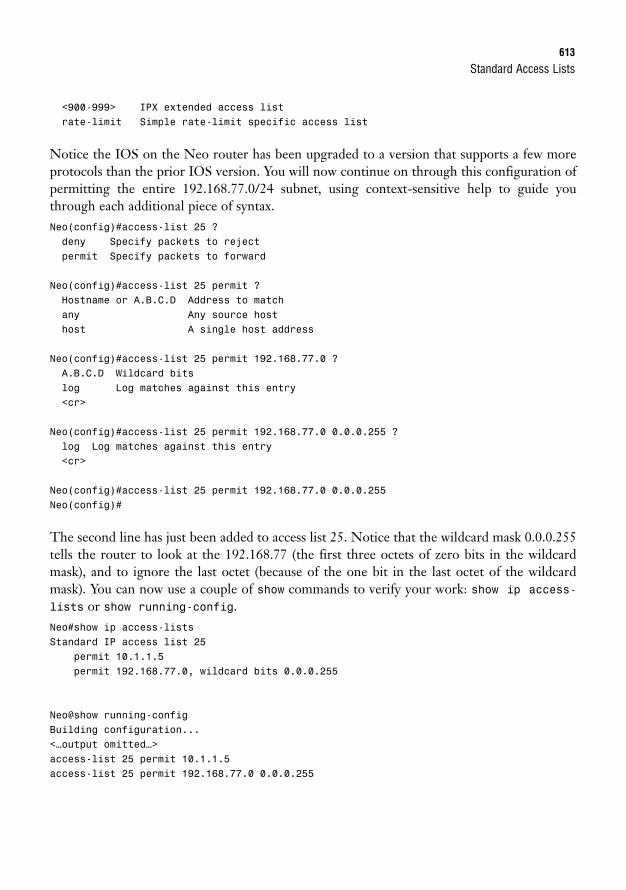
Standard Access Lists613
<900-999> IPX extended access listrate-limit Simple rate-limit specific access list
Notice the IOS on the Neo router has been upgraded to a version that supports a few moreprotocols than the prior IOS version. You will now continue on through this configuration ofpermitting the entire 192.168.77.0/24 subnet, using context-sensitive help to guide youthrough each additional piece of syntax.Neo(config)#access-list 25 ?deny Specify packets to rejectpermit Specify packets to forward
Neo(config)#access-list 25 permit ?Hostname or A.B.C.D Address to matchany Any source hosthost A single host address
Neo(config)#access-list 25 permit 192.168.77.0 ?A.B.C.D Wildcard bitslog Log matches against this entry<cr>
Neo(config)#access-list 25 permit 192.168.77.0 0.0.0.255 ?log Log matches against this entry<cr>
Neo(config)#access-list 25 permit 192.168.77.0 0.0.0.255Neo(config)#
The second line has just been added to access list 25. Notice that the wildcard mask 0.0.0.255tells the router to look at the 192.168.77 (the first three octets of zero bits in the wildcardmask), and to ignore the last octet (because of the one bit in the last octet of the wildcardmask). You can now use a couple of show commands to verify your work: show ip access-lists or show running-config.Neo#show ip access-listsStandard IP access list 25
permit 10.1.1.5permit 192.168.77.0, wildcard bits 0.0.0.255
Neo@show running-configBuilding configuration...<…output omitted…>access-list 25 permit 10.1.1.5access-list 25 permit 192.168.77.0 0.0.0.255
614
Initially, it looks as if the router lost the wildcard mask that was added for the 10.1.1.5 host.The Cisco router removes the 0.0.0.0 because an IP address without the wildcard mask isassumed to be an individual host anyway.
Chapter 19: Using Cisco Access Lists
EXAM ALERTSome IOS versions completely remove the wildcard mask as shown in the text, whereas other, newerIOS versions insert the host keyword, such as in the following:
access-list 25 permit host 10.1.1.5
To be safe on the CCNA exam, always use either the wildcard mask or the host keyword when config-uring your access list in a simulation. Never just type in an IP address and press Enter. Although thismay work on real Cisco equipment, the test simulations may deduct points.
Placement of Standard Access ListsAs mentioned before, you can create access lists all day on your router and no functionalchange will ever occur. Access lists take effect only when you apply them in some way. Thischapter focuses on applying access lists for security purposes. Access lists can be placedinbound or outbound on any router interface. When applying access-list for security,remember this mantra:
One access list…
…per protocol,
…per interface,
…per direction
You must take these rules into account when deciding how to engineer the access list. Here iswhat the mantra means: You must design a single access list to include all the possible permitand deny statements you need for each protocol (such as TCP/IP or IPX/SPX, not sub-protocols such as TCP or UDP) on a single interface for the inbound or outbound direction.You are allowed to apply only one access list number inbound and one access list outbound.
Finally, keep this in mind before you apply an access list: The access list goes into effect imme-diately when applied. Before you apply the access list, check the access list thoroughly to makesure you have allowed enough traffic to pass through. The most common mistake made bynetwork administrators is to create an access list and quickly list the items they want to deny.They then apply this to an interface, forgetting about the implicit deny at the end of the accesslist. The access list then acts as a “deny all” statement for the interface, effectively shuttingdown the communication on that interface. If this is done in a production network, it can havedevastating effects.
Standard Access Lists615
The other common mistake is to make changes to an access list while it is applied to an inter-face. Although this can be done successfully, it is not recommended. The changes go into effectimmediately after you press the Enter key, not giving you the time you need to take the entireaccess list into consideration.
Many Cisco administrators create their access lists in a text editor such as Notepad, which enables you toreorder the statements as you see fit before the access list is created and applied.
NOTE
With all these cautions in place, the syntax to apply the access list to the interface is simple.Use the following syntax from interface configuration mode:Router(config-if)#ip access-group <access_list_number> <in/out>
The <in/out> keyword tends to be the most confusing portion of this syntax. The in keywordfilters inbound traffic to the interface, whereas the out keyword filters outbound traffic fromthe interface. The easiest way to remember this is to picture yourself as a router. Seriously,stand up and say out loud, “I am a router.” Now hold your arms out and picture them as routerinterfaces. Your left arm is a FastEthernet connection to a switch. Your right arm is a serial linkto a remote office. If you apply an access list on your FastEthernet interface in the IN-bounddirection, it filters traffic coming from the switch, up your arm, and into your body. If youapply it OUT-bound on your FastEthernet interface, you are filtering traffic leaving yourbody, and going out to the switch. By putting yourself in the place of the router, you will getthe direction right every time.
EXAM ALERTCisco testing procedures do not currently restrict you from standing and waving your arms wildly in thetesting center as long as you do not hit any other test takers.
For example, let’s apply access list 25 that was created previously to a router’s FastEthernet 0interface in the inbound direction. Just as a refresher, I list the syntax used to create the accesslist first, and then apply it to the interface:Trinity(config)#access-list 25 permit 10.1.1.5 0.0.0.0Trinity(config)#access-list 25 permit 192.168.77.0 0.0.0.255Trinity(config)#interface fastethernet 0Trinity(config-if)#ip access-group 25 in
The access list is now applied and in effect. The router permits the host 10.1.1.5 and anyonefrom the network 192.168.77.0/24 to enter the router’s FastEthernet 0 interface (inbound) froman attached switch. The implicit deny keeps any other devices from entering FastEthernet 0.
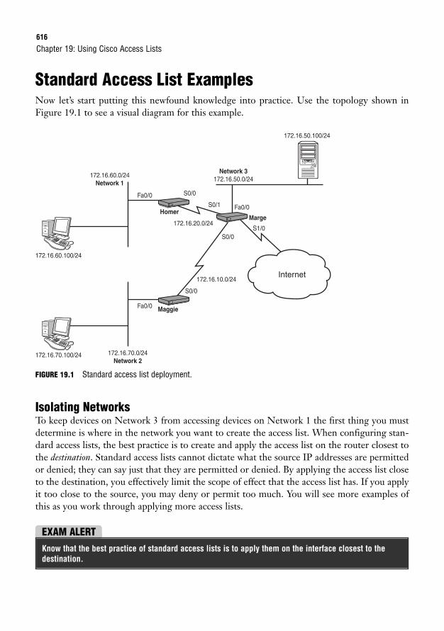
616
Standard Access List ExamplesNow let’s start putting this newfound knowledge into practice. Use the topology shown inFigure 19.1 to see a visual diagram for this example.
Chapter 19: Using Cisco Access Lists
172.16.60.0/24Network 1
Network 3172.16.50.0/24
172.16.70.0/24Network 2
172.16.60.100/24
172.16.20.0/24
172.16.10.0/24Internet
Fa0/0
Fa0/0
S0/0
S0/0
S1/0
S0/1
S0/0
Homer
172.16.70.100/24
172.16.50.100/24
Fa0/0 Maggie
Marge
FIGURE 19.1 Standard access list deployment.
Isolating NetworksTo keep devices on Network 3 from accessing devices on Network 1 the first thing you mustdetermine is where in the network you want to create the access list. When configuring stan-dard access lists, the best practice is to create and apply the access list on the router closest tothe destination. Standard access lists cannot dictate what the source IP addresses are permittedor denied; they can say just that they are permitted or denied. By applying the access list closeto the destination, you effectively limit the scope of effect that the access list has. If you applyit too close to the source, you may deny or permit too much. You will see more examples ofthis as you work through applying more access lists.
EXAM ALERTKnow that the best practice of standard access lists is to apply them on the interface closest to thedestination.
Standard Access Lists617
When you look at the figure, you can see that the Homer router is closest to the destination(Network 1), so that is the place to begin configuration:Homer>enableHomer#configure terminalHomer(config)#access-list 30 deny 172.16.50.0 0.0.0.255
A line has been added to the access list to block Network 1. If the access list is left like this, itwill also deny all other traffic because of the implicit deny at the end, so you need to add astatement that permits all other networks to reach Network 1:Homer(config)#access-list 30 permit any
The any keyword is a shortcut, just as the host keyword is. You could accomplish the same thing byusing the statement:
access-list 30 permit 0.0.0.0 255.255.255.255
When you have a wildcard mask of all 255s, the router does not care what you enter for the IP address(which is all zeros in this case, but could have been anything). This is equivalent to a permit any state-ment. Use whichever one you feel more comfortable with.
TIP
You have created the access list; now it’s time to apply it. Looking back at the figure, there aretwo possible places to apply this access list on the Homer router: inbound on the S0/0 inter-face, or outbound on the Fa0/0 interface. Using the best practice of applying closest to the des-tination, this is how to do the latter:Homer(config)#interface fastethernet 0/0Homer(config-if)#ip access-group 30 out
Voilà! This part of the example is accomplished. Now here’s the complete code without thecommentary:Homer>enableHomer#configure terminalHomer(config)#access-list 30 deny 172.16.50.0 0.0.0.255Homer(config)#access-list 30 permit anyHomer(config)#interface fastethernet 0/0Homer(config-if)#ip access-group 30 out
Isolating a Network from Specific HostsYou now need to prevent just two devices (the Network 1 and 2 hosts) from accessing Network3. If you remember the rule of applying the standard access list closest to the destination, youknow that the configuration should be performed on the Marge router:
618
Marge>enableMarge#configure terminalMarge(config)#access-list 45 deny host 172.16.70.100Marge(config)#access-list 45 deny host 172.16.60.100Marge(config)#access-list 45 permit any
Now that the access list has been created, you have to decide where to apply it. Initially, youmight eye the S0/0 interface inbound. If you applied it there, the host 172.16.70.100 and172.16.60.100 would be denied as soon as they tried to make their way into the S0/0 interfaceof Marge. Although this would prevent the hosts from reaching Network 3, it would also blockthem from accessing Network 1 and the Internet (because they cannot even enter the Margerouter). Aha! Do you now see why it is so important to apply the standard access list close tothe destination? In this case, you need to apply it to the FastEthernet 0/0 interface, outbound:Marge(config)#interface fastethernet 0/0Marge(config-if)#ip access-group 45 out
Perfect. This part of the example is complete.
Isolating the Internal Network from the InternetThe servers on Network 3 contain confidential information and should not be accessible fromthe Internet. Assuming your entire internal network uses 172.16.0.0/16 addresses, this config-uration should maintain the isolation of Network 3 from Network 1 and 2 hosts. Wow! Thisrequires a little thought. You have no idea what addresses may be trying to come in from theInternet, so you have to reverse your strategies. So far, you have been denying a host or net-work and permitting everything else. You must now permit what you know and deny every-thing else, still keeping in mind that you cannot allow the two hosts from the previousobjective to access the server. Start on the Marge router in Global Configuration mode andremove the access list applied previously:Marge(config)#no access-list 45
Chapter 19: Using Cisco Access Lists
Whew! That caution popped up at just the right place. Let’s follow that advice:Marge(config)#interface fastethernet 0/0Marge(config-if)#no ip access-group 45 out
Removing the access list by using the no access-list <number> command does not remove theaccess-group command from the interface. The access list is still applied! Thankfully, an empty accesslist allows all traffic (this overrules the implicit deny statement). However, as soon as you add one line tothe access list, the implicit deny statement is reapplied with all its fury. It is a very good idea to un-applythe access list from the interface while you make changes.
CAUTION
Standard Access Lists619
Now you can start on a new access list. First, deny the specific hosts that should not be able toreach Network 3:Marge(config)#access-list 45 deny host 172.16.70.100Marge(config)#access-list 45 deny host 172.16.60.100
Super. Now that they’re taken care of, you can permit the rest of the 172.16.0.0/16 subnet (allthe internal networks):Marge(config)#access-list 45 permit 172.16.0.0 0.0.255.255
Notice that the wildcard mask cares about only the first two octets of the IP address, thus per-mitting any IP address that begins with 172.16. This is why the deny statements for the hostswere listed first. Otherwise, this line would have permitted them. With the one permit state-ment added, you have finished creating the access list. The implicit deny should catch anyother networks not specified (including those coming from the Internet). Finally, using bestpractices, you need to apply this list close to the destination:Marge(config)#interface fastethernet 0/0Marge(config-if)#ip access-group 45 out
Awesome! This just keeps getting better. Mission accomplished.
Restricting VTY Access
Objective:
. Configure and apply ACLs to limit telnet and SSH access to the router
Now here’s a new application for an access list. So far, access lists have been applied inboundand outbound on interfaces, but access lists can also be applied to VTY lines (which are usedfor Telnet and SSH). This example will allow only the host on Network 2 to Telnet to theMarge router. The command syntax to do this differs slightly from applying an access list to aninterface. Instead of using the ip access-group command, use the access-class command.
After referring back to the figure, you can see that the host on Network 2 has the IP address172.16.70.100. Here’s the configuration:Marge(config)#access-list 55 permit host 172.16.70.100Marge(config)#line vty 0 4cmMarge(config-line)#access-class 55 in
That’s it! The implicit deny blocks all other hosts from accessing your VTY lines. This bringsup a huge tip.
620
Extended Access Lists“Beware of the extended access list!” This grave warning comes from many CCNA testers whohave gone before you. Out of all the topics on the CCNA exam, not one has come close totripping up candidates more than the extended access list. With most things in Cisco, the dif-ficulty comes in the concept and the syntax is quite simple. However, when it comes to theextended access lists, the concepts are fairly straightforward; it is the syntax that can be a mon-ster. Fear not, my brave CCNA studier. After working through this section, you will feel quitecomfortable with extended access lists.
Configuration of Extended Access ListsAfter you have set up a few standard access lists, you’ll have the configuration mastered. Standardaccess lists allow you to permit or deny network traffic based only on the source address. On theother hand, extended access lists allow you to permit or deny traffic based on the sub-protocol,source address, source port number, destination address, and destination port number—andthat’s just what is on the CCNA exam. An extended access list can even filter based on time ofday or user authentication. Now if you imagine fitting all those parameters into a single line ofsyntax, you begin to understand why extended access list syntax can become quite long.
Before we get deep into each step of the syntax, let’s take a step back and look at extendedaccess list parameters from a distance. First off, extended access lists are identified by the num-bers 100–199, as shown by context-sensitive help:Neo(config)#access-list ?<1-99> IP standard access list<100-199> IP extended access list<1100-1199> Extended 48-bit MAC address access list<1300-1999> IP standard access list (expanded range)<200-299> Protocol type-code access list
Chapter 19: Using Cisco Access Lists
If you are configuring access lists on your router remotely, be sure to allow your remote Telnet sessionaccess into the router in the access list. It is a very common mistake to create an access list that kills theremote Telnet session and requires the administrator to drive to the site (or contact someone on-site) toreconfigure the router through the console port. It is, therefore, a good practice to issue the followingcommand before applying an access list remotely:
Router# reload in 5
This instructs the router to reboot itself in 5 minutes if there is no administrative intervention. This way, ifyou lock yourself out of the router, it reboots and sets its configuration back to what it was before youapplied the access list. If the access list applies successfully without limiting remote access, be sure toissue the reload cancel command to stop the automatic reboot countdown.
CAUTION

Extended Access Lists621
<2000-2699> IP extended access list (expanded range)<700-799> 48-bit MAC address access listdynamic-extended Extend the dynamic ACL absolute timer
From a broad view, an extended access list requires three major parameters: a protocol, sourceinformation, and destination information. The general syntax looks like this:Access-list <100-199> <protocol> <source_information><destination_information>
Now let’s walk through the creation of an extended access list, one piece at a time. This exam-ple uses access list 150, putting it smack in the middle of the access list range. For this exam-ple, web access should be allowed for one host, 10.1.1.5.Neo(config)#access-list 150 ?deny Specify packets to rejectdynamic Specify a DYNAMIC list of PERMITs or DENYspermit Specify packets to forwardremark Access list entry comment
The first thing you notice is that you have the standard <permit/deny> option, but now a dynam-ic option has been added to the list. Although dynamic access lists are beyond the scope of theCCNA certification, the concept is pretty amazing: You can have an access list that allows mini-mal outbound or inbound access. If you have a user that needs access to a network through yourrouter, you can authenticate that user to the router with a pre-determined username and password.If the authentication is successful, a dynamic entry is added to the access list allowing the deviceaccess for a certain amount of time, after which the access list entry is removed. Amazing stuff!
Because extended access lists have the same implicit deny statement as standard access lists,you must permit at least one type of packet or all traffic is denied. You can now continue onthrough this configuration of permitting web access for the host 10.1.1.5, using context-sensi-tive help to guide you through each additional piece of syntax.Neo(config)#access-list 150 permit ?<0-255> An IP protocol numberahp Authentication Header Protocoleigrp Cisco’s EIGRP routing protocolesp Encapsulation Security Payloadgre Cisco’s GRE tunnelingicmp Internet Control Message Protocoligmp Internet Gateway Message Protocolip Any Internet Protocolipinip IP in IP tunnelingnos KA9Q NOS compatible IP over IP tunnelingospf OSPF routing protocolpcp Payload Compression Protocolpim Protocol Independent Multicasttcp Transmission Control Protocoludp User Datagram Protocol
622
Now the syntax is starting to look quite a bit different from the standard access list. You nowhave the choice of what protocol to permit or deny.
Chapter 19: Using Cisco Access Lists
EXAM ALERTAlthough the list is quite exhaustive, for the CCNA exam you need to be concerned with only the fol-lowing four protocols: IP, TCP, UDP, and ICMP.
These protocols are roughly defined as the following (the applications are explained furtherduring the discussion on port numbers):
. IP—Permits or denies source/destination addresses that use the entire TCP/IP protocolsuite. Using this keyword permits or denies all access from a source to a destination.
. TCP—Permits or denies source/destination addresses that use TCP-based applica-tions. The most common applications include FTP, Telnet, SMTP, and HTTP.
. UDP—Permits or denies source/destination addresses that use UDP-based applica-tions. The most common applications include DNS and TFTP.
. ICMP—Permits or denies source/destination addresses that use ICMP-based applica-tions. The most common applications include Echo, Echo-Reply, and Unreachables.
In this example, the access list needs to permit HTTP access, which uses the TCP protocol.Neo(config)#access-list 150 permit tcp ?A.B.C.D Source addressany Any source hosthost A single source host
You are now prompted for the source IP address information. Just as with a standard accesslist, you have the option of entering a source IP address followed by a wildcard mask, using thehost keyword to designate an individual host, or using the any keyword to designate all hosts.This example uses the host keyword to designate an individual PC.Neo(config)#access-list 150 permit tcp host 10.1.1.5 ?A.B.C.D Destination addressany Any destination hosteq Match only packets on a given port numbergt Match only packets with a greater port numberhost A single destination hostlt Match only packets with a lower port numberneq Match only packets not on a given port numberrange Match only packets in the range of port numbers
Extended Access Lists623
From this next context-sensitive help prompt, it looks as if there is a prompt to enter either adestination IP address or port information. BEWARE! This is where most extended access listmistakes are made! As you can see from the context-sensitive help, you can enter many formsof port information: a port equal (eq) to a certain number, greater than (gt) a certain number,less than (lt) a certain port number, a range of port numbers, and the list goes on and on.Initially, you might think that this is the place to permit the port for HTTP access (port 80).Unfortunately, that thought process is incorrect. This area is where you discover the strangeand fascinating phenomena known as a source port number.
By this point, you most likely know the commonly used port numbers such as TCP port 21for FTP, TCP port 80 for HTTP, and so on. However, most administrators never learn thatthese are actually destination port numbers. For any TCP/IP-based communication, there isalways a destination and source port number. Here’s how it works: imagine you have a PC con-nected directly to the Internet. You would like to use a web browser to access the latest newsheadlines; however, like most technology-based individuals, you also have 10 other web brows-er instances minimized at the bottom of your task bar. You open a new web browser (instance#11) and access the news website. Sure enough, the web browser window fills with text andpictures of all the latest news and events. Now how in the world did your computer know tofill that web browser window (#11) with the information rather than one of the other 10 youhad minimized at the bottom of the screen? The answer is in the source port information. Assoon as you opened the web browser #11, Windows (or whatever operating system you areusing) generated a unique source port number for that window. Whenever it attempts to com-municate with the destination host, it uses its unique source port number. The source portnumber that the operating system chooses is always above the range of “well known” ports(which range from 0–1023).
For example, imagine that the news website you want to communicate with is Fox News(www.foxnews.com), and your PC’s IP address is 204.1.9.52. When the web browser opens, itgenerates a random source port of 3382. As shown in Figure 19.2, when the web request is sentfrom your PC to the Fox News web server, it is sent to the destination www.foxnews.com:80 (thisis known as a socket—the combination of a destination IP address with a destination port num-ber). It has a source of 204.1.9.52:3382. When the Fox News website communicates back to yourPC, it uses a destination of 204.1.9.52:3382 with a source address of www.foxnews.com:80.
Back to the task at hand. If you enter port number information after the source IP address, youpermit or deny source port information.
You will rarely, if ever, know a network device’s source port number information. This number is randomlygenerated by the host’s operating system.
NOTE
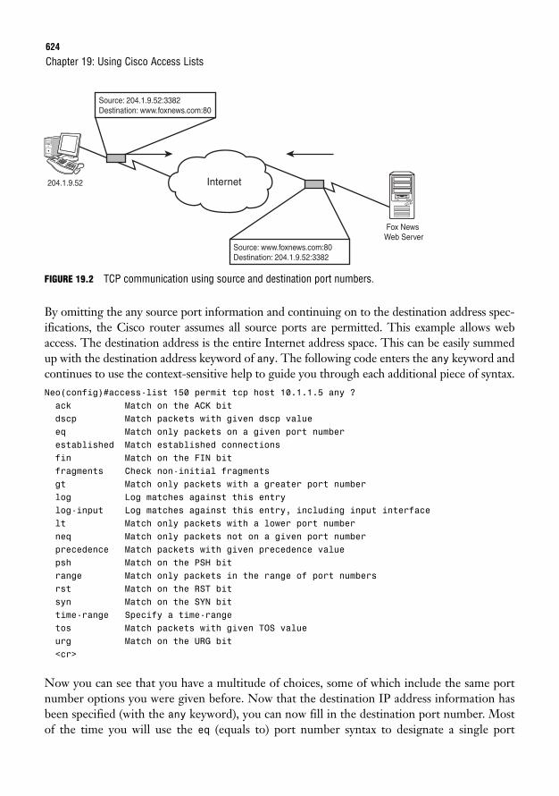
624
FIGURE 19.2 TCP communication using source and destination port numbers.
By omitting the any source port information and continuing on to the destination address spec-ifications, the Cisco router assumes all source ports are permitted. This example allows webaccess. The destination address is the entire Internet address space. This can be easily summedup with the destination address keyword of any. The following code enters the any keyword andcontinues to use the context-sensitive help to guide you through each additional piece of syntax.Neo(config)#access-list 150 permit tcp host 10.1.1.5 any ?ack Match on the ACK bitdscp Match packets with given dscp valueeq Match only packets on a given port numberestablished Match established connectionsfin Match on the FIN bitfragments Check non-initial fragmentsgt Match only packets with a greater port numberlog Log matches against this entrylog-input Log matches against this entry, including input interfacelt Match only packets with a lower port numberneq Match only packets not on a given port numberprecedence Match packets with given precedence valuepsh Match on the PSH bitrange Match only packets in the range of port numbersrst Match on the RST bitsyn Match on the SYN bittime-range Specify a time-rangetos Match packets with given TOS valueurg Match on the URG bit<cr>
Now you can see that you have a multitude of choices, some of which include the same portnumber options you were given before. Now that the destination IP address information hasbeen specified (with the any keyword), you can now fill in the destination port number. Mostof the time you will use the eq (equals to) port number syntax to designate a single port
Chapter 19: Using Cisco Access Lists
Internet204.1.9.52
Fox News Web Server
Source: 204.1.9.52:3382Destination: www.foxnews.com:80
Source: www.foxnews.com:80Destination: 204.1.9.52:3382
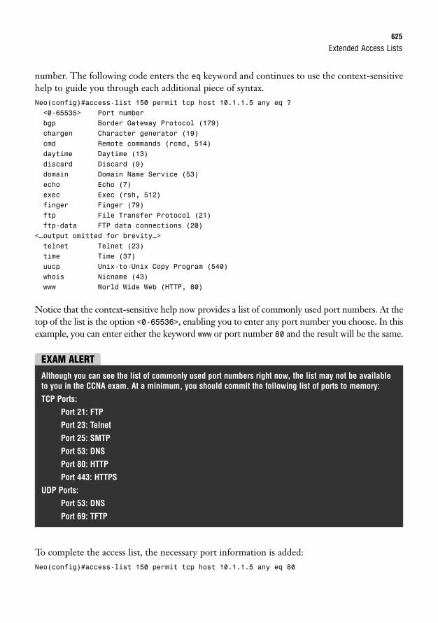
Extended Access Lists625
number. The following code enters the eq keyword and continues to use the context-sensitivehelp to guide you through each additional piece of syntax.Neo(config)#access-list 150 permit tcp host 10.1.1.5 any eq ?<0-65535> Port numberbgp Border Gateway Protocol (179)chargen Character generator (19)cmd Remote commands (rcmd, 514)daytime Daytime (13)discard Discard (9)domain Domain Name Service (53)echo Echo (7)exec Exec (rsh, 512)finger Finger (79)ftp File Transfer Protocol (21)ftp-data FTP data connections (20)
<…output omitted for brevity…>telnet Telnet (23)time Time (37)uucp Unix-to-Unix Copy Program (540)whois Nicname (43)www World Wide Web (HTTP, 80)
Notice that the context-sensitive help now provides a list of commonly used port numbers. At thetop of the list is the option <0-65536>, enabling you to enter any port number you choose. In thisexample, you can enter either the keyword www or port number 80 and the result will be the same.
EXAM ALERTAlthough you can see the list of commonly used port numbers right now, the list may not be availableto you in the CCNA exam. At a minimum, you should commit the following list of ports to memory:
TCP Ports:
Port 21: FTP
Port 23: Telnet
Port 25: SMTP
Port 53: DNS
Port 80: HTTP
Port 443: HTTPS
UDP Ports:
Port 53: DNS
Port 69: TFTP
To complete the access list, the necessary port information is added:Neo(config)#access-list 150 permit tcp host 10.1.1.5 any eq 80
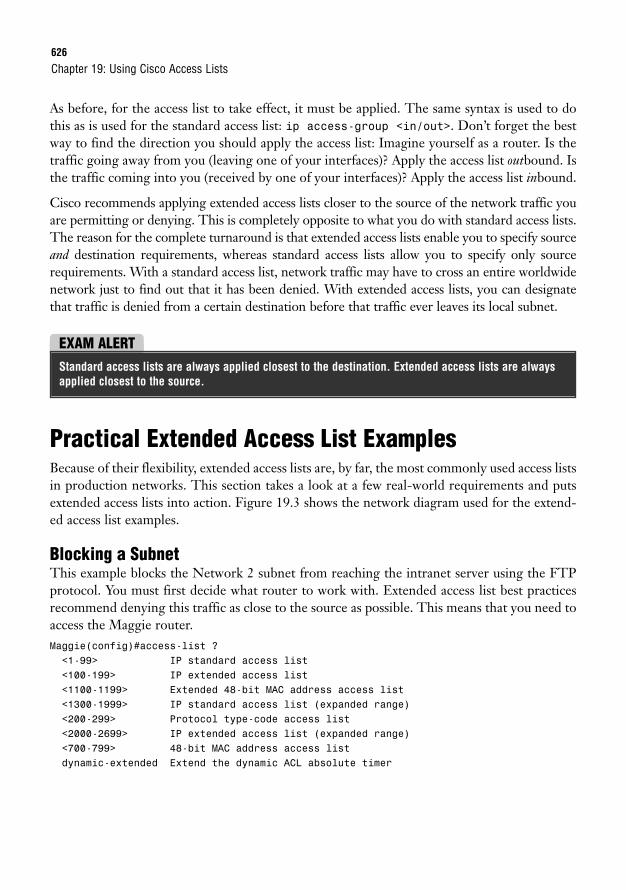
626
As before, for the access list to take effect, it must be applied. The same syntax is used to dothis as is used for the standard access list: ip access-group <in/out>. Don’t forget the bestway to find the direction you should apply the access list: Imagine yourself as a router. Is thetraffic going away from you (leaving one of your interfaces)? Apply the access list outbound. Isthe traffic coming into you (received by one of your interfaces)? Apply the access list inbound.
Cisco recommends applying extended access lists closer to the source of the network traffic youare permitting or denying. This is completely opposite to what you do with standard access lists.The reason for the complete turnaround is that extended access lists enable you to specify sourceand destination requirements, whereas standard access lists allow you to specify only sourcerequirements. With a standard access list, network traffic may have to cross an entire worldwidenetwork just to find out that it has been denied. With extended access lists, you can designatethat traffic is denied from a certain destination before that traffic ever leaves its local subnet.
Chapter 19: Using Cisco Access Lists
EXAM ALERTStandard access lists are always applied closest to the destination. Extended access lists are alwaysapplied closest to the source.
Practical Extended Access List ExamplesBecause of their flexibility, extended access lists are, by far, the most commonly used access listsin production networks. This section takes a look at a few real-world requirements and putsextended access lists into action. Figure 19.3 shows the network diagram used for the extend-ed access list examples.
Blocking a SubnetThis example blocks the Network 2 subnet from reaching the intranet server using the FTPprotocol. You must first decide what router to work with. Extended access list best practicesrecommend denying this traffic as close to the source as possible. This means that you need toaccess the Maggie router.Maggie(config)#access-list ?<1-99> IP standard access list<100-199> IP extended access list<1100-1199> Extended 48-bit MAC address access list<1300-1999> IP standard access list (expanded range)<200-299> Protocol type-code access list<2000-2699> IP extended access list (expanded range)<700-799> 48-bit MAC address access listdynamic-extended Extend the dynamic ACL absolute timer
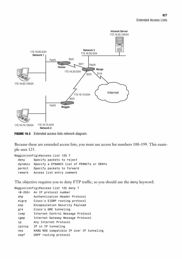
Extended Access Lists627
FIGURE 19.3 Extended access lists network diagram.
Because these are extended access lists, you must use access list numbers 100–199. This exam-ple uses 125.Maggie(config)#access-list 125 ?deny Specify packets to rejectdynamic Specify a DYNAMIC list of PERMITs or DENYspermit Specify packets to forwardremark Access list entry comment
The objective requires you to deny FTP traffic, so you should use the deny keyword:Maggie(config)#access-list 125 deny ?<0-255> An IP protocol numberahp Authentication Header Protocoleigrp Cisco’s EIGRP routing protocolesp Encapsulation Security Payloadgre Cisco’s GRE tunnelingicmp Internet Control Message Protocoligmp Internet Gateway Message Protocolip Any Internet Protocolipinip IP in IP tunnelingnos KA9Q NOS compatible IP over IP tunnelingospf OSPF routing protocol
172.16.60.0/24Network 1
Network 3172.16.50.0/24
172.16.70.0/24Network 2
172.16.60.100/24
172.16.20.0/24
172.16.10.0/24Internet
Fa0/0
Fa0/0
S0/0
S0/0
S1/0
S0/1
S0/0
Homer
172.16.70.100/24
Intranet Server172.16.50.100/24
Fa0/0 Maggie
Marge
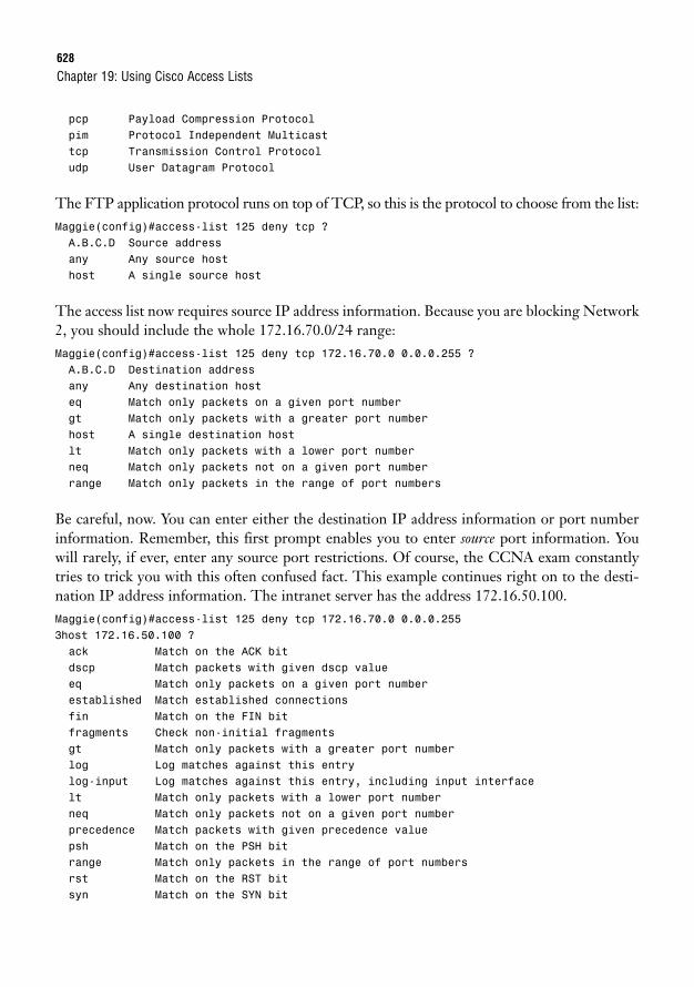
628
pcp Payload Compression Protocolpim Protocol Independent Multicasttcp Transmission Control Protocoludp User Datagram Protocol
The FTP application protocol runs on top of TCP, so this is the protocol to choose from the list:Maggie(config)#access-list 125 deny tcp ?A.B.C.D Source addressany Any source hosthost A single source host
The access list now requires source IP address information. Because you are blocking Network2, you should include the whole 172.16.70.0/24 range:Maggie(config)#access-list 125 deny tcp 172.16.70.0 0.0.0.255 ?A.B.C.D Destination addressany Any destination hosteq Match only packets on a given port numbergt Match only packets with a greater port numberhost A single destination hostlt Match only packets with a lower port numberneq Match only packets not on a given port numberrange Match only packets in the range of port numbers
Be careful, now. You can enter either the destination IP address information or port numberinformation. Remember, this first prompt enables you to enter source port information. Youwill rarely, if ever, enter any source port restrictions. Of course, the CCNA exam constantlytries to trick you with this often confused fact. This example continues right on to the desti-nation IP address information. The intranet server has the address 172.16.50.100.Maggie(config)#access-list 125 deny tcp 172.16.70.0 0.0.0.2553host 172.16.50.100 ?ack Match on the ACK bitdscp Match packets with given dscp valueeq Match only packets on a given port numberestablished Match established connectionsfin Match on the FIN bitfragments Check non-initial fragmentsgt Match only packets with a greater port numberlog Log matches against this entrylog-input Log matches against this entry, including input interfacelt Match only packets with a lower port numberneq Match only packets not on a given port numberprecedence Match packets with given precedence valuepsh Match on the PSH bitrange Match only packets in the range of port numbersrst Match on the RST bitsyn Match on the SYN bit
Chapter 19: Using Cisco Access Lists

Extended Access Lists629
time-range Specify a time-rangetos Match packets with given TOS valueurg Match on the URG bit<cr>
Now you are given the option again to enter the port configurations. At this point, the routeris requesting destination port information, which is what you need to use to block FTP. Beforeyou can specify an individual port, you must first designate the eq (equal to) syntax:Maggie(config)# access-list 125 deny tcp 172.16.70.0 0.0.0.2553host 172.16.50.100 eq ?<0-65535> Port numberbgp Border Gateway Protocol (179)chargen Character generator (19)cmd Remote commands (rcmd, 514)daytime Daytime (13)discard Discard (9)domain Domain Name Service (53)echo Echo (7)exec Exec (rsh, 512)finger Finger (79)ftp File Transfer Protocol (21)ftp-data FTP data connections (20)
<…output omitted for brevity…>telnet Telnet (23)time Time (37)uucp Unix-to-Unix Copy Program (540)whois Nicname (43)www World Wide Web (HTTP, 80)
You are again given a laundry list of port numbers that you can enter. You can enter the exactport number or use the commonly used port names in the list.Maggie(config)#access-list 125 deny tcp 172.16.70.0 0.0.0.2553host 172.16.50.100 eq 21
The first line of the access list is now created, but don’t forget that there is still an implicit denyat the end of the list. If you were to apply this list now, it would block the subnet from reach-ing anything. You must add at least one permit line; in this case, it is a permit any statement.Maggie(config)#access-list 125 permit ?<0-255> An IP protocol numberahp Authentication Header Protocoleigrp Cisco’s EIGRP routing protocolesp Encapsulation Security Payloadgre Cisco’s GRE tunnelingicmp Internet Control Message Protocoligmp Internet Gateway Message Protocolip Any Internet Protocol
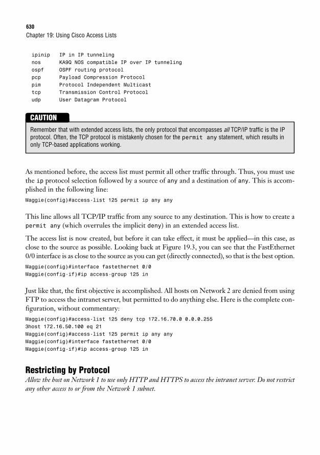
630
ipinip IP in IP tunnelingnos KA9Q NOS compatible IP over IP tunnelingospf OSPF routing protocolpcp Payload Compression Protocolpim Protocol Independent Multicasttcp Transmission Control Protocoludp User Datagram Protocol
Chapter 19: Using Cisco Access Lists
Remember that with extended access lists, the only protocol that encompasses all TCP/IP traffic is the IPprotocol. Often, the TCP protocol is mistakenly chosen for the permit any statement, which results inonly TCP-based applications working.
CAUTION
As mentioned before, the access list must permit all other traffic through. Thus, you must usethe ip protocol selection followed by a source of any and a destination of any. This is accom-plished in the following line:Maggie(config)#access-list 125 permit ip any any
This line allows all TCP/IP traffic from any source to any destination. This is how to create apermit any (which overrules the implicit deny) in an extended access list.
The access list is now created, but before it can take effect, it must be applied—in this case, asclose to the source as possible. Looking back at Figure 19.3, you can see that the FastEthernet0/0 interface is as close to the source as you can get (directly connected), so that is the best option.Maggie(config)#interface fastethernet 0/0Maggie(config-if)#ip access-group 125 in
Just like that, the first objective is accomplished. All hosts on Network 2 are denied from usingFTP to access the intranet server, but permitted to do anything else. Here is the complete con-figuration, without commentary:Maggie(config)#access-list 125 deny tcp 172.16.70.0 0.0.0.2553host 172.16.50.100 eq 21Maggie(config)#access-list 125 permit ip any anyMaggie(config)#interface fastethernet 0/0Maggie(config-if)#ip access-group 125 in
Restricting by ProtocolAllow the host on Network 1 to use only HTTP and HTTPS to access the intranet server. Do not restrictany other access to or from the Network 1 subnet.
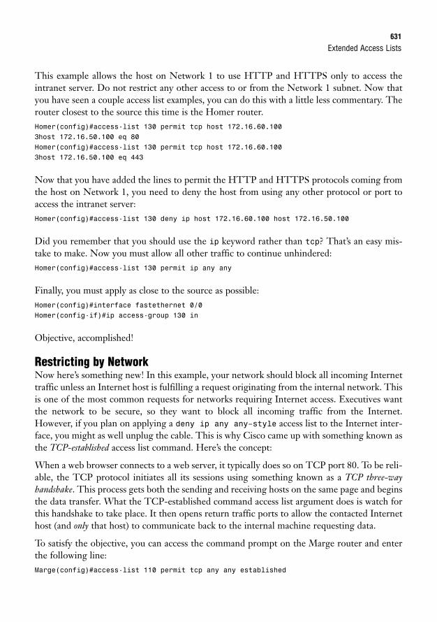
Extended Access Lists631
This example allows the host on Network 1 to use HTTP and HTTPS only to access theintranet server. Do not restrict any other access to or from the Network 1 subnet. Now thatyou have seen a couple access list examples, you can do this with a little less commentary. Therouter closest to the source this time is the Homer router.Homer(config)#access-list 130 permit tcp host 172.16.60.1003host 172.16.50.100 eq 80Homer(config)#access-list 130 permit tcp host 172.16.60.1003host 172.16.50.100 eq 443
Now that you have added the lines to permit the HTTP and HTTPS protocols coming fromthe host on Network 1, you need to deny the host from using any other protocol or port toaccess the intranet server:Homer(config)#access-list 130 deny ip host 172.16.60.100 host 172.16.50.100
Did you remember that you should use the ip keyword rather than tcp? That’s an easy mis-take to make. Now you must allow all other traffic to continue unhindered:Homer(config)#access-list 130 permit ip any any
Finally, you must apply as close to the source as possible:Homer(config)#interface fastethernet 0/0Homer(config-if)#ip access-group 130 in
Objective, accomplished!
Restricting by NetworkNow here’s something new! In this example, your network should block all incoming Internettraffic unless an Internet host is fulfilling a request originating from the internal network. Thisis one of the most common requests for networks requiring Internet access. Executives wantthe network to be secure, so they want to block all incoming traffic from the Internet.However, if you plan on applying a deny ip any any–style access list to the Internet inter-face, you might as well unplug the cable. This is why Cisco came up with something known asthe TCP-established access list command. Here’s the concept:
When a web browser connects to a web server, it typically does so on TCP port 80. To be reli-able, the TCP protocol initiates all its sessions using something known as a TCP three-wayhandshake. This process gets both the sending and receiving hosts on the same page and beginsthe data transfer. What the TCP-established command access list argument does is watch forthis handshake to take place. It then opens return traffic ports to allow the contacted Internethost (and only that host) to communicate back to the internal machine requesting data.
To satisfy the objective, you can access the command prompt on the Marge router and enterthe following line:Marge(config)#access-list 110 permit tcp any any established
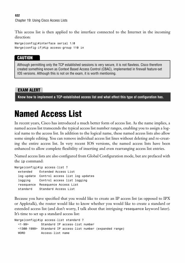
632
This access list is then applied to the interface connected to the Internet in the incoming direction:Marge(config)#interface serial 1/0Marge(config-if)#ip access-group 110 in
Chapter 19: Using Cisco Access Lists
EXAM ALERTKnow how to implement a TCP-established access list and what effect this type of configuration has.
Although permitting only the TCP established sessions is very secure, it is not flawless. Cisco thereforecreated something known as Context Based Access Control (CBAC), implemented in firewall feature-setIOS versions. Although this is not on the exam, it is worth mentioning.
CAUTION
Named Access ListIn recent years, Cisco has introduced a much better form of access list. As the name implies, anamed access list transcends the typical access list number ranges, enabling you to assign a log-ical name to the access list. In addition to the logical name, these named access lists also allowsome simple editing. You can remove individual access list lines without deleting and re-creat-ing the entire access list. In very recent IOS versions, the named access lists have beenenhanced to allow complete flexibility of inserting and even rearranging access list entries.
Named access lists are also configured from Global Configuration mode, but are prefaced withthe ip command:Marge(config)#ip access-list ?extended Extended Access Listlog-update Control access list log updateslogging Control access list loggingresequence Resequence Access Liststandard Standard Access List
Because you have specified that you would like to create an IP access list (as opposed to IPXor Appletalk), the router would like to know whether you would like to create a standard orextended access list (and don’t worry, I talk about that intriguing resequence keyword later).It’s time to set up a standard access list:Marge(config)#ip access-list standard ?<1-99> Standard IP access-list number<1300-1999> Standard IP access-list number (expanded range)WORD Access-list name
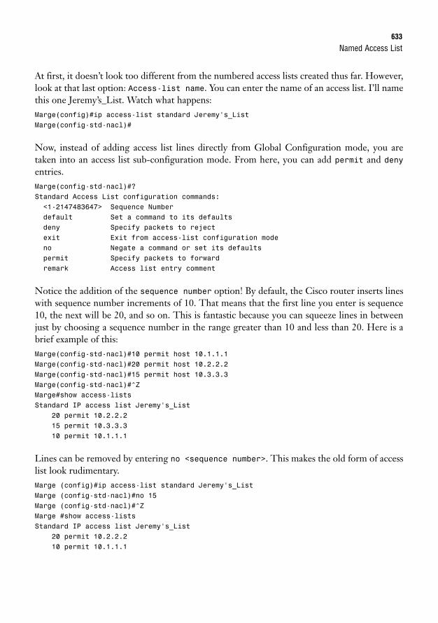
Named Access List633
At first, it doesn’t look too different from the numbered access lists created thus far. However,look at that last option: Access-list name. You can enter the name of an access list. I’ll namethis one Jeremy’s_List. Watch what happens:Marge(config)#ip access-list standard Jeremy’s_ListMarge(config-std-nacl)#
Now, instead of adding access list lines directly from Global Configuration mode, you aretaken into an access list sub-configuration mode. From here, you can add permit and denyentries.Marge(config-std-nacl)#?Standard Access List configuration commands:<1-2147483647> Sequence Numberdefault Set a command to its defaultsdeny Specify packets to rejectexit Exit from access-list configuration modeno Negate a command or set its defaultspermit Specify packets to forwardremark Access list entry comment
Notice the addition of the sequence number option! By default, the Cisco router inserts lineswith sequence number increments of 10. That means that the first line you enter is sequence10, the next will be 20, and so on. This is fantastic because you can squeeze lines in betweenjust by choosing a sequence number in the range greater than 10 and less than 20. Here is abrief example of this:Marge(config-std-nacl)#10 permit host 10.1.1.1Marge(config-std-nacl)#20 permit host 10.2.2.2Marge(config-std-nacl)#15 permit host 10.3.3.3Marge(config-std-nacl)#^ZMarge#show access-listsStandard IP access list Jeremy’s_List
20 permit 10.2.2.215 permit 10.3.3.310 permit 10.1.1.1
Lines can be removed by entering no <sequence number>. This makes the old form of accesslist look rudimentary.Marge (config)#ip access-list standard Jeremy’s_ListMarge (config-std-nacl)#no 15Marge (config-std-nacl)#^ZMarge #show access-listsStandard IP access list Jeremy’s_List
20 permit 10.2.2.210 permit 10.1.1.1
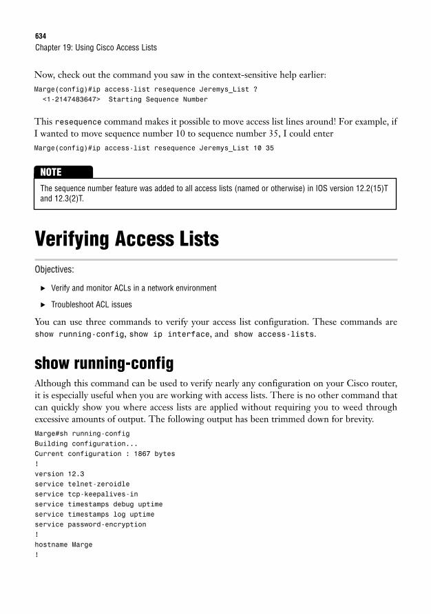
634
Now, check out the command you saw in the context-sensitive help earlier:Marge(config)#ip access-list resequence Jeremys_List ?<1-2147483647> Starting Sequence Number
This resequence command makes it possible to move access list lines around! For example, ifI wanted to move sequence number 10 to sequence number 35, I could enterMarge(config)#ip access-list resequence Jeremys_List 10 35
Chapter 19: Using Cisco Access Lists
The sequence number feature was added to all access lists (named or otherwise) in IOS version 12.2(15)Tand 12.3(2)T.
NOTE
Verifying Access ListsObjectives:
. Verify and monitor ACLs in a network environment
. Troubleshoot ACL issues
You can use three commands to verify your access list configuration. These commands areshow running-config, show ip interface, and show access-lists.
show running-configAlthough this command can be used to verify nearly any configuration on your Cisco router,it is especially useful when you are working with access lists. There is no other command thatcan quickly show you where access lists are applied without requiring you to weed throughexcessive amounts of output. The following output has been trimmed down for brevity.Marge#sh running-configBuilding configuration...Current configuration : 1867 bytes!version 12.3service telnet-zeroidleservice tcp-keepalives-inservice timestamps debug uptimeservice timestamps log uptimeservice password-encryption!hostname Marge!
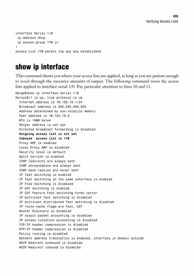
Verifying Access Lists635
interface Serial 1/0ip address dhcpip access-group 170 in!access-list 170 permit tcp any any established
show ip interfaceThis command shows you where your access lists are applied, as long as you are patient enoughto weed through the excessive amounts of output. The following command views the accesslists applied to interface serial 1/0. Pay particular attention to lines 10 and 11.Marge#show ip interface serial 1/0Serial0/1 is up, line protocol is upInternet address is 10.152.19.1/24Broadcast address is 255.255.255.255Address determined by non-volatile memoryPeer address is 10.152.19.2MTU is 1500 bytesHelper address is not setDirected broadcast forwarding is disabledOutgoing access list is not set
Inbound access list is 170
Proxy ARP is enabledLocal Proxy ARP is disabledSecurity level is defaultSplit horizon is enabledICMP redirects are always sentICMP unreachables are always sentICMP mask replies are never sentIP fast switching is enabledIP fast switching on the same interface is enabledIP Flow switching is disabledIP CEF switching is enabledIP CEF Feature Fast switching turbo vectorIP multicast fast switching is disabledIP multicast distributed fast switching is disabledIP route-cache flags are Fast, CEFRouter Discovery is disabledIP output packet accounting is disabledIP access violation accounting is disabledTCP/IP header compression is disabledRTP/IP header compression is disabledPolicy routing is disabledNetwork address translation is enabled, interface in domain outsideWCCP Redirect outbound is disabledWCCP Redirect inbound is disabled
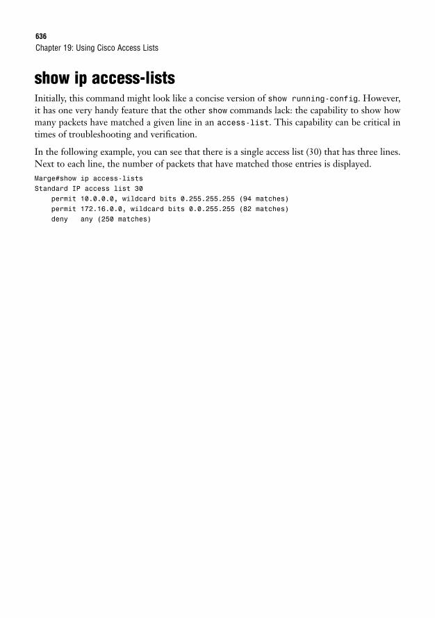
636
show ip access-listsInitially, this command might look like a concise version of show running-config. However,it has one very handy feature that the other show commands lack: the capability to show howmany packets have matched a given line in an access-list. This capability can be critical intimes of troubleshooting and verification.
In the following example, you can see that there is a single access list (30) that has three lines.Next to each line, the number of packets that have matched those entries is displayed.Marge#show ip access-listsStandard IP access list 30
permit 10.0.0.0, wildcard bits 0.255.255.255 (94 matches)permit 172.16.0.0, wildcard bits 0.0.255.255 (82 matches)deny any (250 matches)
Chapter 19: Using Cisco Access Lists
Chapter Summary637
Chapter SummaryThis chapter has given the theory and configuration of IP standard and extended access lists.A full understanding of these concepts is absolutely critical, not only for your network securi-ty, but also for a variety of additional configurations on your router such as NAT, QoS, anddial-on-demand routing (DDR) to name a few.
The two classifications of IP access lists give you all the flexibility you need in applying themto your network. Standard access lists filter based only on the source address. These are use-ful because they consume less processor and memory resources on your router when yourequire only simple allow and deny statements based on source addressing. Common uses ofstandard access lists include NAT, QoS, and restricting Telnet or Secure Shell (SSH) routeraccess. On the other hand, extended access lists enable you to filter based on the sourceaddress, destination address, protocol, and port number. Although they may cost you signifi-cant processor resources, extended access lists give you the ultimate in flexibility when choos-ing the types of traffic to allow or deny in your network. Extended access lists have many uses,but are primarily used for security. The type of access list you create depends on the access listnumber you select when performing the configuration. For standard access lists, use numbersbetween 1–99; for extended access lists, use numbers between 100–199.
Access lists can be created without any effect to your router. For an access list to be put inaction, it must be applied in some way. To apply an access list to an interface, use the ipaccess-group <access_list_number> <in/out> syntax. To determine the direction theaccess list should be applied, put yourself in the place of the router. Is the access list filteringtraffic coming into you (inbound) or going away from you (outbound)? If you would like to usean access list to filter Telnet access to your router, the access list should be applied to your VTYports. Under this line configuration mode, use the access-class <access_list_number> incommand to apply the access list.
Modern IOS versions include the capability to support sequenced, named access lists. This fea-ture offers the tremendous advantage of being able to assign a logical name to the access list,remove statements from the access list, and resequence entries in your access list.
Key Terms. standard access list. extended access list. named access list. IP access-group. access-class
. inverse mask/wildcard mask
. TCP-established
. IP
. TCP
. UDP
. ICMP
. FTP
. HTTP
. HTTPS/SSL
. Telnet
. TFTP
. DNS
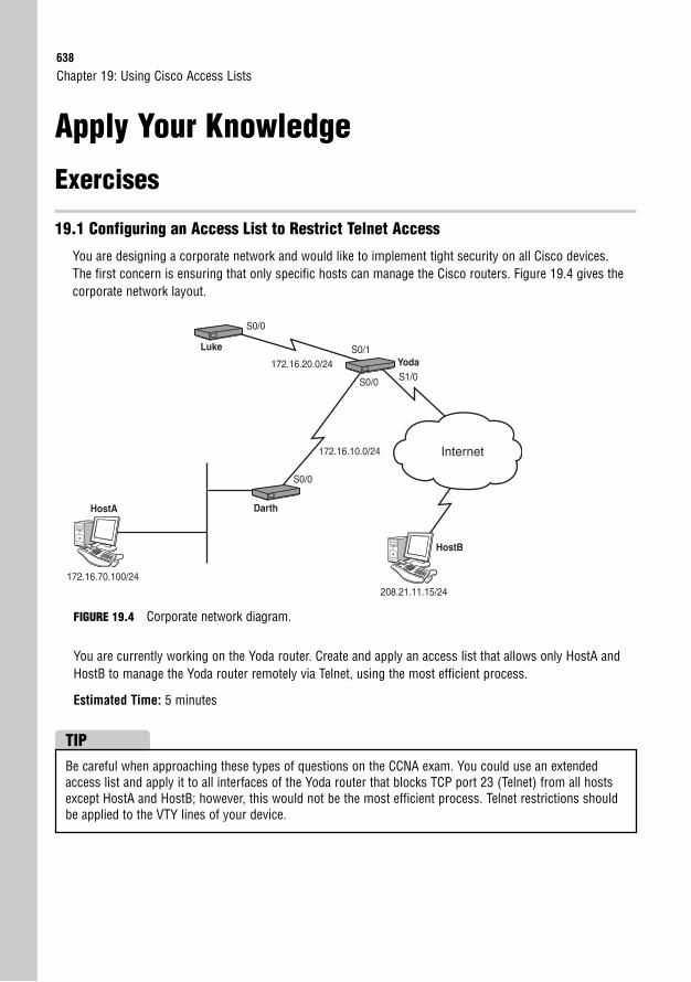
638
Apply Your Knowledge
Exercises
19.1 Configuring an Access List to Restrict Telnet Access
You are designing a corporate network and would like to implement tight security on all Cisco devices.The first concern is ensuring that only specific hosts can manage the Cisco routers. Figure 19.4 gives thecorporate network layout.
Chapter 19: Using Cisco Access Lists
172.16.20.0/24
172.16.10.0/24 Internet
S0/0
S0/0
S1/0
S0/1
S0/0
Luke
172.16.70.100/24
208.21.11.15/24
Darth
Yoda
HostA
HostB
FIGURE 19.4 Corporate network diagram.
You are currently working on the Yoda router. Create and apply an access list that allows only HostA andHostB to manage the Yoda router remotely via Telnet, using the most efficient process.
Estimated Time: 5 minutes
Be careful when approaching these types of questions on the CCNA exam. You could use an extendedaccess list and apply it to all interfaces of the Yoda router that blocks TCP port 23 (Telnet) from all hostsexcept HostA and HostB; however, this would not be the most efficient process. Telnet restrictions shouldbe applied to the VTY lines of your device.
TIP
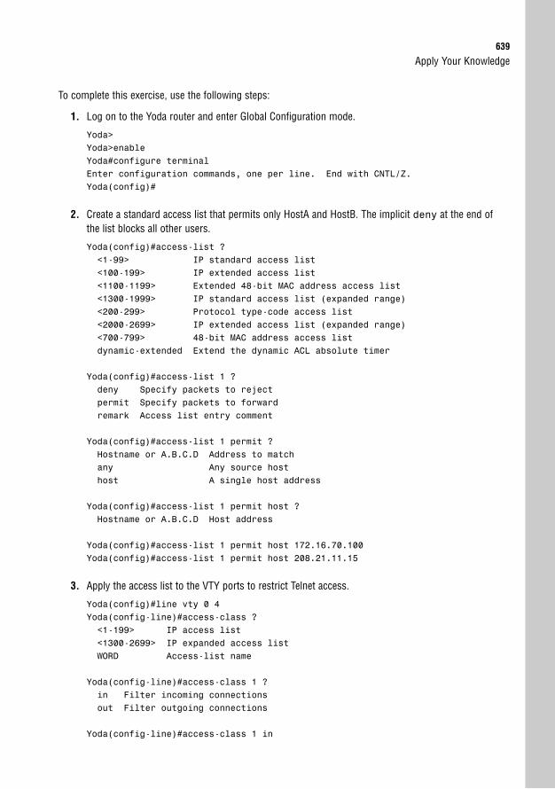
Apply Your Knowledge639
To complete this exercise, use the following steps:
1. Log on to the Yoda router and enter Global Configuration mode.
Yoda>Yoda>enableYoda#configure terminalEnter configuration commands, one per line. End with CNTL/Z.Yoda(config)#
2. Create a standard access list that permits only HostA and HostB. The implicit deny at the end ofthe list blocks all other users.
Yoda(config)#access-list ?<1-99> IP standard access list<100-199> IP extended access list<1100-1199> Extended 48-bit MAC address access list<1300-1999> IP standard access list (expanded range)<200-299> Protocol type-code access list<2000-2699> IP extended access list (expanded range)<700-799> 48-bit MAC address access listdynamic-extended Extend the dynamic ACL absolute timer
Yoda(config)#access-list 1 ?deny Specify packets to rejectpermit Specify packets to forwardremark Access list entry comment
Yoda(config)#access-list 1 permit ?Hostname or A.B.C.D Address to matchany Any source hosthost A single host address
Yoda(config)#access-list 1 permit host ?Hostname or A.B.C.D Host address
Yoda(config)#access-list 1 permit host 172.16.70.100Yoda(config)#access-list 1 permit host 208.21.11.15
3. Apply the access list to the VTY ports to restrict Telnet access.
Yoda(config)#line vty 0 4Yoda(config-line)#access-class ?<1-199> IP access list<1300-2699> IP expanded access listWORD Access-list name
Yoda(config-line)#access-class 1 ?in Filter incoming connectionsout Filter outgoing connections
Yoda(config-line)#access-class 1 in
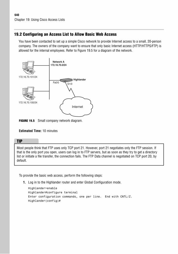
640
19.2 Configuring an Access List to Allow Basic Web Access
You have been contacted to set up a simple Cisco network to provide Internet access to a small, 20-personcompany. The owners of the company want to ensure that only basic Internet access (HTTP/HTTPS/FTP) isallowed for the internal employees. Refer to Figure 19.5 for a diagram of the network.
Chapter 19: Using Cisco Access Lists
Network A172.16.70.0/24
Internet172.16.70.100/24
172.16.70.101/24Highlander
Fa0/0 S1/0
FIGURE 19.5 Small company network diagram.
Estimated Time: 10 minutes
Most people think that FTP uses only TCP port 21. However, port 21 negotiates only the FTP session. Ifthat is the only port you open, users can log in to FTP servers, but as soon as they try to get a directorylist or initiate a file transfer, the connection fails. The FTP Data channel is negotiated on TCP port 20, bydefault.
TIP
To provide the basic web access, perform the following steps:
1. Log in to the Highlander router and enter Global Configuration mode.
Highlander>enableHighlander#configure terminalEnter configuration commands, one per line. End with CNTL/Z.Highlander(config)#
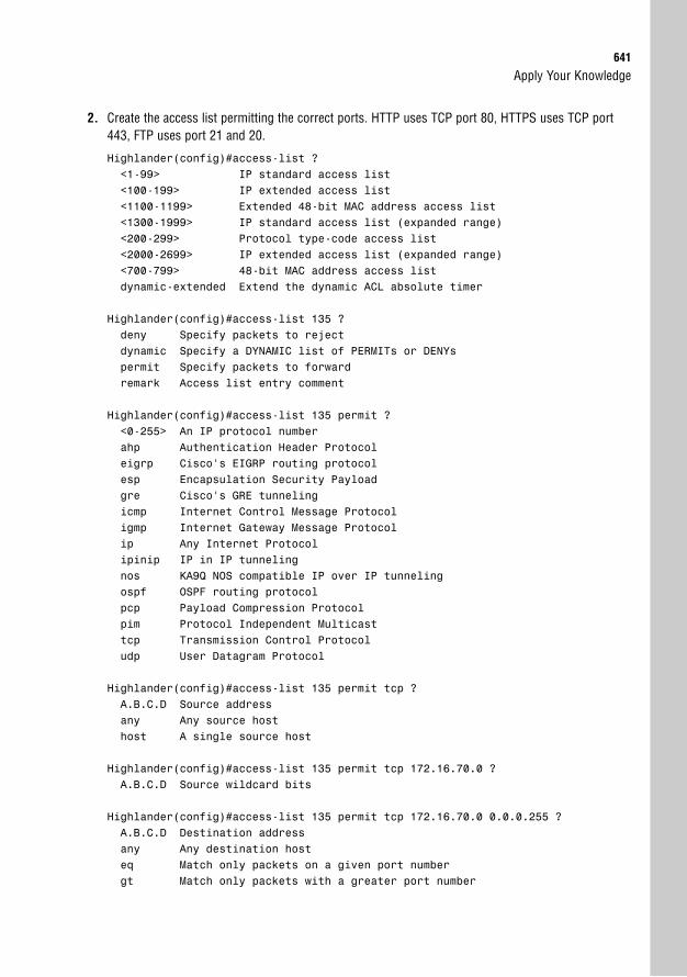
Apply Your Knowledge641
2. Create the access list permitting the correct ports. HTTP uses TCP port 80, HTTPS uses TCP port443, FTP uses port 21 and 20.
Highlander(config)#access-list ?<1-99> IP standard access list<100-199> IP extended access list<1100-1199> Extended 48-bit MAC address access list<1300-1999> IP standard access list (expanded range)<200-299> Protocol type-code access list<2000-2699> IP extended access list (expanded range)<700-799> 48-bit MAC address access listdynamic-extended Extend the dynamic ACL absolute timer
Highlander(config)#access-list 135 ?deny Specify packets to rejectdynamic Specify a DYNAMIC list of PERMITs or DENYspermit Specify packets to forwardremark Access list entry comment
Highlander(config)#access-list 135 permit ?<0-255> An IP protocol numberahp Authentication Header Protocoleigrp Cisco’s EIGRP routing protocolesp Encapsulation Security Payloadgre Cisco’s GRE tunnelingicmp Internet Control Message Protocoligmp Internet Gateway Message Protocolip Any Internet Protocolipinip IP in IP tunnelingnos KA9Q NOS compatible IP over IP tunnelingospf OSPF routing protocolpcp Payload Compression Protocolpim Protocol Independent Multicasttcp Transmission Control Protocoludp User Datagram Protocol
Highlander(config)#access-list 135 permit tcp ?A.B.C.D Source addressany Any source hosthost A single source host
Highlander(config)#access-list 135 permit tcp 172.16.70.0 ?A.B.C.D Source wildcard bits
Highlander(config)#access-list 135 permit tcp 172.16.70.0 0.0.0.255 ?A.B.C.D Destination addressany Any destination hosteq Match only packets on a given port numbergt Match only packets with a greater port number

642
host A single destination hostlt Match only packets with a lower port numberneq Match only packets not on a given port numberrange Match only packets in the range of port numbers
Highlander(config)#access-list 135 permit tcp 172.16.70.0 0.0.0.255 any ?ack Match on the ACK bitdscp Match packets with given dscp valueeq Match only packets on a given port numberestablished Match established connectionsfin Match on the FIN bitfragments Check non-initial fragmentsgt Match only packets with a greater port numberlog Log matches against this entrylog-input Log matches against this entry, including input interfacelt Match only packets with a lower port numberneq Match only packets not on a given port numberprecedence Match packets with given precedence valuepsh Match on the PSH bitrange Match only packets in the range of port numbersrst Match on the RST bitsyn Match on the SYN bittime-range Specify a time-rangetos Match packets with given TOS valueurg Match on the URG bit<cr>
Highlander(config)#access-list 135 permit tcp 172.16.70.0 0.0.0.255 any eq ?<0-65535> Port numberbgp Border Gateway Protocol (179)chargen Character generator (19)cmd Remote commands (rcmd, 514)daytime Daytime (13)discard Discard (9)domain Domain Name Service (53)echo Echo (7)exec Exec (rsh, 512)finger Finger (79)ftp File Transfer Protocol (21)ftp-data FTP data connections (20)gopher Gopher (70)hostname NIC hostname server (101)ident Ident Protocol (113)irc Internet Relay Chat (194)klogin Kerberos login (543)kshell Kerberos shell (544)login Login (rlogin, 513)lpd Printer service (515)nntp Network News Transport Protocol (119)
Chapter 19: Using Cisco Access Lists
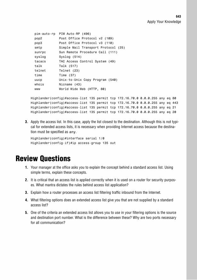
Apply Your Knowledge643
pim-auto-rp PIM Auto-RP (496)pop2 Post Office Protocol v2 (109)pop3 Post Office Protocol v3 (110)smtp Simple Mail Transport Protocol (25)sunrpc Sun Remote Procedure Call (111)syslog Syslog (514)tacacs TAC Access Control System (49)talk Talk (517)telnet Telnet (23)time Time (37)uucp Unix-to-Unix Copy Program (540)whois Nicname (43)www World Wide Web (HTTP, 80)
Highlander(config)#access-list 135 permit tcp 172.16.70.0 0.0.0.255 any eq 80Highlander(config)#access-list 135 permit tcp 172.16.70.0 0.0.0.255 any eq 443Highlander(config)#access-list 135 permit tcp 172.16.70.0 0.0.0.255 any eq 21Highlander(config)#access-list 135 permit tcp 172.16.70.0 0.0.0.255 any eq 20
3. Apply the access list. In this case, apply the list closest to the destination. Although this is not typi-cal for extended access lists, it is necessary when providing Internet access because the destina-tion must be specified as any.
Highlander(config)#interface serial 1/0Highlander(config-if)#ip access-group 135 out
Review Questions1. Your manager at the office asks you to explain the concept behind a standard access list. Using
simple terms, explain these concepts.
2. It is critical that an access list is applied correctly when it is used on a router for security purpos-es. What mantra dictates the rules behind access list application?
3. Explain how a router processes an access list filtering traffic inbound from the Internet.
4. What filtering options does an extended access list give you that are not supplied by a standardaccess list?
5. One of the criteria an extended access list allows you to use in your filtering options is the sourceand destination port number. What is the difference between these? Why are two ports necessaryfor all communication?
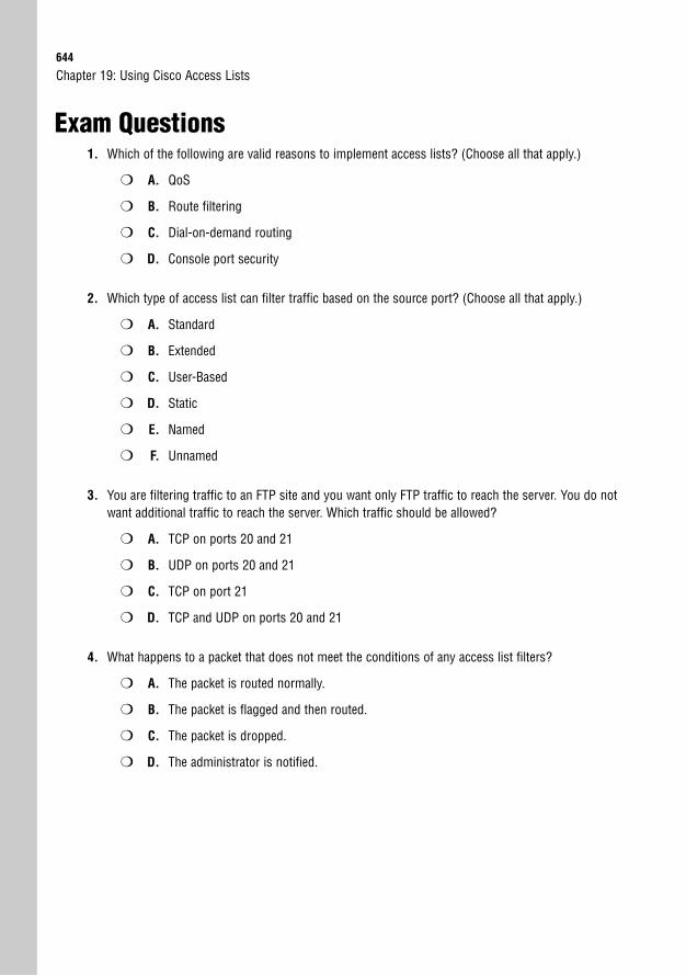
644
Exam Questions1. Which of the following are valid reasons to implement access lists? (Choose all that apply.)
❍ A. QoS
❍ B. Route filtering
❍ C. Dial-on-demand routing
❍ D. Console port security
2. Which type of access list can filter traffic based on the source port? (Choose all that apply.)
❍ A. Standard
❍ B. Extended
❍ C. User-Based
❍ D. Static
❍ E. Named
❍ F. Unnamed
3. You are filtering traffic to an FTP site and you want only FTP traffic to reach the server. You do notwant additional traffic to reach the server. Which traffic should be allowed?
❍ A. TCP on ports 20 and 21
❍ B. UDP on ports 20 and 21
❍ C. TCP on port 21
❍ D. TCP and UDP on ports 20 and 21
4. What happens to a packet that does not meet the conditions of any access list filters?
❍ A. The packet is routed normally.
❍ B. The packet is flagged and then routed.
❍ C. The packet is dropped.
❍ D. The administrator is notified.
Chapter 19: Using Cisco Access Lists
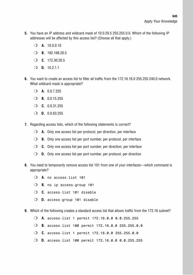
Apply Your Knowledge645
5. You have an IP address and wildcard mask of 10.0.20.5 255.255.0.0. Which of the following IPaddresses will be affected by this access list? (Choose all that apply.)
❍ A. 10.0.0.10
❍ B. 192.168.20.5
❍ C. 172.30.20.5
❍ D. 10.2.1.1
6. You want to create an access list to filter all traffic from the 172.16.16.0 255.255.240.0 network.What wildcard mask is appropriate?
❍ A. 0.0.7.255
❍ B. 0.0.15.255
❍ C. 0.0.31.255
❍ D. 0.0.63.255
7. Regarding access lists, which of the following statements is correct?
❍ A. Only one access list per protocol, per direction, per interface
❍ B. Only one access list per port number, per protocol, per interface
❍ C. Only one access list per port number, per direction, per interface
❍ D. Only one access list per port number, per protocol, per direction
8. You need to temporarily remove access list 101 from one of your interfaces—which command isappropriate?
❍ A. no access-list 101
❍ B. no ip access-group 101
❍ C. access-list 101 disable
❍ D. access-group 101 disable
9. Which of the following creates a standard access list that allows traffic from the 172.16 subnet?
❍ A. access-list 1 permit 172.16.0.0 0.0.255.255
❍ B. access-list 100 permit 172.16.0.0 255.255.0.0
❍ C. access-list 1 permit 172.16.0.0 255.255.0.0
❍ D. access-list 100 permit 172.16.0.0 0.0.255.255
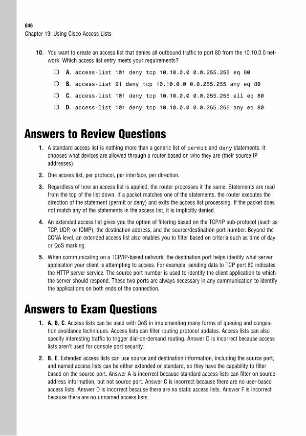
646
10. You want to create an access list that denies all outbound traffic to port 80 from the 10.10.0.0 net-work. Which access list entry meets your requirements?
❍ A. access-list 101 deny tcp 10.10.0.0 0.0.255.255 eq 80
❍ B. access-list 91 deny tcp 10.10.0.0 0.0.255.255 any eq 80
❍ C. access-list 101 deny tcp 10.10.0.0 0.0.255.255 all eq 80
❍ D. access-list 101 deny tcp 10.10.0.0 0.0.255.255 any eq 80
Answers to Review Questions1. A standard access list is nothing more than a generic list of permit and deny statements. It
chooses what devices are allowed through a router based on who they are (their source IPaddresses).
2. One access list, per protocol, per interface, per direction.
3. Regardless of how an access list is applied, the router processes it the same: Statements are readfrom the top of the list down. If a packet matches one of the statements, the router executes thedirection of the statement (permit or deny) and exits the access list processing. If the packet doesnot match any of the statements in the access list, it is implicitly denied.
4. An extended access list gives you the option of filtering based on the TCP/IP sub-protocol (such asTCP, UDP, or ICMP), the destination address, and the source/destination port number. Beyond theCCNA level, an extended access list also enables you to filter based on criteria such as time of dayor QoS marking.
5. When communicating on a TCP/IP-based network, the destination port helps identify what serverapplication your client is attempting to access. For example, sending data to TCP port 80 indicatesthe HTTP server service. The source port number is used to identify the client application to whichthe server should respond. These two ports are always necessary in any communication to identifythe applications on both ends of the connection.
Answers to Exam Questions1. A, B, C. Access lists can be used with QoS in implementing many forms of queuing and conges-
tion avoidance techniques. Access lists can filter routing protocol updates. Access lists can alsospecify interesting traffic to trigger dial-on-demand routing. Answer D is incorrect because accesslists aren’t used for console port security.
2. B, E. Extended access lists can use source and destination information, including the source port,and named access lists can be either extended or standard, so they have the capability to filterbased on the source port. Answer A is incorrect because standard access lists can filter on sourceaddress information, but not source port. Answer C is incorrect because there are no user-basedaccess lists. Answer D is incorrect because there are no static access lists. Answer F is incorrectbecause there are no unnamed access lists.
Chapter 19: Using Cisco Access Lists
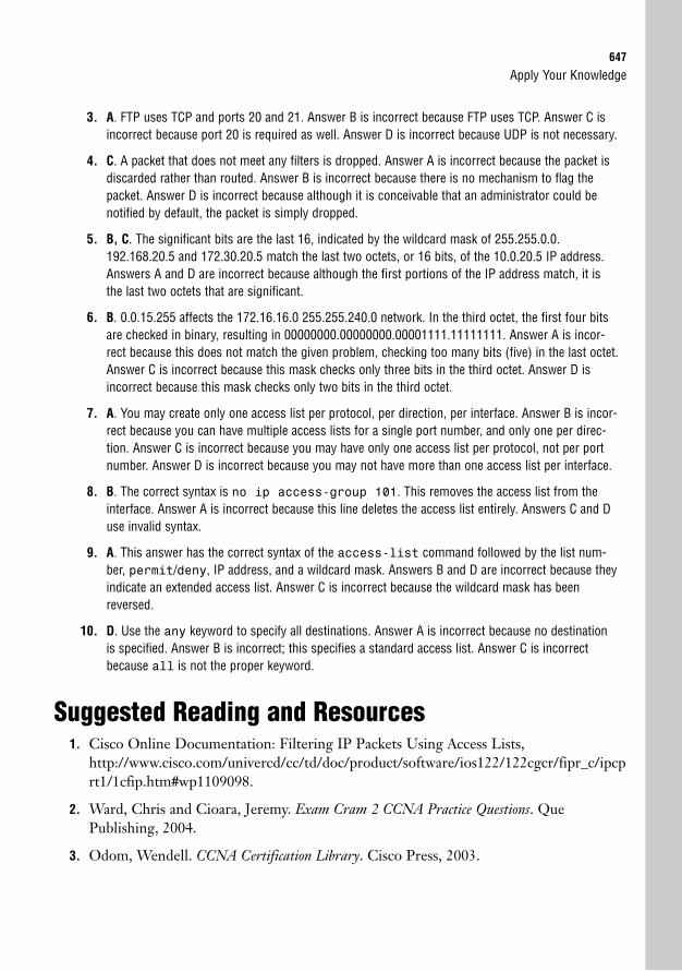
Apply Your Knowledge647
3. A. FTP uses TCP and ports 20 and 21. Answer B is incorrect because FTP uses TCP. Answer C isincorrect because port 20 is required as well. Answer D is incorrect because UDP is not necessary.
4. C. A packet that does not meet any filters is dropped. Answer A is incorrect because the packet isdiscarded rather than routed. Answer B is incorrect because there is no mechanism to flag thepacket. Answer D is incorrect because although it is conceivable that an administrator could benotified by default, the packet is simply dropped.
5. B, C. The significant bits are the last 16, indicated by the wildcard mask of 255.255.0.0.192.168.20.5 and 172.30.20.5 match the last two octets, or 16 bits, of the 10.0.20.5 IP address.Answers A and D are incorrect because although the first portions of the IP address match, it isthe last two octets that are significant.
6. B. 0.0.15.255 affects the 172.16.16.0 255.255.240.0 network. In the third octet, the first four bitsare checked in binary, resulting in 00000000.00000000.00001111.11111111. Answer A is incor-rect because this does not match the given problem, checking too many bits (five) in the last octet.Answer C is incorrect because this mask checks only three bits in the third octet. Answer D isincorrect because this mask checks only two bits in the third octet.
7. A. You may create only one access list per protocol, per direction, per interface. Answer B is incor-rect because you can have multiple access lists for a single port number, and only one per direc-tion. Answer C is incorrect because you may have only one access list per protocol, not per portnumber. Answer D is incorrect because you may not have more than one access list per interface.
8. B. The correct syntax is no ip access-group 101. This removes the access list from theinterface. Answer A is incorrect because this line deletes the access list entirely. Answers C and Duse invalid syntax.
9. A. This answer has the correct syntax of the access-list command followed by the list num-ber, permit/deny, IP address, and a wildcard mask. Answers B and D are incorrect because theyindicate an extended access list. Answer C is incorrect because the wildcard mask has beenreversed.
10. D. Use the any keyword to specify all destinations. Answer A is incorrect because no destinationis specified. Answer B is incorrect; this specifies a standard access list. Answer C is incorrectbecause all is not the proper keyword.
Suggested Reading and Resources1. Cisco Online Documentation: Filtering IP Packets Using Access Lists,
http://www.cisco.com/univercd/cc/td/doc/product/software/ios122/122cgcr/fipr_c/ipcprt1/1cfip.htm#wp1109098.
2. Ward, Chris and Cioara, Jeremy. Exam Cram 2 CCNA Practice Questions. QuePublishing, 2004.
3. Odom, Wendell. CCNA Certification Library. Cisco Press, 2003.

This page intentionally left blank
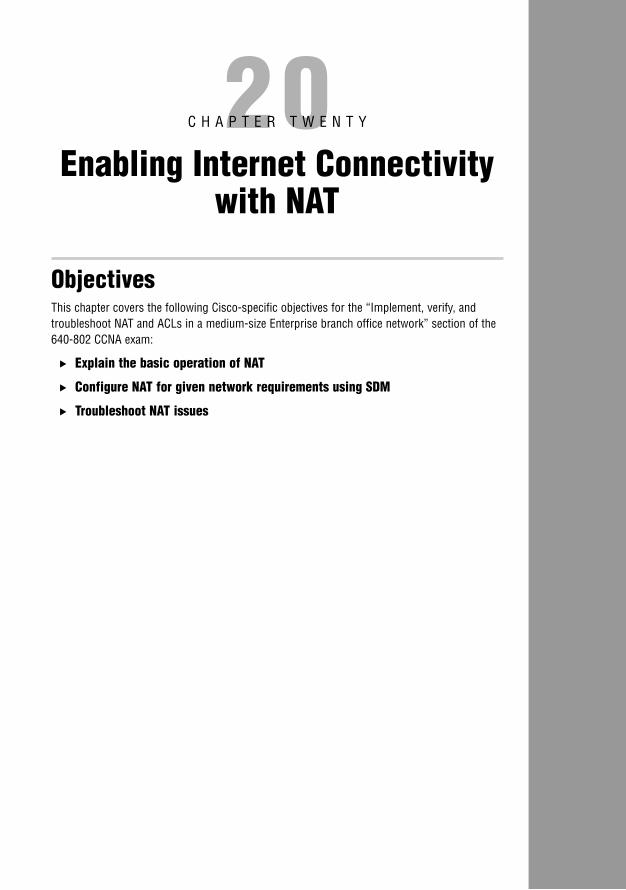
20C H A P T E R T W E N T Y
Enabling Internet Connectivitywith NAT
ObjectivesThis chapter covers the following Cisco-specific objectives for the “Implement, verify, and troubleshoot NAT and ACLs in a medium-size Enterprise branch office network” section of the640-802 CCNA exam:
. Explain the basic operation of NAT
. Configure NAT for given network requirements using SDM
. Troubleshoot NAT issues
Introduction 652
NAT Concepts 653
Static NAT 654
Dynamic NAT 655
NAT Overload and Port Address Translation 656
NAT Terminology 657
Configuring NAT Using Cisco SDM 659
Configuring NAT Overload 659
Advanced NAT Wizard 663
Edit NAT Configuration 669
Verifying NAT Configuration 672
Troubleshooting NAT 675
Chapter Summary 677
Key Terms 677
Apply Your Knowledge 678
Review Questions 678
Exam Questions 678
Answers to Review Questions 681
Answers to Exam Questions 681
Suggested Reading and Resources 682
Outline

Study Strategies. Read the information presented in the chapter, paying special attention to tables, Notes,
and Exam Alerts.
. Focus on the Network Address Translation terminology. Understanding these terms isparamount to understanding the NAT configuration as a whole.
. When studying, focus on the static NAT configurations first, because these are the simplest. After you master this configuration, move on to NAT overload, followed bydynamic NAT.
652
IntroductionI can still remember the very first time I saw Network Address Translation (NAT) in action.“This is the most amazing thing I have ever seen,” I said, with the same awestruck feeling asthe first time you walk up and look over the Grand Canyon. Okay, perhaps it wasn’t that fan-tastic, but at the same time, NAT is definitely at the top of my list of configurations I love toset up.
Despite it being one of the most widely implemented concepts in the world of network tech-nology, NAT is one of the newer topics added to the CCNA exam. This is most likely becauseof its configuration complexity: It requires a thorough understanding of standard access liststo successfully deploy. However, Cisco is very wise in adding it to the entry-level exam, becausenearly every network in the world uses NAT in some shape or form. Even home networksusing Linksys, D-Link, and Netgear routers use NAT.
NAT was originally developed through a combination of Cisco engineers and the InternetEngineering Task Force (IETF) group in 1994 to overcome the quickly approaching IPaddress shortage. With the Internet popularity growing at a rate far faster than expected, theremaining public IP addresses would soon be depleted. At that time, TCP/IP version 6 (IPv6,which would have solved the IP address shortage) had been created in a draft status, but itwould require a worldwide upgrade of network devices and operating system software to suc-cessfully deploy. Rather than upgrading all network-capable devices, the focus was placed oncreating a gateway device that could enable multiple network devices to share a single IPaddress.
As this concept materialized, NAT was born. Theoretically, a router running NAT is capableof allowing more than 60,000 devices to share a single Internet-valid IP address. Practicallyspeaking, the router resources (processor and memory) and WAN bandwidth are depletedlong before that limit is reached. With thousands of devices capable of using a single public IPaddress, the life of TCP/IP version 4 (IPv4) has been extended years beyond what was thoughtpossible.
NAT also acts as a natural security boundary by eliminating end-to-end traceability. If yourrouter has only a single IP address that is connected to the Internet, the public IP address,which is assigned to the outside interface, does not belong to any one internal host. For exam-ple, imagine that your router’s public IP address is 209.1.5.9, and all your internal hosts comefrom the subnet 192.168.1.0/24. Whenever one of the internal hosts accesses the Internet, itis seen as 209.1.5.9. However, if anyone from the Internet attempts to access 209.1.5.9, theaddress maps to no individual host, which makes the internal network invisible to the Internet.
Chapter 20: Enabling Internet Connectivity with NAT
NAT Concepts653
NAT ConceptsObjective:
. Explain the basic operation of NAT
Although the introductory discussion of NAT covers the most popular uses of the technology,NAT can be used for much more. Before you go deeper into the specific uses, though, youmust understand the foundation concepts.
As its core function, Network Address Translation does just that: translate addresses. It cantake any IP address and make it look like another. This is why the creative geniuses behindTCP/IP defined three ranges of “private IP addresses” in RFC 1918. The following is a list ofthe three private address ranges:
. Class A: 10.0.0.0 to 10.255.255.255
. Class B: 172.16.0.0 to 172.31.255.255
. Class C: 192.168.0.0 to 192.168.255.255
You need to know the private IP address ranges.
TIP
You might notice that a private address range is defined for each class of address. This gives acompany more flexibility to use different ranges based on the company size. As a general state-ment, most small companies use the 192.168.X.X range, most medium-sized companies usethe 172.16.X.X to 172.31.X.X ranges, and most large companies use the 10.X.X.X ranges.Remember, this is just a general statement, not a solid rule.
It is commonly stated that these private addresses are nonroutable, but this is untrue.Thousands of companies around the world use these addresses and route them throughouttheir private networks just fine. This misunderstanding came about because all Internet serv-ice providers (ISPs) use access lists to block these addresses from entering or leaving their net-works. It is accurate to say that these private addresses are not Internet routable, because if theywere, there would be thousands of duplicate IP address conflicts every day.
As shown in Figure 20.1, networks connected to the Internet typically use these private IPaddresses internally and then translate them when attempting to access the Internet. Thisenables you to have many duplicate addresses around the world without any conflicts, becausethey never communicate directly. This can cause problems with overlapping IP addresseswhen companies merge, but NAT can even be engineered to solve these problems.
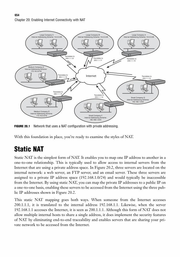
654
FIGURE 20.1 Network that uses a NAT configuration with private addressing.
With this foundation in place, you’re ready to examine the styles of NAT.
Static NATStatic NAT is the simplest form of NAT. It enables you to map one IP address to another in aone-to-one relationship. This is typically used to allow access to internal servers from theInternet that are using a private address space. In Figure 20.2, three servers are located on theinternal network: a web server, an FTP server, and an email server. These three servers areassigned to a private IP address space (192.168.1.0/24) and would typically be inaccessiblefrom the Internet. By using static NAT, you can map the private IP addresses to a public IP ona one-to-one basis, enabling these servers to be accessed from the Internet using the three pub-lic IP addresses shown in Figure 20.2.
This static NAT mapping goes both ways. When someone from the Internet accesses200.1.1.1, it is translated to the internal address 192.168.1.1. Likewise, when the server192.168.1.1 accesses the Internet, it is seen as 200.1.1.1. Although this form of NAT does notallow multiple internal hosts to share a single address, it does implement the security featuresof NAT by eliminating end-to-end traceability and enables servers that are sharing your pri-vate network to be accessed from the Internet.
Chapter 20: Enabling Internet Connectivity with NAT
Large Company CInternal Addressing Scheme: 10.0.0.0/8
Medium Company DInternal Addressing Scheme:
172.16.0.0/16
Small Company FInternal Addressing Scheme:
192.168.1.0/24
Large Company BInternal Addressing Scheme: 10.0.0.0/8
Large Company AInternal Addressing Scheme: 10.0.0.0/8
Internet
Medium Company EInternal Addressing Scheme:
172.16.0.0/16
Small Company GInternal Addressing Scheme:
192.168.1.0/24
Translates to200.1.1.12 Translates to
200.1.1.11Translates to200.1.1.10
Translates to200.1.1.13
Translates to200.1.1.14
Translates to200.1.1.15
Translates to200.1.1.16
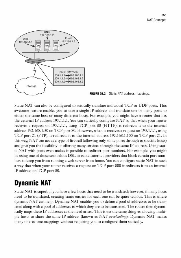
NAT Concepts655
Static NAT can also be configured to statically translate individual TCP or UDP ports. Thisawesome feature enables you to take a single IP address and translate one or many ports toeither the same host or many different hosts. For example, you might have a router that hasthe external IP address 195.1.1.1. You can statically configure NAT so that when your routerreceives a request on 195.1.1.1, using TCP port 80 (HTTP), it redirects it to the internaladdress 192.168.1.50 on TCP port 80. However, when it receives a request on 195.1.1.1, usingTCP port 21 (FTP), it redirects it to the internal address 192.168.1.100 on TCP port 21. Inthis way, NAT can act as a type of firewall (allowing only some ports through to specific hosts)and give you the flexibility of offering many services through the same IP address. Using stat-ic NAT with ports even makes it possible to redirect port numbers. For example, you mightbe using one of those scandalous DSL or cable Internet providers that block certain port num-bers to keep you from running a web server from home. You can configure static NAT in sucha way that when your router receives a request on TCP port 800 it redirects it to an internalIP address on TCP port 80.
Dynamic NATStatic NAT is superb if you have a few hosts that need to be translated; however, if many hostsneed to be translated, creating static entries for each one can be quite tedious. This is wheredynamic NAT can help. Dynamic NAT enables you to define a pool of addresses to be trans-lated along with a pool of addresses to which they are to be translated. The router then dynam-ically maps these IP addresses as the need arises. This is not the same thing as allowing multi-ple hosts to share the same IP address (known as NAT overloading). Dynamic NAT makesmany one-to-one mappings without requiring you to configure them statically.
Internet
Static NAT Table200.1.1.1 192.168.1.1200.1.1.2 192.168.1.2200.1.1.3 192.168.1.3
Web192.168.1.1
DNS192.168.1.2
Email192.168.1.3
FIGURE 20.2 Static NAT address mappings.
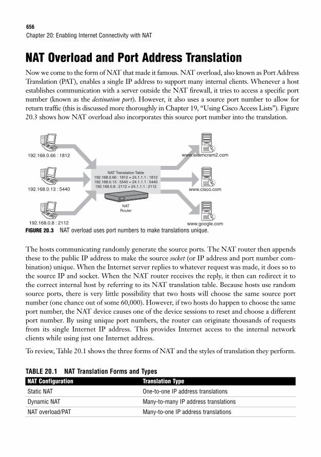
656
NAT Overload and Port Address TranslationNow we come to the form of NAT that made it famous. NAT overload, also known as Port AddressTranslation (PAT), enables a single IP address to support many internal clients. Whenever a hostestablishes communication with a server outside the NAT firewall, it tries to access a specific portnumber (known as the destination port). However, it also uses a source port number to allow forreturn traffic (this is discussed more thoroughly in Chapter 19, “Using Cisco Access Lists”). Figure20.3 shows how NAT overload also incorporates this source port number into the translation.
Chapter 20: Enabling Internet Connectivity with NAT
NAT Translation Table192.168.0.66 : 1812 = 24.1.1.1 : 1812192.168.0.13 : 5540 = 24.1.1.1 : 5440192.168.0.8 : 2112 = 24.1.1.1 : 2112
NATRouter
192.168.0.66 : 1812
192.168.0.13 : 5440
192.168.0.8 : 2112
www.examcram2.com
www.cisco.com
www.google.com
FIGURE 20.3 NAT overload uses port numbers to make translations unique.
The hosts communicating randomly generate the source ports. The NAT router then appendsthese to the public IP address to make the source socket (or IP address and port number com-bination) unique. When the Internet server replies to whatever request was made, it does so tothe source IP and socket. When the NAT router receives the reply, it then can redirect it tothe correct internal host by referring to its NAT translation table. Because hosts use randomsource ports, there is very little possibility that two hosts will choose the same source portnumber (one chance out of some 60,000). However, if two hosts do happen to choose the sameport number, the NAT device causes one of the device sessions to reset and choose a differentport number. By using unique port numbers, the router can originate thousands of requestsfrom its single Internet IP address. This provides Internet access to the internal networkclients while using just one Internet address.
To review, Table 20.1 shows the three forms of NAT and the styles of translation they perform.
TABLE 20.1 NAT Translation Forms and TypesNAT Configuration Translation Type
Static NAT One-to-one IP address translations
Dynamic NAT Many-to-many IP address translations
NAT overload/PAT Many-to-one IP address translations
NAT Terminology657
NAT TerminologyBelieve it or not, setting up NAT is not very difficult; it’s learning the terminology used withNAT that can fry your brain. The first time you see these terms, it may make no sense to you,and that’s just fine. It takes some time to soak in. Now, keep in mind that these are not “Ciscoterms.” Rather, they are an industry standard way of referring to the four different points in aNAT-based network. Before trying to understand four NAT address descriptions, you mustunderstand the building blocks used to construct these terms:
. Inside/outside: These NAT descriptors refer to where a device is physically located. Ifa device is “inside,” it is under your control; it is in your network. If a device is “out-side,” it is not under your control; it is outside your network.
. Local/global: These NAT descriptors refer to where an IP address is located from theperspective of a NAT device. The NAT device is a network device that has its addresstranslated through a NAT router. It could be a PC, a server, an Xbox, or any other typeof host that has a private address that is translated to a real address on the Internet. Ifthe IP address is considered “local,” it is seen as a device on the local subnet from theperspective of a NAT device (this may or may not be true). If the IP address is consid-ered “global,” it is seen as not on the local subnet from the perspective of a NAT device.
If that doesn’t sound confusing, just wait until we start combining these terms for the fourNAT address descriptions. Figure 20.4 shows a visual location of these address on the network.
. Inside local addresses: These addresses are the easiest to understand because theyrefer to everything inside your network. Remember the word constructs discussed just amoment ago: An address “inside” is physically located inside your network. From theperspective of the NAT device, it is “local,” meaning it is seen on the internal network.If an inside local address were to communicate with another inside local address, thatcommunication would be described as standard LAN connectivity. No routers wouldbe needed.
. Inside global addresses: Now the terms begin to mix a little bit. Let’s break thisdown into the individual pieces: First, the address is “inside,” which means that it isphysically located on your network; it is under your control. “Global” means that it isseen as an IP address not on the local subnet from the perspective of one of your NATdevices. Put all this together and you are left with the Internet valid IP addressassigned to your router that is directly connected to the Internet. This is where a fun-damental understanding of inside and outside can really help. If the address were an“outside global,” it would not be under your control, meaning that it could be any ofthe millions of devices attached to the Internet.
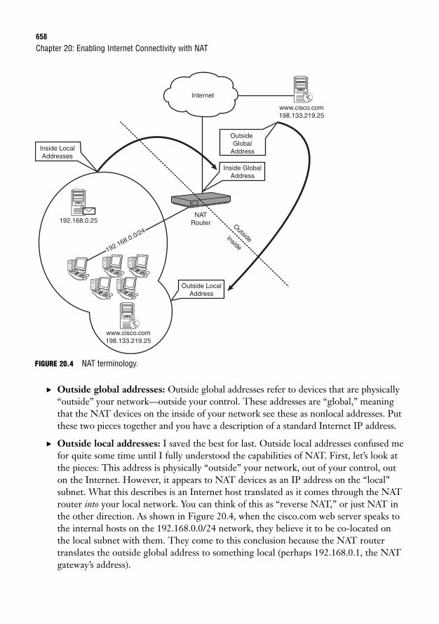
658
FIGURE 20.4 NAT terminology.
. Outside global addresses: Outside global addresses refer to devices that are physically“outside” your network—outside your control. These addresses are “global,” meaningthat the NAT devices on the inside of your network see these as nonlocal addresses. Putthese two pieces together and you have a description of a standard Internet IP address.
. Outside local addresses: I saved the best for last. Outside local addresses confused mefor quite some time until I fully understood the capabilities of NAT. First, let’s look atthe pieces: This address is physically “outside” your network, out of your control, outon the Internet. However, it appears to NAT devices as an IP address on the “local”subnet. What this describes is an Internet host translated as it comes through the NATrouter into your local network. You can think of this as “reverse NAT,” or just NAT inthe other direction. As shown in Figure 20.4, when the cisco.com web server speaks tothe internal hosts on the 192.168.0.0/24 network, they believe it to be co-located onthe local subnet with them. They come to this conclusion because the NAT routertranslates the outside global address to something local (perhaps 192.168.0.1, the NATgateway’s address).
Chapter 20: Enabling Internet Connectivity with NAT
www.cisco.com198.133.219.25
192.168.0.25
www.cisco.com198.133.219.25
Internet
NATRouter
Outside LocalAddress
Inside GlobalAddress
Inside LocalAddresses
OutsideGlobal
Address
192.168.0.0/24OutsideInside
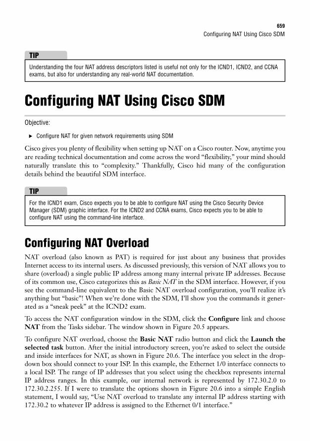
Configuring NAT Using Cisco SDM659
Configuring NAT Using Cisco SDMObjective:
. Configure NAT for given network requirements using SDM
Cisco gives you plenty of flexibility when setting up NAT on a Cisco router. Now, anytime youare reading technical documentation and come across the word “flexibility,” your mind shouldnaturally translate this to “complexity.” Thankfully, Cisco hid many of the configurationdetails behind the beautiful SDM interface.
Understanding the four NAT address descriptors listed is useful not only for the ICND1, ICND2, and CCNAexams, but also for understanding any real-world NAT documentation.
TIP
For the ICND1 exam, Cisco expects you to be able to configure NAT using the Cisco Security DeviceManager (SDM) graphic interface. For the ICND2 and CCNA exams, Cisco expects you to be able to configure NAT using the command-line interface.
TIP
Configuring NAT OverloadNAT overload (also known as PAT) is required for just about any business that providesInternet access to its internal users. As discussed previously, this version of NAT allows you toshare (overload) a single public IP address among many internal private IP addresses. Becauseof its common use, Cisco categorizes this as Basic NAT in the SDM interface. However, if yousee the command-line equivalent to the Basic NAT overload configuration, you’ll realize it’sanything but “basic”! When we’re done with the SDM, I’ll show you the commands it gener-ated as a “sneak peek” at the ICND2 exam.
To access the NAT configuration window in the SDM, click the Configure link and chooseNAT from the Tasks sidebar. The window shown in Figure 20.5 appears.
To configure NAT overload, choose the Basic NAT radio button and click the Launch theselected task button. After the initial introductory screen, you’re asked to select the outsideand inside interfaces for NAT, as shown in Figure 20.6. The interface you select in the drop-down box should connect to your ISP. In this example, the Ethernet 1/0 interface connects toa local ISP. The range of IP addresses that you select using the checkbox represents internalIP address ranges. In this example, our internal network is represented by 172.30.2.0 to172.30.2.255. If I were to translate the options shown in Figure 20.6 into a simple Englishstatement, I would say, “Use NAT overload to translate any internal IP address starting with172.30.2 to whatever IP address is assigned to the Ethernet 0/1 interface.”
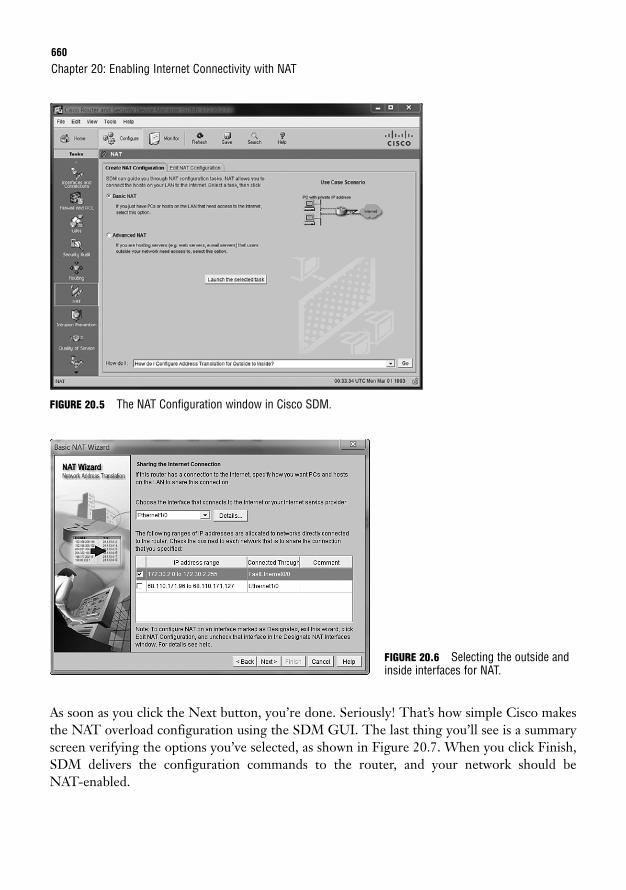
660
FIGURE 20.5 The NAT Configuration window in Cisco SDM.
Chapter 20: Enabling Internet Connectivity with NAT
As soon as you click the Next button, you’re done. Seriously! That’s how simple Cisco makesthe NAT overload configuration using the SDM GUI. The last thing you’ll see is a summaryscreen verifying the options you’ve selected, as shown in Figure 20.7. When you click Finish,SDM delivers the configuration commands to the router, and your network should be NAT-enabled.
FIGURE 20.6 Selecting the outside andinside interfaces for NAT.
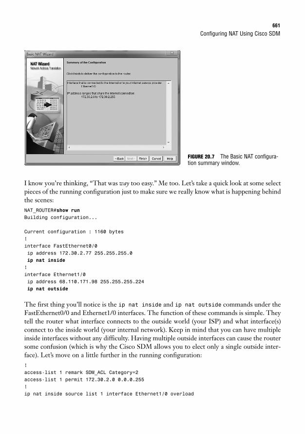
Configuring NAT Using Cisco SDM661
I know you’re thinking, “That was way too easy.” Me too. Let’s take a quick look at some selectpieces of the running configuration just to make sure we really know what is happening behindthe scenes:NAT_ROUTER#show runBuilding configuration...
Current configuration : 1160 bytes!interface FastEthernet0/0ip address 172.30.2.77 255.255.255.0ip nat inside
!interface Ethernet1/0ip address 68.110.171.98 255.255.255.224ip nat outside
The first thing you’ll notice is the ip nat inside and ip nat outside commands under theFastEthernet0/0 and Ethernet1/0 interfaces. The function of these commands is simple. Theytell the router what interface connects to the outside world (your ISP) and what interface(s)connect to the inside world (your internal network). Keep in mind that you can have multipleinside interfaces without any difficulty. Having multiple outside interfaces can cause the routersome confusion (which is why the Cisco SDM allows you to elect only a single outside inter-face). Let’s move on a little further in the running configuration:!access-list 1 remark SDM_ACL Category=2access-list 1 permit 172.30.2.0 0.0.0.255!ip nat inside source list 1 interface Ethernet1/0 overload
FIGURE 20.7 The Basic NAT configura-tion summary window.
662
These commands are what I consider the “power commands” of NAT. Here’s the idea: the firstsection represents an access list that allows the Cisco router to identify the internal network IPaddresses (172.30.2.0/24 in this case). The access list is then utilized in the nat command belowit. That one command is what puts this whole configuration in motion. The best way to under-stand that command is to imagine it as a conversation between you and the router. Trust me—the more you configure Cisco routers, the more conversations like this you will have:
You: I want to do NAT (ip nat).
Router: That’s nice. Where would you like to NAT from?
You: The inside of my network to the outside (inside).
Router: Great! What interface would you like to use for the outside IP address?
You: I’d like to use Ethernet1/0 (interface Ethernet1/0).
Router: How would you like to use it?
You: I’d like all internal IP addresses to share the single IP address on Ethernet 1/0 (overload).
That’s the story! As the router puts these commands into action, all users in the 172.30.2.0/24range are provided with Internet access.
Chapter 20: Enabling Internet Connectivity with NAT
Keep in mind that this is an introductory explanation of the NAT syntax. This configuration is discussedfully in Chapter 21, “Command-Line NAT Implementation.”
NOTE
Providing Internet access to the company through NAT overload is just one piece of the net-working puzzle. Most companies have internal servers that need not only access to the Internetbut access from the Internet. These are typically email servers, web servers, or FTP servers, toname just a few. Fortunately for your business, NAT provides a natural firewall between youand the Internet. Because private addresses are unreachable from the Internet, your internalnetwork is protected from the outside world.
Don’t get a false sense of security by running NAT! Although NAT does protect your internal network frombeing reached directly from the Internet, it is not flawless network security. If one of the hosts on yourinternal network becomes infected with a virus or worm, it can initiate connections through the NAT gate-way and allow return traffic (which could potentially be malicious) back into your network.
NOTE
The problem with this natural firewall is that it also makes your internal servers unreachablefrom the Internet. To solve this, we can use static NAT mappings.

Configuring NAT Using Cisco SDM663
The SDM gives you a couple methods of setting up NAT mappings: configuring the mappingsat the same time as NAT overload (using the Advanced NAT selection on the Create NATConfiguration tab) or adding them individually from the Edit NAT Configuration tab. We’lltalk about both methods here, starting with the Advanced NAT selection.
Advanced NAT WizardThe Advanced NAT configuration wizard, shown in Figure 20.8, is most useful when you aresetting up NAT overload and static NAT mappings at the same time. This section assumes thatyou did not work through the Basic NAT wizard previously (although the Advanced NAT wiz-ard will still function if you previously completed the Basic NAT wizard).
FIGURE 20.8 Beginning the Advanced NAT configuration.
To start the Advanced NAT wizard, simply select its radio button and click the Launch theselected task button. After you see the introductory page, the wizard asks you to identify theinterface connected to your ISP, just as it did in the Basic NAT wizard. However, at this pointyou start to see something different: the wizard also asks if you are using any additional pub-lic IP addresses, as shown in Figure 20.9. Many organizations that run their own internalservers purchase additional, dedicated IP addresses for those servers. If your organization isusing more IP addresses than what is assigned to the outside interface of your router, click theAdd button and enter them one by one. If you do not have additional IP addresses, don’tworry! We can do some really great stuff with the one IP address assigned to your router’s out-side interface (we’ll talk about that in just a moment). In Figure 20.9, I have added the IPaddresses 200.1.1.1 and 200.1.1.2 so that I can use them later in the configuration. We’llassume that our “virtual company” owns these two IP addresses.
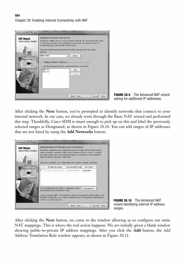
664
After clicking the Next button, you’re prompted to identify networks that connect to yourinternal network. In our case, we already went through the Basic NAT wizard and performedthis step. Thankfully, Cisco SDM is smart enough to pick up on this and label the previouslyselected ranges as Designated, as shown in Figure 20.10. You can add ranges of IP addressesthat are not listed by using the Add Networks button.
Chapter 20: Enabling Internet Connectivity with NAT
FIGURE 20.9 The Advanced NAT wizardasking for additional IP addresses.
After clicking the Next button, we come to the window allowing us to configure our staticNAT mappings. This is where the real action happens. We are initially given a blank windowshowing public-to-private IP address mappings. After you click the Add button, the AddAddress Translation Rule window appears, as shown in Figure 20.11.
FIGURE 20.10 The Advanced NAT wizard identifying internal IP addressranges.
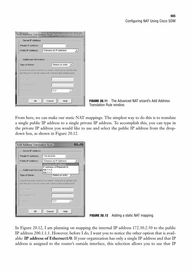
Configuring NAT Using Cisco SDM665
From here, we can make our static NAT mappings. The simplest way to do this is to translatea single public IP address to a single private IP address. To accomplish this, you can type inthe private IP address you would like to use and select the public IP address from the drop-down box, as shown in Figure 20.12.
FIGURE 20.11 The Advanced NAT wizard’s Add AddressTranslation Rule window.
In Figure 20.12, I am planning on mapping the internal IP address 172.30.2.50 to the publicIP address 200.1.1.1. However, before I do, I want you to notice the other option that is avail-able: IP address of Ethernet1/0. If your organization has only a single IP address and that IPaddress is assigned to the router’s outside interface, this selection allows you to use that IP
FIGURE 20.12 Adding a static NAT mapping.
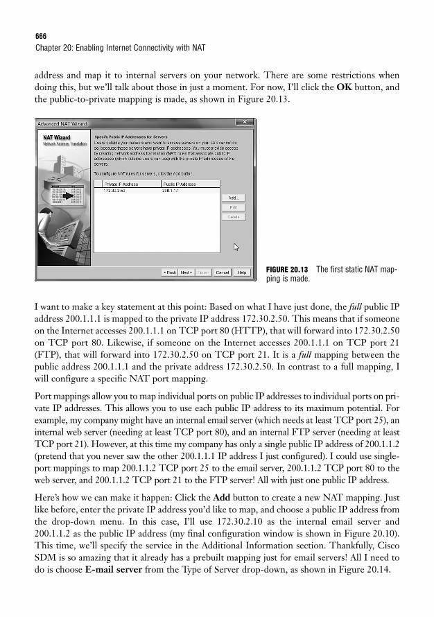
666
address and map it to internal servers on your network. There are some restrictions whendoing this, but we’ll talk about those in just a moment. For now, I’ll click the OK button, andthe public-to-private mapping is made, as shown in Figure 20.13.
Chapter 20: Enabling Internet Connectivity with NAT
I want to make a key statement at this point: Based on what I have just done, the full public IPaddress 200.1.1.1 is mapped to the private IP address 172.30.2.50. This means that if someoneon the Internet accesses 200.1.1.1 on TCP port 80 (HTTP), that will forward into 172.30.2.50on TCP port 80. Likewise, if someone on the Internet accesses 200.1.1.1 on TCP port 21(FTP), that will forward into 172.30.2.50 on TCP port 21. It is a full mapping between thepublic address 200.1.1.1 and the private address 172.30.2.50. In contrast to a full mapping, Iwill configure a specific NAT port mapping.
Port mappings allow you to map individual ports on public IP addresses to individual ports on pri-vate IP addresses. This allows you to use each public IP address to its maximum potential. Forexample, my company might have an internal email server (which needs at least TCP port 25), aninternal web server (needing at least TCP port 80), and an internal FTP server (needing at leastTCP port 21). However, at this time my company has only a single public IP address of 200.1.1.2(pretend that you never saw the other 200.1.1.1 IP address I just configured). I could use single-port mappings to map 200.1.1.2 TCP port 25 to the email server, 200.1.1.2 TCP port 80 to theweb server, and 200.1.1.2 TCP port 21 to the FTP server! All with just one public IP address.
Here’s how we can make it happen: Click the Add button to create a new NAT mapping. Justlike before, enter the private IP address you’d like to map, and choose a public IP address fromthe drop-down menu. In this case, I’ll use 172.30.2.10 as the internal email server and200.1.1.2 as the public IP address (my final configuration window is shown in Figure 20.10).This time, we’ll specify the service in the Additional Information section. Thankfully, CiscoSDM is so amazing that it already has a prebuilt mapping just for email servers! All I need todo is choose E-mail server from the Type of Server drop-down, as shown in Figure 20.14.
FIGURE 20.13 The first static NAT map-ping is made.
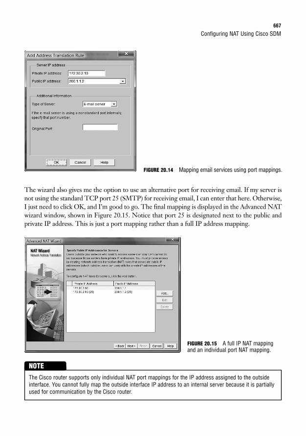
NOTE
Configuring NAT Using Cisco SDM667
The wizard also gives me the option to use an alternative port for receiving email. If my server isnot using the standard TCP port 25 (SMTP) for receiving email, I can enter that here. Otherwise,I just need to click OK, and I’m good to go. The final mapping is displayed in the Advanced NATwizard window, shown in Figure 20.15. Notice that port 25 is designated next to the public andprivate IP address. This is just a port mapping rather than a full IP address mapping.
FIGURE 20.14 Mapping email services using port mappings.
FIGURE 20.15 A full IP NAT mappingand an individual port NAT mapping.
The Cisco router supports only individual NAT port mappings for the IP address assigned to the outsideinterface. You cannot fully map the outside interface IP address to an internal server because it is partiallyused for communication by the Cisco router.
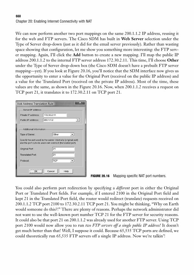
668
We can now perform another two port mappings on the same 200.1.1.2 IP address, reusing itfor the web and FTP servers. The Cisco SDM has built in Web Server selection under theType of Server drop-down (just as it did for the email server previously). Rather than wastingspace showing that configuration, let me show you something more interesting: the FTP serv-er mapping. Again, I’ll click the Add button to create a new mapping. I’ll map the public IPaddress 200.1.1.2 to the internal FTP server address 172.30.2.11. This time, I’ll choose Otherunder the Type of Server drop-down box (the Cisco SDM doesn’t have a prebuilt FTP servermapping—yet). If you look at Figure 20.16, you’ll notice that the SDM interface now gives usthe opportunity to enter a value for the Original Port (received on the public IP address) anda value for the Translated Port (received on the private IP address). Most of the time, thesevalues are the same, as shown in the Figure 20.16. Now, when 200.1.1.2 receives a request onTCP port 21, it translates it to 172.30.2.11 on TCP port 21.
Chapter 20: Enabling Internet Connectivity with NAT
You could also perform port redirection by specifying a different port in either the OriginalPort or Translated Port fields. For example, if I entered 2100 in the Original Port field andkept 21 in the Translated Port field, the router would redirect (translate) requests received on200.1.1.2 TCP port 2100 to 172.30.2.11 TCP port 21. You might be thinking, “Why on Earthwould someone do this?!” There are plenty of reasons. Perhaps the network administrator didnot want to use the well-known port number TCP 21 for the FTP server for security reasons.It could also be that port 21 on 200.1.1.2 was already used for another FTP server. Using TCPport 2100 would now allow you to run two FTP servers off a single public IP address! It doesn’tget much better than that! Well, I suppose it could. Because 65,535 TCP ports are defined, wecould theoretically run 65,535 FTP servers off a single IP address. Now we’re talkin’!
FIGURE 20.16 Mapping specific NAT port numbers.
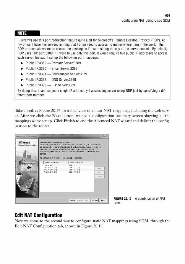
Configuring NAT Using Cisco SDM669
Take a look at Figure 20.17 for a final view of all our NAT mappings, including the web serv-er. After we click the Next button, we see a configuration summary screen showing all themappings we’ve set up. Click Finish to end the Advanced NAT wizard and deliver the config-uration to the router.
I (Jeremy) use this port redirection feature quite a bit for Microsoft’s Remote Desktop Protocol (RDP). Atmy office, I have five servers running that I often need to access no matter where I am in the world. TheRDP protocol allows me to access the desktop as if I were sitting directly at the server console. By default,RDP uses TCP port 3389. If I were to use only this port, it would require five public IP addresses to accesseach server. Instead, I set up the following port mappings:
. Public IP:3389 → Primary Server:3389
. Public IP:3390 → Email Server:3389
. Public IP:3391 → CallManager Server:3389
. Public IP:3392 → DNS Server:3389
. Public IP:3393 → FTP Server:3389
By doing this, I can use just a single IP address, yet access any server using RDP just by specifying a dif-ferent port number.
NOTE
Edit NAT ConfigurationNow we come to the second way to configure static NAT mappings using SDM: through theEdit NAT Configuration tab, shown in Figure 20.18.
FIGURE 20.17 A combination of NATrules.
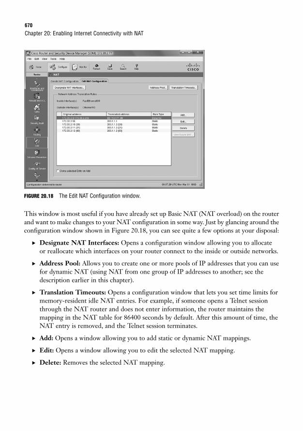
670
FIGURE 20.18 The Edit NAT Configuration window.
This window is most useful if you have already set up Basic NAT (NAT overload) on the routerand want to make changes to your NAT configuration in some way. Just by glancing around theconfiguration window shown in Figure 20.18, you can see quite a few options at your disposal:
. Designate NAT Interfaces: Opens a configuration window allowing you to allocateor reallocate which interfaces on your router connect to the inside or outside networks.
. Address Pool: Allows you to create one or more pools of IP addresses that you can usefor dynamic NAT (using NAT from one group of IP addresses to another; see thedescription earlier in this chapter).
. Translation Timeouts: Opens a configuration window that lets you set time limits formemory-resident idle NAT entries. For example, if someone opens a Telnet sessionthrough the NAT router and does not enter information, the router maintains themapping in the NAT table for 86400 seconds by default. After this amount of time, theNAT entry is removed, and the Telnet session terminates.
. Add: Opens a window allowing you to add static or dynamic NAT mappings.
. Edit: Opens a window allowing you to edit the selected NAT mapping.
. Delete: Removes the selected NAT mapping.
Chapter 20: Enabling Internet Connectivity with NAT
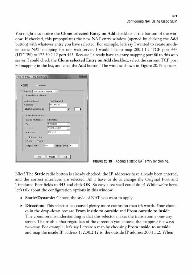
Configuring NAT Using Cisco SDM671
You might also notice the Clone selected Entry on Add checkbox at the bottom of the win-dow. If checked, this prepopulates the new NAT entry window (opened by clicking the Addbutton) with whatever entry you have selected. For example, let’s say I wanted to create anoth-er static NAT mapping for our web server. I would like to map 200.1.1.2 TCP port 443(HTTPS) to 172.30.2.12 port 443. Because I already have an entry mapping port 80 to this webserver, I could check the Clone selected Entry on Add checkbox, select the current TCP port80 mapping in the list, and click the Add button. The window shown in Figure 20.19 appears.
Nice! The Static radio button is already checked, the IP addresses have already been entered,and the correct interfaces are selected. All I have to do is change the Original Port andTranslated Port fields to 443 and click OK. So easy a sea snail could do it! While we’re here,let’s talk about the configuration options in this window:
. Static/Dynamic: Choose the style of NAT you want to apply.
. Direction: This selector has caused plenty more confusion than it’s worth. Your choic-es in the drop-down box are From inside to outside and From outside to inside.The common misunderstanding is that this selector makes the translation a one-waystreet. The truth is that regardless of the direction you choose, the mapping is alwaystwo-way. For example, let’s say I create a map by choosing From inside to outsideand map the inside IP address 172.30.2.12 to the outside IP address 200.1.1.2. When
FIGURE 20.19 Adding a static NAT entry by cloning.
672
the server 172.30.2.12 accesses the Internet, it is seen as 200.1.1.2. Likewise, if some-one on the Internet accesses 200.1.1.2, he or she reaches the server at 172.30.2.12. It’sa two-way translation. The good news is that you can always choose which directionmakes more sense to you—outside-in or inside-out. This selector also gives you moreflexibility when performing dynamic NAT.
. Inside IP Address/Network Mask: The inside address or pool of addresses you wantto translate.
. Outside Interface(s)/Type: Allows you to enter the individual IP address or interfaceyou want to translate. If the Type drop-down box has the IP address selected (shownin Figure 20.15), the IP address field can be modified. If the Type drop-down box hasthe interface selected, the Interface field can be modified.
. Redirect Port/Original Port/Translated Port: Allows you to choose the protocoland port numbers you want to translate.
After I click the OK button, the new static NAT translation is added. As I mentioned earlier,the Edit NAT Configuration tab is the best place to make changes to an existing NAT setup.
Verifying NAT ConfigurationObjective:
. Troubleshoot NAT issues
To verify that everything is working, we need to return to our command-line interface. (TheSDM can verify that packets are passing through interfaces but is unable to show us thedetailed NAT information we need.) The first thing I want to do when I get to the commandline is issue the show ip interface brief command (by far, my favorite command in all ofCisco) to get my bearings:NAT_ROUTER#show ip interface briefInterface IP-Address OK? Method Status ProtocolFastEthernet0/0 172.30.2.77 YES NVRAM up upEthernet1/0 68.110.171.98 YES NVRAM up upSerial1/0 unassigned YES NVRAM administratively down downSerial2/0 unassigned YES NVRAM administratively down down
We can see our internal IP address (172.30.2.77) and our external IP address (68.110.171.98).Let’s start by ensuring that we can reach the Internet without involving NAT by issuing a pingcommand directly from the router. I typically ping the world’s best-known public DNS serv-er at 4.2.2.2 anytime I want to test Internet connectivity:
Chapter 20: Enabling Internet Connectivity with NAT
Verifying NAT Configuration673
NAT_ROUTER#ping 4.2.2.2
Type escape sequence to abort.Sending 5, 100-byte ICMP Echos to 4.2.2.2, timeout is 2 seconds:!!!!!Success rate is 100 percent (5/5), round-trip min/avg/max = 20/23/28 ms
Beautiful. Now I’ll configure an internal client to use this router as its default gateway and dosome Internet surfing. I’ll spare you the screen captures of me surfing the Internet—you’ll justhave to trust that I’m really surfing. Yep, there’s my Apple homepage (I’ve recently becomequite the Apple enthusiast). I’ll also surf over to www.CiscoBlog.com to see if there’s anythingnew. Okay, I’m done surfing. Now let’s verify that NAT is occurring from the Cisco router’sperspective. You can use two major commands to do so. Here’s the first:NAT_ROUTER#show ip nat statisticsTotal active translations: 38 (5 static, 33 dynamic; 37 extended)Outside interfaces:Ethernet1/0
Inside interfaces:FastEthernet0/0
Hits: 1211 Misses: 121Expired translations: 88Dynamic mappings:-- Inside Source[Id: 1] access-list 1 interface Ethernet1/0 refcount 33
The show ip nat statistics command verifies NAT from a more global perspective. Theprimary information you can gather is the outside and inside interface configuration and thenumber of hits and misses. The number of hits defines how many packets match an existingNAT mapping. For example, I went to www.CiscoBlog.com while I was surfing the Internet.The very first packet that went through the Cisco router was considered a “miss” because noexisting NAT translation was created. So, the Cisco router created the NAT translation, pass-ing the traffic from my internal client (172.30.2.177) to the www.CiscoBlog.com website. Thewebsite then received my connection, created a TCP socket, and streamed many packets backto my web browsing application. All those packets were considered “hits” by NAT becausethey matched an existing NAT translation.
The second command you can use to verify that NAT is working is the more popular of thetwo:NAT_ROUTER#show ip nat translationsPro Inside global Inside local Outside local Outside global--- 200.1.1.1 172.30.2.50 --- ---tcp 200.1.1.2:21 172.30.2.11:21 --- ---tcp 200.1.1.2:25 172.30.2.10:25 --- ---tcp 200.1.1.2:80 172.30.2.12:80 --- ---tcp 68.110.171.98:49221 172.30.2.177:49221 17.149.160.10:80 17.149.160.10:80
674
tcp 68.110.171.98:49222 172.30.2.177:49222 17.149.160.10:80 17.149.160.10:80tcp 68.110.171.98:49223 172.30.2.177:49223 17.149.160.10:80 17.149.160.10:80tcp 68.110.171.98:49224 172.30.2.177:49224 17.149.160.10:80 17.149.160.10:80tcp 68.110.171.98:49225 172.30.2.177:49225 17.149.160.10:80 17.149.160.10:80tcp 68.110.171.98:49226 172.30.2.177:49226 17.149.160.10:80 17.149.160.10:80tcp 68.110.171.98:49238 172.30.2.177:49238 17.149.160.10:80 17.149.160.10:80tcp 200.1.1.2:443 172.30.2.12:443 --- ---tcp 68.110.171.98:49236 172.30.2.177:49236 66.151.152.126:80 66.151.152.126:80tcp 68.110.171.98:49237 172.30.2.177:49237 206.16.21.35:80 206.16.21.35:80tcp 68.110.171.98:49242 172.30.2.177:49242 69.89.31.87:80 69.89.31.87:80tcp 68.110.171.98:49244 172.30.2.177:49244 69.89.31.87:80 69.89.31.87:80tcp 68.110.171.98:49245 172.30.2.177:49245 69.89.31.87:80 69.89.31.87:80tcp 68.110.171.98:49243 172.30.2.177:49243 209.85.171.167:80 209.85.171.167:80udp 68.110.171.98:49308 172.30.2.177:49308 4.2.2.2:53 4.2.2.2:53udp 68.110.171.98:49309 172.30.2.177:49309 4.2.2.2:53 4.2.2.2:53udp 68.110.171.98:49310 172.30.2.177:49310 4.2.2.2:53 4.2.2.2:53udp 68.110.171.98:49311 172.30.2.177:49311 4.2.2.2:53 4.2.2.2:53udp 68.110.171.98:49312 172.30.2.177:49312 4.2.2.2:53 4.2.2.2:53udp 68.110.171.98:49313 172.30.2.177:49313 4.2.2.2:53 4.2.2.2:53udp 68.110.171.98:49314 172.30.2.177:49314 4.2.2.2:53 4.2.2.2:53udp 68.110.171.98:49315 172.30.2.177:49315 4.2.2.2:53 4.2.2.2:53tcp 68.110.171.98:49227 172.30.2.177:49227 208.46.174.96:80 208.46.174.96:80tcp 68.110.171.98:49228 172.30.2.177:49228 208.46.174.96:80 208.46.174.96:80tcp 68.110.171.98:49229 172.30.2.177:49229 208.46.174.96:80 208.46.174.96:80
Wow—look at that! These are all the NAT translations my router is currently maintaining.This is how you can really tell if NAT is working. If you look at the first few translations, you’llbe able to verify the static NAT mappings that we entered through the SDM just a fewmoments ago. The IP address in the Inside global column represents the address on the inter-face connecting to the Internet. The IP address in the Inside local column represents the inter-nal IP address on your LAN. Do you see now why it’s so important to know that terminologymentioned at the beginning of the chapter? If it’s a little fuzzy, now would be a good time toflip back a few pages and review.
The static mappings have no data in the Outside local and Outside global columns becausethey are not currently in use (no one is accessing those IP addresses from the Internet at thistime). If they were being accessed, we would see the IP address of the device accessing themin those two columns.
Now take a look farther down; you see a bunch of mappings on the inside global IP address68.110.171.98 and the inside local IP address 172.30.2.177. The global IP address representsmy ISP-assigned Internet address that I am using for NAT overload (all the internal clientsshare this one). The local IP address represents the internal client I was surfing the Internetwith. Next to each of those IP addresses is a colon, followed by a port number. These are thesource UDP and TCP port numbers that my web surfing client uses to keep all its applicationsseparate.
Chapter 20: Enabling Internet Connectivity with NAT
Troubleshooting NAT675
In the two rightmost columns (Outside local and Outside global) you see the public IP address-es that my web surfing client was accessing. I know what you might be thinking: ”Why do youhave so many entries in the NAT table? I thought you accessed just two websites!” You’re right!I did access only two websites. However, my laptop had to do DNS lookups to access both thewebsites, and those websites were supported by many other servers. For example, the Applewebsite might have one server that supplies the raw HTML pages, another server that suppliesall the graphics, another for flash content, and so on. For each of those servers, the client mayhave to do another DNS lookup (which is why you see so many requests to the 4.2.2.2 DNSserver IP address), and the Cisco router has to maintain another NAT mapping to allow datathrough. On top of it all, this is just one laptop surfing the Internet! Imagine what this tablewould look like in a large corporate network. Good thing the show ip nat translation com-mand supports plenty of filtering options!
Troubleshooting NATWhen you use the SDM to configure NAT, not too much can go wrong, but you can followsome general troubleshooting steps if things don’t seem to be working correctly. To start, enterthe following modified show running-config commands:NAT_ROUTER#show running-config interface fastEthernet 0/0Building configuration...
Current configuration : 111 bytes!interface FastEthernet0/0ip address 172.30.2.77 255.255.255.0ip nat insideNAT_ROUTER#show running-config interface Ethernet 1/0Building configuration...
Current configuration : 100 bytes!interface Ethernet1/0ip address 68.110.171.98 255.255.255.224ip nat outside
This filters the large running configuration to just the interfaces you’d like to see. What youwant to verify is that the interface connecting to your internal network is configured as the ipnat inside interface and that the interface connecting to the ISP is configured as the ip natoutside interface.
We’ll talk more about the specifics of the show ip nat translations command in Chapter 21.
NOTE
676
If things look good there, do a ping from the router itself. This will test your Internet con-nectivity without the NAT process getting in the way. The problem could be a simple routingissue (such as missing a default route to your ISP). If things check out in the router-originat-ed ping, try the ping from an internal client. Be sure you’re pinging an IP address rather thana hostname (such as www.examcram.com). You don’t want a DNS problem getting in the way.If the client can ping successfully, NAT is operational.
Last, but not least, is a command that has saved me plenty of troubleshooting time: clear ipnat translations *. This command wipes out the NAT table maintained on the router.Sometimes, when we are setting up a network, we end up with NAT entries in the table thatdon’t belong there. It could just be from changing a client’s IP address before NAT timeoutsare reached, it could be that your public or private IP address changes, or it could just be thatthe router doesn’t feel like NATing today. It’s always worthwhile to try entering clear ip nattranslations * from the privileged prompt before you get too deep in troubleshooting otherissues. Don’t worry; it shouldn’t cause any connectivity problems for existing clients using theInternet. The router will just create a new NAT mapping the next packet that comes through.I have seen this command cause Instant Messenger clients to log out and log back in again, butpeople don’t really use Instant Messenger clients for anything productive anyway, right?
Chapter 20: Enabling Internet Connectivity with NAT
Chapter Summary677
Chapter SummaryYou’d be hard-pressed to find any corporate network in the world providing Internet accesswithout using NAT. Because of this, Cisco has added it as one of the core competencies of botha CCENT and CCNA certified individual.
The big-picture concept of NAT is fairly simple: converting one IP address to another.However, the technical details behind NAT are where the complexity lies. Most of the chal-lenge with NAT is learning the terminology that describes the different addresses on a net-work. Inside local addresses are internal to a network. The inside global address represents thepublic Internet address assigned to your router. Outside global addresses represent all the hostsoutside your network attached to the Internet with Internet IP addresses. Finally, outside localaddresses represent hosts outside your network as they are seen by the internal NAT hosts.
A company planning to use NAT will deploy one of the three private address ranges on itsinternal network, which are prevented from routing to the Internet. It then uses one of thethree forms of NAT—static NAT, dynamic NAT, or NAT overload—to translate these privateranges onto the Internet. Most networks use a combination of NAT overload and static NATto accomplish most major network objectives.
Key Terms. Network Address Translation (NAT)
. Port Address Translation (PAT)
. Static NAT
. Dynamic NAT
. NAT overload
. Private IP addresses
. Public IP addresses
. Inside local address
. Inside global address
. Outside local address
. Outside global address
. Port redirection
678
Apply Your Knowledge
Review Questions1. List the three private ranges of IP addresses typically used with NAT translations.
2. Three forms of NAT are used in networks today: static NAT, dynamic NAT, and NAT overload/PAT.What is the use of each of these forms of NAT?
3. You would like to see the current NAT translations passing through your router. What commandwould you enter?
4. You are troubleshooting NAT on your router. It appears as though some of the entries are mapped toincorrect IP addresses. How can you erase the current NAT translations and allow them to rebuild?
5. Your organization has an internal web server that it needs to make available to the Internet. Whatform of NAT will you use, and why?
Exam Questions1. You have an internal web server that has the IP address 172.16.5.9. You need to enable this server
to be accessed on TCP port 80 from the Internet. What would be the best solution for this situation?
❍ A. Static NAT
❍ B. Dynamic NAT
❍ C. NAT overload
❍ D. Standard routing
2. Which of the following forms of NAT incorporates the source IP address (inside local) along withthe source port number to make every translation unique?
❍ A. Static NAT
❍ B. Dynamic NAT
❍ C. NAT overload
❍ D. NAT port mapping
3. Which of the following is not a task you can perform from the Edit NAT Configuration tab of SDM?
❍ A. Configure access lists for use with dynamic NAT.
❍ B. Select inside and outside interfaces of the router.
❍ C. Adjust NAT timeout values.
❍ D. Configure NAT overload capabilities.
Chapter 20: Enabling Internet Connectivity with NAT
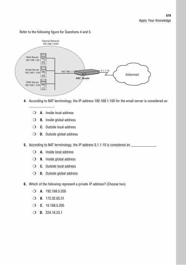
Apply Your Knowledge679
Refer to the following figure for Questions 4 and 5.
Web Server192.168.1.50
Internal Network192.168.1.0/24
DNS Server192.168.1.150
Email Server192.168.1.100
Internet5.1.1.10192.168.1.1
NAT_Router
4. According to NAT terminology, the IP address 192.168.1.100 for the email server is considered an______________.
❍ A. Inside local address
❍ B. Inside global address
❍ C. Outside local address
❍ D. Outside global address
5. According to NAT terminology, the IP address 5.1.1.10 is considered an ______________.
❍ A. Inside local address
❍ B. Inside global address
❍ C. Outside local address
❍ D. Outside global address
6. Which of the following represent a private IP address? (Choose two)
❍ A. 192.168.5.205
❍ B. 172.32.65.31
❍ C. 10.168.5.205
❍ D. 224.16.23.1
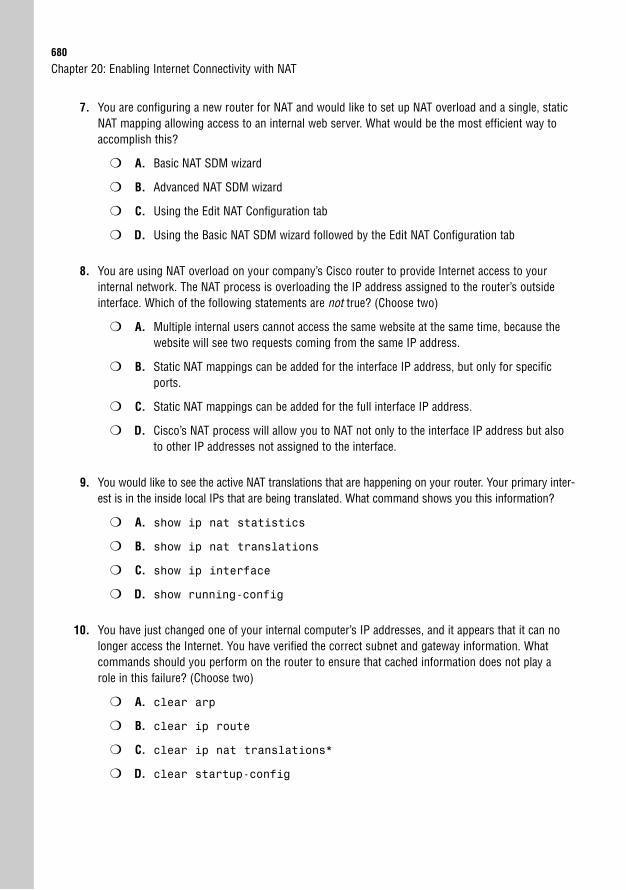
680
7. You are configuring a new router for NAT and would like to set up NAT overload and a single, staticNAT mapping allowing access to an internal web server. What would be the most efficient way toaccomplish this?
❍ A. Basic NAT SDM wizard
❍ B. Advanced NAT SDM wizard
❍ C. Using the Edit NAT Configuration tab
❍ D. Using the Basic NAT SDM wizard followed by the Edit NAT Configuration tab
8. You are using NAT overload on your company’s Cisco router to provide Internet access to yourinternal network. The NAT process is overloading the IP address assigned to the router’s outsideinterface. Which of the following statements are not true? (Choose two)
❍ A. Multiple internal users cannot access the same website at the same time, because thewebsite will see two requests coming from the same IP address.
❍ B. Static NAT mappings can be added for the interface IP address, but only for specificports.
❍ C. Static NAT mappings can be added for the full interface IP address.
❍ D. Cisco’s NAT process will allow you to NAT not only to the interface IP address but alsoto other IP addresses not assigned to the interface.
9. You would like to see the active NAT translations that are happening on your router. Your primary inter-est is in the inside local IPs that are being translated. What command shows you this information?
❍ A. show ip nat statistics
❍ B. show ip nat translations
❍ C. show ip interface
❍ D. show running-config
10. You have just changed one of your internal computer’s IP addresses, and it appears that it can nolonger access the Internet. You have verified the correct subnet and gateway information. Whatcommands should you perform on the router to ensure that cached information does not play arole in this failure? (Choose two)
❍ A. clear arp
❍ B. clear ip route
❍ C. clear ip nat translations*
❍ D. clear startup-config
Chapter 20: Enabling Internet Connectivity with NAT
Apply Your Knowledge681
Answers to Review Questions1. The three private address ranges are as follows:
Class A: 10.0.0.0 to 10.255.255.255
Class B: 172.16.0.0 to 172.31.255.255
Class C: 192.168.0.0 to 192.168.255.255
2. Static NAT is responsible for one-to-one translations. It is typically used to make private serversavailable on the Internet. Dynamic NAT is used to translate one pool of addresses to another. Thisis the least common form of NAT and is typically used to solve duplicate IP addresses when merg-ing two networks. Last is NAT overload. This form of NAT is the most popular because it allowsmany internal hosts to share a common public IP address.
3. The correct command is show ip nat translations from privileged mode.
4. You can enter the command clear ip nat translations * to erase the current NAT tablefrom memory. The table will naturally rebuild as users access the Internet.
5. Static NAT is most appropriate to make internal resources available to the outside world. This isbecause static NAT performs one-to-one translations allowing you to direct specific IP addressrequests to a public address to a privately addressed server.
Answers to Exam Questions1. A. Static NAT provides the best solution when you need a 1:1 translation from a private address or
port number to a public address or port number. Answer B is incorrect because dynamic NATallows many hosts to be translated at the same time. Answer C is incorrect because NAT overloadallows many internal hosts to share a single Internet IP address. Answer D is also incorrect.Standard routing does not work because private addresses are blocked from traversing theInternet.
2. C. NAT overload uses the source port number to send many unique requests out a single, public IPaddress. Answer A is incorrect because static NAT performs 1:1 translations from public to privateIP addresses. Answer B is incorrect because dynamic NAT performs many 1:1 translations withoutrequiring manual entries. Answer D is incorrect because NAT port mapping is not a valid form ofNAT.
3. A. You cannot create access lists for use with dynamic NAT from the Edit NAT Configuration tab.All other tasks can be performed from this window.
4. A. Inside local addresses encompass any address on your internal network that is translated to theoutside network via NAT. Answer B is incorrect because the inside global addresses are the IPsassigned to the outside interface of your router. Answer C is incorrect because the outside localaddresses are outside (Internet) addresses as they appear to a NAT device. Answer D is incorrectbecause the outside global addresses are standard Internet-attached devices.
682
5. B. The inside global addresses are the IPs assigned to the outside interface of your router. AnswerA is incorrect because inside local addresses encompass any address on your internal network thatis translated to the outside network via NAT. Answer C is incorrect because the outside localaddresses are outside (Internet) addresses as they appear to a NAT device. Answer D is incorrectbecause the outside global addresses are standard Internet-attached devices.
6. A, C. The private address ranges are 10.x.x.x, 172.16.x.x to 172.31.x.x, and 192.168.x.x. AnswersB and D fall outside these ranges.
7. B. The Advanced NAT wizard allows you to configure NAT overload and static NAT mappings at thesame time in the same wizard. If you use the Basic NAT wizard (Answer A), you would have to fol-low it up with the Edit NAT Configuration tab, which is not the most efficient way to configure NAT.This makes both Answers A and D incorrect. Answer C is incorrect because using the Edit NATConfiguration tab would require you to manually set up NAT overload and the static NAT mappingindividually, which is not the most efficient process.
8. A, C. When using NAT overload, multiple users can access the same website at the same timebecause the router uses unique source port numbers to distinguish each request. Also, when usingNAT with the IP address assigned to the outside interface, you cannot create a static NAT mappingfor the entire IP address, because this would make local router services unavailable. Both of theother statements are true.
9. B. The show ip nat translations command shows you all active translations currently inplace on your router. It includes the inside local and global and the outside local and globaladdresses for each translation. Answer A is incorrect because the show ip nat statisticscommand tells you only how many translations are currently happening. Answer C is incorrectbecause the show ip interface command does not give you any NAT statistics. Answer D isincorrect because the show running-config command tells you only the NAT configurationsyou have set up.
10. A, C. The clear arp command ensures that the router does not have the incorrect MACaddress mapped to the computer’s IP address. The clear ip nat translations * com-mand ensures that the cached NAT translations are not pointed to the wrong IP address. Answer Bis incorrect. The clear ip route is not necessary because the routing table did not changeand could cause downtime for your router. Answer D is incorrect because the clear startup-config does not remove any cached configuration.
Suggested Reading and Resources1. Cisco TAC NAT Configuration Syntax, http://www.cisco.com/univercd/cc/td/
doc/product/software/ios122/122cgcr/fipr_c/ipcprt1/1cfipadr.htm#wp1042290
2. Chris Ward and Jeremy Cioara. Exam Cram 2 CCNA Practice Questions. QuePublishing, 2004.
3. How Network Address Translation Works, http://computer.howstuffworks.com/nat1.htm
Chapter 20: Enabling Internet Connectivity with NAT
21C H A P T E R T W E N T Y - O N E
Command-Line NATImplementation
ObjectivesThis chapter covers the following Cisco-specific objectives for the “Implement, verify, and trou-bleshoot NAT and ACLs in a medium-size Enterprise branch office network” section of the 640-802 CCNA exam:
. Explain the basic operation of NAT
. Configure NAT for given network requirements
. Troubleshoot NAT issues
Introduction 686
Reviewing NAT Concepts 686
NAT Configurations 689
Static NAT 689
Scenario 1 690
Scenario 2 693
Dynamic Pool Translations 695
Scenario 3 696
NAT Overload 699
Scenario 4 699
Verifying NAT Operation 704
Troubleshooting NAT Operation 705
Chapter Summary 708
Key Terms 708
Apply Your Knowledge 709
Exercise 709
Exam Questions 712
Answers to Exam Questions 714
Suggested Readings and Resources 715
Outline

Study Strategies. Read the information presented in the chapter, paying special attention to tables, Notes,
and Exam Alerts.
. Focus on the Network Address Translation terminology. Understanding these terms isparamount to understanding the NAT configuration as a whole.
. When studying, focus on the static NAT configurations first, because these are the simplest.After you master this configuration, move on to NAT overload, followed by dynamic NAT.
686
IntroductionWelcome to NAT, Part 2. It’s now time to move from the soft and squishy GUI way of work-ing through NAT into the “real man’s way” of configuring NAT—from the command line.Performing the NAT configuration using the command-line interface puts hair on your chest(my apologies to the women using this style of configuration) and also gives you plenty moreflexibility than using the SDM GUI. This chapter builds on the foundational concepts and ter-minology from Chapter 20, “Enabling Internet Connectivity with NAT,” applying the con-cepts directly in command-line configuration. However, because the terminology of NAT isso unique and potentially confusing, I would like to review the terms with you before we begininto the configuration to keep you from having to flip back and forth between chapters. We’llthen walk through the command-line configuration of static NAT, dynamic NAT, and NAToverload.
Reviewing NAT ConceptsObjective:
. Explain the basic operation of NAT
Let’s start by reviewing the three forms of NAT:
. Static NAT: This form of NAT provides a one-to-one translation between IP address-es (typically public and private). These types of mappings are usually used to allowInternet clients to access internal servers. It can be either a full IP address translationor translations of individual TCP or UDP ports.
. Dynamic NAT: This form of NAT translates one pool of IP addresses to another.This is typically used as a temporary solution when companies or departments mergethat have duplicate address schemes. Of the three NAT forms, this is used the leastoften.
. NAT overload/PAT: This form of NAT allows multiple internal clients (typicallyusing private IP address) to share one or more public IP addresses. This is accom-plished by using unique source port numbers for each request coming from the publicIP address. This is the most common form of NAT.
In addition to reviewing the forms of NAT, I’d like to reiterate the terminology used when ref-erencing logical locations on the network. Understanding the NAT terminology is moreimportant now than in the SDM, because the SDM accomplishes most everything for youwithout requiring a deep understanding.
Chapter 21: Command-Line NAT Implementation
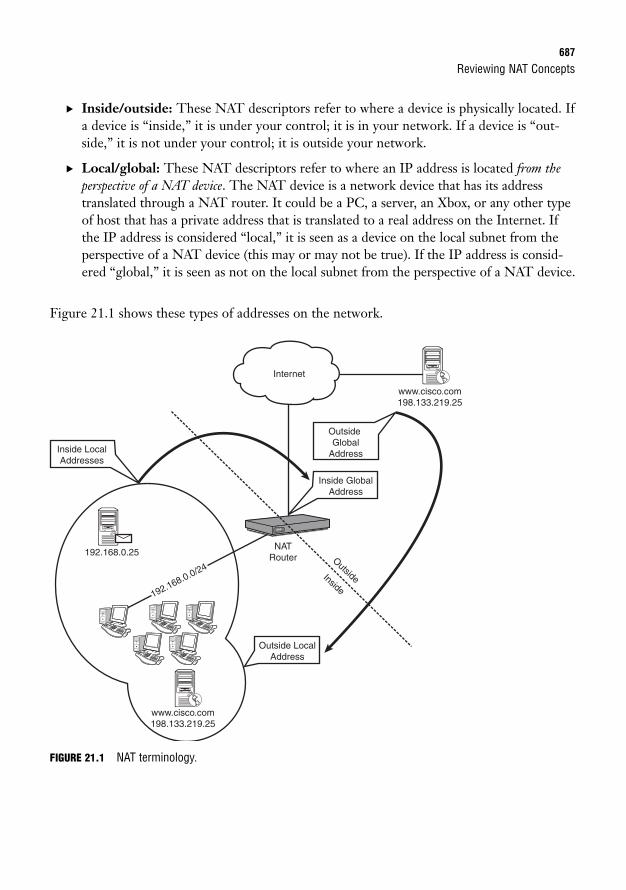
Reviewing NAT Concepts687
. Inside/outside: These NAT descriptors refer to where a device is physically located. Ifa device is “inside,” it is under your control; it is in your network. If a device is “out-side,” it is not under your control; it is outside your network.
. Local/global: These NAT descriptors refer to where an IP address is located from theperspective of a NAT device. The NAT device is a network device that has its addresstranslated through a NAT router. It could be a PC, a server, an Xbox, or any other typeof host that has a private address that is translated to a real address on the Internet. Ifthe IP address is considered “local,” it is seen as a device on the local subnet from theperspective of a NAT device (this may or may not be true). If the IP address is consid-ered “global,” it is seen as not on the local subnet from the perspective of a NAT device.
Figure 21.1 shows these types of addresses on the network.
www.cisco.com198.133.219.25
192.168.0.25
www.cisco.com198.133.219.25
Internet
NATRouter
Outside LocalAddress
Inside GlobalAddress
Inside LocalAddresses
OutsideGlobal
Address
192.168.0.0/24OutsideInside
FIGURE 21.1 NAT terminology.
688
. Inside local addresses: These addresses are the easiest to understand because theyrefer to everything inside your network. An address “inside” is physically located insideyour network. From the perspective of the NAT device, it is “local,” meaning that it isseen on the internal network. If an inside local address were to communicate withanother inside local address, that communication would be described as standard LANconnectivity. No routers would be needed.
. Inside global addresses: Now the terms begin to mix a little bit. Let’s break thisdown into the individual pieces: First, the address is “inside,” which means that it isphysically located on your network; it is under your control. “Global” means that it isseen as an IP address, not on the local subnet from the perspective of one of your NATdevices. Put all this together and you are left with the Internet valid IP addressassigned to your router that is directly connected to the Internet. This is where a fun-damental understanding of inside and outside can really help. If the address were an“outside global,” it would not be under your control, meaning that it could be any ofthe millions of devices attached to the Internet.
. Outside global addresses: Outside global addresses refer to devices that are physically“outside” your network—outside your control. These addresses are “global,” meaningthat the NAT devices on the inside of your network see these as nonlocal addresses.Put these two pieces together and you have a description of a standard Internet IPaddress.
. Outside local addresses: I saved the best for last. Outside local addresses confused mefor quite some time until I fully understood the capabilities of NAT. First let’s look atthe pieces. This address is physically “outside” your network, out of your control, outon the Internet. However, it appears to NAT devices as an IP address on the “local”subnet. What this describes is an Internet host translated as it comes through the NATrouter into your local network. You can think of this as “reverse NAT,” or just NAT inthe other direction. As shown in Figure 21.1, when the cisco.com web server speaks tothe internal hosts on the 192.168.0.0/24 network, they believe it to be co-located onthe local subnet with them. They come to this conclusion because the NAT routertranslates the outside global address to something local (perhaps 192.168.0.1, the NATgateway’s address).
Chapter 21: Command-Line NAT Implementation
Understanding the four NAT address descriptors listed is useful not only for the CCNA exam, but also forunderstanding any real-world NAT documentation.
TIP
NAT Configurations689
NAT ConfigurationsObjective:
. Configure NAT for given network requirements
Configuring NAT is not all that bad as long as you focus on your objective. I mention thisbecause the syntax can be quite daunting when you see all the options available to you.Advanced NAT configurations can get quite complex.
For the CCNA and ICND2 exams, you should be able to perform these three NAT-related tasks:
. Configure static NAT, translating an inside global address (or port number) to an inside localaddress, such as a web, DNS, or email server.
. Configure dynamic NAT, translating a pool of inside local addresses to a pool of outside globaladdresses.
. Configure NAT overload, translating many inside local addresses to a single inside global address.
Of these three, I would especially focus on the first and third configurations, because they are more com-mon in the real world.
TIP
With that said, it’s time to walk through these configurations one at a time.
Static NATAs discussed earlier, static NAT performs a one-to-one mapping from an inside local addressto an inside global address (in English: from a private to a public address). This could meanthat all traffic is translated between these addresses, or it could mean that you just choose cer-tain ports through which to translate. As I go through the syntax, I will expand a little moreon this. Figure 21.2 adds a network diagram to this syntax.
Before we get into the syntax, I want to make sure you’ve got the terms down. The internalnetwork consists of the 192.168.1.0/24 addresses. In NAT terms, these are all inside localaddresses. The router has a single Internet IP address of 5.1.1.10. This is considered the insideglobal address. The rest of the hosts on the Internet that will be accessing your internal serversall have outside global addresses.
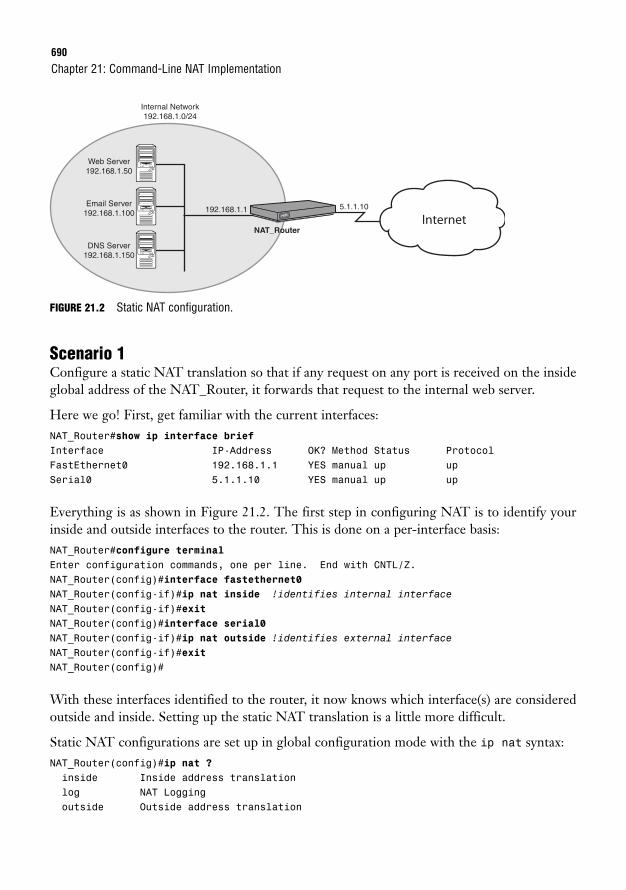
690
FIGURE 21.2 Static NAT configuration.
Scenario 1Configure a static NAT translation so that if any request on any port is received on the insideglobal address of the NAT_Router, it forwards that request to the internal web server.
Here we go! First, get familiar with the current interfaces:NAT_Router#show ip interface briefInterface IP-Address OK? Method Status ProtocolFastEthernet0 192.168.1.1 YES manual up upSerial0 5.1.1.10 YES manual up up
Everything is as shown in Figure 21.2. The first step in configuring NAT is to identify yourinside and outside interfaces to the router. This is done on a per-interface basis:NAT_Router#configure terminalEnter configuration commands, one per line. End with CNTL/Z.NAT_Router(config)#interface fastethernet0NAT_Router(config-if)#ip nat inside !identifies internal interfaceNAT_Router(config-if)#exitNAT_Router(config)#interface serial0NAT_Router(config-if)#ip nat outside !identifies external interfaceNAT_Router(config-if)#exitNAT_Router(config)#
With these interfaces identified to the router, it now knows which interface(s) are consideredoutside and inside. Setting up the static NAT translation is a little more difficult.
Static NAT configurations are set up in global configuration mode with the ip nat syntax:NAT_Router(config)#ip nat ?inside Inside address translationlog NAT Loggingoutside Outside address translation
Chapter 21: Command-Line NAT Implementation
Web Server192.168.1.50
Internal Network192.168.1.0/24
DNS Server192.168.1.150
Email Server192.168.1.100
Internet5.1.1.10192.168.1.1
NAT_Router
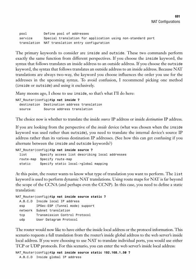
NAT Configurations691
pool Define pool of addressesservice Special translation for application using non-standard porttranslation NAT translation entry configuration
The primary keywords to consider are inside and outside. These two commands performexactly the same function from different perspectives. If you choose the inside keyword, thesyntax that follows translates an inside address to an outside address. If you choose the outsidekeyword, the syntax that follows translates an outside address to an inside address. Because NATtranslations are always two-way, the keyword you choose influences the order you use for theaddresses in the upcoming syntax. To avoid confusion, I recommend picking one method(inside or outside) and using it exclusively.
Many moons ago, I chose to use inside, so that’s what I’ll do here:NAT_Router(config)#ip nat inside ?destination Destination address translationsource Source address translation
The choice now is whether to translate the inside source IP address or inside destination IP address.
If you are looking from the perspective of the inside device (what was chosen when the insidekeyword was used rather than outside), you need to translate the internal device’s source IPaddress rather than its various destination IP addresses. (See how this can get confusing if youalternate between the inside and outside keywords?)NAT_Router(config)#ip nat inside source ?list Specify access list describing local addressesroute-map Specify route-mapstatic Specify static local->global mapping
At this point, the router wants to know what type of translation you want to perform. The listkeyword is used to perform dynamic NAT translations. Using route maps for NAT is far beyondthe scope of the CCNA (and perhaps even the CCNP). In this case, you need to define a statictranslation:NAT_Router(config)#ip nat inside source static ?A.B.C.D Inside local IP addressesp IPSec-ESP (Tunnel mode) supportnetwork Subnet translationtcp Transmission Control Protocoludp User Datagram Protocol
The router would now like to have either the inside local address or the protocol information. Thisscenario requests a full translation from the router’s inside global address to the web server’s insidelocal address. If you were choosing to use NAT to translate individual ports, you would use eitherTCP or UDP protocols. For this scenario, you can enter the web server’s inside local address:NAT_Router(config)#ip nat inside source static 192.168.1.50 ?A.B.C.D Inside global IP address

692
The router now needs to know what inside global address to use. In this example, the router’sinside global address is 5.1.1.10, which is the same IP address assigned to its Serial0 interface.In the real world, you have the option of purchasing blocks of IP addresses from your ISP. Youcan then translate each of these public addresses to an inside local address without the addresseven being assigned to an interface! All you need to do is create static NAT mappings for each ofthe addresses that you have been assigned by the ISP, and your router automatically respondsto them on the interface(s) you have designated as ip nat outside interfaces. This examplehas only a single IP address, so that’s plugged in here:NAT_Router(config)#ip nat inside source static 192.168.1.50 5.1.1.10 ?extendable Extend this translation when usedno-alias Do not create an alias for the global address<cr>
The extendable keyword enables you to have multiple inside global addresses mapped to thesame inside local address (all the mappings must be marked with the extendable keyword).The no-alias command enables you to set up a one-way NAT mapping from the inside tooutside. (The outside interface does not pass requests through to the inside host, but the insidehost is translated to the outside.) In this case, you’re not adding either of these special func-tions, so you can just press the Enter key. Awesome!
You can verify this configuration by using either the show running-config command or themuch more concise show ip nat translations:NAT_Router#show ip nat translationsPro Inside global Inside local Outside local Outside global--- 5.1.1.10 192.168.1.50 --- ---
Because this is a manually defined static entry, only the inside global and inside local fields arepopulated. If a host tried to connect to this entry (to access the internal web server), you wouldsee the outside local and outside global columns populate as well. Let me generate some traf-fic from the outside to show you what this will look like:NAT_Router#show ip nat translationsPro Inside global Inside local Outside local Outside global--- 5.1.1.10 192.168.1.50 --- ---tcp 5.1.1.10:80 192.168.1.50:80 52.1.9.3:3367 52.1.9.3:3367
In this case, an outside host accesses the 5.1.1.10 address with a web browser (TCP port 80).You can see that it keeps the original static entry and adds a line below it, showing the outsidelocal and outside global addresses of the external client. In this case, they are the same becausethe outside host appears as an outside host to the web server (the outside local address). Port3367 is the dynamically generated source port number of the outside host, and port 80 is thedestination port number sent to the web server. Scenario 1 accomplished!
Chapter 21: Command-Line NAT Implementation
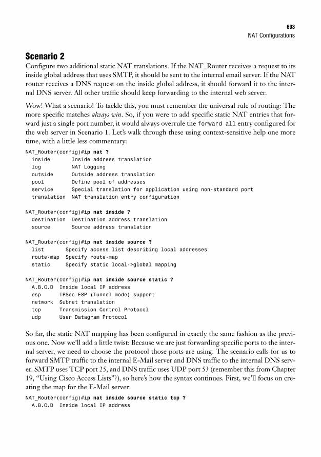
NAT Configurations693
Scenario 2Configure two additional static NAT translations. If the NAT_Router receives a request to itsinside global address that uses SMTP, it should be sent to the internal email server. If the NATrouter receives a DNS request on the inside global address, it should forward it to the inter-nal DNS server. All other traffic should keep forwarding to the internal web server.
Wow! What a scenario! To tackle this, you must remember the universal rule of routing: Themore specific matches always win. So, if you were to add specific static NAT entries that for-ward just a single port number, it would always overrule the forward all entry configured forthe web server in Scenario 1. Let’s walk through these using context-sensitive help one moretime, with a little less commentary:NAT_Router(config)#ip nat ?inside Inside address translationlog NAT Loggingoutside Outside address translationpool Define pool of addressesservice Special translation for application using non-standard porttranslation NAT translation entry configuration
NAT_Router(config)#ip nat inside ?destination Destination address translationsource Source address translation
NAT_Router(config)#ip nat inside source ?list Specify access list describing local addressesroute-map Specify route-mapstatic Specify static local->global mapping
NAT_Router(config)#ip nat inside source static ?A.B.C.D Inside local IP addressesp IPSec-ESP (Tunnel mode) supportnetwork Subnet translationtcp Transmission Control Protocoludp User Datagram Protocol
So far, the static NAT mapping has been configured in exactly the same fashion as the previ-ous one. Now we’ll add a little twist: Because we are just forwarding specific ports to the inter-nal server, we need to choose the protocol those ports are using. The scenario calls for us toforward SMTP traffic to the internal E-Mail server and DNS traffic to the internal DNS serv-er. SMTP uses TCP port 25, and DNS traffic uses UDP port 53 (remember this from Chapter19, “Using Cisco Access Lists”?), so here’s how the syntax continues. First, we’ll focus on cre-ating the map for the E-Mail server:NAT_Router(config)#ip nat inside source static tcp ?A.B.C.D Inside local IP address
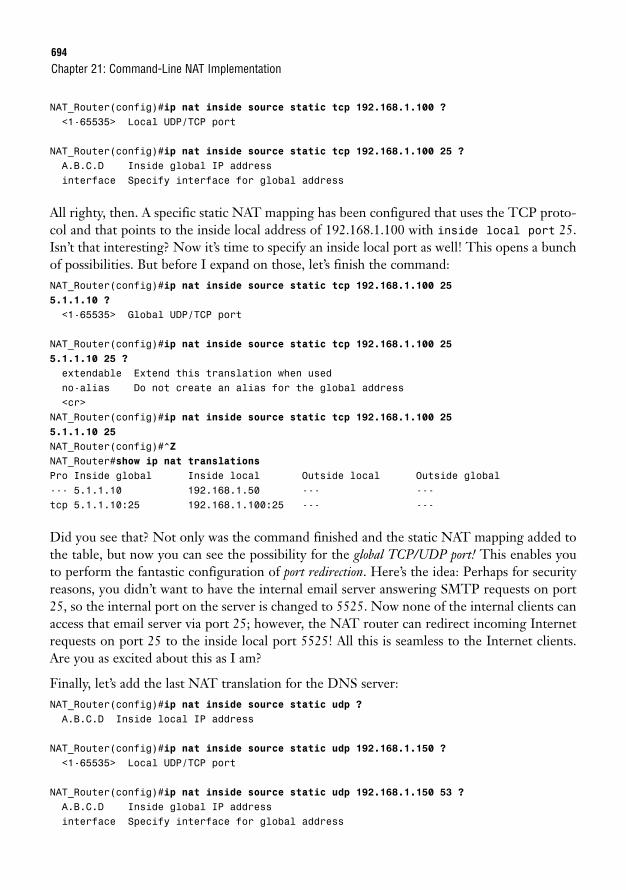
694
NAT_Router(config)#ip nat inside source static tcp 192.168.1.100 ?<1-65535> Local UDP/TCP port
NAT_Router(config)#ip nat inside source static tcp 192.168.1.100 25 ?A.B.C.D Inside global IP addressinterface Specify interface for global address
All righty, then. A specific static NAT mapping has been configured that uses the TCP proto-col and that points to the inside local address of 192.168.1.100 with inside local port 25.Isn’t that interesting? Now it’s time to specify an inside local port as well! This opens a bunchof possibilities. But before I expand on those, let’s finish the command:NAT_Router(config)#ip nat inside source static tcp 192.168.1.100 255.1.1.10 ?
<1-65535> Global UDP/TCP port
NAT_Router(config)#ip nat inside source static tcp 192.168.1.100 255.1.1.10 25 ?
extendable Extend this translation when usedno-alias Do not create an alias for the global address<cr>
NAT_Router(config)#ip nat inside source static tcp 192.168.1.100 255.1.1.10 25
NAT_Router(config)#^ZNAT_Router#show ip nat translationsPro Inside global Inside local Outside local Outside global--- 5.1.1.10 192.168.1.50 --- ---tcp 5.1.1.10:25 192.168.1.100:25 --- ---
Did you see that? Not only was the command finished and the static NAT mapping added tothe table, but now you can see the possibility for the global TCP/UDP port! This enables youto perform the fantastic configuration of port redirection. Here’s the idea: Perhaps for securityreasons, you didn’t want to have the internal email server answering SMTP requests on port25, so the internal port on the server is changed to 5525. Now none of the internal clients canaccess that email server via port 25; however, the NAT router can redirect incoming Internetrequests on port 25 to the inside local port 5525! All this is seamless to the Internet clients.Are you as excited about this as I am?
Finally, let’s add the last NAT translation for the DNS server:NAT_Router(config)#ip nat inside source static udp ?A.B.C.D Inside local IP address
NAT_Router(config)#ip nat inside source static udp 192.168.1.150 ?<1-65535> Local UDP/TCP port
NAT_Router(config)#ip nat inside source static udp 192.168.1.150 53 ?A.B.C.D Inside global IP addressinterface Specify interface for global address
Chapter 21: Command-Line NAT Implementation
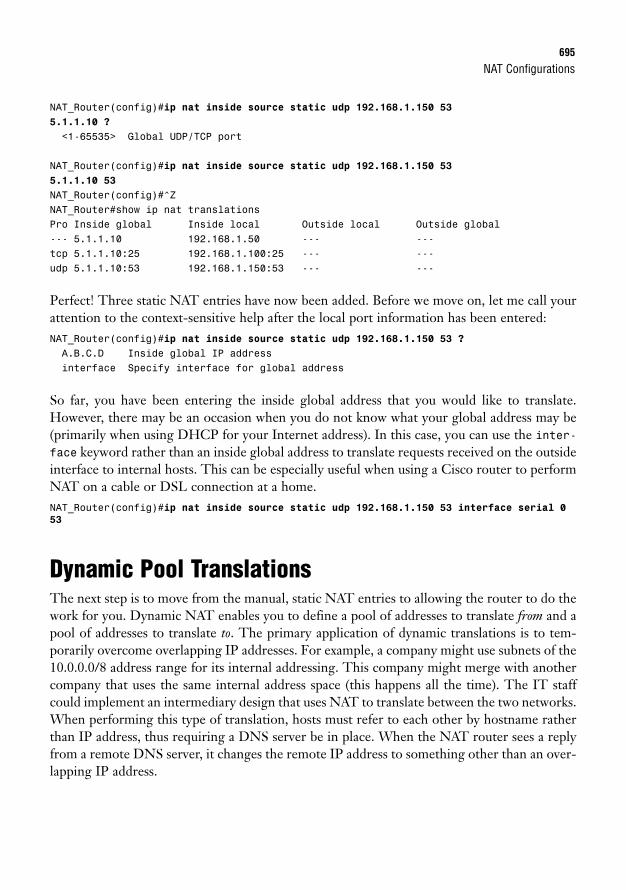
NAT Configurations695
NAT_Router(config)#ip nat inside source static udp 192.168.1.150 535.1.1.10 ?
<1-65535> Global UDP/TCP port
NAT_Router(config)#ip nat inside source static udp 192.168.1.150 535.1.1.10 53
NAT_Router(config)#^ZNAT_Router#show ip nat translationsPro Inside global Inside local Outside local Outside global--- 5.1.1.10 192.168.1.50 --- ---tcp 5.1.1.10:25 192.168.1.100:25 --- ---udp 5.1.1.10:53 192.168.1.150:53 --- ---
Perfect! Three static NAT entries have now been added. Before we move on, let me call yourattention to the context-sensitive help after the local port information has been entered:NAT_Router(config)#ip nat inside source static udp 192.168.1.150 53 ?A.B.C.D Inside global IP addressinterface Specify interface for global address
So far, you have been entering the inside global address that you would like to translate.However, there may be an occasion when you do not know what your global address may be(primarily when using DHCP for your Internet address). In this case, you can use the inter-face keyword rather than an inside global address to translate requests received on the outsideinterface to internal hosts. This can be especially useful when using a Cisco router to performNAT on a cable or DSL connection at a home.NAT_Router(config)#ip nat inside source static udp 192.168.1.150 53 interface serial 0
53
Dynamic Pool TranslationsThe next step is to move from the manual, static NAT entries to allowing the router to do thework for you. Dynamic NAT enables you to define a pool of addresses to translate from and apool of addresses to translate to. The primary application of dynamic translations is to tem-porarily overcome overlapping IP addresses. For example, a company might use subnets of the10.0.0.0/8 address range for its internal addressing. This company might merge with anothercompany that uses the same internal address space (this happens all the time). The IT staffcould implement an intermediary design that uses NAT to translate between the two networks.When performing this type of translation, hosts must refer to each other by hostname ratherthan IP address, thus requiring a DNS server be in place. When the NAT router sees a replyfrom a remote DNS server, it changes the remote IP address to something other than an over-lapping IP address.
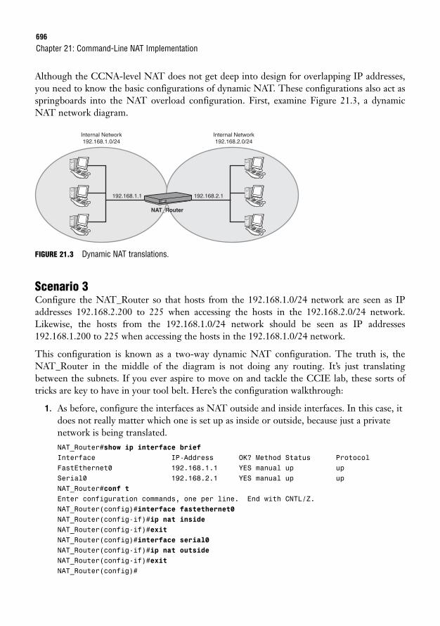
696
Although the CCNA-level NAT does not get deep into design for overlapping IP addresses,you need to know the basic configurations of dynamic NAT. These configurations also act asspringboards into the NAT overload configuration. First, examine Figure 21.3, a dynamicNAT network diagram.
Chapter 21: Command-Line NAT Implementation
Internal Network192.168.1.0/24
Internal Network192.168.2.0/24
192.168.1.1 192.168.2.1
NAT_Router
FIGURE 21.3 Dynamic NAT translations.
Scenario 3Configure the NAT_Router so that hosts from the 192.168.1.0/24 network are seen as IPaddresses 192.168.2.200 to 225 when accessing the hosts in the 192.168.2.0/24 network.Likewise, the hosts from the 192.168.1.0/24 network should be seen as IP addresses192.168.1.200 to 225 when accessing the hosts in the 192.168.1.0/24 network.
This configuration is known as a two-way dynamic NAT configuration. The truth is, theNAT_Router in the middle of the diagram is not doing any routing. It’s just translatingbetween the subnets. If you ever aspire to move on and tackle the CCIE lab, these sorts oftricks are key to have in your tool belt. Here’s the configuration walkthrough:
1. As before, configure the interfaces as NAT outside and inside interfaces. In this case, itdoes not really matter which one is set up as inside or outside, because just a privatenetwork is being translated.NAT_Router#show ip interface briefInterface IP-Address OK? Method Status ProtocolFastEthernet0 192.168.1.1 YES manual up upSerial0 192.168.2.1 YES manual up upNAT_Router#conf tEnter configuration commands, one per line. End with CNTL/Z.NAT_Router(config)#interface fastethernet0NAT_Router(config-if)#ip nat insideNAT_Router(config-if)#exitNAT_Router(config)#interface serial0NAT_Router(config-if)#ip nat outsideNAT_Router(config-if)#exitNAT_Router(config)#
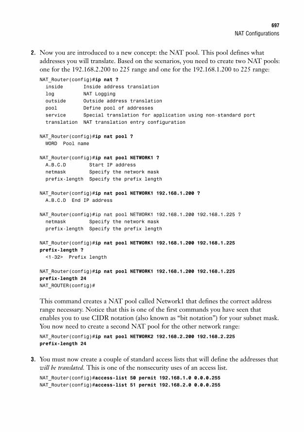
NAT Configurations697
2. Now you are introduced to a new concept: the NAT pool. This pool defines whataddresses you will translate. Based on the scenarios, you need to create two NAT pools:one for the 192.168.2.200 to 225 range and one for the 192.168.1.200 to 225 range:NAT_Router(config)#ip nat ?inside Inside address translationlog NAT Loggingoutside Outside address translationpool Define pool of addressesservice Special translation for application using non-standard porttranslation NAT translation entry configuration
NAT_Router(config)#ip nat pool ?WORD Pool name
NAT_Router(config)#ip nat pool NETWORK1 ?A.B.C.D Start IP addressnetmask Specify the network maskprefix-length Specify the prefix length
NAT_Router(config)#ip nat pool NETWORK1 192.168.1.200 ?A.B.C.D End IP address
NAT_Router(config)#ip nat pool NETWORK1 192.168.1.200 192.168.1.225 ?netmask Specify the network maskprefix-length Specify the prefix length
NAT_Router(config)#ip nat pool NETWORK1 192.168.1.200 192.168.1.225prefix-length ?
<1-32> Prefix length
NAT_Router(config)#ip nat pool NETWORK1 192.168.1.200 192.168.1.225prefix-length 24
NAT_ROUTER(config)#
This command creates a NAT pool called Network1 that defines the correct addressrange necessary. Notice that this is one of the first commands you have seen thatenables you to use CIDR notation (also known as “bit notation”) for your subnet mask.You now need to create a second NAT pool for the other network range:NAT_Router(config)#ip nat pool NETWORK2 192.168.2.200 192.168.2.225prefix-length 24
3. You must now create a couple of standard access lists that will define the addresses thatwill be translated. This is one of the nonsecurity uses of an access list.NAT_Router(config)#access-list 50 permit 192.168.1.0 0.0.0.255NAT_Router(config)#access-list 51 permit 192.168.2.0 0.0.0.255
698
4. Now you can put all the pieces together and turn on the NAT translation between thenetworks. The first thing is to define a translation going from the 192.168.1.0/24 sub-net to the 192.168.2.0/24 network:NAT_Router(config)#ip nat ?inside Inside address translationlog NAT Loggingoutside Outside address translationpool Define pool of addressesservice Special translation for application using non-standard porttranslation NAT translation entry configuration
NAT_Router(config)#ip nat inside ?destination Destination address translationsource Source address translation
NAT_Router(config)#ip nat inside source ?list Specify access list describing local addressesroute-map Specify route-mapstatic Specify static local->global mapping
NAT_Router(config)#ip nat inside source list ?<1-2699> Access list number for local addressesWORD Access list name for local addresses
NAT_Router(config)#ip nat inside source list 50 ?interface Specify interface for global addresspool Name pool of global addresses
NAT_Router(config)#ip nat inside source list 50 pool ?WORD Pool name for global addresses
NAT_Router(config)#ip nat inside source list 50 pool NETWORK2 ?overload Overload an address translation<cr>
NAT_Router(config)#ip nat inside source list 50 pool NETWORK2NAT_Router(config)#
If you were to read the preceding line of syntax in English, it would sound somethinglike this: “Translate the internal addresses defined in access list 50 into the pool ofaddresses defined in the NAT pool NETWORK2.” Keep a mental note of that over-load keyword you see in the final-context sensitive help; you’ll make use of that soon.For now, let’s define the translation going back the other way:NAT_Router(config)#ip nat outside source list 51 pool NETWORK1NAT_Router(config)#
Notice that this time an outside-to-inside translation is configured because the inter-face is marked as connected to the 192.168.2.0/24 subnet as the outside interface.
Chapter 21: Command-Line NAT Implementation
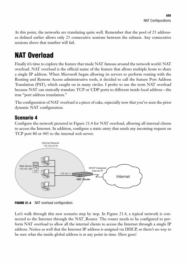
NAT Configurations699
At this point, the networks are translating quite well. Remember that the pool of 25 address-es defined earlier allows only 25 consecutive sessions between the subnets. Any consecutivesessions above that number will fail.
NAT OverloadFinally it’s time to explore the feature that made NAT famous around the network world: NAToverload. NAT overload is the official name of the feature that allows multiple hosts to sharea single IP address. When Microsoft began allowing its servers to perform routing with theRouting and Remote Access administrative tools, it decided to call the feature Port AddressTranslation (PAT), which caught on in many circles. I prefer to use the term NAT overloadbecause NAT can statically translate TCP or UDP ports to different inside local address—thetrue “port address translation.”
The configuration of NAT overload is a piece of cake, especially now that you’ve seen the priordynamic NAT configuration.
Scenario 4Configure the network pictured in Figure 21.4 for NAT overload, allowing all internal clientsto access the Internet. In addition, configure a static entry that sends any incoming request onTCP port 80 or 443 to the internal web server.
Internal Network172.16.0.0/16
Web Server172.16.1.80
Internet
DHCP-AssignedInternet IP
172.16.1.1
NAT_Router
FIGURE 21.4 NAT overload configuration.
Let’s walk through this new scenario step by step. In Figure 21.4, a typical network is con-nected to the Internet through the NAT_Router. The router needs to be configured to per-form NAT overload to allow all the internal clients to access the Internet through a single IPaddress. Notice as well that the Internet IP address is assigned via DHCP, so there’s no way tobe sure what the inside global address is at any point in time. Here goes!
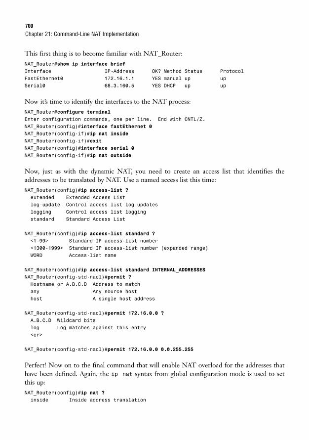
700
This first thing is to become familiar with NAT_Router:NAT_Router#show ip interface briefInterface IP-Address OK? Method Status ProtocolFastEthernet0 172.16.1.1 YES manual up upSerial0 68.3.160.5 YES DHCP up up
Now it’s time to identify the interfaces to the NAT process:NAT_Router#configure terminalEnter configuration commands, one per line. End with CNTL/Z.NAT_Router(config)#interface fastEthernet 0NAT_Router(config-if)#ip nat insideNAT_Router(config-if)#exitNAT_Router(config)#interface serial 0NAT_Router(config-if)#ip nat outside
Now, just as with the dynamic NAT, you need to create an access list that identifies theaddresses to be translated by NAT. Use a named access list this time:NAT_Router(config)#ip access-list ?extended Extended Access Listlog-update Control access list log updateslogging Control access list loggingstandard Standard Access List
NAT_Router(config)#ip access-list standard ?<1-99> Standard IP access-list number<1300-1999> Standard IP access-list number (expanded range)WORD Access-list name
NAT_Router(config)#ip access-list standard INTERNAL_ADDRESSESNAT_Router(config-std-nacl)#permit ?Hostname or A.B.C.D Address to matchany Any source hosthost A single host address
NAT_Router(config-std-nacl)#permit 172.16.0.0 ?A.B.C.D Wildcard bitslog Log matches against this entry<cr>
NAT_Router(config-std-nacl)#permit 172.16.0.0 0.0.255.255
Perfect! Now on to the final command that will enable NAT overload for the addresses thathave been defined. Again, the ip nat syntax from global configuration mode is used to set this up:NAT_Router(config)#ip nat ?inside Inside address translation
Chapter 21: Command-Line NAT Implementation
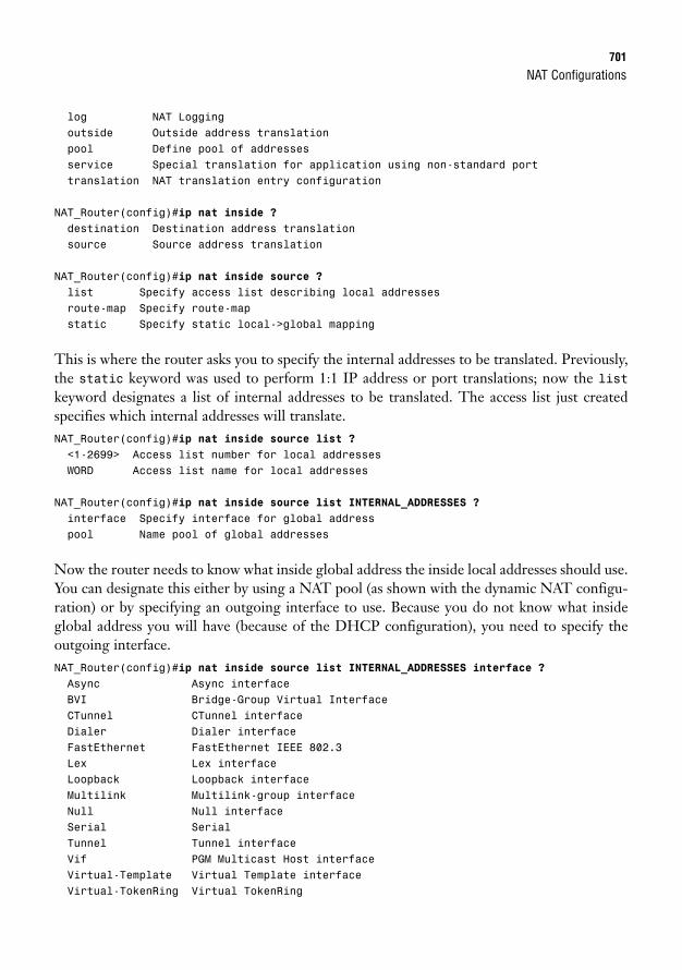
NAT Configurations701
log NAT Loggingoutside Outside address translationpool Define pool of addressesservice Special translation for application using non-standard porttranslation NAT translation entry configuration
NAT_Router(config)#ip nat inside ?destination Destination address translationsource Source address translation
NAT_Router(config)#ip nat inside source ?list Specify access list describing local addressesroute-map Specify route-mapstatic Specify static local->global mapping
This is where the router asks you to specify the internal addresses to be translated. Previously,the static keyword was used to perform 1:1 IP address or port translations; now the listkeyword designates a list of internal addresses to be translated. The access list just createdspecifies which internal addresses will translate.NAT_Router(config)#ip nat inside source list ?<1-2699> Access list number for local addressesWORD Access list name for local addresses
NAT_Router(config)#ip nat inside source list INTERNAL_ADDRESSES ?interface Specify interface for global addresspool Name pool of global addresses
Now the router needs to know what inside global address the inside local addresses should use.You can designate this either by using a NAT pool (as shown with the dynamic NAT configu-ration) or by specifying an outgoing interface to use. Because you do not know what insideglobal address you will have (because of the DHCP configuration), you need to specify theoutgoing interface.NAT_Router(config)#ip nat inside source list INTERNAL_ADDRESSES interface ?Async Async interfaceBVI Bridge-Group Virtual InterfaceCTunnel CTunnel interfaceDialer Dialer interfaceFastEthernet FastEthernet IEEE 802.3Lex Lex interfaceLoopback Loopback interfaceMultilink Multilink-group interfaceNull Null interfaceSerial SerialTunnel Tunnel interfaceVif PGM Multicast Host interfaceVirtual-Template Virtual Template interfaceVirtual-TokenRing Virtual TokenRing
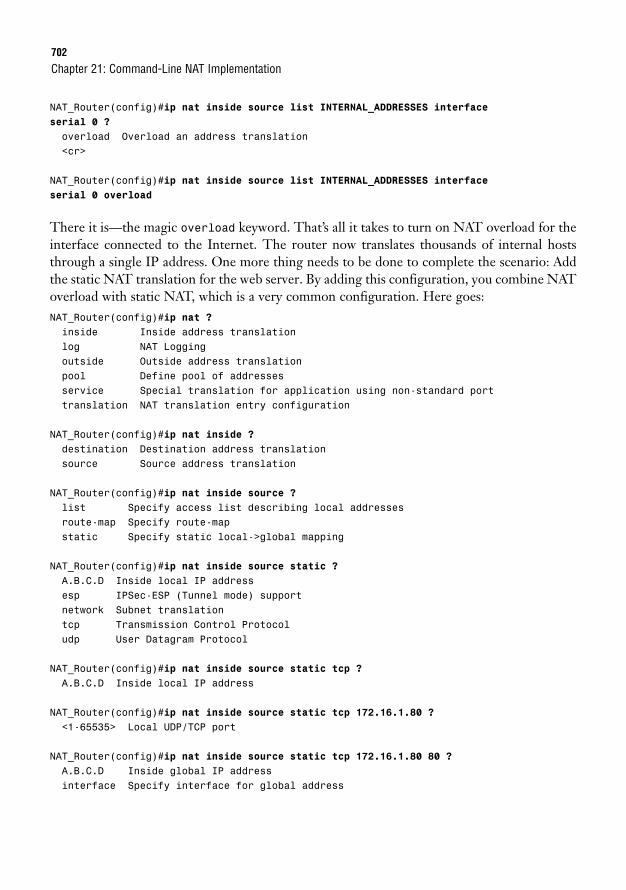
702
NAT_Router(config)#ip nat inside source list INTERNAL_ADDRESSES interfaceserial 0 ?
overload Overload an address translation<cr>
NAT_Router(config)#ip nat inside source list INTERNAL_ADDRESSES interfaceserial 0 overload
There it is—the magic overload keyword. That’s all it takes to turn on NAT overload for theinterface connected to the Internet. The router now translates thousands of internal hoststhrough a single IP address. One more thing needs to be done to complete the scenario: Addthe static NAT translation for the web server. By adding this configuration, you combine NAToverload with static NAT, which is a very common configuration. Here goes:NAT_Router(config)#ip nat ?inside Inside address translationlog NAT Loggingoutside Outside address translationpool Define pool of addressesservice Special translation for application using non-standard porttranslation NAT translation entry configuration
NAT_Router(config)#ip nat inside ?destination Destination address translationsource Source address translation
NAT_Router(config)#ip nat inside source ?list Specify access list describing local addressesroute-map Specify route-mapstatic Specify static local->global mapping
NAT_Router(config)#ip nat inside source static ?A.B.C.D Inside local IP addressesp IPSec-ESP (Tunnel mode) supportnetwork Subnet translationtcp Transmission Control Protocoludp User Datagram Protocol
NAT_Router(config)#ip nat inside source static tcp ?A.B.C.D Inside local IP address
NAT_Router(config)#ip nat inside source static tcp 172.16.1.80 ?<1-65535> Local UDP/TCP port
NAT_Router(config)#ip nat inside source static tcp 172.16.1.80 80 ?A.B.C.D Inside global IP addressinterface Specify interface for global address
Chapter 21: Command-Line NAT Implementation
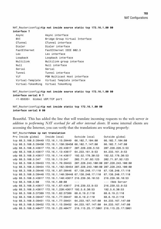
NAT Configurations703
NAT_Router(config)#ip nat inside source static tcp 172.16.1.80 80interface ?
Async Async interfaceBVI Bridge-Group Virtual InterfaceCTunnel CTunnel interfaceDialer Dialer interfaceFastEthernet FastEthernet IEEE 802.3Lex Lex interfaceLoopback Loopback interfaceMultilink Multilink-group interfaceNull Null interfaceSerial SerialTunnel Tunnel interfaceVif PGM Multicast Host interfaceVirtual-Template Virtual Template interfaceVirtual-TokenRing Virtual TokenRing
NAT_Router(config)#ip nat inside source static tcp 172.16.1.80 80interface serial 0 ?
<1-65535> Global UDP/TCP port
NAT_Router(config)#ip nat inside static tcp 172.16.1.80 80interface serial 0 80
Beautiful. This has added the line that will translate incoming requests to the web server inaddition to performing NAT overload for all other internal clients. If some internal clients areaccessing the Internet, you can verify that the translations are working properly:NAT_Router#show ip nat translationPro Inside global Inside local Outside local Outside globaltcp 68.3.160.5:39449 172.16.1.15:39449 66.102.7.104:80 66.102.7.104:80tcp 68.3.160.5:39450 172.16.1.150:39450 66.102.7.147:80 66.102.7.147:80udp 68.3.160.5:43617 172.16.1.25:43617 207.228.226.5:53 207.228.226.5:53udp 68.3.160.5:43617 172.16.1.13:43617 64.233.161.9:53 64.233.161.9:53udp 68.3.160.5:43617 172.16.1.14:43617 192.52.178.30:53 192.52.178.30:53udp 68.3.160.5:347 172.16.1.13:347 202.71.97.92:123 202.71.97.92:123tcp 68.3.160.5:39453 172.16.1.76:39453 207.228.243.100:80 207.228.243.100:80tcp 68.3.160.5:39454 172.16.1.182:39454 207.228.243.100:80 207.228.243.100:80tcp 68.3.160.5:39446 172.16.1.87:39446 67.138.240.17:110 67.138.240.17:110tcp 68.3.160.5:39448 172.16.1.140:39448 67.138.240.17:110 67.138.240.17:110udp 68.3.160.5:43617 172.16.1.140:43617 216.239.36.10:53 216.239.36.10:53tcp 68.3.160.5:80 172.16.1.80:80 --- --- !Web Serverudp 68.3.160.5:43617 172.16.1.67:43617 216.239.53.9:53 216.239.53.9:53udp 68.3.160.5:43617 172.16.1.220:43617 192.5.6.30:53 192.5.6.30:53tcp 68.3.160.5:37389 172.16.1.82:37389 68.6.19.2:110 68.6.19.2:110tcp 68.3.160.5:39447 172.16.1.77:39447 68.6.19.2:110 68.6.19.2:110tcp 68.3.160.5:39451 172.16.1.77:39451 64.233.167.147:80 64.233.167.147:80tcp 68.3.160.5:39452 172.16.1.15:39452 64.233.167.147:80 64.233.167.147:80udp 68.3.160.5:40477 172.16.1.25:40477 216.115.25.17:5061 216.115.25.17:5061
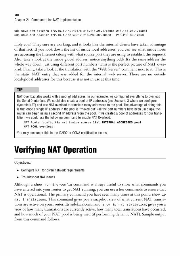
704
udp 68.3.160.5:40478 172.16.1.142:40478 216.115.25.17:5061 216.115.25.17:5061udp 68.3.160.5:43617 172.16.1.150:43617 216.239.32.10:53 216.239.32.10:53
Holy cow! They sure are working, and it looks like the internal clients have taken advantageof that fact. If you look down the list of inside local addresses, you can see what inside hostsare accessing the Internet (along with what source port they are using to establish the request).Also, take a look at the inside global address; notice anything odd? It’s the same address thewhole way down, just using different port numbers. This is the perfect picture of NAT over-load. Finally, take a look at the translation with the “Web Server” comment next to it. This isthe static NAT entry that was added for the internal web server. There are no outsidelocal/global addresses for this because it is not in use at this time.
Chapter 21: Command-Line NAT Implementation
NAT Overload also works with a pool of addresses. In our example, we configured everything to overloadthe Serial 0 interface. We could also create a pool of IP addresses (see Scenario 3 where we configuredynamic NAT) and use NAT overload to translate many addresses to the pool. The advantage of doing thisis that once a single IP address in the pool is “maxed out” (all the port numbers have been used up), therouter can begin using a second IP address from the pool. If we created a pool of addresses for our trans-lation, we could use the following command to enable NAT Overload:
NAT_Router(config)#ip nat inside source list INTERNAL_ADDRESSES poolNAT_POOL overload
You may encounter this in the ICND2 or CCNA certification exams.
TIP
Verifying NAT OperationObjectives:
. Configure NAT for given network requirements
. Troubleshoot NAT issues
Although a show running-config command is always useful to show what commands youhave entered into your router to get NAT running, you can use a few commands to ensure thatNAT is operational. The primary command you have seen many times at this point: show ipnat translations. This command gives you a snapshot view of what current NAT transla-tions are active on your router. Its sidekick command, show ip nat statistics, gives you aview of how many translations are currently active, how many total translations have occurred,and how much of your NAT pool is being used (if performing dynamic NAT). Sample outputfrom this command follows:
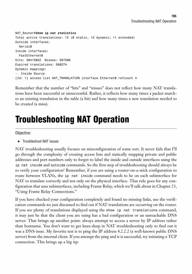
Troubleshooting NAT Operation705
NAT_Router#show ip nat statisticsTotal active translations: 12 (0 static, 12 dynamic; 11 extended)Outside interfaces:Serial0
Inside interfaces:FastEthernet0
Hits: 38415022 Misses: 567286Expired translations: 568274Dynamic mappings:-- Inside Source[Id: 1] access-list NAT_TRANSLATION interface Ethernet0 refcount 4
Remember that the number of “hits” and “misses” does not reflect how many NAT transla-tions have been successful or unsuccessful. Rather, it reflects how many times a packet match-es an existing translation in the table (a hit) and how many times a new translation needed tobe created (a miss).
Troubleshooting NAT OperationObjective:
. Troubleshoot NAT issues
NAT troubleshooting usually focuses on misconfiguration of some sort. It never fails that I’llgo through the complexity of creating access lists and statically mapping private and publicaddresses and port numbers only to forget to label the inside and outside interfaces using theip nat inside and outside commands. So the first step of troubleshooting should always beto verify your configuration! Remember, if you are using a router-on-a-stick configuration toroute between VLANs, the ip nat inside command needs to be on each subinterface forNAT to translate correctly and not only on the physical interface. That rule goes for any con-figuration that uses subinterfaces, including Frame Relay, which we’ll talk about in Chapter 23,“Using Frame Relay Connections.”
If you have checked your configuration completely and found no missing links, use the verifi-cation commands we just discussed to find out if NAT translations are occurring on the router.If you see plenty of translations displayed using the show ip nat translations command,it may just be that the client you are using has a bad configuration or an unreachable DNSserver. That brings up another point: always attempt to access a server by IP address ratherthan hostname. You don’t want to get knee-deep in NAT troubleshooting only to find out itwas a DNS issue. My favorite test is to ping the IP address 4.2.2.2 (a well-known public DNSserver) from the internal client. If you attempt the ping and it is successful, try initiating a TCPconnection. This brings up a big tip:
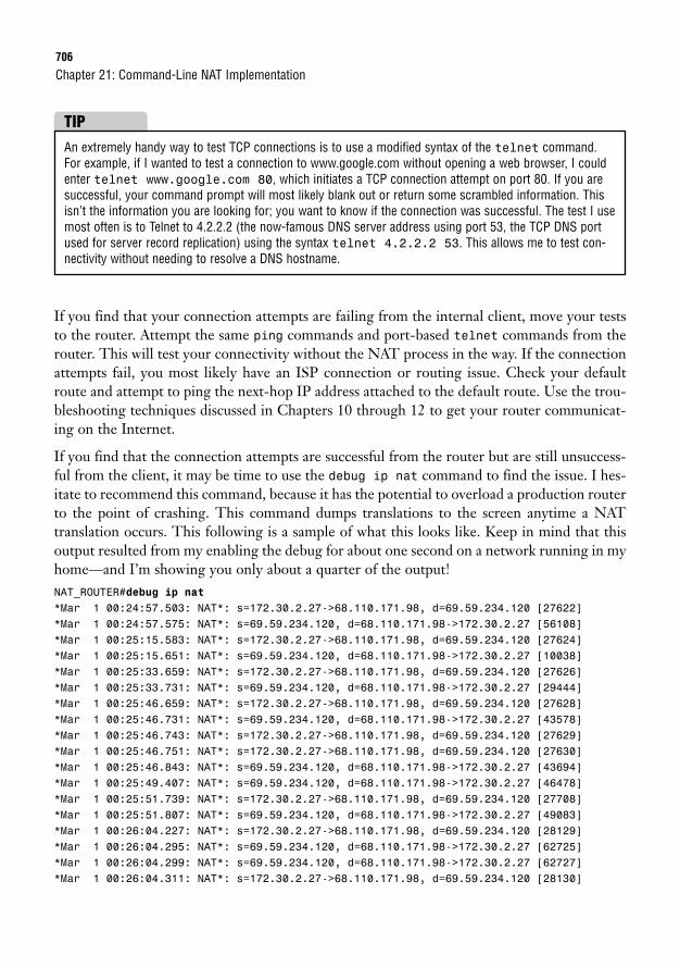
706
If you find that your connection attempts are failing from the internal client, move your teststo the router. Attempt the same ping commands and port-based telnet commands from therouter. This will test your connectivity without the NAT process in the way. If the connectionattempts fail, you most likely have an ISP connection or routing issue. Check your defaultroute and attempt to ping the next-hop IP address attached to the default route. Use the trou-bleshooting techniques discussed in Chapters 10 through 12 to get your router communicat-ing on the Internet.
If you find that the connection attempts are successful from the router but are still unsuccess-ful from the client, it may be time to use the debug ip nat command to find the issue. I hes-itate to recommend this command, because it has the potential to overload a production routerto the point of crashing. This command dumps translations to the screen anytime a NATtranslation occurs. This following is a sample of what this looks like. Keep in mind that thisoutput resulted from my enabling the debug for about one second on a network running in myhome—and I’m showing you only about a quarter of the output!NAT_ROUTER#debug ip nat*Mar 1 00:24:57.503: NAT*: s=172.30.2.27->68.110.171.98, d=69.59.234.120 [27622]*Mar 1 00:24:57.575: NAT*: s=69.59.234.120, d=68.110.171.98->172.30.2.27 [56108]*Mar 1 00:25:15.583: NAT*: s=172.30.2.27->68.110.171.98, d=69.59.234.120 [27624]*Mar 1 00:25:15.651: NAT*: s=69.59.234.120, d=68.110.171.98->172.30.2.27 [10038]*Mar 1 00:25:33.659: NAT*: s=172.30.2.27->68.110.171.98, d=69.59.234.120 [27626]*Mar 1 00:25:33.731: NAT*: s=69.59.234.120, d=68.110.171.98->172.30.2.27 [29444]*Mar 1 00:25:46.659: NAT*: s=172.30.2.27->68.110.171.98, d=69.59.234.120 [27628]*Mar 1 00:25:46.731: NAT*: s=69.59.234.120, d=68.110.171.98->172.30.2.27 [43578]*Mar 1 00:25:46.743: NAT*: s=172.30.2.27->68.110.171.98, d=69.59.234.120 [27629]*Mar 1 00:25:46.751: NAT*: s=172.30.2.27->68.110.171.98, d=69.59.234.120 [27630]*Mar 1 00:25:46.843: NAT*: s=69.59.234.120, d=68.110.171.98->172.30.2.27 [43694]*Mar 1 00:25:49.407: NAT*: s=69.59.234.120, d=68.110.171.98->172.30.2.27 [46478]*Mar 1 00:25:51.739: NAT*: s=172.30.2.27->68.110.171.98, d=69.59.234.120 [27708]*Mar 1 00:25:51.807: NAT*: s=69.59.234.120, d=68.110.171.98->172.30.2.27 [49083]*Mar 1 00:26:04.227: NAT*: s=172.30.2.27->68.110.171.98, d=69.59.234.120 [28129]*Mar 1 00:26:04.295: NAT*: s=69.59.234.120, d=68.110.171.98->172.30.2.27 [62725]*Mar 1 00:26:04.299: NAT*: s=69.59.234.120, d=68.110.171.98->172.30.2.27 [62727]*Mar 1 00:26:04.311: NAT*: s=172.30.2.27->68.110.171.98, d=69.59.234.120 [28130]
Chapter 21: Command-Line NAT Implementation
An extremely handy way to test TCP connections is to use a modified syntax of the telnet command.For example, if I wanted to test a connection to www.google.com without opening a web browser, I couldenter telnet www.google.com 80, which initiates a TCP connection attempt on port 80. If you aresuccessful, your command prompt will most likely blank out or return some scrambled information. Thisisn’t the information you are looking for; you want to know if the connection was successful. The test I usemost often is to Telnet to 4.2.2.2 (the now-famous DNS server address using port 53, the TCP DNS portused for server record replication) using the syntax telnet 4.2.2.2 53. This allows me to test con-nectivity without needing to resolve a DNS hostname.
TIP
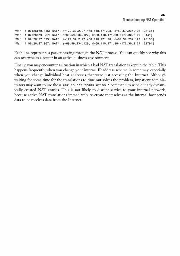
Troubleshooting NAT Operation707
*Mar 1 00:26:09.815: NAT*: s=172.30.2.27->68.110.171.98, d=69.59.234.120 [28131]*Mar 1 00:26:09.887: NAT*: s=69.59.234.120, d=68.110.171.98->172.30.2.27 [3141]*Mar 1 00:26:27.895: NAT*: s=172.30.2.27->68.110.171.98, d=69.59.234.120 [28133]*Mar 1 00:26:27.967: NAT*: s=69.59.234.120, d=68.110.171.98->172.30.2.27 [22794]
Each line represents a packet passing through the NAT process. You can quickly see why thiscan overwhelm a router in an active business environment.
Finally, you may encounter a situation in which a bad NAT translation is kept in the table. Thishappens frequently when you change your internal IP address scheme in some way, especiallywhen you change individual host addresses that were just accessing the Internet. Althoughwaiting for some time for the translations to time out solves the problem, impatient adminis-trators may want to use the clear ip nat translation * command to wipe out any dynam-ically created NAT entries. This is not likely to disrupt service to your internal network,because active NAT translations immediately re-create themselves as the internal host sendsdata to or receives data from the Internet.
708
Chapter SummaryNetwork Address Translation (NAT) has become so successful for prolonging the life of IPv4that it has now become a prohibitor of a progressive move to TCP/IP version 6. Because of itswidespread use, NAT features have grown over the years to provide a solution to almost anynetwork situation.
A company planning to use NAT will deploy one of the three private address ranges on itsinternal network, which are prevented from routing to the Internet. The company will thenuse one of the three forms of NAT—static NAT, dynamic NAT, or NAT overload—to trans-late these private ranges onto the Internet. Most networks use a combination of NAT overloadand static NAT to accomplish most major network objectives.
Most of the challenge with NAT is learning the terminology that describes the differentaddresses on a network. Inside local addresses are internal to a network. The inside globaladdress represents the public Internet address assigned to your router. Outside global address-es represent all the hosts outside your network attached to the Internet with Internet IPaddresses. Finally, outside local addresses represent hosts outside your network as they are seenby the internal NAT hosts.
Key Terms. Network Address Translation (NAT)
. Port Address Translation (PAT)
. Static NAT
. Dynamic NAT
. NAT overload
. Private IP addresses
. Public IP addresses
. Inside local address
. Inside global address
. Outside local address
. Outside global address
. Port redirection
. NAT pool
Chapter 21: Command-Line NAT Implementation
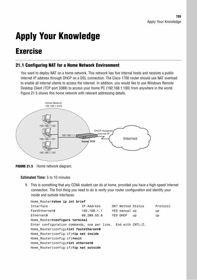
Apply Your Knowledge709
Apply Your Knowledge
Exercise
21.1 Configuring NAT for a Home Network Environment
You want to deploy NAT on a home network. This network has five internal hosts and receives a publicInternet IP address through DHCP on a DSL connection. The Cisco 1700 router should use NAT overloadto enable all internal clients to access the Internet. In addition, you would like to use Windows RemoteDesktop Client (TCP port 3389) to access your home PC (192.168.1.100) from anywhere in the world.Figure 21.5 shows this home network with relevant addressing details.
Home Network192.168.1.0/24
Internet
DHCP-AssignedInternet IP
192.168.1.1
192.168.1.100
192.168.1.101
192.168.1.102
Home_RTR
FIGURE 21.5 Home network diagram.
Estimated Time: 5 to 10 minutes
1. This is something that any CCNA student can do at home, provided you have a high-speed Internetconnection. The first thing you need to do is verify your router configuration and identify yourinside and outside interfaces:
Home_Router#show ip int briefInterface IP-Address OK? Method Status ProtocolFastEthernet0 192.168.1.1 YES manual up upEthernet0 68.209.55.8 YES DHCP up upHome_Router#configure terminalEnter configuration commands, one per line. End with CNTL/Z.Home_Router(config)#int fastethernet0Home_Router(config-if)#ip nat insideHome_Router(config-if)#exitHome_Router(config)#int ethernet0Home_Router(config-if)#ip nat outside
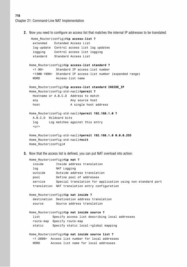
710
2. Now you need to configure an access list that matches the internal IP addresses to be translated:
Home_Router(config)#ip access-list ?extended Extended Access Listlog-update Control access list log updateslogging Control access list loggingstandard Standard Access List
Home_Router(config)#ip access-list standard ?<1-99> Standard IP access-list number<1300-1999> Standard IP access-list number (expanded range)WORD Access-list name
Home_Router(config)#ip access-list standard INSIDE_IPHome_Router(config-std-nacl)#permit ?Hostname or A.B.C.D Address to matchany Any source hosthost A single host address
Home_Router(config-std-nacl)#permit 192.168.1.0 ?A.B.C.D Wildcard bitslog Log matches against this entry<cr>
Home_Router(config-std-nacl)#permit 192.168.1.0 0.0.0.255Home_Router(config-std-nacl)#exitHome_Router(config)#
3. Now that the access list is defined, you can put NAT overload into action:
Home_Router(config)#ip nat ?inside Inside address translationlog NAT Loggingoutside Outside address translationpool Define pool of addressesservice Special translation for application using non-standard porttranslation NAT translation entry configuration
Home_Router(config)#ip nat inside ?destination Destination address translationsource Source address translation
Home_Router(config)#ip nat inside source ?list Specify access list describing local addressesroute-map Specify route-mapstatic Specify static local->global mapping
Home_Router(config)#ip nat inside source list ?<1-2699> Access list number for local addressesWORD Access list name for local addresses
Chapter 21: Command-Line NAT Implementation
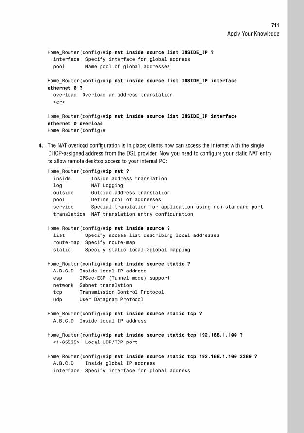
Apply Your Knowledge711
Home_Router(config)#ip nat inside source list INSIDE_IP ?interface Specify interface for global addresspool Name pool of global addresses
Home_Router(config)#ip nat inside source list INSIDE_IP interfaceethernet 0 ?
overload Overload an address translation<cr>
Home_Router(config)#ip nat inside source list INSIDE_IP interfaceethernet 0 overload
Home_Router(config)#
4. The NAT overload configuration is in place; clients now can access the Internet with the singleDHCP-assigned address from the DSL provider. Now you need to configure your static NAT entryto allow remote desktop access to your internal PC:
Home_Router(config)#ip nat ?inside Inside address translationlog NAT Loggingoutside Outside address translationpool Define pool of addressesservice Special translation for application using non-standard porttranslation NAT translation entry configuration
Home_Router(config)#ip nat inside source ?list Specify access list describing local addressesroute-map Specify route-mapstatic Specify static local->global mapping
Home_Router(config)#ip nat inside source static ?A.B.C.D Inside local IP addressesp IPSec-ESP (Tunnel mode) supportnetwork Subnet translationtcp Transmission Control Protocoludp User Datagram Protocol
Home_Router(config)#ip nat inside source static tcp ?A.B.C.D Inside local IP address
Home_Router(config)#ip nat inside source static tcp 192.168.1.100 ?<1-65535> Local UDP/TCP port
Home_Router(config)#ip nat inside source static tcp 192.168.1.100 3389 ?A.B.C.D Inside global IP addressinterface Specify interface for global address
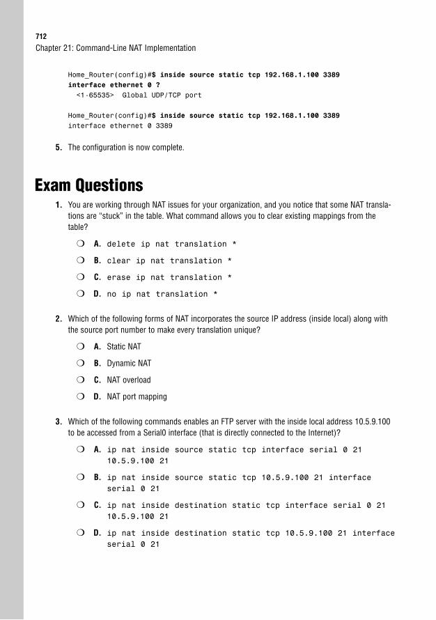
712
Home_Router(config)#$ inside source static tcp 192.168.1.100 3389interface ethernet 0 ?
<1-65535> Global UDP/TCP port
Home_Router(config)#$ inside source static tcp 192.168.1.100 3389interface ethernet 0 3389
5. The configuration is now complete.
Exam Questions1. You are working through NAT issues for your organization, and you notice that some NAT transla-
tions are “stuck” in the table. What command allows you to clear existing mappings from thetable?
❍ A. delete ip nat translation *
❍ B. clear ip nat translation *
❍ C. erase ip nat translation *
❍ D. no ip nat translation *
2. Which of the following forms of NAT incorporates the source IP address (inside local) along withthe source port number to make every translation unique?
❍ A. Static NAT
❍ B. Dynamic NAT
❍ C. NAT overload
❍ D. NAT port mapping
3. Which of the following commands enables an FTP server with the inside local address 10.5.9.100to be accessed from a Serial0 interface (that is directly connected to the Internet)?
❍ A. ip nat inside source static tcp interface serial 0 2110.5.9.100 21
❍ B. ip nat inside source static tcp 10.5.9.100 21 interfaceserial 0 21
❍ C. ip nat inside destination static tcp interface serial 0 2110.5.9.100 21
❍ D. ip nat inside destination static tcp 10.5.9.100 21 interfaceserial 0 21
Chapter 21: Command-Line NAT Implementation
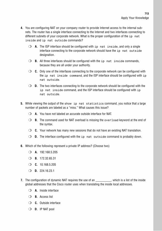
Apply Your Knowledge713
4. You are configuring NAT on your company router to provide Internet access to the internal sub-nets. The router has a single interface connecting to the Internet and two interfaces connecting todifferent subnets of your corporate network. What is the proper configuration of the ip natinside and ip nat outside commands?
❍ A. The ISP interface should be configured with ip nat inside, and only a singleinterface connecting to the corporate network should have the ip nat outsidedesignation.
❍ B. All three interfaces should be configured with the ip nat inside commands,because they are all under your authority.
❍ C. Only one of the interfaces connecting to the corporate network can be configured withthe ip nat inside command, and the ISP interface should be configured with ipnat outside.
❍ D. The two interfaces connecting to the corporate network should be configured with theip nat inside command, and the ISP interface should be configured with ipnat outside.
5. While viewing the output of the show ip nat statistics command, you notice that a largenumber of packets are labeled as a “miss.” What causes this issue?
❍ A. You have not labeled an accurate outside interface for NAT.
❍ B. The command used for NAT overload is missing the overload keyword at the end ofthe syntax.
❍ C. Your network has many new sessions that do not have an existing NAT translation.
❍ D. The interface configured with the ip nat outside command is probably down.
6. Which of the following represent a private IP address? (Choose two)
❍ A. 192.168.5.205
❍ B. 172.32.65.31
❍ C. 10.168.5.205
❍ D. 224.16.23.1
7. The configuration of dynamic NAT requires the use of an __________, which is a list of the insideglobal addresses that the Cisco router uses when translating the inside local addresses.
❍ A. Inside interface
❍ B. Access list
❍ C. Outside interface
❍ D. IP NAT pool
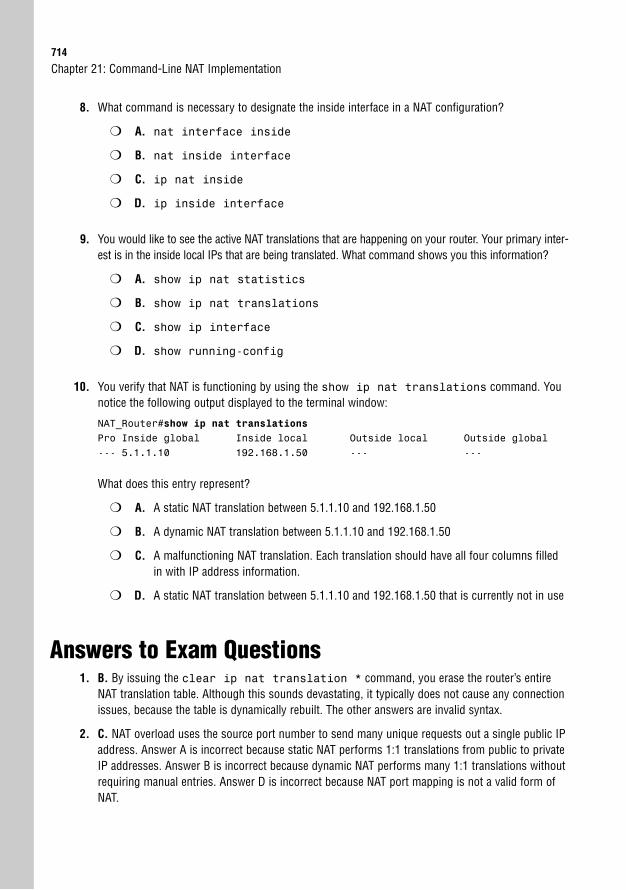
714
8. What command is necessary to designate the inside interface in a NAT configuration?
❍ A. nat interface inside
❍ B. nat inside interface
❍ C. ip nat inside
❍ D. ip inside interface
9. You would like to see the active NAT translations that are happening on your router. Your primary inter-est is in the inside local IPs that are being translated. What command shows you this information?
❍ A. show ip nat statistics
❍ B. show ip nat translations
❍ C. show ip interface
❍ D. show running-config
10. You verify that NAT is functioning by using the show ip nat translations command. Younotice the following output displayed to the terminal window:
NAT_Router#show ip nat translationsPro Inside global Inside local Outside local Outside global--- 5.1.1.10 192.168.1.50 --- ---
What does this entry represent?
❍ A. A static NAT translation between 5.1.1.10 and 192.168.1.50
❍ B. A dynamic NAT translation between 5.1.1.10 and 192.168.1.50
❍ C. A malfunctioning NAT translation. Each translation should have all four columns filledin with IP address information.
❍ D. A static NAT translation between 5.1.1.10 and 192.168.1.50 that is currently not in use
Answers to Exam Questions1. B. By issuing the clear ip nat translation * command, you erase the router’s entire
NAT translation table. Although this sounds devastating, it typically does not cause any connectionissues, because the table is dynamically rebuilt. The other answers are invalid syntax.
2. C. NAT overload uses the source port number to send many unique requests out a single public IPaddress. Answer A is incorrect because static NAT performs 1:1 translations from public to privateIP addresses. Answer B is incorrect because dynamic NAT performs many 1:1 translations withoutrequiring manual entries. Answer D is incorrect because NAT port mapping is not a valid form ofNAT.
Chapter 21: Command-Line NAT Implementation
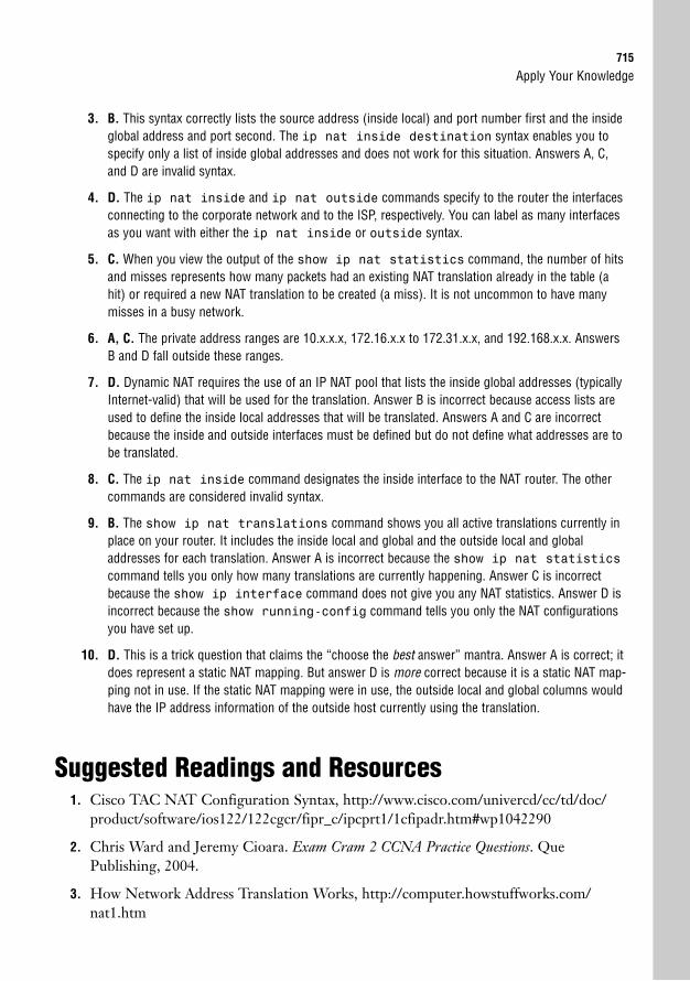
Apply Your Knowledge715
3. B. This syntax correctly lists the source address (inside local) and port number first and the insideglobal address and port second. The ip nat inside destination syntax enables you tospecify only a list of inside global addresses and does not work for this situation. Answers A, C,and D are invalid syntax.
4. D. The ip nat inside and ip nat outside commands specify to the router the interfacesconnecting to the corporate network and to the ISP, respectively. You can label as many interfacesas you want with either the ip nat inside or outside syntax.
5. C. When you view the output of the show ip nat statistics command, the number of hitsand misses represents how many packets had an existing NAT translation already in the table (ahit) or required a new NAT translation to be created (a miss). It is not uncommon to have manymisses in a busy network.
6. A, C. The private address ranges are 10.x.x.x, 172.16.x.x to 172.31.x.x, and 192.168.x.x. AnswersB and D fall outside these ranges.
7. D. Dynamic NAT requires the use of an IP NAT pool that lists the inside global addresses (typicallyInternet-valid) that will be used for the translation. Answer B is incorrect because access lists areused to define the inside local addresses that will be translated. Answers A and C are incorrectbecause the inside and outside interfaces must be defined but do not define what addresses are tobe translated.
8. C. The ip nat inside command designates the inside interface to the NAT router. The othercommands are considered invalid syntax.
9. B. The show ip nat translations command shows you all active translations currently inplace on your router. It includes the inside local and global and the outside local and globaladdresses for each translation. Answer A is incorrect because the show ip nat statisticscommand tells you only how many translations are currently happening. Answer C is incorrectbecause the show ip interface command does not give you any NAT statistics. Answer D isincorrect because the show running-config command tells you only the NAT configurationsyou have set up.
10. D. This is a trick question that claims the “choose the best answer” mantra. Answer A is correct; itdoes represent a static NAT mapping. But answer D is more correct because it is a static NAT map-ping not in use. If the static NAT mapping were in use, the outside local and global columns wouldhave the IP address information of the outside host currently using the translation.
Suggested Readings and Resources1. Cisco TAC NAT Configuration Syntax, http://www.cisco.com/univercd/cc/td/doc/
product/software/ios122/122cgcr/fipr_c/ipcprt1/1cfipadr.htm#wp1042290
2. Chris Ward and Jeremy Cioara. Exam Cram 2 CCNA Practice Questions. QuePublishing, 2004.
3. How Network Address Translation Works, http://computer.howstuffworks.com/nat1.htm

This page intentionally left blank
22C H A P T E R T W E N T Y - T W O
Wide Area NetworkConnections
ObjectivesThis chapter covers the following Cisco-specific objectives for the “Implement and verify WANlinks” section of the 640-802 CCNA exam:
. Describe different methods for connecting to a WAN
. Configure and verify a basic WAN serial connection
. Configure and verify a PPP connection between Cisco routers
. Troubleshoot WAN implementation issues
OutlineIntroduction 720
WAN Connection Types 720
Leased Lines 721
In the Field 721
Circuit-Switched Networks 721
Packet-Switched Networks 722
Broadband 722
Virtual Private Networks (VPNs) 723
Metropolitan Ethernet (Metro Ethernet) 723
The WAN Physical Layer 724
WAN Data Link Encapsulations 725
Serial Line Internet Protocol (SLIP) 725
Point-to-Point Protocol (PPP) 726
Cisco High-Level Data Link Control (HDLC) 726
X.25 Link Access Procedure, Balanced(LAPB) 726
Frame Relay 726
Asynchronous Transfer Mode (ATM) 726
PPP over Ethernet (PPPoE) and PPP over ATM (PPPoA) 727
Cisco HDLC 727
PPP 727
Sub-Layer 1: ISO HDLC 729
Sub-Layer 2: Link Control Protocol (LCP) 729
Authentication 729
Callback 731
Compression 732
Multilink 733
Sub-Layer 3: Network Control Protocol 733
Configuring PPP 734
Authentication 734
Compression 736
Verifying PPP 737
Troubleshooting PPP 738
Chapter Summary 741
Key Terms 741
Apply Your Knowledge 742
Exercises 742
Review Questions 745
Exam Questions 745
Answers to Review Questions 747
Answers to Exam Questions 748
Suggested Reading and Resources 749

Study Strategies. Read the information presented in the chapter, paying special attention to tables, Notes,
and Exam Alerts.
. Although Wide Area Network configuration is important, many of the advanced configura-tion options discussed are reserved for the CCNP BCRAN exam. At the CCNA level, besure to focus on understanding the concepts thoroughly.
. Because it is in widespread use, focus your energy on learning the ideas behind the PPPprotocol. Be sure to pay special attention to the authentication concepts.
720
IntroductionIn nearly all traditional Cisco texts, Wide Area Networks (WANs) are typically moved to theend of the book. This is amusing to me because WAN connectivity is usually listed in the topthree functions of a router. WAN connections do just that: connect networks that have a widearea separating them. This type of connection requires you to work with one or more serviceproviders that supply the logical connections between your locations.
The good news about WAN connections is this: These technologies only encompass thePhysical and Data Link layers of the OSI Model. Just like the concepts of ethernet and tokenring, WAN links are just another method of transporting data between devices. So with onlytwo layers worth of technology, WAN links should be fairly simple to learn, right? Well, that’sthe bad news: Because of the ever-increasing demands of the IT machine, WAN links havebecome increasingly complex to the point where they can be a specialization in themselves.Thankfully, the CCNA exam focuses primarily on two specific types of WAN connections:
. Leased Lines
. Frame Relay
Chapter 22: Wide Area Network Connections
EXAM ALERTTo prepare for the CCNA exam, you need to be very familiar with these WAN connections. Those prepar-ing for ICND1 exam should focus their studies primarily on Leased Line concepts and configurations.
Although there are many more WAN connection types, these are currently the most popular.By studying these WAN connections you will learn the foundation concepts behind WANconnections in general, making it easier to learn any new WAN technologies as they emerge.
WAN Connection TypesObjective:
. Describe different methods for connecting to a WAN
The following three categories of WAN connections comprise most of the connections usedby businesses around the world. As the name implies, each of the WAN connection categoriescontains multiple connection types. If you ever called a service provider and asked for a pack-et-switched connection, the next question would inevitably be, “What type?”
WAN Connection Types721
Leased LinesThis connection category is what most people are familiar with when they hear the term,“WAN connection.” A leased line connection provides a dedicated, point-to-point linkbetween two locations. The beauty of this connection type is that you have a virtual privateroad between your sites. You have complete control over the traffic on that road; nobody elsecan share the road with you. If you have a T1-speed connection (1.544Mbps) between yourlocations, that bandwidth is always dedicated to you, regardless of whether you use it or not.Therefore, leased lines are typically the most expensive connection types.
In the FieldThe two factors that directly affect the cost of a leased line are
. How far apart, geographically, the sites are located
. The amount of bandwidth required
Leased lines are the most appropriate when you need a fixed amount of bandwidth and com-plete control over all your traffic. Companies that are implementing Voice over IP (VoIP),which runs their telephone system over the data network, will usually vie for leased line con-nections. Because the telecommunications carrier (service provider) is dedicating the leasedline bandwidth to you, they can provide a guaranteed level of service. This not only includesthe uptime (reliability) of the line, but also delay requirements. The delay of the line is howlong it takes a packet to get from the entry point to the end of the connection. Long delayscan cause the quality of a VoIP call to degrade to the point of sounding like a bad cellularphone call. Because the service provider typically has end-to-end control over a leased lineconnection, they can guarantee a specific level of delay.
Circuit-Switched NetworksAnytime you hear the hum of a dial tone followed by the rhythmic beeping of digits, you aremore than likely connected to a circuit-switched network. This type of connection establishesa dedicated channel (or circuit) for the duration of the transmission, and then tears down thechannel when the transmission is complete. This is known as a dial-on-demand connection. Thelargest circuit-switched network in the world is the telephone system, which links togethermany different network segments to create an end-to-end circuit for each telephone call.
Circuit-switched networks can be called a “connection-oriented” network type. They are mostuseful when you have small amounts of data to reliably send at a time. Some circuit-switchednetworks charge on a per-use or per-minute basis (primarily ISDN), so the amount you payfor the connection is directly related to how much you use it. This type of connection wouldbe ideal for a small office that uses local area network (LAN) connectivity during the day and
722
then replicates all the updated data back to the main site in the evening. For example, youmight have a sales office that creates a log of transactions that it sends back to the corporateheadquarters at night.
Packet-Switched NetworksPacket-switched networks enable the service provider to create a large pool of bandwidth fortheir clients, rather than dedicate specific amounts of bandwidth to each client (as in leasedlines). The client can then dictate what circuits they would like established through the serv-ice provider network between their sites (these are called permanent virtual circuits), providingan end-to-end connection. By using packet-switched networks to provide WAN connectivity,you can gain lower-cost WAN connections that can potentially provide more bandwidth toyour locations.
When you sign up for a packet-switched network, the service provider gives you a guaranteedlevel of bandwidth. The higher your service guarantee, the more you pay for the connectionon a monthly basis. The great aspect of a packet switched network is that you usually get morethan you are guaranteed; depending on the type of contract you negotiate with the serviceprovider, you could get much more bandwidth than you are guaranteed. However, you mustrealize that this bandwidth is just that: non-guaranteed. If you send extra traffic during a busytime of day, the service provider can drop the traffic and be well within the service contract.This also applies for delay guarantees. Because traffic sent through a packet-switched networkmay take different paths (depending on the service provider’s infrastructure) to reach the des-tination, most service providers offer a very loose delay guarantee (if they decide to offer oneat all).
BroadbandBroadband technology, in its base definition, is a system that enables you to send multiple sig-nals over a wire at one time. The alternative technology, baseband, enables you to send only asingle signal over the wire at a time. Broadband connections primarily encompass smalloffice/home office (SOHO) WAN links that use cable modem or DSL technology to connectto the Internet. A cable service provider sends multiple signals over a cable coaxial line,enabling a home user to run many services, such as cable television, high-speed Internet, andtelephone service, over a single line. Telephone providers are offering the same servicesthrough the copper phone line connections.
Medium and large businesses are just now beginning to consider cable and DSL connectionsas backup Internet connections for their main offices. Broadband technology is one of thenewest WAN connection offerings to market, and has yet to prove its reliability on a long-termbasis.
Chapter 22: Wide Area Network Connections
WAN Connection Types723
Virtual Private Networks (VPNs)VPNs are not a specific type of WAN connection, but are often used to accomplish the samepurpose as a WAN connection. Connections to the Internet have become widely available atan extremely low cost (when compared against the other types of WAN connectivity). Ratherthan purchasing dedicated circuits between locations, you can just purchase a standard Internetconnection at each site. The quality of your Internet connection determines the quality of yourWAN connectivity. After all sites have a connection to the Internet, you can then create tun-nels through the Internet to each location, enabling the sites to connect through a full-meshrelationship (every site is directly connected, through the Internet, to every other site). Thesetunnels isolate the interoffice connectivity from the rest of the Internet traffic and secure thetraffic through heavy encryption algorithms.
The VPN tunnels are created with the application of a heavy amount of encryption to the traf-fic sent between the locations. Because sending your company’s private data across a public net-work, such as the Internet, could be perilous, you should scramble (encrypt) your data beforesending it. Because the process of encrypting and de-encrypting data is extremely hard on arouter processor, you may choose to offload this work to a router VPN card (a hardware add-on), a PIX firewall (Cisco’s firewall platform), or a VPN concentrator (a specific device managesand maintains many VPN connections). Within this concept lie the advantages and disadvan-tages of using VPNs for your WAN connections. The major advantage is the cost: You canestablish full connectivity between all your locations for a small fraction of what it would costto purchase dedicated WAN links. You can also allow home users to connect into the officethrough a VPN connection to allow for telecommuting employees. The disadvantage is thedelay incurred in applying the VPN encryption algorithms and the unreliable nature of theInternet. Although the Internet is the most redundant network in the world, because of themassive amount of traffic that crosses the Internet daily, the delay can be inconsistent.
Metropolitan Ethernet (Metro Ethernet)Metro ethernet technology began to emerge early in the new millennium as a viable alterna-tive to traditional WAN connections when connecting offices within a metropolitan area (pri-marily major cities). At the end of the century, .com-based businesses were booming. Many ofthese companies began laying complex fiber optic–based networks throughout many of themajor metropolitan areas of the nation. When the world economy plummeted at the turn ofthe century, many of these .com companies went out of business, leaving huge amounts ofunmanaged fiber cable under the city streets. This fiber was quickly acquired by local serviceproviders and is slowly being leased to their customers.
Using this fiber to connect offices in the same general region allows for WAN links at speedsof 1000Mbps or greater, at a fraction of the cost of a standard T1 line. The WAN link can eventerminate onto a standard Category 5E/6 UTP copper cable and plug directly into a switch
724
using a fiber to copper converter at the customer premise. This enables the WAN connectionsto be managed completely through VLANs with no dedicated router hardware in place. Theconnections, which are already fast enough, become even faster.
Metro ethernet is beginning to stretch even between cities, as service providers are planting fiberoptic cable runs between major metropolitan areas. It shouldn’t be too long before intra-nationWAN links are rated in terms of Gbps as a standard. Metro ethernet is becoming quite popularin government organizations that have many locations in the same general geographic region.
Chapter 22: Wide Area Network Connections
EXAM ALERTFor the ICND1 exam, you should be familiar with the following network types:
. Leased Lines
For the ICND2 and CCNA exams, you should be familiar with the following network types:
. Leased Lines
. Packet Switched
The WAN Physical LayerThe physical connections for WANs are very diverse, primarily because of the diverse formfactors that were created by CSU/DSU manufacturers. The Channel Service Unit/DataService Unit (CSU/DSU) device is the box that connects and converts your WAN cabling tothe service provider’s WAN cabling. Although CSU/DSUs often have many lights, buttons,and LCD displays, they are typically nothing more than a glorified terminal adapter, convert-ing between the service provider’s cable and your local router connection. Figure 22.1 showsa typical physical layout for a WAN connection.
Your Cable Service Provider’s Cable
CSU/DSUCisco Router
ServiceProvider
FIGURE 22.1 WAN physical connection points.
If a CSU/DSU is involved, you will be responsible for purchasing the cable that connects yourrouter to the CSU/DSU unit.
Cisco routers primarily use serial interfaces when connecting to a WAN. The Cisco interfacescome in two types: DB-60 serial interfaces and Smart Serial interfaces. Typically, older routersuse the DB-60 style interfaces, whereas newer routers use the Smart Serial interfaces. The DB-60 interface received its name because of the 60 pins in the interface. Smart Serial interfacesare much more space efficient, and can squeeze two interfaces into the same WAN InterfaceCard (WIC) that the DB-60 interface used.
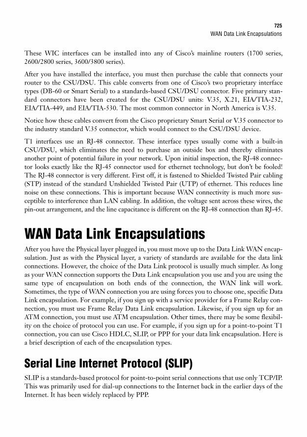
WAN Data Link Encapsulations725
These WIC interfaces can be installed into any of Cisco’s mainline routers (1700 series,2600/2800 series, 3600/3800 series).
After you have installed the interface, you must then purchase the cable that connects yourrouter to the CSU/DSU. This cable converts from one of Cisco’s two proprietary interfacetypes (DB-60 or Smart Serial) to a standards-based CSU/DSU connector. Five primary stan-dard connectors have been created for the CSU/DSU units: V.35, X.21, EIA/TIA-232,EIA/TIA-449, and EIA/TIA-530. The most common connector in North America is V.35.
Notice how these cables convert from the Cisco proprietary Smart Serial or V.35 connector tothe industry standard V.35 connector, which would connect to the CSU/DSU device.
T1 interfaces use an RJ-48 connector. These interface types usually come with a built-inCSU/DSU, which eliminates the need to purchase an outside box and thereby eliminatesanother point of potential failure in your network. Upon initial inspection, the RJ-48 connec-tor looks exactly like the RJ-45 connector used for ethernet technology, but don’t be fooled!The RJ-48 connector is very different. First off, it is fastened to Shielded Twisted Pair cabling(STP) instead of the standard Unshielded Twisted Pair (UTP) of ethernet. This reduces linenoise on these connections. This is important because WAN connectivity is much more sus-ceptible to interference than LAN cabling. In addition, the voltage sent across these wires, thepin-out arrangement, and the line capacitance is different on the RJ-48 connection than RJ-45.
WAN Data Link EncapsulationsAfter you have the Physical layer plugged in, you must move up to the Data Link WAN encap-sulation. Just as with the Physical layer, a variety of standards are available for the data linkconnections. However, the choice of the Data Link protocol is usually much simpler. As longas your WAN connection supports the Data Link encapsulation you use and you are using thesame type of encapsulation on both ends of the connection, the WAN link will work.Sometimes, the type of WAN connection you are using forces you to choose one, specific DataLink encapsulation. For example, if you sign up with a service provider for a Frame Relay con-nection, you must use Frame Relay Data Link encapsulation. Likewise, if you sign up for anATM connection, you must use ATM encapsulation. Other times, there may be some flexibil-ity on the choice of protocol you can use. For example, if you sign up for a point-to-point T1connection, you can use Cisco HDLC, SLIP, or PPP for your data link encapsulation. Here isa brief description of each of the encapsulation types.
Serial Line Internet Protocol (SLIP)SLIP is a standards-based protocol for point-to-point serial connections that use only TCP/IP.This was primarily used for dial-up connections to the Internet back in the earlier days of theInternet. It has been widely replaced by PPP.
726
Point-to-Point Protocol (PPP)This protocol has largely replaced SLIP connections for point-to-point WAN connectionsand dial-up networking. PPP was released as an improvement to SLIP and added support fornon-TCP/IP protocols and encrypted authentication (among many other features). PPP is themost popular protocol for connecting point-to-point WAN connections.
Cisco High-Level Data Link Control (HDLC)HDLC was originally designed as an open standard protocol, meaning all routers could sup-port it. However, the open standard version of HDLC was pretty horrible. It did not supportmultiple network-layer protocols, which meant that you could support only one protocol (suchas TCP/IP, IPX/SPX, or AppleTalk) over your WAN connection. In view of this shortcoming,Cisco modified the standard HDLC to support this missing feature. However, anytime a stan-dard is modified, the protocol becomes proprietary. In this case, you can use HDLC only onCisco routers to connect to other Cisco routers. HDLC is the default encapsulation on all seri-al interfaces on Cisco routers. Although HDLC does not have as many features as PPP, it doesoffer very low overhead, which makes your WAN connections very efficient.
X.25 Link Access Procedure, Balanced (LAPB)This encapsulation is used on X.25-based networks, which is the predecessor to Frame Relay.Although X.25 is used rarely in well-developed countries, it has widespread use in countriesnot as technologically advanced.
Frame RelayThis encapsulation relates directly to the Frame Relay WAN connection, which is the fastersuccessor to X.25. Frame Relay increased its speed capabilities by removing much of the errorcorrection that is no longer needed on the more reliable circuits of today. Frame Relay haswidespread use in nearly all well-developed areas.
Asynchronous Transfer Mode (ATM)This technology is very similar to frame relay, but chops packets into very small pieces (53bytes each) called cells. Because all the frames are exactly the same size, routers are able toprocess them much quicker. ATM also has the capability to run at very fast speeds because itadapts to run over fiber optic cabling.
Chapter 22: Wide Area Network Connections
PPP727
PPP over Ethernet (PPPoE) and PPP over ATM (PPPoA)These technologies have been implemented to allow service providers to harness the featuresof PPP on an ethernet or ATM connection. This technology is primarily used in DSL high-speed Internet deployments.
EXAM ALERTThe ICND1 exam requires you to be familiar with the configuration of HDLC and PPP. The CCNA examrequires you to be familiar with the configuration of HDLC, PPP, and Frame Relay encapsulation types.
Cisco HDLCAs mentioned previously, HDLC in its truest form is an industry standard created by theInternational Organization for Standardization (ISO). These are the same folks who createdthe OSI Model (bless their hearts). Because the ISO version of HDLC lacked the support formultiple protocol use, Cisco modified it and caused HDLC on Cisco routers to become a pro-prietary protocol.
The beauty of HDLC is that it is very simple and works out of the box. Typically, if you aredeploying a WAN connection with a Cisco router on each side of the link, it eliminates plen-ty of troubleshooting involved in trying to enable the connection with HDLC, even if you planon using PPP in the long run. Because HDLC is so simple, there are no options to negotiateand you can rule it out of any troubleshooting you may encounter. If the link is not comingup, it is usually something on the service provider side of the business.
Because HDLC is enabled by default, you don’t need to perform any additional configurationfor the data link configuration of your serial interfaces. However, if the data link encapsulationwas changed to something other than HDLC, you can re-enable HDLC by moving into interface configuration mode for the serial interface you want to use and type the commandencapsulation hdlc.
PPPObjectives:
. Configure and verify a PPP connection between Cisco routers
. Configure and verify a basic WAN serial connection
The PPP protocol has become the industry standard for connecting multi-vendor environ-ments over WANs. Whenever people think about using an “industry standard” for anything,they usually think of the bland, saltine-cracker type of protocol. Surprisingly, PPP defies the
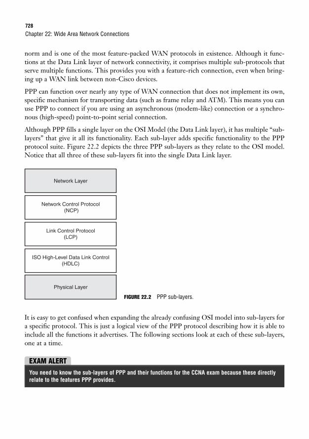
728
norm and is one of the most feature-packed WAN protocols in existence. Although it func-tions at the Data Link layer of network connectivity, it comprises multiple sub-protocols thatserve multiple functions. This provides you with a feature-rich connection, even when bring-ing up a WAN link between non-Cisco devices.
PPP can function over nearly any type of WAN connection that does not implement its own,specific mechanism for transporting data (such as frame relay and ATM). This means you canuse PPP to connect if you are using an asynchronous (modem-like) connection or a synchro-nous (high-speed) point-to-point serial connection.
Although PPP fills a single layer on the OSI Model (the Data Link layer), it has multiple “sub-layers” that give it all its functionality. Each sub-layer adds specific functionality to the PPPprotocol suite. Figure 22.2 depicts the three PPP sub-layers as they relate to the OSI model.Notice that all three of these sub-layers fit into the single Data Link layer.
Chapter 22: Wide Area Network Connections
Network Control Protocol (NCP)
ISO High-Level Data Link Control(HDLC)
Physical Layer
Link Control Protocol(LCP)
Network Layer
It is easy to get confused when expanding the already confusing OSI model into sub-layers fora specific protocol. This is just a logical view of the PPP protocol describing how it is able toinclude all the functions it advertises. The following sections look at each of these sub-layers,one at a time.
FIGURE 22.2 PPP sub-layers.
EXAM ALERTYou need to know the sub-layers of PPP and their functions for the CCNA exam because these directlyrelate to the features PPP provides.
PPP729
Sub-Layer 1: ISO HDLCInitially, seeing this layer in PPP seems quite odd. Wasn’t HDLC a competing protocol to PPP?This sub-layer of PPP comprises the industry standard ISO HDLC. This sub-layer is responsi-ble for allowing PPP to be supported by multiple devices. It gives the devices that run PPP com-mon ground to stand on when they communicate with each other. As you will see in just amoment, the LCP layer above is responsible for negotiating all the features of HDLC. Becauseall devices that run HDLC may not support every single feature, the HDLC sub-layer enablesthe base PPP communication to continue, even if the platforms support different features.
Sub-Layer 2: Link Control Protocol (LCP)You can think of the LCP sub-layer as the feature negotiation layer. All the features that PPPsupports are negotiated by LCP. These features are
. Authentication
. Callback
. Compression
. Multilink
EXAM ALERTBe able to pick the features negotiated by LCP out of a line-up.
AuthenticationThe authentication features of PPP enable you to require a username and password for theconnecting device to bring up the WAN connection. This is not a very important feature onleased line, point-to-point connections because the only way a hacker would be able to get adevice connected to the WAN would be to render one of the on-site administrators uncon-scious and replace the on-site router with one of the hacker’s own. The PPP authenticationfeatures are most useful for dial-up connections that could be reached by users connected tothe Public Switched Telephone Network (PSTN).
For example, you may choose to connect a modem to your router through the AUX port toallow dial-up access, should all the LAN and WAN connectivity to the router fail. This modemwould be assigned a phone number, accessible from any computer modem in the world. PPPauthentication would require a username and password to be entered before the modem con-nection would bridge a successful connection.
There are two types of authentication supported by PPP: the Password AuthenticationProtocol (PAP) and the Challenge Handshake Authentication Protocol (CHAP).
730
PAPThis authentication protocol is one of the earliest authentication types to be released for WANconnectivity. If PAP is enabled for the connection, the call flow progresses as follows:
1. Client dials up to a router running PPP.
2. After the link (connection) is established, the client sends its username and password atthe LCP (feature) layer.
3. The PPP router checks the username and password against its user database and allowsor denies the client.
Although this list of three steps is a logical authentication process, it has a few flaws. First off,the client dictates the timing of sending the username and password; the server (router run-ning PPP) receives the username and password whenever the client decides to send it. Thiscauses the PAP mechanism to be susceptible to playback attacks. This is a type of attack wherea hacker captures (sniff) packets from a conversation and then plays the packets back in anattempt to mirror the connection. Because the client is in complete control of the authentica-tion attempt, the server accepts the played-back packets whenever the client decides to sendthem.
The authentication of PAP is also done in clear text, which makes it even more vulnerable topacket-sniffing intruders. Anyone who does have a way of monitoring the connection can cap-ture the packets, break them open, and find the username and password used for authentica-tion in clear text. Can you say, “network devastation”?
With all this being said, the only reason you would choose to use the PAP method for authen-tication is if you were using very old equipment that did not support the newer method ofauthentication, CHAP.
CHAPCHAP is a much more secure procedure for connecting to a PPP-based system. The authen-tication process for CHAP goes like this:
1. Client dials up to a router running PPP.
2. The router sends a challenge message to the client.
3. The client responds with the hash of the password it is configured to use.
4. The router looks up the password hash against its database. If the hash matches, theclient is allowed into the network.
5. After the client is authenticated, the router sends re-authentication messages at randomintervals, requiring the client to send the password hash whenever prompted.
Chapter 22: Wide Area Network Connections
PPP731
Doesn’t that list already make you feel better than PAP? The first thing to notice is that therouter (server) is in control of the authentication process. Rather than accepting the usernameand password whenever the client decides to send it, the router demands the username andpassword on its timeframe. If the client isn’t ready to ante up with the credentials, the serverimmediately terminates the connection. This makes performing a playback attack much moredifficult to accomplish.
Even if a hacker were to successfully execute a playback attack with CHAP, the randomauthentication interval ensures the hacker will not be connected for long. Executing the initialplayback attack would require intricate timing for the hacker to be successful. The randomauthentication requests would be nearly impossible to keep up.
The clear text issues have also been solved by using a system known as password hashing.Without getting too deep into cryptography and security mechanisms, you must understandthat this is not the same thing as encrypting a password and sending it across the network.Given the time, nearly any encryption algorithm can be broken if the data is captured. Usinga hashed version of the password means that the client never actually sends the real passwordacross the line. To accomplish this, the router (PPP server) and the PPP client must be con-figured to have the identical password. Before the client sends the password, it runs an irre-versible mathematical algorithm on the password. The result of that algorithm is called thehash, which is sent to the server. The server runs the same algorithm on its password and com-pares the two hashes. If the answer is the same, the client successfully authenticates.
Now, you may be thinking the same thing I did when I first heard about this process, “Well,can’t you just get the mathematical formula and reverse it to figure out what the password isfrom the hash? For example, if the formula is (the password)∞2 = the hash, could you just takethe (hash÷2) = the password?” Fair question, but just wait until you see the formula. The hash-ing method (formula) used is known as the MD5 hash. This formula has been engineered withthe sole purpose of being irreversible. With that in mind, someone might capture the passwordhash and find out that it is 5,381,120,123,590. Now the trick is to reverse-engineer an irre-versible formula to figure out how the algorithm came up with that answer. It would be mucheasier for hackers to render the IT staff unconscious at whatever site they were looking to com-promise and steal the servers containing the data they needed.
CallbackJust as the name implies, the PPP callback functionality enables a dial-up server (or router)running PPP to use a predefined number to call the person back who initially dialed into thelocation. One of the major advantages of this function is the increased security: It requires thedial-up user to authenticate and then be present at the predefined phone number to be able toreceive the return call. The other advantage is the toll consolidation. If you have long distanceusers dialing into the network, you leave your company at the mercy of the long distance car-riers of your users. By using PPP callback, you can ensure that the company long distancecharges are applied, which are typically much lower than normal carrier charges.
732
A PPP callback process goes through the following steps:
1. A user dials into a router using PPP and authenticates.
2. Upon a successful authentication, the router terminates the connection (typically with-out any notification) and dials the user back at the predefined number configured bythe administrator.
3. Upon reconnect, the user authenticates a second time.
4. Upon a successful authentication, the user is granted network access.
CompressionWhen I first heard about compression on a WAN link, my mind flashed back to the days ofthe Stacker compression program of Microsoft DOS. This program slowed your computerdown to a crawl to gain a few megabytes of storage space on a hard disk. Surprisingly, one ofthe two compression algorithms used on PPP WAN connections is named “Stacker”; howev-er, the effects are much less devastating than they were with the old DOS program.
Using compression to make your WAN connection more efficient is not a new concept. Thesetechnologies have been around since the days of DOS. However, these technologies havebecome much more viable on today’s networks because of the increase in CPU and memoryresources on network equipment. The tradeoff when choosing to use compression is that yougain more WAN bandwidth by sacrificing your router’s processor and memory resources. Howmuch you sacrifice depends on the type of compression algorithm you use.
StackerThe compression type analyzes the data that is being sent and replaces continuous streams of char-acters with codes. These codes are stored in a dictionary and looked up on the other end of theconnection to rebuild the original data. The Stacker algorithm (which is actually called Lempel-Ziv) uses a “flat dictionary-style compression.” This means that for every packet of data, it goesthrough the same process: Look up the character streams in the dictionary, replace the characterswith codes, begin again. Therefore, it is very good for network connections that have constantlyvarying data types (such as SQL, HTTP, FTP, and so on) crossing them. It doesn’t matter whatthe previous traffic was; the same compression algorithm is applied. The Stacker algorithm isnotoriously heavy on CPU resources and has less effect on the router’s memory resources.
PredictorThis compression algorithm received its name because it literally attempts to predict the nextcharacter stream that will be sent or received. It uses a similar dictionary lookup process asStacker; however, it takes the most common characters looked up and builds a cached indexfile. Anytime some traffic needs to be sent or received, the index file is checked first. If thecharacter stream (or codes) is not found in the index file, it then consults the full dictionary to
Chapter 22: Wide Area Network Connections
PPP733
find the necessary compression or decompression algorithm. Therefore, the Predictor algo-rithm works best on network connections that have fairly similar traffic patterns (that can becached in the index file). For example, perhaps you have a WAN link back to a central officethat houses an intranet server that users access to update the corporate e-commerce website.In this case, the traffic patterns would be very similar (HTTP/HTTPS) for most times of theday. The Predictor algorithm usually uses more memory resources and has less effect on therouter’s CPU than the Stacker algorithm (as long as the traffic patterns do not vary largely).
Microsoft Point-to-Point CompressionMicrosoft has its own compression algorithm for PPP, aptly named the Microsoft Point-to-PointCompression (MPPC). This protocol offers slightly improved processor and bandwidth utiliza-tion for Microsoft Windows–based clients. Because other devices, such as Cisco routers, wouldneed to support this compression algorithm for Microsoft Windows to use it, Microsoft releasedthe algorithm as an RFC standard (RFC 2118). Under the licensing in this RFC, Microsoft per-mits other vendors to implement MPPC solely for the purpose of connecting to other MPCCclients. MPPC therefore is used only to allow Windows dial-up users to use compression.
MultilinkPPP multilink enables you to bundle multiple WAN connections into a single, logical connec-tion. This could be as small as bundling two 33.6Kbps modems together to make a 67.2Kbpsconnection, or bundling four T1 lines together to give yourself a 6.176Mbps connection. Theseparate interfaces that are bundled together are no longer seen as individual interfaces, butrather join a larger “logical” multilink interface. You can assign this single interface its own IPaddress, configure authentication, or optimize the logical line with compression. It acts and feelslike a real interface, even though it could potentially comprise many physical links.
There are two major benefits to using Multilink PPP (MLPPP). First off, the logical linkbecomes a single point of management. Rather than figuring out what the traffic utilization ison all the individual physical lines, you can focus your monitoring software (if you have some)on just a single interface. The second benefit to MLPPP is the fact that all physical links bun-dled in the logical group get exact load balancing. When I say “exact,” I mean the down-to-the-exact-bit-level kind of exact. MLPPP chops all your packets (referred to as fragmentation)into exactly equal sizes before it sends them across the line. This leads to the one drawback ofusing MLPPP: slightly increased processor and memory utilization on your router.
Sub-Layer 3: Network Control ProtocolThe final sub-layer of PPP is what gives it the functionality to allow multiple Network layerprotocols to run across a single WAN link at any given time. I think of this layer as the PPPDUPLO® LEGO® block connector. Have you ever seen the DUPLO® blocks for small chil-dren? They all have that standard connector with which any other DUPLO® can connect sothe child can put any two pieces together (which provides positive affirmation, I’m sure). In
734
that same sense, the Network Control Protocol (NCP) sub-layer of PPP has open-source, net-work-layer connectors that anyone can plug into. For example, the TCP/IP protocol has aconnector called IPCP (the CP stands for “control protocol”) that enables TCP/IP to runacross a PPP WAN link. IPX/SPX has a connector called IPXCP. With the open-sourcenature of this protocol, I could create a “Jeremy protocol” and then write a JeremyCP to allowit to run across a PPP WAN link. Cisco has written its own extension called CDPCP thatenables the Cisco Discovery Protocol to run across a PPP WAN link, which enables therouters on each end of the connection to use CDP to see each other.
Configuring PPPObjectives:
. Configure and verify a basic WAN serial connection
. Configure and verify a PPP connection between Cisco routers
The configuration of PPP without any options does not even deserve its own section. All youneed to do is access the interface you would like to enable to run PPP and type the commandencapsulation ppp. After you do that on both sides of the connection, you’re finished. Forexample, if I wanted to configure PPP on the Serial 0 interface of a router, here is the process:AccessServer#configure terminalEnter configuration commands, one per line. End with CNTL/Z.AccessServer(config)#interface serial 0AccessServer(config-if)#encapsulation ppp
After you begin turning on the options, the configuration can get a little more complex. Thischapter discusses turning on PPP authentication and compression technology.
AuthenticationThe CCNA exam focuses on configuring PPP authentication between two Cisco routersrather than using authentication for dial-up users (this is covered in the Building Cisco RemoteAccess Networks CCNP course). Typically, when Cisco routers are performing authenticationon a WAN link, the routers will be configured as two-way authentication. Two-way authenti-cation means that both routers authenticate each other. Typically, when a dial-up user connectsto a router, one-way authentication is performed (the user must authenticate to the Ciscorouter, not vice-versa).
To set up CHAP PPP authentication, you must do the following:
1. Turn on PPP encapsulation.
2. Configure the necessary hostname for the authenticating routers.
Chapter 22: Wide Area Network Connections
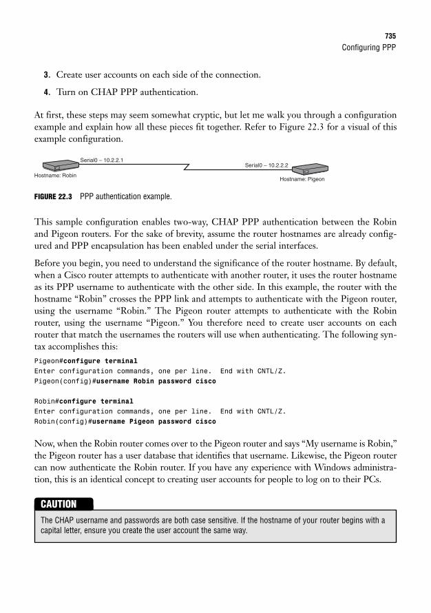
Configuring PPP735
3. Create user accounts on each side of the connection.
4. Turn on CHAP PPP authentication.
At first, these steps may seem somewhat cryptic, but let me walk you through a configurationexample and explain how all these pieces fit together. Refer to Figure 22.3 for a visual of thisexample configuration.
Serial0 – 10.2.2.1Serial0 – 10.2.2.2
Hostname: RobinHostname: Pigeon
FIGURE 22.3 PPP authentication example.
This sample configuration enables two-way, CHAP PPP authentication between the Robinand Pigeon routers. For the sake of brevity, assume the router hostnames are already config-ured and PPP encapsulation has been enabled under the serial interfaces.
Before you begin, you need to understand the significance of the router hostname. By default,when a Cisco router attempts to authenticate with another router, it uses the router hostnameas its PPP username to authenticate with the other side. In this example, the router with thehostname “Robin” crosses the PPP link and attempts to authenticate with the Pigeon router,using the username “Robin.” The Pigeon router attempts to authenticate with the Robinrouter, using the username “Pigeon.” You therefore need to create user accounts on eachrouter that match the usernames the routers will use when authenticating. The following syn-tax accomplishes this:Pigeon#configure terminalEnter configuration commands, one per line. End with CNTL/Z.Pigeon(config)#username Robin password cisco
Robin#configure terminalEnter configuration commands, one per line. End with CNTL/Z.Robin(config)#username Pigeon password cisco
Now, when the Robin router comes over to the Pigeon router and says “My username is Robin,”the Pigeon router has a user database that identifies that username. Likewise, the Pigeon routercan now authenticate the Robin router. If you have any experience with Windows administra-tion, this is an identical concept to creating user accounts for people to log on to their PCs.
The CHAP username and passwords are both case sensitive. If the hostname of your router begins with acapital letter, ensure you create the user account the same way.
CAUTION
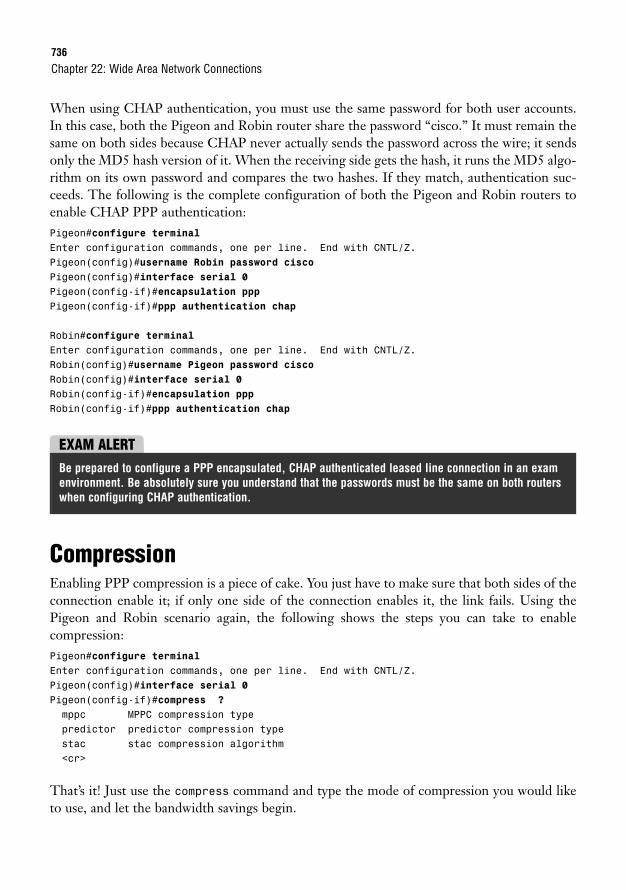
736
When using CHAP authentication, you must use the same password for both user accounts.In this case, both the Pigeon and Robin router share the password “cisco.” It must remain thesame on both sides because CHAP never actually sends the password across the wire; it sendsonly the MD5 hash version of it. When the receiving side gets the hash, it runs the MD5 algo-rithm on its own password and compares the two hashes. If they match, authentication suc-ceeds. The following is the complete configuration of both the Pigeon and Robin routers toenable CHAP PPP authentication:Pigeon#configure terminalEnter configuration commands, one per line. End with CNTL/Z.Pigeon(config)#username Robin password ciscoPigeon(config)#interface serial 0Pigeon(config-if)#encapsulation pppPigeon(config-if)#ppp authentication chap
Robin#configure terminalEnter configuration commands, one per line. End with CNTL/Z.Robin(config)#username Pigeon password ciscoRobin(config)#interface serial 0Robin(config-if)#encapsulation pppRobin(config-if)#ppp authentication chap
Chapter 22: Wide Area Network Connections
EXAM ALERTBe prepared to configure a PPP encapsulated, CHAP authenticated leased line connection in an examenvironment. Be absolutely sure you understand that the passwords must be the same on both routerswhen configuring CHAP authentication.
CompressionEnabling PPP compression is a piece of cake. You just have to make sure that both sides of theconnection enable it; if only one side of the connection enables it, the link fails. Using thePigeon and Robin scenario again, the following shows the steps you can take to enable compression:Pigeon#configure terminalEnter configuration commands, one per line. End with CNTL/Z.Pigeon(config)#interface serial 0Pigeon(config-if)#compress ?mppc MPPC compression typepredictor predictor compression typestac stac compression algorithm<cr>
That’s it! Just use the compress command and type the mode of compression you would liketo use, and let the bandwidth savings begin.
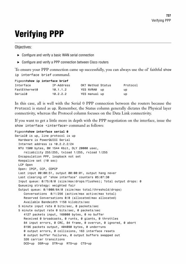
Verifying PPP737
Verifying PPPObjectives:
. Configure and verify a basic WAN serial connection
. Configure and verify a PPP connection between Cisco routers
To ensure your PPP connection came up successfully, you can always use the ol’ faithful showip interface brief command.Pigeon#show ip interface briefInterface IP-Address OK? Method Status ProtocolFastEthernet0 10.1.1.2 YES NVRAM up upSerial0 10.2.2.2 YES manual up up
In this case, all is well with the Serial 0 PPP connection between the routers because theProtocol is stated as up. Remember, the Status column generally dictates the Physical layerconnectivity, whereas the Protocol column focuses on the Data Link connectivity.
If you want to get a little more in depth with the PPP negotiation on the interface, issue theshow interface <interface> command as follows:Pigeon#show interface serial 0Serial0 is up, line protocol is upHardware is PowerQUICC SerialInternet address is 10.2.2.2/24MTU 1500 bytes, BW 1544 Kbit, DLY 20000 usec,
reliability 255/255, txload 1/255, rxload 1/255Encapsulation PPP, loopback not setKeepalive set (10 sec)LCP OpenOpen: IPCP, CCP, CDPCPLast input 00:00:51, output 00:00:01, output hang neverLast clearing of “show interface” counters 05:07:30Input queue: 0/75/0/0 (size/max/drops/flushes); Total output drops: 0Queueing strategy: weighted fairOutput queue: 0/1000/64/0 (size/max total/threshold/drops)
Conversations 0/1/256 (active/max active/max total)Reserved Conversations 0/0 (allocated/max allocated)Available Bandwidth 1158 kilobits/sec
5 minute input rate 0 bits/sec, 0 packets/sec5 minute output rate 0 bits/sec, 0 packets/sec
4127 packets input, 168000 bytes, 0 no bufferReceived 0 broadcasts, 0 runts, 0 giants, 0 throttles84 input errors, 0 CRC, 84 frame, 0 overrun, 0 ignored, 0 abort8196 packets output, 404090 bytes, 0 underruns0 output errors, 0 collisions, 163 interface resets0 output buffer failures, 0 output buffers swapped out326 carrier transitionsDCD=up DSR=up DTR=up RTS=up CTS=up
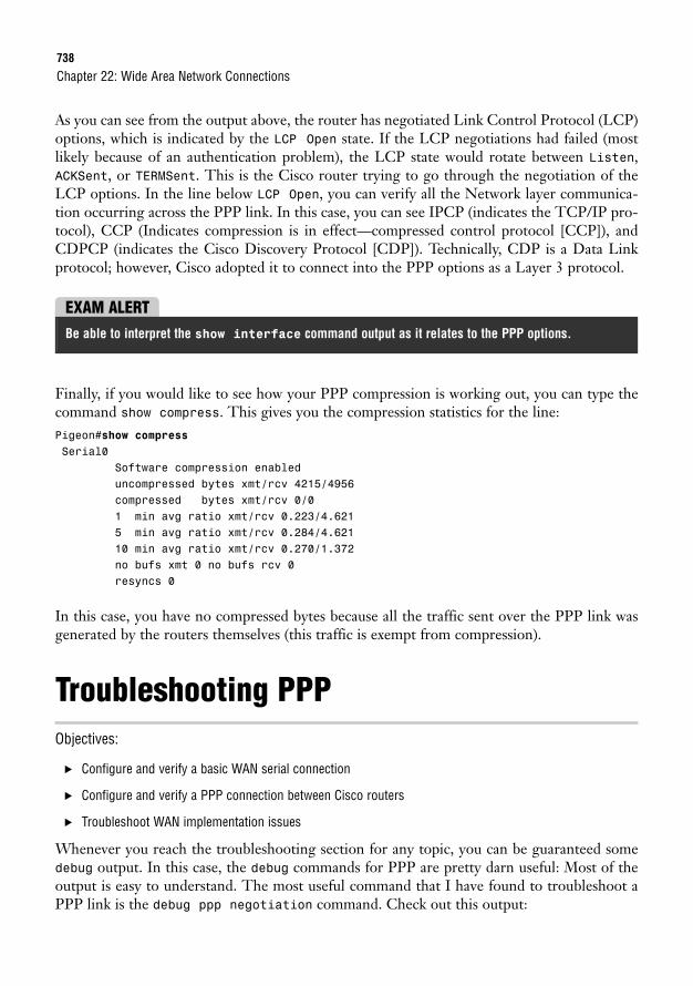
738
As you can see from the output above, the router has negotiated Link Control Protocol (LCP)options, which is indicated by the LCP Open state. If the LCP negotiations had failed (mostlikely because of an authentication problem), the LCP state would rotate between Listen,ACKSent, or TERMSent. This is the Cisco router trying to go through the negotiation of theLCP options. In the line below LCP Open, you can verify all the Network layer communica-tion occurring across the PPP link. In this case, you can see IPCP (indicates the TCP/IP pro-tocol), CCP (Indicates compression is in effect—compressed control protocol [CCP]), andCDPCP (indicates the Cisco Discovery Protocol [CDP]). Technically, CDP is a Data Linkprotocol; however, Cisco adopted it to connect into the PPP options as a Layer 3 protocol.
Chapter 22: Wide Area Network Connections
EXAM ALERTBe able to interpret the show interface command output as it relates to the PPP options.
Finally, if you would like to see how your PPP compression is working out, you can type thecommand show compress. This gives you the compression statistics for the line:Pigeon#show compressSerial0
Software compression enableduncompressed bytes xmt/rcv 4215/4956compressed bytes xmt/rcv 0/01 min avg ratio xmt/rcv 0.223/4.6215 min avg ratio xmt/rcv 0.284/4.62110 min avg ratio xmt/rcv 0.270/1.372no bufs xmt 0 no bufs rcv 0resyncs 0
In this case, you have no compressed bytes because all the traffic sent over the PPP link wasgenerated by the routers themselves (this traffic is exempt from compression).
Troubleshooting PPPObjectives:
. Configure and verify a basic WAN serial connection
. Configure and verify a PPP connection between Cisco routers
. Troubleshoot WAN implementation issues
Whenever you reach the troubleshooting section for any topic, you can be guaranteed somedebug output. In this case, the debug commands for PPP are pretty darn useful: Most of theoutput is easy to understand. The most useful command that I have found to troubleshoot aPPP link is the debug ppp negotiation command. Check out this output:
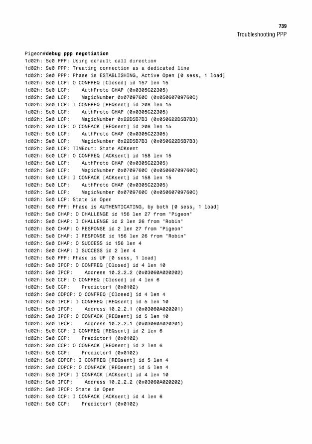
Troubleshooting PPP739
Pigeon#debug ppp negotiation1d02h: Se0 PPP: Using default call direction1d02h: Se0 PPP: Treating connection as a dedicated line1d02h: Se0 PPP: Phase is ESTABLISHING, Active Open [0 sess, 1 load]1d02h: Se0 LCP: O CONFREQ [Closed] id 157 len 151d02h: Se0 LCP: AuthProto CHAP (0x0305C22305)1d02h: Se0 LCP: MagicNumber 0x0709760C (0x05060709760C)1d02h: Se0 LCP: I CONFREQ [REQsent] id 208 len 151d02h: Se0 LCP: AuthProto CHAP (0x0305C22305)1d02h: Se0 LCP: MagicNumber 0x22D5B7B3 (0x050622D5B7B3)1d02h: Se0 LCP: O CONFACK [REQsent] id 208 len 151d02h: Se0 LCP: AuthProto CHAP (0x0305C22305)1d02h: Se0 LCP: MagicNumber 0x22D5B7B3 (0x050622D5B7B3)1d02h: Se0 LCP: TIMEout: State ACKsent1d02h: Se0 LCP: O CONFREQ [ACKsent] id 158 len 151d02h: Se0 LCP: AuthProto CHAP (0x0305C22305)1d02h: Se0 LCP: MagicNumber 0x0709760C (0x05060709760C)1d02h: Se0 LCP: I CONFACK [ACKsent] id 158 len 151d02h: Se0 LCP: AuthProto CHAP (0x0305C22305)1d02h: Se0 LCP: MagicNumber 0x0709760C (0x05060709760C)1d02h: Se0 LCP: State is Open1d02h: Se0 PPP: Phase is AUTHENTICATING, by both [0 sess, 1 load]1d02h: Se0 CHAP: O CHALLENGE id 156 len 27 from “Pigeon”1d02h: Se0 CHAP: I CHALLENGE id 2 len 26 from “Robin”1d02h: Se0 CHAP: O RESPONSE id 2 len 27 from “Pigeon”1d02h: Se0 CHAP: I RESPONSE id 156 len 26 from “Robin”1d02h: Se0 CHAP: O SUCCESS id 156 len 41d02h: Se0 CHAP: I SUCCESS id 2 len 41d02h: Se0 PPP: Phase is UP [0 sess, 1 load]1d02h: Se0 IPCP: O CONFREQ [Closed] id 4 len 101d02h: Se0 IPCP: Address 10.2.2.2 (0x03060A020202)1d02h: Se0 CCP: O CONFREQ [Closed] id 4 len 61d02h: Se0 CCP: Predictor1 (0x0102)1d02h: Se0 CDPCP: O CONFREQ [Closed] id 4 len 41d02h: Se0 IPCP: I CONFREQ [REQsent] id 5 len 101d02h: Se0 IPCP: Address 10.2.2.1 (0x03060A020201)1d02h: Se0 IPCP: O CONFACK [REQsent] id 5 len 101d02h: Se0 IPCP: Address 10.2.2.1 (0x03060A020201)1d02h: Se0 CCP: I CONFREQ [REQsent] id 2 len 61d02h: Se0 CCP: Predictor1 (0x0102)1d02h: Se0 CCP: O CONFACK [REQsent] id 2 len 61d02h: Se0 CCP: Predictor1 (0x0102)1d02h: Se0 CDPCP: I CONFREQ [REQsent] id 5 len 41d02h: Se0 CDPCP: O CONFACK [REQsent] id 5 len 41d02h: Se0 IPCP: I CONFACK [ACKsent] id 4 len 101d02h: Se0 IPCP: Address 10.2.2.2 (0x03060A020202)1d02h: Se0 IPCP: State is Open1d02h: Se0 CCP: I CONFACK [ACKsent] id 4 len 61d02h: Se0 CCP: Predictor1 (0x0102)
740
1d02h: Se0 CCP: State is Open1d02h: Se0 CDPCP: I CONFACK [ACKsent] id 4 len 41d02h: Se0 CDPCP: State is Open1d02h: Se0 IPCP: Install route to 10.2.2.11d02h: %LINEPROTO-5-UPDOWN: Line protocol on Interface Serial0,3changed state to up
Isn’t that some great stuff?!? Okay, it does take a little bit of screening through all the output,but if you look about halfway through, you can see the exchange of the Robin and Pigeon host-names. This shows the challenge/response action of the CHAP protocol. Thankfully, you cansee a SUCCESS message to finish it off, showing the Pigeon and Robin routers have successful-ly authenticated each other. Near the bottom of the output, you see the CCP (compressionnegotiation) negotiate the Predictor algorithm between the two routers. Finally, at the end ofthe output, you see the link come up.
If your PPP connection is failing, this debug command will definitely show you the cause (aslong as the failure is related to PPP). Another popular command is debug ppp authentica-tion, which gives the same output, but slims it down to just the authentication information(because this is where many failures occur).
Chapter 22: Wide Area Network Connections
741
Chapter Summary
Chapter SummaryManaging WAN connections is one of the primary functions of a router. WAN connections tiedistant locations together into a common network infrastructure. Choosing a WAN connectionhas become more difficult in recent years because there are now many more WAN connectiontechnologies at our disposal. However, the most popular WAN connection technologies boildown to three main categories: Leased Lines, Circuit Switched, and Packet Switched.
After you have chosen the Physical connection type you would like to use, you can then moveup to the Data Link connectivity. For leased line connections, the two major protocols in usetoday are HDLC and PPP. On a Cisco router, HDLC has been modified to support multipleupper-layer protocols and has thus become proprietary. HDLC’s major feature is the lowamount of network overhead it causes on the WAN connection. Other than that, it is feature-less. PPP is the more popular data link protocol because it supports multi-vendor interoper-ability and a plethora of features.
Key Terms. leased lines
. packet-switched networks
. circuit-switched networks
. broadband
. Virtual Private Networks (VPNs)
. Integrated Services Digital Network(ISDN)
. metro ethernet
. X.25
. Frame Relay
. Asychronous Transfer Mode (ATM)
. High-level Data Link Control(HDLC)
. Point-to-Point Protocol (PPP)
. PPP over Ethernet (PPPoE)
. PPP over ATM (PPPoA)
. V.35
. X.21
. EIA/TIA-232, -449, and -530
. Link Control Protocol (LCP)
. Network Control Protocol (NCP)
. Password Authentication Protocol(PAP)
. Challenge Handshake AuthenticationProtocol (CHAP)
. stacker compression
. predictor compression
. Microsoft Point-to-Point Compression(MPPC)
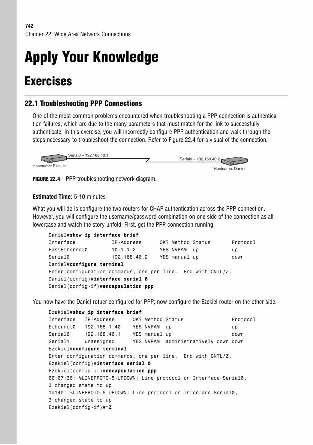
742
Chapter 22: Wide Area Network Connections
Apply Your Knowledge
Exercises
22.1 Troubleshooting PPP Connections
One of the most common problems encountered when troubleshooting a PPP connection is authentica-tion failures, which are due to the many parameters that must match for the link to successfully authenticate. In this exercise, you will incorrectly configure PPP authentication and walk through thesteps necessary to troubleshoot the connection. Refer to Figure 22.4 for a visual of the connection.
Serial0 – 192.168.40.1Serial0 – 192.168.40.2
Hostname: EzekielHostname: Daniel
FIGURE 22.4 PPP troubleshooting network diagram.
Estimated Time: 5-10 minutes
What you will do is configure the two routers for CHAP authentication across the PPP connection.However, you will configure the username/password combination on one side of the connection as alllowercase and watch the story unfold. First, get the PPP connection running:
Daniel#show ip interface briefInterface IP-Address OK? Method Status ProtocolFastEthernet0 10.1.1.2 YES NVRAM up upSerial0 192.168.40.2 YES manual up downDaniel#configure terminalEnter configuration commands, one per line. End with CNTL/Z.Daniel(config)#interface serial 0Daniel(config-if)#encapsulation ppp
You now have the Daniel rotuer configured for PPP; now configure the Ezekiel router on the other side.
Ezekiel#show ip interface briefInterface IP-Address OK? Method Status ProtocolEthernet0 192.168.1.40 YES NVRAM up upSerial0 192.168.40.1 YES manual up downSerial1 unassigned YES NVRAM administratively down downEzekiel#configure terminalEnter configuration commands, one per line. End with CNTL/Z.Ezekiel(config)#interface serial 0Ezekiel(config-if)#encapsulation ppp00:07:36: %LINEPROTO-5-UPDOWN: Line protocol on Interface Serial0,3 changed state to up1d14h: %LINEPROTO-5-UPDOWN: Line protocol on Interface Serial0,3 changed state to upEzekiel(config-if)#^Z
Apply Your Knowledge743
1d14h: %SYS-5-CONFIG_I: Configured from console by consoleEzekiel#ping 192.168.40.2Type escape sequence to abort.Sending 5, 100-byte ICMP Echos to 192.168.40.2, timeout is 2 seconds:!!!!!Success rate is 100 percent (5/5), round-trip min/avg/max = 56/59/72 ms
It looks like the PPP link has been brought up successfully and you are now able to ping between the tworouters. Now add the authentication piece to the picture:
Ezekiel#configure terminalEnter configuration commands, one per line. End with CNTL/Z.Ezekiel(config)#username Daniel password examprepEzekiel(config)#interface serial 0Ezekiel(config-if)#ppp authentication chap00:11:11: %LINEPROTO-5-UPDOWN: Line protocol on Interface Serial0,3 changed state to down
Notice that as soon as you turned on CHAP authentication for one side of the connection, the link wentdown. This is because one side of the connection is configured to require authentication while the otheris not configured to support it. You can solve that problem and, at the same time, introduce the authenti-cation configuration error.
Daniel#configure terminalEnter configuration commands, one per line. End with CNTL/Z.Daniel(config-if)#exitDaniel(config)#username Ezekiel password examcramDaniel(config)#interface serial 0Daniel(config-if)#ppp authentication chapDaniel(config-if)#exitDaniel(config)#exit1d14h: %SYS-5-CONFIG_I: Configured from console by consoleDaniel#show ip interface briefInterface IP-Address OK? Method Status ProtocolFastEthernet0 10.1.1.2 YES NVRAM up upSerial0 192.168.40.2 YES manual up down
Notice that the password examcram was used for the Ezekiel account rather than examprep. BecauseCHAP requires both passwords to be the same on both sides of the connection, the Serial0 link remainsdown. Now, if we did not know about this configuration error, the troubleshooting process would gosomething like this:
Daniel#show interface serial 0Serial0 is up, line protocol is downHardware is PowerQUICC SerialInternet address is 192.168.40.2/24MTU 1500 bytes, BW 1544 Kbit, DLY 20000 usec,
reliability 255/255, txload 1/255, rxload 1/255Encapsulation PPP, loopback not setKeepalive set (10 sec)
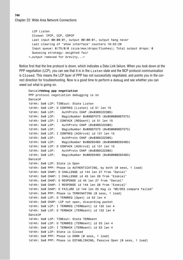
744
Chapter 22: Wide Area Network Connections
LCP ListenClosed: IPCP, CCP, CDPCPLast input 00:00:01, output 00:00:01, output hang neverLast clearing of “show interface” counters 16:52:28Input queue: 0/75/0/0 (size/max/drops/flushes); Total output drops: 0Queueing strategy: weighted fair
<…output removed for brevity...>
Notice first that the line protocol is down, which indicates a Data Link failure. When you look down at thePPP negotiation (LCP), you can see that it is in the Listen state and the NCP protocol communicationis Closed. This means the LCP layer of PPP has not successfully negotiated, and points you in the cor-rect direction for troubleshooting. Now is a good time to perform a debug and see whether you canweed out what is going on.
Daniel#debug ppp negotiationPPP protocol negotiation debugging is onDaniel#1d14h: Se0 LCP: TIMEout: State Listen1d14h: Se0 LCP: O CONFREQ [Listen] id 51 len 151d14h: Se0 LCP: AuthProto CHAP (0x0305C22305)1d14h: Se0 LCP: MagicNumber 0x098EF573 (0x0506098EF573)1d14h: Se0 LCP: I CONFACK [REQsent] id 51 len 151d14h: Se0 LCP: AuthProto CHAP (0x0305C22305)1d14h: Se0 LCP: MagicNumber 0x098EF573 (0x0506098EF573)1d14h: Se0 LCP: I CONFREQ [ACKrcvd] id 131 len 151d14h: Se0 LCP: AuthProto CHAP (0x0305C22305)1d14h: Se0 LCP: MagicNumber 0x002934B3 (0x0506002934B3)1d14h: Se0 LCP: O CONFACK [ACKrcvd] id 131 len 151d14h: Se0 LCP: AuthProto CHAP (0x0305C22305)1d14h: Se0 LCP: MagicNumber 0x002934B3 (0x0506002934B3)Daniel#1d14h: Se0 LCP: State is Open1d14h: Se0 PPP: Phase is AUTHENTICATING, by both [0 sess, 1 load]1d14h: Se0 CHAP: O CHALLENGE id 144 len 27 from “Daniel”1d14h: Se0 CHAP: I CHALLENGE id 45 len 28 from “Ezekiel”1d14h: Se0 CHAP: O RESPONSE id 45 len 27 from “Daniel”1d14h: Se0 CHAP: I RESPONSE id 144 len 28 from “Ezekiel”1d14h: Se0 CHAP: O FAILURE id 144 len 25 msg is “MD/DES compare failed”1d14h: Se0 PPP: Phase is TERMINATING [0 sess, 1 load]1d14h: Se0 LCP: O TERMREQ [Open] id 52 len 41d14h: Se0 CHAP: LCP not open, discarding packet1d14h: Se0 LCP: I TERMREQ [TERMsent] id 132 len 41d14h: Se0 LCP: O TERMACK [TERMsent] id 132 len 4Daniel#1d14h: Se0 LCP: TIMEout: State TERMsent1d14h: Se0 LCP: O TERMREQ [TERMsent] id 53 len 41d14h: Se0 LCP: I TERMACK [TERMsent] id 53 len 41d14h: Se0 LCP: State is Closed1d14h: Se0 PPP: Phase is DOWN [0 sess, 1 load]1d14h: Se0 PPP: Phase is ESTABLISHING, Passive Open [0 sess, 1 load]
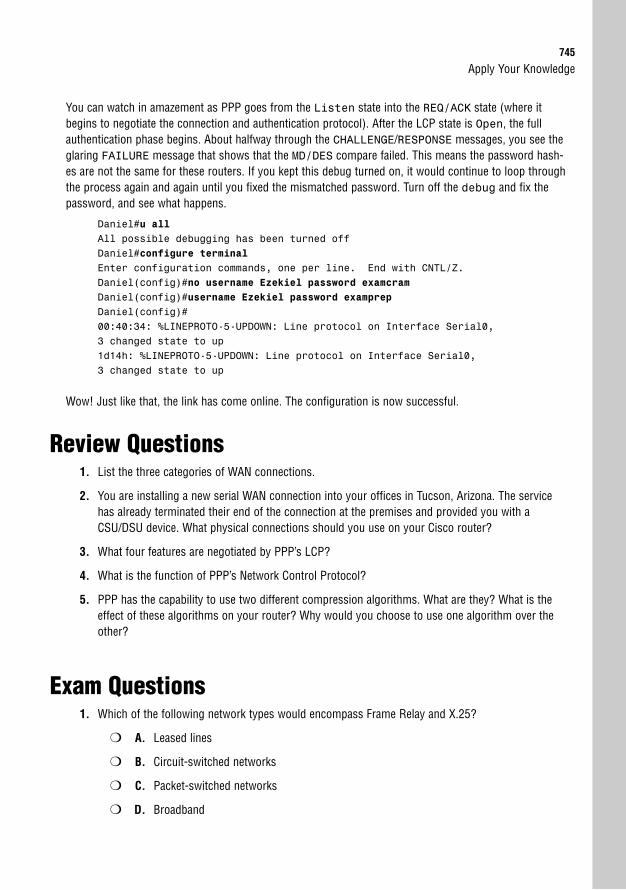
Apply Your Knowledge745
You can watch in amazement as PPP goes from the Listen state into the REQ/ACK state (where itbegins to negotiate the connection and authentication protocol). After the LCP state is Open, the fullauthentication phase begins. About halfway through the CHALLENGE/RESPONSE messages, you see theglaring FAILURE message that shows that the MD/DES compare failed. This means the password hash-es are not the same for these routers. If you kept this debug turned on, it would continue to loop throughthe process again and again until you fixed the mismatched password. Turn off the debug and fix thepassword, and see what happens.
Daniel#u allAll possible debugging has been turned offDaniel#configure terminalEnter configuration commands, one per line. End with CNTL/Z.Daniel(config)#no username Ezekiel password examcramDaniel(config)#username Ezekiel password examprepDaniel(config)#00:40:34: %LINEPROTO-5-UPDOWN: Line protocol on Interface Serial0,3 changed state to up1d14h: %LINEPROTO-5-UPDOWN: Line protocol on Interface Serial0,3 changed state to up
Wow! Just like that, the link has come online. The configuration is now successful.
Review Questions1. List the three categories of WAN connections.
2. You are installing a new serial WAN connection into your offices in Tucson, Arizona. The servicehas already terminated their end of the connection at the premises and provided you with aCSU/DSU device. What physical connections should you use on your Cisco router?
3. What four features are negotiated by PPP’s LCP?
4. What is the function of PPP’s Network Control Protocol?
5. PPP has the capability to use two different compression algorithms. What are they? What is theeffect of these algorithms on your router? Why would you choose to use one algorithm over theother?
Exam Questions1. Which of the following network types would encompass Frame Relay and X.25?
❍ A. Leased lines
❍ B. Circuit-switched networks
❍ C. Packet-switched networks
❍ D. Broadband
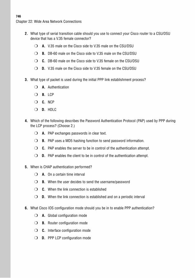
746
Chapter 22: Wide Area Network Connections
2. What type of serial transition cable should you use to connect your Cisco router to a CSU/DSUdevice that has a V.35 female connector?
❍ A. V.35 male on the Cisco side to V.35 male on the CSU/DSU
❍ B. DB-60 male on the Cisco side to V.35 male on the CSU/DSU
❍ C. DB-60 male on the Cisco side to V.35 female on the CSU/DSU
❍ D. V.35 male on the Cisco side to V.35 female on the CSU/DSU
3. What type of packet is used during the initial PPP link establishment process?
❍ A. Authentication
❍ B. LCP
❍ C. NCP
❍ D. HDLC
4. Which of the following describes the Password Authentication Protocol (PAP) used by PPP duringthe LCP process? (Choose 2.)
❍ A. PAP exchanges passwords in clear text.
❍ B. PAP uses a MD5 hashing function to send password information.
❍ C. PAP enables the server to be in control of the authentication attempt.
❍ D. PAP enables the client to be in control of the authentication attempt.
5. When is CHAP authentication performed?
❍ A. On a certain time interval
❍ B. When the user decides to send the username/password
❍ C. When the link connection is established
❍ D. When the link connection is established and on a periodic interval
6. What Cisco IOS configuration mode should you be in to enable PPP authentication?
❍ A. Global configuration mode
❍ B. Router configuration mode
❍ C. Interface configuration mode
❍ D. PPP LCP configuration mode
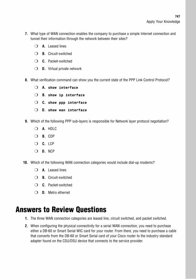
Apply Your Knowledge747
7. What type of WAN connection enables the company to purchase a simple Internet connection andtunnel their information through the network between their sites?
❍ A. Leased lines
❍ B. Circuit-switched
❍ C. Packet-switched
❍ D. Virtual private network
8. What verification command can show you the current state of the PPP Link Control Protocol?
❍ A. show interface
❍ B. show ip interface
❍ C. show ppp interface
❍ D. show wan interface
9. Which of the following PPP sub-layers is responsible for Network layer protocol negotiation?
❍ A. HDLC
❍ B. CDP
❍ C. LCP
❍ D. NCP
10. Which of the following WAN connection categories would include dial-up modems?
❍ A. Leased lines
❍ B. Circuit-switched
❍ C. Packet-switched
❍ D. Metro ethernet
Answers to Review Questions1. The three WAN connection categories are leased line, circuit switched, and packet switched.
2. When configuring the physical connectivity for a serial WAN connection, you need to purchaseeither a DB-60 or Smart Serial WIC card for your router. From there, you need to purchase a cablethat converts from the DB-60 or Smart Serial card of your Cisco router to the industry standardadapter found on the CSU/DSU device that connects to the service provider.
748
3. The four features negotiated by the PPP Link Control Protocol (LCP) are compression, callback,multilink, and authentication.
4. The Network Control Protocol (NCP) enables the router to encapsulate multiple upper-layer proto-cols (such as IP, IPX, and Appletalk) over a PPP WAN connection.
5. The two PPP compression algorithms are Stacker and Predictor. The Stacker algorithm requiresmore processor resources and fewer memory resources. The Predictor algorithm uses more mem-ory resources and fewer processor resources. Stacker is the best algorithm to use when there arevarying traffic types crossing the PPP WAN connection. Predictor works best when you have simi-lar traffic types using the PPP WAN connection.
Answers to Exam Questions1. C. Frame Relay and X.25 fall under the packet-switched networks category. These networks estab-
lish connections through a service provider cloud using virtual circuits. Answer B is incorrectbecause circuit-switched networks include technologies such as modems and ISDN. Answer A isincorrect because leased lines use dedicated bandwidth between locations. Answer D is incorrectbecause broadband encompasses DSL and cable modem technology.
2. B. The Cisco side of the connection always uses either a DB-60 or Smart Serial connector (theseare always male because the router has female ports). Because the CSU/DSU has a V.35 femaleconnector, you should be using a V.35 male transition cable. All other answers are incorrectbecause they use either the wrong connector type or gender on the Cisco side.
3. B. The Link Control Protocol (LCP) is used to negotiate all options related to PPP during the linkestablishment phase. The Network Control Protocol (NCP) negotiates the upper-layer protocolsonly after the initial PPP link has been established. The HDLC layer of PPP is what allows for multi-vendor interoperability with the protocol. Answer A is incorrect because an authentication packetfalls under the LCP negotiations. Answer C is incorrect because NCP negotiates the upper-layerprotocols. Answer D is incorrect because HDLC is used to give PPP an industry standard founda-tion when connecting to non-Cisco equipment.
4. A, D. PAP is the older of the two PPP authentication protocols. It has major security flaws, includ-ing the sending of passwords in clear text and allowing the client to choose when it sends thepassword. Answers B and C are incorrect because the MD5 hashing and server control is a func-tion of the CHAP.
5. D. CHAP requires authentication both when the link is initially established and on a periodic basisthereafter. This is awesome because it combats playback attacks and packet sniffing (passwordsare not sent). PAP requires authentication only when the link is initially established and when theclient chooses to send the credentials, which is why answers B and C are incorrect. Answer A isincorrect because CHAP also sends authentication credentials when the link is initially established.
6. C. You enable PPP authentication from the interface configuration mode by typing the commandppp authentication <chap/pap>. All other answers are either irrelevant or non-existent(there is no PPP LCP configuration mode in the Cisco IOS).
Chapter 22: Wide Area Network Connections
Apply Your Knowledge749
7. D. VPNs enable companies to purchase simple Internet connections and tunnel their informationthrough the networks between their sites. This information is heavily encrypted to ensure it is notcompromised crossing the public network. This is far cheaper than any other type of WAN connec-tion, but can suffer from the heavy encryption slowdown. Answers A, B, and C are incorrectbecause leased lines and circuit-switched and packet-switched networks require no tunneling orencryption capabilities.
8. A. The show interface command is used to verify the current state of the PPP LCP negotia-tions. This shows Open, Listen, ACKSent, or TERMSent, depending on the state of LCP at thetime (you want LCP to show Open). The other show commands are either irrelevant or would pro-duce invalid syntax.
9. D. NCP is used to negotiate the Network layer protocols. These negotiations are typically shown asin the syntax <negotiated protocol>CP in show interface output, such as IPCP (forthe IP protocol), CDPCP (for the CDP protocol), or IPXCP (for the IPX protocol). Answer A isincorrect because HDLC is used at a lower layer of PPP to provide multi-vendor interoperability,and answer C is incorrect because LCP is used to negotiate PPP features. Answer B is incorrectbecause CDP has nothing to do with WAN links.
10. B. Circuit-switched connections encompass anything that has to dial a number to make a connec-tion. These connections typically use the telephone company as a backbone. Answer C is incorrectas packet-switched networks include technologies such as X.25 and Frame Relay. Answer A isincorrect because leased lines do not dial because they are permanently established connections.Answer D is incorrect because metro ethernet is extremely high-speed connections runningthrough a metropolitan area.
Suggested Reading and Resources1. Cisco Introduction to WAN Technologies, http://www.cisco.com/
univercd/cc/td/doc/cisintwk/ito_doc/introwan.htm.
2. Ward, Chris and Cioara, Jeremy. Exam Cram 2 CCNA Practice Questions. QuePublishing, 2004.
3. Quinn, Eric and Glauser, Fred. BCRAN Exam Cram 2 (Exam 642-821). QuePublishing, 2003.

This page intentionally left blank

23C H A P T E R T W E N T Y - T H R E E
Frame Relay
ObjectivesThis chapter covers the following Cisco-specified objectives for the “Implement and verifyWAN links” section of the 640-802 CCNA exam:
. Describe different methods for connecting to a WAN
. Configure and verify Frame Relay on Cisco routers
. Troubleshoot WAN implementation issues
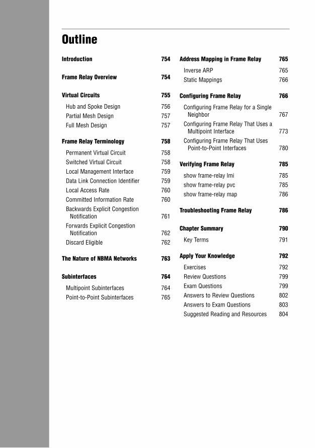
OutlineIntroduction 754
Frame Relay Overview 754
Virtual Circuits 755
Hub and Spoke Design 756
Partial Mesh Design 757
Full Mesh Design 757
Frame Relay Terminology 758
Permanent Virtual Circuit 758
Switched Virtual Circuit 758
Local Management Interface 759
Data Link Connection Identifier 759
Local Access Rate 760
Committed Information Rate 760
Backwards Explicit Congestion Notification 761
Forwards Explicit Congestion Notification 762
Discard Eligible 762
The Nature of NBMA Networks 763
Subinterfaces 764
Multipoint Subinterfaces 764
Point-to-Point Subinterfaces 765
Address Mapping in Frame Relay 765
Inverse ARP 765
Static Mappings 766
Configuring Frame Relay 766
Configuring Frame Relay for a SingleNeighbor 767
Configuring Frame Relay That Uses aMultipoint Interface 773
Configuring Frame Relay That Uses Point-to-Point Interfaces 780
Verifying Frame Relay 785
show frame-relay lmi 785
show frame-relay pvc 785
show frame-relay map 786
Troubleshooting Frame Relay 786
Chapter Summary 790
Key Terms 791
Apply Your Knowledge 792
Exercises 792
Review Questions 799
Exam Questions 799
Answers to Review Questions 802
Answers to Exam Questions 803
Suggested Reading and Resources 804

Study Strategies. Read the information presented in the chapter, paying special attention to
tables, Notes, and Exam Alerts.
. Spend as much time as you find necessary on the terms and concepts ofFrame Relay. After you fully understand the operation, the configurationis not very difficult.
. Although configuration questions may exist, the CCNA exam typicallyfocuses on the concepts behind Frame Relay, with many of the configura-tions reserved for the CCNP BCRAN exam.
754
IntroductionUp until now, most of the WAN connection types discussed so far have provided dedicatedbandwidth. For example, if you purchase a point-to-point leased-line connection at a T1speed, you have 1.544Mbps at your disposal, 24 hours a day. This bandwidth is there regard-less of whether you use it or not. Likewise, if you are using an ISDN BRI connection and dialthe line up, you have 128Kbps of bandwidth at your disposal. Your network might not chooseto send a single packet across the line; regardless, the 128Kbps of bandwidth sits there wait-ing. But with Frame Relay (and packet-switched networking, in general), the service providershad a novel idea: If you’re not using your bandwidth, should it just sit there? I think not.
Welcome to the world of Frame Relay, the first connection type where lightning-bolt WANlinks terminate into some sort of fluffy cloud rather than going directly to another router. Thisis a place where your destination address is not actually at the destination, but rather, termi-nates at the source. With Frame Relay, the bandwidth you pay for might just be the beginningof the bandwidth you get. Yes, my friends, you have entered the WAN Link Twilight Zone.
Frame Relay OverviewObjective:
. Describe different methods for connecting to a WAN
Frame Relay is by far the most conceptually complex topic in the CCNA-level material. Muchas with subnetting, though, after you get it, you’ll think it’s the greatest thing since slicedbread. However, until you get to that point, you’ll probably think people that use Frame Relayare insane. Unfortunately (or fortunately, depending on your perspective), Frame Relay is oneof the more popular WAN connection types in use in production networks. It offers the highspeed demanded by the networks of today at cut-rate prices that managers love.
Frame Relay connections work quite differently than the typical WAN connections discussedthus far. Rather than have a single connection from a location to another location (also knownas point-to-point), you might have a connection going from one location to five other loca-tions out a single, physical serial interface. You start to get the feel that this is an ethernet-styleconnection where any device connected to a hub can reach any other device plugged into thesame hub. Depending on your Frame Relay configuration, this may not be far from the truth.Rather than connect sites together through individual physical interfaces, Frame Relay con-nects sites together with virtual circuits.
Chapter 23: Frame Relay
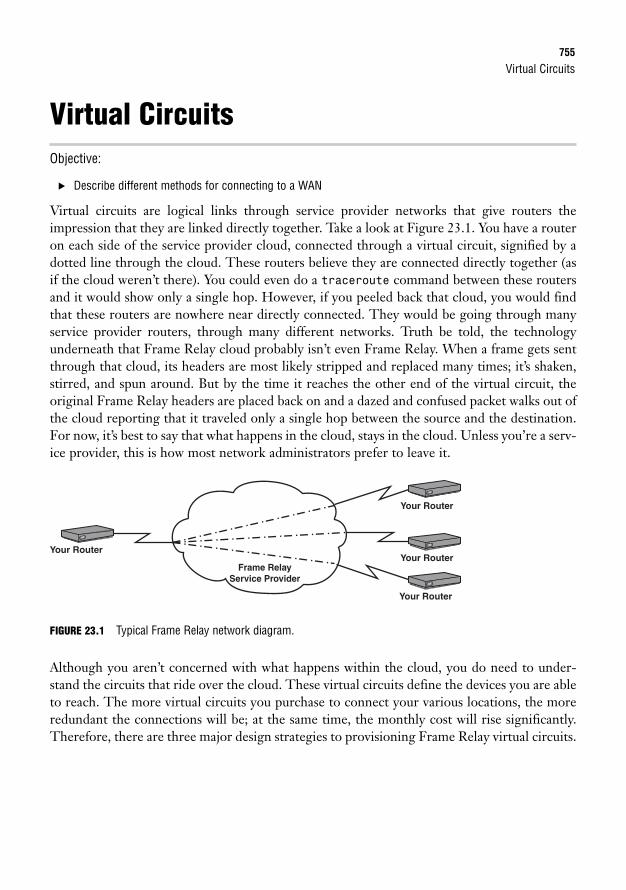
Virtual Circuits755
Virtual CircuitsObjective:
. Describe different methods for connecting to a WAN
Virtual circuits are logical links through service provider networks that give routers theimpression that they are linked directly together. Take a look at Figure 23.1. You have a routeron each side of the service provider cloud, connected through a virtual circuit, signified by adotted line through the cloud. These routers believe they are connected directly together (asif the cloud weren’t there). You could even do a traceroute command between these routersand it would show only a single hop. However, if you peeled back that cloud, you would findthat these routers are nowhere near directly connected. They would be going through manyservice provider routers, through many different networks. Truth be told, the technologyunderneath that Frame Relay cloud probably isn’t even Frame Relay. When a frame gets sentthrough that cloud, its headers are most likely stripped and replaced many times; it’s shaken,stirred, and spun around. But by the time it reaches the other end of the virtual circuit, theoriginal Frame Relay headers are placed back on and a dazed and confused packet walks out ofthe cloud reporting that it traveled only a single hop between the source and the destination.For now, it’s best to say that what happens in the cloud, stays in the cloud. Unless you’re a serv-ice provider, this is how most network administrators prefer to leave it.
Your RouterYour Router
Your Router
Frame Relay Service Provider
Your Router
FIGURE 23.1 Typical Frame Relay network diagram.
Although you aren’t concerned with what happens within the cloud, you do need to under-stand the circuits that ride over the cloud. These virtual circuits define the devices you are ableto reach. The more virtual circuits you purchase to connect your various locations, the moreredundant the connections will be; at the same time, the monthly cost will rise significantly.Therefore, there are three major design strategies to provisioning Frame Relay virtual circuits.
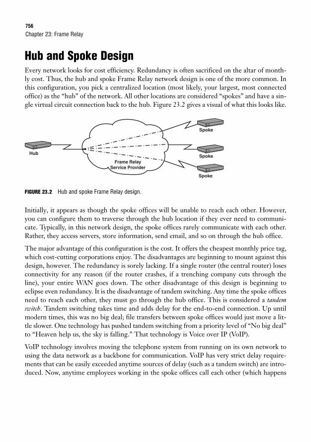
756
Hub and Spoke DesignEvery network looks for cost efficiency. Redundancy is often sacrificed on the altar of month-ly cost. Thus, the hub and spoke Frame Relay network design is one of the more common. Inthis configuration, you pick a centralized location (most likely, your largest, most connectedoffice) as the “hub” of the network. All other locations are considered “spokes” and have a sin-gle virtual circuit connection back to the hub. Figure 23.2 gives a visual of what this looks like.
Chapter 23: Frame Relay
HubSpoke
Spoke
Frame Relay Service Provider
Spoke
FIGURE 23.2 Hub and spoke Frame Relay design.
Initially, it appears as though the spoke offices will be unable to reach each other. However,you can configure them to traverse through the hub location if they ever need to communi-cate. Typically, in this network design, the spoke offices rarely communicate with each other.Rather, they access servers, store information, send email, and so on through the hub office.
The major advantage of this configuration is the cost. It offers the cheapest monthly price tag,which cost-cutting corporations enjoy. The disadvantages are beginning to mount against thisdesign, however. The redundancy is sorely lacking. If a single router (the central router) losesconnectivity for any reason (if the router crashes, if a trenching company cuts through theline), your entire WAN goes down. The other disadvantage of this design is beginning toeclipse even redundancy. It is the disadvantage of tandem switching. Any time the spoke officesneed to reach each other, they must go through the hub office. This is considered a tandemswitch. Tandem switching takes time and adds delay for the end-to-end connection. Up untilmodern times, this was no big deal; file transfers between spoke offices would just move a lit-tle slower. One technology has pushed tandem switching from a priority level of “No big deal”to “Heaven help us, the sky is falling.” That technology is Voice over IP (VoIP).
VoIP technology involves moving the telephone system from running on its own network tousing the data network as a backbone for communication. VoIP has very strict delay require-ments that can be easily exceeded anytime sources of delay (such as a tandem switch) are intro-duced. Now, anytime employees working in the spoke offices call each other (which happens
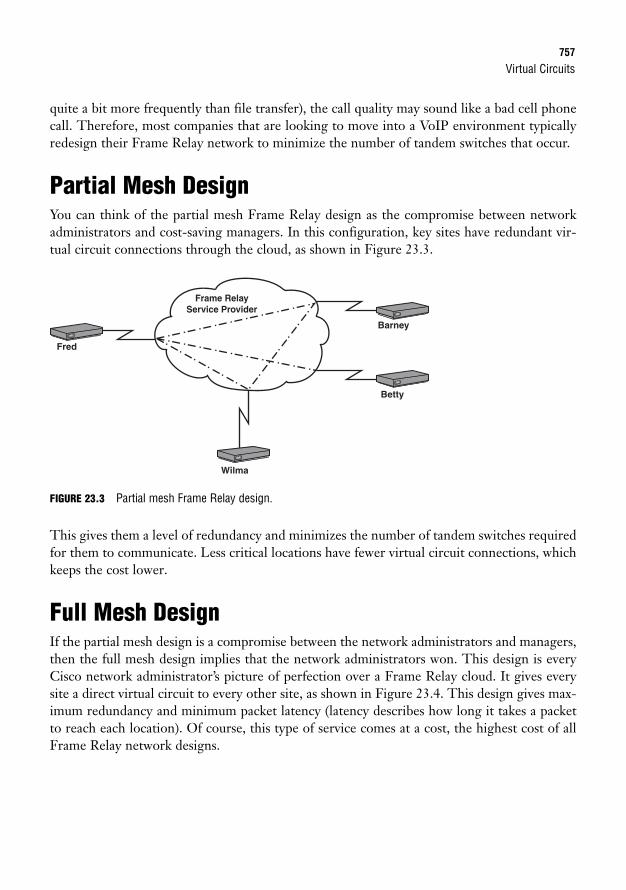
Virtual Circuits757
quite a bit more frequently than file transfer), the call quality may sound like a bad cell phonecall. Therefore, most companies that are looking to move into a VoIP environment typicallyredesign their Frame Relay network to minimize the number of tandem switches that occur.
Partial Mesh DesignYou can think of the partial mesh Frame Relay design as the compromise between networkadministrators and cost-saving managers. In this configuration, key sites have redundant vir-tual circuit connections through the cloud, as shown in Figure 23.3.
Wilma
Fred
Betty
Frame Relay Service Provider
Barney
FIGURE 23.3 Partial mesh Frame Relay design.
This gives them a level of redundancy and minimizes the number of tandem switches requiredfor them to communicate. Less critical locations have fewer virtual circuit connections, whichkeeps the cost lower.
Full Mesh DesignIf the partial mesh design is a compromise between the network administrators and managers,then the full mesh design implies that the network administrators won. This design is everyCisco network administrator’s picture of perfection over a Frame Relay cloud. It gives everysite a direct virtual circuit to every other site, as shown in Figure 23.4. This design gives max-imum redundancy and minimum packet latency (latency describes how long it takes a packetto reach each location). Of course, this type of service comes at a cost, the highest cost of allFrame Relay network designs.
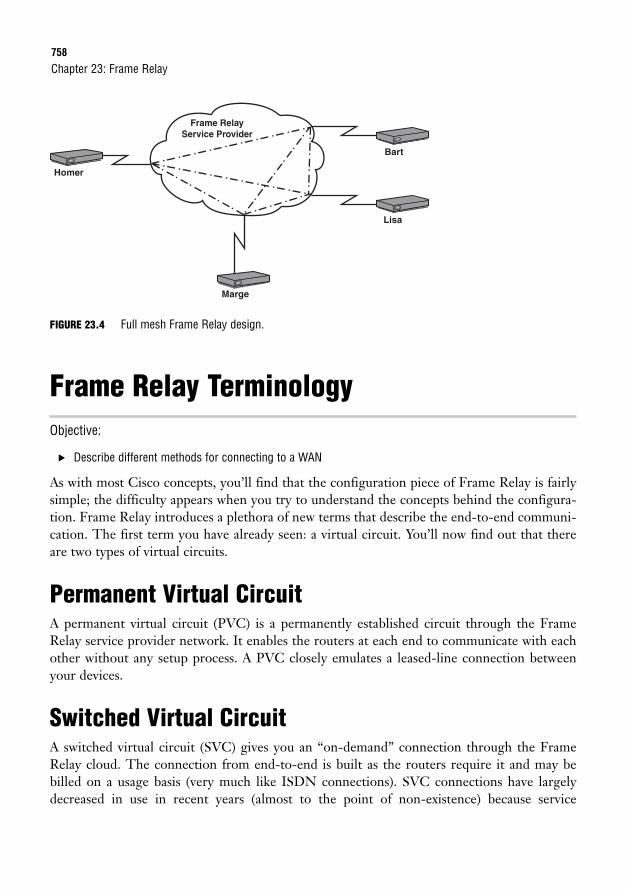
758
FIGURE 23.4 Full mesh Frame Relay design.
Frame Relay TerminologyObjective:
. Describe different methods for connecting to a WAN
As with most Cisco concepts, you’ll find that the configuration piece of Frame Relay is fairlysimple; the difficulty appears when you try to understand the concepts behind the configura-tion. Frame Relay introduces a plethora of new terms that describe the end-to-end communi-cation. The first term you have already seen: a virtual circuit. You’ll now find out that thereare two types of virtual circuits.
Permanent Virtual CircuitA permanent virtual circuit (PVC) is a permanently established circuit through the FrameRelay service provider network. It enables the routers at each end to communicate with eachother without any setup process. A PVC closely emulates a leased-line connection betweenyour devices.
Switched Virtual CircuitA switched virtual circuit (SVC) gives you an “on-demand” connection through the FrameRelay cloud. The connection from end-to-end is built as the routers require it and may bebilled on a usage basis (very much like ISDN connections). SVC connections have largelydecreased in use in recent years (almost to the point of non-existence) because service
Chapter 23: Frame Relay
Marge
Homer
Lisa
Frame Relay Service Provider
Bart
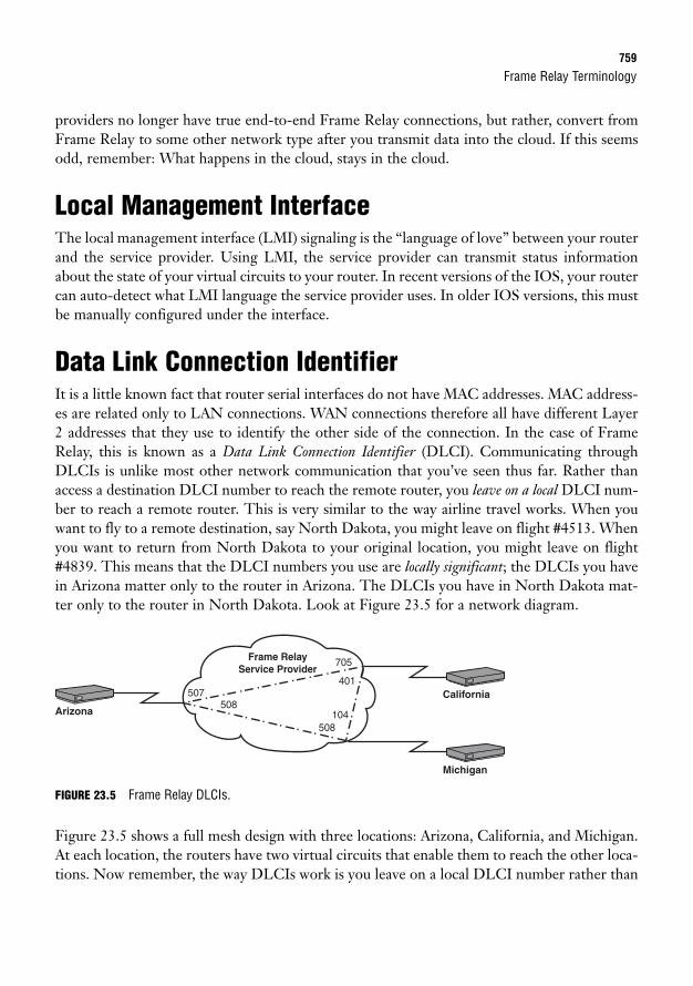
Frame Relay Terminology759
providers no longer have true end-to-end Frame Relay connections, but rather, convert fromFrame Relay to some other network type after you transmit data into the cloud. If this seemsodd, remember: What happens in the cloud, stays in the cloud.
Local Management InterfaceThe local management interface (LMI) signaling is the “language of love” between your routerand the service provider. Using LMI, the service provider can transmit status informationabout the state of your virtual circuits to your router. In recent versions of the IOS, your routercan auto-detect what LMI language the service provider uses. In older IOS versions, this mustbe manually configured under the interface.
Data Link Connection IdentifierIt is a little known fact that router serial interfaces do not have MAC addresses. MAC address-es are related only to LAN connections. WAN connections therefore all have different Layer2 addresses that they use to identify the other side of the connection. In the case of FrameRelay, this is known as a Data Link Connection Identifier (DLCI). Communicating throughDLCIs is unlike most other network communication that you’ve seen thus far. Rather thanaccess a destination DLCI number to reach the remote router, you leave on a local DLCI num-ber to reach a remote router. This is very similar to the way airline travel works. When youwant to fly to a remote destination, say North Dakota, you might leave on flight #4513. Whenyou want to return from North Dakota to your original location, you might leave on flight#4839. This means that the DLCI numbers you use are locally significant; the DLCIs you havein Arizona matter only to the router in Arizona. The DLCIs you have in North Dakota mat-ter only to the router in North Dakota. Look at Figure 23.5 for a network diagram.
Arizona
California
Michigan
Frame Relay Service Provider
705
508104
401
508507
FIGURE 23.5 Frame Relay DLCIs.
Figure 23.5 shows a full mesh design with three locations: Arizona, California, and Michigan.At each location, the routers have two virtual circuits that enable them to reach the other loca-tions. Now remember, the way DLCIs work is you leave on a local DLCI number rather than
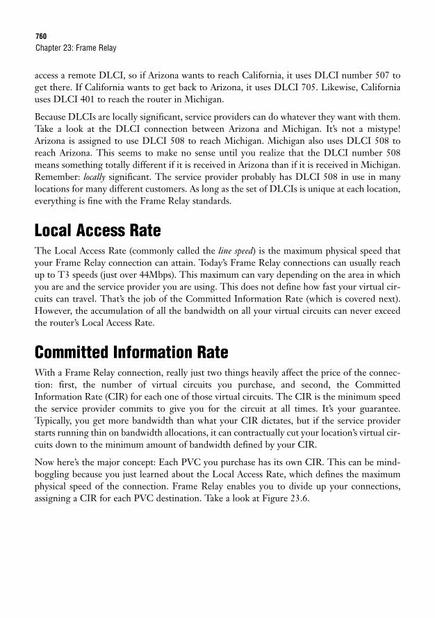
760
access a remote DLCI, so if Arizona wants to reach California, it uses DLCI number 507 toget there. If California wants to get back to Arizona, it uses DLCI 705. Likewise, Californiauses DLCI 401 to reach the router in Michigan.
Because DLCIs are locally significant, service providers can do whatever they want with them.Take a look at the DLCI connection between Arizona and Michigan. It’s not a mistype!Arizona is assigned to use DLCI 508 to reach Michigan. Michigan also uses DLCI 508 toreach Arizona. This seems to make no sense until you realize that the DLCI number 508means something totally different if it is received in Arizona than if it is received in Michigan.Remember: locally significant. The service provider probably has DLCI 508 in use in manylocations for many different customers. As long as the set of DLCIs is unique at each location,everything is fine with the Frame Relay standards.
Local Access RateThe Local Access Rate (commonly called the line speed) is the maximum physical speed thatyour Frame Relay connection can attain. Today’s Frame Relay connections can usually reachup to T3 speeds (just over 44Mbps). This maximum can vary depending on the area in whichyou are and the service provider you are using. This does not define how fast your virtual cir-cuits can travel. That’s the job of the Committed Information Rate (which is covered next).However, the accumulation of all the bandwidth on all your virtual circuits can never exceedthe router’s Local Access Rate.
Committed Information RateWith a Frame Relay connection, really just two things heavily affect the price of the connec-tion: first, the number of virtual circuits you purchase, and second, the CommittedInformation Rate (CIR) for each one of those virtual circuits. The CIR is the minimum speedthe service provider commits to give you for the circuit at all times. It’s your guarantee.Typically, you get more bandwidth than what your CIR dictates, but if the service providerstarts running thin on bandwidth allocations, it can contractually cut your location’s virtual cir-cuits down to the minimum amount of bandwidth defined by your CIR.
Now here’s the major concept: Each PVC you purchase has its own CIR. This can be mind-boggling because you just learned about the Local Access Rate, which defines the maximumphysical speed of the connection. Frame Relay enables you to divide up your connections,assigning a CIR for each PVC destination. Take a look at Figure 23.6.
Chapter 23: Frame Relay
Frame Relay Terminology761
FIGURE 23.6 Frame Relay CIR.
You now have a hub and spoke Frame Relay design where Arizona is connected to California,Missouri, and Oregon. Focus for the moment on Arizona: The Local Access Rate is shown asT1 speed—1.544Mbps. Each PVC has its own CIR: The PVC to California is rated at a CIRof 500Kbps, the PVC to Missouri uses a CIR of 450Kbps, and the connection to Oregon usesa 300Kbps CIR. Notice that the total bandwidth of all the PVCs does not exceed the LocalAccess Rate of the line. Remember, the CIR is the minimum amount of bandwidth the serv-ice provider gives you. If you oversubscribe your Local Access Rate with the sum of all theCIRs, you may be physically limiting how much bandwidth the service provider would be will-ing to give you (and paying too much for your connection).
Many service providers offer extremely low-cost Frame Relay connections that are rated at azero CIR. This means that you’ll probably get bandwidth, but the service provider does notguarantee anything. When signing up for one of these connections, be sure to use a reputableservice provider because some of the smaller service providers may be oversubscribing theirnetwork with these connections and not have enough bandwidth to give you a reliable connection.
Backwards Explicit Congestion NotificationBecause service providers allow you to burst above your CIR (using more bandwidth thanyou’re paying for), you have the potential of taking advantage of the service provider. If notconfigured differently, your router will attempt to send across all PVCs at the maximum speedthe physical interface can handle (your Local Access Rate). If there is a large mismatch betweenyour CIR and the Local Access Rate, your PVC will soon begin to become congested. Theservice provider will send messages to the router sending the large amount of traffic attempt-ing to tell it to slow down. This is known as a Backwards Explicit Congestion Notification(BECN) message. The method the service provider uses to send this notification is importantto understand.
ArizonaMissouri
Oregon
Frame RelayService Provider
CaliforniaLine Speed1.544Mbps
CIR 500KbpsCIR 450Kbps
CIR 300Kbps
762
Because of the way PVCs are engineered, the service provider cannot communicate directly tothe router sending the data. Instead, it modifies the headers of return traffic to notify the per-son sending the excessive amount of data. For example, imagine that you were sitting at theArizona location (from the prior Figure 23.6) transferring a large file to the California loca-tion via FTP. The entire time you are sending this file, the California site is sending TCPAcknowledgments (ACKs) back to confirm the data receipt. If the Arizona site is excessivelyexceeding the CIR, the service provider flips a bit (known as the BECN bit) in the header ofthe ACK messages to notify the sender that it needs to slow down.
By default, your Cisco router ignores the BECN message (what audacity!). It does so becauseBECN response falls under a major configuration called Frame Relay Traffic Shaping, whichyou’ll learn plenty about if you decide to continue on into the CCNP courses. It is to youradvantage to drop your speed when you receive a BECN message because the service providerwill soon thereafter liquidate the vast majority of your traffic in the Frame Relay cloud, caus-ing drastic performance reductions.
Forward Explicit Congestion NotificationThis one is one of the most misunderstood of all Frame Relay terms. After you understand theconcept of a BECN, it seems logical to assume a Forward Explicit Congestion Notification(FECN) tells the receiving side of the connection to slow down. This is not true at all. Whywould a Frame Relay service provider tell the receiver to slow down? It is not sending any traf-fic, just receiving it. Instead, a FECN message is used to tell the receiver to generate trafficthat the service provider can tag with a BECN to tell the sender to slow down. I’m sure you’rethinking, “What?!?” Here’s an example.
Again, you have a device in Arizona sending traffic to the California location. This time, they aresending an enormous video stream (which uses UDP communication). UDP requires noacknowledgments, so the service provider has no return traffic to mark as a BECN to tell thesender to slow down. Instead, it tags some of the traffic heading to the receiver. This is known asa FECN (it uses the same bit in the header as the BECN, but is interpreted as a FECN becauseit is sent the other way). If the receiving router is configured to support FECNs, it generates some“junk” (called a Q.922 test frame), puts it in a frame, and sends it back to the sender. The junk inthe packet is really junk. The sending router in Arizona drops it after it is received. All it’s therefor is to give the service provider something to tag to tell Arizona to slow down. So, a FECN mes-sage is just a method to generate some traffic so the service provider can send a BECN.
Discard EligibleThis term describes any traffic that you send above the CIR you have purchased. Because youare using bandwidth that you did not pay for, the service provider automatically tags yourpackets as Discard Eligible (written as De—that’s D subscript e). Just because a packet ismarked De doesn’t mean it will be discarded. Most of the time it makes it across the Frame
Chapter 23: Frame Relay
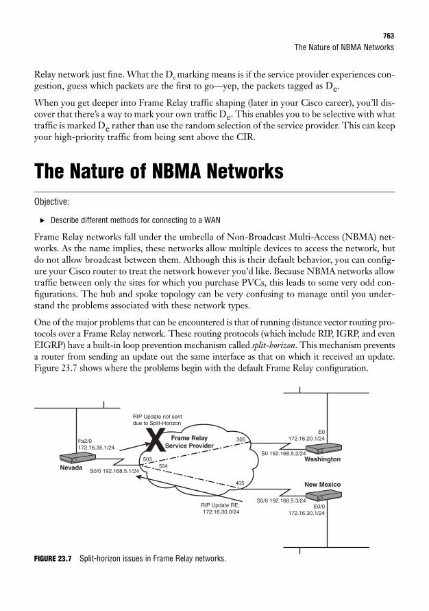
The Nature of NBMA Networks763
Relay network just fine. What the De marking means is if the service provider experiences con-gestion, guess which packets are the first to go—yep, the packets tagged as De.
When you get deeper into Frame Relay traffic shaping (later in your Cisco career), you’ll dis-cover that there’s a way to mark your own traffic De. This enables you to be selective with whattraffic is marked De rather than use the random selection of the service provider. This can keepyour high-priority traffic from being sent above the CIR.
The Nature of NBMA NetworksObjective:
. Describe different methods for connecting to a WAN
Frame Relay networks fall under the umbrella of Non-Broadcast Multi-Access (NBMA) net-works. As the name implies, these networks allow multiple devices to access the network, butdo not allow broadcast between them. Although this is their default behavior, you can config-ure your Cisco router to treat the network however you’d like. Because NBMA networks allowtraffic between only the sites for which you purchase PVCs, this leads to some very odd con-figurations. The hub and spoke topology can be very confusing to manage until you under-stand the problems associated with these network types.
One of the major problems that can be encountered is that of running distance vector routing pro-tocols over a Frame Relay network. These routing protocols (which include RIP, IGRP, and evenEIGRP) have a built-in loop prevention mechanism called split-horizon. This mechanism preventsa router from sending an update out the same interface as that on which it received an update.Figure 23.7 shows where the problems begin with the default Frame Relay configuration.
NevadaWashington
New Mexico
S0/0 192.168.5.1/24
S0 192.168.5.2/24
E0172.16.20.1/24
E0/0172.16.30.1/24
RIP Update RE:172.16.30.0/24
Fa2/0172.16.35.1/24
RIP Update not sentdue to Split-Horizon
S0/0 192.168.5.3/24
Frame Relay Service Provider
305
503504
405
X
FIGURE 23.7 Split-horizon issues in Frame Relay networks.
764
This figure shows a typical hub and spoke configuration between Nevada, Washington, andNew Mexico. Because this network is so simple, this company has decided to use the RIP rout-ing protocol. Here’s how the problem starts: New Mexico sends an RIP routing update toNevada regarding its 172.16.30.0/24 network. Nevada receives the update coming in its S0interface. Now the spilt-horizon rule steps in and tells the Nevada router not to send that rout-ing update back out the interface on which it was received. Washington never hears about the172.16.30.0 network through the RIP protocol and is unable to access any devices at that loca-tion. The same thing goes for the Washington network. The advertisement reaches theNevada router, but is never sent to New Mexico because of the split-horizon rule.
Two methods are used to solve this problem. First, you can disable the split-horizon mecha-nism altogether. This is a risky move because you are then relying on the other loop preven-tion mechanisms to keep a loop from happening in the network. The second method is to usesubinterfaces.
Chapter 23: Frame Relay
EXAM ALERTKnow the terminology behind Frame Relay. Especially ensure you understand the CIR and DLCI concepts.
SubinterfacesObjective:
. Describe different methods for connecting to a WAN
Using subinterfaces to solve your split-horizon problem is the best way to go. Subinterfacesenable you to break your single, physical interface into multiple, logical interfaces. You stillhave only a single physical connection to the Frame Relay service provider, however, yourrouter sees it as multiple connections. There are two categories of Frame Relay subinterfaces:point-to-point and multipoint. Only the point-to-point interface type is designed to fix thesplit-horizon issue by creating a subinterface for each PVC connection. However, becausewe’re talking about subinterfaces, it would be a good idea to talk about multipoint as well.
Multipoint SubinterfacesForgive me for allowing my opinion to get in the way of a neutral CCNA book, but multipointinterfaces are about as useful as a squirt gun for a scuba diver. This subinterface type enablesyou to have multiple PVCs terminating under a single, logical subinterface. This type of subin-terface is how a physical interface behaves if no subinterfaces are created. It still encounters thesame split-horizon issues, forcing you to disable split-horizon. You might wonder, “How is this
Address Mapping in Frame Relay765
type of subinterface helpful then?” Like I said…squirt gun for a scuba diver. Multipoint subin-terfaces can be useful in other, non–Frame Relay deployments, but in Frame Relay they causemore trouble than anything.
Point-to-Point SubinterfacesThis subinterface type enables you to logically design your Frame Relay network as a series ofpoint-to-point connections, no matter how complex your PVC configuration may be. EachPVC circuit is assigned to a single, point-to-point subinterface. This solves the split-horizonissue without much intervention from you because the Cisco router now sees each PVC as itsown interface. For example, if a routing update is received on Serial 0, split-horizon blocks thatupdate from being sent back out Serial 0. After you configure point-to-point subinterfaces cor-rectly, the router sees an update come in on one of the subinterfaces, such as Serial 0.10. It hasno problem sending that update out another subinterface, such as Serial 0.20, because it seesthese interfaces as two, distinct ports.
Address Mapping in Frame RelayObjective:
. Configure and verify Frame Relay on Cisco routers
Frame Relay functions at the Data Link layer of the OSI model. It provides services for theWAN just as ethernet provides services for the LAN. Because everything we do today typical-ly relies on IP addresses, Frame Relay needs to have a way of mapping its Data Link layeraddress (a DLCI) to a Network layer address (typically an IP address). For example, yourrouter may know that it can reach some location through DLCI 505, but DLCI 505 doesn’treally mean anything to your router. Your router works with IP addresses, not DLCI numbers.So to allow DLCI 505 to mean something, your router needs to somehow map this to the IPaddress that DLCI 505 can reach. There are two methods you can use to accomplish this:Inverse ARP and static mappings.
Inverse ARPInverse ARP is the router’s automated method to map DLCIs to IP addresses. It works as follows:
1. You connect your router to the Frame Relay service provider through a serial interface.
2. The service provider uses LMI to identify your router and send your router a list ofDLCIs it can use to reach your remote sites.
766
3. Your router sends Inverse ARP messages to each one of these DLCI numbers. ThisInverse ARP message carries the simple message, “Hello DLCI! Please send your IPaddress.”
4. The remote router receives the message and responds with its IP address.
5. Your router maps the DLCI number to the IP address it received.
The router sends these Inverse ARP messages to each DLCI number it has received until ithas a complete mapping table of DLCI numbers to IP addresses. All along, you as the admin-istrator have done…nothing! This is a completely automated process that makes the FrameRelay setup seamless for small environments. The only drawback to this method is it does notwork for subinterfaces. For Inverse ARP to function properly, you must leave all assignedDLCIs under the physical interface, which causes this interface to become a multipoint inter-face (if you have multiple DLCI numbers). As you have already seen, multipoint interfaceshave problems with split-horizon.
Static MappingsThe alternative to allowing Inverse ARP to automatically configure your environment is to usestatic maps. This method is also specific to multipoint-style interfaces. Using this method, youcan manually enter the DLCI to IP address mapping for each PVC. This gives you completecontrol over the mapping process and enables you to have more than one interface (unlikeInverse ARP). The specifics of this configuration, along with the considerations for point-to-point interfaces, are covered later in this chapter.
Chapter 23: Frame Relay
EXAM ALERTKnow what the differences are between Inverse ARP Frame Relay configuration and static mappings.
Configuring Frame RelayObjective:
. Configure and verify Frame Relay on Cisco routers
Configuring Frame Relay can be very simple or slightly complex, depending on your networkrequirements and design. I’d like to walk you through three configuration scenarios, explain-ing step-by-step how each piece is configured. By the time you’re finished here, you’ll be aFrame Relay expert. The three configuration scenarios are as follows:
. Configuring Frame Relay for a single neighbor
. Configuring Frame Relay that uses a multipoint interface
. Configuring Frame Relay that uses a point-to-point interface
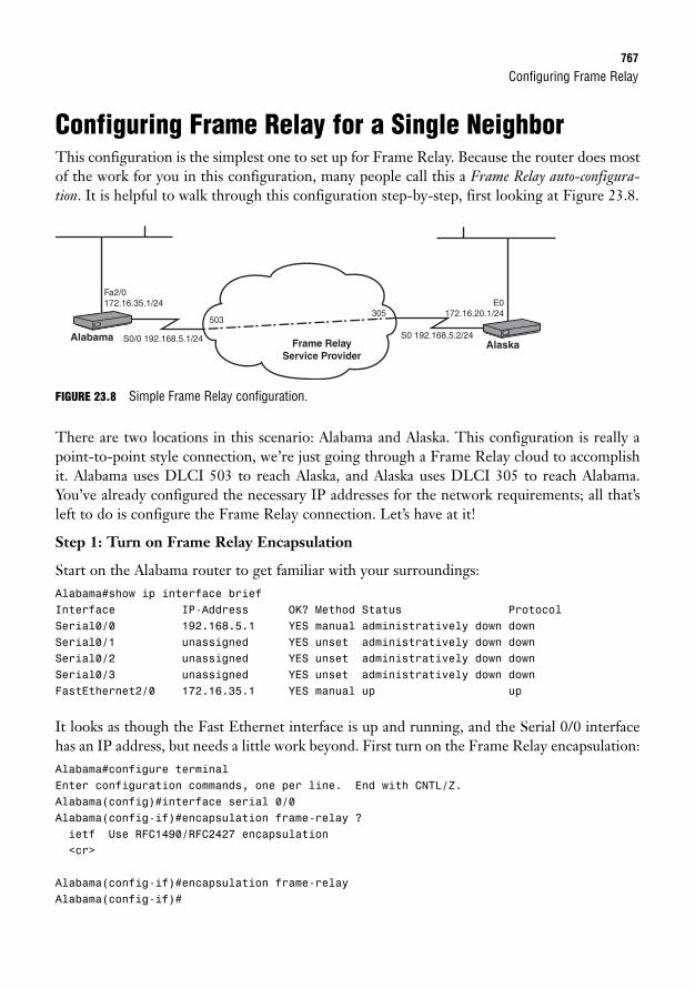
Configuring Frame Relay767
Configuring Frame Relay for a Single NeighborThis configuration is the simplest one to set up for Frame Relay. Because the router does mostof the work for you in this configuration, many people call this a Frame Relay auto-configura-tion. It is helpful to walk through this configuration step-by-step, first looking at Figure 23.8.
AlaskaS0 192.168.5.2/24
E0172.16.20.1/24
Alabama S0/0 192.168.5.1/24
Fa2/0172.16.35.1/24
Frame Relay Service Provider
305503
FIGURE 23.8 Simple Frame Relay configuration.
There are two locations in this scenario: Alabama and Alaska. This configuration is really apoint-to-point style connection, we’re just going through a Frame Relay cloud to accomplishit. Alabama uses DLCI 503 to reach Alaska, and Alaska uses DLCI 305 to reach Alabama.You’ve already configured the necessary IP addresses for the network requirements; all that’sleft to do is configure the Frame Relay connection. Let’s have at it!
Step 1: Turn on Frame Relay Encapsulation
Start on the Alabama router to get familiar with your surroundings:Alabama#show ip interface briefInterface IP-Address OK? Method Status ProtocolSerial0/0 192.168.5.1 YES manual administratively down downSerial0/1 unassigned YES unset administratively down downSerial0/2 unassigned YES unset administratively down downSerial0/3 unassigned YES unset administratively down downFastEthernet2/0 172.16.35.1 YES manual up up
It looks as though the Fast Ethernet interface is up and running, and the Serial 0/0 interfacehas an IP address, but needs a little work beyond. First turn on the Frame Relay encapsulation:Alabama#configure terminalEnter configuration commands, one per line. End with CNTL/Z.Alabama(config)#interface serial 0/0Alabama(config-if)#encapsulation frame-relay ?ietf Use RFC1490/RFC2427 encapsulation<cr>
Alabama(config-if)#encapsulation frame-relayAlabama(config-if)#
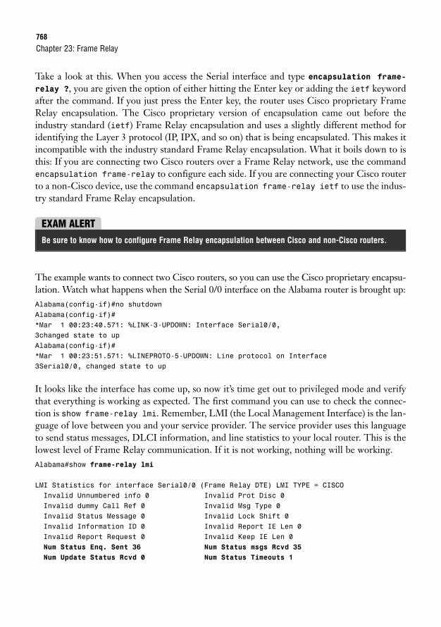
768
Take a look at this. When you access the Serial interface and type encapsulation frame-relay ?, you are given the option of either hitting the Enter key or adding the ietf keywordafter the command. If you just press the Enter key, the router uses Cisco proprietary FrameRelay encapsulation. The Cisco proprietary version of encapsulation came out before theindustry standard (ietf) Frame Relay encapsulation and uses a slightly different method foridentifying the Layer 3 protocol (IP, IPX, and so on) that is being encapsulated. This makes itincompatible with the industry standard Frame Relay encapsulation. What it boils down to isthis: If you are connecting two Cisco routers over a Frame Relay network, use the commandencapsulation frame-relay to configure each side. If you are connecting your Cisco routerto a non-Cisco device, use the command encapsulation frame-relay ietf to use the indus-try standard Frame Relay encapsulation.
Chapter 23: Frame Relay
EXAM ALERTBe sure to know how to configure Frame Relay encapsulation between Cisco and non-Cisco routers.
The example wants to connect two Cisco routers, so you can use the Cisco proprietary encapsu-lation. Watch what happens when the Serial 0/0 interface on the Alabama router is brought up:Alabama(config-if)#no shutdownAlabama(config-if)#*Mar 1 00:23:40.571: %LINK-3-UPDOWN: Interface Serial0/0,3changed state to upAlabama(config-if)#*Mar 1 00:23:51.571: %LINEPROTO-5-UPDOWN: Line protocol on Interface3Serial0/0, changed state to up
It looks like the interface has come up, so now it’s time get out to privileged mode and verifythat everything is working as expected. The first command you can use to check the connec-tion is show frame-relay lmi. Remember, LMI (the Local Management Interface) is the lan-guage of love between you and your service provider. The service provider uses this languageto send status messages, DLCI information, and line statistics to your local router. This is thelowest level of Frame Relay communication. If it is not working, nothing will be working.Alabama#show frame-relay lmi
LMI Statistics for interface Serial0/0 (Frame Relay DTE) LMI TYPE = CISCOInvalid Unnumbered info 0 Invalid Prot Disc 0Invalid dummy Call Ref 0 Invalid Msg Type 0Invalid Status Message 0 Invalid Lock Shift 0Invalid Information ID 0 Invalid Report IE Len 0Invalid Report Request 0 Invalid Keep IE Len 0Num Status Enq. Sent 36 Num Status msgs Rcvd 35
Num Update Status Rcvd 0 Num Status Timeouts 1
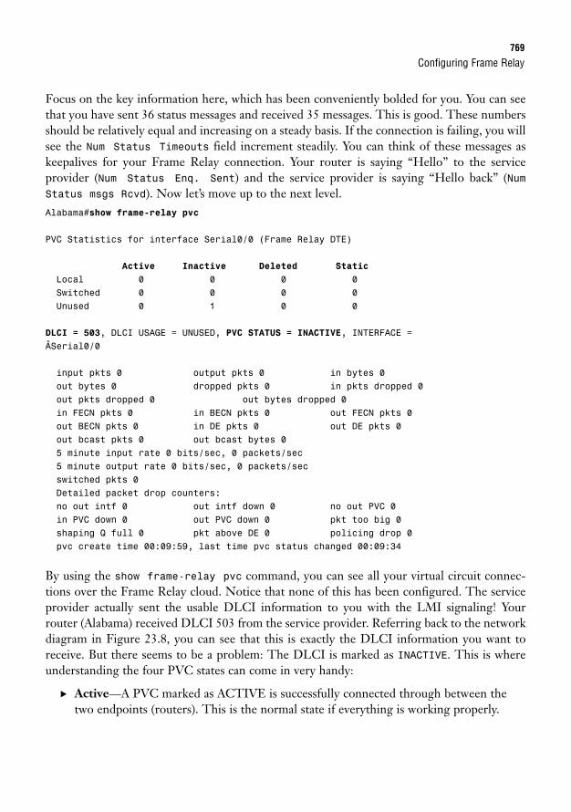
Configuring Frame Relay769
Focus on the key information here, which has been conveniently bolded for you. You can seethat you have sent 36 status messages and received 35 messages. This is good. These numbersshould be relatively equal and increasing on a steady basis. If the connection is failing, you willsee the Num Status Timeouts field increment steadily. You can think of these messages askeepalives for your Frame Relay connection. Your router is saying “Hello” to the serviceprovider (Num Status Enq. Sent) and the service provider is saying “Hello back” (NumStatus msgs Rcvd). Now let’s move up to the next level.Alabama#show frame-relay pvc
PVC Statistics for interface Serial0/0 (Frame Relay DTE)
Active Inactive Deleted Static
Local 0 0 0 0Switched 0 0 0 0Unused 0 1 0 0
DLCI = 503, DLCI USAGE = UNUSED, PVC STATUS = INACTIVE, INTERFACE =ÂSerial0/0
input pkts 0 output pkts 0 in bytes 0out bytes 0 dropped pkts 0 in pkts dropped 0out pkts dropped 0 out bytes dropped 0in FECN pkts 0 in BECN pkts 0 out FECN pkts 0out BECN pkts 0 in DE pkts 0 out DE pkts 0out bcast pkts 0 out bcast bytes 05 minute input rate 0 bits/sec, 0 packets/sec5 minute output rate 0 bits/sec, 0 packets/secswitched pkts 0Detailed packet drop counters:no out intf 0 out intf down 0 no out PVC 0in PVC down 0 out PVC down 0 pkt too big 0shaping Q full 0 pkt above DE 0 policing drop 0pvc create time 00:09:59, last time pvc status changed 00:09:34
By using the show frame-relay pvc command, you can see all your virtual circuit connec-tions over the Frame Relay cloud. Notice that none of this has been configured. The serviceprovider actually sent the usable DLCI information to you with the LMI signaling! Yourrouter (Alabama) received DLCI 503 from the service provider. Referring back to the networkdiagram in Figure 23.8, you can see that this is exactly the DLCI information you want toreceive. But there seems to be a problem: The DLCI is marked as INACTIVE. This is whereunderstanding the four PVC states can come in very handy:
. Active—A PVC marked as ACTIVE is successfully connected through between thetwo endpoints (routers). This is the normal state if everything is working properly.
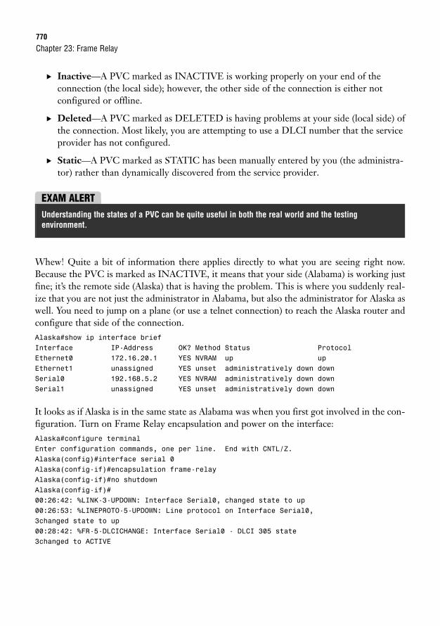
770
. Inactive—A PVC marked as INACTIVE is working properly on your end of the connection (the local side); however, the other side of the connection is either not configured or offline.
. Deleted—A PVC marked as DELETED is having problems at your side (local side) ofthe connection. Most likely, you are attempting to use a DLCI number that the serviceprovider has not configured.
. Static—A PVC marked as STATIC has been manually entered by you (the administra-tor) rather than dynamically discovered from the service provider.
Chapter 23: Frame Relay
EXAM ALERTUnderstanding the states of a PVC can be quite useful in both the real world and the testing environment.
Whew! Quite a bit of information there applies directly to what you are seeing right now.Because the PVC is marked as INACTIVE, it means that your side (Alabama) is working justfine; it’s the remote side (Alaska) that is having the problem. This is where you suddenly real-ize that you are not just the administrator in Alabama, but also the administrator for Alaska aswell. You need to jump on a plane (or use a telnet connection) to reach the Alaska router andconfigure that side of the connection.Alaska#show ip interface briefInterface IP-Address OK? Method Status ProtocolEthernet0 172.16.20.1 YES NVRAM up upEthernet1 unassigned YES unset administratively down downSerial0 192.168.5.2 YES NVRAM administratively down downSerial1 unassigned YES unset administratively down down
It looks as if Alaska is in the same state as Alabama was when you first got involved in the con-figuration. Turn on Frame Relay encapsulation and power on the interface:Alaska#configure terminalEnter configuration commands, one per line. End with CNTL/Z.Alaska(config)#interface serial 0Alaska(config-if)#encapsulation frame-relayAlaska(config-if)#no shutdownAlaska(config-if)#00:26:42: %LINK-3-UPDOWN: Interface Serial0, changed state to up00:26:53: %LINEPROTO-5-UPDOWN: Line protocol on Interface Serial0,3changed state to up00:28:42: %FR-5-DLCICHANGE: Interface Serial0 - DLCI 305 state3changed to ACTIVE
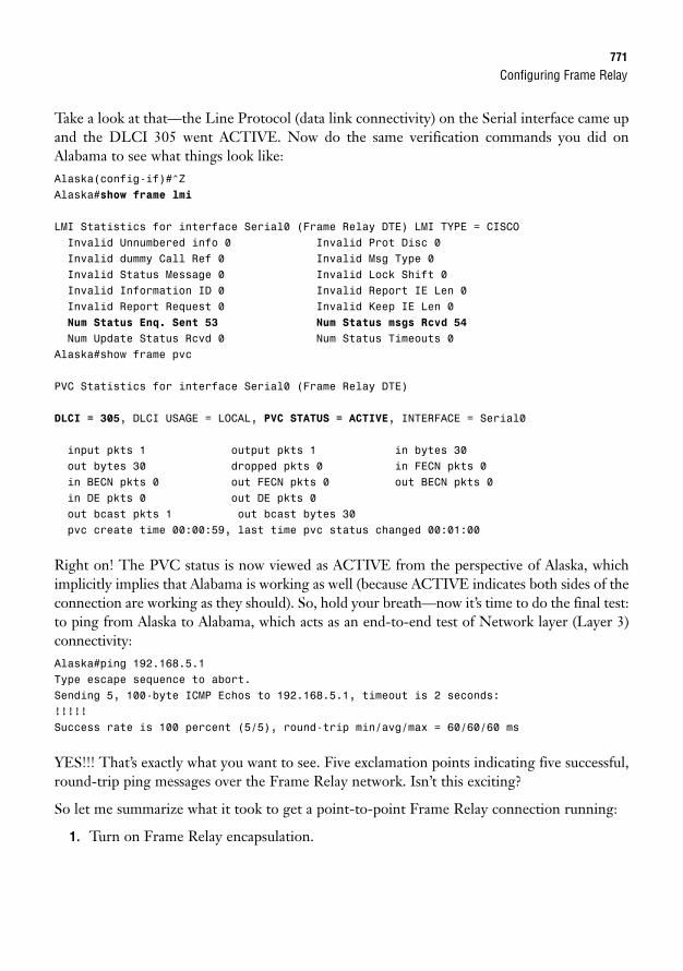
Configuring Frame Relay771
Take a look at that—the Line Protocol (data link connectivity) on the Serial interface came upand the DLCI 305 went ACTIVE. Now do the same verification commands you did onAlabama to see what things look like:Alaska(config-if)#^ZAlaska#show frame lmi
LMI Statistics for interface Serial0 (Frame Relay DTE) LMI TYPE = CISCOInvalid Unnumbered info 0 Invalid Prot Disc 0Invalid dummy Call Ref 0 Invalid Msg Type 0Invalid Status Message 0 Invalid Lock Shift 0Invalid Information ID 0 Invalid Report IE Len 0Invalid Report Request 0 Invalid Keep IE Len 0Num Status Enq. Sent 53 Num Status msgs Rcvd 54
Num Update Status Rcvd 0 Num Status Timeouts 0Alaska#show frame pvc
PVC Statistics for interface Serial0 (Frame Relay DTE)
DLCI = 305, DLCI USAGE = LOCAL, PVC STATUS = ACTIVE, INTERFACE = Serial0
input pkts 1 output pkts 1 in bytes 30out bytes 30 dropped pkts 0 in FECN pkts 0in BECN pkts 0 out FECN pkts 0 out BECN pkts 0in DE pkts 0 out DE pkts 0out bcast pkts 1 out bcast bytes 30pvc create time 00:00:59, last time pvc status changed 00:01:00
Right on! The PVC status is now viewed as ACTIVE from the perspective of Alaska, whichimplicitly implies that Alabama is working as well (because ACTIVE indicates both sides of theconnection are working as they should). So, hold your breath—now it’s time to do the final test:to ping from Alaska to Alabama, which acts as an end-to-end test of Network layer (Layer 3)connectivity:Alaska#ping 192.168.5.1Type escape sequence to abort.Sending 5, 100-byte ICMP Echos to 192.168.5.1, timeout is 2 seconds:!!!!!Success rate is 100 percent (5/5), round-trip min/avg/max = 60/60/60 ms
YES!!! That’s exactly what you want to see. Five exclamation points indicating five successful,round-trip ping messages over the Frame Relay network. Isn’t this exciting?
So let me summarize what it took to get a point-to-point Frame Relay connection running:
1. Turn on Frame Relay encapsulation.
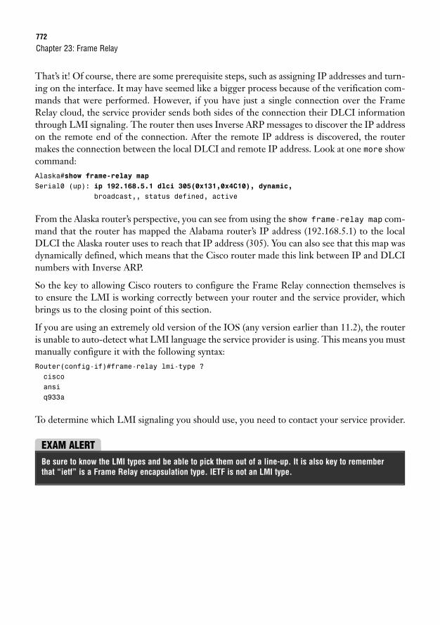
772
That’s it! Of course, there are some prerequisite steps, such as assigning IP addresses and turn-ing on the interface. It may have seemed like a bigger process because of the verification com-mands that were performed. However, if you have just a single connection over the FrameRelay cloud, the service provider sends both sides of the connection their DLCI informationthrough LMI signaling. The router then uses Inverse ARP messages to discover the IP addresson the remote end of the connection. After the remote IP address is discovered, the routermakes the connection between the local DLCI and remote IP address. Look at one more showcommand:Alaska#show frame-relay mapSerial0 (up): ip 192.168.5.1 dlci 305(0x131,0x4C10), dynamic,
broadcast,, status defined, active
From the Alaska router’s perspective, you can see from using the show frame-relay map com-mand that the router has mapped the Alabama router’s IP address (192.168.5.1) to the localDLCI the Alaska router uses to reach that IP address (305). You can also see that this map wasdynamically defined, which means that the Cisco router made this link between IP and DLCInumbers with Inverse ARP.
So the key to allowing Cisco routers to configure the Frame Relay connection themselves isto ensure the LMI is working correctly between your router and the service provider, whichbrings us to the closing point of this section.
If you are using an extremely old version of the IOS (any version earlier than 11.2), the routeris unable to auto-detect what LMI language the service provider is using. This means you mustmanually configure it with the following syntax:Router(config-if)#frame-relay lmi-type ?ciscoansiq933a
To determine which LMI signaling you should use, you need to contact your service provider.
Chapter 23: Frame Relay
EXAM ALERTBe sure to know the LMI types and be able to pick them out of a line-up. It is also key to rememberthat “ietf” is a Frame Relay encapsulation type. IETF is not an LMI type.
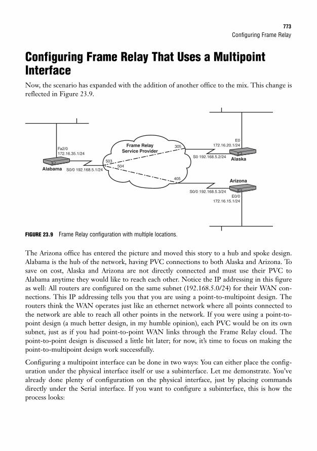
Configuring Frame Relay773
Configuring Frame Relay That Uses a MultipointInterfaceNow, the scenario has expanded with the addition of another office to the mix. This change isreflected in Figure 23.9.
Alabama
Alaska
Arizona
S0/0 192.168.5.1/24
S0 192.168.5.2/24
E0172.16.20.1/24
E0/0172.16.15.1/24
Fa2/0172.16.35.1/24
S0/0 192.168.5.3/24
Frame Relay Service Provider
305
503504
405
FIGURE 23.9 Frame Relay configuration with multiple locations.
The Arizona office has entered the picture and moved this story to a hub and spoke design.Alabama is the hub of the network, having PVC connections to both Alaska and Arizona. Tosave on cost, Alaska and Arizona are not directly connected and must use their PVC toAlabama anytime they would like to reach each other. Notice the IP addressing in this figureas well: All routers are configured on the same subnet (192.168.5.0/24) for their WAN con-nections. This IP addressing tells you that you are using a point-to-multipoint design. Therouters think the WAN operates just like an ethernet network where all points connected tothe network are able to reach all other points in the network. If you were using a point-to-point design (a much better design, in my humble opinion), each PVC would be on its ownsubnet, just as if you had point-to-point WAN links through the Frame Relay cloud. Thepoint-to-point design is discussed a little bit later; for now, it’s time to focus on making thepoint-to-multipoint design work successfully.
Configuring a multipoint interface can be done in two ways: You can either place the config-uration under the physical interface itself or use a subinterface. Let me demonstrate. You’vealready done plenty of configuration on the physical interface, just by placing commandsdirectly under the Serial interface. If you want to configure a subinterface, this is how theprocess looks:
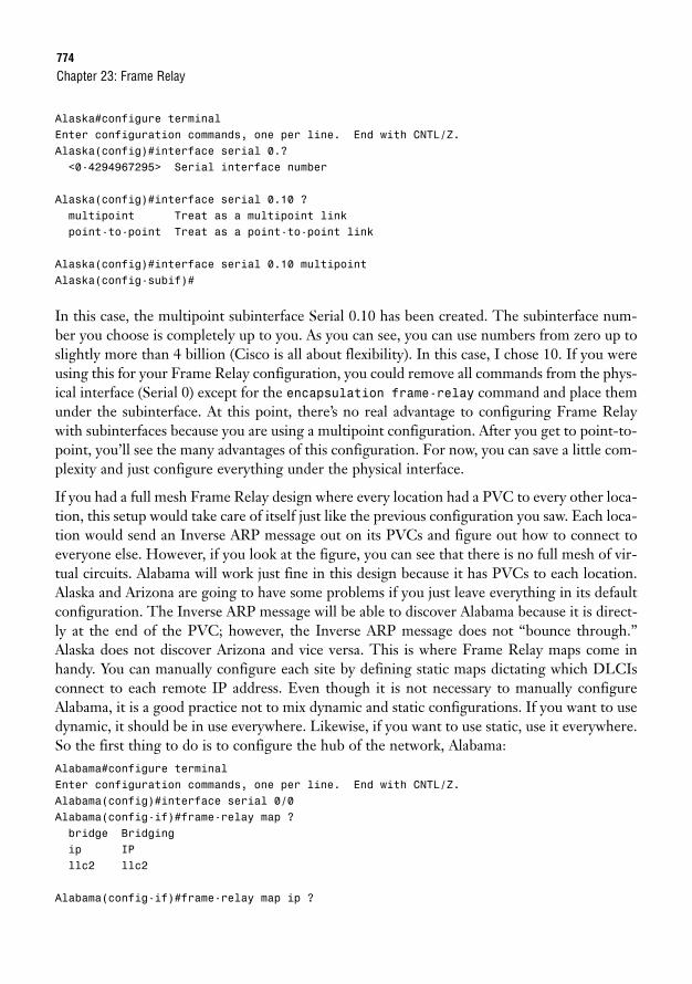
774
Alaska#configure terminalEnter configuration commands, one per line. End with CNTL/Z.Alaska(config)#interface serial 0.?<0-4294967295> Serial interface number
Alaska(config)#interface serial 0.10 ?multipoint Treat as a multipoint linkpoint-to-point Treat as a point-to-point link
Alaska(config)#interface serial 0.10 multipointAlaska(config-subif)#
In this case, the multipoint subinterface Serial 0.10 has been created. The subinterface num-ber you choose is completely up to you. As you can see, you can use numbers from zero up toslightly more than 4 billion (Cisco is all about flexibility). In this case, I chose 10. If you wereusing this for your Frame Relay configuration, you could remove all commands from the phys-ical interface (Serial 0) except for the encapsulation frame-relay command and place themunder the subinterface. At this point, there’s no real advantage to configuring Frame Relaywith subinterfaces because you are using a multipoint configuration. After you get to point-to-point, you’ll see the many advantages of this configuration. For now, you can save a little com-plexity and just configure everything under the physical interface.
If you had a full mesh Frame Relay design where every location had a PVC to every other loca-tion, this setup would take care of itself just like the previous configuration you saw. Each loca-tion would send an Inverse ARP message out on its PVCs and figure out how to connect toeveryone else. However, if you look at the figure, you can see that there is no full mesh of vir-tual circuits. Alabama will work just fine in this design because it has PVCs to each location.Alaska and Arizona are going to have some problems if you just leave everything in its defaultconfiguration. The Inverse ARP message will be able to discover Alabama because it is direct-ly at the end of the PVC; however, the Inverse ARP message does not “bounce through.”Alaska does not discover Arizona and vice versa. This is where Frame Relay maps come inhandy. You can manually configure each site by defining static maps dictating which DLCIsconnect to each remote IP address. Even though it is not necessary to manually configureAlabama, it is a good practice not to mix dynamic and static configurations. If you want to usedynamic, it should be in use everywhere. Likewise, if you want to use static, use it everywhere.So the first thing to do is to configure the hub of the network, Alabama:Alabama#configure terminalEnter configuration commands, one per line. End with CNTL/Z.Alabama(config)#interface serial 0/0Alabama(config-if)#frame-relay map ?bridge Bridgingip IPllc2 llc2
Alabama(config-if)#frame-relay map ip ?
Chapter 23: Frame Relay
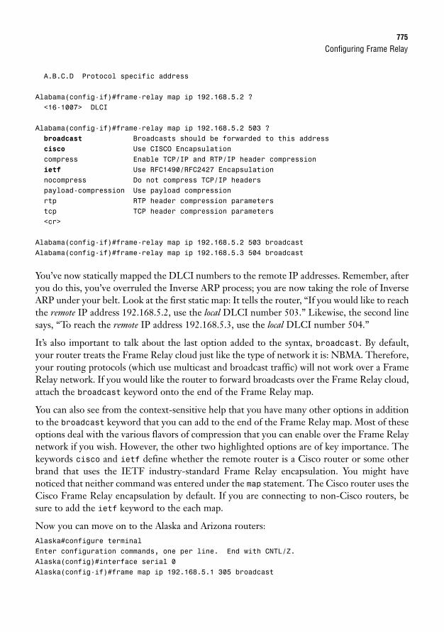
Configuring Frame Relay775
A.B.C.D Protocol specific address
Alabama(config-if)#frame-relay map ip 192.168.5.2 ?<16-1007> DLCI
Alabama(config-if)#frame-relay map ip 192.168.5.2 503 ?broadcast Broadcasts should be forwarded to this addresscisco Use CISCO Encapsulationcompress Enable TCP/IP and RTP/IP header compressionietf Use RFC1490/RFC2427 Encapsulationnocompress Do not compress TCP/IP headerspayload-compression Use payload compressionrtp RTP header compression parameterstcp TCP header compression parameters<cr>
Alabama(config-if)#frame-relay map ip 192.168.5.2 503 broadcastAlabama(config-if)#frame-relay map ip 192.168.5.3 504 broadcast
You’ve now statically mapped the DLCI numbers to the remote IP addresses. Remember, afteryou do this, you’ve overruled the Inverse ARP process; you are now taking the role of InverseARP under your belt. Look at the first static map: It tells the router, “If you would like to reachthe remote IP address 192.168.5.2, use the local DLCI number 503.” Likewise, the second linesays, “To reach the remote IP address 192.168.5.3, use the local DLCI number 504.”
It’s also important to talk about the last option added to the syntax, broadcast. By default,your router treats the Frame Relay cloud just like the type of network it is: NBMA. Therefore,your routing protocols (which use multicast and broadcast traffic) will not work over a FrameRelay network. If you would like the router to forward broadcasts over the Frame Relay cloud,attach the broadcast keyword onto the end of the Frame Relay map.
You can also see from the context-sensitive help that you have many other options in additionto the broadcast keyword that you can add to the end of the Frame Relay map. Most of theseoptions deal with the various flavors of compression that you can enable over the Frame Relaynetwork if you wish. However, the other two highlighted options are of key importance. Thekeywords cisco and ietf define whether the remote router is a Cisco router or some otherbrand that uses the IETF industry-standard Frame Relay encapsulation. You might havenoticed that neither command was entered under the map statement. The Cisco router uses theCisco Frame Relay encapsulation by default. If you are connecting to non-Cisco routers, besure to add the ietf keyword to the each map.
Now you can move on to the Alaska and Arizona routers:Alaska#configure terminalEnter configuration commands, one per line. End with CNTL/Z.Alaska(config)#interface serial 0Alaska(config-if)#frame map ip 192.168.5.1 305 broadcast
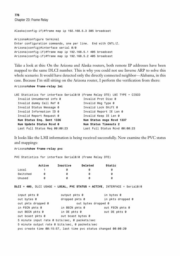
776
Alaska(config-if)#frame map ip 192.168.5.3 305 broadcast
Arizona#configure terminalEnter configuration commands, one per line. End with CNTL/Z.Arizona(config)#interface serial 0/0Arizona(config-if)#frame map ip 192.168.5.1 405 broadcastArizona(config-if)#frame map ip 192.168.5.2 405 broadcast
Take a look at this: On the Arizona and Alaska routers, both remote IP addresses have beenmapped to the same DLCI number. This is why you could not use Inverse ARP to solve thiswhole scenario: It would have detected only the directly connected neighbor—Alabama, in thiscase. Because I’m still sitting on the Arizona router, I perform the verification from there:Arizona#show frame-relay lmi
LMI Statistics for interface Serial0/0 (Frame Relay DTE) LMI TYPE = CISCOInvalid Unnumbered info 0 Invalid Prot Disc 0Invalid dummy Call Ref 0 Invalid Msg Type 0Invalid Status Message 0 Invalid Lock Shift 0Invalid Information ID 0 Invalid Report IE Len 0Invalid Report Request 0 Invalid Keep IE Len 0Num Status Enq. Sent 1336 Num Status msgs Rcvd 1337
Num Update Status Rcvd 0 Num Status Timeouts 2
Last Full Status Req 00:00:23 Last Full Status Rcvd 00:00:23
It looks like the LMI information is being received successfully. Now examine the PVC statusand mappings:Arizona#show frame-relay pvc
PVC Statistics for interface Serial0/0 (Frame Relay DTE)
Active Inactive Deleted Static
Local 1 0 0 0Switched 0 0 0 0Unused 0 0 0 0
DLCI = 405, DLCI USAGE = LOCAL, PVC STATUS = ACTIVE, INTERFACE = Serial0/0
input pkts 0 output pkts 0 in bytes 0out bytes 0 dropped pkts 0 in pkts dropped 0out pkts dropped 0 out bytes dropped 0in FECN pkts 0 in BECN pkts 0 out FECN pkts 0out BECN pkts 0 in DE pkts 0 out DE pkts 0out bcast pkts 0 out bcast bytes 05 minute input rate 0 bits/sec, 0 packets/sec5 minute output rate 0 bits/sec, 0 packets/secpvc create time 00:15:57, last time pvc status changed 00:00:20
Chapter 23: Frame Relay

Configuring Frame Relay777
Arizona#show frame-relay mapSerial0/0 (up): ip 192.168.5.1 dlci 405(0x195,0x6450), static,
broadcast,CISCO, status defined, active
Serial0/0 (up): ip 192.168.5.2 dlci 405(0x195,0x6450), static,broadcast,CISCO, status defined, active
Based on the output from the show frame-relay pvc and show frame-relay map com-mands, it looks like DLCI 405 is ACTIVE and statically mapped to both the remote IPaddresses it is able to reach. Because it tests round-trip connectivity, the final ping test verifiesthat the rest of the locations are configured correctly as well:Arizona#ping 192.168.5.1
Type escape sequence to abort.Sending 5, 100-byte ICMP Echos to 192.168.5.1, timeout is 2 seconds:!!!!!Success rate is 100 percent (5/5), round-trip min/avg/max = 56/58/60 ms
Arizona#ping 192.168.5.2
Type escape sequence to abort.Sending 5, 100-byte ICMP Echos to 192.168.5.2, timeout is 2 seconds:!!!!!Success rate is 100 percent (5/5), round-trip min/avg/max = 116/117/124 ms
Take a look at that—successful pings everywhere! However, things are not as peachy as they mayseem initially. Compare those round trip times for the two destinations. When the first ping wasperformed from Arizona to Alabama, the average round-trip response time was 58ms. The sec-ond ping went from Arizona to Alaska, and the round-trip response time effectively doubled, mov-ing up to 117ms! Although the hub and spoke topologies are very cost effective, they can havedevastating effects on delay-sensitive traffic, such as Citrix, Voice over IP, or Video over IP.
Now that the Frame Relay network is working correctly, it may be tempting to walk awaycheering and feeling quite fantastic about the general state of your life. However, one morething needs to be checked. Take a look again at Figure 23.8. Each location has a LAN con-nection, representing the offices in those locations. Although the Frame Relay network maybe humming along, you still need to check the routing tables to ensure each one of these loca-tions is able to reach the other. Behind the scenes, I’ve configured EIGRP for AutonomousSystem 100 on each router, sending and receiving advertisements on all interfaces. Look at therouting table on Alabama first:Alabama#show ip routeCodes: C - connected, S - static, R - RIP, M - mobile, B - BGP
D - EIGRP, EX - EIGRP external, O - OSPF, IA - OSPF inter areaN1 - OSPF NSSA external type 1, N2 - OSPF NSSA external type 2
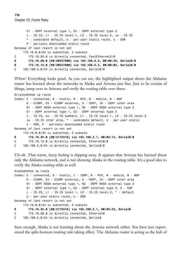
778
E1 - OSPF external type 1, E2 - OSPF external type 2i - IS-IS, L1 - IS-IS level-1, L2 - IS-IS level-2, ia - IS-IS* - candidate default, U - per-user static route, o - ODRP - periodic downloaded static route
Gateway of last resort is not set172.16.0.0/24 is subnetted, 3 subnets
C 172.16.35.0 is directly connected, FastEthernet2/0D 172.16.20.0 [90/20537600] via 192.168.5.2, 00:00:35, Serial0/0
D 172.16.15.0 [90/20537600] via 192.168.5.3, 00:00:03, Serial0/0
C 192.168.5.0/24 is directly connected, Serial0/0
Whew! Everything looks good. As you can see, the highlighted output shows the Alabamarouter has learned about the networks in Alaska and Arizona just fine. Just to be certain ofthings, jump over to Arizona and verify the routing table over there.Arizona#show ip routeCodes: C - connected, S - static, R - RIP, M - mobile, B - BGP
D - EIGRP, EX - EIGRP external, O - OSPF, IA - OSPF inter areaN1 - OSPF NSSA external type 1, N2 - OSPF NSSA external type 2E1 - OSPF external type 1, E2 - OSPF external type 2i - IS-IS, su - IS-IS summary, L1 - IS-IS level-1, L2 - IS-IS level-2ia - IS-IS inter area, * - candidate default, U - per-user statico - ODR, P - periodic downloaded static route
Gateway of last resort is not set172.16.0.0/24 is subnetted, 2 subnets
D 172.16.35.0 [90/2172416] via 192.168.5.1, 00:02:12, Serial0/0
C 172.16.15.0 is directly connected, Ethernet0/0C 192.168.5.0/24 is directly connected, Serial0/0
Uh-oh. That warm, fuzzy feeling is slipping away. It appears that Arizona has learned aboutonly the Alabama network, and is not showing Alaska in the routing table. It’s a good idea toverify the Alaska routing table as well.Alaska#show ip routeCodes: C - connected, S - static, I - IGRP, R - RIP, M - mobile, B - BGP
D - EIGRP, EX - EIGRP external, O - OSPF, IA - OSPF inter areaN1 - OSPF NSSA external type 1, N2 - OSPF NSSA external type 2E1 - OSPF external type 1, E2 - OSPF external type 2, E - EGPi - IS-IS, L1 - IS-IS level-1, L2 - IS-IS level-2, * - defaultU - per-user static route, o - ODR
Gateway of last resort is not set172.16.0.0/24 is subnetted, 2 subnets
D 172.16.35.0 [90/2172416] via 192.168.5.1, 00:03:22, Serial0
C 172.16.20.0 is directly connected, Ethernet0C 192.168.5.0/24 is directly connected, Serial0
Sure enough, Alaska is not learning about the Arizona network either. You have just experi-enced the split-horizon routing rule taking effect. The Alabama router is acting as the hub of
Chapter 23: Frame Relay
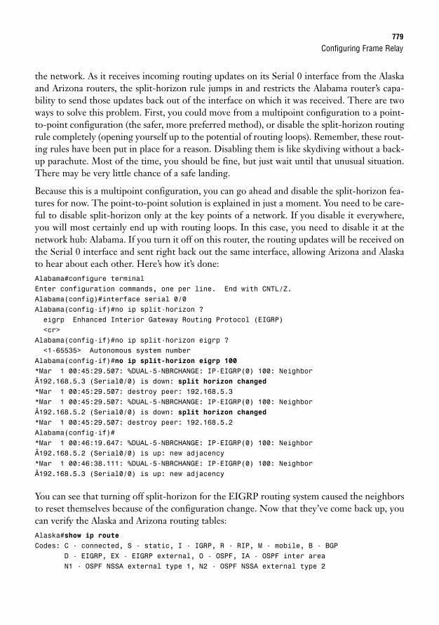
Configuring Frame Relay779
the network. As it receives incoming routing updates on its Serial 0 interface from the Alaskaand Arizona routers, the split-horizon rule jumps in and restricts the Alabama router’s capa-bility to send those updates back out of the interface on which it was received. There are twoways to solve this problem. First, you could move from a multipoint configuration to a point-to-point configuration (the safer, more preferred method), or disable the split-horizon routingrule completely (opening yourself up to the potential of routing loops). Remember, these rout-ing rules have been put in place for a reason. Disabling them is like skydiving without a back-up parachute. Most of the time, you should be fine, but just wait until that unusual situation.There may be very little chance of a safe landing.
Because this is a multipoint configuration, you can go ahead and disable the split-horizon fea-tures for now. The point-to-point solution is explained in just a moment. You need to be care-ful to disable split-horizon only at the key points of a network. If you disable it everywhere,you will most certainly end up with routing loops. In this case, you need to disable it at thenetwork hub: Alabama. If you turn it off on this router, the routing updates will be received onthe Serial 0 interface and sent right back out the same interface, allowing Arizona and Alaskato hear about each other. Here’s how it’s done:Alabama#configure terminalEnter configuration commands, one per line. End with CNTL/Z.Alabama(config)#interface serial 0/0Alabama(config-if)#no ip split-horizon ?eigrp Enhanced Interior Gateway Routing Protocol (EIGRP)<cr>
Alabama(config-if)#no ip split-horizon eigrp ?<1-65535> Autonomous system number
Alabama(config-if)#no ip split-horizon eigrp 100*Mar 1 00:45:29.507: %DUAL-5-NBRCHANGE: IP-EIGRP(0) 100: NeighborÂ192.168.5.3 (Serial0/0) is down: split horizon changed*Mar 1 00:45:29.507: destroy peer: 192.168.5.3*Mar 1 00:45:29.507: %DUAL-5-NBRCHANGE: IP-EIGRP(0) 100: NeighborÂ192.168.5.2 (Serial0/0) is down: split horizon changed*Mar 1 00:45:29.507: destroy peer: 192.168.5.2Alabama(config-if)#*Mar 1 00:46:19.647: %DUAL-5-NBRCHANGE: IP-EIGRP(0) 100: NeighborÂ192.168.5.2 (Serial0/0) is up: new adjacency*Mar 1 00:46:38.111: %DUAL-5-NBRCHANGE: IP-EIGRP(0) 100: NeighborÂ192.168.5.3 (Serial0/0) is up: new adjacency
You can see that turning off split-horizon for the EIGRP routing system caused the neighborsto reset themselves because of the configuration change. Now that they’ve come back up, youcan verify the Alaska and Arizona routing tables:Alaska#show ip routeCodes: C - connected, S - static, I - IGRP, R - RIP, M - mobile, B - BGP
D - EIGRP, EX - EIGRP external, O - OSPF, IA - OSPF inter areaN1 - OSPF NSSA external type 1, N2 - OSPF NSSA external type 2
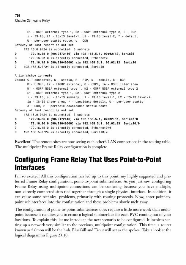
780
E1 - OSPF external type 1, E2 - OSPF external type 2, E - EGPi - IS-IS, L1 - IS-IS level-1, L2 - IS-IS level-2, * - defaultU - per-user static route, o - ODR
Gateway of last resort is not set172.16.0.0/24 is subnetted, 3 subnets
D 172.16.35.0 [90/2172416] via 192.168.5.1, 00:02:12, Serial0
C 172.16.20.0 is directly connected, Ethernet0D 172.16.15.0 [90/21049600] via 192.168.5.1, 00:02:12, Serial0
C 192.168.5.0/24 is directly connected, Serial0
Arizona#show ip routeCodes: C - connected, S - static, R - RIP, M - mobile, B - BGP
D - EIGRP, EX - EIGRP external, O - OSPF, IA - OSPF inter areaN1 - OSPF NSSA external type 1, N2 - OSPF NSSA external type 2E1 - OSPF external type 1, E2 - OSPF external type 2i - IS-IS, su - IS-IS summary, L1 - IS-IS level-1, L2 - IS-IS level-2ia - IS-IS inter area, * - candidate default, U - per-user statico - ODR, P - periodic downloaded static route
Gateway of last resort is not set172.16.0.0/24 is subnetted, 3 subnets
D 172.16.35.0 [90/2172416] via 192.168.5.1, 00:02:57, Serial0/0
D 172.16.20.0 [90/21049600] via 192.168.5.1, 00:02:33, Serial0/0
C 172.16.15.0 is directly connected, Ethernet0/0C 192.168.5.0/24 is directly connected, Serial0/0
Excellent! The remote sites are now seeing each other’s LAN connections in the routing table.The multipoint Frame Relay configuration is complete.
Configuring Frame Relay That Uses Point-to-PointInterfacesI’m so excited! All this configuration has led up to this point: my highly suggested and pre-ferred Frame Relay configuration, point-to-point subinterfaces. As you just saw, configuringFrame Relay using multipoint connections can be confusing because you have multiple,non–directly connected sites tied together through a single physical interface. In addition, itcan cause some technical problems, primarily with routing protocols. Now, enter point-to-point subinterfaces into the configuration and these problems slowly melt away.
The configuration of point-to-point subinterfaces does require a little more work than multi-point because it requires you to create a logical subinterface for each PVC coming out of yourlocations. To explain this, let me introduce the next scenario to be configured. It involves set-ting up a network very similar to the previous, multipoint configuration. This time, a routerknown as Salmon will be the hub. BlueGill and Trout will act as the spokes. Take a look at thelogical diagram in Figure 23.10.
Chapter 23: Frame Relay
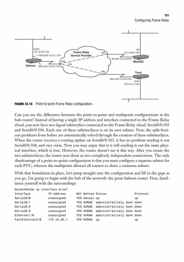
Configuring Frame Relay781
FIGURE 23.10 Point-to-point Frame Relay configuration.
Can you see the difference between the point-to-point and multipoint configurations at thehub router? Instead of having a single IP address and interface connected to the Frame Relaycloud, you now have two logical subinterfaces connected to the Frame Relay cloud: Serial0/0.503and Serial0/0.504. Each one of these subinterfaces is on its own subnet. Now, the split-hori-zon problems from before are automatically solved through the creation of these subinterfaces.When the router receives a routing update on Serial0/0.503, it has no problem sending it outSerial0/0.504, and vice versa. Now you may argue that it is still sending it out the same phys-ical interface, which is true. However, the router doesn’t see it this way. After you create thetwo subinterfaces, the router sees them as two completely independent connections. The onlydisadvantage of a point-to-point configuration is that you must configure a separate subnet foreach PVC, whereas the multipoint allowed all routers to share a common subnet.
With that foundation in place, let’s jump straight into the configuration and fill in the gaps asyou go. I’m going to begin with the hub of the network: the great Salmon router. First, famil-iarize yourself with the surroundings:Salmon#show ip interface briefInterface IP-Address OK? Method Status ProtocolSerial0/0 unassigned YES manual up upSerial0/1 unassigned YES NVRAM administratively down downSerial0/2 unassigned YES NVRAM administratively down downSerial0/3 unassigned YES NVRAM administratively down downEthernet1/0 unassigned YES NVRAM administratively down downFastEthernet2/0 172.16.35.1 YES NVRAM up up
SalmonBlueGill
Trout
S0/0.504 10.6.6.1/24
S0/0.503 10.5.5.1/24
S0.305 10.5.5.2/24
E0172.16.20.1/24
E0/0172.16.15.1/24
Fa2/0172.16.35.1/24
S0/0.405 10.6.6.2/24
Frame Relay Service Provider
305
503504
405
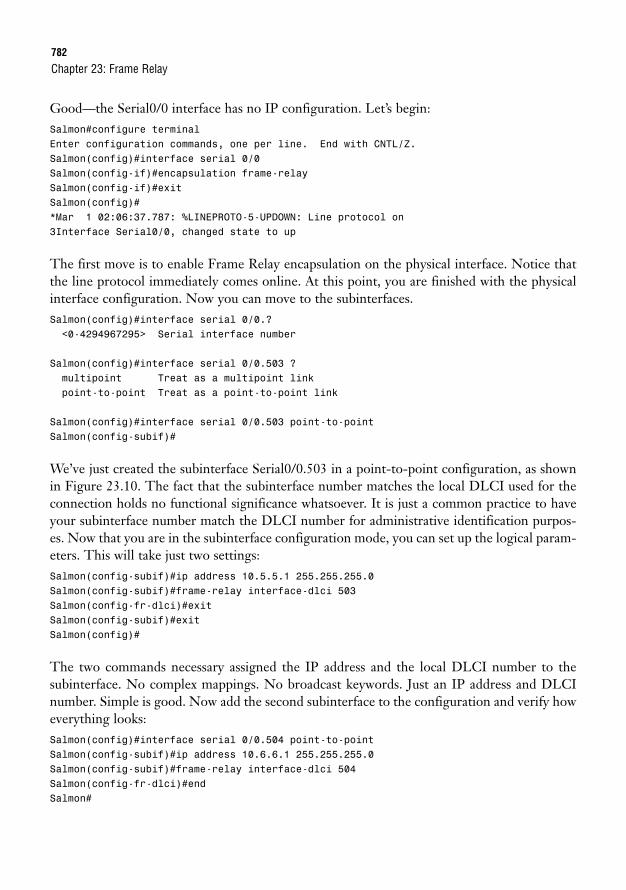
782
Good—the Serial0/0 interface has no IP configuration. Let’s begin:Salmon#configure terminalEnter configuration commands, one per line. End with CNTL/Z.Salmon(config)#interface serial 0/0Salmon(config-if)#encapsulation frame-relaySalmon(config-if)#exitSalmon(config)#*Mar 1 02:06:37.787: %LINEPROTO-5-UPDOWN: Line protocol on3Interface Serial0/0, changed state to up
The first move is to enable Frame Relay encapsulation on the physical interface. Notice thatthe line protocol immediately comes online. At this point, you are finished with the physicalinterface configuration. Now you can move to the subinterfaces.Salmon(config)#interface serial 0/0.?<0-4294967295> Serial interface number
Salmon(config)#interface serial 0/0.503 ?multipoint Treat as a multipoint linkpoint-to-point Treat as a point-to-point link
Salmon(config)#interface serial 0/0.503 point-to-pointSalmon(config-subif)#
We’ve just created the subinterface Serial0/0.503 in a point-to-point configuration, as shownin Figure 23.10. The fact that the subinterface number matches the local DLCI used for theconnection holds no functional significance whatsoever. It is just a common practice to haveyour subinterface number match the DLCI number for administrative identification purpos-es. Now that you are in the subinterface configuration mode, you can set up the logical param-eters. This will take just two settings:Salmon(config-subif)#ip address 10.5.5.1 255.255.255.0Salmon(config-subif)#frame-relay interface-dlci 503Salmon(config-fr-dlci)#exitSalmon(config-subif)#exitSalmon(config)#
The two commands necessary assigned the IP address and the local DLCI number to thesubinterface. No complex mappings. No broadcast keywords. Just an IP address and DLCInumber. Simple is good. Now add the second subinterface to the configuration and verify howeverything looks:Salmon(config)#interface serial 0/0.504 point-to-pointSalmon(config-subif)#ip address 10.6.6.1 255.255.255.0Salmon(config-subif)#frame-relay interface-dlci 504Salmon(config-fr-dlci)#endSalmon#
Chapter 23: Frame Relay
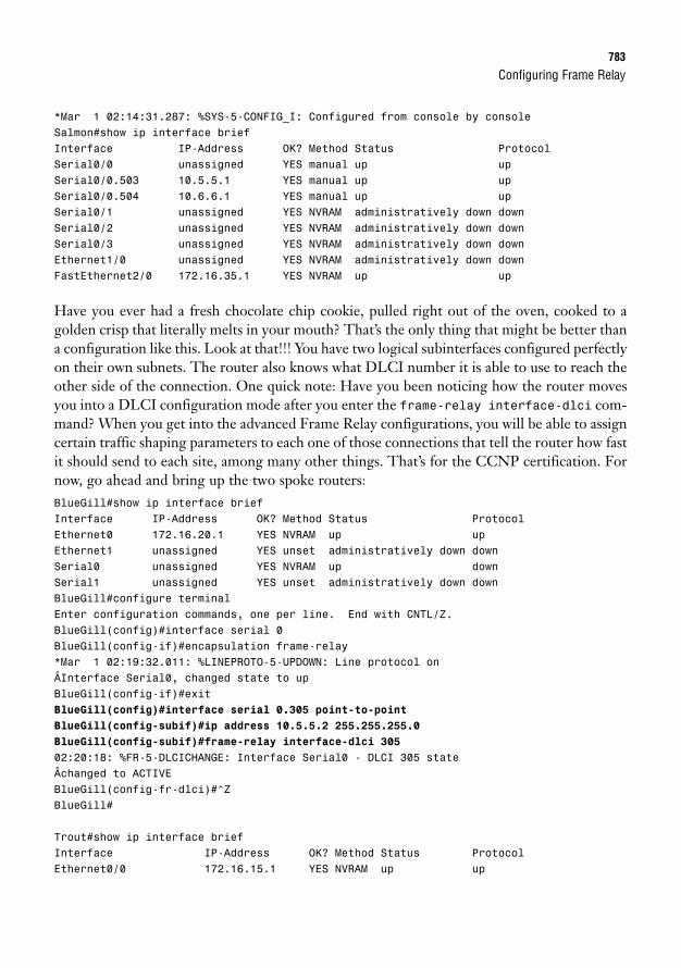
Configuring Frame Relay783
*Mar 1 02:14:31.287: %SYS-5-CONFIG_I: Configured from console by consoleSalmon#show ip interface briefInterface IP-Address OK? Method Status ProtocolSerial0/0 unassigned YES manual up upSerial0/0.503 10.5.5.1 YES manual up upSerial0/0.504 10.6.6.1 YES manual up upSerial0/1 unassigned YES NVRAM administratively down downSerial0/2 unassigned YES NVRAM administratively down downSerial0/3 unassigned YES NVRAM administratively down downEthernet1/0 unassigned YES NVRAM administratively down downFastEthernet2/0 172.16.35.1 YES NVRAM up up
Have you ever had a fresh chocolate chip cookie, pulled right out of the oven, cooked to agolden crisp that literally melts in your mouth? That’s the only thing that might be better thana configuration like this. Look at that!!! You have two logical subinterfaces configured perfectlyon their own subnets. The router also knows what DLCI number it is able to use to reach theother side of the connection. One quick note: Have you been noticing how the router movesyou into a DLCI configuration mode after you enter the frame-relay interface-dlci com-mand? When you get into the advanced Frame Relay configurations, you will be able to assigncertain traffic shaping parameters to each one of those connections that tell the router how fastit should send to each site, among many other things. That’s for the CCNP certification. Fornow, go ahead and bring up the two spoke routers:BlueGill#show ip interface briefInterface IP-Address OK? Method Status ProtocolEthernet0 172.16.20.1 YES NVRAM up upEthernet1 unassigned YES unset administratively down downSerial0 unassigned YES NVRAM up downSerial1 unassigned YES unset administratively down downBlueGill#configure terminalEnter configuration commands, one per line. End with CNTL/Z.BlueGill(config)#interface serial 0BlueGill(config-if)#encapsulation frame-relay*Mar 1 02:19:32.011: %LINEPROTO-5-UPDOWN: Line protocol onÂInterface Serial0, changed state to upBlueGill(config-if)#exitBlueGill(config)#interface serial 0.305 point-to-point
BlueGill(config-subif)#ip address 10.5.5.2 255.255.255.0
BlueGill(config-subif)#frame-relay interface-dlci 305
02:20:18: %FR-5-DLCICHANGE: Interface Serial0 - DLCI 305 stateÂchanged to ACTIVEBlueGill(config-fr-dlci)#^ZBlueGill#
Trout#show ip interface briefInterface IP-Address OK? Method Status ProtocolEthernet0/0 172.16.15.1 YES NVRAM up up
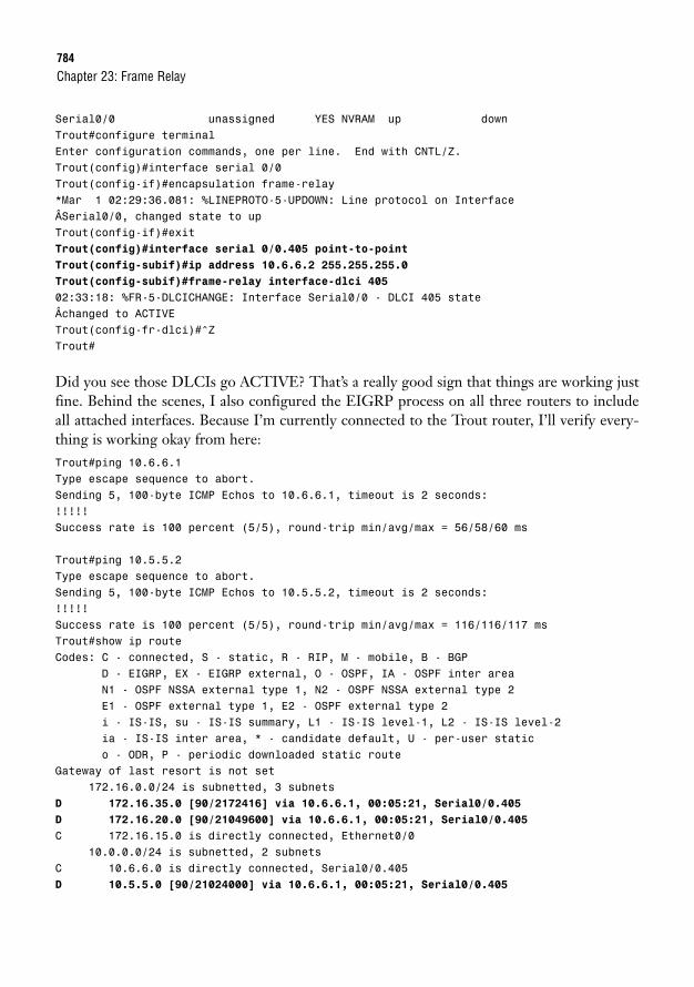
784
Serial0/0 unassigned YES NVRAM up downTrout#configure terminalEnter configuration commands, one per line. End with CNTL/Z.Trout(config)#interface serial 0/0Trout(config-if)#encapsulation frame-relay*Mar 1 02:29:36.081: %LINEPROTO-5-UPDOWN: Line protocol on InterfaceÂSerial0/0, changed state to upTrout(config-if)#exitTrout(config)#interface serial 0/0.405 point-to-point
Trout(config-subif)#ip address 10.6.6.2 255.255.255.0
Trout(config-subif)#frame-relay interface-dlci 405
02:33:18: %FR-5-DLCICHANGE: Interface Serial0/0 - DLCI 405 stateÂchanged to ACTIVETrout(config-fr-dlci)#^ZTrout#
Did you see those DLCIs go ACTIVE? That’s a really good sign that things are working justfine. Behind the scenes, I also configured the EIGRP process on all three routers to includeall attached interfaces. Because I’m currently connected to the Trout router, I’ll verify every-thing is working okay from here:Trout#ping 10.6.6.1Type escape sequence to abort.Sending 5, 100-byte ICMP Echos to 10.6.6.1, timeout is 2 seconds:!!!!!Success rate is 100 percent (5/5), round-trip min/avg/max = 56/58/60 ms
Trout#ping 10.5.5.2Type escape sequence to abort.Sending 5, 100-byte ICMP Echos to 10.5.5.2, timeout is 2 seconds:!!!!!Success rate is 100 percent (5/5), round-trip min/avg/max = 116/116/117 msTrout#show ip routeCodes: C - connected, S - static, R - RIP, M - mobile, B - BGP
D - EIGRP, EX - EIGRP external, O - OSPF, IA - OSPF inter areaN1 - OSPF NSSA external type 1, N2 - OSPF NSSA external type 2E1 - OSPF external type 1, E2 - OSPF external type 2i - IS-IS, su - IS-IS summary, L1 - IS-IS level-1, L2 - IS-IS level-2ia - IS-IS inter area, * - candidate default, U - per-user statico - ODR, P - periodic downloaded static route
Gateway of last resort is not set172.16.0.0/24 is subnetted, 3 subnets
D 172.16.35.0 [90/2172416] via 10.6.6.1, 00:05:21, Serial0/0.405
D 172.16.20.0 [90/21049600] via 10.6.6.1, 00:05:21, Serial0/0.405
C 172.16.15.0 is directly connected, Ethernet0/010.0.0.0/24 is subnetted, 2 subnets
C 10.6.6.0 is directly connected, Serial0/0.405D 10.5.5.0 [90/21024000] via 10.6.6.1, 00:05:21, Serial0/0.405
Chapter 23: Frame Relay
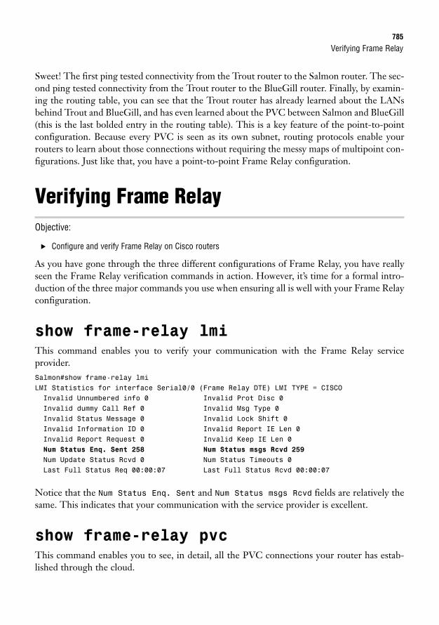
Verifying Frame Relay785
Sweet! The first ping tested connectivity from the Trout router to the Salmon router. The sec-ond ping tested connectivity from the Trout router to the BlueGill router. Finally, by examin-ing the routing table, you can see that the Trout router has already learned about the LANsbehind Trout and BlueGill, and has even learned about the PVC between Salmon and BlueGill(this is the last bolded entry in the routing table). This is a key feature of the point-to-pointconfiguration. Because every PVC is seen as its own subnet, routing protocols enable yourrouters to learn about those connections without requiring the messy maps of multipoint con-figurations. Just like that, you have a point-to-point Frame Relay configuration.
Verifying Frame RelayObjective:
. Configure and verify Frame Relay on Cisco routers
As you have gone through the three different configurations of Frame Relay, you have reallyseen the Frame Relay verification commands in action. However, it’s time for a formal intro-duction of the three major commands you use when ensuring all is well with your Frame Relayconfiguration.
show frame-relay lmi
This command enables you to verify your communication with the Frame Relay serviceprovider.Salmon#show frame-relay lmiLMI Statistics for interface Serial0/0 (Frame Relay DTE) LMI TYPE = CISCOInvalid Unnumbered info 0 Invalid Prot Disc 0Invalid dummy Call Ref 0 Invalid Msg Type 0Invalid Status Message 0 Invalid Lock Shift 0Invalid Information ID 0 Invalid Report IE Len 0Invalid Report Request 0 Invalid Keep IE Len 0Num Status Enq. Sent 258 Num Status msgs Rcvd 259
Num Update Status Rcvd 0 Num Status Timeouts 0Last Full Status Req 00:00:07 Last Full Status Rcvd 00:00:07
Notice that the Num Status Enq. Sent and Num Status msgs Rcvd fields are relatively thesame. This indicates that your communication with the service provider is excellent.
show frame-relay pvc
This command enables you to see, in detail, all the PVC connections your router has estab-lished through the cloud.
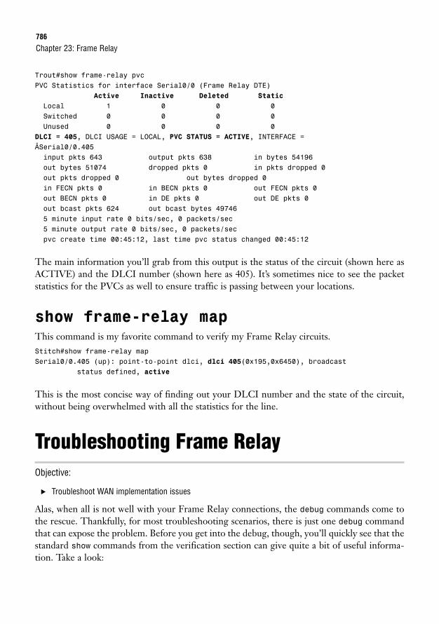
786
Trout#show frame-relay pvcPVC Statistics for interface Serial0/0 (Frame Relay DTE)
Active Inactive Deleted Static
Local 1 0 0 0Switched 0 0 0 0Unused 0 0 0 0
DLCI = 405, DLCI USAGE = LOCAL, PVC STATUS = ACTIVE, INTERFACE =ÂSerial0/0.405input pkts 643 output pkts 638 in bytes 54196out bytes 51074 dropped pkts 0 in pkts dropped 0out pkts dropped 0 out bytes dropped 0in FECN pkts 0 in BECN pkts 0 out FECN pkts 0out BECN pkts 0 in DE pkts 0 out DE pkts 0out bcast pkts 624 out bcast bytes 497465 minute input rate 0 bits/sec, 0 packets/sec5 minute output rate 0 bits/sec, 0 packets/secpvc create time 00:45:12, last time pvc status changed 00:45:12
The main information you’ll grab from this output is the status of the circuit (shown here asACTIVE) and the DLCI number (shown here as 405). It’s sometimes nice to see the packetstatistics for the PVCs as well to ensure traffic is passing between your locations.
show frame-relay map
This command is my favorite command to verify my Frame Relay circuits.Stitch#show frame-relay mapSerial0/0.405 (up): point-to-point dlci, dlci 405(0x195,0x6450), broadcast
status defined, active
This is the most concise way of finding out your DLCI number and the state of the circuit,without being overwhelmed with all the statistics for the line.
Troubleshooting Frame RelayObjective:
. Troubleshoot WAN implementation issues
Alas, when all is not well with your Frame Relay connections, the debug commands come tothe rescue. Thankfully, for most troubleshooting scenarios, there is just one debug commandthat can expose the problem. Before you get into the debug, though, you’ll quickly see that thestandard show commands from the verification section can give quite a bit of useful informa-tion. Take a look:
Chapter 23: Frame Relay

Troubleshooting Frame Relay787
Stitch#show frame-relay mapSerial0/0.407 (down): point-to-point dlci, dlci 407(0x197,0x6470), broadcast
status deletedSerial0/0.405 (up): point-to-point dlci, dlci 405(0x195,0x6450), broadcast
status defined, activeSerial0/0.406 (down): point-to-point dlci, dlci 406(0x196,0x6460), broadcast
status defined, inactive
Just a simple show frame-relay map command can point you in the initial direction for trou-bleshooting the circuit. As you can see from the output, there are three different DLCI numbersin three different activity states. First up is DLCI 407, which is in a status of DELETED. Thismeans that the router is attempting to communicate with the service provider through DLCI407, but the service provider has no idea what the router is talking about. They have no DLCI407 defined. In this case, the configuration problem is most likely on your own router. Typingthe DLCI number incorrectly is one likely cause. Otherwise, the service provider dropped theball and did not accurately set up the connections. The second DLCI in the list is DLCI 405,which is in a status of ACTIVE. This is a good circuit, going through to the other end of theconnection. The final DLCI in the list is DLCI 406, which is in a status of INACTIVE. Thismeans that the end of the connection is configured, and the service provider recognizes theDLCI you are attempting to use. The other end of the connection is where the problem lies.They have either configured an incorrect DLCI or have not configured the interface at all.
Just from this initial output, you can figure out a direction or a location to begin your trou-bleshooting efforts. Now comes the lower-level debug troubleshooting.Salmon#debug frame-relay lmiFrame Relay LMI debugging is onDisplaying all Frame Relay LMI data*Mar 1 00:05:07.215: Serial0/0(out): StEnq, myseq 1, yourseen 0, DTE down
*Mar 1 00:05:07.215: datagramstart = 0x1DA2F74, datagramsize = 14*Mar 1 00:05:07.215: FR encap = 0x00010308*Mar 1 00:05:07.215: 00 75 95 01 01 01 03 02 01 00*Mar 1 00:05:17.215: Serial0/0(out): StEnq, myseq 2, yourseen 0, DTE down
*Mar 1 00:05:17.215: datagramstart = 0x1C01254, datagramsize = 14*Mar 1 00:05:17.215: FR encap = 0x00010308*Mar 1 00:05:17.215: 00 75 95 01 01 00 03 02 02 00*Mar 1 00:05:27.215: Serial0/0(out): StEnq, myseq 3, yourseen 0, DTE down
*Mar 1 00:05:27.215: datagramstart = 0x1DA21B4, datagramsize = 14*Mar 1 00:05:27.215: FR encap = 0x00010308*Mar 1 00:05:27.215: 00 75 95 01 01 00 03 02 03 00*Mar 1 00:05:37.215: Serial0/0(out): StEnq, myseq 4, yourseen 0, DTE down
*Mar 1 00:05:37.215: datagramstart = 0x1C00494, datagramsize = 14*Mar 1 00:05:37.215: FR encap = 0x00010308*Mar 1 00:05:37.215: 00 75 95 01 01 00 03 02 04 00
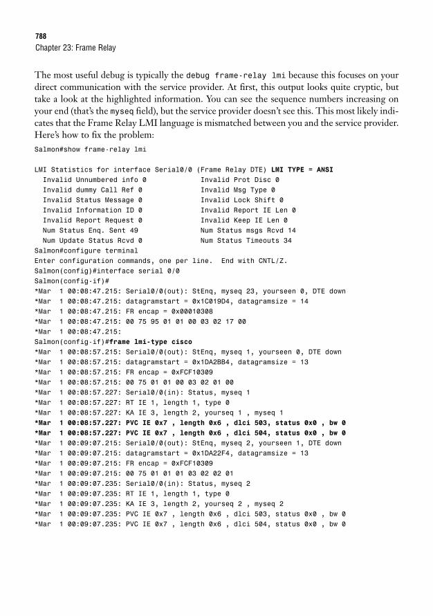
788
The most useful debug is typically the debug frame-relay lmi because this focuses on yourdirect communication with the service provider. At first, this output looks quite cryptic, buttake a look at the highlighted information. You can see the sequence numbers increasing onyour end (that’s the myseq field), but the service provider doesn’t see this. This most likely indi-cates that the Frame Relay LMI language is mismatched between you and the service provider.Here’s how to fix the problem:Salmon#show frame-relay lmi
LMI Statistics for interface Serial0/0 (Frame Relay DTE) LMI TYPE = ANSIInvalid Unnumbered info 0 Invalid Prot Disc 0Invalid dummy Call Ref 0 Invalid Msg Type 0Invalid Status Message 0 Invalid Lock Shift 0Invalid Information ID 0 Invalid Report IE Len 0Invalid Report Request 0 Invalid Keep IE Len 0Num Status Enq. Sent 49 Num Status msgs Rcvd 14Num Update Status Rcvd 0 Num Status Timeouts 34
Salmon#configure terminalEnter configuration commands, one per line. End with CNTL/Z.Salmon(config)#interface serial 0/0Salmon(config-if)#*Mar 1 00:08:47.215: Serial0/0(out): StEnq, myseq 23, yourseen 0, DTE down*Mar 1 00:08:47.215: datagramstart = 0x1C019D4, datagramsize = 14*Mar 1 00:08:47.215: FR encap = 0x00010308*Mar 1 00:08:47.215: 00 75 95 01 01 00 03 02 17 00*Mar 1 00:08:47.215:Salmon(config-if)#frame lmi-type cisco*Mar 1 00:08:57.215: Serial0/0(out): StEnq, myseq 1, yourseen 0, DTE down*Mar 1 00:08:57.215: datagramstart = 0x1DA2BB4, datagramsize = 13*Mar 1 00:08:57.215: FR encap = 0xFCF10309*Mar 1 00:08:57.215: 00 75 01 01 00 03 02 01 00*Mar 1 00:08:57.227: Serial0/0(in): Status, myseq 1*Mar 1 00:08:57.227: RT IE 1, length 1, type 0*Mar 1 00:08:57.227: KA IE 3, length 2, yourseq 1 , myseq 1*Mar 1 00:08:57.227: PVC IE 0x7 , length 0x6 , dlci 503, status 0x0 , bw 0
*Mar 1 00:08:57.227: PVC IE 0x7 , length 0x6 , dlci 504, status 0x0 , bw 0
*Mar 1 00:09:07.215: Serial0/0(out): StEnq, myseq 2, yourseen 1, DTE down*Mar 1 00:09:07.215: datagramstart = 0x1DA22F4, datagramsize = 13*Mar 1 00:09:07.215: FR encap = 0xFCF10309*Mar 1 00:09:07.215: 00 75 01 01 01 03 02 02 01*Mar 1 00:09:07.235: Serial0/0(in): Status, myseq 2*Mar 1 00:09:07.235: RT IE 1, length 1, type 0*Mar 1 00:09:07.235: KA IE 3, length 2, yourseq 2 , myseq 2*Mar 1 00:09:07.235: PVC IE 0x7 , length 0x6 , dlci 503, status 0x0 , bw 0*Mar 1 00:09:07.235: PVC IE 0x7 , length 0x6 , dlci 504, status 0x0 , bw 0
Chapter 23: Frame Relay
Troubleshooting Frame Relay789
Sure enough, you saw that the LMI type was hard-coded as ANSI. After it was changed overto Cisco, the debug showed the sequence numbers matching up between your router and theservice provider. Right after the sequence number synchronization, the service provider’srouter delivers the DLCI information to your router. This is where it pays to know the statuscodes. These are not covered on the CCNA exam, but are tested on when you get into theCCNP level exams:
Status 0x0 = INACTIVE
Status 0x2 = ACTIVE
Status 0x4 = DELETED
In this case, you can see that both DLCI 503 and 504 are marked as INACTIVE.
Most of the Frame Relay troubleshooting comes from a misconfiguration of the Frame RelayDLCI. It’s very easy to map the wrong DLCI to the wrong IP address because Frame Relayuses a very different addressing perspective than most other networking technologies.Understanding the Frame Relay circuit states can really help in isolating the problem quickly.
790
Chapter SummaryThis chapter has taken you from the basics of Frame Relay into a fairly complex configurationusing subinterfaces. The steepest part of the learning curve in the Frame Relay world is in try-ing to understand the terminology. Frame Relay uses a new set of Layer 2 addresses known asDLCIs. These are your logical addresses, which enable you to communicate with remotedevices over the Frame Relay cloud. Unlike typical addressing, DLCIs work through a local-ized system—that is, you leave on a local DLCI to reach a remote destination over a PVC.This PVC is established for you by a service provider (after you have paid an excessive amountof money) and is one of the primary criteria that determine your monthly cost for the line. Theother cost-affecting criterion is the CIR you purchase for each circuit. This is the speed thatthe service provider commits to give you for each PVC you purchase. Many times, you will beable to burst above this speed if extra bandwidth is available.
After you understand the terminology of Frame Relay, you have three different configurationoptions. For simple network designs, you can let the Inverse ARP system take care of theFrame Relay setup for you. If you just enable Frame Relay encapsulation on your Serial inter-face, the router can configure itself. It does this by using LMI signaling to receive all its DLCIinformation from the service provider. The router can then use Inverse ARP to discover theremote devices. As your network becomes more advanced and uses multiple virtual circuits,you can rely on a multipoint or point-to-point configuration. The advantage of multipoint isthat all the routers connected to the Frame Relay cloud can share a common subnet. Themajor problem with this configuration comes from the routing loop prevention mechanismsplit-horizon. This prevents a router from sending a routing update out the same interface asthat over which it was received. Coming to the rescue are point-to-point subinterfaces. Theseenable you to statically assign a DLCI number to a dedicated subinterface. Because each PVChas its own subinterface, there are no problems with split-horizon.
Chapter 23: Frame Relay
Chapter Summary791
Key Terms. virtual circuit
. permanent virtual circuit (PVC)
. switched virtual circuit (SVC)
. hub and spoke design
. partial mesh design
. full mesh design
. Local Management Interface (LMI)
. Data Link Connection Identifier (DLCI)
. local access rate/line speed
. Committed Information Rate (CIR)
. Backwards Explicit Congestion Notification (BECN)
. Forward Explicit Congestion Notification (FECN)
. Discard Eligible (De)
. Non-Broadcast Multi-Access (NBMA)
. split-horizon
. point-to-point subinterfaces
. point-to-multipoint/multipoint subinterfaces
. Frame Relay map
. inverse ARP
. static mappings
. Cisco Frame Relay encapsulation
. IETF Frame Relay encapsulation
. ACTIVE, INACTIVE, and DELETED PVC status
. Cisco, ANSI, and Q933A LMI signaling
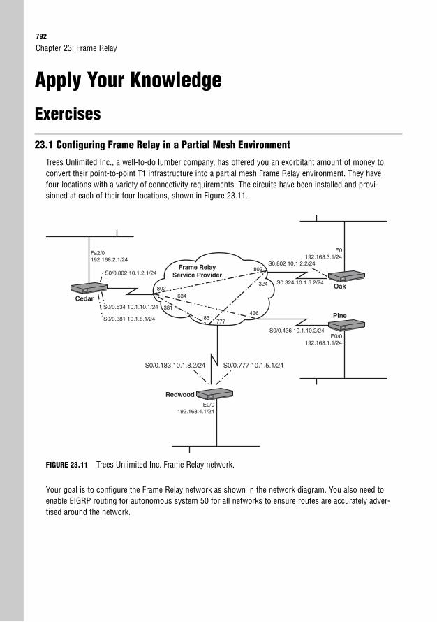
792
Apply Your Knowledge
Exercises
23.1 Configuring Frame Relay in a Partial Mesh Environment
Trees Unlimited Inc., a well-to-do lumber company, has offered you an exorbitant amount of money toconvert their point-to-point T1 infrastructure into a partial mesh Frame Relay environment. They havefour locations with a variety of connectivity requirements. The circuits have been installed and provi-sioned at each of their four locations, shown in Figure 23.11.
Chapter 23: Frame Relay
E0/0192.168.4.1/24
Cedar
Oak
PineS0/0.634 10.1.10.1/24
S0/0.802 10.1.2.1/24
S0/0.381 10.1.8.1/24
S0.802 10.1.2.2/24
S0.324 10.1.5.2/24
E0192.168.3.1/24
E0/0192.168.1.1/24
Fa2/0192.168.2.1/24
S0/0.436 10.1.10.2/24
Frame Relay Service Provider
802
436
324
634
381
183777
802
Redwood
S0/0.777 10.1.5.1/24 S0/0.183 10.1.8.2/24
FIGURE 23.11 Trees Unlimited Inc. Frame Relay network.
Your goal is to configure the Frame Relay network as shown in the network diagram. You also need toenable EIGRP routing for autonomous system 50 for all networks to ensure routes are accurately adver-tised around the network.
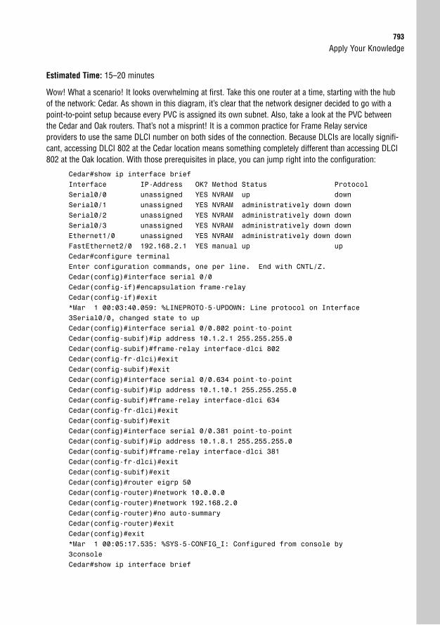
Apply Your Knowledge793
Estimated Time: 15–20 minutes
Wow! What a scenario! It looks overwhelming at first. Take this one router at a time, starting with the hubof the network: Cedar. As shown in this diagram, it’s clear that the network designer decided to go with apoint-to-point setup because every PVC is assigned its own subnet. Also, take a look at the PVC betweenthe Cedar and Oak routers. That’s not a misprint! It is a common practice for Frame Relay serviceproviders to use the same DLCI number on both sides of the connection. Because DLCIs are locally signifi-cant, accessing DLCI 802 at the Cedar location means something completely different than accessing DLCI802 at the Oak location. With those prerequisites in place, you can jump right into the configuration:
Cedar#show ip interface briefInterface IP-Address OK? Method Status ProtocolSerial0/0 unassigned YES NVRAM up downSerial0/1 unassigned YES NVRAM administratively down downSerial0/2 unassigned YES NVRAM administratively down downSerial0/3 unassigned YES NVRAM administratively down downEthernet1/0 unassigned YES NVRAM administratively down downFastEthernet2/0 192.168.2.1 YES manual up upCedar#configure terminalEnter configuration commands, one per line. End with CNTL/Z.Cedar(config)#interface serial 0/0Cedar(config-if)#encapsulation frame-relayCedar(config-if)#exit*Mar 1 00:03:40.059: %LINEPROTO-5-UPDOWN: Line protocol on Interface3Serial0/0, changed state to upCedar(config)#interface serial 0/0.802 point-to-pointCedar(config-subif)#ip address 10.1.2.1 255.255.255.0Cedar(config-subif)#frame-relay interface-dlci 802Cedar(config-fr-dlci)#exitCedar(config-subif)#exitCedar(config)#interface serial 0/0.634 point-to-pointCedar(config-subif)#ip address 10.1.10.1 255.255.255.0Cedar(config-subif)#frame-relay interface-dlci 634Cedar(config-fr-dlci)#exitCedar(config-subif)#exitCedar(config)#interface serial 0/0.381 point-to-pointCedar(config-subif)#ip address 10.1.8.1 255.255.255.0Cedar(config-subif)#frame-relay interface-dlci 381Cedar(config-fr-dlci)#exitCedar(config-subif)#exitCedar(config)#router eigrp 50Cedar(config-router)#network 10.0.0.0Cedar(config-router)#network 192.168.2.0Cedar(config-router)#no auto-summaryCedar(config-router)#exitCedar(config)#exit*Mar 1 00:05:17.535: %SYS-5-CONFIG_I: Configured from console by3consoleCedar#show ip interface brief
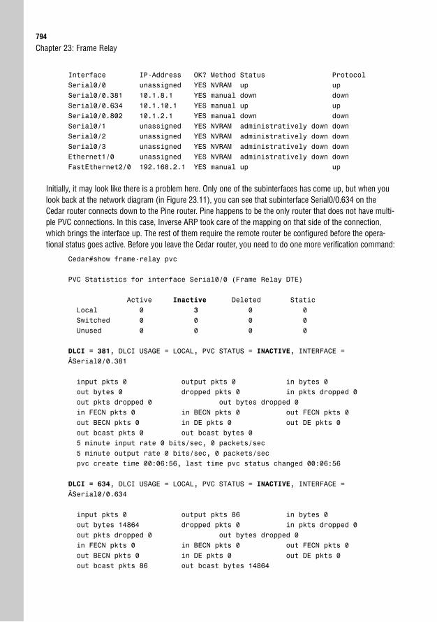
794
Interface IP-Address OK? Method Status ProtocolSerial0/0 unassigned YES NVRAM up upSerial0/0.381 10.1.8.1 YES manual down downSerial0/0.634 10.1.10.1 YES manual up upSerial0/0.802 10.1.2.1 YES manual down downSerial0/1 unassigned YES NVRAM administratively down downSerial0/2 unassigned YES NVRAM administratively down downSerial0/3 unassigned YES NVRAM administratively down downEthernet1/0 unassigned YES NVRAM administratively down downFastEthernet2/0 192.168.2.1 YES manual up up
Initially, it may look like there is a problem here. Only one of the subinterfaces has come up, but when youlook back at the network diagram (in Figure 23.11), you can see that subinterface Serial0/0.634 on theCedar router connects down to the Pine router. Pine happens to be the only router that does not have multi-ple PVC connections. In this case, Inverse ARP took care of the mapping on that side of the connection,which brings the interface up. The rest of them require the remote router be configured before the opera-tional status goes active. Before you leave the Cedar router, you need to do one more verification command:
Cedar#show frame-relay pvc
PVC Statistics for interface Serial0/0 (Frame Relay DTE)
Active Inactive Deleted StaticLocal 0 3 0 0Switched 0 0 0 0Unused 0 0 0 0
DLCI = 381, DLCI USAGE = LOCAL, PVC STATUS = INACTIVE, INTERFACE =ÂSerial0/0.381
input pkts 0 output pkts 0 in bytes 0out bytes 0 dropped pkts 0 in pkts dropped 0out pkts dropped 0 out bytes dropped 0in FECN pkts 0 in BECN pkts 0 out FECN pkts 0out BECN pkts 0 in DE pkts 0 out DE pkts 0out bcast pkts 0 out bcast bytes 05 minute input rate 0 bits/sec, 0 packets/sec5 minute output rate 0 bits/sec, 0 packets/secpvc create time 00:06:56, last time pvc status changed 00:06:56
DLCI = 634, DLCI USAGE = LOCAL, PVC STATUS = INACTIVE, INTERFACE =ÂSerial0/0.634
input pkts 0 output pkts 86 in bytes 0out bytes 14864 dropped pkts 0 in pkts dropped 0out pkts dropped 0 out bytes dropped 0in FECN pkts 0 in BECN pkts 0 out FECN pkts 0out BECN pkts 0 in DE pkts 0 out DE pkts 0out bcast pkts 86 out bcast bytes 14864
Chapter 23: Frame Relay
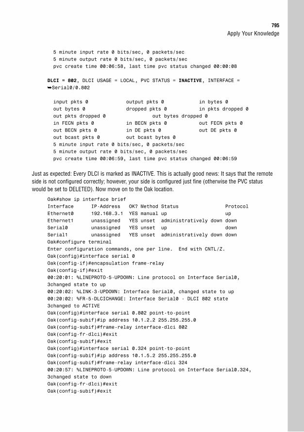
Apply Your Knowledge795
5 minute input rate 0 bits/sec, 0 packets/sec5 minute output rate 0 bits/sec, 0 packets/secpvc create time 00:06:58, last time pvc status changed 00:00:08
DLCI = 802, DLCI USAGE = LOCAL, PVC STATUS = INACTIVE, INTERFACE =➥Serial0/0.802
input pkts 0 output pkts 0 in bytes 0out bytes 0 dropped pkts 0 in pkts dropped 0out pkts dropped 0 out bytes dropped 0in FECN pkts 0 in BECN pkts 0 out FECN pkts 0out BECN pkts 0 in DE pkts 0 out DE pkts 0out bcast pkts 0 out bcast bytes 05 minute input rate 0 bits/sec, 0 packets/sec5 minute output rate 0 bits/sec, 0 packets/secpvc create time 00:06:59, last time pvc status changed 00:06:59
Just as expected: Every DLCI is marked as INACTIVE. This is actually good news: It says that the remoteside is not configured correctly; however, your side is configured just fine (otherwise the PVC statuswould be set to DELETED). Now move on to the Oak location.
Oak#show ip interface briefInterface IP-Address OK? Method Status ProtocolEthernet0 192.168.3.1 YES manual up upEthernet1 unassigned YES unset administratively down downSerial0 unassigned YES unset up downSerial1 unassigned YES unset administratively down downOak#configure terminalEnter configuration commands, one per line. End with CNTL/Z.Oak(config)#interface serial 0Oak(config-if)#encapsulation frame-relayOak(config-if)#exit00:20:01: %LINEPROTO-5-UPDOWN: Line protocol on Interface Serial0,3changed state to up00:20:02: %LINK-3-UPDOWN: Interface Serial0, changed state to up00:20:02: %FR-5-DLCICHANGE: Interface Serial0 - DLCI 802 state3changed to ACTIVEOak(config)#interface serial 0.802 point-to-pointOak(config-subif)#ip address 10.1.2.2 255.255.255.0Oak(config-subif)#frame-relay interface-dlci 802Oak(config-fr-dlci)#exitOak(config-subif)#exitOak(config)#interface serial 0.324 point-to-pointOak(config-subif)#ip address 10.1.5.2 255.255.255.0Oak(config-subif)#frame-relay interface-dlci 32400:20:57: %LINEPROTO-5-UPDOWN: Line protocol on Interface Serial0.324,3changed state to downOak(config-fr-dlci)#exitOak(config-subif)#exit
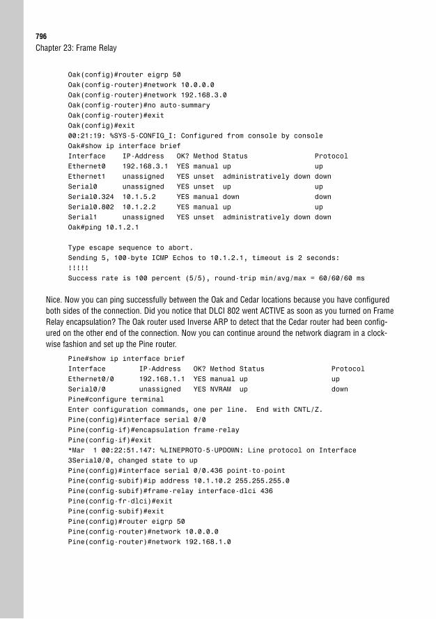
796
Oak(config)#router eigrp 50Oak(config-router)#network 10.0.0.0Oak(config-router)#network 192.168.3.0Oak(config-router)#no auto-summaryOak(config-router)#exitOak(config)#exit00:21:19: %SYS-5-CONFIG_I: Configured from console by consoleOak#show ip interface briefInterface IP-Address OK? Method Status ProtocolEthernet0 192.168.3.1 YES manual up upEthernet1 unassigned YES unset administratively down downSerial0 unassigned YES unset up upSerial0.324 10.1.5.2 YES manual down downSerial0.802 10.1.2.2 YES manual up upSerial1 unassigned YES unset administratively down downOak#ping 10.1.2.1
Type escape sequence to abort.Sending 5, 100-byte ICMP Echos to 10.1.2.1, timeout is 2 seconds:!!!!!Success rate is 100 percent (5/5), round-trip min/avg/max = 60/60/60 ms
Nice. Now you can ping successfully between the Oak and Cedar locations because you have configuredboth sides of the connection. Did you notice that DLCI 802 went ACTIVE as soon as you turned on FrameRelay encapsulation? The Oak router used Inverse ARP to detect that the Cedar router had been config-ured on the other end of the connection. Now you can continue around the network diagram in a clock-wise fashion and set up the Pine router.
Pine#show ip interface briefInterface IP-Address OK? Method Status ProtocolEthernet0/0 192.168.1.1 YES manual up upSerial0/0 unassigned YES NVRAM up downPine#configure terminalEnter configuration commands, one per line. End with CNTL/Z.Pine(config)#interface serial 0/0Pine(config-if)#encapsulation frame-relayPine(config-if)#exit*Mar 1 00:22:51.147: %LINEPROTO-5-UPDOWN: Line protocol on Interface3Serial0/0, changed state to upPine(config)#interface serial 0/0.436 point-to-pointPine(config-subif)#ip address 10.1.10.2 255.255.255.0Pine(config-subif)#frame-relay interface-dlci 436Pine(config-fr-dlci)#exitPine(config-subif)#exitPine(config)#router eigrp 50Pine(config-router)#network 10.0.0.0Pine(config-router)#network 192.168.1.0
Chapter 23: Frame Relay
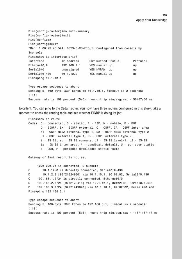
Apply Your Knowledge797
Pine(config-router)#no auto-summaryPine(config-router)#exitPine(config)#Pine(config)#exit*Mar 1 00:23:45.504: %SYS-5-CONFIG_I: Configured from console by3consolePine#show ip interface briefInterface IP-Address OK? Method Status ProtocolEthernet0/0 192.168.1.1 YES manual up upSerial0/0 unassigned YES NVRAM up upSerial0/0.436 10.1.10.2 YES manual up upPine#ping 10.1.10.1
Type escape sequence to abort.Sending 5, 100-byte ICMP Echos to 10.1.10.1, timeout is 2 seconds:!!!!!Success rate is 100 percent (5/5), round-trip min/avg/max = 56/57/60 ms
Excellent. You can ping to the Cedar router. You now have three routers configured in this story; take amoment to check the routing table and see whether EIGRP is doing its job:
Pine#show ip routeCodes: C - connected, S - static, R - RIP, M - mobile, B - BGP
D - EIGRP, EX - EIGRP external, O - OSPF, IA - OSPF inter areaN1 - OSPF NSSA external type 1, N2 - OSPF NSSA external type 2E1 - OSPF external type 1, E2 - OSPF external type 2i - IS-IS, su - IS-IS summary, L1 - IS-IS level-1, L2 - IS-ISia - IS-IS inter area, * - candidate default, U - per-user statico - ODR, P - periodic downloaded static route
Gateway of last resort is not set
10.0.0.0/24 is subnetted, 2 subnetsC 10.1.10.0 is directly connected, Serial0/0.436D 10.1.2.0 [90/21024000] via 10.1.10.1, 00:02:02, Serial0/0.436C 192.168.1.0/24 is directly connected, Ethernet0/0D 192.168.2.0/24 [90/2172416] via 10.1.10.1, 00:02:02, Serial0/0.436D 192.168.3.0/24 [90/21049600] via 10.1.10.1, 00:02:02, Serial0/0.436Pine#ping 192.168.3.1
Type escape sequence to abort.Sending 5, 100-byte ICMP Echos to 192.168.3.1, timeout is 2 seconds:!!!!!Success rate is 100 percent (5/5), round-trip min/avg/max = 116/116/117 ms
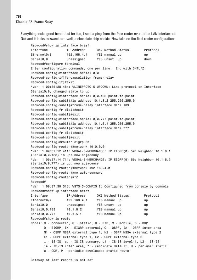
798
Everything looks good here! Just for fun, I sent a ping from the Pine router over to the LAN interface ofOak and it looks as sweet as…well, a chocolate chip cookie. Now take on the final router configuration:
Redwood#show ip interface briefInterface IP-Address OK? Method Status ProtocolEthernet0/0 192.168.4.1 YES manual up upSerial0/0 unassigned YES unset up downRedwood#configure terminalEnter configuration commands, one per line. End with CNTL/Z.Redwood(config)#interface serial 0/0Redwood(config-if)#encapsulation frame-relayRedwood(config-if)#exit*Mar 1 00:35:28.484: %LINEPROTO-5-UPDOWN: Line protocol on Interface3Serial0/0, changed state to upRedwood(config)#interface serial 0/0.183 point-to-pointRedwood(config-subif)#ip address 10.1.8.2 255.255.255.0Redwood(config-subif)#frame-relay interface-dlci 183Redwood(config-fr-dlci)#exitRedwood(config-subif)#exitRedwood(config)#interface serial 0/0.777 point-to-pointRedwood(config-subif)#ip address 10.1.5.1 255.255.255.0Redwood(config-subif)#frame-relay interface-dlci 777Redwood(config-fr-dlci)#exitRedwood(config-subif)#exitRedwood(config)#router eigrp 50Redwood(config-router)#network 10.0.0.0*Mar 1 00:37:12.411: %DUAL-5-NBRCHANGE: IP-EIGRP(0) 50: Neighbor 10.1.8.1(Serial0/0.183) is up: new adjacency*Mar 1 00:37:14.714: %DUAL-5-NBRCHANGE: IP-EIGRP(0) 50: Neighbor 10.1.5.2(Serial0/0.777) is up: new adjacencyRedwood(config-router)#network 192.168.4.0Redwood(config-router)#no auto-summaryRedwood(config-router)#^ZRedwood#*Mar 1 00:37:30.316: %SYS-5-CONFIG_I: Configured from console by consoleRedwood#show ip interface briefInterface IP-Address OK? Method Status ProtocolEthernet0/0 192.168.4.1 YES manual up upSerial0/0 unassigned YES unset up upSerial0/0.183 10.1.8.2 YES manual up upSerial0/0.777 10.1.5.1 YES manual up upRedwood#show ip routeCodes: C - connected, S - static, R - RIP, M - mobile, B - BGP
D - EIGRP, EX - EIGRP external, O - OSPF, IA - OSPF inter areaN1 - OSPF NSSA external type 1, N2 - OSPF NSSA external type 2E1 - OSPF external type 1, E2 - OSPF external type 2i - IS-IS, su - IS-IS summary, L1 - IS-IS level-1, L2 - IS-ISia - IS-IS inter area, * - candidate default, U - per-user statico - ODR, P - periodic downloaded static route
Gateway of last resort is not set
Chapter 23: Frame Relay
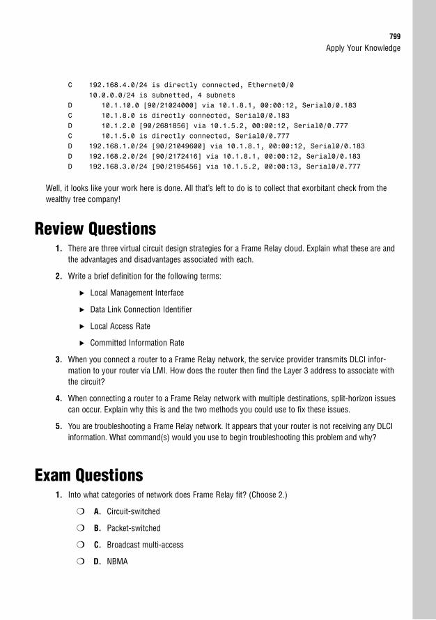
Apply Your Knowledge799
C 192.168.4.0/24 is directly connected, Ethernet0/010.0.0.0/24 is subnetted, 4 subnets
D 10.1.10.0 [90/21024000] via 10.1.8.1, 00:00:12, Serial0/0.183C 10.1.8.0 is directly connected, Serial0/0.183D 10.1.2.0 [90/2681856] via 10.1.5.2, 00:00:12, Serial0/0.777C 10.1.5.0 is directly connected, Serial0/0.777D 192.168.1.0/24 [90/21049600] via 10.1.8.1, 00:00:12, Serial0/0.183D 192.168.2.0/24 [90/2172416] via 10.1.8.1, 00:00:12, Serial0/0.183D 192.168.3.0/24 [90/2195456] via 10.1.5.2, 00:00:13, Serial0/0.777
Well, it looks like your work here is done. All that’s left to do is to collect that exorbitant check from thewealthy tree company!
Review Questions1. There are three virtual circuit design strategies for a Frame Relay cloud. Explain what these are and
the advantages and disadvantages associated with each.
2. Write a brief definition for the following terms:
. Local Management Interface
. Data Link Connection Identifier
. Local Access Rate
. Committed Information Rate
3. When you connect a router to a Frame Relay network, the service provider transmits DLCI infor-mation to your router via LMI. How does the router then find the Layer 3 address to associate withthe circuit?
4. When connecting a router to a Frame Relay network with multiple destinations, split-horizon issuescan occur. Explain why this is and the two methods you could use to fix these issues.
5. You are troubleshooting a Frame Relay network. It appears that your router is not receiving any DLCIinformation. What command(s) would you use to begin troubleshooting this problem and why?
Exam Questions1. Into what categories of network does Frame Relay fit? (Choose 2.)
❍ A. Circuit-switched
❍ B. Packet-switched
❍ C. Broadcast multi-access
❍ D. NBMA
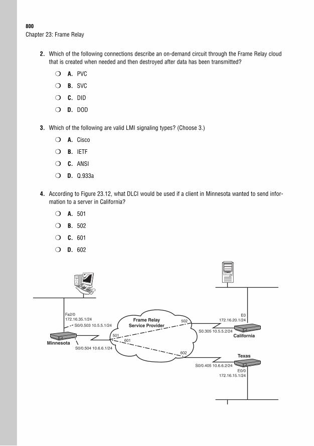
800
2. Which of the following connections describe an on-demand circuit through the Frame Relay cloudthat is created when needed and then destroyed after data has been transmitted?
❍ A. PVC
❍ B. SVC
❍ C. DID
❍ D. DOD
3. Which of the following are valid LMI signaling types? (Choose 3.)
❍ A. Cisco
❍ B. IETF
❍ C. ANSI
❍ D. Q.933a
4. According to Figure 23.12, what DLCI would be used if a client in Minnesota wanted to send infor-mation to a server in California?
❍ A. 501
❍ B. 502
❍ C. 601
❍ D. 602
Chapter 23: Frame Relay
Minnesota
California
Texas
S0/0.504 10.6.6.1/24
S0/0.503 10.5.5.1/24
S0.305 10.5.5.2/24
E0172.16.20.1/24
E0/0172.16.15.1/24
Fa2/0172.16.35.1/24
S0/0.405 10.6.6.2/24
Frame Relay Service Provider
502
501601
602
Apply Your Knowledge801
5. A router connected to a Frame Relay service provider can occasionally send faster than the sub-scribed _________, but never faster than the _________.
❍ A. Local Access Rate, CIR
❍ B. Virtual Circuit Speed, CIR
❍ C. CIR, Virtual Circuit Speed
❍ D. CIR, Local Access Rate
6. If your router is sending too much information into the Frame Relay cloud, the service providertags any return traffic with a ______ to notify your router to reduce its transmission rate.
❍ A. De
❍ B. BECN
❍ C. FECN
❍ D. Burst
7. By default, Cisco routers receive LMI messages from the service provider that provide all usableDLCI numbers for the local circuit. How does your router find out the remote devices it is able toreach?
❍ A. The router sends Hello messages down each virtual circuit.
❍ B. The router uses CDP to discover its directly connected neighbors.
❍ C. The router uses Inverse ARP messages.
❍ D. The router does not need to do anything; LMI signaling from the service provider auto-configures the router.
8. You have two routers connected over a Frame Relay network. The router in Arizona has the IPaddress 10.1.1.1/24 and uses a local DLCI of 512. The router in Michigan has the IP address10.1.1.2/24 and uses a local DLCI of 598. Which syntax among the following choices correctly cre-ates a static map that enables Arizona to reach Michigan and allows routing protocol functionality?
❍ A. frame-relay map ip 10.1.1.2 512 broadcast
❍ B. frame-relay map ip 10.1.1.1 512 broadcast
❍ C. frame-relay map ip 10.1.1.2 598 broadcast
❍ D. frame-relay map ip 10.1.1.1 598 broadcast
802
9. You are configuring your router’s Serial 0 interface to communicate across the Frame Relay cloudwith a non-Cisco router. You would like to use the Inverse ARP feature of the router to avoid con-figuring static maps; what command would you use to enable this feature?
❍ A. encapsulation frame-relay
❍ B. inverse-arp frame-relay
❍ C. ietf inverse-arp
❍ D. encapsulation frame-relay ietf
10. You are troubleshooting your Frame Relay connections. After typing in the show frame-relaypvc command, one of your PVCs shows up as DELETED. What causes this?
❍ A. Your router is incorrectly configured. You need to add the right DLCI information andthe circuit should come up.
❍ B. The remote router is incorrectly configured.
❍ C. You are physically disconnected from the service provider.
❍ D. You need to switch from a multipoint configuration to a point-to-point configurationand create a subinterface for each PVC you plan on using.
Answers to Review Questions1. The three Frame Relay virtual circuit design strategies are hub and spoke, partial mesh, and full
mesh. Hub and spoke is the cheapest design; however, it also offers the least amount of redundan-cy. If the hub location fails, the entire WAN mesh goes down. In addition, the hub and spokedesign increases the amount of delay for packets traveling between the spoke locations. This canbe devastating for VoIP traffic. Partial mesh designs connect key sites with multiple virtual circuits.This offers redundancy for those key locations, but can become a more costly design. Full meshoffers the ultimate level of redundancy and delay guarantees, but requires a huge monthly cost tosupport the large number of circuits.
2. Local Management Interface (LMI): This is the language spoken between your Frame Relay routerand the service provider that is used to provide DLCI status and traffic statistics.
Data Link Connection Identifier (DLCI): This is the Data Link address used to identify virtual circuitsin the Frame Relay cloud.
Local Access Rate: This is the maximum physical speed your interface connected to the FrameRelay cloud can use.
Committed Information Rate: This is the level of bandwidth the service provider commits to giveyou on a regular basis.
3. After your router receives DLCI information, it sends Inverse ARP messages to each DLCI numberrequesting the Layer 3 address of the remote router.
Chapter 23: Frame Relay
Apply Your Knowledge803
4. Split-horizon is a loop-prevention mechanism that prevents a router from advertising a route outthe same interface that received the original route advertisement. It can cause problems withFrame Relay because a hub router could have multiple destinations connected to a single physicalinterface. When those destinations send advertisements to the hub router, split horizon preventsthe router from propagating the advertisements to other remote offices. The two methods you can use to resolve this issue are disabling the split-horizon mechanism or using point-to-point subinterfaces.
5. The command you would be most likely to use to troubleshoot the failed DLCI communication isthe show frame-relay lmi command. It enables you to focus on the communication withthe Frame Relay service provider. If necessary, you may also use the debug frame-relaylmi command to probe deeper into the messages exchanged between your router and the serviceprovider.
Answers to Exam Questions1. B, D. Frame Relay is considered a packet-switched network and operates in much the same way as
X.25 and ATM. Rather than have users connected directly together over leased lines, virtual circuitsare established through the service provider network. Frame Relay also falls under the NBMA cate-gory. This means that, by default, multiple devices can access the network, but broadcast mes-sages are not forwarded. Answer A is incorrect because circuit-switched networks encompassconnections that use the telephone company as a backbone. Answer C is incorrect because itdescribes ethernet connectivity, not Frame Relay.
2. B, A. SVC is an on-demand circuit through the Frame Relay cloud that is created when needed andthen destroyed after data has been transmitted. This circuit type is not commonly used and hasbeen widely replaced by PVCs, which is Answer A. Answers C and D are incorrect because theseacronyms have nothing to do with Frame Relay.
3. A, C, D. The valid LMI signaling methods are Cisco, ANSI, and Q.933a. Answer B is incorrectbecause IETF represents the industry standard Frame Relay encapsulation that allows non-Ciscodevices to interoperate with Cisco devices over a Frame Relay cloud.
4. A. DLCI addressing works exactly opposite of how most folks think it should work. Rather thansend to a destination DLCI number, you leave on a local DLCI number. In this case, the Minnesotarouter would leave on DLCI 501 to reach the California office. Answer B is incorrect becauseCalifornia would leave on DLCI 502 to get to Arizona. Answers C and D are incorrect because theyreference the connection between Minnesota and Texas.
5. D. A router connected to a Frame Relay service provider can often send faster than the CommittedInformation Rate (CIR), but never faster than the Local Access Rate. The CIR describes the mini-mum amount of bandwidth that the service provider contractually guarantees the client. The LocalAccess Rate references the fastest physical speed the line can handle. Answers B and C are incor-rect because there is no such thing as a Virtual Circuit Speed. Answer A is incorrect because theterms are reversed.
804
6. B. The service provider tags any return traffic with a Backwards Explicit Congestion Notification(BECN) marking. By default, your router ignores these notifications. Answer A is incorrect becauseDiscard Eligible (De) describes markings placed on any traffic sent above the CIR. Answer C isincorrect because Forward Explicit Congestion Notification (FECN) markings are placed on packetsif there is no return traffic that can be marked with BECNs to tell the sender to slow down. AnswerD is what happens to a balloon if you poke it with a needle.
7. C. After the routers receive the DLCI information through LMI signaling, they send Inverse ARPmessages through to the other side of the connection. This enables them to discover the remote IPaddresses they are able to reach. Answer A is incorrect because Hello messages are specific torouting protocols such as OSPF and EIGRP. Answer B is incorrect because Cisco DiscoveryProtocol enables you to see information just about directly connected Cisco devices. Answer D isincorrect because LMI can only give your routers the DLCI numbers it can use to reach remotedevices, but cannot tell the router how the remote devices are configured.
8. A. The correct syntax of the Frame Relay map command is frame-relay map ip<remote_ip_address> <local_dlci> broadcast. The broadcast keyword enablesrouting protocol updates to function. In this case, Arizona is trying to reach the remote IP addressin Michigan of 10.1.1.2, and uses the local DLCI of 512 to get there. All other answers use eitherthe wrong DLCI or IP address.
9. D. To use the industry standard Frame Relay encapsulation, you need to type in encapsulationframe-relay ietf. This enables Inverse ARP to map your Frame Relay circuits for you.Answer A is incorrect because this uses the Cisco proprietary Frame Relay encapsulation that doesnot work with any non-Cisco gear. The other two answers use invalid syntax and commands.
10. A. Three primary PVC states indicate the status of the line. ACTIVE means there are no problems.INACTIVE means that there is a problem with the remote router, which rules out Answer B. DELET-ED means that there is a problem with your local router. Typically, this is caused by using theincorrect DLCI information. Answer D is eliminated because multipoint and point-to-point designsuse DLCI information in the same way. If the DLCI shows up as DELETED under a multipoint con-figuration, it shows up as DELETED under a point-to-point configuration. Finally, if you were physi-cally disconnected from the service provider, you would not see DLCI information (because LMI isused to send the DLCI status to your router), making answer C incorrect.
Suggested Reading and Resources1. Cisco TAC Configuring Frame Relay, http://www.cisco.com/univercd/cc/td/doc/prod-
uct/software/ios121/121cgcr/wan_c/wcdfrely.htm.
2. Ward, Chris and Cioara, Jeremy. Exam Cram 2 CCNA Practice Questions. QuePublishing, 2004.
3. Chin, Jonathan. Cisco Frame Relay Solutions Guide. Cisco Press, 2004.
Chapter 23: Frame Relay
24C H A P T E R T W E N T Y - F O U R
Understanding VPNConnectivity
ObjectivesThis chapter covers the following Cisco-specified objectives for the “Implement and verifyWAN links” section of the 640-802 CCNA exam:
. Describe different methods for connecting to a WAN
. Describe VPN technology (including: importance, benefits, role, impact,components)
OutlineIntroduction 808
Understanding VPN Connectivity 808
VPN Benefits and Considerations 809
Types of VPNs 810
Site-to-Site VPNs 810
Remote-Access VPNs 811
The Pieces That Make a VPN Tick 814
Understanding IPsec 815
Encryption 816
Diffie-Hellman 818
Secure Socket Layer (SSL) 819
Authentication/Data Integrity 820
IPsec Protocols 821
Chapter Summary 823
Key Terms 823
Apply Your Knowledge 824
Review Questions 824
Exam Questions 824
Answers to Review Questions 826
Answers to Exam Questions 827
Suggested Readings and Resources 828

Study Strategies. Read the information presented in the chapter, paying special attention to Notes.
. VPN connections are becoming increasingly prevalent in the industry. Although VPNswere not a major topic on the ICND1, ICND2, or CCNA exams at their initial release (andat the time of this writing), you can expect more VPN topics to be added as time passes.
. Because of the complexity, VPN configurations are not part of the ICND1, ICND2, or CCNAexams. Focus your study on the benefits of VPN connections and why an organizationwould choose VPN connectivity.
808
IntroductionInternet connectivity is everywhere. My wife and I (Jeremy) recently took a trip to Hondurasto assist some of the struggling areas. After flying through a rainforest, our plane toucheddown in the main city. We were quickly escorted to a van where we drove with many othersfor a couple hours to a remote region of the country. I’ll never forget the irony of the scenewhen I arrived. A woman was washing clothes in a bucket on the corner. Directly across fromher was a small building with a flashing sign that said “Internet Cafe.” Amazing!
Therein lies the concept: If the Internet is everywhere, and just about every major organiza-tion has an Internet connection, why not use the Internet as a style of “WAN link” to connectoffices? This is the idea of virtual private networks (VPNs). This network connection style isconsidered virtually private because we are really sending our corporate internal data over apublic network—the Internet, to be exact. So as you can imagine, you have plenty of securityconsiderations to think through before you launch your company’s internal records into thegreat Internet abyss.
Understanding VPN ConnectivityObjective:
. Describe different methods for connecting to a WAN
Anyone who has ever set up a private point-to-point WAN link between two offices can prob-ably attest to some of the challenges: long wait times (it can take months to get a private lineinstalled), high monthly costs, and technical issues between your equipment and the carrier.On the other hand, Internet connections are relatively inexpensive and typically faster toinstall. These are just a few of the reasons why VPN connectivity has become so popular. As Ijust mentioned, VPN connectivity allows any location that has Internet connectivity to bringup a virtual private line between locations, allowing true any-to-any connectivity, as shown inFigure 24.1.
The focus of most of this chapter is the “private” piece of the VPN acronym. For the VPN tobe considered a secure means of transferring data, that data must be heavily encrypted.
Chapter 24: Understanding VPN Connectivity
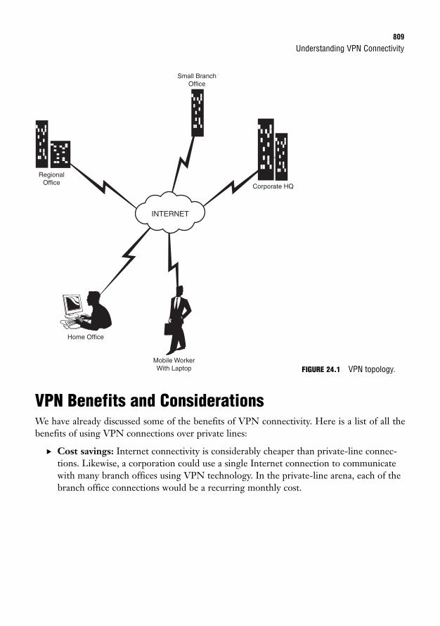
Understanding VPN Connectivity809
VPN Benefits and ConsiderationsWe have already discussed some of the benefits of VPN connectivity. Here is a list of all thebenefits of using VPN connections over private lines:
. Cost savings: Internet connectivity is considerably cheaper than private-line connec-tions. Likewise, a corporation could use a single Internet connection to communicatewith many branch offices using VPN technology. In the private-line arena, each of thebranch office connections would be a recurring monthly cost.
INTERNET
RegionalOffice
Corporate HQ
Mobile WorkerWith Laptop
Home Office
Small BranchOffice
FIGURE 24.1 VPN topology.
TIP
810
. Remote-access connections: If a corporation used only private-line connections,mobile workers and telecommuters would be limited to dialup technology to obtainremote access to the company. Dialup is considered extremely slow by today’s stan-dards. Many newer computers no longer feature preinstalled modems.
. Scalability: VPN connections allow the company to grow to add new locations with-out adding significant infrastructure considerations.
Chapter 24: Understanding VPN Connectivity
Be sure to understand the benefits of VPN connectivity over leased-line connections.
Looking at this list of benefits, it may seem like a no-brainer to choose VPN connections overother styles of WAN connectivity. Unfortunately, there is no perfect WAN connection, andVPN has its share of drawbacks:
. Higher overhead: Because of the significant amount of encryption that must be per-formed on all data sent over the VPN, VPN technology does cause more overheadthan a traditional WAN link. This can manifest itself in many ways: the processor andmemory utilization of your router or firewall will increase, more delay in sending andreceiving packets, and more overhead in the header of each packet sent.
. Varying service levels: Because the Internet is considered the “network of networks,”there is no guarantee when sending and receiving data. Although the Internet has beenproven time and time again to be stable and resilient, a downstream ISP failure can causeyour data to reroute through a slower connection, causing varying service levels. Thismakes deploying real-time applications such as voice and video over IP a challenge.
. Security considerations: Although varying levels of encryption and authentication canbe applied to your VPN connection(s), the data is still being sent over a public net-work. Some high-security organizations may find this risk unacceptable.
Types of VPNsVPN connections come in two major genres: site-to-site and remote-access VPNs. Let’s talkabout each of these individually.
Site-to-Site VPNsSite-to-site VPNs are the direct replacement for private-line WAN connections. They allowoffices to maintain permanent or semipermanent connections between each other through theInternet, as shown in Figure 24.2.
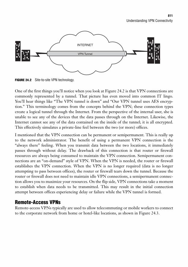
Understanding VPN Connectivity811
FIGURE 24.2 Site-to-site VPN technology.
One of the first things you’ll notice when you look at Figure 24.2 is that VPN connections arecommonly represented by a tunnel. That picture has even moved into common IT lingo.You’ll hear things like “The VPN tunnel is down” and “Our VPN tunnel uses AES encryp-tion.” This terminology comes from the concepts behind the VPN; these connection typescreate a logical tunnel through the Internet. From the perspective of the internal user, she isunable to see any of the devices that the data passes through on the Internet. Likewise, theInternet cannot see any of the data contained on the inside of the tunnel; it is all encrypted.This effectively simulates a private-line feel between the two (or more) offices.
I mentioned that the VPN connection can be permanent or semipermanent. This is really upto the network administrator. The benefit of using a permanent VPN connection is the“always there” feeling. When you transmit data between the two locations, it immediatelypasses through without delay. The drawback of this connection is that router or firewallresources are always being consumed to maintain the VPN connection. Semipermanent con-nections are an “on-demand” style of VPN. When the VPN is needed, the router or firewallestablishes the VPN connection. When the VPN is no longer required (data is no longerattempting to pass between offices), the router or firewall tears down the tunnel. Because therouter or firewall does not need to maintain idle VPN connections, a semipermanent connec-tion allows you to maximize your resources. On the flip side, VPN connections take a momentto establish when data needs to be transmitted. This may result in the initial connectionattempt between offices experiencing delay or failure while the VPN tunnel is formed.
Remote-Access VPNsRemote-access VPNs typically are used to allow telecommuting or mobile workers to connectto the corporate network from home or hotel-like locations, as shown in Figure 24.3.
INTERNET
VPN Tunnel
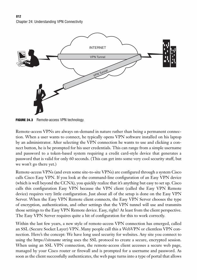
812
FIGURE 24.3 Remote-access VPN technology.
Remote-access VPNs are always on-demand in nature rather than being a permanent connec-tion. When a user wants to connect, he typically opens VPN software installed on his laptopby an administrator. After selecting the VPN connection he wants to use and clicking a con-nect button, he is be prompted for his user credentials. This can range from a simple usernameand password to a token-based system requiring a credit card-style device that generates apassword that is valid for only 60 seconds. (This can get into some very cool security stuff, butwe won’t go there yet.)
Remote-access VPNs (and even some site-to-site VPNs) are configured through a system Ciscocalls Cisco Easy VPN. If you look at the command-line configuration of an Easy VPN device(which is well beyond the CCNA), you quickly realize that it’s anything but easy to set up. Ciscocalls this configuration Easy VPN because the VPN client (called the Easy VPN Remotedevice) requires very little configuration. Just about all of the setup is done on the Easy VPNServer. When the Easy VPN Remote client connects, the Easy VPN Server chooses the typeof encryption, authentication, and other settings that the VPN tunnel will use and transmitsthose settings to the Easy VPN Remote device. Easy, right? At least from the client perspective.The Easy VPN Server requires quite a bit of configuration for this to work correctly.
Within the last few years, a new style of remote-access VPN connection has emerged, calledan SSL (Secure Socket Layer) VPN. Many people call this a WebVPN or clientless VPN con-nection. Here’s the concept: We have long used security for websites. Any site you connect tousing the https://sitename string uses the SSL protocol to create a secure, encrypted session.When using an SSL VPN connection, the remote-access client accesses a secure web page,managed by your Cisco router or firewall and is prompted for a username and password. Assoon as the client successfully authenticates, the web page turns into a type of portal that allows
Chapter 24: Understanding VPN Connectivity
INTERNET
VPN Tunnel
VPN Tunnel
Understanding VPN Connectivity813
a VPN-style connection as long as the web page remains open. This phenomenal new type ofconnection allows you to have remote-access VPN clients without the need to install clientsoftware or have extensive training teaching remote users how to use the VPN connection.
The SSL VPN comes in two forms:
. Clientless: The purely clientless SSL VPN connection allows you to create a webpage listing the resources that the user can access after he or she has successfullyauthenticated to the VPN. For example, the user would connect, enter his or her user-name and password, and be redirected to a web page with links to all the commonresources the user could access. The clientless VPN does not allow users to use appli-cations on their own PC over the VPN.
. Thin client: The thin-client form of the SSL VPN asks to install an ActiveX- or Java-based plug-in after the user has successfully authenticated to the VPN. This plug-inallows other applications (only TCP-based applications at this time) to run from theuser’s PC across the VPN. An example of this connection type in action goes some-thing like this: The user opens the SSL VPN web page in her browser and is promptedfor a username and password. After she enters the correct authentication credentials,the web page asks the user if she wants to install the thin client. If she accepts thisrequest, a small program downloads and runs. Depending on how you (as the networkadministrator) structure the SSL VPN, the web page can then redirect to a “quicklink” page with access to many of the common resources inside the network. You couldalso just have the web page redirect to a “Connection Successful” message. The usercan now open TCP-based applications (such as email or web browsing, to name a cou-ple) and access servers located at the corporate office through the VPN.
Let me mention off the CCNA record that I believe this new SSL VPN connection will be the“wave of the future” in regards to remote-access VPNs. Cisco has already released a newimplementation called the Cisco Secure Desktop. Check this out: When the thin client down-loads to the user’s PC, it also installs a “secure desktop” system that takes over the user’sWindows desktop environment. The thin client tracks any files that the user downloads fromthe corporate office. When the user disconnects from the VPN, all the secure corporate filesare removed from her PC (they literally disappear)! When the user reconnects to the VPN,the SSL VPN thin client automatically replaces all the files that the user previously had on herPC, in the respective locations. Isn’t that amazing? The secure desktop system ensures that ifthe end user’s PC is stolen or compromised (such as by a worm or virus), the corporate datawill be inaccessible. Nice.
Be sure to understand the difference between site-to-site and remote-access VPN connectivity.
NOTE
814
The Pieces That Make a VPN TickObjective:
. Describe VPN technology (including: importance, benefits, role, impact, components)
To run a VPN connection, you must have a router or firewall that supports VPN connectivi-ty (such as the Cisco ISR or ASA Firewall) and a VPN client (only if you are deploying aremote-access VPN).
Most of the modern business-class routers manufactured by Cisco are considered IntegratedServices Routers (ISRs). These routers are designed to fill multiple roles in a network, one ofwhich is managing site-to-site and remote-access VPN connectivity. However, to supportVPNs, you may need to upgrade the IOS version that the router is running to a version thatsupports security features. Cisco also supports the ASA Firewall (previously known as the PIXFirewall). The ASA firewall is designed to handle many security aspects of the network andsupports both site-to-site and remote-access VPN connections. Depending on the size andneeds of your business, you can choose one or both product lines. ISRs are designed to han-dle routing as their primary function (which they do quite well) and handle VPNs as a sec-ondary function (which they do fairly well). The ASA is designed to handle VPNs and otherfirewall processes as its primary function (which it does quite well) and routing as a secondaryfunction (which it does fairly well).
If you are managing a site-to-site connection, two routers or two ASA firewalls are all that willbe required. If you are managing remote-access VPN connections, you will also need to con-sider a VPN client. These clients can come in many forms:
. Cisco VPN client: If you purchase a Cisco SmartNET agreement (Cisco’s fancy namefor an extended support and warranty agreement) with your ISR router or ASA fire-wall, you can download the latest versions of the Cisco VPN client. This provides themost compatibility (supports many features) when used with the Cisco VPN solution.For example, you can enable a VPN-triggered firewall that begins working as soon asthe user connects to the VPN. This firewall can protect the client from being compro-mised by Internet-based attacks while connected to the VPN. When the user discon-nects from the VPN, the firewall disables itself to allow unfiltered Internet and localnetwork access. The rules of this firewall can be controlled by the Cisco administrator(that’s you!).
. Certicom client: The Certicom client is a widely supported VPN client that can beinstalled on portable devices such as a PDA. This allows the user to connect to the cor-porate VPN from the PDA device and perform tasks such as checking corporate email.
. Cisco VPN 3002 hardware client: You can install this lower-cost device in a smalloffice/home office (SOHO) environment. It establishes on-demand VPN connections
Chapter 24: Understanding VPN Connectivity
Understanding IPsec815
when data that needs to cross the VPN is sent. This can be done without installing anysoftware on the client PCs or requiring extra training on the use of VPN software.Although this product is considered end of life (EOL—no longer manufactured byCisco), other products like this are manufactured by third-party companies that arecompatible with the Cisco VPN solution.
. Third-party IPsec VPN software: The industry-standard IPsec protocol is supportedin many other VPN clients. So, if you or your company has purchased some othernon-Cisco, IPsec-compatible VPN software, chances are you can make it work withthe Cisco VPN solution. It may just take a little more work!
Understanding IPsecObjective:
. Describe VPN technology (including: importance, benefits, role, impact, components)
I’ve mentioned the IPsec protocol a few times, so let’s now take a moment to discuss the roleit plays. First, the name IPsec is short for IP Security, which is a suite of subprotocols (muchin the same way that TCP/IP is a suite of subprotocols) that is used to protect data crossing anetwork. Because IPsec operates at the network layer of the OSI model, it can protect datafrom the transport layer and above. This means that IPsec can protect any type of TCP- orUDP-based communication. This gives IPsec a large advantage over other encryption proto-cols, such as SSH and SSL. These encryption protocols work at the transport layer and arerestricted to specific ports. For example, SSH encrypts only TCP port 22 by default, and SSLencrypts only TCP port 443 by default.
You might be wondering, “Why is IPsec a suite of protocols? Isn’t it just supposed to encryptthe data?” Excellent question. There are a couple ways to answer this. First, the makers ofIPsec realized that there was far more to protecting data than just performing encryption.Encrypted packets can still be captured and used maliciously. For example, say you send somedata encrypted using IPsec that transfers $1,000 to a bank account. An attacker could capturethe data and resend it many times to cause multiple transfers to go through, even though theattacker cannot see the actual data in the packet.
The second answer to the question is a little more complex. IPsec is considered a suite of pro-tocols, but it is unable to provide any direct security features in and of itself. Now, if that does-n’t blow your mind, nothing will! Here’s the idea: IPsec is better described as a framework ofprotocols, as shown in Figure 24.4.
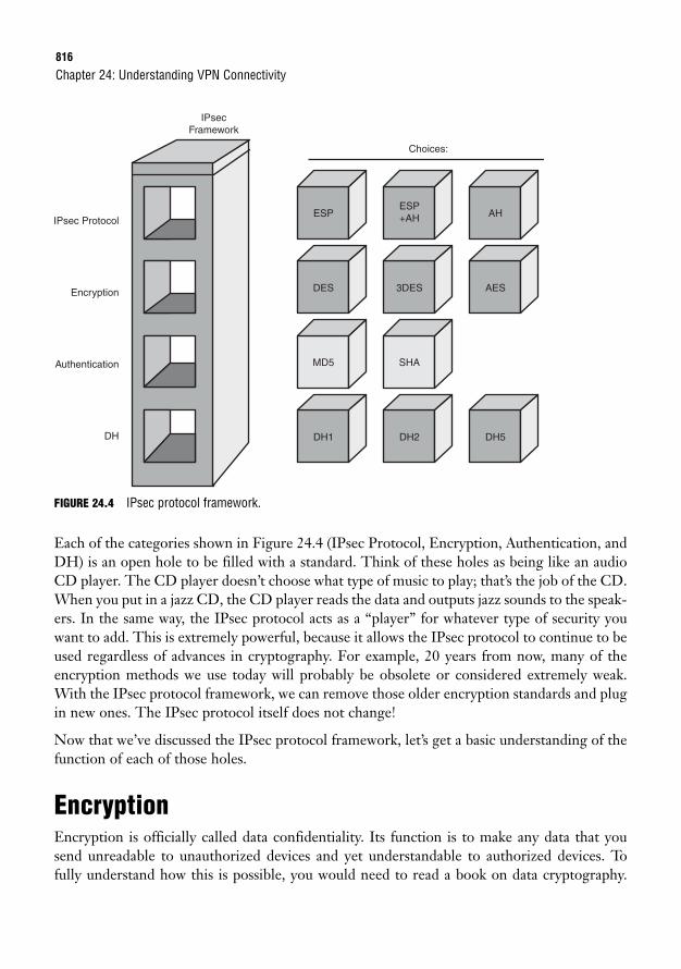
816
FIGURE 24.4 IPsec protocol framework.
Each of the categories shown in Figure 24.4 (IPsec Protocol, Encryption, Authentication, andDH) is an open hole to be filled with a standard. Think of these holes as being like an audioCD player. The CD player doesn’t choose what type of music to play; that’s the job of the CD.When you put in a jazz CD, the CD player reads the data and outputs jazz sounds to the speak-ers. In the same way, the IPsec protocol acts as a “player” for whatever type of security youwant to add. This is extremely powerful, because it allows the IPsec protocol to continue to beused regardless of advances in cryptography. For example, 20 years from now, many of theencryption methods we use today will probably be obsolete or considered extremely weak.With the IPsec protocol framework, we can remove those older encryption standards and plugin new ones. The IPsec protocol itself does not change!
Now that we’ve discussed the IPsec protocol framework, let’s get a basic understanding of thefunction of each of those holes.
EncryptionEncryption is officially called data confidentiality. Its function is to make any data that yousend unreadable to unauthorized devices and yet understandable to authorized devices. Tofully understand how this is possible, you would need to read a book on data cryptography.
Chapter 24: Understanding VPN Connectivity
IPsec Protocol
IPsecFramework
Choices:
Encryption
Authentication
DH
ESP
DES
MD5
DH1
ESP+AH
3DES
SHA
DH2
AH
AES
DH5
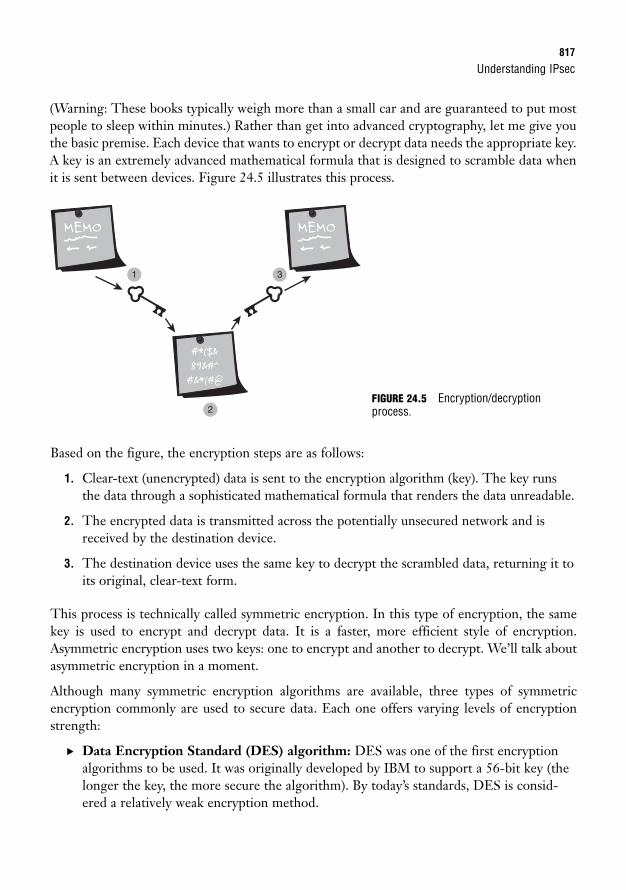
Understanding IPsec817
(Warning: These books typically weigh more than a small car and are guaranteed to put mostpeople to sleep within minutes.) Rather than get into advanced cryptography, let me give youthe basic premise. Each device that wants to encrypt or decrypt data needs the appropriate key.A key is an extremely advanced mathematical formula that is designed to scramble data whenit is sent between devices. Figure 24.5 illustrates this process.
Based on the figure, the encryption steps are as follows:
1. Clear-text (unencrypted) data is sent to the encryption algorithm (key). The key runsthe data through a sophisticated mathematical formula that renders the data unreadable.
2. The encrypted data is transmitted across the potentially unsecured network and isreceived by the destination device.
3. The destination device uses the same key to decrypt the scrambled data, returning it toits original, clear-text form.
This process is technically called symmetric encryption. In this type of encryption, the samekey is used to encrypt and decrypt data. It is a faster, more efficient style of encryption.Asymmetric encryption uses two keys: one to encrypt and another to decrypt. We’ll talk aboutasymmetric encryption in a moment.
Although many symmetric encryption algorithms are available, three types of symmetricencryption commonly are used to secure data. Each one offers varying levels of encryptionstrength:
. Data Encryption Standard (DES) algorithm: DES was one of the first encryptionalgorithms to be used. It was originally developed by IBM to support a 56-bit key (thelonger the key, the more secure the algorithm). By today’s standards, DES is consid-ered a relatively weak encryption method.
FIGURE 24.5 Encryption/decryptionprocess.
818
. Triple DES (3DES) algorithm: To address the weaknesses of DES, the 3DES algo-rithm was produced. This algorithm did not reinvent the wheel of encryption. Instead,it ran the DES algorithm three times with different encryption keys (thus the name3DES). This significantly improved the strength of the original DES algorithm.
. Advanced Encryption Standard (AES): AES is one of the newer encryption algo-rithms. It was created by Rijndael (a group of two Belgian cryptographers) in responseto a competition created by the National Institute of Standards and Technology(NIST)—a division of the U.S. government. It was designed to increase encryptionstrength beyond the DES and 3DES standards and yet be more efficient on thedevice’s processor. As it stands today, AES offers 128-, 192-, and 256-bit encryption.
Diffie-HellmanThe Diffie-Hellman (DH) key exchange algorithm addresses a gigantic missing piece of thesymmetric encryption systems we just talked about. Again, the symmetric encryption algo-rithms (including DES, 3DES, and AES) use a “shared key” approach in which the same keycan encrypt and decrypt data. This is very efficient on processing cycles, but it raises a ques-tion. If the same key encrypts and decrypts data, how do both of the devices get the key?Simple! The devices just send the key to each other over the network. So, next question: If theyjust send the key to each other over the network, couldn’t someone intercept the key and useit to decode all the transmissions? Ah, now that is the problem, and this is where the DH keyexchange algorithm comes in.
The goal of the DH algorithm is to give devices a way to securely exchange the shared key overa public network. To accomplish this, it uses an advanced process in which both endpointsexchange results to a mathematical formula over a clear network. Using these results, eachVPN endpoint can determine a shared secret value that is used to generate symmetricalencryption keys (which are much easier for the devices to process) to use for the VPN session.
Chapter 24: Understanding VPN Connectivity
As you might be able to tell, I am avoiding a detailed explanation of the mathematics behind the Diffie-Hellman algorithm. If you would like a deeper understanding of this process, visit http://en.wikipedia.org/wiki/Diffie-Hellman.
NOTE
The DH key exchange algorithm uses monstrously huge numbers (some more than 300 dig-its long) to accomplish its mathematical cryptographic process. Although DH is much moresecure than symmetric encryption, it is much harder on the device’s processor. This is why DHcryptography is used only briefly at the start of the session to generate symmetric encryptionkeys.
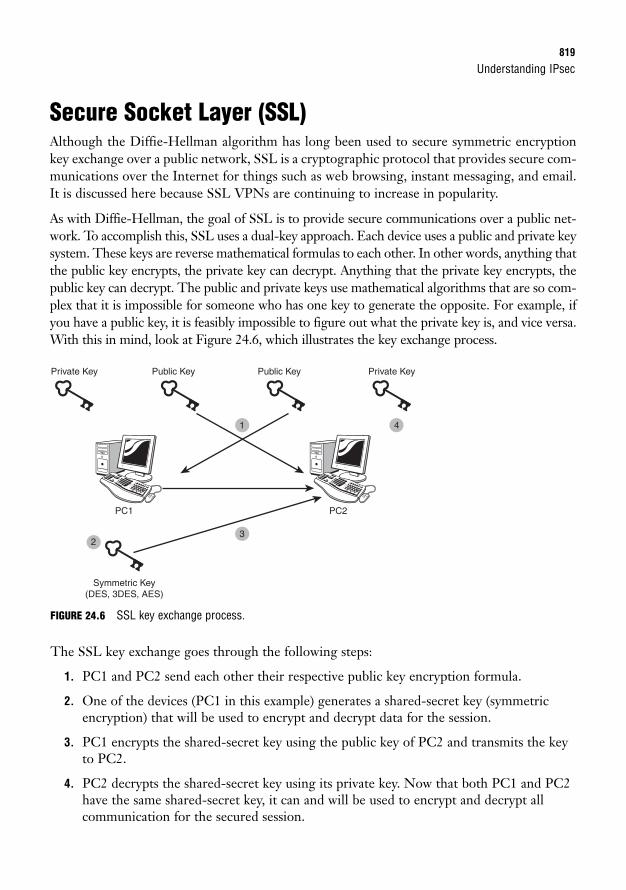
Understanding IPsec819
Secure Socket Layer (SSL)Although the Diffie-Hellman algorithm has long been used to secure symmetric encryptionkey exchange over a public network, SSL is a cryptographic protocol that provides secure com-munications over the Internet for things such as web browsing, instant messaging, and email.It is discussed here because SSL VPNs are continuing to increase in popularity.
As with Diffie-Hellman, the goal of SSL is to provide secure communications over a public net-work. To accomplish this, SSL uses a dual-key approach. Each device uses a public and private keysystem. These keys are reverse mathematical formulas to each other. In other words, anything thatthe public key encrypts, the private key can decrypt. Anything that the private key encrypts, thepublic key can decrypt. The public and private keys use mathematical algorithms that are so com-plex that it is impossible for someone who has one key to generate the opposite. For example, ifyou have a public key, it is feasibly impossible to figure out what the private key is, and vice versa.With this in mind, look at Figure 24.6, which illustrates the key exchange process.
Private Key Public Key
Symmetric Key(DES, 3DES, AES)
Public Key Private Key
PC1 PC2
1
32
4
FIGURE 24.6 SSL key exchange process.
The SSL key exchange goes through the following steps:
1. PC1 and PC2 send each other their respective public key encryption formula.
2. One of the devices (PC1 in this example) generates a shared-secret key (symmetricencryption) that will be used to encrypt and decrypt data for the session.
3. PC1 encrypts the shared-secret key using the public key of PC2 and transmits the keyto PC2.
4. PC2 decrypts the shared-secret key using its private key. Now that both PC1 and PC2have the same shared-secret key, it can and will be used to encrypt and decrypt allcommunication for the secured session.
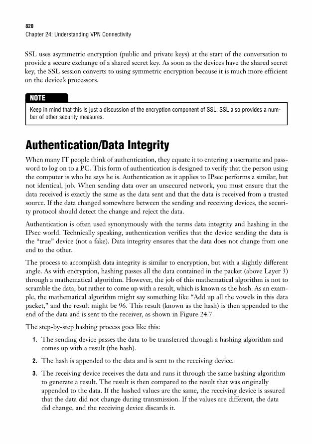
820
SSL uses asymmetric encryption (public and private keys) at the start of the conversation toprovide a secure exchange of a shared secret key. As soon as the devices have the shared secretkey, the SSL session converts to using symmetric encryption because it is much more efficienton the device’s processors.
Chapter 24: Understanding VPN Connectivity
Keep in mind that this is just a discussion of the encryption component of SSL. SSL also provides a num-ber of other security measures.
NOTE
Authentication/Data IntegrityWhen many IT people think of authentication, they equate it to entering a username and pass-word to log on to a PC. This form of authentication is designed to verify that the person usingthe computer is who he says he is. Authentication as it applies to IPsec performs a similar, butnot identical, job. When sending data over an unsecured network, you must ensure that thedata received is exactly the same as the data sent and that the data is received from a trustedsource. If the data changed somewhere between the sending and receiving devices, the securi-ty protocol should detect the change and reject the data.
Authentication is often used synonymously with the terms data integrity and hashing in theIPsec world. Technically speaking, authentication verifies that the device sending the data isthe “true” device (not a fake). Data integrity ensures that the data does not change from oneend to the other.
The process to accomplish data integrity is similar to encryption, but with a slightly differentangle. As with encryption, hashing passes all the data contained in the packet (above Layer 3)through a mathematical algorithm. However, the job of this mathematical algorithm is not toscramble the data, but rather to come up with a result, which is known as the hash. As an exam-ple, the mathematical algorithm might say something like “Add up all the vowels in this datapacket,” and the result might be 96. This result (known as the hash) is then appended to theend of the data and is sent to the receiver, as shown in Figure 24.7.
The step-by-step hashing process goes like this:
1. The sending device passes the data to be transferred through a hashing algorithm andcomes up with a result (the hash).
2. The hash is appended to the data and is sent to the receiving device.
3. The receiving device receives the data and runs it through the same hashing algorithmto generate a result. The result is then compared to the result that was originallyappended to the data. If the hashed values are the same, the receiving device is assuredthat the data did not change during transmission. If the values are different, the datadid change, and the receiving device discards it.
Understanding IPsec821
FIGURE 24.7 Hashing/data integrity process.
The hashing algorithm is obviously much more complex than simply adding up all the vowelsin the data. Currently, two widely supported hashing algorithms are used:
. Message Digest 5 (MD5) was created in 1991 by Ronald Rivest, an MIT professor.Uses a 128-bit hashing algorithm.
. Secure Hash Algorithm 1 (SHA-1) was published in 1995 by the NIST to increase thestrength of the original MD5 algorithm. Generally uses a 160-bit hashing algorithm.
As with encryption, the more bits that are used in the hashing algorithm, the stronger itbecomes. You should use the strongest hashing algorithm that your VPN platform supports.
IPsec ProtocolsThe final “piece” of the IPsec framework is the IPsec protocol itself. As I mentioned, the indi-viduals who created IPsec wanted it to be a protocol that would last through the ages. To makethis happen, they even granted the flexibility to change the entire protocol engine! Today weuse blocks such as Diffie-Hellman, encryption, and authentication, but maybe in 10 years somenew security method will be added to the bundle. Perhaps biometric VPN security will be an
Hashing Algorithm
1 Hashing Algorithm
3
2
HashResult
HashResult
Clear-Text Data
HashResult
HashResult
Clear-TextData
Clear-Text Data
822
option. Users would be required to complete a retinal scan to authenticate to the VPN (I canfeel my sci-fi movie self emerging). We might need to add a “retinal block” to the IPsec pro-tocol framework that is required for VPN establishment.
Okay, my example is a little out there, but the concept is sound. The IPsec protocol frameworkcan be extended to support future security methods. Currently, you can use two “engines” forIPsec:
. Authentication Header (AH): The AH protocol was the first IPsec engine to bereleased. It supported only authentication (verifying the sending and receiving devices)and data integrity (ensuring that data does not change in transmission). AH does notsupport any encryption.
. Encapsulating Security Payload (ESP): The ESP protocol was the second IPsecengine to be released. It filled in the massive missing piece of AH: encryption. TheESP protocol supports all three pieces of the IPsec framework: authentication, dataintegrity, and encryption. Because of this, it is by far the more popular of the two IPsecengines.
Chapter 24: Understanding VPN Connectivity
Chapter Summary823
Chapter SummaryThe popularity of VPN technology can only increase as time goes on. The availability and lowcost of Internet connection has made this method of communicating very convenient for cor-porations to use. Keep in mind that although VPNs are scalable, flexible, and low-cost, theyalso suffer the same drawbacks of normal Internet connectivity. There is no guarantee of con-sistent low-delay, high-speed service 24 hours a day. Likewise, the overhead that VPN con-nections add to your devices is a large consideration when choosing which WAN technologyyour organization will use.
Modern VPNs are powered by the IP Security (IPsec) protocol, which is a framework of sub-protocols in which each plays a role in keeping the connection secure. When designing a VPN,you must choose the appropriate levels of encryption, authentication, and Diffie-Hellman(DH) to balance performance and security. Keep in mind that there is far more to IPsec andcryptography in general than what is presented in this chapter. This chapter was designed togive you enough understanding that you can recognize terms and functions of the VPN com-ponents both in the real world and on the CCNA exam.
Key Terms. Virtual private network (VPN)
. Site-to-site VPN
. Remote-access VPN
. SSL or web VPN
. Cisco Easy VPN Server
. Cisco Easy VPN Remote
. IP Security (IPsec) protocol
. Authentication
. Encryption
. Hashing
. Data integrity
. Diffie-Hellman (DH)
. Data Encryption Standard (DES)
. Triple DES (3DES)
. Advanced Encryption Standard (AES)
. Message Digest 5 (MD5)
. Secure Hash Algorithm 1 (SHA-1)
. Authentication Header (AH)
. Encapsulating Security Payload (ESP)
824
Apply Your Knowledge
Review Questions1. What are the three benefits of using VPN connectivity over private lines?
2. Describe the two types of VPN implementations. What would be an ideal use of each?
3. The three primary security techniques used over VPN connections are encryption, authentication,and data integrity. Briefly describe the purpose of each.
4. What are the differences between asymmetric and symmetric encryption?
5. Briefly describe how SSL can securely send an encryption/decryption key over a public network.
Exam Questions1. Your organization has just opened a new office in Detroit. You have existing offices in Phoenix, San
Diego, and Albuquerque that are tied together using VPN technology. What physical or logicalchanges should you add to support the VPN connection to the new office?
❍ A. No new interfaces are needed. The VPN configuration needs only to be applied to therouter.
❍ B. No new interfaces are needed. You need to communicate with the ISP to provision anew DLCI.
❍ C. A new serial interface needs to be added to the router to support the new connection.The encapsulation should be set to match the service provider’s requirements.
❍ D. A new Fast Ethernet interface needs to be added to the router to support the new con-nection. You must communicate with the service provider to provision the new circuit.
2. Which of the following is not a valid benefit of using VPN technology?
❍ A. Lower costs
❍ B. More flexibility when configuring site-to-site connections
❍ C. The ability to support telecommuters
❍ D. Lower network overhead
Chapter 24: Understanding VPN Connectivity
Apply Your Knowledge825
3. What is needed to support an SSL VPN connection?
❍ A. The router should be configured to support SSL VPN connections. The client can con-nect using a standard web browser.
❍ B. The router should be configured to support SSL VPN connections. The client must usethe Cisco VPN client when connecting.
❍ C. The router should be configured to support SSL VPN connections. The client must usea third-party thin client to connect.
❍ D. The router does not need to be configured to support SSL VPN connections. The clientplatform delivers all configuration when it connects.
4. What platforms can support site-to-site and remote-access VPNs? (Choose two)
❍ A. Cisco IOS
❍ B. Cisco IPS Appliance
❍ C. Cisco Catalyst 3550
❍ D. Cisco ASA 5500
5. Which of the following is not a component of the IPsec framework?
❍ A. ESP
❍ B. SHA-1
❍ C. TCP
❍ D. MD5
❍ E. AES
6. Which of the following represent data integrity algorithms? (Choose two)
❍ A. AES
❍ B. MD5
❍ C. DES
❍ D. 3DES
❍ E. SHA-1
826
7. Which of the following are symmetric encryption algorithms? (Choose two)
❍ A. DH
❍ B. SHA-1
❍ C. DES
❍ D. AES
8. You have just finished proposing a new VPN solution to your organization’s upper management.They have approved the solution, provided that you use the strongest level of encryption possible.What algorithm will you choose?
❍ A. 3DES
❍ B. AES
❍ C. SHA-1
❍ D. MD5
9. You would like to implement IPsec over your LAN network. You are not as interested in encryptionfeatures, because they can cause tremendous overhead, but you would like to implement authenti-cation and data integrity features. What IPsec protocol will you use?
❍ A. AH
❍ B. DH
❍ C. ESP
❍ D. SHA-1
10. What process passes data through a mathematical algorithm to generate a 128- or 160-bit result?
❍ A. Encryption
❍ B. Diffie-Hellman
❍ C. Hashing
❍ D. ESP
Answers to Review Questions1. VPN connectivity is more cost-effective and scalable than leased-line connections. In addition, it
provides the capability for remote-access connections (such as telecommuters or mobile workers).
2. VPN connections can be either site-to-site or remote-access. Site-to-site is the direct replacementfor a leased line and acts as a permanent connection between offices. Remote-access connectionsallow users to connect to the corporate network from a remote location, such as a home or motel.
Chapter 24: Understanding VPN Connectivity
Apply Your Knowledge827
3. Encryption is designed to scramble data before it is sent and descramble it at the remote end. Thiskeeps people from intercepting and interpreting data that is communicated over a network.Authentication ensures that the devices sending and receiving data are really who they say theyare. Data integrity ensures that data does not change when it is sent across the network.
4. Asymmetric encryption uses a public and private key system. Each key is the reverse of the other(the public key can decrypt what the private key encrypts, and vice versa). This encryption type isvery processor-intensive. Symmetric encryption uses the same key to encrypt and decrypt data. Itis much more processor-efficient than asymmetric encryption.
5. SSL can secure communication over a public network between two devices. The devices firstexchange public keys and use the opposite device’s public key to encrypt a session key. The encrypt-ed session key is then exchanged between the devices and is decrypted using the private key. Afterthis, the session key is used to encrypt and decrypt all communication between the two devices.
Answers to Exam Questions1. A. A big advantage of VPN connections is their flexibility and scalability. If you need to add a new
office, all you need to do is apply the necessary configuration to the router, allowing it to connectthrough the Internet to the new office. No new interfaces are necessary to accomplish this.
2. D. VPN solutions offer many benefits, but lower network overhead is not one of them. Because theVPN forms a tunnel through the public network, new IP headers must be generated and applied tothe packet. This increases the network overhead for this type of connection.
3. A. SSL VPN connections allow you to deploy a VPN solution without installing a client on the end-user PC. To connect to the VPN, the user opens a web page hosted by the router or ASA deviceand authenticates. The web page then becomes a VPN portal. This is why SSL VPNs are oftencalled WebVPNs.
4. A, D. Specific feature sets of the Cisco IOS (used on routers) can support site-to-site and remote-access VPNs. Cisco also manufactures the ASA 5500 series security appliance, which is specifical-ly designed to support VPN solutions.
5. C. The TCP protocol fits into the TCP/IP protocol suite rather than the IPsec protocol suite. Allother protocols listed are either encryption, authentication, or IPsec core protocols.
6. B, E. The two data integrity algorithms are MD5 (128-bit hash) and SHA-1 (160-bit hash).
7. C, D. The two encryption algorithms are DES (offering 56-bit encryption) and AES (offering 128-,192-, and 256-bit encryption).
8. B. AES currently offers the strongest levels of encryption possible for symmetric encryption. It canreach up to 256-bit encryption.
9. A. The Authentication Header (AH) is the older of the two IPsec core protocols. It supports onlyauthentication and data integrity features. The Encapsulating Security Payload (ESP) adds encryption.
10. C. Hashing features pass data through a mathematical algorithm to generate a hash used for dataintegrity. Passing data through an algorithm to scramble it is called encryption.

828
Suggested Readings and Resources1. Wikipedia cryptography explanation, http://en.wikipedia.org/wiki/Cryptography
2. Richard Deal. The Complete Cisco VPN Configuration Guide. Cisco Press, 2005.
3. Bruce Schneier. Applied Cryptography: Protocols, Algorithms, and Source Code in C, SecondEdition. Wiley, 1996.
4. Chris Ward and Jeremy Cioara. Exam Cram 2 CCNA Practice Questions. QuePublishing, 2004.
Chapter 24: Understanding VPN Connectivity
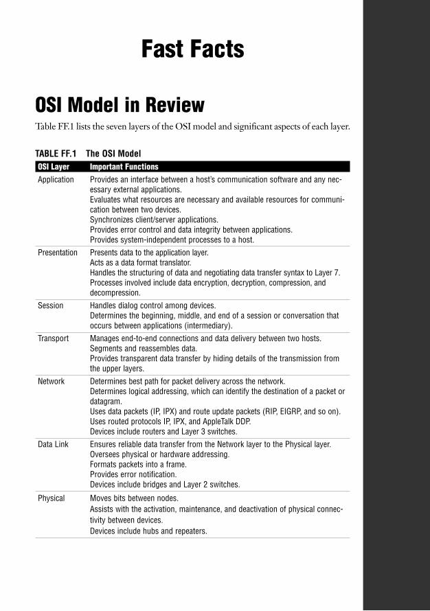
Fast Facts
OSI Model in ReviewTable FF.1 lists the seven layers of the OSI model and significant aspects of each layer.
TABLE FF.1 The OSI ModelOSI Layer Important FunctionsApplication Provides an interface between a host’s communication software and any nec-
essary external applications.Evaluates what resources are necessary and available resources for communi-cation between two devices.Synchronizes client/server applications.Provides error control and data integrity between applications.Provides system-independent processes to a host.
Presentation Presents data to the application layer.Acts as a data format translator.Handles the structuring of data and negotiating data transfer syntax to Layer 7.Processes involved include data encryption, decryption, compression, anddecompression.
Session Handles dialog control among devices.Determines the beginning, middle, and end of a session or conversation thatoccurs between applications (intermediary).
Transport Manages end-to-end connections and data delivery between two hosts.Segments and reassembles data.Provides transparent data transfer by hiding details of the transmission fromthe upper layers.
Network Determines best path for packet delivery across the network.Determines logical addressing, which can identify the destination of a packet ordatagram.Uses data packets (IP, IPX) and route update packets (RIP, EIGRP, and so on).Uses routed protocols IP, IPX, and AppleTalk DDP.Devices include routers and Layer 3 switches.
Data Link Ensures reliable data transfer from the Network layer to the Physical layer.Oversees physical or hardware addressing.Formats packets into a frame.Provides error notification.Devices include bridges and Layer 2 switches.
Physical Moves bits between nodes.Assists with the activation, maintenance, and deactivation of physical connec-tivity between devices.Devices include hubs and repeaters.
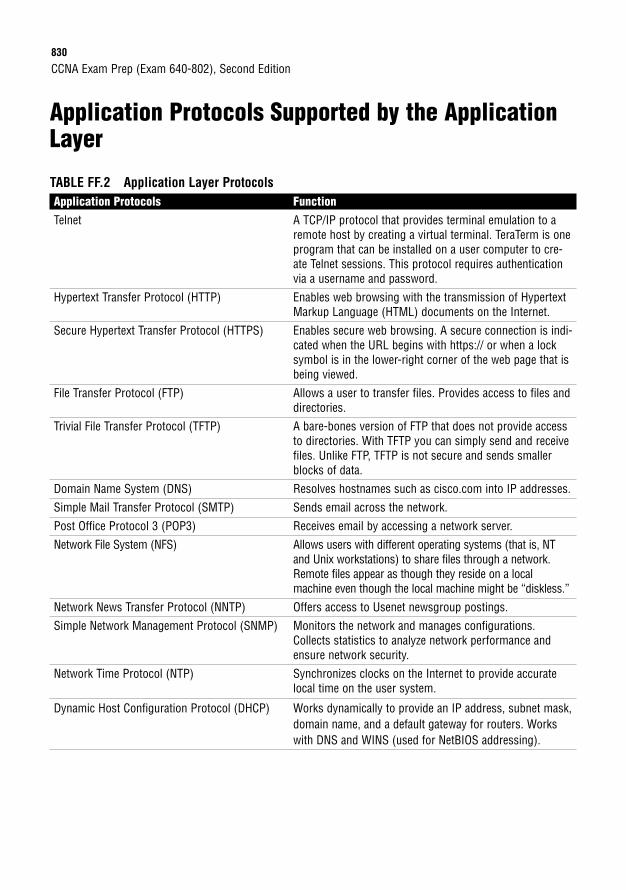
830
Application Protocols Supported by the ApplicationLayer
TABLE FF.2 Application Layer ProtocolsApplication Protocols FunctionTelnet A TCP/IP protocol that provides terminal emulation to a
remote host by creating a virtual terminal. TeraTerm is oneprogram that can be installed on a user computer to cre-ate Telnet sessions. This protocol requires authenticationvia a username and password.
Hypertext Transfer Protocol (HTTP) Enables web browsing with the transmission of HypertextMarkup Language (HTML) documents on the Internet.
Secure Hypertext Transfer Protocol (HTTPS) Enables secure web browsing. A secure connection is indi-cated when the URL begins with https:// or when a locksymbol is in the lower-right corner of the web page that isbeing viewed.
File Transfer Protocol (FTP) Allows a user to transfer files. Provides access to files anddirectories.
Trivial File Transfer Protocol (TFTP) A bare-bones version of FTP that does not provide accessto directories. With TFTP you can simply send and receivefiles. Unlike FTP, TFTP is not secure and sends smallerblocks of data.
Domain Name System (DNS) Resolves hostnames such as cisco.com into IP addresses.
Simple Mail Transfer Protocol (SMTP) Sends email across the network.
Post Office Protocol 3 (POP3) Receives email by accessing a network server.
Network File System (NFS) Allows users with different operating systems (that is, NTand Unix workstations) to share files through a network.Remote files appear as though they reside on a localmachine even though the local machine might be “diskless.”
Network News Transfer Protocol (NNTP) Offers access to Usenet newsgroup postings.
Simple Network Management Protocol (SNMP) Monitors the network and manages configurations.Collects statistics to analyze network performance andensure network security.
Network Time Protocol (NTP) Synchronizes clocks on the Internet to provide accuratelocal time on the user system.
Dynamic Host Configuration Protocol (DHCP) Works dynamically to provide an IP address, subnet mask,domain name, and a default gateway for routers. Workswith DNS and WINS (used for NetBIOS addressing).
CCNA Exam Prep (Exam 640-802), Second Edition
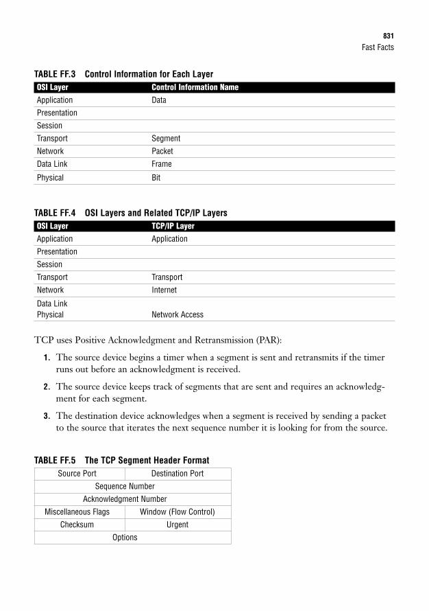
Fast Facts831
TABLE FF.3 Control Information for Each LayerOSI Layer Control Information NameApplication Data
Presentation
Session
Transport Segment
Network Packet
Data Link Frame
Physical Bit
TABLE FF.4 OSI Layers and Related TCP/IP LayersOSI Layer TCP/IP LayerApplication Application
Presentation
Session
Transport Transport
Network Internet
Data LinkPhysical Network Access
TCP uses Positive Acknowledgment and Retransmission (PAR):
1. The source device begins a timer when a segment is sent and retransmits if the timerruns out before an acknowledgment is received.
2. The source device keeps track of segments that are sent and requires an acknowledg-ment for each segment.
3. The destination device acknowledges when a segment is received by sending a packetto the source that iterates the next sequence number it is looking for from the source.
TABLE FF.5 The TCP Segment Header FormatSource Port Destination Port
Sequence Number
Acknowledgment Number
Miscellaneous Flags Window (Flow Control)
Checksum Urgent
Options

832
TABLE FF.6 Applications Using TCP and Related PortsApplication Port Number(s)FTP 20, 21
Telnet 23
SMTP 25
DNS (zone transfers) 53
HTTP 80
POP3 110
NNTP 119
HTTPS 443
TABLE FF.7 The UDP HeaderSource Port Destination Port
Length Checksum
TABLE FF.8 Applications Using UDP and Related PortsApplication Port Number(s)DHCP 67, 68
DNS (name resolution) 53
TFTP 69
NTP 123
SNMP 161
Network DomainsTwo domains determine data transport reliability:
. Broadcast domain: A group of nodes that can receive each other’s broadcast messagesand are segmented by routers.
. Collision domain: A group of nodes that share the same media and are segmented byswitches. A collision occurs if two nodes attempt a simultaneous transmission. CarrierSense Multiple Access Collision Detection (CSMA/CD) sends a jam signal to notify thedevices that there has been a collision. The devices then halt transmission for a randombackoff time.
CCNA Exam Prep (Exam 640-802), Second Edition
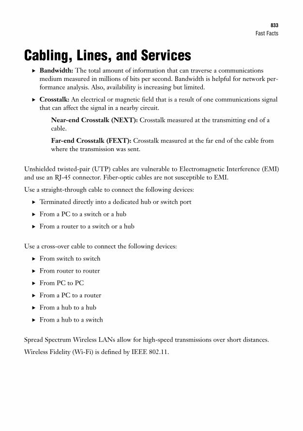
Fast Facts833
Cabling, Lines, and Services. Bandwidth: The total amount of information that can traverse a communications
medium measured in millions of bits per second. Bandwidth is helpful for network per-formance analysis. Also, availability is increasing but limited.
. Crosstalk: An electrical or magnetic field that is a result of one communications signalthat can affect the signal in a nearby circuit.
Near-end Crosstalk (NEXT): Crosstalk measured at the transmitting end of acable.
Far-end Crosstalk (FEXT): Crosstalk measured at the far end of the cable fromwhere the transmission was sent.
Unshielded twisted-pair (UTP) cables are vulnerable to Electromagnetic Interference (EMI)and use an RJ-45 connector. Fiber-optic cables are not susceptible to EMI.
Use a straight-through cable to connect the following devices:
. Terminated directly into a dedicated hub or switch port
. From a PC to a switch or a hub
. From a router to a switch or a hub
Use a cross-over cable to connect the following devices:
. From switch to switch
. From router to router
. From PC to PC
. From a PC to a router
. From a hub to a hub
. From a hub to a switch
Spread Spectrum Wireless LANs allow for high-speed transmissions over short distances.
Wireless Fidelity (Wi-Fi) is defined by IEEE 802.11.
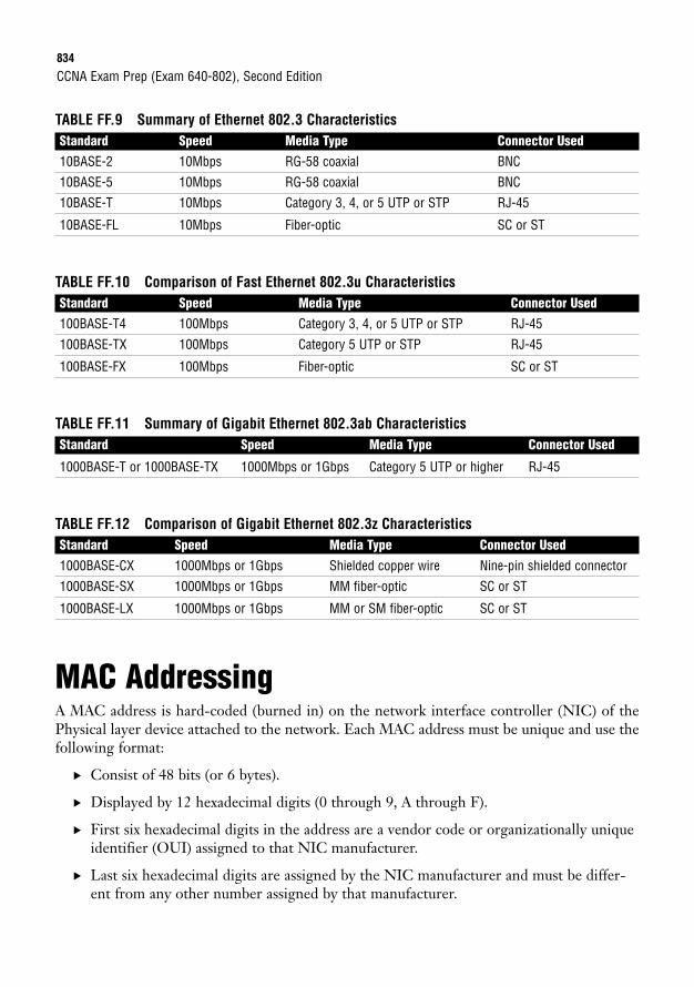
834
TABLE FF.9 Summary of Ethernet 802.3 CharacteristicsStandard Speed Media Type Connector Used10BASE-2 10Mbps RG-58 coaxial BNC
10BASE-5 10Mbps RG-58 coaxial BNC
10BASE-T 10Mbps Category 3, 4, or 5 UTP or STP RJ-45
10BASE-FL 10Mbps Fiber-optic SC or ST
TABLE FF.10 Comparison of Fast Ethernet 802.3u CharacteristicsStandard Speed Media Type Connector Used100BASE-T4 100Mbps Category 3, 4, or 5 UTP or STP RJ-45
100BASE-TX 100Mbps Category 5 UTP or STP RJ-45
100BASE-FX 100Mbps Fiber-optic SC or ST
TABLE FF.11 Summary of Gigabit Ethernet 802.3ab CharacteristicsStandard Speed Media Type Connector Used
1000BASE-T or 1000BASE-TX 1000Mbps or 1Gbps Category 5 UTP or higher RJ-45
TABLE FF.12 Comparison of Gigabit Ethernet 802.3z CharacteristicsStandard Speed Media Type Connector Used1000BASE-CX 1000Mbps or 1Gbps Shielded copper wire Nine-pin shielded connector
1000BASE-SX 1000Mbps or 1Gbps MM fiber-optic SC or ST
1000BASE-LX 1000Mbps or 1Gbps MM or SM fiber-optic SC or ST
MAC AddressingA MAC address is hard-coded (burned in) on the network interface controller (NIC) of thePhysical layer device attached to the network. Each MAC address must be unique and use thefollowing format:
. Consist of 48 bits (or 6 bytes).
. Displayed by 12 hexadecimal digits (0 through 9, A through F).
. First six hexadecimal digits in the address are a vendor code or organizationally uniqueidentifier (OUI) assigned to that NIC manufacturer.
. Last six hexadecimal digits are assigned by the NIC manufacturer and must be differ-ent from any other number assigned by that manufacturer.
CCNA Exam Prep (Exam 640-802), Second Edition
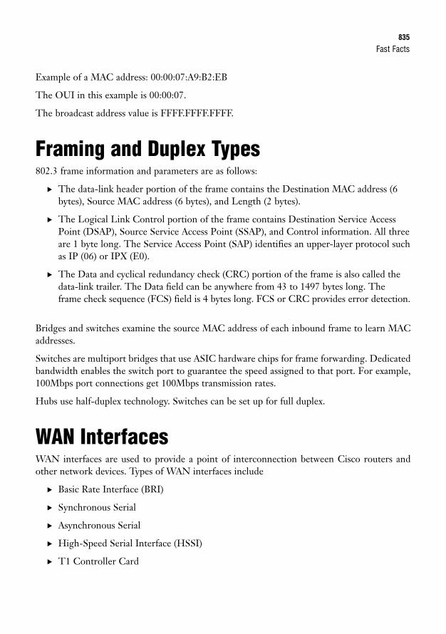
Fast Facts835
Example of a MAC address: 00:00:07:A9:B2:EB
The OUI in this example is 00:00:07.
The broadcast address value is FFFF.FFFF.FFFF.
Framing and Duplex Types802.3 frame information and parameters are as follows:
. The data-link header portion of the frame contains the Destination MAC address (6bytes), Source MAC address (6 bytes), and Length (2 bytes).
. The Logical Link Control portion of the frame contains Destination Service AccessPoint (DSAP), Source Service Access Point (SSAP), and Control information. All threeare 1 byte long. The Service Access Point (SAP) identifies an upper-layer protocol suchas IP (06) or IPX (E0).
. The Data and cyclical redundancy check (CRC) portion of the frame is also called thedata-link trailer. The Data field can be anywhere from 43 to 1497 bytes long. Theframe check sequence (FCS) field is 4 bytes long. FCS or CRC provides error detection.
Bridges and switches examine the source MAC address of each inbound frame to learn MACaddresses.
Switches are multiport bridges that use ASIC hardware chips for frame forwarding. Dedicatedbandwidth enables the switch port to guarantee the speed assigned to that port. For example,100Mbps port connections get 100Mbps transmission rates.
Hubs use half-duplex technology. Switches can be set up for full duplex.
WAN InterfacesWAN interfaces are used to provide a point of interconnection between Cisco routers andother network devices. Types of WAN interfaces include
. Basic Rate Interface (BRI)
. Synchronous Serial
. Asynchronous Serial
. High-Speed Serial Interface (HSSI)
. T1 Controller Card
836
BRI is an Integrated Services Digital Network (ISDN) line that consists of two 64Kbps bear-er (B) channels and one 16Kbps data (D) channel.
DCE equipment might consist of a
. Modem
. Channel Service Unit/Data Service Unit (CSU/DSU)
. BRI NT-1
DTE equipment might consist of a
. Router
. PC
. Server
Memory TypesFour memory components are used by Cisco devices. Those components include ROM, flash,RAM, and NVRAM.
RAM contains the running IOS, with the exception of run from flash (RFF) routers. RAM alsocontains the running configuration or the active configuration that is used after a machine isbooted.
IOS File Naming ConventionsGiven the example filename c2600-ipbase-1.122-1.T.bin, from left to right, each portion of thefilename represents the following:
. c2600: Hardware platform (Cisco 2600 router)
. ipbase: Feature set
. 1: File format (compressed relocatable)
. 122: IOS version number
. l: Maintenance release number
. T: Train identifier
CCNA Exam Prep (Exam 640-802), Second Edition

Fast Facts837
Utilities Using ICMPInternet Control Messaging Protocol (ICMP) is used by ping and traceroute utilities. PacketInternet Groper (ping) allows you to validate that an IP address exists and can accept requests.
. Ping is an echo and the response is an echo response.
. Routers send Destination Unreachable messages when they can’t reach the destinationnetwork and they are forced to drop the packet. The router that drops the packet sendsthe ICMP DU message.
A traceroute traces the route or path taken from a client to a remote host. Traceroute alsoreports the IP addresses of the routers at each next hop on the way to the destination. This isespecially useful when you suspect that a router on the route to an unreachable network isresponsible for dropping the packet.
Network SecurityThree classes of attack are commonly found in today’s network environment:
. Access attacks
. Reconnaissance attacks
. Denial of service (DoS) attacks
Access AttacksAn access attack is just what it sounds like: an attempt to access another user account or net-work device through improper means. The four main types of access attacks are
. Password attacks
. Trust exploitation
. Port redirection
. Man-in-the-middle
838
Reconnaissance AttacksThe four main subcategories or methods for gathering network data for a reconnaissanceattack are
. Packet sniffers
. Port scans
. Ping sweeps
. Information queries
Denial of Service (DoS) AttacksDoS attacks are often implemented by a hacker as a means of denying a service that is normallyavailable to a user or organization. The three main types of DoS attacks are
. Distributed DoS
. TCP SYN
. Smurf
Mitigating Network ThreatsThe following actions can be taken to lessen the impact of an attack on a network:
. Authentication, Authorization, and Accounting (AAA)
. Cisco access control lists (ACLs)
. Cisco IOS Secure Management features: SSH, SNMP, Syslog, and NTP
. Encryption protocols: SSH, IPsec, and SSL
. Security appliances and applications: Firewall, IPS, and IDS
IP AddressingIPv4 addresses
. Consist of 32 bits.
. Are broken into four octets (8 bits each).
CCNA Exam Prep (Exam 640-802), Second Edition
Fast Facts839
. Use dotted-decimal format; an example is 172.16.122.204.
. Minimum value (per octet) is 0, and the maximum value is 255.
. 0.0.0.0 is a network ID.
. 255.255.255.255 is a broadcast IP.
TABLE FF.13 IPv4 Address ClassesFirst Octet Second Octet Third Octet Fourth Octet
Class A Network Host Host Host
Class B Network Network Host Host
Class C Network Network Network Host
TCP/IP defines two additional address classes:
. Class D: Used for multicast addresses.
. Class E: Used for research purposes.
TABLE FF.14 Address Class RangesClass First Octet Decimal RangeA 1 to 126
B 128 to 191
C 192 to 223
D 224 to 239
E 240 to 255
The 127.x.x.x address range is reserved for loopback addresses.
Default subnet masks:
. Class A: 255.0.0.0
. Class B: 255.255.0.0
. Class C: 255.255.255.0
840
Classless AddressingClassless Interdomain Routing (CIDR) notation might also be used to identify the subnetmask. The CIDR notation for each network class can be determined by counting the 1s inbinary or the number of bits that make up the network portion of the address.
The mask is written in slash notation as follows:
. Class A: /8
. Class B: /16
. Class C: /24
Private RangesIANA private address space allocations:
. Class A: 10.0.0.0 to 10.255.255.255
. Class B: 172.16.0.0 to 172.31.255.255
. Class C: 192.168.0.0 to 192.168.255.255
Subnetting
TABLE FF.15 Decimal to Binary ConversionsClass First Octet Decimal Range0 00000000
128 10000000
192 11000000
224 11100000
240 11110000
248 11111000
252 11111100
254 11111110
255 11111111
CCNA Exam Prep (Exam 640-802), Second Edition
Fast Facts841
To calculate the hosts in a subnet, we can use the formula 2H – 2. The exponent H representsthe number of host bits in a network.
To calculate the networks in a subnet, we can use the formula 2N – 2. The exponent N repre-sents the number of subnet bits in a network.
The range of valid IP addresses in a subnet is the first IP address after the Network ID and thelast IP address before the broadcast IP address.
The following represents IP subnetting:
IP address = 100.15.209.0
Subnet mask = 255.255.254.0
Network ID = 100.15.208.0
Broadcast IP = 100.15.209.255
Valid IP range = 100.15.208.1 to 100.15.209.254
IPv6IPv6 is a workable IP version that was created in the event that the IP space from IPv4 isexhausted.
IPv6 address format summary:
. Defined by RFC 2373 and RFC 237.
. Consists of 128 bits, with a 64-bit network prefix and a 64-bit local identifier.
. Represented by 32 hexadecimal digits broken into eight smaller groups of four.
. Utilizes CIDR notation (slash notation) to discern a subnet range, so you might see thesame IP address subnetted and written out as2001:0BD2:0200:08F1:0000:0000:0000:16AB/16.
The same IPv6 IP address can be written out in all of the following ways:
2001:0BD2:0200:08F1:0000:0000:0000:16AB
2001:BD2:200:8F1:0:0:0:16AB
2001:BD2:200:8F1::16AB
842
Types of IPv6 Addresses. Link-local addresses: Addresses that have the shortest reach of the IP address types.
They can only go as far as the Layer 2 domain. These addresses are autogeneratedwith or without the use of a DHCP server. So, when an IPv6 node goes online, thisaddress is assigned automatically.
. Unique/site-local addresses: Addresses that have a broader scope than link-localaddresses. They can expand to the size of an organization and are used to describe theboundary of the organizational network. These are the private addresses for IPv6.
. Global addresses: Addresses that have the broadest scope of all. As the name indi-cates, these addresses are for global use—that is, for Internet communications.
. Multicast: Addresses that are extremely important because of their use in group com-munications and broadcast messaging.
Integrating IPv4 and IPv6There are several ways to integrate IPv4 and IPv6 addressing. You can implement dual-stack,tunneling, or translation techniques to help IPv4 and IPv6 addresses exist together on the net-work simultaneously.
Layer 3 FunctionsRouters and Layer 3 switches perform the following functions:
. Do not forward broadcasts or multicasts by default.
. Make best path decisions.
. Filter packets with access lists.
. Remove and add Layer 2 frames.
. Use quality of service (QoS) rules for traffic types.
Routers decide which interface to forward a packet through by examining the network portionof each IP address.
CCNA Exam Prep (Exam 640-802), Second Edition
Fast Facts843
IOS Terminal Access MethodologiesTo gain access to an EXEC session to an IOS for configuration and administration, you canuse the following methods:
. Console: Out-of-band CLI access via a rollover cable connected to the COM port ofyour terminal PC.
. Auxiliary: Out-of-band CLI access via rollover cable connected to external modem forremote access.
. Telnet: In-band CLI access to an active IP address on the device’s vty lines using theTelnet protocol. Requires configuration.
. SSH: Secure encrypted in-band CLI access to an active IP address using the SSH pro-tocol. Requires configuration.
. HTTP/HTTPS: In-band GUI access to an active IP address using the HTTP orHTTPS protocol. Requires configuration.
IOS Boot ProcessesTo solidify the startup process, the following is a recap of the stages of the bootup, any fallbackprocedures, and the memory locations involved:
1. POST located in ROM tests hardware.
2. Bootstrap located in ROM looks at boot field in configuration register to locate IOS.0x2100 boots to ROMmon located in ROM.
3. 0x2101 to 0x210F prompt bootstrap to parse startup-config in NVRAM for any bootsystem commands. If there are any commands, do what they say.
4. If no boot system commands, load first file in flash. If no file in flash, TFTP boot. Ifno IOS file found from TFTP, go to ROMmon mode.
5. After IOS is loaded, check configuration register. If 0x2142, ignore startup-config inNVRAM. If 0x2102, load startup-config in NVRAM. If no startup-config, TFTPautoinstall. If no TFTP autoinstall configuration found, enter Setup Mode.
844
IOS NavigationTABLE FF.16 IOS Navigation ModesMode Prompt DescriptionUser EXEC Router> Basic troubleshooting and verification
Privileged EXEC Router# All available commands, including delete,clear, erase, configure, copy, and reload
Global configuration Router(config)# Configurations that apply to the entire device
Line configuration Router(config-line)# Configurations that apply to the terminal linesinto a device
Interface configuration Router(config-if)# Configurations that apply to interfaces
Subinterface configuration Router(config-subif)# Configurations that apply to logical extensions ofthe physical interface
Router configuration Router(config-router)# Configurations that apply to routing protocols
VLAN configuration Switch(vlan)# VLAN-specific configurations in switches
Context-Sensitive HelpThe question mark shows all the available commands at that particular prompt. To see all theavailable commands that start with a letter or letter(s), type the letter(s) immediately followedby a question mark. To see the list of commands that follows a keyword, type the keyword, aspace, and a question mark. Commands can be abbreviated as long as there are enough char-acters to recognize what command you are entering.
Terminal Editing Keys
TABLE FF.17 Cisco IOS Terminal Editing KeystrokesKeystroke FunctionCtrl+A Moves the cursor to the beginning of the command line.
Ctrl+E Moves the cursor to the end of the command line.
Ctrl+B Moves the cursor back one character.
Ctrl+F Moves the cursor forward one character.
Esc+B Moves the cursor back one word.
Esc+F Moves the cursor forward one word.
CCNA Exam Prep (Exam 640-802), Second Edition
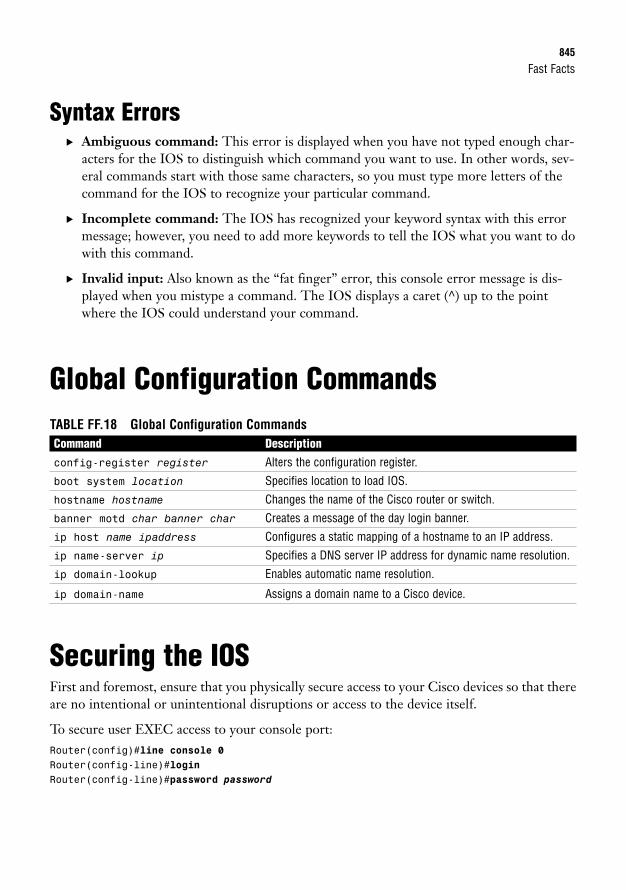
Fast Facts845
Syntax Errors. Ambiguous command: This error is displayed when you have not typed enough char-
acters for the IOS to distinguish which command you want to use. In other words, sev-eral commands start with those same characters, so you must type more letters of thecommand for the IOS to recognize your particular command.
. Incomplete command: The IOS has recognized your keyword syntax with this errormessage; however, you need to add more keywords to tell the IOS what you want to dowith this command.
. Invalid input: Also known as the “fat finger” error, this console error message is dis-played when you mistype a command. The IOS displays a caret (^) up to the pointwhere the IOS could understand your command.
Global Configuration CommandsTABLE FF.18 Global Configuration CommandsCommand Descriptionconfig-register register Alters the configuration register.
boot system location Specifies location to load IOS.
hostname hostname Changes the name of the Cisco router or switch.
banner motd char banner char Creates a message of the day login banner.
ip host name ipaddress Configures a static mapping of a hostname to an IP address.
ip name-server ip Specifies a DNS server IP address for dynamic name resolution.
ip domain-lookup Enables automatic name resolution.
ip domain-name Assigns a domain name to a Cisco device.
Securing the IOSFirst and foremost, ensure that you physically secure access to your Cisco devices so that thereare no intentional or unintentional disruptions or access to the device itself.
To secure user EXEC access to your console port:Router(config)#line console 0Router(config-line)#loginRouter(config-line)#password password
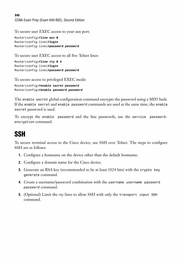
846
To secure user EXEC access to your aux port:Router(config)#line aux 0Router(config-line)#loginRouter(config-line)#password password
To secure user EXEC access to all five Telnet lines:Router(config)#line vty 0 4Router(config-line)#loginRouter(config-line)#password password
To secure access to privileged EXEC mode:Router(config)#enable secret passwordRouter(config)#enable password password
The enable secret global configuration command encrypts the password using a MD5 hash.If the enable secret and enable password commands are used at the same time, the enablesecret password is used.
To encrypt the enable password and the line passwords, use the service password-
encryption command.
SSHTo secure terminal access to the Cisco device, use SSH over Telnet. The steps to configureSSH are as follows:
1. Configure a hostname on the device other than the default hostname.
2. Configure a domain name for the Cisco device.
3. Generate an RSA key (recommended to be at least 1024 bits) with the crypto keygenerate command.
4. Create a username/password combination with the username username password
password command.
5. (Optional) Limit the vty lines to allow SSH with only the transport input SSHcommand.
CCNA Exam Prep (Exam 640-802), Second Edition
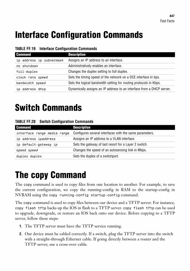
Fast Facts847
Interface Configuration CommandsTABLE FF.19 Interface Configuration CommandsCommand Descriptionip address ip subnetmask Assigns an IP address to an interface.
no shutdown Administratively enables an interface.
full-duplex Changes the duplex setting to full duplex.
clock rate speed Sets the timing speed of the network on a DCE interface in bps.
bandwidth speed Sets the logical bandwidth setting for routing protocols in Kbps.
ip address dhcp Dynamically assigns an IP address to an interface from a DHCP server.
Switch CommandsTABLE FF.20 Switch Configuration CommandsCommand Descriptioninterface range media range Configures several interfaces with the same parameters.
ip address ipaddress Assigns an IP address to a VLAN interface.
ip default-gateway ip Sets the gateway of last resort for a Layer 2 switch.
speed speed Changes the speed of an autosensing link in Mbps.
duplex duplex Sets the duplex of a switchport.
The copy CommandThe copy command is used to copy files from one location to another. For example, to savethe current configuration, we copy the running-config in RAM to the startup-config inNVRAM using the copy running-config startup-config command.
The copy command is used to copy files between our device and a TFTP server. For instance,copy flash tftp backs up the IOS in flash to a TFTP server. copy flash tftp can be usedto upgrade, downgrade, or restore an IOS back onto our device. Before copying to a TFTPserver, follow these steps:
1. The TFTP server must have the TFTP service running.
2. Our device must be cabled correctly. If a switch, plug the TFTP server into the switchwith a straight-through Ethernet cable. If going directly between a router and theTFTP server, use a cross-over cable.
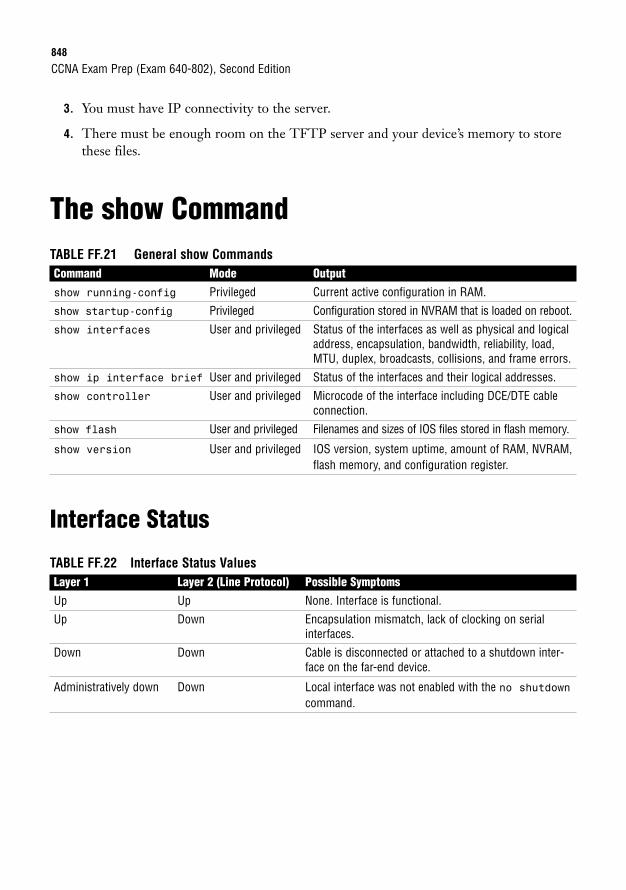
848
3. You must have IP connectivity to the server.
4. There must be enough room on the TFTP server and your device’s memory to storethese files.
The show CommandTABLE FF.21 General show CommandsCommand Mode Outputshow running-config Privileged Current active configuration in RAM.
show startup-config Privileged Configuration stored in NVRAM that is loaded on reboot.
show interfaces User and privileged Status of the interfaces as well as physical and logicaladdress, encapsulation, bandwidth, reliability, load,MTU, duplex, broadcasts, collisions, and frame errors.
show ip interface brief User and privileged Status of the interfaces and their logical addresses.
show controller User and privileged Microcode of the interface including DCE/DTE cable connection.
show flash User and privileged Filenames and sizes of IOS files stored in flash memory.
show version User and privileged IOS version, system uptime, amount of RAM, NVRAM,flash memory, and configuration register.
Interface Status
TABLE FF.22 Interface Status ValuesLayer 1 Layer 2 (Line Protocol) Possible SymptomsUp Up None. Interface is functional.
Up Down Encapsulation mismatch, lack of clocking on serialinterfaces.
Down Down Cable is disconnected or attached to a shutdown inter-face on the far-end device.
Administratively down Down Local interface was not enabled with the no shutdowncommand.
CCNA Exam Prep (Exam 640-802), Second Edition
Fast Facts849
Cisco Discovery Protocol. Proprietary Cisco Layer 2 protocol that uses multicast to gather hardware and protocol
information about directly connected devices.
. Network layer protocol and media independent.
. Enabled by default on all Cisco devices, but can be disabled globally:Router(config)#no cdp run
or can be disabled on interface-by-interface basis:Router(config-if)#no cdp enable
. To learn the remote device’s Layer 3 address and IOS versionRouter>show cdp neighbor detail
orRouter>show cdp entry *
TelnetTelnet enables a virtual terminal connection to a remote device’s IP address using theApplication layer protocol called Telnet (TCP port 23 at the Transport layer).
To Telnet from IOS, enter the keyword telnet followed by the IP address or hostname. If youenter only an IP address or hostname in user or privileged EXEC, IOS automatically assumesthat you are Telnetting. To Telnet to a Cisco device, the vty passwords must be set, or youreceive the “Password required, but none set” error. To access Privileged EXEC in a Telnetsession, you must have enable password set, or you receive the “% No password set” error.
. To suspend the Telnet session, press Ctrl+Shift+6, x.
. To see a list of the active sessions in the originating router, use the show sessionscommand.
. To resume a suspended session, press the Enter key from user EXEC or privilegedEXEC mode, or enter resume followed by the session number.
. To close a Telnet session from the device you are Telnetted into, enter exit or logoutfrom user EXEC or privileged EXEC mode.
. To close a Telnet session from the originating device, enter disconnect followed bythe session number.
. To see log messages in your Telnet session, use the privileged EXEC mode commandterminal monitor in the device that you are Telnetted into.
850
DHCPYour Cisco device can act as a DHCP server and respond to DHCP requests on a segment. Toconfigure the Cisco device as a DHCP server, you must first enable the interface that will receivethe DHCP requests and assign an IP address to it. After the interface is enabled, you define theDHCP address pool with the ip dhcp pool poolname global configuration command. In dhcp-config mode, you can define the DHCP address scope with the network command followed bythe IP subnet to be assigned. You can also define additional parameters such as the default gate-way, DNS server, domain name, and length of the IP lease. To exclude IP addresses from beingassigned (such as if you have statically assigned them to specific devices), use the ip dhcp
excluded-address ip-address command to remove the IP(s) from the scope.
To verify the devices that have been assigned IP addresses from the DHCP address scope, usethe show dhcp bindings command.
SwitchesSwitches have the following functions:
. Segment LANs into multiple collision domains.
. Learn MAC addresses by examining the source MAC address of each frame receivedand store them in a CAM table.
. Base their forwarding decisions based on the destination MAC address of an Ethernetframe.
. Flood broadcast, multicast, and unknown unicast frames out all ports except the one itwas received.
A switch has three methods of forwarding frames:
. Store-and-forward: Latency varying transmission method that buffers the entireframe and calculates the CRC before forwarding the frame.
. Cut-through: Only looks at the destination MAC address in an Ethernet frame andforwards it.
. Fragment-free: Checks the first 64 bytes for frame fragments (due to collisions)before forwarding the fame.
CCNA Exam Prep (Exam 640-802), Second Edition
Fast Facts851
Duplex Connections. Half-duplex interfaces have one-way communication with suboptimal throughput
because they operate in a collision domain in which CSMA/CD must be enabled.When connected to a hub, they must run half duplex.
. Full-duplex interfaces simultaneously send and receive, allowing higher throughputbecause CSMA/CD is disabled. Connections to other switches or devices can be fullduplex.
Spanning Tree Protocol IEEE 802.1dSTP is a Layer 2 protocol that is used to prevent switching loops in networks with redundantswitched paths.
TABLE FF.23 STP Port StatesState Function Transition TimeDisabled The interface is administratively shut down NA
or disabled from port violation.
Blocking Does not forward any user data. All ports start out in this state. 0 to 20 secondsDoes not send, but still can receive BPDUs to react to topology changes.
Listening Begins to transition to a forwarding state by listening and sending BPDUs. 15 secondsNo user data sent.
Learning Begins to build MAC addresses learned on the interface. No user data sent. 15 seconds
Forwarding User data forwarded.
STP elects root bridge/switch by determining which switch has the lowest Bridge ID in thetopology learned from sending and receiving BPDUs. Bridge ID is a combination of Priorityand MAC address.
All nonroot switches determine root port based on the fastest (lowest cumulative cost) pathback to root switch. If a tie occurs, the Bridge ID followed by port priority and port numberare the tie breakers.
On each segment, the switch advertising the fastest way back to the root switch is the desig-nated port for that segment.
If port is not a root or a designated port, it is blocking.
852
TABLE FF.24 Port Cost ValuesInterface Cost10Gbps 2
1Gbps 4
100Mbps 19
10Mbps 100
STP ConfigurationSTP is enabled by default for all VLANs in a switch. To change the priority to a lower valuefor root switch elections, use one of the following commands:Switch(config)#spanning-tree vlan 1 priority 4096
orSwitch(config)#spanning-tree vlan 1 root
STP Topology Changes and EnhancementsIn the event of a topology change, formerly blocked ports might transition to a forwardingstate. It might take up to 50 seconds to transition from a blocking state to a forwarding state.
An exception to these 50 seconds is if the following Cisco enhancements are in place to speedup convergence:
. PortFast skips the listening and learning states on end-devices such as servers, PCs,and printers. PortFast can cause switching loops if a hub or switch is connected. BPDUGuard adds protection by disabling a port if the interface receives a BPDU.
. UplinkFast skips the listening and learning transitions when a direct failure occurs onits root port on a switch with redundant uplinks to a distribution switch.
. BackboneFast speeds up convergence by skipping the max age time when switcheslearn of a failure indirectly.
EtherChannelEtherChannel is a Cisco method of bundling redundant links between switches to act as a sin-gle aggregated link. This allows utilization of all the link’s bandwidth, because STP treats thelink as a single interface (no blocking/discarding ports). In the case of a link failure,EtherChannel automatically distributes the traffic load over the remaining links in milliseconds.
To add an interface to an EtherChannel bundle (up to eight), use the channel-group chan-nel# mode on command in the interface configuration.
CCNA Exam Prep (Exam 640-802), Second Edition
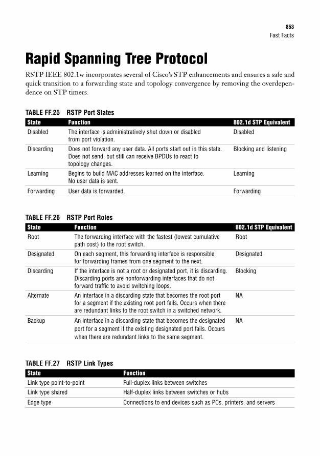
Fast Facts853
Rapid Spanning Tree ProtocolRSTP IEEE 802.1w incorporates several of Cisco’s STP enhancements and ensures a safe andquick transition to a forwarding state and topology convergence by removing the overdepen-dence on STP timers.
TABLE FF.25 RSTP Port StatesState Function 802.1d STP EquivalentDisabled The interface is administratively shut down or disabled Disabled
from port violation.
Discarding Does not forward any user data. All ports start out in this state. Blocking and listeningDoes not send, but still can receive BPDUs to react to topology changes.
Learning Begins to build MAC addresses learned on the interface. LearningNo user data is sent.
Forwarding User data is forwarded. Forwarding
TABLE FF.26 RSTP Port RolesState Function 802.1d STP EquivalentRoot The forwarding interface with the fastest (lowest cumulative Root
path cost) to the root switch.
Designated On each segment, this forwarding interface is responsible Designatedfor forwarding frames from one segment to the next.
Discarding If the interface is not a root or designated port, it is discarding. BlockingDiscarding ports are nonforwarding interfaces that do not forward traffic to avoid switching loops.
Alternate An interface in a discarding state that becomes the root port NAfor a segment if the existing root port fails. Occurs when there are redundant links to the root switch in a switched network.
Backup An interface in a discarding state that becomes the designated NAport for a segment if the existing designated port fails. Occurs when there are redundant links to the same segment.
TABLE FF.27 RSTP Link TypesState FunctionLink type point-to-point Full-duplex links between switches
Link type shared Half-duplex links between switches or hubs
Edge type Connections to end devices such as PCs, printers, and servers
854
RSTP ConvergenceEdge ports immediately transition to a forwarding state when connected to RSTP ports. Forpoint-to-point link types, transitioning to a forwarding state involves a synchronization process:
1. After switches are connected to a point-to-point link, they exchange BPDUs.
2. If a switch determines its port will become a designated port, it sends a proposal tostart forwarding to its neighbor.
3. The neighboring switch receives the proposal. If its port is a root port, it synchronizesthe change by putting all nonedge ports into a discarding state and sending an agree-ment back to the original switch. If its port is a discarding port, it does not respond tothe proposal.
4. The original switch immediately transitions to a forwarding state if it receives anagreement or eventually transitions to a forwarding state after a forward delay occurs.
RSTP uses BPDUs as keepalives to detect if a neighboring switch goes down. When the topol-ogy change is detected, RSTP immediately starts aging out the affected MAC address and tellsits neighbors to do the same.
Virtual LANs (VLANs)VLANs logically divide a switch into multiple broadcast domains at Layer 2.
Each VLAN can represent a logical grouping of users by function or department. As users inthese VLANs move, we simply need to change the VLAN assigned to their switch port.VLANs also enhance security because users in one VLAN cannot communicate to users inanother VLAN without the use of a Layer 3 device providing inter-VLAN routing.
VLAN Configuration VLANs can be statically assigned to switch access ports or dynamically assigned by using aVMPS. By default, all interfaces are assigned to the management VLAN, VLAN 1.
To configure a VLAN:
1. Create the VLAN in global configuration:Switch(config)#vlan 2Switch(config-vlan)#
2. The VLAN must be named:Switch(config-vlan)#vlan 2 name ExamPrep
CCNA Exam Prep (Exam 640-802), Second Edition
Fast Facts855
3. The desired ports must be added to the new VLAN:Switch(config)#interface FastEthernet 0/1Switch(config-if)#switchport access vlan 2
Voice VLANsVoice VLANs are used to separate VoIP traffic from data on an access port for QoS, managea-bility, and traffic confinement.Switch(config-if)#switchport voice vlan 30
TrunksVLANS can span multiple switches using trunks. Trunks multiplex traffic from all VLANs overa single connection. The VLAN identifier is tagged over the trunk using one of the followingtagging methods:
. ISL: A Cisco-proprietary trunk that encapsulates the original Ethernet frame with a 26-byte header and a 4-byte CRC.
. IEEE 802.1q: Standards-based VLAN tagging that inserts a 4-byte tag in the originalEthernet frame. Traffic originating from the native VLAN (VLAN 1 by default) is nottagged over the trunk. If native VLAN configuration does not match on both sides, thiscould cause VLAN leakage.
Trunk ConfigurationSwitch(config)#interface FastEthernet 0/24Switch(config-if)#switchport trunk encapsulation [isl|dot1q]Switch(config-if)#switchport mode trunk
Trunks can be secured by allowing only specific VLANs to traverse to switches that specificallyrequire access to those VLANs. The command to specify the VLANs to be included in the “allowedlist of VLANs” is switchport trunk allowed vlan {add | remove | except} vlan_list.
VLAN Trunking ProtocolCisco created VTP to minimize the amount of VLAN administration in switches by enabling aVTP server to multicast VTP advertisements to other switches in the same VTP domain.Switches receiving these advertisements synchronize their VLAN database with the VLANinformation advertised from the server, assuming that the revision number is higher.
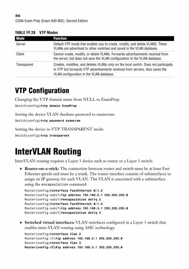
856
TABLE FF.28 VTP ModesMode FunctionServer Default VTP mode that enables you to create, modify, and delete VLANS. These
VLANs are advertised to other switches and saved in the VLAN database.
Client Cannot create, modify, or delete VLANs. Forwards advertisements received fromthe server, but does not save the VLAN configuration in the VLAN database.
Transparent Creates, modifies, and deletes VLANs only on the local switch. Does not participatein VTP but forwards VTP advertisements received from servers. Also saves theVLAN configuration in the VLAN database.
VTP ConfigurationChanging the VTP domain name from NULL to ExamPrep:Switch(config)#vtp domain ExamPrep
Setting the device VLAN database password to examcram:Switch(config)#vtp password examcram
Setting the device to VTP TRANSPARENT mode:Switch(config)#vtp transparent
InterVLAN RoutingInterVLAN routing requires a Layer 3 device such as router or a Layer 3 switch:
. Router-on-a-stick: The connection between router and switch must be at least FastEthernet speeds and must be a trunk. The router interface consists of subinterfaces toassign an IP gateway for each VLAN. The VLAN is associated with a subinterfaceusing the encapsulation command:Router(config)#interface FastEthernet 0/1.2Router(config-subif)#ip address 192.168.2.1 255.255.255.0Router(config-subif)#encapsulation dot1q 2Router(config)#interface FastEthernet 0/1.3Router(config-subif)#ip address 192.168.3.1 255.255.255.0Router(config-subif)#encapsulation dot1q 3
. Switched virtual interfaces: VLAN interfaces configured in a Layer 3 switch thatenables inter-VLAN routing using ASIC technology:Router(config)#interface Vlan 2Router(config-if)#ip address 192.168.2.1 255.255.255.0Router(config)#interface Vlan 3Router(config-if)#ip address 192.168.3.1 255.255.255.0
CCNA Exam Prep (Exam 640-802), Second Edition
Fast Facts857
Port SecurityHere’s the configuration that limits the number of MAC addresses that can be dynamicallylearned on a switch port:Switch(config-if)#switchport mode accessSwitch(config-if)#switchport port-securitySwitch(config-if)#switchport port-security maximum 1Switch(config-if)#switchport port-security violation {protect | restrict | shutdown}
If a violation occurs, the default response of a Catalyst switch is to shut down the port. To havethe port increase a violation counter and alert an administrator using SNMP, use the restrictkeyword. The protect keyword allows only traffic from the secure port and drops packetsfrom other MAC addresses until the number of MAC addresses drops below the maximum.
To secure an interface by statically assigning the permitted MAC address(es) attached to theport, use the switchport port-security mac-address MAC_address command on theinterface. Alternatively, you can have the switch learn these addresses up to the maximum byusing sticky-learned addresses with the command switchport port-security mac-addresssticky.
Routing CharacteristicsPackets originating from a nonrouting device destined for another network are sent to theirdefault gateway (Layer 3 device on segment). The router consults its routing table to deter-mine if the destination network can be reached. If not, the ICMP Destination Unreachablemessage is sent to the source. If so, packet is forwarded out interface associated with the des-tination network in routing table.
Routing Sources. Connected interfaces: As soon as we assign an IP address to a working (up/line pro-
tocol up) interface, the router associates the entire subnet of the interface’s IP addressin the routing table.
. Static routes: Manual entries that an administrator enters into the configuration thatdescribe the destination network and the next hop (router along the destination path).
. Routing protocols: Protocols exchanged between routing devices to dynamicallyadvertise networks.
When multiple routing sources are advertising the same IP subnet, the router uses the sourcewith the lowest administrative distance.
858
TABLE FF.29 Default Administrative DistancesRouted Source Default DistanceConnected 0
Static route 1
EIGRP (internal) 90
OSPF 110
RIPv1 and v2 120
EIGRP (external) 170
Static and Default RoutesStatic routes are useful in stub networks in which we want to control the routing behavior bymanually configuring destination networks into the routing table:Router(config)#ip route 10.0.0.0 255.0.0.0 192.168.2.5
A floating static route can be configured when redundant connections exist and you want touse the redundant link if the primary fails. This is configured by adding a higher administra-tive distance at the end of a static route:Router(config)#ip route 10.0.0.0 255.0.0.0 192.168.2.9 2
A default route is a gateway of last resort for a router when there isn’t a specific match for anIP destination network in the routing table (such as packets destined for the Internet):Router(config)#ip route 0.0.0.0 0.0.0.0 serial 0/0
With routing protocols, you can specify a default network, which is a network in the routingtable that routing devices consider to be the gateway of last resort. Using their routing proto-cols, they determine the best path to the default network:Router(config)#ip default-network 192.168.1.0
Dynamic Routing ProtocolsIn complex networks with multiple pathways to destinations, dynamic routing protocolsenable routers to advertise their networks to each other and dynamically react to topologychanges.
Routing protocols determine the best path based on the lowest metric.
CCNA Exam Prep (Exam 640-802), Second Edition
Fast Facts859
Routing MetricsBecause one of the core responsibilities of routing protocols is to build routing tables to determineoptimal routing paths, we need to have some means of measuring which routes are preferred whenthere are multiple pathways to a destination. Routing protocols use some measure of metrics toidentify which routes are optimal to reach a destination network. The lowest cumulative metric toa destination is the preferred path and the one that ultimately enters the routing table. Differentrouting protocols use one or several of the following metrics to calculate the best path.
TABLE FF.30 Routing MetricsMetric DescriptionHop count The number of routing devices that the packet must travel to reach a destination network
Bandwidth The cumulative bandwidth of the links to the destination in kilobits per second
Delay The length of time (measured in microseconds) a packet takes from source to destination
Reliability The consistency of the links and paths toward the destination based on error rates of theinterfaces
Load The cumulative amount of congestion or saturation of the links toward the destination
MTU The maximum frame size that is allowed to traverse the links to the destination
Cost An arbitrary number typically based on the link’s bandwidth
Interior and Exterior Gateway Routing Protocols. Interior gateway routing protocols: IG routing protocols advertise networks and
metrics within an autonomous system.
. Exterior gateway routing protocols: EG routing protocols advertise networks inbetween autonomous systems.
Classful and Classless Routing Updates. Classful routing: The routing updates only contain the classful networks without any
subnet mask. Summarization is automatically done when a router advertises a networkout an interface that is not within the same major subnet. Classful routing protocolsmust have a FLSM design and do not operate correctly with discontiguous networks.
. Classless routing: The routing updates can contain subnetted networks because thesubnet mask is advertised in the updates. Route summarization can be manually config-ured at any bit boundary. Classless routing protocols support VLSM designs and dis-contiguous networks.
860
Routing Protocol Classes. Distance vector: The entire routing table is periodically sent to directly connected
neighbors regardless of a topology change. These routing protocols manipulate therouting table updates before sending that information to their neighbors and are slowto converge when a topology change occurs.
. Link state: All possible link states are stored in an independent topology table in whichthe best routes are calculated and put into the routing table. The topology table is ini-tially synchronized with discovered neighbors followed by frequent hello messages.These routing protocols are faster to converge than distance vector routing protocols.
. Hybrid: By using the best characteristics from link-state and routing protocols, theseadvanced routing protocols efficiently and quickly build their routing information andconverge when topology changes occur.
RedistributionRedistribution is the method of configuring routing protocols to advertise networks fromother routing protocols:
. One-way redistribution: Networks from an edge protocol are injected into a morerobust core routing protocol, but not the other way around. This method is the safestway to perform redistribution.
. Two-way redistribution: Networks from each routing protocol are injected into theother. This is the least preferred method because it is possible that suboptimal routingor routing loops might occur because of the network design or the difference in con-vergence times when a topology change occurs.
Distance Vector Routing Loop MitigationDistance vector routing protocols contain several measures to prevent routing loops:
. Maximum hop counts: To ensure that routing metrics do not increment until infinityin a routing loop, distance vector routing protocols have a maximum hop count.
CCNA Exam Prep (Exam 640-802), Second Edition
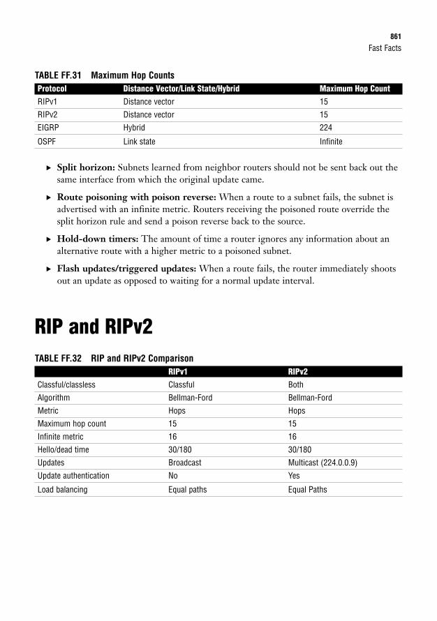
Fast Facts861
TABLE FF.31 Maximum Hop CountsProtocol Distance Vector/Link State/Hybrid Maximum Hop CountRIPv1 Distance vector 15
RIPv2 Distance vector 15
EIGRP Hybrid 224
OSPF Link state Infinite
. Split horizon: Subnets learned from neighbor routers should not be sent back out thesame interface from which the original update came.
. Route poisoning with poison reverse: When a route to a subnet fails, the subnet isadvertised with an infinite metric. Routers receiving the poisoned route override thesplit horizon rule and send a poison reverse back to the source.
. Hold-down timers: The amount of time a router ignores any information about analternative route with a higher metric to a poisoned subnet.
. Flash updates/triggered updates: When a route fails, the router immediately shootsout an update as opposed to waiting for a normal update interval.
RIP and RIPv2TABLE FF.32 RIP and RIPv2 Comparison
RIPv1 RIPv2Classful/classless Classful Both
Algorithm Bellman-Ford Bellman-Ford
Metric Hops Hops
Maximum hop count 15 15
Infinite metric 16 16
Hello/dead time 30/180 30/180
Updates Broadcast Multicast (224.0.0.9)
Update authentication No Yes
Load balancing Equal paths Equal Paths
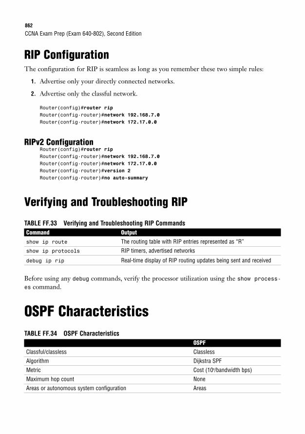
862
RIP ConfigurationThe configuration for RIP is seamless as long as you remember these two simple rules:
1. Advertise only your directly connected networks.
2. Advertise only the classful network.
Router(config)#router ripRouter(config-router)#network 192.168.7.0Router(config-router)#network 172.17.0.0
RIPv2 ConfigurationRouter(config)#router ripRouter(config-router)#network 192.168.7.0Router(config-router)#network 172.17.0.0Router(config-router)#version 2Router(config-router)#no auto-summary
Verifying and Troubleshooting RIP
TABLE FF.33 Verifying and Troubleshooting RIP CommandsCommand Outputshow ip route The routing table with RIP entries represented as “R”
show ip protocols RIP timers, advertised networks
debug ip rip Real-time display of RIP routing updates being sent and received
Before using any debug commands, verify the processor utilization using the show process-es command.
OSPF CharacteristicsTABLE FF.34 OSPF Characteristics
OSPFClassful/classless Classless
Algorithm Dijkstra SPF
Metric Cost (108/bandwidth bps)
Maximum hop count None
Areas or autonomous system configuration Areas
CCNA Exam Prep (Exam 640-802), Second Edition
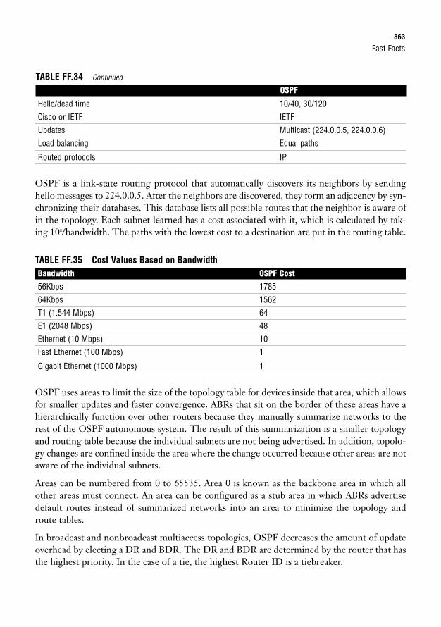
Fast Facts863
Hello/dead time 10/40, 30/120
Cisco or IETF IETF
Updates Multicast (224.0.0.5, 224.0.0.6)
Load balancing Equal paths
Routed protocols IP
OSPF is a link-state routing protocol that automatically discovers its neighbors by sendinghello messages to 224.0.0.5. After the neighbors are discovered, they form an adjacency by syn-chronizing their databases. This database lists all possible routes that the neighbor is aware ofin the topology. Each subnet learned has a cost associated with it, which is calculated by tak-ing 108/bandwidth. The paths with the lowest cost to a destination are put in the routing table.
TABLE FF.35 Cost Values Based on BandwidthBandwidth OSPF Cost56Kbps 1785
64Kbps 1562
T1 (1.544 Mbps) 64
E1 (2048 Mbps) 48
Ethernet (10 Mbps) 10
Fast Ethernet (100 Mbps) 1
Gigabit Ethernet (1000 Mbps) 1
OSPF uses areas to limit the size of the topology table for devices inside that area, which allowsfor smaller updates and faster convergence. ABRs that sit on the border of these areas have ahierarchically function over other routers because they manually summarize networks to therest of the OSPF autonomous system. The result of this summarization is a smaller topologyand routing table because the individual subnets are not being advertised. In addition, topolo-gy changes are confined inside the area where the change occurred because other areas are notaware of the individual subnets.
Areas can be numbered from 0 to 65535. Area 0 is known as the backbone area in which allother areas must connect. An area can be configured as a stub area in which ABRs advertisedefault routes instead of summarized networks into an area to minimize the topology androute tables.
In broadcast and nonbroadcast multiaccess topologies, OSPF decreases the amount of updateoverhead by electing a DR and BDR. The DR and BDR are determined by the router that hasthe highest priority. In the case of a tie, the highest Router ID is a tiebreaker.
TABLE FF.34 Continued
OSPF
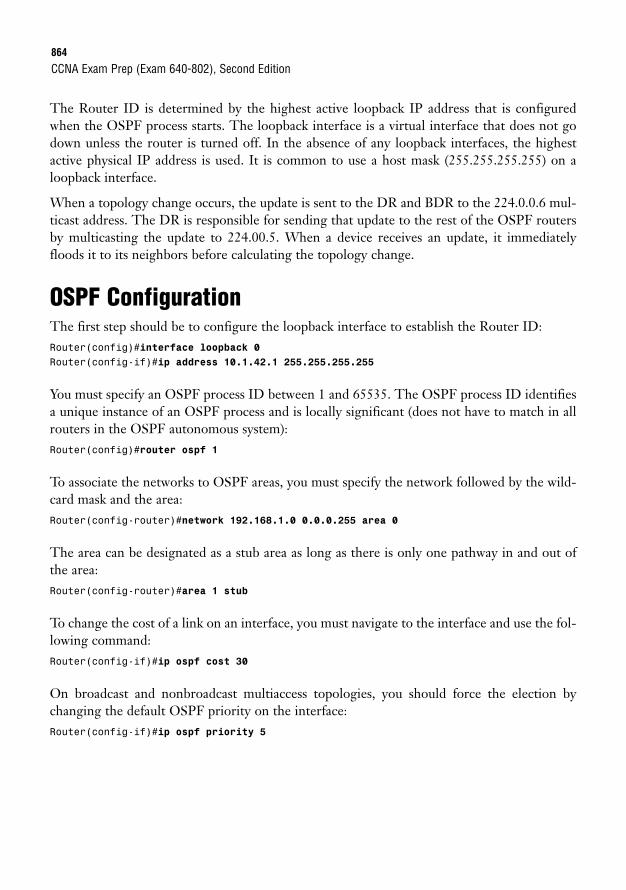
864
The Router ID is determined by the highest active loopback IP address that is configuredwhen the OSPF process starts. The loopback interface is a virtual interface that does not godown unless the router is turned off. In the absence of any loopback interfaces, the highestactive physical IP address is used. It is common to use a host mask (255.255.255.255) on aloopback interface.
When a topology change occurs, the update is sent to the DR and BDR to the 224.0.0.6 mul-ticast address. The DR is responsible for sending that update to the rest of the OSPF routersby multicasting the update to 224.00.5. When a device receives an update, it immediatelyfloods it to its neighbors before calculating the topology change.
OSPF ConfigurationThe first step should be to configure the loopback interface to establish the Router ID:Router(config)#interface loopback 0Router(config-if)#ip address 10.1.42.1 255.255.255.255
You must specify an OSPF process ID between 1 and 65535. The OSPF process ID identifiesa unique instance of an OSPF process and is locally significant (does not have to match in allrouters in the OSPF autonomous system):Router(config)#router ospf 1
To associate the networks to OSPF areas, you must specify the network followed by the wild-card mask and the area:Router(config-router)#network 192.168.1.0 0.0.0.255 area 0
The area can be designated as a stub area as long as there is only one pathway in and out ofthe area:Router(config-router)#area 1 stub
To change the cost of a link on an interface, you must navigate to the interface and use the fol-lowing command:Router(config-if)#ip ospf cost 30
On broadcast and nonbroadcast multiaccess topologies, you should force the election bychanging the default OSPF priority on the interface:Router(config-if)#ip ospf priority 5
CCNA Exam Prep (Exam 640-802), Second Edition
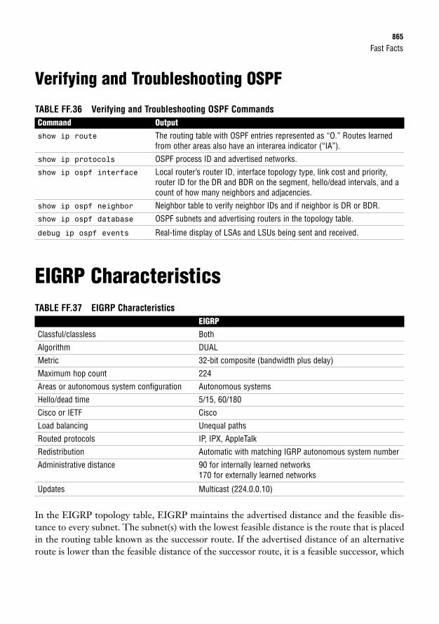
Fast Facts865
Verifying and Troubleshooting OSPF
TABLE FF.36 Verifying and Troubleshooting OSPF CommandsCommand Outputshow ip route The routing table with OSPF entries represented as “O.” Routes learned
from other areas also have an interarea indicator (“IA”).
show ip protocols OSPF process ID and advertised networks.
show ip ospf interface Local router’s router ID, interface topology type, link cost and priority,router ID for the DR and BDR on the segment, hello/dead intervals, and acount of how many neighbors and adjacencies.
show ip ospf neighbor Neighbor table to verify neighbor IDs and if neighbor is DR or BDR.
show ip ospf database OSPF subnets and advertising routers in the topology table.
debug ip ospf events Real-time display of LSAs and LSUs being sent and received.
EIGRP CharacteristicsTABLE FF.37 EIGRP Characteristics
EIGRPClassful/classless Both
Algorithm DUAL
Metric 32-bit composite (bandwidth plus delay)
Maximum hop count 224
Areas or autonomous system configuration Autonomous systems
Hello/dead time 5/15, 60/180
Cisco or IETF Cisco
Load balancing Unequal paths
Routed protocols IP, IPX, AppleTalk
Redistribution Automatic with matching IGRP autonomous system number
Administrative distance 90 for internally learned networks170 for externally learned networks
Updates Multicast (224.0.0.10)
In the EIGRP topology table, EIGRP maintains the advertised distance and the feasible dis-tance to every subnet. The subnet(s) with the lowest feasible distance is the route that is placedin the routing table known as the successor route. If the advertised distance of an alternativeroute is lower than the feasible distance of the successor route, it is a feasible successor, which
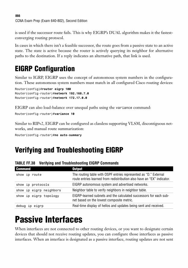
866
is used if the successor route fails. This is why EIGRP’s DUAL algorithm makes it the fastest-converging routing protocol.
In cases in which there isn’t a feasible successor, the route goes from a passive state to an activestate. The state is active because the router is actively querying its neighbor for alternativepaths to the destination. If a reply indicates an alternative path, that link is used.
EIGRP ConfigurationSimilar to IGRP, EIGRP uses the concept of autonomous system numbers in the configura-tion. These autonomous system numbers must match in all configured Cisco routing devices:Router(config)#router eigrp 100Router(config-router)#network 192.168.7.0Router(config-router)#network 172.17.0.0
EIGRP can also load-balance over unequal paths using the variance command:Router(config-router)#variance 10
Similar to RIPv2, EIGRP can be configured as classless supporting VLSM, discontiguous net-works, and manual route summarization:Router(config-router)#no auto-summary
Verifying and Troubleshooting EIGRP
TABLE FF.38 Verifying and Troubleshooting EIGRP CommandsCommand Outputshow ip route The routing table with OSPF entries represented as “D.” External
route entries learned from redistribution also have an “EX” indicator.
show ip protocols EIGRP autonomous system and advertised networks.
show ip eigrp neighbors Neighbor table to verify neighbors in neighbor table.
show ip eigrp topology EIGRP-learned subnets and the calculated successors for each sub-net based on the lowest composite metric.
debug ip eigrp Real-time display of hellos and updates being sent and received.
Passive InterfacesWhen interfaces are not connected to other routing devices, or you want to designate certaindevices that should not receive routing updates, you can configure those interfaces as passiveinterfaces. When an interface is designated as a passive interface, routing updates are not sent
CCNA Exam Prep (Exam 640-802), Second Edition
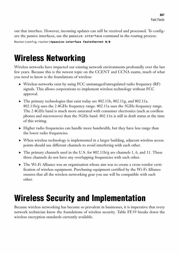
Fast Facts867
out that interface. However, incoming updates can still be received and processed. To config-ure the passive interfaces, use the passive-interface command in the routing process:Router(config-router)#passive-interface fastethernet 0/0
Wireless NetworkingWireless networks have impacted our existing network environments profoundly over the lastfew years. Because this is the newest topic on the CCENT and CCNA exams, much of whatyou need to know is the foundations of wireless:
. Wireless networks exist by using FCC unmanaged/unregulated radio frequency (RF)signals. This allows corporations to implement wireless technology without FCCapproval.
. The primary technologies that exist today are 802.11b, 802.11g, and 802.11a.802.11b/g uses the 2.4GHz frequency range. 802.11a uses the 5GHz frequency range.The 2.4GHz band is much more saturated with consumer electronics (such as cordlessphones and microwaves) than the 5GHz band. 802.11n is still in draft status at the timeof this writing.
. Higher radio frequencies can handle more bandwidth, but they have less range thanthe lower radio frequencies.
. When wireless technology is implemented in a larger building, adjacent wireless accesspoints should use different channels to avoid interfering with each other.
. The primary channels used in the U.S. for 802.11b/g are channels 1, 6, and 11. Thesethree channels do not have any overlapping frequencies with each other.
. The Wi-Fi Alliance was an organization whose aim was to create a cross-vendor certi-fication of wireless equipment. Purchasing equipment certified by the Wi-Fi Allianceensures that all the wireless networking gear you use will be compatible with eachother.
Wireless Security and ImplementationBecause wireless networking has become so prevalent in businesses, it is imperative that everynetwork technician know the foundations of wireless security. Table FF.39 breaks down thewireless encryption standards currently available.
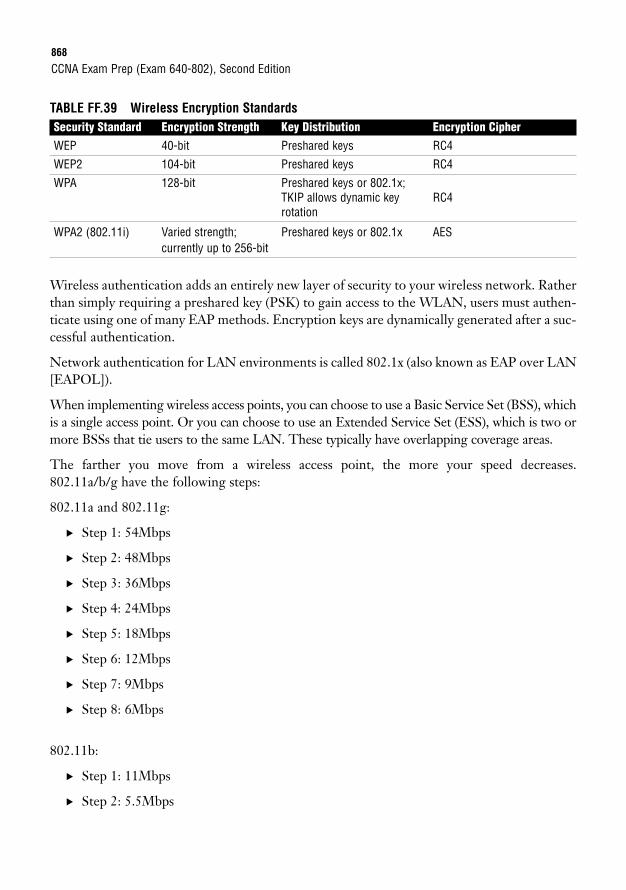
868
TABLE FF.39 Wireless Encryption StandardsSecurity Standard Encryption Strength Key Distribution Encryption CipherWEP 40-bit Preshared keys RC4
WEP2 104-bit Preshared keys RC4
WPA 128-bit Preshared keys or 802.1x; TKIP allows dynamic key RC4rotation
WPA2 (802.11i) Varied strength; Preshared keys or 802.1x AEScurrently up to 256-bit
Wireless authentication adds an entirely new layer of security to your wireless network. Ratherthan simply requiring a preshared key (PSK) to gain access to the WLAN, users must authen-ticate using one of many EAP methods. Encryption keys are dynamically generated after a suc-cessful authentication.
Network authentication for LAN environments is called 802.1x (also known as EAP over LAN[EAPOL]).
When implementing wireless access points, you can choose to use a Basic Service Set (BSS), whichis a single access point. Or you can choose to use an Extended Service Set (ESS), which is two ormore BSSs that tie users to the same LAN. These typically have overlapping coverage areas.
The farther you move from a wireless access point, the more your speed decreases.802.11a/b/g have the following steps:
802.11a and 802.11g:
. Step 1: 54Mbps
. Step 2: 48Mbps
. Step 3: 36Mbps
. Step 4: 24Mbps
. Step 5: 18Mbps
. Step 6: 12Mbps
. Step 7: 9Mbps
. Step 8: 6Mbps
802.11b:
. Step 1: 11Mbps
. Step 2: 5.5Mbps
CCNA Exam Prep (Exam 640-802), Second Edition
Fast Facts869
. Step 3: 2Mbps
. Step 4: 1Mbps
Implementing a wireless network typically should be done in four steps:
1. Ensure hardwired operation.
2. Install the wireless access point in your tested switchport.
3. Configure a basic wireless network, and test it.
4. Add wireless security, and test it.
Cisco Access ListsAccess lists are a Cisco configuration paramount to enabling your router to do any major task.The following facts are relevant to access lists:
. A Cisco access list is nothing more than an ordered list of permit and deny statements.
. They are read by the router in a top-down format. As soon as a match condition isreached, the access list stops processing.
. If you reach the end of an access list and have not been explicitly permitted, you areimplicitly denied.
. Numbered and named access lists do not allow you to reorder statements; however,named access lists allow you to delete individual access list lines.
Access lists have a number of functions on the Cisco router. The primary access lists uses are
. Packet filtering
. Quality of Service (QoS)
. Network Address Translation (NAT)
. Route filtering
There are two types of IP-based access lists:
. Standard access lists are capable of filtering traffic based only on the source IP address.
. Extended access lists are capable of filtering traffic based on protocol, source address,source port number, destination address, and destination port number.
870
IP Standard access lists use numbers 1 to 99, and IP Extended access lists use numbers 100 to199.
The configuration of a standard access list uses the following syntax:Router(config)#access-list <1-99> <permit/deny> <source_IP_address> <wildcard_mask>
The following configuration creates access list 25, which permits a single host (10.1.1.5) andthe 192.168.1.0/24 subnet:Router(config)#access-list 25 permit 10.1.1.5 0.0.0.0Router(config)#access-list 25 permit 192.168.1.0 0.0.0.255
As a shortcut, you can use the host keyword instead of a wildcard mask of 0.0.0.0 and the anykeyword instead of a wildcard mask of 255.255.255.255. The following example shows thesekeywords in action:Router(config)#access-list 25 permit host 10.1.1.5Router(config)#access-list 25 deny any
When looking to apply an access list to an interface, remember the following mantra:
One access list
. Per protocol
. Per interface
. Per direction
When trying to find what direction to apply an access list, picture yourself as a router. Holdout an arm to represent an interface. If the traffic is moving away from your body, it should beapplied out (outbound) on the interface. If the traffic is coming into your body, it should beapplied in (inbound) on the interface. Standard access lists are always applied closest to thedestination. Extended access lists are always applied closest to the source.
The following is the generic syntax used to apply access lists to an interface:Router(config-if)#ip access-group <access-list_number> <in/out>
The following configuration applies access list 25 in the inbound direction:Router(config-if)#ip access-group 25 in
Access lists can also be applied to vty ports to restrict Telnet access to your router. The fol-lowing configuration applies access list 25 to a router’s vty ports:Router(config)#line vty 0 4Router(config-line)#access-class 25 in
CCNA Exam Prep (Exam 640-802), Second Edition
Fast Facts871
Extended access list configuration gets slightly more complex than a standard access list. Thefollowing is the generic syntax used to create an extended access list:Router(config)#access-list <100-199> <permit/deny> <protocol> <source_IP_address><wildcard_mask> <source_port_number> <destination_IP_address> <wildcard_mask><destination_port_number>
There are many IP-based protocols that extended access lists can permit or deny. The follow-ing is a list of the protocols you should be familiar with:
. IP permits or denies source/destination addresses using the entire TCP/IP protocolsuite. Using this keyword permits or denies all access from a source to a destination.
. TCP permits or denies source/destination addresses using TCP-based applications.The most common applications include FTP, Telnet, SMTP, and HTTP.
. UDP permits or denies source/destination addresses using UDP-based applications.The most common applications include DNS and TFTP.
. ICMP permits or denies source/destination addresses using ICMP-based applications.The most common applications include Echo, Echo-Reply, and Unreachables.
When configuring extended access lists, you rarely, if ever, know a network device’s source portnumber information. This number is randomly generated by the host’s operating system. Youshould leave it blank for any CCNA-level configuration you perform.
You need to know these commonly used port numbers for the CCNA exam:
TCP Ports. Port 21: FTP
. Port 22: SSH
. Port 23: Telnet
. Port 25: SMTP
. Port 80: HTTP
. Port 443: HTTPS
UDP Ports. Port 53: DNS
. Port 69: TFTP
872
The following access list permits a single host (10.1.1.5) to access any destination using port80 (HTTP):Router(config)#access-list 150 permit tcp host 10.1.1.5 any eq 80
The following access list denies a network subnet (172.16.70.0/24) from accessing a single host(172.16.50.100) using port 21 (FTP):Router(config)#access-list 125 deny tcp 172.16.70.0 0.0.0.255 host 172.16.50.100 eq 21
Often, you need to end an access list with a “permit all” statement. The following examplesshow how to accomplish this:
Standard access list example:Router(config)#access-list 12 permit any
Extended access list example:Router(config)#access-list 125 permit ip any any
Often, a router connected to the Internet denies all incoming traffic to secure the internal net-work. However, this prevents internal users from receiving responses to their common webbrowsing requests. The following extended access list entry permits any return traffic that is aresponse to a request originated from the internal network:Router(config)#access-list 150 permit tcp any any established
You can verify access lists using a few show commands:
. show running-config shows the full access list configuration and the interfaces whereyou have applied them.
. show ip interface shows the inbound and outbound access lists applied to eachinterface.
. show access-lists shows all access lists created on the router and the number oftimes each entry has been matched.
. show ip access-lists shows just the IP-based access lists on the router and thenumber of times each entry has been matched.
Network Address Translation (NAT)NAT is in use on virtually every Internet-connected router in the world today. This technol-ogy acts as a security boundary and Internet address sharing system. The following facts arerelevant to NAT.
CCNA Exam Prep (Exam 640-802), Second Edition
Fast Facts873
NAT typically operates by translating private IP addresses to public Internet addresses. Thefollowing are the private address ranges as defined by RFC 1918:
. Class A: 10.X.X.X
. Class B: 172.16.X.X to 172.31.X.X
. Class C: 192.168.X.X
The three primary forms of NAT are as follows:
. Static NAT allows you to manually map one IP address to another in a one-to-onerelationship.
. Dynamic NAT allows you to define a pool of addresses to be translated along with apool of addresses they will be translated to.
. NAT Overload/PAT allows a single Internet IP address to support many internalclients.
The standards bodies have developed many terms to describe the location of an IP address inthe world of NAT:
. Inside local addresses: Refers to everything inside your network.
. Inside global addresses: The Internet valid IP address assigned to your router that isdirectly connected to the Internet.
. Outside global addresses: A standard Internet IP address accessible from any hostconnected to the Internet.
. Outside local addresses: How an Internet host is seen by the internal network as it istranslated through the NAT router into your local network.
The following shows a Static NAT configuration fully translating 192.168.1.50 (on the internalnetwork) to 5.1.1.10 (on the Internet). It then shows a single Static NAT port translation map-ping 192.168.1.150 port 53 (DNS) on the internal network to 5.1.1.11 port 53 on the Internet:NAT_Router(config)#interface fastethernet0NAT_Router(config-if)#ip nat insideNAT_Router(config)#interface serial0NAT_Router(config-if)#ip nat outsideNAT_Router(config)#ip nat inside source static 192.168.1.50 5.1.1.10NAT_Router(config)#ip nat inside source static udp 192.168.1.150 53 5.1.1.11 53
The following shows a NAT Overload/PAT configuration translating the entire internal net-work (192.168.1.0/24) to a single Internet address assigned to the Serial0 interface:
874
NAT_Router(config)#interface fastethernet0NAT_Router(config-if)#ip nat insideNAT_Router(config)#interface serial0NAT_Router(config-if)#ip nat outsideNAT_Router(config)#access-list 50 permit 192.168.1.0 0.0.0.255NAT_Router(config)#ip nat inside source list 50 interface serial0 overload
Wide-Area NetworksWide area network (WAN) connections tie together geographically distant locations, enablingthem to communicate as if directly connected. The following facts are relevant to WANs.
WAN technologies only encompass the Physical and Data Link layers of the OSI model. Thethree major categories of WAN technology used to connect networks today are as follows:
. Leased lines provide a dedicated, point-to-point link between two locations.
. Circuit-switched networks establish a dedicated channel (or circuit) for the durationof the transmission and then tear down the channel when the transmission is complete.
. Packet-switched networks enable the service provider to create a large pool of band-width for its clients, who establish connections through the shared bandwidth usingvirtual circuits.
Cisco routers connect to most WAN connections through their serial ports. The Cisco side ofthe connection uses either a DB-60 or Smart Serial port. The CSU/DSU that the Cisco routerconnects to has one of five standard connectors: V.35, X.21, EIA/TIA-232, EIA/TIA-449, orEIA/TIA-530.
At the Data Link layer, Cisco routers primarily use one of two WAN encapsulations for leased-line and circuit-switched networks:
. Point-to-Point Protocol (PPP): The most popular, industry-standard, feature-packedprotocol for connecting routers
. Cisco High-level Data Link Control (HDLC): A Cisco-proprietary, low-overheadprotocol that makes your WAN connections very efficient between Cisco devices
HDLC is the default encapsulation on all Cisco serial interfaces. However, PPP is used to gainmore features and industry standard capabilities when connecting over the WAN. It is madeup of three sublayers:
. ISO HDLC is responsible for enabling PPP to be supported by multiple devices.
. Link Control Protocol (LCP) is the feature negotiation layer that performs the fol-lowing functions:
CCNA Exam Prep (Exam 640-802), Second Edition
Fast Facts875
. Authentication requires a username and password for the connecting device.
. Callback enables a dialup server (or router) running PPP to call back the personwho initially dialed into the location using a predefined number.
. Compression makes WAN connections more efficient by minimizing the amountof data sent.
. Multilink bundles multiple WAN connections (or WAN channels in the case ofISDN) into a single, logical connection.
. Network Control Protocol (NCP) gives PPP the functionality to enable multipleNetwork layer protocols to run across a single WAN link at any given time.
When configuring PPP authentication, you can choose between two authentication protocols:
. Password Authentication Protocol (PAP) sends username and password once inclear-text format when authenticating.
. Challenge Handshake Authentication Protocol (CHAP) sends a username andhashed password when demanded by the CHAP server.
When configuring PPP compression, you can choose between three compression types:
. Stacker: A flat compression algorithm that is notoriously heavy on CPU resources andhas less effect on the router’s memory resources. Useful for WAN links with many traf-fic patterns.
. Predictor: A dictionary-based compression algorithm that is notoriously heavy onmemory resources and has less effect on the router’s CPU resources. Useful for WANlinks with similar traffic patterns.
. Microsoft Point-to-Point Compression (MPPC): Used for Microsoft Windowsdialup clients wanting to use compression.
To activate PPP encapsulation on an interface, use the following syntax:Router(config)#interface serial 0Router(config-if)#encapsulation ppp
When adding CHAP authentication to your configuration, you need to ensure that you createa user account that matches the hostname of the other side of the connection. In addition, thepasswords must be the same on both sides. Here is a PPP CHAP authentication configurationbetween the Kirk and Spock routers:Kirk(config)#username Spock password ciscoKirk(config)#interface serial 0Kirk(config-if)#encapsulation ppp
876
Kirk(config-if)#ppp authentication chap
Spock(config)#username Kirk password ciscoSpock(config)#interface serial 0Spock(config-if)#encapsulation pppSpock(config-if)#ppp authentication chap
To enable PPP compression on an interface, you can use the following syntax:Router(config-if)#compress ?mppc MPPC compression typepredictor predictor compression typestac stac compression algorithm
The show interface command is one of the most useful when verifying the PPP configura-tion. The connection is active when the LCP Open tag is seen, as shown here:Router#show interface serial 0Serial0 is up, line protocol is upHardware is PowerQUICC SerialInternet address is 10.2.2.2/24MTU 1500 bytes, BW 1544 Kbit, DLY 20000 usec,
reliability 255/255, txload 1/255, rxload 1/255Encapsulation PPP, loopback not setKeepalive set (10 sec)LCP OpenOpen: IPCP, CCP, CDPCP
When troubleshooting PPP authentication issues, use the debug ppp authentication com-mand to observe the authentication process as it occurs.
Frame RelayFrame Relay is the only packet-switched network tested on the CCNA exam. It is one of themore popular connections in businesses today. The following facts are relevant to Frame Relay.
Frame Relay offers the high speeds demanded by the networks of today at cut-rate prices.Rather than connecting sites through individual physical interfaces, Frame Relay connectssites using virtual circuits. Virtual circuits are logical links through service provider networksthat give routers the impression that they are directly linked. The more virtual circuits pur-chased to connect network locations, the more redundant the network connections will be; atthe same time, the monthly cost will rise significantly. Because of this, there are three designstrategies for provisioning virtual circuits:
. Hub and spoke: A centralized location (most likely, your largest, most connectedoffice) acts as the network’s “hub.” All other locations are considered “spokes” and havea single virtual circuit connection back to the hub.
CCNA Exam Prep (Exam 640-802), Second Edition
Fast Facts877
. Partial mesh: Key network sites have redundant virtual circuit connections throughthe Frame Relay cloud. Other noncritical sites might only have a single virtual circuit.
. Full mesh: Every site has a direct virtual circuit to every other site in the network.
Frame Relay also introduces another set of terminology that CCNA candidates should befamiliar with:
. Permanent Virtual Circuit (PVC): A permanently “nailed-up” circuit through theFrame Relay service provider network.
. Switched Virtual Circuit (SVC): An “on-demand” connection through the FrameRelay cloud.
. Local Management Interface (LMI): Signaling between your router and the FrameRelay service provider.
. Data Link Connection Identifier (DLCI): The Data Link layer addressing used byFrame Relay to identify endpoints connected to the Frame Relay service provider.
. Local access rate: The maximum physical speed that a Frame Relay connection canattain.
. Committed Information Rate (CIR): The minimum speed the service provider com-mits to give you for a virtual circuit at all times.
. Backward Explicit Congestion Notification (BECN): A message sent by the serviceprovider notifying a router sending at an excessive data rate to reduce its speed.
. Forward Explicit Congestion Notification (FECN): A message sent by the serviceprovider notifying a receiving router to send information that can be tagged as aBECN to tell a router sending at an excessive data rate to reduce its speed.
. Discard Eligible (DE): Describes any traffic that you send above the CIR you havepurchased.
To provide more logical configurations, Cisco routers can create multiple subinterfaces thatcan connect to any number of virtual circuits. Two types of subinterfaces can be created:
. Point-to-point subinterfaces are assigned to a single virtual circuit. Only one DLCInumber assigned per point-to-point subinterface.
. Multipoint subinterfaces are assigned to one or more virtual circuits. NumerousDLCI numbers can be mapped under a multipoint subinterface.
878
Using multipoint interfaces or the physical Serial interface for multiple virtual circuits causesknown problems with the distance vector routing protocol loop-prevention mechanism, splithorizon.
Cisco routers initially receive a list of DLCIs they can reach from the Frame Relay serviceprovider. There are two ways they can map the DLCI number to the remote IP address it canreach at the other end of the connection:
. Inverse ARP enables the router to send messages down each one of the DLCI num-bers to discover the router’s IP address on the remote end.
. Static mappings allow the Cisco administrator to manually map each DLCI numberto the router’s IP address on the remote end.
Understanding the states of a Frame Relay PVC can be quite useful in both the real world andthe testing environment:
. Active: The PVC is successfully connected through between the two endpoints(routers). This is the normal state if everything is working properly.
. Inactive: The PVC is working properly on your end of the connection (the local side);however, the other side of the connection is either not configured or offline.
. Deleted: The PVC is having problems on your end (the local side) of the connection.Most likely, you are attempting to use a DLCI number that the service provider hasnot configured.
. Static: The PVC has been manually entered by you (the administrator) rather thanbeing dynamically discovered from the service provider.
Configuring a Frame Relay interface for a single virtual circuit requires the following minimalconfiguration:Router(config)#interface serial 0Router(config-if)#encapsulation frame-relay
If you are connecting to a non-Cisco router through the Frame Relay cloud, use the commandencapsulation frame-relay ietf to enable your interface with the industry standard FrameRelay encapsulation.
If you are using an extremely old version of the IOS (any version earlier than 11.2), the routeris unable to autodetect what LMI language the service provider is using. This means that youmust manually configure it using the following syntax:Router(config-if)#frame-relay lmi-type ?ciscoansiq933a
CCNA Exam Prep (Exam 640-802), Second Edition
Fast Facts879
The following is a sample configuration of a multipoint interface using static Frame Relaymaps. In this case, 192.168.5.1 is the remote end IP address and DLCI 405 is used to get there.Likewise, 192.168.5.2 is another remote-end router that can be reached through DLCI 406:Router(config)#interface serial 0/0.10 multipointRouter(config-if)#frame map ip 192.168.5.1 405 broadcastRouter(config-if)#frame map ip 192.168.5.2 406 broadcast
The following is a sample configuration using the same setup as the preceding example, butusing point-to-point interfaces:Router(config)#interface serial 0/0.405 point-to-pointRouter(config-if)#frame-relay interface-dlci 405Router(config)#interface serial 0/0.406 point-to-pointRouter(config-if)#frame-relay interface-dlci 406
When troubleshooting Frame Relay connections, start with the show frame-relay lmi com-mand to check connectivity to the service provider. From there, use show frame-relay pvcto check the status of the virtual circuits.
VPN ConnectivityVPN technology allows businesses to use their existing Internet connections to connect toother offices (site-to-site VPNs) or allow telecommuting or mobile users to connect into theoffice network from their PCs (remote-access VPN).
VPNs provide a variety of benefits over private-line connections:
. Cost savings over private-line connections
. Remote-access connections for telecommuting or mobile users
. Scalability
At the same time, VPNs have some major drawbacks:
. Higher overhead
. Varying service levels
. Additional security considerations
VPN connections come in two major genres: site-to-site and remote-access VPNs.
Site-to-site VPNs are the direct replacement for private-line WAN connections. They allowoffices to maintain permanent or semipermanent connections between each other through theInternet.
880
Remote-access VPNs typically are used to allow telecommuting or mobile workers to connectto the corporate network from home or hotel-like locations. These remote-access VPNs comein a couple of styles: client-based (requires the installation of a VPN client) and clientless (alsoknown as SSL or WebVPN; users connect through a secure web page).
The key protocol that drives VPN connections is IPsec. This is actually a suite of protocolsthat provide standards for encryption, authentication, and data integrity.
Three primary encryption standards are used with IPsec:
. Data Encryption Standard (DES) algorithm was originally developed by IBM tosupport a 56-bit key.
. Triple DES (3DES) algorithm uses three different DES keys to encrypt data, thustripling the strength of DES.
. Advanced Encryption Standard (AES) currently offers 128-, 192-, and 256-bitencryption.
Currently, two data-integrity standards are used with IPsec:
. Message Digest 5 (MD5) uses a 128-bit hashing algorithm.
. Secure Hash Algorithm 1 (SHA-1) uses a 160-bit hashing algorithm.
CCNA Exam Prep (Exam 640-802), Second Edition
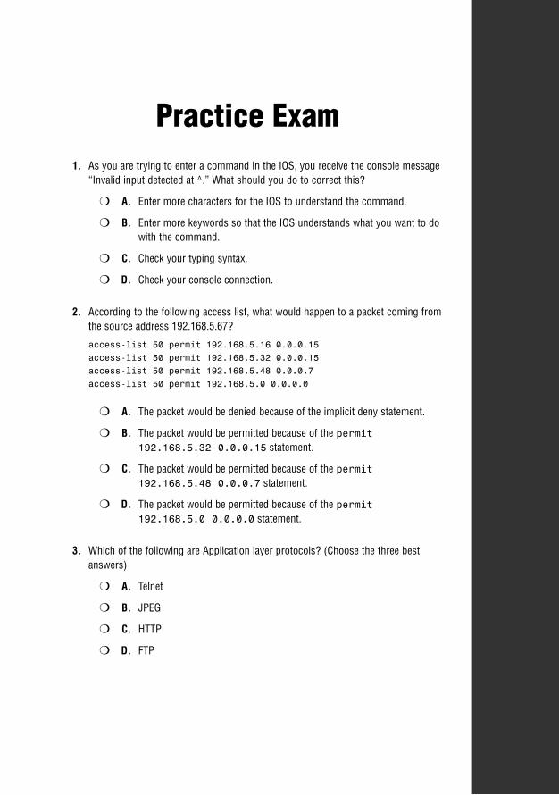
Practice Exam1. As you are trying to enter a command in the IOS, you receive the console message
“Invalid input detected at ^.” What should you do to correct this?
❍ A. Enter more characters for the IOS to understand the command.
❍ B. Enter more keywords so that the IOS understands what you want to dowith the command.
❍ C. Check your typing syntax.
❍ D. Check your console connection.
2. According to the following access list, what would happen to a packet coming fromthe source address 192.168.5.67?
access-list 50 permit 192.168.5.16 0.0.0.15access-list 50 permit 192.168.5.32 0.0.0.15access-list 50 permit 192.168.5.48 0.0.0.7access-list 50 permit 192.168.5.0 0.0.0.0
❍ A. The packet would be denied because of the implicit deny statement.
❍ B. The packet would be permitted because of the permit192.168.5.32 0.0.0.15 statement.
❍ C. The packet would be permitted because of the permit192.168.5.48 0.0.0.7 statement.
❍ D. The packet would be permitted because of the permit192.168.5.0 0.0.0.0 statement.
3. Which of the following are Application layer protocols? (Choose the three bestanswers)
❍ A. Telnet
❍ B. JPEG
❍ C. HTTP
❍ D. FTP
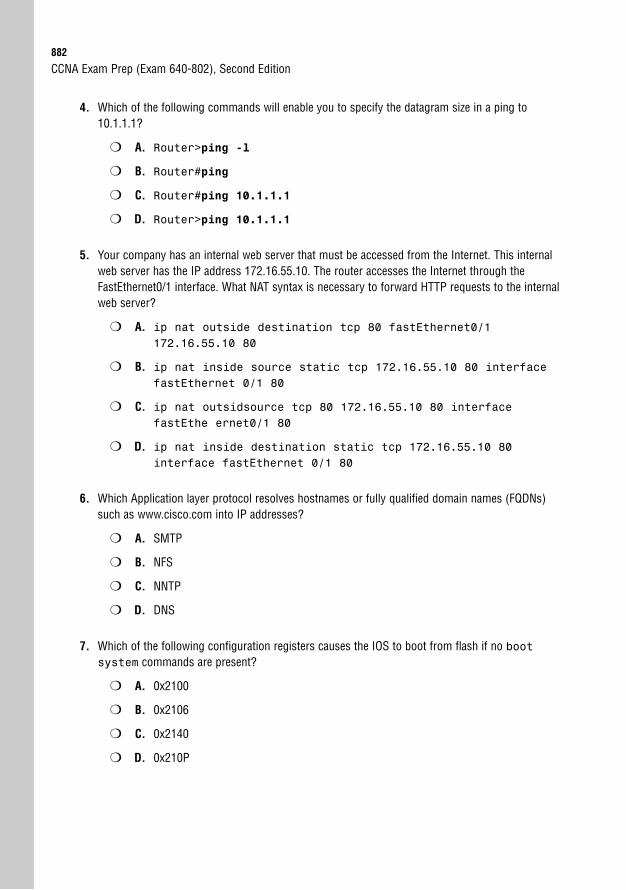
882
4. Which of the following commands will enable you to specify the datagram size in a ping to10.1.1.1?
❍ A. Router>ping -l
❍ B. Router#ping
❍ C. Router#ping 10.1.1.1
❍ D. Router>ping 10.1.1.1
5. Your company has an internal web server that must be accessed from the Internet. This internalweb server has the IP address 172.16.55.10. The router accesses the Internet through theFastEthernet0/1 interface. What NAT syntax is necessary to forward HTTP requests to the internalweb server?
❍ A. ip nat outside destination tcp 80 fastEthernet0/1172.16.55.10 80
❍ B. ip nat inside source static tcp 172.16.55.10 80 interfacefastEthernet 0/1 80
❍ C. ip nat outsidsource tcp 80 172.16.55.10 80 interfacefastEthe ernet0/1 80
❍ D. ip nat inside destination static tcp 172.16.55.10 80 interface fastEthernet 0/1 80
6. Which Application layer protocol resolves hostnames or fully qualified domain names (FQDNs)such as www.cisco.com into IP addresses?
❍ A. SMTP
❍ B. NFS
❍ C. NNTP
❍ D. DNS
7. Which of the following configuration registers causes the IOS to boot from flash if no boot system commands are present?
❍ A. 0x2100
❍ B. 0x2106
❍ C. 0x2140
❍ D. 0x210P
CCNA Exam Prep (Exam 640-802), Second Edition
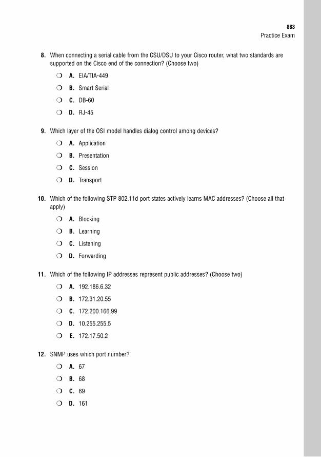
Practice Exam883
8. When connecting a serial cable from the CSU/DSU to your Cisco router, what two standards aresupported on the Cisco end of the connection? (Choose two)
❍ A. EIA/TIA-449
❍ B. Smart Serial
❍ C. DB-60
❍ D. RJ-45
9. Which layer of the OSI model handles dialog control among devices?
❍ A. Application
❍ B. Presentation
❍ C. Session
❍ D. Transport
10. Which of the following STP 802.11d port states actively learns MAC addresses? (Choose all thatapply)
❍ A. Blocking
❍ B. Learning
❍ C. Listening
❍ D. Forwarding
11. Which of the following IP addresses represent public addresses? (Choose two)
❍ A. 192.186.6.32
❍ B. 172.31.20.55
❍ C. 172.200.166.99
❍ D. 10.255.255.5
❍ E. 172.17.50.2
12. SNMP uses which port number?
❍ A. 67
❍ B. 68
❍ C. 69
❍ D. 161
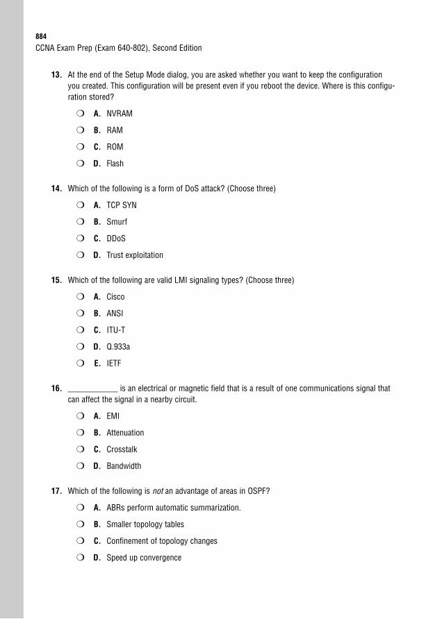
884
13. At the end of the Setup Mode dialog, you are asked whether you want to keep the configurationyou created. This configuration will be present even if you reboot the device. Where is this configu-ration stored?
❍ A. NVRAM
❍ B. RAM
❍ C. ROM
❍ D. Flash
14. Which of the following is a form of DoS attack? (Choose three)
❍ A. TCP SYN
❍ B. Smurf
❍ C. DDoS
❍ D. Trust exploitation
15. Which of the following are valid LMI signaling types? (Choose three)
❍ A. Cisco
❍ B. ANSI
❍ C. ITU-T
❍ D. Q.933a
❍ E. IETF
16. ____________ is an electrical or magnetic field that is a result of one communications signal thatcan affect the signal in a nearby circuit.
❍ A. EMI
❍ B. Attenuation
❍ C. Crosstalk
❍ D. Bandwidth
17. Which of the following is not an advantage of areas in OSPF?
❍ A. ABRs perform automatic summarization.
❍ B. Smaller topology tables
❍ C. Confinement of topology changes
❍ D. Speed up convergence
CCNA Exam Prep (Exam 640-802), Second Edition
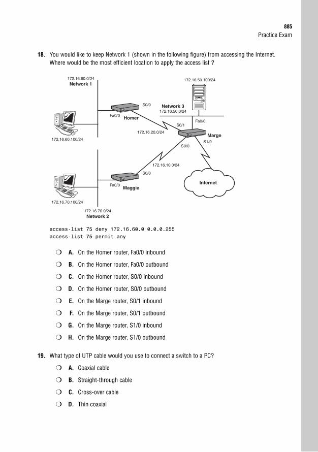
Practice Exam885
18. You would like to keep Network 1 (shown in the following figure) from accessing the Internet.Where would be the most efficient location to apply the access list ?
Fa0/0S0/1
S0/0S1/0
S0/0
Fa0/0
172.16.70.0/24Network 2
172.16.60.0/24Network 1
Maggie
172.16.50.100/24
172.16.70.100/24
Marge
Network 3172.16.50.0/24
S0/0
Homer
Internet
Fa0/0
172.16.60.100/24
172.16.20.0/24
172.16.10.0/24
access-list 75 deny 172.16.60.0 0.0.0.255access-list 75 permit any
❍ A. On the Homer router, Fa0/0 inbound
❍ B. On the Homer router, Fa0/0 outbound
❍ C. On the Homer router, S0/0 inbound
❍ D. On the Homer router, S0/0 outbound
❍ E. On the Marge router, S0/1 inbound
❍ F. On the Marge router, S0/1 outbound
❍ G. On the Marge router, S1/0 inbound
❍ H. On the Marge router, S1/0 outbound
19. What type of UTP cable would you use to connect a switch to a PC?
❍ A. Coaxial cable
❍ B. Straight-through cable
❍ C. Cross-over cable
❍ D. Thin coaxial
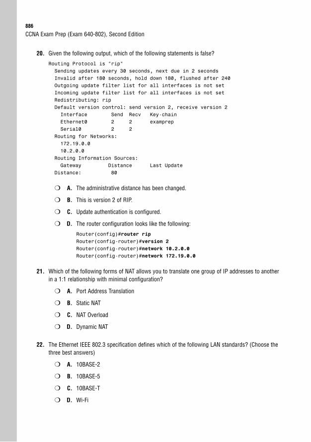
886
20. Given the following output, which of the following statements is false?
Routing Protocol is “rip”Sending updates every 30 seconds, next due in 2 secondsInvalid after 180 seconds, hold down 180, flushed after 240Outgoing update filter list for all interfaces is not setIncoming update filter list for all interfaces is not setRedistributing: ripDefault version control: send version 2, receive version 2Interface Send Recv Key-chainEthernet0 2 2 examprepSerial0 2 2
Routing for Networks:172.19.0.010.2.0.0
Routing Information Sources:Gateway Distance Last Update
Distance: 80
❍ A. The administrative distance has been changed.
❍ B. This is version 2 of RIP.
❍ C. Update authentication is configured.
❍ D. The router configuration looks like the following:
Router(config)#router ripRouter(config-router)#version 2Router(config-router)#network 10.2.0.0Router(config-router)#network 172.19.0.0
21. Which of the following forms of NAT allows you to translate one group of IP addresses to anotherin a 1:1 relationship with minimal configuration?
❍ A. Port Address Translation
❍ B. Static NAT
❍ C. NAT Overload
❍ D. Dynamic NAT
22. The Ethernet IEEE 802.3 specification defines which of the following LAN standards? (Choose thethree best answers)
❍ A. 10BASE-2
❍ B. 10BASE-5
❍ C. 10BASE-T
❍ D. Wi-Fi
CCNA Exam Prep (Exam 640-802), Second Edition
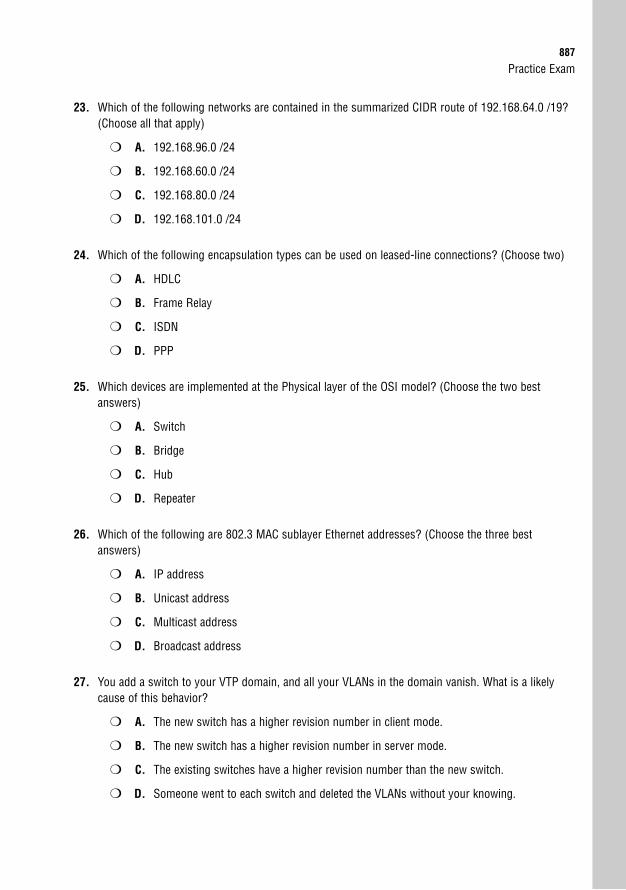
Practice Exam887
23. Which of the following networks are contained in the summarized CIDR route of 192.168.64.0 /19?(Choose all that apply)
❍ A. 192.168.96.0 /24
❍ B. 192.168.60.0 /24
❍ C. 192.168.80.0 /24
❍ D. 192.168.101.0 /24
24. Which of the following encapsulation types can be used on leased-line connections? (Choose two)
❍ A. HDLC
❍ B. Frame Relay
❍ C. ISDN
❍ D. PPP
25. Which devices are implemented at the Physical layer of the OSI model? (Choose the two bestanswers)
❍ A. Switch
❍ B. Bridge
❍ C. Hub
❍ D. Repeater
26. Which of the following are 802.3 MAC sublayer Ethernet addresses? (Choose the three bestanswers)
❍ A. IP address
❍ B. Unicast address
❍ C. Multicast address
❍ D. Broadcast address
27. You add a switch to your VTP domain, and all your VLANs in the domain vanish. What is a likelycause of this behavior?
❍ A. The new switch has a higher revision number in client mode.
❍ B. The new switch has a higher revision number in server mode.
❍ C. The existing switches have a higher revision number than the new switch.
❍ D. Someone went to each switch and deleted the VLANs without your knowing.
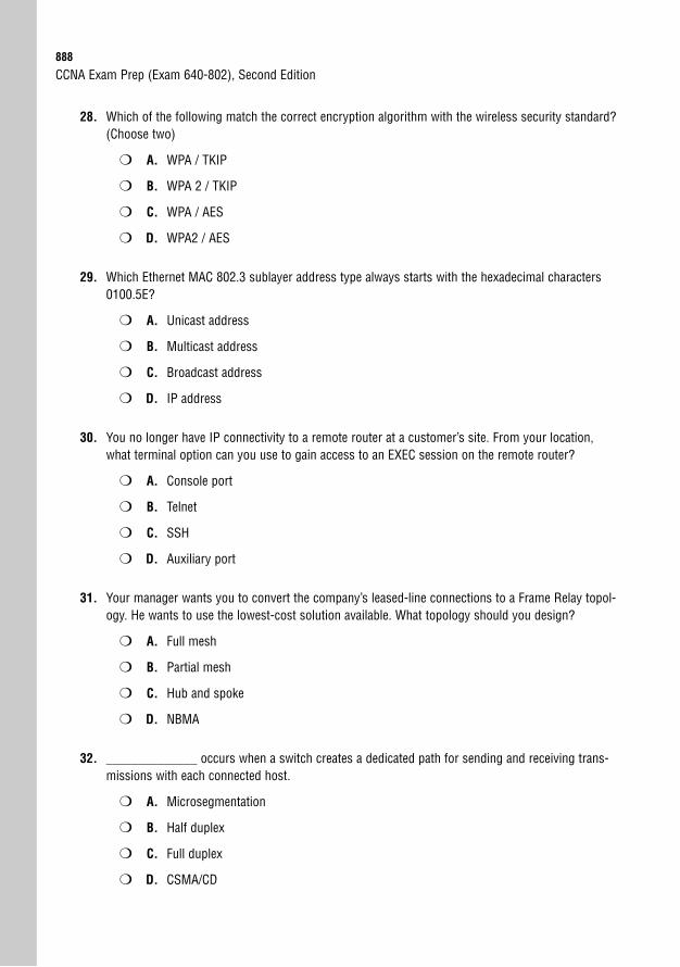
888
28. Which of the following match the correct encryption algorithm with the wireless security standard?(Choose two)
❍ A. WPA / TKIP
❍ B. WPA 2 / TKIP
❍ C. WPA / AES
❍ D. WPA2 / AES
29. Which Ethernet MAC 802.3 sublayer address type always starts with the hexadecimal characters0100.5E?
❍ A. Unicast address
❍ B. Multicast address
❍ C. Broadcast address
❍ D. IP address
30. You no longer have IP connectivity to a remote router at a customer’s site. From your location,what terminal option can you use to gain access to an EXEC session on the remote router?
❍ A. Console port
❍ B. Telnet
❍ C. SSH
❍ D. Auxiliary port
31. Your manager wants you to convert the company’s leased-line connections to a Frame Relay topol-ogy. He wants to use the lowest-cost solution available. What topology should you design?
❍ A. Full mesh
❍ B. Partial mesh
❍ C. Hub and spoke
❍ D. NBMA
32. ______________ occurs when a switch creates a dedicated path for sending and receiving trans-missions with each connected host.
❍ A. Microsegmentation
❍ B. Half duplex
❍ C. Full duplex
❍ D. CSMA/CD
CCNA Exam Prep (Exam 640-802), Second Edition
Practice Exam889
33. You want to speed up convergence on switch ports connected to hosts, but you are afraid of someoneplugging in a switch or hub and causing a loop. Which features address both requirements? (Choose two)
❍ A. BackboneFast
❍ B. PortFast
❍ C. UplinkFast
❍ D. BPDU Guard
34. How many wireless channels are available in the U.S. for the 2.4GHz band without overlapping fre-quencies for close-proximity wireless access points?
❍ A. 1
❍ B. 3
❍ C. 11
❍ D. 23
35. Which devices are implemented at the Data Link layer of the OSI model? (Choose the two best answers)
❍ A. Hub
❍ B. Repeater
❍ C. Switch
❍ D. Bridge
36. What range represents the first octet value of a Class A address?
❍ A. 0 to 126
❍ B. 1 to 126
❍ C. 128 to 191
❍ D. 192 to 223
37. The EIGRP routing protocol is advertising the 172.16.0.0 network. In the same autonomous system,RIP is advertising the 10.0.0.0 network. What will the contents of the routing table look like in arouter running both routing protocols?
❍ A. 10.0.0.0 and 172.16.0.0 will be learned through EIGRP because it has a lower adminis-trative distance.
❍ B. 10.0.0.0 and 172.16.0.0 will be learned through RIP because it has a higher administra-tive distance.
❍ C. 10.0.0.0 will be learned through EIGRP, and 172.16.0.0 will be learned through RIP.
❍ D. 10.0.0.0 will be learned through RIP, and 172.16.0.0 will be learned through EIGRP.
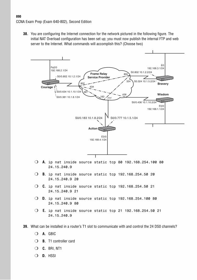
890
38. You are configuring the Internet connection for the network pictured in the following figure. Theinitial NAT Overload configuration has been set up; you must now publish the internal FTP and webserver to the Internet. What commands will accomplish this? (Choose two)
CCNA Exam Prep (Exam 640-802), Second Edition
E0/0192.168.4.1/24
CourageBravery
WisdomS0/0.634 10.1.10.1/24
S0/0.802 10.1.2.1/24
S0/0.381 10.1.8.1/24
S0.802 10.1.2.2/24
S0.324 10.1.5.2/24
E0192.168.3.1/24
E0/0192.168.1.1/24
Fa2/0192.168.2.1/24
S0/0.436 10.1.10.2/24
Frame RelayService Provider
802
436
324
634
381
183777
802
Action
S0/0.777 10.1.5.1/24S0/0.183 10.1.8.2/24
❍ A. ip nat inside source static tcp 80 192.168.254.100 8024.15.240.9
❍ B. ip nat inside source static tcp 192.168.254.50 2024.15.240.9 20
❍ C. ip nat inside source static tcp 192.168.254.50 2124.15.240.9 21
❍ D. ip nat inside source static tcp 192.168.254.100 8024.15.240.9 80
❍ E. ip nat inside source static tcp 21 192.168.254.50 2124.15.240.9
39. What can be installed in a router’s T1 slot to communicate with and control the 24 DS0 channels?
❍ A. GBIC
❍ B. T1 controller card
❍ C. BRI, NT1
❍ D. HSSI
Practice Exam891
40. What is the end result of the 192.168.2.0 network based on the following output?
RouterA#debug ip ripRIP protocol debugging is onRouterA#00:26:27: RIP: received v1 update from 192.168.1.6 on Serial0/000:26:27: 192.168.2.0 in 12 hops00:26:37: RIP: received v1 update from 192.168.1.12 on Serial0/100:26:37: 192.168.2.0 in 12 hops
❍ A. The router forwards packets to 192.168.1.6 because it received that update first.
❍ B. The router forwards packets to 192.168.1.12 because it received that update last.
❍ C. The router ignores the updates because the maximum hop count is reached.
❍ D. Both entries are put in the router, and it load-balances over both links.
41. You need to block a host from Internet access by using an access list. When creating the accesslist, you use the syntax access-list 99 to start the command. What type of access list isthis?
❍ A. An IP standard access list
❍ B. An IP extended access list
❍ C. An IP standard expanded range access list
❍ D. An IP extended expanded range access list
42. What is 00111000 10110011 01010111 11011010 converted into decimal format?
❍ A. 56.179.87.217
❍ B. 56.179.87.218
❍ C. 56.179.87.219
❍ D. 56.179.87.220
43. Which of the following is not a difference between RIPv2 and EIGRP?
❍ A. EIGRP can be configured as classless.
❍ B. EIGRP requires all routers to be Cisco.
❍ C. EIGRP supports IP, IPX, and AppleTalk.
❍ D. EIGRP can distinguish between internal and external networks.
892
44. You are configuring your Cisco 2600XM series router to connect across the WAN to a Cisco 3800series router. You would like to use the default WAN encapsulation. Will this work?
❍ A. Yes. All Cisco routers support the same WAN encapsulation standards.
❍ B. Yes. Newer Cisco routers support different WAN encapsulation standards, but they arebackward-compatible with older WAN encapsulation types.
❍ C. No. Newer Cisco routers use PPP as their WAN encapsulation types, and older Ciscorouters use HDLC.
❍ D. No. Newer Cisco routers use the industry-standard HDLC, and older Cisco routers usea proprietary version.
45. What is the broadcast IP of 212.84.5.66/26?
❍ A. 212.84.5.125
❍ B. 212.84.5.126
❍ C. 212.84.5.127
❍ D. 212.84.5.128
46. Which of the following statements is true about the 10.1.100.0 network based on the followingoutput?
CstmrARtr#show ip route...output omitted...
Gateway of last resort is 192.168.1.9 to network 0.0.0.0
D 10.1.100.0 /24 [90/16] via 192.168.1.9, 00:00:11, Serial0C 172.17.0.0/16 is directly connected, Ethernet0D 172.16.0.0/16 [90/2340] via 172.17.0.2, 00:00:02, Ethernet0
192.168.1.0/30 is subnetted, 1 subnetsC 192.168.1.8 is directly connected, Serial0
❍ A. The 10.1.100.0 network is 16 hops away.
❍ B. EIGRP is configured to be classless.
❍ C. Serial 0 has an IP address of 192.168.1.9.
❍ D. The maximum hop count has been reached.
CCNA Exam Prep (Exam 640-802), Second Edition
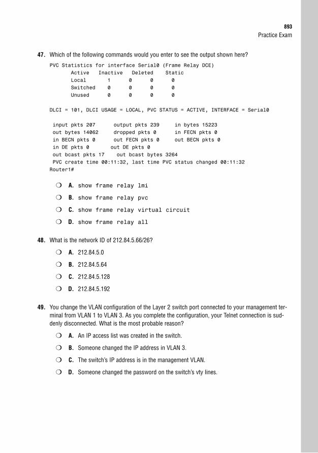
Practice Exam893
47. Which of the following commands would you enter to see the output shown here?
PVC Statistics for interface Serial0 (Frame Relay DCE)Active Inactive Deleted StaticLocal 1 0 0 0Switched 0 0 0 0Unused 0 0 0 0
DLCI = 101, DLCI USAGE = LOCAL, PVC STATUS = ACTIVE, INTERFACE = Serial0
input pkts 207 output pkts 239 in bytes 15223out bytes 14062 dropped pkts 0 in FECN pkts 0in BECN pkts 0 out FECN pkts 0 out BECN pkts 0in DE pkts 0 out DE pkts 0out bcast pkts 17 out bcast bytes 3264PVC create time 00:11:32, last time PVC status changed 00:11:32Router1#
❍ A. show frame relay lmi
❍ B. show frame relay pvc
❍ C. show frame relay virtual circuit
❍ D. show frame relay all
48. What is the network ID of 212.84.5.66/26?
❍ A. 212.84.5.0
❍ B. 212.84.5.64
❍ C. 212.84.5.128
❍ D. 212.84.5.192
49. You change the VLAN configuration of the Layer 2 switch port connected to your management ter-minal from VLAN 1 to VLAN 3. As you complete the configuration, your Telnet connection is sud-denly disconnected. What is the most probable reason?
❍ A. An IP access list was created in the switch.
❍ B. Someone changed the IP address in VLAN 3.
❍ C. The switch’s IP address is in the management VLAN.
❍ D. Someone changed the password on the switch’s vty lines.
894
50. Which of the following are valid interface connections for serial WAN connections? (Choose three)
❍ A. EIA/TIA-449
❍ B. V.35
❍ C. RJ-48
❍ D. RJ-44
❍ E. X.21
51. What does the c2600 portion of the Cisco IOS filename c2600-ipbase-1.122-1.T.bin represent?
❍ A. Hardware platform
❍ B. Feature set
❍ C. Train identifier
❍ D. IOS version
52. After Telnetting from Router A into Router B, you realize that your debug outputs are not showingon the terminal screen in Router B. How can you remedy this?
❍ A. RouterA#terminal monitor
❍ B. RouterA(config-line)#terminal monitor
❍ C. RouterB(config-line)#terminal monitor
❍ D. RouterB#terminal monitor
53. You have created an access list and applied it inbound for your router’s Internet connection. Youwant the router to send a message out the console port whenever inbound access is deniedbecause of this access list. What command can you add to the end of your access list statementsto enable this feature?
❍ A. report
❍ B. logging
❍ C. log
❍ D. record
❍ E. match
CCNA Exam Prep (Exam 640-802), Second Edition
Practice Exam895
54. Which of the following statements is false regarding the successor and feasible successor?
❍ A. The lowest feasible distance is the successor route.
❍ B. Both are located in the topology database.
❍ C. The feasible successor is determined if the feasible distance is less than the advertiseddistance of the successor route.
❍ D. The successor route is placed in the routing table.
55. What allows an end device to receive power over a copper Ethernet cable?
❍ A. Long-Reach Ethernet
❍ B. Gigabit Ethernet
❍ C. Fast Ethernet
❍ D. Power over Ethernet
56. What command configures a default route in a Layer 2 switch?
❍ A. ip route 0.0.0.0 0.0.0.0 FastEthernet 0/0
❍ B. ip default-gateway 172.16.1.1
❍ C. ip default-network 192.168.1.0
❍ D. default-route 172.16.1.1
57. You are using a Cisco 7921 Wireless VoIP device. While speaking to your coworker on the phone,you are walking through multiple wireless cells. What type of network topology is this?
❍ A. Multiservice
❍ B. Roaming
❍ C. Basic Service Set
❍ D. Extended Service Set
58. You walk away from your terminal for five minutes to get some coffee. When you return, younotice that someone has made configuration changes to your router. Which three commands willkeep this from happening in the future?
❍ A. Router(config-line)#line-timeout 1
❍ B. Router(config-line)#login
❍ C. Router(config)#password password
❍ D. Router(config)#exec-timeout 1
❍ E. Router(config-line)#password password
❍ F. Router(config-line)#exec-timeout 1
896
59. Your new junior technician can’t figure out why traffic from VLAN 1 isn’t being tagged with a VLANidentifier over the 802.1q trunk port. What should you tell him?
❍ A. They are baby giant frames, so there is no room in the frame.
❍ B. They are from the native VLAN.
❍ C. VLAN 1 should not be forwarded over a trunk.
❍ D. Only one VLAN is allowed over a trunk.
60. You are configuring an office to use a Cisco router to connect to the Internet. The onsite networkadministrator wants to publish an internal email server, two internal web servers, and an internalFTP server to the Internet so that outside users can access them. What is necessary for this configuration?
❍ A. You need a public Internet IP address for each internal server. These addresses can bemapped using Static NAT features.
❍ B. You need a single public Internet IP address for this configuration, and you use NATOverload to share it between all four internal servers.
❍ C. You need a single public Internet IP address for this configuration, and you use StaticNAT to map specific ports to all four internal servers.
❍ D. You need two public Internet IP addresses to accommodate the internal web servers.The FTP and email server can be mapped to individual ports on either of the addresses.
61. Which of the following conditions could cause the port to transition to a disabled state? (Chooseall that apply)
❍ A. A BPDU is detected on a BPDU Guard-enabled port.
❍ B. The port is not a root or designated port.
❍ C. The switch connected to your port has a faster way back to the root.
❍ D. A port security violation has occurred.
62. Which of the following is not true of a loopback interface with OSPF?
❍ A. It is a virtual interface.
❍ B. It commonly has a 255.255.255.255 netmask.
❍ C. It ensures that an interface is always active for OSPF processes.
❍ D. The higher physical interface number becomes the Router ID.
CCNA Exam Prep (Exam 640-802), Second Edition
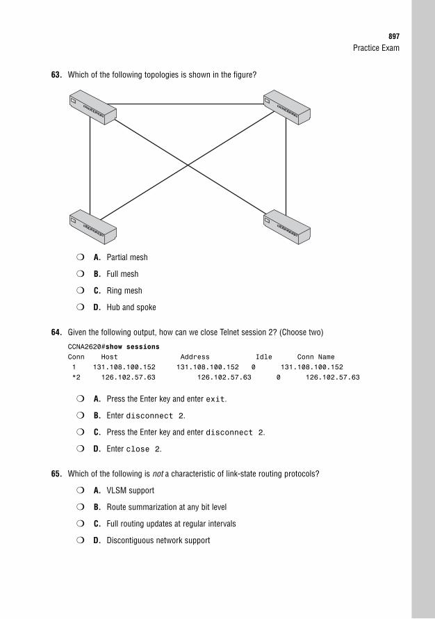
Practice Exam897
63. Which of the following topologies is shown in the figure?
❍ A. Partial mesh
❍ B. Full mesh
❍ C. Ring mesh
❍ D. Hub and spoke
64. Given the following output, how can we close Telnet session 2? (Choose two)
CCNA2620#show sessionsConn Host Address Idle Conn Name1 131.108.100.152 131.108.100.152 0 131.108.100.152*2 126.102.57.63 126.102.57.63 0 126.102.57.63
❍ A. Press the Enter key and enter exit.
❍ B. Enter disconnect 2.
❍ C. Press the Enter key and enter disconnect 2.
❍ D. Enter close 2.
65. Which of the following is not a characteristic of link-state routing protocols?
❍ A. VLSM support
❍ B. Route summarization at any bit level
❍ C. Full routing updates at regular intervals
❍ D. Discontiguous network support
898
66. Which of the following is not part of the VLAN configuration process?
❍ A. Name the VLAN.
❍ B. Create the VLAN.
❍ C. Set the VTP domain to client mode.
❍ D. Assign the VLAN to a switch port.
67. You have just finished proposing a new VPN solution to your organization’s upper management.They have approved the solution, provided that you use the strongest level of encryption possible.What algorithm will you choose?
❍ A. SHA-1
❍ B. AES
❍ C. 3DES
❍ D. MD5
68. You connected your switch into a device at half duplex. What is a possible reason for not using fullduplex?
❍ A. It is a 10Mbps port.
❍ B. You are connecting it to another switch.
❍ C. You are using a straight-through cable.
❍ D. You are connected to a hub.
69. Which of the following is not an additional feature of RIPv2 over RIPv1?
❍ A. Full update followed by hellos
❍ B. Update authentication
❍ C. Multicast updates
❍ D. Classless support
70. How many bits are there in an IPv6 address?
❍ A. 32 bits
❍ B. 64 bits
❍ C. 96 bits
❍ D. 128 bits
CCNA Exam Prep (Exam 640-802), Second Edition

Practice Exam899
71. Which of the following are encryption protocols? (Choose three)
❍ A. IPsec
❍ B. SSL
❍ C. NTP
❍ D. SSH
72. Private addressing for IPv6 is represented by what kind of address?
❍ A. Link-local
❍ B. Global
❍ C. Unique/site-local
❍ D. Multicast

This page intentionally left blank

Answers to Practice Exam
Answers at a Glance1. C
2. A
3. A, C, D
4. B
5. B
6. D
7. B
8. B, C
9. C
10. B, D
11. A, C
12. D
13. A
14. A, B, C
15. A, B, D
16. C
17. A
18. F
19. B
20. D
21. D
22. A, B, C
23. C
24. A, D
25. C, D
26. B, C, D
27. B
28. A, D
29. B
30. D
31. C
32. A
33. B, D
34. B
35. C, D
36. B
37. D
38. C, D
39. B
40. D
41. A
42. B
43. A
44. A
45. C
46. B
47. B
48. B
49. C
50. A, B, E
51. A
52. D
53. C
54. C
55. D
56. B
57. D
58. B, E, F
59. B
60. D
61. A, D
62. D
63. A
64. A, B
65. C
66. C
67. B
68. D
69. A
70. D
71. A, B, D
72. C
902
Answers with Explanations1. C. The “Invalid input detected at ^” terminal message indicates that the IOS understood the config-
uration command up to the ^. This type of message is typical when the command contains a typo.Answer A is the correction for an “Ambiguous Command” message. Answer B is the correction foran “Incomplete Command” message. Answer D is incorrect because the terminal session is stillconnected.
2. A. The packet would be denied because of the implicit deny statement at the end of the access list.Answer B is incorrect because the first permit statement matches only the range of addressesfrom 192.168.5.16 to 31. Answer C is incorrect because the third permit statement matches onlythe range of addresses from 192.168.5.48 to 63. Answer D is incorrect because the last permitstatement matches only the 192.168.5.0 network address.
3. A, C, D. Telnet, HTTP, and FTP are all protocols supported by Layer 7, or the Application layer, ofthe OSI model. Answer B is incorrect because JPEG is a Layer 6, or Presentation layer, supportedprotocol.
4. B. You must use an extended ping to specify the datagram size when pinging an IP address. To doan extended ping in the Cisco IOS, you must be in privileged EXEC mode, and the command isping without specifying an IP address. Answer A is incorrect because it is a DOS command, notan IOS command. Answer C is incorrect because you do not specify the IP address after the pingkeyword. Answer D is incorrect because you must be in privileged EXEC mode.
5. B. The ip nat syntax can be quite cryptic, because the Cisco router gives you plenty of flexibilitywith the form and directions of NAT translation. In this case, we are looking to create a Static NATtranslation to allow TCP port 80 (HTTP) to pass through the Cisco router to the internal web server.There are two ways to accomplish this. We can create a Static NAT translation from the inside per-spective or from the outside perspective. In this question, the only correct answer is the translationperformed from the inside: ip nat inside source static tcp 172.16.55.10 80interface fastEthernet 0/1 80. If we were to perform the Static NAT translation from theoutside perspective, we would not be given the option to choose to translate from an interface(fastEthernet 0/1 in this case). Answers A, C, and D would result in an invalid syntax message.
6. D. DNS resolves hostnames into IP addresses. Answer A is incorrect because SMTP sends emailacross the network. Answer B is incorrect because NFS allows users with different operating sys-tems (that is, NT and UNIX workstations) to share files. Answer C is incorrect because NNTP offersaccess to Usenet newsgroup postings.
7. B. If the boot field in the configuration register is 2-F, the router or switch will load the IOS fromflash when no boot system commands are present. Answers A and C will load into ROMmonbecause the boot field is 0. Answer D has a P in the boot field, which is not a valid hexadecimalcharacter.
8. B, C. Cisco routers typically support DB-60, which is a 60-pin connection. Only one DB-60 inter-face is supported per WIC card. Because of this, Cisco developed the Smart Serial connector,which is much smaller and supports more condensed interfaces. Answer A is incorrect becauseEIA/TIA-449 connects to the CSU/DSU side of the connection. Answer D is incorrect because thisis a LAN interface standard.
CCNA Exam Prep (Exam 640-802), Second Edition
Answers to Practice Exam903
9. C. The Session layer of the OSI model handles dialog control among devices and determines thebeginning, middle, and end of a session or conversation that occurs between applications (inter-mediary). The Application layer (Answer A) provides an interface between a host’s communicationsoftware and any necessary external applications. The Presentation layer (Answer B) presents datato the Application layer. The Transport layer (Answer D) manages end-to-end connections and datadelivery between two hosts.
10. B, D. During the learning and forwarding STP port states, the switch actively learns MAC address-es it receives on that interface. Answers A and C are incorrect because MAC addresses are notlearned during the blocking and listening port states.
11. A, C. The only private addresses are from the ranges 10.0.0.0 to 10.255.255.255, 172.16.0.0 to172.31.255.255, and 192.168.0.0 to 192.168.255.255. Because Answers A and C fall outside thoseranges, they are considered public IP addresses.
12. D. SNMP uses port number 161. Answers A and B are incorrect because DHCP uses port numbers67 and 68. Answer C is incorrect because TFTP uses port number 69.
13. A. When a configuration is saved, it is stored in NVRAM as the startup-config. Answer B is incor-rect because the running-config is stored in RAM. Answer C is incorrect because POST, ROMmon,and RxBoot are located in ROM. Answer D is incorrect because the compressed IOS file is storedin flash.
14. A, B, C. TCP SYN, smurf, and DDoS are all types of DoS attacks. Answer D is incorrect becausetrust exploitation is a type of access attack.
15. A, B, D. Answers A, B, and D are all valid signaling types for Local Management Interface (LMI).Answer C is incorrect because the ITU-T is a standards organization that actually created theQ.933a standard. Answer E is incorrect because this is the industry-standard type of Frame Relayencapsulation, not an LMI signaling type.
16. C. Crosstalk is an electrical or magnetic field that is a result of one communications signal that canaffect the signal in a nearby circuit. Answer A is incorrect because EMI is the interference causedby electromagnetic signals. Answer B is incorrect because attenuation occurs over long distancesas a signal loses strength. Answer D is incorrect because bandwidth is the total amount of infor-mation that can traverse a communications medium measured in millions of bits per second.
17. A. OSPF ABRs do not perform automatic summarization. Route summarization entries must bemanually configured with the area area# range summaryaddress command. Answers B,C, and D are all valid advantages of OSPF.
18. F. When applying standard access lists, it’s always best to apply them closest to the destination.Because they can only permit or deny based on the source address, placing them too close to thesource might allow or deny too much access. For example, if the access list were placed on theFa0/0 port of the Homer router, Network 1 would not be able to access any resources on the net-work. All other answers are incorrect because they are not the closest to the Internet destination.
904
19. B. When connecting a switch to a PC, you must use a straight-through UTP cable. Answer A isincorrect because coaxial cable is typically used for cable television. Answer C is incorrect becausecross-over cables are used to connect like devices, such as switches to other switches or PCs toother PCs. Answer D is incorrect because thin coaxial (also known as thinnet) is used in older net-work topologies.
20. D. Answer D is the false answer because you must configure directly connected classful networks.Thus, 10.2.0.0 is incorrect because the classful network should be 10.0.0.0. Answer B is incorrectbecause, based on the output, the routing protocol configured is RIPv2 with update authentication.Answer A is incorrect because the administrative distance for RIPv2 is 120; however, the outputshows the AD as 80. Answer C is incorrect because the output does show that update authentica-tion is indeed configured.
21. D. Dynamic NAT allows you to configure multiple pools of IP addresses and translate betweenthem. The router dynamically matches each IP address to one another as a request is made.Answer A is incorrect because Port Address Translation (PAT) is just another name for NATOverload. Answer B is incorrect because although Static NAT could perform this task, it would takequite a bit of configuration to manually map IP addresses in large pools. Answer C is incorrectbecause NAT Overload takes a group of IP addresses and translates them to a single (overloaded)IP address.
22. A, B, C. 10BASE-2, 10BASE-5, and 10BASE-T are all 10Mbps IEEE 802.3 Ethernet standards.Answer D is incorrect because Wi-Fi is a wireless technology that is defined by IEEE 802.11.
23. C. The summary route for 192.168.64.0 /19 summarized the networks from 192.168.64.0 /24 to192.168.95.0 /24. Because 5 bits were stolen (25 = 32), 32 networks are being summarized.Answers A, B, and D are incorrect because these do not fall in the summary range.
24. A, D. HDLC and PPP are the only encapsulation types supported by Cisco on leased-line connec-tions. Answer B is incorrect because Frame Relay is an encapsulation used on a Frame Relay pack-et-switched network. Answer C is incorrect because ISDN is a type of circuit-switched technology.
25. C, D. Hubs and repeaters are hardware devices used at the Physical layer of the OSI model toextend a network. Answers A and B are incorrect because switches and bridges are hardwaredevices used at the Data Link layer to segment a network.
26. B, C, D. Unicast, multicast, and broadcast addresses are Ethernet address types used at the 802.3MAC sublayer. Answer A is incorrect because IP addresses are logical addresses used at theNetwork layer of the OSI model.
27. B. If you add another switch to a VTP domain that is in server mode and has a higher revisionnumber, other switches in the VTP domain use the VLANs in the new server’s database. If there areno VLANs in the database, the other switches remove all the VLANs in their databases as well.Answer A is incorrect because a switch in client mode does not advertise its own VLANs. AnswerC is incorrect because devices with a higher revision number ignore the VTP advertisements of thenew server. Answer D is possible, but Answer B is more likely than someone deleting your VLANswithout you knowing.
CCNA Exam Prep (Exam 640-802), Second Edition
Answers to Practice Exam905
28. A, D. The WPA algorithm uses the TKIP algorithm to generate dynamic keys during a wireless ses-sion. This helped handle many of the security concerns of WEP. WPA2 (also known as 802.11i)uses the AES encryption algorithm, which is considered one of the best encryption standardsavailable.
29. B. All multicast addresses start with 0100.5E. Answer A is incorrect because unicast addressesstart with the OUI of the manufacturer NIC. Answer C is incorrect because broadcast addressesbegin with FFFF.FF. Answer D is incorrect because IP addresses are not Ethernet MAC sublayeraddresses, and they use dotted-decimal format rather than hexadecimal format.
30. D. Modems typically are connected to the auxiliary port and are used as a “last-resort” method ofaccessing the remote router. Answers B and C are incorrect: Because you no longer have IP con-nectivity to the router, you cannot use SSH and Telnet. Answer A is incorrect: You cannot consoleinto the router because it is in a remote location. The only viable solution left is to call into amodem that is connected through the Auxiliary port.
31. C. For a low-cost connection, you could use a hub-and-spoke topology. With this design, youwould need only a connection from the hub office to each of the spokes. Answer A is incorrectbecause each router would need a separate connection for every other router in the topology. Thiswould be quite expensive in a large topology. Answer B is incorrect because you would still havemore connections than a hub and spoke. Answer D is incorrect because nonbroadcast multiaccess(NBMA) does not affect the cost of Frame Relay.
32. A. Microsegmentation occurs when a switch creates a dedicated path for sending and receivingtransmissions with each connected host. Answer B is incorrect because half duplex allows onlyone-way data transmission. Answer C is incorrect because full duplex allows two-way data trans-mission. Answer D is incorrect because CSMA/CD is an algorithm used for arbitration on anEthernet network.
33. B, D. To speed up convergence for end devices such as computers, servers, and printers, you canenable PortFast, which bypasses the listening and learning port states. To keep that port from hav-ing a hub or switch connect to it and causing loops, you can enable BPDU Guard, which disablesthe interface if it receives a BPDU. Answers A and C will not speed up convergence for enddevices.
34. B. In the U.S., only three nonoverlapping channels are available for the 2.4GHz band. Europe hasfour nonoverlapping channels, because access to other unlicensed RF bands is available. Themoral of the story? If you’re having trouble finding a free wireless channel in your area, move toEurope.
35. C, D. Switches and bridges are hardware devices used at the Data Link layer to segment a net-work. Answers A and B are incorrect because hubs and repeaters are hardware devices used at thePhysical layer of the OSI model to extend a network.
36. B. Class A addresses have a first octet value of 1 to 126. Class B addresses have a first octet valueof 128 to 191. Class C addresses have a first octet value of 192 to 223. Answers A, C, and D areincorrect because they do not correctly identify this range.
906
37. D. Routing protocols do not advertise each others’ networks unless redistribution has occurred.Answers A and B are incorrect: Because the routing protocols are not advertising the same net-work, administrative distance does not play into this. Answer C is incorrect because it reverses thenetworks the routing protocols are advertising.
38. C, D. The generic Static NAT syntax for TCP translations is ip nat inside source statictcp inside_ip inside_port outside_ip/outside_interface outside_port.In this case, only Answers C and D match this syntax. Answers A and E flip the IP address andport numbers in the wrong location, which produces a syntax error. Answer B uses port 20, whichis used by FTP; however, only port 21 is used to initiate an FTP session. After a client initiates theincoming FTP session on port 21, the FTP server establishes an outgoing FTP data connectionusing port 20. Because of this, no incoming NAT translation is necessary for TCP port 20.
39. B. A T1 controller card can be installed in a router’s T1 slot to communicate with and control the24 DS0 channels. Answer A is incorrect because a GBIC interface module can be inserted into theGigabit Ethernet slot to allow for different media connections to that port. Answer C is incorrectbecause if it is not built in on a Cisco router via a BRI-U interface, the service provider requiresseparate BRI NT-1 hardware as a termination point for the communications line, which then con-nects to the Cisco router. Answer D is incorrect because HSSI is a high-speed interface that offersup to 52Mbps transmission rates to the WAN from a Cisco router.
40. D. Because the update is coming from two different sources with the same metric, RIP load-bal-ances over both equal paths. Answers A and B are incorrect because the order in which theupdates were received is negligible. Answer C is incorrect because the maximum hop count forRIP is 15.
41. A. Standard IP access lists are numbered from 1 to 99. Answer B is incorrect because extended IPaccess lists are numbered from 100 to 199. Answer C is incorrect because the expanded rangestandard access list is 1300 to 1999. Answer D is incorrect because the expanded range extendedaccess list is 2000 to 2699.
42. B. The first octet is 32+16+8=56. The second octet is 128+32+16+2+1=179. The third octet is64+16+4+2+1=87. The last octet is 128+64+16+8+2=218. So the address in dotted-decimal formatis 56.179.87.218. The last bit in the last octet is 0, which means that any address ending with anodd-numbered octet can be eliminated. All other answers have the wrong decimal conversion.
43. A. EIGRP and RIPv2 can both be configured as classless routing protocols using the no auto-summary command. All other answers are unique differences between RIPv2 and EIGRP.
44. A. Cisco routers (new and old) all use a Cisco-proprietary version of HDLC on their serial connec-tions. Although there is an industry-standard HDLC, very few vendors support it. Answer B isincorrect because there are no “backward-compatible” WAN standards. Answers C and D areincorrect because newer Cisco routers still use the Cisco-proprietary HDLC as the default encapsulation.
45. C. The broadcast IP of 212.84.5.66/26 is 212.84.5.127. The next network ID after 212.84.5.64 is212.84.5.128. To determine the broadcast IP, you subtract 1 from the next network ID, which inthis case is 212.84.5.127. All other answers are incorrect because they are not the broadcast IP.
CCNA Exam Prep (Exam 640-802), Second Edition
Answers to Practice Exam907
46. B. 10.1.100.0 shows a subnet mask of /24, which means that it was not automatically summarizedto its classful boundary of 10.0.0.0/8. Because this network is learned from EIGRP, the administra-tor had to make this classless by using the no auto-summary command. Answers A and D areincorrect because hop count is not a factor in this case; EIGRP does not use hop count as its met-ric. Answer C is incorrect because Serial 0 has the IP address of 192.168.1.8 displayed as the con-nected interface entry.
47. B. The show frame relay pvc command provides you with statistics for each configuredconnection, as well as traffic statistics. Answer A is incorrect because the output is not for LMIstatistics. Answers C and D are incorrect because there are no such commands.
48. B. The network ID of 212.84.5.66/26 is 212.84.5.64. The CIDR notation represents subnet mask255.255.255.192. The binary equivalent of the subnet mask host field is 11000000. The binaryequivalent of the 212.84.5.66 host field is 01000010. Using Boolean AND, the network ID is212.84.5.64. Therefore, Answers A, C, and D are incorrect.
49. C. VLAN 1, the management VLAN, contains the IP address for the switch and CDP and VTPadvertisements. If your terminal computer is not connected to the management VLAN, you cannotTelnet to that switch. Answer A is incorrect because an IP access list cannot be configured in Layer2 switches. Answer B is incorrect because the management VLAN is VLAN 1. Answer D will notdisconnect the active Telnet session.
50. A, B, E. The five primary standards that are used for serial interface connections (to the CSU/DSU)are V.35, X.21, EIA/TIA-232, EIA/TIA-449, and EIA/TIA-530. Answers C and D are incorrect becauseRJ-48 is the standard for a T1 connection, and RJ-44 is not a defined standard.
51. A. The c2600 portion of the IOS filename represents the hardware platform. In this case, it is aCisco 2600 series router. Answer B is incorrect because the term ipbase refers to the IP Base fea-ture set. Answer C is incorrect because the train identifier is T for Technical. Answer D is incorrectbecause the IOS version is represented by 122, or version 12.2.
52. D. The terminal monitor command copies and consoles messages to the Telnet sessions ofan IOS router or switch. This command is done in privileged EXEC mode in the device you areTelnetted into. Answers A, B, and C are incorrect because they are either on the wrong router or inthe wrong mode.
53. C. If you add the log keyword to the end of an access list entry, the router reports any matcheson that line to the console port. This logging can also be redirected to a reporting server. AnswersA, B, D, and E are invalid syntax.
54. C. The feasible successor is determined if the route’s advertised distance is less than the feasibledistance of the successor route in the routing table. The feasible successor and the successorrouter are both maintained in the topology table. Answers A, B, and D are true regarding the suc-cessor and feasible successor.
55. D. Power over Ethernet is a technology that allows an end device to receive power over a copperEthernet cable. Answer A is incorrect because Long-Reach Ethernet (LRE) is an Ethernet specifica-tion developed by Cisco to provide broadband service over existing telephone-grade or Category 1,2, or 3 wiring. Answers B and C are incorrect because Gigabit Ethernet and Fast Ethernet standardsdo not include the ability to supply power to an end device.
908
56. B. Because this is a Layer 2 switch, the gateway of last resort is configured by setting the defaultgateway. Answers A and C are incorrect because you cannot configure a default route or a defaultnetwork in a Layer 2 switch. Answer D is not a valid command.
57. D. An Extended Service Set (ESS) wireless topology is the combination of two or more BasicService Set (BSS) networks. This allows client roaming (between wireless cells) without serviceinterruption.
58. B, E, F. To secure your console connection when you walk away from the IOS terminal, you needto decrease the exec-timeout and set the login and password. These configurations must be per-formed in line configuration mode. All other answers are incorrect because they are performed inthe wrong configuration mode.
59. B. With 802.1q trunks, traffic originating from the native VLAN is not tagged with a VLAN identifi-er. Answer A is incorrect because information can always be added to a frame, even if it is a babygiant. Answer C is incorrect because VLAN 1 is always forwarded over a trunk by default. AnswerD is incorrect because many VLANs can be sent over a trunk.
60. D. NAT can accomplish some pretty amazing feats; however, sharing an IP address for two serversthat use the same port number is not one of them. In this case, you need two public Internetaddresses to allow both internal web servers to be accessed on TCP port 80. The other servers canuse port 21 (FTP) and port 25 (SMTP) on either of the public Internet IP addresses. Answer Acould be used to solve this problem, but it is not the best solution because it would be more costlyto deploy than Answer D. Answer B is incorrect because NAT Overload would let the servers sharea single IP address only when accessing the Internet, not when the requests originate from theInternet. Answer C is incorrect because you could only map TCP port 80 on the single IP addressto one of the internal web servers. The other internal web server could not be accessed from theInternet.
61. A, D. The port will become disabled if a BPDU is detected on a BPDU Guard-enabled port, as wellas if there is a port security violation. Answers B and C are incorrect because that would cause theport to be in a blocking state.
62. D. When using loopback interfaces with OSPF, the physical interfaces are no longer used to deter-mine the Router ID. All other answers are true and play a significant role in the OSPF Router ID.
63. A. There are redundant links between the routers. However, there are not redundant links betweenall the routers. Answer B is incorrect because there are not redundant links between all the routers.Answer C is incorrect because even though the connections form a ring as shown here, if it werein the cloud, it would not look like this. Answer D is incorrect because it is not a star or hub-and-spoke topology—there is no central point.
64. A, B. To disconnect the Telnet session, you can enter disconnect followed by the session num-ber in the originating router. Or you can press the Enter key to resume the Telnet session and enterexit in the device you are Telnetted into to close the Telnet session. Answer C is incorrectbecause pressing Enter first resumes your session with the remote router and causes the disconnect command to fail. Answer D is incorrect because it is invalid syntax.
CCNA Exam Prep (Exam 640-802), Second Edition
Answers to Practice Exam909
65. C. Link-state routing protocols (OSPF and IS-IS) do not send full routing updates at regular inter-vals. Answers A, B, and D are characteristic of link-state routing protocols; however, this questionis looking for the false answer.
66. C. Setting the VTP domain to client mode does not allow you to configure any VLANs on theswitch. Answers A, B, and D typically are performed during a VLAN configuration process.
67. B. AES currently offers the strongest levels of encryption possible for symmetric encryption. It canreach up to 256-bit encryption.
68. D. When connecting to a hub, you must have the port running in half duplex, because CSMA/CDmust be enabled. Answer A is incorrect because the speed is irrelevant. Answer B is incorrectbecause you can run full duplex when connecting to switches. Answer C is incorrect because itdoes not matter what cable is used.
69. A. RIPv2 has update authentication and multicasts updates to 224.0.0.9 and can support classlessrouting. Answer A is not a feature because RIPv2 is a distance vector routing protocol that sendscontinuous updates every 30 seconds instead of Hello messages, such as RIPv1.
70. D. IPv6 addresses consist of 128 bits. Answer A is the correct bit count of an IPv4 address.Answers B and C are incorrect because they are not valid IP address bit counts.
71. A, B, D. IPsec, SSL, and SSH are all encryption protocols. Answer C is incorrect because NTP(Network Time Protocol) synchronizes clocks on a network.
72. C. Unique/site-local addresses are the private address space for IPv6. Answer A is incorrectbecause link-local addresses represent the address automatically assigned to a device at Layer 2.Answer B is incorrect because a global address is a public IP address. Answer D is incorrectbecause a multicast address in IPv6 is the same as a broadcast IP address.

This page intentionally left blank
A P P E N D I X
What’s on the CD-ROMThe CD-ROM features an innovative practice test engine powered byMeasureUp™, giving you yet another effective tool to assess your readiness forthe exam.
Multiple Test ModesMeasureUp practice tests can be used in Study, Certification, or Custom Mode.
Study ModeTests administered in Study Mode allow you to request the correct answer(s) to andan explanation for each question during the test. These tests are not timed.
You can also specify the objectives or missed questions you want to include inyour test, the timer length, and other test properties.
In Study Mode, you receive automatic feedback on all correct and incorrectanswers. The detailed answer explanations are a superb learning tool in their ownright.
Certification ModeTests administered in Certification Mode closely simulate the actual testing envi-ronment you will encounter when taking a licensure exam and are timed. Thesetests do not allow you to request the answer(s) and/or explanation to each ques-tion until after the exam.
Custom ModeCustom Mode allows you to specify your preferred testing environment. Use thismode to specify the categories you want to include in your test, timer length,number of questions, and other test properties. You can modify the testing envi-ronment during the test by clicking the Options button.
912
Attention to Exam ObjectivesMeasureUp practice tests are designed to appropriately balance the questions over each technical area covered by a specific exam. All concepts from the actual exam are covered thoroughly to ensure that you’re prepared for the exam.
Installing the CDThe system requirements are as follows:
. Windows 95, 98, Me, NT 4, 2000, XP, or Vista
. 14MB of disk space for the testing engine
. An average of 2MB of disk space for each individual test
. Control Panel Regional Settings must be set to English (United States)
. PC only
To install the CD-ROM, follow these instructions:
1. Close all applications before beginning this installation.
2. Insert the CD into your CD-ROM drive. If the setup starts automatically, go to step 6.If the setup does not start automatically, continue with step 3.
3. Select Start, Run.
4. Click Browse to locate the MeasureUp CD. In the Browse dialog box, from the LookIn drop-down list, select the CD-ROM drive.
5. In the Browse dialog box, double-click Setup.exe. In the Run dialog box, click OK tobegin the installation.
6. On the Welcome screen, click MeasureUp Practice Questions to begin the installation.
7. Follow the Certification Prep Wizard by clicking Next.
8. To agree to the Software License Agreement, click Yes.
9. On the Choose Destination Location screen, click Next to install the software toC:\Program Files\Certification Preparation. If you cannot locate MeasureUp PracticeTests on the Start menu, see the next section.
10. On the Setup Type screen, select Typical Setup. Click Next to continue.
11. In the Select Program Folder screen, you can name the program folder where your testswill be located. To select the default, simply click Next, and the installation continues.
Appendix: What’s on the CD-ROM
Technical Support913
12. After the installation is complete, verify that Yes, I Want to Restart My ComputerNow is selected. If you select No, I Will Restart My Computer Later, you cannotuse the program until you restart your computer.
13. Click Finish.
14. After restarting your computer, choose Start, Programs, Certification Preparation,Certification Preparation, MeasureUp Practice Tests.
15. On the MeasureUp Welcome Screen, click Create User Profile.
16. In the User Profile dialog box, complete the mandatory fields, and click CreateProfile.
17. Select the practice test you want to access, and click Start Test.
Creating a Shortcut to the MeasureUpPractice TestsTo create a shortcut to the MeasureUp practice tests, follow these steps:
1. Right-click your desktop.
2. From the shortcut menu, select New, Shortcut.
3. Browse to C:\Program Files\MeasureUp Practice Tests, and select theMeasureUpCertification.exe or Localware.exe file.
4. Click OK.
5. Click Next.
6. Rename the shortcut MeasureUp.
7. Click Finish.
After you complete step 7, use the MeasureUp shortcut on your desktop to access theMeasureUp products you ordered.
Technical SupportIf you encounter problems with the MeasureUp test engine on the CD-ROM, please contactMeasureUp at 800-649-1687, or email [email protected]. Support hours of operation are7:30 a.m. to 4:30 p.m. EST. In addition, you can find Frequently Asked Questions (FAQs) in theSupport area at www.measureup.com. If you would like to purchase additional MeasureUp prod-ucts, call (678) 356-5050 or 800-649-1687, or visit www.measureup.com.

This page intentionally left blank
Glossary
10BASE-T An IEEE 802.3 Ethernet stan-dard that has a maximum segment length of100m and has a 10Mbps data transmissionspeed. 10BASE-T can use Category 3, 4, or5 unshielded twisted-pair (UTP) or shieldedtwisted-pair (STP) cables for connectivity.
802.11a An IEEE wireless networking stan-dard released in 1999 that uses the 5GHz fre-quency range. 802.11a clients can theoretical-ly transmit at a maximum speed of 54Mbps.
802.11b An IEEE wireless networkingstandard released in 1999 that uses the2.4GHz frequency range. 802.11b clientscan theoretically transmit at a maximumspeed of 11Mbps.
802.11g An IEEE wireless networkingstandard released in 2003 that uses the2.4GHz frequency range. 802.11g clientscan theoretically transmit at a maximumspeed of 54Mbps. This standard is back-ward-compatible with 802.11b clients.
802.11n A predraft standard for wirelessnetworking that uses Multiple Input,Multiple Output (MIMO) signals to achievehigher throughput. Current predraft equip-ment uses the 2.4GHz frequency range.
802.1q An IEEE frame-tagging methodover trunk ports that insert the 4-byteVLAN identifier inside the originalEthernet frame.
802.1x An authentication protocol gearedtoward LAN environments. 802.1x requiresthat users authenticate to the network beforethey are granted wired or wireless access.
916
AAAA (Authentication, Authorization, andAccounting) A group of three services thatare used in conjunction with an authentica-tion server and a software service such asTerminal Access Controller Access ControlSystem (TACACS) or RemoteAuthentication Dial-in User Service(RADIUS) to provide a secure network con-nection with a record of user activities.
ABR (Area Border Router) A router that sitsbetween multiple areas in a hierarchicalOSPF network. These routers are responsi-ble for summarizing subnets to the rest ofthe OSPF autonomous system. Because theymust maintain topology information fromseveral areas, these routers are typicallyrobust in resources.
access attack A class of attack in which ahacker attempts to access another useraccount or network device through improp-er means.
access-class The command used toapply an access list to vty ports.
access port A switch port that has a singleVLAN assigned to it. These are typicallyused for connectivity between end devices.
ACTIVE, INACTIVE, and DELETED PVC statusThe three states of a Frame Relay PVC.Active means that the connection is good onboth ends. Inactive means that the remoterouter is misconfigured. Deleted means thatthe local router is misconfigured.
adjacency A term that describes the stateafter two OSPF neighbors have synchro-nized their topology databases.
administrative distance An arbitrary valuebetween 1 and 255 that is assigned to deter-mine the trustworthiness of the routingsources.
advertised distance The composite metricto a destination that is being advertisedfrom our EIGRP neighbors.
AES (Advanced Encryption Standard) Thenewest encryption algorithm. It is managedby the National Institute of Standards andTechnology (NIST), a division of the U.S.government. It was designed to increaseencryption strength beyond the DES and3DES standards and yet be more efficient onthe device’s processor. As it stands today, AESoffers 128-, 192-, and 256-bit encryption.
AH (Authentication Header) One of thecomponents that powers the IPsec securitysuite of protocols. AH defines capabilitiesfor authentication and data-integrity algo-rithms but does not provide the capabilityfor encryption.
Application layer Layer 7 of the OSImodel. Provides an interface between ahost’s communication software and any nec-essary external applications (that is, email,file transfers, and terminal emulation). Thislayer can also evaluate what resources arenecessary to communicate between twodevices and determine their availability.
area A subdivision of an autonomous sys-tem composed of groups of contiguous net-works and attached hosts. Used in link-staterouting protocols to minimize routingupdate overhead and confine network instability.
AAA
BDR917
ARP (Address Resolution Protocol) A proto-col that maps a known IP address to a MACaddress by sending a broadcast ARP. Whenthe destination IP address is on another sub-net, the sender broadcasts ARP for therouter’s Ethernet port or default gateway, sothe MAC address sent back is that of therouter’s Ethernet port.
ASP (AppleTalk Session Protocol) A sessionlayer protocol that manages client/serverbased communications, but is specific toAppleTalk client and server devices.
asynchronous A serial interface that doesnot synchronize the clocks for the bit streamof the sending and receiving end of a seriallink.
ATM (Asynchronous Transfer Mode) A pack-et-switched connection type that reacheshigh speeds by dividing all packets intoequal-sized cells of 53 bytes each.
attenuation A term used to describe how asignal loses strength over long distances.
authentication The process of requiring orprompting for credentials before a devicecan access the network.
autonomous system A collection of routingdevices under the same administrative control.
autonomous system number An indicatorin an IGRP and EIGRP configuration thatidentifies the autonomous system to whichthe routers are actively sending routingupdates.
auxiliary port An out-of-band managementconnection used to connect to an externalmodem with a rollover cable.
Bbackbone area Also known as the transitarea, Area 0 is an area to which all otherareas must connect.
BackboneFast Cisco STP enhancementthat skips the max-age timer when switcheslearn of a failure indirectly.
backbone router Any router that is con-nected to Area 0.
Backward Explicit Congestion Notification(BECN) A signaling method used by aFrame Relay service provider that attemptsto drop the speed of a router sending exces-sive data.
balanced hybrid routing protocol A class ofrouting protocol that uses the best charac-teristics from link-state and routing proto-cols. These advanced routing protocols effi-ciently and quickly build their routing infor-mation and converge when topologychanges occur.
bandwidth The total amount of informa-tion that can traverse a communicationsmedium measured in millions of bits persecond. Bandwidth is helpful for networkperformance analysis. Also, availability isincreasing but limited.
bandwidth speed An interface configura-tion command that assigns a logical speed tothe interface for accurate routing metrics.
banner motd delimiting_char banner
delimiting_char A global configurationcommand to create a message-of-the-daylogin banner.
BDR (Backup Designated Router) A routerthat is elected in OSPF as a redundantdevice in case the Designated Router fails.
918
bearer channel (B channel) Used as abuilding block for ISDN connections.Provides 64Kbps of bandwidth per channel.
Bellman-Ford Algorithm A routing algo-rithm used by RIP and IGRP, which entailsrouting updates being received and updatedbefore propagating the message to otherrouting devices.
binary A computer language that is repre-sented by a bit value of 0 or 1.
blocking Ports that are not the root or thedesignated port in a STP election that areleft in a blocking state. Data is not transmit-ted on these ports, but BPDUs can still bereceived.
Bluetooth A wireless technology that uses ashort-range wireless radio connection toallow various devices to interconnect. Suchdevices include cell phones, PCs, and per-sonal digital assistants (PDAs). The onlyrequirement to establish connectivity is a 10meter range (approximately 33 feet)between communicating devices. When inrange, Bluetooth uses an RF link in the2.4GHz range that has a 720Kbps per chan-nel capacity to transfer voice or data.
BOD (Bandwidth on Demand) A Ciscoextension to the PPP Multilink concept thatallows more DDR connections to bebrought up as bandwidth is needed and dis-connected as bandwidth is not needed.
Boolean AND A mathematical operationthat can be used to identify the network IDand broadcast IP given an IP address andsubnet mask.
boot field The last hexadecimal characterin a configuration register that specifieswhere to find an IOS.
bootstrap Instructions loaded from ROMto activate the IOS loading code.
boot system location filename Aglobal configuration command that specifieslocations and filenames to load the IOS.
BPDU (Bridge Protocol Data Unit) A Layer 2message sent in an STP environment toadvertise bridge IDs, root bridge MACaddresses, and root path costs.
BPDU Guard A Cisco enhancement toPortFast that prevents loops by moving anaccess port to a disabled state if a BPDU isreceived.
BRI (Basic Rate Interface) An IntegratedServices Digital Network (ISDN) line thatconsists of two 64Kbps bearer (B) channelsand one 16Kbps data (D) channel. Voice,video, and data traffic can be carried overthe B channels. Signals between telephonecompany switches use the D channel.
bridge A hardware device at the Data Linklayer that connects two segments in a singlenetwork or connects two networks. Theysimply forward data between those seg-ments/networks without analyzing or redi-recting the data.
bridge ID A Spanning Tree Protocol switchidentifier composed of a combination ofbridge priority and MAC address.
broadband A term used to describe high-speed Internet connections such as DSL orcable modems.
broadcast An Ethernet LAN address inwhich a frame is sent to all devices in thesame LAN. Broadcast addresses are alwaysthe same value—FFFF.FFFF.FFFF.
bearer channel (B channel)
classful routing protocol919
broadcast domain A group of nodes thatcan receive each other’s broadcast messagesand are segmented by routers.
broadcast IP The last IP address in a net-work. Every host bit for the broadcast IPaddress is turned on (or all 1s).
broadcast multiaccess (BMA) topologyConsists of multiple devices that access thesame medium and can hear each others’broadcasts and multicast messages such asEthernet networks.
broadcast subnet The last subnet in a net-work, which has all 1s in the subnet field.
BSS (Basic Service Set) Describes a net-work topology with an independent wirelessaccess point managing a group of clients.
bus topology A network topology that isset up so that the network nodes are con-nected via a single cable (also referred to asa trunk or a backbone). Electrical signals aresent from one end of the cable to the other.
CCAM (Content-Addressable Memory) table Atable in RAM that stores MAC addresses ina switch.
CAS (Channel Associated Signaling) A typeof connection that incorporates signalinginformation with the data being sent. Alsocalled Robbed Bit Signaling (RBS).
CCS (Common Channel Signaling) A type ofconnection that separates signaling informa-tion from the data transmission. ISDN is aCCS-style technology.
CDP (Cisco Discovery Protocol) A Layer 2Cisco-proprietary protocol that advertisesinformation to directly connected Cisconeighbors.
cdp enable An interface configurationcommand to enable CDP on an interface(on by default).
cdp run A global configuration commandto enable CDP on a device (on by default).
CHAP (Challenge Handshake AuthenticationProtocol) A strong authentication typeused with PPP encapsulation. Passwords arehashed and sent multiple times over thecourse of a WAN connection.
CIR (Committed Information Rate) Theminimum speed guaranteed to a customerby a Frame Relay service provider.
Circuit Switched Network A WAN connec-tion type that encompasses dial-on-demandtechnologies such as modems and ISDN.
Cisco, ANSI, and Q933A LMI signaling Thethree forms of Frame Relay LMI signaling.Cisco IOS 11.2 and later automaticallydetect the Frame Relay signaling type.Earlier versions of the IOS must be codedmanually.
Cisco Frame Relay Encapsulation A Cisco-proprietary Frame Relay encapsulation thatcan be used only when communicatingthrough a Frame Relay service provider toother Cisco routers.
classful routing protocol Routing updatescontain only the classful networks, withoutany subnet mask. Summarization is auto-matically done when a router advertises anetwork out an interface that is not within
920
the same major subnet. Classful routingprotocols must have a FLSM design and donot operate correctly with discontiguousnetworks.
Classless Interdomain Routing (CIDR) A wayto allocate and specify Internet addressesused in routing. Offers more flexibility thanthe original system of IP address classes.
classless routing protocol Routing updatescan contain subnetted networks because thesubnet mask is advertised in the updates.Route summarization can be manually con-figured at any bit boundary. Classless rout-ing protocols support VLSM designs anddiscontiguous networks.
CLI (command-line interface) An interfacethat defines the method used to communi-cate with an operating system. In the case ofCisco, this is IOS.
client mode A VTP mode in which youcannot create, modify, or delete VLANs.Forwards advertisements received from theserver but does not save VLAN configura-tion to the VLAN database.
clock rate speed An interface configu-ration command that specifies the clockingspeed in bps.
collision domain A group of nodes thatshare the same media and are segmented byswitches. A collision occurs if two nodesattempt a simultaneous transmission.
composite metric A metric used by IGRPand EIGRP composed of bandwidth plusdelay by default. Can also supportReliability, Load, and MTU as well.
config-register register A globalconfiguration command to alter the config-uration register.
configuration register A 16-bit (four hexa-decimal characters) value in NVRAM thatspecifies how the router or switch shouldoperate during initialization.
connected interface As soon as we assignan IP address to a working (up/line protocolup) interface, the router associates the entiresubnet of the interface’s IP address in therouting table.
console port An out-of-band managementconnection used to connect to a PC with arollover cable.
copy from to A privileged EXEC com-mand that copies files from one location toanother.
cost An arbitrary number typically basedon the link’s bandwidth.
count to infinity When routers are continu-ously passing updates to unreachable net-works between each other in a routing loop,the metric continues to increase forever.
CPE (Customer Premises Equipment) Refersto equipment located on the customerpremises, such as the router and typicallythe CSU/DSU.
crosstalk An electrical or magnetic fieldthat is a result of one communications signalthat can affect the signal in a nearby circuit.
CSMA/CD A process that sends a jam signalto notify the devices that there has been acollision. The devices then halt transmissionfor a random back-off time.
CSU/DSU (Channel Service Unit/Data ServiceUnit) A device that serves as an intermedi-ary between the service provider and theWAN router. In most cases, the CSU/DSUprovides clocking for the router.
classful routing protocol
dialer pool921
Ctrl+Shift+6, x A keystroke to suspendTelnet sessions and cancel lookups andpings.
cut-through A frame transmission methodthat looks only at the destination MACaddress in an Ethernet frame and forwards it.
Ddata integrity Using measures to ensurethat data does not change in transmission.This typically is described as hashing data.
Data Link layer Layer 2 of the OSI model.Ensures reliable data transfer from theNetwork layer to the Physical layer fortransmission across the network.
data packet A packet that transports dataacross the internetwork and is supported byIP and IPX protocols.
DCE (Data Circuit-Terminating Equipment)Also called Data CommunicationsEquipment. The term used to identify adevice that connects the Data TerminalEquipment (DTE) to a service provider’scommunications line. Types of DCE aremodems, CSU/DSUs, and BRI NT-1s.
DDR (Dial-on-Demand Routing) A technol-ogy used to bring up network connectionswhen needed and disconnect them after theneed is satisfied. Typically used for ISDNconnections.
DE (Discard Eligible) Any traffic exceedingthe CIR in a Frame Relay network is auto-matically marked by the service provider asDiscard Eligible, which means that it couldbe dropped in case of network congestion.
default gateway A gateway of last resort inswitches and PCs. This default gateway isthe IP address that hosts and switches sendtheir traffic to when the destination is onanother segment.
default route A gateway of last resort for arouter when there isn’t a specific match foran IP destination network in the routingtable (such as packets destined for theInternet).
demarc (demarcation) The point at whichthe telco terminates its line to the customer.
DES (Data Encryption Standard) One of thefirst electronic encryption algorithms to beused. It was originally developed by IBM tosupport a 56-bit key. By today’s standards,DES is considered a relatively weak encryption.
designated port On each STP segment, theswitch with the lowest cumulative cost tothe root has the designated port.
dialer interface A logical interface thatcontains a configuration that can be appliedto a physical interface when needed.
dialer list/dialer group The syntaxused to create a list of interesting traffic(dialer list) and apply that list to an interface(dialer group).
dialer map Used to manually map aremote IP address to the phone number arouter should dial to reach it.
dialer pool A pool of physical interfacesthat a logical, dialer interface can draw fromwhen attempting to make a connection.
922
dialer profile A newer form of DDR con-nection that allows you to define differentconfigurations to be applied to an ISDNinterface when certain destinations aredialed.
Diffie-Hellman Algorithm An asymmetric(public and private key) algorithm thatallows for secure exchange of encryptionkeys over a public network.
Digital Signal Level 1 (DS1) Also called aT1, this line offers a 1.544Mbps data trans-mission speed. A single T1 consists of 24digital signal level 0 (DS0) channels that are64Kbps each and an additional 8Kbps thatare reserved for management overhead.
Dijkstra SPF Algorithm A routing algorithmused by OSPF and IS-IS that builds and calculates the shortest path to all knowndestinations.
discarding state A Rapid Spanning Treenonforwarding port state that entails a portthat does not participate in the switchedtopology because BPDU updates are notactively being sent and MAC addresses arenot being learned. Similar to 802.1dSpanning Tree Protocol’s blocking state.
disconnect conn# A user or privilegedEXEC command to disconnect a suspendedTelnet session.
discontiguous network A major networkseparated by another major network that isautomatically summarized, causing routingconfusion.
distance vector routing protocol A class ofrouting protocol in which the entire routingtable is periodically sent to directly connect-ed neighbors regardless of a topologychange. These routing protocols manipulate
the routing table updates before sendingthat information to their neighbors and areslow to converge when a topology changeoccurs.
distributed DoS attack A type of DoS attackin which multiple systems are compromisedto send a DoS attack to a specific target.
DLCI (Data Link Connection Identifier) Adata link address used by Frame Relay.
DNA SCP (Digital Network ArchitectureSession Control Protocol) A proprietaryDigital Equipment CorporationNetworking (DECnet) Session layer proto-col. Also referred to as a DECnet session.
DNS (Domain Name System) AnApplication layer protocol that resolveshostnames and fully qualified domainnames, such as www.cisco.com, into IPaddresses.
DoS (denial of service) attack A class ofattack that is implemented to deny a servicethat is normally available to a user or organization.
DR (Designated Router) Elected in OSPFto minimize routing update overhead thatcan occur in broadcast and nonbroadcastmultiaccess topologies.
DTE (Data Terminal Equipment) A device atthe user end of a network that is connectedto the service provider via the DCE device.Types of DTE are PCs, routers, and servers.
DTP (Dynamic Trunking Protocol) A proto-col used by Cisco to negotiate trunking.
DUAL (Diffusing Update Algorithm) Thealgorithm used by EIGRP to determine thebest loop-free path to a destination, as wellas alternative paths in certain conditions.
dialer profile
exec-timeout minutes seconds923
dual-ring topology A network topology thatuses two rings for redundancy purposes. If afailure occurs on one ring, the other pro-vides operability.
duplex A device’s communication mode.Can be either half duplex or full duplex,depending on the connection type.
Dynamic Host Configuration Protocol (DHCP)An Application layer protocol that worksdynamically to provide an IP address, subnetmask, domain name, and default gateway tonetwork clients.
dynamic NAT Automatically performs NATtranslations between two or more pools ofaddresses.
EEGP (Exterior Gateway Protocol) A routingprotocol that advertises networks betweenautonomous systems.
EIA/TIA-232, -449, and -530 Physical serialinterface standards on CSU/DSU devices.
EIGRP (Enhanced Interior Gateway RoutingProtocol) A Cisco-proprietary enhance-ment of IGRP to support classless routing,multiple routed protocols, a 32-bit compos-ite metric, and the DUAL algorithm for fastconvergence and loop-free routing.
EMI (electromagnetic interference) Theinterference caused by electromagnetic sig-nals, which can decrease data integrity.
enable password password A globalconfiguration command that sets a clear-textpassword for entering privileged EXECmode.
enable secret password A global con-figuration command that sets an MD5encrypted password for entering privilegedEXEC mode.
Encapsulating Security Payload (ESP) Oneof the engines that can power the IPsecsecurity suite of protocols. ESP definescapabilities for authentication, data integrity,and encryption algorithms.
encapsulation The process of adding aheader or trailer to the Protocol Data Unitat each layer of the OSI model.
encryption The process of scrambling data,thus making it unreadable, before transmit-ting it over the network.
erase startup-config A privilegedEXEC command that deletes the startup-config in NVRAM to return the router orswitch to the original “out-of-box” configu-ration after reboot.
Error-Disabled A port security state inwhich a violation has occurred and theinterface has been disabled.
ESS (Extended Service Set) A wirelesstopology that includes two or more wirelessaccess points, providing extended wirelesscoverage across the network.
EtherChannel A Cisco link aggregationmethod that bundles multiple links betweentwo switches into a single logical link.
Ethernet A LAN specification introducedin the 1970s when Xerox needed a network-ing system to connect PCs.
exec-timeout minutes seconds A lineconfiguration command that specifies thelength of terminal inactivity before closingthe EXEC session.
924
extended access list A list of permit anddeny statements capable of matching net-work traffic based on the protocol used,source IP address, source port number, des-tination IP address, and destination portnumber.
Ffeasible distance The composite metriccomposed of the advertised distance to adestination plus the composite metric toreach that advertising router from the localrouter.
feasible successor route A backup route inthe EIGRP topology table that is enabled ifthe successor route fails. Determined if theadvertised distance of the candidate feasiblesuccessor is less than the feasible distance ofthe successor route.
FECN (Forward Explicit Congestion Notification)A signaling method used by a Frame Relayservice provider. It attempts to drop the speedof a router sending excessive data by having areceiving router send traffic back to thesender tagged as a BECN message.
FEXT (Far-End Crosstalk) The crosstalkmeasured at the far end of the cable fromwhere the transmission was sent.
fiber A cable that uses light rather thanelectrical signals to send data transmissions.These optical light signals travel a fiberglasscore, and you might hear this technologyreferred to as fiber optics or optical cabling.Fiber is not susceptible to electromagneticinterference.
filter A program or device that uses adefined set of criteria to break up data andsignals.
flapping A term used to describe a failinginterface that is constantly going up anddown.
flash A type of system memory that isinstalled on either an electrically erasable,programmable, read-only memory (EEP-ROM), or Personal Computer MemoryCard International Association (PCMCIA)card. Flash memory contains the CiscoInternetworking Operating System (IOS)image. The router uses flash by default tolocate the IOS when it is booted.Configuration files might also be stored on aflash card. Flash is also nonvolatile memory.
floating route A route with a higher admin-istrative distance that enters the routingtable when the primary route fails.
flow control A process that provides buffercontrols that prevent packet flooding to thedestination host. Buffers store bursts of datafor processing when the transmission iscomplete.
FLSM (Fixed-Length Subnet Mask) A designthat assumes that subnet routes from differ-ent parts of their classful network all use thesame subnet mask that they use. Any sub-netted networks must contain the same sub-net mask throughout the topology.
forward-delay timer The time to transitionfrom listening to learning and learning toforwarding. Each forward delay is 15 seconds.
forwarding An STP port state in which theinterface transmits and receives data.
fragment-free A frame transmissionmethod that checks the first 64 bytes forframe fragments (due to collisions) beforeforwarding the frame.
host mask925
frame A packet that is formatted by theData Link layer of the OSI model for trans-mission to the Physical layer.
Frame Relay One of the more popularpacket-switched connection types thatestablishes site-to-site connections througha service provider network. Can attainspeeds up to T3 and uses DLCI numbers asits Layer 2 addressing.
FTP (File Transfer Protocol) An Applicationlayer protocol that allows a user to transferfiles and provides access to files and directories.
full duplex Bidirectional transmissionsenabling higher throughput becauseCSMA/CD is disabled. Connections toother switches or devices can be full duplex.
full-mesh design A costly, but fully redun-dant, packet-switched network design inwhich all routers are directly connected toall other routers through virtual circuits.
full-mesh topology A network topologythat is set up so that each device is directlyconnected to every other device on the net-work. This connection method has built-inredundancy. If one link goes down, thedevice transmits via another link.
GGBIC (Gigabit Interface Converter) An inter-face module that can be inserted into theGigabit Ethernet slot on a switch to allowfor different media connections to that port.The physical media can range from copperto single-mode fiber. A GBIC is also hot-swappable, so it can be installed withoutinterrupting service to that switch.
global address A type of IPv6 address with the broadest scope. These addressesare for global use—that is, for Internet communications.
Hhalf duplex One-way communicationtransmission with suboptimal throughputbecause it operates in a collision domain inwhich CSMA/CD must be enabled. Whenconnected to a hub, half duplex must berun.
hashing The process of running datathrough an algorithm that generates a resultbased on the actual data. This result isknown as the hash. In most cases, this resultis then sent with the data to the receivingdevice. The receiving device can then rerunthe hash algorithm and compare the resultsto ensure that the data did not change intransmission.
HDLC (High-level Data Link Control) AWAN encapsulation that can be used overleased lines and circuit-switched connec-tions. Does not have many features, but uses minimal network overhead when communicating. Cisco’s version of HDLC is proprietary.
hold-down timer A routing loop mitigationprocess in which a router ignores any infor-mation about an alternative route with ahigher metric to a poisoned subnet for anamount of time.
hop A metric determined by the numberof routers along the destination path.
host mask 255.255.255.255 or /32 subnetmask used on loopback interfaces to repre-sent a single host.
926
hostname hostname A global configura-tion command to name the router.
HSSI (High-Speed Serial Interface) A high-speed interface that offers up to 52Mbpstransmission rates to the WAN from a Ciscorouter. The higher speed capacity is relevantif the corporate backbone requires high-speed Internet access and VPN connectivity.
HTTP (Hypertext Transfer Protocol) AnApplication layer protocol that enables webbrowsing with the transmission ofHypertext Markup Language (HTML) doc-uments on the Internet.
HTTPS (Secure Hypertext Transfer Protocol)An Application layer protocol that enablessecure web browsing using SSL. A secureconnection is indicated when the URLbegins with https:// or when there is a locksymbol in the lower-right corner of the webpage that is being viewed.
hub A multiple port repeater. A smallerhub consists of four or five ports and mightbe called a workgroup hub. When data isreceived, the hub then retransmits that dataon all the other ports.
hub-and-spoke design One of the lowest-cost designs in a packet-switched network.All offices connect to a central office (thehub) through a single virtual circuit connec-tion. If the hub router goes down, all con-nectivity through the packet-switched net-work is lost.
I–J–KICMP (Internet Control Messaging Protocol)A Network layer protocol that provides pingand traceroute utilities.
idle timer/fast idle timer Configurationparameters used with DDR connections toset the amount of time the connectionshould stay online without seeing interestingtraffic.
IDS (Intrusion Detection System) A passivedevice that listens to traffic passing througha network to generate alerts and issue TCPresets if necessary.
IETF Frame Relay Encapsulation An indus-try-standard Frame Relay encapsulation thatcan be used when communicating with non-Cisco routers through a Frame Relay serviceprovider.
IGP (Interior Gateway Protocol) A routingprotocol that advertises networks and met-rics within an autonomous system.
IGRP (Interior Gateway Routing Protocol) ACisco-proprietary distance vector routingprotocol that uses a composite metric todetermine the optimal path.
in-band Management signals traversingover the same networking paths and inter-faces as the data stream.
information query A type of query that issent via the Internet to resolve hostnamesfrom IP addresses or vice versa.
infrared A wireless technology that usesinfrared beams to pass data across the net-work. A television remote uses infraredtechnology to send requests to the televisionset. Speeds can reach a maximum of16Mpbs, and signals are used for short dis-tance communications.
inside global address NAT terminologythat describes the public address assigned tothe NAT gateway.
hostname hostname
IPS927
inside local address NAT terminology thatdescribes the private addresses behind theNAT gateway.
Integrated Services Digital Network (ISDN) Acircuit-switched network that combines mul-tiple B channels that can handle 64Kbps eachwith a single signaling (D) channel to form a WAN connection between twolocations.
interesting traffic Used when configuringDDR to tell the router what traffic is valu-able enough to initiate a call using the DDRconnection.
interface configuration A configurationmode that sets parameters specific to theinterface.
interface range media port_range Aswitch global configuration command that nav-igates several switch ports that will ultimatelyshare similar configuration parameters.
internetwork The connection of more thanone network. These networks are linked byhardware devices to function as a larger sin-gle network. An internetwork can also becalled an internet.
inter-VLAN routing Traffic routed from oneVLAN to another by using an external routeror a Layer 3 switch.
inverse ARP A method that allows a FrameRelay router to automatically discover theremote routers by sending Inverse ARP mes-sages to each local DLCI number it receivesfrom the service provider.
inverse mask/wildcard mask A completereversal of the subnet mask that is used pri-marily when configuring OSPF and accesslist.
IOS The software developed and main-tained by Cisco to support a full array ofsystem functions, applications (includingInternet applications), and network hard-ware in a single software package.
IP (Internet Protocol) A Network layer pro-tocol that uses logical or virtual addressingto get a packet from a source to its destina-tion. IP addresses are used by routers tomake forwarding decisions.
ip access-group A command used toapply an access list to an interface.
ip address address subnet_mask Aninterface configuration command thatassigns an IP address to an interface.
ip address dhcp An interface configura-tion command that dynamically obtains anIP address for the interface.
ip default-gateway gateway_IP Aswitch global configuration command thatsets a default route/gateway of last resort fora Layer 2 switch.
ip dhcp pool A global configuration com-mand that defines a DHCP address pool.
ip domain-lookup A global configurationcommand that enables dynamic name reso-lution lookups.
ip host hostname IP A global configu-ration command to create a static map of anIP address to a hostname.
ip name-server dns_server_IP A glob-al configuration command that specifies upto six DNS servers for dynamic resolution.
IPS (Intrusion Prevention System) An activedevice that is inline with the traffic path ona network. An IPS listens promiscuously toall incoming traffic to identify attacks, whichthe system can then block.
928
IP Security (IPsec) A protocol frameworkthat provides many types of security for net-work communication. IPsec is commonlyused in VPN connections.
IPv4 (IP version 4) A version of IP address-ing that uses 32-bit addresses grouped intofour octets. Each octet has a minimum valueof 0 and a maximum value of 255. IPv4addresses are presented in dotted decimalformat.
IPv6 (IP version 6) An IP address formatthat was created in the event that the IPv4address space is exhausted. IPv6 addressesare 128 bits long and are represented by 32hexadecimal digits broken into eight smallergroups of 4 bits, which are separated bycolons.
ISL (interswitch link) A Cisco frame-tag-ging method over trunk ports that encapsu-lates the original frame with a 26-byte head-er and a 4-byte CRC.
LLACP (Link Aggregation Control Protocol)An IEEE standardized dynamic bundlingprotocol for negotiating EtherChannel bundles.
LAN (local-area network) An internetworkthat is limited to a local or small geographicarea. An example of a LAN would be theindividual computers or workstations thatare connected on one floor of a building.
LCP (Link Control Protocol) A sublayer pro-tocol of PPP responsible for negotiatingauthentication, multilink, compression, andcallback.
learning An STP port state in which theinterface begins to build MAC addresseslearned on the interface.
leased line Typically the most expensiveWAN connection that constructs a dedicat-ed, point-to-point connection between locations.
line configuration A configuration modethat sets parameters specific to the terminalline.
link-local address An IPv6 address typethat can only go as far as the Layer 2domain. These addresses are autogeneratedwhen an IPv6 node goes online and areassigned automatically.
link-state routing protocol A class of rout-ing protocols in which all possible link statesare stored in an independent topology tablein which the best routes are calculated andput into the routing table. The topologytable is initially synchronized with discov-ered neighbors followed by frequent hellomessages. These routing protocols are fasterto converge than distance vector routingprotocols.
listening An STP port state in which theinterface begins to transition to a forward-ing state by listening and sending BPDUs.No user data sent.
LLC (Logical Link Control) A Data Linksublayer defined by IEEE 802.2.
LMI (Local Management Interface) The sig-naling method used between a Frame Relayservice provider and the customer premisesequipment.
IP Security (IPsec)
MIMO (Multiple Input, Multiple Output)929
local access rate/line speed The maximumphysical speed a WAN connection is capableof reaching.
login A line configuration command thatenables prompting of a password on the ter-minal lines.
longest-match rule In routing logic, dic-tates that when there are several subnettedentries for a destination network, the small-est and most specific subnet is chosen overothers.
loopback interface A virtual interface thatdoes not go down unless the router isturned off. Used by OSPF to determine theRouter ID.
LRE (Long-Reach Ethernet) An Ethernetspecification developed by Cisco to providebroadband service over existing telephone-grade or Category 1, 2, or 3 wiring. Speedsvary between 5 to 15Mbps and can reach amaximum segment length of up to 5000m.
LSA (Link State Advertisement) Used byOSPF to send hello messages and updateinformation on attached interfaces, metricsused, and other variables.
LSU (Link State Update) A specific type ofLSA that entails new information being sentto neighbor routers after an adjacency hasbeen formed with that neighbor.
MMAC (Media Access Control) A Data Linksublayer defined by IEEE 802.3.
MAC address A hard-coded (burned-in)address on the network interface controller(NIC) of the Physical layer node attached tothe network.
MAN (Metropolitan Area Network) An inter-network that is larger than a LAN butsmaller than or equal in size to a WAN.
management VLAN VLAN 1 by default.The management VLAN contains theswitch’s management IP address and CDPand VTP advertisements.
man-in-the-middle attack A type of accessattack that occurs when a hacker eavesdropsor listens for network traffic and intercepts adata transmission. As soon as the transmis-sion is intercepted, the untrustworthy hostcan position itself between the two commu-nicating hosts, interpret the data, and stealinformation from the packets sent.
max-age timer The maximum length oftime a bridge port saves its configurationBPDU information. The value is 20 secondsby default.
MD5 (Message Digest 5) A hashing algo-rithm created in 1991 by Ronald Rivest, anMIT professor. Uses a 128-bit hash.
Metro Ethernet A new type of technologyallowing for low-cost, high-speed fiber con-nections between offices within metropoli-tan areas.
microsegmentation The process in which aswitch creates a dedicated path for sendingand receiving transmissions with each con-nected host. Each host then has a separatecollision domain and a dedicated bandwidth.
MIMO (Multiple Input, Multiple Output) Animplementation of 802.11 wireless technolo-gy that uses multiple antennas at both thetransmitter and receiver to improve the per-formance of the wireless connection.
930
MPPC (Microsoft Point-to-Point Compression)A PPP compression algorithm developed byMicrosoft for Windows dial-up clients.
modem A device that converts a digital sig-nal into an analog signal for transmissionover a telephone line. The signal is convert-ed back into a digital format when it reachesthe device on the other end of that tele-phone line.
multicast An Ethernet LAN address inwhich a frame can be sent to a group ofdevices in the same LAN. IEEE Ethernetmulticast addresses always begin with0100.5E in hexadecimal format. The lastthree bytes can be any combination.
multimode A type of fiber cable that isgenerally used for shorter distances and isideal for a campus-sized network.
multiplexing Combining multiple messagesover a single channel.
Nnamed access list An access list identifiedby a name rather than a number. Can bestandard or extended, and allows the dele-tion of individual access list lines.
NAT (Network Address Translation) A tech-nique that translates a private IP address toa public IP address for outbound transmis-sion to the Internet. NAT also translates apublic IP address to a private IP address for inbound transmission on the internalnetwork.
native VLAN VLAN 1 by default. Trafficoriginating from the native VLAN is nottagged over the trunk link.
NAT overload Allows multiple internalclients to share a single Internet IP addressusing port numbers to distinguish requests.
NAT pool NAT terminology that describesa pool of addresses that a router can use forNAT translations.
NBMA (nonbroadcast multiaccess) A WANnetwork design that allows multiple clientsto attach, but not send broadcast messagesto each other. Frame Relay is an example ofan NBMA network.
NCP (Network Control Protocol) A sublayerprotocol of PPP responsible for enablingmultiple Network layer protocols to workover a PPP-encapsulated WAN connection.
neighbor table A table used by link-stateand balanced hybrid routing protocols thatmaintains all neighbors discovered byreceiving hello messages from other routersusing the same routing protocol.
network ID Also called a network numberor subnet ID, this address is the first IPaddress in a network. Every host bit for thenetwork ID address is turned off (or all 0s).
network interface A network componentthat provides connectivity from an end-userPC or laptop to the public network.Depending on the interface, you might seeup to three light-emitting diodes (LEDs) thathelp to determine status of the connection.
Network layer Layer 3 of the OSI model.Determines the best path for packet deliveryacross the network. Routed protocols suchas IP are used to determine logical address-ing that can identify the destination of apacket or datagram. The most common net-work device found at the Network layer is arouter; however, Layer 3 switches mightalso be implemented.
MPPC (Microsoft Point-to-Point Compression)
packet-switched network931
NEXT (Near-End Crosstalk) The crosstalkmeasured at the transmitting end of a cable.
NFS (Network File System) (pertaining to asession layer) A Session layer protocolthat accesses remote resources transparentlyand represents files and directories as if localto the user system.
NFS (Network File System) (pertaining to anapplication layer) An Application layerprotocol that allows users with differentoperating systems (that is, NT and Unixworkstations) to share files.
NNTP (Network News Transfer Protocol) AnApplication layer protocol that offers accessto Usenet newsgroup postings.
nonbroadcast multiaccess topologyConsists of multiple devices that access thesame medium and cannot hear each other’sbroadcasts and multicast messages such asFrame Relay networks.
no shutdown An interface configurationcommand that administratively enables aninterface.
NTP (Network Time Protocol) AnApplication layer protocol that synchronizesclocks on the Internet to provide accuratelocal time on the user system.
NVRAM (Nonvolatile Random-Access Memory)A type of system memory that stores thestartup configuration. This configuration isloaded when the router is booted.
OODR (On-Demand Routing) An enhance-ment to CDP that enables a stub router toadvertise the connected IP prefix.
OSI model A layered architecture modelcreated by the International Organizationfor Standardization (ISO) to internetworkvarious vendor specific networks.
OSPF (Open Shortest Path First) An open-standard classless routing protocol that usescost as a metric and uses areas to minimizerouting overhead.
OSPF priority An arbitrary number config-ured on an OSPF interface to influence aDR and BDR election. Default is 1.
Out-of-band Management signals travers-ing a dedicated channel separate from thedata stream.
outside global address NAT terminologythat describes an Internet valid addressaccessible from any device connected to theInternet.
outside local address NAT terminologythat describes an Internet valid address as itis seen from the internal network.
Ppacket A unit of data that contains controlinformation and might also be referred to asa datagram. Packets are used by theNetwork layer of the OSI model.
packet sniffer A software program or pieceof hardware that captures, decodes, and ana-lyzes traffic sent over a network.
packet-switched network A type of WANconnection that establishes connectionsusing virtual circuits. ATM, Frame Relay,and X.25 fall under this category of connection.
932
PAgP (Port Aggregation Protocol) A propri-etary dynamic bundling protocol for negoti-ating EtherChannel bundles.
PAP (Password Authentication Protocol) Aweak authentication type used with PPPencapsulation. Usernames and passwords are transmitted a single time in clear-textformat.
partial-mesh design A packet-switchednetwork design that compromises betweencost and redundancy by providing key locations with multiple virtual circuit connections.
partial-mesh topology A network topologythat has direct connectivity between some ofthe network devices, but not all of them,such as the full mesh topology.
passive interface A routing processcommand that defines an interface thatstops sending routing updates. The interfacestill can accept routing updates.
password attack A type of access attack inwhich a hacker attempts to obtain a pass-word for a device.
password password A line configurationcommand that specifies the password to beprompted on a terminal line.
PAT (Port Address Translation) A techniquethat translates a Transport protocol connec-tion (TCP or UDP) from an outside net-work host/port to an internal networkhost/port.
PDU (Protocol Data Unit) A unit thatincludes the message and the protocol/con-trol information from the forwarding layerof the OSI model.
Physical layer Layer 1 of the OSI model.Moves bits between nodes. Electrical,mechanical, procedural, and functionalrequirements are defined at the Physicallayer to assist with the activation, mainte-nance, and deactivation of physical connec-tivity between devices.
ping (Packet Internet Groper) An echorequest sent by a device that uses ICMP atthe Network layer to validate that an IPaddress exists and can accept requests. Theresponse is called an echo response.
ping sweep A tool that sends an echorequest to numerous host IP addresses atthe same time to see which host(s)respond(s) with an echo reply.
POE (Power over Ethernet) A technologythat allows an end device to receive powerover a copper Ethernet cable. End devicesthat might use PoE include IP telephones,wireless access points, video cameras, andcard scanners.
point-to-multipoint/multipoint subinterfaceA subinterface that allows multiple DLCInumbers to be mapped to remote IPaddresses under the same logical interface.
point-to-point subinterface A subinterfacetypically used for Frame Relay that assigns asingle DLCI number to a single subinter-face and creates a point-to-point style con-nection through a packet-switched cloud.
point-to-point topology A network topologyin which two routing devices are separatedby a segment.
PAgP (Port Aggregation Protocol)
protect933
poison reverse A routing loop mitigationprocess in which a router receives a poi-soned route and overrides the split horizonrule to send the subnet as “possibly down”back to the source.
POP3 (Post Office Protocol 3) AnApplication layer protocol that receivesemail by accessing an Internet server.
PortFast A Cisco STP enhancement thatskips the listening and learning port statesfor end-devices.
port redirection NAT terminology thatdescribes statically translating from one portto another.
port scan A software program that surveysa host network for open ports.
port security A method to limit the num-ber of MAC addresses that are dynamicallylearned on a switch port.
POST (power-on self test) A test performedby a ROM chip to initially test the hardwareon bootup.
PPP (Point-to-Point Protocol) A WANencapsulation type that provides many fea-tures and is supported by nearly all routervendors.
PPP multilink An industry-standard featurethat allows multiple connections to be bun-dled into a single, logical connectionbetween two network locations.
PPPoA (PPP over ATM) An encapsulationtypically used by DSL service providers togain the features of PPP over an ATM connection.
PPPoE (PPP over Ethernet) An encapsula-tion typically used by DSL service providersto gain the features of PPP over an Ethernetconnection.
predictor compression A dictionary-basedcompression type that attempts to predictthe traffic patterns that will be sent over aWAN connection. Is good for links thathave very few types of traffic. Uses morememory resources than the sister compres-sion type, Stacker.
Presentation layer Layer 6 of the OSImodel. Presents data to the Applicationlayer and acts as a data format translator.
PRI (Primary Rate Interface) A type ofISDN connection that uses 23 B channelsand a single D channel. Provides bandwidthequivalent to a T1 line.
private IP address An address that is notroutable over the Internet. These includethe 10.0.0.0/8 network, the 172.16.0.0 to172.31.255.255/16 networks, and the192.168.0.0 to 192.168.255.255/24 networks.
privileged EXEC The highest privilegedcommand mode, which allows full access toall commands.
process ID A number between 1 and 65535that represents a unique instance of anOSPF process. The process ID is locallysignificant (it does not have to match in allrouters in the OSPF autonomous system).
protect A port security violation action inwhich frames from unsecure MAC addressesare dropped until the number of MACaddresses drops below the maximum.
934
proxy ARP (Proxy Address ResolutionProtocol) A protocol that allows a router torespond to an ARP request that has beensent to a remote host. Some UNIXmachines (especially Solaris) rely on ProxyARP versus default gateways.
public IP address An address that isroutable over the Internet.
PVC (Permanent Virtual Circuit) A perma-nently established virtual circuit through aservice provider network.
PVST (Per-VLAN Spanning Tree) Aninstance of Spanning Tree Protocol runs foreach active VLAN in a switched network.
QQ.921 The ISDN D channel protocol usedat the Data Link layer.
Q.931 The ISDN D channel protocol usedat the Network layer.
QoS (quality of service) The method ofprioritizing certain types of traffic whencongestion affects performance.
RRAM (Random-Access Memory) A type ofmemory that is used for short-term storageof a machine’s running IOS and runningconfiguration. This is the only type of sys-tem memory that is not permanent.
RARP (Reverse Address Resolution Protocol)A protocol that maps a known MAC addressto an IP address.
reconnaissance attack A class of passiveattack in which a hacker surveys a networkand collects data for a future attack.
redistribution A method of configuringrouting protocols to advertise networksfrom other routing protocols.
reload A privileged EXEC command toperform a reboot of the router or switch.
remote-access VPN A VPN connectiontype that allows telecommuting or mobileworkers to connect to the corporate net-work from their PCs.
repeater A device consisting of a transmit-ter and a receiver. When the repeaterreceives a signal, it amplifies the signal andthen retransmits. This effectively enablesthe signal to travel over a greater distance.
restrict A port security violation action inwhich a violation increases the violationcounter and an SNMP alert is generated.
resume conn# A user or privileged EXECcommand resumes a suspended Telnet session.
RF (radio frequency) A method of broad-casting that uses alternating current to pro-duce radio waves. RF typically is used in802.11 wireless networking.
ring topology A network topology that isset up so that one device is directly connect-ed to two other devices on the same net-work. When a device emits a data signaltransmission, it is sent in a single directionto the next connected device. The transmis-sion continues to pass along each devicesuccessively until it arrives back at the origi-nal transmitting device. This method createsa ring or a loop.
proxy ARP
RxBoot935
RIP (Routing Information Protocol) A stan-dard distance vector routing protocol thatuses hop count as its only metric.
RIPv2 (RIP version 2) An enhancement toRIP to support classless updates, routerauthentication, and multicast updates.
ROM (Read-Only Memory) A type of systemmemory that contains the basic code forbooting a device and maintaining power-onself test (POST), ROM Monitor(ROMmon), bootstrap, and RxBoot.
ROMmon (ROM Monitor) A small codeset inROM that allows you to perform elemen-tary functions to manually get the router orswitch back to a functioning state.
root bridge The base of the STP topologycalculations elected based on the lowestBridge ID.
root port A nonroot bridge port that hasthe lowest cumulative cost to a root bridge.
routed protocol A protocol such as IP thatcan be routed using a router.
route poison A routing loop mitigationprocess in which a router sets a failed subnetto an infinite metric and advertises it to itsneighbor.
router ID The IP address by which a deviceis known to an OSPF autonomous system.Determined by the highest active loopbackIP address that is configured when theOSPF process starts. If your router does nothave a loopback interface, it uses the highestphysical interface IP address.
router-on-a-stick An inter-VLAN routingmethod by trunking to an external routerwith subinterfaces.
route summarization The process of adver-tising multiple network IDs into a singleroute.
route update packet A packet that sendsupdates to neighbor routers about all net-works connected to that internetwork and issupported by routing protocols such as RIP,EIGRP, and OSPF.
routing protocol A protocol that exchangesnetwork routes between routing devices to dynamically advertise networks. RIP,OSPF, and EIGRP are examples of routingprotocols.
routing table The routing logic stored inRAM, where packet forwarding decisionsare made.
RPC (Remote Procedure Call) A Sessionlayer protocol that is the basis forclient/server communications. Calls are cre-ated on the client and then carried out onthe server.
RSTP (Rapid Spanning Tree Protocol) IEEE802.1w RSTP incorporates similar tech-nologies as Cisco’s PortFast, UplinkFast,and BackboneFast.
running-config The active configurationrunning in RAM.
RxBoot Also known as a mini-IOS, RxBootis a limited IOS in ROM with enough func-tionality to load an IOS from a TFTP server.
936
SSAN (Storage-Area Network) A subnetworkor special-purpose network. Allows users ona larger network to connect various datastorage devices with clusters of data servers.
SDM (Security Device Manager) A web-based tool that was developed by Cisco forits IOS software-based routers. SDM givesusers the option to configure and monitor arouter without relying heavily on the CLI.
server mode The default VTP mode thatenables you to create, modify, and deleteVLANS. These VLANs are advertised toother switches and saved in the VLAN database.
service password-encryption A global configuration command that encrypts allpasswords that are clear text in the configuration.
Session layer Layer 5 of the OSI model.Handles dialog control among devices.
setup mode An interactive dialog sessionto establish an initial configuration. Setupmode is automatically loaded when there isa missing startup-config in NVRAM.
SHA-1 (Secure Hash Algorithm 1) A hashingalgorithm published in 1995 by the NIST toincrease the strength of the hash algorithmfrom the original MD5 standard. Uses a160-bit hash.
show cdp neighbors A user or privilegedEXEC command to display the device ID,local interface, holdtime, capability, plat-form, and port ID learned from CDP adver-tisements of directly connected neighbors.
show cdp neighbors detail A user orprivileged EXEC command to display theoutput of the show cdp neighbors com-mand in addition to the Cisco IOS versionand the Layer 3 address of directly connect-ed neighbors.
show controller A user or privilegedEXEC command to display the interfacemicrocode including whether a DTE orDCE cable is connected to the interface.
show dhcp lease A user or privilegedEXEC command to display the IP addressassigned to the interface(s) configured bythe ip address dhcp command.
show flash A user or privileged EXECcommand to display the filenames and sizesof IOS files stored in flash memory.
show interfaces A user or privilegedEXEC command to display the status of theinterfaces as well as physical and logicaladdress, encapsulation, bandwidth, reliabili-ty, load, MTU, duplex, broadcasts, colli-sions, and frame errors.
show ip dhcp bindings A user or privi-leged EXEC command to display the IPaddresses dynamically assigned to devicesfrom the DHCP-enabled router.
show ip interface brief A user orprivileged EXEC command to display asummary of the interface statuses and logi-cal addressing.
show sessions A user or privilegedEXEC command to verify active Telnet ses-sions initiated from local device.
show version A user or privileged EXECcommand to display the IOS version, systemuptime, amount of RAM, NVRAM, flashmemory, and configuration register.
SAN
static NAT937
SIA (Stuck In Active) timer Enabled whenan EIGRP router goes into an active state inthe event of a topology change. The SIAtimer is the amount of time a neighborEIGRP router has to respond to a query.The default is 180 seconds.
single-mode A type of fiber cable that isused to span longer distances than multi-mode fiber. Single-mode fiber also allowsfor a higher data rate and faster data trans-mission speeds.
site-to-site VPN A VPN configuration thatdirectly replaces a private line connection byestablishing a permanent or semipermanentconnection between sites.
SMTP (Simple Mail Transfer Protocol) AnApplication layer protocol that sends emailacross the network.
smurf attack A type of DoS attack in whichmultiple broadcast ping requests are sent toa single target from a spoofed IP address.
SNMP (Simple Network ManagementProtocol) An Application layer protocolthat monitors the network and managesconfigurations.
SPID (Service Provider Identifier)Sometimes required on ISDN lines upondial-in for billing purposes.
split-horizon A distance vector routingprotocol loop-prevention mechanism thatprevents data from being sent back in thedirection from which it was received.
SQL (Structured Query Language) A Sessionlayer protocol that functions as a query lan-guage that requests, updates, and managesdatabases.
SSH (Secure Shell) A protocol that enablesterminal encrypted connections to remotedevices with an IP address.
SSL (Secure Socket Layer) A protocol thatprovides a secure channel between twodevices at the Application layer (Layer 7) ofthe OSI model.
SSL VPN Also known as WebVPN. Allowsusers to connect to a VPN without requir-ing a client installation. Users access theVPN using a secure web page.
stacker compression A flat compressiontype that uses the same compression algo-rithm for all traffic types. Is a good com-pression for links that have many types oftraffic. Uses more processor resources thanthe sister compression type, Predictor.
standard access list A list of permit anddeny statements that can match networktraffic based on the source IP address only.
star topology A network topology that isthe most commonly implemented networkdesign. With this topology, there is a centraldevice with separate connections to eachend node. Each connection uses a separatecable. You might also hear this called a hub-and-spoke topology.
startup-config A saved configuration storedin NVRAM that is loaded when the routeror switch boots.
static Frame Relay map A manual methodof mapping a local DLCI number to theremote IP address it is capable of reachingover a Frame Relay cloud.
static NAT Manually maps a NAT-translat-ed address, typically between a publicInternet address and a private internaladdress.
938
static route A manual entry that an admin-istrator enters into the configuration thatdescribes the destination network and thenext hop.
sticky secure MAC address A MAC addressdynamically learned using port security thatthe switch automatically configures to besecure MAC addresses.
store-and-forward A latency-varying trans-mission method that buffers the entireframe and calculates the CRC before for-warding the frame.
STP (Spanning Tree Protocol) A Layer 2protocol that eliminates loops caused byredundant connections on a switched network.
STP (Shielded Twisted-pair) cable A branchof twisted-pair cabling that uses an addition-al shield that provides an additional reduc-tion of interference and attenuation.
stub network A network with a single entryand exit point.
stub routing An EIGRP routing featurethat minimizes convergence in hub-and-spoke networks.
subinterface A logical extension of a physi-cal interface that is treated by the IOS as anactual interface.
subnet (subnetwork) A smaller networkcreated from a Class A, B, or C network.
subnet mask A 32-bit address used by anetwork device to identify which part of anIP address is the subnet portion.
subnetting The process of breaking a largenetwork of IP addresses into smaller, moremanageable address ranges.
successor route The route in a topologytable with the lowest feasible distance to asubnet. This route is also placed in the rout-ing table.
supernet A summarized route.
SVI (Switched Virtual Interface) Created ina Layer 3 switch to perform inter-VLANrouting.
switch A multiport bridge that uses anApplication-Specific Integrated Circuit(ASIC) to forward frames at the Data Linklayer. Each port of the switch has dedicatedbandwidth.
Switched Virtual Circuit (SVC) An on-demand virtual circuit through a serviceprovider network.
switchport trunk allowed vlan Aninterface configuration command that speci-fies which VLANs or VLAN ranges are per-mitted over a trunk link.
synchronization A Rapid Spanning TreeProtocol process of blocking all nonedgepoint-to-point links before sending a pro-posal to ensure that a change in a switchedtopology gets accurately synchronized withall other local ports.
synchronous A serial interface that syn-chronizes clocks for the bit stream of boththe sending and receiving end of a seriallink.
SYSLOG A management feature that col-lects log messages from a Cisco device andsends them to a syslog server to keep arecord of any network occurrences.
static route
triggered update939
TTCP (Transmission Control Protocol) A reli-able connection-oriented Transport layerprotocol. TCP uses acknowledgments,sequencing, and flow control to ensure reliability.
TCP Established A type of extended accesslist entry that can be added to allow returntraffic, satisfying a client request.
TCP/IP (Transmission ControlProtocol/Internet Protocol) A suite of proto-cols developed by the Department ofDefense to help develop internetworks.
TCP SYN attack A type of DoS attack inwhich a SYN request is sent to a device witha spoofed IP address. The attacking systemdoes not acknowledge the resulting SYN-ACK, which causes the session connectionqueues to fill up and stop taking new con-nection requests.
Telnet A TCP/IP protocol that providesterminal emulation to a remote host by cre-ating a virtual terminal.
telnet IP_address A user or privilegedEXEC command to initiate a virtual termi-nal session to a remote device.
terminal editing key A shortcut key to navi-gate the cursor in lieu of the arrow keys.
TFTP (Trivial File Transfer Protocol) AnApplication layer protocol that is a bare-bones version of FTP that does not provideaccess to directories. With TFTP, you cansimply send and receive files.
token passing A process in which a 3-bytetoken (or special bit pattern) is inserted in aframe and passed in a single direction fromone node to another until it forms a com-
plete loop. The node that has possession ofthe token is the only one that can send dataat any given time on that LAN. Becauseonly one node can send data at a time, colli-sions are avoided.
Token Ring A LAN protocol that uses atoken-passing media access technology in aphysical ring or physical star topology,which creates a logical ring topology. TokenRing is defined by the IEEE 802.5 standard.
topology table A table used by link-stateand balanced hybrid routing protocols thatmaintains every possible route to any givensubnet along with its associated metric.
traceroute A Network layer tool that tracesthe route or path taken from a client to aremote host. Traceroute also reports the IPaddresses of the routers at each next hop onthe way to the destination.
transparent bridge A bridge that goesunnoticed by the other devices on a network.
transparent mode A VTP mode in whichyou can create, modify, and delete VLANsonly on the local switch. Transparentswitches do not participate in VTP but for-ward VTP advertisements received fromservers. Also saves VLAN configuration in aVLAN database.
Transport layer Layer 4 of the OSI model.Responsible for end-to-end connections anddata delivery between two hosts. The capa-bility to segment and reassemble data is akey function of this layer.
triggered update A routing loop mitigationprocess in which a router immediatelyshoots out an update as opposed to waitingfor the normal update interval.
940
Triple DES (3DES) algorithm Produced toaddress the weaknesses of DES. This algo-rithm did not reinvent the wheel of encryp-tion, so to speak. Instead, it ran the DESalgorithm three times with different keys(thus the term 3DES). This significantlyimproved the strength of the original DESalgorithm.
trunk An interconnection between switchesthat multiplexes traffic from all VLANs toother switches.
trust exploitation A type of access attackthat occurs when a device or group ofdevices on a shared segment erroneouslytrust information that has been provided byan untrustworthy source.
UUDP (User Datagram Protocol) An unreli-able connectionless Transport layer proto-col. UDP headers contain only the sourceand destination ports, a length field, and achecksum.
unicast An Ethernet LAN address thatidentifies the MAC address of an individualLAN or NIC card.
unique/site-local address An IPv6 addresstype that can expand to the size of an organ-ization and that is used to describe theboundary of the organizational network.This is the private addressing for IPv6.
UplinkFast A Cisco STP enhancement thatskips the listening and learning port stateson redundant trunk links to distributionlayer switch.
user EXEC An initial command mode withlimited commands to test connectivity andverify statistics.
UTP (Unshielded Twisted-Pair) cable Abranch of twisted-pair cabling that uses fourpairs of colored wire. UTP is vulnerable toEMI and uses an RJ-45 connector. Thereare five categories of UTP cable, labeledCategory 1 to Category 5.
VV.35 A physical serial interface standard onCSU/DSU devices.
variance A multiplier used in IGRP andEIGRP that enables these routing protocolsto load balance over unequal paths.
virtual circuit A logical connection througha service provider network that makes theattached routers believe they are directlyconnected.
VLAN A Layer 2 method of segmentingbroadcast domains. Each VLAN created in aswitch represents a logical grouping ofdevices into their own broadcast domain.
VLSM (Variable-Length Subnet Mask) Adesign that allows you to allocate an IP sub-net according to the needed number ofhosts for that subnet. Requires classlessrouting.
VMPS (VLAN Membership Policy Server) Adynamic method of associating MACaddresses with VLANs.
voice VLAN Sometimes called auxiliaryVLANs, voice VLANs create a separatebroadcast domain on an access port to logi-cally segment and administer VoIP traffic.
Triple DES (3DES) algorithm
WPA2941
VPN (Virtual Private Network) A type ofnetwork connection that allows securetransmission of network data over theInternet between two or more locations.
VTP (VLAN Trunking Protocol) A Layer 2Cisco-proprietary protocol that minimizesthe administrative overhead involved inreplicating VLAN configurations by having a VTP server advertise the VLANconfigurations.
VTP domain A collection of switches par-ticipating in VTP advertisements.
VTP pruning Reduces unnecessary floodedtraffic, such as broadcast, multicast,unknown, and flooded unicast packets toother switches by repressing flooded trafficto switches from inactive VLANs.
WWAN (wide-area network) An internetworkthat covers more than one geographicalarea.
WebVPN Also known as an SSL VPN.Allows users to connect to a VPN withoutrequiring a client installation. Users accessthe VPN using a secure web page.
Wi-Fi Alliance A group of large companiesthat own and control the Wi-Fi Certifiedlogo and ensure that 802.11 wireless equip-ment is cross-compatible.
wildcard mask Sometimes referred to as aninverse mask. Used to identify to the IOShow much of an IP address should beapplied to a criterion in a configurationstatement. A 0 means that the correspon-ding bit must match. A 1 means to ignorethe corresponding bit value.
windowing A process used by TCP inwhich windows are determined by thereceiving system to limit the amount of datasegments (bytes) that can be sent by thesource device without an acknowledgmentfrom the recipient. Window sizes vary andcan change throughout the duration of aconnection.
wireless cell Defines a region of coverageby a wireless access point.
wireless channel Defines distinct ranges ofradio frequencies that are used for 802.11transmission. Your goal in designing wirelessnetworks is to ensure that wireless coveragefrom adjacent access points uses differentchannels so as not to interfere with eachother.
wireless fidelity (Wi-Fi) A wireless net-working standard defined by IEEE 802.11.The 802.11 standard allows for transmissionspeeds of up to 1 to 2Mbps and uses a radiofrequency of 2.4GHz.
wireless roaming The ability of a wirelessclient to move between different wirelessaccess points without losing network connectivity.
WPA (Wi-Fi Protected Access) Offers astronger encryption scheme than the origi-nal WEP standard without changing wire-less hardware requirements. ImplementsTemporal Key Integrity Protocol (TKIP)and the Message Integrity Code (MIC).
WPA2 (Wi-Fi Protected Access 2) Alsoknown as 802.11i. Implements a strongersecurity system for wireless networks usingthe Advanced Encryption Standard (AES)encryption cipher.

942
X–Y–ZX.21 A physical serial interface standardon CSU/DSU devices.
X.25 The predecessor packet-switchedtechnology to Frame Relay. X.25 usedexcessive error checking, which sloweddown the connection.
X Window A Session layer protocol thatcommunicates with remote UNIX machinesand allows the user to operate the device asif it is attached locally.
zero subnet rule The first subnet in a net-work that has all binary 0s in the subnetfield.
X.21

Index
NUMBERS3-layer hierarchical models. See hierarchical models3DES (Triple Data Encryption Standard algorithm),
IPsec encryption, 81810-Gigabit Ethernet (10GbE), 9310BASE-FL Ethernet networks, 8910BASE-T Ethernet networks, 8910BASE2 Ethernet networks, 8810BASE5 Ethernet networks, 89100BASE-FX, 90100BASE-T4, 90100BASE-TX, 90802.11 (wireless networks), 560-561
802.11a, 63-64, 567802.11b, 63-64, 567802.11g, 63-64, 567-568802.11i (WPA2), wireless network security, 584802.11n, 568channel surfing, 565data transmission, 562-563IEEE, 561ITU-R, 561overlapping signals, 564-565RF bands, 563-564Wi-Fi Alliance, 561
802.1q trunks, VLAN, 508-510802.1x (wireless authentication), 585-586802.3. See Ethernet802.3u. See Fast Ethernet1000BASE-T, 911000BASE-X, 92
AAAA (Authentication, Authorization, Accounting),
network security, 122, 125ABR (Area Border Routers), 397access attacks
man-in-the-middle attacks, 116network security, 837
944
password attacks, 115port redirection, 116trust exploitation, 116
Access layer (hierarchical models), 34access lists
extended access lists, 869-872functions of, 869interfaces, applying to, 870“permit all” statements, 872standard access lists, 869, 872TCP port numbers, 871UDP port numbers, 872verifying, 872vty ports, applying to, 870
access ports, 503access rates (local), Frame Relay, 877access-group command, 618access-list command, 610, 614ACK packets, 28ACL (Access Control Lists), 604
deny statements, 604-606Dial-on-Demand routing, 608extended ACL
blocking subnets, 626-630configuring, 620-626restricting HTTP/HTTPS access, 631-632
IOS formatting, 606named ACL, configuring, 632-633NAT, 609network security, 123-125packet filtering, 607permit statements, 604-606QoS, 608route filtering, 609standard ACL
configuring, 610-613isolating networks, 616-619placement of, 614-615restricting VTY access, 619verifying, 613-614
verifyingshow ip access-lists command, 636show ip interface command, 635show running-config command, 634
ACTIVE states (PVC), 769ad hoc wireless networks, 587adjacnecy tables. See neighbor tablesadministration routing distances (default), 857-858administrative distances (IOS), 324advanced distance vector routing protocols. See
balanced hybrid routing protocolsAdvanced NAT wizard (NAT Configuration window),
663-669advertised distances, neighbor routers, 419AES (Advanced Encryption Standard algorithm),
IPsec encryption, 818AH (Authentication Headers), IPsec, 822ambiguous command syntax errors, IOS, 845answers (practice exams), 901-909AP (Access Points), wireless networks
BSS, 588ESS, 588troubleshooting, 593
Application layerOSI model, 16-17
functions of, 829protocols list, 830
TCP/IP model, 26-27area command, OSPF, 409areas (link-state routing protocols), 395-398ARP (Address Resolution Protocol), 33
Inverse ARP, 765Proxy ARP, 137RARP, 137
asynchronous serial interfaces, 188ATM (Asynchronous Transfer Mode), WAN, 726-727attenuation, 57authentication
802.1x (wireless authentication), 585-586IPsec, VPN, 820PPP, 729, 875-876
callbacks, 731CHAP, 730-731, 734-736compression, 732configuring, 734-736MPPC, 733MPPP, 733
access attacks
cable945
PAP, 730Predictor algorithm, 732Stacker algorithm, 732
wireless networks, 868autonomous systems, 339auxiliary ports, 210
password configuration, 537-538User EXEC access, securing, 248
Bbackbone areas (OSPF), 397BackboneFast
configuring, 478STP, 852verifying activation, 479
backups, TFTP servers, 267-269balanced hybrid routing protocols, 416bandwidth, 56, 833
EIGRP configuration, 423OSPF, cost values based on bandwidth chart, 863
bandwidth command, router configuration, 254banner motd (message of the day command), 242banners
login banners, creating, 242SDM, changing in, 297
baseband, WAN, 722Basic NAT wizard (NAT Configuration window),
659-663BDR (Backup Designated Routers), OSPF elections,
401-403BECN (Backwards Explicit Congestion Notifications),
761, 877BGP (Border Gateway Protocols), 340binary, 137
binary-to-decimal conversion, 138-139decimal-to-binary conversion, 141, 150, 840
blockingports, 447, 451subnets, extended ACL, 626-630
Bluetooth technology, 64Boolean AND, 146-147boot processes, IOS, 843
boot system command, 241bootstrap process, 213BPDU (Bridge Protocol Data Units)
blocked ports, 451designated ports, 450inferior BPDU, 478root ports, 448-449RSTP topology changes via, 485spanning-tree portfast bpduguard command, 479
BPDU Guard, 477configuring, 478verifying activation, 479
BRI (Basic Rate Interfaces), 187-188, 836bridges, 97
blocked ports, 451Bridge ID, 447-449designated ports, 450diameters, 454frame-forwarding, 444MAC filtering, 98primary tasks of, 95root bridges
changing switch priorities in STP, 458root ports, 448-449STP, 447-449
broadband, WAN, 722broadcast addresses, 83broadcast domains, 832broadcast IP, 144, 149broadcast multiaccess topologies (OSPF), 400-403broadcast storms, 446BSS (Basic Service Sets), WAP, 588bus topologies, 52-53
Ccable
coaxial cable, 57-58cross-over cable, 60fiber-optic cable, 62rolled cable, 61straight-through cable, 59twisted-pair cable, 58-61, 833
How can we make this index more useful? Email us at [email protected]
946
call setups. See three-way handshakescallbacks, PPP authentication, 731CAM (Content Addressable Memory) tables, 442catalyst switches, securing, 195
physical access to, 536terminal access to, 537-539
CD-ROMinstalling, 912test modes, 911
CDP (Cisco Discovery Protocol), 270disabling, 273Layer 2 security, 546no cdp enable command, 273no cdp run command, 273show cdp neighbors command, 271
certification mode (CD-ROM), 911channel surfing (wireless networks), 565channel-group command, EtherChannel
assignments, 480CHAP (Challenge Handshake Authentication
Protocol), PPP authentication, 730-731, 734-736, 875
CIDR (Classless Interdomain Routing), 147, 338, 840CIR (Committed Information Rates), 760-762, 877circuit-switched networks (WAN), 721, 874classful network boundaries, RIP, 369classful routing, 333-334, 859classless routing, 333-339, 859clear ip nat translations * command, troubleshoot-
ing NAT, 676, 707client mode (VTP), 512clientless SSL VPN (Secure Socket Layer Virtual
Private Networks), 813clock rate command, router configuration, 254coaxial cable, 57-58collision domains, 95, 832commands
context-sensitive help, 844displaying, 844EIGRP
troubleshooting commands list, 866verification commands list, 866
interface configuration commands list, 847
IOSabbreviations, 224common syntax errors, 226-227global configuration, 845listing, 223shortcut keys, 225
OSPFtroubleshooting commands list, 865verification commands list, 865
RIPtroubleshooting commands list, 862verification commands list, 862
switch configuration commands list, 847compression
MPPC, PPP authentication, 733PPP, 732, 736, 875-876
config-register command, 240configure command, 221. See also Global
Configurationconfiguring
access lists, extended access lists, 871ACL
extended ACL, 620-626named ACL, 632-633standard ACL, 610-613
BackboneFast, STP, 478BPDU Guard, STP, 478default routers, SDM, 329-330dynamic NAT, 695-698EIGRP, 422, 866
bandwidth, 423ip default-network command, 424stub routing, 424unequal-path load balancing, 423-424via SDM, 425
Frame Relay, 879multipoint interfaces, 773-779point-to-point interfaces, 780-785single neighbors, 767-772
interface commands list, 847IOS, global configuration commands list, 845IPv6 autoconfiguration, 164
call setups
cut-through method (frame-forwarding)947
NAT, 659NAT Overload/PAT, 873Static NAT, 873
NAT overload, 699-704advanced configuration, 663-669basic configuration, 659-663editing configurations, 670-672verifying configurations, 672-675
OSPF, 407-408, 864loopback interfaces, 404via SDM, 410-411wildcard masks, 405-407
PortFast, STP, 478PPP
authentication, 734-736compression, 736
RIP, 368-370, 374, 862RIPv2, 373routers, 255
assigning duplexes, 253assigning IP addresses, 252assigning speed to, 253backing up IOS files via TFTP servers,
268backing up via TFTP servers, 267-269bandwidth command, 254clock rate command, 254enabling interfaces, 253LAN-specific commands, 253no keepalives command, 253no shutdown command, 253returning to default configurations, 255saving configurations, 254verifying configurations, 257-258WAN-specific commands, 254
SDMbanners, 297domain names, 297global configurations, 296-297, 301-306host names, 297router interface configuration, 306-308secret passwords, 297
static NAT, 689-695
static routers, SDM, 329-330STP, 852subinterfaces, Frame Relay, 773switches
assigning IP addresses via DHCP, 456-457assigning management IP addresses to, 455backing up IOS files via TFTP servers, 268backing up via TFTP servers, 267-269configuration commands list, 847defining default gateways, 455multiple switch interfaces, 457returning to default configurations, 255
trunks, 855UplinkFast, STP, 478VLAN, 505, 854
802.1q trunks, 509DTP dynamic trunks, 510ISL trunks, 509
VTP, 514-515, 856WAN, PPP, 875-876
Connection-Oriented Communication sessions, 28console access, securing to USER EXEC, 246-247console ports, 209context-sensitive help, commands, 844copy command, 254, 270, 847-848copy running-config flash command, 269copy tftp flash command, 269Core layer (hierarchical models), 35-36counts to infinity, mitigating, 363CPE (Customer Premise Equipment), 189CRC (Cyclic Redundancy Checks), 444cross-over cable, 60crosstalk, 57, 833crypto key generate rsa command, 246CSMA/CD (Carrier Sense Multiple Access Collision
Detection), 88, 445CSU/DSU (Channel Service Units/Data Service
Units), 189-190, 724Ctrl+Shift+6 keyboard shortcut, suspending Telnet
sessions, 274-275custom mode (CD-ROM), 911cut-through method (frame-forwarding), 444
How can we make this index more useful? Email us at [email protected]
948
Ddata integrity, IPsec, 820Data Link layer (OSI model), 21-23, 94
bridges, 97MAC filtering, 98primary tasks of, 95
Ethernetaddressing, 81-84framing, 85-87
FDDI protocols, 80-81functions of, 829switches, 95, 98-99Token Ring protocols, 78-79
Data Link WAN encapsulationsATM, 726Frame Relays, 726HDLC, 726LAPB, 726PPP, 726PPPoA, 727PPPoE, 727SLIP, 725
data packets, Network layer (OSI model) routing, 168data transmission, wireless networks, 562-563DCE (Data Communications Equipment), 23,
188, 836DDoS (Distributed Denial of Service) attacks, 119DE (Discard Eligible), 877dead/invalid timers, 367debug command, 266-267, 377debug frame-relay lmi command, troubleshooting
Frame Relays, 788debug ip eigrp command, 427debug ip nat command, troubleshooting NAT, 706debug ip ospf command, 415debug ppp authentication command, 740, 876debug spanning-tree command, 461decimals
binary-to-decimal conversion, 138-139decimal-to-binary conversion, 141-142, 150, 840decimal-to-hexadecimal conversion, 142-143
default administrative routing distances, 857-858
default gateways (routing), 320-321default routes, 328, 858
configuring via SDM, 329-330verifying, 330-331
default-information originate command, OSPF, 410delays (forward), 454DELETED states (PVC), 770demarcation points, 189deny statements, ACL, 604-606DES (Data Encryption Standard algorithm), IPsec
encryption, 817description command, assigning descriptions to
router interfaces, 253designated ports
RSTP, 486STP, 450
Desktop layer (hierarchical models). See Accesslayer (hierarchical models)
Destination Unreachable error messages (ICMP),265, 837
device monitoring, SDM, 309DH (Diffie-Hellman) key exchange algorithm, VPN
encryption, 818DHCP (Dynamic Host Configuration Protocol), 850
IOS, 278ip dhcp excluded-address ip-address
command, 277ip dhcp pool poolname command, 276show ip dhcp binding command, 277
IP addressesassigning to switches, 456-457IPv6 autoconfiguration, 164
router amnesia, 278SDM, configuring, 304, 306
dial-on-demand connections (WAN), 721Dial-on-Demand routing, 608Dijkstra Shortest Path First (SPF) algorithms, 394discovery protocol, 849displaying commands, 844distance vector routing protocols, 340. See also
routing loopshold-down timers, 861maximum hop counts, 860operations of, 358-359
data integrity
EIGRP (Enhanced Interior Gateway Routing Protocol)949
RIP, 861-862routing poisoning with poison reverse, 861split horizon, 861updates, 861
distribution frames, 62Distribution layer (hierarchical models), 35DLCI (Data Link Connection Identifiers), 759-760, 877
inverse ARP, 765, 878static mappings, 878
DNS (Domain Name Servers)SDM, configuring, 302TCP/UDP support, 30
DoD (Department of Defense) models. See TCP/IPmodel
domainscollision domains, segmenting/creating, 95names
changing in SDM, 297configuring resolution, 244-245
DoS (Denial of Service) attacksDDoS attacks, 119network security, 838wireless networks, 581
DR (Designated Routers), OSPF elections, 401-403DRAM (Dynamic Random Access Memory), 191.
See also RAMDS1 (Digital Signal level 1) services, 188DTE (Data Terminal Equipment), 23, 189-190, 836DTP (Dynamic Trunk Protocol), VLAN, 510DUAL algorithms (EIGRP), 419-421duplexes
interfaces, 851logic, 99router assignments, 253
dynamic DTP trunks, VLAN, 510dynamic NAT (Network Address Translation), 655,
686, 695-698, 873dynamic routing protocols, 331, 858
distance vector routing protocols, 340hold-down timers, 861maximum hop counts, 860RIP, 861-862RIPv2, 861
route poisoning with poison reverse, 861split horizon, 861updates, 861
EG, 859hybrid routing protocols, 341, 860
balanced hybrid routing protocols, 416EIGRP, 417-427, 865-866
IG, 859interior/exterior gateway routing protocols, 339link state routing protocols, 340-341, 860
areas, 395LSA, 394LSU, 395neighbor tables, 394OSPF, 396-415, 862-865SPF, 394
redistribution, 860routed protocols versus, 331routing metrics, 859routing updates, 859
EEdit NAT Configuration window (SDM), 670-672EG (Exterior Gateway) routing protocols, 859EIA/TIA (Electronic Industries
Association/Telecommunications IndustryAssociation), 190
EIGRP (Enhanced Interior Gateway RoutingProtocol)
characteristics of, 417-418, 865-866configuring, 422, 866
bandwidth, 423ip default-network command, 424stub routing, 424unequal-path load balancing, 423-424via SDM, 425
DUAL algorithms, 419-421feasible successor routes, 419SIA timers, 421stub routing, 421, 424successor routes, 419-421troubleshooting, 427, 866verifying, 425-427, 866
How can we make this index more useful? Email us at [email protected]
950
eigrp stub command, EIGRP stub routing configuration, 424
EMI (Electromagnetic Interference), 57enable password command, 243, 251, 846enable secret command, 243, 251, 539, 846encapsulation, 24
Frame Relay, 767, 770-771PPP, 875
encapsulation frame-relay command, 768encryption
IPsec, 124-125, 816-820SSH, 124-125SSL, 124-126VPN, 816-820, 880wireless networks, 867
WEP, 582-583WPA, 584WPA2, 584
erase startup-config command, 255ESP (Encapsulating Security Payload), IPsec, 822ESS (Extended Service Sets), WAP, 588EtherChannel, 479-481, 852Ethernet, 87
10BASE-FL, 8910BASE-T, 8910BASE2, 8810BASE5, 8910GbE, 93802.3, 89, 834802.3ab, 834802.3u, 91, 834802.3z, 92-93, 834addressing, 81-84Fast Ethernet, 90framing, 85-87, 835Gigabit Ethernet
1000BASE-T, 911000BASE-X, 92GBIC, 187ports, 187
LRE, 93Metro Ethernet, WAN, 723switch interfaces. See ports
exams (practice)answers, 901-909MeasureUp, 912-913questions, 881-899
EXEC, 211IOS terminal access methodologies, 843ping command, 265Priveleged EXEC, 220. See also configure
commandaccess, security, 846debug command, 266-267passwords, assigning, 243ping command, 266Telnet, virtual terminal access, 275terminal monitor command, 275-276
Telnet, virtual terminal access, 274-276User EXEC
access security, 845auxiliary access, securing, 248console access, securing, 246-247overview, 219SSH access security, 248-251Telnet, 248-251, 275
exec-timeout command, 247, 539extended access lists, 869-872extended ACL (Access Lists), 620
blocking subnets, 626-630configuring, 620-626restricting HTTP/HTTPS access by, 631-632
exterior/interior gateway routing protocols, 339
FFast Ethernet, 90FCS (Frame Check Sequence) fields, 508FDDI (Fiber Distributed Data Interface) protocol,
80-81feasible distances (local routers), 419feasible successor routes, 419feature sets (IOS), 192FECN (Forward Explicit Congestion Notifications),
762, 877FEXT (Far-End Crosstalk), 57fiber-optic cable, 62, 833
eigrp stub command, EIGRP stub routing configuration
Global Configuration951
filteringMAC addresses, 443packets, 607routes, 609
firewalls, 125-126, 814flapping, 396Flash, 191
copy running-config flash command, 269copy tftp flash command, 269distance vector routing protocol updates, 861show flash command, 262
flash updates (routers), 367floating static routes, 327, 858FLSM (Fixed Length Subnet Masks), 334formatting ACL, IOS, 606forward delays, 454fragment-free method (frame-forwarding), 444fragmentation, MLPPP, 733Frame Relay, 754. See also NBMA networks
address mapping, 765-766BECN, 761, 877CIR, 760-762, 877configuring, 879
multipoint interfaces, 773-779point-to-point interfaces, 780-785single neighbors, 767-772
DE, 877DLCI, 759-760, 877-878encapsulation, 767, 770-771FECN, 762, 877LMI, 759, 877Local Access Rates, 760, 877PVC, 769-770show frame-relay map command, 772, 777show frame-relay pvc command, 769, 777subinterfaces
configuring, 773multipoint subinterfaces, 764overview, 764point-to-point subinterfaces, 765
troubleshooting, 786-789, 879verifying operation of, 785-786
virtual circuits, 755CIR, 877full mesh topologies, 757, 877hub and spoke topologies, 756, 876multipoint subinterfaces, 877partial mesh topologies, 757, 877point-to-point subinterfaces, 877PVC, 758, 877-878SVC, 758-759, 877-878
WAN, 726frame-forwarding, 442-444, 850full duplex connections (switches), 445full mesh topologies (virtual circuits), 757, 877full-duplex modes, 99
Ggain, 65gateways
routersdefault gateways, 320-321interior/exterior gateway routing
protocols, 339switches, defining default gateways, 455
GBIC (Gigabit Interface Converters), 187Gigabit Ethernet
10-Gigabit Ethernet (10GbE), 931000BASE-T, 911000BASE-X, 92GBIC, 187overview, 91ports, 187
Global Configuration, 221banner motd (message of the day command), 242boot sequences, changing, 240-241boot system command, 241config-register command, 240crypto key generate rsa command, 246domain name resolution, configuring, 244-245enable password command, 243enable secret command, 243host names, changing, 242hostname command, 242
How can we make this index more useful? Email us at [email protected]
952
interface configuration, 222IOS commands list, 845ip dhcp excluded-address ip-address
command, 277ip domain-name command, 245ip host command, 244ip name-server command, 245line configuration, 222-223login banners, creating, 242no cdp enable command, 273no cdp run command, 273Privileged EXEC mode, assigning passwords
to, 243SDM, 296
banners, 297DHCP, 304-306DNS, 302domain names, 297host names, 297router access, 301secret passwords, 297
service password-encryption command, 244service timestamp command, 267SSH, 245-246
global IP addresses, 162, 842, 873global/local (NAT), 657, 687
Hhacking wireless networks, 581half-duplex connections, switches, 445half-duplex modes, 99hashing
algorithms, 821passwords, 731
HDLC (High-Level Data Link Control), 726-727, 874help
context-sensitive help, commands, 844technical support, 913
hexadecimals, 142-143hierarchical models, 33-34
Access layer, 34Core layer, 35-36Distribution layer, 35overview, 33-34
hold-down timers, 366, 861hop counts, distance vector routing protocols, 860host names, changing, 242, 297hostname command, 242HSSI (High-Speed Serial Interfaces), 188HTTP (Hypertext Transfer Protocol), 210, 631-632HTTPS (Secure Hypertext Transfer Protocol),
631-632hub and spoke topologies
EIGRP, stub routing, 421virtual circuits, 756, 876
hubs, 65hybrid routing protocols, 341, 860
balanced hybrid routing protocols, 416EIGRP
characteristics of, 417-418, 865-866configuring, 422-425, 866DUAL algorithms, 419-421feasible successor routes, 419SIA timers, 421stub routing, 421, 424successor routes, 419-421troubleshooting, 427, 866verifying, 425-427, 866
IIANA (Internet Assigned Numbers Authority), IP
addressesassigning, 137, 148private addresses, class ranges of, 840
ICMP (Internet Control Messaging Protocol), 136, 165
Destination Unreachable error messages, 265, 837
overview, 32-33PING command, 265, 837traceroute command, 266, 837
IDF (Intermediate Distribution Frames), 62IDS (Intrusion Detection Systems), 125-126IEEE (Institute of Electrical and Electronic
Engineers), 561, 834IEEE 802.3. See EthernetIEEE 802.3ab. See Gigabit EthernetIEEE 802.3u. See Fast Ethernet
Global Configuration
IP (Internet Protocol) addresses953
IEEE 802.3z. See Gigabit EthernetIFS (Integrated File Systems), 270IGP (Interior Gateway Protocols), 339, 859IGRP. See EIGRPimage files, naming (IOS), 193INACTIVE states (PVC), 770incomplete command syntax errors, IOS, 845inferior BPDU, 478information queries (reconnaissance attacks), 118infrared technology, 64inside global addresses (NAT), 657, 873inside local addresses (NAT), 657, 688, 873inside/outside (NAT), 657, 687installing
CD-ROM, 912SDM, 295
interface configuration (Global Configuration), 222, 847
interface range command, 457, 480interface status values (show command), 848interior/exterior gateway routing protocols, 339Internet, isolating internal networks from, 618-619Internet layer (TCP/IP model), 31-33internetworks, 10
LAN, 11layered architecture. See OSI modelMAN, 12SAN, 14VAN, 14WAN, 12-13
interVLAN routing, 517, 856routers “on a stick,” 517-519security, 857SVI, 519-520
invalid input syntax errors, IOS, 845invalid/dead timers, 367Inverse ARP, 765, 878inverse masks. See wildcard masksIOS (Internetworking Operating System), 191-193
ACL, formatting, 606administrative distances, 324boot processes, 843
commandsabbreviations, 224common syntax errors, 226-227context-sensitive help, 844displaying, 844listing, 223shortcut keys, 225
configuration files, creating static entries,244-245
DHCP, 276-278EXEC access methodologies, 843feature sets, 192file naming conventions, 836Global Configuration. See also configure
commandcommands list, 845interface configuration, 222line configuration, 222-223
image files, naming, 193loading, router/switch start-up, 213-216navigation modes, 844Privileged EXEC, 220routers, backing up via TFTP servers, 268security
enable password command, 846enable secret command, 846network security, 123-125privileged EXEC access, 846service password-encryption command, 846SSH, 846user EXEC access, 845
show flash command, 262show version command, 262-263syntax errors, 845terminal editing keystrokes, 844trains, 192User EXEC, 219
IP (Internet Protocol) addresses, 31, 137binary
binary-to-decimal conversion, 138-139decimal-to-binary conversion, 141, 150
Boolean AND, 146-147broadcast IP, 144, 149
How can we make this index more useful? Email us at [email protected]
954
hexadecimals, 142-143IPv4
address classes, 143-145class ranges of, 839classes of, 839default subnet masks, 839IPv6 integration, 164, 842private (RFC 1918) addressing, 148subnet masks, 146-150, 156subnetting IP, 149-159
IPv6address format, 160-161autoconfiguration, 164communications, 160format summary, 841global addresses, 162, 842ICMPv6, 165IPv4 integration, 164, 842link-local addresses, 161multicast addresses, 163, 842site-local addresses, 162, 842unique addresses, 162, 842
management addresses, assigning to switches, 455
NAT, 148, 653, 873network ID, 144routers
assigning to, 252verifying assignment in, 277
SDM, assigning to, 306subnet ID, 144subnets, 841switches, assigning to via DHCP, 456-457
ip address dhcp command, 457ip command, configuring named ACL, 632ip default-gateway command, 456ip default-network command, EIGRP
configuration, 424ip dhcp excluded-address ip-address command, 277ip dhcp pool poolname command, 276ip domain-name command, 245ip host command, 244ip name-server command, 245
ip nat inside commandNAT overload configuration, 661troubleshooting NAT, 705
ip nat outside command, NAT overload configura-tion, 661
ip ospf cost command, OSPF, 410ip ospf priority command, OSPF, 410ip summary-address eigrp command, EIGRP
configuration, 424IPS (Intrusion Prevention Systems), 125-126, 586IPsec (Internet Protocol Security)
AH, 822ESP, 822network security, 124-125VPN, 815
authentication, 820data integrity, 820DH (Diffie-Hellman) key exchange
algorithm, 818encryption, 816-817SSL, 819-820
IPv4 (Internet Protocol version 4) addresses, 838.See also CIDR
address classes, 143-145class ranges of, 839classes of, 839default subnet masks, 839IPv6 integration, 164, 842private (RFC 1918) addressing, 148subnet masks, 146-150, 156subnetting IP, 149-151
calculating hosts, 152-153calculating increments, 155-157calculating networks, 153-154determining range of valid IP, 158-159zero subnet rule, 155
IPv6 (Internet Protocol version 6) addressesaddress format, 160-161autoconfiguration, 164communications, 160format summary, 841global addresses, 162, 842ICMPv6, 165IPv4 integration, 164, 842
IP (Internet Protocol) addresses
link state routing protocols955
link-local addresses, 161, 842multicast addresses, 163, 842site-local addresses, 162, 842unique addresses, 162, 842
ISDN (Integrated Services Digital Networks), BRI,187-188
ISL (Inter-Switch Link) protocol, trunks, 508-510ISO HDLC (PPP), 729isolating networks via standard ACL, 616-619ITU-R (International Telecommunication Union-
Radiocommunication Sector), 561
J - K - Lkeyboard shortcuts, suspending Telnet sessions,
274-275keystrokes, IOS terminal editing, 844
LAN (Local Area Networks), 11, 186-187router configuration, 253VLAN, 502
access ports, 503configuring, 505, 854interVLAN routing, 517-520, 856-857Layer 2 security, 543-545management VLAN, 504membership methods, 503single-switch scenarios, 504subinterfaces, 517-518troubleshooting, 522-523trunks, 506-510, 855verifying, 506VMPS, 504voice VLAN, 520-521, 855VTP, 511-517, 546
WLANhacking, 581Spread Spectrum Wireless LAN, 833
LAPB (X.25 Link Access Procedure, Balanced),WAN Data Link encapsulations, 726
Layer 1, 23-24. See also Physical layerLayer 2 security, 21-23. See also Data Link layer
(OSI model)CDP, 546
port security, 540static MAC addresses, 541verifying, 542-543
VLAN, 543-545VTP, 546
Layer 3 switches, 20, 165, 168. See also Networklayer (OSI model)
interVLAN routing, 856-857purpose of, 842
Layer 4, 19. See also Session layer (OSI model);Transport layer (OSI model)
Layer 5, 18. See also Session layer (OSI model)Layer 6, 17. See also Presentation layer (OSI
model)Layer 7, 16-17. See also Application layerlayered architectures. See OSI modelLCP (Link Control Protocol), PPP authentication, 729
callbacks, 731CHAP, 730-731, 734-736compression, 732MPPC, 733MPPP, 733PAP, 730Predictor algorithm, 732Stacker algorithm, 732
leased-line networks (WAN), 721, 874Line Configuration, 222-223
enable password command, 251enable secret command, 251exec-timeout command, 247logging synchronous command, 247service password-encryption command, 251User EXEC, securing
auxiliary access, 248console access, 246-247SSH access, 248-251Telnet access, 248-251
link state routing protocols, 340-341, 860areas, 395LSA, 394LSU, 395neighbor tables, 394
How can we make this index more useful? Email us at [email protected]
956
OSPF, 396area command, 409areas, 396-398BDR elections, 401-403broadcast multiaccess, 400-403characteristics of, 396-403, 862-863configuring, 404-411, 864cost values based on bandwidth chart, 863default-information originate command, 410DR elections, 401-403initializing, 404ip ospf cost command, 410ip ospf priority command, 410loopback interfaces, 404metrics, 399NBMA, 400point-to-point, 400router ID, 399-400troubleshooting, 415, 865verifying, 412-414, 865wildcard masks, 405-407
SPF, 394link-local IPv6 addresses, 161, 842LLC (Logical Link Controls), 22-23LMI (Local Management Interfaces), 759, 877load balancing (unequal-path), EIGRP, 423-424Local Access Rates, 760, 877local IP addresses, NAT, 873local routers, feasible distances, 419local/global (NAT), 657, 687log command, configuring standard ACL, 612logging synchronous command, 247login banners, 242longest match rule, 343loopback interfaces, 400, 404loops (routing), 360-362
counts to infinity, 363invalid/dead timers, 367route poisoning, 365-366split horizons, 363-364, 763triggered updates, 367
lower layers (OSI model), 18LRE (Long Reach Ethernet), 93LSA (Link-State Advertisements), 394LSU (Link-State Updates), 395
MMAC (Media Access Control) addresses, 22, 834.
See also Ethernet, addressingCAM tables, 442filtering, 98, 443limitations of, 759ports, limiting in, 540router assignments, 166static MAC addresses, switch port security, 541
man-in-the-middle attacks, network security, 116management IP addresses, assigning to
switches, 455management VLAN (Virtual Local Area
Networks), 504MAN (Metropolitan Area Networks), 12mapping NAT port numbers, 668-669max age timers, 453MD5 (Message Digest 5) hashing algorithm, 821MDF (Main Distribution Frames), 62MeasureUp practice tests, 912-913memberships, VLAN, 503memory
components of, 191types of, 836
mesh topologies, 55Metro Ethernet, WAN, 723microsegmentation, 100mitigating network attacks
AAA, 122, 125ACL, 123-125encryption, 124-126IOS security, 123-125
MLPPP (Multilink Point-to-Point Protocol), PPPauthentication, 733
modules, routers, 194-195MPPC (Microsoft Point-to-Point Compression),
733, 875multicast addresses, 83, 163, 842multilayer switches, 168multimode (MM) fiber-optic cable, 62multipoint subinterfaces, 764, 877
link state routing protocols
networks957
Nnamed ACL (access lists), configuring, 632-633naming conventions, IOS files, 836NAT (Network Address Translation), 148, 609, 872
configuring via SDM, 659debug ip nat command, 706development of, 652dynamic NAT, 655, 686, 695-698, 873inside global addresses, 657, 873inside local addresses, 657, 688, 873inside/outside, 657, 687ip nat inside command, 705local/global, 657, 687outside global addresses, 658, 688, 873outside local addresses, 658, 688, 873private IP addresses, 653show ip nat statistics command, 704show ip nat translations command, 704-705static NAT, 654-655, 686
configuring, 689-695, 873show ip nat translations command, 692show running-config command, 692
telnet command, 706troubleshooting, 705-707
clear ip nat translations * command, 676, 707show running-config command, 675, 704
verifying operation of, 704NAT Configuration window (SDM)
Advanced NAT wizard, 663-669Basic NAT wizard, 659-663
NAT overload, 656, 686, 699-704, 873configuring via SDM
advanced configuration, 663-669basic configuration, 659-663editing configurations, 670-672verifying configurations, 672-675
port numbers, mapping, 668-669show ip nat statistics command, 673show ip nat transition command, 675
native VLAN (Virtual Local Area Networks), 508navigation modes (IOS), 844NBMA (Non-Broadcast Multi-Access) topologies
(OSPF), 400. See also Frame Relay
NCP (Network Control Protocol), PPP, 733neighbor discovery, CDP, 270-273neighbor routers, advertised distances, 419neighbor tables, 394network command, DHCP IOS, 276network ID, 144Network Interface layers (TCP/IP model), 33Network layer (OSI model), 20
ARP, 137functions of, 136, 829ICMP, 136IP addresses, 137, 142. See also IPv4; IPv6
binary-to-decimal conversion, 138-139Boolean AND, 146-147broadcast IP, 144, 149decimal-to-binary conversion, 141, 150decimal-to-hexadecimal conversion,
142-143hexadecimals, 142-143management addresses, assigning to
switches, 455NAT, 148, 653, 873network ID, 144private (RFC 1918) addressing, 148router assignments, 252, 277subnet ID, 144subnets, 149-159, 841switch assignments via DHCP, 456-457
Layer 3 switches, 165, 168Proxy ARP, 137RARP, 137routers, 165-168traceroutes, 136
networksdomains, 832HTTP/HTTPS access, restricting by extend-
ed ACL, 631-632interfaces, 65security, 114
access attacks, 115-116, 837DoS attacks, 119-121, 838mitigating attacks, 122-126, 838reconnaissance attacks, 117-118, 838
How can we make this index more useful? Email us at [email protected]
958
standard ACL, isolating via, 616-619subnets
bus topologies, 52-53changing RSTP via BPDU, 485calculating in, 841mesh topologies, 55ring topologies, 53-54star topologies, 54wireless networks, 587-588
wireless networks, 560802.11a, 567802.11b, 567802.11g, 567-568802.11n, 568channel surfing, 565data transmission, 562-563IEEE, 561ITU-R, 561overlapping signals, 564-565RF bands, 563-564Wi-Fi Alliance, 561
NEXT (Near-End Crosstalk), 57nibbles, 143no access-list command, 618no cdp enable command, 273, 546no cdp run command, 273, 546no command, 240no debug all command, 267no exec command, catalyst switch security, 539no ip directed-broadcast command, 121-122no keepalives command, 253no shutdown command, 253, 270, 540nonedge ports, RSTP, 486NTP (Network Time Protocol), network security,
124-125NVRAM (Nonvolatile Random Access Memory), 191
Oone-way redistribution (routing protocols), 860OSI model, 14
Application layer, 16-17, 829-830compared to TCP/IP models, 26Data Link layer, 21-23, 829
information, controlling, 830layered communications, 24list of layers, 25lower layers, 18Network layer, 20, 829Physical layer, 23-24, 829Presentation layer, 17, 829related TCP/IP layers, 831Session layer, 18, 829Transport layer, 19, 829upper layers, 15
OSPF (Open Shortest Path First), 862area command, 409backbone areas, 397BDR elections, 401-403configuring, 407-408, 864
loopback interfaces, 404via SDM, 410-411wildcard masks, 405-407
cost values based on bandwidth chart, 863debug ip ospf command, 415default-information originate command, 410DR elections, 401-403initializing, 404ip ospf cost command, 410ip ospf priority command, 410metrics of, 399router ID, 399-400stub areas, 398topologies, 400-403troubleshooting, 415, 865verifying, 412-414, 865wildcard masks, 405-407
outside global addresses (NAT), 658, 688, 873outside local addresses (NAT), 658, 688, 873outside/inside (NAT), 657, 687overlapping signals (wireless networks), 564-565
Ppacket filtering, 607packet sniffers, 117packet-switched networks (WAN), 722, 874
networks
practice exams959
PAP (Password Authentication Protocol), PPPauthentication, 730, 875
PAR (Positive Acknowledgment andRetransmission), 27, 831
partial mesh topologies (virtual circuits), 757, 877passive RIP interfaces, 371-372passive-interface command, 867passwords
aux ports, 537-538enable password command, 243, 251enable secret command, 251hashing, 731network security, 115Privileged EXEC mode, assigning to, 243recovery (router/switch start-ups), 216-217secret passwords, changing in SDM, 297service password-encryption command, 244, 251switch security, 537-538VTP, 546
PAT (Port Address Translation). See NAT OverloadPDU (Protocol Data Units), 24permanent virtual circuits, 722“permit all” statements, access lists, 872permit statements, ACL, 604-606Physical layer
hubs, 65network interfaces, 65OSI model, 23-24, 829repeaters, 64WAN, 724-725
physical security, switches, 536ping command, 265, 460, 837ping sweeps, 117pinouts, 59PoE (Power over Ethernet), 196point-to-point subinterfaces, 765, 877point-to-point topologies (OSPF), 400poison reverse, 365, 861PortFast, 476-477
configuring, 478verifying activation, 479
PortFast, STP, 852
ports, 455access ports, 503auxiliary ports, 210, 537-538blocked ports, 447, 451console ports, 209designated ports, 450, 486Gigabit Ethernet ports, 187Layer 2 security, 540
static MAC addresses, 541verifying, 542-543
MAC addresses, limiting in, 540NAT port numbers, mapping, 668-669nonedge ports, RSTP, 486redirecting
network security, 116static NAT configuration, 694
roles, RSTP, 482-483root ports, 448-449scans, 118states
RSTP, 482-483transitioning, 453-454
synchronization, RSTP, 486-488TCP port number access lists, 871UDP port number access lists, 872
POST (Power-On Self-Tests), router/switch startupprocesses, 212
PPP (Point-to-Point Protocol), 727authentication, 732-736compression, 736, 875configuring, 734-736ISO HDLC, 729LCP, 729-736NCP, 733troubleshooting, 738-740verifying operation of, 737-738WAN, 726, 874-876
PPPoA (PPP over ATM), WAN, 727PPPoE (PPP over Ethernet), WAN, 727practice exams
answers, 901-909MeasureUp, 912-913questions, 881-899
How can we make this index more useful? Email us at [email protected]
960
Predictor algorithm, PPP authentication, 732predictor compression algorithms, PPP compres-
sion, 875Presentation layer (OSI model), 17, 829private (RFC 1918) addressing, 148private IP addresses, NAT, 653Privileged EXEC, 220. See also configure com-
mand; User EXECaccess, security, 846debug command, 266-267passwords, assigning, 243ping command, 266Telnet, virtual terminal access, 275terminal monitor command, 275-276
Proxy ARP (Address Resolution Protocol), 33, 137pruning, VTP, 514PVC (Permanent Virtual Circuits), 758, 769-770,
877-878
Q - RQoS (Quality of Service), 608queries (information), reconnaissance attacks, 118questions (practice exams), 881-899
RAM (Random Access Memory), 191RARP (Reverse Address Resolution Protocol), 33, 137rebooting via reload command, 269reconnaissance attacks
information queries, 118network security, 838packet sniffers, 117ping sweeps, 117port scans, 118
redirecting ports, static NAT configuration, 694redistributing routing protocols, 343-344, 860reload command, 269remote-access VPN (Virtual Private Networks),
811-813, 880repeaters, 64resequence command, configuring named ACL, 634revisioning, VTP, 514RF bands, wireless networks, 563-564RFC 1918 (private) addressing, 148
ring topologies, 53-54RIP (Routing Information Protocol), 379-380
characteristics of, 367configuring, 368-370, 374, 862passive interfaces, 371-372RIPv2 versus, 381, 861troubleshooting, 377-378, 862verifying, 375-376, 862
RIPv2 (Routing Information Protocol version 2)characteristics of, 372configuring, 373RIP versus, 381, 861update authentication, 374
rolled cable, 61ROM (Read-Only Memory), 191ROMmon, router/switch start-up, 213root bridges
Bridge ID, 447-449root ports, 448-449STP, 447-449switch priorities changing in STP, 458
root ports, STP, 448-449route filtering, 609route poisoning
distance vector routing protocols, 861mitigating, 365-366
route summarization, VLSM, 338-339route update packets, Network layer (OSI)
routing, 168router ID (OSPF), 399-400routers, 194-195
ABR, 397access lists, 869address mapping, Inverse ARP, 765administrative distances, 324amnesia via DHCP, 278boot sequences, changing, 240-241classful routing protocols, 333-334classless routing protocols, 333-339configuration
backing up via TFTP servers, 267-269verifying, 257-258
default gateways, 320-321
Predictor algorithm, PPP authentication
routing by rumor961
default routes, 328, 858configuring via SDM, 329-330verifying, 330-331
Dial-on-Demand routing, 608dynamic routing protocols, 858
distance vector routing protocols, 340,358-359, 860-861. See also routing loops
EG, 859hybrid routing protocols, 341, 860IG, 859interior/exterior gateway routing proto-
cols, 339link state routing protocols, 340-341,
394-415, 860redistribution, 860routed protocols versus, 331routing metrics, 859routing updates, 859
ICMP, Destination Unreachable error messages, 837
interface configuationassigning duplexes, 253assigning IP addresses, 252assigning speed to, 253bandwidth command, 254clock rate command, 254enabling, 253LAN-specific commands, 253no keepalives command, 253no shutdown command, 253returning to default configurations, 255saving, 254WAN-specific commands, 254
interface status/statistics, viewingshow controller command, 261show interfaces command, 259-260show ip interface brief command, 261
interVLAN routing, 856-857IOS files, backing up via TFTP servers, 268IP addresses, verifying assignment of, 277Layer 3 functions, 842Local Access Rates, 760local routers, feasible distances, 419metrics of, 332-333, 859
multipoint subinterfaces, 877neighbor routers, advertised distances, 419Network layer (OSI model), 165-168passive-interface command, 867point-to-point subinterfaces, 877redistributing, 343-344RIP, 379-380
characteristics of, 367configuring, 368-370, 374, 862passive interfaces, 371-372RIPv2 versus, 381, 861troubleshooting, 377-378, 862verifying, 375-376, 862
RIPv2characteristics of, 372configuring, 373RIP versus, 381, 861update authentication, 374
routing sources, 323-324, 857-858SDM, 294
access configuration, 301, 306-308device monitoring, 309global configurations, 296-297, 301-306installing, 295
show processes command, 267smurf attacks, 121start-up procedures
bootstrap, 213configuration loading, 215IOS loading, 213-216password recovery, 216-217POST, 212practice challenge, 218ROMmon, 213setup mode, 216
static routes, 325configuring, 326, 329-330floating static routes, 327, 858verifying, 330-331
VPN, 814WAN, 874-876
routers “on a stick,” interVLAN routing, 517-519routing by rumor, 358
How can we make this index more useful? Email us at [email protected]
962
routing loops, 360-362. See also distance vectorrouting protocols
counts to infinity, 363invalid/dead timers, 367route poisoning, 365-366split horizons, 363-364triggered updates, 367
routing tables, 341-343RSTP (Rapid Spanning Tree Protocol), 481, 486, 490
convergence, 854designated ports, 486edge types, 485link types, 485, 853nonedge ports, 486port roles, 482-483, 853port states, 482-483, 853port synchronization, 486-488STP comparisons to, 481topology changes via BPDU, 485
SSAN (Storage Area Networks), 14SDM (Security Device Manager), 294
default routes, configuring, 329-330device monitoring, 309Edit NAT Configuration window, 670-672EIGRP configuration, 425global configurations, 296
banners, 297DHCP, 304, 306DNS, 302domain names, 297host names, 297router access, 301secret passwords, 297
installing, 295NAT Configuration window
Advanced NAT wizard, 663-669Basic NAT wizard, 659-663
NAT overload configurationadvanced configuration, 663-669basic configuration, 659-663editing configurations, 670-672verifying configurations, 672-675
OSPF configuration, 410-411RIP, configuring, 374router interface configuration
enabling interfaces, 307IP address assignments, 306saving configuration, 308verifying configurations, 308
static routes, configuring, 329-330secret passwords, changing in SDM, 297security (networks), 114
access attacks, 837man-in-the-middle attacks, 116password attacks, 115port redirection, 116trust exploitation, 116
DoS attacks, 838DDoS attacks, 119smurf attacks, 121TCP SYN attacks, 120-121
interVLAN routing, 857IOS, 845-846mitigating attacks, 838
AAA, 122, 125ACL, 123-125encryption, 124-125firewalls, 125-126IDS, 125-126IPS, 125-126IPsec, 124-125NTP, 124-125SNMP, 123, 125SSH, 123-125SSL, 124, 126syslog, 124-125
reconnaissance attacks, 838information queries, 118packet sniffers, 117ping sweeps, 117port scans, 118
VPN, encryption, 880wireless networks
authentication, 868encryption standards, 867
routing loops
SSH (Secure Shell)963
Segment Header format (TCP), 831server mode (VTP), 511service password-encryption command, 244, 251,
539, 846service timestamp command, 267Session layer (OSI model), 18, 829setup mode (router/switch start-ups), 216SHA-1 (Secure Hash Algorithm), 821shortcuts
keyboard, suspending Telnet sessions, 274-275MeasureUp practice tests, creating, 913
show cdp neighbors command, 271show commands, 256
access lists, verifying, 872EIGRP verification, 425-427general commands list, 848IFS, 270interface status values, 848list of, 264OSPF verification, 412-414router configurations, verifying, 257-258
show compress command, verifying PPP compres-sion, 738
show controller command, viewing router interfacestatus/statistics, 261
show controllers serial command, 273show dhcp lease command, 278, 457show flash command, 262show frame-relay lmi command, 768, 785show frame-relay map command, 772, 777, 786show frame-relay pvc command, 769, 777, 785show interface command, 259-261, 876show interface <interface> command, verifying
PPP operation, 737-738show interface trunk command, 510, 522-523, 545show interfaces interface-id command, 461show ip access-lists command, verifying ACL,
613-614, 636show ip dhcp binding command, 277show ip interface brief command, viewing router
interface status/statistics, 261show ip interface command, verifying ACL, 635show ip nat statistics command, 673, 704
show ip nat transition command, verifying NAToverload configurations, 675
show ip nat translations command, 692, 704-705show port-security address command, 542show port-security interface command, 542show processes command, 267show running-config command, 257-258, 270,
278, 692troubleshooting NAT, 675verifying
ACL, 634NAT configuration, 704standard ACL, 613-614
show sessions command, Telnet sessions, 274show startup-config command, 257show version command, 193, 262-263show vlan command, 506, 510, 522show vtp password command, 523show vtp status command, 515, 523SIA (Stuck in Active) timers, 421single-mode (SM) fiber-optic cable, 62site-local IPv6 addresses, 162, 842site-to-site VPN (Virtual Private Networks), 810, 879SLIP (Serial Line Internet Protocol), WAN Data
Link encapsulations, 725smurf attacks, 121SNAP (Subnetwork Access Protocol), 87SNMP (Simple Network Management Protocol),
network security, 123-125sources (routing tables), 323-324spanning-tree portfast bpduguard command, 479speed, router assignments, 253SPF (Shortest Path First) algorithms, 394split horizons, 763
distance vector routing protocols, 861mitigating, 363-364
Spread Spectrum Wireless LAN (Local AreaNetworks), 833
SSH (Secure Shell)catalyst switch security, 538enabling, 245-246EXEC sessions, 211IOS security, 846
How can we make this index more useful? Email us at [email protected]
964
network security, 123-125User EXEC access, securing, 248-251
SSL (Secure Socket Layer)network security, 124-126VPN
clientless SSL VPN, 813encryption, 819-820thin-client SSL VPN, 813
Stacker algorithm, PPP authentication, 732stacker compression algorithms, PPP
compression, 875standard ACL (access lists), 869, 872
configuring, 610-613isolating networks, 616
from specific hosts, 617-618internal networks from Internet, 618-619
placement of, 614-615verifying, 613-614VTY, restricting access, 619
star topologies, 54startup processes. See boot processesstatic MAC addresses, switch port security, 541static maps, 766, 878static NAT (Network Address Translation),
654-655, 686configuring, 689-695, 873show ip nat translations command, 692show running-config command, 692
static routes, 325configuring, 326, 329-330floating static routes, 327, 858verifying, 330-331
STATIC states (PVC), 770store-and-forward method (frame-forwarding), 444STP (Spanning Tree Protocol)
BackboneFast, 478-479, 852blocked ports, 451BPDU Guard, 477-479configuring, 852designated ports, 450EtherChannel, 479-481, 852PortFast, 476-479, 852
portscost values, 851designated ports, 486nonedge ports, 486roles, 482-483, 853root ports, 448-449states, 453-454, 482-483, 851-853synchronization, 486-488
root bridges, 446-449RSTP, 490
comparisons to STP, 481convergence, 854designated ports, 486edge types, 485link types, 485, 853nonedge ports, 486port roles, 482-483, 853port states, 482-483, 853port synchronization, 486-488topology changes via BPDU, 485
switches, 458topology changes, 852troubleshooting, 461UplinkFast, 477-479, 852verifying, 459
STP cable, 58-59. See also twisted-pair cablestraight-through cable, 59, 833stub areas (OSPF), 398stub networks, 325stub routing, 421, 424study mode (CD-ROM), 911subinterfaces
configuring, 773Frame Relays, 764-765VLAN, 517-518
subnet ID, 144subnets
blocking, extended ACL, 626-630decimal to binary conversions, 840hosts, calculating, 841IP addresses, 841masks, 150, 156
CIDR notation, 147FLSM, 334
SSH (Secure Shell)
switchport port-security violation shutdown command965
IPv4, 146-149IPv4 addresses, 839VLSM, 335-339
networks, calculating, 841subnetting IP (Internet Protocol), 149-151
calculatinghosts, 152-153increments, 155-157networks, 153-154
range of valid IP, determining, 158-159zero subnet rule, 155
successor routes (EIGRP), 419-421summarization (route), VLSM, 338-339SVC (Switched Virtual Circuits), 758-759, 877-878SVI (Switched Virtual Interfaces), interVLAN rout-
ing, 519-520switches, 98-99, 195-196
basic connectivity, troubleshooting, 460-461boot sequence, changing, 240-241catalyst switches
securing physical access to, 536securing terminal access to, 537-539
configurationbacking up via TFTP servers, 267-269commands list, 847returning to default configurations, 255
default gateways, defining, 455diameters, 454filtering, 443frame-forwarding, 442-444, 850full duplex connections, 445functions of, 850half-duplex connections, 445interface range command, 457IOS files, backing up via TFTP servers, 268IP addresses, assigning
management IP addresses, 455via DHCP, 456-457
ip default-gateway command, 456Layer 2 security
CDP, 546port security, 540-541verifying, 542-543
VLAN, 543-545VTP, 546
Layer 3 switches, 842functions of, 165, 168interVLAN routing, 856-857
microsegmentation, 100multilayer switches, 168multiple switch interfaces, configuring, 457physical security, 536ports, 455
access ports, 503blocked ports, 451changing costs of, 458designated ports, 450limiting MAC addresses in, 540
primary tasks, 95redundant design, 446show dhcp lease command, 457show interfaces interface-id command, 461start-up procedures
bootstrap, 213configuration loading, 215IOS loading, 213-216password recovery, 216-217POST, 212practice challenge, 218ROMmon, 213setup mode, 216
STP, 446changing port costs in, 458changing priority in, 458root bridges, 447-449
trunks, 855VLAN, single-switch scenarios, 504
switchport access vlan command, configuringVLAN, 506
switchport mode trunk command, VLAN trunking, 522switchport port security mac-address sticky com-
mand, 541switchport port-security command, 540switchport port-security maximum command, 541switchport port-security violation shutdown com-
mand, 541
How can we make this index more useful? Email us at [email protected]
966
SYN packets, 28SYN-ACK packet, 28synchronization, RSTP, 486-488synchronous serial interfaces, 188syntax errors, IOS, 845syslog, network security, 124-125system requirements, CD-ROM installations, 912
TT1 controller cards, 188TCN (Topology Change Notifications), 486TCP (Transfer Control Protocol), 27-29
applications that utilize, 832PAR, 831port number access lists, 871Segment Header format, 831
TCP SYN attacks, 120-121TCP/IP layers, related OSI layers, 831TCP/IP model
Application layers, 26-27compared to OSI model, 26Internet layers, 31-33Network Interface layers, 33overview, 26Transport layers, 27-30
technical support, 913Telnet, 210, 849
catalyst switch security, 538multiple session example, 275resuming sessions, 275showing sessions, 274suspending sessions, 274-275terminal monitor command, 275-276User EXEC access, securing, 248-251virtual terminal access, 274-276
telnet command, troubleshooting NAT, 706terminal, 208
auxiliary ports, 210console ports, 209editing, IOS editing keystrokes, 844HTTP, 210SSH, 211virtual terminal access, Telnet, 274-276
terminal monitor command, 275-276test modes (CD-ROM), 911tests (practice)
answers, 901-909MeasureUp, 912-913questions, 881-899
TFTP serversrouters, backing up
configurations, 267-269IOS files, 268
switches, backing upconfigurations, 267-269IOS files, 268
thin-client SSL VPN (Secure Socket Layer VirtualPrivate Networks), 813
three-way handshakes, 28throughput, 12timers (max age), 453timestamps
debug messages, 267service timestamp command, 267
Token Ring protocols, 78-79topologies
bus topologies, 52-53mesh topologies, 55ring topologies, 53-54RSTP, changing via BPDU, 485star topologies, 54wireless networks, 587-588
traceroute command, 136, 266, 837RIP, 377switches, troubleshooting basic connectivity, 460
traffic policing (QoS), 608trains (IOS), 192transmitting data over wireless networks, 562-563transparent mode (VTP), 512-513Transport layer (OSI model), 19, 27-30, 829triggered updates (routing), 367troubleshooting
debug command, 266-267EIGRP, 427, 866Frame Relays, 786-789, 879NAT, 675-676, 705-707
SYN packets
virtual circuits967
OSPF, 415, 865ping command, 265PPP, 738-740, 876RIP, 377-378, 862show processes command, 267STP, 461switches, basic connectivity, 460-461traceroute command, 266VLAN, 522-523wireless networks, 592-593
trunks, 855configuring, 855VLAN, 506
802.1q trunks, 508-510DTP dynamic trunks, 510ISL trunks, 508-510
VTP, 855trust exploitation, network security, 116twisted-pair cable, 58-61two-way redistribution (routing protocols), 860
UUDP (User Datagram Protocol), 29-30
applications that utilize, 832headers, 832port number access lists, 872
undebug all command, 267unequal-path load balancing, EIGRP, 423-424unicast addresses, 82unique IPv6 addresses, 162, 842unshielded twisted-pair cable versus fiber-optic
cable, 833updates
broadcast multiaccess topologies (OSPF),401-403
dynamic routing protocols, 861LSU, 395RIPv2, 374routers, 859
UplinkFast, 477configuring, 478STP, 852verifying activation, 479
upper layer (OSI model), 15User EXEC. See also Privileged EXEC
access security, 845auxiliary access, securing, 248console access, securing, 246-247overview, 219SSH access, securing, 248-251Telnet
securing access, 248-251virtual terminal access, 275
UTP cable, 58-59. See also twisted-pair cable
VVAN (Virtual Area Networks), 14variance command, unequal-path load balancing
in EIGRP, 424verifying
access lists, 872ACL
show ip access-lists command, 636show ip interface command, 635show running-config command, 634standard ACL, 613-614
EIGRP, 425-427, 866Frame Relay operation, 785-786NAT, 672-675, 704OSPF, 412-414, 865port security, switch ports, 542-543PPP, 876
show compress command, 738show interface <interface> command,
737-738RIP, 375-376, 862router configurations, 257-258SDM router interface configurations, 308STP, 459VLAN, 506, 510VTP, 515
virtual circuits, 755, 876CIR, 877full mesh topologies, 757, 877hub and spoke topologies, 756, 876multipoint subinterfaces, 877
How can we make this index more useful? Email us at [email protected]
968
partial mesh topologies, 757, 877permanent virtual circuits, 722point-to-point subinterfaces, 877PVC, 758, 877-878SVC, 758-759, 877-878
virtual terminal access, Telnet, 274-276VLAN (Virtual Local Area Networks), 502
access ports, 503configuring, 505, 854interVLAN routing, 856
“routers on a stick,” 517-519security, 857SVI, 519-520
Layer 2 security, 543-545management VLAN, 504membership methods, 503show interfaces trunk command, 522-523show vlans command, 522show vtp password command, 523show vtp status command, 523single-switch scenarios, 504subinterfaces, 517-518switchport mode trunk command, 522troubleshooting, 522-523trunks, 506-507
802.1q trunks, 508-510configuring, 855DTP dynamic trunks, 510ISL trunks, 508-510VTP, 855
verifying, 506VMPS, 504voice VLAN, 520-521, 855VTP, 516-517
client mode, 512configuring, 514-515pruning, 514revisioning, 514server mode, 511transparent mode, 512-513verifying, 515
workgroups, 34
VLSM (Variable-Length Subnet Masks), 335-339VMPS (VLAN Membership Policy Servers), 504voice VLAN (Virtual Local Area Networks),
520-521, 855VPN (Virtual Private Networks)
components of, 814-815connectivity, 808-810encryption, 880IPsec, 815
AH, 822authentication, 820data integrity, 820encryption, 816-820ESP, 822
remote-access VPN, 811-813, 880site-to-site VPN, 810, 879SSL VPN, 813WAN, 723
VTP (VLAN Trunking Protocol), 516-517, 855client mode, 512configuring, 514-515Layer 2 security, 546pruning, 514revisioning, 514server mode, 511show vtp status command, 515transparent mode, 512-513verifying, 515vtp mode command, 515
vtp mode command, 515vtp password command, 546VTY (Virtual Teletype)
access, restricting via standard ACL, 619ports, access lists, 870
WWAN (Wide Area Networks), 12-13, 835-836
baseband connections, 722broadband connections, 722circuit-switched networks, 721, 874Data Link encapsulations
ATM, 726Frame Relays, 726
virtual circuits

zero subnet rule969
HDLC, 726LAPB, 726PPP, 726PPPoA, 727PPPoE, 727SLIP, 725
dial-on-demand connections, 721interfaces
asynchronous serial interfaces, 188BRI, 187-188DCE, 188DTE, 189-190HSSI, 188synchronous serial interfaces, 188T1 controller cards, 188
leased line connections, 721leased-line networks, 723, 874packet-switched networks, 722, 874Physical layer, 724-725routers, 167
configuring, 254connecting to, 874HDLC, 874PPP, 874-876
VPN, 723WAP (Wireless Access Points)
BSS, 588ESS, 588troubleshooting, 593
war driving, 580WEP (Wired Equivalent Privacy), wireless
networks, 582-583Wi-Fi, IEEE 802 characteristics, 63-64, 834Wi-Fi Alliance, 561wildcard masks, OSPF, 405-407windowing, 28wireless networks, 560-561
802.11a, 567802.11b, 567802.11g, 567-568802.11n, 568802.1x (wireless authentication), 585-586ad hoc networks, 587
channel surfing, 565characteristics of, 867data rates, 590-591data transmission, 562-563encryption, 582-584IEEE, 561implementing, 587, 592, 869IPS, 586ITU-R, 561overlapping signals, 564-565RF bands, 563-564security
authentication, 868encryption standards, 867
threats todirect hacking, 581employee ignorance, 581-582war driving, 580
topologies, 587-588troubleshooting, 592-593WAP
BSS, 588ESS, 588troubleshooting, 593
Wi-Fi Alliance, 561WLAN (wireless local area networks). See wireless
networksworkgroup layers (hierarchical models). See
Distribution layer (hierarchical models)workgroups
hubs, 65VLAN, 34
WPA (Wi-Fi Protected Access), wireless networks, 584
WPA2 (Wi-Fi Protected Access version 2), wirelessnetworks, 584
X - Y - ZX.25 link access procedure, balanced. See LAPB
(X.25 Link Access Procedure, Balanced)
zero subnet rule, 155
How can we make this index more useful? Email us at [email protected]


![nameless horizons [second edition]](https://img.dokumen.tips/doc/110x75/635753af3cd558f04e04c6ad/nameless-horizons-second-edition.jpg)


