Embed Size (px)
Citation preview
Order at shop.witherbys.com
Society of International Gas Tanker & Terminal Operators Ltd
CATALOGUE
PUBLICATIONS
FEBRUARY 2022


CONTENTS
- Application of Amendments to Gas Carrier Codes Concerning Type C Tank Loading Limits 1 - Best Management Practices to Deter Piracy – BMP5 2 - Crew Safety Standards and Training for Large LNG Carriers 3 - ESD Systems, Second Edition 4 - Fire Prevention in the Cargo Containment Systems of Liquefied Gas Carriers in Shipyards 5 - Floating LNG Installations, First Edition 6 - Gas Concentrations in the Insulation Spaces of Membrane LNG Carriers 7 - Guide for Planning Gas Trials for LNG Vessels 8 - Guidance for the Prevention of Rollover in LNG Ships 9 - Guidance on Gas Carrier and Terminal Gangway Interface, First Edition 10 - A Guide to Contingency Planning for Marine Terminals Handling Liquefied Gases in Bulk, Second Edition 11 - Guidelines for the Alleviation of Excessive Surge Pressures on ESD for Liquefied Gas Transfer Systems 12 - Guidelines on the Ship-Board Odourisation of LPG 13 - Hydrates in LPG Cargoes 14 - Jetty Maintenance and Inspection Guide 15 - A Justification into the Use of Insulation Flanges (and Electricity Discontinuous Hoses) at the
Ship/Shore and Ship/Ship Interface 16 - Liquefied Gas Carriers: Your Personal Safety Guide, Second Edition 17 - Liquefied Gas Fire Hazard Management 18 - Liquefied Gas Handling Principles on Ships and in Terminals, Fourth Edition 19 - Liquefied Petroleum Gas Sampling Procedures 20 - LNG and LPG Experience Matrix Guidelines for Use 21 - LNG Emergency Release Systems. Recommendations, Guidelines and Best Practices 22 - LNG Marine Loading Arms and Manifold Draining, Purging and Disconnection Procedure 23 - LNG Operations in Port Areas: Essential Best Practices for the Industry 24 - LNG Shipping Suggested Competency Standards, Third Edition 25 - LNG Steamship Suggested Competency Standards for Engineers 26 - LPG Shipping Suggested Competency Standards, First Edition 27 - Recommendations for Cargo Control Room HMI, First Edition 28 - Recommendations for Designing Cargo Control Rooms, First Edition 29 - Recommendations for Liquefied Gas Carrier Manifolds 30 - Recommendations for Management of Cargo Alarm Systems 31 - Recommendations for Relief Valves on Gas Carriers, Third Edition 32 - Report on the Effects of Fire on LNG Carrier Containment Systems 33 - Ship to Ship Transfer Guide for Petroleum, Chemicals and Liquefied Gases 34 - Ship/Shore Interface for LPG/Chemical Gas Carriers and Terminals 35 - SIGTTO Information Papers (Consolidated Edition 2022) 36 - Simulation Information Paper: The Use of Computer Simulation in LNG Shipping and
Terminal Applications 37 - Site Selection and Design for LNG Ports and Jetties (IP No.14) 38 - Suggested Quality Standards for LNG Training Providers 39 - Support Craft at Liquefied Gas Facilities. Principles of Emergency Response and Protection – Offshore 40 - Support Craft at Liquefied Gas Facilities. Principles of Emergency Response and Protection – Onshore 41 - The Selection and Testing of Valves for LNG Applications 42 - The Selection and Testing of Valves for LPG Applications 43 - Thermowells in LNG Carrier Liquid Lines 44

1
OVERVIEW CONTENTS
PUBLICATIONS
Order at shop.witherbys.com
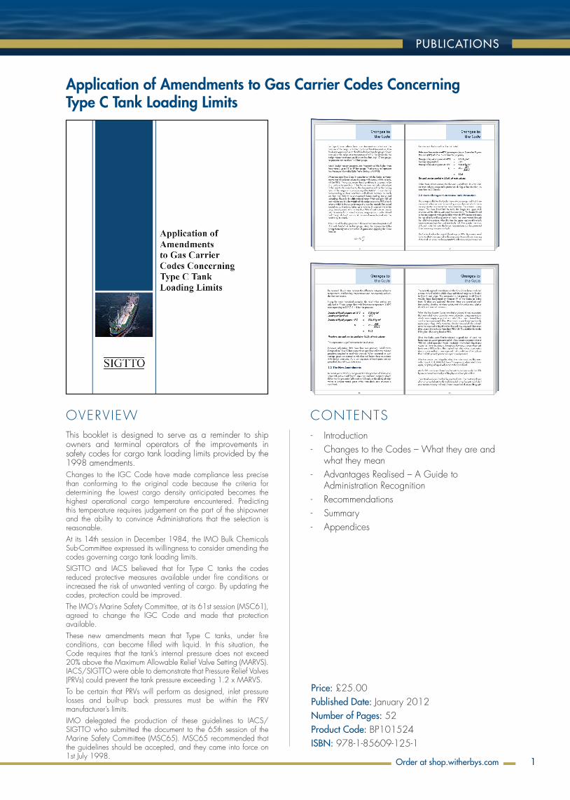
Application of Amendments to Gas Carrier Codes Concerning Type C Tank Loading Limits
- Introduction - Changes to the Codes – What they are and
what they mean - Advantages Realised – A Guide to
Administration Recognition - Recommendations - Summary - Appendices
This booklet is designed to serve as a reminder to ship owners and terminal operators of the improvements in safety codes for cargo tank loading limits provided by the 1998 amendments.Changes to the IGC Code have made compliance less precise than conforming to the original code because the criteria for determining the lowest cargo density anticipated becomes the highest operational cargo temperature encountered. Predicting this temperature requires judgement on the part of the shipowner and the ability to convince Administrations that the selection is reasonable.At its 14th session in December 1984, the IMO Bulk Chemicals Sub-Committee expressed its willingness to consider amending the codes governing cargo tank loading limits.SIGTTO and IACS believed that for Type C tanks the codes reduced protective measures available under fire conditions or increased the risk of unwanted venting of cargo. By updating the codes, protection could be improved.The IMO’s Marine Safety Committee, at its 61st session (MSC61), agreed to change the IGC Code and made that protection available.These new amendments mean that Type C tanks, under fire conditions, can become filled with liquid. In this situation, the Code requires that the tank’s internal pressure does not exceed 20% above the Maximum Allowable Relief Valve Setting (MARVS). IACS/SIGTTO were able to demonstrate that Pressure Relief Valves (PRVs) could prevent the tank pressure exceeding 1.2 x MARVS.To be certain that PRVs will perform as designed, inlet pressure losses and built-up back pressures must be within the PRV manufacturer’s limits.IMO delegated the production of these guidelines to IACS/ SIGTTO who submitted the document to the 65th session of the Marine Safety Committee (MSC65). MSC65 recommended that the guidelines should be accepted, and they came into force on 1st July 1998.
Price: £25.00Published Date: January 2012Number of Pages: 52Product Code: BP101524ISBN: 978-1-85609-125-1
OVERVIEW CONTENTS
CATALOGUE
Order at shop.witherbys.com2 download as a PDF from sigtto.org
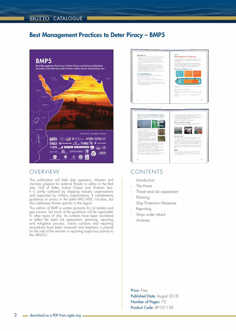
- Introduction - The threat - Threat and risk assessment - Planning - Ship Protection Measures - Reporting - Ships under attack - Annexes
This publication will help ship operators, Masters and mariners prepare for external threats to safety in the Red Sea, Gulf of Aden, Indian Ocean and Arabian Sea. It is jointly authored by shipping industry organisations and supported by military organisations. It complements guidance on piracy in the latest IMO MSC circulars, but also addresses threats specific to the region. This edition of BMP is written primarily for oil tankers and gas carriers, but much of the guidance will be applicable to other types of ship. Its contents have been reordered to reflect the latest risk assessment, planning, reporting and mitigation process. Transit corridors and reporting procedures have been reviewed and emphasis is placed on the role of the mariner in reporting suspicious activity to the UKMTO.
Best Management Practices to Deter Piracy – BMP5
Price: FreePublished Date: August 2018Number of Pages: 72Product Code: BP101138
OVERVIEW CONTENTS
PUBLICATIONS
3
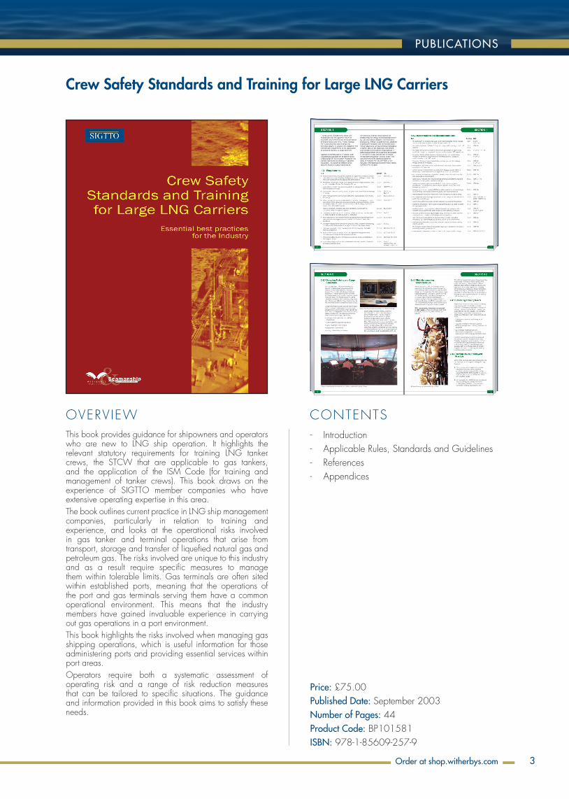
Crew Safety Standards and Training for Large LNG Carriers
- Introduction - Applicable Rules, Standards and Guidelines - References - Appendices
This book provides guidance for shipowners and operators who are new to LNG ship operation. It highlights the relevant statutory requirements for training LNG tanker crews, the STCW that are applicable to gas tankers, and the application of the ISM Code (for training and management of tanker crews). This book draws on the experience of SIGTTO member companies who have extensive operating expertise in this area. The book outlines current practice in LNG ship management companies, particularly in relation to training and experience, and looks at the operational risks involved in gas tanker and terminal operations that arise from transport, storage and transfer of liquefied natural gas and petroleum gas. The risks involved are unique to this industry and as a result require specific measures to manage them within tolerable limits. Gas terminals are often sited within established ports, meaning that the operations of the port and gas terminals serving them have a common operational environment. This means that the industry members have gained invaluable experience in carrying out gas operations in a port environment. This book highlights the risks involved when managing gas shipping operations, which is useful information for those administering ports and providing essential services within port areas. Operators require both a systematic assessment of operating risk and a range of risk reduction measures that can be tailored to specific situations. The guidance and information provided in this book aims to satisfy these needs.
Price: £75.00Published Date: September 2003Number of Pages: 44Product Code: BP101581ISBN: 978-1-85609-257-9
Order at shop.witherbys.com

4
OVERVIEW CONTENTS
CATALOGUE
order at Witherbys.comOrder at shop.witherbys.com
21
Overflow Control and Vacuum Protection
4. Overflow Control and Vacuum Protection
Overflow control and vacuum protection are safety systems that perform a critical function on a ship. This section provides a brief overview of IGC Code14 requirements and gives recommendations for overflow control systems, including testing.
4.1 IGC Code Requirements
4.1.1 Vacuum protection
Vacuum protection systems are required for certain cargo tank designs. These systems consist of two independent pressure switches that will send a signal to stop suction of liquid or vapour from the cargo tanks (IGC Code 8.3.1.1).
This requirement is distinct from ESD systems, as it is contained in Chapter 8 of the IGC Code, Vent systems for cargo containment. This is a system designed to protect the cargo tank from damage. The function of vacuum protection systems may also be achieved by activating the ESD system (IGC Code 18.10.4.1). Figure 4 shows vacuum protection options.
Activate cargo ESD
Stop pumps (cargo mode)
Stop compressor (cargo mode)
Stop compressor (reliquefaction mode)
Vacuum protection (cargo tank)
Figure 4: Vacuum protection options
4.1.2 Overflow control
Chapter 13 of the IGC Code requires overflow control to be provided for cargo tanks using two sensors that are both independent of the gauging system and of each other. For quick reference, notable requirements of the current IGC Code have been listed in Annex 1.
Overflow control is an independent safety system, but it may use the ESD system to achieve its function, as shown in Figure 5. To prevent a cargo tank from becoming liquid full, it may use an ESD valve. It may also activate the ESD system for a full cargo shutdown to prevent excessive pressure in the loading line.
Close valves (cargo tank) Overflow control (cargo tank)
Activate cargo ESD
Figure 5: Overflow control options14 IMO – International Code for the Construction and Equipment of Ships Carrying Liquefied Gases in Bulk (Reference 1)
22
Overflow Control and Vacuum Protection
The alarm required by IGC Code 13.3.1 provides a warning that the cargo tank is approaching a high level. As this sensor is independent of the gauging system, it can also serve to protect against level gauge failure. The sensor required by IGC Code 13.3.2 protects against overfilling caused by gauge failure, operator error or if the tank filling valve leaks after being shut.
The section on overflow control also specifies verification, testing and interlock measures to reduce the risk of sensor failure.
4.2 Recommendations for Overflow Control
Although the IGC Code does not require overflow control for all types of cargo tanks, this is usually fitted in practice. Consequently, it is recommended to exceed the scope of the IGC Code guidance and fit overflow control for all cargo tanks, including any coolant tanks on deck.
The layers of protection and the possible degradation factors can be seen in the highly simplified bowtie in Figure 6. If the high-level alarm (IGC Code 13.3.1) and automatic shutoff valve (IGC Code 13.3.2) are independent of the gauging system, and of each other, then they can fulfil the function of a barrier. By definition, a preventative barrier should be able to stop the threat independently.
Loss ofcontainment
Hydrocarbon(methane/propane)
Overflow of cargotank
Level alarm sensorfail
Level alarm sensorfail
Periodic prooftest (13.3.5)
Interlock withmanifold valve
(18.1, Table – Note 4)
Override is timelimited to maximum
45 seconds
Pre-operations testing (18.10.5)
Level alarmoverride on
Periodic proof test (13.3.5)
Pre-operationstesting (18.10.5)
Cargo transferis planned and
monitored
High-level alarmand operator
action (13.3.1)
Automatic actuateshutoff valve/ESD (13.3.2)
Figure 6: Simplified bowtie showing overflow threat15
Failure of the overflow control system is shown as escalation factors and these are mitigated by pre-arrival testing and periodic proof testing.
Overflow control is an independent safety system, but it can make use of parts of the ESD system to achieve its function. For example, the shutoff valve on the cargo tank could be a dedicated valve for overflow control. However, if there is already an ESD valve at the cargo tank, then the overflow control can use this valve to achieve the function and operate the valve individually (ie without activating a full ESD).15 IMO – International Code for the Construction and Equipment of Ships Carrying Liquefied Gases in Bulk (Reference 1) – references in bowtie
14
ESD Systems
Ship ESD valves (seconds)
Terminal ESD valves (seconds)
Terminal ERS valves (seconds)
Ship loading 25 – 30 10 – 15 -
Ship discharge 25 – 30 30 – 60 Minimum 5
Table 2: Suggested valve timings
Although the IGC Code does not require ESD valves at the cargo tank for tanks 0.07 MPa and below, these are usually fitted in practice. Consequently, it is recommended to extend the IGC Code guidance and fit ESD valves on all liquid and vapour lines, even for tanks 0.07 MPa and below.
It is useful to note that master gas valves (MGVs) are part of the gas burning safety system (GBSS), which is covered by the IGC Code in Chapter 16. Although an MGV is similar to an ESD valve, it is not an ESD valve and is not part of the ESD system.
3.2.2 Liquid detection in the vent system
On rare occasions, there is a possibility of cargo liquid presence in the vent system. This possibility is sufficiently serious to justify fitting additional liquid sensors to detect this event.
As there is very low probability of liquid in the vent system, these sensors should not generate spurious activations. The design of the liquid sensors should prevent them from being overridden. The liquid sensors should trigger a full ESD on detection of liquid. See Initiator 4 – Liquid detection (cargo vent) in Table 3.
These sensors should be placed in suitable locations in the vent system to detect the presence of liquid. The location of these sensors should be as close to the potential source as practicable. This will help to minimise the amount of liquid that escapes into the vent system. Multiple locations may need to be fitted with sensors to achieve this goal.
These sensors should detect liquid directly, using a float type or equivalent method, and should not be based on temperature or gas detection. The system should be designed so that it does not activate when only cargo vapour is present.
3.2.3 ESD function overview
This section provides an overview of ESD systems. The primary functions of ESD are set by the IGC Code. The interface of ESD with related systems can be seen in Table 3.
Analysis of credible scenarios helps to improve understanding of the necessary functions of a safety system. For example, as shown in Figure 2, fire detection in the cargo area would most likely be the result of loss of containment of flammable cargo. In this circumstance, a suitable system should lead to full shutdown of cargo transfer operations and any gas burning in the engine room.
15
ESD Systems
Hydrocarbon(methane/propane)
Unignitedrelease
Ignited release
Unignitedrelease
Ignitedrelease
Loss ofcontainment
Hydrocarbon(methane/propane)
Loss ofcontainment
Push-button(ESD –
18.10.3.1)
Refer to unignited
release barriers
Fire detection(ESD –
18.10.3.2)
Fire protection(water spray
system – 11.3)
Liquid detectionin cargo
vent systemGas detection
Overpressure
Transfer pipingfailure
Process pipingfailure
Overflow of cargo tank
Overflow ofcargo tank Cargo transfer
is planned andmonitored
High-level alarmand operator
action (13.3.1)
Automatic actuateshutoff valve/ESD (13.3.2)
Cold spill
Figure 2: Simplified bowties for loss of containment11
In the simplified bowties, it is clear that manual activation of ESD is a barrier on the right side (push-button 18.10.3.1). Barriers on the right are recovery barriers that are meant to mitigate the effects of the top event (loss of containment). The design of gas carriers incorporates manual ESD activation as an important aspect of the safety case.
In the above scenario, loss of containment is the point when control of the process has been lost. It is important that personnel are trained to understand the exact point when control of the process has been lost and the importance of manual ESD activation. This can reduce any hesitancy to manually activate the ESD push-button to stop work in an emergency.
When the cargo ESD is activated, it is recommended to follow the IGC Code principle and “return the cargo system to a safe static condition”. There are four initiators shown in Figure 3, but additional initiators may be received from related systems, such as overflow control, vacuum protection and the GBSS.
11 IMO – International Code for the Construction and Equipment of Ships Carrying Liquefied Gases in Bulk (Reference 1) – references in bowtie
- Introduction and Scope - Key Safety System Philosophies - ESD Systems - Overflow Control and Vacuum Protection - Gas Burning Safety System - Ship Shore Link - Emergency Release Systems - Annexes
This document provides recommendations for ESD and related safety systems, including overflow control, ship shore link and emergency release systems. Guidance for testing these systems is provided and bowties are used to help explain the IGC Code requirements. In addition to discussing the requirements of the IGC Code, this document recommends additional measures for linked ESD systems for LPG. An overview of the types of ship shore link systems that are typically used in the industry is provided in the annexes, including guidance for cyber security issues associated with linked ESD systems. This new document updates and replaces the previous publication, ESD Arrangements & Linked Ship/Shore Systems for Liquefied Gas Carriers (2009).
ESD Systems, Second Edition
Price: FreePublished Date: 2021Number of Pages: 66ISBN: 978-1-85609-998-1
download as a PDF from sigtto.org

5
OVERVIEW CONTENTS
PUBLICATIONS
Order at shop.witherbys.com
- Introduction - Preliminary Conditions - General Precautions - Precautions for LNG Carriers - Precautions for LPG Carriers - Precautions in Vessels Under Construction - Summary - Appendices
This guide was prepared to draw attention to the high number of serious casualties that have occurred involving fires in the cargo containment system of liquefied gas carriers, whilst vessels have been in shipyards. The guide proposes risk mitigation measures to those responsible for managing these activities.
Fire Prevention in the Cargo Containment Systems of Liquefied Gas Carriers in Shipyards
Price: FreePublished Date: 2001Number of Pages: 14
download as a PDF from sigtto.org

6
OVERVIEW CONTENTS
CATALOGUE
order at Witherbys.comOrder at shop.witherbys.com
- Introduction and Scope - Technical Assessment - Operations
The purpose of this document is to provide guidance that covers all stages in a floating LNG installation project, from accurate assessment of the site through to safe operational status.This document covers two critical areas when considering floating LNG installations:1. Technical assessment2. OperationsThe technical assessment section provides guidance on the considerations for a floating LNG installation project. This includes pre-front-end engineering design and front-end engineering design (pre-FEED/FEED) data collection and design criteria, physical location and site assessment, the applicable floating LNG installations to consider and project overview from commissioning to end of life.The operations section reinforces best practices for the safe operation of floating LNG installations and their associated infrastructure. Recommendations are based on mitigating identified risks and hazards.
Floating LNG Installations, First Edition
Price: £225.00Published Date: 2021Number of Pages: 104Product Code: BP105232ISBN: 978-1-85609-963-9
7
OVERVIEW CONTENTS
PUBLICATIONS
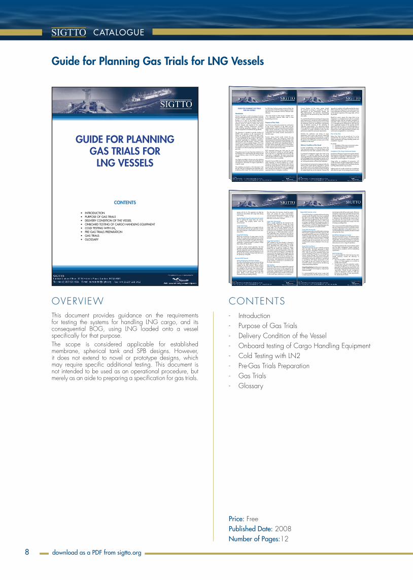
9.2.2 Leak Testing for Mark containment systems
9.2.2.1 Ammonia test
The tightness of the primary membranes of the Mark type containment system is checked bycarrying out an ammonia test. For this test all the weld seams on the primary membrane are paintedwith a reactive yellow paint and ammonia is injected in the bottom of tank under test. The followingconcentration shall be observed 25% at the bottom and at least 1% at the top of the capacity undertest.
If the paint in contact with ammonia turns purple or blue, all defects shall be repaired. The test isconducted during 20 hours (after all the reference leaks left on purpose in the tank have reacted).
Nippon Kaiji Kyokai (NKK) has conducted numerous tests and has established the curves shownbelow which relate the porosity size to the holding time of the tests.
Similarly and in view of the simplicity of conducting tests using a tracer gas, helium tests areperformed to locate the possible defects on the corrugated membrane of existing vessels.
9.2.2.2 Secondary Barrier Testing for Mark Systems
The integrity of the Mark systems primary and secondary barriers is also by vacuum testing andfollows the same general principles as described in 9.2.1.2 for NO systems, though the details ofthe tests are different.
Once all defects detected by ammonia testing have been repaired the primary membrane can beconsidered as perfectly tight; a Vacuum decay test is conducted during the whole time wherescaffolding are dismantled from the tanks.
The secondary membrane of the Mark type containment systems requires a proof of tightness thatis different to that for the secondary membrane of the NO type systems, since the former isdesigned to be liquid-tight but not gas-tight.
The test is performed by creating a differential pressure between the primary space and thesecondary space and recording the behaviour over a certain period of time. The data obtained priorto ship’s delivery are kept as reference and utilised for comparison purposes during the vessel’slifetime.
Ammonia concentration: 1%
Minimum
Standard
Maximum
10
8
5
3
20.5 1 2 5 8 10 15
Calculated values
Test Results
Test Holding time in hours
Def
ect
dia
met
er in
µm
48
9.2.2.3 Acceptable porosity of the Mark secondary membrane
From actual experience onboard LNGCs and from laboratory testing, it has been demonstrated to
the satisfaction of maritime administrations that a normalised porosity area (NPA) of 14.5 cm2
per
5,000 m2
of secondary membrane is an acceptable safe threshold, provided that this area is spreadthroughout the area of the containment system and there are no local failures of the secondarybarrier.
A higher NPA is permitted for ships in service, in accordance with GTT procedures, to allow forgradually increasing porosity that may be experienced with increasing numbers of thermal cyclesexperienced by the tanks. As stated in 5.3.6.2 a more stringent value is applied to Mk III vessels.
For ships in operation the procedure shown below will be followed if, during the global checking ofthe secondary membrane, the NPA obtained does not fall within the reference locus, furtherinvestigations utilising a thermographic camera may be undertaken. Recently “multi-probe acoustictests” have been conducted with some success. The test consists of installing ultrasonic probes ina pre-defined pattern on the inner hull, cofferdam bulkheads and primary membrane and thenpulling a vacuum on the insulated space to be tested.
1
2
3
LOCAL CHECK
-400mm Hg
GLOBAL CHECK
RESULT ANALYSIS
Pressure
Time
VACUUM CURVE
Vacuum pumpP
CRITERIA – TGZ NAV 3201
NOT ACCEPTABLE ACCEPTABLE
OK
LOCALIZATION AND CRITERIA – TG2 NAV 3202
REPAIR OK
Thermographic survey
49
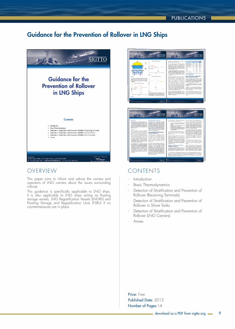
2.3 Conceptual principles of membrane containment systems
From the delivery in 1969 of the first gas ship with a membrane-type containment system, theGaztransport NO 82 system, containment systems constructed to the membrane design concepthave incorporated all the mandatory design features listed above.
The design concept of all membrane containment systems is based on the utilisation of materialswith proven cryogenic and insulation capabilities and on the ability to create and maintain inertatmospheres all around the spaces between the inner hulls and the cargo (see diagrams above).
The insulation spaces around tanks built to membrane cargo containment system designs arepermanently monitored for possible defects using detection methods based on a gas concentrationassessment and continuous temperature monitoring at the secondary membranes and at thedouble-hull levels.
Nitrogen breathing and, if necessary, sweeping of the insulation spaces are key features on shipswith membrane containment systems. The mixture that has circulated in these spaces is analysedfor possible hydrocarbon content before being discharged to a vent mast at a height equal to the
NO Type Mark Type
Pressure Control Pressure Control
Nitrogen InjectionHeaders
Gas Analyser
Gas Analyser
Oxygen content below 3% Vol
Oxygen content below 3% Vol IBS
IS
Secondary Membrane
Primary Membrane
Inner Hull
Gas DomeVentMast
Membrance Principles
9
ship’s breadth divided by three, as per the IGC Code. Such vent masts on a liquefied natural gasCarrier (LNGC) of 145,000m3, for example, would extend at least 13 meters above the trunk deck.
The main safety features incorporated into the design of a membrane LNG carrier to prevent thelow-temperature cargo coming into contact with and damaging the ship’s steel structure are thedouble barriers of the containment system itself. Each of these barriers consists of a thin membranemade of material able to withstand and absorb thermal contraction backed by a layer of insulation.
The primary barrier is the inner element which comes into contact with the cargo and is designedto contain that cargo. The secondary barrier is the liquid-resistant outer element of the cargocontainment system. It, too, is designed to carry out a specific task as laid down in the IGC Code,i.e. to contain any envisaged leak of liquid cargo through the primary barrier for a period of 15 days.During this time the temperature on the double hull must not drop to or below a level which woulddamage the capabilities of the marine steel grades used in the ship’s construction.
The distributions of the steel grades which are to form the inner hull are selected at the design stageby considering the worst possible environmental conditions and a full LNG flooding of the primaryspace. A temperature chart of the inner hull is drawn and checked against the capabilities of marinesteel grades with a rather comfortable margin. A sample of such a temperature chart is shownbelow.
Temperature chart for steel grade distribution
USCG CONDITIONS IGC CONDITIONS
External air temperature -18ºCWind 5 Knots
Sea Water temperature 0 ºCLNG on Secondary barrier
External air temperature -18ºCWind no
Sea Water temperature 0 ºCLNG on Secondary barrier
-21.8
-22.5
-22.4
-10.4
-1.6
-3.5
-27.1
-25.8
-25.7
-13.9
-5.2
-7.1
Insulation thickness
Secondary 0.300 m
Primary 0.230 m
-2.9
-3.9
-3.5
-1.6
-3.5
-7.7
-7.5
-5.2
-7.1
-7.1
LNG Cargo Temperature-163 ºC
Air inside Cofferdams 5 ºC
-22
-26
-Air temperature insidecompartment in ºC
Inner Hull Steel Plating
(tempearture in ºC)
-9.5
-4.3
10
GAS CONCENTRATIONS
IN THE
INSULATION SPACES
OF
MEMBRANE LNG CARRIERS
March 2007
Notice of Terms of Use
While any advice given in this document has been developed using the best information currently available to the Societyof International Gas Tanker and Terminal Operators Ltd (SIGTTO) as received from its membership, it is intended purelyas guidance to be used at the user’s own risk. No responsibility is accepted by SIGTTO, or any officer, director, employee,representative or the membership of SIGTTO, or by any person, firm, corporation or organisation who, or which, has beenin any way concerned with the furnishing of information or data, the compilation or any translation, publishing, supply orsale of the document for the accuracy of any information or advice given in the document or any omission from thedocument or for any consequence whatsoever resulting directly or indirectly from the compliance with or adoption of inwhole or in part any guidance contained in the document even if caused by a failure to exercise reasonable care.
1
SIGTTO
- Introduction - Background and Design Parameters - Statutory and Flag State Requirements - Systems and Equipment - Risk Assessment - Insulation Space Pressurisation - normal
conditions - Insulation Space Pressurisation - abnormal
conditions - Monitoring and Recordkeeping - Membrane Testing - Vetting and Condition Assessment - Training Requirements for Crew Responsible
for the Operation of Membrane LNG Containment Systems
- Control of Emissions - Conclusions - Appendices
This guidance document examines the gas concentrations likely to be found in the insulation spaces of membrane LNG ships, and determines, by good engineering practice, an acceptable upper limit.
Gas Concentrations in the Insulation Spaces of Membrane LNG Carriers
Price: FreePublished Date: 2007Number of Pages: 77
download as a PDF from sigtto.org
8
OVERVIEW CONTENTS
CATALOGUE
order at Witherbys.comOrder at shop.witherbys.com
spaces with dry n2. this operation can often be carried out concurrently with cargo tank drying and inerting.
equator ring n2 Purge (for spherical tank vessels)Prior to putting the cargo tanks into service, the equator ring purging system must be commissioned.
Cargo Tank dryingcargo tanks and pipelines are purged with dry air produced by the inert gas generator and the dew point reduced in these spaces to lower than minus 20°c.
Cargo Tank inertingbefore the introduction of cargo vapour into the system, the cargo tanks and pipelines are inerted to further reduce the dew point and reducing the o2 content to a level that is insufficient to support combustion. a typical target o2 content is a level that is below 2% by volume.
In order to mimic normal operation, the tank inerting is carried out using shipboard equipment. however, dependent upon the requirements of the selected lnG terminal, it may be necessary to use n2 gas for the inerting of cargo tanks that are to be ‘gassed up’ alongside.
arrival at lnG Terminal
Testing of emergency Shut down Systemsthe extent of testing that can be carried out during Gas trials will usually depend upon the system installed at the lnG terminal. where primary and back up ship/shore communication systems are installed at the terminal, then testing of the corresponding vessel’s systems is recommended. once the vessel is securely moored at the lnG berth, details of the pending gas trials are discussed at the pre-loading meeting.
the ship–shore link functions should be tested. these will include the voice communication channels and the data transfer channels, including mooring tension monitoring, in addition to the esd alarm and function channels.
Cargo Tank ‘Gassing-up’lnG is usually supplied by the terminal to the shipboard lnG vaporiser through the spray line and the generated vapour is directed to the cargo tanks. the inert gas displaced from the cargo tanks may be directed ashore, according to the terminal’s requirements. typically the target for gassing up is a 98% hydrocarbon content in each applicable tank. Gassing-up may only be carried out in those tanks that are scheduled for cooling and loading while the vessel is at the lnG terminal.
Cargo Tank Cool-downlnG supplied to the spray header is directed to the spray nozzles of the cargo tanks to be cooled. boG, generated from tank cooling, is usually discharged to the terminal through the vapour header via the vessel’s gas compressors. tanks are cooled to reduce the temperature of the tank wall and its internal structure at a controlled rate to ensure that the volume of boG is kept within the required limits. for Imo type ‘b’ tanks (spherical tanks and IhI-sPb), control of the cooling rate is critical in order to minimise thermal stresses in the tank structure. tank temperatures are monitored to ensure cooling is carried out in accordance with the design requirements.
lnG loadingwhen the cargo tanks have attained the required temperature, the amount of lnG required for the entire Gas trials process can be loaded into the cooled tanks. displaced boG is discharged to the terminal through the vapour header and manifold, via the vessel’s gas compressors, as necessary.
depart lnG Terminal, at Sea
once lnG loading is complete and the post loading custody transfer formalities have been completed the vessel can usually depart from the terminal. after the vessel has departed the lnG terminal the boG from the loaded cargo tanks is either used as fuel gas, handled by the reliquefaction plant (if installed on the vessel) or thermally oxidised in a gas combustion unit (Gcu), depending upon the readiness of equipment to handle the boG.
Cargo Tank Gassing-upusing the spray pump in one of the tanks containing lnG, liquid is supplied to the lnG vaporiser. the gas generated by the vaporiser is directed to those remaining cargo tanks that were not gassed up, cooled or loaded at the lnG terminal. displaced inert gas from these remaining tanks is usually vented through the forward-most vent mast until a hydrocarbon content is detected in the inert gas stream.
Cargo Tank Cool-downthe remaining tanks are now cooled by spraying lnG into them. the boG generated is either used as fuel gas, reliquefied or disposed of in the Gcu. Only in case of an equipment failure that prevents handling of the gas or, in an emergency, should venting through the forward-most vent mast be performed. tank temperatures should be monitored to ensure the cool-down is carried out in accordance with design requirements. In the final stages of the tank cooling, the liquid lines should be cooled in preparation for the following cargo pump testing sequence.
Cargo Pump Testing (Including main cargo pumps, spray and fuel gas and emergency cargo pumps where provided).
It is recommended that each pump in every tank is tested sequentially, the lnG necessary for these
tests being transferred from tank to tank. where an emergency cargo pump is provided, the gas trials testing programme should incorporate a test of this pump. where emergency tank to tank transfer is designed to be performed by pressurising of the cargo tank, this cargo transfer is not normally performed during the gas trials, except in the case of testing a prototype tank.
If it is a requirement of the shipbuilding specification that any cargo pump can be run using the vessel’s emergency generator as the electric source, it is recommended that this capability be demonstrated during the Gas trials.
Boil-off Gas Management System testing of dual fuel burning or reliquefaction plant operation and Gcu operation is recommended, if applicable. the testing should be for a duration sufficient to demonstrate successful control of cargo tank pressures over a range of operations.
the interfaces between the cargo machinery plant and the boG management system should be demonstrated as compliant with the shipbuilding specification.
dual fuel BurningIt is recommended that dual fuel burning tests should ordinarily include the following as applicable:• Gas burning either in boilers with the steam
dump, or in main engines or in a Gcu, to handle excess boil-off.
• Gas burning in the main propulsion system, including the operation of the plant at the equivalent of 100% gas burning at mcr, with the fuel gas requirements being met by forced vaporisation. should the gas management system be designed to allow for solely gas burning at all ranges of load requirements, this should also be tested.
Guide for PlanninG GaS TrialS for lnG VeSSelS
introduction
the term ‘Gas trials’ is used to encompass those tests that are undertaken during a period when a quantity of lnG is taken onboard for testing shipboard facilities at, or near to, the design temperature. Gas trials are usually carried out prior to the vessel entering service in order to confirm the correct function, integrity and capacity of the complete cargo system, including containment, insulation, cargo handling equipment, pipelines and valves and the equipment to handle boil-off gas (boG).
this document is intended to provide members of sIGtto some guidance on the requirements for testing the systems for handling the lnG cargo, and its consequential boG, using lnG loaded onto a vessel specifically for that purpose. the scope is considered applicable for established membrane, spherical tank and sPb designs. however, it does not extend to novel or prototype designs, which may require specific additional testing. this document is not intended to be used as an operational procedure, but merely as an aide to preparing a specification for gas trials.
the guidance aims to cover those items tested prior to the handover of a vessel and also the testing carried out post delivery, when a first full cargo has been loaded.
any figures provided in the text are only indicative and reference should be made to the shipbuilder and manufacturer’s information for figures applicable to a specific vessel.
the underlying assumption in this document is that the Gas trials are conducted by the shipbuilder prior to delivery of the vessel. this is the common practice
for lnG ships, but by no means exclusive (note, the normal practice in the lPG industry appears to be for the trials to be conducted at the first load port after delivery).
‘Gas trials Guide for lnG vessels’, sname 1977 is an informative reference often cited in lnG shipbuilding contracts.
Purpose of Gas Trials
Gas trials are performed primarily for confirmation of the correct operation of the lnG and gas handling systems, which cannot otherwise be factory tested, and for verification of the correct operation of the equipment and systems that will be used for containment and custody transfer measurement of the lnG cargo.
function testing should usually include the gas management system, the monitoring control and alarm systems for the lnG tanks and liquid pumps, valve operation, the gas compressors, heat exchangers, gas combustion units (Gcu) and reliquefaction plant, if provided. where applicable, dual or tri fuel engines should usually also be included in the test programme in their respective gas burning modes.
boG generated during gas trials may be used either as fuel burnt in boilers or multi-fuel engines, sent to the Gcu, or reliquefied and returned to the cargo tanks, as applicable. the vapour may also be returned ashore while the vessel is alongside the lnG terminal if this facility is available.
disposal of excess boG may be dealt with through steam dumping or thermal oxidising in a Gcu. venting of natural gas to atmosphere, other than to test the vent system operation, should not be included as part of Gas trials procedure and it is suggested that it should only take place if unavoidable through equipment failure or emergency condition.
correct function of the entire system should be confirmed as being in compliance with the requirements of the classification society, the flag administration, the particular ship-building specification for the vessel and any other criteria that may apply.
It is usual that the performance testing of cargo pumps and compressors is carried out at the manufacturer’s facility prior to delivery to the shipyard, to ensure that the equipment meets the specification requirements and to facilitate accuracy of the recording of calibrated measurements. the operational testing of this equipment at full capacity during Gas trials is therefore not usually intended to prove that the performance meets the contractual requirements.
similarly the calibration and testing of cargo temperature, level sensor and pressure measuring devices used for custody transfer purposes, is usually carried out at the equipment manufacturer’s facility in the presence of a third party surveyor, prior to their installation on the vessel.
delivery Condition of the Vessel
a major consideration in the planning of the Gas trials may be the condition in which the vessel is to be delivered to the owner after completion of Gas trials.
If contractual arrangements require the vessel to be delivered in a gas-free condition then any liquid remaining onboard on completion of Gas trials will need to be discharged ashore, necessitating a second visit to the selected lnG terminal. thereafter, cargo tank warm-up, inerting and aeration will have to be undertaken.
If contractual and commercial arrangements allow for delivery of the vessel with the cargo tanks in ‘gassed up’ condition and/or with residual lnG remaining on board, then a second visit to the terminal for discharge of residual liquid may not be required. however the
‘gassed-up’ condition will usually preclude the return of the vessel to the shipyard for any remaining works to be undertaken and certain post trial options, such as the internal inspection of the cargo tanks, will not be possible.
should an owner require the cargo tanks to be subjected to a complete thermal cycle, for example cooling the tanks until the secondary membrane is reduced to -100°c in all regions, this will usually result in an extended period alongside the lnG terminal and a significant increase in the quantity of lnG required for the Gas trials. It is recommended that, in these cases, the requirements are discussed with the shipyard at an early stage and details included in the contractual arrangements for vessel delivery.
Prior to Gas Trials
before Gas trials can be carried out, it is to be expected that the shipyard’s confirmation that the cargo containment and cargo handling systems are completed is required.
to include:• completion of the cargo containment system• onboard testing of cargo equipment• cold testing (with ln2)
Completion of the Cargo Containment System
Irrespective of the type of containment system selected, the inspection and testing of the cargo tank components will usually be undertaken in fabrication shops and onboard the vessel throughout its construction.
cargo tanks, on completion of construction, will usually have been strength and leak tested, at ambient temperature, in accordance with classification society and flag administration requ irements.
tightness tests are usually carried out on membrane tanks after the repair of any leakage found during the
- Introduction - Purpose of Gas Trials - Delivery Condition of the Vessel - Onboard testing of Cargo Handling Equipment - Cold Testing with LN2 - Pre-Gas Trials Preparation - Gas Trials - Glossary
This document provides guidance on the requirements for testing the systems for handling LNG cargo, and its consequential BOG, using LNG loaded onto a vessel specifically for that purpose.The scope is considered applicable for established membrane, spherical tank and SPB designs. However, it does not extend to novel or prototype designs, which may require specific additional testing. This document is not intended to be used as an operational procedure, but merely as an aide to preparing a specification for gas trials.
Guide for PlanninG GaS TrialS for
lnG VeSSelS
ConTenTS
• IntroductIon• PurPose of Gas trIals• delIvery condItIon of the vessel• onboard testInG of carGo handlInG equIPment• cold testInG wIth ln2
• Pre-Gas trIals PreParatIon• Gas trIals• Glossary
Guide for Planning Gas Trials for LNG Vessels
Price: FreePublished Date: 2008Number of Pages: 12
download as a PDF from sigtto.org
9
OVERVIEW CONTENTS
PUBLICATIONS
Order at shop.witherbys.com
- Introduction - Basic Thermodynamics - Detection of Stratification and Prevention of
Rollover (Receiving Terminals) - Detection of Stratification and Prevention of
Rollover in Shore Tanks - Detection of Stratification and Prevention of
Rollover (LNG Carriers) - Annex
This paper aims to inform and advise the owners and operators of LNG carriers about the issues surrounding rollover.This guidance is specifically applicable to LNG ships. It is also applicable to LNG ships acting as floating storage vessels, LNG Regasification Vessels (LNGRV) and Floating Storage and Regasification Units (FSRU) if no countermeasures are in place.
Guidance for the Prevention of Rollover in LNG Ships
Price: FreePublished Date: 2012Number of Pages: 14
download as a PDF from sigtto.org
10
OVERVIEW CONTENTS
CATALOGUE
Order at shop.witherbys.comdownload as a PDF from sigtto.org
Society of International Gas Tanker & Terminal Operators Ltd
Guidance on Gas Carrier and Terminal Gangway Interface
First Edition
- Introduction and Scope - Gangway Systems - Gangway Hazard Management - Design and Operation - Small-scale Gas Carrier Considerations - Annexes
This document provides information on design considerations for the gangway landing areas on ships and the gangway system for terminals. It discusses different gangway types and configurations, and provides recommendations in an effort to maximise safe access to the ship via the gangway. The document encourages the use of a structured risk-based approach to gangway design and provides references for human factors considerations.
Guidance on Gas Carrier and Terminal Gangway Interface, First Edition
Price: FreePublished Date: 2021Number of Pages: 44ISBN: 978-1-85609-969-1
11
OVERVIEW CONTENTS
PUBLICATIONS
Order at shop.witherbys.com
- Prevention of Major Accidents - Emergency Planning - Incident Control - Incident Follow-Up - The Organisation of a Major Emergency
Exercise - Appendices - Illustration of Typical Emergency Plan
Contents List - International Regulations and Guidelines - APELL - Saveso Directives
This book specifically deals with the safe storage and transfer of liquefied gases at marine terminals. It can also be adapted to be used at a terminal that handles any hazardous substance in bulk. It provides terminal management with guidance on contingency planning, including identifying and controlling potential hazards, controlling incidents and the review periods. The first edition of this guide was originally prepared in 1989 by a joint industry working group made up of members from OCIMF, ICS and SIGTTO. The document has been revised and extended to include “Guidelines for Preparing and Co-ordinating a Major Ship/Shore Emergency Exercise”, published by SIGTTO in 1994. A joint action between the International Maritime Organization (IMO) and the Environment Office of the United Nations Environment Programme (UNEP IE) in 1996 adapted an existing process, “Awareness and Preparedness for Emergencies at Local Level (APELL)” to port areas. The APELL process was developed as a response to various industrial accidents that have had a detrimental effect on the environment. The main APELL recommendations for port areas that are included in this publication are the Seveso II Directive (Control of Major Accident Hazard Regulations (COMAH) in the UK), which is applicable to all sites where dangerous substances are located. On and off site emergency plans must be available at sites within the EU where this directive is applicable. This guide is not a code of practice or intended to cover all types of major industrial accident. The local and national legislation should always be considered when using the guide.
A Guide to Contingency Planning for Marine Terminals Handling Liquefied Gases in Bulk, Second Edition
Price: £40.00Published Date: January 2001Number of Pages: 42Product Code: BP101510ISBN: 978-1-85609-215-9
12
OVERVIEW CONTENTS
CATALOGUE
order at Witherbys.comOrder at shop.witherbys.com
This publication explains the concept of surge pressure and provides practical advice on its associated hazards and risk management. It outlines the principal design and operational recommendations for cargo transfer systems and will benefit managers, designers and operators of liquefied gas carriers.This publication provides advice at every level of liquefied gas carrier operation. It encourages a mutual understanding of safe transfer procedures between designers, engineers and operators of both liquefied gas carriers and terminal loading and unloading systems. Readers are also made aware of the factors contributing to surge pressure hazards and the benefits of a linked ship/shore ESD system in mitigating these.
Guidelines for the Alleviation of Excessive Surge Pressures on ESD for Liquefied Gas Transfer Systems
Price: £175.00Published Date: July 2018Number of Pages: 66Product Code: BP101124ISBN: 978-1-85609-767-3
- Introduction and Scope - Surge - Surge Hazards and Risk Management - Recommendations and Guidelines - Annexes
13
OVERVIEW CONTENTS
PUBLICATIONS
Order at shop.witherbys.com
- Background - Types of Odourant - Transportation and Storage of Odourant - Risk Management and Safety - Design, Operation and Maintenance of
Odourant Injection Equipment - Training - Glossary of Terms - Appendices
This publication is a reference guide for operational and commercial staff in the LPG shipping and terminal industries. It is supported by photographs and diagrams that illustrate safe transportation and storage of gas odourants. It also includes a table that outlines material compatibility with ethyl mercaptan odourant.These guidelines were produced following notification to the SIGTTO Secretariat of several potentially dangerous incidents involving odourants. Detail is given on personal, environmental and business risk management. The capabilities and limitations of odourant injection equipment are also included. These guidelines should be written into charter parties when shipboard odourisation is to take place.
Guidelines on the Ship-Board Odourisation of LPG
Price: £40.00Published Date: September 2000Number of Pages: 28Product Code: BP101692ISBN: 978-1-85609-209-8
14
OVERVIEW CONTENTS
CATALOGUE
order at Witherbys.comOrder at shop.witherbys.com
- Introduction of Water into LPG - The Formation of Hydrates - Avoidance of Ice or Hydrate Formation - Shipboard Test Methods - Hazards Associated with Ice/Hydrates - Summary and Recommendations - References - Appendices
This publication is a technical review of the processes and procedures commonly found in production, storage and transportation of LPG cargoes. It examines the presence of water in LPG cargoes, the formation of hydrates and methods for their elimination.Hydrate formation in cargo systems of refrigerated LPG carriers can damage pumps and other machinery and obstruct cargo handling. This publication, based on a review conducted for SIGTTO by Mr R C Gray of the Technology Department of British Shipbuilders, deals specifically with hydrates forming in commercially dry refrigerated LPG. It identifies the ways in which water can enter and remain within the cargo, leading to the formation of hydrates. It examines different methods to prevent ice and hydrate formation and outlines procedures for cargo tank sampling. The Appendices provide practical information on the propane-water system, use of LPG freeze valves and the addition of methanol as a treatment method.
Hydrates in LPG Cargoes
Price: £75.00Published Date: July 2008Number of Pages: 50Product Code: BP100523ISBN: 978-1-905331-27-7
15
OVERVIEW CONTENTS
PUBLICATIONS
Order at shop.witherbys.com
- General Maintenance Principles - Topsides - Substructure - List of Abbreviations - Bibliography - Index
This guide provides information on effective maintenance of critical items of equipment for both oil and liquefied gas terminal jetties. It advises on possible failure modes for each item of equipment and also discusses proactive and reactive maintenance strategies.Reliable equipment at the jetty is vital for safe transfer of cargo between the ship and shore.Maintenance of this equipment is particularly important because of the harsh environmental conditions often experienced.This guide provides information on the basic function, failure, inspection, maintenance and repair of all the key equipment items and systems. It is not intended to provide guidance on safety management procedures or to replace the manufacturers’ instruction manuals. However, it is designed to provide a description of a typical jetty and the likely faults that may occur if maintenance work is not carried out regularly.
Jetty Maintenance and Inspection Guide
Price: £175.00Published Date: September 2008Number of Pages: 118Product Code: BP100334ISBN: 978-1-85609-343-9

16
OVERVIEW CONTENTS
CATALOGUE
Order at shop.witherbys.com
- Background - Research - Electrical Characteristics of Cargo Transfer
Hoses - Supporting Calculations - Inductive Circuits - Examples Showing the Effects of Hose
Resistance and Inductance - Effect of Capacitance - Multiple Loading Arms and Parallel Circuits - Testing of Insulation Flanges - Conclusions and Recommendations - References - Definitions - Appendix - Acknowledgements
Insulation flanges have been in wide use for more than three decades and, while there have been no reported incidents of fires at tanker or gas carrier manifolds that may have been caused by arcing when connecting or disconnecting cargo hoses or arms, their use and effectiveness is still often challenged.The purpose of this document is to provide an explanation of how insulation flanges provide protection against ignition caused by arcing.
A Justification into the Use of Insulation Flanges (and Electricity Discontinuous Hoses) at the Ship/Shore and Ship/Ship Interface
Price: FreePublished Date: 2014Number of Pages: 14
download as a PDF from sigtto.org
17
OVERVIEW CONTENTS
PUBLICATIONS
Order at shop.witherbys.com
- Introduction - Carriage of Liquefied Gases by Sea - Hazards and Risks of Liquefied Gas Cargoes - Flammability - Toxicity - Enclosed Spaces - Basic Firefighting - Pollution Prevention - Emergency Procedures - Definitions and Descriptions
This pocketbook provides easy to understand safety guidance that should be followed by all personnel serving on board liquefied gas carriers. It describes the hazards associated with liquefied gas products and sets out essential safeguards to protect life, the environment and the cargo being carried.This publication highlights the hazards that may be encountered on board a liquefied gas carrier, such as toxicity, flammability, enclosed spaces and cargo spillage. It examines how these risks may be managed and provides guidance on personal protective equipment (PPE), emergency response and pollution prevention. It also outlines safety management systems (SMS), permits to work (PTW) and safety inspections.
Liquefied Gas Carriers: Your Personal Safety Guide, Second Edition
Price: £25.00Published Date: December 2012Number of Pages: 44Product Code: BP101770ISBN: 978-1-85609-572-3
18
OVERVIEW CONTENTS
CATALOGUE
order at Witherbys.comOrder at shop.witherbys.com
- Characteristics and Hazards of Liquefied Gases
- Liquefied Gas Installations - Liquefied Gas Ships - Principles of Fire Hazard Management - Prevention of Fires and Explosions - The Principles of Fire and Gas Detection - Fire and Explosion Mitigation - Emergency Response Strategies
This book examines fire hazard management in the liquefied gas shipping and terminal industry, with reference to large refrigerated and smaller pressurised storage terminals, ships, cylinder filling plant and road and rail tanker loading racks. It is aimed at operational staff involved in handling flammable liquefied gas, as well as fire officers and other emergency planners who have liquefied gas installations in their jurisdiction.This book provides an insight into the design and operation of liquefied gas installations and the equipment that is essential to their safe and efficient functioning. It describes the properties of flammable liquids and gases and explains how they should be stored and transported. It considers how the risk of combustion can be reduced to an acceptable level and examines the lessons learnt from relevant incidents.Fire hazard management and emergency response strategies are covered in depth, from the contingency planning stage to fire prevention and detection, firefighting media and procedures, personal protective equipment (PPE) and maintenance of critical systems. The book also lists relevant codes, standards and guidelines in use throughout the world.
Liquefied Gas Fire Hazard Management
Price: £175.00Published Date: July 2004Number of Pages: 198Product Code: BP101777ISBN: 978-1-85609-265-4
19
OVERVIEW CONTENTS
PUBLICATIONS
Order at shop.witherbys.com
- Introduction - Properties of Liquefied Gases - Principles of Gas Carrier Design - The Ship — Equipment and Instrumentation - The Terminal — Equipment and
Instrumentation - The Ship/Shore Interface - Cargo Handling Operations - Cargo Measurement and Calculation - Personal Health and Safety
This publication covers every aspect of the safe handling of bulk liquid gases (LNG, LPG and chemical gases) on board ships and at the ship/shore interface.Liquefied Gas Handling Principles on Ships and in Terminals emphasises the importance of understanding the physical properties of gases in relation to the practical operation of gas handling equipment on ships and at terminals.In the sixteen years since this publication was last updated, the liquefied gas shipping and terminal industry has undergone considerable change.?This revision reflects these changes, providing updated information on ship design, propulsion systems, size of fleet, floating regasification and reliquefaction, Arctic LNG, containment systems, efficiency increases in operations, ship capacities, technology, best practice and legislation.This title incorporates ‘Quantity Calculations LPG and Chemical Gases, 2nd Edition’ (SIGTTO).
Liquefied Gas Handling Principles on Ships and in Terminals, Fourth Edition
Price: £275.00Published Date: July 2016Number of Pages: 568Product Code: BP100834ISBN: 978-1-85609-714-7

20
OVERVIEW CONTENTS
CATALOGUE
order at Witherbys.comOrder at shop.witherbys.com
- Taking Samples of Liquefied Gas Cargoes - Summary - Bibliography
This book is a guide to liquefied petroleum gas sampling procedures and contains updated recommendations produced by a working group made up of several industry experts and coordinated by SIGTTO.This publication is a comprehensive guide to liquefied petroleum gas sampling. It covers the entirety of the process from beginning to end and looks at:• The basic reasons for taking cargo samples• Sampling connections, eg open and closed loop systems• Types of sample containers• Recommended standard sample connections• Safe procedures for taking samples.It has been fully updated by a working group made up of several industry experts and coordinated by SIGTTO.
Liquefied Petroleum Gas Sampling Procedures
Price: £25.00Published Date: May 2010Number of Pages: 28Product Code: BP100662ISBN: 978-1-905331-99-4
21
OVERVIEW CONTENTS
PUBLICATIONS
i
SIGTTO LNG and LPG Experience Matrix Guidelines for Use
6
LNG Officer Experience Matrix
Navigating Officer Sea Time - All Vessels
Combined Sea Time Individual Minimum Sea Time as Certificated Officer
Master 4 years at chief officer or above
4 Years
Chief Officer 2 Years
Navigating Officer LNG Specific Sea Time
Combined Sea Time Individual Minimum Sea Time as Certificated Officer
Master 2 years in rank on LNG vessels
4 years sea time with another Dangerous Cargo Endorsement, then a Min 30 days intensive training (to include at least one load and discharge operation) + completion of SIGTTO competency standards training for LNGor, 2 years LNG specific experienceor, 2 years LPG experience + completion of SIGTTO competency standards training for LNG.
Chief Officer 2 years experience with another Dangerous Cargo Endorsement then a Min 30 days intensive training (to include at least one load and discharge operation) + completion of SIGTTO competency standards trainingor 1 year LNG specific experienceor 1 year LPG experience + completion of SIGTTO competency standards training for LNG.
Engineering Officer Sea Time – All Vessels
Combined Sea Time Individual Minimum Sea Time as Certificated Engineering Officer
Chief Engineer 4 years at second engineer or above
4 Years
2nd Engineer 2 years
Engineering Officer Steam LNG Vessel Sea Time
Combined Sea Time Individual Minimum Sea Time as Certificated Engineering Officer
Chief Engineer 2 years in rank on steam LNG vessels
4 years diesel sea time with a minimum of 30 days intensive training + completion of SIGTTO competency standards training for LNG + Completion of SIGTTO competency standards for steam engineers and the appropriate steam endorsement for the rank.or, 2 years steam sea time and completion of SIGTTO competency standards for steam engineersor, two years steam LNG sea time.
2nd Engineer 2 years diesel sea time with a minimum of 30 days intensive training + completion of SIGTTO competency standards training for LNG + Completion of SIGTTO competency standards for steam engineersor, 1 year steam sea time and completion of SIGTTO competency standards for steam engineersor, 1 year steam LNG sea time.
Gas Engineer 1 year as a certified engineering officer on an LNGCor a minimum of 30 days intensive training + completion of SIGTTO competency standards training for LNG (Note 4)
7
Engineering Officer Diesel & Diesel Electric LNG Vessel Sea Time
Combined Sea Time Individual Minimum Sea Time as Certificated Engineering Officer
Chief Engineer 2 years in rank on LNG vessels
4 years steam and/or diesel sea time with a minimum of 30 days intensive training + completion of SIGTTO competency standards training for LNG (unless 1 year completed on LNG vessels) (Notes 4 + 5 + 6)
2nd Engineer 2 years steam and/or diesel sea time with a minimum of 30 days intensive training + completion of SIGTTO competency standards training for LNG (unless 1 year completed on LNG vessels) (Notes 4+5 +6 )
Gas Engineer 1 year as a certified engineering officer on an LNGCor, a minimum of 30 days intensive training + completion of SIGTTO competency standards training for LNG (Notes 4 + 6)
Note:
1. 1st Officer and 1st Asst. Engineer terminology considered equivalent to Chief Officer and 2nd Engineer for the purposes of these guidelines.
2. Seatime refers to time onboard a vessel and may include an allowance for time served working in a relevant capacity within the ship management office, standing by a new build or conversion or laid-up. Such time shall be treated as 1/3rd actual time, up to a maximum period of one year.
3. Intensive training to be for not less than 30 days in the rank the individual will be assuming on an LNG vessel. Such individual shall also be required to have completed the relevant SIGTTO competency standard training commensurate with the position. During this time the Observer should become familiar with the company’s SMS Manuals as a whole, but specifically as they affect their position onboard.
4. Senior engineering officers sailing on vessels with gas combustion units and reliquefaction
plants and other ship specific equipment should have thorough equipment specific training on its operation and maintenance.
5. Engineer officers sailing on vessels with DE should have thorough equipment specific training on the operation and maintenance.
6. Sea time assigned to new building and/or repair to be credited as experience up to a maximum of 3 months.
7. Companies should ensure that procedures are in place to ensure that adequate time and familiarisation is given for relieving officers to become fully appraised of the differences in operation and limitations of a containment system with which they have no or limited experience. This should consist of at least one cargo operation.
8. For combined LNG/LPG carriers, some relaxation of these requirements may be considered if it can be demonstrated that the officer has experience with liquefied gases in a similar containment system.
3
Summary
The Matrix is one of many tools that may be used to determine if personnel are acceptable from a safety perspective and it is important to appreciate that the Matrix is offered as a tool for evaluating and managing risk.
When evaluating risk, in the event of non-compliance with a particular element of the Matrix, consideration should be given to other mitigating
factors. These should include (but not limited to) bespoke training, the manning scale in place, time served with the ship owner or operator and the wider competence management systems employed by the owner or operator as to officer recruitment and development, including competency standards such as the Society’s ‘LNG Shipping Suggested Competency Standards’ and the ‘LPG Shipping Suggested Competency Standards’ (the ‘SIGTTO Competency Standards’).
4
Recommendations
1. The charterers of LNG/LPG carriers and operators of LNG/LPG terminals are recommended to adopt the Matrix voluntarily as their standard, for the sake of having consistent safety standards across the industry.
2. The Matrix should be one of many tools used to consider whether personnel are suitable or not and should not be the sole tool.
3. The charterers of LNG/LPG carriers and operators of LNG/LPG terminals should
not reject a ship for the sole reason that an individual officer falls short of a threshold requirement in the Matrix, at least not without wider consideration being given.
4. A risk based approach that considers both experience and competence is to be preferred and a combination of compliance with the requirements of the Matrix and the SIGTTO Competency Standards is encouraged, alongside the use of other available risk management tools.
- Present Situation - Summary - Recommendations - Annex
In the years since the Matrix was published, it has been brought to the attention of the Society that some terminals and charterers are applying it prescriptively, so that the levels of experience are considered to be minimum thresholds, where any shortfall is unacceptable (no matter how small). By contrast, the Society’s accompanying recommendation to the Matrix is that: “in the event of non-compliance with a particular element of the experience matrix, consideration should be given to other mitigating factors, including bespoke training, the manning scale in place, time with the LNG/LPG ship owner/operator and the wider competence management systems employed by the ship operator in officer recruitment and development”. It was, therefore, agreed at GPC 73 (and subsequently approved by the board in May 2016) that the Secretariat should issue further guidance as to the recommended application of the Matrix in the assessment and management of risk.
LNG and LPG Experience Matrix Guidelines for Use
Price: FreePublished Date: 2016Number of Pages: 12
download as a PDF from sigtto.org
22
OVERVIEW CONTENTS
CATALOGUE
order at Witherbys.comOrder at shop.witherbys.com
- Introduction and Scope - Emergency Release Systems (ERS) - Recommendations, Guidelines and
Best Practices - Primary and Secondary Purposes - Risks
This guide sets out best practice for the operation and maintenance of LNG emergency release systems (ERS), with the aim of safeguarding personnel, the environment and property during LNG operations.Developed with the input of manufacturers, terminal operators and LNG shippers, this publication applies a risk-based approach covering the structure and operation of ERS. It sets out guidelines and best practices for ERS usage and also examines ERS hazards and risk management. The annexes provide competencies and training guides and suggested further reading.
LNG Emergency Release Systems. Recommendations, Guidelines and Best Practices
Price: £125.00Published Date: January 2017Number of Pages: 97Product Code: BP100981ISBN: 978-1-85609-730-7
23
OVERVIEW CONTENTS
PUBLICATIONS
10
2nd Stage: Draining of Ship Side Liquid MLA & Manifold Piping
Valve Open Valve Closed Open-Close Check Pressure Gauge
LNG flow N2 flow Full Drained: Gas <4.5% Purged Gas <2%
ESD
N2 supply
ESD
ESD by-pass
Pressure gauge
Spray header to designated cargo tank
Manifold drain
Cool down bypassArm drain
Manual
e.g.; Jetty KnockOut Drum, etc.
Drain
Always closed
Ship’s side Shore Side
ESD cool-down
Double shut
Vent& Quick Coupling
1. Verify that terminal has closed the MLA purgevalve. Verify that Shore N2 supply valve is open.
2. Open ship’s ESD valve*. Confirm MLA’s valve isopen. Monitor the pressure. Listen to the cargoflowing. When pressure suddenly drops andliquid flow stops, close the cool down valve.
3. Allow pressure to rise to 3 to 5 bar and Openthe cool down valve until pressure drops to0.5 bar. Close cool down valve.
4. Repeat step 3 one more time. N2 pressure canbe lower but not less than 2 bar. (Empty cargopiping needs much more nitrogen)
* ESD valve may remain closed during this process on theterminal’s request. This will increase the number of cyclesrequired to achieve the 2nd stage draining objective.
5. Open Vent valve slowly. Check methane %by volume through vent valve and if it is lessthan 4.5%, crack open manifold drain valveto verify that piping is dry. A few droplets mayinitially be observed. If you observe free liquidflow close, the manifold drain valve and repeatsteps 4 and 5. If the piping is dry, check the gascontent at the MLA’s drain valve.
6. Upon verifying that piping is liquid free and thatthe methane % by volume is less than 4.5% atthe manifold drain valve, close the drain valve.Verify that the MLA drain valve is closed.Proceed to Stage 3.
11
3rd Stage: Gas Freeing of Ship Side Liquid/Vapor MLA & Manifold Piping
Valve Open Valve Closed
Double shut
Open-Close Methane Check
Pressure Gauge
LNG flow N2 flow Full Drained: Gas Purged Gas <2%
ESD
Vent valve & Quick Coupling
N2 supply
ESD
ESD by-pass
Pressure gauge
Spray header to designated cargo tank
Manifold drain
Cool down ESD cool-down bypass Arm drain
Manual
e.g.; Jetty Knock Out Drum, etc.
Drain
Always closed
Ship’s side Shore Side
1. Close the ship’s ESD valve. Close the ship’s ESDbypass valve. Let pressure rise to 3 to 5 bar.
2. Open ship’s ESD by-pass valve until pressuredrops to 0.5 bar. Close the ship’s ESD bypassvalve.
3. Open Vent valve slowly. Check the methane %by volume through vent valve. If reading is lessthan 2% methane % by volume, Open ManifoldDrain valve and measure Methane % by volumeto read less than 2% Methane % by volume.Shore side may check Methane % by volumethrough the MLA drain valve.If any reading is above 2%, Repeat steps 1 to 3until all check points are less than 2% Methane% by volume.
4. Close ALL valves except the MLA’s PERC valves,with the piping pressurized at 0.5 bar*. Set ESDvalve to ‘passive’.Proceed with draining and purging of remainingliquid MLAs following above 3 Stages.
Disconnecting a MLA:1. Check pressure to be equal or above 0.5 bar.
2. Check methane % by volume at manifold drainvalve to be less than 2%.
3. Depressurize through check points.
4. Disconnect MLA (by terminal’s staff).
5. Fit blind flange & tighten the bolts.
* Piping (blue section) should remain pressurized until MLAdisconnection to prevent leaks and ensure valves tightness.
8
Before Draining and PurgingAll persons involved, ship and shore, should have a clear understanding of method to be followed. To achieve this a meeting should be carried out before the job, the requirements of the agreed procedure fully followed and satisfied and relevant entry to be inserted in cargo operation book.
Upon Completion of Draining/Purging and Before Start of the MLA DisconnectionRelevant Permit to Work forms to be completed and signed. LO/TO to be carried out in remote valve ESD (set to passive mode).
Draining of Ship-Shore Piping ComplexAny gas flowing under pressure into liquid filled piping is always ascending in inclined and vertical pipes until reaching a dead end, (double shut valve, top of MLA) where it creates a ‘gas piston’, pushing the liquid downwards. In horizontal pipes of large and medium diameter the gas always lays on top forcing the liquid downwards. A gas piston is also created with LNG trapped between closed valves as it warms up. (Gas means either nitrogen or cargo vapor). Under a certain gas pressure the
liquid escapes from any opening at the lower part of piping. Pressure of 1 bar is enough to push LNG through a narrow pipe up to 22 m higher of the lower point that this pressure is exerted.
Pressure should not allowed to drop below 0.5 bar or nitrogen should not stopped flowing throughout the entire operation.
This Procedure has been agreed between Ship and Terminal representatives with the changes described in the last page.Vessel: ______________________________________
Representative: _______________________________
Signature: ___________________________________
Terminal: ____________________________________
Representative: _______________________________
Signature: _____________________
Date: ________________ Time: _________________
9
1st Stage: Draining Shore Side Liquid MLA (into shore tank)
Ship’s side Shore Side
Valve Open Valve Closed Open-Close Check Pressure Gauge
LNG flow N2 flow Full Drained: Gas Purged Gas <2%
Double shut ESD
Vent& Quick Coupling
ESD
ESD by-pass
Spray header to designated cargo tank
Manifold drain
Cool down
Vapor Piston
Drain
Manual
ESD cool-down bypass
e.g.; Jetty KnockOut Drum, etc.
Pressure gauge
Arm drain
N2 supply
1. Upon completion of cargo operation.
A. Verify that trunk deck cargo liquid pipingis drained as per cargo manual. Verify that double shut valves are 100% closed.
B. Line up spray piping from connected manifolds to the designated cargo tank as described above.
C. The ship’s ESD valve and ESD bypass valve will remain Closed while the shore side part of MLA is blown back ashore by nitrogen*.
D. Cool down valve should be Open to relieve pressure between the double shut valve and the ESD valve into the designated cargo tank.
* Terminal staff will drain and purge the shore side MLA intotheir piping or a vessel such as a knock-out drum, as shownabove.
(The trapped & under pressure cargo will drain into the designated cargo tank. This practice will speed up the ship side piping draining).
2. When the terminal has confirmed the shore sidesection of the MLA is liquid free, close terminalESD and ESD cool-down bypass valves and theship staff will Open the ESD bypass valve.
3. After terminal staff confirm that they havefinished with draining the shore side MLA,proceed to 2nd Stage.
i
LNG Marine Loading Arms and Manifold Draining,
Purging and Disconnection Procedure
- Introduction - Principal Objective - Overview - Conclusion - Annexes
This advice has been prepared following reports that there appears to be confusion and misunderstanding among some ship and jetty operators over the safe conduct of this operation.This advice specifically pertains to terminals employing rigid marine loading arms (MLAs). (The basic principles are applicable for hose systems that may be used for LNG ship-to-ship transfer, but there will be differences in the details.)
LNG Marine Loading Arms and Manifold Draining, Purging and Disconnection Procedure
Price: FreePublished Date: January 2017Number of Pages: 15
download as a PDF from sigtto.org
24
OVERVIEW CONTENTS
CATALOGUE
order at Witherbys.comOrder at shop.witherbys.com
- Introduction - Hazards of LNG Operations - Risk Assessment - Managing Tanker Transits - Terminal Site Selection - Managing Gas Transfer Operations - Managing Relations With Port Authorities
and Other Stakeholders
This book highlights the risks associated with gas operations in port areas and sets out best practice guidelines covering port transit and gas transfer operations . It also considers terminal site selection and management of relations with port authorities and other stakeholders.This book discusses the criteria influencing site selection for marine gas terminals and provides guidance on control of the main risk elements.It acknowledges the dynamic nature of operating environments and the fact that risk profiles will change with time. Operators require both a systematic assessment of operating risk and a range of risk reduction methods that can be tailored to be effective in specific circumstances. This book aims to satisfy both these requirements.It also looks at management of relations with the providers of port services, other port users and the wider social community of the port.
LNG Operations in Port Areas: Essential Best Practices for the Industry
Price: £75.00Published Date: September 2003Number of Pages: 34Product Code: BP101791ISBN: 978-1-85609-256-2

25
OVERVIEW CONTENTS
PUBLICATIONS
Order at shop.witherbys.com
- Deck – Management - Deck – Operational - Cargo Equipment – Management - Cargo Equipment – Operational - Underpinning Knowledge
This document is written at a level suitable for organisations involved in training officers for LNG cargo operations. The high-level nature of the content is directed at a reader who is technically qualified and experienced in the subject of training and LNG operations.These suggested standards are useful for all types of LNG carriers, regardless of size. They are relevant to any officer that is involved in the entire LNG cargo cycle operation, including the role of cargo engineer.It is the responsibility of the owner to decide the appropriate level and type of training required, as part of a formal competence management system. Additional training, not covered by this document, may be required for specific operations or equipment.
LNG Shipping Suggested Competency Standards, Third Edition
Price: £175.00Published Date: January 2021Number of Pages: 164Product Code: BP104452ISBN: 978-1-85609-959-2
26
OVERVIEW CONTENTS
CATALOGUE
order at Witherbys.comOrder at shop.witherbys.com
- Engine Management - Engine Operational - Underpinning Knowledge - Appendix
Marine transportation of LNG is the only sector of merchant shipping where steam propulsion systems remain widely employed. This SIGTTO publication sets out competence standards for engineers operating and maintaining these systems and forms default minimum training recommendations for best practice.This set of standards has been written using the ‘competency based method’ that is widely used in STCW and the industry in general.Each of the main sections (management and operational) provides a summary of the various competences that must be attained, listing the required knowledge and understanding and the outcomes of effective performance.The standards are not mandatory, but SIGTTO believes they represent current best practice for operational training standards for engineers. SIGTTO strongly recommends that they should be adopted and also improved and expanded by operators to suit their own ships and operations.
LNG Steamship Suggested Competency Standards for Engineers
Price: £125.00Published Date: November 2010Number of Pages: 36Product Code: BP101194ISBN: 978-1-85609-401-6
27
OVERVIEW CONTENTS
PUBLICATIONS
Order at shop.witherbys.com
- Deck – Management - Deck – Operational - Cargo Equipment – Management - Cargo Equipment – Operational - Underpinning Knowledge
In 2007, SIGTTO set up a series of working groups to bring together the LPG shipping experience on fully pressurised, semi-pressurised/semi-refrigerated and fully refrigerated LPG carriers and ethylene carriers. This led to creation of the best practice standards collated into this book and formally adopted by the SIGTTO board in May 2008. The standards have been written using the ‘competence based methodology’ that is widely used in STCW and the industry in general.This book is for anyone serving on an LPG carrier, as either deck or engine officer, or any operator who has LPG carriers or ethylene carriers in their fleet. The book builds on the competency-related work carried out by SIGTTO in the LNG sector and provides information on the minimum standards that officers should be trained to and the knowledge that underpins it.This book should be used as guidance and is not considered to be mandatory. However, the standards represent the current best practice for operational training standards for officers and should be considered by an individual or company for adoption.
LPG Shipping Suggested Competency Standards, First Edition
Price: £125.00Published Date: July 2008Number of Pages: 64Product Code: BP100320ISBN: 978-1-905331-26-0
28
OVERVIEW CONTENTS
CATALOGUE
Order at shop.witherbys.comdownload as a PDF from sigtto.org
12
Recommendations
Task requiringinformation only
Define taskrequirements Loading
Gassing up
Preparing
New build
Loadedpassage
Gas trials
Emergencyprocedures
Troubleshooting
Re-gas
Preparation fordry dock
Ship-to-shiptransfer
Ballastpassage
Discharge
Cool down
Completion
Start
Monitoring
Line up
Disconnection
Levels and rates
Valveposition
Pressure
Ballaststatus
Trim
List
High duty compressor status
Alarms
Communication
Reliquefaction
Display
Control Method ofcontrol
Mimic
Controller
List images
Valve location
Local
Remote
Auto
High-level tasks
Task requiring bothinformation and control
Figure 2: Example of a simplified range of high-level tasks
13
Recommendations
Task requiringinformation only
Define taskrequirements Loading
Gassing up
Preparing
New build
Loadedpassage
Gas trials
Emergencyprocedures
Troubleshooting
Re-gas
Preparation fordry dock
Ship-to-shiptransfer
Ballastpassage
Discharge
Cool down
Completion
Start
Monitoring
Line up
Disconnection
Levels and rates
Valveposition
Pressure
Ballaststatus
Trim
List
High duty compressor status
Alarms
Communication
Reliquefaction
Display
Control Method ofcontrol
Mimic
Controller
List images
Valve location
Local
Remote
Auto
High-level tasks
Task requiring bothinformation and control
Figure 2: Example of a simplified range of high-level tasks
16
Recommendations
CCR requirements
Personnel
Operators
Humidity
Air conditioning
Illumination levels
Glare mitigation
Workstation design
Ergonomics of control stations(dimensions)
Operator displaysize and position
Observer displaysize and position
CommunicationsAnti-slip
Anti-static
Gas detection
Custody transfer system
Personal protectiveequipment (PPE)
Lifesaving equipment
Cargo operations manual
Equipment manuals
Logbook
Ballast water management log
Desks
Cargo and ballast plans
Supervisor
Observers
Environment
Lighting
Noise
Room layout
Surface finishes
Additionalcabinets
Referencematerials
Operationalmaterials
Physical space requirements
Figure 3: Simplified outline of a concept design
17
Recommendations
CCR requirements
Personnel
Operators
Humidity
Air conditioning
Illumination levels
Glare mitigation
Workstation design
Ergonomics of control stations(dimensions)
Operator displaysize and position
Observer displaysize and position
CommunicationsAnti-slip
Anti-static
Gas detection
Custody transfer system
Personal protectiveequipment (PPE)
Lifesaving equipment
Cargo operations manual
Equipment manuals
Logbook
Ballast water management log
Desks
Cargo and ballast plans
Supervisor
Observers
Environment
Lighting
Noise
Room layout
Surface finishes
Additionalcabinets
Referencematerials
Operationalmaterials
Physical space requirements
Figure 3: Simplified outline of a concept design
Human Element Series
Society of International Gas Tanker & Terminal Operators Ltd
Recommendations for Cargo Control Room HMI
First Edition
L1P L1S
L2S
L3S
L4S
VS
L2P
VP
L3P
L4P
Manifold Ave. Temp: -162,5˚CPress. : 3,2 mpa
Open: 95% Closed
Closed
Closed
Closed
Closed
Vapour crossover valve
HD compressor
Flow
Pressure
Vane position
Open: 95%
Open: 95%
Open: 95%
Open: 95%
Open: 95%
39605 m3/h
3,2 kpa
70 IGV
CCTV
95%
95%
2890 m3/h
ESD status:
Cargo tank 1:
Automatic loadingsequence: Sequence
status
Active stepNot active Start Stop
Vol:
ETC:
8695 m3
2335
ETC: 2335
Press:
Ave.Temp:
7.2 kPA
Fill:Rate:
FV1:
FV2:
35 %
-162,5 ˚C
95%
95%
2890 m3/h
Cargo tank 2:Vol: 8695 m3
Press:
Ave.Temp:
7.2 kPA
Fill:Rate:
FV1:
FV2:
67 %
-162,5 ˚C
ETC: 2335
95%
95%
2890 m3/h
Cargo tank 3:Vol: 8695 m3
Press:
Ave.Temp:
7.2 kPA
Fill:Rate:
FV1:
FV2:
68 %
-162,5 ˚C
ETC: 2335
95%
95%
2890 m3/h
Cargo tank 4:Vol: 8695 m3
Press:
Ave.Temp:
7.2 kPA
Fill:Rate:
FV1:
FV2:
49 %
-162,5 ˚C
Ballast / Deballast sequence status
List: -0.8 m
2350
Trim:
BST1 PS m3
2.5 m
95 %
2350
xxx
xxx
xxx
xxx
FPT
Stability
GM:
BM:
Ring: Open BWT: Inactive Sea: Open to Low
Drafts:
m3
2.5 m
95 %
5300APT m3
6.0 m
95 %
2350BST1 SS m3
2.5 m
95 %
1200BST2 SS m3
1.5 m
0 %
6200BST3 SS m3
10.5 m
95 %
4200BST4 SS m3
7.5 m
95 %
5300BST5 SS m3
6.0 m
95 %
1200BST2 PS m3
1.5 m
0 %
6200BST3 PS m3
10.5 m
95 %
4200BST4 PS m3
7.5 m
95 %
5300BST5 PS
Outlet
m3
6.0 m
95 %
95 %
2.5 bar
5000 m3/h
Pressure
Amperage
Flow rate
Outlet 95 %
2.5 bar
5000 m3/h
Pressure
Amperage
Flow rate
Outlet 95 %
2.5 bar
5000 m3/h
Pressure
Amperage
Flow rate
- Part – 1 Introduction - Part – 2 Recommendations - Annexes
This document recommends a human-machine interface (HMI) design process that is centred around the needs of the operator, allowing effective monitoring and control of the system. This document builds on the SIGTTO publication Recommendations for Designing Cargo Control Rooms, which recommends a human-centred approach to the design of cargo control rooms (CCRs).Specific guidance and examples are provided to explain the HMI design process, including examples of key questions to consider when specifying the requirements of the HMI. An example of a task-based display for a loading operation is provided to show how user feedback is used to improve the presentation of information to the operator.
Recommendations for Cargo Control Room HMI, First Edition
Price: FreePublished Date: 2021Number of Pages: 42ISBN: 978-1-85609-996-7
29
OVERVIEW CONTENTS
PUBLICATIONS
Order at shop.witherbys.com
Recommendations for Designing Cargo Control Rooms, First Edition
download as a PDF from sigtto.org
Society of International Gas Tanker & Terminal Operators Ltdwww.sigtto.org
Human Element Series
Recommendations for Designing Cargo Control Rooms
First Edition
ISBN 978-1-85609-957-8
- Introduction - Recommendations - Annexes
This document recommends the application of ergonomic design principles to cargo control rooms (CCRs) on liquefied gas carriers.
Price: FreePublished Date: 2020Number of Pages: 30ISBN: 978-1-85609-957-8
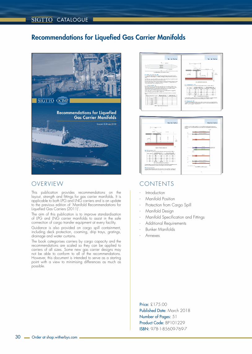
30
OVERVIEW CONTENTS
CATALOGUE
order at Witherbys.comOrder at shop.witherbys.com
- Introduction - Manifold Position - Protection from Cargo Spill - Manifold Design - Manifold Specification and Fittings - Additional Requirements - Bunker Manifolds - Annexes
This publication provides recommendations on the layout, strength and fittings for gas carrier manifolds. It is applicable to both LPG and LNG carriers and is an update to the previous edition of ‘Manifold Recommendations for Liquefied Gas Carriers (2011)’.The aim of this publication is to improve standardisation of LPG and LNG carrier manifolds to assist in the safe connection of cargo transfer equipment at every facility.Guidance is also provided on cargo spill containment, including deck protection, coaming, drip trays, gratings, drainage and water curtains.The book categorises carriers by cargo capacity and the recommendations are scaled so they can be applied to carriers of all sizes. Some new gas carrier designs may not be able to conform to all of the recommendations. However, this document is intended to serve as a starting point with a view to minimising differences as much as possible.
Recommendations for Liquefied Gas Carrier Manifolds
Price: £175.00Published Date: March 2018Number of Pages: 51Product Code: BP101229ISBN: 978-1-85609-769-7
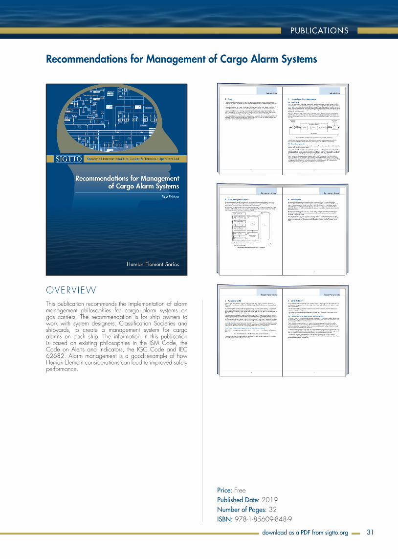
31
OVERVIEW
PUBLICATIONS
Order at shop.witherbys.com
This publication recommends the implementation of alarm management philosophies for cargo alarm systems on gas carriers. The recommendation is for ship owners to work with system designers, Classification Societies and shipyards, to create a management system for cargo alarms on each ship. The information in this publication is based on existing philosophies in the ISM Code, the Code on Alerts and Indicators, the IGC Code and IEC 62682. Alarm management is a good example of how Human Element considerations can lead to improved safety performance.
Recommendations for Management of Cargo Alarm Systems
Price: FreePublished Date: 2019Number of Pages: 32ISBN: 978-1-85609-848-9
download as a PDF from sigtto.org
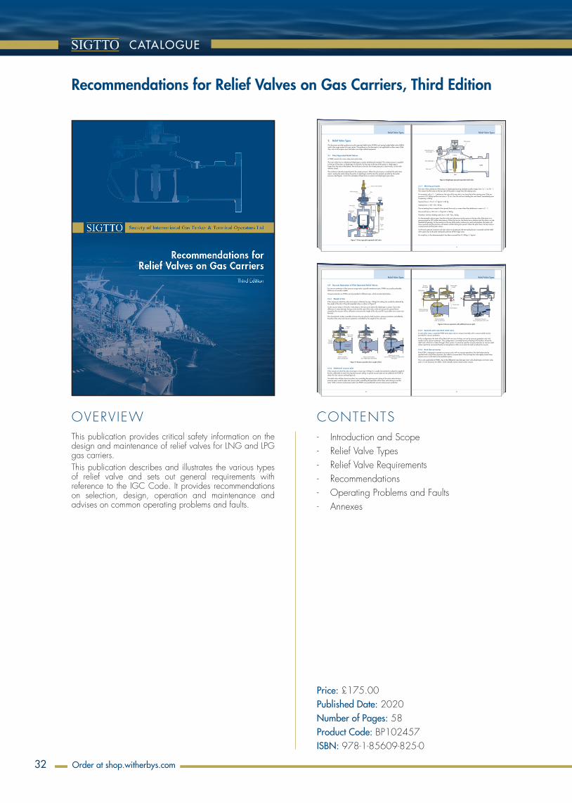
32
OVERVIEW CONTENTS
CATALOGUE
order at Witherbys.comOrder at shop.witherbys.com
12
2.4 Vacuum Operation of Pilot Operated Relief Valves
For vacuum protection of low pressure cargo tanks, typically membrane tanks, PORVs are usually preferable. SLRVs are not usually suitable.
Vacuum protection on PORVs can be provided in different ways, which are described below.
2.4.1 Weight of disc
If the vacuum at which the valve must open is relatively low (eg -1 kPag), this setting can usually be obtained by the weight of the disc of the pilot operated valve, as shown in Figure 5.
As the vacuum drops in the tank, it also drops in the top cavity above the diaphragm or piston. Due to the difference in areas between the top cavity and the seat of the valve, at the set vacuum the upward force caused by the vacuum will be sufficient to overcome the weight of the disc and lift it up to allow air to come into the tank.
This characteristic makes it possible to have only one valve for both functions: pressure protection controlled by the pilot of the valve and vacuum protection controlled by the weight of the valve disc.
Pressurepilot
Main valvetop cavity
Pressuresensing
from tank
To tank
Normal condition,under usual pressure
Reaching set vacuum,vacuum force overcomes weight of disc
valve opensVacuum starts to drop,
disc weight keeps valve closed
P
PP
V
VV
To vent mastatmosphere
Weight
Figure 5: Vacuum operation from weight of disc
2.4.2 Additional vacuum pilot
If the vacuum at which the valve must open is lower (eg -5 kPag), it is usually not practical to adjust the weight of the disc sufficiently to reach this required vacuum setting. A special vacuum pilot can be added to the PORV to obtain this low vacuum setting (Figure 6).
The relief valve will then have two pilots: one controlling the opening and closing of the main valve during a pressure event, and the other, the vacuum pilot, controlling the operation of the main valve during a vacuum event. With a vacuum and pressure pilot, one PORV can provide both vacuum and pressure protection.
Relief Valve Types
13
Pressurepilot closed
Vacuum pilotclosed
Check valve
Common pressure sensing from tank
Normal condition,under usual pressure
To atmosphere
Check valve
Reaching set vacuum,vacuum pilot opens main valve
P
PP
Figure 6: Vacuum operation with additional vacuum pilot
2.4.3 Separate pilot operated relief valve
In some other cases, a separate PORV set to open only on vacuum (normally with a vacuum pilot) may be provided for vacuum protection.
In this configuration, the tank will be fitted with two sets of valves: one set for pressure protection only and another set for vacuum protection. This configuration is normally found on floating LNG facilities, where the relief valve will have to relieve through a flare system. It cannot be used for vacuum protection as vacuum relief valves need to be connected directly to atmosphere to allow air to enter the tank to reduce the vacuum.
2.4.4 Back flow preventer
If the PORV is designed to operate on pressure only, with no vacuum operations, the relief valve may be specified with a back flow preventer, also called a vacuum block. This can keep the valve tightly closed when vacuum occurs in the tank or the insulation space.
This is only applicable to PORVs, due to the differential area between main valve diaphragms and main valve seats. It is not necessary for SLRVs, which naturally remain closed under vacuum.
Relief Valve Types
7
Relief Valve Types
2. Relief Valve Types
This document provides guidance on pilot operated relief valves (PORVs) and spring loaded relief valves (SLRVs) used in the cargo system of a gas carrier. The guidance in this document is not applicable to other areas of the ship, such as the engine room and other non-cargo related equipment.
2.1 Pilot Operated Relief Valves
A PORV consists of a main valve and a pilot valve.
The main valve has an unbalanced diaphragm or piston (unbalanced member). The system pressure is applied to the top of the piston or diaphragm via the pilot. As the area at the top of the piston or diaphragm is larger than the area at the bottom, the net force on the disc from these pressures is downwards, so the valve remains closed.
The net force is directly proportional to the system pressure. When the set pressure is reached, the pilot valve opens, venting the space above the piston or diaphragm and the disc lifts, pushed upwards by the system pressure. See Figures 1 and 2 for examples of these forces on piston and diaphragm type valves.
Auxiliary setter (if fitted)
Pilot bonnet vent
Main valve
Unbalancedpiston
Pilot
Field testconnection
Checkvalve
Pressuresensing
line
Nozzle
P (tank)
P (tank)
Inlet
OutletO-ring
seat
Figure 1: Piston type pilot operated relief valve
8
Relief Valve Types
External pressuresensing pipe
Pilot exhaust
Main diaphragm
Main seat
Inlet
P (tank)
P (tank)
Outlet
Figure 2: Diaphragm type pilot operated relief valve
2.1.1 Working principles
The ratio of the unbalance of the piston or diaphragm (moving member) usually ranges from 1.2 : 1 to 3.0 : 1. This means that the area on the top side of the piston is larger than the seating area.
For example, with a 2 : 1 imbalance, the area of the top side is two times that of the seating area. If the set pressure is 0.7 MPag and the seat area is 12 cm2, then the net force holding the seat closed, immediately prior to opening, is 84 kg.
Upward force = 12 cm2 × 7 kg/cm2 = 84 kg
Seating force = 168 – 84 = 84 kg
The net seating force is equal to the upward force only in cases where the imbalance in areas is 2 : 1.
Downward force = 2(12 cm2 × 7 kg/cm2) = 168 kg
Therefore, net force holding valve shut = 168 – 84 = 84 kg
For the example valve to open, the pilot valve must de-pressurise the space on the top side of the piston to a pressure equal to 50% of the inlet pressure. When that occurs, the forces are in balance and the valve is on the threshold of opening. As the pressure on the top of the piston continues to vent to atmosphere, the piston will move upwards and the pressure will remain constant during this period. When the pilot closes, the top cavity is re-pressurised and the piston closes.
As the tank pressure increases and rises closer to set pressure, the net sealing force is increased until the relief valve opens due to the pilot venting the pressure off the larger area.
For simplicity, in this above example it has been assumed that 0.1 MPag = 1 kg/cm2.
- Introduction and Scope - Relief Valve Types - Relief Valve Requirements - Recommendations - Operating Problems and Faults - Annexes
This publication provides critical safety information on the design and maintenance of relief valves for LNG and LPG gas carriers.This publication describes and illustrates the various types of relief valve and sets out general requirements with reference to the IGC Code. It provides recommendations on selection, design, operation and maintenance and advises on common operating problems and faults.
Recommendations for Relief Valves on Gas Carriers, Third Edition
Price: £175.00 Published Date: 2020Number of Pages: 58Product Code: BP102457ISBN: 978-1-85609-825-0

33
OVERVIEW CONTENTS
PUBLICATIONS
Order at shop.witherbys.com
109
Appendix 1
3) In case of 200 kw/m2
Maximum displacement is 0.24 m at failure
WSIL 341c - Appendix.indd 109 9/4/2009 7:01:40 PM
110
Appendix 1
3. von Mises Stress at Failure
1) In case of 88 kw/m2
Maximum von Mises stress is 480 MPa at failure
2) In case of 108 kw/m2
Maximum von Mises stress is 498 MPa at failure
WSIL 341c - Appendix.indd 110 9/4/2009 7:01:41 PM
9
Previous Incidents
Full details of this incident were presented at the Gastech 1985 conference in Nice, France, in a paper by Captain J A Carter entitled ‘Salvage of Cargo from the War Damaged Gaz Fountain’.
1.3 25,000 dwt Single Hull Product Carrier
A single hull 25,000 dwt product carrier, owned and operated by a major oil company was involved in a collision in the southern North Sea. The vessel was carrying a full cargo of gasoline, which ignited and burned for over 24 hours before the fire was extinguished and the vessel boarded. Bronze butterworth plates and PV valves had melted in the intensity of the fire, and deck pipelines were badly buckled, but there was no serious buckling or distortion of the vessel’s structure.
1.4 ‘val rosandra’ Propylene Fire
On 28 April 1990 the 3,990 m3 ethylene carrier ‘Val Rosandra’, laden with 2,250 tonnes of fully refrigerated propylene at minus 47degC, was discharging at Brindisi in Italy when a violent explosion occurred in the cargo compressor motor room.
WSIL 341c - Report on the effects of fire LNG.indd 9 9/4/2009 7:05:08 PM
10
Previous Incidents
‘val rosandra’ after initial explosion and fire
The motor room was so severely damaged that a switch panel was blown onto the deck and cargo pipework outside the room ruptured. In addition, the port and starboard domes of No 3 cargo tank also ruptured. As a result of the explosion the escaping propylene ignited and the fire continued to be fed by cargo evaporating from the damaged domes.
As local emergency services responded to the incident, the crew abandoned ship. The vessel was subsequently towed to the edge of the port limits where the fire was monitored from a safe distance. Although the fire showed no signs of escalation over a number of days, it was decided not to attempt to salvage the vessel or her cargo. Instead, charges were detonated around the domes of the remaining four tanks to allow the propylene cargo to escape gradually and burn off. It was agreed that once this had been accomplished, the vessel would be scuttled.
‘val rosandra’ after the tank domes were breached with charges
On 21 May 1990, over 3 weeks after the initial explosion and with the fire still burning at No 3 tank, the vessel was towed out to sea. The tank domes of the 4 undamaged tanks were breached with explosive charges. Although this resulted in some escalation of the fire, it was not to the extent the authorities had anticipated. The slow burn rate was attributed to the fact that the cargo was fully refrigerated and would only burn as fast as heat penetrated the insulated tank walls and domes and evaporated the propylene. On 8 June 1990, 41 days after the initial explosion and fire, a large quantity of explosive was detonated on ‘Val Rosandra’s’ hull and, on this occasion, the ethylene carrier’s demise was not long in coming.
WSIL 341c - Report on the effects of fire LNG.indd 10 9/4/2009 7:05:11 PM
RepoRt on the effects of fiRe
on LnG caRRieR containment
systems
WSIL 341c - Report on the effects of fire LNG.indd 1 9/4/2009 7:04:52 PM
- Introductions - Previous Incidents - The Origins of the IGC-Code - Fire Scenarios - LNG Carrier Pressure Relief Systems - Simplified Reapplication of the Code for Loss
of Insulation - Heat Transfer Into the tank - Time Based Heat Transfer - Response of Insulation Materials to Heat - Discussion - Conclusions - Recommendations - Appendices
This report investigates the response of LNGC cargo tanks exposed to a large enveloping pool fire that could possibly result from the spillage of LNG onto the sea and its subsequent ignition.
Report on the Effects of Fire on LNG Carrier Containment Systems
Price: FreePublished Date: 2009Number of Pages: 232
download as a PDF from sigtto.org

34
OVERVIEW CONTENTS
CATALOGUE
order at Witherbys.comOrder at shop.witherbys.com
- General Principles - Conditions and Requirements - Safety - Communications - Operational Preparations - Manoeuvring and Mooring - Procedures Alongside - Unmooring - Equipment - Emergencies - Appendices
This cross industry publication developed jointly by ICS, OCIMF, SIGTTO and CDI provides guidance on planning and execution of STS operations. It is applicable to all ships involved in transfer activities and to all types of bulk liquid cargoes, whether transferred at sea or in port. It will benefit Masters, Marine Superintendents and others, such as STS service providers and transfer organisers, involved in STS operations.This industry guide provides recommendations on safety, minimum equipment levels and good operating practices for STS operations. It is a required publication on the SIRE Vessel Inspection Questionnaires (VIQ) for Oil Tankers, Combination Carriers, Shuttle Tankers, Chemical Tankers and Gas Tankers.This book supersedes:• Ship to Ship Transfer Guide (Petroleum) 4th Edition published in 2005• Ship to Ship Transfer Guide (Liquefied Gas) 2nd Edition published in 1995• LNG Ship to Ship Transfer Guidelines published in 201.1This book builds on the previous recommendations and recognises experience gained in the industry of STS transfer operations, including transferring chemical (MARPOL Annex II) and liquefied natural gas (LNG) cargoes.
Ship to Ship Transfer Guide for Petroleum, Chemicals and Liquefied Gases
Price: £275.00Published Date: November 2013Number of Pages: 160Product Code: BP102015ISBN: 978-1-85609-594-5
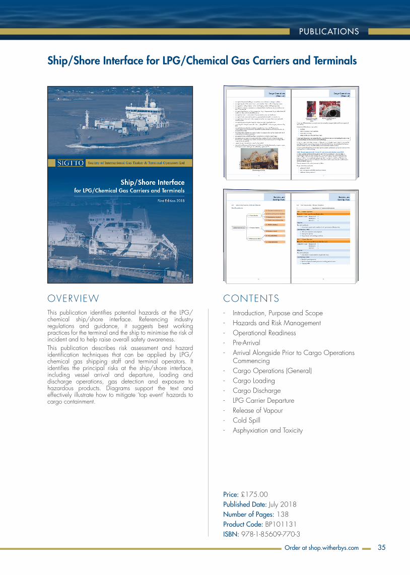
35
OVERVIEW CONTENTS
PUBLICATIONS
Order at shop.witherbys.com
This publication identifies potential hazards at the LPG/chemical ship/shore interface. Referencing industry regulations and guidance, it suggests best working practices for the terminal and the ship to minimise the risk of incident and to help raise overall safety awareness.This publication describes risk assessment and hazard identification techniques that can be applied by LPG/chemical gas shipping staff and terminal operators. It identifies the principal risks at the ship/shore interface, including vessel arrival and departure, loading and discharge operations, gas detection and exposure to hazardous products. Diagrams support the text and effectively illustrate how to mitigate ‘top event’ hazards to cargo containment.
Ship/Shore Interface for LPG/Chemical Gas Carriers and Terminals
Price: £175.00Published Date: July 2018Number of Pages: 138Product Code: BP101131ISBN: 978-1-85609-770-3
- Introduction, Purpose and Scope - Hazards and Risk Management - Operational Readiness - Pre-Arrival - Arrival Alongside Prior to Cargo Operations
Commencing - Cargo Operations (General) - Cargo Loading - Cargo Discharge - LPG Carrier Departure - Release of Vapour - Cold Spill - Asphyxiation and Toxicity
OVERVIEW CONTENTS
36
CATALOGUE
order at Witherbys.comOrder at shop.witherbys.com
Price: £195.00Published Date: February 2022Number of Pages: 521Product Code: BP105722ISBN: 978-1-914992-42-1
- A Justification into the Use of Insulation Flanges (and Electrically Discontinuous Hoses) at the Ship/Shore and Ship/Ship Interface
- ESD Systems - Fire Prevention in the Cargo Containment Systems
of Liquefied Gas Carriers in Shipyards - Gas Concentrations in the Insulation Spaces of
Membrane LNG Carriers - Guidance for the Prevention of Rollover in
LNG Ships - Guidance on Gas Carrier and Terminal Gangway
Interface - Guide for Planning Gas Trials For LNG Vessels - LNG and LPG Experience Matrix (Including
Guidelines for Use) - LNG Marine Loading Arms and Manifold
Draining, Purging and Disconnection Procedure - Report on the Effects of Fire On LNG Carrier
Containment Systems - Recommendations for Cargo Control Room HMI - Recommendations for Designing Cargo
Control Rooms - Recommendations for Management of Cargo
Alarm Systems - Simulation Information Paper - Suggested Quality Standards for LNG
Training Providers - Cont.
This publication contains all the SIGTTO Information Papers that are in force for 2022, for the guidance of industry members.
SIGTTO Information Papers (Consolidated Edition 2022)
OVERVIEW CONTENTS
37
INFORMATION PAPERS
order at Witherbys.comOrder at shop.witherbys.com
- Introduction - Computer Simulation in LNG Shipping and
Terminal Applications - Project Feasibility - The Fast Time Simulator - Project Simulation Models - Introducing the Human Factor - Full Mission Bridge Simulation - Factors to consider in Simulation - Use of bow thrusters - Berthing in the simulator - Bridge Team and Resource Management - Management of Simulation - Use of Simulators as a research tool - Other Applications of Simulation in LNG
Operations and Training - Mooring - Use of manned models for pre-command
experience - Liquid Cargo Operations Simulators - Steam Simulator Training - IAS simulation - Conclusion
This paper looks at the application of simulation in the LNG shipping and terminal interface areas of operations.It discusses the types of simulation programmes available, their application and makes some general recommendations on their use.
Simulation Information Paper: The Use of Computer Simulation in LNG Shipping and Terminal Applications
Price: FreePublished Date: 2010Number of Pages: 15
download as a PDF from sigtto.org

OVERVIEW CONTENTS
38
CATALOGUE
order at Witherbys.comOrder at shop.witherbys.com
- Summary - Principal Recommendations - Acknowledgments - Introduction - Development of LNG Standards - Site Selection - Design Criteria for Jetties - Risk Management in the Port Approach - The Human Element - Grounding and Collision Risk - References - Appendix
This book is aimed at port developers as a guide to the minimum design criteria required when a port is built or altered to accommodate LNG carriers. It contains operational and design considerations before questioning these in the context of the human element. The consequences of collisions and groundings are studied and methods of limiting the effect of such accidents are offered.This publication addresses safety issues for LNG ports. It focuses on eliminating spillages at both the ship/shore interface and navigational approach channels.The book outlines the way forward for site selection of LNG terminals, establishes a basis for safe jetty design and considers the safety factors in the port approach. It also considers the existing industry guidelines that cover cargo operations at the ship/shore interface. It is suggested that LNG’s excellent safety record is owing to the existing standards being adopted. As the industry becomes more widespread, continuing success will depend not only on better acceptance of the existing standards but also on future improvements. Some of the newer aspects are described and a checklist can be found in the appendix.
Site Selection and Design for LNG Ports and Jetties (IP No.14)
Price: £40.00Published Date: February 1997Number of Pages: 25Product Code: BP102051ISBN: 978-1-85609-129-9
39
OVERVIEW CONTENTS
PUBLICATIONS
Order at shop.witherbys.com
11
2.1 General
Part 2 approval is the approval by the Verifier of individual course titles against the stated learning deliverables within each course.
While part 1 approval assesses the quality management of the training organisation as a whole, part 2 examines the delivery of learning for a specific course title. Part 2 gives confidence to all stakeholders that the learners gain the learning that they expect.
The approval of any course title is limited to the course title, learning objectives, duration, teaching and assessment methods as approved, and cannot be transferred to another course.
In order for the Verifier to assess that this is the case, part 2 requires that:
• Learning objectives are published to the potential learner / customer in advance of contract
• learning objectives are relevant, specific and measured (for further explanation, see section 3)
• the tutor is competent in the subject matter and competent in learning / teaching methodologies
• learners’ achievement of these objectives is measured and recorded (by continuous assessment or examination).
Where completion of the course, or passing an examination, results in a formal qualification in accordance with the requirements of another third party, any requirements stated by that certifying authority must also be adhered to.
2.2 Pre-requisites and Documentation
For a course to be considered for part 2 approval, part 1 approval must be complete.
The following documentation must be supplied to the Verifier:
• Unique course title (and unique identifier / course code if used)
• name of individual representative responsible for the management of this course title
• course web page, factsheet, information page, brochure or prospectus
– As a minimum, the factsheet / webpage should contain the learning objectives, the summary of who the course is suitable for, and the duration of the course
• learning objectives
– The learning objectives set what learning the learners will gain from the course. They should be clearly defined, relevant, assessable and assessed, and are provided to the learners/customers in advance of the course. The learning objectives provide the learning goal against which the course is assessed. Where the technical content of the course is outside the expertise of the Verifier, a third party may be contracted to conduct this assessment
• a summary of who the course is suitable for
– This information may form part of the factsheet, web page, brochure or prospectus
• duration of the course
• the maximum number of delegates when one tutor is present/2 tutors are present
PART 2 – APPROVAL OF MARINE TRAINING COURSES
12
• any pre-course work required of learners
• summary of the method used to assess learners
– This should be categorised into either a written exam, multiple choice exam, documented practical demonstration, or documented continuous assessment. Each type will have different implications for approval
• tutor resource requirements for this course
• tutor course notes / lesson plans and materials including photographs of significant visual aids not available to be submitted in paper / electronic format
• learner materials
• list of other approvals for the course, and standards against which these approvals have been made
– Where the course has been designed to meet a particular standard or approval, knowledge of this will help the Verifier understand the structure and content of the course
• feedback and assessment results (if available)
• course passing thresholds and certificate requirements.
2.3 Initial Approval
To assess the suitability of a course the Verifier should assess the factsheet / webpage, brochure or prospectus content against what the course delivers.
Once the documents meet the requirements the Verifier should agree with the training provider a mutually convenient schedule for monitoring of the course through observation.
Note that monitoring of the whole course should not be required unless it is of only 1 day duration, or the course has never been run. However, for courses of longer duration, the training provider should be able to specify which day(s) of the course the training provider prefers to be observed.
Should the Verifier require any corrective actions, these should be discussed and agreed with the Training provider and might include follow up visit if extent of corrective actions needs to be followed up on site prior to annual monitoring
Once the monitoring and review of feedback and assessment results have been successfully completed, full approval should be issued.
Approval issued
Initial Approval Process
Review of feedbackand assessment
results (if available)
Monitoring of part or all of the course
delivery
Submission
Document review
3
Introduction
SIGTTO’s LNG Shipping Suggested Competency Standards and LNG Steamship Suggested Competency Standards for Engineers are used by the industry to assist with training key staff. This training is usually provided by departments of shipping companies (internal), third party training service providers (external) or a combination of both.
This Guide aims to encourage the creation of a quality control framework that should assist with creating a consistent minimum standard of training across the LNG shipping industry. To achieve this objective, this Guide proposes common requirements for the verification of training providers. As these are proposed as minimum requirements, verification should be carried out using the Verifier’s standards rather than the contents of this Guide.
Training providers should select suitable organisations with relevant experience in the LNG industry to provide the verification service. For the purposes of this Guide, these organisations are referred to as the
Verifier. In drawing up this Guide the schemes of various organisations were consulted (see references).
While SIGTTO encourages training providers to seek such verification as part of their quality control measures, this is essentially a relationship between the training provider, as a client, and the Verifier as an organisation providing the service. While SIGTTO is not involved in this relationship it actively encourages this form of quality control. Certification of the training provider is provided by the Verifier alone and should not be construed in any way as an endorsement by SIGTTO.
The information provided in this Guide, along with the quality control provided by verification, is expected to be particularly useful for more recent entrants into the LNG shipping industry. However, it is recognised that certain operators in the industry have mature systems for training and may not benefit from the suggestions in this Guide.
4
Scope
This document provides guidance on the verification of training for the key staff in the LNG industry, including the officers of an LNG carrier and appropriate staff in the shore organization. Shipping companies should identify positions in the company that they would consider appropriate for such training and employees that have a direct role in safety, operations and technical management may be considered appropriate for such training.
This Guide is written to assist Verifiers in identifying whether training providers have reached the minimum standard expectation. Verifiers should have standards and rules in place used by their organisation to provide the certification service.
Shipping companies and training providers may still need to comply with additional requirements, provided for in the verifying organisation’s rules and standards.
This Guide
Verifier
Trainee
Training Courses
Company Training Systems
Training Providers
Training System for Key Staff
i
Suggested Quality Standards for LNG Training Providers
(First Edition 2014)
- Certification of Training Provider - Approval of Marine Training Courses - Annex – Training Record Books
This guide aims to encourage the creation of a quality control framework that should assist with creating a consistent minimum standard of training across the LNG shipping industry.The guide proposes minimum goal-based objectives that may be considered in the verification process of training providers.The information provided in this guide, along with the quality control provided by verification, is expected to be particularly useful for more recent entrants into the LNG shipping industry.
Suggested Quality Standards for LNG Training Providers
Price: FreePublished Date: 2014Number of Pages: 20
download as a PDF from sigtto.org

40
OVERVIEW CONTENTS
CATALOGUE
order at Witherbys.comOrder at shop.witherbys.com
- Scope - Risk Based Method and Terminology - Document Structure - Assessing the Risk and the Management of
Specific Events - The Operating Environment - Top Events - Loss of Containment - Collision/Grounding - Loss of Position - Evacuation, Rescue and Pollution Prevention
This publication is about the role of support craft in assisting with safe operations and emergency response for liquefied gas carriers and facilities. It looks at how the service could be improved by a more up to date approach and an improved understanding of hazards, barriers, risk scenarios and response strategies. It provides suggested competency standards to assist with the creation of training programmes for support craft crew.This book demonstrates how risk assessment may be used to develop response and protection strategies for support craft. It considers the ‘top events’ that will typically concern operators of support craft (i.e. loss of containment, collision/grounding, loss of position, and evacuation, rescue and pollution prevention) and discusses the threats, barriers and consequences of each event, highlighting the part that support craft can play in mitigating risk through planning and operational readiness.The text is supported with colour illustrations and photographs, as well as diagrams showing the ‘bowtie’ method of risk assessment and management.Annexes provide useful information on:• Response considerations and planning• equipment and capabilities of support craft• water-spray systems• support craft emergency response competencies• fire and gas dispersion modelling.This title incorporates A Contingency Planning and Crew Response Guide for Gas Carrier Damage at Sea and in Port Approaches, 3rd Edition (SIGTTO) and A Guide to Contingency Planning for the Gas Carrier Alongside and Within Port Limits, 2nd Edition (SIGTTO).
Price: £125.00Published Date: October 2016Number of Pages: 93Product Code: BP100918ISBN: 978-1-85609-715-4
Support Craft at Liquefied Gas Facilities. Principles of Emergency Response and Protection – Offshore
41
OVERVIEW CONTENTS
PUBLICATIONS
Order at shop.witherbys.com
- Scope and Methodology - Introduction - Assessing the Risk and the Management of
Specific Events - The Operating Environment - Top Events - Annexes
Support craft perform a vital role in assisting with safe operations and emergency response for liquefied gas carriers and facilities. This service could be improved by a more up to date approach and a deeper understanding of credible scenarios and response strategies. The information in this book is provided primarily for organisations involved in the transportation of liquefied gas cargoes, although, it may also be of assistance to regulators and government agencies.This publication uses a risk assessment method to offer context and define some example emergency scenarios and response strategies.All of the responses are based on the following order of priority: protection of life, the environment and property. Protection of life has been considered not only in the context of the ship and terminal staff involved in a cargo operation, but also of the emergency responders and the general public in the vicinity.SIGTTO has ensured this publication explains the basis of design of facilities and gas carriers, including the purpose and limitation of equipment used. This should assist in the improvement of existing practice.
Support Craft at Liquefied Gas Facilities. Principles of Emergency Response and Protection – Onshore
Price: £125.00Published Date: September 2015Number of Pages: 87Product Code: BP100448ISBN: 978-1-85609-691-1

42
OVERVIEW CONTENTS
CATALOGUE
order at Witherbys.comOrder at shop.witherbys.com
Appendix A Considerations During Construction and Maintenance Periods
Construction:In order to ensure compatibility actuators should be approved by the valve manufacturer and setup during the Factory Acceptance Tests (FAT).
Suggested actions to minimise problems with valves after installation.
• Work with the yard to ensure the makers’ list includes only valve suppliersacceptable to you.
• Where possible valves and actuators (manual or powered) should be provided by the valve manufacturer and tested as a unit before leaving the factory. Valve and actuator to be marked to ensure correct actuator is mated to the corresponding valve.
• After FAT, remove all actuators and ensure stored in a clean dry environment.• Protect valve internals from heat damage during installation if necessary for
those valves that will be welded permanently into pipelines• Valve suppliers should be used to re-fit, hook up and commission valves after
heavy engineering is completed. (The valve can still be operated manually if required)
• Ensure site teams are aware of the potential problems and daily checks are carried out
• Check for water ingress before installation• Check cables and glands, ensure they are the same size• Check the wiring has been done correctly• Ensure the cable is not under tension and enough cable has been provided
for easy reach to gangways or deck when actuators are removed from the valve headwork
• Any modification or change to the actuator is done with the approval of the valve supplier or by the valve supplier
Examples of problems found during construction:
Installation• Destruction or damage of the cable gland plug (before wiring)• Wrongly connected Cable Gland• Use of Sealants (cable and gland not the same size/incompatible)• Cable Gland not tightened properly after installation of the cable
Commissioning• Actuators with gaskets and O rings damaged or missing• Wired incorrectly• Actuators re positioned in order to fit in a space• Setting modifications (Torque and potentiometer settings changed or
incorrect)• Poor communication with the control room/system (CCR not communicating
correctly with the actuator, providing incorrect position data)
In ServiceSuggested actions to minimise problems with valves during service: Follow Manufacturers’ guidelines for operation and maintenance Consider appropriate training from valve & actuator supplier if necessary Ensure Instruction Manuals are on board Ensure good house-keeping, Ensure maintenance schedules included in Planned Maintenance System Regularly check operation of automation/actuators Check studs and nuts Be aware of materials exposed to the possibility of galvanic corrosion Ensure correct spares inventory held
Examples of problems with valves during service:Leaking valves can be identified by frost creep past the valve seat and/or in the gland area, causes of leakage may include:
• Continuous leakage due to damage or wear to the valve seat• Manual valve will not open/close fully – due to corrosion, over-tightened
gland nuts or debris/hyrdrates under the seat• Problems with connections, studs and nuts or metal fatigue.
Examples of problems with actuators Actuator will not open the valve –Torque setting incorrect Actuator will not close the valve -Seat leakage or damage Actuator does not communicate correctly with the CCR / VRC – water ingress,
cable damage Actuator will not engage manual override – Check lever Galvanic corrosion – Wrong material
Example maintenance schedule (Note – schedules will differ between different valve types and manufacturers):
5 year docking 10 year docking 15 year docking 20 year docking 25 year docking
Replace all gland and bonnet gaskets manufactured from soft material
Overhaul all actuators
Check Studs nuts and bolts
Hydraulics
Generalmaintenance
Same as five years
Check and replace cables
Check and replace actuators if required
Replace studs, nuts and bolts
Check connections
Check seats
Same as five years
UT scanning of castings
Possible Replacement of actuators
Check for metal fatigue
VRC and hydraulics
Same as five and ten years
Same as five and fifteen years
ELEMENT DESIGN FEATURES when the valve is in the full open position
LPG in any cavity regardless of the position of the disk/plug.Any space where liquid lock could occur should be fitted with a safety device to prevent over pressurisation. LPG should not be released to the atmosphereunder normal conditions.
Disc / Plug, mechanism to seal the valve
Disc / Plug should be fixed to the stem with vibration-proof connection. In order to prevent seat damage the plug mechanism should, where possible, not rotate on a metal to metal seat, as this allows sealing faces to remain stationary during final closing.
Valve connections . Flange connections should be minimised as far as possible Such welded valves & lines should be able to be maintained in situ.
Bolting, studs and nuts All material selected must be suitable for marine use and should not be susceptible to galvanic corrosion
Flow Path The valve type and size should be selected to minimise the pressure differential across the valve.
Valve Automation The valve must be installed so it is able to support the weight of the actuator in all conditions, including vibration and acceleration due to motion in a seaway Itmay be necessary to fit local supports and to strengthen the pipeline in way of the valve – especially in branch locations.
Valve Material Materials used in the construction of valves should be compatible with all cargoes listed on the certificate of fitness.
Valve Testing
The IGC Code (5.3.2.1) specifically requires tightness testing for cargo valves that are to be used for service temperatures below – 550C. For systems working at temperatures above that limit, normal classification society requirements are applied.
It is recommended that each type and size of valve operating at temperatures above – 550C should be subjected to seat tightness and operational testing over the full range of operating temperatures & pressures up to the rated design pressure of the valve. Some valves may be “tight” when subject to high pressures and or temperatures, but experience significant leakage when operated at lower pressures and or temperatures.
The first valve in a series and for each size should undergo extensive testing to ensure that it operates correctly throughout the full range and combination of pressure and temperature that the valve could experience in service.Subsequent valves should be randomly selected and tested at design conditions and the extremes of their operating envelope.
The following general tests are carried out on all valves, but this document will concentrate on the tests specifically required for low temperature valves
Shell strength test.Hydrostatic or Pneumatic test to 1.5 X Maximum Design AllowableWorking Pressure.
Shell leak test.Pneumatic test to 1.1 X Maximum Allowable Working Pressure.
Seat leak test.
Pneumatic test to 1.1 X Maximum Allowable Working Pressure.
LPG Valves should be tested in accordance with the guidance above – with logical amendments in respect of minimum design temperatures and the following standards:-
BS EN 12266-1:2003 Industrial valves. Testing of valves. Pressure tests, test procedures and acceptance criteria. Mandatory requirements
BS EN 12266-2:2002. Industrial valves. Testing of valves. Tests, test procedures and acceptance criteria.
Guidance to Inspectors When Testing Low Temperature Valves
It is recommended that third party inspection is utilised during low temperature valve testing for Class approval. The valve material traceability should be in accordance class rules and regulations
A third party inspector is also required to ensure that the valve test system is strictly in accordance with the relevant test procedure and there are no leakages (pin holes in pipe work) extra pipe work, bypass systems, heaters or other mechanisms that would affect the accuracy of the readings and results recorded. It is also important to review the calibration of the measuring equipment to ensure good working order and accuracy. The calibration of the measuring equipment should be traceable to a recognised national standard.
Pressure Gauge
Coolant such as 60% Ethylene Glycol water mix
Cooling Coil
Alcohol Bubbler Flow Meter
Test Gas
Test Fluid E.g. R404A
The SelecTion and TeSTing of ValVeS for
lng applicaTionS
- Scope - Introduction - Cryogenic Valve Design for LNG service - ESD valves - Valve testing - Guidance to Inspectors when Testing Valves - Current Codes and Standards Applicable to
Valves for LNG Service
This document is intended to offer guidance to designers and operators on the general requirements for valves for Liquefied Natural Gas (LNG) service. It is also considered to be applicable to valves for liquefied ethylene and liquefied ethane service.
The Selection and Testing of Valves for LNG Applications
Price: FreePublished Date: 2008Number of Pages: 10
download as a PDF from sigtto.org
43
OVERVIEW CONTENTS
PUBLICATIONS
Order at shop.witherbys.com
Pneumatic test to 1.1 X Maximum Allowable Working Pressure.
LPG Valves should be tested in accordance with the guidance above – with logical amendments in respect of minimum design temperatures and the following standards:-
BS EN 12266-1:2003 Industrial valves. Testing of valves. Pressure tests, test procedures and acceptance criteria. Mandatory requirements
BS EN 12266-2:2002. Industrial valves. Testing of valves. Tests, test procedures and acceptance criteria.
Guidance to Inspectors When Testing Low Temperature Valves
It is recommended that third party inspection is utilised during low temperature valve testing for Class approval. The valve material traceability should be in accordance class rules and regulations
A third party inspector is also required to ensure that the valve test system is strictly in accordance with the relevant test procedure and there are no leakages (pin holes in pipe work) extra pipe work, bypass systems, heaters or other mechanisms that would affect the accuracy of the readings and results recorded. It is also important to review the calibration of the measuring equipment to ensure good working order and accuracy. The calibration of the measuring equipment should be traceable to a recognised national standard.
Pressure Gauge
Coolant such as 60% Ethylene Glycol water mix
Cooling Coil
Alcohol Bubbler Flow Meter
Test Gas
Test Fluid E.g. R404A
Pre-test equipment checks
It is important that the third party inspector checks the testing apparatus to ensure serviceability and.
• Check the piping of the equipment to ensure that it complies with the standard piping diagram.
• Pressure gauges are calibrated.• Open all the flow valves and the valve under test, to ensure that there are no
restrictions in the system i.e. helium is ejected from the outlet vent. During this check the flow meter and bubbler should be disconnected to prevent damage.
Checking for liquid lock in the stem of the low temperature globe valve.
This test may/should be conducted in addition to the low temperature sealing test and will demonstrate if there is liquid lock in the stem when the valve is in the fully open position.
• Blank the valve inlet and outlet• Connect a suitable air supply (not exceeding the working pressure of the
valve) to the valve inlet• Open the valve and allow air to enter the valve body• Fully open the valve until the hand-wheel will not rotate any further i.e. “back-
seated”• Disconnect the air supply and vent the pressure in the valve body• Submerge the valve in a water bath and close the valve.• Air bubbles rising from the valve will indicate that air was trapped in the stem
and thus LPG could also be trapped leading to serious overpressure and failure of the valve extension.
Valve and Actuator maintenance and serviceThe valve and actuator manufacturers should provide guidance on maintenance procedures and intervals, such guidance should be incorporated in to the vessels maintenance schedule. Valves that are in intermittent service or in particularly harsh environments may need to have an enhanced maintenance plan.
Current Codes Standards & Material Requirements Referencing Valves for LPG Service:
For a valve to work effectively in low temperature LPG service conditions the design must take into consideration both pressure and thermal conditions and still provide a tight shut off without leakage. The material mass in the casting design may be
to IEC 60509 or equivalent and suitable for marine use. Electrically operatedactuators and control systems should be suitable for the hazardous area in which they are located. The actuator should be able to work in extreme winter conditions and harsh marine environment.
It is recommended that the valve and actuator are sourced and supplied as a unit to ensure they are compatible and setup to work with each other.
During construction and maintenance actuators should be kept in a dry environment to prevent corrosion of internal parts. When assembling the actuator to the valve it should be ensured that it is mated to the same valve that it came from to ensure that settings such as torque, range of movement etc are correct for that specific valve. Particular care should be given to ensuring glands, “O” rings, and other sealing and securing arrangements have not been damaged.
Specific Consideration for Emergency Shut-Down (ESD) Valves
The normal design conditions set out in the IGC Code must be complied with,especially in terms of local & remote actuation, avoidance of pressure surge and positive closure of the product flow.
The design of ESD valves should be such that the valve spindle is positively connected to the valve plug such that the valve cannot remain open when the actuator is in the closed position, or indicating closed. (Ref. 3)
It is recommended that valves that are required to perform an ESD function are “fire safe” in accordance with ISO10497.
Design Considerations for valves in LPG service.
When selecting a valve it is important to ensure that it is designed and manufactured to the relevant standard or code; this may require compliance with more than one standard or code.
For general design features specific to LPG requirements see table below.
ELEMENT DESIGN FEATURES Stem sealing device. (Gland packing at the top of the extension)
There should be compatibility between the packing material and surface smoothness of the valve stem.
Bonnet JointsAttaching the valve cover to valve body
The valve should be designed to take into account the thermal stresses in transient state occurring during cool down and warm up operation.
Screw Mechanism Should limit potential seizure due to materials used. Anti-galling austenitic stainless steel prevents seizure and valve failure when used with correct packing
Stem/shaft/spindle retention.(Applies to valves with stem/shaft/spindle that may be subject to pressure).
Each valve stem/shaft/spindle should be fitted with a device such that it cannot come apart or eject the stem/shaft/spindle in normal operation.
Liquid lock in the stem/shaft/spindle area
The valve should be designed in such a way that liquid lock cannot occur when the valve is in the fully open position. The design should be free from trapping
ELEMENT DESIGN FEATURES when the valve is in the full open position
LPG in any cavity regardless of the position of the disk/plug.Any space where liquid lock could occur should be fitted with a safety device to prevent over pressurisation. LPG should not be released to the atmosphereunder normal conditions.
Disc / Plug, mechanism to seal the valve
Disc / Plug should be fixed to the stem with vibration-proof connection. In order to prevent seat damage the plug mechanism should, where possible, not rotate on a metal to metal seat, as this allows sealing faces to remain stationary during final closing.
Valve connections . Flange connections should be minimised as far as possible Such welded valves & lines should be able to be maintained in situ.
Bolting, studs and nuts All material selected must be suitable for marine use and should not be susceptible to galvanic corrosion
Flow Path The valve type and size should be selected to minimise the pressure differential across the valve.
Valve Automation The valve must be installed so it is able to support the weight of the actuator in all conditions, including vibration and acceleration due to motion in a seaway Itmay be necessary to fit local supports and to strengthen the pipeline in way of the valve – especially in branch locations.
Valve Material Materials used in the construction of valves should be compatible with all cargoes listed on the certificate of fitness.
Valve Testing
The IGC Code (5.3.2.1) specifically requires tightness testing for cargo valves that are to be used for service temperatures below – 550C. For systems working at temperatures above that limit, normal classification society requirements are applied.
It is recommended that each type and size of valve operating at temperatures above – 550C should be subjected to seat tightness and operational testing over the full range of operating temperatures & pressures up to the rated design pressure of the valve. Some valves may be “tight” when subject to high pressures and or temperatures, but experience significant leakage when operated at lower pressures and or temperatures.
The first valve in a series and for each size should undergo extensive testing to ensure that it operates correctly throughout the full range and combination of pressure and temperature that the valve could experience in service.Subsequent valves should be randomly selected and tested at design conditions and the extremes of their operating envelope.
The following general tests are carried out on all valves, but this document will concentrate on the tests specifically required for low temperature valves
Shell strength test.Hydrostatic or Pneumatic test to 1.5 X Maximum Design AllowableWorking Pressure.
Shell leak test.Pneumatic test to 1.1 X Maximum Allowable Working Pressure.
Seat leak test.
- Scope - Introduction - Valve Design for LPG Service - Specific Consideration for Emergency Shut-
Down (ESD) Valves - Design Considerations for valves in LPG
service - Valve Testing - Current Codes Standards & Material
Requirements Referencing Valves for LPG Service
- Bibliography - Appendix A Considerations During
Construction and Maintenance Periods
This document is intended to offer guidance to designers and operators on the general requirements for valves for Liquefied Petroleum Gas (LPG) service This guidance is primarily intended for application to LPG ships, but may be applied throughout the LPG industry as appropriate.
The Selection and Testing of Valves for LPG Applications.
Contents Scope......................................................................................................................... 3
Introduction ................................................................................................................ 3
Valve Design for LPG Service.................................................................................... 3
Cargo sampling valve requirements ....................................................................... 5
Effect of extended bonnet and spindle.................................................................... 5
Valve Actuator Selection......................................................................................... 5
Specific Consideration for Emergency Shut-Down (ESD) Valves .............................. 6
Design Considerations for valves in LPG service....................................................... 6
Valve Testing ............................................................................................................. 7
Guidance to Inspectors When Testing Low Temperature Valves ........................... 8
Pre-test equipment checks ..................................................................................... 9
Checking for liquid lock in the stem of the low temperature globe valve................. 9
Valve and Actuator maintenance and service......................................................... 9
Current Codes Standards & Material Requirements Referencing Valves for LPG Service: ...................................................................................................................... 9
Bibliography ............................................................................................................. 11
Appendix A Considerations During Construction and Maintenance Periods............ 12
Construction: ........................................................................................................ 12
In Service.............................................................................................................. 13
Note: This document applies only to valves installed on LPG vessels; however it can provide guidance to valves at LPG terminals. This document is designed to be a supplemental guide to work in conjunction with the relevant codes and standards for LPG valves and does not seek to override them.
Notice of Terms of UseWhile any advice given in this document has been developed using the best information currently available to the Society of International Gas Tanker and Terminal Operators Ltd (SIGTTO) as received from its membership, it is intended purely as guidance to be used at the user’s own risk. No responsibility is accepted by SIGTTO, or any officer, director, employee, representative or the membership of SIGTTO, or by any person, firm, corporation or organisation who, or which, has been in any way concerned with the furnishing of information or data, the compilation or any translation, publishing, supply or sale of the document for the accuracy of any information or advice given in the document or any omission from the document or for any consequence whatsoever resulting directly or indirectly from the compliance with or adoption of in whole or in part any guidance contained in the document even if caused by a failure to exercise reasonable care.
The Selection and Testing of Valves for LPG Applications
Price: FreePublished Date: 2012Number of Pages: 13
download as a PDF from sigtto.org
44
OVERVIEW CONTENTS
order at Witherbys.comOrder at shop.witherbys.com
CATALOGUE
- Background - Definition - Failure Description - Commentary - Operational Requirements and Proposed
Remedy - Suggestions
This document was produced in response to a number of failures of thermowells fitted into LNG cargo liquid lines.This document provides some further guidance and information on the subject.
Thermowells in LNG Carrier Liquid Lines
Price: FreePublished Date: 2011Number of Pages: 4
download as a PDF from sigtto.org
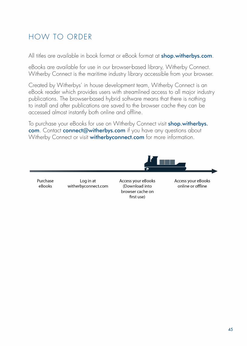
45
HOW TO ORDER
All titles are available in book format or eBook format at shop.witherbys.com.
eBooks are available for use in our browser-based library, Witherby Connect. Witherby Connect is the maritime industry library accessible from your browser.
Created by Witherbys’ in house development team, Witherby Connect is an eBook reader which provides users with streamlined access to all major industry publications. The browser-based hybrid software means that there is nothing to install and after publications are saved to the browser cache they can be accessed almost instantly both online and offline.
To purchase your eBooks for use on Witherby Connect visit shop.witherbys.com. Contact [email protected] if you have any questions about Witherby Connect or visit witherbyconnect.com for more information.


order at Witherbys.comOrder at shop.witherbys.com
The SelecTion and TeSTing of ValVeS for
lng applicaTionS
FEBRUARY 2022


