Embed Size (px)
Citation preview
PLASTICFITTINGS CA
TALO
G C-P
F-040
0
NIBCO. Worldwide Choice In Flow Control.®
NIBCO INC. World Headquarters • 1516 Middlebury St. • Elkhart, IN 46516-4740 U.S.A. • Telephone: 1.800.234.0227 • 1.219.295.3000 • www.nibco.com
Worldwide Choice In Flow Control®
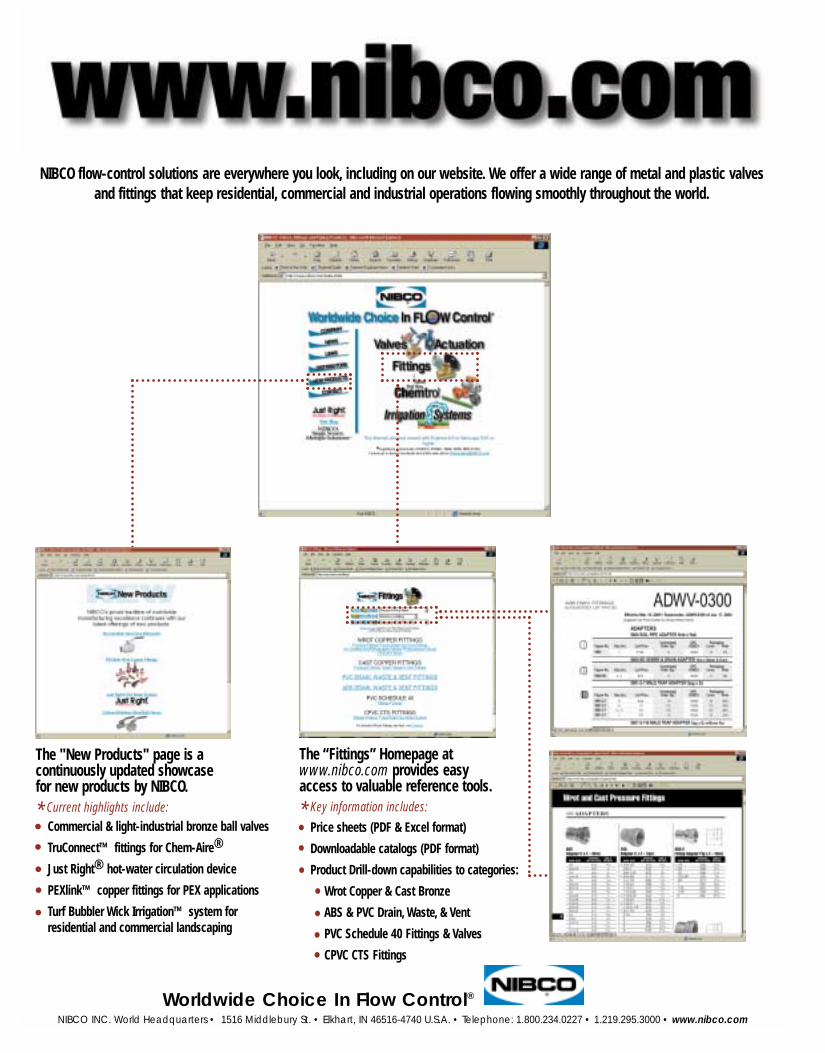
NIBCO flow-control solutions are everywhere you look, including on our website. We offer a wide range of metal and plastic valves and fittings that keep residential, commercial and industrial operations flowing smoothly throughout the world.
Commercial & light-industrial bronze ball valves
TruConnect™ fittings for Chem-Aire®
Just Right® hot-water circulation device
PEXlink™ copper fittings for PEX applications
Turf Bubbler Wick Irrigation™ system for residential and commercial landscaping
The "New Products" page is a continuously updated showcasefor new products by NIBCO.
* Current highlights include:
Price sheets (PDF & Excel format)
Downloadable catalogs (PDF format)
Product Drill-down capabilities to categories:
Wrot Copper & Cast Bronze
ABS & PVC Drain, Waste, & Vent
PVC Schedule 40 Fittings & Valves
CPVC CTS Fittings
The “Fittings” Homepage atwww.nibco.com provides easyaccess to valuable reference tools.
* Key information includes:
NIBCO INC. World Headquarters n 1516 Middlebury St. n Elkhart, IN 46516-4740 U.S.A. n www.nibco.com
Table Of Contents
Numerical Index......................................................................................................................4
Material Selection....................................................................................................................6
Key to NIBCO Figure Numbers................................................................................................9
Methods of Designating Inlets of Fittings..............................................................................10
ABS & PVC-DWV...................................................................................................................11
CPVC-CTS .............................................................................................................................36
Schedule 40 PVC...................................................................................................................45
Plastic Irrigation Products.....................................................................................................61
Schedule 80 PVC...................................................................................................................62
Engineering Data...................................................................................................................77
ABS Figure Number Comparison ........................................................................................101
PVC Figure Number Comparison........................................................................................105
Warranty..............................................................................................................................109
INDEX
3
NIBCO INC. World Headquarters n 1516 Middlebury St. n Elkhart, IN 46516-4740 U.S.A. n www.nibco.com
4
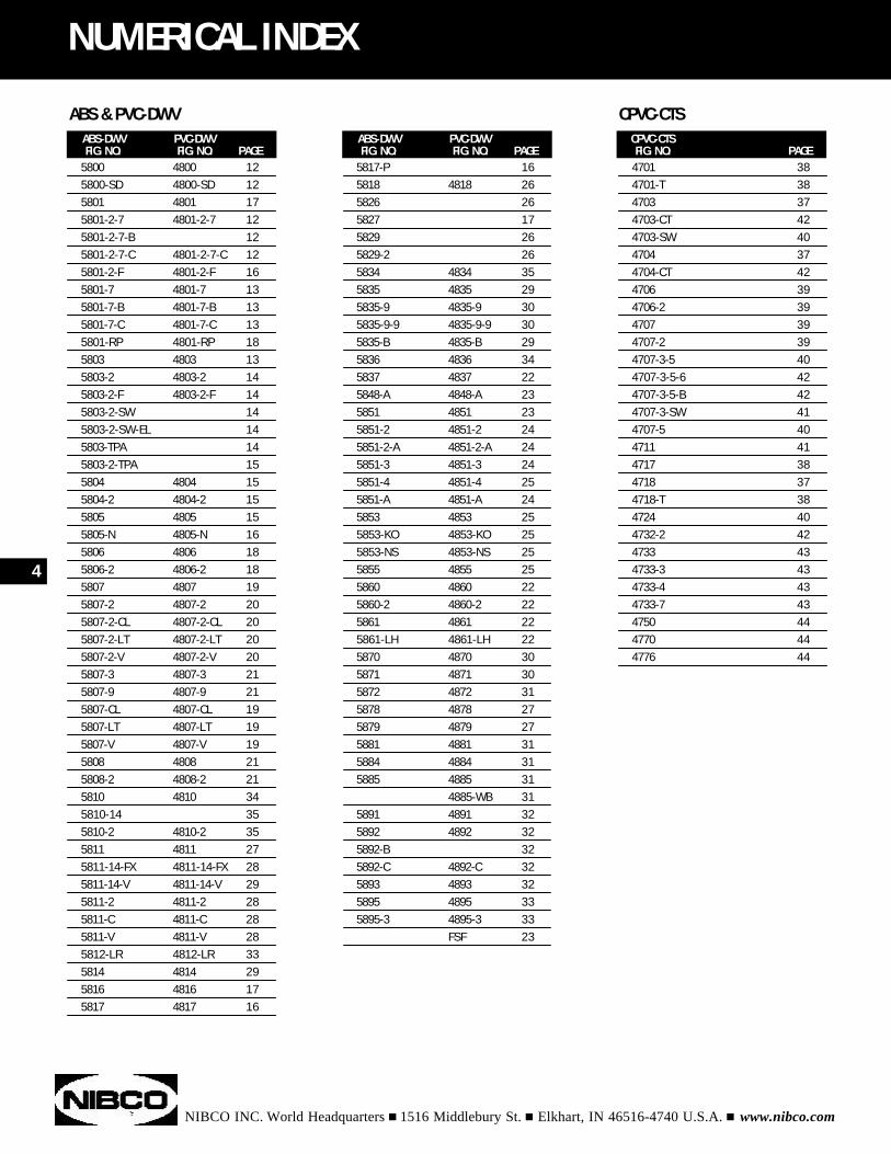
NUMERICAL INDEX
ABS-DWV PVC-DWVFIG. NO. FIG. NO. PAGE
5800 4800 125800-SD 4800-SD 125801 4801 175801-2-7 4801-2-7 125801-2-7-B 125801-2-7-C 4801-2-7-C 125801-2-F 4801-2-F 165801-7 4801-7 135801-7-B 4801-7-B 135801-7-C 4801-7-C 135801-RP 4801-RP 185803 4803 135803-2 4803-2 145803-2-F 4803-2-F 145803-2-SW 145803-2-SW-EL 145803-TPA 145803-2-TPA 155804 4804 155804-2 4804-2 155805 4805 155805-N 4805-N 165806 4806 185806-2 4806-2 185807 4807 195807-2 4807-2 205807-2-CL 4807-2-CL 205807-2-LT 4807-2-LT 205807-2-V 4807-2-V 205807-3 4807-3 215807-9 4807-9 215807-CL 4807-CL 195807-LT 4807-LT 195807-V 4807-V 195808 4808 215808-2 4808-2 215810 4810 345810-14 355810-2 4810-2 355811 4811 275811-14-FX 4811-14-FX 285811-14-V 4811-14-V 295811-2 4811-2 285811-C 4811-C 285811-V 4811-V 285812-LR 4812-LR 335814 4814 295816 4816 175817 4817 16
5817-P 165818 4818 265826 265827 175829 265829-2 265834 4834 355835 4835 295835-9 4835-9 305835-9-9 4835-9-9 305835-B 4835-B 295836 4836 345837 4837 225848-A 4848-A 235851 4851 235851-2 4851-2 245851-2-A 4851-2-A 245851-3 4851-3 245851-4 4851-4 255851-A 4851-A 245853 4853 255853-KO 4853-KO 255853-NS 4853-NS 255855 4855 255860 4860 225860-2 4860-2 225861 4861 225861-LH 4861-LH 225870 4870 305871 4871 305872 4872 315878 4878 275879 4879 275881 4881 315884 4884 315885 4885 31
4885-WB 315891 4891 325892 4892 325892-B 325892-C 4892-C 325893 4893 325895 4895 335895-3 4895-3 33
FSF 23
4701 384701-T 384703 374703-CT 424703-SW 404704 374704-CT 424706 394706-2 394707 394707-2 394707-3-5 404707-3-5-6 424707-3-5-B 424707-3-SW 414707-5 404711 414717 384718 374718-T 384724 404732-2 424733 434733-3 434733-4 434733-7 434750 444770 444776 44
ABS-DWV PVC-DWVFIG. NO. FIG. NO. PAGE
CPVC-CTSFIG. NO. PAGE
ABS & PVC-DWV CPVC-CTS
NIBCO INC. World Headquarters n 1516 Middlebury St. n Elkhart, IN 46516-4740 U.S.A. n www.nibco.com
NUMERICAL INDEX
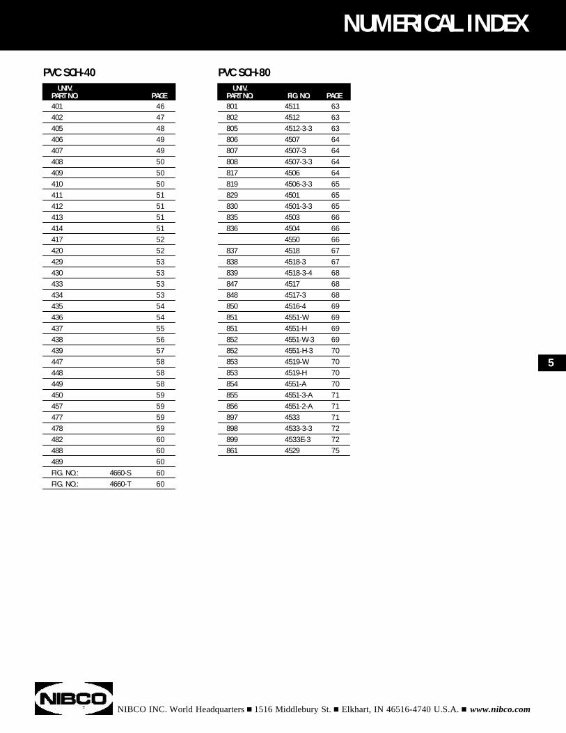
UNIV.PART NO. PAGE401 46402 47405 48406 49407 49408 50409 50410 50411 51412 51413 51414 51417 52420 52429 53430 53433 53434 53435 54436 54437 55438 56439 57447 58448 58449 58450 59457 59477 59478 59482 60488 60489 60FIG. NO.: 4660-S 60FIG. NO.: 4660-T 60
801 4511 63802 4512 63805 4512-3-3 63806 4507 64807 4507-3 64808 4507-3-3 64817 4506 64819 4506-3-3 65829 4501 65830 4501-3-3 65835 4503 66836 4504 66
4550 66837 4518 67838 4518-3 67839 4518-3-4 68847 4517 68848 4517-3 68850 4516-4 69851 4551-W 69851 4551-H 69852 4551-W-3 69852 4551-H-3 70853 4519-W 70853 4519-H 70854 4551-A 70855 4551-3-A 71856 4551-2-A 71897 4533 71898 4533-3-3 72899 4533E-3 72861 4529 75
UNIV.PART NO. FIG. NO. PAGE
PVC SCH-40 PVC SCH-80
5
NIBCO INC. World Headquarters n 1516 Middlebury St. n Elkhart, IN 46516-4740 U.S.A. n www.nibco.com
6
Material SelectionThermoplastics and Elastomers
ABS(Acrylonitrile-butadiene-styrene) Class 3-2-2-2-2, con-forming to ASTM D 3965, is a time proven material. Thesmooth inner surface and superior resistance to depositformation makes ABS drain, waste and vent material idealfor residential and commercial sanitary systems. The res-idential DWV system can be exposed in service to a widetemperature span. ABS-DWV has proven satisfactory foruse from -40°F to 180°F. These temperature variations canoccur due to ambient temperature fluctuations or the dis-charge of hot liquids into the system. ABS-DWV is veryresistant to a wide variety of materials ranging fromsewage to commercial household chemical formulations.ABS-DWV is joined by solvent cementing or threading andcan easily be connected to steel, copper, or cast ironthrough the use of transition fittings.
PVC(Polyvinyl Chloride) conforming to ASTM D 1784 Class12454, formerly designated Type 1, Grade 1, PVC is themost frequently specified of all thermoplastic materials. Ithas been used successfully for over 30 years in such areasas chemical processing, industrial plating, chilled waterdistribution, deionized water lines, chemical drainage, andirrigation systems. PVC is characterized by high physicalproperties and resistance to corrosion and chemical attackby acids, alkalies, salt solutions and many other chemicals.It is attacked, however, by polar solvents such as ketones,some chlorinated hydrocarbons, and aromatics. The max-imum service temperature of PVC is 140°F. With a designstress of 2,000 psi, PVC has the highest long-term hydro-static strength at 73°F of any of the major thermoplasticsbeing used for piping systems. PVC is joined by solventcementing, threading, or flanging.
CPVC(Chlorinated Polyvinyl Chloride) Class 23447, formerlydesignated Type IV, Grade 1 conforming to ASTM D 1784,has physical properties at 73°F similar to those of PVC andits chemical resistance is similar to or generally better thanthat of PVC. CPVC, with a design stress of 2000 psi andmaximum service temperature of 210°F, has, over a periodof about 30 years, proven to be an excellent material for hotcorrosive liquids, hot and cold-water distribution, and sim-ilar applications above the temperature range of PVC. CPVCis joined by solvent cementing, threading, or flanging.
Polyethylene (PE)Polyethylene is perhaps the most common olefin material.Because it is an olefin it cannot be joined with cements, butmust be assembled by mechanical means such as barbedinsert fittings. PE is light weight, low cost, has excellentchemical resistance, low coefficient of friction, and is non-toxic. It is commonly used for the transport of cold water.
Teflon®
PTFE (Polytetrafluoroethylene) has outstanding resis-tance to chemical attack by most chemicals and solvents.PTFE has a temperature rating of -200°F to 500°F. PTFE, aself-lubricating compound, is used as a seat material inNIBCO/Chemtrol® ball valves.
FPM (Viton® or Fluorel®)(Fluoroelastomer) FPM is inherently compatible with abroad spectrum of chemicals. Because of this extensivechemical compatibility, which spans considerable concen-tration and temperature ranges, fluorocarbons have gainedwide acceptance as a material of construction for butterflyvalve “O”-rings and seats. Fluorocarbons can be used inmost applications involving mineral acids (with the excep-tion of HCI), salt solutions, chlorinated hydrocarbons, andpetroleum oils.
EPDM (EPT)EPDM is a terpolymer elastomer made from ethylene-propylene diene monomer. EPDM has good abrasion andtear resistance and offers excellent chemical resistance toa variety of acids and alkalines. It is susceptible to attackby hydrocarbons and is not recommended for applicationsinvolving petroleum oils, strong acids, or strong alkalines.
Teflon, a ® Reg.Trade Mark - E-1. duPont de NemoursViton, a ® Reg.Trade Mark - EA. duPont de NemoursFluorel, a ® Reg.Trade Mark - 3M Corp.
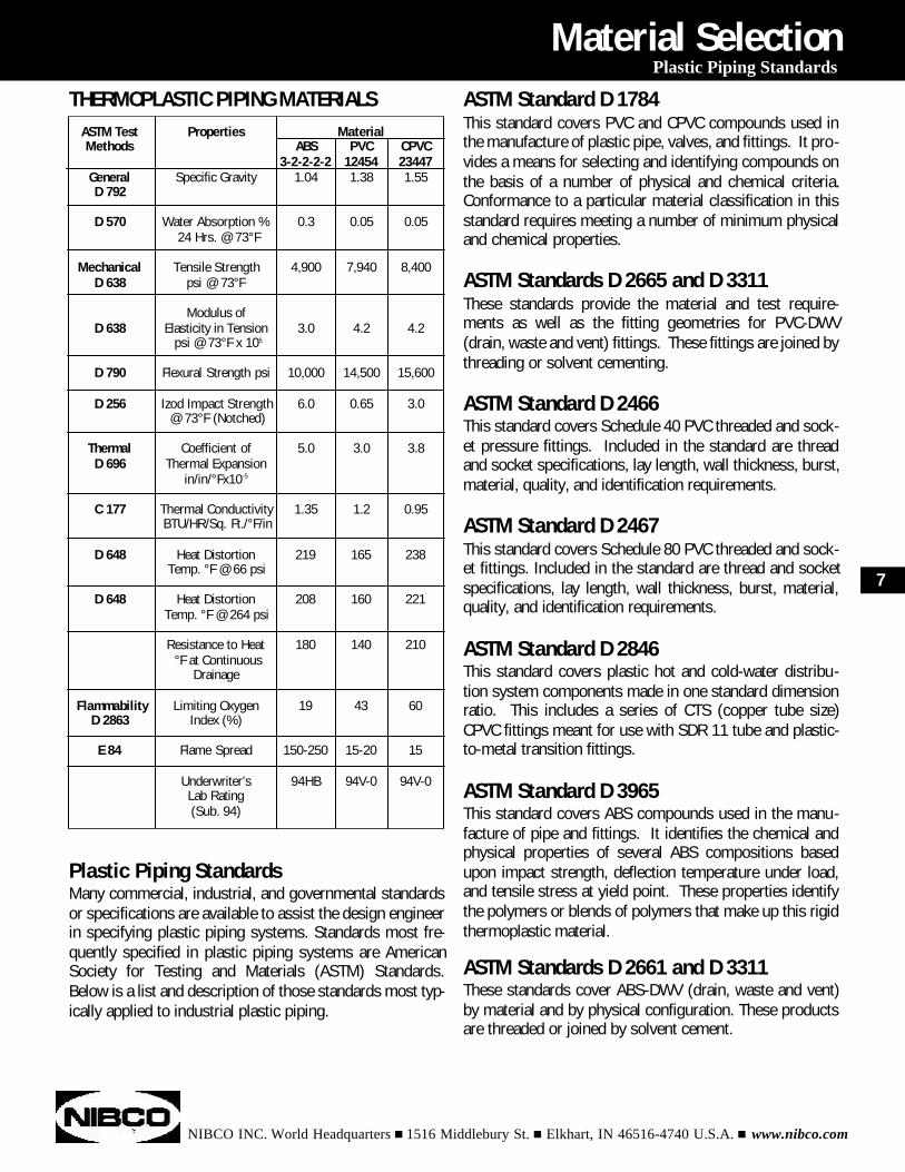
ASTM Test Properties MaterialMethods ABS PVC CPVC
3-2-2-2-2 12454 23447General Specific Gravity 1.04 1.38 1.55D 792
D 570 Water Absorption % 0.3 0.05 0.0524 Hrs. @ 73°F
Mechanical Tensile Strength 4,900 7,940 8,400D 638 psi @ 73°F
Modulus ofD 638 Elasticity in Tension 3.0 4.2 4.2
psi @ 73°F x 105
D 790 Flexural Strength psi 10,000 14,500 15,600
D 256 Izod Impact Strength 6.0 0.65 3.0@ 73°F (Notched)
Thermal Coefficient of 5.0 3.0 3.8D 696 Thermal Expansion
in/in/°Fx10-5
C 177 Thermal Conductivity 1.35 1.2 0.95BTU/HR/Sq. Ft./°F/in
D 648 Heat Distortion 219 165 238Temp. °F @ 66 psi
D 648 Heat Distortion 208 160 221Temp. °F @ 264 psi
Resistance to Heat 180 140 210°F at Continuous
Drainage
Flammability Limiting Oxygen 19 43 60D 2863 Index (%)
E 84 Flame Spread 150-250 15-20 15
Underwriter’s 94HB 94V-0 94V-0Lab Rating (Sub. 94)
NIBCO INC. World Headquarters n 1516 Middlebury St. n Elkhart, IN 46516-4740 U.S.A. n www.nibco.com
Material SelectionPlastic Piping Standards
THERMOPLASTIC PIPING MATERIALS
Plastic Piping StandardsMany commercial, industrial, and governmental standardsor specifications are available to assist the design engineerin specifying plastic piping systems. Standards most fre-quently specified in plastic piping systems are AmericanSociety for Testing and Materials (ASTM) Standards.Below is a list and description of those standards most typ-ically applied to industrial plastic piping.
ASTM Standard D 1784This standard covers PVC and CPVC compounds used inthe manufacture of plastic pipe, valves, and fittings. It pro-vides a means for selecting and identifying compounds onthe basis of a number of physical and chemical criteria.Conformance to a particular material classification in thisstandard requires meeting a number of minimum physicaland chemical properties.
ASTM Standards D 2665 and D 3311These standards provide the material and test require-ments as well as the fitting geometries for PVC-DWV(drain, waste and vent) fittings. These fittings are joined bythreading or solvent cementing.
ASTM Standard D 2466This standard covers Schedule 40 PVC threaded and sock-et pressure fittings. Included in the standard are threadand socket specifications, lay length, wall thickness, burst,material, quality, and identification requirements.
ASTM Standard D 2467This standard covers Schedule 80 PVC threaded and sock-et fittings. Included in the standard are thread and socketspecifications, lay length, wall thickness, burst, material,quality, and identification requirements.
ASTM Standard D 2846This standard covers plastic hot and cold-water distribu-tion system components made in one standard dimensionratio. This includes a series of CTS (copper tube size)CPVC fittings meant for use with SDR 11 tube and plastic-to-metal transition fittings.
ASTM Standard D 3965This standard covers ABS compounds used in the manu-facture of pipe and fittings. It identifies the chemical andphysical properties of several ABS compositions basedupon impact strength, deflection temperature under load,and tensile stress at yield point. These properties identifythe polymers or blends of polymers that make up this rigidthermoplastic material.
ASTM Standards D 2661 and D 3311These standards cover ABS-DWV (drain, waste and vent)by material and by physical configuration. These productsare threaded or joined by solvent cement.
7
ASTM Standard F 1498This standard covers dimensions, tolerances, and gaging oftapered pipe threads used on plastic ends of pipe and fittings.
ASTM Standard F 1970This standard covers fittings and appurtenances intendedto be used in PVC or CPVC plastic piping, or as a transitionfrom such systems to metal systems. These products,such as unions, flanges, or valves, are not included in thescope of other ASTM specifications.
ASME B1.20.1 (American Society ofMechanical Engineers)This specification details the dimensions, tolerances, andgaging of tapered pipe threads used on metallic ends ofpipe and fittings, plus machined plastic threaded ends.
ANSI/NSF Standard 14 (NSF International,formerly National Sanitation Foundation)This standard establishes the minimum physical and per-formance requirements for plastic piping system compo-nents and related materials. It also provides a basis forcertification of products to consensus standards, or otherphysical and performance requirements where no consen-sus standard exists. It requires adherence to appropriateASTM Standards and specifies minimum quality controlprograms. To comply with this standard the manufacturermust allow periodic testing of product and auditing of pro-cedures by a third-party agency.
ANSI/NSF Standard 61At the request of the U.S. Environmental Protection Agency(EPA), a consortium led by NSF International developedthis standard. It was developed to establish minimumrequirements for the control of potential adverse humanhealth effects from products which contact drinking water.This Standard complements the performance requirementsthat are contained within ASTM product standards. NIBCOPVC & CPVC fitting products intended for potable waterapplications have been tested and certified by a third-partyagency for compliance to ANSI/NSF Standard 61.
CSA (Canadian Standards Association)CSA tests piping products against Canadian standards.These standards require that products meet certain criteriasuch as dimensions, strength, and compatibility with potablewater. Most products sold in Canada require the CSA listing.
IAPMO (International Association ofPlumbing and Mechanical Officials)IAPMO is responsible for the Uniform Plumbing Code(UPC). Products listed by IAPMO are tested by third-partyorganizations and/or meet PS (Product Standards) or IS(Installation Standards) which are written by IAPMO.Listed products will contain the UPC or IAPMO-T (1¹⁄₄"sizes for mobile home and recreational vehicle (MHRV)use) mark.
Chemical ResistanceThermoplastics exhibit a ‘GO’ or ‘NO-GO’ type of resistancewhen contacted by aggressive chemicals. That is, they eitherresist attack completely or they deteriorate rapidly, in whichcase, the mechanism of attack is either solvation or reactionwith the base molecule. Solvation, which is the most com-mon form of attack, involves penetration of a chemical into theplastic causing softening, swelling, and loss of physical prop-erties. Reaction with the base molecule involves the breakageof the molecular chain, crosslinking, or substitution reactions.
The NIBCO Chemical Resistance Guide contains specificchemical resistance information for the various plastic andelastomeric materials used in the NIBCO product line. Wheninterpreting the information presented in this brochure it isimportant to note that it is based only on unstressed immer-sion testing at the temperatures noted, using pure chemicalsor saturated solutions, except where otherwise specified. It isunwise to specify a plastic material without chemical resist-ance information relative to the specific environment of theintended application. Therefore, in situations where theaggressive environment involves a mixture of chemicals, theChemical Resistance Guide can be used to investigate theeffects of individual chemicals; however, because of possiblesynergisms, the suitability of a particular plastic for handling achemical mixture should be verified. Also, since chemicalsare more aggressive at higher temperatures and concentra-tions, chemical resistance information should not be extrapo-lated to higher temperatures and concentrations. Conversely,chemicals are generally less aggressive at lower temperaturesand concentrations; therefore, extrapolation of chemicalresistance information to lower temperatures and concentra-tions is generally acceptable.
When chemical resistance information is not available or afirst-of-a-kind process is involved, data may be obtainedthrough immersion testing. ASTM D 543 provides a methodfor conducting such tests, and the chemical, as well as, thetemperature used in this test should be identical to the antici-pated process condition.
NIBCO INC. World Headquarters n 1516 Middlebury St. n Elkhart, IN 46516-4740 U.S.A. n www.nibco.com
8
Material SelectionPlastic Piping Standards and Chemical Resistance
2 x 1 ¹⁄₂ x ³⁄₄ 2382 x 1 ¹⁄₂ x 1 2392 x ¹⁄₂ x 1¹⁄₂ 2412 x 2 x ¹⁄₂ 2472 x 2 x ³⁄₄ 2482 x 2 x 1 2492 x 2 x 1 ¹⁄₄ 2502 x 2 x 1 ¹⁄₂ 2512¹⁄₂ x 2¹⁄₂ x ¹⁄₂ 2872¹⁄₂ x 2¹⁄₂ x ³⁄₄ 2882¹⁄₂ x 2¹⁄₂ x 1 2892¹⁄₂ x 2¹⁄₂ x 1¹⁄₄ 2902¹⁄₂ x 2¹⁄₂ x 1¹⁄₂ 2912¹⁄₂ x 2¹⁄₂ x 2 2923 x 3 x ¹⁄₂ 3333 x 3 x ³⁄₄ 3343 x 3 x 1 3353 x 3 x 1 ¹⁄₄ 3363 x 3 x 1 ¹⁄₂ 3373 x 3 x 2 3383 x 3 x 4 3424 x 4 x ³⁄₄ 4164 x 4 x 1 4174 x 4 x 1 ¹⁄₄ 4184 x 4 x 1 ¹⁄₂ 4194 x 4 x 2 4204 x 4 x 3 422
¹⁄₂ x ¹⁄₂ x ¹⁄₄ 072¹⁄₂ x ¹⁄₂ x ³⁄₄ 074³⁄₄ x ¹⁄₂ x ¹⁄₂ 094³⁄₄ x ¹⁄₂ x ³⁄₄ 095³⁄₄ x ³⁄₄ x ¹⁄₂ 101³⁄₄ x ³⁄₄ x 1 1021 x ¹⁄₂ x 1 1221 x ³⁄₄ x ¹⁄₂ 1241 x ³⁄₄ x ³⁄₄ 1251 x ³⁄₄ x 1 1261 x 1 x ¹⁄₂ 1301 x 1 x ³⁄₄ 1311 x 1 x 1 ¹⁄₄ 1321 x 1 x 1 ¹⁄₂ 1331¹⁄₄ x 1 x ¹⁄₂ 1561¹⁄₄ x 1 x ³⁄₄ 1571¹⁄₄ x 1 x 1 1581¹⁄₄ x 1 ¹⁄₄ x ¹⁄₂ 1661¹⁄₄ x 1 ¹⁄₄ x ³⁄₄ 1671¹⁄₄ x 1 ¹⁄₄ x 1 1681¹⁄₂ x 1 ¹⁄₄ x ¹⁄₂ 1991¹⁄₂ x 1 ¹⁄₄ x ³⁄₄ 2011¹⁄₂ x 1 ¹⁄₄ x 1 2021¹⁄₂ x 1 ¹⁄₂ x ¹⁄₂ 2091¹⁄₂ x 1 ¹⁄₂ x ³⁄₄ 2101¹⁄₂ x 1 ¹⁄₂ x 1 2111¹⁄₂ x 1 ¹⁄₂ x 1¹⁄₄ 2121¹⁄₂ x 1 ¹⁄₂ x 2 213
401 Tee Slip x Slip x Slip402 Tee Slip x Slip x FIPT405 Tee FIPT x FIPT x FIPT406 90° Ell Slip x Slip407 90° Ell Slip x FIPT408 90° Ell FIPT x FIPT409 90° Street Ell Spg x Slip410 90° Ell MIPT x Slip411 90° Street Ell Spg x FIPT412 90° Street Ell MIPT x FIPT414 90° Side Outlet Ell Slip x Slip x FIPT417 45° Ell Slip x Slip420 Cross All Slip429 Coupling Slip x Slip430 Coupling FIPT x FIPT434 Riser Extender MIPT x FIPT435 Female Adapter Slip x FIPT436 Male Adapter MIPT x Slip437 Bushing Slip x Slip438 Bushing Spg x Slip439 Thread Bushing MIPT x FIPT447 Cap Slip448 Thread Cap FIPT449 Plug Spg450 Thread Plug MIPT475 Wye All Slip482 Deep Socket Coupling Slip x Slip488 Running Trap Spg x Spg489 P-Trap Spg x Spg
NIBCO INC. World Headquarters n 1516 Middlebury St. n Elkhart, IN 46516-4740 U.S.A. n www.nibco.com
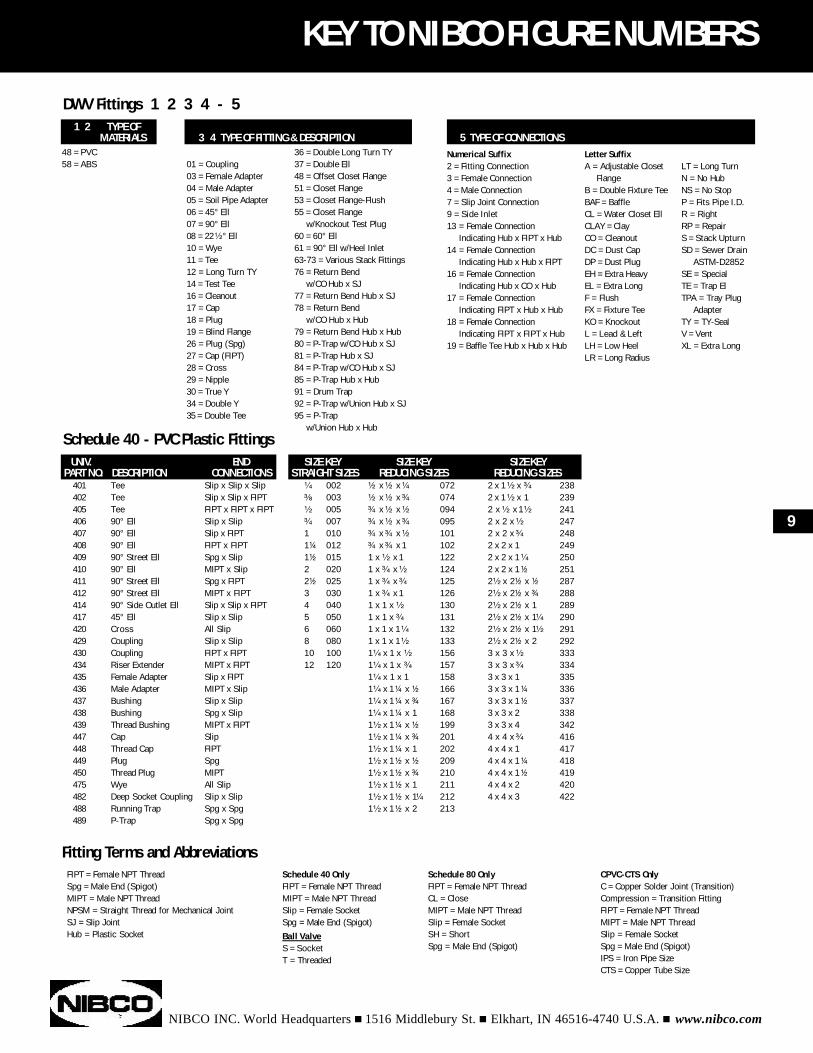
KEY TO NIBCO FIGURE NUMBERS
1 2 TYPE OFMATERIALS
48 = PVC58 = ABS 01 = Coupling
03 = Female Adapter04 = Male Adapter05 = Soil Pipe Adapter06 = 45° Ell07 = 90° Ell08 = 22 ¹⁄₂° Ell10 = Wye11 = Tee12 = Long Turn TY14 = Test Tee16 = Cleanout17 = Cap18 = Plug19 = Blind Flange26 = Plug (Spg)27 = Cap (FIPT)28 = Cross29 = Nipple30 = True Y34 = Double Y35 = Double Tee
36 = Double Long Turn TY37 = Double Ell48 = Offset Closet Flange51 = Closet Flange53 = Closet Flange-Flush55 = Closet Flange
w/Knockout Test Plug60 = 60° Ell61 = 90° Ell w/Heel Inlet63-73 = Various Stack Fittings76 = Return Bend
w/CO Hub x SJ77 = Return Bend Hub x SJ78 = Return Bend
w/CO Hub x Hub79 = Return Bend Hub x Hub80 = P-Trap w/CO Hub x SJ81 = P-Trap Hub x SJ84 = P-Trap w/CO Hub x SJ85 = P-Trap Hub x Hub91 = Drum Trap92 = P-Trap w/Union Hub x SJ95 = P-Trap
w/Union Hub x Hub
3 4 TYPE OF FITTING & DESCRIPTION
DWV Fittings 1 2 3 4 - 5
5 TYPE OF CONNECTIONSNumerical Suffix2 = Fitting Connection3 = Female Connection4 = Male Connection7 = Slip Joint Connection9 = Side Inlet13 = Female Connection
Indicating Hub x FIPT x Hub14 = Female Connection
Indicating Hub x Hub x FIPT16 = Female Connection
Indicating Hub x CO x Hub17 = Female Connection
Indicating FIPT x Hub x Hub18 = Female Connection
Indicating FIPT x FIPT x Hub19 = Baffle Tee Hub x Hub x Hub
Letter SuffixA = Adjustable Closet
FlangeB = Double Fixture TeeBAF = BaffleCL = Water Closet EllCLAY = ClayCO = CleanoutDC = Dust CapDP = Dust PlugEH = Extra HeavyEL = Extra LongF = FlushFX = Fixture TeeKO = KnockoutL = Lead & LeftLH = Low HeelLR = Long Radius
LT = Long TurnN = No HubNS = No StopP = Fits Pipe I.D.R = RightRP = RepairS = Stack UpturnSD = Sewer Drain
ASTM-D2852SE = SpecialTE = Trap ElTPA = Tray Plug
AdapterTY = TY-SealV = VentXL = Extra Long
UNIV. ENDPART NO. DESCRIPTION CONNECTIONS
Schedule 40 - PVC Plastic Fittings
¹⁄₄ 002³⁄₈ 003¹⁄₂ 005³⁄₄ 0071 0101¹⁄₄ 0121¹⁄₂ 0152 0202¹⁄₂ 0253 0304 0405 0506 0608 08010 10012 120
SIZE KEY SIZE KEY SIZE KEYSTRAIGHT SIZES REDUCING SIZES REDUCING SIZES
FIPT = Female NPT ThreadSpg = Male End (Spigot)MIPT = Male NPT ThreadNPSM = Straight Thread for Mechanical JointSJ = Slip JointHub = Plastic Socket
Fitting Terms and AbbreviationsSchedule 40 OnlyFIPT = Female NPT ThreadMIPT = Male NPT ThreadSlip = Female SocketSpg = Male End (Spigot)
Ball ValveS = SocketT = Threaded
Schedule 80 OnlyFIPT = Female NPT ThreadCL = CloseMIPT = Male NPT ThreadSlip = Female SocketSH = ShortSpg = Male End (Spigot)
CPVC-CTS OnlyC = Copper Solder Joint (Transition)Compression = Transition FittingFIPT = Female NPT ThreadMIPT = Male NPT ThreadSlip = Female SocketSpg = Male End (Spigot)IPS = Iron Pipe SizeCTS = Copper Tube Size
9
NIBCO INC. World Headquarters n 1516 Middlebury St. n Elkhart, IN 46516-4740 U.S.A. n www.nibco.com
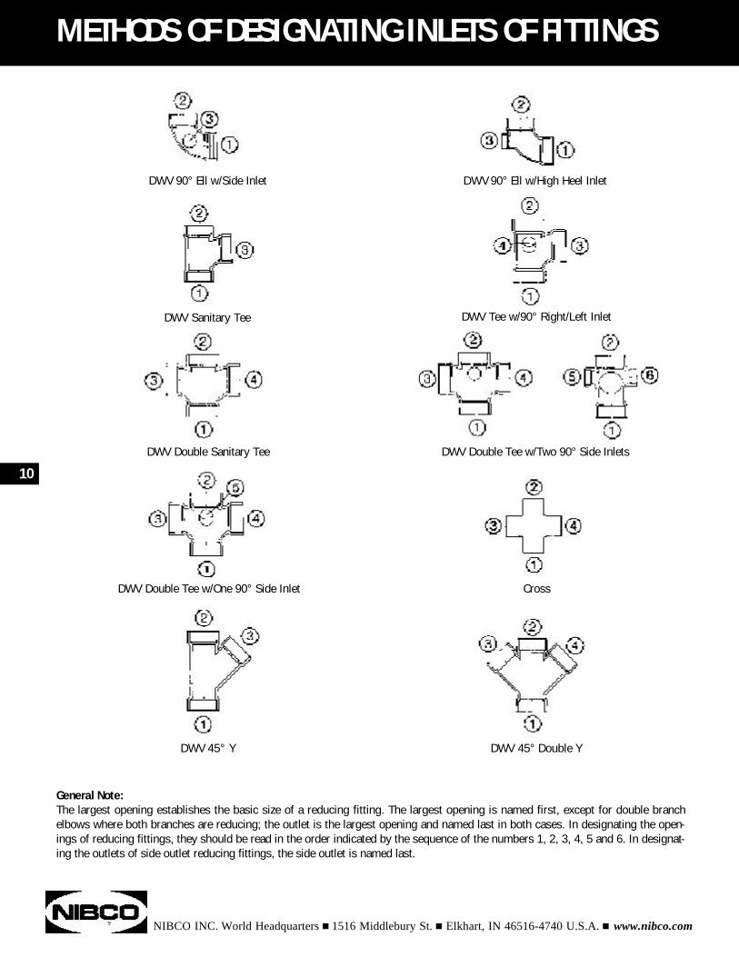
METHODS OF DESIGNATING INLETS OF FITTINGS
General Note:The largest opening establishes the basic size of a reducing fitting. The largest opening is named first, except for double branchelbows where both branches are reducing; the outlet is the largest opening and named last in both cases. In designating the open-ings of reducing fittings, they should be read in the order indicated by the sequence of the numbers 1, 2, 3, 4, 5 and 6. In designat-ing the outlets of side outlet reducing fittings, the side outlet is named last.
DWV 90° Ell w/Side Inlet
DWV Sanitary Tee
DWV Double Sanitary Tee
DWV Double Tee w/One 90° Side Inlet
DWV 45° Y
DWV 90° Ell w/High Heel Inlet
DWV Tee w/90° Right/Left Inlet
DWV Double Tee w/Two 90° Side Inlets
Cross
DWV 45° Double Y
10
11
NIBCO INC. World Headquarters n 1516 Middlebury St. n Elkhart, IN 46516-4740 U.S.A. n www.nibco.com
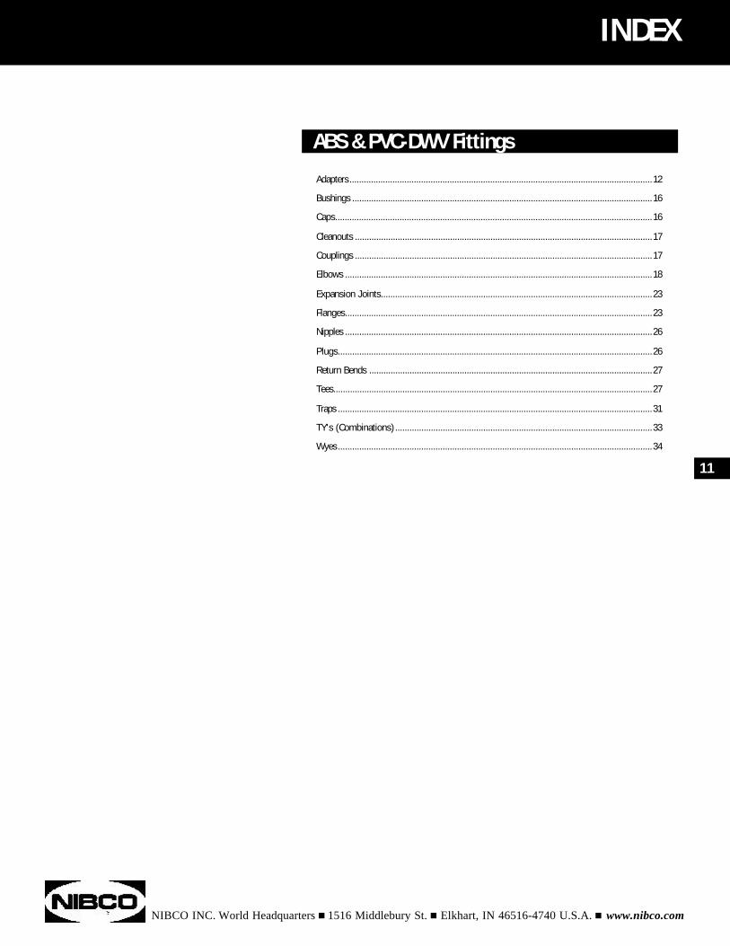
ABS & PVC-DWV Fittings
Adapters...............................................................................................................................12
Bushings ..............................................................................................................................16
Caps.....................................................................................................................................16
Cleanouts .............................................................................................................................17
Couplings .............................................................................................................................17
Elbows .................................................................................................................................18
Expansion Joints..................................................................................................................23
Flanges.................................................................................................................................23
Nipples .................................................................................................................................26
Plugs....................................................................................................................................26
Return Bends .......................................................................................................................27
Tees......................................................................................................................................27
Traps ....................................................................................................................................31
TY's (Combinations)............................................................................................................33
Wyes....................................................................................................................................34
INDEX
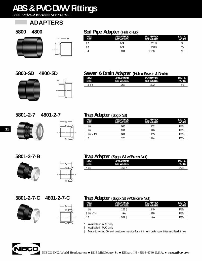
ADAPTERS
NIBCO INC. World Headquarters n 1516 Middlebury St. n Elkhart, IN 46516-4740 U.S.A. n www.nibco.com
NOM. ABS APPROX. PVC APPROX. DIM. ASIZE NET WT./LBS. NET WT./LBS. INCHES
† 2 N/A .301 § ³⁄₈
† 3 N/A .708 § ⁷⁄₁₆
4 .834 1.158 ¹⁄₂
ABS & PVC-DWV Fittings5800 Series-ABS/4800 Series-PVC
5800 4800 Soil Pipe Adapter (Hub x Hub)
NOM. ABS APPROX. PVC APPROX. DIM. ASIZE NET WT./LBS. NET WT./LBS. INCHES3 x 4" .362 .502 ⁹⁄₁₆
5800-SD 4800-SD Sewer & Drain Adapter (Hub x Sewer & Drain)
NOM. ABS APPROX. PVC APPROX. DIM. ASIZE NET WT./LBS. NET WT./LBS. INCHES1¹⁄₄ .085 .102 1²¹⁄₃₂
1¹⁄₂ .094 .120 1²¹⁄₃₂
1¹⁄₂ x 1¹⁄₄ .084 .105 1²¹⁄₃₂
2 .126 .174 1¹³⁄₁₆
5801-2-7 4801-2-7 Trap Adapter (Spg x SJ)
NOM. ABS APPROX. DIM. ASIZE NET WT./LBS. INCHES
* 1¹⁄₂ .166 § 1²¹⁄₃₂
5801-2-7-B Trap Adapter (Spg x SJ w/Brass Nut)
NOM. ABS APPROX. PVC APPROX. DIM. ASIZE NET WT./LBS. NET WT./LBS. INCHES1¹⁄₂ .123 § .149 1²¹⁄₃₂
† 1¹⁄₂ x 1¹⁄₄ N/A .128 1²¹⁄₃₂
* 2 .202 § N/A 1¹³⁄₁₆
5801-2-7-C 4801-2-7-C Trap Adapter (Spg x SJ w/Chrome Nut)
* Available in ABS only† Available in PVC only§ Made to order. Consult customer service for minimum order quantities and lead times
12
ADAPTERS (continued)
NIBCO INC. World Headquarters n 1516 Middlebury St. n Elkhart, IN 46516-4740 U.S.A. n www.nibco.com
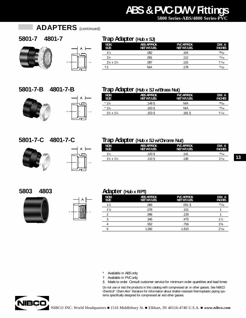
NOM. ABS APPROX. PVC APPROX. DIM. ASIZE NET WT./LBS. NET WT./LBS. INCHES1¹⁄₄" .082 .104 ²⁹⁄₃₂
1¹⁄₂ .091 .112 ¹⁵⁄₁₆
1¹⁄₂ x 1¹⁄₄ .087 .115 1¹⁄₁₆
† 2 N/A .178 ³¹⁄₃₂
ABS & PVC-DWV Fittings5800 Series-ABS/4800 Series-PVC
5801-7 4801-7 Trap Adapter (Hub x SJ)
NOM. ABS APPROX. PVC APPROX. DIM. ASIZE NET WT./LBS. NET WT./LBS. INCHES
* 1¹⁄₄ .148 § N/A ²⁹⁄₃₂
* 1¹⁄₂ .163 § N/A ¹⁵⁄₁₆
1¹⁄₂ x 1¹⁄₄ .153 § .181 § 1¹⁄₁₆
5801-7-B 4801-7-B Trap Adapter (Hub x SJ w/Brass Nut)
NOM. ABS APPROX. PVC APPROX. DIM. ASIZE NET WT./LBS. NET WT./LBS. INCHES1¹⁄₂" .120 § .141 ¹⁵⁄₁₆
1¹⁄₂ x 1¹⁄₄ .110 § .138 1¹⁄₁₆
5801-7-C 4801-7-C Trap Adapter (Hub x SJ w/Chrome Nut)
* Available in ABS only† Available in PVC only§ Made to order. Consult customer service for minimum order quantities and lead timesDo not use or test the products in this catalog with compressed air or other gasses. See NIBCOChemtrol® Chem-Aire® literature for information about shatter-resistant thermoplastic piping sys-tems specifically designed for compressed air and other gasses.
NOM. ABS APPROX. PVC APPROX. DIM. ASIZE NET WT./LBS. NET WT./LBS. INCHES1¹⁄₄" .066 .091 § ²⁷⁄₃₂
1¹⁄₂ .078 .101 12 .096 .135 13 .345 .475 1¹⁄₂
4 .552 .756 1⁵⁄₈
6 1.282 1.815 2¹⁄₃₂
5803 4803 Adapter (Hub x FIPT)
13
ADAPTERS (continued)
NIBCO INC. World Headquarters n 1516 Middlebury St. n Elkhart, IN 46516-4740 U.S.A. n www.nibco.com
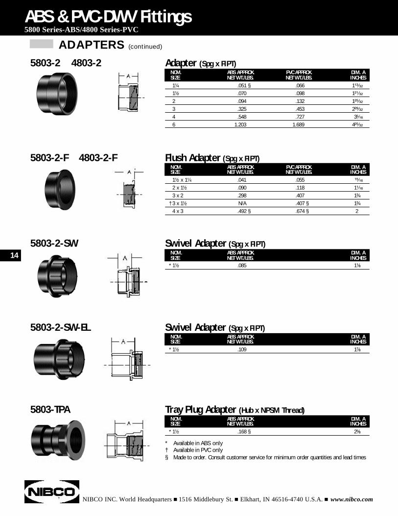
NOM. ABS APPROX. PVC APPROX. DIM. ASIZE NET WT./LBS. NET WT./LBS. INCHES1¹⁄₂ x 1¹⁄₄ .041 .055 ¹⁵⁄₁₆
2 x 1¹⁄₂ .090 .118 1¹⁄₁₆
3 x 2 .298 .407 1³⁄₄
† 3 x 1¹⁄₂ N/A .407 § 1³⁄₄
4 x 3 .492 § .674 § 2
ABS & PVC-DWV Fittings5800 Series-ABS/4800 Series-PVC
5803-2-F 4803-2-F Flush Adapter (Spg x FIPT)
NOM. ABS APPROX. DIM. ASIZE NET WT./LBS. INCHES
* 1¹⁄₂ .085 1¹⁄₈
5803-2-SW Swivel Adapter (Spg x FIPT)
NOM. ABS APPROX. DIM. ASIZE NET WT./LBS. INCHES
* 1¹⁄₂ .109 1⁷⁄₈
5803-2-SW-EL Swivel Adapter (Spg x FIPT)
NOM. ABS APPROX. DIM. ASIZE NET WT./LBS. INCHES
* 1¹⁄₂ .168 § 2⁵⁄₈
5803-TPA Tray Plug Adapter (Hub x NPSM Thread)
* Available in ABS only† Available in PVC only§ Made to order. Consult customer service for minimum order quantities and lead times
NOM. ABS APPROX. PVC APPROX. DIM. ASIZE NET WT./LBS. NET WT./LBS. INCHES1¹⁄₄ .051 § .066 1¹³⁄₃₂
1¹⁄₂ .070 .098 1²¹⁄₃₂
2 .094 .132 1²⁵⁄₃₂
3 .325 .453 2²⁹⁄₃₂
4 .548 .727 3⁵⁄₁₆
6 1.203 1.689 4²⁵⁄₃₂
5803-2 4803-2 Adapter (Spg x FIPT)
14
ADAPTERS (continued)
NIBCO INC. World Headquarters n 1516 Middlebury St. n Elkhart, IN 46516-4740 U.S.A. n www.nibco.com
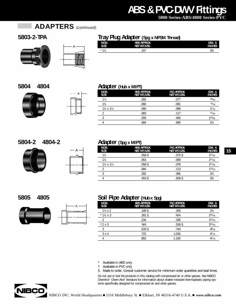
NOM. ABS APPROX. PVC APPROX. DIM. ASIZE NET WT./LBS. NET WT./LBS. INCHES1¹⁄₄" .055 .077 ²⁹⁄₃₂
1¹⁄₂ .060 .081 ¹⁵⁄₁₆
1¹⁄₂ x 1¹⁄₄ .060 .088 1¹⁄₁₆
2 .083 .117 ³¹⁄₃₂
3 .293 .400 1¹⁹⁄₃₂
4 .484 .695 2¹⁄₈
ABS & PVC-DWV Fittings5800 Series-ABS/4800 Series-PVC
5804 4804 Adapter (Hub x MIPT)
NOM. ABS APPROX. PVC APPROX. DIM. ASIZE NET WT./LBS. NET WT./LBS. INCHES1¹⁄₄ .058 § .075 § 1²¹⁄₃₂
1¹⁄₂ .063 .089 1²¹⁄₃₂
1¹⁄₂ x 1¹⁄₄ .058 § .078 1²¹⁄₃₂
2 .084 .113 1¹³⁄₁₆
3 .282 .385 3¹⁄₂
4 .454 § .609 § 3⁷⁄₈
5804-2 4804-2 Adapter (Spg x MIPT)
NOM. ABS APPROX. PVC APPROX. DIM. ASIZE NET WT./LBS. NET WT./LBS. INCHES1¹⁄₂"x 2 .189 § .265 3¹⁄₂
* 1¹⁄₂ x 3 .391 § N/A 3¹³⁄₁₆
2 .234 .335 3¹³⁄₁₆
† 2 x 3 N/A .536 § 3¹³⁄₁₆
3 .533 § .744 4³⁄₁₆
3 x 4 .722 1.026 4¹⁄₁₆
4 .853 1.190 4⁷⁄₁₆
5805 4805 Soil Pipe Adapter (Hub x Spg)
NOM. ABS APPROX. DIM. ASIZE NET WT./LBS. INCHES
* 1¹⁄₂ .157 3³⁄₈
5803-2-TPA Tray Plug Adapter (Spg x NPSM Thread)
* Available in ABS only† Available in PVC only§ Made to order. Consult customer service for minimum order quantities and lead timesDo not use or test the products in this catalog with compressed air or other gasses. See NIBCOChemtrol® Chem-Aire® literature for information about shatter-resistant thermoplastic piping sys-tems specifically designed for compressed air and other gasses.
15
BUSHINGS
NIBCO INC. World Headquarters n 1516 Middlebury St. n Elkhart, IN 46516-4740 U.S.A. n www.nibco.com
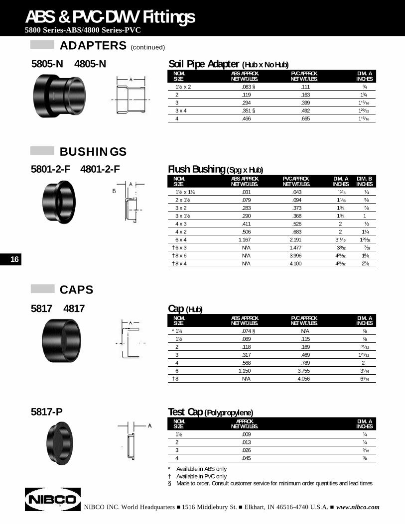
NOM. ABS APPROX. PVC APPROX. DIM. A DIM. BSIZE NET WT./LBS. NET WT./LBS. INCHES INCHES1¹⁄₂ x 1¹⁄₄ .031 .043 ¹⁵⁄₁₆ ¹⁄₄
2 x 1¹⁄₂ .079 .094 1¹⁄₁₆ ³⁄₈
3 x 2 .283 .373 1³⁄₄ ⁷⁄₈
3 x 1¹⁄₂ .290 .368 1³⁄₄ 14 x 3 .411 .526 2 ¹⁄₂
4 x 2 .506 .683 2 1¹⁄₄
6 x 4 1.167 2.191 3¹¹⁄₁₆ 1²⁹⁄₃₂
† 6 x 3 N/A 1.477 3⁹⁄₃₂ ⁷⁄₃₂
† 8 x 6 N/A 3.996 4²¹⁄₃₂ 1⁵⁄₈
† 8 x 4 N/A 4.100 4²¹⁄₃₂ 2⁷⁄₈
ABS & PVC-DWV Fittings5800 Series-ABS/4800 Series-PVC
5801-2-F 4801-2-F Flush Bushing (Spg x Hub)
NOM. ABS APPROX. PVC APPROX. DIM. ASIZE NET WT./LBS. NET WT./LBS. INCHES
* 1¹⁄₄ .074 § N/A ⁷⁄₈
1¹⁄₂ .089 .115 ⁷⁄₈
2 .118 .169 ³¹⁄₃₂
3 .317 .469 1²³⁄₃₂
4 .568 .789 26 1.150 3.755 3¹⁄₁₆
† 8 N/A 4.056 6³⁄₁₆
5817 4817 Cap (Hub)
NOM. APPROX. DIM. ASIZE NET WT./LBS. INCHES1¹⁄₂ .009 ¹⁄₄
2 .013 ¹⁄₄
3 .026 ⁵⁄₁₆
4 .045 ³⁄₈
5817-P Test Cap (Polypropylene)
CAPS
NOM. ABS APPROX. PVC APPROX. DIM. ASIZE NET WT./LBS. NET WT./LBS. INCHES1¹⁄₂ x 2" .083 § .111 ³⁄₄
2 .119 .163 1³⁄₄
3 .294 .399 1¹⁵⁄₁₆
3 x 4 .351 § .492 1²⁹⁄₃₂
4 .466 .665 1¹⁵⁄₁₆
5805-N 4805-N Soil Pipe Adapter (Hub x No Hub)
* Available in ABS only† Available in PVC only§ Made to order. Consult customer service for minimum order quantities and lead times
ADAPTERS (continued)
16
CLEANOUTS
NIBCO INC. World Headquarters n 1516 Middlebury St. n Elkhart, IN 46516-4740 U.S.A. n www.nibco.com
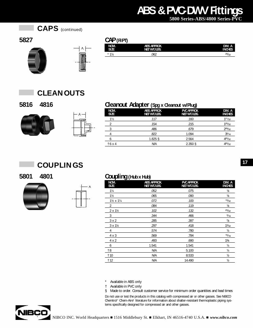
NOM. ABS APPROX. PVC APPROX. DIM. ASIZE NET WT./LBS. NET WT./LBS. INCHES1¹⁄₂" .117 .160 1²¹⁄₃₂
2 .154 .215 1²⁵⁄₃₂
3 .486 .679 2²⁹⁄₃₂
4 .822 1.094 3⁵⁄₁₆
6 1.825 § 2.564 4²⁵⁄₃₂
† 6 x 4 N/A 2.350 § 4²⁵⁄₃₂
ABS & PVC-DWV Fittings5800 Series-ABS/4800 Series-PVC
5816 4816 Cleanout Adapter (Spg x Cleanout w/Plug)
NOM. ABS APPROX. PVC APPROX. DIM. ASIZE NET WT./LBS. NET WT./LBS. INCHES1¹⁄₄ .052 .075 ¹⁄₈
1¹⁄₂ .065 .090 ¹⁄₈
1¹⁄₂ x 1¹⁄₄ .072 .100 ¹³⁄₃₂
2 .084 .119 ¹⁄₈
2 x 1¹⁄₂ .102 .132 ²³⁄₃₂
3 .344 .466 ³⁄₁₆
3 x 2 .285 .397 ⁷⁄₈
3 x 1¹⁄₂ .297 .418 1³⁄₃₂
4 .574 .780 ¹⁄₄
4 x 3 .569 .784 ¹⁵⁄₁₆
4 x 2 .493 .690 1³⁄₈
6 1.541 1.541 ¹⁄₄
† 8 N/A 5.100 ¹⁄₄
† 10 N/A 8.533 ¹⁄₂
† 12 N/A 14.490 ¹⁄₂
5801 4801 Coupling (Hub x Hub)
COUPLINGS
NOM. ABS APPROX. DIM. ASIZE NET WT./LBS. INCHES
* 1¹⁄₂ .062 ²⁹⁄₃₂
5827 CAP (FIPT)
CAPS (continued)
* Available in ABS only† Available in PVC only§ Made to order. Consult customer service for minimum order quantities and lead timesDo not use or test the products in this catalog with compressed air or other gasses. See NIBCOChemtrol® Chem-Aire® literature for information about shatter-resistant thermoplastic piping sys-tems specifically designed for compressed air and other gasses.
17
ELBOWS
NIBCO INC. World Headquarters n 1516 Middlebury St. n Elkhart, IN 46516-4740 U.S.A. n www.nibco.com
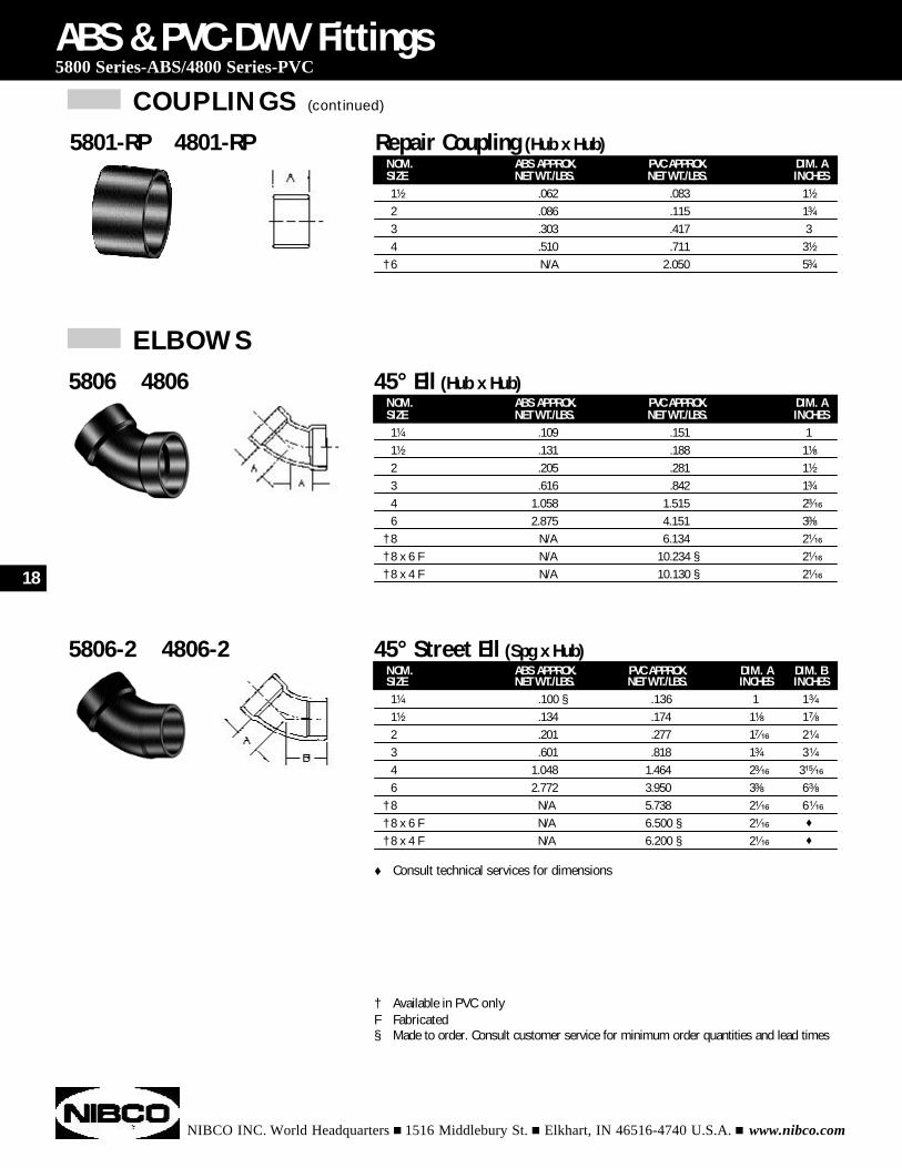
NOM. ABS APPROX. PVC APPROX. DIM. ASIZE NET WT./LBS. NET WT./LBS. INCHES1¹⁄₄ .109 .151 11¹⁄₂ .131 .188 1¹⁄₈
2 .205 .281 1¹⁄₂
3 .616 .842 1³⁄₄
4 1.058 1.515 2³⁄₁₆
6 2.875 4.151 3³⁄₈
† 8 N/A 6.134 2¹⁄₁₆
† 8 x 6 F N/A 10.234 § 2¹⁄₁₆
† 8 x 4 F N/A 10.130 § 2¹⁄₁₆
ABS & PVC-DWV Fittings5800 Series-ABS/4800 Series-PVC
5806 4806 45° Ell (Hub x Hub)
NOM. ABS APPROX. PVC APPROX. DIM. A DIM. BSIZE NET WT./LBS. NET WT./LBS. INCHES INCHES1¹⁄₄ .100 § .136 1 1³⁄₄
1¹⁄₂ .134 .174 1¹⁄₈ 1⁷⁄₈
2 .201 .277 1⁷⁄₁₆ 2¹⁄₄
3 .601 .818 1³⁄₄ 3¹⁄₄
4 1.048 1.464 2³⁄₁₆ 3¹⁵⁄₁₆
6 2.772 3.950 3³⁄₈ 6³⁄₈
† 8 N/A 5.738 2¹⁄₁₆ 6¹⁄₁₆
† 8 x 6 F N/A 6.500 § 2¹⁄₁₆ t
† 8 x 4 F N/A 6.200 § 2¹⁄₁₆ t
5806-2 4806-2 45° Street Ell (Spg x Hub)
NOM. ABS APPROX. PVC APPROX. DIM. ASIZE NET WT./LBS. NET WT./LBS. INCHES1¹⁄₂ " .062 .083 1¹⁄₂
2 .086 .115 1³⁄₄
3 .303 .417 34 .510 .711 3¹⁄₂
† 6 N/A 2.050 5³⁄₄
5801-RP 4801-RP Repair Coupling (Hub x Hub)
COUPLINGS (continued)
† Available in PVC onlyF Fabricated§ Made to order. Consult customer service for minimum order quantities and lead times
18
t Consult technical services for dimensions
ELBOWS (continued)
NIBCO INC. World Headquarters n 1516 Middlebury St. n Elkhart, IN 46516-4740 U.S.A. n www.nibco.com
NOM. ABS APPROX. PVC APPROX. DIM. ASIZE NET WT./LBS. NET WT./LBS. INCHES
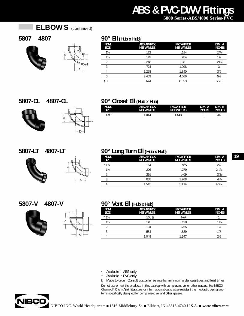
* 1¹⁄₄ .164 N/A 2¹⁄₄
1¹⁄₂ .206 .279 2¹¹⁄₁₆
2 .291 .409 3⁷⁄₃₂
3 .855 1.268 4¹⁄₁₆
4 1.542 2.114 4¹⁵⁄₁₆
ABS & PVC-DWV Fittings5800 Series-ABS/4800 Series-PVC
5807-LT 4807-LT 90° Long Turn Ell (Hub x Hub)
NOM. ABS APPROX. PVC APPROX. DIM. ASIZE NET WT./LBS. NET WT./LBS. INCHES
* 1¹⁄₄ " .106 § N/A 11¹⁄₂ .145 .190 1³⁄₁₆
2 .194 .255 1¹⁄₂
3 .584 .839 1⁷⁄₈
4 1.048 1.547 2¹⁄₂
5807-V 4807-V 90° Vent Ell (Hub x Hub)
NOM. ABS APPROX. PVC APPROX. DIM. A DIM. BSIZE NET WT./LBS. NET WT./LBS. INCHES INCHES4 x 3 1.044 1.448 3 3³⁄₈
5807-CL 4807-CL 90° Closet Ell (Hub x Hub)
NOM. ABS APPROX. PVC APPROX. DIM. ASIZE NET WT./LBS. NET WT./LBS. INCHES1¹⁄₄ .122 .184 1⁹⁄₁₆
1¹⁄₂ .149 .204 1³⁄₄
2 .248 .331 2⁵⁄₁₆
3 .724 1.008 34 1.278 1.840 3⁷⁄₈
6 3.453 4.666 5⁵⁄₈
† 8 N/A 8.553 5³¹⁄₃₂
5807 4807 90° Ell (Hub x Hub)
* Available in ABS only† Available in PVC only§ Made to order. Consult customer service for minimum order quantities and lead timesDo not use or test the products in this catalog with compressed air or other gasses. See NIBCOChemtrol® Chem-Aire® literature for information about shatter-resistant thermoplastic piping sys-tems specifically designed for compressed air and other gasses.
19
ELBOWS (continued)
NIBCO INC. World Headquarters n 1516 Middlebury St. n Elkhart, IN 46516-4740 U.S.A. n www.nibco.com
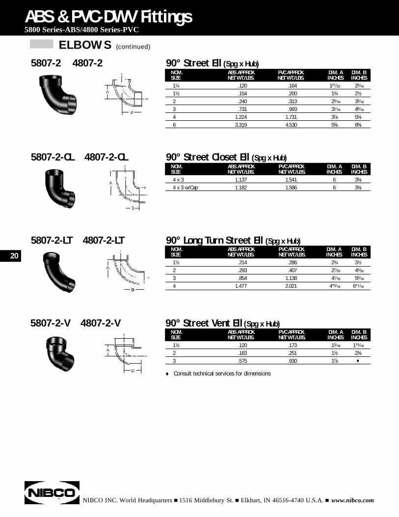
NOM. ABS APPROX. PVC APPROX. DIM. A DIM. BSIZE NET WT./LBS. NET WT./LBS. INCHES INCHES1¹⁄₂ .120 .173 1³⁄₁₆ 1¹⁵⁄₁₆
2 .183 .251 1¹⁄₂ 2³⁄₈
3 .575 .930 1⁷⁄₈ t
ABS & PVC-DWV Fittings5800 Series-ABS/4800 Series-PVC
5807-2-V 4807-2-V 90° Street Vent Ell (Spg x Hub)
NOM. ABS APPROX. PVC APPROX. DIM. A DIM. BSIZE NET WT./LBS. NET WT./LBS. INCHES INCHES4 x 3 1.137 1.541 6 3³⁄₈
4 x 3 w/Cap 1.182 1.586 6 3³⁄₈
5807-2-CL 4807-2-CL 90° Street Closet Ell (Spg x Hub)
NOM. ABS APPROX. PVC APPROX. DIM. A DIM. BSIZE NET WT./LBS. NET WT./LBS. INCHES INCHES1¹⁄₂ .214 .286 2³⁄₄ 3¹⁄₂
2 .293 .407 2⁷⁄₃₂ 4³⁄₃₂
3 .854 1.138 4¹⁄₁₆ 5⁹⁄₁₆
4 1.477 2.021 4¹⁵⁄₁₆ 6¹¹⁄₁₆
5807-2-LT 4807-2-LT 90° Long Turn Street Ell (Spg x Hub)
NOM. ABS APPROX. PVC APPROX. DIM. A DIM. BSIZE NET WT./LBS. NET WT./LBS. INCHES INCHES1¹⁄₄ " .120 .164 1²¹⁄₃₂ 2⁵⁄₁₆
1¹⁄₂ .154 .200 1³⁄₄ 2¹⁄₂
2 .240 .313 2⁵⁄₁₆ 3³⁄₁₆
3 .731 .993 3¹⁄₁₆ 4⁹⁄₁₆
4 1.224 1.731 3⁷⁄₈ 5⁵⁄₈
6 3.319 4.530 5⁵⁄₈ 8⁵⁄₈
5807-2 4807-2 90° Street Ell (Spg x Hub)
20
t Consult technical services for dimensions
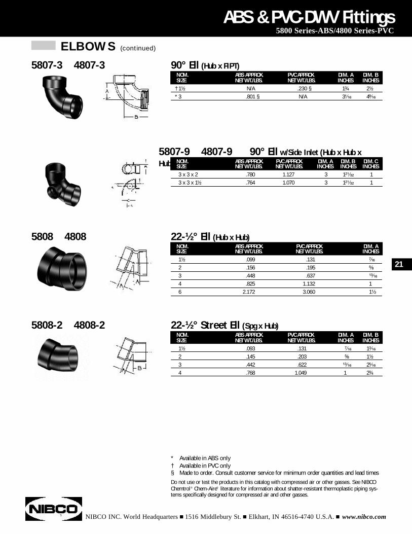
ELBOWS (continued)
NIBCO INC. World Headquarters n 1516 Middlebury St. n Elkhart, IN 46516-4740 U.S.A. n www.nibco.com
NOM. ABS APPROX. PVC APPROX. DIM. A DIM. BSIZE NET WT./LBS. NET WT./LBS. INCHES INCHES1¹⁄₂ .093 .131 ⁷⁄₁₆ 1³⁄₁₆
2 .145 .203 ⁵⁄₈ 1¹⁄₂
3 .442 .622 ¹³⁄₁₆ 2⁵⁄₁₆
4 .768 1.049 1 2³⁄₄
ABS & PVC-DWV Fittings5800 Series-ABS/4800 Series-PVC
5808-2 4808-2 22-½° Street Ell (Spg x Hub)
* Available in ABS only† Available in PVC only§ Made to order. Consult customer service for minimum order quantities and lead timesDo not use or test the products in this catalog with compressed air or other gasses. See NIBCOChemtrol® Chem-Aire® literature for information about shatter-resistant thermoplastic piping sys-tems specifically designed for compressed air and other gasses.
NOM. ABS APPROX. PVC APPROX. DIM. A DIM. B DIM. CSIZE NET WT./LBS. NET WT./LBS. INCHES INCHES INCHES3 x 3 x 2 .780 1.127 3 1²¹⁄₃₂ 13 x 3 x 1¹⁄₂ .764 1.070 3 1²¹⁄₃₂ 1
5807-9 4807-9 90° Ell w/Side Inlet (Hub x Hub xHub)
NOM. ABS APPROX. PVC APPROX. DIM. ASIZE NET WT./LBS. NET WT./LBS. INCHES1¹⁄₂ .099 .131 ⁷⁄₁₆
2 .156 .195 ⁵⁄₈
3 .448 .637 ¹³⁄₁₆
4 .825 1.132 16 2.172 3.060 1¹⁄₂
5808 4808 22-½° Ell (Hub x Hub)
NOM. ABS APPROX. PVC APPROX. DIM. A DIM. BSIZE NET WT./LBS. NET WT./LBS. INCHES INCHES
† 1¹⁄₂ N/A .230 § 1³⁄₄ 2¹⁄₂
* 3 .801 § N/A 3¹⁄₁₆ 4⁹⁄₁₆
5807-3 4807-3 90° Ell (Hub x FIPT)
21
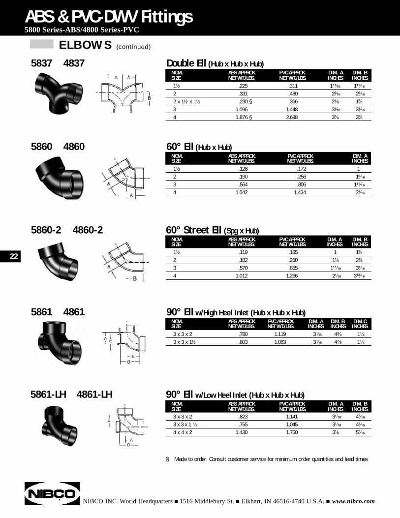
ELBOWS (continued)
NIBCO INC. World Headquarters n 1516 Middlebury St. n Elkhart, IN 46516-4740 U.S.A. n www.nibco.com
ABS & PVC-DWV Fittings5800 Series-ABS/4800 Series-PVC
§ Made to order. Consult customer service for minimum order quantities and lead times
NOM. ABS APPROX. PVC APPROX. DIM. A DIM. BSIZE NET WT./LBS. NET WT./LBS. INCHES INCHES1¹⁄₂ .119 .165 1 1³⁄₄
2 .182 .250 1¹⁄₄ 2¹⁄₈
3 .570 .855 1¹¹⁄₁₆ 3³⁄₁₆
4 1.012 1.266 2¹⁄₁₆ 3¹³⁄₁₆
5860-2 4860-2 60° Street Ell (Spg x Hub)
NOM. ABS APPROX. PVC APPROX. DIM. ASIZE NET WT./LBS. NET WT./LBS. INCHES1¹⁄₂ " .128 .172 12 .190 .256 1⁵⁄₁₆
3 .564 .806 1¹¹⁄₁₆
4 1.042 1.434 2¹⁄₁₆
5860 4860 60° Ell (Hub x Hub)
NOM. ABS APPROX. PVC APPROX. DIM. A DIM. B DIM.CSIZE NET WT./LBS. NET WT./LBS. INCHES INCHES INCHES3 x 3 x 2 .780 1.119 3¹⁄₁₆ 4³⁄₄ 1¹⁄₄
3 x 3 x 1¹⁄₂ .803 1.083 3¹⁄₁₆ 4⁷⁄₈ 1¹⁄₄
5861 4861 90° Ell w/High Heel Inlet (Hub x Hub x Hub)
NOM. ABS APPROX. PVC APPROX. DIM. A DIM. BSIZE NET WT./LBS. NET WT./LBS. INCHES INCHES3 x 3 x 2 .823 1.141 3¹⁄₁₆ 4⁷⁄₁₆
3 x 3 x 1 ¹⁄₂ .755 1.045 3¹⁄₁₆ 4³⁄₁₆
4 x 4 x 2 1.430 1.750 3¹⁄₈ 5⁷⁄₁₆
5861-LH 4861-LH 90° Ell w/Low Heel Inlet (Hub x Hub x Hub)
NOM. ABS APPROX. PVC APPROX. DIM. A DIM. BSIZE NET WT./LBS. NET WT./LBS. INCHES INCHES1¹⁄₂ " .225 .311 1¹¹⁄₁₆ 1¹¹⁄₁₆
2 .331 .480 2⁵⁄₁₆ 2⁵⁄₁₆
2 x 1¹⁄₂ x 1¹⁄₂ .230 § .366 2¹⁄₈ 1⁷⁄₈
3 1.096 1.448 3¹⁄₁₆ 3¹⁄₁₆
4 1.876 § 2.698 3⁷⁄₈ 3⁷⁄₈
5837 4837 Double Ell (Hub x Hub x Hub)
22
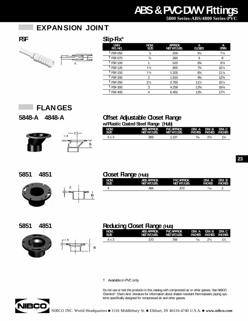
EXPANSION JOINT
† FSF-050 ¹⁄₂ .209 5¹⁄₂ 7¹⁄₂
† FSF-075 ³⁄₄ .360 6 8† FSF-100 1 .525 6³⁄₈ 8⁷⁄₈
† FSF-125 1¹⁄₄ .955 7³⁄₄ 10¹⁄₄
† FSF-150 1¹⁄₂ 1.205 8¹⁄₈ 11¹⁄₈
† FSF-200 2 1.915 9⁵⁄₈ 12⁵⁄₈
† FSF-250 2¹⁄₂ 2.765 11¹⁄₄ 15¹⁄₄
† FSF-300 3 4.258 12⁵⁄₈ 16⁵⁄₈
† FSF-400 4 6.452 13³⁄₄ 17³⁄₄
FSF Slip-Fix®
UNIV. NOM. APPROX. A AFIG. NO. SIZE NET WT./LBS. CLOSED OPEN
NIBCO INC. World Headquarters n 1516 Middlebury St. n Elkhart, IN 46516-4740 U.S.A. n www.nibco.com
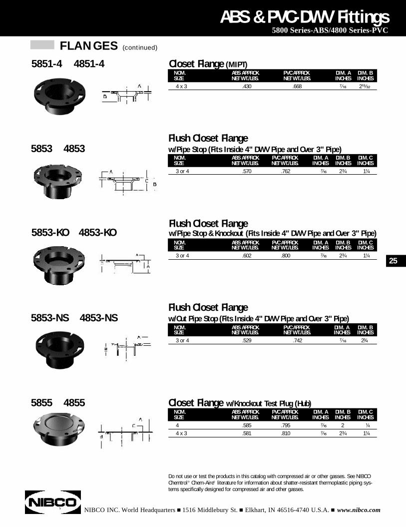
FLANGES
ABS & PVC-DWV Fittings5800 Series-ABS/4800 Series-PVC
† Available in PVC only
Do not use or test the products in this catalog with compressed air or other gasses. See NIBCOChemtrol® Chem-Aire® literature for information about shatter-resistant thermoplastic piping sys-tems specifically designed for compressed air and other gasses.
NOM. ABS APPROX. PVC APPROX. DIM. A DIM. BSIZE NET WT./LBS. NET WT./LBS. INCHES INCHES4 .466 .672 ⁷⁄₁₆ 2
5851 4851 Closet Flange (Hub)
NOM. ABS APPROX. PVC APPROX. DIM. A DIM. B DIM. CSIZE NET WT./LBS. NET WT./LBS. INCHES INCHES INCHES4 x 3 .903 1.137 ⁵⁄₁₆ 2³⁄₄ 1¹⁄₂
5848-A 4848-A Offset Adjustable Closet Flange w/Plastic Coated Steel Flange (Hub)
NOM. ABS APPROX. PVC APPROX. DIM. A DIM. B DIM. CSIZE NET WT./LBS. NET WT./LBS. INCHES INCHES INCHES4 x 3 .570 .769 ⁷⁄₁₆ 2³⁄₄ 1¹⁄₄
5851 4851 Reducing Closet Flange (Hub)
23
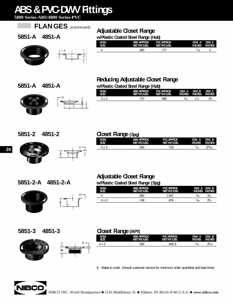
FLANGES (continued)
NIBCO INC. World Headquarters n 1516 Middlebury St. n Elkhart, IN 46516-4740 U.S.A. n www.nibco.com
ABS & PVC-DWV Fittings5800 Series-ABS/4800 Series-PVC
§ Made to order. Consult customer service for minimum order quantities and lead times
NOM. ABS APPROX. PVC APPROX. DIM. A DIM. BSIZE NET WT./LBS. NET WT./LBS. INCHES INCHES4 x 3 .540 .719 ⁷⁄₁₆ 2²⁵⁄₃₂
5851-2 4851-2 Closet Flange (Spg)
NOM. ABS APPROX. PVC APPROX. DIM. A DIM. BSIZE NET WT./LBS. NET WT./LBS. INCHES INCHES
4 x 3 .583 .666 § ⁷⁄₁₆ 2⁵⁄₁₆
5851-3 4851-3 Closet Flange (FIPT)
NOM. ABS APPROX. PVC APPROX. DIM. A DIM. BSIZE NET WT./LBS. NET WT./LBS. INCHES INCHES4 .850 1.047 ⁵⁄₁₆ 3¹⁄₄
4 x 3 .748 .876 ⁵⁄₁₆ 2³⁄₄
Adjustable Closet Flange5851-2-A 4851-2-A w/Plastic Coated Steel Flange (Spg)
NOM. ABS APPROX. PVC APPROX. DIM. A DIM. CSIZE NET WT./LBS. NET WT./LBS. INCHES INCHES4 .665 .777 ⁵⁄₁₆ 2
Adjustable Closet Flange5851-A 4851-A w/Plastic Coated Steel Flange (Hub)
NOM. ABS APPROX. PVC APPROX. DIM. A DIM. B DIM. CSIZE NET WT./LBS. NET WT./LBS. INCHES INCHES INCHES4 x 3 .770 .898 ⁵⁄₁₆ 1¹⁄₄ 2³⁄₄
Reducing Adjustable Closet Flange 5851-A 4851-A w/Plastic Coated Steel Flange (Hub)
24
NIBCO INC. World Headquarters n 1516 Middlebury St. n Elkhart, IN 46516-4740 U.S.A. n www.nibco.com
ABS & PVC-DWV Fittings5800 Series-ABS/4800 Series-PVC
Do not use or test the products in this catalog with compressed air or other gasses. See NIBCOChemtrol® Chem-Aire® literature for information about shatter-resistant thermoplastic piping sys-tems specifically designed for compressed air and other gasses.
FLANGES (continued)
NOM. ABS APPROX. PVC APPROX. DIM. A DIM. B DIM. CSIZE NET WT./LBS. NET WT./LBS. INCHES INCHES INCHES4 .585 .795 ⁷⁄₁₆ 2 ¹⁄₄
4 x 3 .581 .810 ⁷⁄₁₆ 2³⁄₄ 1¹⁄₄
5855 4855 Closet Flange w/Knockout Test Plug (Hub)
NOM. ABS APPROX. PVC APPROX. DIM. A DIM. B DIM. CSIZE NET WT./LBS. NET WT./LBS. INCHES INCHES INCHES3 or 4 .602 .800 ⁷⁄₁₆ 2³⁄₄ 1¹⁄₄
Flush Closet Flange5853-KO 4853-KO w/Pipe Stop & Knockout (Fits Inside 4" DWV Pipe and Over 3" Pipe)
NOM. ABS APPROX. PVC APPROX. DIM. A DIM. BSIZE NET WT./LBS. NET WT./LBS. INCHES INCHES3 or 4 .529 .742 ⁷⁄₁₆ 2³⁄₄
Flush Closet Flange5853-NS 4853-NS w/Out Pipe Stop (Fits Inside 4" DWV Pipe and Over 3" Pipe)
Flush Closet Flange5853 4853 w/Pipe Stop (Fits Inside 4" DWV Pipe and Over 3" Pipe)
NOM. ABS APPROX. PVC APPROX. DIM. A DIM. BSIZE NET WT./LBS. NET WT./LBS. INCHES INCHES4 x 3 .430 .668 ⁷⁄₁₆ 2¹⁵⁄₃₂
5851-4 4851-4 Closet Flange (MIPT)
NOM. ABS APPROX. PVC APPROX. DIM. A DIM. B DIM. CSIZE NET WT./LBS. NET WT./LBS. INCHES INCHES INCHES3 or 4 .570 .762 ⁷⁄₁₆ 2³⁄₄ 1¹⁄₄
25
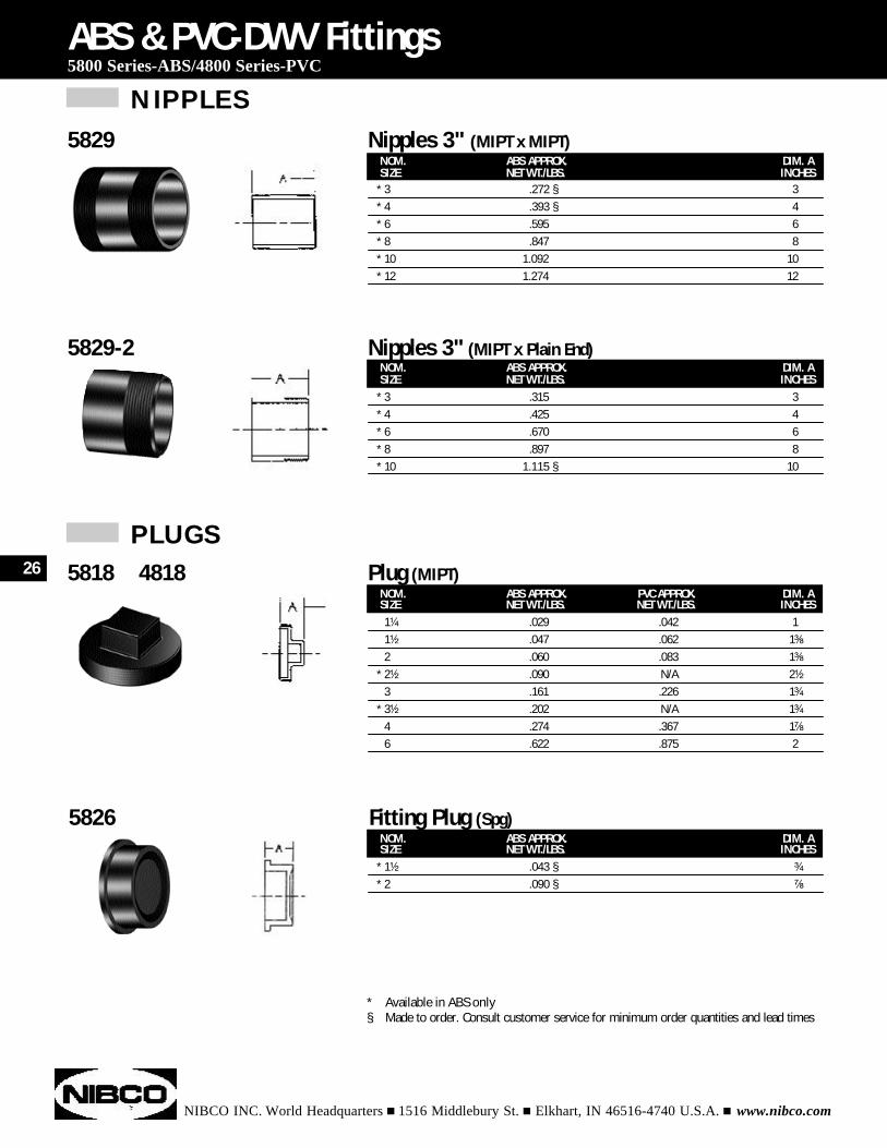
NOM. ABS APPROX. DIM. ASIZE NET WT./LBS. INCHES
* 3 .272 § 3* 4 .393 § 4* 6 .595 6* 8 .847 8* 10 1.092 10* 12 1.274 12
5829 Nipples 3" (MIPT x MIPT)
NIPPLES
NIBCO INC. World Headquarters n 1516 Middlebury St. n Elkhart, IN 46516-4740 U.S.A. n www.nibco.com
NOM. ABS APPROX. PVC APPROX. DIM. ASIZE NET WT./LBS. NET WT./LBS. INCHES1¹⁄₄ .029 .042 11¹⁄₂ .047 .062 1³⁄₈
2 .060 .083 1³⁄₈
* 2¹⁄₂ .090 N/A 2¹⁄₂
3 .161 .226 1³⁄₄
* 3¹⁄₂ .202 N/A 1³⁄₄
4 .274 .367 1⁷⁄₈
6 .622 .875 2
ABS & PVC-DWV Fittings5800 Series-ABS/4800 Series-PVC
5818 4818 Plug (MIPT)
NOM. ABS APPROX. DIM. ASIZE NET WT./LBS. INCHES
* 1¹⁄₂ .043 § ³⁄₄
* 2 .090 § ⁷⁄₈
5826 Fitting Plug (Spg)
* Available in ABS only§ Made to order. Consult customer service for minimum order quantities and lead times
NOM. ABS APPROX. DIM. ASIZE NET WT./LBS. INCHES
* 3 .315 3* 4 .425 4* 6 .670 6* 8 .897 8* 10 1.115 § 10
5829-2 Nipples 3" (MIPT x Plain End)
PLUGS26
NIBCO INC. World Headquarters n 1516 Middlebury St. n Elkhart, IN 46516-4740 U.S.A. n www.nibco.com
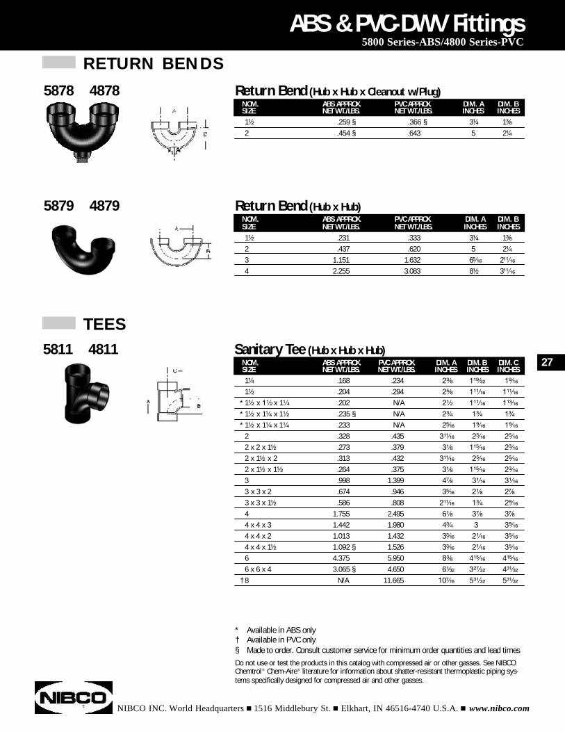
NOM. ABS APPROX. PVC APPROX. DIM. A DIM. B DIM. CSIZE NET WT./LBS. NET WT./LBS. INCHES INCHES INCHES1¹⁄₄ .168 .234 2³⁄₈ 1¹⁹⁄₃₂ 1⁹⁄₁₆
1¹⁄₂ .204 .294 2⁵⁄₈ 1¹¹⁄₁₆ 1¹¹⁄₁₆
* 1¹⁄₂ x 1¹⁄₂ x 1¹⁄₄ .202 N/A 2¹⁄₂ 1¹¹⁄₁₆ 1¹³⁄₁₆
* 1¹⁄₂ x 1¹⁄₄ x 1¹⁄₂ .235 § N/A 2³⁄₄ 1³⁄₄ 1³⁄₄
* 1¹⁄₂ x 1¹⁄₄ x 1¹⁄₄ .233 N/A 2⁵⁄₁₆ 1⁹⁄₁₆ 1⁹⁄₁₆
2 .328 .435 3¹¹⁄₁₆ 2⁵⁄₁₆ 2⁵⁄₁₆
2 x 2 x 1¹⁄₂ .273 .379 3¹⁄₈ 1¹⁵⁄₁₆ 2³⁄₁₆
2 x 1¹⁄₂ x 2 .313 .432 3¹¹⁄₁₆ 2⁵⁄₁₆ 2⁵⁄₁₆
2 x 1¹⁄₂ x 1¹⁄₂ .264 .375 3¹⁄₈ 1¹⁵⁄₁₆ 2³⁄₁₆
3 .998 1.399 4⁷⁄₈ 3¹⁄₁₆ 3¹⁄₁₆
3 x 3 x 2 .674 .946 3⁵⁄₁₆ 2¹⁄₈ 2⁷⁄₈
3 x 3 x 1¹⁄₂ .586 .808 2¹¹⁄₁₆ 1³⁄₄ 2⁹⁄₁₆
4 1.755 2.495 6¹⁄₈ 3⁷⁄₈ 3⁷⁄₈
4 x 4 x 3 1.442 1.980 4³⁄₄ 3 3⁹⁄₁₆
4 x 4 x 2 1.013 1.432 3³⁄₁₆ 2¹⁄₁₆ 3⁵⁄₁₆
4 x 4 x 1¹⁄₂ 1.092 § 1.526 3³⁄₁₆ 2¹⁄₁₆ 3⁵⁄₁₆
6 4.375 5.950 8³⁄₈ 4¹⁵⁄₁₆ 4¹⁵⁄₁₆
6 x 6 x 4 3.065 § 4.650 6¹⁄₃₂ 3²⁷⁄₃₂ 4³¹⁄₃₂
† 8 N/A 11.665 10⁷⁄₁₆ 5³¹⁄₃₂ 5³¹⁄₃₂
ABS & PVC-DWV Fittings5800 Series-ABS/4800 Series-PVC
5811 4811 Sanitary Tee (Hub x Hub x Hub)
* Available in ABS only† Available in PVC only§ Made to order. Consult customer service for minimum order quantities and lead timesDo not use or test the products in this catalog with compressed air or other gasses. See NIBCOChemtrol® Chem-Aire® literature for information about shatter-resistant thermoplastic piping sys-tems specifically designed for compressed air and other gasses.
NOM. ABS APPROX. PVC APPROX. DIM. A DIM. BSIZE NET WT./LBS. NET WT./LBS. INCHES INCHES1¹⁄₂ .231 .333 3¹⁄₄ 1³⁄₈
2 .437 .620 5 2¹⁄₄
3 1.151 1.632 6⁵⁄₁₆ 2¹¹⁄₁₆
4 2.255 3.083 8¹⁄₂ 3¹¹⁄₁₆
5879 4879 Return Bend (Hub x Hub)
TEES
NOM. ABS APPROX. PVC APPROX. DIM. A DIM. BSIZE NET WT./LBS. NET WT./LBS. INCHES INCHES1¹⁄₂ .259 § .366 § 3¹⁄₄ 1³⁄₈
2 .454 § .643 5 2¹⁄₄
5878 4878 Return Bend (Hub x Hub x Cleanout w/Plug)
RETURN BENDS
27
TEES (continued)
NIBCO INC. World Headquarters n 1516 Middlebury St. n Elkhart, IN 46516-4740 U.S.A. n www.nibco.com
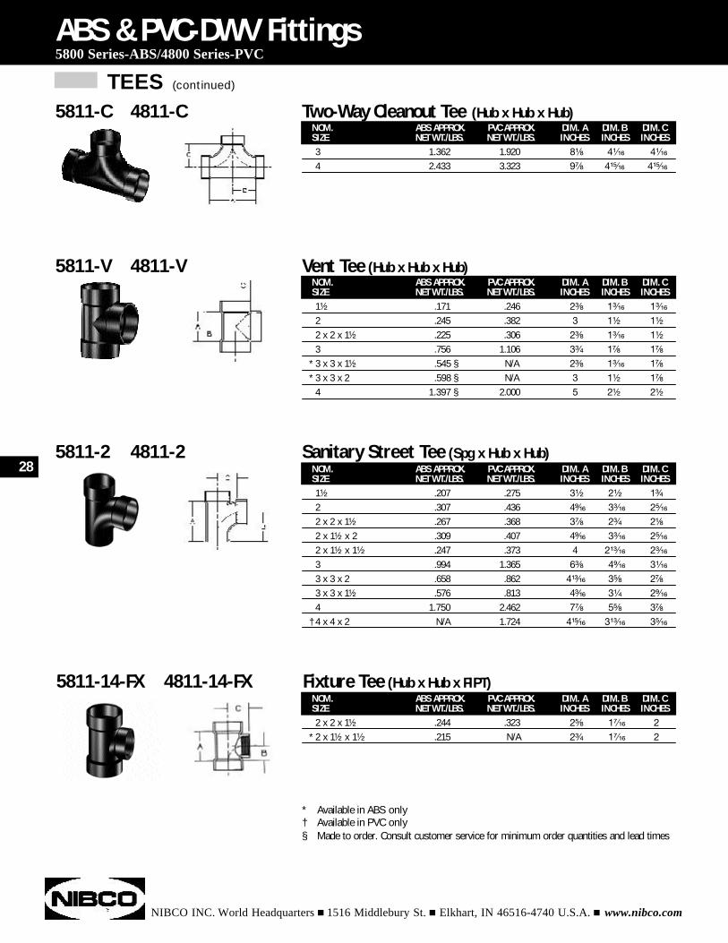
NOM. ABS APPROX. PVC APPROX. DIM. A DIM. B DIM. CSIZE NET WT./LBS. NET WT./LBS. INCHES INCHES INCHES1¹⁄₂ .207 .275 3¹⁄₂ 2¹⁄₂ 1³⁄₄
2 .307 .436 4⁹⁄₁₆ 3³⁄₁₆ 2⁵⁄₁₆
2 x 2 x 1¹⁄₂ .267 .368 3⁷⁄₈ 2³⁄₄ 2¹⁄₈
2 x 1¹⁄₂ x 2 .309 .407 4⁹⁄₁₆ 3³⁄₁₆ 2⁵⁄₁₆
2 x 1¹⁄₂ x 1¹⁄₂ .247 .373 4 2¹³⁄₁₆ 2³⁄₁₆
3 .994 1.365 6³⁄₈ 4⁹⁄₁₆ 3¹⁄₁₆
3 x 3 x 2 .658 .862 4¹³⁄₁₆ 3⁵⁄₈ 2⁷⁄₈
3 x 3 x 1¹⁄₂ .576 .813 4³⁄₁₆ 3¹⁄₄ 2⁹⁄₁₆
4 1.750 2.462 7⁷⁄₈ 5⁵⁄₈ 3⁷⁄₈
† 4 x 4 x 2 N/A 1.724 4¹⁵⁄₁₆ 3¹³⁄₁₆ 3⁵⁄₁₆
ABS & PVC-DWV Fittings5800 Series-ABS/4800 Series-PVC
5811-2 4811-2 Sanitary Street Tee (Spg x Hub x Hub)
NOM. ABS APPROX. PVC APPROX. DIM. A DIM. B DIM. CSIZE NET WT./LBS. NET WT./LBS. INCHES INCHES INCHES2 x 2 x 1¹⁄₂ .244 .323 2⁵⁄₈ 1⁷⁄₁₆ 2
* 2 x 1¹⁄₂ x 1¹⁄₂ .215 N/A 2³⁄₄ 1⁷⁄₁₆ 2
5811-14-FX 4811-14-FX Fixture Tee (Hub x Hub x FIPT)
* Available in ABS only† Available in PVC only§ Made to order. Consult customer service for minimum order quantities and lead times
NOM. ABS APPROX. PVC APPROX. DIM. A DIM. B DIM. CSIZE NET WT./LBS. NET WT./LBS. INCHES INCHES INCHES1¹⁄₂ .171 .246 2³⁄₈ 1³⁄₁₆ 1³⁄₁₆
2 .245 .382 3 1¹⁄₂ 1¹⁄₂
2 x 2 x 1¹⁄₂ .225 .306 2³⁄₈ 1³⁄₁₆ 1¹⁄₂
3 .756 1.106 3³⁄₄ 1⁷⁄₈ 1⁷⁄₈
* 3 x 3 x 1¹⁄₂ .545 § N/A 2³⁄₈ 1³⁄₁₆ 1⁷⁄₈
* 3 x 3 x 2 .598 § N/A 3 1¹⁄₂ 1⁷⁄₈
4 1.397 § 2.000 5 2¹⁄₂ 2¹⁄₂
5811-V 4811-V Vent Tee (Hub x Hub x Hub)
NOM. ABS APPROX. PVC APPROX. DIM. A DIM. B DIM. CSIZE NET WT./LBS. NET WT./LBS. INCHES INCHES INCHES3 1.362 1.920 8¹⁄₈ 4¹⁄₁₆ 4¹⁄₁₆
4 2.433 3.323 9⁷⁄₈ 4¹⁵⁄₁₆ 4¹⁵⁄₁₆
5811-C 4811-C Two-Way Cleanout Tee (Hub x Hub x Hub)
28
TEES (continued)
NIBCO INC. World Headquarters n 1516 Middlebury St. n Elkhart, IN 46516-4740 U.S.A. n www.nibco.com
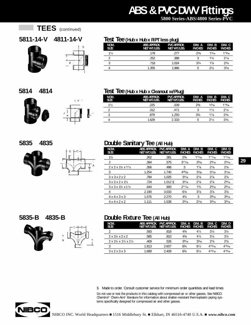
NOM. ABS APPROX. PVC APPROX. DIM. A DIM. B DIM. C DIM. DSIZE NET WT./LBS. NET WT./LBS. INCHES INCHES INCHES INCHES1¹⁄₂ .262 .381 2⁵⁄₈ 1¹¹⁄₁₆ 1¹¹⁄₁₆ 1¹¹⁄₁₆
2 .394 .575 3¹¹⁄₁₆ 2⁵⁄₁₆ 2⁵⁄₁₆ 2⁵⁄₁₆
2 x 2 x 1¹⁄₂ x 1¹⁄₂ .356 .496 3 1⁷⁄₈ 2¹⁄₈ 2¹⁄₈
3 1.254 1.740 4²⁵⁄₃₂ 3¹⁄₃₂ 3¹⁄₃₂ 3¹⁄₃₂
3 x 3 x 2 x 2 .784 1.025 3⁵⁄₁₆ 2¹⁄₈ 2⁷⁄₈ 2⁷⁄₈
3 x 3 x 2 x 1¹⁄₂ .724 1.012 § 3⁵⁄₁₆ 2¹⁄₈ 2⁷⁄₈ 2⁹⁄₁₆
3 x 3 x 1¹⁄₂ x 1¹⁄₂ .644 .900 2¹¹⁄₁₆ 1³⁄₄ 2⁹⁄₁₆ 2⁹⁄₁₆
4 2.190 3.033 6¹⁄₈ 3⁷⁄₈ 3⁷⁄₈ 3⁷⁄₈
4 x 4 x 3 x 3 1.576 2.270 4³⁄₄ 3 3⁹⁄₁₆ 3⁹⁄₁₆
4 x 4 x 2 x 2 1.111 1.538 3³⁄₁₆ 2¹⁄₁₆ 3⁵⁄₁₆ 3⁵⁄₁₆
ABS & PVC-DWV Fittings5800 Series-ABS/4800 Series-PVC
5835 4835 Double Sanitary Tee (All Hub)
NOM. ABS APPROX. PVC APPROX. DIM. A DIM. B DIM. C DIM. DSIZE NET WT./LBS. NET WT./LBS. INCHES INCHES INCHES INCHES2 .593 .818 4⁵⁄₈ 4¹⁄₄ 3¹⁄₂ 3¹⁄₂
2 x 1¹⁄₂ x 2 x 2 .585 .810 4⁵⁄₈ 4¹⁄₄ 3¹⁄₂ 3¹⁄₂
2 x 1¹⁄₂ x 1¹⁄₂ x 1¹⁄₂ .409 .526 3⁹⁄₁₆ 3³⁄₁₆ 2⁷⁄₈ 2⁷⁄₈
3 1.813 2.607 6³⁄₄ 6¹⁄₄ 4¹⁵⁄₁₆ 4¹⁵⁄₁₆
3 x 2 x 3 x 3 1.689 2.409 6³⁄₄ 6¹⁄₄ 4¹⁵⁄₁₆ 4¹⁵⁄₁₆
5835-B 4835-B Double Fixture Tee (All Hub)
§ Made to order. Consult customer service for minimum order quantities and lead timesDo not use or test the products in this catalog with compressed air or other gasses. See NIBCOChemtrol® Chem-Aire® literature for information about shatter-resistant thermoplastic piping sys-tems specifically designed for compressed air and other gasses.
NOM. ABS APPROX. PVC APPROX. DIM. A DIM. B DIM. CSIZE NET WT./LBS. NET WT./LBS. INCHES INCHES INCHES1¹⁄₂ .225 .339 2³⁄₈ 1³⁄₁₆ 1¹³⁄₁₆
2 .312 .471 3 1¹⁄₂ 2¹⁄₈
3 .879 1.250 3³⁄₄ 1⁷⁄₈ 2⁵⁄₈
4 1.629 2.333 5 2¹⁄₂ 3³⁄₈
5814 4814 Test Tee (Hub x Hub x Cleanout w/Plug)
NOM. ABS APPROX. PVC APPROX. DIM. A DIM. B DIM. CSIZE NET WT./LBS. NET WT./LBS. INCHES INCHES INCHES1¹⁄₂ .178 .277 2³⁄₈ 1³⁄₁₆ 1¹³⁄₁₆
2 .252 .388 3 1¹⁄₂ 2¹⁄₈
3 .718 1.024 3³⁄₄ 1⁷⁄₈ 2⁵⁄₈
4 1.355 1.966 5 2¹⁄₂ 3³⁄₈
5811-14-V 4811-14-V Test Tee (Hub x Hub x FIPT less plug)
29
TEES (continued)
NIBCO INC. World Headquarters n 1516 Middlebury St. n Elkhart, IN 46516-4740 U.S.A. n www.nibco.com
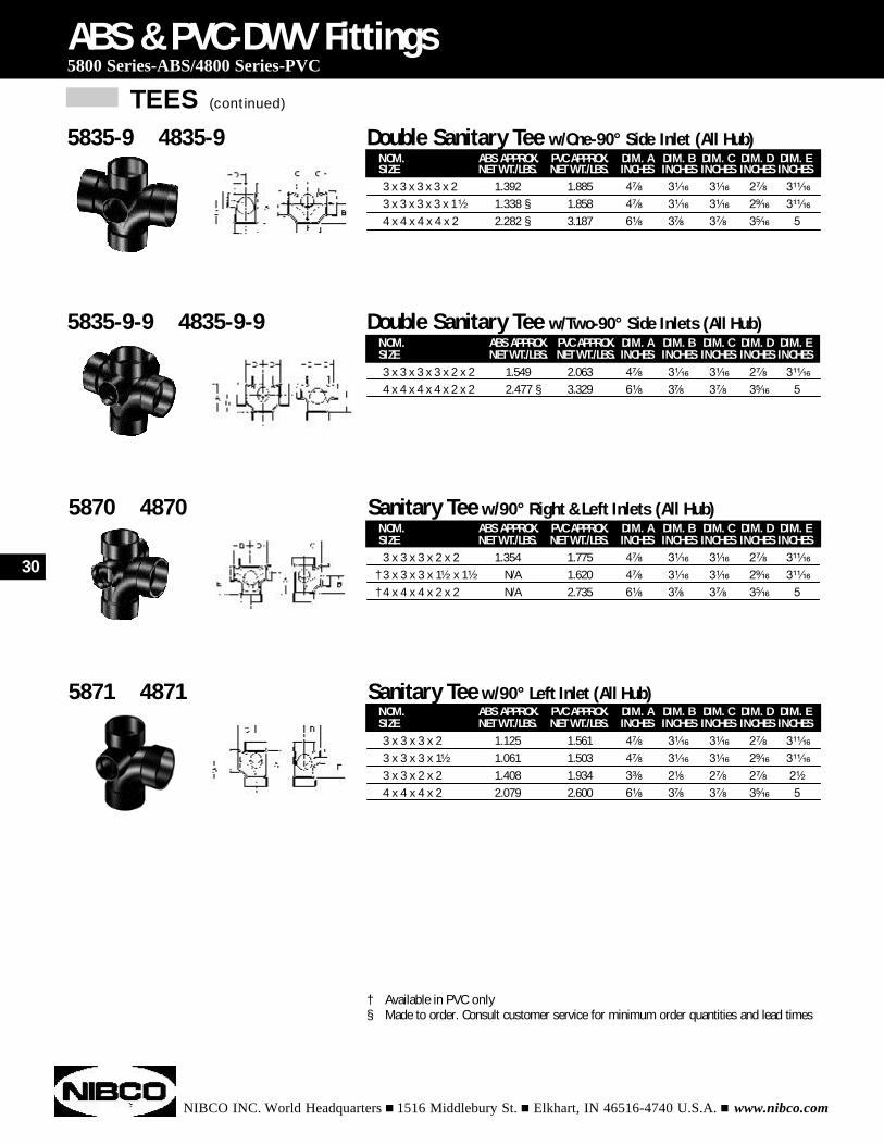
NOM. ABS APPROX. PVC APPROX. DIM. A DIM. B DIM. C DIM. D DIM. ESIZE NET WT./LBS. NET WT./LBS. INCHES INCHES INCHES INCHES INCHES3 x 3 x 3 x 3 x 2 x 2 1.549 2.063 4⁷⁄₈ 3¹⁄₁₆ 3¹⁄₁₆ 2⁷⁄₈ 3¹¹⁄₁₆
4 x 4 x 4 x 4 x 2 x 2 2.477 § 3.329 6¹⁄₈ 3⁷⁄₈ 3⁷⁄₈ 3⁵⁄₁₆ 5
ABS & PVC-DWV Fittings5800 Series-ABS/4800 Series-PVC
5835-9-9 4835-9-9 Double Sanitary Tee w/Two-90° Side Inlets (All Hub)
NOM. ABS APPROX. PVC APPROX. DIM. A DIM. B DIM. C DIM. D DIM. ESIZE NET WT./LBS. NET WT./LBS. INCHES INCHES INCHES INCHES INCHES3 x 3 x 3 x 2 1.125 1.561 4⁷⁄₈ 3¹⁄₁₆ 3¹⁄₁₆ 2⁷⁄₈ 3¹¹⁄₁₆
3 x 3 x 3 x 1¹⁄₂ 1.061 1.503 4⁷⁄₈ 3¹⁄₁₆ 3¹⁄₁₆ 2⁹⁄₁₆ 3¹¹⁄₁₆
3 x 3 x 2 x 2 1.408 1.934 3³⁄₈ 2¹⁄₈ 2⁷⁄₈ 2⁷⁄₈ 2¹⁄₂
4 x 4 x 4 x 2 2.079 2.600 6¹⁄₈ 3⁷⁄₈ 3⁷⁄₈ 3⁵⁄₁₆ 5
5871 4871 Sanitary Tee w/90° Left Inlet (All Hub)
NOM. ABS APPROX. PVC APPROX. DIM. A DIM. B DIM. C DIM. D DIM. ESIZE NET WT./LBS. NET WT./LBS. INCHES INCHES INCHES INCHES INCHES3 x 3 x 3 x 2 x 2 1.354 1.775 4⁷⁄₈ 3¹⁄₁₆ 3¹⁄₁₆ 2⁷⁄₈ 3¹¹⁄₁₆
† 3 x 3 x 3 x 1¹⁄₂ x 1¹⁄₂ N/A 1.620 4⁷⁄₈ 3¹⁄₁₆ 3¹⁄₁₆ 2⁹⁄₁₆ 3¹¹⁄₁₆
† 4 x 4 x 4 x 2 x 2 N/A 2.735 6¹⁄₈ 3⁷⁄₈ 3⁷⁄₈ 3⁵⁄₁₆ 5
5870 4870 Sanitary Tee w/90° Right & Left Inlets (All Hub)
† Available in PVC only§ Made to order. Consult customer service for minimum order quantities and lead times
NOM. ABS APPROX. PVC APPROX. DIM. A DIM. B DIM. C DIM. D DIM. ESIZE NET WT./LBS. NET WT./LBS. INCHES INCHES INCHES INCHES INCHES3 x 3 x 3 x 3 x 2 1.392 1.885 4⁷⁄₈ 3¹⁄₁₆ 3¹⁄₁₆ 2⁷⁄₈ 3¹¹⁄₁₆
3 x 3 x 3 x 3 x 1¹⁄₂ 1.338 § 1.858 4⁷⁄₈ 3¹⁄₁₆ 3¹⁄₁₆ 2⁹⁄₁₆ 3¹¹⁄₁₆
4 x 4 x 4 x 4 x 2 2.282 § 3.187 6¹⁄₈ 3⁷⁄₈ 3⁷⁄₈ 3⁵⁄₁₆ 5
5835-9 4835-9 Double Sanitary Tee w/One-90° Side Inlet (All Hub)
30
TRAPS
NIBCO INC. World Headquarters n 1516 Middlebury St. n Elkhart, IN 46516-4740 U.S.A. n www.nibco.com
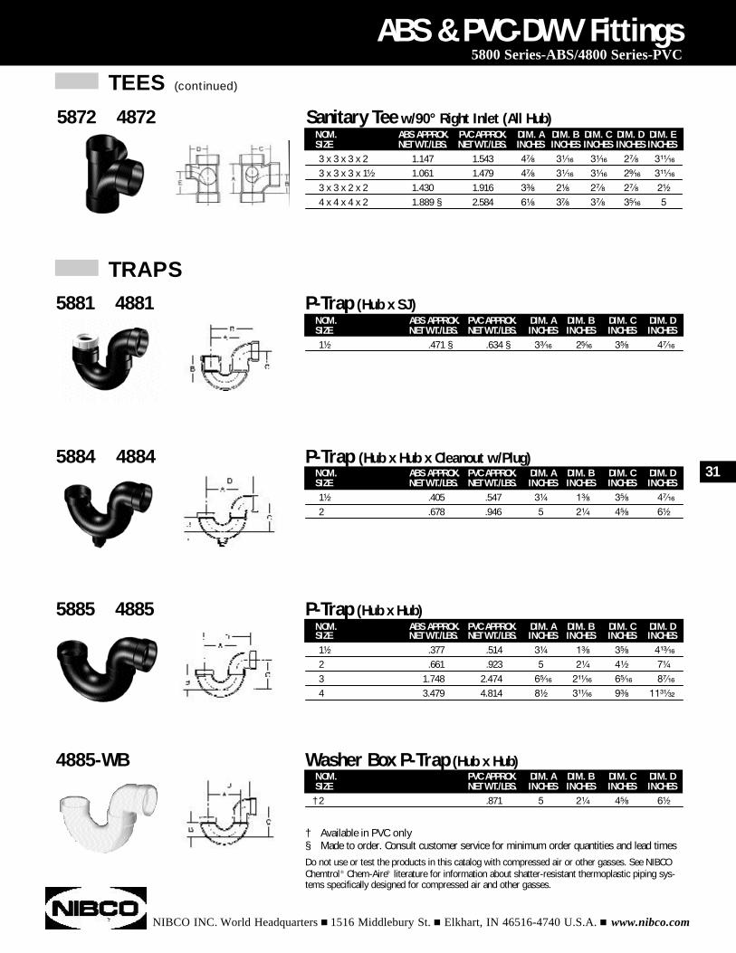
NOM. ABS APPROX. PVC APPROX. DIM. A DIM. B DIM. C DIM. DSIZE NET WT./LBS. NET WT./LBS. INCHES INCHES INCHES INCHES1¹⁄₂ .471 § .634 § 3³⁄₁₆ 2⁵⁄₁₆ 3⁵⁄₈ 4⁷⁄₁₆
ABS & PVC-DWV Fittings5800 Series-ABS/4800 Series-PVC
5881 4881 P-Trap (Hub x SJ)
NOM. ABS APPROX. PVC APPROX. DIM. A DIM. B DIM. C DIM. DSIZE NET WT./LBS. NET WT./LBS. INCHES INCHES INCHES INCHES1¹⁄₂ .405 .547 3¹⁄₄ 1³⁄₈ 3⁵⁄₈ 4⁷⁄₁₆
2 .678 .946 5 2¹⁄₄ 4⁵⁄₈ 6¹⁄₂
5884 4884 P-Trap (Hub x Hub x Cleanout w/Plug)
NOM. ABS APPROX. PVC APPROX. DIM. A DIM. B DIM. C DIM. DSIZE NET WT./LBS. NET WT./LBS. INCHES INCHES INCHES INCHES1¹⁄₂ .377 .514 3¹⁄₄ 1³⁄₈ 3⁵⁄₈ 4¹³⁄₁₆
2 .661 .923 5 2¹⁄₄ 4¹⁄₂ 7¹⁄₄
3 1.748 2.474 6⁵⁄₁₆ 2¹¹⁄₁₆ 6⁵⁄₁₆ 8⁷⁄₁₆
4 3.479 4.814 8¹⁄₂ 3¹¹⁄₁₆ 9³⁄₈ 11³¹⁄₃₂
5885 4885 P-Trap (Hub x Hub)
NOM. PVC APPROX. DIM. A DIM. B DIM. C DIM. DSIZE NET WT./LBS. INCHES INCHES INCHES INCHES
† 2 .871 5 2¹⁄₄ 4⁵⁄₈ 6¹⁄₂
4885-WB Washer Box P-Trap (Hub x Hub)
† Available in PVC only§ Made to order. Consult customer service for minimum order quantities and lead timesDo not use or test the products in this catalog with compressed air or other gasses. See NIBCOChemtrol® Chem-Aire® literature for information about shatter-resistant thermoplastic piping sys-tems specifically designed for compressed air and other gasses.
NOM. ABS APPROX. PVC APPROX. DIM. A DIM. B DIM. C DIM. D DIM. ESIZE NET WT./LBS. NET WT./LBS. INCHES INCHES INCHES INCHES INCHES3 x 3 x 3 x 2 1.147 1.543 4⁷⁄₈ 3¹⁄₁₆ 3¹⁄₁₆ 2⁷⁄₈ 3¹¹⁄₁₆
3 x 3 x 3 x 1¹⁄₂ 1.061 1.479 4⁷⁄₈ 3¹⁄₁₆ 3¹⁄₁₆ 2⁹⁄₁₆ 3¹¹⁄₁₆
3 x 3 x 2 x 2 1.430 1.916 3³⁄₈ 2¹⁄₈ 2⁷⁄₈ 2⁷⁄₈ 2¹⁄₂
4 x 4 x 4 x 2 1.889 § 2.584 6¹⁄₈ 3⁷⁄₈ 3⁷⁄₈ 3⁵⁄₁₆ 5
5872 4872 Sanitary Tee w/90° Right Inlet (All Hub)
TEES (continued)
31
TRAPS (continued)
NIBCO INC. World Headquarters n 1516 Middlebury St. n Elkhart, IN 46516-4740 U.S.A. n www.nibco.com
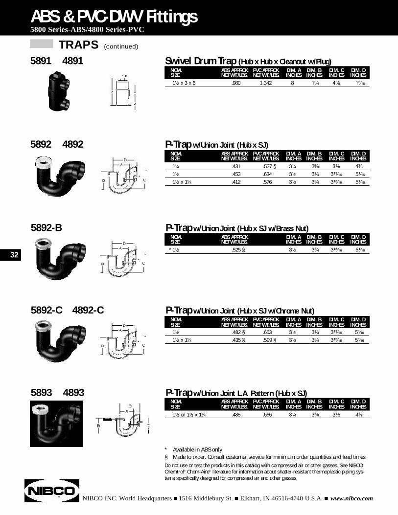
NOM. ABS APPROX. PVC APPROX. DIM. A DIM. B DIM. C DIM. DSIZE NET WT./LBS. NET WT./LBS. INCHES INCHES INCHES INCHES1¹⁄₄ .431 .527 § 3¹⁄₄ 3⁹⁄₁₆ 3³⁄₈ 4³⁄₈
1¹⁄₂ .453 .634 3¹⁄₂ 3³⁄₄ 3¹³⁄₁₆ 5¹⁄₁₆
1¹⁄₂ x 1¹⁄₄ .412 .576 3¹⁄₂ 3³⁄₄ 3¹³⁄₁₆ 5¹⁄₁₆
ABS & PVC-DWV Fittings5800 Series-ABS/4800 Series-PVC
5892 4892 P-Trap w/Union Joint (Hub x SJ)
NOM. ABS APPROX. PVC APPROX. DIM. A DIM. B DIM. C DIM. DSIZE NET WT./LBS. NET WT./LBS. INCHES INCHES INCHES INCHES1¹⁄₂ .482 § .663 3¹⁄₂ 3³⁄₄ 3¹³⁄₁₆ 5¹⁄₁₆
1¹⁄₂ x 1¹⁄₄ .435 § .599 § 3¹⁄₂ 3³⁄₄ 3¹³⁄₁₆ 5¹⁄₁₆
5892-C 4892-C P-Trap w/Union Joint (Hub x SJ w/Chrome Nut)
NOM. ABS APPROX. DIM. A DIM. B DIM. C DIM. DSIZE NET WT./LBS. INCHES INCHES INCHES INCHES
* 1¹⁄₂ .525 § 3¹⁄₂ 3³⁄₄ 3¹³⁄₁₆ 5¹⁄₁₆
5892-B P-Trap w/Union Joint (Hub x SJ w/Brass Nut)
NOM. ABS APPROX. PVC APPROX. DIM. A DIM. B DIM. C DIM. DSIZE NET WT./LBS. NET WT./LBS. INCHES INCHES INCHES INCHES1¹⁄₂ or 1¹⁄₂ x 1¹⁄₄ .485 .666 3¹⁄₄ 3⁵⁄₈ 3¹⁄₂ 4¹⁄₂
5893 4893 P-Trap w/Union Joint L.A. Pattern (Hub x SJ)
* Available in ABS only§ Made to order. Consult customer service for minimum order quantities and lead timesDo not use or test the products in this catalog with compressed air or other gasses. See NIBCOChemtrol® Chem-Aire® literature for information about shatter-resistant thermoplastic piping sys-tems specifically designed for compressed air and other gasses.
NOM. ABS APPROX. PVC APPROX. DIM. A DIM. B DIM. C DIM. DSIZE NET WT./LBS. NET WT./LBS. INCHES INCHES INCHES INCHES1¹⁄₂ x 3 x 6 .980 1.342 8 1³⁄₄ 4⁵⁄₈ 1³⁄₁₆
5891 4891 Swivel Drum Trap (Hub x Hub x Cleanout w/Plug)
32
TRAPS (continued)
NIBCO INC. World Headquarters n 1516 Middlebury St. n Elkhart, IN 46516-4740 U.S.A. n www.nibco.com
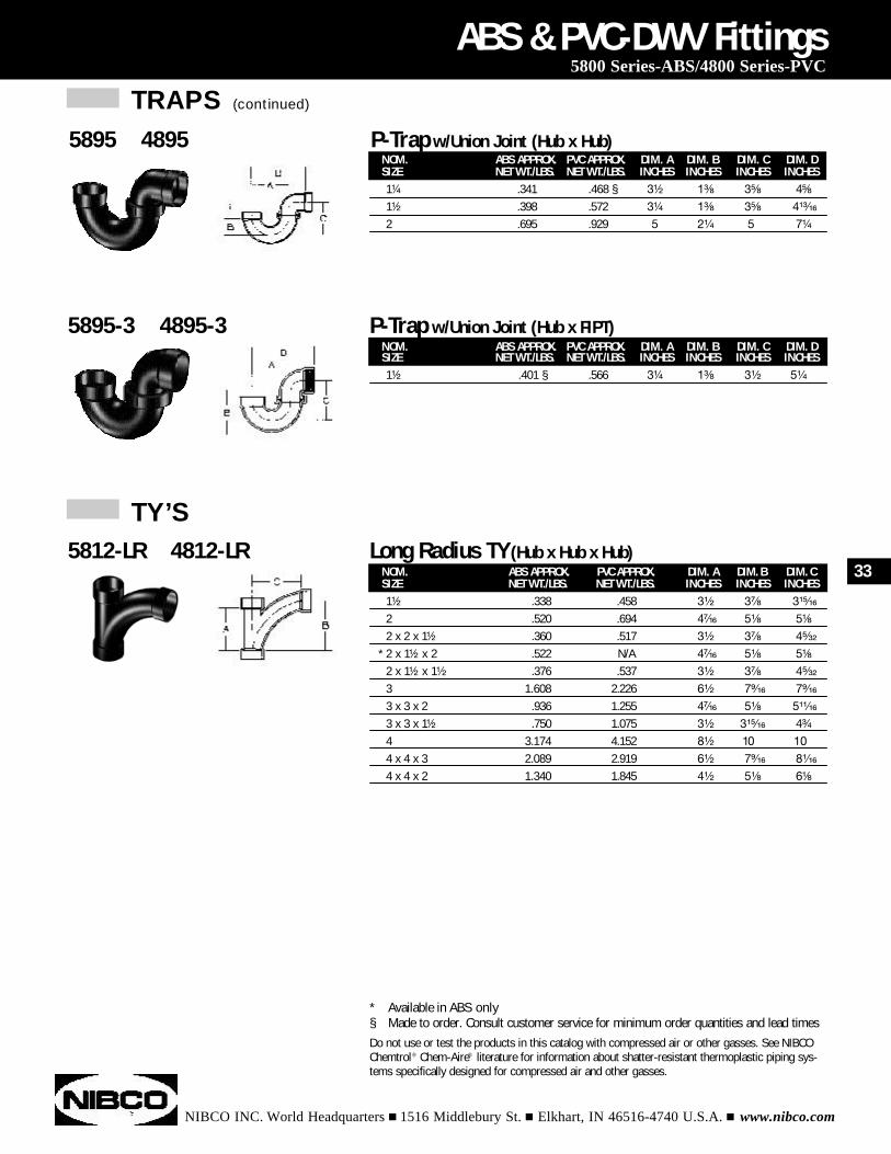
NOM. ABS APPROX. PVC APPROX. DIM. A DIM. B DIM. C DIM. DSIZE NET WT./LBS. NET WT./LBS. INCHES INCHES INCHES INCHES1¹⁄₂ .401 § .566 3¹⁄₄ 1³⁄₈ 3¹⁄₂ 5¹⁄₄
ABS & PVC-DWV Fittings5800 Series-ABS/4800 Series-PVC
5895-3 4895-3 P-Trap w/Union Joint (Hub x FIPT)
NOM. ABS APPROX. PVC APPROX. DIM. A DIM. B DIM. CSIZE NET WT./LBS. NET WT./LBS. INCHES INCHES INCHES1¹⁄₂ .338 .458 3¹⁄₂ 3⁷⁄₈ 3¹⁵⁄₁₆
2 .520 .694 4⁷⁄₁₆ 5¹⁄₈ 5¹⁄₈
2 x 2 x 1¹⁄₂ .360 .517 3¹⁄₂ 3⁷⁄₈ 4⁵⁄₃₂
* 2 x 1¹⁄₂ x 2 .522 N/A 4⁷⁄₁₆ 5¹⁄₈ 5¹⁄₈
2 x 1¹⁄₂ x 1¹⁄₂ .376 .537 3¹⁄₂ 3⁷⁄₈ 4⁵⁄₃₂
3 1.608 2.226 6¹⁄₂ 7⁹⁄₁₆ 7⁹⁄₁₆
3 x 3 x 2 .936 1.255 4⁷⁄₁₆ 5¹⁄₈ 5¹¹⁄₁₆
3 x 3 x 1¹⁄₂ .750 1.075 3¹⁄₂ 3¹⁵⁄₁₆ 4³⁄₄
4 3.174 4.152 8¹⁄₂ 10 10
4 x 4 x 3 2.089 2.919 6¹⁄₂ 7⁹⁄₁₆ 8¹⁄₁₆
4 x 4 x 2 1.340 1.845 4¹⁄₂ 5¹⁄₈ 6¹⁄₈
5812-LR 4812-LR Long Radius TY (Hub x Hub x Hub)
TY’S
* Available in ABS only§ Made to order. Consult customer service for minimum order quantities and lead timesDo not use or test the products in this catalog with compressed air or other gasses. See NIBCOChemtrol® Chem-Aire® literature for information about shatter-resistant thermoplastic piping sys-tems specifically designed for compressed air and other gasses.
NOM. ABS APPROX. PVC APPROX. DIM. A DIM. B DIM. C DIM. DSIZE NET WT./LBS. NET WT./LBS. INCHES INCHES INCHES INCHES1¹⁄₄ .341 .468 § 3¹⁄₂ 1³⁄₈ 3⁵⁄₈ 4⁵⁄₈
1¹⁄₂ .398 .572 3¹⁄₄ 1³⁄₈ 3⁵⁄₈ 4¹³⁄₁₆
2 .695 .929 5 2¹⁄₄ 5 7¹⁄₄
5895 4895 P-Trap w/Union Joint (Hub x Hub)
33
WYES
NIBCO INC. World Headquarters n 1516 Middlebury St. n Elkhart, IN 46516-4740 U.S.A. n www.nibco.com
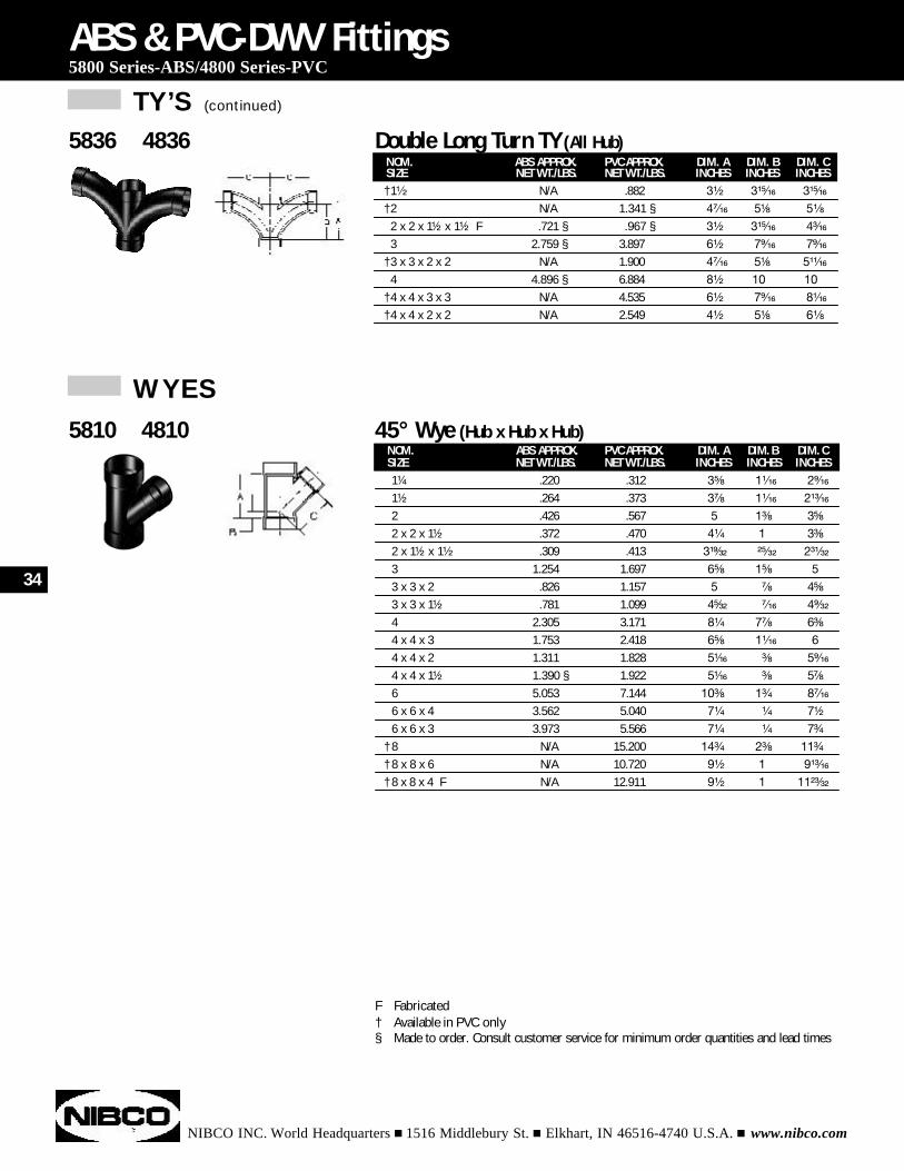
NOM. ABS APPROX. PVC APPROX. DIM. A DIM. B DIM. CSIZE NET WT./LBS. NET WT./LBS. INCHES INCHES INCHES1¹⁄₄ .220 .312 3⁵⁄₈ 1¹⁄₁₆ 2⁹⁄₁₆
1¹⁄₂ .264 .373 3⁷⁄₈ 1¹⁄₁₆ 2¹³⁄₁₆
2 .426 .567 5 1³⁄₈ 3⁵⁄₈
2 x 2 x 1¹⁄₂ .372 .470 4¹⁄₄ 1 3³⁄₈
2 x 1¹⁄₂ x 1¹⁄₂ .309 .413 3¹⁹⁄₃₂ ²⁵⁄₃₂ 2³¹⁄₃₂
3 1.254 1.697 6⁵⁄₈ 1⁵⁄₈ 5
3 x 3 x 2 .826 1.157 5 ⁷⁄₈ 4⁵⁄₈
3 x 3 x 1¹⁄₂ .781 1.099 4⁵⁄₃₂ ⁷⁄₁₆ 4⁹⁄₃₂
4 2.305 3.171 8¹⁄₄ 7⁷⁄₈ 6³⁄₈
4 x 4 x 3 1.753 2.418 6⁵⁄₈ 1¹⁄₁₆ 6
4 x 4 x 2 1.311 1.828 5¹⁄₁₆ ³⁄₈ 5⁹⁄₁₆
4 x 4 x 1¹⁄₂ 1.390 § 1.922 5¹⁄₁₆ ³⁄₈ 5⁷⁄₈
6 5.053 7.144 10³⁄₈ 1³⁄₄ 8⁷⁄₁₆
6 x 6 x 4 3.562 5.040 7¹⁄₄ ¹⁄₄ 7¹⁄₂
6 x 6 x 3 3.973 5.566 7¹⁄₄ ¹⁄₄ 7³⁄₄
† 8 N/A 15.200 14³⁄₄ 2³⁄₈ 11³⁄₄
† 8 x 8 x 6 N/A 10.720 9¹⁄₂ 1 9¹³⁄₁₆
† 8 x 8 x 4 F N/A 12.911 9¹⁄₂ 1 11²³⁄₃₂
ABS & PVC-DWV Fittings5800 Series-ABS/4800 Series-PVC
5810 4810 45° Wye (Hub x Hub x Hub)
NOM. ABS APPROX. PVC APPROX. DIM. A DIM. B DIM. CSIZE NET WT./LBS. NET WT./LBS. INCHES INCHES INCHES†1¹⁄₂ N/A .882 3¹⁄₂ 3¹⁵⁄₁₆ 3¹⁵⁄₁₆
†2 N/A 1.341 § 4⁷⁄₁₆ 5¹⁄₈ 5¹⁄₈
2 x 2 x 1¹⁄₂ x 1¹⁄₂ F .721 § .967 § 3¹⁄₂ 3¹⁵⁄₁₆ 4³⁄₁₆
3 2.759 § 3.897 6¹⁄₂ 7⁹⁄₁₆ 7⁹⁄₁₆
†3 x 3 x 2 x 2 N/A 1.900 4⁷⁄₁₆ 5¹⁄₈ 5¹¹⁄₁₆
4 4.896 § 6.884 8¹⁄₂ 10 10
†4 x 4 x 3 x 3 N/A 4.535 6¹⁄₂ 7⁹⁄₁₆ 8¹⁄₁₆
†4 x 4 x 2 x 2 N/A 2.549 4¹⁄₂ 5¹⁄₈ 6¹⁄₈
5836 4836 Double Long Turn TY (All Hub)
TY’S (continued)
F Fabricated† Available in PVC only§ Made to order. Consult customer service for minimum order quantities and lead times
34
WYES (continued)
NIBCO INC. World Headquarters n 1516 Middlebury St. n Elkhart, IN 46516-4740 U.S.A. n www.nibco.com
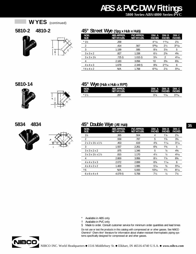
NOM. ABS APPROX. PVC APPROX. DIM. A DIM. B DIM. CSIZE NET WT./LBS. NET WT./LBS. INCHES INCHES INCHES1¹⁄₂ .365 .504 4 1¹⁄₈ 2⁷⁄₈
2 .558 .787 5 1³⁄₈ 3⁵⁄₈
2 x 2 x 1¹⁄₂ x 1¹⁄₂ .453 .619 4³⁄₈ 1¹⁄₁₆ 3⁷⁄₁₆
3 1.557 2.261 6⁵⁄₈ 1⁵⁄₈ 5
3 x 3 x 2 x 2 .975 1.346 5 ⁷⁄₈ 4⁵⁄₈
3 x 3 x 1¹⁄₂ x 1¹⁄₂ .815 1.170 4¹⁄₄ ¹⁄₂ 4⁵⁄₁₆
4 2.800 3.956 8¹⁄₄ 1⁷⁄₈ 6³⁄₈
4 x 4 x 3 x 3 2.072 2.899 6⁵⁄₈ 1¹⁄₁₆ 6
4 x 4 x 2 x 2 1.400 1.995 5¹⁄₁₆ ³⁄₈ 5⁹⁄₁₆
† 6 N/A 5.000 10³⁄₁₆ 1³⁄₄ 8⁷⁄₁₆
6 x 6 x 4 x 4 4.079 § 5.706 7¹⁄₄ ¹⁄₄ 7¹⁄₂
ABS & PVC-DWV Fittings5800 Series-ABS/4800 Series-PVC
5834 4834 45° Double Wye (All Hub)
* Available in ABS only† Available in PVC only§ Made to order. Consult customer service for minimum order quantities and lead timesDo not use or test the products in this catalog with compressed air or other gasses. See NIBCOChemtrol® Chem-Aire® literature for information about shatter-resistant thermoplastic piping sys-tems specifically designed for compressed air and other gasses.
NOM. ABS APPROX. DIM. A DIM. B DIM. CSIZE NET WT./LBS. INCHES INCHES INCHES*1¹⁄₂ .287 3⁷⁄₈ 1¹⁄₁₆ 3¹³⁄₁₆
5810-14 45° Wye (Hub x Hub x FIPT)
NOM. ABS APPROX. PVC APPROX. DIM. A DIM. B DIM. CSIZE NET WT./LBS. NET WT./LBS. INCHES INCHES INCHES
* 1¹⁄₂ .258 4¹¹⁄₁₆ 1¹³⁄₁₆ 2⁷⁄₈
2 .414 .567 5²⁹⁄₃₂ 2¹⁄₄ 3²¹⁄₃₂
3 1.199 .595 8¹⁄₈ 3¹⁄₈ 5
3 x 3 x 2 .827 1.158 6¹⁄₂ 2³⁄₈ 4⁵⁄₈
3 x 3 x 1¹⁄₂ .725 § 1.015 § 5³⁄₄ 2 4⁵⁄₁₆
4 2.183 3.056 10 3⁵⁄₈ 6³⁄₈
4 x 4 x 3 1.678 2.349 § 8³⁄₈ 2¹³⁄₁₆ 6
† 4 x 4 x 2 N/A 1.768 6¹³⁄₁₆ 2¹⁄₈ 5⁹⁄₁₆
5810-2 4810-2 45° Street Wye (Spg x Hub x Hub)
35
NIBCO INC. World Headquarters n 1516 Middlebury St. n Elkhart, IN 46516-4740 U.S.A. n www.nibco.com
CPVC-CTS Pressure Fittings
Adapters . . . . . . . . . . . . . . . . . . . . . . . . . . . . . . . . . . . . . . . . . . . . . . . . . . . . . . . . . . . . . .37
Bushings . . . . . . . . . . . . . . . . . . . . . . . . . . . . . . . . . . . . . . . . . . . . . . . . . . . . . . . . . . . . .37
Caps . . . . . . . . . . . . . . . . . . . . . . . . . . . . . . . . . . . . . . . . . . . . . . . . . . . . . . . . . . . . . . . . .38
Couplings . . . . . . . . . . . . . . . . . . . . . . . . . . . . . . . . . . . . . . . . . . . . . . . . . . . . . . . . . . . . .38
Elbows . . . . . . . . . . . . . . . . . . . . . . . . . . . . . . . . . . . . . . . . . . . . . . . . . . . . . . . . . . . . . . .39
Straps . . . . . . . . . . . . . . . . . . . . . . . . . . . . . . . . . . . . . . . . . . . . . . . . . . . . . . . . . . . . . . . .40
Swivel Adapters . . . . . . . . . . . . . . . . . . . . . . . . . . . . . . . . . . . . . . . . . . . . . . . . . . . . . . . .40
Tees . . . . . . . . . . . . . . . . . . . . . . . . . . . . . . . . . . . . . . . . . . . . . . . . . . . . . . . . . . . . . . . . .41
Transition Fittings . . . . . . . . . . . . . . . . . . . . . . . . . . . . . . . . . . . . . . . . . . . . . . . . . . . . . . .42
Transition Unions . . . . . . . . . . . . . . . . . . . . . . . . . . . . . . . . . . . . . . . . . . . . . . . . . . . . . . .42
Valves . . . . . . . . . . . . . . . . . . . . . . . . . . . . . . . . . . . . . . . . . . . . . . . . . . . . . . . . . . . . . . . .44
Rapid Hot Water Delivery System (Just-Right®) . . . . . . . . . . . . . . . . . . . . . . . . . . . . . . . . .44
FlowGuard® Gold™ is a patented CPVC formulated compound developed by B.F. Goodrich to improve the impact resistance of CPVC hot & cold water plumbing products.
INDEX
36
ADAPTERS
NIBCO INC. World Headquarters n 1516 Middlebury St. n Elkhart, IN 46516-4740 U.S.A. n www.nibco.com
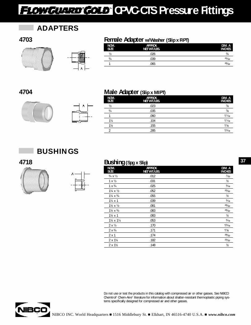
NOM. APPROX. DIM. ASIZE NET WT./LBS. INCHES¹⁄₂ .026 ³⁄₄
³⁄₄ .039 ²⁵⁄₃₂
1 .065 ²⁹⁄₃₂
CPVC-CTS Pressure Fittings
4703 Female Adapter w/Washer (Slip x FIPT)
NOM. APPROX. DIM. ASIZE NET WT./LBS. INCHES¹⁄₂ .023 ⁷⁄₈
³⁄₄ .035 ⁷⁄₈
1 .060 1¹⁄₁₆
1¹⁄₄ .104 1¹⁄₁₆
1¹⁄₂ .155 1¹⁄₈
2 .285 1³⁄₁₆
4704 Male Adapter (Slip x MIPT)
NOM. APPROX. DIM. ASIZE NET WT./LBS. INCHES³⁄₄ x ¹⁄₂ .012 ⁷⁄₃₂
1 x ¹⁄₂ .031 ¹⁄₂
1 x ³⁄₄ .025 ⁵⁄₁₆
1¹⁄₄ x ¹⁄₂ .052 ²³⁄₃₂
1¹⁄₄ x ³⁄₄ .055 ¹⁄₂
1¹⁄₄ x 1 .039 ⁵⁄₁₆
1¹⁄₂ x ¹⁄₂ .081 ²⁹⁄₃₂
1¹⁄₂ x ³⁄₄ .083 ²⁹⁄₃₂
1¹⁄₂ x 1 .083 ¹⁄₂
1¹⁄₂ x 1¹⁄₄ .053 ⁵⁄₁₆
2 x ¹⁄₂ .170 1⁵⁄₁₆
2 x ³⁄₄ .171 1¹⁄₈
2 x 1 .174 ²⁹⁄₃₂
2 x 1¹⁄₄ .182 ²³⁄₃₂
2 x 1¹⁄₂ .148 ¹⁄₂
4718 Bushing (Spg x Slip)
BUSHINGS
Do not use or test the products in this catalog with compressed air or other gasses. See NIBCOChemtrol® Chem-Aire® literature for information about shatter-resistant thermoplastic piping sys-tems specifically designed for compressed air and other gasses.
37
BUSHINGS (continued)
NIBCO INC. World Headquarters n 1516 Middlebury St. n Elkhart, IN 46516-4740 U.S.A. n www.nibco.com
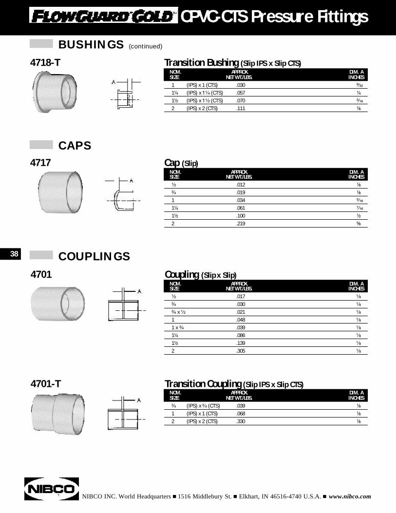
NOM. APPROX. DIM. ASIZE NET WT./LBS. INCHES¹⁄₂ .012 ¹⁄₈
³⁄₄ .019 ¹⁄₈
1 .034 ⁵⁄₁₆
1¹⁄₄ .061 ⁷⁄₁₆
1¹⁄₂ .100 ¹⁄₂
2 .219 ⁵⁄₈
4717 Cap (Slip)
NOM. APPROX. DIM. ASIZE NET WT./LBS. INCHES¹⁄₂ .017 ¹⁄₈
³⁄₄ .030 ¹⁄₈
³⁄₄ x ¹⁄₂ .021 ¹⁄₈
1 .048 ¹⁄₈
1 x ³⁄₄ .039 ¹⁄₈
1¹⁄₄ .086 ¹⁄₈
1¹⁄₂ .139 ¹⁄₈
2 .305 ¹⁄₈
4701 Coupling (Slip x Slip)
NOM. APPROX. DIM. ASIZE NET WT./LBS. INCHES³⁄₄ (IPS) x ³⁄₄ (CTS) .039 ¹⁄₈
1 (IPS) x 1 (CTS) .068 ¹⁄₈
2 (IPS) x 2 (CTS) .330 ¹⁄₈
4701-T Transition Coupling (Slip IPS x Slip CTS)
COUPLINGS
NOM. APPROX. DIM. ASIZE NET WT./LBS. INCHES1 (IPS) x 1 (CTS) .030 ⁹⁄₃₂
1¹⁄₄ (IPS) x 1¹⁄₄ (CTS) .057 ¹⁄₄
1¹⁄₂ (IPS) x 1¹⁄₂ (CTS) .070 ³⁄₁₆
2 (IPS) x 2 (CTS) .111 ¹⁄₈
4718-T Transition Bushing (Slip IPS x Slip CTS)
CAPS
38
CPVC-CTS Pressure Fittings
NIBCO INC. World Headquarters n 1516 Middlebury St. n Elkhart, IN 46516-4740 U.S.A. n www.nibco.com
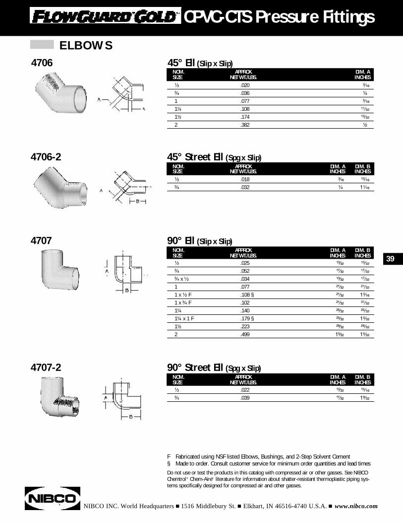
NOM. APPROX. DIM. A DIM. BSIZE NET WT./LBS. INCHES INCHES¹⁄₂ .018 ³⁄₁₆ ¹³⁄₁₆
³⁄₄ .032 ¹⁄₄ 1¹⁄₁₆
4706-2 45° Street Ell (Spg x Slip)
NOM. APPROX. DIM. A DIM. BSIZE NET WT./LBS. INCHES INCHES¹⁄₂ .025 ¹³⁄₃₂ ¹³⁄₃₂
³⁄₄ .052 ¹⁷⁄₃₂ ¹⁷⁄₃₂
³⁄₄ x ¹⁄₂ .034 ¹³⁄₃₂ ¹⁷⁄₃₂
1 .077 ²¹⁄₃₂ ²¹⁄₃₂
1 x ¹⁄₂ F .108 § ²¹⁄₃₂ 1³⁄₁₆
1 x ³⁄₄ F .102 ²¹⁄₃₂ ³¹⁄₃₂
1¹⁄₄ .140 ²⁵⁄₃₂ ²⁵⁄₃₂
1¹⁄₄ x 1 F .179 § ²⁵⁄₃₂ 1³⁄₃₂
1¹⁄₂ .223 ²⁹⁄₃₂ ²⁹⁄₃₂
2 .499 1⁵⁄₃₂ 1⁵⁄₃₂
4707 90° Ell (Slip x Slip)
NOM. APPROX. DIM. A DIM. BSIZE NET WT./LBS. INCHES INCHES¹⁄₂ .022 ¹³⁄₃₂ ¹⁵⁄₁₆
³⁄₄ .039 ¹⁷⁄₃₂ 1⁹⁄₃₂
4707-2 90° Street Ell (Spg x Slip)
F Fabricated using NSF listed Elbows, Bushings, and 2-Step Solvent Cement§ Made to order. Consult customer service for minimum order quantities and lead timesDo not use or test the products in this catalog with compressed air or other gasses. See NIBCOChemtrol® Chem-Aire® literature for information about shatter-resistant thermoplastic piping sys-tems specifically designed for compressed air and other gasses.
NOM. APPROX. DIM. ASIZE NET WT./LBS. INCHES¹⁄₂ .020 ³⁄₁₆
³⁄₄ .036 ¹⁄₄
1 .077 ⁵⁄₁₆
1¹⁄₄ .108 ¹¹⁄₃₂
1¹⁄₂ .174 ¹³⁄₃₂
2 .382 ¹⁄₂
4706 45° Ell (Slip x Slip)
ELBOWS
39
CPVC-CTS Pressure Fittings
ELBOWS (continued)
NIBCO INC. World Headquarters n 1516 Middlebury St. n Elkhart, IN 46516-4740 U.S.A. n www.nibco.com
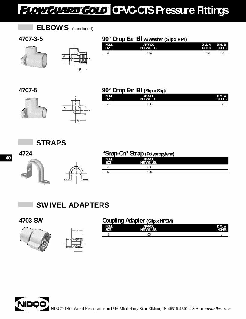
NOM. APPROX. DIM. ASIZE NET WT./LBS. INCHES¹⁄₂ .036 ¹³⁄₃₂
4707-5 90° Drop Ear Ell (Slip x Slip)
NOM. APPROX.SIZE NET WT./LBS.¹⁄₂ .003³⁄₄ .004
4724 “Snap-On” Strap (Polypropylene)
NOM. APPROX. DIM. ASIZE NET WT./LBS. INCHES¹⁄₂ .034 1
4703-SW Coupling Adapter (Slip x NPSM)
STRAPS
SWIVEL ADAPTERS
NOM. APPROX. DIM. A DIM. BSIZE NET WT./LBS. INCHES INCHES¹⁄₂ .067 ¹³⁄₃₂ 1¹⁄₈
4707-3-5 90° Drop Ear Ell w/Washer (Slip x FIPT)
40
CPVC-CTS Pressure Fittings
NIBCO INC. World Headquarters n 1516 Middlebury St. n Elkhart, IN 46516-4740 U.S.A. n www.nibco.com
CPVC Fittings
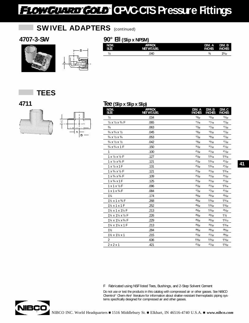
NOM. APPROX. DIM. A DIM. B DIM. CSIZE NET WT./LBS. INCHES INCHES INCHES¹⁄₂ .034 ¹³⁄₃₂ ¹³⁄₃₂ ¹³⁄₃₂
¹⁄₂ x ¹⁄₂ x ³⁄₄ F .065 ¹¹⁄₁₆ ¹¹⁄₁₆ ¹⁷⁄₃₂
³⁄₄ .063 ¹⁷⁄₃₂ ¹⁷⁄₃₂ ¹⁷⁄₃₂
³⁄₄ x ³⁄₄ x ¹⁄₂ .045 ¹³⁄₃₂ ¹³⁄₃₂ ¹⁷⁄₃₂
³⁄₄ x ¹⁄₂ x ³⁄₄ .053 ¹⁷⁄₃₂ ¹⁹⁄₃₂ ¹⁷⁄₃₂
³⁄₄ x ¹⁄₂ x ¹⁄₂ .042 ¹³⁄₃₂ ¹⁵⁄₃₂ ¹⁷⁄₃₂
³⁄₄ x ³⁄₄ x 1 F .150 ³¹⁄₃₂ ³¹⁄₃₂ ²¹⁄₃₂
1 .100 ²¹⁄₃₂ ²¹⁄₃₂ ²¹⁄₃₂
1 x ¹⁄₂ x ¹⁄₂ F .127 ²¹⁄₃₂ 1³⁄₁₆ 1³⁄₁₆
1 x ¹⁄₂ x ³⁄₄ F .121 ²¹⁄₃₂ 1³⁄₁₆ ³¹⁄₃₂
1 x ¹⁄₂ x 1 F .131 ²¹⁄₃₂ 1³⁄₁₆ ²¹⁄₃₂
1 x ³⁄₄ x ¹⁄₂ F .121 ²¹⁄₃₂ ³¹⁄₃₂ 1³⁄₁₆
1 x ³⁄₄ x ³⁄₄ F .109 ²¹⁄₃₂ ³¹⁄₃₂ ³¹⁄₃₂
1 x ³⁄₄ x 1 F .125 ²¹⁄₃₂ ³¹⁄₃₂ ²¹⁄₃₂
1 x 1 x ¹⁄₂ F .096 ²¹⁄₃₂ ²¹⁄₃₂ 1³⁄₁₆
1 x 1 x ³⁄₄ F .084 ¹⁷⁄₃₂ ¹⁷⁄₃₂ ²¹⁄₃₂
1¹⁄₄ .174 ²⁵⁄₃₂ ²⁵⁄₃₂ ²⁵⁄₃₂
1¹⁄₄ x 1 x ³⁄₄ F .268 ²⁵⁄₃₂ 1³⁄₃₂ 1⁵⁄₁₆
1¹⁄₄ x 1 x 1 F .252 ²⁵⁄₃₂ 1³⁄₃₂ 1³⁄₃₂
1¹⁄₄ x 1 x 1¹⁄₄ F .213 ²⁵⁄₃₂ 1³⁄₃₂ ²⁵⁄₃₂
1¹⁄₄ x 1¹⁄₄ x ¹⁄₂ F .226 ²⁵⁄₃₂ ²⁵⁄₃₂ 1¹⁄₂
1¹⁄₄ x 1¹⁄₄ x ³⁄₄ F .229 ²⁵⁄₃₂ ²⁵⁄₃₂ 1⁵⁄₁₃
1¹⁄₄ x 1¹⁄₄ x 1 F .213 ²⁵⁄₃₂ ²⁵⁄₃₂ 1³⁄₁₆
1¹⁄₂ .284 ²⁹⁄₃₂ ²⁹⁄₃₂ ²⁹⁄₃₂
1¹⁄₂ x 1¹⁄₂ x 1 .215 ²¹⁄₃₂ ²¹⁄₃₂ ²⁹⁄₃₂
2 .636 1⁵⁄₃₂ 1⁵⁄₃₂ 1⁵⁄₃₂
2 x 2 x 1 .421 ²¹⁄₃₂ ²¹⁄₃₂ 1⁵⁄₃₂
4711 Tee (Slip x Slip x Slip)
TEES
F Fabricated using NSF listed Tees, Bushings, and 2-Step Solvent CementDo not use or test the products in this catalog with compressed air or other gasses. See NIBCOChemtrol® Chem-Aire® literature for information about shatter-resistant thermoplastic piping sys-tems specifically designed for compressed air and other gasses.
NOM. APPROX. DIM. A DIM. BSIZE NET WT./LBS. INCHES INCHES¹⁄₂ .040 ³⁄₄ 1⁹⁄₃₂
4707-3-SW 90° Ell (Slip x NPSM)
SWIVEL ADAPTERS (continued)
41
CPVC-CTS Pressure Fittings
TRANSITION FITTINGS
NIBCO INC. World Headquarters n 1516 Middlebury St. n Elkhart, IN 46516-4740 U.S.A. n www.nibco.com
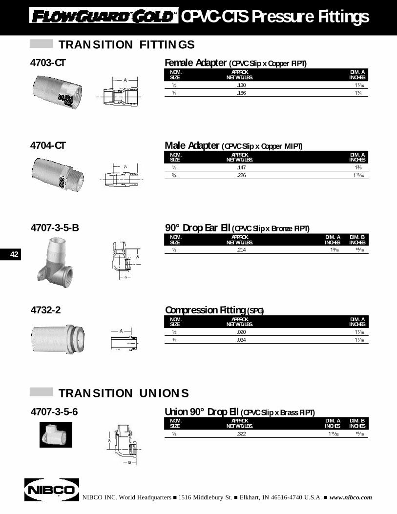
NOM. APPROX. DIM. ASIZE NET WT./LBS. INCHES¹⁄₂ .147 1³⁄₈
³⁄₄ .226 1¹¹⁄₁₆
4704-CT Male Adapter (CPVC Slip x Copper MIPT)
NOM. APPROX. DIM. A DIM. BSIZE NET WT./LBS. INCHES INCHES¹⁄₂ .214 1³⁄₁₆ ¹³⁄₁₆
4707-3-5-B 90° Drop Ear Ell (CPVC Slip x Bronze FIPT)
NOM. APPROX. DIM. ASIZE NET WT./LBS. INCHES¹⁄₂ .020 1⁷⁄₁₆
³⁄₄ .034 1⁷⁄₁₆
4732-2 Compression Fitting (SPG)
NOM. APPROX. DIM. A DIM. BSIZE NET WT./LBS. INCHES INCHES¹⁄₂ .322 1¹¹⁄₃₂ ¹⁵⁄₁₆
4707-3-5-6 Union 90° Drop Ell (CPVC Slip x Brass FIPT)
TRANSITION UNIONS
NOM. APPROX. DIM. ASIZE NET WT./LBS. INCHES¹⁄₂ .130 1⁷⁄₁₆
³⁄₄ .186 1¹⁄₄
4703-CT Female Adapter (CPVC Slip x Copper FIPT)
42
CPVC-CTS Pressure Fittings
TRANSITION UNIONS (continued)
NIBCO INC. World Headquarters n 1516 Middlebury St. n Elkhart, IN 46516-4740 U.S.A. n www.nibco.com
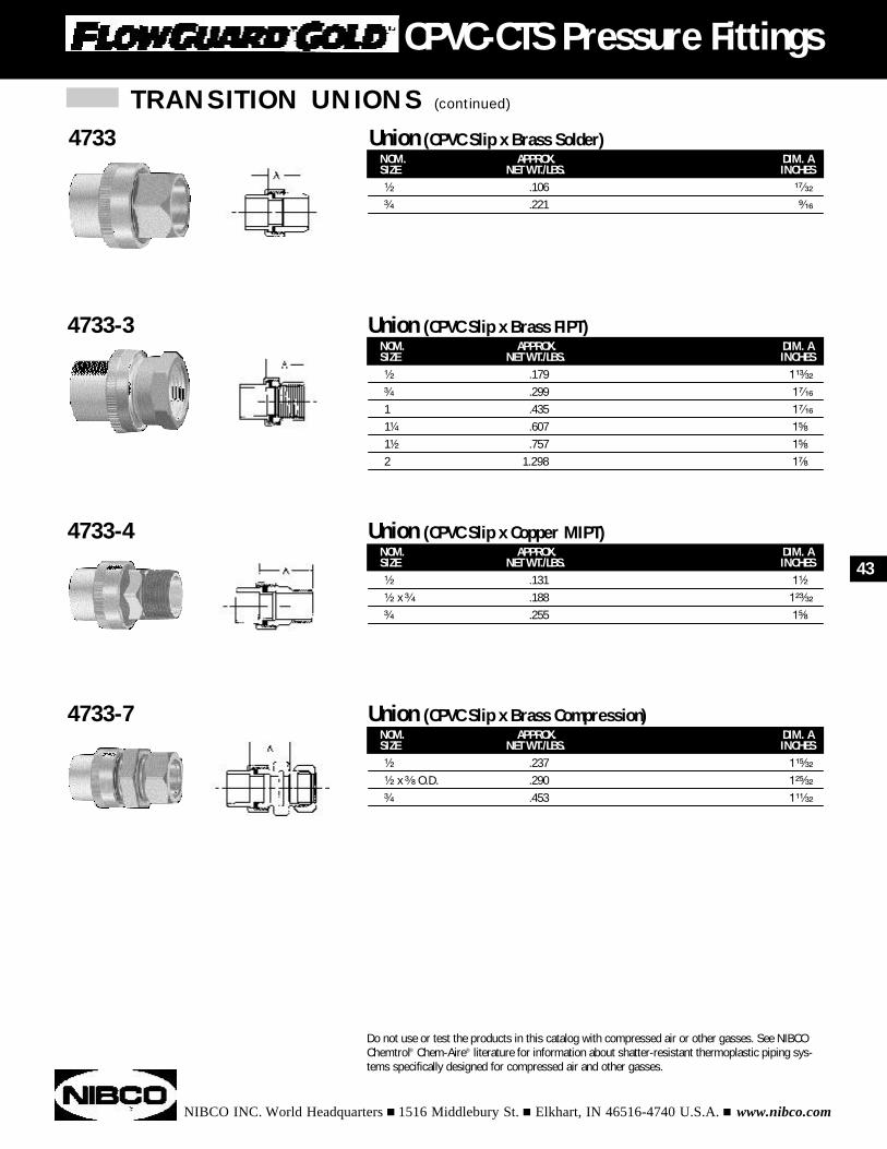
NOM. APPROX. DIM. ASIZE NET WT./LBS. INCHES¹⁄₂ .179 1¹³⁄₃₂
³⁄₄ .299 1⁷⁄₁₆
1 .435 1⁷⁄₁₆
1¹⁄₄ .607 1⁵⁄₈
1¹⁄₂ .757 1⁵⁄₈
2 1.298 1⁷⁄₈
4733-3 Union (CPVC Slip x Brass FIPT)
NOM. APPROX. DIM. ASIZE NET WT./LBS. INCHES¹⁄₂ .131 1¹⁄₂
¹⁄₂ x ³⁄₄ .188 1²³⁄₃₂
³⁄₄ .255 1⁵⁄₈
4733-4 Union (CPVC Slip x Copper MIPT)
NOM. APPROX. DIM. ASIZE NET WT./LBS. INCHES¹⁄₂ .237 1¹⁵⁄₃₂
¹⁄₂ x ³⁄₈ O.D. .290 1²⁵⁄₃₂
³⁄₄ .453 1¹¹⁄₃₂
4733-7 Union (CPVC Slip x Brass Compression)
NOM. APPROX. DIM. ASIZE NET WT./LBS. INCHES¹⁄₂ .106 ¹⁷⁄₃₂
³⁄₄ .221 ⁹⁄₁₆
4733 Union (CPVC Slip x Brass Solder)
Do not use or test the products in this catalog with compressed air or other gasses. See NIBCOChemtrol® Chem-Aire® literature for information about shatter-resistant thermoplastic piping sys-tems specifically designed for compressed air and other gasses.
43
CPVC-CTS Pressure Fittings
NIBCO INC. World Headquarters n 1516 Middlebury St. n Elkhart, IN 46516-4740 U.S.A. n www.nibco.com
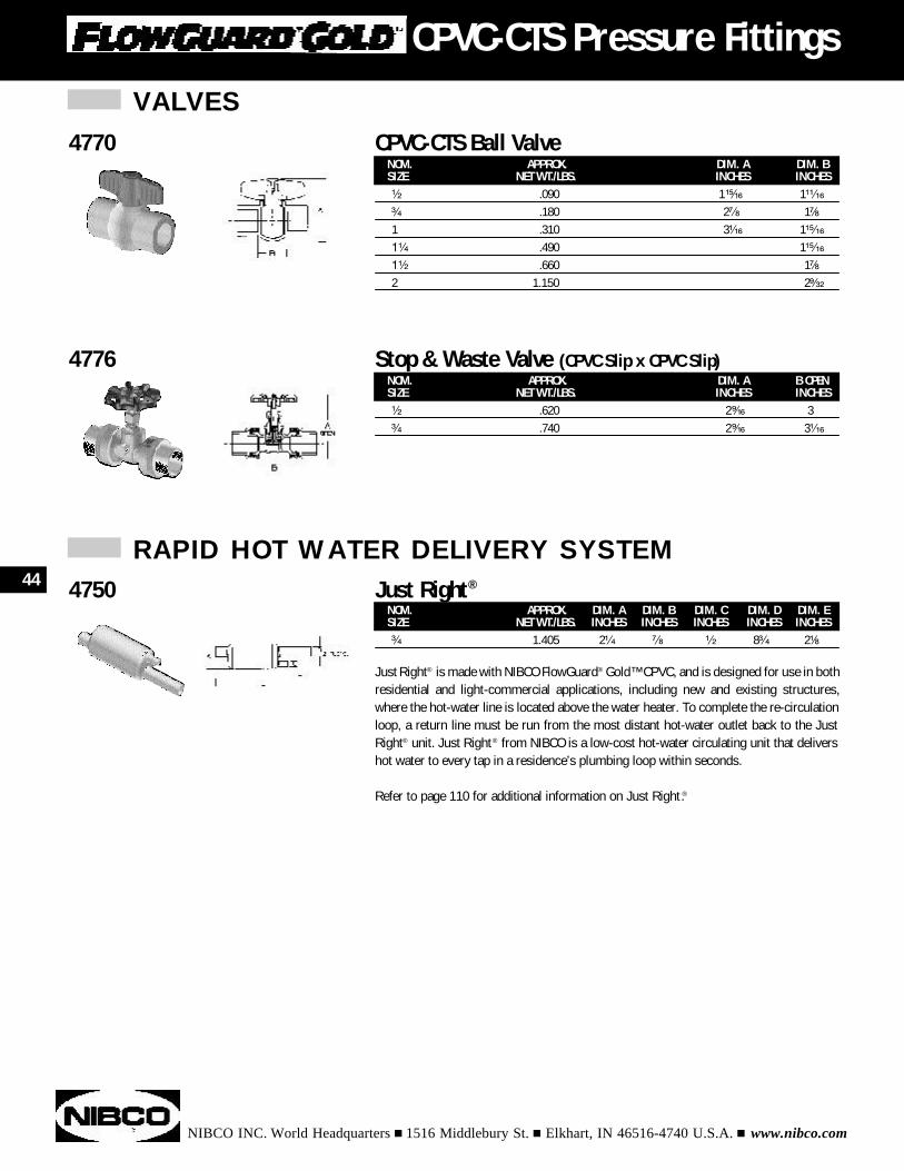
NOM. APPROX. DIM. A DIM. BSIZE NET WT./LBS. INCHES INCHES¹⁄₂ .090 1¹⁵⁄₁₆ 1¹¹⁄₁₆
³⁄₄ .180 2⁷⁄₈ 1⁷⁄₈
1 .310 3¹⁄₁₆ 1¹⁵⁄₁₆
1¹⁄₄ .490 1¹⁵⁄₁₆
1¹⁄₂ .660 1⁷⁄₈
2 1.150 2⁹⁄₃₂
4770 CPVC-CTS Ball Valve
NOM. APPROX. DIM. A DIM. B DIM. C DIM. D DIM. ESIZE NET WT./LBS. INCHES INCHES INCHES INCHES INCHES³⁄₄ 1.405 2¹⁄₄ ⁷⁄₈ ¹⁄₂ 8³⁄₄ 2¹⁄₈
Just Right® is made with NIBCO FlowGuard® Gold™ CPVC, and is designed for use in bothresidential and light-commercial applications, including new and existing structures,where the hot-water line is located above the water heater. To complete the re-circulationloop, a return line must be run from the most distant hot-water outlet back to the JustRight® unit. Just Right® from NIBCO is a low-cost hot-water circulating unit that delivershot water to every tap in a residence’s plumbing loop within seconds.
Refer to page 110 for additional information on Just Right.®
4750 Just Right®
NOM. APPROX. DIM. A B OPENSIZE NET WT./LBS. INCHES INCHES¹⁄₂ .620 2⁹⁄₁₆ 3³⁄₄ .740 2⁹⁄₁₆ 3¹⁄₁₆
4776 Stop & Waste Valve (CPVC Slip x CPVC Slip)
VALVES
44
CPVC-CTS Pressure Fittings
RAPID HOT WATER DELIVERY SYSTEM
NIBCO INC. World Headquarters n 1516 Middlebury St. n Elkhart, IN 46516-4740 U.S.A. n www.nibco.com
PVC Schedule 40 Pressure Fittings
Adapters . . . . . . . . . . . . . . . . . . . . . . . . . . . . . . . . . . . . . . . . . . . . . . . . . . . . . . . 53 & 59
Bushings. . . . . . . . . . . . . . . . . . . . . . . . . . . . . . . . . . . . . . . . . . . . . . . . . . . . . . . . . . . 55
Caps . . . . . . . . . . . . . . . . . . . . . . . . . . . . . . . . . . . . . . . . . . . . . . . . . . . . . . . . . . . . . . 58
Couplings . . . . . . . . . . . . . . . . . . . . . . . . . . . . . . . . . . . . . . . . . . . . . . . . . . . . . . . . . . 53
Couplings - Deep Socket . . . . . . . . . . . . . . . . . . . . . . . . . . . . . . . . . . . . . . . . . . . . . . . 60
Couplings - Nested . . . . . . . . . . . . . . . . . . . . . . . . . . . . . . . . . . . . . . . . . . . . . . . . . . . 59
Crosses. . . . . . . . . . . . . . . . . . . . . . . . . . . . . . . . . . . . . . . . . . . . . . . . . . . . . . . . . . . . 52
Elbows . . . . . . . . . . . . . . . . . . . . . . . . . . . . . . . . . . . . . . . . . . . . . . . . . . . . . . . . . . . . 49
Plugs . . . . . . . . . . . . . . . . . . . . . . . . . . . . . . . . . . . . . . . . . . . . . . . . . . . . . . . . . . . . . 58
Tees . . . . . . . . . . . . . . . . . . . . . . . . . . . . . . . . . . . . . . . . . . . . . . . . . . . . . . . . . . . . . . 46
Traps. . . . . . . . . . . . . . . . . . . . . . . . . . . . . . . . . . . . . . . . . . . . . . . . . . . . . . . . . . . . . . 60
Unions . . . . . . . . . . . . . . . . . . . . . . . . . . . . . . . . . . . . . . . . . . . . . . . . . . . . . . . . . . . . 59
Valves. . . . . . . . . . . . . . . . . . . . . . . . . . . . . . . . . . . . . . . . . . . . . . . . . . . . . . . . . . . . . 60
Plastic Irrigation Products . . . . . . . . . . . . . . . . . . . . . . . . . . . . . . . . . . . . . . . . . . . . . . 61
INDEX
45
NIBCO INC. World Headquarters n 1516 Middlebury St. n Elkhart, IN 46516-4740 U.S.A. n www.nibco.com
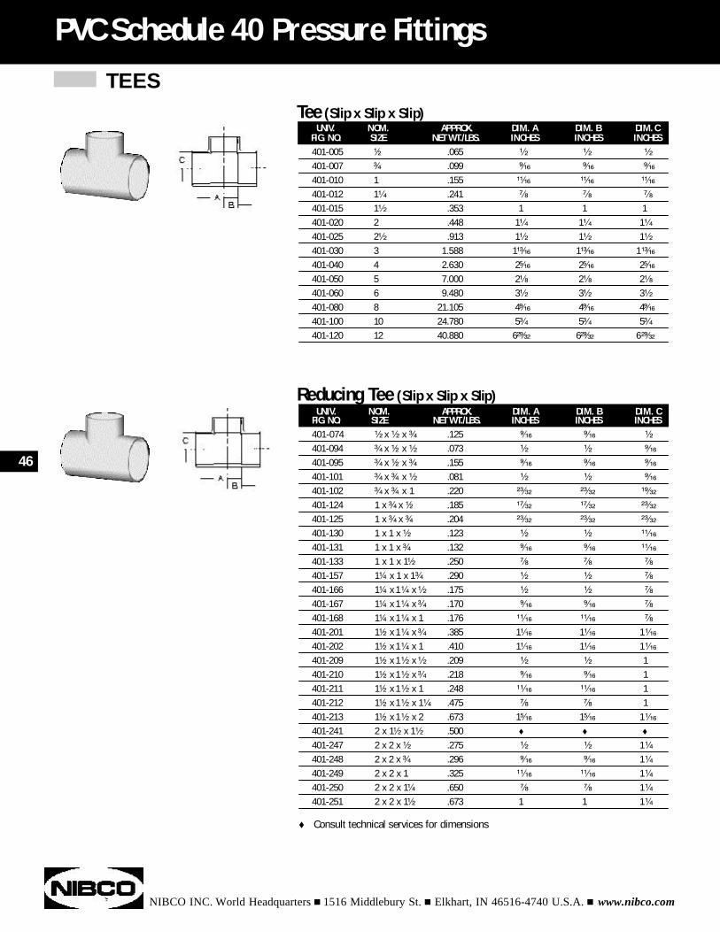
UNIV. NOM. APPROX. DIM. A DIM. B DIM. CFIG. NO. SIZE NET WT./LBS. INCHES INCHES INCHES401-005 ¹⁄₂ .065 ¹⁄₂ ¹⁄₂ ¹⁄₂
401-007 ³⁄₄ .099 ⁹⁄₁₆ ⁹⁄₁₆ ⁹⁄₁₆
401-010 1 .155 ¹¹⁄₁₆ ¹¹⁄₁₆ ¹¹⁄₁₆
401-012 1¹⁄₄ .241 ⁷⁄₈ ⁷⁄₈ ⁷⁄₈
401-015 1¹⁄₂ .353 1 1 1401-020 2 .448 1¹⁄₄ 1¹⁄₄ 1¹⁄₄
401-025 2¹⁄₂ .913 1¹⁄₂ 1¹⁄₂ 1¹⁄₂
401-030 3 1.588 1¹³⁄₁₆ 1¹³⁄₁₆ 1¹³⁄₁₆
401-040 4 2.630 2⁵⁄₁₆ 2⁵⁄₁₆ 2⁵⁄₁₆
401-050 5 7.000 2¹⁄₈ 2¹⁄₈ 2¹⁄₈
401-060 6 9.480 3¹⁄₂ 3¹⁄₂ 3¹⁄₂
401-080 8 21.105 4⁹⁄₁₆ 4⁹⁄₁₆ 4⁹⁄₁₆
401-100 10 24.780 5³⁄₄ 5³⁄₄ 5³⁄₄
401-120 12 40.880 6²⁹⁄₃₂ 6²⁹⁄₃₂ 6²⁹⁄₃₂
PVC Schedule 40 Pressure Fittings
Tee (Slip x Slip x Slip)
UNIV. NOM. APPROX. DIM. A DIM. B DIM. CFIG. NO. SIZE NET WT./LBS. INCHES INCHES INCHES401-074 ¹⁄₂ x ¹⁄₂ x ³⁄₄ .125 ⁹⁄₁₆ ⁹⁄₁₆ ¹⁄₂
401-094 ³⁄₄ x ¹⁄₂ x ¹⁄₂ .073 ¹⁄₂ ¹⁄₂ ⁹⁄₁₆
401-095 ³⁄₄ x ¹⁄₂ x ³⁄₄ .155 ⁹⁄₁₆ ⁹⁄₁₆ ⁹⁄₁₆
401-101 ³⁄₄ x ³⁄₄ x ¹⁄₂ .081 ¹⁄₂ ¹⁄₂ ⁹⁄₁₆
401-102 ³⁄₄ x ³⁄₄ x 1 .220 ²³⁄₃₂ ²³⁄₃₂ ¹⁹⁄₃₂
401-124 1 x ³⁄₄ x ¹⁄₂ .185 ¹⁷⁄₃₂ ¹⁷⁄₃₂ ²³⁄₃₂
401-125 1 x ³⁄₄ x ³⁄₄ .204 ²³⁄₃₂ ²³⁄₃₂ ²³⁄₃₂
401-130 1 x 1 x ¹⁄₂ .123 ¹⁄₂ ¹⁄₂ ¹¹⁄₁₆
401-131 1 x 1 x ³⁄₄ .132 ⁹⁄₁₆ ⁹⁄₁₆ ¹¹⁄₁₆
401-133 1 x 1 x 1¹⁄₂ .250 ⁷⁄₈ ⁷⁄₈ ⁷⁄₈
401-157 1¹⁄₄ x 1 x 1³⁄₄ .290 ¹⁄₂ ¹⁄₂ ⁷⁄₈
401-166 1¹⁄₄ x 1¹⁄₄ x ¹⁄₂ .175 ¹⁄₂ ¹⁄₂ ⁷⁄₈
401-167 1¹⁄₄ x 1¹⁄₄ x ³⁄₄ .170 ⁹⁄₁₆ ⁹⁄₁₆ ⁷⁄₈
401-168 1¹⁄₄ x 1¹⁄₄ x 1 .176 ¹¹⁄₁₆ ¹¹⁄₁₆ ⁷⁄₈
401-201 1¹⁄₂ x 1¹⁄₄ x ³⁄₄ .385 1¹⁄₁₆ 1¹⁄₁₆ 1¹⁄₁₆
401-202 1¹⁄₂ x 1¹⁄₄ x 1 .410 1¹⁄₁₆ 1¹⁄₁₆ 1¹⁄₁₆
401-209 1¹⁄₂ x 1¹⁄₂ x ¹⁄₂ .209 ¹⁄₂ ¹⁄₂ 1401-210 1¹⁄₂ x 1¹⁄₂ x ³⁄₄ .218 ⁹⁄₁₆ ⁹⁄₁₆ 1401-211 1¹⁄₂ x 1¹⁄₂ x 1 .248 ¹¹⁄₁₆ ¹¹⁄₁₆ 1401-212 1¹⁄₂ x 1¹⁄₂ x 1¹⁄₄ .475 ⁷⁄₈ ⁷⁄₈ 1401-213 1¹⁄₂ x 1¹⁄₂ x 2 .673 1⁵⁄₁₆ 1⁵⁄₁₆ 1¹⁄₁₆
401-241 2 x 1¹⁄₂ x 1¹⁄₂ .500 t t t
401-247 2 x 2 x ¹⁄₂ .275 ¹⁄₂ ¹⁄₂ 1¹⁄₄
401-248 2 x 2 x ³⁄₄ .296 ⁹⁄₁₆ ⁹⁄₁₆ 1¹⁄₄
401-249 2 x 2 x 1 .325 ¹¹⁄₁₆ ¹¹⁄₁₆ 1¹⁄₄
401-250 2 x 2 x 1¹⁄₄ .650 ⁷⁄₈ ⁷⁄₈ 1¹⁄₄
401-251 2 x 2 x 1¹⁄₂ .673 1 1 1¹⁄₄
Reducing Tee (Slip x Slip x Slip)
TEES
46
t Consult technical services for dimensions
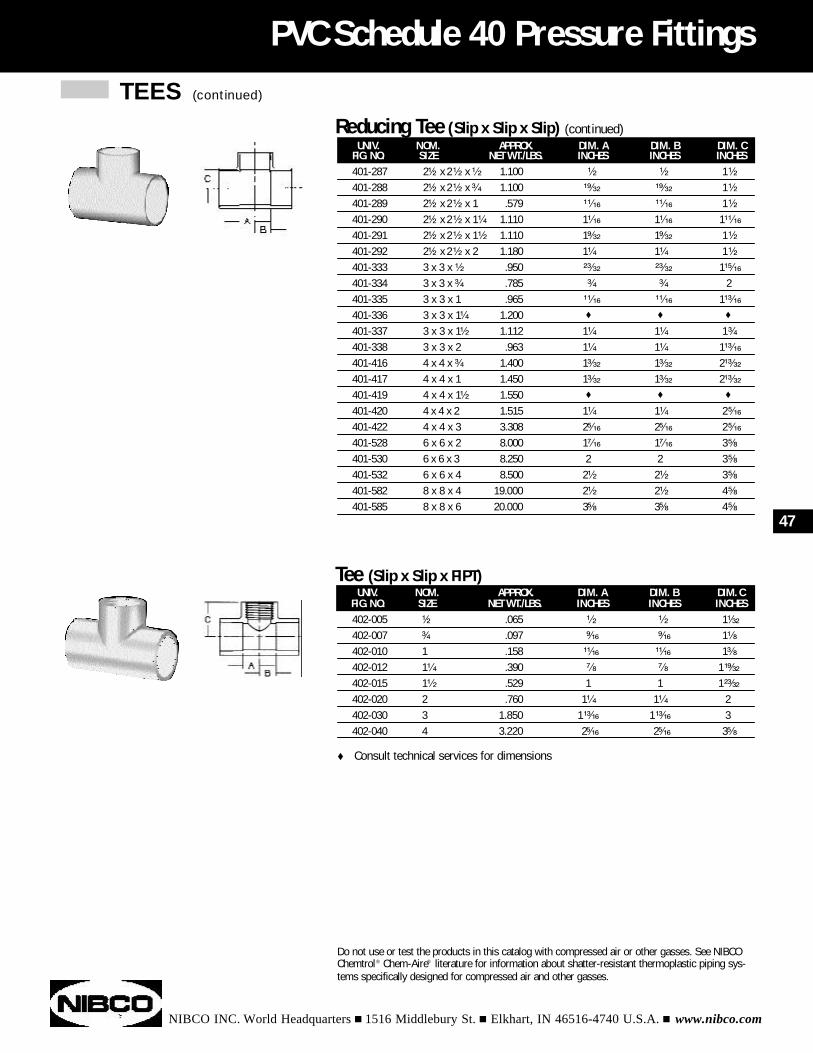
TEES (continued)
NIBCO INC. World Headquarters n 1516 Middlebury St. n Elkhart, IN 46516-4740 U.S.A. n www.nibco.com
PVC Schedule 40 Pressure Fittings
UNIV. NOM. APPROX. DIM. A DIM. B DIM. CFIG. NO. SIZE NET WT./LBS. INCHES INCHES INCHES401-287 2¹⁄₂ x 2¹⁄₂ x ¹⁄₂ 1.100 ¹⁄₂ ¹⁄₂ 1¹⁄₂
401-288 2¹⁄₂ x 2¹⁄₂ x ³⁄₄ 1.100 ¹⁹⁄₃₂ ¹⁹⁄₃₂ 1¹⁄₂
401-289 2¹⁄₂ x 2¹⁄₂ x 1 .579 ¹¹⁄₁₆ ¹¹⁄₁₆ 1¹⁄₂
401-290 2¹⁄₂ x 2¹⁄₂ x 1¹⁄₄ 1.110 1¹⁄₁₆ 1¹⁄₁₆ 1¹¹⁄₁₆
401-291 2¹⁄₂ x 2¹⁄₂ x 1¹⁄₂ 1.110 1⁹⁄₃₂ 1⁹⁄₃₂ 1¹⁄₂
401-292 2¹⁄₂ x 2¹⁄₂ x 2 1.180 1¹⁄₄ 1¹⁄₄ 1¹⁄₂
401-333 3 x 3 x ¹⁄₂ .950 ²³⁄₃₂ ²³⁄₃₂ 1¹⁵⁄₁₆
401-334 3 x 3 x ³⁄₄ .785 ³⁄₄ ³⁄₄ 2401-335 3 x 3 x 1 .965 ¹¹⁄₁₆ ¹¹⁄₁₆ 1¹³⁄₁₆
401-336 3 x 3 x 1¹⁄₄ 1.200 t t t
401-337 3 x 3 x 1¹⁄₂ 1.112 1¹⁄₄ 1¹⁄₄ 1³⁄₄
401-338 3 x 3 x 2 .963 1¹⁄₄ 1¹⁄₄ 1¹³⁄₁₆
401-416 4 x 4 x ³⁄₄ 1.400 1³⁄₃₂ 1³⁄₃₂ 2¹³⁄₃₂
401-417 4 x 4 x 1 1.450 1³⁄₃₂ 1³⁄₃₂ 2¹³⁄₃₂
401-419 4 x 4 x 1¹⁄₂ 1.550 t t t
401-420 4 x 4 x 2 1.515 1¹⁄₄ 1¹⁄₄ 2⁵⁄₁₆
401-422 4 x 4 x 3 3.308 2⁵⁄₁₆ 2⁵⁄₁₆ 2⁵⁄₁₆
401-528 6 x 6 x 2 8.000 1⁷⁄₁₆ 1⁷⁄₁₆ 3⁵⁄₈
401-530 6 x 6 x 3 8.250 2 2 3⁵⁄₈
401-532 6 x 6 x 4 8.500 2¹⁄₂ 2¹⁄₂ 3⁵⁄₈
401-582 8 x 8 x 4 19.000 2¹⁄₂ 2¹⁄₂ 4⁵⁄₈
401-585 8 x 8 x 6 20.000 3⁵⁄₈ 3⁵⁄₈ 4⁵⁄₈
Reducing Tee (Slip x Slip x Slip) (continued)
UNIV. NOM. APPROX. DIM. A DIM. B DIM. CFIG. NO. SIZE NET WT./LBS. INCHES INCHES INCHES402-005 ¹⁄₂ .065 ¹⁄₂ ¹⁄₂ 1¹⁄₃₂
402-007 ³⁄₄ .097 ⁹⁄₁₆ ⁹⁄₁₆ 1¹⁄₈
402-010 1 .158 ¹¹⁄₁₆ ¹¹⁄₁₆ 1³⁄₈
402-012 1¹⁄₄ .390 ⁷⁄₈ ⁷⁄₈ 1¹⁹⁄₃₂
402-015 1¹⁄₂ .529 1 1 1²³⁄₃₂
402-020 2 .760 1¹⁄₄ 1¹⁄₄ 2402-030 3 1.850 1¹³⁄₁₆ 1¹³⁄₁₆ 3402-040 4 3.220 2⁵⁄₁₆ 2⁵⁄₁₆ 3⁵⁄₈
Tee (Slip x Slip x FIPT)
47
Do not use or test the products in this catalog with compressed air or other gasses. See NIBCOChemtrol® Chem-Aire® literature for information about shatter-resistant thermoplastic piping sys-tems specifically designed for compressed air and other gasses.
t Consult technical services for dimensions
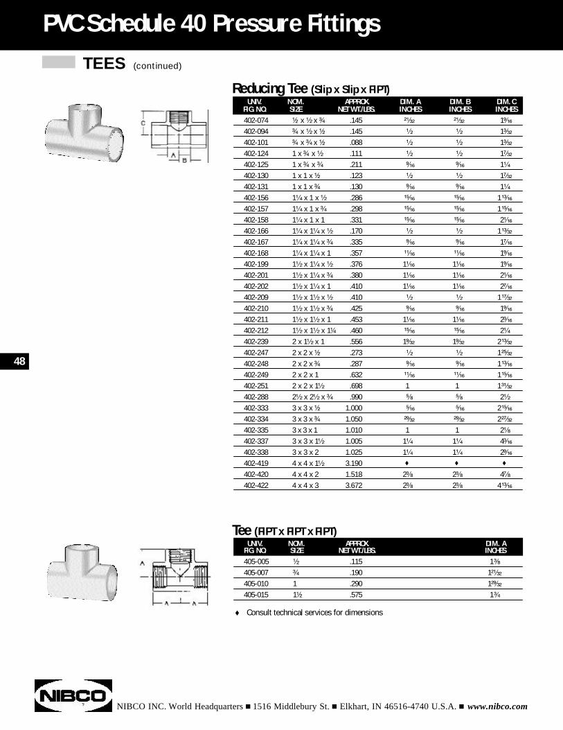
TEES (continued)
NIBCO INC. World Headquarters n 1516 Middlebury St. n Elkhart, IN 46516-4740 U.S.A. n www.nibco.com
PVC Schedule 40 Pressure Fittings
UNIV. NOM. APPROX. DIM. AFIG. NO. SIZE NET WT./LBS. INCHES405-005 ¹⁄₂ .115 1³⁄₈
405-007 ³⁄₄ .190 1²¹⁄₃₂
405-010 1 .290 1²⁹⁄₃₂
405-015 1¹⁄₂ .575 1³⁄₄
Tee (FIPT x FIPT x FIPT)
UNIV. NOM. APPROX. DIM. A DIM. B DIM. CFIG. NO. SIZE NET WT./LBS. INCHES INCHES INCHES402-074 ¹⁄₂ x ¹⁄₂ x ³⁄₄ .145 ²¹⁄₃₂ ²¹⁄₃₂ 1⁹⁄₁₆
402-094 ³⁄₄ x ¹⁄₂ x ¹⁄₂ .145 ¹⁄₂ ¹⁄₂ 1³⁄₃₂
402-101 ³⁄₄ x ³⁄₄ x ¹⁄₂ .088 ¹⁄₂ ¹⁄₂ 1³⁄₃₂
402-124 1 x ³⁄₄ x ¹⁄₂ .111 ¹⁄₂ ¹⁄₂ 1⁷⁄₃₂
402-125 1 x ³⁄₄ x ³⁄₄ .211 ⁹⁄₁₆ ⁹⁄₁₆ 1¹⁄₄
402-130 1 x 1 x ¹⁄₂ .123 ¹⁄₂ ¹⁄₂ 1⁷⁄₃₂
402-131 1 x 1 x ³⁄₄ .130 ⁹⁄₁₆ ⁹⁄₁₆ 1¹⁄₄
402-156 1¹⁄₄ x 1 x ¹⁄₂ .286 ¹⁵⁄₁₆ ¹⁵⁄₁₆ 1¹³⁄₁₆
402-157 1¹⁄₄ x 1 x ³⁄₄ .298 ¹⁵⁄₁₆ ¹⁵⁄₁₆ 1¹⁵⁄₁₆
402-158 1¹⁄₄ x 1 x 1 .331 ¹⁵⁄₁₆ ¹⁵⁄₁₆ 2¹⁄₁₆
402-166 1¹⁄₄ x 1¹⁄₄ x ¹⁄₂ .170 ¹⁄₂ ¹⁄₂ 1¹³⁄₃₂
402-167 1¹⁄₄ x 1¹⁄₄ x ³⁄₄ .335 ⁹⁄₁₆ ⁹⁄₁₆ 1⁷⁄₁₆
402-168 1¹⁄₄ x 1¹⁄₄ x 1 .357 ¹¹⁄₁₆ ¹¹⁄₁₆ 1⁹⁄₁₆
402-199 1¹⁄₂ x 1¹⁄₄ x ¹⁄₂ .376 1¹⁄₁₆ 1¹⁄₁₆ 1⁹⁄₁₆
402-201 1¹⁄₂ x 1¹⁄₄ x ³⁄₄ .380 1¹⁄₁₆ 1¹⁄₁₆ 2¹⁄₁₆
402-202 1¹⁄₂ x 1¹⁄₄ x 1 .410 1¹⁄₁₆ 1¹⁄₁₆ 2⁷⁄₁₆
402-209 1¹⁄₂ x 1¹⁄₂ x ¹⁄₂ .410 ¹⁄₂ ¹⁄₂ 1¹⁷⁄₃₂
402-210 1¹⁄₂ x 1¹⁄₂ x ³⁄₄ .425 ⁹⁄₁₆ ⁹⁄₁₆ 1⁹⁄₁₆
402-211 1¹⁄₂ x 1¹⁄₂ x 1 .453 1¹⁄₁₆ 1¹⁄₁₆ 2³⁄₁₆
402-212 1¹⁄₂ x 1¹⁄₂ x 1¹⁄₄ .460 ¹⁵⁄₁₆ ¹⁵⁄₁₆ 2¹⁄₄
402-239 2 x 1¹⁄₂ x 1 .556 1⁹⁄₃₂ 1⁹⁄₃₂ 2¹³⁄₃₂
402-247 2 x 2 x ¹⁄₂ .273 ¹⁄₂ ¹⁄₂ 1²⁵⁄₃₂
402-248 2 x 2 x ³⁄₄ .287 ⁹⁄₁₆ ⁹⁄₁₆ 1¹³⁄₁₆
402-249 2 x 2 x 1 .632 ¹¹⁄₁₆ ¹¹⁄₁₆ 1¹⁵⁄₁₆
402-251 2 x 2 x 1¹⁄₂ .698 1 1 1³¹⁄₃₂
402-288 2¹⁄₂ x 2¹⁄₂ x ³⁄₄ .990 ⁵⁄₈ ⁵⁄₈ 2¹⁄₂
402-333 3 x 3 x ¹⁄₂ 1.000 ⁵⁄₁₆ ⁵⁄₁₆ 2¹⁵⁄₁₆
402-334 3 x 3 x ³⁄₄ 1.050 ²⁹⁄₃₂ ²⁹⁄₃₂ 2²⁷⁄₃₂
402-335 3 x 3 x 1 1.010 1 1 2¹⁄₈
402-337 3 x 3 x 1¹⁄₂ 1.005 1¹⁄₄ 1¹⁄₄ 4³⁄₁₆
402-338 3 x 3 x 2 1.025 1¹⁄₄ 1¹⁄₄ 2⁹⁄₁₆
402-419 4 x 4 x 1¹⁄₂ 3.190 t t t
402-420 4 x 4 x 2 1.518 2³⁄₈ 2³⁄₈ 4⁷⁄₈
402-422 4 x 4 x 3 3.672 2³⁄₈ 2³⁄₈ 4¹³⁄₁₆
Reducing Tee (Slip x Slip x FIPT)
48
t Consult technical services for dimensions
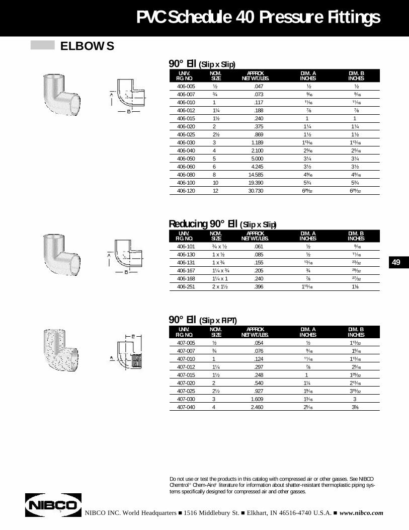
ELBOWS
NIBCO INC. World Headquarters n 1516 Middlebury St. n Elkhart, IN 46516-4740 U.S.A. n www.nibco.com
PVC Schedule 40 Pressure Fittings
UNIV. NOM. APPROX. DIM. A DIM. BFIG. NO. SIZE NET WT./LBS. INCHES INCHES406-005 ¹⁄₂ .047 ¹⁄₂ ¹⁄₂
406-007 ³⁄₄ .073 ⁹⁄₁₆ ⁹⁄₁₆
406-010 1 .117 ¹¹⁄₁₆ ¹¹⁄₁₆
406-012 1¹⁄₄ .188 ⁷⁄₈ ⁷⁄₈
406-015 1¹⁄₂ .240 1 1406-020 2 .375 1¹⁄₄ 1¹⁄₄
406-025 2¹⁄₂ .869 1¹⁄₂ 1¹⁄₂
406-030 3 1.189 1¹³⁄₁₆ 1¹³⁄₁₆
406-040 4 2.100 2⁵⁄₁₆ 2⁵⁄₁₆
406-050 5 5.000 3¹⁄₄ 3¹⁄₄
406-060 6 4.245 3¹⁄₂ 3¹⁄₂
406-080 8 14.585 4⁹⁄₁₆ 4⁹⁄₁₆
406-100 10 19.390 5³⁄₄ 5³⁄₄
406-120 12 30.730 6²⁹⁄₃₂ 6²⁹⁄₃₂
90° Ell (Slip x Slip)
UNIV. NOM. APPROX. DIM. A DIM. BFIG. NO. SIZE NET WT./LBS. INCHES INCHES406-101 ³⁄₄ x ¹⁄₂ .061 ¹⁄₂ ⁹⁄₁₆
406-130 1 x ¹⁄₂ .085 ¹⁄₂ ¹¹⁄₁₆
406-131 1 x ³⁄₄ .155 ¹³⁄₁₆ ²³⁄₃₂
406-167 1¹⁄₄ x ³⁄₄ .205 ³⁄₄ ²⁹⁄₃₂
406-168 1¹⁄₄ x 1 .240 ⁷⁄₈ ²⁷⁄₃₂
406-251 2 x 1¹⁄₂ .396 1¹⁵⁄₁₆ 1¹⁄₈
Reducing 90° Ell (Slip x Slip)
UNIV. NOM. APPROX. DIM. A DIM. BFIG. NO. SIZE NET WT./LBS. INCHES INCHES407-005 ¹⁄₂ .054 ¹⁄₂ 1¹³⁄₃₂
407-007 ³⁄₄ .076 ⁹⁄₁₆ 1⁹⁄₁₆
407-010 1 .124 ¹¹⁄₁₆ 1¹³⁄₁₆
407-012 1¹⁄₄ .297 ⁷⁄₈ 2³⁄₁₆
407-015 1¹⁄₂ .248 1 1²⁹⁄₃₂
407-020 2 .540 1¹⁄₄ 2¹³⁄₁₆
407-025 2¹⁄₂ .927 1⁹⁄₁₆ 3¹⁹⁄₃₂
407-030 3 1.609 1³⁄₁₆ 3407-040 4 2.460 2⁵⁄₁₆ 3⁵⁄₈
90° Ell (Slip x FIPT)
49
Do not use or test the products in this catalog with compressed air or other gasses. See NIBCOChemtrol® Chem-Aire® literature for information about shatter-resistant thermoplastic piping sys-tems specifically designed for compressed air and other gasses.
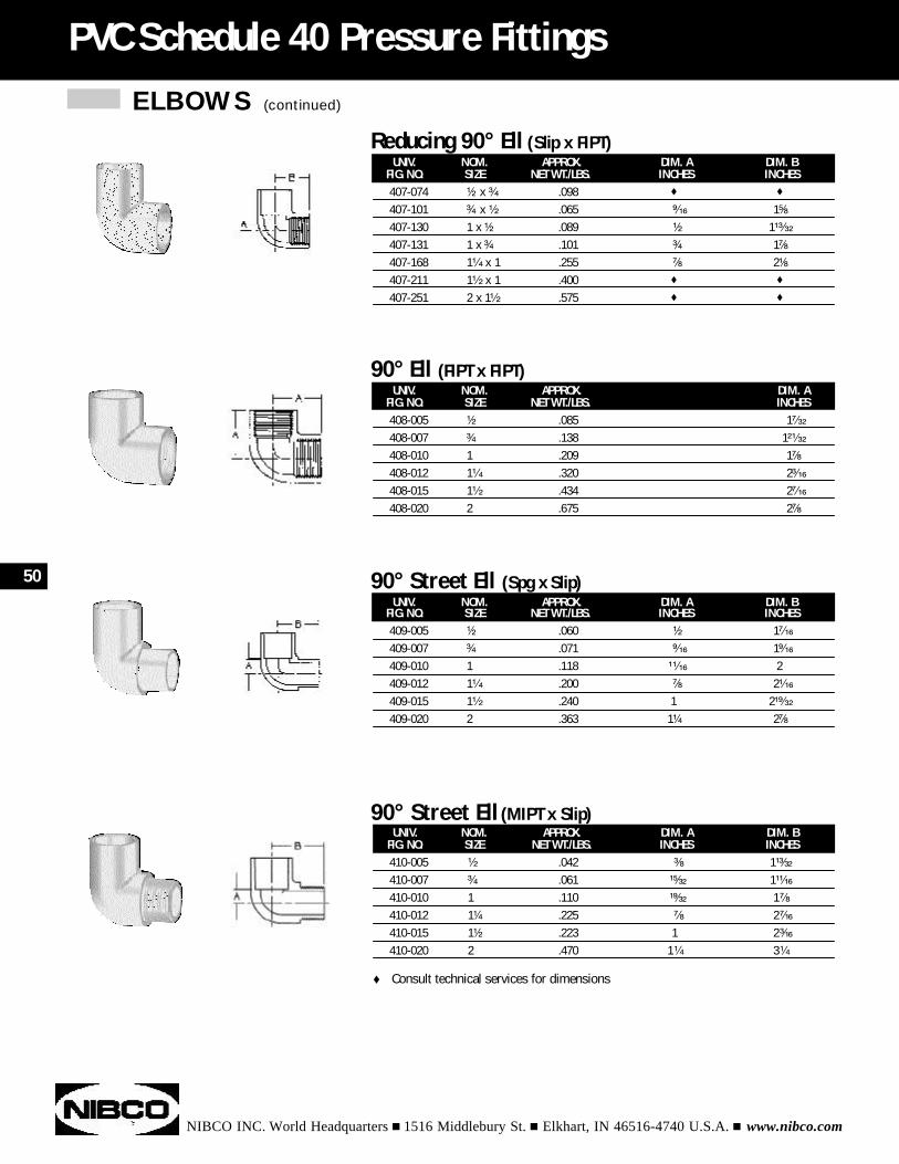
ELBOWS (continued)
NIBCO INC. World Headquarters n 1516 Middlebury St. n Elkhart, IN 46516-4740 U.S.A. n www.nibco.com
PVC Schedule 40 Pressure Fittings
UNIV. NOM. APPROX. DIM. A DIM. BFIG. NO. SIZE NET WT./LBS. INCHES INCHES410-005 ¹⁄₂ .042 ³⁄₈ 1¹³⁄₃₂
410-007 ³⁄₄ .061 ¹⁵⁄₃₂ 1¹¹⁄₁₆
410-010 1 .110 ¹⁹⁄₃₂ 1⁷⁄₈
410-012 1¹⁄₄ .225 ⁷⁄₈ 2⁷⁄₁₆
410-015 1¹⁄₂ .223 1 2³⁄₁₆
410-020 2 .470 1¹⁄₄ 3¹⁄₄
90° Street Ell (MIPT x Slip)
UNIV. NOM. APPROX. DIM. A DIM. BFIG. NO. SIZE NET WT./LBS. INCHES INCHES407-074 ¹⁄₂ x ³⁄₄ .098 t t
407-101 ³⁄₄ x ¹⁄₂ .065 ⁹⁄₁₆ 1⁵⁄₈
407-130 1 x ¹⁄₂ .089 ¹⁄₂ 1¹³⁄₃₂
407-131 1 x ³⁄₄ .101 ³⁄₄ 1⁷⁄₈
407-168 1¹⁄₄ x 1 .255 ⁷⁄₈ 2¹⁄₈
407-211 1¹⁄₂ x 1 .400 t t
407-251 2 x 1¹⁄₂ .575 t t
Reducing 90° Ell (Slip x FIPT)
UNIV. NOM. APPROX. DIM. AFIG. NO. SIZE NET WT./LBS. INCHES408-005 ¹⁄₂ .085 1⁷⁄₃₂
408-007 ³⁄₄ .138 1²¹⁄₃₂
408-010 1 .209 1⁷⁄₈
408-012 1¹⁄₄ .320 2³⁄₁₆
408-015 1¹⁄₂ .434 2⁷⁄₁₆
408-020 2 .675 2⁷⁄₈
90° Ell (FIPT x FIPT)
UNIV. NOM. APPROX. DIM. A DIM. BFIG. NO. SIZE NET WT./LBS. INCHES INCHES409-005 ¹⁄₂ .060 ¹⁄₂ 1⁷⁄₁₆
409-007 ³⁄₄ .071 ⁹⁄₁₆ 1⁹⁄₁₆
409-010 1 .118 ¹¹⁄₁₆ 2409-012 1¹⁄₄ .200 ⁷⁄₈ 2¹⁄₁₆
409-015 1¹⁄₂ .240 1 2¹⁹⁄₃₂
409-020 2 .363 1¹⁄₄ 2⁷⁄₈
90° Street Ell (Spg x Slip)50
t Consult technical services for dimensions
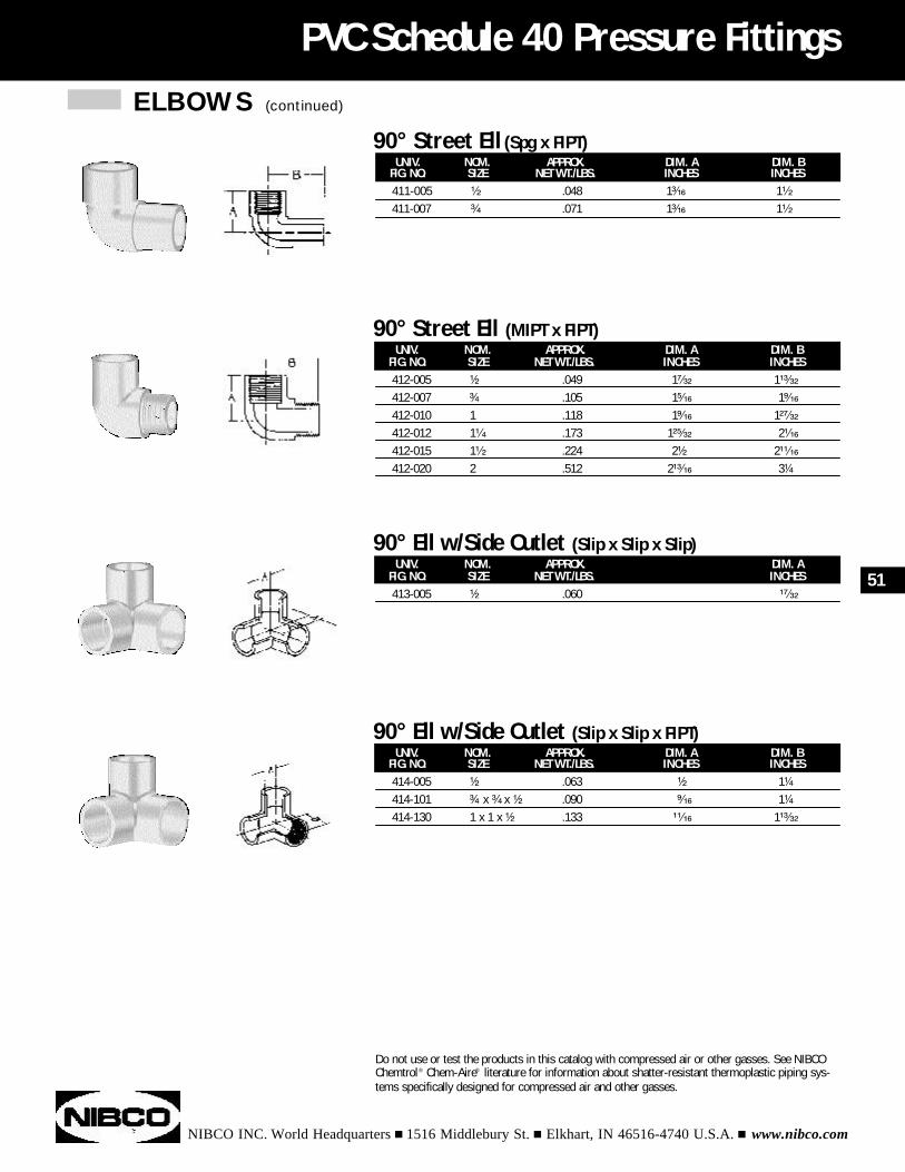
ELBOWS (continued)
NIBCO INC. World Headquarters n 1516 Middlebury St. n Elkhart, IN 46516-4740 U.S.A. n www.nibco.com
PVC Schedule 40 Pressure Fittings
UNIV. NOM. APPROX. DIM. A DIM. BFIG. NO. SIZE NET WT./LBS. INCHES INCHES411-005 ¹⁄₂ .048 1³⁄₁₆ 1¹⁄₂
411-007 ³⁄₄ .071 1³⁄₁₆ 1¹⁄₂
90° Street Ell (Spg x FIPT)
UNIV. NOM. APPROX. DIM. A DIM. BFIG. NO. SIZE NET WT./LBS. INCHES INCHES412-005 ¹⁄₂ .049 1⁷⁄₃₂ 1¹³⁄₃₂
412-007 ³⁄₄ .105 1⁵⁄₁₆ 1⁹⁄₁₆
412-010 1 .118 1⁹⁄₁₆ 1²⁷⁄₃₂
412-012 1¹⁄₄ .173 1²⁵⁄₃₂ 2¹⁄₁₆
412-015 1¹⁄₂ .224 2¹⁄₂ 2¹¹⁄₁₆
412-020 2 .512 2¹³⁄₁₆ 3¹⁄₄
90° Street Ell (MIPT x FIPT)
UNIV. NOM. APPROX. DIM. AFIG. NO. SIZE NET WT./LBS. INCHES413-005 ¹⁄₂ .060 ¹⁷⁄₃₂
90° Ell w/Side Outlet (Slip x Slip x Slip)
UNIV. NOM. APPROX. DIM. A DIM. BFIG. NO. SIZE NET WT./LBS. INCHES INCHES414-005 ¹⁄₂ .063 ¹⁄₂ 1¹⁄₄
414-101 ³⁄₄ x ³⁄₄ x ¹⁄₂ .090 ⁹⁄₁₆ 1¹⁄₄
414-130 1 x 1 x ¹⁄₂ .133 ¹¹⁄₁₆ 1¹³⁄₃₂
90° Ell w/Side Outlet (Slip x Slip x FIPT)
51
Do not use or test the products in this catalog with compressed air or other gasses. See NIBCOChemtrol® Chem-Aire® literature for information about shatter-resistant thermoplastic piping sys-tems specifically designed for compressed air and other gasses.
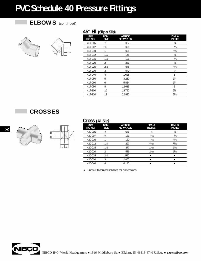
ELBOWS (continued)
NIBCO INC. World Headquarters n 1516 Middlebury St. n Elkhart, IN 46516-4740 U.S.A. n www.nibco.com
PVC Schedule 40 Pressure Fittings
UNIV. NOM. APPROX. DIM. AFIG. NO. SIZE NET WT./LBS. INCHES417-005 ¹⁄₂ .037 ¹⁄₄
417-007 ³⁄₄ .065 ⁵⁄₁₆
417-010 1 .098 ¹¹⁄₃₂
417-012 1¹⁄₄ .148 ³⁄₈
417-015 1¹⁄₂ .191 ⁷⁄₁₆
417-020 2 .281 ⁵⁄₈
417-025 2¹⁄₂ .676 ¹¹⁄₁₆
417-030 3 .940 ³⁄₄
417-040 4 1.628 1417-050 5 3.250 1³⁄₄
417-060 6 5.854 1³⁄₄
417-080 8 12.615 2417-100 10 13.790 2⁵⁄₈
417-120 12 22.890 3³⁄₃₂
45° Ell (Slip x Slip)
UNIV. NOM. APPROX. DIM. A DIM. BFIG. NO. SIZE NET WT./LBS. INCHES INCHES420-005 ¹⁄₂ .076 ¹⁄₂ ¹⁄₂
420-007 ³⁄₄ .131 ⁹⁄₁₆ ⁹⁄₁₆
420-010 1 .180 ¹¹⁄₁₆ ¹¹⁄₁₆
420-012 1¹⁄₄ .297 ²⁹⁄₃₂ ²⁹⁄₃₂
420-015 1¹⁄₂ .377 1¹⁄₃₂ 1¹⁄₃₂
420-020 2 .539 1⁹⁄₃₂ 1⁹⁄₃₂
420-025 2¹⁄₂ 1.590 t t
420-030 3 2.400 t t
420-040 4 4.140 t t
Cross (All Slip)
CROSSES
52
t Consult technical services for dimensions
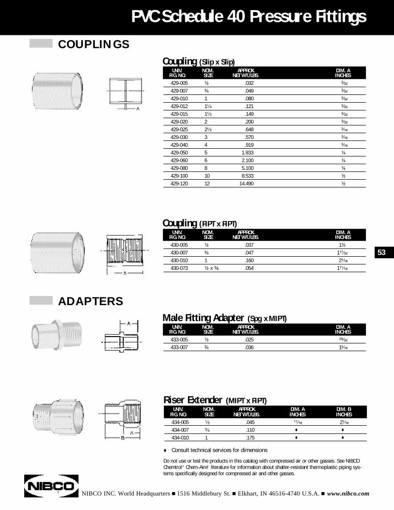
COUPLINGS
NIBCO INC. World Headquarters n 1516 Middlebury St. n Elkhart, IN 46516-4740 U.S.A. n www.nibco.com
PVC Schedule 40 Pressure Fittings
UNIV. NOM. APPROX. DIM. AFIG. NO. SIZE NET WT./LBS. INCHES430-005 ¹⁄₂ .037 1¹⁄₂
430-007 ³⁄₄ .047 1¹⁷⁄₃₂
430-010 1 .160 2¹⁄₁₆
430-073 ¹⁄₂ x ³⁄₈ .054 1¹¹⁄₁₆
Coupling (FIPT x FIPT)
UNIV. NOM. APPROX. DIM. AFIG. NO. SIZE NET WT./LBS. INCHES433-005 ¹⁄₂ .025 ²⁹⁄₃₂
433-007 ³⁄₄ .036 1³⁄₁₆
Male Fitting Adapter (Spg x MIPT)
UNIV. NOM. APPROX. DIM. AFIG. NO. SIZE NET WT./LBS. INCHES429-005 ¹⁄₂ .032 ³⁄₃₂
429-007 ³⁄₄ .049 ³⁄₃₂
429-010 1 .080 ³⁄₃₂
429-012 1¹⁄₄ .121 ³⁄₃₂
429-015 1¹⁄₂ .149 ³⁄₃₂
429-020 2 .200 ³⁄₃₂
429-025 2¹⁄₂ .648 ³⁄₁₆
429-030 3 .570 ³⁄₁₆
429-040 4 .919 ³⁄₁₆
429-050 5 1.933 ¹⁄₄
429-060 6 2.100 ¹⁄₄
429-080 8 5.100 ¹⁄₄
429-100 10 8.533 ¹⁄₂
429-120 12 14.490 ¹⁄₂
Coupling (Slip x Slip)
53
Do not use or test the products in this catalog with compressed air or other gasses. See NIBCOChemtrol® Chem-Aire® literature for information about shatter-resistant thermoplastic piping sys-tems specifically designed for compressed air and other gasses.
UNIV. NOM. APPROX. DIM. A DIM. BFIG. NO. SIZE NET WT./LBS. INCHES INCHES434-005 ¹⁄₂ .045 ¹¹⁄₁₆ 2¹⁄₁₆
434-007 ³⁄₄ .110 t t
434-010 1 .175 t t
Riser Extender (MIPT x FIPT)
t Consult technical services for dimensions
ADAPTERS
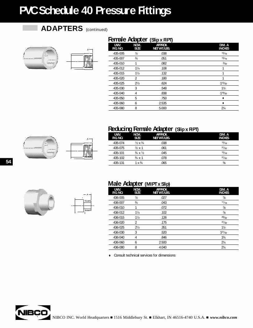
NIBCO INC. World Headquarters n 1516 Middlebury St. n Elkhart, IN 46516-4740 U.S.A. n www.nibco.com
PVC Schedule 40 Pressure Fittings
UNIV. NOM. APPROX. DIM. AFIG. NO. SIZE NET WT./LBS. INCHES435-005 ¹⁄₂ .038 ¹³⁄₁₆
435-007 ³⁄₄ .051 ¹³⁄₁₆
435-010 1 .082 ³⁄₃₂
435-012 1¹⁄₄ .108 1435-015 1¹⁄₂ .132 1435-020 2 .180 1435-025 2¹⁄₂ .624 1¹³⁄₃₂
435-030 3 .548 1¹⁄₂
435-040 4 .838 1¹⁹⁄₃₂
435-050 5 .750 t
435-060 6 2.535 t
435-080 8 5.000 2¹⁄₄
Female Adapter (Slip x FIPT)
ADAPTERS (continued)
UNIV. NOM. APPROX. DIM. AFIG. NO. SIZE NET WT./LBS. INCHES435-074 ¹⁄₂ x ³⁄₄ .038 ¹³⁄₁₆
435-075 ¹⁄₂ x 1 .061 ³¹⁄₃₂
435-101 ³⁄₄ x ¹⁄₂ .045 ¹³⁄₁₆
435-102 ³⁄₄ x 1 .078 ³¹⁄₃₂
435-131 1 x ³⁄₄ .065 ⁵⁄₈
Reducing Female Adapter (Slip x FIPT)
54
UNIV. NOM. APPROX. DIM. AFIG. NO. SIZE NET WT./LBS. INCHES436-005 ¹⁄₂ .027 ⁷⁄₈
436-007 ³⁄₄ .043 ¹¹⁄₁₆
436-010 1 .072 ⁷⁄₈
436-012 1¹⁄₄ .102 ⁷⁄₈
436-015 1¹⁄₂ .126 ²⁹⁄₃₂
436-020 2 .175 ³¹⁄₃₂
436-025 2¹⁄₂ .351 1¹⁄₂
436-030 3 .520 1²¹⁄₃₂
436-040 4 .846 1³⁄₄
436-060 6 2.500 2¹⁄₄
436-080 8 4.040 2¹⁄₄
Male Adapter (MIPT x Slip)
t Consult technical services for dimensions
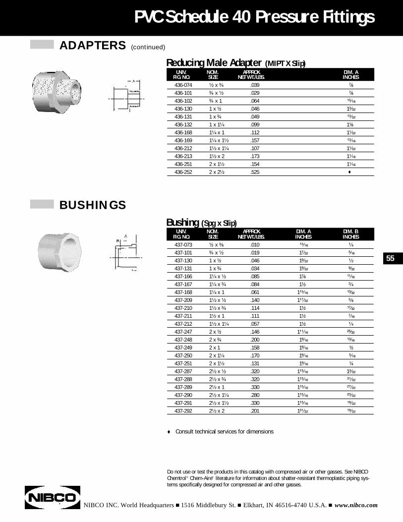
ADAPTERS (continued)
NIBCO INC. World Headquarters n 1516 Middlebury St. n Elkhart, IN 46516-4740 U.S.A. n www.nibco.com
PVC Schedule 40 Pressure Fittings
UNIV. NOM. APPROX. DIM. AFIG. NO. SIZE NET WT./LBS. INCHES436-074 ¹⁄₂ x ³⁄₄ .039 ⁷⁄₈
436-101 ³⁄₄ x ¹⁄₂ .029 ⁷⁄₈
436-102 ³⁄₄ x 1 .064 ¹⁵⁄₁₆
436-130 1 x ¹⁄₂ .046 1³⁄₃₂
436-131 1 x ³⁄₄ .049 ¹³⁄₃₂
436-132 1 x 1¹⁄₄ .099 1¹⁄₈
436-168 1¹⁄₄ x 1 .112 1¹⁄₃₂
436-169 1¹⁄₄ x 1¹⁄₂ .157 ¹³⁄₁₆
436-212 1¹⁄₂ x 1¹⁄₄ .107 1¹⁄₃₂
436-213 1¹⁄₂ x 2 .173 1¹⁄₁₈
436-251 2 x 1¹⁄₂ .154 1¹⁄₁₆
436-252 2 x 2¹⁄₂ .525 t
Reducing Male Adapter (MIPT X Slip)
BUSHINGS
UNIV. NOM. APPROX. DIM. A DIM. BFIG. NO. SIZE NET WT./LBS. INCHES INCHES437-073 ¹⁄₂ x ³⁄₈ .010 ¹⁵⁄₁₆ ¹⁄₄
437-101 ³⁄₄ x ¹⁄₂ .019 1⁷⁄₃₂ ⁵⁄₁₆
437-130 1 x ¹⁄₂ .046 1⁹⁄₃₂ ¹⁄₂
437-131 1 x ³⁄₄ .034 1⁹⁄₃₂ ⁹⁄₃₂
437-166 1¹⁄₄ x ¹⁄₂ .085 1⁷⁄₈ ¹¹⁄₁₆
437-167 1¹⁄₄ x ³⁄₄ .084 1¹⁄₂ ³⁄₄
437-168 1¹⁄₄ x 1 .061 1¹⁵⁄₁₆ ¹³⁄₃₂
437-209 1¹⁄₂ x ¹⁄₂ .140 1¹⁷⁄₃₂ ⁵⁄₈
437-210 1¹⁄₂ x ³⁄₄ .114 1¹⁄₂ ¹⁷⁄₃₂
437-211 1¹⁄₂ x 1 .111 1¹⁄₂ ⁷⁄₁₆
437-212 1¹⁄₂ x 1¹⁄₄ .057 1¹⁄₂ ¹⁄₄
437-247 2 x ¹⁄₂ .146 1¹¹⁄₁₆ ²⁵⁄₃₂
437-248 2 x ³⁄₄ .200 1⁹⁄₁₆ ¹³⁄₁₆
437-249 2 x 1 .158 1⁹⁄₁₆ ¹⁄₂
437-250 2 x 1¹⁄₄ .170 1⁹⁄₁₆ ⁵⁄₁₆
437-251 2 x 1¹⁄₂ .131 1⁹⁄₁₆ ¹⁄₄
437-287 2¹⁄₂ x ¹⁄₂ .320 1¹⁵⁄₁₆ 1³⁄₃₂
437-288 2¹⁄₂ x ³⁄₄ .320 1¹⁵⁄₁₆ ³¹⁄₃₂
437-289 2¹⁄₂ x 1 .330 1¹⁵⁄₁₆ ²⁷⁄₃₂
437-290 2¹⁄₂ x 1¹⁄₄ .280 1¹⁵⁄₁₆ ²³⁄₃₂
437-291 2¹⁄₂ x 1¹⁄₂ .330 1¹⁵⁄₁₆ ¹⁹⁄₃₂
437-292 2¹⁄₂ x 2 .201 1³¹⁄₃₂ ¹⁹⁄₃₂
Bushing (Spg x Slip)
55
Do not use or test the products in this catalog with compressed air or other gasses. See NIBCOChemtrol® Chem-Aire® literature for information about shatter-resistant thermoplastic piping sys-tems specifically designed for compressed air and other gasses.
t Consult technical services for dimensions
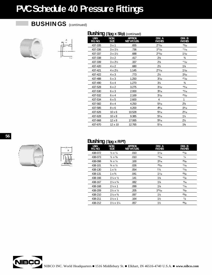
BUSHINGS (continued)
NIBCO INC. World Headquarters n 1516 Middlebury St. n Elkhart, IN 46516-4740 U.S.A. n www.nibco.com
PVC Schedule 40 Pressure Fittings
UNIV. NOM. APPROX. DIM. A DIM. BFIG. NO. SIZE NET WT./LBS. INCHES INCHES437-335 3 x 1 .655 2¹³⁄₃₂ ¹⁹⁄₃₂
437-336 3 x 1¹⁄₄ .736 1³¹⁄₃₂ ¹¹⁄₁₆
437-337 3 x 1¹⁄₂ .688 2¹³⁄₃₂ 1¹⁄₃₂
437-338 3 x 2 .417 2¹⁄₈ ³⁄₄
437-339 3 x 2¹⁄₂ .337 2¹⁄₈ ¹¹⁄₃₂
437-420 4 x 2 .680 2¹⁄₂ 1¹⁄₈
437-421 4 x 2¹⁄₂ 1.145 2¹⁵⁄₁₆ 1¹⁄₃₂
437-422 4 x 3 .773 2¹⁄₂ 1⁹⁄₃₂
437-488 5 x 3 1.250 3⁷⁄₃₂ ²⁷⁄₃₂
437-490 5 x 4 1.270 3¹⁄₄ ³⁄₄
437-528 6 x 2 3.275 3¹⁄₃₂ ¹⁹⁄₁₆
437-530 6 x 3 2.000 3⁵⁄₁₆ ¹⁵⁄₁₆
437-532 6 x 4 2.169 3¹⁄₃₂ ²⁵⁄₃₂
437-534 6 x 5 2.600 4 1437-582 8 x 4 4.250 5³⁄₁₆ 2⁷⁄₈
437-585 8 x 6 4.200 4⁹⁄₁₆ 1⁹⁄₁₆
437-626 10 x 6 10.528 5⁵⁄₁₆ 2³⁄₁₆
437-628 10 x 8 9.385 5⁵⁄₁₆ 1¹⁄₄
437-668 12 x 8 17.065 5⁹⁄₁₆ 2¹⁄₂
437-670 12 x 10 12.765 5⁷⁄₁₆ 1³⁄₈
Bushing (Spg x Slip) (continued)
UNIV. NOM. APPROX. DIM. A DIM. BFIG. NO. SIZE NET WT./LBS. INCHES INCHES438-072 ¹⁄₂ x ¹⁄₄ .010 1¹⁄₁₆ ²¹⁄₃₂
438-073 ¹⁄₂ x ³⁄₈ .010 ¹⁵⁄₁₆ ¹⁄₄
438-098 ³⁄₄ x ¹⁄₄ .100 1⁹⁄₁₆ ²⁵⁄₃₂
438-101 ³⁄₄ x ¹⁄₂ .026 ²⁹⁄₃₂ ¹¹⁄₁₆
438-130 1 x ¹⁄₂ .054 1¹⁄₄ ¹¹⁄₁₆
438-131 1 x ³⁄₄ .041 1¹⁄₁₆ ²³⁄₃₂
438-166 1¹⁄₄ x ¹⁄₂ .141 1¹⁄₈ ¹⁷⁄₃₂
438-167 1¹⁄₄ x ³⁄₄ .082 1¹⁄₈ ⁹⁄₁₆
438-168 1¹⁄₄ x 1 .099 1¹⁄₈ ¹¹⁄₁₆
438-209 1¹⁄₂ x ¹⁄₂ .205 1²⁵⁄₃₂ ¹⁵⁄₃₂
438-210 1¹⁄₂ x ³⁄₄ .097 1¹⁄₂ ²³⁄₃₂
438-211 1¹⁄₂ x 1 .164 1¹⁄₂ ⁷⁄₈
438-212 1¹⁄₂ x 1¹⁄₄ .057 1¹⁄₂ ²⁹⁄₃₂
Bushing (Spg x FIPT)56
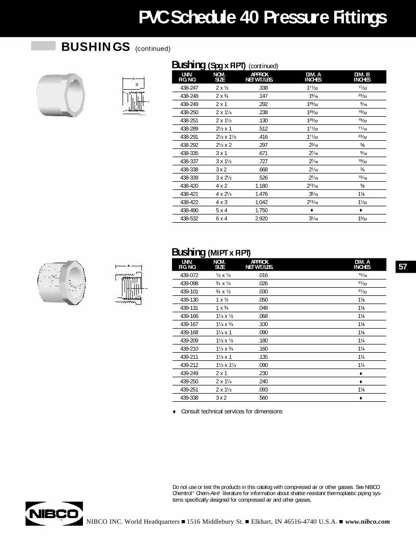
BUSHINGS (continued)
NIBCO INC. World Headquarters n 1516 Middlebury St. n Elkhart, IN 46516-4740 U.S.A. n www.nibco.com
PVC Schedule 40 Pressure Fittings
UNIV. NOM. APPROX. DIM. AFIG. NO. SIZE NET WT./LBS. INCHES439-072 ¹⁄₂ x ¹⁄₄ .016 ¹⁵⁄₁₆
439-098 ³⁄₄ x ¹⁄₄ .026 ³¹⁄₃₂
439-101 ³⁄₄ x ¹⁄₂ .030 ³¹⁄₃₂
439-130 1 x ¹⁄₂ .050 1¹⁄₈
439-131 1 x ³⁄₄ .048 1¹⁄₈
439-166 1¹⁄₄ x ¹⁄₂ .068 1¹⁄₈
439-167 1¹⁄₄ x ³⁄₄ .100 1¹⁄₈
439-168 1¹⁄₄ x 1 .090 1¹⁄₈
439-209 1¹⁄₂ x ¹⁄₂ .180 1¹⁄₄
439-210 1¹⁄₂ x ³⁄₄ .160 1¹⁄₄
439-211 1¹⁄₂ x 1 .135 1¹⁄₄
439-212 1¹⁄₂ x 1¹⁄₄ .090 1¹⁄₄
439-249 2 x 1 .230 t
439-250 2 x 1¹⁄₄ .240 t
439-251 2 x 1¹⁄₂ .093 1¹⁄₈
439-338 3 x 2 .560 t
Bushing (MIPT x FIPT)
UNIV. NOM. APPROX. DIM. A DIM. BFIG. NO. SIZE NET WT./LBS. INCHES INCHES438-247 2 x ¹⁄₂ .338 1¹¹⁄₃₂ ¹⁷⁄₃₂
438-248 2 x ³⁄₄ .147 1⁹⁄₁₆ ²³⁄₃₂
438-249 2 x 1 .292 1²⁹⁄₃₂ ⁹⁄₁₆
438-250 2 x 1¹⁄₄ .238 1²⁹⁄₃₂ ¹⁹⁄₃₂
438-251 2 x 1¹⁄₂ .130 1²⁹⁄₃₂ ¹⁹⁄₃₂
438-289 2¹⁄₂ x 1 .512 1¹¹⁄₃₂ ¹¹⁄₁₆
438-291 2¹⁄₂ x 1¹⁄₂ .416 1¹¹⁄₃₂ ²³⁄₃₂
438-292 2¹⁄₂ x 2 .297 2³⁄₁₆ ⁵⁄₈
438-335 3 x 1 .671 2⁷⁄₁₆ ⁹⁄₁₆
438-337 3 x 1¹⁄₂ .727 2⁷⁄₁₆ ¹⁹⁄₃₂
438-338 3 x 2 .668 2¹⁄₁₆ ³⁄₄
438-339 3 x 2¹⁄₂ .526 2⁷⁄₁₆ ¹⁵⁄₁₆
438-420 4 x 2 1.180 2¹³⁄₁₆ ⁵⁄₈
438-421 4 x 2¹⁄₂ 1.476 3⁵⁄₁₆ 1¹⁄₈
438-422 4 x 3 1.042 2¹³⁄₁₆ 1¹⁄₃₂
438-490 5 x 4 1.750 t t
438-532 6 x 4 2.920 3¹⁄₁₆ 1³⁄₃₂
Bushing (Spg x FIPT) (continued)
57
Do not use or test the products in this catalog with compressed air or other gasses. See NIBCOChemtrol® Chem-Aire® literature for information about shatter-resistant thermoplastic piping sys-tems specifically designed for compressed air and other gasses.
t Consult technical services for dimensions
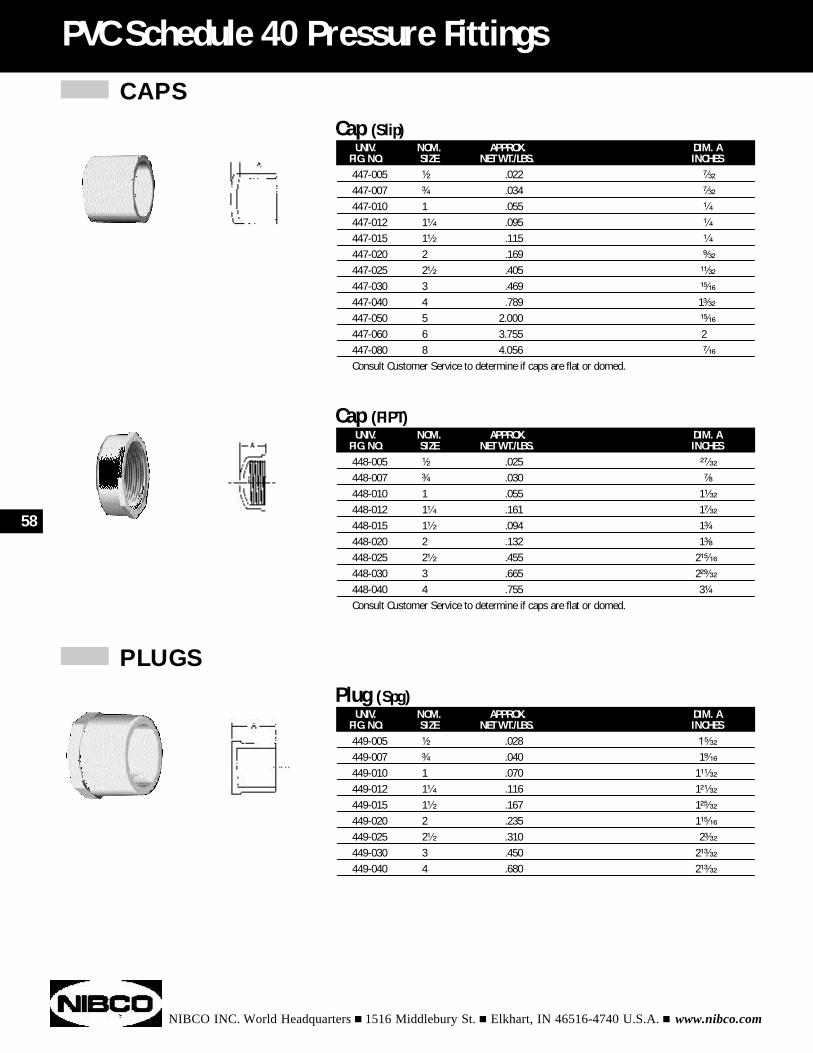
CAPS
NIBCO INC. World Headquarters n 1516 Middlebury St. n Elkhart, IN 46516-4740 U.S.A. n www.nibco.com
PVC Schedule 40 Pressure Fittings
UNIV. NOM. APPROX. DIM. AFIG. NO. SIZE NET WT./LBS. INCHES448-005 ¹⁄₂ .025 ²⁷⁄₃₂
448-007 ³⁄₄ .030 ⁷⁄₈
448-010 1 .055 1¹⁄₃₂
448-012 1¹⁄₄ .161 1⁷⁄₃₂
448-015 1¹⁄₂ .094 1³⁄₄
448-020 2 .132 1³⁄₈
448-025 2¹⁄₂ .455 2¹⁵⁄₁₆
448-030 3 .665 2²⁹⁄₃₂
448-040 4 .755 3¹⁄₄
Consult Customer Service to determine if caps are flat or domed.
Cap (FIPT)
UNIV. NOM. APPROX. DIM. AFIG. NO. SIZE NET WT./LBS. INCHES447-005 ¹⁄₂ .022 ⁷⁄₃₂
447-007 ³⁄₄ .034 ⁷⁄₃₂
447-010 1 .055 ¹⁄₄
447-012 1¹⁄₄ .095 ¹⁄₄
447-015 1¹⁄₂ .115 ¹⁄₄
447-020 2 .169 ⁹⁄₃₂
447-025 2¹⁄₂ .405 ¹¹⁄₃₂
447-030 3 .469 ¹⁵⁄₁₆
447-040 4 .789 1³⁄₃₂
447-050 5 2.000 ¹⁵⁄₁₆
447-060 6 3.755 2447-080 8 4.056 ⁷⁄₁₆
Consult Customer Service to determine if caps are flat or domed.
Cap (Slip)
PLUGS
UNIV. NOM. APPROX. DIM. AFIG. NO. SIZE NET WT./LBS. INCHES449-005 ¹⁄₂ .028 1⁵⁄₃₂
449-007 ³⁄₄ .040 1⁹⁄₁₆
449-010 1 .070 1¹¹⁄₃₂
449-012 1¹⁄₄ .116 1²¹⁄₃₂
449-015 1¹⁄₂ .167 1²⁵⁄₃₂
449-020 2 .235 1¹⁵⁄₁₆
449-025 2¹⁄₂ .310 2³⁄₃₂
449-030 3 .450 2¹³⁄₃₂
449-040 4 .680 2¹³⁄₃₂
Plug (Spg)
58
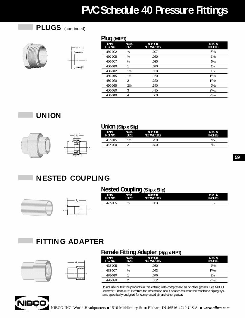
PLUGS (continued)
NIBCO INC. World Headquarters n 1516 Middlebury St. n Elkhart, IN 46516-4740 U.S.A. n www.nibco.com
PVC Schedule 40 Pressure Fittings
UNIV. NOM. APPROX. DIM. AFIG. NO. SIZE NET WT./LBS. INCHES457-015 1¹⁄₂ .200 ¹¹⁄₁₆
457-020 2 .500 ²⁵⁄₃₂
Union (Slip x Slip)
UNIV. NOM. APPROX. DIM. AFIG. NO. SIZE NET WT./LBS. INCHES450-002 ¹⁄₄ .007 ²³⁄₃₂
450-005 ¹⁄₂ .020 1¹⁄₁₆
450-007 ³⁄₄ .030 1³⁄₃₂
450-010 1 .070 1¹⁄₄
450-012 1¹⁄₄ .108 1¹⁄₈
450-015 1¹⁄₂ .160 1²⁵⁄₃₂
450-020 2 .220 1¹⁵⁄₁₆
450-025 2¹⁄₂ .340 2³⁄₃₂
450-030 3 .495 2¹³⁄₃₂
450-040 4 .560 2¹³⁄₁₆
Plug (MIPT)
UNIV. NOM. APPROX. DIM. AFIG. NO. SIZE NET WT./LBS. INCHES477-005 ¹⁄₂ .033 ¹⁄₂
Nested Coupling (Slip x Slip)
UNIV. NOM. APPROX. DIM. AFIG. NO. SIZE NET WT./LBS. INCHES478-005 ¹⁄₂ .030 1⁹⁄₁₆
478-007 ³⁄₄ .043 1¹³⁄₁₆
478-010 1 .076 2¹⁄₈
478-020 2 .182 2¹¹⁄₃₂
Female Fitting Adapter (Spg x FIPT)
59
Do not use or test the products in this catalog with compressed air or other gasses. See NIBCOChemtrol® Chem-Aire® literature for information about shatter-resistant thermoplastic piping sys-tems specifically designed for compressed air and other gasses.
UNION
NESTED COUPLING
FITTING ADAPTER
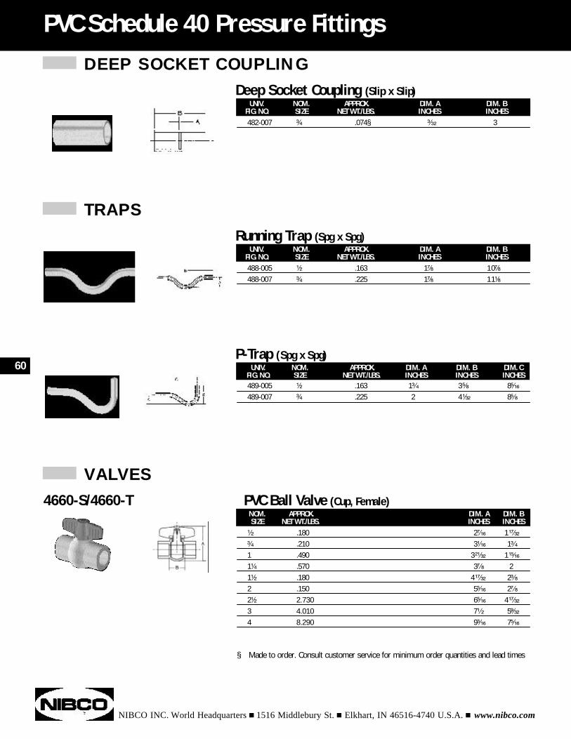
DEEP SOCKET COUPLING
NIBCO INC. World Headquarters n 1516 Middlebury St. n Elkhart, IN 46516-4740 U.S.A. n www.nibco.com
PVC Schedule 40 Pressure Fittings
UNIV. NOM. APPROX. DIM. A DIM. BFIG. NO. SIZE NET WT./LBS. INCHES INCHES482-007 ³⁄₄ .074§ ³⁄₃₂ 3
Deep Socket Coupling (Slip x Slip)
TRAPS
UNIV. NOM. APPROX. DIM. A DIM. BFIG. NO. SIZE NET WT./LBS. INCHES INCHES488-005 ¹⁄₂ .163 1⁷⁄₈ 10⁷⁄₈
488-007 ³⁄₄ .225 1⁷⁄₈ 11¹⁄₈
Running Trap (Spg x Spg)
UNIV. NOM. APPROX. DIM. A DIM. B DIM. CFIG. NO. SIZE NET WT./LBS. INCHES INCHES INCHES489-005 ¹⁄₂ .163 1³⁄₄ 3⁵⁄₈ 8⁵⁄₁₆
489-007 ³⁄₄ .225 2 4¹⁄₃₂ 8⁵⁄₈
P-Trap (Spg x Spg)
VALVES
NOM. APPROX. DIM. A DIM. BSIZE NET WT./LBS. INCHES INCHES
¹⁄₂ .180 2⁷⁄₁₆ 1¹⁷⁄₃₂
³⁄₄ .210 3¹⁄₁₆ 1³⁄₄
1 .490 3²¹⁄₃₂ 1¹⁵⁄₁₆
1¹⁄₄ .570 3⁷⁄₈ 21¹⁄₂ .180 4¹⁷⁄₃₂ 2³⁄₈
2 .150 5⁵⁄₁₆ 2⁷⁄₈
2¹⁄₂ 2.730 6⁵⁄₁₆ 4¹⁷⁄₃₂
3 4.010 7¹⁄₂ 5⁹⁄₃₂
4 8.290 9³⁄₁₆ 7⁵⁄₁₆
4660-S/4660-T PVC Ball Valve (Cup, Female)
60
§ Made to order. Consult customer service for minimum order quantities and lead times
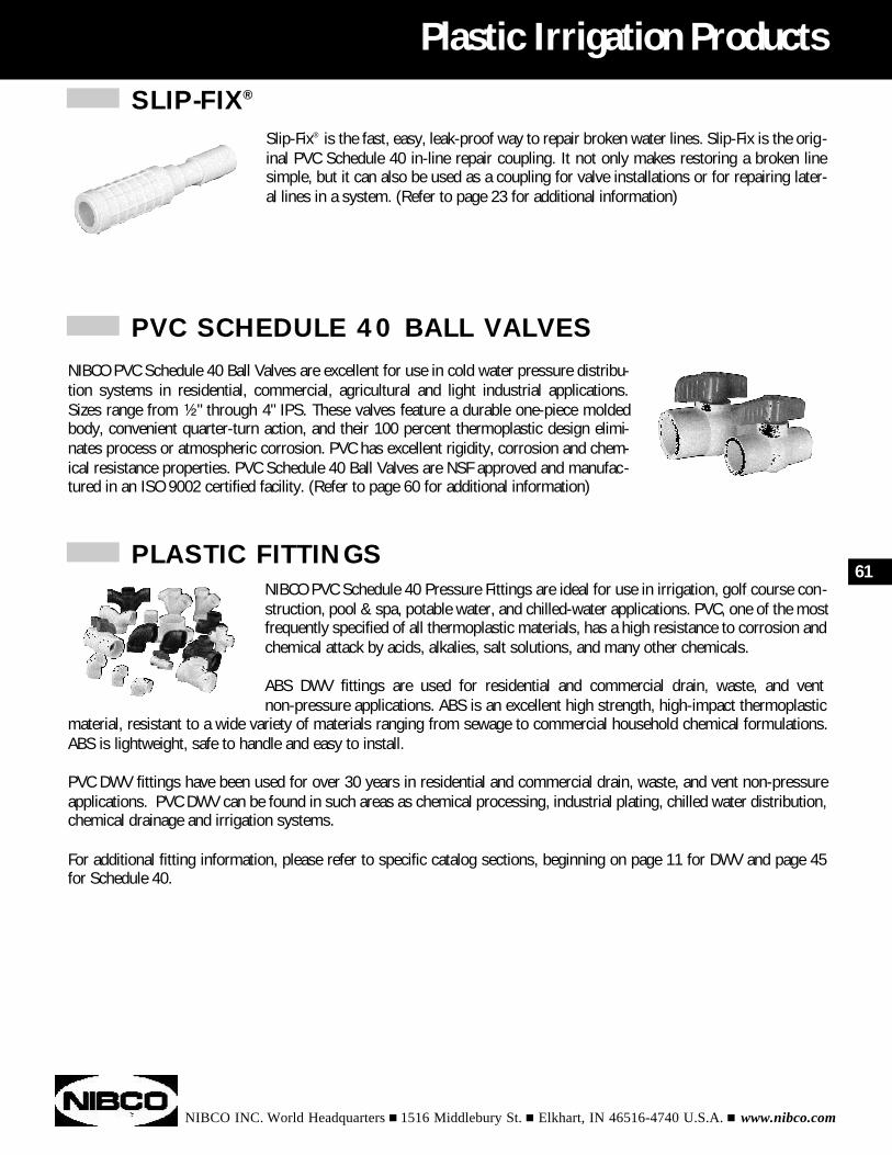
SLIP-FIX®
NIBCO INC. World Headquarters n 1516 Middlebury St. n Elkhart, IN 46516-4740 U.S.A. n www.nibco.com
Plastic Irrigation Products
PVC SCHEDULE 40 BALL VALVES
PLASTIC FITTINGS61
Slip-Fix® is the fast, easy, leak-proof way to repair broken water lines. Slip-Fix is the orig-inal PVC Schedule 40 in-line repair coupling. It not only makes restoring a broken linesimple, but it can also be used as a coupling for valve installations or for repairing later-al lines in a system. (Refer to page 23 for additional information)
NIBCO PVC Schedule 40 Ball Valves are excellent for use in cold water pressure distribu-tion systems in residential, commercial, agricultural and light industrial applications.Sizes range from ¹⁄₂" through 4" IPS. These valves feature a durable one-piece moldedbody, convenient quarter-turn action, and their 100 percent thermoplastic design elimi-nates process or atmospheric corrosion. PVC has excellent rigidity, corrosion and chem-ical resistance properties. PVC Schedule 40 Ball Valves are NSF approved and manufac-tured in an ISO 9002 certified facility. (Refer to page 60 for additional information)
NIBCO PVC Schedule 40 Pressure Fittings are ideal for use in irrigation, golf course con-struction, pool & spa, potable water, and chilled-water applications. PVC, one of the mostfrequently specified of all thermoplastic materials, has a high resistance to corrosion andchemical attack by acids, alkalies, salt solutions, and many other chemicals.
ABS DWV fittings are used for residential and commercial drain, waste, and vent non-pressure applications. ABS is an excellent high strength, high-impact thermoplastic
material, resistant to a wide variety of materials ranging from sewage to commercial household chemical formulations.ABS is lightweight, safe to handle and easy to install.
PVC DWV fittings have been used for over 30 years in residential and commercial drain, waste, and vent non-pressureapplications. PVC DWV can be found in such areas as chemical processing, industrial plating, chilled water distribution,chemical drainage and irrigation systems.
For additional fitting information, please refer to specific catalog sections, beginning on page 11 for DWV and page 45for Schedule 40.
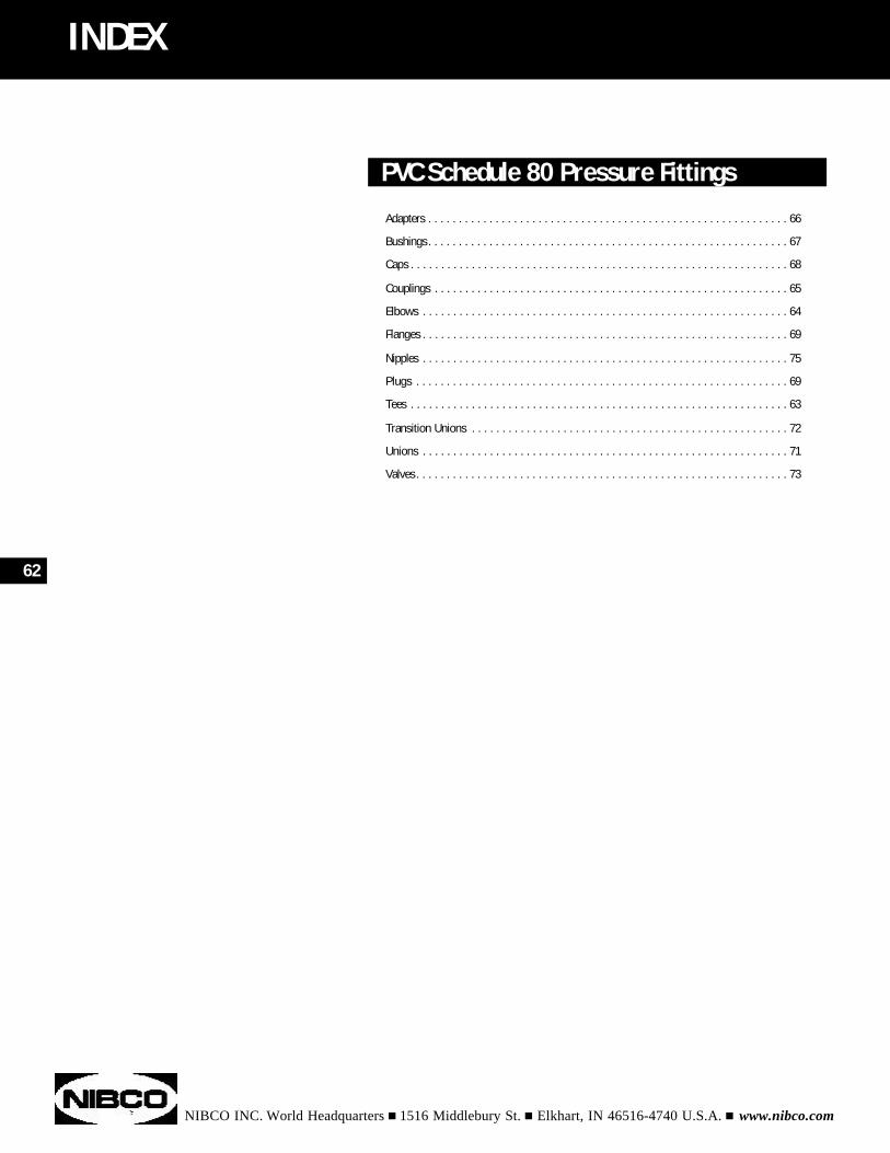
NIBCO INC. World Headquarters n 1516 Middlebury St. n Elkhart, IN 46516-4740 U.S.A. n www.nibco.com
PVC Schedule 80 Pressure Fittings
Adapters . . . . . . . . . . . . . . . . . . . . . . . . . . . . . . . . . . . . . . . . . . . . . . . . . . . . . . . . . . . 66
Bushings. . . . . . . . . . . . . . . . . . . . . . . . . . . . . . . . . . . . . . . . . . . . . . . . . . . . . . . . . . . 67
Caps . . . . . . . . . . . . . . . . . . . . . . . . . . . . . . . . . . . . . . . . . . . . . . . . . . . . . . . . . . . . . . 68
Couplings . . . . . . . . . . . . . . . . . . . . . . . . . . . . . . . . . . . . . . . . . . . . . . . . . . . . . . . . . . 65
Elbows . . . . . . . . . . . . . . . . . . . . . . . . . . . . . . . . . . . . . . . . . . . . . . . . . . . . . . . . . . . . 64
Flanges . . . . . . . . . . . . . . . . . . . . . . . . . . . . . . . . . . . . . . . . . . . . . . . . . . . . . . . . . . . . 69
Nipples . . . . . . . . . . . . . . . . . . . . . . . . . . . . . . . . . . . . . . . . . . . . . . . . . . . . . . . . . . . . 75
Plugs . . . . . . . . . . . . . . . . . . . . . . . . . . . . . . . . . . . . . . . . . . . . . . . . . . . . . . . . . . . . . 69
Tees . . . . . . . . . . . . . . . . . . . . . . . . . . . . . . . . . . . . . . . . . . . . . . . . . . . . . . . . . . . . . . 63
Transition Unions . . . . . . . . . . . . . . . . . . . . . . . . . . . . . . . . . . . . . . . . . . . . . . . . . . . . 72
Unions . . . . . . . . . . . . . . . . . . . . . . . . . . . . . . . . . . . . . . . . . . . . . . . . . . . . . . . . . . . . 71
Valves. . . . . . . . . . . . . . . . . . . . . . . . . . . . . . . . . . . . . . . . . . . . . . . . . . . . . . . . . . . . . 73
INDEX
62
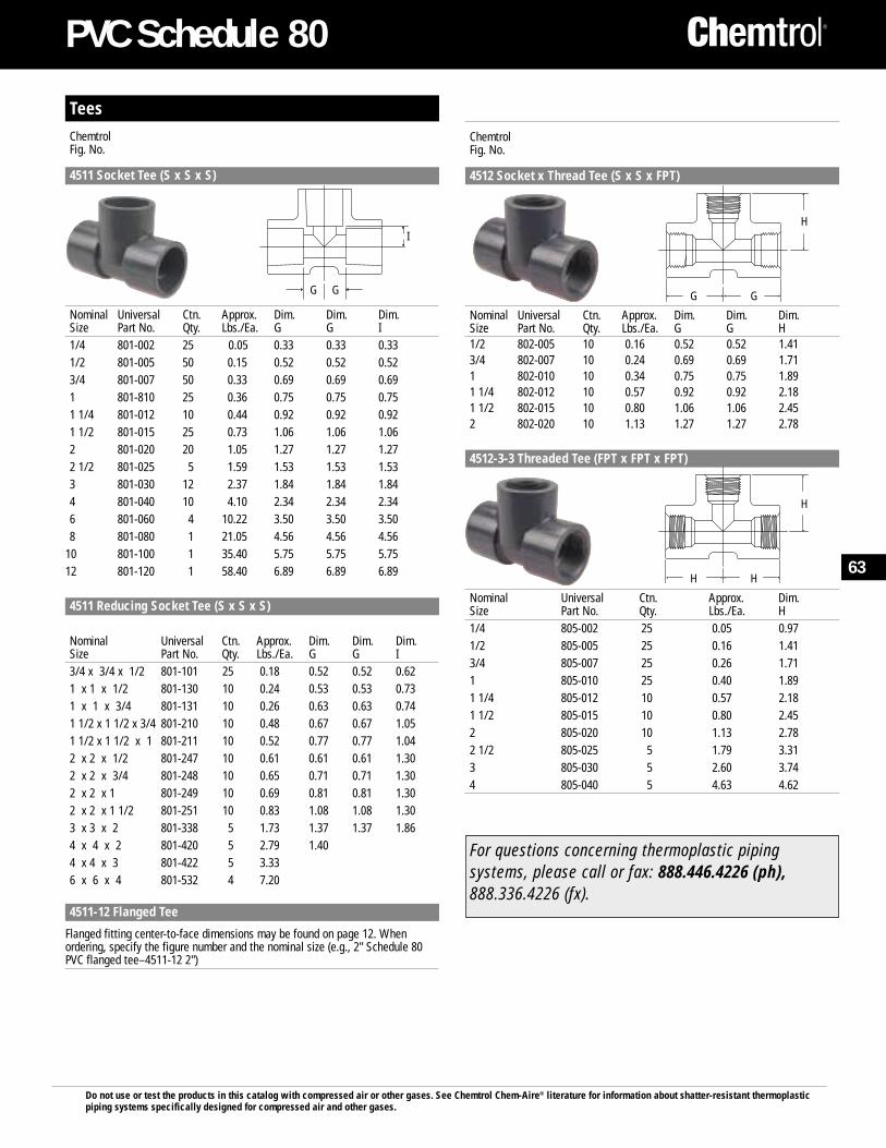
Do not use or test the products in this catalog with compressed air or other gases. See Chemtrol Chem-Aire® literature for information about shatter-resistant thermoplasticpiping systems specifically designed for compressed air and other gases.
PVC Schedule 80
TeesChemtrolFig. No.
4511 Socket Tee (S x S x S)
Nominal Universal Ctn. Approx. Dim. Dim. Dim.Size Part No. Qty. Lbs./Ea. G G I1/4 801-002 25 0.05 0.33 0.33 0.331/2 801-005 50 0.15 0.52 0.52 0.523/4 801-007 50 0.33 0.69 0.69 0.691 801-810 25 0.36 0.75 0.75 0.751 1/4 801-012 10 0.44 0.92 0.92 0.921 1/2 801-015 25 0.73 1.06 1.06 1.062 801-020 20 1.05 1.27 1.27 1.272 1/2 801-025 5 1.59 1.53 1.53 1.533 801-030 12 2.37 1.84 1.84 1.844 801-040 10 4.10 2.34 2.34 2.346 801-060 4 10.22 3.50 3.50 3.508 801-080 1 21.05 4.56 4.56 4.56
10 801-100 1 35.40 5.75 5.75 5.7512 801-120 1 58.40 6.89 6.89 6.894511
4511 Reducing Socket Tee (S x S x S)
Nominal Universal Ctn. Approx. Dim. Dim. Dim.Size Part No. Qty. Lbs./Ea. G G I3/4 x 3/4 x 1/2 801-101 25 0.18 0.52 0.52 0.621 x 1 x 1/2 801-130 10 0.24 0.53 0.53 0.731 x 1 x 3/4 801-131 10 0.26 0.63 0.63 0.741 1/2 x 1 1/2 x 3/4 801-210 10 0.48 0.67 0.67 1.051 1/2 x 1 1/2 x 1 801-211 10 0.52 0.77 0.77 1.042 x 2 x 1/2 801-247 10 0.61 0.61 0.61 1.302 x 2 x 3/4 801-248 10 0.65 0.71 0.71 1.302 x 2 x 1 801-249 10 0.69 0.81 0.81 1.302 x 2 x 1 1/2 801-251 10 0.83 1.08 1.08 1.303 x 3 x 2 801-338 5 1.73 1.37 1.37 1.864 x 4 x 2 801-420 5 2.79 1.404 x 4 x 3 801-422 5 3.336 x 6 x 4 801-532 4 7.20
4511-12 Flanged Tee
Flanged fitting center-to-face dimensions may be found on page 12. Whenordering, specify the figure number and the nominal size (e.g., 2" Schedule 80PVC flanged tee–4511-12 2")
ChemtrolFig. No.
4512 Socket x Thread Tee (S x S x FPT)
Nominal Universal Ctn. Approx. Dim. Dim. Dim.Size Part No. Qty. Lbs./Ea. G G H1/2 802-005 10 0.16 0.52 0.52 1.413/4 802-007 10 0.24 0.69 0.69 1.711 802-010 10 0.34 0.75 0.75 1.891 1/4 802-012 10 0.57 0.92 0.92 2.181 1/2 802-015 10 0.80 1.06 1.06 2.452 802-020 10 1.13 1.27 1.27 2.7811
4512-3-3 Threaded Tee (FPT x FPT x FPT)
Nominal Universal Ctn. Approx. Dim.Size Part No. Qty. Lbs./Ea. H1/4 805-002 25 0.05 0.971/2 805-005 25 0.16 1.413/4 805-007 25 0.26 1.711 805-010 25 0.40 1.891 1/4 805-012 10 0.57 2.181 1/2 805-015 10 0.80 2.452 805-020 10 1.13 2.782 1/2 805-025 5 1.79 3.313 805-030 5 2.60 3.744 805-040 5 4.63 4.62
G G
I
H
HH
H
GG
For questions concerning thermoplastic pipingsystems, please call or fax: 888.446.4226 (ph),888.336.4226 (fx).
63
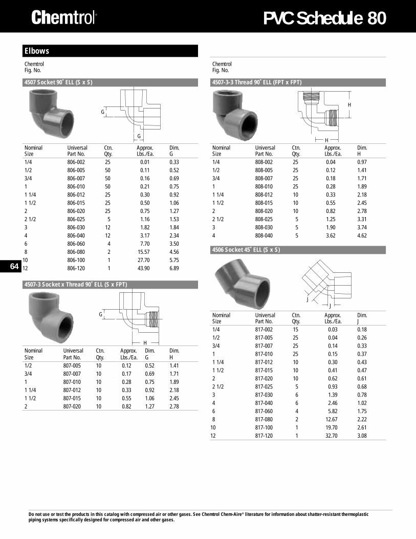
ElbowsChemtrolFig. No.
4507 Socket 90˚ ELL (S x S)
Nominal Universal Ctn. Approx. Dim.Size Part No. Qty. Lbs./Ea. G1/4 806-002 25 0.01 0.331/2 806-005 50 0.11 0.523/4 806-007 50 0.16 0.691 806-010 50 0.21 0.751 1/4 806-012 25 0.30 0.921 1/2 806-015 25 0.50 1.062 806-020 25 0.75 1.272 1/2 806-025 5 1.16 1.533 806-030 12 1.82 1.844 806-040 12 3.17 2.346 806-060 4 7.70 3.508 806-080 2 15.57 4.56
10 806-100 1 27.70 5.7512 806-120 1 43.90 6.8911
4507-3 Socket x Thread 90˚ ELL (S x FPT)
Nominal Universal Ctn. Approx. Dim. Dim.Size Part No. Qty. Lbs./Ea. G H1/2 807-005 10 0.12 0.52 1.413/4 807-007 10 0.17 0.69 1.711 807-010 10 0.28 0.75 1.891 1/4 807-012 10 0.33 0.92 2.181 1/2 807-015 10 0.55 1.06 2.452 807-020 10 0.82 1.27 2.78
ChemtrolFig. No.
4507-3-3 Thread 90˚ ELL (FPT x FPT)
Nominal Universal Ctn. Approx. Dim.Size Part No. Qty. Lbs./Ea. H1/4 808-002 25 0.04 0.971/2 808-005 25 0.12 1.413/4 808-007 25 0.18 1.711 808-010 25 0.28 1.891 1/4 808-012 10 0.33 2.181 1/2 808-015 10 0.55 2.452 808-020 10 0.82 2.782 1/2 808-025 5 1.25 3.313 808-030 5 1.90 3.744 808-040 5 3.62 4.62
4506 Socket 45˚ ELL (S x S)
Nominal Universal Ctn. Approx. Dim.Size Part No. Qty. Lbs./Ea. J1/4 817-002 15 0.03 0.181/2 817-005 25 0.04 0.263/4 817-007 25 0.14 0.331 817-010 25 0.15 0.371 1/4 817-012 10 0.30 0.431 1/2 817-015 10 0.41 0.472 817-020 10 0.62 0.612 1/2 817-025 5 0.93 0.683 817-030 6 1.39 0.784 817-040 6 2.46 1.026 817-060 4 5.82 1.758 817-080 2 12.67 2.22
10 817-100 1 19.70 2.6112 817-120 1 32.70 3.08
Do not use or test the products in this catalog with compressed air or other gases. See Chemtrol Chem-Aire® literature for information about shatter-resistant thermoplasticpiping systems specifically designed for compressed air and other gases.
G
G
G
H
H
H
JJ
64
PVC Schedule 80
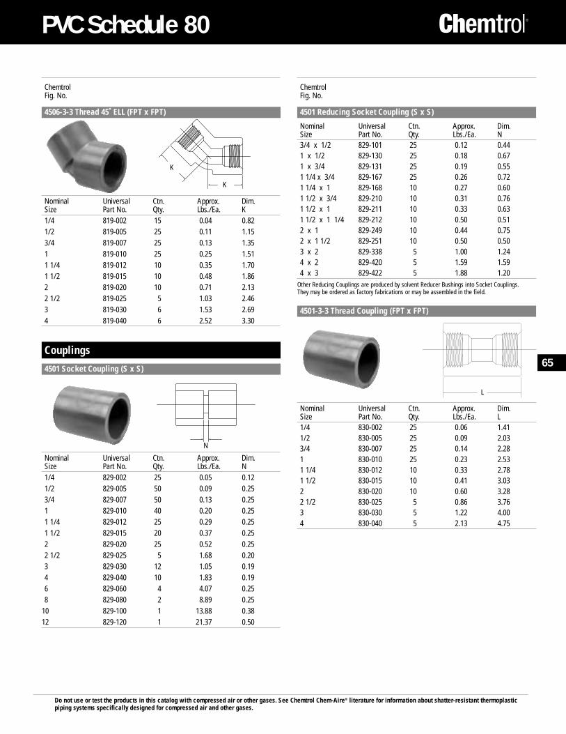
Do not use or test the products in this catalog with compressed air or other gases. See Chemtrol Chem-Aire® literature for information about shatter-resistant thermoplasticpiping systems specifically designed for compressed air and other gases.
ChemtrolFig. No.
4501 Reducing Socket Coupling (S x S)
Nominal Universal Ctn. Approx. Dim.Size Part No. Qty. Lbs./Ea. N3/4 x 1/2 829-101 25 0.12 0.441 x 1/2 829-130 25 0.18 0.671 x 3/4 829-131 25 0.19 0.551 1/4 x 3/4 829-167 25 0.26 0.721 1/4 x 1 829-168 10 0.27 0.601 1/2 x 3/4 829-210 10 0.31 0.761 1/2 x 1 829-211 10 0.33 0.631 1/2 x 1 1/4 829-212 10 0.50 0.512 x 1 829-249 10 0.44 0.752 x 1 1/2 829-251 10 0.50 0.503 x 2 829-338 5 1.00 1.244 x 2 829-420 5 1.59 1.594 x 3 829-422 5 1.88 1.20
Other Reducing Couplings are produced by solvent Reducer Bushings into Socket Couplings. They may be ordered as factory fabrications or may be assembled in the field.
4501-3-3 Thread Coupling (FPT x FPT)
Nominal Universal Ctn. Approx. Dim.Size Part No. Qty. Lbs./Ea. L1/4 830-002 25 0.06 1.411/2 830-005 25 0.09 2.033/4 830-007 25 0.14 2.281 830-010 25 0.23 2.531 1/4 830-012 10 0.33 2.781 1/2 830-015 10 0.41 3.032 830-020 10 0.60 3.282 1/2 830-025 5 0.86 3.763 830-030 5 1.22 4.004 830-040 5 2.13 4.75
ChemtrolFig. No.
4506-3-3 Thread 45˚ ELL (FPT x FPT)
Nominal Universal Ctn. Approx. Dim.Size Part No. Qty. Lbs./Ea. K1/4 819-002 15 0.04 0.821/2 819-005 25 0.11 1.153/4 819-007 25 0.13 1.351 819-010 25 0.25 1.511 1/4 819-012 10 0.35 1.701 1/2 819-015 10 0.48 1.862 819-020 10 0.71 2.132 1/2 819-025 5 1.03 2.463 819-030 6 1.53 2.694 819-040 6 2.52 3.30
Couplings
4501 Socket Coupling (S x S)
Nominal Universal Ctn. Approx. Dim.Size Part No. Qty. Lbs./Ea. N1/4 829-002 25 0.05 0.121/2 829-005 50 0.09 0.253/4 829-007 50 0.13 0.251 829-010 40 0.20 0.251 1/4 829-012 25 0.29 0.251 1/2 829-015 20 0.37 0.252 829-020 25 0.52 0.252 1/2 829-025 5 1.68 0.203 829-030 12 1.05 0.194 829-040 10 1.83 0.196 829-060 4 4.07 0.258 829-080 2 8.89 0.25
10 829-100 1 13.88 0.3812 829-120 1 21.37 0.50
K
K
N
4501-3-3
L
65
PVC Schedule 80
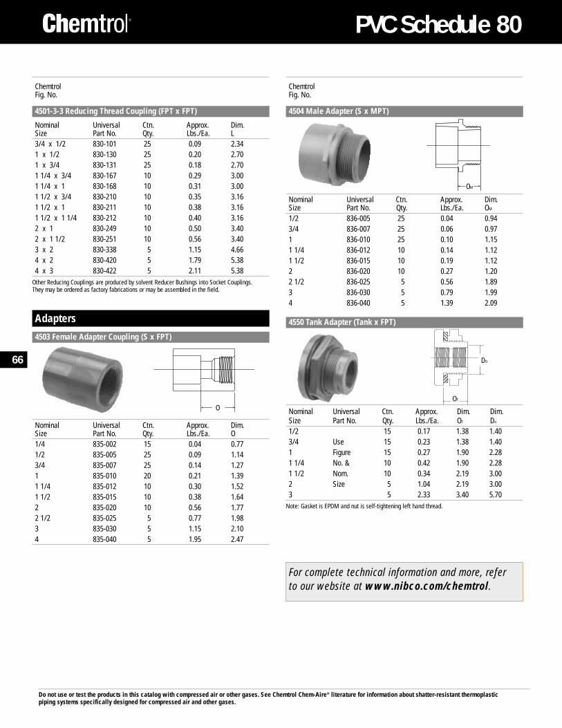
Do not use or test the products in this catalog with compressed air or other gases. See Chemtrol Chem-Aire® literature for information about shatter-resistant thermoplasticpiping systems specifically designed for compressed air and other gases.
ChemtrolFig. No.
4501-3-3 Reducing Thread Coupling (FPT x FPT)
Nominal Universal Ctn. Approx. Dim.Size Part No. Qty. Lbs./Ea. L3/4 x 1/2 830-101 25 0.09 2.341 x 1/2 830-130 25 0.20 2.701 x 3/4 830-131 25 0.18 2.701 1/4 x 3/4 830-167 10 0.29 3.001 1/4 x 1 830-168 10 0.31 3.001 1/2 x 3/4 830-210 10 0.35 3.161 1/2 x 1 830-211 10 0.38 3.161 1/2 x 1 1/4 830-212 10 0.40 3.162 x 1 830-249 10 0.50 3.402 x 1 1/2 830-251 10 0.56 3.403 x 2 830-338 5 1.15 4.664 x 2 830-420 5 1.79 5.384 x 3 830-422 5 2.11 5.38
Other Reducing Couplings are produced by solvent Reducer Bushings into Socket Couplings. They may be ordered as factory fabrications or may be assembled in the field.
Adapters
4503 Female Adapter Coupling (S x FPT)
Nominal Universal Ctn. Approx. Dim.Size Part No. Qty. Lbs./Ea. O1/4 835-002 15 0.04 0.771/2 835-005 25 0.09 1.143/4 835-007 25 0.14 1.271 835-010 20 0.21 1.391 1/4 835-012 10 0.30 1.521 1/2 835-015 10 0.38 1.642 835-020 10 0.56 1.772 1/2 835-025 5 0.77 1.983 835-030 5 1.15 2.104 835-040 5 1.95 2.47
ChemtrolFig. No.
4504 Male Adapter (S x MPT)
Nominal Universal Ctn. Approx. Dim.Size Part No. Qty. Lbs./Ea. OM
1/2 836-005 25 0.04 0.943/4 836-007 25 0.06 0.971 836-010 25 0.10 1.151 1/4 836-012 10 0.14 1.121 1/2 836-015 10 0.19 1.122 836-020 10 0.27 1.202 1/2 836-025 5 0.56 1.893 836-030 5 0.79 1.994 836-040 5 1.39 2.09
4550 Tank Adapter (Tank x FPT)
Nominal Universal Ctn. Approx. Dim. Dim.Size Part No. Qty. Lbs./Ea. OT Do
1/2 15 0.17 1.38 1.403/4 Use 15 0.23 1.38 1.401 Figure 15 0.27 1.90 2.281 1/4 No. & 10 0.42 1.90 2.281 1/2 Nom. 10 0.34 2.19 3.002 Size 5 1.04 2.19 3.003 5 2.33 3.40 5.70
Note: Gasket is EPDM and nut is self-tightening left hand thread.
O
OM
OT
DO
For complete technical information and more, refer to our website at www.nibco.com/chemtrol.
66
PVC Schedule 80
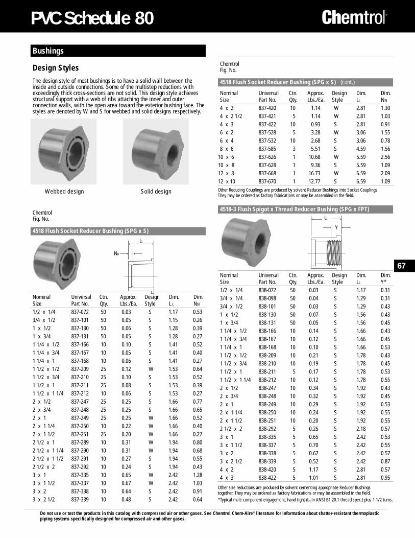
Do not use or test the products in this catalog with compressed air or other gases. See Chemtrol Chem-Aire® literature for information about shatter-resistant thermoplasticpiping systems specifically designed for compressed air and other gases.
ChemtrolFig. No.
4518 Flush Socket Reducer Bushing (SPG x S) (cont.)
Nominal Universal Ctn. Approx. Design Dim. Dim.Size Part No. Qty. Lbs./Ea. Style LL NN
4 x 2 837-420 10 1.14 W 2.81 1.304 x 2 1/2 837-421 5 1.14 W 2.81 1.034 x 3 837-422 10 0.93 S 2.81 0.916 x 2 837-528 5 3.28 W 3.06 1.556 x 4 837-532 10 2.68 S 3.06 0.788 x 6 837-585 3 5.51 S 4.59 1.56
10 x 6 837-626 1 10.68 W 5.59 2.5610 x 8 837-628 1 9.36 S 5.59 1.0912 x 8 837-668 1 16.73 W 6.59 2.0912 x 10 837-670 1 12.77 S 6.59 1.09Other Reducing Couplings are produced by solvent Reducer Bushings into Socket Couplings. They may be ordered as factory fabrications or may be assembled in the field.
4518-3 Flush Spigot x Thread Reducer Bushing (SPG x FPT)
Nominal Universal Ctn. Approx. Design Dim. Dim.Size Part No. Qty. Lbs./Ea. Style LL Y*1/2 x 1/4 838-072 50 0.03 S 1.17 0.313/4 x 1/4 838-098 50 0.04 S 1.29 0.313/4 x 1/2 838-101 50 0.03 S 1.29 0.431 x 1/2 838-130 50 0.07 S 1.56 0.431 x 3/4 838-131 50 0.05 S 1.56 0.451 1/4 x 1/2 838-166 10 0.14 S 1.66 0.431 1/4 x 3/4 838-167 10 0.12 S 1.66 0.451 1/4 x 1 838-168 10 0.10 S 1.66 0.531 1/2 x 1/2 838-209 10 0.21 S 1.78 0.431 1/2 x 3/4 838-210 10 0.19 S 1.78 0.451 1/2 x 1 838-211 5 0.17 S 1.78 0.531 1/2 x 1 1/4 838-212 10 0.12 S 1.78 0.552 x 1/2 838-247 10 0.34 S 1.92 0.432 x 3/4 838-248 10 0.32 S 1.92 0.452 x 1 838-249 10 0.29 S 1.92 0.532 x 1 1/4 838-250 10 0.24 S 1.92 0.552 x 1 1/2 838-251 10 0.20 S 1.92 0.552 1/2 x 2 838-292 5 0.25 S 2.18 0.573 x 1 838-335 5 0.65 S 2.42 0.533 x 1 1/2 838-337 5 0.70 S 2.42 0.553 x 2 838-338 5 0.67 S 2.42 0.573 x 2 1/2 838-339 5 0.52 S 2.42 0.874 x 2 838-420 5 1.17 S 2.81 0.574 x 3 838-422 5 1.01 S 2.81 0.95
Other size reductions are produced by solvent cementing appropriate Reducer Bushings together. They may be ordered as factory fabrications or may be assembled in the field.*Typical male component engagement, hand tight (L1 in ANSI B1.20.1 thread spec.) plus 1 1/2 turns.
Bushings
Design StylesThe design style of most bushings is to have a solid wall between theinside and outside connections. Some of the multistep reductions withexceedingly thick cross-sections are not solid. This design style achievesstructural support with a web of ribs attaching the inner and outerconnection walls, with the open area toward the exterior bushing face. Thestyles are denoted by W and S for webbed and solid designs respectively.
ChemtrolFig. No.
4518 Flush Socket Reducer Bushing (SPG x S)
Nominal Universal Ctn. Approx. Design Dim. Dim.Size Part No. Qty. Lbs./Ea. Style L L NN
1/2 x 1/4 837-072 50 0.03 S 1.17 0.533/4 x 1/2 837-101 50 0.05 S 1.15 0.261 x 1/2 837-130 50 0.06 S 1.28 0.391 x 3/4 837-131 50 0.05 S 1.28 0.271 1/4 x 1/2 837-166 10 0.10 S 1.41 0.521 1/4 x 3/4 837-167 10 0.05 S 1.41 0.401 1/4 x 1 837-168 10 0.06 S 1.41 0.271 1/2 x 1/2 837-209 25 0.12 W 1.53 0.641 1/2 x 3/4 837-210 25 0.10 S 1.53 0.521 1/2 x 1 837-211 25 0.08 S 1.53 0.391 1/2 x 1 1/4 837-212 10 0.06 S 1.53 0.272 x 1/2 837-247 25 0.25 S 1.66 0.772 x 3/4 837-248 25 0.25 S 1.66 0.652 x 1 837-249 25 0.25 W 1.66 0.522 x 1 1/4 837-250 10 0.22 W 1.66 0.402 x 1 1/2 837-251 25 0.20 W 1.66 0.272 1/2 x 1 837-289 10 0.31 W 1.94 0.802 1/2 x 1 1/4 837-290 10 0.31 W 1.94 0.682 1/2 x 1 1/2 837-291 10 0.27 S 1.94 0.552 1/2 x 2 837-292 10 0.24 S 1.94 0.433 x 1 837-335 10 0.65 W 2.42 1.283 x 1 1/2 837-337 10 0.67 W 2.42 1.033 x 2 837-338 10 0.64 S 2.42 0.913 x 2 1/2 837-339 10 0.48 S 2.42 0.64
Webbed design Solid design
NN
LL
Y
LL
67
PVC Schedule 80
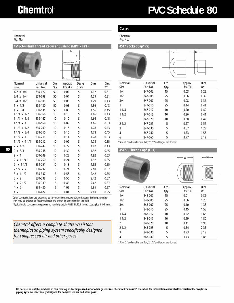
Do not use or test the products in this catalog with compressed air or other gases. See Chemtrol Chem-Aire® literature for information about shatter-resistant thermoplasticpiping systems specifically designed for compressed air and other gases.
ChemtrolFig. No.
4518-3-4 Flush Thread Reducer Bushing (MPT x FPT)
Nominal Universal Ctn. Approx. Design Dim. Dim.Size Part No. Qty. Lbs./Ea. Style L L Y*1/2 x 1/4 839-072 50 0.02 S 1.17 0.313/4 x 1/4 839-098 50 0.04 S 1.29 0.313/4 x 1/2 839-101 50 0.03 S 1.29 0.431 x 1/2 839-130 50 0.05 S 1.56 0.431 x 3/4 839-131 50 0.05 S 1.56 0.451 1/4 x 1/2 839-166 10 0.15 S 1.66 0.431 1/4 x 3/4 839-167 10 0.10 S 1.66 0.451 1/4 x 1 839-168 10 0.09 S 1.66 0.531 1/2 x 1/2 839-209 10 0.18 S 1.78 0.431 1/2 x 3/4 839-210 10 0.16 S 1.78 0.451 1/2 x 1 839-211 5 0.14 S 1.78 0.531 1/2 x 1 1/4 839-212 10 0.09 S 1.78 0.552 x 1/2 839-247 10 0.27 S 1.92 0.432 x 3/4 839-248 10 0.30 S 1.92 0.452 x 1 839-249 10 0.23 S 1.92 0.532 x 1 1/4 839-250 10 0.24 S 1.92 0.552 x 1 1/2 839-251 10 0.18 S 1.92 0.552 1/2 x 2 839-292 5 0.21 S 2.18 0.573 x 1 1/2 839-337 5 0.58 S 2.42 0.553 x 2 839-338 5 0.56 S 2.42 0.573 x 2 1/2 839-339 5 0.45 S 2.42 0.874 x 2 839-420 5 1.09 S 2.81 0.574 x 3 839-422 5 0.81 S 2.81 0.95
Other size reductions are produced by solvent cementing appropriate Reducer Bushings together.They may be ordered as factory fabrications or may be assembled in the field.*Typical male component engagement, hand tight (L1 in ANSI B1.20.1 thread spec.) plus 1 1/2 turns.
CapsChemtrolFig. No.
4517 Socket Cap* (S)
Nominal Universal Ctn. Approx. Dim.Size Part No. Qty. Lbs./Ea. OC
1/4 847-002 15 0.03 0.251/2 847-005 25 0.06 0.393/4 847-007 25 0.08 0.371 847-010 25 0.14 0.411 1/4 847-012 10 0.20 0.401 1/2 847-015 10 0.26 0.412 847-020 10 0.38 0.422 1/2 847-025 5 0.57 0.573 847-030 5 0.87 1.294 847-040 5 1.53 1.586 847-060 5 3.77 2.13
*Sizes 2" and smaller are flat; 2 1/2" and larger are domed.
4517-3 Thread Cap* (FPT)
Nominal Universal Ctn. Approx. Dim.Size Part No. Qty. Lbs./Ea. W1/4 848-002 15 0.01 0.891/2 848-005 25 0.06 1.283/4 848-007 25 0.10 1.381 848-010 25 0.15 1.551 1/4 848-012 10 0.22 1.661 1/2 848-015 10 0.29 1.802 848-020 10 0.41 1.932 1/2 848-025 5 0.64 2.353 848-030 5 0.93 3.194 848-040 5 1.73 3.86
*Sizes 2" and smaller are flat; 2 1/2" and larger are domed.
OC
W W
OC
Y
LL
Chemtrol offers a complete shatter-resistantthermoplastic piping system specifically designedfor compressed air and other gases.
68
PVC Schedule 80
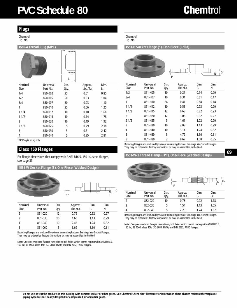
Do not use or test the products in this catalog with compressed air or other gases. See Chemtrol Chem-Aire® literature for information about shatter-resistant thermoplasticpiping systems specifically designed for compressed air and other gases.
ChemtrolFig. No.
4551-H Socket Flange (S), One-Piece (Solid)
Nominal Universal Ctn. Approx. Dim. Dim.Size Part No. Qty. Lbs./Ea. G N1/2 851-H05 10 0.21 0.54 0.203/4 851-H07 10 0.31 0.61 0.171 851-H10 24 0.41 0.68 0.181 1/4 851-H12 10 0.53 0.73 0.201 1/2 851-H15 12 0.68 0.82 0.232 851-H20 12 1.03 0.92 0.272 1/2 851-H25 5 1.61 1.02 0.203 851-H30 10 2.08 1.13 0.294 851-H40 10 3.14 1.24 0.326 851-H60 5 4.79 1.36 0.318 851-H80 2 8.67 1.50 0.35
Reducing Flanges are produced by solvent cementing Reducer Bushings into Socket Flanges.They may be ordered as factory fabrications or may be assembled in the field.
4551-W-3 Thread Flange (FPT), One-Piece (Webbed Design)
Nominal Universal Ctn. Approx. Dim. Dim.Size Part No. Qty. Lbs./Ea. G OF
2 852-020 10 0.78 0.92 1.183 852-030 5 1.54 1.13 1.554 852-040 5 2.25 1.24 1.67
Reducing Flanges are produced by solvent cementing Reducer Bushings into Socket Flanges.They may be ordered as factory fabrications or may be assembled in the field.
Note: One-piece webbed flanges have oblong bolt holes which permit mating with ANSI B16.5,150 lb.; BS 1560, class 150; ISO 2084, PN10; and DIN 2532, PN10 flanges.
PlugsChemtrolFig. No.
4516-4 Thread Plug (MPT)
Nominal Universal Ctn. Approx. Dim.Size Part No. Qty. Lbs./Ea. LL
1/4 850-002 25 0.01 0.851/2 850-005 50 0.03 1.043/4 850-007 50 0.03 1.101 850-010 25 0.06 1.251 1/4 850-012 10 0.10 1.661 1/2 850-015 10 0.14 1.782 850-020 10 0.19 1.922 1/2 850-025 5 0.29 2.183 850-030 5 0.51 2.424 850-040 5 0.95 2.81
1/4" Plug is solid, only
Class 150 FlangesFor flange dimensions that comply with ANSI B16.5, 150 lb., steel flanges, see page 39.
4551-W Socket Flange (S), One-Piece (Webbed Design)
Nominal Universal Ctn. Approx. Dim. Dim.Size Part No. Qty. Lbs./Ea. G N2 851-020 12 0.79 0.92 0.273 851-030 10 1.60 1.13 0.294 851-040 10 2.42 1.24 0.326 851-060 5 3.69 1.36 0.31
Reducing Flanges are produced by solvent cementing Reducer Bushings into Socket Flanges.They may be ordered as factory fabrications or may be assembled in the field.
Note: One-piece webbed flanges have oblong bolt holes which permit mating with ANSI B16.5,150 lb.; BS 1560, class 150; ISO 2084, PN10; and DIN 2532, PN10 flanges.
LL
G1°
N
OF
1°G
G1°
N
69
PVC Schedule 80
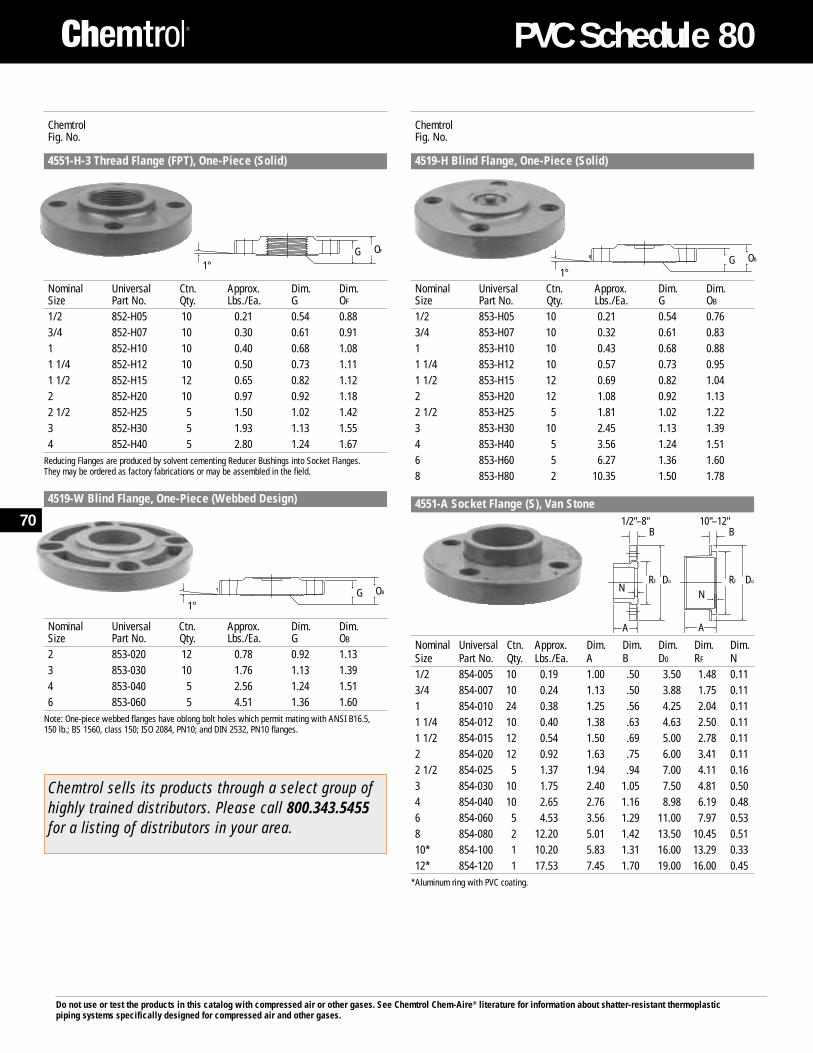
Do not use or test the products in this catalog with compressed air or other gases. See Chemtrol Chem-Aire® literature for information about shatter-resistant thermoplasticpiping systems specifically designed for compressed air and other gases.
ChemtrolFig. No.
4519-H Blind Flange, One-Piece (Solid)
Nominal Universal Ctn. Approx. Dim. Dim.Size Part No. Qty. Lbs./Ea. G OB
1/2 853-H05 10 0.21 0.54 0.763/4 853-H07 10 0.32 0.61 0.831 853-H10 10 0.43 0.68 0.881 1/4 853-H12 10 0.57 0.73 0.951 1/2 853-H15 12 0.69 0.82 1.042 853-H20 12 1.08 0.92 1.132 1/2 853-H25 5 1.81 1.02 1.223 853-H30 10 2.45 1.13 1.394 853-H40 5 3.56 1.24 1.516 853-H60 5 6.27 1.36 1.608 853-H80 2 10.35 1.50 1.78
4551-A Socket Flange (S), Van Stone
Nominal Universal Ctn. Approx. Dim. Dim. Dim. Dim. Dim.Size Part No. Qty. Lbs./Ea. A B D0 RF N1/2 854-005 10 0.19 1.00 .50 3.50 1.48 0.113/4 854-007 10 0.24 1.13 .50 3.88 1.75 0.111 854-010 24 0.38 1.25 .56 4.25 2.04 0.111 1/4 854-012 10 0.40 1.38 .63 4.63 2.50 0.111 1/2 854-015 12 0.54 1.50 .69 5.00 2.78 0.112 854-020 12 0.92 1.63 .75 6.00 3.41 0.112 1/2 854-025 5 1.37 1.94 .94 7.00 4.11 0.163 854-030 10 1.75 2.40 1.05 7.50 4.81 0.504 854-040 10 2.65 2.76 1.16 8.98 6.19 0.486 854-060 5 4.53 3.56 1.29 11.00 7.97 0.538 854-080 2 12.20 5.01 1.42 13.50 10.45 0.5110* 854-100 1 10.20 5.83 1.31 16.00 13.29 0.3312* 854-120 1 17.53 7.45 1.70 19.00 16.00 0.45
*Aluminum ring with PVC coating.
ChemtrolFig. No.
4551-H-3 Thread Flange (FPT), One-Piece (Solid)
Nominal Universal Ctn. Approx. Dim. Dim.Size Part No. Qty. Lbs./Ea. G OF
1/2 852-H05 10 0.21 0.54 0.883/4 852-H07 10 0.30 0.61 0.911 852-H10 10 0.40 0.68 1.081 1/4 852-H12 10 0.50 0.73 1.111 1/2 852-H15 12 0.65 0.82 1.122 852-H20 10 0.97 0.92 1.182 1/2 852-H25 5 1.50 1.02 1.423 852-H30 5 1.93 1.13 1.554 852-H40 5 2.80 1.24 1.67
Reducing Flanges are produced by solvent cementing Reducer Bushings into Socket Flanges.They may be ordered as factory fabrications or may be assembled in the field.
4519-W Blind Flange, One-Piece (Webbed Design)
Nominal Universal Ctn. Approx. Dim. Dim.Size Part No. Qty. Lbs./Ea. G OB
2 853-020 12 0.78 0.92 1.133 853-030 10 1.76 1.13 1.394 853-040 5 2.56 1.24 1.516 853-060 5 4.51 1.36 1.60
Note: One-piece webbed flanges have oblong bolt holes which permit mating with ANSI B16.5,150 lb.; BS 1560, class 150; ISO 2084, PN10; and DIN 2532, PN10 flanges.
OB
1°G
AA
NN
B B
RF Do RF Do
OF
1°G OB
1°G
Chemtrol sells its products through a select group ofhighly trained distributors. Please call 800.343.5455for a listing of distributors in your area.
1/2"–8" 10"–12"70
PVC Schedule 80
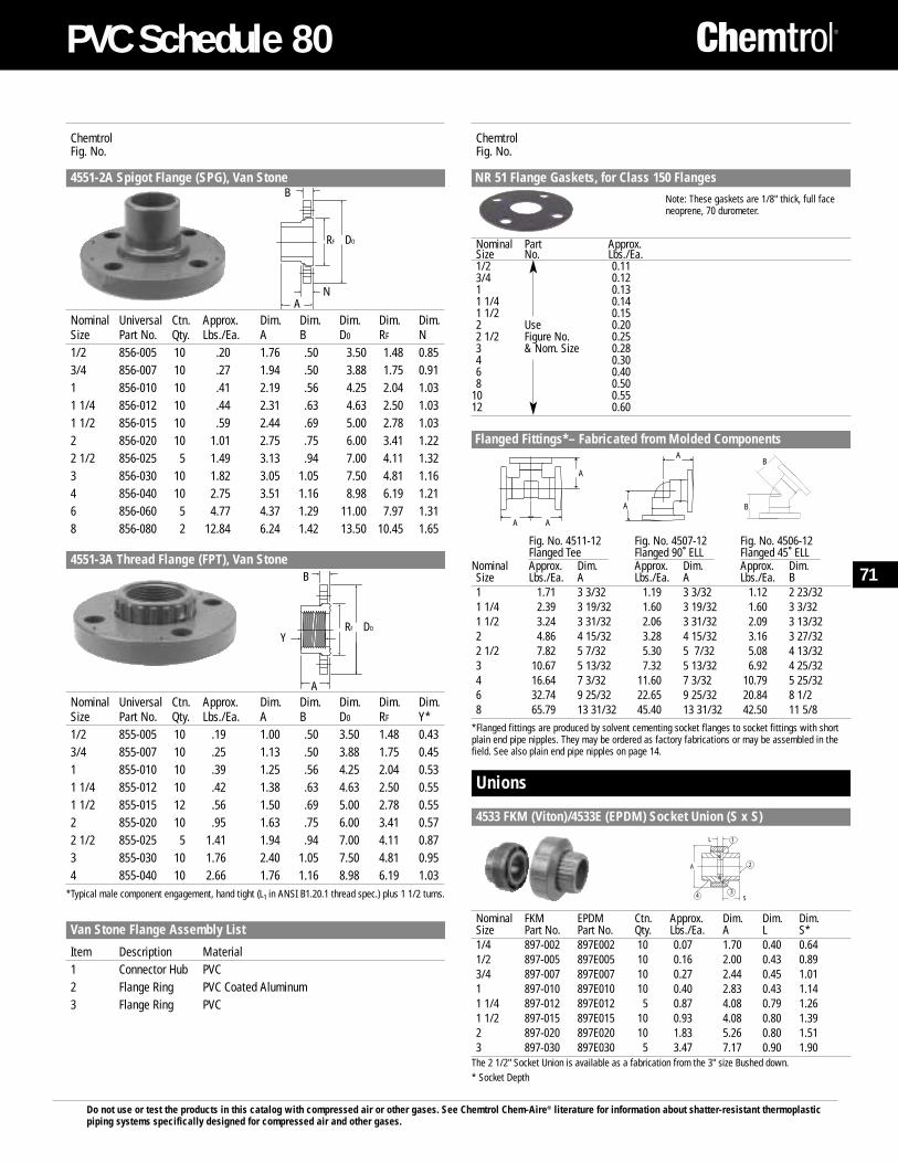
Do not use or test the products in this catalog with compressed air or other gases. See Chemtrol Chem-Aire® literature for information about shatter-resistant thermoplasticpiping systems specifically designed for compressed air and other gases.
ChemtrolFig. No.
NR 51 Flange Gaskets, for Class 150 Flanges
Note: These gaskets are 1/8" thick, full faceneoprene, 70 durometer.
Nominal Part Approx. Size No. Lbs./Ea.1/2 0.113/4 0.121 0.131 1/4 0.141 1/2 0.152 Use 0.202 1/2 Figure No. 0.253 & Nom. Size 0.284 0.306 0.408 0.50
10 0.5512 0.60
Flanged Fittings*– Fabricated from Molded Components
Fig. No. 4511-12 Fig. No. 4507-12 Fig. No. 4506-12Flanged Tee Flanged 90˚ ELL Flanged 45˚ ELL
Nominal Approx. Dim. Approx. Dim. Approx. Dim.Size Lbs./Ea. A Lbs./Ea. A Lbs./Ea. B1 1.71 3 3/32 1.19 3 3/32 1.12 2 23/321 1/4 2.39 3 19/32 1.60 3 19/32 1.60 3 3/321 1/2 3.24 3 31/32 2.06 3 31/32 2.09 3 13/322 4.86 4 15/32 3.28 4 15/32 3.16 3 27/322 1/2 7.82 5 7/32 5.30 5 7/32 5.08 4 13/323 10.67 5 13/32 7.32 5 13/32 6.92 4 25/324 16.64 7 3/32 11.60 7 3/32 10.79 5 25/326 32.74 9 25/32 22.65 9 25/32 20.84 8 1/2 8 65.79 13 31/32 45.40 13 31/32 42.50 11 5/8
*Flanged fittings are produced by solvent cementing socket flanges to socket fittings with shortplain end pipe nipples. They may be ordered as factory fabrications or may be assembled in thefield. See also plain end pipe nipples on page 14.
Unions
4533 FKM (Viton)/4533E (EPDM) Socket Union (S x S)
Nominal FKM EPDM Ctn. Approx. Dim. Dim. Dim.Size Part No. Part No. Qty. Lbs./Ea. A L S*1/4 897-002 897E002 10 0.07 1.70 0.40 0.641/2 897-005 897E005 10 0.16 2.00 0.43 0.893/4 897-007 897E007 10 0.27 2.44 0.45 1.011 897-010 897E010 10 0.40 2.83 0.43 1.141 1/4 897-012 897E012 5 0.87 4.08 0.79 1.261 1/2 897-015 897E015 10 0.93 4.08 0.80 1.392 897-020 897E020 10 1.83 5.26 0.80 1.513 897-030 897E030 5 3.47 7.17 0.90 1.90
The 2 1/2" Socket Union is available as a fabrication from the 3" size Bushed down.* Socket Depth
ChemtrolFig. No.
4551-2A Spigot Flange (SPG), Van Stone
Nominal Universal Ctn. Approx. Dim. Dim. Dim. Dim. Dim.Size Part No. Qty. Lbs./Ea. A B D0 RF N1/2 856-005 10 .20 1.76 .50 3.50 1.48 0.853/4 856-007 10 .27 1.94 .50 3.88 1.75 0.911 856-010 10 .41 2.19 .56 4.25 2.04 1.031 1/4 856-012 10 .44 2.31 .63 4.63 2.50 1.031 1/2 856-015 10 .59 2.44 .69 5.00 2.78 1.032 856-020 10 1.01 2.75 .75 6.00 3.41 1.222 1/2 856-025 5 1.49 3.13 .94 7.00 4.11 1.323 856-030 10 1.82 3.05 1.05 7.50 4.81 1.164 856-040 10 2.75 3.51 1.16 8.98 6.19 1.216 856-060 5 4.77 4.37 1.29 11.00 7.97 1.318 856-080 2 12.84 6.24 1.42 13.50 10.45 1.65
4551-3A Thread Flange (FPT), Van Stone
Nominal Universal Ctn. Approx. Dim. Dim. Dim. Dim. Dim.Size Part No. Qty. Lbs./Ea. A B D0 RF Y*1/2 855-005 10 .19 1.00 .50 3.50 1.48 0.433/4 855-007 10 .25 1.13 .50 3.88 1.75 0.451 855-010 10 .39 1.25 .56 4.25 2.04 0.531 1/4 855-012 10 .42 1.38 .63 4.63 2.50 0.551 1/2 855-015 12 .56 1.50 .69 5.00 2.78 0.552 855-020 10 .95 1.63 .75 6.00 3.41 0.572 1/2 855-025 5 1.41 1.94 .94 7.00 4.11 0.873 855-030 10 1.76 2.40 1.05 7.50 4.81 0.954 855-040 10 2.66 1.76 1.16 8.98 6.19 1.03
*Typical male component engagement, hand tight (L1 in ANSI B1.20.1 thread spec.) plus 1 1/2 turns.
Van Stone Flange Assembly List
Item Description Material1 Connector Hub PVC2 Flange Ring PVC Coated Aluminum3 Flange Ring PVC
DO
AN
B
RF
DO
A
B
RF
Y
A A
A
A
AB
B
1L
A
4
2
3S
71
PVC Schedule 80
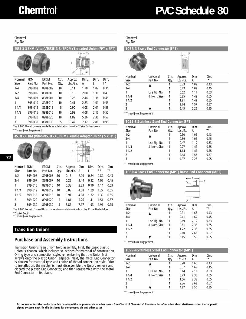
Do not use or test the products in this catalog with compressed air or other gases. See Chemtrol Chem-Aire® literature for information about shatter-resistant thermoplasticpiping systems specifically designed for compressed air and other gases.
ChemtrolFig. No.
4533-3-3 FKM (Viton)/4533E-3-3 (EPDM) Threaded Union (FPT x FPT)
Nominal FKM EPDM Ctn. Approx. Dim. Dim. Dim.Size Part No. Part No. Qty. Lbs./Ea. A L T*1/4 898-002 898E002 10 0.11 1.70 1.07 0.311/2 898-005 898E005 10 0.16 2.00 1.30 0.433/4 898-007 898E007 10 0.28 2.44 1.38 0.451 898-010 898E010 10 0.41 2.83 1.51 0.531 1/4 898-012 898E012 5 0.90 4.08 2.01 0.551 1/2 898-015 898E015 10 0.92 4.08 2.16 0.552 898-020 898E020 10 1.82 5.26 2.36 0.573 898-030 898E030 5 3.47 7.17 2.88 0.95
The 2 1/2" Thread Union is available as a fabrication from the 3" size Bushed down.* Thread Joint Engagement
4533E-3 FKM (Viton)/4533E-3 (EPDM) Female Adapter Union ( S x FPT)
Nominal FKM EPDM Ctn. Approx. Dim. Dim. Dim. Dim.Size Part No. Part No. Qty. Lbs./Ea. A L S* T†
1/2 899-005 899E005 10 0.16 2.00 0.84 0.89 0.433/4 899-007 899E007 10 0.26 2.44 0.82 1.02 0.451 899-010 899E010 10 0.38 2.83 0.90 1.14 0.531 1/4 899-012 899E012 10 0.89 4.08 1.29 1.27 0.551 1/2 899-015 899E015 10 0.91 4.08 1.32 1.39 0.552 899-020 899E020 5 1.81 5.26 1.41 1.51 0.573 899-030 899E030 5 3.86 7.17 1.93 1.91 0.95
The 2 1/2" Socket x Thread Union is available as a fabrication from the 3" size Bushed down.* Socket Depth† Thread Joint Engagement
Transition Unions
Purchase and Assembly InstructionsTransition Unions result from field assembly. First, the basic plasticUnion is chosen, which includes selections for material of construction,O-ring type and connection style, remembering that the Union Nutscrews onto the plastic Union Tailpiece. Next, the metal End Connectoris chosen for material type and choice of thread connection style. Priorto installation, the mechanic must disassemble the Union, remove anddiscard the plastic End Connector, and then reassemble with the metalEnd Connector in its place.
1L
A
4
2
3T T
1L
A
4
2
3
S T
ChemtrolFig. No.
TCBR-3 Brass End Connector (FPT)
Nominal Universal Ctn. Approx. Dim. Dim.Size Part No. Qty. Lbs./Ea. A T*1/2 1 0.33 1.02 0.433/4 1 0.43 1.02 0.451 Use Fig. No. 1 0.52 1.19 0.53 1 1/4 & Nom. Size 1 0.85 1.42 0.551 1/2 1 1.81 1.42 0.552 1 2.74 1.57 0.573 1 5.45 2.25 0.95
* Thread Joint Engagement
TCSS-3 Stainless Steel End Connector (FPT)Nominal Universal Ctn. Approx. Dim. Dim.Size Part No. Qty. Lbs./Ea. A T*1/2 1 0.30 1.02 0.433/4 1 0.39 1.02 0.451 Use Fig. No. 1 0.47 1.19 0.531 1/4 & Nom. Size 1 0.77 1.42 0.551 1/2 1 1.64 1.42 0.552 1 2.48 1.57 0.573 1 4.97 2.25 0.95
* Thread Joint Engagement
TCBR-4 Brass End Connector (MPT) Brass End Connector (MPT)
Nominal Universal Ctn. Approx. Dim. Dim.Size Part No. Qty. Lbs./Ea. A T*1/2 1 0.31 1.66 0.433/4 1 0.41 1.69 0.451 Use Fig. No. 1 0.49 2.19 0.531 1/4 & Nom. Size 1 0.81 2.38 0.551 1/2 1 1.72 2.38 0.552 1 2.60 2.63 0.573 1 5.45 3.50 0.95
* Thread Joint Engagement
TCSS-4 Stainless Steel End Connector (MPT)Nominal Universal Ctn. Approx. Dim. Dim.Size Part No. Qty. Lbs./Ea. A T*1/2 1 0.28 1.66 0.433/4 1 0.37 1.69 0.451 Use Fig. No. 1 0.44 2.19 0.531 1/4 & Nom. Size 1 0.73 2.38 0.551 1/2 1 1.56 2.38 0.552 1 2.36 2.63 0.573 1 4.97 3.50 0.95
* Thread Joint Engagement
AT
AT
72
PVC Schedule 80
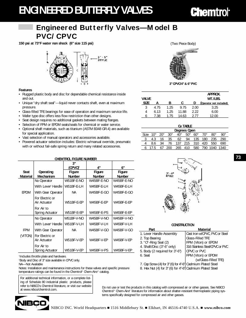
Engineered Butterfly Valves—Model BPVC/CPVC
NIBCO INC. World Headquarters n 1516 Middlebury St. n Elkhart, IN 46516-4740 U.S.A. n www.nibco.com
ENGINEERED BUTTERFLY VALVES
Features• Rugged plastic body and disc for dependable chemical resistance inside
and out.• Unique “dry shaft seal”—liquid never contacts shaft, even at maximum
pressure.• Glass-filled TFE bearings for ease of operation and maximum service life.• Wafer type disc offers less flow restriction than other designs.• Seat design requires no additional gaskets between mating flanges.• Selection of FPM or EPDM seats/seals for chemical or water service.• Optional shaft materials, such as titanium (ASTM B348 GR.4) are available
for special application.• Vast selection of manual operators and accessories available. • Powered actuator selection includes: Electric w/manual override, pneumatic
with or without fail-safe spring return and many related accessories.
CHEMTROL FIGURE NUMBER3"
(CPVC)2 4" 6"Seat Operating Figure Figure Figure
Material Mechanism Number Number NumberNo Operator W51BF-E-NO W45BF-E-NO W45BF-E-NO
With Lever1 Handle W51BF-E-LH W45BF-E-LH W45BF-E-LH
EPDM With Gear Operator NA W45BF-E-GO W45BF-E-GO
For Electric orAir Actuator W51BF-E-EP W45BF-E-EP W45BF-E-EP
For Air toSpring Actuator W51BF-E-EP W45BF-E-PS W45BF-E-EP
No Operator W51BF-V-NO W45BF-V-NO W45BF-V-NO
With Lever1 Handle W51BF-V-LH W45BF-V-LH W45BF-V-LH
FPM With Gear Operator NA W45BF-V-GO W45BF-V-GO
(VITON) For Electric orAir Actuator W51BF-V-EP W45BF-V-EP W45BF-V-EP
For Air toSpring Actuator W51BF-V-EP W45BF-V-PS W45BF-V-EP
CONSTRUCTIONPart Material
1. Lever Handle Assembly Cast Iron w/CPVC, PVC or Steel2. Top Bearing Glass-Filled TFE3. “O”-Ring Seal (2) FPM (Viton) or EPDM4. Shaft/Disc (3"-6" only) 316 Stainless Steel/CPVC or PVC5. Body (2 required for 3"-6") CPVC or PVC6. Seat FPM (Viton) or EPDM
(w/Glass-Filled TFE)7. Cap Screw (4) for 3" (6) for 4"-6" Cadmium Plated Steel8. Hex Nut (4) for 3" (6) for 4"-6" Cadmium Plated Steel
1Includes throttle plate and hardware.2Body and Disc of 3" size available in CPVC only.NA—Not AvailableNotes: Installation and maintenance instructions for these valves and specific pressuretemperature ratings can be found in the Chemtrol® Chem-Aire® catalog.
Do not use or test the products in this catalog with compressed air or other gasses. See NIBCOChemtrol® Chem-Aire® literature for information about shatter-resistant thermoplastic piping sys-tems specifically designed for compressed air and other gasses.
150 psi at 73°F water non shock (6" size 115 psi)
Cv TABLEDegrees Open
Size 10° 20° 30° 40° 50° 60° 70° 80° 90°3 4.3 16 35 62 94 135 180 235 2904 8.6 34 76 137 215 310 420 550 6906 17.5 67 200 265 410 580 790 1040 1340
APPROX.VALVE WT./LBS.SIZE A B C D (Operator not included)
3 4.75 1.25 9.75 2.00 3.254 6.13 1.25 11.88 2.22 6.006 7.38 1.75 14.63 2.77 12.00
(Two Piece Body)
3" CPVC/4" & 6" PVC
73
For additional technical information, or a complete list-ing of Schedule 80 industrial plastic products, pleaserefer to NIBCO's Chemtrol literature, or visit our websiteat www.nibco/chemtrol.com.
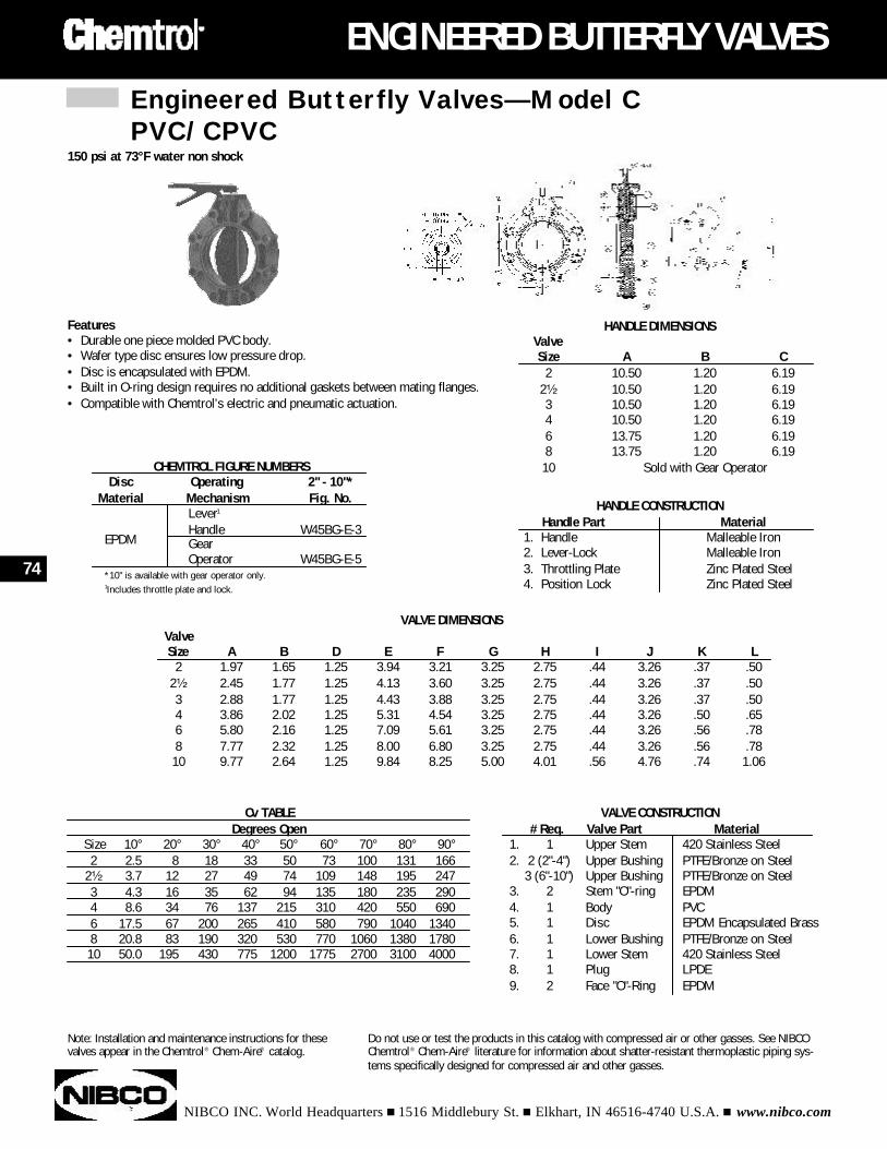
Engineered Butterfly Valves—Model CPVC/CPVC
NIBCO INC. World Headquarters n 1516 Middlebury St. n Elkhart, IN 46516-4740 U.S.A. n www.nibco.com
ENGINEERED BUTTERFLY VALVES
Features• Durable one piece molded PVC body.• Wafer type disc ensures low pressure drop.• Disc is encapsulated with EPDM.• Built in O-ring design requires no additional gaskets between mating flanges.• Compatible with Chemtrol’s electric and pneumatic actuation.
HANDLE DIMENSIONSValve Size A B C
2 10.50 1.20 6.192¹⁄₂ 10.50 1.20 6.193 10.50 1.20 6.194 10.50 1.20 6.196 13.75 1.20 6.198 13.75 1.20 6.1910 Sold with Gear Operator
HANDLE CONSTRUCTIONHandle Part Material
1. Handle Malleable Iron2. Lever-Lock Malleable Iron3. Throttling Plate Zinc Plated Steel4. Position Lock Zinc Plated Steel
CHEMTROL FIGURE NUMBERSDisc Operating 2" - 10"*
Material Mechanism Fig. No.Lever1
Handle W45BG-E-3EPDM Gear
Operator W45BG-E-5*10" is available with gear operator only.1Includes throttle plate and lock.
VALVE DIMENSIONSValve Size A B D E F G H I J K L
2 1.97 1.65 1.25 3.94 3.21 3.25 2.75 .44 3.26 .37 .502¹⁄₂ 2.45 1.77 1.25 4.13 3.60 3.25 2.75 .44 3.26 .37 .503 2.88 1.77 1.25 4.43 3.88 3.25 2.75 .44 3.26 .37 .504 3.86 2.02 1.25 5.31 4.54 3.25 2.75 .44 3.26 .50 .656 5.80 2.16 1.25 7.09 5.61 3.25 2.75 .44 3.26 .56 .788 7.77 2.32 1.25 8.00 6.80 3.25 2.75 .44 3.26 .56 .7810 9.77 2.64 1.25 9.84 8.25 5.00 4.01 .56 4.76 .74 1.06
VALVE CONSTRUCTION# Req. Valve Part Material
1. 1 Upper Stem 420 Stainless Steel2. 2 (2"-4") Upper Bushing PTFE/Bronze on Steel
3 (6"-10") Upper Bushing PTFE/Bronze on Steel3. 2 Stem "O"-ring EPDM4. 1 Body PVC5. 1 Disc EPDM Encapsulated Brass6. 1 Lower Bushing PTFE/Bronze on Steel7. 1 Lower Stem 420 Stainless Steel8. 1 Plug LPDE9. 2 Face "O"-Ring EPDM
Cv TABLEDegrees Open
Size 10° 20° 30° 40° 50° 60° 70° 80° 90°2 2.5 8 18 33 50 73 100 131 166
2¹⁄₂ 3.7 12 27 49 74 109 148 195 2473 4.3 16 35 62 94 135 180 235 2904 8.6 34 76 137 215 310 420 550 6906 17.5 67 200 265 410 580 790 1040 13408 20.8 83 190 320 530 770 1060 1380 178010 50.0 195 430 775 1200 1775 2700 3100 4000
Note: Installation and maintenance instructions for thesevalves appear in the Chemtrol® Chem-Aire® catalog.
Do not use or test the products in this catalog with compressed air or other gasses. See NIBCOChemtrol® Chem-Aire® literature for information about shatter-resistant thermoplastic piping sys-tems specifically designed for compressed air and other gasses.
150 psi at 73°F water non shock
74
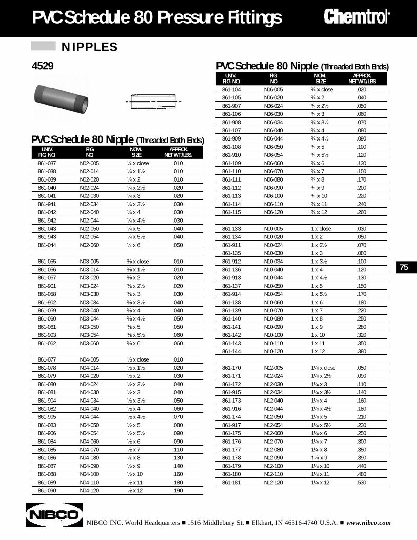
NIPPLES
NIBCO INC. World Headquarters n 1516 Middlebury St. n Elkhart, IN 46516-4740 U.S.A. n www.nibco.com
PVC Schedule 80 Pressure Fittings
UNIV. FIG. NOM. APPROX.FIG. NO. NO. SIZE NET WT./LBS.861-037 N02-005 ¹⁄₄ x close .010861-038 N02-014 ¹⁄₄ x 1¹⁄₂ .010861-039 N02-020 ¹⁄₄ x 2 .010861-040 N02-024 ¹⁄₄ x 2¹⁄₂ .020861-041 N02-030 ¹⁄₄ x 3 .020861-941 N02-034 ¹⁄₄ x 3¹⁄₂ .030861-042 N02-040 ¹⁄₄ x 4 .030861-942 N02-044 ¹⁄₄ x 4¹⁄₂ .030861-043 N02-050 ¹⁄₄ x 5 .040861-943 N02-054 ¹⁄₄ x 5¹⁄₂ .040861-044 N02-060 ¹⁄₄ x 6 .050
861-055 N03-005 ³⁄₈ x close .010861-056 N03-014 ³⁄₈ x 1¹⁄₂ .010861-057 N03-020 ³⁄₈ x 2 .020861-901 N03-024 ³⁄₈ x 2¹⁄₂ .020861-058 N03-030 ³⁄₈ x 3 .030861-902 N03-034 ³⁄₈ x 3¹⁄₂ .040861-059 N03-040 ³⁄₈ x 4 .040861-060 N03-044 ³⁄₈ x 4¹⁄₂ .050861-061 N03-050 ³⁄₈ x 5 .050861-903 N03-054 ³⁄₈ x 5¹⁄₂ .060861-062 N03-060 ³⁄₈ x 6 .060
861-077 N04-005 ¹⁄₂ x close .010861-078 N04-014 ¹⁄₂ x 1¹⁄₂ .020861-079 N04-020 ¹⁄₂ x 2 .030861-080 N04-024 ¹⁄₂ x 2¹⁄₂ .040861-081 N04-030 ¹⁄₂ x 3 .040861-904 N04-034 ¹⁄₂ x 3¹⁄₂ .050861-082 N04-040 ¹⁄₂ x 4 .060861-905 N04-044 ¹⁄₂ x 4¹⁄₂ .070861-083 N04-050 ¹⁄₂ x 5 .080861-906 N04-054 ¹⁄₂ x 5¹⁄₂ .090861-084 N04-060 ¹⁄₂ x 6 .090861-085 N04-070 ¹⁄₂ x 7 .110861-086 N04-080 ¹⁄₂ x 8 .130861-087 N04-090 ¹⁄₂ x 9 .140861-088 N04-100 ¹⁄₂ x 10 .160861-089 N04-110 ¹⁄₂ x 11 .180861-090 N04-120 ¹⁄₂ x 12 .190
PVC Schedule 80 Nipple (Threaded Both Ends)
75
UNIV. FIG. NOM. APPROX.FIG. NO. NO. SIZE NET WT./LBS.861-104 N06-005 ³⁄₄ x close .020861-105 N06-020 ³⁄₄ x 2 .040861-907 N06-024 ³⁄₄ x 2¹⁄₂ .050861-106 N06-030 ³⁄₄ x 3 .060861-908 N06-034 ³⁄₄ x 3¹⁄₂ .070861-107 N06-040 ³⁄₄ x 4 .080861-909 N06-044 ³⁄₄ x 4¹⁄₂ .090861-108 N06-050 ³⁄₄ x 5 .100861-910 N06-054 ³⁄₄ x 5¹⁄₂ .120861-109 N06-060 ³⁄₄ x 6 .130861-110 N06-070 ³⁄₄ x 7 .150861-111 N06-080 ³⁄₄ x 8 .170861-112 N06-090 ³⁄₄ x 9 .200861-113 N06-100 ³⁄₄ x 10 .220861-114 N06-110 ³⁄₄ x 11 .240861-115 N06-120 ³⁄₄ x 12 .260
861-133 N10-005 1 x close .030861-134 N10-020 1 x 2 .050861-911 N10-024 1 x 2¹⁄₂ .070861-135 N10-030 1 x 3 .080861-912 N10-034 1 x 3¹⁄₂ .100861-136 N10-040 1 x 4 .120861-913 N10-044 1 x 4¹⁄₂ .130861-137 N10-050 1 x 5 .150861-914 N10-054 1 x 5¹⁄₂ .170861-138 N10-060 1 x 6 .180861-139 N10-070 1 x 7 .220861-140 N10-080 1 x 8 .250861-141 N10-090 1 x 9 .280861-142 N10-100 1 x 10 .320861-143 N10-110 1 x 11 .350861-144 N10-120 1 x 12 .380
861-170 N12-005 1¹⁄₄ x close .050861-171 N12-024 1¹⁄₄ x 2¹⁄₂ .090861-172 N12-030 1¹⁄₄ x 3 .110861-915 N12-034 1¹⁄₄ x 3¹⁄₂ .140861-173 N12-040 1¹⁄₄ x 4 .160861-916 N12-044 1¹⁄₄ x 4¹⁄₂ .180861-174 N12-050 1¹⁄₄ x 5 .210861-917 N12-054 1¹⁄₄ x 5¹⁄₂ .230861-175 N12-060 1¹⁄₄ x 6 .250861-176 N12-070 1¹⁄₄ x 7 .300861-177 N12-080 1¹⁄₄ x 8 .350861-178 N12-090 1¹⁄₄ x 9 .390861-179 N12-100 1¹⁄₄ x 10 .440861-180 N12-110 1¹⁄₄ x 11 .480861-181 N12-120 1¹⁄₄ x 12 .530
4529 PVC Schedule 80 Nipple (Threaded Both Ends)
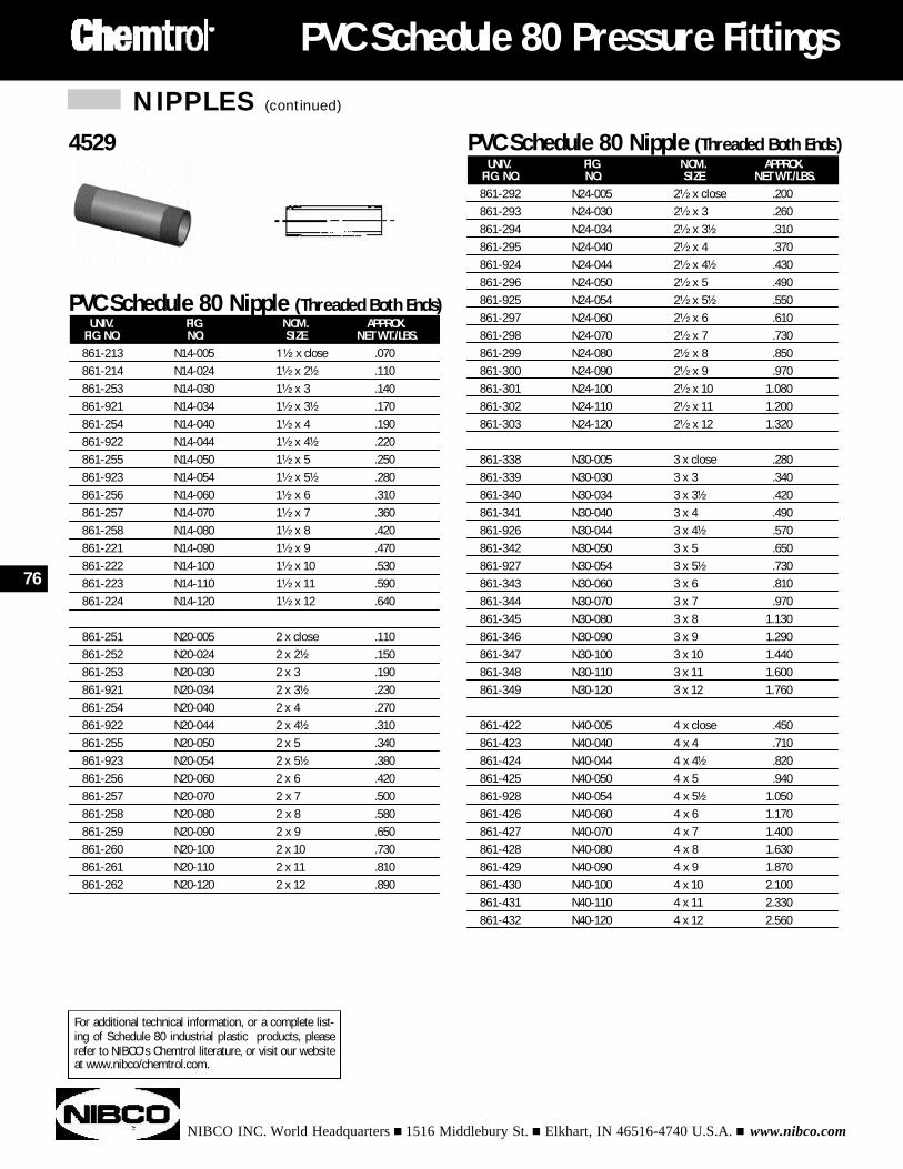
NIPPLES (continued)
NIBCO INC. World Headquarters n 1516 Middlebury St. n Elkhart, IN 46516-4740 U.S.A. n www.nibco.com
PVC Schedule 80 Pressure Fittings
76
UNIV. FIG. NOM. APPROX.FIG. NO. NO. SIZE NET WT./LBS.861-213 N14-005 1¹⁄₂ x close .070861-214 N14-024 1¹⁄₂ x 2¹⁄₂ .110861-253 N14-030 1¹⁄₂ x 3 .140861-921 N14-034 1¹⁄₂ x 3¹⁄₂ .170861-254 N14-040 1¹⁄₂ x 4 .190861-922 N14-044 1¹⁄₂ x 4¹⁄₂ .220861-255 N14-050 1¹⁄₂ x 5 .250861-923 N14-054 1¹⁄₂ x 5¹⁄₂ .280861-256 N14-060 1¹⁄₂ x 6 .310861-257 N14-070 1¹⁄₂ x 7 .360861-258 N14-080 1¹⁄₂ x 8 .420861-221 N14-090 1¹⁄₂ x 9 .470861-222 N14-100 1¹⁄₂ x 10 .530861-223 N14-110 1¹⁄₂ x 11 .590861-224 N14-120 1¹⁄₂ x 12 .640
861-251 N20-005 2 x close .110861-252 N20-024 2 x 2¹⁄₂ .150861-253 N20-030 2 x 3 .190861-921 N20-034 2 x 3¹⁄₂ .230861-254 N20-040 2 x 4 .270861-922 N20-044 2 x 4¹⁄₂ .310861-255 N20-050 2 x 5 .340861-923 N20-054 2 x 5¹⁄₂ .380861-256 N20-060 2 x 6 .420861-257 N20-070 2 x 7 .500861-258 N20-080 2 x 8 .580861-259 N20-090 2 x 9 .650861-260 N20-100 2 x 10 .730861-261 N20-110 2 x 11 .810861-262 N20-120 2 x 12 .890
PVC Schedule 80 Nipple (Threaded Both Ends)
UNIV. FIG. NOM. APPROX.FIG. NO. NO. SIZE NET WT./LBS.861-292 N24-005 2¹⁄₂ x close .200861-293 N24-030 2¹⁄₂ x 3 .260861-294 N24-034 2¹⁄₂ x 3¹⁄₂ .310861-295 N24-040 2¹⁄₂ x 4 .370861-924 N24-044 2¹⁄₂ x 4¹⁄₂ .430861-296 N24-050 2¹⁄₂ x 5 .490861-925 N24-054 2¹⁄₂ x 5¹⁄₂ .550861-297 N24-060 2¹⁄₂ x 6 .610861-298 N24-070 2¹⁄₂ x 7 .730861-299 N24-080 2¹⁄₂ x 8 .850861-300 N24-090 2¹⁄₂ x 9 .970861-301 N24-100 2¹⁄₂ x 10 1.080861-302 N24-110 2¹⁄₂ x 11 1.200861-303 N24-120 2¹⁄₂ x 12 1.320
861-338 N30-005 3 x close .280861-339 N30-030 3 x 3 .340861-340 N30-034 3 x 3¹⁄₂ .420861-341 N30-040 3 x 4 .490861-926 N30-044 3 x 4¹⁄₂ .570861-342 N30-050 3 x 5 .650861-927 N30-054 3 x 5¹⁄₂ .730861-343 N30-060 3 x 6 .810861-344 N30-070 3 x 7 .970861-345 N30-080 3 x 8 1.130861-346 N30-090 3 x 9 1.290861-347 N30-100 3 x 10 1.440861-348 N30-110 3 x 11 1.600861-349 N30-120 3 x 12 1.760
861-422 N40-005 4 x close .450861-423 N40-040 4 x 4 .710861-424 N40-044 4 x 4¹⁄₂ .820861-425 N40-050 4 x 5 .940861-928 N40-054 4 x 5¹⁄₂ 1.050861-426 N40-060 4 x 6 1.170861-427 N40-070 4 x 7 1.400861-428 N40-080 4 x 8 1.630861-429 N40-090 4 x 9 1.870861-430 N40-100 4 x 10 2.100861-431 N40-110 4 x 11 2.330861-432 N40-120 4 x 12 2.560
4529 PVC Schedule 80 Nipple (Threaded Both Ends)
For additional technical information, or a complete list-ing of Schedule 80 industrial plastic products, pleaserefer to NIBCO's Chemtrol literature, or visit our websiteat www.nibco/chemtrol.com.
NIBCO INC. World Headquarters n 1516 Middlebury St. n Elkhart, IN 46516-4740 U.S.A. n www.nibco.com
INDEX
Engineering Data
Pressure Ratings . . . . . . . . . . . . . . . . . . . . . . . . . . . . . . . . . . . . . . . . . . . . . . . . . . . . . 78
ABS & PVC-DWV Pipe & Fittings . . . . . . . . . . . . . . . . . . . . . . . . . . . . . . . . . . . . . . . . . 80
CPVC-CTS Copper Tube Size (SDR 11) Tube and Fittings . . . . . . . . . . . . . . . . . . . . . . . 81
PVC Schedule 40 Pipe &Pressure Fittings. . . . . . . . . . . . . . . . . . . . . . . . . . . . . . . . . . 82
PVC Schedule 80 Pipe & Pressure Fittings . . . . . . . . . . . . . . . . . . . . . . . . . . . . . . . . . . 83
General Storage, Handling, and Safety Considerations for
Thermoplastic Piping Components . . . . . . . . . . . . . . . . . . . . . . . . . . . . . . . . . . . . . 84
Solvent Welding Instructions for ABS, PVC, & CPVC-CTS Pressure
and DWV Piping Systems . . . . . . . . . . . . . . . . . . . . . . . . . . . . . . . . . . . . . . . . . . . . 86
Threading Instructions for Thermoplastic Pipe . . . . . . . . . . . . . . . . . . . . . . . . . . . . . . . 92
Flanged Joints. . . . . . . . . . . . . . . . . . . . . . . . . . . . . . . . . . . . . . . . . . . . . . . . . . . . . . . 95
Adapting Plastic Piping to Other Piping Materials . . . . . . . . . . . . . . . . . . . . . . . . . . . . . 97
Pipe Support Spacing . . . . . . . . . . . . . . . . . . . . . . . . . . . . . . . . . . . . . . . . . . . . . . . . . 98
Expansion and Contraction of Plastic Pipe . . . . . . . . . . . . . . . . . . . . . . . . . . . . . . . . . . 99
77
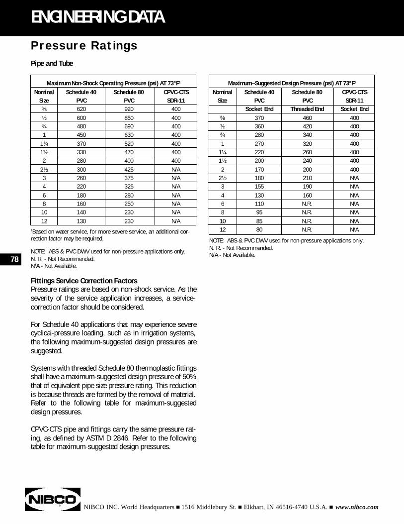
NOTE: ABS & PVC DWV used for non-pressure applications only.N. R. - Not Recommended.N/A - Not Available.
NIBCO INC. World Headquarters n 1516 Middlebury St. n Elkhart, IN 46516-4740 U.S.A. n www.nibco.com
78
ENGINEERING DATA
Pipe and Tube
1Based on water service, for more severe service, an additional cor-rection factor may be required.
NOTE: ABS & PVC DWV used for non-pressure applications only.N. R. - Not Recommended.N/A - Not Available.
Fittings Service Correction FactorsPressure ratings are based on non-shock service. As theseverity of the service application increases, a service-correction factor should be considered.
For Schedule 40 applications that may experience severecyclical-pressure loading, such as in irrigation systems,the following maximum-suggested design pressures aresuggested.
Systems with threaded Schedule 80 thermoplastic fittingsshall have a maximum-suggested design pressure of 50%that of equivalent pipe size pressure rating. This reductionis because threads are formed by the removal of material.Refer to the following table for maximum-suggesteddesign pressures.
CPVC-CTS pipe and fittings carry the same pressure rat-ing, as defined by ASTM D 2846. Refer to the followingtable for maximum-suggested design pressures.
Maximum Non-Shock Operating Pressure (psi) AT 73°F1
Nominal Schedule 40 Schedule 80 CPVC-CTSSize PVC PVC SDR-11³⁄₈ 620 920 400¹⁄₂ 600 850 400³⁄₄ 480 690 4001 450 630 400
1¹⁄₄ 370 520 4001¹⁄₂ 330 470 4002 280 400 400
2¹⁄₂ 300 425 N/A3 260 375 N/A4 220 325 N/A6 180 280 N/A8 160 250 N/A10 140 230 N/A12 130 230 N/A
Pressure Ratings
Maximum–Suggested Design Pressure (psi) AT 73°F1
Nominal Schedule 40 Schedule 80 CPVC-CTSSize PVC PVC SDR-11
Socket End Threaded End Socket End³⁄₈ 370 460 400¹⁄₂ 360 420 400³⁄₄ 280 340 4001 270 320 400
1¹⁄₄ 220 260 4001¹⁄₂ 200 240 4002 170 200 400
2¹⁄₂ 180 210 N/A3 155 190 N/A4 130 160 N/A6 110 N.R. N/A8 95 N.R. N/A10 85 N.R. N/A12 80 N.R. N/A
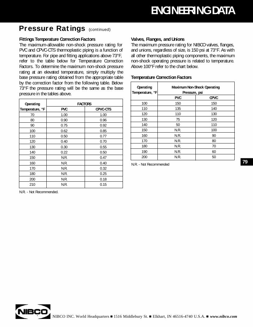
NIBCO INC. World Headquarters n 1516 Middlebury St. n Elkhart, IN 46516-4740 U.S.A. n www.nibco.com
ENGINEERING DATA
Fittings Temperature Correction FactorsThe maximum-allowable non-shock pressure rating forPVC and CPVC-CTS thermoplastic piping is a function oftemperature. For pipe and fitting applications above 73°F,refer to the table below for Temperature CorrectionFactors. To determine the maximum non-shock pressurerating at an elevated temperature, simply multiply thebase pressure rating obtained from the appropriate tableby the correction factor from the following table. Below73°F the pressure rating will be the same as the basepressure in the tables above.
N.R. - Not Recommended.
79
Operating FACTORSTemperature, °F PVC CPVC-CTS
70 1.00 1.0080 0.90 0.9690 0.75 0.92100 0.62 0.85110 0.50 0.77120 0.40 0.70130 0.30 0.55140 0.22 0.50150 N.R. 0.47160 N.R. 0.40170 N.R. 0.32180 N.R. 0.25200 N.R. 0.18210 N.R. 0.15
Operating Maximum Non-Shock OperatingTemperature, °F Pressure, psi
PVC CPVC100 150 150110 135 140120 110 130130 75 120140 50 110150 N.R. 100160 N.R. 90170 N.R. 80180 N.R. 70190 N.R. 60200 N.R. 50
Pressure Ratings (continued)
Valves, Flanges, and UnionsThe maximum pressure rating for NIBCO valves, flanges,and unions, regardless of size, is 150 psi at 73°F. As withall other thermoplastic piping components, the maximumnon-shock operating pressure is related to temperature.Above 100°F refer to the chart below.
Temperature Correction Factors
N.R. - Not Recommended
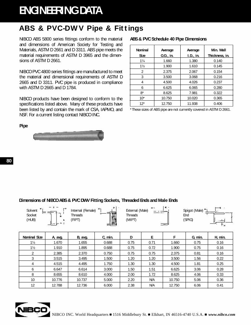
NIBCO ABS 5800 series fittings conform to the materialand dimensions of American Society for Testing andMaterials, ASTM D 2661 and D 3311. ABS pipe meets thematerial requirements of ASTM D 3965 and the dimen-sions of ASTM D 2661.
NIBCO PVC 4800 series fittings are manufactured to meetthe material and dimensional requirements of ASTM D2665 and D 3311. PVC pipe is produced in compliancewith ASTM D 2665 and D 1784.
NIBCO products have been designed to conform to thespecifications listed above. Many of these products havebeen listed by and contain the mark of CSA, IAPMO, andNSF. For a current listing contact NIBCO INC.
Pipe
NIBCO INC. World Headquarters n 1516 Middlebury St. n Elkhart, IN 46516-4740 U.S.A. n www.nibco.com
80
ENGINEERING DATA
Nominal Average Average Min. Wall Size O.D., in. I.D., in. Thickness, in.1¹⁄₄ 1.660 1.380 0.1401¹⁄₂ 1.900 1.610 0.1452 2.375 2.067 0.1543 3.500 3.068 0.2164 4.500 4.026 0.2376 6.625 6.065 0.2808* 8.625 7.981 0.32210* 10.750 10.020 0.36512* 12.750 11.938 0.406
Nominal Size A, avg. B, avg. C, min. D E F G, min. H, min.1¹⁄₄ 1.670 1.655 0.688 0.75 0.71 1.660 0.75 0.161¹⁄₂ 1.910 1.895 0.688 0.75 0.72 1.900 0.75 0.162 2.385 2.370 0.750 0.75 0.75 2.375 0.81 0.163 3.515 3.495 1.500 1.20 1.20 3.500 1.56 0.224 4.515 4.495 1.750 1.30 1.30 4.500 1.81 0.256 6.647 6.614 3.000 1.50 1.51 6.625 3.06 0.288 8.655 8.610 4.000 2.00 1.72 8.625 4.06 0.3310 10.776 10.737 5.000 2.20 N/A 10.750 5.06 0.3612 12.788 12.736 6.000 2.38 N/A 12.750 6.06 0.41
ABS & PVC-DWV Pipe & FittingsABS & PVC Schedule 40 Pipe Dimensions
*These sizes of ABS pipe are not currently covered in ASTM D 2661.
Dimensions of NIBCO ABS & PVC DWV Fitting Sockets, Threaded Ends and Male Ends
Solvent Internal (Female) External (Male) Spigot (Male)Socket Threads Threads End(HUB) (FIPT) (MIPT) (SPIG)
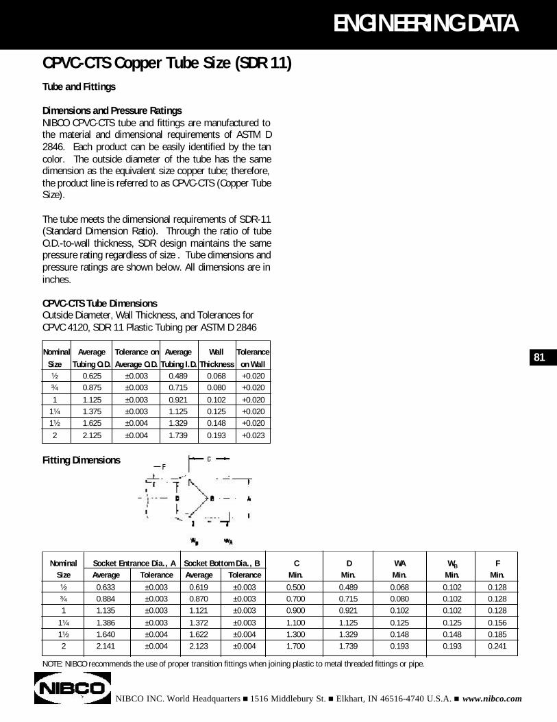
Tube and Fittings
Dimensions and Pressure RatingsNIBCO CPVC-CTS tube and fittings are manufactured tothe material and dimensional requirements of ASTM D2846. Each product can be easily identified by the tancolor. The outside diameter of the tube has the samedimension as the equivalent size copper tube; therefore,the product line is referred to as CPVC-CTS (Copper TubeSize).
The tube meets the dimensional requirements of SDR-11(Standard Dimension Ratio). Through the ratio of tubeO.D.-to-wall thickness, SDR design maintains the samepressure rating regardless of size . Tube dimensions andpressure ratings are shown below. All dimensions are ininches.
CPVC-CTS Tube DimensionsOutside Diameter, Wall Thickness, and Tolerances forCPVC 4120, SDR 11 Plastic Tubing per ASTM D 2846
Fitting Dimensions
NIBCO INC. World Headquarters n 1516 Middlebury St. n Elkhart, IN 46516-4740 U.S.A. n www.nibco.com
ENGINEERING DATA
Nominal Average Tolerance on Average Wall ToleranceSize Tubing O.D. Average O.D. Tubing I.D. Thickness on Wall¹⁄₂ 0.625 ±0.003 0.489 0.068 +0.020³⁄₄ 0.875 ±0.003 0.715 0.080 +0.0201 1.125 ±0.003 0.921 0.102 +0.020
1¹⁄₄ 1.375 ±0.003 1.125 0.125 +0.0201¹⁄₂ 1.625 ±0.004 1.329 0.148 +0.0202 2.125 ±0.004 1.739 0.193 +0.023
Nominal Socket Entrance Dia., A Socket Bottom Dia., B C D WA WB FSize Average Tolerance Average Tolerance Min. Min. Min. Min. Min.¹⁄₂ 0.633 ±0.003 0.619 ±0.003 0.500 0.489 0.068 0.102 0.128³⁄₄ 0.884 ±0.003 0.870 ±0.003 0.700 0.715 0.080 0.102 0.1281 1.135 ±0.003 1.121 ±0.003 0.900 0.921 0.102 0.102 0.128
1¹⁄₄ 1.386 ±0.003 1.372 ±0.003 1.100 1.125 0.125 0.125 0.1561¹⁄₂ 1.640 ±0.004 1.622 ±0.004 1.300 1.329 0.148 0.148 0.1852 2.141 ±0.004 2.123 ±0.004 1.700 1.739 0.193 0.193 0.241
81
CPVC-CTS Copper Tube Size (SDR 11)
NOTE: NIBCO recommends the use of proper transition fittings when joining plastic to metal threaded fittings or pipe.
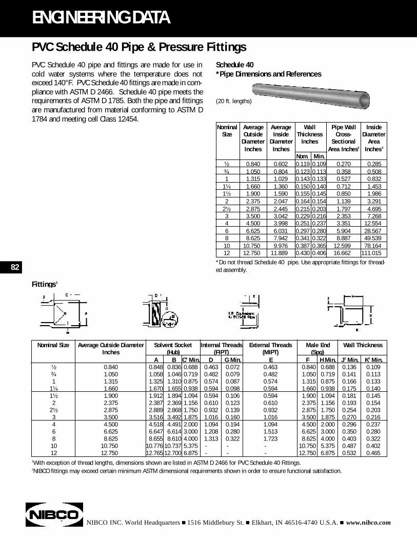
Fittings1
1With exception of thread lengths, dimensions shown are listed in ASTM D 2466 for PVC Schedule 40 Fittings.2NIBCO fittings may exceed certain minimum ASTM dimensional requirements shown in order to ensure functional satisfaction.
PVC Schedule 40 pipe and fittings are made for use incold water systems where the temperature does notexceed 140°F. PVC Schedule 40 fittings are made in com-pliance with ASTM D 2466. Schedule 40 pipe meets therequirements of ASTM D 1785. Both the pipe and fittingsare manufactured from material conforming to ASTM D1784 and meeting cell Class 12454.
NIBCO INC. World Headquarters n 1516 Middlebury St. n Elkhart, IN 46516-4740 U.S.A. n www.nibco.com
82
ENGINEERING DATA
Nominal Average Average Wall Pipe Wall InsideSize Outside Inside Thickness Cross- Diameter
Diameter Diameter Inches Sectional AreaInches Inches Area Inches2 Inches2
Nom. Min.¹⁄₂ 0.840 0.602 0.119 0.109 0.270 0.285³⁄₄ 1.050 0.804 0.123 0.113 0.358 0.5081 1.315 1.029 0.143 0.133 0.527 0.832
1¹⁄₄ 1.660 1.360 0.150 0.140 0.712 1.4531¹⁄₂ 1.900 1.590 0.155 0.145 0.850 1.9862 2.375 2.047 0.164 0.154 1.139 3.291
2¹⁄₂ 2.875 2.445 0.215 0.203 1.797 4.6953 3.500 3.042 0.229 0.216 2.353 7.2684 4.500 3.998 0.251 0.237 3.351 12.5546 6.625 6.031 0.297 0.280 5.904 28.5678 8.625 7.942 0.341 0.322 8.887 49.53910 10.750 9.976 0.387 0.365 12.599 78.16412 12.750 11.889 0.430 0.406 16.662 111.015
Nominal Size Average Outside Diameter Solvent Socket Internal Threads External Threads Male End Wall ThicknessInches (Hub) (FIPT) (MIPT) (Spg)
A B C2 Min. D G Min. E F H Min. J2 Min. K2 Min.¹⁄₂ 0.840 0.848 0.836 0.688 0.463 0.072 0.463 0.840 0.688 0.136 0.109³⁄₄ 1.050 1.058 1.046 0.719 0.482 0.079 0.482 1.050 0.719 0.141 0.1131 1.315 1.325 1.310 0.875 0.574 0.087 0.574 1.315 0.875 0.166 0.133
1¹⁄₄ 1.660 1.670 1.655 0.938 0.594 0.098 0.594 1.660 0.938 0.175 0.1401¹⁄₂ 1.900 1.912 1.894 1.094 0.594 0.106 0.594 1.900 1.094 0.181 0.1452 2.375 2.387 2.369 1.156 0.610 0.123 0.610 2.375 1.156 0.193 0.154
2¹⁄₂ 2.875 2.889 2.868 1.750 0.932 0.139 0.932 2.875 1.750 0.254 0.2033 3.500 3.516 3.492 1.875 1.016 0.160 1.016 3.500 1.875 0.270 0.2164 4.500 4.518 4.491 2.000 1.094 0.194 1.094 4.500 2.000 0.296 0.2376 6.625 6.647 6.614 3.000 1.208 0.280 1.513 6.625 3.000 0.350 0.2808 8.625 8.655 8.610 4.000 1.313 0.322 1.723 8.625 4.000 0.403 0.32210 10.750 10.776 10.737 5.375 - - - 10.750 5.375 0.487 0.40212 12.750 12.765 12.700 6.875 - - - 12.750 6.875 0.532 0.465
PVC Schedule 40 Pipe & Pressure FittingsSchedule 40*Pipe Dimensions and References
(20 ft. lengths)
*Do not thread Schedule 40 pipe. Use appropriate fittings for thread-ed assembly.
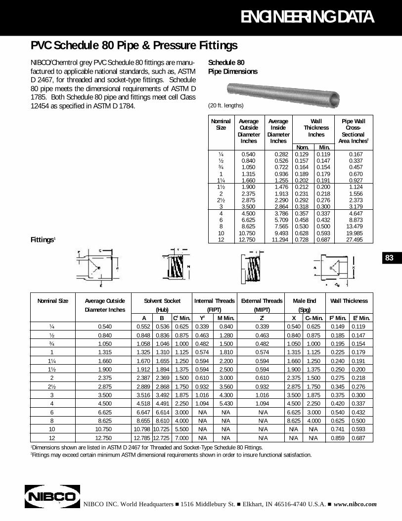
Schedule 80Pipe Dimensions
(20 ft. lengths)
NIBCO/Chemtrol grey PVC Schedule 80 fittings are manu-factured to applicable national standards, such as, ASTMD 2467, for threaded and socket-type fittings. Schedule80 pipe meets the dimensional requirements of ASTM D1785. Both Schedule 80 pipe and fittings meet cell Class12454 as specified in ASTM D 1784.
NIBCO INC. World Headquarters n 1516 Middlebury St. n Elkhart, IN 46516-4740 U.S.A. n www.nibco.com
ENGINEERING DATA
Nominal Average Average Wall Pipe WallSize Outside Inside Thickness Cross-
Diameter Diameter Inches SectionalInches Inches Area Inches2
Nom. Min.¹⁄₄ 0.540 0.282 0.129 0.119 0.167¹⁄₂ 0.840 0.526 0.157 0.147 0.337³⁄₄ 1.050 0.722 0.164 0.154 0.4571 1.315 0.936 0.189 0.179 0.670
1¹⁄₄ 1.660 1.255 0.202 0.191 0.9271¹⁄₂ 1.900 1.476 0.212 0.200 1.1242 2.375 1.913 0.231 0.218 1.556
2¹⁄₂ 2.875 2.290 0.292 0.276 2.3733 3.500 2.864 0.318 0.300 3.1794 4.500 3.786 0.357 0.337 4.6476 6.625 5.709 0.458 0.432 8.8738 8.625 7.565 0.530 0.500 13.47910 10.750 9.493 0.628 0.593 19.98512 12.750 11.294 0.728 0.687 27.495
Nominal Size Average Outside Solvent Socket Internal Threads External Threads Male End Wall ThicknessDiameter Inches (Hub) (FIPT) (MIPT) (Spg)
A B C2 Min. Y2 M Min. Z2 X Cm Min. F2 Min. E2 Min.¹⁄₄ 0.540 0.552 0.536 0.625 0.339 0.840 0.339 0.540 0.625 0.149 0.119¹⁄₂ 0.840 0.848 0.836 0.875 0.463 1.280 0.463 0.840 0.875 0.185 0.147³⁄₄ 1.050 1.058 1.046 1.000 0.482 1.500 0.482 1.050 1.000 0.195 0.1541 1.315 1.325 1.310 1.125 0.574 1.810 0.574 1.315 1.125 0.225 0.179
1¹⁄₄ 1.660 1.670 1.655 1.250 0.594 2.200 0.594 1.660 1.250 0.240 0.1911¹⁄₂ 1.900 1.912 1.894 1.375 0.594 2.500 0.594 1.900 1.375 0.250 0.2002 2.375 2.387 2.369 1.500 0.610 3.000 0.610 2.375 1.500 0.275 0.218
2¹⁄₂ 2.875 2.889 2.868 1.750 0.932 3.560 0.932 2.875 1.750 0.345 0.2763 3.500 3.516 3.492 1.875 1.016 4.300 1.016 3.500 1.875 0.375 0.3004 4.500 4.518 4.491 2.250 1.094 5.430 1.094 4.500 2.250 0.420 0.3376 6.625 6.647 6.614 3.000 N/A N/A N/A 6.625 3.000 0.540 0.4328 8.625 8.655 8.610 4.000 N/A N/A N/A 8.625 4.000 0.625 0.50010 10.750 10.798 10.725 5.500 N/A N/A N/A N/A N/A 0.741 0.59312 12.750 12.785 12.725 7.000 N/A N/A N/A N/A N/A 0.859 0.687
83
PVC Schedule 80 Pipe & Pressure Fittings
Fittings1
1Dimensions shown are listed in ASTM D 2467 for Threaded and Socket-Type Schedule 80 Fittings.2Fittings may exceed certain minimum ASTM dimensional requirements shown in order to insure functional satisfaction.
NIBCO INC. World Headquarters n 1516 Middlebury St. n Elkhart, IN 46516-4740 U.S.A. n www.nibco.com
84
ENGINEERING DATA
STORAGEThermoplastic piping components are designed and man-ufactured for use in systems involving the transport ofaggressive liquids as well as potable water. In order toensure their integrity, they must be handled with reason-able care prior to installation.
PipeWhen pipe is received in standard lifts it should remain inthe lift until ready for use. Lifts should not be stackedmore than three high and should always be stacked wood-on-wood. Loose pipe should be stored on racks with aminimum support spacing of three feet. Pipe should beshaded but not covered directly when stored outside inhigh ambient temperatures. This will provide for free cir-culation of air and reduce the heat build-up due to directsunlight exposure.
FittingsFittings should be stored in their original cartons to keepthem free of dirt and reduce the possibility of damage. Ifpossible, fittings should be stored indoors.
Solvent Cements and PrimersSolvent cements have a definitive shelf life and each canand carton is clearly marked with a date of manufacture.Stock should be rotated to insure that the oldest materialis used first.
HANDLINGPipe and FittingsCare should be exercised to avoid rough handling of ther-moplastic pipe and fittings. They should not be draggedover sharp projections, dropped, or have objects droppedupon them. Pipe ends should be inspected for cracksresulting from such abuse. Transportation by truck orpipe trailer will require that the pipe be continuously sup-ported and all sharp edges on the trailer bed that come incontact with the pipe must be padded.
Solvent Cements and PrimersKeep containers for solvent cements tightly closed exceptwhen in use. Avoid prolonged breathing of solventvapors, and when pipe and fittings are being joined in par-tially enclosed areas use a ventilating device to attenuatevapor levels. Keep solvent cements, primers, and clean-
ers away from all sources of ignition, heat, sparks, andopen flames. Avoid repeated contact with the skin bywearing proper gloves impervious to the solvents.Application of the solvents or cements with rags and barehands is not recommended; natural fiber brushes andother suitable applicators can produce satisfactoryresults.
IMPORTANT FACTS TO KNOW ABOUT ABS, PVC, ANDCPVC SOLVENT CEMENT1. ABS solvent cement should be used only for joining
ABS pipe and fittings.2. PVC solvent cement should be used only for joining
PVC Pipe and fittings.3. CPVC solvent cement should be used only for joining
CPVC pipe and fittings.4. A good joint is as strong as the pipe, since the solvent
chemically welds the fitting to the pipe.5. The solvent cement containers should always be cov-
ered when not in use to prevent excessive evaporation. Do not use thinner. Cement that shows signs of thick-ening and is lumpy should be discarded.
6. PVC solvent cement and primer can be used for both PVC pressure and DWV piping systems.
SAFETY CONSIDERATIONSPipe and FittingsABS, PVC, and CPVC products contained within this cata-log are intended for use in the distribution of media thatare chemically compatible with the piping materials. Dueto the inherent hazards associated with testing thesecomponents and piping systems with compressed air orother compressed gases, NIBCO does not allow pneu-matic testing or use of these products in compressedair or gas piping systems.
Note: pressurized (compressed) air and other com-pressed gases contain large amounts of stored energy,which present serious safety hazards should the systemfail for any reason.
See NIBCO Chemtrol Chem-Aire literature for informationabout a shatter-resistant thermoplastic piping systemspecifically designed for use with compressed air or othertypes of compressed gases.
General Storage, Handling, and Safety Considerationsfor Thermoplastic Piping Components
NIBCO INC. World Headquarters n 1516 Middlebury St. n Elkhart, IN 46516-4740 U.S.A. n www.nibco.com
ENGINEERING DATA
Solvent Cements and PrimersDANGER:• Solvent cements and primers are extremely flammable.• Vapors from solvent cements and primers may be
harmful if inhaled for prolonged periods of time.• Solvent cements and primers may be harmful if swal-
lowed.• Solvent cements and primers may cause skin or eye
irritation.
CAUTION: Solvent Cements and Primers are composedof various solvents and as such require special conditionsfor storage. Because of their flammability they must notbe stored in an area where they might be exposed to igni-tion, heats, sparks, or open flames.
85
General Storage, Handling, and Safety Considerationsfor Thermoplastic Piping Components (continued)
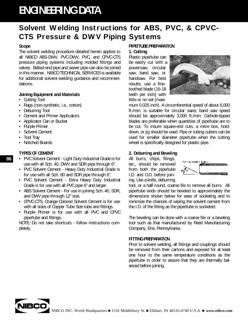
PIPE/TUBE PREPARATION 1. Cutting Plastic pipe/tube canbe easily cut with apowersaw, circularsaw, band saw, orhandsaw. For bestresults, use a fine-toothed blade (16-18teeth per inch) withlittle or no set (maxi-mum 0.025 inch). A circumferential speed of about 6,000ft./min. is suitable for circular saws; band saw speedshould be approximately 3,000 ft./min. Carbide-tippedblades are preferable when quantities of pipe/tube are tobe cut. To insure square-end cuts, a mitre box, hold-down, or jig should be used. Pipe or tubing cutters can beused for smaller diameter pipe/tube when the cuttingwheel is specifically designed for plastic pipe.
2. Deburring and BevelingAll burrs, chips, filings,etc., should be removedfrom both the pipe/tubeI.D. and O.D. before join-ing. Use a knife, deburringtool, or a half-round, coarse file to remove all burrs. Allpipe/tube ends should be beveled to approximately thedimensions shown below for ease of socketing and tominimize the chances of wiping the solvent cement fromthe I.D. of the fitting as the pipe/tube is socketed:
The beveling can be done with a coarse file or a bevelingtool such as that manufactured by Reed ManufacturingCompany, Erie, Pennsylvania.
FITTING PREPARATIONPrior to solvent welding, all fittings and couplings shouldbe removed from their cartons and exposed for at leastone hour to the same temperature conditions as thepipe/tube in order to assure that they are thermally bal-anced before joining.
NIBCO INC. World Headquarters n 1516 Middlebury St. n Elkhart, IN 46516-4740 U.S.A. n www.nibco.com
86
ENGINEERING DATA
ScopeThe solvent welding procedure detailed herein applies toall NIBCO ABS-DWV, PVC-DWV, PVC, and CPVC-CTSpressure piping systems including molded fittings andvalves. Belled-end pipe and sewer pipe can also be joinedin this manner. NIBCO TECHNICAL SERVICES is availablefor additional solvent-welding guidance and recommen-dations.
Joining Equipment and Materials• Cutting Tool• Rags (non-synthetic, i.e., cotton)• Deburring Tool• Cement and Primer Applicators• Applicator Can or Bucket• Purple Primer• Solvent Cement• Tool Tray• Notched Boards
TYPES OF CEMENT• PVC Solvent Cement - Light Duty Industrial Grade is for
use with all Sch. 40, DWV and SDR pipe through 6".• PVC Solvent Cement - Heavy Duty Industrial Grade is
for use with all Sch. 80 and SDR pipe through 6".• PVC Solvent Cement - Extra Heavy Duty Industrial
Grade is for use with all PVC pipe 6" and larger.• ABS Solvent Cement - For use in joining Sch. 40, SDR,
and DWV pipe through 12" size.• CPVC-CTS, Orange Colored Solvent Cement is for use
with all sizes of Copper Tube Size tube and fittings.• Purple Primer is for use with all PVC and CPVC
pipe/tube and fittings.NOTE: Do not take shortcuts - follow instructions com-pletely.
Solvent Welding Instructions for ABS, PVC, & CPVC-CTS Pressure & DWV Piping Systems
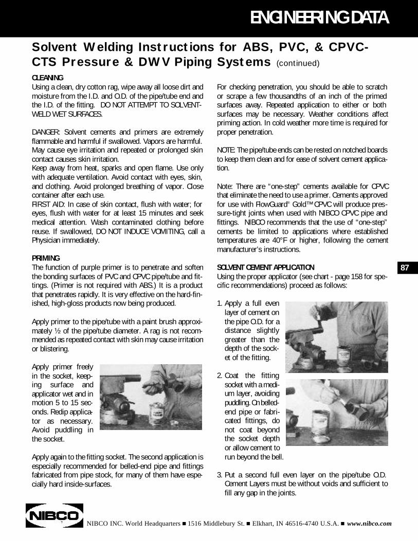
NIBCO INC. World Headquarters n 1516 Middlebury St. n Elkhart, IN 46516-4740 U.S.A. n www.nibco.com
ENGINEERING DATA
CLEANINGUsing a clean, dry cotton rag, wipe away all loose dirt andmoisture from the I.D. and O.D. of the pipe/tube end andthe I.D. of the fitting. DO NOT ATTEMPT TO SOLVENT-WELD WET SURFACES.
DANGER: Solvent cements and primers are extremelyflammable and harmful if swallowed. Vapors are harmful.May cause eye irritation and repeated or prolonged skincontact causes skin irritation.Keep away from heat, sparks and open flame. Use onlywith adequate ventilation. Avoid contact with eyes, skin,and clothing. Avoid prolonged breathing of vapor. Closecontainer after each use.FIRST AID: In case of skin contact, flush with water; foreyes, flush with water for at least 15 minutes and seekmedical attention. Wash contaminated clothing beforereuse. If swallowed, DO NOT INDUCE VOMITING, call aPhysician immediately.
PRIMINGThe function of purple primer is to penetrate and softenthe bonding surfaces of PVC and CPVC pipe/tube and fit-tings. (Primer is not required with ABS.) It is a productthat penetrates rapidly. It is very effective on the hard-fin-ished, high-gloss products now being produced.
Apply primer to the pipe/tube with a paint brush approxi-mately ¹⁄₂ of the pipe/tube diameter. A rag is not recom-mended as repeated contact with skin may cause irritationor blistering.
Apply primer freelyin the socket, keep-ing surface andapplicator wet and inmotion 5 to 15 sec-onds. Redip applica-tor as necessary.Avoid puddling inthe socket.
Apply again to the fitting socket. The second application isespecially recommended for belled-end pipe and fittingsfabricated from pipe stock, for many of them have espe-cially hard inside-surfaces.
87
Solvent Welding Instructions for ABS, PVC, & CPVC-CTS Pressure & DWV Piping Systems (continued)
For checking penetration, you should be able to scratch or scrape a few thousandths of an inch of the primed surfaces away. Repeated application to either or both surfaces may be necessary. Weather conditions affectpriming action. In cold weather more time is required forproper penetration.
NOTE: The pipe/tube ends can be rested on notched boardsto keep them clean and for ease of solvent cement applica-tion.
Note: There are “one-step” cements available for CPVCthat eliminate the need to use a primer. Cements approvedfor use with FlowGuard® Gold™ CPVC will produce pres-sure-tight joints when used with NIBCO CPVC pipe and fittings. NIBCO recommends that the use of “one-step”cements be limited to applications where established temperatures are 40°F or higher, following the cementmanufacturer’s instructions.
SOLVENT CEMENT APPLICATIONUsing the proper applicator (see chart - page 158 for spe-cific recommendations) proceed as follows:
1. Apply a full even layer of cement on the pipe O.D. for a distance slightly greater than the depth of the sock-et of the fitting.
2. Coat the fitting socket with a medi-um layer, avoiding puddling. On belled-end pipe or fabri-cated fittings, do not coat beyond the socket depth or allow cement to run beyond the bell.
3. Put a second full even layer on the pipe/tube O.D. Cement Layers must be without voids and sufficient to fill any gap in the joints.
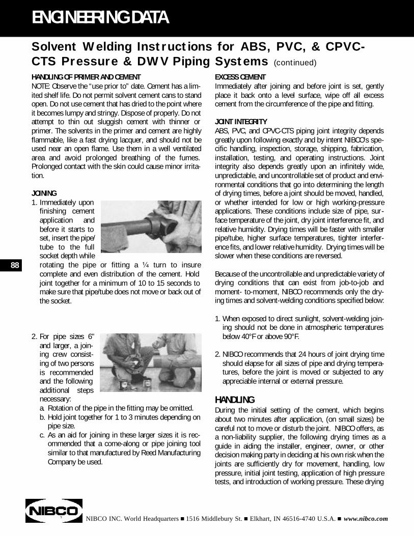
NIBCO INC. World Headquarters n 1516 Middlebury St. n Elkhart, IN 46516-4740 U.S.A. n www.nibco.com
88
ENGINEERING DATA
HANDLING OF PRIMER AND CEMENTNOTE: Observe the “use prior to” date. Cement has a lim-ited shelf life. Do not permit solvent cement cans to standopen. Do not use cement that has dried to the point whereit becomes lumpy and stringy. Dispose of properly. Do notattempt to thin out sluggish cement with thinner orprimer. The solvents in the primer and cement are highlyflammable, like a fast drying lacquer, and should not beused near an open flame. Use them in a well ventilatedarea and avoid prolonged breathing of the fumes.Prolonged contact with the skin could cause minor irrita-tion.
JOINING1. Immediately upon
finishing cement application and before it starts to set, insert the pipe/tube to the full socket depth while rotating the pipe or fitting a ¹⁄₄ turn to insure complete and even distribution of the cement. Hold joint together for a minimum of 10 to 15 seconds to make sure that pipe/tube does not move or back out of the socket.
2. For pipe sizes 6" and larger, a join-ing crew consist-ing of two persons is recommendedand the following additional steps necessary:a. Rotation of the pipe in the fitting may be omitted.b. Hold joint together for 1 to 3 minutes depending on
pipe size.c. As an aid for joining in these larger sizes it is rec-
ommended that a come-along or pipe joining toolsimilar to that manufactured by Reed Manufacturing Company be used.
Solvent Welding Instructions for ABS, PVC, & CPVC-CTS Pressure & DWV Piping Systems (continued)
EXCESS CEMENTImmediately after joining and before joint is set, gentlyplace it back onto a level surface, wipe off all excesscement from the circumference of the pipe and fitting.
JOINT INTEGRITYABS, PVC, and CPVC-CTS piping joint integrity dependsgreatly upon following exactly and by intent NIBCO’s spe-cific handling, inspection, storage, shipping, fabrication,installation, testing, and operating instructions. Jointintegrity also depends greatly upon an infinitely wide,unpredictable, and uncontrollable set of product and envi-ronmental conditions that go into determining the lengthof drying times, before a joint should be moved, handled,or whether intended for low or high working-pressureapplications. These conditions include size of pipe, sur-face temperature of the joint, dry joint interference fit, andrelative humidity. Drying times will be faster with smallerpipe/tube, higher surface temperatures, tighter interfer-ence fits, and lower relative humidity. Drying times will beslower when these conditions are reversed.
Because of the uncontrollable and unpredictable variety ofdrying conditions that can exist from job-to-job andmoment- to-moment, NIBCO recommends only the dry-ing times and solvent-welding conditions specified below:
1. When exposed to direct sunlight, solvent-welding join-ing should not be done in atmospheric temperatures below 40°F or above 90°F.
2. NIBCO recommends that 24 hours of joint drying time should elapse for all sizes of pipe and drying tempera-tures, before the joint is moved or subjected to any appreciable internal or external pressure.
HANDLINGDuring the initial setting of the cement, which beginsabout two minutes after application, (on small sizes) becareful not to move or disturb the joint. NIBCO offers, asa non-liability supplier, the following drying times as aguide in aiding the installer, engineer, owner, or otherdecision making party in deciding at his own risk when thejoints are sufficiently dry for movement, handling, lowpressure, initial joint testing, application of high pressuretests, and introduction of working pressure. These drying
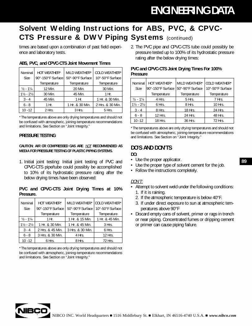
NIBCO INC. World Headquarters n 1516 Middlebury St. n Elkhart, IN 46516-4740 U.S.A. n www.nibco.com
ENGINEERING DATA
times are based upon a combination of past field experi-ence and laboratory tests.
ABS, PVC, and CPVC-CTS Joint Movement Times
*The temperatures above are only drying temperatures and should notbe confused with atmospheric, joining-temperature recommendationsand limitations. See Section on “Joint Integrity.”
PRESSURE TESTING
CAUTION: AIR OR COMPRESSED GAS ARE NOT RECOMMENDED ASMEDIA FOR PRESSURE TESTING OF PLASTIC PIPING SYSTEMS.
1. Initial joint testing: Initial joint testing of PVC and CPVC-CTS pipe/tube could possibly be accomplished to 10% of its hydrostatic pressure rating after the below drying times have been observed:
PVC and CPVC-CTS Joint Drying Times at 10%Pressure.
*The temperatures above are only drying temperatures and should notbe confused with atmospheric, joining-temperature recommendationsand limitations. See Section on “Joint Integrity.”
Nominal HOT WEATHER* MILD WEATHER* COLD WEATHER*Size 90°-150°F Surface 50°-90°F Surface 10°-50°F Surface
Temperature Temperature Temperature¹⁄₂ - 1¹⁄₄ 12 Min. 20 Min. 30 Min.1¹⁄₂ - 2¹⁄₂ 30 Min. 45 Min. 1 Hr.
3 - 4 45 Min. 1 Hr. 1 Hr. & 30 Min.6 - 8 1 Hr. 1 Hr. & 30 Min. 2 Hrs. & 30 Min.
10 -12 2 Hrs. 3 Hrs. 5 Hrs.
89
Solvent Welding Instructions for ABS, PVC, & CPVC-CTS Pressure & DWV Piping Systems (continued)
2. The PVC pipe and CPVC-CTS tube could possibly be pressure tested up to 100% of its hydrostatic pressure rating after the below drying times:
PVC and CPVC-CTS Joint Drying Times For 100%Pressure
*The temperatures above are only drying temperatures and should notbe confused with atmospheric, joining-temperature recommendationsand limitations. See Section on “Joint Integrity.”
DO’S AND DON’TSDO:• Use the proper applicator.• Use the proper type of solvent cement for the job.• Follow the instructions completely.
DON’T:• Attempt to solvent weld under the following conditions:
1. If it is raining.2. If the atmospheric temperature is below 40°F.3. If under direct exposure to sun at atmospheric tem-
peratures above 90°F• Discard empty cans of solvent, primer or rags in trench
or near piping. Concentrated fumes or dripping cement or primer can cause piping failure.
Nominal HOT WEATHER* MILD WEATHER* COLD WEATHER*Size 90°-150°F Surface 50°-90°F Surface 10°-50°F Surface
Temperature Temperature Temperature¹⁄₂ - 1¹⁄₄ 1 Hr. 1 Hr. & 15 Min. 1 Hr. & 45 Min.1¹⁄₂ - 2¹⁄₂ 1 Hr. & 30 Min. 1 Hr. & 45 Min. 3 Hrs.
3 - 4 2 Hrs. & 45 Min. 3 Hrs. & 30 Min. 6 Hrs.6 - 8 3 Hrs. & 30 Min. 4 Hrs. 12 Hrs.
10 -12 6 Hrs. 8 Hrs. 72 Hrs.
Nominal HOT WEATHER* MILD WEATHER* COLD WEATHER*Size 90°-150°F Surface 50°-90°F Surface 10°-50°F Surface
Temperature Temperature Temperature¹⁄₂ - 1¹⁄₄ 4 Hrs. 5 Hrs. 7 Hrs.1¹⁄₂ - 2¹⁄₂ 6 Hrs. 8 Hrs. 10 Hrs.
3 - 4 8 Hrs. 18 Hrs. 24 Hrs.6 - 8 12 Hrs. 24 Hrs. 48 Hrs.
10 -12 18 Hrs. 36 Hrs. 72 Hrs.
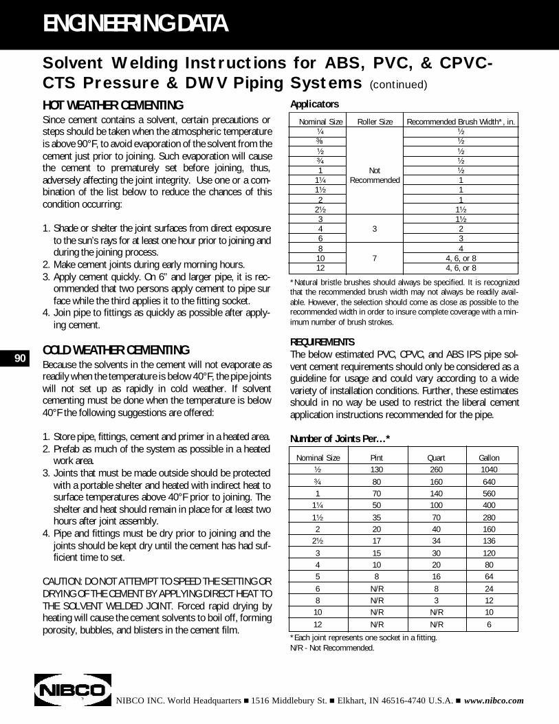
Nominal Size Roller Size Recommended Brush Width*, in.¹⁄₄ ¹⁄₂³⁄₈Ó ¹⁄₂¹⁄₂ ¹⁄₂³⁄₄ ¹⁄₂1 Not ¹⁄₂
1¹⁄₄ Recommended 11¹⁄₂ 12 1
2¹⁄₂ 1¹⁄₂3 1¹⁄₂4 3 26 38 410 7 4, 6, or 812 4, 6, or 8
NIBCO INC. World Headquarters n 1516 Middlebury St. n Elkhart, IN 46516-4740 U.S.A. n www.nibco.com
90
ENGINEERING DATA
HOT WEATHER CEMENTINGSince cement contains a solvent, certain precautions orsteps should be taken when the atmospheric temperatureis above 90°F, to avoid evaporation of the solvent from thecement just prior to joining. Such evaporation will causethe cement to prematurely set before joining, thus,adversely affecting the joint integrity. Use one or a com-bination of the list below to reduce the chances of thiscondition occurring:
1. Shade or shelter the joint surfaces from direct exposure to the sun’s rays for at least one hour prior to joining and during the joining process.
2. Make cement joints during early morning hours.3. Apply cement quickly. On 6” and larger pipe, it is rec-
ommended that two persons apply cement to pipe surface while the third applies it to the fitting socket.
4. Join pipe to fittings as quickly as possible after apply-ing cement.
COLD WEATHER CEMENTINGBecause the solvents in the cement will not evaporate asreadily when the temperature is below 40°F, the pipe jointswill not set up as rapidly in cold weather. If solventcementing must be done when the temperature is below40°F the following suggestions are offered:
1. Store pipe, fittings, cement and primer in a heated area.2. Prefab as much of the system as possible in a heated
work area.3. Joints that must be made outside should be protected
with a portable shelter and heated with indirect heat to surface temperatures above 40°F prior to joining. The shelter and heat should remain in place for at least two hours after joint assembly.
4. Pipe and fittings must be dry prior to joining and the joints should be kept dry until the cement has had suf-ficient time to set.
CAUTION: DO NOT ATTEMPT TO SPEED THE SETTING ORDRYING OF THE CEMENT BY APPLYING DIRECT HEAT TOTHE SOLVENT WELDED JOINT. Forced rapid drying byheating will cause the cement solvents to boil off, formingporosity, bubbles, and blisters in the cement film.
Solvent Welding Instructions for ABS, PVC, & CPVC-CTS Pressure & DWV Piping Systems (continued)
Applicators
*Natural bristle brushes should always be specified. It is recognizedthat the recommended brush width may not always be readily avail-able. However, the selection should come as close as possible to therecommended width in order to insure complete coverage with a min-imum number of brush strokes.
REQUIREMENTSThe below estimated PVC, CPVC, and ABS IPS pipe sol-vent cement requirements should only be considered as aguideline for usage and could vary according to a widevariety of installation conditions. Further, these estimatesshould in no way be used to restrict the liberal cementapplication instructions recommended for the pipe.
Number of Joints Per...*
*Each joint represents one socket in a fitting. N/R - Not Recommended.
Nominal Size Pint Quart Gallon¹⁄₂ 130 260 1040³⁄₄ 80 160 6401 70 140 560
1¹⁄₄ 50 100 4001¹⁄₂ 35 70 2802 20 40 160
2¹⁄₂ 17 34 1363 15 30 1204 10 20 805 8 16 646 N/R 8 248 N/R 3 1210 N/R N/R 1012 N/R N/R 6
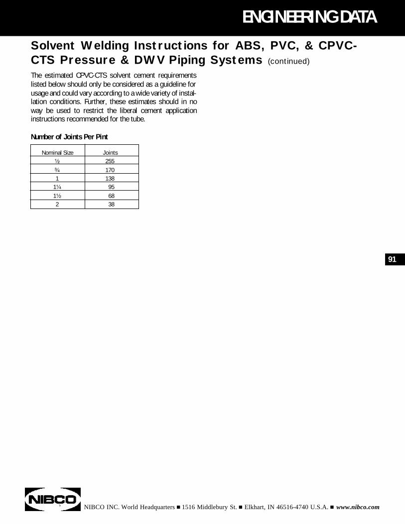
NIBCO INC. World Headquarters n 1516 Middlebury St. n Elkhart, IN 46516-4740 U.S.A. n www.nibco.com
ENGINEERING DATA
The estimated CPVC-CTS solvent cement requirementslisted below should only be considered as a guideline forusage and could vary according to a wide variety of instal-lation conditions. Further, these estimates should in noway be used to restrict the liberal cement applicationinstructions recommended for the tube.
Number of Joints Per Pint
91
Solvent Welding Instructions for ABS, PVC, & CPVC-CTS Pressure & DWV Piping Systems (continued)
Nominal Size Joints¹⁄₂ 255³⁄₄ 1701 138
1¹⁄₄ 951¹⁄₂ 682 38
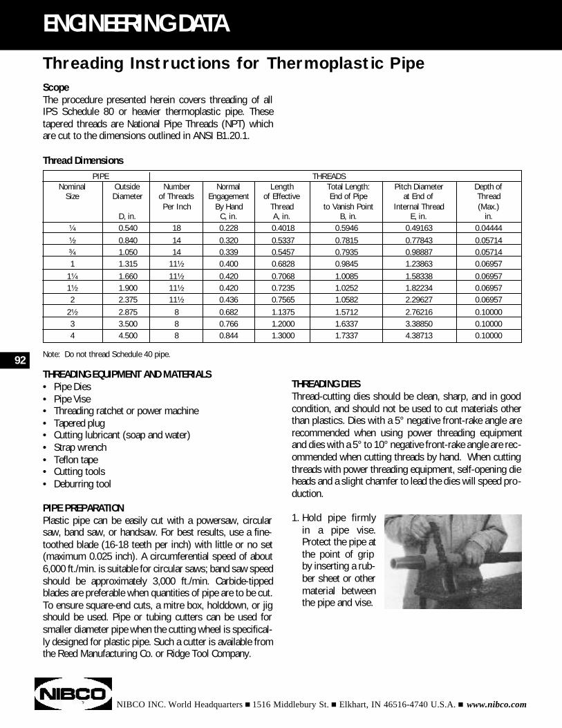
NIBCO INC. World Headquarters n 1516 Middlebury St. n Elkhart, IN 46516-4740 U.S.A. n www.nibco.com
92
ENGINEERING DATA
ScopeThe procedure presented herein covers threading of allIPS Schedule 80 or heavier thermoplastic pipe. Thesetapered threads are National Pipe Threads (NPT) whichare cut to the dimensions outlined in ANSI B1.20.1.
Thread Dimensions
Note: Do not thread Schedule 40 pipe.
THREADING EQUIPMENT AND MATERIALS• Pipe Dies • Pipe Vise • Threading ratchet or power machine • Tapered plug • Cutting lubricant (soap and water) • Strap wrench • Teflon tape • Cutting tools • Deburring tool
PIPE PREPARATIONPlastic pipe can be easily cut with a powersaw, circularsaw, band saw, or handsaw. For best results, use a fine-toothed blade (16-18 teeth per inch) with little or no set(maximum 0.025 inch). A circumferential speed of about6,000 ft./min. is suitable for circular saws; band saw speedshould be approximately 3,000 ft./min. Carbide-tippedblades are preferable when quantities of pipe are to be cut.To ensure square-end cuts, a mitre box, holddown, or jigshould be used. Pipe or tubing cutters can be used forsmaller diameter pipe when the cutting wheel is specifical-ly designed for plastic pipe. Such a cutter is available fromthe Reed Manufacturing Co. or Ridge Tool Company.
Threading Instructions for Thermoplastic Pipe
PIPE THREADSNominal Outside Number Normal Length Total Length: Pitch Diameter Depth of
Size Diameter of Threads Engagement of Effective End of Pipe at End of ThreadPer Inch By Hand Thread to Vanish Point Internal Thread (Max.)
D, in. C, in. A, in. B, in. E, in. in.¹⁄₄ 0.540 18 0.228 0.4018 0.5946 0.49163 0.04444¹⁄₂ 0.840 14 0.320 0.5337 0.7815 0.77843 0.05714³⁄₄ 1.050 14 0.339 0.5457 0.7935 0.98887 0.057141 1.315 11¹⁄₂ 0.400 0.6828 0.9845 1.23863 0.06957
1¹⁄₄ 1.660 11¹⁄₂ 0.420 0.7068 1.0085 1.58338 0.069571¹⁄₂ 1.900 11¹⁄₂ 0.420 0.7235 1.0252 1.82234 0.069572 2.375 11¹⁄₂ 0.436 0.7565 1.0582 2.29627 0.06957
2¹⁄₂ 2.875 8 0.682 1.1375 1.5712 2.76216 0.100003 3.500 8 0.766 1.2000 1.6337 3.38850 0.100004 4.500 8 0.844 1.3000 1.7337 4.38713 0.10000
THREADING DIESThread-cutting dies should be clean, sharp, and in goodcondition, and should not be used to cut materials otherthan plastics. Dies with a 5° negative front-rake angle arerecommended when using power threading equipmentand dies with a 5° to 10° negative front-rake angle are rec-ommended when cutting threads by hand. When cuttingthreads with power threading equipment, self-opening dieheads and a slight chamfer to lead the dies will speed pro-duction.
1. Hold pipe firmly in a pipe vise. Protect the pipe at the point of grip by inserting a rub-ber sheet or other material between the pipe and vise.
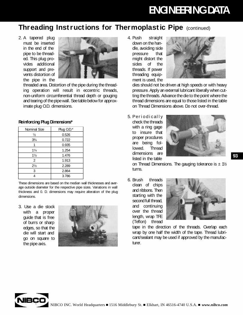
2. A tapered plug must be inserted in the end of the pipe to be thread-ed. This plug pro-vides additional support and pre-vents distortion of the pipe in the threaded area. Distortion of the pipe during the thread-ing operation will result in eccentric threads, non-uniform circumferential thread depth or gouging and tearing of the pipe wall. See table below for approx-imate plug O.D. dimensions.
Reinforcing Plug Dimensions*
These dimensions are based on the median wall thicknesses and aver-age outside diameter for the respective pipe sizes. Variations in wallthickness and 0. D. dimensions may require alteration of the plugdimensions.
3. Use a die stock with a proper guide that is free of burrs or sharp edges, so that the die will start and go on square to the pipe axis.
NIBCO INC. World Headquarters n 1516 Middlebury St. n Elkhart, IN 46516-4740 U.S.A. n www.nibco.com
ENGINEERING DATA
93
Threading Instructions for Thermoplastic Pipe (continued)
Nominal Size Plug O.D.*¹⁄₂ 0.5263³⁄₄ 0.7221 0.935
1¹⁄₄ 1.2541¹⁄₂ 1.4762 1.913
2¹⁄₂ 2.2893 2.8644 3.786
4. Push straight down on the han-dle, avoiding side pressure that might distort the sides of the threads. If power threading equip-ment is used, the dies should not be driven at high speeds or with heavy pressure. Apply an external lubricant liberally when cut-ting the threads. Advance the die to the point where the thread dimensions are equal to those listed in the table on Thread Dimensions above. Do not over-thread.
5. P e r i o d i c a l l y check the threads with a ring gage to insure that proper procdures are being fol-lowed. Thread dimensions are listed in the table on Thread Dimensions. The gauging tolerance is ± 1¹⁄₂turns.
6. Brush threads clean of chips and ribbons. Thenstarting with the second full thread,and continuing over the thread length, wrap TFE (Teflon) thread tape in the direction of the threads. Overlap each wrap by one half the width of the tape. Thread lubri-cant/sealant may be used if approved by the manufac-turer.
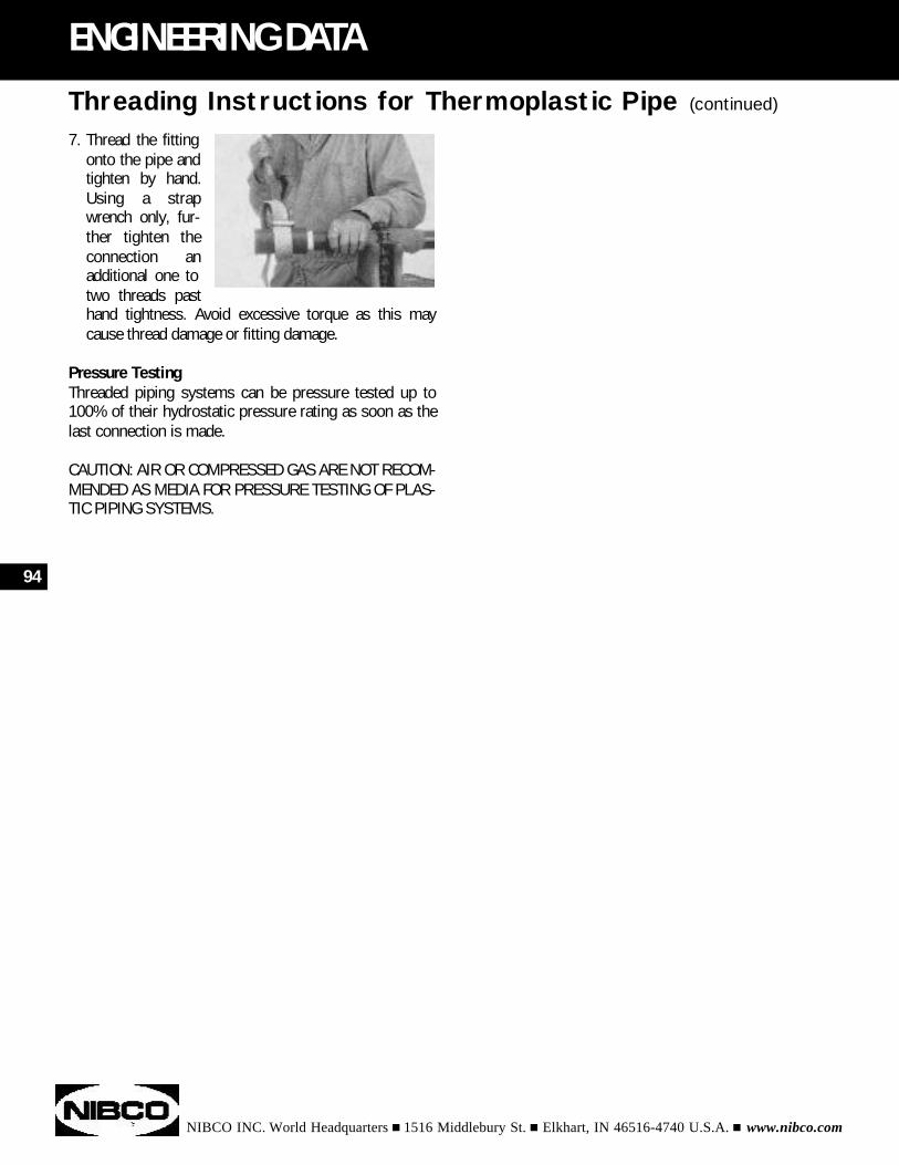
NIBCO INC. World Headquarters n 1516 Middlebury St. n Elkhart, IN 46516-4740 U.S.A. n www.nibco.com
94
ENGINEERING DATA
7. Thread the fitting onto the pipe and tighten by hand. Using a strap wrench only, fur-ther tighten the connection an additional one to two threads past hand tightness. Avoid excessive torque as this may cause thread damage or fitting damage.
Pressure TestingThreaded piping systems can be pressure tested up to100% of their hydrostatic pressure rating as soon as thelast connection is made.
CAUTION: AIR OR COMPRESSED GAS ARE NOT RECOM-MENDED AS MEDIA FOR PRESSURE TESTING OF PLAS-TIC PIPING SYSTEMS.
Threading Instructions for Thermoplastic Pipe (continued)
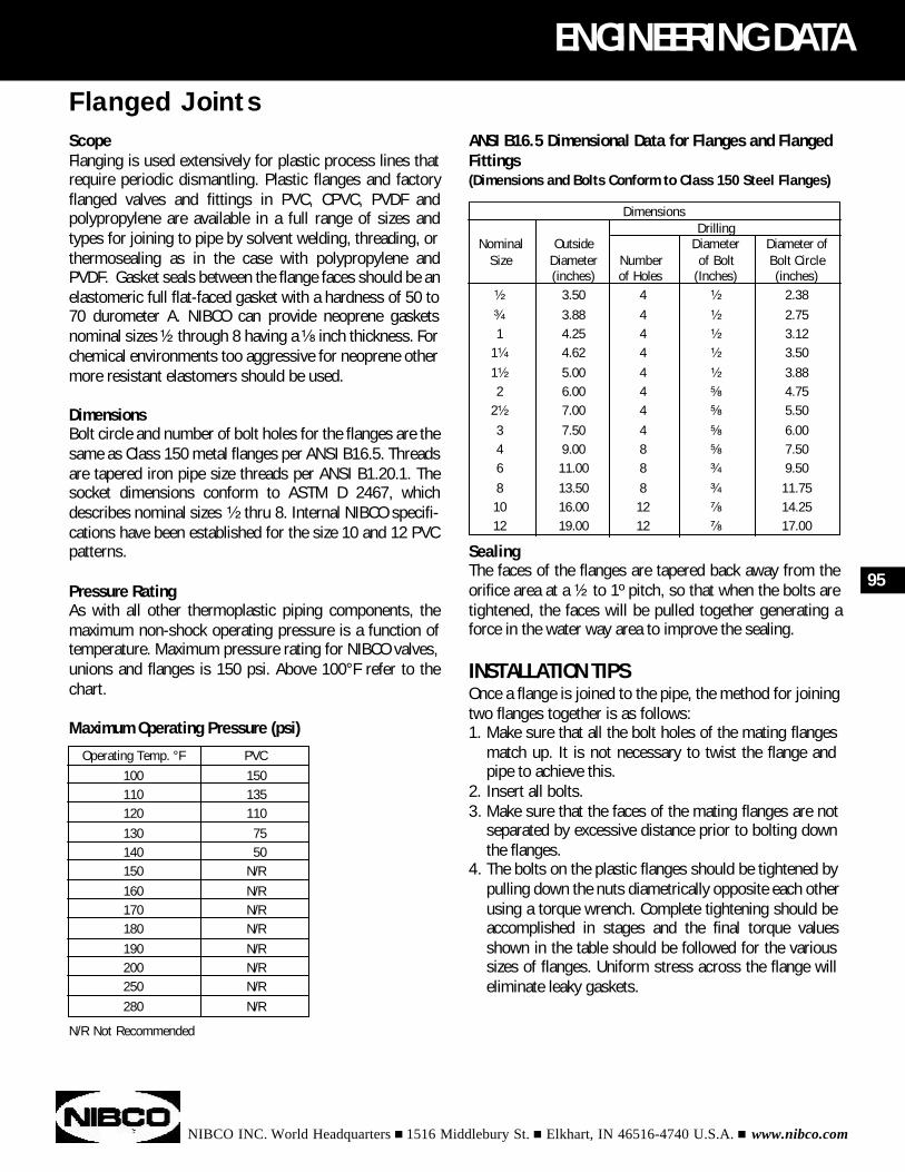
NIBCO INC. World Headquarters n 1516 Middlebury St. n Elkhart, IN 46516-4740 U.S.A. n www.nibco.com
ENGINEERING DATA
ScopeFlanging is used extensively for plastic process lines thatrequire periodic dismantling. Plastic flanges and factoryflanged valves and fittings in PVC, CPVC, PVDF andpolypropylene are available in a full range of sizes andtypes for joining to pipe by solvent welding, threading, orthermosealing as in the case with polypropylene andPVDF. Gasket seals between the flange faces should be anelastomeric full flat-faced gasket with a hardness of 50 to70 durometer A. NIBCO can provide neoprene gasketsnominal sizes ¹⁄₂ through 8 having a ¹⁄₈ inch thickness. Forchemical environments too aggressive for neoprene othermore resistant elastomers should be used.
DimensionsBolt circle and number of bolt holes for the flanges are thesame as Class 150 metal flanges per ANSI B16.5. Threadsare tapered iron pipe size threads per ANSI B1.20.1. Thesocket dimensions conform to ASTM D 2467, whichdescribes nominal sizes ¹⁄₂ thru 8. Internal NIBCO specifi-cations have been established for the size 10 and 12 PVCpatterns.
Pressure RatingAs with all other thermoplastic piping components, themaximum non-shock operating pressure is a function oftemperature. Maximum pressure rating for NIBCO valves,unions and flanges is 150 psi. Above 100°F refer to thechart.
Maximum Operating Pressure (psi)
N/R Not Recommended
95
Flanged Joints
Operating Temp. °F PVC100 150110 135120 110130 75140 50150 N/R160 N/R170 N/R180 N/R190 N/R200 N/R250 N/R280 N/R
ANSI B16.5 Dimensional Data for Flanges and FlangedFittings(Dimensions and Bolts Conform to Class 150 Steel Flanges)
SealingThe faces of the flanges are tapered back away from theorifice area at a ¹⁄₂ to 1º pitch, so that when the bolts aretightened, the faces will be pulled together generating aforce in the water way area to improve the sealing.
INSTALLATION TIPSOnce a flange is joined to the pipe, the method for joiningtwo flanges together is as follows:1. Make sure that all the bolt holes of the mating flanges
match up. It is not necessary to twist the flange and pipe to achieve this.
2. Insert all bolts.3. Make sure that the faces of the mating flanges are not
separated by excessive distance prior to bolting down the flanges.
4. The bolts on the plastic flanges should be tightened by pulling down the nuts diametrically opposite each other using a torque wrench. Complete tightening should be accomplished in stages and the final torque values shown in the table should be followed for the various sizes of flanges. Uniform stress across the flange will eliminate leaky gaskets.
DimensionsDrilling
Nominal Outside Diameter Diameter ofSize Diameter Number of Bolt Bolt Circle
(inches) of Holes (Inches) (inches)¹⁄₂ 3.50 4 ¹⁄₂ 2.38³⁄₄ 3.88 4 ¹⁄₂ 2.751 4.25 4 ¹⁄₂ 3.12
1¹⁄₄ 4.62 4 ¹⁄₂ 3.501¹⁄₂ 5.00 4 ¹⁄₂ 3.882 6.00 4 ⁵⁄₈ 4.75
2¹⁄₂ 7.00 4 ⁵⁄₈ 5.503 7.50 4 ⁵⁄₈ 6.004 9.00 8 ⁵⁄₈ 7.506 11.00 8 ³⁄₄ 9.508 13.50 8 ³⁄₄ 11.7510 16.00 12 ⁷⁄₈ 14.2512 19.00 12 ⁷⁄₈ 17.00
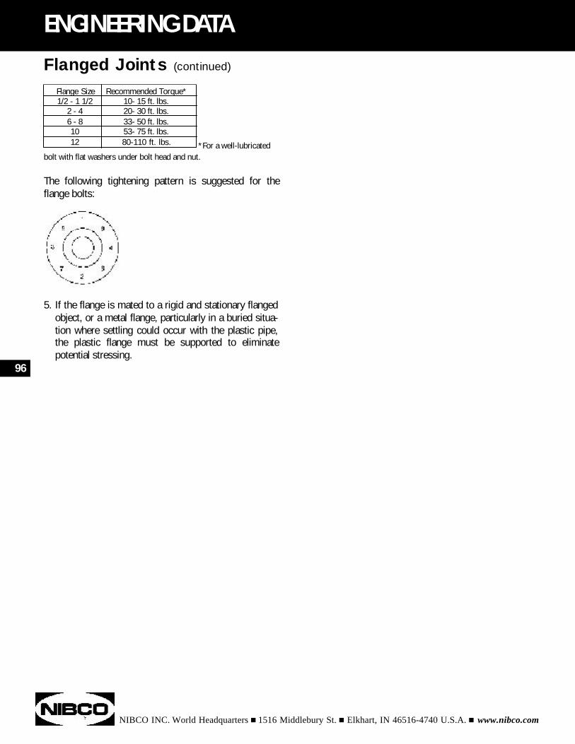
*For a well-lubricatedbolt with flat washers under bolt head and nut.
The following tightening pattern is suggested for theflange bolts:
5. If the flange is mated to a rigid and stationary flanged object, or a metal flange, particularly in a buried situa-tion where settling could occur with the plastic pipe, the plastic flange must be supported to eliminate potential stressing.
NIBCO INC. World Headquarters n 1516 Middlebury St. n Elkhart, IN 46516-4740 U.S.A. n www.nibco.com
96
ENGINEERING DATA
Flanged Joints (continued)
Flange Size Recommended Torque*1/2 - 1 1/2 10- 15 ft. lbs.
2 - 4 20- 30 ft. lbs.6 - 8 33- 50 ft. lbs.10 53- 75 ft. lbs.12 80-110 ft. lbs.
NIBCO INC. World Headquarters n 1516 Middlebury St. n Elkhart, IN 46516-4740 U.S.A. n www.nibco.com
ENGINEERING DATA
THREADED CONNECTIONS - ABS, CPVC, & PVC pipe lessthan Schedule 80 wall should not be threaded. Mostcodes require transition from one material to another byuse of appropriate adapter fittings. NIBCO offers a com-plete line of adapters for ABS, CPVC, & PVC.Common thread sealants should not be used on threadedABS, CPVC, or PVC joints. When necessary, Teflon* pipetape can be used.
CONNECTING CPVC TO METAL PIPE OR FITTINGS - Therecommended methods of joining CPVC tube to metalthreaded valves or piping are to use one of the specialtransition unions or a CPVC adapter with a threaded-brassinsert. Threaded plastic-to-metal connection are not rec-ommended. The difference in the rates of expansion ofCPVC and metal may cause leakage in threaded joints
An approved temperature/pressure relief valve should beassembled to the hot water heater so that the probe orsensing element enters the water at the top of the heater.Using metal nipples, extend the metal piping at least 12inches from the water heater on both the cold water sup-ply and the hot water discharge lines. Special transitionunions or CPVC adapters with a brass threaded insertmust be used to join the CPVC tube to the nipples. Do notuse CPVC pipe and fittings with commercial type non-storage water heaters.
CONNECTING CPVC TO HOT WATER HEATERAn approved temperature/pressure relief valve should beassembled to the hot water heater so that the probe orsensing element enters the water at the top of the heater.Using metal nipples, extend the metal piping at least 12inches from the water heater on both the cold water sup-ply and the hot water discharge lines. Special transitionunions or CPVC adapters with a threaded-brass insertmust be used to join the CPVC tube to the nipples. Do notuse CPVC pipe and fittings with commercial type non-storage water heaters.
*A registered trademark of E.I. DuPont
97
Adapting Plastic Piping to Other Piping Materials
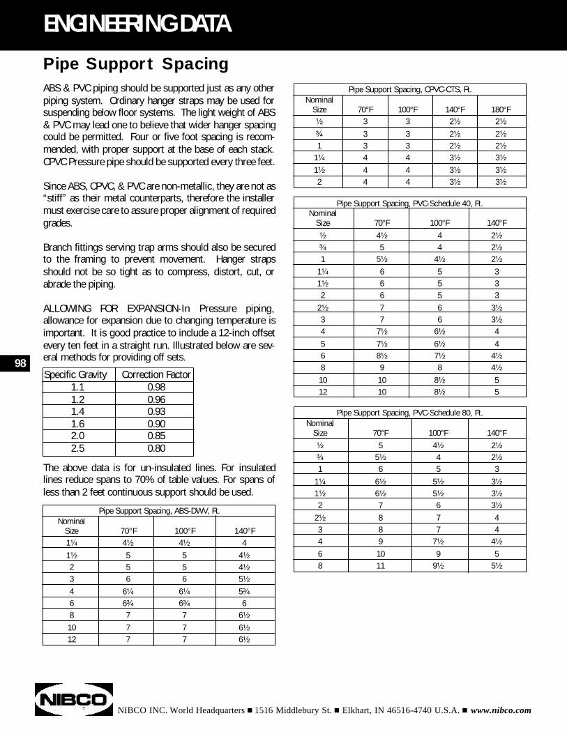
ABS & PVC piping should be supported just as any otherpiping system. Ordinary hanger straps may be used forsuspending below floor systems. The light weight of ABS& PVC may lead one to believe that wider hanger spacingcould be permitted. Four or five foot spacing is recom-mended, with proper support at the base of each stack.CPVC Pressure pipe should be supported every three feet.
Since ABS, CPVC, & PVC are non-metallic, they are not as“stiff” as their metal counterparts, therefore the installermust exercise care to assure proper alignment of requiredgrades.
Branch fittings serving trap arms should also be securedto the framing to prevent movement. Hanger strapsshould not be so tight as to compress, distort, cut, orabrade the piping.
ALLOWING FOR EXPANSION-In Pressure piping,allowance for expansion due to changing temperature isimportant. It is good practice to include a 12-inch offsetevery ten feet in a straight run. Illustrated below are sev-eral methods for providing off sets.
The above data is for un-insulated lines. For insulatedlines reduce spans to 70% of table values. For spans ofless than 2 feet continuous support should be used.
NIBCO INC. World Headquarters n 1516 Middlebury St. n Elkhart, IN 46516-4740 U.S.A. n www.nibco.com
98
ENGINEERING DATA
Pipe Support Spacing
Specific Gravity Correction Factor1.1 0.981.2 0.961.4 0.931.6 0.902.0 0.852.5 0.80
Pipe Support Spacing, ABS-DWV, Ft.Nominal
Size 70°F 100°F 140°F1¹⁄₄ 4¹⁄₂ 4¹⁄₂ 41¹⁄₂ 5 5 4¹⁄₂
2 5 5 4¹⁄₂
3 6 6 5¹⁄₂
4 6¹⁄₄ 6¹⁄₄ 5³⁄₄
6 6³⁄₄ 6³⁄₄ 68 7 7 6¹⁄₂
10 7 7 6¹⁄₂
12 7 7 6¹⁄₂
Pipe Support Spacing, CPVC-CTS, Ft.Nominal
Size 70°F 100°F 140°F 180°F¹⁄₂ 3 3 2¹⁄₂ 2¹⁄₂
³⁄₄ 3 3 2¹⁄₂ 2¹⁄₂
1 3 3 2¹⁄₂ 2¹⁄₂
1¹⁄₄ 4 4 3¹⁄₂ 3¹⁄₂
1¹⁄₂ 4 4 3¹⁄₂ 3¹⁄₂
2 4 4 3¹⁄₂ 3¹⁄₂
Pipe Support Spacing, PVC-Schedule 40, Ft.Nominal
Size 70°F 100°F 140°F¹⁄₂ 4¹⁄₂ 4 2¹⁄₂
³⁄₄ 5 4 2¹⁄₂
1 5¹⁄₂ 4¹⁄₂ 2¹⁄₂
1¹⁄₄ 6 5 31¹⁄₂ 6 5 32 6 5 3
2¹⁄₂ 7 6 3¹⁄₂
3 7 6 3¹⁄₂
4 7¹⁄₂ 6¹⁄₂ 45 7¹⁄₂ 6¹⁄₂ 46 8¹⁄₂ 7¹⁄₂ 4¹⁄₂
8 9 8 4¹⁄₂
10 10 8¹⁄₂ 512 10 8¹⁄₂ 5
Pipe Support Spacing, PVC-Schedule 80, Ft.Nominal
Size 70°F 100°F 140°F¹⁄₂ 5 4¹⁄₂ 2¹⁄₂
³⁄₄ 5¹⁄₂ 4 2¹⁄₂
1 6 5 31¹⁄₄ 6¹⁄₂ 5¹⁄₂ 3¹⁄₂
1¹⁄₂ 6¹⁄₂ 5¹⁄₂ 3¹⁄₂
2 7 6 3¹⁄₂
2¹⁄₂ 8 7 43 8 7 44 9 7¹⁄₂ 4¹⁄₂
6 10 9 58 11 9¹⁄₂ 5¹⁄₂
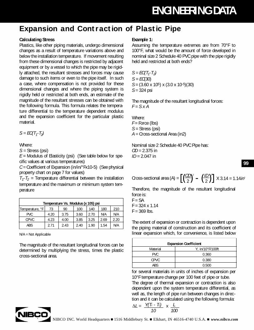
NIBCO INC. World Headquarters n 1516 Middlebury St. n Elkhart, IN 46516-4740 U.S.A. n www.nibco.com
99
ENGINEERING DATA
Calculating StressPlastics, like other piping materials, undergo dimensionalchanges as a result of temperature variations above andbelow the installation temperature. If movement resultingfrom these dimensional changes is restricted by adjacentequipment or by a vessel to which the pipe may be rigid-ly attached, the resultant stresses and forces may causedamage to such items or even to the pipe itself. In sucha case, where compensation is not provided for thesedimensional changes and where the piping system isrigidly held or restricted at both ends, an estimate of themagnitude of the resultant stresses can be obtained withthe following formula. This formula relates the tempera-ture differential to the temperature dependent modulusand the expansion coefficient for the particular plasticmaterial.
S = EC(T1-T2)
Where:S = Stress (psi)E = Modulus of Elasticity (psi) (See table below for spe-cific values at various temperatures)C = Coefficient of Expansion (in/in/°Fx10-5) (See physicalproperty chart on page 7 for values)T1-T2 = Temperature differential between the installationtemperature and the maximum or minimum system tem-perature
N/A = Not Applicable
The magnitude of the resultant longitudinal forces can bedetermined by multiplying the stress, times the plasticcross-sectional area.
Temperature Vs. Modulus (x 105) psiTemperature, °F 73 90 100 140 180 210
PVC 4.20 3.75 3.60 2.70 N/A N/ACPVC 4.23 4.00 3.85 3.25 2.69 2.20ABS 2.71 2.43 2.40 1.90 1.54 N/A
OD 2 ID 2
2 2[( ) - ( )] X 3.14 = 1.14in2
Expansion and Contraction of Plastic PipeExample 1:Assuming the temperature extremes are from 70°F to100°F, what would be the amount of force developed innominal size 2 Schedule 40 PVC pipe with the pipe rigidlyheld and restricted at both ends?
S = EC(T1-T2)S = EC(30)S = (3.60 x 105) x (3.0 x 10-5)(30)S = 324 psi
The magnitude of the resultant longitudinal forces: F = S x A
Where: F = Force (lbs) S = Stress (psi) A = Cross-sectional Area (in2)
Nominal size 2 Schedule 40 PVC Pipe has:OD = 2.375 in ID = 2.047 in
Cross-sectional area (A) =
Therefore, the magnitude of the resultant longitudinalforce is: F = SA F = 324 x 1.14 F = 369 lbs.
The extent of expansion or contraction is dependent uponthe piping material of construction and its coefficient oflinear expansion which, for convenience, is listed below
for several materials in units of inches of expansion per10°F temperature change per 100 feet of pipe or tube.The degree of thermal expansion or contraction is alsodependent upon the system temperature differential, aswell as, the length of pipe run between changes in direc-tion and it can be calculated using the following formula:
Expansion CoefficientMaterial Y, in/10°F/100ft
PVC 0.360CPVC 0.380ABS 0.500
Y(T1 - T2) L10 100
∆L = x
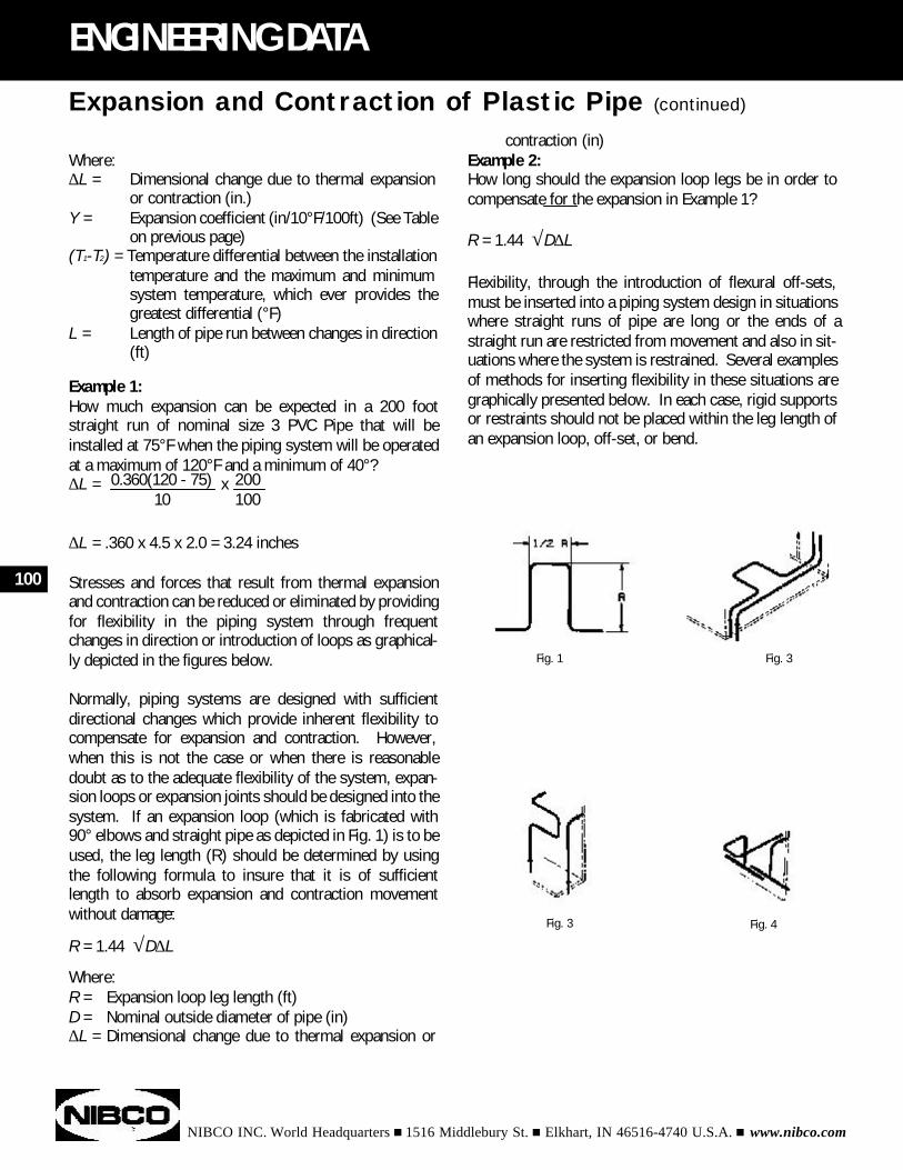
Where:∆L = Dimensional change due to thermal expansion
or contraction (in.)Y = Expansion coefficient (in/10°F/100ft) (See Table
on previous page)(T1-T2) = Temperature differential between the installation
temperature and the maximum and minimum system temperature, which ever provides the greatest differential (°F)
L = Length of pipe run between changes in direction (ft)
Example 1:How much expansion can be expected in a 200 footstraight run of nominal size 3 PVC Pipe that will beinstalled at 75°F when the piping system will be operatedat a maximum of 120°F and a minimum of 40°?
∆L = .360 x 4.5 x 2.0 = 3.24 inches
Stresses and forces that result from thermal expansionand contraction can be reduced or eliminated by providingfor flexibility in the piping system through frequentchanges in direction or introduction of loops as graphical-ly depicted in the figures below.
Normally, piping systems are designed with sufficientdirectional changes which provide inherent flexibility tocompensate for expansion and contraction. However,when this is not the case or when there is reasonabledoubt as to the adequate flexibility of the system, expan-sion loops or expansion joints should be designed into thesystem. If an expansion loop (which is fabricated with90° elbows and straight pipe as depicted in Fig. 1) is to beused, the leg length (R) should be determined by usingthe following formula to insure that it is of sufficientlength to absorb expansion and contraction movementwithout damage.
R = 1.44 √D∆L
Where:R = Expansion loop leg length (ft)D = Nominal outside diameter of pipe (in)∆L = Dimensional change due to thermal expansion or
NIBCO INC. World Headquarters n 1516 Middlebury St. n Elkhart, IN 46516-4740 U.S.A. n www.nibco.com
ENGINEERING DATA
0.360(120 - 75) 20010 100
∆L = x
100
Expansion and Contraction of Plastic Pipe (continued)
contraction (in)Example 2:How long should the expansion loop legs be in order tocompensate for the expansion in Example 1?
R = 1.44 √D∆L
Flexibility, through the introduction of flexural off-sets,must be inserted into a piping system design in situationswhere straight runs of pipe are long or the ends of astraight run are restricted from movement and also in sit-uations where the system is restrained. Several examplesof methods for inserting flexibility in these situations aregraphically presented below. In each case, rigid supportsor restraints should not be placed within the leg length ofan expansion loop, off-set, or bend.
Fig. 1 Fig. 3
Fig. 3 Fig. 4
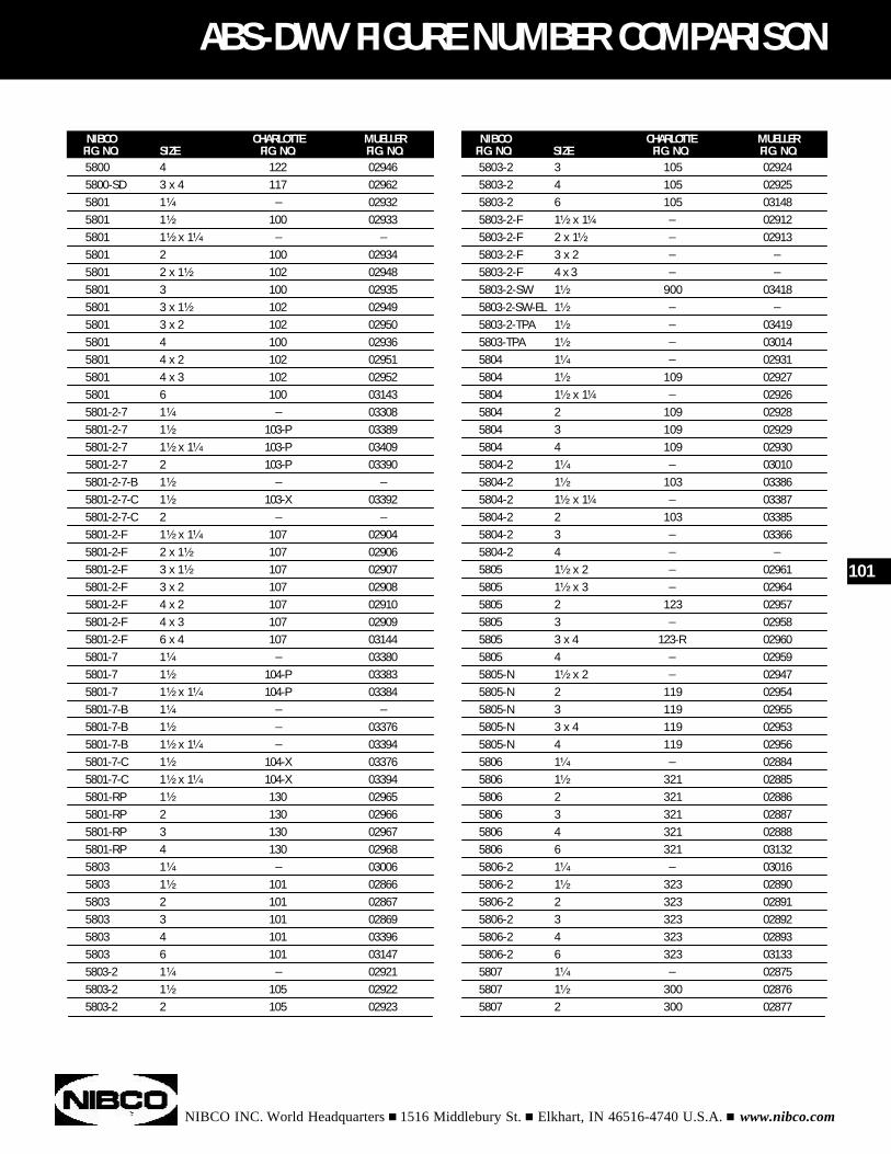
NIBCO INC. World Headquarters n 1516 Middlebury St. n Elkhart, IN 46516-4740 U.S.A. n www.nibco.com
ABS-DWV FIGURE NUMBER COMPARISON
NIBCO CHARLOTTE MUELLERFIG. NO. SIZE FIG. NO. FIG. NO.
NIBCO CHARLOTTE MUELLERFIG. NO. SIZE FIG. NO. FIG. NO.5800 4 122 029465800-SD 3 x 4 117 029625801 1¹⁄₄ _ 029325801 1¹⁄₂ 100 029335801 1¹⁄₂ x 1¹⁄₄ _ _
5801 2 100 029345801 2 x 1¹⁄₂ 102 029485801 3 100 029355801 3 x 1¹⁄₂ 102 029495801 3 x 2 102 029505801 4 100 029365801 4 x 2 102 029515801 4 x 3 102 029525801 6 100 031435801-2-7 1¹⁄₄ _ 033085801-2-7 1¹⁄₂ 103-P 033895801-2-7 1¹⁄₂ x 1¹⁄₄ 103-P 034095801-2-7 2 103-P 033905801-2-7-B 1¹⁄₂ _ _
5801-2-7-C 1¹⁄₂ 103-X 033925801-2-7-C 2 _ _
5801-2-F 1¹⁄₂ x 1¹⁄₄ 107 029045801-2-F 2 x 1¹⁄₂ 107 029065801-2-F 3 x 1¹⁄₂ 107 029075801-2-F 3 x 2 107 029085801-2-F 4 x 2 107 029105801-2-F 4 x 3 107 029095801-2-F 6 x 4 107 031445801-7 1¹⁄₄ _ 033805801-7 1¹⁄₂ 104-P 033835801-7 1¹⁄₂ x 1¹⁄₄ 104-P 033845801-7-B 1¹⁄₄ _ _
5801-7-B 1¹⁄₂ _ 033765801-7-B 1¹⁄₂ x 1¹⁄₄ _ 033945801-7-C 1¹⁄₂ 104-X 033765801-7-C 1¹⁄₂ x 1¹⁄₄ 104-X 033945801-RP 1¹⁄₂ 130 029655801-RP 2 130 029665801-RP 3 130 029675801-RP 4 130 029685803 1¹⁄₄ _ 030065803 1¹⁄₂ 101 028665803 2 101 028675803 3 101 028695803 4 101 033965803 6 101 031475803-2 1¹⁄₄ _ 029215803-2 1¹⁄₂ 105 029225803-2 2 105 02923
101
5803-2 3 105 029245803-2 4 105 029255803-2 6 105 031485803-2-F 1¹⁄₂ x 1¹⁄₄ _ 029125803-2-F 2 x 1¹⁄₂ _ 029135803-2-F 3 x 2 _ _
5803-2-F 4 x 3 _ _
5803-2-SW 1¹⁄₂ 900 034185803-2-SW-EL 1¹⁄₂ _ _
5803-2-TPA 1¹⁄₂ _ 034195803-TPA 1¹⁄₂ _ 030145804 1¹⁄₄ _ 029315804 1¹⁄₂ 109 029275804 1¹⁄₂ x 1¹⁄₄ _ 029265804 2 109 029285804 3 109 029295804 4 109 029305804-2 1¹⁄₄ _ 030105804-2 1¹⁄₂ 103 033865804-2 1¹⁄₂ x 1¹⁄₄ _ 033875804-2 2 103 033855804-2 3 _ 033665804-2 4 _ _
5805 1¹⁄₂ x 2 _ 029615805 1¹⁄₂ x 3 _ 029645805 2 123 029575805 3 _ 029585805 3 x 4 123-R 029605805 4 _ 029595805-N 1¹⁄₂ x 2 _ 029475805-N 2 119 029545805-N 3 119 029555805-N 3 x 4 119 029535805-N 4 119 029565806 1¹⁄₄ _ 028845806 1¹⁄₂ 321 028855806 2 321 028865806 3 321 028875806 4 321 028885806 6 321 031325806-2 1¹⁄₄ _ 030165806-2 1¹⁄₂ 323 028905806-2 2 323 028915806-2 3 323 028925806-2 4 323 028935806-2 6 323 031335807 1¹⁄₄ _ 028755807 1¹⁄₂ 300 028765807 2 300 02877
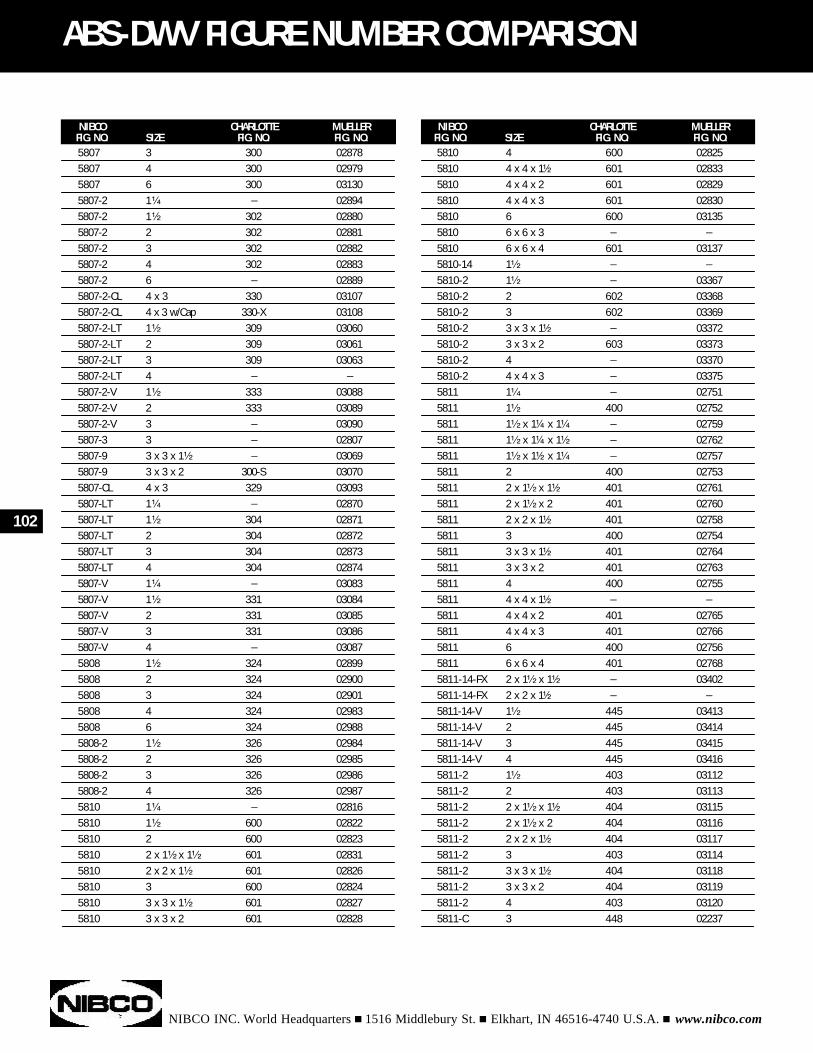
NIBCO INC. World Headquarters n 1516 Middlebury St. n Elkhart, IN 46516-4740 U.S.A. n www.nibco.com
102
ABS-DWV FIGURE NUMBER COMPARISON
NIBCO CHARLOTTE MUELLERFIG. NO. SIZE FIG. NO. FIG. NO.
NIBCO CHARLOTTE MUELLERFIG. NO. SIZE FIG. NO. FIG. NO.
5810 4 600 028255810 4 x 4 x 1¹⁄₂ 601 028335810 4 x 4 x 2 601 028295810 4 x 4 x 3 601 028305810 6 600 031355810 6 x 6 x 3 _ _
5810 6 x 6 x 4 601 031375810-14 1¹⁄₂ _ _
5810-2 1¹⁄₂ _ 033675810-2 2 602 033685810-2 3 602 033695810-2 3 x 3 x 1¹⁄₂ _ 033725810-2 3 x 3 x 2 603 033735810-2 4 _ 033705810-2 4 x 4 x 3 _ 033755811 1¹⁄₄ _ 027515811 1¹⁄₂ 400 027525811 1¹⁄₂ x 1¹⁄₄ x 1¹⁄₄ _ 027595811 1¹⁄₂ x 1¹⁄₄ x 1¹⁄₂ _ 027625811 1¹⁄₂ x 1¹⁄₂ x 1¹⁄₄ _ 027575811 2 400 027535811 2 x 1¹⁄₂ x 1¹⁄₂ 401 027615811 2 x 1¹⁄₂ x 2 401 027605811 2 x 2 x 1¹⁄₂ 401 027585811 3 400 027545811 3 x 3 x 1¹⁄₂ 401 027645811 3 x 3 x 2 401 027635811 4 400 027555811 4 x 4 x 1¹⁄₂ _ _
5811 4 x 4 x 2 401 027655811 4 x 4 x 3 401 027665811 6 400 027565811 6 x 6 x 4 401 027685811-14-FX 2 x 1¹⁄₂ x 1¹⁄₂ _ 034025811-14-FX 2 x 2 x 1¹⁄₂ _ _
5811-14-V 1¹⁄₂ 445 034135811-14-V 2 445 034145811-14-V 3 445 034155811-14-V 4 445 034165811-2 1¹⁄₂ 403 031125811-2 2 403 031135811-2 2 x 1¹⁄₂ x 1¹⁄₂ 404 031155811-2 2 x 1¹⁄₂ x 2 404 031165811-2 2 x 2 x 1¹⁄₂ 404 031175811-2 3 403 031145811-2 3 x 3 x 1¹⁄₂ 404 031185811-2 3 x 3 x 2 404 031195811-2 4 403 031205811-C 3 448 02237
5807 3 300 028785807 4 300 029795807 6 300 031305807-2 1¹⁄₄ _ 028945807-2 1¹⁄₂ 302 028805807-2 2 302 028815807-2 3 302 028825807-2 4 302 028835807-2 6 _ 028895807-2-CL 4 x 3 330 031075807-2-CL 4 x 3 w/Cap 330-X 031085807-2-LT 1¹⁄₂ 309 030605807-2-LT 2 309 030615807-2-LT 3 309 030635807-2-LT 4 _ _
5807-2-V 1¹⁄₂ 333 030885807-2-V 2 333 030895807-2-V 3 _ 030905807-3 3 _ 028075807-9 3 x 3 x 1¹⁄₂ _ 030695807-9 3 x 3 x 2 300-S 030705807-CL 4 x 3 329 030935807-LT 1¹⁄₄ _ 028705807-LT 1¹⁄₂ 304 028715807-LT 2 304 028725807-LT 3 304 028735807-LT 4 304 028745807-V 1¹⁄₄ _ 030835807-V 1¹⁄₂ 331 030845807-V 2 331 030855807-V 3 331 030865807-V 4 _ 030875808 1¹⁄₂ 324 028995808 2 324 029005808 3 324 029015808 4 324 029835808 6 324 029885808-2 1¹⁄₂ 326 029845808-2 2 326 029855808-2 3 326 029865808-2 4 326 029875810 1¹⁄₄ _ 028165810 1¹⁄₂ 600 028225810 2 600 028235810 2 x 1¹⁄₂ x 1¹⁄₂ 601 028315810 2 x 2 x 1¹⁄₂ 601 028265810 3 600 028245810 3 x 3 x 1¹⁄₂ 601 028275810 3 x 3 x 2 601 02828
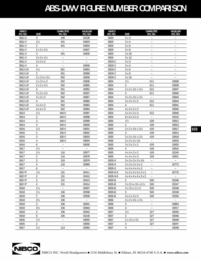
NIBCO INC. World Headquarters n 1516 Middlebury St. n Elkhart, IN 46516-4740 U.S.A. n www.nibco.com
ABS-DWV FIGURE NUMBER COMPARISON
NIBCO CHARLOTTE MUELLERFIG. NO. SIZE FIG. NO. FIG. NO.
NIBCO CHARLOTTE MUELLERFIG. NO. SIZE FIG. NO. FIG. NO.
103
5811-C 4 448 022385811-V 1¹⁄₂ 441 034035811-V 2 441 034045811-V 2 x 2 x 1¹⁄₂ _ 034075811-V 3 441 034055811-V 3 x 3 x 1¹⁄₂ _ _
5811-V 3 x 3 x 2 _ _
5811-V 4 _ 034065812-LR 1¹⁄₂ 501 028535812-LR 2 501 028585812-LR 2 x 1¹⁄₂ x 1¹⁄₂ 502 028355812-LR 2 x 1¹⁄₂ x 2 502 028365812-LR 2 x 2 x 1¹⁄₂ 502 028655812-LR 3 501 028525812-LR 3 x 3 x 1¹⁄₂ 502 028375812-LR 3 x 3 x 2 502 028575812-LR 4 501 028605812-LR 4 x 4 x 2 502 028635812-LR 4 x 4 x 3 502 028645814 1¹⁄₂ 444-X 029975814 2 444-X 029985814 3 444-X 029995814 4 444-X 030005816 1¹⁄₂ 105-X 030015816 2 105-X 030025816 3 105-X 030035816 4 105-X 030045816 6 _ 030055817 1¹⁄₄ _ _
5817 1¹⁄₂ 116 029775817 2 116 029785817 3 116 029795817 4 116 029805817 6 _ _
5817-P 1¹⁄₂ 131 024115817-P 2 131 024125817-P 3 131 024135817-P 4 131 024145818 1¹⁄₄ _ 029375818 1¹⁄₂ 106 029385818 2 106 029395818 2¹⁄₂ 106 _
5818 3 106 029415818 3¹⁄₂ 106 029435818 4 106 029425818 6 106 031465826 1¹⁄₂ _ 030555826 2 _ 030565827 1¹⁄₂ 114 02993
5829 3 x 3 _ _
5829 3 x 4 _ _
5829 3 x 6 _ _
5829 3 x 8 _ _
5829 3 x 10 _ _
5829 3 x 12 _ _
5829-2 3 x 3 _ _
5829-2 3 x 4 _ _
5829-2 3 x 6 _ _
5829-2 3 x 8 _ _
5829-2 3 x 10 _ _
5834 1¹⁄₂ 611 028385834 2 611 028395834 2 x 2 x 1¹⁄₂ x 1¹⁄₂ 612 028475834 3 611 028405834 3 x 3 x 1¹⁄₂ x 1¹⁄₂ _ 028435834 3 x 3 x 2 x 2 612 028445834 4 611 028415834 4 x 4 x 2 x 2 _ 028455834 4 x 4 x 3 x 3 612 028465834 6 x 6 x 4 x 4 _ 031425835 1¹⁄₂ 428 028125835 2 428 028135835 2 x 2 x 1¹⁄₂ x 1¹⁄₂ 429 028175835 3 428 028145835 3 x 3 x 1¹⁄₂ x 1¹⁄₂ 429 028185835 3 x 3 x 2 x 1¹⁄₂ _ 028195835 3 x 3 x 2 x 2 429 028205835 4 428 028155835 4 x 4 x 2 x 2 429 022405835 4 x 4 x 3 x 3 429 028215835-9 3 x 3 x 3 x 3 x 1¹⁄₂ _ _
5835-9 3 x 3 x 3 x 3 x 2 _ 027725835-9 4 x 4 x 4 x 4 x 2 _ _
5835-9-9 3 x 3 x 3 x 3 x 2 x 2 _ 027705835-9-9 4 x 4 x 4 x 4 x 2 x 2 _ _
5835-B 2 500 022465835-B 2 x 1¹⁄₂ x 1¹⁄₂ x 1¹⁄₂ 500 022475835-B 2 x 1¹⁄₂ x 2 x 2 500 022485835-B 3 500 022495835-B 3 x 2 x 3 x 3 500 022505836 2 x 2 x 1¹⁄₂ x 1¹⁄₂ _ _
5836 3 _ 028545836 4 _ 029175837 1¹⁄₂ 327 030455837 2 327 030465837 2 x 1¹⁄₂ x 1¹⁄₂ 327 030495837 3 327 030475837 4 _ 03048
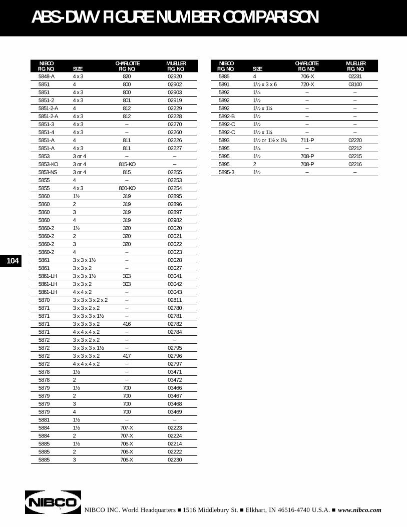
NIBCO INC. World Headquarters n 1516 Middlebury St. n Elkhart, IN 46516-4740 U.S.A. n www.nibco.com
104
ABS-DWV FIGURE NUMBER COMPARISON
NIBCO CHARLOTTE MUELLERFIG. NO. SIZE FIG. NO. FIG. NO.
NIBCO CHARLOTTE MUELLERFIG. NO. SIZE FIG. NO. FIG. NO.
5885 4 706-X 022315891 1¹⁄₂ x 3 x 6 720-X 031005892 1¹⁄₄ _ _
5892 1¹⁄₂ _ _
5892 1¹⁄₂ x 1¹⁄₄ _ _
5892-B 1¹⁄₂ _ _
5892-C 1¹⁄₂ _ _
5892-C 1¹⁄₂ x 1¹⁄₄ _ _
5893 1¹⁄₂ or 1¹⁄₂ x 1¹⁄₄ 711-P 022205895 1¹⁄₄ _ 022125895 1¹⁄₂ 708-P 022155895 2 708-P 022165895-3 1¹⁄₂ _ _
5848-A 4 x 3 820 029205851 4 800 029025851 4 x 3 800 029035851-2 4 x 3 801 029195851-2-A 4 812 022295851-2-A 4 x 3 812 022285851-3 4 x 3 _ 022705851-4 4 x 3 _ 022605851-A 4 811 022265851-A 4 x 3 811 022275853 3 or 4 _ _
5853-KO 3 or 4 815-KO _
5853-NS 3 or 4 815 022555855 4 _ 022535855 4 x 3 800-KO 022545860 1¹⁄₂ 319 028955860 2 319 028965860 3 319 028975860 4 319 029825860-2 1¹⁄₂ 320 030205860-2 2 320 030215860-2 3 320 030225860-2 4 _ 030235861 3 x 3 x 1¹⁄₂ _ 030285861 3 x 3 x 2 _ 030275861-LH 3 x 3 x 1¹⁄₂ 303 030415861-LH 3 x 3 x 2 303 030425861-LH 4 x 4 x 2 _ 030435870 3 x 3 x 3 x 2 x 2 _ 028115871 3 x 3 x 2 x 2 _ 027805871 3 x 3 x 3 x 1¹⁄₂ _ 027815871 3 x 3 x 3 x 2 416 027825871 4 x 4 x 4 x 2 _ 027845872 3 x 3 x 2 x 2 _ _
5872 3 x 3 x 3 x 1¹⁄₂ _ 027955872 3 x 3 x 3 x 2 417 027965872 4 x 4 x 4 x 2 _ 027975878 1¹⁄₂ _ 034715878 2 _ 034725879 1¹⁄₂ 700 034665879 2 700 034675879 3 700 034685879 4 700 034695881 1¹⁄₂ _ _
5884 1¹⁄₂ 707-X 022235884 2 707-X 022245885 1¹⁄₂ 706-X 022145885 2 706-X 022225885 3 706-X 02230
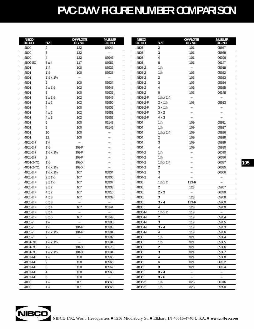
NIBCO INC. World Headquarters n 1516 Middlebury St. n Elkhart, IN 46516-4740 U.S.A. n www.nibco.com
PVC-DWV FIGURE NUMBER COMPARISON
NIBCO CHARLOTTE MUELLERFIG. NO. SIZE FIG. NO. FIG. NO.
NIBCO CHARLOTTE MUELLERFIG. NO. SIZE FIG. NO. FIG. NO.4800 2 122 059444800 3 122 _
4800 4 122 059464800-SD 3 x 4 117 059624801 1¹⁄₄ 100 059324801 1¹⁄₂ 100 059334801 1¹⁄₂ x 1¹⁄₄ _ _
4801 2 100 059344801 2 x 1¹⁄₂ 102 059484801 3 100 059354801 3 x 1¹⁄₂ 102 059494801 3 x 2 102 059504801 4 100 059364801 4 x 2 102 059514801 4 x 3 102 059524801 6 100 061434801 8 100 061454801 10 100 _
4801 12 100 _
4801-2-7 1¹⁄₄ _ _
4801-2-7 1¹⁄₂ 103-P _
4801-2-7 1¹⁄₂ x 1¹⁄₄ 103-P _
4801-2-7 2 103-P _
4801-2-7C 1¹⁄₂ 103-X _
4801-2-7C 1¹⁄₂ x 1¹⁄₄ 103-X _
4801-2-F 1¹⁄₂ x 1¹⁄₄ 107 059044801-2-F 2 x 1¹⁄₂ 107 059064801-2-F 3 x 1¹⁄₂ 107 059074801-2-F 3 x 2 107 059084801-2-F 4 x 2 107 059104801-2-F 4 x 3 107 059094801-2-F 6 x 3 _ _
4801-2-F 6 x 4 107 061444801-2-F 8 x 4 _ _
4801-2-F 8 x 6 107 061494801-7 1¹⁄₄ _ 063804801-7 1¹⁄₂ 104-P 063834801-7 1¹⁄₂ x 1¹⁄₄ 104-P 063844801-7 2 _ 063824801-7B 1¹⁄₂ x 1¹⁄₄ _ 063944801-7C 1¹⁄₂ 104-X 063764801-7C 1¹⁄₂ x 1¹⁄₄ 104-X 063944801-RP 1¹⁄₂ 130 059654801-RP 2 130 059664801-RP 3 130 059674801-RP 4 130 059684801-RP 6 130 _
4803 1¹⁄₄ 101 058684803 1¹⁄₂ 101 05866
105
4803 2 101 058674803 3 101 058694803 4 101 063964803 6 101 061474803-2 1¹⁄₄ _ 059184803-2 1¹⁄₂ 105 059224803-2 2 105 059234803-2 3 105 059244803-2 4 105 059254803-2 6 105 061484803-2-F 1¹⁄₂ x 1¹⁄₄ _ _
4803-2-F 2 x 1¹⁄₂ 108 059134803-2-F 3 x 1¹⁄₂ _ _
4803-2-F 3 x 2 _ _
4803-2-F 4 x 3 _ _
4804 1¹⁄₄ 109 059314804 1¹⁄₂ 109 059274804 1¹⁄₂ x 1¹⁄₄ 109 059264804 2 109 059284804 3 109 059294804 4 109 059304804-2 1¹⁄₄ _ 060104804-2 1¹⁄₂ _ 063864804-2 1¹⁄₂ x 1¹⁄₄ _ 063874804-2 2 _ 063854804-2 3 _ 063664804-2 4 _ _
4805 1¹⁄₂ x 2 123-R _
4805 2 123 059574805 2 x 3 _ 063984805 3 123 059584805 3 x 4 123-R 059604805 4 123 059594805-N 1¹⁄₂ x 2 119 _
4805-N 2 119 059544805-N 3 119 059554805-N 3 x 4 119 059534805-N 4 119 059564806 1¹⁄₄ 321 058844806 1¹⁄₂ 321 058854806 2 321 058864806 3 321 058874806 4 321 058884806 6 321 061324806 8 321 061344806 8 x 4 _ _
4806 8 x 6 _ _
4806-2 1¹⁄₄ 323 060164806-2 1¹⁄₂ 323 05890
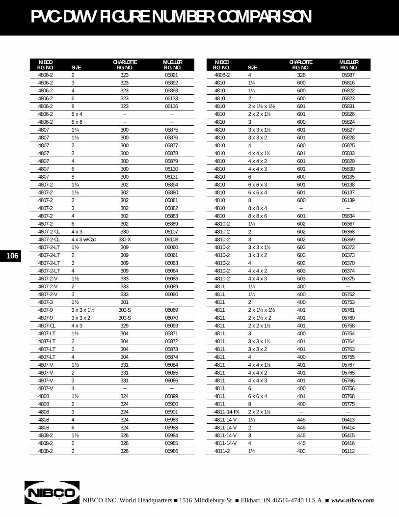
NIBCO INC. World Headquarters n 1516 Middlebury St. n Elkhart, IN 46516-4740 U.S.A. n www.nibco.com
106
PVC-DWV FIGURE NUMBER COMPARISON
NIBCO CHARLOTTE MUELLERFIG. NO. SIZE FIG. NO. FIG. NO.
NIBCO CHARLOTTE MUELLERFIG. NO. SIZE FIG. NO. FIG. NO.
4808-2 4 326 059874810 1¹⁄₄ 600 058164810 1¹⁄₂ 600 058224810 2 600 058234810 2 x 1¹⁄₂ x 1¹⁄₂ 601 058314810 2 x 2 x 1¹⁄₂ 601 058264810 3 600 058244810 3 x 3 x 1¹⁄₂ 601 058274810 3 x 3 x 2 601 058284810 4 600 058254810 4 x 4 x 1¹⁄₂ 601 058334810 4 x 4 x 2 601 058294810 4 x 4 x 3 601 058304810 6 600 061354810 6 x 6 x 3 601 061384810 6 x 6 x 4 601 061374810 8 600 061394810 8 x 8 x 4 _ _
4810 8 x 8 x 6 601 058344810-2 1¹⁄₂ 602 063674810-2 2 602 063684810-2 3 602 063694810-2 3 x 3 x 1¹⁄₂ 603 063724810-2 3 x 3 x 2 603 063734810-2 4 602 063704810-2 4 x 4 x 2 603 063744810-2 4 x 4 x 3 603 063754811 1¹⁄₄ 400 _
4811 1¹⁄₂ 400 057524811 2 400 057534811 2 x 1¹⁄₂ x 1¹⁄₂ 401 057614811 2 x 1¹⁄₂ x 2 401 057604811 2 x 2 x 1¹⁄₂ 401 057584811 3 400 057544811 3 x 3 x 1¹⁄₂ 401 057644811 3 x 3 x 2 401 057634811 4 400 057554811 4 x 4 x 1¹⁄₂ 401 057674811 4 x 4 x 2 401 057654811 4 x 4 x 3 401 057664811 6 400 057564811 6 x 6 x 4 401 057684811 8 400 057754811-14-FX 2 x 2 x 1¹⁄₂ _ _
4811-14-V 1¹⁄₂ 445 064134811-14-V 2 445 064144811-14-V 3 445 064154811-14-V 4 445 064164811-2 1¹⁄₂ 403 06112
4806-2 2 323 058914806-2 3 323 058924806-2 4 323 058934806-2 6 323 061334806-2 8 323 061364806-2 8 x 4 _ _
4806-2 8 x 6 _ _
4807 1¹⁄₄ 300 058754807 1¹⁄₂ 300 058764807 2 300 058774807 3 300 058784807 4 300 058794807 6 300 061304807 8 300 061314807-2 1¹⁄₄ 302 058944807-2 1¹⁄₂ 302 058804807-2 2 302 058814807-2 3 302 058824807-2 4 302 058834807-2 6 302 058894807-2-CL 4 x 3 330 061074807-2-CL 4 x 3 w/Cap 330-X 061084807-2-LT 1¹⁄₂ 309 060604807-2-LT 2 309 060614807-2-LT 3 309 060634807-2-LT 4 309 060644807-2-V 1¹⁄₂ 333 060884807-2-V 2 333 060894807-2-V 3 333 060904807-3 1¹⁄₂ 301 _
4807-9 3 x 3 x 1¹⁄₂ 300-S 060694807-9 3 x 3 x 2 300-S 060704807-CL 4 x 3 329 060934807-LT 1¹⁄₂ 304 058714087-LT 2 304 058724807-LT 3 304 058734807-LT 4 304 058744807-V 1¹⁄₂ 331 060844807-V 2 331 060854807-V 3 331 060864807-V 4 _ _
4808 1¹⁄₂ 324 058994808 2 324 059004808 3 324 059014808 4 324 059834808 6 324 059884808-2 1¹⁄₂ 326 059844808-2 2 326 059854808-2 3 326 05986
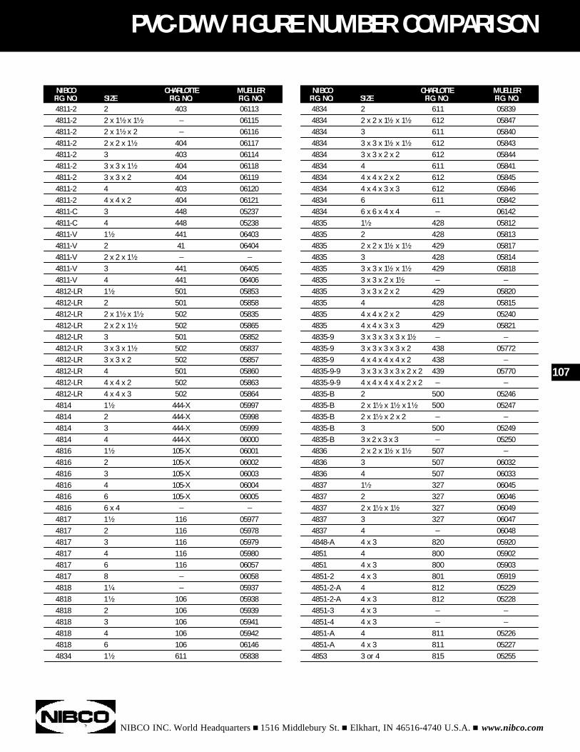
NIBCO INC. World Headquarters n 1516 Middlebury St. n Elkhart, IN 46516-4740 U.S.A. n www.nibco.com
PVC-DWV FIGURE NUMBER COMPARISON
NIBCO CHARLOTTE MUELLERFIG. NO. SIZE FIG. NO. FIG. NO.
NIBCO CHARLOTTE MUELLERFIG. NO. SIZE FIG. NO. FIG. NO.
4834 2 611 058394834 2 x 2 x 1¹⁄₂ x 1¹⁄₂ 612 058474834 3 611 058404834 3 x 3 x 1¹⁄₂ x 1¹⁄₂ 612 058434834 3 x 3 x 2 x 2 612 058444834 4 611 058414834 4 x 4 x 2 x 2 612 058454834 4 x 4 x 3 x 3 612 058464834 6 611 058424834 6 x 6 x 4 x 4 _ 061424835 1¹⁄₂ 428 058124835 2 428 058134835 2 x 2 x 1¹⁄₂ x 1¹⁄₂ 429 058174835 3 428 058144835 3 x 3 x 1¹⁄₂ x 1¹⁄₂ 429 058184835 3 x 3 x 2 x 1¹⁄₂ _ _
4835 3 x 3 x 2 x 2 429 058204835 4 428 058154835 4 x 4 x 2 x 2 429 052404835 4 x 4 x 3 x 3 429 058214835-9 3 x 3 x 3 x 3 x 1¹⁄₂ _ _
4835-9 3 x 3 x 3 x 3 x 2 438 057724835-9 4 x 4 x 4 x 4 x 2 438 _
4835-9-9 3 x 3 x 3 x 3 x 2 x 2 439 057704835-9-9 4 x 4 x 4 x 4 x 2 x 2 _ _
4835-B 2 500 052464835-B 2 x 1¹⁄₂ x 1¹⁄₂ x 1¹⁄₂ 500 052474835-B 2 x 1¹⁄₂ x 2 x 2 _ _
4835-B 3 500 052494835-B 3 x 2 x 3 x 3 _ 052504836 2 x 2 x 1¹⁄₂ x 1¹⁄₂ 507 _
4836 3 507 060324836 4 507 060334837 1¹⁄₂ 327 060454837 2 327 060464837 2 x 1¹⁄₂ x 1¹⁄₂ 327 060494837 3 327 060474837 4 _ 060484848-A 4 x 3 820 059204851 4 800 059024851 4 x 3 800 059034851-2 4 x 3 801 059194851-2-A 4 812 052294851-2-A 4 x 3 812 052284851-3 4 x 3 _ _
4851-4 4 x 3 _ _
4851-A 4 811 052264851-A 4 x 3 811 052274853 3 or 4 815 05255
107
4811-2 2 403 061134811-2 2 x 1¹⁄₂ x 1¹⁄₂ _ 061154811-2 2 x 1¹⁄₂ x 2 _ 061164811-2 2 x 2 x 1¹⁄₂ 404 061174811-2 3 403 061144811-2 3 x 3 x 1¹⁄₂ 404 061184811-2 3 x 3 x 2 404 061194811-2 4 403 061204811-2 4 x 4 x 2 404 061214811-C 3 448 052374811-C 4 448 052384811-V 1¹⁄₂ 441 064034811-V 2 41 064044811-V 2 x 2 x 1¹⁄₂ _ _
4811-V 3 441 064054811-V 4 441 064064812-LR 1¹⁄₂ 501 058534812-LR 2 501 058584812-LR 2 x 1¹⁄₂ x 1¹⁄₂ 502 058354812-LR 2 x 2 x 1¹⁄₂ 502 058654812-LR 3 501 058524812-LR 3 x 3 x 1¹⁄₂ 502 058374812-LR 3 x 3 x 2 502 058574812-LR 4 501 058604812-LR 4 x 4 x 2 502 058634812-LR 4 x 4 x 3 502 058644814 1¹⁄₂ 444-X 059974814 2 444-X 059984814 3 444-X 059994814 4 444-X 060004816 1¹⁄₂ 105-X 060014816 2 105-X 060024816 3 105-X 060034816 4 105-X 060044816 6 105-X 060054816 6 x 4 _ _
4817 1¹⁄₂ 116 059774817 2 116 059784817 3 116 059794817 4 116 059804817 6 116 060574817 8 _ 060584818 1¹⁄₄ _ 059374818 1¹⁄₂ 106 059384818 2 106 059394818 3 106 059414818 4 106 059424818 6 106 061464834 1¹⁄₂ 611 05838
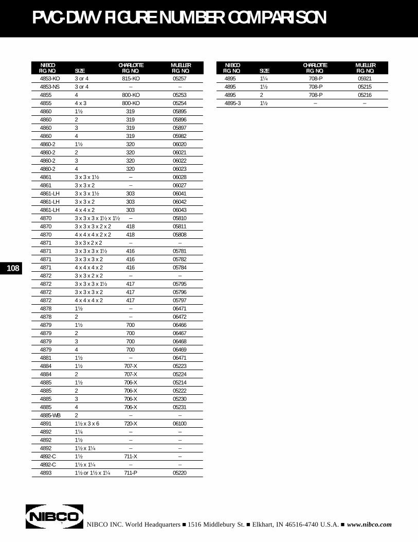
NIBCO INC. World Headquarters n 1516 Middlebury St. n Elkhart, IN 46516-4740 U.S.A. n www.nibco.com
108
PVC-DWV FIGURE NUMBER COMPARISON
NIBCO CHARLOTTE MUELLERFIG. NO. SIZE FIG. NO. FIG. NO.
NIBCO CHARLOTTE MUELLERFIG. NO. SIZE FIG. NO. FIG. NO.
4895 1¹⁄₄ 708-P 059214895 1¹⁄₂ 708-P 052154895 2 708-P 052164895-3 1¹⁄₂ _ _
4853-KO 3 or 4 815-KO 052574853-NS 3 or 4 _ _
4855 4 800-KO 052534855 4 x 3 800-KO 052544860 1¹⁄₂ 319 058954860 2 319 058964860 3 319 058974860 4 319 059824860-2 1¹⁄₂ 320 060204860-2 2 320 060214860-2 3 320 060224860-2 4 320 060234861 3 x 3 x 1¹⁄₂ _ 060284861 3 x 3 x 2 _ 060274861-LH 3 x 3 x 1¹⁄₂ 303 060414861-LH 3 x 3 x 2 303 060424861-LH 4 x 4 x 2 303 060434870 3 x 3 x 3 x 1¹⁄₂ x 1¹⁄₂ _ 058104870 3 x 3 x 3 x 2 x 2 418 058114870 4 x 4 x 4 x 2 x 2 418 058084871 3 x 3 x 2 x 2 _ _
4871 3 x 3 x 3 x 1¹⁄₂ 416 057814871 3 x 3 x 3 x 2 416 057824871 4 x 4 x 4 x 2 416 057844872 3 x 3 x 2 x 2 _ _
4872 3 x 3 x 3 x 1¹⁄₂ 417 057954872 3 x 3 x 3 x 2 417 057964872 4 x 4 x 4 x 2 417 057974878 1¹⁄₂ _ 064714878 2 _ 064724879 1¹⁄₂ 700 064664879 2 700 064674879 3 700 064684879 4 700 064694881 1¹⁄₂ _ 064714884 1¹⁄₂ 707-X 052234884 2 707-X 052244885 1¹⁄₂ 706-X 052144885 2 706-X 052224885 3 706-X 052304885 4 706-X 052314885-WB 2 _ _
4891 1¹⁄₂ x 3 x 6 720-X 061004892 1¹⁄₄ _ _
4892 1¹⁄₂ _ _
4892 1¹⁄₂ x 1¹⁄₄ _ _
4892-C 1¹⁄₂ 711-X _
4892-C 1¹⁄₂ x 1¹⁄₄ _ _
4893 1¹⁄₂ or 1¹⁄₂ x 1¹⁄₄ 711-P 05220
NIBCO INC. World Headquarters n 1516 Middlebury St. n Elkhart, IN 46516-4740 U.S.A. n www.nibco.com
WARRANTY INFORMATION
Applicable to NIBCO INC. Plumbing Plastic Fittings and Valves
NIBCO INC. warrants each NIBCO plumbing plastic fitting(including plumbing valves) to be free from defects in materialsand workmanship under normal use and service for a period offive (5) years from the date of purchase.
In the event any defect occurs which the owner believes is cov-ered by this Warranty, the owner should immediately contactNIBCO INC., Technical Services, either in writing or by tele-phone call, (888) 446-4226 or (219) 523-3480. The owner willbe instructed to return said fitting or valve, at the owner’sexpense, to NIBCO INC. or an authorized NIBCO INC. represen-tative for inspection. In the event said inspection discloses toNIBCO INC.’s satisfaction that said fitting or valve is defective, areplacement shall be mailed free of charge to the owner, andNIBCO INC. shall further pay the installing contractor the sum often ($10.00) dollars to apply on the cost of installation of saidreplacement fitting or valve.
TO THE EXTENT PERMITTED BY LAW, THIS WARRANTY SPECIF-ICALLY EXCLUDES INCIDENTAL AND CONSEQUENTIAL DAM-AGES OF EVERY TYPE AND DESCRIPTION RESULTING FROMANY CLAIMED DEFECT IN MATERIAL OR WORKMANSHIP,INCLUDING BUT NOT LIMITED TO, PERSONAL INJURIES ANDPROPERTY DAMAGES. Some states do not allow the exclusionor limitations of incidental or consequential damages, so theselimitations may not apply to you. TO THE EXTENT PERMITTEDBY LAW, IMPLIED WARRANTIES OF MERCHANTABILITY ANDFITNESS FOR A PARTICULAR PURPOSE ARE LIMITED IN DURA-TION.
This Warranty gives you specific legal rights, and you may alsohave other rights which vary from state to state.
NIBCO Limited Warranty
109
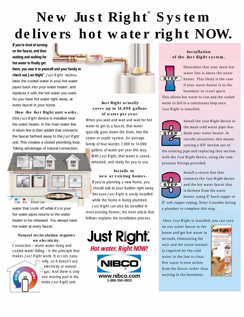
If you’re tired of turning
on the faucet, and then
waiting and waiting for
hot water to finally get
there, you owe it to yourself and your family to
check out Just Right®. Just Right recircu-
lates the cooled water in your hot water
pipes back into your water heater, and
replaces it with the hot water you want.
So you have hot water right away, at
every faucet in your home.
How the Just Right unit works.One Just Right device is installed near
the water heater, in the main water line.
A return line is then added that connects
the faucet farthest away to the Just Right
unit. This creates a closed plumbing loop.
Taking advantage of natural convection,
water that cools off while it’s in your
hot water pipes returns to the water
heater to be reheated. You always have
hot water at every faucet.
Natural recirculation requires no electricity.
Convection _ warm water rising andcooled water falling _ is the principle thatmakes Just Right work. It occurs natu-
rally, so it doesn’t useelectricity or naturalgas. And there is only
one moving part in theentire Just Right unit.
Just Right actually saves up to 14,000 gallons
of water per year.When you wait and wait and wait for hot
water to get to a faucet, that water
typically goes down the drain, into the
sewer or septic system. An average
family of four wastes 7,000 to 14,000
gallons of water per year this way.
With Just Right, that water is saved,
reheated, and ready for you to use.
Installs innew or existing homes.
If you're planning a new home, you
should talk to your builder right away
because Just Right is easily installed
while the home is being plumbed.
Just Right can also be installed in
most existing homes; the inset article that
follows explains the installation process.
Determine that your main hot
water line is above the water
heater. This likely is the case
if your water heater is in the
basement or crawl space.
This allows hot water to rise and the cooled
water to fall in a continuous loop once
Just Right is installed.
Install the Just Right device in
the main cold water pipe that
feeds your water heater. In
retrofit situations, this means
cutting a 9 14" section out of
the existing pipe and replacing that section
with the Just Right device, using the com-
pression fittings provided.
Install a return line that
connects the Just Right device
and the hot water faucet that
is farthest from the water
heater, using 12" hard copper or38" soft copper tubing. Note: Consider hiring
a plumber to complete this step.
Once Just Right is installed, you can turn
on any water faucet in the
house and get hot water in
seconds, eliminating the
wait and the waste normal-
ly required for the cold
water in the line to clear.
Hot water is now inches
from the faucet rather than
waiting in the basement.
New Just Right® System delivers hot water right NOW.
Hot water. Right NOW!
www.nibco.com1-888-350-0833
Installation of the Just Right system.
Cold Hot Return Line
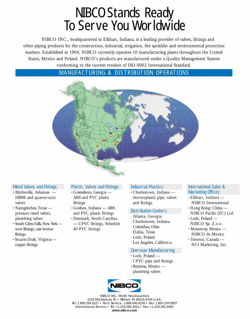
NIBCO INC., headquartered in Elkhart, Indiana, is a leading provider of valves, fittings and other piping products for the construction, industrial, irrigation, fire sprinkler and environmental protectionmarkets. Established in 1904, NIBCO currently operates 10 manufacturing plants throughout the United
States, Mexico and Poland. NIBCO's products are manufactured under a Quality Management System conforming to the current revision of ISO-9002 International Standard.
NIBCO Stands Ready To Serve You Worldwide
Metal Valves and Fittings:•Blytheville, Arkansas —
IBBM and quarter-turnvalves
•Nacogdoches, Texas — pressure rated valves,plumbing valves
•South Glens Falls, New York — wrot fittings, cast bronzefittings
•Stuarts Draft, Virginia —copper fittings
Plastic, Valves and Fittings:•Greensboro, Georgia — ABS and PVC plastic fittings
•Goshen, Indiana — ABSand PVC plastic fittings
•Denmark, South Carolina— CPVC fittings, Schedule40 PVC fittings
Distribution Centers:•Atlanta, Georgia•Charlestown, Indiana•Columbus, Ohio•Dallas, Texas•Lodz, Poland•Los Angeles, California
Overseas Manufacturing:•Lodz, Poland — CPVC pipe and fittings
•Reynosa, Mexico — plumbing valves
Industrial Plastics:•Charlestown, Indiana — thermoplastic pipe, valves and fittings
International Sales &Marketing Offices:•Elkhart, Indiana —
NIBCO International•Hong Kong/China —NIBCO Pacific (FC) Ltd.
•Lodz, Poland —NIBCO Sp. Z.o.o.
•Monterrey, Mexico —NIBCO de Mexico
•Toronto, Canada —NCI Marketing, Inc.
NIBCO INC. World Headquarters1516 Middlebury St. • Elkhart, IN 46516-4740 U.S.A.
Tel: 1.800.234.0227 • Tech Service: 1.888.446.4226 • Fax: 1.800.234.0557International Service • Tel: +1.219.295.3221 • Fax: +1.219.295.3455
www.nibco.com
M A N U FA C T U R I N G & D I S T R I B U T I O N O P E R AT I O N S
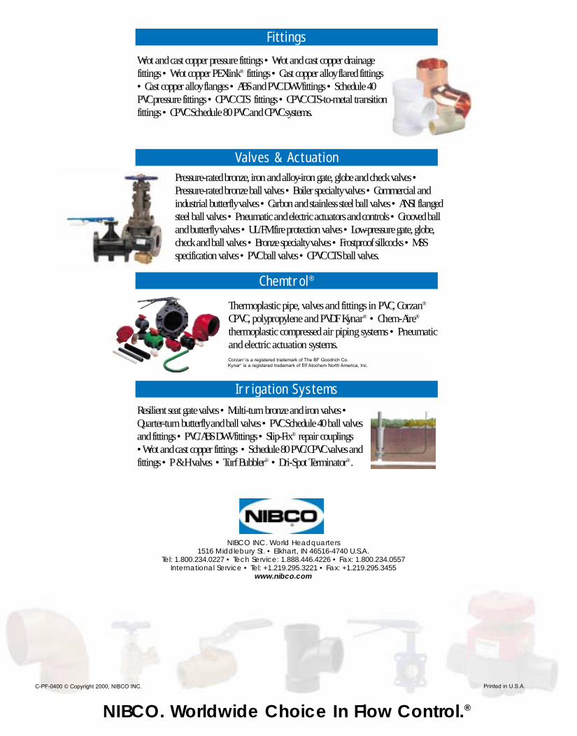
NIBCO INC. World Headquarters1516 Middlebury St. • Elkhart, IN 46516-4740 U.S.A.
Tel: 1.800.234.0227 • Tech Service: 1.888.446.4226 • Fax: 1.800.234.0557International Service • Tel: +1.219.295.3221 • Fax: +1.219.295.3455
www.nibco.com
Resilient seat gate valves • Multi-turn bronze and iron valves •Quarter-turn butterfly and ball valves • PVC Schedule 40 ball valvesand fittings • PVC/ABS DWV fittings • Slip-Fix® repair couplings•Wrot and cast copper fittings • Schedule 80 PVC/CPVC valves andfittings • P & H valves • Turf Bubbler® • Dri-Spot Terminator®.
NIBCO. Worldwide Choice In Flow Control.®
C-PF-0400 © Copyright 2000, NIBCO INC. Printed in U.S.A.
Pressure-rated bronze, iron and alloy-iron gate, globe and check valves •Pressure-rated bronze ball valves • Boiler specialty valves • Commercial andindustrial butterfly valves • Carbon and stainless steel ball valves • ANSI flangedsteel ball valves • Pneumatic and electric actuators and controls • Grooved balland butterfly valves • UL/FM fire protection valves • Low-pressure gate, globe,check and ball valves • Bronze specialty valves • Frostproof sillcocks • MSSspecification valves • PVC ball valves • CPVC CTS ball valves.
Thermoplastic pipe, valves and fittings in PVC, Corzan®
CPVC, polypropylene and PVDF Kynar® • Chem-Aire®
thermoplastic compressed air piping systems • Pneumaticand electric actuation systems.
Wrot and cast copper pressure fittings • Wrot and cast copper drainage fittings • Wrot copper PEXlink® fittings • Cast copper alloy flared fittings• Cast copper alloy flanges • ABS and PVC DWV fittings • Schedule 40PVC pressure fittings • CPVC CTS fittings • CPVC CTS-to-metal transition fittings • CPVC Schedule 80 PVC and CPVC systems.
Corzan¤ is a registered trademark of The BF Goodrich Co. Kynar¤ is a registered trademark of Elf Atochem North America, Inc.
Fittings
Valves & Actuation
Chemtrol®
Irrigation Systems


