Embed Size (px)
Citation preview

1
Carbon supported PdM (M = Fe, Co) electrocatalysts for formic
acid oxidation. Influence of the Fe and Co precursors
L. Juárez-Marmolejoa, S. Pérez-Rodríguezb, M. G. Montes de Oca-Yemhaa*, M. Palomar-Pardavéa, M. Romero-Romoa, A. Ezeta-Mejíac, P. Morales-Gild
M. V. Martínez-Huertae, M. J. Lázaro-Elorrib*
a Universidad Autónoma Metropolitana-Azcapotzalco, Departamento de Materiales, C.P.02200, CDMX, México. b Instituto de Carboquímica, CSIC, Miguel Luesma Castán 4, 50018 Zaragoza, España. c Instituto Politécnico Nacional, ESIQIE. Departamento de Ingeniería Metalúrgica, UPALM Ed. 7, C.P. 07738, CDMX, México. d Instituto Mexicano del Petróleo, Laboratorio de Caracterización de Materiales Sintéticos y Naturales, Eje Central Lázaro Cárdenas 152, CDMX, CP 07730, México. e Instituto de Catálisis y Petroleoquímica, CSIC, C/Marie Curie 2, 28049 Madrid, España.
* Corresponding authors emails:
[email protected] (MGMY) and [email protected] (MJLE)
Abstract
Pd and PdM (M = Fe and Co) nanostructured electrocatalysts were synthesized by
the impregnation method and supported on carbon black Vulcan XC-72R for the
formic acid oxidation reaction, FAOR, in acid medium. Nitrates or chlorides were
used as Fe and Co precursors to study the counter ion role on the physicochemical
features and electrochemical performance of the electrocatalysts. TEM analysis
showed that PdM was deposited on the carbon material with a particle size around
2-3 nm. From XRD, peaks associated with the fcc palladium planes were observed
along with evidence of PdM alloy formation, particularly when the nitrate salts were
used as metal precursors. Furthermore, XPS analyses indicated that nitrates
promote the metal oxide formation to a greater extent than chlorides, mainly for Pd.
PdCo electrocatalyst obtained from nitrates exhibited the highest performance for
FAOR with a steady state current density of 451 and 313 µA cm-2 at 200 and 400
mV respectively, which is in both cases, 3 times larger than that developed for a
commercial Pd/C catalyst.

2
Key words: Palladium; palladium-iron; palladium-cobalt; formic acid oxidation; CO
oxidation
1. Introduction
Direct formic acid fuel cells (DFAFCs) have attracted considerable interest as a
promising alternative for clean energy generation due to their overall efficiency and
low pollutant emissions [1] The use of formic acid as fuel presents potential
advantages such as its non-toxicity, stability at ambient temperature and low
permeation through the Nafion® membrane (crossover effect) [2-5]. In addition,
formic acid can be used in high concentrations, up to 20 M as compared with
methanol [4, 6, 7].
Further, it has been stated that the formic acid oxidation reaction (FAOR) mechanism
possibly evolves through either a direct or an indirect route. The former involves its
direct oxidation into carbon dioxide, whereas dehydration of formic acid to adsorbed
carbon monoxide and its subsequent oxidation into carbon dioxide constitutes the
latter [8-11].
The rate of FAOR can increase when using an electrocatalyst that usually consists
of metal nanoparticles dispersed on convenient carbon materials with different
structures, morphologies and sizes [12]. These carbonaceous supports increase the
active surface area and hence, enhance the electrochemical activity. In addition,
carbon supported materials display adequate physicochemical and chemical
properties, such a large specific surface area, high conductivity and stability, which
play a fundamental role on the overall electrocatalysts efficiency [13].
Electrocatalysts based on Pt and its alloys have been widely studied for FAOR.
Although generally speaking Pt-based electrodes exhibit a good performance toward
FAOR, different disadvantages must be addressed, such as its high cost and the
surface poisoning arising from significant CO adsorption as reaction intermediary,
which blocks the direct formic acid oxidation [14]. In order to improve the FAOR
efficiency, notable efforts have been made into designing more active
electrocatalysts. Pd has attracted special attention due to its higher activity for FAOR
3
as compared with pure Pt [14-18]. It is well known that Pd-based catalysts favor
oxidation reactions of various organic molecules such as: methanol, ethanol and
formic acid. This is because the use of Pd-based as a catalyst has some advantages
as tolerance to CO as well as, good catalytic activity [19, 20].
However, the stability of monometallic Pd is not satisfactory and its performance
needs to be improved in terms of CO tolerance. In order to address these issues,
the use of bimetallic nanocatalytic systems adding a second transition metal, such
as Fe, Co, Ir, Au, Cu, Sn, Ni, Ag to the Pd structure have been proposed [21-33].
Several electrocatalysts synthesis methods have been reported in the literature,
which usually involve the reduction of a metal salt with a chemical agent (e.g. H2,
sodium borohydride, ethylene glycol, hydrazine) [34-36]. Different metal precursor
salts have been used such as chlorides, nitrates and sulfates. However, up to now
the role of the counter ion of the metal precursor salt on the catalytic performance
has not been thoroughly studied. The use of different counter ions could result in
electrocatalysts with different physicochemical properties and thus, the activity for
FAOR could be modified.
This work deals with the effect of Fe and Co precursor (P) salts namely: chlorides
(Cl) or nitrates (N) on the electrochemical performance toward FAOR of PdM-P/C
(M = Fe or Co) electrocatalysts. Carbon-supported electrocatalysts were
synthesized by the impregnation method using sodium borohydride as reducing
agent. Iron/Cobalt chloride/nitrates were used as metal precursors. Pd/C catalyst
was also synthesized as comparison. The resulting catalysts were characterized by
different analytical techniques such as X-ray diffraction (XRD), transmission electron
microscopy (TEM) and energy dispersive X-ray spectroscopy (EDX) analysis. The
electrochemical performance was studied by cyclic voltammetry and
chronoamperometry in 0.5 M H2SO4. Under laboratory temperature conditions,
namely 25 °C.
2. Experimental Setup

4
2.1 Electrocatalysts synthesis
The carbon-supported Pd electrocatalyst was synthesized using sodium
borohydride, NaBH4 (Sigma-Aldrich, 99.9%) as reducing agent and the commercial
carbon black Vulcan XC-72R (Cabot) as support. Briefly, the carbon Vulcan was
dispersed in deionized water followed by ultrasonication for 1 hour. Subsequently, a
5 mM Na2PdCl4 (Sigma Aldrich, 98%) solution was added to that containing the
support and the pH was set to 5 with 0.5 M NaOH (Sigma-Aldrich, 99.99%); then, a
26 mM NaBH4 solution was added slowly. The resulting electrocatalyst (named as
Pd/C) was filtered followed by repeated washing and drying at 70 °C overnight.
For PdFe and PdCo catalysts, the Pd precursor was 5 mM of H2PdCl4 synthesized
as follows: PdCl2 (Sigma-Aldrich, 99%) was diluted and brought to boiling with
hydrochloric acid, 0.25 M HCl (Sigma-Aldrich, 36.5%) under reflux. Then 5 mM Fe
or Co precursor chlorides or nitrates-base salts were dissolved in water. Nitrate
(Fe(NO3)39H2O, Sigma-Aldrich, 98%; Co(NO3)26H2O, Sigma-Aldrich, 98%) or
chloride (FeCl3, Sigma-Aldrich, 97%; CoCl26H2O, Sigma-Aldrich, 98%) salts were
used as metal precursors to obtain the corresponding PdM-P/C (M = Fe or Co)
electrocatalysts. Finally, the mixture of both metallic precursors was added to the
support dispersion following the same synthesis method used for the Pd/C catalyst.
Catalysts obtained from nitrates were denoted as PdM-N/C, while those obtained
from chlorides were labeled as PdM-Cl/C. The metal molar ratio in the PdFe and
PdCo electrocatalysts was 1:1. Appropriate amounts of metal precursors were used
to obtain a theoretical metal loading of 20 wt% onto Vulcan XC-72R.
2.2 Physicochemical characterization
The Pd-based electrocatalysts were characterized by EDX, XRD, XPS and TEM to
study the composition, structure and particle size of the resulting nanoparticles, as
well as their dispersion onto the carbon support.
To establish the powder electrocatalyst composition a Hitachi S-3400N SEM
equipment was used coupled with a Röntec XFlash Si(Li) detector for EDX analysis.
5
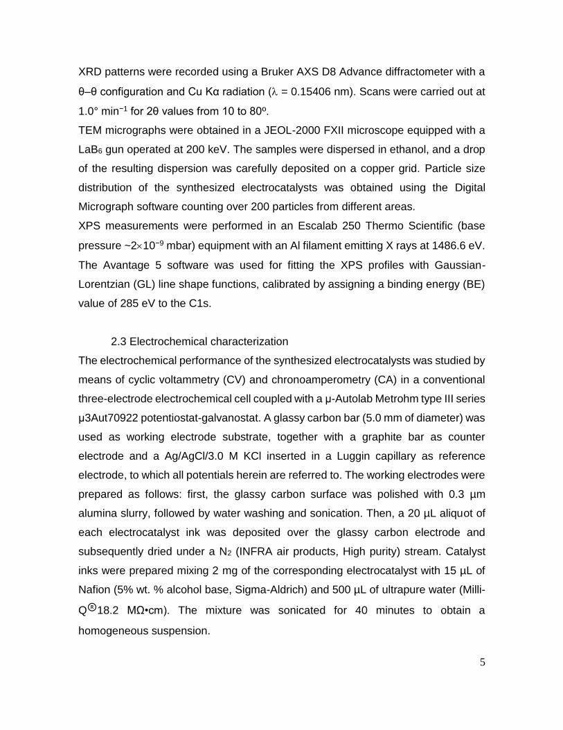
XRD patterns were recorded using a Bruker AXS D8 Advance diffractometer with a
θ–θ configuration and Cu Kα radiation ( = 0.15406 nm). Scans were carried out at
1.0° min−1 for 2θ values from 10 to 80º.
TEM micrographs were obtained in a JEOL-2000 FXII microscope equipped with a
LaB6 gun operated at 200 keV. The samples were dispersed in ethanol, and a drop
of the resulting dispersion was carefully deposited on a copper grid. Particle size
distribution of the synthesized electrocatalysts was obtained using the Digital
Micrograph software counting over 200 particles from different areas.
XPS measurements were performed in an Escalab 250 Thermo Scientific (base
pressure ~210−9 mbar) equipment with an Al filament emitting X rays at 1486.6 eV.
The Avantage 5 software was used for fitting the XPS profiles with Gaussian-
Lorentzian (GL) line shape functions, calibrated by assigning a binding energy (BE)
value of 285 eV to the C1s.
2.3 Electrochemical characterization
The electrochemical performance of the synthesized electrocatalysts was studied by
means of cyclic voltammetry (CV) and chronoamperometry (CA) in a conventional
three-electrode electrochemical cell coupled with a μ-Autolab Metrohm type III series
μ3Aut70922 potentiostat-galvanostat. A glassy carbon bar (5.0 mm of diameter) was
used as working electrode substrate, together with a graphite bar as counter
electrode and a Ag/AgCl/3.0 M KCl inserted in a Luggin capillary as reference
electrode, to which all potentials herein are referred to. The working electrodes were
prepared as follows: first, the glassy carbon surface was polished with 0.3 µm
alumina slurry, followed by water washing and sonication. Then, a 20 µL aliquot of
each electrocatalyst ink was deposited over the glassy carbon electrode and
subsequently dried under a N2 (INFRA air products, High purity) stream. Catalyst
inks were prepared mixing 2 mg of the corresponding electrocatalyst with 15 µL of
Nafion (5% wt. % alcohol base, Sigma-Aldrich) and 500 µL of ultrapure water (Milli-
Q®18.2 MΩ•cm). The mixture was sonicated for 40 minutes to obtain a
homogeneous suspension.

6
Electrochemical experiments were carried out at room temperature and atmospheric
pressure. The working electrode was immersed in the supporting electrolyte 0.5 M
H2SO4 (Sigma Aldrich, 99.999 %) deaerated with N2. The electrocatalysts were
cycled from −200 to 1000 mV at 500 mV s−1 for 20 complete cycles to clean the
surface. Then, 3 cyclic voltammograms (CVs) were recorded at 20 mV s−1 in the
same potential range to activate the surface. The last voltammogram was termed as
blank.
CO-stripping voltammograms were monitored to study the performance of the
catalysts toward CO electrooxidation. For such a purpose, CO (INFRA air products,
High purity) was adsorbed on the electrocatalyst by bubbling it through the working
electrolyte during 15 min at −170 mV. Then, the solution was saturated with N2 for
20 min to remove the CO excess and a cyclic voltammetry was carried out from −200
to 1000 mV at 20 mV s−1 for 3 cycles. Electrochemically active surface areas, EASA,
were obtained by the ratio between the experimental charge (obtained by CO
stripping peak integration) and the charge density corresponding to a CO adsorbed
monolayer oxidation on Pd polycrystalline surface (315 µC cm−2) [23]. The faradaic
currents were normalized by the respective EASA to obtain the current densities (µA
cm−2) given in the text.
The FAOR voltammograms were assessed in 0.5 M H2SO4 + 2.0 M HCOOH (Sigma
Aldrich, 95%) by cycling the potential between −200 and 1000 mV at 20 mV s−1.
Chronoamperometry evaluation of the current density response at steady state
conditions (jss) was carried out stepping the potential to 200 and 400 mV, both for
900 seconds.
The electrochemical performance of the synthesized catalysts was compared with
that obtained using a commercial Pd/C catalyst (Sigma-Aldrich, 30 wt. %). This
electrocatalyst has been labeled as PdSA/C in the text.
3. Results and discussion
3.1 Physicochemical characterization

7
The metal content of the Pd-based catalysts was studied by EDX (Table 1). All the
laboratory-made electrocatalysts presented a metal loading similar to the nominal
value (20 wt.%). Additionally, the EDX atomic ratio was around 50:50 for the
bimetallic catalysts in agreement with the theoretical values.
Figure 1a shows the XRD patterns of PdSA/C and synthesized electrocatalysts. A
characteristic peak at around 2θ = 25º, associated with the graphite (002) diffraction
plane of the support was shown by all synthetized electrocatalysts. Also, their
diffraction patterns exhibit three characteristic peaks at around 2θ = 40.09º, 46.63º
and 68.08º, which are assigned to (111), (200) and (220) planes of Pd fcc.
Comparing the position of Pd-related peaks of the synthesized Pd/C catalyst and
bimetallic catalysts, a shift to higher 2θ values was observed for the bimetallic
catalysts obtained from nitrate salts (see Table 1 and Figure 1b), which may be
explained by the contraction of the Pd lattice structure by the introduction of the
second metal Fe or Co. However, this shift is not as evident for catalysts obtained
from chlorides due to a lower alloying degree. Other authors have obtained poor
alloying after using synthesis methods of electrocatalysts involving low temperatures
[20, 37-40]. Reduction treatments at higher temperatures or the control of other
experimental conditions (such as pH, concentration, reducing agent, stabilizing
agent, synthesis method) resulted in nanoparticles with an improved alloying degree,
as well as cluster-type and core-shell morphologies [18, 41-43]. Finally,
monometallic Pd catalysts (Pd/C and PdSA/C) showed a diffraction peak around 34º
associated to PdO formation. PdM-Cl catalyst displays some relatively low intensity
peaks on the XRD patterns at 2θ = 35.76º and 65.63º that can be associated with
Fe3O4 and Co3O4 respectively.
In order to further characterize the catalysts, the XPS technique was used. Figure 2
presents XPS spectra recorded from PdM catalysts synthesized in this work. From
these images it is possible to note that regardless of the precursor salt, Co (see
Figure 2a) and Fe (see Figure 2b) were fully oxidized at the surface. In the case of
Co the main component was Co3O4 [44, 45] while for Fe it was present as a mixture
of FeO, Fe(OH)2 (Fe(II)) and Fe3O4 (Fe(II) and Fe(III)) species [46]. As can be noted
8
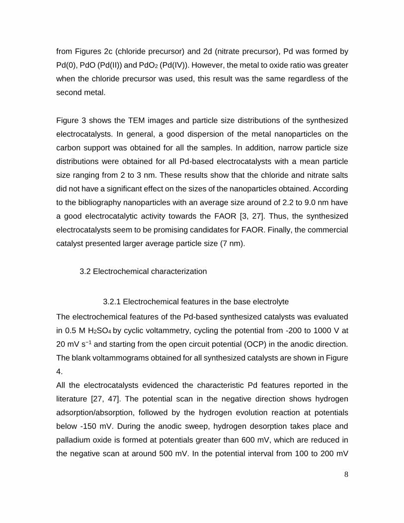
from Figures 2c (chloride precursor) and 2d (nitrate precursor), Pd was formed by
Pd(0), PdO (Pd(II)) and PdO2 (Pd(IV)). However, the metal to oxide ratio was greater
when the chloride precursor was used, this result was the same regardless of the
second metal.
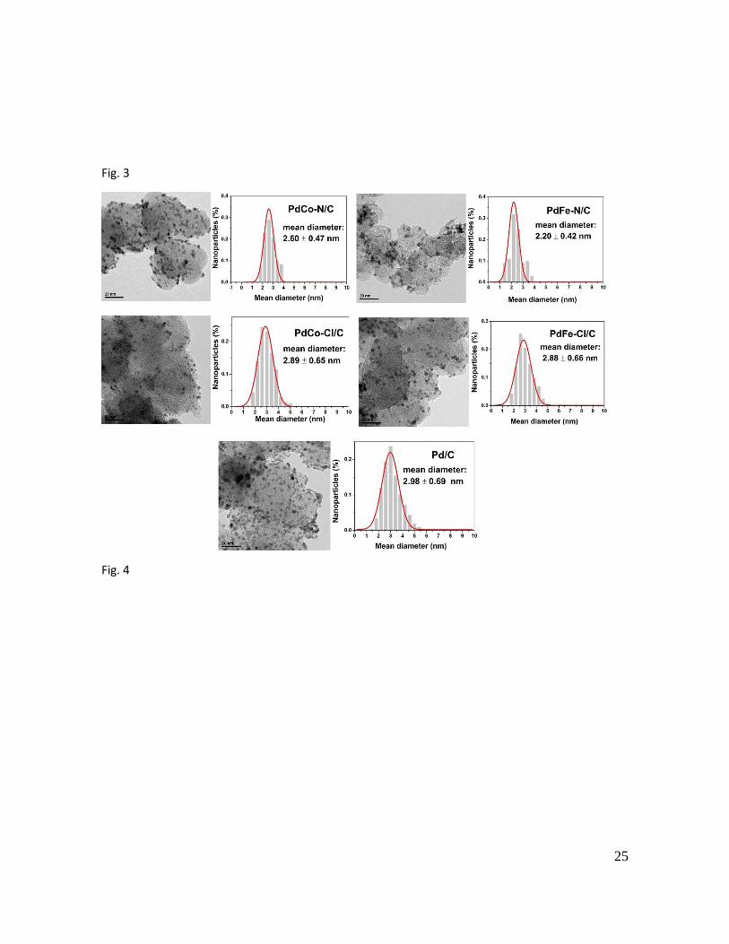
Figure 3 shows the TEM images and particle size distributions of the synthesized
electrocatalysts. In general, a good dispersion of the metal nanoparticles on the
carbon support was obtained for all the samples. In addition, narrow particle size
distributions were obtained for all Pd-based electrocatalysts with a mean particle
size ranging from 2 to 3 nm. These results show that the chloride and nitrate salts
did not have a significant effect on the sizes of the nanoparticles obtained. According
to the bibliography nanoparticles with an average size around of 2.2 to 9.0 nm have
a good electrocatalytic activity towards the FAOR [3, 27]. Thus, the synthesized
electrocatalysts seem to be promising candidates for FAOR. Finally, the commercial
catalyst presented larger average particle size (7 nm).
3.2 Electrochemical characterization
3.2.1 Electrochemical features in the base electrolyte
The electrochemical features of the Pd-based synthesized catalysts was evaluated
in 0.5 M H2SO4 by cyclic voltammetry, cycling the potential from -200 to 1000 V at
20 mV s−1 and starting from the open circuit potential (OCP) in the anodic direction.
The blank voltammograms obtained for all synthesized catalysts are shown in Figure
4.
All the electrocatalysts evidenced the characteristic Pd features reported in the
literature [27, 47]. The potential scan in the negative direction shows hydrogen
adsorption/absorption, followed by the hydrogen evolution reaction at potentials
below -150 mV. During the anodic sweep, hydrogen desorption takes place and
palladium oxide is formed at potentials greater than 600 mV, which are reduced in
the negative scan at around 500 mV. In the potential interval from 100 to 200 mV

9
the current density remains constant and is associated to interfacial electrical control
(double layer). Interestingly, the PdFe electrocatalyst synthesized using nitrates as
a metal precursor (PdFe-N/C) presented another oxidation peak from 300 to 500 mV
which could be associated with the oxidation of exposed Fe. Han and Xu [48]
synthesized PdFe alloy nanoparticles, where the voltammogram, see Figure 4a in
48, also showed an oxidation peak prior to that of Pd oxide formation, that
corresponded to the electrochemical oxidation of exposed Fe atoms from the surface
layer.
3.2.2. CO stripping
CO stripping voltammetry was used to obtain the electroactive surface area (EASA)
of Pd-based electrocatalysts and to evaluate the catalyst surface tolerance for CO
poisoning. Figure 5 shows the results obtained for all the electrocatalysts.
During the anodic sweep of the first scan (solid curves) the hydrogen adsorption/
absorption/desorption region is totally blocked confirming that CO was adsorbed at
the catalyst surfaces. Two peaks attributed to CO electrooxidation are discerned for
all the electrocatalysts, with the exception of the commercial catalyst which
presented a main peak at 723 mV. The location of the peaks depends on the
electrocatalyst: the first contribution (peak I) is centered within the 558 to 673 mV,
while the second one (peak II) occurs at potentials from 707 to 723 mV. Bimodal CO
oxidation profiles have been already reported by other authors on Pd electrocatalysts
supported on carbon materials [47, 49, 50]. The maximum oxidation potentials of
both peaks and the onset potential for the CO oxidation reaction are summarized in
Table 2.
A different catalytic activity toward CO electrooxidation is evident, which is ascribed
to differences in the size and structure of metal nanoparticles [51]. In this context,
the commercial catalyst requires a more positive potential to oxidize CO compared
with the synthesized Pd/C. In fact, the main oxidation occurs at 716 mV in the
catalyst obtained by reduction with NaBH4, while 723 mV are required in the
commercial one. Further, the first oxidation contribution does not appear at PdSA/C
surface. These results clearly indicate that the synthesized catalyst with a particle
10
size around 2 to 3 nm display an improved activity toward CO oxidation than the
commercial catalyst with a larger particle size. Thus, larger particle sizes led to a
less activity for CO removal.
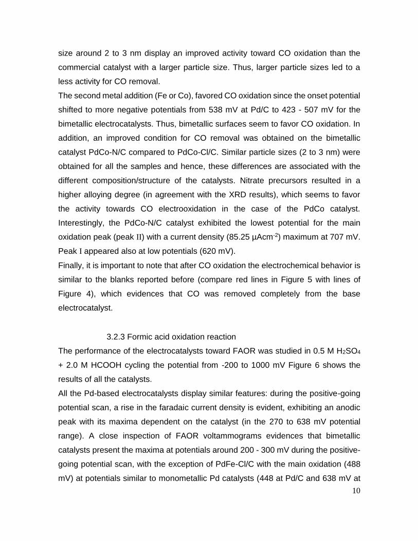
The second metal addition (Fe or Co), favored CO oxidation since the onset potential
shifted to more negative potentials from 538 mV at Pd/C to 423 - 507 mV for the
bimetallic electrocatalysts. Thus, bimetallic surfaces seem to favor CO oxidation. In
addition, an improved condition for CO removal was obtained on the bimetallic
catalyst PdCo-N/C compared to PdCo-Cl/C. Similar particle sizes (2 to 3 nm) were
obtained for all the samples and hence, these differences are associated with the
different composition/structure of the catalysts. Nitrate precursors resulted in a
higher alloying degree (in agreement with the XRD results), which seems to favor
the activity towards CO electrooxidation in the case of the PdCo catalyst.
Interestingly, the PdCo-N/C catalyst exhibited the lowest potential for the main
oxidation peak (peak II) with a current density (85.25 µAcm-2) maximum at 707 mV.
Peak I appeared also at low potentials (620 mV).
Finally, it is important to note that after CO oxidation the electrochemical behavior is
similar to the blanks reported before (compare red lines in Figure 5 with lines of
Figure 4), which evidences that CO was removed completely from the base
electrocatalyst.
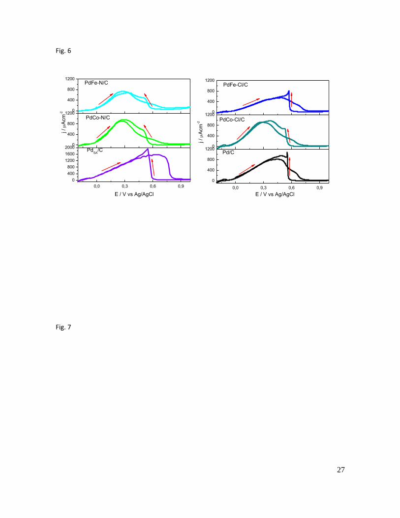
3.2.3 Formic acid oxidation reaction
The performance of the electrocatalysts toward FAOR was studied in 0.5 M H2SO4
+ 2.0 M HCOOH cycling the potential from -200 to 1000 mV Figure 6 shows the
results of all the catalysts.
All the Pd-based electrocatalysts display similar features: during the positive-going
potential scan, a rise in the faradaic current density is evident, exhibiting an anodic
peak with its maxima dependent on the catalyst (in the 270 to 638 mV potential
range). A close inspection of FAOR voltammograms evidences that bimetallic
catalysts present the maxima at potentials around 200 - 300 mV during the positive-
going potential scan, with the exception of PdFe-Cl/C with the main oxidation (488
mV) at potentials similar to monometallic Pd catalysts (448 at Pd/C and 638 mV at

11
the commercial electrode). In the cathodic sweep, once Pd oxide reduction takes
place, formic acid is again re-oxidized displaying even higher current densities than
those developed during the anodic excursion, which is explained by a high tolerance
to catalyst poisoning [50, 52]. Table 3 displays the main oxidation potential (Ep) and
the peak current density (jp) developed during the anodic excursion.
PdSA/C displayed the largest current density but the main peak for formic acid
oxidation during the anodic excursion appeared at more positive potentials. Indeed,
the anodic peak position developed during the forward scan of Pd-based
electrocatalysts follows this sequence: PdSA/C (638 mV) > PdFe-Cl/C (488 mV) >
Pd/C (448 mV) > PdCo-Cl/C (287 mV) > PdFe-N/C (273 mV) > PdCo-N/C (270 mV).
Thus, the second metal addition in general resulted in an improved condition toward
FAOR for all the electrocatalysts, with the exception of PdFe-Cl/C. This catalyst
presented a behavior similar to the synthesized monometallic catalyst (Pd/C). In
other words, bimetallic electrodes showed the highest current density toward FAOR
in the potential range from 200 to 300 mV, while pure Pd catalysts and PdFe-Cl/C
presented a higher efficiency at potentials around 400 – 600 mV.
As is well known, for the electrocatalytic oxidation of HCOOH, there are usually
involved the so-called dual pathways, which are dehydrogenation and dehydration,
as represented by reactions (1) and (2), respectively [53, 54] :
COOH→CO2+2H++2e- (1)
HCOOH→COads+H2O→CO2+2H++2e- (2)
Although the dehydrogenation is the main pathway on Pd catalyst, recent studies
reveal that COads can still accumulate on the surface of Pd, leading to the
degradation of the catalytic performance over time under DFAFC conditions [55].
Therefore, according to the fact that PdCo-N/C catalyst showed high catalytic activity
towards CO electrooxidation, it was expected good performance also during the
formic acid electrooxidation.
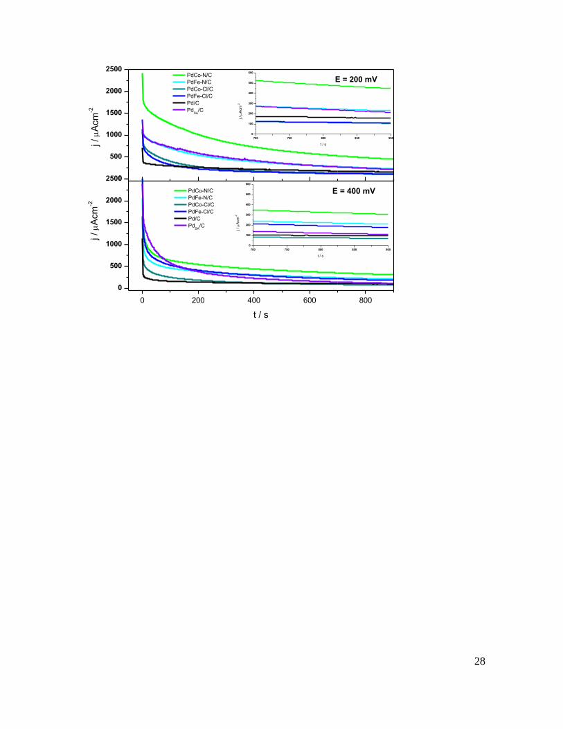
The steady state anodic current density (jss) was evaluated through
chronoamperometry at 200 and 400 mV during 900 seconds. The jss-t plots for all
the electrocatalysts are shown in Figure 7, while Table 4 reports the current densities

12
of the catalysts evaluated at 900 seconds at both potentials. The jss at 200 mV
followed this sequence: PdCo-N/C > PdFe-N/C > PdSA/C > Pd/C > PdFe-Cl/C >
PdCo-Cl/C, while the jss at 400 mV followed this sequence: PdCo-N/C > PdFe-N/C
> PdFe-Cl/C > PdSA/C > Pd/C > PdCo-Cl/C.
Interestingly, the PdCo-N/C exhibited the largest current density at both potentials,
with an anodic current density around two and three times larger than the
monometallic catalysts (Pd/C and PdSA/C).
Regarding the effect of the Fe/Co metal precursor, the bimetallic catalysts obtained
from nitrates (PdCo-N/C and PdFe-N/C) showed higher activity towards FAOR
compared to their analogues (PdCo-Cl/C and PdFe-Cl/C, respectively). Moreover,
PdCo-N/C depicted better catalytic activity than PdFe-N/C probably due to a greater
alloying degree between Pd and Co.
Conclusions
In this work, the effect of the Fe/Co metal precursor salt (nitrates or chlorides) on the
physicochemical properties and catalytic activity for CO oxidation and FAOR of Pd-
M/C (M = Fe or Co) electrocatalysts was studied. Catalysts were obtained by
impregnation and reduction with sodium borohydride using iron/cobalt
chloride/nitrates as metal precursors. Results were compared with a monometallic
Pd/C synthesized catalyst obtained by the same methodology.
XRD patterns evidenced that Pd was deposited on the carbon material with a fcc
structure. In the case of bimetallic catalysts, the use of nitrates and chlorides allowed
obtaining PdM alloys. However Fe/Co precursors from nitrates showed higher
alloying degree with Pd, as compared with the PdM-Cl/C catalysts. XPS results
demonstrated that nitrates favored the metal oxide formation. Furthermore, high
dispersion of metal nanoparticles with an average size of 2-3 nm was observed by
TEM for all the catalysts.

13
CO-stripping voltammograms showed that the addition of the second metal (Fe or
Co) resulted in an improved condition for CO removal.
Regarding the activity of catalysts toward FAOR, PdCo-N/C and PdFe-N/C exhibited
the highest steady state anodic current densities.
Acknowledgements
LJM is grateful to CONACYT for the grant awarded for this research, as well as to
the UAM-A and the ICB for the support provided. MGMY, MRR, MPP and AEM thank
the SNI for the distinction of their membership and the stipend provided. MGMY is
indebted to L'oreál-UNESCO-CONACyT-AMC for the grant Women in Science
2016. MJL and SPR gratefully acknowledge financial support given by Spanish
MINECO (ENE2014-52158-C2-1-R).
References
[1] Rice C, Ha S, Masel R, Waszczuk P, Wieckowski A, Barnard T. Direct formic acid
fuel cells. J Power Sources 2002;111:83-9.
[2] Yu X, Pickup PG. Recent advances in direct formic acid fuel cells (DFAFC). J
Power Sources 2008;182:124-32.
[3] Zhu Y, Kang Y, Zou Z, Zhou Q, Zheng J, Xia B, et al. A facile preparation of
carbon-supported Pd nanoparticles for electrocatalytic oxidation of formic acid.
Electrochem Commun 2008;10:802-5.
[4] Aslam N, Masdar M, Kamarudin S, Daud W. Overview on direct formic acid fuel
cells (DFAFCs) as an energy sources. APCBEE Procedia. 2012;3:33-9.
[5] Ong B, Kamarudin S, Basri S. Direct liquid fuel cells: A review. Int J Hydrogen
Energy 2017;42:10142-57.
[6] Rice C, Ha S, Masel R, Wieckowski A. Catalysts for direct formic acid fuel cells.
J Power Sources 2003;115:229-35.
[7] Rhee Y-W, Ha SY, Masel RI. Crossover of formic acid through Nafion®
membranes. J Power Sources 2003;117:35-8.

14
[8] Cuesta A, Cabello G, Osawa M, Gutiérrez C. Mechanism of the Electrocatalytic
Oxidation of Formic Acid on Metals. ACS Catal 2012;2:728-38.
[9] Jiang K, Zhang H-X, Zou S, Cai W-B. Electrocatalysis of formic acid on palladium
and platinum surfaces: from fundamental mechanisms to fuel cell applications. Phys
Chem Chem Phys 2014;16:20360-76.
[10] Jeon H, Jeong B, Joo J, Lee J. Electrocatalytic oxidation of formic acid: closing
the gap between fundamental study and technical applications. Electrocatalysis
2015;6:20-32.
[11] Cai W, Li J, Jiang Y, Liu C, Ma L, Xing W. Formic acid electro-catalytic oxidation
at high temperature in supporting electrolyte free system: Mechanism study and
catalyst stability. J Electroanal Chem 2016;761:68-73.
[12] Uhm S, Kwon Y, Chung ST, Lee J. Highly effective anode structure in a direct
formic acid fuel cell. Electrochimica Acta 2008;53:5162-8.
[13] Carmo M, Paganin V, Rosolen J, Gonzalez E. Alternative supports for the
preparation of catalysts for low-temperature fuel cells: the use of carbon nanotubes.
J Power Sources 2005;142:169-76.
[14] Zhang X-G, Arikawa T, Murakami Y, Yahikozawa K, Takasu Y. Electrocatalytic
oxidation of formic acid on ultrafine palladium particles supported on a glassy
carbon. Electrochimica Acta 1995;40:1889-97.
[15] Zhou WP, Lewera A, Larsen R, Masel RI, Bagus PS, Wieckowski A. Size effects
in electronic and catalytic properties of unsupported palladium nanoparticles in
electrooxidation of formic acid. J Phys Chem B 2006;110:13393-8.
[16] Ge J, Xing W, Xue X, Liu C, Lu T, Liao J. Controllable synthesis of Pd
nanocatalysts for direct formic acid fuel cell (DFAFC) application: from Pd hollow
nanospheres to Pd nanoparticles. J Phys Chem C 2007;111:17305-10.
[17] Li H, Sun G, Jiang Q, Zhu M, Sun S, Xin Q. Synthesis of highly dispersed Pd/C
electro-catalyst with high activity for formic acid oxidation. Electrochem Commun
2007;9:1410-5.
[18] Montes de Oca MaG, Plana D, Celorrio V, Lazaro MJ, Fermín DJ.
Electrocatalytic properties of strained Pd nanoshells at Au nanostructures: CO and
HCOOH oxidation. J Phys Chem C 2011;116:692-9.
15
[19] Moraes L, Matos B, Radtke C, Santiago E, Fonseca F, Amico S, et al. Synthesis
and performance of palladium-based electrocatalysts in alkaline direct ethanol fuel
cell. Int J Hydrogen Energy 2016;41:6457-68.
[20] Rivera Gavidia LM, Sebastián D, Pastor E, Aricò AS, Baglio V. Carbon-
supported Pd and PdFe alloy catalysts for direct methanol fuel cell cathodes.
Materials 2017;10:580.
[21] Wang X, Xia Y. Electrocatalytic performance of PdCo–C catalyst for formic acid
oxidation. Electrochem Commun 2008;10:1644-6.
[22] Morales-Acosta D, Ledesma-Garcia J, Godinez LA, Rodríguez HG, Álvarez-
Contreras L, Arriaga LG. Development of Pd and Pd–Co catalysts supported on
multi-walled carbon nanotubes for formic acid oxidation. J Power Sources
2010;195:461-5.
[23]Celorrio V, de Oca MM, Plana D, Moliner R, Fermin D, Lazaro M.
Electrochemical performance of Pd and Au–Pd core–shell nanoparticles on surface
tailored carbon black as catalyst support. Int J Hydrogen Energy 2012;37:7152-60.
[24] Celorrio V, Montes de Oca M, Plana D, Moliner R, Lázaro M, Fermín D. Effect
of carbon supports on electrocatalytic reactivity of Au–Pd core–shell nanoparticles.
J Phys Chem C 2012;116:6275-82.
[25] Mazumder V, Chi M, Mankin MN, Liu Y, Metin Ö, Sun D, et al. A Facile Synthesis
of MPd (M = Co, Cu) Nanoparticles and Their Catalysis for Formic Acid Oxidation.
Nano Lett 2012;12:1102-6.
[26] Ji Y, Zhao R, Zhang G, Chen Y, Tang Y, Lu T. Room-temperature synthesis and
electrocatalysis of carbon nanotubes supported palladium–iron alloy nanoparticles.
Electrochimica Acta 2013;111:898-902.
[27] Liao M, Hu Q, Zheng J, Li Y, Zhou H, Zhong C-J, et al. Pd decorated Fe/C
nanocatalyst for formic acid electrooxidation. Electrochimica Acta 2013;111:504-9.
[28] Zhang L, Wan L, Ma Y, Chen Y, Zhou Y, Tang Y, et al. Crystalline palladium–
cobalt alloy nanoassemblies with enhanced activity and stability for the formic acid
oxidation reaction. App Catal B Environ 2013;138-139:229-35.

16
[29] Al-Akraa I, M. Mohammad A, S. El-Deab M, El Anadouli B. Advances in Direct
Formic Acid Fuel Cells: Fabrication of Efficient Ir/Pd Nanocatalysts for Formic Acid
Electro-Oxidation Int J Electrochem Sci 2015;10:3282-90.
[30] Mao H, Huang T, Yu A. Electrochemical surface modification on CuPdAu/C with
extraordinary behavior toward formic acid/formate oxidation Int J Hydrogen Energy
2016;41:13190-96.
[31] Vafaei M, Rezaei M, Tabaian SH, Mahboubi F, Haghshenas DF. Facile
synthesis of a highly active Pd/Co bimetallic nanocatalyst on carbon fiber cloth via a
two-step electrodeposition for formic acid electrooxidation. J Solid State
Electrochem 2015;19:289-98.
[32] Zhou Y, Du C, Han G, Gao Y, Yin G. Ultra-low Pt decorated PdFe alloy
nanoparticles for formic acid electro-oxidation. Electrochimica Acta 2016;217:203-9.
[33] Pires F, Villullas H. Pd-based catalysts: Influence of the second metal on their
stability and oxygen reduction activity. Int J Hydrogen Energy 2012;37:17052-9.
[34] Aricò AS, Stassi A, D'Urso C, Sebastián D, Baglio V. Synthesis of Pd3Co1@
Pt/C Core‐Shell Catalysts for Methanol‐Tolerant Cathodes of Direct Methanol Fuel
Cells. Chem A Eur J 2014;20:10679-84.
[35] Matin MA, Jang J-H, Kwon Y-U. PdM nanoparticles (M= Ni, Co, Fe, Mn) with
high activity and stability in formic acid oxidation synthesized by sonochemical
reactions. J Power Sources 2014;262:356-63.
[36] Ma Y, Li T, Chen H, Chen X, Deng S, Xu L, et al. A general strategy to the
synthesis of carbon-supported PdM (M= Co, Fe and Ni) nanodendrites as high-
performance electrocatalysts for formic acid oxidation. J Energy Chem
2017;26:1238-44.
[37] Calderón J, Nieto-Monge M, Pérez-Rodríguez S, Pardo J, Moliner R, Lázaro M.
Palladium–nickel catalysts supported on different chemically-treated carbon blacks
for methanol oxidation in alkaline media. Int J Hydrogen Energy 2016;41:19556-69.
[38] Calderón J, Celorrio V, Nieto-Monge M, Fermín D, Pardo J, Moliner R, et al.
Palladium–nickel materials as cathode electrocatalysts for alkaline fuel cells. Int J
Hydrogen Energy 2016;41:22538-46.

17
[39] Zhang Z, Xin L, Sun K, Li W. Pd–Ni electrocatalysts for efficient ethanol oxidation
reaction in alkaline electrolyte. Int J Hydrogen Energy 2011;36:12686-97.
[40] Vecchio CL, Sebastián D, Alegre C, Aricò AS, Baglio V. Carbon-supported Pd
and Pd-Co cathode catalysts for direct methanol fuel cells (DMFCs) operating with
high methanol concentration. J Electroanal Chem 2018;808:464-73.
[41]Chen A, Ostrom C. Palladium-based nanomaterials: synthesis and
electrochemical applications. Chem Rev 2015;115:11999-2044.
[42] Sun D, Si L, Fu G, Liu C, Sun D, Chen Y, et al. Nanobranched porous palladium–
tin intermetallics: One-step synthesis and their superior electrocatalysis towards
formic acid oxidation. J Power Sources 2015;280:141-6.
[43] Yan H, Bai Z, Chao S, Cui Q, Niu L, Yang L, et al. Effects of additives on
palladium nanocrystals supported on multiwalled carbon nanotubes and their
electrocatalytic properties toward formic acid oxidation. Ionics 2014;20:259-68.
[44] Petitto SC, Marsh EM, Carson GA, Langell MA. Cobalt oxide surface chemistry:
The interaction of CoO (1 0 0), Co3O4 (1 1 0) and Co3O4 (1 1 1) with oxygen and
water. J Mol Catal A-Chem 2008;281:49-58.
[45] Faisal F, Stumm C, Bertram M, Waidhas F, Lykhach Y, Cherevko S, et al.
Electrifying model catalysts for understanding electrocatalytic reactions in liquid
electrolytes. Nat Mater 2018:1.
[46] Gavidia LMR, García G, Anaya D, Querejeta A, Alcaide F, Pastor E. Carbon-
supported Pt-free catalysts with high specificity and activity toward the oxygen
reduction reaction in acidic medium. App Catal B Environ 2016;184:12-9.
[47] He N, Qin C, Wang R, Ma S, Wang Y, Qi T. Electro-catalysis of carbon black or
titanium sub-oxide supported Pd–Gd towards formic acid electro-oxidation. RSC Adv
2016;6:68989-96.
[48] Han B, Xu C. Nanoporous PdFe alloy as highly active and durable
electrocatalyst for oxygen reduction reaction. Int J Hydrogen Energy
2014;39:18247-55.
[49] Pérez-Rodríguez S, Rillo N, Lázaro M, Pastor E. Pd catalysts supported onto
nanostructured carbon materials for CO2 valorization by electrochemical reduction.
App Catal B Environ 2015;163:83-95.

18
[50] Miyake H, Okada T, Samjeské G, Osawa M. Formic acid electrooxidation on Pd
in acidic solutions studied by surface-enhanced infrared absorption spectroscopy.
Phys Chem Chem Phys 2008;10:3662-9.
[51] Hoshi N, Kida K, Nakamura M, Nakada M, Osada K. Structural effects of
electrochemical oxidation of formic acid on single crystal electrodes of palladium. J
Phys Chem B 2006;110:12480-4.
[52]Tang Y, Edelmann RE, Zou S. Length tunable penta-twinned palladium
nanorods: seedless synthesis and electrooxidation of formic acid. Nanoscale
2014;6:5630-3.
[53] Grozovski V, Climent V, Herrero E, Feliu JM. Intrinsic activity and poisoning rate
for HCOOH oxidation on platinum stepped surfaces. Phys Chem Chem Phys
2010;12:8822-31.
[54] Zhang J, Chen M, Li H, Li Y, Ye J, Cao Z, et al. Stable palladium hydride as a
superior anode electrocatalyst for direct formic acid fuel cells. Nano Energy
2018;44:127-34.
[55] Zhang LY, Zhao ZL, Li CM. Formic acid-reduced ultrasmall Pd nanocrystals on
graphene to provide superior electocatalytic activity and stability toward formic acid
oxidation. Nano Energy 2015;11:71-7.

19
Table 1. Physical characteristics of the Pd-based electrocatalysts: total metal content and
ratio obtained from EDX , 2Ɵ of Pd(111) from XRD and particle size from TEM of the
electrocatalysts.
Electrocatalyst
XRD TEM SEM-EDX
Pd (111) Particle size Elemental composition
2 Theta / degree
(nm) Metal content Pd:M
wt. % at. %
Pd/C 40.10 2.98 ± 0.69 21.00 100
PdSA/C 40.09 7.00 ± 1.19 29.94 100
PdFe-Cl/C 40.14 2.88 ± 0.66 18.94 45:55
PdCo-Cl/C 40.12 2.89 ± 0.65 20.26 43:57
PdFe-N/C 40.23 2.20 ± 0.42 17.91 45:55
PdCo-N/C 40.33 2.60 ± 0.47 19.46 54:46

20
Table 2. CO oxidation potentials from cyclic voltammograms shown in Fig. 5 and EASA
from CO stripping for the different catalyst.
Electrocatalyst
CO
onset
potential
(mV)
CO
oxidation
potential
peak - I
(mV)
CO
oxidation
potential
peak - II
(mV)
EASA
(cm2)
Pd/C 538 673 716 43.39
PdSA/C 551 -- 723 13.16
PdFe-Cl/C 423 558 711 9.43
PdCo-Cl/C 507 664 717 17.06
PdFe-N/C 437 610 722 9.94
PdCo-N/C 488 620 707 18.41

21
Table 3. Potential and current density of the voltammetric peaks of the CVs shown in Fig.
6.
Electrocatalyst Ep
(mV)
jp
(A cm-2)
Pd/C 448 819
PdSA/C 638 1573
PdFe-C/C 488 550
PdCo-C/C 287 915
PdFe-N/C 273 738
PdCo-N/C 270 908

22
Table 4. Current density at steady state, at 200 and 400 mV for 900 s in 2.0 M HCOOH +
0.5 M H2SO4.
Electrocatalyst
jss at 200 mV
(A cm-2)
jss at 400 mV
(A cm-2)
Pd/C 157.3 96.9
PdSA/C 214.3 110.2
PdFe-Cl/C 110.9 178.9
PdCo-Cl/C 107.72 70.36
PdFe-N/C 229.3 211.7
PdCo-N/C 451.1 313.1

23
Figure Captions
Figure 1. a) XRD patterns of the Pd-based electrocatalysts and b) Zoom around the
2 Theta Pd(111) region.
Figure 2. XPS spectra recorded from PdM synthesized catalyst a) Co2p, b) Fe2p,
c) Pd3d (for nitrate precursors) and d) Pd3d (for chloride precursors).
Figure 3. TEM images and particle size distribution of the Pd-based electrocatalysts.
Figure 4. Cyclic voltammograms of the Pd-based electrocatalysts recorded in 0.5 M
H2SO4 at 20 mV s−1.
Figure 5. CO stripping voltammograms recorded with the Pd-based electrocatalysts
in 0.5 M H2SO4. At 20 mV s−1 scan rate.
Figure 6. Cyclic voltammograms recoding during FAOR with the Pd-based
electrocatalysts in 2.0 M HCOOH + 0.5 M H2SO4, at 20 mV s−1 scan rate. In all cases
the potential started at −200 mV in the positive direction.
Figure 7. Potentiostatic current density transients recorded during FAOR, in 2.0 M
HCOOH and 0.5 M H2SO4, using the synthesized electrocatalysts for two different
applied potentials indicated in the figures. The insets show a closed region of the
current density at the longest times.

24
Fig. 1
Fig. 2
30 40 50 60 70 80
Pd (
220
)
Pd (
200
)
2 Theta / degree
PdSA
/C
Pd/C
PdCo-N/C
C (
00
2)
Inte
ns
ity
/ a
. u
PdCo-Cl/C
PdFe-N/CP
d (
111
)
PdFe-Cl/C
a)
37 38 39 40 41 42
PdFe-Cl/C
PdCo-Cl/C
PdFe-N/C
PdCo-N/C
Inte
nsity / a
.u.
Pd/C
2 Theta / degree
b)
5000
6000
7000
8000
9000
10000
11000
12000
330335340345350
Cou
nts
/ s
Binding energy / eV
Pd3d
Pd(II)
Pd(IV)Pd(0)
6000
7000
8000
9000
10000
11000
12000
13000
14000
15000
16000
770775780785790795800805810
Co
un
ts /
s
Binding energy / eV
PdCo-Cl/C
PdCo-N/C
Co2p
5000
6000
7000
8000
9000
10000
11000
12000
13000
14000
15000
330332334336338340342344346348350
Co
un
ts /
s
Binding energy / eV
Pd3dPd3d
Pd(II)
Pd(IV)
Pd(0)
6000
7000
8000
9000
10000
11000
12000
13000
14000
15000
16000
700705710715720725730735740745
Cou
nts
/ s
Binding energy / eV
PdFe-Cl/C
PdFe-N/C
Fe2pa)
c)
b)
d)
25
Fig. 3
Fig. 4

26
Fig. 5
-80
-40
0
40
80
-80
-40
0
40
80
0,0 0,3 0,6 0,9
-80
-40
0
40
80
-80
-40
0
40
80
-80
-40
0
40
80
0,0 0,3 0,6 0,9
-80
-40
0
40
80
PdFe-N/C
PdCo-N/C
PdSA
/C
E / V vs Ag/AgCl
PdFe-Cl/C
PdCo-Cl/C
j / A
cm
-2
j / A
cm
-2
Pd/C
E / V vs Ag/AgCl
-80
-40
0
40
80
-80
-40
0
40
80
0,0 0,3 0,6 0,9
-80
-40
0
40
80
-80
-40
0
40
80
-80
-40
0
40
80
0,0 0,3 0,6 0,9
-80
-40
0
40
80
PdFe-N/C
PdCo-N/C
PdSA
/C
E / V vs Ag/AgCl
PdFe-Cl/C
PdCo-Cl/C
j / A
cm
-2
j / A
cm
-2
Pd/C
E / V vs Ag/AgCl
27
Fig. 6
Fig. 7
0,0 0,3 0,6 0,9
0
400
800
12000
400
800
12000
400
800
1200
E / V vs Ag/AgCl
Pd/C
PdCo-Cl/C
j / A
cm
-2
PdFe-Cl/C
0,0 0,3 0,6 0,9
0
400
800
1200
1600
20000
400
800
12000
400
800
1200
j / A
cm
-2
E / V vs Ag/AgCl
PdSA
/C
PdCo-N/C
PdFe-N/C
28
0
500
1000
1500
2000
2500
0 200 400 600 800
0
500
1000
1500
2000
2500
j / A
cm
-2
PdCo-N/C
PdFe-N/C
PdCo-Cl/C
PdFe-Cl/C
Pd/C
PdSA
/C
700 750 800 850 900
0
100
200
300
400
500
600
j / A
cm
-2
t / s
E = 200 mV
j / A
cm
-2
t / s
PdCo-N/C
PdFe-N/C
PdCo-Cl/C
PdFe-Cl/C
Pd/C
PdSA
/C
700 750 800 850 900
0
100
200
300
400
500
600
j / A
cm
-2
t / s
E = 400 mV


