Embed Size (px)
Citation preview
EN - User Manual PORTABLE 100,000-CTS GRAPHIC MULTIMETERS
CA 5292-BT CA 5293-BT
CA 5292 CA 5293
2
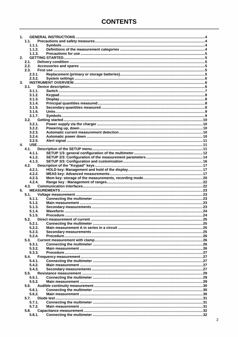
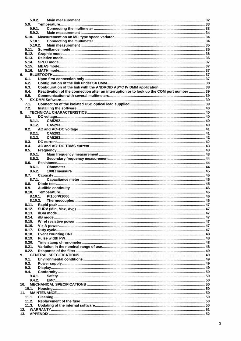
CONTENTS
1. GENERAL INSTRUCTIONS ................................................................................................................................ 4
Precautions and safety measures ............................................................................................................. 4 1.1.1.1.1. Symbols .............................................................................................................................................. 4 1.1.2. Definitions of the measurement categories .................................................................................... 4 1.1.3. Precautions for use ........................................................................................................................... 5
2. GETTING STARTED ............................................................................................................................................ 5 Delivery condition ...................................................................................................................................... 5 2.1. Accessories and spares ............................................................................................................................ 5 2.2. First use ...................................................................................................................................................... 5 2.3.
2.3.1. Replacement (primary or storage batteries) .................................................................................... 5 2.3.2. System settings ................................................................................................................................. 6
3. INSTRUMENT OVERVIEW .................................................................................................................................. 6 Device description ...................................................................................................................................... 6 3.1.
3.1.1. Switch ................................................................................................................................................. 7 3.1.2. Keypad ................................................................................................................................................ 8 3.1.3. Display ................................................................................................................................................ 8 3.1.4. Principal quantities measured .......................................................................................................... 8 3.1.5. Secondary quantities measured ....................................................................................................... 8 3.1.6. Units .................................................................................................................................................... 9 3.1.7. Symbols .............................................................................................................................................. 9 Getting started .......................................................................................................................................... 10 3.2.
3.2.1. Power supply via the charger ......................................................................................................... 10 3.2.2. Powering up, down .......................................................................................................................... 10 3.2.3. Automatic current measurement detection ................................................................................... 10 3.2.4. Automatic power down ................................................................................................................... 10 3.2.5. Alert signal ....................................................................................................................................... 11
4. USE .................................................................................................................................................................... 11 Description of the SETUP menu .............................................................................................................. 11 4.1.
4.1.1. SETUP 1/3: general configuration of the multimeter .................................................................... 12 4.1.2. SETUP 2/3: Configuration of the measurement parameters ........................................................ 14 4.1.3. SETUP 3/3: Configuration and customization ............................................................................... 16 Description of the "Keypad" keys ........................................................................................................... 17 4.2.
4.2.1. HOLD key: Management and hold of the display .......................................................................... 17 4.2.2. MEAS key: Advanced measurements ............................................................................................ 17 4.2.3. Mem key: storage of the measurements, recording mode ........................................................... 20 4.2.4. Range key : Management of ranges ............................................................................................... 22 Communication interfaces....................................................................................................................... 22 4.3.
5. MEASUREMENTS ............................................................................................................................................. 23 Voltage measurement .............................................................................................................................. 23 5.1.
5.1.1. Connecting the multimeter ............................................................................................................. 23 5.1.2. Main measurement .......................................................................................................................... 23 5.1.3. Secondary measurements .............................................................................................................. 23 5.1.4. Waveform ......................................................................................................................................... 24 5.1.5. Procedure ......................................................................................................................................... 24 Direct measurement of current ............................................................................................................... 25 5.2.
5.2.1. Connecting the multimeter ............................................................................................................. 25 5.2.2. Main measurement A in series in a circuit .................................................................................... 25 5.2.3. Secondary measurements .............................................................................................................. 25 5.2.4. Procedure ......................................................................................................................................... 26 Current measurement with clamp ........................................................................................................... 26 5.3.
5.3.1. Connecting the multimeter ............................................................................................................. 26 5.3.2. Main measurement .......................................................................................................................... 26 5.3.3. Procedure ......................................................................................................................................... 27 Frequency measurement ......................................................................................................................... 27 5.4.
5.4.1. Connecting the multimeter ............................................................................................................. 27 5.4.2. Main measurement .......................................................................................................................... 27 5.4.3. Secondary measurements .............................................................................................................. 27 Resistance measurement ........................................................................................................................ 29 5.5.
5.5.1. Connecting the multimeter ............................................................................................................. 29 5.5.2. Main measurement .......................................................................................................................... 29 Audible continuity measurement ............................................................................................................ 30 5.6.
5.6.1. Connecting the multimeter ............................................................................................................. 30 5.6.2. Main measurement .......................................................................................................................... 30 Diode test .................................................................................................................................................. 31 5.7.
5.7.1. Connecting the multimeter ............................................................................................................. 31 5.7.2. Main meausrement .......................................................................................................................... 31 Capacitance measurement ...................................................................................................................... 32 5.8.
5.8.1. Connecting the multimeter ............................................................................................................. 32
3
5.8.2. Main measurement .......................................................................................................................... 32 Temperature .............................................................................................................................................. 33 5.9.
5.9.1. Connecting the multimeter ............................................................................................................. 33 5.9.2. Main measurement .......................................................................................................................... 34
Measurement on an MLI type speed variator ......................................................................................... 34 5.10.5.10.1. Connecting the multimeter ............................................................................................................. 34 5.10.2. Main measurement .......................................................................................................................... 35
Surveillance mode .................................................................................................................................... 35 5.11. Graphic mode ........................................................................................................................................... 36 5.12. Relative mode ........................................................................................................................................... 36 5.13. SPEC mode ............................................................................................................................................... 37 5.14. MEAS mode............................................................................................................................................... 37 5.15. MATH mode............................................................................................................................................... 37 5.16.
6. BLUETOOTH ..................................................................................................................................................... 37 Upon first connection only ...................................................................................................................... 37 6.1. Configuration of the link under SX DMM ................................................................................................ 38 6.2. Configuration of the link with the ANDROID ASYC IV DMM application ............................................. 38 6.3. Reactivation of the connection after an interruption or to look up the COM port number ................ 39 6.4. Communication with several multimeters .............................................................................................. 39 6.5.
7. SX-DMM Software ............................................................................................................................................. 39 Connection of the isolated USB optical lead supplied .......................................................................... 39 7.1. Installing the software .............................................................................................................................. 40 7.2.
8. TECHNICAL CHARACTERISTICS .................................................................................................................... 40 DC voltage ................................................................................................................................................. 40 8.1.
8.1.1. CA5292 .............................................................................................................................................. 40 8.1.2. CA5293 .............................................................................................................................................. 40 AC and AC+DC voltage ............................................................................................................................ 41 8.2.
8.2.1. CA5292 .............................................................................................................................................. 41 8.2.2. CA5293 .............................................................................................................................................. 42 DC current ................................................................................................................................................. 42 8.3. AC and AC+DC TRMS current ................................................................................................................. 43 8.4. Frequency ................................................................................................................................................. 43 8.5.
8.5.1. Main frequency measurement ........................................................................................................ 43 8.5.2. Secondary frequency measurement .............................................................................................. 44 Resistance................................................................................................................................................. 44 8.6.
8.6.1. Ohmmeter ......................................................................................................................................... 44 8.6.2. 100Ω measure .................................................................................................................................. 45 Capacity .................................................................................................................................................... 45 8.7.
8.7.1. Capacitance meter ........................................................................................................................... 45 Diode test .................................................................................................................................................. 45 8.8. Audible continuity .................................................................................................................................... 46 8.9.
Temperature .............................................................................................................................................. 46 8.10.8.10.1. Pt100/Pt1000 ..................................................................................................................................... 46 8.10.2. Thermocouples ................................................................................................................................ 46
Rapid peak ................................................................................................................................................ 47 8.11. SURV (Min, Max, Avg) .............................................................................................................................. 47 8.12. dBm mode ................................................................................................................................................. 47 8.13. dB mode .................................................................................................................................................... 47 8.14. W ref resistive power ............................................................................................................................... 47 8.15. V x A power ............................................................................................................................................... 47 8.16. Duty cycle.................................................................................................................................................. 47 8.17. Event counting CNT ................................................................................................................................. 48 8.18. Pulse width PW ......................................................................................................................................... 48 8.19. Time stamp chronometer ......................................................................................................................... 48 8.20. Variation in the nominal range of use ..................................................................................................... 48 8.21. Response of the filter ............................................................................................................................... 49 8.22.
9. GENERAL SPECIFICATIONS ........................................................................................................................... 49 Environmental conditions........................................................................................................................ 49 9.1. Power supply ............................................................................................................................................ 49 9.2. Display ....................................................................................................................................................... 49 9.3. Conformity ................................................................................................................................................ 50 9.4.
9.4.1. Safety ................................................................................................................................................ 50 9.4.2. EMC ................................................................................................................................................... 50
10. MECHANICAL SPECIFICATIONS .................................................................................................................... 50 Housing ..................................................................................................................................................... 50 10.1.
11. MAINTENANCE ................................................................................................................................................. 50 Cleaning .................................................................................................................................................... 50 11.1. Replacement of the fuse .......................................................................................................................... 50 11.2. Updating of the internal software ............................................................................................................ 50 11.3.
12. WARRANTY....................................................................................................................................................... 51 13. APPENDIX ......................................................................................................................................................... 52
4
1. GENERAL INSTRUCTIONS
Thank you for purchasing a CA5292/CA5293. For best results from your instrument:
- read this user manual carefully, - comply with the precautions for use.
Precautions and safety measures 1.1. This device is compliant with safety standard IEC 61010-2-033, the leads are compliant with IEC 61010-031. Failure to observe the safety instructions may result in electric shock, fire, explosion, or destruction of the instrument and of the installations.
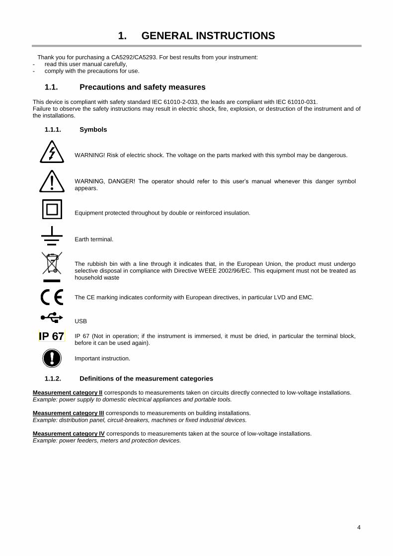
1.1.1. Symbols
WARNING! Risk of electric shock. The voltage on the parts marked with this symbol may be dangerous.
WARNING, DANGER! The operator should refer to this user’s manual whenever this danger symbol appears.
Equipment protected throughout by double or reinforced insulation.
Earth terminal.
The rubbish bin with a line through it indicates that, in the European Union, the product must undergo selective disposal in compliance with Directive WEEE 2002/96/EC. This equipment must not be treated as household waste
The CE marking indicates conformity with European directives, in particular LVD and EMC.
USB
IP 67 (Not in operation; if the instrument is immersed, it must be dried, in particular the terminal block, before it can be used again).
Important instruction.
1.1.2. Definitions of the measurement categories Measurement category II corresponds to measurements taken on circuits directly connected to low-voltage installations. Example: power supply to domestic electrical appliances and portable tools. Measurement category III corresponds to measurements on building installations.
Example: distribution panel, circuit-breakers, machines or fixed industrial devices. Measurement category IV corresponds to measurements taken at the source of low-voltage installations. Example: power feeders, meters and protection devices.
5
1.1.3. Precautions for use
The operator and/or the responsible authority must carefully read and clearly understand the various precautions to be taken in use.
Do not use the instrument in an explosive atmosphere or in the presence of inflammable gas or smoke.
Do not use the instrument on networks with a rated voltage or category higher than those mentioned.
Do not use the instrument if it seems damaged, incomplete or incorrectly closed
Keep your hands and fingers away from the unused terminals of the device. When handling sensors or test probes, do not place fingers beyond physical finger guard.
All elements on which the insulation is damaged (even partially) must be put out of service for repair or disposed at waste.
Respect the environmental conditions of use.
Use personal protection equipment when conditions require it.
When handling the leads, the probe tips, and the crocodile clips, keep your fingers behind the physical guards.
Comply with the environmental conditions of use.
2. GETTING STARTED
Delivery condition 2.1. Check completeness of the delivery against your order. Delivered in a cardboard box with: - Operating directions in 11 languages on CD-ROM with SX-DMM software - Getting started guide on paper (available on CD)
- 1 set of safety leads (red and black) with double insulation probe tip ( of the probe tips: 4mm) 1,000V CAT III 20A - 1 set of 4 AA/R6 Ni-MH storage batteries - 1 5VDC, 2A mains/USB adapter (100-240V, 50/60Hz, 0.5A) with a USB power cord - 1 statement of manufacturer's measurements - Optical USB communication lead - 1 carrying bag
Accessories and spares 2.2. - Current clamps (see CHAUVIN ARNOUX catalogue) - Two-wire Pt100 temperature probe (HX0091) - Two-wire Pt1000 temperature probe (HA1263) - K thermocouple with banana adapter (P011021067) - Metrology software for Windows (HX0059B) - Set of rechargeable batteries (HX0051B) - HV probe (SHT40KV) - CMS clamp (HX0064) - Bluetooth key (P011102112) - Multifix adapter for DMM (P01102100Z) - External charger for Ni-MH storage batteries - Fuse 1,000V 11A >20kA 10x38mm (Get in touch with our Manumesure Regional Technical Centre) - Kit of test accessories for DMM (P01295459Z) - Carrying case with Multifix (HX0052C) For the accessories and spares, consult our web site: www.chauvin-arnoux.com
First use 2.3.
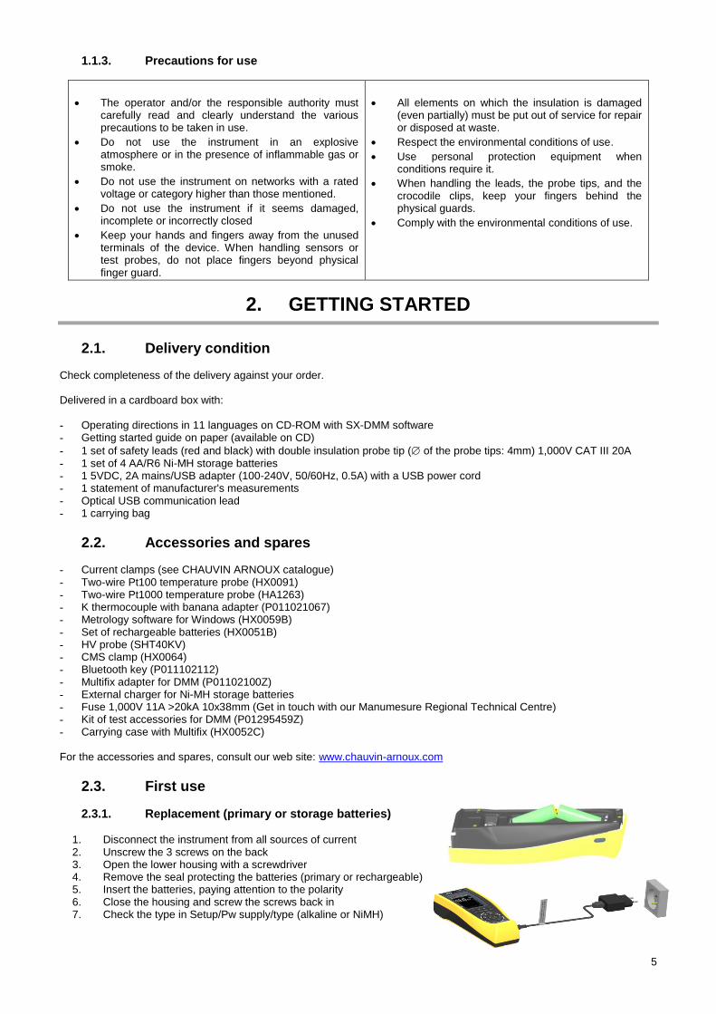
2.3.1. Replacement (primary or storage batteries)
1. Disconnect the instrument from all sources of current 2. Unscrew the 3 screws on the back 3. Open the lower housing with a screwdriver 4. Remove the seal protecting the batteries (primary or rechargeable) 5. Insert the batteries, paying attention to the polarity 6. Close the housing and screw the screws back in 7. Check the type in Setup/Pw supply/type (alkaline or NiMH)
6
To switch the instrument on, press the key. Make sure that the batteries are adequately charged.
When the instrument is off and connected to mains using the USB adapter provided, the LEDs of the switch blink to
indicate that the instrument is charging.
2.3.2. System settings
Language
To select the language in which the menus of the multimeter are displayed:
1. Press the key
2. Select the menu
3. Select 4 combinations of two languages are available: English/Italian, English/Spanish, English/ German and English/French. As default, the multimeter contains English/French. The other combinations are available as updates of the internal program, by downloading the multimeter loader from: www.chauvin-arnoux.com
Clock
To change the date and time:
1. Press the key
2. Select the menu
3. Select
3. INSTRUMENT OVERVIEW
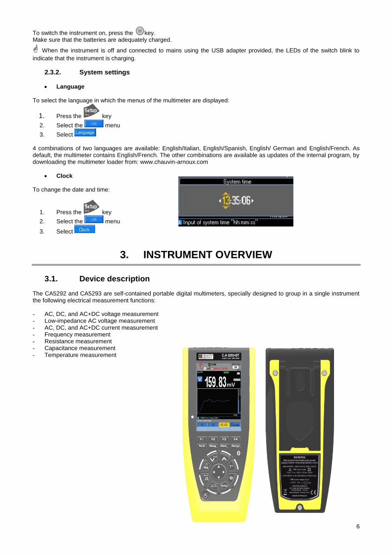
Device description 3.1. The CA5292 and CA5293 are self-contained portable digital multimeters, specially designed to group in a single instrument the following electrical measurement functions: - AC, DC, and AC+DC voltage measurement - Low-impedance AC voltage measurement - AC, DC, and AC+DC current measurement - Frequency measurement - Resistance measurement - Capacitance measurement - Temperature measurement
7
3.1.1. Switch
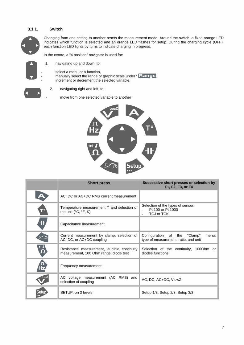
Changing from one setting to another resets the measurement mode. Around the switch, a fixed orange LED indicates which function is selected and an orange LED flashes for setup. During the charging cycle (OFF), each function LED lights by turns to indicate charging in progress. In the centre, a "4 position" navigator is used for:
1. navigating up and down, to:
- select a menu or a function, - manually select the range or graphic scale under " ", - increment or decrement the selected variable.
2. navigating right and left, to:
- move from one selected variable to another
Short press Successive short presses or selection by F1, F2, F3, or F4
AC, DC or AC+DC RMS current measurement
Temperature measurement T and selection of the unit (°C, °F, K)
Selection of the types of sensor: - Pt 100 or Pt 1000 - TCJ or TCK
Capacitance measurement
Current measurement by clamp, selection of AC, DC, or AC+DC coupling
Configuration of the "Clamp" menu: type of measurement, ratio, and unit
Resistance measurement, audible continuity measurement, 100 Ohm range, diode test
Selection of the continuity, 100Ohm or diodes functions
Frequency measurement
AC voltage measurement (AC RMS) and selection of coupling
AC, DC, AC+DC, VlowZ
SETUP, on 3 levels Setup 1/3, Setup 2/3, Setup 3/3
8
3.1.2. Keypad The keypad has the following function keys:
The keys are taken into account and applied when pressed. If the key press is validated, the instrument beeps. The active keys on a long press are identified by "…": Meas…, Mem… , Setup…
Short press Long press
Hold of the display. Selection of RUN, HOLD or Auto HOLD.
Measurement menu with 3 levels. Reset for SURV/PEAK/REL and CNT
Start/Stop storage.
Selection of the files and configuration of the records.
Choice of automatic or manual range change.
3.1.3. Display
3.1.4. Principal quantities measured
VLowZ AC voltage measurement at low impedance (VLowZ)
VAC AC voltage measurement
VAC/DC DC or AC+DC voltage measurement at high impedance (V)
A Current measurement A (AC, DC, AC+DC)
Hz Frequency measurement
Ω Resistance measurement
C Capacitance measurement
T° Temperature measurement
% Measurement of relative value or duty cycle
Continuity, diode test
3.1.5. Secondary quantities measured For the secondary quantities measured, refer to table in the appendix.
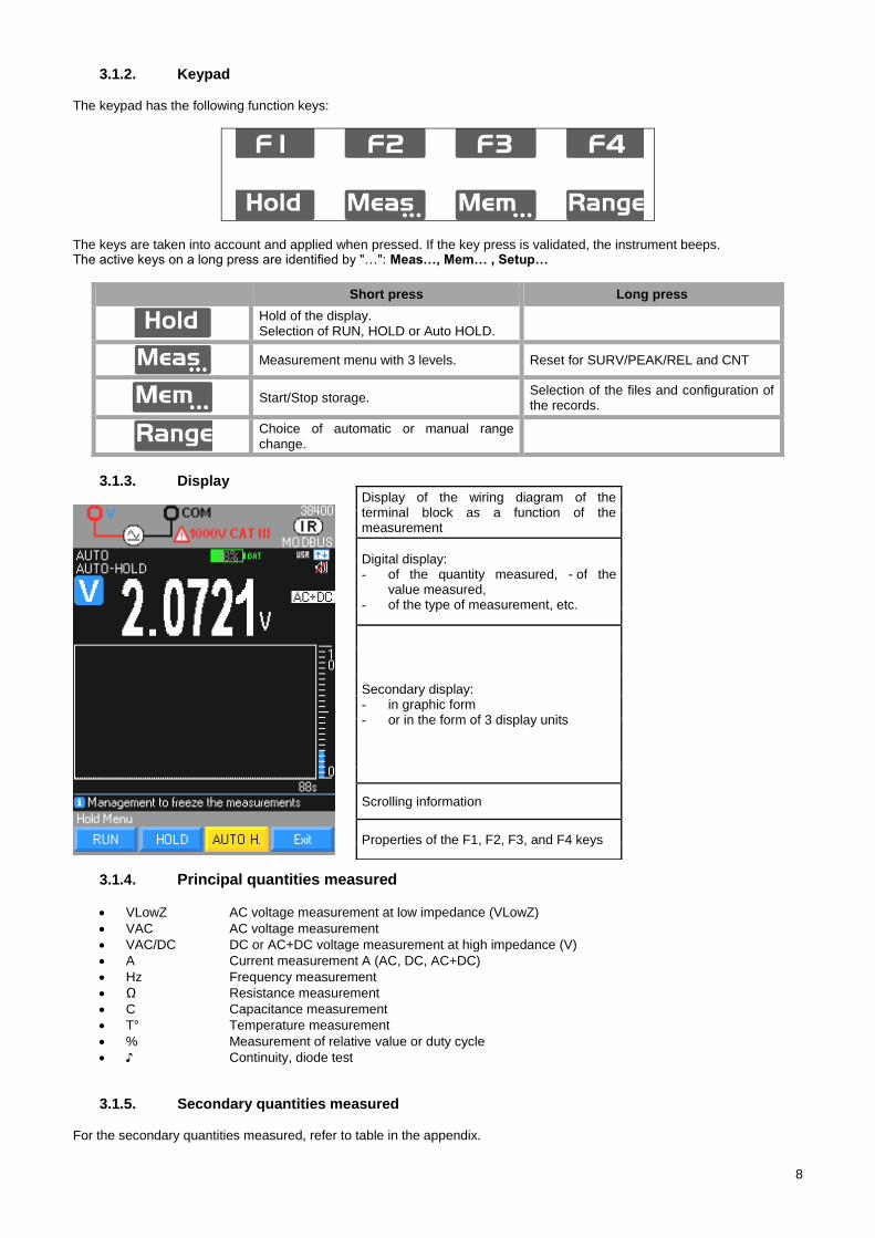
Display of the wiring diagram of the terminal block as a function of the measurement
Digital display: - of the quantity measured, - of the
value measured, - of the type of measurement, etc.
Secondary display: - in graphic form - or in the form of 3 display units
Scrolling information
Properties of the F1, F2, F3, and F4 keys
9
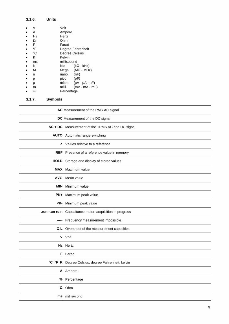
3.1.6. Units
V Volt
A Ampère
Hz Hertz
Ω Ohm
F Farad
°F Degree Fahrenheit
°C Degree Celsius
K Kelvin
ms millisecond
k kilo (kΩ - kHz)
M Méga (MΩ - MHz)
n nano (nF)
p pico (pF)
µ micro (µV - µA - µF)
m milli (mV - mA - mF)
% Percentage
3.1.7. Symbols
AC Measurement of the RMS AC signal
DC Measurement of the DC signal
AC + DC Measurement of the TRMS AC and DC signal
AUTO Automatic range switching
Values relative to a reference
REF Presence of a reference value in memory
HOLD Storage and display of stored values
MAX Maximum value
AVG Mean value
MIN Minimum value
PK+ Maximum peak value
PK- Minimum peak value
.run r.un ru.n Capacitance meter, acquisition in progress
----- Frequency measurement impossible
O.L Overshoot of the measurement capacities
V Volt
Hz Hertz
F Farad
°C °F K Degree Celsius, degree Fahrenheit, kelvin
A Ampere
% Percentage
Ω Ohm
ms millisecond
10
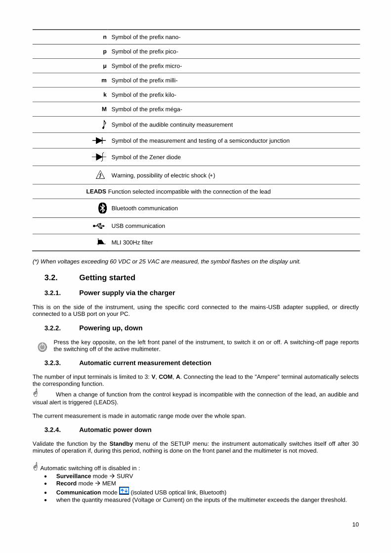
n Symbol of the prefix nano-
p Symbol of the prefix pico-
μ Symbol of the prefix micro-
m Symbol of the prefix milli-
k Symbol of the prefix kilo-
M Symbol of the prefix méga-
Symbol of the audible continuity measurement
Symbol of the measurement and testing of a semiconductor junction
Symbol of the Zener diode
Warning, possibility of electric shock ()
LEADS Function selected incompatible with the connection of the lead
Bluetooth communication
USB communication
MLI 300Hz filter
(*) When voltages exceeding 60 VDC or 25 VAC are measured, the symbol flashes on the display unit.
Getting started 3.2.
3.2.1. Power supply via the charger This is on the side of the instrument, using the specific cord connected to the mains-USB adapter supplied, or directly connected to a USB port on your PC.
3.2.2. Powering up, down
Press the key opposite, on the left front panel of the instrument, to switch it on or off. A switching-off page reports the switching off of the active multimeter.
3.2.3. Automatic current measurement detection The number of input terminals is limited to 3: V, COM, A. Connecting the lead to the "Ampere" terminal automatically selects
the corresponding function.
When a change of function from the control keypad is incompatible with the connection of the lead, an audible and
visual alert is triggered (LEADS). The current measurement is made in automatic range mode over the whole span.
3.2.4. Automatic power down Validate the function by the Standby menu of the SETUP menu: the instrument automatically switches itself off after 30
minutes of operation if, during this period, nothing is done on the front panel and the multimeter is not moved.
Automatic switching off is disabled in :
Surveillance mode SURV
Record mode MEM
Communication mode (isolated USB optical link, Bluetooth)
when the quantity measured (Voltage or Current) on the inputs of the multimeter exceeds the danger threshold.
11
3.2.5. Alert signal An intermittent audible signal is emitted:
in the "Voltage" setting, when the range is exceeded
(MANUal and AUTO mode - last range)
in the "Current" setting, when the range is exceeded (MANUal mode), starting from a measurement of 10 Amperes
when the connection of the leads is incompatible with the function selected
when the danger thresholds are exceeded (if the function is validated) When the range is exceeded, the audible signal is accompanied by display of the "O.L" acronym.
When the symbol is activated:
the voltage on the "Volt" input exceeds 60 VDC or 25 VAC
the current injected between the "Ampere" terminal and COM exceeds 10A
the range (voltage or current) is exceeded in MANUAL mode
4. USE
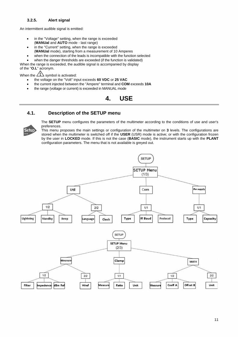
Description of the SETUP menu 4.1.
The SETUP menu configures the parameters of the multimeter according to the conditions of use and user's
preferences. This menu proposes the main settings or configuration of the multimeter on 3 levels. The configurations are stored when the multimeter is switched off if the USER (USR) mode is active; or with the configuration frozen by the user in LOCKED mode. If this is not the case (BASIC mode), the instrument starts up with the PLANT
configuration parameters. The menu that is not available is greyed out.
12
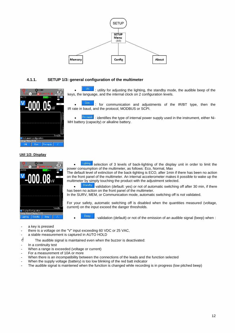
4.1.1. SETUP 1/3: general configuration of the multimeter
: utility for adjusting the lighting, the standby mode, the audible beep of the keys, the language, and the internal clock on 2 configuration levels.
: for communication and adjustments of the IR/BT type, then the IR rate in baud, and the protocol, MODBUS or SCPI.
: identifies the type of internal power supply used in the instrument, either Ni-MH battery (capacity) or alkaline battery.
Util 1/2: Display
selection of 3 levels of back-lighting of the display unit in order to limit the power consumption of the multimeter, as follows: Eco, Normal, Max The default level of extinction of the back-lighting is ECO, after 1min if there has been no action on the front panel of the multimeter. An internal accelerometer makes it possible to wake up the multimeter by simply touching the product with the adjustment selected.
validation (default: yes) or not of automatic switching off after 30 min, if there has been no action on the front panel of the multimeter. In the SURV, MEM, or Communication mode, automatic switching off is not validated. For your safety, automatic switching off is disabled when the quantities measured (voltage, current) on the input exceed the danger thresholds.
: validation (default) or not of the emission of an audible signal (beep) when :
- a key is pressed - there is a voltage on the "V" input exceeding 60 VDC or 25 VAC, - a stable measurement is captured in AUTO HOLD
The audible signal is maintained even when the buzzer is deactivated:
- In a continuity test - When a range is exceeded (voltage or current) - For a measurement of 10A or more - When there is an incompatibility between the connections of the leads and the function selected - When the supply voltage (battery) is too low blinking of the red batt indicator
- The audible signal is maintened when the function is changed while recording is in progress (low pitched beep)
13
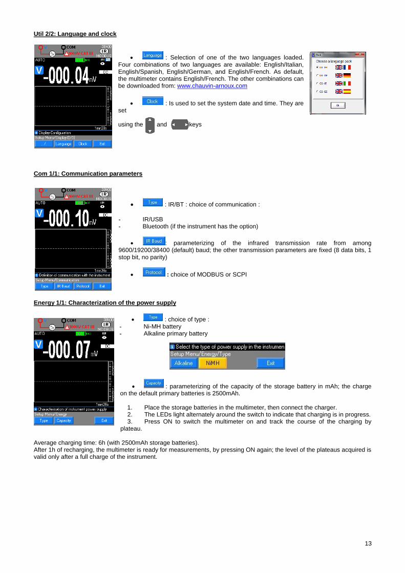
Util 2/2: Language and clock
: Selection of one of the two languages loaded. Four combinations of two languages are available: English/Italian, English/Spanish, English/German, and English/French. As default, the multimeter contains English/French. The other combinations can be downloaded from: www.chauvin-arnoux.com
: Is used to set the system date and time. They are set using the and keys
Com 1/1: Communication parameters
: IR/BT : choice of communication :
- IR/USB - Bluetooth (if the instrument has the option)
: parameterizing of the infrared transmission rate from among 9600/19200/38400 (default) baud; the other transmission parameters are fixed (8 data bits, 1 stop bit, no parity)
: choice of MODBUS or SCPI
Energy 1/1: Characterization of the power supply
: choice of type : - Ni-MH battery - Alkaline primary battery
: parameterizing of the capacity of the storage battery in mAh; the charge on the default primary batteries is 2500mAh.
1. Place the storage batteries in the multimeter, then connect the charger. 2. The LEDs light alternately around the switch to indicate that charging is in progress. 3. Press ON to switch the multimeter on and track the course of the charging by
plateau.
Average charging time: 6h (with 2500mAh storage batteries). After 1h of recharging, the multimeter is ready for measurements, by pressing ON again; the level of the plateaus acquired is valid only after a full charge of the instrument.
14
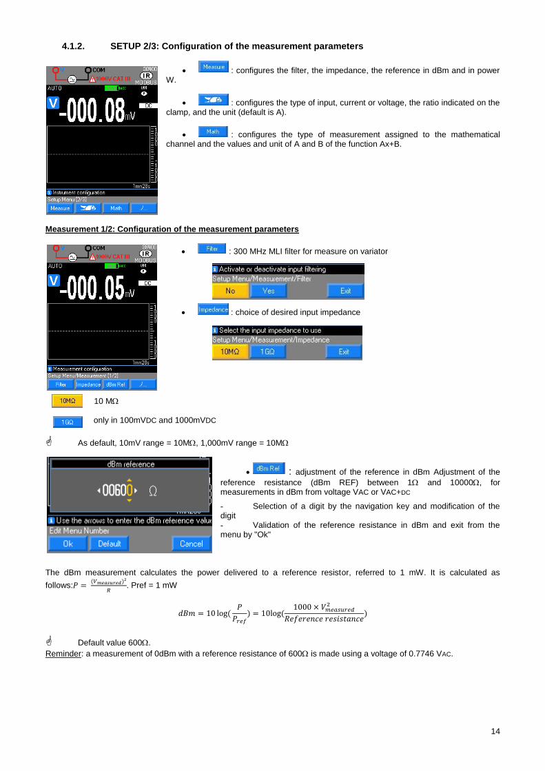
4.1.2. SETUP 2/3: Configuration of the measurement parameters
: configures the filter, the impedance, the reference in dBm and in power W.
: configures the type of input, current or voltage, the ratio indicated on the clamp, and the unit (default is A).
: configures the type of measurement assigned to the mathematical channel and the values and unit of A and B of the function Ax+B.
Measurement 1/2: Configuration of the measurement parameters
: 300 MHz MLI filter for measure on variator
: choice of desired input impedance
10 M only in 100mVDC and 1000mVDC
As default, 10mV range = 10M, 1,000mV range = 10M
: adjustment of the reference in dBm Adjustment of the
reference resistance (dBm REF) between 1 and 10000, for measurements in dBm from voltage VAC or VAC+DC
- Selection of a digit by the navigation key and modification of the digit - Validation of the reference resistance in dBm and exit from the menu by "Ok"
The dBm measurement calculates the power delivered to a reference resistor, referred to 1 mW. It is calculated as
follows:𝑃 = (𝑉𝑚𝑒𝑎𝑠𝑢𝑟𝑒𝑑)²
𝑅. Pref = 1 mW
𝑑𝐵𝑚 = 10 log(𝑃
𝑃𝑟𝑒𝑓) = 10log (
1000 × 𝑉𝑚𝑒𝑎𝑠𝑢𝑟𝑒𝑑2
𝑅𝑒𝑓𝑒𝑟𝑒𝑛𝑐𝑒 𝑟𝑒𝑠𝑖𝑠𝑡𝑎𝑛𝑐𝑒)
Default value 600.
Reminder: a measurement of 0dBm with a reference resistance of 600 is made using a voltage of 0.7746 VAC.
15
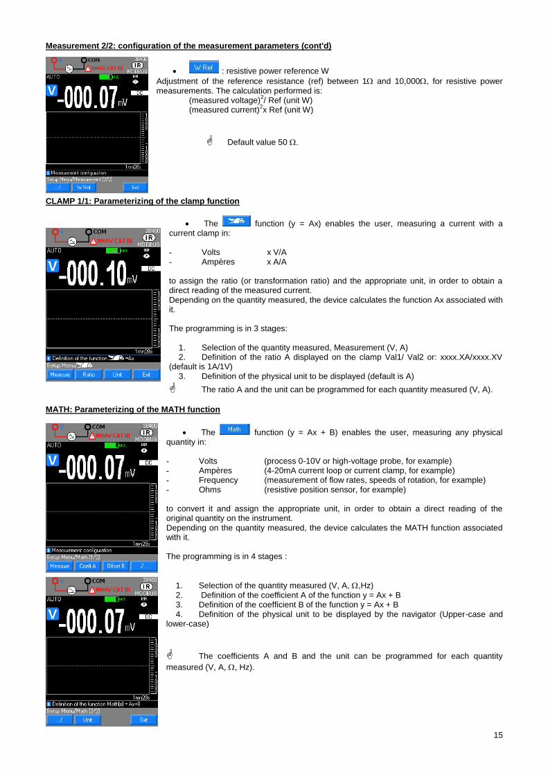
Measurement 2/2: configuration of the measurement parameters (cont'd)
: resistive power reference W
Adjustment of the reference resistance (ref) between 1 and 10,000, for resistive power measurements. The calculation performed is: (measured voltage)
2/ Ref (unit W)
(measured current)2x Ref (unit W)
Default value 50 .
CLAMP 1/1: Parameterizing of the clamp function
The function (y = Ax) enables the user, measuring a current with a current clamp in: - Volts x V/A - Ampères x A/A to assign the ratio (or transformation ratio) and the appropriate unit, in order to obtain a direct reading of the measured current. Depending on the quantity measured, the device calculates the function Ax associated with it. The programming is in 3 stages:
1. Selection of the quantity measured, Measurement (V, A) 2. Definition of the ratio A displayed on the clamp Val1/ Val2 or: xxxx.XA/xxxx.XV
(default is 1A/1V) 3. Definition of the physical unit to be displayed (default is A)
The ratio A and the unit can be programmed for each quantity measured (V, A).
MATH: Parameterizing of the MATH function
The function (y = Ax + B) enables the user, measuring any physical quantity in: - Volts (process 0-10V or high-voltage probe, for example) - Ampères (4-20mA current loop or current clamp, for example) - Frequency (measurement of flow rates, speeds of rotation, for example) - Ohms (resistive position sensor, for example) to convert it and assign the appropriate unit, in order to obtain a direct reading of the original quantity on the instrument. Depending on the quantity measured, the device calculates the MATH function associated with it. The programming is in 4 stages :
1. Selection of the quantity measured (V, A, ,Hz) 2. Definition of the coefficient A of the function y = Ax + B 3. Definition of the coefficient B of the function y = Ax + B 4. Definition of the physical unit to be displayed by the navigator (Upper-case and
lower-case)
The coefficients A and B and the unit can be programmed for each quantity
measured (V, A, , Hz).
16
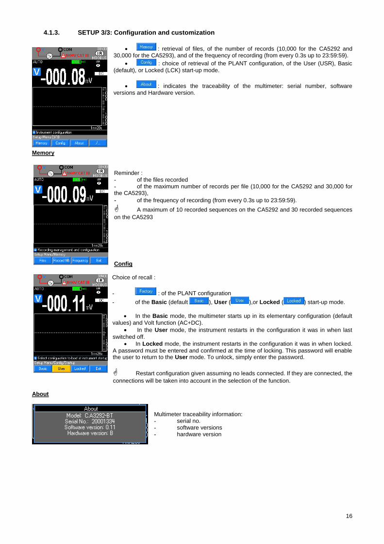
4.1.3. SETUP 3/3: Configuration and customization
: retrieval of files, of the number of records (10,000 for the CA5292 and 30,000 for the CA5293), and of the frequency of recording (from every 0.3s up to 23:59:59).
: choice of retrieval of the PLANT configuration, of the User (USR), Basic
(default), or Locked (LCK) start-up mode.
: indicates the traceability of the multimeter: serial number, software versions and Hardware version.
Memory
Reminder : - of the files recorded - of the maximum number of records per file (10,000 for the CA5292 and 30,000 for the CA5293),
- of the frequency of recording (from every 0.3s up to 23:59:59).
A maximum of 10 recorded sequences on the CA5292 and 30 recorded sequences
on the CA5293 Config
Choice of recall :
- : of the PLANT configuration
- of the Basic (default ), User ( ),or Locked ( ) start-up mode.
In the Basic mode, the multimeter starts up in its elementary configuration (default
values) and Volt function (AC+DC).
In the User mode, the instrument restarts in the configuration it was in when last
switched off. In Locked mode, the instrument restarts in the configuration it was in when locked.
A password must be entered and confirmed at the time of locking. This password will enable the user to return to the User mode. To unlock, simply enter the password.
Restart configuration given assuming no leads connected. If they are connected, the
connections will be taken into account in the selection of the function. About
Multimeter traceability information: - serial no. - software versions - hardware version
17
Description of the "Keypad" keys 4.2.
4.2.1. HOLD key: Management and hold of the display
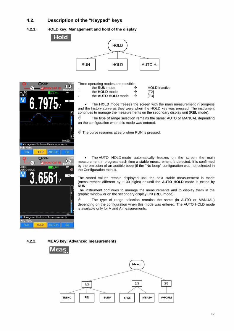
Three operating modes are possible: - the RUN mode HOLD inactive - the HOLD mode [F2] - the AUTO HOLD mode [F3]
The HOLD mode freezes the screen with the main measurement in progress
and the history curve as they were when the HOLD key was pressed. The instrument continues to manage the measurements on the secondary display unit (REL mode).
The type of range selection remains the same: AUTO or MANUAL depending
on the configuration when this mode was entered.
The curve resumes at zero when RUN is pressed.
The AUTO HOLD mode automatically freezes on the screen the main measurement in progress each time a stable measurement is detected. It is confirmed by the emission of an audible beep (if the "No beep" configuration was not selected in the Configuration menu). The stored values remain displayed until the next stable measurement is made (measurement different by ±100 digits) or until the AUTO HOLD mode is exited by RUN.
The instrument continues to manage the measurements and to display them in the graphic window or on the secondary display unit (REL mode).
The type of range selection remains the same (in AUTO or MANUAL)
depending on the configuration when this mode was entered. The AUTO HOLD mode is available only for V and A measurements.
4.2.2. MEAS key: Advanced measurements
18
MEAS 1/3
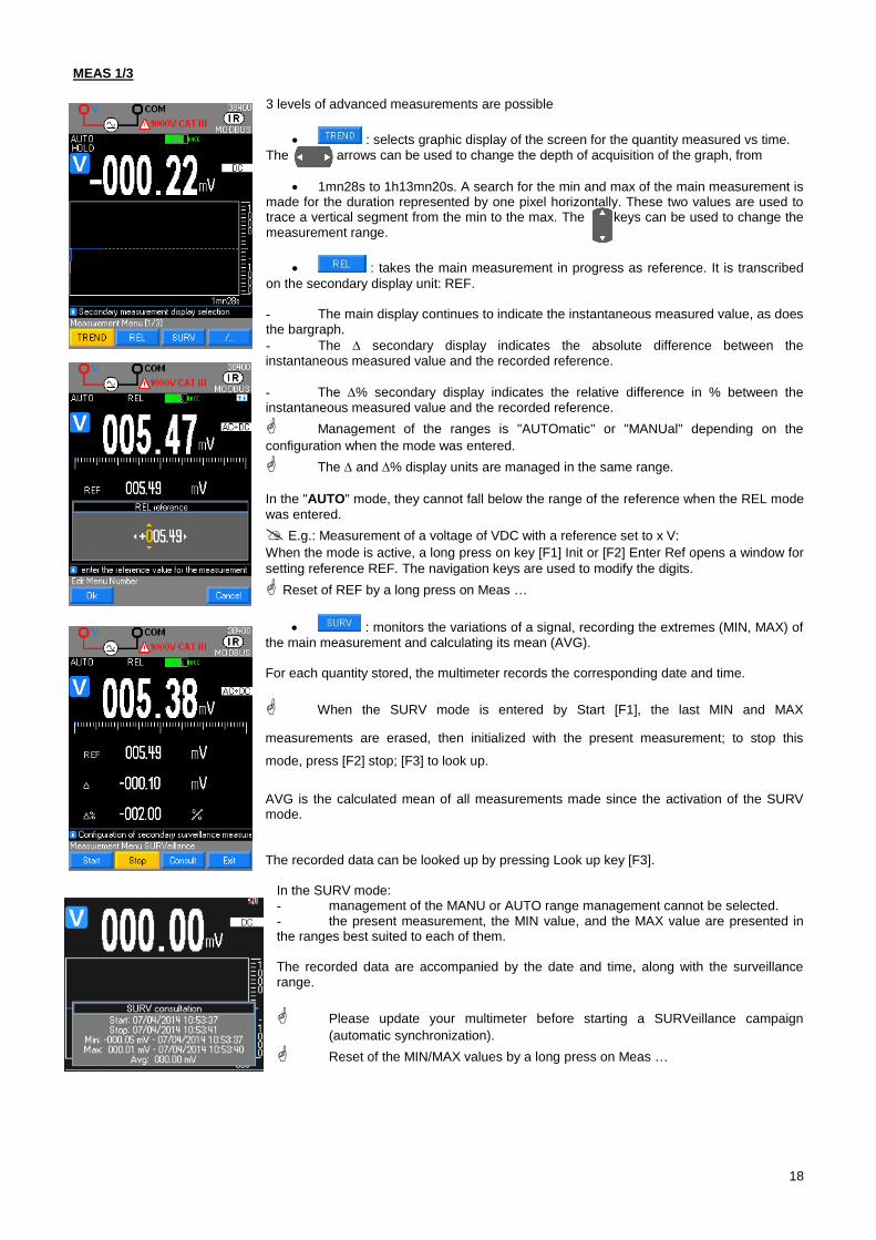
3 levels of advanced measurements are possible
: selects graphic display of the screen for the quantity measured vs time.
The arrows can be used to change the depth of acquisition of the graph, from
1mn28s to 1h13mn20s. A search for the min and max of the main measurement is made for the duration represented by one pixel horizontally. These two values are used to trace a vertical segment from the min to the max. The keys can be used to change the measurement range.
: takes the main measurement in progress as reference. It is transcribed
on the secondary display unit: REF. - The main display continues to indicate the instantaneous measured value, as does the bargraph.
- The secondary display indicates the absolute difference between the instantaneous measured value and the recorded reference.
- The % secondary display indicates the relative difference in % between the instantaneous measured value and the recorded reference.
Management of the ranges is "AUTOmatic" or "MANUal" depending on the
configuration when the mode was entered.
The and % display units are managed in the same range. In the "AUTO" mode, they cannot fall below the range of the reference when the REL mode
was entered.
E.g.: Measurement of a voltage of VDC with a reference set to x V:
When the mode is active, a long press on key [F1] Init or [F2] Enter Ref opens a window for
setting reference REF. The navigation keys are used to modify the digits.
Reset of REF by a long press on Meas …
: monitors the variations of a signal, recording the extremes (MIN, MAX) of the main measurement and calculating its mean (AVG). For each quantity stored, the multimeter records the corresponding date and time.
When the SURV mode is entered by Start [F1], the last MIN and MAX
measurements are erased, then initialized with the present measurement; to stop this
mode, press [F2] stop; [F3] to look up.
AVG is the calculated mean of all measurements made since the activation of the SURV mode. The recorded data can be looked up by pressing Look up key [F3].
In the SURV mode: - management of the MANU or AUTO range management cannot be selected. - the present measurement, the MIN value, and the MAX value are presented in the ranges best suited to each of them. The recorded data are accompanied by the date and time, along with the surveillance range.
Please update your multimeter before starting a SURVeillance campaign
(automatic synchronization).
Reset of the MIN/MAX values by a long press on Meas …
19
MEAS 2/3
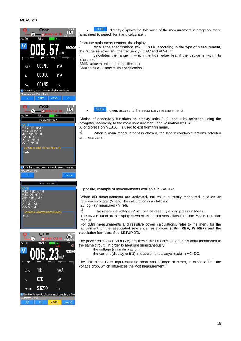
: directly displays the tolerance of the measurement in progress; there
is no need to search for it and calculate it. From the main measurement, the display: - recalls the specifications (x% L ±n D) according to the type of measurement, the range selected and the frequency (in AC and AC+DC) - calculates the range in which the true value lies, if the device is within its tolerance: SMIN value minimum specification SMAX value maximum specification
: gives access to the secondary measurements. Choice of secondary functions on display units 2, 3, and 4 by selection using the navigator, according to the main measurement, and validation by OK. A long press on MEAS… is used to exit from this menu.
When a main measurement is chosen, the last secondary functions selected
are reactivated.
Opposite, example of measurements available in VAC+DC.
When dB measurements are activated, the value currently measured is taken as
reference voltage (V ref). The calculation is as follows: 20 log10 (V measured / V ref).
The reference voltage (V ref) can be reset by a long press on Meas…
The MATH function is displayed when its parameters allow (see the MATH Function menu). For dBm measurements and resistive power calculations, refer to the menu for the adjustment of the associated reference resistances (dBm REF, W REF) and the
calculation formulas. See SETUP 2/3. The power calculation VxA (VA) requires a third connection on the A input (connected to
the same circuit), in order to measure simultaneously: - the voltage (main display unit) - the current (display unit 3), measurement always made in AC+DC. The link to the COM input must be short and of large diameter, in order to limit the voltage drop, which influences the Volt measurement.
20
MEAS 3/3
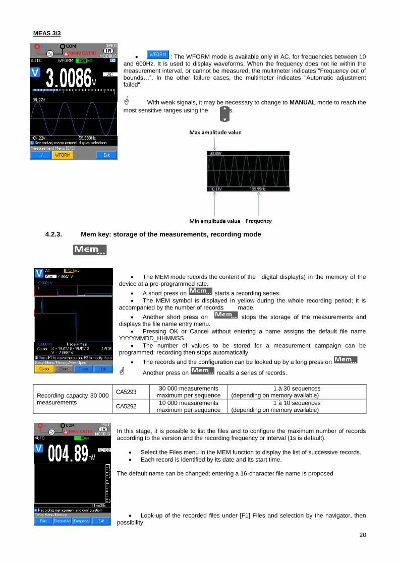
: The WFORM mode is available only in AC, for frequencies between 10 and 600Hz. It is used to display waveforms. When the frequency does not lie within the measurement interval, or cannot be measured, the multimeter indicates "Frequency out of bounds…". In the other failure cases, the multimeter indicates "Automatic adjustment failed".
With weak signals, it may be necessary to change to MANUAL mode to reach the
most sensitive ranges using the keys.
4.2.3. Mem key: storage of the measurements, recording mode
The MEM mode records the content of the digital display(s) in the memory of the device at a pre-programmed rate.
A short press on starts a recording series.
The MEM symbol is displayed in yellow during the whole recording period; it is accompanied by the number of records made.
Another short press on stops the storage of the measurements and displays the file name entry menu.
Pressing OK or Cancel without entering a name assigns the default file name YYYYMMDD_HHMMSS.
The number of values to be stored for a measurement campaign can be programmed: recording then stops automatically.
The records and the configuration can be looked up by a long press on
Another press on recalls a series of records.
Recording capacity 30 000 measurements
CA5293 30 000 measurements
maximum per sequence 1 à 30 sequences
(depending on memory available)
CA5292 10 000 measurements
maximum per sequence 1 à 10 sequences
(depending on memory available)
In this stage, it is possible to list the files and to configure the maximum number of records according to the version and the recording frequency or interval (1s is default).
Select the Files menu in the MEM function to display the list of successive records.
Each record is identified by its date and its start time. The default name can be changed; entering a 16-character file name is proposed
Look-up of the recorded files under [F1] Files and selection by the navigator, then possibility:
21
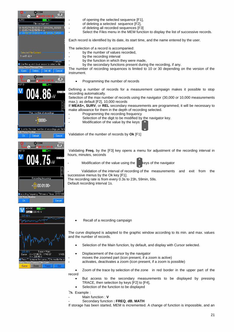
- of opening the selected sequence [F1], - of deleting a selected sequence [F2], - of deleting all recorded sequences [F3] - Select the Files menu in the MEM function to display the list of successive records. Each record is identified by its date, its start time, and the name entered by the user. The selection of a record is accompanied: - by the number of values recorded, - by the recording interval - by the function in which they were made, - by the secondary functions present during the recording, if any. The number of recording sequences is limited to 10 or 30 depending on the version of the instrument.
Programming the number of records Defining a number of records for a measurement campaign makes it possible to stop recording automatically. Selection of the max number of records using the navigator (30,000 or 10,000 measurements max.); as default [F2], 10,000 records If MEAS+, SURV, or REL secondary measurements are programmed, it will be necessary to
make allowance for them in the depth of recording selected. - Programming the recording frequency - Selection of the digit to be modified by the navigator key. - Modification of the value by the keys: Validation of the number of records by Ok [F1]
Validating Freq. by the [F3] key opens a menu for adjustment of the recording interval in
hours, minutes, seconds - Modification of the value using the keys of the navigator - Validation of the interval of recording of the measurements and exit from the successive menus by the Ok key [F1]. The recording rate is from every 0.3s to 23h, 59min, 59s. Default recording interval 1s.
Recall of a recording campaign The curve displayed is adapted to the graphic window according to its min. and max. values and the number of records.
Selection of the Main function, by default, and display with Cursor selected.
Displacement of the cursor by the navigator - moves the zoomed part (icon present, if a zoom is active) - activates, deactivates a zoom (icon present, if a zoom is possible)
Zoom of the trace by selection of the zone in red border in the upper part of the record
But access to the secondary measurements to be displayed by pressing TRACE, then selection by keys [F2] to [F4],
Selection of the function to be displayed
Example :
- Main function : V - Secondary function : FREQ, dB, MATH
If storage has been started, MEM is incremented. A change of function is impossible, and an
22
attempt is reported by a low-pitched beep. Only the SETUP menu can still be opened. The acquisition in progress must be stopped (press MEM) to modify a parameter, a function, or a configuration.
4.2.4. Range key : Management of ranges
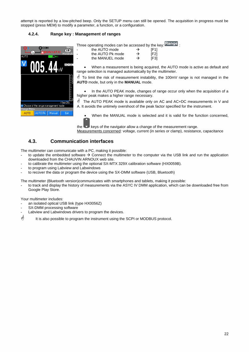
Three operating modes can be accessed by the key: : - the AUTO mode [F1] - the AUTO Pk mode [F2] - the MANUEL mode [F3]
When a measurement is being acquired, the AUTO mode is active as default and range selection is managed automatically by the multimeter.
To limit the risk of measurement instability, the 100mV range is not managed in the
AUTO mode, but only in the MANUAL mode.
In the AUTO PEAK mode, changes of range occur only when the acquisition of a higher peak makes a higher range necessary.
The AUTO PEAK mode is available only on AC and AC+DC measurements in V and
A. It avoids the untimely overshoot of the peak factor specified for the instrument.
When the MANUAL mode is selected and it is valid for the function concerned,
the keys of the navigator allow a change of the measurement range. Measurements concerned: voltage, current (in series or clamp), resistance, capacitance
Communication interfaces 4.3. The multimeter can communicate with a PC, making it possible: - to update the embedded software Connect the multimeter to the computer via the USB link and run the application
downloaded from the CHAUVIN ARNOUX web site. - to calibrate the multimeter using the optional SX-MTX 329X calibration software (HX0059B). - to program using Labview and Labwindows - to recover the data or program the device using the SX-DMM software (USB, Bluetooth) The multimeter (Bluetooth version)communicates with smartphones and tablets, making it possible: - to track and display the history of measurements via the ASYC IV DMM application, which can be downloaded free from
Google Play Store.
Your multimeter includes: - an isolated optical USB link (type HX0056Z) - SX-DMM processing software - Labview and Labwindows drivers to program the devices.
It is also possible to program the instrument using the SCPI or MODBUS protocol.
23
5. MEASUREMENTS
Voltage measurement 5.1.
5.1.1. Connecting the multimeter
5.1.2. Main measurement
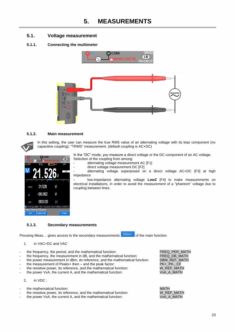
In this setting, the user can measure the true RMS value of an alternating voltage with its bias component (no capacitive coupling): "TRMS" measurement. (default coupling is AC+DC)
In the “DC” mode, you measure a direct voltage or the DC component of an AC voltage. Selection of the coupling from among: - alternating voltage measurement AC [F1] - direct voltage measurement DC [F2] - alternating voltage superposed on a direct voltage AC+DC [F3] at high impedance
- low-impedance alternating voltage LowZ [F4] to make measurements on
electrical installations, in order to avoid the measurement of a "phantom" voltage due to coupling between lines.
5.1.3. Secondary measurements
Pressing Meas… gives access to the secondary measurements of the main function.
1. in VAC+DC and VAC
- the frequency, the period, and the mathematical function: FREQ_PER_MATH - the frequency, the measurement in dB, and the mathematical function: FREQ_DB_MATH - the power measurement in dBm, its reference, and the mathematical function: DBM_REF_MATH - the measurement of Peaks+ then – and the peak factor: PK+_PK-_CF - the resistive power, its reference, and the mathematical function: W_REF_MATH - the power VxA, the current A, and the mathematical function: VxA_A_MATH
2. in VDC :
- the mathematical function: MATH - the resistive power, its reference, and the mathematical function: W_REF_MATH - the power VxA, the current A, and the mathematical function: VxA_A_MATH
24
3. in VLowZ - the mathematical function: MATH - the frequency, the period: FREQ_PER
The 100mV range is present only in MANUAL mode, by . In all cases, "OL" is displayed above 1050V and a beep sounds when the measurement exceeds 600V. The hazardous voltage symbol is displayed if "V" exceeds 60 VDC or 25 VAC
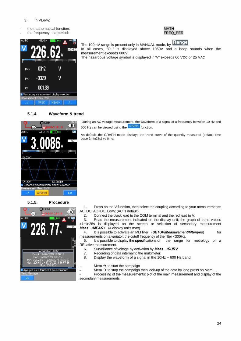
5.1.4. Waveform & trend
During an AC voltage measurement, the waveform of a signal at a frequency between 10 Hz and
600 Hz can be viewed using the function. As default, the GRAPH mode displays the trend curve of the quantity measured (default time base 1min28s) vs time.
5.1.5. Procedure 1. Press on the V function, then select the coupling according to your measurements:
AC, DC, AC+DC, LowZ (AC is default).
2. Connect the black lead to the COM terminal and the red lead to V. 3. Read the measurement indicated on the display unit; the graph of trend values
>1min28s is displayed on the screen or selection of secondary measurement Meas…/MEAS+ (4 display units max).
4. It is possible to activate an MLI filter (SETUP/Measurement/filter/yes) for measurements on a variator: the cutoff frequency of the filter <300Hz.
5. It is possible to display the specifications of the range for metrology or a
RELative measurement. 6. Surveillance of voltage by activation by Meas…/SURV 7. Recording of data internal to the multimeter: 8. Display the waveform of a signal in the 10Hz – 600 Hz band
- Mem to start the campaign - Mem to stop the campaign then look-up of the data by long press on Mem … - Processing of the measurements: plot of the main measurement and display of the secondary measurements.
25
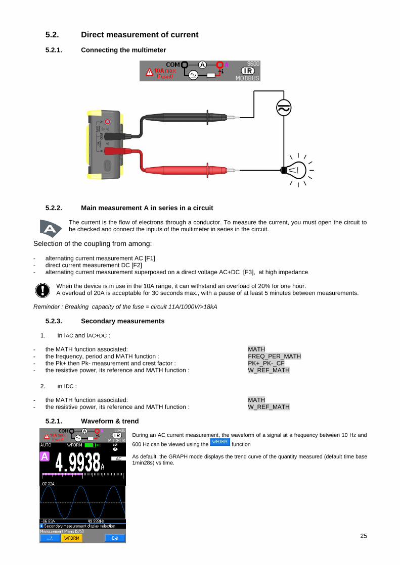
Direct measurement of current 5.2.
5.2.1. Connecting the multimeter
5.2.2. Main measurement A in series in a circuit
The current is the flow of electrons through a conductor. To measure the current, you must open the circuit to be checked and connect the inputs of the multimeter in series in the circuit.
Selection of the coupling from among: - alternating current measurement AC [F1] - direct current measurement DC [F2] - alternating current measurement superposed on a direct voltage AC+DC [F3], at high impedance
When the device is in use in the 10A range, it can withstand an overload of 20% for one hour. A overload of 20A is acceptable for 30 seconds max., with a pause of at least 5 minutes between measurements.
Reminder : Breaking capacity of the fuse = circuit 11A/1000V/>18kA
5.2.3. Secondary measurements
1. in IAC and IAC+DC : - the MATH function associated: MATH - the frequency, period and MATH function : FREQ_PER_MATH - the Pk+ then Pk- measurement and crest factor : PK+_PK-_CF - the resistive power, its reference and MATH function : W_REF_MATH
2. in IDC :
- the MATH function associated: MATH - the resistive power, its reference and MATH function : W_REF_MATH
5.2.1. Waveform & trend During an AC current measurement, the waveform of a signal at a frequency between 10 Hz and
600 Hz can be viewed using the function As default, the GRAPH mode displays the trend curve of the quantity measured (default time base 1min28s) vs time.
26
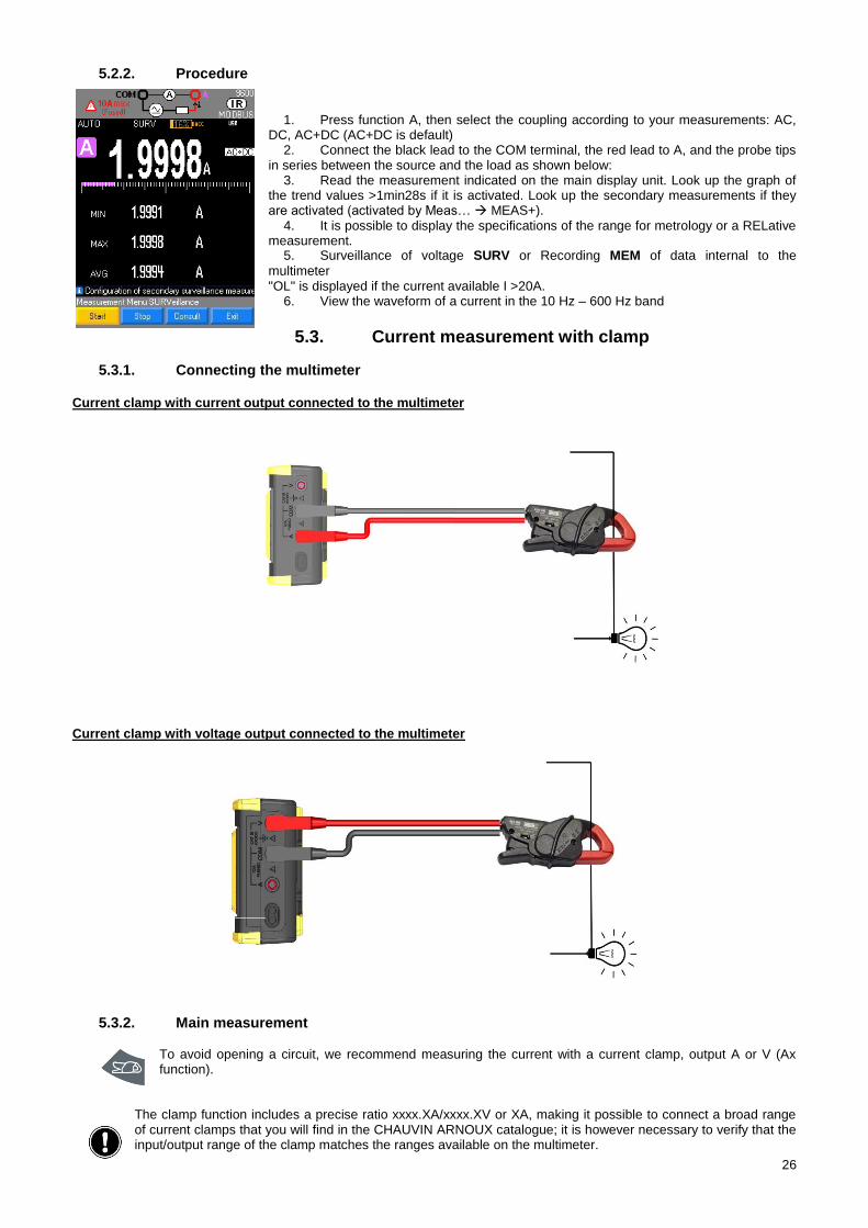
5.2.2. Procedure
1. Press function A, then select the coupling according to your measurements: AC, DC, AC+DC (AC+DC is default)
2. Connect the black lead to the COM terminal, the red lead to A, and the probe tips in series between the source and the load as shown below:
3. Read the measurement indicated on the main display unit. Look up the graph of the trend values >1min28s if it is activated. Look up the secondary measurements if they are activated (activated by Meas… MEAS+).
4. It is possible to display the specifications of the range for metrology or a RELative measurement.
5. Surveillance of voltage SURV or Recording MEM of data internal to the
multimeter "OL" is displayed if the current available I >20A.
6. View the waveform of a current in the 10 Hz – 600 Hz band
Current measurement with clamp 5.3.
5.3.1. Connecting the multimeter
Current clamp with current output connected to the multimeter
Current clamp with voltage output connected to the multimeter
5.3.2. Main measurement
To avoid opening a circuit, we recommend measuring the current with a current clamp, output A or V (Ax function).
The clamp function includes a precise ratio xxxx.XA/xxxx.XV or XA, making it possible to connect a broad range of current clamps that you will find in the CHAUVIN ARNOUX catalogue; it is however necessary to verify that the input/output range of the clamp matches the ranges available on the multimeter.
27
The accuracy of this "clamp" function depends on the accuracy of the clamp and of the range used on the multimeter.
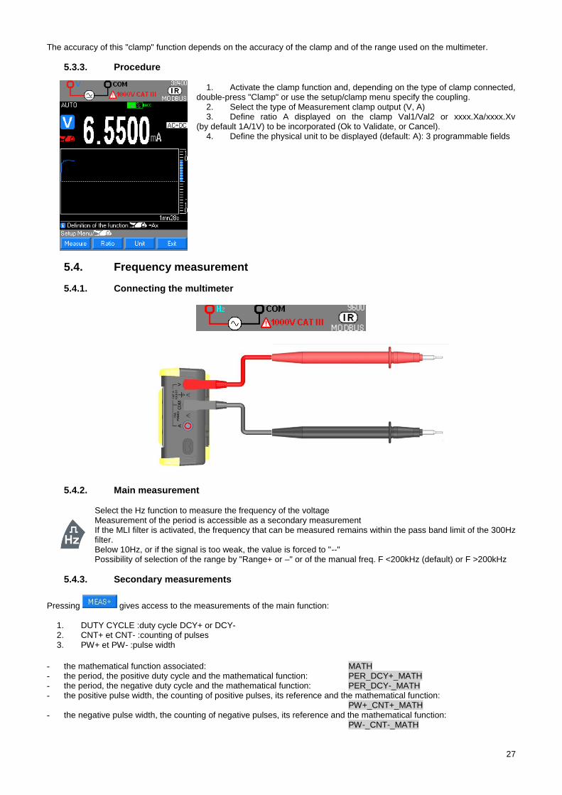
5.3.3. Procedure
1. Activate the clamp function and, depending on the type of clamp connected, double-press "Clamp" or use the setup/clamp menu specify the coupling.
2. Select the type of Measurement clamp output (V, A) 3. Define ratio A displayed on the clamp Val1/Val2 or xxxx.Xa/xxxx.Xv
(by default 1A/1V) to be incorporated (Ok to Validate, or Cancel). 4. Define the physical unit to be displayed (default: A): 3 programmable fields
Frequency measurement 5.4.
5.4.1. Connecting the multimeter
5.4.2. Main measurement
Select the Hz function to measure the frequency of the voltage Measurement of the period is accessible as a secondary measurement If the MLI filter is activated, the frequency that can be measured remains within the pass band limit of the 300Hz filter. Below 10Hz, or if the signal is too weak, the value is forced to "--" Possibility of selection of the range by "Range+ or –" or of the manual freq. F <200kHz (default) or F >200kHz
5.4.3. Secondary measurements
Pressing gives access to the measurements of the main function:
1. DUTY CYCLE :duty cycle DCY+ or DCY- 2. CNT+ et CNT- :counting of pulses 3. PW+ et PW- :pulse width
- the mathematical function associated: MATH - the period, the positive duty cycle and the mathematical function: PER_DCY+_MATH - the period, the negative duty cycle and the mathematical function: PER_DCY-_MATH - the positive pulse width, the counting of positive pulses, its reference and the mathematical function:
PW+_CNT+_MATH - the negative pulse width, the counting of negative pulses, its reference and the mathematical function:
PW-_CNT-_MATH
28
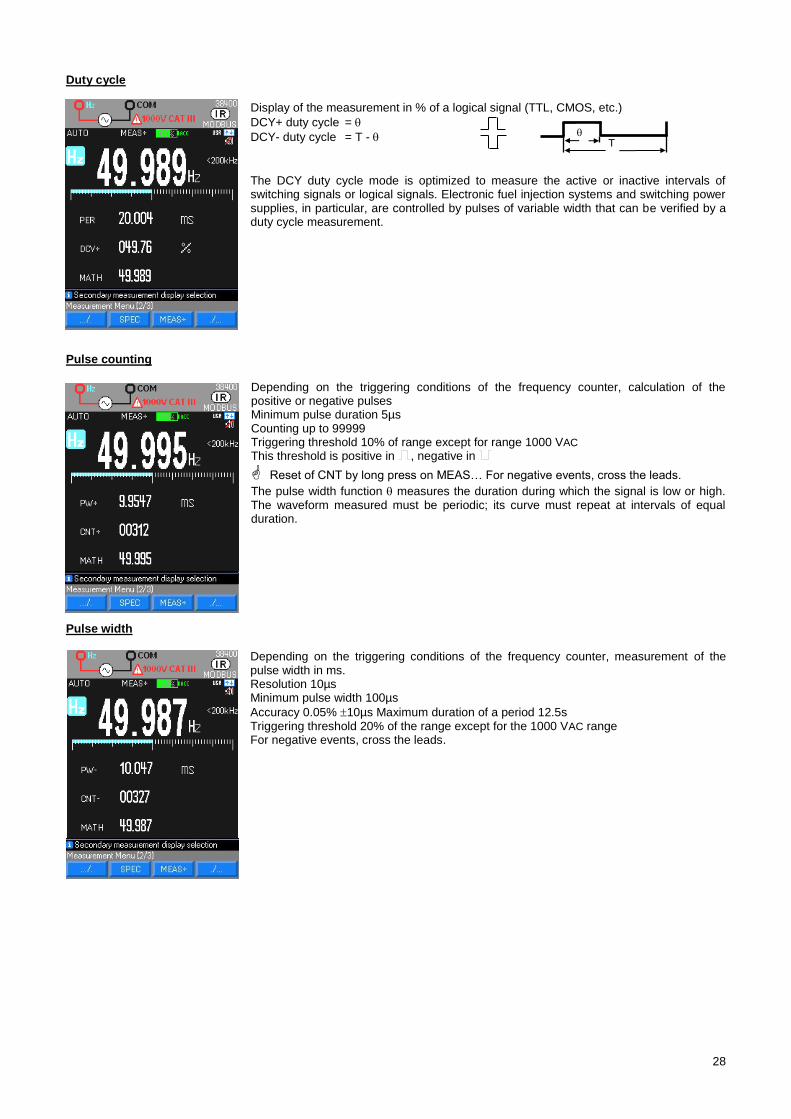
Duty cycle
Display of the measurement in % of a logical signal (TTL, CMOS, etc.)
DCY+ duty cycle =
DCY- duty cycle = T -
The DCY duty cycle mode is optimized to measure the active or inactive intervals of switching signals or logical signals. Electronic fuel injection systems and switching power supplies, in particular, are controlled by pulses of variable width that can be verified by a duty cycle measurement.
Pulse counting
Depending on the triggering conditions of the frequency counter, calculation of the positive or negative pulses Minimum pulse duration 5µs Counting up to 99999 Triggering threshold 10% of range except for range 1000 VAC This threshold is positive in , negative in
Reset of CNT by long press on MEAS… For negative events, cross the leads.
The pulse width function measures the duration during which the signal is low or high. The waveform measured must be periodic; its curve must repeat at intervals of equal duration.
Pulse width
Depending on the triggering conditions of the frequency counter, measurement of the pulse width in ms. Resolution 10µs Minimum pulse width 100µs
Accuracy 0.05% 10µs Maximum duration of a period 12.5s Triggering threshold 20% of the range except for the 1000 VAC range For negative events, cross the leads.
T
29
Resistance measurement 5.5.
5.5.1. Connecting the multimeter
5.5.2. Main measurement
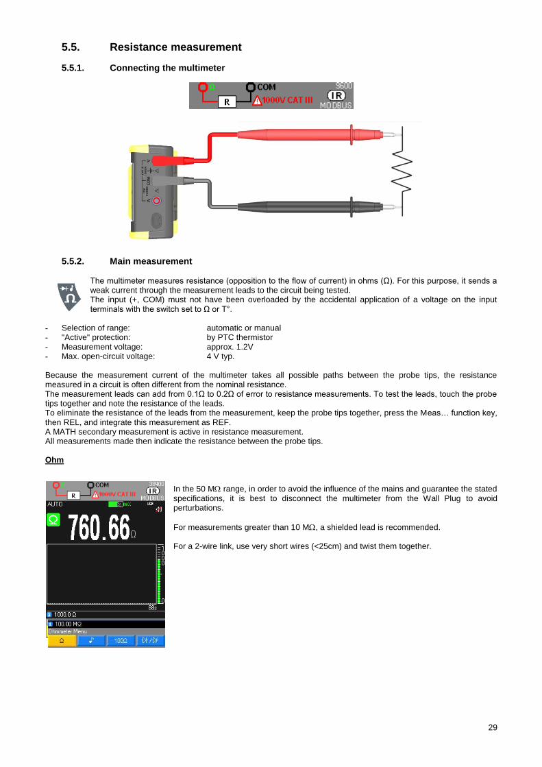
The multimeter measures resistance (opposition to the flow of current) in ohms (Ω). For this purpose, it sends a weak current through the measurement leads to the circuit being tested. The input (+, COM) must not have been overloaded by the accidental application of a voltage on the input terminals with the switch set to Ω or T°.
- Selection of range: automatic or manual - "Active" protection: by PTC thermistor - Measurement voltage: approx. 1.2V - Max. open-circuit voltage: 4 V typ. Because the measurement current of the multimeter takes all possible paths between the probe tips, the resistance measured in a circuit is often different from the nominal resistance. The measurement leads can add from 0.1Ω to 0.2Ω of error to resistance measurements. To test the leads, touch the probe tips together and note the resistance of the leads. To eliminate the resistance of the leads from the measurement, keep the probe tips together, press the Meas… function key, then REL, and integrate this measurement as REF. A MATH secondary measurement is active in resistance measurement. All measurements made then indicate the resistance between the probe tips. Ohm
In the 50 M range, in order to avoid the influence of the mains and guarantee the stated specifications, it is best to disconnect the multimeter from the Wall Plug to avoid perturbations.
For measurements greater than 10 M, a shielded lead is recommended. For a 2-wire link, use very short wires (<25cm) and twist them together.
30
100 Ohm measurements
Press the F3 key to access this function.
So as not to damage the circuit tested, note that the multimeter provides a current
of approximately 10mA max. at an open-circuit voltage of 28 volts max. For low resistance measurements, <100 Ohm, this single range provides good resolution.
Audible continuity measurement 5.6.
5.6.1. Connecting the multimeter
5.6.2. Main measurement
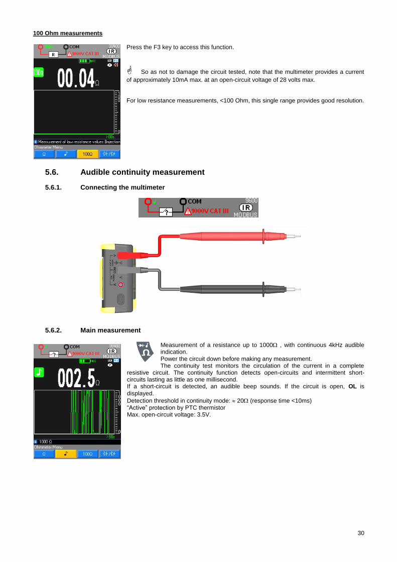
Measurement of a resistance up to 1000 , with continuous 4kHz audible indication. Power the circuit down before making any measurement. The continuity test monitors the circulation of the current in a complete
resistive circuit. The continuity function detects open-circuits and intermittent short-circuits lasting as little as one millisecond. If a short-circuit is detected, an audible beep sounds. If the circuit is open, OL is
displayed.
Detection threshold in continuity mode: 20 (response time <10ms) “Active” protection by PTC thermistor Max. open-circuit voltage: 3.5V.
31
Diode test 5.7.
5.7.1. Connecting the multimeter
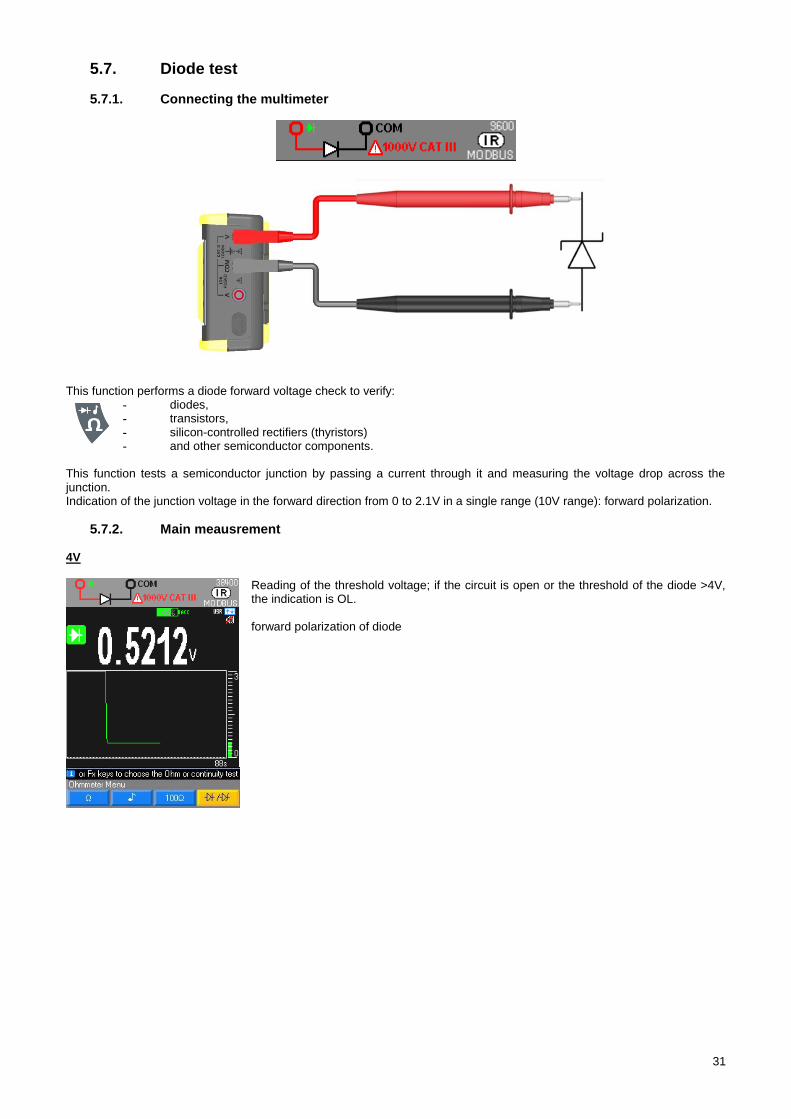
This function performs a diode forward voltage check to verify: - diodes, - transistors, - silicon-controlled rectifiers (thyristors) - and other semiconductor components.
This function tests a semiconductor junction by passing a current through it and measuring the voltage drop across the junction. Indication of the junction voltage in the forward direction from 0 to 2.1V in a single range (10V range): forward polarization.
5.7.2. Main meausrement 4V
Reading of the threshold voltage; if the circuit is open or the threshold of the diode >4V, the indication is OL. forward polarization of diode
32
26V
Zener diode or LED: selecting this diode applies the same function as for the diode above but with a maximum voltage of 26V and a maximum current of 10mA.
Capacitance measurement 5.8.
5.8.1. Connecting the multimeter
5.8.2. Main measurement
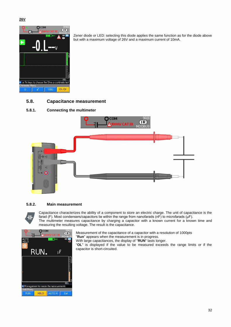
Capacitance characterizes the ability of a component to store an electric charge. The unit of capacitance is the farad (F). Most condensers/capacitors lie within the range from nanofarads (nF) to microfarads (μF). The multimeter measures capacitance by charging a capacitor with a known current for a known time and measuring the resulting voltage. The result is the capacitance.
Measurement of the capacitance of a capacitor with a resolution of 1000pts "Run" appears when the measurement is in progress. With large capacitances, the display of "RUN" lasts longer. "OL" is displayed if the value to be measured exceeds the range limits or if the
capacitor is short-circuited.
33
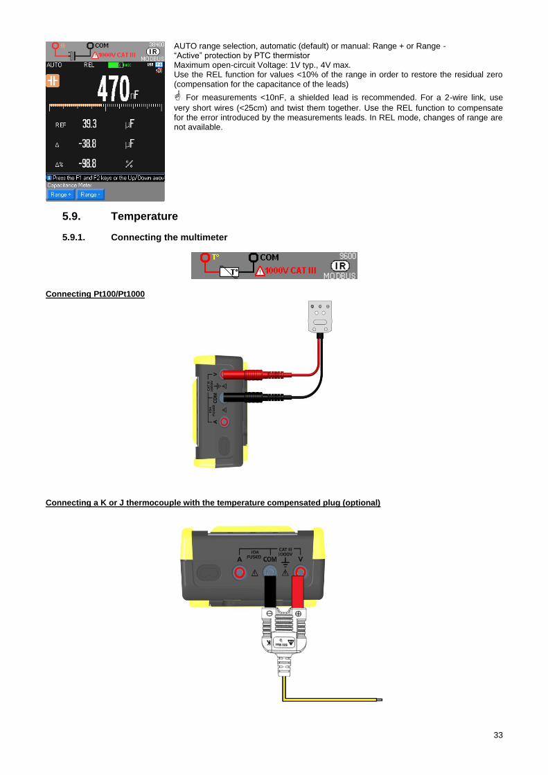
AUTO range selection, automatic (default) or manual: Range + or Range - “Active” protection by PTC thermistor Maximum open-circuit Voltage: 1V typ., 4V max. Use the REL function for values <10% of the range in order to restore the residual zero (compensation for the capacitance of the leads)
For measurements <10nF, a shielded lead is recommended. For a 2-wire link, use
very short wires (<25cm) and twist them together. Use the REL function to compensate for the error introduced by the measurements leads. In REL mode, changes of range are not available.
Temperature 5.9.
5.9.1. Connecting the multimeter
Connecting Pt100/Pt1000
Connecting a K or J thermocouple with the temperature compensated plug (optional)
34
5.9.2. Main measurement
To measure a temperature:
1. Connect the sensor to the V and COM terminals, making sure to get the polarity right. 2. Choose the unit: °C (Celsius), K (Kelvin) or °F (Fahrenheit). 3. Select ".../…". 4. Choose the type of sensor Pt100, Pt1000, TCJ, or TCK.
If "OL" is displayed, the sensor is open-circuit or the measured value exceeds the range limit.
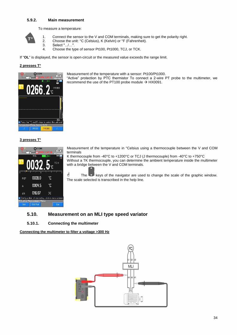
2 presses T°
Measurement of the temperature with a sensor: Pt100/Pt1000. “Active” protection by PTC thermistor To connect a 2-wire PT probe to the multimeter, we recommend the use of the PT100 probe module HX0091.
3 presses T°
Measurement of the temperature in °Celsius using a thermocouple between the V and COM terminals K thermocouple from -40°C to +1200°C or TCJ (J thermocouple) from -40°C to +750°C Without a TK thermocouple, you can determine the ambient temperature inside the multimeter with a bridge between the V and COM terminals.
The keys of the navigator are used to change the scale of the graphic window.
The scale selected is transcribed in the help line.
Measurement on an MLI type speed variator 5.10.
5.10.1. Connecting the multimeter Connecting the multimeter to filter a voltage >300 Hz
35
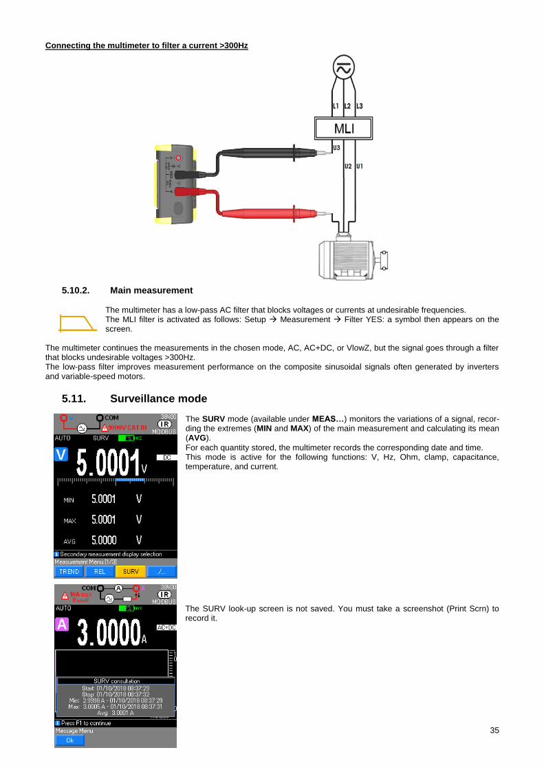
Connecting the multimeter to filter a current >300Hz
5.10.2. Main measurement
The multimeter has a low-pass AC filter that blocks voltages or currents at undesirable frequencies. The MLI filter is activated as follows: Setup Measurement Filter YES: a symbol then appears on the screen.
The multimeter continues the measurements in the chosen mode, AC, AC+DC, or VlowZ, but the signal goes through a filter that blocks undesirable voltages >300Hz. The low-pass filter improves measurement performance on the composite sinusoidal signals often generated by inverters and variable-speed motors.
Surveillance mode 5.11. The SURV mode (available under MEAS…) monitors the variations of a signal, recor-ding the extremes (MIN and MAX) of the main measurement and calculating its mean (AVG).
For each quantity stored, the multimeter records the corresponding date and time. This mode is active for the following functions: V, Hz, Ohm, clamp, capacitance, temperature, and current. The SURV look-up screen is not saved. You must take a screenshot (Print Scrn) to record it.
36
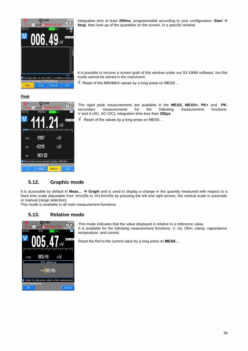
Integration time at least 200ms, programmable according to your configuration: Start Stop, then look-up of the quantities on the screen, in a specific window.
It is possible to recover a screen grab of this window under our SX-DMM software, but this mode cannot be stored in the instrument.
Reset of the MIN/MAX values by a long press on MEAS…
Peak
The rapid peak measurements are available in the MEAS, MEAS+, PK+ and PK-
secondary measurements for the following measurement functions: V and A (AC, AC+DC); integration time less than 250µs.
Reset of the values by a long press on MEAS…
Graphic mode 5.12. It is accessible by default in Meas… Graph and is used to display a change in the quantity measured with respect to a
fixed time scale adjustable from 1mn28s to 1h13mn20s by pressing the left and right arrows; the vertical scale is automatic or manual (range selection). This mode is available in all main measurement functions.
Relative mode 5.13. This mode indicates that the value displayed is relative to a reference value. It is available for the following measurement functions: V, Hz, Ohm, clamp, capacitance, temperature, and current. Reset the Ref to the current value by a long press on MEAS…
37
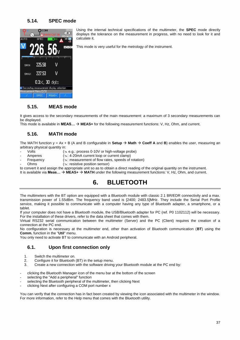
SPEC mode 5.14.
Using the internal technical specifications of the multimeter, the SPEC mode directly
displays the tolerance on the measurement in progress, with no need to look for it and calculate it. This mode is very useful for the metrology of the instrument.
MEAS mode 5.15. It gives access to the secondary measurements of the main measurement: a maximum of 3 secondary measurements can be displayed. This mode is available in MEAS… MEAS+ for the following measurement functions: V, Hz, Ohm, and current.
MATH mode 5.16. The MATH function y = Ax + B (A and B configurable in Setup Math Coeff A and B) enables the user, measuring an
arbitrary physical quantity in: - Volts ( e.g.: process 0-10V or high-voltage probe) - Amperes (: 4-20mA current loop or current clamp) - Frequency (: measurement of flow rates, speeds of rotation) - Ohms (: resistive position sensor) to convert it and assign the appropriate unit so as to obtain a direct reading of the original quantity on the instrument. It is available via Meas… MEAS+ MATH under the following measurement functions: V, Hz, Ohm, and current.
6. BLUETOOTH
The multimeters with the BT option are equipped with a Bluetooth module with classic 2.1 BR/EDR connectivity and a max. transmission power of 1.55dBm. The frequency band used is [2400; 2483.5]MHz. They include the Serial Port Profile service, making it possible to communicate with a computer having any type of Bluetooth adapter, a smartphone, or a tablet. If your computer does not have a Bluetooth module, the USB/Bluetooth adapter for PC (ref. P0 1102112) will be necessary. For the installation of these drivers, refer to the data sheet that comes with them. Virtual RS232 serial communication between the multimeter (Server) and the PC (Client) requires the creation of a connection at the PC end. No configuration is necessary at the multimeter end, other than activation of Bluetooth communication (BT) using the Comm. function in the "Util" menu.
You only need to activate BT to communicate with an Android peripheral.
Upon first connection only 6.1.
1. Switch the multimeter on. 2. Configure it for Bluetooth (BT) in the setup menu. 3. Create a new connection with the software driving your Bluetooth module at the PC end by:
- clicking the Bluetooth Manager icon of the menu bar at the bottom of the screen - selecting the "Add a peripheral" function - selecting the Bluetooth peripheral of the multimeter, then clicking Next - clicking Next after configuring a COM port number x You can verify that the connection has in fact been created by viewing the icon associated with the multimeter in the window. For more information, refer to the Help menu that comes with the Bluetooth utility.
38
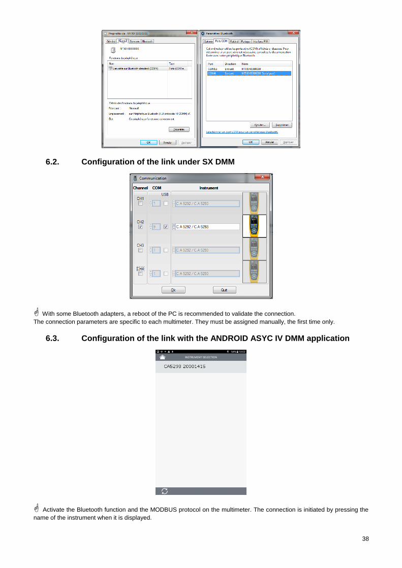
Configuration of the link under SX DMM 6.2.
With some Bluetooth adapters, a reboot of the PC is recommended to validate the connection.
The connection parameters are specific to each multimeter. They must be assigned manually, the first time only.
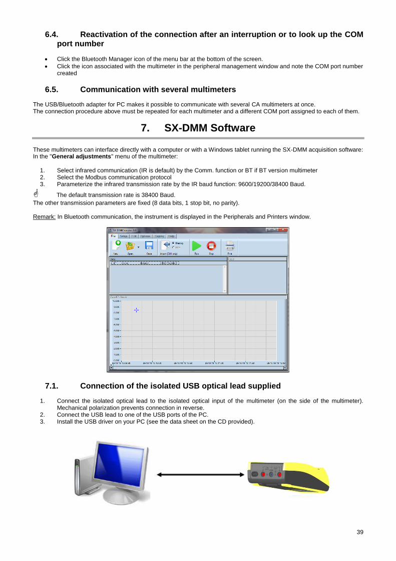
Configuration of the link with the ANDROID ASYC IV DMM application 6.3.
Activate the Bluetooth function and the MODBUS protocol on the multimeter. The connection is initiated by pressing the
name of the instrument when it is displayed.
39
Reactivation of the connection after an interruption or to look up the COM 6.4.port number
Click the Bluetooth Manager icon of the menu bar at the bottom of the screen.
Click the icon associated with the multimeter in the peripheral management window and note the COM port number created
Communication with several multimeters 6.5. The USB/Bluetooth adapter for PC makes it possible to communicate with several CA multimeters at once. The connection procedure above must be repeated for each multimeter and a different COM port assigned to each of them.
7. SX-DMM Software
These multimeters can interface directly with a computer or with a Windows tablet running the SX-DMM acquisition software: In the "General adjustments" menu of the multimeter:
1. Select infrared communication (IR is default) by the Comm. function or BT if BT version multimeter 2. Select the Modbus communication protocol 3. Parameterize the infrared transmission rate by the IR baud function: 9600/19200/38400 Baud.
The default transmission rate is 38400 Baud. The other transmission parameters are fixed (8 data bits, 1 stop bit, no parity). Remark: In Bluetooth communication, the instrument is displayed in the Peripherals and Printers window.
Connection of the isolated USB optical lead supplied 7.1.
1. Connect the isolated optical lead to the isolated optical input of the multimeter (on the side of the multimeter). Mechanical polarization prevents connection in reverse.
2. Connect the USB lead to one of the USB ports of the PC. 3. Install the USB driver on your PC (see the data sheet on the CD provided).
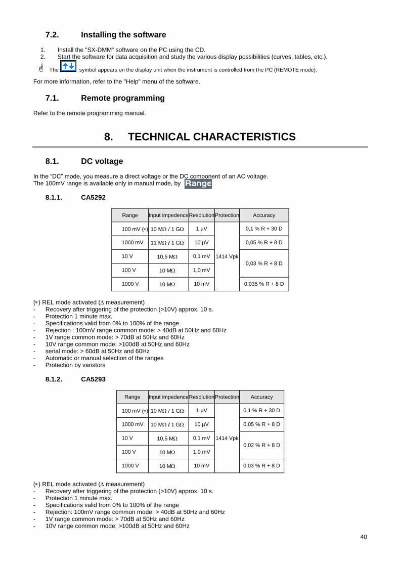
40
Installing the software 7.2.
1. Install the "SX-DMM" software on the PC using the CD. 2. Start the software for data acquisition and study the various display possibilities (curves, tables, etc.).
The symbol appears on the display unit when the instrument is controlled from the PC (REMOTE mode).
For more information, refer to the "Help" menu of the software.
Remote programming 7.1. Refer to the remote programming manual.
8. TECHNICAL CHARACTERISTICS
DC voltage 8.1. In the “DC” mode, you measure a direct voltage or the DC component of an AC voltage. The 100mV range is available only in manual mode, by
8.1.1. CA5292
Range Input impedence Resolution Protection Accuracy
100 mV () 10 M / 1 G 1 µV
1414 Vpk
0,1 % R + 30 D
1000 mV 11 M / 1 G 10 µV 0,05 % R + 8 D
10 V 10,5 M 0,1 mV
0,03 % R + 8 D
100 V 10 M 1,0 mV
1000 V 10 M 10 mV 0,035 % R + 8 D
() REL mode activated ( measurement) - Recovery after triggering of the protection (>10V) approx. 10 s. - Protection 1 minute max. - Specifications valid from 0% to 100% of the range - Rejection : 100mV range common mode: > 40dB at 50Hz and 60Hz - 1V range common mode: > 70dB at 50Hz and 60Hz - 10V range common mode: >100dB at 50Hz and 60Hz - serial mode: > 60dB at 50Hz and 60Hz - Automatic or manual selection of the ranges - Protection by varistors
8.1.2. CA5293
Range Input impedence Resolution Protection Accuracy
100 mV () 10 M / 1 G 1 µV
1414 Vpk
0,1 % R + 30 D
1000 mV 10 M / 1 G 10 µV 0,05 % R + 8 D
10 V 10,5 M 0,1 mV
0,02 % R + 8 D
100 V 10 M 1,0 mV
1000 V 10 M 10 mV 0,03 % R + 8 D
() REL mode activated ( measurement) - Recovery after triggering of the protection (>10V) approx. 10 s. - Protection 1 minute max. - Specifications valid from 0% to 100% of the range - Rejection: 100mV range common mode: > 40dB at 50Hz and 60Hz - 1V range common mode: > 70dB at 50Hz and 60Hz - 10V range common mode: >100dB at 50Hz and 60Hz
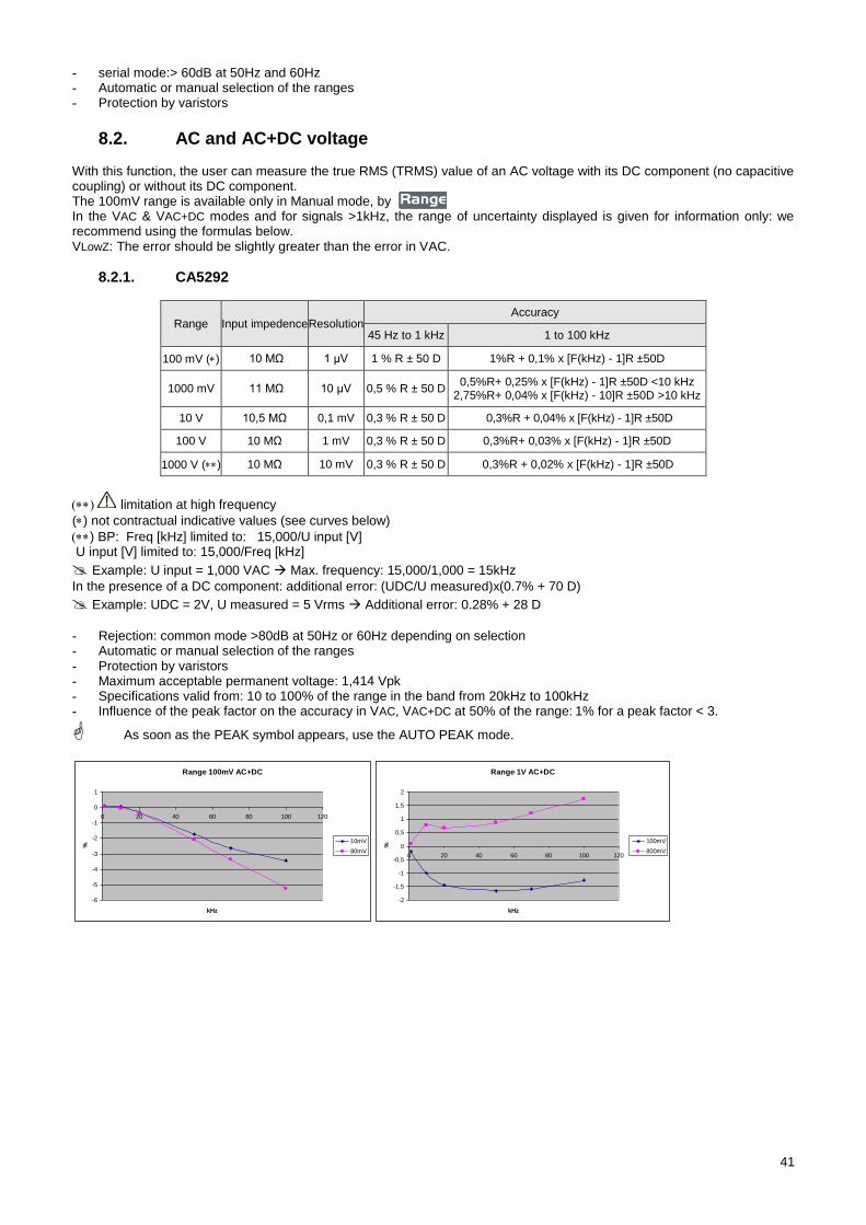
41
- serial mode:> 60dB at 50Hz and 60Hz - Automatic or manual selection of the ranges - Protection by varistors
AC and AC+DC voltage 8.2. With this function, the user can measure the true RMS (TRMS) value of an AC voltage with its DC component (no capacitive coupling) or without its DC component. The 100mV range is available only in Manual mode, by In the VAC & VAC+DC modes and for signals >1kHz, the range of uncertainty displayed is given for information only: we recommend using the formulas below. VLowZ: The error should be slightly greater than the error in VAC.
8.2.1. CA5292
Range Input impedence Resolution Accuracy
45 Hz to 1 kHz 1 to 100 kHz
100 mV () 10 MΩ 1 μV 1 % R ± 50 D 1%R + 0,1% x [F(kHz) - 1]R ±50D
1000 mV 11 MΩ 10 μV 0,5 % R ± 50 D 0,5%R+ 0,25% x [F(kHz) - 1]R ±50D <10 kHz
2,75%R+ 0,04% x [F(kHz) - 10]R ±50D >10 kHz
10 V 10,5 MΩ 0,1 mV 0,3 % R ± 50 D 0,3%R + 0,04% x [F(kHz) - 1]R ±50D
100 V 10 MΩ 1 mV 0,3 % R ± 50 D 0,3%R+ 0,03% x [F(kHz) - 1]R ±50D
1000 V () 10 MΩ 10 mV 0,3 % R ± 50 D 0,3%R + 0,02% x [F(kHz) - 1]R ±50D
limitation at high frequency
() not contractual indicative values (see curves below)
) BP: Freq [kHz] limited to: 15,000/U input [V] U input [V] limited to: 15,000/Freq [kHz]
Example: U input = 1,000 VAC Max. frequency: 15,000/1,000 = 15kHz
In the presence of a DC component: additional error: (UDC/U measured)x(0.7% + 70 D)
Example: UDC = 2V, U measured = 5 Vrms Additional error: 0.28% + 28 D
- Rejection: common mode >80dB at 50Hz or 60Hz depending on selection - Automatic or manual selection of the ranges - Protection by varistors - Maximum acceptable permanent voltage: 1,414 Vpk - Specifications valid from: 10 to 100% of the range in the band from 20kHz to 100kHz - Influence of the peak factor on the accuracy in VAC, VAC+DC at 50% of the range: 1% for a peak factor < 3.
As soon as the PEAK symbol appears, use the AUTO PEAK mode.
Range 100mV AC+DC
-6
-5
-4
-3
-2
-1
0
1
0 20 40 60 80 100 120
kHz
%
10mV
80mV
Range 1V AC+DC
-2
-1,5
-1
-0,5
0
0,5
1
1,5
2
0 20 40 60 80 100 120
kHz
%
100mV
800mV
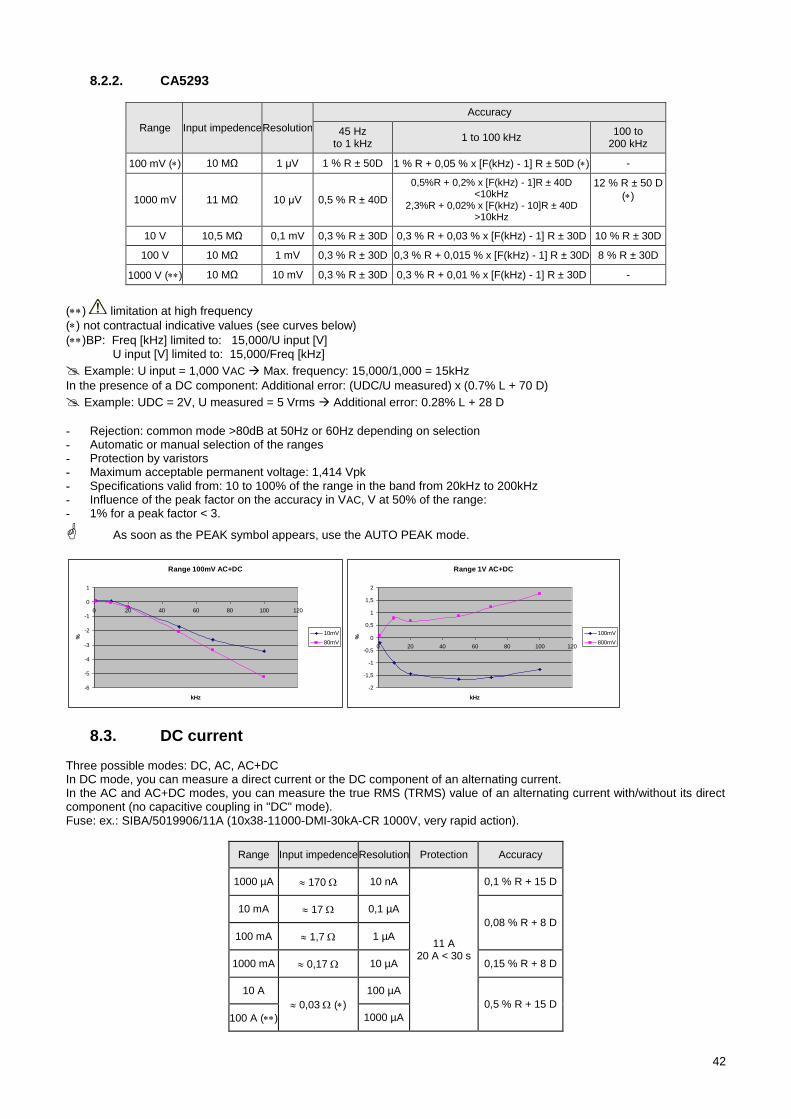
42
8.2.2. CA5293
Range Input impedence Resolution
Accuracy
45 Hz to 1 kHz
1 to 100 kHz 100 to
200 kHz
100 mV () 10 MΩ 1 μV 1 % R ± 50D 1 % R + 0,05 % x [F(kHz) - 1] R ± 50D () -
1000 mV 11 MΩ 10 μV 0,5 % R ± 40D
0,5%R + 0,2% x [F(kHz) - 1]R ± 40D <10kHz
2,3%R + 0,02% x [F(kHz) - 10]R ± 40D >10kHz
12 % R ± 50 D
()
10 V 10,5 MΩ 0,1 mV 0,3 % R ± 30D 0,3 % R + 0,03 % x [F(kHz) - 1] R ± 30D 10 % R ± 30D
100 V 10 MΩ 1 mV 0,3 % R ± 30D 0,3 % R + 0,015 % x [F(kHz) - 1] R ± 30D 8 % R ± 30D
1000 V () 10 MΩ 10 mV 0,3 % R ± 30D 0,3 % R + 0,01 % x [F(kHz) - 1] R ± 30D -
() limitation at high frequency
() not contractual indicative values (see curves below)
()BP: Freq [kHz] limited to: 15,000/U input [V] U input [V] limited to: 15,000/Freq [kHz]
Example: U input = 1,000 VAC Max. frequency: 15,000/1,000 = 15kHz
In the presence of a DC component: Additional error: (UDC/U measured) x (0.7% L + 70 D)
Example: UDC = 2V, U measured = 5 Vrms Additional error: 0.28% L + 28 D
- Rejection: common mode >80dB at 50Hz or 60Hz depending on selection - Automatic or manual selection of the ranges - Protection by varistors - Maximum acceptable permanent voltage: 1,414 Vpk - Specifications valid from: 10 to 100% of the range in the band from 20kHz to 200kHz - Influence of the peak factor on the accuracy in VAC, V at 50% of the range: - 1% for a peak factor < 3.
As soon as the PEAK symbol appears, use the AUTO PEAK mode.
DC current 8.3. Three possible modes: DC, AC, AC+DC In DC mode, you can measure a direct current or the DC component of an alternating current. In the AC and AC+DC modes, you can measure the true RMS (TRMS) value of an alternating current with/without its direct component (no capacitive coupling in "DC" mode). Fuse: ex.: SIBA/5019906/11A (10x38-11000-DMI-30kA-CR 1000V, very rapid action).
Range Input impedence Resolution Protection Accuracy
1000 µA 170 10 nA
11 A 20 A < 30 s
0,1 % R + 15 D
10 mA 17 0,1 µA
0,08 % R + 8 D
100 mA 1,7 1 µA
1000 mA 0,17 10 µA 0,15 % R + 8 D
10 A
0,03 ()
100 µA
0,5 % R + 15 D
100 A () 1000 µA
Range 100mV AC+DC
-6
-5
-4
-3
-2
-1
0
1
0 20 40 60 80 100 120
kHz
%
10mV
80mV
Range 1V AC+DC
-2
-1,5
-1
-0,5
0
0,5
1
1,5
2
0 20 40 60 80 100 120
kHz
%
100mV
800mV
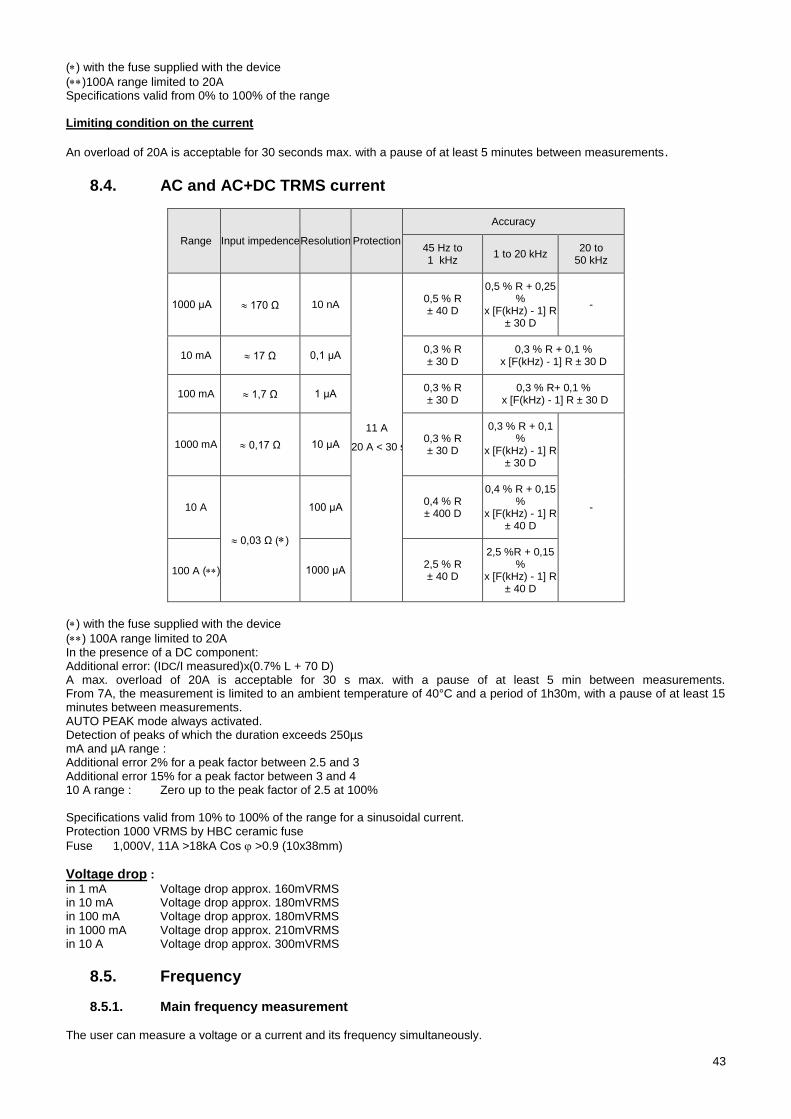
43
() with the fuse supplied with the device
()100A range limited to 20A Specifications valid from 0% to 100% of the range Limiting condition on the current
An overload of 20A is acceptable for 30 seconds max. with a pause of at least 5 minutes between measurements.
AC and AC+DC TRMS current 8.4.
Range Input impedence Resolution Protection
Accuracy
45 Hz to 1 kHz
1 to 20 kHz 20 to
50 kHz
1000 μA 170 Ω 10 nA
11 A
20 A < 30 s
0,5 % R ± 40 D
0,5 % R + 0,25 %
x [F(kHz) - 1] R ± 30 D
-
10 mA 17 Ω 0,1 μA 0,3 % R ± 30 D
0,3 % R + 0,1 % x [F(kHz) - 1] R ± 30 D
100 mA 1,7 Ω 1 μA 0,3 % R ± 30 D
0,3 % R+ 0,1 % x [F(kHz) - 1] R ± 30 D
1000 mA 0,17 Ω 10 μA 0,3 % R ± 30 D
0,3 % R + 0,1 %
x [F(kHz) - 1] R ± 30 D
- 10 A
0,03 Ω ()
100 μA 0,4 % R ± 400 D
0,4 % R + 0,15 %
x [F(kHz) - 1] R ± 40 D
100 A () 1000 μA 2,5 % R ± 40 D
2,5 %R + 0,15 %
x [F(kHz) - 1] R ± 40 D
() with the fuse supplied with the device
() 100A range limited to 20A In the presence of a DC component: Additional error: (IDC/I measured)x(0.7% L + 70 D) A max. overload of 20A is acceptable for 30 s max. with a pause of at least 5 min between measurements. From 7A, the measurement is limited to an ambient temperature of 40°C and a period of 1h30m, with a pause of at least 15 minutes between measurements. AUTO PEAK mode always activated. Detection of peaks of which the duration exceeds 250µs mA and µA range : Additional error 2% for a peak factor between 2.5 and 3 Additional error 15% for a peak factor between 3 and 4 10 A range : Zero up to the peak factor of 2.5 at 100% Specifications valid from 10% to 100% of the range for a sinusoidal current. Protection 1000 VRMS by HBC ceramic fuse
Fuse 1,000V, 11A >18kA Cos >0.9 (10x38mm)
Voltage drop :
in 1 mA Voltage drop approx. 160mVRMS in 10 mA Voltage drop approx. 180mVRMS in 100 mA Voltage drop approx. 180mVRMS in 1000 mA Voltage drop approx. 210mVRMS in 10 A Voltage drop approx. 300mVRMS
Frequency 8.5.
8.5.1. Main frequency measurement The user can measure a voltage or a current and its frequency simultaneously.
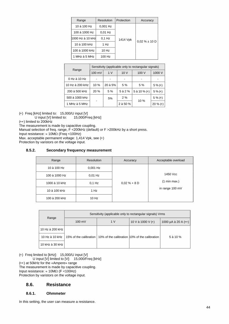
44
Range Resolution Protection Accuracy
10 à 100 Hz 0,001 Hz
1414 Vpk 0,02 % ± 10 D
100 à 1000 Hz 0,01 Hz
1000 Hz à 10 kHz 0,1 Hz
10 à 100 kHz 1 Hz
100 à 1000 kHz 10 Hz
1 MHz à 5 MHz 100 Hz
Range Sensitivity (applicable only to rectangular signals)
100 mV 1 V 10 V 100 V 1000 V
0 Hz à 10 Hz - - - - -
10 Hz à 200 kHz 10 % 20 à 5% 5 % 5 % 5 % ()
200 à 500 kHz 20 % 5 % 5 à 2 % 5 à 10 % () 5 % ()
500 à 1000 kHz -
5%
2 % 10 %
5 % ()
1 MHz à 5 MHz 2 à 50 % 20 % ()
() Freq [kHz] limited to: 15,000/U input [V] U input [V] limited to: 15,000/Freq [kHz]
() limited to 200kHz The measurement is made by capacitive coupling. Manual selection of freq. range, F <200kHz (default) or F >200kHz by a short press.
Input resistance: 10M (Freq <100Hz)
Max. acceptable permanent voltage: 1,414 Vpk, see () Protection by varistors on the voltage input.
8.5.2. Secondary frequency measurement
Range Resolution Accuracy Acceptable overload
10 à 100 Hz 0,001 Hz
0,02 % + 8 D
1450 Vcc
(1 min max.)
in range 100 mV
100 à 1000 Hz 0,01 Hz
1000 à 10 kHz 0,1 Hz
10 à 100 kHz 1 Hz
100 à 200 kHz 10 Hz
Range
Sensitivity (applicable only to rectangular signals) Vrms
100 mV 1 V 10 V à 1000 V () 1000 µA à 20 A ()
10 Hz à 200 kHz
15% of the calibration 10% of the calibration 10% of the calibration 5 à 10 % 10 Hz à 10 kHz
10 kHz à 30 kHz
() Freq limited to [kHz]: 15,000/U input [V] U input [V] limited to [V]: 15,000/Freq [kHz]
() at 50kHz for the «Ampere» range The measurement is made by capacitive coupling.
Input resistance: 10M (F <100Hz) Protection by varistors on the voltage input.
Resistance 8.6.
8.6.1. Ohmmeter In this setting, the user can measure a resistance.
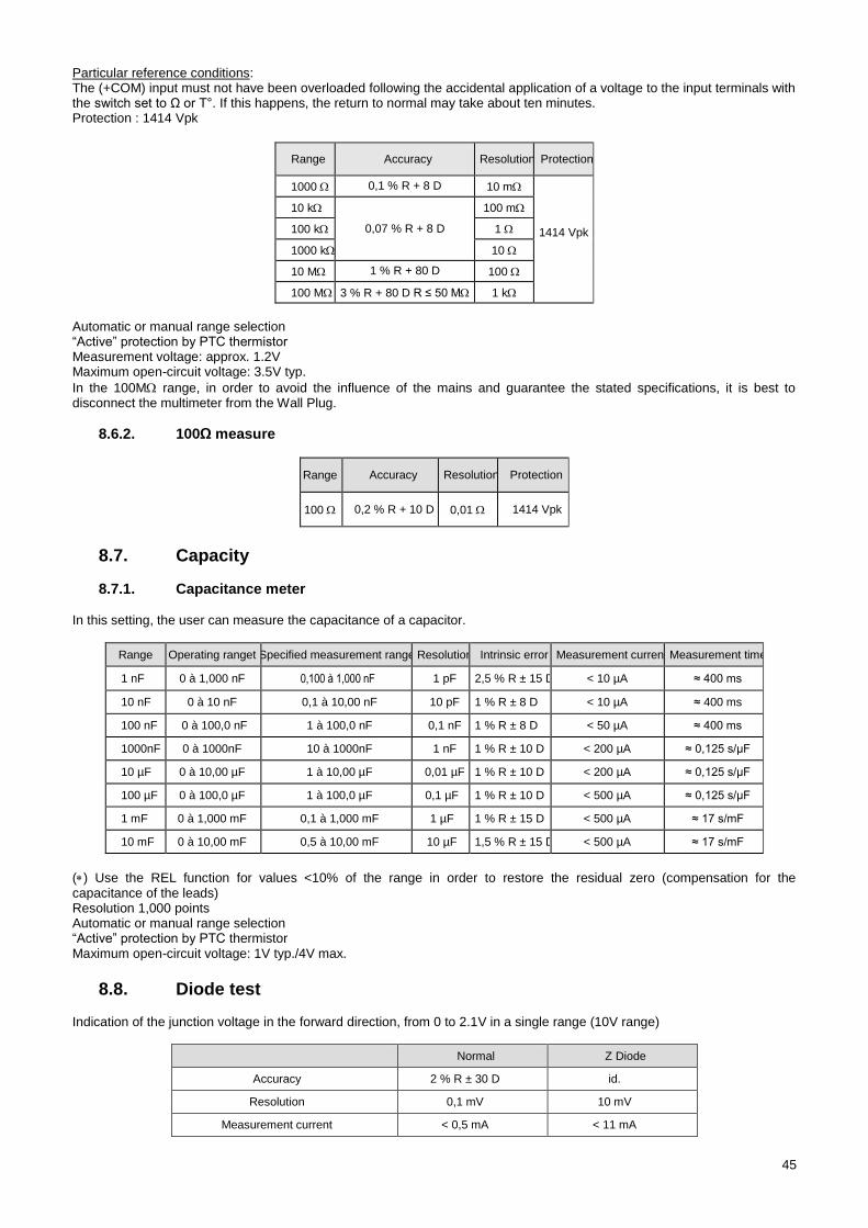
45
Particular reference conditions: The (+COM) input must not have been overloaded following the accidental application of a voltage to the input terminals with the switch set to Ω or T°. If this happens, the return to normal may take about ten minutes. Protection : 1414 Vpk
Range Accuracy Resolution Protection
1000 0,1 % R + 8 D 10 m
1414 Vpk
10 k
0,07 % R + 8 D
100 m
100 k 1
1000 k 10
10 M 1 % R + 80 D 100
100 M 3 % R + 80 D R ≤ 50 M 1 k
Automatic or manual range selection “Active” protection by PTC thermistor Measurement voltage: approx. 1.2V Maximum open-circuit voltage: 3.5V typ.
In the 100M range, in order to avoid the influence of the mains and guarantee the stated specifications, it is best to disconnect the multimeter from the Wall Plug.
8.6.2. 100Ω measure
Range Accuracy Resolution Protection
100 0,2 % R + 10 D 0,01 1414 Vpk
Capacity 8.7.
8.7.1. Capacitance meter In this setting, the user can measure the capacitance of a capacitor.
Range Operating ranget Specified measurement range Resolution Intrinsic error Measurement current Measurement time
1 nF 0 à 1,000 nF 0,100 à 1,000 nF 1 pF 2,5 % R ± 15 D < 10 µA ≈ 400 ms
10 nF 0 à 10 nF 0,1 à 10,00 nF 10 pF 1 % R ± 8 D < 10 µA ≈ 400 ms
100 nF 0 à 100,0 nF 1 à 100,0 nF 0,1 nF 1 % R ± 8 D < 50 µA ≈ 400 ms
1000nF 0 à 1000nF 10 à 1000nF 1 nF 1 % R ± 10 D < 200 µA ≈ 0,125 s/µF
10 µF 0 à 10,00 µF 1 à 10,00 µF 0,01 µF 1 % R ± 10 D < 200 µA ≈ 0,125 s/µF
100 µF 0 à 100,0 µF 1 à 100,0 µF 0,1 µF 1 % R ± 10 D < 500 µA ≈ 0,125 s/µF
1 mF 0 à 1,000 mF 0,1 à 1,000 mF 1 µF 1 % R ± 15 D < 500 µA ≈ 17 s/mF
10 mF 0 à 10,00 mF 0,5 à 10,00 mF 10 µF 1,5 % R ± 15 D < 500 µA ≈ 17 s/mF
() Use the REL function for values <10% of the range in order to restore the residual zero (compensation for the capacitance of the leads) Resolution 1,000 points Automatic or manual range selection “Active” protection by PTC thermistor Maximum open-circuit voltage: 1V typ./4V max.
Diode test 8.8. Indication of the junction voltage in the forward direction, from 0 to 2.1V in a single range (10V range)
Normal Z Diode
Accuracy 2 % R ± 30 D id.
Resolution 0,1 mV 10 mV
Measurement current < 0,5 mA < 11 mA
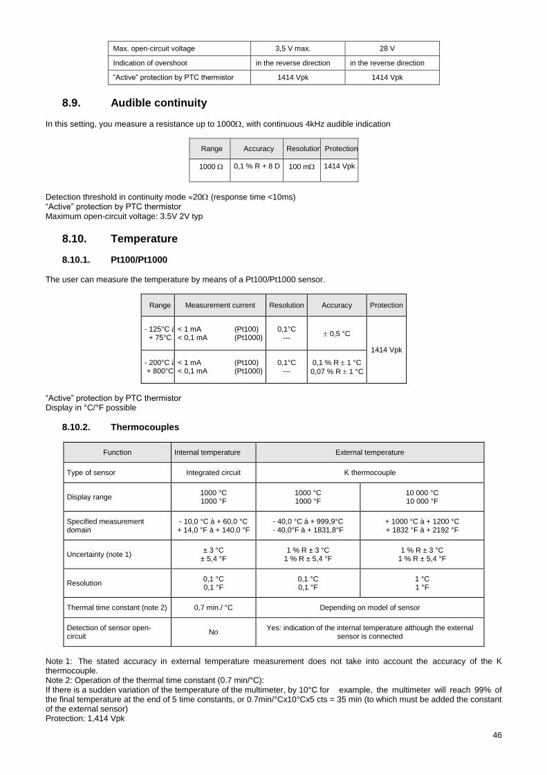
46
Max. open-circuit voltage 3,5 V max. 28 V
Indication of overshoot in the reverse direction in the reverse direction
“Active” protection by PTC thermistor 1414 Vpk 1414 Vpk
Audible continuity 8.9.
In this setting, you measure a resistance up to 1000, with continuous 4kHz audible indication
Range Accuracy Resolution Protection
1000 0,1 % R + 8 D 100 m 1414 Vpk
Detection threshold in continuity mode 20 (response time <10ms) “Active” protection by PTC thermistor Maximum open-circuit voltage: 3.5V 2V typ
Temperature 8.10.
8.10.1. Pt100/Pt1000 The user can measure the temperature by means of a Pt100/Pt1000 sensor.
Range Measurement current Resolution Accuracy Protection
- 125°C à + 75°C
< 1 mA (Pt100) < 0,1 mA (Pt1000)
0,1°C ---
0,5 °C
1414 Vpk
- 200°C à + 800°C
< 1 mA (Pt100) < 0,1 mA (Pt1000)
0,1°C ---
0,1 % R 1 °C
0,07 % R 1 °C
“Active” protection by PTC thermistor Display in °C/°F possible
8.10.2. Thermocouples
Function Internal temperature External temperature
Type of sensor Integrated circuit K thermocouple
Display range 1000 °C 1000 °F
1000 °C 1000 °F
10 000 °C 10 000 °F
Specified measurement domain
- 10,0 °C à + 60,0 °C + 14,0 °F à + 140,0 °F
- 40,0 °C à + 999,9°C - 40,0°F à + 1831,8°F
+ 1000 °C à + 1200 °C + 1832 °F à + 2192 °F
Uncertainty (note 1) ± 3 °C
± 5,4 °F 1 % R ± 3 °C
1 % R ± 5,4 °F 1 % R ± 3 °C
1 % R ± 5,4 °F
Resolution 0,1 °C 0,1 °F
0,1 °C 0,1 °F
1 °C 1 °F
Thermal time constant (note 2) 0,7 min./ °C Depending on model of sensor
Detection of sensor open-circuit
No Yes: indication of the internal temperature although the external
sensor is connected
Note 1: The stated accuracy in external temperature measurement does not take into account the accuracy of the K thermocouple. Note 2: Operation of the thermal time constant (0.7 min/°C): If there is a sudden variation of the temperature of the multimeter, by 10°C for example, the multimeter will reach 99% of the final temperature at the end of 5 time constants, or 0.7min/°Cx10°Cx5 cts = 35 min (to which must be added the constant of the external sensor) Protection: 1,414 Vpk
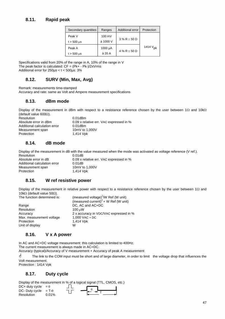
47
Rapid peak 8.11.
Secondary quantities Ranges Additional error Protection
Peak V
t > 500 s
100 mV
à 1000 V 3 % R 50 D
1414 Vpk Peak A
t > 500 s
1000 µA
à 20 A 4 % R 50 D
Specifications valid from 20% of the range in A, 10% of the range in V The peak factor is calculated: CF = (Pk+ - Pk-)/2xVrms Additional error for 250µs < t < 500µs: 3%
SURV (Min, Max, Avg) 8.12. Remark: measurements time-stamped Accuracy and rate: same as Volt and Ampere measurement specifications
dBm mode 8.13.
Display of the measurement in dBm with respect to a resistance reference chosen by the user between 1 and 10k
(default value 600). Resolution 0.01dBm Absolute error in dBm 0.09 x relative err. VAC expressed in % Additional calculation error 0.01dBm Measurement span 10mV to 1,000V Protection 1,414 Vpk
dB mode 8.14. Display of the measurement in dB with the value measured when the mode was activated as voltage reference (V ref.). Resolution 0.01dB Absolute error in dB 0.09 x relative err. VAC expressed in % Additional calculation error 0.01dB Measurement span 10mV to 1,000V Protection 1,414 Vpk
W ref resistive power 8.15.
Display of the measurement in relative power with respect to a resistance reference chosen by the user between 1 and
10k (default value 50). The function determined is: (measured voltage)
2/W Ref (W unit)
(measured current)2 W Ref (W unit)
Range DC, AC and AC+DC
Resolution 100 W Accuracy 2 x accuracy in VDC/VAC expressed in % Max. measurement voltage 1,000 VAC + DC Protection 1,414 Vpk Unit of display W
V x A power 8.16. In AC and AC+DC voltage measurement: this calculation is limited to 400Hz. The current measurement is always made in AC+DC. Accuracy (typical)/Accuracy of V measurement + Accuracy of peak A measurement
The link to the COM input must be short and of large diameter, in order to limit the voltage drop that influences the
Volt measurement. Protection : 1414 Vpk
Duty cycle 8.17. Display of the measurement in % of a logical signal (TTL, CMOS, etc.)
DC+ duty cycle =
DC- Duty cycle = T- Resolution 0.01%
T
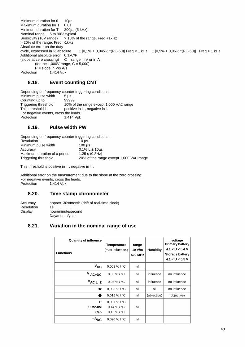
48
Minimum duration for 10s Maximum duration for T 0.8s
Minimum duration for T 200s (5 kHz) Nominal range 5 to 90% typical Sensitivity (10V range) > 10% of the range, Freq <1kHz > 20% of the range, Freq >1kHz Absolute error on the duty cycle, expressed in % absolute ± [0,1% + 0,045% *(RC-50)] Freq < 1 kHz ± [0,5% + 0,06% *(RC-50)] Freq > 1 kHz Additional absolute error 0.1xC/P (slope at zero crossing) C = range in V or in A (for the 1,000V range, C = 5,000) P = slope in V/s A/s Protection 1,414 Vpk
Event counting CNT 8.18. Depending on frequency counter triggering conditions. Minimum pulse width 5 µs Counting up to 99999 Triggering threshold 10% of the range except 1,000 VAC range This threshold is: positive in , negative in For negative events, cross the leads. Protection 1,414 Vpk
Pulse width PW 8.19. Depending on frequency counter triggering conditions. Resolution 10 µs Minimum pulse width 100 µs Accuracy 0.1% L ± 10µs Maximum duration of a period 1.25 s (0.8Hz) Triggering threshold 20% of the range except 1,000 VAC range This threshold is positive in , negative in . Additional error on the measurement due to the slope at the zero crossing: For negative events, cross the leads. Protection 1,414 Vpk
Time stamp chronometer 8.20. Accuracy approx. 30s/month (drift of real-time clock) Resolution 1s Display hour/minute/second Day/month/year
Variation in the nominal range of use 8.21.
Quantity of influence
Functions
Temperature
(max influence.)
range
10 V/m
500 MHz
Humidity
voltage Primary battery
4.1 < U < 6.4 V
Storage battery
4.1 < U < 5.5 V
VDC 0,003 % / °C nil
V AC+DC 0,05 % / °C nil influence no influence
VAC L_Z 0,05 % / °C nil influence no influence
Hz 0,003 % / °C nil nil no influence
0,015 % / °C nil (objective) (objective)
10M/50M
Cap
0,007 % / °C
0,14 % / °C
0,15 % / °C
nil
mADC 0,020 % / °C nil
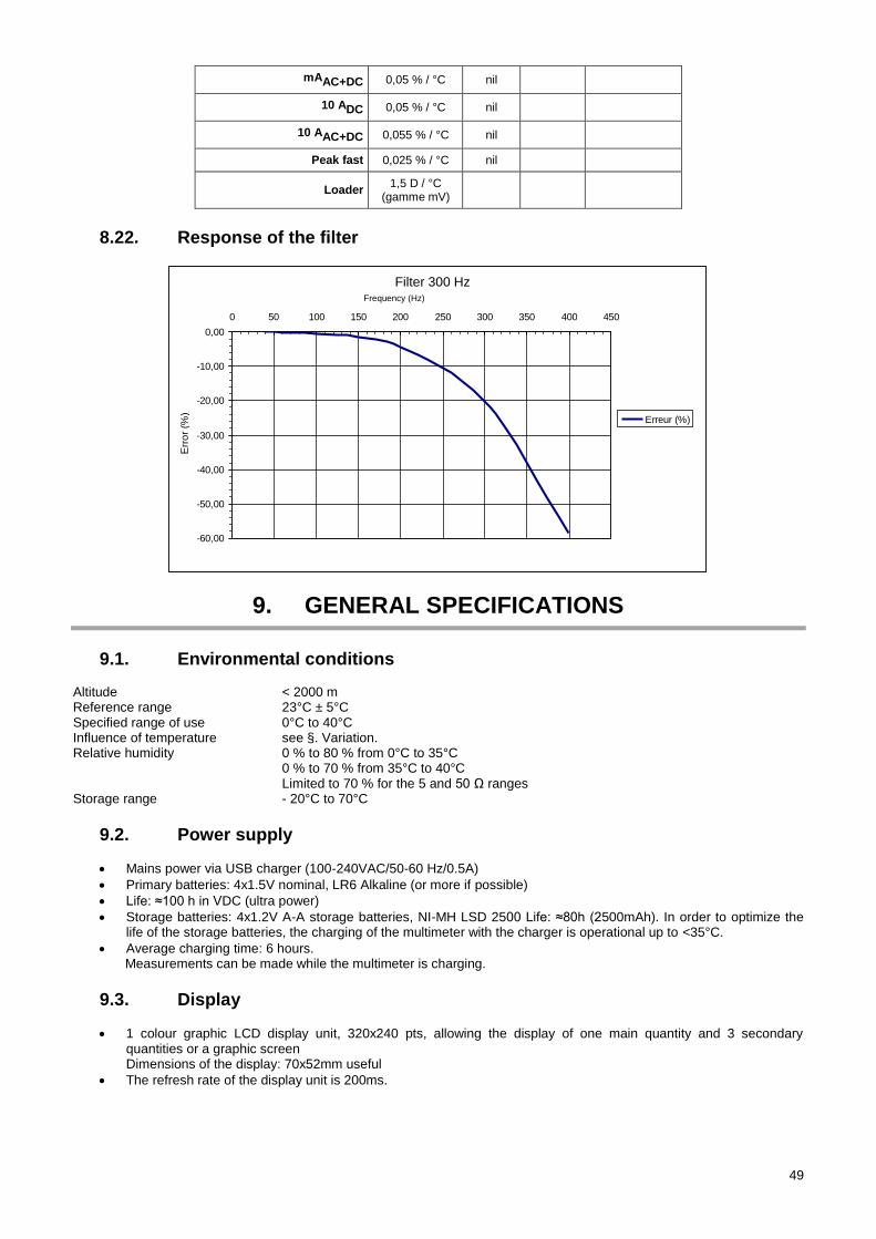
49
mAAC+DC 0,05 % / °C nil
10 ADC 0,05 % / °C nil
10 AAC+DC 0,055 % / °C nil
Peak fast 0,025 % / °C nil
Loader 1,5 D / °C
(gamme mV)
Response of the filter 8.22.
9. GENERAL SPECIFICATIONS
Environmental conditions 9.1. Altitude < 2000 m Reference range 23°C ± 5°C Specified range of use 0°C to 40°C Influence of temperature see §. Variation. Relative humidity 0 % to 80 % from 0°C to 35°C 0 % to 70 % from 35°C to 40°C Limited to 70 % for the 5 and 50 Ω ranges Storage range - 20°C to 70°C
Power supply 9.2.
Mains power via USB charger (100-240VAC/50-60 Hz/0.5A)
Primary batteries: 4x1.5V nominal, LR6 Alkaline (or more if possible)
Life: ≈100 h in VDC (ultra power)
Storage batteries: 4x1.2V A-A storage batteries, NI-MH LSD 2500 Life: ≈80h (2500mAh). In order to optimize the life of the storage batteries, the charging of the multimeter with the charger is operational up to <35°C.
Average charging time: 6 hours. Measurements can be made while the multimeter is charging.
Display 9.3.
1 colour graphic LCD display unit, 320x240 pts, allowing the display of one main quantity and 3 secondary quantities or a graphic screen Dimensions of the display: 70x52mm useful
The refresh rate of the display unit is 200ms.
Filtre 300Hz
-60,00
-50,00
-40,00
-30,00
-20,00
-10,00
0,00
0 50 100 150 200 250 300 350 400 450
Fréquence (Hz)
Err
eu
r (%
)
Erreur (%)
Filter 300 Hz Frequency (Hz)
Err
or
(%)
50
Conformity 9.4.
9.4.1. Safety According to NF EN 61010-1:
Insulation class 2
Degree of pollution 2
Use indoor
Altitude < 2000 m
Measurement categoryof the "measurement" inputs CAT III, 1000V with respect to earth
Measurement categoryof the "measurement" inputs CAT IV, 600V with respect to earth
9.4.2. EMC This instrument is designed in conformity with the EMC standards in force and its compatibility has been tested in accordance with the following standards: Emissions (cl. A) and Immunity NF EN 61326-1
9.4.3. Radio Equipment Directive (RED) – for the BT versions of the multimeters This instrument is designed in compliance with directive 2014/53/EU and has been tested in accordance with the following standards: ETSI EN 301 489-1 ETSI EN 301 489-17 ETSI EN 300 328 EN 62311
10. MECHANICAL SPECIFICATIONS
Housing 10.1.
Dimensions 196 x 90 x 47.1mm
Mass 570g
Materials ABS V0
Dust- and water-tightness IP67, according to NF EN 60529 (Not in operation; if the instrument is immersed, it must be dried, in particular the terminal block, before it can be used again)
11. MAINTENANCE
Except for the fuse and the batteries, the instrument contains no parts that can be replaced by personnel who have not been specially trained and accredited. Any unauthorized repair or replacement of a part by an "equivalent" may gravely impair safety.
Cleaning 11.1. Disconnect the instrument completely and switch it OFF. Use a soft cloth, dampened with soapy water. Rinse with a damp cloth and dry rapidly with a dry cloth or forced air. Do not use alcohol, solvents, or hydrocarbons. Make sure that no foreign body interferes with the operation of the snap device of the sensor.
Replacement of the fuse 11.2. For safety reasons the fuse must always be replaced by an identical model:
11A: 10x38 -1,000V -F
Updating of the internal software 11.3. With a view to providing, at all times, the best possible service in terms of performance and technical upgrades, Chauvin Arnoux invites you to update the embedded software of the device by downloading the new version, available free of charge on our web site. Our site: http://www.chauvin-arnoux.com Embedded software Under Support, click on ASYC IV embedded software /Loader Asyc IV v.xx.exe
4 language pairs are available: English/French, English/Spanish, English/German, and English/Italian.
51
Connect the device to your PC using the USB cord provided. The update of the embedded software depends on its compatibility with the hardware version of the instrument. This version is indicated in SET-UP (see §5). Attention: updating the embedded software resets the configuration and causes the loss of the stored data. As a precaution, save the stored data to a PC before updating the embedded software.
12. WARRANTY
Except as otherwise stated, our warranty is valid for 36 months starting from the date on which the equipment was sold.
Extract from our General Conditions of Sale provided on request. The warranty does not apply in the following cases: - Inappropriate use of the equipment or use with incompatible equipment; - Modifications made to the equipment without the explicit permission of the manufacturer’s technical staff; - Work done on the device by a person not approved by the manufacturer; - Adaptation to a particular application not anticipated in the definition of the equipment or not indicated in the user’s
manual; Damage caused by shocks, falls, or floods.
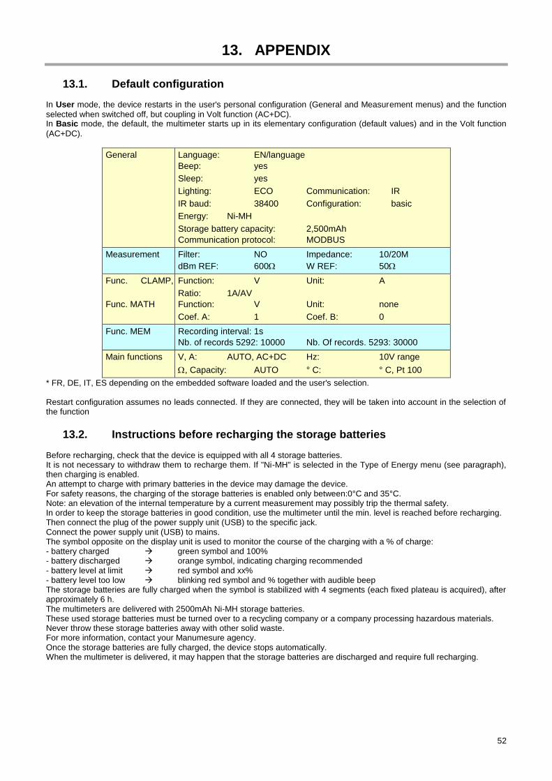
52
13. APPENDIX
Default configuration 13.1. In User mode, the device restarts in the user's personal configuration (General and Measurement menus) and the function
selected when switched off, but coupling in Volt function (AC+DC). In Basic mode, the default, the multimeter starts up in its elementary configuration (default values) and in the Volt function
(AC+DC).
General Language: EN/language
Beep: yes
Sleep: yes
Lighting: ECO Communication: IR
IR baud: 38400 Configuration: basic
Energy: Ni-MH
Storage battery capacity: 2,500mAh
Communication protocol: MODBUS
Measurement Filter: NO Impedance: 10/20M
dBm REF: 600 W REF: 50
Func. CLAMP,
Func. MATH
Function: V Unit: A
Ratio: 1A/AV
Function: V Unit: none
Coef. A: 1 Coef. B: 0
Func. MEM Recording interval: 1s
Nb. of records 5292: 10000 Nb. Of records. 5293: 30000
Main functions V, A: AUTO, AC+DC Hz: 10V range
, Capacity: AUTO ° C: ° C, Pt 100
* FR, DE, IT, ES depending on the embedded software loaded and the user's selection. Restart configuration assumes no leads connected. If they are connected, they will be taken into account in the selection of the function
Instructions before recharging the storage batteries 13.2. Before recharging, check that the device is equipped with all 4 storage batteries. It is not necessary to withdraw them to recharge them. If "Ni-MH" is selected in the Type of Energy menu (see paragraph), then charging is enabled. An attempt to charge with primary batteries in the device may damage the device. For safety reasons, the charging of the storage batteries is enabled only between:0°C and 35°C. Note: an elevation of the internal temperature by a current measurement may possibly trip the thermal safety. In order to keep the storage batteries in good condition, use the multimeter until the min. level is reached before recharging. Then connect the plug of the power supply unit (USB) to the specific jack. Connect the power supply unit (USB) to mains. The symbol opposite on the display unit is used to monitor the course of the charging with a % of charge: - battery charged green symbol and 100% - battery discharged orange symbol, indicating charging recommended - battery level at limit red symbol and xx% - battery level too low blinking red symbol and % together with audible beep The storage batteries are fully charged when the symbol is stabilized with 4 segments (each fixed plateau is acquired), after approximately 6 h. The multimeters are delivered with 2500mAh Ni-MH storage batteries. These used storage batteries must be turned over to a recycling company or a company processing hazardous materials. Never throw these storage batteries away with other solid waste. For more information, contact your Manumesure agency. Once the storage batteries are fully charged, the device stops automatically. When the multimeter is delivered, it may happen that the storage batteries are discharged and require full recharging.
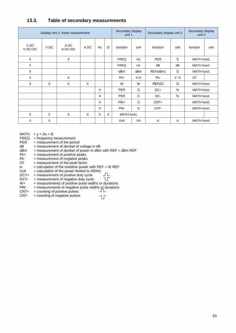
53
Table of secondary measurements 13.3.
Display unit 1: mean measurement Secondary display
unit 1 Secondary display unit 2
Secondary display unit 3
V AC V AC+DC
V DC A AC
A AC+DC A DC Hz Ω function unit function unit function unit
X X FREQ Hz PER S MATH funct.
X FREQ Hz dB dB MATH funct.
X dBm dBm REF(dBm) Ω MATH funct.
X X Pk+ V-A Pk- V -A CF
X X X X W W REF(Ω) Ω MATH funct.
X PER S DC+ % MATH funct.
X PER S DC- % MATH funct.
X PW+ S CNT+ MATH funct.
X PW- S CNT- MATH funct.
X X X X X X MATH funct.
X X VxA VA A A MATH funct.
MATH = y = Ax + B FREQ = frequency measurement PER = measurement of the period dB = measurement of decibel of voltage in dB dBm = measurement of decibel of power in dBm with REF = dBm REF Pk+ = measurement of positive peaks Pk- = measurement of negative peaks CF = measurement of the peak factor w = calculation of the resistive power with REF = W REF VxA = calculation of the power limited to 400Hz DCY+ = measurement of positive duty cycle DCY- = measurement of negative duty cycle W+ = measurements of positive pulse widths or durations PW- = measurements of negative pulse widths or durations CNT+ = counting of positive pulses CNT- = counting of negative pulses

54
X0
48
55
A0
2-E
d.0
1-0
2/2
01
9


