Embed Size (px)
Citation preview
Automatic Sliding DoorOperator Drawings

2016 Automatic Sliding Door Operator Drawings 3
Table of contentsProduct Drawing number Page
EL 301Aluminium frame shopfront 1A201107 4Aluminium door SA1 10201070 5Aluminium door SA2 1A201084 6Frameless glass door 12mm 1A201086 7Frameless glass door 15mm 1B201087 8Frameless glass door 19mm 92031210 9Frameless with top & bottom rail 10201201 10Telescopic aluminium frame door (TS 301) 10701030 11Telescopic frameless with top and bottom rail 10701031 12Telescopic frameless with top rail K-TYPE (TS 301) 10701032 13Compact profile aluminium door SA1 10501032 14Compact profile aluminium door SA2 10501037 15Compact profile frameless glass door 12mm 10501031 16Compact profile frameless glass door 15mm 10501034 17Slimline frame system SA1 10201100 18Slimline frame system SA2 10201096 19Slimline frame system plan view 10201102 20Timber door SA1 92031517 21
HD 200 Aluminium door SA1 10601000 22Aluminium door SA2 10601001 23Frameless glass door 12mm 10601002 24Telescopic aluminium frame door (TS 200) 20801000 25Telescopic frameless with top and bottom rail 20801003 26Telescopic frameless with top rail K-TYPE 20801009 27Slimline frame system SA1 10601005 28Slimline frame system SA2 10601006 29AL 401Aluminium door SA1 10101075 30Frameless glass door 12mm 1A101076 31Frameless glass door 15mm 1B101078 32Frameless glass door 19mm 1B101077 33 AL 501 Aluminium door SA2 50301002 34Frameless glass door 19mm 50301000 35Frameless glass door 25mm 50301001 36 Floor GuidesType A: Standard to suit aluminium door frame B08013001 37Type C: Telescopic to suit aluminium door frame B08013015 38Type F: Nylon 12mm for frameless glass door A08013012 39Type H: Frameless glass door with bottom rail B08003023 40 Installation details 41Door Height Calculations 42Aluminium frame door fittings and adjustments 43Frameless glass fittings and adjustments 44Frameless glass hole detail (TIB 40) 45DORMA CDS 43S top rail glass preparation 46Standard floor guide fittings and adjustments 47Access requirements for above ceiling mounting 48

2016Automatic Sliding Door Operator Drawings4 2016Automatic Sliding Door Operator Drawings4
EL 301Aluminium frame shopfront (1A201107)
DO
OR
HE
IGH
T = FFL TO
UN
DE
RS
IDE
OF TR
AN
SO
M(1
0M
M C
LEA
RA
NC
E =
10
MM
DO
OR
CO
VER
)
2016 Automatic Sliding Door Operator Drawings 52016 Automatic Sliding Door Operator Drawings 5
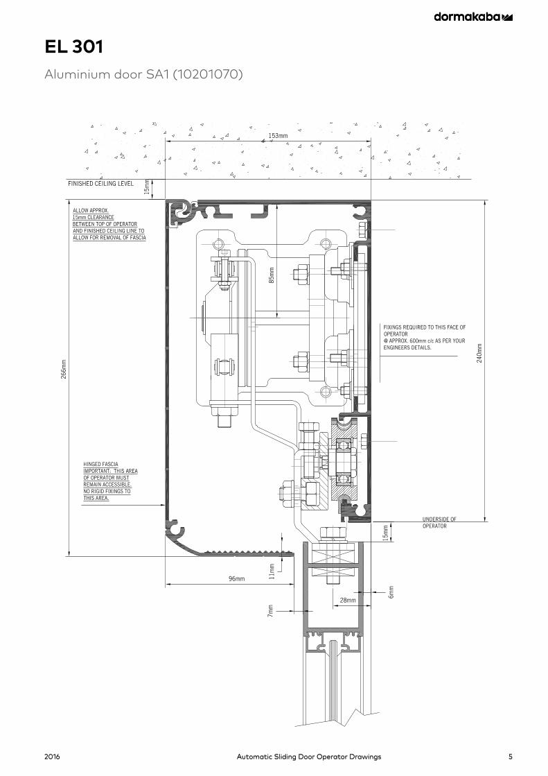
EL 301Aluminium door SA1 (10201070)
2016Automatic Sliding Door Operator Drawings6
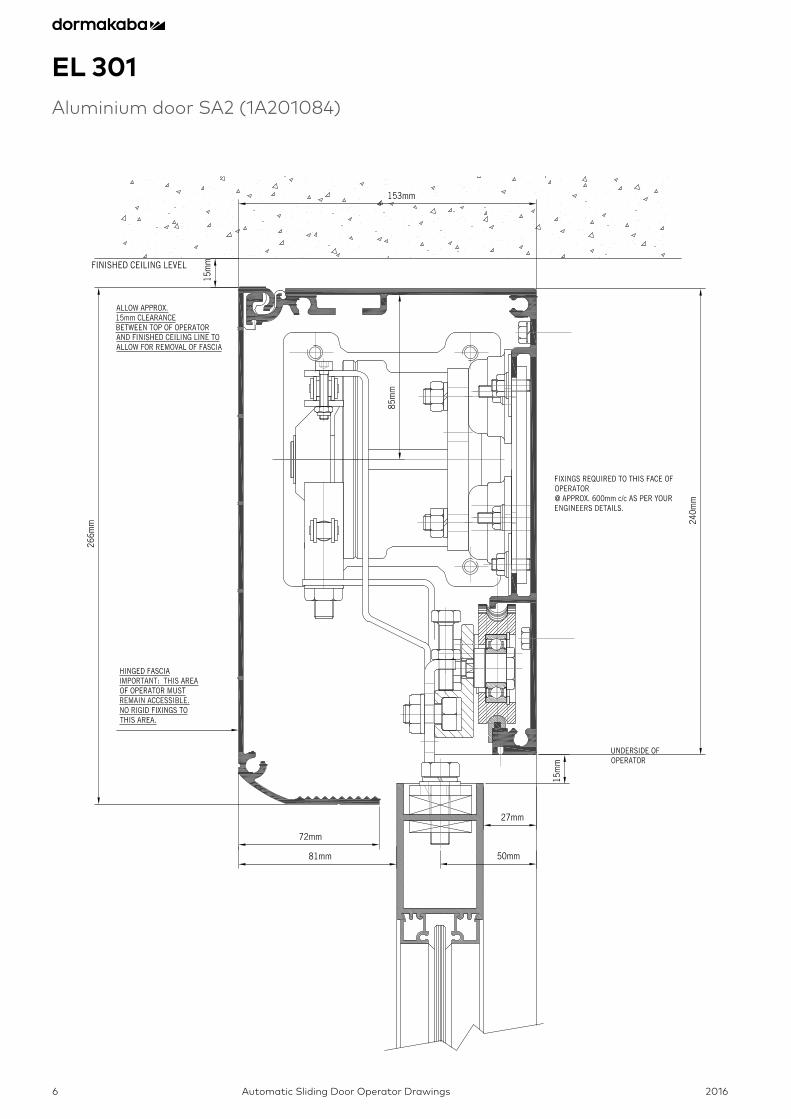
EL 301Aluminium door SA2 (1A201084)

2016 Automatic Sliding Door Operator Drawings 7
EL 301Frameless glass door 12mm (1A201086)
2016Automatic Sliding Door Operator Drawings8
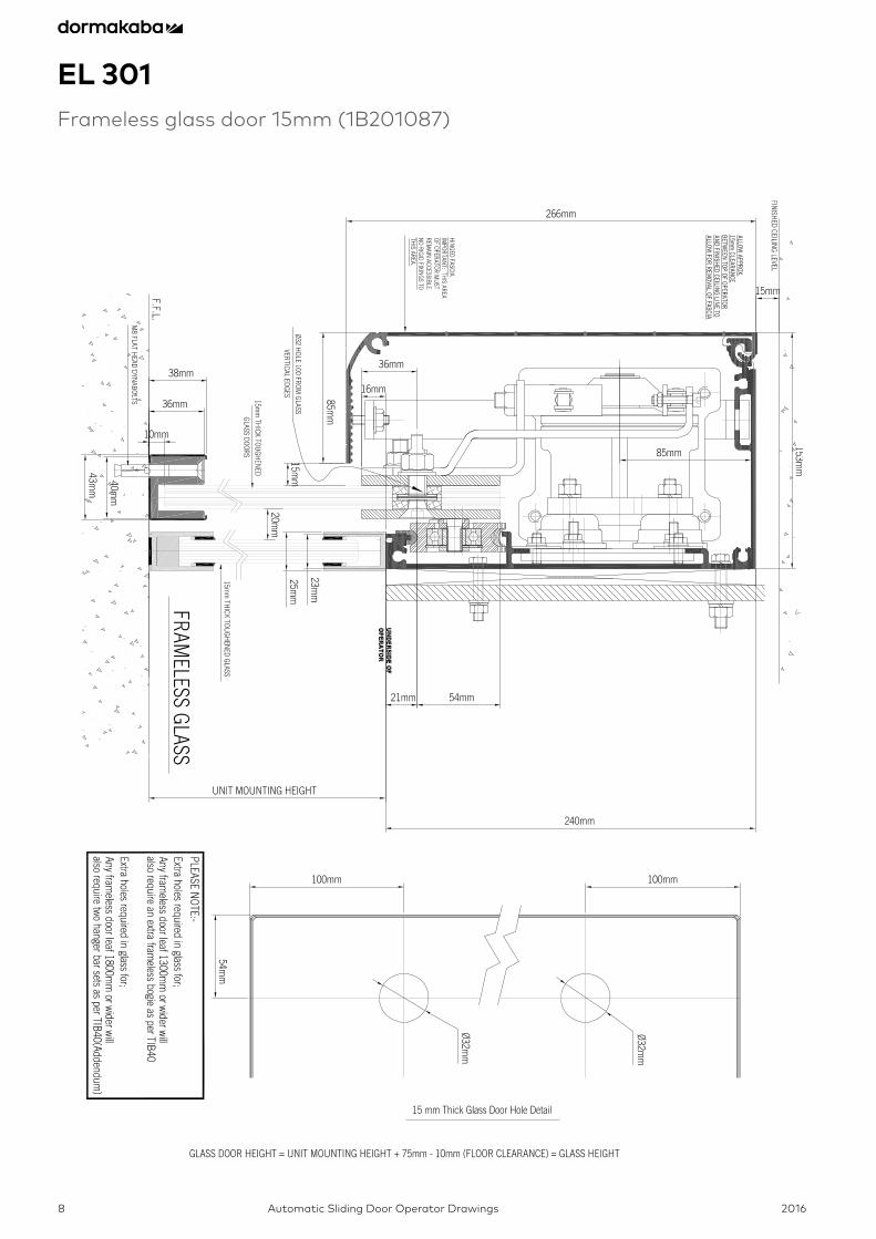
EL 301Frameless glass door 15mm (1B201087)
2016 Automatic Sliding Door Operator Drawings 9
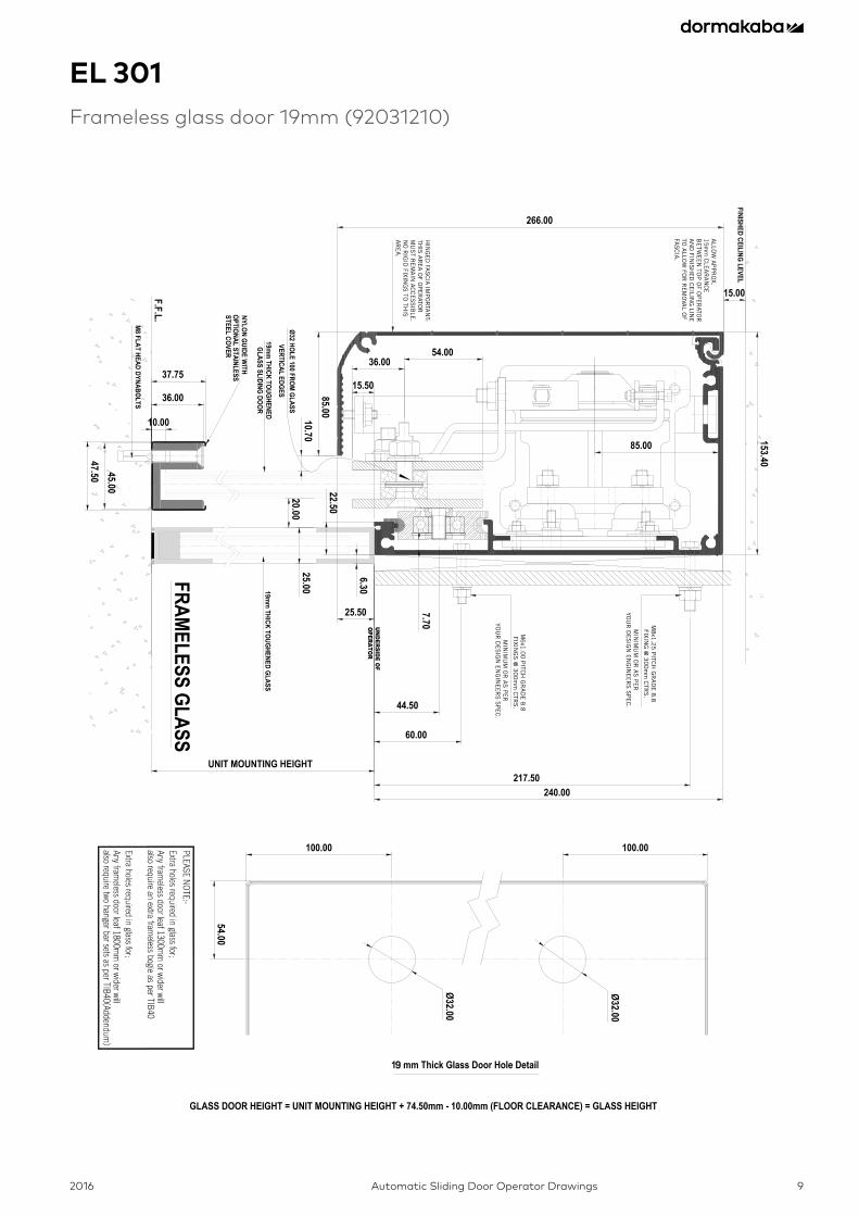
EL 301Frameless glass door 19mm (92031210)
40
40
9
ALLO
W A
PP
RO
X.1
5m
m C
LEA
RA
NC
EB
ETW
EE
N TO
P O
F OP
ER
ATOR
A
ND
FINIS
HE
D C
EILIN
G LIN
E
TO A
LLOW
FOR
RE
MO
VAL O
F FA
SC
IA.
HIN
GE
D FA
SC
IA IM
PO
RTA
NT:
THIS
AR
EA
OF O
PE
RATO
R
MU
ST R
EM
AIN
AC
CE
SS
IBLE
. N
O R
IGID
FIXING
S TO
THIS
A
RE
A.
M8
x1.2
5 P
ITCH
GR
AD
E 8
.8FIXIN
G @
30
0m
m C
TRS
.
MIN
IMU
M O
R A
S P
ER
YOU
R D
ES
IGN
EN
GIN
EE
RS
SP
EC
.
M6
x1.0
0 P
ITCH
GR
AD
E 8
.8FIXIN
GS
@ 3
00
mm
CTR
S.
MIN
IMU
M O
R A
S P
ER
YOU
R D
ES
IGN
EN
GIN
EE
RS
SP
EC
.
2016Automatic Sliding Door Operator Drawings10
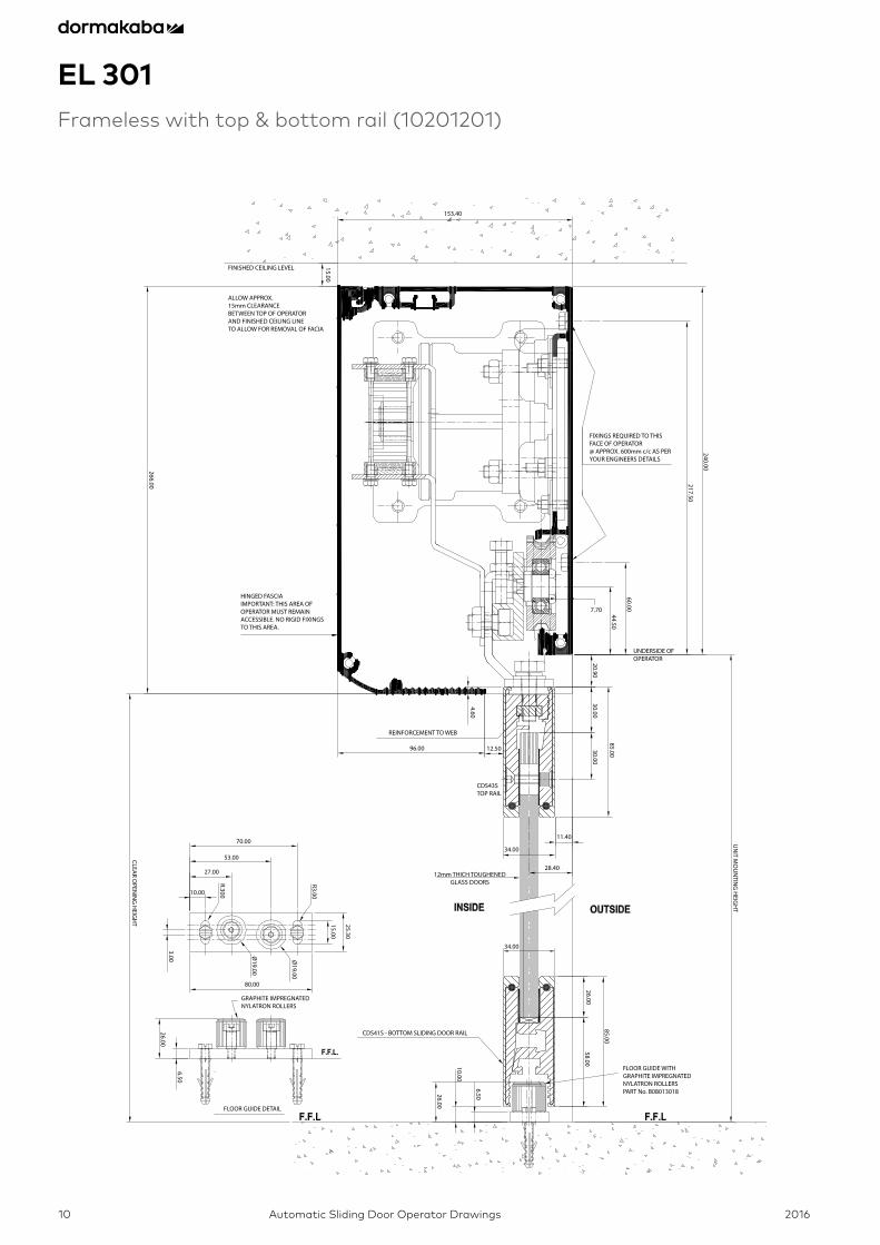
EL 301Frameless with top & bottom rail (10201201)
FIXINGS REQUIRED TO THISFACE OF OPERATOR@ APPROX. 600mm c/c AS PERYOUR ENGINEERS DETAILS
ALLOW APPROX.15mm CLEARANCEBETWEEN TOP OF OPERATORAND FINISHED CEILING LINETO ALLOW FOR REMOVAL OF FACIA
HINGED FASCIAIMPORTANT: THIS AREA OFOPERATOR MUST REMAINACCESSIBLE. NO RIGID FIXINGSTO THIS AREA.
UNDERSIDE OF OPERATOR
REINFORCEMENT TO WEB
CDS43STOP RAIL
12mm THICH TOUGHENED GLASS DOORS
GRAPHITE IMPREGNATEDNYLATRON ROLLERS
CDS41S - BOTTOM SLIDING DOOR RAIL
FLOOR GUIDE DETAIL
FINISHED CEILING LEVEL
FLOOR GUIDE WITHGRAPHITE IMPREGNATEDNYLATRON ROLLERSPART No. B08013018
UN
IT MO
UN
TING
HEIG
HT
CLEAR O
PENIN
G H
EIGH
T
153.40
7.70
96.00 12.50
34.00
11.40
28.40
34.00
80.00
70.00
53.00
27.00
10.00
15.00
266.00
4.60
3.00
25.30
15.00
R3.00
R.300
Ø19.00
Ø19.00
26.00
6.50
26.00
6.50
10.00
85.00
26.0058.00
85.00
30.0030.00
20.90
60.00
44.50
217.50
240.00
2016 Automatic Sliding Door Operator Drawings 11
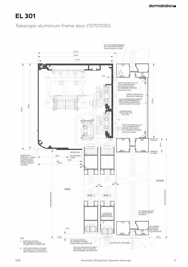
EL 301Telescopic aluminium frame door (10701030)
UNDERSIDE OFOPERATOR
2016Automatic Sliding Door Operator Drawings12
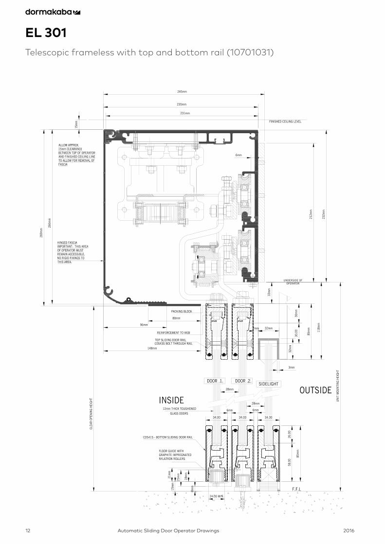
EL 301Telescopic frameless with top and bottom rail (10701031)
UNDERSIDE OFOPERATOR
2016 Automatic Sliding Door Operator Drawings 13
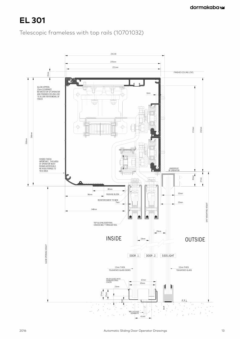
EL 301Telescopic frameless with top rails (10701032)
2016Automatic Sliding Door Operator Drawings14
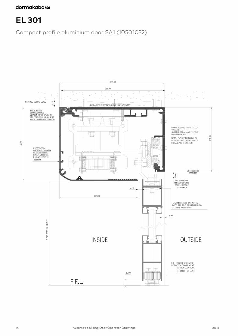
EL 301Compact profile aluminium door SA1 (10501032)
UNDERSIDE OFOPERATOR
2016 Automatic Sliding Door Operator Drawings 15
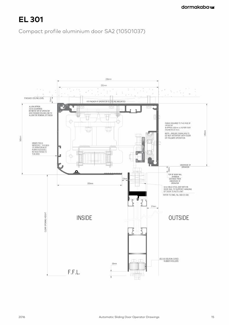
EL 301Compact profile aluminium door SA2 (10501037)
2016Automatic Sliding Door Operator Drawings16
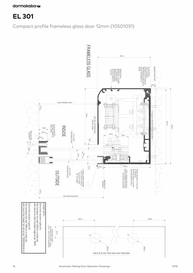
EL 301Compact profile frameless glass door 12mm (10501031)
2016 Automatic Sliding Door Operator Drawings 17
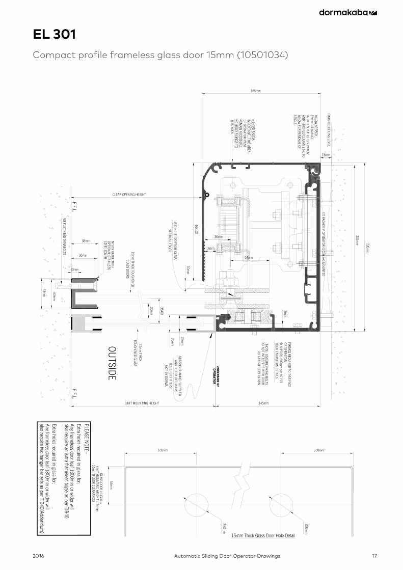
EL 301Compact profile frameless glass door 15mm (10501034)
2016Automatic Sliding Door Operator Drawings18
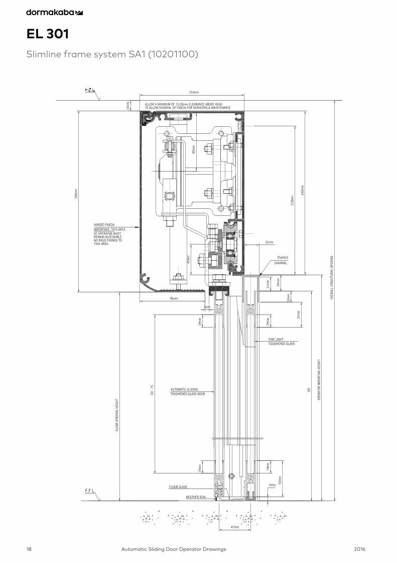
EL 301Slimline frame system SA1 (10201100)
2016 Automatic Sliding Door Operator Drawings 19
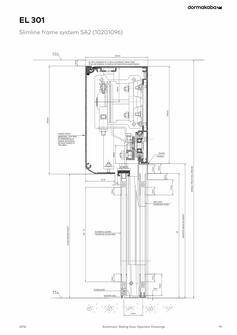
EL 301Slimline frame system SA2 (10201096)
2016Automatic Sliding Door Operator Drawings20
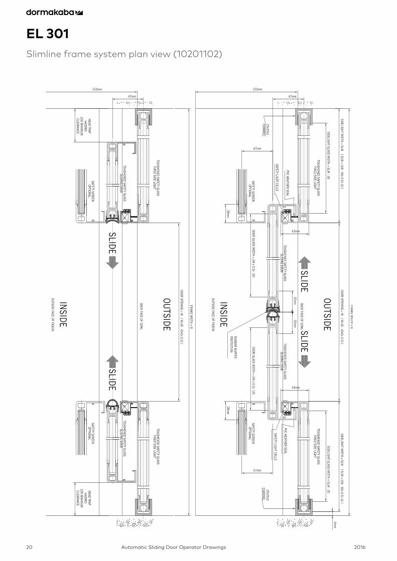
Slimline frame system plan view (10201102)
EL 301Slimline frame system plan view (10201102)
2016 Automatic Sliding Door Operator Drawings 21
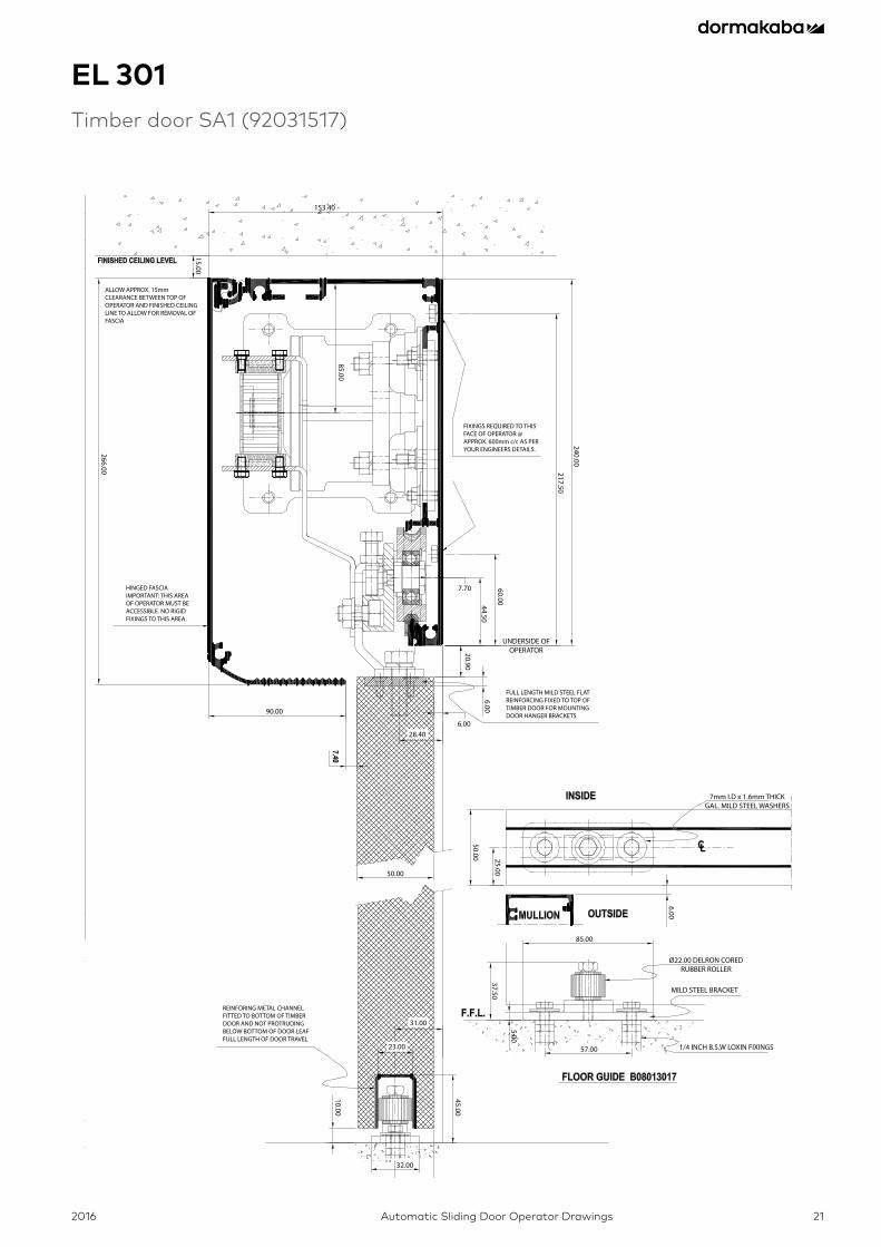
EL 301Timber door SA1 (92031517)
ALLOW APPROX. 15mm CLEARANCE BETWEEN TOP OF OPERATOR AND FINISHED CEILING LINE TO ALLOW FOR REMOVAL OF FASCIA
HINGED FASCIAIMPORTANT: THIS AREAOF OPERATOR MUST BE ACCESSIBLE. NO RIGID FIXINGS TO THIS AREA.
FIXINGS REQUIRED TO THIS FACE OF OPERATOR @ APPROX. 600mm c/c AS PER YOUR ENGINEERS DETAILS.
FULL LENGTH MILD STEEL FLATREINFORCING FIXED TO TOP OF TIMBER DOOR FOR MOUNTING DOOR HANGER BRACKETS
REINFORING METAL CHANNELFITTED TO BOTTOM OF TIMBER DOOR AND NOT PROTRUDING BELOW BOTTOM OF DOOR LEAFFULL LENGTH OF DOOR TRAVEL
153.40
90.00
50.00
6.00
85.00
57.00
25.00
32.00
28.40
31.00
23.00
7.70
1/4 INCH B.S.W LOXIN FIXINGS
MILD STEEL BRACKET
Ø22.00 DELRON COREDRUBBER ROLLER
45.00
10.00
37.50
5.00
6.00
25.00
50.00
7mm I.D x 1.6mm THICKGAL. MILD STEEL WASHERS
6.00
20.90
240.00
217.50
266.00
15.00
85.00
60.0044.50
UNDERSIDE OFOPERATOR
2016Automatic Sliding Door Operator Drawings22
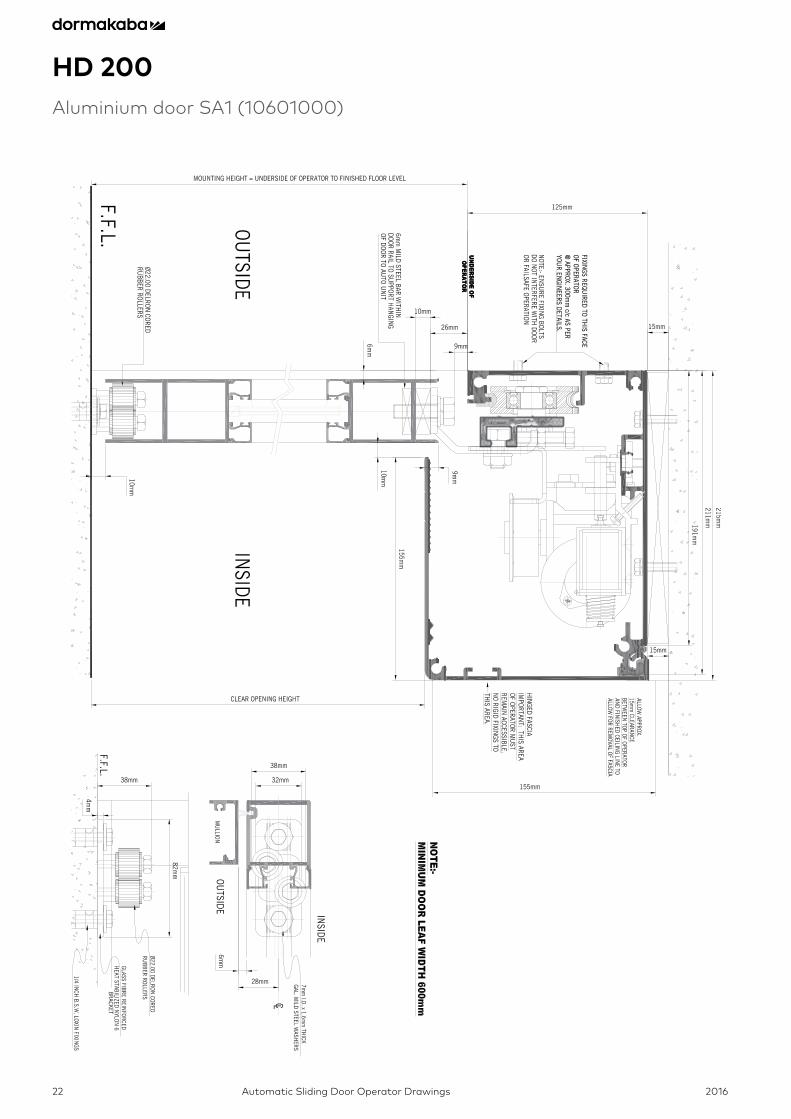
HD 200Aluminium door SA1 (10601000)

2016 Automatic Sliding Door Operator Drawings 23
HD 200Aluminium door SA2 (10601001)
2016Automatic Sliding Door Operator Drawings24
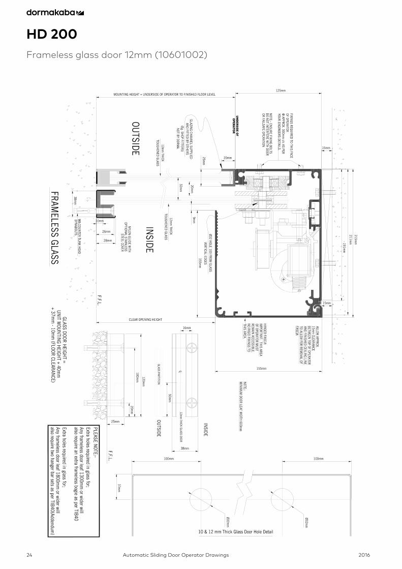
HD 200Frameless glass door 12mm (10601002)
2016 Automatic Sliding Door Operator Drawings 25
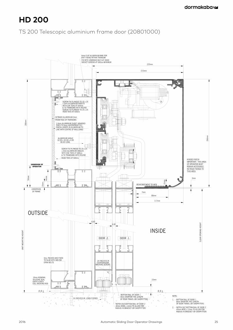
HD 200TS 200 Telescopic aluminium frame door (20801000)
2016Automatic Sliding Door Operator Drawings26
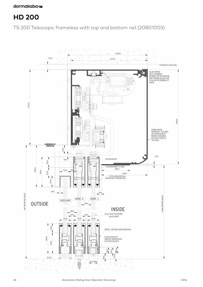
HD 200TS 200 Telescopic frameless with top and bottom rail (20801003)

2016 Automatic Sliding Door Operator Drawings 27
HD 200TS 200 Telescopic frameless with top rail K-TYPE (20801009)
2016Automatic Sliding Door Operator Drawings28
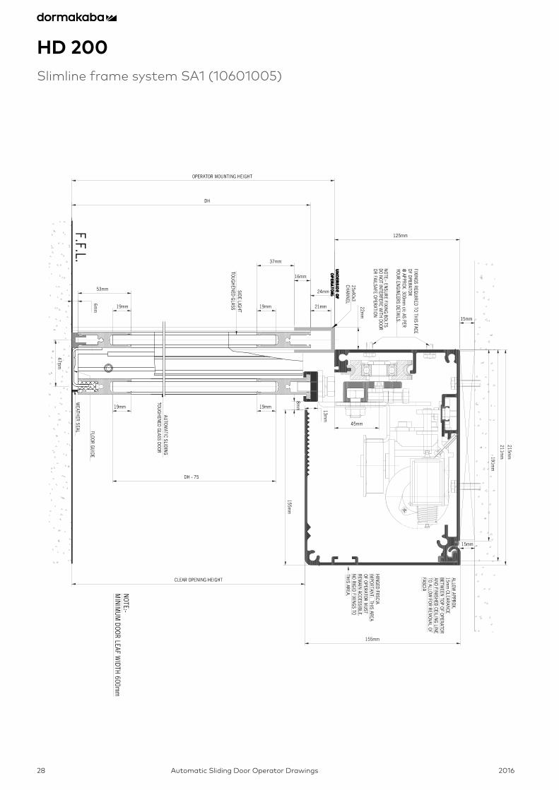
HD 200Slimline frame system SA1 (10601005)
2016 Automatic Sliding Door Operator Drawings 29
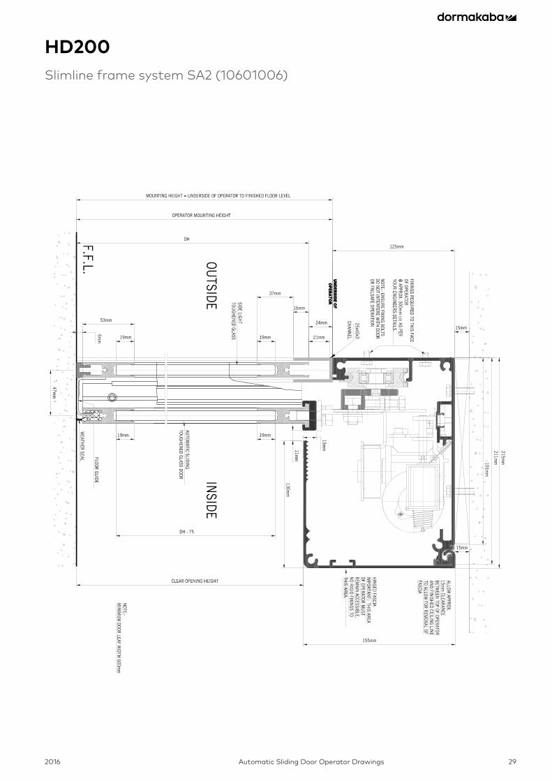
HD200Slimline frame system SA2 (10601006)

2016Automatic Sliding Door Operator Drawings30
AL 401Aluminium door SA1 (10101075)

2016 Automatic Sliding Door Operator Drawings 31
AL 401Frameless glass door 12mm (1A101076)
2016Automatic Sliding Door Operator Drawings32
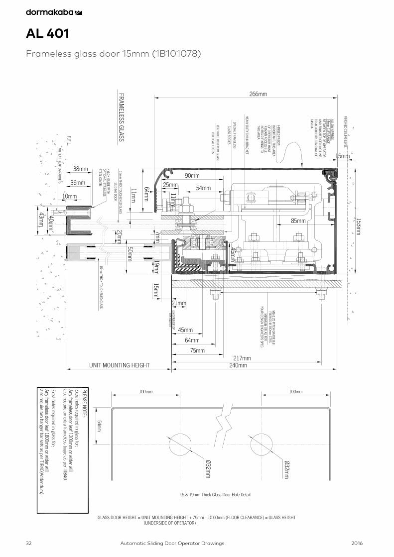
AL 401Frameless glass door 15mm (1B101078)
2016 Automatic Sliding Door Operator Drawings 33
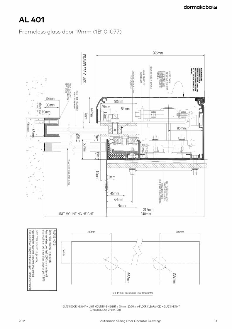
AL 401Frameless glass door 19mm (1B101077)
2016Automatic Sliding Door Operator Drawings34
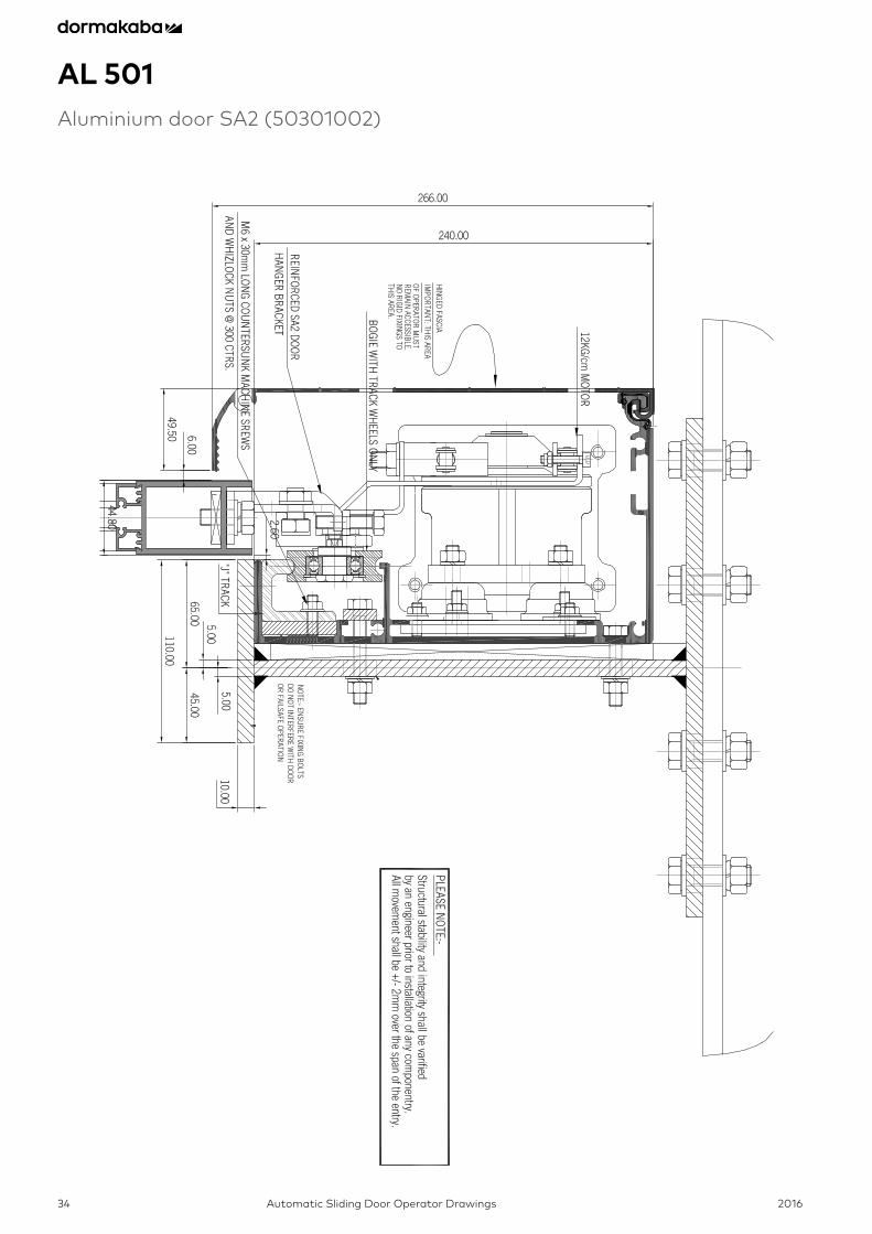
AL 501Aluminium door SA2 (50301002)
2016 Automatic Sliding Door Operator Drawings 35
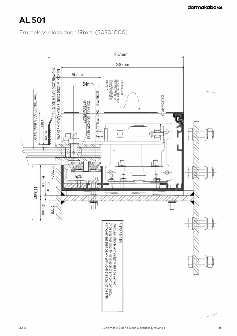
AL 501Frameless glass door 19mm (50301000)
2016Automatic Sliding Door Operator Drawings36
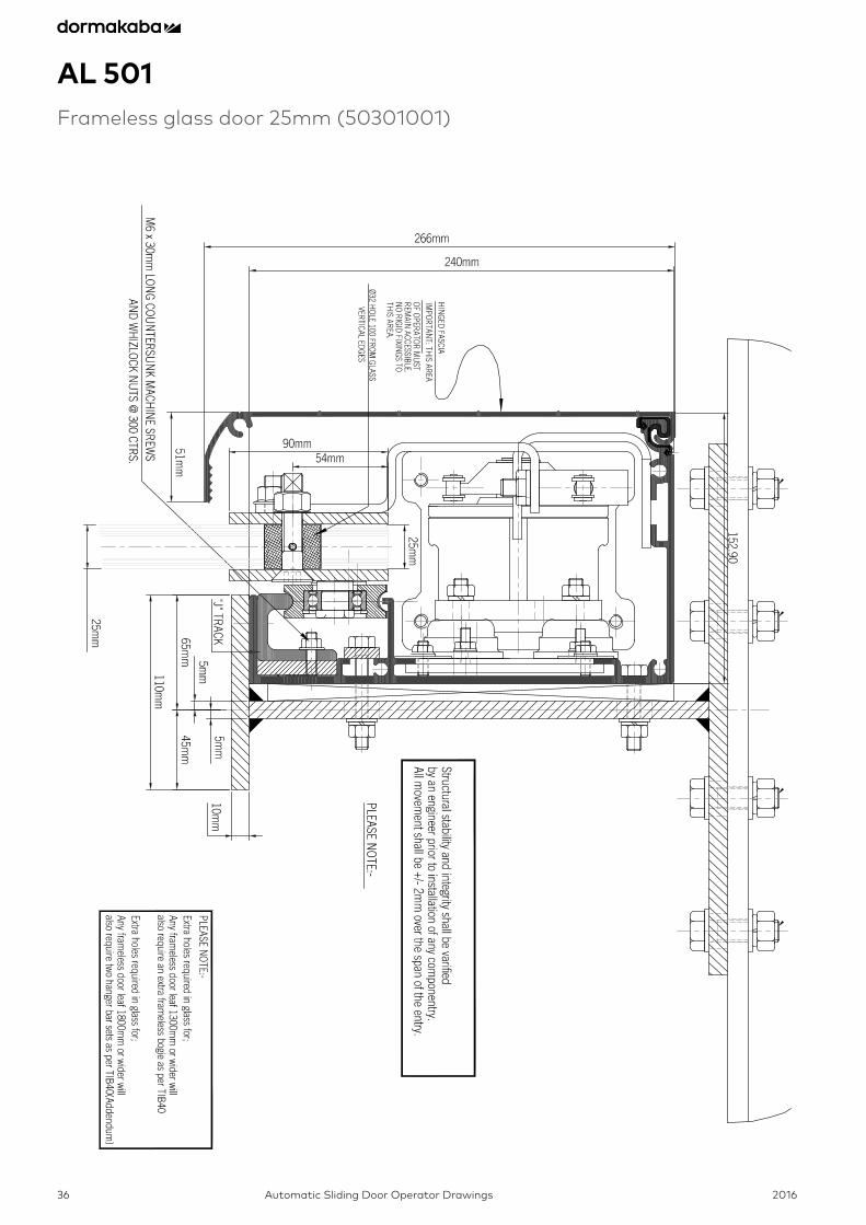
AL 501Frameless glass door 25mm (50301001)
2016 Automatic Sliding Door Operator Drawings 37
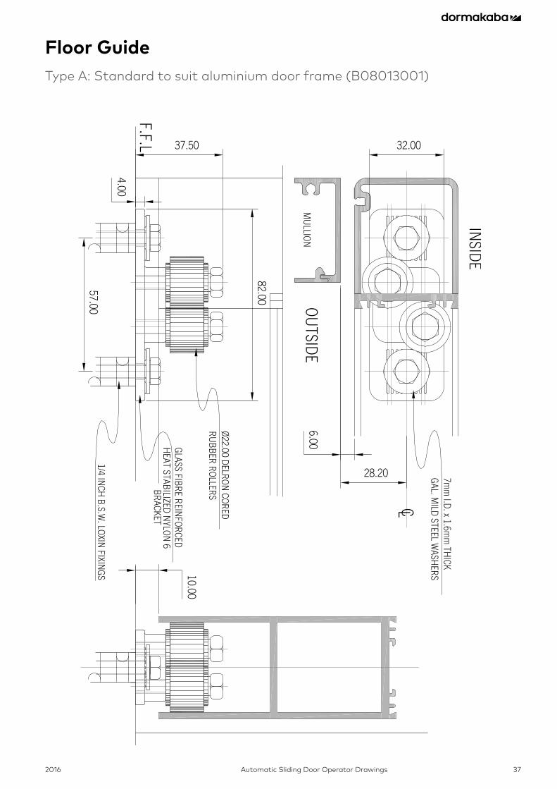
Floor GuideType A: Standard to suit aluminium door frame (B08013001)
2016Automatic Sliding Door Operator Drawings38
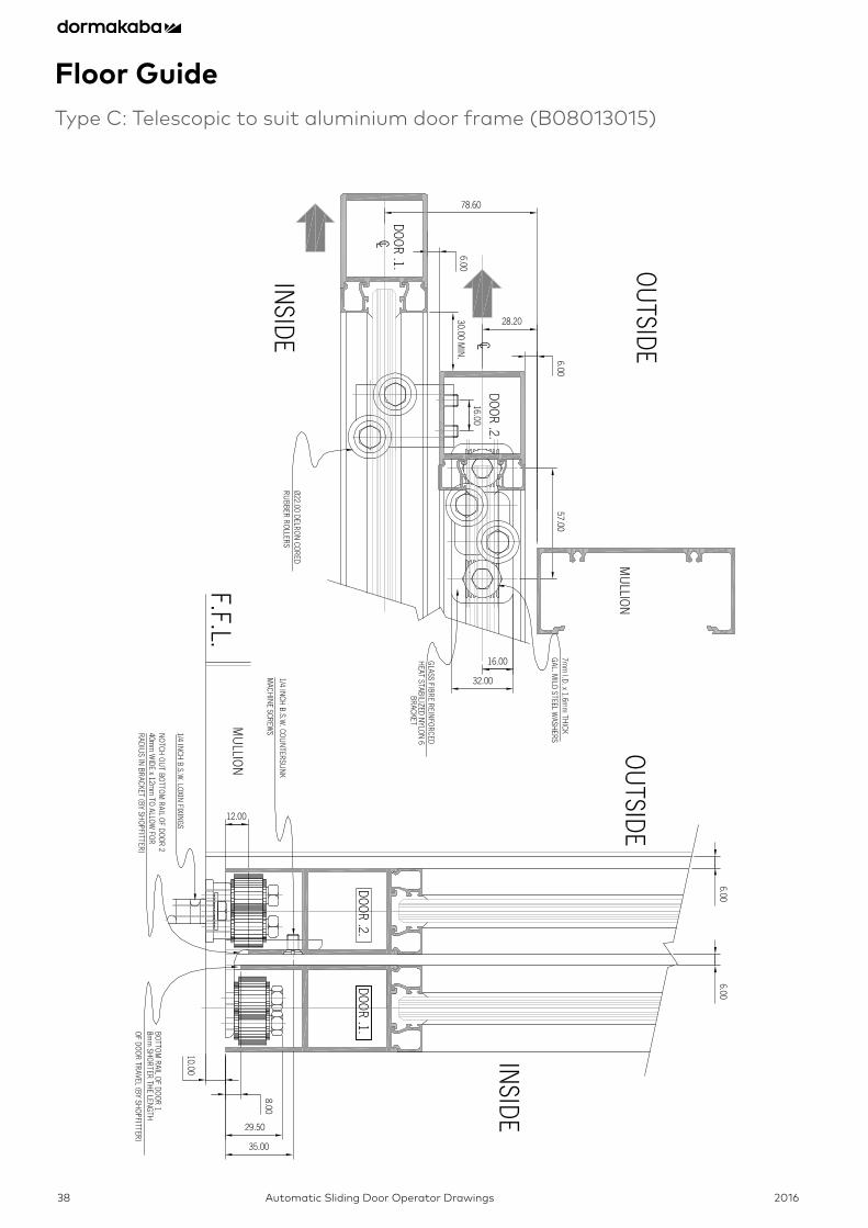
Floor GuideType C: Telescopic to suit aluminium door frame (B08013015)
2016 Automatic Sliding Door Operator Drawings 39
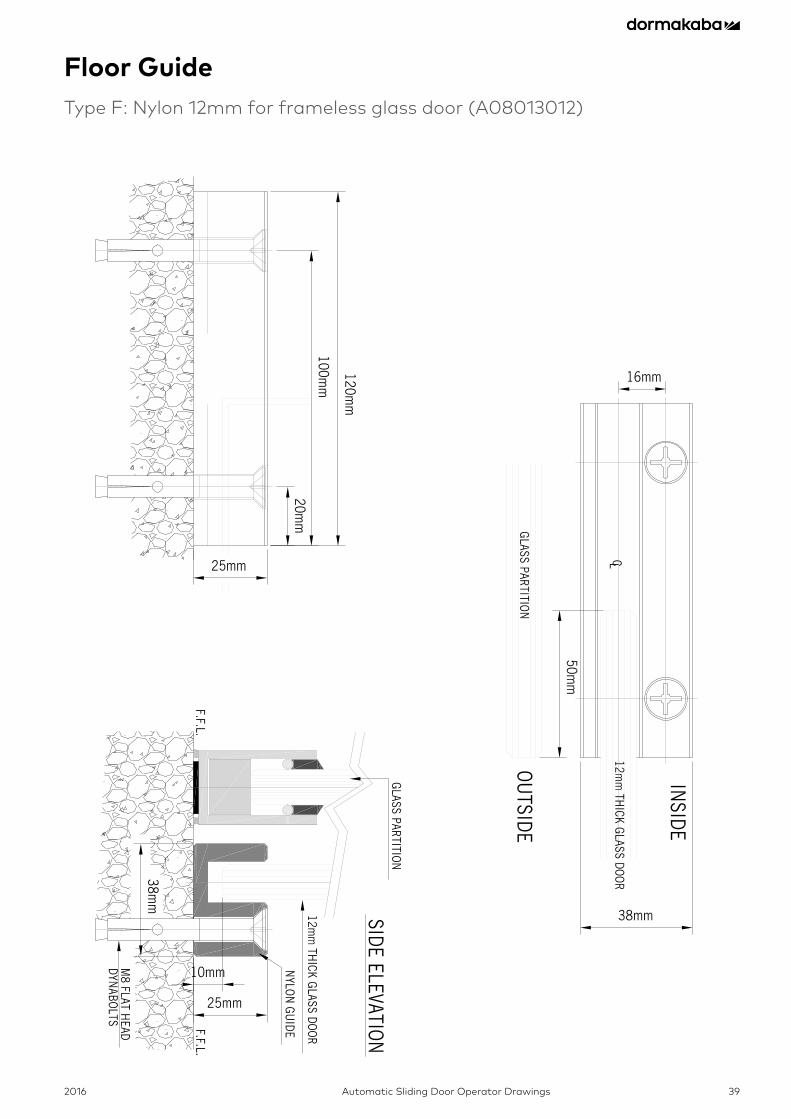
Floor GuideType F: Nylon 12mm for frameless glass door (A08013012)

2016Automatic Sliding Door Operator Drawings40
Floor GuideType H: Frameless glass door with bottom rail (B08003023)
6.0
06
.00
82
.00
41
.00
35
.00
33
.00
33
.00
33
.00
35
.00
35
.00
41
.00
15
.00
24
.00
MIN
7.0
0
26
.00
14
0.0
0
70
.00
40
.00
40
.00
30
.00
30
.00
SE
LF TAP
PIN
G S
CR
EW
SN
o. 10
x12
mm
TYPE
C.(2
)
BO
TTOM
SLID
ING
DO
OR
RA
ILD
42
LS/9
50
mm
82.00
41.00
35.00 35.00 35.00
6.00 6.0025.30
17.50
24.50
30.00
8.00
2016 Automatic Sliding Door Operator Drawings 41
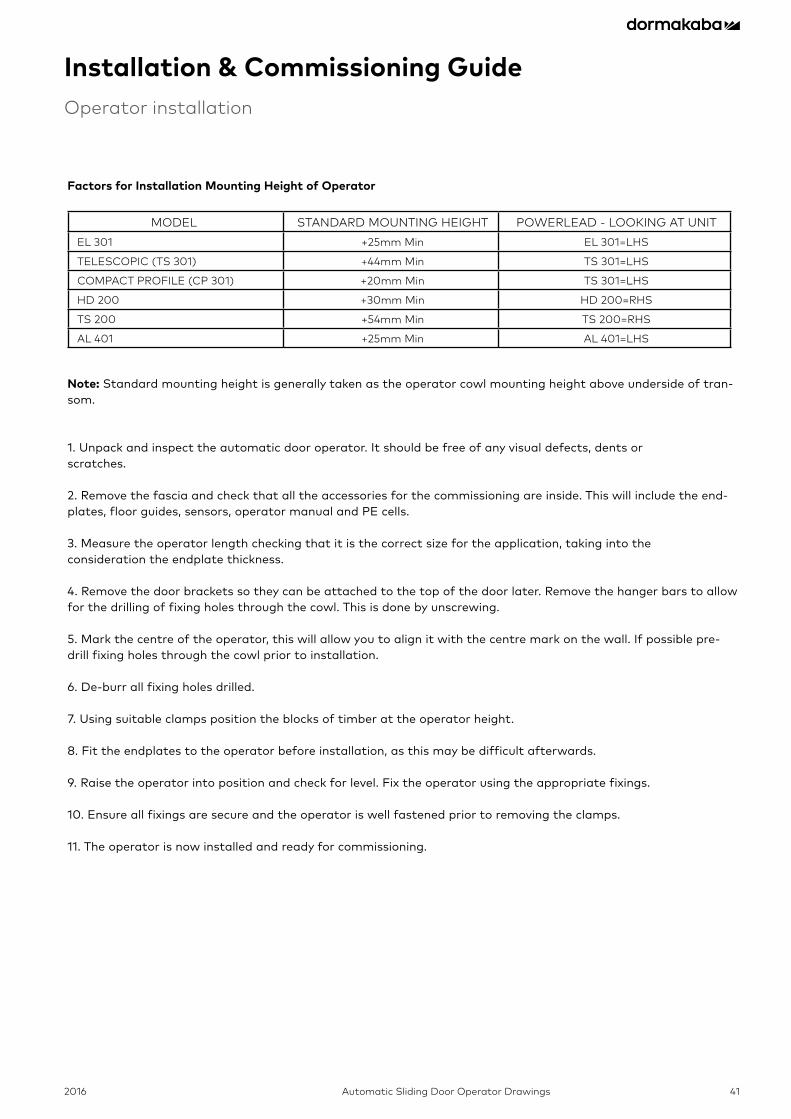
Installation & Commissioning GuideOperator installation
Factors for Installation Mounting Height of Operator
MODELL STANDARD MOUNTING HEIGHT POWERLEAD - LOOKING AT UNITEL 301 +25mm Min EL 301=LHS
TELESCOPIC (TS 301) +44mm Min TS 301=LHS
COMPACT PROFILE (CP 301) +20mm Min TS 301=LHS
HD 200 +30mm Min HD 200=RHS
TS 200 +54mm Min TS 200=RHS
AL 401 +25mm Min AL 401=LHS
Note: Standard mounting height is generally taken as the operator cowl mounting height above underside of tran-som.
1. Unpack and inspect the automatic door operator. It should be free of any visual defects, dents or scratches.
2. Remove the fascia and check that all the accessories for the commissioning are inside. This will include the end-plates, floor guides, sensors, operator manual and PE cells.
3. Measure the operator length checking that it is the correct size for the application, taking into the consideration the endplate thickness.
4. Remove the door brackets so they can be attached to the top of the door later. Remove the hanger bars to allow for the drilling of fixing holes through the cowl. This is done by unscrewing.
5. Mark the centre of the operator, this will allow you to align it with the centre mark on the wall. If possible pre-drill fixing holes through the cowl prior to installation.
6. De-burr all fixing holes drilled.
7. Using suitable clamps position the blocks of timber at the operator height.
8. Fit the endplates to the operator before installation, as this may be difficult afterwards.
9. Raise the operator into position and check for level. Fix the operator using the appropriate fixings.
10. Ensure all fixings are secure and the operator is well fastened prior to removing the clamps.
11. The operator is now installed and ready for commissioning.
2016Automatic Sliding Door Operator Drawings42
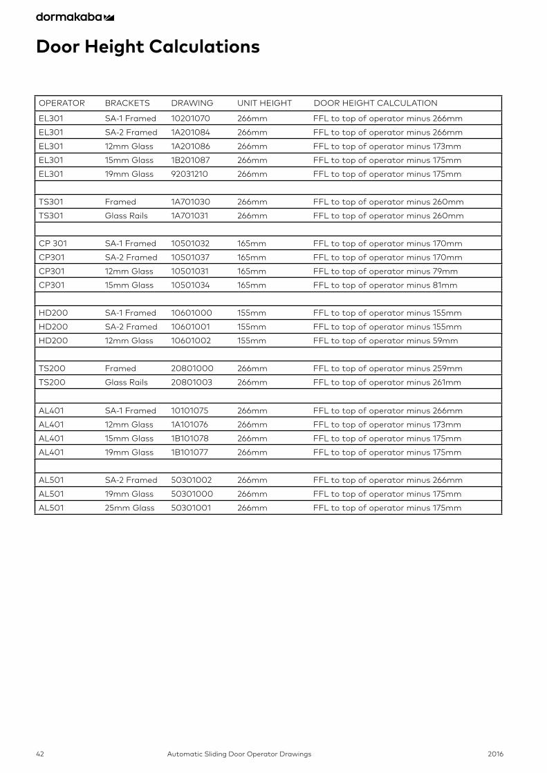
OPERATOR BRACKETS DRAWING UNIT HEIGHT DOOR HEIGHT CALCULATION
EL301 SA-1 Framed 10201070 266mm FFL to top of operator minus 266mm
EL301 SA-2 Framed 1A201084 266mm FFL to top of operator minus 266mm
EL301 12mm Glass 1A201086 266mm FFL to top of operator minus 173mm
EL301 15mm Glass 1B201087 266mm FFL to top of operator minus 175mm
EL301 19mm Glass 92031210 266mm FFL to top of operator minus 175mm
TS301 Framed 1A701030 266mm FFL to top of operator minus 260mm
TS301 Glass Rails 1A701031 266mm FFL to top of operator minus 260mm
CP 301 SA-1 Framed 10501032 165mm FFL to top of operator minus 170mm
CP301 SA-2 Framed 10501037 165mm FFL to top of operator minus 170mm
CP301 12mm Glass 10501031 165mm FFL to top of operator minus 79mm
CP301 15mm Glass 10501034 165mm FFL to top of operator minus 81mm
HD200 SA-1 Framed 10601000 155mm FFL to top of operator minus 155mm
HD200 SA-2 Framed 10601001 155mm FFL to top of operator minus 155mm
HD200 12mm Glass 10601002 155mm FFL to top of operator minus 59mm
TS200 Framed 20801000 266mm FFL to top of operator minus 259mm
TS200 Glass Rails 20801003 266mm FFL to top of operator minus 261mm
AL401 SA-1 Framed 10101075 266mm FFL to top of operator minus 266mm
AL401 12mm Glass 1A101076 266mm FFL to top of operator minus 173mm
AL401 15mm Glass 1B101078 266mm FFL to top of operator minus 175mm
AL401 19mm Glass 1B101077 266mm FFL to top of operator minus 175mm
AL501 SA-2 Framed 50301002 266mm FFL to top of operator minus 266mm
AL501 19mm Glass 50301000 266mm FFL to top of operator minus 175mm
AL501 25mm Glass 50301001 266mm FFL to top of operator minus 175mm
Door Height Calculations
2016 Automatic Sliding Door Operator Drawings 43
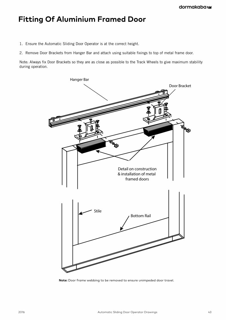
Fitting Of Aluminium Framed Door
1. Ensure the Automatic Sliding Door Operator is at the correct height. 2. Remove Door Brackets from Hanger Bar and attach using suitable fixings to top of metal frame door. Note: Always fix Door Brackets so they are as close as possible to the Track Wheels to give maximum stability during operation.
Detail on construction& installation of metal
framed doors
StileBottom Rail
Hanger Bar
Door Bracket
Note: Door frame webbing to be removed to ensure unimpeded door travel.
2016Automatic Sliding Door Operator Drawings44
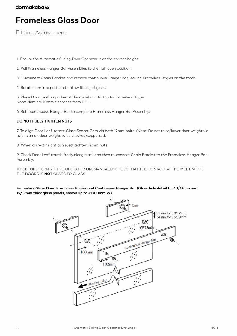
Frameless Glass DoorFitting Adjustment
1. Ensure the Automatic Sliding Door Operator is at the correct height.
2. Pull Frameless Hanger Bar Assemblies to the half open position.
3. Disconnect Chain Bracket and remove continuous Hanger Bar, leaving Frameless Bogies on the track.
4. Rotate cam into position to allow fitting of glass.
5. Place Door Leaf on packer at floor level and fit top to Frameless Bogies. Note: Nominal 10mm clearance from F.F.L
6. Refit continuous Hanger Bar to complete Frameless Hanger Bar Assembly. DO NOT FULLY TIGHTEN NUTS
7. To align Door Leaf, rotate Glass Spacer Cam via both 12mm bolts. (Note: Do not raise/lower door weight via nylon cams - door weight to be chocked/supported)
8. When correct height achieved, tighten 12mm nuts.
9. Check Door Leaf travels freely along track and then re-connect Chain Bracket to the Frameless Hanger Bar Assembly.
10. BEFORE TURNING THE OPERATOR ON, MANUALLY CHECK THAT THE CONTACT AT THE MEETING OFTHE DOORS IS NOT GLASS TO GLASS.
Frameless Glass Door, Frameless Bogies and Continuous Hanger Bar (Glass hole detail for 10/12mm and 15/19mm thick glass panels, shown up to <1300mm W)
37mm for 10/12mm54mm for 15/19mm
2016 Automatic Sliding Door Operator Drawings 45
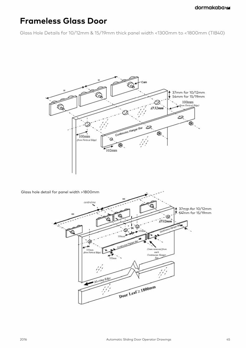
Frameless Glass DoorGlass Hole Details for 10/12mm & 15/19mm thick panel width <1300mm to <1800mm (TIB40)
37mm for 10/12mm54mm for 15/19mm
37mm for 10/12mm54mm for 15/19mm
Glass hole detail for panel width >1800mm
2016Automatic Sliding Door Operator Drawings46
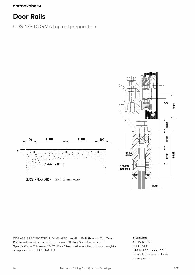
Door RailsCDS 43S DORMA top rail preparation
CDS 43S SPECIFICATION: On-Eazi 85mm High Bolt through Top Door Rail to suit most automatic or manual Sliding Door Systems.Specify Glass Thickness 10, 12, 15 or 19mm. Alternative rail cover heights on application. ILLUSTRATED
FINISHESALUMINIUM: MILL, SAA STAINLESS: SSS, PSSSpecial finishes available on request.
(10 & 12mm shown)

2016 Automatic Sliding Door Operator Drawings 47
Standard Floor Guide Installation
8
.
CHECK CLEARANCE BY MOVING DOOR LEAF BACK AND FORTH.
TURN FLOORGUIDE UNTIL APPROX. 1mm CLEARANCE BETWEEN ROLLER AND RAIL. 5
NOTE : Instructions shown are for STANDARD aluminium doors and STANDARD Floor guides.
1 - 2mm SIDELIGHT
HT
4 ENSURE DOORS CAN CLOSE FULLY. (MILLING INTERNAL WEB OF DOOR MAY BE NECESSARY)
OUTSIDE
3 DRILL 2 × Ø13mm HOLES AND FIX WITH SUPPLIED LOXIN AND WASHERS.
2 PLACE FLOORGUIDE SO DOORS ARE
PLUMB.
SIDELIGHT
OUTSIDE
½ DOOR THICKNESS +
10mm
PLACED SSUCH THAT DOOR CAN FULLY CLOSE
1 CLOSE DOORS FULLY. SQUARE AND ALIGN DOORS. CHECK DOORS PARALLEL TO JAMBS. MARK POSITIONS.
SIDELIGHT SIDELIGHT
VIEW FROM INSIDE
6 HANG, SQUARE AND ALIGN DOORS. CHECK DOORS PARALLEL TO JAMBS (10mm CLEARANCE). CHECK DOORS CLOSE FULLY.
VIEW FROM INSIDE
SIDELIGHT SIDELIGHT
(if necessary)
SIDELIGHT
2016Automatic Sliding Door Operator Drawings48
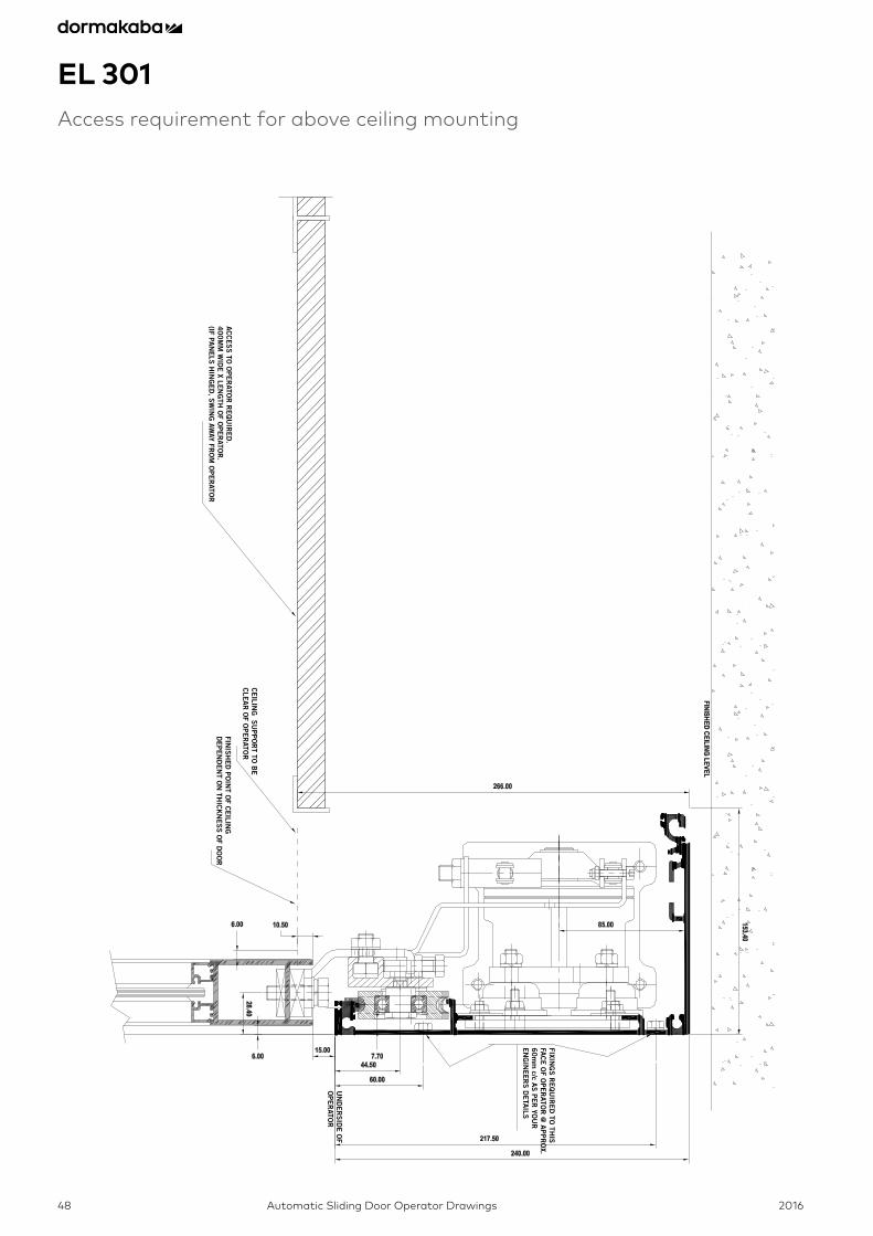
EL 301Access requirement for above ceiling mounting
AC
CE
SS
TO O
PE
RATO
R R
EQ
UIR
ED
.4
00
MM
WID
E X LE
NG
TH O
F OP
ER
ATOR
.(IF PA
NE
LS H
ING
ED
, SW
ING
AWAY FR
OM
OP
ER
ATOR
CE
ILING
SU
PP
OR
T TO B
EC
LEA
R O
F OP
ER
ATOR
FINIS
HE
D P
OIN
T OF C
EILIN
G
DE
PE
ND
EN
T ON
THIC
KN
ES
S O
F DO
OR
FIXING
S R
EQ
UIR
ED
TO TH
ISFA
CE
OF O
PE
RATO
R @
AP
PR
OX.
60
mm
c/c AS
PE
R YO
UR
E
NG
INE
ER
S D
ETA
ILS
UN
DE
RS
IDE
OF
OP
ER
ATOR

2016 Automatic Sliding Door Operator Drawings 49
Notes

2016Automatic Sliding Door Operator Drawings50
Notes

2016 Automatic Sliding Door Operator Drawings 51
Notes

dormakabaHead Office46-52 Abbott RoadHallam VIC 3803T 1800 675 411F +61 (3) 8795 [email protected]
www.dormakaba.com.au
Aut
o S
lidin
g D
oor O
pera
tor D
raw
ings
Boo
klet
S
ubje
ct t
o ch
ange
wit
hout
not
ice