Embed Size (px)
Citation preview

Automated Testing usingSymbolic Model Checking and Temporal Monitoring
Cyrille Artho a, Howard Barringer b, Allen Goldberg c,Klaus Havelund c, Sarfraz Khurshid d, Mike Lowry e,
Corina Pasareanu c, Grigore Rosu f, Koushik Sen f, Willem Visser g,Rich Washington g
aComputer Systems Institute, ETH Zurich, SwitzerlandbUniversity of Manchester, England
cKestrel Technology, NASA Ames Research Center, USAdMIT Computer Science and Artificial Intelligence Laboratory, USA
eNASA Ames Research Center, USAfDepartment of Computer Science, Univ. of Illinois at Urbana-Champaign, USA
gRIACS, NASA Ames Research Center, USA
Abstract
Software testing is typically an ad hoc process where human testers manually write testinputs and descriptions of expected test results, perhaps automating their execution in aregression suite. This process is cumbersome and costly. This paper reports results on aframework to further automate this process. The framework consists of combining auto-mated test case generation based on systematically exploring the program’s input domain,with runtime analysis, where execution traces are monitored and verified against temporallogic specifications, and analyzed by concurrency error detection algorithms. The approachsuggests a methodology for generating specifications dynamically for each input instancerather than statically once-and-for-all. This approach of generating properties specific toa single test case is novel. The paper describes an application of this methodology to aplanetary rover controller.
Key words:Automated testing, test-case generation, model checking, symbolic execution, runtimeanalysis, temporal logic monitoring, concurrency analysis, C++, planetary rover controller.
Preprint submitted to Theoretical Computer Science 16th March 2004

1 Introduction
A program is typically tested by manually creating a test suite, which in turn is a setof test cases. An individual test case is a description of a test input sequence to theprogram, and a description of properties that the corresponding output is expectedto have. This manual procedure may be unavoidable since for real systems, writingtest cases is an inherently innovative process requiring human insight into the logicof the application being tested. Discussions with robotics and space craft engineersat NASA seems to support this view. However, an equally widespread opinion isthat a non-trivial part of the testing work can be automated. In a case study, an8,000-line Java application was tested by different student groups using differenttesting techniques [4]. It is conjectured that the vast majority of bugs in this systemthat were found by the students could have been found in a fully automatic way.The paper presents work on applying low-overhead automated testing to identifybugs quickly. We suggest a framework for generating test cases in a fully automaticway as illustrated by Figure 1. For a particular program to be tested, one establishesa test harness consisting of four modules: a test input generator module, a propertygenerator module, a program instrumentation module and an observer module.
generationTest input Program
Instrumentation
generationProperty
Observer
Figure 1. Test case generation (test input generation and property generation) and runtimeanalysis (instrumentation and observation).
The test input generator automatically generates inputs to the application, one byone. A generated input is fed to the the property generator, which automaticallygenerates a set of properties that the program should satisfy when executed on thatinput. The input is then fed to the program, which executes, generating an exe-cution trace. The observer module checks the behavior of the executed programagainst the generated set of properties. Hence, it takes an execution trace and theset of properties generated by the property generator as input. The program itselfmust be instrumented to report events that are relevant for monitoring that the prop-erties are satisfied on a particular execution. This instrumentation can in some casesbe automated. The test input generator and the property generator are both written(“hard-wired”) specifically for the application that is tested. This replaces manualconstruction of test cases. However, the observer module is generic and can bere-used on different applications. In the rest of this paper the term test case gener-ation is used to refer to test input generation and property generation, and the termruntime analysis to refer to instrumentation as well as observation.
The framework described above has been applied to a case study, a planetary rover
2

controller. Test cases are generated using a model checker and the properties gen-erated are specific to a single test case. Properties are expressed in temporal logic.The approach of generating properties specific to a single test case is novel.
The paper is organized as follows. Section 2 outlines our technology for test casegeneration: symbolic execution and model checking. Section 3 describes the run-time analysis techniques: temporal logic monitoring and concurrency analysis. Sec-tion 4 describes the case study, where these technologies are applied to a planetaryrover controller. Finally Section 5 concludes the paper and outlines how this workwill be continued.
2 Test Case Generation
This section presents the test case generation framework. As mentioned earlier,test generation is considered as consisting of test input generation and propertygeneration.
2.1 Test Input Generation
2.1.1 Model based testing
In practice today, the generation of test inputs for a program under test is a time-consuming and mostly manual activity. However, test input generation naturallylends itself to automation, and therefore has been the focus of much research atten-tion – recently it has also been adopted in industry [18,23,7,10]. There are two mainapproaches to generating test inputs automatically: a static approach that generatesinputs from some kind of model of the system (also called model-based testing),and a dynamic approach that generates tests by executing the program repeatedly,while employing criteria to rank the quality of the tests produced [16,22]. The dy-namic approach is based on the observation that test input generation can be seen asan optimization problem, where the cost function used for optimization is typicallyrelated to code coverage (e.g. statement or branch coverage). The model-based testinput (test case) generation approach is used more widely (see Hartman’s surveyof the field [12]). The model used for model-based testing is typically a model ofexpected system behavior and can be derived from a number of sources, namely, amodel of the requirements, use cases, design specifications of a system [12] – eventhe code itself can be used to create a model (e.g. approaches based on symbolicexecution [15,18]). As with the dynamic approach, it is most typical to use somenotion of coverage of the model to derive test inputs, i.e., generate inputs that coverall transitions (or branches, etc.) in the model.
3

On the one hand, constructing a model of the expected system behavior can be acostly process. On the other hand, generating test inputs just based on a specifi-cation of the input structure and input pre-conditions can be very effective, whiletypically less costly. In [14] a verification framework is presented that combinessymbolic execution and model checking techniques in a novel way. The frameworkcan be used for test input generation as follows: the input model is described asa non-deterministic program annotated with constraints that describes all valid in-puts, and the model checker is used to traverse the (symbolic) state space of thisprogram. As the property the model checker should check for, one asserts that nosuch test input exists – this causes the model checker to produce a counter-examplewhenever a valid test input has been generated. From this counter-example trace thetest input is produced. It is important that various techniques for searching the statespace should be available since this gives the flexibility to generate a large array oftest inputs to achieve better coverage of the behavior of the system under test. Fortest input generation the Java PathFinder model checker (JPF) is used that analyzesJava programs [24] and supports various heuristic search strategies (for example,based on branch coverage [11] or random search). In Section 4.2 we show how thismodel checker is used to generate test inputs for the Mars K9 rover.
Using symbolic execution for test case generation is a well-known approach, buttypically only handles sequential code with simple data. In previous work, this tech-nique has been extended to handle complex data-structures (e.g. lists and trees),concurrency as well as linear constraints on integer data [14]. Symbolic executionof a program path results in a set of constraints that define program inputs that ex-ecute the path; these constraints can often be solved using off-the-shelf decisionprocedures to generate concrete test inputs. When the program represents an exe-cutable specification, symbolic execution of the specification enables us to generateinputs that give us, for instance, full specification coverage. Note that these spec-ifications are typically not very large – no more than a few thousand lines, in ourexperience – and hence will allow efficient symbolic execution.
The most closely related work to ours is the Korat tool [3] that generates test inputsfrom Java predicates, but instead of model checking they use a dedicated, efficient,search strategy. The use of the counter-example capability of a model checker togenerate test inputs have also been studied by many others (see [13] for a goodsurvey), but most of these are based on a full system model, not just the inputstructure and pre-conditions as suggested here.
2.1.2 Symbolic Execution for Test Input Generation
The enabling technology for black-box test-input generation from an input specifi-cation is the use of symbolic execution. Optionally the system under test itself canbe symbolically executed, for white-box testing, the techniques are in fact the same.The main idea behind symbolic execution [15] is to use symbolic values, instead
4

int x, y;read x,y;
1: if (x > y) {2: x = x + y;3: y = x - y;4: x = x - y;5: if (x > y)6: assert(false);
}
x: X, y: YPC: X<=Y
x: Y, y: XPC: X>Y
x: X+Y, y: XPC: X>Y
x: X+Y, y: YPC: X>Y
x: X, y: YPC: X>Y
x: X, y: YPC: true
3
4
2
1 1
5 5
x: Y, y: XPC: X>Y & Y>X
FALSE!
x: Y, y: XPC: X>Y & Y<=X
Figure 2. Code for swapping integers and corresponding symbolic execution tree.
of actual data, as input values, and to represent the values of program variables assymbolic expressions. The state of a symbolically executed program includes, inaddition to the (symbolic) values of program variables and the program counter,a path condition. The path condition is a (quantifier-free) Boolean formula overthe symbolic inputs; it accumulates constraints which the inputs must satisfy in or-der for an execution to follow the particular associated path. A symbolic executiontree characterizes the execution paths followed during the symbolic execution ofa program. The nodes represent program states and the arcs represent transitionsbetween states.
Consider as an example (taken from [14]) the code fragment in Figure 2, whichswaps the values of integer variables x and y, when x is greater than y. Figure 2also shows the corresponding symbolic execution tree. Initially, the path condition,PC, is true and x and y have symbolic values X and Y, respectively. At each branchpoint, PC is updated with assumptions about the inputs according to the alternative(possible) paths. For example, after the execution of the first statement, both thenand else alternatives of the if statement are possible, and PC is updated accord-ingly. If the path condition becomes false, i.e., there is no set of inputs that satisfyit, this means that the symbolic state is not reachable, and symbolic execution doesnot continue for that path. For example, statement (6) is unreachable. In order tofind a test input to reach branch statement (5) one needs to solve constraint X > Y– e.g. make inputs x and y 1 and 0, respectively.
Symbolic execution traditionally arose in the context of sequential programs witha fixed number of integer variables. We have extended this technique to handledynamically allocated data structures (e.g. lists and trees), complex preconditions(e.g. lists that have to be acyclic), other primitive data (e.g. strings) and concur-rency. A key feature of our algorithm is that it starts the symbolic execution of aprocedure on uninitialized inputs and it uses lazy initialization to assign valuesto these inputs, i.e., it initializes parameters when they are first accessed duringthe procedure’s symbolic execution. This allows symbolic execution of procedures
5

path condition (data)
heap configuration
thread scheduling
Modelchecking
state
proceduresDecision
test coverage
continue/backtrack
criterion
test suite[constraints on inputs + thread scheduling]
input specificationand precondition
Figure 3. Framework for test input generation.
without requiring an a priori bound on the number of input objects. Procedure pre-conditions are used to initialize inputs only with valid values.
As mentioned before our symbolic execution-based framework is built on top of theJava PathFinder (JPF) model checker [24]. JPF is an explicit-state model checkerfor Java programs that is built on top of a custom-made Java Virtual Machine(JVM). It can handle all of the language features of Java, and in addition it treatsnon-deterministic choice expressed in annotations of the program being analyzed.For symbolic execution the model checker was extended to allow backtrackingwhenever a path-condition is unsatisfiable (determined by calling a decision proce-dure).
2.1.3 Framework for Test Input Generation
Figure 3 illustrates our framework for test input generation. The input specificationis given as a non-deterministic Java program that is instrumented to add supportfor manipulating formulas that represent path conditions. The instrumentation al-lows JPF to perform symbolic execution. Essentially, the model checker exploresthe (symbolic) state space of the program (for example, the symbolic execution treein Figure 2). A symbolic state includes a heap configuration, a path condition oninteger variables, and thread scheduling information. Whenever a path conditionis updated, it is checked for satisfiability using an appropriate decision procedure;currently our system uses the Omega library [19] that manipulates linear integerconstraints. If the path condition is unsatisfiable, the model checker backtracks.A testing coverage criterion is encoded in the property the model checker shouldcheck for. This causes the model checker to produce a counter-example whenevera valid (symbolic) test input has been generated. From this trace a (concrete) testinput is produced. Since only input variables are allowed to be symbolic, all con-straints that are part of a counter-example are described in terms of inputs, andfinding a solution to these constraints will allow a valid set of test data to be pro-duced. Currently a simple approach is used to find these solutions. Only the first
6

solution is considered. In future work we will refine the solution discovery processto also consider characteristics such as boundary cases.
Currently, the model checker is not required to perform state matching, since statematching is, in general, undecidable when states represent path conditions on un-bounded data. It is also important that performing symbolic execution on programswith loops can explore infinite execution trees (and it might not terminate). There-fore, for systematic state space exploration, limited depth-first search or breadth-first search is used; our framework also supports heuristic-based search [11].
2.2 Property Generation
Any verification activity is in essence a consistency check between two artifacts. Inthe framework presented here the check is between the execution of the programon a given input, and an automatically generated specification for that given input,consisting of a set of properties about the corresponding execution trace. In othercontexts it may be a check of the consistency between the program and a com-plete specification of the program under all inputs. This redundancy of providinga specification in addition to the program is expensive but necessary. The successof a verification technology partly depends on the cost of producing the specifica-tion. The hypothesis of this work is twofold. First, focusing on the test effort itselfand writing “testing oriented” properties, rather than a complete formal specifica-tion may be a cheaper development process. Second, automatically generating thespecification from the input may be easier than writing a specification for all inputs.
More precisely, the artifact produced here is a program that takes as input an inputto a program and generates a set of properties, typically assertions in linear tem-poral logic. The assertions are then checked against each program execution usingthe runtime analysis tools described in Section 3. For the case study presented inSection 4, writing this program was straightforward, and considerably easier thanwriting a single set of properties relevant to all inputs.
Notice that this approach leverages the runtime monitoring technology to greateffect, just as test case generation leverages model checking and symbolic analysis.In addition, we anticipate the development of property generation tools specificto a domain or class of problems. The software under test in our case study isan interpreter for a plan execution language. In this circumstance, the program togenerate properties uses the decomposition of the plan with respect to the grammarof the plan language. Like a trivial compiler, the property generator produces test-input-specific properties as semantic actions corresponding to the parse. Several ofNASA’s software systems have an interpreter structure, and it is anticipated thatthis testing approach can be applied to several of these as well.
7
3 Runtime Verification
Many different languages and logics have been proposed for specifying and analyz-ing properties of program state or event traces, each with characteristics that makeit more or less suitable for expressing various classes of trace properties; they rangefrom stream-based functional, single assignment and dataflow languages, throughregular (and extended regular) expression based pattern-matching languages, to awhole host of modal and, in particular, linear-time temporal logics. In Section ??,such languages and logics that have been applied directly to run-time property anal-ysis are discussed more fully. Suffice it to say here that the general framework oflinear-time temporal logics (LTL) appeared most appropriate for our own work butthat none of the proposed temporal logics for run-time analysis, of which we wereaware, provided the right combination of expressivity, naturality, flexibility, effec-tiveness, convenience and ease of use we desired. Of course, more often than not,it can be observed that the greater the expressivity of the property specificationlogic, the higher the computational cost for its analysis. As a consequence this hasled us in the past to research efficient algorithms for the evaluation of restrictedsub-logics, e.g. pure past time LTL, pure future LTL, extended regular expressions,metric temporal logic, and so forth. But we were dissatisfied that (i) we had no uni-fying base logic from which these different temporal logics could be built and (ii)we were overly restrictive on the way properties could be expressed, e.g. forcingpure past, or pure future, etc.. Our research thus led us to develop and implementa core, discrete temporal logic, EAGLE, that supports recursively defined formu-las, parameterisable by both logical formulas and data expressions, over a set offour primitive modalities corresponding to the “next”, “previous”, “concatenation”and “sequential temporal composition” operators. The logic, whilst primitive, isexpressively rich and enables users define their own set of more complex tempo-ral predicates tuned to the particular needs of the run-time verification application.Indeed, in the paper [?] we have shown how a range of finite trace monitoring log-ics, including future and past time temporal logic, extended regular expressions,real-time and metric temporal logics, interval logics, forms of quantified temporallogics and context free temporal logics, can be embedded within EAGLE. However,in order to be truly fit for purpose, the implementation of EAGLE must ensure that“users only pay for what they use”.
3.1 Syntax of EAGLE
The syntax of EAGLE is shown in Figure 4. A specification S consists of a declara-tion part D and an observer part O. The declaration part, D, comprises zer o or morerule definitions R, and similarly, the observer part, O, comprises zero or more mon-itor definitions M, which specify the properties that are to be monitored. Both rulesand monitors are named (N), however, rules may be recursively defined, whereas
8

S :: � D O
D :: � R�
O :: � M�
R :: ��� max � min � N � T1 x1 ������ Tn xn � � F
M :: � mon N � F
T :: � Form � primitive type
F :: � True � False � xi � expression
F � F1 � F2 � F1 � F2 � F1 � F2 � F1 � F2�F ��� F � F1 � F2 � F1; F2 � N � F1 ����� Fn � � xi
Figure 4. Syntax of EAGLE
monitors are simply non-recursive formulas. Each rule definition R is preceded bya keyword max or min , indicating whether the interpretation given to the rule iseither maximal or minimal. Rules may be parameterized; hence a rule definitionmay have formal arguments of type F orm, representing formulas, or of primitivetype int, long, float, etc., representing data values.
An atomic formula of the logic is either a logical constant True or False , ora boolean expression over the observer state, or a type correct formal argumentxi, i.e. of type Form or of primitive type bool. Formulas can be composed in theusual way through the traditional set of propositional logic connectives, , � , � ,� and � . Temporal formulas are then built using the two monadic temporal op-erators,
�F (in the next state F holds) and � F (in the previous state F holds),
and the dyadic temporal operators, F1 � F2 (concatenation) and F1; F2 (sequentiallycompose). Importantly, a formula may also be the recursive application of a rule tosome appropriately typed actual arguments. That is, an argument of type Form canbe any formula, with the restriction that if the argument is an expression, it mustbe of boolean type; an argument of a primitive type must be an expression of thattype.
The body of a rule/monitor is thus a (boolean-valued) formula of the syntactic cat-egory Form (with meta-variables F , etc.). We further require that any recursive callon a rule is strictly guarded by a temporal operator.
3.2 Semantics of EAGLE
The models of our logic are observation (or execution) traces. An observation traceσ is a finite sequence of observed program states σ � s1s2 ��� sn, where �σ � � n isthe length of the trace. Note that the ith state si of a trace σ is denoted by σ � i � and
9

the term σ � i � j � denotes the sub-trace of σ from position i to position j, both positionsbeing included. The semantics of the logic is then defined in terms of a satisfactionrelation between observation traces and specifications. That is, given a trace σ anda specification D O, satisfaction is defined as follows:
σ � � D O iff � � mon N � F ��� O � σ � 1 � � D F
A tr ace satisfies a specification if the trace, observed from position 1 - the index ofthe first observed program state - satisfies each monitored formula. The definitionof the satisfaction relation � � D � � Trace � nat � � Form, for a set of rule defini-tions D, is defined inductively over the structure of the formula and is presentedin Figure 5. First of all, note that the satisfaction relation � � D is actually defined
σ � i � � D exp iff 1 � i � �σ � and evaluate � exp � � σ � i �� � � true
σ � i � � D True
σ � i � � D False
σ � i � � D F iff σ � i � � D F
σ � i � � D F1 � F2 iff σ � i � � D F1 and σ � i � � D F2
σ � i � � D F1 � F2 iff σ � i � � D F1 or σ � i � � D F2
σ � i � � D F1 � F2 iff σ � i � � D F1 implies σ � i � � D F2
σ � i � � D F1 � F2 iff σ � i � � D F1 is equivalent to σ � i � � D F2
σ � i � � D�
F iff i � �σ � and σ � i 1 � � D F
σ � i � � D � F iff 1 � i and σ � i � 1 � � D F
σ � i � � D F1 � F2 iff � j s.t. i � j � �σ � 1 and σ � 1 � j � 1 � � i � � D F1 and σ � j ���σ � � � 1 � � D F2
σ � i � � D F1; F2 iff � j s.t. i � j � �σ � 1 and σ � 1 � j � 1 � � i � � D F1 and σ � j � 1 ���σ � � � 1 � � D F2
σ � i � � D N � F1 ����� Fm � iff
����������� ����������
if 1 � i � �σ � then:
σ � i � � D F � x1 �� F1 ���� � xm �� Fm �where (N � T1 x1 ����� Tm xm � � F ��� D
otherwise, if i � 0 or i � �σ �� 1 then:
rule N is defined as max in D
Figure 5. Definition of σ � i � � D F for 0 � i ���σ �! 1 for some trace σ � s1s2 " " " s #σ #for the index range 0 � i � �σ � 1 and thus provides a value for a formula beforethe start of observations and also after the end of observations - this approach wastaken to fit with our model of program observation and evaluation of monitoring
10

formulas, i.e. you only know the end has been reached when you’ve passed it andno more observation states are forthcoming - and it is at that point that a value forthe formula may need to be determined. At these boundary points, expressions in-volving reference to the observation state (where no state exists) are trivially false.A next time (resp. previous time) formula also evaluates false at the point beyondthe end (resp. before the beginning). A rule, however, has its value at such pointsdetermined by whether it is maximal, in which case it is true, or minimal, in whichcase it is false. Indeed, there is a correspondence between this evaluation strategyand maximal (minimal) fixed point solutions to the recursive definitions. Thus, forexample, the formula Always � φ � will evaluate to true on an empty trace - sinceAlways was defined maximal, whereas the formula SometimeP � φ � will evaluate tofalse on an empty trace - as it was declared as minimal.
The propositional connectives are given their usual interpretation. The next andprevious time temporal operators are as expected. The concatenation and sequen-tial temporal composition operators are, however, not standard in linear temporallogics, although the sequential temporal composition often features in interval tem-poral logics and can also be found in process logics. A concatenation formula F1 � F2
is true if and only if the trace σ can be split into two sub-traces σ � σ1σ2, such thatF1 is true on σ1, observed from the current position i, and F2 is true on σ2 from po-sition 1 (relative to σ2). Note that the first formula F1 is not checked on the secondtrace σ2, and, similarly, the second formula F2 is not checked on the first trace σ1.Also note that either σ1 or σ2 may be an empty sequence. The sequential temporalcomposition differs from concatenation in that the last state of the first sequence isalso the first state of the second sequence. Thus, the formula F1; F2 is true if andonly if the trace σ can be split into two overlapping sub-traces σ1 and σ2 such that
σ � σ � 1 ��� �σ1 � � 1 �1 σ2 and σ1 ���σ1 � � � σ2 � 1 � and such that F1 is true on σ1, observed
from the current position i, and F2 is true on σ2 from position 1 (relative to σ2).This operator captures the semantics of sequential composition of finite programs.
Finally, applying a rule within the trace, i.e. positions 1 ��� n, consists of replacingthe call by the right-hand side of its definition, substituting the actual arguments forformal parameters. At the boundaries (0 and n 1) a rule application evaluates totrue if and only if it is maximal.
3.3 Examples of EAGLE Formulas
We shall as example set up the framework we need for the case study to be pre-sented in Section 4. Consider that we observe a robotics controller that executesa set of actions. We want to observe that actions start and terminate correctly, andwithin expected time periods. Actions can terminate either with success or with fail-ure. Events are time stamped with the number of milliseconds since the start of theapplication. The controller is instrumented to emit events containing a command,
11
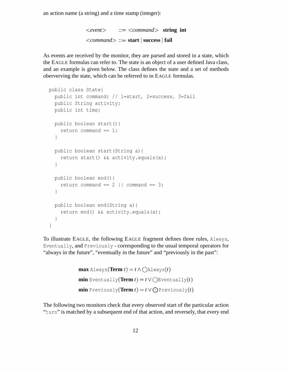
an action name (a string) and a time stamp (integer):
� event � :: � � command � string int
� command � :: � start � success � fail
As events are received by the monitor, they are parsed and stored in a state, whichthe EAGLE formulas can refer to. The state is an object of a user defined Java class,and an example is given below. The class defines the state and a set of methodsoberverving the state, which can be referred to in EAGLE formulas.
public class State{public int command; // 1=start, 2=success, 3=failpublic String activity;public int time;
public boolean start(){return command == 1;
}
public boolean start(String a){return start() && activity.equals(a);
}
public boolean end(){return command == 2 || command == 3;
}
public boolean end(String a){return end() && activity.equals(a);
}}
To illustrate EAGLE, the following EAGLE fragment defines three rules, Always,Eventually, and Previously - corresponding to the usual temporal operators for“always in the future”, “eventually in the future” and “previously in the past”:
max Always � Term t � � t � � Always � t �min Eventually � Term t � � t � � Eventually � t �min Previously � Term t � � t � � Previously � t �
The following two monitors check that every observed start of the particular action“turn” is matched by a subsequent end of that action, and reversely, that every end
12
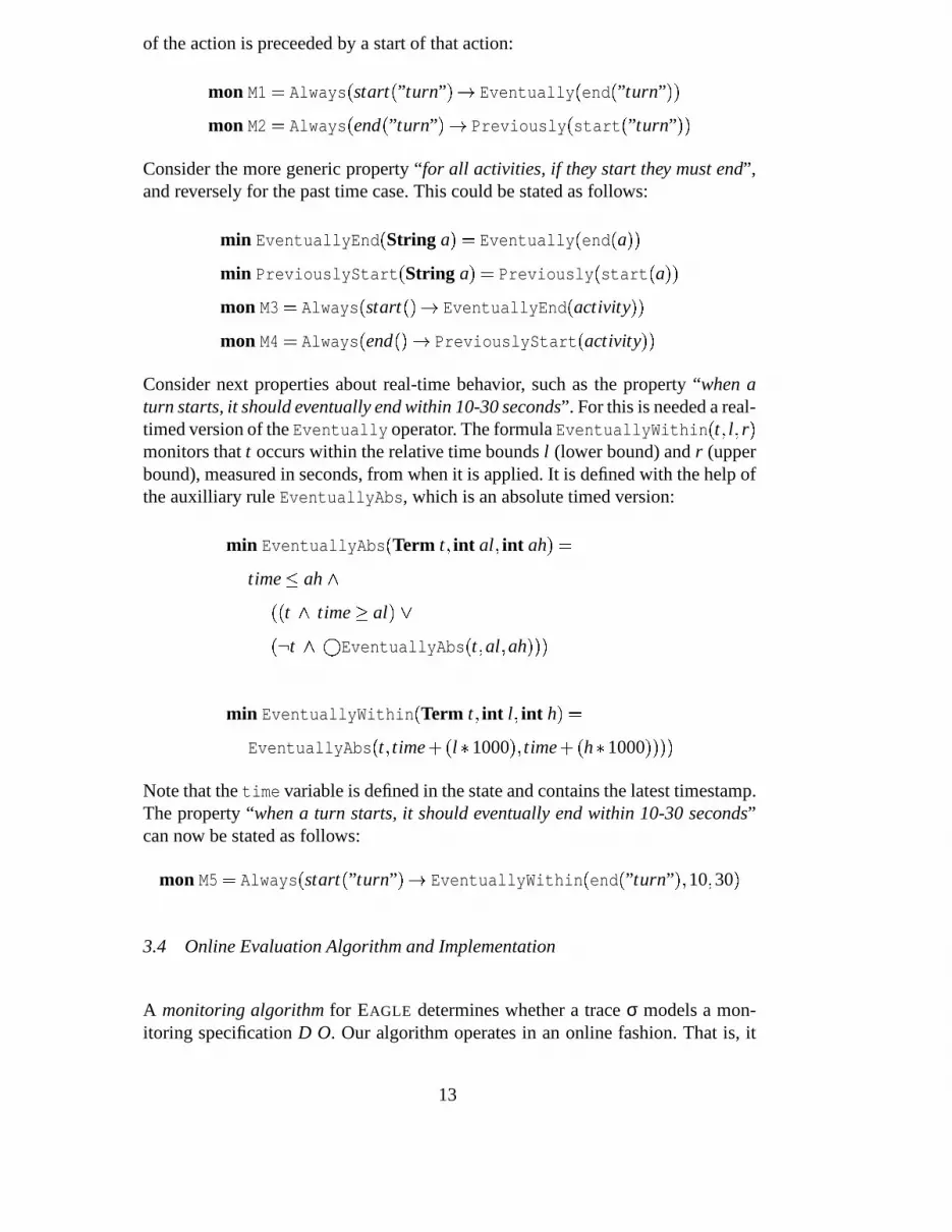
of the action is preceeded by a start of that action:
mon M1 � Always � start � ”turn” � � Eventually � end � ”turn” ��mon M2 � Always � end � ”turn” � � Previously � start � ”turn” ��
Consider the more generic property “for all activities, if they start they must end”,and reversely for the past time case. This could be stated as follows:
min EventuallyEnd � String a � � Eventually � end � a ��min PreviouslyStart � String a � � Previously � start � a ��mon M3 � Always � start � � � EventuallyEnd � activity ��mon M4 � Always � end � � � PreviouslyStart � activity ��
Consider next properties about real-time behavior, such as the property “when aturn starts, it should eventually end within 10-30 seconds”. For this is needed a real-timed version of the Eventually operator. The formula EventuallyWithin � t � l � r �monitors that t occurs within the relative time bounds l (lower bound) and r (upperbound), measured in seconds, from when it is applied. It is defined with the help ofthe auxilliary rule EventuallyAbs, which is an absolute timed version:
min EventuallyAbs � Term t � int al � int ah � �time � ah �
�� t � time � al � �� t � �
EventuallyAbs � t � al � ah ���
min EventuallyWithin � Term t � int l � int h � �EventuallyAbs � t � time � l � 1000 � � time � h � 1000 ����
Note that the time variable is defined in the state and contains the latest timestamp.The property “when a turn starts, it should eventually end within 10-30 seconds”can now be stated as follows:
mon M5 � Always � start � ”turn” � � EventuallyWithin � end � ”turn” � � 10 � 30 �
3.4 Online Evaluation Algorithm and Implementation
A monitoring algorithm for EAGLE determines whether a trace σ models a mon-itoring specification D O. Our algorithm operates in an online fashion. That is, it
13

is presented sequentially each state of σ and does not refer back to past states orforward to future states. This allows the algorithm to be used in online monitoringcontexts.
Ideally if a monitoring specification is expressible in a more restricted system, e.g.LTL, then the EAGLEalgorithm should perform about as well as an efficient al-gorithm for the restricted system. We have prove this true for LTL, and will beexploring other logics.
The algorithm employs a function eval � D � s � that examines a state, s and transformsa monitor D into a monitor D � such that sσ � � D O iff σ � � D � O.
The algorithm is, where possible, a direct implementation of the definition of EA-GLEsemantics. So for example if D monitors a formula F1 � F2, then (with a slightoverloading of the notation)
eval � F1 � F2 � s � � eval � F1 � s � � eval � F1 � s � F2 � s � �Furthermore,
eval � � F � s � � F �However, an online algorithm that examines a trace in temporal order cannot treatthe previous state operator so easily. Thus the algorithm maintains an auxiliary datastructure (assumed available to eval) used by eval on sub-formulas headed by the �operator, that records the result of (partially) evaluating the formula in the previousstate. This is illustrated as follows:
min Sometime � Form F � � F � � Sometime � F �min R � int k � � � � y 1 � � k �mon M � SometimeR � x �
This monitor will be true if somewhere in the trace there are two successive statessuch that in the value of y in the first state is one less than the value of x in thesecond state. More generally, notice that the combination of parameterizing ruleswith data values and use of the next and previous state operators enable constraintsthat relate the values of state variables occurring different states.
Since eval recursively decomposes the formulas, eventually eval will be called on� y 1 � � k. Note the state variable y refers to the value of y in the previous state,while the formal parameter k is bound to the value of x in the current state. Sincethe previous state is unavailable, in the prior step the algorithm must take someaction to record relevant information. Our algorithm pre-evaluates and caches theevaluation any formula P headed by a previous state operator, in this case the for-mula y 1 � � k. However since the value of k will not be known at that point, theevaluation is partial. In particular note that the atomic formulas and the underlying
14

expression language (in our case this is Java expressions), must be partially evalu-ated 1 . Also note that since the formula P can be arbitrarily complex, in particularanother previous state operator may be nested within, the pre-evaluation is done bya recursive call to eval.
This is basic idea of the algorithm. One subtle point is that the sub-formulas thatmust be pre-evaluated must be identified and properly initialized prior to process-ing the first state. This is done by expanding monitor formulas by unfolding ruledefinitions, while avoiding infinite expansion due to recursive rule definitions.
eval yields a formula that may be simplified without altering the correctness ofthe algorithm. Indeed the key to efficient monitoring and provable space boundsis adequate simplification. In our implementation, formulas are represented in dis-junctive normal form where each literal is an instance of negation, the previous ornext operator or a rule application. Subsumption, i.e. simplifying � a � b � � a to a isessential.
3.5 Complexity of EAGLE
It is evident from the semantics given above in Section 3.1 that, in theory, EAGLE
is a highly expressive and powerful language; indeed, given the unrestricted natureof the data types and expression language, it is straightforward to see it is Turing-complete. This is not of much interest practically. Furthermore, assuming that alldata is finitely bounded with, of course, finite input traces is also of not much in-terest. What is of more interest is the cost of evaluation, using our implementationalgorithms, of an Eagle temporal constraint under, say, zero cost evaluation of anydata computation that may ensue; this then informs us of the complexity of the tem-poral aspects of the evaluation of the logic. An alternative way of viewing this isto show that our algorithm can meet known optimal bounds for various sub-logicsembedded within Eagle. To that end, there are some initial complexity results thatare of interest.
Our first result relates to an embedding of propositional linear time temporal logic(LTL), over both future and past. In [?], we show that the step evaluation for an ini-tial LTL formula of size m has an upper time complexity bound of O � m422m log2 m �and a space bound of O � m22m logm � , thus showing that the evaluation at any pointis not dependent on the length of the history, i.e. the input seen so far. The result isclose to the lower bound of O � 2 �
m � for monitoring LTL given in [?].
Kouhsik and Grigore - are there any results that can be put down about thealgorithm when restricted to metric temporal logic - as in Grigore’s paper
1 A simpler alternative to partial evaluation is to form a closure and do the complete eval-uation when all variables are bound.
15
for RV’04? I haven’t had time to investigate.
3.6 Experimental Timings
3.7 Event Extraction
The event extraction can be achieved in a number of ways, including wrapping andinstrumentation. In a wrapping approach, the standard execution environment is re-placed with a customized one that allows observation by wrapping system libraries.This is the approach of Purify [20]. In the instrumentation approach, source code(or object code) is augmented with code that generates the event stream. Our ex-periments use both approaches. The instrumentation approach is used to generateevents for the temporal logic monitoring. As will be explained, this monitoring ex-amines events indicating the start and end of task executions, and the code has beenmanually instrumented to generate these events. The wrapping approach is used togenerate events for the concurrency analysis, where lock acquisitions and lock re-leases are monitored. These events are generated by wrapping method calls aroundPOSIX [17] thread methods, and then instrument the wrappers.
We are working on technology for automatic program instrumentation. Here codeis instrumented based on an instrument specification that consists of a collection ofpredicate/action rules. The predicate is a predicate on program statements. Thesepredicates are conjunctions of atomic predicates that include method invocations,references to global variables, object variables, and local variables, and lock usage.The actions are specifications describing the inserted instrumentation code. Theyinclude reporting the program location, a time stamp, the value of an expression,and invocation of auxiliary methods. Values of primitive types are recorded in theevent itself, but if the value is an object, a unique integer descriptor of the object isrecorded.
Such an instrumentation package, named jSpy, has been implemented for instru-menting Java bytecode [9]. This was first implemented using Jtrek [5], a Java APIthat provides lower-level instrumentation functionality. Use of bytecode instrumen-tation, and of Jtrek in particular, has worked out well. However, at the time of writ-ing, a new version is being implemented based on the BCEL library [6], which isOpen Source, unlike Jtrek, which has been discontinued.
3.8 Observer Framework
As described above, runtime analysis is divided into two parts: instrumentation andexecution of the instrumented program. To minimize the impact on the program un-
16

der test, events should contain minimal information. Two categories of informationneed to be transmitted: essential information, needed to detect property violations,and contextual information, needed to print out informative error messages whenproperties get violated. Instrumentation is done such that contextual information issent only when it changes, and not with every event. The event observer, (see Fig-ure 6), can be correspondingly be split into two stages. The event dispatcher readsthe events and sends a reconstructed version to one or more property analyzers.
Instrumentedprogram
Eventanalysis
InterpretationEvents
Observer
Event Eve
ntco
nver
sion
Result
ContextEvent dispatcher
Internal events
Observable events
Par
sing
Propertyanalyzer
Figure 6. The observer architecture.
The event dispatcher parses events, and converts them into a unified format, accom-modating different instrumentation packages. The contextual information, trans-mitted in internal events (not emitted to the property analyzers), include threadnames, code locations, and reentrant acquisitions of locks (lock counts). The eventdispatcher package maintains a database with the full context of the events. Thisallows for writing simpler property analyzers. The property analyzers subscribe toparticular event types made accessible through an observer interface [8] and arecompletely decoupled from each other.
It is up to each property analyzer to record all relevant information for keeping ahistory of the events, since the context maintained by the event dispatcher changesdynamically with event evaluation. The property analyzer reports violations ofproperties in its model using the stored data and context information. The main ad-vantages of this approach are the decoupling of the instrumentation package fromobservation, and the ability to re-use one event stream for several property analyz-ers.
3.9 The JPaX Concurrency Analyzer
Multi-threaded programs are particularly difficult to test due to the fact that theyare non-deterministic. A multi-threaded program consists of several threads thatexecute in parallel. A main issue for a programmer of a multi-threaded application
17

is to avoid data races where several threads access a shared object simultaneously.Multi-threading programming languages therefore provide constructs for ensuringmutual exclusion, usually in the form of locks. If other threads utilize the samelock when accessing an object, mutual exclusion is guaranteed. If threads do notacquire the same lock (or do not acquire locks at all) when accessing an objectthen there is a risk of a data race. It algorithm [21] can detect such disagreementsby analyzing single execution traces. The Eraser algorithm has been implementedin the JPaX tool. Recent work has shown that another kind of error, high-leveldata races, can still be present in programs that use mutual exclusion for accessingindividual fields, but not sets of fields, correctly [1].
Deadlocks can occur when two or more threads acquire locks in a cyclic manner.As an example of such a situation consider two threads T1 and T2 both acquiringlocks A and B. Thread T1 acquires first A and then B before releasing A. Thread T2
acquires B and then A before releasing B. This situation poses a deadlock situationsince thread T1 can acquire A where after thread T2 acquires B, where after boththreads cannot progress further. JPaX includes such a deadlock detection algorithm.An extension to this algorithm reduces the number of false positives [2].
4 Case Study: A Planetary Rover Controller
The case study described here is the planetary rover controller K9, and in particularits executive subsystem, developed at NASA Ames Research Center – a full accountof this case study is described in [4]. The executive receives plans of actions that therover is requested to carry out, and executes these plans. First a description of thesystem is presented, including a description of what plans (the input domain) looklike. Then it is outlined how plans (test inputs) can be automatically generated usingmodel checking. Finally it is described how, for each plan, one can automaticallygenerate a set of temporal logic properties that the executive must satisfy whenexecuting the plan.
4.1 System Description
The executive is a multi-threaded system (35,000 lines of C++ code) that receivesflexible plans from a planner, which it executes according to a plan language seman-tics. A plan is a hierarchical structure of actions that the rover must perform. Tra-ditionally, plans are deterministic sequences of actions. However, increased roverautonomy requires added flexibility. The plan language therefore allows for branch-ing based on conditions that need to be checked, and also for flexibility with respectto the starting time and ending time of an action. This section gives a short presen-tation of the (simplified) language used in the description of the plans that the rover
18

Plan � Node
Node � Block # Task
Block � (block
NodeAttr
:node-list (NodeList))
NodeList � Node NodeList # εTask � (task
NodeAttr
:action Symbol�:fail �
�:duration DurationTime � )
NodeAttr � :id Symbol�:start-condition Condition �
�:end-condition Condition �
�:continue-on-failure �
Condition � (time StartTime EndTime)
(block:id plan:continue-on-failure:node-list ((task:id drive1:start-condition (time +1 +5):end-condition (time +1 +30):action BaseMove1:duration 20
)(task:id drive2:end-condition (time +10 +16):action BaseMove2:fail
) ) )
Figure 7. Plan grammar (left) and an example of a plan (right).
executive must execute.
4.1.1 Plan Syntax
A plan is a node; a node is either a task, corresponding to an action to be executed,or a block, corresponding to a logical group of nodes. Figure 7 (left) shows thegrammar for the language. All node attributes, with the exception of the node’sid, are optional. Each node may specify a set of conditions, e.g. the start condition(that must be true at the beginning of the node execution) and the end condition (thatmust be true at the end of the node execution). Each condition includes informationabout a relative or absolute time window, indicating a lower and an upper boundon the time. The continue-on-failure flag indicates what the behavior will be whennode failure is encountered.
The attributes fail and duration were added to facilitate testing of the executive.During testing using test case generation, the real actions are never executed sincethis would require operating the rover mechanics. Attributes :fail and :durationreplace the actions during testing. Flag fail specifies the action status of a task afterexecution; duration specifies the duration of the action. Figure 7 (right) shows aplan that has one block with two tasks (drive1 and drive2). The time windowshere are relative (indicated by the ’+’ signs in the conditions).
4.1.2 Plan Semantics
For every node, execution proceeds through the following steps: (1) Wait until thestart condition is satisfied; if the current time passes the end of the start condition,
19

class UniversalPlanner { ...static int nNodes = 0;static int tRange = 0;
static void Plan(int nn, int tr) {nNodes = nn; tRange = tr;UniversalAttributes();Node plan = UniversalNode();print(plan);assert(false);
}
static Node UniversalNode() {if (nNodes == 0) return null;if (chooseBool()) return null;if (chooseBool())return UniversalTask();
return UniversalBlock();}
static Node UniversalTask() {Symbol action = new Symbol();boolean fail = chooseBool();int duration = choose(tRange);Task t =new Task(id, action, start,
end, continueOnFailure,fail, duration);
nNodes--;return t;
}
static Node UniversalBlock() {nNodes--;ListOfNodes l = new ListOfNodes();for (Node n = UniversalNode();
n != null; n = UniversalNode())l.pushEnd(n);
Block b =new Block(id, l, start, end,
continueOnFailure);return b;
}
static Symbol id;static TimeCondition start, end;static boolean continueOnFailure;
static UniversalAttributes() {id = new Symbol();Symbolic sTime1 = new SymInt();Symbolic sTime2 = new SymInt();Symbolic._Path_cond._add_GT(sTime2, sTime1);start =
new TimeCondition(sTime1.solution(),sTime2.solution());
Symbolic eTime1 = new SymInt();Symbolic eTime2 = new SymInt();Symbolic._Path_cond._add_GT(eTime2,eTime1);end = new TimeCondition(eTime1.solution(),
eTime2.solution());continueOnFailure = chooseBool();
} }
Figure 8. Code that generates input plans for system under test.
the node times out and this is a node failure. (2) The execution of a task proceedsby invoking the corresponding action. The action takes exactly the time specified inthe :duration attribute. Note that this attribute during testing replaces the actualexecution of the action on the rover. The action’s status must be fail, if :fail istrue or the time conditions are not met; otherwise, the status must be success. If thestatus of the action indicates failure, its task fails. The execution of a block simplyproceeds by executing each of the nodes in the node-list in order. (3) If time exceedsthe end condition, the node fails. On a node failure, when execution returns to thesequence, the value of the continue-on-failure flag of the failed node is checked.If true, execution proceeds to the next node in the sequence. Otherwise the nodefailure is propagated to any enclosing nodes. If the node failure passes out to thetop level of the plan, the remainder of the plan is aborted.
4.2 Test Input Generation
Figure 8 shows part of the Java code, referred to as the universal planner, that isused to generate plans (i.e., test inputs for the executive). The framework suggestedin Section 2 is used where an annotated Java program specifies only the structureof the inputs together with the preconditions on this structure. Model checkingwith symbolic execution generates the inputs. In order to specify the structure non-deterministic choice (choose methods) are exploited over all structures allowed in
20

the grammar presented in Figure 7, and preconditions are specified as constraintsover some of the integer variables in the structure. For the latter, only time pointsare considered. Furthermore, these represent inputs to our specification, to allowsymbolic execution and constraint solving to generate valid test cases. For brevity,only a small sample set of constraints is shown here (stating that the end time islarger than the start time of an interval).
To illustrate the flexibility in our approach, some of the variables are consideredconcrete inputs, e.g. the number of nodes in the total structure (nNodes), and yetothers, e.g. the duration of a task (duration), is concretized by non-deterministicchoice. The assertion in the program specifies that it is not possible to create a“valid” plan (i.e., executions that reach this assertion generate valid plans). TheJPF model checker model checks the universal planner and is thus used to explorethe (infinite) state space of the generated input plans. Different search strategiesfind multiple counterexamples; for each counterexample JPF is run in simulationmode to print the generated plan to a file, which then serves as input to the rover.
class Symbolic { ...static PathCondition _Path_cond;Symbolic _plus(Symbolic e) { ... }Symbolic _minus(Symbolic e) { ... }int solution() { ... }
}
class PathCondition { ...Constraints c;void _add_GT(Symbolic e1,
Symbolic e2){c.add_constraint_GT(e1,e2);if (!c.is_satisfiable())
backtrack();return;
} }
Figure 9. Library classes for symbolic execution.
Figure 9 gives part of the library classes that provide symbolic execution. ClassSymbolic implements all symbolic constraints and includes a subclass SymIntthat represents symbolic integer values. The static field Symbolic._Path_condstores the (numeric) path condition. Method _add_GT updates the path conditionwith the greater-than constraint. Methodis_satisfiable uses the Omega library to check if the path condition is infea-sible (in which case, JPF will backtrack). The solution method first solves theconstraints and then returns one solution value for a symbolic integer (solutions arecurrently not defined for non-integer symbolic values).
4.3 System Analysis
The semantics of a particular plan can very naturally be formulated in temporallogic. In writing such properties, the following predicates were used: start � id � (trueimmediately after the start of the execution of the node with the corresponding id),success � id � (true when the execution of the node ends successfully), fail � id � (truewhen the execution of the node ends with a failure), and end � id � , which denotessuccess � id � � fail � id � . The code was instrumented to monitor these predicates. Fur-thermore, for each plan a collection of temporal properties over these predicates
21

��� start � plan � , i.e., the initial node plan should eventually start.
��� � start � plan ��� �1 5start � drive1 �� , i.e., if the plan starts, then task drive1 should begin
execution within 1 and 5 time units.
��� � start � drive1 ����� � 1 30success � drive1 �� � fail � drive1 ��� , i.e., if task drive1 starts,then it should end successfully within 1 and 30 time units or it should eventually termi-nate with a failure.
��� � success � drive1 ��� � start � drive2 �� , i.e., if task drive1 ends successfully, then taskdrive2 should eventually begin execution.
��� � end � drive2 ��� � success � plan �� , i.e., termination of task drive2 implies successfultermination of the whole plan (due to continue-on-failure flag).
��� success � drive1 � , i.e., task drive1 should end successfully (since :duration is withintime window).
��� fail � drive2 � , i.e., task drive2 should fail (due to :fail).
Figure 10. Temporal logic properties representing partial semantics of plan in Fig. 7.
was generated automatically. Their validity was verified on execution traces. As anexample, the properties for the plan shown in Figure 7 (right) are shown in Figure10. This set of properties does not fully represent the semantics of the plan, but theapproach appears to be sufficient to catch errors.
The runtime analysis identified a number of errors in the executive. A preliminary,partially automated system for runtime testing found a deadlock and a data race. Forthe deadlock, the additional instrumentation triggered the deadlock during execu-tion, but in fact the pattern existed in the un-instrumented version of the executive,and would have been identified by the instrumentation, even if it had not occurredexplicitly. The data race, involving access to a shared variable used to communicatebetween threads, was suspected by the developers, but had not been confirmed incode. The trace analysis allowed the developers to see the read/write pattern clearlyand redesign the communication. The fully automated testing system detected abug that had been seeded in the code for verification purposes: the bug producedan execution failure when a plan node was processed after the beginning of its startwindow. Finally, the automated testing system found a missing feature that hadbeen overlooked by the developers: the lower bounds on execution duration werenot enforced, so the temporal logic model predicted failure when execution in factsucceeded. This latter error was unknown to the developers, and it showed up laterduring actual rover operation before it was corrected.
22

5 Conclusions and Future Work
A framework for testing based on automated test case generation and runtime anal-ysis has been presented. This paper proposed and demonstrated the use of modelchecking and symbolic execution for test case generation, and the use of rewriting-based temporal logic monitoring during the execution of the test cases. The frame-work requires construction of a test input generator and a property generator forthe application. From that, an arbitrarily large test suite can be automatically gener-ated, executed and verified to be in conformity with the properties. For each inputsequence (generated by the test input generator) the property generator constructsa set of properties that must hold when the program under test is executed on thatinput. The program is instrumented to emit an execution log of events. An observerchecks that the event log satisfies the set of properties.
We take the position that writing test oracles as temporal logic formulas is bothnatural and leverages algorithms that efficiently check if execution on a test inputconforms to the properties. While property definition is often difficult, at least forsome domains, an effective approach is to write a property generator, rather thana universal set of properties that are independent of the test input. Note also thatthe properties need not completely characterize correct execution. Instead, a usercan choose among a spectrum of weak but easily generated properties to strongproperties that may require construction of complex formulas.
In the near future, we will continue the development of a complete testing envi-ronment for the K9 rover executive, and seek to get this technology transferred toNASA engineers. We will be exploring how to improve the quality of the generatedtest suite by altering the search strategy of the model checker, and by improving thesymbolic execution technology. We will also investigate the use of real-time logicand other more complicated logics. In particular, the Eagle logic should provide agood framework for monitoring. We are continuing the work on instrumentationof Java bytecode and will extend this work to C and C++. Our research group hasdone fundamental research in other areas, such as software model checking (modelchecking the application itself, and not just the input domain), and static analysis.In general, our ultimate goal is to combine the different technologies into a singlecoherent framework.
References
[1] C. Artho, K. Havelund, and A. Biere. High-level Data Races. In VVEIS ’03, April2003.
[2] S. Bensalem and K. Havelund. Reducing False Positives in Runtime Analysis ofDeadlocks. Internal report, to be published, October 2002.
23
[3] C. Boyapati, S. Khurshid, and D. Marinov. Korat: Automated Testing Based on JavaPredicates. In Proceedings of the International Symposium on Software Testing andAnalysis (ISSTA), July 2002.
[4] G. Brat, D. Giannakopoulou, A. Goldberg, K. Havelund, M.Lowry, C. Pasareanu,A. Venet, and W. Visser. A Comparative Field Study of Advanced VerificationTechnologies. Internal report, in preparation for submission, November 2002.
[5] S. Cohen. Jtrek. Compaq, http://www.compaq.com/java/download/jtrek.
[6] Markus Dahm. BCEL. http://jakarta.apache.org/bcel/.
[7] D. Drusinsky. The Temporal Rover and the ATG Rover. In SPIN Model Checking andSoftware Verification, volume 1885 of LNCS, pages 323–330. Springer, 2000.
[8] E. Gamma, R. Helm, R. Johnson, and J. Vlissides. Design Patterns – Elements ofReusable Object-Oriented Software. Addison-Wesley, 1995.
[9] A. Goldberg and K. Havelund. Instrumentation of Java Bytecode for RuntimeAnalysis. In Proc. Formal Techniques for Java-like Programs, volume 408 ofTechnical Reports from ETH Zurich, Switzerland, 2003. ETH Zurich.
[10] W. Grieskamp, Y. Gurevich, W. Schulte, and M. Veanes. Generating Finite StateMachines from Abstract State Machines. In Proceedings of the InternationalSymposium on Software Testing and Analysis (ISSTA), July 2002.
[11] A. Groce and W. Visser. Model Checking Java Programs using Structural Heuristics.In Proceedings of the 2002 International Symposium on Software Testing and Analysis(ISSTA). ACM Press, July 2002.
[12] A. Hartman. Model Based Test Generation Tools.http://www.agedis.de/documents/ModelBasedTestGenerationTools_cs.pdf.
[13] H. Hong, I. Lee, O. Sokolsky, and H. Ural. A Temporal Logic Based Theory of TestCoverage and Generation. In Proceedings of the 8th International Conference on Toolsand Algorithms for Construction and Analysis of Systems (TACAS), April 2002.
[14] S. Khurshid, C. Pasareanu, and W. Visser. Generalized Symbolic Execution for ModelChecking and Testing. In Proceedings of TACAS’03: Tools and Algorithms for theConstruction and Analysis of Systems, volume 2619 of LNCS, Warsaw, Poland, April2003.
[15] J. C. King. Symbolic Execution and Program Testing. Communications of the ACM,19(7):385–394, 1976.
[16] B. Korel. Automated Software Test Data Generation. IEEE Transaction on SoftwareEngineering, 16(8):870–879, August 1990.
[17] B. Nichols, D. Buttlar, and J. P. Farrell. Pthreads Programming. O’Reilly, 1998.
[18] Parasoft. http://www.parasoft.com.
[19] W. Pugh. The Omega Test: A Fast and Practical Integer Programming Algorithm forDependence Analysis. Communications of the ACM, 31(8), August 1992.
24

[20] Purify: Fast Detection of Memory Leaks and Access Errors. January 1992.
[21] S. Savage, M. Burrows, G. Nelson, P. Sobalvarro, and T. Anderson. Eraser: A DynamicData Race Detector for Multithreaded Programs. ACM Transactions on ComputerSystems, 15(4):391–411, November 1997.
[22] N. Tracey, J. Clark, and K. Mander. The Way Forward for Unifying Dynamic Test-Case Generation: The Optimisation-Based Approach. In International Workshop onDependable Computing and Its Applications (DCIA), pages 169–180. IFIP, January1998.
[23] T-VEC. http://www.t-vec.com.
[24] W. Visser, K. Havelund, G. Brat, and S. Park. Model Checking Programs. InProceedings of ASE’02: The 15th IEEE International Conference on AutomatedSoftware Engineering. IEEE CS Press, September 2000.
25


