Embed Size (px)
Citation preview
lssue t, APdl 1986555-102-201
AT&T SYstem 85Release 2. Versions 1, 2, and 3
System DescriPtion
Reference Manual
Copyright O 1986 AT&T Technologies lnc
All Fighls Reserued
PinledinUSA
TO ORDER COPIES OF ?EIS MANUAL
Cslt AT&T Custoner Information Cent€r on 800-432-6600In Canada Call 800-255-1242
Write: AT&T Customer Information Center2855 North Franklin RoadP. O. Box 19901
Indianapolis, Indiana 46219
CONTENTS
1. OVERVIEWORGANIZATIONINTRODUCTION
1-1
1-1
1-2
1-11
1-111-11
1-12
INTRODUCING RELEASE 2, VERSION 3
CALL-HANDLING CAPABILITIESFCC RULES AND REGI]LATIONS
FCC Registration NumbersDigital Tie Trunk Resistration
A Closer Look at R2V3 Capabilities1-4t-51-9
ComplianceConn€ction Informatior
UNDERWRITERS LABORATORIES (IJL) LISTING ANDRECOGNITION
2. FIINCTIONALDESCRIPTIONGENERAL
Call Prccessing ModulesTime-Multiplexed Sq'itch (TMS)Remot€ Modules
SYSTEM 85 APPLICATIONS
Data Communications
2-1HOW SYSTEM 85 WORKSCommon Control
2-A2-ta2-n
Remote Groups 2-29Applications Processors (APs) - 2-30
Digital Service-1 (DS-1) InterfaceDigital Multiplexed Interface (DMI)
Data Communicatiom Int€rlac€ Unit (DCIU)2-35
Private Network Configurations .
3-20
2-352-39
3-1
3-4
3-8
Distributed Communication SystemAutomated Transmission Measurcment System (ATMS) 2-41
2-472-482-672-69Synchronization
3. SYSTEM HARDWARE
Information System Network (ISN)
BASIC SWITCH CABINETSovERvtEw
Overview
Unduplicated Cornmon Control Cabinet (J58886J)Duplicated Common Control Cabinet (J58886K)Time Multipl€x€d Switch (TMS)/Remote Module Interface (RMI) Cabin€t(J58886F)Module Control Cabinet (J588868.)Port Cabinet (J58886C)Remote Group Housing (J58889AN)
SYSTEM CABINDT CONFIGURATIONS
3-103-123-13
3-18
Standard Reliability ConfigurationHigh Reliability ConligurationCritical Reliability ConfigurationRemote Module ConfigurationRemote Group Configuration
t-
CABINET EQUIPMENT 3-2t3-24s-24
'-Zt
3-A3-29
3-36
3-463-483-50
Alarm PanelHigh Capacity Mini-Record€r (HCMR)Thermal Sensor AssemblyFan AssemblyAC Dist bution UnitsRectiliers .DCIDC ConvertersBus Bar 3-23
3-g)3-30
3-403-413-43
3-603-683-693-?0
3-?63-?83-?83-80
4-104-104-121-144-184-n4-%4-25
DC FiltersFrequencyNominal H
Ge[eratorsoldover Equipment
Extended Power Reserv€ EquipmentCARRIERS
Common Control Carrier (J58888E)Power Carriel (J58888F)DC,/DC Converter Unit (J58889T)TMS Carrier (J58888C)
RMI Canier (J58888S)
Module Control Carrier (J58888M)Port Csrrie. (J58888A)DS-1/MRemote
FAT Carrier (J58888N)Group Housing (J58889AN)
CIRCUIT PACKSSN-Coded Circuit PacksTN-Coded Circuit PacksUN-Coded Circuit PacksANN-Coded Circuit PacksPort Circuit Pack Assignments
SYSTEM INTERCONNDCTIONSCross-Connect UnitCablesFiber-OpticDuct Work
Link Subsystem
SWITCH EQUIPMENT CODE SUMMARY
4. PERIPHERAL EQUIPMENT 4-14-2ATTENDANT CONSOI,E
VOICE TERMINALS AND ADJUNCTSOverview
DATA EQUIPMENT AND INTERFACE DEVICESData ModulesModems (Dats Sets)Asynchronous Data Unit (ADU)Multiple Asynchronols Data Unit (MADU)Protocol Converte$Channel Division Multiplexer (CDM)Channel Expansion Multiplexer (CEM)
Analog Voice Te.minalsHybrid Voic€ T€rminalsDigital Voice TerminalsVoice Terminal Adjuncts
ll-
4-35
4-374-394-434-43
Data Channel Repeater . . . .
Information Syst€ms Network (ISN) Interface4-M4-444-44
4-524-524-544-544-55d-55l-56
I-ocal Distribution Selvice Unit (LDSU)Isolating Data Interface (IDI)
BUSINESS COMMUNICATIONS TERMINALS (BCTS)
500 BcTAT&T Personal Terminal 510D513 BCT
Administration Panel (MAAP)tion Data System (FADS) Terminal
515 BCTPRINTERS
443 Printer445 Printer450 Printer460 Printer
MISCDLLANEOUS PERIPHERALSSyst€m Management Terminai (SMT)Maintenence andForce Administra
1-U4-454-454-474-494-501-52
4-624-641-614-65
Position Status Indicators . . .
4-584-594-60
AUXILIARY EQUIPMENT . . 4-62
89A Control Unit 4-65Customer Pr€mises Facility Terminal (CPFT) Equipment 4-65Data Channel R€peate . 4-66Information Systems N€twork (ISN) Interfac€ . . 4-67Local Distribution Service Unit (LDSU) 4-67Radio Paging Int€rface Trunk Unit , . 4-61Recorded Announc€m€nt Set 4-68Recorded Telephone Dictation (RTD) Equipnent -Transfer PanelVoice Coupler 4-69
4-69
4-704-704-104-734-?34-764-164-78{-80
Voice Switched Gain Amplilier
APPLICATIONS PROCESSOR (AP) EQUIPMENT
System Status Indicators
3B5 APAP Periph€ral Int€rfaces
AUDIO INFORMATION EXCHANGE (AUDIX) EQUIPMENTControl CabinetDisk Cabinet
STATION MESSAGE DETAIL RECORDING (SMDR) EQUIPMENT
5. FEATURES AND SERVICESOVERVIEWNEW FEATURES AND ENHANCEMENTSFEATURE DESCRIPTIONSFEATURE-RELATED HARDWARE
Auxiliar! CabinetAutomatic Trunk Level Interface UnitChannel Division Multiplexer (CDM) EquipmentChannel Expansion Multipl€xer (CEM) Equipment
OverviewAP16
4-684-69
5-15-15-65-9
-lu
6. SOF'TWARE DESCRIFTION 6-16-lARCHITECTURE
OverviesOp€rating SystemTranslatiomCell Proc6sing Routine3 , . .
6-16-l6-2
6-3&.36-36-46-46-4&56-5
ffi6-66-6
't-t
7-47-4
8-l8-18-l8-2
9-19-19-1
9-39-3949-49-59-5
On-Line end Off-Line Maintenance RoutinesAdministration Routines
MEMORY ALLOCATIONREAL-TIME CONSTRAINTSTAPE CARTRIDCES
Festures .Traffic Monitoring
OverviewOrganizationConfigurations
DCIU SOFTWAREAPPLICATIONS PROCESSOR (AP) SOFTWARE
?. SYSTEM ADMINISTRATIONOVERVIEWSYSTEM ADMINISTRATION_SYSTEM ADMINIS1RATORSYSTEM ADMINISTRATION_SERVICE PERSONNEL
8. RELIABILITYGENERAL
9. MAINTENANCE PLAN .
ENHANCED AVAILABILITY CONFIGURATIONSSYSTEM AVAILABILITY
CENERALMAINTENANCE HARD\4'AREMAINTBNANCE TESTS .
MAINTENANCEPROCEDURES .
Error Detection and l,ogging .Error RecoveryAlarm ReportingLocal and Remote Diagnostic TestingCircuit Pack Replacement and Veiification Testing .
rO. SYSTEM ENCINEERINGSWITCH ENGINEERING_TRAFFIC
Port Usage Rate (PUR) and ErlangSwitching NetworkConf€rence TrafficTime-Multiplexed Switch (TMS) and MismatchProcesaor Occupancy and Crche MemoryRemote Modules and Unbalsnced SyBtems
10-1
10-110-110-21G210-31G310-3l0-410-5
Service Objectives (Grade of Service)Capacities

SWITCH ENGINEERING-HARDWARE,/SOFTWARECONFIGURATION
Hardware
Switch Memory Configuration LimitsCircuit Pack Assignments in Port Carriers
AUXILIARY CABINET AND EQUIPMENT CONFICURATIONBasic Auxiliary Cabinet and EquipmentC€neral Configuration Guidelin€s
DISTANCE SPECIFICATTONSAttendant ConsoleAnalog Voice TerminalsMulti-Appearance Voic€ TerminalsDeta TerminalsData ModulesSwitch ModulesMiscellaneous
10-610-6l0-610-?
10-1110-1510-1510-1?10-1910-2010-2210-2510-28l0-3010-3210-33l0-35l0-3610-3710-38
t0-3910-3910-4010-42t0-42\0-4210-4310-44
l0-4610-4610-4610-4810-4810-4910-51
l1-111-111-3
11-1511-21
1l-n11-28
lt-36
TONESPROTOCOLS
CHARACTERISTICSIRCUIT BREAKER REQUIREMENTS, FLOOR
LOADING, AND HEAT DISSIPATIONAC-Powered Systems
T€mperature and HumidityMechanical RequirementsMisc€llaneous Requirements
INSTALLING SYSTEM 85 AT CONSTRUCTION SITESEQUIPMENT DESIGNATIONS, TERMINATION FIELDS, ANDREFERENCE POINTS
Cabinet Designation and NumberingTermination Fields and Refer€nce Point Designations
DUCT WORK AND CABLE RUNSDuct WorkCable RunsEquiprnPnt Room Layour
11. SYSTEM POWERAC POWER AND GROUNDING
AC Power RequirementsPower Source
Internal Grounding Arrangement With AC Power Source-48 V DC STANDBY POWER AND GROUNDING
-48 V DC Standby Power Plant Configurationlnternal Powe! Distribution With -48 V DC StandbySyBtem Grcunding With -48 V DC Standby Power
TRUNK SPECIFICATIONSANAIOG TRANSMISSIONPOWER CONSUMPTION, C
48 V DC Standby Powered Syst€msEQUIPMENT ROOM ENVIRONMENTAL CONSIDERATIONS
Intemel Pow€r Distribution With ACSystem Grounding With AC Power
12. UPGRADES (TO R2V3)tr.LOOR PLANSOFTWARE TRANSLATIONSR1 TO R2V3 UPGRADESR2Vr to R2V3 UPGRADESR2V2 TO R2V3 UPGRADES
r3. PRICE ELEMENT CODE (PEC) DESCRIPflONSPECS BY EQUIPMENT TYPE
Soltwar€
l2-112-t12-1
13-113-118-1
r2-212-2
rg-213-21&3t3-3
13-31g{
CabinetgCarriersLine Port Circuit PacksTrunk Port Circuit PecksFeature-Releted Circuit PacksCommon Control Circuit Pach ond EquipmentTUS Circuit Pacls end Equipm€ntModule Control Circuit Pecks and Equipm.ntRemot€ Module Circuit Packs and EquipmentRemote Cruup EquiDm€ntNominal Holdover Equipment (J8?46 )Attendant Console EquiDmentAuxiliary Equipment
13-lr3-413-4l3-5r8-613-613-613-6t3-7
14-l
l5-1
16.1
Duct WorkMbcelleneous
NUMERICAL USTINC Oi' PEC8
14. REI'ERENCES
15. cLossARY
16. INDEX
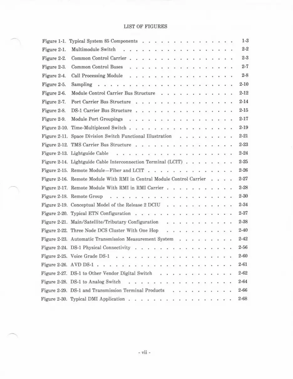
LIST OF' I'IGURES
rypical System 85 Components .
Multimodule S{ritch
Figure l-1.
Figur€ ?1.
Figure 2-Z
Figue 2-3.
Figure 2-4.
Figure 2-5.
Figure 2-6.
Figure 2-7.
Figure 2-8.
Figure 2-9.
Figure 2-10.
Figure 2-11.
Figur. 2-12.
Figure 2-13.
Figule 2-14.
Figure 2-15.
Figure 2-16.
Figure 2-l?.
Figure 2-18,
Figure 2-19.
Figure 2-20.
Figure 2-21.
FiE.rre 2-2.
Figure 2-23.
Figure 2-24.
F'igure 2-25.
Figule 2-26.
?is're 2-n.
Fieure 2-28-
Figure 2-29.
Figure 2-30.
Colnmon Control Carrier
Common Control Bus€s
Call Processing Module
1-3
2-2
2-g
2-8
2-10
2-14
%15
2-\7
2-19
2-21
2-
DS-l Carrier Bus Structure . , .
Module Port Groupings . . . .
Sampling
AVD DS-l
Module Cotrtrol CaIIier Bus Shucturc
Port Csrrier Bus Structure
Time-Multiplexed Switch
Space Division Switch Functional lllustration
Lightguide Cable
Main/Satellit€/Tributary Configuration
Three Node DCS Cluster With One Hop
Automatic Trammission Measur€ment System
Voice Grade DS-l
Typical ETN Configuration .
TMS Carrier Bus Structure . . .
Lightguide Cable Irterconnection Terminal (LCIT) 2-E
Remote Module-Fiber and LCIT . . 2-qi
Bemote Module With RMI in Central Module Control Car er 2-nRemote Module With RMI in RMI Carrier 2-A
Remote Group 2-{2-34
2-37
2-38
2-40
242
2-56
242-61
,62,642-66
2-68
Conceptual Model of the Release 2 DCIU
DS-l Physical Connectivity .
DS-l to Other V€ndor Digital Switch
DS-l to Analog Switch
DS-1 and lYansmission Terminal Products
Typical DMI Application . , . .

Figure }1. Unduplicat€d Common Control Cabinet (J58886.J)
Figure 3-2 Duplicated Common Control Cabinet (J58886K)
Figure 3-3. Time Multiplex€d Switch/Remote Module Interface Cabinet(J58886F)
3-5
3-9
s-llFigure 3-4.
Fisur€ 3-5.
Figure 3{.Figure 3-?.
Figure 3-8.
Figure 3-9.
Figure }l0.Figure 3-ll.Fisure 3-12.
Figure 3-13.
Figure $14.
Figure 3-15.
Figure 3-16.
Figule 3-17.
Figure 3-18-
Figure 3-19.
Figure 3-20.
Figure 3-21.
Figure 3-22.
Figure 3-23.
Figure 3-24.
Figur€ 3-25.
Module Control Cabinet
Port Csbinet (J58886C)
(J58886B)
Remote Group Housing (J58889AN) . 3-12
Module/Cabinet/Carrier t ayout for Standard ReliebilityConfiguretion . 3-15
Module/Cabinet/Carrier Layout for High R€lisbilityConfiguration 3-l?
Module/Cabinet/Carrier Layout for Critical ReliabilityConfiguration 3-19
Remote Module System Connguration (Phase 1) . a-21
R€mote Module System Configuration (Phase 2) . 3-nRemote Croup System Configuration 3-B
3-
3-A
3-34
Power Carrier (J58888F) 3-36
Unduplicat€d Common Control Alarm Panel (J58889W)
Duplicatcd Common Control Alsrm Pan€l (J58889X)
Common Control Carlier (J58888E)
(J58888M)
DClDC Converter Unit (J58889T)
TMS Carrier (J58888C)
nMI Calrier (J58888S)
Modul€ Control Carrier
Port Carrier (J58888A)
DS-r/MFAT Carrier (J58888N) , 3-47
Remote Group Housing (J58889AN) 3-49
Typicsl Msin Cro$-Connect Unit 3-74
Cable Routing Througb Duct Work . 3-?9
3$r
3-38
3-40
3-41
3-44
4-3
4-5
t-7
Figure 4-1. Attendant Con8ole
Figule 4-2. visuelly Impaired
Fisure {-3, Attendant Console
Attendant Service Equipment
Repeater (J58889Y)
Figure 4-4.
Figure 4-5.
Figure 4-6.
Figure 4-?.
Figure 4-8.
Figure 4-9.
Figure 4-10.
Figure 4-11.
Figure 4-12.
Figur€ 4-13.
Figure 4-14.
Figure 4-15.
Fisure 4-16.
Ofl-Premis€s AtteDdant Console Connectivity
System 85 Voice Terminals 4-11
Analog Voice Terminal Connectivity 4-12
2&nDMCC (Analog) Voice Terminal . 4-13
4-8
Hybrid Voice Terminal Connectivity 4-15
4-11
4-?l3
a-n4-30
Digital Voice Terminal Connectivity
Multibutton El€ctronic Telephones (METS)
Data Modules in Multiple Mounting Rack (7141)
Asynchronous Data Unit (ZBA)
ADU Typical Applications
Multiple Asynchronous Data Unit (MADU) TypicalApplications
3Zl0 Dala Modulps (Protocol Converters) Typical Applications
32?0AlT Data Module
32?0C Data Modul€
500/513 Business Communications Terminal (BCT)
500 BCT Keyboard (Without Numeric Keypad)
4-18
4-N
4-21
4-24
4-
4-21
4-31
4-34
4-36
4-37
4-38
4-40
4-40
4-42
4-45
4-46
4-44
7404D (Digital) Voice/Data Terminal
Sp€.keryhon€ (S101A/Sl02A)
lncal and Satellite Adjunct Povrer Sources
Typical System 85 Data Module Usage
PDM/MPDM Connectivity
Modular Processor Data Module (DSU ?00D) in Stand-AloneHousing
Figur€ 4-1?. Modem Pooling
Figure 4-18. TDM/MTDM Connectivity
Figure 4-19. Modular Trunk Data Modul€ (DSU 700E) in Stand-AloneHousing
Figure 4-20. Digitat Terminal Data Module (DSU ?01A) Typical Application
Figure 4-21.
Fieure 4-22.
Figure 4-23.
Figtre 4- .
Figure 4-25.
Figur€ 4-26.
F igure 4-2?.
Figure 4-28.
Figure 4-m.
Figure 4-30. AT&T Personal Terminal 5l0D .
Figure 4-31.
Figurc 4-32.
Figure 4-33.
Figure 4-34.
Figure 4-35.
Figure 4-36.
Figure 4-3?.
Figure 4-38.
Figure 4-39.
Figure 4-40.
Figur€ 4-41.
Figure 4-42.
Figur€ 4-43.
Fisure 4-.14.
515 Business Communications T€rminal
System 85 Printers
System Management T€rminal (J58889K)
Maintenance and Administration Panel (J58889J)
Force Administmtion Data System Terminal (102Ff-A)
Position Status Indicator Unit (1068l-A)
System Status Indicator Unit (30A8)
Auxiliary Cabinet (J58886N)
Customer PI€mises Facility Terminal Shetf (J99380)
Applications Processor 16 (APrG) Cabinet (J59222A)
4-51
4-53
4-56
4-51
4-54
4-59
4-60
4-63
4-66
4-71
4-74
4-17
4-79
4-81
6-2
9-3
10-12
to-21
10-%
10-26
r0-n10-28
l0-29
3B5 Applications Processor (3B5 AP)
AUDIX Control Cabinet (J58886L)
AUDIX Disk Cabinet (J58886M)
Station M€ssag€ D€tail Recording Cabinet (J58886H)
Figur€ 6-1. System 85 Operating System Functional Diagram
Fjgure 7-1. Relative Administration Capability Among System ManagementF€aturcs
Figure 9-1.
F igure 10-1.
Figure 10-2.
Figure l0-3.
Figure l0-4.
Figure l0-5.
Figure 10-6.
Figure 10-?.
Figure l0-8.
Figure 10-9.
Circuit Pack Pairins
System 85 Maintenance Procedures
Distanc€ Limitations lor Att€ndant Consoles
Distance Limitations for Voice Terminal Models ?309S and7305S
Distance Limitations for Voice Terminal Models 2500, 2500 DMGC,and 2554 . 10-23
Distance Limitations for Voice Terminal Models ?101A and?r03A . ..--10-aDistance Limitations for Voice Terminal Models ?203H and't205H
Distanc€ Limitations for Voice Terminal Models ?403D, ?404D, and7405D
Distance Limitations for the 515 BCT and the 5f0D
Distance Limitations for Data Terminal Model 513 BCT
Figure 10-10.
Figirre 10-11.
Figure 10-12.
Figure 10-13.
Figure 10-14.
Figure 10-15.
Figure 10-16.
Fisure 10-1?.
Figure 10-18.
Figurc 10-19.
Figur€ 11-1.
Figur€ 11-2-
Figure 11-3.
Figure 1l-4.
Fisurc 11-5.
Figure l1-6.
Figure 11-?.
Figure 1l-8.
Figurc 11-S-
Figur€ ll-10.
Figure l1-11.
Figure l1-12.
Figure 11-13.
Fisure 11-14.
Fisure 11-15.
Distance Limitations for Data Modules
Distance Limitations for Switch Modules
10-31
10-32
10-34
10-35
10-47
1G50
10-52
10-53
Cabin€t Numb€iing
Cabling Specifications
Top View of Cabinet Dimensions
Cabinet and Duct Work Heights
Call Progress and Binging Tones
Multimodul€ Syst€m Lineup Constraints
Single-Phase 120l240-V AC Pow€r Distribution
Additional AC Protector Cabinet
AC Power Distribution ll-2AC Power Configurations . , .
3'Phase 120l208-V AC Power Distribution
Single-Module System Lineup Constraints 1G55
10-56
11-4
11-6
11-?
11-9
System Cabinet AC Power Connectivity . 11-12
Detail of Cabinet AC Power Duct . t1-13
System Equipment Feeders and Receptacles With AC Power
Typical Cabinet Po\r'er Arrangements lor Ac-Power€dSystem
11-14
I1-1?
1t-25
t1-26
1tn11-30
Module Control and Common Control Pow€I (AC-PoweredSystem) 11-18
TMS and Duplicated Common Control Cabinet Pow€r (Ac-PoweredSystem) 11-19
Port Cabinet Power (AC-Powered System) . 11-20
Grounding Arrangement lor AC-Powered Syst€m . 11-21
\pical Arrangement for Module cmund and Digital Ground in AC-Powered System
Typical ASystem
rrangement for Lightning Ground in Ac-Powered
Figure 11-16. Typical 48 V DC Standby Power Arrangement
Figure 1l-17. Standby Power Feeder Arrangem€nts
Figurc 11-18. System Equipm€nt Feeders with -48 V DC Standby Power
FiguFe U-19. rypicsl Crbinet Po*er Arrangemetrts for -48 V DC Poveredgystem 11-8lt
Ftgue U-20. Xodulo CoDtrol sld CoEmotr Coltml Poro! (--d8 V DC Poeer€dSyst€n). . 11{4 \---l
Figure 11-91. TMS rnd Duplicrtad Commor Control Cabilot Pow€! (-48 V DCPowered gyrtea) Ui35
I'igul€ U-2a Po[t C.bln€t Powor (-.16 V DC Poserld gyrt rh) . . lt€6Figule U-23. CFourding ArrangrmGlt for -{8 V DC Pow€ted Sylt€D . l1-g?
FiSore U-%. lvpical Ar'.ngsnett for odule Gmund rd Digit l Grouad iD -,aS VDC Poe€F.d Syste . 114)
-ltl-
TABLE 2-4.
TABLE 2.B,
TABLE 2-C.
TABLE }4.TABLE 3-B.
TABLE 3-C.
TABLE 3.D.
TABLE 3.E.
TABLE 3-F.
TABLE 3.G.
TABLE 3-H.
TABLE 3-I.
TABLE 5-4.
TABLE 'B.TABLE lGA.
TABLE 10.B.
TABLE 1O-C.
TABLE 10.D.
TABLE 1O-E.
TABLE r0"F-
Network Parameters
Contamination Hezards
LIST OF TABLES
ATMS TTL Test Measurement Copability
ATMS Exception Recording Table 2-45
ATMS Scheduled Retest Decision Table , . . 2-46
Common Control Carrie! Circuit Packs &35
Pow€r Carri€r Circuit Packs . . 3-36
DC/DC Converter Unit Circuit Pscks g-37
TMS Carrier Circuit Packs . 3-39
RMI Carlier Circuit Packs . . . 3-40
uodule Control Calrier Circuit Packs . . . . . . . 3-12
Port Canier Circuit Packs . . .. 3-45
DS-I/MFAT Carrie. Circuit Packs 346
Remote Group Howing Circuit Packs g-48
System 85 Feature Availabiliw . 5-2
Feature/Hardwere Cross-Refercnce
Trunk Parameters
System Parameters . 10'8
Line Parameters 10-9
Terminal Feature Par.meters . 10-9
10-10
10-10
1G.45

l. ovERvlEw
This document provides general technical information on Releas€ 2, versions 1, a aad 3(R2Vl, B2Va and R2Vg) of the AT&T Syst€d 85 (System 85). It is interded lor use byAT&T Information Sy8t€ms (AT&T-IS) sales and technicel personnel. A detailed index irincluded at the back of this book to make it easier to u6e as a reference manual. For acomplet4 ligting of Systam 85 docum€nts, refer to AT&T gysteD 86-DocunentatiotrGulde (55t102{0).
ORGANIZATloN
The rest of this document is divided into the followinq sectionsi
. FUNCTIONAL DESCRIPTION
. SYSTEM HABDWARE
. PERIPHERAL EQUIPMENT
. FEATURES AND SERVICES
. SOFTWARE DESCRIPTON
. SYSTEM ADMINISTRATION
. RELIABILITY
. MAINTENANCE PLAN
. SYSTEM ENGINEERING
. SYSTEM POWER
. UPCRADES (TO R2V3)
. PRICE ELEMENT CODE (PEC) DESCRIPTIONS
. REFERENCDS
. GLOSSARY
. INDEX.
l.t
INTRODUCTION
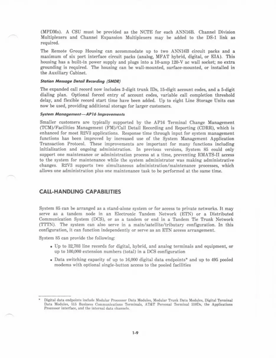
System 85 is an advanced digital switching system which integrat€s voice and datacommunications. It not only provides all the features and functions of a state-of-the-artPBx (such as stored program control, self-diagnostic routin€s, optional duplication of criticalsubsyst€ms, and system expandability), but goes a step further by allowing digital data to beswitched without b€ing converted to analog signais. Syst€m 85 iDcorpomtes a design whichuses Pulse Code Modulation (PCM) for voice and the Digital Communications Protocol (DCP)for integrated voice-data $Ditching. Advenced information management capabilities can b€used to set up high-sp€€d connections betw€en mainframe computers, data €ntry t€rminals,word processors, and penonal computeB. The RS-232C, RS-449, and V.35 interfaces areamong the industry-wide standards accommodated by System 85.
A vari€ty of attractive voice terminals are available with System 85. Functionally, themodels range from basic desk telephones to multi-appearance voice terminals to integratedvoice-data work stations. Most voice t€rminals accept optional adjuncts which expand theircapabilities.
A veriety of data modules provide interfaces for terminals or processing €quipm€nt usingstandard data rat€s. With these modules, data can be switched between on-premises data€quipment or to outgoing analog or digital data facilities.
Applications Prccessors (APs), including the n€w 3B5 AP, enhance the communicationscapabilities of System 85 by providing comprehensiv€ voic€, data, and network managem€nts€rvices and a broad range of integrated messaging and office management applications.
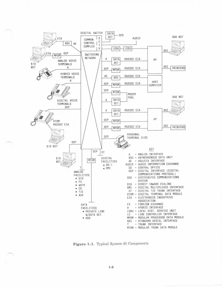
To get a g€neral idea of the kinds of equipment System 85 interconnects, see Figure l-1. Adetailed index (including references to these and other equipment) is provided at the end ofthis document.
l-2
OIGITAL SIIIICH
DCP
5133CT
Attaloo votcEIENiIilALS
HYERID VOICE
TENiI[ALSH
RS232C EIA
RS232C ETA
500 EcT
DIGITAL VOICE,IENit[ALS
DCP\
OTDIIPS232C ETA
\:
FACILITIES. DID
.c0
DI6ITALFACILlTIES. DS- 1
. DIII
ADU .AE.
AIJDIX .c0'DCP '
DCS =
T
$iAIlALl]G IIlIERFACEasYrrrcHRoirous 0ATA lllllTADU/EIA INI€RFACEAUl]IO IIIFORI'tATIOI{ EXC}IANGE
CEI{'IRAL (]FfICEDI6ITAL IIITERTACE (OIGITAL
c0t'lrut{IcaTI0il8 PRoT0c0L )
DISTRISI.]TEO COI'II'iUNICATIl] S
SYSTEII
FACILIIIES
T/OAIA SET
DID . DIRECI INIIARD DIALII{GDIII . DIGITAL I'II]LTIPLEXEO II{TERFAC!DT . DIGITAL IIE TRUI1X II1TERFACE
DTI]I! . DICITAL TERIIII{AL I]ATA I'IOOIJIE
EIA . 'LECTROI{ICS
IIlDUSINIESASSOCIATIl)II
FX ' FOREIOII EXCHAI{GE
H . I]YBRIO IIITENFACE
LDSU = LoCAL DIST. SEnVICE UIIITLC = LIilE C0 TnoLlEn IllIEnFACEItPD = ioDULAR PRoCESSon DAIA I'|oDULE
SSI = STAI{DAnD SERIAL INTERFTCEI . TPU k IilIERFACEIITOII - I'II]DULAR TNUM OITA I'IOOULE
tr'igure l-1. Typical System 85 Components
es232c EIASTITCHII{G
DCP ffi RS232C EII
ns2320 ErA
l-3

INTRODUCING REI.EASE 2, VENSION 3
Rel€ase 2, Version 3 (R2V3) of System 85 enhances the capabilities offer€d in previousversiong of System 85 by adding new f€atur€s and expanding the scope, capacity, and utilityof many €xisting features. Larger system capacities and configurations of R2Vg makeSystem 85 mor€ attractive than ev€r to large multilocetion customers.
Herc are highlights fo! R2Vg hardware:
. Up to 8 m€gawords of memory which provide increased call processing capaciti€s andconfigumtion limits
. 385 Applications Processor (AP) compatibility and APl6 €nhancements
. Remotely loceted groups of voic€,/data t€rminal po circuits Iinked to the System 85central location by Remot€ Croup Interfaces (RCIS)
. Multiple Line Storage Units (LSUs) for call detsil recording applications
. Expanded Digital Service (DS-1) interface capabilities for loop-start c€ntral office,foreign exchange (FX), Wide Area Telecommunications Service (WATS), and DigitalMultiplexed Interface (DMI) applications
. Information Systems Network (ISN) interface to provide access to a distributedprocessing system with an open architecture and high-speed transpo capability
. Data inte aces that enable IBM 32?0-typ€ display terminals to communicate with ahost through System 85 and allow substitution of less expensive Arnerican StandardCode for Information lnterchange (ASCII) terminals
. New terminals with enhanced voic€ and data capabilities.
Highlights for R2V3 software include:
. System Capacity of 32,?03 Line Records
. Automatic Call Distribution
. Busy Out of 2-Way Trunks
. Call Management System
. Centralized System Management
. Dedicated Switch Conn€ctions
. Display Message Scrolling
. Enhanced Symmetrical Routing
. Expanded (5-Digit) Dialing Plan
. Extension Number Portability
. Hot Line Service
. Interexchange Carrier Access
. Reduced Port Contention (Administration/Maintenance)
. Significant enhancements in existing voic€, data, and network features, includingintegrated messaging services through the Unified Messaging concept-
t.4
Here is a Iook st some of the terminal equipme[t being introduced to System 85 in the B2Vgtime frame:
AfEf P.Mncl f.minol 5l0O
- New voice terminal with integrated data snd display capabilities
- Has a touch-sen6itive scr€€n for user input
- Uses sn SN270B digital port int€rface
- Has a range of 5fi0 leet over 24 AWG wire
- Is 120 V ac powered.
7101D
- N€w low-cost voice/data telminal
- Has a built-in asynchronous modem and comes with sn RS-232C cable
- Uses an SN270B digital polt int€rfac€
- Has a mng€ of 5000 feet ov€r 24 AWG wi!€
- Is lm V sc powered.
Ptotocol Convqle.s
- Data modules (with coaxi&l-to-DcP connections) allowing IBM St7ctypeterminel connection to host through System 85
- Other protocol converters allowing us€ of less eq)ensive ASCII-type terminelsin place of dedicat€d 3270-type terminals
- Use less expensive standard twisted-pair building wiring instead of coaxialcable.
DCP tMdccs lot PC 6300 ond UNIX* PC 7300
DCP interface boards allotr' direct connectiotr of PC 6300 and UNIX PC ?300 toSystem 85 through an SNroB digibl port interface.
A Clorq Look ot R2V3 Copobilities
tlk vb.d &otins
For R2V3, enhancements allov,/ a great€r nudber of li8t entries. The system list, group list,and personal list maximums have b€€n incleased. Lists can now be programmed by anyext€nsion number that "home6" to the controlling terminal. The Manual Digit Entryfunction allows digits to be entered manually along with the automstically dialed digits.
. Tradsnark of AT&T.
t.5
Auromork All Di.hhutioa ond Cdl ,[email protected] ,rram on ,h. APt6
The Automatic Call Distribution (ACD) feature repleces the Direct Department Calling(DDC), Uniform Call Distribution (UCD), and Enhanced Uniform Call Distribution (EUCD)call distribution featurcs. On€ of the most significant improvements with ACD is theaddition of th€ Most Idle Agent call distribution algorithm; an atgorithm which gives anincoming call to the agent who has been idle the longest. The Service Observing featureallows an observer to monitor performance of agents.
A dedicated AP16 can be used to provid€ Call Management System (CMS) capability. Switchsoftware sends information relating to trunk calls, station calls, queuing, agent actions, etc.,over a DCIU link to the AP. At the AP, CMS generates d€tailed reports based on thess data;thes€ reports are used by the customer to manage group sizing.
The ACD feature supports 1024 ag€nts; CMS supports 144 agents.
AAn Anditioncl R.uting
The System 85 switch can limit th€ number of satellite links in any €nd-to-end privatenetwork routing pattern. This feature lets tandem switches know how many sat€llite Iinkshav€ already b€en used by sn incoming call a tells a tand€m switch to choose anexclusiv€ly terrestrial facility for the outgoing call if the satellite link limit has beenreached.
This type of g€neralized route selection permits customers to sp€cify routing patterns thatarc bas€d on additional call att butes oth€r than just th€ destination add4ss. [n thisapplication, routing is a lunction ol the destination addrcss and the number of satellitetrunks already inserted in the connection, so that customers can specify strictly terrestrialroutes for calls that have used the system limit of satellit€ links.
In addition to controlling the number of satellite links in any tandem route, this f€ature canbe used to control the use of many different types of routing facilities in any network.
AAR/APS Pdt en Quauing
For R2V3, interaction between the Outgoing Trunk Qu€uing feature and the AAR/ARSfeatur€s has changed. In previous versions, if all appropriate trunk groups in a pattern hadbeen searched lor an idle trunk and none were found, a cell was allowed to qu€ue only on thefirst choice trunk group ol the pattern. With R2V3, a call can queue on any trunk group in apattern, except for trunk groups to which the caller is denied access.
C.nr.ollzed Sy't m ,lanas.men, .n 385 AP
The 3B5 AP is a 32-bit minicomputer system which can serve as an adjunct processor toSystem 85. Applications which relate to System 85 are:
. Message Center
. Directory
. Centralized System Management (CSM).
Messag€ Center and Directory are the same features previously oflered on AP16, except thatth€ 8B5 AP allows the support of greater capacities than the AP16.
t-6
The CSM feature is a Boftware package which allows customers to administ€r and controlcustomer-prcmis€s-bes€d business communications systems. This feature runs oD adedicated 3B5 AP. lt is particularly useful to large, multilocation, Electronic TandemNetwork/Distributed Comrnunication System customers. It off€rs the following applicatioDs:
. Cost Menagement
. Terminal Change Management
. Facility Mangement
. Traffic Maragement
. Adjunct Processo! Manag€ment.
Dishdl Sarykc-t (Dtt)DS-l frunk lnterface
The ANN11 has been improved to provide both grcund-start and loop-start PBX, CO,FX, WATS trunks, and DID trunks. This version is designated as the ANN11C.
DS) CoricE
Different trunk tJDes can occupy different channels on the same DS-1 transmissionfacility so long as the channel-to-trunk type assignments are made in 4-channel blocksto correspond with a logical trunk board.
D+lype Chonnel Bank
The DS-1 interface has also be€n enhanced to provide 24 analog voiceband Off-PremisesStation service i{ith a D4-typ€ channel bank or equivalent at the distant end. The DS-lline interface supports loop-start signaling and call sequencing.
R2V3 softwar€ supports various combinations of DS-1 interfaces, remote groupinterfaceq and Multi-Function Analog Terminal (MFAT) line ports located in the sameDS-l Carrier. Synchronization is essential for the prcper operation of DS-lapplications.
Expand.d AAR Rovr. Pr.ls.n.. Li.rt
Before R2V3, AAR routing tables allowed 255 routing patterns with each pattern containingfour possible prcf€renc€s ananged in order of preference for routing the call. With RzVg,the number of AAR routing patterns is increased to 640, and these pattems are expanded topermit up to 16 preferences per muting pattern.
Expond.d AeS 6Digi, f.dntlarion Capoulity
6Digit franslation fable Nmbeing Pldn Arco Code
With R2V3, the number of 6-digit translation tables is increased from 60 to 160. Thissupports a 6-digit transletion for every possible Nurnbering Area Code. Also, thenumber of routing pattems that may be used per NPA in the 6-digit tlanslation tablesis increased frcm four to ten.
Expondcd Nunb*ing Plon
A private network can now serve up to 100,000 extension numberc through the use of th€ 5-Digit Dialing-Full capability. Calls may be made to other users in the same switch ordifferent switch in e privste network using five digits, without dialing an access code orpausing for dial tone between digits. Through the Extensiod Number Portability feature,users within the uniform numbering plan can rctain their 4- or s-digit extension numberwhen rnoving to another switch within the complex which also has extension numberportability. Users can also keep the same DID numb€I even if the new switch is s€rved by adifferent central off ice.
1-7
,ar.rcx.hans. canier (lxc) 4....tR2Vg provides connection to any Interexchange Carrier complying with the FCC rules. This
is done in a manner totally transparent to the usen AAR/ARS trunk group outpulsinginstructions accept a user-dialed ?- to lo-digit address and construct outpulsing appropriatefor any IXC access method.
hh.mc,ioa Syrr.rn N.rwqk (RN) tn e"d..
The RzVg switch provides El€ctmnic Industries Association (EIA) RS-232C trunkconnectivity with a colocated ISN high-speed packet switch. As with th€ ISN connectivitvarrangement intmduced with R2V2, the following parameters apply:
. Th€ ISN concentrator may be shelf-mounted or housed in a System 85 AuxiliatyCabinet with en 8.64-Mbps fiber int€rface to the ISN nod€; 120 V ac is requiredfor the concentrator.
. Th€ int€rconnecting trunks are l-way and do not support autobauding.
. Trunk data beud rates must be s€t at €ither 300, 1200, 2400, 4800, 9@0, or19.2k bps for full-dupl€x 10-bit start/stop asynchronous data communications.
. The Modem Pooling feature provides conn€ctivity betw€en ISN endpoints andremote endpoints acc€ssed via Syst€m 85 CO trunks, WATS trunks, FX trunks,DID trunks, APLT trunks, tie trunks, and ETN trunks.
. End-to-end digital conn€ctivity with ISN endpoints is provided for €rdpointswhich are s€rved €ither directly by the local System 85 switch or by a rernote
System 85/?5 with DS-l trunks to the local System 85.
BCTs
In R2V3, calls from 515 BCTS through System 85 to ISN endpoints use a n€w call setupprocedure: the calling data terminal user enters a break, waits for a dial prompt, enter8
ihe addregs of the EIA trunk group, waits for a second dial prompt, and then €ntersthe destination addr€ss. For the 500 BCT, call progress messages between the two dialprompts are suppr€ssed.
ISN Co s
Calls lor ISN to Systern 85 can be originated using either this same 2-stage dialingprocedure, or a l-stage prccedurc. with 1-stage dialing, the calling user enters the
address of the EIA trunk group imm€diatelv followed bv the desiination address, all on
one input text line.
R2Vg allows System 85 port circuit packs to be located in a remote location up to 100 miles
lrom the switch. The r€mote group is connected to the System 85 centrel location through a
DS-l link. Il this link h copper wire/cable and is connected to the public network, a
Chann€l Service Unit (CSU) is rcquired at the central and remote ends to serve as N€twork
Channel Terminating Equipment (NCTE)
A DS-1 car er can serve up to four remotely located port groups using ANN15B int€rfac€s.
Dach remote group is interfaced to the CSU via a Remote Carrier Controller circuit pack
(ANN16B) and supports any thrce of the following port inte ac€ circuit packs: SN238 (EIA),SN2?0B (digital), SN228B (analog), and ANNI?B (MFAT hvbrid). The maximum number ofterminal ports supported is:23 analog,23 hybrid (?300S s€ri€s)' 12 digital (?400D series)' 11
Digital Tlrrninal Data Modules (DTDMS), 12 DIA, or 12 Modular Processor Data Modules
t-8
(MPDMs). A CSU must be provided as th€ NCTE for each ANN16B. Channel DivisionMultiplexers and Chenn€l Expansion Multiplexers may b€ added to the DS-1 link asrequired.
The Remote Group Housihg can accommodate up to two ANN16B circuit packs and amaximum of six port interface circuit packs (analog, MFAT hybrid, digital, or EIA). Thishousing has a built-in power supply and plugs into a 10-amp 120-V ac wall socket; no extragrounding is required. The housing can b€ wall-mounted, surface-mount€d, or installed inthe Auxiliary Cabinet.
S,a,bn lie..age O.rail R.cuding (Sh[n)
The expanded call record now inctudes 3-digit trunk IDs, l5-digit account codes, and a 5-digitdialing plan. Optional forced entry of account codes, variable call completion thresholdd€lay, and flexibl€ recod sta time have been added. Up to eight Line Storage UnitB cannow be used, providing additional storage for larger customers.
Sprcm ltonagem.nr-APt6 lmwvemonrt
Smaller customers are typically supported by the AP16 Terminal Change Management(TcM)/Facilities Managem€nt (FM),/Call Detail R€cording and Reporting (CDRR), which isenhanced for most R2V3 applications. Response time through input for system managernentfunctions has been improved by increased use of the System Management ApplicationTransection P&tocol. These improvements ar€ important for many functions includinginitialization and ongoing administ.ation. ln previous versions, System 85 could onlysupport one maintenence or administration process at a time, preventing RMATS-II accessto the system for maintenance while the system administrator was making administrativechang€s. R2Vg supports two simultaneous administration/maintenance processes, whichallows one administration plus one maintenance task to be p€rformed at the same time.
CAII.HANDTING CAPABIIITIES
System 85 can be ananged as a stand-alon€ system or for access to private networks. It mayserve as a tandem node in an Electronic Tandem Network (ETN) or a DistributedCommunication System (DCS), or as a tandem or end in a Tandem Tie Trunk Network(TTTN). The system can also serve in a main/sat€llite,/tibutary configuration. In thigconfiguration, it can function independently or serve as an ETN access arrangement.
System 85 can provide the following:
r Up to 32,?03 line records for digital, hybrid, and analog terminals and €quipment, orup to 100,000 €xtension numbers (total) in a DCS configuration
. Data switching capacity of up to 16,000 digital data endpoints* and up to 495 pooledmodems with optional singl€-button access to the pooled facilities
' Digital data endpo'lts includc Modular Proc€$or Data Modul€s, Modula. Trunk Dara Modul4, Disital T.rninilDat. Modules, 515 Business Connrni.at'ons Ternilals, AT&T PereoDal Terftilal 510Ds, tbe ApplicationsProces$r inlerfac€, .nd th€ irternal data ch3lnels.
t.9
. qp to 6000 phrsical trunkg including centlil offic€ (@) trunks, Direct InwardDisling (DID) trunks, tie trunks, forcig! oxchangc (FX) t-nii'iyia" a.""Telecommunicotions S€rvice (WATS) trunls, and other-common carri""i"ont
".It-should be not€d, however, thst tle libits listad for e{ch of these items may rot becchievsble in sny oDe system. Allorvable lirnits ore aete"-in"a acco"aing-m_expectea catturage._For exampl€, if light cllliDg b expectad, the limits may Ue attoiJ. dn the ottre.hsnd, if heaw calling and d$tt switchiDg.re expectad, the limit IbtJ ioi""J'it"_ coofano.t be_provided. A single.module system has e c_epocity of approximat"iy s{nO fu"y loo.calls (BHCs). This is equivsteut tr 1200 tin_e-lof heavy
"iri* ti"ih". ,l ."jti.iule ryetenhas a tapacity of approximat€ly 20,000 BHC (6000 iines of t"""v
""i""
-ii"ifi"l. e OCSnetwork conliguratior h.s e cspocity of up to 150,000 BHC.
For_d-ejiiled_-infortn.tion on other System 85 perametars, reler to Section 10, SYSTEMENGINEERTNG.
tl0
FCC RULES AND REGUTATIONS
FCC R€gi.trotion Number.
The AT&T System 85 is registered for compliance with FCC Part 68 Rul€s for Registration.The system has also been tested and complies with Part 15, Subpert J of the FCC rulesrelating to electro-magretic interfer€nce (EMI). System 85 is a fully protected customerswitching Byst€m regstered under the multilunction (MF) category. the system r€gistrationnumber is AS593M-11185-MF-E with a Ringer Equivalence Number (REN) of 3.0A (highestREN of registered interfaces).
Additionally, a new Emergency Transfer Panel (5?3-5) which incorpoDtes an automaticground-start function is registered for use with th€ system. This unit is intended to replacethe 609A panel. The new unit is registered s€parately and carries Registration NumberCPC?46-633?5-TP-N with a RDN of 0.4B and interface jgck RJ21X (USOC).
Digirol Tiq Trunk RegLlrotion complicnce
Th€ System 85 DS-1 Digital Tie Trunk Interlace must comply with FCC interim procedur€s,taliffs, and rules for connection to High-Capacity Terrest al Digital Service (provided byoperating telephone compani€s) in Docket 81-216 (FCC 83-268). The DS-1 interface connectsto th€ telephone openting company interface through grandfather€d Network ChannelTerminating Equipment (NCTE) that assures compliance with part of the Intedm Plan.Additionally, th€ tariff requir€s that complianc€ with the signal power and billing protectionrules, as applied to the analog content of €ncoded information, must be assured.
System 85, when conn€cted to the High-Capacity Terrestrial Digital Service in anarrangement as specifi€d below, complies with the requirements of the "FCC Interim Plansfor Conn€ction of Customer Provided CSUs (Chann€l Service Lhits) and NCTE to DiCitalS€rvices," as required by Docket 81-216 (I'CC 83-268). Specifically, this arrangement complieswith local tariffs and interim tariff lll70 rcquirements that allow connection of DS-1terminal equipment to the network when that equipment is connected by means ol agrandlathered NCTE- The arrangement used for providing this intedace is e 551-typeNCTE. ?he NCTE conn€cts, on the terminal side, to the Syst€m 85 DS-1 interface.
The system, including the DS-l interface, complies with the tariff requirernents for SignalPower Limits (PaIt 68, Section 308) and Billing Plot€ction Limits (Part 68, Section 314).
The FCC also rcquires that any equipment connected under the interim plan must b€modified, if requircd, in resg)nse to finel rules in FCC Docket 81-216. When the new ruleeare issued, it may be necessary to modify or change equipment that is installed during theinterim plan.
l-t I

Connaction lnfolmation
The public switch€d tel€phone network connection information for Syst€m 85 intertaces is asfollows:
The privatelinefollows:
SN23OB2-Wire CO,FX. WATS
RJ21XRJ2GX
Ground 1.0A
sN232BDID RJzTX
RJ2GX0.0B
TN492Cw/212ARData Set
2-Wire CO RJ2lX Loop 0.0A
2.04.
services connection information (interfac€s with service code g.oF) is as
sNza3c TIE RI2CX TI-31M
SN244BAIOD R"I2lX
RI2CXAX15X
SN228BOPS RJ2GX
RJ2r.XR.Il1C
oL13C Type C,20 Hz
sN229BoPsoPs
RJMX&t21XRJ11C
oL13C Type C,20 Hz
SN243BoPs RJ2CX
RJ21XRJ11C
oL13C Type C,20 Hz
UNDERWRTTERS T.ABORATORTES (Ur.) r.rST|NG AND RECOGNTTTON
AT&T Infolmation Systems Laboratories (AT&T-ISL) has pursued UL listing for all versionsof System 85 and relat€d equipm€nt. Standards llu78, 114 are being used for testingSystem 85, the AP16, data modul€s, data terminals, and p nters. Listing of voice terminalsand their adjuncts is not requircd at thjs time.
Listing for Release t has been achieved. Listing for Release 2 is targeted during the filstquarter of 1986. Il interim information is required to satisfy local codes, the NationalCustomer Support Center (NCSC) or Engine€tin& Prcduct Planning, and Support contact listshould be consulted.
l-t2
2. FUNCTIONAT DESCRIPTION
GENERAI
This section deseribes how a System 85 digital switch works and introduces theseapplications:
. Privat€ network configurations
- Electronic Tandem Network
- Main/SatelliteAributary
- Distributed Communication Syst€m
- Automatic Transmi$ion Measurement System (ATMS) feature
. Data communications
. Digital S€rvice-l (DS-1)
. Synchronization
. Information Systems Network (ISN).
HOW SYSTEM 85 WORKS
System 85 uses a digital switch to route voice or data calls from one point to another.Figure 2-1 shows a bale bones diagram of the switch. H€re is how it wolks:
. The common control orchestrates the operation of the switch by controlling the callprocessing modules and the tirn€-multiplexed switch.
. Each call processing module sup€rvises the ports under its control by reporting allchanges in port status to the common control. (All lines and trunks use port circuitsto interface with the switch.) Call processing modules also s€t up intramodule portconnections when told to do so by the common control.
. Wh€n System 85 is configured as a single-module systern, the time-multiplex€dsvritch is not provided. Int€rmodul€ calls are unnecessary.
. When setting up an intermodule call, the common control telle the two modulescontaining the ports to be connect€d to conn€ct those ports to th€ time-multiplexedswitch.
r The common control instructs the tim€-multiplexed switch to complete theconnection.
a-l

ct;ttx (xtxTRot-
CANRIEN
TIIC ]IUIIIPLEIEDsrltfl (Iis)
cU-PRESSIIO
1i)0utE
ctttPROCESSIXO
IIOOULE
trlgure 2-1. Multimodule Switch
2-2
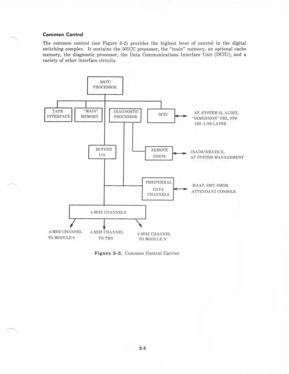
Con.non Conlrol
The common contrcl (see Figurc 2-2) provid$ th€ highest level ol conhol in the digitslswitching complex. It contains the 501CC processor, the "haiD" memory, an optional cachem€mory, the diegnostic processor, the Data Communications Interface Unit (DCIU), and avariety of oth€r interface circuits.
AP, SYSTEM 85, AUDIX,"DIMENSION" PBX. FP8
ISS, 3 OR LATER
INADS/RMATS-II,AP SYSTEM MAXACEMENT
MAAP, S!{T, SMD&
AI'IENDAM CONSOLE
4-MHZ CHANNELTO MODULE N
Figure 2-2. Common Control Carrier
PERIPHERAL
DATACHANNELS
2-3
sorcc P.o..t'd
The 501CC processor performs highlevel csll processing by executing prcgrams stored inmsin m€mory. It monitors and controls port-to-port conn€ctions, provides status indicationto useB, and p€rforms th€ operations nece3sary to implement system features.
The 50lCC processor is contained in four circuit pacls:
1. Th€ SOICC Bus Interface conn€cts the 50lCC to the system bus and to the cech€memory bus. It is also used to buffer deta and addressing information.
2. The 501CC Sequencer contains th€ micrcstore thet runs the 50lCC. It also includesloglc that sequences the microstore.
3. The 501CC Instruction Decod€r contains special logic which preproc€sseg
instructions bound for the ALU.
4- The 501CC Arithmetic Logic Unit (ALU) operates on 16 bits oI data simultaneouslyand has a 24-bit addr€ss bus.
The 50lCC processor use! the main m€mory which contains the gene c aoftware program,system translalion paramete.s, call processing status, end administrative and meintenanceprocedures. The main mernory consists of multiple 1-megaword Random Access Memory(RAM) circuit packs. Each word in memory contsins 16 dat. bits plus 6 bits of ErrorC,orrection Code (DCC) for a tol^l oI 2 bib. With ECC, 1-bit errors are automaticellycorected end multiple bit errors are det€cted.
Th€ 501CC processor has access to an optional l6-k word high-speed cache memory. Thecache memory stor€s a copy of rec€ntly acc€ssed instruction or data words. And it has enacc6s time {.hich is three times faster than that of the main memoiy. This reduces the*ait time when the 501CC procBsor needs to f€tch something lrom memory. Currentstudies show that nine out of ten times the 501CC processor will find the iDstruction or datsword it is seeking in the cach€ memory. This increases the system's busy hour cellthroughput capacity.
The cache memory communicates with the 50lCC processor over a dedicated bus.
Diogn6rk Pw.sor
The diagnostic processor detects common control failures and isolates faults to the circuitpack level in the Common Control Carrier. D€mand diagnostica (microdiagrostica)performed by the diagrostic processor can be invoked locally via the alarm panel or remot€lyfrom a remote maint€nance facility.
A dedicated maintenance bus, controll€d by the diegnostic processor, conn€cts to €ach circuitpack in the common control.
21

_ Dard Amnuni.orion. ,nrqlc.. Un (DCIU)
The DCIU is the interface between System 85's 501CC processor and:
. Applications Processors (APs)
. Audio Information Exchang€ (AUDIX) system
. Oth€r Release 2 Syst€m 85 switches
. System ?5 switches
. FP8 Issue 3 Enhanced DIMENSION* PBXs.
When a System 85 is part of a Distributed Communication Service (DCS) network, the D0IUplovides the interface betw€€n the System 85 and the other switches or PBXS.
Details on how the DCIU works app€ar later in this section.
feP. ,nrorta..
Th€ tape interface connects the 501CC pmcessor to a High Capacity Mini-Recorder (HCMR).The HCMR is equipped $dth a tape cartridg€ which maintains a permanent record of mainmemory cont€nts lor initialization and backup.
n.mor. P..a tnrqld..
The Remote Port Inte ace provides two po s for external communications. Port 0 is usedto communicate with the RMATS-II center. It has an internal automatic cslling unit forautomatic alarm reporting which eliminates the need for an ext€rnal autodialer- Port 1 isused for customer administration. Both ports provide an RS-232C compatible int€rfac€ forexternal data set connections. The Remote Port Interface also accepts contact closure alarm
.- inputs from ext€mal equipment such as auxiliary cabinets and APs.
Pdiphqct ,nr.rfca
Th€ Peripheral Interface provides dual-speed data channels which connect to localadministrative and maintenance panels, attendant consoles, SMDR data collection devices,etc.
4-rlHz Ch.nn*The common control uses 4-MHz channels to communicate with call processing modules andth€ time-multiplexed switch. Each channel connects the common control's 16-bit parallelI/O bus to a 4-MHz s€rial data channel.
ComM c.nr,ol 8u...
The thrce main bus€s in the common control (see Figur€ 2-3) arc:
. The system bus
. The DCIU bus
. The buffered bus.
1 Reqisiered trad€n.rk of AT&T.
2-5
Sys'€,n aus
The system bus provides a path for lollowiag common control circuits to commudcate withesch other:
. 501@ procesaor
. Main memory
o DCIU
. Tap€ int€rface
o I/O Buflet
. Other circuits-Thes€ circuits (sho\rn i! Figurc 2-3) are deecribed in Section 3,SYSTEM HARDWARE unde! CIRCUIT PACKS.
The 501C{, DCIU, Tape Interface, Duplication Channel, and Soltware Conhol AnalysisMonitor aDd Procersor Evenl Recorder (Scsmper-Maintenance Tool) use th€ system bus toFrform dat! transfers by Direct Memory Acceso (DMA). DMA allorls faster add moreefficient data transfer&
DCIU But
The DCIU bug cotrnech the four DCIU cilcuit pecks to each other. This epproach reducestraffic on the system bus and decreas€s the throughput time for the DCIU.
Bu#ercd Bw
This bus coDD€cts the peripheral data channels, 4-MHz channels, and the disgnosticprocessor (along with the remote interface) to an Input/Output (I/O) buffe!. The I/O bufferis connected to the system bus. Thfu allows the common contnol to s€nd and receiveinlormation sithout having to wait for time on the system bus.
2.6

501CC
IIITERFACE
COIITROLLER
DUPIICATIOIII
50iccSEOUEI{CER
50lCC ARITHI'IETIC
t-ocrc ulrr (^l-u)
TIII368
IIEI'IORY PROIECTTils13
DCIU
]EST SUPPORT
DCIU SYSIEN
IiITERFACEDCIU PROCESSOR
iE oRY
BUFFERED 8US
REIlOTE
I TERFACE0rAGi0SrrcPROCESSOR
PERIPHERAL
DATA CHAIlIIIELS
i""""'Yr1369"""" "'i: cacHE r,rE oRY i
: loPlr0l{al) :
TO OUPLICATEO
cofilto[ c0ilTR0L
TO I'IIGII CAPICITYuilr-RECoR0ER {ficn8)
r0 S0FT|ARE collTRotIIAIYSTS noirToR I PRoCESSoR
EVEilr RECoRo€R (SCAIIPER)
TO AP, AUDIX,AND DCS IIOOES
EXTERIIALAIARI'IS
[.|AAP. SllT,SI'IDR. AT]EIIOATTc0its0LEs, ETc,
raos/ aP
RNATS.II SYSTEIIISSUE 3 NAilAGEIIEIIT
Titi, Rttl, AIDNODULE COIITROLS
Figure 2-3. Common Control Buses
2-7
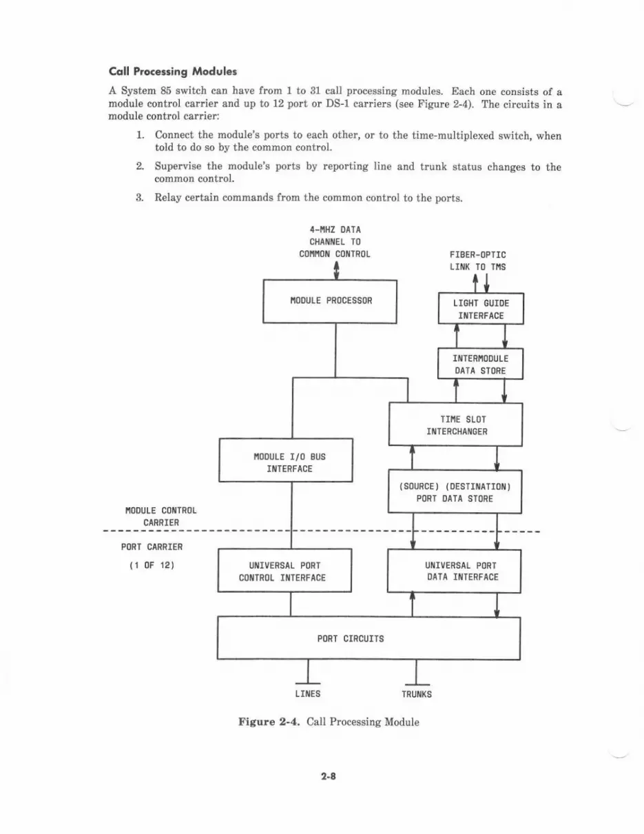
Ccll Procersiog Moduler
A System 85 switch can have from 1 to 31 call processing modules- Each one consists of amodule control carrier and up to 12 port or DS-1 carri€rs (see Figure 2-4). The circuits in emodule contrcl carrier:
l. Connect the module's po s to each other, or to the time-multiplexed switch, whentold to do so by the common control.
2. Supervise the module's pods by rcporting line and trunk status changes to thecommon contrcl.
3. Relay c€rbin commands from the common control to the ports.
4.NHZ DATA
cHAflflEt T0cofifioit coilTRoL FIBER.OPTIC
LIIIIK TO TIIS
IIODULE C(]IIITROL
CARRIER
PORT CARR]ER
{r 0F 12)
LIIIES TRUiI(S
Figure 2-4. Call Processing Module
IIOOULE PROCESSOR LIGHT GUIOE
IIIlERFACE
Iil]ERNODULEDATA SIDRE
TII'IE SLOT
II{IERCHAIIIGER
I,IODULE I/O 8US
IIITERFACE
(s0uRcE j (DE81rriaTr0 )POR] DATA STORE
UIIIVERSAL P(]R]COI{TROT IIIITERFACE
UIIIIVERSAI PORIOATA IIIITERFACE
2.4
Nsitinnt Voi.. AkThis ig a brief description of how an analog voice signal is digitized and how a digitizedsignal is chang€d back to an analog signal. Knowledge of how this is done is essential toundeEtanding digital switching.
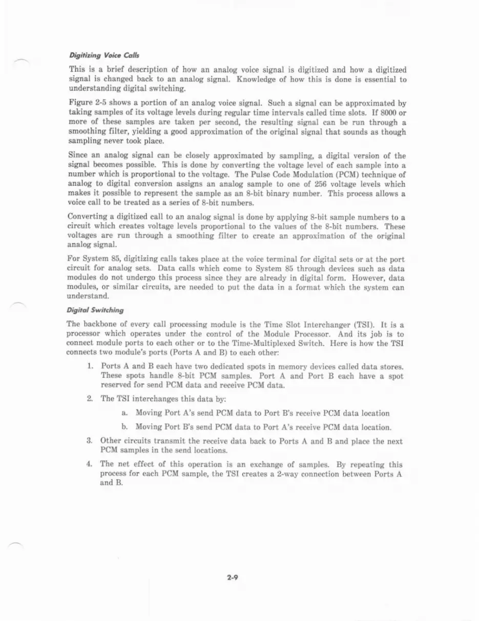
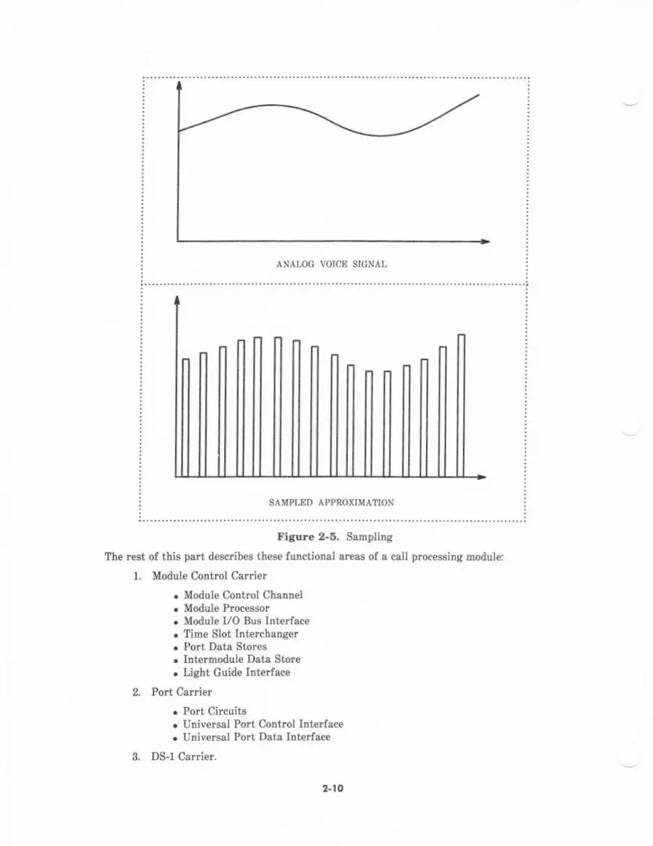
Figure 2-5 sbows s portion of an analog voice signal. Such a signal can be approximated byteking ssrnples of its voltage levels during regular time intarvals called time slots. lf 8000 ormore of thes€ samples sre taken per second, the resulting signal can b€ run throDgh asmoothing filter, yielding a good approximation ol the odginal signal that sounds as thoughsampling never took placo.
Sinc€ an analog signal can b€ cl$ely approximated by sampling, & digital v€rsion of thesiglal becomes pssible. This is done by converting th€ voltage lev€l of each sample into anumber which is proportional to the voltsge. The Puls€ Code Modulstion (PCM) technique ofanalog to digital converuion assigns an analog sample to on€ of 256 voltage levels whichmates it possible to r€present the sample as an 8-bit binary numb€r. This process allows avoice call to be tr€ated as a series of 8-bit numbers.
CoDverting a digitized call to an analog signal is done by applying 8-bit sample numb€rs to acircuit which creates voltsge l€vels proportionsl to the valu€s of th€ 8-bit numbeB. Thesevoltages are run thmugh a smoothing filter to creete an approximation of the originalanalog signal.
For System 85, digitizing calls takes place at the voice t€rminal for digital sets or at the portcircuit for analog sets- Dats calls which come to System 85 through devices such as datamodules do not undergo this proc€ss since they sre already in digital form. However, datamodul€s, or similar circuits, are needed to put the data in a format which the system canuDderstand.
Digiat Swit hidg
The backbone of every call processing module is the Tim€ Slot Interchanger (TSI). lt is aprocessor which operates under the control of th€ Module Processor. And its job is toconn€ct module ports to each oth€r or to th€ Tim€-Multiplexed Switch. H€re is how th€ TSIconnects two module's ports (Ports A and B) to esch other:
1. Ports A and B €sch have tr,vo dedicat€d spots in memory devices called data stor€s.These spots handle 8-bit PCM semples. Port A and Port B €ach have a spotreserved for send PCM deta and receive PCM dats.
2. The TSI interchanges this data by:
a. Moving Port A's send PCM data to Port B's r€c€ive PCM date locstion
b. Moving Po.t B's send PCM dsta to Port A's receive PCM data location.
3. Other circuits transmit the receive dsta back to Polts A and B and place th€ nextPCM samples in th€ send locations.
4. The net effect of this operation is an exchange of samples. By repeating thisprocess for each PCM sample, th€ TSI creates a 2-way conn€ction between Ports Aand B.
2-9
ANAI,OI'! VOICE SI{'!NAI,
SAMPLED APPROXIMATION
Figure 2-6. Sampling
The rest of this part d€scrib€s these functional sress of a call processing module:
1. Module Control Ca ier
. Module Control Channel
. Module Processor
. Module I/O Bus Interface
. Time Slot Interchanger
. Polt Dat3 Stores
. Intermodule Data Store
. Light Guide Intarface
Port Carli€r
. Port Circuits
. Unive$al Port Control Inteaface
. UniveBal Port Data Interface
DS-1 Carrie!.
2.
s.
2.t0

,llodda Adr.ot Cani..
The circuits in this carrier are shared by all port car.iers and DS-l cariers within the samecall processing module.
odule Conbol Chonnel
This circuit (TN401) interfaces the 4-MHz s€rial I/O link from th€ common control to themodule control.
lAo&t I e Co nhol Prceesso r
The module control processor (TN380C) performs these tasks for the Common Control:
. Digit collection
. Scanning polts for off-hook conditions and button depressions
. Controlling port circuits
. Controlling the TSI
. Gathering traffic data
. Helping with administration and maintenance.
r'Aodule l/O Bur lntatfdce
The Modul€ I/O Bus Interface circuits (TN400BS) provid€ bidircctional connectivity betw€€nthe Module Control Processor and the Port Carriers.
Tin. Slot lnErchdnsc. (Tst)
These circuits-the TSI P-Stor€ (TN445) and the TSI Arithmetic Logic Unit (ALU)--- (TN446)-perform digital switching for the module. In addition to the 2-port intramoduleconnection described above, the TSI can create a 3-way conference connection; performingany necessary loss calculations with its ALU. The TSI can also connect ports to a fiber-opticlink connected to the Time-Multiplexed Sr,vitch in order to *tablish intermodule connections.
Pott Ddtd Storcs
Port Data Stores (TN440BS) contain memory which provides storag€ locations for data andsamples of PCM voice to be 4cted on and switched by the Time Slot lnterchanger. Adedicated source and destination location is pmvided for each port.
lntemodule Dota Stores
The Intermodule Data Store (TN441) is similar to a Port Data Store. But inst€ad of storingsend and receive data for ports, it stores s€nd and receive data for the Time-MultiplexedSwitch.
Ibht Glide tnre.tdce
The Light Guide Interface (TN481) forrnats data or sarnples of PCM voic€ for transmissionbetween th€ module and Time-Multiplexed Switch and provid€s a termination for the Time-Multiplexed Switch-to-Module fiber-optic link.
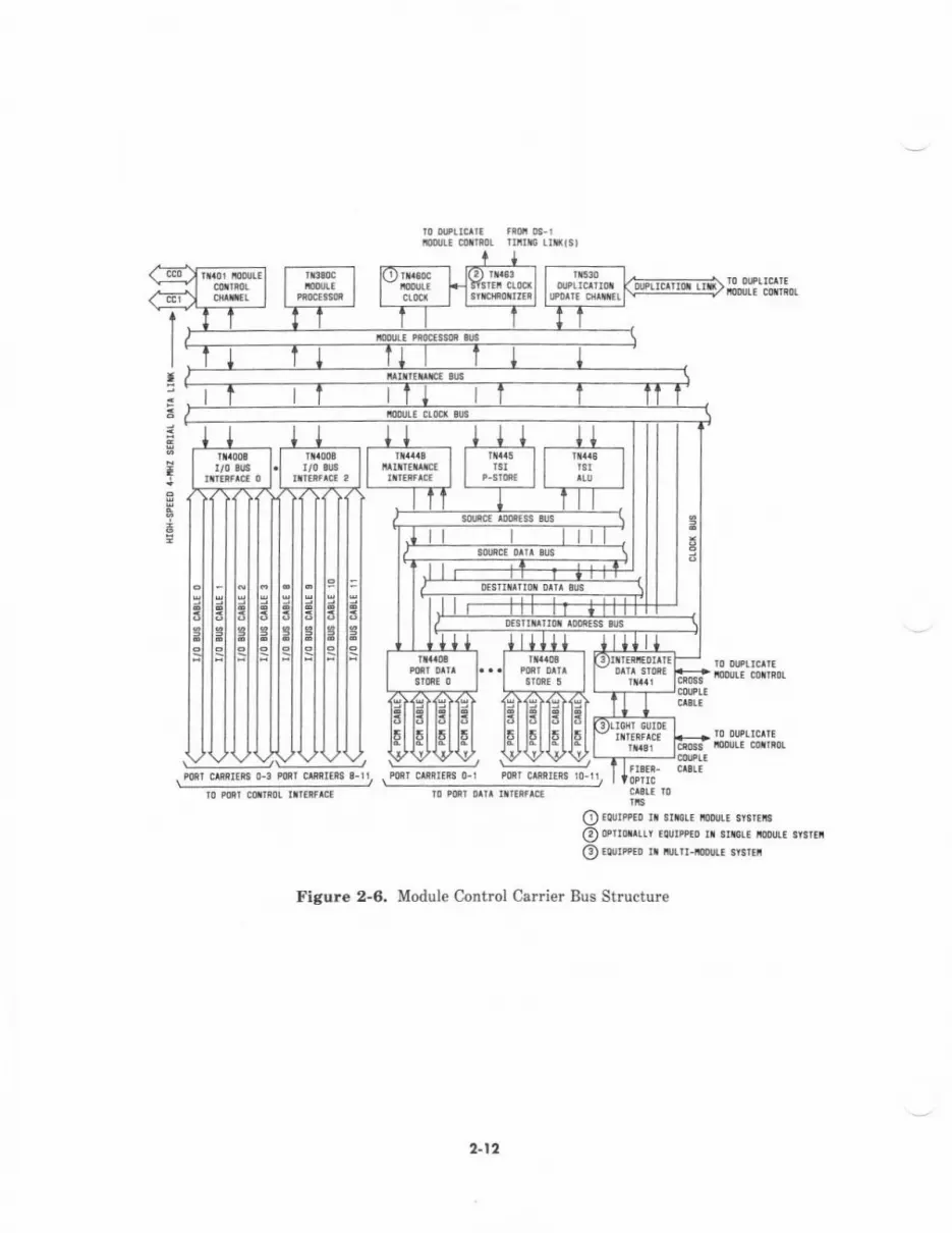
Alodule Conhol Coriet 8us Structure
Figure 2-6 depicts th€ bus structure of the module control carrier.
2-11
ourE corrifi nir$ rr*tst
I
\::____:____:J \_:____-:_:r
O RUrppEo rr iric!. ioDurr srsrri!
@ oernnrrr rounPEo n smrF ioDu!. s$r6i
@€curPEo n lrltn- {!! sysrltr
Figure 2-6. Module Control Carrier Bus Structure
I
Pml c^RR[ii 0-3 Porl c[it6$ r-
a-17
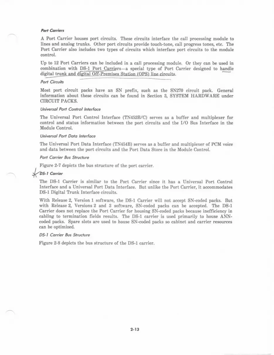
A Port Carrier houses port circuits. These circuits interface the catl processing module tolines and analog trunks. Other port circuits provide touch-tone, call prcgress tones, etc. ThePoIt Carrier also includ€s two types of circuits which interface port circuits to the modul€control.
Up to 12 Port Ca iets can be included in a call plocessinR module. Or they can be used incombinatioD with DS-l Port Carriers-a special type of Port Carrie! designed to handledigjtal trunk and dfsital Off-Premises Station rOPSI Iihp.ir."ilq.
Most port circuit packs have an SN prefix, such as the SN2?0 circuit pack. Generalinformation about these cilcuits can be found in Section 3, SYSTEM HARDWARE underCIRCUIT PACKS.
Itniversol Pod Contol htteloce
The Universal Port Control Interface (TN452B/C) serves as a buffer and multiplexer forcontrol and status information between th€ port circuits and the I/O Bus Interface in theModule Contrcl.
Unive6ol Po.t Dcra lnteidce
The Universal Port Data Int€ ace (TN454B) serves as a buffer and multiplexer of PCM voiceand data between the port circuits and the Port Data Store in the Module Control.
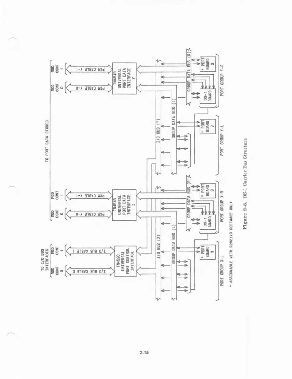
Port Co.i6r Bus Stru.tore
Figrre 2-7 depicts the bus structure of the port carrier.
l(ost ceni.,
The DS-l Carrier is similar to the Port Carrier since it has a Universal Port ControlInterface and s Universal Port Data lnterface. But unlike the Port Carrier, it eccommodate€DS-1 Digital Trunk Interface circuits.
With Release 2, Version 1 softu,are, the DS-l Carrier will not accept SN-coded packs. Butwith Release 2, Versions 2 and 3 software, SN-coded packs can be accepted. The DS-1Carrier does not replace the Port Carier for housing SN-coded packs because inefficiency incabling to termination fields results. The DS-1 carrier is used primarily to house ANN-cod€d packs. Spare slots are used to house SN-coded packs so cabinet and car er resourcescan be optimized.
DS-l Cddd Bu Srru.tue
tr'igure 2-8 depicts th€ bus structure of the DS-l car er.
2-t 3

-sE-l-r l]flc llcd
0-l 318YC Ktd
FE
FE"
ie
FH't-r ltSvc lrSd
0-I ItsYc rcd
rP;g
Ee-
',i; E H
ggEH
'EH
!E
E3
r9;E
lq
(J
FCI
T
T
B
s
E
c
g
c
II
ie-i=aEi!
3 XIB
; tlF
5
E.
Eo
E.
e€
2-la
EE-I:
EE"I
6Z*tsE.!
9
.9
o
xoE) op
i!06rsl !
c;Ef,
3E-
EF.
sftr!E-
'P=lrE-
2-t 5
d=-t-l tl8Yc md
0-l Il0Yc rad
EEt-r 318YC ICd
J9dH6=isgFE
I :tsvc sns o/I
0 3]SYC Sn8 0/I
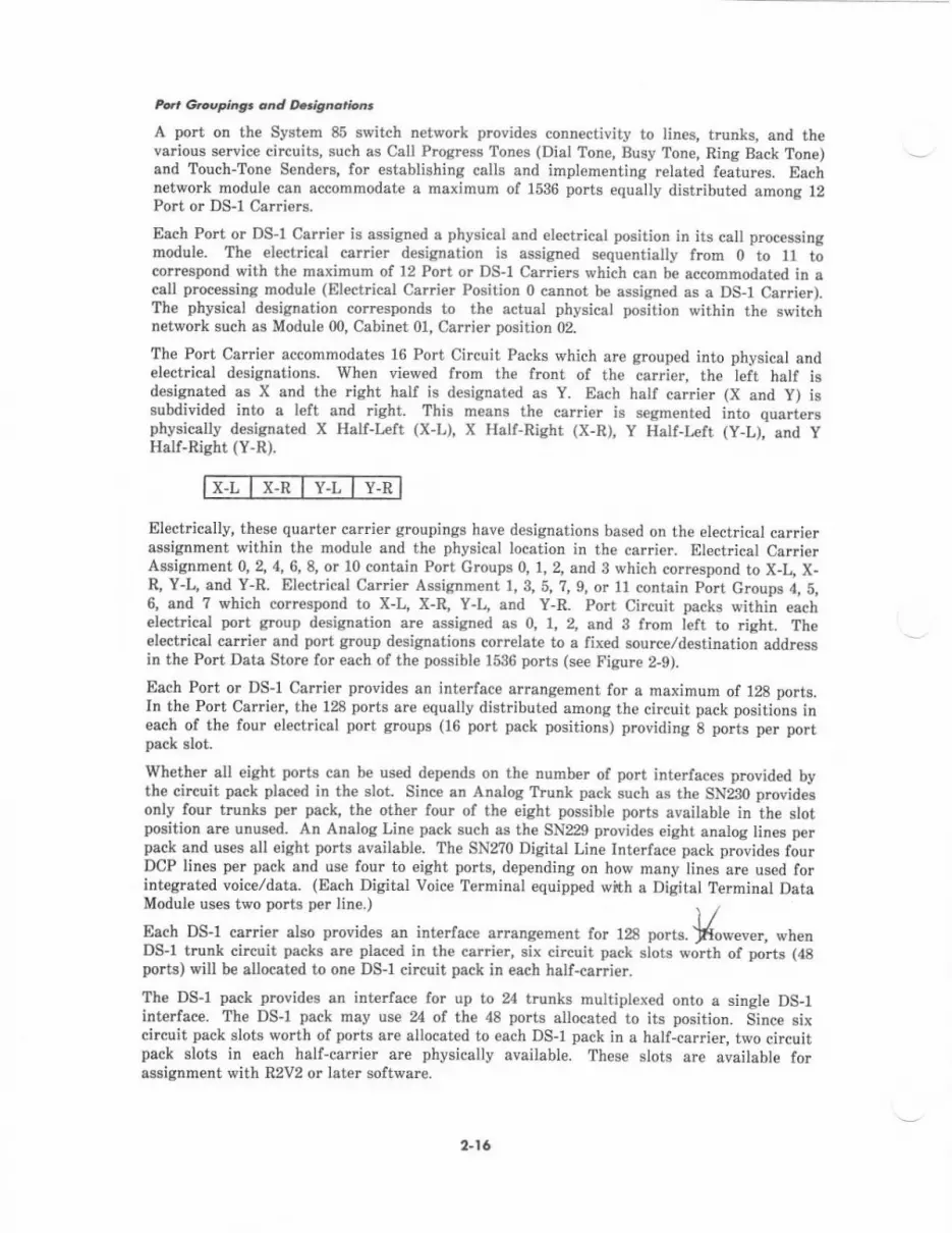
Pat Gtuepingt oad O.tlgadri.Dt
A port oD the System 85 switch network provides connectivity to lines, trunks, and thevarious senice circuits, such as Call Progress Tones (Dial Tone, Busy Tone, Ring Back Tone)and Touch-Tone Senders, for establishing calls and implementing related features. Eachnetwork module can accommodate a maximum of 1536 ports equally distributed among 12Port or DS-l Carriers.
Each Port or DS-l Carrier is assigned a physical and elect cal position in its call processingmodule. The electrical ca$ier desigration is assigned sequentially from 0 to 11 tocorrespond with the maximum of 12 Port or DS-l Carriers which can be accommodated in acall processing modul€ (Electrical Car €r Position 0 cannot be assign€d as a DS-l Carrier).The physical d€signetion corresponds to the actual physical position within th€ switchnetwork such as Module 00, Cabinet 01, Carrier position 02.
The Port Carrier accommodates 16 Port Circuit Packs which are grouped into physical andelectrical designations. When vi€wed from the frcnt of the carrier, the left half isd€signated as X and th€ right half is designat€d as Y. Each half carrier (X and y) issubdivided into a left and right. This means the carrier is segmented into quart€rsphysically desisnated X Hall-Irft (X-L), X Half-Right (X-R), Y Half-Left (y-L), and yHalf-Risht (Y-R).
x-L x-R Y.L Y-R
Electrically, these quarter carrier groupings have designations based on the electrical carrierassignment within the module and the physical location in th€ carrier. Electdcal CarrierAssignment 0,2,4,6,8, or l0 contain Port Croups 0, 1,2, and B which correspond to X-L, X-R, Y-L, and Y-R. Electrical Carrier Assignment 1, 3, 5, ?,9, or 11 contain port croups 4, b,6, and 7 which correspond to X-L, X-R, Y-L, and Y-R. Port Circuit packs within €achelectrical port group designation are assign€d as Q 1, 2, and 3 from left to right. Theelectricai car er and port g.oup designations correlate to a fixed source/destination addressin the Port Data Store for each of the possible 1536 ports (see Figure 2-9).
Each Port or DS-1 Carrier provides an interface a.rangement for a maximum of 128 ports.In the Port Carrier, the 128 ports are equally distributed among th€ circuit pack positions ineach ol th€ four electrical po grcups (16 port pack positions) providing 8 polts per portpack slot.
Whether all eight ports can be us€d depends on th€ numb€r of port interfaces provided bythe circuit pack pleced in the slot. Since an Analog Trunk pack such es the SN230 provide;only four trunks p€r pack, the other four of the eight possibl€ ports availabl€ in the slotposition arc unused. An Analog Line pack such as the SN229 provides eight analog tines perpack and uses all eight po s availabl€. The SN270 Digital Line Interface pack provides fourDCP lines per pack and use four to eight ports, depending on how many lines are used forintegrated voice/data. (Each Digital Voice Terminal €quipped with a Digital Terminal DataModule uses two ports per line., I ,Each DS-l carrier also provial€s an interface arrangement for 128 ports. fiowever, whenDS-l trunk circuit packs are placed in the carrier, six circuit pack slots worth of ports (48ports) lr,ill be allocated to on€ DS-l circuit pack in each half-carrier.
The DS-l pack provides an int€rface for up to 24 trunks multiplexed onto a single DS-1interface. Th€ DS-l pack may use 24 of the 48 ports allocated to its position. Since sixcircuit pack slots worth of ports are allocated to each DS-1 pack in a half-carrier, two circuitpsck slots in each half-carrier are phyBically available. These slots are available forassignment with R2V2 or later software.
2-16
9 \:_./
-l
E
o
ct
-l------l_ -l I
ts-;- ;-i- E-E- E-E.SE:E22:E
e ;ss
-a -;-
6 E'8t-
14 =l L E= |
ieEl r--.-E-rlE-i'l I 5: r
€
g
2-17
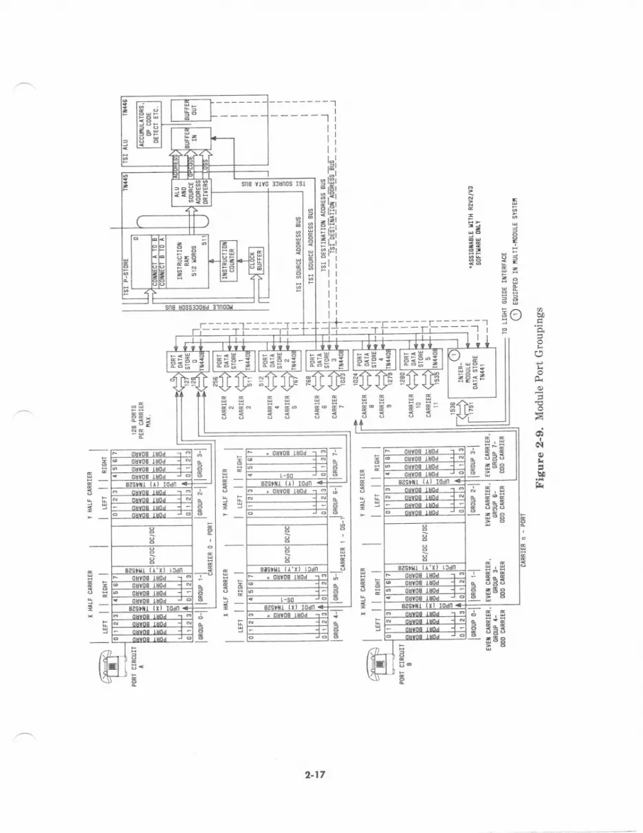
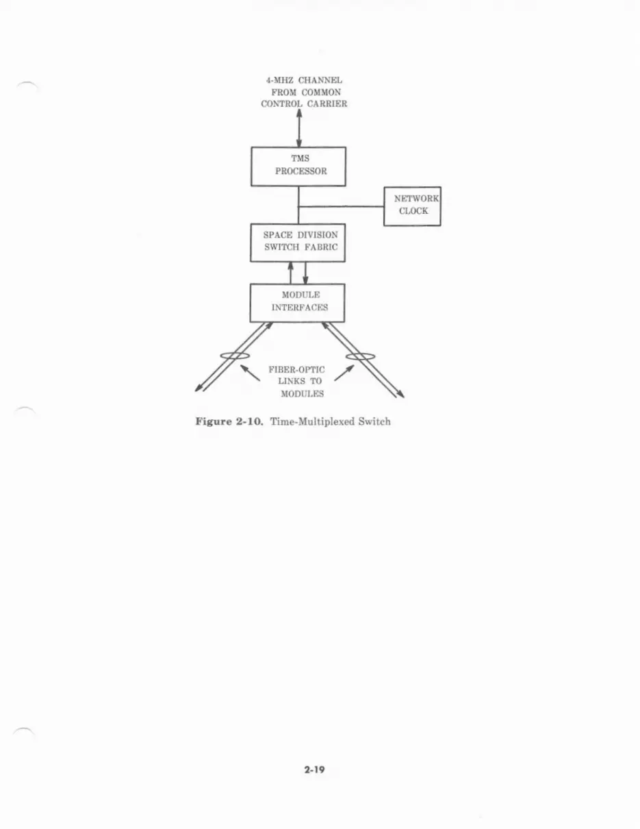
lime-Multipl.xed Swirch (TMS)
The Time-Multiplexed Switch (TMS) (see Figure 2-10) is a digital switch that prcvides voiceand data conn€ctions between modules in a multimodule System 85. This means theCommon Control uses the TMS to complete intermodule connections. Sparing some of thedetails, here is how the Common Control sets up an int€rmodule voice conn€ction:
l. Th€ Common Control instructs the modules involv€d to set up 2-way connections totbeir Light Guide Inte ace circuits. (Recall that the modules will make theseconn€ctions by manipulating PCM sampl€s in their port and intermodule datastores.)
2. Each Light Guide Inteface circuit s€nds a PCM sample to the TMS ov€r anoutgoing fiber-optic link (along with up to 255 other samples). The samples aretransmitted in serial form.
3. The TMS receives the samples in two of its module interface circuits.
4- The Common Control instructs th€ TMS to make two l-way connections betweenthe module interfac€ circuits.
5. the samples are passed through the TMS switch fabric to the module interfacecircuits and then on to the modules involved in the connections.
6. Each Light Guide lntedac€ circuit takes the sample from the incoming fiber-opticlink and writes the sample to the Intermodule Data Store.
?. The modules complete the connection by switching the samples to the port.
Intermodule data calls are handled the same way.
Ihe rest oI this part explains how the lMS does its job. The following major functionalereas are described:
. Module interfaces
. Switch
. Control structure
. Clock.
Each Module Interface circuit (TN482) terminates a duplex fiber-optic link connected to amodul€. A Modul€ Interface circuit:
. Forwards data or PCM sampl€s received from a module to the switch.
. Transmits data or PCM samples from the switch lo a module.
2-18
SPACE DIVISIONSWITCH FABRIC
Figure 2-lO. Time-Multiplexed Switch
2-19

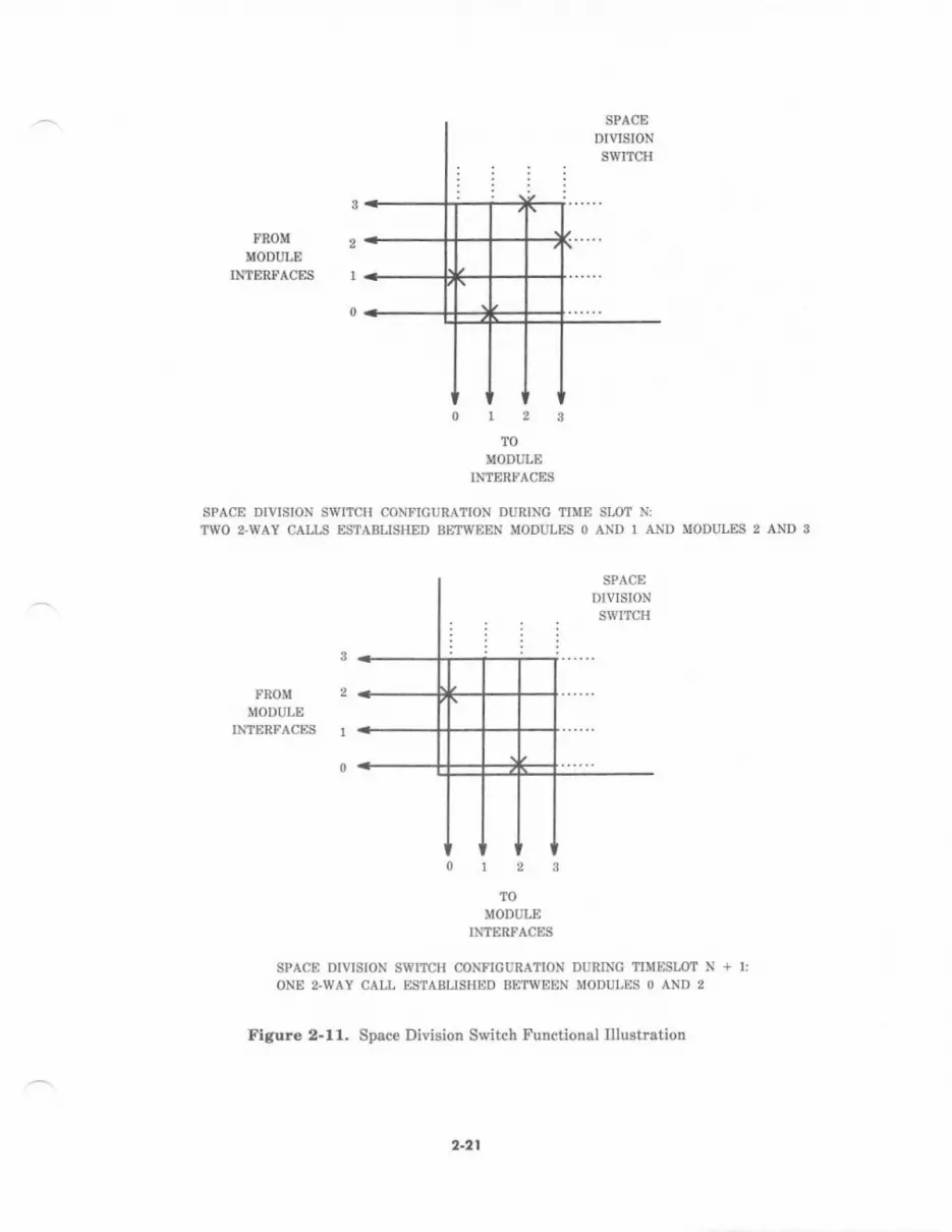
The TMS uses a switching method that is different from the one used by call processingmodules. The TMS makes connections in a different way than the modules. It uses aswitching scheme called time-multiplexed space switching. Space switching means the TMShas switch fabric where actual physical connections are made (see Figure 2-11). If spac€sv,/itching was all that \rent on, these condections v'ould last for the dumtion of the call. Butthis would b€ a waste since the switch would spend most of its time waiting for modules tosend their next samples. This is where time multiplexing comes to the rescue. It lets theswitch reconfigure to handl€ other connections. Time multiplexing allows 256 codnectionpatterns to be applied to the switch on a tim€-shared basis.
Each modul€ sends a strcam of bits to the TMS; the stream is partitioned into groups ol 2b6time slots. A time slot can contain a PCM sample, data, or be unused. The TMS switchIabric uses time multiplexing to provide 256 connection p.tterns; one for each time slot.When th€ common control decides to set up an intermodule call, it tells both module controlsto us€ the same time slot for sending samples from those ports to the TMS.
Example: The common control assigns an inte?module call between PoIt A inModule 0 and PoIt B in Module 1 to time slot 10. Module 0 sends allsamples from Port A and Module 1 sends atl samples frcm Port Bto the TMS during time slot 10. The common control tells the TMSto make two 1-way connections thrcugh the TMS switch fabricdudng time slot 10: one from Module 0 to Module l, and the otherfrom Module 1 to Module 0. These connections last long enough forone sample to be passed thrcugh each ol them. After passingthrough the switch fab c, the samples are sent to the moduleinterface units for transmigsion back to the modules.
The switch consists ol three types of circuits:
1. Fan Out (TN473)
2. Fan In (UN150)
3. Switch Fabric Multiplexers (TN4?0s).
The TMS has a proc€ssor (TN38l) that carries out commands from th€ Common Contrcl andtells the switch which connections to establish. It also participates in maintenance anddiagnostic mutines.
Syrr.m Ch& Syncltoni2.r
The System Clock Synchronizer (TN463) is located in the TMS for multimodule systems.(For a single-module system, it is Iocated in the module control.) When synchronization to ahigh-speed digital facility is required, this circuit can slave to external clock sources. Moreinformation is provided in this section under Synchronization.
2-20
3
FROM 2}IODULE
TNTERFACEI 1
0
u#ur.eINTERFACES
SPACE DIVISION SWITCH CONFIGURATION DURINC TIME SIO? N:
?WO z-WAY CAIIS ESTABLISHED BETII'EEN MODULES 0 AND 1 Al\lD MODIILES 2 AND 3
3
FBOM 2
MODULEINTERFACES r
0
TOMODULE
INTERFACES
SPACE DIVISION SWITCH CONFIGUBAIION DURTNG TTUEST.OIT N + I:ONE z.WAY CALL ESTABLISHED BETWEEN MODULES O AND 2
Figure 2-11. Space Divieioa Switch Functional Illustration
2-2t
T,,S Codct Stts Stru.twe
Figurc 2-12 depicts the bus structure of the TMS carrier.
Remote Modulcr
The Remot€ Module feature overcomes the 200 f€et distance limitation of the 4-MHz coaxialcable tbat ptuvides the serial control channel between the common control and each modulecontrol. One to 30 r€mote modules can be located up to 13,000 feet (3,962 meters) from thecommon control. This is mad€ possible by using fib€r-optic cable instead of coaxial cable.
Remote modules incrcese the g€ographical erea that a single switch can serve. PrevioNly, acampus or industrial park with buildings more than 200 feet epart usually required morethan one switch. Remote modules can reduce or eliminate the need for additional switches.
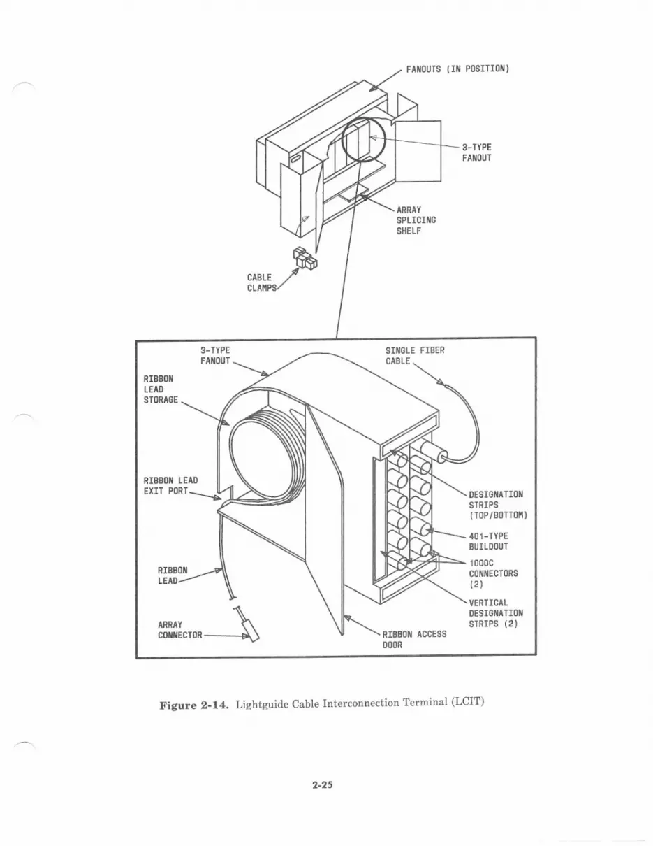
The standard fiber-optic subsystem for System 85 is designed with 62.5 micron core fiber. Ituses fiber bbon cable for interbuilding and intrabuilding distribution. Each cable cancontain up to 12 ribbon fibers of 12 fibers each (see Figure 2-13). Each €nd of this cable isterminated at a Lightguide Cable Interconnection Terminal (LCIT) (s€e Figlre 2-14). TheLCIT fans out into 12 individual fibers with bi-conic conn€ctors. Thes€ conn€ctors accept 401
series build-ouh (attenuators) which balance the optical power level to eliminat€ overdrivingand underdriving the receiverc. The LCIT and attenuato$ are the demarcation point forswitching equipment and facilities dist bution.
The fiber-optic subsyst€m for System 85 can also b€ d€signed with 50 micron core fiber butit must be a higher grade fiber to overcome increased optical loss. All sections of 4 fibertink must be the same size. In other words, 62.5 micron and 50 micron fibfi cannot be mix€din the sane link.
Connection from the LCIT(s) to the swit hing equipment is via a singl€ jacketed fib€r pair(duplex) ceble. On€ fiber is the tlansmit link; the other is the receive link. Each cabl€terminates on the eppropliate cari€r backplsne with a paddleboard transmittet or rec€iver:
. Z9pC-Transmitter (TMS), terminat€s on TN480 and TN481
. Zg8t-Transmitter (RMI), terminates on TN456
. zg82D-Receiver (TMS and RMI), termirates on TN480, TN481, and TN456.
2"22

39
=t
apg
@
Q
FN
N
92
Ig-P
2
rl
ItrI
l
tfr
tI
nl1 Y1V0 Itit t M315 ollds HCIH
2.24
E32E

12dr
>.o1
STREIgTHiEtiEER
P(]LYESTERTIPE
Figure 2-19. Lightguide Cable
,4ItilER St{Errl
OUTER SHEITH
TIIERIIIL IRAP
c0l[EcT0R
ollE T0 TI,IELVE
RrEB0ll{i 0F 12
FIBERS II EACH
SEC A-A
a-21
FtrouTs lrt P0srTIol/)
3-TYPEFAIII(]IJT
CABLECLAXP
Figure 2-14. Lightguide Cable Interconn€ction Terminal (LCIT)
2-25
3-TYPEFAIIIOUT
SIiIGLE FIBERCABI-E
ARRAY
co{ilEcToR
DESIGIIATIOIISTRIPS(r0P/B0Tr0r'll
401-TYPEBUILDOUT
1000cc0ttlflEcT0Rs{2)
VERTICAIDESIGIIATIOIIsrRrPs (21
RIBBOX ACCESS
u00R
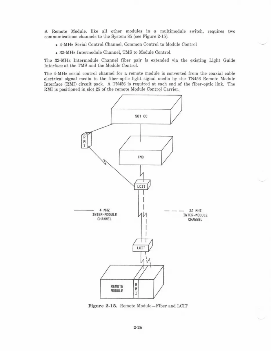
A Remot€ Module, Iike all oth€r modules in a multimodule switch, requires twocommudications channels to the System 85 (see Figure 2-15):
. 4-MHz Serial Control Channel, Common Contrcl to Module Control
. 32-MHz Intermodule Channel, TMS to Module Control.
The 32-MHz Intermodule Channel fiber pair is er.tended via the existing Light GuideInterfac€ at the TMS and the Module Contrcl.
The 4-MHz serial control channel for a remote module is converted from the coaxial cableelect cal signal media to the fiber-optic light signal rnedia by the TN456 Remote ModuleInterface (RMI) circuit pack. A TN456 is rcquired at each end of the fiber-optic link. TheRMI is positioned in slot 25 of the remote Module Control Carder.
32 llHZIIiTER-NOOUTE
CIIAIIIIIEL
Figure 2-16. Remote Module-Fiber and LCIT
'rl
2-26

In System 85 Remot€ Module-Phase 1, th€ RMI is positioned in slot 25 of a central localeModule Control Carrier. One central locale Module Contrcl Carrier equipped with an RMI isrequired for each remote modul€ (see Figure 2-16).
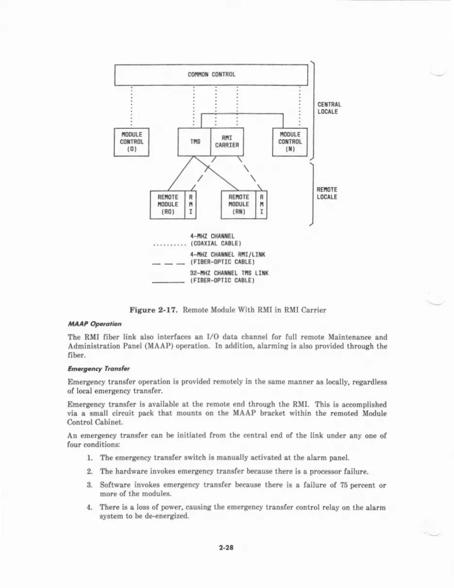
In System 85 fumote Module Phas€ 2, the centrsl locale RMIS are positioned in a R€moteModule CaBier (see Figrne 2-17t. The Remote Module Carrier can be equipped with up to 16RMIS and is mounted in e TMS cabin€t. The Remote Module Carrier eliminates the one-to-one relationship of central to r€mote modules thet exist€d with Phase I . A System 85 {,ithunduplicated modul€ control(s) can be equipped with a maximurn of two Remote ModuleCarriers and 30 RMI circuit packs. All System 85s require a minimum of one central localemodule. A System 85 can be provided with both Phas€ I and Phase 2 equipmentarfangements,
If a System 85 has fully duplicated control functions (Common Control, Module Cortrol,TMS), the RMIg are also duplicated. In a duplicated Phase I arrangement, an RMI isrequired in each central and remote Module Contml Carrier (four p€r remote module). In aduplicat€d Phase 2 arrangement, two RMIS are r€quired per r€mote modul€ in the RemoteModule Carrier and two RMIS (one per Module Control Card€.) at the r€mote module. Atotal of four liber pairs ar€ required p€r remote module, if duplicated. When s€parete pathsarc s€lected for the duplicated fib€r, the difference b€tween the two lengths cannot exceed2.400 feet (732 meters). A System 85 u,ith duplicated module control(s) can b€ equipp€d witha maximum of 4 RMI carri€rs and 60 RMI circuit packs.
cmt{tx cotTRoL
... :
CETlRALLocltE
R€IIIIELOCALE
TIIIE IIILTIPIETEOSIIIICH
lt00urEcollTRor
R
iI
III
t0txrLEc0[In0t
t-tlHz ctiltiilEL(collln clsrEll-llllz cHtxiEL 8lll/tll({Fl*n-oPrrc crslE)32-itz cMttEL Tls LIn((FIBEi.OPTTC CAELEI
2-27
Figure 2-16. Remote Module With RMI in Central Module Control Carrier
colttiol coNTnoL
CETTRAL
t0cAlf
REIIO]EtocltE
a-nHz cfit tEL..... ... .. (corxur crslE)
a-ifl cliltt€L R6I/Lrt((FI8ER.OPIIC CAELE'
32-iIZ CHliiEL lll3 Lr ((Fr8ER-oPrrC CtStE t
Figure 2-17. Remote Module With RMI in RMI Carrier
The RMI liber link also interfac€s an I/O dsta channel for full remote Maintenance endAdministration Panel (MAAP) operation. In addition, alarming is also provided through thefiber.
Em.rg.,Et f.oE taEm€rgency transfer operation is provid€d remotely in th€ sarne manne! as locelly, regardleBsof local emergency transf€r.
Emergency transfer is available at the remote end through the RMI. This b accomplish€dvia s smell circuit pack that mounts on the MAAP bracket within the remoted ModuleControl Cabinet.
An emergency transfer can be initiated from the central €nd of the link under any one offour conditions:
l. The em€rg€ncy transfer sl'itch is manually activeted et the alarm pan€I.
2. Th€ hardware invokes emetgency transfer because there is a processor failure.
3. Software invokes emergency transfet beceus€ there is a failure of ?5 percent ormore of the modules.
4. Th€re is a loss of power, causing the emergency transfer control relay on the alarmsystem to be de-energized.
2-24
IIF RiICIRRIES
iDIJIEctxr8ol
{it
REIIllTEIIODULE
t80l
R
INEiOTETIODULE
tnxt
n
I

At the remot€ end of th€ link, an emergency transf€r is invoked und€r any one of threeedditional conditioDs:
1. The remote nodule fails, preventing it from responding to messages from theCommon Control.
2. The fib€l link fails, breaking communications between the C,('mmon Control andthe remote Module Control.
3. The power fails at the remote end.
Emerg€lcy transfer requires that trunks (outgoing or away) be terminated on tbe rehotemodule.
The equipment room comiderations fo! r€mote module equipment are the same as the local€quipment !oom. This includes environmental, floor loading, and acldc power (includingdistribution and ac protection). Network interlace is also rcquired for central officefacilities.
|nffkA multimodule system with all modul$ colocat€d with the common equipment has the portcircuits equally distributed (balanced) among all modulea. This rvay all modules carryapproximately the same traffic load. Remote module arrangements requile an unbalancedconfiguiation to accohmodste port connections within the remote module. This unbalancedconfiguration requires sp€cific traffic guidelines that ar€ administer€d only by the NationalCustomer Support Cent€r (NCSC).
lcrncL Grcup.
The use ol DS-1 lacilities is expanded in R2V3 to includ€ optional remot€d lines (analo&hybrid, and digital) and non-Co rernoted trunks (digital and EIA). This capability allowssmall groups of voice terminals and their port interface circuits (equivalent to one or moteport carriers, but less than one module) to be located up to 100 miles away from the centralswitch.
Twenty-thr€€ PCM time slots and one signaling tirne slot are multiplexed onto the DS-lchannel by e pai. of remot€ grcup interfaces. One typ€, the Remote Carrier Local (RCL)interfece, is located at th€ central s{'itch and appears as three port circuit boards to callprocessing software. The other interface, the Remote Carrier Controlle! (RCC), is located atthe remote sit€ and appears as a Port Data Interfac€/Port Control Interface to the remotedport circuits. Each remote port group is limited to th€ 24 time slots available on the DS-llink. Figure 2-18 illustrates the basic R€mote Group connection-
2-29
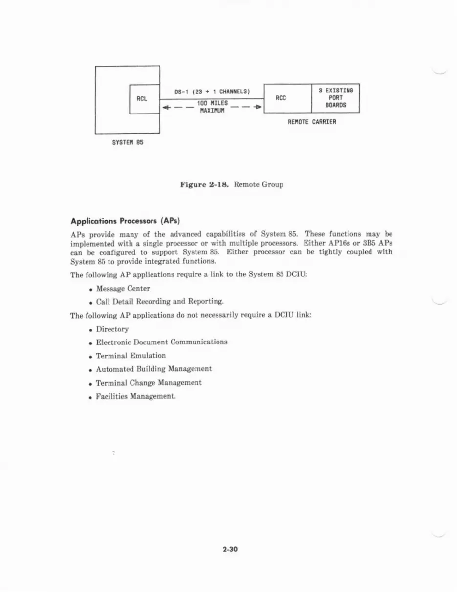
6r8rEi 86
!8-r123+ro{rnELSllrtEg
i^IIT:REIIOTE CANRIER
Figure 2-l& R€mot8 Group
Appli.arion. hc..trct (AP.)
APs provide nany of the edvanced capabilities of Systom 85. Thes€ functions mey be
irnplementad eith a single proc€ssor or vith multiple proceerors. Either APl6s or 385 APscan be configured to support Syst€m 85. Either plocessor catr be tightly coupled withSystem 85 to provide integrated functions.
The following AP applicctions require a link to the System 85 DCIU:
o Message Center
o Call Deteil Recording .nd Repo.tinS.
The fouowinS AP applications do not necessarily require a DCIU link:
. Directory
. Electronic l)ocumeDt Communications
. Terminsl Emulation
o Automated Building Management
. Terminal Change Mansg€ment
. Facilities MsnsgemelL
2-30

Dolq c.m.nv.icqlion3 lnterfqco Unit (trclu)
The DCIU is a microprocessor-controlled communications interface mounted in the CommonControl calrier. The 501CC uses a program call€d the DCIU Inte ace P&gram (DIP) tocommunicate with the DCIU. Communication between the DCIU and the 501CC processor isvia direct memory access to the 501CC system buq thk allows th€ DCIU to scan buff€rs in501CC m€mory for outgoing messages and to writ€ incoming messageg directly into buffersin 50lCC memo.y.
The DCIU has eight full-duplex synchronous data links v,hich can be connected to any of thefollowing remote machines:
. Applications Proc$sors (APs)
. Audio Information Exchange (AUDIX) system
. Othe! System 85 switches
. Syst€m ?5 switcheg
. tr'P8 Issue 3 Enhenced DIMENSION PBXg.
8X.25 Protocol
Messages passing between the DCIU and remote machines and between the DCIU and DIPconform to the BX.25 protocol. The following brief discussion of BX.25 is intended tointroduce relevant terminology used in describing the DCIU.
BX.25 is a layered protocol, which means for example that the details of €IIor correction andflow control are handled by low€r level entities in a way which is tmnsparent to higher levelentities- H€re are the levels:
ADDlication LaverS€ssion LaverPacket LayerLink Laver
Phvsical Laver
This layer, also call€d lpvel 1, is a hardware sp€cification (voltage levels, signal lines,etc.) which is compatible with RS-232C and RS-4d9.
This layer, also known as Level 2, is primarily responsible for d€tecting bit er?ors bymeans of a cyclic rcdundancy check and correcting those errcrs by retransmission; thigprocedure is compatible with High-Icvel Data Link Control (HDLC) pmc€dur€ and isperformed by DCIU firmware and by an HDLC chip on each of the DCIU'S eight links.
This layer, also known as Izvel 3, multiplexes differcnt logical streams of deta thmughthe Iavel 2 €ntity and regulat€s th€ flow of data on each of these logical streams so asto prevent the overrundng of receiver buffers. Level 3 responsibiliti€s are perform€dby firmware in the DCIU.
This layer binds two applications into a s€ssion and shields th€ applications from th€details of controlling the Lev€l 3 interfece. Session Layer services ar€ provided by DIPon the 501CC.
2.3 t

This layer is named but not regulated in BX.25.
Connunicotion Pdthways and Endpoints
BX.25 terms describing communication pathways and their endpoints ^re
linh, lagicalchannel. wrt, oirtual ciranit, Wynnent 1)irlxLal circuit, vlrb,al call.
IinkLink is a Lev€l 2 term describing a segment of a communication path, e.g., between twoDCIU'g or between a DCIU and an AP Line Controller, on which therc is established aLev€l 2 protocol. Link includes vrhateve. entities are performing Level 2 senices ateach end of the s€gment. Note that since link is a Level 2 term, it does not imply whatkind ol hardware is us€d at Lev€l 1.
Logical channel is a Iavel 3 term d€Bcribing one of many logically independent streamsof data which are multiplexed on a single link. The definition ol a logical channelbegins and €nds with the Level 3 entities at each end of a given link. This m€anslogical channel numbers are defined on a given segment of a communication path andthat a single logrcal stream of data may be assigned different logical channel numbereon differcnt segm€nts of a eommunication path.
Virtual circuit is a Level 3 term referring to the entire communication path betweentwo Lev€l 3 entities. Since the communication path may consist of several links, with adifferent logical channel number used on each link, the logical channel numb€rs atopposite ends of a virtual circuit can differ.
Pemdnent Vduol Ci.cuitA p€rmanent vidual circuit is a virtual circuit that is permanently establish€d, asopposed to a Virhnl Cdll uthich is a virtual cicuit that is dynamically established asthe need arises and th€n released l;rhen no longer needed.
Port is a Session Leyer term describing a gateway between Sessior Layer and a singleapplication. To the application, a port looks like an I/O device. Once a session hasbeen established, it is sale to think of ports as the endpoints of a virtual circuitbetvreen two applications. Although the pott numbers at opposite ends are generallynot equal, the Session Layer entity at €ach end knows the port numbers at both ends.
l,lessdge, Pdcket, and Frcne
The units ol information in BX.25 are the z€ssog€ , the packet, aad the frd@e. Starting withthe data that an application (e.g., on the 501CC) wishes to send to its rcmote peer (on theAP), the Session Layer entity (DIP) serving the local application prefaces the applicationdata with a Session Layer Data Header (SLDH), thereby forming a message. The SLDHdescribes the length of the application message and defines a message sequence numb€r usedby the rcmote Session Layer entity to insure that messages are received in the same orderthey were sent.
Iavel 3 (in the DCIU) then prefaces the Session Layer message lvith another header to forma packet. If the message exceeds the maximum packet size, Level 3 will brcak the messageinto multiple pack€ts in a way which allows later reconstruction of the o ginal message.
I SLDH I appl nsg
2-32
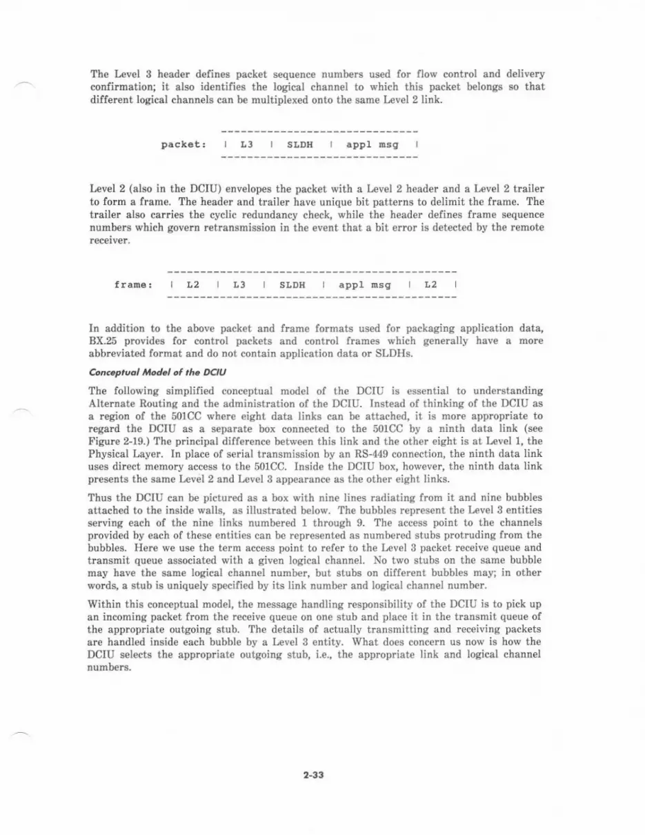
Th€ L€vel 3 head€r defines packet sequence numbers used for flow control and deliveryconfirmation; it also identifies the logical channel to which this packet telongs so thatdifferent logical channels can b€ multipl€x€d onto th€ same Lev€l 2 link.
packet: r slDlt
Level 2 (also in the DCIU) €nvelopes th€ packet with a Level 2 h€ader and a Level 2 trailerto form a frame. The header and trailer have unique bit patterns to delimit the frame. Thetrailer also carries the cyclic redundancy check, while the head€r defines frame sequenc€numbers which govem retransmission in the event that a bit error is detected by the remot€
I t3 I appl msg
L2 I L3 I SLDH I appl nsg L2
In addition to the above packet and frame formats used for packaging application data,BX.25 provides lor conttul packets and control frames which generally have a moreabbreviated format and do not contain applicetion data or SLDHS.
Concaprucl od.l ol the DCIU
Th€ following simplified conceptual model ol the DCIU is essential to understandingAlternate Routing and the administration of the DCIU. Instead of thinking of the DCIU asa region of the 50lCC where eight data links can be attached, it is morc appropriate tor€gard the DCIU as a s€parate box connected to the 501CC by a ninth data link (see
Fieure 2-19.) The principal difference between this link and the other eight is at Level 1, thePhysical Layer. In place of serial transmission by an RS-449 connection, the ninth data linkuses direct memory access to the 501CC. INide the DCIU box, however, the ninth data linkpresents the same Level2 and Level S appearance as th€ oth€r eight links.
Thus the DCIU can be pictured as a box with nine lines radiating from it and nine bubblesattached to the inside walls, as illustrated below. The bubbles rcpresent the Level 3 entitiesserving each of the nin€ links numbered 1 through 9. The 4ccess point to th€ channelsprovided by each of these entities can b€ represented as numbered stubs protruding from thebubbles. Here we use the term acc€ss point to r€f€r to the Level 3 packet receive qu€ue andtransmit queue associated with a given logical channel- No tv,o stubs on the same bubblemay heve the same logical chann€l number, but stubs on dilf€r€nt bubbles may; in otherwords, e stub is uniquely specified by its link numb€r and logical channel number.
Within this conceptual model, the message handling responsibility of th€ DCIU is to pick upan incoming psck€t from the receive queue on on€ stub and plac€ it in the transmit queue olthe appropriate outgoing stub. The details of actually transmitting and receiving packetsaI€ handled inside each bubble by a Level 3 entity. What does concern us now is how theDCIU selects the appmpriat€ outgoing stub, i.e., th€ appropriate link and logical channel
2-33
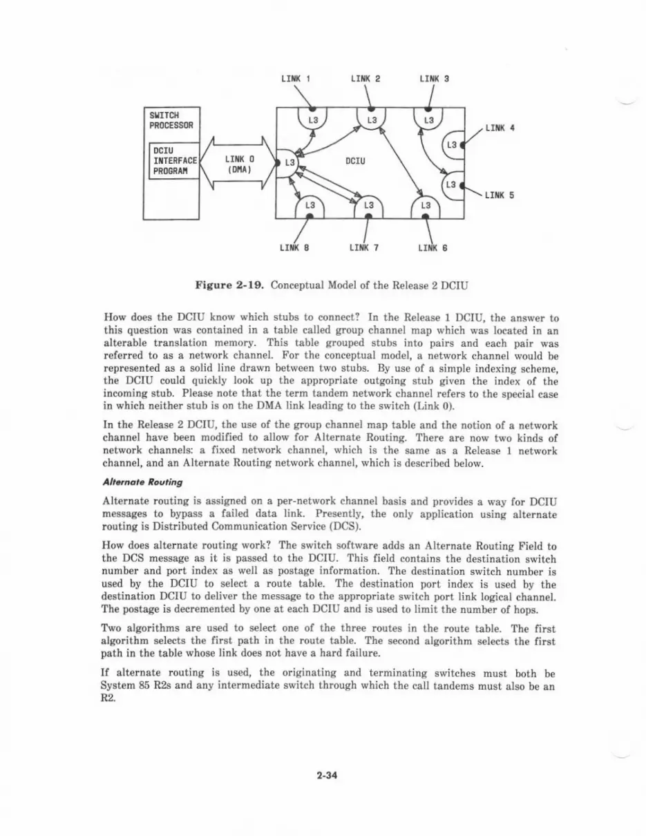
t It 2
sfrrcl{PR0CESSm
DCIUIfl]ENFACEPRl)GRAII
tIilK 5
Figure 2-19. Conceptual Model of the Release 2 DCIU
How does the DCIU know which stubs to connect? In the R€leas€ I DCIU, the answe. tothis qu€stion was contained in a table called group channel map which was located in ansltereble trunslation memo.y. This table grouped stubs into pairs and each pair wasref€rrcd to as a network channel. For the conceptual mod€I, a network channel would bercpr€sented as a solid line dra n between two stubs. By use of a simple indexing scheme,the DCIU could quickly look up the appropriate outgoing stub given the index of theincoming stub- Please note that the term tandem network channel refers to the special casein which n€ither stub is on the DMA link leading to th€ switch (Link 0).
In the Release 2 DCIU, the us€ of the group channel map table and the notion of a networkchannel have been modified to allow for Alternate Routing. There are now two kinds ofnetwork channels: a lixed network channel, which is the same as a Release 1 networkchsnn€I, and an Alternate Routing network channel, which is described below.
Alternete muting is assigred on a pei-network chann€l basis and provides a way for DCIUmessages to bypass a failed data link. Presentiy, the only application using alterneterouting is Distributed Communication S€rvice (DCS).
How does altemate rcuting work? The switch software adds an Alternate Routing Field tothe DCS message as it is passed to the DCIU. This lield contains the destination switchnumber and polt index as well as postage information. The destination switch number isused by the DCIU to select a route table. The destination port index is used by thedetination DCIU to deliver the message to the approp ate switch port link logical chann€I.The postag€ is decrement€d by one at each DCIU and is used to limit the numb€r ot hops.
Two algorithms are used to select on€ ol the three routes in the route table. The firstalgorithm selects th€ first path in the rout€ table. The second algorithm selects the firstpath in the table whos€ link does not have a hard failurc.
If alternate routing is used, the originating and terminating switch€s must both beSystem 85 R2s and any intermediate switch through which the call tandems must also be anR2.
2-34
SYSTETIA 85 APPTICATIONS
PrivoL Nrtwork 6nfi gvrqtions
A privete detwork is a web of trunk and switching facilities dedicated to the use of abuginess or organization. It may have as few as two switches or hundr€ds of switcheslocated throughout the country. An Electronic Tandem Network (ETN) is similar to thepublic network, in that a call may pass through one or mor€ intermediate $xitches beforereaching its destination. These intermediat€ switches that accept and pass on call trafficlrom other locations are called tand€m switch€s. By conc€ntrating and distributing calltraffic, tandem switches off€r a cost-effective altemative to th€ large number of direct trunkgroups thet would othenpise be necessary to interconnect the switches (nodes) of a privatenetwolk.
The following configurations rnake it possible for organizations of all eizes to realize thebenefits of a private network:
. Electronic Tandem Network-Serves the needs of a medium-to-large organizationwith many locations nationwide or worldwid€.
. Main/Satellite/Tributary-SeNes th€ needs of the customer with a fe*' locations in asmall geographic ar€a. Or, as part of an El€ctrcnic Tand€m N€twork, a largerbusiness can interconnect several geographically disperc€d Main/Satellite/Tributarycomplexes-
. Distributed Communication System-Serves the needs of a singl€location ormultilocation customs requiring sev€ral switches that operat€ as a single syst€m.
For a detailed discussion of these three configurations, refer to AT&T-IS Network andI)ats Services-Refererce Manosl (555-025-m1).
A featurc that is very useful for private networks is the Automatic TransmissionMeasurement System (ATMS). It is discussed after the pdvate net ork configurations,
2-35

EL.noak fonA.,n ,hrw..k (EN)
An ETN is a network of privately owned trunk and switching facilities. It consists oftand€m switches, the intertandem tie trunks n'hich interconnect them, and the access orbypass access tie ttunks from a tandem switch to a main switch. Figure 2-20 depicts atypicat ETN configuration, \rith n€twork switches prcviding sophisticated voice t€rminal anddata featur€s as well as tandem switching of network calls.
On€ of the most fundamental attributes of an ETN is a uniform numbering plan. It assignsa unique number to every voice or data terminal in an ETN. Here is how it is set upl
. Each switch in an ETN has a location cod€. This cod€ is similar to the 3-digit centralollice code of a public network telephone numb€r.
. Within each switch, a uniqu€ €xtension number id€ntifies every terminal.
Because call rcuting is under the control of a stored software program, a telephone numberonly hss to be dialed once, even though the call may pass thrcugh more than one switch.Softwar€ routinB known as subnet trunking can even modify a telephone number. Forinstance, if all private network routes to a particular location are busy, th€ switch changesthe dialed pdvete network number to a public network number and routes the callaccordingly. Network switches use touch-tone sende z€d operation, a process that reducescall setup and completion time.
Network switches automatically loute private network and public n€twork calls over themost ecoDomical trunk facility available. If the first-choice loute is busy, tbe switch mekesas many as three attempts to complete a private network call (nine attempts for publicnetwork calls) via allernate routes. The first-choice rcute is normally more direct thanalternate routes. In fact, an alternate route may involv€ thr€e or more switches and two ormore ti€ trunks in tandem. Alternat€ routing can teduce network trunk rcquirem€nts bymaking more efficient use of trunk facilities. This capability also reduces serviceinterruptions sinc€ a call has more than one possible path to its d4tinetion. If for anyreason a trunk must be taken out ol service, calls can use another route until the trunk isrestored to normal operation.
Data calls ere more susceptibl€ to signal degradation than are voice calls, and transmissionquality depends, in part, on the number of hunks and sy,ritches in a connection.Consequently, data calls use separate trunk groups and routing patterns (th€ first-choiceroute and any alternete rcutes) that are designed to minimize tandem connections.
In addition to automatic routing featurcs, an ETN offerg a rneans of defining network callingprivileges. Individuel terminals or groups of terminals can be denied access to a specificoutgoing trunk facility lik€ WATS, or all trunk faciliti6. Furthermore, network supportfeatures combine hardware and software components that coll€ct and proc€ss traffic data,administer network features and parameters, and automatically test trunk facilities andreport the results.
2-36
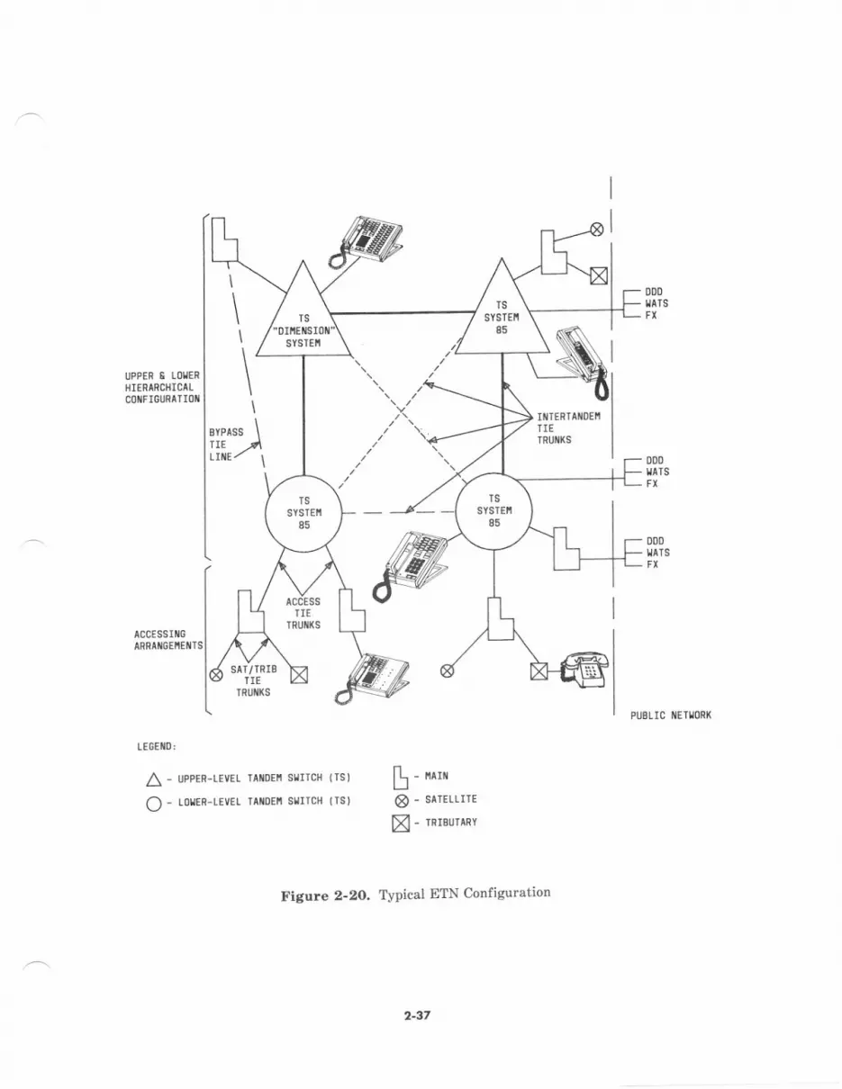
UPPEF I LOIERI]IERARCIIICAL
000IIATS
000IIATS
\
\\
\,
ass \TIE
ODD
accEssutcARRAflOENCNTS
LE6EIlD:
A - UpPER-IEVEL
O - LorEF-LEvEt
PI]ELlC IIETIONX
IAIIDEII SIITCH I III
rat{DEtt srrlcH {Ts)[-u"8 - SATEILIIE
[ - rnreurrnv
figure 2-2O, Typical ETN Configuration
2-37
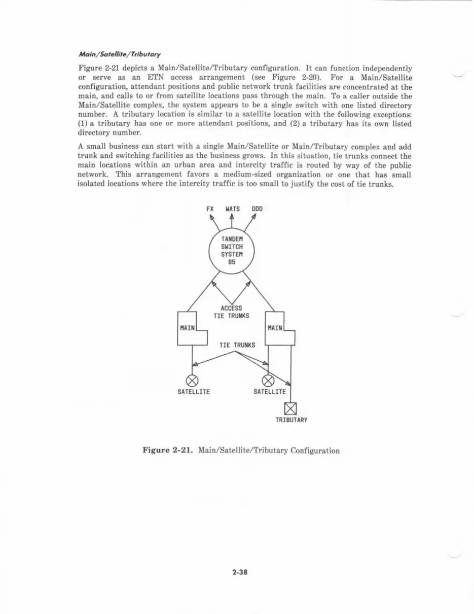
tloi /tot tli./hibutorr
Figwe 2-21 depicts a Main/Satellite,/Tributary configuBtion. It can function independentlyor serve aa an ETN access arrangement (see Figurc 2-20). For a Main/Sat€llit€conligulatior! atte[dant positions and public network trunk faciliti€s ar€ concentrated at themain, and calb to or from satellite locrtions pass through the main. To a caller oukide theMain/Sstellite complex, the system app€ars to be a single switch with one list4d directorynumber. A tributary locstion is similar to s sst€llit€ location with the follovring exceptions:(1) o tributary has one or mo!€ attendant positions, and (2) a tributary has its own listeddir€ctory number.
A small business can start with a singl€ Main/Sat€llite or Main/Tributary coitpl€x and addtrunk snd switching facilities as the business g.ows. In this situation, tie trunka connect them&in locstions within sn urban area and intercity haflic is mutrd by way of the Dublicnet\irork. This arrangement favols s medium*ized organization or one that has smallholated locations where the intercity traffic is too small to justify th€ cost of tie trunks.
FI tATS
TRIEUTIRY
Figuro 2-21. Main/Satellite/Tributary Configuration
23t
TIE TRUI'I(s
TIE TRIJIIXS
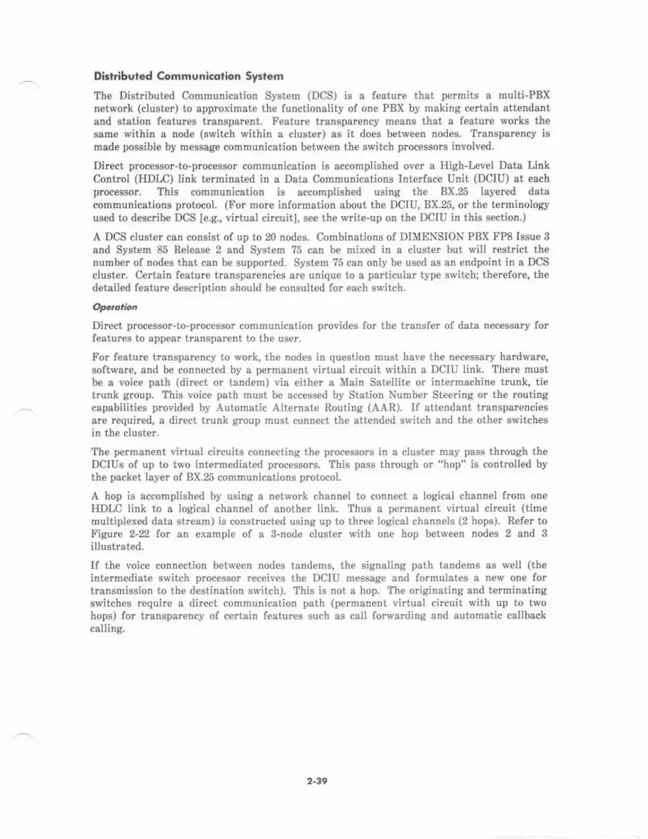
Di.lribvled Communi.dtion Sytlem
The Dist buted Communication Syst€m (DCS) is a feature that p€rmits a multiPBxnetwork (cluster) to approximate the functionality of one PBX by making ce ain attendantand station features hansparcnt. Feature transparcncy means that a featurc works thesame within a node (switch within a cluster) as it does between nodes. Trenspamncy ismade possible by message communication between the switch processors involved.
Dircct processor-to-proces8or communicatiod is accomplish€d over a High-Irvel Data LinkControl (HDLC) link terminated in a Data Communications Interface Unit (DCIU) at eachprocessor. This communication is accomplished using th€ BX.25 layered datacommunications protocol. (For more information about the DCIU,8X.25, or the terminologyused to describe DCS [e.g., virtual circuiti, see the write-up on th€ DCIU in this section.)
A DCS cluster can consist of up to 20 nodes. Combinations of DIMENSION PBX FP8 Issue 3
and System 85 Release 2 and Syst€m ?5 can be mixed in a clust€r but will r€st ct th€numb€r of nodes that can be supported. System ?5 can only be used as an endpoint in e DCScluster. Certain feature transparencies are unique to a particular type switch; therefore, thedetailed feature description should be consulted for each switch.
Direct p.oce$or-to-processor communication provides for the t€nsfer of data nec€ssary forfeatures to appear transparent 1o the user,
For feature transparency to work, the nodes in question must have the necessary hardware,software, and be connected by a pe.manert virtual circuit within a DCIU link. There mustbe a voice path (direct or tandem) via either a Main Satellit€ or intermachine trunk, ti€trunk group. This voic€ psth must be access€d by Station Numbe. Steering or the routingcapabilities provided by Automatic Alternate Routing (AAR). If attendant transparenciesare requircd, a direct trunk group must conn€ct the attended switch and the oth€I switchesin the cluster.
The permanent virtual circuits connecting the processors in a cluster may pass through th€DCIUS of up to two interm€diated processors. This pass through or "hop" is controlled bythe packet layer of BX.25 communications protocol.
A hop is accomplished by using a network channel to connect a logical channel from oneHDLC link to a logical channel of another link. Thw a permanent virtual circuit (timemultiplexed data stream) is constructed using up to thr€€ logical channels (2 hops). Refer toFig.ure 2-22 for an exarnple ol a 3-node cluster with one hop between nodes 2 and 3illustmted.
If the voice connection between nod€s tandems, the signaling path tandems as well (th€intermediate switch pmcessor rec€iv€s the DCIU message and tormulates a n€w one fortransmission to th€ destination switch). This is not a hop. The originating and terminatingswitches require a direct communication path (permanent virtual circuit with up to twohops) for transparency of c€rtain f€atures such as call lorwarding and automatic cellbackcalling.
2-39
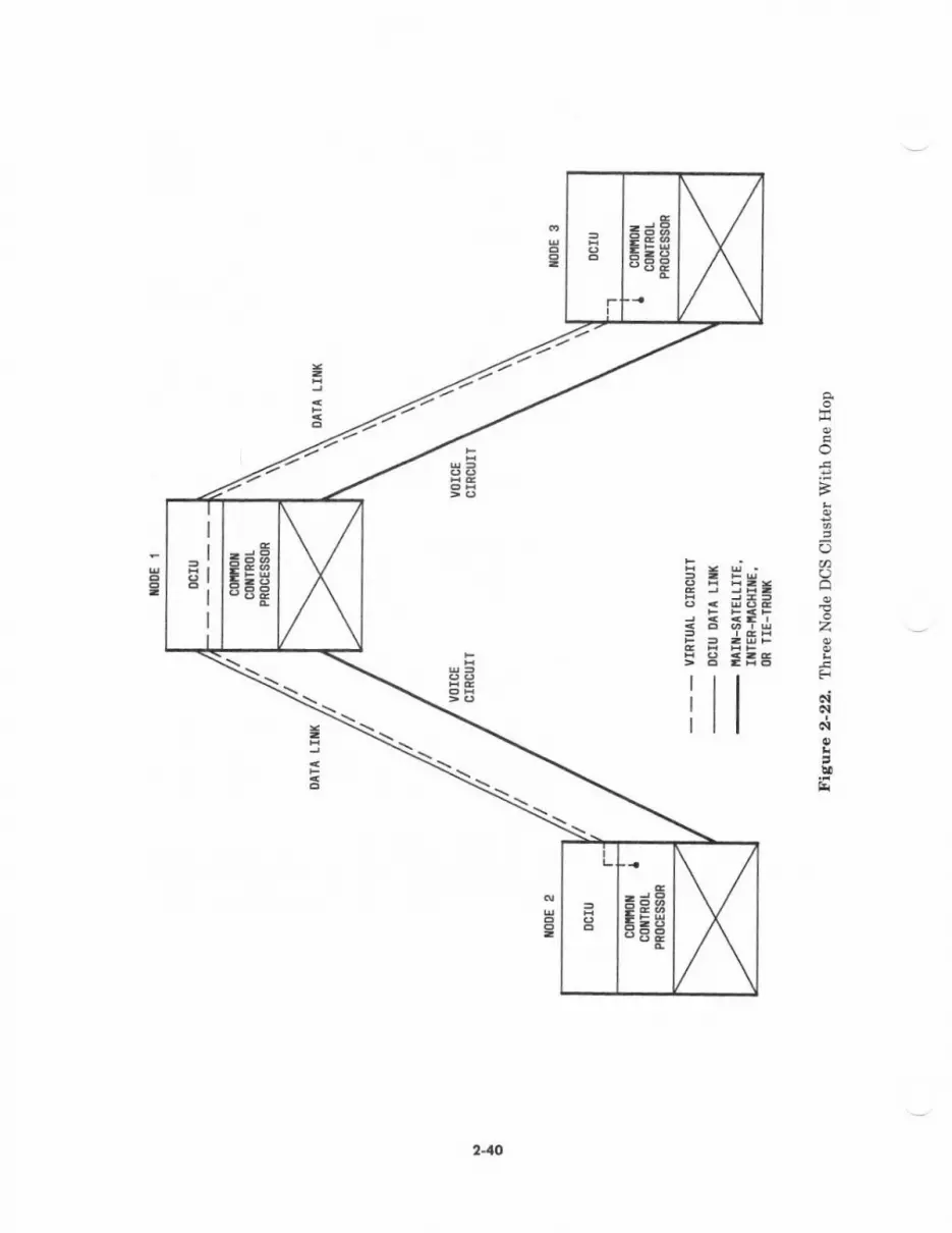
=dHEEE
= -'4E -1'z ,/
t TEfll=3
iI\:\\
i\*.- \E -=\_
S.
--5e=8
o
F
(J
Qlo3i
c-EFN
N
,!,tsi
41lJ
H
R2V2 of System 85 introduc€d alternate routing to DCS. DCS m€ssages can now be s€ntover an alternate route if a failure exists on the rout€ of first choice. Two alternete routegcsn be specified in addition to the route ol first choice. For more information, see thewrite-up on the DCIU in this section.
The eight links supported by the System 85 DCIU permit a DCS cluster with up to 20 nodes.
Any link thst carries a 2-hop permanent virtual circuit must be limit€d to a maximum ofnine messages per s€cond and operate at 9.6 kbps or higher (nine messages per s€condcorr€sponds to about 10,000 busy hour calls).
Reliability considerutions rnay necessitat€ a limit to the number of 2-hop p€rmanent virtuelcircuits in a cluster as w€ll as economic considerations caused by the message-linktransmission speed limits.
All nodes in a DCS clust€r must b€ within the continental United States and since messagedelay is a limiting factor, communications paths involving unusual delay, such as SatelliteCircuits, must b€ avoided.
Aulofiotod lron3mi3aion Meo3ur.menl Sy:rem (ATMS)
Automated Transmission Measurement Syst€m (ATMS) is an integrat€d hardware- andsoft\rar€-based facility monitoring system. It automatically m€asures the transmissioncharacteristics of private "analog and voice-grade" DS-l and public network trunk facilities.Th€ ATMS feature is available with Release 2 of System 85 or ihe DIMENSION PBX FP8,Issue 3 softwate- This capability is $pecially impodant for ETN and DCS custome$, v,/hocan use ATMS to conduct scheduled and demand maintenance tests on th€ir trunkingfacilities. Thes€ tests h€lp assess the health of the network, which l€ads to better networkmanagement. ATMS can b€ access€d by the user with any of these facilities:
. Centralized System Managenent (CSM)
. Facilities Manag€ment (FM)
. Initialization and Administration System (INADS)
. Remote Maintenance, Administmtion, and Traffic System II (RMATS-II)
. Maintenance and Administration Panel (MAAP).
ATMS automatically measures thrce kinds of transrnission impairrnent: loss, voice, and echo.It do€s this by setting up a connection betw€€n an origineting test line (OTL) on the near-end switch and a terminating t€st line (TaL) on the far-end switch through the trunk to betest€d (see Figurc 2-23). Transmission tests are then made automatically.
ATMS compar€s the results of these tests with thresholds that have been previously set inorder to id€ntify trunks which are out of tolerance or unusable. If trouble is found, ATMStak€s certain recovery actions including alarming and removing the unusabl€ trunk fromservice,
241

The following list shows all possibl€ transmission m€asurehents. The measurements anOTL makes may only include a part of this list sinc€ so|n€ TfLs cannot perform all oI thetests.
. Two-wey loss at 404, 1004, 8nd 2804 hertz
. Two-way loss at 1004 h€rtz
. Two-way C-message weighted noise
r Two-way C-notched noise
. Two-way singitrg rcturn lo$-low frequency
. Two-wey singing return loss-high frequency
. Two-way echo return loss.
s9rrct{ I SIITCfi B
Other type switch$.be made on tie trunks
Figure 2-23. Automatic Trsnsmi$ion M€asurement System
AaE qorba
The OTL can be configured from either g DIMENSION Fp8, Issue 3 or s System 8b,R€leec€ 2.
Only System 85 and DIMENSION FP8 can be equipped with OTLS.however, can b€ provided with TtLs. This allows measurements tothat connect to other type switch6.
ATMS ertablish€s e connection from the OTL, across the t€stedthe far-end switch. fi€ OTL allows up to l8 transmissiond€pending on the type of TTL used (see Tabl€ 2-A),
The OTL for System 85 is the SN26IB; for DIMENSION Fp8 it is the LC12. The TTL forSyrtem 85 is the SN260 or SN261B; for DIMENSION Fp8 it is the LCL4S or Zlnt2.
trunk, to a TTL circuit onparaheter measur€hents
412
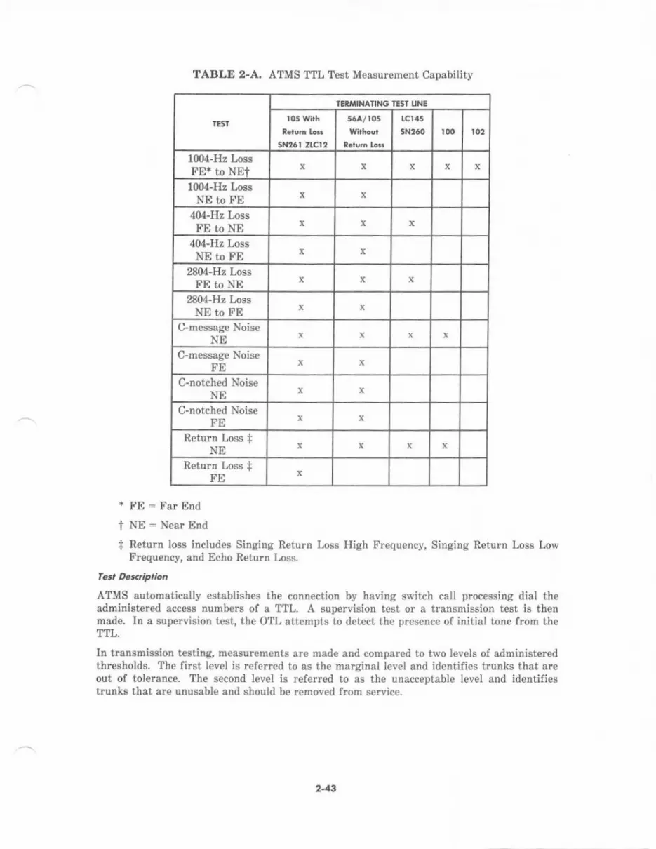
TABLE 2-A, ATMS TTL Test Measurement Capability
IESI
IIRI/IIN IING IISI LINE
5Nt6r ZrCt'
LCttt5
1004-Hz Loss['E* to NEt
1004-Hz l,ossNE to FE x
404-Hz Loss['E to NE
404-Hz LossNE to FE x x
2804-H, LossFE to NE x
2804-Hz LossNE to FE
C-message NoiseNE
C-message NoiseFE
C-notched NoiseNE
C-notched NoiseFE
Return Loss +NE
Return Loss +FE
* FE = Far End
I NE : Near End
+ Return loss includes Singing Return Loss High Fr€quency, Singing Return Loss LowFrequ€ncy, and Echo Return Loss.
ATMS automatically €stablishes the connection by having switch call processing dial theadministered acc€ss numbers of a TTL. A supervision test or a transmission test is thenmade. In a supervision test, th€ OTL attempts to detect the presence of initial tore frcm theTTL.
In transmission t€stin& measur€ments are made and compar€d to two levels of administeredthresholds. The first l€vel is referred to as the marginal level and identifies trunks that areout ol tolerance. The second level is refeued to as the unacceptable level and identifiestrunks that are unusable and should be removed from service.
243
Two test modes are available: scheduled and demand.
Scheduled testing allows the user to:
. Set up as many as 16 ind€pendent test schedules that specify start time, duration (inhours), days of the week the test will run, and the number of we€ks between tests
. Define thresholds for test measurements
. Display trunks that failed the tests along with the rcason for each failur€.
the switch automatically establish€s test connections according to the test schedule. Trunkswhose measurcments fail the administered thresholds have their identities andmeasurements stored in the switch. Also stored are the id€ntiti€s of any trunks that couldnot be tested and the reason the test could not be made. As a part of scheduled testing,certain recovery and alarming actions are taken for failed trunks.
Demand testing allows the user to immediately test a trunk, all trunks in a trunk group, orall trunks in the system. Thme tests are contained in the demand testing capability:
Test. 1-Allows the displaying ol the scheduled test results (no transmissionmeasurem€nts). tnformation displayed includ€s the identity of the failing trunk anda fault code indicetinq the reason.
Test 2-Provides a transmission test on a single trunk or all trunks in a trunk group.
All possible tests (determined by the capability of the TTL) will be executed and themeasurement results can be displayed. Other capabilities of this test include s"camp-on" feature on in-use trunks which allows them to be tested when callprocessing rcleases the trunks. Maintenance busied trunks may be tested (they areautomatically *turned to the maintenance busy state after the test) and a trunk canbe maintenance busied or released from maintenance busy.
T€st S,Provides the supervision test which attempts to detect only an initial tone(Test Progress Tone or 104-Hz Tone) from the TTL. Test 3 operations (ciacuitselection. busy out, camp-on) ar€ identical to those of test 2.
Ex..ptioh R@ding
During scheduled testing, exception recording occuts when ATMS encounters trunk failuresor trunk t€sts that cannot be made. The recording consists of both the traditional errorlogging in the Maint€nance Information Data Structute (MIDS) and the PeriodicMaint€nance Information Data Structurc (PMIDS), plus logging in several exception tables.Tabl€ 2-B summarizes the exception recording
Note that the exception tables described in Table 2-B are not available through MAAPprocedur€s. The exception tables are available to System Management as rcquired. Theycan also be cleared in the switch at the requ€st of System Management.
2-14
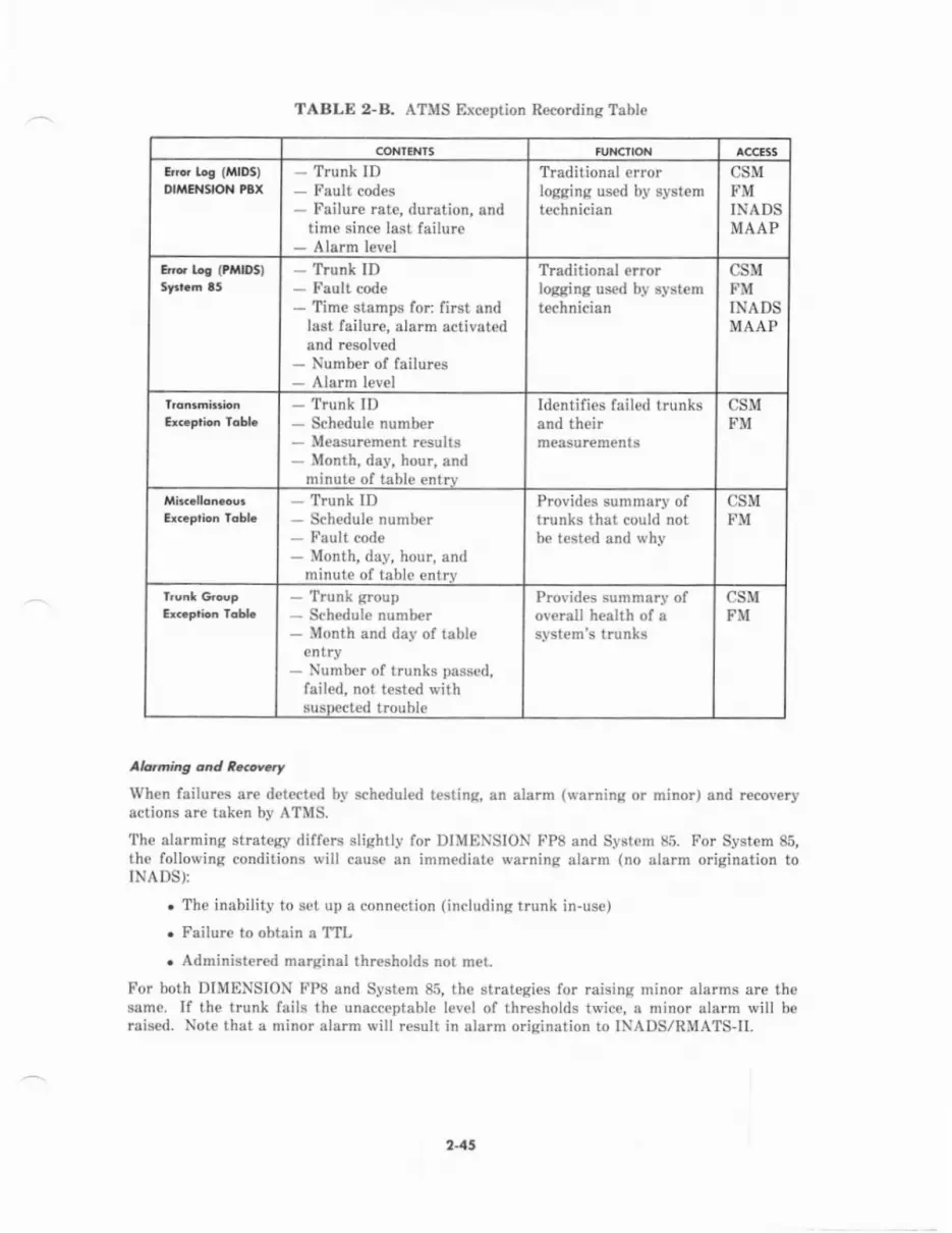
TABLE 2-B. ATMS Exception Recording Table
CONIENTS
E o tos {MlDs)olMEl{gtoll tBx - Trunk ID
- Fault codes
- Failure rate, duntion, andtime sinc€ last failure
- Alarm level
Traditional errorloqqing used bI systemtechnician
CSMFMINADSMAAP
Ed Le (PltIDS) - Trunh ID
- Fault code
- Time stamps for: first andlast failure, alarm activatedand resolved
- Number of failures
- Alarm level
Traditional errorlogging used by syst€mtechnician
csMFMINADSMAAP
- Trunk ID
- Schedule number
- Measurcment results
- Month, day, hour, andminute of table entrv
Identifies failed trunksand their
csMFM
- Trunk ID
- Schedule number
- Fuult code
- Month, day, hour, andminute of table entrv
Provides summary oftrunks that could notbe tested and why
csMFM
- Trunk group
- Schedule number
- Month and day of tableantry
- Number of trunks passed,failed, not tested withsuspect€d trouble
Provides sunmary ofoverall health of asystem's trunks
csMFM
Atatming o'rd z..ova.y
When failures are detected by scheduled testing, an alarm (warnin,a or minor) and recoveryactions are taken by ATMS.
The alarming strateey differs slightly for DIMENSION FP8 and Systam 85. For System 85,thc following conditions will cause an immediate warning alarm (no alarm origination toINADS):
. The inability to set up a connection (including trunk in-use)
. Failure to obtain a TTL
. Administered marginal thresholds not m€t.
For both DIMENSION F'P8 and System 85, th€ strategies for raising minor alarms are thesame. [f the trunk fails the unacceptable level of thresholds twice, a minor alarm will berais€d. Note that a minor alarm will result in alarm orisination to INADS/RMATS-II.
215
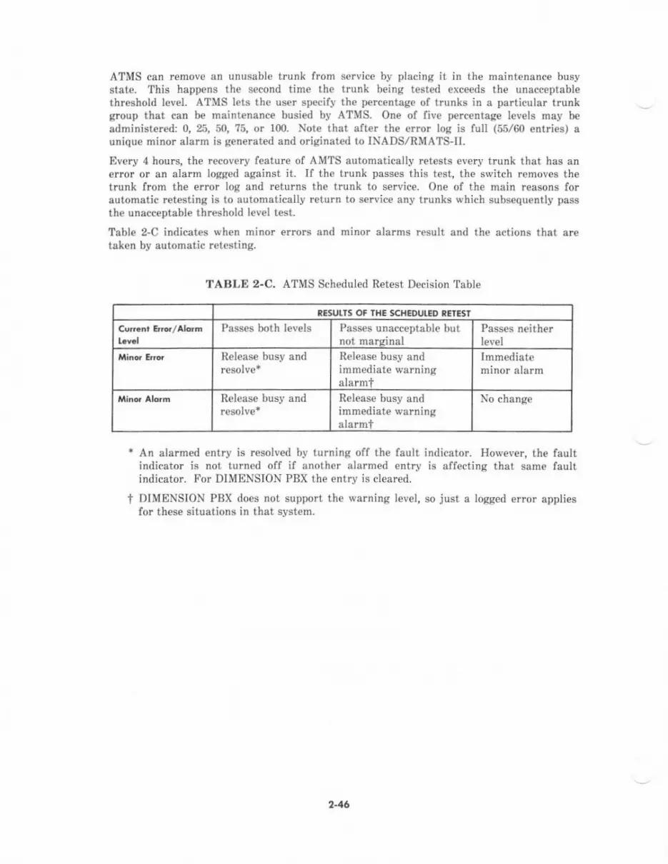
ATMS can remove an unusable trunk from service bv placing it in the maintonance busystate. This happens the second time the trunk being test€d exceeds the unacceptabl€threshold lev€I. ATMS lets the user specify the percentage ol trunks in a particular trunkgroup that can be maintenance busied by ATMS. One of fivc percentage levels may b€administered: 0,25, 50,75, or 100. Note that after the error log is full (55/60 entries) aunique minor alarm is gen€rat€d and originated to INADS/RMATSll.
Ev€ry 4 hours, the recovery feature of AMTS automatically retests every trunk that has anerror or an alarm logged against it. If the trunk passes this test, the switch removes thetrunk from the error log and returns the trunk to service. One of th€ main reasons forautomatic r€testing is to automatically return to s€rvice any trunks which subs€quently passthe unacceptable threshold levei test.
Table 2-C indicates wh€n ninor errors and minor alarms result and the actions thai aretaken by automatic retesting.
TABLE 2-C. ATMS Scheduled Retest Decision Tsble
IE5UTIS OF IHE SCHIOULED TETESI
Pesses both levpls Passes unacceptable butnot marcinal
Passes neither
Release busy and Release busy andimmediate warningalarmt
Immediateminor alarm
R€l€ase busy and Release busy andimmediate warningalarmt
No change
* An alarmed entry is resolved by turning off the fault indicator. Holvever, the faultindicator js not turn€d off if another alarmed entry is affecting that same faultindicator. For DIMENSION PBX the entry is cleared.
t DIMENSION PBX does not support the warning level, so just a logged error appliesfor these situations in that system.
2-46

D.tlo Communiaolions
Syst€m 85 is a digital switching system capable of voice and data communications usinganalog and digital data endpoints. A data network can be set up using System 85 as acentral switching point to inte.connect other switching syst€ms, host computers, and usersboth on- and off-premises.
The System 85 switch connects to almost any type of data equipment provided with anElectronic Industri€s Association (EIA) RS-232C interface. Supported types of equipmentinclude:
. Data terminals
. Printers
. Graphic and facsimile equipment
. Computers.
Data modules or EIA port circuit packs provide the digital interface betiveen th€ System 85switch and dats terminals, hosts, and off-premises facilities. Because th€ switch itself isdigital, this interface does not requi.e analog eonversion unless the facilities themselves areanalog. Since data modules use plug-in connectors and flexible extension numbering isavailable for data terminals, system support personnel can rcarrange the system to m€etdynamic organizational needs.
The connectivity between Systern 85 and the data endpoints is provided by sevoral DataManagem€nt interface features. Data CommunicatioN Access provides the connectionbetween on-premises data endpoints when both connect to the switch via analog facilities.Host Computer Access provides the connection b€tween on-premises data endpoints whenboth data endpoints connect to the switch using digital facilities. Modem Pooling providesanalog-to-digital and digital-to-analog conversion resources for off-premises connections.The resources are pooled for switch€d access operation. Remot€ data equipment can beprovided switched access from local data terminals through Off'Premises Data-OnlyExtensions. Analog or digitai privateline facilities, dedicated to data, can be used. Whenmultiplexing is advantageous, th€ DS-I Interface provides a means to replace analog tietrunks, digital CO trunks, and OPS lines rvith DS-l facilities. This armngement can beexpanded to increase the capacity or add dedicated data channels by using ChannelExpansion and Channel Division Multiplexing. For R2V3, the Digital Multipl€xed Interfaceintroduces a cost-effective mcans of system-to-host communications.
Data management user featur€s provide an efficient and reliable means of establishing dataconnections from the data terminals. Data Call Setup, along with several VoiceCommunications features, provides the user with access to the data network. And DataProtection adds reliability to the system bv preventing other System 85 features frominterrupting the data transmissions.
Terminal Emulation can be provided on th€ AP to integrate th€ System 85 data networkwith an IBM host computer. Emulation programs make the AP and the AP data terminalsappear as an IBM 32?0 display system or IBM 278013?80 data communications terminals.
For a detailed discussion of data communications, refer to AT&T System a5 (R2Vg)-Festure Descriptions-Reference Manual (555-102-301).
2-47

Digitol Service-l (DS-l) lnterfqc€
The System 85 DS-l interface provides a high-pe ormanc€ digital communications interfaceto System 85 which is T-carrier compatible.
. The T1 carrier is the standard method for interconnecting digital telecommunicationsystems within North America- It is a 4-wire twisted pair digital trunking facilitywbich operates at 1.544 Mbps and has provisions for synchronization, control, andmaintenance-
What does DS-t rnean? Il is a Digittl S€rvice (DS) number which corresponds to a digitaltransmission rat€. Her€ are some examples of DS numbers: DS-0 = 64 kbps, DS-l =1.544 Mbps, DS-2 : 6.312 Mbps, and so on. The System 85 DSI interface combines 24 DS-O
signals (twenty-four 64-kbps channels) and 8000 framing bits into one data stream operatingat the Ds-t rat€ (1.544 Mbps).
The DS-1 interfac€ can be used in conjunction with other System 85s for transparenttransmission of Digital Communications Protocol (DCP) formatted data. A completelydigital link (with no protocol conversion) may be established from a DCP endpoint on on€System 85 to another System 85 DCP endpoint.
A channel may be used for digitized voice, data, or signaling transmission. Each DS-ochann€l (separate chann€l within the data stream) can be treat€d as a trunk circuit. Thechann€ls can be administered as trunks; this means that they can be assigned to trunkgroups and features and can also be restricted just like analog trunks.
The ANN-IIC provides the System 85 DS-l interface. This circuit pack can emulate th€following types of analog trunks:
. CO (ground-start and loop-start)
. DID (battery-reversal)
. FX (ground-start and loop-start)
. OPS
. Remote Acc€ss (gmund-start)
. Tie
. WATS (ground-start and loop-start).
DS-l digital trunks can provide a cost-effective alternative to analog trunks whenconsidering the number of facilities requir€d for data calls and the maximum data ratessuppoded.
The ANN-flD also supports DS-l based switch-to-host computer connections (DigitalMultiplexed Interface with Bit Odented Sisnaling tDMl"BOS]).
F,omins, uac c.dins, oDd funotins
Specifications for th€ framing, line coding and signaling employed on a DS-1 interface isnecessary to insure compatible communication betwe€n digital terminal products such asdigital switches, Chann€l Banks, and host computers. The typ€s of framing, line coding, andsignaling employed are independent of each other and don't depend on the transport facility(with the possible exception of line coding). Even though framing, line coding, and signalingare independent of each other, they must be compatible between the terminal €quipmentendpoints; for example, if one type of signaling is used at one end, the sam€ typ€ of signalinghas to be used at the other end.
244

Two types of framing formats can be used with the System 85 DS-t interface:
. D4 formet
. Fe format (Fe is an abbreviation for extended framing).
Both formats use a basic frame which consists of 24 eight-bit time slots followed by oneframing bit which adds up to 193 bits per frame. Since th€re arc 24 eight-bit time slots,both formats provide 24 channels. A channel passes 8 bits of information during its timeslot in each framq for example, it takes two frames for a channel to pass 16 bits ofinformation. The D4 and Fe fo.mats organize frames into larger structures called super-frames. Within each super-ftame, th€ formats dictate which frames are used to passsignaling information and define how the framing bit is to be interpr€ted.
D4 Frcning Fomot
With D4 framing, the framing bit is divided into two fields: terminal framing patternand signaling framing pattern. The terminal fram€ pattern is an alternating one-zeropattern and is used to determine the boundaries between frames. The signaling framepattern is used to determine which frames contain signaling data. It repeats ev€ry l2frames providing a l2-fran,e super-frame. During th€ 6th and 12th frames of a D4super-frame, the least significant bit of each of the 24 chann€l's time slots may be usedto pass signaling information for each channel. This method of signaling is known as"robbed'bit" signaling. (Anoth€r method, called 24th channel signaling, uses th€ 24thchannel to pass signaling for the other 23 channels. This method leaves the leastsignificant bits in the 6th and 12th fram€s unaffect€d.)
I2345678I
1011
t2
0
;
iii0
1
;
;
;
i
;
Bits l-8Bits 1-8Bits 1-8Bits l-8Bits r-8Bits 1-?Bits 1-8Bits 1-8Bits l-8Bits l-8Bits 1-8Bits 1-7
Bit 8
Bit 8 B
a'rote 1r Fs-Signaling Frarning (sequence...001110...).
Nor6 2: Ft-Terminal Framing (sequence ...101010...).
llot3 3: Option T Transparent (robbed-bit signaling disabled, bit 8 us€d fortraffic).
Noto 4: Option 2-2-state signaling (channel A).
Not3 5: Option 4-4-state signaling (channels A & B).
249
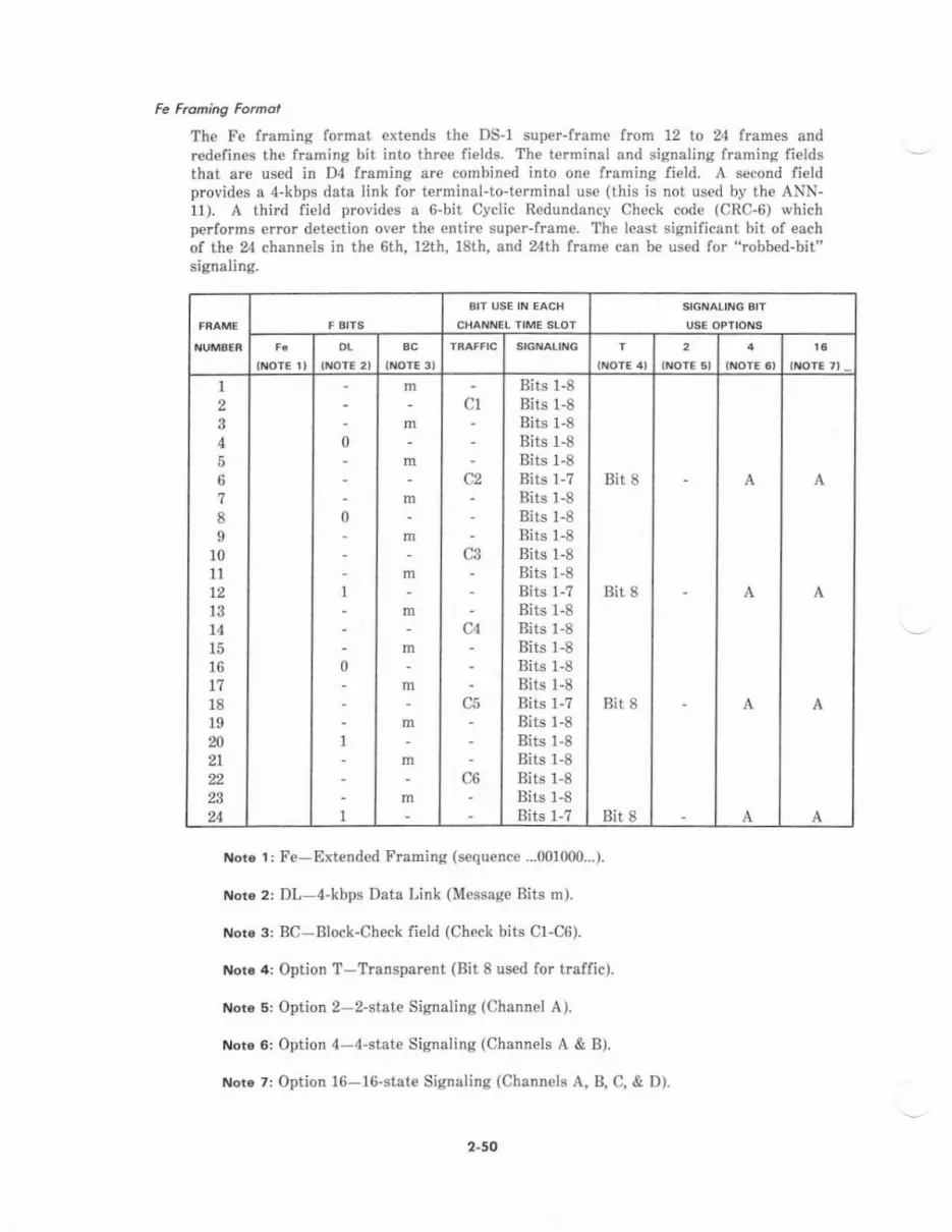
Fe Froning Fomot
The Fe framing format ext€nds th€ DS-1 super-frame from 12 to 24 frames andredefines the framing bit into th.ee fields. The terminal &nd signaling framing fieldsthat are used in D4 framing are combined into one lraming field. A second fi€ldprovides e 4-kbps data link for terminal-to-terminal use (this is not used by th€ ANN-11). A third fietd provid$ a 6-bit Cyclic R€dundancy ch€ck code (CRC-6) whichperforms €rror d€tection over the entire super-frame. The least significant bit of eachof the 24 channels in th€ 6th, 12th, 181h, and zth frame can b€ used for "robbed-bit"signaling.
INOT€ 2I
t6
1
23A
567
8
l0l112131415
t718t9202t
24
;
;
i
;
i
;
iT
T
ii
iT
;
:'
i:
..,
;:
a:
"',
Bits 1-8Bits 1-8Bits 1-8Bits l-8Bits 1-8Bits 1-7Bits 1-8Bits 1-8Bits 1-8Bits 1-8Bits l-8Bits 1-?Bits 1-8Bits 1-8Bits 1-8Bits 1-8Bits l-8Bits l-?Bits 1-8Bits 1-8Bits 1-8Bits 1-8Bits 1-8Bits l-7
Bit 8
Bit I
Bit 8
Bit 8
ilot€ 1: Fe-Extended Framing (sequence ..,001000...).
Note 2: Dl--4-kbps Data Link (Message Bits m).
Noro 3: BC-Block-Check field (Check bits C1-CG).
or. 4: Option T-Transparent (Bit 8 used for traffic).
Noto 5: Option 2-2-state Signaling (Channel A).
Nor6 6: Option 4-4-stat€ Signaling (Chann€ls A & B).
r'|016 7: Option l6-16-state Signaling (Channels A, B, C, & D).
2"50
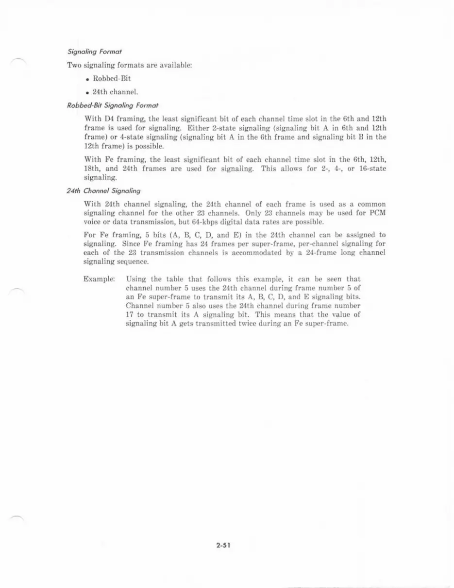
Two signaling formats are available:
. Robb€d-Bit
. 24th channel.
Robbed-ait Signoling Fomot
With Dl framing, the least significant bit of each channel tim€ slot in the 6th and 12thframe is used for signaling. Either 2-state signaling (signaling bit A in 6th and 12thlrame) or 4-stat€ signaling (signaling bit A in the 6th frame and signaling bit B in the12th frame) is possible.
With Fe ftamin& the least significant bit of each channel time slot in the 6th, l2th,18th, and 24th lrames are us€d for signaling. This allows lor 2-, 4-, or 16-statesignaling-
21rh Chcnnel Sisnclins
With th channel signalin& the 24th channel of each fmme is used as a commonsignaling chsnnel for the oth€r 23 channels. Only 23 channels may be used for PCMvoice or data transmission, but 64-kbps digital data rates are possible.
For Fe framing, 5 bits (A, B, C, D, and E) in the 24th channel can be assigned tosignaling. Since Fe lraming has frames per super-frame, per-channel signaling loreach ol the 23 transmission channels is accommodated by a 24-frame long channelsignaling sequence.
Example Using th€ tabl€ that follows this example, it can be seen thatchannel number 5 uses the 24th channel during frame number 5 ofan Fte super-frame to transmit its A, B, C, D, and E signaling bits.Channel number 5 also uses the 24th channel during frame numberl7 to transmit its A signaling bit. Thie means that the value ofsignaling bit A gets transmitted twice during an Fe super-frame.
2.5 t
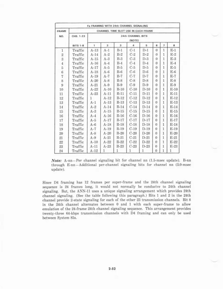
CHAXNEL IIME STOT US€ I't EACH fiAM€
INOTE'
6
I23I56
89
1011
t2l3l4l5l6t118l9202t
24
TrafficTrafficTrafficTrafficTrafficTrafficTrafficTrafficTrafficTraffic'lratlrcTrafficTrafficTrafficTrafficTrafficT.afficTrafficTrafficTraffic'I ratlrcTrafficTrafficTraffic
A-13A-14A-15A-16A-17A-r8A-19A-20L-21
A-231
A-l
A-3A-4A-5A-6
A-8A-9A-r0A-llA-t2
A-lL-2A-3A-4A-5A-6
A-8A-9A-10A-llA-12A-r3A-14A-15A-16A-17A-18A-19A-20A-2rA-2l\-nl
B-1B-2B-3B-4B-5B-6B.?B-8B-9B-r0B-11B-r2B-13B-14B-15B-16B-17B-18B-r9B-2oB-27B-2,B-23I
c-rc-2c-3c-4C-5c-6c-7c-8c-9C-10c-11c-12c-13c-14c-15c-r6c-11c-18c-19c-20c-21
c-aI
D-lD-2D-3D-4D-5D-6D-',lD-8D-9D-10D-llD-t2D-13D-14D-15D-16D-17D-r8D-19D-mD-21D-nD-ZiI
000000000000000000000000
1
IIIII1
1
1
IIIIIt1
1
IIIIIII
E-1E-2E,3E-4E-5E-6E-7E-8E-9E-10E-l1E-12E-13E-l4E-15E-16E-1?E-18E-19E-20E-21
E-23I
lvot"l A-nn-Per channel signaling bit for channel nn (1.5-msec update). B-nnthrough E-nn-Additional per-channel signaling bits for channel nn (8.o-msec
update).
Since D4 framing has 12 trames per super-frame and the 24th channel signalingsequence is 24 framB lon& it would not normally be conducive to 24th channelsignaling. But, the ANN-11 uses a unique signaling arrangement which provides 24thchannel signaling. (S€€ the table following this paragraph.) Bits I and 2 in the zthchannel provide 2-state sigaaling for each of the oth€r 23 transmission channels. Bit 8
in the 24th channel alternates between 0 and I with each super-frame to allowemulation of the z4-frame 24th channel signaling sequence. This arrangement providestw€nty-three -kbps transmission channels with D4 framinE and can only be usedbetween System 85s.
2-52
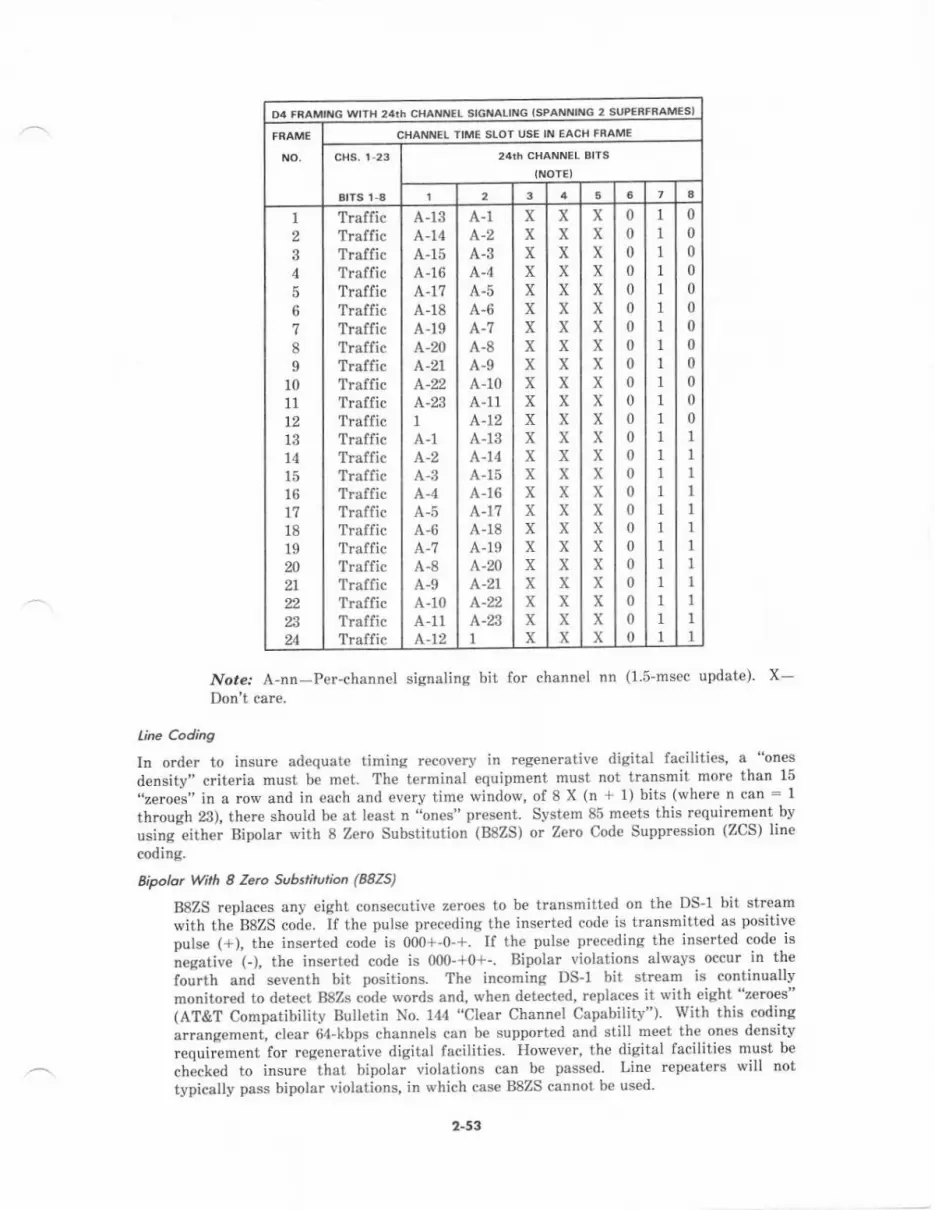
iII{CT SIGNALII{G ISPANITING 2 SUPERFRAMESI
CHAnll{ET TIME SIOI USE IN IAC'I FRAME
6
1
2
4567
8I
1011
1213141516171819202t22
24
TrafficTrafficTr.fficTrafficTrafficTrafficTrafficTrafficTrafficTrafficTrafficTraflicTrafficTrafficTrafficTrafficTrafficTrafficTrafficTrafficTraflicTrafficTrafficTraffic
A-13A-14A-15A-16A-1?A-18A-r9A-20A-21L-22A-23IA-lL-2
A-5A-6
A-8A-9A-10A-11A.-12
A-1
A-3A,4A-5A-6L-7A-8A-9A-10A-11A.-12A-13A-14
A-16L-1.7A-18A-19L-20!\-21
A.-n1
XxxXxXXXXxXxxxxxxxxxXxxx
xXXxxxxxxxXXxxxxXXXXxxxX
xXxxXXXxXXxxXXXXXXXxxxxx
0000
000
00000000000000000
II1
1
1
1
1
1
1
1
1
1
1
1
1
I1
1
1
II1
1
I
0000
000000001
1
I1
1
1
1
1
1
I1
1
Nore.' A-nn-Per-channel signaling bit for channel nn (1.5-msec update) X-Don't car€.
line Coding
In order to insurc ad€quate timing recovery in regenerative digital faciliti€s, a "ones
density" criteria must be met- The terminal equipment must not transmit- more than 15
"zeroes" in a row anal in each and every time window, of 8 X (n + r) bits (where n can: Ithrough 23), there should be at least n "ones" pr€sent System 85 meets this requirement by
usinglither Bipolar with 8 Zero Substitution (B8ZS) or Zero Cod€ Suppression (ZCS) lin€
coding.
Bipolat With I Zerc Sub.titution (B8ZS)
B8ZS replaces any eight consecutive zeroes to be transmitted on th€ DS-l bit stt€am
with thtB8ZS code. If the pulse pr€ceding the inserted code is transmitted as positive
putse (+), the inserted code is 000+-0-+. If the pulse preceding the inserted code is
neeative (), the inserieal code is 000-+0+-. Bipolar violations alwavs occur in the
fourth and sev€nth bit positions. The incoming DS-l bit stream is continuallvmonitored to detect BSZS coale words and, wh€n detected, teplac€s it with eight "zeroes"(AT&T Compatibility Bulletin No. 144 "Clear Channet Capabilitv"). With this coding
arrangement, cl€ar 64-kbps channets can be supported and still meet the ones densitv
requiiement for regeneralive digital facilities. However, the digital facilities must be
checked to insure that bipolar violations can be passed. Line repeaters will not
typically pass bipolar violations, in which case BSZS cannot be used'
2-53

Ze.o code surycssion (zcs)
ZCS is th€ most predominant line codjng used. If any 8-bit tirne slot contains all"zeroes", bit 2 is changed from a "zero" to a "one" (AT&T Compatibility BulletinNo. 119). This is not signilicant in PCM voice transmission, but would obviously causeerrors in digital data. Therefor€, only digital data formats which do not allow timeslots conteining eight "zeroes" may be used. Digital Communications Protocol (DCP)formatted data meets this criteria for data rates from 300 bps to 19.2 kbps, 56 kbps,and restricted 64 kbps. The restricted 64 kbps is used for 6witched 515 BCTtransmission to a remote AP16 with SIJCP interface. The High Level Data LinkControl (HDLC) fornat is inverted for this application to meet the ZCS crite a for full& kbps data rates.
Sytt.m 85 Ut-l Signalins
The DS-1 interface can be administered in either of two modes of signaling, 24th channelsignaling or robbed-bit signaling.
In the robbed-bit signaling mode, all 24 chann€ls are used as trunks with certain bits on th€chennels us€d for siglaling. Each of the 24 trunk channels can be us€d for voic€connections, analog voiceband data connections, or ACCUNET* Switched 56-kbps Service.Th€ maximurn analog voiceband data rate supported is 9.6 kbps. Voic€band data alsorequir€s data sets or modern pool resources,
In the 24th channel siqnaling mode,23 channels ar€ used as tmnks and the 24th channel isused fo. signaling. Since the 23 channels have no bits robbed for signaling, the integrity oftheir 64-kbps data streams are preserved. This allows 64-kbps transmission ol digital data.
ftunk Arsbnn.nts
A trunk channel which supports voice, DCP formatted digital data calls, and analogvoiceband data calls is refetred to as Alternate Voice Data (AVD); AVD trunks may also bereferred to as data-glade trunks. A trunk channel which supports voic€ calls and analogvoiceband data calls only is referred to as voice grade. A DS-1 interface using 24th channelsignaling can have both AVII and voice-grade trunks assign€d to the 23 possible trunkchannels- A DS-l interface using .obbed-bit signaling can have only voice grade trunks orACCUNET Switched 56-kbps Service assign€d to the 24 trunk chann€ls. DS-l AVD andvoic€-grade trunks may be assigned in any manner that analog tie trunks, CO trunks, FXtrunks, OPS, and WATS trunks may be assigned. For €xample, trunks on the same DS-1pack may be assigned to separate trunk groups, assuming the physical terminations permitthis, or a numb€r of the trunks may be assigned to a dummy trunk group. All of th€ routeselection functionality of Automatic Alternate Routing (AAR) and Automatic RouteSelection (ARS) is available with DS-r AVD and voice-grade trunks.
Care must b€ taken not to mix voice-grade and AVD trunk grcups in the same routingpatterns. For a data call, the decision to use a modem pool is bas€d on the type of trunkrequested, not the type of trunk provided by the system. Using an access code for an AVDtnrnk to mak€ a digital data call lrom a DCP connected terminal instructs the System 85 notto provide a mod€m pool resource. If a voice-grad€ trunk is provided because of mixed tnrnkto trunk group or routing pattern assignments, the data call cannot be established as nomodem pool resource will be allocat€d.
' &€s'st.r€d s€rvic. na.k or AT&T.
a-s1
Phytical Annecrivity
Aveniew
The System 85 DS-l interfac€ conforms to DSX-1 standar& (AT&T PUB 6%11). Th€ D91carrier houses up to two ANN-l1 circuit packs. A standard 50-pin connector, manufacturedby Arnphenol Products, accessible at the back of the switah cabinet housing the carrier isused for each DS-1 int€rface to rnate with a special connecting cable. The connecting cable is60&type (ABAM) whicL pmvides 6 pairs (sead pai!, receive peir, and four unused pair.1) of22 AWG wire which are shielded and jacketed. CoDnecting cable8 are used to interface toChannel Service UDits (Figurc 2-%), Transmission Terminal Products (CDM and CEM), andcolocated Syst€m 85s equipp€d with DS-1.
' One of thes unused raiF nsy be usd to provide. @ntaci d6ure lmpbaek signzt |rom tie Ds-l pacL to the€quipnert it connftt. to- Th€ signEl indicat€s that the €quipnent should loopb.ct rhe r€nd to r€ceive pair lronth€ Ds-l pdk lor densnd t€.ts initirted vis a m.int ..n@ pmeduft.
2-55
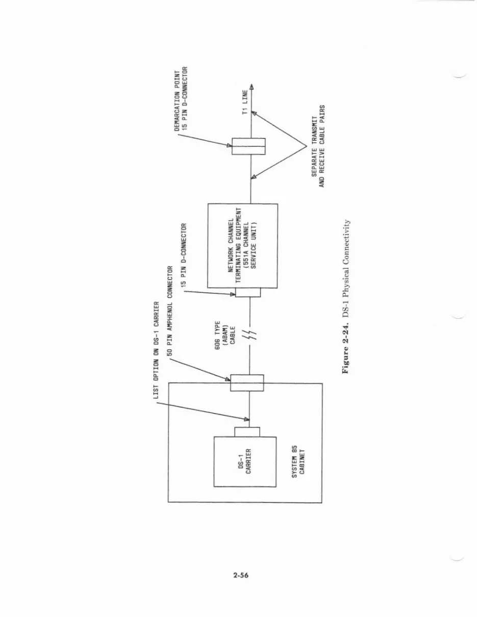
.E=s:t6-IP
c
i
I
E
(.)
.g
o
6td
,u&
s
*
II
;EH
-tl5t E
lrEur5-l.
E
2-16
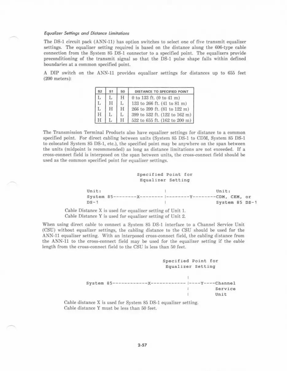
Equolizet Setings ond Dstonce linitations
The DS-l circuit pack (ANN-11) has option switches to select one of fiv€ transmit equalizersettings. The equalizer setting required is based on the distance along the 606-type cableconnection from the System 85 DS-l conn€ctor to a specified point. The €qualizers providepreconditioning of the transmit signal so that the DS-l pulse shape falls within definedboundaries at a common specified point.
A DIP switch on the ANN-I1 provides equalizer settings for distances up to 655 feet(200 rnetels)l
sl DISTANCE IO SPECIFIED POINT
LLLHH
LHHLL
HLHLH
0 to 133 ft. (0 to 4l m)133 to 266 ft. (41 to 8l m)266 to 399 ft. (81 to 122 rn)399 to 532 ft. (122 to 162 m)532 to 655 ft. (162 to 200 m)
The Transmission Terminal Products also have equalizer settings for distance to a commonspecified point. For direct cabling betwoen units (System 85 DS-l to CDM, System 85 DS-lto colocated System 85 DS-1, etc.), the specified point may be anywhere on the span bet*eenthe units (midpoint is reconm€nded) as long as distanc€ limitations are not €xceeded- If across-connect field is interposed on the span between units, the cross-connoct field should beused as the common specified point for equalizer settings.
speci f ied Point fo!Equal i zer Setting
Unit: I Unit!SysteF 85--- ----X--------J--------y--------CDn, CEU, orDS-l I Systen 85 DS-1
Cable Distance X is used for equalizer setiing of Unit l.Cable Distance Y is used for equalizer setting of Unit 2.
When using direct cable to connect a System 85 DS-1 interfac€ to a Channel Service Unit(CSU) without equalizer settings, the cabling distance to the CSU should be used for theANN-ll equalizer setting. With an interposed cross-connect fi€ld, the cabling distance fromthe ANN-1l to the cross-conn€ct field may be used for the equalizer setting if th€ cabl€length from the cross-connect field to the CSU is l€ss than 50 fe€t.
speci lied Point forEquaI i zer Setting
systed 85------------x------------ l----Y----Cbanneli SelviceI Unit
Cable distance X is used for System 85 DS"1 equalizer setting.Cable dislance Y must bc less than 50 feet.
2-57
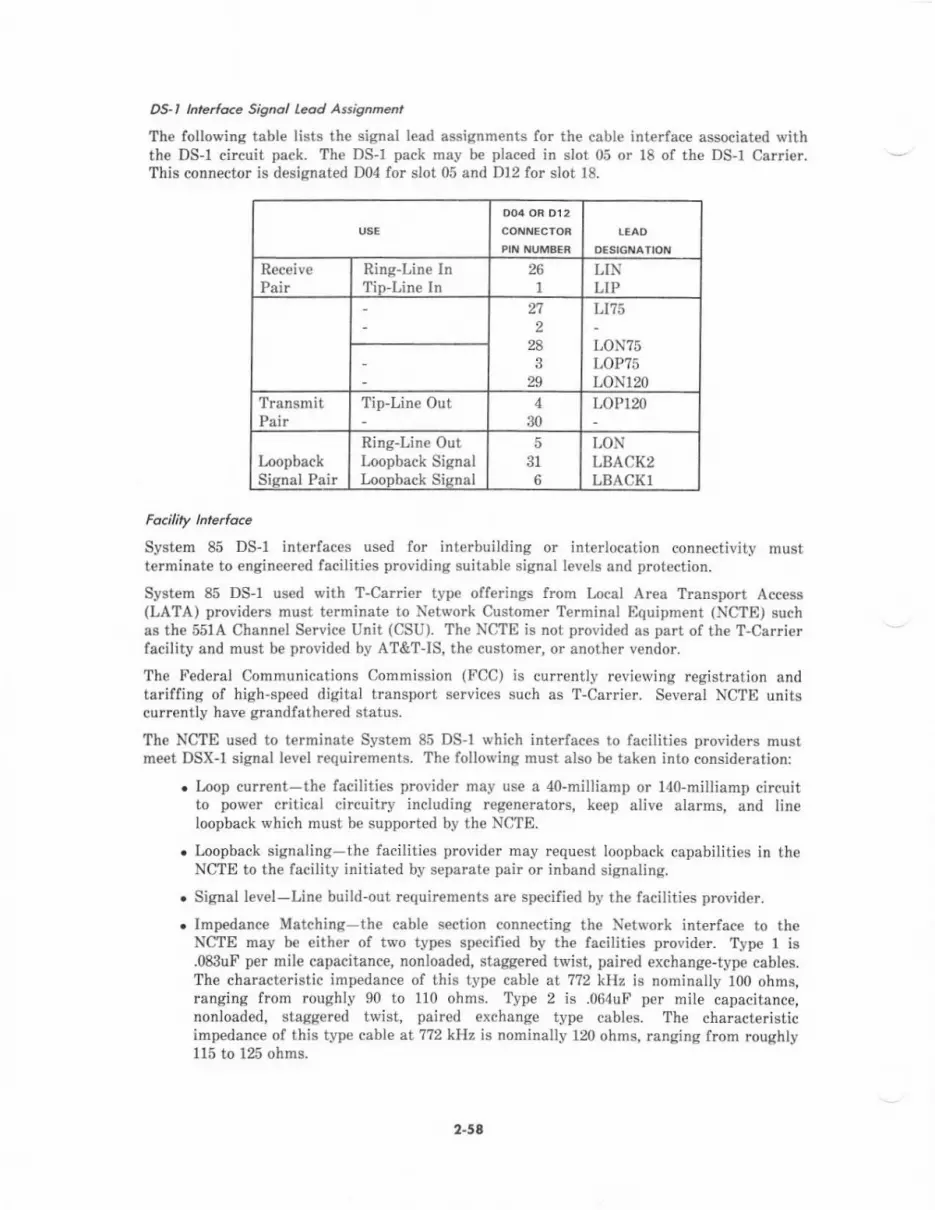
DS-l l ertc<e Sisnol L@d Assisnneot
The following table lists the signal lead assignments fo. the cable interface associated Niththe DS-l circuit pack. The DS-l pack may be placed in slot 05 or 18 of the DS-1 Carrier.This connector is desiqnated D04 for slot 05 end D12 for slot 18.
Receiv€Pair
Ring-Line InTin-Line ln
261 LIP
228
329
LtI3
LON75LOP?5LONr20
TransmitPair
Tip-Line Out 430
LOP120
InopbackSisnal Pair
Ring-Line OutLoopback SignalLoonback Sisnal
531
6
LONLBACK2LBACKT
System 85 DS-l interfaces used for int€rbuilding or interlocation connectivity mustterminate to €ngineered facilities providing suitable signal levels and protection.
System 85 DS-1 used with T-Carrier type offerings from Local Area Transport Access(LATA) providers must terminate to Network Customer Terminal Equipment (NCTE) suchas the 551A Channel Service Unit (CSU). The NCTE is not provided as part of the T-Carrierfacility and must be provided by AT&TIS, the customer, or another vendor.
The Federal Communications Commission (FCC) is currently reviewing registration andtariffing of high-speed digital transport services such as T-Carrie.. Several NCTE unitscurrently have grandfathered status.
The NCTE used to terminat€ System 85 DS-l which interfaces to fecilities providers mustme€t DSX-I signal level requirements. The following must also be taken into consideration:
. Loop current-the facilities provider may us€ a 4o-millianp or l4O-milliamp circuitto power c tical circuitry including regederators, keep alive alarms, and lineloopback which must be supported by th€ NCTE.
. Loopback signaling-the facitities provider may request loopback capabilities in theNCTE to the facility initiated by separate pair or inband signaling.
. Signal level-Line build-out requirem€nts are sp€cified by th€ faciliti€s provider.
. Impedance Matching th€ cable section connecting th€ Network int€rfac€ to theNCTE may be either of two types specified by the faciliti€s prcvider. Type I is.083uF per mile capacitance, nonloaded, staggercd twist, paired exchange-type cables.The characteristic impedance of this type cable at 772 kHz is nominally 100 ohms,ranging frorn roughiy 90 to 110 ohms. Type 2 is .064uF per miie capacitance,nonloaded, staggered twist, paired exchange type cables. The characteristicimpedance of this typ€ cabl€ at 772 kHz is nominally 120 ohms, ranging from roughly115 to 125 ohms.
2-58
Alocdled SysEn 85 lnle,lo.e
Syst€m 85 DS-1 may b€ used to provide digital tie-trunks between System 85s located in thesame building. Intervening equipment such as rep€aters or channel servi@ units are notrcquired. Direct connectivity can be provided up to a maximum of 1310 feet.
Oigit t Sshch c.an aiviry
DS-l may be used to interconnect System 85s with either th cha'nnel or robbed-bitsignaling to provid€ voice-grade and/or AVD trunks (Figures 2-25 alrd 2-26).
DS-l may also be used to connect to other vendor digital switches with certain restrictions.When connecting to other v€ndor DS-1 or T-Carrier compatible interfaces, robb€d-bitsignaling and voice-grede trunks must be uged on System 85. AVD and 24th channelsigrlaling trunks cannot be used with other vendor switch interfaces. The other vendorinterface must be D4 framing and signaling compatible. Th€ other vendor digital switchmust also be able to supply timing to the System 85 (if it is a master) or be able to derivetiming from the System 85 (if it is a slav€). This msy or may not be possible, depending onthe other vendor switch clock accuracy (Figu& 2-27).
2.59
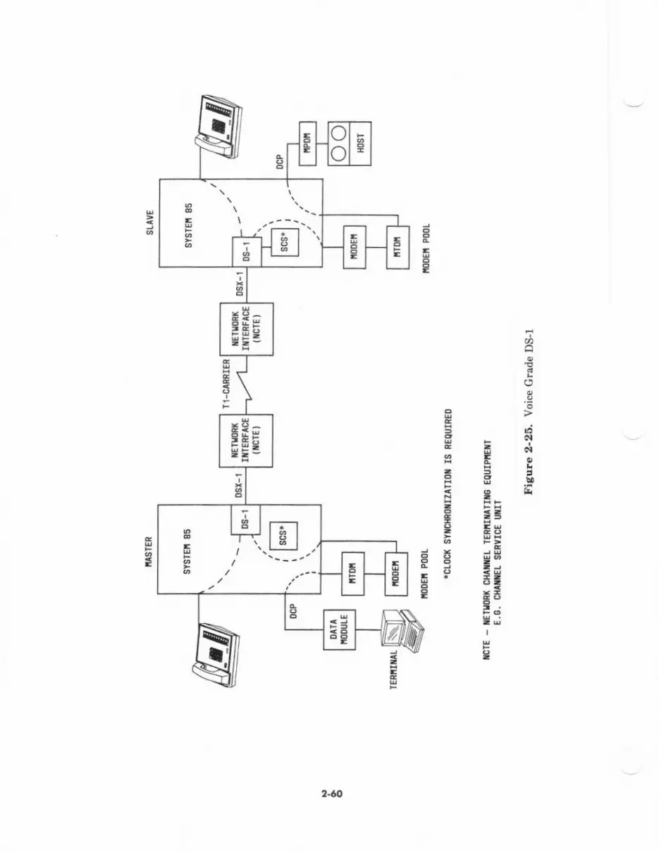
E
,t
.9E>5'da-c!
996i-EE t!
E duz ,,t.:t;I
R
E
3
EE
E
E
t=t.!!...
2.6
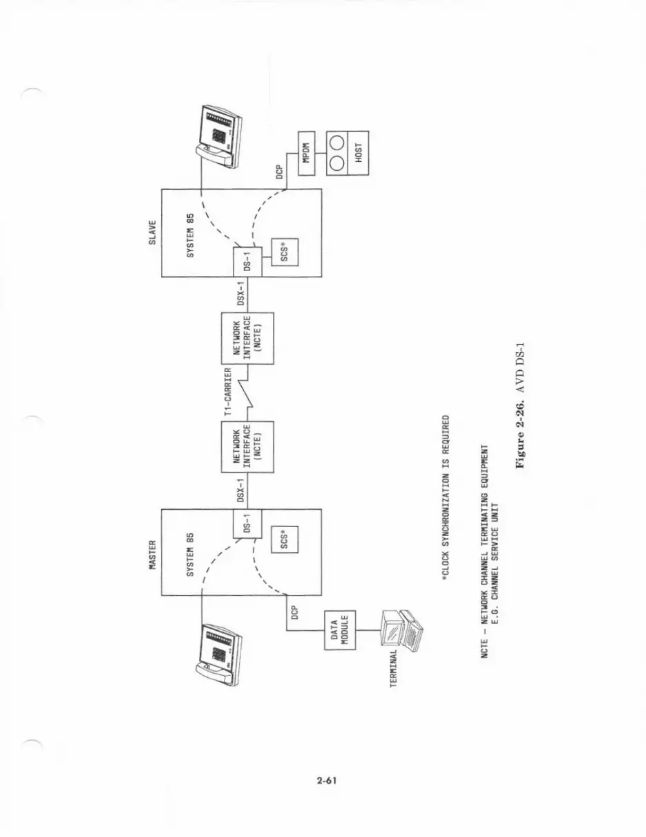
I
ao
€_clHNtd,e,H=aeFai3P tl
t;3
2-61

arl
a{
,Eh
ig --9-c'Ef
E
r3
tE
,,
I
!!fi<tdl
gi=6
3
E
2"62

AnoLg Swir.h Connariv Y
nc I av 16 neari ih 'dniunction
with analoq to iligital conversion transmission prodDcts for
;oTilliJlti;;;"' "i'ii"r'"" p'""iai"s analoglrunk. interfaces ln this arrangemeDt'
t"tu"a-'lri"i,r*tdrt* ,nd voice-grade trunis must-be used to interface to a teminal product
"r"f-". ift" 5a- di"tt"I Banli which i" nSX-r
"ign"t level and D4 mbbed-bit signali4
compatible (see Figure 2-28).
2-63
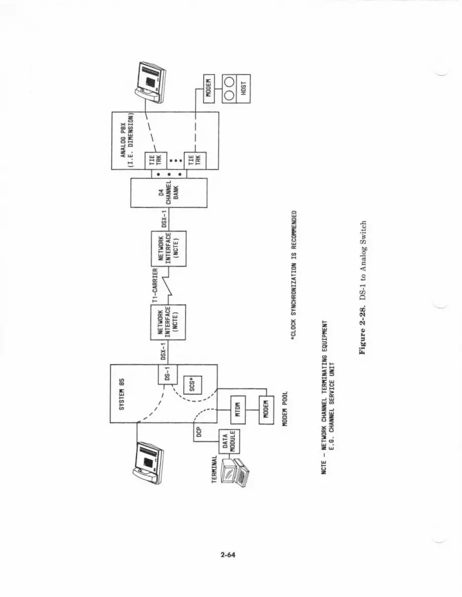
oo
I.Tt.
;
+t tgtt \-u -,
f,t=lsAEa6.luq9-e
tjro-d@Ntr=*:!-!o'58
*=
R E3H EI-
=Et.I
24
,,lu brp l.xu Con n e<riv y
The Channel Dxpansion Multiplexer (CEM) and Channel Division Multipl€xer (CDM) incombination with the System 85 DS-l trunk interface provide extrcmely flexiblearrangements to optimize voice and both switched and point-to-point data networks.
The CEM employs a new signal processing technique which results in a significantly mo!€€fficient digital representation ol Pulse Code Modulat€d voice or voiceband datatransmission. It provides a 2 to 1 compression of voic€band channels which allows up to 48channels of voiceband transmission et 32 kbps per channel to pass over a single DS-lint€rfac€. Two DS-1 interfaces with 24 channels each can pasg through the CEM and exitwith a siirgle DS-1 interface. Voice quality on a compressed channel at 32 kbps is stillsubjectively €quivalent to that at 64 kbps, and voiceband data transmission up to 4.8 kbpgcan b€ supported. The CEM can selectively compress channels so that full 64-kbpsuncompressed chaDnels from eith€r of the two DS-1 inputs can be mixed with compressedvoiceband channels on the DS-1 output. Each uncompressed channel, how€ver, takes up 2 ofthe 48 possible 32-kbps channels on the output.
The CDM prcvides a means to individually input digital transmission channels onto a DS-linterface. A 24th Channel Signaling DS-1 interface from System 85 may only require 15 ofthe 23 possible trunk channels. Th€ DS-1 interface from System 85 may be passed to a CDMwhere the eight unused channels may be allocated to equipment requiring nonswitchedpoint-to-point connectivity.
Care must be €xercis€d wh€n using CDMS and CEMs in conjunction with System 85 DS-1.With zth Channel Signaling, the 24th channel used for signaling and any AVD trunkchannels used for DCP formatted digital data transmission (no data setr or modem poolemployed) requir€ full 64-kbps channels and may not be comprcss€d in the CEM. Onlyvoice-grad€ trunks should be compressed in the CEM. Trunk assignments on System 85 DS-1 channels must be coordinated with CEM channel comprcssions and CDM channelassignments so as to insur€ duplicated channel assignm€nts or unwanted compression isavoided (see Figure 2-29).
2-55

g-!Eg-*
<!EC
E
F
o
ct6t
TFr
=t;-E
Is
i3r9d
t:l6a=
ttt.EE
rEHgi3
24
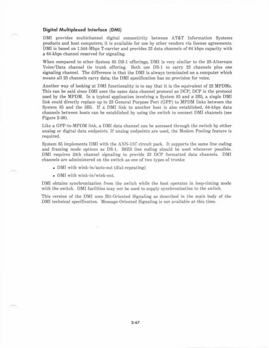
Digirql Mulriploxed lnrerfo.e (DMl)
DMI prcvid€s multichannel digital conn€ctivity between AT&T Infolmation Syst€msproducts and host computers; it is available for use by other vendo$ via license agreements.DMI is based on 1.544-Mbps T-carrier and provides 23 data channels of 64 kbps capacity witha 6d-kbps channel reserved for signaling.
When compared to other System 85 DS-l offerings, DMI is very similar to the 23-AlternateVoice/Data chann€l tie trunk offering. Both use DS-l to ca.ry 23 channels plus onesignaling channel. Th€ difference is that the DMI is always terminated on a computer whichmeans all 23 channels carry data; the DMI specification has no provision for voice.
Another way of looking at DMI functionality i3 to say that it is the €quivalent of 23 MPDMs.This can be said since DMI uses the same data channel protocol as DCP; DCP is the protocolus€d by th€ MPDM. In a typical application involving a System 85 and a 3B5, a single DMIlink could directly replace up to 23 General Puryose Port (GPP) to MPDM links between th€System 85 and the 3B5. If a DMI link to another host is also established, M-kbps datachannels between hosts can b€ established by using the switch to connect DMI channels (seeFigure 2-30).
Like a GPP-to-MPDM link, a DMI data channel can be accessed through the switch by eitheranalog or digital data endftoints. If enalog endpoints are us€d, the Modem Pooling feature isrequired.
System 85 implements DMI with the ANN-11C circuit pack. It suppods the sam€ line codingand framing mode options as DS-r. B8ZS line coding should be used wh€never possible.DMI requires 24th chann€l signaling to provide 23 DCP lormatt€d data chann€ls. DMIchannels arc administ€red on the switch as one of two types of trunks:
. DMI with wink-in/auto-out (dial-repeating)
o DMI with wink-in/wink-out.
DMI obtains synchronization from the switch while th€ host operates in loop-timing modewith th€ switch. DMI facilities may not be used to supply synchronization to the switch.
This version of the DMI uses Bit-Ori€nted Signaling as described in the mein body of theDMI technical specification. Message-Oriented Signaling is not aveilable at this time.
2-6'
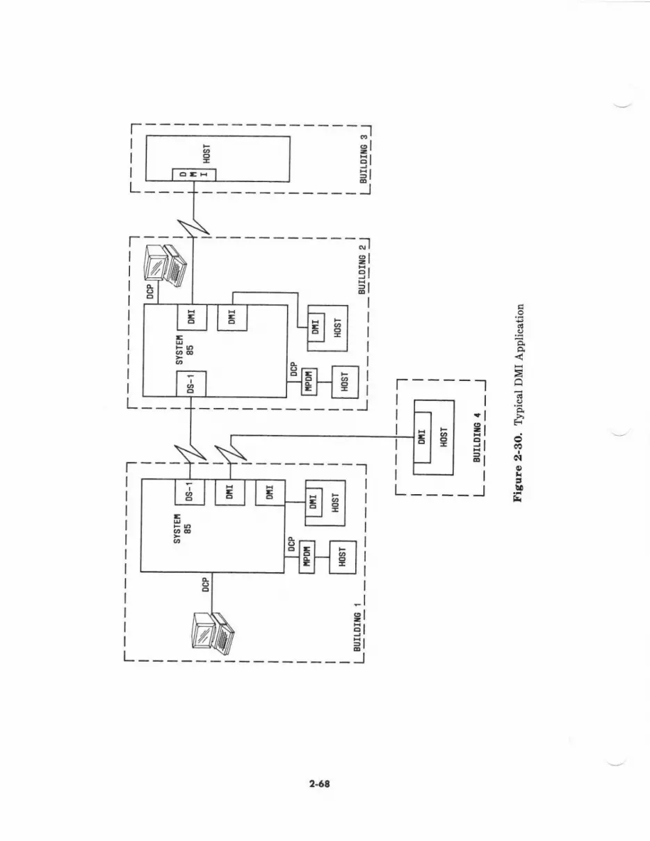
|--:----J9r:l
9lEr
=l
JEI
|------l
L_____J
3
Ea
Er
N
tsr
2.64

Synchronizotion
An accurate network clock is crucial for error-free operation of a digital switch. The digitalswitch uses the network clock to provide ermr-free timing signals for the many concurrentand sequential opentions requircd to switch digital voice and data.
The network clock must be able to synchronize to an external timing sourc€ when int€rfacingto high-speed digital facilities such as DS-1. And it must b€ able to provide satisfactorystand-alone accuracy if an external synchronization source is lost or the network clock is tob€ the synchronizstion source for other digital systems.
When two pieces of digitel equipr[ent using high-sp€€d digital interfaces communicate, theymust be abl€ to synchroniz€ so that no bits will be tost. Without synchronization, the clockfrequencies of two systems may be slightly different and sets of bits referred to as framesmay occasionally be repeated or d€leted. When a lrame is deleted or repeated, it is called aslip. Slips degrade voice quality and cause errors in data or signaling information. Here aretwo examples which show how slips happen:
Examplq If System A's clock frequency causes 10,000 bits to be sent toSystem B in 1 second and System B's clock frequ€ncy allows only9,999 bits to be receiv€d in I s€cond, a slip, or fram€ deletion, inSystem B will occur. Since Syst€m 85 packages bits in bufferedframes and only complete frames are eccepted, a fram€ will be lost.
Example; If System A sent 10,000 bits and Syst€m B tried to receive 10,001bits, a frame would be repeated in Sy6tem B.
Notc.' The bit rates for thee€ examples arc much lower than thoseactually used. These examples are purely illustrative and notintended to imply actual bit rat€s or error probabilities.
A repeat€d or deleted freme has little €flect on the quality of a voice call. Repeating ordeleting whole frames is better than sending a pertial frame since doing so producesannoying clicks. Where slips really caus€ trouble is with digital data or signalinginformation since the loss or rcpetition of a frame will corrupt the intelligence of theinformation. This is why synchronization is essential.
Synchronization for System 85 is handled by the TN-463 System Clock Synchronizer- Thiscircuit is required whenever DS-1 is used with System 85. The TN-463 resides in the TMScarrier for multimodule switches or in the Module Control carri€r for single-moduleswitches.
For more information ebout synchronization, rcfer to AT&T-IS Network and DataServicoB-Reference Madusl (555-025-201).
2-69
lniormolion Syrrcm Nerwork (lSN)
AT&T Information Systems Network (ISN) provides high-speed data communications linksbetween devices in a multistation data processing environment. System 85 can be linked toan ISN system on the same premise to prcvide integrated eccess to the data communicationsdevice on both systems.
The main component of ISN is the Pecket Controller which, among oth€r things, establishesconnections between devices served by ISN. Devices conn€ct to the Packet Controllerthrough int€rfac€ modules such as the Fiber Intedace Module or the EIA AsynchronousIntedace Module (AIM). Interface modules can be locsted in the Packet Controller orhoused in an ISN Conc€ntrator. A fiber-optic cable connects Concentrators to the Pack€tController carrying multiplexed data to and from the devices connect€d to Conc€ntrators.Each Conc€ntrstor uses statistical multiplexing to concentrate up to 40 channels into an8.64-Mbps data stream.
ISN Conne.tiity
The basic link between System 85 and ISN is an EIA conn€ction between an SN- 8 quadEIA port in System 85 and a Z3A Asynchronous Data Unit (ADU) conD€cted to anAsynchronous lnte ace Module (AIM) iD the ISN. The EIA connection establishes a l-waytrunk, which must b€ set for 300; 1,200; 2,400; 4,800; 9,500; or 19,200 bps; autobauding is notprovided. The AIM can be located in either a Concentrator which conn€cts to the PacketController by optical fib€r or in the ISN Packet Controller.
If the Packet Controller is located in another room or anoth€r building, s Concentrator isplaced in a System 85 Auxiliary cabinet and a fib€r-optic cable is run to the ISN PacketControll€r in the other location. If the ISN Pscket Contrcller is located in the same roomwith the System 85 equipment, the two syst€ms are directly linked by EIA connections.
Once tle System 85-ISN link is estatiished:
. The System 85 modem pooling feature provides connectivity between ISN endpointsand remote endpoints accessed through System 85 CO trunks, WATS trunks, FXtrunks, DID trunks, APLT trunks, tie trunks, and ETN trunks.
. End-to-end digital connectivity with ISN endpointe is provided lor endpoints whichare serv€d either directly by the local System 85 switch or by a remote System 85/?5\r'ith DS-1 trunks to the locel System 85.
2-7l)
3. SYSTEM HARDWARE
ovERvtEllt
This section describ€s the System 85 switch hardwate within the following major areas ofcoverage:
. Basic Switch Cabinets
. Syst€m Cabinet Configurations
. Cabinet Equipment
r Carriers
. Circuit Packs
. System Int€rconnections
. Switch E4uipm€nt Code Summary.
BASIC SWTCH CABINETS
The following bisic hardwsre units can be used to configure a System 85 digital switah:.
. Unduplicated Common Control Cabinet (J58886J)
r Duplicated Comrnon Control Cabinet (J58886K)
. Time-Multiplexed Switch (TMS)/Remote Module Interface (RMI) Cabinet (J58886F)
. Module Control Cabinet (J58886B)
. Port Cabin€t (J58886C)
. nemote Group Housing (J58889AN).
3.1

Unduplicorcd C.onmon Crntrcl Cdbin.t (J58886J)
Al! Unduplicet€d Commotr Control Cabinet (see Figure 3-f) providB a standard reliabilitycommon control tor the digital swit-ch. This cobinet contains the followirg equipmelt:
. An unduplicated alarm panel
. A total of up to thre€ port and,/or DS-I/MFAT carriers
. One common control calrier
. A dc ftn ass€Ebly with frequency g€nerator
. A high capacity mini-recorder
. One dcldc converter unit
. A bus bor.
In stsndard ac-F)crened systems, this cabinet b equipp€d with a battery reserve unit(dedicatad to the common contrcl car er fo! nominal holdover) and a dc filter for -48 Vpower from sn edac€nt Module CoDtrol Cabin€t.
In cost-reduced ac-powered systems, this cabinet is equipped with an ac dietribution unit,bulk Off-Line-Switcher (OLS) power supply, and OLS battery reserve udit mounted at thebottom. The dcldc converter unit and mini-recorder are moved up and mounted under thefaa assembly.
In syst€ms power€d from a strndby power plant, this cabinet is equipped with a standbypower dc filter for two -48 V powe! sources,
If all carrier positiom are equipp€d in th€ cabinet, an ED-1E430-?0,G2 thermal sensor.$embly is equipped as psrt of ihe alerm psnel; otherwise, an ED-1D130-?0,G1 themalaensor s8s€mbly is placed above the topmost csrrier. One Unduplicated Common ControlCabinei is required in an unduplicated common contml system.
3-2
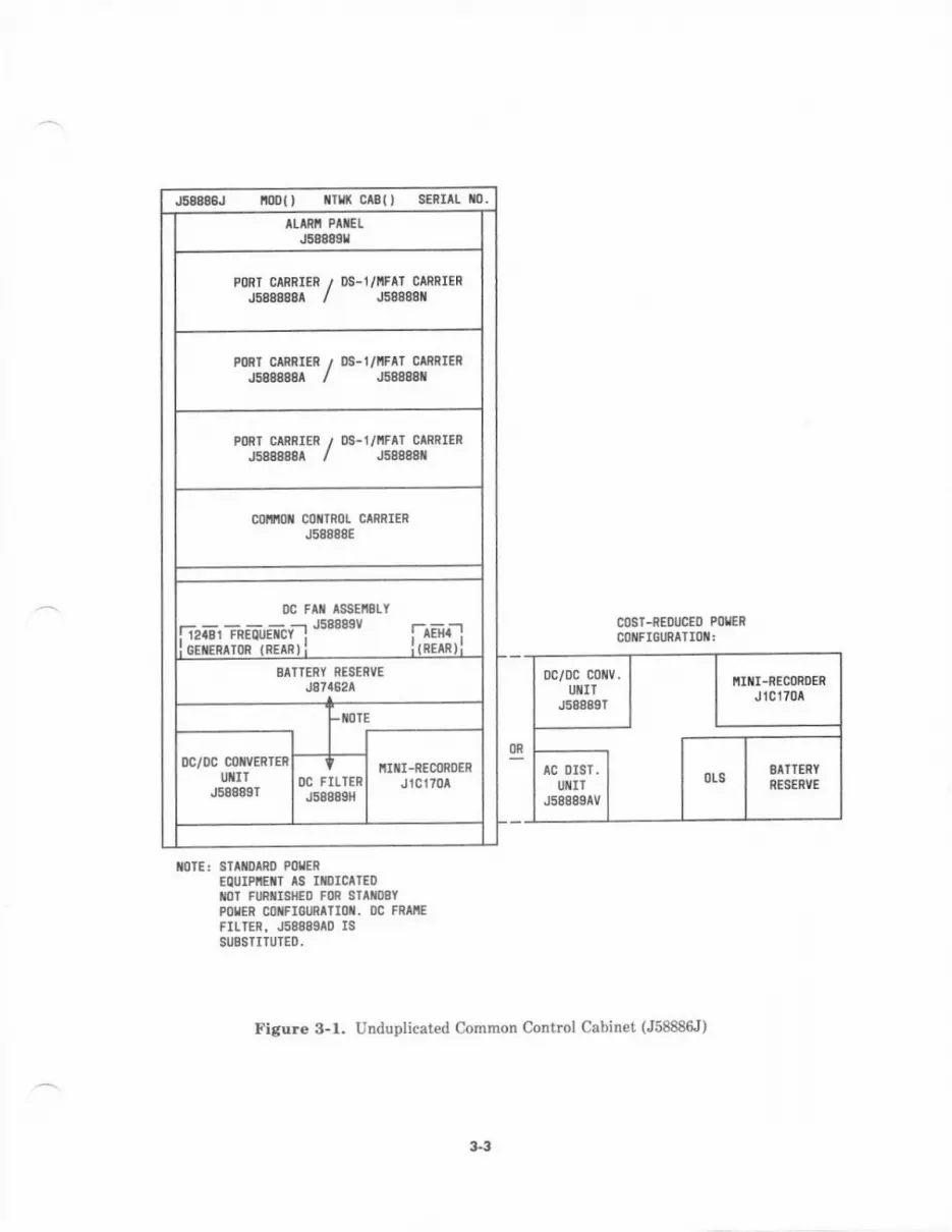
J5888gJ nl) $ra( crll) s€Rr^| 10.
PORT CARRIER / Ds-l/I'IFA] CARRIER
J588888A / J588881
mRI c flnIER , os-t/iFll GrnRIEn.lsdosoar / J588a8t
PoRI CTnRIER ,/ Ds-t/llFlT CAnRIEnJ588888A / J588881
col'ltoi cotTRol CARRTER
J58888E
!c Flt ^s8EiaLY------J50889V! i2IBI FREOUEICY :
,iEiiririiii'iiiin r I
SAI]ERY RESERVE
J87162A
c0sT-nEqicEo P0IIRMiFIGURATIOT:
mTE! ST DIRO PoIEREQUIPE|T IS IIICAT€O10] FURTI$IED FOR SIIiDEIPOIIER GOiFIOINAIIOi. OC FRIIf,FILTER. J588SEAD JSSUBSTITUIEO.
Figure 3-1. Unduplicat€d Common Conhol Cabinet (J58886tr)
33
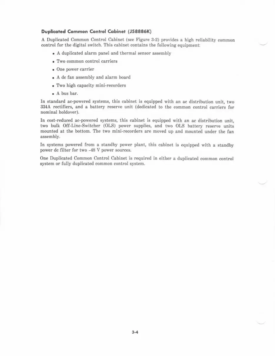
Dsplicqted common Crntrol Cdbinet (J58886K)
A Duplicated Common Control Cabinet (see Figure S-2) provides a high reliability commoncontrcl for the digitel switch. This cabin€t contaids the following equipment:
. A duplicated alarm panel and thermal s€nsor assembly
. Two common control carriers
. One power carrier
. A dc fan assembly and alarm board
. Two high capacity mini-recorders
. A bus bar.
In standard ac-pov/ered systems, this cabinet is equipped with an ac distribution unit, two334A rcctifiers, and a battery reserve unit (dedicated to the common control carriers fornominal holdover).
In cost-rcduced ac-powercd systems, this cabinet is equipped with an ac distribution unit,two bulk Off-Line-Switcher (OLS) power supplies, and two OLS battery reserve unitsmounted at the bottom. The two mini-recorders are moved up and mounted under the fanassembly.
In systems powered from a standby power plant, this cabinet is €quipped with a standbypower dc lilter for two -48 V power sources.
One Duplicated Common Control Cabinet is required in €ither a duplicated common controlsystem or fully duplicated common control system.
3-1
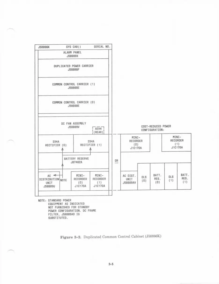
J388881( SYS Cr8{) SERrll r0.
TLIRi PIIELJ58889r
OIPLICITEO MTER CMRIERJ58888F
collnt c0irRot clRRrER (1)J58888E
colitot cotTRot GARRTER
J58888E(0)
0c FAt lssEltSLYJ58889V !--^Eii-!
Ir nrrn t I
33tARECIIFIEI {O)
+
3:!lAREC]IFI€R (I)
+
SIT]ERY RESERV€
J87/t624
.lIIOTE
ir r- I ttrtl-nrconoen I neconosn
ro) | trtJ1C170A I J1C170^
COST-NEDUCEO POIIER
mxFIoURATIoil.
tlolE: SIAflolRo PoIEREQUIPiEiT TS IiDICAIEDMT FlntlsllED FOR 8IAIOBIPOSER C FIGInAIIOT. DC FRIIfFIII€R. J588&IAD ISSIJBSTIIUTEO,
Figure 3-2. Duplicated Common Control Cabinet (J58886K)
3-5
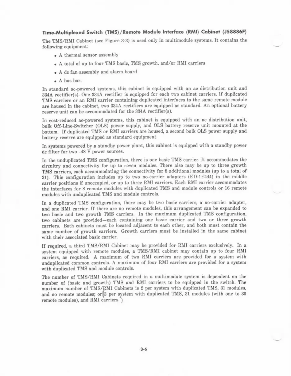
Tim€-Muhipl.xcd Swirch (TMS)/Remotc Module lnterfoce (RMl) Ccbinct (J58886F)
The TMS/RMI Cabin€t (see Figure 3-3) is used onlv in multimodule svst€ms. It contains thelollowing equipmedt:
. A thermal sensor assembly
. A total of up to four TMS basic, TMS gro\a'th, andlor RMI carriers
. A dc fan assembly and alarm board
. A bus bar.
In standard ac-powered systems, this cabinet is equipped with an ac distribution unit and
334A rectifier(s). One 334A rectifier is equipped for each two cabinet carriers. If duplicatedTMS carriers or an RMI car.ier containing duplicated interfaces to the same remote modul€
are housed in the cabinet, two 334A rectifiers are equipped as standard. An optional batt€ryreserve unit can b€ accommodated for the 334A rectifier(s).
In cost-r€duced ac-poqTered systems, this cabinet is equipped with an ac distribution unit,bulk Off-Lin€-Switcher (OLS) power supply, and OLS battery reserve unit mounted at thebottom. If duplicated TMS or RMI carriers are housed, a second bulk OLS power supply andbattery reserv€ are equipped as standard equipment
In systems powered by a standby power plant, this cabinet is €quipped with a standby powerdc filier for two -48 v power sources.
In the unduplicated TMS configuration, ther€ is one basic TMS carrier. It accommodates thecircuitry and connectivity lor up to seven modules There also may be up to three grcwthTMS cafiiers, each accommodating the connectivity for 8 additional modules (up to a total of31). This configuration includes up to two no-carrier adapterc (ED-1E444) in the middlecarrie! positions if unoccupied, or up to thr€e RMI carriers. Each RMI carrier eccommodates
the interlac€s for 8 remote moduies with duplicated TMS and modul€ controls or 16 remotemodules with unduplicated TMS and module controls.
In a duplicated TMS configuration, there may be two basic car.iers, a no-carrier adapter,and one RMI carrier. If there are no temote modules, this arrangement can be expanded totwo basic and two growth TMS carriers. In the maximum duplicated TMS configuration,two cabinets are provid€d-each containing one basic carrier and two or three growthcadiers. Both cabinets must be located adjacent to each other, and both must contain thesame numb€r of gtoEth carriers. Groqrth cariers must be installed in the same cabinetwith their associat€d basic carriet.
If rcquired, a third TMS/RMI Cabinet may be provided for RMI carriers exclusively. In asystem equipped with remote modules, a IMS/RMI cabinet may contain up to four RMIcarders, as required. A maximum of two RMI carri€rs are provided for a system withunduplicated common controls. A maximum of four RMI carriers are provided for a syst€mwith duplicated TMS and module controls.
The number of TMS/RMI Cabinets required in a multimodule system is dependent on thenumber of (basic and erowth) TMS and RMI carriers to be equipped in the switch. Th€maximum number of TMS./RMI Cabinets is 2 per system with duplicated TMS, 31 modules,
anil no remote modules; orl3 per system with duplicat€d TMS,31 modules (with one to 30
remote modules), and RMI csrriers.)
3-6
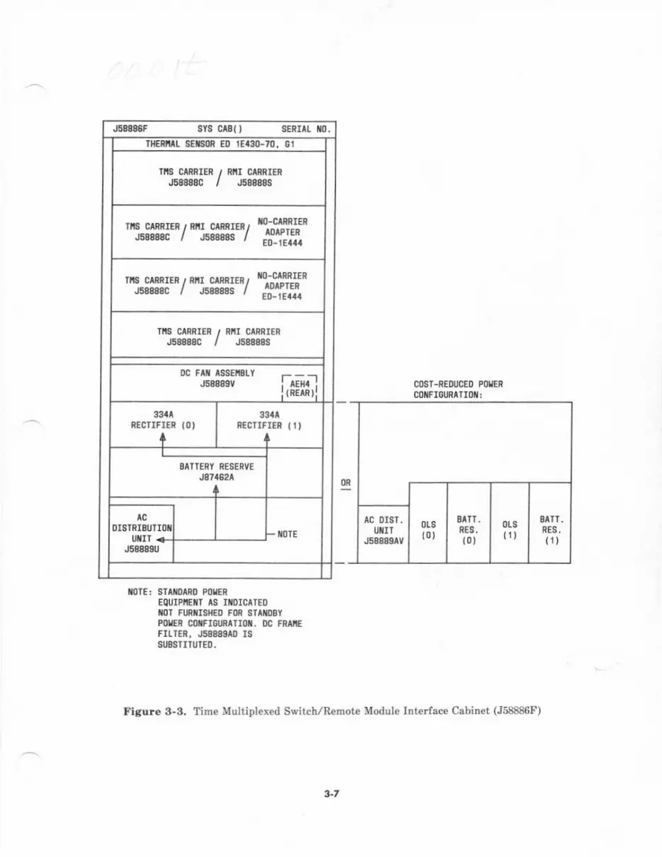
J5888SF SYS CABo SERTTL ilo,THERIIIL SEXAOR EO 1EI3O-70. Gl
rrs ctflRIER / RiI CARRI€RJ58888C / J58888S
'TuS![I"/'"!3ilii'Y'fi'ffii'
":,$i31"/ "LS8!a'Y'hi#li-
TfiS CTRRIER / RiI CARPIERJSaAAaC / JsAtadS
0c FAil assEttStYJ58889V laEr;-l
I rRE^R)l
33alREC]IFTER IO'
+
33tlRECIIFIER (1)
+
BATTERY RESERVE
J874521
A
- il0TE
AC
OISTNIBUTI,OI{
J588ASU
COSI-REDUCEO PO{ENCOilFIOURATI()il:
liolE: ST^ilDARD P0IEREQUIPIIEIIl AS IIIOICATEOIIOT FURIIISHEO FOR STIIIOBYPOI'ER CONFIGURA]I()N. OC FRAIIEFILTER, J58889I0 ISSUBSIIIUTEO.
Figure 3-3. Time Multiplexed Switch/Remot€ Module Interlace Cabinet (J58886F)
3-7
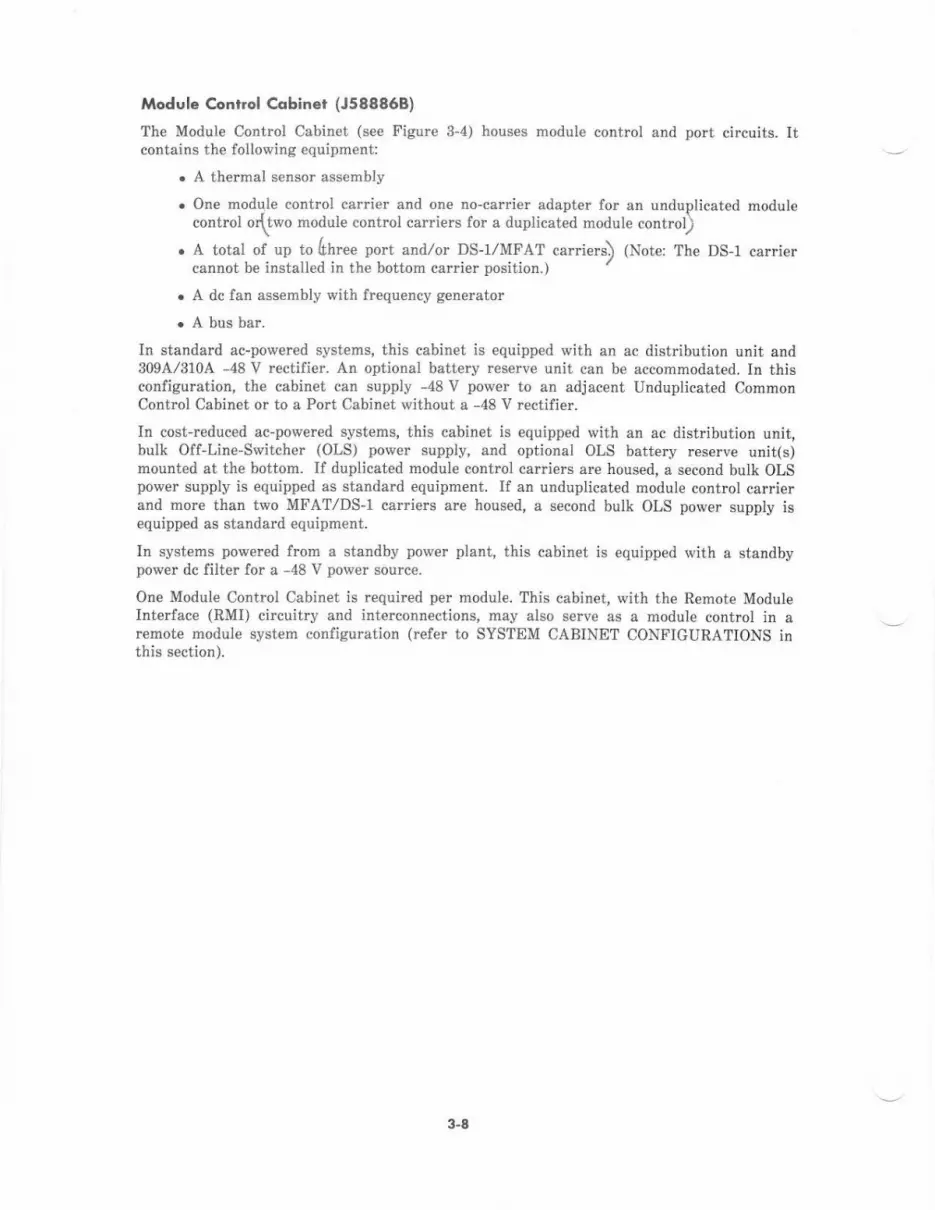
Module €onrrol Cqbiner (J588868)
The Module Control Cabinet (see Figure 3-4) houses module control and port circuits. Itcontains the following equipment:
. A thermal sensor assembly
. One modqle control carrier and one no-carrier adapter for an unduplicated modulecontrol odtwo module control carriers lor a duplicatid module control)\
. A total of up lo(hree porr and/or DS-I/MFAT carriers) (Note: The DS-I carriercannol be installed in the botlom carrier posilion.,
. A dc fan assembly with frequency g€n€rator
. A bus bar.
In standard ac-powered systems, this cabinet is equipp€d with an ac distribution unit and309A,/3104 -48 V rectifier. An optional battery reserve unit can be accommodated. In thisconfiguration, th€ cabinet can supply -48 V power to an adjacent Unduplicated CommonControl Cabinet or to a Port Cabin€t without a -48 V rectifier.
In cost-rcduced ac-powered systems, this cabinet is equipp€d with an ac dist bution unit,bulk Off-Line-Switcher (OLS) power supply, and optional OLS battery rcserve unit(s)mounted at the bottom. If duplicated module control carriers are housed, a second bulk OLSpower supply is equipped as standard equipment. If an unduplicated module control carrierand more than two MFAT/DS-I carriers are housed, a second bulk OLS power supply isequipped as standard equipm€nt.
In syst€ms pov,/ered from a standby power plant, this cabinet is equipped with a standbypower dc filter for a -48 V power source.
One Module Control Cabinet is required per module. This cabinet, with the Remot€ ModuteIntedace (RMI) circuitry and interconnections, may also serve as a module control in arcmote module system configuration (refer to SYSTEM CABINET CONFIGURATIONS inthis section).
3-a
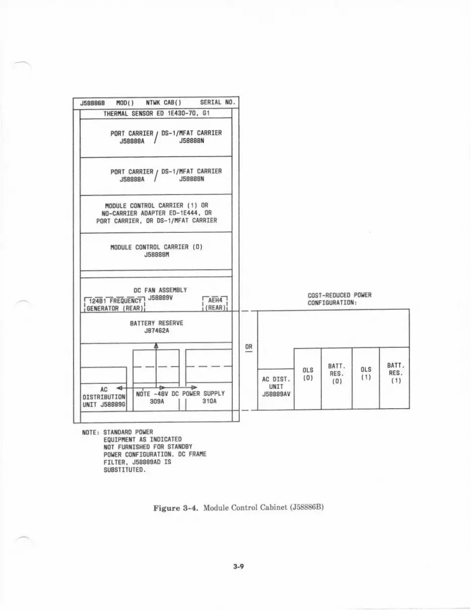
J588889 t{)Dl' lTll( c Bl, s:Rrll t0.mER L 8EilSoR E0 1E130-70, Gl
PORI CIRRIER / DS-I/NFIT CIRRIENJ68888A / J58888il
PMT CMRIER , DS-1/IFAI CIRBIERJES888A / J58A8gt
ioDlJLE C0lrR0L c f,nlER (ll mxo-crRnlEn mlPrER ED-lE44l, 0R
PORI CMRIER, OR DS-I/IIFAT CIRRIEN
IIODUI.E COTTROL CIRRIER (O'J58888tt
0c Fli lssElSl-YFiaiiEr-rnEEuElci'lJsmsv l-rEll-'llnrsmrnp iprrnrl :rnErRri
BITTERY RESERVE
J87a62A
..8V OC POUER SUPPLY
3os^ I I 310rUTIT
cosr-nEoucEo PoL€RcoxFr6uRtlt0i:
MIE: SIII|)INO POTER
EQUIPITTT IS II)ICATEDrc] FUNIISIIED FOR STAEEYPOIER CITFIGURATIOII. DC FRIIIEFrLIEn, J5888910 rSSUBS]ITIITEl).
Figule 3-4. Module Control Cabin€t (J588868)
3.9
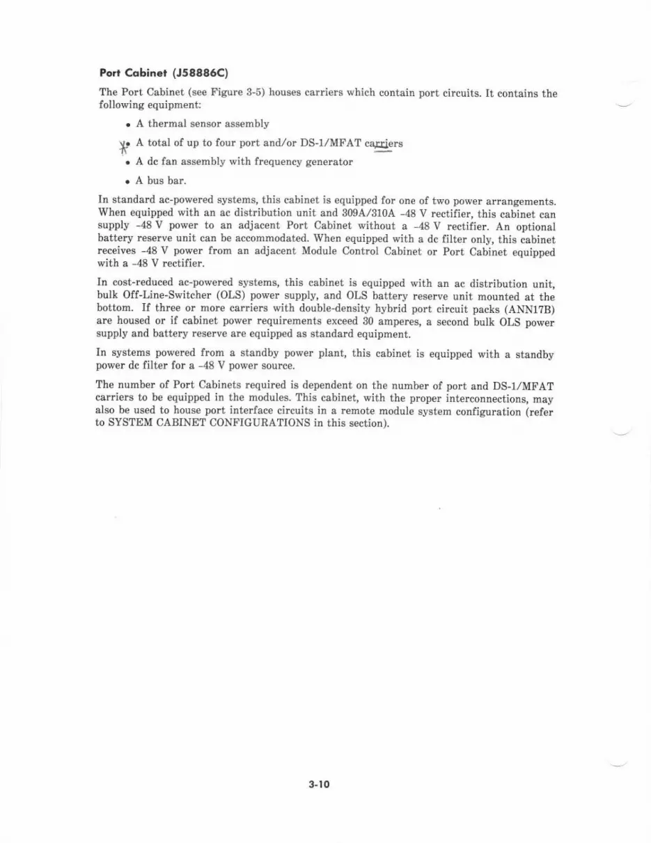
Port Cobinet (J58886C)
The Port Cabinet (see Figure 3-5) houses carri€rs which contain port circuits. [t contains thefollorving equipment:
. A thermal sensor assembly
*' A lolal of up to four port andlor DS-I/MFAT cEqiers
. A dc fan assembly with frequency genentor
. A bus bar.
In standard ac-power€d systems, this cabinet is equipped for one of two power arrangements.Wh€n equipped with an ac distribution unit and 3094/310A -48 V rectifi€r, this cabinet cansupply -48V power to an adjacent Port Cabinet without a 48V rcctifier. An optionalbattery rcserve unit can be accommodated. When equipped with a dc filter onty, this cabinetreceives -48 V power from an adjacent Module Control Cabinet or PoIt Cabin€t equippedwitha-4SVrectifier.
In cost-rcduced ac-pov{ercd systems, this cabinet is equipped with an ac distribution unit,bulk Off-Line-Switcher (OLS) power supply, and OLS battery res€rve unit mounted at th€bottom. If three or more carriers with double-density hyb d port circuit packs (ANN1?B)are housed or if cabinet po\rer requircments exceed 30 amperes, a second bulk OLS powersupply and battery reserve are equipped as standard equipment.
In systems po\r,ered from a standby power plant, this cabinet is equipped with a standbypower dc filter for a -48 V power source.
?he number of Port Cabinets required is dependent on the number of port and DS-I/MFATcarriers to be equipped in the modules. This cabinel with the proper interconnectjons, mayalso be used to house port interface circuits in a remote module system configuration (referto SYSTEM CABINET CONFIGURATIONS in this section).
3-to
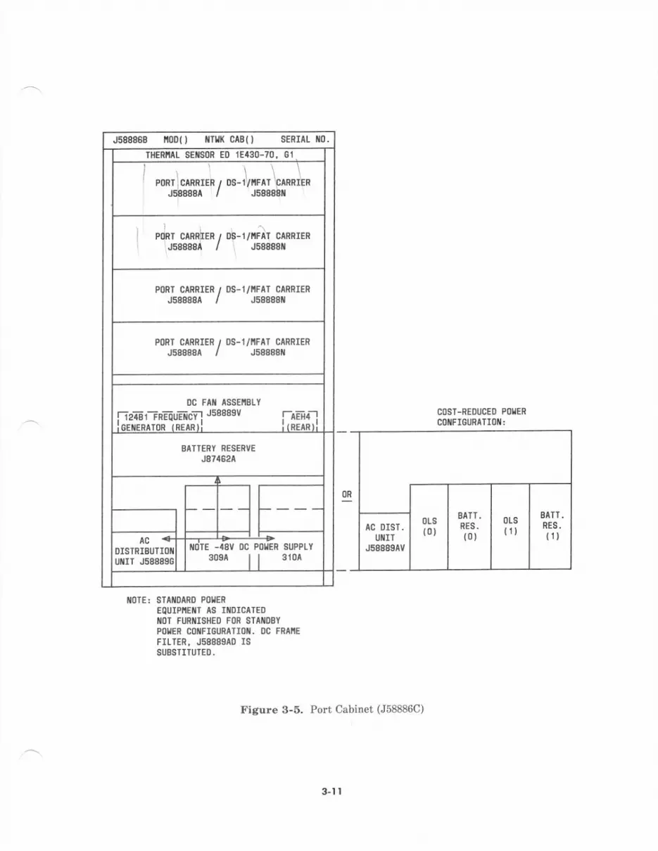
J588888 r,r00{J i/rrK CABO SERTAL rio.
IHERNAL SEIISOR ED 1E430-70. Gl
] ,orrJrn*rrrr, or- Jrrrnr 'oo**)r,.iinnnnr / JsEeSar
I pJnr cmnhrn, Db-1,/iFAT caRnIERrsdssdi / I Jsssssi
PoRT CARRIER / DS-1/l'tFAT CARFIEnJs88a8A / J58888il
P()NT CARRIER / OS-1/NFAI CARRIERJ58A88A / J58888t{
DC FAI{ ASSEIIBLY
| 12481 FnEo!EICY ! ""'"' ! AEH4 I
lerwprron inrrnrl ltnuntl
BAITERY RESERVEJe?4e24
OISTRIBUTIOilur{rT J58889C
-I8V DC POIIER SUPPLI30sa | | 3104
AC DIST.UIIIT
J588894V
COST-REOUCEO Pl)IERCOIFIGURATIOII:
flolE: STAil0AR0 PoIEREOUIPI,IEI{T AS IXDICATEDIIOT FURIIIISHED FOR STAI{DBY
POIER COIIFIGURATIOII. OC FRAI'IE
FILTER, J58889A0 ISSUESTITUTED.
Figure 3-5. Port Cabinet (J58886C)
3-l I

Remot. Group Hou3ing (J58889AN)
Th€ Remote Gloup Housing (see Figure 3-6), though not a full-size Port Cabinet, is a basic
switch hardware unit that houses port interface circuits in a remot€ group system
configuration (refer to SYSTEM CABINET CONFIGURATIONS in this section). Similarlv toa cabinet, this unit also provides fan cooling, pov,r€r rectification, and thermal det€ction(with over-t€mperatur€ shutdown capability) to support the equipment. within. An inveltercircuit provides ringing current for the polt interfaces. This housing (install€d at the renotelocatio;) may be mounted in an Auxiliary Cabinet, wall-mounted, or set on a table or shelfBoth nominal holdover and long-t€rm battery r€serve capabilities are optional
When mounted in an Auxiliary Cabinet, the Remote Group Housing is powered through the
cabin€t -48 V rectifier or by an extemal battery plant. The dc-dc conv€rter in the housing
converts this input voltege to the low_levet dc voltages required by the port interface
circuits. For cabinet mounting, a circuit ground is required in addition to lightning ground
When wall- or shelf-mounted, the Remote Grotrp Housing is powered from an ac feeder
protected by a dedicated customer-prcvided fuse or circuit breaker. No disconnect switch, ac
protector cabidet, or ac load center is required.
IEIOIE OId',P IIIYEIFICE
c
cBlt c818
@clc)e)RCT CSU C81 CSU
PrR tux ^t-lla
-_./ '@@@@GROL HLD COII CEII
@
otlorrltl, -,, u,oro'
r2ovAc/laavocPORT
PORI O
IIITFCE IlriilSB)
o
PORT
PORT
D/t
D5
o
Figure 9-6. Remote Croup Housing (J58889AN)
3.12

SYSTEM CABINET CONFIGURATIONS
Overview
System 85 switching and interlace equipment is housed in th€ basic switch cabinets installedin an equipment rcom. Switch cabinets that can contain any pott interface circuits (line,trunk, or peripheral) are referred to as N€twork Cabin€ts. Switch cabinets that containcontrol or switching circuitry exclusively are referred to as System Cabinets. (An exceptionto this rule is the unduplicated Common Control cabinet, which is always considered aNetwork Cabinet, with or without port or DS-1/MFAT carriers.)
Switch cabinets are configured in functional groups known as modules. A module consists ofup to four N€twork Cabinets: a module control cabinet and up to thrce port cabinets. ANetwork Cabinet associat€d with a particular module houses port or DS-I/MFAT carrie$for that module only. A single Network Cabinet cannot hous€ port or DS-I/MFAT carriersassociated with different modules.
A system in th€ basic configumtion consists of a single module with one common controlcabinet. A standard multinodule configuration consists of up to 15 modules, along with twoSystem Cabin€ts (one duplicated common control and one TMS/RMI). An expandedmultimodule configuration consists of 16 to 3l modules, along with up to lour SystemCabinets (one duplicated common control and up to three TMS/RMI).
Th€ internal administrative assignments for cabinet id€ntification within the switchingsystem designate each cabinet with a 2-digit module identifier and cabinet identifi€r. Moduledesignations range from 00 to 30 (31 modules), plus 99 for System Cabinets. The cabinetidentifiers range from 0 to 3 (four cabinets per modul€) for module numbers 00 through 30and nodule numb€r 99. The physical carrier position designation within any cabinet is 0, l,a and 3 from bottom to top-
In standard systems configured for ac pow€r input, only certain cabinets need be equippedwith r€ctifiers. This is dictated by physical cabiret pairing for power arrangements. In asingle-module system or th€ first nodule of a multimodule system with unduplicatedcontrols, the module control cabinet must be adjacent to the common control cabinet. Bothcabinets derive power from the 309A/310A -48 V rectifi€r located in the module controlcabin€t. The TMS and duplicated common control cabinets arc always equipped with 3344-48 V rectifiers for internal use only. Additional Network Cabinets are paired (one sharingrectifier pow€r with another cabinet not housing a rectifier). A port cabinet not equippedwith a -48 V rcctifi€r must derive power from en adjacent module control cabinet or fromanother port cabinet with a 309A/310A rcctifier. Any pair of cabin€ts sharing power mustbe associated with the same module-
In cost-reduced ac-pow€red systems and in systems configur€d for dc power input from astandby power plant, -48 V dc is fed to each cabinet individually. These arrangements arenot subj€ct to cabinet pairing restrictions for power arrangements. In these cas€s, themodule control in a single-module system or the first module in a multimodule systemshould still be placed adjacent to the common control, which may still be associated with themodule (housing port circuits).
System 85 can be provided in four dilferent configurations rclated to system reliability. Thediffercnce between th€se configurations is the amount of duplication of major subsystems.These options include:
. Standard reliability-no duplication of major subsystems
. High reliability duplicated common controls
3-r3

. C tical rcliability-duplicated common controls, duplicated TMS, and duplicatedmodule control(s)
. Clitical reliability with battery reserve-same as critical reliability with the additionof the long-term batteiy resene option.
Two edditional system configuration options-remote modules snd remote groups-provid€grcater flexibility to basic switch interface capabilities. These options allow groups of voiceand data terminals at remote locations to interface dircctly to the main system switch, thusmaking them functionally equivalent to on-premises terminals. The remote module optionplovides this capability at the network module level, while the remote group option providesthis capability at th€ carrier or subcarrier level through dedicated port interfaces.
Slondord Reliqbiliry Configu.otion
Figrr€ 3-7 illustrates the module/cabinet/carrier layout for a standard reliability systemconfigured with standard ac power input and optional battery reserve units for nominalholdover. The module control cabinet(s) comes equipped with one module control csrlier(calrier position 0) and can accommodate up to thr€e port and/or DS-I,/MFAT csrriers.How€ver, if uwrading to duplicated controls is a serious luture consideration, a carrierspace (carrier position 1) can be left vacent to accommodate the subsequent addition of asecond module control carrier. In this case, a total of only two port and DS-I,/MFATcarriers can be accommodated in the module control cabinet(s).
The module control cabinet in a sirgle-module system or the first module in a multimodul€system must be adjacent to th€ common control cabinet. The common control cabinetcontains port or DS-I/MFAT carriers for the first module and must derive power from thigadjacent cabinet. Additional port cabinets with and without rectifi€rs ar€ provided fo. eachmodule as requircd. [f RMI carri€rs are not required in a multimodule syst€m, a single TMScabinet can accommodate th€ TMS basic and growth carriers for a full 3l-modul€ system.
In this configuration, the TMS cabinet is a System Cabinet, while the common controlcabinet. module control cabinets, and port cabinets are all Network Cabinets.
3.14
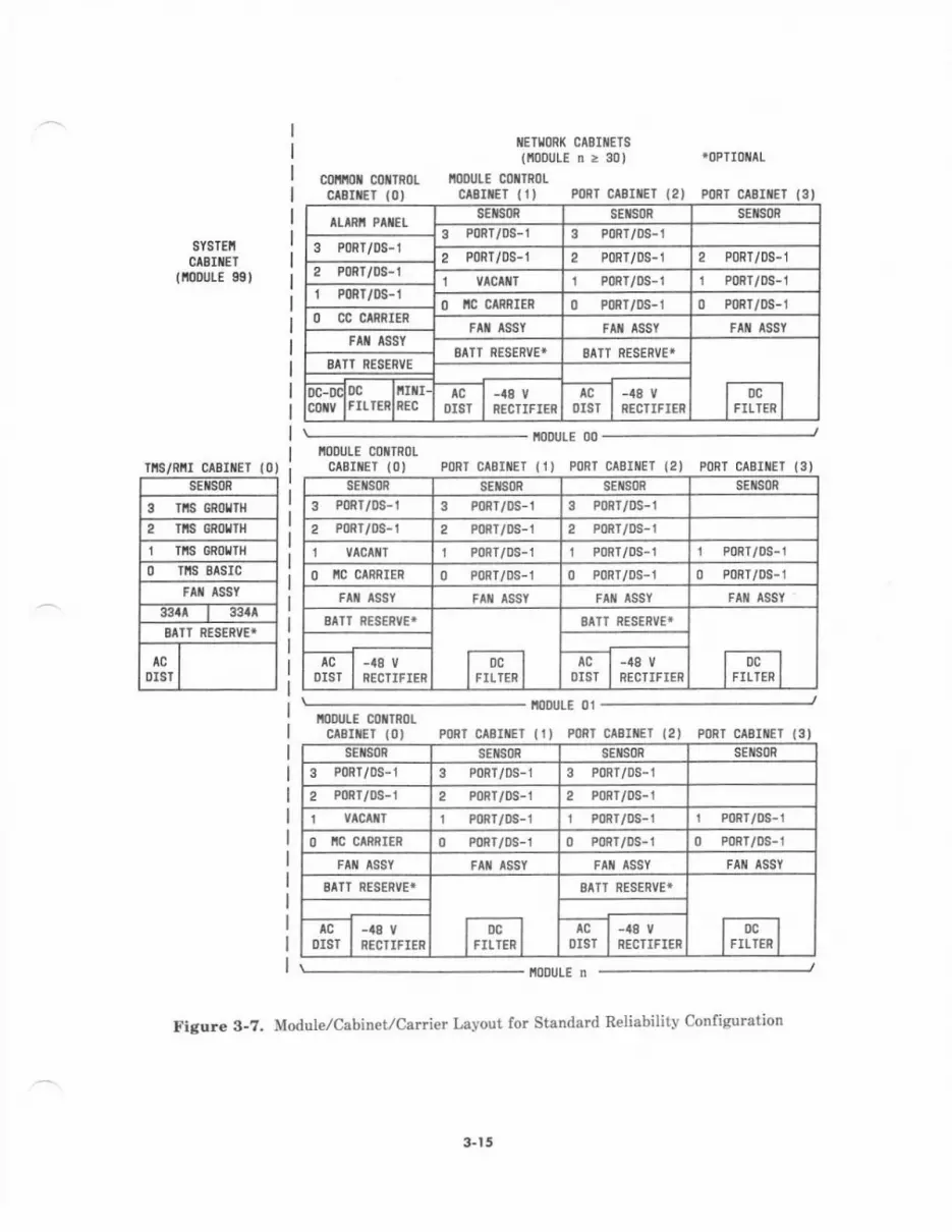
SYSTEI'CABIIIET
(ioourE 98)
rs/Rttr clB /ET (0)SEIS0R
3 S GnoUIt
2 Tlts GRotTtl
Tis GRolltlO TI,IS BASIC
FAT ASSY
33/u 334t
SATI RESERVE+
AC
DIST
IIEIIORK CASITETS(i0DULE n> 30) *0PII0IIAL
cottlt0il c0tTRoL llooulE coxlRotclsItET {01 clEIiEr (r) P0RT clBriEr (2) PoRr c srrEr {3,
ALARII PAflEIsEiso8 sEtsoR sEilsoR
3 PoRT/0S-1 3 P0RT/08-13 PoRT/!S-1 2 PoRT/0S-1 2 PoRr/0s-1 2 PoRT/0S-12 P0nT/DS-1 1 VtCAttT r PoRT/DS-1 1 PORT/DS-Jr P0Rr,/0s-1 O IC CTRRIER 0 PoRr/os-r o P0Rl/0s-1O CC CARRIER
FAII ASSY FIII ASSY FA ASSYFAfl ASSY
gATT NESERVE* EAIT RESERVE'
i,,lg,*l
SATI RESERVE
DC.D(c0iv
DC lilfll-rrrrenlnrc DISI
-48 vRECTIFIER
AC
DIST-48 V
RECTIFITN
IIODUTE C(]NTR()L
CABITET (O) PORT CABIIIEI { 1) PORT CABIIIET {2) PORT CABIiIET (3)
ioDt LE 00
ltooutE 01IODULE Cl)iTRO!
crBriET (0) p0RT clBrlEt (rJ PoRT caEUtET (2) poRr clErrEr {3)sEtsoR sEils0R sEits0R SE SoR
3 PonT/0s-1 3 P0RT/DS-1 3 PoRt/0s-1
2 P0RI/DS-1 2 P0RT/0S-1 2 PoRT/DS-1
vAcAttT r PonT/Ds-1 r PoRT/oS-r 1 P0Rr/0s-1
O IIC CARRIER 0 PoRr/Ds-1 0 PoRT/DS-l 0 P0Rr/0s-1
FAiI ASSY FAIII ASSY
BAIT RESERVE*
IDclrrrrrn
EATT RESERVE*
loclI rrlren I
tcOIST
-48 V
NECTIFIERtc
0Is1-48 vRECTIFIER
I,IODULE N
figure 3-?. Module,/Cabinet/Carrier Lavout for Standard Reliabilitv Configuration
sEfls0R SEIISOR SEIISOR sEils0R
3 PoRT/0S-r 3 P0RI/0S-i 3 PoRT/oS-i
2 PoRt/os-1 2 PoRr/os-r 2 PoRT/oS-1
I P08T/DS-1 1 PoRT/oS-1 1 PoRT/0S-1
O IIC CARRIER 0 PoRT/DS-1 0 P0RT/oS-1 0 PoRT/oS-1
FIN TSSY F t tssY FAI{ ASSY
BTTI RESERVEi
loc 1
I rrrren I
SATI RESENVIT
oclrrrren I^cOIST
-48 V
RECTIFIER OIST-48 V
RECTIFIER
3-r 5
High Reliobilily Conligu.qtion
Figure 3-8 illustntes the module/cabinet/carrier layout for a high rcliability systemconfigured with standard ac power input and optional battery reserve units for nominalholdover. The module contml cabinet(s) comes equipped with one module control carrier(car er position 0) and can accommodate up to three port andlor DS-1/MFAT caniers.However, if upgrading to duplicated controls is a serious future consideration, a carrierspace (canier position l) can be left vacant to accommodate the subsequent addition ol asecond module control car er. In this case, a total of only two port and DS-I/MFAT car elscan be eccommodated in the module control cabinet(s).
The duplicated common control cabinet does not house port or DS-1,zMFAT carriers andcontains two 334A -48 V rectifiers for internal po*er. Additional port cabin€ts with andv,/ithout rcctifiers are prcvided for each module as requircd. If RMI caniers are not requiredin a multimodule system, a single TMS cabinet can accommodate TMS basic and grorrthcarriers for a full 31-module system.
In this configuration, the duplicated common control cabinet and TMS cabinet are SystemCabinets, while the module control and po cabinets arc all Network Cabinets.
3-t 6
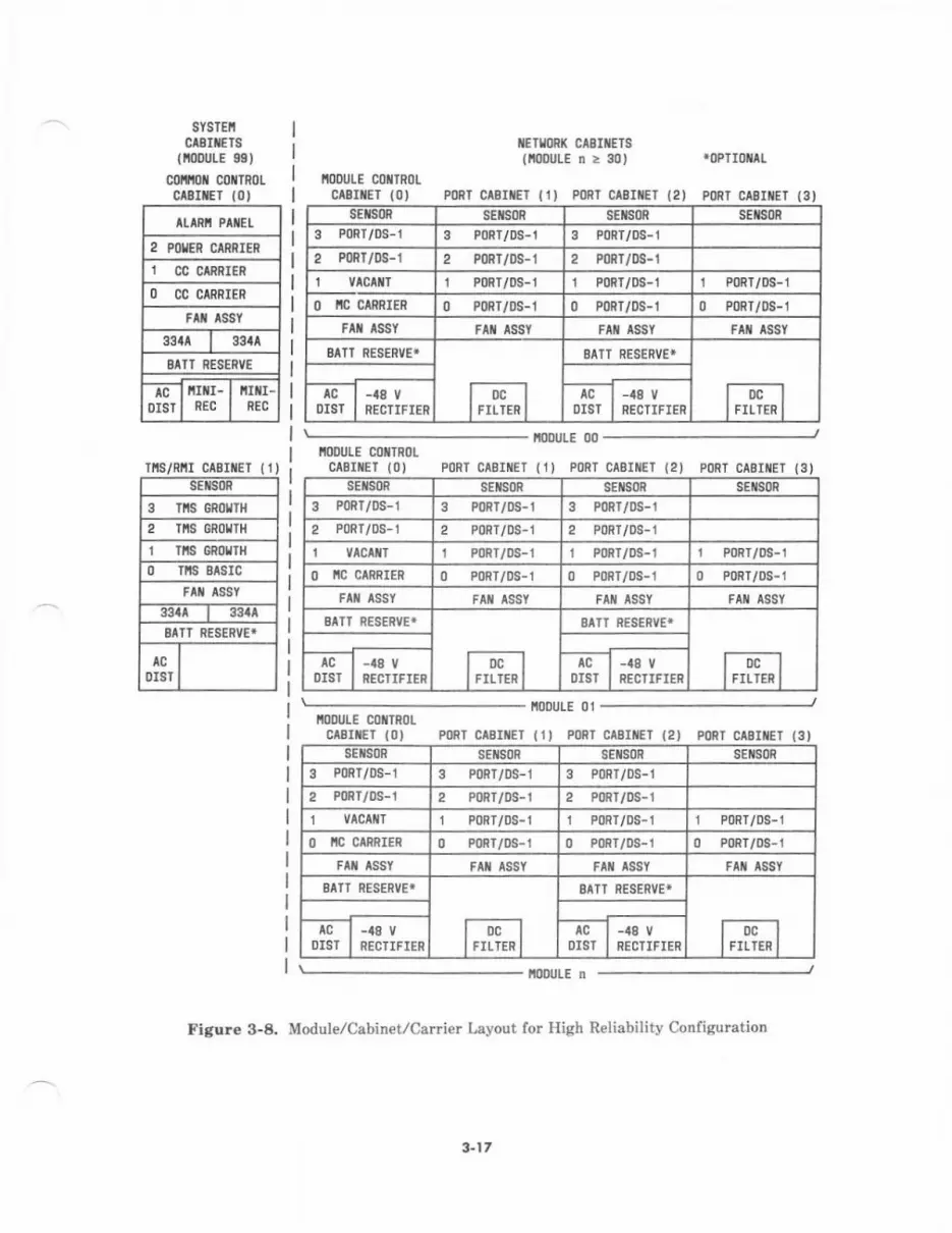
SYSTEIIctErrErs
(nolulE gst
c0infl coilTRoLc$rrEr {0,
ItARi PATEL
2 POTER RNIER
1 CC CTRRIER
l) CC CIRRIER
Ftx tssY
33tl I 33tlSITT RESERVE
AC
DIST
irIr-REC
irtr-REC
Tis/RnI cAB tET (!)sEilsoR
3 TIIS GROITH
2 tns cnouTH
I Ttts GR0tTt{
0 Tis EtsrcFAIi ASSY
33at 33!al
BIIT RESENVE*
0rsl
llETt0Rt( ct8rtErt(tlooULE n> 30) roPTlotll
IT()DIJLE COTTRl)L
c^8rNET {0) PoRT CIBIiET {1) P0nT C$IiET 12) poRT CABITET (3)sEts0n sEils08 sEts0n sEts0R
3 PoRT/DS-1 3 P0RT/DS-I 3 P0Rr/0s-1
2 PoRT/DS-l 2 PoRT/oS-1 2 PoRT/DS-1
i vlcltT I P0RT/DS-1 r PoRT/0s-1 I PoRT/oS-1
O IIC CIRRIER 0 PoRT/DS-1 o p0RT/Ds-1 0 PoRT/DS-1
F^i lssY Flf, lssY Flt AssY FAt lssY
BITT RESERVE*
1,,ff,,1
EATT RESERVE*
rmtcDIST RECTIFI€R
tcOIST
-t8 vRECTIFIER
ll0olJLE coilTR0tCABIIEI (0) poRT CABrtEl (1) PoRT CAEIilET (2) poRI CASII/EI {3)
iooutE 00
iooutt 01fiooulE c0tiTRot
CAEIilET (0) p08T CIEIiET (1' PoRI CtEIiEl (2) poRI CAEIilET (3)sEils0R sElsoR SEIISOR sEils0n
3 PoRT/DS-1 3 PoRT/oS-t 3 P0Rr/DS-1
2 P08T/0S-1 2 PoFr/os-t 2 PoRT/0S-1
1 VlcailT 1 PoRT/0S-1 1 PoRT/DS-1 1 PoRT/DS-t
0 ic ctRnIER 0 P0RT/0S-1 0 P0RT/oS-1 0 PoRT/DS-1
FA{ ASSY
BATT RESERVET
IocllrrLren I
BIII RESENVE*
Dclrrrren I
AC
DIST-48 V
RECIIFIERAC
DIST-48 V
RECTIFIEF
i0DULE n
Figure 3-8. Module/Cabinet/Car er Layout for Hish Reliability Configu.ation
sEtsoR SENSOR SEIIS()R sE[soR
3 PoRT/DS-1 3 PoRT/oS-1 3 PoRT/DS-1
2 PoRT/0S-1 2 PoRT/DS-1 2 PoRT/DS-l
vlcrir 1 P0RT/0S-I 1 P08T/DS-1 1 PoRr/os-l
O IIG CARRIER 0 PoRT/oS-1 0 PonT/Ds-1 0 PoRr/Ds-1
Fll lssY FAI{ ASSY FAII ASSI FAII ASSY
BTII RESERVET
locllrnrrnl
BAII PESENVE'
lDcllrrLrrn I
lcDIST
-48 V
RECTIFIERAC I-48V
OIST I RECTIFIER
3-17
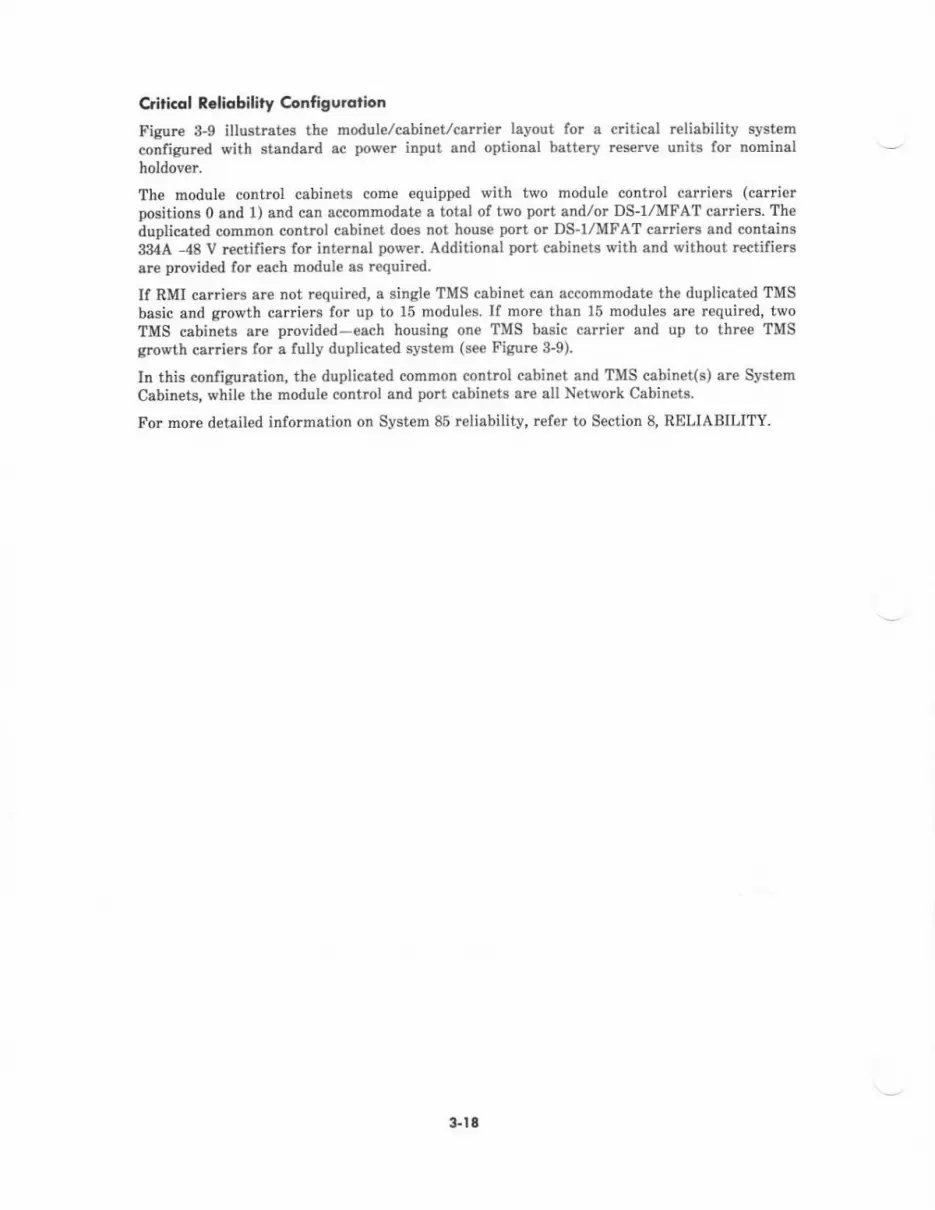
Qiticol t.liobility 6nff gurotlon
Figure 3-9 illostrates the module/cabineycarrier layout for a critical reliability systemconfigured with standard sc power input and optional battery res€rve units for nominalholdover.
The module control cabinets come equipped with two module cont?ol calriers (car erpositions 0 and 1) and can accommodat€ a totsl of two port and/o! DS-I/MFAT carriers. Thedupliceted common control cabinet does not house port or DS_I/MFAT carriers snd contains33ttA ,48 V rcctifieB for internal power. Additional port cabinets with and withoui rcetifiergare provided for esch module aa required.
If RMI c.rriers are not requited, a single TMS cabinet can accommodate the duplicated TMSbasic and growth carriers lor up to 15 modules. If morc than 16 modules ar€ r€quired, twoTMS cabinets are provided-each housing one TMS basic carrier and up to three TMSgrowth caniers for a fully duplicated s$tam (see Figure 3-9).
In this configq8tion, the duplicated c.ommon control cabinet and TMS cabinet(s) are System
Csbinets, while the module control and port cabineh are ell Network Cabinet8.
For more detailed inlormation on System 85 reliability, refer to Section 8, RELIABILITY.
3.lt
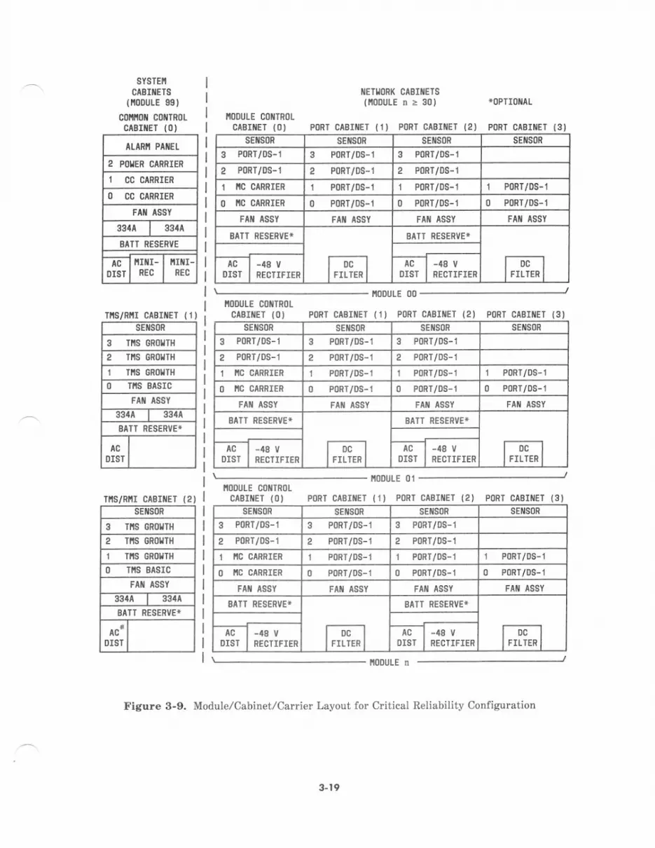
SYSTEI!
CABIilETS{i0ouLE 99)
co l coilTRotCTBIilET (O)
AI-ARI' PAIIEL
2 POIIER CIRRIER
1 CC CIRRIER
O CC CIRRIER
FAil ISSY
334^ I 334A
BATT PESENVE
DISINIflI-
REC
ltUtr-nEc
fl'ts/Rit cAB tET 11)sEtsoR
3 TllS GRol'lTH
2 TiS 6R0!TH
I tns 6n0rlt{Tis BtsrcFA ASSY
3344 33tA
SATT RESERVE*
lcDIST
Ttts/Rfir caE iET {2)SEIISOR
I rts 6R0ltTH
2 TI,IS GRO{]H
1 TtlS GRot{Tfi
O TIIS BASIC
FAII ASSY
33{A I 3344
SATT RESERVET
ac'DIST
I/EII,JORI( CABIIIEISllooutEn>30) *0PTI0ilAL
IIOOULE COilTRl)LCASIIIET {O) PORT CABIIIE] 11) PORT CABIIIET (2) PORT CABIII€T (3)
sE son sEil80R sE[s0R SEIISOR
3 PoRT/DS-1 3 P0RT/DS-I 3 PoRT/DS-1
2 P0RT/0S-i 2 P0Rr/DS-1 2 PoRT/DS-l
1 IIC CARRIER 1 P0Rr/os-1 1 P0RT/0S-1 I P0R1/0S-1
O IIC CIRRIER 0 P0RT/DS-l 0 PoRT/DS-1 o PoRT/oS-1
Flt lssY FAII ASSY FA{ ISSY FAII ASSY
BATT RESERVEI
loclIFILTER I
BATT RESERVEI
lDclI FILTER I
AC
DIST-48 V
RECTIFIERAC
0tst-48 yRECTIFIER
NODULE COIITR(]ICIBIIIEI (O) PORT CABIIIET (I) PORT CABIIIET (2J PORT CASIIiET {3)
[00uLE 00
IIODULE 01IIODUTE COIITROI
CABIi/EI {O) PORT CABIIIET {1) PORI CABIIIET (2) PORT CAEIIIEI (3)sEfls0R sEilsoR SEISoR SEIISOR
3 P0Rr/0s-1 3 P0RT/DS-1 3 P0itT/DS-1
2 PoRT/0S-1 2 P0Rr/0s-1 2 PoRT/0S-1
1 I'IC CARRIER I PoRT/DS-l 1 P0RT/0S-1 1 P0RT/0S-1
O IlC CARRIER 0 P0RT/0S-1 0 PonT/os-1 0 PoRT/oS-1
FI ASSY FAI{ ASSY FAII ASSY
AATT RESERVE*
fJi."l
BAIT RESERVE*
| ,,1f,, I
ACDIST RECTIFIER
AC
OIST-48 vRECTIFIER
i0DULE tr
Figure 3-9. Module/Cabinet/Carrier Layout for C tical Reliability Configuration
sEils0R SEIISOR sEils0n SE S0R
3 PoRr/0s-1 3 PonT/os-1 3 PoRT/0S-1
2 PoRT/0S-1 2 PoRT/oS-1 2 P0RT/DS-1
1 iC CANPTER 1 PoRT/oS-j 1 PoRr/DS-1 1 P0RT/DS-j
O IIC CARRIER 0 PoRT/DS-1 0 P0RT/DS-1 0 P0Rr/Ds-r
FAII ASSY FAT ASSY
BATT RESERVEI
fDc I
lrrlrrnl
AATi NESERVE*
I D-llrrLrenl
ACDIST
-48 V
RECTIFIERAC
DIST-48 V
RECTIFIEN
3- t9
R.mota Modulc Configurotion
The optional remote module configuration pmvides for one or more modul€s at remotelocrtions directly connected to the system switah. Cabin€ts in this configuration are dimilaria leyout and herdware to clbinets irl a detwork module at the central switch location, withthe addition of the Remote Module Interlsco (RMI) circuitry and intercontrect equipment.The ssme basic relisbility requi*ments for subsystems in the mein switch csbinets(d€scrib€d in the prec€ding coverage) also apply to the remotely located cabin€ts in thisconfiguration. Duplicatad subsystems at th€ c€ntral switch location require duplicatedsubrystems at the r€mote location. Remote modul€ cabin€ts have similar internaledministrative assigtrments to those of Network Cabinets at the central switch location.System csll prccering functions for remote modul€s are perfotmed in a manner similar tothose of central switch modules.
System 85 remot€ modules are provided in one of two configuretion options: Phas€ I andPhase 2.
O.In e Phase 1 r€mote module configuration (see Figure 3-10), an RMI circuit pack (TN456) isA ingtalled in a dodule control cabinet at the central location. A matching RMI circuit pack is
i$stsll€d in th€ modute control cabinet at the temote location. The RMIS ere directlyconnected by the lightguide cable interconnect terminals (I/CIT8) and fiber-optic link. Withthi8 configuration, the numbei of remote modules cannot exceed the number of modules otthe central switch location. A Phase 1 system provides tle ability to place up to 15 modulecontrol cabinets at one or more rcmote locations.
3.r0
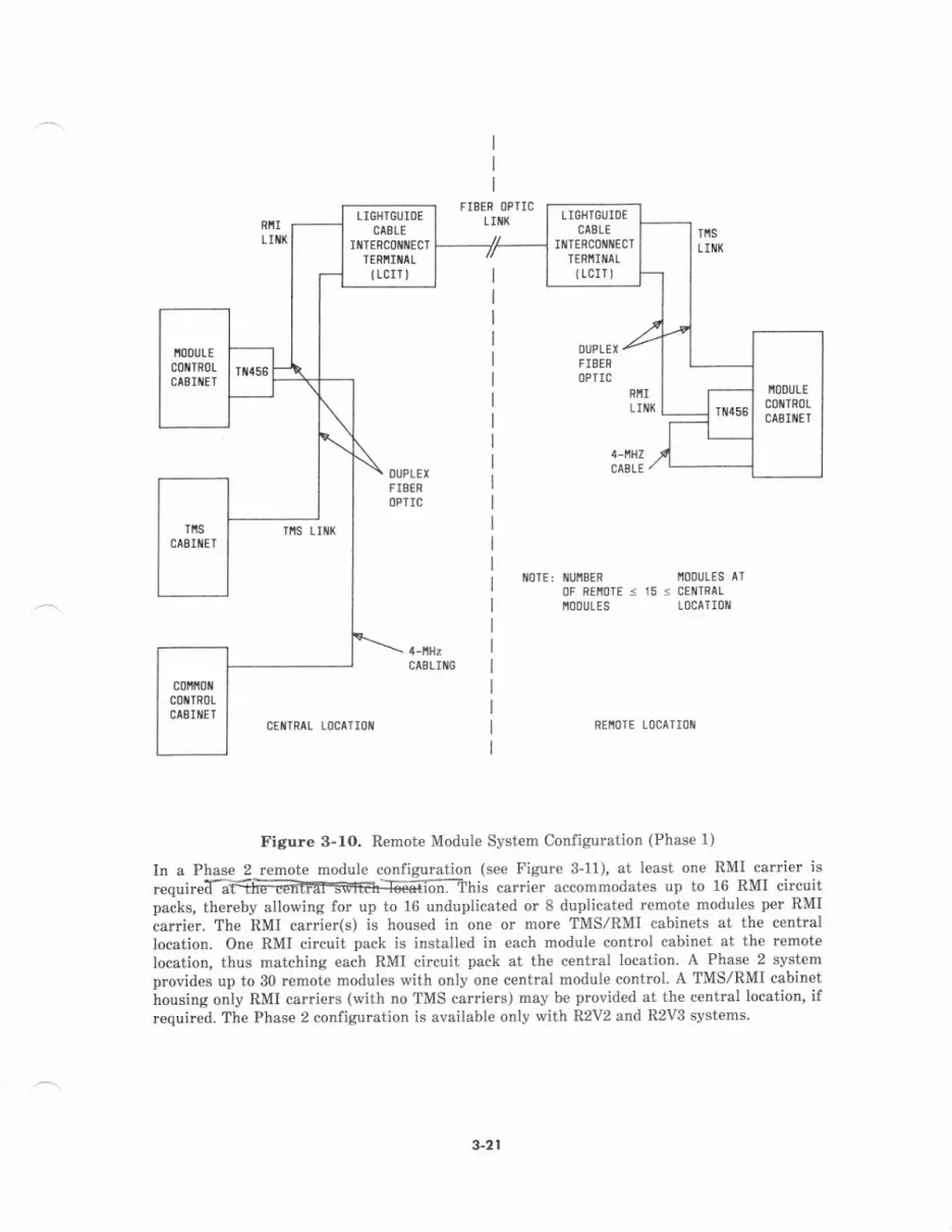
LIOHICUIDICABLE
IIITEFCOIIiIECTTERIIII{AL
{rcrrl
LIOHTGUIOECAELE
INTERCOIIIIECTTERNIMLtLcIr)
c0l 0t{colTRoLctsIttET
FIEER OPTICLIIIX
OUPLEX
FIBERl]PTIC
TfiSLII{X
DIIPLEX
rIBENOPTIC
oTE: IUI'IBEF |'IoDULES AT
0F REI'|oIE < i5 r CE TRALI,IODULES L(]CATION
ris Lrllx
REIIOTE Ll]CATI(]Il
Figure 3-1O, Remot€ Module System Configuration (Phase 1)
In a Phase 2 remote module configuration (see Figure 3-11), at least one RMI carrier isrequiretraiiffii:ifsfEh=6i6;:-ihis carrier accommodat€s up to 16 RMT circritpacks, ther€by allorving for up to 16 unduplicated or 8 dupticated remote modules per RMIiarrier. The RMI carrier(s) is housed in one or more TMS/RMI cabinets at the centrallocation. One RMI circuit pack is installed in each module control cabinet at the remote
location, thus matching each RMI circuit pack at the centrat location. A Phase 2 svstemprovides up to 30 remote modules with only on€ central module control. A TMS/RMI cabinethousing only RMI carriers (with no TMS carriers) may be pmvided at the central location' ifrcquired. The Phase 2 configuration is available only with R2V2 and R2V3 svstems
3-21

IIGIITGUTDECTELE
llERC0ltilECrlEittrltiaL(LCII)
LIGIiIGUIO€cr8LI
IIIIERCONNECIIEiIT!NAL(LCIl)
r/0 8us
OUPLEX
FISEROPTIC
t{0TE: t{ultlEn0F nEnoTE <30ttoDUtEs
OUPLET
FIEEROPTIC
Tlts trtx
CCNTRIL LOCA'II]I{ nEi0tE tdcaTrot
Figure 3-11, Remote Modul€ System Configuration (Phase 2)
Remot Groupcontigu.olion
The optional remote group confielration (see Figur€ 3-12) provides for small groups of voiceand/or data t€rminals at a remote location, connected directly to the system switch throughDS-l facilities. Because this configuration involves only small numbers of DS-l portint€rface circuits, there arc no switch cabinet considerations involved at the network modulelevel. Remote groups are equivalent functionally to the oth€r groups of analo& hybrid, anddigital port interfaces installed within the port cabin€ts at the central system location.System call prcc*sing functions for rcmot€ groups are performed in a manner similar tothose of ports at the central location.
3-22

Eact remotary rocated port $oup is conn€cted -to a Ds-r carrier (instaled in s Dort csbinet
ft -aF:fitlffi 'fl.li#'", i,iii#i iiT;:.nl*1.*"*$.krm j l"?"tsjlover the D$l link critb en int€rface .;rcuit-psck fmllofii ii'im *."," " "up too"ing(rorer to.cARRlERs in.riig section). r*" lr.ir,rrsBil$i;-d ;a;;i;T;
"t;r_"d"t"dp€r remot€ group housing. Each RGI rhterfa4e circuit packe rircuit pack psir occornmodates up to thre€ port
cEtTRtL toctTtotREIIOTE LOCATIOT
Figure g-le Remote Group Systern Configuratior!
$23
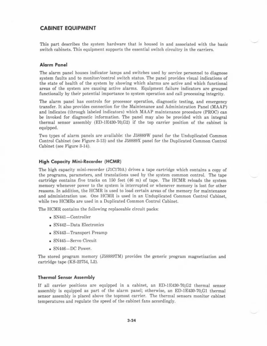
CABINET EOUIPMENT
This pa describ€s the system hardware that is housed in and associated with the basicswitch cabi$ets. This equipment supports the essential switch circuitry in the carriers.
Alorm Ponel
The ala.m panel houses indicator lamps and switches used by sefiice perconnel to diagnosesystem faults and to monitor/control switch status. The panel provides visual indications ofthe state of health of the syst€m by showing which alarms are active and which functionalareas of the system arc causing active alarms. Equipm€nt failure indicators are groupedfunctionally by th€ir potential importance to system operation and call processing int€grity-
The alarm panel has controls for proc€ssor operation, diagnostic testing, and emergencytransfer. It also provides connection for the Maintenanc€ and Administration Panel (MAAP)and indicates (through labeled indicators) which MAAP maintenance procedure (PROC) canbe invoked for diagnostic information. The panel may also be provided with an integralthermal sensor ass€mbly (ED-1E430-70,G2) if the top ca ier position of the cabinet isequipped.
Two types of alarm panels are available: the J58889W panel for the Unduplicated CommonControl Cabinet (s€e Figure 3-13) and the J58889X panel for the Duplicated Common ControlCabinet (see Fignrc 3-14).
High Copdcity Mini-Recorder (HCMR)
The high capacity mini-recorder (J1C1?0A) drives a tape cartridge which contains a copy ofthe progmms, parameters, and tmnslations used by the system common contrcl. The tapecartridge contains five tracks on 150 feet (46 m) of tape. The HCMR reloads the systemrnemory whenever power to the system is interupted or whenever memory is lost for otherreasons. Ir addition, the HCMR is used to load certain areas of the memory for maintenanceand administration use. One HCMR is used in an Unduplicated Common Control Cabinet,while two HCMRs are used in a Duplicated Common Control Cabinet-
The HCMR contains the following replaceable circuit packs:
. SN441-Controller
. SN442-Data Electrcnics
. SN443-Transport Preamp
. SN44s-Servo Circuit
. SN446-DC Power.
The stored program memory (J58889TM) provides the generic program magnetization andcatbidse t"pe (KS-22754, L2).
Thermol Sensor Assembly
If alt carrier positions arc equipped in a cabinet, an ED-1E430-?0,G2 thermal sensorassembly is equipped as part of the alarm panel; otherwise, an ED-1E430-70,G1 th€rmalsensor assembly is placed above the topmost carrier. The thermal sensols monitor cabin€ttemperatures and regulat€ the speed of the cabinet fans accordingly.
3-24
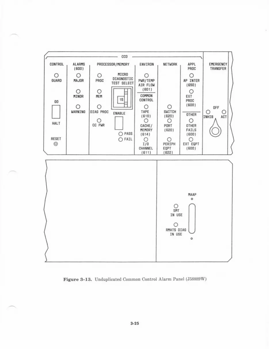
ETVIROI
(JPtn,/IEI?IIT FLfi
(6t11)
clrtotC€TTROL
oTAPE
1810JocrcllE/m{nY
;rcn0DIAGI$TICrEsr s€t EcT
@EUIBLE!
O Prss | (B1a) otoPENTPH I EXI EQFT
EoPr I {000)
EltERoE[CtTRATSFEN
oo"'6"
Figur€ 3-13. Unduplicated Common Contml Alarm Panel (J58889W)
3.25
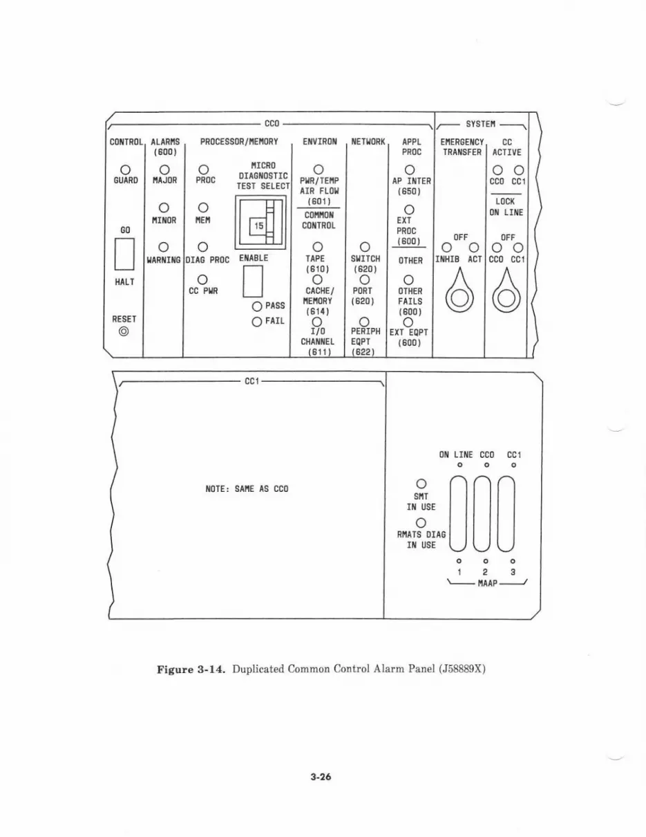
SYSTEIT
coilTR0L. aLtRlls PR0CES80R/iEfioRY E[VrR0I IET!oP|( APPL I EI1ERGEIICY(600) PRI)C I TRANSFER
ircRoortGlosTrcIESI SEIECT
fr---TilildltlL----il|
EIIIBLE
To PASS
O FAIL
oPn0c
olo
GO!HILT
GUAND I IJORo
PLR/TEl,lPlrR FtoI
(801)
c0 oilc0ltTR0L
oIAPE
{ 610)o
CACHE/NEiORY(61r)
oAP IIITER
{650)
oEXT
PROC(800)
l)THER
o()IHER
FAILS{600)o
EXT EQPT(600)
oto
oloo
cc PlR
ccICTIVE
oocco cc1
OFFoocco cc1
oIIIHIB
tocK0 LIltE
ifltoR I fiEI!
RESET
@ 0cHA ItEL
611
oSfITCH(820)o
PORT
{620)
oPENIPHEQPI
IIARIIIIG IDIIC PROC
oACT
6t6622
cct
iloTE: SAfiE AS CCo
0[ LII{E CCo CC1
L nnn"J" Ill ll I
"il,'3l^'u u u123\- iAAP
-J
Figure 3-14. Duplicat€d Common Control Alarm Panel (J58889X)
3-26
Fon Asrembly
The fan assembly (J58889V) in each switch cabinet provides three forced-draft fans tomaintain inte or t€mperature within the acceptable operating limit. The fans ar€ mountedvertically side by side and are designed to run continuously with dc pow€r. The fans operateon low speed for noise reduction until the ambient temperature r€aches 95'F (35'C). Athigher temperatures, the fans switch to high-speed operation. A removable air filter in theassembly traps airborne matter and must b€ changed periodically.
The fan assembly also accommodates a frequency genemtor (12481), fusing and powersources for attendant consoles, ground blocks for internal syst€m ground connections, and acircuit board (AEHa) for cabinet fuse and power alarm interconnections and airflowmonitoring circuits. The airflow monitor circuit compares the temperature differentialbetween the air intake at the fan assembly and the air exit at the top of th€ cabinet. If thedifferential reaches 16.5oC, a fan failure is indicated and a fan alarm for the cabinet isactivated. The assembly also contains a low-voltage monitor which activates an alarm whenthe cabinet dc voltage drops below -42 V.
AC Dislribufion Units
Each cabinet ac distdbution unit provides ac pow€r, filtering, and frame grounding for the-48 v rectifier(s) and utility receptacle(s), as required. The distribution unit receives powerfrom a commercial ac power source. This ac porver is then passed through anelectromagnetic interference (EMI) filter for distribution. The EMI filter also prevents EMIfrom beine generat€d back into th€ power source by the system. Utility r€ceptacles aremounted on the ac distribution unit housinq. A circuit breaker is provided for each utilityreceptacle.
The ac distribution units and their main applications are as follovs:
. J58889U used in the Duplicated Common Controi and TMS Cabinets, for systemswith the standard dc power configuration. This unit provides an electrically filter€dsource of ac power for one or two 334A rectifierc. ?he unit has two power cords withplugs which mate to 3-wire Twist-Lock receptacles (providing 120 V ac, 60 Hz). Twostandard outlets supply power lor the 334A rectifierc, and one utility outlet isprovided lvith access from the front of the cabinet.
. J58889c-used in th€ Module Control and Port Cabinets, for syst€ms with thestandard dc power configutation. This unit provid€s an electrically filtered source ofac power for th€ 309A/310A rectifier. The unit has a power cord with plug whichmates to a 4-wire Twist-Lock receptacle (providing single-phase 720/240 V ac ot 3-phase 120/208 V ac, 60 Hz). Power for the 309A/310A rectifier is supplied throughhard-wired terminal lug connections. One utility outlet is provided with access fromthe front of the cabinet.
. J58s8gAv-replaces the J58889U and J58889G units, for systems with the new cost-reduced dc power configuration. This unit is used in each switch cabin€t and providesan electrically filtered source of ac power for one or two Off-Line-Switcher (OLS)powe. supplies. The version of this unit used in a cabinet with one OLS power supplyis equipped with one power cord and one 3-wire r€ceptacle for the OLS. The versionof this unit used in a cabinet with two OLS power supplies is equipped with twopower cords and two s-wirc rec€ptacles lor the OLS.
3-27

Rcdiffert
Three types ol r€ctifi€rs may b€ used in system switch cabinets. Each typ€ of rectifierconverts ac pow€r to -48 V and sery€s as the primary dc power source for th€ cabinet it ishoused in.
3(nA/3toA Patitio
The 309A/310A r€ctifier, consisting of two combined units, is the primary d€ power source insystems with the standard dc power configuration. It is mounted at the bottom of alternaten€twork cabinets. This rectifi€r includes a magnetics packag€ (309A) and an electronicspackage (310A). The magnetic package contains a transformer which steps down the inputvoltag€ and supplies low-voltag€ ac povrer to the el€ctrcnics packag€. The el€ctronicspackage contains the ac-to-dc rectifier, cooling fans, filter circuit, and control unit (AENI)which regulates the output.
One rcctifier has an output capacity of 60 amperes and can provide -48 V dc power for onecabinet or a pair of cabinets. The nonrectifier-equipped cabinet (in a pair of cabinets sharingpow€r) houses a dc filter. Input power from the ac distribution unit may be either 208 or240 V @Hz Adjusbble taps at the primary winding of the 309A transformer provide foreither input voltage. An access cover on the front of the 309A is us€d for verifying orchanging the option setting.
An ac sense voltage interfac€s with the battery reserve unit to detect an ac power failure atth€ r€ctifier input. The rectifie. provides thre€ alarm indications to the AEH4 alarmdistribution unit: fan alarm (failurc of fan in 3l0A), fuse alarm (circuit breaker tripped in310A), and rectifier alarm (loss of 48 V output).
334A P..rifi.t
The 334A rectifier provides -48 V dc power to the Duplicated Common Control Cabinet andth€ TMS,/RMI Cabinet in systems with the standard dc power configuration- Two 334Arectifiers are mounted under the fan assembly of each of th€se cabin€ts. This unit rectifiesl20V 60Hz from th€ ac distribution unit to -48vdc power. A control unit (AEN1)regulates the output. Each rectifier has an output capacity of 20 amperes and providesprirnary power for half of th€ cabinet. An ac sense voltage int€rfaces with the batteryreserve unit to detect an ac power failure at the rectifier input.
The rectifier provides three alarm indications to the AEH4 alarm distribution unit: fanalarm, fuse alarm, and reetifier alarm.
Ouk A#-un -Swirchd (OIS) Powe. Sun,y
Each bulk OLS power supply (ITI PEC 3965-1) provid€s -48 V dc power for a switch cabinetin systems v'ith the new cost-reduced dc power configuntion. Two bulk OLS power suppliesare mounted in Common Control, TMS, and Module Control Cabinets if they ar€ duplicated.A second bulk OLS is optional in the Module Control and Port Cabinets if required by portpower demands,
These new bulk OLS units provide lower cost, incrcased reliability, greater ac inputflexibility for universal applications, and reduc€d space rcquirements. They are designed toreplace 309A./310A end 334A r€ctiliers in the System 85 svritch cabinets.
One bulk OLS has an output capacity of 30 amper€s and can provide -48 V dc power. Inputpower from the ac distribution unit ranges from 1?0 to 2?5 V ac single phase, at 4? to 63 Hz.
3-28
DCIDC Conve.t '.The dcldc convert€rs are units ilr circuit pack form that provide low-level dc voltages for theswitch. Source voltage for the converters is provided by the -48 V rectifier output.
The dcldc conve.ters include the lollowingi
. 494GA converters-provide -5 V and +5 V dc (50 watts) for the TMS carriers,duplicated module control carriers, DS-I/MFAT carriers, and port carriels. This unitprovides 50 watts on one output or 40 watts on one output and 10 watts on the otheroutput.
. 495FA convert€rs-provide +5 V dc (250 watts) for the common control carrier(s)(via the power carrier or dcldc converter unit), fMS carriers, RMI car ers, andmodul€ control cerri€n.
Bu. Bdr
The bus bar (ED-18435) is a laminated assembly that provides dc power dist bution andground to the carriers and fans in each cabinet. The bus bar is mounted vertically on tberight side within the cabinet frame- Terminals are desigrated to identify the individuallayeN of conductors.
DC FilreB
Two types of dc filters are used in system cabinets.
Th€ J58889H dc filter provides input filtering for the vadous equipm€nt in cabinets whichrec€iv€ -r8 V povrer from an adjacent cabinet. Thr€e 4-AWG q'ires (-48 V unfilt€red, -48 Vfiltered ltalk batteryl, and circuit ground I-48 V rcturnl) arc used to connect the dc bus barsand circuit ground blocks for two cabinets sharing -48 V power. The dc filter in a cabinetwithout a .ectifier connects to the bus bar and circuit ground in parallel with th€ filter€dand unfiltercd power leads, to prcvide additional filte.ing for both power sources.
The J58889AD filter provides input filtering for the Auxiliary Cabinet and for cabinetswhich receive -48 V direct input in an extended power reserve configuration. The unitreceives dc power lrom the batt€ry ptant and distribut€s it to the equipment through the busbar. C€rbin filters are configured for two s€parate inputs and outputs when dual powersources are required (such as in the Common Control and TMS Cabinets).
3-29
Fraqu.nay Ganerolo.a
Two types of frequency generetors are us€d to provide ringing voltage to periph€ralequipm€nt.
The 1%B1 lrequency generator ptovides low-frequency voltag€ for nonelectronic ringingvoice t€rminels and oth€r peripheral equipment, such as recorded telephone dictation. ltgoutput is superimposed on the -48 V rectilier output. Normal input voltage for the frequencygenerator reng€s from -45.5 V dc to -52.5 V dc. Th€ output chancteristics are as follows:
. Sinusoidal voltage of ?5 V to t00 V, RMS
. Load of 0 to l8 high-impedance ringers with series capacitors
. Frequency of 2l Hz, al Hz
Th€ 12481 receives fused -48 V power from th€ network cabinet fan assembly and ismountd on the rear of the assembly (except in the Auxiliary Cabinet wh€re it i3 containedin the J58889N unit). Ringing voltage is distributed to th€ port and DS-l carriers thloughdaiay chain cables. A maximum of four ports p€r quart€. carrier (port group) can receiv€ringing current simultaneously and is referred to as'ting group blocking." If the frequencyg€nerstor malfunctions, a signal is provided to the AEH4 alarm distribution unit, whichactivates sn alarm for the cabinet,
The other type of frequency generator is contained in the CALI circuit board. This is a
special-epplication unit mounted within each remote gtoup housing in a Remote Croupsystem configuration. The CAL1 board provides m-Hz ringing voltage for the .emoted portgroups. The CAL1 elso provides low-voltage det€ction, alarm conversion, and othermiscellaneous features. Ringing voltage is provided by two dcldc conv€rter circuits whichgenerate +90 V and -190 V lrom a nominal -48 V supply. Up to four -48 V fuse alarms andfive contact closur€ alarms can b€ paralleled. R€sistors are provid€d for 2-speed fanop€rstion and over-temperature shutdo*n.
Ncmincl Holdover Equipment
The nominal holdover capability maintains dc voltege for an ac-pow€red System 85 should ashort-term loss of comm€rcial ac power occur,
This capability is standard for the Common Control Cabinet and nrovides a minimum ofl0 minutes of holdover for common control carrier(s) and related equipment. The actuslemount of holdover is dependent on the number of circuit packs. Th€ holdover pievents tspereloads due to loss of msin memory cont€nts during a short-term ac pow€r interruption. Allassociated common control equipment, including the HCMRg and alarm panel, is also heldover during this period.
The nominal holdover equipment is optional lor the TMS, Module Control, and Port Cabinetsequipped with rectifiers. Depending on circuit pack configurations and traffic generated
during thig period, holdover pow€r sustains operation of these cabinets for approximately 3
to 5 minutes. Th€ holdover furnishes power for the switch network and all peripheralsderiving power from switch interfaces.
Two types of batt€ry reerv€ hardrxere for nominal holdover are used in th€ switch cabinets.The holdov€! capability for systems with the stendard dc power configuration is providedthrough the J8?462A battery reserve unit and its associated hardvtare. This battery reserv€unit is mounted under the cabinet fan assembly or 334A rectifiers, as required. Each batteryr8erve unit hss a basic housing and ass€mbly (3:]A apparstus unit) and accepts thefollowing modular units as required.
3-30
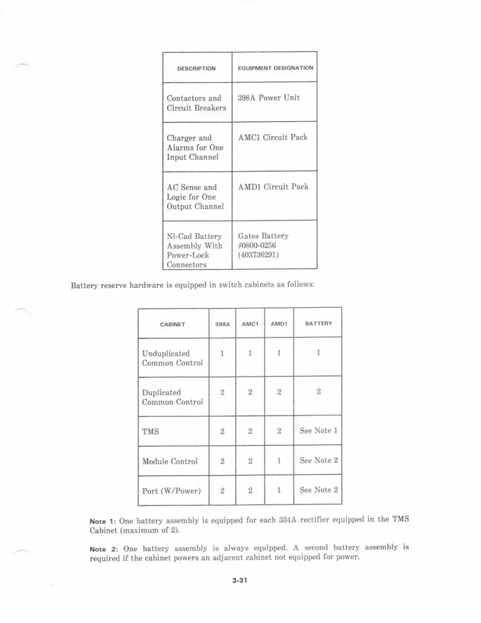
EOUIPMENT DESIGNATIOI{
Contactom andCiftuit Breakers
398A Power Unit
Charger andAlarms for OneInput Channel
AMC1 Circuit Pack
AC Sense andLogic for OneOutput Channel
AMD1 Circuit Pack
Ni-Cad BatteryAssembly WithPower-LockConnectors
Gates Battery10800-0256(403?36291)
Battery reseN€ hardware is equipped in switch cabinets as follows:
UnduplicatedCommon Control
1 1 1
DuplicatedCommon Control
2 2 2 2
TMS 2 2 2 See Note 1
Module Contrcl 2 2 See Note 2
Port (w/Power) 2 2 See Note 2
Not. l: One battery assembly is equipped for €ach 3344 rectifier equipp€d in the TMS
Cabinet (maximum of 2).
Not€ 2: One battery assembly is alway€ equipped A second batterv assemblv isrequired if the cabinet powe6 an adjacent cabinet not equipped for power'
3-31
The rechargeable battery pack contains 24 sealed lead acid cells. These cells provide anormal -48 V output. To prevent damage to the cells, the unit is disconnected when theoutput voltage drops to about -42 V. When commercial ac power is restored, the batteriesbegin recharging immediately. The batteries require a maximum of 16 hours to reach a fullycharged state after they have been fully discharged. (The specified holdove. durations arefor worst-case conditions and assume that associat€d batteries are fully charged.)
The holdover capability for systems with the new cost-r€duced dc power configuration isprovided through the OLS battery reserve unit (ITt PEC 3965-2)- Installed and paired with abulk OLS power supply, this battery rcserve unit is mount€d at the bottom of the switchcabinet. In cabinets equipped with two bulk OLS power supplies, two batte.y reserve unitsmay also be equipped.
All holdover power configurations provide for single outputs of 90 or 60 amper€s or for dualoutputs of 30 amperes each, as required per cabinet. Eaeh battery reserve unit is rated at5 ampere-hours and supplies up to 30 ampercs at a nominal 48 V dc. The input power tothe unit is derived (through the bus bar) frcm the r€ctifier in the same or adjacent eabinet.Each unit requires approximately 0.6 ampercs at 48 V per input channel.
AC sense leads monitor the status of rectifiers feeding the cabinets. If commercial ac poweris lost, the battery reserve unit supplies -48 V dc power to the cabinet equipment throughthe bus bar. The rcseNe unit provides a nominal holdover alarm input to the AEH4 alarmdist bution unit mounted behind the fan assembly. The alarm is activated if there is amalfunction in the battery reserve unit or if the unit is supplying holdover power to th€cabinet.
Extended Power Re3erve Equipmenl
The (optional) extended power rese$e capability mrintains dc voltage for System 85 shoulda long-term loss of power occur. In the event of an interruption of commercial ac power, theextended power reserve sustains operation of the system cabinets for up to 8 hours through aseparate battery plant. The battery plant provides 48 V dc power dircctly to the cabinetsthrough feeders. To prcvent damage to the batt€ries, they are disconnected when theiroutput voltage drops to about -42 V. When commercial ac power is restored, the batteryplant is automatically reconnected to ac power for recharging.
Extended power res€rve configurations vary according to individual system requirements.For systems with up to eight modules, each cabinet is powered by its own 3O-ampere feederprotected by a circuit breaker in the battery plant. Cabinets with dual dc powerarrangements (such as the Duplicated Common Control and TMS Cabinets) are equippedwith two -48 V feeders per cabinet. In larger systems, feeders from the battery plant feed aPower Distributing Fram€ (PDF) located so that it can supply a group of cabinets.
In cabinets equipp€d for extended power reserve, the usual cabinet power configuration(rectifiers, battery rcsene unit, and ac distribution unit) is not needed. Instead, a modifiedfilter arrangement is required at the bottom of the cabinet. The J58889AD dc filter andterminal strip (accessible from the back of the cabinet) provides a termination point for the-48 V dc cabinet feede(s).
The AP(s) and Auxiliary Cabinet(s) retain an ac power input configuration (in addition toth€ 48 V dc input) for ac-powered auxiliary equipment. The source may be standby ac powerfrom an inverter or may be a feeder from the main ac service supplying the battery plant. Ifthe ac-powered equipment is not powered from th€ inverter, these units will not beoperational during an ac power outage.
For detailed information on extended power reserve battery plant r€quirements, ref€r toSection 11, SYSTEM POWER.
3-32
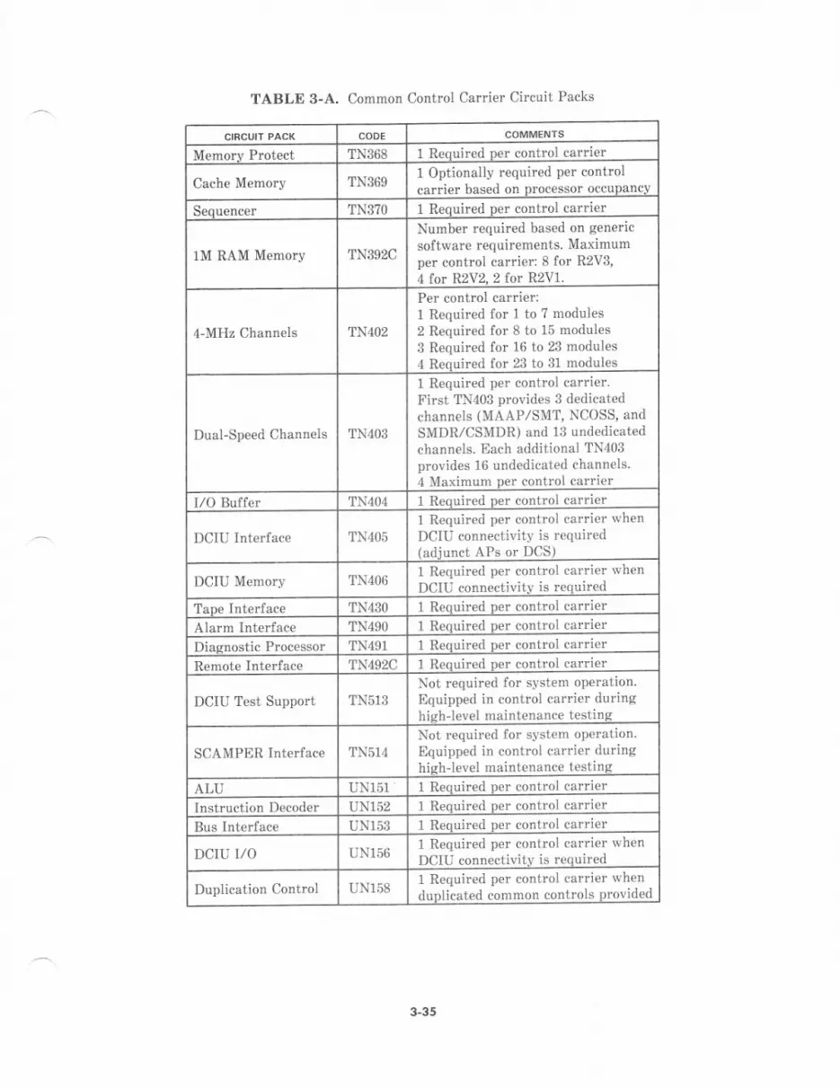
TABLE 3-A. Common Control Carrier Circuit Packs
CODE
TN368 1 R€quired per control carrier
Cache Memory TN3691 Optionalty required per controlca.rier based on Drocessor occupancv
Sequencer TN370 1 Reouired Der control carrier
1M RAM Memory TN392C
Number requir€d based on genericsoftware requirements. Maximumper control carrier: 8 for R2V3,4 for R2V2. 2 for R2V1.
4'MHz Channels TN402
P€r control carrier:I Required for 1 to 7 modules2 Required for 8 to 15 modules3 Required for 16 to 23 modules4 Reouired for 23 to :1 modules
Dual-Speed Channels TN403
1 Required per control carrier-First TN403 provides 3 dedicatedchannels (MAAP/SMT, NCOSS, andSMDR/CSMDR) and 13 undedicatedchannels. Each additional TN403provid€s 16 undedicated channels.4 Maximum p€r control carrie.
I/O Buf{er TN404 I Reouiled Der control carrier
DCIU Intedace TN4O5
1 Required per control carrier lvhen
DCIU connectjvity is requir€d(adjunct APs or DCS)
DCIU M€mory TN4O61 R€quired per control ca ier rvhenDCIII .onnectivitv is required
T:rne Interlace TN43O I Reouired per contro
Alarm Interface TN49O 1 Reauired Der contro
Diaonostic Processor TN491 1 Required per contro
Remote Interlace TN492C 1 Reouired ner contro
DCTU Test Support TNs13Not required for syst€m oporation.Equipped in control carrier duringhiqh-l€vel maintenance testing
SCAMPER tnt€rface TN5]4Not required for system operation.Equipped in control carrjer duringhish level maintenance testinq
ALU UN151 I Renuir€d n€r contro
Tnstruction Decoder IINl52 1 Required per contro
Bus Int€rface UNI53 I Renuir€d n€r contro
DCII] I/O I;N]56 1 Required per control carrier whenDCIU connectivjtv is r€quired
Duplication Control IlN1581 Requir€d per control carrier whenduplicated common controls provided
3-35

Power Corrier (J58888F)
The power carrier (see Figure 3-16) provides dc power in the Duplicated Common ControlCabin€t. It contains dclde converters that provide logiclevel dc voltages requir€d by the twocommon control carriers. This unit occupies one of the carrier positions in the cabinet andreceiv€s 48 V dc through the bus bar. The carder is functionally segmented into two halves,i'hich pmvide fully isolat€d logic lev€l voltages to each of the common control carriers.
Each dcldc converter circuit pack is functionally partitioned in the carrier to simplifymaintenance and replacement. For additional information, refer to Tabl€ 3-B and DCIDCConverters in this section.
Figure 3-16. Power Carrier (J58888F)
TABLE 3-8. Power Car er Circuit Packs
00 0r 02 03 04 05oooooooo
cc1 05 neAcv o @---
o"o @'"
Te"oTd"01 c82
..0 ^o"
Qrtcrv "o' @-$
DClDC Converter 494GA 2 Reouired ner carrierDCIDC Converter 495FA 4 Requir€d Der carrier
3-36
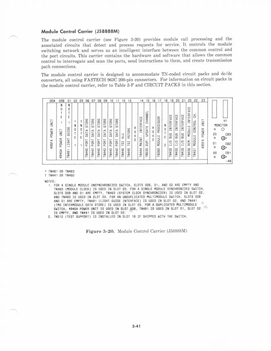
Module €ontrol Conier (J58888M)
The module control carrier (see Figure 3-20) provides module call processing and the
associated circuits that detect and process requests for service. It controls the module
switching network and serves as an intelligent interface between the common control and
the port circuits. This carrier contains the hardware and software that allows the common
control to interrogate and scan the ports, send instnrctions to them, and create transmissionpath connections.
The module control carri€r is designed to accommodate TN-coded circuit packs and dcldcconverters, all using FASTECH 963C 200-pin connectots. For infotmation on circuit packs inthe moalule control carrier, refer to Table 3-F and CIRCUIT PACKS in this section.
306070409 10 11 12 13 !!H1
Ill]NITl]Roo23 c33oG'01 cB2oG>00 c3toG>
0T
E
1
0T
E
1
0T
E
I
t0T
E
1
It0TES:L F0R A SIIG!E ti00llLE Ut{SYilCHR0t{rZED StJrrCH. SL0TS 008. 01. AlllD 02 ARt EIIPTY Ail0
Tt{450 (iooulE clocl() Is usEo lll sLor 03. FoR a srl{GLE I'oDULE sYl{cHRollrzED sl,JrTcH.slors 008 ano 01 ARE ErlPTY, Tl{453 (SYSrErl CLoC( SYNCHRoTIIZERI rS USEo Ill SLoT 02,AIID T 4AO IS USED IIT SLOT 03. FOR AO UNOUPLICAIED I'ULTIITOOULE SUITCH. SLOTS OOB
AI{O (]1 ARE EIIPTY. TII48I {LIGHI CUIOE IIlIERFACE) IS USEl] II SLl]I 02, AIIID IN441(TIIS IIITERI'IODULE DAIA STORE) IS USEO IN SLOT 03. FOR I DUPLICAIED I'ULTIIIOOULE
SII'ICH, 49'GA PI]IER UI{IT IS USED If, SLO'T OllB, TiI481 IS USTO III SLOT OI, SLOT 02
IS $IPTY, At{D {aat rS tlsEo IN SLoT 03.2. TI{512 {TES'I SUPPORI] IS IIISTALLED IIII SLOT 18 IF SIlIPPED III'IH THE SIIITCN.
Figure 3-20. Module Control Carrier (J58888M)
3-41

TABLE 3-F. Module Control Carrier Circuit Packs
CODE
Module Processor TN380 I Required per control camier
L/O Bus lnterface 'tN400B
1 Requir€d per control carrier tointerface to a total of 4 port,DS-l, or RMI carriers. 3 MaximumDer control carrier
Module ControlChannel
TN4O1 I Required p€r controt carrier
Port Data Storc TN44OB
1 Required per control canier tointerface to a total of 2 port orDS-1 carriers. 6 Maximum per controlcarier
Intermodule DataStore 'tN44l 1 Required per contml carrier only
in multimodule svstem
Maintedance Interface TN444B 1 Reouired ner control carrierTSI P-Store TN445 I Required per controL carrierTSI ALU TN446 1 Required per control carrierRemote ModuleInterface
TN4561 Required per remote module inPhase I eouiDment confiEuration
Module ClockOscillator
TN460C1 Required per control carrier onlyin sinqle-module svsten'r
System ClockSvnchrcnizer
TN4631 Required per control carrier insinsle-module svstem with DS-1 trunks
Light Guide Interface TNd8l 1 Required per control carrier onlyin multimodule svstem
Test Suppo.t TN5128Not rcquired for system op€ration.Equipped during high-level majntenancetestinq
Duplication/UpdateChannel
TN53O1 Required p€r control carrier onlywhen duplicated controls are Drovided
DCIDC Converter 494GA1 R€quircd per control car er onlyin multimodule systems with duplicatednodule controls
DC./DC Converter 495FA 2 R€quired Der control carrier
3-42
(Port Coriq (J5gg88A)
The standard port carrier (see Figure 3-21) connects the system to external €quipment(analog/digital, voice/data, and lines/trunks). This carrier provides dedicated port circuitsdetermined by the peripheral terminal equipment or trunking facilities connected- It alsoprovides an interface to the module control for Dort control and status information, and forpulse code modulated voice or data connections.
The port canier uses FASTECH technology and is de6ign€d to accommodate SN-codedcircuit packs using 100-pin 963G connectors and TN-coded circuit packs using 200-pin 963Cconnectors. Any port circuit pack that needs access to eight or fevrcr time slots on the groupbus may be iNtalled into any univ€rsal port position in the carrier. However, the& arepai ng rules lor assigning these packs due to cabling assignm€nts to termination fields andnumbei of circuits per pack. Eight 25-pair connectors, manufactured by Amphenol Products,are provided for irput/output cabling to termination fields with each connectoraccommodating the int€rfaces for two adjacent port circuit pscks.
For information on cilcuit pecks in the port carrier, refer to Table 3-G and CIRCUITPACKS. For information on port circuit pack pairing rules, refer to Port Circuit PackAssisnments, under CIRCUIT PACKS in this s€ction.
,) ." 'l 1ti
. ., /
')
3-43

03 04 05
Bo
,.o
OO.
[OTES:r. CARRIER PoSITroIS 00-03. 05-08. 13-16, 18-21 IRE U|{MnSAL
poRl Posrrrois tNIcN c^[ ^ccEPT
THE Follotlric sti-c00E0CIRCUIT PACXS:
cl(T Ptcr(c00E
CIRCUIT PICX CX'I PACI(
CODE
CIRCUIT PACI(
sNz?ast{228st{229sil230sN231stl232sil233sN23esl2atsN2t3
sN250sil251st252slt253st{25ast255sN28rst{270
iFEt rI[E PonlOFF PREIIISES LIIIEOII PREIIISES IINEc0 rRultxIUIILIIRY TRUI{X
DID TNUM(
TIE TRUI{X/ATTEIIOAIIT IIITERFICEEIA II{TERFACECOIITICT I'iIERFICE
C'.LL PROGRESS IOIIET(UCH-TOIE NECEIVENICUCH-TOIE SEI{DEN
ALXILIARY TOIIES
AIIEITDAIIT COIIFEREIICEIOI{E DEIECTON 2IIiILl]C/DIGITAI FACIIIIY TESTC€ilENAL PURPOSE PO'T
{
2. crRRlER P0SIII0iS 00 T|{RoUCH 02 CAI{ ACCEPT Sr{244 AUToiATTC TUiSCR roEfirrFrC^Tr0(ru, cIRcuIT Ptcl(
CASIIIET - LEFT REAN
COIIIIECTOR PAIIELCASII{ET - NIGHI REIF
Cl]I{I{ECTl]R PAIIEL
Figure 3-21. Port Carrier (J58888A)
(sL015
(sL0Ts
20,211
n07
18, i9)
fluD6
st0ls
t05
st0rs
ID4
r5, r6)
15.181
(s10rc
lstols
0?.08
0D3
05,06
nU02
)(
t(
SLOTS
ilD1
SLOIS
nU00
02,03)
00,01)
3.44
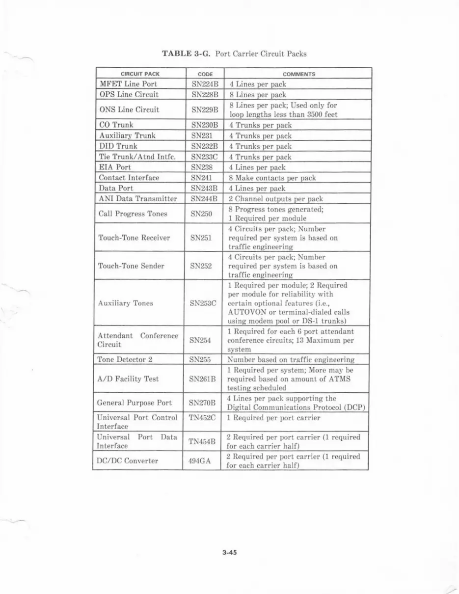
MFET Line Port sN224B 4 Lines ner nack
OPS Line Circuit SN228B 8 Lines Der Dack
ONS Line Circuit sN229B8 Lines per pack; Used only forIoon lensths less than 3500 f€et
CO ?runk sN230B 4 Trunks D€r nack
Auxiliarv Trunk SN231 4 Trunks Der oackDID Trunk SN232B 4 Trunks per DackTie Trunk/Atnd Intfc. sN233C 4 Trunks ner na.kEIA Port SN238 4 Lines Der Dack
Contact Interface SN241 8 Make contacts ner nack
Data Port sN243B 4 Lines oer oackANI Data Transmitter SNz4B 2 Channel outDuts Der nack
Call Progress 'lon€s SN25O8 Progress tones generated;1 Reouired ner modDle
Touch-Tone Receiver SN25T
4 Circuits per pack; Numberrequired per system is based ontraffic ensineerins
Touch-Tone Spnd€. sN2524 Circuits per pack; Numberrequired per system is based ontraffic ensineerins
sN253C
1 R€quired per module; 2 Requiredper module for r€liabilit], lvithccrtain optional features (i.e.,AUTOVON or terminal-dialed callsusins modem pool or DS-l trunks)
Attendant ConfercnceCircuit sN254
I Required lor each 6 port attendantconference circuits; l3 Maximum per
Tone Detector 2 SN255 Number based on traffic ensineerins
A/D Facility T€st SN261BI Required per system; More may b€required based on amount of ATMStestinq scheduled
Gen€ral Purpose Port SN27OB4 Lines per pack supporting theDisital Communications Protocol {DCP)
Universal Port Control TN452C 1 Required per port carrier
Universal Port DataTN454B
2 Requircd pcr port carricr (1 requir€dfor each carrier half)
DClDC Converter 494GA2 Required per port carrier (r requiredfor ea.h carrior half)
TABLE 3-G. Pori. Carrier Circuit Packs
3-45
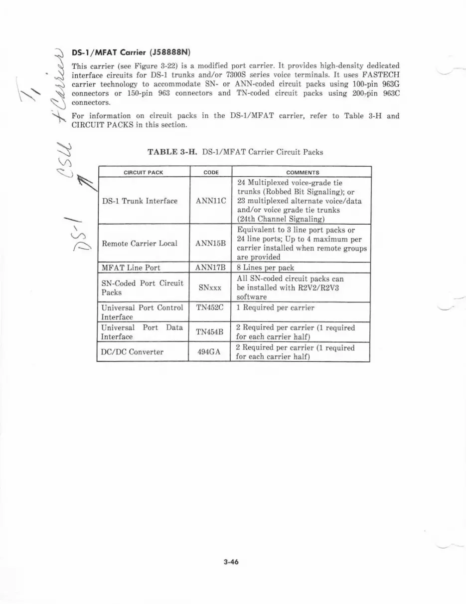
t\J
\\\
\\A\
\\
DS-l /MFAT Corrier (J58988N)
This carrier (see Figure 3-22) is a modilied port carrier. It provides high-density dedicatedinterface circuits for DS-l trunks and/or ?3005 series voice t€rninals. It uses FASTECHcar er technology to accommodate SN- or ANN-coded circuit packs using 100-pin 963Gconnectors or 150-pin 963 connectors and TN-coded circuit packs using 200r0in 963C
For information on circuit packs in the DS-1/MFAT carrier, refer to Table 3-H andCIRCIIIT PACl(S in this s€ction.
TABLE 3-H. DS-I/MFAT Carrier Circuit Packs
DS-1 Trunk Interface ANN11C
24 Multiplexed voice-grade tietrunks (Robbed Bit Signaling); or23 multiplexed alternate voice/dataandlor voice grade tie trunks(24th Channel Sisnaline)
Remote Ca ier Local ANN158
Equivalent to 3 line port packs or24 tine ports; Up to 4 maximum percarder installed when remote groupsare provided
MFAT Line Port ANN1?R 8 Lines oer oack
SN-Coded Port CircuitPacks
SNxxxAll SN-coded circuit packs canbe installed with R2V2IR2VBsoftware
Universal Port ControlInterface
TN452C 1 Required per carrier
Universal Port DataInterface
TN454B2 Required per canier (1 requiredfor each carrier half)
DCIDC Converter 494GA2 Requir€d per carrier (1 requiredfor each carrier half)
(/^A
3-46
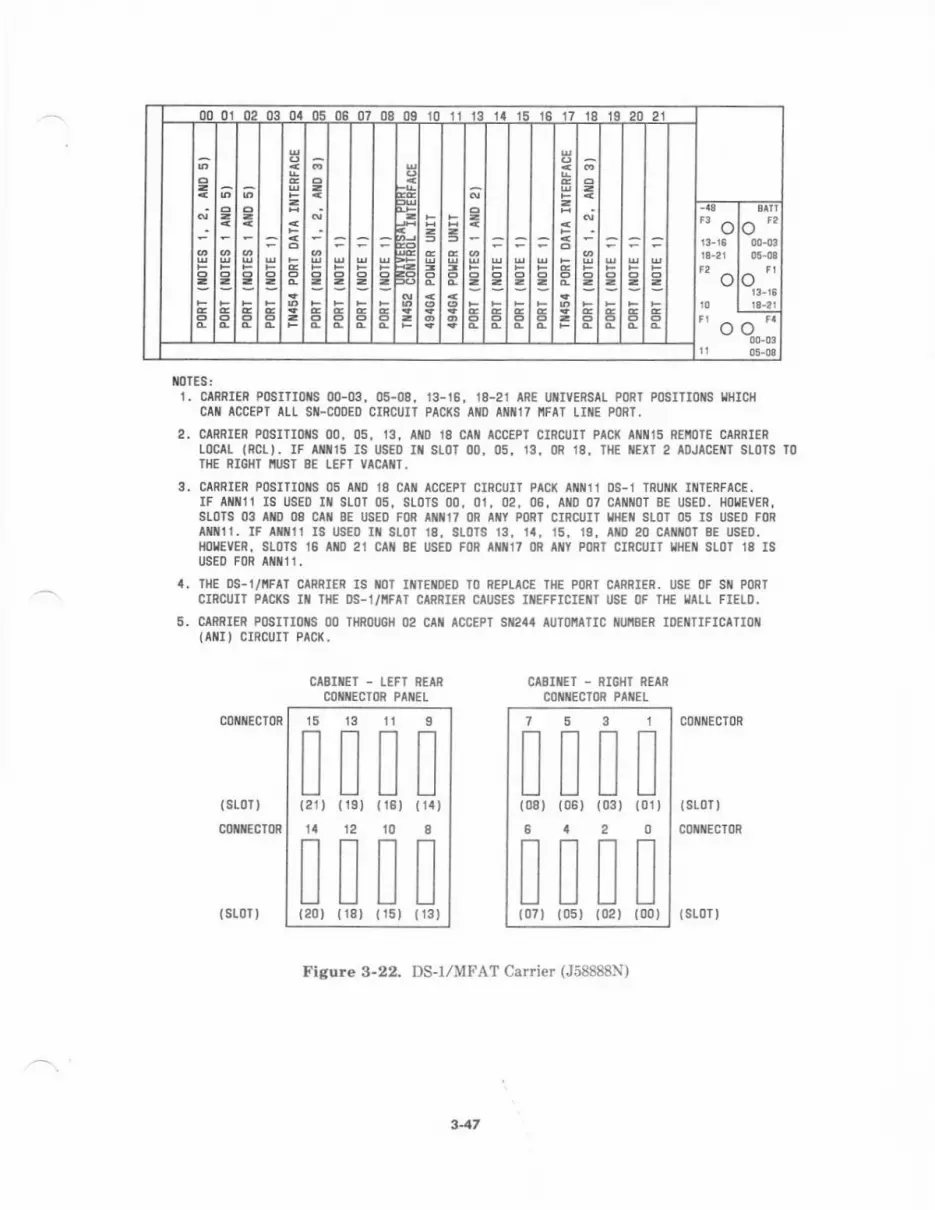
00 0l 02 03 0t 05 06 07 08 0g 10 11 13 14 15 16 17 1g 19 20 21
'"o
o
,'o
o'"
o''o"
{l)TES:1. CARRIER PoSITIoNS 00-03, 05-08. 13-16, 18-21 ARE UItMRStt P0Rr P0SITI0NS l,lltICH
CAII ACCEPT AIL SII-CODED CIRCUIT PAC(S AIID ATT17 I'IFAT LII{E PI)RT.
2. CARRIER POSITIOIS OO, 05. 13. AIIO I8 CAII ACCEPT CIRCUIT PAC( ATI!I15 REI'IOTE CANRIERroctL lRcLl. IF lti|ts Is usED I{ sLoT 00. 05, 13, 0R 18, THE |{EXT 2 AoJACEilT SIoTS T0II{E RIGNI NUST 8E LEFT VACAIT.
3. CARnIER POSITIOIIS 05 AIID 18 CAiI ACCEPT CIRCUIT PAC( AIIIIII l OS.I TRUIIIX IIII]ERFACE,IF AI{1111 IS USED Ill SLor 05, SLoTS 00, 01, 02, 06, Ailo 07 CAI{ oT 8E USED. Ho!EVER,SLOTS 03 AID 08 CIN 8E USED FON ITN17 OR AIIY PORT CIRCUII I]IEII SLOT 05 IS USED FORaIx1t. IF txitt Is usEo IN st0r 18, sloTs 13, 1a, 15, 19, atD 20 catl{oT BE usED.HOIEVER, SIOTS 16 AIIO 21 CAN 8E USED FOR ATN17 ()R AI{Y PORT CIRCUI] IIIEiI SLOT 18 ISusEo FoR a{x 11 .
4. THE OS.I/IIFAI CIRRIER IS IIOT II{TEIIDED TO REPLICE TI1E PORT CIRRIER, USE OF SIi PORT
CIRCUII PACrc Iil THE DS-1/IIFAI CARNIER CAUSES INEFFICIEIII USE OF TIE IIAIL FIELD.
5. CARNIER POSITIOIIS OO TI]ROUGI] 02 CAI{ ACCEPI SII24I AUI(]I'IATIC ilUiSER IOEIITIFICATIOI{(AIII I CIRCUIT PACK.
CASIflET - IEFI REAR
CITIIECIOR PII{ELCAEITET - RIGIIT REAR
COIIIIECTOR PIIIEL
c0t{lEcT0R c0 tttEcT0R
{sr0r)coxilEcToR
(sL0T)
CONIIECIOR
(slor I {st0r}
Fisure 3-22. DS-r/MFAT Carrier (J58888N)
347
s
I{14}
8
!{ l3)
15 l3 11
ml(21) {19) (r8'ta 12 10!ti
(20) (18) t15
1
!(01
53
!l) {06) (03 )
'|
I(08
6
I{07
0
I) (00)
2
I{02
II (05)
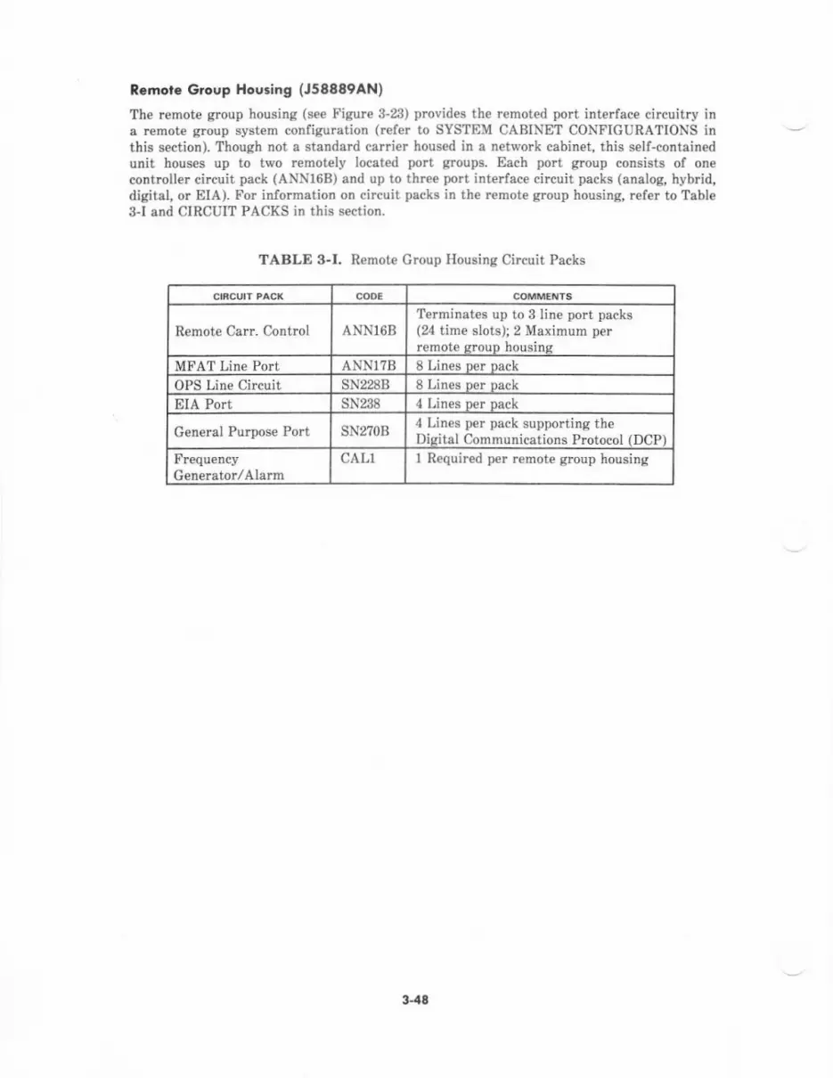
Remot€ Group Ho6ing (J58889AN)
The remote group housing (s€€ Figure 3-23) provides the remoted port interface circuitry ina r€mot€ group system configuration (refer to SYSTEM CABINET CONFIGURATIONS inthis section). Though not a standard carrier housed in a network cabinet, this self-containedunit houses up to two remotely located port groups. Each port group consists of onecontroller circuit pack (ANN16B) and up to three port inte ace circuit packs (analog, hybrid,digital, or EIA). For information on circuit packs in the remote group housing, ref€r to Table3l and CIRCUIT PACKS in this section.
TABLE 3-I. Remote Croup Housing Circuit Packs
Remote CaIr. Cortml ANN16BTerminates up to 3 line port packs(24 time slots); 2 Maximum perremote srouD housins
MFAT Line Port ANNl?B 8 Lines per pack
OPS Line Circuit SN2288 8 Lines per oack
EIA Port SN238 4 Lines per pack
General Purpose Port SN2?OB4 Lin€s per pack supporting theDisital Cornmunications Protocol (DCP)
Frequ€ncyG€nerator/Alarm
CALl 1 Required per remote group housing
3-48
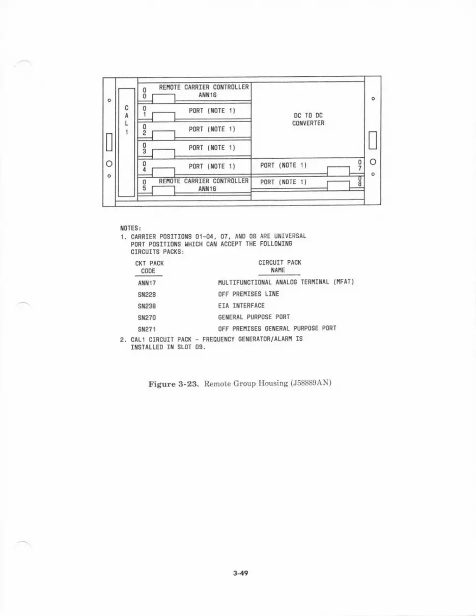
Io
Io
o REioTE CAnRIER C0rrsoLLER0 t--t r!!!8
0c r0 !cCITVERTER
0IJ PmT lnTE r I
-l-r---r-:911-lir--r :ryg-f
0ll PoRT { oTE 1} PORT {TOIE 1) 0tlO REM]E CIRflIER COiIROIIERi-r-----t-rxltg- PoRT (xorE 1) f----'l E
flotEs:1. C|RRIER PoSTIIoXS 01-01, 07, lllD 08 IRE UlrvEEsaL
PltRT POSITIOIIS IIHICI'I CAI ACCEPI II{E FOLIOIIITGCIRCUITS PAC(S:
CKT PAC( CIRCUIT PACK
coDE llltlE
Ar T
9t228
st2sS
s12m
3t271
IIUITIFUTCII IAL ATOG IERIIIIIIL (IIFATI
OF; PREIIISES LIIIE
EIA II'IERFTC€
GEiERtl P$MSE MRl
OFF PREIIISES GEiERAI PURPOS€ PORT
2, CAL1 CIRCUIT PAq( - F8EOUETCY OEIIERATOR/ALTRi ISITSTALLEI) IT SLOT 09.
Figure 3-23. Remote Croup Housing (J58889AN)
3.49
CIRCUIT PACKS
System 85 circuit packs contain the circuitry required for operation of the system. Thesecircuits include common control circuits, network control circuits, port interface circuits, andspecial applications circuits. Circuit packs are installed in slots within carriers. Each carrieris located in one of four designat€d carrier slots within each switch cabinet.
Most circuit packs make use ol a packaging system technology in which female connectorsmate with male pins in the carrier backplane- Many circuit packs contain red, yellow, andgreen lieht-€mitting diode (LED) indicators on the faceplate as aids in determining theiroperational status. In addition, a circuit pack may provide test points to alloiv interrogationof internal circuit slatcs for faulr diagnosis.
Most circuit packs use identification (ID) chips and signature analysis chips (SACs) fortestine purposes. The ID chips, assigned on a per-board basis, interfac€ to the Input/Output(I/O) bus. The ID chips provide readable information about circuit pack type and vintage.They contain drivers and status sensors for the green and red maintenance LEDS. The IDchips also contain a test register which can be written and then read to validate theaddrcss/data paths thrcugh the I/O buffers. The SAC function detects timing-reiated errorsby initializing a unique data stream, known as a signature, during a self-test mode. After th€register is cleared, the returned signatur€ is compared to a "known good" signature. The twosignatures are identical when the SAC is functioning properly.
Some circuit packs contain option switches that are set accoding to the interface type, rangerequirement, data rate, or other factors that impact the specific circuit pack application.These option switches are set or verified during initial installation and testing. For detailedinformation on specific circuit pack option switch settings, refer to AT&T System 86-Itrstallation-Service Manual (555-102-104).
Each circuit pack is equipped with an identification faceplate containing a color-coded label.The system circuit packs are grouped by color according to function to simplify maintenanceand repair. A circuit pack may be replaced only with a simitar circuit pack having either thesame or subsequent suffix as that prjnted on the ca.ri€r designation strip. (For example, anSN230 cannot be used if the designation strip specifi€s SN230B. Therefore, SN230B, C, orlater alpha-suffixed SN230 packs are suitable replacements.) Suffix codes indicate successiveimprovements or modifications. Circuit pack availability and applications [according toSystem 85 Release (R) and Version (V)l are listed on th€ next two pages.
3-50
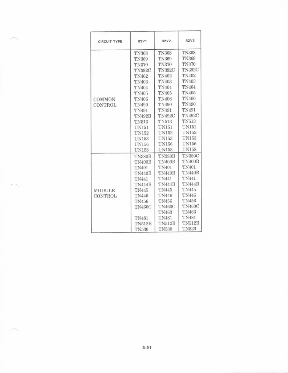
COMMONCONTROL
1N368TN369TN370TN392CTN402TN4O3TN404TN4O5TN4O6TN49OTN491TN492BTN513UN151UN152UN153UN156UN158
TN368TN369TN3?OTN392CTN4O2TN4O3TN4O4TN4O5TN406TN49OTN491TN492CTN51SUN151UN152UN153UN156UN158
TN368TN369TN3?OTN392CTN402TN4O3
TN4O4TN4O5TN4O6TN49OTN491TN492CTN513UN151UN152UNl53UNl56UNl58
MODULECONTROL
TN38OBTN4OOBTN401TN44OBTN441TN444BTN445TN446TN456TN460C
TN481TN5128TN53O
TN38OBTN4OOBTN4O1
TN440BTN441TN444BTN445TN446TN456TN460CTN463TN481TN5128TN53O
TN380CTN4OOBTN4O1TN44OBTN441TN444BTN445TN446TN456TN460CTN463TN481TN5128TNSSO
3-5 |

PORTINTERFACE
SN224BSN221BSN228SN222BSN229SN23OSN23TsN2S2BsN233B
SN241SN2438SN244SN25O
SN25TSN252sN253CSN254sN255SN26OsN261SN2?OTN452BTN4&B
SN2ZB
sN228
SN229SN23OSN231SN232BSN233BsN238SN241sN243BSN244BSN25OsN251sN252sN253CSN254SN255
sN26lBsN270BTN452BTN454BANNlIB
ANN17B
sN224B
SN228B
sN229BsN230BsN23lsN232BsN233CsN238SN241SN243BSN244BSN25OSN25IsN252sN253CSN254SN255
SN261BSN27OBTN452CTN454BANNl1CANNT58ANN16BANN1?B
TMS
TN381TN4OOBTN4OlTN452BTN461TN462
TN4?OTN4?3TN480TN482TNsT28TN53OUN150
TN381TN4OOBTN4O1
TN452BTN461TN462TN463TN4?OTN473TN480TN482TN5128TN53OtINt50
TN38ITN4OOBTN4OITN452CTN461TN462TN463TN4?OTN4?3TN480TN482TN512BTN53OItN150
3-52
SN-Coded Circuit Pqcks
The SN-cod€d circuit packs are the port interfaces of the system. These circuit packs aredesigned with FASTECH packaging system technology that utilizes a 100-pin conn€ctor.Each circuit pack measures approximately 13.8?5 inches (352 nn) in length by ?.6?0 inches(195 mm) in h€ight. The faceplate of each circuit pack provides 19 positions for LED and testpoint placement.
The SN-cod€d circuit packs are usually located in the port ca.rier only. They may be locat€din spare slots within a DS-1/MFAT carrier in R2V2IR2VB system configurations, but thiscauses inefficient use of the wall field.
SN224A FEf Line Pq,
This circuit pack interlaces the digital switch to hybrid sets such as 7200H series voiceterminals, Multibutton Electronic Telephones (METS), and Electronic Custom TelephoneService (ECTS) sets.
The SN224B has its own microprocessor which provides an interface between the moduleproc€ssor and the voice terminal control data links. Control information to and from a
terminal is transmitted in digital form. Voice information is transmitt€d in analog form.The SN2 B provides four port circuits, each serving a single voice terminal. Each circuit hasthree pairs: one pair for voice, one pair for featur€ button control information, and one pairfor feature lamp control information. The SN224B provides phantom power to the terminalsove. the two data pairs.
A single shorting plug option adapts all lour ports for hybrid or ECTS data pulse timing.The ?200H series voic€ torminals will work with ECTS data pulse timing but are limit€d to arange of 1000 feet (S05 m). The MET,zECTS terminals will not work with hybrid terminalpulse timing.
The SN224B is required whenever ?200H series voice terminals or MDT/ECTS sets are usedin the system.
SN228B OPS line Ciftvit
This circuit pack int€rfaces the digital switch to analog voice te.minals that are off-premisesto the main location of the system, or on-premises with a la.ge loop insertion loss. It alsoprovides lightning protection.
The SN228B provides off-premises extension capability '{ith call monitoring andtransmission level detect compensation- It incoryorates one option switch p€r port forimpedance compensation. This switch offers either a 600-ohm or RC impedance equivalentbalance network to optimiz€ transmission quality. The SN228B provides selection of either ao-dB or 3-dB loss per circuit for short or long loop applications.
Each circuit receives loop signaling from the voice terminal to detect switchhook status androtary dial pulses. Analog signals from the voice terminal are receiv€d over the tip and ringpair, encoded as serial pulse code modulation (PCM) data and transmitted to the networkThe PCM signals from the network are d€coded and ttansmitted as analog signals over thetit and ring pait to the attached terminal. This circuit pack also provides 20-Hz ringing
--Xth" l,t"""r(o Waitinq featur€ is suDnorted whcn interfaced to a ?100A series voice terminal.'The port circuit signals th€ voice terminal to light the Message waiting indicator by
providing a ground on the ring lead. The ground signal is a 0.l-second pulse occur ng every1.3 seconds in phase with the beginning of a ringing cycle. (The ring relay is used toimplement the ground signal which occurs b€twe€n ringing generation in the cycle-) Theindicator draws 10 milliamps from the line circuit battery feed, rvhich is enough to power itwithout indicating an off-hook state.
3"53
The SN228B incorporates line current driv€rs and can b€ used for btidged 2500 voice
terminals or 1A2 key applications- Four ringers can be supported. (Onlv two 2500 t€rminalsshould be bridged to insurc adequate transmission levels with multiple terminals off_hook )
The ?100A series voice terminals cannot be used in physically bridged applications due toloop current considerations and the Message Waiting feature current drain requirement.
Th€ SN223B provides eight separate line circuits and is ususllv used when the loop length isgreater than 3500 feet (106? m). The SN228B does permit a shorter rang€ when required.ihi8 circuit pack is the only analog port interface supported in the remote group housing due
to its horizontal mounting. (Since it has no mercutv relavs, the SN228B is not mountings€nsitive.)
SN229A ONS U,c Cicvi,
This circuit pack interfaces the digital switch to analog voice terminals within the system, orto off-premises voice terminals that have a low loop ins€rtion loss Each port circuitinco.porates a 600-ohm balance network. Th€ SN229B provides a fixed 3_dB loss per circuitto compensate for sholt loop loss and to insure adequat€ voice lev€ls.
The SN229B operates much lik€ the SN228B, receiving loop signaling fmm th€ voice
terminals to detect switchook status and rotary dial pulses Analog signals from the voice
terminal are received over th€ tip and ring pair, encoded as serial PCM data, andtransmitted to the n€twork. The PCM signals from th€ network are decoded and
transmitt€d as analog signals ov€r the tip and ring psir to the attached terminal. Thiscircuit pack also provid€s 20_Hz ringing current.
The Message Waiting featurc is supported when inte aced to a ?100A series voice terminal.The port circuit signals the voice terminal to light the Messag€ Waiting indicator by
providing a ground on the ring lead. The ground signal is a 0l-second pulse occuring €very1-3 seconds in phase with the beginning of a ringing cycle. (The ring relay is used toimplement the ground signal which occurs between dnging generation in the cycle-) Theindicator alraws 10 milliamps from th€ ljne circuit battery f€€d, which is enough to power itwithout indicating an off-hook state
The SN229B does not incorporate line current drivers and should not be used for bridgedterminal or 1A2 k€y applications.
The SN229B provid€s eight separate line circuits and is usually us€d when the loop length isless than or equal to 3500 fe€t (106? rn).
SN23OE Co rrunk (Ooend gan)
This circuit pack provid€s 2-wire c€ntral office (CO), Foreign Exchange (Fx), and wide AreaTelecommunications Servic€ (WATS) ground-start trunk interfaces to a local CO. TheSN230B intefaces the digital switch to a CO through a 2-wire tip and ring connection. The
four circuits employ ground-start signaling and can be used in l-way incoming, 1_way
outgoing, or 2-way transmission. Each circuit pack provides lour s€parate trunk circuits
An option switch is provided for each trunk circuit. These switches s€lect the balancingnetwork corrcsponding to the tip and ring loop equivalence to which the trunk circuit isconnected. Each switch offers either a 600"ohm or an RC irnpedance equivalent balance
SN23l Auxiliaty hunl<
This circuit pack provides a trunk'type interface betw€en the digital switch and auxiliaryequipment. Examples of auxiliary equipment are as follows:
. Loudspeaker Paging
. Music-on-hold
3-54
. Recorded &nnouncement
. Recorded telephone dictation.
Th€ SN231 provides four 2-wire trunk circuits. Option switches allow each circuit to serve asa 1-way incoming, 1-way outgoing, or 2-way transmission path, depending on the registrationrequirements and auxiliary equipment to which the circuit is connected. Ground signalingbetw€€n the auxiliary equipment and each trunk circuit occurs through a separate paird€signated AL and S. The AL lead is used to receive signaling from the auxiliary equipmentthrough a ground applied to AL. The S lead is used to receive signaling from the auxiliaryequipment through a ground applied to S. The SN231 also supports sending dial pulses overthe tip and ring leads.
The SN231 provides an option switch for each circuit with four sections (toggle switches) p€roption switch. One s€ction (D) is not used. The r€maining sections (A, B, and C) provid€ forvarious signaling arrangements. The B and C sections allow the trunk to serve in thefollowing ways:
. l-way incoming with B open and C closed
. l-way outgoing with B closed and C open
. 2-way tr.nsmission with B and C closed.
The A section is closed when the auxiliary equipment requires only one path for groundsignaling using th€ S lead for l-way signaling, either incoming or outgoing.
SN232A DrD T.vnL
This circuit pack provides an interfac€ between the local CO and the digital switch. Itpermits incoming calls to terminate on a specific port within the system without requiringattendant assistance-
Each of the four trunk circuits has a 2-wire audio connection with provision for detecting alow-resistance loop closurc (high-low signaling) by the CO as an off-hook or ready-to-transmit dial pulses indication. In response, the Direct Inward Dialing (DID) trunk returns areversal of battery as an indication of ready-to-receive dial pulsing or immediately r€ceivesthe dial pulsing, depending upon the exchange requirem€nts.
Th€ SN232B provides four separate trunk circuits. Each trunk ci.cuit has an option switchto select a 600-ohm or RC impedance equivalent balance network corresponding to the tipand ring loop impedance to which the trunk port is connected.
SN233B/C fi. f.unr/A,rendan, lnraioce
This circuit pack is normally used to provide Common Contrcl Switching Arrang€m€nt(CCSA) access and tie trunk service. It may also be used for certain DID applications, as arelease link trunk (RLT) for the Centralized Attendant Service (CAS) f€ature, and as anaudio intedace for th€ attendant console.
The SN2.33B provides four separate trunk circuits. Each trunk provides a 4-wire audioconn€ction (transmit and receive pairs) and two signaling leads (with option switches) forTypes 1or 5, E&M signaling. (B&M Type I interfaces cannot be set "back-to-back" directlyunless an external signal conversion d€vice is used.)
The SN233C compatibl€ E&M (cE&M) circuit pack offers direct E&M lype 1 and 5connectiviti€s. Ownership of external faciliti€s and rcgulatory/protective issues determines
Access to both transmit and receiv€ audio pairs and to the E&M signaling leads for eachtrunk are provided by jacks at the circuit pack faceplate. Plug insertion into tho transmitand receive jacks acc€sses the local end and op€ns the pair towad the distant end. Optionswitches ar€ provided for each signaling lead and for each trunk individually to determine
3-55
the type of access from ihe E&M sienaling jacks. Th€ option can be set to allow access to thedistant end when the plug is insert€d or to b.idse the sisnalins lead when the jack isinserted.
When the SN233B is connected to an attendant console, only one signaling lead is used-Additional option switches are provid€d for simplex signaling, lightning-protected E&M (toprovide off-premis€s connections without extemal int€rface equipment), and for A-law ormu-law companding.
5N238 EIA Po't
This circuit pack provides a cost-effective interface b€tw€en the digital switch and generaltrade devices that employ Electronic Industries Association (EIA) RS-232C signalingprotocol. From a cail processing aspect, it appears as a digital port interface connected to adata module. Used in conjunction with a ZBA asynchronous data unit (ADU) at the devic€end, the SN238 completes the RS-232C connection.
The SN238 supports American Standard Code for Information Interchange (ASCII) dialingand full-duplex asynchronous communications. It features option switch settings for portdata rates, autoband and parity, and keyboard dialing. Each 2-pair (send and rcceive) datalink supports standard data rates from 300 to 19,200 bps, with built-in limited distancenodelns (LDMS) to ove.come th€ distance limitations of RS-232C protocol. Links up toseve.al miles in length can be suppoded depending on the data rate used.
The requir€d standard RS-232C signais supported by the SN238 are:
. Signal Ground
. Transmitted Data
. Data Terminal Ready
. Received Line Signal Detector, Data Set Ready, and Clear to Send (all provided asone signal).
The SN238 provides four port interfac€ circuits for RS-232C devices. Each circuitincorporates the complementary ADU functionality and protocol conversion to th€ digitalcommunications protocol (DCP).
The SN238 has the followjng switches for various option s€ttings:
. S1A (O/EPR)-In the on position sel€cts Odd Parity and in the off position selectsEven Parity.
. SIB (PRTY)-In the on position enables Parity and in the off position disablesParjty.
. S1C (19.2 k) In the on position selects 19.2 kbps as the data rat€ for all four ports.
. SlD (9600)-In the on position sel€cts 9600 bps as the data rate for all four ports.
. S1E (4800)-In the on position selects 4800 bps as the data rate for all four ports.
. S1F (2400)-In the on position selects 2400 bps as th€ data rate for all four ports.
. S1G (1200) In the on position sel€cts 1200 bps as the data rate for all four ports.
. SlH (300)-In the on position selects 300 bps as th€ data rate for all four ports.
. S2A (AUTO o)-In the on position enables and in the oll position disabies the Auto-band and Auto-parity function for port 0.
. S2B (AUTO 1)-In the on position enables and in the off position disables the Auto-band and Auto-parjty function for port 1.
3-56
. S2C (AUTO 2)-In the on position enables and in the off position disables the Auto-band and Auto-parity function for port 2.
. S2D (AUTO 3)-In the on position enables and in the off position disables the Auto-band and Auto-parity function for port 3.
. S2E (KYBD 0)-In the on position enables and in the off position disables theKeyboard Dialing function for port 0.
. S2B (KYBD l)-ln the on position enabl€s and in the off position disables theKeyboard Dialing function for port 1,
. S2C (KYBD 2)-In the on position enables and in the off position disables theKeyboard Dialing function for port 2.
. SzD (KYBD 3)-In the on position enables and in the off position disables th€Keyboard Dialing function for port 3.
SN24t C.o.rac, tntttd@
This circuit pack is used as an interface to provide signaling to external equipment. It istypically used to operate indicators (LEDS or beehive lamps) through the closure of contactson the circuit pack. The SN241 provides eight "make" contaets that are operated (closed) oncommand lrom the common control, These contacts are connected to the peripheralequipment through tip and ring pairs that are electrically isotated from the circuit pack.
At least one SN241 is requir€d when the EUCD and CAS features are provided.
SN243A Dora ?od
This circuit pack provides a 2-wire tip and ring connection to data €quipment for 2-wayvoiceband data transmission and also p.ovides the off-premise ext€nsion functionality lorthe Off-Prcmises Terminal feature using trunk-type translations.
The SN243B contains four separate trunk-type data ports. Each port provides a tip and ringconnection. The data port is a line termination but is viewed as a trunk port by the callprocessing software, For outgoing calls, the alerting functions are prcvided bJ this circuitpack. The associated data equipment requi*s a line-circuit-type of termination. Each portcircuit has an option switch that selects a 600-ohm or RC impedance equivalent balance
SN2ZKA AM Dero f.do.mia,e.
This circuit pack ttansmits th€ extension and trunk numbers of calls that are to beidentified for billing pu.poses to a local CO or CCSA office.
The SNZ4B has two basic functions. One function is dc simpl€x signaling, in whichhandshaking is performed with the CO to prcperly set up the switch and CO fortransmission of information. Th€ other function is to convert and transmit the informationstored in ihe ANI Data R€gister circuit.
Battery and ground signaling are used to perform handshaking betw€en the switch xnd theCO. These signals are used to indicate an idle state, a busy signal, a transmit signa), andswitch or CO disconnect signals.
The SN244B provides two channels, with only one channel active at any one tim€. Thesignaling and information transfer occurs over s tip and ring connection to the CO.
SN25O CdI Prcgr.tr r e.
This circuit pack generates eight call progress tones used by tho system. These tones areused in thei. normal state by the system and by the time siot interchanger (TSI) to producetones that have nonperiodic interrupts.
3-57

The SN250 generates tones dir€ctly in digital form through a digital signal processor (DSP)circuit. The tones are sent to the port data store through th€ TSI- The DSP generates theeight tones continuously and outputs each ton€ in the assisn€d time slot at a separate port.The tones and port assignments are as follows:
. 440-Hz tone at port 0
. Dial tone at port 1
. Inte upted dial tone at port 2
. Ringing tone at port 3
. Call Waitine ringback tone at port 4
. Intercept tone at port 5
. Busy tone at pott 6
. Reorder ton€ at port 7.
The SN250 also performs reflection testing of the port circuits and cail progress tonestesting. One SN250 is requircd p€r module.
SN25 I fouch-fone Re.eiver
This cireuit pack provides the dual-tone multifrequency (DTMF) receiving capability for thesysrem. Ir provides four spparare rou.h-rone rccpirer circuils.
The SN25l provides two main functions. First, the receiving circuit must accept digitallycoded DTMF PCM signals, recognize what signals are present, and convert the PCM signalsinto a 4-bit word. This information is then sent out on the I/O bus to the port controiinterface and the module processor. Secondly, the circuit pack serves as an intedac€supplving both single'ported or dual-ported call connections.
5N252 r6v.h-rone Senda
This circuit pack provides DTMF signaling and dial tone detect capability for the system. Itprovides four separate circuits.
The SN252 contains a DTMF tone sender. It also has a dial tone detector, thus allowing thesystem to pedorm DTMF sjgnaling and dial tone detection on its trunks. The touch-tonesenders can send up to 25 digits, as well as 15 test tones that are used for touch-tone senderand rcceiver maint€nanc€ testing. The tones are generated and detected digitally by using aprogrammable DSP.
SN253C Auxilic.y foiesThis circuit pack generates ton€s used by the system. The foilowing three tones aregenerated in analog format:
. Dial tone
. Audible ring
. Chime tone (Chime Paging).
The following seven ton€s are g€netated in digital format:
. CAS feature (3 identification tones)
. Chime tone
. Data answer tone
. Precedence tone (AUTOVON)
. Priority audible ringback (AUTOVON).
3-58
Option switches Sl and 52 aae used to select the int€mal chim€ tone or the optional relaycontact closure to control an external signaling device. The option switches also select theperiod of the contact closure when an exte.nal signaling device is used.
tN254 A .ndan, 6nle.e.tc. Ci.cui,
this circuit pack allows confer€nce bridging for up to six parties and the attendant. Theconferencing of the time slots is linear. All of the parties must be at the same transmissionlevel coming into the conference circuit to assure that all speake$ are heard at the samelevel. Any combination ol six trunks and internal lines may be conferenced (except COtrunks, two maximum)- The SN254 provides six conferenc€ ci.cuits. There can be up to 13SN254s per system.
5M255 fon. D.t .to. 2
This circuit pack detects all tones and tone pairs on the subscriber loop necessary to provideterminal-dialed data calls through modem-pool-accessed or digital tie trunk facilities.Digital filters using DSP t€chnology detect these tones- The SN255 detects dial tone, busytone, recorder tone, data answer ton€, and other tones which may be encountered during callprogress for leedback to the originating terminal. Th€ tone information is encoded in PCMformat and is sent to the SN255 through the A-bus. The output of the four tone detectioncircuits arc available through the I/O bus.
SN26t (A)/D Fe.iliry rei A..uit
The SN 1 provid€s digital facility testing only. The SN261B provides simultaneous analogand digital facility testing in addition to oth€r R2V2IR2V3 t€sting capabilities. Digitalfacility testing in this context refers to data module connections through the SN2?0B digitalport circuits with trunk-type translations.
The SN261 contains circuitry which permits automatic testing of the system data facilityand data equipment, including data modules and modem pool facilities. The mod€m poolfacility is a combination of Modular Trunk Data Modules (MTDMS) and analog data setsused to convert data from digital to analog format and vice versa.
Digital facility tests are performed through switched connections to the SN26l. When theconnection is established, the SN261 transmits a pseudo-random periodic data pattern. Thispattern is returned to the SN261 through loopback control points in the facility under test orthrough another switched network conn€ction from a second data module. The returned datais checked tor ermrs and the results are reported to the system in terms of both errcrs perbits transmitted and errors per block transmitted. Other failures such as inability to reachthe data transmission mode because of "handshaking" failures are also reported. A typicaltest requir€s 2 to 3 minutes. Modem pool facilities are at times tested in pairs to obtain end-to'end testing requiring digital-to-analog-to-digital conversion. The SN26r is also capable ofproviding a loopback connection to any date module on a dial-up basis through a switchedconn€ction.
Demand tests are provided for all data modules and are invoked by rnaint€nance procedures(PROCs). Periodic tests are provided for rnodem pool facilitios and all data modules aretranslated as trunks (e.g., Host Computer Access); each is checked once per day. Demand andperiodic tests take approximately 3 minutes per conn€ction lor a data modul€ and 12 minutesfor a mod€m pool facility pair.
The SN261B incorporates all the digital facility test capabilities provided by the SN261 plusth€ Originating T€st Lin€ (OTL) and Terminating Test Line functions for the AutomatedTransmission Measurement Syst€m (ATMS) feature. Available with R2V2 and R2Vg systems,the ATMS feature provides a compr€hensive customer-controlled testing capability foranaloa trunk transmission.
3-59

The SN261 complements the SN260 in an R2V1 system, while the SN261B only is required inan R2V2 or R2V3 system. Multiple SN261BS may be required depending on th€ amount ofATMS testing schedul€d for a given period
SN27OB Ged.'al Puryo'e Pet (GPF)
This circuit pack provides an interface between the switching network and the DCP. TheDCP uses two twisted pairs (send and receive) op€rating at a rat€ of 160 kbps lull duplex.This protocol consists of a 20-bit frame with two 8-bit inlormation fields (I-channel), a 1-bitsignaling fi€ld (channel), and a 8-bit framing pattern.
The SN2?08 transfers PCM voice or data between the DCP I-channels and correspondingswitch network time slots. Signaling between th€ attached terminal and common control orother DoP-intedaced terminal is suppotted by the signaling channel. When combined voiceand data are r€quired, both DCP l-channels and corresponding switch n€twork time slots areused. For voice only or data only, one DCP I-channel and corresponding time slot is used.
Each SN2?08 provides four DCP line ports for connection to 7400D s€ €s voic€ terminals(with or without DTDMs), all data modules, AT&T Personal Terminals (510D), and 515
BCTS. when combined voice and data arc required on the DCP, two ports are used. Forvoice service only, one port is used. Phantom power is provided over the two data pairs for?400D series voice terminals and the voice terminal module of the Personal Terminals(PTs)/Business Communications Terminals (BCTs) only. Data modules (including the DTDM)and the remaining PTIBCT functionality are not powercd frcm the SN2?0B.
TN-Coded Cir(uit Pock3
The TN-coded circuit packs are the network control circuits of the system. They are designedwith FASTECH packaging system technology that utitizes a 200-pin connector. Each circuitpack measures approximately 13.375 inches (340 mm) in l€ngth by 7.670 inches (196 mm) inheight. The faceplate of each circuit pack provides 19 positions for LED and t€st pointplacement.
fN368 llemo.y Prot 4
This circuit pack prevents write operations into certain areas of memory and also preventsprogram fetch€s from nonprogram areas of the m€mory. In addition, it performs sanitytiming, bus resolution, and rniscellaneous control functions.
The TN368 is located in the common control carrier.
rN369 Ca.he trlendy
This circuit pack contains lrcquently accessed instructions and data. The high-speed memorydynamically monitors and replaces its contents based upon 50lCC program execution andactivity of other bus masters. It provides processor throughput enhancement by reducing theeffective memory address time.
The TN369 provides memory €nhancement in systems that have nine or nore modules. It islocated in the common control carlier.
This circuit pack contains the microstore and logic for sequencing the microstore, latchingthe microinstruction, and generating the clocking for the 501CC processor. The TN3?0 is oneof the four circuit packs in which the bit-slice-designed processor is partitioned. Thefunctions of the other three circuit packs are controlled by microinstructions suppli€d by thiscircuit pack.
The TNS?o is located in the common control carrier.
3-60

fN38arc odub P.o.."or (fiP)
This circuit pack is the central control unit for all network module operations. It controlscommunications betrveen the common control and the digital network. Th€ TN380C performsthe following tasks for the system:
. Network control
. Port scanning
. Digit collecting and s€nding
. Port alerting and demand distribute.
All communication between the common control and the network is controlled by the MP.The MP interlace to the common control is through the module control channel and a 4-MHzserial subchannel. The MP interfaces the network port circuits through th€ I/O bus interfacefor control and through th€ time slot interchanger (TSI) for servicing connection paths(voice and data).
The MP incorporates a t6-bit mic.oprocessor and contains 32164 kbytes of programmableread-only memory (PROM) for firmwarc storage aDd 32 kbytes of siatic RAM.Qlhe PROMfirmware consists of those routines which perform lin€ and trunk scanning and validatio4digit collecting and sendins, and line alertine)The RAM functions as a storas€ area forprocessing or validating state chang€s.
Th€ TN380C is located in the module control carrier. Within duplicated modules, the TN380smust have matching suffixes (both B or both C). However, TN380s in one module may have adiff€rent suffix from TN380s in another module within the same switch.
fN38l fMS ho.attotThis circuit pack is similar to th€ TN380C MP but contains a dif{erent ROM program. Itprovides the control interface between th€ TMS and the common control.
The TN381 is located in the basic TMS carrier only. In syslems with a duplicated TMS, oneTN38t is required in each basic TMS carrier.
fN392C lhl RA .moryThis circuit pack ptovides I megarvord of memory for the 501CC processor. Each wordconsists of 16 data bits and 6 bits oI error correction code. The TN392C is a self-containedmain memory circuit pack that appears as a slave device on the main system bus. It usesdynamic RAM and contains all of the required control and error-protection circuitry.
The TN392C is located in the common control carrier.
f ,anA l/O Aur ,nrqla@This circuit pack buffers and docodes communications between the MP and port circuits,between th€ MP and Remote Modul€ Int€rface (RMI) circuit packs, and between the TMSprocessor and the TMS switch fabric.
The TN4OOB provides an interface between the MP or the TMS processor bus and I/O buscables which terminate to port contrcl interfaces- Each TN400B can support up to four l/Obus cables. Each interface to a cable is a bidi.ectional, 8-bit parallel, multiplexed data andaddress bus for control, status, and maintenance information.
One 1N400B is required for every thre€ port carriers. It is located in the module control andbasic TMS carriers.
fN4O, iLdul. Anhol Chcnnet ( CC)
This circuit pack is the interlace between the commonbuffers and reformats data communications with th€
control and the digital network. It50lCC for the MP and the TMS
3-6t
The MCC primarily serves a serial-to-parall€l and parallel-to-serial conversion function. Itprovides a first-in, first-out (FIFO) buffer that stores 16-bit message envelopes (in serialform) that are sent by the common control. It converts this 4-MHz serial data ftom thecommon control coaxial cable link to 16-bit parallel information that is compatible with theMP bus.
The TN401 is located in the module control and basie TMS carriers.
rN4O2 4-rtlHr Chcnneh
This circuit pack provides a 4-Mbps I/O mechanism for communication between commoncontrol and distributed controllers in the network modules and TMS. It buffers andr€formats data communications with the TMS processor and MPs for th€ 501CC. Thecommon control uses these chann€ls to distribute network control orders and to scan
The TN402 prcvides sixteen 4-MHz interfaces which are assign€d in pairs to the TMS andmodul€s. Two channels are dedicated to the TMS carrier. All other channels are assiqned intranslations to module control carriers.
The TN402 is located in the common control carrier.
TN 403 Ds ol-Speed Chcn nal
This circuit pack provides the interface between the 50lCC proc€ssor and peripheralsconnected to th€ network. Tlvo of the sixteen channels available per circuit pack are speed-selectable (through option switches) for connecting either a low-speed (185-kbps) or high-speed (833-kbps) peripheral. The remaining 14 channels are used for interfacing low-speedchann€1s only.
The TN403 is used primarily as an interface for attendant consoles. Dedicated channels maybe assigned for the MAAP, Network Control Operations Support Systern (NCOSS), SMT, andSMDR. The TN403 is located in the common control carrier.
fN4O4 l/O Bvlter
This circuit pack bullers 16 data leads, 2 data parity bits, 24 address l€ads, 2 byte/wordwrite leads, and some control teads. It also provides bus termination for the system bus andthe buff€rcd bus.
The TN404 is located in the common control camier.
TN4O5 DCIU lnt lc.e
This circuit pack provides the arbitration control for the DCIU local bus, as well as128 kbytes of dynamic RAM for data storage. The TN405 also provides the circuitry forRAM tirning and control; addressing and buffering; and parity generation, checking, andwait state generation.
The TN405 operates with ihe TN406 and UN156 as a unit to provide the DCIU capability.Th€ TN405 is located in the common control carri€r.
fN4O6 OCIU ,nenory
This circuit pack contains a 16-bit microprocessor and 32 k words of firmrvare used for DCIUprogram execution. It provides the control and status registers used for passing informationsuch as supervisory commands and health status between the DCIU and 501CC processor. Italso provides a control port through which the 501CC can reset or interrupt the DCIU.
The TN406 operates with the TN405 and UN156 as a unit to provide the DCIU capability.The TN.406 is loc't€d in the common control carrier-
3-52

fN43O fcpe lnt.io..This circuit pack connects the high capacity mini-recorder (HCMR) to the 501CC processor,memory, and peripherals through the system bus. The TN430 performs the bulk oI systembus op€rations as a bus master, executing direct memory eccoss (DMA) transfers of datablocks to and from memory. Th€ tape inte ace acts as a bus slave for control and statusinformation r€gisters.
The TN430 contains an 8086 processor, ID chip, OPROMs, RAMs, and a status register whichcontains state-of-health information about the HCMR subsystem. The firmwar€ provides themaintenance capabilities for the subsystem.
The TN430 is located in the common control car er.
fN44Oa Po Oato Sto.e (mS)
This circuit pack buffers, stores, and reformats Pulse Code Modulation (PCM) voice and datatransmission with the port circuits for the TSt. It provides an interface between the se aldata in the ports and parallel data in the TSL The PDS also provides RAM storage for theTSI data. The PDS contains the port multiplexing and demultiplexing logic and the TSIinput and output storage for 256 tim€ slots.
The PDS receives serial data from the port data int€rface and converts it to 16'bit paralleldata that is stored in the TSI RAM. The PDS also rereives parallel data from the TSI,converts it to th€ 32-bit serial group format, and transmits it to the ports through PCMcables. The PCM cables terminate to port data int€rfaces in th€ port carriers. Each TN440Binterfaces to 4 cables, each of which terminates to 1 port data interface and supports 64ports (1 port group or half-carrier).
The TN440B is located in the module control carrier.
fti44 LDtqmodul. Dord Srq. (DS)
This circuit pack buffers, stores, and reformats PCM voice and data transmission betwe€nthe TSI and the TMS through the light guide interface (LGI). The IDS p.ovides RAMstorage for PCM voice or data which may be be acc$sed directly by the TSI source anddestination address and data buses. The IDS performs conversion between parallel and serialdata formats to interface the RAM storage locations to the LGI. It provides the functions lorintermodule calls that the TN440B PDS does for intramodule calls. The IDS also contains themodule clock and the circuitry for switching betw€en duplicated TMS controls.
The TN441 is located in th€ module control carrier.
fN4448 cint.dan.e latetlo..
This circuit pack int€rfaces the MP to all the circuit packs in the module control carri€r formost maintenance purposes. The TN444B provides th€ folloiving functions:
. Interfaces the MP bus to the maintenance bus
. Provides the test vector g€nerator
. Provides the destination register
. Provides a source of IDLE code to the TSI source bus
. Generates a 10-MHz clock for the L/O bus control and th€ maintenance bus control
. Provides termination Ior the network clock signals and the TSI bus
. Checks parity on the MP address bus
3-63
. Prcvides data parity generation and checking for MP r€ad and write operations
. P.ovides two power sense circuits for the dcldc coDverters.
The TN444B is located in th€ module control carrier-
rN445 TSI Ptog.am Sto.e (P-Stot )This circuit pack storcs switching instructions from the common control through the MP forTSI arithmetic logic unit to execute. The TN445 also performs the following functions:
. Provides error detection and control for the TSI
. Provides parity checking on instructions fetched
. Drives th€ source address bus and TSI arithmetic logic unit
. Provides hardware and software initialization and circuit pack identification throughsoftware
. Provides a sense circuit for the associated power regulator.
The TN445 is located in the modul€ control carrier.
fN416 f'l Arirhmeri. logk Unit (ALU)
This circuit pack provides execution logic for the switching instructions stored in the TSI P-Stor€. The TSI ALU digitally inserts loss in port-to-port connections, as required. The TSIALU receives the source PCM voice or data frcm the PDS source memory location, insertsthe apprcpriate loss, and d€livers it to the appropriate destination memory location in thePDS. Under instruction from the P-Store, the TSI ALU also performs digitat addition andsubtraction for 3-party conference calls.
The TN446 is located in the module control car er.
fN452C Univdrcl Port Contrcl Inre,td.. (Urct)
This circuit pack bufferc and decodes communications between the ports and MP, b€tweenthe MP and RMI circuits, and between the switch fabric and the TMS processor. It buffersthe I/O bus signals onto the port carrier backplane. The UPCI rcceives address and signalinformation frorn the I/O bus interface throush the I/O bus cable. Each TN452C caninterface with up to two bus cables. In a duplicated system, one cable comes from eachcontrol car er. The UPCI d€termines which cable is active.
Two TN452CS are required for operation of both halves of a port carrier or DS-I,/MFATcarrier. The TN452C is locat€d in the TMS, RMI, port, and DS-1/MFAT carriers.
fN454B Unive.sal Pot, Doto lnte,tace Pml)This circuit pack is the voice/data interface between the PDS and the port circuits. Itbuffem two groups (64 time slots) of PCM voic€ or data transmission to and from the PDS.The UPDI prcvides an interface between a port group data bus and one or two PCM cableswhich terminate to a PDS. the second cable is used to terminate to the duplicated modulecontrol, if equipped.
Two TN454BS are required for operation of both halves of a port carrier or DS-1/MFATca.rier. The TN454B is located in the port and DS-I/MFAT carriers.
fM56 R.nob ,nodule Inretld.e (RtAq
This circuit pack provid€s an interface to the fiber-optic link us€d for the 4-MHz chann€tbetween the common control (central locale) and the module control of a remote module(remote locale). An option switch sel€cts operation by locale (central or r€mote).
Two TN456s are required fo. each remote module: one in the host module controi or RMIcarrier at the central locale and one in the module control carri€r of the remote module.
3-64
rN,uOC tloduh Clsk O.cildro.
This circuit pack is the timing gource for all clock signals used in a single-module system.The clock signals control sequ€nce timing on all circuit packs that compris€ the time-divisionswitch portion of the module- The TN160C slaves its clock to a system clock synchronizer, if€quipp€d.
The TN460C is located in the module control camier.
fM6l ft'ls Cb.* Otci etot
This circuit pack is the timing sourc€ for all clock signals used in a multimodul€ system andserves as an interface between the system clock synchronization and the circuits whichg€n€ret€ secondary clock signals. The TN461 sleves its clock to a system clock sylchronizer,if equipped.
Th€ TN46l is localed in the basic TMS carri€r.
fN162 locel Cb.* f..mi,'ari.r (lcf)
This circuit pack receives clock oscillator signals, generates secondary signals, anddistributes them for the TMS carrier.
The TN462 is locat€d in the basic TMS carrier.
7N463 Syrr.m Cb* Syn.hrcnize. (scs)
This circuit pack provid€s a free-running clock or €xternally slaved ref€rence source for theTN460C,/TN46I clocks. [t also provides synchronization of clock signals with an €xternslclock when synchronization with high-speed digital facilities is required.
The 1N463 conforms to Stratum 3 and 4 clock requir€ments. In th€ fr€e-running hode, itprovides a clock ref€renc€ with 32 parts p€r million accuracy. When cabled to one or twoDS-l interfac€s, it will slave to an external clock reference of Stretum 3 or 4, or b€tt€r. Oneof the external references is the primary or preferred reference, and the other is thesecondary or back-up exteinal reference,
The TN463 is located in the module control carrier in sinqle-module systems. It is located inthe basic TMS carrier in multimodule syst€ms.
fN47O frns uhiphxq
This circuit pack provides the "half connections" which allow voice and data communicationsbetween modules. Th€ TMS Multiplexer provides a time-division multiplexer function forth€ TMS spac€-division switch. It receives source PCM voice or data transmission from themodule interfaces through the fan-in and fan-out circuits. The PCM information ismultiplexed to two module interfaces for transmission to the appropriate destination module.
Each TN4?0 provides two 32:1 multiplexers. The TN4?0 is located in the TMS carri€r.
frg73 kooutThis circuit pack provides a portion of the distribution function for the TMS space-divisionswitch. In conjunction with the fan-in circuit pack, it provides digital space-division cross-point conn€ctivity from any module to any module. The fan-out receives source PCM voiceor data transmission from four module interfaces and distributes it to the fan-in circuits ofthe half-carrier.
The TN473 is located in the TMS carrier.
fNa& trduh ,6r..tac.
This circuit pack provides t€rmination in th€ TMS for the fiber-optic link to each modulecontrol in a multimodule syst€m. It fremes and formats PCM signals for trensmission fromth€ multiplexer to the light guide interface (LGI) through the fiber-optic link. The TN480
3-65
recovers signals received from the LGI and delivers it to its associated {an-in circuit forswitching through the TMS. It atso transmits the syst€m ciock signal, as well as framing andTMS online status (with duplicated TMS and module control) information, to the modulecontrol.
One TN480 serving a module allows blocking access to the netwo.k; two TN480s allownonblocking access. fhe TN480 is located in the TMS carrier.
fN48t Light Guide lnte.tace (et)This circuit pack provides a termination in th€ module control for the fiber-optic link to theTMS in multimodule systems. It frames and formats PCM signais from the intermodule datastore (IDS) to the module interface in th€ TMS. The LGI ?ecovers PCM signals from themodule inte ace and delivers it to the IDS for switching through the TSI. The LGI alsorecovers frame information and a clock relerence required bv the IDS (deriv€d from the datarate on the fiber-optic link).
The TN481 is actually an extension of the TMS located in the module control. Whenduplicated TMS and module controls are provided, the LGI associated with the online TMSremains active legardless of whether its module control carrier is on- or offline. Cross-coupling of the duplicated LGIs insures access to the online module control.
Th€ TN481 is located in the module control carrier.
fN4A2 flll' lrdinrendn.e lntafo..
This circuit pack contains the TMS maintenance bus interface, test-vector buffer memory,and destination register. The TMS maintenance interface links th€ TMS processor to ali thecircuits in the TMS for test purposes. ln addition, it performs the following functions:
. Links the TMS processor bus to the maintenance bus
. Generates t€st vectors
. Generates a l0-MHz clock for I/O and TMS maintenance bus control
. Tfuminates the TMS clock bus
. Checks TMS processor address-data parity-
The TN482 i. located in rhe basi. TMS rarripr
rN49O Al n tntqtcce
This circuit pack serves as an interface between the 501CC processor and the alarm panel. Italso allows service personnel to exercise manual control over the common control.
The TN490 is a multifunctional circuit pack that generates initialization signals, monitorssystem sanity, supplies state-of-health information, maintains on-line information, provideslor emergency transfer, monitors 48 voltag€ for the common control, interfaces with theremote interface Jor automatic alarm reporting, controls the LED display or the alarmpanel, and maintains the cabinet alarm information.
The TN490 is located in the common control carrier.
fN49 I Diagnotric Proc$tor
This circuit pack provides lor lault isolation to a single common control circuit pack andreports system failures. It can interrogate the ID chips of each of these circuit packs toidentify type, vintage, and issue. The diagnostic processor also provides an int€lligentinterface to RMATS-II, FM, and TCM th.ough the remote interface. This allows automaticalarm origination and reporting to a remote location and r€mote initialization ofmicrodiagnostic tests performed on the common control and r€lated equipment.
3-66

Th€ TN491 contains an 8-bit microproc€ssor to perform tests which isolate failures at thecircuit pack level. It contains the diagnostic processor control (with prog.am and datamemory), maintenance bus control, and buffered bus interface.
The TN49l is located in the common control carri€r.
f ,U92C R..r,or. lnrdtaQ
This circuit pack provid€s the inte.face for the diagnostic processor to extemal equipm€rtalarms and provides two inte ace ports for external access and communications with thecommon control. The first port is dedicated for RMATS-II access and incorpotates anautomatic calling unit for automatic call origination and reporting (eliminating the need forextenal autodialers). The second port is used for customer access to system managemertthrough the TCM/FM facilities. Each poit has an EIA RS-2S2C interfac€, which terminatesto a 25-pin connector at the back of the common control. The first port also has a tip and
ng interfac€ for the RMATS-II central office line. A 212AR data set is normally used toconnect to the remote interface port at 1200 bps data rates.
The TN492C has 10 leads which serve as a common bus for 10 diff€rent alarm types, plus 32l€ads for identifying the equipment reporting the alarm. Only certain leads are used onsp€cific pieces of €quipm€nt. A unit number is assigned to each equipment cabjnet thatuniq'r€ly initiates alarms. A contact closure between a unit lead and an alarm-type lead isdetected and registered through the TN492C. An automatic alarm orisination then occurs,rcporting s major or minor alarm as appropriate.
The TN492C is located in the common control carrier.
TN5l28 f..t Suppq,
This circuit pack pmvides memory expansion fo. the MP and TMS so that code testing maybe p€rform€d. The TN5I2B provides 32 kbytes of static RAM for t€mporarily downloadingthe MP code and lor sc.atchpad work lists. It also provides 16 kbyt€s of EPROM to supportthe Basic-16 software development system. A serial link int€rface is provided fordownloading prograrns and communicating with a consol€.
The TN512B is field-iDstalled in the module control carrier or TMS ca ier only duringtroubleshooting.
fN5r3 OCIU f.'t Suppo,
This circuit pack performs the same functions for the DCIU processor as the TN5I2B doesfor the MP. tt provid€s 16 k words of RAM and 8 k rvords of DPROM. The TN513 monitorsaddresses and data bus transmission, and provides breakpoint matching functions.
The TN5l3 is field-installed in the common control carrier only during troubleshooting.
fN5t4 S<cmpd Intql@This circuit pack prcvides an interface through which the Scamp€r (Software ControlAnalysis Monitor and Event Recorder) may be us€d for high-level troubleshooting of thecommon control. It is us€d to monitor and control th€ various address and data buses.
The 1N514 is field-installed in the common control carrier only during troubleshooting.
fN53O Dupli@rion/Updo,c Ch.dnel (DUP)
A pair of these circuit packs is used to directly link the two module control carri€N of aduplicated module control system. Two TN530s link the online and offline sides of aduplicated module control. Both circuit packs provide a bidirectional, hieh-spe€d data linkbetween the module controls. Through this link all data, address, and control informationfrom the on-line carrier can flow to the offline carrier so that "soft switches" can beperformed with no loss of data or degradation of service. The TN530s monitor the 6tate of
health of both module processors and select the healthier processor to be on-line. Thesecircuit packs simultan€ously keep the memory of the off-line proc€ssor up to date.
Two TN530s (of matching vintages) are required only when a system has duplicated modulecontrols. The TN530 is located in the module control carrier.
UN-Coded Cir.uil Pocks
This circuit pack provides a portion of the distribution function for the TMS space-divisionswitch. In conjunction with the fan-out, it provides digital spac€-division cross-pointconnectivity from any module to any module. One fan-in and one fan-out circuit pack islocated in each hau of each TMS carrier. The UNl50 receives PCM vojce or data signalsfrom the fan-out circuits of the same half-carriers. The fan-in then distributes it to theappropriate module intedace.
The UN150 is located in the TMS carrier.
UNt5t Afthmetk Losk Unir (AtU)
This circuit pack contains the units that process and t€mporarily store data normallyobtained from main memory or I/O locations. The memory of the UN151 also houses high-usage dataladdr€ss tables. This is one of the four circuit packs into which the bit-sl;ce-designed 501CC processor is partitioned.
The UNl5l is located in the common control carrier.
U N I 5 2 I nttu u.tion D6.odq
This circuit pack contains special logic to accelerate the d€coding of instruction fields and/oroperator d€scriptors for th€ ALU and decoding ol addresses for the 501CC sequ€ncer.Int€rrupt contrcl, sanity timing, and the signatute-analysis circuit also reside in the UN152.This is one of the four circuit packs into which the bit-slice-designed 501CC processor ispartitioned.
The UN152 is located in the common control car er.
UNl53 Aus ln,ertoce
This circuit pack contains the 501CC processor interface to the cache bus and to the systembus. The UNl53 also holds the registers used to latch memory and L/O addresses and data.Commands obtained through thes€ interfaces are d€coded and used in sequencing themicrostore, which in turn instructs the rernainder of the processor. This is one of the fourcircuit packs into which the bit-slice-designed 501CC processor is partitioned.
The UN153 is located in the common controi carrier.
uNt56 DC|U t/O
This circuit pack provides the interface between the DCIU and an external prccessor. TheUNl56 provides eight fult-duplex, synchronous data links lor communicating to an adjunctprocessor or other switch processor at a DCS node. It contains all support circuitrynecessary for port operation such as decoding, timing, DMA, High-Level Data Link Control(HDLC), and arbitration logic for each data link. Each of the eight interfaces is EIA RS-4491423 and terminat€s to a 37-pin connectot on the back of the common control.
The IINl56 is lo.ated in ihe comrnon control carrier.
3-68
ItN' 5e Dupti.erbn Ant..lA Dair of th€se circuit packs is used to directly link the two common control carriers of aduplicated common control system. Two UN158s link the online and off_line sides of aduplicated common control. Both circuit packs pmvide a bidirectionsl, high-speed data linkbetween the common controls. Through this link all data, address, and control informationfrom the onlin€ carrier can flow to th€ off-line carrier so that "soft switches" can tre
p€rformed with no loss of data or degradation of service. The UN158s monitor the stete ofheslth of both 50lCC processors and select the healthier processor to be on-line. These
circuit packs simultaneously keep the memory of the otf-line processor up to date
Two UN158s are required only when a system has duplicated common controls. Th€ UNl58 islocated in the common control carri€r-
ANN-Coded Ci?cuit Pock.
The ANN-coded circuit packs are speeial-application port int€rfaces. All of thes€ circuitpacks installed in R2V3 systems must have "B" (or later) suffixes
ANNTTA/C D9, rrunL tnrqlao
This circuit pack provides direct high-speed digital conn€ctivity betrveen System 85 andexternal facilities. Voice and data transmission with this interface providos an alternative tocurrent analog tic trunks; high'sp€ed data transmission capabilities are made possible.
The ANNTTB/C provides a digital tie trunk inte ace which confotms to DSX-I standardsand is T-car ar compatible. Tha interfaca is 2-pair (send and receive) full-duplex operatingat 1.544 Mbps in each direction. Tw€nty-four 64-kbps channels plus framing are supportedon each pair. The ANN11B/C can be optioned through administrative procedures (PROCS) toprovide D{ or extended (Fe) framing, Bipolar with 8 Zero Substitution (B8ZS) or Zero Code
Suppr€ssion (ZCS), and Robbed-tsit Signating or 24th-channel signaling.
The ANNIIB/C performs direct conversion between thc A&B bit signaling on the DS-tfacility and the E&M signaling usod *'ith the switch. The circuits appear as tie trunks to thesystem switch call processing, but provide two types of interfac€s to the outside.
Onc option uses Robbed-Bit signaling and appears functionallv as normal analog ti€ trunks.!:ach of th€ 24 channels in this option can be assigned as voic€-grade trunks. Th€ otheroption performs all signaling on th€ 24th channel, leaving no bit robbing on the otherchannels. Thcse 23 channels can be assignad as €ither voice_grade trunks or AlternateVoice/Data (AVD) trunks. AvD trunks support voice and restricted full 64-kbps data. Thisoption can only be used for tie trunks betwean two System 85s. The Robbed_Bit option mustbe used for all other applications and may be us€d for tie trunks b€tN€€n System 85s
Thc physical interface to the ANNIlB/C is provided by a 5o-pin connector, manufactured bv
Amphenot Products, on the back of its cabinet and is part of th€ ca*ier assemblv it is
mountad in. The csbl€ mating to this connector must be 606-tvpe shielded cable. The shield isaluays ground€d at the connector end,
The ANNIlB/C also provides a signaling pair over the connector interface rvhich can be used
to activate a remote loopback for damand maintenance tosting. The circuit pack provides an
isolated contact closure on the pdir to signal the external unit to loop back the receive-to-send pair for the testing p€riod.
Two outputs are also provided to interface to the system clock synchronizor(s) (SCS) If theDS-l link terminated to the ANN11B/C is to seNe as an external clock reference, theANNIIB/C is cabl€d to one or both SCSS (dependinc on n€twork control duplication). TheANNIIB/C d€rives a timing reforonce from the incoming DS-l bit stream (used bv the SCS
to slave th€ network clock to it).
3-6t'
For R2V3, the ANNl1C leatures the following enhancements:
. Provides both sround-start and loop start CO, FX, WATS (Inlout), and (r€verse
battery) DID trunks in addjtjon to tie trunks.
. Provides 24 analog voiceband OPS service with a D4 channel bank or equjvalent.
Th€ ANN11B/C provides 24 channels which logically are equivalent to 6 SN233B tie trunkcircuit packs. The corresponding slots in th€ carrier are reserved and cannot be used forother port circuits. The ANN11B/C is located in the DS-1/MFAT carrier.
ANNISB Renc!. Cd'ria Lel (PCt)
This circuit pack is the {irst of a pair of circuit packs that provides an interface for theRemote croup capability (R2vg). It is locat€d tt the central switch and serves as the localinterface to remoted ports which can be hybrid, analog, digital, or EIA int€rfaces.
The ANNIsB is equivalent to any combination of S line port circuit packs, or 24 line ports.The corresponding slots in the tocal carrier tre reserved and cannot be used for other portcircuits. The ANNl58 is required whenever remote carri€rs are us€d in the system.
ANNI6R R.mor. Cc i* Conbo a (RCC)
This circuit pack is the second of a pair of circuit packs that provide an interface for theRemote Group capability (R2V3). It is located at the remote ca ier and serues as the link tothe switch for the remoted hybrid, analog, digital, or EIA ports.
The ANN16B terminates S line port circuit packs (24 time slots), appearing as a Port DataInterface (PDI) and Port Control Interface (PCI) to the remoted ports. The ANN16B isrequired whenever remote carriers are used in the system.
ANNITB hlFAf lin. Pq,
This circuit pack provides a double-density interface between the digital switch and ?3005series voice terminals. The design and operation of the ANN1?B is simila! to that of theSN224B line port. It provides eight port circuits, each s€rving a single voice terminal.
The ANNI?B is required whenever ?3005 s€ri€s voice terminals are used in the system. It islocated in th€ DS-1/MFAT carrier.
Po.t Circuil Pock Assignments
Circuit packs are assigned to and instail€d in designated carrier slots within the systemcabinets. For detailed information on circuit pack/slot assignments for each type of carrier,refer to CARRIERS in this section.
A major consideration with system port interface configurations involves cablingrestrictions. These restrictions dictate certain circuit pack pairings. Each 25-pair cableconnecting the port or DS-l carrier to the termination field accommodates the interfacesfrom two circuit packs. T.affic and reliability considerations require placement of certainpacks so they will be distributed throughout the system. Administration considerationsdirect the quantity and placement of like units in a carrier.
An example of cabling rcstrictions dictating circuit pack pairing is the analog line circuitpack, which provides eight ports per pack. Pair assignments on the pack and carrier wiringfrom the pair of slots to the z5-pair interface dictate that an analog line pack may be pairedwith a similar pack or another pack not requiring access to the termination field (e.g.,
touch-tone sender pack). Additionally, an adapter or "Y" cable is required at thetermination field end if connectodzed hardware is used. The Y cabl€ is designed to maintain8-pair uniformity per port on the termination block for analog line packs.
3-70
An example of reliability considerations dictating circuit pack pairing is the call progress
tones (CPT) pack (SN250). This pack does not require access at the termination field andmay be physically paired with another CPT pack. However, if a port carrier dcldc converteror control/data interfac€ pack fails which serves the same pottion of the carrier with th€CPT circuit pack pair, all service to the module would be lost. Therefore, these packs should
be placed in separate carriers and preferably in separate cabinets sened by different porver
sN-CoAed chcpit Po* Pahing
The SN-coded circuit packs are divided into basic groups and subgroups for pairing purposes.
The packs in each subgroup should be distributed thrcughout separate carriers andpreferably in cabinets served by different power sources for teliability considerations
Group A consists of the following subg.oups:
. A1 SN250 Call Progress Tones
. A2 SN251 Touch-Tone R€ceiver
. AS SN252 Touch-Tone Sender
. A4 SN253C Auxiliary Tones
. A5 SN254 Attendant Confer€nce Circuit
. A6 SN255 lone Detector 2
. A? SN261B Analog/Digital Facility Test.
The circuit packs in Group A ar€ predominately those which are essential to call processing
or feature operation and for which access is not required at the termination field. Twoexceptions are subgroups A4 and A?. The former must be cabled to the termination field,while the latter provides capabilities not essential to call processing or feature op€ration
The circuit packs in Group B provide eight interfac€s pet pack for rvhich access is requiredeither at the line field or the trunk/auxiliarv field. Group B consists of the followingsubgroups:
. 81 SN228B Analog LineSN229B Analog LineSN241 Contact Interface
. 82 SN228B Analog LineSN229B Analog Line.
The circuit packs listed in subgroup 81 ar€ used for applications which requir€ aceess at theline field (e.g., internal building applications). The circuit packs listed in subgroup 82 are
used for applications which currently require access at th€ trunk/auxiliary field (e.g., out-of-building or off'premis€s).
The circuit packs in Group C provid€ four interfaces per pack for which access is required ateither the line field or the trunk/auxiliary field. Group C consists of the follolving subgroups:
SN224B MFET Line PortSN238 EIA PortSN243B Data PortSN2?0B Digital Port
.c1
3-71

SN224B-out-of-building application on nonexposed cableSN238-out-of-building application on non€xposed cable or to conc€ntrateinterface for access in equipment room, such as to th€ ISN network
SN243B-out-of-building, off-premise, or modem pool applicationSN2?0B-out'of-building application on nonexposed cable or modem poolapplication.
The circuit packs list€d in subgroup Cl are us€d for applications whicb require acc€ss at theline field. The packs listed in subgroup C2 are used in applications which currently requiresccess at the trunk/auxiliary field.
The circuit packs in Group D provide four interfaces per pack for which access is rcquir€d atthe trunk,/auxiliary field. These circuit packs shoutd be distributed among separate carriersand pr€lerably cabinets served by different power sources. Allocation of trunk packs amongmodules in a multimodule system is also essential for proper traffic balancing (per locale forremote modul€s). Group D consists of the following subgroups:
.c2
.nl SN230B CO TrunkSN23l Auxiliary TrunkSrr-232B DID TrunkSN233B Tie Trunk.
DS-l lnbrto..l.lodula tuo*'ot Compctibility
In various System 85 applications, software compatibility between different suffix-codedversions of the DS-1 trunk interface circuit packs (ANNI1) and the Module Processor circuitpacks (TN380) must be considered. The following compatibility matrix applies in this
R2V1Ba
B,C (Note 1)B,C (Note 2)
RzV2Bc
B,C (Note 1)B-C fNote 2)
FEMA c C (Note 3ATITOPLEX c C (Note 3
R2V3 c C (Note ;ll
Not€ 1: When ANNI1C and TNS8OB are used with this software, only the Tie Trunk andDMI DS-1 leatures are availabl€.
Note 2: When ANN11C and TN380C are used with this software, only the Tie Trunk andDMI DS-1 l€atures are available unless the "S€ries 900" DS-l software patch is present.This patch adds ground-start FX, WATS, Remote Access, DID, and CO trunks to theDS-l features available.
Noto 3: This combination supports all ANNIlC features.
3-72
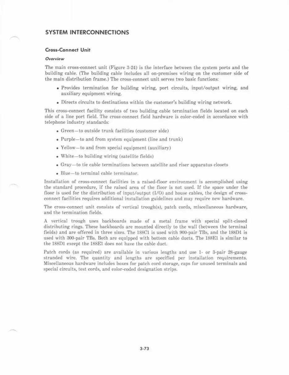
SYSTEM INTERCONNECTIONS
Clo$-Conn€cl LJnir
The main cross-connect unit (Figure 3-24) is the interface between the system ports and thebuilding cable. (The buitding cable inctudes all on-premises iviring on th€ customer side ofthe main distribution frame.) The cioss-connect unit serves two basic functions:
. Provides termination for building wiring, port circuits, input/output wiring, andauxiliary equipment wiring.
. Dirccts circuits to destinations within the customer's building wiring network.
This cross-connect facility consists of tivo building cable termination fields located on eachside of a line port field. The cross'connect field hardware is color-coded in accordsnce rvithtelephone industry standards:
. Green-to outside trunk facilities (customer side)
. Purple to and from system equipment (line and trunk)
. Yellow-to and fron special equipment (auxiliary)
r White-to building wi.ing (sat€llite fields)
. Gray to tie cabl€ terminations between satellite and riser apparatus clos€ts
. Blue-to terminal cable terminator.
Installation of cross-connect facilities in a raised-floor environment is accomplished usingthe standard procedure, if the raised area of the floor is not used. If the space under thefloor is used for th€ distribution of input/output (t/O) and house cabl€s, the design of cross-connect facilities requircs additional installation guidelines and may require nerv hardware.
The cross-conn€ct unit consists of v€rtical trough(s), patch cords, miscellaneous hardware,and the termination fields.
A vertical trough uses backboards made of a metal frame rvith special split'closeddistributing rings. These backboards are mounted directly to the \r'all (between the terminalfields) and are offered in three sizes. The 188C1 is used with 900-pair TBs, and the 188D1 isu6ed with 300-pair TBs. Both are equipped with bottom cable ducts. The 188E1 is simjlar tothe 188D1 oxcept the 188E1 do€s not have the cable duct.
Patch cords (as required) are available in various lengths and use 1- or 3-pair 28-gaugestranded wire. The quantity and lengths are specified per installation requirements.Miscellaneous hardware includes boxes for patch cord storage, caps for unused terminals andspecial circuits, test cods, and color-coded designation strips.
3-73
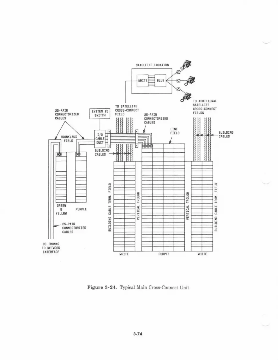
SITELLITE LOCATIOII
IO SAIEILIIEcR0ss-coiNEcr
TO ADDITIOI{ALSATELLITEcR0ss-coilt{EcrFIETOS
tIt{€FIETD BIJILDIIIG
cASLES
GREEf,
25-PAIRcolliEcroRrtE06AELE6
Figure 3-24. Tvpical Main Cross-Connect Unit
2
3-74
f.rmincrion Fi.ld.
Terrnination fields provide access points to cross-connect trunk facilities ard to externalterminal equipment interfaces. Th€se fi€lds may be located on more than one wall or frameand may vary in configuration. Three types of te.mination fields are used with System 85:
. Trunk/auxiliary field terminates the system analog trunk interfaces, off-premise8line inferfaces, and miscellaneous connections (such as external alarm inputs,attendant console, and SMDR data channels)- This type of field also terminatesinte aces such as modem pool interfaces, or intedac€s which must be groupedtogether trom multiple modules to connect colocated equipment in the semeequipment room (such as the ISN concentrator).
r Line field-terminates the system voice t€rminal and data equipment interfaceswhich are cross-connected to the br.rilding wiring distribution. The build;ng wiringdistribution terminates to the white portion of the line field and provid€s acc€ss tovarious terminal equipment located throughout the building.
r DS-1 field-provides cross-connect points for DS-1 cables. These cables may rundirect from the switch cabinet to their t€rmination point (other colocated switch,multiplexers, channel service units, etc.). Howevel specifie translation assignmentsto DS-l interface locations may not be known at the time th€ hardvare is orderedand processed. Ditect cabling, especially with double connectorized cables, willcomplicate accurat€ determination of cable lengths and inhibit flexibility inconnectivity. This field should be logically seqmented on or totally separated fromthe trunk/auxiliary fields. This will minimize the possibilitv of cross-connectingnon-Ds-l to DS-l cables.
The number and conliguration of termination fields is depend€nt on the number and types ofint€rfac€s to be accommodated. A system will typically have one of each field type permodule. Multipl€ modules may terminate to a single trunk/auxiliary field and a single linefield, but one module cannot terminate to multiple trunk/auxiliary fields or multiple linefields.
A termination field identifier and relerence pojnt is assigned to each termination field todetermine cabinet-to-field l/O cable lengths. Trunk/auxiliary lield reference points aredesignated T/A00, T/401, etc. Line field reference points are designated LN00, LN01, etc.,and normally corrcspond to the module numb€r (00,01, €tc.) of the I/O cables that ar€terminated to it. A separat€ DS-1 field requires its ovn unique ref€rence point in theequipment room.
I I Afype Hodwo,e
Two versions of 110-type termination field hardware are available lor use with System 85.The l10P-type hardware provid€s female 50-pin connectorized interfaces, manufactured byAmphenol Products, for the I/O cable terminations- The 1loA-type hadware can beequipped with or without this connectorized interface. This type hardwar€ may be used inconjunction with the lloP-type. Such a combination rvould typically include ll0A-type at themain cross-connect field and l10P-type at th€ satellite clos€ts.
The ll0P-type termination field has a te.minal block layout and d€signation strips whichcorrcspond to the System 85 8-pair unilorm wiring circuit assignments. The I/O cablesrequired to connect cabinets to the terrnination field are provided with the system. These arecurr€ntly 25-pair shielded cables \rith a male so-pair connector, manufactured by AmphenolProducts, on each end. An auxiliary/trunk or lino lield rnay consist of one to four columns of110P-type hardware for I/O cable terminations and a corresponding number of columns fortrunk facility or internal building wiring terminations. An appropriate amount of space isallocated between c€rtain columns to ninimiz€ cross-connect wiring congestion. Each l10P-
3-75

type hardware column can terminate up to thirty-six 50-pin connectorized cables,manufactured by Amphenol Products, (900 pairc).
Th€ l10A-type hardware requires less space than the l1oP-type and can be configured toallow greater flexibility in cross-connects b€tween specific switch interfaces and buildingwir;ng pairs. The r10A-type hadware can be used with any size system and is recommendedfor systems which cut with (or will grow to) five or more modules. Use of this hardware onlarger systerns rvill minimize switch-inteface-to-building wiring mismatch and cross-connectcongestion that may b€ prevalent with 110P-type modular line fi€lds and patch cords. Thecables which terminat€ to the 110A-type hardware can use a connectodzed interface orarrangement for lield termination. The feasibility of using this hardware is dependent on thesize of the system and cable congestion anticipated. Cross-connects are impl€mented withpunch-down wire. Special considerations must be given to L/O cable lengths (from the switchcabinets to the termination fields) and to the type of interface requir€d.
€obles
The various types of system cables (ED-18434) include the following:
. 902A polyvinyl chloride (PVC) flat ribbon cables
. 25-pair standard and shielded connectorized cables
. 4-MHz channel coaxial cables
. Discrete wires of various gauges for alarm, voltage, and ground leads
. Connectorized cables for slow-speed I/O data channel peripherals
. ll0-tlpe connectorizcd patch rords
. Fiber-optic cables.
9O2A Caues
The 902A PVC flat ribbon cables are 31-conductor cables terminat€d on each end with 9434Rpaddleboard connectors. The 943AR paddleboard connectors are provided with an arrow thatindicates the top of the assembly and a clamp that firmly holds the cable to the connector.These cables are provided in varying lengths, with intercabinet cable length dependent uponthe lloor plan cabinet layout.
The 902A cables are used to connect the common control carriers in duplicated commoncontrols, to connect the module control carriers in duplicated module controls, to connect themodule control carriers to the port carriers, and to connect th€ common controi carrier(s) tothe {irst port carrier.
Six of the 902A cables that connect the module control carrier(s) to th€ port carriers includetwo input/output bus (IOB) cables and four pulse code modulation (PCM) cables. The IOBcables interfac€ the module processor to the port circuit packs via the IOB interface and portcontrol interfac€. The PCM cables interface the port circuits to the port data inte acecircuit packs.
25-Pci Ccble.
The 25-pair connectorized building cables arc z4-gaDge 50-conductor cables with eachconductor individually cover€d with a PVC insulator jacket. The vinyl jacket conforms to theeven-count color code scheme. The individual conductors are combin€d and cov€red in anouter jacket of light olive grav vinyl. These cables are terminated on each end with a 25-pair
3-75
The 25-pair connectorized cables are used to connect from the network interface module tothe trunk/auxiliary cross-connect fi€ld, from the trunk/auxiliary cross-connect field to themain cross-connect field, and from the main cross'connect field to the system equipmentcabinets.
The 25-pair shielded connectorized cables are similar to the standard connectorized cableexcept that the outer vinyl jacket is covered with a tinned copper wire braided shield. Thesecables are used between the system and the main cross-connect field.
4-ltHz Channel Cables
The 4-MHz channel coaxial cables are dual-conductor cable rvith a bmided outer conductorand a central solid wire conductor. The out€r conductor surrounds dielectric materiat and iscovered with a PVC jacket. Th€ central conductor is terminated at the common control endwith 953 k paddleboard connectors and at the module control end with 982AA paddleboadconnectors. Th€ outer conductor is not terminated on the common control end. These cablesint€dace th€ 4-MHz data subchannel in the common control carrier to the module controlcarrier.
Discrete wires of various gauges that are used in the system are usually insulat€d, strandedwire. Wires are terminated on each end with spade lugs or connectors or a combination ofspade lugs and connectors. The connector types used ar€ paddl€board and Burndyconnectors. The discrete wires are used to connect the frequency generator to the portcarri€rs and to connect voltage and ground from the bus bar to the carriers and othercabinets. Discr€te wires are also used {or connect;on of th€ thermal sensor and {or alarmfield terminal strip connections to th€ alarm panel.
The conn€ctorized cables (mounting cord) for the slorv-speed data channel peripherals areusually 12-pair or 25-pair standard building cable terminated with appropriate connectorsfor connection to the peripheral. These cables connect the Maintenance and AdministrationPanel (MAAP), System Management T€rminal (SMT), and attondant console to the commoncontrol cabinet.
The 110-type connectorized patch cords are stranded 24-gauge wire with polyvinyl chlorideinsulation. The connectors are designed to mate with standard 110-type connecting blocksand are configur€d for either l-pair (1l0P2A) or 8-pair (110P6A) termination. Patch cordsare designed for cross-connect field connections with building wiring. Quantities and lengthsvary and are system d€pendent.
FibeFopti. Ccbl6
The system fib€r-optic cables are designed with 62.5-micron core fiber. Fiber ribbon cable isused for inter- and intra-building distribution. Each cable can contain up to 12 ribbon fibersof 12 fibers eaeh. The fib€r-optic cables use transmitt€r and rec€iver intedaces to interfaceto the system carriers. Each of these cables is duplex, containing a send fiber and a receivefiber in the same jacket. Each send and r€ceive fiber link requires a transmitter at one endand a receiver at the other end. Signals are converted from Transistor-Transistor-Logic(TTL) driven data to unipolar light pulses and are then carried over the fiber-optic cable.After the pulses are carried ov€r the cable, they ar€ then converted ftom light pulses back toTTL d ven data.
The fiber-optic cables are used to connect the TMS and th€ module controls and to connectthe TMS and remote modul€ interfaces.
3-77
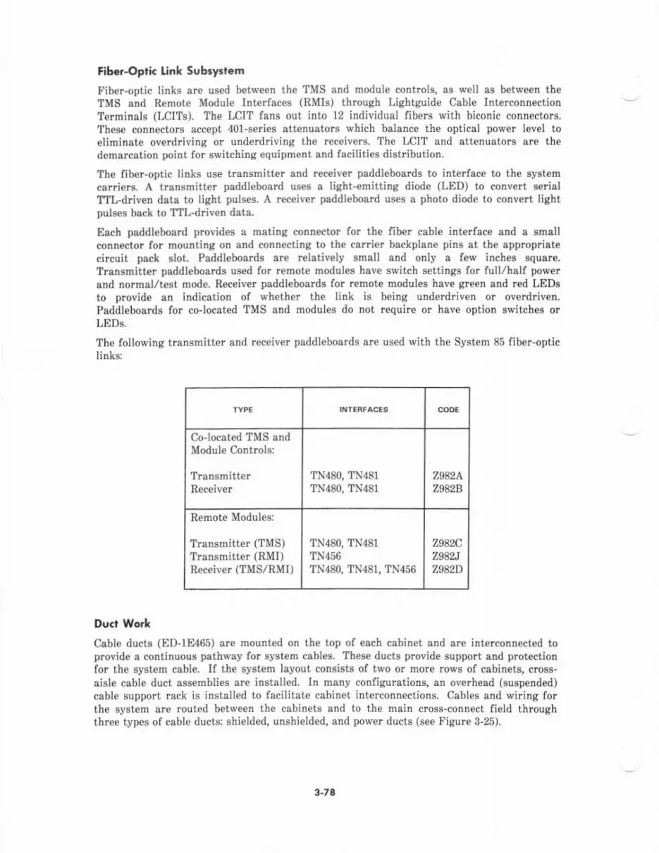
Fib€ropli. Link Subsystem
Fiber-optic links are used between the TMS and module controis, as well as between theTMS and Remote Module Interfaces (RMIs) through Lighiguide Cable Interconn€ctionTerninals (LCITS). The LCIT fans out into 12 individual fibers with biconic connectors.These connectors accept 401-series attenuators which balance the optical pov,/er level toeliminate overdriving or underdrivinc the receivers. The LCIT and attenuetors sre thedemarcation point for switching equipment and facilities distribution.
The fiber-optic links use transmitter and receiver paddleboards to interface to the systemcarriers. A transmitter paddleboard uses a light-emitting diode (LED) to convert serislTll-driven data to light pulses. A receiver paddleboard uses a photo diode to convert lightpuls6 back to TTL-d ven data.
Each paddleboard provides a mating connector for the fiber cable interface and a smallconn€ctor for mounting on and connecting to the carrier backplane pins at the appropriatecircuit pack slot. Paddl€boards are relatively small and only a f€w inch8 squere.T.ansmitter paddleboards used for remote modules have switch settings for full/hslf powerand normal/test mode. Receiver paddlebo4rds for r€mot€ modules have green and red LED!to provide an indication of whether th€ link is being underdriven or overdriven.Paddleboards for colocated TMS and modules do not requirc or have option switches orLEDs.
The following transmitter and receiver paddleboards are used with the System 85 fiber-opticlinks:
Colocated TMS andModule controls:
TransmitterR€c€iv€r
TN48O, TN481TN480, TN481
z9a2A.z9a2B
Remote Modules:
Transmitter (TMS)Transmitter (RMI)Receiver (TMS/RMI)
TN48O, TN481TN456TN480, TN48t, TN456
z9a2cz98Nz9a2D
Duct Work
Cabl€ ducts (ED-1E465) are mount€d on th€ top of each cabinet and arc inteiconnected toprovide a continuous pathway for system cables. These ducts provid€ support and protectionfor the system cable. If the system Iayout consists of two or more rows of cabinets, cross-aisle cable duct assembli€s are installed. In many configurations, an overhead (suspended)cable support mck is installed to facilitate cabinet interconnections. Cables and wiring forthe system are rout€d between the cabinets and to the main cross-connect field throughthree types of cable ducts: shielded, unshielded, and power ducts (se€ Figure 3-25).
3-78
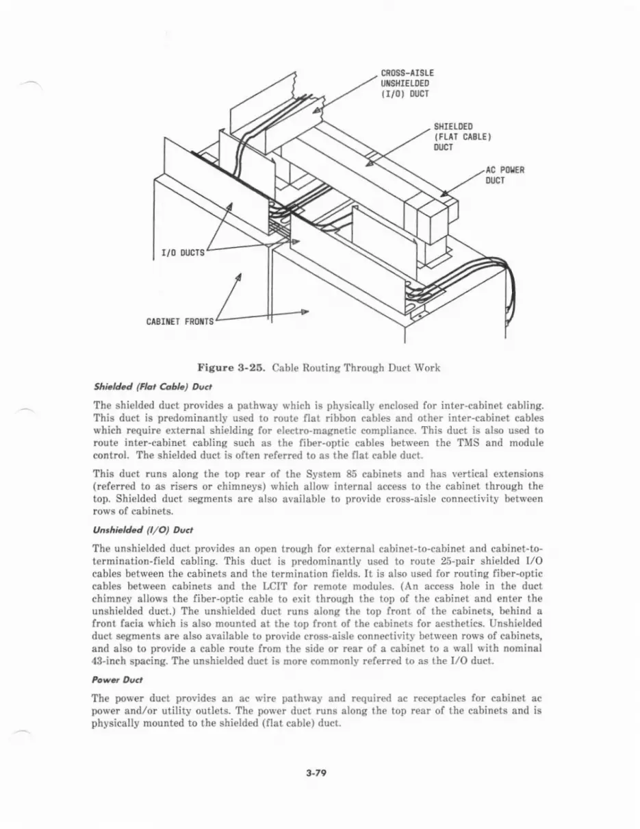
cRoss-rIsrEUTSHIELDED
{r/0) oucr
SHIEI.l)ED
lFrlT c 8r"E )l'lrcT
lc FolEnoucT
r/0 oucTs
ctSliET F8oils
Fi8ure 3.25. Cable Routing Through Duct Work
Shi.td.d (Ho, AbL) Du.,
The shielded duct provid€s a pathway which is physically enclosed for inter-cabinet cabling.This duct is predominantly used to route flat ribbon cables and other inter-cabinet cableswhich require external shielding for ol€ctro-magnatic complianc€. This duct is also us€d toroute inter-cabinet cabling such as the fiber-optic cables between the TMS and modulecontrol. The shielded duct is often ref€rred to as th€ flat cable duct.
This duct runs along the top .ea. of the System 85 cabinets and has vertical extensions(referred to as risers or chinneys) which allow internal access to the cabinet through thetop. Shielded duct segments are also available to provide cross-aisle connectivity betweenrows of cabin€ts.
Unrhi.A.d (,/O) Du.t
The unshielded duct provides an open trough for external cabinet-to-cabinet and cabinet-to-tetmination-field cabling. This duct is predomiiantly used to route 25-pair shielded I/Ocables betw€en the cabinets and the tarmination fields. It is also used for routing fiber-opticcables between cabinets and th€ LCIT for remot€ modules. (An access hole in the ductchimney allows the fiber-optic csbl€ to exit through the top of the cabinet and enter theunshielded duct.) The unshielded duct runs along the top front of the cabin€ts, behind afront facia which is also mounted at th€ top front of the cabinets for a€sthetics. Unshieldedduct segments are also aveilable to provide cross-aisl€ connectivity betwe€n .ows of cabinets,and also to provide a cable rout€ from the side or r€ar of a cabinet to a wall with nominal43-inch spacing. The unshielded duct is more commonly r€ferr€d to as the I/O duct.
The power duct provides an ac wire pathway and required ac receptacles for cabinet acpower and/or utility outlets. The power duct runs along the top rear of the cabinets and isphysically mount€d to the shielded (flat cable) ducl.
3-ra
SWITCH EQUIPMENT CODE SUMMARY
The following equipment codes designate major hardware units associated \r'ith the basicSystem 85 switch:
FtD-1I]430-70 Th€rmal Sensor Ass€mblvED-1E434-11 Svstem Cables
ED-1E435,70 Bus BarnD-1E436-10 Intra-Cabinet Cables
ED-1E43?-10 Inter-Cabinet Cables
ED-18444-?0 No-Carrier AdapterED-1E453-?0 Document File AssemblyED-1E465-?0 Duct WorkJlC170A Hish CaDacitv Mini-Record€rJ58886B Module Control CabinetJ58886C Port CabinetJ58886F TMS/RMI CabinetJ58886J UnduDlicated Common Control CabinetJ58886K Duolicated Common Control CabinetJ58888A Port CarrierJ58888C TMS CarrierJ58888E Cornmon Control CarrierJ58888F DuDlicated Common Control Power CarrierJ58888M Module Control CarrierJ58888N DS-1./MF AT CarrierJ588885 RMI CarrierJ58889AD DC {Frame) Filter UnitJ588894N Remote Group HousinqJ58889AV AC Distribution Unit (With OLS Hardware)J58889G AC Distribution UnitJ58889r{ DC I'ilter tlnit.I588897 Unduplicated Comrnon Control DCIDC Converter UnitJ58889TM Prosram Tape
J58889U AC Distribution UnitJ58889V DC Fan Assemblv
J58889W Unduplicared Common Conlrol Alarm PanelJ58889X DuDlicated Common Control Alarm Panel
J874624. Battery Reserve UniL
3-80

FACEPLAIE GUIDE
TOiIEGEIIERATl]F
Figure .1-2. Visually Impaired Attendant S€rvice Equipment
4-5
An ndont C.ontol. Pap@,B
Attendant console rcpeaters (J58889Y) ar€ electronic circuit amplifiers and/or isolators thatprovide rung€ extension and/or surge protection frcm high voltages such as lightning. Whenthe console is located in a separate building from the system control complex, but nearenough that range ext€nsion is not needed, the rcpeat€rs are equipped to provide surg€protection only.
The following equipment is used in conjunction with the basic unit (see Figure 4-3) toprovide the specific configudtion of surge prot€ction andlor range extension requjred:
. AE48-single dircction r€peater, requir€d for rang€ extension. Also, p.ovides datachann€l lightning protection for off-premise console with range extension.
. AE4gB-clock and regulator, required for range extension.
. WJ3-single direction data link buffer, used for both the system-end and console-endrepeatets. Th€se are required for lightning protection without range extercion.
. WJ6-alarm repeater, required for the system-end repeater.
. WJZ elarm repeater, required fo. th€ console-€nd repeater.
. 284B1-powei unit, required with or without range extension.
. 28D2-power unit, required for range extension.
Figure 4-4 illustrat€s connectivity for an off-premises attendant console with rangeextension and interm€diat€ repeat€rs. A repeater located at the console end of the channeli8 usually wall mounted. A repeater located at the system end of the chandel is mount€d inthe Auxiliary Cabinet.
Each attendant console rcpeater providing rang€ extension requir€s 1m-V 60-Hz commercialpowe!. Attendant console repeaters not providing range extension require 120-V 60-Hzcommercial pov,/er only at the repeater near the consol€.
Power for the attendant console is -48 V dc and is d€rived from connectors on ModuleControl Cabinets and Port Cabinets equipped with rectifiers. If range extension is requiredwith repeaters, power for the console is derived locally at the consol€-end repeat€r. During acommercial ac power outage, a console without range extension will op€rat€ for the length oftime specified for nominal holdover or extended power reserve (if equipped). Consoles usingout-of-building protectior or range extension will not be op€rable during this time unle$ th€repeater €quipment is also powered through holdover or essential ac pow€r sources.
Three signal leeds from the common control car er are multipli€d to €ach console. Theseleads are alarm (ALM*), acknowledge (ACK*), and alarm power (-48ACAL). They controlvisual indications of system alarm status on the attendant consoles. The alarm lamp on theconsole is light€d whenever there is an active major or minor alarm. The ACK lamp islighted wh€rev€r the active alarm has been successfully reported to the remote maintenenc€cenler through th€ r€mote int€rface in the common control.
For each att€ndent consol€, four data channel leads conn€ct to a low-speed peripherslinterface (TN403) in the System 85 common control. Six voice and contrcl leads connect to anatt€ndant console audio interface (SN233B/C) port circuit.
1"5
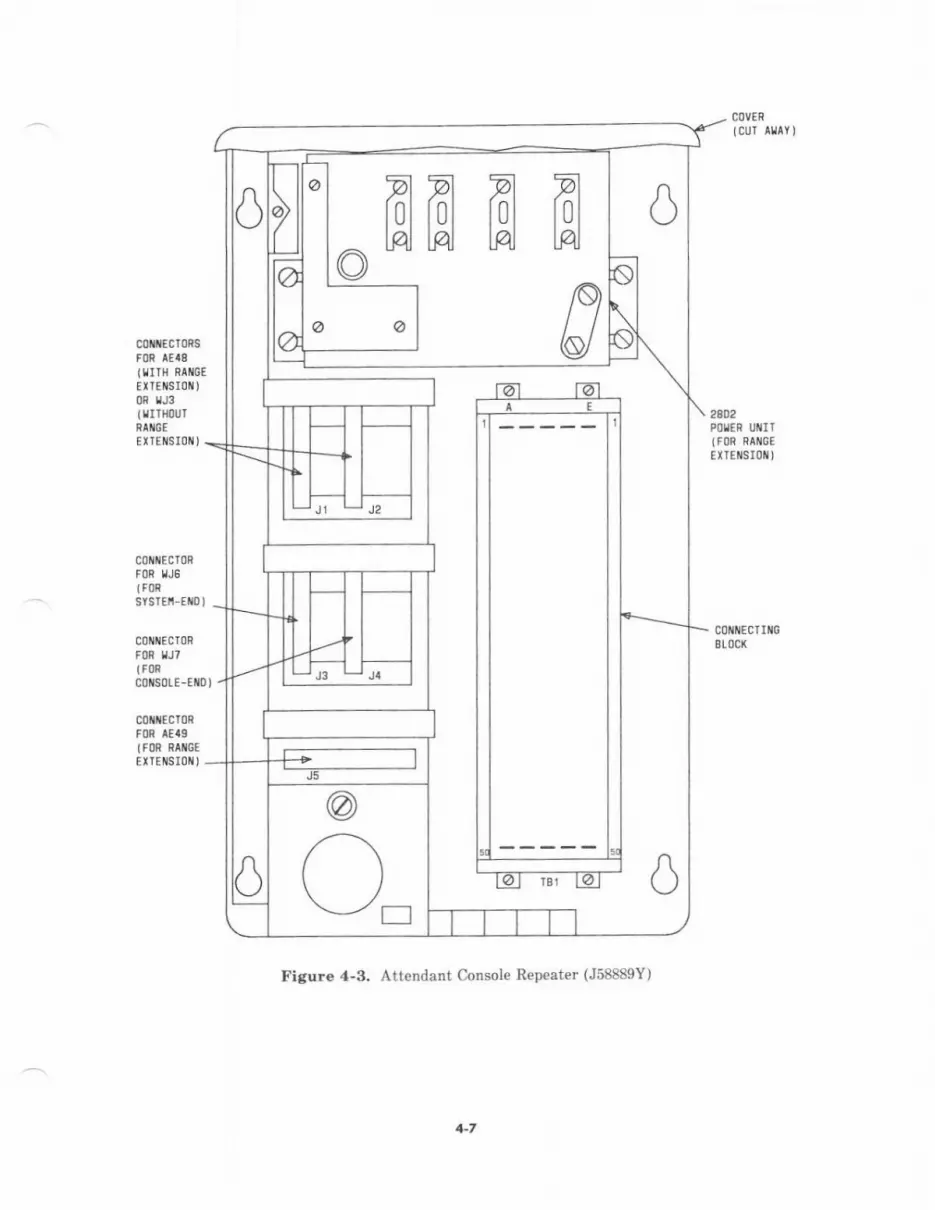
COVER
ICUI ATAY]
cstfcToesFfi IE'g(fIIH RAIICE
Et'IEtis!0r{)OR TJ3ltrlltouTRINGE
2eD2POgEi UiIT(FOR hAIi6EEXtEt{SIotil
EITEIISIOII)
cou{EcT0nFon tJ5(F0nsYsTEi Eml
c0M{Ecr0RFOR fJ7tFnc0N0LE-E{0,
courEcrriloSLOCX
coltttccronFon lEaglFon Rr*GtEtTEilsI0ti)
I'igure 4-3. Attendant Console Repeatet (J58889Y)
+7

(J
o
i:
t
4-8
The attendant console is equipped with a l2-pair mounting cord that is connected to a 12- or25-pair system distribution cable. The mounting cod is equipp€d with a 50-pin KS-16689, Llconn€ctor, while a mating connector terminates the distribution cable.
The first console cable is run to a jumper€d module control cabinet connector. Thesejurnpered connectors allow the console to be disconnected and a '1est" consol€ conn€cted atthe module contml cabin€t. All other console cables extend from the auxiliary cross-conn€atfield tD th€ console location.
Wh€n repeat€rs without mng€ extension are used, the distance b€tw€en the attendantconsole and the system must not exceed 16'00 feet (305 n). When repeaters with rangeextension are used, the maximum distance is 11,000 feet (3,353 rn).
For more detail€d information on the attendant console, refer to AT&T SyBten 86(R2Vg)-Colt3ol€ Operation-Uier'! Guide (555-102-?30).
a-9
VOICE TERMINATS AND ADJUNCTS
Overview
Voic€ terminals have a variety of controlling and monitoring capabilities. ln addition toproviding basic telephone service (placing and answering calis), voice terminsls also acc€ssSystem 85 featurcs. They offer a vride spectrum of price/performance tradeoffs to tsilor thesyst€m to a customer's needs.
Two analog and seven multi-appearance models, along lvith feature-int€nsiv€ optionaladjuncts, are designed specifically for use with Syst€m 85 (see Figure 4-5). All Svstem 85voice t€rminals can be desk or wall mounted, and most offer (mutually exclusive)speakerphon€ and h€adset adapter options. They are available in black, brcwn, rvhite, andburgundy.
In addition to the System 85 models, thrc€ 2500-type models ard fiv€ Multibutton ElectronicTelephone (MET) models can be supported by the system. (The METs are supported only onan "in-place" basis and are not generally available. They must be administered as ?200Hs€ries hybrid voice terminals with similar button assignment restrictions.)
The voice t€rminsls, adjuncts, and system switch interfaces conform to a modular uniformwiring arrang€m€nt. This arrangement provides lor a maximum of three pairs of wiringfrom the switch interface cross-connect point (satellite closet or equipm€nt room) to a 4-pairmodular jack. Th€ fourth pair provides an option for remote power lor certain voice terminaladjuncts. (Note: None of the voice terminals sp€cifically designed for System 85 areregistered under FCC Part 68 Rules for the emergeDcy transf€r capability- This precludesth€ir use for direct connection to the public switched network or for em€rgency transferapplications. The 2500-type sets must be used in these cases.)
a-10

?203H 0R 74030
7205H 0R 74050
Figure 4-5. Svstem 85 voice Terminals
4-l I
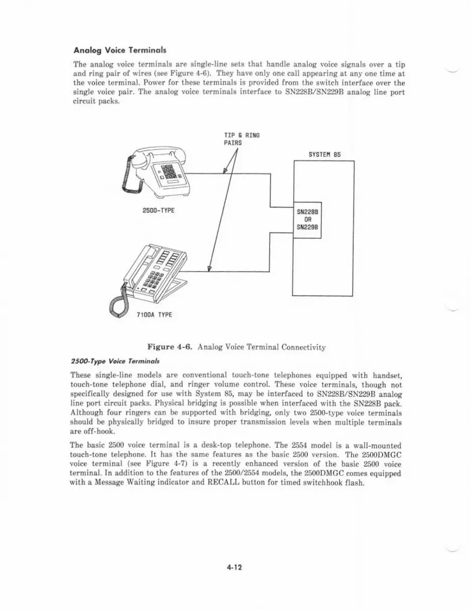
Anqlog VoiG€ Terminolt
The analog voice terminals are singlelin€ sets that handle analog voic€ signals over a tipand ring pair of wires (see Figure 4-6). They have only one call appearing at any one time etthe voice terminal. Power for these t€rminals is provided from the switch interface over thesingle voice pair. The analog voice terminals interface to SN228B./SN229B analog line portcircuit packs.
Figure 4-6, Analog Voic€ T€rminal Conn€ctivity
2s(n-fype Voic. fqminclt
These singleline models are conventional touch-tone t€lephones equipped with handset,touch'tone telephone dial, and ringer volume control. These voice terminals, though notspecilically designed for use with System 85, may be interfaced to SN228B/SN229B analogline port circuit packs. Physical bridging is possibl€ when intedaced with the SN228B pack.Although four ringers can be supported with bridging, only two 2500-type voice terminalsshould be physically bridged to insure proper transmission levels when multiple terminalsare off-hook.
Th€ basic 2500 voice terminal is a d€sk-top telephone. The 2554 model is a wall-mountedtouch-tone telephone. It hes the same features as the basic 2500 version. The 2500DMGCvoice terminal (see Figure 4-7) is a rec€ntly enhanced version of the basic 2500 voiceterminal. In addition to the features of the 2500/2554 models, the 2500DMGC comes equippedwith a Message Waiting indicator and RECALL button for timed switchhook flash.
4-12
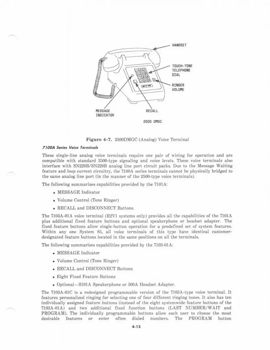
t{t[DsET
TOUCH-TOXE
TELEPIIOI{EDIIL
RIIICERVOLUIIE
NESSIGEIl{0lclToR
RECTLL
2500 DllGc
Figure 4-7. 2500DMGC (Analog) Voice Terminal
7l0OA Saria. Voic. fe.ainaL
Th€se singleline analog voice terminals require on€ pair of wiring for operation and arecompatible with standard 2500-type signaling and voice levels. These voice terminals alsointerface with SN228B/SN229B analog line port circuit packs. Due to the M€ssag€ waitinsfeature and loop current circuitry, the ?1004 series termjnals cannot be physically bridged tothe same analog line port (in the manner of the 2500-type voico terminals).
The following summarizes capabilities provided by the 7101A:
. MESSAGE Indicator
. Volume Control (Tone Ringer)
. RECALL and DISCONNECT Buttons.
The 7103A-01A voice t€rrninal (R2V1 systems only) provid€s all the capabilities of th€ ?101Aplus additional fixed feature buttons and optional speakerphone or headset adapter. Th€fixed feature buttons allow single-button operation for a predefined set of system features.Within any one System 85, all voice terminals of this type have identical customer-designated feature buttons located in th€ same positions on all the terminals.
The following summarizes capabilities provided by the ?103-01A:
. MESSAGE Indicator
. Volume Control (Tone Ringer)
. RECALL and DISCONNECT Buttons
. Eight Fixed Feature tsuttons
. Optional-Sl01A Speak€rphone or 500A H€adset Adapter.
The 7103A-01C is a r€desicned programmable version of the ?103A-type voice terminal. Itfeatures pe$onaliz€d ringing for selecting one of four different ringing ton€s. It also has t€nindividually assigned featur€ buttons (instead oI the €jght systemwide f€ature buttons of the7r03A-0tA) and two additional fixed function buttons (LAST .\"UMBER/WAIT andPROGRAM). The individually programmable buttons allow each us€r to choose the mostdesimble features or enter often dialed numbers. The PROGRAM button
4-t 3

activates/deactivates the programming mode. The WAIT button is used when storing enumber that requires a second dial tone. Programming is eccomplished by switching thevoice terminal into the program mode and €ntering up to l3 characters (including WAIT) perfeature button. If there is a power failure or th€ terminal is unplugged, the customer-programmed memory is maintained by an internal backup battery.
The following summarizes capabilities provided by the 7103A-01C:
. MESSAGE lndicator
. Volume Control (Tone Ringer)
. Four Fixed Function Buttons
. Ten Feature Buttons
. Optional-Sl01A Speakerphone or 500A Headset Adapter.
Hybrid Voice Tcrminol:
The hybrid voice terminals are multlappearanc€ sets that employ digital signaling andanalog voice over three wire pairs (see Figur€ 4-8). They can have one, two, or rnore callsappearing simultaneously at the voice terminal. Power for these terminals and their optionaladd-on modules is phantomed frcm the switch interface over the two digital pairs used forcontrol and signaling. The ?200H series terminals and METS interfac€ to SN2ZB hybridline port circuit packs. The ?3005 series terminals interface to ANNI?B double-densityhybrid line po circuit packs.
TnnH Se'i., Voi.. rdminolt
Two ?200H series voice terminals are availabl€. These are multi-appearanc€ models based onMET technology and requiring 3-pair wiring fot operation. One wire pair is used for analogvoice and two pairs are used for digital control and signaling- These voice terminels interfaceto SN224B hybrid line port circuit packs.
The following summarizes capabilities provided by the ?203H:
. MESSAGD Indicator
. Volume Control (Tone Ringer)
. Lamp Test Switch
. Six Fixed Function Buttons
. Ten Appearance/Feature Buttons
. Optional-S101A Speakerphone or 500A Headset Adapter.
The ?m5H incorporates all the capabilities provided by the ?203H plus 2 additionalfeature-only buttons. It may also accommodate an add-on call coverage module whichprovides m additional app€a.ancelfeature buttons and a function key module which provides24 additional feature-only buttons. The call coverage module attaches to th€ top of the voiceterminal, and the function key module attaches to the right side. These optional modules usethe same phantom power from the switch (through the digital pairs) that also powers the7205H. This impacts the distance allowed from the switch.
4- t4
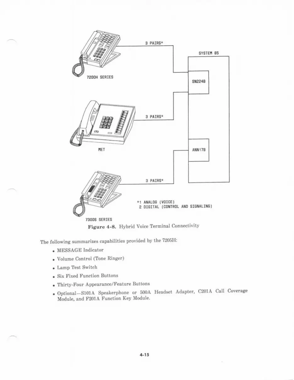
7200x SERIES
3 PAIRS}
3 Plrngr
.1 lilAloo tvorcE )2 DIoITIL lCollrRol- Ato srcl^Lrllo)
73006 SERIES
Fignre 'l'8. Hvbrid Voice Terminal Connectivitv
The following summarizes c-spabilities provid€d by the 7$5H:
. MESSAGE Indicator
. Volum€ Control (Tone Ringer)
. Larnp Test Switch
. Six Fixed Function Buttons
. Thirty-Four App€arance/Feature Buttons
. Optional-SlolA Speak€rphone or 50OA Hesds€t Adapter, CmlA Call Coverage
Module, end F20lA Function I(ev Module.
,a.l5
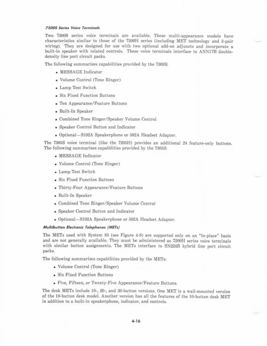
73tbs Sqia voi.. fc.minolt
Two ?3005 series voice terminals are available. These multiappearance models havecharacte stics sirnilar to those of the ?200H series (including MET technology and 3-pairwiring). They arc design€d for use with two optional add-on adjuncts and incorporate abuilt-in speaker with related controls. These voice terminals interface to ANNI?B double-density line port circuit packs.
The following summarizes capabilities provided by the 7303S:
. MESSAGE Indicator
. Volum€ Control (Tone Ringer)
. Lamp Test Switch
. Six Fixed Function Buttons
.'len Appearanc€/tr'eature Buttons
. Built-In Spe.ker
. Combined Tone Ringer/Speaker Volum€ Contrcl
. Speak€r Control Button and Indicator
. Optional-S102A Speakerphone or 502A Headset Adapter.
The ?3055 voice terminal (like the 7205H1 provides an additional 24 feature-only buttons.The following summariz€s capabilities provided by the ?3055:
. MESSAGE Indicator
r Volume Control (Tone Ringer)
. Lamp Test Switch
. Six Fixed Function Buttons
. Thirty-Four Appearance/Feature Buttons
. Built-In Speaker
. Combined Tone Ringer/Sp€aker Volume Control
. Speaker Control Button and Indicator
. Optional-Slo2A Speakerphone or 502A H€adset Adapter.
uhibutton Ekhoni. f.hphon6 ( Efr)
The METs used with System 85 (see Figure 4-9) a.€ supported only on an',in-place,'basi6and are not generally available. They must be administered as ?200H series voice terminalswith similar button assignments. The METS interface to SN224B hybrid line port circuitpacks.
The following summarizes capabilities provided by the METsi
. Volume Control (Tone Ringer)
. Six Fixed Function Buttons
. Five, Fjfteen, or Twenty-Five Appearance./Feature Buttons.
The desk METs include 10-,20-, and 30-button versions. One MET is a wall-mounted versionof the lo-button desk mod€l. Anoth€r version has all th€ features of the lo-button desk METin addition to a built-in speakerphone, indicator, and controls.
4-16
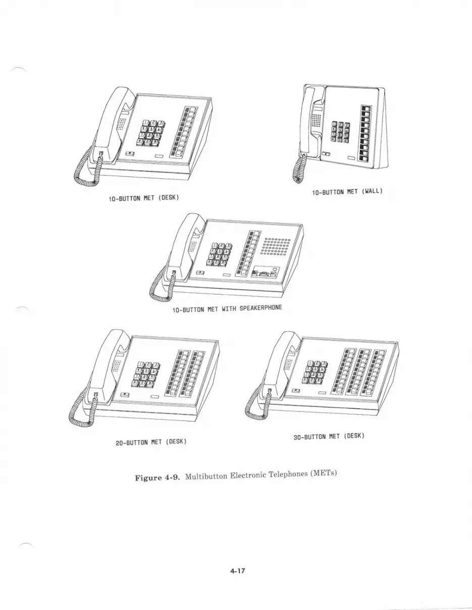
10-BUTT0I{ i',lET (llaLL)lO-BUTTolll ltET (oES()
1O-BUTIOiI IIET IIITH SPEAKERPHOIIE
2o-BUTToll rlET ( oEs( )3O-BUTT0N I',IET (oEs()
Figure 4-9. Multibutton Electronic Telephon€s (METs)
lrn/iH i:iii;;:
tfl@l
{sffiffiffit
4-17

Digitol Voi.. lerminol.
Th€ digital voice terminals are multi-appearance sets that employ both digital signaling andvoice over a 4-wir€ digital communications protocol (DCP) channel (se€ Figur€ 4-10). Eachdata pair supports one signaling channel and two information channels for simultan€ousPulse Code Modulation (PCM) voice and data. Similar to th€ hybrid voice t€rminals, theycsn also have one, two, or more calls appearing simultaneously at the terminal. Power fordigital voice terminals is phantomed from the switch int€rface over the two data pairs. Theiroptional add-on modules and adjuncts are powered locally by an adjunct power supply, orfrom a power source in a satellite closet through a fourth pair of voice terminal wiring. The?400D series voice terminals interface to SNroB digital port circuit packs. The AT&TPersonal Terminal 510D and 515 BCT (discuss€d later in this section) employ similar voiceterminel conn€ctivity.
11 RECEIVE DTTI1 Sa t oalt
Figure 4-10. Digital Voice Terminel Conn€ctivity
7400D S.ti.t Vol.. fqminoh
Three 7400D series voice terminals are available. These terminals convert analog voice todigital PCM for transmission through the DCP and vice versa. They allow integration ofvoice and data simultaneously over the 2-pair DCP interface. All of the optional modulesand adjuncts for ?400D series terminals are pow€red locally by an adjunct power supply orfrom a power sourc€ in a satellite closet through a fourth pair of terminal wiring. Thesevoice terminals int€ ace to SN270B digital port circuit packs.
The ?403D voic€ terminal is externally and functionally equivalent to the ?203H hybridterminal. In addition, the ?403D may also accommodate a Digital Terminal Data Module(DIDM), which attaches to the right side and allows connection of an EIA RS-232C dataterminal. With this arrangement, two individual ports are effectively utilized in th€switching network, but ale multiplexed over a single port inte ace and DCP line. Thefollowing summarizes capabilities provided by the 7403D:
. MESSACE Indicator
. Volume Contml (Tone Ring€i)
. Lamp Test Switch
. Six Fixed Function Buttons
sYSTEi 85
?.OOO SERIES
+18
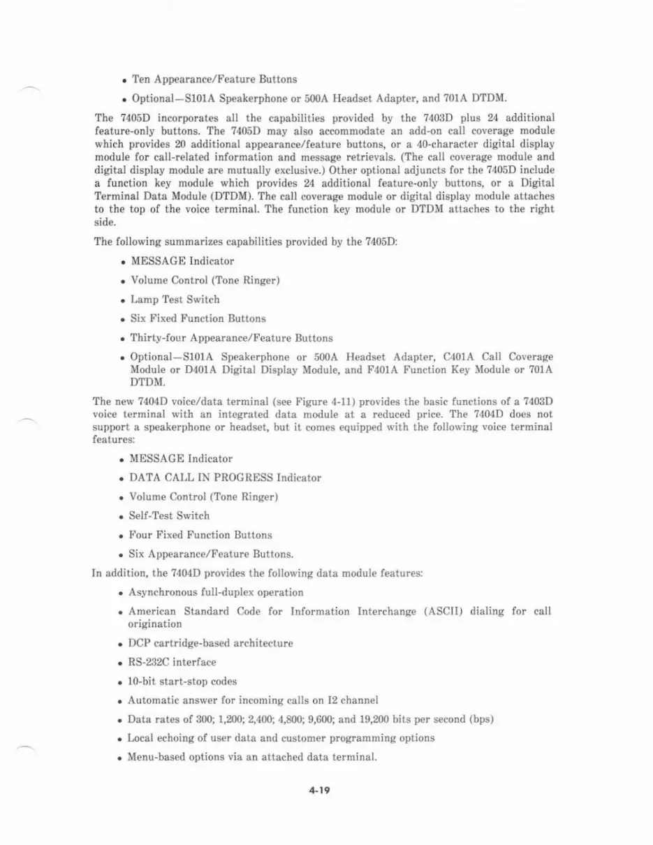
. Ten Appearance/Feature Buttons
. Optional-Sl0lA Speak€rphone or 500A H€adset Adapt€r, and 701A DTDM.
The 7405D incorporates all the capabilities provided by the 7403D plus 24 additionalfeaturc-only buttons. The ?405D may also accommodate an add'on call coverage modulewhich provides 20 additional appearance/feature buttons, or a 40-character digital displaymodule for call-related information and message retrievals. (Th€ call coverage module anddigital display module are mutually exclusive.) Other optional adjuncts lor the ?405D includea function key modul€ which provides 24 additional feature-only buttons, or a DigitalTerminal Data Module (DTDM). The call coveBge modul€ or digital display module attachesto the top of the voice terminal. The function key module or DTDM attaches to the rightside.
The following summarizes capabilities provided by the ?405D:
. MESSAGE Indicator
. Volume Control (Tone Ringer)
. Lamp T€st Switch
. Six Fix€d Function Buttons
. Thirty-four Appearance/Feature Buttons
. Optional-StolA Speakerphone or 500A Headset Adapter, C401A Call Cov€rageModule or D40lA Digital Display Module, and F401A Function Key Module or 70lADTDM,
The new ?404D voice/data terminal (see l.igure 4-11) provides the basic functions of a 7403Dvoice t€rminal with an integrated data module at a reduced price. The ?404D does notsupport a speakerphone or headset, but it comes equipped with the lollowing voice terminalfeatures:
. MESSAGE Indicator
. DATA CALL IN PROGRESS Indicator
. Volume Control (Tone Ringer)
. Seif-Test Switch
. Four Fixed Function Buttons
. Six Appearance,/Feature Buttons.
In addition, the ?404D provides the following data module features:
. Asynchronous full-duplex op€ration
. American Standard Cod€ for Information Interchange (ASCII) dialing for callorigination
. DCP cartridge-based architecture
. RS-232C interf,ce
. lo-bit start-stop codes
. Automatic answer for incoming calls on 12 channel
. Data rates of 300; 1,200; 2,400; 4,m0; 9,600; and 19,200 bits per second (bps)
. Local €choing of user data and custom€r prog.amming options
. Menu-bas€d options via an attached data terminal.
/Ll9
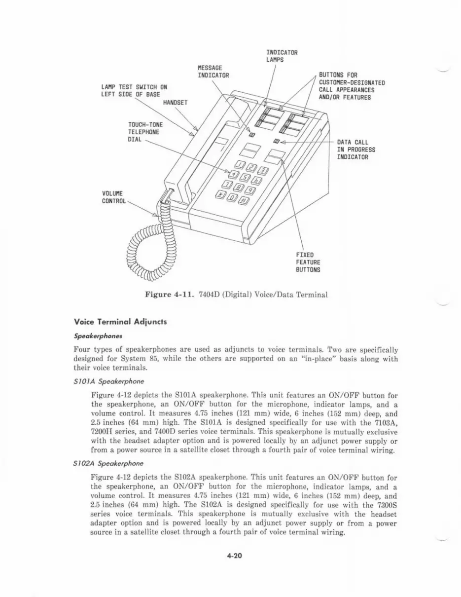
IIIOICII()RLlttPs
LEFTTESTSIDE
SIITCH OIIOF SASE
8UTr0ilS FoRCUSTI)IIER.DESIGTATEOCILL APPEIRAIICESIIID/(]R FEATURES
0aTA cAU-Iil PRI)GRESS
IIIOICATOR
fiti0s€l
FIXEltFEAIURESUTroris
Figure 4-11. 7404D (Disital) Voice/Data Terminal
Voice Terminol Adion.l.
Fou. types of speakerphones are used as adjuncts to voice terminals. Two are sp€cificallydesigned for System 85, while the others are support€d on an "in-place" basis along withtheir voice terminals.
St0IA Spedkeryhone
Figur€ 4-12 depicts the 5101A speakerphone. Thjs unit features an ON,/OFF button forthe sp€akerphone, an ON,/OFF button for the microphone, indicator lamps, and avolum€ control. It measures 4.?5 inch€s (121 mm) wide, 6 inches (152 mm) deep, and2.5 inches (64 nm) high. The S101A is designed specifically lor use with the ?103A,7200H series, and ?400D series voice terminals. This sp€:kerphone is mutually exclusivewith the headset adapter option and is powered locally by an adjunct powe. supply orfrom a povrer source in a satellite closet through a loulth pair of voice terminal wiring.
Sl02A Speakaryhone
Figurc 4-12 depicts the Sl02A speakerphone. This unit features an ON,/OFF button forthe speakerphone, an ON/OFF button for the microphone, indicator lamps, and avolume control- It measurcs 4.?5 inches (121 mm) wide, 6 inches (152 mm) deep, and2.5 inches (64 mn) high. The S102A is designed specifically for use with the 7300Sseries voice terminals. This speakerphone is mutually exclusive with the headsetadapt€r option and is powered locally by an adjunct power supply or frcm a powersource in a satellite closet through a fourth pair of voice terminal wiring.
4-20
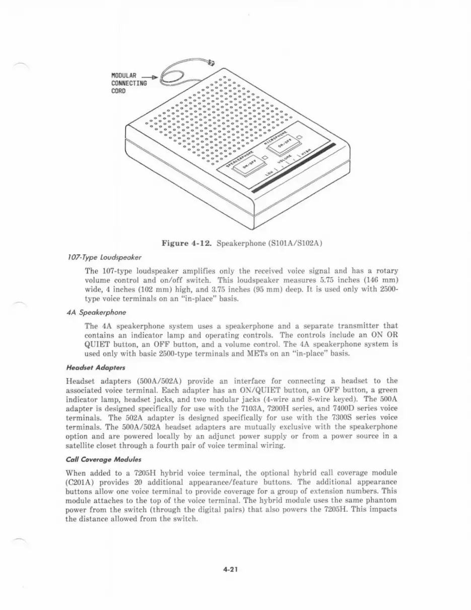
ioouLtt ____a,
coilltEcTItGCORD
Figure 4-12. Speakerphone (S10lA/SI02A)
107-Type loudspeoke.
The 10?-type loudspeaker amplifies only the received voice signal and has a rotaryvolum€ control and onloff switch- This loudspeaker measures 5.75 inches (146 mm)wid€, 4 inches (102 mm) hish, and 3.?5 inch€s (95 mm) deep. It is used only with 25U)-iyp€ voice terminals on an "in-place" basjs.
The 4A speakerphone system uses a speakerphone and a separate transmitter thatcontains an indicator lamp and operating controls. The controls include an ON OR
QUIET button, an OFF button, and a volume control. The 4A speakerphone system isused only with basic 2500-type terminals and METS on an "in-place" basis.
Headset adapters (500A/502A) provide an interface for connecting a headset to theassociated voice terminal. Each adapter has an ON/QUIET button, an OFF button, a greenindicator lamp, headset jacks, and two modular jacks (4-wire and 8-wire keyed). The 5004adapt€r is designed sp€cifically for use with the ?103A, ?200H saries, and 7400D seri€s voiceterminals. The 502A adapter is designed specifically for use with the ?300S series voiceterminals. The 500A/502A headset adapters are mutually exclusive with the speakerphon€option and are power€d locally by an adjunct power supply ot from a power source in a
satellite closet through a fourth pair of voice terminal wiring.
CaI Cov.rds. oAub.
When added to a rusH hybrid voice terminal, the optional hyb d call covemge module(C20lA) provides 20 additional appearance/featDre buttons. The additional appearancebuttons allow one voice terminal to provide coverage for a group of extension numbers. Thismodule attaches to the top of the voice terminal. The hybrid module uses the same phantompower fmm the switch (through the digital pairs) that also povers the ?205H. This impactsthe distance allowed from th€ switch.
4-2t
The corresponding digital version ol the call coverage rnodule (C401A) is attached to th€7405D digital voice terminal. This module js powered locally by an adjunct power supply, orfrom a power source in a satellite closet through a fourth pair of terminal wiring. Thedigital call coverage module is mutually exclusive with the digital display module.
Fuacti.a K.y Modul8
When attached to a ?205H hybrid voice terminal, th€ optional hybrid function key module(F201A) provides 24 additional feature-only buttons for expanded feature capabilities. Thismodul€ attaches to th€ right side of th€ voice terminal. The hybrid module uses the samephantom power from the switch (through the digital pairs) that also powers the ?205H. Thisimpacts the distence allowed from the switch.
The corresponding digital version of the function key module (F401A) is attached to the?405D digital voice terminal. This module is pow€red locallv by an adiunct power supply, orfrom a power source in a satellite closet through a fourth pair of terminai wiring.
Disird fe.mindl ooro blodule (Droln)
The 7403D and ?405D digital voice terminals may accommodate a DTDM (DSU 70fA), whichattaches to the right side of the voice terminal and allows connection of an EIA RS-232Cdata terminal. With this armngement, two individual ports are effectively utili?€d in theswitching network, but are multiplexed over a single port interfac€ and DCP line. The DTDMis mutually exclusive with th€ function key module. For more det4iled information, reler tomDM (under DATA EQUIPMENT AND INTERFACE DEVICES in this s€ction).
Dbircl Dkploy ,rtodul.
When attached to a ?405D digital voice te.minal, the optional digitai display module (D401A)provides a 40-character digital display for call-related information and message retrievals.The digital display module attaches to the top of th€ voice terminal. This module is powered
locally by an adjunct power supply, or from a power source in a satellite closet thrcugh afourth pair of terminal wiring. The digital display module is mutually €xclusive with thedigital call cov€rage module.
The automatic dialer (28?0A1) is an optional add-on adjunct for a MET (provided on an "in-place" basis onty). The dialer provides the capability to record and eutomatically dial 31
telephone dumbers of up to 15 digits each. It also p.ovides last number dialed (manually)memory and the capability to pause for subsequent dial tones du ng automatic dialing(WAIT input).
The automatic dialer is equipped with a touch'tone t€lephone dial, 32 programmable buttons,RECORD indicator, and 4 fixed function buttons.
Voi.a f&minct AJiuD.t Powg
Optional adiuncts enhance €xisting System 85 voice terminal features or add capabilities tothem. However, power for the following adjuncts is not derived from the switch interface:
. Speakeryhon€ (S101A/SI02A)
. H€adset adapt€r (500A/502A)
. Digital call coverage module (C40lA)
. Digital lunction key module (F401A)
4-22
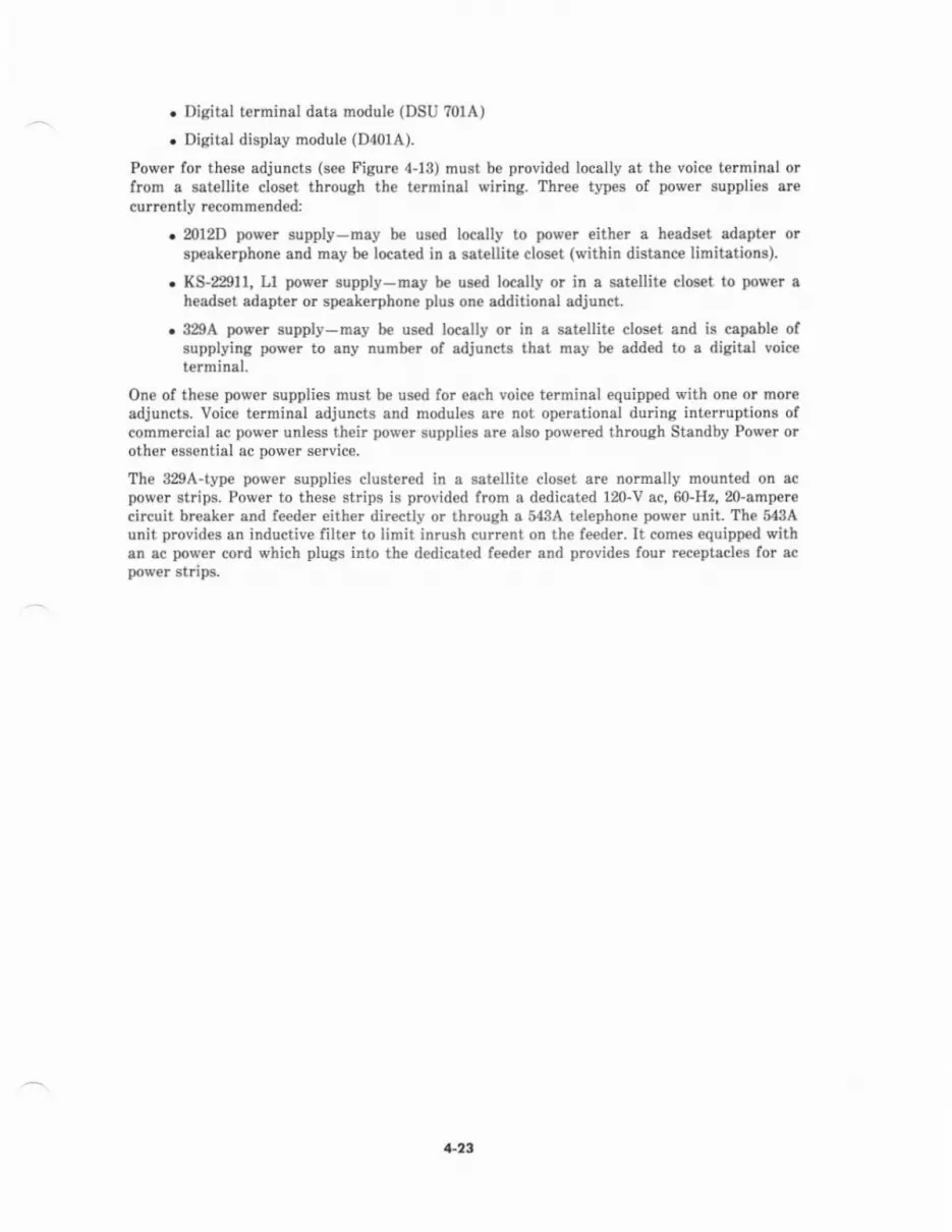
. Disital terminal data nodule (DSU ?01A)
. Digital display module (D401A).
Power for th€se adjuncts (see Figure 4-13) must be provid€d locally at the voice terminsl orfrom s satellite closet through the terminsl wiring. Three types of povrer suppli€s arecurtently r€commended:
. ml2D power supply-may be used locally to power either a headset adapt€r orspeakerphone and rnay be located in a satellite closet (within distanc€ limitations).
. KS-22911, Ll power supply-may be used locally or in a satellit€ clos€t to power ah€ads€t adepter or speakerphone plus one additional adjunct.
. 329A porrer supply-may be us€d locally or in a satellite closet and is capeble ofsupplying power to eny number of adjuncts thet may be add€d to a digittl voiceterminal.
One of these power supplies must be used for each voice terminal equipp€d with one or moreadjuncts. Voice t€rminal adjuncts end modul€s are not operational during interruptions ofcommercial ac power unless their povrer supplies are slso power€d thtougb Standby Power orother esrential ac power service.
Th€ 329A-type power supplies clust€red in a satellite closet are normally mounted on acpower strips. Power to these strips is provided from a dedicated 120-V ac, 60-H2,20-amperecircuit breaker and feeder eithe. directly or through a g3A t€lephone pow€r unit. The 543Aunit provides an inductive filter to limit inrush current on the fe€der. It comes equipp€d withan ac power cotd which plugs iDto the dedicated feeder and provides four r€ceptacl€s for ecpower strip3.
1-23

L0caLPI)IIER SUPPTY:20120 0F 329A0R t(s-22911
OL/TLET
TERI'IIIIALOEVICE
TERITIiIALt)EVICE
Tr0it
Figure 4.13, Local and Satellite Adjunct power Sources
AC POIER STRIP
SITEII.ITE LOCATIOIII
4-24
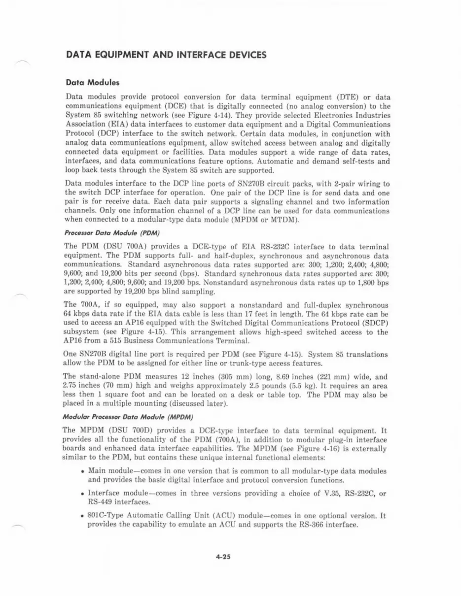
DATA EQUIPMENT AND INTERFACE DEVICES
Dotc Modules
Data modules provide protocol conve.sion for data terminal equipment (DTE) or datacommunications €quipment (DCE) that is digitally connected (no analog conversion) to theSystem 85 switching network (se€ Figure 4"14). They provide selected Electronics IndustriesAssociation (EIA) data interfaces to customer data equipment and a Digital ComhunicationsProtocol (DCP) interface to the switch network. Certain data modules, in conjunction withanalog data communications equipment, allow switched access between analog and digitallyconn€cted data equipment or facilities. Deta modules support a wide range of data rates,interfaces, and data communications feature options. Automatic and demand self-tests andloop back t€sts through the System 85 switch are support€d.
Data modules interface to the DCP line ports of SN2?0B circuit packs, with z-pair wiring toth€ switch DCP int€rface for operation. One pair of the DCP line is for send data and onepair is for receive data. Each data pair supports a signaling channel and two informationchannels. Only one information channel of a DCP line can be used for data communicationswh€n connected to a modular-type data module (MPDM or MTDM).
Prccet.or Doto ltodvle (PDtt)
The PDM (DSU ?00A) provides a DCE-type of EIA RS-232C interface to data t€rminalequipment. Th€ PDM supports full- and half-duplex, synchronous and asynchronous datacommunications. Standard asynchronous data rates supported are: 300; 1,200; 2,400; 4,800;9,600; and 19,200 bits per second (bps). Standard synchronous data rat€s supported are: 300;1,200;2,400;{,800;9,600;and 19,m0 bps. Nonstandard asynchronous drta rates up to 1,800 bpsare supported by 19,200 bps blind sampling.
The 700A, if so equipped, may also support a nonstandard and full-duplex synchronous64 kbps data rate if the EIA dsta cable is l€ss than l? f€et in length. Th€ 64 kbps rate can b€used to acc€ss an AP16 equipped with the Switched Digital Communications Protocol (SDCP)subsystem (see Figure 4-15). This arrangement allows high-speed switched access to theAP16 from a 515 Busin€ss Communications Terminal.
One SNZ0B digital line port is required per PDM (see Figure 4-15). System 85 translationsallow the PDM to be assigned for either line or tmnk-type access features.
The stand-alone PDM m€asures 12 inches (305 mm) long, 8.69 inches (221 mm) wide, and2.75 inches (70 mm) high and w€ighs apprcximately 2.5 pounds (5.5 kg). It requires an arealess then 1 square foot and can be locat€d on a desk or table top. The PDM may also beplaced in a multiple mounting (discussed later).
.dult tu...rr.. Dota ttoduL (INm 't)The MPDM (DSU ?00D) provides a DCE-type interface to data terminal equipment. Itprovid€s all the functionality of the PDM (700A), in addition to modular plug-in interfaceboards and enhanced data interface capabilities. The MPDM (see Figure 4-16) is externatlysimilar to the PDM, but contains these unique internal functional el€ments:
. Main module-comes in one version that is common to all modular-tvpe data modul€sand provides the basic digital interface and protocol conversion functions.
.Interface module-comes in three versions providing a choice of V.35, RS-232C, orRS-449 interfaces.
. 8olc-Type Automatic Callins Unit (ACU) module-comes in one optional version. Itprovides the capability to emulate an ACU and supports th€ RS-366 interface.
4-45
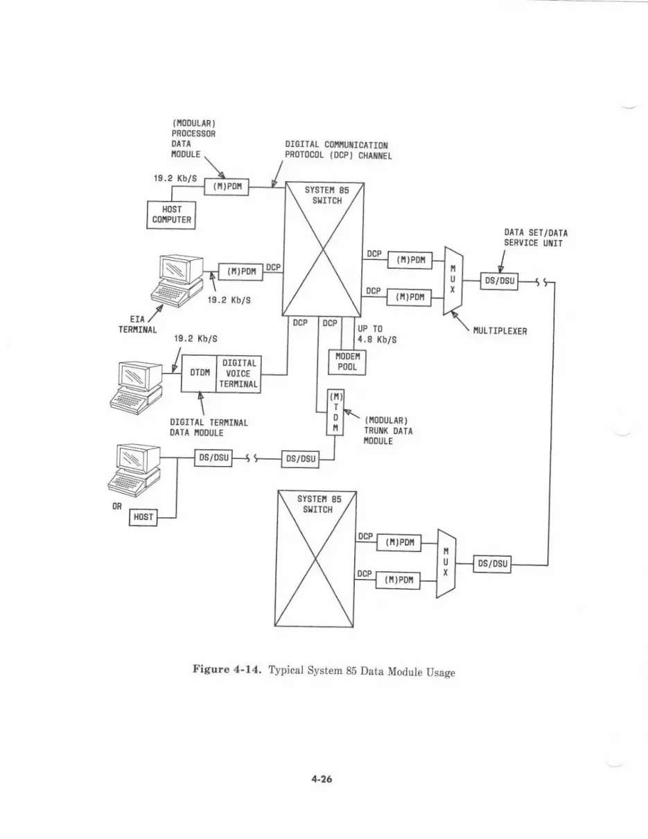
{lt00utA8)PROCESSOR
DATA OIGITAIPROIOCOLIIOOULE
19.2 Kb/S
col,{'tut{I cATIoil{DCP) CltAiItEt
OATA SET/OATASERVICE UIIIT
EIATERIIIiIAT
Kb/s
Kb/s
OIEITAL TERIIIilIIDATA IIIOOUTE
Figure 4-14. Typical System 8b Data Moalule Usase
0cP DcP I luPI lr nT()
Kb/s
l[00utAR)TRUIII( DATII'ODIJLE
\ sYsTE[ 85 /\*r"r,/
IIUTTIPL :IER
DCP
-;;-lU
x
I lqi vi, r-
DS/DSU
+26
0 Ttr€ rl.lGt
M OTHER
OIE III IEYICE
Dlll IERiIt t.toSr
n 0llfROIE EIA O€YIC€
sYSTEi 85SflIICH
XOTE 1
6DCP
2 ptlnloGPl
(2r €rllE)(28 BrUoEl
2 PAIR(ocPt
2 PAtnl2t 8au0E I128 3rr0El
2 PIIR(DC")
2 PAtnl2r sruoE,{?8 0rtiot)
17',
tloTES.1. Rl5E lS SPECTFTEo rt R8-232C lrPPnoI. 6{t'l2. Rlloc l8 8PECIFrE0 rt R8-AnC, ns-a4!t, 0R V.35
Figure 4-16. PDM/MPDM Connectivity
+27
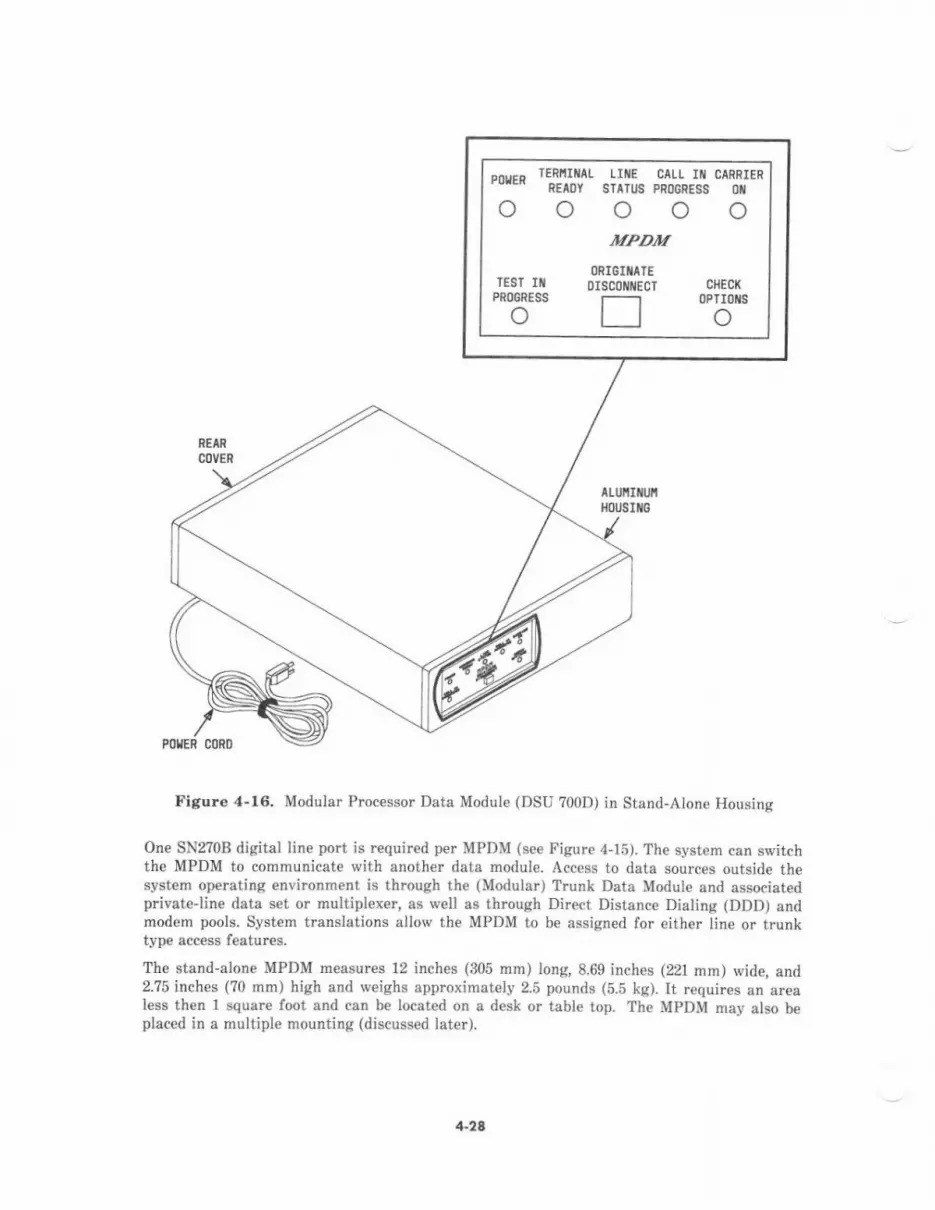
Figure 4-16. Modular Processor Data Module (DSU 700D) in Stand-Alone Housing
One SN2?08 digital line port is requir€d per MPDM (see Figur€ 4-15). The system can switchthe MPDM to communicate with another data module. Access to data sources outside thesyst€m op€rating €nvironm€nt is through the (Modular) Trunk Data Module and associatedpiivateline data set or multiplexer, as well as through Direct Distance Dialing (DDD) andmodem pools. System translations allow the MPDM to b€ assiqn€d for eith€r lin€ or trunktype eccess features.
The stand-alone MPDM measurcs 12 inches (305 mm) long, 8,69 inches (221 mn) wide, and2.75 inches (70 mm) high and weighs approximately 2.5 pounds (5.5 kg). It requires an arealess then I square foot and can be locat€d on a desk or table top. The MPDM may also beplaced in a multiple mounting (discussed later).
4-24

r.unk Detu ,noAub ODr't)
The TDM (DSU 7008) provides a DTE-type of EIA RS-232C int€rface to data servic€ unitsfor access to Digital Datsphon€ Sewice, privateline (nonpublic switched network) data sets,common data rate multiplexers, etc. The TDM supports full- and half-duplex standardasynchronous data rat€s from 300 to 19,200 bps; standard synchronous data rates from 300 to19,m0 bps; and nonstandard asynchronous data rates up to 1,800 bps ivith 19,200 bps blindsampling.
The 700C (TDM/2) has all the functionality of the ?008, in addition to public switchednetwotk data access, The ?00C may be used in conjunction with public switched n€tworkdata sets to provide modem pooling resources for System 85 (see Figure 4-1?). In thisapplication, a single conversion r€source consists of a TDM and an analog data modemconnected at the RS-232C int€rfac€. This conversion resource performs the analog-to-digitaland digital-to-analog conversions that allo$, the analog and DCP data endpoints tocommunicate,
EIA TENiIiIAt
L-::--::---- ---l
OIGITAL PORTS
r=-=---------:---==-:j-l
COIIIVERSIOII RESOURCES
Figure 4-17. Modem Pooling
4-?9
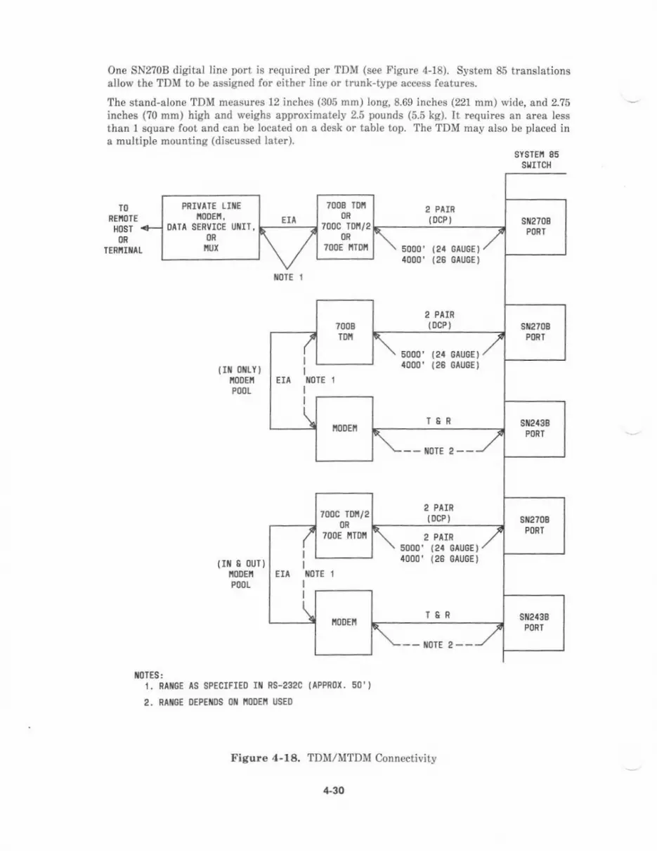
One SN270B digital line port is required per TDM (see Figure 4-18). System 85 translationsallow th€ TDM to be assigned for either line or trunk-type acc€ss features.
The stand-alone TDM measures 12 inches (305 rnm) long,8.69 inches (221 mm) wide, and 2.?5
inches (70 mm) high and weighs approximately 2.5 pounds (5.5 kg). It requires an area lessthan I squar€ foot and can be located on a desk or table top. The TDM may also be placed ina multiple mounting (discussed later).
':',1'll'*
TO
SEIIOTE
HOST
of,
2 PIIR(DCP)
5000' (24 GAUGEI
1000, (26 Gtu6E)
2 PAIN(osP )
2 PAIR{ocPl
TERIIIIIAI
rolE 1
trt oitY )i00EtlP00t
( Itt I ouT)It00Er'lP(,OL
IoTES:1. RAI/GE IS 8PECIFIED III
2. RTIIGE DEPEIIDS llfl IIODEII
RS-232C {APPR0I. 50')
IJSED
Figure 4-18. TDM/MTDM Connectivity
PRIVATE IIIEll0DEll,
DATA SERVICE IJIIIT,OR
IIUI
5000, (24 GAUGE)
1000, (26 GAUGE )
7o0c rui/2OR
700E iTDll 2 PAIN5000' (24 GrUGE)4000, (26 eaucE)
4"30

,'lodulo, r.vnk Doto ,todule (r.uDrt)
The MTDM (DSU ?00E) pmvides a DTE type interface to data terminal €quipment. Itprovides all the functionality of the TDM,/2 (?00C), in addition to modular plug-in interfaceboards and €nhanced data interface capabiliti€s. The MTDM (see Figure 4-19) is externally6imilar to th€ TDM but contains these uniqu€ int€rnal functional elements:
. Main module-comes in one version that is common to all modular-type data modulesand provides the basic digital interface and protocol conversion functions.
. Interface module-provid€s an RS-232C inte ace.
One SN2?0B digital line port is rcquired per MTDM (see Figure 4-18). System 85translations allow the MTDM to be assigned for either line or trunk-type access featur€s.
The stand-alone MTDM measures 12 inches (305 mm) long, 8.69 inches (221 mm) wide, and2.?5 inches (?0 mrn) high and weighs approaimately 2.5 pounds (5.5 kg). It requires an arealess than 1 square foot and can b€ located on a desk or table top. Th€ MTDM may also beplaced in a multiple mounting (discussed later).
ALUIII UIIHOUSITG
/POIER CORD
Figore 4-19. Modular Trunk Data Module (DSU ?00E) in Stand-Alone Housing
+31

Irbira, fqmiodl D.ro ,'todvL (DfD 4)
The DTDM (DSU ?01A) provides a DCE-typ€ interface to data terminal equipm€nt- Itsupports full- and half-duplex standard asynchmnous data €tes from 300 to 19,200 bps;standard synchronous data rates from 300 to 19,200 bps; and nonstandard asynchronous datarates up to 1,800 bps with 19,200 bps blind sampling.
The DTDM (s€e Figlre 4-20) operates as an adjunct to a ?400D seri€s digital voice terminaland is attached to the right side of the terminal. One SN270B digital line port is required perDTDM. The 701A uses the second information chann€l ol the voice terminal DCP line fordata communications. This arrangement ellows integrated simultaneous voice and datacommunications (see Figure 4-14).
The DTDM meesur€s 5 inches (127 mm) wide, 8.4 inches (213 mm) deep, and 1.?5 inches(44 mm) hiqh and weighs approximately 1-?5 pounds (3.86 kg).
OISITTt TERiIflTt0lTl LE I DIDI'I)
Figure 4-2O. Digital Terminal Data Module (DSU 701A) Typical Application
e%w( *%**6,
'e,L
1-32
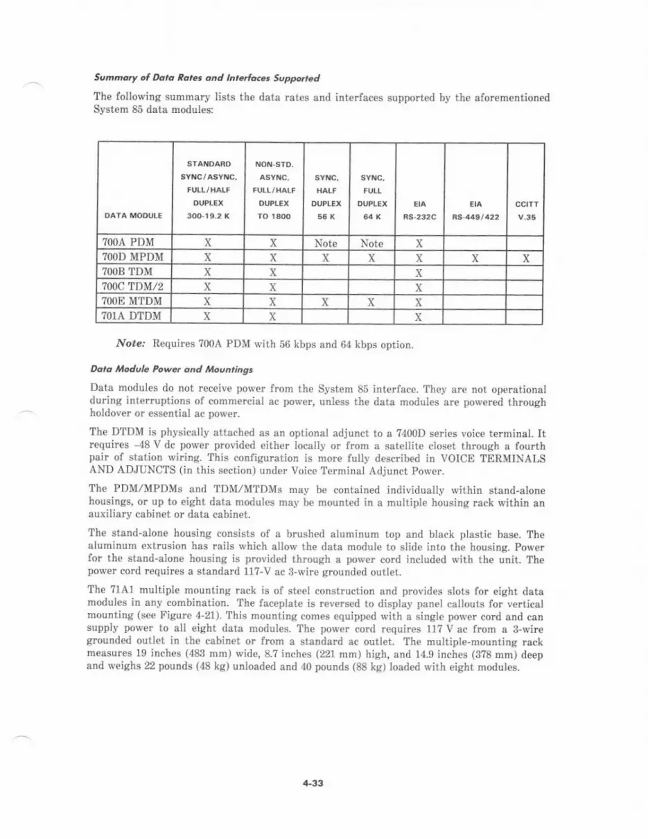
Semno.t ol Da,c zara onA tnrdfacct Support dThe following summary lists the data rates and interfaces supported by the aforementionedSystem 85 data modules:
TOOA PDM x x Note Note x?OOt' MPDM x x x x x x X?OOB TDM x X x700c TDM/2 x x x?OOE MTNM x x x x x7O1A DTDM x x x
Nore. Requires ?00A PDM with 56 kbps and 64 kbps option.
Dara i4odule Power and Moentinss
Data modules do not receive power from the System 85 interface. They are not operationalduring interruptions of commercial ac powar, unless the data modul€s are powered throughholdover or essential ac pow€r.
The DTDM is physically attached as an optional adjunct to a ?400D series voice terminal. Itrcquires -48 V dc power provided €ither locally or Imm a satellite closet through a fourthpair of station wiring. This configuration is more fully described in VOICE TERMINALSAND ADJUNCTS (in this section) under Voice Terminal Adjunct Power.
The PDM/MPDMs and TDM,/MTDMS may be contained individually \i,itbin stand-alonehousings, or up to eight data modules may b€ mounted in a multipl€ housing rack vrithin anauxiliary cabinet or data cabinet.
The stand-alone housing consists of a brushed aluminum top and black plastic base. Thealuminum extrusion has rails which allow the data module to slide into the housing. Powerfor the stand-alone housing is provided through a power cord included with th€ unit. Thepower cord rcquires a standard 11?-V ac 3-wire grounded outl€t.
The 7lA1 multiple mounting rack is of steel construction and provides slots for eight datamodules in any combination. The faceplate is r€versed to display panel callouts for verticalmounting (see Figure 4-2r). This nounting cornes equipped with a single power cord and cansupply power to all eight data modules. The porver cord r€quires 11? V ac from a 3-wiregrounded outlet in the cabin€t or from a standard ac outlet. The multiple-mounting rackmeasures 19 inches (483 mm) wide,8.? inches (221 mm) high, and 14.9 inches (3?8 mm) deepand weighs 22 pounds (48 kg) unloaded and 40 pounds (88 kg) loaded with eight nodules.
,l.33
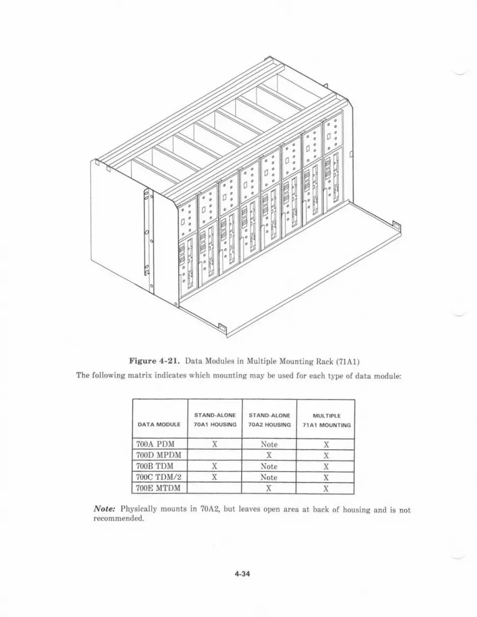
Figure 4-21. Data Modules jn Multiple Mounting Rack (?1A1)
The following matrix indicates which mounting may be used tor €ach type of data module:
?OOA PDM x Note X?OOD MPDM x X?OOB TDM X Note x700c'tDM/2 x Note X?OOE MTDM x X
Nore.' Physically mounts in ?0A2, but leaves open area at back of housing and is notr€commended.
4-34
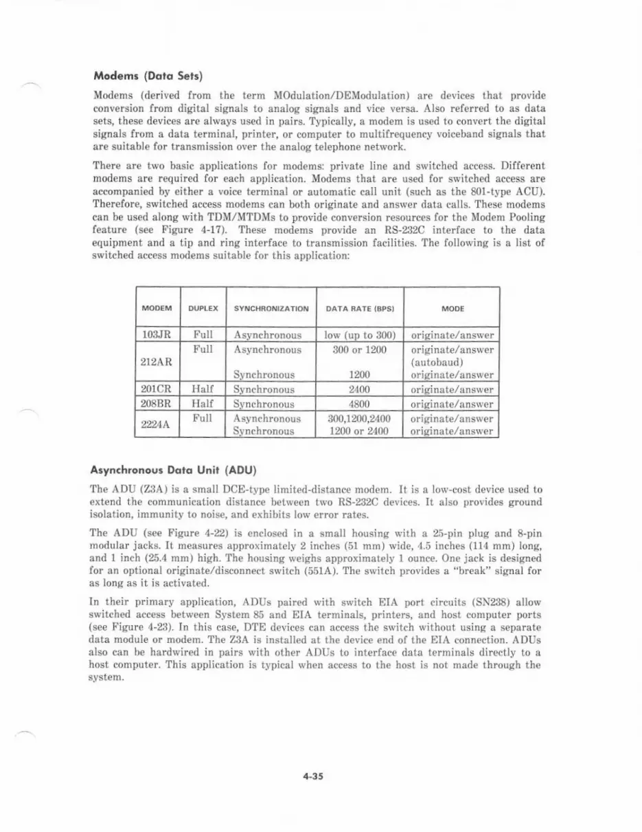
Modems (Ddro Scrs)
Modems (derived from ihe t€rm Modulation/DBModulation) are devices that provideconversion from digital signals to analog signals and vice v€rsa. Also referred to as datasets, these devices are always used in pai$. Typically, a modem is used to convert the digitalsignals from a data terminal, printer, or computer to multifrequency voiceband signals thatare suitable for transmission over the analog telephone network.
Ther€ arc two basic applications for modems: private line and switched access. Differentmodems aie aequired for each application. Modems that are used for switched access areaccompanied by either a voice terminal or automatic call unit (such as the 801-type ACU).Therefore, switched access modems can both originate and answer data calls. These modemscan be used along with TDM/M?DMS to provide conversion resources for the Modem Poolingfeatur€ (s€e Figure 4-17). These modems provide an RS-232C int€rface to the dataequipment and a tip and ring interface to transmission facilities. The following is a list ofswitched access modems suitable for this application:
103.1R Full Iow (uD to 300)
212ARFull
Synchronous
300 or 1200
1200
originate,/answer(autobaud)
201CR Half 2400
2O8BR Half Svnchronous 4800 orisinate/answer
22244.Full
Synchronous300,1m0,24001200 or 2400
originate,/answer
Asynchronous Dolo Unir (ADU)
The ADU (ZgA) is a small DCE-type iimited-distance modem. It is a low-cost device used toextend the communication distance between two RS-232C devices. It aiso prcvides groundisolation, immunity to noise, and exhibits low error rates.
The ADU (see Figurc 4-22) is enclosed in a srnall housing with a 25-pin plug and 8-pinmodular jacks. It measurcs approximately 2 inches (51 mm) wide, 4.5 inches (114 mm) long,and I inch (25.4 mm) high. The housing weighs approximately 1 ounce. One jack is designedfor an optional originate/disconnect switch (551A). The switch provides a "break" signal foras long a6 it is activated.
In th€ir primary application, ADUS paired with switch EIA port circuits (SN238) allowswitched access between System 85 and EIA terminals, printers, and host computer ports(see Figure 4-23). In this case, DTE devices can access the switch without using a separat€data modul€ or mod€m. The ZBA is installed at the device end of the EIA connection. ADUSalso can b€ hardwired in pairs with other ADUS to interface data terminals directly to ahost compute.. This application is typical when access to the host is not made throuqh th€system.
4-35
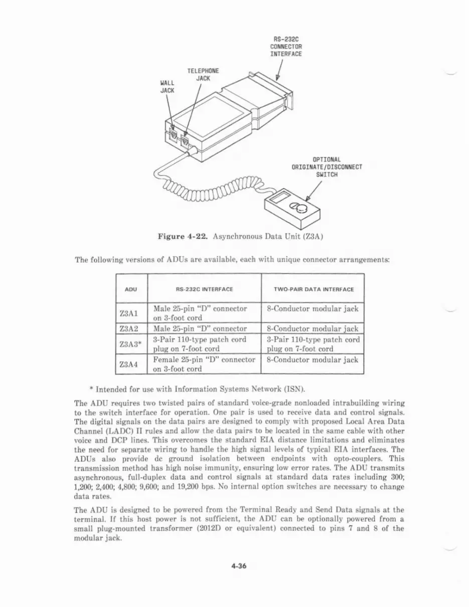
RS-232CcoxrEcT0RIXTERFICE
OPIIOIIILORIGITATE/DISCOI{ECT
sgrrcl
The following versions of ADUs are available, each with unique connector arrangem€nts:
TWO.PAIR DA'A IXT€Af AC'
ZSATMale 25-pin "D" connectoton 3-foot cord
8-Conductor modular jack
z3A2 Male 25-oin "D" connector 8-Conductor modular iack
23A3* 8-Pair 11o-type patch cordnlus on ?-foot cord
3-Pair 1lo-type patch cordDlus on ?-foot cord
z3A4Female 25-pin "D" connectoron 8-foot cord
8-Conductor modular jack
+ lntended for us€ with Information Systems Network (IS1\*).
The ADU requires two twisted pairs of standard voice-grade nonload€d intrabuilding wiringto th€ switch interfac€ for operation. One pair is used to receive data and control signals.The digital signals on the data pairs ar€ designed to comply with proposed l,ocal Area DataChannel (LADC) II rules and allow the dats pairs to be located in th€ sam€ cable with othervoice and DCP lin€s. This overcomes the stsndard EIA distance limitatiods and eliminatesthe need for s€parate wiring to handle th€ high signal levels of typical EIA interfaces. TheADUS also provid€ dc ground isolation between endpoints with opto-couplers. Thistlansmission method has high noise immunity, ensuring low error rates. The ADU transmitsasynchronous, full-duplex data and control signals at standard data rates including 300;
1,200; 2,400; 4,800; 9,600; and 19,200 bps. No internal option switches ar€ necessary to changedata rat€s.
The ADU is designed to be porvered from the Terminal Ready and Send Data signals at th€t€rminal. If this host power is not sufficient, the ADU can be optionally powered from asmall plug-mounted transformer (ml2D or equivalent) connected to pins ? and 8 of themodular jack.
4.36
Figure,l-22. Asynchronous Data Unit (ZgA)
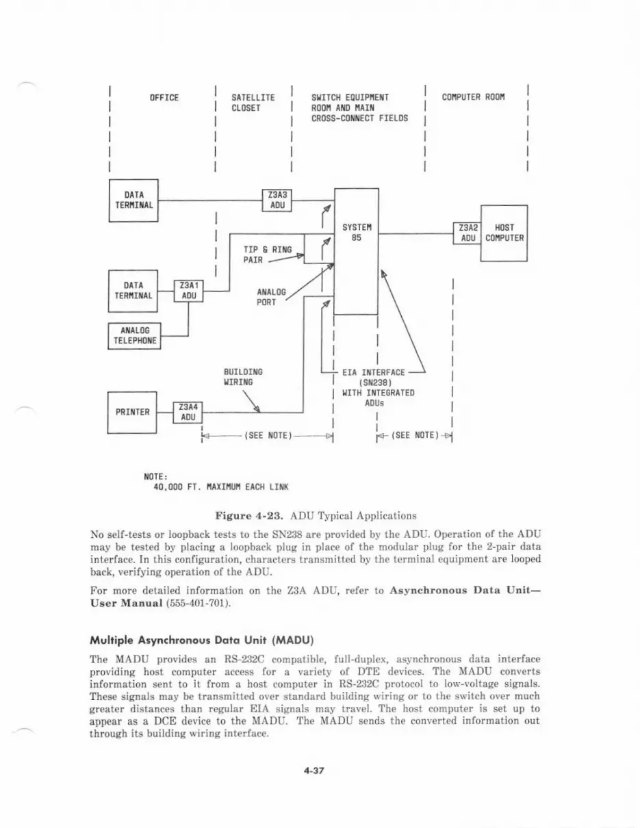
OFFICE SATELLlNct08ET
slllTcll EourPiEilTR00n Ailo llallrCN()SS-CONTECT FIELDS
coiPUrER n00fi
EIA ITTERFACE
F_ (sEE r/orE) __l
(sr298 )I.IITI{ IIIIEGRATED
A0Us
Ij
F {sEE rlolE I el
iIOTE:a0,000 FT. I'tAxlllult EAcfi Lltit(
Figure 4-23, ADU Typical Applications
No self-tests or loopback tests to th€ SN238 are provided by the ADU. Operation of the ADUmay be t€sted by placing a loopback plug in place of the modular plug for the 2-pair datainterface. In this configuration, characters transmitted by the terminal equipment are loopedback, v€rifying operation of th€ ADU.
For more detailed information on the Z3A ADU, refe. to Asynchronous Data Unit-User Msnual (555-401-?01).
Multiple A3ynchronoui Ddro Unir (ltADU)
The MADU provides an RS-232C compatible, full-duplex, asynchronous data int€rfaceproviding host computer access for a variety of DTE devices. The MADU convertsinformation sent to it from a host computer in RS-232C protocol to lov-voltage signals.These signals may be transmitted ovet standard building viring or to the switch ov€r muchgreater distances than regular EIA signals may travel. The host computer is set up toappear as a DCE device to the MADU. The MADU sends the converted inlormation outthrough its building wiring interfac€.
SYSTEI'I
85
/l-37

The MADU has the circuit functionality of the ADU in addition to the following:
. The circuit packs (BPPz) ar€ s€lf-powered and do not require power from the hostcomputer.
. Status LEDS are provided for each port to indicate the host's Deta T€rminal Ready(DTR) state, port in-use status, and busy-out state.
. Both a manual busy-out switch and a host-driven busy-out lead are provided tofacilitate MADU maintenance and testing.
The MADU interface includes the following hard\,earel
. BPP2 circuit packs each providing €ight full-duplex ports
. ?001A faceplate and 504A1 circuit module for the BPP2S
. ?2A carrier used to house up to eight BPP2S or a singl€-unit housing for individualcircuit packs
. M48C octopus cable for multiple port t€rminations
. Pow€r strip assembly with outlets, filter, and circuit breaker
. Transformer and modular cords used for carrier power arrengement.
The MADU may be used in various connection arrang€ments (see Figure 4-24). Like theADU, it can b€ bardwired with ADUs to interface data terminals directly to a hostcomputer, or it can be connected to System 85 through an EIA port circuit pack (SN238). Th€forrner application is typical when access to th€ host is not made through the system,Standard building wiring is sufficient when connecting the MADU through the system.Modular connectors provide hookups to the building wiring, host computer, and power cord.
OFFICE BUILDIIIIGIIIRIIG
suTo{ I
E0urPnENTlR0olt
SUILDIilGIIRIXG
SIIITCI{EDcollilEcTr0 sEII PORIS
CI]IIPUTER ROOII
1r08RS-232CPORTS
EIA IIITERFACE(slt238 )
OCP PORT
( sx270B )
1T08ns-232CPORTS
HARDIIREO ARRTIIGEIIEII]
Figure 4-2,1, Multiple Asynchronous Data Unit (MADU) Typical Applications
+38
In a stand-alone configuration, a single MADU is placed horizontally, measuring 1.65 inches(42 mm) high and 7.6? inches (195 mm) wide. This configuration is cost-effective if only oneor two MADUS are required. The single-unit housings are stackable.
In a fully-equipp€d MADU carrier configuration, 64 po s are available per calrier. Thisreduces considerably the amount of space and number of cabinets required to conn€ctasynchronous devices to a host comput€r with PDM/MPDMS or other devices-
For more detailed information on th€ MADU, refer to Multiple Asynchronous DataUnit-Urer Manual (555-401-?02).
Prorocol Converrerr
Switched access to a protocol converl€r allows cost-effective connectivity to external systemsand other internal host systems. Several types of protocol converters are available withSystem 85 to provide this compatibility.
Th€ 32?0 series data modules are protocol convert€$ that allow IBM 32?0-typ€ dataterminals to communicate with a host computer through the system switch using standardtwisted-pair building wiring instead of coaxial cable. A 3270 deta module at one end of theswitch converts m€ssages and data from coaxial cabl€ protocol to the DCP protocolsupported by th€ system. In addition to eliminating the need for coaxial wiring, thisarrangement allows more terminals to acc€ss the system resources through available portsor cluster controllers rather than by direct connection to specific controllers (see Figure 4-25).
Another s€ries of protocol converters allows lower equipment costs through the use of lessexpensiv€ ASCII terminals (in place of dedicated 32?0-type terminals) and standard buildingwiring. Four types are currently available: the 4271,4276,5274,
^nd 5276 protocol converters.
32rof Dore tAoAuh
The 32?0T (T€rminal) data module is a pmtocol conve er attached to a Cat€gory A 3270-type terminal, such as an IBM 3278 Information Display System. The 32?0T is thenconnected to the building wiring by a standard 4-pair modular cord. The 3270T data moduleapp€ars as a cluster controller to the terminal. The terminsl sends messages for thecontroller in coaxial cable Category A protocol, which the data modul€ conv€tts to DCPprotocol. Data and messages are then sent through the system switch to the 3270C at thecluster controller side of the switch. The 32?0C decodes the DCP information back to coaxialcable protocol and sends it to the controtler. The protocol conversion sequence is rev€rsed lorcontroller messages to th€ terminal. This method of communicating with a host comput€r istransparent to the computer.
Th€ 327m data module (s€€ Figure 4-26) js a self-contained unit installed near the 32?0-typ€terminal. It measures 9.14 inches (232 mm) in length, 5.64 inches (143 mm) in width, and1.33 inches (34 mm) in height. The 3270T w€ighs approximately 1.25 pounds and requires anexternal ac-to-dc power supply which converts commercial ac power to 5 V dc. Each 32?07data module provides a coaxial interface for connecting a short coaxial cable to the displayterminal and an 8-pin modular jack for connecting to a digital endpoint (wall jack). Inaddition, the 3270T has a rear-mounted telephone jack which can support a 2500-type or7100A s€ries voic€ terminal.
4-39
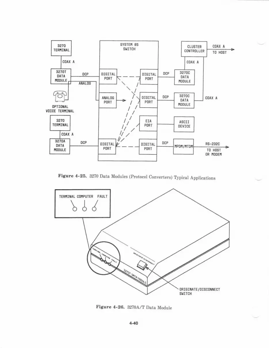
3270TENiI[AL
sYsTEi 85SIIITCH
CLUSTER
COIIIROLLERc0 (aTO HOST
cotx Il'oo'
32?0tl)IIA
ioDutE.0cP DIGITAL
PORT
OIGITALPORT
0cP 3270CDATA
i0DULE
c00( AIIIALOGPORT
\DCP 3270C/ \ DrGrTAL
oPlrotlLCE TERIIIIITI
N()DULE
;Jponr I
TO HI)ST
3270IERIIIIIAL
/,/ Iti .,4ASCII
OEVICE
COAI A ,!,/.,42704DATI
i0DutE
0cP DIgITALPORT
i' I----l OIGITALPORT
0cPllPD[/ttTD[
Vl)ICE
Figure 4-26. 3270 Data Modules (protocol Converters) Typical Applications
Figure 4-26, 32?0AlT Data Module
TERIIIIIIIL COIIPUTER FAULT\J/
0RIGIMATE/DISC0il[ECTSTITCH
4-40
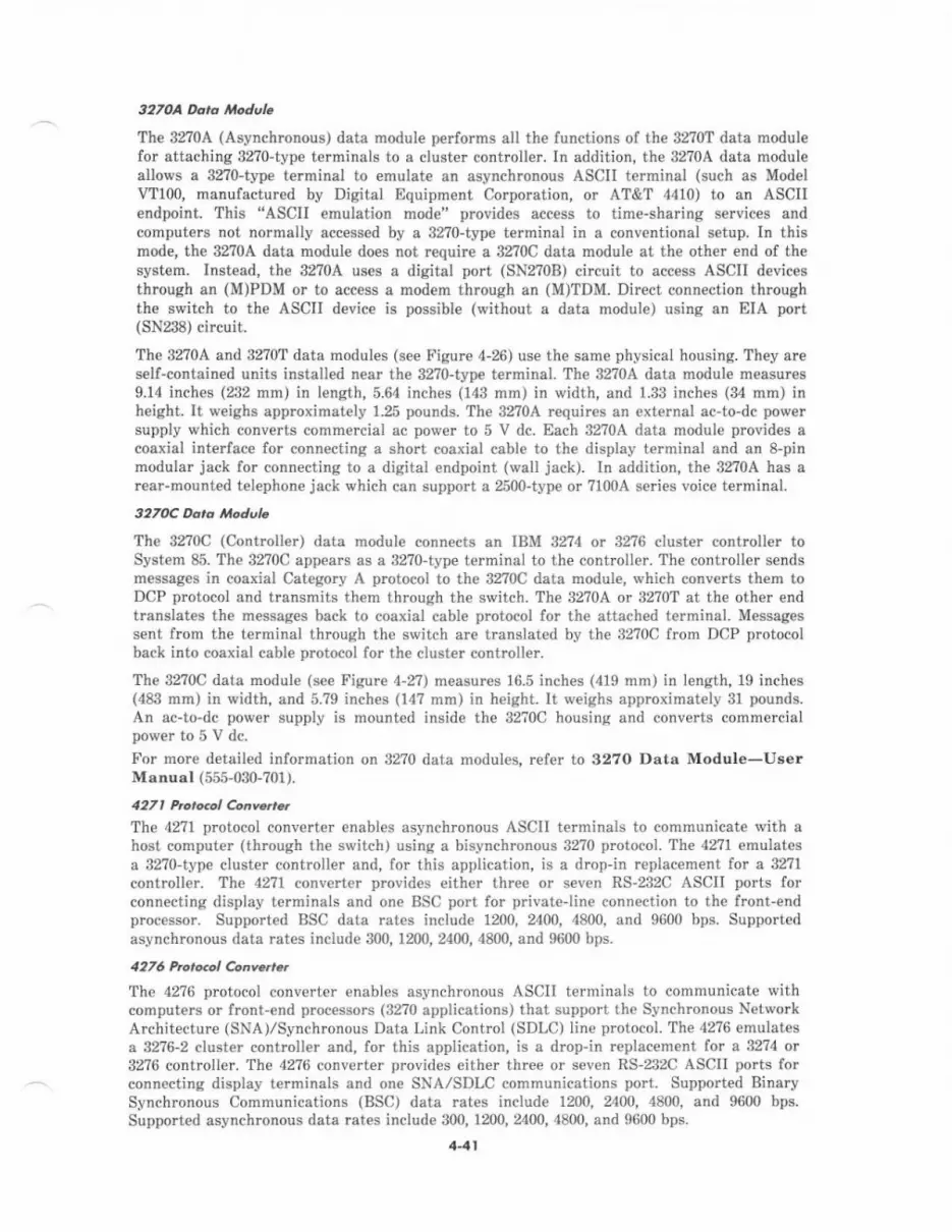
3270A Deto ttodul.
The 32704 (Asynchronous) data module p€rforms all the functions of the 32?0T data modulefor attaching 32?0-type terminals to a cluster contrcller. In addition, the 32704 data moduleallows a 3270-type terminal to emulate an asynchronous ASCII t€rminal (such as ModelVTI0O, manufactured by Digital Equipment Corporation, or AT&T 4410) to an ASCIIendpoint. This "ASCII emulation mode" provides acc€ss to time-sharing services andcomputers not normally accessed by a 32?0-typ€ terminal in a conv€ntional setup. In thismode, the 3270A data module does not r€quire a 32?0C data module at the other end of thesyst€m. Instead, the 3270A uses a digital port (SN2?08) circuit to access ASCII devicesthrough an (M)PDM or to access a modem through an (M)TDM. Direct connection throughth€ switch to the ASCII device is possibte (without a data module) using an EIA port(SN238) circuit.
The 3270A and 32?0T data modules (see Figure 4-26) use the sam€ physical housing. They areself-contained units installed near the 32?0-typ€ terminal. The 32704 data module measures9.14 inches (232 nm) in length,5.64 inches (143 mm) in width, and 1.33 inches (34 mm) inheight. It weighs approximately 1-25 pounds. The 32?04 requi.es an external ac-to-dc pow€rsupply which converts commercial ac power to 5 V dc. Each 32?0A data module p&vid€s acoaxial interfac€ for connecting a short coaxial cable to the display terminal and an 8-pinmodular jack for connecting to a digital endpoint (wall jack). In addition, the 32?0A has arear-mounted telephon€ jack which can support a 2500-type or 7100A series voice terminal.
327(rc Dard ,'lodule
The 3270C (Contrcll€r) data module connects an IBM 3274 or 32?6 cluster controller toSystem 85. The 32?0C appears as a 3270-type terminal to the controller. The controller sendsmessag€s in coaxial Category A protocol to the 32?0C data module, which convorts th€m toDCP protocol and transmits them through the switch. The 32?0A or 3270T at the other endtranslates the messages back to coaxial cable prctocol for th€ attached terminal. Messagessent from the terminal through the switch are translated by the 3270C from DCP protocolback into coaxial cable protocol for th€ cluster controller.
The 3270C data module (see Figure 4-2?) rneasures 16.5 inches (419 mm) in length, 19 inches(483 rnm) in width, and 5.79 inches (14? mm) in height. It weighs approximately 31 pounds.An ac-to-dc power supply is mounted inside the g2?0C housing and converts commercialpowertoSVdc.For mor€ detailed information on 3270 data modules, refer to 3270 Data Module-UserManual (555-030-701).
427, horo@l ConY..ae.
The 42?l protocol converter enables asynchronous ASCII terminals to communicate with ahost computer (through the switch) using a bisynchronous 32?0 protocol. The 4271 emulatesa 32?0-type cluster controll€r and, for this application, is a drop-in replacement for a 32?1
contioller. The 42?1 converter provides €ither three or seven RS-232C ASCTI ports forconnecting display terminals and one BSC po.t for privateline connection to the front-endprocessor. Supported BSC data ra1€s include 1200, 2400, 4800, and 9600 bps. Suppo{edasynchronous data rates include 300, 1200, 2400, 480t), and 9ti00 bps.
4276 tuoto.ol C.nBt..The 42?6 protocol converter enables asynchronous ASCII terminals to communicate withcomputers or front-end processors (32?0 applications) that support the Synchronous NetworkArchitecture (SNA)/Synchronous Data Link Control (SDLC) line protocol. The 4276 emulatesa 3276-2 cluster controller and, for this application, is a drop-in r€placem€nt fot a 3274 ot82?6 controller. The 4276 converter provides €ither three or seven RS'232C ASCII ports forconnecting display lerrninals and one SNA,/SDLC communications port. Supported BinarySynchronous Communications (BSC) dats rates include L200, 2400, 4a00, and 9600 bps.Supported asynchmnous data rates include 300, 1200, 2400, 4800, and 9600 bps.
441

FNOilT COVER
,uuio; ;l;
SnltcUSUIOSELNAYIIEX
Q @ooo
ERALCI'SUIOSILIAYITEX
@ @ooo
Figllte 4-27, 32?0C Data Module
5271 P.o,ocol 6nY.tr.t
The 52?4 protocol converter enables BSC 32?0 compatible display terminals to communicatewith compute.s or front-end processors (32?0 applications) that support the SNA/SDLC lineprotocol. The 5274 emulates a 8270-type cluster controller and, for this application, is adrop-in repiacement fo. a 32?4 controller. The 52?4 converter provides three BSC ports forconnecting from one to three cluster controllers, including AP16s that provide g?70
emulation- Each protocol converter will support up to a maximum of 32 BSC displayterminals frcm the 3 cluster controllers. Supported SNA/SDLC include 1200, 2400, 4800, end9600 bps. Supported BSC data rates include 1200, 2400, 4800, and 9600 bps.
442

5276 hor..ol C.ovarr.r
The 52?6 protocol converter permits one BSC 3780 or 2?80 compatible display terminal tocommunicat€ with a computer or fmnt-end processor that supports the SNA/SDLC lineprotocol. Th€ 52?6 emulates a cluster controller and is a drop-in replacement tot a 3n6-2controller.
For more detailed information on protocol conv€rters and their applications, refer toAT&T-IS Network and Data Services-Refererce Manual (555-025-201).
Chonnel Divirion Mulriplexer (CDM)
A CDM provides an economical means to directly access the same DS-1 digital transmissionfacility that also provides interswitch connectivity. thi6 multiplexer connects directly to theintegrated DS-1 interface in a System 85. The CDM allows preselected voice, data, or videoto be added to or removed from the DS-1 facility while passing the remaining channelsthrough on a digital basis. The CDM provides point-to-point or multipoint nonswitchedprivateline data connections ov€r the same digital facility.
The CDM is availabl€ in single-shelf or double-shelf configurations. The single-shelf unit hasa basic shelf with circuitry for line interface circuits, alarms, porver converter, and up toeight channel service units (CSUs). The double-shelf unit has the same basic shelf plus as€cond shelf with spac€ for 16 additional CSUS, lor a total of up to 24 CSUS. The single-shelfunit cannot be upgraded to a double-shelf unit. Standard equipm€nt for both configlrationsincludes:
. Line interface circuits
. Strobe generator assembly
. -48 V dc power conv€rter
. Alarm assembly
. Equalizer assemblies
. Channel select matrix
. Jack panel unit.
Chonnel Exponrion Multiplexer (CEM)
A CEM compresses 64-kbps voice and voiceband data signals into 32-kbps channels. Thismultipl€xer connects directly to the integrated DS-1 interface in a System 85. The CEM cancompress two DS-l signals, each with up to twenty-four 64-kbps channels, into on€ DS-1signal containing a maximum of forty-eight 32-kbps channels. A multiplexer is required ateach end of the DS-1 link to recover compressed signals for point-to-point DS-1 applications.
The CllM eonsists of a single-sh€lf unit housing all th€ equipment needed to double thecapacity of a DS-1 facility. The basic circuitry for the shelf has all the common equipmentfor line interfaces, alarns, and CSUS. Optional equipment for the CEM includes:
. 16- and 32-millisecond echo cancellation cards
. Signal plug-in eard
. 48 V power supply.
4-43

Dola Chonnel R€p€dlel
The data channel repeater (J588?9K) is an electronic circuit amplifier and isolator thatprovides range ext€nsion andlor surge prot€ction for the system low-sp€ed date channels. Itis connected in series with the data channel to repeat data pulses and to provide insulationb€tw€€n input and output pairs. Th€ data channel repeater d€tects and r€constructsincoming modifi€d biphase (bipolar) data pulses to eliminate any pulse attenuation ordistortion as well as to increase data channel rang€
The two basic arrangements are single channel and dual channel, each of which can be withor without rang€ extension. The maximum distance between a r€peat€r and th€ system orperipheral device is 1000 feet (305 m). The maximum distanc€ betw€en two rcpeaters is3000 feet (914 m). Up to four repeaters may be used to €xtend the maximum distanc€ to11.000ieet (3,359 m).
lnformolion Syilems Network (lSN) lnrerfoce
The ISN interface provides enhanced EIA RS-232C trunk connectivity to the ISN with a co-located high-speed packet switch. This interface is provided through DIA ports (SN238),
asynchronous data units (ADUS), and an ISN concentrator.
The ISN concentrator multiplexes 40 DIA ports over a fiber interface to the ISN node- Theconcentrator carrier houses five interface circuit packs which accommodate eight ports each.Eight ADUS are.equired per ISN concentrator circuit pack, or one ADU per EIA port.
Lo<cl Dislribution Service Unit (I,DSU)
The LDSU (48250) interfaces the System 85 switch DCIU with an €xternal processor, such asan AP, AUDIX, or another DCIU. The LDSU also provides rcquired gtound isolation betwe€nthe Common Control Cabinet (containing the DCIII) and the external processor. Two LDSUSper €xternal processor are .equired to provide this interface-
Each LDSU contains:
. A transmitter with filtering and modulation-allows data transmission at sp€€dsfrom 2.4 kilobits pe. second (kbps) up to 19.2 kbps
. A receiver with equalization, demodulation, clock recovery, and signal presence
d€tection-accepts incoming data from a 150-ohm line
. A regulated dc power supply for the required dc voltage
. An EIA RS-232C interface.
Note.. A single Isolating Data Interface may be substituted for two LDSUS between€ach external processor.
boloting Doto lnlerlo.e (lDl)
The IDI (105A) is a miniature connection unit for point-to-point, full-duplex operation.Powered entirely fmm the EIA interface through control signals, the IDI plugs directlybetween the System 85 switch DCIIJ and the connecting €xternal processor (AP, AUDIX, oranother DCIU). One IDI conn€cted to an exterdal processor provides an economicalsubstitute for two synchronous Local Distribution Service Units (LDSUS). Like a pair ofLDSUS, th€ IDI provides ground isolation betw€en the two endpoints. It needs noadjustm€nts or option settings, since it operates automatically at the DCIU data rate anduses timing from the DCIU as the controlling time source.
441
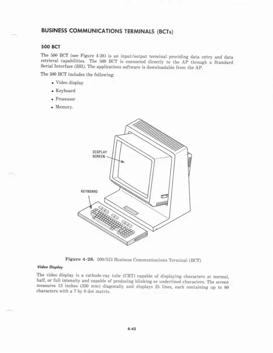
BUSINESS COiIMUNICAT|ONS TERtrltNAtS (BCTs)
5@ BCT
Th€.500. BCT !Tt. FiCuIg 4-28) is an input/output terminal providing data entry snd dstaretri€y8l cepebilities. The S{D BCI is conn€ct d directly t; the Ai through a StandardSerial Interlace (SSI). The applications software is downloadable from the Ap]Th.500 BCT includes the following:
. Video displey
. Keyboerd
. Proce$or
. Memory.
0rsPtltSCnfET
lEY80/U0
Figuro 4-28. 500/5lg Business Communications Terminal (BCT)t/rd.o e*rTh.€- vid€o-displey is a cathode-iay tub€ (CRT) capable of displaying characters et normal,half, or full intensity and capabl€ of producing bli;king or r.rnderlinei characters. The screenmeasures 13- inches- (3:n mm) diagonally and displsys 25 lines, each containing up to g0characters with a ? by I dot matiix.
1{5

The detached keyboard is connected to the video display by a 6-foot (1.8-m) cord. The500 BCT k€yboard (see Figure 4-29) houses 96 keys organized into seven lunctional groups:
. Function Group 1-Twelve editing keys with English abbreviations stendard to text-editing functions.
. Function Group z-Eight customer-d€signated function keys; the lebels for thesekeys appear on the 25th lin€ of the video display and can vary according to the tasksb€ing performed.
. Function Group 3-Num€ric and programmed function keys; the programmedfunction keys operate in conjunction with the CONTROL key and are labeled on adesignator strip above the group.
. Function Croup 4-QWERTY keys conforming to standard typewriter convention(upp€rcase and lowercase)
. Function Group 5-Space bar, CONTROL, NUMERIC, CONFIRM, and CANCEL keys
. Function G.oup 6-Cursor control keys
. Function Group ?-G€neral system function keys: HELP, PRINT, HOME, PAOE, andBEGIN/END.
Other keyboard features include sculptured nonglare keys,4'k€y rollov€r, matrix key coding,auto-repeat, an output sounder for audible keystroke feedback, and a "ping" to alert theoperator when important events have occurred.
6n0uP r GROUP 2
li t, EI IE E] t1 rrlItGROIJP
'
i?:lfilt,t mtNnl ;it; ll ; ill]il- I ll'r"{ *"lL:lLlL!t I
I
Etr----]fi;;ll*,
WtrtrtrtrtrtrtrtrtrtT"y44lttrEltrtrtrtrtrl I
W*W"1 t@n 4f-, 6 6FOUP
GR
Figur€ 4-29. 500 BCT Keyboard (Without Numeric Keypad)
The 280 processor controls the input and output for the 500 BCT and is housed in the base ofthe video display unit.
446
The m€mory is pa of the processor and stores:
. Display font
. Applications programs
. Diagnostic programs for power-up self-diagnostics
. Bootstrap (initializing) programs.
Memory for the 500 BCT includes 64 kbytes of random access memory (RAM) and 32 kbytesof read-only memory (ROM).
Powe, ond loatioD
The 500 BCT requires 11?-V 60-Hz commercial power from a 3-rvire grounded outlet.
The maximum cabl€ distance between the 500 BCT and tbe AP is 5000 feet (1524 m).Approximat€ly 4 square feet of table or desk space is required.
AT&T Perronql Termindl 5lOD
The Personal Terminal 5l0D (see Figur€ 4-30) is a new voic€/display terminal providing thecombined capabilities of a 7405D voice terminal, digital display module, data module, and513 BCT. The 510D has a DCP interfac€ and display capabiliti€s for dedicated S-channelmessages. It offers a small footprinl stvlish design, and easy use.
The 510D offers the following standard f€atur€s:
. A 280 processor.
r A 9-inch (229-mm) diagonal monitor with nonglare display. The display is organizedin 40-,80-, or 132-charact€r by 2?lin€ formats and supports five video attributes onan individual character basis. Lines 26 and 2? are reserved for screenlabeled actionblocks. A rvindow at the top is dedicated to telephony instructions and messag€s,leaving the remainder of the display for us€ by data applications (I2 channel) or localapplications.
. A touchscr€€n that overlays the monitor to provide easy access to terminal functionswithout a keyboard.
. Screen-based keyboard with a QWERTY layout.
. Privacy mode that blanks off all but selected pats of the disptay-
. lime manager.
. Screen-based caiculator.
. Personal directory.
. Self-diaqnostics.
. Time-of-day and elspsed-time display.
. Aotomatic "sleep mode" display dimming alter 15 minut€s of inactivity.
. Eight action blocks that provide access to the terminal capabilities and that areprogrammable for hosr interacrion.
+47

T0uclt-sEilsrrrvESCREEI/
SPEIKERPIII)IIE0I/0FF
NICROPHOIIIE
0i/0FF
PHOIESUTTOII
PRIVTCY0l/0FF
iEssAGE
Figure 4-30. AT&T Personal Terminal 5l0D
The 5l0D provides the following voice/display features:
. Message Waiting indicator
. Built-in speaker and microphone with control buttons and indicators
. Volume controls for tone ringer and speaker
. Four app€arances on the screen
. Nine programmable feature buttons on the touchscreen
. Automatic display of calling and called party identification
. Screen-accessed telephon€ directory that allows l-touch voice and data call setupfrom a diEctory of approximately 100 entries
. A hard button to dispiay the "PHONE" screen.
The 510D provides the following data featur€s:
. Full- or half-duplex, flow-controlled, parity-protected, asynchronous data at speedsup to 19,200 bps
. VT100 and 51ll BCT terminal emulation
4-48
. ANSI X3.64 compatible
. Character or block transmi$ion
. Two pages of data mehory
. Six character sets of which two may be selected at a time
. Smooth vertical scrolling and horizontsl scrolling
. Multiple $indows
. Protected fields for forms support.
Options for the 5l0D include:
. Feature €xpansion with pluggable cartridges containing modules for demonstration,training, directory extension, and terminal security
. An optional ?2-k€y keyboard with featur€s that ar€ a subset ol those transmitt€d byth€ 103-key and 89-key keyboards used with the 5lg/5l5 BCTS (discussed later).
5r3 8Cr
The 513 BCI (see Figure 4-28) is an input/output terminal providing data entry and dataretrievsl capabilities- The 513 BCT is connected by an DIA interface to a disital voiceterminal,/DTDM combination, then to the system through the DCp. The 5lB BCT also maybe connected to the DCP through a modem or PDM,/MPDM.
The 513 BCT includes the following:
. Video display
. (eyboard
. Processor
. Memory.
The video display is a cathode-ray tube (CRT) capable of displaying characters at normal,half, or full intensity and capable of producing bljnking or underlined charact€rs. The screenm€asures 12 inches (305 mm) diagonally and th€ scr€en displeys 2? lines, €ach containing upto 80 chaBcters with a ? by 9 dot matrix.
The detached k€yboard is conn€cted to the video display by a 6-foot (1.8-m) cord. A l03-keyproduct family keyboard is standard, and an optional 89-kev keyboa.d is available. Bothkeyboards provide linear feedback upon key depression.
The processor controls the input and output for th€ b1g BCT and is housed in the base of thevideo display unit.
The memory is part of the processor and sto.es:
. Display font
. Applications programs
a"a9
. Diagnostic progmms for power-up sell-diagnostics
. Bootstrap (inilializing) programs.
Memory for the 513 BCT includes 64 kbytes of RAM and 32 kbytes of ROM.
P.|9.r ond lodrion
The 513 BCT requires 11?-V 60-Hz commercial power from a 3-wire grounded outlet.
The maximum csble distance between the 513 BCT and a PDM/MPDM is 50 leet (15 m) and1e3B than 5000 feet (1524 m) fron the PDM/MPDM to th€ AP. Approximately 4 square feetof table or desk space is required.
515 8Cr
The 515 BCI (see Figrre 4-31) is e voice/display terminal providing the combinedcapabiliti€s ot
^ 7403D voice terminal, digital display module, data module, and 513 BCT.
The 5r5 BCa is an intelligent t€rminal that is downloadable from the AP. It has a DCPvoic€/data interface and display capabilities for dedicated S-channel messages, and may beconfigur€d with an auxilialy pa.allel or serial printer, Data communicstions are supportedoptionally ov€r an EIA RS-232C int€rfac€. Th€ 515 BCT includes the following
. Video display
r Keyboard
. Proc€ssor
. Memory
. Voice terminal components-
Vib Oir*rThe video display is a l2-inch (305 mm) diagonal CRT capable of displaying characteB atnormsl, half, or full intensity and capable of producing blinking or underlined characters.Th€ screen displays ZT lines- Each line contains up to 80 characters with a ? by I dot matrix.On€ line at the top of th€ scr€en is devoted to displaying S-channel tel€phony messag€s. Twolines at the bottom are devoted to screen-labeled keys.
The detached keyboard is connected to the video displsy by a 6-foot (1.8-m) co.d. Two typesof keyboards are available. The large keyboard houses 103 keys; the small keyboard has an89-key proper subs€t.
The processor is housed in the base of the video display unit. It controls the input andoutput and requests a download of application software fiom the AP.
The memory is part ol the processor end stores:
. Display font
. Applications programs
. Diagnostic programs for power-up self-diagnostics
. Bootstrap (initializing) programs.
4-50
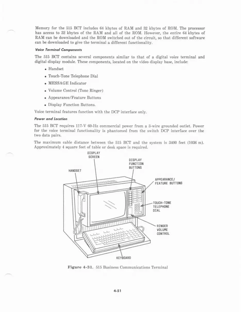
Memory for the 515 Bgt includes 64 kbytes of RAM and 32 kbytes of ROM. The processorhas access to 32 kbytes of the RAM and all of the ROM. However, the entire 6{ kbyt€s ofRAM can be downloaded and the ROM switched out of th€ circuit, so that different softwar€can be downloaded to give the terminal a differ€nt lunctionality.
Voic. fe,'',inol Compon.nts
The 515 BCT contains several components similar to that of a digital voice terminal anddigital display module. These components, located on the video display base, include:
. Handset
. Touch-Tone Telephone Dial
. MESSAGE Indicator
. Volume Control (Ton€ Ringer)
. Appearance/Feature Buttons
. Display tr'unction Buttons.
Voice terminal features function with the DCP interface only.
Powd and lo.orion
The 515 BCT requires 117-V 60-Hz commercial porv€r from a 3-wir€ grounded outlet. Powerfor the voice terminal functionality is phantomed from the switch DCP inte ace over thetwo data pairs.
The maximum cable distanca between th€ 515 BCT .nd the system is 3400 feet (1036 m).Approximately 4 square feet of table or desk spac€ is required.
l)ISPLAYSCREEI
DISPIAYFUilCtIoil
ToilsH^tosEr
^PPEARAIICE/FEATURE SIJTTOiS
TOUCH-TOIIETEIEPIIOXEDIAL
RITGERVOLUIIEcortn0L
Figure 4-3r. 515 Business Communications T€rminal
a-5 t

PRINTERS
The p nters used with System 85 (see Figure 4-32) are peripheral output devices thatproduc€ hard copy (printed pages) from data files as requested by a data t€rminal user. Fourprinters ar€ available for use with th€ system:
. ,143 Print€r
. 445 Printer
. 450 Printer
. 460 Printer.
The System 85 print€rs:
. Are used in conjunction with an AP
. Can produce an original and five copi$ (two copies on the 443 printer)
. Accommodate up to 132 columns and print from a stsndard g4-character set(uppercase and lowercase)
. Use American Standard Cod€ for lnformation Interchange (ASCII)
. Have a tractor-feed drive (optional on 450 printer)
. Require a Standard Serial Interface (SSI) dste chann€l
. Requi!€ 1m-V 60-Hz power from a 3-wire gtounded outlet.
a43 Prinlot
Th€ 443 printer:
. Is a low-speed, inexpensive draft-quelity matrix print€r
. Prints 47.5 characters per second (cps) with e throughput 30 cps
. AccommodatB paper widlhs of 3 to l5 inches (?6 to 381 mm)
. [s designed for table or desk use.
The 443 p nter prints et l0 charact€rs per inch (25.4 Inm) with a g-wire matrix print head.Friction feed and full forms control is provided. The ON/OFF switch is located on the toprjght of the printer.
The 443 printer can b€ located up to 5000 f€€t (1524 m) from the AP Cabin€t and requiresapproximately 4 square feet of desk or table space.
445 Prinlar
The 445 pdnter:
. Is a high-speed, draft-quality line printer
. Prints up to 220 lines p€r minut€ (300 lines per minute with the 64-charactermoncase chafact€r set)
. Accornmodat$ paper widths of 4-ll8 to 15 inchB (105 to 381 mm).
4-52

..3 PNIfiER {45 PRIIIIER
I5O PRIiTER .50 PRIT'ER
Figur€ 4-32. System 85 Printers
The 445 printer prints at 10 charactets per inch with hammers striking th€ character palletsin a moving belt. Form length and width are operator-adjustable and full forms control isprovided. The 445 print€r is housed in an upright cabinet designed to reduce printer noise.Paper-handling facilities in the cabinet include:
. The paper supply and th€ pap€r supply shelf
. The paper accumulator and the paper accumulator shelf
. A window at the top of the cabinet for viewing the printout, and another windownear the bottom front of th€ cabinet for viewing the pdntout accumulation.
A FORM ADVANCE switch and a red PAPER switch are iocated on the right front of thecabinet. These switches control th€ paper, and lhe PAPER switch lights wh€never the paperjams or the printer is out of paper. The ON/OFF switch is located on the left front of thecabinet.
The 445 printer can be located up to 2000 feet (610 m) frorn the AP Cabinet and requiresapDroximately 4 square feet of floor space.
4-53
450 Prinl€r
The 450 printer is a medium-speed, document-quality character printer. It prints up to 55characters per second with bidirectional printing. It can print a 132-column line with spacingof 10 characters per inch; it can also print a l58-column lin€ with spacing of 12 charactersper inch. Other 450 printer features include:
. Tab, margin, and form control
. Friction-feed and optional adjustable tractor-feed
. Accommodates paper widths of 3 to 15 inches (?6 to 381 mm)
. Variable form length of 4 to 14 inches (r02 to 356 mm).
The ON/OFF switch is located on the back of the printer.
Th€ 450 printer can be iocated up to 5000 feet (1524 m) fron the AP Cabinet and ftquiresapprcximately 4 square feet of desk ot table space.
460 Prinlel
The 460 printer:
. Is a medium-speed, draft-quality matrix printer
. Prints at 200 cps (340 cps burst)
. Accommodates paper widths of 3 to 16 inches (?6 to 406 mm)
. Is designed for table or desk use.
The 460 printer uses a ?-wire print head and provides full forms control. It also offers threechoic€s of cha.acter density:
. Normal-10 characters p€r inch, with 132 characters per line
. Condens€d-16 characters per inch, with 218 characters per line
. Expand€d-5 characters per inch, with 66 characters per line.
Th€ control panel, located on the right side of the printer, contains four control buttons;
. ON LINE (onloff) switch
. TOP OF FORM advances paper to the top of the form when pressed momenta ly
. PAPDR STEP advances the paper one line for each press of the button
. ALARM CLEAR-lights when a fault is detected; when pressed, clears the printerlogic.
The auxiliary contml panel, on the right side of the printer, has the foilowing controls:
. Lin€s Per Inch (LPI) Switch-selects six or eight lines per inch (25.4 mm)
. Form Length Switch-selects 11 commonly used form l€ngths
. Two-Digit Status Display-indicates which function was being performed ivhen aproblem occurred
. Pitch Switch-allows the s€laction of 10 or 16.? characters per inch
. Test Switch-exercises the printer for t€sting (without external data input).
The 460 printer can be located up to 5000 feet (1524 m) from tbe AP Cabinet and requiresapproximately 4 square feet of desk or table space.
4-54
MISCEII.ANEOUS PERIPHENAIS
Syitcm Monogemonl Te.minol (sMT)
The SMT (J58889K) is a keyboard/display terminal used by the system administrator toperform local switch administration functions, such as the following
. Change line ext€nsion numb€rs and featur€s assigned to voice terminals
. Add and remove restrictions assign€d to line extension numbers
. Chsng€ authorization codes
. Search translations (in memory) for particular line extension numbers (to identifythe services provided).
The SMT (see Figure 4-33), measuring approximately 16 inches (406 mm) in length and8.25 inch€s (210 mm) in width, is designed for desk-top us€. Th€ display panel and keyboardare specifically angled and designed to provide the user easy liewing and operation. TheSMT contains:
. A l2-button keypad
. 24 Control buttons
. 4 Digital displays
. 8 Status lamps
r Flipcharts.
Whenever power is applied to the SMT, one of the status lamps indicates the SMT's currentoperational status, such as the following
. Maint€nance and Administration Panel (MAAP); Remote Maint€nanc€,Administration, and Traffic System II (RMATS-II); or T€rminal Chang€ Management(TCM) is in use.
. Disconne.t.
. Line or trunk b€ing administered is busied out.
The SMT shares the same data channel to the system as the MAAP, RMATS-II, and TCM.The channel is used on a first-come, first-served basis. Operation of the SMT requires lm-V60-Hz commercial pow€r from a 3-wire ground€d outlet. The SMT can b€ located up to1000 f€et (305 m) from the Common Control Cabinet.
The Rr SMT is fully compatible for R2 us€, but in Rl required an external interface unit(ED-18440) not need€d for R2. Installation for the R2 application requires removal of theinterfacc unit and replacement with a bypass cable.
For more dctailod information on the SMT, refer to AT&T System 86 (B2V3)-SMTAdministration Managemert-User's Guide (555-102-501).
4.55

Figure 4"33. System Management Terninal (J58889K)
Moinlenonce qnd AdminLt.dtion Ponel (MAAp)
The .MAAP. (J58889J) is a keyboard/display terminal us€at by seFice personnel to pertbrmadministration and maintenance procedur€s locally at the switch. ttrese procedures attowservice persornel to modify call processing translation tables and io p*forrn tf,"maintenance funcrions of system inrerrogar ion. iesl ing, and fau lr icolation.
The MAAP (see Figure 4-34) contains a 12-button keypad and four rows of controt buttons.It provides a 25-digit operational display, a B-digit procedu.€ number display, a 2-digit fieldide-ntification display, and a 2-digit error code display. It also has eigtrt iilO tamps *ratindicate alarm and op€rational status.
The MAAP plugs into a MAAP connector on the Common Controi Cabinet alarm panet (seeFigures 3-19 and 3-14) or into an €xtended MAAp connector in Module Control Cabinets andremote modules. There is one connector for each common control processor and oneconn€ctor for whichever processor is currently on-line in a duplicateil common controlsystem. The MAAP shares the same data channel to the syst€m aslhe SMT, RMATS_II, andTCM. The channel is used on a first-come, first-served basis.
4-56

Flipcharts are attached to the MAAP and serve as a quick reference for each of thenumbered administration and maintenanc€ procedur€s (PROCS). Each flipchatt explains theboundaries, limits, and definitions of the fields presented on the operational display for agiven PROC.
For more detailed information on using the MAAP lor administration procedures, refer toAT&T System 86 (n2v3)-Feature Translationc-Service Mstusl (555-102-10?).
For rnore detailed information on using the MAAP for maintenance procedurcs, rcfer toAT&T Syrtem 86 (R2V3)-Mairtenance-Service Manual (555-102-108).
Figure 4.3,1, Maintenance and Administration Panel (J58889J)
u'O !O reo a.droI -1 ._,-11 i ;: Li '1,r Er _ _ D D ti
EEEEEEEDtiEE'- ll _ Mll Lr!!l L!!l
L=l Li:ll ll:ll Lji-.1 Lel Li!
+57

Fo..o AdfiinLtrdtion Dalo Sy.lem (FADs) Terminol
The FADS terminal (see Figure 4-35) is used to display call traffic data fo. the CentralizedAttendant SeFice (CAS) andlor Uniform Call Distribution (UCD) features. The FADSdisplay terminal includes:
. A l2-button keypad to €nter the requ€sted datt
. Two display fields to show the data request€d
. Faceplate designating type of data displayed.
The FADS arrang€ment may be used to display CAS force edministration data forint€grated attendant concentration applications- Force administration data is made availableat a main location by both visual and printed displays. One dedicated low-sp€€d data channeland on€ 102F1-A terminal per system is used in this case. For UCD group studies (R2V1systems only), one 102G1-A terminal per group (maximum of 12) may be used.
Figure 4.36. Force Administntion Data System Terminal (102F1-A)
4.58
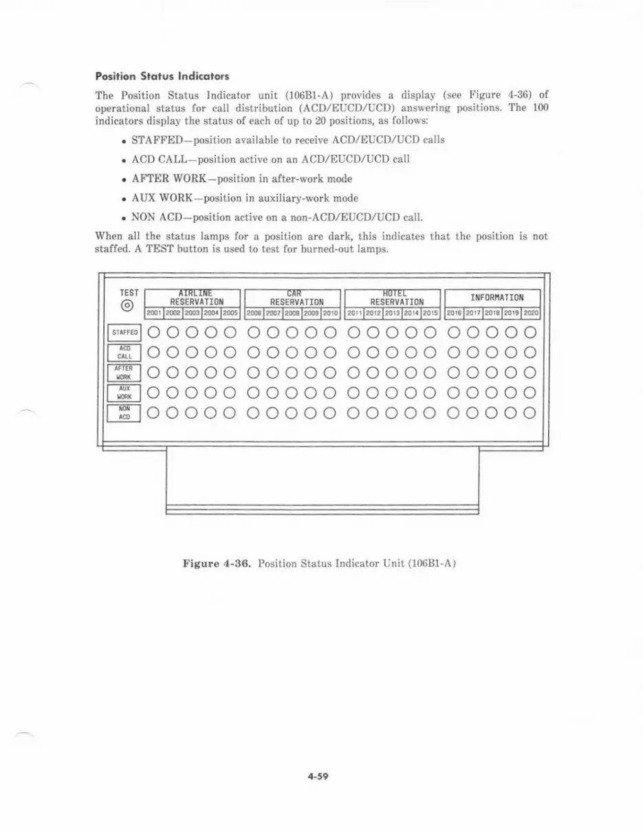
Posilion Slolus lndicdtora
The Position Status Indicator unit (106Bf-A) provides a display (see Figure 4-36) ofoperational status for call distribution (ACD,/EUCD/UCD) answering positions. The 100
indicators display the status of each of up to 20 positions, as follows:
. STAFFED-position available to receiv€ ACDIEUCIJ/UCD calls
. ACD CALL-position active on an ACD/EUCD/UCD call
. AFTER WoRK-position in after-vrork mode
. AUX WORK-position in auxiliary-work mode
. NON AcD-position activ€ on a non-ACD/EUCD/UCD call.
When all the status lamps for a position are dark, this indicates that th€ position is notstafted. A TEST button is used to test for burned-out lamps.
Figure 4-36. Fosition Status Indicator Unit (10681-A)
TEST
o@l--iE-lt*-iE--lt,nrt-1nii-1t,,*,tT--rfi--lIAclI
RESERVATIOII
ooooooooooooooooooooooooo
RESERVATIOII2(Ic t2mr t26a t20c0 t 2010
RESERVATIOII IIIFORIIATIOIII
ooooooooooooooooooooooooo
ooooooooooooooooooooooooo
ooooooooooooooooooooooooo
4-59
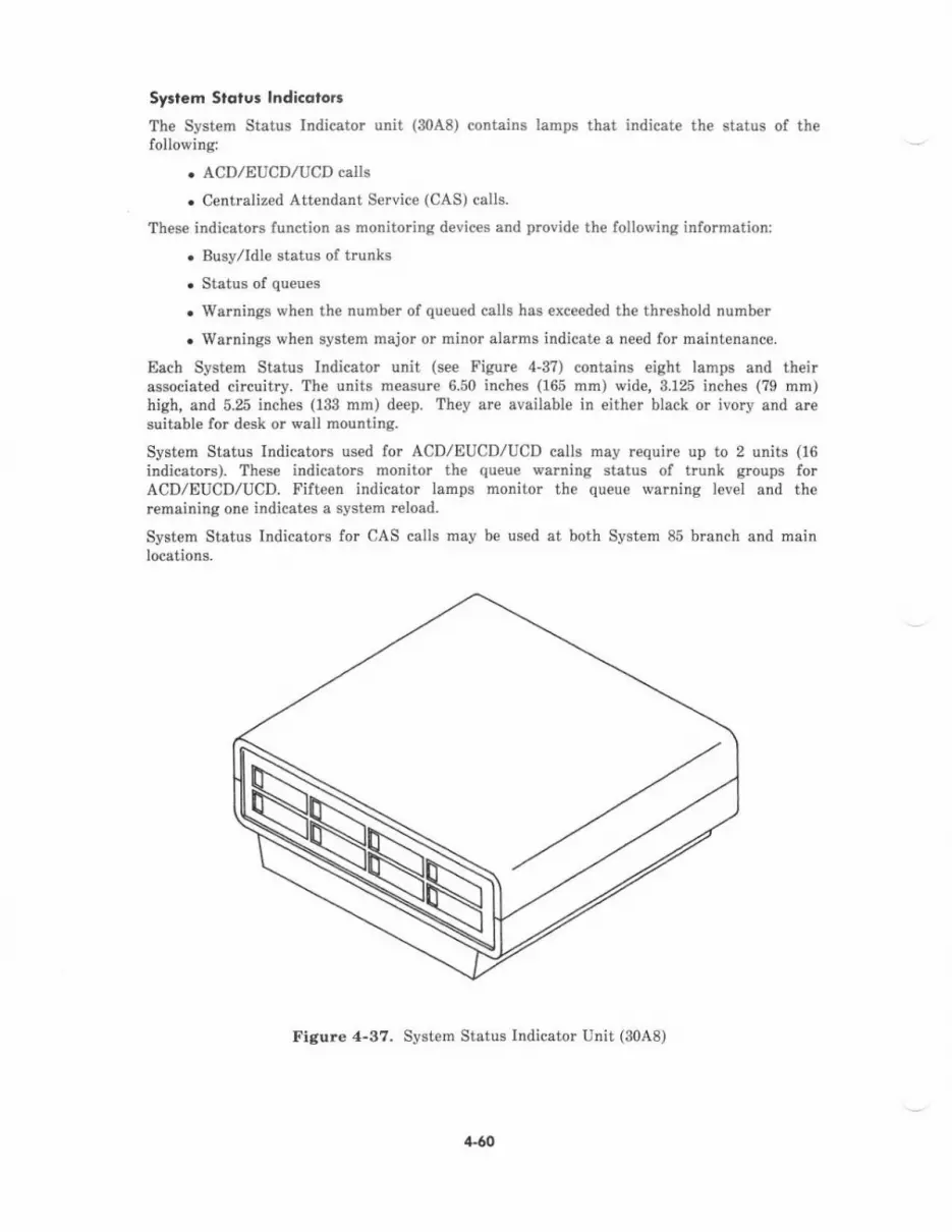
Sy.t.m Slqtus lndicotot.
The System Status Indicator unit (30A8) conbins lamps that indicate the status of thefollowing:
. ACD,zEUCDIUCD calls
. C€ntnlized Attendant Service (CAS) calls.
These indicators function as monitoring devices and provid€ the following information:
. Busy./Idle status ol hunks
. Status of queues
. Warnings when the number of queu€d calls has €xceeded the threshold number
. Warnings when system major or minor alarms iddicate a need for maintenance.
Each System Status Irdicator unit (s€e Figlrrc 4-3?) contains eight lamps and theirassociat€d circuitry. The unitr mearur€ 6.50 inches (165 mm) wid€,3.125 inches (?9 mm)high, and 5.25 inches (133 mm) deep. They are availabl€ in either black or ivory and aresuitable {or desk or wall mounting.
System Status Indicators us€d for ACD,/EUCD,/UCD calls may requile up to 2 units (16indicators). These indicators monitor the queue werning status of trunk gtoups forACDIEUCD/UCD. Fifteen indicator lamps monitor the queue warning level and theremeining one indicates a system r€load.
System Status lndicators for CAS calls may be used et both System 85 brunch and mainlocations-
Figure 4-37. System Status Indicator Unit (3048)
t.60
A maximum of 15 System Status Indicator units (with 8 indicators per unit) can be used atsny System 85 main location. When th€ maximum number of units is in we, th€ indicatolsare assigned as follows:
. 110 indicators to monitor 110 Release Link Trunks (RLTS)
. 4 indicators to monitor the following system status information:
Ov€rload-the queue threghold number is exceeded
Major-the system has a major alarm
Minor-the system hes a minor alarm
Crontrol-the system is in the backup mode.
If the maximum number of 110 RLTg and the overload, major, minor, and contrcl functionssre to b€ monitored, 15 System Status Indicator units are requir€d as follows:
. 14 units to monitor the 110 RLTS (leaving 2 indicators unused)
r 1 unit to monitor 2 or all of these indicators: overload, major alarm, minor alarm,and coDtrol.
A maximum of three System Stafus Indicator units can be u6ed at any System 85 branchlocation. Whelr the maximum number of units is in us€, th€ indicators are essigned sslollows:
. 2 units (16 indicators) to monitor 16 RLT8
. I unit (8 indicators)-4 indicotors are used to indicat€ overload, major alarm, minoralarm, and control,
rl-61
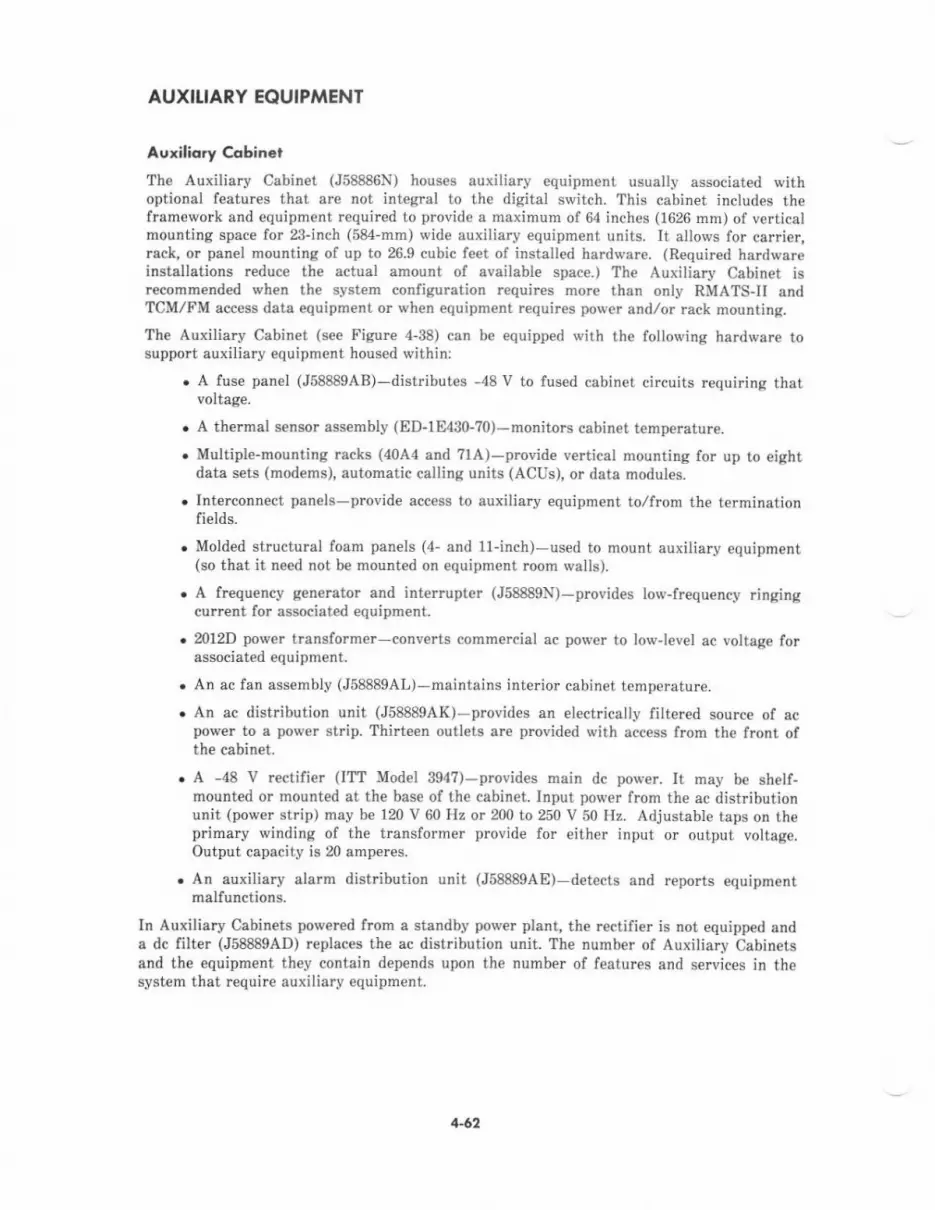
AUXIIIARY EQUIPMENT
Auxiliory Cobinct
The Auxiliary Cabinet (J58886N) houses ar:xiliary equipment usually associated withoptional features that are not integral to the digital switch. This cabinet includes theframework and equipment requir€d to provide a maximum of 64 inches (1626 mm) of verticalmounting space for 23-inch (584-mm) wide auxiliary equipment units. It allows for carri€r,rack, or panel mounting of up to 26.9 cubic feet ol install€d hardwar€. (Required hardwareinstallations reduce the actual amount of availabl€ space.) The Auxiliary Cabinet isrecomm€nded q,hen the system contiguration requires more than only RMATSII andTCM/FM access data equipm€nt or when equipment requires power andlor rack mounting.
Tbe Auxiliary Cabinet (see Figure 4-38) can be equipped with the folloving hardware tosupporr auxiliary equipmenl housed $ ithin:
. A fuse panel (J58889AB)-distributes -48 V to fused cabinet circuits requiring thatvoltage.
. A thermal s€nsor assenbly (ED-lE430-?0)-monitors cabinet temperatur€.
. Multiple-mounting racks (40A4 and ?lA)-prcvide vertical mounting for up to eightdeta sets (modems), automatic calling units (ACUS), or deta modules.
. Interconnect panels-provid€ access to auxiliary equipment to,/from the terminationfield6.
. Molded structural foam panels (4- and 11-inch)-used to mount auxiliary equipm€nt(so that it need not be mounted on equipment room walls).
. A frequ€ncy g€nerator and interupt€r (J58889N)-provides low-frequency ringingcurrent for associated equipment.
. 2012D power transformer-converts commercial ac power to lowJevel ac voltage forassociated equipment.
. An ac fan assembly (J58889AL)-maintains interior cabinet temperature.
. An ac distribution unit (J58889AK)-provides an electrically filtered source of acpower to a pow€r strip. Thirteen outlets are provid€d with access frcm the fron| ofthe cabinet.
. A -48 V r€ctifi€r (ITT Model 394?)-provides main dc power. It may be shelf-mounted or mounted at the base of the cabinet. Input power from the ac distributionunit (power strip) may be 120 V 60 Hz or 200 to 250 V 50 Hz. Adjustable taps on theprimary winding of the tnnsformer provide for either input or output voltage.Output capacity is 20 amp€res.
. An auxiliary alarm distribution unit (J58889A8) detects and reports equipmentmalfunctions.
In Auxiliary Cabinets powered from a standby power planl the rectifier is not equipped ands dc filter (J588894D) replaces the ac distribution unit. The numb€r of Auxiliary Cabinetsand the equipment they contain depends upon the number of features and sewices in thesystem that require auxiliary equipment.
1-62
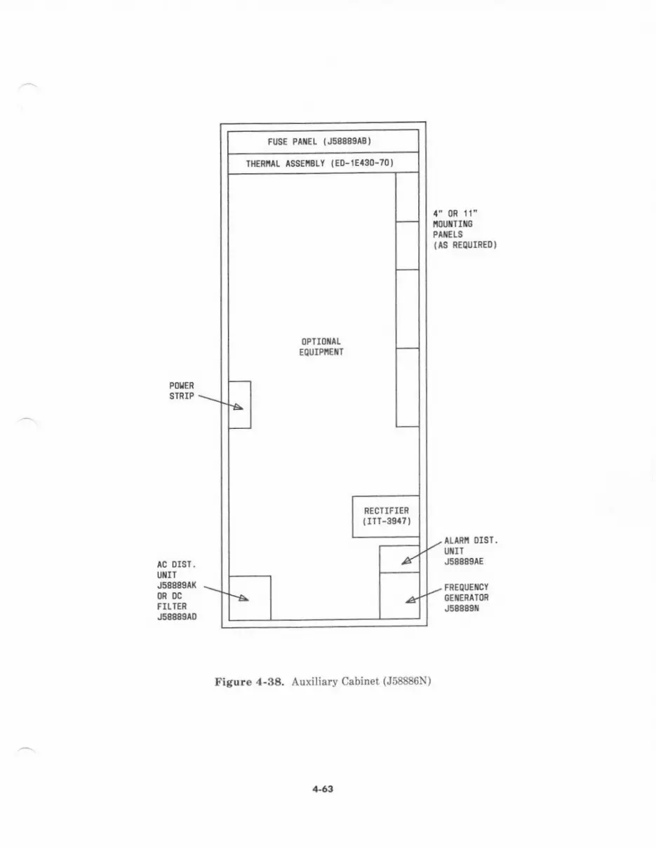
tc DrSt,IT
.5t880tl(ccFILIENJ68t80lD
PITERATRIP
t' 0R it"iflIIIFPIEIS(l8 nECJIIEDI
^Lfif ol3r,
IJIITJSgg0grE
tnEolC*YEEETTMJSga0gr
trkur. 4-9& Aurili.ry Cebinet (J58886N)
Ft[E P|EL (.li888ll'
Tlcritt l88El3lt lEo-lEa€o-tol
a-6il
Auxiliary Cabinet alarms are consolidated for the various equipment and conditions withinthe cabinet. The alarm distribution unit registers these conditions and provides acompatible interface for the ext€rnal equipment alarm input (provided by the remoteinterface circuit pack in the common control carrier). This allows automatic registering andreporting of auxiliary equipment alarms by the switch ala.m panel. The possible AuxiliarvCabinet alarm tlTes are as follows:
. Temp€raturc
. Rectifier
. Circuit breaker/fuse
. Frcquency generator
. Fans.
A 212AR data set and loop-start trunk aro required to provide RMATS-II access to theswitch. A data set may also be needed for AP access to a s\r'itch remote port. Th€se datasets may be installed in a multiple-mounting rack in the Auxiliary Cabinet, if th€ cabinet islocated within 50 feet (15 m) of the common control.
Interconnect panels for 3-pair connections (ED-18443) rnay provide 32 or 64 terminations.The panels provide 110-type termination blocks which are pre\rired to 50-pin connectors,manufactured by Amphenol Products, mount€d on the back of the Auxiliary Cabinet.Tw€nty-five pair L/O cables complete the connection between the interconnect panel and theselect€d termination field. With this arrangement, S-pair modulsrity and pair sequencing onthe 110 blocks is preserved. Th€ int€rconnect panels are used for line and auxiliary trunkport access such as to data sets, data modules, or recorded announcem€nt channels.They mayalso be used for any miscellaneous connections within the Auxiliary Cabiret.
Special cable assemblies for certain data sets and data modul€s are provided which ailowEIA connector access at the back of the cabinet for direct cable runs to data terminal ordata communications equipment.
Avlomqtic lrunk tevel lnlerloce Unit
This unit (J5305,0P) provides automatic ttunk level access to customer-provided €quipmentused for functions such as radio paging or recorded telephone dictation.
Chonnel Divbion Multiplexer (CDM) Equipment
A CDM pmvides an economical means to directly access the same DS-l digita) transmissionfacility that also provides interswitch connectivity. This multiplexer connects directly to theinteqrated DS-l interfac€ in a System 85. The CDM allows prcselected voice, data, or videoto be added to or removed frcm the DS-1 facility while passing the remaining chann€lsthrough on a digital basis. The CDM provides point-to-point or multipoint nonswitchedprivateline data connections over the same digital facility.
Th€ CDM is availabl€ in single-shelf or double-shelf configurations. The single-shelf unit hasa basic shelf with circuitry for line interface circuits, alarms, porv€r convetter, and up toeight channel service units (CSUs). The double-sbelf unit has the same basic shelf plus a
s€cond shelf with space for 16 additional CSUs, for a total ol up to 24 CSUs. The single-shelfunit csnnot be upgraded to a double-shelf unit. Standard equipment for botb configuntiongincludes:
. T,ine interface circuits
. Strobe generator assembly
4-64
-48 V dc power converter
Alarm assembly
Equalizer assemblies
Channel select matrix
Jack panel unit.
Chonnel Exponsion Muhipleror (CEM) Equipment
A CEM compresses 64-kbps voice and voiceband data signals into 32-kbps channels. Thismultiplexer connects directly to the integrated DS-1 interface in a System 85. The CEM cancompress two DS-1 signals, each with up to twenty-four 64-kbps channels, into one DS-1sigral containing a maximum of forty-eight 32-kbps channels. A multiplex€r is required ateach end of the DS-l link to recov€r eompressed signals for point-to-point DS-1 applications.
The CEM consists of a single-shelf unit housine all the equiprnent nc€ded to double thecapacity of a DS-l facilitv. Th€ basic circuitry for the shelf has all the common €quipm€ntfor line interfaces, alarms, and CSUS. Optional equipment for the CEM includes:
. 16- and 32-millisecond echo cancellation cards
. Signal plug-in card
r -48 V power supplv.
89A control Unir
The 894 control unit provides feature controls and protective isolation betweon the systemand customer-provided paging equipment. The control unit performs the follo$ing functions:
. Provides circuitry for seizing the paging system or cod€ calling system.
. Provides capability to "busy oul." Also provides an option wh€re a page'in-progresshas priority ov€. a busy-out signal.
. Permits application of music, tones, or a mix. Also removes music rvhen paging isselected.
. Suppresses objectionable disconnect clicks on conclusion of a voice page.
. Presents a balanced input to the paging trunk circuit and a balanced output to apaging system power amplifier.
r Equalizes loud and soft voice signals.
The 89A control unit is powered by a 2012D power transformer.
Curlotne. Plemi5e5 Focility Terminol (CPFT) Equipmenr
The CPFT €quipment (J99980) provides transmission and signaling rang€ extension for thesystem line and trunk circuits. This equipment consists of metallic facility terminai (MFT)circuit packs and terminal balancing networks housed in connectorized shelves. The CPFTequipment torminates either 2- or 4-wire metallic facilities and is contained in a separateauxiliary cabinet.
4-65
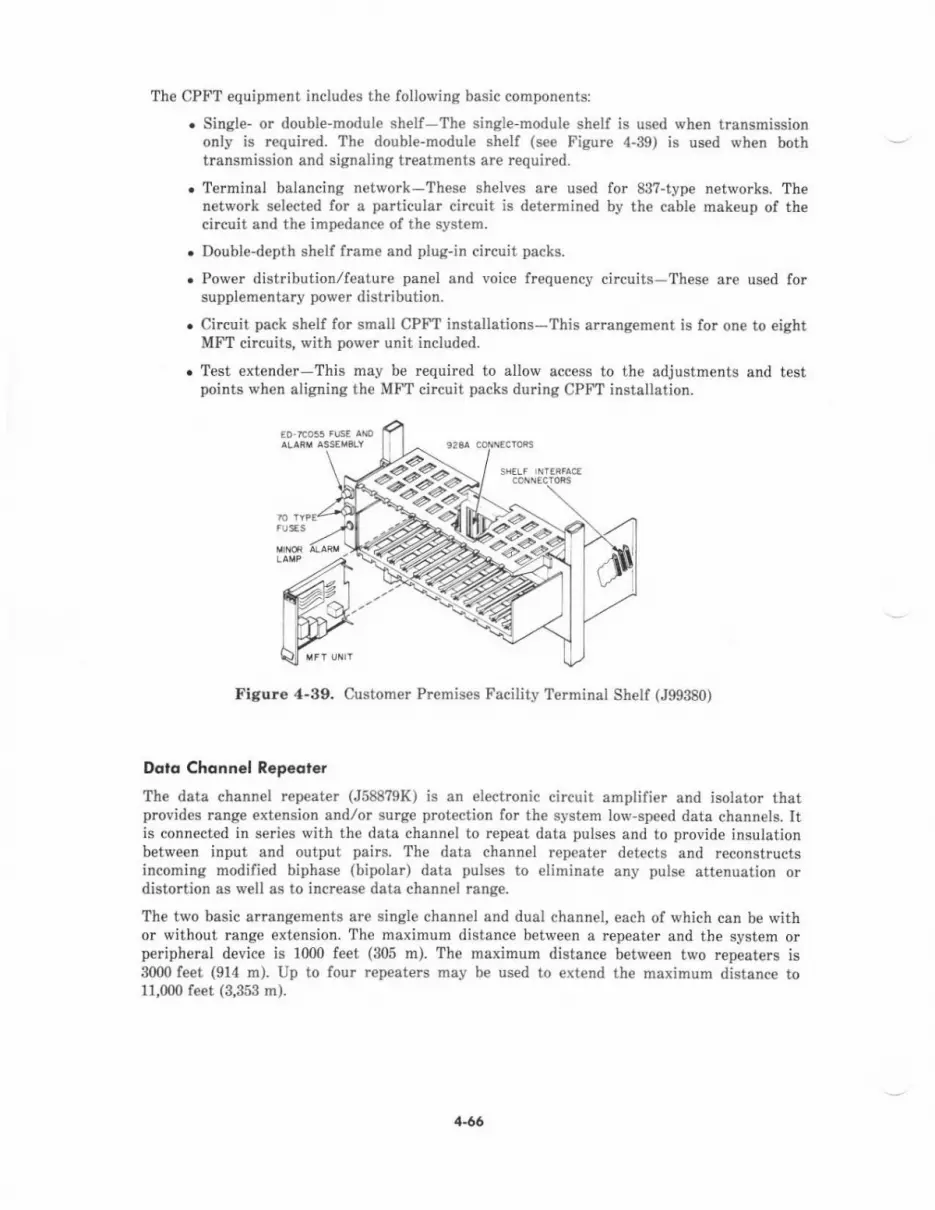
The CPFT €quipment includes the following basic components:
. Single- or doubl€-module shelf Th€ single-modul€ shelf is used when transmissiononly is required. The double-module shelf (s€€ Figure 4-39) is us€d when bothtransmission and signaling treatments are required.
r Terminal belancing network-These shelves are us€d for 88?-type networks. Thenetwork selected for a pa icular circuit is determined by the cable mak€up of th€circuit and the impedance of th€ syst€m.
. Double-depth shelf frame and plug-in circuit packs.
. Power distribution/featur€ pan€l and voice frequency circuits-These are used forsupplementary power distribution.
. Circuit pack shell for small CPFT installations-This arrangement is lor one to eightMFT circuits, with power unit included.
. Test extender This may be required to allow access to th€ adjustments and testpoints when aligning the MFT circuit packs during CPFT installation.
Figure ,l-39. Customer Pr€mises Faciliiy Terminal Shelf (J99380)
Dolq Chonnel R.p.dter
Th€ deta channel repeater (J58879K) is an electmnic circuit amplifier and isolator thatprcvides range extension andlor surge protection for the system low'speed data channels. Itis connected in series with the data channel to repeat dsta pulses and to provide insulationbetween input and output pairs. The data chann€l repeater detects and reconstructsincoming modified biphase (bipolar) data pulses to eliminate any pulse attenustion ordistortion as well as to incrcase data channel rang€.
The two basic arrangements are single channel and dual channel, each of which can be withor without rrnge extension. The maximum distance between a.epeater and the system orperipheral device is 1000 feet (305 m). The maximum distance between treo repeaters is3000 feet (914 m). Up to four rep€aters may be used to extend the maximum distance to11,000 feet (3,353 m).
>z-^>?a
1-66
Inloimolion Sy.l.ft. Nelwo.k (lSN) lnbrfa..Th€ ISN interface prcvid€s enhanced EIA RS-232C trunk connectivity to the ISN with a co-located high-speed pack€t switch. This interface is provid€d through EIA ports,asynchmnous data units (ADUS), and an ISN concentrator.
The ISN conc€ntrator multiplexes 40 EIA ports (SN238) over a fiber int€rface to the ISNnode. Th€ concentrator carrier houses five inlerface circuit packs which accommodate eightports each. Eight ADUs are required per ISN concentrator circuit pack, or one ADU per EIAport. The carlier may be shelf mount€d or housed in the System 85 Auxiliary Cabinet withan E.64 Mbps fiber interface to the ISN node; lm V ac is required for the conc€ntBtor.Trunk data baud rat€s must be set at €ither 300, 1200, 24tlo, 4800, 9600, or 19.2k bps for fullduplex 10-bit start/stop asynchronous date, communications.
The Mod€m Pooling feature provides connectivity b€tw€€n ISN endpoints and r€mot€endpoints access€d via System 85 CO trunks, WATS trunks, FX trunks, DID trunks, APLTtrunks, tie trunks, and DTN trunks. End-to-end digital connectivity with ISN endpoints isprovided for endpoints which are served eith€r direclly by the local System 85 switch or by aremote System 85,/75 with DS-1 trunks to the local System 85.
lo.dl Dbhibulion Service Unit (IDSU)
Th€ LDSU (48250) interfaces the System 85 switch Data Communications Interface Unit(DCIU) x'ith an external proc€ssor, soch as an AP, AUDIX, or another DCIU. The LDSU elsoprovides tequircd ground isolation between the Common Control Cabinet (containing theDCIU) and the external processor. Two LDSUS per external processor are requir€d to providethis int€rfac€.
Each LDSU contains:
. A transmitter with filtering and modulation-allows data transmission at speedsfrom 2.4 kilobits per second (kbps) up to 19.2 kbps
. A rec€iver with equalization, demodulation, clock r€covery, and signal pres€nc€detection-accepts incoming data from a 150-ohm line
. A regulated dc power supply for the r€quired dc voltage
. An EIA RS-232C interface.
Nore.' A single l05A Isolating Data Intarface (IDI) may be substituted for two LDSUSbetween each external proc€ssor.
lodio Poging lnte.toce Tlunk Unit
This unit (J58824CD) is required to provide the Radio Paging Access feature. The unit hastwo incoming ports and two answ€r ports. The four porls are conn€cted to two central offic€trunk circuits. In addition to th€ inte.fac€ unit, the foltowing €quipm€nt is requir€d:
. Touch-tone calling receiver (G1)
. Link and €lectronic diel unit (J5884?Y)
. 36A voice coupl€r and 2012D power transformer.
1-67
The radio paging interface trunk unit is available in th€ following configurations to meetspecified requirements:
. For radio paging without answerback
. For radio paging with answerback
. To repeat dialed digits on a 2-out-of-? lead basis
. For one applique unit when touch-tone signals are converted to dial pulses
. For one applique unit when touch-tone signals are converted to dc sigrals on a 2-out-of-? lead basis.
Recorded Announcernenl Set
The recorded announcement set provides the capability to int€rcept incoming calls and routeth€m to a recorded message which indicates to the caller the rcason for interception. On€ setmust be used for each UCD/DDC delay announcement message or for Int€rcept Treatment
Thr€e types of recorded announc€ment sets are available: the (5-16?65 set, the 13A set, andth€ Model 213300 s€t, manufactured by Cook El€ctrics. The KS-16?65 set pres€rves samplesof speech for playback in analog form (stored on magnetic tape). It includes an amplifi€r,mounting bracket and connecting cord, and 36A voice coupler with its 2012D powertransformer. The 13A set preserves samples of speech for playback in digital lorm (stored ina magnetic bubble memory). It is equipped for eight cbann€ls and provides variable messagelengths oI3 to 24 s€conds, adjusted in 3-s€cond incr€ments. The 13A set also provides an 8:1space savings and iow maintenance. The Model 213300 set also features voic€ storage andreproduction in digital form. It provides one channel of voice with message lengths of up to16 seconds. This set f€atures rcmote recording capability through a line access number.
Connections between the system and a recorded announcement set are made thrcugh thecross-connect field and voice coupl€r.
Rerorded Telephone Di(lolion (RTD) Equipmenl
The RTD trunk (J5882?E) allows access to and control of dictating equipment by voiceterminal users within the system. Th€ record and playback functions of the dictatingequipment are dial-controlled. The start and stop functions may be dial- or voice-controlled.The RTD equipment includes the following:
. Dial dictation machines (not in Auxiliary Cabinet)
. RTD trunk equipment
. Fr€quency generator and interrupt€r unit
. Touch-tone interface and receiver
. Voice terminal for RTD attendant
. Voice coupler and transforhet (discussed later).
4-68
flonrlcr Pancl
TVo typ€s of transfer panels arc available for installation in the Auxiliary Cabinet.
Th€ Model 5?3-5 panel, manufactured by Porta Systems Corporation, is usually used for theemergency trsnsfer capability. This provides a dir€ct connection to centml office (CO) trunksfor pr€selected 2500-type voice terminal6 during a major system equipment failure or powerfailure at th€ Bystem location. When the feilure occurs, CO trunks are automaticellyconnected through r€lays in th€ emergency transf€r panel to the voice terminals, bypassingthe system switch. Opelation of th€ 5?3-5 panel does not require ground-starl buttons on thevoice terminals. This pan€l provid€s transfer for five trunks.
The 609A panel is usually used for the night tnnsfer or alternate console p$itioncepabiliti*, if used for emerg€ncy transfer for voice terminals. A ground-start key isr€quired at each presel€cted voic€ terminal to signal the CO when the voic€ terminal userwants to place e call. The 609A panel provides transfer for ten trunks.
Voicc Couplcr
The 36A voice coupler is used to coupl€ the transmission of music, voice, or other sign&ls toth€ system- Th€ coupl€r also provides protection of the tip and ring circuit by limiting signalpowe. lrom the music source, dictation machine, or paging equipment. For Radio PagingAccess, the voice coupler is required when 2-way transmission or l-way receiving is provided.For Music-On-Hold Access, th€ coupler provides isolation to the music source, which shouldbe on at all times. For lntercept Treatment-Recorded Announcement, the coupler providesan interface b€twe€n the system and the announcement set. For Recorded Telephon€Dictstion Acce$, the coupler connects the system and the dial dictation machine.
The 36A voice coupler is powercd by th€ 2012D pow€r transformer (set at -15 dBm).
Voi.. SwitGhcd Gcin Ampliffcr
This amplifier (VFR-5050) automatically inserts extra transmission gain wh€n totel end-to-end losses are large enough to degrade transmission quality in a central offic€ trunkconnection. Switched bidirectionally under voice control, this equipment improves thetransmission level of the connection. Up to 13 amplifiers (in circuit pack lorm) are housed inthe 500-13 carrier.
&60

APPUCATIONS PROCESSOR (AP) EQUTPMENT
Overview
The AP Cabinet houses a minicomputer system connected to various data entry snd rctrievaldevices. It controls many functions and {eatures not directly associat€d with call processing.Int€rnally, the AP consists of the main central processing unit (CPU) and th€ peripheralsubsystems. The CPU provides computing power and.uns the op€rating system, offering asoftware ex€cution environment to all applications programs. The peripherals are operatedthrough microprocessor-bas€d controllers, executing their own plograms independent of themain CPU.
An AP may be connected to the System 85 switch through the Data CommunicatiorNInterface Unit (DCIU) or through a digital port (SN270B). The AP is housed in a singlecabin€t containing seveBl standard and optional subsystems. Terminais, printers, and datasets (modems) are connect€d extemally.
An AP may support any of the following System 85 featurcs:
. Call Detail Rpcording and Reporting
. Directory
. Electronic Document Communications
. Facilities Management
. Leave Word Calling (AP-based)
. Message Center
. Terminal Chang€ Management
. Terminal Dmulation.
The AP is provided in one of two major configurations: the AP16 and the 3B5 AP. Dependingon the optional hardware subsystems provided, different variations of both types of APCabinets are possible.
API6
The AP16 (J59222A) is controlled by a 16-bit main processor using an AP version of theUNIX op€rating system. The main processor communicates with internal and externalequipment through 8-bit microprocessor-based subsystems. The AP16 Cabinet (see Figure 4-40) hous6 the following equipment:
. Syst€m contlol and maintenance panel-permits access to the control, monitoring,and maintenance functions for the AP. lt is located on the front of the AP Cabinet.The system control panel has the keylock-protected ON-OFF-RESET s\ritch; powerstatus, test status, and alarm status indicators; and the panel test pu6hbutton. Themaintenance pan€l i9 located next to the system control panel. It has a 24-chancteralphanumeric display, sevetal pushbuttons and switches for testing, and the panelenabl€ key-lock switch.
.212-A,E d^ta set and alarm origination equipment-provides an interface forconnection to R€mote Maintenance, Administration, and Traffic System II (RMATS-II) and alarm alerting to remote facilities.
4-7l)

sYsTEi coiTRol- ltDluriTEultcE PlxEr
lrrcr{ crPlcrlY i r-8EC0R0€n
FUSE/CIRCUI' SREIIGR MllTIiG,MRD DISX EXCIOSURE,
TC OISTRTSUIIOII IJIIIT AiDFlil lssEllgLY
I]ARI) OISK ORIVE
POTER SIFPTY
Figure .1-,1o. Applicatioffi Processor 16 (AP16) Cabin€t (J59222A)
1-r1
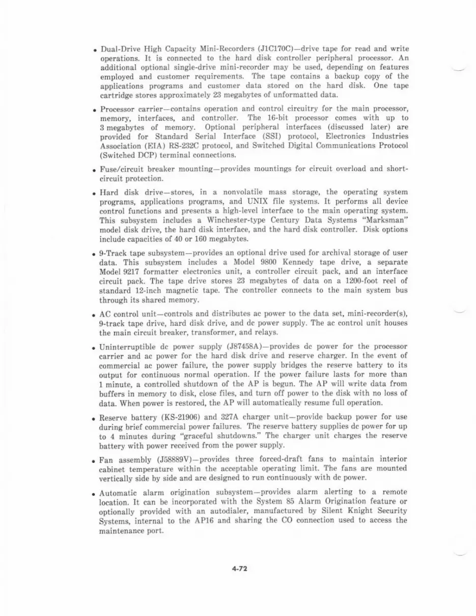
Dual-Drive High Capacity Mini-Recorde.s (J1C1?0C) driv€ tspe for r€ad and writ€operations, It is connect€d to th€ hard disk controller periphe.al proc€sso.- Anadditional optional single-drive minirecorder may be used, depending on featuresemployed and customer requirements. The tape contains a backup copy of theapplications programs and customer data stored on the hard disk. One tapecartridge stores approximately 23 megabytes of unformatted data.
Processor carri€r-contains operation and control circuitry for the main processor,memory, interfaces, and controller. The 16-bit processo. comes with up to3 meqabyt€s of memory. Optional pedpheral interfaces (discussed later) areprovided for Standard Serial Int€rfac€ (SSI) protocol, Electronics IndustriesAssocistion (FIIA) RS-232C protocol, and Switched Digital Communications Protocol(Switched DCP) terminal connections.
Fuse/circuit breaker mounting-provides mountings for circuit overload and short-circuit protection.
Hard disk driv€-stores, in a nonvolatile mass sto.age, the operating systemprograms, applications programs, and UNIX file systems. It performs all devicecontrol functions and presents a highlev€l interface to the main operating system.This subsystem includes a Winchester-type Century Data Systems "Marksman"model disk drive, the hard disk int€rfac€, and the hard disk controller. Disk optionsinclude capacjties of 40 or 160 megabytes.
g-Track tape subsystem-provides an optional driv€ used for archival storage of userdate. This subsyst€m includ€s a Model 9800 K€nnedy tape driv€, a separateMod€l 921? formatter electronics unit, a controll€r circuit pack, and an interfacecircuit pack. The tape drive stores 23 megabytes of data on a 1200-foot reel ofstandard 12-inch magn€tic tape. The controller connects to the main system busthrough its shared memory.
AC control unit-controls and dist butes ac power to th€ dats set, mini-recorder(s),g-track tape drive, hard disk drive, and dc power supply. the ac control unit houses
the main circuit breaker, transformer, and relays.
Uninterruptible dc power supply (J8?458A)-provides dc power for the processor
carrier and ac power for the hard disk drive and reserve charger. In the event ofcommercial ac power failure, the power supply bridges the reserve battery to itsoutput for continuous normal op€ration. If the power lailure lasts for more thanl minut€, a controlled shutdown of the AP is begun. Th€ AP will write data frombuffers in memory to disk, close files, and turn off power to the disk with no loss ofdata. When power is restored, the AP will automatically resume full operation.
Reserve battery (KS-21906) and 3274 charg€r unit-provide backup power for use
during brief commercial power failures. The res€rve battery supplies dc power for up
to 4 minut€s during "graceful shutdowns." The charger unit charg€s the reserve
battery with power received from the power supply.
Fan assembly (J58889V)-provides three forced-draft fans to maintain interiorcabinet temperature within the acceptable operating limit. The fans arc mount€d
vertically side by side and are designed to run continuously with dc power.
Automatic alarm origination subsystem-provides alarm alerting to a remotelocation. It can be incorporated with the System 85 Alarm Origination feature oroptionally provided with an autodialer, manufactured by Silent Knight S€curitySystems, int€rnal to the APl6 and sharing the CO connection used to access themaintenance port,
1-72

For mo!€ detailed information on the AP16, refer to ApplicatiolB P.oceB3or 16-Reference Manuel (585-201-201 or 999-?00-40?).
3B5 AP
Th€ 3B5 AP is controlled by a 32-bit main processor. This higher-capacity v€rsion of the APhas many of the capabilities of the APl6 (discussed previously) in addition to the following:
. Expandable to 8 megabytes of main memory with cache memory
. Digital Communications Protocol (DCP) controller/interface
. l,ocal Area Network (LAN) usiog back-end pecket switch aDd fiber-optic links fotinterconnection with other 3B5 APs (16-Mbps data rate)
. Customer programming in Office Program Language (OPL)
. Crowth cabinet option.
Th€ basic 3B5 AP Cabinet (see Figur€ 4-41) houses the following equipment:
r Basic control unit-contains major AP components such as the central control; themain store, integrated disk file, and storage module drive controllers; and powercontrols/converters. In addition, this unit houses the alarm int€rfaces, memory, APperipheral interfaces (discussed later), and other input/output (I/O) circuitry.
. Growth control unit-pmvid€s additional slots for I/O and memory circuitry.
. AC control panel-contmls and distributes ac pow€r to various cabinet hardware. Agrowth ac panel is provid€d with the growth control unit.
. g-Track tape subsystem-provides storege of user data. This subsystem includes anintelligent tape controller and a Model 92181 Control Data Corporation tape unit. Thetape unit stores 1600 characters per inch in an ANsl-compatibl€, phase-encodedformat.
. l'an assembly-provides forced-draft fans to maintain interior cabinet temp€raturewithin th€ acceptable operating limit. The fans are d€sign€d to run \tith dc pow€r.
. Disk drive-stores the of'€rating systcm programs, applications programs, and filesystems. Up to two 160-megabyte disks with power supply may be accommodated.
. Autodialer-provides alarm al€rting to e remote location.
For more d€tail€d information on the SBlt AP, refer to 3B5 AP-System Description-RefereDce Marual (585-210-201).
AP Pcriphcrol lnterfcccs
Four types of terminal controller/interface subsystems provid€ ports for hardwired orswitched connections to an AP,
The SSI terminal subsystem links 500 BCTS or SSI printers through direct connection at56 kbps. Fiach SSI t€rminal int€rface provid€s user/operator acc€ss to the AP through up tosixteen 500 BCT terminals and two SSI printers (additional printers may be connected inplace of terminals). They may be locatcd up to 5000 feet (1524 m) from the AP and arecabled to the I/O connector field in the back of the AP directly or through building wiring.Dial-up access into the SSI is not provided. Prograrns are downloaded into the terminal'smemory by the AP when each te.minal is turh€d on.
+73
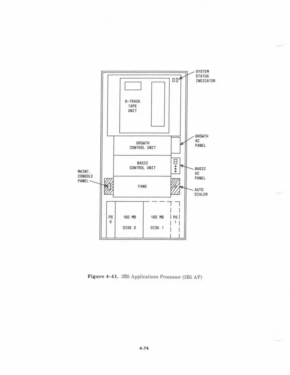
EASICCOXTROL UIIT 8t8rc
PtilEt
AUIODIA!EN
Figure 4-41. 385 Applications Processor (3BS AP)
+74

EIA Sukyxr.m
The EIA terminal subsystem provides ports for switched or nonswitched RS-232C compatibleterminals and/or printers at up to 1200 bps asynchronous. Each EIA t€rminal interfaceprovides up to 12 interface ports for RS-232C compatible asynchronous communication, plusup to 2 interface channels for operation of RS-366 compatible Automatic Calling Units(ACUS). Optional data sets and ACUS are located externally. The RS-232C compatibleterminals (including the 513 BCT), printers, or other devices are connected locally throughnull modems, data s€ts, or the System 85 equipped with data modules for local or remoteswitched access.
SDCP Subtys,em
The Switched DCP (SDCP) terminal subsystem provides ports for switched access from515 BCTS through the System 85 and Modular Proc€ssor Data Modules (MPDMS) at 64 kbps.This subsystem supports the same interface to the 515 BCT that is supported bv the SSIsubsystem to the 500 BCT. All AP features are accessible with this subsysten. Each SDCPterminal interface supports up to 12 simultaneously connected 515 BCTS. Each polt musthave an MPDM to conn€ct to a switch using DCP protocol. The 515 BCTS are supported withhigh-sp€ed intedaces into the AP. They must be switched through digital switches and useonly digital facilities if used from remote locations to access the AP.
Une Conh.lc' Svb.yst.m
The line controlier subsystem provides the AP with two medium,speed communicationsports, linking it to a remote mainftame computer, a data n€twork, another AP, or aSystem 85 common control Data Communications Interface Unit (DCIU). Each Iinecontroller interface provides one RS-232C compatible port and one RS-449 compatible port,switch prognmmable for different modes and speeds of operation. When connected to a co-located DCIU, two Local Dist bution Service Units (LDSUs) or a single lsolating DataInterface (IDI) ar€ us€d to provide ground isolation betw€en the AP Cabin€t and th€ DCIU.For additional info nation on LDSUS, refer to AUXILIARY EQUIPMENT in this section.
4-75
AUDIO INFORMATION EXCHANGE (AUDIX) EQUIPMENT
The AUDIX equipment provid€s capabilities to perform th€ following functions of voice mail:
. Prepare voice messages
. Edit voice messages
. Send voice messages
. Receive and store voice messages frcm others.
The AUDIX system is configurcd in an amangement which includes the following majorhardware components:
. Control Cabinet
. Disk Cabinet.
In addition, a local administration terninal (513 BCT, 5f5 BCT, 5420, or similar terminal) isused to perform maintenance and administration tasks. Optional print€rs can be slav€d todrta terminels or can be connected to the AP for r€port outputs.
control Cqbin.t
The Control Cabinet (J58886L) contains the followiDg subsystems which control all AUDIXoperations and process voice signals duiing storage and retdeval:
. Feature processor-handles most AUDIX control functions and controls all userinteractions.
. Voice session processor-acts as the interface between voic€ terminal us€rs on th€System 85 switch and the AUDIX system.
. Data base processor-controls the operation of the disks through one or two diskcontrollers.
. Voice processors-sample digital voice signals, encode the silent parts, and compressthe remaining signals.
The Control Cabinet also contains the AUDIX data interface to the switch DCIU I/O circuitpack (UNl56). It also contains up to 32 voice ports with access to analog voice ports in thesv,itch (SN228B/SN229B circuit packs). Th€ AUDIX ports are represented by these switchanalog ports, and call handling is performed thrcugh the System 85 call distributioncapabilities.
The Control Cabin€t (see Figur€ 4-42) contains the following AUDIX equipment:
. A power carrier (J58888l)-provides lowlevel dc pow€r for the cabinet.
. A port carrier (J58888J)-provides the data and voice interfaces to the switch.
. A control cafiier (J58888H)-contains operation and contml circuitry.
. A data base processor carrier (J58888K)-controls the operation of the disks throughone or two disk controllers.
+76
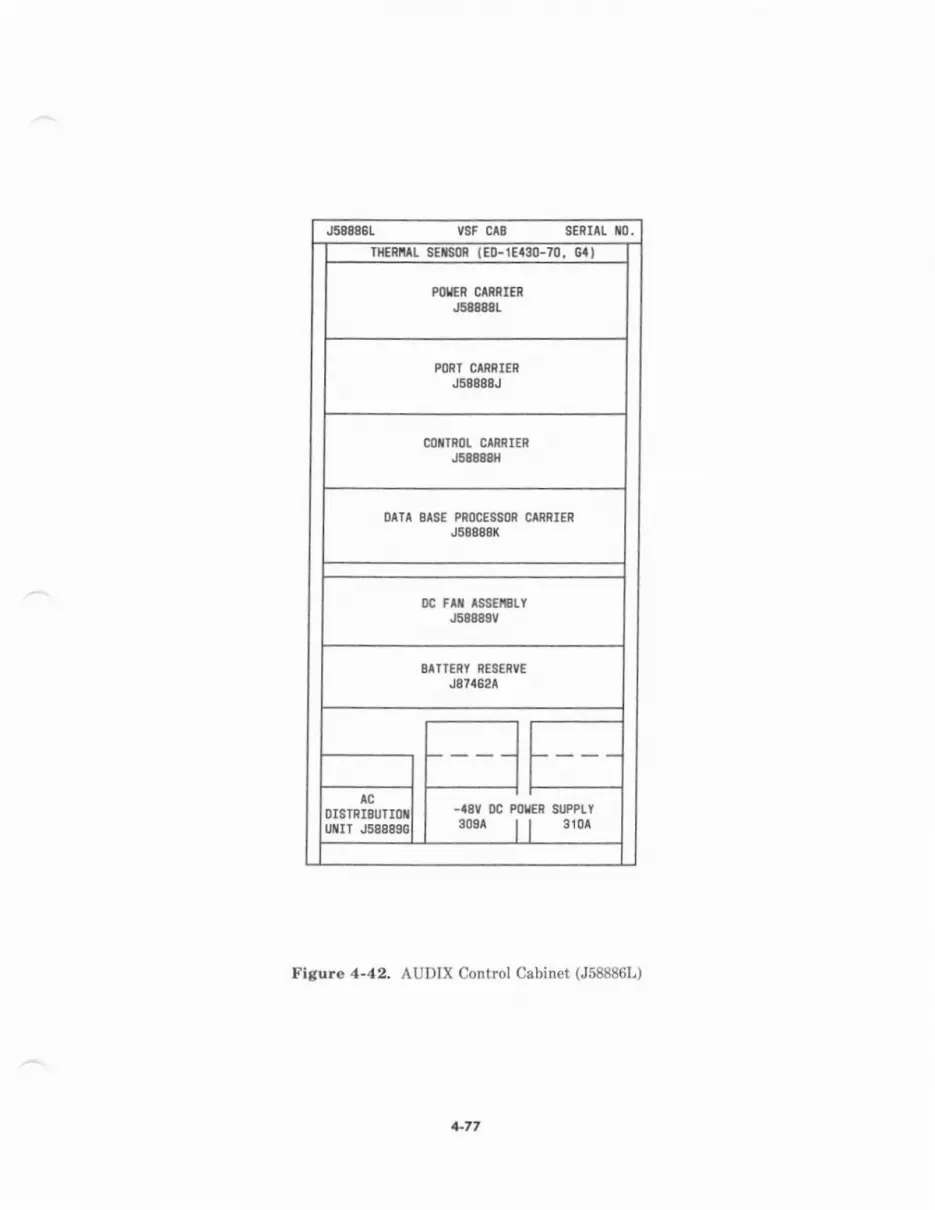
J588861 VSF C 8 SEnrlt t0.rcRrlL stts0 t€0-1E$0-70, cal
I
?ol:n cmRrnJ58888t
POf,T CMRIERJ58888J
COiIROL RAIERJ6a8a&t
OAIA sISE PROCESSOR CMRIERJ68888K
0c Flt rssErlYJ58A8gV
OATTERI RESE'VEJg7a62r
-I8Y DC POTER SI'PPLY308^ | | 310^
Dtsrxlautr t
u[rr Js888s0l
Fisure 4-42. AUDIX Control Cabinet (J58886L)
+77
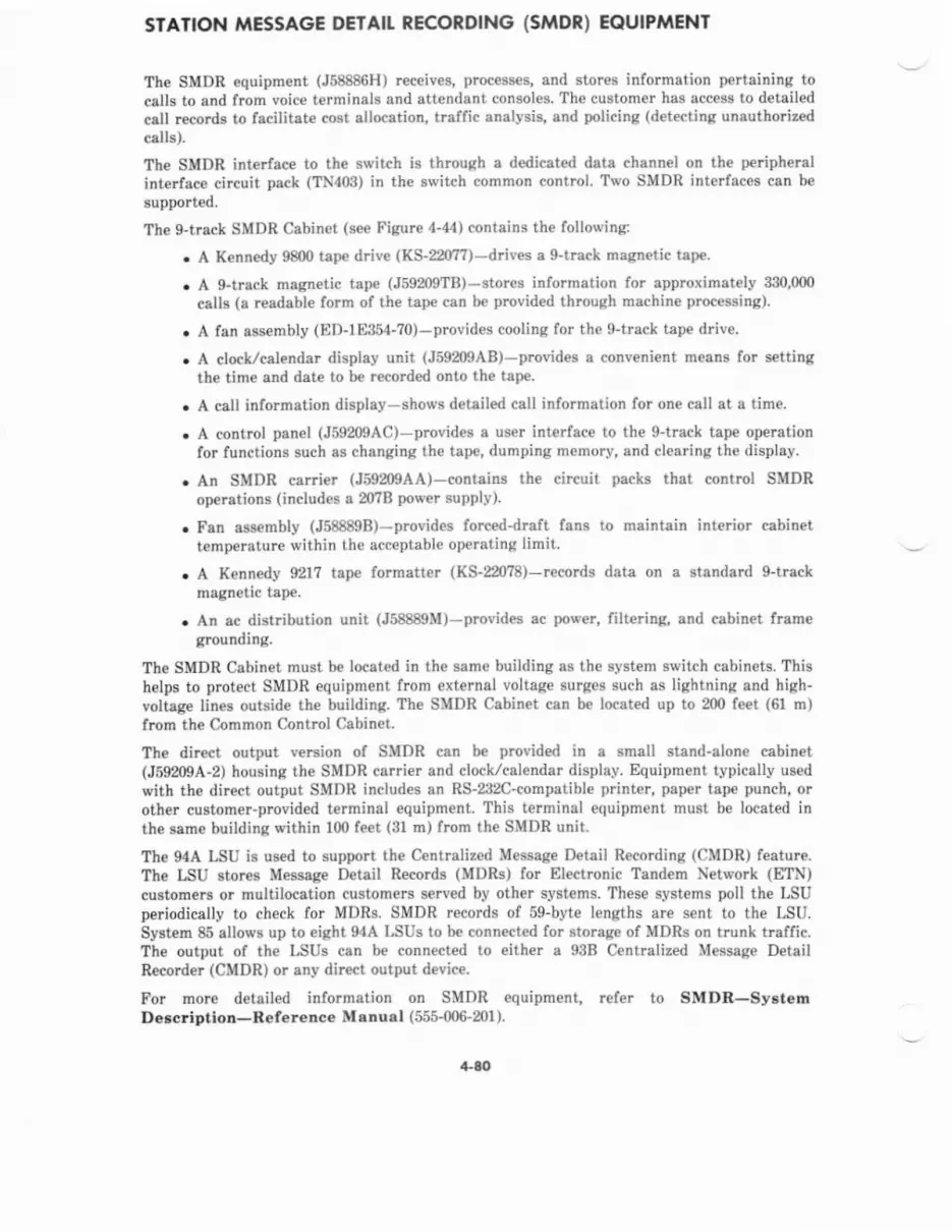
SIATION MESSAGE DETAIT RECORDING (sMDR) EQUIPMENT
The SMDR equipment (J58886H) receives, proc€sses, and stores information pertaining tocalls to end from voice terminals and attendant consoles. Th€ customer has acc€ss to detailedcall records to facilitate cost allocation, traffic analysis, and policing (detecting unauthoriz€dcalls).
The SMDR interface to the switch is through a dedicated data channel on the peripheralinterface circuit pack (TN403) in the switch common control Two SMDR interfaces can be
supported.
The g-track SMDR Cabinet (s€€ Fisure 4-44) contains the following:
. A Kennedy 9800 tape drive (Ks-220??)-driv€s a g-track magnetic tsp€
. A g-track magnetic tape (J59209T8)-stores information for approximately 330,000
calls (a readable form of the tape can b€ provided through machin€ processing).
. A lan assembly ( E D-1 E354-?0) - provides cooling for the g-track tap€ drive.
. A clock/calendar display unit (J59209AB)-provides a convenient means for settingth€ time and date to be r€cord€d onto the tape.
. A coll informetion display-shows detailed call information for one call at a time.
. A control panel (J59mgAc)-provides a user interfac€ to the g-tlacl tape operationfor functions such as changing the tape, dumping menory, and clearing the display
. An SMDR carrier (J59209AA)-contains th€ circuit packs that control SMDRop€rations (includes a m?B power supplv)-
. Fan assembly (J58889B)-provides forc€d-draft fans to maintain interior cabinettemper&turc within the acceptabl€ operating limit.
. A Kennedy 921? tape formatter (Ks-220?8)-rccords data on a standard g-treck
magnetic tape.
. An ac distribution unit (J58889M)-provides ac power, filtering, and cabinet fram€grounding.
The SMDR Cabinet must b€ located in the same building as the system switch cabinets. Thishelps to protect SMDR equipment from external voltage surges such as lightning and high-voltage lines outsid€ the building. Tbe SMDR Cabinet can be located up to 200 feet (61 m)from the Common Control Cabinet.
The direct output version of SMDR can b€ provided in a small stand-alone cabin€tQ5920pA-2) housins the SMDR carri€r and clock/calendar display. Equipment typically usedwith th€ direct output SMDR includes an Rs-282c-compatibl€ printer, paper tape punch, orother customea-provided terminal equipm€nt. This terminal equipment must be located inthe same building within 100 feet (31 m) from the SMDR unit.
The 94A LSU is used to support the C€ntralized Message Detail Recording (CMDR) feature.The LSU stores M€ssag€ Detail R€cords (MDRS) for Electronic Tandem Network (ETN)custom€rs or multilocation customers s€rv€d by other systems. These systems poll the LSUperiodically to check for MDRS. SMDR records of sg-byte lengths are sent to the LSU.System 85 allows up to eight 94A LSUS to be connected for storage of MDRS on trunk traffic.The output of the LSUS can be connected to either a 938 Centralized Message DetailRecorder (CMDR) or any direct outpul device.
For more detailed information on SMDR equipment, refer to SMDR-SystemDescriDtlon-neference MsDual (555-006-201 ).
+80
Ftr AsSEiSt Y
ED-1E364-70
TAPE DRIVExB-220n
cloo(/c t ED rDISfl.AY
cAtL ttFodt rmtOISPIIY
cttTRot P|IEL.Fgm9lc
F rgsEigttJ588a0t
rAP€FMiIITER(s-22078
Si)R CMRIERJ69200t4
Figure {-.14. Ststion Messag€ Detail Recording Cabinet (Jb8886H)
aco T--1 oann
-f--r.1
Gtt

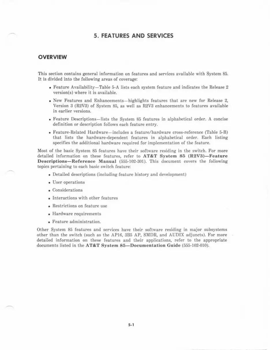
5. FEATURES AND SERVICES
ovERvtEw
This section contains general information on featurcs and services available with System 85.It is divided into th€ following areas of coverage:
. Feature Availability-Table 5-A lists each system feature and indicates the Release 2version(s) where it is available.
. New F€atures and Dnhancements highlights features that are new for Release 2,Version g (R2VB) of System 85, as well as R2V3 enhancements to features availablein earlier versions.
. Feature Descriptions-lists the System 85 features in slphabetical order. A concisedefinition or description follows each feature entry.
. Feature-Related Hardware-includes a featun/hardware cross-refer€nce (Tabl€ 5-B)that lists the hardware-dep€ndent features in alphabetical order. Each listingspecifies the additional hardware required for implementation of the feature.
Most of the basic System 85 features have their software residing in the switch. For moredetailed information on these features, refer to AT&T System 85 (R2v3)-FeatureDescriptions-Reference Msnual (555-102-301). This document covers the followingtopics pertaining to each basic awitch feature:
. Detailed descriptions (ineluding feature history and dev€lopment)
. User operations
. Considerations
. Interactions with other features
. Restrictions on feature use
. Hardware requirements
. Feature administration.
Other System 85 features and services have their softwarc residing in major subsystemsother than the switch (such as the APl6,3B5 AP, SMDR, and AUDIX adjuncts). For mor€detailed information on these features and their applications, refer to the appropriatedocuments listed in the AT&T System 86-Documentation Guide (555-102-010).
5-t
TABLE 6-4. System 85 Feature Availability
Abbreviated Dialins x x xAdvanced Privat€ Line T€rmination (APLT) x x xAttendant Auto-Manual SDlittins x x xAttendant Call Waitins (ACW) X x xAttendant Control of Trunk Group Access(ACTGA)
x x X
Att€ndant Direct Extension Selection (DXS)With tsusv LamD Field (BLF)
X X x
Attendant Direct Trunk GrouD Selection X X XAttendant DisDlav X x XAttendant Inte.nosition Callino and T.ansfer x x xAttendant Recall x x XAttendant Release LooD (ARL) ODeration X X xAudio Information Exchanse (AUDIX) x xAuthorization Codes X x XAutomatic Alternat€ Routinc (AAR) X X xAAR/ARS Patt€rn Oueuins xAutomatic Call Distribution { ACD) xAutomatic Callback x x XAutomatic Circuit Assurance (ACA) X X xAutomatic ldentification of Outward Dialing(AIOD)
x X x
Automatic Route Selection (ARS) x X xAutomatic Transmission Measurement SystemrATMS)
x x
Automatic Voice Network (AUTOVON) x x xBrideed Call X X XBusv Out of Two-Wav Trunks xBusv V€rification of Lines x X xCall Coveraqe x x XCall Detail R€cordins and ReDortins (CDRR) X x xCall Fo.wardins-Busv and Don't Answer x x x0all Forwardinq-Follow Me x x xCall Hold xCall Manasement Syst€m (CMS) xCall Park x x xCall Pickup x x XCall Waitins X X xCentmliz€d Attendant Service {CAS) x x x
3.2
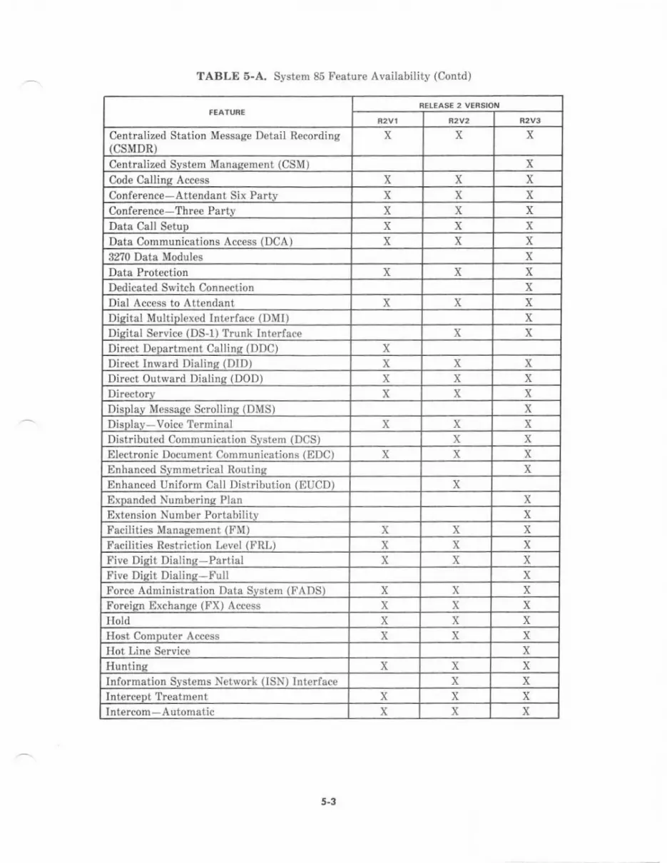
TABLE 5-A. System 85 Feature Availability (Contd)
Centralized Station Message Detail Recording(csMDR)
X x x
Centralized Svstem Manasem€nt (CSM) xCode Callino Ac.ess x X XConference-Attendant Six Partv X X XConference Three Parlv X X X
Data Call SetuD X x xData Communications A{:c€ss IDOA) x x x32?0 Data Modules xData Protection X x xDedicated Switch Connoction xD al Access to Attendant x x xI] sital MDltiDlexed Inte.face 1l)MIl XD pital Service (DS-l) Trunk Intorface X X
Direct Deoartment Calline {DDC) xDirect Inwad Dialinq (DID) X x XDirect Outward Dialins {DOD) X X xDirectorv X x xDisnlav Messase Scrollino IDMS) XDisDIav-Voice Terminal X x XDistribured Comrnunication S! slem r DCS, x xElectronic llocument Communications (EDC) x x xEnhanced Svmmetrical Routin'! xEnhanced (Iniform Call I)istribution (nUCD) xExDanded Nurnborins Plan xExtension NumLer Portability xFacilities Manaqement (FM) X x xFacil;ties Restr;ct;on L{rvel IFRL) x x xFive Diqit Dialinq-Partial X x XFive Disit Dialine-Full XForce Administration Data Srstem (!'ADS) x X XForeisn Exchanso (FX) Access X x xHold x X xHost ComDut€r Access X X xHot Line Servic€ XHuntins x X xInformation Svstems Network (ISN) Interface x xInterceot Treatment x x xInt€r.om Automatic x x X
5-3
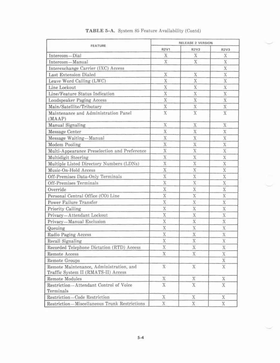
TABLE 5-A, System 85 Feature Availabilit! (Contdr
Inteftom-Dial x x xlntercom-Manual x X xInteiexchanee Car €r (IXC) Access xLast Extension Dialed X X xLeave Word Calline (LWC) x x xLine Inckout X x XLine/Feature Status Indication x x xLoudsDeaker Pasins Access X x xMsin,/Satellite/Tributarv x X XMaintenance and Administration Panel(MAAP)
X x x
Manual Sisnalins X x xMessase Center x x xM€ssaoe Waitins-Manual x x xModem Poolins x X xMulti-ADDearance Preselect jon and Preference x x xMultidisit Ste€dns X x xMultiDle Listed Directory Numbers (LDNS) x x XMusic-On-Hold Access x X xOf f-Premises Data-Onlv Terminals x x xOff-Premises Terminals X X xOverride X X XPersonal Central Office tCO) Line X X xPower Failure Transfet x x xPriority Callins x x xPrivacv-Attendant Lockout x x xPrivacv-Manual Exclusion x X xOueuine x x xRadio Pacine Access X X xR€call Sisnalins x X xRecorded TeleDhon€ Dictation (RTD) Access x x XRemote Access X x XRemot€ Grouos xR€mot€ Maintenance, Administration, andTraffic Svstem Il (RMATS-II) Access
x x x
Remote Modules x x xRestriction-Attendant Control of Voice?erminals
X x x
Restriction-Code Restriction x x XRest ction-Miscellaneous Trunk Rest ctions x X X
54
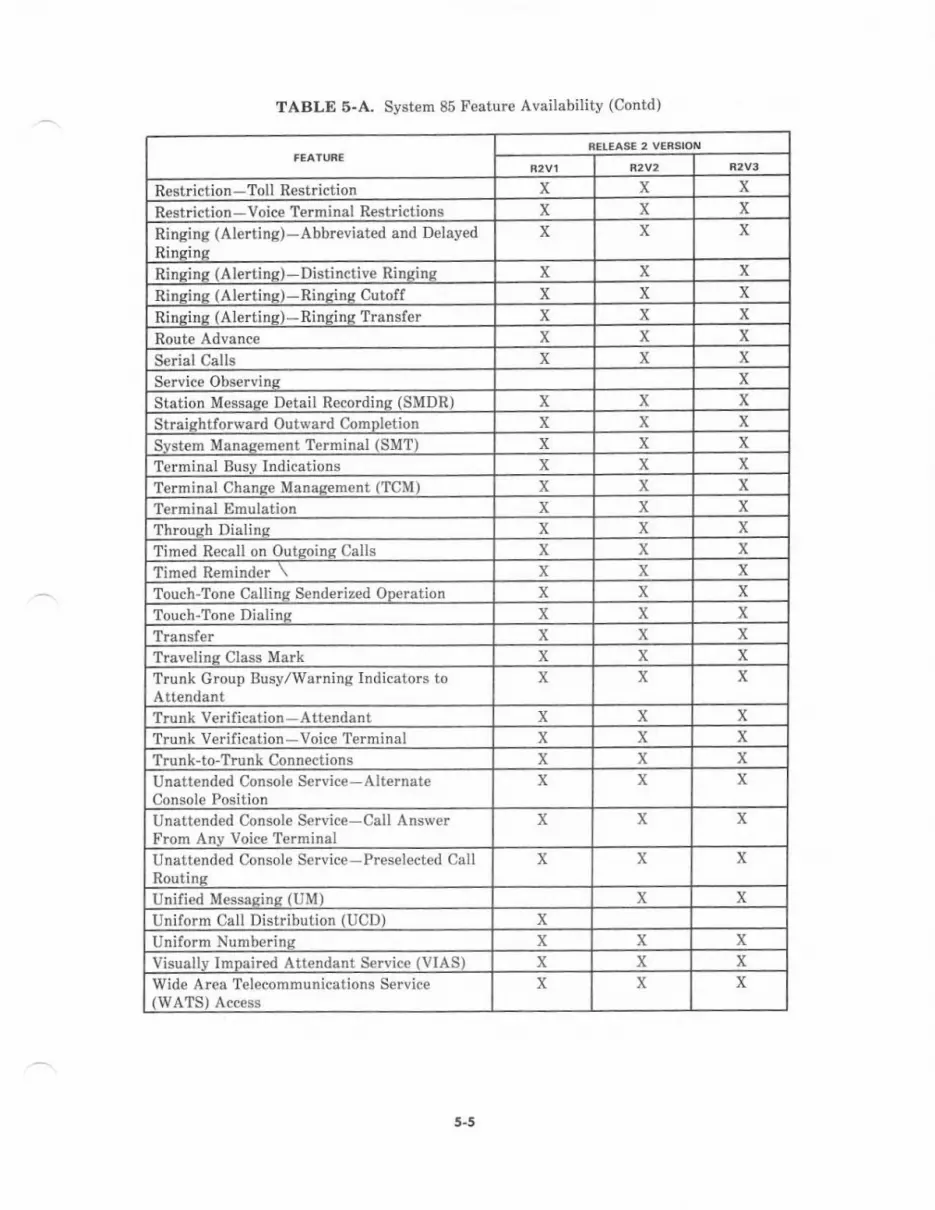
TABLE 5-A. System 85 F€ature Availability (Contd)
Restriction -Toll Restriction x X xR€striction -Voice Terminal Restrictions X x x
Ringing (Alerting)-Abbreviated and DelayedRinsins
x x x
Rinqine (Alertinq)-Distinctiv€ Ringins x x xRinsins (Alertinq)-Rinqins Cutoff x x X
Rinqins (Alertine)*Rinsins Transler x x xRoute Advance x x xSerial Calls X x X
Service Observins X
Station M€ssase Detail Recordins (SMDR) X x X
Straishtforward Outward ComDletion x X X
Svstem Manaqement Terminal (SMT) x x X
Teiminal Busv Indications x x xTerminal Chanee Manasement (TCM) x x xTerminal tlmulation x x XThrouoh Dielino x x X
Timed Recall on Outeoinq Calls x x x'limed ft€mrndor \ X X xTouch-Tone Callins Senderized ODeration X X xTouch-Tone Dialinq X x xTransler x x xT.avelins Class Mark x x xTrunk Group Busy/warning Indicators toAttendant
x x x
Trunk Verification Attendant X x xTrunk verification-Voice Terminal x x xTrDnk-ro-TrDnk Conn€ctions x x xUnattend€d Console Service-AIt€rnateConsole Position
X X x
Unattended Console Service-Call AnsrverFrom Anv Voice Terminal
x x x
Unatt€nded Console Scrvice-Preselected CallRoutine
x x X
Unified Messaqinq (UM) X xUniform Cali Distribution (UCDI xIlniform Nunberins x x xVisuallv ImDaired Attendant Sarvice (VIAS) x X xWide Area Telecommunications Service(WATS) Acc€ss
x x x
5-5
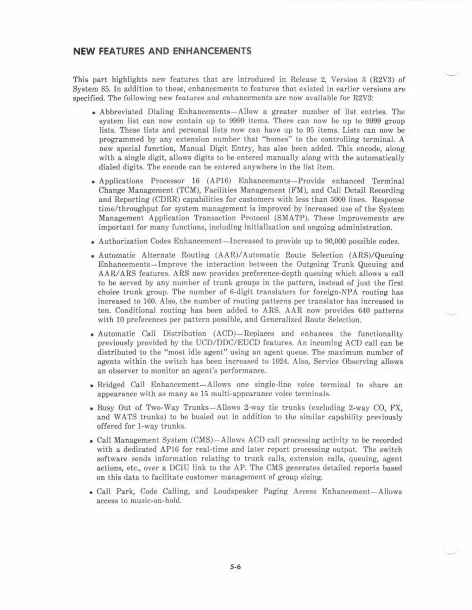
NEW FEATURES AND ENHANCEMENTS
This part highlights new features that arc introduced in Release 2, Vemion 3 (R2Vg) ofSystem 85. IIr addition to these, enhancements to features that existed in earlier versions aresp€cified. The following new features and enhanc€m€nts are now availabl€ for R2V3:
. Abbreviated Dialing Enhancements-Allow a gr€ater number of list entries. Th€system list can now contain up to 9999 items. Th€re can now be up to 9999 grouplists. These lists and personal lists now can have up to 95 items. Lists can now beproglammed by any extension number that "homes" to the controlling terminal. Anew special function, Manual Digit Entry, has also been added. This encode, alongwith a single digit, allows digits to b€ entered manually along with the automaticallydialed digits. The encode can be entered anywhere in the list item.
. Applications Processor 16 (AP16) Enhancenents-Provide €nhanced TerminalChange Management (TCM), Facilities Management (FM), and Call Detail Recordingand Reporting (CDRR) capabilities for customers with less than 5000lines. Respons€timelthroughput for system management is improved by increas€d use of the SystemManagement Application Transsction Protocol (SMATP). Thes€ improvements areimportant for many functions, including initialization and ongoing administration.
. Authorization Codes Enhancement-Incrcased to provide up to 90,000 possible codes.
. Automatic Alternate Routing (AAR)/Automatic Route Selection (ARs)/QueuingEnhancem€nts-Improve th€ interaction between th€ Outgoing Trunk Queuing andAAR/ARS features. ARS now provides p.eference-depth queuing which allows a callto be served by any numb€r of trunk groups in the patt€rn, instead of just the firstchoice trunk group. The number of 6-digit translators for foreign-NPA routing hasincrcased to 160. Also, the numb€r of routing patterns per translator has increased toten. Conditional routing has be€n added to ARS. AAR now provides 640 patternswith 10 preferences per pattern possible, and Generalized Route Selection.
. Automatic Call Distribution (AcD)-Replaces and enhances the functionalitypreviously provided by the UCD/DDC/EUCD features. An incoming ACD call can bedist buted to the "most idle agent" using an agent queue. fhe maximum number ofagents within the switch has be€n increased to 1024. Also, Service Observing allowsan observer to monitor an agent's performance,
. B dged Call Enhancement-Allows one singleline voice t€rminal to share anappearance with as many as 15 multi-appearance voice terminals.
. Busy Out of Two-Way Trunks-Allows 2-way tie trunks (excluding 2-way CO, FX,and WATS t.unks) to be busied out in addition to the similar capability previouslyoffered for l-way trunks.
. Call Management System (CMS)-Allows ACD call processing activity to be.ecordedwith a dedicated AP16 for real-tide and later rcport processing output. The switchsoltware sends information relating to trunk calls, extension calls, queuing, agentactions, etc., ov€r a DCIU link to the AP. The CMS generates detailed repo s basedon this data to fecilitate customer management of group sizing.
. Call Park, Code Calling, and Loudspeaker Paging Access Enhancement-Allowsaccess to music-on-hold.
5.6

. C€ntraliz€d Station Message Detail Recording (CSMDR) and SMDREnhancements-Expanded call record now includ€s 3-digit trunk IDs, l5-digitaccount cdes, and a 5-digit dialing plan. Optional forced entry of account codes andflexible record start time hav€ been added. The number of Local Storag€ Units thatcan be attached to a singl€ switch has increased to eight. Call completion thresholddelay is now vsriable per trunk group, rangrng fmm 2 to 98 seconds.
. C€ntralized Syst€m Menegem€nt (CSM)-Provides a versatile system manag€mentvehicle for larg€ customers with more than 5000 lines. Employing th€ 385 AP, ithondles all FM snd TCM functions, Traffic Mensgement and AutomaticTransmission Measuring, Cost Management, and AP Managem€nt. This f€ature also
may support AUDIX, System 75, and lnformation Systems Network. The CSMcontains switch image data bases with switch translation information, user records,
and an equipment inventory. It also provid* centralized multiswitch polling storage(via SMDR) and processing of m*sag€ detail recording.
. \nO D^ta Modules-Introduces a family of coaxial-to-DcP (Digital CommunicationsProtocol) conv€rters that allow IBM 32?0-typ€ display terminals to communicate withe host computer through System 85. The converters terminate the coaxial cableprotocol and convert the information into a form and protocol compatible with DCP.
. Dedicated Ssitch Conn€ction-Supports continuous connection of associatedterminals through the switch. This provides a set of full-duplex dedicated connectionsthrough analog line/trunk ports and Digital Service (DS-l) interfaces.
. Digital Multiplexed Interface-P.ovides a cost-eff€ctive multiplexing scheme forswitch-to-remote-host communications, using simple A/B bit tie-trunkJike signalingand s€nding 23-channel data over DS-1 facilities.
. Digital Service (DS-l) Interface Enhancements-Provide both ground'start andloop-start CO, FX, WATS (Inlout), and (reverse battery) DID trunks in addition totie trunks. Different trunk types can occupy different channels on the same DS-ltransmission fecility so long as the channelto-trunk-type assignm€nts are made inpsirs. The DS-1 interface is also enhanced to provide 24 analog voiceband OPS
servic€ with a D4 channel bank or equivelent at the distant €nd. Provision of thistype service impli€s that the interface be able to support loop-start signalidg and callsequencing.
. Display Message S$olling (DMS) Provides for retrieval of Message Center Service(MCS) messages longer than 40 chamcters using the do-character display module.The user can scroll through discrete mcssage segments to view th€ entirc m€ssag€.
. Display-Voice Terminal Flnhancement-lncreased to provide up to 32,?67 entries inthe Name/Number data base.
. Enhanced Symmetrical Routing-Allows up to nine diff€rcnt tie trunk groups to bepreferenced in any given AAR pattern when calling oth€r nodes in the privatenetwork.
. Expanded Numbering Plan Allows a private network to serve up to 100,000
extension numbers through the use of a 5-Digit Dialing-!'ull capability Calls maybe made to other us€rs in the same switch or different switch in a private networkusing five digits, without dialing an access cod€ or peusing for dial tone betweendigits. ln addition, the Extension Number Portability feature allows users to retaintheir 4- or 5-digit extension number wh€n transferring to another switch within thisUniform Numbering plan.
s-7
. Hold Enhancement-Provides Hold dial access cod€ availability for single-appearaDcevoice terminal us€rs. This access to "Call Hold" allows more flexible handling of callsby providing an enduring ability to return held calls.
r Hot Line Service-Provides for automatic dialing to a preassigned number in theprivate or public network when the user of a Hotlin€ voice terminal goes off-hook_Hotline terminals receive incoming calls normally (unless r€stricted by anotherfeature) and are administered on a per-analog-line basis. This feature is intmalucedas part of F€derul Emergency Management Agency (FEMA) enhancements and isimplemented thrcugh the Abbreviated Dialing f€ature.
.Information Systems Network (ISN) Interface-Provides enhanced connectivity tothe ISN, a distributed prccessing system with an open architecture and high-speedtransport capability. The ISN interface may share a common administrationterminal with the switch.
. Interexchange Carrier (IXC) Access-Provides voice terminal users the capability tospecify the IXC vendor to be used for a call to a given dialing destination. Up to 24digits may be outpulsed.
. Reduced PoIt Contention-Supports two simultaneous administration/maintenanceprocesses, which now allows one administration plus one maintenance task to beperfo.med at th€ same time. Previous versions of the system have supported only onemaintenance or administration process at a time.
. Remote Group Capability Makes provision for remoting System 85 port circuitpacks up to approximately 100 miles {rom the main switch. This permits smallclusters of off-premises analog, hybrid, EIA, and digital terminals with total featur€transparency.
. Trunk Verification-Voice Terminal Enhancem€nt-Provides the abitity to busy outz-way tie trunks.
. Unified Messaging (UM)-Introduces a fully integrated, cost-effective family ofdistinct messaging services. Unified Messaging prcvides the conceptual basis forcombining the AUDIX, Call Coverage, Leave Word Catling Message Center, andElectrcnic Document Communications services. The first phase of UM in R2VBfocuses on Integrated Alerting and Notification. This capability allows int€gration ofalerting functions regardless of the originating service and notification of additionalmessages waiting from other services.
5-a
FEAIURE DESCRIPTIONS
Abb.eviobd AoEngAllows a voice terminal user to access numbe* with fewer button presses than by usinga touch-tone dial. Single-line voice terminal users dial an access code and indexnumb€r. Multi-appearance voice terminal userc press a singl€ button. This feature isenhanced in R2Vg to allow a greater number of list entries. System list, personal list,and group list maximums are all increased from previous limits.
Advonc.d Pivote Line Teminotion (APLT)
Provides access to and termination from the following private line networks: CommonControl Switching Arrangement (CCSA) and Enhanc€d Private SwitchedCommunications Service (EPSCS). This feature allows network inward dialing anddirect outward dialing to distant network locations.
Afiendont Auto./,1onual S p I ifi ingAllows the attendant to privat€Iy identify the calling party to the voice terminal user.
ArEndant Cdll WaitingAllows a call to wait when the attendant extends a call to a busy singleline voiceterminal. This reduces the attendant workload by reducing th€ number of recallattempts to a busy extension.
Atte,don, Contrcl ol rrunk Croup Accas (ACTGA)Prevents voic€ terminal us€rs from directly accessing selected trunk groups. If a us€rdials a trunk group unde. att€ndant control, the call is routed to the attendant (whod€cides whether to allow the call). This leature ensures efficient use of trunk g.oups bylimiting access during hjgh-demand p€riods.
Afiendont Di.e.t Extention Sele.tion (DXS) With Busy lanp Field (8LF)Allows the attendant to piace or extend calls to any of up to 600 (or 1800) extensionnumbe$ by pr€ssing two buttons instead of dialing a number, The BLF indicates thebusy/idle status of each ext€nsion.
At endont Dhec, Trunk G.oup SelectionAllows the attendant to access an idle outgoing trunk by pressing the button assignedto th€ desired trunk group-
Provides the attendant with information needed for rapid call completion. Thealphanumeric display shows the identity, nature, status, and class of service of thecalling line or trunk. Capabilities include Calling Number Display, Class-of-SeNiceDisplay, Incoming Call ldentification (ICI), and Trunk Identification.
A endant lnteryosinon Cd ing ond T.onsletAllows an attendant in a multiposition system to call another attendant bv dialing anaccess code and the called attendant's number- This feature is useful for consultation oncall processing and for special handling requiring cail transfers.
Allows a voice terminal user on a 2-party or conlerence call to r€call the attendant forassistance.
Anendant Releose Loop (ARL) OperctionAllows the attendant to hold an incoming trunk call off the console if completion of thecall has to be delayed. This frees the release loop to handle other incoming calls.
5-9
Audio lnlomation Exchonse (AUDIX)Provides the ability to perform voic€ mail functions from a subscriber's voice terminal.With AUDIX a subscriber can prepar€, edit, and send voice messages to other users. Asubscriber can also rec€ive and store incoming voice m€ssages ftom others. CaIlprocessing provides the means for establishing voice conn€ctions and for passingfeaturc-rclated control information to the AUDIX adjunct.
Authoizotion CodesIn R2V3, authorization codes are increased to provide 90,000 possible codes. These maybe sny 4- to ?-digit number selected by the customer. The elirnination of seed andcheck digits permits this fl€xible code assignment- Authorization codes may be used tooverrid€ the Faciliti€s R€st ction Level (FRL) of a caller's line or incoming trunk topermit access to otherwise rcstricted facilities.
Autonotic Ahenote Rounng (AAR)Prcvides alternate routing for calls within the private network (tie trunk calls). Thisfeature establishes routing patterns which are ordered lists of the routes (trunk groups)that the system can use to complet€ a call. Each routing pattern has a first-choic€(most direct route) trunk group aDd up to three alt€.nate trunk groups anang€d inord€r of preferenc€.
A A R Co nditionol RoutinsProvides control over th€ number oI satellite links in any tand€m connection andcontrols the use ol many different types of facilities in a routing pattern.
The maximum number of satellite hops allowed in an end-to-€nd private networkrouting pattern may be limited through a network utility known as G€neralized RouteSelection (GRS). A satellite hop is the us€ of a satellite link as a trunk in a routingpattern. This feature provides the ability to limit the number of these links in order toavoid unacceptable degradations and delays sometim€s associated with satelliteconnections. In this application, routing is a lunction of the destination address and thenumber of satellite trunks already inserted in the connection path.
Adonatic AlEmoE Routins (AAR)/Autondtic Roure Sel.crion (ARS) Ponen QueuhsEnhanc€s th€ interaction between Outgoing Trunk Queuing and th€ AAR/ARSfeatures. In previous releases, qu€uing is allowed only on th€ first-choic€ trunk group in€ach pattern, after all appropriate t.unk groups in a pattern have been searchedunsuccessfully for an idle trunk. With this R2V3 enhancement, a call is queued on alltrunk groups in the pattern (except restricted trunk groups) rather than just the first.
Autondtic Coll Distibution (ACD)Permits incoming Direct Inward Dialing (DID), Central Office (CO), Foreign Exchange(FX), Tie Trunk, and Wide Area Telecommunications Service (WATS) calls as well aslocal extension and attendant calls to be terminated to the most idle of a prear.ang€dgroup (split) of answering posil.ions. Th€se positions appear as normal ext€nsions to theswitch and can function in the usual mann€r to originate and receive calls directly. ForVersion 3, this feature replaces and enhances the functionality previously provided bythe Version 2 EUCD f€ature.
A\bndnc Co bo.kAllows a user to call a busy extension, go on-hook, and then be automatically cornectedwhen the called extension b€comes idle. When both extensions are idle, the callingterminal receives distinctive ringing. Upon answer, the called extension is alerted. Thisfeature provides the convenience of having the system monitor the busy/idle statuB ofboth €xtensions, rather than the user redialing. It is generally used when the CallCoverage featur€ is not utilized.
5-10
Autonctk C;rcuit Asrurcnce (ACA)Provides early detection of possible trunk malfunctions. Switch software measures andrecords the holding time (duration) for each call on specified trunk groups. Comparingactual holding times to preassigned limits, the switch d€tects and counts the number ofunusually long or short calls that are characteristic of laulty trunk circuits.Verification of such trouble can then be performed by an attendant or voice t€rminaluser. When prcbl€ms are d€tected on a trunk, a designated attendant is automaticallyale ed. The attendant may then check the trunk condition using the TrunkVerification Attendantfeature.
Autonotk lde'tili.dtion of Orrrvo.d Aalins (A|OD)Provides automatic identification of extension numbers on outward calls in conjunctionwith Automatic Message Accounting (AMA) facitities at the local central office. Thisfeature p€rmits individual extension bilting on toll calls and the €quivalent on privat€network calls.
Aubndnc Route Sele.tion (ARS)Provides alternate routing for calls through the public n€twork. This featureestablishes routing patterns with a fi$t-choice trunk group and up to ten alternatetrunk groups arranged in order of prcference. Usually, the fi$t-choice group is theleast expensiv€ trunk facility for a given time-of-day and day-of-week, while eachalternar€ route is increasingly more expensive.
Autonati. frcntnitsion hledsurcnenr Systen (A AS)Allows the custom€r to make meaningfrl transmission tests of on-network and off'network facilities by measuring loss, noise, and echo impairments. This feature isimplemented through switch hardware and associated software in both the switch andthe AP.
Autondtic voicc Netwotk (AUTOVON)Provid€s preemption capabilities for calls related to national defense. AUTOVON ispart of the Def€nse Communications System- The AUTOVON interface allowsattendants and users to acc€ss the military network with an access cod€. Users canreceive assistance on outgoing calls by dialing an attendant assistance code.
Bridsed CoAllows multi-app€arance voice terminal users sharing an extension number to bridgeonto an existing call on that number. The z-party call becomes a 3-party call. For R2VAthis feature is enhanced to allow a single-line voice terminal to share an appearancervith up to 15 multi-appearance voice t€rminals.
Busy Out of Two-Woy frunksFor R2V3, this leature allows 2-way tie trunks (excluding 2-rvay CO, FX, and WATStrunks) to be busied out in addition to the sirnilar capability previously offered for l-way trunks. It may be the customer's responsibility to coordinate the busy-out action atboth ends of th€ circuit and to initiate actions to clear any resulting alarms.
Busy Ue ficdtion ot linesAllows the attendant to ve fy that an apparently busy extension is actually busy. Thisis done through the use of the VERFY button on the attendant con6ol€.
Call CoverogeAllows a user's incoming calls to be automatically redirccted to alternate answeringpoints. Up to three answering points may be specified in a prcarranged coverag€ path.A coverage path is specifi€d p€r principal (user with Call Coverage active). ForVersions 2 and 3, two coverage paths can be assigned per principal. This feature maytake eff€ct for aU incoming calls, or when the user is busy on a call, or wh€n the userdoes not answer the call.
5.1I
The Call Coverage f€atur€ ftees users from the problems of missed incoming calls. Theyhave the assuranc€ that calls will always be answered and messages taken. CallCoverage is preprogrammed so there are no feature codes to rememb€r.
cd D.toi! Re.odins ond Reponins (CDRR)
Provides call detail recording and administration capabilities on the AP for callsprocessed thrcugh the switch. The customer has access to detailed call records tofacilitat€ call costing, cost allocation, traffic analysis, and policing (detectingunauthoriz€d calls).
Co Forwdrdhg-Busy ond Don't Atl'Jv/er
Forwards calls to a selected extension or attendant. Whenev€r the called user is busyor does not answer, the call is automatically forwarded to a destination assigned by theuser. This f€atur€ provides a simpl€ form of coverag€ lor calls that might otherwise gounanswered.
CdI FoNotdins-Fo ou/ r'l'eFolwards calls to a selected €xtension or attendant. Whenever the called user activatesthis feature, all calls sre automatically forwarded to a destination assigned by the us€r.
Allows a single-lin€ voice terminal user to temporarily disconnect from a call (using aHold feature acc€ss code), perform other call functions, and then retum to the originalcall.
Ca ,lAanosenent Systen (C/'tS)Allows ACD/EUCD call processing activity to be recorded rvith a dedicated AP16 forreal-time and later report processing output. The switch software sends informationrelating to trunk calls, extension cails, queuing, agent action6, €tc., over a DCIU link toth€ AP. The AP-CMS generates detailed rcpo.ts based on this data to facilitatecustomer management of group sizing.
Allows a user to put a call on hold and then transf€r the call to an answer-backchannel. Any other voic€ terminal within th€ system can th€n pick up the call. Thisprocedure is useful when needed information is in another ar€a or the call could b€handled more efficiently in another aroa. For R2V3, this feature has access to music-on-hold.
CoI PickupAllows a user to answer any call to another ext€nsion within the user's specified group.
This provides a simple means for answering calls to unattended voice terminals.
Cd WoitingProvides notification to a voice terminal user when a call is waiting. After hearing thespecial tone, th€ called user can then answer by using €ith€r the answer-hold cod€ or bygoing on-hook. This featur€ esentially doubles the user's call-handling ability.
Centrolized Afiendont Setvice (CAS)Allo{'s users served by separate syst€ms (at two or mor€ locations) to concentrate theattendant positions at one location. At unattended branch locations, calls requiringattendant assistanc€ route over release link trunks to the centralized (main) attendantlocation.
Centralized Stdtion Aessose Detail Recodins (CSr'ADR)
Provid€s a record of incoming and outgoing calls through the switch. This featurc isnormally used in a network environment for centralized call information collection.The customer has access to detailed call records to facilitate cost allocation, trafficanalysis, and policing (detecting unauthorized calls). Call records may be produced
through a g-track tape or the direct output option. The recorded information includes
5-t2

date (month and day), time of call completion, call duration, condition code (call type),dialed access code or trunk group acc€ss code, dialed number, and calling extensionnumber (or dial access cod€ of incoming trunk group). When applicabi(,, the CSMDRfeatu.e also records th€ account number dialed, time in queue, Faciliiies Restrictionl,evel (FRL), Automatic Route Selection (ARS) plan, incoming and outgoing circuit ID,and Intercxchange Carrier (IXC) code.
Th€ R2V3 vemion of CSMDR introduces several enhancements to the existing feature.An optional capability allows for provision of user-dialed account codes of up to 15digits. An administrable option for forced entry of account codes is provided for boththe 5- and 15-digit capabilities. Call completion thrcsholds are changed from a fixedd€lay to a customer-administrable per-trunk-group variable ranging lrom 2 to 98seconds. Up to €ight CSMDR Local Storage Urits per switch can be supported forincreas€d capacity and added reliability.
Cen .olized System /AonoEenent (CSIA)
For R2V3, provides a versatile system managem€nt vehicle lor large customers withmore than 5000 lines. Employing the 3B5 AP, it handles all FM and ToM functions,Traffic Management and Automatic Transmission Measuring, Cost Management, andAP Management. This feature also may support AUDIX, Systern ?5, and InformationSystems Network. The CSM contains switch image data bases with switch translationinformation, user.ecords, and an equipment inventory. I[ also prolides centralizedmultiswitch polling storage (via SMDR) and processing of message detail rccording.
Code Ca ing AccessAllows attendants, voice terminal users, and tie trunk users io page rvith coded signals.Thes€ signals consist of chirnes, bells, or gongs distributed br a loudsDeaker st'stem.The called party answers the pago by dialing an answer-back code from anl loireterminal within the svstem. This feature is especialll useful lor alcriing users *ho arenormally away from their desk (such as rnaintenanco or securitr personnol). For R2V:],this feature has access to music-on-hold.
Confe.q.e-A endont Six PddyAllorvs the attendant to set up a confercnce for up to six confereos, plus the attendant.Conf€rees from inside and outsid€ the svstcm can be addod for consultation.
Confercnce-Three PartAIlows voice terminal users to set up 3-partt conferences rvithout attendant assistance.
Provides several ways to establish completely digital data calls botween local (lvithinthe system) data terminals. When used with the Modem Pooling or DS-1 Inte.facefeatures, the user can make either analog or digital switched onnections betlr'een localdata terminals and external data endpoints. This feature does not requir€ thededication of a voice terminal to a data call.
Dotd Connunications A<cBs (DCA)Provides connectivity for data terminals thar usc convcntionrl analog interlac€modems. This leature permits gradual or phased conversion to digital service forexisting analog equipm€nt facilities. A data call is set up as a voice call; then control istransferr€d to the associated modem. The voice terminal js usually dedicated to thedata call (unavailable for voice service) while the call is in proqress.
3270 Dato ,AodubsIntroduces a family of coaxial-to-DcP converters that allow IBM 32?0-t{p€ displayterminals to communicate with a host computer through System 85. The convertersterminate the coaxial cablc p.otocol and convert thc information into a forrn andprotocol compatible with DCP. One converter connects a terminal to DCP while asimilar converter connects the cluster controlle. to DCP. The converters usa DCP mode
5-13

3. A unique messag€ set conveys the terminal input and output to and from the clustercontroller. These modules support t€rminal dialing. Each one appears to System 85softwar€ similar to a modular processor data module (MPDM).
Prcvides protection for data cails from system-generated tones or intrusion att€mnts.This feature offers botb temporary and permanent protection options for either digitalor analog data calls.
Dedicdted Switch ConoectionSupports continuous connection of t€rminals through the switch. This feature provialesa set of full-duplex d€dicated connections through analog line ports, anatog trunk ports,and DS-l inte.faces. After any sewice disruption, the systen will automatica yreestablish these customer-specified connections.
Didl Accets to AflendantAllows a voice terminal user to access an attendant by dialing a code, usually zero (0).The attendant can then extend the call to trunks, oth€r voice terminals. or otheratt€ndants. This featur€ permits a user to contact the attendant for assistance or toextend access to normally restricted facilities.
Disitol Muhiplexed ktenee (D/it)Prcvid€s a cost effective means of switch-to-host communications with simple A/B bittie-trunklike signaling. Twenty-three clear 64-kbps channels transfer daia from anequivalent number of Digital Communications Protocot (DCp) or Electronic tndustrjesAssociation (EIA) terminals to the host. The multiplexed channels can be sent overDigital Service (DS-l) carrier facilities, allowing the host to be tocated remotely fromthe switch- The DMI effectively remov€s any distance limitation for interconnectingSyst€m 85s and host processors, with high-speed data communications links, in aninterpremises conf iguration.
Dishol SeNice (DS-t) frunk lntet{a.eProvides a high-speed, high-volume digitai trunking lacitity that operates at1.544 Mbps. By muttiplexing 24 digitai channels onto a single T1 carrier. DS-l offers aneconomical alternative to the standard 4-wire analog tie trunk. The DS-l trunkint€rlace is compatible with all switch and network configurations of System gb andgives complete access to voice-only or Alternate Voice/Data (AVD) communicationspaths. The DS-1 capability also eliminates the ne€d for modem pools.
This feature is enhanced in R2V3 to provide both ground-start and loop,start CO, FX,WATS (In,/Out), and (revelse battery) DID trunks in addition to tie trunks. Differenrtrunk types can occupy djfferent channels on the sam€ DS-l transmission facilitv solong as the channel-to-trunk-type assignments arc made in pairs. The DS-1 interface isalso enhanced to provide 24 anrlog voiceband OpS service with a D4 channel bank orequivalent at the distant end. Provision of this type service implies that the jnt€rfacebe able to support loop-start signaling and call sequencinq.
Dhect Depadnent Co ins (DDC)Provides a distribution service for departments with a high volume of incoming calls.Each department terminates one or more non-DID Iisted directory number (LDN) typetrunk groups to a designated voice terminal in a linear hunting group. (This feature isavailable for Ve$ion I only.)
Dire.t tnwdd Diolins (DID)Allows calls from the public n€twork to connect to the dialed extension number withoutattendant assistance. The DID feature can also allow access to Data CommunicationsAccess ports, local attendants, Centralized Attendant Sewice (CAS) attendants. andremote voice terminals without attendant assistance. (Extension numbers are alsoassjgned to attendants.)
5-t4
Dircd Out'rord Aolhv (DOD)Allows a voice terminal user to access the public network without attendanl assislance.
Di.eclo,yAn AP-based service which provides acc€ss to an internal company personnel directorylor a designated agent. The agent can perform directory lookup with a BusinessCommunications Terminel (BCT) and may obtsin hard copy printouts of the dir€ctoryinformstion.
Display / ersdge S.rc ins (D/AS)Provides for r€trieval of Message Center Service (MCS) me$ages longer than 40characters using the 4o-character display module. The user can scrcll through discretemessege segments to view the entir€ message.
Disploy-Voicc fcminolProvides updated call and message information on e 40-character alphanumeric display.Display modes are selected by the user of a digital voice terminsl equipped with thedisplay. This f€atur€ is enhehced in R2V3 to allow e geeter number of name/numberdata base entries.
Dktibutad Connunkorion Syst ,n (DCS)
Provides the ability to connect two or more switching systems to operate as one largeswitching syst€m. Centralization is accomplished by controi signals transmitted overData Communications Interface Unit (DCIU) links and voice/data signals transmittedover tie trunks. The DCS multimachine network can serve customers who require morecapacity than a single system can provid€ andlor custorners who require multilocationsystems to function as a single system.
The DCS configrration allows a defined set of transparent attendant and voice terminalf€atures. A feature is transpsrent if it works th€ same whether terminals involved in acall are assigned to the same node (switch) or differ€nt nodes. The tollowing att€ndantfeatures are transpar€nt for DCS: Attendant Call lvaiting, Att€ndant Control of TrunkGroup Access, Automatic Circuit Assumnce, Busy Verification of Lines, CellingNumber Display, Class-of-Service Disptay, Direct Trunk Group Selection, Incoming CallIdentification, Trunk Group Busy,/Warning Indicators, and Trunk Verification byCustomer. The following voice terminal features are transparent for DCS: AbbreviatedDialing, Ringing (Ale ing)-Distinctive Ringing, Automatic Callback, Call Coverage,Call Forwarding-All Calls, Call Waiting, Leave Word Calting (on AP), and ThreeParty Conference and Transf€r-
Eletrcnic Docun.nt Connuni.otions (EDC)An AP-based service which encompasses the entire text information, gen€ralion, andmovement technologies available with the syst€m. The EDC feature combines th€capabilities of text mail, electronic filing, text p.ocessing, data antry, and formscr€ation in one package.
Enhd,,<cd Synn.tricol RoutinsAllows up to nine different tie trunk groups to be preferenced in any given AARpattern when calling other nodes in the network.
Enhdnccd Unifom Coll Distibution (EUCD)Provides increesed call-handling efficiency for departm€nts that receive a high volumeof similar incoming calls. Selected voice terminal users (agents) can be organized into agroup to ellow for balanced call distribution arnong th€ agents. Offered in Version 2only, this teature replaced and enhanced the functionality previously provided by theVersion I Uniforrn Call Distribution (UCD)/Direct Department Callins (DDC) featur€s.
5.t5

E panded ttunbeins PlonAllows a private network to serve up to 100,000 €xtension numbers through the use of a5-digit dialing plan. Th€ actual number of lin€s serv€d d€p€nds upon the calling raterequired by the customer and is limit€d by other internal software factors.
Extcnsion Nunbet PoddbilityRetains a user's extension number when moving to another R2Vg switch within a
network. If a user is served by any tie trunk network with a uniform numbering plan,the user can retain his/her existing 4- or s-digit extension number when moving toanother switch within the complex which also offers this feature. The user may alsoretain his/her AUTOVON, DID, and Electrcnic Tandem Network (ETN) numbers whenmoving to a different node within the multiswitch environment.
Fdcilities lAonogenent f )Provides an AP-based system management too) for managing system status,performance information, and network administration capabilities. These capabilitiesare accessed with a BCT. The following network features can b€ adninisterod andchanged through FM: Automatic Circuit Assurance, Facilities Restriction Levels,Authorization Codes, Call Queuing, Synchronization, and Trunk Group MaintenanceBusy. When a system is set up and functioning, a customer can produce meaningfultmffic reports that are designed to rcveal system usage patt€rns and performance data.
Focilities Rej/'knon Lev6l (FRI) dnd Authoization Code'The FRL feature defines network calling privileges. Authorization codes protect aprivate network against unauthoriz€d calls. Each call-originating facility and eachauthorization cod€ has an FRL. Each trunk group in an AAR or ARS pattem also hasan FRL. Wlien a user places a call, the routing paltern is selected based on the diaieddigits. The switch then compares the FRL of the originating facility (default FRL) tothe FRLS of the trunk groups in the pattern and choos$ accordingiy. The authori?ationcode is optional and is dial€d by a caller. The switch replaces the default FRL with anFRL associated with the authorization code. Using the new FRL, the caller can make a
second attempt to place a call. The system can be arranged so that only callers having ahigh enough FRL can make calls through th€ public network.
Fivc Asit Dioling-FuProvides a means for voice terminal users to call other users in th€ same switch or adifferent switch in a private network using five digits, without dialing an access code orpausing for dial ton€ between digits.
Force Adninistotion Ddto Systen (FADS)
Collecis and stores traffic-related information for CAS and,/or UCD groups. Access tothis data is obtained through on€ or mor€ FADS display terminals. Optionally, aprinter may be provided with each terminel to obtain printouts of the traffic data. (TheUCD FADS is available for Version 1 only.)
Foreisn Exchong. (FX) Access
Provides connectivity to central office (CO) tnrnks from sreas outside of the localservice area where th€ switch is located. This feature provides the same functionality tothe FX CO service area as is provided by local CO trunks in the local dialing area.
Allows a multi-appearance voice terminal user to tempomrily disconnect from a call(using a feature button), perform other call functions, and then return to the originalcall. For R2V3, the Hold dial access code is made available for single-appearance voiceterminal users (see Call Hold).
Hosl Conputet Ac.essProvides for switched connections between local host computers and other dataendpoints. Both digital and analog connections are supported. This leature also provides
5.t 6
th€ ability to place host comput€r-originated digital data calls without an automaticcalling unit.
Provides for automatic dialing to a preassigned number in the private or publicnetwork when th€ us€r of a Hotline voice terminal goes off-hook. Hotline terminelsreceive incoming calls normally (unless restricted by another feature) and sreadministered on a per-anelogline basis. This feature is introduced in R2Vg as part ofFederal Emergelcy Management Ag€ncy (FEMA) enhancements and is implementedthrough the Abbreviated Dialing feature.
Provides call routing to anoth€r voice terminal in a pr€set group when the calledterminal is busy. The group member's status (busy or idle) is checked in apr€determined order. If an extension is busy, the call routes to (hunts to) the nextavailable group member. The search for an idle member can be circular or linear.
lnlomation ,stel',,s tterwo* (SN) tnteioccProvides enhanced conn€ctivity lthrough an BIA trunk and Asynchronous Data Unit(ADU)I to a distributed processing system with an open architectur€ and high-speedttansport capability. ISN combines diverse processing equipment into a fully int€grat€dnetwork using packet switching, centralized syst€m management, state-of-the-artoptical fiber distribution, and an innovative network topologt'. ISN provides automatedsystem management and simple operator-initist€d administrative and maintenanceprocedurcs- It also has capacity for addition/enhancement of equipment withouts€rvice disruptions or network congestion. Th€ ISN interface may share a commonadminist.ation terminal with the switch.
lnE.cept heotmentProvid€s intercept tone, attendant assistance, recorded announcement, or recordedannouncement with tim€-out to attendant when a call cannot complete or when use of af€atur€ is denied.
lnlarcom-AulomdlicProvides a dedicated talking path between two multi-appearance voice terminals. Thecalled t€rminal is notified with distinctive ringing when the other terminal goes off-hook and activates the feature.
Allows multiappearance voice terminal users to gein mtrid access to oth€r userc in thesame intercom group. The calling user dials a 1- or 2-digit code to reach the desir€dparty who r€ceiv€s distinctive ringing.
lntarcon-/nonualAllows a multi-appearance voic€ terminal user to acc€ss other terminels assign€d to thesame intercom group. At eny one time, up to three users in the group can connect. Thisfeature cannot be used without MBnuel Signaling.
lnt rcxcharye Codet (IXC) AccasProvid€s, in a mann€r totally transparent to the user, connection to any IXC complyingwith the FCC Rul€s. To accomplish this, AAR/ARS trunk group outpulsing instructionsaccept a user-dialed ?- to lo-digit address and construct outpulsing appropriate for anyof th€ stan&rd IXC access methods. Up to 24 digits may b€ outpuls€d, and SMDRrecords an IXC identifier.
lo., Extesih DidledAutomatically redials the last extension number dial€d wheneve. multi-appearancevoice terminal us€rs press a designat€d button. This f€ature is useful fo. redials to abusy extension.
5-17

Ledve Wotd Ca ins (LWC)Alloi,s int€rnal calle$ to leave m€ssages for other internal users without th€assistance of a secr€tary or Message C€nter agent- This feature stores a standardmessage on th€ AP, Audio Information Exchange (AUDIX) adjunct, or the switch.
The LWC feature is design€d to encourage the use of automatic rather than manualmessage storage and retri€val, For example, a caller can activate the feature on aredirected call rather than leaving a message with an agent. A single touch on a voiceterminal does the following:
. Stores a "please call" rnessage and the caller's nam€ and extension number.
. Automaticslly lights the message waiting light on th€ voice terminal.
When messages are retrieved, the system identifi€s the caller and time of eachmessage. The user can then activate "return call" to automaticaily return the call.
If the call is handled by a coverage point, the coverage person can leave the message forthe caller by activating the "Coverage Callback" function.
Provides an int€rc€pt tone when a user picks up the hands€t and does not dial within10 seconds. The ext€nsion is taken out of sewice until the handset is placed on-hook.This feature fre€s swjtching facilities for other calls.
Line / Fedture Stdtus I ndicotionProvides a visual indication of call status and featurc activation stetus for multi-appearance voic€ terminals. This feature prevents call interruptions and serves es areminder of the features that are active. Appearance buttons and feature buttons areassociated with gre€n status lamps- App€arance buttons are also associated with red I-us€ (in-use) status lamps.
lovdspeoker Pagins Acc*sPrcvides attendants and voice terminal users access to voice paging equipment. Thisleature permits contacting a given party without a messenger or repeated dialing and isuseful in em€rgency situations- The Loudspeaker Paging Access feature is enhanced inR2V3 to provide a music option. This allows a user to be opl.ionaily connected to music(instead of audible ringback) while in the "parked" condition. When a loudspeakerpaging circuit is accessed, an answerback channel may be requested and the call is held(parked) until the paged pa y r€sponds.
tAdin/ Sate ite /I.ibuto ryProvides a private network configuration, with one main switch and several associat€dswitches, that serves the needs of a customer with a few locations in a small geographicarea. Attendant positions and public network trunk faciliti€s are usually concentrat€dat the main switch. As part of sn El€ctronic Tandem Network (ETN), a larger customercan interconnect several geographically dispers€d Main/Satellite/Tributary complexes.To a caller outside th€ complex, the system appears to be a single switch with oneListed Directory Number (LDN). A tributary location is similar to a satellite location,except that it has one or more attendant positions and has its own LDN.
lAainrenonce ond Administrotion Pdn.l (|/'AAP)Provid€s th€ basic interface between the Systems Technician and System 85. It providesaccess to maintenance and administration procedures (PROCS). These procedures allowthe technician to rnodily call prccessing translation tables and to p€rform themaintenance functions of system interrogation, testing, fault isolation, and repair.Some MAAP PROCS are offline, and a r€quest to access them causes the software toread from the tape cartridge into a designated memory biock. Most MAAP operationsdo not interfere with systpm serviccs.
5- 18
The MAAP provides buttons for entering dats and commands and provides displaydevicB to indicat€ dat, and status information. The extended MAAP capability allowsphysical connection of a MAAP to a modul€ control, in addition to the staddardcommon control connection. This additionat MAAP interface is incorporated in the lastmodule control in the €xtend€d MAAP chain. For more detailed information on theMAAP, r€f€r to Section 4, PERIPHERAL EQUIPMENT.
lAcNol SigndingAllows a multi-appearance terminal user to signal a pres€lect€d terminal by pr€ssing a
button. This leatur€ is us€d in conjunction with the Manual Int€rcom feetur€ to providesignaling.
An AP-based service which provid$ coverage of calls which otherwise would not be
an3wered. Calls are routed via a redir€ction feature (Call Coverage) to the assignedgroup for enswering calls with the intended principal's name, current status, messageglor incoming celle$, and for message rccording.
lAcssoga Wointg -AltuualEnables multi-appearence voic€ terminal users to light the status lamp associated withthe manual message $aiting button at a[other prcassign€d terminal. This featurenormslly indicates a need to contact the activating party or a desir€ not to bedisturbed, depending on its application.
Provides for switched connections between the system's data modules and computerports and €xternal analog networks. This feature bridges the gap between digital_int€rfaced on-premises equipment and analog carriers in public or private networks.On-prcmises terminals and hosts can call, and be called from, off-premises op€rationssuch a9 remote host computers or data €ntry points.
Modem pools use paired groups of port circuits (on€ digital and one analog). EachModem Pool group can gupport up to 99 conv€rsion resources. Rout€ Advance can accesg
up to five groups, for a maximum of 495 conversion resources, b€for€ a call is denied orenters a queue. The conversion resource consists of a tlunk data module or modulartrunk dsta module (MTDM) coupled with a modem (data set). Modem Poolingautomatically supports incoming calls placed dir€ctly to a digital data endpoint. Thesystem can recognize the need for a conversion resource on these calls. Modem Poolingalso supports a call plac€d to a voice terminal when an assigned data button is used totransfer the call to the desired data endpoint. The Modem Pooling feature is designedspecifically to support incoming or outgoing (interswitch) calls.
l,tuhi-Appedrcncc Prcsele.tion md PrelercnceProvides multi-appearanc€ voice t€rminal users with the following options for placingor answering calls on selected appearances: Pr$election, Ringing (AIe ing) AppearancePreference, Idle App€arenc€ Preference, Prime App€arance Preference, No AppearancePaefe*nce, and Last App€arance Prefer€nce,
Lluhi&gil Stc.ingAllows a user to dial what appears to be an extension numb€r, which the switchtranslst€s into a trunk group or featur€ access code. Th€ access code is th€n used toroute the call to the desir€d location.
/tukpl. Lisbd Arectory I'tunbe.s (LDNS)
Provide multiple, publicly pubtished numbers for access to a single system. Theserumbers may te.minat€ at consoles or individual sroups within a company. For callshandled by the attendant, each LDN can have a unique display on the console.
5- r9
lAusic-On-Hold AccessProvides customer-provided music to a held party to indieate that the connection is stillin effect-
Ofi-Prcnises Dato-Only feminokProvides a means ol establishing direct dsta communications with remote workstations. Thes€ remote facilities use privateline data channels that do not compete forlimited external connections to the system.
Ofi-Prcnises reminobProvides a means of establishing direct voice communications with remote terminals.These rcmot€ voice t€rminals use dedicat€d line interface circuits that do not comp€tefor limited external (trunk interface) connections to the system.
Permits autho zed multi-appearance voice terminal users to interrupt oth€r us€Is busyon a 2-party conn€ction. A warning tone intrudes on the busy connection b€fore th€interruption.
Pe.sondl Centftl O#ice (CO) IineGuarantees privacy and direct access to dedicated CO trunks by establishing a directconnection to the public network using CO, Foreign Exchang€ (Fx), or wide AreaTelecommunications Service (wATS) t.unks.
Powe. Foihtrc fruEfetProvides service between designated c€ntral office (CO) trunks and designated voiceterminals on the switch if a power failure occurs, if reserve power is not provided, or ifthe battery reserve is d€pleted. This feature is also provided when certain major alarmconditions occur.
Priority CdllinsProvid€s priority ringing to an idle singleline voice terminal or to an idle appearanceof a multi-appearance terminal.
P t i vdcy - A ft en da nt Lo c k ou tPrevents the attendant from reentering a 2-party connection held on the consol€, unlessrccall€d by a user.
Ptivccy -l/'onu
dl Exclus ionPrevents other users with the same €xtension number from bridging onto a terminal inuse. This feature is useful at voice terminals where the user has occasional need forassured privacy but a general need for other terminals to pick up calls.
QueuhsImproves caller efficiency by reducing or eliminating repeated dialing attempts whenall available trunks for a particular call are busy. A queue is a space in memory whereinformation about waiting call atiempts is stored. This feature is useful during periodsof high call volume. Th€ switch processes calls in queue on a first-in, first-out ba6is.Three types of queuing are available, with optional type combinations and time-in-queue limits: off-hook priority, off-hook nonpriority, and ringbscL queuing.
Rodio Poging A.cassEnables attendants and voice t€rminal useB to pag€ a person who is canying a radioreceiver. The paged party can answer the call by using a voice terminal and accessingan answer-back channel. This feature is provid€d for persons who do not no.mallyremain at one location or whos€ services cannot remain out of reach for even shortperiods of time.
5-2lJ
Reca SisndlinsAllows a singleJine voice t€rminal user who is busy on a 2-party call to place th€second party on hold ond obtain r€call dial tone. The user can then call another partyor activate anothea featur€.
R*orded Telephooe Diaofion (RTD) AccessP€rmits us€rs to acc€ss customer-provided dictation equipment- The start and stopfunctions can be voice- or dial-controlled.
Permits a caller from the public network to €nter the private network and access thefeatures and services it provides. To ensure private network secu ty, the switch can beset up to require a barrier code (one code lor all users) or an authorization code(individual codes) before processing a call. A remote access uset normally requires atouch-tone dialing instrument, but a time-out option enables callers to use a rotary-dialinstrument to reach the attendant.
Mak€s provision for r€motely locating System 85 port circDit packs up to approximately100 miles from th€ main switch. This permits small clusters of distant voice/dataterminals with total feature transpar€ncy. A remote group, utilizing standard DS-lfacilities accessed through a Remote Croup Interface (RGI), ivill support off-prernisesanalog hybrid, EIA, and digital ports. Each.emote group supports any combination ofthree interface circuit packs. Local trunk interfaces to the remote group are notsupported.
Ro],,ob /tAainrenance, Adninistrction. dnd Trc#i. Systen (RIAATS-II) A..essPrcvides a service (operated by AT&T-IS) using a computer and the UNIX operatingsystem to perform maintenance, administration, and tralfic studies from a centrallocation. It also provides some pre-cutover changes at thc time of installation. TheRMATS-II receives alarm notification from the system through an automatic callingunit. The RMATSII then accesses System 85 by direct distance dialing.
Provide an efficient alternative configuration for a campus-type environment, wherecustomer buildings are clust€red and the users require similar system capabilities.Remote modules offer feature transparency with less space and cost than separatesystems. The number of remote modules is determined by the number and typ€ ofinterfaces at the main system sit€.
Rett icion-Aflenddnt Cont ol of Voice fe.nholsAllows an attendant to activate or cancel restrictions for specific extension numbers.This feature assigns any one of the folloiving types of restriction to one €xtensionnumber or to a g.oup: Outward and Terminal-to-Terminal, Outward and T€rmination,Outward, Terminal-to-Terminal, Termination, and Total Restriction.
R e st i cti on - C o d e R est i ct i o nAIlows users to place calls from authorjzed extension numbers to specified geographicalareas.'lhree rcstriction Ievels arc available to define th€ type of calls allorved from avoice terminal. Five unique lists can be established, each defining a different set ofthree geographical areas.
Restiction-ll,iscelloneous Trunk RestictionsR€stricts preselected voice terminals from the us€ of certain trunk groups.
Restiction-To ResticlionRestticts pres€lected voice terminals from placing toll calis except with attendant
5-2t
Restiction-Voice femindl Rest ctionsProvides the following fixed restrictions for voice terminals to inhibit the call receivingandlor originating abilities of the users: Inward, Manual Terminating Line,Origination, Outward, T€rminal-to-Terminal Only Calling, and Termination Restriction.
Rhsins (Ahdins)-Abbrcvioted qd Detoyed RinsinsProvides multi-appearance voice terminal users with manual transfer or delayedautomatic transfer of slerting (for all bridged appearances of an extension number ondiffe.ent terminals). This leature cannot be used when Call Cov€rage is defined.
Rinsins (Aledins)-Dininctive RinsiDsHelps users distinguish betwe€n va ous types of incoming calls by providing thr€edistinctive ringing burst patterns.
Rinsins (Aledins)-Rinsins CutofiSilences the ringing at a particular terminal, but does not affect the functions of thestatus lamp for the called app€arance.
Rinsins (Aledins)-Rinsins rr sretAllows multi-appearance voice terminal us€rs to transfer all alerting for a givenextension number to another terminal that is assigned the same number or that has sbridged appearance of th€ same number.
Pmvid€s for outgoing calls to be automatically routed over alternate trunk groups whenthe trunk group of first choice is busy.
Allows the att€ndant to connect a caller lrom th€ public network to two or more voiceterminals in succession.
Sdvke ObseNinsAllows the ACD split supervisors to monitor the performance of assigned ACD agentposition6 in an extended, convenient, and transparenl manner,
Slation lAessage Detoil Re.otding (ShlDR)Provides a r€cord of incoming and outgoing calls through the switch. The customer hasaccess to detailed call records to facilitate cost allocation, tmffic analysis, and policing(detecting unauthodzed calls). Call records may be produced through a g-track tape orthe direct output option. The recorded information includes: date (month and day),time of call completion, call duration, condition code (call type), dialed access code ortrunk group access code, dialed number, and calling €xtension number (or dial accesscode of incoming trunk group). When applicable, the SMDR feature also r€cods theaccount number dialed, time in queue, Facilities Rest ction Lev€l (FRL), andAutomatic Route S€lection (ARS) plan.
The R2Vg version of SMDR introduces several enhancements to the existing feature- Anoptional capability allows for provision of user-dialed account codes of up to 15 digits.An administrable option for forced entry of account codes is provided for both the 5-and 15-digit capabilities. Csll completion thresholds are changed from a fixed delay to acustom€r-administrable per-trunk-group variable mnging from 2 to 98 seconds. Up toeight SMDR Local Storage Units can b€ support€d for increased capacity and addedreliability. The maximum number of SMDR records is increased to 6000.
Strcightfon drd Outword ConpletionAllows an attendant to complete an outgoing trunk call for a user. By completing suchcalls, the att€ndant can screen calls and control their d€stinations.
5-22
SysEn lnmosenent Terninal 6r'Al)Provides an interface terminal for customer management of system translations andnetwork administration. The SMT us€s a s€ries of procedu*s (PROCS) to accomplishdesignated functions. The SMT gives a customer the ability to administer softwaretranslations of System 85 in the fotlowing categories: voice terminal rearrangement andbutton assignments, line assignments, class of service, feature administration, andsystemwid€ options.
Th€ SMT provides buttons for ent€ring data and commands and provides displaydevices to indicate data and status information. A PROC flipchart for each procedureis attached to th€ SMT and serves as a quick reference. !'or more detailed informationon the SMT, refer to S€ction 4, PERIPHERAL EQUIPMENT.
Te.ninol Busy lndicotiontProvides a visual indication of the busy or idl€ status of one multi-appearanc€ voiceterminal to another. A secondary answering position uses this information whenservicing calls for a busy primary position.
Taminal Chonse tAdddsement (TC ,)
Provid€s an AP-bas€d tool for administration of Syst€m 85 terminals. User interface toTCM is through a BCT. Following are the major capabilitjes of TCM:
. Terminal rearrangement and change-allows for the addition, move, anddeletion of voice terminals on any accessible sivitch.
. Voice terminal feature administration-p€rmits the assignment of capabilitieson a per-terminal basis.
. Data module administration-p€rmits assignment of a data module as a voiceterminal or as a supplem€nt to a voice terminal.
. Call restriction administration-determin€s the restrictions that apply to aspecific voice terminal. With special access codes, users can reassign restrictionson a p€r-call basis.
. Miscellaneous syst€m operations-include limited maint€nance of switchsoftwarc and the capability to run backup tapes of current 6witchconfigurations.
. Report generation-provides on-line and printed reports of terminal and swjtchconfigurations and group assignments.
Provides an efficient and economical means of accessing diverse computer systems fromth€ same terminal. It is an AP-bss€d communications pmc€ssing featu.e, providingboth data communications and system interface services. Three types of TerminalEmulation are availabl€:
. 3270 Bisync Emulation
. TTY 33,/35 KSR Emulation
. 2780/3?80 Emulation.
Emulation is provided by softwar€ routines that r€side in the AP. The APcommunicates directlv with the host (unswitched mode) ovar analog or digital linksusing modems or digital sorvice units. Switched links through System 85 ar€ us€d forsome, but not all, emulations.
5-23
Ihtoush AalinsAllows an attendant to sel€ct the outgoing trunk group a call rvill use. The calling partythen dials the digits required to complete the call. The attendant retains control oftrunk use whil€ reducing att€ndant call processing time.
Tined Re.o on Outgoing Co s
Automatically transfers outgoing calls to the attendant after s predetermined tim€interval. The system sends a warning ton€ to the calling party before transfer occurs,
Automatically alerts th€ att€ndant after 30 seconds for calls placed in queue or on hold.Th€ attendant can reenter the call and decid€ whether to terminate the call or permitwaiting to continue.
fouch-Tone Ca ins SendeiEd OperotionReduces the time necessary to set up calls to distant locations equipped to receivetouch-tone calling signals. If a distant location is not equipped for them, the systemgenerates and s€nds dial pulses.
fouch-fone DidlingProvid€s quick and easy dialing from a touch-tone dialing pad. Touch-tone dialing padsare standard on voice terminals and attendant consoles. When pressing th€ buttons, adistinctive tone is g€nerated for each button.
Allows users to tmnsfer calls to other terminals or trunks without attendant
fraveling Cldss /,lcrkUsed by n€twork switches to determin€ call routing. When an AAR or ARS call isrouted through a ti€ trunk to a distant private netwo.k switch, the final digit s€nt isth€ Traveling Class Mark. This digit is based on the FRL assign€d to the originatingfacility and is only sent from one tandem switch to another.
T.unk Group Buty/Wdmhg lndkotots to AftendqltProvid€s the attendant with e visual warning when the number of available trunks in agroup reaches a pr€set level. A visual indication is also provided when all trunks in agroup are busy.
r ru n k Vq il i c ot io o - A fi en d dntAllows the attendant to test the condition of a trunk. This featur€ can test outgoingtrunks when they are busy or idle; incoming trunks can be tested only when busy.
ftunk Veritkdtion-Voice femholAllows a d€sigllat€d voic€ terminal user to test the operation of individual trunks. Theuser can then identify and rcmove defective trunks from service. Remote testing fromoutside the system is now also possible.
f run k -to - T ru n k C o n necti on tAllows the attendant to connect an incoming or outgoing trunk call to an outgoingtrunk.
lJnoflcnded Console Servke-Ahemote Console Posinon
Directs all calls for one attendant console to an alternate console. The regularattendant operates a transfer switch so that calls will be redirected to an alternateconsole position. This feature is useful at night, when only one console is in service (forexample, a console at a secu ty desk).
s-24
Unattended Console Scnice-Cou Answe. Fron Ary Voke TeminolAllows a voice terminal user to answer calls made to an attendant not on duty. Theincoming call activates a gong, b€ll, or chime to alert the answe ng us€r.
Uncfiended Console Sstvice-tueselccted Co RoutinsRedirects calls for the attendant to designated extension numbers whenever the consoleis unattended. The attendant can designate and canc€l the assignments, as desired,without disturbing calls in progress.
Un ified lAessogi ns (U/rt)Introduces a fully integrated, cost-effectiv€ fanily of distinct messaging serviccs.Unified Messaging provides the conceptual basis for combining the AUDIX, CallCoverage, Leave Word Calling, Message Center, and Electronic DocumentCommunications services. The first phase of this capability focuses on IntegmtedAlerting and Notification, which allows integration of alerting functions regardless ofthe originating service and notilication of additionel messages waiting from otherservices.
Unilom Cd Distribution (UCD)Terminates incoming LDN-type trunk calls, without att€ndant assistance, dircctly tothe next idle of a prear.anged group ol voice terminels. (This feature is available lorVersion 1 only.)
Unilorn NunbeingProvid€s a consistent numbering plan throughout a private network. The caller dialsthe AAR access cod€ plus a 4- to ?-digit number that uniquely identifies each terminalon the network. Network size determines how many digits a caller has to dial to place a
call. Each number has a location code and an extension number- To reach a terminalassigned to the sam€ switch, only the extension number must be dialed. Ilirect DistanceDialing (DDD) calls are routed through the ARS feature.
Visuo y lnpdircd Afiendont Servi.e (VIAS)Provides additional devices (light-sensitive pen, tone genentor, and grooved faceplate)to enable visually impaired att€ndants to operate th€ att€ndant console.
wide Arco rehconnunicdrions seNice UA|S) AccessProvides users with direct acc€ss into the WATS network. Outgoing call service to apredetermined area or ar€as is provided on a reduced cost basis compared tocorrcsponding toll service. Calls using this feature can be originat€d by System 85 usersor Remote Access users provided restrictions are not app)ied, or connection may beestablished using attendant assistance,
FEATURE-REIATED HARDWARE
Th€ following Feature/Hardware Cross-Reference (Table 5-B) lists the hardware-dcpendentfeatures in alphabetical order. llach listing specifies the additional hardware required forimplementation of the featule. Equipment that is assumed to be provided with the system isnot specified as hardware r€quirements. For voice features that can b€ us€d at any voiceterminels, no hardware r€quirements are listed. I'eaturcs that are used only at multi-appearance voice terminals and voice./data terminals (7200H/?300S/?400D series, 515 BCT,and 510D) are so noted. Circuit packs are listed where deemed approp ate.
5-25
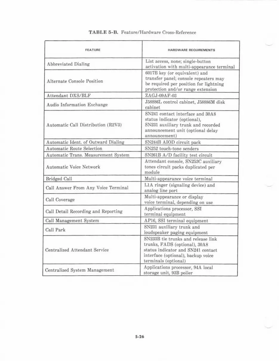
HARDWARE RCOUIBEMENTS
Abbreviated DialingList access, non€; single-buttonactivation with multiaDD€arance terminal
Alternate Console Position
601?B k€y (or equivalent) andtransf€r panel; console repeaters maybe required per positiori for lightningprotection and/or ranse extension
Attendant DXS/BLF ZACJ-09AF.Os
Audio Information ExchangeJ58886L control cabinet, J58886M diskcabinet
Automatic Call Distribution (R2V3)
SN241 contact interface and 30A8status indicator (optional),SN231 auxiliary trunk and recordedannouncement unit (optional delay
Autometic ldent. of Outward Dialinq SN244B AIOD circuit pack
Automatic Route Selection SN252 touch-tone senders
Automatic Trans, Measurement System SN261B A,/D facilitv test circuii
Automatic Voice NetworkAttendant console, SN253C auxiliarytones circuit packs duplicated permodule
B dsed Call Multiappearance voice terminal
Call Answer From Any Voice Terminal LIA ringer (signaling device) andanaloc line Dort
Call CoverageMulti-appearance or displayvoice terminal. deDandinp on use
Call Detail Recording and ReportingApplications processor, SSIterminal €quiDment
CalI Manaeem€nt Svstem AP16. SSI terminal eouiDment
Crll Pa.kSN231 auxiliary trunk andloudsDeaker Dasins eouioment
Centralized Attendant Service
SN233B tie trunks and rcl€as€ linktrunks, FADS (optional), 30A8status indicator and SN24l contactinterface (optional), backup voiceterminals (optional)
Centralized System ManagementApplications processor, 94A localstoraee unit. 93B Doller
TABLE 5-B. Feature/Hadware Cross-R€farence
5-26

TABLE 5-B. Feature/Hardware Cross-Reference (Contd)
HABOWANE NCOUNEME'{TS
Code Calling Acress
SN23l auxiliary trunk port;KS-166m,L5 relay for gong orbell, or 89A control unit and20r2D for chime
Conf€rence-Attendant Six Partv SN254 att€ndant conference circuit32?0 Data Modul€s Related interconnect hardwar€
Disital MultiDlexed Interface ANNIlC DS-1 trunk interfaceDisital Service-l Trunk Interface ANNTTC circuit Dack
Direct Department Calling (R2Vl)
SN241 contact interface and 30A8status indicator (optional), FADS(optional), SN231 auxiliary trunkand reco.ded announcem€nt unit(oDtional dela\' announcem€nt)
Direct Inward Dislins SN232B DID trunkDir€ct Outward Dialino SN230B CO trunk
DirectoryApplications procassor and SSIterminal eouiDment. or 5101)
Display Messagc ScrollingMessage Center equipment; displayvoice t€rminal. 515 BCT. or 5l0D
Display-Voico Terminal 40lA display module with ?405Dvoice terminal, or 515 BCT, or 5l0D
Distributed Communicalion Syst€mDCIU links, SN2:ttB ti€ trunks,other svitches
Electrcnic Document CommunicationsApplications pro(essor,SSI terminal equiDment
Enhanced Uniform Call Distribulion (R2V2) Same as llCD
Facilities Managemant Applications processor, SSI terminslecuiDment
Force Administration Data Syst€m (forCAS only)
l02l'l-A display unit,211A power unit,KS-19252,L? adapter, m42-2ADDMASTER' printer, periph€ralinterface channel
Host ComDuter Access MPDM. MTDM, or ADUInformation Svstems Interfac€ SN238 EIA trunk and ZBA ADU
Intercept Treatment SN231 auxiliary ttunk andrecord€d announcement channelMulti-aDoearance !oice tarminal
Leave Word CallingAPl6 (vhere applicabla), forretrieval: printer, Message Centeras€nt. or disnlav voice terminal
' Resislerd tra.lnna.\ ol ]\dd.'.strr Co.Dor.rnrn.
s-27
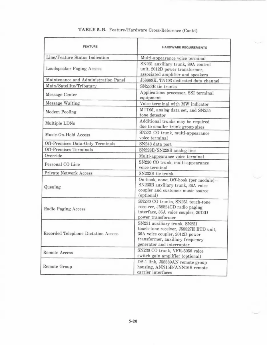
TABLE 6-8. Feature/Hardware Cross-Reference (Contd)
HARDWARE AEOUIaEMEN'S
LinelFeature Status Indication Multiappearance voice terminal
Loudspeaker Paging AccessSN231 auxiliary trunk, 89A controlunit, 2012D power transformer,associated amplifier and sDeakers
Maintenanc€ and Administration Panet J58889K. TN403 dedicated data channclMain/Satell;telTribut,rv sN233B tie trunks
Message Center Applications processor, SSI terminalequipm€nt
Message Waitins Voice terminal with MW indicator
Modem Pooling MTDM, analog data set, and SN255tone d€tector
Multiple LDNS Additional trunks may be requireddue to smaller trunk grouD sizes
Music-On-Hold AccessSN231 CO trunk, nulti-appearancevoice terminal
Off-Premises Data-Onlv Terminals $N243 data portOf f-Premises Terminals SN228B/SN229B analos lineOvenide Multi-app€arance voice te.minal
Perconal CO Lin€ SN230 CO trunk, multi-appearance
Private Network Acc€ss SN233B tie trunk
Queuing
On-hook, none; Off-hool (per module)-SN233B auxiiiary trunk. 364 voicecoupler and customer music source(optional)
Radio Paging Access
SN230 CO trunks, SN25l touch,tonereceiver, J58824CD radio paginginterface, 364 voice coupler, 2012Dpower transformer
Recorded Telephone Dictation Access
SN231 auxiliary trunk, SN251touch-tone receiver, J5882?E RTD unit,36A voice coupler, 2012D powertransformer, auxiliary f requencygenerator and interrupter
Remote Access SN230 CO trunk. VFR-5050 voiceswitch gain amplifier (optionat)
Remote GroupDS-1 link, J58889AN remote grouphousing, ANN15B,/ANNl6B remotecarrier interfaces
5-28
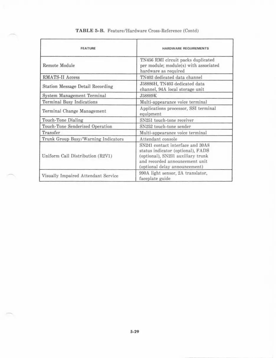
HARDWARE BEOUIBEMEIIiS
Renote ModuleTN456 RMI circuit packs duplicatedper module; module(s) with associatedhardware as reouired
RMATSII Access TN403 dedicated data channel
Station M€ssage Detail RecordingJ58886H, TN403 dedicated datachannel- 94A local storase unit
Svstem Manasement Terminal J58889K
Terminal Busv Indications Multi-apD€arance voice terminal
Terminal Change Management Applications processor, SSI terminaleauiDment
Touch-Tone Dialins SN251 touch-tone receiverTouch-Tone S€nderized ODeration Sli252 touch-tone senderTrsnsfer Multi-aDnearance voire terminalTrunk Grouo Busv/Warnine Indicators Attendant console
Uniform CaLl Distribution (R2V1,
SN241 contact interface and 30A8status indicator (optional), FADS(optional), SN23l auxiliary trunkand recorded announcement unit(oDtional delav announcement)
Visually Impaired Attendant Service9904 light sensor, 2A translator,faceDlate euide
TABLE 5.B. Feature/Hardware Cross-Reference (Contd)
s-29

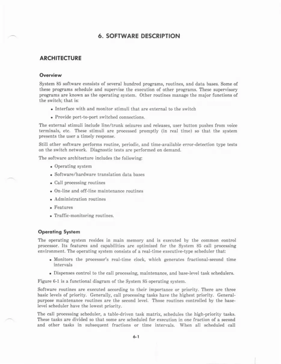
6. SOFTWARE DESCRIPTION
ARCHITECTURE
Ovqrview
System 85 software consists of several hundred programs, routines, snd data bas€s. Sohe ofthese programs schedule and supervise the execution of other programs. Th€se supervisoryprograrns are known as the operating system. Other routines msnage the major functions ofthe switch; that is:
. Interface with and monitor stimuli that are external to the switch
. Provide port-to-port switched connections.
The external stimuli include line/trunk seizures and releases, user button pushes from voicet€rminals, etc. These stimuli are proc€ssed promptly (in reel time) so that the systempresents the user s tim€ly response.
Still other software performs routine, periodic, and time-available error-detection type testson the switch n€twork. Diagnostic tests ar€ performed on demand.
The software architecture includes the following:
. Opereting system
. Softwar€/hardware translation data bases
. Call processing routines
. Online and offline maintenance routines
. Administration routines
. Features
. Traffic-monitoring routines.
Op.roting Syrl.rrThe operating system resides in main memory and is executed by the common controlprocessor. Its feetures end capsbilities are optimized for thc System 85 call processingenvircnment. The operating system consists of a real-time €xecutive-type scheduler that:
. Monitors the processor's real-time clock, which generates fractional-second timeintervalg
. Dispenses control to the call processing, maintenance, and base-lev€l task 6chedulers.
Figurc 6-1 is a functionsl diegram of the System 85 operating system.
Software routines are executed according to their importanc€ or priority. There are threebasic levels of priority- Generally, call processing tasks have the highest priority. G€neral-purpose maintenance routine are th€ second level. Those routines controlled by th€ base-level scheduler have th€ lowest priodty.
The call piocessing scheduler, a tabl€-driven task mat.ix, schedules the high-priority tasks.- These tasks are divided so that some ar€ schedul€d for execution in on€ lraction of a second
and other tesks iD subs€queht fractions or time intervals. When all sch€duled call
&l
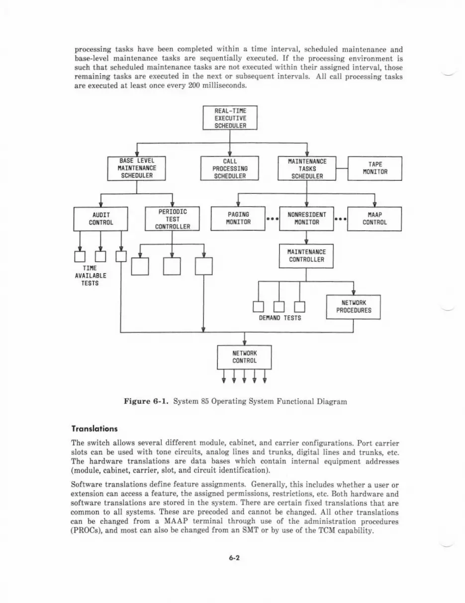
processing tasks have been completed within a time interval, scheduled maintenance andbaselevel maint€nance tasks are sequentially executed. If the processing environment issuch that scheduled maint€nanc€ tasks ar€ not executed within their assigned interval, thoseremaining tasks are ex€cuted in the n€xt or subsequent intervals. All call processing tasksare executed at least once ev€ry 200 millis€conds.
Figure 6-1. System 85 Operating System Functional Diagram
Tronslotiona
The switch allows several different module, cabin€t, and carrier configurations. Port carri€rslots can be used with tone circuits, analog lines and trunks, digital lines and trunks, etc.The hardware translations are data bases which contain int€rnal equipment addresses(module, cabinet, carrier, slot, and circuit identification).
Software translations define feature assignm€nts. Generally, this includes wh€ther a user orextension can acc€ss a feature, the assigned permissions, restrictions, etc. Both hardware andsoftware translations are stored in th€ system. There are certain fixed traDslations that arecommon to all systems. These are precoded and cannot be changed. All other translatioNcan be changed lrom a MAAP terminal through use of the administration procedures(PROCS), add most can also b€ changed frcm an SMT or by use oI the TCM capability-
R€AI-]IIIEEIECUTIVESCHEDULER
OEiIAIIIO TESTS
clLtPROCESSIIIIG
SCIIEDULER
IlAII{TEIIAI{CECOTTRl)LIER
6-2
Coll Procering Routiner
Call processing involves €stablishing and removing communications connections betweenports. Call processing functions ar€ distributed b€tween the module processors and th€common control. Those call processing functions which peiform port scanning are stored inread-only memories that are a part of the module processors. Ports ar€ scanned snd theirstatus is r€cord€d in the module processor's status memory. Call processing functions areinitiated when new (that is, changed) port status information is received from the moduleprocessor. Therefore, the common control call processing routines read the status of eachmodule processor (in r€al time) and provid€ the request€d services. Typically, these willinclude:
. Completing calls-that is, connecting a calling (originating) port to the call€d ports
. Providing the features and s€ruices that are enabled for the requesting port.
On-Line ond Ofl-line Mointenonce Routin.s
Online maintenance tests ar€ operational tests and serve the purpose of performing errordetection, error recording, and €rror recovery if possible. Offline maintenance t€sts aredemend tests and reside on the tape cartridge. They are loaded into main memory uponcommand and executed on demand,
The on-line maintenance t€sts ar€ schedul€d by the operating system. They €xecute on aroutine, periodic, or time-available basjs. Network control (s€e Figure 6-1) contains theroutin€s which perform network circuit testing. Stimuli for these tests are provided in thelorm of t.anslations data. Test status information (incompl€te, pass, fail) is w tten into th€status area of main memory. Test failu.e data is written into a periodic or time-availablefailure log. Test failure data consists of the circuit numb€r, fault code, alarm level, etc. Thefailure log can be examined by diagnostic tests for determining the identity of the failingcircuit and, if required, the s€cond and third most likely choices.
Offline maintenance test procedures (PROCS) a.e identified by 3-digit numbers. The MAAPcontrol soltware (part of the operating system, see Figure 6-1) monitors the MAAP terminal,processes user commands, and loads a designated PROC into an arca of main memory knov,/nas the paging buffer. ?hese tests are diagnostic in natur€. They ate used to isolate andidentify a fault to a replaceable item such as a circuit pack.
Adminisl]otion Roulines
Administntion is the means whereby the switching equipment (hardware) and services canbe customiz€d, within certain limits, to meet user needs. Administration capabilities areprovided through readily accessibl€ software routines (PROC8). The switching equipment canbe administered by entering configuration/assignment changes into the translation databases. Additionally, there are administration procedures which permit changes to existingfeature or servic€ capabilities and add,/r€move access to oth€r features/services on a per-port
Feolures
System 85 featur€s are provided laryely by software routineshardware. Section 5, FEATURES AND SERVICES, provides a
and some r€quire specialbrief description ol €ach
&3
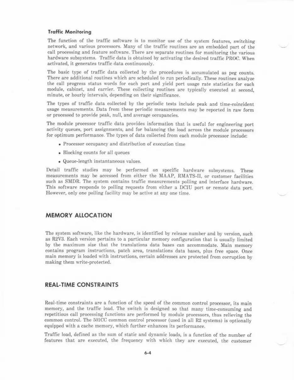
T.offic Monito.ing
The function of the traffic software is to monitor use of the system features, switchingnetwork, and various processors. Many of the traffic routines are an embedded part of thecell processing and featur€ software. There are separate routines for monitoring the varioushardwar€ subsystems. Traffic data is obtain€d by activating the desired traffic PROC. Whenactivated, it generates tlaffic data continuously.
The basic type of traffic data collected by the procedures is accumulated as peg counts.There are additional routines which are scheduled to run periodically. These routines analyzethe call progress status words for each port and yield port ussge rate statistics for eachmodul€, cabinet, and carrier. These collecting routines ar€ typically executed at second,minute, or hourly intervals, depending on their significance-
The types of truffic data collected by the periodic tests include peak and time-coincidentusage measurements. Data from th€se p€riodic measurements may be reported in raw formor plocesspd to pro!ide peak, null. and average occupancies.
The module processor traffic data provides information that is useful for engineering portactivity queu€s, port assignments, and for balancing the load across the module processo$for optimum perforrnance. The types of data collected fmm each module proc€ssor include:
. Pmcessor occupancy and distribution of execution time
. Blocking counts for all queues
. Queuelength instantaneous values.
Detail traffic studi€s may be performed on specific hardware subsystems. Thesemeasur€ments may be accessed from either the MAAP, RMATS-II, or custom€r lacilitiessuch as SMDR. The system contains traffic m€asurements polling and inteface hardwsre.This software rcsponds to polling r€quests from either a DCIU port or remote data port.However, only one polling facility may be active at any one time.
MEMORY AI.TOCATION
The system software, like the hardware, is identified by release number and by version, suchas R2V3. Each v€rsion pertains to a particular memory configuration that is usually limitedby the maximum size that th€ translations data bases can accommodat€. Main memorycontains program instructions, patch area, translations data bases, plus free spsce. Oncemain memory is loaded with instructions, certain addresses are protected lrom corruption bymaking them write-protected.
REAt.TIME CONSTRAINTS
Real-time constmints are a function of the speed of th€ common control processor, its mainmemory, and the traffic load. The switch is designed so that many time-consuming andrepetitious call processing functions are performed by module processors, thus relieving thecommon control. The 50lCC common control processor (used in all R2 systems) is optionallyequipped with a cache memory, which further enhanc€s its performanc€.
Traffic load, defined as th€ sum of static and dynamic loads, is a function of the number offeatures that are executed, the frequency with which they are executed, the customer
6-4
configuration, and the instantaneous (peak) call processing load. The configurationcontribution to load is known as the ststic load, and the call prmessing contribution isknown as the dynamic load.
The r€sl-time constraint or maximum system capacity is defined as a load of ?5 perc€nt.This limit reserves approximately 25 percent of the processor capacity for Snrforrningroutin€, periodic, and tim€-available maiotenance and overload handling tasks. The load isdetermined on a per-system basis by completing trsffic engine€ring worksheets.
For additionel idormation concerning tralfic engineering, refer to AT&T System 86(R2V3)-T!rffi c Dsta Aralysis Guide-Adl!iDirt16tion Menual (555-102-502).
TAPE CARTRIDGES
Ovcrvicw
The high capacity mini-recorder (HCMR) is the device which loads software into mainmemory. The software is contained on a tape cartridge cassette. The cass€tte mediumprovides a flexible and conv€nient way to tmnsport software fmm the factory to the field.Therefore, software updates/revisions can be easily incorporated into €xisting systems.
The HCMR has extensiv€ error detection and correction capabilities which remove tbe needto have multiple copies of data on the tap€. The drive can read or write in €ither the forwardor revers€ tape directions.
The HCMR p€rforms four basic system functions. They are:
. Irad tape-loads the common control main memory wilh prcgrams, translationsdata, and patches following an initialization or power recovery-
. l,oad offline-load, from tap€, an off-line procedure (PROC) into the paging bufferof main memory-
. Run tap€-updates th€ tap€'s translation data to match the memory's contents.
. Patch-write program modification data on identified patch blocks which will thenoverwrite program data in m€moiy during a load tape operation.
Orgonirotion
Data is recorded on the tape cartridge in 1024 wo.d blocks using a 5-track format. It isrecorded in streaming mode (continuous recording). Data is organiz€d in a logical orderedformat that assures th€ quickest reload of the syst€m in case of a po,rer failure.
Th€ tap€ cartridge(s) contains header information which identifies th€ tap€ and specifies anyparticular requirements fot using the Lape. The tape translations directory gives a listing ofthe trsnslation table names and memory addresses for all translation data on the tape. Thetext blocks contain the actual data to be loaded into memorx. This data includes r€sidentprograms, translations, offline prograrns (PROCS), and patches-
6-S
Conligurotions
The tape cartridges are available in various configurations, depending upon the jntended use.
These include:
. Blank tape-reserved for making backup copies.
. G€n€ric tape-contains program instructions for the particular system release andv€rsion without any of the assignable tBnslations (som€times called CAPDEF tape).
. Customized Hardware and Pseudo Software (CHAPS) tape-consists ol the g€nericsoftware plus a subset of translations rellecting th€ complete syst€m hardwareconfiguration. This tap€ is preliminary (not customer-specific) and is used foroperational field testing of hardware.
. Fully customized program tape-consists of the generic softwa.e plus all of theequipment and customer-specific tlanslations.
The tape cartridges are always shipped from the manufacturer with the latest availablev€rsion of software. When a system is upgraded using a generic tap€, a run tape operationmust be ex€cuted in order to write the translation data onto the new tape.
DCIU SOFTWARE
The DCIU is a special applications I/O processor. It has its own memory and execut€ssoftwarc that resides in the memory. Th€ main component of the DCIU software is th€network interface program (NIP). This program provides packet-type communicationfacilities for th€ eight physical ports. Each port contains eight logical channels whichimpl€ment the BX.25 packet communications ptotocol. The DCIU software is a part of thegeneric program, contained on the tape cartridge, and is loaded into the DCIU memoryduring initialization.
Appr.rcATroNS PROCESSOR (AP) SOFTWARE
The AP software is written in a highlev€l programming language ("C" language) and mayvary from one AP installation to another. Architecture of the AP software is characterizedby several layers of programs executed at various times by the AP processing unit endperipheral controllers. For a detailed discussion of the AP software, reler to ApplicetionsProcessor 1o-Beference Menual (555-201-201).
6-6

7. SYSTEM ADMINISTRATION
ovERvrEw
The soltware which controls System &5 operation us€s a variety of tables Iocat€d in systemmemory to keep track of:
. Port circuits
. Trunk circuits
r Extension numbers
. Feature assignments
. Network coDjiguration
. System configuration
. Systemwide options.
Collectively, these tables are called translations. Thus by tabulating this data, information(such as th€ number of modules the system has, the equipment location of a dat3 module, orthe features a voic€ terminal may access) can easily be chanqed.
System 85 comes with a tape which includes gen€ric softwarc and tmnslations. Wh€n thesystem is installed, the tape is used to load the main memory. The information used tocreate these translations comes from the order form rcceiv€d by the factory. A printedrecord of these tlanslations is provided by the Customer System Document (shipped with€ach Syst€m 85)-
Adminishation is the prccess of changing tmnslations. System 85 uses a se es of progremscell€d procedutes to chang€ translations. A person wanting to administer the system (changetransletions) can acc€ss the prcc€dure progr:ams through one of the System Managementfeatur*. System Management features provide an interlace b€tw€en the us€r 4nd theprocedure programs. The System Manag€ment featurus include:
r Centralized System Management (CSM)-A versatile system management featurc forlarge customers with more than 5000 tines. This feature is n€w for R2V3, and itresides on th€ 3B5 AP. It handles all FM and TCM functions, Traffic Managementand Automatic Trunsmission Measuring, Cost Management, and AP Management. Itcatr ako suppo AUDIX, Syst€m ?5, and Information Systems Network.
. Facilities Management (FM)-A feature on the AP, available to the syst€madministrator vie a BCT. This featur€ is us€d for network administration.
. Terminal Change Manegement (TCM)-A feature on the AP, available to th€ systemadministrator via a BCT. This featurc is used for feature assignment and terminalreerrangement.
. Syst€m Management Terminal (SMT)-A terminal availabl€ to the systemadministretor to perform any type of translation changes described under FM andTCM.
. Maintenance and Administmtion Panel (MAAP)-A panel (terminal) available toservic€ personnel to change any type of translation. It can also be used to run sevenlmaint€nance routines-
7-l
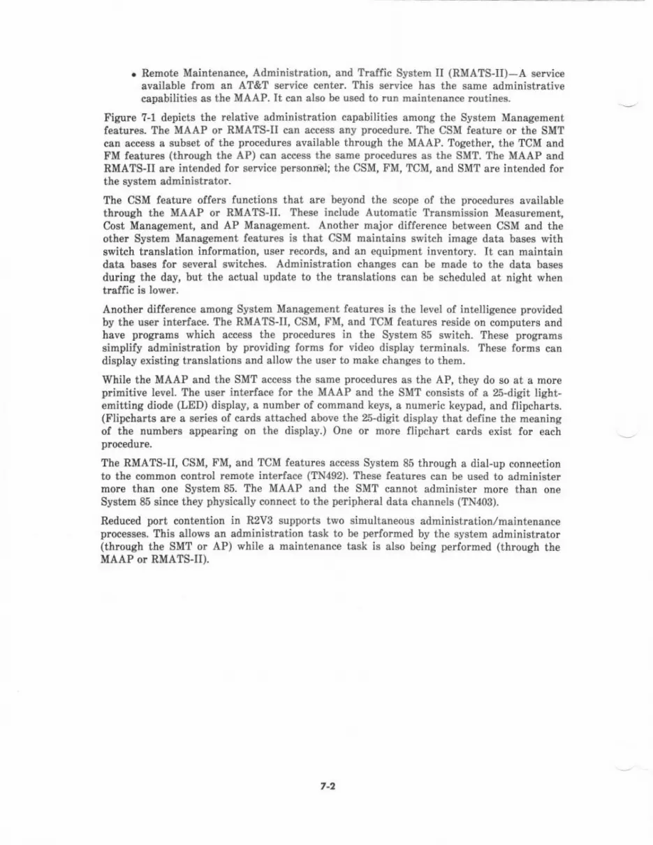
. Remote MaiDtenenc€, Administration, and Traffic System II (RMATS-II)-A serviceavailable from an AT&T service center. This s€rvice has the same administrativecapabilities as th€ MAAP. It cen also be used to run maint€nance ioutin€s.
Figlre 7-1 depicts the relative administration capabilities among the System Managementfeatures. Th€ MAAP or RMATS-U can access any procedure. The CSM feature or the SMTcan access a subset of the procedures availsble through the MAAP. Together, the TCM andFM features (through the AP) csn access the same procedur€s as the SMT. The MAAP andRMATS-II are int€nd€d for s€rvice pemonnal; the CSM, FM, TCM, and SMT are intended forthe system adrninistretor.
The CSM feature offers functions that ar€ beyond the scope of the procedures availablethrough the MAAP or RMATSII. These include Automstic Transmission Measurement,Cost Manag€ment, aDd AP Manag€ment. Another major difference between CSM and theother System Manag€ment t€atures is ttat CSM maintains switch image data bases \rithswitch translation information, user r€cords, and an equipment inventory. It cen maintaindata bases for several switch$. Administration chsnges can be made to the data bas€sduring the day, but the actual update to the translations can be scheduled at night whentraffic is lower.
Another difference among System Manegement featurcs is the level of intelligence providedby the user interfsce. The RMATS-II, CSM, FM, and TCM features leside on computers andhav€ programs which sccess the procedures in th€ System 85 switch. These programssimplify administration by providing forms for video display terminsls. These forms candisplay existing translations end ellow th€ user to make changes to th€m.
While the MAAP and the SMT access the same procedures as the AP, they do so at a morcp mitive level. ?he user interface for the MAAP and the SMT consish of a 25-digit light-emitting diode (LED) display, a number ol command keys, a numeric keypad, and flipchads.(Flipcharts are e series ol cards attached above the 25-digit display that define the m€aningol ihe numbers appearing on the display.) One or more flipchart cards exist for eachplocedurc.
The RMATS-II, CSM, I'M, and TCM features access System 85 through a dial-up connectionto the common control lemote interlace (TN492). These f€atures can be used to sdministermore than one System 85. The MAAP and the SMT cannot administer more than oneSysiem 85 since they physically conrcct to the peripheral date channels (TN403).
Reduced polt coDtention in R2Vg supports two simultan€ous administration/maintenanceprocesses. This allows sn administration task to be performed by the system administrator(thlough the SMT or AP) while a maint€nance task is abo being performed (through theMAAP or RMATSJI).
7-2
8. RETIABII,ITY
GENERAI.
To ensure reliability, System 85 uses high-quality components and thoroughly debuggedsoftware. Hardwarc circuit and firmware designs are thoroughly reviewed and tested beloreprototype circuits ar€ provided for softwarc designers. Softwar€ designs are reviewed duringdesign and coding. Then, each design goes through validation tests unit testing, integrationtesting, function testing, and system testing. System testing also selves as a validation testfor hardware and firmware designs.
Befo.e standard production is started, several controlled introduction systems arc put intoservice. AT&T closely follows the operation of th€se systems and quickly finds and fixes anyremaining faults before the systems are installed.
Each System 85 switch must pass thrce lev€ls of testing during manufacture, shipping, andinstallation. First, it undergoes a sedes of factory tests of component parts, circuit packs,major subsystems, and th€ entire assembled system. Second, it may undergo a series ofquality assurance tests, in which systems ready lor shipm€nt are randomly selected forextensive retesting. Thid, it undergoes a s€ries of installation tests, in which AT&Tpersonnel unpack and inspect for possible shipping damage and retest the system after finalassembly and installalion-
Reliability refers to th€ lailure rate of a system. Maintainability refe* to the ease oftroubleshooting and servicing with minimum downtime or degradation of service.Availability refers to the probability that a system is operational at any given time anddepends on its r€liability and maintainability. System 85 availability may be enhanced byoptionally provided subsystems. These ensure that the switch can continue to performwithout interruption even if some hardware component fails.
ENHANCED AVAITABII.ITY CONFIGURATIONS
System 85 is off€red in four basic configumtions. The configurations differ principally inthe enhanced availability provided by duplication of major system components and relatedhardware. These options includ€:
. Standard availability-no duplication of major components
r High availability-duplicated common control
. Critical availability-duplicated common control, duplicated tine-multiplex€d switch(TMS), and duplicated nodule control(s)
. Critical availability with battery rese.ve-same as critical availability with th€addition of the long-terrn (8-hour) battery backup option.
In a standard availability system, if a fauit occurs in th€ common control, the system usuallycontinues to operat€ because of the fault-tolerant design of the common cont.ol. Howevor,there are common control faults that may rende. the entire system inoperable- Also, TMSand network module faults can significantly affect servic€. If se.vice becomes severelyd€graded, the system is placed in emergency transfer until it can be diagnosed and repairedby systems technicians. If the technicians are on-site, normal rcpair time is 30 minutes. lf g
8-l
systems t€chnician must be dispatched from a service center, the system could be out ofservice for several hours.
The enhanced-availability configurations p.ovide the following benefits:
. There is a significant increase in system aveilability if the common control, TMS,and network modules are all duplicated.
r If a fault occurs in a part of th€ system thet is duplicated, th€ syst€m softwaiecauses th€ standby unit to b€ automatically activated. Most of th€ time service isr6tored in only a feu, seconds, ceusing little or no degradation of service.Uninterrupted service can be maintained while faults are repaired and tested in th€offline portion of duplicated subrystems. The probability of the duplicatedsubsyltem failing while the defective portion is being repaired is extrem€ly small.
. For some s€doos common control faults, it takes only a minute or two for softwarcto reestablish the records for calls that w€re in progress when the fault occurred.Calls in progress ar€ not affected during this process; only new call attempts areaffected-
. Uninterrupted service is possible during system updates ot hardware or software.Whcn a system is updated, modifications can be made in the off-lin€ portion ofduplicated subsystems.
. Reliable service (neglecting occasional short r€covery times) is virtually guaranteedas long as human erro. and long-term power outages do not occur. In the unlikelyevent that independent major controls malfunction at the same time, systeh levelsoltware can test all of the hardwsre and then reconfigure the system and restores€rvice.
System availability can b€ significantly affected by commercial power outag€s. For th€System 85 switch, standard and optional featur€s minimiz€ the effect of these outsg6. As astandard f€ature, power for the common control is held over with batte es for a minimumof l0 minutes. During commercial power outag€s of less than l0 minutes, service is r€storedautomatically within about 2() seconds after power is restored, as there is no ne€d to reloadth€ programs or translations from the memory lape. Optionally, a 3- to 5-minute nominalholdover can be provided for the rest of th€ switch for continuous service during outages ofless than 3 minutes. During an extended power failure, customer-designated lines ar€automatically transfeued to central office trunks. Long-term extend€d power reserve(engineered to customer needs, typically up to 8 hours) is also available as an oplion.
For the AP, battery holdover for at least l0 minutes can optionally be provided. This allowstime for the system to be shut down gracefully with no loss of customer data.
SYSTEM AVAITABII.ITY
System 85 is desiped to provide continuous service with a small predicted outeg€ time pery€ar. Syst€m availability is directly related to "downtime". Downtime is expressed as thepredicted average time that a single user is out of service in minutes per year. Dov/ntime fore single user includes that which aff€cts all us€rs (for example, common control faults), thatwhich affects the group of which e user is a part (for example, network module faults), andthst which affects only the single us€r (for example, a port circuit fault).
8-2
A giv€n system may have more or less downtime than predicted. Predictions are based onan average for a large number of systems. The device failure ratcs used are based onexperience using similar d€vices in similar systems. The syst€m is assumed to be operatingat a roorn temperature of approximat€ly 80 degrees Fahrenheit. Only hardware failurescaus€d by faults in the common equipnent, switching network, and port circuitry areconsidered. Voice terminal faults, comrnercial power failures, human errors, and softwarefaults ar€ not included. Also, these predictions are based on system operation after the 1-year warranty period,
A fault is now consider€d to cause downtim€ if it prevents a user from placing or receiving acall for more than 15 seconds. (In the past, central offices have coosid€ied 30 s€conds as anoutage.) Predicted single user downtime in e y€ar is a function of the mean numb€r of faultsoccur.ing per year that affect a single user and the mean time to repair (VTIR). The MTIRincludes diagnostic, repair, and travel time for a systems technician to get to the equipmentsite. The m€alr travel time depends on how far th€ systems technician is from the site(equals zero if the technician is on-site). The predict€d MTTR for System 85, not includingtrav€l time, is 20 minutes. (For previous sysf€ms, 30 minutes has been considered as theMTTR,)
For detailed information on predicted availability (in relation to the four systemconfiguration options), ref€r to Sy3tem a6 Roliebility add Msintenance (999-?m-4011S,
Issue 1).
When a faulty unit is not duplicated, downtime depends on how often a fault occum and th€repsir time. When a faulty unit is duplicated (for example, common control or TMS),downtime is primerily a function of how oft€n a fault occurs and the automatic recoverytime, which ranges from seconds to minut€s, depending on the fault and the subsystem. Forsome common control faults (for €xample, proccssor faults), a "hard srvitch" occurs and thaconnection status is copied from the switching network so that existing calls are notaffected. This takes from less than m seconds to several minutes, dep€nding on the systemsize. For most faults, th€ switch to the duplicated subsystem tak€s sevcral s€conds with veryIittle impact on service.
The duplicated common control in the high availability case and the duplicated TMS andnetwork module in the critical availability case significantly reduces the predicted userdowntime. Adding th€ long-term battory backup option provides addiiional duplication forth€ network module and port cabinet rectifiers to further reduce predicted downtime. Forthis ease, the primary contributor to downtime is the port circuitry that is not duplicaied.The single user downtime due to eommon control, TMS, and netrvork module faults is l€ssthan 2 minutes per ycar. The total downtime for a single user is predicted to b€ l€ss than8 minutes p€r year, ev€n with an MTTR of 2 hours. This corresponds to an availabilitygreat€r than 99.998 percent.
The increased system price (not including terminal equipment) to go from a standardavailability to a criticsl availability system is about 10 percent for a system larger than 3000
lin$. If the cost of terminsl equipment is considered, th€ percent of price increas€ to obteincritical availability is even less, b€cause t€rminal €quipment often represents up to half thecost of the total syst€m price.
The AP is not duplicated, so any serious fault results in syst€m downtime. The downtime is afunction of how oft€n th€ systern fails and the repair tim€. For an MTTR of I hour, thepredicted syst€m downtime for l year is 2 hours. This corresponds to an availability greaterthan 99.9? percent.
8-3
Loopback test circuits-P.ovide controlled loopbacks in the data circuits to loop backtest data for v€ fication of proper circuit operation and to isolate faults.
Circuit pack ID chips-Allow maintenance technicians to interrogate the typ€,vintage, and issue ol circuit pecks.
Circuit pack LEDS Indicate circuit packs under test, failed circuit packs, andcircuits in us€.
Alerm Panel-Provides visual alarm indicators (LEDS) that indicate the status of theproc€ssor m€mory, common control, network, switch environment, applicationsproc€ssor, and other subsystems. Iocated in the common control cabinet, it indicatesthe status of the system at a glance.
Analog/digital facility test circuit-Provides t€st source andlor destination fortransmission tests of analog facilities and bit-error-rate measurements of digitalfacilities and circuits.
. Terminal testing-Provides self-t€st and loop-around test capabilities. Data rnoduleself-tests are run periodically whenever a module is idle.
. Attendant console-Has an alarm indicator which is lighted when an alarm i6g€nerated and an acknowl€dg€ indicator which is st€adily lighted when the alarm issuccessfully rcported vie th€ Alsrm Origination feeture. This indicator flashes if thealarm cannot be reported.
MAINTENANCE TESTS
Using maintenanc€ hardwarc, there are a number of maintenance tests that System 85performs automatically on itself andlor that are easily performed by syst€m technicians tofurther reduce maintenance costs and downtime:
. X-ray testing-At the factory and again during installation, exercises the switchthoroughly and locates any faults b€fore cutover to the customer. X-ray testingfeaturcs an accelerat€d testing rate to quickly and thorcughly test system hardwarcwithout the need for customer translation data. These tests must be performedIocslly and require that the syst€m be out of service. The tests can be controlled fromRMATS-II after the X-ray tape is loaded into the system. The factory and pre-cutover tests make use of the internal maintenance control structure.
. Reinitialization-Automatically verifies system integrity each time the switch isturned on or r€started, end confirms that the major parts of the switch are operatingprop€rly.
. Periodic and time-available background tests-Automatically detect less criticalfaults before they are noticed by the system user- Thes€ background tests ar€ used toidentify failed circuits, remov€ them ftom service, and alert maintenance personnelto the problem. ['or duplicated subsyst€ms, background tests are run on the off-linesubsystem but at a lower rate than for the on-line subsyst€m.
r Terminal t€sts-Enable the user or system technician to diagnose and r€pairterminal probl€ms quickly, resulting in short downtime and low maintenance costs.Multi-appearance voice terminals have self-test capability that the user can activateto t€st the terminal and diagnose terminal problems. Dial-up self-tests let th€ userverify button, lamp, and ringing operation. All digital communications protocol(DCP) terminals also have built-in self-test capability activat€d by operating a t€stbutton with t€st rcsults on the telminal.
9-2

An error and alarm log provides a log for errors detected by opeaational error processingand background tests. Logged are: the circuit reporting the error, the fault code indicatingtype of error (when provided), time of first and last €rror, time of alarm (if any), and acount of the total number of times the error occurred. The error log is automaticallyanalyzed every minute, and circuits with error counts over threshold are alarmed. When analarmed error is cleared, the entry is marked resolved, providing a history of resolved
MAINTENANCE PROCEDURES
The maintenance procedures sho\rn in Fig]rre 9-1 includ€ both the automatic system checksand audits that occur continuously and th€ manual diagnostic and repair procedures used bysyst€m technicians to identify and r€solve problems.
Figure 9-1. System 85 Maintenance Procedures
Error Detoclion and Logging
The first step in resolving a problem is to accurately detect the error. Th€ following types oferrors are automatically and continuously ch€ck€d by operational error processing or auditedby the switch:
r Power and environrnental faults
. Parity error on memory read, deta transfer, or tim€-division network paths
. Digital communications protocol (DCP) link protocol efors
. Lisht suide link ermrs
. Call processing eFors.
ERROR OETECTIOIIAIID TOGCIIIG
AIARII REPORTII{G
REII()TEDIAGIIOS]IC
IESTIiG
CIRCUIT REPTACEIIEIIT,VENIFICAIIOT
'ESIIIG
9-3
In addition, the following types of backgrcund t€sts ar€ automatically pe.formed to det€ctother errors:
. Periodic and time-available tests-Critical circuits are tested as often as everysecond. Less clitical circuits are tested at a lowet rate or on a time-available basis(that is, when a processor i6 not busy with call processing or other maintenancetasks).
. Audits-Status data (for exampl€, reprcsenting the state of a trunk circuit) areaudited on a time-available basis to d€tect discrepancies caused by noise hits orsoftware errors. Discrcpancies found by audits are logged, but not alarm€d.
. Refreshes-Some status data (for example, lamp status in terminals) are refreshedp€riodically to correct any errors that may arise due to noise or power interruptions.
All errors detected through background tests or operational error prcc€ssing are logged. [nsome cases, additional testing is automatically done to determin€ the severity of th€ error.When the error count is over a certain set threshold, an alarm is automatically generated.The switch alarm log includes unit typ€, unit location, alarm status, numb€r of e ors, andtime of first error, alarming, and alarm rcsolution.
Error Recovery
Once a fault is id€ntified, the switch may tak€ one or more of the folloiving steps tominimiz€ the impact of th€ fault:
. Reconfigure duplicated circuits-Keep the best subsystem onlin€. If severalsubsystems are duplicated (for example, common control, TMS, and networkmodules), the optimum configuration is select€d to remain online.
. Busy-out circuits-Make circuits with faults unavailable for service (for example, afaulty trunk circuit).
. Reinitialize-P€rform at several levels when the detect€d error indicat€s thatsoftware or data ar€ inconsistent or that a processor is malfunctioning.
Alorm Reporting
Wh€n a fault is detected and verified, System 85 automatically generat€s one of thefollowing thre€ alarms:
. Major alarm-A serious s€rvice fault is det€cted. System local and remote alarms areactivated.
. Minor alarm-Service is degraded, but only a feq, users er€ affected. System localand remote alarms ar€ activated.
. warning alarm-Tbere is a fault, but service is probably not notic€ably degrad€d-The system local alarm is activated.
Th€ alarm l€vel is established by the det€ction test that reports the error. System 85automatically reports all major and minor alarms to a remote AT&T maintenance center(RMATS-II) and to the attendant console and the alarm panel. Warning alarms are onlyreported to th€ alarm panel. An indicator on the attendant console is lighted when the alarmhas been successfully reported to RMATS-II.
9-1
lotcl ond Remole Diogno.tic T6tingThe MAAP (for the switch) and the alarm pan€l of the Applications Prccessor are theprincipal local communications links htween System 85 and the system technician. High€rlevel testing can be performed through the SCAMPER interface and the DCIU t€st circuitpacks (if provided), which may be plugged into slots in the common control carrier. Remotemaintenance is performed by means ol a dial"up connection to RMATS-IL Locat (MAAP)maintenance and remote (RMATS-II) msintensnce csn perform the following maintenoncefunctions:
. Examine error and alarm logs to find the most serious faults
. Run error-detection tests of circuits to verify if th€ syst€m is still defective
. Run diagn$tic t€sts
. Resolve alarms in the alarm log end retire alarm indicetions
. Switch between duplicated subsystems to place standby subsystems in service
r Make circuits available or unavailable for service
. Monitor system status
. R€initializ€ all or part of the syst€m.
Reduced port contention in R2VB allows a maintenance task to be p€rformed (throughRMATSII or MAAP) simultaneously with a local administration change by the systemadministrator. For more detailed information on MAAP maintenance procedures, refer toAT&T System 86 (n2V3)-Maintensnce-Servic€ Matrual (555-102-f08).
Circuil Pccl l€plo.€m.nl ond V.riffGdtion l€rtingOn the System 85 switch, if a diagnostic test finds a problem, the red LED (if provided) islighted on th€ first-choice circuit pack to be replaced. The circuit pack can then be replacedby the maintenance technician without inteirupting service, except in the area directlyaffected by its replac€ment.
ln most cas€s, verification tests are automaticslly run on th€ circuit pack as soon ss it isplugged in. If the fault is not corr€cted, the maintenance interface can b€ used to indicete asecond-choic€ replac€meni by lighting the red LED (if provided) on the second-choice circuitpack (if any). If replacing a second ci*uit pack do€s not corr€ct the fault, the process can tlerepeated fo. a third-choice raplacement (if any).
When the vedfication test indicates that the fault is conected, the alarm log entry isautomatically resolved &nd the circuit is returned to seNice.
On the applications processor, if a diagnostic test finds a problem, the first,choic€ circuitpack to r€place is indicated on the maintenance t€rminal display. Power must be turn€d offto replace th€ circuit pack. After circuit pack replacem€nt, the power is turned on andinitialization tests v€rify proper circuit operation. lf initialization t€sts pass, the alarm igcleared.
9-5

IO. SYSTEM ENGINEERING
This section highlights the €ngineering considerations for a System 85, Release 2configuration. Detail€d traffic and hardware configuration information is contained inApplicrtions Englaeering Manual (555-l0l-600). The Applications Engineering Manuslis a 2-volume document divid€d into three maior secticns. These sections are: ConfigurationGuide, Configuration R€f€rences, and Appendices. The Configuration Guide provides step-by-step instructions and worksheets used to €ngineer and mnligure a System 85, Release 2.The ConfigumtioD R€f€rences contain an in-depth analysis of unusual configurationsituations. Exampl€s of Configuration References are: Processor Occupancy Evaluation,Time-Multiplexed Switch (TMS) Evalustion, Nonblocking Configuration Cuidelines, etc.Appendic$ provide additional, more technical information on various engine€ring topicssuch as: theory of essentially Nonblocking (P.000001) configuration, PUR, CUR, Erlang andCCS explanations, TMS Mismatch Blocking, etc. App€ndice are also provided on auxiliaryc&binet hardware configuratione and developing equipment room specifications.
SWITCH ENGINEERING_TRAFFIC
Traffic Engineering is required for System 85 traffic sensitive €quipment components andsoftware records. Examples are: number of modules, touch-tone register packs, touch-tonesender packs, data tone detector packs, cach€ memory, dial pulse register reco.ds, intercomtrunk records, TMS capacity check and processor occupancy check.
Overproviding tialfic sensitiv€ equipment may appear to b€ a safe means of satisfying acustomer's service objectives. But, it ignores th€ customer's conc€rn about cost snd mayresult in a loss of sale. On th€ other hand, cutting cost at the expense ol grade of servicecan gen€rat€ a poor product. This would damage AT&T'S credibility and could jeopardizefuture busin€ss with the customer and others who hear about it. To avoid these pitfalls,traffic and €quipment engin€ering methods hav€ been developed to provide least-cost syst€mconfigurations which meet stated servic€ objectives. Th€se methods are contained inApplications Ergine€ritrg Marual-AT&T System 85, Rel€ase 2. The followinginfothation highlights the traffic considerations.
Porl U!qg. Rote (PUR) dnd Erlong
Due to the new and different types of functions b€ing provided by System 85, a newcbaracterization of custom€r-switched t.affic through the network module labric has beend€veloped. It is called Port Usage Rate (PUR). PUR differs from th€ tpditionat trafficmeasure of hundred call seconds (CCS) in two respects.
l. It is based on the avemge number of busy ports (a port is any item, line, trunk,comput€r, €tc., requiring int€rconnection to the switching network) instead of the"connections" in progress. This approach is bett€r for characterizing customertraffic when there is a large amount of confercnce traffic or when there is avs ety of types of traffic betw€€n many different types of ports; both of theseconditions exist within System 85.
2. PUR is expressed in units of Erlanss. The Erlang has rcplaced CCS/Hour as th€traffic m€asurement unit of choice and the Erlang is internationally acc€pted.
to.l
Po., U@9. Por. (PUR)
The PUR expressed in units of Erlangs is the basic measure of traffic int€nsity in theSystem 85 switching network. Th€ traditional CCS measure of traffic intensity is not used;instead, the capacity ol the network is given in terms of PUR. The PUR can be interpret€das the average number of simultan€ously busy ports.
&Lng Uni,
The Erlang is the international unit of traffic load equal to the sverage numb$ ofsimultaneous calls offered to or canied by a group of servers. Erlangs n€ed not bereferenced to time interval; how€ver, the typical time unit is th€ busy hours, in vrhich case1 Erlang : 36 CCS per hour.
Chard.,etizing Cqtom.t frctlk
Characterizing individual groups of customer lines using the PUR method is advantageous insystems such as System 85 vr'h€rc there are a variety of traffic "types" off€r€d to the switch.When looking at a particular group of ports with common characteristics, it is easier todefine their r€lative impact on the n€twork by simply stating their occupancy du ng th€busy hour. Once th€ occupancy of a particular group of pods is known, multiplying thisoccupancy by the numb€r ol ports in the group gives th€ PUR for the group. Adding thePURS ol all the groups gives the overall PUR. In any specilic case, occupancies for eachdifferent type of port must be determined. Date terminals will frequently have much higheroccupanci€s than voice lines. Trunk port occupancies vary depending on group siz€ andgrade of service. Computer ports are typically very heavily loaded.
Switching Nelwork
A physical capacity of 1536 ports exists in each module of the 81 possible modul€s inSystem 85. However, only 254 simultaneous connections can be establish€d in €ach module.B€cause of this, traffic engineering procedures are required to:
. Determine the busy-hour traffic load generated by port traffic sources
. Evaluate the switch traffic capacity ageinst the load.
These p?ocedurcs determine whether the objective grade of se ice can be maintained.
Every port is assigned a dedicated time slot. These time slots guarantee acc€ss to the TimeSlot Interchanger (TSI). Eaeh port in a 2-port connection r€quires a TSI pmgram storeword; this means a 2-poit connection uses a total of two TSI program store words (alsocalled a "program word pair"). A maximum of 256 TSI program word pairs ale available forport-to-port conn€ctions. Even though the n€twork can terminate up to 1536 ports permodule, only 256 2-port connections per module can be set up at any one given time.Although ev€ry port is guaranteed a time slot into the TSI, not all ports can simultaneouslybe involved in a connection through the TSI.
Conference Troffic
Unlike switching networks using pulse amplitude modulatiotr (PAM), System 85 uses a pulsecode modulation (PCM) network- From a traffic engineering standpoint, the elechonicdiff€r€nces between the two are unimportant. But, the differ€nce in how each handlesconference connections is significant. In a single-module PAM network, a g-pa y confercnceconnection can b€ handled *ith a single time slot. Th€ same connection in a pCM networkr€quircs three TSI program word pairs (the equivalent of three time slots in a system usingPAM).
lo-2
Conference calling reduc€s the traftic capecity of the TSI. For example, if four 8-partyconference connections were simultaneously in progr€ss; 12 TSI program word pairs would berequired, 1 for each pa{y. When this is contrasted with the 6 TSI program word pairsrequircd to connect 12 parties with six 2-party connections, it can be s€en that conferencinghas a signilicant impact on the traffic handling capacity of a network modul€.
Three-party conference calls are not the only connections that involve 3-port connections.For example, from the time a station goes off-hook until the first digit is dialed, a 8-portconnection (using three TSI program store words) exists between a station line, a tonesource, and a touch-tone r€ceiver. (Once the first digit is dialed the tone source drops out,Ieaving a 2-port connection.) These types of codnections arc r€feued to as system-gene.at€dconference calls.
Another example of system-generated conference traffic involves the use of a touch-tonesender. Th€ outgoing call rcquires a 2-port connection between the originating port and atouch-tone dialing register, the outgoing trunk and a sender. These two connections areequival€nt lrom the standpoint of TSI usage to four 2-port connections.
Time-Mulriplexed Switch (TMS) ond Misrnotch
Unlike other traffic sensitive components which block calls when all servers into th€ groupare in use (ref€rred to as conc€ntration blocking), the TMS is limited by a form of blockingcalled "mismatch blocking." To make an intermodule connection, the TMS must link a timeslot of one module to a like-numbered time slot of th€ other module. Ev€n though eachmodule bas 256 tine slots into the TMS, a call cannot be completed between any twomodules unless the same tim€ slot number is available in both modules. If the TMS isunabl€ to lind like-numbered time slots, mismatch blocking occurs making it impossible toset up a call between two modules; this can occur even when there are idle time slots on thechannels that connect the modules to the TMS.
Plocca3o. Occuponcy ond Ccche Memory
Tbere are two major processors in System 85: the main processor (50lCC) and the ModuleProcessor. Each module contains a module processor with a capacity of ?000 busy hour calls.The main pmcessor (501CC) can handle over m,00 busy hou. calls. lf the estimated busyhour calls exceeds 20,000, a detailed processor occupancy evaluation is needed to determinehow many more calls can be prcc€ssed before the processor reaches maximum busy houroccupancy.
For heavy traffic applications, a device called cache memory is installed. This device, whichis provided by adding a TN369 circuit pack to the Common Control, reduces processoroccupancy. Cache is a high-speed memory used to decreas€ the access time to programinstructions. The cache memory has an access time of about one-third that of the mainmemory. The cache memory maintains "copies" of trequ€ntly acc€ssed storage elem€nts;when a storag€ element is repetitively r€quest€d, the cache memory can quickly return its"copy" of lhat element. saving the slower main memory access.
Romole Modulcr ond Unbolqnaed Systems
System 85 r€mote modules can be placed up to 13,000 feet from the main processor.Applications using remote modules c.eate unbalanced traffic and hardwar€ between themodules. This requires special engin€ering methodologies.
t o-3
S.rvi.e Obioctive! (Grode ol Service)
The System 85 has an overall s€rvice otjective of P.002 (2,/1000) blocking pmbability for theStandard conliguBtion and P.000001 (1/1,000,000) blocking prcbability for the ess€ntiallynonblocking configuntion. These probabilities apply to th€ switching fabric and do notinclude blocking caused by lack of port circuits such as central office trunks, tie trunks,s€rvic€ ci&uits, etc.
On an intermodule call, blocking can occur from three sources: the originating module TSI,the TMS, and the terminating module TSI. The capacity of each module TSI is based on ablocking probability of P.001. The capacity of the TMS is bas€d on a blocking probability ofless than P.0001. When all the probabilities ar€ add€d together, th€ resuit is:
P.001 + P.0001 + P.001 : P.0021.
Rounding off will yield the objective se ice level of P.002. The essentielly nonblockingconfiguration (P.m0001) is obtain€d by artificially increesing th€ traffic losd by 25 percentand providing modules bas€d on this inflated value. When the switch encount€N the realtraffic load (25 percent less than the engineered load), enough equipment is in place to carrythe trallic with a one in one million probability of blocking.
A nonblocking switching network is basically a hardware configuration but is addressed herefor completeness. The total number of ports having acc€ss to th€ switch network isd€t€rmined. This includ€s service-type ports such as call progress tones and touch-tonesend€rs and r€ceivers.
The number of modules required is calculated by insuring that €very po.t can be involved ina connection simultaneously through the TSI in a singl€-module system and through the TSIsnd TMS in a multimodule system, The methodology essentially limits tbe number of portsequipped per module. For a single-module system, on the order of 500 ports may beequipped. For a multimodule system, a maximum of only 128 ports per module may beequipped to insure TMS mismatch blocking cannot occur. These numbers must also bedeBted to teke into account percentages of 3-port conference traffic which requiresadditional TSI and TMS resources.
t0-a

Here i8 a comparison of the number of modules r€quired bssed on treffic for an sverog€system rvith 80 pdcetrt voice traffic and m percent datr tr8ffic engineer€d and configuredfor the thr€e different gndes of s€rvice:
3.g)0 lines @ 4 Ccs/litre voice15 CCS/line Incohing1.5 @S/line Outgoirg1 CCS/line IDtarcnm
128 computrr ports @ CCS/porL (50%lpecilic and 50% tronspecific)
4if Trunlr @ 22 CCS./tru*
q.d. .l a-ti.. N{nl, d M.AUL. Lqcr.d
Stlndad (P.002) 4Essentially Nonblocking (P.000001) 5Totally Nonblocking 30
This example is for illu6trative pu4Dse6 only. The number of modules required for aspecific applicatioD and grade of s€rvi@ must b€ determined individually using th€sppropriate engircering snd conligu.stion methodologies.
C.pcciri...-- The TSII cspacity p€I module is set at dg) PUR. this value is etablished bas€d on 256 TSII
maximum connections, 2 ports !e! connection, 512 marimum poats connectad, up to 5 percentconf€rence traffiq and some limited source gain bas€d on 100 ports per module. Thes6vrriablB are spplied to an Erlang B finite gource bloc}ed calb clearcd model resulting ir4ir0 PUR clpaci6' pe. module at P.001 grade of rervice.
The TMS cspsci8 fu based on 256 msximuEr conuections from s given modul€ to the TMS, aPoison arrival rate, and sirnulation techniques to determine mismatch blocking. fiis resultsir . range from 1{0 PUn to 195 PUR p€r modul€, d€lEnding on the number of modules inthe system.
rG5

SwlTCH ENGINEERING_HARDWARE/SOFTWARE CONFIGURATION
This section us€s the term "hardware" to refer to items such as circuit packs, carri€rs, andcebinets thet are physically arranged to construct a System 85 switch and,/or auxiliarycabinet.
The Applicrtior EDSin€eridg Meduel-Syston A5 (555-r0f-600) provides thealgorithms, worksh€ets, snd instructions necessary to determin€ the ord€rable hardwere andsoftware items fot the switch and auxiliery cabinet. The algorithms take into eccountvarisbles for the required t€rminal and trunk interfac€s, trsffic, f€stures, distanceconstraints, carrier and cabinet capacity, etc. Special sections are provided to configureunbalanced or Remote Module systems which require specific hardwsr€ allocation permodule or groups of modul€s (requires completion of unbalanced,/remote module trafficengine€ring as e prerequisite). The result of completing the configuration is a specificquantity and type of Price Element Codes (PEC9).
PECS are the means by which the r€quired herdware and softwsrc is specified formanulacturing snd by which the customer is billed. Attribut€s associated with PECs are am€ans to provide variations of the basic item order€d. The attributes specified in theApplications Engin€€ring Manual configuration arc thos€ which are pertinent to insure thesystem can provid€ the functionality requir€d. Attributes for items guch as cabineteerthquake protections mounting bolts or Btyle of door are not configuration dependent andmust b€ specified as needed.
Certain PECs specified in the configuration are rcferred to as Pseudo-PEcs which have X600as th€ first four chaiacters. Thes€ arc used to identify hardware quantities used fortranslation assignment data ch€cks, to sp€cify quantities of ce ain traffic sensitive softvrar€varisbles such as intercom records and origineting registerc, end to provid€ mnfigurationinformation for the manufecturer.
A review of the switch gederic program memory configu$tion limit&tions should bep€rformed prior to and is r€quired upon compl€tion of the configuration piocess to insur€thst no limitetioB have tleen exce€ded.
Hordwqrc
The hardware PECS ere unique groupings of apparatus such as J- and ED-coded hardwsr€that comprise a logrcal building block (e.g., cabin€t, carrier, and circuit packs) for the switahand auxiliary csbinet. Th€se were established with the intent of minimizing the number ofunique PECg required while maintaining sufficient granularity to minimiz€ the amoudt ofhardware provided for s specific customer's application. An ord€r of magnitude of l0OO
unique hardware items has been reduced to an order of magnitude of 100 hardware PECa.These PECS msy be used to specify th€ hardware order fot a 500line single-module systemor a ?oooline 18-moduls system with any variatioN ol terminal, trunk, or featurer€quirements.
Softrrqrc
Software PECS sre used to specify feature groups within the generic program v,rhich areindividually billable, such aB Electmnic Tandem Networking and Distributed CommunicationSystem. This provides a means to incr€mentally offer desired features and functionality.
t0.6
Swil.h Mamory Configerotion Linil.Th€ limits described in the following tables are system maximums. Certain limih may notbe achi€vabl€ simultan€ously.
The following tables list the maximum parameters for hardwar€ and software it€ms forRelease 2, VeBion 1; Version 2; and version 3:
. TABLE 10-A. System Parameters
. TABLE lGB. Line Parameters
. TABLE 10-C. Terminal Feature Psrameterg
. TABLE l0-D. Trunk Parameters
r TABLE 10-E. Network ParameteB.
tG7
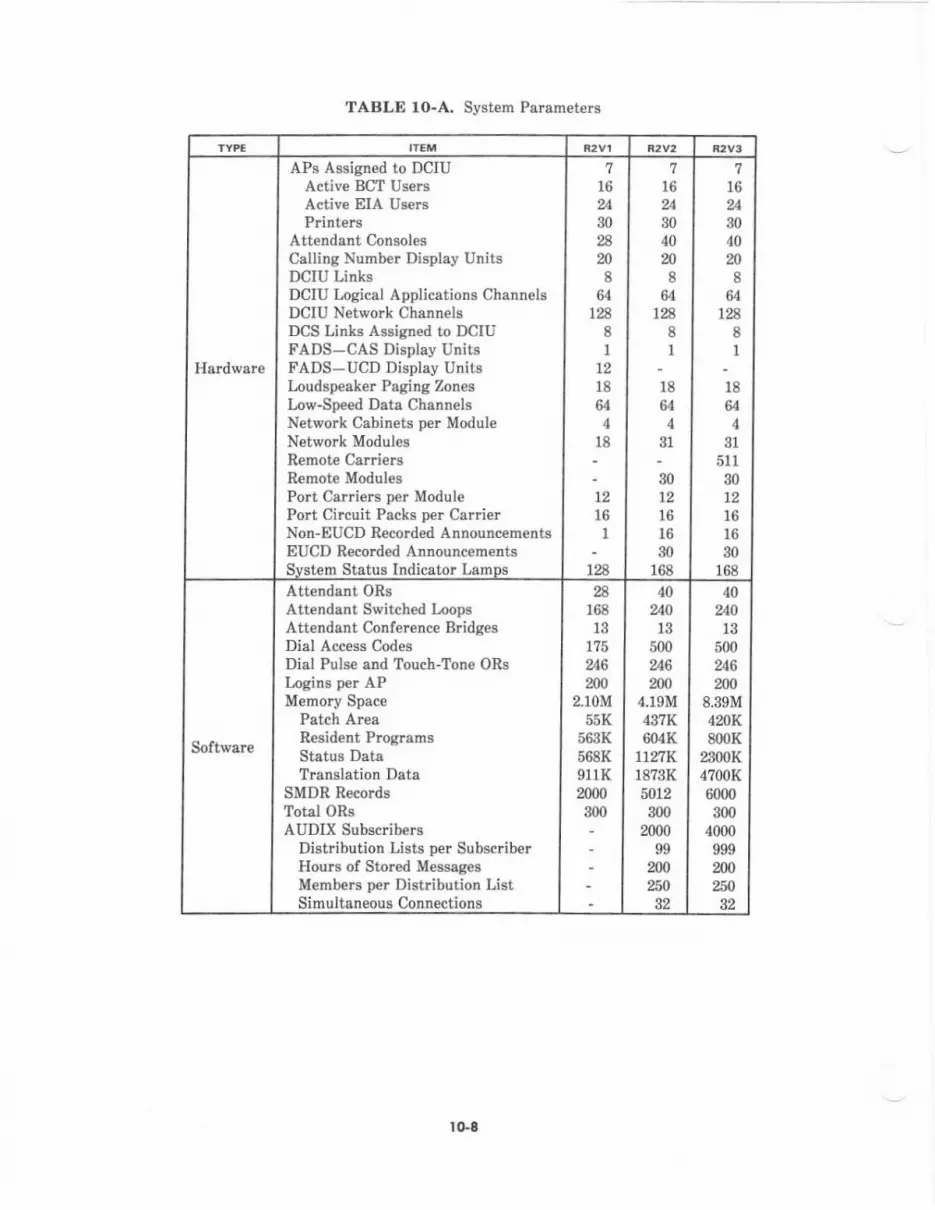
APB Assigned to DCIUActive BCT UsersActive EIA Us€rsPrinters
Attendant ConsolesCalling Numb€r Display UnitsDCIU LinksDCIU Logical Applications ChannelsDCIU Network ChannelsDCS Links Assisned to DCIUFADS-CAS Display UnitsFADS-UCD Display UnitgLoudspeaker Paging ZonesLow-Sp€ed Data ChannelsNetwork Cabinets per ModuleNetvrork ModulesRemote CarriersRemote ModulesPo Carders per ModulePort Circuit Packs per CauierNon-EUCD Recorded AnnouncemertsEUCD Recoded Announcem€ntsSvstem Status Indicator LamDs
1216
1
728
7
30
m8
64128
8I
121864
4
l8
7l6
3040m8
641A
81
18
644
31
30t2161630
168
l8u
4
511
301215l630
168
7
304020
864
1288I
Software
Attendant ORsAttendant Switch€d LoopsAttendant Confercnce BridgesDial Access CodesDial Pulse and Touch-Tone ORsIagins per APMernoty Space
Patch ArcaResid€nt ProgramsStatus DataTranslation Data
SMDR RecordgTotal ORsAUDIX Subscribers
Dist bution Lists per SubscriberHours of Stored Messag€sMemb€rs per Distribution ListSimultaneous Connections
16813
175
62U)
2.10M55I<
563K568K911K2000
'i
400
5006
2004.19M437K604K
1127K18?3Kfi12300
200099
M250
a6200
8.39M4mK800K
2300R4700K6000
3004000
999
40240l3
500
2000
TABLE rO-A. Syst€m Parameters
rG8

TABLE 10-B. Line Parameters
* The ?3OgS and ?3055 terminals ar€ not provided in R2V1.
TABLE 1O-C. Terminal Feature Parameters
Hardware
Analog Terminals (2500, 2554, 7101A, ?103A)Multi-Appcarance Terminals (?m8H, ?205H,
730351, ?mss*, ?403D, 74MD,7105D1Line Side Dats ModulesDisplay Modules (Includins 5f3,/515 BCT)
?,000
5,0005,000
900
8,000
5,0008,0402.M0
32,000
r0,00016,0fi)
5_000
Software Line Records 15.000 19-145 32.7M
HardwareAbbreviat€d Dialing ButtonsAuto Message Waiting LampsAuto Messase Waitins LamDs oer Line
24,0647,5N
1
65,536r0,500
I
65,53632,000
I
Soltware
Abbreviated Dialing Charrcters p€r ButtonAbbreviated Dialing Cha.acters per CallAbbreviated Dialing Group ListsAbbreviated Dialing Nonsystem ListsAbb!€viat€d Dialing Syst€m List RecordsAuto/Manual Intercom R€cordsButton Table WordsCall Pickup GroupsChamcters p€r NameCoverage GroupsDisplay NarnesLine Appearance OccurrencesLine Appesrsnces per T€rminalLine Classes of ServiceLWC Messages Without APManual Sisnalins Pairs
2,04'l99
30064,000
1,00030
3,0005,000
16
633,000
140
n36
5m
n36
1,0005,\m
99300
220,0021,000
304,0968,500
161263
6,0001!0
n36
9,99913,10?9,999
300408,?50
1,000
304,096
32,767l672
6,000140
tG9

TABLE lO-D. Trunk Parameters
TABLE fO-E, Network Parameters
Hardware
AIOD Circuit PacksDS-l Trunk Cirmit PacksContact Interface Circuit PacksPersonal CO LinesPhysical TrunksRelease Link Trunks, InwardRelease Link Trunks, OutwardRemote Access Trunks
26
34150
2250110
1645
2256
1505000
1101645
251234
15060001r0
1645
Software
AIOD QueuesAssignable Trunk RecordsCode Restriction LevelsFl€xibl€ Night Trunk GroupsFlexible Night Trunks per Trunk GroupHost Access Trunk GroupsModem Pool Trunk GroupsRLT Groups at the MainRout€ Advance-No. of Trunk CroupsTrunks per Trunk GroupTrunk Records (Total)ACDIEUCD Splits or UCD GroupsACD,/EUCD,/UCD Asents D€r GrouD
6n05
425599
175175405
993250
40
6't525
4
99a8238
405
797030
512
68525
4
99a8238405
897030
512
Hardware DCS Nodes 12 20 20
Softvrare
AAR RoutesAAR Trunk Groups per Route ListARS Foreign NPASARS RoutesARS (Home) NPAS-Free NNX ListARS Trunk Groups per RouteAuthorization CodesAU1OVON Precedence L€velsAUTOVON Routing Pstt€rns (Nodes)Facilities R€striction L€vels
46464u16
90006
128
54
6464u16
90005
128
64016
160
64160t6
90,0006
128
lo-to
Ci.cuit PoGk Araignmgnts in Port Carriart
The port carrier is designed to acc€pt all SN-coded port circuit packs. Therc ar€ severalsimilar, but different, circuit packs ured in the System 85 network. Certain types of packs
can be paired with other typ€s; others can only b€ paired with one of the same typ€.Additionally, certain circuit packs may be cabled to eith€r Line Fields or Trunk/AuxiliarvFields dep€nding on th€ typ€ ol application.
Ch.uit PaeI PohiDg
Cabling restrictions dictate c€rt.in circuit pack pairing. Each 25-pair cable connecting theport carrier to the termination field accommodates the inteifaces from two citcuit packs.
Traflic and reliability considerations iequire placement of certain circuit pecks so they willbe distributed throughout the system. Administration considerations direct the quantity andplacement of like units in a carrier.
An example of cabling restrictions dictating circuit pack pairing is the analog lin€ pack. Theanalog line pack provides eight ports per pack. Pair assignments on the pack and carrierwiring from the pair of circuit pack slots to the z5-pair cabl€ interface dictat€ that an analogline pack may be paired with anoth€r analog line pack or a circuit pack which does notrequire access at the termination fi€ld (e.g., Touch-Tone Sender). Additionally, an adapteror "Y" cable (EDfE44-11, G?1) is required at the termination field end if connectorizedhardware is used for the termination field. The "Y" cable is designed to maintain 3-pairuniformity p€r port on the termination block for analog line packs.
An example of reliability considerations dictating circuit pack pairing is the Call ProgressTones pack. This pack does not r€quire access at the termination field and may b€physically paired with enother Call Progress Tones pack. However, if a port carri€r dc to dcpower pack or control or data interface pack failed which setved the portion ot the carrier inwhich th€ pair was placed, all s€rvice to the module would be lost. Therefore, these packs
should not be paired and should be placed in separat€ carriers and preferably in separatecabinets s€rved by different power sources.
Ci.c.tit Pa.L G,ovpin$ and Pc ins Rulor
The SN-coded circuit packs can be segmented into basic groups and subgroupings for pairingpurposes. tr'igure 10-1 provides a table with r€commended pairing rules for the followinggroups and subgroups.
lo-l I
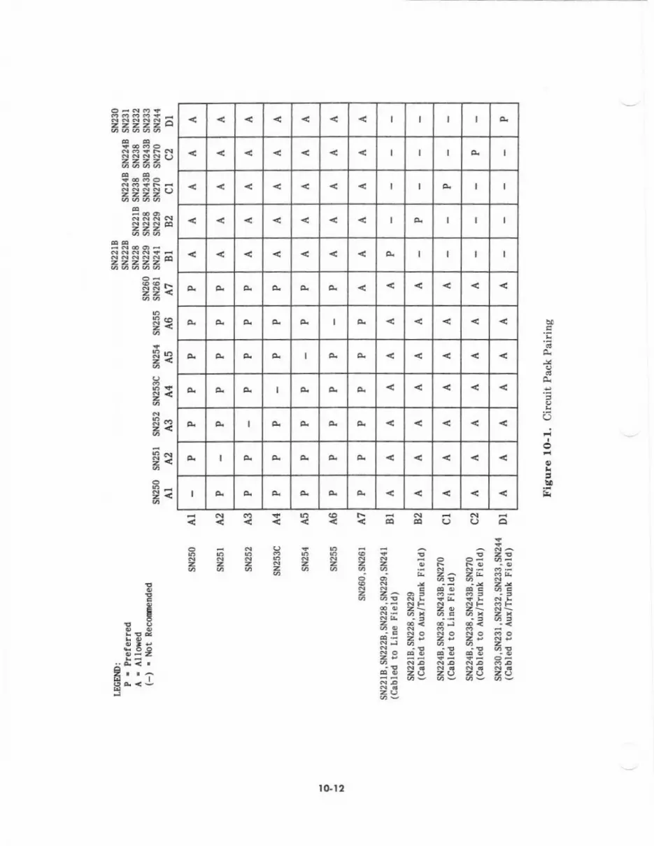
I
I
I I
I I I
I I I
Q
SSi:
H
i<Rn
Sr
E€
t?<toaoo(Ja
i i ; R R; ?i=a;iaa
rGt2
A1 SN250 Call Progr€ss Totes
A2 SN25l Touch-Tone Receiver
Ag SN252 Touch-Tone Sender
A4 SN253C Auxiliary Tones
A5 SN254 Attendant Confe!€nce
A6 SN255 Dat Tone Detector
A7 SN2@ Analog Facility TestSN261 Analog,/Digital Facility Test
The circuit packs in Croup A are predominately those which are essential to call proc€ssingo! featute operation and for $/hich access ig not rcquired at the t€rmination field. T*,oexceptions are Subgroups A4 (SN232C) atrd A? (SN 0 and SN261). The SN253C plovides theinterface fol chime tone, dial tone, and ritrgbsck ton€ for certsin auxiliary equipment andmust b€ cabled to the t€rmination field. tte SN260 and SN261 provide certain trunk andmodem pool testing capabilities that are not ess€ntial to call processing or feature opelation.
The circuit pecks in each subgroup should be distribut€d in separat€ carriers and preferablyin cabin€ts serv€d by differ€nt pow€r sources for reliability considelations.
Gaort a
Bl SN221B Analog PoSN222B Anslog PortSN Analog PortSN229 Analog PortSN241 Contact Intedace
82 SN221B Anslog PortSN228 Analog PortSN229 Analog Port
The circuit packs in Grcup B provide eight interfsces per pack lor which acce3s is requiredat eith€r th€ Lin€ Field or Trunk/Auxiliary Field. The circuit packs listed in Subgmup 81ar€ us€d for applic4tions u'hich requi& scc€ss at the Lin€ Field (e.g., int€rnal buildingapplication). The circuit packs listed in Subgroup 82 are us€d for applications whichcurrently require access at th€ Trunk/Auxiliary Field (i.e., out of building or off-pr€mtuesapplications).
to-13
Cr SN224B Hybrid PortSN238 ADU/EIA PortSN2A]B Dsts PoIt (Analog)SNZ70 Digital Port
C2 SNDaB Hybrid PortSN238 ADU/EIA PortSN%3B Data Port (Analog)SNto Digital Port
The circuit packs in Gmup C provide four interfeces per pack for which eccess is required ateithe! th€ Line Field or TrunvAuxiliary Field. Th€ circuit packs listed in Subgroup C1 areused for applications which require access at the Line Field (e.g., internel buildingspplicatiotr which uses building wiring access). The circuit packs listed in Subgroup C2 areused for applications which cu ently require access at th€ Trunk/Auxiliary Field:
SN224B Out-of-buiidingapplicationon"nonexposedcable"
SN238 Out-of-building epplication on "nonexpGed cable" or to physicallyconcentrate intelfeces for access in equipment room such as to theIntormation Systems N€twork
SNZ3B Out-of-building, off-premis€, or modem pool application
SN?70 Out-of-building application on "nonexposed" cable or modem loolspplication
(t(xrt o
D1 SN230 CO tunkSN231 Auxiliary TrunkSN232 DID TrunkSN23:l Tie Trunk
The circuit packs in Group D provide four interfaces p€r pack for which access is required atthe TrunvAuxiliary Field. These circuit packs should b€ distributed among Beparst€carriers and preferably cabineb served by different pow€r sources for reliabilityconsiderstions. Allocation of trunk packs among moduls in a multimodule syst€m i$ alsoess€ntial for proper traffic belencing (p€r locale lor Remote Modules).
IO.ta

AUXIIIARY CABINET AND EQUIPMENT CONFIGURATION
The System 85 Auxiliarv Cabinet is used for housing auxiliary hardware on shelves andracks. Molded structural foam panels are availabl€ for mounting auxiliary equipment insid€the cabinet instead of on a wall. The Auxiliary Cabinet may or may not be requir€ddepending on the system configuration. If otrly remote sccess equipment (such as the 2l2ARdata s€t) is lequired, consideration should be given to wall mounting the data €quipment.But an Auxiliary Cabinet is recommended il additional auxiliary equipment is necessary,especially if the equipment requires power or lack mounting.
Bosic Auxiliory Cobinet qnd Equipment
The J58886N1 L-1 Auxiliary Cabinet includes a J58889AE1 L-1 alarm distdbution panel andcan be equipped to accept ac input power or -48 V dc input power:
r The ac input power option consists of a J58886N1 L-29 ac power outlet strip and aJ588894K1 L2 ac pow€I dist bution unit. A -48 V dc power supply can be ordered ifinternal -48 V dc i8 required.
. The -48 V dc input power option consists of a J58889AB1 L-1 fuse pan€l and aJ58889ADI Ll wiring and €quipment packag€ which includes a dc filter unit.
Here is a list of optional equipment:
. Fan assembly for forced air cooling
. Small interconnect panel (thirty-two 3-pair terminatiods)
. Large interconhect panel (sixty-four 3-pair t€rminations)
. ll-inch vertical height structural foam mounting panel
. 4-inch vertical height structural foam mounting panel
. Frequency (ringing) gen€rator and interrupter
. Miscellaneous mounting packages which include adapter brackets for lg-inch or 23-inch wide rack equipment, sh€lves for local area data sets, cable assemblies for datas€ts, and data modules. Mounting packages are also available for Remote GroupInterface, Channel Division Multiplexer (CDM), Channel Expansion Multiplexer(CEM), and Chann€l Service Unit (CSU).
Avtiliery C.bin., AlonThe alarm distribution unit in each Auxiliary Cabinet consolidates alarms for the variousequipm€nt and conditions within the cabinet. It also provides a compatible interface for theexternal €quipment alarm input provided by the TN492C in the 501 common control. Thisallows automatic regi8tering snd reporting ol Auxiliary Cebinet alarms by System 85. Thepossible Auxiliary Cabinet alarm types are:
. T€mperature
. Rectifier
. Circuit breaker/fuse
. Faequency Generator
IO-t5
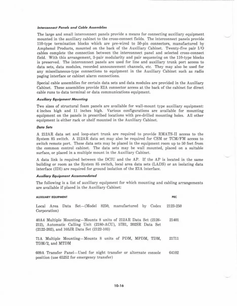
t r..todn <, [email protected] oDd AU. A.-mbli..
Th€ larg€ and small interconnect panels provide a means for connecting auxiliary equipmentmounted in the auxiliary cabinet to the cross-connect fields. The int€rconnect panels provide110-type termination blocks which are pre-wired to 50-pin connecto$, manufactured byAmphenol Products, mounted on the back of the Auxiliary Cabinet. Twenty-five psir I/Ocables complet€ the connection between the interconnect panel and selected cross-connectfield. With this arrangement, 3-pair modularity and peir sequencing on the 110-type blocksis preserved. The interconnect panels arc used for line and auxiliary trunk port access todata s€ts, data modules, r€corded announcement channels, etc. They rnay also be used forany miscellaneous-type conneetions to equipment in the Auxiliary Cabinet such as radiopaging interface or cabitrel elerm connections.
Special cable assemblies lor ce ain data set6 and data modules are prcvided in the AuxiliaryCabinet. Th€s€ assemblies provide EIA connector access at the back of the cabinet lor diEctcable runs to data terminal or data cornrnunications equipment.
Au'irtuy Equipn n, hlovnrids
Two sizes of structural foam panels are evailabl€ for wall-mount type auxiliary equipment:4 inches high and 1l inches high. Vaiious configurations are available for mountingequipment on the panels in prcscribed locations with pre-drilled mounting holes. All otherequipment is either rack or shelf mounted in the Auxiliary Cabinet.
A 212AR d^la set and loop-start trunk are required to provid€ RMATS-II access to theSystem 85 switch. A 212AR data set may also be lequired for CSM or TCM/FM access toswitch rcmote port. These data s€ts may be plac€d in the equipment room up to 50 feet frcmthe common control cabinet. The data sets may be wall mounted, plac€d on a suitablesu ace, or placed in a multiple mount in the Auxiliary Cabinet.
A data link is required between the DCIU and the AP. If the AP is located in the sam€building or loom as the System 85 switch, local alea data sets (LADS) or an isolating datainterface (IDI) ere required lor ground isolation of the EIA interface.
^ u' i I ia.y & v i p m.a, A..om modore J
The foilowing is a list ol auxiliary equipmedt for which mounting and cabling arraDgementsare evailable if placed in the Auxiliary Cabinetl
aul ^tY
EctuttiaF{r
Ircal Area Deta Set-(Model 8250, manulactured by CodexCorporation)
40A4 Multiple Mounting-Mounts 8 units of 212AR Data Set (2126-
212), Automatic Calling Unit (2180-ACU), 5?B1, 202SR Date Set(2122-m2), snd 103JR Data Set (2122-103)
?1A Multiple Mounting-Mounts 8 units of PDM, MPDM, TDM,TDM/2, and MTDM
609A Transfer Pan€I-Used for night transf€r or alternete consoleposition (us€ 65252 for emerg€ncy transfer)
tcc
2123-%0
21401
21711
64102
ro.t6

AUIIUA'Y I(IUI'MEITI PBC
89A Control Unit and m12D power supply-Used for loudspeaker 64152
Paging
13A Recorded Announcement Carrier-Includes basic equipment andmounts 8 unih of 24-second announcement cbannel circuit packs(61967)
500-13 LORAIN'Multiple Mounting-Mounts 13 units of LORAINModel VFR-5050 Voice Switch Gain Circuit Pack (65291) andASTRO-ENDYNEt Model 11625-1 E&M 1lpe I Trunk SignalingConverter Circuit Pack (65255)
36A Voice Coupler and m12D Power Supply
J5888ZCD-1 Radio Paging Interlace
J58882?E'1 Recorded T€lephon€ Dictation Trunk Interface Unit
J53050F-2 Automatic Trunk Interconnect Unit
64966
65230
65n5
65297
65241
65246
Emergency Transfer Panel 65 2
Single lG-second recorded announc€m€nt channel unit (COOK+ Model 65270213300-23016113 and 213288 ac po\rer converter)
ADU Multiple Mountins-mounts 40 ZSA3 ADUS 65393
ISN Concentrator Carrier-mounts 5 interface packs (65394) 69010
Gcncrcl Conft gurotion Guidclines
There are several things to consider when configuring Auxiliary Cabinets. The maximumamount of vertical mounting sDac€ in any on€ cabinet is M inches. However, the usablevertical spac€ is 51 inches in front and 34 inches in the rcar. This allows for subsequenteddition of a -48 V dc power supply. C€rtain piec€s of hardware r€quired to support theauxiliary €quipment mounted in the cabinet are installed in fixed places and should bechecked first when arranging equipment. Optional support equiprnent refers to items suchas interconnect panels, -48 V rectifier, and fans-
When the ac input power option is ord€red, the ac dishibution unit and the alarmdistribution unit are mounted in the base of the csbinei; this uses up the filst ? inches ofv€rtical mounting spac€. If a -48 V rectifier is called for, it is mounted in the base of thecabinet.
+
T.adenark of Lo.ain El€cfonics Corporation.
lrademark of Astro-Endrne Corporation.Tr3.l€hf,.k .l Cook El€ctri.s
! Gl7
When either -48 V dc input or th€ -48 V rectifier is ordered, a fuse panel is included. Thispanel mounts in th€ top 2 inches in the front of the cabinet (vertical height of 62 to64 inch€s).
The fan assembly is mounted in the cabinet door and intrudes 3 inch€s into the cabinet. Th€fans are ac powered. The thermal sensor is mounted in vertical height 61 to 62 inches b€lowthe fuse panel.
kont oDd zed. Ulounring
ProvkioN have been made for front aDd rear mounting of auxiliary equipment. However,frcnt and reer mounting is rcstricted to foam panels mounted front and rcar in the sam€v€rtical height locations and to the thermal sensor and fuse panel. Shelf and rack-mounted€quipment in the front of th€ cabinet will protrude past the centa line of the cebinet andpreclude mounting €quipment in th€ rear at the same vertical h€ight- lt is advisable to plscefoam panels above the 2g-inch vertical height to take advantage of front and rear mounting.
Equhn.n, Ph..n.nt h Cabin r.
Auxiliary €quipment to b€ installed should be identified and plac€d into the follo$,ing fourp mary categori€s:
1. Equipment requiring lorced air cooling
2. Equipment r€quiring 48 V dc
3. Equipment requiring 115 v ac receptacl€s
4. Other €quipm€nt.
These groupings d€termine the oder in which the equipment is placed into the AuxiliaryCabinets. All equipment requiring forced air cooling should be considered first to see if itcan be hous€d in the same cabinet. The second grouping to be consid€red is €quipm€ntrequiring -48 V dc. The third grouping to be considered is equipment requiring 115 V acreceptacles. Hardware outside the three pr€vious groupings is grouped last.
Th€ vertical mounting space, number of 8-pair cross-connects, end ac r€ceptacl€s required foreach pi€ce of hardware should be determined at the same time as the equipment category.
When an Auxiliary Cabinet is ordered with the ac input power option, ten standard acreceptacles arc included.
A simple sketch should be made, showing front and rear views of the cabinet configuration,as a final check against ell paramet€rs. It should be compared with the list of hardware to€nsure that all parameters have been met. This will also provide the System Technicianwith the requircd leyoui of the equipment in the Auxiliary Cabinet(s).
l()Lla

DISTANCE SPBCITICATIONS
Tfi! !.ction .p€cili6 th. loDir.l oDer.tl.g dbtuco lori
. Atteldllt Co[lolor
o Attdog Voicc Tcrnhrlso }{uft,ifiractioa Voice Tsrui!.16
. Voice/Ilt &ri!r.. OoDDlnic|do! ltaoild!
. Drta4dt hd!€l! CoDoudcrtioo! Tlroildrr Dete odolar
. gwit4h Uoduh.
. Misc€Ilu€ou!.
IhG t r[ '!oDi!.I D.ti[un' di.t !.. (or t D8.) i. tfo nrriuun rlbtr,rcc .t ehi.h ttnirinutr ..c.ptsbb voltrgo lor coEEt oDac.tio! b .!ru!ad; thia edo. .ssdoa. at opcrbr. of f2e'F (60'C).
tGlt
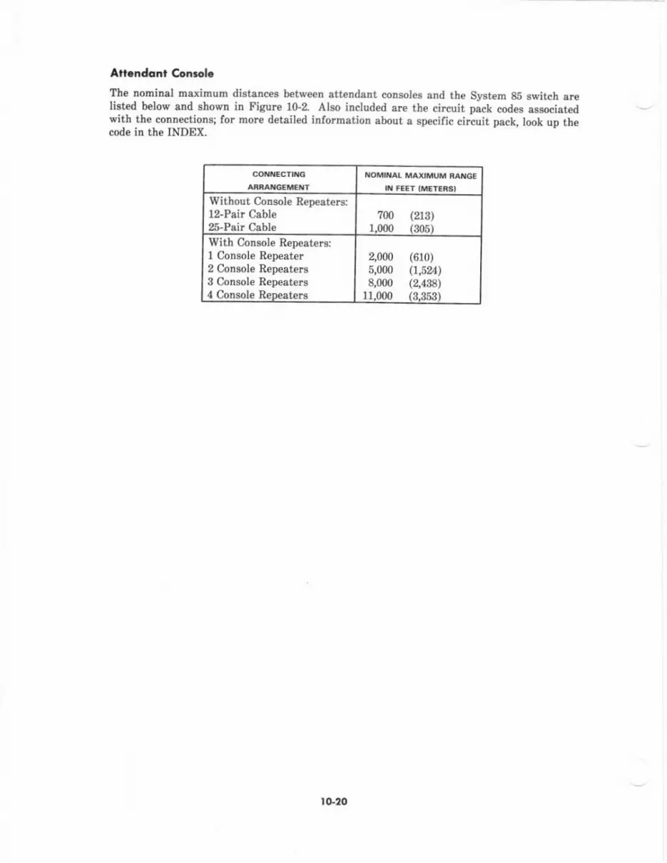
Afi.ndonl Con.ol.
The trominal maximum distances between att€ndant consol4 and the Sj/stem 8E switch srelist€d below and shown in Figure 10-2. Alao included are the circuit pack codes sssociatedwith the connectioN; fo. more detsiled information about a specific cirauit pack, look up thecode in the INDEX.
XOMII'AL MAXIMI'M MI{G'IX FEET IMET'iSI
Without Colrsole Repeaters:l2-Pair Cable25-Pair Cable
(213)(305)
7N1.000
With CoNole Repeatersi1 Console Repeeter2 Console Repeaters3 Console Rep€aters4 Comole R€neaters
2,000 (610)5,000 (1,5%)8,000 (a4:]8)
1r.000 (3.853)
tG20
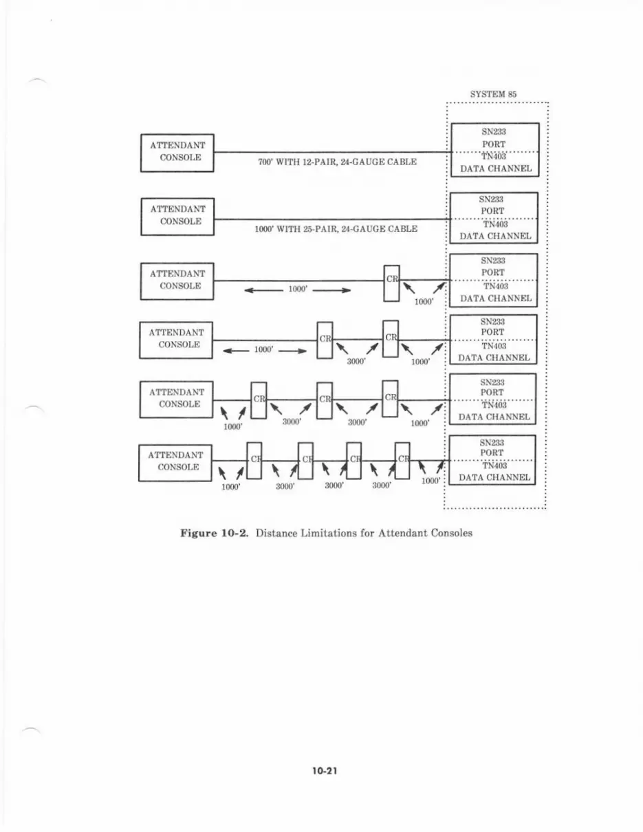
?OO' WITH I2.PAIR, %.CAUGECABLE
rqD' WITIi 26.PAIR. %.GAUGE CABLE
SYSTEM 85
<- 10(n'-,
Figure lo-2. Distance Limitations for Attendant Consoles
tG2l
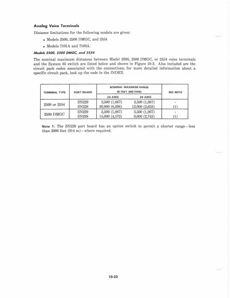
Anolog Voice Terminolc
Distanc€ limitations for the following models are given:
. ModelE 2500,2500 DMGC, and 255a
. Models 71014 and ?103A.
Itod.l. 251m, 25(m Dr,tGC, cnd 2554
The nominal maximum distances between Model 2500, 2500 DMGC, or 2554 voice terminalsand the System 85 switch are listed belorp and shown in F igure 10-3. Also included are thecircuit pack codes associated with the connections; lor more detailed information about aspecific circuit pack, look up the code in the INDEX.
NOMINAL MAXIMUM RANGE
II{ F€ET IMETEBSI SEE NOTE
24 Al/vG
25M or 54SN229sN228
3,500 (1,06?) 3,500 (1,067)20-000 (6-096) 12-ff)0 /3_658) fl)
%OO DMGCsN229SN228
3,500 (1,06?) 3,500 (1,067)15.000 (4.5?2) 9.000 (2.?43) rr)
Noro l: The SN228 port board has an option switch to permit a shorter range-lessthan 3000 feet (914 m)-where required.
to-42
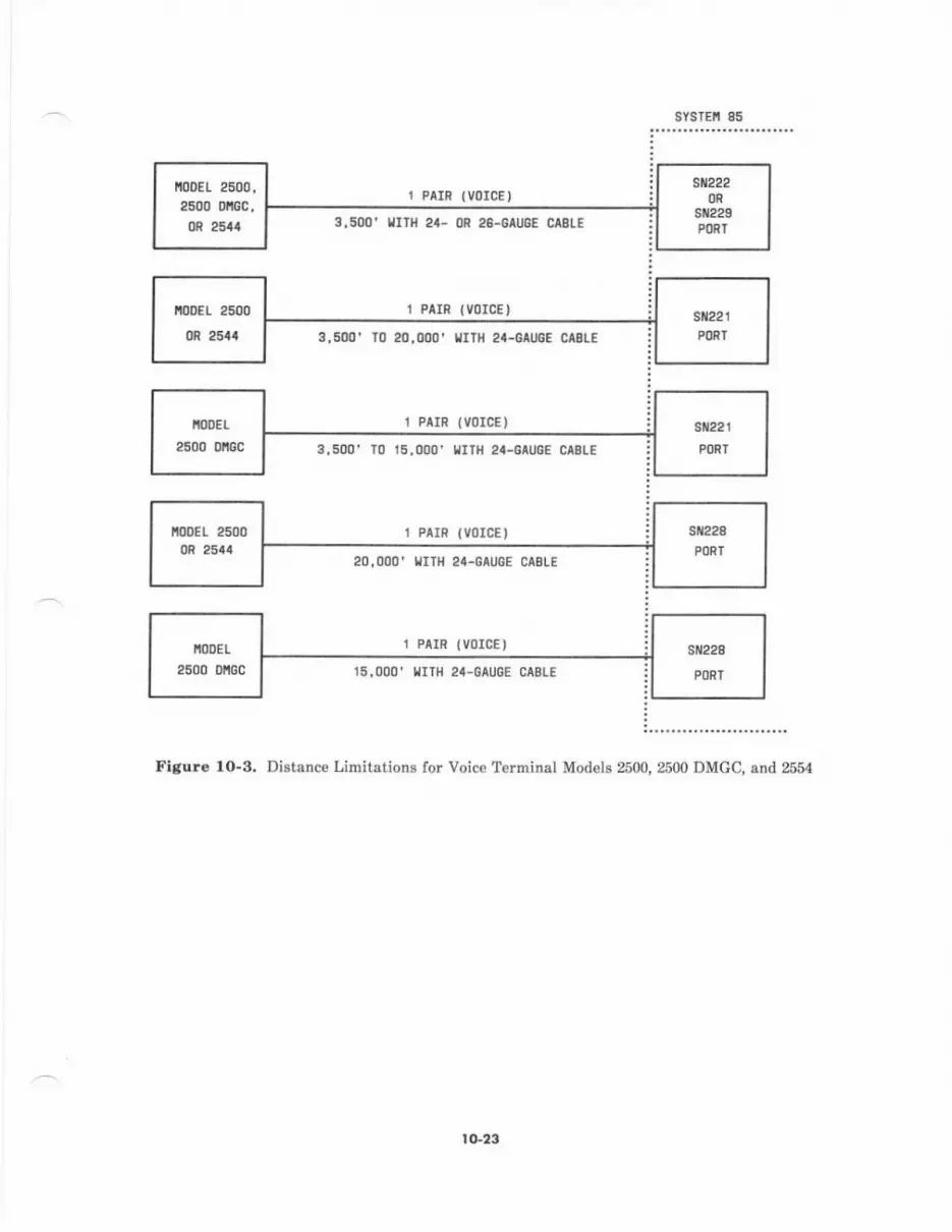
i00Et 2500,2500 orcc,m 25a.t
sYsTEfi 85
1 PAIR {VOICE)
IITI{ 2'- OR 26-GAUGE CABTE
r PrrR (volcE,
T0 20,000' IIT|{ 24-G UGE CtBtE
r P^rR (v0IcE)
3,500' IO 15,OOO' TITH 24-GAUGE CAELE
1 PArR lVoICt)
I{ITI{ z'-OAUGE CABLE
l PAIR (VOICE )
15,000' l,lrrH 24-0au0E CAELE
Flgur€ 1O-3. Distance Limitations for Voice Terminal Mod€ls 2500, 2500 DMGC, and 2554
tG23

Iiod.h TtOtA dnd 7tO3A
The nominal maximum distances between Mod€l 7101A or ?103A
System 85 switch ar€ listed below and shown in Figure 10-4.terminals and the
NOMINAL MAXIMUM RANGE
IN FEET (METERSI
7101A sN229SN228
s,500 (1,067) 3,500 (1,06?)li.o(n (4.5't2) 9.000 12.?43 i (1)
7103A sN229sN228
3,500 (1,067) 3,500 (1,067)15.000 (4.5?2) 9.000 (2.743)'
(2)(1.2\
t{ote t: The SN228 port board has an option switch to permit a shorter range-lessthan 3000 f€€t (914 m)-where required.
trtote 2: Additional power is required when Speakerphone or Headset modul€s arc usedwith the 7103A. It can be provided locally using a 2012D transformer or remotely fromthe satellite closet. The nominal maximum distance from the modular terminal walljack to the satellite closet is 150 feet (46 m) for 24-AWG wire; this maximum is lowerwhen 26-AWC wire is used.
sYstEi 85
1 PAIR {VOICE)
I'lITll 24- 0R 26-GAUGE CABLE
3,500' T0 15,000' LtrTH 24-GAUGE CABLE
1 PAIR (VOICE)
15, OOO' I,JITI{ 24-GAU6E CABLE
Figure 1O-4. Distance Limitations for Voice Terminal Models ?101A and ?103A
IoDEL 71014
0R 71034
fi00E1 710140R 71034
[00E1 710140R 71034
t G24
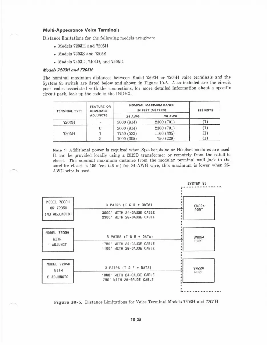
Muhi-Appeoron.e Voice Termincls
Distance limitations for the following models are giv€n:
. Mod€ls 7203H and ?205H
. Models 7303S and ?305S
. Models ?403D,7404D, and ?405D.
tnodelr 72o3H cnd 7205H
The nominal maximum distances between Model 7203H or 7205H voice terminals and theSystem 85 switch are listed below and shown in Figure 10-5. Also included ale the circuitpack codes associated with the connections; for morc detailed information about a specificcircuit pack, look up the code in the INDEX.
Note 1: Additional power is required wh€n Speakerphone or Headset modules are used
It can be provided locally using a 2012D transformer or remotely from the satellitecloset. The nominal maximum distance from the modular terminal wall jack to thesat€llite closet is 150 feet (46 rn) for 24-AWG wire; this maximum is lower when 26-
AWG wire is used.
sYsrE[ 85
NOMINAL MAXIMUM RANGE
II\I FEET IMETERSI
7m}H 3000 1914) 2300 (701) (1)
7m'H01
2
3000 (914) 2300 (701)1?50 (533) 1100 (335)1000 (305) 750l22S)
(1)(1)(1)
3PAIRS{T8R+OAIA)
3OOO' IIITH 24-6AIIGE CABLE
2300' urTH 26-GAU6E CASI-E
3PAIRS(T6R+OAIA)
1750' l,{rTH 2a-GAUCE CAELE
11OO' I,IIIII 26-GAUGE CABLE
3 PAIRS (1 &R.OATA)
1000' I'IITH 24-GAUGE CABTE
750' IIITI'] 26.GAUGE CABLE
Figure 1O-5. Distance Limitations for Voice Terminal Models ?203H and ?205H
l10DEL 7203t1
0R 720511
{ttlo ADJUilCTS)
r,!0DEL 7205H
I,IITH
1 AOJUICT
lG25

od.lr 73035 ond 7m5S
The nominal maximum distances between Model ?3035 or 73055 voice terminals and theSystem 85 switch arc listed below and shown in Figure 10-6. Also included are the circuitpack codes associated with the connectioN; for more detailed information about a specificcircuit pack, Iook up the code in the INDEX.
NOMII{At MAXIMUM FAIIGE
II{ FE€T IMETENS'
?303S 0l
1?00 (5r9) 1000 (s05)1000 (305) 650 (198)
(1)1l)
?305S 01
1000 (305) 650 (198)?00 (2r3) 450 (13?)
(r)(1)
Noto 1: Rang€ may be extended to 2000 feet (610 m) for 24- or 26-AWG wire by addinglocal -48 V dc power in the satellite closet. Power supplies such as the 346A or 329Amay be connected to the fourth pair from the terminals to obtain the increased range.
sYsTEr,r 85
3PAIRS{IeR+0lIA)1000, l,lr]lt 2t-ctucE caELE650' IITH 26-GAUGE CIIIE
3 PAIRS {1 8R+DAIA)
I/ITH 24-GAUGE CABIEIIIH 28-GAUGE CAEIE
Flgure 1O-8. Distance Limitations for Voice Terminal Models ?3035 and ?305S
ItooEL 73035
0R 73055
{t0 aoJulcTs)
ttooEl 7303s
0R 730ss
(1 AoJUI{C])
I 0-26
Irlodah 74O3D, 71tY4 and 71O5D
The nominal maximum distances between Model 7403D,7404D,(740-D) and the System 85 switch are listed below and shown inare the circuit pack codes associated vrith the connectioN; forabout a specific circuit pack, look up the code in the INDEX.
or ?405D voice terminalsFigure 10-7- Also includedmore detailed information
NOMIIIAL MAXIMUM BAITGE
II{ FEET IMETEASI
24 AWG 26 AWG
?403D 3400 (1036) 2200 (6?1) (1.2i
7404D 3400 (1036) 2200 (6?1) (1)
74051) 0-l-or2 3400 0036) 2200 (6711 (1, 2)
Not6 1: Additional power is requir€d when any of the following adjuncts are used with?40-D series voice terminals: Coverage Module, Digital Terminal Data Module (DTDM),Display Module, Function Key Module, Heads€t module, or Speakerphone module.Additionat power can be provided locally using a ml2D transformer or remotely ftomthe satellite closet. The nominal maximum distance from the modular terminal walljack to the satellite closet is 150 feet (46 m) for 24-AWG wire; this maximum is lowerwhen 26-AWG wire is used.
Nots 2: The distances given are nominal maximums. Distances of up to 5000 f€€t lor24-AWG wire and up to 4000 feet for 26-AWG wire arc typical.
SYSTEII 85
2 PAIRS {DCP)
(ilor,tlr{at ) IJITI] z4-GAUGE CASIE(toNIilAT) IIIIH 26-GAUGE CABIE
2 PAIRS IDCP)
5000' (Typtcat) LrTll 24-GAU6E CABLE
4OOO' (IYPICAL) I,IIIII 26.GAUGE CABLE
Figure lO-7. Distance Limitations for Voic€ Terminal Models ?403D, ?404D, and ?405D
?40_D I'!0DE!S
IITH OR
I,IITI{OUT ADJUI{CIS
740-0 [oDELS
IIIIH OR
IIIIHOUT AOJUI{CTS
to-27

Dalo Te.mindl3
Distance limitations for the following data te?minals arc given:
. 515 BCT and Per€onal Terminal5l0D
. 513 BCT (or any othe" EIA RS-232C data terminal).
It4od.h 515 BCf and 5l(DThese models are voice/data t€rminals which means that in addition to being data terminals,they also have the voic€ terminal capabilities found in the ?40_D series voice t€rminals. Thenominal maximum distances between the 515 BCT or the 510D and the System 85 switch arelist€d below and shown in Figure 10-8. Also included are the circuit pack codes associatedv,/ith the connections; for more detailed information about a specific circuit pack, look up thecode in th€ INDEX. If optional printers are used, see distance limitations for electricalinterfaces in this se.tion.
NOMIITAL MAXIMUM BANGE
IIV F€ET IMETERSI
515 BCT 3400 (1036) 2200 (671t (1. 2. 3)510D s400 (1036) 2ZN (671\ (1. 2. 3)
Nor6 1: Th€se terminals plug into 117-V 60-Hz 3-wirc grounded outlets.
Nore 2: The distances given are nominal maximums. Distances of up to 5000 leet for24-AWG wirc and up to 4000 feet for 26-AWG wire are typical.
Note 3: Both models have a parallel printer, manulactured by Centronics DataComputer Corporation, interface v,/ith a distance limit of 10 feet. The 51b BCT also hesan EIA RS-232C se al p.inter interface (nominal distance limit is 50 feet).
SYSTEI'I 85
2 PAIRS (OCP)
3400' ([o[ rat)2200' ( o[ tal)
z4-GAIJGE CAEIE26-GAUGE CAELE
TITHl,tITH
2 PArRS {oCP)
5OOO' (TYPICAL) I'IITH 24-GAUGE CABIE4000' (TYPICAL) IIIIH 26-0AUGE CAS|E
Figure l0-8. Distance Limiiations for the 515 BCT and lhp 510D
t0-28
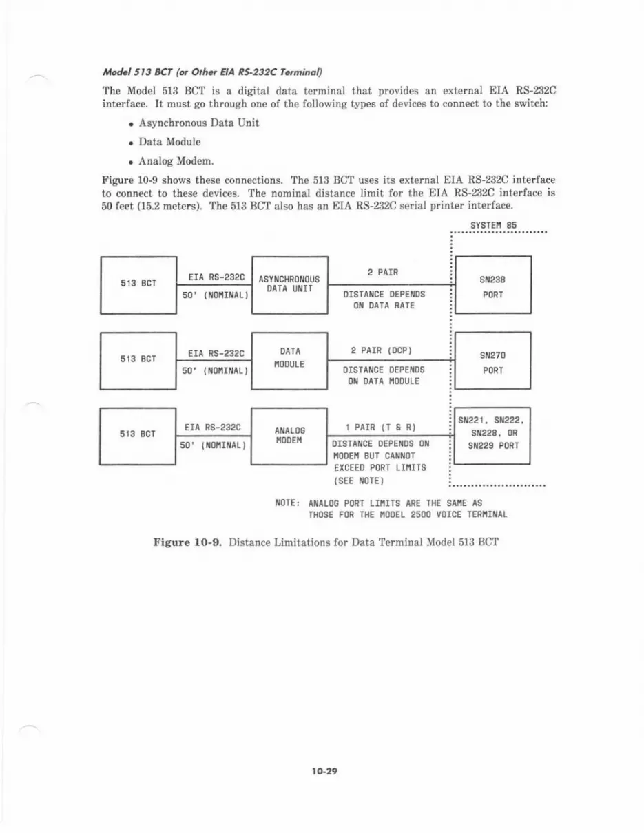
Jtted.l Sr3 BCf (q O.h., HA RS-232C fqnineq
The Model 513 BCT is a digital drta terminal that provides an external EIA RS-232Cinterface. It must go through one of the following types of devic€s to connect to the switch:
. Asynchronous Data Unit
. Data Module
. Analog Mod€m.
Figure 10-9 shov,s these connections. The 513 BCT uses its external EIA RS-232C interfaceto connect to these devices. The nominal distance limit for the EIA RS-232C interface is50 feet (15.2 meters). The 513 BCT also has an EIA RS-232C 6€rial printer interface.
sYsrEi 85
Era ns-292c 2 FAIR
s0'(tiot{flilaL)
EIA FS-232C
50'{ ofiItrlaLl
Eri Rs-232C
DISTAI{CE DEPEIIDS
OII DATA NATE
2 PAIR (DCP)
OISIAiICE DEPENDS
OII DATA IIOOULE
1 PAIR 1T E R)
oIsTAitcE oEPElllos oilIITODEII BUI CAI{IIOT
EXCEED PORT L]IlITS(SEE IIIOTE}
50'(ilotll At)
t01E: Aillloc PoRT lIrlIIS ARE TliE SAiE lSIIIOSE FON THE NOOEI 25OO VOICE TERI'IIIAL
Figure lO-9. Distance Limitations for Data Terminal Model 513 BCT
ASYIICHROIIIOUSDATA IIIIII
st{22r, si222,sil228, 0R
sir229 PoRT
I t'"20
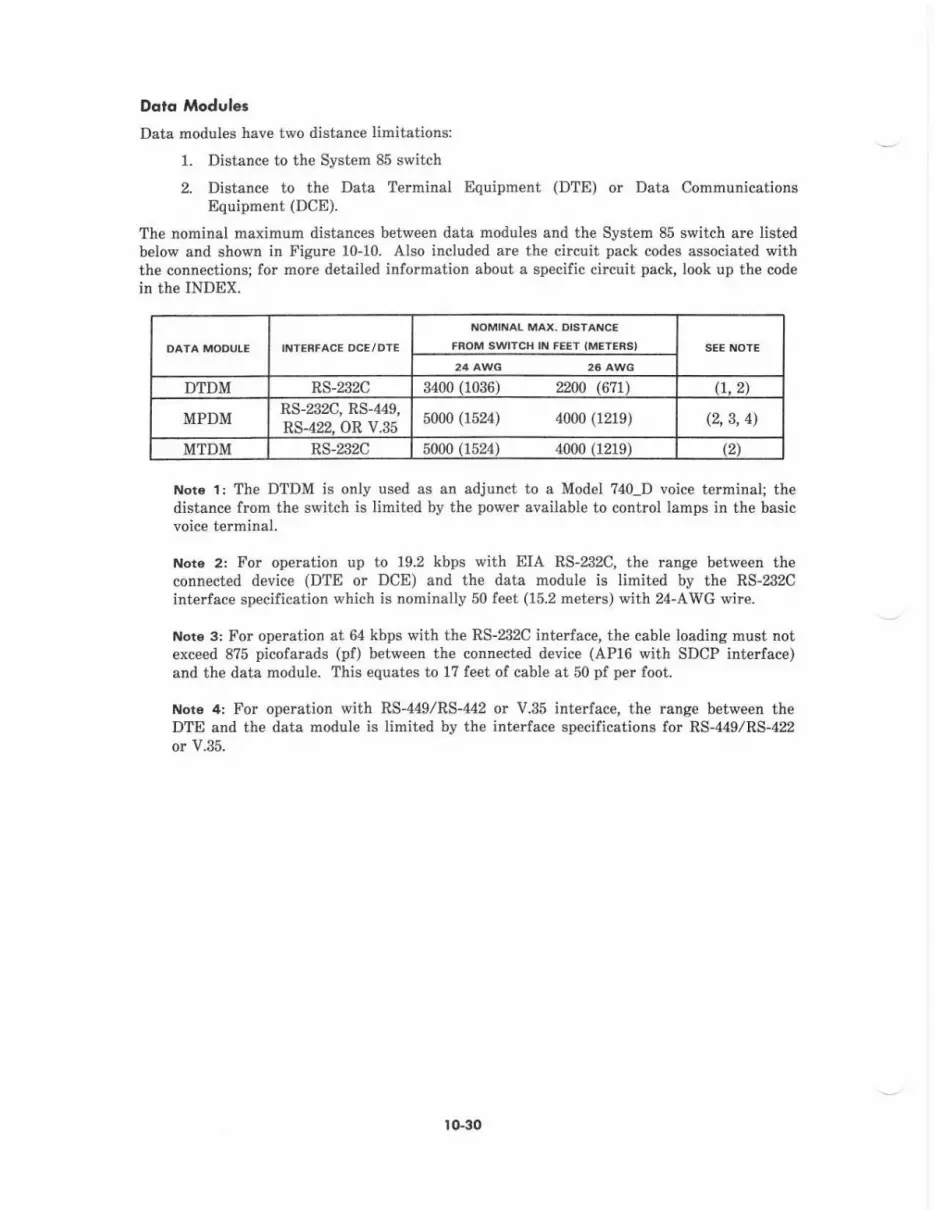
Doto Modulec
Data modules have two distance limitations:
1. Distance to the System 85 switch
2. Distence to the Data Termidal Equipment (DTE) or Data CommunicationsEquipment (DCE).
The nominal maximum distances between data modules and the Syst€m 85 switch ar€ listedbelow and shown in Figur€ 10-10. Also included are the circuit pack codes associated withthe connections; for more detailed information about a sp€cific circuit pack, look up the codein the INDEX.
NOMINAL MAX. DISTANC€
FAOM SwlTCH IN F€ET IMElEf,S}
24 AWG 26 AWG
DTDM RS-232C 3400 (1036) 22tr0 (671\ (1, 2)
MPDMRS-232C, RS-449,RS-422. OR V.35
5000 (1524) 4000 (1219) (2, 3, 4\
MTDM RS-232C 5000 11524 ) 4000 (1219) (21
Note 1: The DTDM is only used as an adjunct to a Model ?40_D voice terminal; thedistance from the switch is limited by the power available to control lamps in the basicvoice terminal.
Noto 2: For op€ration up to 19.2 kbps with EIA RS-232C, the runge between theconnected device (DTE or DCE) and the data module is limited by the RS-232Cinterface specification which is nominally 50 leet (15.2 meters) with 24'AWG wire.
t{ote 3: For operation at & kbps with the RS-232C interface, the cable loading must notexceed 875 picofarads (pf) between the connected device (AP16 \rith SDCP interface)and th€ data module. This equates to 1? feet of cable at 50 pf per foot.
Nor6 4: For operation with RS-449/RS-442 or V.35 intedace, the range between theDTE and the data module is limited by the interlace specifications for RS-449/RS-422or V.35.
lo-30
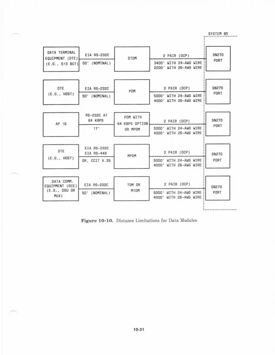
DATA TERI,IITAL
EQUIPIIEIIT (D]E )(E.G., 513 BCT)
sYsTEi 85
EIA RS-232C
EIA RS-232C
50'lr/0 It/aL)
3400' ltrTH 24-Al,lG llrRE22OO' I,IIIH 26-AIIG IIIRE
2 PAIR (OCP)
2 PAIR (DCP)
2 PAIR (OCP)
2 PAIR (OCP)
l,lITll 24-Allc IIIREl,lITll 26-Al,lc LIIRE
2 PAIR (DCP)
IIITH 24-ALlG IiIREI'IITH 26-AI.IG IIRE
5000' {ITN 24-AllG l,lIRE
4000' IIITH 26-Al,lG l,llRE
5000' IrTlt 24-Al,l0 r/rRE4000' IIITH 26-AlrG nrRE
EIA RS-232CEIA RS-449
0R, ccrT v.35
EIA RS-232C
s0'(flo{rflAr)
Figure lO-lO. Distance Limitations for Data Modules
PDI'I IITH(BPS OPTIOIII
0R llPDfi
0ala cot .
EQUIPI'IEIIIT {OCE)(E.G., DSU OR
fiuxI
tG3t
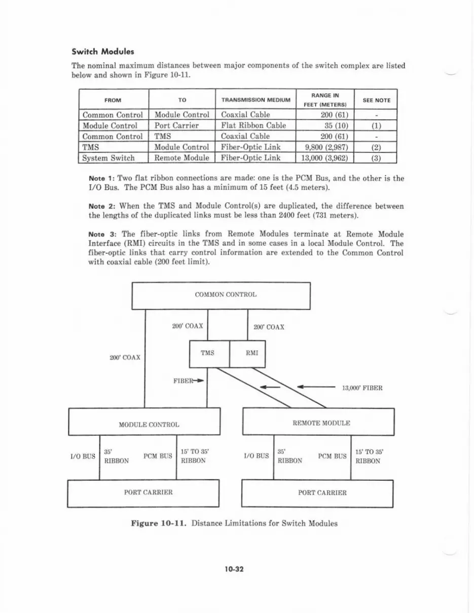
Swirch Modulcr
The nominal maximum distances between major components of the switch complex are listedb€low and shown in Fignre 10-11.
TRA'{SMFSION MEOIUM
Common Control Module Control Coaxial Cable 200 (61)
Module Control Port Carrier Flat Ribbon Cable 35 110) r1)
Common Contrcl TMS Coaxial Cable 200 (61)
TMS Modul€ Control Fiber-Ootic Link 9.800 (2.98?) (2)
Svstem Switch Remote Module Fiber-ODtic Link 13.000 (3.962) (3i
Noi6 1: Two flat ribbon connections are made: one is the PCM Bus, and the other is theI/O Bus. The PCM Bus also has a minimum of 15 feet (4.5 met€Is).
Not6 2: When the TMS and Module Control(s) arc duplicated, the difference betweenthe lengths of the duplicated links must be less than 2400 feet (731 meters).
Noto 3: The fiber-optic links from Remote Modules terminate at Remote ModuleInt€rfac€ (RMI) circuits in the TMS and in some cases in a local Module Control. Thefiber-optic links that carry conhol information are extended to the Commor Controlwith coaxial cable (200 f€€t limit).
200 coAx
2,0'coAx
13,OOO'FIBER
I/O BUS I/O BUS
Figure 10-ll. Distance Limitations lor Switch Modules
,)0 coAx
FIBFIR->
35' pcm gusRIBBON i1""o" PcM BUs
PORT CARRIER PORT CARRIER
rG32
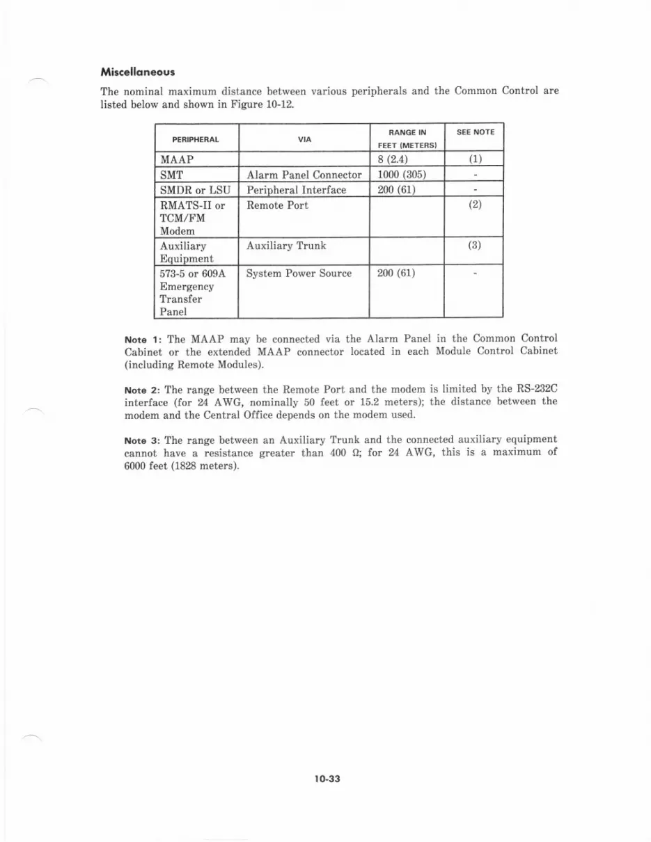
Miscelloneoos
The nominal maximum distance between various peripherals and the Common ControlIisted below and shown in Fisur€ 10-12.
SCE iIOTE
MAAP 3 (2.4\ (1)
SMT Alarm Panel Connector 10{n 1905)
SMDR or LSU PeriDheral Interface 200 (61)
RMATS-II orTCM/FMMod€m
\2)
AuxiliaryEquiDment
Auxiliary Trunk (3)
5?3-5 or 609AEmerg€ncyTransferPanel
Syst€m Power Source 200 (61)
Not€ l: The MAAP may be connected via the Alarm Panel in the Common ContrclCabinet or the €xtend€d MAAP connector located in each Module Contrcl Cabinet(includins Remote Modules).
Note 2: The range betw€en the Remote Port and th€ modem is limited by the RS-232Cinterface (for 24 AWG, nominally 50 feet or 15.2 meters); the distance between th€mod€m and the Central Office depends on the modem used.
Noto 3: The range between an Auxiliary Trunk and the connected auxiliary equipmentcannot hav€ a resistance greate. than 400 0; for 24 AWG, this is a maximum of6000 feet (1828 meters).
ro-33

sYsTE[ 85
llrlt{ 2t-GtuGE ctStE
50' I loltrxar-,
T0 c0 tUtE c(TFoR tccEss
TO/FROII RIi'IIS-II0R
^P TCll/FIl
Figure 10.I2, Distance Limitations for Miscellaneous Peripherals
str23lAUXILIARY
TRUI! (
lG34
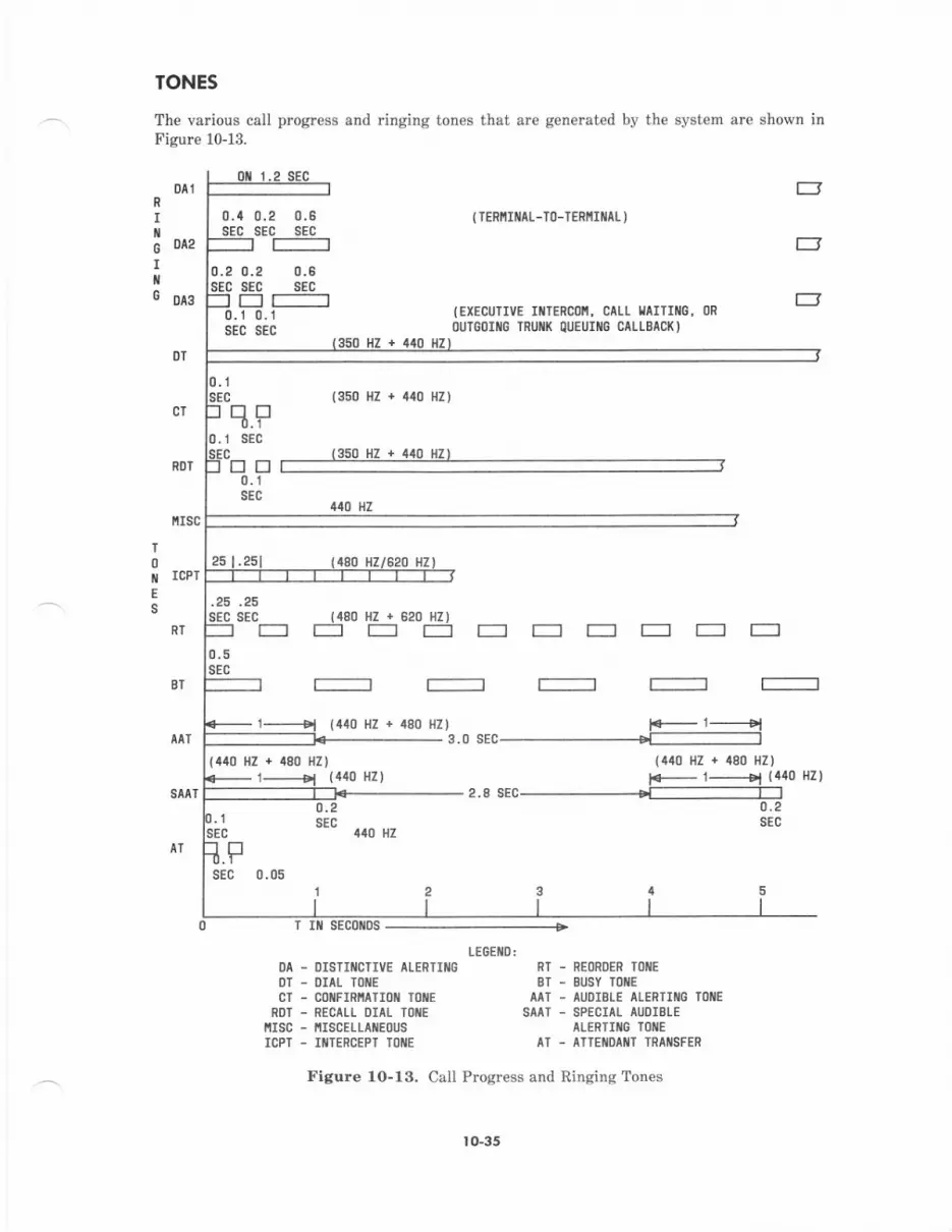
TONES
The various call progress and ringing tones that are generat€d by the system are shown inF igure 10-13.
DAI
0.4sEc
R
III0 042
IiiG olg
T
0IE
s
0.2 0.6sEc sEc
0.2 0.2 0.6sEc sEc sEcE r--------
0. 1 0.1sEc sEc
.25 .25sEc sEc
{440 t{z + 480 HZ)
( TERIIIIIAL-T(]-TERIIIIIAL )
={EXECUTIVE IIITERC()II, CALL I,IAITIIIIG,OU'G()IIIC TRUil( OIJEUIIIG CALLEACI()
rsc
ICPT
RT
BT
SAAT
0.1sEc
(480 HZ + 520 HZ)E]EE--E--EE
{350 flZ + 440 UZ)
440 HZ
(440 HZ){440 HZ + 480 HZ)
F- 1------el (140 Hz)
0.5sEc
1------tl (410 HZ + {80 HZI F- 1------1El3.0SEC---------------'T-------------
LFsEc 0.05
0.2sEc
410 HZ
'|
2.8 SEC -.----T--]0.2sEc
T Illt sEco[Ds
TEGEilD:DA . OISTITCTIVE ALERTIIIG NT - REOROER TOIIE
OT - OIAT TOIIIE BT . BUSY IOIIECI - COIIFIRIIAIIOII I0 E AAT - AUDIELE AIERIIIIG TOIIE
RDT - RECAIL DIAL TOIIE SAAT - SPECIAL AUOISLEI'ISC - IIISCELLAIIEOUS AIERTIIIG TOIIE
ICPT . IiITEFCEPT IOIIE AI - ATTEIIOIIIIT TRAIISFER
Figure 10-13. Call Progr€ss and Ringing Tones
to-35
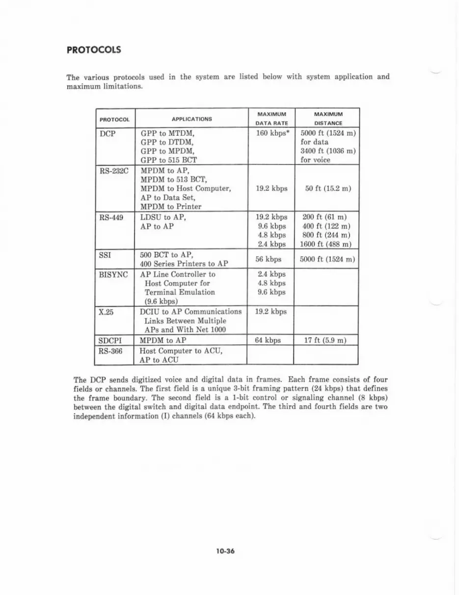
PROTOCOTS
The various protocols used in the system are list€d b€low with system application andmaximum limitations.
DCP GPP to MTDM,GPP to DTDM,GPP to MPDM,GPP to 515 BCT
160 kbps* 5000 ft (1524 m)for data3400 ft (1036 m)for voice
RS-232C MPDM to AP,MPDM to 513 BCT,MPDM to Host Computer,AP to Data Set,MPDM to P nter
19.2 kbps 50 tt (15.2 m)
RS-{49 LDSU to AP,AP to AP
19.2 kbps9.6 kbps4.8 kbps2.4 kbDs
200 ft (61 n)400 lt On m)800 ft (244 ln)
1600 ft (488 m)SSI 500 BCT to AP,
dOo Series Printers to AP 56 kbps 5000 ft (1524 m)
BISYNC AP Line Controller toHost Computer forTelminal Dmulation(9.6 kbDs)
2.4 kbps4.8 kbps9.6 kbps
x.25 DCIU to AP CommunicationsLinks Between MultipleAk and With N€t 1000
19.2 kbps
SDCPI MPDM to AP 64 kbos r? ft (5.9 m)RS-366 Host Computer to ACU,
AP to ACU
The DCP sends digitized voice and digital data in frames. Each frame consists of fourfields or channels. The lirst field is a unique 3-bit framing pattern (24 kbps) that definesthe flame boundary. The second field is a l-bit control or signaling chann€l (8 kbps)betvreen the digital switch and digital data endpoint. The third and fourth fields sre twoindep€ndent information (I) channels (& kbps each).
lG36
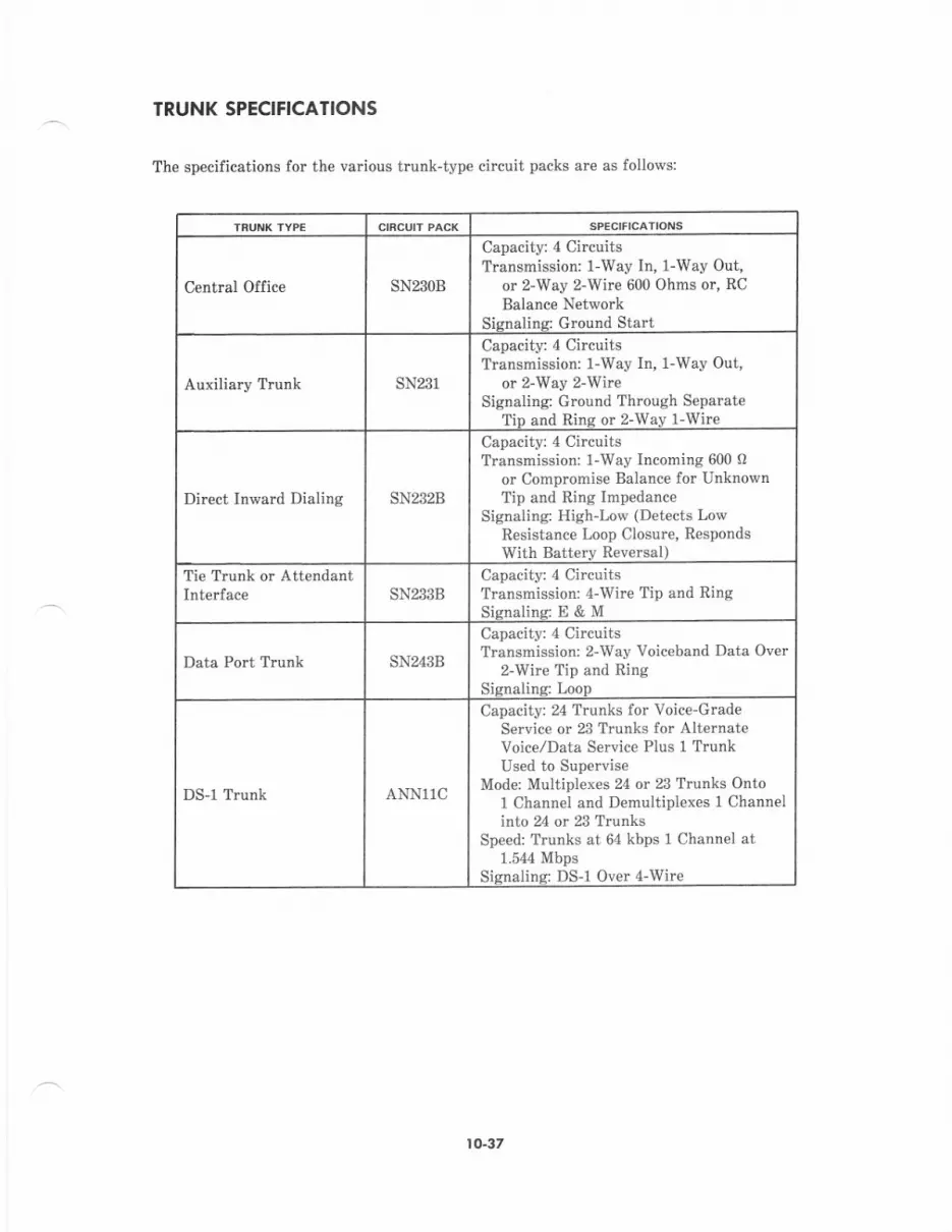
TRUNK SPECIFICATIONS
The specifications for the various trunk-type circuit packs are as follows:
Centml Office SN23OB
Capacity: 4 CircuitsTransmission: 1-Way In, 1-Way Out,
o. z-Way z-Wire 600 Ohms or, RCBalance Network
Sisnaline Ground Start
Auxiliary Trunk SN291
Capacity: 4 CircuitsTransrnission: l-Way In, 1-Way Out,
or 2-Way 2-WireSignaling: Ground Through Separate
TiD and Rinq or 2-Wav l-Wire
Direct Inward Dialing SN232B
Capacity: 4 CireuitsTransmission: 1-Way Incoming 600 o
or Compromise Balance for UnknownTip and Ring Impedance
Signaling: Hieh-Low (Detects LowResistance Loop Closure, R€spondsWith Batterv Reversal)
Ti€ Trunk or AttendantSNA$B
Capacity: 4 CircuitsTransmission: 4-wire Tip and RingSisnalins: E & M
Data Port Trunk sN243B
Capacity: 4 CircuitsTransmission: 2-Way Voiceband Data Over
2-wire Tip and RingSionalins: Loon
DSI Trunk ANN11C
Capacity: 24 Trunks for Voice-Grad€SeNice or 23 Trunks for Alt€rnateVoice/Data Service Plus 1 TrunkUsed to Supervis€
Mode: Multiplexes 24 or 23 Trunks OntoI Channel and Demultiplexes 1 Channelinto 24 or 23 Trunks
Sp€ed: Trunks at 64 kbps 1 Channel at1.544 Mbps
Sisnalins: DS-1 Over 4-Wirc
I O-37
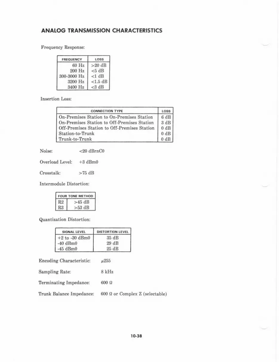
ANAI.OG TRANSMISSION CHARACTERISTICS
Frequency Respons€:
LO33
60 HzN0 Hz
300-3000 Hz8p,mHz3l/l0Hz
>20 dB<5 dB<1 dB<1.5 dB<3 dB
Ins€rtion Irss:
R2 I >45 dBR.9 I >53 dB
Nois€: <20 dBrno0
Overload Level +3 dBmo
CrGstelk >?5 dB
Intermodule Distortion:
On-Premises Station to On-Premides StationOn-Premises Station to Off-Premises StrtionOff-Premises St.tion to Off-Premiseo StationStatiotr-toTrunkTrunk-to-Trunk
6dB3dB0dB0dBodB
Quantization Distortion:
+2 to -30 dBmo-40 dBno-45 dBmo
35 dB29 dB%dB
Encodingcharact€listid p255
Sampling Rate: 8 kHz
Terminating Impedanc€i 600 o
Trunk Balance Impedancei 600 o or Compl€x Z (selectabl€)
rG36

POWER CONSUMPTION, CIRCUIT BREAKER REQUIREMENTS, FI.OORI.OADING, AND HEAT DISSIPATION
AGPowered Syrtem:
The following table provides statistics olr the dc watt power consumption, circuit brcakerr€quirements, weight and maximum dissipation for the vadous System 85 and relatedequipment based on Price Element Code (PEC). The dc watt and BTU/Hour values providedIor TMS, Modul€ Contrcl, Port and Common Conttol cabinets include required cabinet andcarrier values only. Values for Port, DS-1, TMS Grortth, and Remote Module Interfacecardem are provided sepamtely. These values apply to ac-powered systems.
casNEr/CAITIER
DC StNCtE- OOUBII- WEIGHT M X.
walts PoLE PotE (1B5.) lrulHR,PEI lnEAXEIs ITCAKE's PEI PCI
UNIT 'ER
UNII PET UNII UNIT UNI'
6552-CSD DuplicatedCommon CtrlCabinet
6552-MCU UnduplicatedModule CtriCabinet
6552-MCD Duplicat€dModule CtrlCabinet
6552-CSU
65310
65311
65340
UnduplicatedCommon CtrlCabinet
TMS CrowthCa ier
750 2110
750
?50 3525
750 4500
680
1200
370
5050
Port CabinetWith Power
Port CabinetWithout Power
Port Carrier
6',t0
xn
750
750
340
1900
s590
580
?80
215
340
750
750
130
r30
240
240
290
380
65941 DS-1 Carrier
6552-TMU UnduplicatedTMS Cabin€t
6552-TMD DuplicatedTMS Cabinet
65302
| 0-39

cat$d
DC 9INGIE.
Pat atE^tcts
DOUBII. WEIGHI MAIPOl: Gas.) 3tU/Hr.O'EAI(E! PEI P'I
'Et UNII
40065389 Remote Mod.InterfaceCarrier
Aux. Cebinet
APl6 Cabinet
65210
cattNE /cattlEl
ll60
65445 600
rffxl
5{X)
600
600
1360
2560
1000SMDR Cabinet 400 1
(g-Track)
* Check "AT&T-IS Price Element Manual" lor PEC-
-48 V DC Stdndby Powered Sy3tems
The following table provides information on tbe dc watt power consumption, circuit breakerrcquirements, weight, and meximum heat dissipetion for the various System 85 and r€lat€dequipm€nt based on Price Element Codes (PECa). The DC Watt and MU/Hour valuesprovided for TMS, Module Control, Port and Common Control Cabinets include requiredcabinet and cauier values only. Values for Port, DS-l, TMS Growth, and Rernote ModuleInterface carriers are provided separately. These values apply to -48 V dc standby poweredsystems.
OC 5INGIE- DOUUE WEIGHI MAX.warrs rorE rolE (185.) !ru/Hn,PEr atlAr(Ers aIE (ats rEt PatUNI' ?Et UNII PEI UNIT UNII UNII
6552-CLU Unduplicatedcommon CtrlCabin€t
6552-CLD DuplicatedCommon CtrlCabin€t
6552-MLU UnduplicatedModule CtrlCabin€t
6552-MLD DuplicatedModule CtrlCabinet
12U)
680
3?0
7fi 2110
?50 4200
7fi 1300
?50 2340670
65312 Port Cabinet
Port Carrier
215130
24065340
l0-{0
750
340

cAdNE /CAIIIER
DC 5tNclt- DOUttE-$ratts PorE rollPEI BIEAX'Ns BIEAXETSUNII PER UNII
'ER UNII
{LBS-) BTU/HT.
UNII
65341
6552-TLU
6552-TLD
65302
DS-1 Canier
UnduplicatedTMS Cabinet
Duplicat€dTMS Cabinet
TMS GrowthCard€r
o
2p02
380
2(n
u0
1015
1330
580
1160
?50
?50
65389 Remote Mod. 400Int€rfaceCar er
65445 Aux. Cabinet 300 1
(-48 V dc input)
65u5 Aux. Cabinet 600 1
(AC input)
* APl6 Cabinet 1000 1
(AC input)
65210 SMDR Cabin€t 400 1
(9-Track)(AC input)
* Check "AT&T-IS Price Element Manual" Ior PEC.
500
500
1000
1360
2560
1000
600
600
lG4l
EQUIPMENT ROOM ENVIRONMENTAT CONSIDERATIONS
l.mp.roiure ond Humidity
The equipment room environment has a substantial effect on the overall op€rationalavailability of any syst€m. Syst€m 85 has been designed to operate in a broad renge of€nvironm€ntal conditions. But, to minimize downtime the equipment rcom environmentshould be kept within the recomm€nded opereting tang€ shown below- Not doing soincressB the likelihood of equipment failure and causes additional maintenance servicingb€yond that anticipated for AT&T maintensnce contracts.
Rcconn €na.d Conthuous Opcrathg RdDge
Temperetur€: 65"F to 85'F Ambient Room TemperatureHumidity: 20% to 60% Relative Humidity
Short-Term Maximum Operational Limits:
40'F with 15% to 95% relative humidity120'F with 157. to 34% relative humidity
Recommended continuous operating ambient temperatu.e and relative humidity must bemeintained 24 houls a day, ? days a week. Ambient temperature is determined at a distanceof 5 feet (1.5 m) above the floor after the equipment is in operation. Normally an eir-conditioning system {'ill be required to keep th€ equipm€nt room envimnment within the.€commended op€rating limits throughout the year. The air-conditioning system must beable to remove the maximum amount of heat dissipated by the system-
Mcchonicql lequiremenla
H€re are some other requirements for the equipm€nt room:
. Width of doorways and stairways must be sufficient to p€rmit the movement olassembled €quipment frames or cabinets. Minimum width is 3 feet (0.9 m).
. Floors must be level within 1/8 of an inch (3 mm) over 8linear f€et (2.? m) and b€free of excessive viblation.
. Cover the equipm€nt room floor with tile, linoleum, or sealer (paint) to provid€ adurable, dust-free surface. Carpet rnay be used but should be antistatic or treatedwith antistatic ch€micals.
. Walls and ceiling are to be sealed, dust-free, and of a suitable light color to eidillumination. T\rrpentine must not be used for thinning paint or for any otherpurpose in equipment arcts.
. Illuminate the equipment and attendant areas uniformly. Lighting fixtures must beatove the maximum height of equipment and essociated cabling. And, provide30 foot-candles 3 f€et (0.9 m) above the floor for the equipment area. The lightswitch which controls Iighting for the equipm€nt area must be readily accessible.
. Fire prot€ction sprinkler heads, if installed in the equipment area, shall be arrangedto operate at 212'F or high€r temp€rature.
10-42
. Water atrd drain pipes within the equipment ar€a must be fittrd with drip pans.
. When a standby power plant with wet storage batleries is installed, theenvironmental requirements may become more shingent. Additional ventilation mayalso be required in accordanc€ with national, state, and local codes.
. Equipment area floor strength must be sufficient to calry the equipment Ioads asindicated.
Mircclloneour Rcquircmcnts
The following sre miscellaneous requirements for System 85:
. Th€ €quipm€nt area must be lree of excessive electromagnetic rsdiation emanatingfrom such sources as radar transmitters, Iadio communications equipmedt, X-raydevices, nonsynchronous motors, etc. The System 85 radio frequency immunity is:
rrEQrre{cY t^tacE rrt^)(llrtt M tNttN5ttY100 kllz to 40 MHz ? Volts per Meter40 MHz t! 200 MHz 5 Volts pei Meter
. Copying machines must not b€ in the switching equipment area. The area allocatedto system equipment is dedicated fo! this purpose only. It is not to be used fo!stoBge of materials or for work operations that could damage or interfere with th€operation of digital electrodic equipm€nt.
. Secured storage for equipment shall be provided before end during installation.
. During installation, the foliowing ehall be performed:
a- Air conditioning/heating lor equipment room.
b. Access into work arer (equipment snd storage)
c. Toilet facilities for installation personnel.
. It is the customer's responsibility to provide and maintain portable fire extinguishersp€r National Fire Protection Association (N.F.P.A), Volume No. 10.
tGa3
INSTALLING SYSTEM 85 AT CONSTRUCTION SITES
When customer premise communication systems, such as System 85, are installed on
construction sites or when construction activities take place near customer-owned or leased
switching equipment, therc is considerable risk of contaminating the equipment. This can
cause damage to the equipment, resulting in s€rvice cut delays and additional cost to thecontractors and the customer. lable l0-F specifies some of the more common contaminationhazards found on construction sites
Ideally, customer prcmise switching equipment should not be installed until all constructionactivities arc compl€ted. In cases where this is unsatisfactory to the customer, equipmentinstallation may begin when:
1. The equipment rcom itself is complete with a prcperly filt€red, dry air supply.
2. Construction activities in the immediate surroundings (the areas adjacent toequipment room entrances) arc complete. In the event that changes in or near theequipment mom must be made, it is essential that the equipment already in place
b€ adequately protected.
If the equipment rcom might b€ subject to contamination, the following steps should be
taken to protect the equipment.
l. Pktstic enclosure: A temporary enclosure surrounding the equipment should be
built. Any sawing or other particle-producing activity related to this should be
done outside the equipment room. Further, if it is at all possible for wat€I to €nterthe equipment room through the roof or ceiling, a waterproof covering over the topshould be provided. Water can, and fr€quently does, travel horizontally on theunderside of a ceiling to fall on equipment not directly under th€ point of entry.The covering must be placed with proper regard for how the wat€r is to run off.
When airbome contamination is possible, such as id the presence of welding smoke(or any other activity that produces a visible haze in the air), the enclosure mustbe completely sealed (with waterproof tape if necessary). This armngement willprcvent airbome particles from entering the enclosure.
Il the equipment v,ill be operating, then the enclosure should be prcssu zed withfiltered dry air. The air supply should meet the rcquirements for equipmentcooling detailed in this manual. It is highly recommended that if watercontamination is possible, the equipment should be turned off to prcvent thepossibility of electrolytic corrosion.
2. Cledn up The equipment room and the exte or of the temporary enclosure shouldbe thoroughly cleaned b€forc it is removed. A vacuum cleaner and brushes shouldbe used. The vacuum cleaner should be of a typ€ that removes particles from itsairstream by both impaction and filtration. This is to prevent contamination fromrcentedng the air. If any contaminants have entered the equipment, especiallywater, consult the servic€ organization.
l0-{4

TABLE 1o-F. Contemidation Hazards
DANG'I IO 3(X'IPMEN'
Concret€ dust Concret€ srindins
Dust and fibers can penetrate connectorscausing:
. A..plerrtpd wear dnp fo its ahr2rivc rzlnrp
Plast€r dust Dry wall and ceiling tileinstallation
Fiberglass lnsulation for walls andducts
Organic and Insulation, carp€tinstallation, and ceiling til€installation
. Open circuits (sometimes int€rrnittent) dueto nonconducting properties.
Rock wool InsulationMetal particles Duct work, welding, torch
cutting, and metal worksuch as filing, drilling, andgrinding
Particles arc abrasive and conducting, and canbridge conductors to cause shorts. Iron andsteel particles are attracted to magnetic fieldsand high-voltage areas. Welding is especiallyhazardous because welding smoke condensesinto largc numbers of small melal sphereswhich can form long filaments vrhen
Chemicals andpetrol€umproducts
Leaks through roof andbroken pipes
Water ent€ring equipment usually containssufficient ionic compounds to cause damage byelectrolytic corrosion. Turning oll power willhalt the process until cleanup can be done.Buildins wiring can also be affected byel€ctrclvtic corrosion.
Flooding of surrounding
De-icing and concretecuring
Dust in equipm€nt, in the presence of highhumidity caused by local floodin& can attractwat€r in the air and combine with it to formelectrclytic solutions.De-icing and concrete curing compounds canact with water to form electrolytic aolutions.See comments about water.
Concrete finishing Concrete linishing is typically done with acidsthat can corrod€ €quipment and buildingwiring.
Conbustion Combustion products can be corrosive toeoDiDment and connectors.
Fuel storage Fuel near equipment can leave deposits onconnectors and relays. These deposits will intime oxidize, forming a nonconductive coatingcausing intermittent problems. Also, fueldenosits attract dust.
Oil base paints Painting Vapors may cause damage to plastic and
I G45
EQUIPMENT DESIGNATIONS, TERMINATION FIEIDS, AND REFERENCEPOINTS
Cobin.t D.tignotion ond Nombeiing
The System 85 cabin€ts fall into three categories: (a) system cabinets, (b) network cabinets,and (c) special function cabinets.
Sytlcn CabhaltSystem csbinets are delined as TMS and duplicated common control cabin€ts. Thesecabinets are assigned to module 99 and are designated as TM990l, TM9902, and CC9900.
Netv,/ork cabinets are cabinets which may be equipp€d $ith port caniers, i.e.,nonduplicated common control, module control, and port cabinets. Th€ general formatfor designating a system or a network cabin€t is:
z-letter cebin€t code2-digit module number2-digit cabinet number.
For example, PP0102 r€fers to a port cabinet with power (PP), in the second module(01), and is th€ third cabinet (02) in th€ second modul€. (The code 00 refers to the firstmodule or cabinet.)
Spcciol Fu,rction Cobin ts
Special function cabin€ts are Auxiliary, Applications Processor, and SMDR cabinetswhich are identified by their cabinet code and a 2-digit number beginning with 00 sndincr€meDted s€quentially by on€. For example: AUX00 refers to the first Auxiliarycabinet-
Figure 10-14 provid€s deteils on all cabinet designations and numbering.
T.itninolion Ficldr qnd R.f.r.nc. Poinl D..ignoliont
Relesse 2 of System &5 may rcquire multiple termination field reference points. This isnecessary in order to calculete accurate cabinet to termination field cable lengths. Th€termination fields may be located on more than one wall or frame and may v|ry inconliguration.
Terminstion fields provide acc€ss points to cross-connect trunk fecilities and externalterminal equipm€nt to System 85 interfaces. For detailed information on t€rmination fields,refer to S€ction 3, SYSTEM HARDWARE, under SYSTEM INTERCONNECTIONS.
rG46
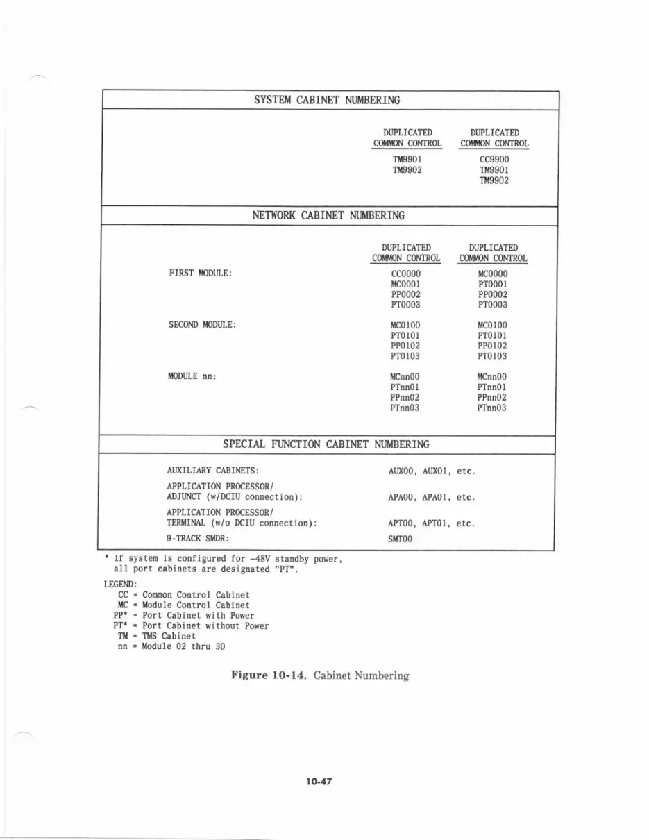
SYSTT:M CABINET NIJIIIIBERIM
DIJPLICATED DIJPLICATT]D
colttoN coNTtoL cotmN CoNTR0L
'Ir,!9901
9902cc9900T 9901'Illtgg02
NETI{ORK CABINET NIJI{BERII.IG
DUPLICATED DU?LICATEDc0mN coirTtol coinoN coNrrol
FIRST IODULE: cc0000irc0001?P0002Pr0003
c0100PTol0lPPol02Pro103
icnn00?TnnolPPnno2PTnn03
irc0000PT000lPmo02PTo003
[{c0100?T0t0lPPOIl)2Prc103
i{Cnn00PTnnolPPnn02PInn03
SEC0I'ID iloUJLE:
MODIJLE
SPECIAI, FUNCTION CABINET MJIIIBERING
AIIXILIARY CABINETS:
ATPLICATION PROCESSOR/
ADJUNT ($/DCIU connection) :
APPLICATION PROCXSSOR/
TERIIIML ($/o DCIU conn€ctton):g-IT-{CR SmRi
Al,X00, Al,X0l , etc
APA00, APA0I, etc
API00, APT01, etc
sitT00
. If systeD ts configured for --{8V standby porer,all port cabitrets are designated "PT".
LEGEND:
CC - Comon Control CobinetC - odule Control Cabtnet
PP. . Port Cabtnet with PowerPTl - Port Cabinet sithout PowerT . ftS Cabinetnn ' tlodule 02 thru 30
Figure lO-14. Cabinet Numbering
1()-47
DUCT WORK AND CABI.E RUNS
Duct Work
Cables are run through two type of ducts: unshielded and shielded. tn addition, cables mayb€ run on ladd€r rsck if the standard system unshi€lded duct work does not provide therequired routing for a particular application.
shbLH (Fb, C.r,t ) ouc,
The shielded duct provides a pathway which is physically enclosed for int€rcabinet cabling.This duct is predominantly used to route flat ribbon cabtes and other intercabinet cable;which require external shielding for electromsgnetic compliance. This duct is also used toroute eables requirihg intercabinet cabling such as the fiber-optic cables between the TMSand modul€ control. Th€ shielded duct is often r€ferred to as the flat cable duct.
The shielded duct runs along the top rear of the System 8E cabinets snd has verticalextension referred to as risers or chimneys which sllow int€rnal eccess to the cabin€tthrough th€ lop. Shielded duct segments are also availabl€ to provide cross-eisl€connectivity betw€€n rows of cabinets.
Unrti.tdad (t/O) Du.rr
The unshi€lded duct provides an open trough for external cabinet-to-cabinet and cebinet-to-termination field cabling. This duct is predominantly used to route 25-pair shielded I/Ocable betw€€n the cabinets and the termination tields. It is elso used for routing fiber-opticcabl€s between cabinets and th€ Lightguide Communicetions Int€rface Terminat (LCIT)-forremote modules (an access hole in the shielded duct chimney allows the fib€r-optic cable toexit through th€ top of the cabinet and enter the unshielded duct). The unshield;d duct runsalong the top front ol the cabinets b€hind a front lacia which also is mount€d at the topfrobt of the cabinets for aesthetics. Unshielded duct segments are also available to providicross-aisle connectivity between rows of cabinets snd also to provid€ a cable route from theside or rear of a cabin€t to a wall with nominal 43-inch (1.1-m) spacing. The unshi€lded ductis more commonly referred to as th€ I/O duct.
The power duct provid€s an ac wire rac€way and required ac receptacles lor cabinet ac pow€rand,/or utility outlets. The lower duct runs along the top .ear of th€ cabinets and isphysically mounted to the shield€d duct.
Ovct Wqk P,i.. Ehm.n, 6d. (PEq O.t('iptbat
Duct urork must be specified for the System 85 to provide the power ducts, I/O (unshielded)ducts, and flat cable (shi€ld€d) ducts required for the system interconnections anal powerconnections. The particular equipment room layout and types of csbin€ts will dictate thequantity and type of duct work required. The following describ€s the pECs available for thevarious packages of duct work.
. PEC 653?9 orders the duct work per cabinet and includes th€ power duct, I/O duct,flat cable duct (shi€lded), and fecia required p€r cabinet. The appropriate attributesp€cifies the required power duct for the type of cabinet it is to be mount€d on.
. PEC 653m orders the appropriate duct work requir€d per lineup. It includes all endcaps and facia required.
. PEC 65381 orders the duct work to ext€nd the AT&T System 85 I/O cabl€ duct to thewall. This duct is 12 inches (305 Inm) wide by 10 inches (254 mn) high. It wilprovide for a nominal 43-inch (1.1-m) distance froh the cabinet to the wall. Theappropriate attribute sp€cifies wheth€r th€ duct will €xt€nd from the r€ar of thecabinet to the wall.
t (}'zl8
. PEC 65382 ord€rs an adapter to ellovr a l2-inch (305-mn) wide ladder rack tointerface to the I/O cable duct- The appropriat€ attribute specifi€s wheth$ th€interface to the ladder rack is to the teft, right, or rear of the cabinet lineup. Thisinterface allows one end of the ladder rack to be physically mounted to the I/O ducton the cabinet.
. PEC 65383 od€rs the cross-aisle flat cable (shielded) duct. One is required for eachflat cable cross-aisle segment.
. PEC 653&l orders the cross-aisle I/O duct. On€ is required for each I/O cable cross-aisle segment.
Coble Runr
The term "cable run" is intended to mean a particular run of cable, a group of cables, orcertain classification of cables run through cable duct or on the ladder rack.
The following are the various types of cable runs:
. Flat ribbon and coaxial cable runs are those runs that are restrict€d in an €l€ctricalsense and must be routed between cabinets thmuqh the enclosed or shielded duct andkept separate from I/O cables.
. Flat ribboD cables connect the port carrier and module control carriers and must berouted between module control and port cabin€ts through the enclosed or shieldedduct and kept separate from I/O cables.
. Coaxial cables connect the common control to the modul€ control, TMS, and RMIcarriers. These cables are run between the respective cabinets through th€ enclosedor shielded duct.
. Fib€r-optic cables run betw€en the module control cabinets and colocated TMScabinet. This type of cabl€ run is routed through the shielded ducts.
. For remote module syst€ms, fiber-optic cables run b€tween th€ TMS cabinet(s) andLCIT and between the moduie control cabinets and LCIT (if it contains RMI packs)at the central locale via th€ I/O duct. Also, at remote local€s, fiber-optic cables runbetwe€n the module control cabinet(s) and LCIT via the I/O duct.
. The 25-pair lin€, trunk, and miscellaneous I/O cable runs are those cables (usually25-pair) r/hich run in the unshielded L/O duct between cabinets or to the terminationfield on the I/O duct between cabinets or to the termination field on the I/O ductand/or ladder rack.
. The minimum length of L/O cable is presently defined to be 50leet (15 m) for Release2. Since these cabl€s are run in open or unshi€lded ducts, shielded cables are used tominimize electromagnetic radiation. The minimum length of 50 feet is currentlyr€quired to comply with FCC Part l5 rules for electromagnetic radiation. Thisminimum length of shielded L/O cable is anticipated to be reduced t approximat€ly5 feet (1.5 m) at a later date. The 5-foot minimum requires the use of ferrite coreson internal cabinet cebles which connect to cables which leave the cabinet via therear-mount€d connectors and are run in the unshielded I/O duct. Unless the systemis equipped with the following versions of equipment (or later versions), the sO-footminimum shielded I/O cable iength applies.
Figure 10-15 specifies required intercabinet and cabinet-to-t€rmination field and LCITcabling. Currently, the manufactur€r is accepting equipment room floor plans formultimodule systems to determine required cable lengths. The floor plan must be designatedwith all required reference points, cable routing, and cable running distance information.Cabling distances for single-module systen are specified via "Y600" type PECS and must b€provided with all other hardwarc and software PECS order€d.
10.49
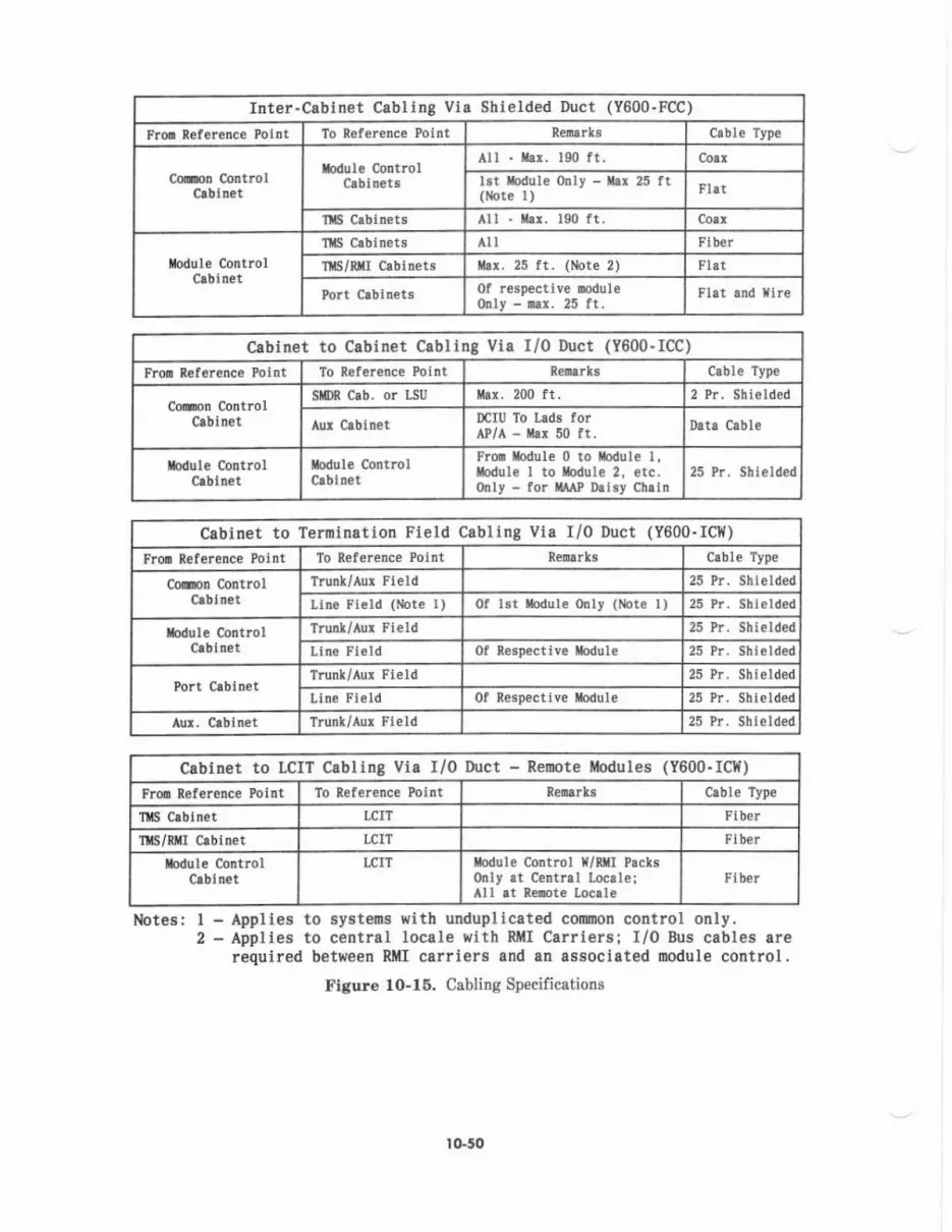
Inter-Cabinet Cabltng Via Shielded Duct (Y600.FCC)
Fron Rel€rence Point To Reference Point Cable Type
Cooon ControlclDlnet
fodul€ cotrtrolClbinets
All - ilar. 190 ft. Coax
lst todule only - tr! 25 ft(Note r)
1lIS Crbin€ts alt 190 ft.
Crbtnet
TllS Crbinets a Fiber
T S/RII Cabtnets ,r. 25 ft. (Note 2) Flat
0f respective mduleonly - 0ar. 25 ft.
Cabinet to Cabinet Cabling Via I/0 Duct (Y600-ICC)
Froo Reference Point To Reference Point cable Type
Colrlon ControlCrbtn€t
SilDR Cab. or LSU lhr. 200 ft. 2 ?r. Shielded
Aux Cabinet DCIU To Lads forAP/A - ihr 50 ft. Datd cable
Xodule Controlclbinet
todule @ntrol Fron otule 0 to ilodule l.[odul€ I to llodul€ 2, etc.only - for rMP Dlisy Chlin
25 Pr. Shi€lded
cabinet to Temlnation Field Cabling via r/0 Duct (Y600-rclt)
Fror R€l€renc€ Point To Refer€nce Potnt Renarks Cabl€ Type
Co@n Control T.unk/Aur Field 25 ?r. Shielded
Llne Field (lbte I) 0f lst rbdule orly (Note l) 25
lbdule controlCrbin€t
Trunt/Aur Fierd Pr. Shielded
Ltn€ Fteld Ol R€specttve ilod'rl€ 2t Pr. Shielded
Port Cabtn€tTrunk/Aur Fierd 25 Pr- Shtelded
Line Fleld 0f Resp€ctiv€ Module 25 Pr. Shlelded
Aur. Ctbinet Trunl/Aur Fi€ld 25 Pr. Shi€lded
Cabinet to LCIT Cabling Via I/0 Ihrct - ReDote Modules (Y600-ICI{)
Fron Rel€r€nc€ Poirt To Refer€nce Point Cable Type
t S C.blnet LCIT Flber
flS/R I Crbinet LCIT Fib€r
Iodule Control IrCIT rbdrle Control X/n I Packsonly rt Central Loca le iAll rt Reoote Locrle
Fiber
Notes: I - Applies to systeos $ith unduplicated comon control only.2 - Applies to central locale with Rl{I Carriers; I/0 Bus cables are
required b€tween RllI csrriers and an associated oodule control.Figu.e 10-15. Cabling Specifieations
I O.50
Equipment Room loyout
This part provides information on physical equipment and cabling requirements forequipment room layouts. Refer to AT&T System 86-Equipment Room Floor Plan6and Specificatiols Plsnning Manual (555-102-603) for a more thorough discussion onlayout and planning parameters.
Coun.r DimeBionr dnd R.quh.d C.iling Heighrr
An equipment cabinet is nominally 32.?5 inches (832 mm) wide, 24.5 inches (622 mm) deep(rear plane to face of front door), and ?0 inches (17?8 mm) hieh (without duct work and withleveling feet extend€d). Figure 10-16 shows the top vievr of cabinet outline dimensionsincluding door arcs and cabling reference point-
The preferred equipment room ceiling height is 9 feet (2.7 m). Systems configured in asingle row using standard I/O duct work to a wall require a ceiling height of 8.5 feet (2.6 rn)
[provides 11 inches (280 mm) clearance from top of duct to ceiling]. A minimum ceilingheight of 8 feet (2.4 rn) may be used but wili allow only 5 inches (12? nm) of clearancebetween th€ top of the I/O duct segment to the wall and the ceiline. With an 8.5-foot (2.6-m)c€iling height or less, ladder rack is rccommended in lieu of an L/O duct to the wall. Thebottom of the ladder rack must be 82 inches (2.1 m) from the floor to allow adequat€ head
Systems con{igured in multiple rows using cross-aisle I/O ducts and I/O duct segments to awall also r€quire a ceiling height of 8.5 feet (2-6 m) to prcvide an 1l-inch (280-mm) clearancefrom the top of the I/O duct to the ceiling- With ceiling heights less than 8.5 feet, laddetIack should b€ used in lieu of I/O ducts to v,/alls andlor cross-aisle I/O duct. The bottom ofthe ladder rack must be 82 inches (2.1 m) from the floor to allow adequate head clearance.
Ceiling height requirements for termination field configurations which ar€ wall- or fram€-mount€d and associated cable runs must also be considered.
Figurc 10-17 illustrates cabinet and duct work heights.
IO-5t

24.50122
i1
-T-APPNOX IIE POSITII OF
I _ 6r{rEL0ED DUCT
-r-I
APPNOX IITEPOSITIOII OF
I I/O DUCTIi_
81.75FRoilT D00n mc
x0IE: tLL 0IiE{8I0il8 Ifl IIICHES
Figure 10-16, Top View of Cebinet Dimensiong
lG52
u.*{ -t
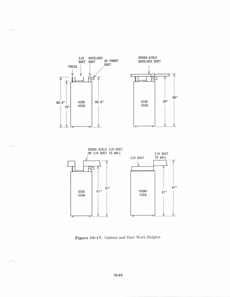
T85"
SHIELOEDoucT
cR0s8 ^rsLE
r/0 oucTl)R I/O OUCT TO TTLL
CROSS-AISLESIIIELDED DIJC]rc PoIER
DUCT
r/00ucl
ACIA I
+l
ile1"
r/0 DucrTO IIILL
Figure l0-l?. Cabin€t and Duct Work Heights
to-53
r/0 DucT
quip.n.D, layou, Conthdinr'
Cabinet Pairing and Distadce Limits:
. In an ac-powered system, cabin€t pails that share the same rectifier must be located -side by side- Cabin€t pails that share power are:
1 Unduplicated common control and module control of the lirst module
2. Modul€ control and port without power of the same modul€
3. Port with power and port without power of the same modul€.
. Port cabinets must be within 25 cable feet (?.6 m) of their module control cabinet viathe shielded duct.
. A TMS cabinet with a Remot€ Module Interface Carier must be within 25 cable feetof an associated Module Control Cabinet via th€ shielded duct (for I/O Busconnection from Module CoIrtIoI Carder).
. Duplicated TMS cabinets must be adjacent to each other.
. A1l module control and TMS cabinets must be within 190 cable feet (58 m) of th€common control cabinet via the shielded duct (except for Remote Modules).
. An auxiliary cabinet containing Local Ar€a Data Sets (LADS) for DCIU to APconnectivity must be within 40 feet (12 n) of the common control cabinet (and alsowithin 40 feet of the AP) via the I/O duct.
Cabinet Lineup Constraints:
. Duct work requires that no holes be left in an equipment row; i.e., duct work cannotspan an empty space with cabin€ts on each side.
. Cabinet orientation must b€ consistent; i.e., the fronts of all cabinets will face towardth€ same wall in single and multiple row configurations.
. A distance oI 38 inches (965 mm) is required between rows, as measured from thefront door of one row to th€ back of the next row.
. A distance of 43 inches (1.1 m) is required from the cabinet row (rcar or side) to thevrall if I/O duct work to the wall is used. If required, a ladder rack can be providedin va ous lengths (ll'herc duct work is not used because the cabinets are furthe. that43 inches frcm the wall).
Note,. The height of the bottom of the I/O duct segment to the wall is82 inches (2.1 m) from the floor and will not clear the top of wall mounted 900-pair 100P-type columns.
. A space of 3/8 inch (10 mm) should be maintained between cabinets within a cabinetlineup.
. Cross-aisle ducts should run in a struight line in order to minimize cable codgestionand length.
. Shielded (flat) cross-aisle ducts should be mounted across module control cabinets,thercby minimizing cable congestion.
. The I/O cross-aisle ducts should run near the center of the cabinet row in order toreduce cable congestion.
. Crose-aisle I/O and shielded ducts cannot both be placed on the same cabinet.
Figures 10-18 and 10-19 illustmte the required lineup constraints for singl€-module andmultimodule systems, respectirely.
ro-54

ffllsrSLEorsctnEcT
IC PROTECTM CMIitTll) lc Lt ,to ccnEr
s0 t[.(762 mliIt.J__
1 Itl. 125 dl CollDUtT 0VEnHEAD
OVER
r,/0 castEIIUCI
cR0s8c0ililEclFIELD
38 rr.(S5-,i.
IALt
FROXT
a9 rx.{1082
Figuro lo-lt Single-Module System Lineup CoNtraints
tG55
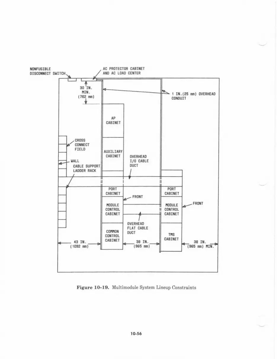
I*IEISLEorsc{ntEfi sIIrcx
AC PROTECTM CAEITEI
^I} tc LolD c€llER
I It. {25 ri) oVERHEAo
comurT
FROIIT
43 rt.
0vEnfiElDFur cl3tE0lrcT
ln. 38 rt,{r0r2 933 n) c)
iIlt.(78e m)
+
IIILLCISLE SUPPOR]tloDER RAq(
Figure lO-19. Multimodule Sf€tem Lineup Constraints
I G56
I I. SYSTEM POWER
The equipment contain€d in System 85 switch cabinets runs off of -48vdc power. On asystemwid€ basis, power is supplied to switch cabinets in one of two ways (but not both):
1. AC power is brought into the cabinet where it is converted to -48 V dc. AC poweris eith€r 3-phas€ 208 V ac or single-phase 240 V ac.
2. -48 V dc is brought into the cabinet from an outside dc power source. This methodis called -48 V dc Standby Power (sometimes referred to as -48 V dc input power).
Th€ rest of this section explains the power and grounding requirements for both of th€sepowering methods. AC input power and qrounding is discussed fi$t.
AC POWER AND GROUNDING
The system ac power distribution shown in Figure 1l-1 consists of:
. A main disconnect or safety switch
. An ac prot€ctor cabinet
. An ac load distribution center.
The customer or agent must make arrangements with an electrical contractor for thepurchase and installation of this €quipment and its associated wiring, with the exception ofthe ac protector cabinet. The ac p.otector cabinet \r,ill be supplied by AT&T as part of thesystem order; however, this cabin€t must be installed by the €lectrical contractor along withthe main disconnect switch and ac load center by the negotiated equipment-room-ready date.
After the System 85 equipment has been physically installed, the customer or agent mustalso arrange for the el€ctrical contractor to wir€ and install the individual feeder circuitsfrom th€ ac load center to the system cabin€t and equipment receptacles.
Standby power to a Release 2, System 85 may be arranged with essential service(engine/alternator) or with chargers, battery plants, and inverters which supply standby acpower. [n these arrangements, th€ ac power and grounding requirements as listed in thiss€ction apply to the Syst€m 85.
I t-t
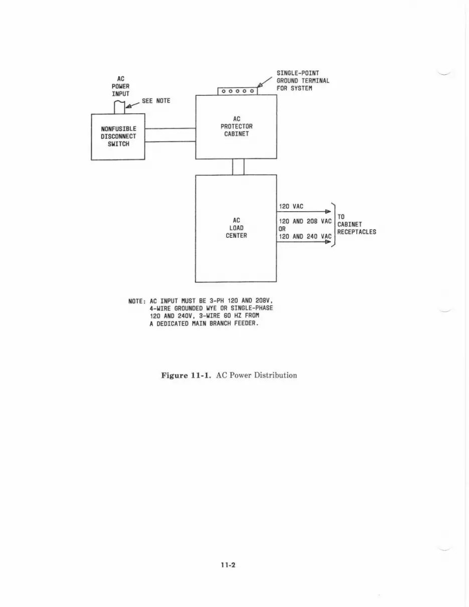
SIXGTE-POIflT
POIERGROUXO TERIIITIIFOR SYSTEII
lcPROTECTOR
cAErlElIOXFISIELEDISCOIECT
sltrld{
lcLOAD
CETTES
120 vtc
120 AtD 208m120 aro 240
lc
..>)vrc l llsr ET
u^a Inecrcrrclrs-+)
mIE: lG ItfUT mST BE 3-Pl 120 AID 2mv,4-frRE 6R0!ilDE0 llYE 0R Srtl0lE-Pl{/lsE120 AID 2a0V, 8-rrRE 80 llz FRoll
A I|EDICITED IAI{ ERIIICII FEEOER.
Figtrre ll-1. AC Power Distuibution
I t-2
AC Power Requirement3
Dadifited,rloin B,an.h Feedet C ligutdtion
The customer or agent must prcvide a dedicated main bmnch feeder protected and suppliedaccording to local cod€s. A dedicated main brarch feeder is defined as one which has asingle load (i.e., System 85) connected to a power source. No other €quipment shall b€connected to this branch. This provides isolation from €lectrically noisy or heavy variableloads (motors, elevators, etc.) which could have an adverse impact on System 85 operation.
One of two types of ac power configurations must be used as the dedicated main branchfeeder for System 85:
fype I3-phase grounded $Te4 wire (plus safety ground)120/208 v ac RMs, ! 10% @ 60Hz(! 3 Hz)
or -15% @ 60 Hz (! 0.3 Hz)
This configuration (see Figure 11-2 top) is provided by a 3-phase transformer with awye secondary. The 120 V ac is meaeured between the wye center tap (neutral) andeach of the thr€€ "hot" l€gs (Phas€ A, Phase B, and Phase C). The 208 V ac ismeasured between any two of the three "hot" Iegs.
Type 2Single-phase3 wirc (plus safety ground)120/240 v ac RMS, ! lova @ 60 Hz (! 3 Hz)
ot -L5Ea @ 60 Hz (! 0.3 Hz)
This configuration (see Figure 11-2 bottom) is provided by a center tapped transformersecondary. The 120 V ac is measured between the center tap (neutral) and either of thetwo outer "hot" Iegs (A and B). The 240 V ac is measured between the two outer "hot"legs.
I t-3
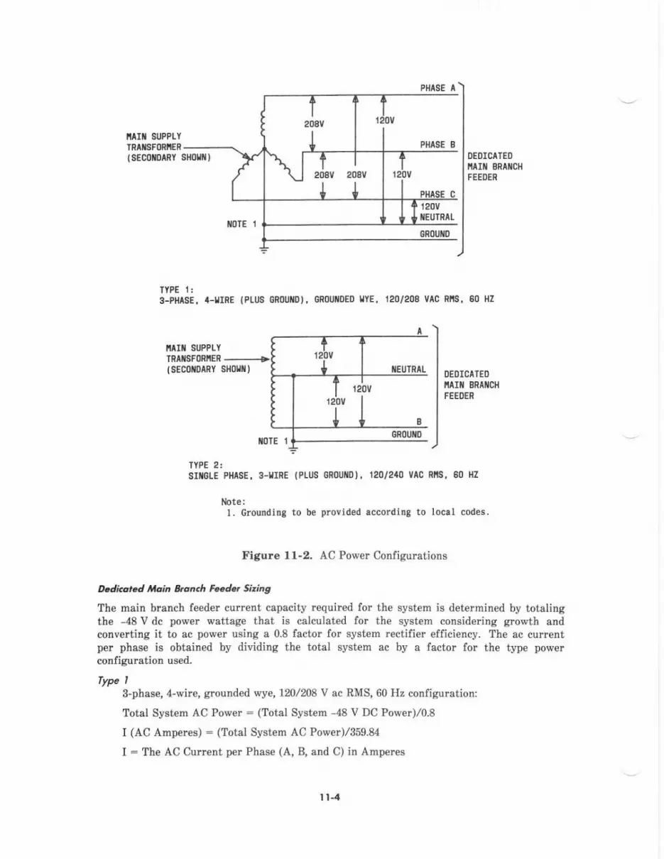
FHTSE t
IIAIII SUPPLYTRIIISFORIIER
I SEC0{|DIRY DEOICATEOI'ta t 8RAilCHFEEDER
TYPE 1:3-PHASE. /t-llIRE {PI-US GRoUI|o), GR0U|I0ED l,lYE, 120/208 VAC RllS, €0 HZ
ITAIII SUPPIYTRttlSF0RllER ---------+(sEcofiD^RY sllom,
DEDICAIEOIIAIII BRIIICHFEEOER
TYPE 2:s rctE PHASE, 3-rrRE (PrU6 GRoUilo), 120/2{0 VAC RllS, 80 llz
lJote:1. Crounding to b€ provided accordinS to local codes.
Figure l1-2. AC Power Configumtions
Dedico,ed *l.,in &on.h FsJer gzing
The main branch feeder current capacity tequired for the system is determined by totalingthe -48 V dc power wattage that is calculated for the system considering gro&th andconverting it to .c power using a 0.8 factor for system rectifier efficiency. The ac currentper phase is obtain€d by dividing the totsl system ac by a factor for the type powerconfiguration used.
Typs I3-phase, 4-wire, grounded wye, 120lm8 V ac RMS, 60 Hz configumtion:
Total System AC Pow€r : (Total System -48 V DC Pow€r)/o.8
I (AC Amperes) : (Total System AC Power)/359.84
I : The AC Current per Phase (A, B, and C) in Amperes
r t-4
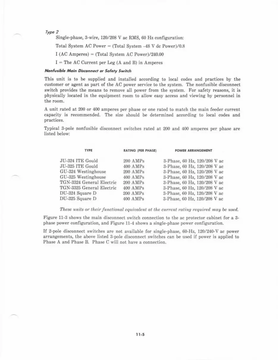
rype 2Single-phase, s-wire, 120/208 V ac RMS, 60 Hz configuration:
Total System AC Power : (Total System -48 V dc Pov,er)/o.8
I (AC Ampercs) : (Total System AC Pow€r)/240.00
I = The AC Current per Leg (A and B) in Ampere6
,bntwiltu tlein U..o,t.ci q Safary Svir.h
This unit is to be supplied and installed according to local codes and practices by thecuatomer or agent as part of the AC power service to the system. The nonfusible disconnectswitch provides the means to remove all power from th€ system. For safety reasons, it isphysically located in the equipment room to allovr easy access and viewing by personn€l inthe room,
A unit rated at 200 or 400 amperes per phase or one reted to match the main feeder currcntcapacity is recommended. The siz€ should b€ determined according to local codes andPractices.
Typical 3-pole nonfusible disconnect switches rated at 200 and 400 amperes per phas€ ar€listed below:
TYPE RAIING ('CR PHASE) POWCR ANNAN6'/VIENT
JU-324 ITE Gould 200 AMPS 3-Phase,60 Hz, 1mlm8 V acJU-325 ITE Gould 400 AMPS 3-Phase,60 Hz, 120/208 V acGU-324 Westinghouse 200 AMPS 3-Phase,60 Hz, 120/208 V acGU-325 Westinghouse 400 AMPs S-Phase,60 Hz, 120/208 V acTGN-3324 General Electric 200 AMPS 3-Phase,60 Hz,120lm8 V acTGN-3325 G€neral Electric 400 AMPS 8-Phase,60 Hz, 120/208 V acDU-324 Square D 200 AMPS 3-Phasa,60 Hz, 120,/208 V acDU-325 Square D 400 AMPS 3-Phase, 60 Hz, 1201208 V ac
These units or their functiondl equiudlent ut the currcnt raling rcquirud mau be used.
Figure t1-3 shows th€ main disconnect switch connection to the ac protector cabinet for a 3-phase power configuration, and Figure 1l-4 shows a single-phase porver configuration.
If z-pole disconnect switches arc not available for single-phase, 60-H2,120/240-V ac powetarrangements, the above listed 3-pole disconnect switches can be used if power is applied toPhase A and Phase B. Phase C will not have a connection.
I t-5
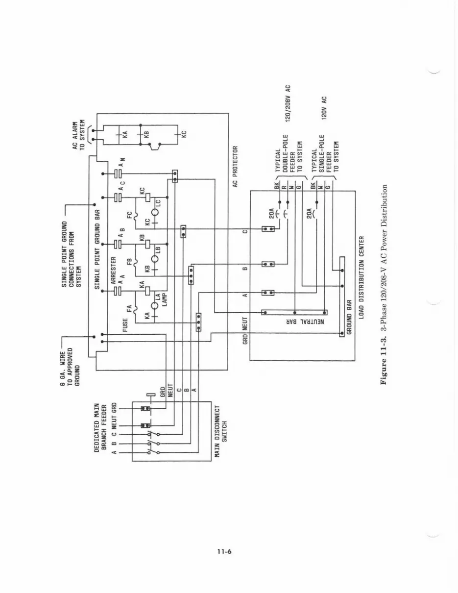
a
i?!N
h
!i
EE 8EE raE i=E -5E oB'-
I l-6
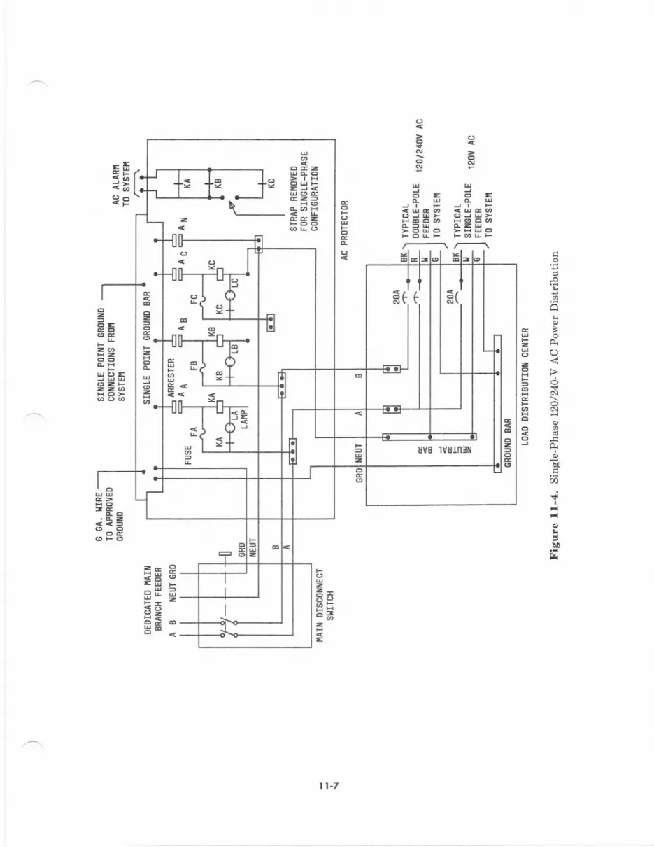
a=
=-E= -
1l-7
=
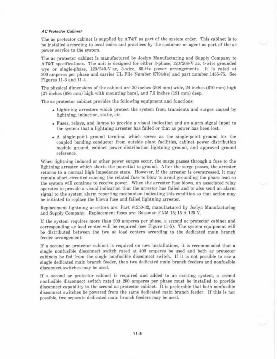
AC Pt$..rot Coune,
The ac protector cabinet is supplied by AT&T as part of th€ syst€m order. This cabinet is tobe installed accoding to local codes and practices by the customer or agent as part of the acpower servic€ to the system.
The ec protector cabinet is manufactured by Joslyn Manufacturing and Supply Company toAT&T specifications. The unit is d€signed for eith€r 3-phas€, 120l208-V ac, 4-wirc ground€dwye or single-phas€, 1n/240-V ^c,
3-wire, 60-Hz pow€r anangements. It is rated at200 amperes per phase and carries UL Fil€ Nunb€r E?944(s) and part number 1455-?5. See
Fisures l1-3 and 11-4.
The physical dimensions of the cabinet ar€ 20 inch€s (508 mrn) wide, inches (610 mm) highlfl inches (686 mm) high with mounting barsl, and ?.5 inches (191 mm) deep.
The ec protector cabinet provides the following equipment and functions:
. Lightning arrest€rs which protect the system from transients and surges caused bylightning, induction, static, etc.
. Fuses, relays, and lamps to provide a visual indication and an alarm signal input tothe system that a lightning artester has failed or that ac power has been lost.
. A single-point ground terminal which serves as th€ single-point ground for thecoupled bonding conductor from outside plant facilities, cabinet power distributionmodule ground, cabinet power distribution lightning ground, and approved grcundrefe.ence.
When lightning induced or other pow€r surg€s occur, the surge passes through a fuse to thelightning arrester which shorts the potential to ground. After th€ surge passes, the arresterreturns to a norn:al high impedanc€ state. However, if the arrcster is overstressed, it mayremain short-circuited causiDg th€ rclat€d fuse to blow to avoid gTounding th€ phss€ lead sothe system will continue to rec€ive power. When the arrester fuse blows, an associated relayoperates to plovide a visual indication that the arrester has failed alld to also send an alalmsignal io the system alarm reporting mechanism indicating this condition so that action maybe initiated to replace the blown fuse and fail€d lightning arrester.
Replacement lightning arrestors arei Part 1ll 0-32, manufactured by Joslyn Manufacturingand Supply Cornpany. R€placement fuses arei Bussman FNM 15; 15 A 125 V.
lf the system requi.es mor€ than 200 amper€s per phase, a second ac protector cabinet andcorresponding ac load center will be required (see Figure l1-5). The system equipment willb€ distributed between the two ac load centers according to the dedicated main branchfeeder arrang€ment,
If a second ac protector cabinet is required on new installations, it is recomm€nded that asingle nonfusible disconnect switch rat€d at 400 amperes be used and both ac protectorcabinets b€ fed from the singl€ nonfusible disconnect switch. If it is not possible to use asingle dedicated main branch feeder, then two dedicated main branch feeders and nonfusibledisconnect ss/itches may be used.
If a s€cond ac protector cabin€t is r€quired and added to an existing system, a secondnonfusibl€ disconn€ct switch rated at 20O amperes per phase must be installed to providedisconnect capability to the second ac prctector cabinet. It is prefeBble that both nonlusibledisconnect switch€s be powered frcm the same dedicated main branch feeder. If this is notpossible, two sepante dedicated main branch feeders may be used.
I t-6

:93 3.5 -E.g g
3.:Eg3S93
=@
()
O
=<?
4
\
I t-9
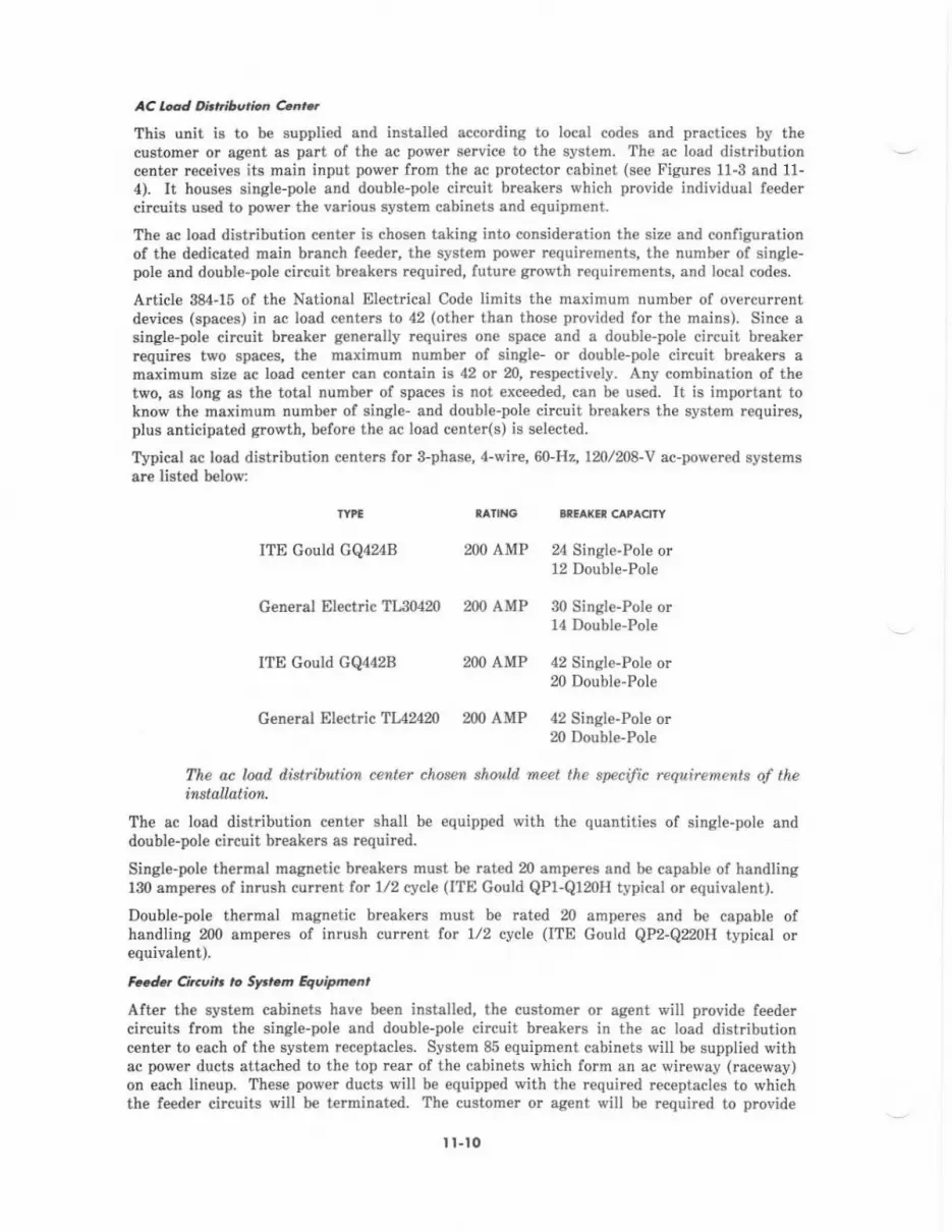
AC l$d O'tt .ibe.ion 4 .,This unit is to be supplied and installed according to local codes and practices by thecustom€r or agent as part of th€ ac pow€r s€rvice to the syst€m. The ac load distributioncenter receives its main input power from the ac prctector cabinet (see Figures 1l-3 and 11-4). It hous6 single-pole and double-pole circuit brcaken which provide individual feedercircuits used to pow€I the various system cabinets and equipment.
The ac load distribution center is chosen taking into consideFtion the size and configurationof the d€dicat€d main branch feeder, the system power rcquirements, the number of single-pole and double'pole circuit breakers requir€d, future growth r€quirements, and local codes.
Article 384-15 of the National Elect cal Code limits the maximum numb€r of overcur.entdevices (spac€s) in ac Ioad centers to 42 (other than those provided for the mains). Since asingle-pole circuit breaker generally requires one space and a double-pole circuit breakerrequires two spsces, the maximum number of singl€- or double-pole circuit breakers amaximum size ac load c€nter can contain h 42 or n, respectively. Any combination of thetwo, as long as the total number of spaces is not exceed€d, can be us€d. It is important toknow the maximum number of single- and double-pole circuit breakers the system requires,plus anticipated growth, before the ac load center(s) is selected.
Typical ac load distribution centers for 3-phese, A-wire, 60-Hz,120/208-v ac-powered syst€msare listed below:
ITE Could GQ424B m0 AMP 24 Single-Pole or12 Double-Pole
General Electric TIJ0420 200 AMP 30 Single-Pole or14 Double-Pol€
ITE Gould GQ442B 200 AMP 42 Single-Pole or20 Double-Pole
General Electric TUZ20 200 AMP 42 Singl€-Pole orm Doubl€-Pole
The ac load d&tdbution cenler chosen shouw meet lhe specijic requiremenls of thehBtall.atiot
The ac load distribution center shall be equipped with the quantities of single-pole anddouble-pol€ circuit breakers as required.
Single-pole th€rmal magnetic breakers must. be rated m amperes and b€ capable of handling130 amperes of inrush current for 1/2 cycle (ITE Gould QP1-Q120H typical or equival€nt).
Double-pole thermal magnetic breakers must be rated 20 amperes and be capable ofhandling 200 amper€s of inrush current lor 1/2 cycle (ITE Gould QP2-Q220H typical orequivalent).
Fcedd Circu t ,o Srrem quipm.nt
After th€ syst€m cabinets heve been installed, the customer or agent will provide feedercircuits from the singl€-pole end double-pole circuit breakers in the ac load distributioncenter to each of the system receptacl€s. System 85 equipment cabinets will be supplied withac power ducts attached to the top rear of the cabinets which form sn ac wireway (raceway)on each lineup. These power ducts will be €quipped with the required receptacles to whichthe feeder circuits will be t€rminated. Th€ customer or ag€nt will be required to provide
I t-to
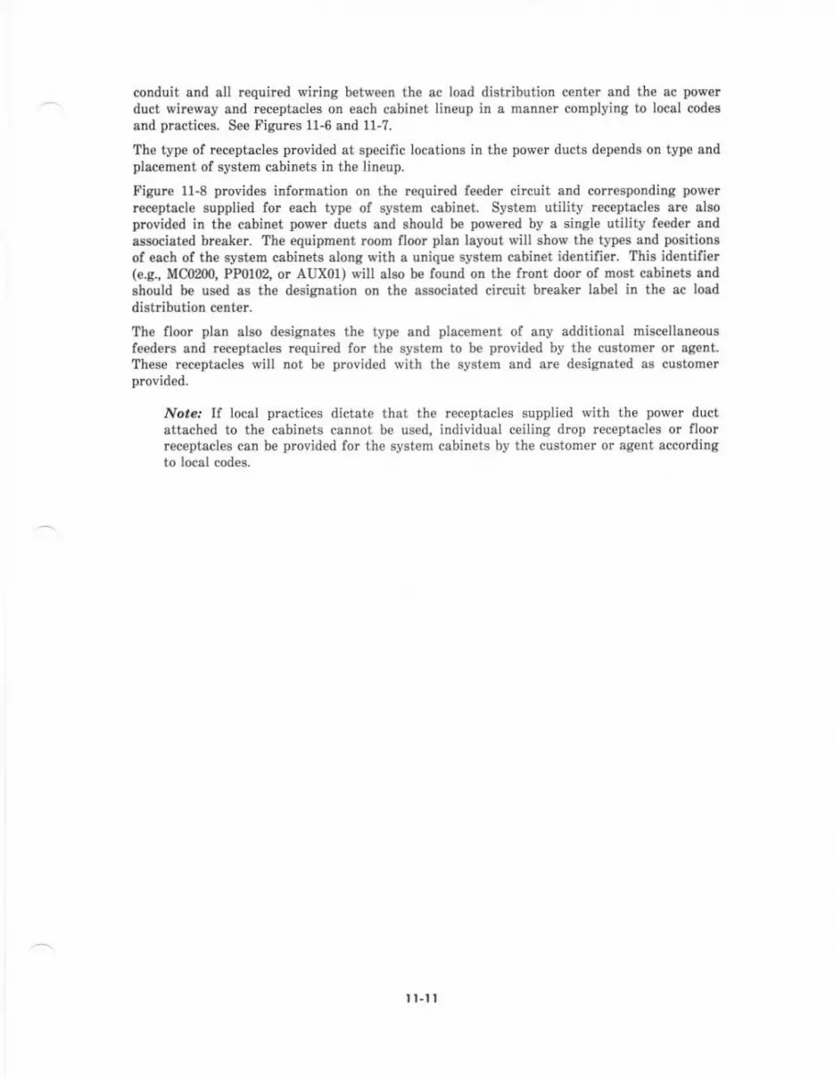
conduit and all required wiring between the ac load distribution center and the ac powerduct wireway and rcceptacles on €ach cabinet lineup in a manner complying to locel codesand practices. See Figurcs 11-6 and 11-?.
The type of receptacles pmvided at specific locations in the power ducts depends on type andplac€menf of syst€m cabinets in the lineup.
Figure 11-8 provides information on th€ requir€d feeder circuit and corresponding powerreceptacle suppli€d for each type of system cabinet. System utility receptacles are alsoprovided in th€ cabilet power ducts and should be powered by a single utility te€der andassociated breaker. The equipment mom floor plan layout will show the types and positionsof esch of the swtem cebinets along with s unique system cabiret identifier. This identifier(e.g., MC0200, PP0102, or AUX01) will also be found on the front door of most cabineb andshould be used as the designation on the associated circuit brealer label in the ac loaddistribution center.
Tha floor plan also designates the lype and plac€ment of any additional miscellan€ousfeeders and receptacles required for the system to b€ provided by the customer or agent.These receptacles will not be provided with th€ system and arc desiglated as customerprovided.
Not€.' If local practices dictate that the receptacles supplied with the power ductattached to the cabinets cannot be used, individual ceiling drop receptacles or floorreceptacles can be pmvided for the system csbinets by the customer or agent accordingto local codes.
tt.tl
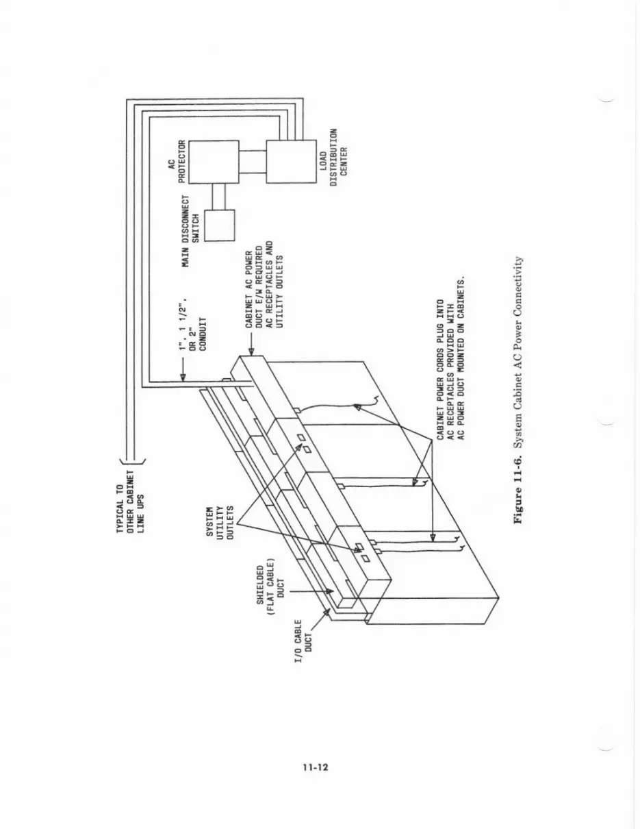
o
'O
a
I
CEB
o9HBa;3t
:-cE
3
I l.l2
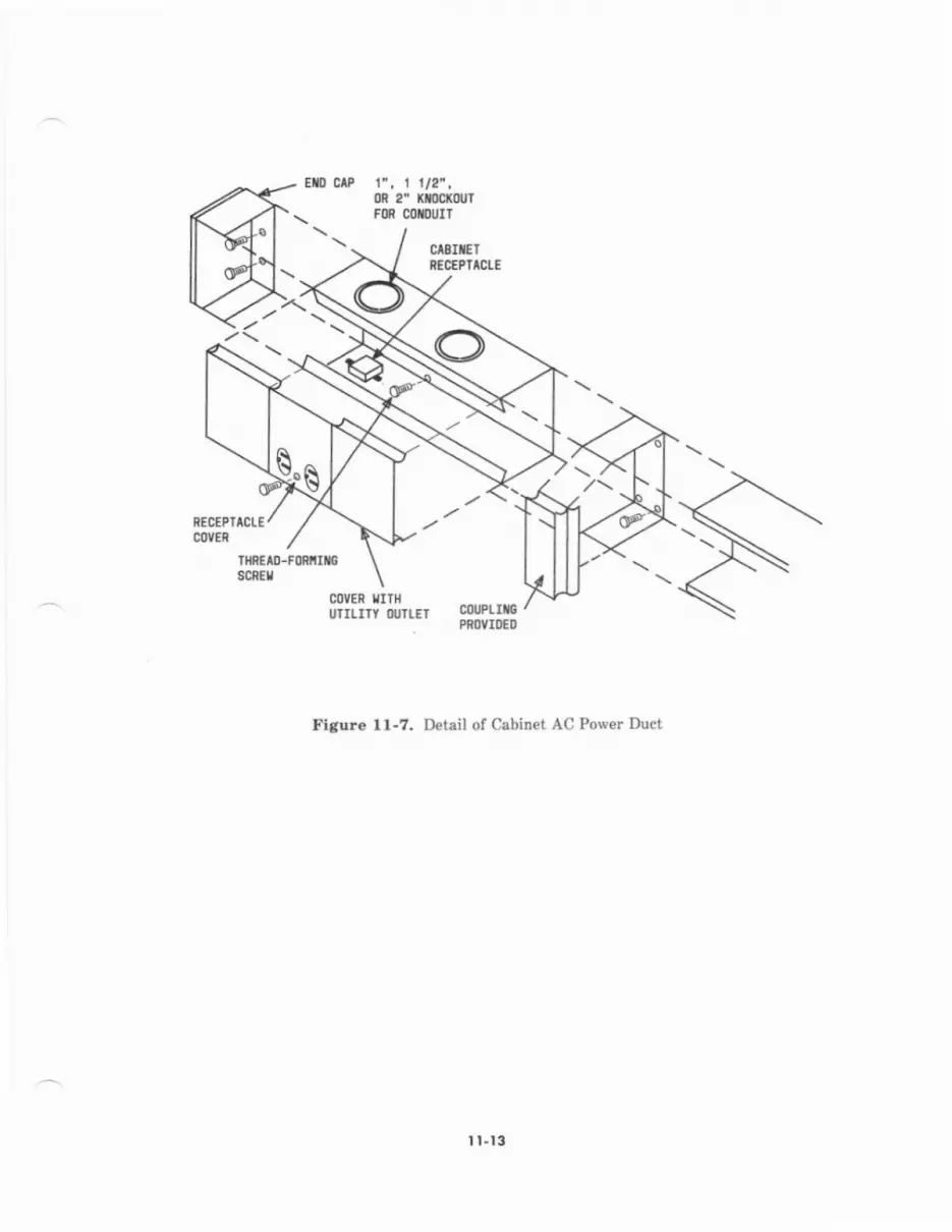
f, 1t12".0R 2" Xmof,ortFM MflIruIT
COVER IITI{UIILITY IIJILEI couPtrS
PiOYIDEO
Flaure 11-7, D€tail of Cabinet AC Power Duct
t t.t3

aei;r!*,;
FE
99=I -F
- =;i r!= st
:9;
jj3= q
&
Eo@; :r'i.-3 I=xtiEi ?ra
=F1
uldi
I=di
ffiRsSE> >
Q
@
-ffiRS
9aiir
E=
,-t'-l,(i l
;l=l.r'
FH
3' B
ffiHgFH; ;t
,-F-l,ut-t ru
rE E
3=F.
I t-t4
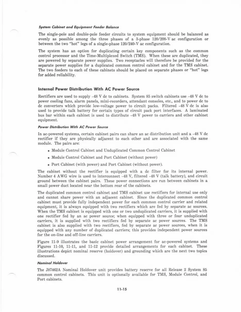
SFran Cobina ond Equipm.n, Fade. Balonc.
The single-pole and double-pole fe€der circuits to system equipment should be balanced asevenly as possible among th€ three phases of a 8-phase 1m/2p8-y ac configuration orbetwe€n the two "hot" legs of a single-phase |N/ 0-]/ ac configaration.
The system has an option for duplicating c€rtain key components such as th€ commoncontrol processor and the Time-Multiplexed Switch (TMS). When these are duplicated, th€yare powered by separate povrer supplies. Two receptacles will therefore be provided for th€aeparate power supplies for a duplicated common contrcl cabinet and for the TMS cabinet.The two feed€rs to each of thes€ cabin€ts should be placed on sepsrate phases or "hot" l€gsfor added reliability.
lnt.rnql Power Dkl.ibulion With AC Powor Soulce
Rectifiers are used to supply -48 V dc to cabinets. System 85 switch cabinets use -48 V dc topower cooling fans, alarm panels, mini-recorders, attendant consoles, etc., and to power dc todc converters which provide lo\r-voltage power to circuit packs. Filtered -48 V dc is alsoused to provid€ talk batt€ry for certain types of circuit pack port int€rfaces. A laminatedbus bar within each cabin€t is used to distribute -48V power to car ers and other cabinetequipment.
Pow.. ArhiburtDn With AC Pow.t So!rc
In ac-powered systems, certain cabinet pairs can shsrc an ac distribution unit and a -48 V dcrectifier if they are physically adjacent to each other and are associated with the samemodule. The pairs are:
. Module Contrcl Cabinet and Unduplicated Common Control Cabin€t
. Module Control Cabinet and Port Cabin€t (without power)
. Port Cabinet (with power) and Port Cabin€t (without pow€r).
The cabinet without the rectilier is equipped with a dc filt€r for its internal power.Nr:mber 4 AWG wire is used to interconnect -48 V, filtercd -48 V (talk battery), and circuitground between the cabinet pairs. These power connections are run b€tween cabinets in asmall power duct located near the bottom rear of the cabinets.
The duplicated common cont.ol cabinet and TMS cabinet use rectifiers for int€mal us€ onlyand cannot share pow€r with an adjacent cabinet. Sinc€ the duplicated common contrclcabinet must provide fully independent pow€r for each common control cadier and relatedequipment, it is always equipped with t\r'o r€ctifi€Is which are fed by separate ac sources.When the TMS cabinet is equipped with one or two unduplicated carriets, it is supplied withone rectifier fed by an ac power source; when equipped with three or four unduplicatedcarriers, it is supplied with two rectifiers fed by separate ac power sources. The TMScabin€t is also supplied with two rcctifi€rs, fed by separate ac power sources, when it isequipped with any number of duplicated carriers; this provid€s indep€ndent power sourcesfor lhe on-lin€ and off-line caniers.
Figure 1l-9 illustrates the basic cabinet power armngement for ac-powered systems andFigures 1l-10, 11-11, and 11-12 provide detailed arrangements for each cabin€t. Theseillustrations depict nominal reserve (holdover) and grounding which are the next two topicsdiscussed.
The J8?462A Nominal Holdover unit p.ovides battery reserve for all Release 2 System 85common control cabinets. This unit is optionally available for TMS, Module Control, andPo.t cabinets-
I l-15

t'lonhdl Holdove. fot Connon Contol
For unduplicat€d and duplicat€d ac-pow€red Common Control cabinets, the J87462A NominalHoldover unit:
. I8 alwsys included.
. Will Fovid€ at least 10 minutes holdover power to the common control. Holdoverpower b€yond l0 minutes dep€nds on the number of circuit packs equipped in thecommon contrcl carrier.
. Prcvents the loss of main memory cont€nts during the holdovff period. Thiseliminates the need for tape reloads if &c porrer is restorcd within the holdoverp€riod.
o Allows common control €quipment such as miri-remrd€r6 and the alarm panel tDop€rate during the holdover period.
. Requires up to 16 hours to fully recherg€ after a complete diBcharge.
Noninol Hol4owr for Othct S',titch Cdbinas
For AC power€d TMS, Module Control, and Port cabinets equipped with r€ctifi€rs, th€J87462A Norninal Holdover unit:
r Is optionally available.
. Provid€s power lor the switch n€twork and all switch-powercd peripherals.
. Provides 3 to 5 minutes of holdove! power depending on the type and quantity ofcircuit packs in th€ cabinets and the amount of traffic present du ng the holdoverperiod-
. Requires up to 16 hours to fully recharge after a complete discharge.
I l.t6
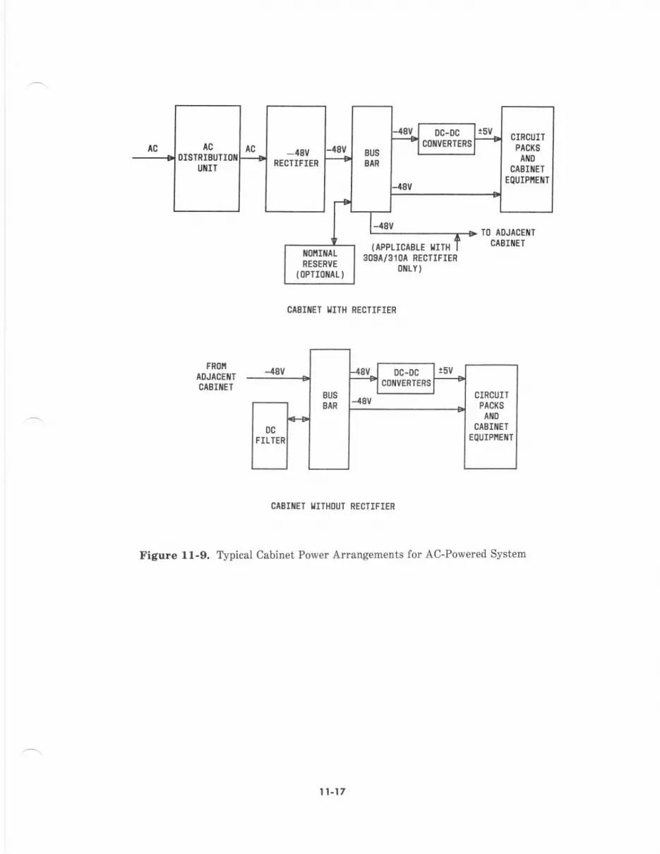
tcDISTRIEIJTIOII
UIIIT
a8vRECTIFIER
TO AOJACEI{TCABIIIET(APPLICIELE |IIH
3O9I/3104 RECTIFIER0rLY)
CABIilET IIIII{ RECIIFIER
CAEIIIET IIIIHI)IJT RECTIFIER
Figure l1-9. Typical Cabinet Power Anangements for Ao_Powered Syst€m
I t-t7

120l20a UAC
OR
120/2a0 vac
PORT/DS-1 CARRIENS
NODULE COilTNOL CARRIERS
-48T tilo GRoT:FILIERED -48V USED
FOR TIIK BA]TERY
{BAII)
I'IODIJLE C|IIITROL
-48+GR0
CABIIIEI
PORT/DS-1 CARRIERS
c0 t0 Co TRoLCARRIER
,IFRl)IIAOJAC€IICABIIET
-/t8CIRCUIT ORl)
collllot col/TRoL cAErtET
Figure 1l-10. Module Control and Common Control Power (Ao-Powered System)
309A/3l0l-a8v
RECTIFIER
AC
DISINIgUTUIIIT
DC FAII ASSEITBLY
CINCUIT GROUIID
CIRCUITPACKS
DC FAII ASSEI,IELY
-18
R I CARRIERS
r20vlc(r) r20vrcl1)
120l/lC{0) TI'S/RIII CARRIERS{0}+GRD{0)
Tlts ctBrttT
oUPLICATED Colfltol CoilTRoL CtSIilET
Figure ll-11. TMS and Duplicated Common Contrcl Cabinet Power (Ao-Povered Svstem)
120yAC{0lr___-;;; _ {810)
0c Ffi{ tssEt!8t-Y
(11+GRo(r)
120VrC{0t {0 t+GRo{ 0 )120VAC{0)i ;;i----1 {8{0
0c-0c(0) cot/vERrER {1,
CARRIER
GnD(0)colflto coirTRoL
CARRIER
{0}
OC FAII ASSETIBLY
GROUIIID CIRCUIT
I l-19
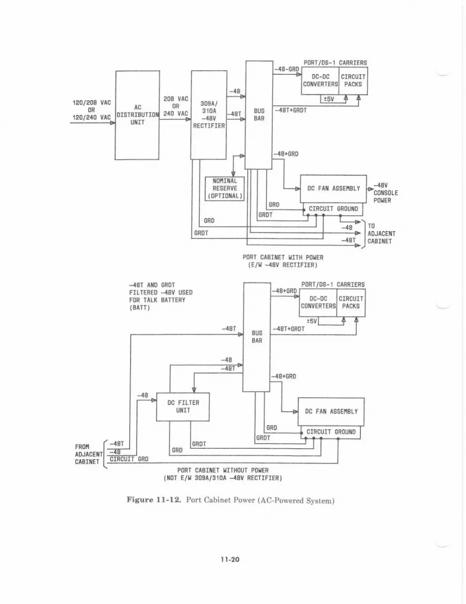
120l2OA v^COR
t20l240 vAc
FROI!ADJICETTCABIIIET
-4AT+GROT
-48Vc0ils0LEPDllEN
;*)'----} IADJACE T+gt lcrsr er
PORT CAEIIIET I,IITH POIIER
{E/T _€V RECTIFIEF)
-48T AIIO GROT
FILTERED {8V USEO
FOR ]ALK EATTERY(BAIT)
Pl)RT/OS-I CARRIERS
PoRT CABIIET IIITHoUT Pol,lER
{r0r €/l 30sa/310a --48Y REcrrFrER)
Figure l1-12. Port Cabinet Power (Ac-Powered System)
lcDISTRIBUTI
UIIIT
309t/3104-,18v
RECTIFIER
OC FAII ASSEIIBLYIONIilAIRESERVE
{OPTIOIiAL)
CIRCUIT OROUI{D
0C FAll ASSEI,IELY
CIRCUIT GROUIII)
I l-20
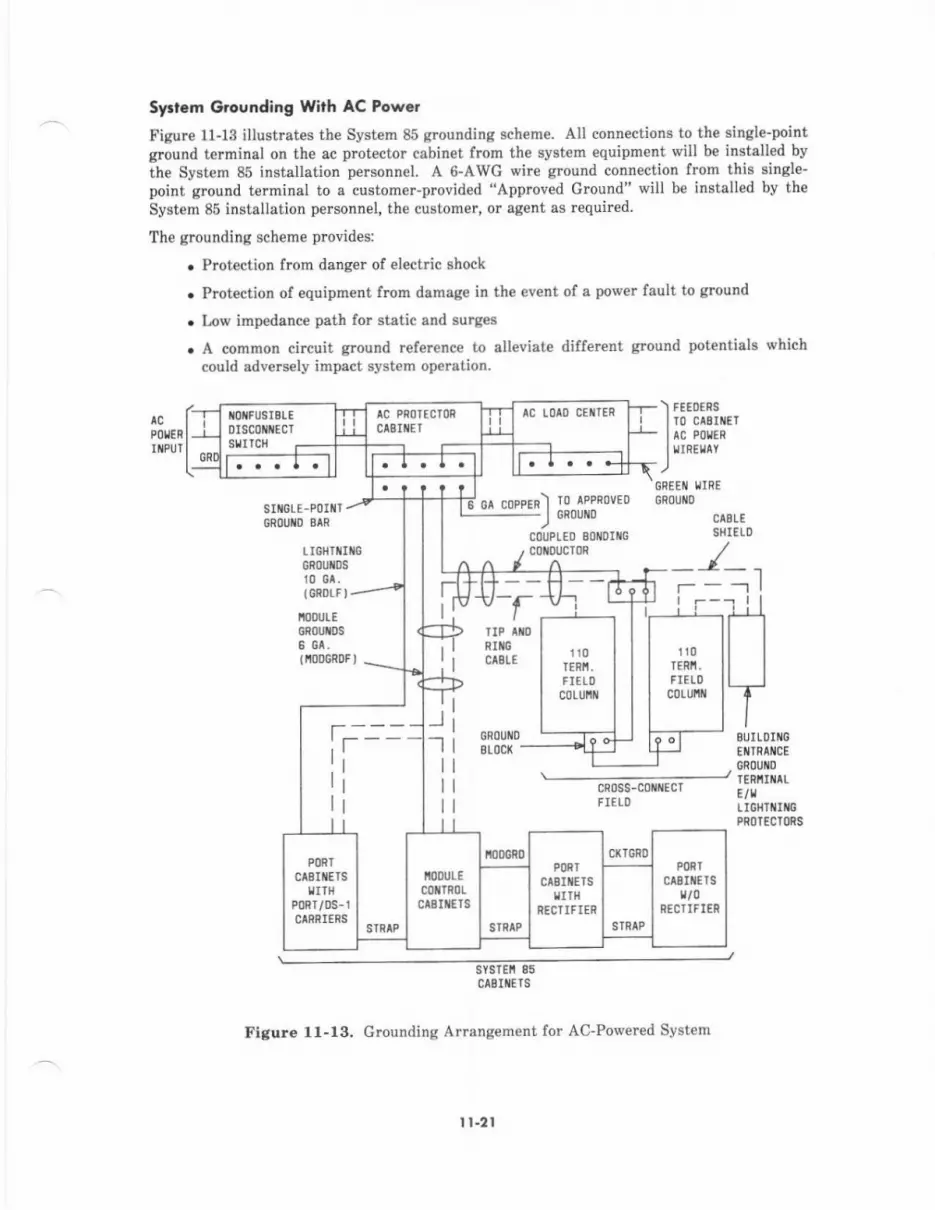
Sy.t.m Grcunding With AC Powei
Figure 11-13 iltustntes the System 85 grounding scheme. All connections to the single_pointglound terminal on the ac prot€ctor cabin€t ftom the system equipment will be installed by
ihe System 85 installation personnel. A 6-AWC wire ground connection from this single_point ground terminal to a customer-provid€d "Approved Ground" will be installed by theSystem 85 installation personnel, the customer, or agent as requircd
The grounding scheme prcvides:
. Protection from danget of electric shock
. Protection of equipment from damage in the event of a pow€r fault to ground
. l,ow impedance path for static and surges
. A common circuit ground refer€nce to alleviat€ different ground potentials whichcould adveNely impact system operation.
P0$nNOIIFUSIEL€
0Iscot{t{EcTstllcll
Ae PhorEclonctElrEr
') FE€DERS
Iro crEl' I AC PoUE|
lrrnrurv.)
GREEiI I,JIFE
cs
t;;;-ll] l. 1. r.. +t.
cA coppER) ro APPRoVEo_J CFoU D
c0TJPLED 80ll0Ill0, comuc'IoR
SIIIGLE-Pl)INI/GROUIIO BIN
LIGHTI!IIGGNOUIDSr0 61,(cRoLFl-
'IOOULE6n0u[Ds6 eA,tr,r0DGRoF I
I
fI
--l-1
_l-l
I
I
I
r-rTIP TND
NIrcCAgLC
0h0uilDBLOCl(
69 -
110TERIT.
FIELl)c0Lul,lll
r10tEni.FIELl)
c0LUiil
fr-----ilIr
cn0ss-collllEcTFIELD
PORT
AEtttrs9ITH
nT/0s-rIRRICRS
t!00!LEl0lTR0rtEIt{ETS
i0oGn0PORT
ctElllcTsIITH
RECTTFIEN
cxr6F0PORT
clB$tEts
RTCTIFIER
BUILOII{OEIIIRAI{CECRl)UI{D
TENNIilAIE/rttGHTII16PRl]IECIORS
sYslEn 85clSllicls
Figure 1l-13, Grounding Arrangement for A0-Powered Svstem
I r-21
An "approved ground" is an acceptable grounding medium as specified in S€ction 250-81 ofthe National Elect c Code (NEC). An approved grcund may consist of any of the following:
. Grounded Building Steel-The metal frame of the building where effectivelygrounded, such as with bonded joints.
. Acceptable Water Pip€ A metal pipe, not less than 1/2 inch (13 mm) in diameter,electrically connected to a m€ta1 undergound water pipe that is in direct contactwith the earth for 10 feet (3 m) or morc. This must be elecirically continuous (ormade el€ctrically continuous by bonding around insulated joints, plastic pipe, orplastic water metels) to a point where th€ protector ground is connected.
. Concrete-Encased Gmund An electrode encased by at least 2 inches (51 mm) ofconcrete and located within and near the bottom of a concrete foundation or footingin direct contact with earth. This must consist of at least 20 feet (6.1 m) of one ormole steel rcinlorcing bars or rods of not less than 1/2 inch (13 mm) diameter, or atleast 2 feet (610 mm) of bare solid copper wire not smaller than No. 4 AWG.
. Ground Rine A sround ring that encircles a building or structure in direct contactwith the earth at a depth of at least 2-1/2 feet (762 mm) below the €arth's surface.This must consist of at least 20 feet (6.1 rn) of barc copper conductor not smallerthan No. 2 AWG.
An approved floor ground in a high-rise buildins suitable for connections to the groundterminal in the riser closet and to a system single-point ground may be any of the following:
. Grounded building steel
. Acceptable water pipe
. Power feed metallic conduit supplying panei boards on the floor
. The $ounding conductor for the secondary sid€ of the power transformer feeding thefloor
. A grounding point specifically provided in the building for this purpose.
Sysrem G.ound L.adr
The following leads are used to effectively ground System 85. These leads are required inconjunction with the approved and single-point grounds discuss€d above and will be installedby System 85 installation personn€l (exc€pt for grcen wire grounds in ac feeders).
Co u p led Bond ing Conductot
The coupl€d bonding conductor prcvides a connection between the system single-pointground and the protector ground terminal for cable facilities at the building entmnce.It is run adjacent to protected pairs in an associated cabl€. The mutual couplingbetween the bonding conductor and the pairs .educes the difference in €lectricalpotential in t€rminating equipm€nt which may result frorn lightning surees. Thisconductor can consist of the following:
. when pairs are run in shielded cable, the cable shield shall be used as thecoupled bonding conductor. Shield continuity must be verifi€d using a T-124,manufactured by Wilcor Grounding Syst€ms, or equivalent.
. With inside wiring cable, the coupled bonding conductor shall consist of anumber l0 AWG wir€ that is tie-wrapped to the cable. If this is impractical, sixdedicated, good spare pairs within the cable may he used as the coupled bondingconductor. The six spare pairs must be twisted and soldered to prevent theiruse for other purposes.
A suitable connecting point (coupled bonding conductor terminal block) should bepmvided for the connection to the system single-point ground.
l1-22
Equipnent Grcunding Conductor (Gr*n Whe)
The AC power equipment must be grounded by an equipment grounding conductor(green wire) in compliance with NEC, Article 250-32 (1981 Edition). This ground servesas the gre€n wire ground for th€ Syst€m 85 in accordance with NEC, Articl€s 250-42and 250-45 and is distributed to cabinets equipped with rectifie$ via the ac f€€dercircuits.
Li shtnins Grcund (CR Dt F)
Each cabinet containing a port or DS-l carrier requires a lightning ground connectionto rcut€ lightning surges away from circuit components. A lightning ground (GRDL) ischain-wired to each cabinet within a module. The lightning ground is wired frcm oneof the cabinets to the system single-point grcund terminal via GRDLF. Each modul€must have a separate lightning ground connection (GRDLF) to the system single-pointground.
r'Aodule G@rnd ( ODGRDF)
Each cabinet equipped with a rectifier requires a circuit ground connection to thesystem single-point ground to ensure proper system op€ration. A circuit ground(MODGRD) is chain-wired to eacb rectifier-equipped cabinet within each module and toany adjacent syst€m cabinets such as the duplicated common control or TMS- Thecircuit ground is wired from one of the cabin€ts to the system single,point $oundterminal via MODGRDT. Each module must have a separate circuit grcund connection(MODGRDF) to the system single-point ground.
lnternol Grounding Arangement Wirh AC Power Sourco
Int€rnal grounding arangements p.ovide equipm€nt pmtection from lightning surg€s, insureprop€r system operation, and insure safety.
Th€re are four basic types ol intracabinet and intercabinet grounds used in ac-poweredsystems. They are:
. Module Ground (Circuit Ground)
. Lightning cround
r Green Wire Ground
r Cabinet Bonding Ground.
These grounds are kept totally isolated from each other in the system cabinets and areindividually routed to the System Single-Point Cround at the AC Protector Cabinet wher€they are interconn€cted. In addition to these, a digital ground (GRDD) which is tied tocircuit grcund is dist buted to port or DS-1 carriers within a cabinet to insure a lowimpedance path for digital signals.
Each switch cabinet is equipped with a circuit ground block located on the dc fanassembly. The circuit ground block is connected to the lower distribution grounds ofthe cabinst bus bar. A number 6 AWC wire is used to int€rconnect the circuit groundblock of each Port Cabinet equipped with a rectifier to the circuit ground block of itsassociated Module Control Cabinet. The circuit ground block of duplicated commoncontml and TMS cabinets are connected via a number 6 AWG wire to the circuitground block of the closest module control cabinet. A number 6 AWG wire is run fromthe circuit ground block of each module control cabinet to the system sinsl€,pointground via an Electro'Magnetic Compliance (EMC) filter located in the cabinet.
I t-23

Each of these module gound connections to the system single-point ground isdesignated MODGRDF (see Figurc 11-14).
Ag dl Gtound
Digital gound connections (GRDD) rcpresent four or more equally spaced number 14
AWG wire straps used to el€ctricelly interconnect adjoining or sequential car ercwithin a cabinet to insure a low impedanc€ path for digital signals. The digital groundsarc connected to the circuit ground block on the dc fan assembly (see Figure 1l-14).
Iightning Crcund
Each cabinet equipped with port or DS-l carriers has number 10 AWG wire stmpscheined to each port or DS-l caffier from a terminal strip located in the cabinet.?hese connections arc used to route lightning surges away trom circuit components. Anumb€r 10 AWG wir€ is chain-wir€d frcm th€ lightning ground terminal st p of onecabinet in a module to each other cabinet associated with the module in that row. Thiscabinet will have a number 10 AWG wire run from its lightning ground terminal stripto the System Single-Point Ground via an Electro-Magnetic Compliance (EMC) filterlocated in the cabinet. The cabinet equipped with this EMC filter will either be anunduplicated common control cabinet ot Port Cabinet. lf one or more port cabinets arelocat€d cmss-aisle from their associated module control cabin€t, one of the portcabinets must also be equipped with an EMC filter and hav€ a lightning goundconn€ction to the system single-point ground. The lightning ground terminal stdp ofthe cabidet with th€ DMC filter and lightning ground connection is chain-wired to anyother port cabinets in the row associated \rdth its module. Each of the lightning groundconnections fmm the modules to the system single-point ground is designated GRDLF(s€e Figure 11-15).
Grccn Wirc Crcund
Each cabinet equipped with a rectifier will hav€ a green wire ground from the acfe€der(s) which is electrically connected to the cabinet frame. The green wire ground ofthe ac feeder(s) is conn€cted to the system single-point ground bv the ac distributionarrangement.
Ccbinet Bondins Oround
A braided strap approximat€ly 5 inches long is used to bond adjacent cabinet framestogether within a lineup (excluding Auxiliary, AP16, 385 AP, and g-track SMDRcabinets). The bonding strap is fast€ned to the lower rear cover mounting screws. Thisbonding is us€d to r€duce Electro-Magnetic Interference (EMI) radiation andsusceptibility. The Auxiliary, AP16,3B5 AP, and g-track SMDR cabinets use the grcenwire ground of their ac feeders exclusively for their grounding arrangement and noother grcunds or bonds are connected to them. Their ac leeders originate from the acdistribution source for the switch cabinets.
1l-21
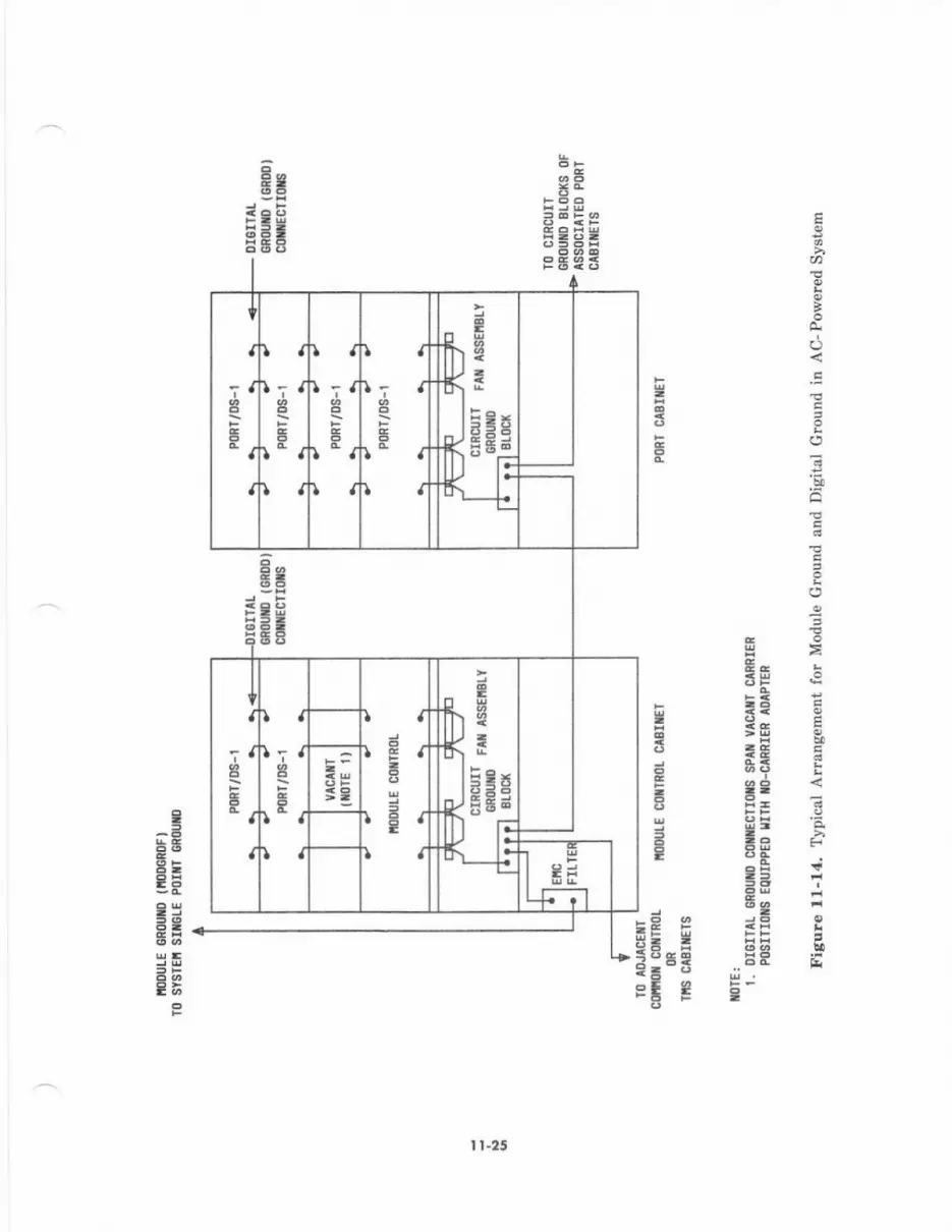
BgttsEEi
(A
I
()
o
b0
a
,o
6A
r- e"
-g .i
r ii tE3 ..EE E
F3
=t
3
!E
{
I.7 I
E
I
lll; J
c
II
IJI rJ
\J
IJl; t
t' a
IJ
egtIEga
Ia
iJ€5"a
a
IJli J
ct'lIJ
IJ.ga
rE r-IJ
3
8E
3A
I t.25
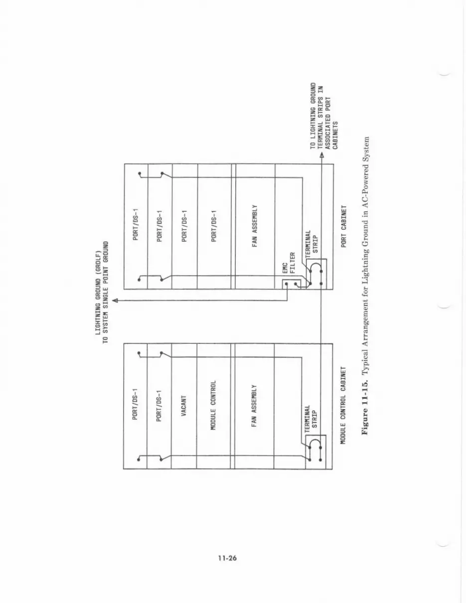
l=ETE
E
aa
to
Ict9
5
€
E
{F.eda'i
3E
I5EgEIt=,aSEtB
=EqsP
e
I
I t-26
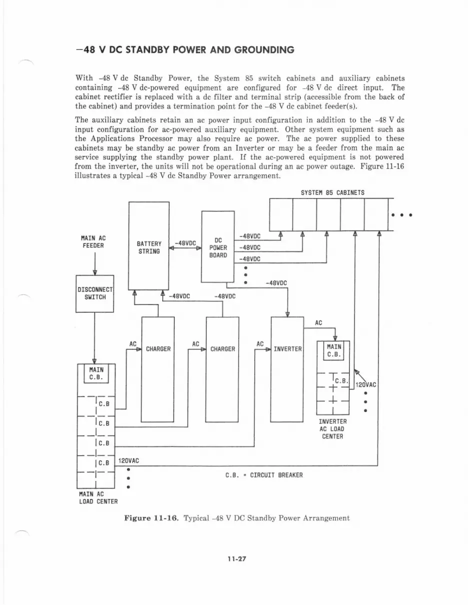
_48 V DC STANDBY POWER AND GROUNDING
With -48 V dc Standby Power, the System 85 switch cabinets and auxiliary cabinetscontainilg -48 V dc-powered equipment are configured for 48 V dc direct input. Thecabinet rectifie. is teplaced with a dc filter and terminal st p (accessible from the back ofthe cabinet) and provides a termination point for the -48 V dc cabinet feeder(s).
The auxiliary cabinets retain an ac power input configumtion in addition to the -48 V dcinput configuration for ac-powered auxiliary equipment. Other system equipment such asthe Applications Processor may also require ac power. The ac power supplied to thesecabinets may be standby ac power from an Inverter or may be a feeder from the main acservice supplying the standby power plant. If the ac-powercd equipment is not poweredfrcm th€ inverter, the units will not be operational during an ac power outage. Figure 11-16illustrates a typical -48 V dc Standby Power arrangement.
CABIiIETS
C-B- = CIRCUIT BREA(ER
lta t acI'AO CEiITER
Figure 1l-16. Typical -48 V DC Standby Pow€r Arrangement
sYsTEi 85
EATTERY
STRIilG
IIIIVERTER
AC LOAO
CEIITER
CIIARGEN IIIIVERTENCHAN6ER
-t;;I-l;;
-t--t-
1t-27
-,18 V DC Stondby Powor Plont conligurolion
The Standby Power Plant consists of:
. Charg€rs-ac to dc conversion
. Battery Strings-storag€ of dc pow€r
. DC Power Board-circuit brcakels for dc feeders and ground discharg€ bar forground returns
. Inverters-dc to ac conversion.
The chargers are used for converting ac to dc power. The chargers are sized to supply powerto system equipment via dc feeders with additional capacity to charge a fully drained batteryst ng (usually in a 24-hour period). Reliability and rcdundancy considerations may alsoimpact the number and capacity of the chargers chosen. For example, if 200 amper€s mustbe supplied, thre€ 10o amper€s may be provided inst€ad of a single 20o amp€re charger. Ifone of the 100 ampere chargers should fail, the two remaining charges will still be capable ofsatisfying th€ system power requirements without drawing on the battery strings.
The battery strings store dc power and arc sized to supply power to system equipment via dcfeeders end inverte$ foi a specified period of time. During an ac power outage, th€ charge.sare inoperable and the battery strings supply th€ system po{,er. The battery strings ar€usually sized to suppiy powet lot a1/2-,1-,2-, 4-, 6-, or 8-hour period, but may be engineeredfor any specific period within technical limitations.
The DC Power Board is used for power distribution. The board is sized to handle the totalamount of dc power rcquired for system equipment and inverters. The sizing should alsoconsider the quantity and rating of circujt breakers rcquired for dc feed€rs.
Invert€rs have an ac and dc input and an ac output. If the ac input fails, it draws -48 V dcpower and converts it to ac power. Inverters are sized to supply th€ type and quantity of acfeeders required by the system. Th€ inverters will supply an ac load distribution centerequipped with the appropriat€ circuit breakers for the system ac feeders. The numb€r andcapacity of inverters mey also be determined considering reliability and redundancy.
l'tain AC F..du size and Pow.t A.runs.m.n,
The mein ac feeder size and power arrangement is d€termined by the specific requirementsol th€ standby power plant configured. Any ac feed€rs to System 85 equipment that will notbe provided lrom inverters should b€ consid€red \then the main ac feed€r is being sized. ASystem 85 AC Protector Cabinet is not required with -48 V dc Standby Power.
-48 V DC F..dq A.dng.m.nr
After the System 85 cabinets have been installed, feed€r circuits must be run from thesingle-pol€ circuit breakers and ground discharge bar in the dc power board to theappropriate cabinets (see Figure l1-1?)-
The circuit br€3ker for each System 85 cabinet feeder should be a 3o-ampercs high inrushcurlent unit with an auxiliary alarm contact (make contact when tripped), such as AM1-839-A-30-251 manufactured by Heinmann Electric Company.
Note,' Equipment arrangements are currently being evaluated to handle inrushcurrents. Use of this breaker or its equivalent may require multiple attempts to r€s€tit.
This circuit breaker or its equivalent is recommend€d. Power to the feeder should benominal -48 V dc and may range from 42.5 V dc to -52 V dc.
I t-28

A terminal strip (accessible flom the back of the SyBtem 85 cabinet) is used to t€rminat€ the-48 V dc and ground leads of the feede! circuit. Th€ termiDal strip acc€pts up to No. 2 AWGwir€.
The leeder must be engineered for less thaD I p€rcent voltage drop et m amperes. This canb€ provided with No. 2 AWC wire up to s maximum of 50 feet from th€ circuit breaker tothe cabinet t€rminsl strip.
The most economical alrangement for physically running the fe€ders is to route them via aladder reck lrom the dc power board to the cabin€t lineups, through the I/O csble duct,along the tops of the c.binets, and doft1l to the terninal st.ip locat€d at the back of thecsbinets. Howevet local codes and practices may dictate alternative armngemenh forfeeder distribution an(Vor demarcation point8 for the feeder.
1t-29
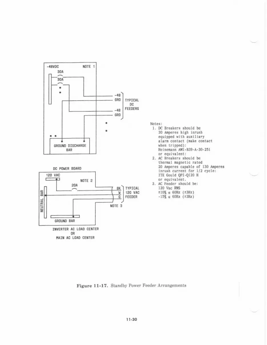
-48)cRD I rYprc^Lloc-., I rerornsu*J
Notesll Dc Breakers should be
30 Airperes high inrushequipped witb auxiltaiyalarD contact (nat€ contactuh€n trrpped):
2.
3.
Hetne'nann A I-039.A.30-25I
AC Breakers should b€thermal magnetic rated20 ADp€r€s capable of 130 Arp€resinrusn current for l/2 cycle;ITE Gould QPI.Ql20 H
or €quival€nt.AC Feeder should be:120 Vac RIISt10* @ 60Hz (!3flr)- l5g o 60Hz (!3Hz)
tilVERIER AC LOIO CEIITER
OR
NTII AC LOAO CEIITER
Figure 1l-17, Standby Power Feedet Arrangements
-T- iloTE 2
-l20^Ell L_^-
I r-30

AC F.eder Anang.ment-Stdndby Pove.
AC feeders to auxiliary cabinets, Applications Processors, utility receptacles, and any wall-mounted syst€m €quipment will be provided from the singl€-pole circuit breakers in themain ac load center or the inverter AC load center when standby ac powet is required (see
Figure 11-18). The utility feeders and r€mote access data set should be powered from theinverter ac load center. Failure to do so will impair any required maintenance activityduring an ac power outag€.
System 85 cabinets arc supplied with ac power ducts attached to the top rear of the cabinets.They form an ac wireway (mceway) on each lineup. These power ducts will be equipped withthe required receptacles for auxiliary and AP cabinets to which their feeder circuits will beterminated (see Figure 11-7). System 85 switch cabinets are supplied with direct dc feedersand do not require ac feeders or receptacles in the power duct. Power ducts for theSystem 85 switch cabinets arc supplied to prcvide continuity of the ac wireway for AP andAuxiliary cabinets in the same lineup. They also provide utility receptacles at apprcximat€lyevery other cabinet position. The utility rcceptacles should be porvered from a single acleeder and associated circuit breaker.
Conduit and wiring must b€ run from the main ac load center andlor inverter ac load centerto the ac power duct and receptacles on each cabin€t lineup in a manner complying withlocal codes and practices. Additional miscellaneous feedeN, conduit, and receptacles mustalso be provided for any system equipment not contained in system cabinets (see Figure 11-17).
Note.' If local practices dictate that the rcceptacles supplied with the power ductattached to the cabinets cannot be us€d, individual ceiling drop or floor receptacles maybe us€d.
I l-3t
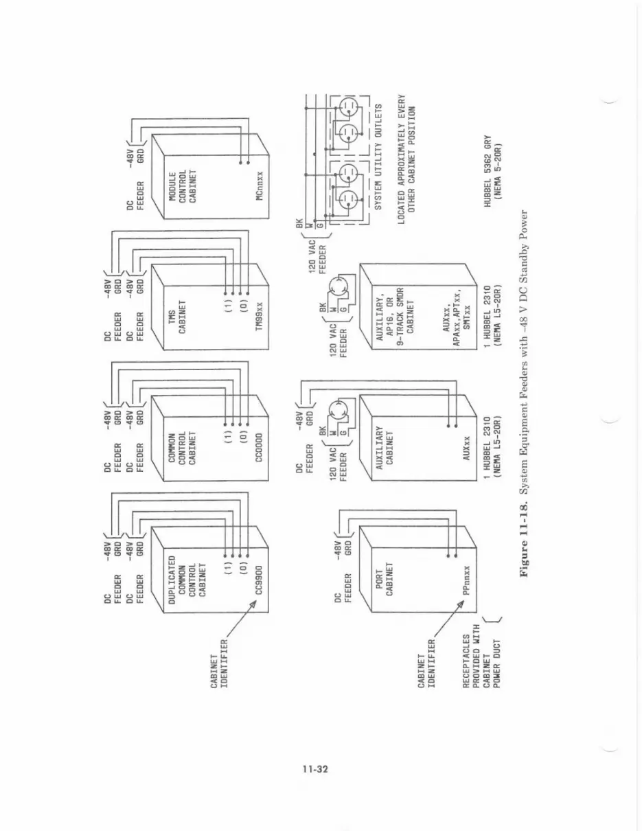
oaSRB;
i\i I
E=
N1
srf
9-)A
=2
fiEEE
B
Qa
>
3-
t'l
=E;ti -Er _-.!<i 5*i
=EEs i1a
,.s'-l,(, I
=dE i e BE=E E
5!4?-li: : 6 oEE- O
I l-32
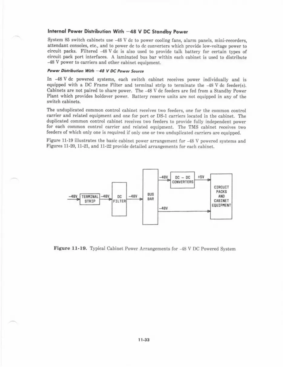
lnt..nol Pow.r DitLibu on With -48 V DC Srqndby Pow..Syst€m 85 switch cabinets use -48 V dc to power cooling lens, alarm panels, mini-remrders,att€ndant consoles, etc., and to power dc to dc conv€rters which provid€ low-voltag€ power tocircuit packs. Filtered -48 V dc is also used to provide talk battery for certain types ofcircuit pack port inte aces. A larninated bus bar within each cabinet is used to distribute-d8 V power to calriers and other cabinet equipment.
P.w.r Dirniberion Wth -4A V DC Powe. SooH
In -48 V dc powered systems, each switch cabinet receiv€s prower individually and isequipped with a DC Frame Filter and terminal strip to terminat€ the -48 V dc feeder(s).Cabinets ar€ not paircd to share power. The -48 V dc f€€ders sre f€d from a Standby PowerPlant which provides holdover power. Battery reserve units ar€ not equipped in any of theswitch cabinets.
The unduplicated cornmon control cabinet rec€ives two feeders, one for the common controlcarder and relat€d equipment and one for port or DS-1 carriers located in the cabinet. Theduplicated common control cabinet receives two feed€N to l,rovid€ fully independent pow€rfor esch common control carrier and r€lated equipment. The TMS cabinet rec€ives twofeed€rs of which only one is required il only one or two unduplicated carri€rs are equipped.
Figure 11-19 illustrates th€ basic cabinet power errang€ment for -48 V powered systems andFigurcs 1l-m, 11-21, and 1l-22 prcvide detailed arrangem€nts for each cabinet.
Figlre 11.10, Typical Cabinet Power Adangements for -48 V DC Powered Syst€m
I t-33

l)S-1 CARRIERS
ti)DUtE coiTRot cmnrEe(s)-.4 + GRD
IIODULE COXTROI CAEIIIET-/t8vDc lrs€o FonTALK BTTIERI (8AIT)
-t8RSV:
-t8v0c usE0 FoRc0[10]/ coltlRotAIII) ALANfi PAIiEL
PORI/DS-1 CARSIERS
0cFILT'N
-48(r)cRD{r)
c0lttot c0flTR0t cA8:IEt
Figure 11-20. Module Control and Common Control Power (-48 V DC Powered System)
DC.DCc0l/v€RTERS
-a8T + CRDT !5V
TERfiITALSTRIP
CINCUITPACKS
0c-0cCOIIVERIERS
DC FAIIASSEIIBLY
0c-0cCOTVERTERS
CIRCUITPAC(S
0c-0ccotvERlEns
DC FAIIlssEnBtY
I t-3r
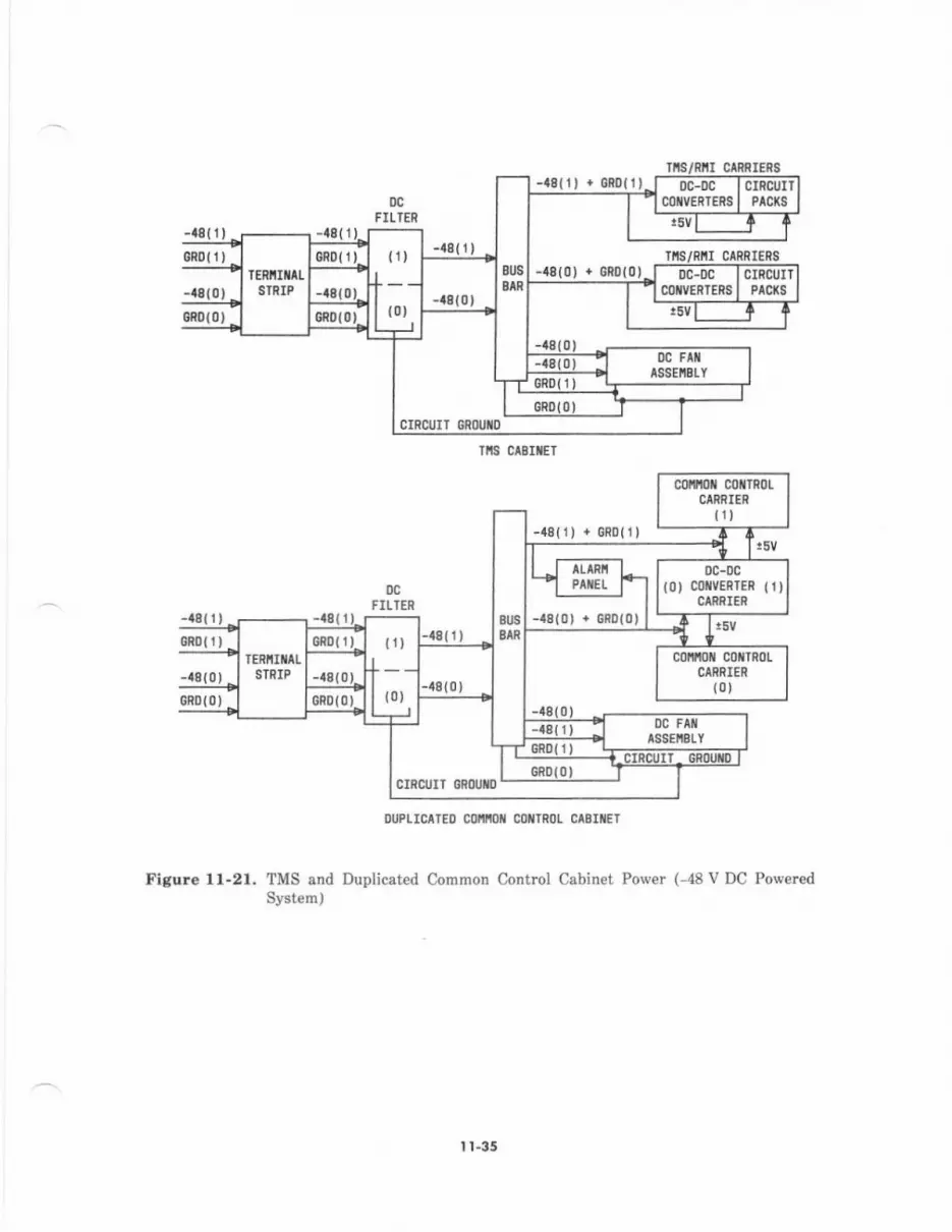
-48{t) + 0n011,0c
FILTER
rts/Ril crRRI€ns
TIIS CABIIIET
CIRCUIT GNOUTD
0c FAllASSEIIBIY
-18(0) + GR0(0)
DC.DC(0) coilvERIER {1)
CARRIER
TERI'IIIIALSTPIP
-48{0)
cotnoll co{rRotCARRIER
(0)
DC FATtssEltELY
-48{ 1)
ouPtrcllEo coin coilTRo! ca8(tET
Figure 1l-21. TMS and Duplicated Common Control Cabinet Power (-48 V DC PoweredSystem)
I t-35
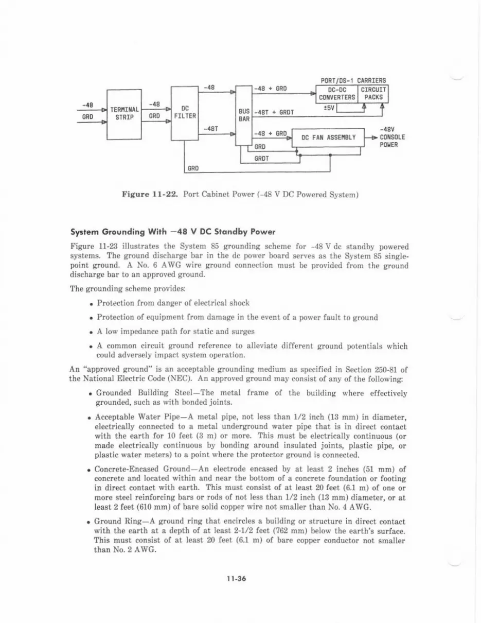
PORT l)S-1 CIRRIERS-a8 + cRo
Fi8ur€ 1l-22. Pott Cabinet Powe. ( 48 V DC Pow€red System)
sy.tem Grounding Wirh -48 V DC Stdndby Power
Figure 11-23 iuustrates th€ System 85 groundilg scheme for -48 V dc standby poweredsystems. The ground discharg€ bar in the dc pow€r board serves as th€ System 85 single-point ground. A No. 6 AWG wire ground connection must be provided from the grounddischarge bar to an approved ground.
The grounding sch€me provides:
. Protection from darger of el€ctrical shock
. Prct€ction of equipm€nt from damag€ in th€ event of a pow€r fault to qround
. A low impedance path for static and surges
. A common circuit ground reference to alleviate different ground pot€ntials whichcould advers€ly impact syst€m operation.
An "approv€d ground" is an acc€ptable grounding medium as specified in Section 250-81 ofthe National Electric Code (NEC). An approved ground may consist of any of the following:
. Grounded Building Steel-The metal frame of the building where effectiv€lygrcunded, such as with bonded joints.
. Acceptable Water Pipe-A metal pipe, not less than 1/2 inch (13 mm) in diamet€r,elechically connected to a metal underglound water pipe that is in direcl contactwith th€ earth for 10 feet (3 m) or mor€. This must be electrically continuous (ormade €lectrically continuous by bonding around insulated joints, plastic pipe, orplastic water meters) to a point where th€ prot€ctor ground is connected.
. Concrete-Encased Ground-An electrode encased by at least 2 inches (51 mrn) ofconcrete and located within and n€ar the bottom of a concrete foundation or footingin dircct contact with earth. This must consist of at least 20 feet (6.1 m) ol one ormore steel reirforcing bars or rods of not l€ss than 1/2 inch (13 mm) diameter, or atleast 2 feet (610 mm) of bare 6olid copper wire not smaller than No. 4 AWG.
. Ground Ring-A ground ring that encircl€s a building or structure in dir€ct contactwith the earth at a depth of at le Et 2-1/2leet (762 mm) below the earth's surface.This must consist of at least m feet (6.1 m) ol bare copper conductor not smallerthrn No. 2 AIVG-
0c-0cCOIIVERTENS
CIRCUIIFlct(s
0c Fti assEnErl
I t-36
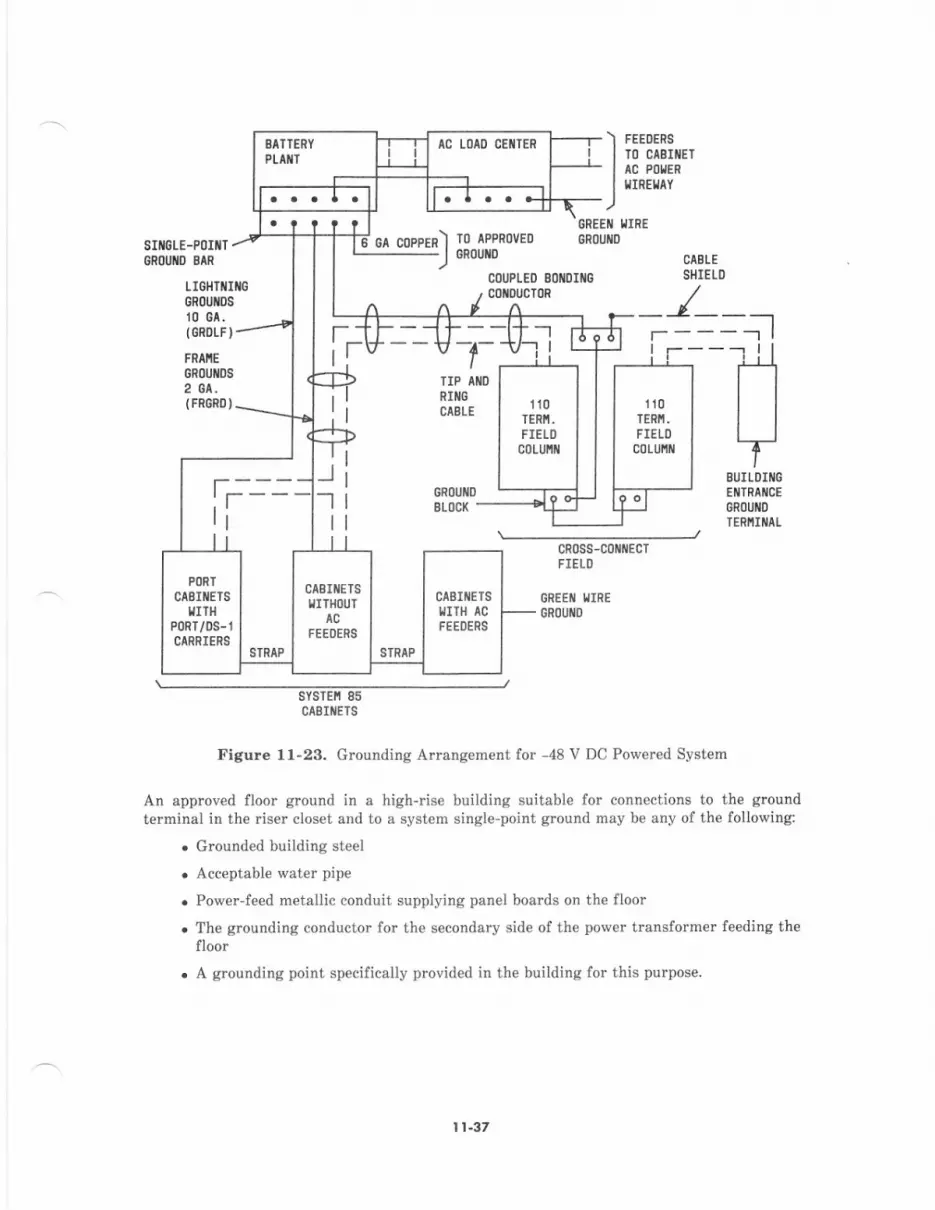
SItI6LEGROUIID
BATTERY
PI,ATT
t. . . I . t
AC LOAD CEIITER
--=-4
\FEIro
DERS
ctslttEPOI'IER
ElAY
Jih??
;p'1 tO rPcnOv
-J oRouxD
COUPI
, CollDt
GREEII IIIR
LE.POIilT-ilD BAN
LIGHTIIIiGRl)UIIDS
10 GA.
IGROLF).
FRAIIEGROUIIDS
2 0^.(FRCRDI.
f-
GI COPP 6ROUfl
ED BOIIDIIIGCTOR
s
- -t'i .t- r-l--1
110TERiI.FIELl)
c0LU[il
ti
ji-"1
I
RIIIIGCABLE
110TERI,I.
FIEIOc0LUl$l
fr---:l1 I
cn0ss-c0il EcTFIEIl]
GSEEII I'IIREGRoUflo
PORIAEIIIIETSIITII
)Rr/0s-rARRIERg
STRAP
cABIIiETSIITI{OUT
AC
EEOER9
SIRAP
CIBIIIETSIIITH AC
FEEl)ERS
:;l
HBUILDIIIGEIITRAICEGR(]UIID
TERNIiIAI
sYsTEfi 85CABIIIETS
Figure 1l-23. Grounding Arrangement for -48 V DC Powered System
An approved floor ground in a high-rise building suitable for connections to the groundterminal in the riser closet and to a system single-point grcund may be any of the following:
. Grounded building steel
. Acceptable water pipe
. Power-feed metallic conduit supplying panel boards on the floor
. The grounding conductor for the secondary side of the power transformer feeding thefloor
. A srounding point specifically provided in the building for this purpose.
I 1.37
Sy.t. Grou.d ted.The following leads are used to effectively ground System 85. These leads arc rcquired inconjunction with the apprcved and single-point grounds discussed above and will be installedby System 85 installation personnel (with the exception of green wire grounds in ac feeders).
Coupled Bonding Conductor
The coupled bonding conductor prcvides a conn€ction between the system single-pointground and th€ protector ground terminal for cable facilities at the building entrance.It is run adjacent to protected pails in an associated cable. The mutual couplingbetween the bonding conductor and the pairs reduces the difference in elect?icalpotential in terminating €quipment which may rcsult from lightning surges. Thisconductor can consist of the following:
. When pairs are run in shielded cable, the cable shield shall be used as thecoupled bonding conducior. Shield continuity must be verified using a T-124,manufactured by Wiicor Grounding Systems, or equivalent.
. With inside wiring cable, the coupled bonding conductor shall consist of a No. 10
AWG wire tbat is tie-wrapped to th€ cable. If this is impractical, six dedicated,good spare pairs within th€ cabl€ may be used as the coupled bonding conductor.The six spare pairs must be twisted and soldered to prevent their use for otherpurposes.
A suitable connecting point (coupled bonding conductor terminal block) should beprovided for the connection to the system single-point ground.
Equipnent Grounding Conductot (Grcen Wire)
the ac power equipment must be grounded by an equipm€nt grounding conductor(green wirc) in compliance with NEC, Article 250'32 (1981 Edition). This gound seru€sas the green wirc ground for the System 85 in accodance with NEC, Articles 250-42and 250-45 and is distdbuted to cabinets equipped with rectifiem via the ac feedercircuits.
Lis htnins Grcun d (GR D IF)
Each cabinet containing a port or DS-1 carrier tequires a lightning eround connectionto route lightning surges away fmm circuit components. A lightning ground (GRDL) ischain-wired to each cabinet withir a module. Then the lightning ground is wired fromone of the cabinets to the system singl€-point ground terminal via GRDLF. Eachmodule must have a separate lightning ground connection (GRDLF) to the systemsingle-point glound-
Frdne Grcund (FRGRD)
Each cabinet which does not use an ac feede. requires a cabin€t frame groundconnection for safety precautions from shock hazards. A frame ground wire is tied toeach non-ac powered cabinet in a lineup and to a No.2 AWG wire which is terminatedto the single-point ground terminal. Each cabinet lineup rcquires a separat€ frameground connection to th€ system single_point ground.
Grounding A cngemen, With - 48 v DC Povd Sout e
There are thrce basic types of intracabinet and intercabinet grounds used in -48vdcpowered systems. They are:
. Equalizing Ground (Circuit Grcund)
. Lightning Ground
. Fmme Gmund
I r-38
These grounds are kept totally isolated lrom €ach other in the syst€m cabinets and arcindividually routed to the ground discharge bar on the Standby Powe. Plant DC PowerBoard which serv€s as the system single-point ground. In addition to these, a digital groundwhich is tied to circuit ground is distributed to port or DS-1 car ers within a cabin€t toinsure a low impedance path for digital signals.
Equalizins Grcund
Each switch cabinet is equipped with a circuit ground block located on the dc fan assembly.The circuit ground block is connected to the power distribution grounds of the cabinet busbar and to the ground(s) of -48 V dc feeders powering the cabinet. The ground leads of the-48 V dc feeders originate from the ground discharge bar (system single-point ground) in thedc power board of the standby power plant. A No. 4 AWG wire is run frorn the circuitground block in the module control cabinet to the circuit ground block in each cabinetcontaining port or DS-1 carriers associeted with that module. This is used to equalize thecircuit ground potentials of cabinets within a module. The equalizing ground is not requiredfor TMS or duplicat€d common control cabinets (see Figure 1l-Z).Agiral G.ound
Digital ground connections (GRDD) repres€nt four equally spac€d No. 14 AWG wire strapsused to €lectrically interconnect adjoining or sequential carrieN with a cabinet to insure alow impedance path for digital signals. The digital grounds are connected to the circuitground block on the dc fan assembly (see Figure 11-24).
Lishtnins Oround
Each cabinet €quipped with port or DS-l carriers has No. l0 AWG wire straps chained toeach port or DS-l carrier from a terminal strip located jn the cabinet. These connections areused to route lightning surges away from circuit components. A No. 10 AWG wire is chain-wired lrom the lightning ground terminal strip of one cabinet in a module to each othercabinet associated with the module in that row. This cabinet will have a No. l0 AWG \rirerun from its lightning ground terminal strip back to the System Single-Point Ground via anElectro-Magnetic Compiiance (EMC) filter located in the cabinet. The cabinet equipped withthis EMC lilter will either be an unduplicated common control cabinet or Port Cabinet. Ifone or more port cabinets are locat€d cross-aisl€ from their associat€d modul€ controlcabinet, one of the port cabinets must also be equipped with an EMC filter and have alightning ground connection to the system single-point ground. The lightning groundterminal strip of the cabinet with the EMC filter and lightning ground connection is chain-wired to any other port cabinets in the row associated with its module. Each of thelightning ground connections from the modules to the system single-point ground isdesisnated GRDLF.
I l-39

o
.Fr
a
!9
ii -:aH a;=5
3Fr
q,l
i9 :
-iEiE-+!EE=bEdxE.=PAE=F6
€f
56
6=
-9
;5@PE63
=E
Edc=
I t.40
r2. UPGRADES (TO R2V3)
A System 85 upgrade is the process of transforming the hardware and software of aprcviously install€d system to that of a later vemion. This is performed vhen increased callprocessing demands, need for greater feature capabilities, and other changes in customerrequirements justify such an action. Upgrades from System 85 Release 1 (R1); Release 2,
Version I (R2V1); or Release 2, Version 2 (R2V2) to Release 2, Version 3 (R2vg) aresupported with minimal hardware/software changes.
FI.OOR PI.AN
The floor plan ensures that all system components will be located according to agreementsmade with the customer. It is used as a site insp€ction guid€ to €nsure that customer-prcvided elect cal and mechanical facilities are corrcct, agreeing with plant requirementsand electrical codes, b€fore installation.
Appropdate floor plan modifications are performed according to the typ€ and extent ofsystem upgrade. The floor plan is revised when additional cabinets are r€quired for th€up$ade. These cabinets are installed at the most convenient positions within the cabinetlineup (including rcquir€d power, cabling, and ductwork modifications), in accordance withthe proper configuration gidelines. I{ an additional common control cabinet is required, itmust be located rvithin 200 cable feet of the module control cabinet(s).
SOFTWARE TRANSI.ATIONS
Translation recovery is the process of removing tmnslation data from an existing tapecartridge for transfer onto a new tape cartridge containing a new program generic andlorconfiguration. To prepare a new tape for the upgraded system, the translation data must bestdpp€d from the previous system tape through the r€covery process. The sttipped data ismodified to reflect hardwarc rcarrangem€nts required lor the upgraded configuration.Additionallv. new translation data or added hardware items must be add€d to thetranslation database. This database, composed of three items (recovery from previoussystem, modifications or rearrangements, and new additions), is used to gen€rat€ theupgraded syst€m tape.
Appropriate translation recovery procedures are performed according to the type and extentof system upgrade. A copy of the currcnt software tape is sent to AT&T, where thetranslations are extracted and loaded onto a tape with R2Vg software programs.
In most instances, additional memory is required to upgrad€ to the R2VB system. An R2V3system will require 4 to 8 megawords of memory p€r common control, depending on theconliguration of terminals, trunks, and features sp€cified.
12-l
RI TO R2V3 UPGRADES
Ordering and implementing procedures for an upgrade from R1 to R2Vg are essentiallyunchanged from the R1-to'R2 procedures previously described under UPGRADE PLANS inReferetrce Manual-AT&T System 85 (R2Vl/V2)-System Description (999-?00-006IS, Issue 1). However, additional memory is requircd to upgrade to the R2Vg system. Thelollowing guidelines apply in this case:
. If upgrading from an unduplicated Rl to an unduplicated R2V3 system, eight 1-megaword memory circuit packs (TN392C) must be ordered (maximumconfiguration).
. If upgrading frcm an unduplicat€d R1 to a duplicated R2V3 system, sixteen l-m€gaword memory circuit packs must be ordered (maximum configuration).
. If upgrading {rom a duplicated Rl to a duplicated R2Vg system, sixteen l-megawordmemory circuit packs must be ordered (maximum configuration).
For more d€tailed information on Rl-to-R2 upgrades, refer to Service Manual-AT&TSystem 86-In-Service System Upgredes (555-101-11lIS).
R2Vl ro R2V3 UPGRADES
To upgrade from R2V1 to R2VB (maximum configuration), the following guidelines applyl
. If th€ R2V1 common control is unduplicated, six l-m€gaword m€mory circuit packsmust be ordered.
. If the R2Vl common control is duplicated, twelv€ l-megaword memory circuit packsmust be order€d.
R2V2 TO R2V3 UPGRADES
To upgrade from R2V2 to R2V3 (maximum configuration), the following guidelines apply:
. If the R2V2 common control is unduplicated, four l-megaword memory circuit packsmust be ordered.
. If the R2V2 common control is duplicated, eight 1-megaword memory circuit packsmust be ord€red.
t2-2
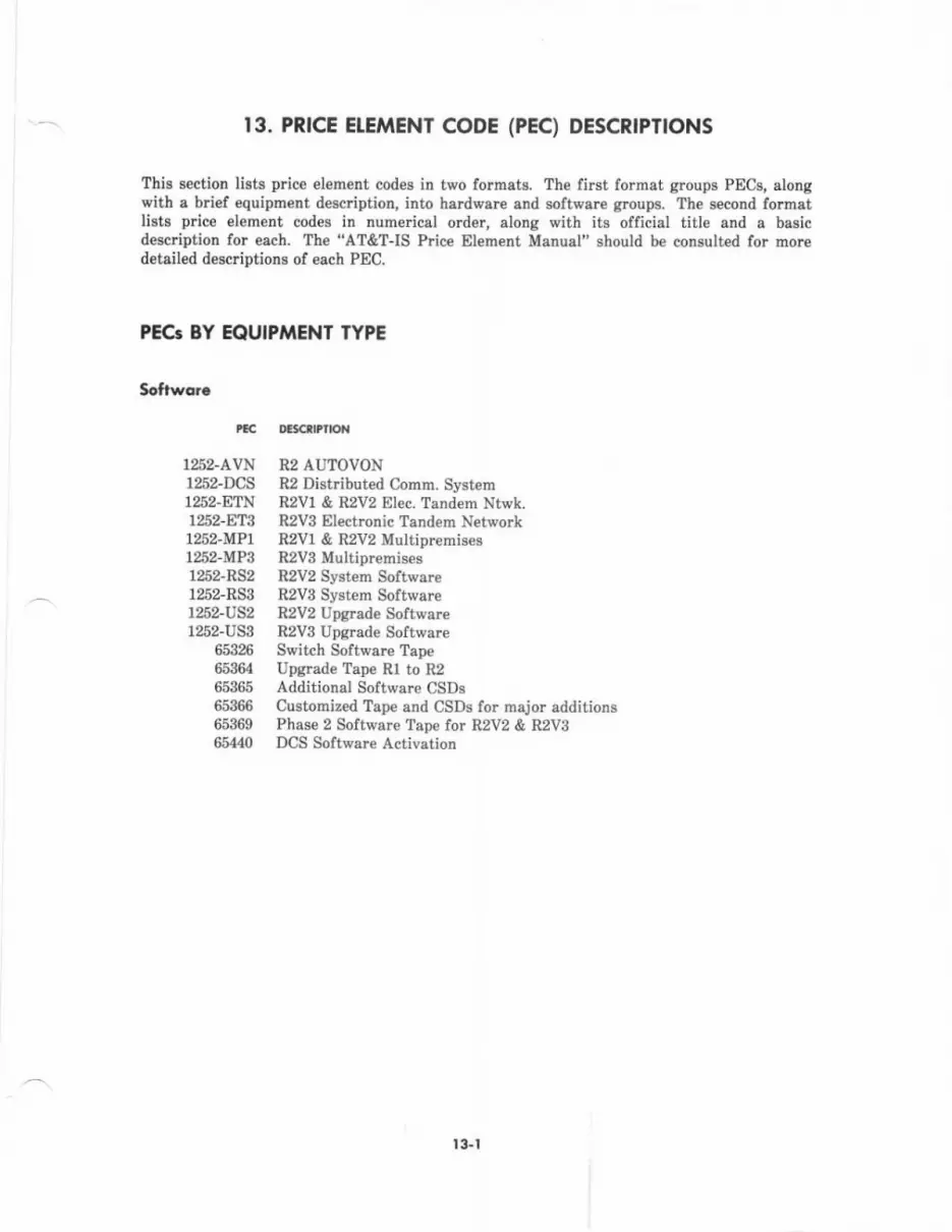
t3. PRTCE ETEMENI CODE (pEC) DESCR|PTIONS
Thie section lists price eleme[t cod€s in two formats. The first format groups PECg, slonSwith a brief equipment description, into hardware and software groups. The second formatlists price elom€Dt codes in numerical order, along with its official titlo and o basicd€scription for each. The .'AT&T-IS Price Element Manual" should be consulted for morcdetailed descriptions of each PEC.
PEG BY EOUIPMENT TYPE
Softworo
tac
125ZAVNr252-DCS1252-ETN1252-ET31252-MP11:62-MP31252-RS21252-RS3t2lt2-vs21252-US3
&5:126
653646536565366653696511.!0
oclc$tfld{
R2 AUTOVONRZ Distributed Comm. SystemR2V1 & R2V2 EIec. Tendem Nt\,rk.R2V3 Electronic Tandem NetwolkR2V1 & R2v2 MultipremisesR2V3 Multiprernis€gR2V2 SFtem SoftwareR2V3 System SoftwareB2V2 Upgrade Soft*'.reR2V3 Upgrade SoftwareSwitch Software TapeUf'grade Tape Rl to R2Additional Software CSDSCustomized Tape and CSDs for rnajor additionsPhase 2 Software Tape lor R2V2 & R2V3DCS Software Activation
r 3.t
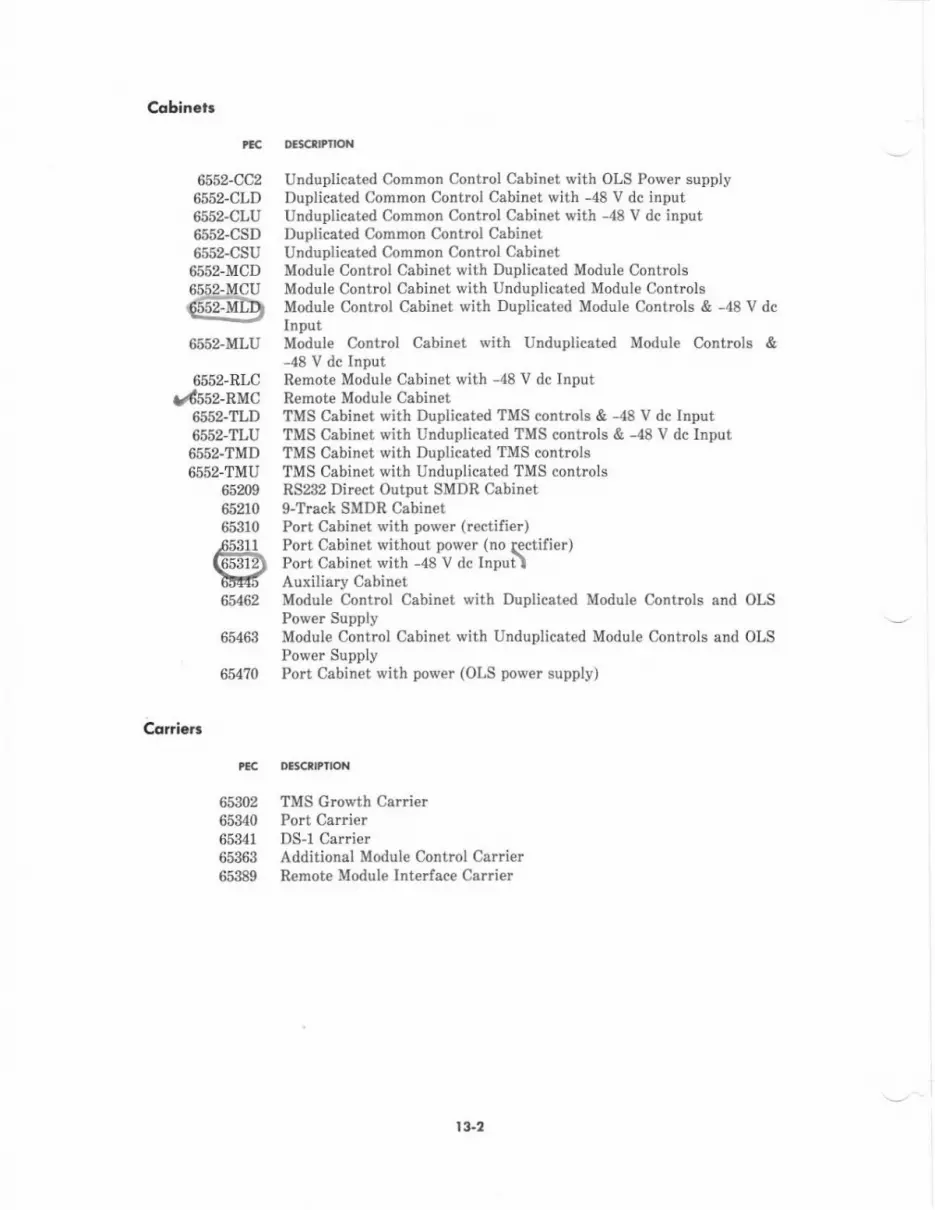
C.dbin.t.
rcc DEgarltllot{
6552-CC2 Unduplicated Common Control Cabinet with OLS Power supply6552-CLD Duplicated Common Control Cabinet with -48 V dc input6552-CLU Unduplicat€d Common Control Cabinet with -48 V dc input655?CSD Duplicated Common Control Cabinet6552-CSU Unduplicated Common Contml Cabinet6552-MCD Module Control Cabinet with Duplicated Module Controls65t2jUCU Module Control Cabin€t with Unduplicat€d Module Controls6fl52-fifD Module Control Cabinet with Duplicated Module controls & -48 v dc
--__, .rnpur
6552-MLU Module Contrcl Cabinet with Unduplicated Modul€ Controls &-48 V dc Input
6552-RLC Remote Module Cabinet with -48 V dc InputUd552-RMC Remote Module Cabinet
6552-TLD TMS Cabin€t *ith Duplicated TMS controls & -48 V dc Input6552-TLU TMS Cabinet with Unduplicated TMS controls & -48 V dc Input6552-TMD TMS Cabinet with Duplicated TMS controls6552-TMU TMS Cabinet with Unduplicated TMS controls
65209 RS232 Di&ct Output SMDR Cabinet65210 g-Tfeck SMDR Cabinet65310 Port Cabinet \r'ith po\r'er (rectifier)-65311 Port Cabinet without Dower (no rectifier)
(6TEi?) Port cabiner with -48'v dc Inpui\tltrtf, luxiliarr Cabinet6tt62 Module Control Cabinet with Duplicated Module Controls and OLS
Power Supply65463 Module Control Cabinet with Unduplicated Module Controls and OLS
Power Supply654?0 Pott Cabinet with pow€r (OLS power supply)
icrdcrr
PEC OLCllPtlON
65302 TMS Growth Canier65340 Port Carder65341 DS-l Carrier65363 Additional Module Control Carrier65389 Remote Modul€ Interlace Carrier
l3-2
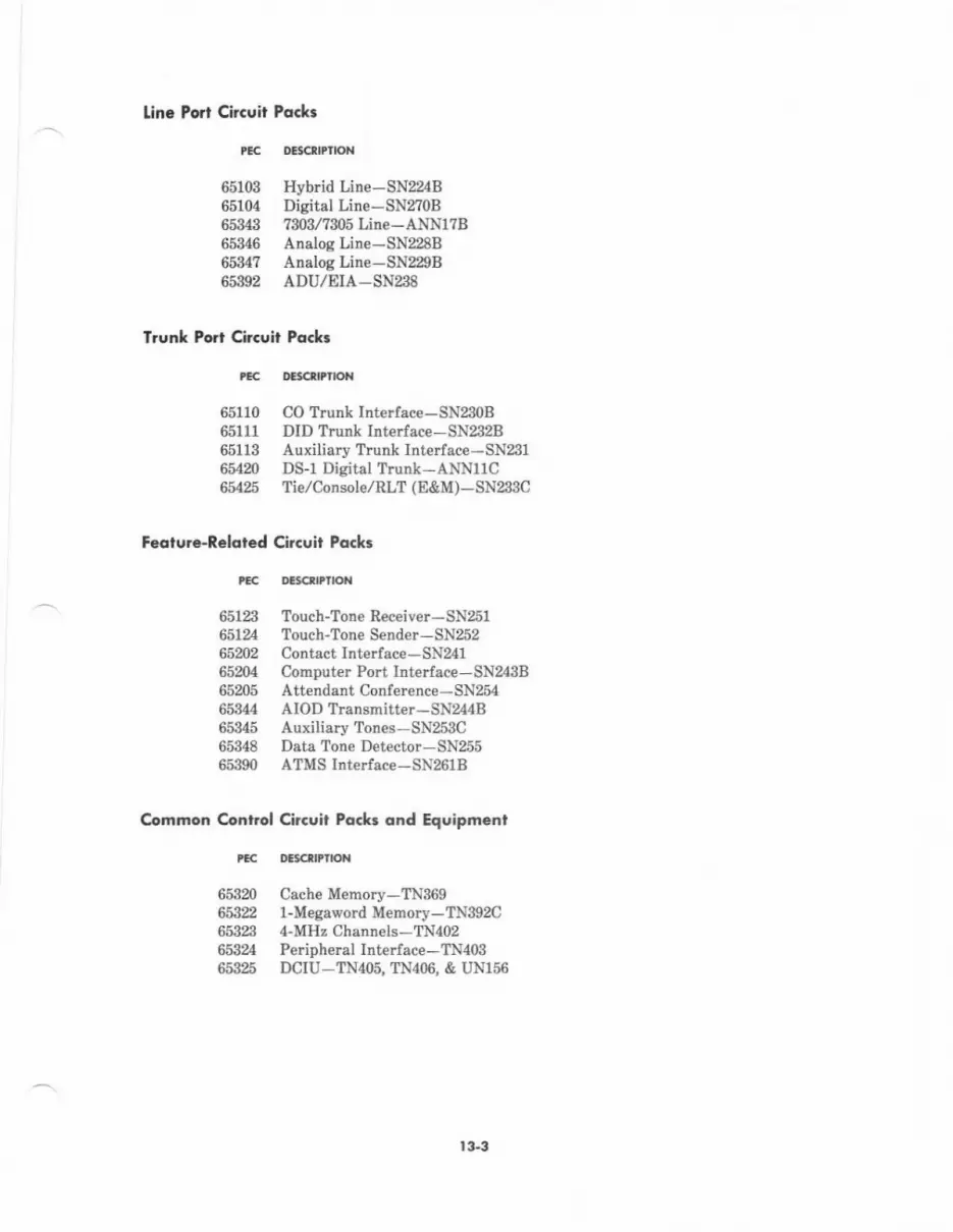
tin. Port Circuil Pqck.
tlc nBt€rlPloN
65103 Hyb d Line-SN B65104 DigitalLine-SNfloB65343 7$3/?$5Line-ANNl?B65346 AnslogLine-SN228B6534? AnologLine-SN22gB65392 ADU/EIA-SN238
Irunl Porr Clrcuit Pq.lr
tEc DEcrllatox
65110 CO Tnr* Irterlace-SN230B65U1 DID Trunk Interface- SN232B65113 AuxiliaryTrunklntelface-SN2g1654m DS-1 Disital Trunk-ANNUC65,125 Tieloonsole,/RlT (E&M)-SN233C
F.otul€-Reloled Circuil Pock3
Cornmon Control
DaSCrDnON
Touch-Tone Receiver-SNzslTouch-To!€ Send€r-SN252Contact lnterface - SN241Cohputar Port Interface-SNzl3BAttendsnt Conlerence - SN254AIOD Transmitter-SN244BAuxili8ry Tones-SN253CData Tone Det€ctor-SN255ATMS Interface-SN261B
Cl.GUit Po.k5 ond Equipncnl
DE CTDI|oT
Cache Memory-TN3691-Megaword Memory-TN3g2o4-MEz Channels-TN{02Peripheral Interlace-TN4o3DCIU-TN4O5, TN4O6, & UN156
tEc
65123€5]2465202652045520565344653456534865390
tcc
65820663n6532365324&53%
t33
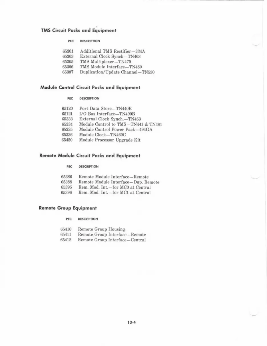
lliS Circoit Poc&r ond Equipm.nl
ttc D€tcrDlloN
65301 AdditionalTMSRectifier*384A65303 ExternalClockS]'nch-IN46il65305 TMSMultiplexer-TN4?o65306 TMS Module Int€rfece-TN48o65$7 Duplication,/Update Chennel-TNs3o
Modulc Control Gircuit Pa.k. ond Equipm.nt
tac ocaclltflot{
65120 Port Dats Store-TN44oB65121 I/O Bus Interface -TN400B6583:l Extern8lClockSynch.-TN46365334 Module Control to TMS-TN441 & TN48165385 Modul€ Control Power Pack-4g4CA6539G Modul€Clock-TN460C65450 Module Processor Upgrade Kit
Rrmota Modul. Citcuit Pockr ond Equipmcnt
tl< oBlcflPtloN
65386 RemoteModulelnterface-R€mote65388 Remote Module Interface-Dup. R€mot€65395 Rem. Mod. Int -for MCO st Centrsl65396 Rem. Mod. Int.-for MCI at Centrel
R.mot. Groep Equipm.nt
tlc oEtcflrrpN
65410 Remote Group Housing6 11 Remote Grcup Interface-Remote6S12 Remote Group Inte ac€-Cenhal
l3-4
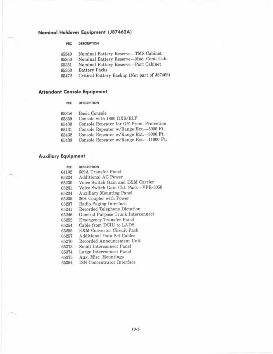
Nominql Hddcwr Equipmcnr (18746.2A1
ttc
653496535065351
6535365472
D€rcirI'O'{
Nominel Batt€ry Reserve-TMs Cabin€tNominal Batt€ry Reserve-Mod. Cont, Cab.Nominal Battery R€serve-Port CobinetBatt€ry PacksCritical Battery Backup (Not part of J87462)
Atl.Ddont ccntola Equipmenl
tlc D€lcrltrlol{
65358 Basic Console66359 Comole with 18{n DXS/BLF6 30 Consol€ Repeater fot Off_Prem. Protection65431 Consol€ Rep€ater w,/Range Ext.-5000 Ft65432 Consol€ Repeater w/Range Ext.-8000 Ft65488 Conaole Repeater dRang€ Ext.-11000 Ft.
Auxiliory Equipmcnt
rcc D6ctlrrlox64102 609A TrsDsler Patrel6Sn4 Additional AC Poc,er652$ Voice Switrh Gain and E&M Carrier6581 Voice Switch Gain CkL Pack-VFR-5o5o65234 Auxiliary Mounting Panel65235 36A Coupl$ with Power6523? Radio Paging Intelface65241 RecordedTelephoneDictation65246 Genenl Purpose Trunk Interconnect65252 Emeryency Translet Pan€l65254 Cabl€ Irom DCIU to LADS65255 E&M Converter Circuit Pack65 ? Additional Dsta S€t Cable665210 Recorded Announcement Unit653?3 Smatl Inttrconnect Panel653?4 Large Intalconnect Panel6 1l5 Aur. Misc. Mountings65394 ISN Concentrator Interface
t 3.5
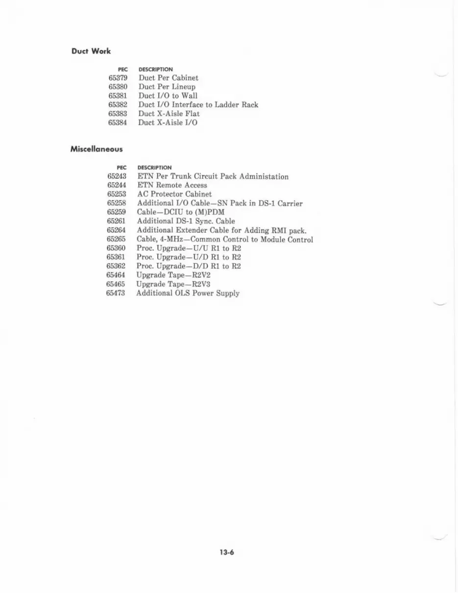
Duc Wo*
rtc 06cdPllot{65379 Duct Per Cabinet65380 Duct Per Lineup65381 Duct I/O to Wall65382 Duct I/O Interface to Ladder Rack65983 Duct X-Aisle Flat65384 Duct X-Aisle I/O
lAircclloneour
Pac Dlsc PnoN
65Z8 ETN Per Trunk Circuit Pack Administation65 4 ETN Remote Access65253 AC Prctector Cabinet65258 Additional I/O Cable-SN Pack in D$l Calrier65 9 Cable-DCIU to (M)PDM65efl Additional DS-l Sync. Csble65264 Additioml Extender Cable for Addine RMI pack.65265 Cable, 4-MHz-Common Contlol to Module Control65360 Proc. Upgrade-U/U Rl to R265361 Proc. Upgrade-U/D Rl to R265362 P!oc. Upgrade-D,/D R1 to R265464 UpgradeTape-RzV265465 UpgredeTape-R2Vg6tt?3 Additional OLS Power Supply
t3{
NUA ERICAL tlSTlNG OF PBCc
rft lxD D6cttnoit
1252-AVN AUTOVON:Charge for AUTOVON syrtem software.
I252-DCS DIST COMMUN SYS.R*Charge for DCS sofiware.
I%2-B[N ELEC TANDM NTWK-R*Charge for BfN software-R2vl and R2V2.
1%2.8T3 ELEC TANDM NTWK-R2V3:Charge for ETN software-R2V3.
1%2.MP1 MULTIPREMISES.R2:Charge for rnultipremise (mein/setellite) softwar€-R2V1 and R2V2.
r252.MP3 MULTIPREMISES-R2V8:Charge for multipremis€s (main/satellit€) softwar€ -R2V3.
I252-RS2 SYSTEMSOF'TWARE.R2V?Charge for basic/required sy3tem softwar€-R2V2.
r252-RS3 SYSTEMSOFTWARE.R2Vs:Chcrge for basic/requircd system softwarc-R2v3.
I252-US2 UPCRADE SFWR TO R2V2.Charge for R2V2 upgrade softwarc.
r252-US3 UPCRADE SFWR TO R2V3:Charge for RZVS upgrade software.
6552-CC2 SYS 85 COM C'IL W,/SMTProvides J58886J R2 common control cabi[et, wirin& cables, alarmpanel, common contrcl carri€r, basic circuit packs, etc.; aFanged forac input power. This PEC includes an OLS power supply.
6552.CLD SYS 85 DUP WSMT.LT:Provid$ J58886K R2 duplicated common control carrier, wiring,cables, basic circuit packs, etc.; arranged lor ac input power.
6552.CLU SYS 85 COMM WSMT.LT:Provid$ J58886J R2 common control cabinet, common control carrier,basic circuit packs, wiring, csbles, alarm psnel, etc.; arranged for-48 V dc input pow€r.
t3-7

tlc fllE AND DESCNPflON
6552-CSD SYS 85 DUP CTL W/SMT:Pmvides J58886K R2 duplicated common control cabin€t, vriring,cables, alarm pan€ls, two common control carrierc, basic circuitpacks, etc.: arrang€d for ac input power.
6552-CSU SYS 85 W,/SMT:Provides J58886J R2 common control cabin€t, wiring, cabl€s, alarmpanel, common contlol carrier, basic circuit packs, etc.; arranged forac input pow€r.
6552.MCD MOD CTL DUPLICATED:Provides J58886B R2 module contrcl cabinet, two module controlcar €rs, wiring, cables, basic circuit packs, etc.; arranged for ac inputpower.
6552-MCU MODULE CTL CABINET:Provides J588868 R2 module control cabinet, module control carrier,basic circuit packs, wiring, cables, etc.; arranged for ac input power.
6552.MLD MOD CTL DUP.LTProvides J588868 R2 module control cabinet, two module controlca$iers, basic circuit packs, wiring cables, etc.; arranged for 48 V dcinput power,
6552.MLU MODULECTL-LT:Prcvides J58886B R2 module conhol cabinet, module control callier,basic circuit packs, wi ng, cables, etc.; arranged for -48 V dc inputpower.
6552-RLC REM MOD CABINET-LT:Provides J588868 R2 module control cabinet, module control carrier,basie circuit packs, remote module interface circuit, LCIT andassociated interconnections, wiring, cabl€s, etc.; arrang€d for 48 V dcinput power.
6552-RMC REM MOD CABINET:Provides J58886B R2 module control cabinet, module control carrier,basic circuit packs, remote module interface circuit, LCIT andassociated interconnections, wiring, cables, etc.; armng€d for ac inputpower.
6552-T,D TMS CTL DUP-LT:Provides J58886F R2 duplicated TMS cabinet, two TMS controlca$iers, basic circuit packs, wiring, cables, etc.; arranged for -48 V dcinput power.
t 3-8
tEc llnE tr'D DElcrttltot{
655?TLU TMS CONTROLL:TProvide6 J58886F R2 TMS cabinet, TMS control canier, basic circuitpacks, wiring cabl€s, etc.; arranged lor -48 V dc input power.
6552-TMD TMS DUP CTL CABINET:Provides J58886F R2 duplicalcd TMS cabinel two TMS cotrtrolcsni€rs, basic circuit packs, ririn& cebles, etc.; arrang€d for ac iBputp0wer.
6552.TMU TMS CONTBOL CABINET:Provides J58886F RZ TMS crbinet, TMS cotrtrol csmi€r, basic circuitpeckg, wirin& cables, etc.; arrang€d for ac input power.
65103 HYBRIDINTERFACE:SN224B provides four hybrid voice ports lor hyb d voice terminalgsuch as the ?2O0H Seri€s.
651M DIGITALINTERFACE:SNZ?0B provid€s four digital voice/dats ports for digibl voic€terminals, dsta modules, and integrsted voice/data terminals.
65110 CO TRI'NK INTERFACE:SN230B provides four trunk porh for CO, FX, and WATS.
651T1 DID TRUN( INTERFACE:SN232B provid€s lour trunk ports for DID.
65113 AUX TRIJNK INTERFACE:SN231 provides four trunk ports for auxiliary equipment.
65120 PORT DATA STORE:TN440B provides PDS for module control to each two port calriers.
65121 ADDL MODULE CTL ITFC:TN400B provides L/O bulfer interfece for modul€ control to each fourDort ca.rieB.
65123 1T RECEIVER PACK:SN251 provide four touch-tone receiver circuits.
651% fT SENDER PACK:SN252 provides four touch-tone send€r circuits.
65202 CAS,/UCD INDICATOR IF:SN241 plovides eight contact interfac€ circuits for UCD/EUCD/ACDand CAS.
t 3-9

PEC TIYIE AND DEgC 'TloN
65204 COMPUTER PORT INTERFACE:SN243B provides four trunk-type external computer ports.
65205 ATID CONF 6-PORT:SN254 provides 6-port attendant conference circuit.
65209 SMDR W,/RS232 OUTPUT:J59209A RS-232C SMDR direct output cabinet, SMDR dir€ct outputcarier and circuit packs, and all other required equipment.
652T0 SMDR W,/g.TRACK OUTPUT:J58886H g-tmck SMDR Cabinet, SMDR carrier and circuit packs, andall other rcquired equipment.
65N,4 ADDL AC DISTR]BUTIONPrcvides six additional ac outlets for auxiliarv cabinet.
65230 V.S.G. CARRIER:Inrain Mfg.460054L (comcode 402984231) provides housing for 19V.S.C. packs or E&M conveners.
65231 V.S.G. PACK:Lorain CP VFR-5050 (comcode 40m86079) provides voice switchedgain circuit.
65234 AUX MOUNTING PANEL:Provides 4-inch or l1-inch foam mounting panels for auxiliarycabinet.
65235 36A COUPLER W,/POWER:36A Voice Coupld and, 2012D provides int€rface from commonequipment to unregistered customer-provided auxiliary equipment.
65237 RADIO PG INT.TT:J58824CD prcvides radio paging intedace. Touch-ton€ withoufconversion.
65241 RECORD TEL DICTATION:J588278 prcvides recorded telephone dictation interface.
65243 ETN PER TRK CKT PACK:No material. Prcvides billing for ETN.
t3-ro
n t ^No
oE9art2io{
65%4 ETN-RDMOTEACCESS:Teitone M106 remote access unit provides ETN access lor remot€t€sting.
652,16 GEN PURPOSE TRK I,/C:J53050F provide6 trunk int€rface to customer-provided equipm€nt.
65253 AC PROTECTOR CABINET:JOSLYN 1455-?5 prot€ctor cabinet provides ac protection forSystem 85.
66254 CABLE LADS TO S85/AP:EDIE434-11 provides cabl€ to connect Iocal area dab set to DCIU.
65255 E&M CONVERTERS:Astro Endyne E&MC 11625-1-f provides four E&M circuits forconn€ction betvreen colocated PBX systems.
6525? ADDL DATA SET CABLES:ED1E434-11 provid€s data csbles to connect e second 212AR data setfor custom€r Remote Interface access,
65258 ADDL I,/O CABLE:EDIE134-11 provides I/O cables to connect an SN-coded circuit packin a DS-1 carrier.
65259 CABLE DCIU TO PDM:ED1E434-11 provides cables to connect the DCIU to an (M)PDM forAUDIX.
6526T ADDL DSl SYNC CABLE:ED1E434-11 provides additional DS-1 cable.
65264 ADDL EXTENDER CABLE:ED1E434-11 provides cabl€s for adding remote module int€ ace.
65265 CCIMC CABLEED1E434-11 Group &l providB 4-MHz cable for connecting theCommon Control to th€ Modul€ Control.
65270 RECORD ANN-BASIC UN:Cook El€ctric Announcement Unit (213300-2301611) and ac converter(213288) provides singl€-chsnnel ennouncement.
65301 TMSRECTIFIER-ADD:Provides additional 334A rectifier for TMS cebinet.
l3.t I

lllll aND oEtcnt?tot{
65302 TMS GROWTH CARRIE&J58886C plovides TMS Fowth carrier, bssic circuit packs, wiring,cabling, etc.
65303 TMS EXT CLOCK SYNCH:TN469 synchlonizes tls system clock with digital faciliti€s.
65305 TMS MULTIPLEXERTN4?0 provides portion of TMS fabric.
65306 TMS MODULE INTERFACE:TN480 int€rfaces the TMS to module controls.
65$? TMS DUPLICATION BDS:Two TN530r provide link between duplicated TMS control cerriers.
65310 PORT CABINET W,/PWR:J58886C pori cabinet and basic equipment; arranged for ac inputlon/er.
65311 PORT CABINET w/O PWR:J58886C port cabinet snd basic equipment; arranged for dc inputpower from adjacent cabinet.
6$T2 PORT CABINET-LT:J58886C port cabinet and b4sic equipment; arranged for -48 V dcinput power.
65320 MEMORY-CACHE:TN369 provides addition.l high speed 16 k memory to increas€processor thrcughput.
65322 MEMORY-I MW COM CTL:TN392C provides 1 megaword of memory,
65323 COM CII,/MOD CTL INT:TN402 provides 4-MHz channel interface betweetr the common controland module control.
65324 PERIPHERALINTDRFACE:TN403 provides 16 additional data channels (16-31) for interfacingbetween the common control and periphenls.
trc
r3-t2

lltu At{D oa'c$tlroll
65826 DATA COM INT UNITTN405, TN406, and UN156 DCIU cilcuit packs.
65326 SWITCH SOF'TWARE TAPE:J58889TM provides four csrtridg€ tdpes with stored program memorymoSnetirstion, customiz€d traDslations, and CSD8.
65339 MOD CLOCK-EXT SYNCHITN463 provides tynchronizatior for eingle-module syst€m clock withdiaital facilities.
65334 MOD CIL TO TMS:TN44l and TN481 int€rlace the module control to TMS.
65335 MOD CTL POWER PACK:494GA power pack for module control in multimodule system withduplicated module contrcls.
6$iM MOD CIOCK-SINGLE MODTN460C provides system clock for single-module rystem.
65340 PORT CARRIER:J58888A port cerrie!, basic circuit packs, wiring, cabling, etc
65941 DSI CARRIER:J58888N DS-1 carrier, basic circuit packs, wiring, cabling, otc.
66943 7303/7305U{aERFACE:ANNI?B provides sight multifurction analog telminal polts for the?3005 S€ries voice termiDals.
65344 AIOD DATA TRANSMITTER:SN244B provid* t{'o channels to COICCSA lor automatic billing.
65345 CAS/CODE TONE SOURCE: (Auxiliary Tone Sourc€)SN253C provides tones for CAS and code c&lliDg, AUTOVON, certdintarminal dialed data calls, eta.
65346 OFF-PREM ANALOG INl:SN228B p.ovides €ight analog lin€ ports for offlon premiBes up to20,000 feet (6006 m).
tcc
l3.t 3
rEc fl'lE ANO DEsClltflON
6534? ANALOGINTERFACE:SN229B provides eight analog line po.ts for on-premises up to35m leet (1067 m).
65348 DATA TONE DETECTOR:SN255 provides tone detection for certain terminal dialed data calls.
65349 NOMINAL BAT RES-TMS:J8?462 provides nominal battery resene housing and basic €quipmentfor TMS cabinet.
65350 NOMINAL BAT RES.MOD:J87462 provides nominal battery reserve housing and basic equipmentlor module control cabinet.
65351 NOMINAL BAT RES-PORT:J87462 provides nominal battery reserve housing and basic equipmentfor port cabinet.
65353 BATTERY-NOMINAL:J87462 prcvides nominal battery reserve battery pack.
65358 CONSOLE w/O DXS:ZAAG-09AF-03 attendant console without direct extensionselect/busy lamp buttons.
65359 CONSOLE W,/1800 DXS:ZAGJ-09AF-03 attendant console with 18 ercups of 100 directextension s€lect/busy lamp buttons.
65360 PROCUPGRADE-U,/U:Prcvides replacement equipment requircd for existing module andaux cabinets when upgrading an unduplicated R1 common control toan unduplicated R2 common cont.ol.
65361 PROCUPGRADE-U/D:Provides replacement equipment required for existing module andaux cabinets when upgrading an unduplicated R1 common control toa duplicated R2 common control.
65362 PROCUPGRAGE.D/D:Provides replacement equipment required for existing module andaux cabinets when upgrading a duplicated R1 common control to aduplicated R2 common control.
l3- t4
tEc ntE a{0 Dercnlllo{
65363 ADDL MOD CTL CARRIER:J58888M provides edditional module control carrier and basic packsrequired when changing from unduplicated to duplicated modulecotrtrol.
6536I UPGRADE TAPE:Provides c8rtridge tapes with stored program memory magretizstion,custornized translations and CSDg for system upgrades, i.e., Rl to R2,etc,
65365 ADDL SF"IWR CSD'SProvid* three paper copies of the Customer Syst€rn Document.
65366 SFWR TAPE-MAJOR ADDN:Provides translated tspes end Customer System Documents on majoradditions.
6536!} SFWR TAPBPHASE 2:Provides translst€d Phase 2 tap€s and CSDs for new R2V2s andR2Vgs. Phase 2 tefps sr€ primerily intend€d to contain stationreview information Buch es button assignments or clasB of s€rviceassignm€nts.
653?3 SM INTERCON PANEL:Provides 32 thrce-pair telminatiotls. Used lor connecting auxiliery€quipment to the r€.r of the J58886G auxiliary cabinet.
653?4 LG INTERCON PANEL:Provide8 64 three-pair terminations. Us€d fol connecting auxiliaryequipment to the !€ar of tho J58886G auxiliary cabinet.
65375 AUX MISC MOUNAINGS:Miscellareous mountings for J58886G auxiliary cabin€t.
653?9 DUCT PER CABINET:EDIB!64-?0 end ED1B165-?0 provide fscia and duct work for the topof 6ach cabin€t.
65380 DUCT PER LINEUP:ED1E464-70 and ED1E465-?0 provide facia and duct work lor eachlineup of cabinets.
13.t 5
ttc ntrl A D oascflPfloN
65381 DUCT I/O TO WALL:ED1E465-?0 provides duct work from I/O to wall.
65382 DUCT I/O INT LADDERIED1E465-?0 prcvides duct work which interfaces to ledder rack.
65383 DUCT X.AISLE FLAT:ED1E465-?0 provides cross-aisle flat cable duct work segment.
65384 DUCT X.AISLE I/O:ED1E465-70 provides cross-aisle I/O duct work segment.
65386 REM MOD INT-REMOTE:Interface at the remote equipment location for one rcmot€ module fora system with udduplicated module control. Includes one RMI circuitpack (TN456), ED1E434 fiber-optic cabling to the wall field, and MCintracabinet cabling.
65388 REM MOD INT-REMOTE-DUP:Interlace at the remote equipment location for one remote module fora system with duplicated module contrcl. Includes two RMI circuitpacks (TN456), ED1E434 fiber-optic cabling to the wall field, and MCintracabinet at cabling.
65389 REMOTE MOD CARRIER:J58888S provides RMI canier, basic circuit packs, cabling, etc.
65390 ATMS INTERFACE:SN261B provides o ginating and terminating transmission testing oftrunking facilities,
65392 EIA INTERFACEjSN238 provides inte ace lor four asynchronous data units.
65394 ISN CONC INTERFACE:Provides mounting brackets lor one ISN concentrator, cabling andhardware for conn€cting the concentrator to the maximum number ofasynchronous data units.
65395 REM MOD INT.CENT MCO:Int€rfac€ at the central equipment location for one modul€ control O
(MC0). Includes one RMI circuit pack (TN456) and ED1E434 fiber-optic cablins to the LCIT.
l3-16

tllu rltlD Dtsctltlloal
65396 REM MOD IM.CENT MCI:Int€rface at the ceDtral equipment location for one module control 1(MCl), Includes one RMI circuit pack (TN456) and ED1E434 fiber-optic cabling to the LCIT.
65410 REMOTE GRP HOUSING:Provides power and mounting equipment for a ieEote group.
65111 REMoTE GRP INT.REMOTEANN16B and variour ED1M34-11 cables provide the remote groupinterface at the remote location.
65412 REMOTE GRP INT.CENTRAL:ANNI5B and various ED1DI34-11 cables provide tle remot€ groupinterface at the central loaation.
65{20 DSl TRK INTERFACE:ANN11C and various ED1M34-11 cables provide the DS-1 trunkinterfece.
66425 TIE,/CONSOLE,/RLT(E&M)SN233C pmvides four tielconsole/releede link trunk truDk po!h.
65426 MF SENDER ITF'CProvides ...
6542I MF RECEIVER ITFCProvides ...
6 $ CSL OFF PREMISES PORT:Is equipp€d with two console repeaters without range extension.Limit 10001€€t (305 m). (J58889Y)
65481 CSL RPTR W/RE (5K FT)lIs equipped with two console repeaters with renge extension.(J58889Y)
65,t32 CSL RPTR W/RE (8K I.T):Is equipped with three console repeaters vrith range e*t€Dsion.(J58889Y)
66433 CLS RPTR W/RE (11K FT):IB equipped with four colrsole repest€rs. (J58889Y)
tlc
t 3.t7
tllu ANo DEscrPnox
65,t40 DCS SPTWR ACTIVATION:Charge for activating DCS software in a System 85 switch.
6s441 FANS (6 45):J58889AL provides lan {or auxiliary cebineq PEC also includesthermal s€nsor.
654,12 FREQ GEN (65{45):J58889N provides frequency generator for auxiliary cabinet.
6544:| -48V PWR (65445)lJ58886N provides -{8 V power for auxilisry cabinet.
65445 AUXILIARYCABINETIProvides J58886N auxilialy cabinet.
65450 MOD PROC UPGRADE KITProvides equipment to upgrade the TN380B module processor to eTN380C module processor, This kit is required when upgrading anR2V1 switch to eithe! an R2V2 or R2VB switch.
65462 MOD CTL CAB-DUPProvides J588868 R2 module coDtrol cabinet, two module controlcarri€$, wiring, cables, basic circuit packs, etc.; arranged for ec inpltpnwer. This PEC includes an OLSI power supply.
6546i} MOD CTL CA&UNDUPProvides J58886B R2 module control crbinet, module control carie!,bssic circuit packs, wiring, cables, etc.; arranged for ac input power.This PEC includes an OLS power supply.
6&64 UPCRADETAPE-R2Vz:Upgrade tapes and CSDs lor upgrading system to R2V2.
65465 UPGRADDTAPE.RzVS:Upgrade tapes and CSDg fo! upgrading system to R2V3.
654?0 PORT CAB WPWRJ58886C port cabinet snd besic equipment; srnnged for ac inputprower. This PEC includes an OLS power supply.
6'r?2 CRITICAL BATT BACKUPProvides batt€ry charg€r 8nd battery.
65d73 ADDITIONAL OLS POWERProvides an additional OLS power supply.
r3-rg

I4. REFERENCES
The following documents are associated with System 85 and, when available,additional information:
AT&TIS Network and Data Services-Reference Manual
AT&T System 85 (R2V3)-Consol€ Operation-User's Guide
AT&T Systen 85-Documentation Guide
AT&T System 85 (R2vg)-Feature Descriptions-Refe&nce Manual
AT&T System 85 (R2Vg)-Feature Translations-Service Manual
AT&T System 85-Installation-Service Manual
AT&T-Large Business Systems Catalog
AT&T System 85 (R2V3)-Maintenance-Service Manual
AT&T Systen 85 (R2V3) SMT Administration Managernent-User'sGuide
may be used for
555-025-nl
555-102-7,30
555-102-010
555-102-301
555-102-10?
555-102-104
555-000-010
555-102-108
555-102-501
AT&T Syst€m 85 (R2v3)-Traffic Data Analysis Guide
AUDIX-Introduction to AUDIX-Service Manual
CSM-Facilities Manag€ment-User's Guide
CSM-Terminal Change Manag€ment-User's Guide
SMDR-System Description-Reference Manual
The following schematic drawings (SDs) and associatedassociated with System 85 and, when availabl€, may be used
sMDR Ckt.
System Power Distribution Ckt.
Cabinet Power Distribution Ckt,
MAAP Ckt. and SMT Ckt.
Comlnon Control, DCIU, and Power Units Ckt.
Port lnterface Ckt.
Time Multiplexed Switch Ckt.
555-102-502
585-300-020
585-220-702
5a5-220-701
555-006-201
circuit descriptions (CDs)for additional information:
sD-lE 449-01
sD-rE 551-0r
sD-18 552-01
sD-rll 554-01
sD-lE 555-01
sD-1E 557-01
sD-lE 558-01
l+l
Attendent Console CkL
Auxiliary Equipment Application Ckt.
Common Control Carrier
Attendant Console Repeats Ckt.
Common Control Power Ckts.
Alarm Panel Ckt.
Module Control Ckt.
Syst€h Interconnection and Information Ckt.
AP Application Ckt.
DS-I/MFAT Port Caffier
AUDIX Control Ckt.
Remote Group Housitrg
sD-1E 559{1
sD-1E 56201
sD-18 565-01
sD-1E 566-01
sD-18 56?-01
sD-18 568{1
sD-1E 5?0-01
sD-1E 580{1
sD-lE 581-01
sD-1E 582-01
sD-1E 587-01
sD-18 600-01
t+2
t5. GrossARY
Tlis s€ction pmvides explanotions for acronymr and definitions of t€rms us€d iD thiSdocumoDt.
AAEAutom.tic AlterDaie Routing
ACAAutoDatic Circuit A6surance
AC|OAAttendant Control of Trunk Group Access
ACUAutonatic Calling Unit
ADUAsynchronous Data UDit
A'ODAutomatic Identification ol Outword Dialing
ALUArithmetic lrgic Unit
AlNAAutomatic Message Accounting
-APApplicstions Pmc6ror
APIAtt€Ddsnt Release lrop
AnsAutomrtic Route SelectioD
ASCAmerican Standsrd Code for Inform&tion Interchangp
Af*tsAutometic Trsnsmission Measurement System
auuxAudio Inlomatiot Exchange
AU|OVONAutomatic Voice Netsork
AWAlternatt Voice/Datr
AhrrinsAudible rnd/or vi6utl (lemp) .ignals indicstiDg atliv.l ol a termiDatiDg call.
AnalogOf or relating to date in tle form of dir€ctly measurable quentities.
Andog voi.. f.nninokVoice terminals serv€d by a singleline tip end ring circuit (2500 series and ?100A36ries).
M-l
An assigned numb€r used to respond to a page from a code calling or loudspeak€rpaging system, or to r€€stablish a pa.ked call.
A feature acc€ss code thal wh€n dialed, places th€ cunent call on hold and establishesa connection with the attempted call.
Appeorcnce BunonA button on a voice terrninal accessing an appearance of an extension number; indicatorlamps next to the button Iight when a terminal user makes outgoing calls, receiv€sincoming calls, or holds calls. Any 2lamp button on a multi-appearance voice terminalcan be assigned as an appearance button,
Adicdtions Prcgran sThe software that provides features and functions for the applications processor.
The formation or construction of ha.dware and/or software.
Asyn.hrcnout Ddto TrcntnissionA scheme for s€nding and receiving data \i/hen there is no r€st ction on when dataelements may occur.
A trunk circuit used to connect auxiliary equipment to a switching system, for example,Radio Paging.
BSZSBipolar with 8 Zero Substitution
8CfBusiness Communications Terminal
BHCBusy Hour Calls
BIFBusy Lamp Field
A voice t€rminal used with the Centralized Attendant Service feature to answer calls ata branch location when the attendant st th€ main location is not available.
A unit of transmission speed equal to the number of code elements per second.
Bit (Bincry Disit)One unit of inlormation in binary notation (having two possible states or valuest zeroor one),
8it-SwappingThe process of using the parity bit to replace a defectiv€ bit in a memory v,/ord.
Bit-SynchronousA bit is rcturned to the original transmitting source for each transmitted bit.
An area of memory, undisturbed by removal of operating power, used to initialize aprocessor for op€ration.
15-2

boetq PtogonA program c'ontained in bootstrap memory which copies the UNIX o!€rating systamfrom hard disk to main memory.
&tllctA circuit or comllonent which isolates one electricel circuit llom another. In software,an aFee of memory uged for temporary storage.
ButOne or more conductors used as e path over which information is transrnitted.
qr.A single unit of binary digits, usually consisting of 8 bits process€d togeth€r.
cAsCaDtralized Att€ndant Servic€
CCS (Hundnd Co Sacohdt)A trsffic-m€esuting unit thst express€s the load of one or more traffic-handlingdevices. A device used for I hour without interruption generates 36 CCS which equelst erlang (see Erlang).
cmRCall D€teil Recording and Reporting
CHAPSCustomiz€d Hardware and Pseudo Software
CPFfCustomer Premise Facility Terminal
cRfCathode Ray T\.rbe
csuChannel Service Unit. This term is synonymous with NCTE (Network ChannelTerminetion Equipment)-
C LonguaepA general-purpose computer programming language,
Cantol Otlkc (CO)A place shere public t€Iephone switching equipm€nt is housed.
centrdl O#icc (CO) TrunkA telecommunications channel on the public network between the CO and System 85.
ChdfiElA communications psth over which voice or data simals ar€ carried-
Clock BvtA conductor or group of conductors carrying clock signsls.
Conn on Contol Svi/trhint A.r@gen nt (CCSA)A private telecommunications network using dedicated trunks and a shared switchingc€nte! for interconnecting compeny locations.
Cy.b SEolingA rnemory cycle stolen lrom the normal Central Processing Unit (CPU) op€rstion for sdirect memory acc€ss opergtion.
DCEDate Comrnunications F,quipment
t5-3
DCtUDats Communications Intedace Unit
DCPDigital Communications Protocol
DCSDistdbuted Communication System
DDCDirect Department Calling
DDDDirect Distance Dialing
DIDDirect Inward Dialing
D'lData Manag€m€nt
DIAADirect Memory Access
DlIIDigital Multiplexed Interf ace
DODDirect Outward Dialing
DS.IDigital SeNice-1
DSPDigital Signal Proc€ssor
DfD/iiDigital T€rminal Data Module
DTEData Terminal Equipment
DTlAFDual-Tone Multifrequency
DfRData Terminal Ready
DUPDuplication/Update
tuo Bv$e.An electronic storage arca, for blocks of data, between two processing devices orprograms.
Dato Connunicotionr Equipn.nt (DCE)
Any €quipment that connects to a data terminal device using an EIA RS-282C i[terface.These may include communication devices, modems, common carrier lines, and faciliti€sthat interconnect deta terminel equipment.
Data Connunicdtions lnteiace Unil (DCIU)An interface between the System 85 main prccessor (EOICC) and Aps, AUDIXequipment, or (in a DCS configumtion) other switches. The DCIU consists of fourcircuit packs in the common control carrier,
l5-4

Data Saryice Unit- A device designed to trarcmit digital data on hansmission faciliti€s.
Dcto feminal Equipnent (DfE)A termi[al that serves as a data source or a data link allowing the data @mmunicationcontrol function to b€ p€rformed in accordanc€ with a link protocol.
DcnwMpbxcrA device or circuit used to separate two or mor€ signals traNmitt€d over e singlechannel that lrere previously combined by a cornpatible multiplexer.
Ashcl frunkA circuit in a telecommunications chennel designed to handle data.
Dirc.t Distonce Diolins (DDD)Lng distanc€ calls completed without op€rator assistance-
Arcd Extension Sd.hction (DXS)
An option on an attendant mnsole which allows an attendent dir€ct access to an idlevoice terminal (inside the system) by pressing a hundreds button and a tens and unitsbutton.
Dis* DriveA mechanism used to stor€ data on and retrieve data from one or more magneticplatters (disks).
Duplex Mo LhkEl€ctronic equipment that permits sutomatic transmission of digital informationbetween two points simultaneously in both dir€ctions.
Duplicdd Connon ContrclTwo proc€ssors assuring continuous op€retion of the System 85 switch- While oneprocessor is on-line, the other is used as a backup. The backup processor goes on-lineperiodically or when a trouble eondition occurs-
Dyndnh /n noryA type of semiconductor memory in which the presence or absenc€ of an electricalcharge reprcsents the two states of a storege element.
ECC
ECfS
EDC
EIA
Error Corrcction Cod€
Electronic Custom Telephone Senice
Electronic Document Communications
Eleetronics Industri€s Association
Electro-Magnetic InterferenceElnt
€INElectronic Tendem Network
EUCDEnhanced Uniform Call Distribution
The softvrar€ that permits programs written for one computer to be run on anothercomPuter.
r5-5
Enho.rced Pivot Sw;tchaA Connunicotiont Servicc (EPSCS)
A private network that provides advsnced voice and data telecommunications Bervicesto componies with a large number of locatiotrs.
ErlangA tralfic-m€ssuring unit that expr€sa4 the load of one or more traffic-handling devices[36 CCS equals 1 erlang-s€e CCS (Hundred Call Seconds)].
FADSForce Administration Date System
FIFOFilst-ln Filst-Out
FlnFaciliti6 Management
FRL
Facilities Restriction Iavel
Forcigo E chong. (FX)
A centrel oflice other than the one located in th€ cslling customer area.
Aprol Porpoe Pot (GPP)
A port used for either a digitsl t€lephone or . data module.
HC*IRHish Caprcity Mini-Recorder
HDLCHigh-Lev€l Dat! Link Control
tlardrhdkhg LoskI-ogic circuits used to establish a data connection between two d€vices.
A rigid magletic platter us€d to store data.
Hvndrcd cau s.@dr (ccs)A traffic-measuring unit that expresseE the load ol one or mor€ traffic-handlingdevices. A device used for t hour without interruption generat€s 36 CCS which equalsI erlang (see Erlang).
HybtidOf or relating to processing of both analog and digitsl data.
tctlncoming Crll Identilication
IDIdentificstion
tolIsolating Data Interface
tDsIntermodule Data Stote
to8Input/Output Bus
,SNIDformstion Systems Network
r5{

l/O ConhdndSign.ls to and lrom input and output (I/O) €quipment re8ulting from I/O iDstructioDs.
l-U.a LonpAn indicstor lamp on e multiappearance voic€ t€lminal that indicat€s whether o! Ilot rparticular appeerance is in us€.
lnqeA mesns of accessing ad appearaDce. It is a button on s multi-appeararce voiceterhinal, d port for on Analog/Digital F'acility Test Circuit (ADFTC) board, and an
"implicit button" for e 8ingle-line voice termiDal ot data module.
lndlig.nt feminolA d&ta ttrminsl containing a micloprocessor to rcduce the dota trammitt€d snd toexpand th€ data receiv€d.
ln Gioc.A common boundary between two syst€ms or pieces of equipment.
UNLocal Ar€o Network
LCTlrcsl Clock Termination
IDNList€d Directory Number
LDSULocsl Distlibution Service Unit
- LED
Light-Emitting Diode
LGILight cuid€ Interface
LPILines Per Inch
tstLarge Scale Integlation
LWCLeave Word Calling
Li,rc
Singl€line-the family of voice telminels that csn be conn€cted to only one call at atime
Multi-appearance-the family of voice terminals on which s€veral calls (ususlly amaximum of three) can b€ handled et the same time on the same e*tension number.
The hardw&re providing the access point to the system switching network for eachcircuit associated with an extension.
linkA transmitter-receivea chennel or dystem that @nnects two locations.
Maintenance and Administration Psnel
t3.7

AAdJliultiple Aslmchroious Dat Unit
/.lCCModule Control ChaDiel
*tEfl{ultibutton Electronic Telepbole
Multi-Function
tuFAfMulti-FuDction Aralog Terminal
*tFfMetallic Facility Terminal
Module Procesaor
tPD'lModulsr Procerao! Dots Module
lfD'lModular Trunk Data Module
JATNMean Time to Repeir
A centrelized area wherc sttendants sldqrer calb rout€d from brench locstion&
A device thst modulates and demodul8te! signals trensmitted over a communicationa -path. A160 known ss a deta set.
t N-255A type of cod€ by wbich alslog signals are eDcoded to digital signrl&
l'lohiphxcrA device lor simultaneous transmi$ion of two or mote signal8 over a commontlinsmis8ion m€dium.
NCsCNational Cugtomer Support C€lltcr
NCIENetwork Chantrel Termination Equipment. This term is synonymous with CSU(Chsnnel SeNice Unit).
NECNationsl Electriol fue
NstioDol Fire Protection As8ociation
NetworL llterface PrograD
N6twork Management
I t.t
An iDterconnect€d system of tronsmission liD€s that provid€s connections between voicetermitrals.
A single switrh ib s DCS network coDfiguretion.
olsOff-Line-Switcher
oHOffice Management
ofLOriginating Test Line
Oll-LoodhsTh€ deleg8tion of procesing functions by the cenhal processor to p€ripheral proc€ssors,
A t€lm us€d to describe System 85 voica or datg terminsls that are not located witlinthe 6ame building or site as the system digital switch, or having loop lengths gr€aterthen 3500 feet (1067 m).
Opc.orion Cod.The part of a computea instruction word which specifies the op€mtion to be performed.
PCi4Pub€ fue Modulatiotr
PDFPower Distributing Fmme
PDS
Port Data Store
PURPo Usage Ratz
PROCProcedute
PROAProgrammcble Read-Only Memory
PTPersonal Terminal
PVCPolyvinyl Chloride
Pdcket Swit.hingTime division multiplexing of data informstior packeh over a high-speed digibl linl.
Any set of physicel prope ies whose values determine the characteristics or behaviorof something.
Pori,A method of checking the accuracy ol binsry dumbers.
A point ol access to the aystem or to a compute! th4t uses trunks or lin€s fortransmitting or receiving voice or dsta.
15.9
A network used exclusively for handling the telecommunications needs of a particular
A set of conventions or rules governing the format and timing of message exchanges tocontrcI data movement and correction of errors.
A network which can be openly access€d for local or long distance calling.
ArcueAn ordered sequence of calls waiting to b€ processed.
QueuinsThe process of placing calls in an ordered sequence waiting for an idle trunk.
RCCRemote Canier Controller
RCT
Remote Carrier Local
RfNRing€r Equivalence Number
RGIRemote Group Inte ace
RLfRelease Link Trunk
R tRemote Module Interface
PSCRegional Support Center
RTD
Recorded Telephode Dictation
Rodio Pasins frunkA t€lecommunications channel used to access paging transmitter equipment.
Rdldon Accers ,anory (RAk)A storage arrangement wh€re information can be written into and retrieveil frommemory with a speed that is independent oI the location of the information in storage.
Reod-Only /teno.y (RO/A)
A storage arrangement only for information retrieval applications.
the process of retrieving information from memory.
The periodic renewing or restoring of data or data-carrying elect cal charge in asemiconductor memory,
A short-term storage ciicuit usually having a capacity of one computer word.
Renob Ac.ess frunkA t€lecommunications chanDel used by an autho z€d user to gain access to System gb.
l5-t0
RhEing. Audible signsls indicating arrival of a telmidating call.
scsSystem Clock Synchronizer
socPSwitch€d Digital Communications Protocol
st4System Manag€m€nt
shtD&Station Message Deteil Recording
s4fSystem Management Terminal
ss,Strndard Serial Intelface
S'ChannelA channel used for communicating control signals betw€€n System 85 end a datemodule.
Sonplins Switd,A time division switch that samples a common bus st a rate of approximately 8000tim€s p€r second.
S.anne.A circuit or devic€ that samples each of a gloup of circuits to determine busy or idlestatus.
Seial DoloAn operation wh€le dab is transmitted or process€d 1 bit after the other.
sof, SwirchA planned transfer ol system contrcl from one prcc€ssor to another that does not affectselvice.
soflworeA set of computer programs design€d to accomplish otr€ or more tasks.
Stondard S.iol lnt.nac. (SS0A communications protocol that interfaces the AP to 400-seri€s print€rs and the500 BcT-
St ttus lnlon\otiodItrlormation defining the current stste of call proc€ssing witlir s switching system.
Stotus LonpAn indicator lamp showing the status of a call appea8nce by th€ statr of the lamp(lighted, flashing fluttering, or da.k)-
Sroftd Pftgron ContolSoftrDare programs controlling system operation.
Stoftd PrcgtdnsA s€t of instructions in computer me ory specifying th€ operations to be perJormedand the location of the data on v,/hich these opelations are to be performed.
-- SwitrJI'he doftware-controll€d communications processor complex that interprets dialingpulses,/tones/keyboard charact€rs and makes the proper interconnections both within
r5-tl

the system and ext€rnal to the system. The switch itself consists of a digital computer,loftware, stoBge device (memory), and ca iers with special hardware to perform theactual connections.
Swidbd Disital Connunications Prctocol lnt .lacc (SDCP|)
An interlace that conn€cts a data modul€ with a port in the AP. Its primary function igto provide System 85 with a link lor downloading AP files into the 515 BCT.
Switch.d Loop Ope.ononAn automatic system in which an incoming call is switched to an idle loop on anavailable attendant console.
Synchrcnous Datd TrcnsnissionA scheme for sending and receiving data, wh€re data el€m€nts may occur only atregular specified times. Sending and rec€iving devices must operate in step with eachother.
Systen AdninittototAn executive responsible for specifying features and/or services available to systemusers,
A process that allows stored data to be written from a tape into the system memory.
Sytten Stotut lndicalotA lamp on a panel that indicates the busy/idle condition of R€leas€ Link Trunkg.
fct4Terminal Chang€ Management
ftsTime Multiplexed Svitch
fstTime Slot lnterchange.
ffLTransistor-Transistor lngic
fdnden fie frunk Nstwo (m'N)A p vate n€twork in which several custom€r switching systems are interconn€cted.
fb TtunkA telecommunications channel between two svrikhing systems.
fonc RingetA device with a speaker used in €lectronic voice terminals to alert the user.
A mechanism used to advance paper for a printer.
Sp€cific information assigned to a terminal or to the system and customized for th€
frunkA communications channel between two switching systems.
The hardwar€ providing the access point to the system switching netrvork for eachcircuit associated with a trunk.
t5-r2
fun*eyA button on e b.ckup voice terrninal (used with the Centralized Attendant Servicefeature at o branch location); when turned clockwise or counterclockwis€, switchesbetween oD-hook snd off-hmk stotus; when pressed, flashes the switrhhoolc.
UCDUniform Call Distribution
UL
Undenrriters L4boratories
u4Unified Messaging
UNIX Oprdiry ,sE nA time-sharing software operating system for dats proc$sing equipment.
UPCIUniversal Port Control Interfac€
UPDIUniversal Port Data Interface
tEocUniversal Service Ordering Code
vtAsVisually lmpaired Attendant Service
VfuI
Voice Management
Vok SedkcThe swikhing and transmission of voic€ frequencies.
A single-appearance or multiappearance telephone.
Wid. Arca Teh.onnunicoiotls Se|ke (WA|S) T.nkA telecommunications channel used for special direct distsnce dialing rates.
Wit Op.ntionThe process of putting information into memory.
X.25 Pcclet SolhtorcPrograms designed to implement X.25 protocol.
zcsZero Code Suppre$ion
t5-t3

16. TNDEX
r0sA lslating Data Inte @ 0DD, .i,-.{-t
110-'IVpe HardMre (TerminEtion Field), 3-751ZB1 Frequency Generator, ,-J,1M RAlt Mono.y Circuit Pel, TN392C, J-6r
zth Channel Signaling, e-5125m-Ttpe Voi@ lernirsie l-r9
3t)gAl310A Rerif ier, r-933zl0 Data Modules, 5-rj
Protocol Conv€rtels, l-Jg33!A Retifier, 3 ,a
.l-MH' Chrnnels, ?-5TN!02 4-MHz Channel Ci.cuit Pack, r-d,
.18-V DC Power SourceG.oundins A!.ang€hent, JI-J8Power Dbhibution, ll-3,
,E-V DC Stardby Po*er, lr-2748 V DC I'eed€. Arrangen€nt,ll-93
AC F€€der Ar.ans€m€nt. tr-rrIntern.l Powe. Diskibution, rr-JtMlin AC F€€der Sik and Power Ar..nsebent,
t1-28Po*er Plant Corfigu.ation, ll 2aSysten Grounding, r7i6
5m Busidess Comnun'cations I€.hinal (mT), l-15
510D, AT&T P€.sonal TerDinal,l ,2Dilflne Lihitations, 70-23
513 BBine$ Communicarior3 T€rmiMl (BCT),1 ,e515 Busi.€s Conmun'catiors T€rninal (BCT), l-50
Distance LihitatioE, ro-*r56 kbps Service, ACCUNE"I Switch€d, .i, 5,
?004 Proc€Bso! Data Module (PDM), r-r57008/C T.unk Data Modul€ (TDM),4-eeruD Modula. P.o.lssor Data Module (MPDM). ,-?5?00E Modulsr Trunk Data Modul€ (MTDM),.1 ,r?014 Digital TermiMl Dar. Modul€ (DTDM),.tJ,?100A Seri€s voic€ T€.niMls, { rJ?200H S€ries Voi@ Teminah, {-?.1?3005 Sed€s voi@ T€rninal3, 1-?6?4mD Serie Voice Temin.b, l-13
89A Conlrol Unit.l-dj
94l' taal Storage Urit, J 80
AAR Codilional RoutiDg,5 l0AAR/ARS Patten Queuins, 5-r0Abbrevhted Dialiry 5-9AC Dkhibliion Unib, J-rzAC Power and Grounding, lr-l
AC Lad Distributioa Cenler, lt-roAC Power Requirenents, ,l-JAC Protecto. Cabin€t, 7I-8Dedi€ted Msin Bnncn F@de. Confisuiatio4 tr-,D€dicated Msin Br.nch I'€eder Si2ina, !r-,Feeder Circu'ts to Systen Equipnent tr-loIntemal GroundiD. Anansenent, 1, ,Jl.te.nal Pow€. Disllibution, 17 l,Nonlusible M.in Di*onn.ct, rI-5Power Distribution, rr-t5Sdery swirch, rr-5Syst€m Cabinet and Equipment Feeder Balan@,
t1 t5Acc€ss, Interexchange Car.ie. oxc),, rzACCUNET Swit hed 66 kbps Seftice, r-5.1AdaDr€.s, ueadet, l-.r?Adjuncis, Vdice T€.minal, l-20
Adni.istratior RoutiDes, 6-JAdminist.alion, Systen, 7-lAdvanc€d Priv.t€ Lin€ Termin.tioi (APLT), i-eAEH4 Ala.m Distribulion Uni!,, ?zAla.h ltrte.fac€ Circuit Pack, TN490,3 66
Ala.ms, Auxilia.y Cabinet, d-61,, r0-15
DCIU,2-31DCS, I e.t
Anplifi€r, Voice Swilched Grin, l-6e
(Aulos)/Disital Feility TeBt Circuit P k, SN261,
Analog Switch DS-l Conn.ctivity, ,-d,Alalog T.anBmission Cha.act€.istics, r0 33Anslos Voie T€.mi.als. '{-1,
Di3iance Liniiations, r0-?2ANI Data Trammilter Circuit Pack, 8N24IB, J-57ANN-Cod€d Circuit P.clis, J-6e
ANNllB/C DS 1 l.unk lnla.Iac€, r-69ANN15B R€mote Csrrier Local (RCL), r-20,4.NNr6B R.note Carri.. Corlroller (RCC), 3-20ANNI?B MFAT Lin€ Port, J-70
ANN-II Signll Lesd Assiglnenl, r-J8ApDli€tions Proessor (AP)
APl6 Enlanc€menis,5-d
Funeiional Desc.iptio., r-roApDlic.tiors, Syst€n 85, 9-r5
t6-t

Arithn€ti. L.sic Unit (ALt)) Cinuit Pek, UNUr,t-64
a$igue!t!, Crbin€t lri€n.l Adnibi!t..ti@, r-.rJAaignmentd, Port Circuit Pscfts, ,-zA.ynchronou! D.ti Urit (ADU),l-r5AT&T P.rnd T.rniml tloD,l-JzATMS (Auton.lod Transmision Meeu'ehent
AhninB rnd Revery, 2-rJCorfigur.tior, 2-4,Ereptiotr Reordin& 2-l.lOrisirrting T6t Une, r-ltTernimting T$t Li.e, r-{rT€lt De*riplion, ,-rJ
tnnsnh6ion Mesulenerlg 2-.12
Att.ndr.t Auto-Mrnu.l SDlitti.& 5-9Atrend.nt Ctll Waiti.g, 5-9Attendatrt Co.feEnct Circlit P.ck, SN25,l, J-5eAttenddt Conele ,l-9
DiBt rce Linit.tions, ro-r,
Attlrdet ContDl of Tbnt Grcup A..g (ACI(;A),
Attendant DiRt Ex&Bion Sel€ction (DXS) WithBusy ramp Field (BLF), 5-e
Att€Ddant Dirftt Trunk Group S€l€ctio., J-,At!.ndrnt Di!Dl.y, 5-9Alt.ndrnt Intery..itio! Crlli.s.!d Tran.ler, 5-9Attendant Reell, 5-9Attendant R.les t op (ABL) Op€btiot,,-eArt€ndsnt S.rvice, Visully lnplir€d, r-{AUDIX (Aodio Inform'tion Exch.na€), 5-to
Coltml C.bineL l-76Disk C4binet, .t-78
Authoriation Cod$. 5-.r4. 5-t6Auronstic Alt mite Routins (AAR),5-loArtometic Crll Dilfibution (ACD), 5-r0Aqtoh.ii. Cdlbecl, 5-r0Autom.tic Circrii A$un'e (ACA), 5-r,Aut natic Dialer, ,-r9Aotomatic ldenlilicition of Oot*rld Dialins (AIOD),
5-1tAotomatic Route Selction (ARS), 5-rlAutorlitic Tr.nlhisoion M.uuEEelt Syst€h
(ATMS). 5-rr,. r-1rAutomatic Tlunk lrvel InLrface Unit,.l-d.{Alfonatic Voie Net*ork (AUTOVON), J-r,Auxilisry Clbin L l-62
Alxiliary C$inet Aldm!, ,0-r5Crbl. A*hbli6, ,0- rdConf ieu.stion Cuidelinos, ro-rZEquiphenl 10-15EquiDbent Pl@nen! ro- leFired Plt.m.!t of Equipnetrt, ,0-r7Font dd R4r. Mountitr& rGtahlerconn..t P.trel3, J0-rdLhl of E4uipnert Accomnodat€d, ro-rdYerti@l Mountirs ol &uiphenl, t -15
Auxiliary Equipnent, I dre
Auxili$y Ton.. Cir.uit P&k, SN253C, r-53Aulil'.ryTrunk Ciruit Pelq SN23l, r-51Avsilsbility of F€stu.es, 5-9A!.ilsbility. Systen, 3-,
BaZS (BiFh.ltith 3 Z!rc Subditution), ?-ntBekup Power, tr-tjBaBi. SPilch Crbinets, r-,httery R€Bene, ll-rjBC& (BlrinN Cohhuniorions T.rDin.l.), .{-J5
500 8cT, t-.t55t3 BCT. ,{ ,r,515 Wf , 1-50
Bipoler with 8 Z.!o Sub.ritrtion (B8ZS),2-.uBridsed Cdl,5-rl
Bult Off-Lineswitch€r (OlS) Powe. Slpplr 3-r8
Buff€red, r-6C.nnot Contrcl, 2-5DCIU,
'.6DS I CsFier,2-8t/o,2-6
Module Contrcl Calrier, r-rr
TMS C.rrier, ,-r?Bus Ba., J-29aus Inre.ti@ Circuit Psclq UNr$, r-d3BBin€$ Cobnusiotion! Termin.l! (8e BCT8)B!3y Oul ofawo-W.y TruDk,5-t,Busy Verificalior of Li..3,5-1,BX25 Proteol, ?-rr
Commu.icstion Palhwiys snd Endpointd, g J,M6ege, Pet€q snd F..me, 9-92
AUDIX Control, -r-16AUDIX Dhlq J-7,
B$ic Swiich, J-,Bondins Ground (AC Power Source), tr-rtCorfisurrtions, Syd[en, t ,JD€siglrlion erd Nunb.riry t0-t6Din€mior. ud Requir€d C€iliDg Heishl+ ,o-5,Duplicat€d Conno. Corirol, 3- jInlolnal Administrrtive Asttlments, i-rJModllo C.nt.ol, ,-3
Tim. MultiDlered ssitch (TMs)/Renore ModuleInte.lee (RMI), r-5
Unduplicrled Conmon Cont.ol, J-,
Prc$! OcuDrnry, ro-JT1,,1369 Crche Mehory Circuit Psck, J-60
CALr Frequency Generstor/Alarm Bosrd, J-Jo
C.ll Covense Modules, .{-r,CsU Det il l@rdins and ReDortins (CDRR),5 ,9Call Dislribution (ACD), Aulomatic, r-r,Call FoNs.dins, t-t,C.ll Hold,5-r?Call U.leg€men1 System (CMS), J-t2
1&2

Csll Pdl, 5-t2Cill Piclep, 5-r,C.ll Ptocsir8 Yodul6, ,-,Clll Pre$i.g Routin6, 6-JC.ll Prosms TorB Circuir P&k, SN25o,3-57C.ll ll/.iti!& J-r,Csll-Haldli.s Crpsbiliti€., l-9C.pa.iti$, TMS.trd TSl. ro-.t
Conmon Corirol, J-ttDS-I/MFAT,
'-,i6Module Conirol,3-lrPorl,2-13,,t-48
RMI,3-,IOS*iich, J-rJTMS.
' '7Cent lired Allendsnt S.nie (CAS), ,-reC4ltnli'ed Slltio! M.e$s! Det il RNrdins
(c'.sllDR),5-r,Cent.aliad Syst€n MMegemont (CSM), 5-rtChelel Divisio. Multipl.x€r (CDM), .{-JJCianrel ExpaNiotr Moltiplexer (CEM),4 ,JChann€ls,4'MHz, r-5Circuit Br€rker Requiremerb, to-J9Circuii Cround (AC Power Sourc€), rr-rjCireuit Cmund (DC Po{er Source), Ir-re
ANN-Coded, J-69Assictrme.l! itr Porl C.fti€r& r0-r,Conho! Cont.ol Cerier, J-rsDCIDC C.rverter unit, J JtDS-I/UFAT C.r.ier, r-.tdEquipn€nt, Atterdmt Con$le, .{-tCroupinss rnd P.iri.s RulB, r0-rrIdeltifi@tion .nd tull@nent,J J0Module Contrcl Ca.rier, r-t?Option S*itch*, J-io
PECB lor Fertu!€ Belst€d, tj-r
Powe! Carrier, J-JdR€hote Group Housirs, ,-.1.eRMI C.rder, J-loSN-Clded, J-5JTMS C.nier, J-r9TN-Coded. J-6oUN-Cod.d, J-6a
CO Trutrl (Crourd Stsrl) Cncuit P.ct, SN2llo& r-5.1Cod" C.llitrg A@$, 5-uCodes, Aotlorirstion, J-r,Codes, Swit h Equipn€nt,, ,l,Col@ted Syst.m 85 DS-r Inkrfee. ,-59
Cabin€t, Dupli.ated, J-,Cabinet, Unduplicat€d, r ,
Functional Deeriptiotr, 2-JConDstibilitr, DS-l Inted4.rd Modure Proccsr,
Condilionrl Roltins, AAR, 5-r0Co.feletre Tr.frrc, to-2ConLleDc.-Attendant Six Psrry, 5-13
Conf.rne-Th@ Panv. j-rt
Aoxili.ry Csbiler rld EquiDnert r0-r5Erhucd Avsilability, 8-rPrivr& Notvorlc ,,r5Ssitch Memo.y Liriits, ,o-7Syst.h C.binet, t-rJ
Contrationi. Attendsnt Con&le.,l-t
Analog Swit h DS-I, ,-6JDisital Switch DS-l, r-59tsN, r-7oMlltiplexe! DS 1, r-d5R4mote l,lodule, ,-r,
Conele, Attendet, .l-9Cont&t lDte.f@ Circuit Ps.k, SNZI,3-J?Contentior. Reduc€d Po.t. 5-aCortrcl Cabiret, AUDIX, T-76Contrcl Csbinet, Modlle, J-3Coltrcl Utrit, 89A, J-65Conee.ter unit, DCIDC, J-JzConferters" DC/DC, J-29Converten, Ptuhl, ,{-39Critical R€liability System Configlrstion, r-r,Crc$-CoMect Unit, r-7,Cro$-Ref€r.nce, F€alu.e/Ha.dw.re, 5-2tCuiioner Pr.hise! Faciliry I€.ninal (CPFT)
Custoher Trslfie (Cha.aclerizitrg), ta-?
Dl F6niry Fornat, 2-J9Ihtr Ctll S.tuA 5-rJDrts ChaDn€l Rep€ate., l-tlDrt. Commui@tions, ?-.1/Dat. Connunic.tions A@s (DCA), 5-.rJDat. Connunications Interfac. Unit (DCIU), ?-J,,t-tt
Dat. Eqoipment ald Interf&e Deri.6, r-rJ
p10,5 1tDrtN Rate.nd Interfaces Soplorl.d, {-JJDi6r.nce Lihitations, ro-JoPower.!d Mou!1inss, 1-$
D.t! Port Circuit Pek, SN243B, J-5t
Dat R.t$.nd Intorf.B SoDDortd by Dr15
Datr S.ts (Uodens), {-JtDrts Stores, Intermodule, ?-lID.ts Stores, Po ,2-rrD3tt T.rninal Distance Limibtion.. r0-9eDstr Unir (ADU), Asvnchronous, ,|'uDsia Uhit (MADU), MDltipl€ Asynchronous, l-r7DC FilteB, J-29DC/DC Conv€rl€rs, , ?e
Corv€rttr Uni1, J-JzCorve.t4. Unia Ciroit Pets, J-Jz
DCIU (Dah Connurications Interhce Unit),, 5,,t-a,All..n.te Routi!* ? JJ
BX.Z' Prct@L 2-JtCoreptu.l Model, 2-I/O Cinuit Pact, UNl!,6, rt-d3
t 6-3

DCIU (Drlr Conmulicrtions lrterf4 Unlt) fc@rd)Inr4f@ circoit Pad, TN106, r-5,Menory Ciroit PacL, TN406, ,-d,
lest SupDort Ciroit Pel, TN5l3, J dzDCS (Dbl.ibuLd Cotuunicatiors SFLm), r-r9
Alt4h.t Routir&,-JtAltem.te Routirg, , J,
F€t@ Definitio., 5-r5
D!di@t4d Ssit h Cobnetiotr, j-rlO.{ndion, Soflwrre, d-tDiesnGtic Prccd.o!, ,-l
TN,l91 Diagro.lic Puessr Circuit P&L, t-63Di.l Aes co Atterd&t, j-rlDisler, Automitic, .l 4eDtD T.unk Ciftuir P4k, sN232B, J-J5Disibl Di.pl.y Uodule, l-r,Disit.l Groud
AC Power Soure, Ir-rtDC PoPe. Sour.c, rl-.r9
Disital MulriDlered InterLce lDMlr, 2-6r,, n-1,Disitsl S€ni@-l (DS-l) Trud( Int rf@, J-rl
FunetioEl D€e.iption, r-1,Digital Swildt Conn*tivity, ,-59
Disrtat Ssit b Functioml De*riDtioq,-,Disrt3l Swi|hina. ,-9Disiiil Termin.l Dals Modqle (DTDM),l-J,Disital voi@ T.lnirab, l-r8Disitirirs Voie Crlls, e-9Direct Dep.ltnent Calline (DDC), i-UDirt Ine$d Di.liDg (DID),5-rlDirct OutDut SMDR Equipmelr, l-30Dir€t Oltw$d Disling (DOD),5-rj
Didt Cabinet, AUDIX, 1-t8Di.Dlsy M6*se S.rclirs (DMS), r-]5Dilplay-Voie T.rEinal 5-rjDistan@ Lihitations, r0-r9
616 BCT, t0-r8ADlos Voic. Termiml, ,0-r9
^tta dr l(ba@L, 10 &
D.ta ltodole, to-r,Drt Terdin.l!,,o-r3DS 7,2-57Mi$lhn€ous, t0J3Model 5lA BCT, 10-29Models 2.500, 2500 DuGq .!d 255!, ro-r,Uodets 7l0lA.nd ?1034, to-2tModeb ?aBH rnd ?205H, ro-riModels ?30lls snd ?3055, ro-rdModels ?{O3D ?104D, sd ?105D, r0-rz
llti-ADF.Bre Voie T.!mi..k, ro-rjPeMnd T.nnin.l 510D, ,0-28RS 2ArC Terminrl!, ro-29Switcl Moduler, ro-re
Dirtribut€d Comrhunication Systetn (DCS), r-rpl'€.tuE D.filitio!,5 t5
Dilaiiburion Unii, aEH4 Al.rm. J-rzDilt.ibulion Units, AC, r-rlDMI (Dkit l MlltiDlexed I.t rfa€),9-d?
Drrwilss, S.h.mstic, rtr
DS-l (Diait.l SeNice-r)CsEi.r 8!. Stru.ture, ?-rJColletivity, Anslog Switct, 2-6JConlelivity, Diaital Swiich, ,-5,Conneliviiy, Multiplerer, 2-65Dist r@ Linitationd, 2-57Equ.liar S.tti4!, 2-5tF..ility Int d@, ?-.t
Fr.mins, Line Codins, .nd Signrlin& 2-r,
Int rfe Sisral t .d A3sisnnent. ,-58Int rfee/Uodul. Pr(Ber Comp.tibility,, 7,Phyliot Conretivity, r-sJSignalirs, Syst4m 85, 9-t.{Trulk As.isnn€tr|s, ?-.t,1Trunk Into.f@ Circuir P&&, ANNllE/C, J-d9
DS-I/MFAI Calrier, J-.16qi@ir Pels, t-t5
Dusl-Sp.€d Chrnnel Circuil Pack. TN!03. t-6,
PEC De!.riptioN, ,o-lt
Shield.d (rht Crble), ,r-J3Ulltield.d (I/O), ro-.13
DuDlicai€d Common Cortrot Cabinei, ,-4Duplication Control Chcuit P6ck. UNI5E. t-6eDupliqtior/Upda& ChanD.l (DUP) Ciroit Pr\
TNigt, J-67
EIA Po.t Circuir Prck, SN238, J 5dEIA RS-232C Termirsl Diltlne Limit tior!, lo-reEldrcric DocMe.i Conhunietioni (EDC), 5-rjEletlonic Tsnd€m Netqork (RTN), ,-rdEmers.ncy Transf.r, Reno& Module, ,-?,E!8iredn& S'rten 85, rO-,Enh.Dced Avsilability Corfisu.ations, a-l8ult.!c.d Syhmetricsl Routirg, i-tJEnh.ned Unifotu C.ll Diltlibutior (EUCD),5 i5Enhsrcem€nk {A2VB). N€w F€atur* sltd. 5-dEnvnolh.rt.l Considorstiors, F4uiphenr Rtun,
10-ltEqualiar Serting!, DS-1, r-izF4u.lizils Grcund (DC Pry.r SouN), tt-reEqu'ph€rr Codes, S*itch, J-80
Environn.ntal ComiderctioN, ro-.t2
hyout Const..itrts, 10-51RlDote Module, ?-r,
F4uipm€Dl, Audio lnlorhatior Exch.nse (AUDIX),
EquipD€lt, Aun[.ry,,l-6,Erltns and Porr U$s€ R3te, to ,E.lang UDit, ,0-,ErFrd€d NuhberiDg Phr, i-r6Ext€nd€d Powe. Reserv€ (Csbinet Equipm€nt), .'-r,Ext.nsion NuDber Ponsbility, 5-rd
Feiliti.s Minagenent (FM,, 5-16,, r-rFaililies Rshiction L€vel (FRL), j-rt
l&a

Fan-In Circuit Pack, UNl50, J 6,Fsn'Out Cir@it PscL, TN4?3, J-65FCC Rds ald Resulations, ,-rrFe FraaiDg Formsl r-50Featule Availability, Systen 85, i-2F*ture/Hlrd{.re Cm$-R€feene, J 26F*tule snd Enh.h.em€nls, N€w (R2vi), 5-6Featlr6 and Selvices" 5-,riber-Optic CablB, 3-72tr'ibeFoptic Link Subsyst€h, r-78tr'ilt€.s, DC, 8-rpFile Digit Di.lina-Full, 5-16Floor Lsding, r0i9tr'oree Adhi.istration Det. Syslen (FADS), J rd
FAnS TemiDal, ,-i8Foreisn Exchans€ (FX) Acc€ss, i-rdFrming, DS 1,2-.{,
D4,2-19Fe,2-5A
Frequ€ncy Gene.rtore, J-J,F'requency Respon*, Sysl.n 85, l0-J8Function K€y Modules,,{-99
Cener.l PurpGe Port (GPP) Ci.cuit Pack, SN,oB,
Gene.ators, F.€qu€ncy, J-Jo
Giade of Se.vic€, ,, 1
Cabirct Bondins (AC Pow€r Source), rr-21Circuit (AC Power Sourc€), 1I-2rCi.cuit (DC Poaer Source), rr-teDisital (AC Power Sourc€), ?.l-elDigital (DC Poeer So!re), lr-J9Equsliz'ng (DC Powe. Sou.ce), rr JeGr€€n Wire (AC Power Sourc€), .ll-ejLightning (AC Powe. So{rce), ll-rlLishtn'ns (DC Powei Source), lr reModul€ (AC Po{er Source), rl-rr
Orou iry Araisene.r Witr 4&V DC Powd Source,11,i3
Groundi.g for 48-V DC St.ndby Power,lr-rd
H.rdw&e and Softwa.e Paramete.s, 7r-zHardw.r€ R€quhehents for Fertures,5 ?6Hardware, Battery Reserv€, .'-3l)Headwt Adaptels, I ?rHeat Di$ipation, roJ9Hish Capacity Mini R€cord€r (HCMR), r-rlHish Reliability Systen Confiauiation, r-16gigh-Speed Cache Memory, 2 1Hold,5-16Holdov€r (Cabinet Equipment), Nomin.l, r-r0Host ConDuter Acss. .t-rdHot Lin€ S€rvic€, 5-17Housin& Renote Croup, r-12
Hyb.id Voi@ Ternirals, r-1,
I/O Buffer Circuit Pack, TN404, r-d,l/O Brs, 2-6
TN!008l,/O Bus I.terfa@ Ciroit Pek,.t-d,Id€ntificaiion .hd R€pldcenent, Circuil Pack, r-50
Position StstE, r-59systeh Sratus, I d,
InfornAtion Systeh Network (lSN), 2-70,, t l!., 5-1rln*rtion lnss, Syst€n 85, r0-t3Inst.llina SNteh 85 3i Consbuction Sites, l0-1,,Inshuction Deod€. Cicuit Pack, UNlSa J-d,I ercept T.eatrnert, 5-rzIntercom-Automatic, r-I7Inter@m -Disl, 5-I zInte.com-Manual, 5-r zInterconnect Panels, Auxiliary Cabin€|,.{ d4Inter€xch.ng€ Cr.rier (lXC) Access, 5-rz
Digilal Se.vic€ (DS-r) Trulk,5-11DMI (Di8't.l Mulliplexed Interlace), 5-r,,IDI (lelatina Dat. Int€rf&.),, ,,l.folDation Sysl€n3 Netsork oSN), l-1.r,, 5- rzLiaht CDide,, 7r
Interface Trurk Unil, Radio P.Bin&.t-dzInr€.fac€ Udt, Autob.tic Trunk lFv€|,,1-6.{Interhodule Data Stores (IDS), r-tl
TN441 IDS Circuit Pack, 3-6JlsN, 2-70,, !-1!,, 5-17
Ielatins Data Interlac€ (IDI), I 11
I,3st ExteDsior Dial€d, 5-lzLayers-Plysical, Liak, Packet, Session, .nd
taare word Callins (LWC) Fealure De(inition,5-raLight Cuid€ Inle.Iam, ?-ll
TN48l Light Guide Interface Circuit P.ck, J-6d
AC Power Sourc€, tr-2.,DC Pow€r Solrce, ri-J9
Lile Panmeters,lo-,Lin./Fe.ture St.tus Indication, 5-13
Listina and Recosnition, Underw.it€rs Labo.atorieslvLt, 1-12
real Cl@k Termination (LCT) Cituuit Pack, TN462,
Local Dbhibution Serlice Unil (LDSU),,' l1tftation, Arbndant Console, -t-9
Loudspe.ker Paging Access, 5-rir
MAAP Op€latioD, Renot€ Modul€, , ?8
Main/Satellit€/Tributary, ? Jr,, 5-rtMainl€nanc€ and Adninistration Palel (MAAP).
r65
Urat!!.ne fcortdiOr-Litr. rtrd Oftl,ioe RoutiD€, 6-,
TN!{{B M.iDt4n$c. Interl@ Cifttit Pa.k, ,-6rtMsnasoment (t'M), Facilitie!, 5 7dMsi.sen€nt (1CM), T€rninsl C!ans., 5-9,Muu.l Siarli!& 5-J9Ua. TiDe to R.pilr (UITR), e-t
Hish-SFed C&he, e-tM.in. r-In1388 Mehory Prctel Chcuit Pscl, r-60TNa92C I Xesr*ord AAU U.nory Cn@it Pel,
t-6tU.Grs. Center, J-rgMd.sg! Waiting-Msnud, 5-!9MFAT Lin. Port Circuii Pek, ANNI?B, r-70MFET Line Porr Cimuic Pek, SN22t B, r-J'Uini-Rcorder (HCMR), Hish Cap&ity, J-rJMi*.lh@B DbLne Liniistiod, ro-rjUiu.tci, TUS, ,0-,Mod€l 513 BC'I Diltrnc€ Linitations, ,0-r9Modeb 2600, 2500 DMGC, rnd 2554 Dbtsnc€
Uodeh ?1014 ed ?103A Dist ne Lihibtion!" rr-rJUodeb ?2(ltl dd ?205H Dilt .@ Linit tio!., r0-2JMod.l! ?30&S ud ?3O5S Dilbrc LimilatioB, ro-rdUod.l. Ao:lD, ?104D, dd ?il05D DistrDe Limit.tions,
Modem Poolins, 5-r9Moden. (Data S€ti), .{-t5uodul.. P!!ee! D.t Module (MPDU),4-riM.drh Tru ( Dlla Uodule (MTDM).l-JrModul€ (D€firiiion). Swil.h, J rJModub (mDM), Dieral T€rhinal Drlr,l-tUodule (MPDM), Moduls. Ptlc€gr D.ta {-rjModuL (llTDU). Moduls! Tlunk Datr.l-t,Uodule (PDU), P..c€ser Drtl'.{ ,5Uod!|. (TDU), Tru D!tl' l-2eXodul. Clel O$ill.tor Ciroil Pet, TN!6{rc,3-d5Modul. CoDtrol C3binet, t-,Mod e Cont.ol Ca..ie!, J-,1,Xodule Co.tFl C.rrier B!! Structu4, r-1,Module Contel C.lrier Ci.cuit P&ks, r-J.tModlI. Conrml ChanDel, ,-rtUodul. Contbl Chuld(UCC) Cinuir Pt.k, TN10l.
t-atModul€ Cotrtrol Prc.6sor, ,-t,Module Cmund (AC Power Soume), ,l-r,Xodlle l/O B{s ht rf..e, t-rtUodul. Itrie.fe Cimit P&L TN{10, t-dJllodul€ l.t.rfa@, , taModul. Prees. (MP) Circuit Pacl, TN3EoC, r-dl
gl0 Drt!, 5 tJ
Call Pt@si!& 9-3Drtl' l-9,Disilrl Dbpl.y, .l-r2
llonitorin& T.dli., 6-.1
Multi-ADpe$arce Preclatiotr.nd Prefer.ne,.t-r,
Molti-ADDelllre voie T.min.l DiltdcLinit lio!!, .r0-r5
Multibutton Eletronic TeleDhone! (METS), l-tdultidigit Stering, 5-I9
Mulriple alynchmnoB DrL urir (UADU),1-r7M tiple Lisl.d Dhectory Nunb.ls (LDN.), ,-r9Mullipl.rcr (CDM), Ch.rtrol Divhion. r-..,Uultipl€rer (CEM), Ch.ln€l ErD.tr.io!, t-j!Udtiplerer DS-l Colnetivity, ,-djMulic-O!-Hold Acms, 5-9,
N€teolk (ETN), El€ctionic Tandem, ,-JdNei*orl Cabin€t (Definition). t-r,Networl Clel rld SyDchrcniation, ,-69Nelworl Par.hct€B, r0-t0N€w F'€ature8 snd Enhsrc.m€nt. (R2V3), 5-,Nominal Holdovea rr-r5
C.bin.t EquiDh€Dt t-toNohin.l Uainon Distrn@, ro-r9Nuheriol Liltirs of PEC!, ,r-t
Off-LiDe M.ior€nsnc€ RoutineE, On-L'ne rnd, d-tOfi-Premi*B &tr'ODly Termin.l6, 5-r0Off-PreDis TerlDiEls, 5-,OI^s Power SuDply, Bulk, ,-raOn-Lin..nd Olf-Une Msintenane Routine, d-,ONS Line Ci.cuil P&k, SN229B, r-5.1OpratiD! Sy3t€l!, d rOPS LiDe Circuil Pek, SN223B, t-5,Optior Seifche!. Ci.cuit P.ck, J-50
P.d<llebo$ds, Fib€r,Opri. Li , r-23P.nel (MAAP), Mrirtnsnc! srd Adhinist'lrior, l-56
Hard*.re and Softwd., rr-7Line, l0-9
T.rminrl Feiiure, ,0-9
PF.C8 (Price El.nent Codes)By Equiphent llp€, ,3-t
Dlct WorL 10--18
Nrmericrl Li!ti!& 8-7Pe.ipher.l Equipned, Sy3t.m 85, t-rPe.ipheral ltrtoll e,4 5Perhanent Virtlrl Circuit, 2-J2Pe.end CaDtrrl Ofiie (cO) Line,5-?,Pe@o Ternin.l 510D, ,{-I7
Dist$e Liniblionr 10-23Piysiel Connelivity, DS-r, r-t5Ple, Expirded Nunbe.i.s, 5-16
Po Carri.B, ,-1J,, 2-rJ
l6-6

Port C$rier. lcorrd)Circoit P.ck., 3-.15
Circuit Pack Assignhentd, ,- 74, l0-rlPo.t Contenf'on, Reduce4 5-8Po Colttul lnte.face, Univeel, ,-rtPo.t Data Intertac€, Unive.sal, ,-ItPo Drb StoB, r-ll
TN{40B Port Data St re Circuit P.ck, t-6tPort OroupinF and Deignations, ,-16Port Ulrge n:te (PUR) and Erlars, ,0-rPGiiior St.tm Indic.tors,,{-59
Circuit Packs, .t dPower, Syst€n 85, rl-1
Bekup, tl-t.tBrttery ReeFe, ,r-15Comunption, rr-JpDiiFibutior Wio! 4&V DC Po*€r SoDrce, ,, 3JDhhibutio! Wnh AC Power Sour@, lr-15Exlended Pow€r ReBeBe {Csbinet Dquip6ent), 3-r,Nomiral Holdove., ll 15
Power Failu.e T..!sfer, 5-9,voice Te.minal Adjutrcts, ,-ez
P.ice Elem€nt Code (PEC) D€Bcriptions, tr-I
Model 443, l-52Model 4]l5,1-t2Model 450, ,1 5,Model 4@,1-51
Prioriry Calling, J 9,P.iv&y-Attendant Lckout, J-roP.ivacy-ManBl Exclusior, 5-,Pi'vEte Nelqork CoDfiS!.ations, 9-Jj
50lcc,2-tl
Module C.nr.ol,9-trProcesor Occuptncy and Cach€ Meho.y, r, ,
Prc4s. Dat3 Module (PDM), -1,-95
Prot@ol Cotrvert€.s,.1-r9P.otocol Specif ications, l0-J6P.otocol, BX, ,2-3J
Queuing, AAR/ARS Prtt4rn, 5-ro
Radio Pagus Acc4s, 5-r0Radio Pasins Interf!@TrDnk U.it,.l 67
RealTime Constreinls, 6-,{
Recorded Alnouncenent Set, ,l-68Reorded Telephone Dictatiotr
Reo.ding (SMDR) Eqlipm.nt, Station M€seg€Detsil,4-30
R€.tifi€.s, Switch Cabirct, ,-r3R€duc€d Porl Contention, 5-,R€fer€nc€ Point D4i8n.tions, /o-,ld
Reerllstiors, FCC Rules and, l-rrReliibility ConsideBtioss, Circrii P.ck &sisnmenl
371Reliabilitv SDecificatioDs. 8-r
Renote Csr.ier Controller {RCC) Circuit Pack,ANN16B,3-ZO
Remote C&rier tdal {RCL) Cinuil P.ck. ANNI5B.
Circuil Pak!, t 13Functional Desdiption, r-29Ramole Croup Housitr& 3-J2Sy3ten CoDf igur.tion, 3-rz
Renote Interfac€ Circuit Pack, TN492C,3 67Renot€ Uaintena&e, Adninislration,.nd Trsffic
Systeh lI (RMATSJI), 5-rt,, 7-rRenote Modules, 9-rr,, 5-91
En€rgency Tralsler, ?-rjEquipn€rt R@n,2-29MIAP Op€..tion, ?-?8Syst€h Configlration, 3-r,TN456 Renole Module Interface Cilcuit Pek. J 6.1
'ltzlfic,2-xUrbala.ced Systems, r0 J
Remote Po.t lDr€ifae,2 5Rep€a&., Data Cha.n€I, 1-rlRepeat€rs, Atlendant Console, r-6Reserve (Cabinet Equipme.t), Ext€Dd€d Power, 3 r,
Attendant Conhol of Voice lerninals, J-91Crd€ R4r.icrion, J-?IMi3ellan.ous Trnnk R€st.icliors, 5-21Toll Reshiction, 5-rlVoie TerDinal R€slrictio.s. , 2?
Abbr€v'ated and Dd.yed Rineing, J-99Distincliv€ Rirgins, 5 9,Ri.giDg Cutofl, 5 ?,Ringins Transler, 5-r9
RMI Carrie., 9-10
Robbed-Bit Signalilg Fo.mat, 9-51
Administ..tion, 6-JCall Pr@63ins, 6 JOn-Line and Off-LiDe Mai.t€nanc€,6 J
AAR C.!dition.l, 5-t0Enhsn.edSymn€trical,5,5
RS-2.32C Ternin.l Dhlane. Linitatio.s, r0 ,,
ftanper Interfsc€ Chcuit Pack, TN5l4,, dzScn€natic Drawinga (Ref€re.c€s), rl-tscs, r-90S€n$r A$.nbly, Thern.l, 3-2,S€quenc€. Circuit Pack, TN3?0, J-60
S€wic€ Obj.dives (Grsd€ of S€wice), lo-tService Ohervins, 5-r,S€rvice P€r$nnel, SF1€m Adhinislr.lio!, 7-,
t6-7

Slwice. .trd Featut e, J-,gLD.ling Fot@t r-5,Sisn.liu Fornat, Robb€d_Bit, 9-5tSign.lin& 24lh chaDtel, r-rrSN-Cod€d Circuit P&k P.iting, r-7tSN-Cod€d Circuit Ptkr, ,-5J
3!{22,18 FEr Li!€ Pott, J-iJSN228B OPS Lim CiEuit. J-5,SN2AB ONS Line Cimit, t_51SN2a,B @ Ttunt (Gound Starr, t-5{SN23l Auxilhry T.unlr J-518N2328 DID Trulk, ,-5iSN233B/C Tie liunk/Attendlnt lDle!14e, ,-55SN238 EIA Pot. ,-56SN2iI C.ntrct Inte.l@, ,-5t8N%38 Drt Po.l r-57SN2,lllB ANI DsL Tm3mitle., ,_5tSN25O CrU Prcer6 ToN!" t-57SN25r Touch'To!. R@iver, ,-58SN252 Touch-Tone S€nd€!, ,_i8SN253C Auxili.ry Tones, r-58SN25l Attend.n[ Co ercnc. Circuii, J-5eSN255 Tote Det€ctor 2, ,_i9SN26r (Anslos)/Digitd Fr.ility T..t Cinuil, r_ieSNglo8 C.D..l Purlola Port (GPP), , 60
ADplicrliors PrcceMr (AP), 6-6DCIU,6-d
Reli.bility,I r
fnrl, ro-JzSt3ndlrd Relisbility Systen Crnfislratio4 r-rlSbtior Me$.se Debil R@ldittg (SMDR),5-r,
f4uipnotrl I i0Stniahtforw.rd Ollwsd Completion, 5-22
S{it.h, r-tTine Uultipler€d Swit h {TMS),2 ,oB$ic Crbin.t!, t'lE.sineeiina-H.ldve/Soft *rn Co.figuntion,
E sin€erina-r'..ffi c, ro-,Eqriprnent tu€s, 3-3,Funcliotr.l Deeipiion, r-,Monory CoDfieu.stion LiFitd, to-tModul. (D€linitior), J rtModul6 Di.tee LiEit tion!, ,0-r,
S'it hins Netturt, lt lfic Conlid€t.lions, rr-,Ssilchitr& Disibl, 9-9SyrchFnirlion, ,-69Sy.t€m (r'ADS) Te.nind, FoM AdniniltBtio. Drt ,
l-58S$tsm 85
DS-l Signrlir& ,-J.{
Sy.t..n AdtninistBtio!, 7-,S.rvici PonoDml, 7-lSy.t.m Adhinist!.tor, 7-l
Sylt n AvrilthiUty, r-,
Syrten Cabinets, ,-I3
Sy3 en Clek Srnchrclia.,, 90'IN{63 Syslen Clct Synchroni4r Cilcuit Prck, ,-65
SFtem Conlisubtioncriric Reliabiliry,3-r8Higb R.li.bility, J-16Rehote GrouP, J-r2Remot. Module, J-,Sbnd.rd R.li.bilily, r-rt
Sy.ten Crcundina With AC Pow€r, ir-?tSysten Ground L.ads, rr-?2,, rr-t8
Systan Msn.s.ment Te.minrl (SMT), I-ri,, 5-9J,, 7-tSy3ten Pdimelers, l0-3Syltem Slstus I icqtoE,,r-60Syst m, Op€Etins, 6-,
Trpe ClrtridBe, 6-J
TN430 TsDe Inlerl6e CircDit PacI, J-dJ
Telninal (CPFT) Equipment, Custon€r Pr.mi8€sF.cility, .l-6i
T.min BNy hdi..tio4 5-23T!tuiDsl Ch.!s! Msn.spnent (TCM), J-rJ,, z-,Terminal Emulttion, r-9,TerEiDil Fe.to!. P.rsheteB, ltl,Terhir.tion Field!, r-7,Tesl Supporl Circuit Pack, TN512B, J-6lThehal Sener A$.nbly, ,-21Throuah Di.lins, 5-2.1
Ti. Ttu.k/Att€ndsnt Int€.fsce Ciftuit PeLsN2338/C, 3-55
Tire Uultipler.d Swit h (S.€ TMS)Tine Slot Interchsnser (Se TSI)Tin€d Recsll oD Outsoirs Calls,5-r.lTined R?ninder, j-rlTMS (Tihe Muliiplexed Swit h)
C.rrier Bu. struclu.., ,-?2Csnier Circoit PrcLx 3-r,CrDtrcl StructuE, 2-r0Functioml De*ripiio4 r-r,Mismatch Blclinr, to JTMS. TSI, &prciti€s, ,0-5TN46r TMS Cl@l Oscillator Circuii P.ck, J-65TN4?0 TMS Mullipl€xer C'rcuit P8c}, r-dtTN38l TMS Pr@M. Circuit PeI. J-dtTN.!82 TMS Urintemne InLrf.ct Ciroit P&L
TN-Coded Ciftuit Pelc, J-60TN368 M.Dory P6tel" ,-60TN369 C.che M.hory, J-60TN3?0 S€qu€nc€r, J-do1Nil80C Module Pr@.@' (MP), r-rtTN38l TMS Proc.$or, ,-dJTN392C lM RAM M€mo.y, J-6rTN40B I/O Bu lnterf@,.t-6rTN40l Uodule Conhl Chrtrn€l (llCC), t-d,TN{12 r.MH, Chinnels, ,-6,TN4ts Du.l-SFed ChlntuI, r-6,TN,l04 I/O Boffer, J-62TN405 DCIU Interfac€, J-dzTN106 DCIU Memory, s-6,
te8

TN-Coded Circuil Packs fcontd.)TN430 Tap€ Interi.c€, J-6JTN44OB Porr Dats Store (PDS), J 6,'IN1!r hhrmodul€ Data Stole (IDS), J-63TN444B MairtenrD.e Interfse, r-6tTN445 TSI Prosran Store (P-Store),3 d,TN446 TSI Arithnetic Losic UDii (ALU),s-dlTN452C Univ€rsl Port Cort.ol Interfsce (UPCI),
36tTN4tlB Utriv€rel Port D3t! Inta @ (UPDI), J 6,TN456 Remoi€ Module Interfsce (RUI). J-6.tTN460C Modul€ cl@k Oscillator, .'-65TN461 TMS Clock Osaiuator. J-djTN462Ircsl Clock Te.ninstion (LCT), 3-d5TN163 Syslem Cldk Sylchmni4r (SCS), J-djTN'l?o TMS Muliiplerer, 3-65TN4?3 Fsn.Out,3 65TN480 Module Int€rf&e, 3-65TN481 Lighl Guide lnterf.c€ (LGI), r-66TN,l82 TMS M.intanalce IDt€rlee. 3-66TN490 Al.rn lnterf&e. ,-66TN491 Diagmslic Prces$i, J-66TN492C R€mote Ini€.f3ce, J-d7TN512B Teli Suplort, J-dzTN513 DCIU Test Support,3-67TN51,l S.anper Int .Iac€, J-67TN530 Duplication/Utdate Channel (DUP), r-62
Tone D€teto.2 Ciroit Pack, SN255,3-59Tons Specific.tions, t J5Touch-Tone C&lling se.deriad Op€r.tion, i-r.{Touch To!€ Dialin& 5 ,.1
Tou.h-Ton€ Rec€iver Circuit Pack, SN251.3-53Tdu.h-Ton€ S€nde. Cir.uit Pack. SN252, J-5J
Charact€.izi.g Custooer, ro-?
Remote Module, ?-2!Switch Encirce.ing, r0-rSwit bi.s N€two.k Tnffic Consid€.ziions, l0 ,
Tr.nslalions,6-2,, / rTranshision Ch..&tedstics, Analog, lr-JaTraveli.s Clas M.ik, 5-2.1
Trunk A$ighn€nts, DS 1, ,-5,Trrnk Drra Module (IDM),.!-reTrunk Group Busy/wa.ning Indic.to$ io Atie.dant,
52tT k Peraneteh, ,0-1,Trunk Sp€.if icatiotrs, lo-JzTru.k Verificafion Attendant, 5-rlTfu nk verif icetion-Voiee Terminal. 5-J,Trunk-to-Trunk Conleetions, 5-91
T.unls, Blsy Out olTwo-W.y,5-lrlsl (Tim€ Slol Interchalger), ?-9, , 2- r I
TSI rnd TMS, Capacities, r0-5TN446 TSI Arithm€tic LoSic Unit Circuil P.ck, J-61TN445 TSI P-Sto.e Circuit Psck, 3 6,
LN'Cod€d Circuil P&ks, 3-68UNl50 f.!{n, J djUN15r Arithmetic tnsh Unit (ALU),3-68UN152 llstruction D€cod€r, J-63
UN-Coded Circuit Peks fcdid)UN153 Bu6 Interlace. 3-68uNr56 DCIU l/O, r-68UNl58 DuDlicrtion Conttol, J d9
Uneuended Conele SediceAlf.rnate Corsole Pdilio!, 5-?lCaU Ansver Fron Any Voic€ Terminal, 5_riPres€l.ct€d Call Routilg, 5-95
Unbslatued Srstens ard Remole ModulB, l0-,UndeRriteH Laboratorie {UL) Listin. and
Unduplicated Comnon Coafol C.binet, J-2Unified Messssing (UM), r-95Unilorm C.ll Distribution (UCD), 5-rjUnitorm Numb€rins, , 95Unit (U)SU), Id Distdbution S€rice, {-$UniveBal Port Cont.ol Inierf.@, ,-rt
TN452C Uriv€rs&l Po.t Control Int€rf.ce Circuit
IJnir.rBal Poit Datt Interlac€. 2-lJTN.I&B univeB.l Port Data ltterface Circuit P*k,
a-6tUperades (to R2V3), re-r
Visu.lly Impair€d Attelda.t Senice, r--1,, 5-?5
Voice Switched Gain AnDlili€r,, 6e
Voice Terminals {Tel€phon€s), r-r,Adjunct Po*€t,1-2
Model 250i1-Typ€, ,-r:Mod€1 ?100A Series- 1 lJMod€l ?200H Series, -l-1.1
Model ?300S S€ri€s. -, ldModel ?400D Series, -l-tlMETS, {-16
Wide Area Teleconnunications Seniee (WATS)
ZIA Asyrch.onous Dai. Unit (ADU), -, J5
ZCS {Z€ro Code SuDDression), ,-51
t69