Embed Size (px)
Citation preview

J N E R JOURNAL OF NEUROENGINEERING AND REHABILITATION
Asynchronous BCI control using high-frequencySSVEPDiez et al.
Diez et al. Journal of NeuroEngineering and Rehabilitation 2011, 8:39http://www.jneuroengrehab.com/content/8/1/39 (14 July 2011)

RESEARCH Open Access
Asynchronous BCI control using high-frequencySSVEPPablo F Diez1*, Vicente A Mut2, Enrique M Avila Perona1 and Eric Laciar Leber1
Abstract
Background: Steady-State Visual Evoked Potential (SSVEP) is a visual cortical response evoked by repetitive stimuliwith a light source flickering at frequencies above 4 Hz and could be classified into three ranges: low (up to 12Hz), medium (12-30) and high frequency (> 30 Hz). SSVEP-based Brain-Computer Interfaces (BCI) are principallyfocused on the low and medium range of frequencies whereas there are only a few projects in the high-frequencyrange. However, they only evaluate the performance of different methods to extract SSVEP.
Methods: This research proposed a high-frequency SSVEP-based asynchronous BCI in order to control thenavigation of a mobile object on the screen through a scenario and to reach its final destination. This could helpimpaired people to navigate a robotic wheelchair. There were three different scenarios with different difficultylevels (easy, medium and difficult). The signal processing method is based on Fourier transform and three EEGmeasurement channels.
Results: The research obtained accuracies ranging in classification from 65% to 100% with Information TransferRate varying from 9.4 to 45 bits/min.
Conclusions: Our proposed method allows all subjects participating in the study to control the mobile object andto reach a final target without prior training.
BackgroundA Brain-Computer Interface (BCI) is a system that helpsimpaired people to control a device (such as a roboticwheelchair) using their own brain signals. These brainsignals can be obtained from the scalp as electroence-phalographic (EEG) signals.A Steady-State Visual Evoked Potential (SSVEP) is a
resonance phenomenon arising mainly in the visual cortexwhen a person is focusing the visual attention on a lightsource flickering with a frequency above 4 Hz [1]. SSVEPsare periodic, with a stationary distinct spectrum showingcharacteristic SSVEPs peaks, stable over time [2].The SSVEP can be elicited up to at least 90 Hz [3]
and could be classified into three ranges: low (up to 12Hz), medium (12-30) and high frequency (> 30 Hz) [1].In general, the SSVEP in low frequency range has largeramplitude responses than in the medium range. Conse-quently, while the larger the amplitude of the SSVEP,
the easier its detection. The weakest SSVEP is found inthe high frequency range. However, spontaneous EEG(considered here as noise) decrease in higher frequencybands, hence, the signal to noise ratio is similar forthree ranges [4].However, the majority of SSVEP-based BCI are princi-
pally focused in the low and medium range of frequen-cies [5-8]. There is only scant research in the highfrequency range: in [9] Independent Component Analy-sis (ICA) was used to detect early SSVEP at 8.8 and 35Hz, in [10] an alternate half field SSVEP is implementedbetween 25 to 40 Hz for the detection of 8 symbols ona virtual keypad. Canonical correlation analysis (CCA) isapplied to detect SSVEP in the 27 to 43 Hz range in[11]. In [12] the Wavelet Transform and Hilbert-HuangTransform (HHT) are compared to detect SSVEP in 10s EEG for stimulation between 30 up to 50 Hz. Morerecently, spatial filters were applied to enhance theSSVEP detection in four oscillatory visual stimuli at 30,35, 40, and 45 Hz, in [13].In [9] and [11-13] off-line analysis of the EEG were
performed using methods with medium to high
* Correspondence: [email protected] de Tecnología Médica (GATEME), Facultad de Ingeniería,Universidad Nacional de San Juan, San Juan, ArgentinaFull list of author information is available at the end of the article
Diez et al. Journal of NeuroEngineering and Rehabilitation 2011, 8:39http://www.jneuroengrehab.com/content/8/1/39 J N E R JOURNAL OF NEUROENGINEERING
AND REHABILITATION
© 2011 Diez et al; licensee BioMed Central Ltd. This is an Open Access article distributed under the terms of the Creative CommonsAttribution License (http://creativecommons.org/licenses/by/2.0), which permits unrestricted use, distribution, and reproduction inany medium, provided the original work is properly cited.

computational cost such as ICA, CCA, HHT and spatialfilters. An updated and interesting review of SSVEP-based BCI is presented in [14], where frequencies, sti-mulation devices, colour, bit rate and other details ofBCIs are offered.The high-frequency SSVEP range has the advantage of
a great decrease of visual fatigue caused by flickering[10,12,15], making the SSVEP-based BCI a more comfor-table and stable system [15]. Besides, low and mediumfrequency SSVEP ranges interfere with alpha rhythm, andcould cause an epileptic seizure as well [16].Finally, a BCI can be classified into synchronous or
asynchronous. A synchronous BCI needs a synchroniza-tion cue for the beginning of each mental task (or gaz-ing at a flickering light), i.e., it is a time-locked BCI. Onthe other hand, in asynchronous BCI the ongoing EEGis used since the subject can change his mental state (orgaze at a light) at any moment. Of course, asynchronousBCI is more difficult to implement, since they canexperience idle states where the user does not gaze atany flickering light.The objective of this research is to control the naviga-
tion of a mobile object on the screen through differentenvironments using a high-frequency SSVEP-basedasynchronous BCI. A future objective of this approachaims at the navigation of a mobile robot (e.g. a roboticwheelchair) under partially-structured environments.
MethodsEEG acquisitionSix subjects (ages 32 ± 3; 1 F and 5 M) participated inthis study. All subjects provided written consent to par-ticipate and ethical approval was granted by the institu-tional ethics committee. The subjects were seated in a
comfortable chair in front of a monitor with four barson each side (10 cm × 2.5 cm), illuminated by high effi-ciency light-emitting diodes (LEDs) (Figure 1). TheseLEDs are flicker at 37, 38, 39 and 40 Hz for the bars ontop, to the right, then down and to the bars on the left,respectively. These flickering frequencies are almostunperceivable by the user. The frequency of each LED isprecisely controlled with an FPGA Xilinx Spartan2E.The EEG was measured with six channels at O1, Oz,
O2, P3, Pz and P4, referenced to FZ and grounded atlinked A1-A2, but only O1, Oz and O2 channels wereused for on-line feedback. These positions were chosensince they are over visual cortex where SSVEP havehigher amplitude [2]. Positions P3, Pz and P4 wereacquired for further studies, but they were not used inthis work. The EEG signals were acquired with a GrassMP15 amplifiers system and digitalized with a NI-DAQ-Pad6015 (Sample Frequency = 256 Hz for each channel).Cut-off frequencies of analogical pass-band filter wereset to 3 and 100 Hz and a notch filter for 50 Hz lineinterference was used.For each subject, a baseline EEG was acquired pre-
vious to the experiment, where the subjects were askedto focus on a point in the centre of the screen for 60 s,but not to focus on any bar. This baseline was used forequalization of EEG spectrum; this will be explained onSection 3. Two different experiments were carried out:1) A time-locked (synchronous) step and 2) An asyn-chronous control step.
Time-locked stepThe purpose of this step is to evaluate the performanceof the proposed interface in a controlled experiment,since in the next step (asynchronous control) the subject
Figure 1 EEG acquisition equipment and lights on the sides of monitor. Left image: A subject using the SSVEP-based BCI. Right image:acquisition equipment and monitor displaying the difficult scenario.
Diez et al. Journal of NeuroEngineering and Rehabilitation 2011, 8:39http://www.jneuroengrehab.com/content/8/1/39
Page 2 of 8
is who controls the experiment. For this purpose, thisstep is divided into trials, where, the light that the sub-ject must gaze at is indicated for each trial.Each trial lasted 10 s with a variable separation
between trials from 2 to 4 s. The trial begins with abeep (t = 0 s) and 2 s later a flickering bar is randomlyindicated to the subject with an arrow on the screen; atthis time the EEG signal is processed on-line and feed-back is presented at the end of each trial. All subjectsparticipated in four sessions and each session contains20 trials, with only a few minutes between sessions.The possible results of the classification process were:1. Correct: an SSVEP was detected and it corresponds
to the bar indicated by the arrow on the screen, this is aTrue Positive (TP).2. Incorrect: an SSVEP was detected and it is different
from the bar indicated by the arrow on the screen, thisis a False Positive (FP).3. No detection: this situation occurs when the subject
does not concentrate enough on the light or the pro-posed method does not detect an SSVEP, this is a FalseNegative (FN).Additional file 1 shows a subject performing this time-
locked step.
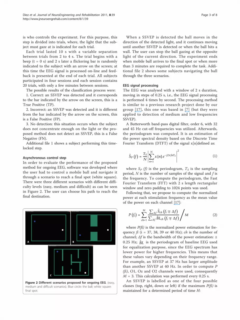
Asynchronous control stepIn order to evaluate the performance of the proposedmethod for ongoing EEG, software was developed wherethe user had to control a mobile ball and navigate itthrough a scenario to reach a final spot (white square).There were three different scenarios with different diffi-culty levels (easy, medium and difficult) as can be seenin Figure 2. The user can choose his path to reach thefinal destination.
When a SSVEP is detected the ball moves in thedirection of the detected light, and it continues movinguntil another SSVEP is detected or when the ball hits awall. The user can stop the ball gazing at the oppositelight of the current direction. The experiment endswhen mobile ball arrives to the final spot or when morethan 3 minutes are required to complete the task. Addi-tional file 2 shows some subjects navigating the ballthrough the three scenarios.
EEG signal processingThe EEG was analysed with a window of 2 s duration,moving in steps of 0.25 s, i.e., the EEG signal processingis performed 4 times by second. The processing methodis similar to a previous research project done by ourgroup [17], this one was based in [7] (but they wereapplied to detection of medium and low frequenciesSSVEP).A Butterworth band-pass digital filter, order 6, with 32
and 45 Hz cut-off frequencies was utilized. Afterwards,the periodogram was computed. It is an estimation ofthe power spectral density based on the Discrete TimeFourier Transform (DTFT) of the signal x[n]defined as:
SP(f)
=TS
N
∣∣∣∣∣N∑
n=1
x [n] e−j2π fnTS
∣∣∣∣∣2
(1)
where SP (f) is the periodogram, TS is the samplingperiod, N is the number of samples of the signal and f isthe frequency. To compute the periodogram, the FastFourier Transform (FFT) with 2 s length rectangularwindow and zero padding to 1024 points was used.Following that, we propose to compute the normalized
power at each stimulation frequency as the mean valueof the power on each channel [17]:
P(fi)
=M∑
ch=1
∑�f Sch
(fi ∓ �f
)∑
�f BLch(fi ∓ �f
)/
M (2)
where P(fi) is the normalized power estimation for fre-quency fi (i = 37, 38, 39 or 40 Hz); ch is the number ofchannel; Δf is the bandwidth of the power estimation: ±0.25 Hz; BL is the periodogram of baseline EEG usedfor equalization purpose, since the EEG spectrum haslower power for higher frequencies. This means thatthese values vary depending on their frequency range.For example, an SSVEP at 37 Hz has larger amplitudethan another SSVEP at 40 Hz. In order to compute P(fi), O1, Oz and O2 channels were used, consequentlyM = 3. This calculation was performed every 0.25 s.An SSVEP is labelled as one of the four possible
classes (top, right, down or left) if the maximum P(fi) ismaintained for a determined period of time H:
Figure 2 Different scenarios proposed for ongoing EEG. (easy,medium and difficult scenarios). Blue circle: the ball; white square:final spot.
Diez et al. Journal of NeuroEngineering and Rehabilitation 2011, 8:39http://www.jneuroengrehab.com/content/8/1/39
Page 3 of 8

class = max{P(fi)
(n)P(fi)
(n−1) . . . P(fi)
(n−H)
}(3)
The time-threshold H in time-locked (synchronous)step is HS and fixed at 1.75 s for on-line feedback. Inasynchronous step HA can be adjusted from 1.5 s to2.25 s.
ResultsTable 1 shows the results in time-locked step for differ-ent HS values and are detailed the Correct, Incorrectand Non-detected trials, average time by trial and theInformation Transfer Rate (ITR). The ITR is a measureof the information transmitted and is calculated as [18]:
ITR = (1 − Pr)
(log2N + (1 − Pw) log2 (1 − Pw) + Pwlog2
(Pw
N − 1
))(4)
where Pr is the probability of non-detected cases, Pw isthe probability of incorrect detected cases and N is thenumber of targets (in our case N = 4). The ITR couldbe expresed in bits/trial or in bits/min.In asynchromous mode, the SSVEP-power calculated
on-line for Subject 5 is presented in Figure 3a. TheSSVEP-power increases when the subject gazes at adetermined ligth and SSVEP-power is labeled as a classwhen time-threshold HA is overcome, i.e., the ballchanges its movement. In this case HA was 2.25 s.Figure 3b shows the direction changes along the task.
In t = 64 s the ball stops since the top-ligth is detectedat this moment (the contrary to current direction), thisdetection was considered as a FP. Threshold HA wasadjusted for each subject in order to reject FP, althoughsome FP were detected anyway, but adjusting to optimalHA the FP rate was lower. Figure 3c shows the path fol-lowed by the ball to reach the final spot (white square).Table 2 presents the results for each subject moving
the ball in difficult scenarios. This table, details themean and standard deviation values of the task time andthe number of decisions made to accomplish the taskand the TP and FP (and its percentages). The last col-umn on this Table is the number of times that the sub-ject performs the task and when he/she reaches the finaldestination. It shows the best HA for each subject aswell. Finally, when subject is gazing the centre of thescreen (looking the moving ball) most of the time, noclasses (top, right, left or down) should be detected.Occasionally, if an SSVEP is detected in this situation, itis considered as a FP (see Tables 1 and 2).
DiscussionOngoing EEG classification of SSVEP (no high-fre-quency) based-BCI is implemented in [6,7] using arefractory time (when no decisions are allowed), inorder to control grasping with a robotic arm. This
refractory time is implemented to avoid FP since therobotic arm takes a time to perform each movement. Inour case the subjects can make decisions every timethey want to and the FP are avoided (or diminished) byadjusting the time-threshold H.Other methods used for high-frequency SSVEP detec-
tion are more expensive computationally [9,11-13], andthey are evaluated in off-line analysis of the EEG butthey were not evaluated for asynchronous EEG classifi-cation. Using spatial filters, an ITR of 22.7 bits/min wasreached in [13].A method to control a mobile robot in indoor envir-
onments was presented in [18], but the subjects need afew days of training to control the mobile robot. In thiscase, the subject can control the mobile object on thescreen in only a few minutes. This is an advantage ofSSVEP based-BCI over other kinds of BCI.The proposed method achieves accuracy in classifica-
tion ranging from 65% to 100%. This could be translatedinto ITR ranging from 9.4 to 45 bits/min. A high bitrate is not required to control a mobile object, since itis not necessary to make decisions every second, e.g.,when it navigates through a corridor. Hence the ITRachieved in this research is more than enough to controla mobile object. This is claimed since the subjects canalmost always effectively navigate the mobile ball to thefinal spot most of the time.In locked-time step, for lower time-threshold HS
higher wrong cases were obtained (Table 1); when HS isincreased these wrong cases were evaluated as non-detected whereas correct cases were not as detrimental.Therefore, adjusting HS is possible to reduce thewrongly-detected cases and to obtain similar accuracy indetection of SSVEP. If HS parameter overcome a certainvalue (depending on each subject) it will eventually beunable to detect a class (top, right, down or left) becauseit is more difficult maintain a SSVEP for long periods oftime.In asynchronous mode, easy and medium scenarios
were used to adjust the time-threshold HA, and then theperformance of each subject was evaluated in the diffi-cult scenario. Besides, in both of these scenarios thesubject learns how to control the ball since it is a hardtask, i.e., when to gaze at the light in order to changethe movement of the ball at the right time and avoidhitting a wall. For this purpose, those scenarios wererepeated a few times (no more than 5 ± 2 in average),depending on the Subject performance.Moreover, sometimes the subjects did not want to
convey any command to the moving ball, however lightsare still in their visual field and a command could bedetected and transmitted to the ball. This problem iscalled the “Midas Touch Effect” [19] and this is the rea-son for the FP. This effect became evident when the
Diez et al. Journal of NeuroEngineering and Rehabilitation 2011, 8:39http://www.jneuroengrehab.com/content/8/1/39
Page 4 of 8

Table 1 Results in time-locked step
Subject Hs = 1,5 s Hs = 1,75 s Hs = 2 s Hs = 2,25 s
TP FP FN Time [s] bits/trial
bits/min
TP FP FN Time [s] bits/trial
bits/min
TP FP FN Time [s] bits/trial
bits/min
TP FP FN Time [s] bits/trial
bits/min
1 100 0 0 2.66 ± 0.36 2 45.1 100 0 0 2.91 ± 0.36 2 41.2 100 0 0 3.16 ± 0.36 2 38 100 0 0 3.41 ± 0.36 2 35.2
2 98.8 1.25 0 2.84 ± 0.69 1.89 39.9 98.8 0 1.25 3.09 ± 0.69 1.98 38.5 98.8 0 1.25 3.43 ± 0.88 1.98 34.7 97.5 0 2,5 3.65 ± 0.77 1.8 29.9
3 80 18.8 1.3 3.11 ± 0.8 0.99 19.20 81.3 13.8 5 3.44 ± 0.95 1.14 19.99 81.3 7.5 11.3 3.86 ± 1.12 1.33 20.7 82.5 3.8 13.8 4.12 ± 1.12 1.47 21.50
4 78.8 21.3 0.0 2.98 ± 0.96 0.92 18.5 77.5 17.5 5.0 3.52 ± 1.37 0.92 15.7 72.5 15 12.5 3.74 ± 1.32 1 16.2 66.3 10 23.8 3.98 ± 1.30 1.04 15.8
5 56.3 40 3.8 4.02 ± 1.39 0.38 5.70 62.5 26.3 11.3 4.67 ± 1.44 0.67 8.60 65 15 20 5.14 ± 1.55 0.92 10.76 57.5 10 32.5 5.36 ± 1.55 0.92 10.37
6 65 31.3 3.8 3.83 ± 1.34 0.59 9.18 62.5 27.5 10 4.29 ± 1.41 0.64 9 53.8 17.5 28.8 4.77 ± 1.48 0.75 9.42 45 10 45 5.07 ± 1.53 0.75 8.93
The values represent the percentages of True Positive (TP), False Positive (FP), and False Negative (FN), the average time (mean ± std) by trial and the ITR in bits/trial and in bits/minute, evaluated for different HS. Inbold: the best results per subject.
Diez
etal.Journalof
NeuroEngineering
andRehabilitation
2011,8:39http://w
ww.jneuroengrehab.com
/content/8/1/39Page
5of
8

moving ball was navigated close to the sides of thescreen where the lights are located.In order to mitigate this effect an adjustable time-
threshold HA was implemented. With short time-thresh-old more FP were attained and the navigation of theball became unstable. On the other hand, with longtime-threshold HA less FP were attained but it washarder to change the movement. Hence, for each subjectthe time-threshold was adjusted in order to obtain acomfortable navigation of the ball. The time-thresholdwas adjusted from 1.75 s up to 2.25 s, depending on thesubject. The threshold HA in Table 2 is not necessarilythe same HS that allows the best ITR in Table 1, sincethey are evaluated under different experimental condi-tions. In Table 1, the experiment is in synchronous
mode, whereas in Table 2, the experiment is in asyn-chronous mode and the threshold HA is adjusted inorder to get a comfortable navigation of the ball (avoid-ing, as much as possible, the Midas touch effect).The threshold HA in asynchronous step was 2 or 2.25
s (see Table 2), hence HA could be used in a fixed valueof 2.25 s (the subjects with HA = 2 s could navigate theball with HA = 2.25 s without performance detriments).However, always is advisable to adapt the BCI in orderto attain the optimum performance.Once the time-threshold was adjusted, subjects had to
control the ball in the difficult scenario and navigate itto the final spot. They accomplished this work in almostall cases (except one time in Subjects 4 and 5). The sub-jects who obtained low ITR in the time-locked step
Figure 3 A trial in the hard scenario. (a) power calculated on-line, (b) Direction changes (c) Path followed through the scenario. The directionchanges are marked by letters. In t = 64 the ball stops due to a FP (H point).
Diez et al. Journal of NeuroEngineering and Rehabilitation 2011, 8:39http://www.jneuroengrehab.com/content/8/1/39
Page 6 of 8

accomplished the work too, however they needed moretime than subjects with high ITR.All subjects participated in this study were asked
about discomfort with flickering, no one express dis-comfort. According with others studies [10,12,15], weobserve that high-frequencies SSVEP produce much lessvisual fatigue than lower frequencies. Furthermore, thediscomfort of subjects observed in a previous work ofour group [17], using SSVEP in medium frequencyrange (13 to 16 Hz), was less compared to this work.In summary, the asynchronous BCI proposed in this
work allows the effective control of a mobile object onthe screen with high-frequency SSVEP (which are lessannoying) and using a simple method to extract SSVEPfrom ongoing EEG.
ConclusionsIn this work, an asynchronous BCI based in high-fre-quency SSVEP is presented, using only three ongoingEEG channels in order to control a mobile object on thescreen. Besides, it used a simple method to detect theSSVEP, i.e., mean powers of each stimulation frequencyevaluated on the periodogram. It obtained accurate clas-sification among 65% to 100% with ITR ranging from9.4 to 45 bits/min.This method allows to all subjects participating in the
study to control the mobile object and to reach a finaltarget without training, by only adjusting one parameter,the time-threshold H. Furthermore, impaired people
could be benefit from this method since it could beeasily extended to control a robotic wheelchair.Written informed consent was obtained for publica-
tion of this case report and accompanying images. Acopy of the written consent is available for review bythe Editor-in-Chief of this journal.
Additional material
Additional file 1: BCI Synchronous step. A movie shows the BCI time-locked (synchronous) step.
Additional file 2: BCI asynchronous step. Another movie shows theBCI asynchronous step control of mobile object on the screen throughdifferent scenarios.
AcknowledgementsPFD, VAM and ELL are supported by Consejo Nacional de InvestigaciónCientífica y Tecnológica, CONICET (National Council for Scientific andTechnological Research).Authors would like to thank to subjects for participating in theseexperiments and to anonymous reviewers for their helpful comments.
Author details1Gabinete de Tecnología Médica (GATEME), Facultad de Ingeniería,Universidad Nacional de San Juan, San Juan, Argentina. 2Instituto deAutomática (INAUT), Facultad de Ingeniería, Universidad Nacional de SanJuan, San Juan, Argentina.
Authors’ contributionsPFD wrote the algorithms and performed the experiments with help fromEAP. VAM and ELL contributed with initial ideas and advisory. All authorsreviewed and approved the final manuscript.
Table 2 Average values on difficult scenario
Subjects HA Task Time [s] Decisions/task Reach final destination?
Total TP FP
1 2 Average 96.2 12.2 11.6 0.6 100%
Std. Dev. 12 2.8 2.1 0.9 (5 of 5)
% 95.1 4.9
2 2 Average 129.8 19.8 18.3 1.5 100%
Std. Dev. 9.4 4 3.4 1.3 (4 of 4)
% 92.4 7.6
3 2 Average 108.3 15.7 14.3 1.3 100%
Std. Dev. 37.4 5.5 4.5 1.2 (3 of 3)
% 91.5 8.5
4 2.25 Average 161.3 18.3 15 3.3 67%
Std. Dev. 22.8 3.1 2.7 0.6 (2 of 3)
% 82.8 18.2
5 2.25 Average 149 16.3 13.7 2.7 67%
Std. Dev. 31.5 4.7 3.2 1.5 (2 of 3)
% 83.7 16.3
6 2.25 Average 176 20.3 15 5.3 100%
Std. Dev. 2.6 6.7 4.6 2.1 (3 of 3)
% 73.8 26.2
Diez et al. Journal of NeuroEngineering and Rehabilitation 2011, 8:39http://www.jneuroengrehab.com/content/8/1/39
Page 7 of 8

Competing interestsThe authors declare that they have no competing interests.
Received: 7 January 2011 Accepted: 14 July 2011Published: 14 July 2011
References1. Regan D, Human Brain Electrophysiology: Evoked Potentials and Evoked
Magnetic Fields in Science and Medicine New York: Elsevier; 1989.2. Vialatte FB, Maurice M, Dauwels J, Cichocki A: Steady-state visually evoked
potentials Focus on essential paradigms and future perspectives.Progress in Neurobiology 2010, 90:418-438.
3. Herrmann CS: Human EEG responses to 1-100 Hz flicker: resonancephenomena in visual cortex and their potential correlation to cognitivephenomena. Exp Brain Res 2001, 137:346-353.
4. Wang Y, Wang R, Gao X, Hong B, Gao S: A Practical VEP-Based Brain-Computer Interface. IEEE Trans on Neural Syst Rehab Eng 2006,14(2):234-239.
5. Valbuena D, Volosyak I, Gräser A: sBCI: Fast Detection of Steady-StateVisual Evoked Potentials. Proceedings 32nd Annual Int Conf IEEE EMBS:August 31-September 4, 2010; Buenos Aires, Argentina 2010, 3966-3940.
6. Ortner R, Allison BZ, Korisek G, Gaggl H, Pfurtscheller G: An SSVEP BCI tocontrol a hand orthosis for persons with tetraplegia. IEEE Trans NeuralSyst Rehabil Eng 2011, 19(1):1-5.
7. Müller-Putz GR, Pfurtscheller G: Control of an Electrical Prosthesis With anSSVEP-Based BCI. IEEE Trans Biomed Eng 2008, 55(1):361-364.
8. Friman O, Volosyak I, Gräser A: Multiple Channel Detection of Steady-State Visual Evoked Potentials for Brain-Computer Interfaces. IEEE TransBiomed Eng 2007, 54(4):742-750.
9. Nielsen SS: Communication speed enhancement for visual based BrainComputer Interfaces. Proceedings 9th Annual Conf Int FES Society:September 2004, Bournemouth, UK 2004.
10. Materka A, Byczuk M, Poryzala P: A Virtual Keypad Based On AlternateHalf-Field Stimulated Visual Evoked Potentials. Proceedings Int Symposiumon Information Technology Convergence (ISICT 2007): 23-24 Nov 2007; Jeon Ju,Korea; 2007, 296-300.
11. Lin Z, Zhang C, Wu W, Gao X: Frequency Recognition Based on CanonicalCorrelation Analysis for SSVEP-Based BCIs. IEEE Trans Biomed Eng 2007,54(6):1172-1176.
12. Huang M, Wu P, Liu Y, Bi L, Chen H: Application and Contrast in Brain-Computer Interface between Hilbert-Huang Transform and WaveletTransform. Proceedings 9th Int Conf for Young Computer Scientists(ICYCS 08),Zhang Jia Jie, Hunan, China 2008, 1706-1710.
13. Garcia Molina G, Mihajlovic V: Spatial filters to detect steady-state visualevoked potentials elicited by high frequency stimulation: BCIapplication. Biomed Tech 2010, 55:173-182.
14. Zhu D, Bieger J, Garcia Molina G, Aarts RM: A Survey of StimulationMethods Used in SSVEP-Based BCIs. Computational Intelligence andNeuroscience (Hindawi Publishing Corp) 2010, Art ID 702357 1-12.
15. Wang Y, Wang R, Gao X, Gao S: Brain-computer Interface based on theHigh-frequency Steady-state Visual Evoked Potential. Proceedings 1stInternational Conference on Neural Interface and Control Proceedings, May2005, Wuhan, China 2005, 26-28.
16. Fisher RS, Harding G, Erba G, Barkley GL, Wilkins A: Photic-and pattern-induced seizures: A review for the epilepsy foundation of americaworking group. Epilepsia 2005, 46(9):1426-1441.
17. Diez PF, Mut V, Laciar E, Avila E: A Comparison of Monopolar and BipolarEEG Recordings for SSVEP Detection. Proceedings 32nd Annual Int ConfIEEE EMBS August 31-September 42010, Buenos Aires, Argentina; 2010,5803-5806.
18. Millán J, del R, Renkens F, Mouriño J, Gerstner W: Noninvasive Brain-Actuated Control of a Mobile Robot by Human EEG. IEEE Trans BiomedEng 2004, 51(6):1026-1033.
19. Moore MM: Real-world applications for brain-computer interfacetechnology. IEEE Trans on Neural Syst and Rehab Eng 2003, 11:162-165.
doi:10.1186/1743-0003-8-39Cite this article as: Diez et al.: Asynchronous BCI control using high-frequency SSVEP. Journal of NeuroEngineering and Rehabilitation 2011 8:39.
Submit your next manuscript to BioMed Centraland take full advantage of:
• Convenient online submission
• Thorough peer review
• No space constraints or color figure charges
• Immediate publication on acceptance
• Inclusion in PubMed, CAS, Scopus and Google Scholar
• Research which is freely available for redistribution
Submit your manuscript at www.biomedcentral.com/submit
Diez et al. Journal of NeuroEngineering and Rehabilitation 2011, 8:39http://www.jneuroengrehab.com/content/8/1/39
Page 8 of 8


