Embed Size (px)
Citation preview
Architecture Recovery of Web Applications
Ahmed E. Hassan and Richard C. HoltSoftware Architecture Group (SWAG)
Department of Computer ScienceUniversity of Waterloo
Waterloo, Canada{aeehassa, holt}@plg.uwaterloo.ca
ABSTRACTWeb applications are the legacy software of the future.Developed under tight schedules, with high employeeturn over, and in a rapidly evolving environment, thesesystems are often poorly structured and poorly docu-mented. Maintaining such systems is problematic.
This paper presents an approach to recover the archi-tecture of such systems, in order to make maintenancemore manageable. Our lightweight approach is flexibleand retargetable to the various technologies that areused in developing web applications. The approach ex-tracts the structure of dynamic web applications andshows the interaction between their various componentssuch as databases, distributed objects, and web pages.The recovery process uses a set of specialized extractorsto analyze the source code and binaries of web appli-cations. The extracted data is manipulated to reducethe complexity of the architectural diagrams. Develop-ers can use the extracted architecture to gain a betterunderstanding of web applications and to assist in theirmaintenance.
1 INTRODUCTIONA web application is a software system whose function-ality is delivered through the web [9]. With the ad-vent of the Internet and the web, many applications areno longer developed using traditional client/server tech-nologies. Instead, new applications are developed usingweb technologies such as web browsers, web servers, andapplication servers. A web browser is the user’s inter-face to the application. Internet protocols such as HyperText Transfer Protocol (HTTP) are used for communi-cating between the interface and the rest of the appli-cation.
Originally developed as a document-sharing platform,the web is still often considered as such. Consequently,
the development of web applications is considered tobe an authoring problem and not a software engineer-ing problem. For example, many of commercial andresearch tools used to analyze the structure of a web ap-plication show only the hyperlink relations between thedifferent web pages. These tools fail to show the interac-tion between the databases, the distributed objects, andthe web pages that form a web application [32]. Such re-lations are important to software developers who mustmaintain or enhance these applications. For examplegiven a database table, a developer may need to answerquestions such as “Which web page writes data to thistable?”, or “Which object reads data from this table?”.Furthermore, a software architect may need to deter-mine the answer for questions such as “Does my appli-cation have a three layered architecture?”, “Which partof my application is affected if the CUSTOMERSPASSWORDSdata table is offline for maintenance?”. Currently, suchinquiries can only be answered by scanning the sourcecode for answers using tools such as grep, consultingdocumentation, or asking senior developers.
Unfortunately, the documentation associated with aweb application does not commonly exist and if it does,it is rarely complete or up-to-date. With a very shortdevelopment cycle, software-engineering principles arerarely applied to the development of web applications.As Pressman notes, the reluctance of web developersto adopt well-proven principles is worrisome [25]. Thetechniques used by web application developers are sim-ilar to the ad hoc ones used by their predecessors inthe 1960s and 1970s. To aggravate matters, the webcommunity has a high turnover rate with an averageemployment length that is just over one year [19]. Theoriginal developers of a maintained web application areoften no longer part of the organization. This lack ofdocumentation and system experts increases the costand time needed to understand and maintain large webapplications.
Recent research [1, 2, 5, 6, 13, 26, 33] recognizes theneed to adapt traditional software engineering principlesto assist in the development of web applications. Re-verse engineering and software visualization have been
proposed as techniques to improve the understandingof large traditional non-web applications [14]. Thesetechniques have been used to study systems such asas the Linux Kernel (800 KLOC) [4], the Apache webserver (80 KLOC) [12], and the Mozilla web browser(2.1 MLOC) [20].
In this paper, we describe an approach to assist devel-opers in understanding their web applications. We de-scribe a set of tools which parse and extract relations be-tween the various components of a web application. Theextracted components and relations are visualized us-ing a specialized viewer. In this paper, we consider thisvisualization to characterize the software architectureof the system. It allows developers to perform impactanalysis on the extracted relations between the compo-nents. The recovered architectures for a number of webapplications were shown to maintenance engineers whoreported that the produced diagrams are useful in as-sisting them in understanding the systems. In manycases, the engineers had produced similar diagrams bymanually examining the source code of various compo-nents. In short, they would have used the tool, if it hadbeen available to them.
Paper OrganizationThe rest of this paper is organized as follows. Section 2describes the interactions between the various compo-nents in a web application. Section 3 describes the typesof information that are needed by developers to gaina better understanding of web applications. Section 4presents a sample web application and its recovered ar-chitecture. Section 5 describes our architecture recoveryapproach for web applications. Section 6 delves deeperinto the presented architecture recovery process and de-scribes the schemas used to analyze the recovered archi-tecture before visualizing it. Section 7 describes relatedwork. Finally, Section 8 draws conclusions from thiswork.
2 COMPONENTS OF A WEB APPLICA-TION
StaticPages
WebBrowser
WebServer
MultimediaObjects
ActivePages
ApplicationServer
DatabasesWeb
Objects
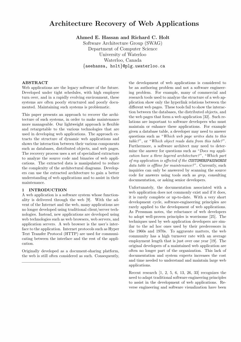
Figure 1: Dataflow Between the Components of a WebApplication
Web applications contain many components that arelinked together to deliver the functionality of the ap-plication (see figure 1). These components are writtenin various programming languages and run on multiplemachines distributed across the network. Each compo-
nent is written in a language which is appropriate to im-plement its functionality. Scripting languages are usedto assemble the different components, and databases areused by the components to store and share their data.
From our experience in studying and analyzing web ap-plications, we observe that there is a recognizable setof components which comprise these system. We be-lieve that this set is a useful basis for analyzing theseapplications. This set consists of web browsers (usedby the clients), web servers, application servers and thefollowing components:
Static pages These contain only HTML code and ex-ecutable code that runs on the web browser. Theyare served by the web server and do not need to bepreprocessed by the application server.
Active pages such as Active Server Pages and JavaServer Pages. These pages contain a mixture ofHTML tags and executable code. When an activepage is requested, the application server prepro-cesses it and integrates data from various resourcessuch as web objects or databases, to generate thefinal HTML web page sent to the browser. Ta-ble 1 shows two active pages: welcome1.asp andwelcome2.asp which are equivalent to the staticpage welcome.html. All pages say “Welcome toCNN.COM ” when displayed in the user’s browser.The symbols <% and %> indicate to the applica-tion server that the text between them is con-trol code which is to be executed and the out-put returned to requesting client. For example, inwelcome2.asp the application server needs to lo-cate the Server object and execute the getName()method, then Write the output to the file returnedto the browser.
Static Page
welcome.html
Active Page welcome1.asp
Active Page welcome2.asp
<html> Welcome to CNN.COM </html>
<html> Welcome to <% Write(“CNN.COM”) %> </html>
<html> Welcome to <% Write(Server.getName()) %> </html>
Table 1: Examples of Active Pages
Web objects These are pieces of compiled code whichprovide a service to the rest of the software systemthrough a defined interface. They are supported bydistributed technologies such as CORBA, EJB andDCOM. They are not objects in the sense of sourcecode object-oriented programming objects such asthose defined in C++ or Java.
Multimedia objects such as images, and videos.
Databases These are used to store data that is sharedamong the various components.
Figure 1 shows the data flow between the various com-ponents of a web application. The user of the appli-cation employs the web browser to access the function-ality of the web application. The user interacts withthe browser by clicking on links and filling form fields.The browser in turn transmits the user’s actions to theweb server. Requests are sent using the HTTP protocol.Upon receiving the request, the web server determinesif it can fulfill the request directly or if the applicationserver must be invoked. The web server serves directlystatic HTML pages and multimedia content such as im-ages, videos, or audio files; or it forwards the request tothe application server. The application server processesactive pages and returns the result to the web server asstatic HTML pages. The web server in turn returns theHTML page back to the requesting web browser, whichdisplays it to the user.
3 VISUALIZATION NEEDS OF DEVELOP-ERS
Web Applications are large complex software systemsthat contain a rich structure with many interesting re-lations between their components. The choice of the ap-propriate relations and components is task dependent.For example, a developer modifying an object used bymany active pages is interested in a different set of rela-tions than a database administrator trying to track allthe components using a specific database table. Unfor-tunately, the only relations shown by current web ap-plication visualization tools are the hyperlinks betweenthe static pages in a web application. This limited visu-alization is not sufficient for a developer to understandthe structure of the web application and the interactionsbetween its various components.
Previous studies in program maintenance and under-standing conducted on the development of traditionalsoftware systems [22, 27, 28, 29] assisted us in defininga set of useful relations and components to recover anddisplay in generated diagrams. Studies have shown thatdevelopers use visualization tools to pinpoint locationsof interest in the system’s code (for example to locateall the files that use a database table); they delve intothese locations of interest to improve their understand-ing using their code editors. In response, our recoveredarchitecture diagrams do not show all the detailed re-lations and components, instead they show an overviewof the system. For example, we do not show the in-ternal structure of code inside the same file. We showthe inter-file relations. Furthermore, we use techniquessuch as containment and information hiding to reducethe complexity of the visualized systems.
In a web applications each component has its own inter-
nal architecture or design. The web application devel-oper is particularly concerned with the topology of thecomponents: how they interact together and how theyare glued together using the various web technologies.On the other hand, the web application developer is notusually interested in the internal architecture of the webserver or the web browser, as they add complexity tothe visualized system without contributing to the over-all understanding of the system. The web server and thebrowser represent software infrastructure similar to theoperating system and the windowing system, whose ar-chitectures are not shown when visualizing traditionalsoftware systems. The architecture diagrams for webapplications should show the main components of a webapplication, such as web objects, database tables, mul-timedia objects that are glued together to implementlarge sophisticated web applications.
When developers search for a better understanding ofa system, the four most common search targets usedby developers are function definitions, uses of a func-tion, variable definition, and all uses of a variable [28].We adapted analogous relations for web applications,but at a higher level of abstraction. Instead of showingvariables, functions and their interrelations, we showdatabase tables, distributed objects, and their interre-lations.
4 AN EXAMPLE WEB APPLICATIONWe have recovered the architecture of several large com-mercial and experimental web applications. These ap-plications had over 200 distributed web objects and over15 databases per application. Space restrictions do notallow us to present the architecture of such large sys-tems, so we will illustrate our approach to architectureextraction in terms of a small example system, calledHopper News.
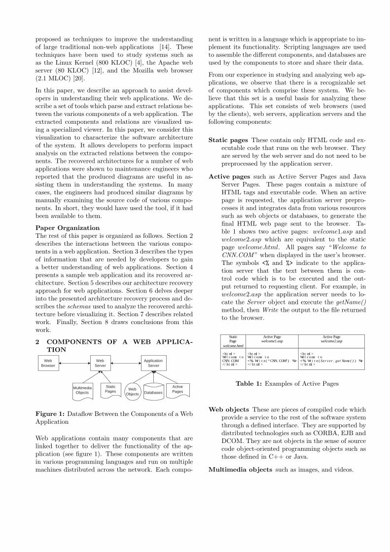
Figure 2: Main Page for Hopper News Web Applica-tion
Hopper News is the web site for a fictitious newspa-per. It features sections for local, national, interna-tional news, sports, weather, and classified advertise-
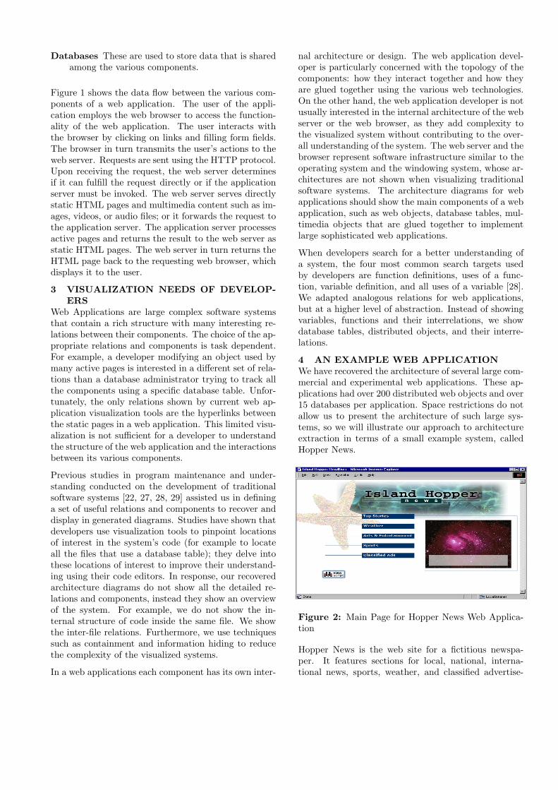
ments. In this sample application, only the classifiedadvertisement section is implemented. The rest of thelinks on the main web page, shown in Figure 2, are notfunctional. The only functional link is the lowest buttonin the page which links to the classified advertisementpage, shown in Figure 3. The application is developedfor the Microsoft Windows platform and contains com-ponents written in HTML, VBScript, VB, and C++.The application is developed by Microsoft to showcasebuilding web application on the Windows platform.
Figure 3: Hopper News Classified Advertisement WebPage
The application supports two main functions: It per-mits a person to browse advertisements, and it permitsregistered users to place advertisements. To place anadvertisement, the user must pay a fee.
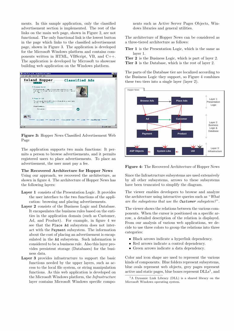
The Recovered Architecture for Hopper NewsUsing our approach, we recovered the architecture, asshown in figure 4. The architecture of Hopper News hasthe following layers:
Layer 1 consists of the Presentation Logic. It providesthe user interface to the two functions of the appli-cation: browsing and placing advertisements.
Layer 2 consists of the Business Logic and Database.It encapsulates the business rules based on the enti-ties in the application domain (such as Customer,Ad, and Product). For example, in figure 4 wesee that the Place Ad subsystem does not inter-act with the Payment subsystem. The informationabout the cost of placing an advertisement is encap-sulated in the Ad subsystem. Such information isconsidered to be a business rule. Also this layer pro-vides persistent storage (Databases) for the busi-ness data.
Layer 3 provides infrastructure to support the basicfunctions needed by the upper layers, such as ac-cess to the local file system, or string manipulationfunctions. As this web application is developed onthe Microsoft Windows platform, the Infrastructurelayer contains Microsoft Windows specific compo-
nents such as Active Server Pages Objects, Win-dows libraries and general utilities.
The architecture of Hopper News can be considered asa three-tiered architecture as follows:
Tier 1 is the Presentation Logic, which is the same aslayer 1.
Tier 2 is the Business Logic, which is part of layer 2.Tier 3 is the Database, which is the rest of layer 2.
The parts of the Database tier are localized according tothe Business Logic they support, so Figure 4 combinesthese two tiers into a single layer (layer 2).
Hopper News
Browse Ads
System LibsASP Objects
ProductPayment
CustomerAd
Place Ads
Util
Layer 1:Presentation
Logic
Layer 3:Infrastructure
Layer 2:BusinessLogic &
Database
Figure 4: The Recovered Architecture of Hopper News
Since the Infrastructure subsystems are used extensivelyby all other subsystems, arrows to these subsystemshave been truncated to simplify the diagram.
The viewer enables developers to browse and analyzethe architecture using interactive queries such as “Whatare the subsystems that use the Customer subsystem?”.
The viewer shows the relations between the various com-ponents. When the cursor is positioned on a specific ar-row, a detailed description of the relation is displayed.From our analysis of various web applications, we de-cide to use three colors to group the relations into threecategories:
• Black arrows indicate a hyperlink dependency.• Red arrows indicate a control dependency.• Green arrows indicate a data dependency.
Color and icon shape are used to represent the variouskinds of components. Blue folders represent subsystems,blue ovals represent web objects, grey pages representactive and static pages, blue boxes represent DLLs1, and
1A Dynamic Link Library (DLL) is a shared library on theMicrosoft Windows operating system.
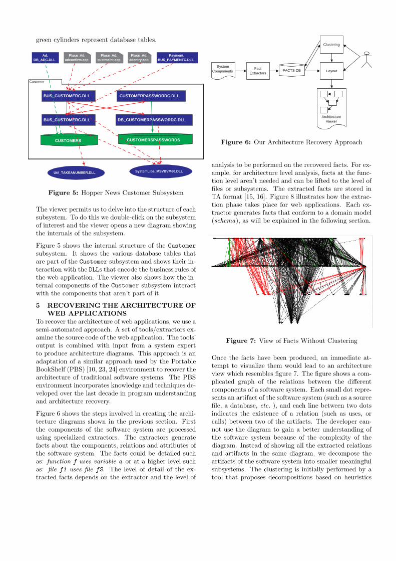
green cylinders represent database tables.
Customer
CUSTOMERS CUSTOMERSPASSWORDS
BUS_CUSTOMERC.DLL
DB_CUSTOMERPASSWORDC.DLLBUS_CUSTOMERC.DLL
CUSTOMERPASSWORDC.DLL
Ad.DB_ADC.DLL
Place_Ad.adconfirm.asp
Place_Ad.custmaint.asp
Place_Ad.adentry.asp
Payment.BUS_PAYMENTC.DLL
Util_TAKEANUMBER.DLL SystemLibs_MSVBVM60.DLL
Figure 5: Hopper News Customer Subsystem
The viewer permits us to delve into the structure of eachsubsystem. To do this we double-click on the subsystemof interest and the viewer opens a new diagram showingthe internals of the subsystem.
Figure 5 shows the internal structure of the Customersubsystem. It shows the various database tables thatare part of the Customer subsystem and shows their in-teraction with the DLLs that encode the business rules ofthe web application. The viewer also shows how the in-ternal components of the Customer subsystem interactwith the components that aren’t part of it.
5 RECOVERING THE ARCHITECTURE OFWEB APPLICATIONS
To recover the architecture of web applications, we use asemi-automated approach. A set of tools/extractors ex-amine the source code of the web application. The tools’output is combined with input from a system expertto produce architecture diagrams. This approach is anadaptation of a similar approach used by the PortableBookShelf (PBS) [10, 23, 24] environment to recover thearchitecture of traditional software systems. The PBSenvironment incorporates knowledge and techniques de-veloped over the last decade in program understandingand architecture recovery.
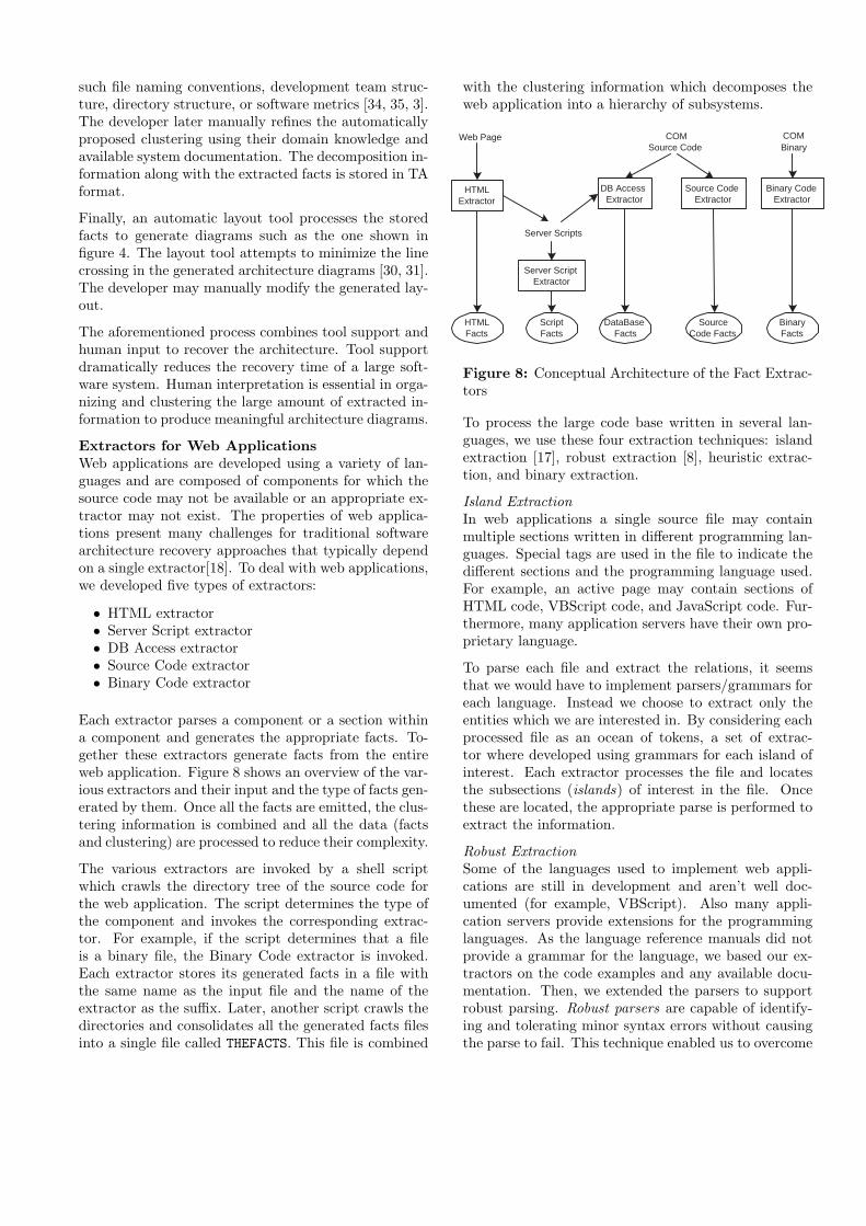
Figure 6 shows the steps involved in creating the archi-tecture diagrams shown in the previous section. Firstthe components of the software system are processedusing specialized extractors. The extractors generatefacts about the components, relations and attributes ofthe software system. The facts could be detailed suchas: function f uses variable a or at a higher level suchas: file f1 uses file f2. The level of detail of the ex-tracted facts depends on the extractor and the level of
SystemComponents
FactExtractors
Clustering
Layout
ArchitectureViewer
FACTS DB
Figure 6: Our Architecture Recovery Approach
analysis to be performed on the recovered facts. For ex-ample, for architecture level analysis, facts at the func-tion level aren’t needed and can be lifted to the level offiles or subsystems. The extracted facts are stored inTA format [15, 16]. Figure 8 illustrates how the extrac-tion phase takes place for web applications. Each ex-tractor generates facts that conform to a domain model(schema), as will be explained in the following section.
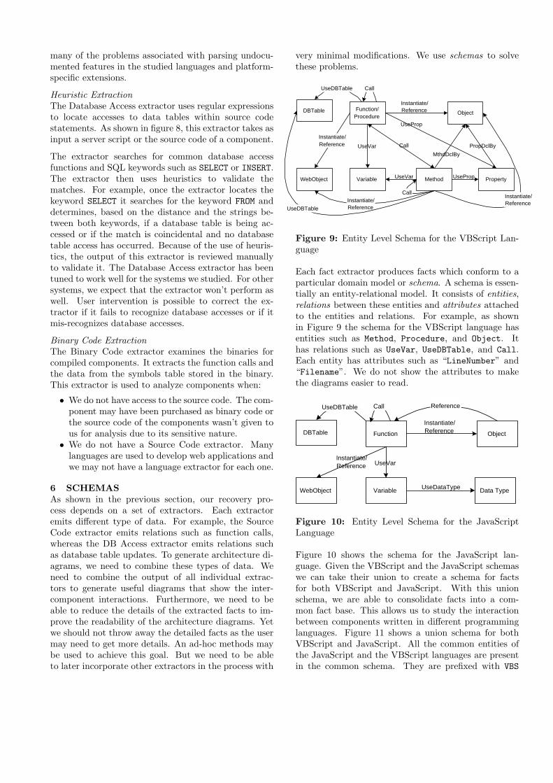
Figure 7: View of Facts Without Clustering
Once the facts have been produced, an immediate at-tempt to visualize them would lead to an architectureview which resembles figure 7. The figure shows a com-plicated graph of the relations between the differentcomponents of a software system. Each small dot repre-sents an artifact of the software system (such as a sourcefile, a database, etc. ), and each line between two dotsindicates the existence of a relation (such as uses, orcalls) between two of the artifacts. The developer can-not use the diagram to gain a better understanding ofthe software system because of the complexity of thediagram. Instead of showing all the extracted relationsand artifacts in the same diagram, we decompose theartifacts of the software system into smaller meaningfulsubsystems. The clustering is initially performed by atool that proposes decompositions based on heuristics
such file naming conventions, development team struc-ture, directory structure, or software metrics [34, 35, 3].The developer later manually refines the automaticallyproposed clustering using their domain knowledge andavailable system documentation. The decomposition in-formation along with the extracted facts is stored in TAformat.
Finally, an automatic layout tool processes the storedfacts to generate diagrams such as the one shown infigure 4. The layout tool attempts to minimize the linecrossing in the generated architecture diagrams [30, 31].The developer may manually modify the generated lay-out.
The aforementioned process combines tool support andhuman input to recover the architecture. Tool supportdramatically reduces the recovery time of a large soft-ware system. Human interpretation is essential in orga-nizing and clustering the large amount of extracted in-formation to produce meaningful architecture diagrams.
Extractors for Web ApplicationsWeb applications are developed using a variety of lan-guages and are composed of components for which thesource code may not be available or an appropriate ex-tractor may not exist. The properties of web applica-tions present many challenges for traditional softwarearchitecture recovery approaches that typically dependon a single extractor[18]. To deal with web applications,we developed five types of extractors:
• HTML extractor• Server Script extractor• DB Access extractor• Source Code extractor• Binary Code extractor
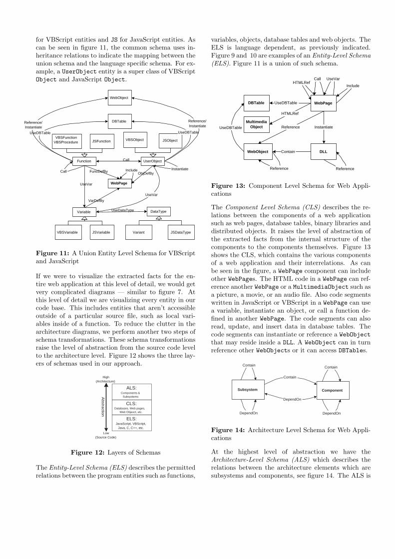
Each extractor parses a component or a section withina component and generates the appropriate facts. To-gether these extractors generate facts from the entireweb application. Figure 8 shows an overview of the var-ious extractors and their input and the type of facts gen-erated by them. Once all the facts are emitted, the clus-tering information is combined and all the data (factsand clustering) are processed to reduce their complexity.
The various extractors are invoked by a shell scriptwhich crawls the directory tree of the source code forthe web application. The script determines the type ofthe component and invokes the corresponding extrac-tor. For example, if the script determines that a fileis a binary file, the Binary Code extractor is invoked.Each extractor stores its generated facts in a file withthe same name as the input file and the name of theextractor as the suffix. Later, another script crawls thedirectories and consolidates all the generated facts filesinto a single file called THEFACTS. This file is combined
with the clustering information which decomposes theweb application into a hierarchy of subsystems.
HTMLExtractor
Source CodeExtractor
DB AccessExtractor
Server ScriptExtractor
Binary CodeExtractor
Web Page
Server Scripts
COMSource Code
COMBinary
HTMLFacts
ScriptFacts
DataBase Facts
SourceCode Facts
BinaryFacts
Figure 8: Conceptual Architecture of the Fact Extrac-tors
To process the large code base written in several lan-guages, we use these four extraction techniques: islandextraction [17], robust extraction [8], heuristic extrac-tion, and binary extraction.
Island ExtractionIn web applications a single source file may containmultiple sections written in different programming lan-guages. Special tags are used in the file to indicate thedifferent sections and the programming language used.For example, an active page may contain sections ofHTML code, VBScript code, and JavaScript code. Fur-thermore, many application servers have their own pro-prietary language.
To parse each file and extract the relations, it seemsthat we would have to implement parsers/grammars foreach language. Instead we choose to extract only theentities which we are interested in. By considering eachprocessed file as an ocean of tokens, a set of extrac-tor where developed using grammars for each island ofinterest. Each extractor processes the file and locatesthe subsections (islands) of interest in the file. Oncethese are located, the appropriate parse is performed toextract the information.
Robust ExtractionSome of the languages used to implement web appli-cations are still in development and aren’t well doc-umented (for example, VBScript). Also many appli-cation servers provide extensions for the programminglanguages. As the language reference manuals did notprovide a grammar for the language, we based our ex-tractors on the code examples and any available docu-mentation. Then, we extended the parsers to supportrobust parsing. Robust parsers are capable of identify-ing and tolerating minor syntax errors without causingthe parse to fail. This technique enabled us to overcome
many of the problems associated with parsing undocu-mented features in the studied languages and platform-specific extensions.
Heuristic ExtractionThe Database Access extractor uses regular expressionsto locate accesses to data tables within source codestatements. As shown in figure 8, this extractor takes asinput a server script or the source code of a component.
The extractor searches for common database accessfunctions and SQL keywords such as SELECT or INSERT.The extractor then uses heuristics to validate thematches. For example, once the extractor locates thekeyword SELECT it searches for the keyword FROM anddetermines, based on the distance and the strings be-tween both keywords, if a database table is being ac-cessed or if the match is coincidental and no databasetable access has occurred. Because of the use of heuris-tics, the output of this extractor is reviewed manuallyto validate it. The Database Access extractor has beentuned to work well for the systems we studied. For othersystems, we expect that the extractor won’t perform aswell. User intervention is possible to correct the ex-tractor if it fails to recognize database accesses or if itmis-recognizes database accesses.
Binary Code ExtractionThe Binary Code extractor examines the binaries forcompiled components. It extracts the function calls andthe data from the symbols table stored in the binary.This extractor is used to analyze components when:
• We do not have access to the source code. The com-ponent may have been purchased as binary code orthe source code of the components wasn’t given tous for analysis due to its sensitive nature.
• We do not have a Source Code extractor. Manylanguages are used to develop web applications andwe may not have a language extractor for each one.
6 SCHEMASAs shown in the previous section, our recovery pro-cess depends on a set of extractors. Each extractoremits different type of data. For example, the SourceCode extractor emits relations such as function calls,whereas the DB Access extractor emits relations suchas database table updates. To generate architecture di-agrams, we need to combine these types of data. Weneed to combine the output of all individual extrac-tors to generate useful diagrams that show the inter-component interactions. Furthermore, we need to beable to reduce the details of the extracted facts to im-prove the readability of the architecture diagrams. Yetwe should not throw away the detailed facts as the usermay need to get more details. An ad-hoc methods maybe used to achieve this goal. But we need to be ableto later incorporate other extractors in the process with
very minimal modifications. We use schemas to solvethese problems.
Call
Function/Procedure
Object
Method Property
Call
Variable
PropDclByUseVar
UseVar
MthdDclBy
UseProp
UseProp
Call
Instantiate/Reference
Instantiate/Reference
DBTable
WebObject
Instantiate/Reference
Instantiate/ReferenceUseDBTable
UseDBTable
Figure 9: Entity Level Schema for the VBScript Lan-guage
Each fact extractor produces facts which conform to aparticular domain model or schema. A schema is essen-tially an entity-relational model. It consists of entities,relations between these entities and attributes attachedto the entities and relations. For example, as shownin Figure 9 the schema for the VBScript language hasentities such as Method, Procedure, and Object. Ithas relations such as UseVar, UseDBTable, and Call.Each entity has attributes such as “LineNumber” and“Filename”. We do not show the attributes to makethe diagrams easier to read.
Function Object
Call
Variable
UseVar
Instantiate/Reference
Reference
Data Type
DBTable
WebObject
UseDBTable
UseDataType
Instantiate/Reference
Figure 10: Entity Level Schema for the JavaScriptLanguage
Figure 10 shows the schema for the JavaScript lan-guage. Given the VBScript and the JavaScript schemaswe can take their union to create a schema for factsfor both VBScript and JavaScript. With this unionschema, we are able to consolidate facts into a com-mon fact base. This allows us to study the interactionbetween components written in different programminglanguages. Figure 11 shows a union schema for bothVBScript and JavaScript. All the common entities ofthe JavaScript and the VBScript languages are presentin the common schema. They are prefixed with VBS
for VBScript entities and JS for JavaScript entities. Ascan be seen in figure 11, the common schema uses in-heritance relations to indicate the mapping between theunion schema and the language specific schema. For ex-ample, a UserObject entity is a super class of VBScriptObject and JavaScript Object.
UseVar
JSObjectVBSObject
UserObjectFunction
JSFunctionVBSFunction
VBSProcedure
JSVariableVBSVariable
Variable
JSDataTypeVariant
DataType
Instantiate
Call
UseDataType
Call
WebPage
UseVar
IncludeFuncDefBy ObjDefBy
VarDefBy
WebObject
DBTable
UseDBTable
Reference/Instantiate
UseDBTable
Reference/Instantiate
Figure 11: A Union Entity Level Schema for VBScriptand JavaScript
If we were to visualize the extracted facts for the en-tire web application at this level of detail, we would getvery complicated diagrams — similar to figure 7. Atthis level of detail we are visualizing every entity in ourcode base. This includes entities that aren’t accessibleoutside of a particular source file, such as local vari-ables inside of a function. To reduce the clutter in thearchitecture diagrams, we perform another two steps ofschema transformations. These schema transformationsraise the level of abstraction from the source code levelto the architecture level. Figure 12 shows the three lay-ers of schemas used in our approach.
Abstraction
Low(Source Code)
High(Architecture)
CLS:Databases, Web pages,
Web Objexct, etc.
ALS:Components &
Subsystems
ELS:JavaScript, VBScript,
Java, C, C++, etc.
Figure 12: Layers of Schemas
The Entity-Level Schema (ELS) describes the permittedrelations between the program entities such as functions,
variables, objects, database tables and web objects. TheELS is language dependent, as previously indicated.Figure 9 and 10 are examples of an Entity-Level Schema(ELS). Figure 11 is a union of such schema.
WebObject
DBTable
Call
WebPage
Include
UseDBTable
UseVar
Reference
DLL
Instantiate
Contain
HTMLRef
MultimediaObject
HTMLRef
Reference Reference
UseDBTable
Figure 13: Component Level Schema for Web Appli-cations
The Component Level Schema (CLS) describes the re-lations between the components of a web applicationsuch as web pages, database tables, binary libraries anddistributed objects. It raises the level of abstraction ofthe extracted facts from the internal structure of thecomponents to the components themselves. Figure 13shows the CLS, which contains the various componentsof a web application and their interrelations. As canbe seen in the figure, a WebPage component can includeother WebPages. The HTML code in a WebPage can ref-erence another WebPage or a MultimediaObject such asa picture, a movie, or an audio file. Also code segmentswritten in JavaScript or VBScript in a WebPage can usea variable, instantiate an object, or call a function de-fined in another WebPage. The code segments can alsoread, update, and insert data in database tables. Thecode segments can instantiate or reference a WebObjectthat may reside inside a DLL. A WebObject can in turnreference other WebObjects or it can access DBTables.
Contain
Subsystem Component
Contain
Contain
DependOnDependOn
DependOn
Figure 14: Architecture Level Schema for Web Appli-cations
At the highest level of abstraction we have theArchitecture-Level Schema (ALS) which describes therelations between the architecture elements which aresubsystems and components, see figure 14. The ALS is
independent of language (such as VBScript, JavaScript)and independent of technology (such as DCOM, EJB,or CORBA).
The different levels of schemas enable developers tostudy their software system at various levels of abstrac-tion. Developers can perform a detailed analysis on thesource code or a higher-level analysis on the architec-ture. They can drill down [7] to investigate architec-ture anomalies at the source code level such as unex-pected subsystem interdependencies. Using roll up op-erations, developers can investigate the effects of sourcecode changes on the overall architecture of the softwaresystem [21]. More generally, schemas provide a conve-nient conceptual framework that helps developers thinkabout the structure of web applications and underliesthe construction of tools that help developers exploreand visualize this structure.
7 RELATED WORKThis section compares our approach to architecture re-covery of web applications to related research that ad-dresses web applications. In particular, we address workon the evolution, the architecture recovery and the mod-eling of web applications.
Web Applications: EvolutionBrereton et al. point out that HTML’s nested tags areanalogous to the block structure of third generation pro-gramming languages and that links between pages areanalogous to GOTO statement [5]. They demonstrate atool that can track the evolution of pages in a web site.The tool is based on a modified network crawler thatvisits the web site multiple times over a span of a yearand reports the change in the contents of the web pages.Ricca and Tonella developed a similar tool [26].
Both tools are suited toward static web sites which donot have active pages, web object, or databases. Theircrawler won’t recognize that many apparent changes inthe web site may be due to active pages and not tothe actual modification of the content of the web page.For example, the tool would indicate that the homepageof a site like CNN.COM changes continuously, but infact the source of the home page rarely changes. Itis an active page, which contains executable code thatretrieves updated information from a database, at thetime the page is accessed.
The approach suggested by Rica, Tonella, and Breretonputs more emphasis on the user’s experience. It at-tempts to track the changes that are sensed by the userof the application. These changes may not be mirroredin the source code of the web application. Also, changesin the source code may not affect the pages viewed bythe user. For example, in an early version of an emailservice web application, the page displaying the user’sinbox may retrieve all the email messages from a flat file.
In a later version, the email messages may be stored inan SQL database. When accessing the page, the userwon’t notice the change. Clearly, the architecture ofthe web application has changed. Our approach ana-lyzes the source of the components of a web application.Using this approach, we can study more sophisticateddynamic web applications. Stated differently, We use awhite box reverse engineering approach and they use ablack box approach.
Web Applications: Architecture RecoveryThe related work discussed thus far is based on toolssuch as parsers and crawlers. In contrast, Antoniol etal. suggest a non-automated technique to recover thearchitecture [1]. The technique is founded on the Rela-tion Management Methodology (RMM), which in turnis based on the Entity Relationship model. Using RMM,the application domain is described in terms of entitytypes, attributes and relationships. For example, anexam booking web application would have entities suchas students, and courses; and relations such as “takes”,and “provides”.
RMM is best suited for static web applications whereasour approach can be used to recover the structure ofdynamic web applications. The RMM recovered ar-chitecture is a high level view of the main entities inthe domain and the relations between them. Our ap-proach extracts the implementation view of the system.The high level view of a system tends to remain stableacross different releases compared to the implementa-tion architecture which changes as new technologies aredeployed, a common occurrence in the fast moving webapplication domain. For example, an RMM recoveredarchitecture would not changed if the courses and thestudents are now stored in a database instead of a flatfile.
Web Applications: ModelingTo aid developers in their analysis, researchers have pro-posed various methods to model web applications. Eachmethod emphasizes an aspect or a set of interesting rela-tions that the developers can model. Ceri et al. presentthe Web Modeling Language (WebML) [6]. WebMLprovides a high level conceptual description of a webapplication. The language is geared towards database-driven applications. WebML is more suited for the highlevel specification of web application than for modelingthe actual implementation because it lacks the conceptsneeded to model control flow. For example, relationsbetween the objects and the call graph cannot be ex-pressed using WebML’s constructs.
Conallen’s work on extending UML [11] to modelweb applications is the most similar to our work [9].Conallen presents the Web Application Extension(WAE) for UML. Web pages are modelled as UML com-
ponents. Every web page is modelled using two differentaspects:
1. The server side aspect where he shows the page’sinteraction with other pages, the business logic ob-jects, the databases and the server provided re-sources.
2. The client side aspect where he shows the page’sinteraction with the browser’s built-in objects andJava applets. This aspect is more concerned withthe page’s layout and presentation.
By contrast our approach focuses mainly on the serverside aspect of modeling web applications. Conallen hasdemonstrated the generation of skeleton code for a webapplication based on a UML specification of the ap-plication. His work can be thought of as the forwardengineering of web applications where our research isconcerned with assisting developers who did not spec-ify their web application using UML but need to un-derstand them. We could convert our diagrams intoUML compliant diagrams using a schema transforma-tion. Current UML tools do not provide the featuresavailable in our specialized viewer, such as querying andhierarchal navigation.
8 CONCLUSIONIn the work we have done, we concentrated on the ex-traction of web applications developed on the MicrosoftWindows platform. While we do not foresee problemswith extractions for applications developed on otherplatforms, we recommend that further research be doneto generalize and improve our approach. Also detailedempirical studies are needed to verify the benefits of ourtools for web developers.
We presented an approach to recover the architectureof web applications. The approach uses a set of special-ized parsers/extractors which analyze the source codeand binaries of web applications. We described theschemas used to produced useful architecture diagramsfrom highly detailed extracted facts. The recovered ar-chitecture is shown as simple box and arrow diagrams.This visualization helps developers of web applicationunderstand the structure of their application, helpingthem to rapidly update it to handle new requirements.
The need for tools to assist developers of web applica-tion is clear and justifiable. Web applications are to-morrow’s legacy software. With a short release cycle, a“no-documentation” culture and high employment at-trition rates, web development companies face severechallenges to stay competitive in a highly volatile mar-ket.
ACKNOWLEDGEMENTSTo validate our approach, we used web applications
provided by Microsoft Inc. and Sun Microsystems ofCanada Inc. In particular, we would like to thank Wai-Ming Wong from Sun for his assistance in our analysisof the web applications.
REFERENCES
[1] G. Antoniol, G. Canfora, G. Casazza, and A. D.Lucia. Web Site Reenginnering using RMM. InProceedings of euroREF: 7th Reengineering Forum,Zurich, Switzerland, Mar. 2000.
[2] C. Boldyreff. Web Evolution: Theory and Prac-tice, 2000. Available online at<http://www.dur.ac.uk/cornelia.boldyreff/lect-1.ppt>
[3] I. T. Bowman. Architecture Recovery for ObjectOriented Systems. Master’s thesis, University ofWaterloo, 1999.
[4] I. T. Bowman, R. C. Holt, and N. V. Brewster.Linux as a Case Study: Its Extracted Software Ar-chitecture. In IEEE 21st International Conferenceon Software Engineering, Los Angeles, USA, May1999.
[5] P. Brereton, D. Budgen, and G. Hamilton. Hyper-text: The Next Maintenance Mountain. Computer,31(12):49–55, Dec. 1998.
[6] S. Ceri, P. Fraternali, and A. Bongio. Web Mod-eling Language (WebML): a modeling language fordesigning Web sites . In The Ninth InternationalWorld Wide Web Conference (WWW9), Amster-dam, Netherlands, May 2000. Available online at<http://www9.org/w9cdrom/177/177.html>
[7] S. Chaudhuri and U. Dayal. An Overview of DataWarehousing and OLAP Technology. ACM SIG-MOD Record, 26(1), Mar. 1997.
[8] G. Clarke and D. T. Barnard. Error Handling ina Parallel LR Substring Parser. Computer Lan-guages, 19(4):247–259, 1993.
[9] J. Conallen. Building Web Applications withUML. object technology. Addison-Wesley Long-man, Reading, Massachusetts, USA, first edition,Dec. 1999.
[10] P. J. Finnigan, R. C. Holt, I. Kalas, S. Kerr,K. Kontogiannis, H. A. Muller, J. Mylopou-los, S. G. Perelgut, M. Stanley, and K. Wong.The software bookshelf. IBM Systems Jour-nal, 36(4):564–593, 1997. Available onlineat <http://www.almaden.ibm.com/journal/sj/364/finnigan.html>

[11] T. O. M. Group. Unified Modeling Lan-guage Specification. The Object Manage-ment Group, June 1999. Available online at<http://www.rational.com/media/uml/post.pdf>
[12] A. E. Hassan and R. C. Holt. A Reference Ar-chitecture for Web Servers. In 7th Working Con-ference on Reverse Engineering, Brisbane, Queens-land, Australia, Nov. 2000.
[13] A. E. Hatzimanikatis, C. T. Tsalidis, andD. Christodoulakis. Measuring the readabilityand maintainability of Hyperdocuments. Soft-ware Maintenance: Research and Practice, 7:77–90, 1995.
[14] Hausi A. Muller and Jen H. Jahnke, Dennis B.Smith and Margaret-Ann Storey and Scott R.Tilley and Kenny Wong. Reverse Engineering: ARoadmap. In Proceedings of Future of Software En-gineering, Limerick, Ireland, June 2000.
[15] R. C. Holt. An Introduction to TA: the Tuple-Attribute Language, Mar. 1997. Available onlineat <http://plg.uwaterloo.ca/~holt/papers/ta.html>
[16] R. C. Holt. Structural manipulations of softwarearchitecture using Tarski relational algebra. In Pro-ceedings of WCRE’98, Oct. 1998.
[17] Island Grammars. Available onlineat <http://losser.st-lab.cs.uu.nl/~visser/cgi-bin/twiki/view/Transform/IslandGrammars>
[18] R. Kazman and S. J. Carriere. Playing detective:Reconstructing software architecture from avail-able evidence. Automated Software Engineering,Apr. 1999.
[19] R. Konrad. Tech employees jumping jobs faster,2000. Available online at <http://news.cnet.com/news/0-1007-202-2077961.html>
[20] E. H. S. Lee. Analyzing Mozilla, 2000.Available online at <http://plg.uwaterloo.ca/~ehslee/pub/mozilla.ppt>
[21] E. H. S. Lee. Software Comprehension Across Lev-els of Abstraction. Master’s thesis, University ofWaterloo, 2000.
[22] T. C. Lethbridge and N. Anquetil. Architectureof a Source Code Exploration Tool: A SoftwareEngineering Case Study. Tr-97-07, School of Infor-mation Technology and Engineering, University ofOttawa, 1997.
[23] The Portable Bookshelf (PBS). Available online at<http://www.turing.toronto.edu/pbs>
[24] D. A. Penny. The Software Landscape: A VisualFormalism for Programming-in-the-Large. PhDthesis, University of Toronto, 1992.
[25] R. S. Pressman. What a Tangled Web We Weave.IEEE Software, 17(1):18–21, Jan. 2000.
[26] F. Ricca and P. Tonella. Visualization of Web SiteHistory. In Proceedings of euroREF: 7th Reengi-neering Forum, Zurich, Switzerland, Mar. 2000.
[27] S. E. Sim. Supporting Multiple Program Compre-hension Strategies During Software Maintenance.Master’s thesis, University of Toronto, 1998. Avail-able online at <http://www.cs.utoronto.ca/~simsuz/msc.html>
[28] S. E. Sim, C. L. A. Clarke, and R. C. Holt. Archety-pal Source Code Searching: A Survey of SoftwareDevelopers and Maintainers. In Proceedings of In-ternational Workshop on Program Comprehension,pages 180–187, Ischia, Italy, June 1998.
[29] S. E. Sim, C. L. A. Clarke, R. C. Holt, and A. M.Cox. Browsing and Searching Software Architec-tures. In Proceedings of International Conferenceon Software Maintenance, Oxford, England, 1999.
[30] K. Sugiyama and K. Misue. Visualization of Struc-tural Information: Automatic Drawing of Com-pound Digraphs. IEEE Transactions on Systems,Man, and Cybernetics, 21(4):867–892, July 1991.
[31] K. Sugiyama, S. Tagawa, and M. Toda. Methodsfor Visual Understanding of Hierarchical SystemStructures. IEEE Transactions on Systems, Man,and Cybernetics, 11(2):109–125, Feb. 1981.
[32] S. Tilley and S. Huang. Evaluating the ReverseEngineering Capabilities of Web Tools for Un-derstanding Site Content and Structure: A CaseStudy. In IEEE 23st International Conference onSoftware Engineering, Toronto, Canada, May 2001.
[33] S. R. Tilley. Web Site Evolution. Avail-able online at <http://mulford.cs.ucr.edu/stilley/research/wse/index.htm>
[34] V. Tzerpos and R. C. Holt. A Hybrid Process forRecovering Software Architecture. In Proceedingsof CASCON ’96, Toronto, Canada, Nov. 1996.
[35] V. Tzerpos and R. C. Holt. Software botryology:Automatic clustering of software systems. In Pro-ceedings of the International Workshop on Large-Scale Software Composition, 1998.


