Embed Size (px)
Citation preview

University of Windsor University of Windsor
Scholarship at UWindsor Scholarship at UWindsor
Electronic Theses and Dissertations Theses, Dissertations, and Major Papers
7-17-1964
Analysis of clamped skewed plates subjected to lateral uniform Analysis of clamped skewed plates subjected to lateral uniform
loading. loading.
Simon S. F. Ng University of Windsor
Follow this and additional works at: https://scholar.uwindsor.ca/etd
Recommended Citation Recommended Citation Ng, Simon S. F., "Analysis of clamped skewed plates subjected to lateral uniform loading." (1964). Electronic Theses and Dissertations. 6363. https://scholar.uwindsor.ca/etd/6363
This online database contains the full-text of PhD dissertations and Masters’ theses of University of Windsor students from 1954 forward. These documents are made available for personal study and research purposes only, in accordance with the Canadian Copyright Act and the Creative Commons license—CC BY-NC-ND (Attribution, Non-Commercial, No Derivative Works). Under this license, works must always be attributed to the copyright holder (original author), cannot be used for any commercial purposes, and may not be altered. Any other use would require the permission of the copyright holder. Students may inquire about withdrawing their dissertation and/or thesis from this database. For additional inquiries, please contact the repository administrator via email ([email protected]) or by telephone at 519-253-3000ext. 3208.

INFORMATION TO USERS
This manuscript has been reproduced from the microfilm master. UMI films
the text directly from the original or copy submitted. Thus, some thesis and
dissertation copies are in typewriter face, while others may be from any type of
computer printer.
The quality of this reproduction is dependent upon the quality of the
copy submitted. Broken or indistinct print, colored or poor quality illustrations
and photographs, print bleedthrough, substandard margins, and improper
alignment can adversely affect reproduction.
In the unlikely event that the author did not send UMI a complete manuscript
and there are missing pages, these will be noted. Also, if unauthorized
copyright material had to be removed, a note will indicate the deletion.
Oversize materials (e.g., maps, drawings, charts) are reproduced by
sectioning the original, beginning at the upper left-hand corner and continuing
from left to right in equal sections with small overlaps.
ProQuest Information and Learning 300 North Zeeb Road, Ann Arbor, Ml 48106-1346 USA
800-521-0600
Reproduced with permission of the copyright owner. Further reproduction prohibited without permission.

Reproduced with permission of the copyright owner. Further reproduction prohibited without permission.
ANALYSIS OF CLAMPED SKEWED PLATES SUBJECTED TO LATERAL UNIFORM LOADING
A THESISSubmitted to the Faculty of Graduate Studies through the Department of Civil Engineering In Partial Fullfilment
of the Requirements for the Degree of Master of Applied Science at The
University of Windsor,
by
Simon S.F. NG B.A.Sc., The University of British Columbia, 1962
Windsor, Ontario, Canada.1964
Reproduced with permission of the copyright owner. Further reproduction prohibited without permission.

UMI Number:EC52544
@UM IUMI Microform EC52544
Copyright 2007 by ProQuest Information and Learning Company. All rights reserved. This microform edition is protected against
unauthorized copying under Title 17, United States Code.
ProQuest Information and Learning Company 789 East Eisenhower Parkway
P.O. Box 1346 Ann Arbor, Ml 48106-1346
Reproduced with permission of the copyright owner. Further reproduction prohibited without permission.

APPROVED BY:
0 5 1 2 8
Reproduced with permission of the copyright owner. Further reproduction prohibited without permission.

ABSTRACTThe Raylelgh-Ritz method Is used to determine the
deflections and moments of clamped skewed plates. A deflection configuration of the skewed plate is assumed in the form:
w - ( 1 - a2 f ( ?2- P2 )2 ( Ao - Aj c@ )
where A and A. are undetermined parameters defining the shapeO 1of the deflection surface.
By minimizing the total energy expression for thebending of plates, the parameters A and A, are evaluated and ao 1deflection equation for the plate established. The deflection equation is then differentiated accordingly to obtain moments and stresses at various points of the plate.
An experiment was performed on the bending of a clamped skewed plate with a skew sides ratio of 1.23 a skew angle of 55 degrees. The results of this experimental investigation are compared with those obtained by the Rayleigh-Ritz procedure.
ill
Reproduced with permission of the copyright owner. Further reproduction prohibited without permission.

ACKNOWLEDGMENTS
The writer wishes to express his gratitude to
Dr. J.B. Kennedy for his guidance and suggestions in the preparation
of this work and for his generous aid and constructive criticism
throughout its development.The writer is also indebted to Mr. William James
who has helped in the checking of both the theoretical analysis
and the setting up of the experiment.The financial assistance offered by the Defence
Research Board is greatly appreciated.
iv
Reproduced with permission of the copyright owner. Further reproduction prohibited without permission.

TABLE OF CONTENTSPage
ABSTRACT ................................................ Ill
ACXNOVUSDGMBHTS ................. ........ iv
CHAPTERI INTRODUCTION ...... 1
II REVIEW OP LITERATURE ............................ h
III THEORETICAL ANALYSIS ........................... g(a) The Place Energy Equation In Oblique
Dimension leas Co-ordinates ....... g(b) The Rayleigh-Rltz Procedure ....... :?(c) Moaent and Displacement Relationships £(d) Sample Calculations ....... ^
IV EXPERIMENTAL STUDY .............................. lg(a) Materials and Apparatus .......(b) Procedure and Results ........... .
V COMPARISON OP RESULTS ......... ^
VI CONCLUSIONS ....... ^
APPENDIX A Fortran Programmes for Theoretical Analysisand Experimental Study........... ^
APPENDIX £ Solutions of Deflections, RectangularMoments and Principal Moments Using the Digital Computer IBM 1&20...... ^
REFERENCES .............................................. 53NOMENCLATURE ............................................ 55VITA ADCTORIS ........................................ 57
v
Reproduced with permission of the copyright owner. Further reproduction prohibited without permission.
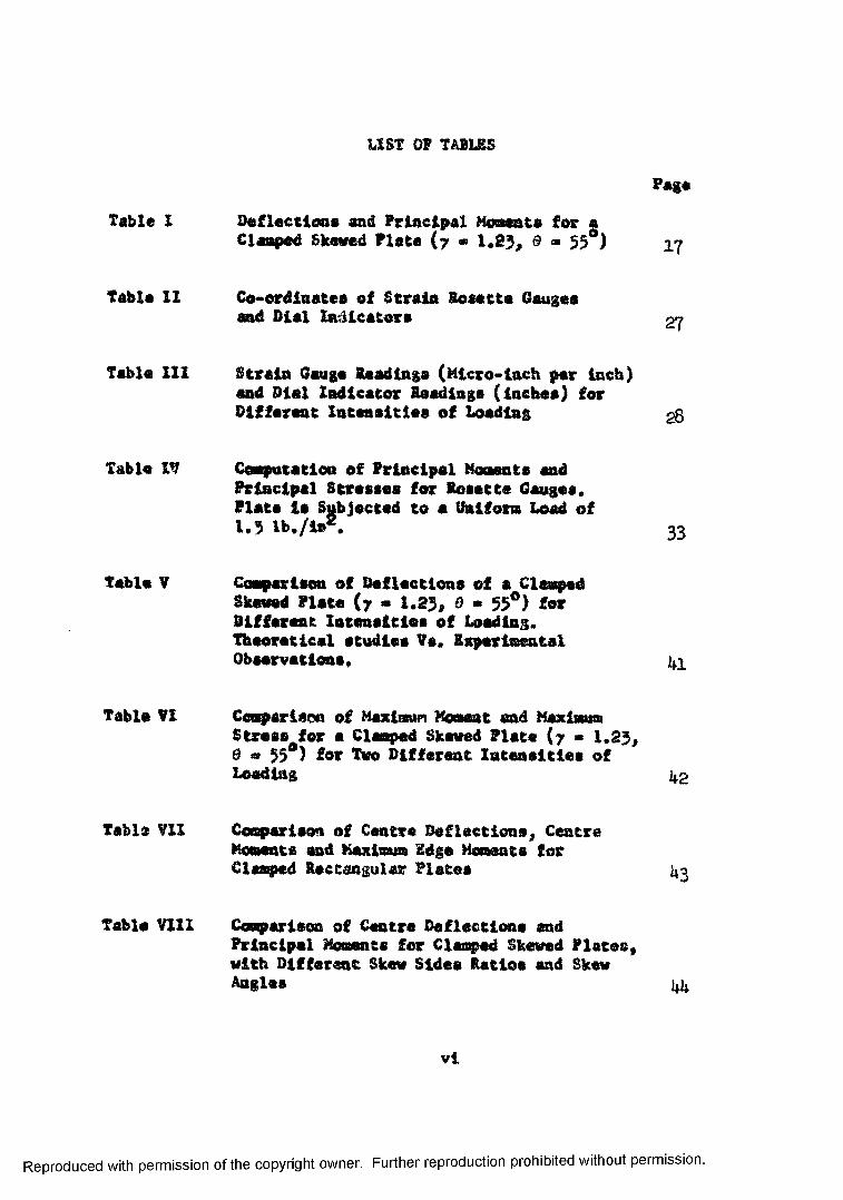
LIST OF TABLES
Table 1
Table 11
Table 111
Table IV
table V
Table VI
Table Vll
Table Vlll
Deflections end Principal Moments for a Clasped Skewed Plate (7 * 1.23, ® * 55 )
Co-ordinates of Strain Rosette Gauges and Biel Indicators
Page
17
27
Strain Gauge Readings (Micro-inch per Inch) end Dial Indicator Readings (inches) for Different Intensities of Loading gg
Computation of Principal Moments and Principal Stresses for Rosette Gauges.Plate is Subjected to a Uniform Load of1.5 Ib./in . 33
Comparison of Deflections of a Clomped Skewed Plate (7 - 1.23, 0 * 55°) for Different Intensities of Loading. Theoretical studies Vs. Experimental Observations,
Comparison of Maximum Moment end Maximum Stress for s Clomped Skewed Plate (7 ■ 1.23, d a 55 ) for Two Different Intensities of Loading i| 2
Comparison of Centre Deflections, CentreMomente end Maximum Edge Moments forClasped Rectangular Plates 1*3
Comporison of Centre Deflections and Principal Moments for Clasped Skewed Plates, with Different Skew Sides Ratios and Skew Angles ^
vi
Reproduced with permission of the copyright owner. Further reproduction prohibited without permission.

LIST OF FIGURES AND PHOTOGRAPHS
FIG, 1
PIG. 2
PIG. J
PIC. k
PHOTO. A
PHOTO. E
PHOTO. C
PHOTO. D
THE RECTANGULAR AND OBLIQUE CO-ORDINATE SYSTEMS 7
LOCATION OP ROSETTE GAUGES 00 TOP SURFACE AMD GAUGE ALIGNMENT
DIMENSIONS OF SKEW PLATE AND LOCATION OF ROSETTE GAUGES OS BOTTOM SURFACE
LOCATION OP DIAL INDICATORS
PHOTOGRAPH SHOWING PAST OF THE SUPPORTING STRUCTURE AND COMPLETED GAUGE AND DIAL INDICATOR INSTALLATIONS
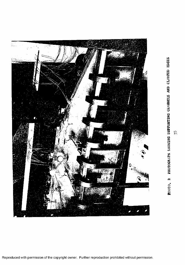
PHOTOGRAPH SHOWING SUPPORTING CHANNELS AND CLAMPED EDGES
PHOTOGRAPH SHOWING SX2U&H INDICATORS AND WOODEN SXEW SOX IK POSITION ON TOP OP PL/VIE
PHOTOGRAPH SHOWING THE CLAMPED EDGES AND THE STRUCTURAL STEEL COLUMNS
2b
23
2b
3^
35
36
37
vii
Reproduced with permission of the copyright owner. Further reproduction prohibited without permission.

CHAPTER 1
INTRODUCTION
Skewed plates and slabs are often required as component parts for large scale structures, such as bridges and
building floor systems, The banding behaviour of such plates is
also of great interest to the aircraft industry, where such plates
are found frequently as parts of swept-back wings and fins of
subsonic and supersonic aircrafts.
Many diverse and indirect Kathode ara now available
for the analysis of claraped rectangular plates subjected to uniform
normal loadings. Some of these methods are cited by Timoshenko and
Woinowsky-Krieger (i) who employ a double series which operates
with two interdependent systems of infinite linear simultaneous
equations. However, no general solutions are yet available for the skewed plate under similar boundary conditions. This is perhaps due
to the fact that the analysis of a parallelogram plate is more
complicated by its absence of orthogonal relationships.The work embodied in this thesis comprises;
1} a theoretical aiialyais on the beading of
clamped skewed plates subjected to a uniformly
distributed lateral land5
arid 22) an experimental investigation of the bending
behaviour of a clamped skewed plate with a skew
sides ratio of 1.2?* and a skew angle of by degrees.1
Reproduced with permission of the copyright owner. Further reproduction prohibited without permission.

with reference to the theoretical work, the Rayleigh-
Rits method (2 ) is used to determine the deflections and acoents of
clamped skewed plates. Essentially, this method is one of the racre
important energy variational methods based on the well-known principle that when a system is in a position of stable equilibrium, its total
energy is a minimum. Following the Eayleigh-Sitz procedure, a
deflection configuration containing undetermined parameters wa3 first
assumed satisfying not only the boundary conditions of the plate but
giving also polar symmetry - a condition quite evident in auniformly loaded skewed plate. The assumed deflection function ic
next inserted into the expression for the complementary energy and
the required integration carried out, the limits of the integration
being extended to cover the entire surface of the plate. The resulting
energy expression is then a function of the undetermined parameters.By minimising this energy expression and solving the simultaneous
equations thus obtained, the parameters are evaluated. Finally, the
deflection equation with its determined parameters is differentiated
to yield the required moments and hence stresses.
The ei-cperlmanfcal investigation consisted of thetl
loading of a l/h thick aluminum plate rigidly clamped c.n all four edges. >5eta-filai strain rosette gauges were installed and
moments and stresses were calculated from the strain measurements recorded for the different intensities of loading, Dial indicators
Reproduced with permission of the copyright owner. Further reproduction prohibited without permission.

were also installed to record the lateral deflection at selected
points on the skewed plate„To facilitate the ccssputation of deflections, siosr̂ nfcG
and the principal moments at specified points on the skewed plate,
progransnes using Fortran language were written and are included in
Appendix A.
5
Reproduced with permission of the copyright owner. Further reproduction prohibited without permission.

CHAPTER I I
REVIEW OF LITERATURE
In 19^1, Vernon P, Jensen (3) investigated slabs with various skew angles, boundary conditions and loading conditions. Finite
difference equations were developed for a general system of skew co
ordinates . By means of these equations, he computed the principal
moments for uniformly loaded slabs simply supported on two or all four
edges.
In 1933# Eric Reiscner (U) showed that the bending stiffness for
a skewed plate is leso than that of an unskewed plate and that pure
bending of the skewed plate is always associated with a twisting de
formation, the relative magnitude of which depends upon the angle of
skew.
In the period between 195^ - i960, a great deal of work was done on skewed plates and skewed structures. The outstanding researchers
in this period are L.S.D. Morlay (5), I. Miraky (6), and P.D. Jones (7).In 1953* P-E. Dorman (8) used the energy approach to investigate
the bending behaviour of a clamped parallelogram plate but the function
he assumed has the restrictive character of satisfying not only the
polar symmetry but also quadrant ayaHaotry — — — —— — & tondition
which is non-existent in a skewed plate.
2i
Reproduced with permission of the copyright owner. Further reproduction prohibited without permission.

One of the more recent contributions co the eolation of skewed
plates and slabs Is the ono by Kennedy and H.W. Huggins (9) who presented an analytical solution for skewed stiffened plates under a
uniformly distributed load. Stresses near the corners of skewed
stiffened plates were also Investigated by Kennedy and Martens (10)
who have observed experimentally that critical stresses often occur
in obtuse corners of such skewed plates.
5
Reproduced with permission of the copyright owner. Further reproduction prohibited without permission.

CHAPTER III
THEORETICAL ANALYSIS
(a) The Plate Energy Equation in Oblique Dimenaioaless Co-ordinates
In investigating the bending behaviour of skew plates, it is often
advantageous to adopt a co-ordinate system parallel to the edges of the
plate, namely the oblique co-ordinates a, and p shown in Fig. 1.
By the transformation
x * 5 cos 9 (3-1)
y o (I + a sin G (3-2)
in which 9 is the skew angle, the following relationships between the
rectangular and the oblique co-ordinate systems hold:
(3-3)
2_sec 9 tan 0 + tan^ 0 (3-̂ 0
a Bw »C e - £ fan 0Bx BS Bg
n2-Q w a a2; 2sec 0 - 2
n2-d w2
Bx_2
Bcz BaBp
A180 ,
dw a C>wBy Bp
>2- >2™o w o w2 ” _2
By Bp
(3-5)
(3-6)
6
Reproduced with permission of the copyright owner. Further reproduction prohibited without permission.

IX
Reproduced with permission of the copyright owner. Further reproduction prohibited without permission.
THE
RECTANGULAR
AND
OBLIQUE
CO-ORDINATE
SYST
EMS

From the classical small deflection theory of thin elastic plates,
the total energy of bending consists of two parts: the strain energy
due to bending and the potential energy of the load distributed over
the plate. The expression for the strain energy of bending in
rectangular co-ordinates can be written as.
J a - D
- 2 (l-v)
f/ o w* 2
>2- , o w"r
2dx dy
f ^2“o w a y m2
-dx dy
)
5*2— 2oi;.o y j
dx dy ( 5-7)
For a clamped skewed plate, the displacement w is zero around the boundary and Eq. (5-7) takes a simpler form since
J
rc f-,2-o w a2w , -\2- 2 ' - ( L x )2 — 5
J -a x a y axSy
dx dy = 0 (5-6)
For a plate subjected to normal uniform load of intensity p,
the potential energy of the total load is
vp dx dy
Hence, the total energy of the system in rectangular co-ordinatesis
a2w + a2wa x2 a y2
- vp dx dy (3-9)
S
Reproduced with permission of the copyright owner. Further reproduction prohibited without permission.

Using the transformation relations Sqs. (3-1) and (3-2), Eq. (5-9)
becomes, in oblique co-ordinates,
X « cos ■J] d^w A~ - 2 — sin 5 + ~as2 a5a£ ag
da d$ (3-10)
Nov, by putting
a -■ aa
^ « aJ3
oa■ dT
w » vh
(3-n)
(3-12)(3-13)
(3-14)
where, a and $ are dimeaslonlesa oblique co-ordinates, 2a and 2b are the oblique dimensions of the plate (Fig, l), h la the thickness of
the plate m & q the dimensionlesa load, the total energy expression can
be further simplified Into the following diaensionlese form:
»h' COS 0/ c7 2 \2LZ. h L. - wq I da d8 (3-15)
a
where
V Sv * cec2 ? ( ~da
d w- 2 sin 0 *caopd2v ,— 5: ;
Reproduced with permission of the copyright owner. Further reproduction prohibited without permission.

(b) The Rayleigh-Kits ProcedureTo apply the Eayleigb-Hifcc procedure, a deflection configuration
for a clamped skewed plate la assumed as:
w«(i -a2)2 (r2 -^2)2 ( A ^ - A ^ ) (3-16)
where A and are undetermined parameters, c l
The boundary conditions for tha clasped plate are:
*r +v > 0 for a » • I, end p » • t
and
la * ^ *t>J’ ? * * 7# and ̂ ** 0 for oc *» - 1
where a is la s direction normal to the edge of the plate (Fig. 1From Eq, (?-lt ), #.c can be readily shewn that all these boundary
cenditione ere satisfied, It way he worth noting also that the
deflection function satisfies polar symmetry, I.e., w(a#3) ** v{•€:,-$). . a necessary condition for a uniformly loaded skewed plate.
In order to aubstit^t^ into the plate energy expression (3-15)# the assumed deflection function w is diffcrc&tiat&d with respect to
the diiasnsicaleas co-or«inates, & aa« £.
Thun:
i s » ( 72 - J32 )2 (~*»A - 12 A, 033 - 2 0 A. cs%. f> o I 1
+ 12 A a2 ); (3-iT)o
10
Reproduced with permission of the copyright owner. Further reproduction prohibited without permission.

2= (1 - QC2 )2 (12 A. 72 c*P - 20 A op5
dp2 1 1
- 4 Ao 72 + 12 Ao p2 ) (3-18)
and,
d2y - 16 A ( 72op - 72 o3P - aP3 + a V )353p 0
x . 4 2 c ^ 4 4 1̂ 2 2 - 2Aj (° 7 CK - 5 7 0J - 7 - 36 7 a 0
2 4 P P P ? li 4 4 I,+ 3$ 7 a r + 6 y f + 30 a p4 - 25 a p4 - 5 P ) (3-19)
licace,
V 2w « sec2 0 (£-~ - 2 sin 0 — + )da dadp dp2
« sec2 9 jf Aq [-474 - A72 + (12 7^ + 3 72) c:2
+ (12 + 8 72 ) P2 - a2P2 (24 72 + 24 ) - 4 p^ + 12 a % k
- 4 72 a* + 12 a^ p2 + 52 sin 9 2 a3p + 32 sin 0 ap3
- 32 sin 0 r2 - 32 sin 0 a3p3J+ A, ( 2 sin 0 7^ + ap (12 72.» 4
+ 12 7S - a3P (20 7^ + 24 72 ) - ap5 (24 y2 + 20) + a5p3 (40 72
+ 40) + 12 ap^ - £0 a3 p' + 12 y2 <x: p - 20 a5 p3 • 10 sin 0 7 V *
2 2 2 4 4 4 4 2+ 72 sin 0 7 a p •>• 30 sin 0 a p + 1 0 sin B p - 12 sin By a
- 60 sin e 72 cc4 p2 - 12 sin d 72 p2 - 60 sin 0 a2 P^jj’ (3-20)
11Reproduced with permission of the copyright owner. Further reproduction prohibited without permission.

Now, the total energy Integral, Eq, (3-15)j can be re-written as,
■ +11 - a w ' 0 * o f
f+y r i * £
r+7 /*
I -7 JCm
-1 -1-7 ^
wq da d£f (3-21)
where the limits of the integration extends over the entire surface
of the plate as shown.2Substituting the form of V w, Eq. (3-20), into the energy ex
pression, Eq. (3*21), and after some tedious algebraic manipulations
and Integrations, the plate energy equation reduces to:
4,T D h1 = -jsj— COS 0
asec 0 [ 20.8050793 75 -r (11.8886168
+ 23.7772337 sin20) y1 + 20.8050793 y9] kQ + 2 (ao aJ
[- 5.9^3085 sin fi 5.9^5083 sin 0 y9 ] + [l.3509791 71
J. (1.3209574 + 2.0419146 sin20) + 1.3509791 7*1] \ jj(3-22)A q o 225
Following tho Rayleigh Ritz ?roc£°ur®> t1jie total energy expression is now minimised vrith respect to each of the undetermined parametera,
r.e.
2L » 0 :dA J oand dl
3a ,
12
Reproduced with permission of the copyright owner. Further reproduction prohibited without permission.

and partial differcotiatioa, tw> linear aissniteaavus *<,u«s.icnisx& ©t-calned, via.,
(20.6050793 V:‘ f {XlM^>i6h * 2$*TT!&V «iaa 9) J 1
* so .(m om \ - (5.9W 5003 y i «*n 0
* 5.9^?°<>3 n* *i» 0 Ja^ =» q cos'* 5 [ 7^ (3-23)
*rtd
- sin @ 7^ aia y 1 &i o
* (l.35097!Jl 7 f * (1.380957* * 8.64191*3 aie2 5) ?9
* i.350yT?rl 7* ] * 0 (3-2U)
Solving £Ue«& equuiioas ttiaultauftauali, rb« fMiras&eare a a1are found to
A - g c a / » [ l . l ’ M M <■ l . ’sagyjfl) -v2 > >,0059119 lZ atn~ S' ^ .‘■iiTlUtO r** 1y
and
A. • q cosf* £ ( C.?v3JJ0id aia ^ *
V
13
Reproduced with permission of the copyright owner. Further reproduction prohibited without permission.

where
'f * ao. 1072275 5 05.5*509-5 y2 * 51.7529915 72 #ia2 0
+ 7I.9I0 IO9 7^ - 7.6521766 y4 sin2 0
+ 62,617^250 7^ sln^ $ * U3.5s*5^9o3 7^
♦ 51.7529915 76 ala2 9 + 26.072273 7&
These parameters ere then Inserted into the expression for the
deflection Eq. (3*16), frosa which deflections at any point within the plate boundaries can be determined.
Ik
Reproduced with permission of the copyright owner. Further reproduction prohibited without permission.

(c) Moment and Displacement Relationships
Froia the transformation equations ( 3-i) ■ant* (3-2)* sncJ the diwen*
alonless ratios, equations (3-11) and (.12), rectangular Borneots can
be expressed in terras of deflections In oblique dimeneienless co
ordinates, « and Thus:
^ “ “ D (“ + v “ }dx dy
K . 2» . D ~ (— w a«c 0 - 2 — - sec 0 tan 0a dot docdd
' 4 “ 2» * 4 l (3-25)d£2 dp2
>2* \2-H - = - D (£ -& “*• v — Sfp )y dy a P
2 2 2- . p k (fLi£ + y sec2 3 - 2 8ec ^ fcsn 02 . 2 V 2 -v -va d£ doc dosdp
* ^ t a a 2 9)) (5-26)Ofj
2 - 2M - . D ( ™ ^ ) h (|~„ sec 9 . tan 8) (>27)ny a2 '555{S ^2
From the rectangular moments M-, K- and the twisting moments
M--, the principal momenta can be calculated la the usual manner:
max11 -- (M- + M-) j I (w— - ii-) + &- - (5-2d)2 x y ! 2j x y' x. ymia
15
Reproduced with permission of the copyright owner. Further reproduction prohibited without permission.

The direction in which the maximum principal stress occurs is
(3-29)
where is the angle measured clockwise from the x direction.
Once these moments for the plate have been ascertained, the
stresses are then readily obtainable by multiplying the corresponding
moments by £ i.e.,h2
(d) Sample CalculationsAs a sample calculation, deflections and moments were worked out
at specified points for a skewed plate with a skew sides ratio of 1.23
and a skew angle of $5 degrees ^ ttieae results are tabulated in Table I. Also, to demonstrate the adaptability of the digital com
puter to this type of problems, deflections, moments, and principal
moments for the same sk ' plate were comp^a by the XB& 1620 and theresults are included in Appendix *j.
16
Reproduced with permission of the copyright owner. Further reproduction prohibited without permission.
(3-30)
(3-31)
< rT tax (3-32)ti2
and(3-33)
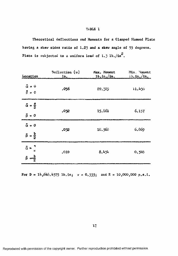
TABLE I
Theoretical deflections end Moments for a Clamped Skewed Plate
having a skew sides ratio of 1.23 and a skew angle of 55 degrees,2Plate is subjected to a uniform load of 1.3 lb,/in .
Deflection (w) Max. Moment Min, MomentLocation ia, lb.In./in. ib.in./ln.
a =» oe » o
.056 22.525 11.436
5 “ |
p = 0.032 15-661 6.157
a » ob2
.032 I6.566 6,8 69
aa w <ub
.010 8.434 0,348
For D » 14,646.4375 lb.in5 v » 0.333j and E = 10,000,000 p.s.i.
Reproduced with permission of the copyright owner. Further reproduction prohibited without permission.

CHAPTER IV
EXPERIMENTAL STUDY
(a) Materials and Apparatus
A 1/4" thick aluminum alloy (12) 6061-T6 plate was cut to the
dimensions shown in Fig. 11. With the dimensions Bhcwn, - e plate
has a skew sides ratio of 1,23 and a skew angle of 35 degrees. A
total of 32 meta-foil strain rosotte gauges were installed on the plate, seven on the top surface and twenty-nine on the bottom surface.
All these rosette gauges are of the 3-gauge 43° rectangular type, having a gage factor of 2.03 and a resistance of 120 ohms. Terminal
strips (type T-50) were used to connect the lead wires to the gauge tabs. The wire leads are twelve feet long, made of No. 26 stranded
copper wire and with vinyl insulation. To provide support for the
plate, tandard steel channels twelve inches deep and weighing 20.7 pounds per foot were cut to the required skew. It was thought that
there might be a possibility that these channels would twist as the
clamped plate was being loaded. As a safety measure, 1/4 inch thick
vertical stiffeners were welded to the channels and were spaced
approximately six inches apart. The plate and channel assembly was
then seated on steel angles attached by 1 inch bolts to heavy 3tael
posts. To assimulate the built-in edge condition, the aluminum plate
was sandwiched between the flange of the channels and a 1 Inch thick cold-rolled steel cover plate, 3 inches wide. The plate was cut in
18
Reproduced with permission of the copyright owner. Further reproduction prohibited without permission.

such a way that It provided a clamping edge of three inches while the
flange width of the channel was also three inches. A wooden box having
the same dimensions and skew as the plate was made, the box was 6 1/2 feet high and was heavily reinforced with 2 inch by 2* inch planks and steel straps. A waterproof sheet made of polyethylene material was
placed Inside the wooden box. The strains were measured by means of
two standard S-R b strain indicator units, two witch and balancing
units (model C-10T and C-1QLTC) and a digital strain indicator which
permitted the strains to be read off directly in micro-inch per inch.
Seven dial indicators were used to measure the deflection of the plate.
To clarify the description of the aforementioned apparatus and the
general set-up of the experiment, photographs were t«< n and are in
cluded on pages ^ to ^
19
Reproduced with permission of the copyright owner. Further reproduction prohibited without permission.

(b) Procedure and Results
The l/h inch thick alumlauza plate was first saved to the required
dimensions and skew, leaving three inches all around for clamping
purposes. The plate was then cleaned with acetone and the locations
Sox both the top and bottom surface gouges laid with reference to the
rectangular axes, x and y. The co-ordinates of all the gauges are
recorded in Table II while their alignment and locations ere shown in
Fig. 2 and 3. The installation of these rosette gauges to*.towed a
set procedure. The spot where the rosette was to be placad was first
wiped clean with acetona and then sanded with a metal conditioner
using silicon carbide paper. The ci.net location of the gauge was
then marked with a ballpen. The same spot was again cleansed In turn
first with a metal conditioner and then with a neutraiiser. tfith the
rosette and the terminal strip properly lined, Eastman 91° cement was
applied to cewant the assembly onto the plate. The gauge and terminal
we then left to dry for one minute during which time pressure was
applied to the gauge by means of the thumb. The insulation of both
ends of the lead wires was next stripped and the bare copper strands
twisted. Each lead wire consisted of three copper strands, one strand
was soldered to one tab 't the terminal strip while the other two
strands were twisted together and soldered to the other tab of the
terminal. The tabs of the terminal strip were then connected In turn
with the tabs o£ the gauges by means of thin copper jumper wires. To
provide waterproof and mechanical protection, besides the usual highly
insulating gauge coating, a special gauge coat made of a two-component
20
Reproduced with permission of the copyright owner. Further reproduction prohibited without permission.

rubber-like resin was also applied to cover the entire gauge and part
of the lead wires. This gauge coating is greenish in colour and photo
graph A on page 3^ shows a clear picture of some of the gauges completely Installed on the bottom surface of the plate. All 32 rosettes were thus installed and the gauge lead wires soldered in position.
The supporting structure for the plate is shown In photograph A,
The plate was placed between the flange of the channel and the 1 inch
steel cover plate and all four edges . e then clamped by special
structural erection clamps spaced six inches apart; allowance was made
here to have clasps placed closer together near the corners of the
plate. (See photograph E on page 35)To allow a direct reading of the deflections, seven indicators
were Installed in locations previously marked on the bottom of the
plate. These are numbered from 1 to T and their locations in terms of
the rectangular co-ordinates are tabulated in Table II and are also
shown in Fig. 4. The wooden skew tank was then placed to rest on the
cover plates and, inside tl.' tank a waterproof sheet of polyethylene
material was carefully laid so that water can be used as a loading
medium.
I'Text, gauge lead wires from 20 rosette gauges were soldered to
twelve 5-channel receptacles especially provided for the three switch and balance units. Unit strains in micro-inch per inch could be read
off directly from o screen of the digital strain indicator. The
remaining 12 rosettes were hooked to the terminals of the two switch boxes which were in turn connected cc a conventional S-U 4 strain
21
Reproduced with permission of the copyright owner. Further reproduction prohibited without permission.

indicator. Unit strains were read off from this indicator in the usual
manner. These instruments are clearly depicted in photograph C on
page 36.Before the plate was loaded, all the gauges and dial indicators
were "zeroed Id ". After the plate was loaded, strain and dial in
dicator readings ware taken and recorded. Such readings were obtained
for every one foot increment in height of water. Readings were also
taken and recorded in a similar manner while the load was taken off
the plate. The average of the loading and unloading readings was
computed and the resulting strains tabulated in Table 111,
Three strain values e^, and (See Fig. 2) ware obtained
frost each rosette gauge. From these values the principal stresses
and principal moments were then computed by using either the Mohr
Circle or the following formulas!
where 0 gives the direction in which the maximum stress occurs, this angle being measured counter-clockwise from the*/ axis.
2 2 efl - «fc) + 2 (efc - «c) ) (k»l)
2 (®a ' Cb)2 r 2 ( % ~ ec)2 ) (U-2)
Reproduced with permission of the copyright owner. Further reproduction prohibited without permission.

2Hmax 6
h2 (t-5)
To facilitate tba computation, a prosrausne in Fortran t?aa
written to give the rectangular aocsenta, principal nwnjents, principal
stresses and the direction of these principal stresses. As a sample
calculation, the digital computer 1620 vas used to calculate the principal moments and principal stresses for each rosette and the
results are tabulated in Table IV. The programs* used for the com
putation is included in Appendix A.
Reproduced with permission of the copyright owner. Further reproduction prohibited without permission.

oM
l>>
Reproduced with permission of the copyright owner. Further reproduction prohibited without permission.
FIG. 2
LOCATION
OF ROSETTE
GAUGES
ON TOP
SURFACE
AND
GAUGE
ALIG
NMEN
T

CMo
Cl
ro
25eiaiswE&OTY « «■
Reproduced with permission of the copyright owneri r i.-vj w
. Further reproduction prohibited without permission.
FIG
. 5
DIM
ENSI
ON
S OF
SK
EW
PLAT
E AN
D LO
CA
TIO
N
OF
ROSE
TTE
GAUG
ES
ON BO
TTOM
SU
RFA
CE

13*
©
H
Reproduced with permission of the copyright owner. Further reproduction prohibited without permission.
FIG. 4
LOCATION
OF DIA
L IN
DICA
TORS

TASLE II
€o-ord£aa£oe of Strain Rosetta Gauges and Dial Indicators.
GaugeNo.
Co-oreinates Gauge Co-ordinates
:: ( in) v ( in. ) No. x ( in \ v • in 1t ~u. ?.» i, 2 * - U .0 + r.. "i2 -1' .0 «•y 22 -10.0 . 73 « • ^ - 57.0 5*3 -'0.0 •> »o. tU -n .o -2 2 1; -7.0 + 1 1 .
-10.0 -33.'- 25 +7.0 -2 2 .-2 . „\'i. 2 -11. -h 1.4
i -11.5 -21.5 . 2 • +2 -2 0 .-11.0 -2 0 . 2 -11 .0 -1 .0
i~\ -too -20.4 ft', .£1 ' 0.0 0.010 *2 .h -2 0 . ■50 -11.0 +3.111 -U..0 -1- -F 0 -; S \12 -5.0 -1.5 -12 -11.0 + ’■. 5
' V -•0.0 -11 Dial 1 -•'.0 -21.4ik ■v ' • ^ -n ' Dial 2 +4.0 -h. 5t •. i -12.4 Dial 3 - .0•i -10.0 -2. 3 Dial a 0.0 0,0; , 0 0 0.0 Dial 5 + .0 ■7 ~!1 0 +3. 1 Dial 0.0 -)2r
? v.o •-F 1. Dial i 0.0 ■2 --
ao -1 ? .5
?7
Reproduced with permission of the copyright owner. Further reproduction prohibited without permission.

S t r a i n R e e d in g . . p e r in c h ') a n t i P l a t t r u H c a t o r
B e a d tn g '-5 ' ? n ; ::•©*■;) f o r d i f f e r e n t in to a s - . i c i e r . o f f o a d ? T ’
Gar-s.eS o
t f a i f o r w I jo a d i n fe e t : o f w a t e r
t 2 j .. - t.: g
? a = 2t.
** *f 0 ..
*- * - ‘ ... ’•
i 0 “ 5 - f-Ai«>
2 a Ji '• •, \ ~ T
2> - S - 6 ■ * — 5 - * 0
9 c - 3 ~l «*>t
■'a ■!■ , t
?b - - *. *• *«y v
"•1 ■ • ■2 -k -h ... "* * - I ^ >■*
I* \ : ?0 . i,-y .>■■ V
S.T>1 - - 8 - 8 ‘■13 -TO “ ; '
‘■1 -w - 1 5-S 2 - 5 8 -*<o .-:-2
v a •:■! ■ *■22 - 2 5 ; 0
. \ .. ! - ’ -:■ r ■*25
■ \ - r:- - I 'd ...;
n .. > oi.. ,.p - 2 - hOT-, - 2 ' -2
0 0 Q 0 0
<?. _■? rs-c ™ r f-
•• C"iT
26
Reproduced with permission of the copyright owner. Further reproduction prohibited without permission.

TABUS III (Coat'd.)
Strain Gauge Headings (Micro-inch per inch) and DialIndicator Beadiaga (inches) for Different Intensities of Loading
Gaugeor Dial Number
Uniform Load In feet of Water1 2 3 4 5 & 1/2
7 c -20 -4 4 —61* •C.« 4* —99 -1073 a -i3 —20 -25 -32 - 378 b - 7 — 8 - 4 «* -4 — 4 - 38 c -28 -47 -61 -79 -94 -1039 a -v 4 ♦ 6 + 8 ♦11 ♦14 + 149 b - 8 - 3 — 4 - 4 - 4. - 39 c -26 -41 -34 -70 -S3 - 88
10 & -26 -35 -81 -110 -139 -13010 b —26 -40 -34 -71 -34 - 9010 c ♦ 1 + 3 * 7 + *0 + 8 * 911 a —15 -35 -56 -72 -90 -100XI h -17 -30 -40 -30 —>9 - 6511 c —43 -78 -108 -13v -167 -182*r **, ♦as *60 ♦91 *121 *153 *16912 b —12 - 9 - 3 + 2 + 6 + 6
12 c — 5 ♦IB +36 *33 * 3910 a — o —i ' - 2 0 -26 -33 - 40I -2 o - 3 - 2 * 5 * 7 Hr* V? + 12* -33 -32 -69 -35 -101 -10814, a —15 -13 -20 -20 -14 - 1414 b — A 1 -13 -14 -17 -20 - 19
Reproduced with permission of the copyright owner. Further reproduction prohibited without permission.

TABLE III (Coat'd.)
Strain Gauge Readings (Micro-Inch per inch) and DialIndicator Readings (inches) for Different Intensities of Loading
Gauge or Dial Number
Uniform Load in feet of Water2 Cl 4 5 1/2
14 c •; ; T- > + 13 -11 *16 +1615 a -55 -ill -160 -210 -255 -26615 b -21 -41 -61 -82 -1C2 -11315 c - 9 -20 -28 -37 -50 -5016 G -17 -32 -43 -54 -63 -7016 b -11 -12 -16 —2C -2316 c -24 -42 -56 -94 -10317 a *5 37 +79 +121 ♦159 +197 +21417 b + 4 *20 +49 +69 +92 +9917 c +30 +70 +101 +130 +166 +16S18 a -33 -57 -77 -95 -111 -12218 b ♦ 4 +12 +20 +23 +24 +26
18 c - 6 -11 -14 -23 -35 -4219 a +13 +44 +73 +100 +128 +14019 b + 9 +21 +42 +70 +93 +13419 c +19 +45 +69 +90 +106 +11620 a -44 -76 -100 -124 -143 -15420 b + 5 +18 *44 +56 +53£0 c +10 +17 +23 *26 +28 +2921 a -53 -93 -125 T r— *■» -176 —19021 b 0 * 7 +16 +23 +31 +37
Reproduced with permission of the copyright owner. Further reproduction prohibited without permission.
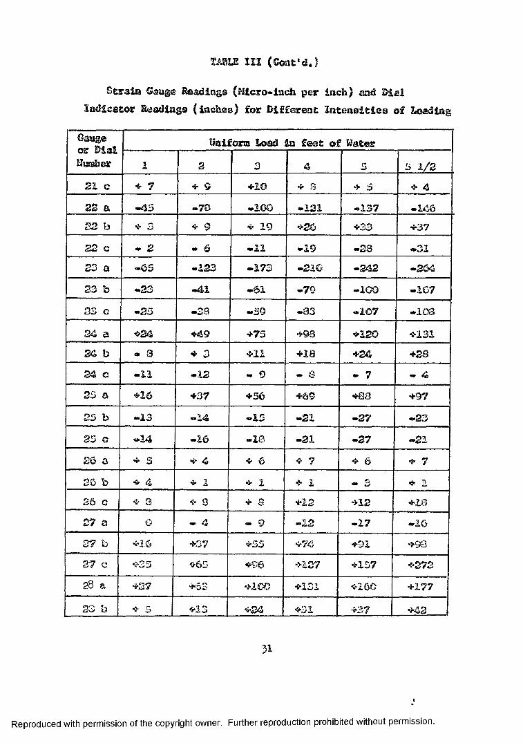
TABLE III (Coat*d.)
Strain Gauge Readings (Micro-inch per inch) and DialIndicator Headings (inches} for Different Intensities of Loading
Gauge or Dial Kucaber
Uniform Load a feet of Water2 3 4 S 5 1/2
21 c * 7 ❖ 9 ❖10 + s ❖ 3 ❖ 423 a ■"43 -7S -100 -121 -237 -146S3 b ❖ 3 ❖ 9 ❖ 19 ❖26 ❖33 ❖3722 c — 2 — ^ -11 -19 —28 -3123 a -65 -123 -173 -210 —242 —26423 b -23 «»41 -61 -79 —100 -1G723 c -25 -33 —59 -83 -107 —10324 a ❖24 ❖49 ❖75 ❖93 ❖120 ❖13124 b — 3 ❖ 3 ❖11 ❖18 ❖24 ❖2324 c —11 -12 - 9 — 8 - 7 - 423 a ❖16 ❖37 ♦56 ❖69 ❖aa ❖9722 b -13 -14 -15 -22 -27 -2325 C •14 -16 -23 -21 -27 -2126 a ❖ s «i* 4 ❖ 6 ❖ 7 ❖ 6 ❖ 726 b ❖ 4 ❖ 1 ❖ 1 ❖ 2 — 3 ❖ 126 c ❖ 3 ❖ 8 ❖ © ❖12 ❖12 ♦1827 a 0 - 4 «- 9 -12 -17 -1627 h ❖16 ❖37 ❖53 ❖74 ❖91 ❖9827 c ❖35 ❖65 ❖127 ❖157 ❖272
03COCVJ ❖63 ❖2 GO ❖231 ❖160 +177O'? ❖ 5 ❖13 ❖24 ❖32 ❖37 ❖42
Reproduced with permission of the copyright owner. Further reproduction prohibited without permission.

TAELS 111 (Confc.d.)
Strata Gauge Readings (.Micro-inch per inch) and Dialindicator Readings (inches) for Different Intensities of LoadingGauge or DialNumber
Uniform Load in feet of Hater1 2 n, 4 5 5 1/2
28 c +33 +48 *63 +73 +3429 a -59 —69 —95 -119 -144 -13229 b -2? -33 —44 -55 —5429 e -76 -100 -122 -138 -143
30 a — 2 - 2 - 1 - 1 + 3 + 6
VC b -18 -30 •42 —54 -63 -63o +25 +53 +80 +106 +136 *147
31 a -34 -60 O'** -107 -130 -13931 h —31 -64 -70 —93 -9832 c —23 -40 —52 -61 -60 -7232 a -iO -21 -35 -52 -67 -7232 b —11 -21 -30 -41 -54 -7232 c +38 —84 -133 *178 +224 +240
Dial i + 3 + 7 *11 *14 *18 +20vjCL&jL 2 +31 +43 +660 +72 *78.Oisi j +13 +23 +34 +44 *53 +53Dial 4 + 0 » +S7 *75 +93Diai 3 +23 <‘.35 +45 +54 +62Dial 6 +24 +36 +47 *37 *63
3ic~ 7 "5 "IS +25 +36 *47 +57 1 *63
Reproduced with permission of the copyright owner. Further reproduction prohibited without permission.

TABLE IV
Computation of Principal Moments andPrincipal Stresses for Rosette Gauges, Plate is
2Subjected to a Uniform Load of 1.5 lb./in .
X
Gauge Principal Moment Principal Stresses 0Number
1Max0.354
Min-0.198
Max34.017
Min-19.017
{radians;-.071
2 0.926 -0.458 88.950 -43.950 -1.4271.03 0 -0.717 98.852 -88.852 -1.339
. 4 . . 0.470 -3.284 45.156 -315.156 -0.7645 2.103 -1.322 201.102 -126902 -1.178
.6 0.514 _ -3.795 49.329 -364.329 -0.195
7 -2.365 -8.885 -227.060 -852.939 -0.3848 -3.058 -9.599 -29". 51:8 -921,471 -0.2569 -0.753 -6.434 -72.304 -617.695 -0.51010 -2.096 -9.466 -201.225 -908.774 -0.60111 -8.953 -16.671 -859.527 -1600.472 -0.27712 13.836 3.195 1328.299 306.700 -1.28813 -2.638 -11.268 -253.265 -1081.735 -0.230lb 0.981 -2.075 94.182 -199.182 -0.50215 -8.922 -20.452 -856.572 -1963.426 -1.01716 -4.761 -10.707 -457.056 -1027.943 -0.08617 22.250 12.437 2130.008 1193.989 -1.49118 -1.431 -12.788 -137.393 -1227.606 -1.347
2Moments are in It), in./in. and stresses are in lb./in .
Reproduced with permission of the copyright owner. Further reproduction prohibited without permission.

TABLE IV (Coat’d.)Computation of Principal Moments and
Principal Stresses for Rosette Gauges. Plate Is Subjected to a Uniform Load of 1.5 lb./in2.
Gauge Principal Moment Principal Stresses 0*Number Max Kin Max Min
r
19 13.365 8.823 I283.OI6 846.983 -1.53620 1.293 -13.324 124.161 -1279.161 -1.21221 -1.188 -16.781 -114.057 -1610.942 -1.19922 -1.892 -15.451 -l8l. 66l -1483.337 -1.30223 -11.937 -24.313 -1145.93^ -233^.063 -1.16924a.-------------- 8.860 1.452 850.598 139.402 -1.02725 6.894 -0.957 661.870 -91.870 • -1.15726 I.569 0.619 150.621 59.379 -0.82627 10.996 2.598 IO55.585 249.414 -0.89328 15.965 7.159 1532.669 687.329 -1.33129 -11.050 -19.419 -IO6O.811 -1864.187 -0.23330 13.281 -0.938 1275.062 -90.062 -0.23031 -9.336 -11.758 -893.323 -1131.676 -0.89632 -7.428 -18.831 -713. H 6 -1806.882 -0.368
3 3 A
Reproduced with permission of the copyright owner. Further reproduction prohibited without permission.

PHOTO. A PHOTOGRAPH SIKW13IG PAKP OP TEE SUPPOSTiaG STaUCTlfRE ASD COMPLETED GMJQE AHD DIAL INDICATOR ISSTALLiTIOSC (tAftTCM OF PLATE )
3^
Reproduced with permission of the copyright owner. Further reproduction prohibited without permission.
Reproduced with permission of the copyright owner. Further reproduction prohibited without permission.

Reproduced with permission of the copyright owner. Further reproduction prohibited without permission.

PHOTO. D PHOTOGRAPH SHOWING THE CLAMPED EDGES AND THE STRUCTURAL STEEL COLUMNS
37
Reproduced with permission of the copyright owner. Further reproduction prohibited without permission.

CHAPTER V
COWAEISOH OF RESULTS AMD OBSERVATIONS
The deflections of the clamped skewed piste recorded points
where the dial indicators were lobster! are compared with the de
flections at the same points derived irota the theoretical analysis.
The comparison is tabulated in Tabid V.
A comparison of the theoretical m i experimental principal stresses
and moments is also made at two locutions of the. skewed plat©, namely,
at points where gauges 11 and gauge IV (centre, ^nugc) are located.
These results arc tabulated in Table VI.
Bp way of comparison, It i& perhaps interesting to compare
Timoshenko’a results on clamped uniformly loaded rectangular pletes with those vived fr>r~ the theoretical analysis. In this particular
case, the angle of skew in the deflection function in set to :;ero and the deflection calculated for different sides ratios of the rectangular
plate. Table VII shows a comparison of the centre deflections, contra
moments and the smii •■■* edge moments.
As can bo seen from Table V, the deflections of the particular
skew plate investigated check vary well with those from the theoretical
analysis. Also the deflections for rectangular plates compare v*ry closely with those given by Timoshenko anti Krleger(l) f°r clamped rectangu
lar plates. (See Table VII)
Centre deflections for clasped skewed plates having different
skew aides ratios and skew angles compare quittr well with those
Reproduced with permission of the copyright owner. Further reproduction prohibited without permission.

obtained by Kennedy. (See Table VIII)
Moments and stresses, on the other hand, do not compare so
closely with either the experimental results or with other Investigators
(Tables VI and VII) The maximum or critical moments have been found
to occur at the midpoint of the longitudinal sides. These moments
are compared with Timoshenko's solution on clamped rectangular plates,
and the deviation of the moment values is in the range of about 10
per cent. Comparisons of principal moments and stresses are also
made with Kennedy*s work (ll) on clamped skewed plates and it is found
that all principal moments and stresses compare quite favourably In
the vicinity of the central portion of the plate but no close agree
ment could be observed for moments and stresses close to the built-in
edges.
A comparison with Kennedy's results for the deflections and
principal moments at the centre of skew plates with different skew
sides ratios and skew angles is tabulated in Tabic V1XI.
To conclude, it may be interesting to note that while based on
the theoretical analysis, the deflections, moments and stresses are
all proportional linearly with the intensity of loading. The experi
mental resulto, however, tend to deviate from this strict linear
relationship, the deviation becomes increasingly evident for high
intensities of loadings. This is understandable in the light that in
the theoretical treatment of clomped skewed platen embodied la this
thesis, only the bending effect on curvature is taken into account,
whereas the tension in the middle surface of the place effecting
3*
Reproduced with permission of the copyright owner. Further reproduction prohibited without permission.

curvecure, is ignored. This effect is presumably negligible when the
lateral deflection v is email as the deflection gets larger,
thf: membrane effect becomes more and more prominent until for large
v&luss of w, the membrane affect becoses predominant and the bending
stiffness is then negligible. It is quite evident from the experimen
tal results in Table 111 that, for the particular skew plate under
investigation, the effect of stretching of the middle plane of the
plate becomes quite appreciable for loadings of * '-•T‘ feet of water
and higher.
bo
Reproduced with permission of the copyright owner. Further reproduction prohibited without permission.

Reproduced with
permission
of the copyright ow
ner. Further reproduction
prohibited w
ithout permission.
TABLE V
Comparison of Deflections of a Clamped Skewed Plate (y=1.23j 0=55°) Different Intensities of Loading
Theoretical Studies Vs. Experimental Observations
Load in ft. ofWater/1»
Gauge 1 Gauge 2 Gauge 5 Gauge 4 Gauge 5 Gauge 6 Gauge 7Experi Theor Experi .Theor,Experi .Theor, Experi Theor. Experi .Theor.Experi Theor. Experi. Theor..003’* .003" .016" .013" .013’* .Oil" .021" ,01<T .013" .Oil" .013" .011 " .013" .011"
2 ’ .007" .007" .031" .026" .023" .021" .040" .037’ .023" .021 " .024" .021 " .025" .021"
3' .011" .010" .045 " .039^ .034" .032 " .057" .056 " .035" .032 " .036" .032 " .036 " .032"
4 * .014" .014" .060 " .052 " .044" .042 " .075" .075 " .045" .042 " .047" .042 " .047" .042 u
5' .018" .0173* .072" .065 " .053" .053 " .089" .093’ .054" .053 " .057" .053 " .057 " .053 "
5 5 2 .020 " j.0191" .078 " .071 " .058" .058 " .098" .102 " .062" .058 " .063" .058 " .063" .058 "
For Location of Dial Gauges See Fig. U

TABLE VI
Comparison of Maximum Moment and Maximum Stress for a Clamped Skewed Plate (7 = 1.23j 0 - 55°) for Two Different Intensities of Loading Theoretical Studies Vs. Experimental Results
Uniform Load
in Ft.of Water
GaugeNo.
Max. Moment (lb. in./ in.)
Max. Stress lbs./ in.^)
Experi. Theor. Experi. Theor.
1*17 7.55 7.44 725 714
11 -3.09 -2.79 -296 -268
3* 17 22.25 22.33 +2136 2144
11 -8.95 -8.39 -859 -806
Centre Gauge v = 0.3 D — 14,648.4375 lb. in
E = 10,000,000 p>3#1>
Reproduced with permission of the copyright owner. Further reproduction prohibited without permission.

Reproduced with
permission
of the copyright ow
ner. Further reproduction
prohibited w
ithout permission.
TABLE VIZ
Comparison of Centre Deflection, Centre Moments and Maximum Edge Moments for Clamped Rectangular Plates
-p-v>i
Centre Deflection Max. Edge Moment Centre Moments
b/' a a 0 , (5 = 0 a = a, 0 = 0 Mx at a - o, p = 0 My at a = (3, P = 0From
Theor. Anal. Titno,From
rheor.Anal. Timo.From
Theor. Anal. Timo.From
Cheor.Anal. Timo.1.0 .021 .020 Pa~rr
2**.170 pa -.205 2pa .110 2pa 2.092 Pa 2.110 Pa 2.092 Pa1.1 .025 II .024 VI -.203 it -.232 11 .126 II .106 " .114 " .0921.2 .029 II .028 tl -.233 it -.256 tf .140 ft .120 " .115 .0911.3 .032 11 .031 tl -.259 tt -.275 If .152 II .131 " .115 " .089 "1.4 .035 VI .033 11 -.282 tt -.290 If .162 If .140 " .114 " .085 "1.5 .038 II .035 II -.301 it -.303 »? .170 If .147 ” .112 " . 081 "1.6 .040 II .037 VI -.318 tt -.312 II .177 II .152 " .109 " .077 "1.7 .042 tt .038 tl -.332 n -.320 ft .183 11 .157 " .107 " . 073 "1.8 .043 It .039 It -.344 tt -.325 ft .187 ft .160 " .104 " .070 "1.9 ,044 II .040 It -.354 tt -.329 II .191 II .163 " .102 " .066 "2.0 .045 If .041 II -.362 it .332 If .195 11 .165 " .099 " . 063 "
V = 0 . 3

TABLE
VIII
Comparison
of Centre Deflections
and Centre
Principal
Momenta
for
Clamped
Skewed Plates wit
h Different
SLew
er*09SIJit/3
«O•ri
AS
(0<D•aUJ
4J
1
ix»*4JflOo
9n■8*3MWas
a88•
£r-a8•
evoo\O•
8UNH.-4o
a
S
r-o•RI«**4oft
tt*—008«
£
ttVO©a
evOC-UNo
a
s
RI1*4o•
•OoJQ
cmaCM8•
E
1*4
o1*4ft
CoHr~o.
s
so•
B
•
K
&o•
6
8?8
a
St—-a-o—
a
800
a
£
S'Ho•
s
•
01uu
J
>>•oa£
w «H
•
cK\IAt-4•
sWNCMS'•
B
oft
Sirv-ar?rs•
t
Soa
8UN
8o•
6IAIAUNH
a
S
v$UN*4a
C
&o a
•hi§
w «a1*4
I•
C&K\H•
s1*41*4of-4•
s-4&o•
Bt-IAtA•
rCMttO•
C S
a—a
C
HUNOS*4a
8o*•4€•
s•riUo«U4<9»<WM■UflOo
>>
-%aa41Ad
4 L 81
•
S
S.
t
£o a
B009-48•
£
Roa
t
0
tA•■4
•
t
*o•
e
£KSa a
C
18a
.wOaJSp*
"sip
•
ef-4t -Ci©•
to
£r*4o•
OS8•
Ce-4KNAOa
«-Si-04OQ•
H8•
to
tt-4o•
8•8-UNJ t©ft
S00CM
8•
Q> 0unC*“
0UN*—4
0& $
0UNH °©vo
oUNt- °o Oo 0ovo
« o•*-4mcm•t»4
irsCM•r-t
IA0J•i>4
IAaH
UN•HWN•H
■Oai-l©•CM
©•CM
U
to
Reproduced with permission of the copyright owner. Further reproduction prohibited without permission.
0.3

- V I
CONCLUSION
The Rayleigh-Ritz technique was employed to establish a deflection
function for clomped uniformly loaded skewed plates. From this function,
deflections, rectangular moments and principal moments were computed
at arbitrary points of plates having different sides ratios and
skew angles. Those results were then compared with those observed
from an experiment on a skewed plate with a skew aides ratio of 1.2J and a skew angle of 55 degrees. Also, the same results were used to co&pare with these obtained by Kennedy, Timoshenko and other investi
gators. These comparisons seem to indicate that the deflection function
established for the clamped uniformly loaded skewed plate represents,
to a reasonably high degree of accuracy, the true deflections of skew
plates having the same boundary conditions.
Satisfactory agreements were also obtained when the principal moments and principal stresses in the central portion of the plate
ware compared with those observed from the experiment. Kowevcr, as
the edge of the plat® is approached, the variation of moments and
stresses is steep end it is in these areas that incongruencies exist
in the values of the principal moments and stresses.To gain confidence in the application of the theoretical analysis
of clamped skewed plates embodied in this thesis another similar
experiment will be conducted in the near future on a uniformly loaded
clomped skewed plate with a skew sides ratio of 1.12 and a akew angle
Reproduced with permission of the copyright owner. Further reproduction prohibited without permission.

of 'J) . The results of such an experiment will again be comparedtical analysis.with those obtained from the -
Reproduced with permission of the copyright owner. Further reproduction prohibited without permission.

APPEflD IX A
Fortran Programme for the Theoretical Analysis of Uniformly Loaded Skewed Plates
C ANALYSIS OF UNIFORMLY LOADED SKEWED PLATES100 READ 10.G.DEGRE.ANU 10 F0RMAT(3F10.5)
T H E T A = D E G R E * 0 .017453292 A 1 = (C O S F ( T H E T A ) )**4 A 2 = (256./225.)*G**5 A3=A1*A2A 4 = 2 0 » 8 0 5 0 7 9 3 * G * * 5 + 1 1.8 8 S 6 16 8 * G * * 7 + 23.7772337*G**7
1*< SINF( THETA) ) #*2+20 . 8050793*G**9 A001=A3/A4
144 A 2 = 1 . 5 3 7 1 140+1.5029560* G * G + 3 . 0 0 5 9 1 19*G*G 1*(SI N F ( T H E T A ) ) * * 2 + l . 5 3 7 1 140*G**4 A3 = A 1*A2A 4 = 2 8 .1072273+43.543 8 9 6 3 * G * * 2 + 5 1.7529915 * G * * 2 * (S I N F (T H E T A )**2) A 5 = 7 1.9188109* G * * 4 - 7 . 8 5 2 1 7 6 8 * G * * 4 * (S I N F (T H E T A )**2)
1 +62 • 8 1 74256*G**4* ( S I NF ( THETA ) -**4 )A 6 = 4 3 . 5 4 3 8 9 6 3 * G * * 6 + 5 1 •7529915*G**6
1 * C SINF <T H E T A )++2)+28. 1072273*G**8 A7=A4+A5+A6 A002 = A3/A7A 2 = 6 . 7 6 3 3 0 1 8 * ( S I N F ( T H E T A ) )+6.7633018 * G * G * S I N F (T H E T A )A3=A1*A2A 4 = 2 8 .10 7 2 2 7 3 + 4 3 . 5 4 3 8 9 6 3 * G * * 2 + 5 1•7529915 * G * * 2 * (S I N F (T H E T A )**2) A5 = 7 1 .9188109*G**4-7.8521768*G** 4*(SINF ( THETA) **2)
1 + 6 2 . 8 174256*G**4*(SINF(THETA ) **4 )A 6 = 4 3 . 5 4 3 8 9 6 3 * G * * 6 + 5 1 •7529915*G**6
1 * (S I N F (T H E T A )**2)+28. 1072273*G**8 A7=A4+A5+A6 A022=A3/A7 PUNCH 198
198 F O R M A T (24H INPUT DATA AND RESULTS)PUNCH 199 »G « THET A .A N U .A 0 0 1 .A002.A022
199 F O R M A T (3H G=F10.5.7H T H E T A = F 10.5.5H ANU=Fl0.5/6H A001=F20.8. 16H A002=F15.8/6H A022=F15.8)
388 DIMENSION T 8 E T A (3)♦T A L P A <3>READ 10 1. (T B E T A ( I ), 1=1,3) . (T A L P A (J) .J=1 .3)
101 F0RMAT(6F10.5)DO 99 J = 1.3 ALPA = T A L P A (J )DO 99 1=1.3 B E T A = T B E T A (I )
Reproduced with permission of the copyright owner. Further reproduction prohibited without permission.

SEC=1,/COSFCTHETA)S = S I N F (T H E T A )C = C O S F ( T H E T A )S E C 3=S E C **3PI = (G**2~BETA**2 >**2P2=I2.*A002 * A L P A * * 2 - 4 •* A 0 0 1P 3 = P 1*P2P4=32.*S*A001P5=G**2* CALPA**3)*BETA+ALPA* ( BETA**3 )
1 -G**2*ALPA*BETA- ( A L P A * * 3 ) * ( B E T A * * 3 3 P6=P4*P5 P7=S**2p a = c * * 2P9= c1• — A L P A * * 2 3**2P l 0 = 1 2 . * A 0 0 1 * B E T A * * 2 - 4 . * A 0 0 1 * G * * 2 PI 1= P 9 * P 10A M A L 1=— S E C 3 * (P 3 + P 6 + (P 7 + A N U * P S )* P 11)AMBE1=-SEC3*{PI 1+ P 6 + (P 7 + A N U * P 8 )* P 3 3A M A B 1= - S E C 3 * S * ( P 3 + P 6 + P l 1 )- S E C * ( 1.- A N U > * < - 1 6 * ) * A 0 0 1 * (- P 5 3 DEF1=P9*P1*A001P 2 0 = - 4 . * A 0 0 2 + 1 2 . * A 0 2 2 * A L P A * B E T A
1-20•*A0 22*(A L P A * * 3 )* B E T A + 12.* A002*ALPA**2 WAA=P1*P20P 2 1-12.* A 0 2 2 * G * * 2 * A L P A * B E T A - 2 0 « * A 0 2 2 * A L P A * B E T A * * 3 - 4 .*A0 02*G**2
1 + 12•*A0 02*BET A **2 W B B = P 9 * P 2 1P22=16.*A0 0 2 * ( G * * 2 * A LPA*BETA-G**2*< ALPA**3> *BETA
1-ALPA*BETA**3 + < A L P A * * 3 ) * ( S E T A * * 3 > 3 P 2 3 = A 0 2 2 * (6.*(G * * 4 )* A L P A * * 2 - 5 •* G * * 4 * A L P A * * 4 - G * * 4 - 3 6 •* G**2*ALPA**2
I * B E T A * * 2 + 3 0 . * G * * 2 * A L P A * * 4 * 3 E T A * * 2 + 6 . * G * * 2 * 3 E T A * * 2 + 3 0 •*ALPA**2 2 * 3 E T A * * 4 - 2 5 . * A L P A * * 4 * B E T A * * 4 - 5 . * B E T A * * 4 )WAB=P22+P23A M A L 2 = - S E C 3 * (W A A - 2 •* S * W A B + (S * * 2 + A N U * C * * 2 )* W B B )AMBE2 = -SEC3*C W8B-2. *S * W A B + ( S**2+.4NU*C**-2 ) *WAA ) A M A B 2 = - S E C 3 * S * C W A A - 2 . * S * W A S + W B B ) + S E C * ( 1 .-ANU)*WAB DEF2=P9* P 1 * ( A 0 0 2 - A 0 2 2 * A L P A * B E T A )P 2 4 = 1 6 . * A 0 0 1 * ( G * * 2 * A L P A * B E T A - G * * 2 * (ALPA* * 3 ) *BETA
1- A L P A * (BET A * * 3 ) + (A L P A * * 3 )*(B E T A * * 3) 3 TAN=S/CA M X 1 = - ( (SEC**2*-P3)-2.*SEC*TAN*P24 +TAN**2*P11+ANU*P11>A M Y 1 =-(PI 1+ A N U * (P 3 * (S E C * * 2 )-2.*SEC*TAN*P24 + P11*CTAN**2) 3 )A M X Y 1 = ( 1 • — ANU 3 * ( P 2 4 * S E C —P 11 * T A N )A M X 2 = — (S E C * * 2 * W A A — 2 . * S E C * T A N * W A B + T A N * * 2 * W B B + A N U * W 3 B ) A M Y 2 = - ( W B B + A N U * C S E C * * 2 * - W A A - 2 . * S E C * T A N * W A B + T A N * * 2 * ( W 3 3 ))3 AMXY2 =( 1 .-ANU 3*(W A B * S E C - W B B * T A N )
hS
Reproduced with permission of the copyright owner. Further reproduction prohibited without permission.

PMMAX =(AMX2+AMY2)/2.+SQRTF( ( (AMX2-AMY2 >/ 2 .)**2+(A M X Y 2 )**2) PMMI N = (AMX2+AMY2 > / 2 . - S Q R T F ( <(A M X 2 - A M Y 2 )/ 2 •)**2+< A M X Y 2 >**2) PUNCH 2 50 1 AMA|_2 . AMBE2 ♦ AMAB2 . AMX2 . AM Y2 .AMXY2
99 PUNCH 15 2 « PMMAX » P M M I N ♦DEF2 * ALPA(BETA150 FORMAT! 7H AMA|_2 = E 1 6 • 8 . 7H AMBE2 =E 1 6 . 8/7H AMAB2=E16.8/
16H AMX2=E16.8.6H A M Y 2 = E 16.8/7H AMXY2=E16.8)151 F O R M A T (7H PMMAX = E 16.8 * 7H PMMIN = E16.3/
26H DEF2=E16. 8/6H A L P A = F 6 . 3 » 6 H S E T A = F 6 .3///2 GO TO 100 END1.23 55.0.0 0*615
k9
0 .33331 .23 0.0 0.5 1 .0
Reproduced with permission of the copyright owner. Further reproduction prohibited without permission.

Fortran Programme for the Experimental Studies of o. Uniformly Loaded Sleeved Plato
C E X P E RIMENTAL STUDIES OF A UNI F O R M L Y LOADED SKEWED PLATE READ 9» E * A N U »T
100 READ 10.SA.SB.SC 9 FORMAT(3F10.8)
10 F O R M A T (3 F 10•8)T 1 = (SA+SC 3/( 1.-ANU)T 2 = < 1./(1•+ A N U ))* S Q R T F ( 2 . * ( S A - S 8 ) **2
1+2.*(SB-SC)**2)S I G M X = (E / 2 •)*(T l + T 2 )S I G M N = (E/2.)*(T1-T2)D I M X M = 0 . 5 * A T A N F ((2.* S B - S A - S C )/ C S A - S C ) )-45.*.017453292 T4=T * T / 6 .PMMAX = T 4*SIGMX PMMIN= T 4 * S I G M NPUNCH 1 1 .SA.SB.SC.SIGMX.SIGMN.DIMXM .PMMAX.PMMIN
11 F O R M A T (4H SA=E16.8,4H SB=E16.8.4H SC=E16.8/17H SIGMX =E16 » 8 »7H SIGMN = E 1 6 • 8.7H DIMXM = E16.8/27H P M M A X =EI 6•8.7H P M M I N = E 16.8///)GO TO 1 00END
10000000. 0.333333 0.250. -3 . 1 •4. -7. -1 .6 • -9. -4.
00 00 0
50
Reproduced with permission of the copyright owner. Further reproduction prohibited without permission.

APPENDIX B
Computer Solution for Deflections, Moments, and Principal Moments for a Uniformly Loaded Skewed Plate with a Skew SideB
Ratio of 1.23 and a skew Angle of 55°
INPUT DATA AND R E S ULTS G = 1 .23000 THET A= .95 993 ANU =A 001= .00111395 A002 =A 0 22= .00192663A M AL2= . 6 7 3 7 9 8 3 6 E - 0 1 AMBE2= A M AB2= . 5 8 3 4 6 1 0 8 E - 0 1 A MX 2 = •3 8 6 4 7 4 8 8 E — 01 AMY2 =A M XY2= .3151778HE-02 P M M A X = .3918 2 3 2 5 E — 01 PMMIN=D E F2= • 3 28812 7 3 E —02A L PA= 0.000 BET A= 0.000
.33330.00143657
. 6219 6 9 6 H E — 01
2 0609022E-01
. 2 0 0 7 4 185E-01
AMAL 2 = . 5 5 376465E— 01 AMBE2=A M AB2= .48392214 E — 0 1 AMX2= . 3 1 7 6 2 6 3 6 E - 0 1 AMY2 = A M X Y 2 = •30304716 E — 02 P M M A X = .3 2 2 2 8 5 7 5 E — 01 PMMIN=D E E2= . 18495715E-02A L PA= 0.000 BET A= .615
•4 9 3 0 3 2 8 1 E — 01
•12518439E-01
. 12052499E-01
A M AL2= - . 7 1 9 3 1 2 5 6 E— 0 1 A M BE2 A M A B 2 = — .7 5 4 7 7 7 4 6 E — 01 AMX2= — .412 5 8 0 7 9 E — 01 AMY2 = A M X Y 2 = - . 16555108E-01 P M M A X = 17614936E-01 P M M I ND E F 2 = .000 O O O O O E — 99A L PA= 0.000 BET A= 1.230
= — . 9 2 1 4 1 3 1 8 E — 01
— . 2 9 2 0 6 9 4 8 E - 0 1
= - . 5 2 8 5 0 0 9 0 E - 0 1
A M A L 2 = . 4 4 834382E— 01 AMBE2= AMAB2= . 4 2 3 43381E— 0 1AMX2= . 2 5715 9 4 6 E —01 AMY2=AMXY2= .56 172069E— 0 2P M M A X = .27 8 3 1 6 6 0 E — 01 PMMIN=D E F2= . 18495715E-02 ALPA= .500 BET A= 0.000
. 4 6 6 9 6 4 8 6 E — 0 1
. 12918 0 2 0 E — 01
• 1 0 8 0 2 3 0 6 E - 0 1
00 00 00
51
Reproduced with permission of the copyright owner. Further reproduction prohibited without permission.
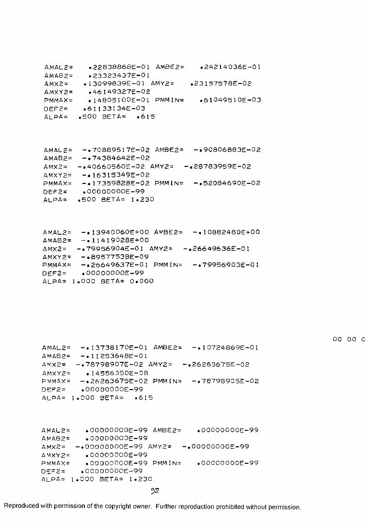
AMAL2= .228 3 8 8 6 8 E — 01 AMBE2=A M A 8 2 ” •2 3 3 2 3 4 3 7 E — 01 AMX2 = • 13099839E-01 AMY2 =AMXY2= . 4 6 149327E-02 PMMAX= . 14805100E-01 PMMIN= O E F 2 = .6 I I 3 3 2 34E-03
•2 4 2 1 4 0 3 6 E - 0 1
•23157578 E —02
.61049510E-03
ALPA = .500 BET A = ■ 615
AMAL2= — .7 0 3 8 9 5 1 7E— 02 AMBE2= - . 90806883E-02 AMAB2= — •74 3 8 4642E— 02AMX2= — •4 0 6 6 0 5 6 0 E — 02 AMY2 = -. 28783959E-02AMXY2= 16315349E-02PMMAX= - ♦ 17359828E-02 PMMIN= - . 5 2 0 8 4 6 9 0 E - 0 2 DEF2= .O O O O O O O O E —99 ALPA = .500 BET A= 1.230
AMAL2= - . 13940060E+00 AMBE2= - . 1 0382480E+00 AMAB2= - . 1 1 419028E+00AMX2= — .79956904E —0 1 AMY2= - . 2 6 6 4 9 6 3 6 E - 0 1 AMXY2= — . 8 9577538E— 09PMMAX= — .2 6 6 4 9 6 3 7 E — 01 PMMlN= - . 7 9 9 5 6 9 0 3 E - 0 1 DEF2= ,O O O O O O O O E — 99ALPA = 1.000 BET A= 0.000
00AMAL2= - . 1 3 7 3 8 1 7 0 E - 0 1 AMBE2= - . 1 0 7 2 4 8 6 9 E - 0 1 AMAB2= - . 1 1 2 5 3 6 4 8 E - 0 1A MX2 = — . 7 8 798907E—02 AMY2 = -.26263675E-02A M X Y2 = . 14556350E-08PMMAX= — . 2 6 263675E—02 PMMIN= -. 78798905E-02 DEF2 = .O O O O O O O O E —99ALPA= 1.000 BET A= .615
AMAL2= .00000000E-99 AMBE2= .OOOOOOOOE-99AMAB2= . O O OOOOOOE—99A MX2 = — . O O OOOOOOE— 99 AMY2 = -.000 00000E-99AMXY2= •OO O O O O O O E — 99PMMAX= .00000000E-99 PMMIN= .OOOOOOOOE-99DEF2 = .OOOOOOOOE-99 ALPA= 1 .000 BET A= 1.230
52?
00 0
Reproduced with permission of the copyright owner. Further reproduction prohibited without permission.

REFERENCES
(1) S.P. Timoshenko and S. Wolnoweki-Krieger, Theory of Plates andShells, 2nd Edition, (McGraw-Hill, 1959).
(2) Loro ^.yleigh, On the Calculation of Chladni’s Figures for V a Square Plate, Phil. Mag., Vol. 22, 1911.
W. Ritz, Uber Eine Neue v-^ode zur Losung GewiasenVariationa-Problems der Mathematischen Physik, J.f. Reine u. Angew. Math., Vol. 135* 19^.
(3) Vernon P. Jensen, Analysis of Skewed Slabs, University ofIllinois Engineering Experimental Station Bulletin,Serial No. 332, pp. 3-*10j Sept., 19^1.
(4) E. Reissner, Bending and Twisting of Skewed Plates, Quart.App. Math., vol. 10, p. 395, 1953.
(5) L.S.D, Morley, Skew Plates and Structures. Pergamon Press, I963,
(6) I. Mirsky, The Deflection of a Thin Flat Clamped ParallelogramPlate Subjected to Uniform Normal Loading. Dept, of Supply, Australia, aeronautical Research Laboratories, Report S.M.175, 1951.
(7) P.D. Jones, Small Deflection Theory of Flat Plates Using ComplexVariables, Dept, of Supply, Australia. Aeronautical Research Laboratories, Report S.M. 260, 195-3.
(8) F.H. Dorman, The Thin Claraped Parallelogram ^ **te under UniformNormal Pressure. Dept, of Supply, Australia. Aeronautical Research Laboratories, Report S.M, 21h, 1955.
53
Reproduced with permission of the copyright owner. Further reproduction prohibited without permission.

(9 ) J.B. Kennedy and M.W. Huggins, Series Solution of Skewed ^ Stiffened Plates, Proceedings of the American Society
of Civil Engineers, Feb. 196b.
(10) J.B. Kennedy and I.C. dartsns, Stresses near Comers of Skewedj ,Stiffened Plates, The Structural Engineer, Nov. 19°5.
(11) J. B. Kennedy, On the Bending os Clasnped Skewed PlatesUnder Uniform Pressure (To be Published).
(12) Aluminum Company of America Handbook, Pittsburgh, Pennsylvania,i960 Edition.
Reproduced with permission of the copyright owner. Further reproduction prohibited without permission.
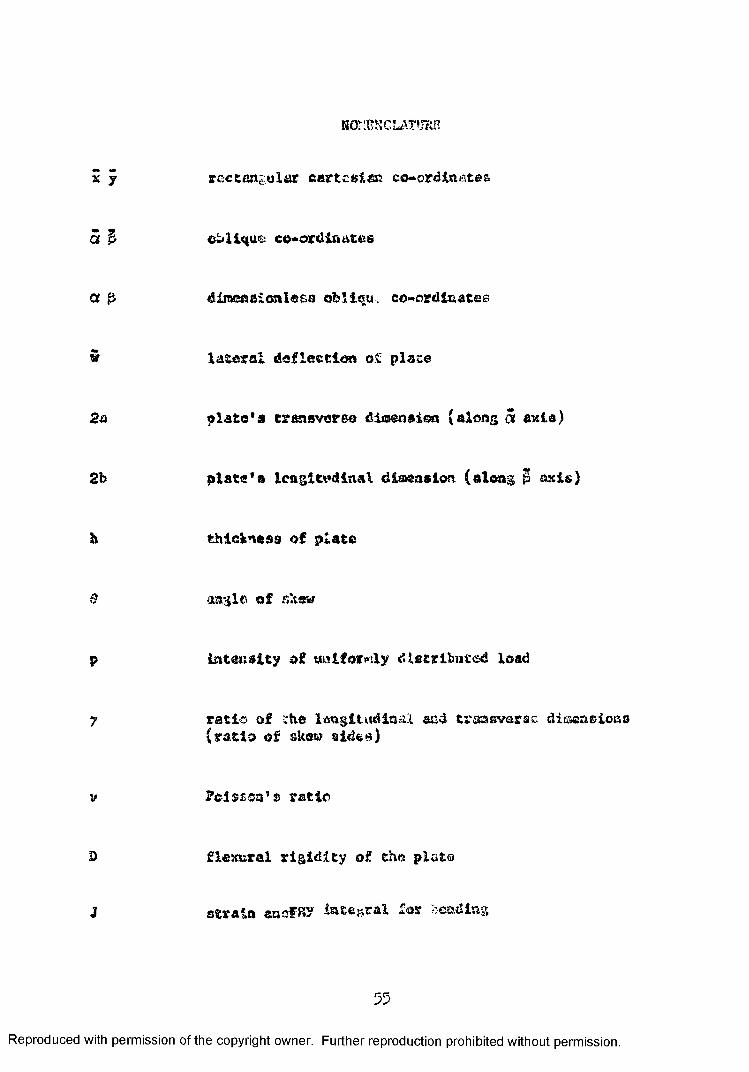
HOMES C LAY * JRB
x y rectangular cartesian co-ordinates
5 & ob lique eo-ord intites
a & direcfSBicnlesa oblieu. co-ordinates
w lateral deflection o£ plate
2a plate's transverse dimension (along <5 axle)
2b plate's icngitwilaal dimension (along $ axis)
h thickness of plate
6 angle of skew
p intensity of wniforwily distributed load
y ratio of the longitudinal and transverse dinsaasiona(ratio of skew aides)
v Pol$£03"s ratio
3) flexural rigidity of the plate
J strain ensFRP integral lor sending
55
Reproduced with permission of the copyright owner. Further reproduction prohibited without permission.

I total energy Integral
Ho bending mcmant per unit length of plate perpendicula tothe x axis
Mo bending moment per unit length of plate porpendicula to^ the y axis
M— twisting moment per unit length of plate perpendicula toxy
m m
the x axis
(j''- normal component of stress parallel to the x axis
CT - normal coaqsonent of stress parallel to the y axis
rr' maximum principal stressmax
0^rain minimum principal stress
Ao9 ^1 parameter in the assumed deflection function
M principal maximum momentmax
M principal minimum moment
e
angle measured clockwise from the x axis, giving the direction in which the maximum principal moment occurs
®c recorded unit strain in the three leys of a rosette gauge
56
Reproduced with permission of the copyright owner. Further reproduction prohibited without permission.

VITA AUCTORIS
195;, Sirnn Shuua was ©on; in Canton, Chico, ua March 6,193 .
19 3̂ Xa Septtmbsr, he entered Pal Yin# School. Conte®,China, whore he obtained bia eleraeatary education,
1950 In Septeaber, 195® > enrolled at w«h Tan Collage,lion a Song, where he obtained his secondary education.
Xa 3epfc«ab<tr, 1937, bo enrolled in first year Science at the University of -McGill, Montreal, Canada.
105c In September, 195 , he entered the University of BritishCotumh4a, Vancouver, Canada to study civil engineering.
19 2 In May, 19 &2, he was graduated from the University ofBritish Columbia with a Bachelor of Applied Science Degree. In June, he was employed as junior engineer in the hydro* electric d«sig« division of tho Interactional Power and Engineering Consultants, Ltd., Vancouver, Krltisb ColuJ&la.
ly 3 In September, 19 3 he enrolled at the University of Windsorin orcer to obtain the degree of faster of Applied Sciance In Civil Engineering.
57
Reproduced with permission of the copyright owner. Further reproduction prohibited without permission.


