Embed Size (px)
Citation preview

Analog Devices Welcomes Hittite Microwave Corporation
NO CONTENT ON THE ATTACHED DOCUMENT HAS CHANGED
www.analog.com www.hittite.com

THIS PAGE INTENTIONALLY LEFT BLANK

HMC1023LP5E Evaluation Kit
User ManualSoftware & Hardware Installation
2 Elizabeth Drive, Chelmsford, MA 01824Phone: 978-250-3343 • Fax: 978-250-3373 • [email protected]
Order On-Line at: www.hittite.com Receive the latest product releases - click on “My Subscription”
Analog, Digital & Mixed-Signal ICs, Modules, Subsystems & Instrumentation
Part #
140-00125-00Rev. A - v00.1212ECN# CP121609
2
Rev. A - v00.1212
Order On-Line: www.hittite.com. For technical application questions: Tel: 978-250-3343 or [email protected]
HMC1023LP5E Evaluation Kit User Manual
Table of Contents
1. Introduction . . . . . . . . . . . . . . . . . . . . . . . . . . . . . . . . . . . . . . . . . . . . . . . . . . . . . . . . . . . . . . . . . . . . . 31.1 Hittite LPF Evaluation Kit Contents . . . . . . . . . . . . . . . . . . . . . . . . . . . . . . . . . . . . . . . . . . . . . . . . . 31.1.1 Hardware . . . . . . . . . . . . . . . . . . . . . . . . . . . . . . . . . . . . . . . . . . . . . . . . . . . . . . . . . . . . . . . . . . . . . . . . 31.1.2 Software . . . . . . . . . . . . . . . . . . . . . . . . . . . . . . . . . . . . . . . . . . . . . . . . . . . . . . . . . . . . . . . . . . . . . . . . . 32. Operating Environment . . . . . . . . . . . . . . . . . . . . . . . . . . . . . . . . . . . . . . . . . . . . . . . . . . . . . . . . . . . 33. Setup and Installation . . . . . . . . . . . . . . . . . . . . . . . . . . . . . . . . . . . . . . . . . . . . . . . . . . . . . . . . . . . . . 43.1 User Provided Equipment . . . . . . . . . . . . . . . . . . . . . . . . . . . . . . . . . . . . . . . . . . . . . . . . . . . . . . . . . 44. Hardware Setup . . . . . . . . . . . . . . . . . . . . . . . . . . . . . . . . . . . . . . . . . . . . . . . . . . . . . . . . . . . . . . . . . . 54.1 Evaluation Board Configuration . . . . . . . . . . . . . . . . . . . . . . . . . . . . . . . . . . . . . . . . . . . . . . . . . . . . 54.1.1 Default Configuration (Differential Inputs/Outputs) . . . . . . . . . . . . . . . . . . . . . . . . . . . . . . . . . . . 54.1.2 Single-Ended Inputs/Outputs Configuration . . . . . . . . . . . . . . . . . . . . . . . . . . . . . . . . . . . . . . . . . 64.1.2.1 Single-Ended Input Configuration . . . . . . . . . . . . . . . . . . . . . . . . . . . . . . . . . . . . . . . . . . . . . . . . . . 64.1.2.2 Single-Ended Output Configuration . . . . . . . . . . . . . . . . . . . . . . . . . . . . . . . . . . . . . . . . . . . . . . . . 64.2 HMC1023LP5E Evaluation Board Interface to Test Equipment . . . . . . . . . . . . . . . . . . . . . . . . . 75. Software Installation/Uninstallation . . . . . . . . . . . . . . . . . . . . . . . . . . . . . . . . . . . . . . . . . . . . . . . . 76. Get Started with Hittite LPF Eval Software . . . . . . . . . . . . . . . . . . . . . . . . . . . . . . . . . . . . . . . . . . . 77. Using HMC1023LP5E Evaluation Software . . . . . . . . . . . . . . . . . . . . . . . . . . . . . . . . . . . . . . . . . . . 97.1 Quick Setup . . . . . . . . . . . . . . . . . . . . . . . . . . . . . . . . . . . . . . . . . . . . . . . . . . . . . . . . . . . . . . . . . . . . . . 97.2 Direct Register Access/Direct SPI Access . . . . . . . . . . . . . . . . . . . . . . . . . . . . . . . . . . . . . . . . . 117.3 Save or Load Complete Register Files . . . . . . . . . . . . . . . . . . . . . . . . . . . . . . . . . . . . . . . . . . . . . 11
3
Rev. A - v00.1212
Order On-Line: www.hittite.com. For technical application questions: Tel: 978-250-3343 or @hittite.com
HMC1023LP5E Evaluation Kit User Manual
1. Introduction
This document describes the functionality of the HMC1023LP5E 6th order Low Pass Filter Evaluation Kit, and provides high level instructions for using the Kit. This kit includes PC compatible software that generates a Graphical User Interface (GUI) allowing the user to read from and write to all device registers, set gain levels, program filter bandwidth and save & recall device configurations.
Note: For most up-to-date software download and information please visit www.hittite.com and navigate to HMC1023LP5E page.
1.1 Hittite LPF Evaluation Kit Contents
1.1.1 Hardware
Item Quantity
HMC1023LP5E Evaluation Board 1
USB Interface Board 1
6’ USB A Male to USB B Male Cable 1
CD ROM (Contains User Manual and software) 1
1.1.2 Software
HMC1023LP5E Eval Software
• Used to enable communication between a PC and HMC1023LP5E
• Enables users to observe full functionality and performance of HMC1023LP5E
Note: All software can be downloaded from www.hittite.com, or shipped on a CD along with other contents of the kit.
2. Operating Environment
The HMC1023LP5E Evaluation Kit is designed for use in a laboratory setting at ambient room temperature (25 °C) and is not protected against moisture. The USB Interface Board has an ESD rating of ±3000V, however the HMC device may have a lower rating (check the product’s data sheet for its specific ESD rating). Use appropriate ESD procedures and precautionary measures when handling all electronic hardware.
4
Rev. A - v00.1212
Order On-Line: www.hittite.com. For technical application questions: Tel: 978-250-3343 or [email protected]
HMC1023LP5E Evaluation Kit User Manual
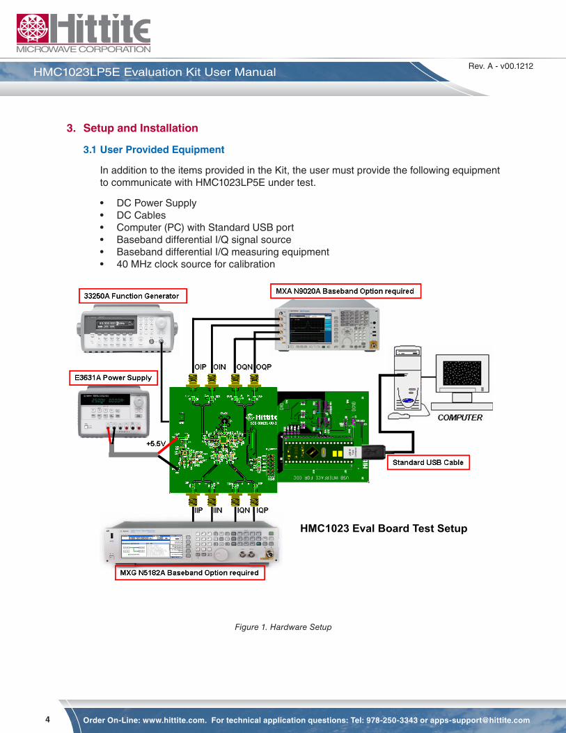
3. Setup and Installation
3.1 User Provided Equipment
In addition to the items provided in the Kit, the user must provide the following equipment to communicate with HMC1023LP5E under test.
• DC Power Supply• DC Cables• Computer (PC) with Standard USB port• Baseband differential I/Q signal source• Baseband differential I/Q measuring equipment• 40 MHz clock source for calibration
Figure 1. Hardware Setup
HMC1023 Eval Board Test Setup
5
Rev. A - v00.1212
Order On-Line: www.hittite.com. For technical application questions: Tel: 978-250-3343 or @hittite.com
HMC1023LP5E Evaluation Kit User Manual
4. Hardware Setup
Setup all hardware according to Figure 1.
• Connect USB board to HMC1023LP5E Eval board.
• Connect the USB cable to USB board.
• Apply +5.5 V to TP2 (TP1 is GND) on (HMC1023LP5E) Eval board. Supply current should be ~230 mA.
• I/Q inputs to J6, J7, J8 and J9.
• I/Q outputs to J1, J2, J3 and J4.
• Common mode voltage (2.5 V typ) is generated directly on the board for the input and output connections.
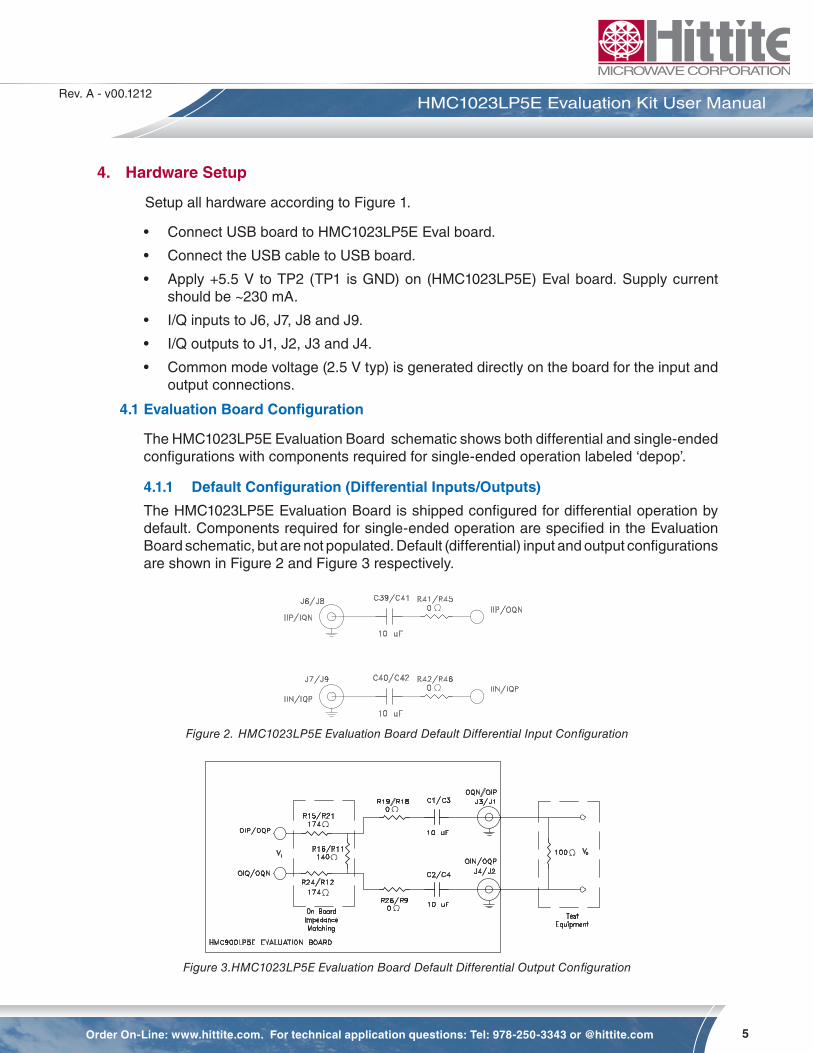
4.1 Evaluation Board Configuration
The HMC1023LP5E Evaluation Board schematic shows both differential and single-ended configurations with components required for single-ended operation labeled ‘depop’.
4.1.1 Default Configuration (Differential Inputs/Outputs)
The HMC1023LP5E Evaluation Board is shipped configured for differential operation by default. Components required for single-ended operation are specified in the Evaluation Board schematic, but are not populated. Default (differential) input and output configurations are shown in Figure 2 and Figure 3 respectively.
Figure 2. HMC1023LP5E Evaluation Board Default Differential Input Configuration
Figure 3.HMC1023LP5E Evaluation Board Default Differential Output Configuration
6
Rev. A - v00.1212
Order On-Line: www.hittite.com. For technical application questions: Tel: 978-250-3343 or [email protected]
HMC1023LP5E Evaluation Kit User Manual
4.1.2 Single-Ended Inputs/Outputs Configuration
Hardware board changes are required to configure the HMC1023LP5E Evaluation Board for single-ended operation
4.1.2.1 Single-Ended Input Configuration
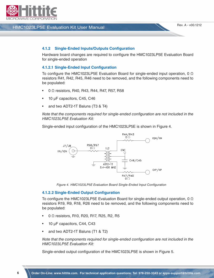
To configure the HMC1023LP5E Evaluation Board for single-ended input operation, 0 Ω resistors R41, R42, R45, R46 need to be removed, and the following components need to be populated:
• 0 Ω resistors, R40, R43, R44, R47, R57, R58
• 10 µF capacitors, C45, C46
• and two ADT2-1T Baluns (T3 & T4)
Note that the components required for single-ended configuration are not included in the HMC1023LP5E Evaluation Kit:
Single-ended input configuration of the HMC1023LP5E is shown in Figure 4.
Figure 4. HMC1023LP5E Evaluation Board Single-Ended Input Configuration
4.1.2.2 Single-Ended Output Configuration
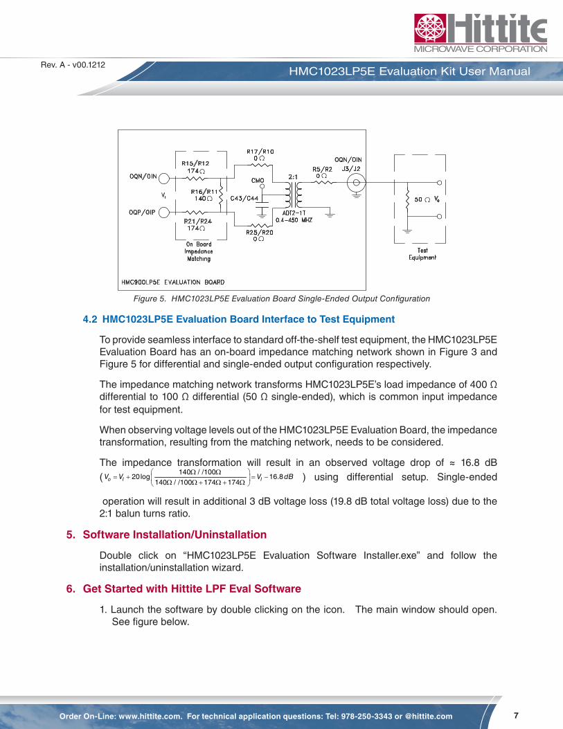
To configure the HMC1023LP5E Evaluation Board for single-ended output operation, 0 Ω resistors R19, R9, R18, R26 need to be removed, and the following components need to be populated:
• 0 Ω resistors, R10, R20, R17, R25, R2, R5
• 10 µF capacitors, C44, C43
• and two ADT2-1T Baluns (T1 & T2)
Note that the components required for single-ended configuration are not included in the HMC1023LP5E Evaluation Kit:
Single-ended output configuration of the HMC1023LP5E is shown in Figure 5.
7
Rev. A - v00.1212
Order On-Line: www.hittite.com. For technical application questions: Tel: 978-250-3343 or @hittite.com
HMC1023LP5E Evaluation Kit User Manual
Figure 5. HMC1023LP5E Evaluation Board Single-Ended Output Configuration
4.2 HMC1023LP5E Evaluation Board Interface to Test Equipment
To provide seamless interface to standard off-the-shelf test equipment, the HMC1023LP5E Evaluation Board has an on-board impedance matching network shown in Figure 3 and Figure 5 for differential and single-ended output configuration respectively.
The impedance matching network transforms HMC1023LP5E’s load impedance of 400 Ω differential to 100 Ω differential (50 Ω single-ended), which is common input impedance for test equipment.
When observing voltage levels out of the HMC1023LP5E Evaluation Board, the impedance transformation, resulting from the matching network, needs to be considered.
The impedance transformation will result in an observed voltage drop of ≈ 16.8 dB (
140 / /10020log 16.8
140 / /100 174 174o I IV V V dB Ω Ω
= + = − Ω Ω + Ω + Ω ) using differential setup. Single-ended
operation will result in additional 3 dB voltage loss (19.8 dB total voltage loss) due to the 2:1 balun turns ratio.
5. Software Installation/Uninstallation
Double click on “HMC1023LP5E Evaluation Software Installer.exe” and follow the installation/uninstallation wizard.
6. Get Started with Hittite LPF Eval Software
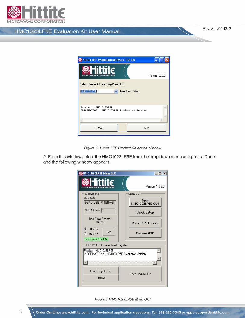
1. Launch the software by double clicking on the icon. The main window should open. See figure below.
8
Rev. A - v00.1212
Order On-Line: www.hittite.com. For technical application questions: Tel: 978-250-3343 or [email protected]
HMC1023LP5E Evaluation Kit User Manual
Figure 6. Hittite LPF Product Selection Window
2. From this window select the HMC1023LP5E from the drop down menu and press “Done” and the following window appears.
Figure 7.HMC1023LP5E Main GUI
9
Rev. A - v00.1212
Order On-Line: www.hittite.com. For technical application questions: Tel: 978-250-3343 or @hittite.com
HMC1023LP5E Evaluation Kit User Manual
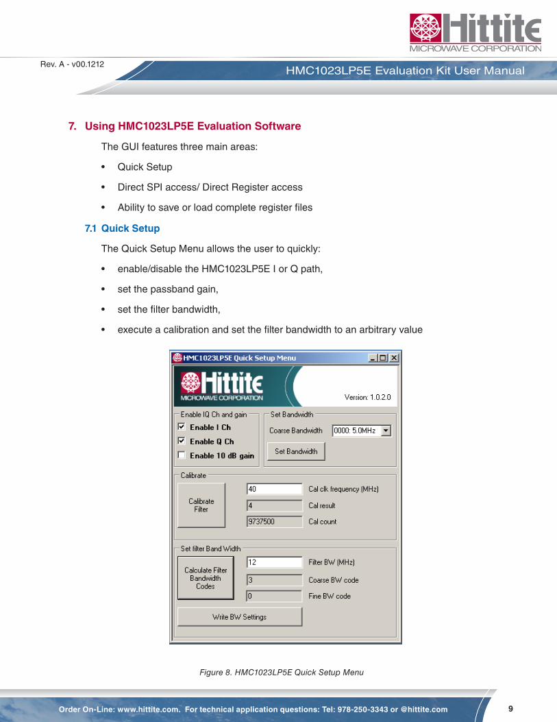
7. Using HMC1023LP5E Evaluation Software
The GUI features three main areas:
• Quick Setup
• Direct SPI access/ Direct Register access
• Ability to save or load complete register files
7.1 Quick Setup
The Quick Setup Menu allows the user to quickly:
• enable/disable the HMC1023LP5E I or Q path,
• set the passband gain,
• set the filter bandwidth,
• execute a calibration and set the filter bandwidth to an arbitrary value
Figure 8. HMC1023LP5E Quick Setup Menu

10
Rev. A - v00.1212
Order On-Line: www.hittite.com. For technical application questions: Tel: 978-250-3343 or [email protected]
HMC1023LP5E Evaluation Kit User Manual
• Enabling I and/or Q channel and setting the HMC1023LP5E to 10dB gain mode are accomplished by checking the appropriate box directly.
• Setting the filter bandwidth without running a calibration is accomplished by choosing one of the selected bandwidths in the pull down menu and pressing the “Set Bandwidth” button. Note that the uncalibrated filter bandwidth is only within +20% of the chosen bandwidth.
• Setting an arbitrary filter bandwidth is accomplished by first running a calibration with a user supplied clock (connected to J5 SMA connector on the HMC1023LP5E evaluation board) and then calculating the bandwidth codes and programming the HMC1023LP5E.
• Enter the frequency of the clock source in MHz (40MHz is recommended, please see the datasheet for other frequencies).
• Connect and enable the clock source
• Press the “Calibrate Filter” button. Note the Cal result and the Cal count outputs.
• Enter the desired arbitrary filter bandwidth and press the “Calculate Filter Bandwidth Codes” button. This routine uses the previous calibration result and calculates the required settings. These settings are applied via the “Write BW Settings” button.
11
Rev. A - v00.1212
Order On-Line: www.hittite.com. For technical application questions: Tel: 978-250-3343 or @hittite.com
HMC1023LP5E Evaluation Kit User Manual
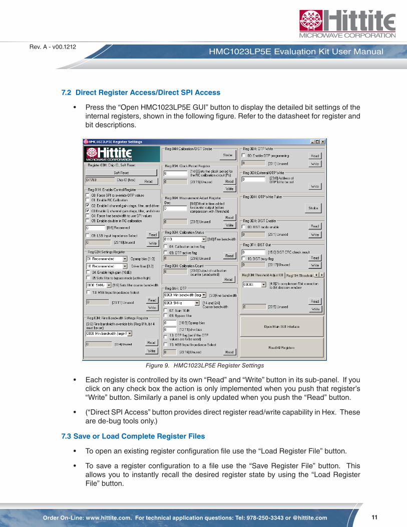
7.2 Direct Register Access/Direct SPI Access
• Press the “Open HMC1023LP5E GUI” button to display the detailed bit settings of the internal registers, shown in the following figure. Refer to the datasheet for register and bit descriptions.
Figure 9. HMC1023LP5E Register Settings
• Each register is controlled by its own “Read” and “Write” button in its sub-panel. If you click on any check box the action is only implemented when you push that register’s “Write” button. Similarly a panel is only updated when you push the “Read” button.
• (“Direct SPI Access” button provides direct register read/write capability in Hex. These are de-bug tools only.)
7.3 Save or Load Complete Register Files
• To open an existing register configuration file use the “Load Register File” button.
• To save a register configuration to a file use the “Save Register File” button. This allows you to instantly recall the desired register state by using the “Load Register File” button.

20 Alpha Road Chelmsford, MA 01824Phone: 978-250-3343 • Fax: 978-250-3373 • [email protected]
Order On-Line at: www.hittite.com Receive the latest product releases - click on “My Subscription”


