Embed Size (px)
Citation preview
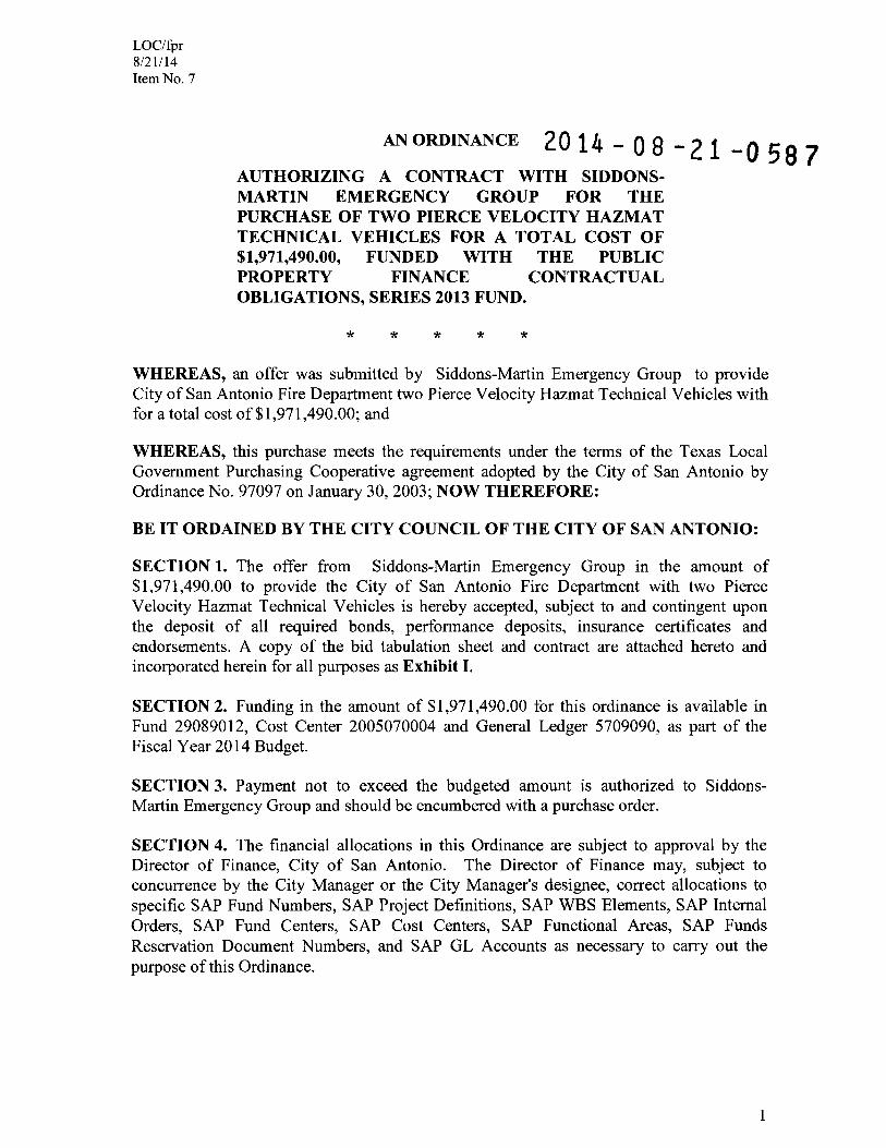
LOC/fpr 8/21114 Item No. 7
AN ORDINANCE 20 14 - 08 - 21 -0 58 7 AUTHORIZING A CONTRACT WITH SIDDONS-MARTIN EMERGENCY GROUP FOR THE PURCHASE OF TWO PIERCE VELOCITY HAZMAT TECHNICAL VEHICLES FOR A TOTAL COST OF $1,971,490.00, FUNDED WITH THE PUBLIC PROPERTY FINANCE CONTRACTUAL OBLIGATIONS, SERIES 2013 FUND.
* * * * *
WHEREAS, an offer was submitted by Siddons-Martin Emergency Group to provide City of San Antonio Fire Department two Pierce Velocity Hazmat Technical Vehicles with for a total cost of$I,971,490.00; and
WHEREAS, this purchase meets the requirements under the terms of the Texas Local Government Purchasing Cooperative agreement adopted by the City of San Antonio by Ordinance No. 97097 on January 30,2003; NOW THEREFORE:
BE IT ORDAINED BY THE CITY COUNCIL OF THE CITY OF SAN ANTONIO:
SECTION 1. The offer from Siddons-Martin Emergency Group in the amount of $1,971,490.00 to provide the City of San Antonio Fire Department with two Pierce Velocity Hazmat Technical Vehicles is hereby accepted, subject to and contingent upon the deposit of all required bonds, performance deposits, insurance certificates and endorsements. A copy of the bid tabulation sheet and contract are attached hereto and incorporated herein for all purposes as Exhibit I.
SECTION 2. Funding in the amount of $1,971,490.00 for this ordinance is available in Fund 29089012, Cost Center 2005070004 and General Ledger 5709090, as part of the Fiscal Year 2014 Budget.
SECTION 3. Payment not to exceed the budgeted amount is authorized to SiddonsMartin Emergency Group and should be encumbered with a purchase order.
SECTION 4. The financial allocations in this Ordinance are subject to approval by the Director of Finance, City of San Antonio. The Director of Finance may, subject to concurrence by the City Manager or the City Manager's designee, correct allocations to specific SAP Fund Numbers, SAP Project Definitions, SAP WBS Elements, SAP Internal Orders, SAP Fund Centers, SAP Cost Centers, SAP Functional Areas, SAP Funds Reservation Document Numbers, and SAP GL Accounts as necessary to carry out the purpose of this Ordinance.
1

LOC/fpr 8/21114 Item No.7
SECTION 5. This ordinance is effective immediately upon passage by eight affirmative votes; otherwise it is effective on the tenth day after passage hereof.
PASSED AND APPROVED this 21 st day of August, 2014.
Ivy R. Taylor
ATTEST: APPROVED AS TO FORM:
2
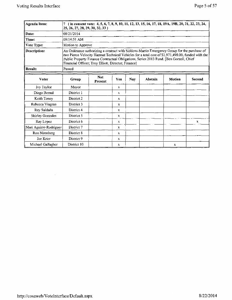
Voting Results Interface Page 5 of 57
Agenda Item: 7 (in consent vote: 4,5,6,7,8,9,10,11,12,13,15,16,17,18, 19A, 19B, 20, 21, 22, 23, 24, 25,26, i7, 28, 29, 30, 32, 33 )
Date: 08/21/2014
Time: 09:14:51 AM
Vote Type: Motion to Approve
Description: An Ordinance authorizing a contract with Siddons-Martin Emergency Group for the purchase of two Pierce Velocity Hazmat Technical Vehicles for a total cost of$I,971,490.00, funded with the Public Property Finance Contractual Obligations, Series 2013 Fund. [Ben Gorzell, Chief Financial Officer; Troy Elliott, Director, Finance]
Result: Passed
Voter Group Not Yea Nay Abstain Motion Second
Present
Ivy Taylor Mayor x
Diego Bernal District 1 x
Keith Toney District 2 x
Rebecca Viagran District 3 x
Rey Saldana District 4 x
Shirley Gonzales District 5 x
Ray Lopez District 6 x x
Mari Aguirre-Rodriguez District 7 x
Ron Nirenberg District 8 x
Joe Krier District 9 x
Michael Gallagher District 10 x x
http://cosawebNoteInterfacelDefault.aspx 8/22/2014
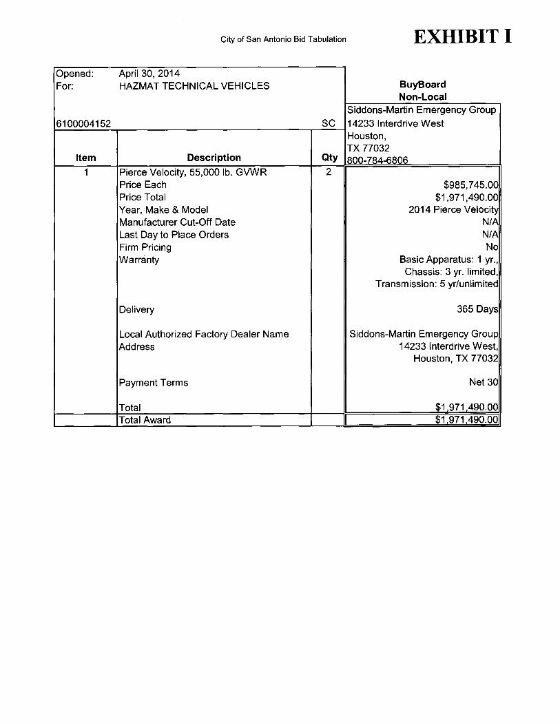
City of San Antonio Bid Tabulation EXHIBIT I
Opened: April 30, 2014 For: HAZMAT TECHNICAL VEHICLES BuyBoard
Non-Local Siddons-Martin Emergency Group
6100004152 SC 14233 Interdrive West Houston, TX 77032
Item Description Qty 800-784-6806 1 Pierce Velocity, 55,000 lb. GVWR 2
Price Each $985,745.00 Price Total $1,971,490.00 Year, Make & Model 2014 Pierce Velocity Manufacturer Cut-Off Date N/A Last Day to Place Orders N/A Firm Pricing No Warranty Basic Apparatus: 1 yr.,
Chassis: 3 yr. limited, Transmission: 5 yr/unlimited
Delivery 365 Days
Local Authorized Factory Dealer Name Siddons-Martin Emergency Group Address 14233 Interdrive West,
Houston, TX 77032
Payment Terms Net 30
Total $1 971 490.00 Total Award $1 971 490

CITY OF SAN ANTONIO PURCHASING AND GENERAL SERVICES DEPARTMENT
REQUEST FOR OFFER ("RFO") NO.: 6100004152
FIRE-HAZMAT TECHNICAL VEHICLES
Date Issued: APRIL 15t 2014
RESPONSES MUST BE RECEIVED NO LATER THAN: APRIL 30, 2014 10:00 AM
Responses may be submitted by any of the following means: Electronic submission through the Portal Hard copy in person or by mail
Address for hard copy responses:
Physical Address: Purchasing & General Services Riverview Tower 111 Soledad, Suite 1100 San Antonio, Texas 78205
For Hard Copy Submissions, Mark Envelope
"FIRE-HAZMA T TECHNICAL VEHICLES·
Offer Due Date: 10:00 A.M., APRIL 30, 2014
RFO No.: 6100004152
Offeror's Name and Address
Mailing Address: Purchasing & General Services P.O. Box 839966 San Antonio, Texas 78283-3966
Bid Bond: NO Performance Bond: NO Payment Bond: NO Other: NO
See Supplemental Terms & Conditions for information on these reqUirements.
Affirmative Procurement Initiative: NO DBE I ACDBE Requirements: NO
See Instructions for Offerors and Attachments sections for more information on these reqUirements.
Pre-Submittal Conference * NO
* If YES, the Pre-Submittal conference will be held on at at.
Staff Contact Person: STEPHANIE CRIOLLO, PROCUREMENT SPECIALIST III, P.O. Box 839966, San Antonio, TX 78283-3966 Email: [email protected]
SBEDA Contact Information:, 210-207-3900,

~o table of contents entries found. i 002 - TABLE OF CONTENTS
(
(
003 -INSTRUCTIONS FOR OFFERORS
Submission of Offers.
Submission of Hard CODY Offers. Submit one original offer, signed in ink, and two copies of the offer enclosed in a sealed envelope addressed to the Purchasing and General Services Department at the address and by the due date provided on the Cover Page. The name and address of offeror, the offer due date and RFO number and title shall be marked on the outside of the envelope(s). All times stated herein ate Central Time. Any offer or modification received after the time and date stated on the Cover Page shall be rejected.
Submission of Electronic Offers. Submit one offer electronically by the due date provided on the Cover Page. All times stated herein are Central Time. Any offer or modification received after the time and date stated on the Cover Page shall be rejected. All forms in this solicitation which require a signature must have a signature affIXed thereto, either by manually signing the document, prior to scanning it and uploading it with your submission, or affIXing it electronically.
Offers sent to City by facsimile or email shall be rejected. MOdified Offers. Offers may be modified provided such modifications are received prior to the time and date set for submission of offers. and submitted in the same manner as original offers. For hard copy offers. provide a cover letter with the offer, indicating it is a mOdified offer and. that the Original offer is being withdrawn. For electronic offers, a modified offer will automatically replace a prior offer submission. See belOlN for information on submitting Altemate Offers.
City shall not be responsible for lost or misdirected offers or mOdifications.
Offerors must sign the Signature Page on hard copy offers and return the RFO document to City. For electronic offers, Offeror's electronic submission. with accompanying affirmations, constitutes a binding Signature for all purposes.
Offerors are cautioned that they are responsible for the security of their log on 10. and password, since unauthorized c use could result in Offeror's being held liable for the submission.
Certified Vendor Registration Form. If Offeror has not completed the City's Certified Vendor Registration (CVR) Form, Offeror is required to do so prior to the due date for submission of offers. The CVR form may be accessed at http://www.sanantonio.gov/purchasing/. Offerors must identify the correct name of the entity that will be providing the goods anellor services under the contract. No nicknames, abbreviations (unless part of the legal title), shortened or short-hand names will be accepted in place of the full, true and correct legal name of the entity.
Alternate Offers. Alternate offers may be allowed at the sole discretion of City.
Hard Copy Alternate Offers. Hard copy alternate offers must be submitted in separate sealed envelopes in the same manner as submission of other offers. Alternate offers must be marked consecutively on the envelope as Alternate Offer No.1, 2, etc. Failure to submit alternate offers in separate envelopes may result in rejection of an offer.
Electronic Alternate Offers Submitted Through the Portal. All alternate offers are recorded with original offers when submitted electronically.
Catalog Pricing. (This section applies to offers using catalog pricing, unless this is a cooperative purchase.)
The offer will be based on manufacturer's latest dated price list(s). Said price list(s) must denote the manufacturer, latest effective date and price schedule.
Offerors shall be responsible for providing one copy of the manufacturer's catalog for each manufacturer for which an offer is submitted. Offeror shall provide said catalog at the time of submission of its offer. Manufacturers' catalogs may be submitted in any of the following formats: paper copy or CD ROM for bids submitted on paper, or PDF file for offers submitted electronically.
Offerors may submit price lists other than the manufacturer's price list. Said price list(s) must denote the company name, effective date and price schedule. These price lists are subject to approval of the City Purchasing & General Services Department.
Specified items identified herein, if any, are for overall offer evaluation and represent the commonly and most used items. Net prices entered for those specified items must reflect the actual price derived from quoted price list less all discounts offered. '
Restrictions on Communication.
Offerors are prohibited from communicating with: 1) elected City officials and their staff regarding the RFO or offers from the time the RFO has been released until the contract is posted as a City Council agenda item; and 2) City employees from the time the RFO has been released until the contract is awarded. These restrictions extend to "thank you· letters, phone calls, emails and any contact that results in the direct or indirect discussion of the RFO andlor offer submitted by Offeror. Violation of this provision by Offeror and/or its agent may lead to disqualification of the offer from consideration.
Exceptions to the restrictions on communication with City employees include:
Offerors may ask verbal questions conceming this RFO at the Pre-Submittal Conference.
Offerors may submit written questions, or objections to specifications, concerning this RFO to the Staff Contact Person listed on the Cover Page on or before 3 calendar days prior to the date offers are due. Questions received after the stated deadline will not be answered. Questions submitted and the City's responses will be posted with this solicitation. All questions shall be sent bye-mail or through the portal.
Offerors may provide responses to questions asked of them by the Staff Contact Person after responses are received. The Staff Contact Person may request clarification to assist in evaluating the Offeror's response. The information provided is not intended to change the offer response in any fashion. Such additional information must be provided within two business days from City's request.
(
Offerors and/or their agents are encouraged to contact the Small Business Office of the International and Economic Development Department for assistance or clarification with issues specifICally related to the City's Small Business Economic Development Advocacy (SBEDA) Program policy and/or completion of the SBEDA form (s), if any, The point of contact is identified on the Cover Page. Contacting the Small Business Office regarding this, RFO after the /' due date is not permitted. If this solicitation contains Affirmative Procurement Initiatives, it will be noted on the \,. Cover Page. .
If this solicitation contains DBElACDBE requirements, respondents and/or their agents may contact the Aviation Departmenfs DBElACDBE Liaison Officer for assistance or clarification with issues specifically related to the DBE! ACDBE policy and/or completion of the required form(s). Point of contact is Ms. Lisa Brice, who may be reached via telephone at (210) 207-3505 or through e-mail at [email protected]. Respondents and/or their agents may contact Ms. Brice at any time prior to the due date for submission of bids. Contacting her or her office regarding this RFO after the due date is not permitted. If this solicitation contains DBElACDBE reqUirements, it will be noted on the Cover Page.
Pre-Submittal Conference.
If a Pre-Submittal Conference is scheduled. it will be held at the time and place noted on the Cover Page. Offerors are encouraged to prepare and submit their questions in writing in advance of the Pre-Submittal Conference in order to expedite the proceedings. City's responses to questions received prior to the conference may be distributed at the PreSubmittal Conference and posted with this solicitation. Attendance at the Pre-Submittal Conference is optional, but highly encouraged.
This meeting place is accessible to disabled persons. Call the Staff Contact Person for information on the location of the wheelchair accessible entrance, or to request an interpreter for the deaf. Interpreters for the deaf must be requested at least 48 hours prior to the meeting. For other assistance, call (210) 207-7245 VoicefTTY.
Any oral response given at the Pre-Submittal Conference that is not confirmed in writing and posted with this solicitation shall not be official or binding on City.
Changes to RFO.
Changes to this RFO made prior to the offer due date shall be made directly to the original RFO. Changes are captured by creating a replacement version each time the RFO is changed. It is Offeror's responsibility to check for

new versions until the offer due date. City will assume that all offers received are based on the final version of the RFO as it exists on the day offers are due.
No oral statement of any person shall modify or otherwise change or affect the terms, conditions or specifications stated in the RFO.
Preparation of Offers.
All information required by the RFO must be furnished or the offer may be deemed non-responsive and rejected. Any ambiguity in the offer as a result of omission, error, unintelligible or illegible wording shall be construed in the favor of City.
Correct Legal Name. If an Offeror is found to have incorrectly or incompletely stated the name of the entity that will provide goods and/or services, the offer may be rejected.
Line Item Offers. Any offer that is considered for award by each unit or line item, must include a price for each unit or line item for which Offeror wishes to be considered. All offers are awarded on the basis of low line item, low total line items, or in any other combination that serves the best interest of City, unless City designates this solicitation as an "all or none" offer in the Supplemental Terms & Conditions.
Allor None Offers. Any offer that is considered for award on an "all or none" basis must include a price for all units or line items. In an "All or None- offer, a unit price left blank shall result in the offer being deemed nonresponsive and disqualified from consideration. An "Allor None" offer is one in which City will award the entire contract to one offeror only.
Deliverv Dates. Proposed delivery dates must be shown in the offer form where required and shall include weekends and holidays, unless specified otherwise in this RFO. Proposed delivery times must be specific. Phrases such as "as required", "as soon as possible" or ·prompt" may result in disqualification of the offer. Special delivery instructions, if any, may be found in the Specifications I Scope of Services section of this document, or in the Purchase Order.
Tax Exemption. The City of San Antonio is exempt from payment of federal taxes, and State of Texas limited sales excise and use taxes. Offerors must not inClude such taxes in offer prices, An exemption certificate will be signed by City where applicable upon request by Offeror after contract award.
Samples, Demonstrations and Pre-award Testing. If requested by City, Offeror shall provide product samples, demonstrations, and/or testing of items offered to ensure compliance with speCifications prior to award of the contract. Samples, demonstrations and/or testing must be provided within 7 calendar days of City's request. Failure to comply with City's request may result in rejection of an offer. All samples (including return thereof), demonstrations, and/or testing shall be at Offeror's expense. Samples will be returned upon written request. Requests for return of samp.les must be made in writing at the time the samples are provided. Otherwise, samples will become property of City at no cost to City. Samples that are consumed or destroyed during demonstrations or testing will not be returned.
Estimated Quantities for Annual Contracts.
Designation as an "annualD contract is found in the contract's title on the Cover Page of this document. The quantities stated are estimates only and are in no way binding upon City. Estimated quantities are used for the purpose of evaluation. City may increase or decrease quantities as needed. Where a contract is awarded on a unit price basis, payment shall be based on the actual quantities supplied.
Offerors shall thoroughly examine the drawings, specifications, schedule(s), instructions and all other contract documents.
Offerors shall make all investigations necessary to thoroughly inform themselves regarding plant and facilities for delivery of material and equipment, or conditions and sitesllocations for providing goods and services as required by this RFO. No plea of ignorance by Offeror will be accepted as a basis for varying the requirements of City or the compensation to Offeror.
Confidential or Proprietary Information. All offers become the property of City upon receipt and will not be returned. Any information deemed to be confidential by Offeror should be clearly noted; however, City cannot guarantee that it will not be compelled to disclose all or part of any public record under the Texas Public Infonnation Act, since information deemed to be confidential by Offeror may not be considered confidential under Texas law, or pursuant to a

Court order. Pricing may be tabulated and posted to City's website, so shall not be considered proprietary or confidential.
/' Costs of Preparation. Offeror shall bear any and all costs that are associated with the preparation of the Offer, r t.
attendance at the Pre-Submittal conference, if any, or during any phase of the selection process.
Rejection of Offers.
City may reject any and all offers, in whole or in part, cancel the RFO and reissue the solicitation. City may reject an offer if:
Offeror misstates or conceals any material fact in the offer; or
The offer does not strictly conform to law or the requirements of the offer;
The offer is conditional; or
Any other reason that would lead City to believe that the offer is non-responsive or Offeror is not responsible.
City, in its sole discretion, may also waive any minor informalities or irregularities in any offer, such as failure to submit sufficient offer copies, failure to submit literature or similar attachments, or business affiliation information.
Changes to Offer Form. Offers must be submitted on the forms furnished. Offers that change the format or content of City's RFO may be rejected.
Withdrawal of Offers. Offers may be withdrawn prior to the due date .. Written notice of withdrawal shall be provided to the Staff Contact Person for offers submitted in hard copy. Offers submitted electronically may be withdrawn electronically.
Evaluation and Award of Contract.
City reserves the right to. make an award on the basis of City's best interests. Award may also be made based on low (" line item, loW total line items, or in any other combination that serves the best interest of City, unless City designates \ this solicitation as an "all or none" offer in the Supplemental Terms & Conditions.
A written award of acceptance, manifested by a City Ordinance, and. a purchase order furnished to Offeror results in a binding contract without further action by either party. Offeror must have the Purchase Order before making any delivery.
City reserves the right to delete items prior to the awarding of the contract, and purchase said items by other means.
Inspection of FacilitiesJEguipment. Depending on the nature of the RFO, Offerors' facilities and equipment may be a determining factor in making the offer award. All Offerors may be subject to inspection of their facilities and eqUipment.
Prompt Payment Discount.
Provided Offeror meets the requirements stated herein, City shall take Offeror's offered prompt payment discount into consideration. The evaluation will not be based on the discount percentage alone, but rather the net price as determined by applying the discount to the offer price, either per line item or total offer amount. However, City reserves the right to reject a discount if the percentage is too low to be of value to City, all things considered. City may also reject a discount if the percentage is so high as to create an overly large disparity between the price City would pay if it is able to take advantage of the discount and the price City would pay if it were unable to pay within the discount period. City may always reject the discount and pay within the 30 day period, at City's sole option.
City will not consider discounts that provide fewer than 10 days to pay in order to receive the discount.
For example, payment terms of 2% 5, Net 30 will NOT be considered in offer evaluations or in the payment of invoices. However, payment terms of 2% 10, Net 30 will result in a two percent reduction in the offer price during offer evaluation, and City will take the 2% discount if the invoice is paid within the 10 day time period.
! Prohibited Financial Interest. The Charter of the City of San Antonio and its Ethics Code prohibit a City officer or '\, employee, as those terms are defined in the Ethics Code, from having a financial interest in any contract with City or any City agency such as City-owned utilities. An officer or employee has a ·prohibited financial interest" in a contract with City

/ l
or in the sale to City of land materials, supplies or service, if any of the following individual(s) or entities is a party to the contract or sale: the City officer or employee; his parent, child or spouse; a business entity in which he or his parent, child or spouse owns ten (10) percent or more of the voting stock or shares of the business entity, or ten (10) percent or more of the fair market value of the business entity; or a business entity in which any indMdual or entity above listed is a subcontractor on a City contract, a partner or a parent or subsidiary business entity.
Conflict of Interest. Effective January 1, 2006, Chapter 176 of the Texas Local Government Code requires that persons, or their agents, who seek to contract for the sale or purchase of property, goods, or services with the City, shall file a completed conflict of interest questionnaire with the City Clerk not later than the 7th business day after the date that the person: (1) begins contract discussions or negotiations with the City; or (2) submits to the City an application, response to a request for proposals or offers, correspondence, or another writing related to a potential agreement with the City. The conflict of interest questionnaire form is available from the Texas Ethics Commission at www.ethics.state.tx.us. Completed conflict of interest questionnaires may be mailed or delivered by hand to the Office of the City Clerk. If mailing a completed conflict of interest questionnaire, mail to: Office of the City Clerk, P.O. Box 839966, San Antonio, TX 78283-3966. If delivering a completed conflict of interest questionnaire, deliver to: Office of the City Clerk, City Hall, 2nd floor, 100 Military Plaza, San Antonio, TX 78205. Offeror should consuH its own legal advisor with questions regarding the statute or form. Do not include this form with your sealed offer. The Purchasing Division will not deliver the form to the City Clerk for you.
004 • SPECIFICATIONS I SCOPE OF SERVICES r l
Scope: The City of San Antonio is soliciting bids to furnish Hazmat Technical Vehicles in accordance with the ' specifications listed herein. These vehicles are used to transport hazardous materials and technicians to the scene of HAZMA T incidents.
GENERAL CONDITIONS: The following general conditions will apply to all items within this bid unless specifically excluded within any item.
City of San Antonio reserves the right to increase or decrease quantity of units being purchased up to the production "cutoff' date submitted on the bid for the particular item, depending on availability of funds. Prices may not be increased during this period; however, the City should benefit from any price decrease. Additional units may be purchased on an "as needed" basis. Successful vendor is required to notify the City of all production ·cut-off' dates necessary for order submission. Unless otherwise approved by the City, Vehicles delivered during a calendar year must be the model year vehicles for that calendar year or newer. Under no circumstances shall Vendor deliver model year vehicles for the preceding calendar year.
All components shall be installed new, unused, standard production model, and equipment is to be serviced in accordance with manufacturer's recommended pre-delivery check list, and ready for operation upon delivery, and shall include all manufacturers' standard equipment unless otherwise specified or replaced therein. Equipment offered under the below listed specifications will be considered unacceptable if for any reason its long term availability on the U.S. Market or in the local area is in doubt.
Equipment must include the maximum standard manufacturer's warranty on all components, with parts and service included. All components, parts and service shall include, as a minimum, a one year unlimited mileageJhours warranty. All warranty times shall start the date the vehicle is placed in service as determined by the City, not on the delivery date. The dealer will be notified by letter of the in-service date of each vehicle by seri131 number. Bidder shall fully explain the warranty by attaching separate, authenticated correspondence or entering such information in the remarks section of this bid. Warranty, reliability, and replacement captive parts costs and availability shall be a consideration in award of this bid. (' Warranty parts and service must be available within 50 mile radius of San Antonio City Hall from and by a factory- " authorized dealer (NO EXCEPTIONS). In the event that a unit purchased from a vendor requires transportation outside of '. Bexar County for a repair covered under warranty, that vendor shall be responsible for paying for all cost associated with the transportation to and from the warranty repair facility. If the vendor chooses to travel to inspect the unit to determine if the repair needed is covered under warranty, all expenses shall be paid for by the vendor. All warranty repairs must be completed within three (3) business days from the date eqUipment is delivered to the vendor unless otherwise approved by the appropriate City of San Antonio BESD Fleet Operations Manager or deSignate. Bidders must certify that all repairs needed after the warranty period will be available within 50 mile radius of San Antonio City Hall.
Delivery - All deliveries are to be made inside the City limits of San Antonio. Vendor must deliver equipment to the follOWing address:
Northeast Service Center Fleet Acquisitions Dept. 10303 Tool Yard Bldg #2 San Antonio, IX. 78233
Telephone number for this address is (210) 207-4603. DeHvery to a non-specified location will result in non-acceptance of the equipment by the City. All deliveries must be pre-arranged with a minimum 24-hour notification, NO EXCEPTIONS. Vehicles will not be accepted after 4:00 P.M. CST. Vehicles with more than 100 miles accumulated on the odometer will not be accepted. All vehicles are required to have a full tank(s) of fuel and a full tank of Diesel Exhaust Fluid, if equipped, when delivered to City specified location.
Equipment Manuals - Each delivered unit must contain an operator's manual NO EXCEPTIONS. A manufacture's parts and maintenance manual or CD ROM must be delivered to the City of San Antonio Fleet Acquisitions at the vendor's cost per model of all eqUipment, accessories, and components, NO EXCEPTIONS.
All priceS will be quoted F.O.B., designated City facility, freight prepaid. All bids will be submitted in triplicate and will include complete manufacturer's specifications for each model being bid.
The Manufacturer's Statement of Origin (MSO), Dealer Temporary license platesltags, proper Invoice, signed 130U form and State Weight Certificate/slip (for trucks over one ton) are required upon delivery of each unit and are required before
payment can be processed. Any of these missing items will delay the payment process.
( All units to be equipped with safety equipment as required by the Federal Government.
t. All accessories and equipment will be OEM. The manufacturer will rate all equipment provided as low emission on all models available and be E-85 compatible where available.
All diesel engine applications are to be of the lowest emission/clean fuel; (Ultra Low Sulfur Diesel) offered by manufacturer and must meet 2010 diesel emission standards set by EPA
Maximum capacity cooling system offered by manufacturer.
Electrical - Heavy duty battery and alternator offered by manufacturer for models being bid. All units to be equipped with oil pressure, water temperature, and volt or amp gauges.
Spare tires required by the below listed specifications must be identical in manufacturer's tread design, ply rating (load range) etc., as those furnished on driving and steering axles. Tires still under evaluation will not be acceptable.
Vehicles to be equipped with OEM tinted glass and current State Inspection Sticker.
All vehicles exteriors to be painted O.E.M. white unless otherwise specified.
Unless otherwise specified under individual items, vehicles provided will have a minimum of a driver's seat and one passenger seat.
All trucks and vans, unless otherwise specified are to be equipped with rubber or vinyl flooring.
All pickup trucks shall be provided with limited slip axles.
No dealership nameplates, markings or decals will be permitted on the vehicles.
BRAND NAMES:
Manufacturer names, trade names, brand names, and product numbers used herein are for the purpose of describing and establishing tested, compatible, approved and acceptable products that are of the type and quality required by the City. The lise of pre-approved brand names are not intended to limit competition; therefore the phrase ·or equal" is added. For purpOses of this contract, the proposed 'or equal" products shall reqUire close adherence to the established standards of performance and quality inherently derived and reasonably expected from the brand named products specified herein. The City shall be the sole judge of equality and suitability.
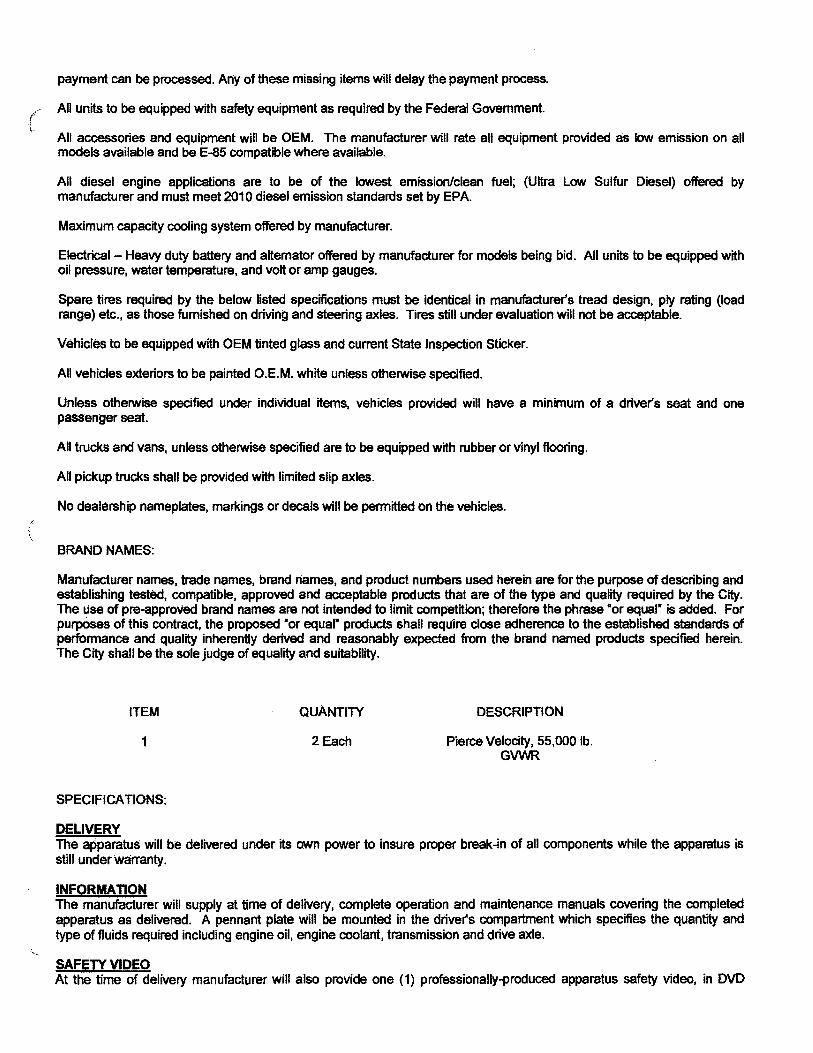
ITEM QuANTITY DESCRIPTION
1 2 Each Pierce Velocity, 55,000 lb. GVWR
SPECIFICATIONS:
DELIVERY The apparatus will be delivered under its own power to insure proper break-in of all components while the apparatus is still under warranty.
IN FORMA TlON The manufacturer will supply at time of delivery, complete operation and maintenance manuals covering the completed apparatus as delivered. A pennant plate will be mounted in the driver'S compartment which specifies the quantity and type of fluids required including engine oil, engine coolant, transmission and drive axle.
SAFETY VIDEO At the time of delivery manufacturer will also provide one (1) professionally-produced apparatus safety video, in OVD
format. This video will address key safety considerations for personnel to follow when they are driving, operating, and maintaining the apparatus, including the following: vehicle pre-trip inspection, chassis operation, and safety driving maintenance.
PERFORMANCE TESTS A road test will be conducted with the apparatus fully loaded and a continuous run of no less than ten miles. During that time the apparatus will show no loss of power nor will it overheat. The transmission drive shaft or shafts and the axles will run quietly and be free of abnormal vibration or noise. The apparatus will meet NFPA 1901 acceleration requirements and NFPA 1901 braking requirements. The apparatus when fully loaded will not have less than 25 percent or more than 50 percent on the front axle and not less than 50 percent or more than 75 percent on the rear axle.
COMMERCIAL GENERAL LIABILITY INSURANCE Certification of insurance coverage will be reqUired. Please see Section 005 for Insurance Requirements.
NFPA 2009 STANDARDS This unit will comply with the NFPA standards effective January 1, 2009, except for fire department directed exceptions. These exceptions will be set forth in the Statement of Exceptions.
Certification of slip resistance of all stepping, standing and walking surfaces will be supplied with delivery of the apparatus.
A plate that is highly visible to the driver while seated will be provided. This plate will show the overall height, length, and gross vehicle weight. rating. The manufacturer will have programs in place for training, proficiency testing and performance for any staff involved with certifICations.
An official of the company will designate, in writing, who is qualified to witness and certify test results.
NFPA COMPLIANCY Apparatus proposed by the bidder will meet the applicable requirements of the National Fire Protection Association (NFPA) as stated in current edition at time of contract execution. Fire depa1tment's specifications that differ from NFPA (' specifications will be indicated in the proposal as "non-NFPA". \
VEHICLE INSPECTION PROGRAM CERTIFICATION To assure the vehicle is built to current NFPA standards, the apparatus, in its entirety will be third-party audit-certified through Underwrite.rs Laboratory (UL) that it is built and complies to all applicable standards in the current edition of NFPA 1901. The certification will include: all deSign, production, operational, and performance testing of not only the apparatus, but those components that are installed on the apparatus.
A placard will be affixed in the driver's side area stating the third party agency, the date, the standard and the certificate number of the whole vehicle audit.
GENERATOR TEST If the unit has a generator, the generator will be tested, approved, and certified by Underwriters Laboratories at the manufacturer's expense. The test results will be provided to the Fire Department at the time of delivery.
BREATHING AIR TEST If the unit has breathing air, Pierce Manufacturing will draw an air sample from the air system and ce1tify that the air quality meets the requirements of NFPA 1989, Standard on Breathing Air Quality for Fire and Emergency Services Respiratory Protection.
INSPECTION TRlP(S) The bidder will provide four (4) factory inspection trip(s) for Two Fire Department personnel per truck customer representative(s). The inspection tripes) will be scheduled at times mutually agreed upon between the manufacturer's representative and the customer. All costs such as travel and lodging will be the responsibility of the vendor.
APPROVAL DRAWING A drawing of the proposed apparatus will be prepared and provided to the purchaser for approval before construction begins. The finalized and approved drawing will become part of the contract document s. This drawing will indicate the { chassis make and model, location of the lights, siren, horns, compartments, major components, etc. \""
ELECTRICAL WIRING DIAGRAMS
('
Two (2) electrical wiring diagrams. prepared for the model of chassis and body, will be provided.
veLOCITY CHASSIS The Pierce® Velocity is the custom chassis developed exclusively for the fire service. Chassis provided will be a new, tilttype custom fire apparatus. The chassis will be manufactured in the apparatus body builder
Velocity"Slis the custom chassis developed exclusively for the fire service. Chassis provided will be a new. tilt-type custom fire apparatus. The chassis will be manufactured in the apparatus body builder
VelocityTM is the custom chassis developed exclusively for the fire service. Chassis provided will be a new, tilt-type custOni fire apparatus. The chassis will be manufactured in the apparatus body builders facility eliminating any split responsibility. The chassis will be designed and manufactured for heavy-duty service, with adequate strength and capacity for the intended load to be sustained and the type of service required. The chassis will be the manufacturer's first line tilt cab.
WHEELBASE The wheelbase of the vehicle will be 272".
GVWRAnNG The gross vehicle weigh t rating will be 55,880 Ibs.
FRAME The chassis frame will be built with two (2) steel channels bolted to five (5) cross members or more, depending on other options of the apparatus. The side rails will have a 13.38" tall web over the front and mid sections of the chassis, with' a continuous smooth taper to 10.75" over the rear axle. Each rail will have a section modulus of 25.992 cubic inches and a resisting bending moment (rbm) of 3,119,040 in-Ib over the critical regions of the frame assembly, with a section moduluS of 18.96 cubic inches with an rbm of 2,275,200 in-lb over the rear axle. The frame rails will be constructed of 120,000 psi yield strength heat-treated .38" thick steel, with 3.50" wide flanges.
FRAME REINFORCEMENT In addition, a mainframe inverted "L" liner will be provided. It will be heat-treated steel measuring 12.00" x 3.00" x .25". Each liner will have a section moduluS of 7.795 cubic inches, yield strength of 1 10,000 psi, and rbm of 857,462 in-lb. Total rbm at whee/base center will be 3,976,502 pounds per rail. The frame liner will be mounted inside of the chassis frame rail and extend the full length of the frame.
FRONT NON DRIVE AXLE The Oshkosh TAK-4® front axle will be of the independent suspension design with a ground rating of 22,800 lb. Upper and lower control arms will be used on each side of the axle. Upper control arm castings will be made of 100,000-psi yield strength 8630 steel and the lower control aim casting will be made of 55,000- psi yield ductile iron. The center cross members and side plates will be constructed out of 80,00o-psi yield strength steel.
Each control arm will be mounted to the center section using elastomer bushings. These rubber bushings Will rotate on low friction plain bearings and be lubricated for life. Each bushing will also have a flange end to absorb longitudinal impact loads, reducing noise and vibrations.
There will be nine (9) grease fittings supplied, one (1) on each control arm pivot and one (1) on the steering gear extension.
The upper control arm will be shorter than the lower arm so that wheel end geometry provides positive camber when deflected below rated load and negative camber above rated load.
Camber at load will be zero degrees for optimum tire life.
The ball joint bearing will be of low friction design and be maintenance free.
Toe links that are adjustable for alignment of the wheel to the center of the chassis will be provided. The Wheel ends will have little to no bump steer when the chassis encounters a hole or obstacle.
The steering linkage will provide proper steering angles for the inside and outside wheel, based on the vehicle wheelbase.
The axle will have a third party certified turning an angle of 45 degrees. Front discharge, front suction, or aluminum wheels will not infringe on this cramp angle.
FRONT SUSPENSION Front Oshkosh TAK-4TM independent suspension will be provided with a minim um ground rating Of 22,800 lb. The ' independent suspension system will be designed to provide maximum ride comfort. The design will allOW the vehicle to ( travel at highway speeds over improved road surfaces and at moderate speeds over rough terrain with minimal transfer of '" road shock and vibration to the vehicle's crew compartment. Each wheel will have torsion bar type spring. In addition, each front wheel end will also have energy absorbing jounce bumpers to prevent bottoming of the suspension.
The suspension design will be such that there is at least 10.00" of total wheel travel and a minimum of 3.75" before suspension bottoms. The torsion bar anchor lock system allows for simple lean adjustments. without the use of shims.
One can adjust for a Jean within 15 minutes per side. Anchor adjustment design is such that it allows for ride height adjustment on each side. The independent suspension was put through a durability test that simulated 140,000 miles of inner city driving,
FRONT SHOCK ABSORBERS Heavy-duty telescoping shock absorbers (KONI) will be provided on the front suspension.
FRONT OIL SEALS Oil seals with viewing window will be provided on the front axle.
FRONT. TIRES Front tires will be Michelin 425165R22,50 radials, 20 ply XFI;: wide base trea(:i, rated for 22.800 Ib maximum axle load and 75 mph maximum sp~. The tires will be mounted on 22.50" x 12.25" steel disc:4ype whe.els with a ten (10}-stud, 1 1.25" bolt circle.
REAR AXLE The rear axle will be a Meritor™, Model RS-30-185, with a capacity of 33,080 lb.
TOP SPEED OF VEHICLE A rear ~Ie rat10 will. be furnished to aUow the vehicle to reach CJ. top speed of 68 MPH.
REAR SUSPENSION The rear suspension will be Standens, semi-elliptical, 3.00" wide x 53.00" long, 12-leaf pack with a ground rating of 33,500 Ibs. The spring hangers will be castings.
The two (2) top leaves will wrap the forward spring hanger pin, and the rear of the spring will be. a slipper style end that will ride in a rear slipper hanger. To reduce bending stress due to acceleration and braking, the front eye will be a berlin eye that will place the front spring pin in the horizontal plane within the main leaf.
A steel encased rubber bushing will be used in the spring eye. The steel encased rubber bushing will be maintenance free and require no, lubrication.
REAR OIL SEALS Oil seals will be provided on the rear axle.
REAR TIRES Rear tires will be four (4) Michelin 3 I 5/80R22.50 radials, 20 ply all position XZA 1 tread, rated for 33,080 Ib maximum axle load and 75 mph maximum speed. The tires will be mounted on 22.50" x 9.00" steel disc-type wheels with a ten (10)stud 11.25" bolt circle.
TIRE BALANCE All tires will be balanced with Counteract balancing beads. The bead s will be inserted into the tire and eliminate the need for wheel weights.
TIRE PRESSURE MANAGEMENT
(
There will be a tire pressure management system provided that will monitor each tires pressure and temperature. A 2.00" gauge located in the cab instrument panel will indicate each tires position, pressure and temperature. A wireless sensor I will be mounted to each wheel for a total of 10 sensors. \
The system will have three (3) alert levels:
/' r Critical Low Pressure Alert Pressure Deviation Alert High Temperature Alert
Each alert will trigger an audible alarm and an indicator light within the gauge to signal the driver of the problem.
The system will be covered by a fIVe (5) year parts and labor warranty. Please see warranty document for details.
HUB COVERS (front) Stainless steel hub covers will be provided on the front axle. An oil level viewing window will be provided.
HUB COVERS (rear) Stainless steel baby moon covers will be provided over the rear axle hubs.
COVERS, LUG NUT, CHROME Chrome lug nut covers will be supplied on front and rear wheels.
MUD FLAPS Mud flaps will be installed behind the front and rear wheels.
SPARE TIRE A 425165R22.S0, 18 ply spare tire to match the vehicle's front tires will be provided, mounted on a steel disc wheel. All wheel surfaces will be provided with powder coat paint #90 red.
SPARE TIRE A 3 I S/80R22.S0, spare tire to match the vehicle's rear tires will be provided, mounted on a steel disc wheel. All wheel surfaces will be provided with powder coat paint #90 red.
WHEEL CHOCKS There will be one (1) pair of folding Ziamatic SAC-44-E, aluminum alloy, Quick-Choe wheel blocks, with easy-grip handle provided.
WHEEL CHOCK BRACKETS There will be one (I) pair of Ziamatic SQCH-44-H style horizontal mounting wheel cho.ck brack ets provided for the Ziamatic SAC-44-E folding wheel chocks. The brackets w ill be made of aluminum and consist of a quick release spring loaded rod to hold the wheel chocks in place. The brackets will be mounted UNDER COMPARTMENT IN FRONT OF REAR WHEELS ON DRIVER SIDE.
ELECTRONIC STABILITY CONTROL A vehicle control system will be provided as an integral pa1 t of the ASS brake system from Meritor Wabco.
The system will monitor and update the lateral acceleration of the vehicle and compare it to a critical threshold where a side roll event may occur. If the critical threshold is met. the vehicle control system w ill automatically reduce engine RPM, engage the engine retarder (if equipped), and selectively apply brakes to the individual wheel ends of the front and rear axles to reduce the possibility of a side roll event.
The system will monitor directional stability through a lateral accelerometer, steer angle sensor and yaw rate sensor. If spinout or drift out is detected, the vehicle control system will selectively apply brakes to the indMdual wheel ends of the front and rear axles to bring the vehicle back to its intended direction.
ANTI-LOCK BRAKE SYSTEM The vehicle will be equipped with a Wabco 4S4M, anti-lock braking system. The ASS will provide a four (4) channel antilock braking control on both the front and rear wheels. A digitally controlled system that utilizes microprocessor technology will control the anti-lock braking system. Each wheel will be monitored by the system. When any wheel begins to lockup, a signal will be sent to the control unit. This control unit WIll then reduce the braking of that wheel for a fraction of a second and then reapply the brake. This anti-lock brake system will eliminate the lockup of any wheel thus helping to prevent the apparatus from skidding out of control.
AUTOMATIC TRACTION CONTROL An anti-Slip feature will be included with the ASS. The Automatic Traction Control will be used for traction in ppor road and weather conditions. The Automatic Traction Control will act as an electronic differential lock that will not allow a
driving wheel to spin, thereby supplying traction at all times. The ABS electronic control unit (ECU) will work with the engine ECU, sharing information concerning wheel Slip. Engine ECU will use information to control engine speed, allowing only as much throttle application as required for the available traction, regardless of how much the driver is " asking for. A "mud/snow" switch will be provided on the instrument panel. Activation of the switch will allow additional tire ( slip to let the truck climb out and get on top of deep snow or mud.-
BRAKES The service brake system will be full air type.
The front brakes will be Knorr/Bendix disc type with a 17.00" ventilated rotor for improved stopping distance.
The brake system will be certified. third party inspected, for improved stopping distance.
The rear brakes will be Meritorllol 16.50" x 8.63" cam operated with automatic slack adjusters.
AIR COMPRESSOR, BRAKE SYSTEM The air compressor will be a Bendix BA-921 with 15.80 cubic feet per minute output at 1,250 RPM.
BRAKE SYSTEM The brake system will include:
Bendix dual brake treadle valve with vinyl covered foot surface
Heated automatic moisture ejector on air dryer
Total air system capacity of 5,198 cubic inches
Two (2) air pressure gauges with a red warning light and an audible alarm that activates when air pressure falls below 60 psi
Spring set parking brake system
Parking brake operated by a push-pull style control valve
A parking "brake on" indicator light on instrument panel
Park brake relaylinversion and anti-compounding valve, in conjunction with a double check valve system, will be provided with an automatic spring brake application at 40 psi The air tank will be primed and painted to meet a minimum 750 hour salt spray test.
To reduce the effects of corrosion, the air tank will be mounted with stainless steel brackets.
Wabco System Saver 1200 air dryer with spin-on coalescing filter cartridge
100 Watt Heater
BRAKE LINES Color-coded nylon brake lines will be provided. The lines will be wrapped in a heat protective loom in the chassis areas that are subject to excessive heat.
AIR INLET/OUTLET One (I) air inlet/outlet will be installed with the female coupling located in the driver side lower step well of cab. This system will tie into the "wef' tank of the brake system and include a check valve in the inlet line and an 85 psi pressure protection valve in the outlet line. The air outlet will be controlled by a needle valve.
A mating male fitting will be provided with the loose equipment.
The air inlet will allow a shoreline air hose to be connected to the vehicle. This will allow station air to be supplied to the brake system of the vehicle to insure constant air pressure.
AIR TANK, ADDITIONAL An additional air tank with 1454 cubic inch displacement will be provided to increase the capacity of the main air brake
(
/
system. This tank will be plumbed into the rear half of the brake system.
The air tank will be primed and painted to meet a minimum 750 hour spray test. To reduce the effects of corrosion, the air tank will be mounted with stainless steel brackets. The output flow of the engine air compressor will vary with engine rpm. Full compressor output will only be achieved at governed engine speed. Engine speed will be limited by generators, pumps and other PTO driven options.
ALL WHEEL LOCK-UP An all wheel lock-up system will be installed which will apply air to the front brakes and use the spring brake at the rear.
AIR FITTINGS. (Special) All the air system fittings including the brake system shall be "compression type" fittings in place of the standard push to connect type.
ENGINE The chassis will be powered by an electronically controlled engine as described below:
Make: Detroit Diesel
Model: 0013
Power: 500 hp at 1800 rpm
Torque: 1650 Ib-ft at 1200 rpm
Govemed Speed: 2080 rpm
Emissions Level: EPA 2013
Fuel: Diesel
Cylinders: Six (6)
Displacement: 781 cubic inches (12.8L)
Starter: De1co 39MT
Fuel Filters: Dual cartridge style with check valve, water separator, and water in fuel· sensor
Coolant Filter: Cartridge style with shut off valves on the supply and return line.
The engine will include On-board diagnostics (OBD), which provides self diagnostic and reporting. The system will give the owner or repair technician access to state of health information for various vehicle sub systems. The system Will monitor vehicle systems, engine and after treatment. The system will illuminate a malfunction indicator light on the dash console if a problem is detected.
HIGH IDLE A high idle switch will be provided, inside the cab, on the instrument panel, that will automatically maintain a preset engine rpm. A switch will be installed, at the cab instrument panel, for activation/deactivation.
The high idle will be operational only when the parking brake is on and the truck transmission is in neutral. A green indicator light will be provided, adjacent to the switch. The light will illuminate when the above conditions are met. The light will be labeled "OK to Engage High Idle."
ENGINE BRAKE A Jacobs engine brake is to be installed with the controls located on the instrument panel within easy reach of the driver. The driver will be able to run the engine brake system on/off and have a high, medium and low setting.
The engine brake will be installed in such a manner that when the engine brake is slowing the vehicle the brake lights are activated.
The ABS system will automatically disengage the auxiliary braking device when required.
CLUTCH FAN A H01 ion fan clutch will be provided. The fan clutch will be automatic when the pump transmission is in "Road" position, " and fully engaged in "Pump" position. (
ENGINE AIR INTAKE An air intake with an ember separator (to prevent road dirt, burning embers, and recirculating hot air from entering the engine) will be mounted at the front of the apparatus, on the passenger side of the engine, The ember separator will be mounted in the air intake with flame retardant, rota-molded polyethylene housing. It will be easily accessible by the hinged access panel at the front of the vehicle.
EXHAUST SYSTEM The exhaust system will be stainless steel from the turbo to the inlet of the selective catalytic reduction (SCR) device, and will be 5.00" in diameter. The exhaust system will include a diesel particulate filter (DPF) and an SCR device to meet current EPA standards. An insulation wrap will be provided on all exhaust pipe between the turbo and SCR to minimize the transfer of heat to the cab. The exhaust will terminate horizontally ahead of the d1 iver side rear wheels. A tailpipe diffuser will be provided to reduce the temperature of the exhaust as it exits. Heat deflector shields will be provided to isolate chassis and body components from the heat of the tailpipe diffuser.
RADIATOR The radialor and the complete cooling system will meet or exceed NFPA and engine manufacturer cooling system standards.
For maximum corrosion resistance and cooling performance, the entire radiator core will be constructed using long life aluminum alloy. The core will be made of aluminum fins, having a serpentine design, brazed to aluminum tubes. The tubes will be brazed to aluminum headers. No solder joints or leaded material of any kind will be acceptable in the core assembly. The radiator core will have a minimum frontal area of 1434 square inches. Supply and retum tanks made of glass-reinforced nylon will be crimped on to the core assembly using header tabs and a compression gasket to complete the radiator core assembly. The radiator will be compatible with commercial antifreeze solutions.
There will be a full steel frame around the entire radiator core assembly. The radiator core assembly will be iso~ted ( within the steel frame by rubber inserts to enhance cooling system durability and reliability. The radiator will be mounted in such a manner as to prevent the development of leaks caused by twisting or straining when the apparatus operates over ' uneven ground. The radiator assembly will be isolated from the chassis frame rails with rubber isolators.
The radiator assembly will include an integral deaeration tank permanently mounted to the top of the radiator framework, with a readily accessible remote-mounted overflow tank. For visual coolant level inspection, the radiator will have a builtin sight glass. The radiator will be equipped with a 15 psi pressure relief cap;
A drain port will be located at the lowest point of the cooling system and/or the bottom of the radiator to permit complete flushing of the coolant from the system.
A heavy-duty fan will draw in fresh, cool air through the radiator. Shields or baffles will be provided to prevent recirculation of hot air to the inlet side of the radiator.
COOLANT UNES Silicone hoses will be used for all engine/heater coolant lines installed by the chassis manufacturer.
Hose clamps will be stainless steel "constant torque type" to prevent coolant leakage. They will react to temperature changes in the cooling system and expand or contract accordingly while maintaining a constant clamping pressure on the hose.
FUEL TANK A 1100-gallon fuel tank will be provided and mounted at rear of chassis. The tank will be constructed of 12-gauge, hot rolled steel. It will be equipped with swash partition s and a vent. To eliminate the effects of corrosion, the fuel tank will be mounted with stainless steel straps, No Exceptions.
A 0.75" drain plug will be provided in a low point of the tank for drainage. {
Fill inlets will be located on the left hand and right hand side of the body and be covered with a hinged, spring loaded, \" stainless steel door that is marked "Ultra Low Sulfur - Diesel Fuel Only."
A 0.50" diameter vent will be provided running from top of tank to just below fuel fill inlet.
The tank will meet all FHWA 393.S7 requirements including a fill capacity of 95% of tank volume. All fuel lines will be provided as recommended by the engine manufacturer.
DIESEL EXHAUST FLUID TANK A 10 gallon diesel exhaust fluid (OEF) tank will be provided and mounted in the driver's side body forward of the rear axle. The tank will be constructed of 16-gauge type 304- l stainless steel.
A .50" drain plug will be provided in a low point of the tank for drainage.
A fill inlet will be located on the driver's side of the body and be covered with a hinged, spring loaded. stainless steel door that is marked "Oiesel Exhaust Fluid Only".
The tank will meet the engine manufacturer's requirement for 1 0 percent expansion space in the event of tank freezing.
The tank will include an integrated heater unit that utilizes engine coolant to thaw the OEF in the event of freezing.
AUXILIARY FUEL PUMP An auxiliary electric fuel pump will be added to the fuel line for priming the engine. A switch located on the cab instrument panel will be provided to operate the pump.
FUEL COOLER An air to fuel cooler will be installed in the engine fuel return line.
TRANSMISSION An Allison 5th generation, model EVS 4000P, electronic, torque converting, automatic transmission will be provided.
The transmission will be equipped with prognostics to monitor oil life, filter life, and transmission health. A wrench icon on the shift selector's digital display will indicate when service is due.
Two (2) PTO openings will be located on left side and top of converter housing (positions 8 o'clock and 1 o'clock).
A transmission temperature gauge with red light and buzzer will be installed on the cab instrument panel.
TRANSMISSION SHIFTER A six (S)-speed push button shift module will be mounted to right of driver on console. Shift position indicator will be indirectly lit for after dark operation.
The transmission ratio will be 1st - 3.5 1 to 1.00, 2nd - 1.91 to 1.00, 3rd - 1.43 to 1.00, 4th - 1.00 to 1.00, 5th - 0.75 to 1.00, Sth - 0.64 to 1.00, R- 4.80 to 1.00.
TRANSMISSION COOLER A Modine plate and fin transmission oil cooler will be provided using engine coolant to control the transmission oil temperature.
DOWNSHIFT MODE (w/enaine brake) The transmission witl be provided with an aggressive downshift mode.
This will provide earlier transmission downshifts to 3rd gear from Sth gear, resulting in improved engine braking performance.
DRiVELINE Drivelines will be a heavy-duty metal tube and be equipped with Spicer 1810 universal joint. The shafts will be dynamically balanced before installation.
A splined slip joint will be provided in each driveshaft, slip joint will be coated with Glidecoat or equivalent.
STEERfNG Dual Sheppard M110 steering gears, with integral heavy-duty power steering, wiH be provided. For reduced system temperatures, the power steering will incorporate an air to oil cooler and an Eaton mOdel VN20F hydraulic pump with integral pressure and flow control. All power steering lines will have wire braded lines with crimped fittings.

A tilt and telescopic steering column will be provided to improve fit for a broader range of driver configurations.
STEERING WHEEL ( The steering wheel will be 18.00' in diameter, have tilting and telescoping capabilities, and a four (4)-spoke design.
There will be a switch pod provided on each side of the steering wheel between the spokes. The switch pods will be an integral part of the steering wheel. Each switch pod will contain four (4) switches. The following switches will be provided:
Air hom
Emergency lighting
Area lighting Front dome light Rear dome light
Q2B siren activate Q2B siren brake Wiper mist
Full floating horn pad
LOGO AND CUSTOMER DESIGNATION ON DASH The dash panel will have an emblem containing the Pierce logo and customer name. The emblem will have three (3) rows of text for the customer's department name. There will be a maximum of eight (8) characters in the first row, 11 characters in the second rrm and 11 characters in the third row.
The first row of text will be: San Antonio The second rrm of text will be: Fire Dept. The third row of text will be: HM-I and HM-34
BUMPER A one (1) piece bum per manufactured from 0.25" fom1ed steel with a 0.38" bend radius will be provided. The bumper will be a minimum of 10.00" high with a 1.50" top and bottom flange, and will extend 22.00" from the face of the cab. The, bumper will be 1 02.00" wide with 45 degree comers and side plates. The bumper will be metal finished and painted job ( color. .
To provide adequate support strength, the bumper will be mounted directly to the front of the C channel frame. The frame will be a bolted modular extension frame constructed of 50,000 psi tensile steel.
GRAVEL PAN A gravel pan, constructed of bright aluminum treadplate, will be furnished between the bumper and the cab face. The pan will be proper1y supported from the underside to prevent flexing and vibration.
Documentation will be provided, upon request, to show that the options selected have been engineered for fit-up and approval for this modular bumper extension. A chart will be provided to indicate the option locations and will include, but not be limited to, the following options: air horns, mechanical sirens, speakers, hose trays (with hose capacities), winches, lights, discharge and suction connections.
LIFT AND TOW MOUNTS Mounted to the frame extension will be lift and tow mounts. The lift and tow mounts will be designed and positioned to adapt to certain tow truck lift systems.
The lift and tow mounts with eyes will be painted the same color as the frame.
TOW EYES Two (2) tow eyes will be mounted through the front face of the bumper. The inner and outer edges of the tow eyes will have a .25" radius.
The tow eyes will be mounted directly to the bumper frame.
Cutouts will be provided in the front face of the stainless steel bumper to allow the tow eyes to extend out the front. {
The tow eyes will be designed and positioned to allow up to a 9,000 lb. straight horizontal pull in line with the centerline of the vehicle. The tow eyes win not be used for lifting of the apparatus.
,. '\:"'.
The tow eyes will be painted job color.
LICENSE PLATE BRACKET . A non-illuminated license plate bracket wi11 be mounted on the front of the vehicle under the cab headlights on the PIS side of the vehicle. The bracket will be fo1 med from bright stainless steel.
EQUIPMENT TRAY The front bumper extension will have mounting provisions for one (1) electric cord reel. The cord reel will be outside of the frame rails on the Cord Reel Mounted in the center side.
Opposite the cord reel location will be a stainless equipment tray recessed in the gravel pan. The tray will be used for storage of rescue tools. The tray will be approximately 3/4 of the width of the bumper extension.
The make and model of the rescue tools will be Cord Reel Mounted in the center.
EQUIPMENT TRAY COVER A raised bright aluminum treadplate cover will be provided full width over the equipment tray and one (1) reel. Cover will be raised approximately 8.50".
The cover will be attached with a stainless steel hinge.
A stainless steel latch will secure the cover in the closed position and a mechanical stay aim will hold the cover in the open position.
CAB The cab will be designed specifically for the fire service and will be manufactured by the chassis builder.
The cab will be constructed of 5052-832 aluminum skins on extruded aluminum framing. For increased structural integrity and occupant protection, the cab structure will include, directly forward of the driver and passenger areas, a .25" firewall plate and .50" lateral support plate that will tie the forward comer posts to the engine tunnel. The cab roof will include a heavy one piece aluminum extrusion with wall thickness up to .12", and will extend from side to side, and attach to the upper forward comer posts by customized aluminum castings. To provide quality at the source and single source customer support, the cab will be built by the apparatus manufacturer in a facility located on the manufacturer's premises.
The cab will be able to tilt 80 degrees to facilitate engine maintenance and removal. The cab pivots will be located 46.00" apart to provide stability while tilting the cab. The cab will be tilted by an electric over hydraulic pump that is connected to two (2) cab lift cylinders that are 2.25" in diameter. The cab will be locked down by a two-pOint automatic locking mechanism actuated after the cab has been lowered.
The overall height (from the cab roof to the ground) will be approximately 102.00". The overall height listed will be calculated based on a truck configuration with the lowest suspension weight ratings, the smallest diameter tires for the suspension, no water weight, no loose equipment weight and no personnel weight Larger tires, wheels and suspension will increase the overall height listed.
The cab will have an interior width of not less than 93.50". The driver and passenger seating positions will have a minimum 24.00" clear width at knee level. .
To reduce injuries to occupants in the seated position s, proper head clearance will be provided. The floor-to-ceiling height inside the cab will be no less than 60.25".
INTERIOR CAB INSULA nON The cab walls, ceiling and engine tunnel will be insulated in all strategic locations to maximize acoustic absorption and thermal insulation. The cab will be insulated with 2.00" insulation in the rear wall, 3.00" insulation in the side walls, and 1.50" insulation in the ceiling.
FENDER LINERS Full circular, aluminum inner fender liners in the wheel wells will be provided.
PANORAMIC WlNDSHIEi..D A one piece. safety glass Windshield with more than 2,802 square inches of clear viewing area will be provided. The windshield will be full width, and provide the occupants with a panoramic view. The windshield will consist of three (3)
layers; the outer light, the middle safety laminate, and the inner light The .114" thick outer light layer will provide superior chip resistance. The middle safety laminate layer will prevent the windshield glass pieces from detaching in the event of breakage. The inner light will provide yet another chip resistant layer. The cab windshield will be bonded to the aluminum " windshield frame using a urethane adhesive. A custom trit pattern will be applied on the outside perimeter of the ( windshield for a finished automotive appearance. '-
SUNVISORS Two (2) smoked Lexan sunvisors, 7.75" x 28.12" long, will be provided. The sunvisors will be located above the windshield with one (1) mounted on each side of the cab.
WINDSHIELD WIPERS Three (3) electric windshield wipers with a washer, in conformance with FMVSS and SAE requirements, will be provided. The wiper blades will be 21.65" long, and together will clear a minimum of 1,783 square inches ot the windshield for maximum visibility in inclement weather.
The windshield washer fluid reservoir will be located at the front of the vehicle and be accessible through the access hood for simple maintenance.
FAST SERVICE ACCESS FRONT TILT HOOD A full width access hood will be provided for convenient access to engine coolant, steering fluid, wiper fluid, cab lift controls, headlight power modules and ember separator. The hood will also provide complete access to the windshield wiper motor and components. The hood will be contoured to provide a sleek automotive appearance. The hood will be constructed of two (2) fiberglass panels bonded together, and will include reinforcing ribs for structural integrity. The hood will include air cylinders to hold the hood in open and closed positions, and a heavy duty latch system that will meet FMVSS 113 (Hood Latch System). The spring loaded hood latch will be located at the center of the hood, with a double action release lever located behind the upper grill. The two-step release requires the lever first be pulled to the driver side until the hood releases from the first latch (primary latch), and then to the passenger side to fully release the hood (secondary latch).
ENGINE TUNNEL To provide structural strength, the engine tunnel sidewalls will be constructed of .50" aluminum plate. To maximize f occupant space, the top edges will be tapered. \
The engine tunnel wHi be insulated on both sides for thermal and acoustic absorption. The underside of the tunnel will be covered with 1.00" thick polyether foam that is reinforced with an aluminized face.
Thermal rating for this insulation will be -40 degrees Fahrenheit to 300 degrees Fahrenheit. The insulation will keep noise (dBA) levels at or lower than the specifications in the current edition of the NFP A 1901 standards.
CAB REAR WALL EXTERIOR COVERING The exterior surface of the rear wall of the cab will be overlaid with bright aluminum treadplate except for areas that are not typically visible when the cab is lowered.
CAB LIFT A hydraulic cab lift system will be provided, conSisting of an electric-powered hydraulic pump, fluid reservoir, dual lift cylinders, remote cab lift controls and all necessary hoses and valves. The hydraulic pump will have a backup manual override, for use in the event of an electrical failure.
The cab lift controls will be located at the driver side front of the cab, easily accessible under the full width front access hood. The controls will include a permanently mounted raisellower switch, For enhanced visibility during cab tilt operations, a remote control tether with onloff switch will be supplied on a coiled cord that will extend from 2.00' (coiled) to 6.00' (extended). '
The cab will be capable of tilting 42 degrees and 80 degrees with crane assist to accommodate engine maintenance and removal. The cab pivots will be located 46.00" apart to provide stability while tilting the cab.
The rear of the cab will be locked down by a two (2)-point, automatic, hydraulic, double hook mechanism that fully engages after the cab has been lowered (self-locking). The dual 2 1/4" diameter hydraulic cylinders will be equipped with a velocity fuse that protects the cab from aCCidentally descending when the cab is in the tilt position.
For increased safety, a redundant mechanical stay and will be provided that must be manually put in place on the driver side between the chassis and cab frame when cab is in the raised position. This device will be manually stowed to its
( \
l
original position before the cab can be lowered.
INTERLOCK. CAB LIFT TO PARKING BRAKE The cab lift safety system will be interlocked to the parking brake. The cab tilt mechanism will be active only when the parking brake is set and the ignition switch is in the on position. If the parking brake is released, the cab tilt mechanism will be disabled.
GRILLE A bright finished aluminum mesh grille screen, inserted behind a formed bright finished grille surround, will be provided on the front center of the cab, and will serve as an air intake to the radiator.
TRIM BAND (cab face) A 10.00" band of 22 gauge brushed stainless steel trim will be installed across the front of the cab, from door hinge to door hinge. Polished stainless steel comer covers will be provided at the cab tum signals. The trim band will be centered on the head lights and applied with two-sided tape. A .625" self adhesive trim strip will be applied around the perimeter of the trim band.
MIRRORS A Retrac Model 613423 dual vision, motorized, west coast style mirror, with chrome finish, will be mounted on each side of the front cab door with spring loaded retractable arms. The flat glass and convex glass will be heated and adjustable with remote control within reach of the driver.
DOORS The cab doors will be the half-height style door. To enhance entry and egress to the cab, the cab doors will be a minimum of 43.59 " wide x 64.71" high.
The cab doors will be constructed of extruded aluminum with a nominal material thickness of .125". The exterior door skins will be constructed from .090" aluminum.
The cab door windows will include a 7.50" high x 10.00" wide drop area at the front to enhance visibility.
A customized, vertical, pull-down type door handle will be provided on the exterior of each cab door. The exterior handle will be designed specifically for the fire service to prevent accidental activation, and will provide 4.00" wide x 2.00" deep hand clearance for ease of use with heavy gloved hands. Each door will also be provided with an interior flush, open style paddle handle that will be readily operable from fore and aft positions, and be designed to prevent accidental activation. The interior handles will provide 4.00" wide x 1.25" deep hand clearance for ease of u se with heavy gloved hands.
The cab doors will be provided with both interior (rotary knob) and exterior (keyed) locks exceeding FMVSS standards. The locks will be capable of activating when the doors are open or closed. The doors will remain locked if locks are activated when the doors are opened, then closed.
A full length, heavy duty, stainless steel, piano-type hinge with a .38" pin and 11 gauge leaf will be provided on all cab doors. There will be double automotive-type rubber seals around the perimeter of the door framing and door edges to ensure a weather-tight fit.
A dark grey vacuum formed ABS panel will house the window switches and will mold into the upper sill of the door panel.
The cab steps at each door location will be located below the cab doors and will be exposed to the exterior of the cab.
DOOR PANELS The inner cab door panels will be constructed out of brushed stainless steel. The cab door panels will be removable without disconnecting door and window mechanisms.
RECESSED POCKET WITH ELASTIC COVER To provide organized storage (clutter control) in the cab for miscellaneous equipment, the cab interior will be provided with recessed storage pocket s. The pockets will be 6.50" wide x 2.12" high x 6.00" deep and will be constructed of rugged, impact resistant, rote-molded low-density polyethylene. The pockets will be provided with a perforated elastic material cover to secure the equipment in the pocket. The pockets will be installed in all available mounting locations of the overhead console.
ELECTRIC WINDOW CONTROLS Each cab entry door will be equipped with an electrically operated tempered glass window. A window control panel will be
ergonomically molded into the armrest of the door panel within easy reach of the respective occupant. Each switch will allow intem1 ittent or auto down operation for ease of use. Auto down operation will be actuated by holding the window down switch for approximately 112 second. The driver control panel will contain a control switch for each cab door's (" window. All other door control panels will contain a single switch to operate the window within that door. .
The window switches will be connected directly to the battery power. This allows the windows to be raised and lowered when the battery switch is in the off position.
ELECTRIC CAB DOOR LOCKS The front driver and passenger doors will have a door lock master switch (custom designed rotary lock knob) built into the interior door latch that will control all front and rear side exit door locks. Each rear cab door will have its own lock control. Each door will have a keyed exterior lock mechanism built into the door handle assembly. There will be one (1) concealed switch on the exterior of the cab, located under the front bumper on the driver side that operates the cab door locks.
The lock system will include two (2) key FOBs that allow for keyless entry into the vehicle. The key FOB system will use code hopping technology for high security and be FCC part 15 compliant
KEY PAD FOR ELECTRIC DOOR LOCKS For iniproved convenience, the cab door locks will include a Trim ark keypad entry system to provide complete keyless entry to the cab. There will be two (2) keypads provided. located one each side of the cab behind the front cab doors. The keypads will include visual and audio feed back to confirm activation and acknowledge con-ect entry code. For enhanced night time use, the keypads will be lighted. For increased security, the system will allow over 3000 possible code combinations.
STEPS. POWER
.~
The cab entrance steps will automatically deploy when the door is opened and stow when the door is closed. Step motion will be electrically powered directly from the battery to be operational at all times. Steps will be of a robust cast aluminum design capable of supporting a 500lb load, when deployed, with minimal deflection. Step surfaces will be covered with aggreSSive slip resistant material that complies with NFPA requirements. When deployed, each step will provide vertical step spacing of approximately 14 inches. Steps will be illuminated for safe entry and egress. Each step will be capable of (~ .. being manually deployed or stowed in the event of a power failure. .,
Each vertical surface of the stowed power step mechanism will be covered with aluminum trim panels painted job color. Black edge protection will be provided to resist paint damage to the leading edges of each step during deployment.
Each power step will be independently controlled through a switch in the door sill to deploy when the door is opened and stow when the door is closed.
STEPUGHTS For reduced overall maintenance costs compared to incandescent lighting, there will be two (2) white LED step lights provided. The lights will be installed at each cab door, one (1) per step, in the driver side front doorstep and passenger side front doorstep.
In order to ensure exceptional illumination , each light will provide a minimum of 25 foot-candles (fc) covering an entire 15" x 15" square placed ten ( 10) inches below the light and a minimum of 1.5 fc covering an entire 30" x 30" square at the same ten ( I 0) inch distance below the light.
The lights will be activated when the adjacent door is opened.
FENDER CROWNS Stainless steel fender crowns will be installed at the cab wheel openings.
STORAGE COMPARTMENTS A transverse compartment will be provided behind the cab doors. A shelf will be provided along the bottom of the compa1tment. This shelf will cover the rear portion of the engine tunnel. The compartment will have a heavy black nylon webbing, made of 2.00" nylon strap with a 2.00" box pattern, provided along the entire front of compartment, excluding any map boxes if installed. Side release buckle s will be used to fasten all sides of the opening.
The doors will be painted aluminum, double pan construction with a O-ring latch.
The frame to frame opening for the compartment opening will be 17.25" wide x 21.00" high.
( \..
CAB ROOF DRIP RAIL For enhanced protection from inclement weather, a drip rail will be fumished on the sides of the cab. The drip rail will be constructed of bright polished extruded aluminum, and be bonded to the sides of the cab. The drip rail will extend the full length of the cab roof.
CUP HOLDER There will be two (2) cup holder(s) provided. Each cup holder will have self-adjusting fingers that will automatically grip beverage containers of various sizes. A recess in the cup holder will allow it to hold beverage containers with handles. The cup holder(s) will be located at customer pick-up.
WORK SURFACE Painted to match the cab interior. There will be a work surface provided on the engine tunnel. The work surface wi!! cover the entire engine tunnel and will be constructed of .19" aluminum to allow the mounting of equipment. The work surface will be approximately 35.50" wide x 54.75" long, with a cutout for the driver side instrument panel. The work surface will start to the rear of the defroster inlet and finish at the end of the engine tunnel. The work surface will be
CAB INTERIOR With safety as the primary objective, the wrap-around style, high impact ASS polymer cab instrument panel will be designed with unobstructed visibility to instrumentation. The dash layout will provide the driver with a quick reference to gauges that anows more time to focus on the road. The center console will be a high impact ASS polymer, and will be easily removable for access to the defroster. The center consoJe wi!! include louvers strategically located for optimal air flow and defrost capability to the windshield. The. passenger side dashboard will be constructed of painted aluminum for durability and low maintenance. For enhanced versatility, the passenger side dash will include a flat working surface. To provide optional (service friendly) control panel s, switches and storage modules, a three (3) piece, 4mm thick polyethylene roio-molded overhead console will also be provided. To complete the cab front interior deSign, painted aluminum modesty panel s will be provided under the dash on both sides of the cab. The driver side modesty panel will provide mounting for the battery switch and diagnostic connectors, while the passenger side modesty panel provides a glove oox, and ground access to the main electrical distribution panel via quick quarter tum fasteners. To provide a deluxe automotive interior, the engine tunnel; side walls and rear wall will be covered by Imperial 1200 upholstery.
The inner cab door panels will include grab handles and control panels molded into the upper section of the door panel. The door pariels will extend 36.50" down from the door window.
The headliner will be installed in both forward and rear cab sections. The crew cab headliner will be one (1) piece. The headliner panel wi!! be a composition of a corrugated high density polyethylene panel covered with a sound bat Tier and upholstery. For quick, easy access of electrical wiring, or to perform other maintenance needs without stripping screws, the headliner will be held in place by a dual lock: fastening system that will require no tools for installation or removal.
The cab structure will include designated raceways for electrical harness routing from the front of the cab to the rear upper portion of the cab. Raceways will be extruded in the forward door frame, floor, walls and overhead in the area where the walls meet the ceiling. The raceways located in the floor will be covered by aluminum extrusion, while the vertical and overhead raceways will be covered by a decorative composite panel. The raceways will improve harness integrity by providing a continuous harness path that eliminates wire chafing and abrasion associated with exposed wiring or routing through drilled metal holes. Harnesses will be laid in place, not pulled through holes d1 iIIed in aluminum tubing. Once laid in place, all harnesses will be held in position by a hook and loop fastening system. The hook and loop system will allow for bracket fastener points to not puncture harnesses. The raceways will include removable covers, providing maintenance personnel with quick and easy access for trouble shooting, or the addition of accessories. Harnesses will be located within the raceway behind the wire way cover.
CAB INTERIOR UPHOLSTERY The cab interior upholstery will be maroon woven with black. All cab interior materials will meet FMVSS 302 (flammability of interior materials).
INTERIOR PAINT (Cab) A rich looking interior will be provided by painting all the metal surfaces inside the cab red, vinyl texture paint.
CAB FLOOR The cab flooring will be constructed with bright aluminum treadplate.
CAB DEFROSTER
To provide maximum defrost and heating perfo1mance, a 54,961-BTU heater-defroster unit with 558 SCFM of air flow will be provided inside the cab. The defroster unit will be strategically located under the center forward portion of the rotomolded instrument panel. For easy access, a removable roto-molded cover will be installed over the defroster unit. The / defroster will include an integral aluminum frame air filter, high performance dual scroll blowers, and ducts designed to f provide maximum defrosting capabilities for the one piece windshield. The defroster ventilation will be built into the design ,of the cab dash instrument panel and will be easily removable for maintenance. The defroster will be capable of clearing 98 percent of the windshield and side glass when tested under conditions where the cab has been cold soaked at 0 degrees Fahrenheit for ten (10) hours, and a two (2) ounce per square inch layer of frostlice has been able to build up on the exterior windshield. The defroster system will meet or exceed SAE 1382 (minimum defrosting system performance requirements).
CAB HEATER Two (2) 36,702-BTU auxiliary heaters with 276 SCFM (each unit) of air flow will be provided one (1) on each side behind the driver and front passenger seating positions. The heaters will include high perf01mance dual scroll blowers (one (1) for each unit). Outlets for the heaters will be located on top of each heater directing heat to the upper portion of the cab, and below the fronts of the driver and passenger seats, for efficient airflow. An extruded aluminum plenum will be incorporated in the cab structure that will transfer heat to the forward cab seating positions.
The heater-defroster and cab heaters will be controlled by a single integral electronic control panel. The heater control panel will allow the driver to control heat flow to the front and rear of the forward seating positions simultaneously. The control panel will incl!Jde variable adjustment for temperature and fan control and be conveniently locatect on the dash in clear view of the driver. The control panel will include highly visible, progressive LED indicators for both fan speed and temperature. For increased convenience, an optional dual control for the passenger position wili also be available.
AIR CONDITIONING A higho.performance, customized air conditioning system will be furnished inside the cab and crew cab. A 19.1 0 cubic inch compressor will be installed on the engine.
The air conditioning system will be capable of CQoling the average cab temperature from 100 degrees Fahrenheit to 64 degrees Fahrenheit in the forward section of the cab, and 69 degrees Fahrenheit in the rear section of the cab, at 50 percent relative humidity within 30 minutes. The cooling performance test will be run only after the cab has been heat (' soaked at 100 degrees Fahrenheit for a minimum of 4 hours. _;
A roof-mounted condenser with a 63,000 BTU output that meets and exceeds the performance specification will be installed on the cab roof. The evaporator unit will be installed in the cab, located in the center of the cab ceiling over the engine tunnel. The evaporator will include two (2) high performance cores and plenums with multiple outlets, one plenum directed to the front and one plenum directed to the rear of the cab.
The evaporator unit will have a 49,000 BTU rating that meets and exceeds the performance specifications. Adjustable air outlets will be strategically located on the evaporator cover per the following:
Two (2) will be directed towards the drivers location Two (2) will be directed towards the officers location Six (6) will be directed towards crew cab area The air conditioner refrigerant will be R- I 34A and will be installed by a certified technician.
The air conditioner will be controlled by a single integral electronic control panel for the heater, defroster and air conditioner. For ease of operation, the control panel will include variable adjustment for temperature and fan control, and be conveniently located on the dash in clear view of the driver. The control panel will include highly visible, progressive LED indicators for both fan speed and temperature. For added convenience, an optional dual control for the passenger position will also be available.
INTERIOR CAB INSULATION The cab walls, ceiling and engine tunnel will be insulated in all strategiC locations to maximize acoustic absorption and thennal insulation. The cab will be insulated with 2.00" insulation in the rear wall, 3.00" insulation in the side walls, and 1.50" insulation in the ceiling. Headliners will be constructed from a high density polyethylene corrugated material. Each headliner will be wrapped with a 0.25" thick fo~ faced poly damp low emissivity foam insulation baiTier for acoustic and thermal control. For ease of installation .and removal, all headliners will be held in place by a dual lock fastening system.
Headliner installation requiring removal of mechanical fasteners will not be acceptable.
Designed for maximum sound absorption and thermal insulation, the rear cab wall will be insulated with a 1.50" thick open
cell acoustical foam. The thennal protection of the foam will provide and R-value of four (4) per 1.00" thickness.
DRAIN LINES ( .There will be added drain lines for the Coleman air conditioning condensation.
WINDOW DEFROST FANS A window defrost fan will be installed on the driver side ceiling of the cab above the engine tunnel, mounted to the reinforced overhead Roto Molded panel. The fan will be 6.SO" diameter with four (4) blades and chrome guard. The fan will include a two (2) speed motor and a three (3) position Hi-Off- Low toggle switch. The fan will provide 250 CFM air flow.
WINDOW DEFROST FANS A window defrost fan will be installed on the passenger side ceiling of the cab above the engine tunnel mounted to the reinforced overhead Roto Molded panel. The fan will be 6.50" diameter with four (4) blades and chrome guard. The fan will include a two (2) speed motor and a three (3) position Hi-Off-Lo toggle switch. The fan will provide 250 CFM air flow.
WINDOW DEFROST FANS There will be four (4) 12 volt DC fans mounted on the ceiling of the crew cab. located 2-in the resource area one each side of the front comers, 2- in the center meeting area.
GRAB HANDLE A black rubber covered grab handle will be mounted on the door post of the driver side cab door to assist in entering the cab. The grab handle will be securely mounted to the post area between the door and windshield. A long rubber grab handle will be mounted on the dash board in front of the officer.
ENGINE COMPARTMENT LIGHT An engine compartment light will be installed under the engine hood, of which the switch is an integral part. Ught will have a .125" diameter hole in its lens to prevent moisture retention.
FLUID CHECK ACCESS DOOR / An access door will be provided on the side of the cab to access the engine and transmission oil level dipsticks. The " access will be for fluid level checks only. The cab will have to be raised to add fluids.
CAB SAFETY SYSTEM The cab will be provided with a safety system designed to protect occupants in the event of a side roll or frontal impact, and will include the following:
A supplemental restraint system (SRS) sensor will be installed on a structural cab member behind the instrument panel. The SRS sensor will perfonn real time diagnostics of all critical subsystems and will record sensory inputs immediately before and during a side roll or frontal impact event.
A slave SRS sensor will be installed in the ceiling of the cab to provide capacity for eight (8) crew cab seating positions.
A fault-indicating light will be provided on the vehicle's instrument panel allowing the driver to monitor the operational status of the SRS system.
A driver side front air bag will be mounted in the steering wheel and will be designed to protect the head and upper torso of the occupant, when used in combination with the three (3)-point seat belt.
A passenger side knee bolster air bag will be mounted in the modesty panel below the dash panel and will be designed to protect the legs of the occupant. when used in combination with the three (3)-point seat belt.
Air curtains will be provided in the outboard bolster of outboard seat backs to provide a cushion between occupant and the cab wall.
Suspension seats will be provided with devices to retract them to the lowest travel position during a side roll or frontal impact event.
Seat belts will be provided with pre-tensioners to remove slack from the seat belt during a side roll or frontal impact event.
FRONTAL IMPACT PROTECTION The SRS system will provide protection during a frontal or oblique impact event. The system will activate when the
vehicle decelerates at a predetermined G force known to cause injury to the occupants.
The cab and chassis will have been subjected, via third party test facility, to a crash impact during frontal and oblique ." impact testing. Testing included all major chassis and cab components such as mounting straps for fuel and air tanks, ( suspension mounts, front suspension components, rear suspensions components, frame rail cross members, engine and . transmission and their mounts, pump house and mounts, frame extensions and body mounts. The testing provided configuration specific information used to optimize the timing for firing the safety restraint system. The sensor will activate the pyrotechnic devices when the connect crash algorithm, wave form, is detected.
The SRS system will deploy the following components in the event of a frontal or oblique impact event:
Driver side front air bag.
Passenger side knee bolster air bag.
Air cm1 ains mounted in the outboard bolster of outboard seat backs.
Suspension seats will be retracted to the lowest travel position.
Seat beHs will be pre-tensioned to firmly hold the occupant in place.
SIDE ROLL PROTECTION The SRS system will provide protection during a fast or slow 90-degree roll to the side, in which the veh.icle com~ to rest on its side. The system will analyze the vehicle's angle and rate of roll to determine the optimal activation of the advanced occupant restraints.
The SRS system will deploy the following components in the event of a side roll:
Air curtains mounted in the outboard bolster of outboard seat backs. Suspension seats will be retracted to the lowest travel position. Seat belts will be pre-tensioned to firmly hold the occupant in place.
SEATING CAPACITY The seating capacity in the cab will be two (2).
DRIVER SEAT A Pierce PS6 seat will be provided in the cab for the driver. The seat design will be a cam action type with air suspension. For increased convenience, the seat will include electric controls to adjust the rake (15 degrees), height (1.12" travel) and horizontal (7.75" travel) position. Electric controls will be located below the fo1ward part of the seat cushion. To provide flexibility for multiple driver configurations, the seat will have a reclining back, adjustable from 20 degrees back to 45 degrees forward. Providing for maximum comfort, the seat back will be a high back style with manual lumbar adjustment lever. for lower back support, and will include minimum 7.50" deep side bolster pads for maximum supp01t. The lumbar adjustment lever will be easily located at the lower outboard position of the seat cushion. For optimal comfort, the seat will be provided with 17.00" deep dual density foam cushions designed with EVe (elastomeric vibration control).
The seat will include the following features incorporated into the side roll protection system.
Side air curtain will be mounted integral to the outboard bolster of the seat back. The air curtain will be covered by a decorative panel when in the stowed position.
A suspension seat safety system will be included. When activated in the event of a side roll, this system will pretenSion the seat belt, then retract the seat to its lowest travel position.
The seat will be furnished with a three (3)-point, shoulder type seat belt. To provide quick, easy use for occupants wearing bunker gear, the seat belt will have a minimum 120.00" shoulder length and 55.00"lap length. The seat belt tongue will be stored at waist position for quick application by the seat occupant The seat belt receptacle will be provided on a cable conveniently nested next to the seat cushion, providing easy accessibility. The seat belt will be furnished with dual automatic retractors that will provide ease of operation in the normal seating position.
OFFICER SEAT A Pierce PS6 seat will be provided in the cab for the passenger. The seat will be a cam action type. witJ:l air suspension. For increased convenience, the seat will include a manual control to adjust the horizontal position (6.00" traveQ. The
(
manual horizontal control will be a towel-bar style located below the forward part of the seat cushion. To provide flexibility for multiple passenger configurations, the seat will have a reclining back adjustable from 20 degrees back to 0 degrees forward. The seat back will be a high back style with manual lumbar adjustment lever; and will include minimum 7.50" deep side bolster pads for maximum support. For optimal comfort, the seat will be provided with 17.00" deep dual density foam cushions designed with EVC (elastomeric vibration control). To ensure safe operation, the seat will be equipped with seat belt sensors in the seat cushion and belt receptacle that will activate an alann indicating a seat is occupied but not buckled.
The seat will include the following features incorporated into the side roll protection system.
Side air curtain will be mounted integral to the outboard bolster of the seat back. The air curtain will be covered by a decorative panel when in the stowed position.
A suspension seat safety system will be included. When activated this system will pretension the seat belt and retract the seat to its lowest travel position.
The seat will be furnished with a three (3)-point, shoulder type seat belt. To provide quick, easy use for occupants wearing bunker gear, the seat belt will have a minimum 120.00" shoulder length and 55.00" lap length. The seat belt tongue will be stored at waist position for quick application by the seat occupant. The seat belt receptacle will be provided on a cable conveniently nested next to the seat cushion providing easy accessibility. The seat belt will be furnished with dual automatic retractors that will provide ease of operation in the normal seating position.
SEAT UPHOLSTERY All Pierce PS6 seat upholstery wilt be maroon woven with black Imperial 1200 material.
SHOULDER HARNESS HEIGHT ADJUSTMENT All seating positions furnished with three (3)-point shoulder type seat belt s will include a height adjustment. This adjustment will optimize the belt s effectiveness and comfort for the seated firefighter.
A total of two (2) seating positions will have the adjustable shoulder harness.
" SEAT BELTS All seating positions in the cab and crew cab will have red seat belts.
SEAT BELT MONITORING ON COMMAND ZONE COLOR DISPLAY A seat belt monitoring screen will be provided on the Command Zone color display. The system will be capable of monitoring up to ten (10) seating position s in the cab with green and red seating icons illuminated as follows:
Seat Occupied Buckled Green Icon Seat Occupied Unbuckled Red Icon Seat Not Occupied Buckled Red Icon Seat Not Occupied Unbuckled No Icon
The seat belt monitoring screen will become active on the Command Zone color display when:
The park brake is released: and there is any occupant seated but not buckled or any belt buckled without an occupant: and there are no other Do Not Move Truck conditions present. As soon as all Do Not Move Truck conditions are cleared, the seat belt monitoring screen will be activated.
The seat belt monitoring screen will be manually selected anytime the Command Zone color display is powered.
The seat belt monitoring screen will be accompanied by an audible alann that will activate when a red seat icon condition exists and the parking brake is released.
HELMET STORAGE Helmet storage will be located in a body compartment.
CAB DOME LIGHTS There will be two (2) Weidon Model 8080-8000-13, LED dome lights with black bezels installed in the cab. The lights will be mounted above the inside shoulder of the driver and officer. The forward, clear, light will be controlled by the door switch and the lens switch. The rear, red, fight will be controlled by the lens switch only.

In addition, there will be two (2) adjustable map lights with an integral switch recessed into the cab ceiling. One (I) light will be located above the driver's seat and one (1) light will be located above the officer's seat.
HAND HELD SPOTUGHT There will be four (4) Stream light, Model Survivor 90509, LED flashlights with 12 volt DC chargers provided and installed I -driver area, I -officers area, I-just inside the side entry door, 1- resource area.
HAND HELD SPOTLIGHT There will be five (5) lights Streamlight, Model Survivor 90503, LED flashlights with chargers and ACIDC chords provided and installed TBD.
The flashlights will be connected battery direct and will charge when the chassis batteries are charging.
HAND HELD SPOTUGHT GANG CHARGER There will be one (1) Stream light, Model 90401 12VDC fIVe (5) bank Survivor hand light charger(s) provided and installed TBD. This is for the charger only, no lights will be provided
Connection will be to a shoreline receptacle.
CAB INSTRUMENTATION The cab instrument panel will consist of gauges, an LCD display, tell tale indicator lights, alarms, control switches, and a diagnostic panel. The function of instrument panel controls and switches will be identified by a label adjacent to each item. Actuation of the headlight switch will illuminate the labels in low light conditions. Telltale indicator lamps will not be illuminated unless necessary. The cab instruments and controls will be conveniently located within the forward cab section directly forward of the driver. Gauge and switch panel s will be designed to be removable for ease of service and low cost of ownership.
GAUGES The gauge panel will include the following ten (to) ivory gauges with chrome bezels to monitor vehicle performance:
VoRmeter gauge (Volts)
Low volts (11.8 VDC)
Amber indicator on gauge assembly with alarm
High volts (15VDC)
Amber indicator on gauge assembly with alarm
Very low voRs (11.3 VDC)
Amber indicator on gauge assembly with alarm
Very high voRs (16 VDC)
Amber indicator on gauge assembly with alarm
Tachometer (RPM)
Speedometer (Preliminary (outside) MPH, Secondary (inside) KmIH)
Fuel level gauge (Empty - Full in fractions)
Low fuel (1/8 full)
Amber indicator on gauge assembly with alarm
Very low fuel (1/32) fuel
Amber indicator on gauge assembly with alarm
(
(

Engine oil pressure gauge (PSI)
Low oil pressure to activate engine warning lights and alarms
Red indicator on gauge assembly with alarm
Front air pressure gauge (PSI)
Low air pressure to activate warning lights and alarm
Red indicator on gauge assembly with alarm
Rear air pressure gauge (PSI)
Low air pressure to activate warning lights and alarm
Red indicator on gauge assembly with alarm
Transmission oil temperature gauge (Fahrenheit)
High transmission oil temperature activates warning lights and alarm
Amber indicator on gauge assembly with alarm
Engine coolant temperature gauge (Fahrenheit)
High engine temperature activates an engine warning light and alarm
Red indicator on gauge assembly with alarm
Diesel Exhaust Fluid Level Gauge (Empty - Full in fractions)
Low fluid (1/8 full)
Amber indicator on gauge assembly with alarm
All gauges and gauge indicators will perform prove out at initial power-up to ensure proper performance.
INDICATOR LAMPS To promote safety, the following telltale indicator lamps will be integral to the gauge assembly and are located above and below the center gauges. The indicator lamps will be "dead-front" design that is only visible when active. The colored indicator lights will have descriptive text or symbols.
The following amber telltale lamps will be present:
Low coolant
Trac cntl (traction control) (where applicable)
Check engine
Check trans (check transmission)
Aux brake overheat (Auxiliary brake overheat)
Air rest (air restriction)
Caution (triangle symbol)
Water in fuel
DPF (engine diesel particulate filter regeneration)
Trailer ASS (where applicable)
Wait to stall.(where applicable)
HET (engine high exhaust temperature) (where applicable)
ASS (antilock brake system)
MIL (engine emissions system malfunction indicator lamp) (where applicable)
SRS (supplementa I restraint system) fault (where applicable)
DEF (low diesel exhaust fluid level)
The following red telltale lamps will be present:
Warning (stop sign symbol)
Seat belt
Parking brake
Stop engine
Rack down
The following green telltale lamps will be provided:
Left tum
Right tum
Battery on
The following blue telltale lamp will be provided:
High beam
ALARMS Audible steady tone warning alarm: A steady audible tone alarm will be provided whenever a warning message is present.
Audible pulsing tone·caution alarm: A pulsing audible tone alarm (chime/chirp) will be provided whenever a caution message is present without a warning message being present.
Alarm silence: Any active audible alarm will be able to be silenced by holding the ignition switch at the top position for three (3) to five (5) seconds. For improved safety. silenced audible alarms will intermittently chirp every 30 seconds until the alarm condition no longer exists. The intermittent chirp will act as a reminder to the operator that a caution or warning condition still exists. Any new warning or caution condition will enable the steady or pulsing tones respectively.
INDICATOR LAMP AND ALARM PROVE-OUT Telltale indicators and alarms will perform prove-out at initial power-up to ensure proper performance.
CONTROL SWITCHES For ease of use, the following controls will be provided immediately adjacent to the cab instrument panel within easy reach of the driver.
c
Emergency master switch: A molded plastic push button switch with integral indicator lamp will be provided. Pressing the « switch will activate emergency response lights and siren control. A green lamp on the switch provides indication that the emergency master mode is active. Pressing the switch again disables the emergency master mode.
Headlight/Parking light switch: A three (3)-position maintained rocker switch will be provided. The first switch position will deactivate all parking lights and the headlights. The second switch position will activate the parking lights. The third switch position will activate the headlights.
Panel backlighting intensity control switch: A three (3)-position momentary rocker switch will be provided. The first switch position decreases the panel backlighting intensity to a minimum level as the switch is held. The second switch position is the default position that does not affect the backlighting intensity. The third switch position increases the panel backlighting intensity to a maximum level as the switch is held.
The following standard controls will be integral to the gauge assembly and are located below the right hand gauges. All switches have backlit labels for low light applications.
High idle engagement switch: A two (2)-position momentary rocker switch with integral indicator la1.1p will be provided. The firs! switch position is the default switch position. The second switch position will activate and deactivate the high idle function when pressed and released. The "Ok To Engage High Idle" indicator lamp must be active for the high idle function to engage. A green indicator lamp integral to the high idle engagement switch will indicate when the high idle function is engaged.
"Ok To Engage High Idle" indicator lamp: A green indicator light will be provided next to the high idle activation switch to indicate that the interlocks have been met to allow high idle engagement.
The following standard controls will be provided adjacent to the cab gauge assembly within easy reach of the d1 ivet. All switches will have backlit labels for low light applications.
Ignition switch: A three (3}-position maintained/momentary rocker switch will be provided. The first switch position will deactivate vehicle ignition. The second switch position will activate vehicle ignition. The third momentary position will disable the Command Zone audible alarm if held for three (3) to five (5) seconds. A green indicator lamp will be activated with vehicle ignition.
Engine start switch: A two (2)-position momentary rocker switch will be provided. The first switch position is the default switch position. The second switch position will activate the vehicle's engine. The switch actuator is designed to prevent accidental activation.
4-way hazard switch: A two (2)-position maintained rocker switch will be provided. The first switch position will deactivate the 4-way hazard switch function. The second switch position will activate the 4-way hazard function. The switch actuator will be red and includes the international 4-way hazard symbol.
Heater, defroster, and optional air conditioning control panel: A control panel with membrane switches will be provided to control heater/defroster temperature and heater, defroster, and air conditioning fan speeds. A green LED status bar will indicate the relative temperature and fan speed settings.
Tum signal arm: A self-canceling tum signal with high beam headlight and windshield wiperlwasher controls will be provided. The windshield wiper control will have high, low, and intermittent modes.
Parking brake control: An air actuated push/pull park brake control valve will be provided.
Chassis hom control: Activation of the chassis hom control will be provided th~ough the center of the steering wheel.
CUSTOM SWITCH PANELS The design of cab instrumentation will allow for emergency lighting and other switches to be placed within easy reach of the operator thus improving safety. There will be positions for up to four (4) switch panels in the overhead console on the driver's side, up to four (4) switch panels in the engine tunnel console facing the driver; up to four (4) switch pan~ls in the overhead console on the officer's side and up to two (2) switch panels in the engine tunnel console facing the officer. All switches will have backlit labels for low light applications.
DIAGNOSTIC PANEL A diagnostiC panel will be accessible while standing on the ground and located inside the driver's side door left of the steering column. The diagnostic panel will allow diagnostiC tools such as computers to connect to various vehicle systems for improved troubleshooting providing a lower cost of ownership. Diagnostic switches will allow engine and ASS systems to provide blink codes should a problem exist.
The diagnostic panel will include the following:
Engine diagnostic port
Transmission diagnostic p01t
ABS diagnostic port
SRS diagnostic port (where applicable)
Command Zone USB diagnostic port
Engine diagnostic switch (blink codes flashed on check engine telltale indicator)
ABS diagnostic switch (blink codes flashed on ABS telltale. indicator)
Diesel particulate fiRer regeneration switch (where applicable)
Diesel particulate fiRer regeneration inhibit switch (where applicable)
CAB LCD DISPLAY A digital four (4}-row by 2O-character dot matrix display will be integral to the gauge panel. The display will be capable of showing simple graphical images as well as text. The display will be split into three (3) sections. Each section will have a dedicated function. The upper left seCtion will display the outside ambient temperature.
The upper right section Will display, along with other configuration specific information:
Odometer
Trip mileage
PTO hours
Fuel consumption
Engine hours
The bottom section will display INFO, CAUTION, and WARNING messages. Text messages will automatically activate to describe the cause of an audible caution or waming alarm. The LCD will be capable of displaying multiple text messages should more than one caution or warning condition exist.
AIR RESTRICTION INDICATOR A high air restriction warning indicator light LCD message with amber warning indicator and audible alarm will be provided.
"00 NOT MOVE APPARATUS" INDICATOR A flashing red indicator light, located in the driving compartment. will be illuminated automatically per the current NFPA requirements. The light will be labeled "Do Not Move Apparatus If Ught Is On."
The same circuit that activates the Do Not Move Apparatus indicator will activate a pulsing alarm when the parking brake is released.
00 NOT MOVE TRUCK MESSAGES Messages will be displayed on the gauge panel LCD located forward of the steering wheel directly in front of the driver whenever the Do Not Move Truck light is active. The messages will deSignate the item or items not in the stowed for vehicle travel position (parking brake disengaged).
The following messages will be displayed (where applicable):
Do Not Move Truck
OS Cab Door Open (Driver Side Cab Door Open)
( '\.
PS Cab Door Open (Passenger's Side Cab Door Open)
OS Crew Cab Door Open (Driver Side Crew Cab Door Open)
PS Crew Cab Door Open (Passenger's Side Crew Cab Door Open)
DS Body Door Open (Driver Side Body Door Open)
PS Body Door Open (Passenger's Side Body Door Open)
Rear Body Door Open
OS Ladder Rack Down (Driver Side Ladder Rack Down)
PS Ladder Rack Down (Passenger Side Ladder Rack Down)
Deck Gun Not Stowed
Lt Tower Not Stowed (Ught Tower Not stowed)
Hatch Door Open
Fold Tank Not Stowed (Fold-A-Tank Not Stowed)
Aerial Not Stowed (Aerial Device Not Stowed)
Stabilizer Not Stowed
steps Not Stowed
Handrail Not Stowed
Any other device that is opened, extended, or deployed that creates a hazard or is likely to cause major damage to the apparatus if the apparatus is moved will be displayed as a caution message after the parking brake is disengaged.
SWITCH PANELS The emergency light switch panel will have a master switch for ease of use plus individual switches for selective control. Each switch panel will contain up to six (6) rocker-type switches each rated for two hundred thousand (200,000) cycles. Panels with less than six (6) switches will include indicators or blanks. The switch panel(s) will be located in the "overhead" position above the windshield on the driver side overhead to allow for easy access.
The switches will be rocker-type and include an integral indicator light. For quick, visual indication the switch will be illuminated whenever the switch is active. A 2-ply, scratch resistant laser engraved Gravoply label indicating the use of each switch will be placed below the switches. The label will allow light to pass through the letters for improved visibility in low light conditions. Switches and light source are integral to the switch panel assembly.
WIPER CONTROL For simple operation and easy reach, the windshield wiper control will be an integral part of the directional light lever located on the stee1 ing column. The wiper control will include high and low wiper speed settings, a one (I)-speed intermittent wiper control and windshield washer switch. The control will have a "retum to park" provision, which allows the wipers to return to the stored position when the wipers are not in use.
SPARE CIRCUIT There will be three (3) pair of wires, including a positive and a negative, installed on the apparatus. The above wires will have the following features:
The positive wire will be connected directly to the battery power. The negative wire will be connected to ground.
Wires wiil be protected to 15 amps at 12 volts DC.
Power and ground will terminate in the center cab area near diver and officer.
Termination will be with 15 amp, power point plug with rubber cover.
Wires will be sized to 125% ofthe protection.
This circuit(s) may be load managed when the parking brake is set.
SPARE CIRCUIT There will be two (2) pair of wires, including a positive and a negative, installed on the apparatus.
The above wires will have the following features:
The positive wire will be connected directly to the battery power.
The negative wire will be connected to ground.
Wires will be protected to 15 amps at 12 volts DC.
Power and ground will terminate in the front resource work station front wall.
Termination will be with 15 amp, power point plug with rubber cover.
Wires will be sized to 125 percent of the protection.
The circuit(s) may be load managed when the parking brake is set.
SPARE CIRCUIT There will be three (3) pair of wires, including a positive and a negative, installed on the apparatus.
The above wires will have the following features:
The positive wire will be connected directly to the battery power.
The negative wire will be connected to ground.
Wires will be protected to 15 amps at 12 volts DC.
Power and ground will terminate Passenger side work area to be placed at preconstruction. Termination will be with 15 amp, power point plug with rubber cover.
Wires will be sized to 125% of the protection.
This circuit(s) may be load managed when the parking brake is. set
DIGIT AL CLOCK A Class I digital clock will be provided in the officer's side overhead switch panel. The clock will be provided with a 12 or 24 hour mode.
VEHICLE ROLL ALERT SYSTEM A Stability Dynamics Ltd, LG Alert system will be provided in the cab. The vehicle roll system display module will be provided on the cab instrument panel, with in convenient sight of the vehicle operator.
The alert system will assist the driver in recognizing when they are exceeding set maximum maneuvering limits of the vehicle. The device will monitor and display lateral "Gil forces perpendicular to the vehicle direction of travel in real time.
RADIO WITH CD PLAYER There will be a Panasonic AMlFMlWeatherband stereo radio with compact disc player and MP3 jack installed.
The compact disc stereo radio will be mounted within reach of the driver.
The quantity and location of the speakers will be one (1) pair of 5.25" speakers located in the cab.
(
(
The type and location of the antenna will be a sid~mounted antenna located on the driver's side of the cab.
INFORMATION CENTER An infonnation center employing a 7.00" diagonal color LCD display will be encased in an ABS plastic housing.
The infonnation center will have the following specifications:
Operate in temperatures from -40 to 185 degrees Fahrenheit An Optical Gel will be placed between the LCD and protective lens Five weather resistant user interface switches Black enclosure with gray decal Sunlight Readable Linux operating system Minimum of 400nits rated display Display can be changed to an available foreign language
OPERATION The infonnation center will be designed for easy operation for everyday use.
The page button will cycle from one screen to the next screen in a rotating fashion.
A video button will allow a NTSC signal into the inf01mation center to be displayed on the LCD. PreSSing any button while viewing a video feed will retum the infonnation center to the vehicle infonnation screens.
A menu button will provide access to maintenance, setup and diagnostic screens. All other button labels will be specific to the infonnation being vieWed.
GENERAL SCREEN DESIGN Where possible, background colors will be used to provide "At a Glance" vehicle infonnation. If inronnation provided on a screen is within acceptable limits, a green background will be used. If a caution or warning situation arises the follOWing
/ will occur:
An amber background /text color will indicate a caution condition. A red background /text color will indicate a warning condition. Every screen will include the following: Exterior Ambient Temperature Time (12 or 24 hour mode)
Text Alert Center:
The infonnation center will utilize an "Alert Center" to display text messages for audible alann tones. The text messages will be written to identify the item(s) causing the audible alann to sound. If more than one (I) text message occurs, the messages will cycle every second until the problem(s) have been resolved. The background color for the "Ale11 Center" will change to indicate the severity of the "warning" message. If a warning and a caution condition occur simultaneously, the red background color will be shown for all alert center messages.
Button Labels: A label for each button will exist. The label will indicate the function for each active button for each screen. Buttons that are not utilized on specific screens will have a button label with no text.
PAGE SCREENS The Information center will include the following screens:
Load Manager Screen: A list of items to be load managed will be provided. The list will provide:
Description of the load Individual load shed priority: The lower the priority number the earlier the device will be shed should a low voltage condition occur.
Load Status: The screen will indicate if a load has been shed (disabled) or not shed. "At a Glance" color features are utilized on this screen
Do Not Move Truck: The Do Not Move Truck screen will indicate the approximate location and type of item that is open or is not stowed for travel. The actual status of the following devices will be indicated:
Driver Side Cab Door Passenger's Side Cab Door Driver Side Crew Cab Door Passenger's Side Crew Cab Door Driver Side Body Doors Passenger's Side Body Doors Rear Body Door(s) Ladder Rack (if applicable) Deck Gun (if applicable) Light Tower (if applicable) Hatch Door (if applicable) Stabinzers (If applicable) Steps (if applicable) Chassis Information: The following information will be shown: Engine RPM Fuel Level Battery Voltage Engine Coolant Temperature Engine Oil Pressure
"At a Glance" color features are utilized on this screen
Active Alarms List: This screen will show a list of all active text messages. The list items text will match the text messages shown in the "Alert Center". The date and time the message occurred is displayed with each message in the list
MENU SCREENS The follOWing screen s will be available through the Menu button:
View System Information: A detailed list of vehicle information:
Battery Volts Pump Hours Transmission Oil Temperature Pump Engaged Engine Coolant Level Engine Oil Level Oil level will only be shown when the engine is not running Power Steering Level
Set daytime and nighttime Display Brightness:
Brightness: Increase and decrease Default setting button Configure Video Mode: Set Video Contrast Set Video Color Set Video Tint
Set Startup Screen:
Choose the screen that will be active at vehicle power-up Set Date & Time: 12 or 24 hour format Set time Set date
VieW Active Alarms:
Shows a list of all active alarms Date and time of the occurrence is shown with each alarm Silence alarms All alarms are silenced
(
(
System ~iagnostics: Module type and 10 number Module version
Module diagnostics information:
Input or output number Circuit number connected to that input or output Circuit name (item connected to the circuit) Status of the input or output Power and Constant Current module diagnostic information: Button functions and button labels may change with each screen.
VEHICLE DATA RECORDER A vehicle data recorder (VCR) will be provided. The VDR will be capable of reading and storing vehicle information. The VDR will be capable of operating in a voltage range from aVDC to I 6VDC. The VOR will not interfere with, suspend, or delay any communications that may exist on the CAN data link during the power up, initialization, runtime, or power down sequence. The VDR will continue operation upon termination of power or at voltages below avoc for a minimum of 10ms.
The information stored on the VDR can be downloaded through a USB port mounted in a convenient location dete1 mined by cab model. A CO provided with the apparatus will include the programming to download the information from the VOR. A USB cable can be used to connect the VDR to a laptop to retrieve required information.
The vehicle data recorder will be capable of recording the following data via hardwired and/or CAN inputs:
Vehicle Speed - MPH
Acceleration - MPH/sec
Deceleration - MPH/sec
Engine Speed - RPM
Engine Throttle Position - % of Full Throttle
ABS Event - On/Off
Seat Occupied Status - Yes/No by Position (1~ Seating Capacity)
Seat Belt Buckled Status - Yes/No by Position (1-6 Seating Capacity)
Master Optical Warning Device Switch - On/Off
Time - 24 Hour Time
~ate - YearlMonthlOay
INTERCOM SYSTEM There will be digital, single radio interface, intercom located in the cab. The front panel will have master volume, and squelch controls with illuminated indicators, allowing for independent level setting of radio and auxiliary audio devices.
There will be one (1) radio listen only I transmit control with select, monitor, receive, and transmit indicators. There will be one (1) auxiliary audio input with select, and receive indicators.
Wireless radio transmit base stations will be provided for four (4) users.
The wireless base station will have a 100' to 1100' range, line of sight. Objects between the transmitter and receiver affect range.
The foilowing Firecom components wiil be provided:
One (1) 51000 Intercom
Four (4) Single radio wireless base stations All necessary power and station cabling
RADIO INTERFACE CABLE The apparatus manufacturer will supply and install one (1) radio interface cable before delivery of the vehicle.
The radio equipment to be used by the customer wal be:
GE. Erickson. MIA Com. or Harris, Model number HatTis Unity Radios.
WIRELESS UNDER HELMET HEADSET ONLY, RADIO TRANSMIT There will be eight (8) Firecom. Model UHW-51 wireless under the helmet, radio transmit headset(s) provided. A heavy duty, coiled 12 volt charging pigtail with plug will be provided Driver, Officer, 2 in the resource area, 4 in the office area.
Each head set will feature:
Noise cancelling electric microphone Flex boom rotates for left or right dress Com Leather ear seals with 24 dB noise reduction Red Radio Push To Talk button Rechargeable battery operates for 24 hours on a full charge IP-65 when wom
HEADSET HANGERS There will be eight (8) headset hanger(s) installed TBD. The hanger(s) will meet NFPA 1901, Section 14.1.11, requirement for equipment mounting.
INTERCOM SYSTEM REMOTE HEAD A Firecom. Model 5100DRH remote intercom head will be provided and mounted in the resource area.
INTERFACE INTERCOM TO AMlFM RADIO Co-A jumper hamess will be installed with a 3.5mm male jack on each end. from the Fire-Com intercom aux inlet to the -AMlFM radio outlet. Auxiliary audio will be mixed with the two-way radio and intercom traffic at exactly one half the -strength of the signal in the headsets.
REMOTE ON/OFF SWITCH FOR AMlFM RADIO A remote, radio on/off switch will be located in the resource area. The switch power will be directly to the battery power.
PORTABLE RADIO CHARGER INSTALLATION There will be eight (8) customer supplied portable two-way radio chargers(s) sent to the apparatus manufacturers preferred radio installer to be installed TBD. Specific shipping requirements will be followed.
MODEM CABLE INSTALLATION There will be one (1) customer supplied pin point X option cable sent to the apparatus manufacturer s preferred radio installer for installation. The cable will be run Rocket Modem !TBD. Two (2) circuits will be provided each with a relay to provide a ground signal to the cable. One (1) will be triggered by ignition on and one (1) will be triggered by lightbar on.
GPS ANTENNA INSTALLATION There will be one (1) customer supplied GPS antenna(s) sent to the apparatus manufacturers preferred installer to be installed on the roof. The antenna coax cable(s) will be run from the antenna.
COMPLETE MDT INSTALLATION There will be one (1) customer supplied Mobile Data Terminal (MDT), Docking station, Mounting bracket, power supply, antenna, GPS, modem. and all cabling sent to the apparatus manufacturer s preferred installer to be installed TBD. Specific shipping requirements will be followed.
TWO WAY RADIO INSTALLATION There will be eight (8) customer supplied two way radio(s) sent to the apparatus manufacturer s preferred radio installer to be installed 4 radios will be mounted in the electronics rackl 2 remote heads will be located in the cab,! 2 remote heads will be located in the resource work area,l2 remote heads will be located in the conference area TBD. No antenna mount or whip will be included in this option. Specific radio Shipping requirement s will be followed.
MOBILE RADIO MODEM INSTALLATION There will be one (1) customer supplied modem(s) sent to the apparatus manufacturers preferred installer to be installed Install Rocket Modem TBO. (
\,_ . Specific shipping requirements will be followed.
t·
COMBO ANTENNA _ There will be three (3) Antenna Plus. Model AP-CW. bolt on, low profile antenna (s) for Cellular, L TE, and WiFi, installed on the cab roof. The antenna color will be black:. The cables will be routed within thE! cab to the Route to rocket modem and other modems, and the IBO.
RADIO ANTENNA MOUNT There will be three (3) standard 1.125", 18 thread antenna-mounting base(s) installed Over the driver and officer area and GPS Officers side behind the lightbar - match 26977-01, 02 on the cab roof with high efficiency, low loss, coaxial cable(s) routed to the radio box. A weatherproof cap will be installed on the mount.
RADIO ANTENNA MOUNTS There will be eight (8) antenna-mounting base(s). Model MATM, with 17 feet of coax cable and weatherproof cap provided for radio equipment up to 900 Mhz.
One (1) of the mounts will be located on the cab roof, just to the rear of the officer seat and the additional mount(s) will be located directly to the left, in the following positions
ANTENNA RACE WAY The cables will be routed to the seat box on the officer side with enough cable for the customer to route to the instrument panel if needed.
VIDEO SYSTEM, SAFETY VISION WITH 7.00" DISPLAY A Safety Vision video system with Model 620 color rear view and Model 622 color side view video camera(s), -if applicable, and LCD display monitor with swivel mount will be provided. All cameras feature a built in microphone, activated with the camera.
Came(a(s) will be on the driver side of the cab activated with the left tum signal and passenger side of the cab activated with the right tum signal and at the rear of the vehicle, as close to center as possible, activated when the vehicle is put into reverse.
Images will be displayed in the cab on a 7.00" color LCD flat panel display capable of displaying up to four (4) simultaneous images with integral camera switcher and integrated speaker permitting audio from the active camera and located in view of the driver on the dash.
VEHICLE CAMERA GUARDS There will be three (3) smooth, tapered aluminum guard(s) fastened over the cab I body camera(s) located All cameras. The guards will be painted to match the surface they are attached to.
ELECTRICAL POWER CONTROL SYSTEM The primary power distribution will be located forward of the officer's seating position and be easily accessible while standing on the ground for simplified maintenance and troubleshooting. Additional electrical distribution centers will be provided throughout the vehicle to house the vehicle's electrical power, circuit protection, and control components. The electrical distribution centers will be located strategically throughout the vehicle to minimize wire length. For ease of m!iJintenance, all elect.rical di.stributipn centers will be easily accessible. All distribution centers containing fuses, circuit breakers and/or relays will be easily accessible.
Distribution centers located throughout the vehicle will contain battery powered studs for supplying customer instal.led equipment thus providing a lower cost of ownership.
Circuit protection devices, which conform to SAE standards, will be utilized to protect electrical circuits. All circuit protection devices will be rated per NFPA requirements to prevent wire and component damage when subjected to extreme current overload. General protect ion circuit breakers will be Type-I automatic reset (continuously resetting). When required, automotive type fuses will be utilized to protect electronic equipment. Control relays and solenoid will have a direct current rating of 125 percent of the maximum current for which the circuit is protected per NFPA.
COMMAND ZONE CONTROL SYSTEM A solid state electronics based control system w ill be utilized to achieve advanced operation and control of the vehicle
components. A fully computerized vehicle network will consist of electronic modules located near their point of use to reduce harness lengths and improve reliability. The control system will comply with SAE J 1939-11 recommended practices.
The control system will operate as a master-slave system whereas the main control module instructs all other system components. The system will contain patented Mission Critical software that maintains critical vehicle operations iri the unlikely event of a main controller error. The system will utilize a Real Time Operating System (RTOS) fully compliant with OSEK NDXTM specifications providing a lower cost of ownership. For increased reliability and simplified use the control system modules will include the following attributes:
Green LED indicator light for module power
Red LED indicator light for networi<. communication stability status
Control system self test at activation and continually throughout vehicle operation
No moving parts due to transistor logic
Software logic control for NFPA mandated safety interlocks and indicators
Integrated electrical system load management without additional components
Integrated electrical load sequencing system without additional components
Customized control software to the vehicle's configuration
Factory and field reprogrammable to accommodate changes to the vehicle's operating parameters
Complete operating and troubleshooting manuals
USB connection to the main control module for advanced troubleshooting
To assure long life and operation in a broad range of environmental conditions, the Command Zone control system modules will meet the follOWing specifications:
Module circuit board will meet SAE 1771 specifications
Operating temperature from -40C to +70C
Storage temperature from -40C to + 7ac
Vibration to 50g
tP67 rated enclosure (Totally protected against dust and also protected against the effect of temporary immersion between 15 centimeters and one (1) meter)
Operating vottage from eight (8) volts to 16 volts DC
The main controller will activate status indicators and audible alarms designed to provide warning of problems before they become critical.
CIRCUIT PROTECTION AND CONTROL DIAGRAM Copies of all job-specific, computer network input and output (1/0) connections will be provided with each chassis. The sheets will indicate the function of each module connection point, circuit protection information (where applicable), wire numbers, wire colors and load management information.
ON-BOARD ADVANCEDNISUAL ELECTRICAL SYSTEM DIAGNOSTICS The on-board information centerwiH include the following diagnostic information:
Text description of active waming or caution alarms
Simplified warning indicators
,.,-
C
(
Amber caution light with intennittent alann
{ . Red warning light with steady tone alann
All control system modules, with the exception of the main control mQdule, will contain on-board visual diagnostic LEOs that assist in troubleshooting. The LEOs will be enclosed within the sealed, transparent module housing near the face of the module. One LED for each input or output will be provided and will illuminate whenever the respective input or output is active. Color-coded labels within the modules will encompass the LEOs for ease of identification. The LED indicator lights will provide point of use infonnation for reduced troubleshooting time without the need for an additional computer.
ADVANCED DIAGNOSTICS An advanced, Windows-based, diagnostic software program will be provided for this control system. The software will provide troubleshooting tools to service technicians equipped with an IBM compatible computer.
The service and maintenance software will be easy to understand and use and have the ability to view system input/output (1/0) infonnation.
INDICATOR LIGHT AND ALARM PROVE-oUT SYSTEM A system will be provided which automatically tests basic indicator lights and alarms located on the cab instrument panel.
VOLTAGE MONITOR SYSTEM A voltage monitoring system will be provided to indicate the status of the battery system connected to the vehicle's electrical load. The system will provide visual and audible warning when the system vottage is below or above optimum levels.
The alarm will activate if the system falls below 11.8 volts DC for more than two (2) minutes.
DEDICATED RADIO EQUIPMENT CONNECTION POINTS There will be three (3) studs provided in the primary power distribution center located in front of the officer for two-way
r' radio equipment. \
The studs will consist of the following: 12-volt 40-amp battery switched power 12-volt 60-amp ignition switched power 12-vott 6O-amp direct battery power
There will also be a 12-vott 10O-amp ground stud located in or adjacent to the power distribution center.
ENHANCED SOFTWARE The Command Zone control system will include the following software enhancements:
All perimeter lights and scene lights (where applicable) will be deactivated when the parking brake is released.
Cab and crew cab dome lights will remain on for ten (10) seconds for improved visibility after the doors close. The dome lights will dim after ten (IO)·seconds or immediately if the vehicle is put into gear.
Cab and crew cab perimeter lights will remain on for ten (10) seconds for improved visibility after the doors close. The dome lights will dim after ten (10) seconds or immediately if the vehicle is put into gear.
EMIIRFI PROTECTION To prevent erroneous signals from crosstalk contamination and interference, the electrical system will meet, at a minimum, SAE 155 112, thus reducing undesired electromagnetic and radio frequency emissions. An advanced electrical system will be used to ensure radiated and conducted electromagnetic interference (EMI) or radio frequency interference (RFI) emissions are suppressed at their source.
The apparatus will have the ability to operate in the electromagnetic environment typically found in fire ground operations to ensure clean operations. The electrical system will meet, without exceptions, electromagnetic susceptibility conforming to SAE J1113125 Region 1, Class C EMR for I OKHz- IGHz to 100 Volts/Meter. The vehicle OEM, upon request, Will
'- provide EMC testing reports from testing conducted on an entire apparatus and will certify that the vehicle meets SAE 155112 and SAE 11113/25 Region 1, Class C EMR for 10KHz-I GHz to 100 Volts/Meter reqUirements. Component and partial (incomplete) vehicle testing is not adequate as overall vehicle design can impact test results and thus is not
acceptable by itself.
EMIIRFI susceptibility will be controlled by applying appropriate circuit designs and shielding. The electrical system will ,,be designed for full compatibility with low-level control signals and high-powered two-way radio communication systems. t Harness and cable routing will be given careful attention to minimize the potential for conducting and radiated EMIIRFI . susceptibility.
ELECTRICAL HARNESSING INSTALLATION All 12-volt wi1ing and harnessing installed by the apparatus manufacturer will conform to specification PM-QA W-10 I: Pierce manufacturing Wiring Harness Specification.
To ensure rugged dependability, all wiring harnesses installed by the apparatus manufacturer will conform to the following specifications:
SAE JI128 - Low tension primary cable
SAE J 1292 - Automobile, truck, truck-tractor, trailer and motor coach wiring
SAE J 163 - Low tension wiring and cable terminals and splice clips
SAE 12202 - Heavy duty wiring systems for on-highway trucks
NFPA 1901 - Standard for automotive fire apparatus
FMVSS 302 - Flammability of interior materials for passenger cars, multipurpose passenger vehicles. trucks and buses
SAE J 1939 - Serial communications protocol
SAE J2030 - Heavy-duty electrical connector performance standard
SAE 12223 - Connections for on board vehicle electrical wiring harnesses
NEe - National Electrical Code
SAE J561 - Electrical terminals - Eyelet and spade type
SAE J928 - Electrical te1minal s - Pin and receptacle type A
For increased reliability and harness integrity. harnesses will be routed throughout the cab and chassis in a manner which allows the harnessing to be laid into its mounting location. Routing of harnessing which requires pulling of wires through tubes will not be allowed.
Wiring will be run in loom or conduit where exposed, and have grommets or other edge protection where wires pass through metal. Wiring will be color, function and number coded. Wire colors will be integral to each wire insulator and run the entire length of each wire. Harnessing containing multiple wires and uses a single wire color for all wires will not be allowed. Function and number codes will be continuously imprinted on all wiring harness conductors at 2.00" intervals. All wiring installed between the cab and into doors will be protected by an expandable rubber boot to protect the wiring. Exterior exposed wire connectors will be positive locking, and environmentally sealed to withstand elements such as temperature extremes, moisture and automotive fluids.
Electrical wiring and equipment will be installed utilizing the following guidelines:
All wire ends not placed into connectors will be sealed with a heat shrink end cap. Wires without a terminating connector or sealed end cap will not be allowed.
All holes made in the roof will be caulked with silicon. Large fender washers, liberally caulked, will be used when fastening equipment to the underside of the cab roof.
Any electrical component that is installed in an exposed area will be mounted in a manner that will not allow moisture to [ accumulate in it. Exposed area will be defined as any location outside of the cab or body. \.
For low cost of ownership. electrical components designed to be removed for maintenance will be quickly accessible. For
ease of use, a coil of wire will be provided behind the appliance to allow them to be pulled away from the mounting area for inspection and service work.
Corrosion preventative compound will be applied to non-waterproof electrical connectors located outside of the cab or body. All non-waterproof connections will require this compound in the plug to prevent corrosion and for easy separation of the plug.
Any lights containing non-waterproof sockets in a weather-exposed area will have corrosion preventative compound added to the socket terminal area.
All electrical terminals in exposed areas will have DOW 1890 protective Coating applied completely over the metal portion of the terminal.
Rubber coated metal clamps will be used to support wire harnessing and battery cables routed along the chassis frame raifs.
Heat shields will be used to protect harnessing in areas where high temperatures exist. Harnessing passing near the engine exhaust will be protected by a heat shield.
Cab and crew cab harnessing will not be routed through enclosed metal tubing. Dedicated wire routing channels will be used to protect harnessing therefore improving the overall integrity of the vehicle electrical system. The design of the cab will allow for easy routing of additional wiring and easy access to existing wiring.
All braided wire harnesses will have a permanent label attached for easy identification of the harness part number and fabrication date.
All standard wiring entering or exiting the cab will be routed through sealed bulknead connectors to protect against water intrusion into the cab.
BATTERY CABLE INSTALLATION All 12-volt batter y cables and battery cable harnessing installed by the apparatus manufacturer wiil confbrm to the following requirements:
SAE J 1 127 - Battery Cable
SAE J561 - Electrical terminal s, eyelets and spade type
SAE 1562 - Nonmetallic loom
SAE J836A - Automotive metallurgical joining
SAE J 1292 - Automotive truck, truck-tractor, trailer and motor coach wiring
NFPA 1901- Standard for automotive fire apparatus
Battery cables and battery cable harnessing will be installed utilizing the following guidelines:
All battery cables and battery harnesses will have a pe1 manent label attached for easy identification of the harness part number and fabrication date.
Splices will not be allowed on battery cables or battery cable harnesses.
For ease of identification and simplified use, battery cables will be color coded. All positive battery cables will be red in color or wrapped in red 100m the entire length of the cable. All negative battery cables will be black in color.
For ease of identification, all positive battery cable isolated studs throughout the cab and chassis will be red in color.
For increased reliability and reduced maintenance, all electrical buss bars located on the exterior of the apparatus will be coated to prevent corrosion.
ELECTRICAL COMPONENT INSTALLATION All lighting used on the apparatus will be, at a minimum, a two (2) wire light grounded through a wired connection to the
battery system. Lights using an apparatus metal structure for grounding will not be allowed.
An operational test will be conducted to ensure that any equipment that is permanently attached to the electrical system is r
properly connected and in working order. The results of the tests will be recorded and provided to the purchaser at time of ( ~~. ~
BATTERY SYSTEM Five (5) 12 volt, Exide Model 31S950X3W batteries that include the follOwing features will be provided:
950 eCA, cold cranking amps
190 amp reserve capacity
High cycle
Group 31
Rating of 4750 CCA at 0 degrees Fahrenheit
950 minutes of reserve capacity
Threaded stainless steel studs
Each battery case will be a black polypropylene material with a vertically nbbed container for increased vibration resistance. The cover will be manifold vented with a central venting location to allow a 45 degree tilt capacity.
The inside of each battery will consist of a "maintenance free" grid construction with poly wrapped separators and a flooded epoxy bottom anchoring for maximum vibration resistance.
ISOLATED BATTERY One (:1) 12 volt. Exide Model 31S950X3W battery will be provided for voltage sensitive components. A battery isolator (", appropriately suited for the group 31 battery capacity will be supplied. '.
BATTERY SYSTEM A Single starting system will be provided.
An ignition switch and sta11er button will be located on the instrument panel.
MASTER BATTERY SWITCH A master battery switch. to activate the battery system. will be provided inside the cab within easy reach of the driver.
An indicator light will be provided on the instrument panel to notify the driver of the status of the battery system.
BATTERY COMPARTMENT A well ventilated battery compartment, with a floor mounted slide-out tray. will be provided, located to the front lower portion of the body ALL ON D/S.
Heavy-duty battery cables will be used to provide maximum power to the electrical system. Cables will be color coded.
Battery terminal connections will be coated with anti--oorrosion compound. Battery solenoid terminal connections will be encapsulated with semi-permanent rubberized compound.
BATTERY CHARGERI AIR COMPRESSOR A Kussmaul Pump Plus 1200. model 091-9-1200 single output battery charger/air compressor system will be provided. A display bar graph indicating the state of charge will be included.
The automatic charger will maintain one (1) set of batteries with a maximum output current of 40 amps.
The 12-volt air compressor will be installed to maintain the air system pressure when the vehicle is not in use.
The battery charger will be wired to the AC shoreline inlet through an AC receptacle adjacent to this battery charger.
Battery charger/compressor will be located in the front left body compartment. The battery charger indicator will be located behind the driver's door on °the outside of the cab.
SHORELINE INLETS °There will be one (1) shoreline receptacle provided to operate the dedicated 120 volt circuits on the truck without the use of a generator.
The shoreline receptacle(s) will be provided with a NEMA 5-20, 120 volt. 20 amp. straight blade Kussmaul Super auto eject plug with a red weatherproof cover. The cover is spring loaded to close. preventing water from entering when the shoreline is not connected.
The unit is completely sealed to prevent road dirt contamination.
A solenoid wired to the vehicle's starter is energized when the engine is started. This instantaneously drives the plug from the receptacle.
An internal switch arrangement will be provided to disconnect the load prior to ejection to eliminate arcing of the connector contacts.
The shoreline will be connected to Direct to battery charger.
A mating connector body will be supplied with the loose equipment. The shoreline receptacle will be located on the driver side front bulkhead of body.
SHORELINE. 1201240V. 1 PHASE. IOOA To pennit electrical operation without the use of the generator, a Hubble, Model M4100B12R, marine rated 100 amp, 1201240V inlet with cover will be provided. Locate on behind d3.
A Hubble. Model M4100C 12R marine rated 100 amp connector will be supplied with the loose equipment.
SWITCH, AUTO TRANSFER To protect either the generator or shoreline inlet from back feed, an automatic 4-p01e, 150 amp contactor system will be installed to switch the on line device between the generator and shoreline inlet when it is connected for use.
The transfer switch will power ALL SHORE LINE SWITCH TO GENERATOR.
SA TTERY ENERGIZER One (1) Canadus, Model HD-12 battery energizer will be installed.
ALTERNATOR A C.E. Niehoff, model C680-1, altemator will be provided. It will have a rated output current of 430 amp as measured by SAE method J56. It will also have a custom three (3)-6et point voltage regulator, manufactured by C. E. Niehoff. The alternator will be connected to the power and ground distribution system with heavy-duty cables sized to carry the full rated alternator output.
POWER DISTRIBUTION RELOCATE The relayslselenoids and fuses located in the frame rail will be located in between the frame rails, on the driver side, as high as possible.
There will be an aluminum cover installed around the components to help deflect water and steam.
ELECTRICAL REQUIREMENTS All electrical components will be mounted above the frame rails. Nothing should be hanging below the frame rails.
DEUTSCH CONNECTORS Tha deutsch connectors located under the rear substructure will be raised at a level at or above the bottom of the frame rail height.
SPECIAL LOCATED JUCTION BOX The junction box normally located behind the DS front cab door step for the shoreline will be relocated to inside the cab.
LOCATION OF CIRCUIT BREAKERS
The circuit breakers for the power points mounted in the EMS compartment and on the doghouse as part of option 90207 will be mounted in the special breaker box for the in-service/out-of-service system located in the cab behind the driver'S seat.
ADDITIONAL CIRCUIT BREAKERS A box containing twenty (20), I 0 amp circuit breakers will be supplied and located in TBD. The box will also include a single ground stUd.
The wiring going into the box will have enough slack so that the wire way cover the box is attached to can be moved out of the way, and the wiring in the wire way can be easily accessed.
The breakers will be for all circuits that are part of the "in-servicelout-of-service" system.
The box will have a removable cover with a label installed that reads, "IN-SERVICElOUT-OF-SERVICE SYSTEM".
On the inside cover of the box a label will be attached that indicates what circuit each breaker is for.
GROMMETS Wires that pass through holes in the chassis, cab, and body will have a rubber grommet to protect the wiring in place of the standard plastic grommet.
Grommets will also be provided for the wiring passing through the door hinges, and any wiring passing through metal structure underneath the headliner in the cab.
SOME LIMITED AREAS WILL BE UNABLE TO BE PROVIDED WITH A RUBBER GROMMET, THIS WILL BE BASEP ON SPACE AVAILABILITY. THOSE AREAS IN WHICH A RUBBER GROMMET WILL NOT FIT WILL HA VE SOME SORT OF PROTECTIVE LOOM INSTALLED.
MASTER SHUT OFF SWITCH, BATTERY DIRECT ITEMS A 75 amp solonoid shut off switch will be provided for all battery direct components TBD.
c
ELECTRONIC LOAD MANAGER ( An electronic load management (ELM) system will be provided that monitors the vehicles 12-volt electrical system, automatically reducing the electrical load in the event of a low voltage condition, and automatically restoring the shed electrical loads when a low voltage condition expires. This ensures the integrity of the electrical system.
For improved reliability and ease of use, the load manager system will be an integral part of the vehicle's solid state control system requiring no additional components to perform load management tasks. Load management systems which require additional components will not be allowed.
The system will include the following features:
System voltage monitoring.
A shed load will remain inactive for a minimum of five minutes to prevent the load from cycling on and off.
Sixteen available electronic load shedding levels.
Priority levels can be set for individual outputs.
High Idle to not be controlled by the load manager.
If enabled:
"Load Man Hi-Idle On" will display on the information center. Hi-Idle will not activate until 30 seconds after engine start up.
Individual switch "on" indicator to flash when the particular load has been shed.
The information center indicates system voltage.
The information center includes a "Load Manager" screen indicating the following:
'.
\,.
Load managed items list, with priority levels and item condition.
Individual load managed item condition:
ON = not shed SHED = shed
SEQUENCER A sequencer wilt be provided that automatically activates and deactivates vehicle loads in a preset sequence thereby protecting the alternator from power surges. This sequencer operation will allow a gradual increase or decrease in alternator output, rather than loading or dumping the entire 12 volt load to prolong the life of the alternator.
For improved reliability and ease of use, the load sequencing system will be an integral part of the vehicle'S solid state control system requiring no additional components to perform load sequencing tasks. Load sequencing systems which require additional components will not be allowed.
Emergency light sequencing will operate in conjunction with the emergency master light switch. When the emergency master switch is activated, the emergency lights will be activated one by one at half- second intervals. Sequenced emergency light switch indicators will flash while waiting for activation.
When the emergency master switch is deactivated, the sequencer will deactivate the warning light loads in'the reverse order.
Sequencing of the following items will also occur, in conjunction with the ignition switch, at half- second intervals:
Cab Heater and Air Conditioning Crew Cab Heater (if applicable)
Crew Cab Air Conditioning (if applicable) Exhaust Fans (if applicable)
Third Evaporator (if applicable)
exTERIOR LIGHTING Exterior lighting will. comply with Federal Department of Transportation, Federal Motor Vehicle Safety Standards and National Fire Protection Association requirements in effect aHime of proposal.
Front headlights will be rectangular shaped, quad style halogen lights mounted in the front trim housing. Headlights will consist of two (2) lights mounted in the front trim on each side of the cab grill. The outside light on each side will contain a low and high beam. The inside light on each side will contain a high beam light only.
The following LED lighting package will provide long life lights for a lower cost of ownership:
One (1) Whelen 600 series LED combination directiOnaVrnarker light will be located in the outside comers of the headlamp trim housing on each side.
Three (3) LED identification lamps will be installed in the center of the cab on the trim above the windshield.
Four (4) LED clearance lamp will be installed, one (1) each side, facing forward and one (1) each side, facing the side on the trim above the windshield.
The three (3) identification lights located at the rear will be installed per the following: Truck-Lite, Model 35, LED
As close as practical to the vertical centerline.
Centers spaced not Jess than six (6) inches or more than twelve (12) inches apart.
Red in color.
All at the same height.
The four (4) ciearance lights iocated at the rear will be installed per the following:
Truck-Lite, Model 35, LED
To indicate the overall width of the vehicle.
One (1) each side of the vertical centerline.
All at the same height.
As near the top as practical.
To be visible from the rear and the side. One (1) each side, facing the side.
One (1) each side, facing the rear.
Per FMVSS I 08 and CMVSS 108 requirements.
REAR FMVSS LIGHTING The rear stopltaiJ and directional LED lighting will consist of the following:
Two (2) Whelen, Model M6BTT red LED stop/taillights.
Two (2) Whelen, Model M6T amber LED arrow tum lights.
Each light will be installed in a housing and include colored lenses.
Four (4) red reflectors will be provided.
BACKUP LIGHTS There will be two (2) Whelen, Model: M6BUW, LED backup lights provided in the taillight housing.
LICENSE PLATE BRACKET There will be one (1) license plate bracket mounted on the rear of the body. ( A white LED light will illuminate the license plate. A polished stainless steel light shield will be provided over the light that . will direct illumination downward, preventing white light to the rear.
UGHTING BEZEL There will be two (2) Whelen, Model M6FCV4P, four (4) place chromed ABS housings with Pi~rce logos provided for the rear M6 series stop/tail, directional, back up, scene lights or waming lights.
BACK-UP ALARM A PRECO, Model 1040, solid-state electronic audible back-up alarm that actuates when the truck is shifted into reverse will be provided. The device will sound at 60 pulses per minute and automatically adjust its volume to maintain a minimum ten (10) dBA above surrounding environmental noise levels.
UGHT. INTERMEDIATE There will be one (1) pair, of Truck-Lite, Model: 300BOY flange mounted amber LED light kits will be furnished, one (1) each side of the rear fender pan el, in place of the standard directional/marker intermediate light. The light will double as a tum signal and marker light.
This installation will include a stainless steel cover.
CAB PERIMETER SCENE LIGHTS There will be two (2) Amdor Model AY-9500-12, 12.00" white LED strip lights provided under the cab access areas:
One (1) for the driver's access.
One (1) for the passenger's side front cab access door.
These lights will be activated automatically when the battery switch is on and the exit doors are opened or by the same { means as the body perimeter scene lights. \
BODY PERIMETER SCENE LIGHTS
There will be a total of two (2) Amdor Luma Bar H20, Model AY-9500-020, 20.00" LED weatherproof strip lights with brackets provided on the apparatus.
C The lights will be mounted in the following locations:
Two (2) lights will be provided under the rear step area, one (1) each side.
The two (2) rear facing lights will be activated per the following and will not activate with the reverse gear:
When the parking brake is applied.
With a switch on the cab instrument panel.
Any additional side facing lights will be activated per the following:
When the parking brake is applied.
When the reverse gear is activated.
With a switch on the cab instrument panel.
ADPITIONAL PERIMETER LIGHTS There will be two (2) lights Amdor, Model AY-9500-012 12.00· white LED perimeter light(s) provided under the bumper outboard of the frame, each side.
STEPUGHTS TWO (2) white LED step lights will be provided. The step lights will be provided at the rear walk through door of body.
In order to ensure exceptional illumination, each light will provide a minimum of 25 foot-candles (fc) covering an entire 15" x 1511 square placed ten (10) inches below the light and a minimum of 1.5 fc covering an entire 3.0" x 30" square at the
" same ten (10) inch distance below the light.
The step lights will be controlled by the automatic door switch, that is located on the rear walk-in door.
All other steps on the apparatus will be illuminated per the current edition of NFPA 1901.
SCENE LIGHTS There will be one (1) Fire Research, Model SPA900-065 LED scene light(s) with chrome trim bezel installed at the rear of the apparatus, passenger side cab area upper.
A control for the light{s) selected above will be the following:
a switch at the driver's side switch panel opening the passenger's side cab or crew cab doors a switch at the command switch panel located in the body no additional switch location
These lights may be load managed when the parking brake is set.
SCENE LIGHTS There will be one (1) Fire Research, Model SPA900-Q65 LED scene light(s) with chrome trim bezel installed at the rear of the apparatus, Driver side cab upper area. A control for the light(s) selected above will be the following: a switch at the driver's side switch panel opening the driver's side cab or crew cab doors a switch at the command switch panel located in the body no additional switch location. These lights may be load managed when the parking brake is set.
12 VOLT LIGHTING There will be one (1) Fire Research, Model SPA851-Q20 white 12 volt LED floodlight(s) provided with a white bezel on the front visor, centered.
The light(s) will be controlled in the following way:
a switch at the drivers side switch panel.
a switch at the command switch panel located in the body
no additional switch location.
no additional switch location
These lights may be load managed when the parking brake is applied.
1 2 VOLT UGHTING There will be two (2) Fire Research, Model SPA260-QI 5, 12 volt LED surface mounted scene light(s) with chrome trim bezel provided Upper passenger side comers.
The light(s) will be controlled in the following way:
a switch at the driver's side switch panel
a switch at the command switch panel located in the body
no additional switch location
no additional switch location The light(s) may be load managed when the parking brake is applied.
12 VOLT LIGHTING There will be one (I) Fire Researoh, Model SPA260-Q15, 12 volt LED surface mounted scene light(s) With chrome trim bezel provided Upper rear on the passenger side.
The light(s) will be controlled in the following way:
a switch at the drivers side switch panel
a switch at the command switch panel located in the body
a switch at the rear of apparatus on the passengers side
no additional switch location
The light(s) may be load managed when the parking brake is applied.
12 VOLT UGHTING There will be two (2) Fire Research, Model SPA26O-Q1 5, 12 volt LED surface mounted scene light(s) with chrome trim bezel provided Drivers side comer.
The light(s) will be controlled in the following way:
a switch at the driver's side switch panel
a switch at the command switch panel located in the body
no additional switch location
no additional switch location
The light(s) may be load managed when the parking brake is applied.
RADIO CUT OUT SWITCH
c
(
An on/off switch will be provided on the drivers side for the AMIFM radio. The switch will allow the driver to disable the { AMlFM radio when it is necessary to hear other communications. \'"
HEAVY DUTY RESCUE BODY CONSTRUCTION
The body will be built as a separate module prior to being mounted onto the substructure. The rescue body will be constructed of 5052 aluminum. The structural suppo1 i framing and the gussets used will be of 2.00" (51 mm) square 0.125" (3 mm) wall 6061 aluminum alloy tubing. All exterior body comers will be 3.00" (76 mm) radius aluminum, corrosion resistant alloy 606 1 extrusions. Spacing of the 2.00" (51 mm) vertical supports will not exceed 14.00" (356 mm) on center. The roof and comer extrusions will be reinforced with interconnecting gusset supports at all stress points. The body will be properly welded into a unitized construction. Proper reinforcing and supports will be utilized throughout the entire construction process to ensure strength and rigidity.
The body will be supported by 2.00" (51 mm) x 2.00" (5 1 mm) x 0.25" (6 mm) wall aluminum tubing. The cross sill tubes will be spaced approximately 15.00" (381 mm) on center and interconnected to the body from front to rear. .
A 1.00" (25 mm) x 3.00" (76 mm) aluminum bar will be used as a stringer and will be welded to the cross sills. The stringer will be used to mount the body to the chassis frame rails.
ROOF CONSTRUCTION The roof will be integral with the body construction. The roof will be constructed of 0.125" (3 mm) bright aluminum tread plate and supported by 2.00" (51 mm) square 0.125" (3 mm) wall tubing welded in place approximately 12.00" (305 mm) on center. The roof will be further rein forced with 2.00" (51 mm) square gussets welded approximately every 48.00" (12 19 mm). The roof perimeters will be constructed of a 3.00" (76 mm) radius extrusion with an integral drip molding. The roof extrusion will also have an inset allowing the roof panel to be recessed into the extrusion giving further support and sealing effect at the o.utside edge.
The roof panel will be welded to the roof extrusions and supports. AU roof seams will be continuously welded.
BODY AND COMPARTMENT SUPPORT The substructure for the body will not be integral with the body but will be a separate assembly.
The bottom of each lOWer compartment floor will be supported by an under slung steel angle grid that will be bolted to the chassis frame rails with grade 8 bolts in order to transfer major stress to the chassis frame and not through the body. The under slung support will be constructed of 0.50" (13 mm) x 2.50" (64 mm) x 2.50" (64 mm) steel angle vertical supports.
/ Horizontal members will be 0.38" (10 mm) x 2.00" (51 mm) X 3.00" (76 mm) and 0.38" (10 mm) x 2.50" (64 mm) x 3.50" \ (89 mm) steel angle.
The complete substructure will be washed, primed and finish painted before being bolted to the chassis frame. A rubber coating will be applied over the painted under slung support structure for an additional corrosion barrier.
A 3.00" (76 mm) x 0.75" (19 mm) rubber liner will be placed on top of the chassis frame rails. The liner will be used to prevent metal to metal contact where the body stringer rests on the chassis frame rails.
The compartment floors will be bolted to the under slung substructure and the body will be secured to the ctJassis frame by a minimum of four (4) tiEHiown assemblies. Each tie-down assembly will consist of two (2) 2.00" (51 mm) x 6.25" (159 mm) x .75" ( 19 mm) steel plates and two (2) 14.00" (356 mm) long, 0.50" ( 13 mm) diameter steel rods. The tiEHiowns will be easily accessible so that the body may be removed.
BODY lENGTH The length of the body will be 392.50" (9,969 mm).
BODY HEIGHT The interior walkway height will be 89.00" (2,261 mm) high. The height of the body will be 1 14.25" (2,902 mm) high without any roof mounted options.
ROOF CONFIGURATION The roof will be flat without any recessed items.
SIDE COMPARTMENTS Roll-up Door Compartments eight (8) compartment doors will be installed on the side compartments. double fciced , aluminl!m construction, painted one (I ) color to match the lower portion of the body and manufactured by AMDOR'u brand roll-up doors.
The door will be constructed using 1.00" (25 mm) extruded double wall aiuminum slats which wili feature a flat smooth interior surface to provide maximum protection against equipment hang-up. The slats will be connected with a structural driven ball and socket hinge deSigned to provide maximum curtain diaphragm strength. Mounting and adjusting the
curtain will be done with a clip system that connects the curtain to the balancer drum allowing for easy tension adjustment without tools. The slats will be mounted in reusable slat shoes with positive snap-lock securement.
Each slat will incorporate weather tight recessed dual durometer seals. One (1) fin will be designed to locate the seal (' within the extrusion. The other fin will serve as a wiping seal which will also allow for compression to prevent water .~ ingression.
The door will be mounted in a one (1 )-piece aluminum side frame with recessed side seals to minimize seal damage during equipment deployment. All seals including side frames, top gutters and bottom panel are to be manufactured utilizing non-marring materials.
The bottom panel flange. of roll-up door will be equipped with two (2) cut-outs to allow for easier access with gloved hands.
A polished stainless steel lift bar with locking key latches to be provided for each roll-up door. The keys to be Model 1250 to match aI/ compartment doors. The lift bar will be located at the bottom of door with striker latches installed at the base of the side frames. Side frame mounted door strikers will include supp01 i beneath the stainless steel lift bar to prevent door curtain bounce, improve bottom seal life expectancy and to avoid false door ajar signals.
All injection molded roll-up door wear components will be constructed of Type 6 Nylon.
The door will have a 3.00" (76 mm) diameter ballancerltensioner drum to assist in lifting the door (garage door style),
The header for the roll-up door assembly will not exceed 4.00" (102 mm).
A heavy-duty magnetic switch will be used for control of "open compartment door" warning lights.
Lap Door Compartments All hinged compartment doors will be lap style with double panel construction and fabricated of 0.09" (2 mm)-5052H34 aluminum. Doors will be a minimum of 1.50" (38 mm) thick with a full interior panel. A"C" section reinforcement will be installed between the outer and interior panels.
I Doors will be provided with a closed cell rubber gasket around the surface that laps onto the body. A second heavy-duty \ automotive rubber molding with a hollow core will be instal4ed on the door framing that seals onto the interior panel.
All compartment doors will have a polished stainless steel continuous hinge, with a pin diameter of 0.25" (6 mm), that is bolted or screwed on with stainless steel fasteners. A strip of isolation tape will be fumished between the hinge and the doorjamb.
All door lock mechanisms will be fully enclosed within the door panels.
Doors will be latched with recessed, polished stainless steel "0" ring handles and Eberhard 106 locks.
A rubber gasket will be provided between the "0" ring handle and the door
LEFT FORWARD COMPARTMENTS
First Compartment A Single lift-up door that is located behind the cab will be the first compartment. The compartment dimensions will be 48.25" wide x 15.44" high x 26.00" deep. The compartment door frame opening \v ill be 48.00" wide x 16.31" high. The compartment clear door opening wi11 be 46.25" wide x 14.56" high.
Second Compartment Directly behind the first compartment will be the second single lift-up door compartment. The compartment dimensions will be 51.25" wide x 15.44" high x 26.00" deep. The compartment door frame opening will be 51.00" wide x 16.31" high. The compartment clear door opening will be 49.25" wide x 14.56" high.
Third Compartment Directly behind the second compartment will be the third single lift-up door compartment. The compartment dimensions will be 51.25" wide x 15.44" high x 26.00" deep. The compartment door frame opening will be 51.00" wide x 16.31" high. (,,' The compartment clear door opening will be 49.25" wide x 14.56" high. "
Fourth Compartment
Located behind the third compa11 ment, and ahead of the rear wheels, will be the fourth compartment. The compartment dimensions will be 24.25" wide x 66.88" high x 26.00" deep at the floor level. The compartment door frame opening will
/''" be 24.00" wide x 64.00" high. The compartment clear door opening will be 21.50" wide x 58.00" high. C Compartment Loading
Each compartment will be capable of holding 800 pounds. Strain gauge test certification of the compartment loading capacities will be provided upon request.
LEFT OVER WHEEL COMPARTMENT Located above the rear wheels will be a compartment. The compartment dimensions will be 62.50" (1588 mm) wide x 39.13" (994 mm) high x 26.00" (OO0 mm) deep. The compartment door frame opening will be 57.00" (1448 mm) wide x 36.25" (92 1 mm) high. The compartment clear door opening will be 54.50" (1384 mm) wide x 31.25" (794 mm) high.
Compartment Loading
The compai1 ment will be capable of holding 1200 Ib (545 kg).
LEFT REAR SIDE COMPARTMENTS
First Compartment The first rear side compartment will be located directly behind the rear wheels. The compartment will be prqvided witt! a full height roll-up door. The compartment dimensions will be 51.00" (1295 mm) wide x 66.88" (1699 mm) high x 26.00" (660 mm) deep. The compartment door frame opening will be 48.50°· (1231 mm) wide x 64.00" (1626 mm) high. The compartment clear door opening will be 46.00" (1168 mm) wide x 58.00" (1473 mm) high.
Second Compartment The second rear side compartment will be located directly behind the first rear side compartment. The compartment will be provided with a single, lift-up door. The compartment will house the on-board generator. Knockouts and/or louvers will be provided as needed to provide proper airflow to the generator.
The compartment dimensions will be a' roll up door 51 .. 00" (1295 mm) wide x 29.50" (749 mm) high x 28.00" (711 mm) deep. The compartment door frame opening will be 48.50" (1231 mm) wide x 30.50" (775 mm) high. The compartmerit clear door opening will be 47.00" (1193 mm) wide x 28.75" (730 mm) high. Compartment Loading
The first compartment will be capable of holding 1,100 Ib (499 kg). The second compartment will be capable of holding 800 Ib (363 kg).
RIGHT FORWARD COMPARTMENTS
First Compartment There will be a compartment with a single lift-up door located directly behind the cab. The compartment dimensions will be 67.75 wide x 15.44" high x 26.00" The compartment door frame opening will be 67.50" wide x 16.31" high. The compai1rnent clear door opening will be 65.75" wide x 14.56" high.
Walk-In Side Access Poor There will be a side entry door with access to the body interior on the passenger side ahead of the rear wheels. The side entry door will be a full box pan design for strength and appearance. The door hinge will be full length polished stainless steel with a .25" stainless steel pin.
A flush mounted, chrome plated paddle type door handle will be provided on the exterior of the personnel entrance door. The Interior door handle will also have flush paddle handle.
The outside handle will be located near the bottom of the door, approximately 55.00" (1397 mm) from the ground, allowing an average height person the ability to open the door while standing on the ground. The inside door handle will be located apprOximately half way up the door in the center.
A chrome plated grab handle will be horizontally mounted on the inside of the access door to aid in closing.
The door will have a sliding window 18.00" wide x 15.00" high with a sliding screen located at the top of the door. The window will have tinted automotive tempered glass. The door opening size with the step area will be 30.00" wide x 73.00"
high.
The side entry door steps will automatically deploy when the door is opened and wil1 stow when the door is closed. Step (" motion will be electrically powered directly from the battery to be operational at all times. Steps will be of a robust cast . aluminum design capable of supporting a 500 Ib load when deployed, with minimal deflection. Step surfaces will becovered with aggressive slip resistant material that complies with NFPA requirements. When deployed, each step will provide vertical step spacing of approximately 14.00". Steps will be illuminated for safe entry and egress. Each step will be capable of being manually deployed or stowed in the event of a power failure.
Entrance step will be enClosed and automatically drop down when the door is opened. Door step assemblies will be of Simplistic and identical design.
Each power step will be independently controlled through a switch in the door sill to deploy when the door is opened and stow when the door is closed.
Second Compartment Located behind the side entry door will be the second compartment. The compartment dimensions will be 47.50" wide x 66.88" high x 26.00" deep at the floor level. The compartment door frame opening will be 47.25" wide x 64.00" high. The compartment clear door opening will be 44.50" wide x 58.00" high.
Third Compartment Located behind the second cornpartment and ahead of the rear wheels,. will be the third compartment. The compartment dimensions will be 50.13" wide x 66.88" high x 26.00" deep at the floor level. The compartment door frame opening will be 47.25" wide x 64.00" high~ The compartment clear door opening will be 44.50" wide x 58~00" high.
Compartment Loading The first compartment will be capable of holding 800 pounds (363 kg). The second and third compartments win be capable of holding 1,100 pounds (499 kg) each. Strain gauge test certification of the compartment loading capacities will be provided upon request.
RIGHT OVER WHEEL COMPARTMENT Located abOve the rear wheels will be a compartment. The compartment dimen.sion s will be 62.50" (1588 mm} wide x ( 39.13" (994 mm) high x 26.00" (660 mm) deep. The compartment door frame opening will be 57.00" (1448 mm) wide x "-36.25" (921 mm) high. The compartment clear door opening will be 54.50" (1384 mm) wide x 31.25" (794 mm) high.
Compartment Loading The compartment will be capable of holding 600 Ib (545 kg).
RIGHT REAR SIDE COMPARTMENTS
First Compartment The first rear side compartment will be located directly behind the rear wheels. The compartment will be provided with a full height roll-up door. The compartment dimensions will be 51.00" (1295 mm) wide x 66.88" (1699 mm) high x 26.00" (660 mm) deep. The compartment door frame opening will be 48.50" (1231 mm) wide x 64.00" (1626 mm) high. The compartment clear door opening will be 46.00" (1 168 mm) wide x 58.00" (1473 mm) high.
Second Compartment The second rear side compartment will be located directly behind the first rear side compartment. The compartment will be provided with a full height roll -up door. The compartment dimensions will be 51.00" (1295 mm) wide x 66.88" (1699 mm) high x 26.00" (660 mm) deep. The compartment door frame opening will be 48.50" (1231 mm) wide x 64.00" (1626 mm) high. The compartment clear door opening will be 46.00" (1168 mm) wide x 58.00" (1473 mm) high.
Compartment Loading Each compartment will be capable of holding 1,100 Ib (499 kg).
REAR ENTRANCE TO BODY INTERIOR The interior area will be 91.00" (2311 mm) wide from wall to wall. The interior counter height will be 41.25" (1048 mm) high over the exterior cohlpartmeritation.
/ .. Access to the interior area will be through a single door. The rear door entrance will be 30.00" (762 mm) wide x 74.00" \.., (1860 mm) high. The rear door will be constructed of 0.090" (2 mm) 5052 aluminum with a full box pan design for strength and appearance. The door will be mounted flush with the exterior of the body.
Both the interior and exterior door handles will be flush mounted, chrome plated, paddle type door handles.
( The outside handle will be located near the bottom of the door, approximately 55.00" (1397 mm) from the ground, allowing a person of average height to open the door while standing on the ground. The inside door handle will be located approximately half way up the door in the center.
A chrome plated grab handle will be hOrizontally mounted on the inside of the access door to aid in closing.
The door hinge will be full length polished stainless steel with a 0.25" (6 mm) stainless. steel pin. The hinge will be attached to the body and door with stainless steel screws or bolts. (hinges that are welded on will not be accepted.) Isolation tape will be furnished between the hinge and the door jam.
The rear door will be furnished with a polished stainless steel door grabber to hold the door in an open position.
The door will close on the non-hinged sides with two (2) air cell, hollow core extruded rubber seals. One (I) seal will be fastened to the door lap and another larger seal fastened to the door opening flange. The bottom seal will be below the flush sweep out walkway. A closed cell rubber seal will be on the hinge side to provide a complete water tight walk-in rescue unit.
The door will have a sliding window 18.00" (457 mm) wide x 15.00" (381 mm) high with a sliding screen located at the top of the door. A second, non -sliding, 18.00" (457 mm) wide x 15.00" (38 1 mm) high window will be installed at the lower portion of the door.
Both windows will have tinted automotive safety glass.
The rear entrance will be provided with a step assembly that will automatically deploy when the door is opened and will stow when the door is closed. The step motion will be electrically powered directly from the battery to be operational at all times. The steps will be of a robust cast aluminum design capable of supporting a 500 Ib (227 kg) load when deployed, with minim al deflection. Step surfaces will be covered with aggressive slip resistant material that complies with NFPA requirements. When deployed, each step will provide vertical step spacing of approximately 14.00" (35() mm). Steps will be illuminated for safe entry and egress. Each step will be capable of being manually deployed or stowed in the event of a power failure.
Each power step will be independently controlled through a switch in the door sill.
INTERIOR CONSTRUCTION
Interior Floor Construction The interior floor will be constructed of a plate welded to the cross sills of the substructure with a 0.75" (19 mm) exterior grade plywood overlay.
The final floor material will be bright aluminum tread plate installed on top of the plywood sub floor with a 4.00" (102 mm) vertical kick plate on each side. The floor will be installed so that a total seal is provided that will allow a complete wash down without any moisture penetrating the plywood sub floor.
Wall and Ceiling Construction The ceiling and side walls will be insulated with a 0.25" (6 mm) double sided foil insulation and a 1.50" (38 mm) acoustical foam insulation.
The ceiling and side walls will be finished with 0.25" (6 mm) plywood and Nevamar Gray Textured laminate overlay.
All angles and comers will be properly trimmed for aesthetic purposes. All joints will be covered with aluminum extrusions.
The material on the ceiling and side walls will be secured with collared screws so that they can be removed for maintenance.
BODY WIDTH The body width will be 100.00" to the outside of the body sheet.
The interior walkway will be increased by 4.00" while the side compartments will remain the same depth.

BODY MODIFICATION The body skirt height will be lowered 5.3 1" ahead of the rear wheels.
LED INTERIOR CEILING LIGHTS C There will be two (2) Durolumen, Model R03852 , 12 volt DC LEO light(s) with white and red LEOs and a frosted lens in a painted recessed mount in the ceiling of the body interior.
The lights will be equally distributed throughout the body interior providing light to the center walkway.
SWITCH FOR CEILING LIGHTS Switching will be provided for each colored portion of the Durolumen light(s). There will be two (2) provided for the red portion and two (2) provided for the clear portion of the lights. Each of these will be configured in a three-way switch configuration.
The first set of switches will be located
One set at pocket door to entrance.
The second set of switches will be located
On front wall so seated person can reach.
In addition to the rocker switches the clear portion of the Ourolumen lights will also be activated when the access door is opened at each entry to the body.
INTERIOR LIGHTING There will be five (5) ROM V4 Durolumen, Model R03851 , white 12 volt LED light(s) located in the work area.
These lights may be load managed when the parking brake is set
INTERIOR LIGHTING ' There will be fout (4) ROM V4 Ourolumen, Model R03851, white 12 volt LED light(s) located Spaced apart in the ( conference area. .
These lights may be load managed when the parking brake is set.
SWITCH 1. INTERIOR LIGHTING The interior lighting located at conference area lights will be controlled by one (1) 12 volt rocker switch located inside the body at the command entrance.
SWITCH 2. INTERIOR LIGHTING The interior lighting located Work area lights will be controlled by one (1) 12 volt rocker switch located near the area entrance.
SWITCH 3. INTERIOR UGHTING The interior lighting located work area lights will be controlled by one ( 1) 12 volt rocker switch located near the area entrance.
BENCH SEAT WITH BACKREST The interior will be provided with a bench style seat with backrest. The seat(s) will be built in a U-shaped configuration and will accommodate a total of six (6) people.
The seat cushion(s) and backrest(s) will consist of a minimum of 2.00" (5 1 mm) thick foam padding covered with maroon woven with black Imperial 1200 material. The seat cushion(s) will be removable to access items stowed below the seat(s).
The seat(s) will be located in slide out.
FOLD - DOWN BENCH SEAT Fold down bench seat(s) will be provided in the interior of the body. The seat(s) will accommodate a total of two (2) occupant(s) in the interior.
( t '-..
.'
The seat(s) will be located two (2) on wall between passenger side forward slideout and side entry door.
Each seat location will be provided with a continuous cushion. The cushion will 18.00" deep and 24.00" wide for each occupant.
The seat upholstery will be made of maroon woven with black Imperial 1200 material.
A single fold down seat iron will be provided for each occupant. The seat iron will be spring loaded keeping the cushion up while not in use. The bottom will be covered with brushed stainless steel for a pleasant appearance when the seat is in the up position.
No seat belts will be provided. A warning sign will be placed in a visible area stating that this bench seat is not be occupied while the vehicle is in motion.
NFPA 1901, 2009 edition, section 14.1.3.10.1 requires all seating positions designed to be occupied while the vehicle is in motion to be connected to the seat belt monitOring system.
The fold down seats are not connected to the seat belt monitoring system. Per fire department specification and request of the fold down seats, this apparatus will be non-compliant to NFPA 1901 standards effective at time of contract execution.
COMMAND CHAIR Installed in the body interior will be a command chair.
The seat upholstery will be made of maroon woven with black Imperial 1200 material.
Arm rests will be provided along with an adjustable back.
Lap style seat belts will be provided.
The chair will swivel and have forward and rearward adjUstments. A 3.00" spacer at the base, with adjustment holes, will be provided for more flexibility with forward and rear-ward adjusbnent.
A total of two (2) will be in forward resource area.
NFPA 1901, 2009 edition, section 14.1.3.10.1 requires all seating positions designed to be occupied while the vehicle is in motion to be connected to the seat belt monitoring system.
The command chair(s) is not connected to the seat belt monitoring system. Per fire department specification and request of this command chair, this apparatus will be non-compliant to NFPA 1901 standards effective at time of contract execution.
BODY HEATER There will be two (2) West Marine Model 7867500, 5,200 btu 120 volt AC heater(s} provided in the body interior, TBD.
EXHAUST FAN, 200 CFM There will be two (2) 200 cfm exhaust fanes) provided in the ceiling of the rescue body, located TBD. The fan will be controlled by a rocker switch.
HEATING AND AIR CONOiTIONING Each unit's overall height will be 8.25" and weigh 92 Ibs. Each unit will include a condensate pump and hose to prevent accumulation on the roof of the body equally distributed in the body roof HYAC units installed arctic white Coleman Mach 8 Low profile, 120 volt, five (5)There will be
Each air conditioner will have cooling capacity of 15,000 BTU, and heating capacity of 6000 BTU.
Aluminum ducts will be plumbed into the air conditioner to distribute the air evenly through adjustable vents. Full height electronics racks Will also be plumbed to the nearest return duct.
will control each unit. A wall mounted digital thermostat capable of controlling the rooftop air conditioner with electric heat element and an optional furnace
CABLE MANAGEMENT RACEWAY SYSTEM There will be a cable conduit provided in the body interior located either as high as possible or at countertop level (approximately 30.00" above the floor). The conduit will be surface mounted and will extend approximately 2.00" - 3.00" " from the wall. The conduit will be removable to enable ease of access and permit future expansion/upgrade of outlets and ( circuits. -
There will be a total of three (3) conduits provided Premier around resource area.
This option is for the cable raceway system only. Any wiring/cabling forthe system will need to be priced separately.
DRY ERASE BOARD A removeable white dry erase marking/magnetic board will be provided. Each board will be sized to fit in the space where specified on the interior d the body.
There will be five (5) dry erase board(s) ON THE WALL INSIDE BODY,OF P-1, P-2,P-3, 0-2, FRONT BULKHEAD WALL UNDER MON ITORS .
INTERIOR CABINTRY cabinetry will be fumished in the interior above the counter top. The cabinet(S) will be 24.00" deep, extending from the counter top to the ceiling, with a maximum width of 60.00". The cabinet(s) will be constructed from high density, warp resistant Kortron wood material, and covered on both sides with a plastic laminate matching the body interior.
Each cabinet will be provided with doors fabricated from clear acrylic plastic material. The doors will have a full-height handle, fabricated from a bright anodized aluminum extmsion. There will be an aluminum extruded track provided creating the cabinet door frame(s). The track will have a plastic liner reducing. door friction for easy operation. To resist door movement while the vehicle is in motion, side felts will be provided where the doors contact the tracks.
Interior configurations with a single cabinet will have two (2) cabinet doors. Each door will cover one- half of the cabinet width.
Interior configurations with two (2) or more cabinets located adjacent to each other will have one (1) door for each cabinet. "" Each door will be able to slide completely away from the cabinet providing maximum cabinet storage clearance. (
There will be three (3) cabinet(s) located Drivers side upper cabinet of the interior.
OVERHEAD CABINET The body interior will be fumished with an overhead cabinet. The cabinet will be constructed of powder coated light gray aluminum with anodized aluminum frames. The cabinet will be 17.00" high x 14.00" deep, with a maximum width of 84.00".
The cabinet will be provided with lift-up doors constructed of double pan construction with a powder coated dry erase finish. Each door will not exceed 30.00" in length and will have a clear door height of 12.75" high. Each door will be mounted on a full-length aluminum hinge. A full-length aluminum extruded rail will be provided at the bottom edge of each door. The rail will act as the latching mechanism as well as the handle for each door. Door stays will be provided on each door to hold the doors in an open position.
When space permits the overhead cabinet will be provided with a radius edge. The edging will provide a uniform finished interior appearance.
When radius edging is provided on the bottom of the cabinet, the cabinet will include under cabinet lighting. The lighting will consist of one (1) puck style light under each door opening. The light will be controlled by a switch mounted on an adjacent wall unless otherwise specified. When more than one (1) cabinet is mounted in the same location the cabinet lights will be controlled from a common switch.
A total quantity of three (3) overhead cabinet(s) will be provided. Each side of the resource area.
OVERHEAD CABINET The body interior will be furnished with overhead cabinet(s). The cabinet(s) will be constructed of powder coated light gray aluminum with anodized aluminum frames. The cabinet(s) will be 17.00" high x 14.00" deep, with a maxim urn width of i
~~ ~
Each cabinet door will be made of double pan construction, and have a powder coated dry erase finish. The door will be
mounted on a full-length aluminum hinge. A full;.length aluminum extruded rail will be provided at the bottom edge of each door. This rail will act as the latching mechanism as well as the handle for each door. Door stays will be provided on each
/' door to hold the doors in an open position. f·
The clear door height will be 12.75", Each door will not exceed 30.00" in length.
When space permits the overhead cabinet(s) will be provided with a radius edge. The edging will provide a uniform finished interior appearance, and allow for integrated under cabinet lighting.
Under cabinet lighting will be provided when the under cabinet radius edging is used. The lighting will consist of one puck light per door opening, The light will be controlled by a switch mounted on an adjacent wall unless otherwise specified. When more than one cabinet is mounted in the same location the cabinet lights will be controlled from a common switch.
A total quantity of two (2) will be provided Passenger side work area.
DRAWER ASSEMBLY The body inte1 ior will be furnished with cabinet drawer assemblies. The drawers will be mounted in a vertical configuration, and capable of holding 250 pounds each.
The clear dimensions of the top cabinet drawer will be 12.25" high x 21.00" deep. Below the top drawer will be the second drawer. The clear dimensions of the second cabinet drawer will be 12.25" high x 21.00" deep. Both drawers will be the same width, and not exceed 24.00". The drawers will be mounted in a cabinet housing constructed of light gray powder coated aluminum with anodized aluminum frames. The housing will be 24.00" deep and completely enclose the drawers.
A full-length aluminum extruded rail will be provided at the top edge of each drawer. This rail will act as the latching mechanism as well as the handle for each drawer.
When space permits the cabinet(s) will be provided with a radius edge. The edging will provide a uniform finished interior appearance.
The cabinet(s} will be located Passenger side resource area for a total quantity of one (1) in the body interior.
EXTERIOR COMPARTMENT ACCESS An area will be provided for access to the exterior compartment from the body interior. The interior area will be provided with cargo net style doors.
The cargo net style door will be a heavy black nylon webbing made of 1" nylon strap with a 2" box pattern. The nylon webbing will be fastened to the bottom side of the opening in a fixed manner. The opposite side will be provided with a full width bar in the webbing attached to seat beH style buckles to hold the cargo net style nylon webbed door closed.
There will be three (3) exterior access area(s) provided in the body located 3 Compartments on the drivers side rear.
CONFERENCE TABLE A conference table will be provided. The table will be constructed from .50" thick phenolic resin material that is double layered along the front resulting in a 1.00" thick front edge. The table will be covered with Mystique Marine Wilsonart flat laminate. The table will be free of any bolts or screws and provide a smooth surface.
The table will be split and have a hinged flip up center section to allow expansion with the slide out section of the conference room. .
The table(s) will have two posts on each split section supporting the table and configured to maximize leg clearance.
The size of the table in the closed position will be approximately 64.00" long x 33.00" wide and approximately 64.00" long x 63.00" wide in the open position.
A total of one (1) will be provided Slide out areCJ.
POCKET DOOR A sliding door win be provided in the body interior for passage from one area to another. The door wili be installed in the body and will be recessed in the open position. The door opening will be a minimum of 28.00".
The door will be a hollow core wood door and covered with .25" plywood lNevamar plastic laminate surface.
Rollers will be incorporated into the slide tracks for the door to move easily in and out of the recessed position. f t
A positive latch will catch automatically to secure the door in the closed position and a strap will hold the door in the open "... position.
The door will have a fixed window in the upper position. A total of two (2) door/doors will be provided.
The door/doors will be located ahead of rear wheels and between the main area and resource room.
VINYL HEAD PROTECTOR Installed over at each entrance color to be maroon to match seats doorway will be a padded vinyl head protector.
A total of two (2) will be provided.
ADJUST ABLE SHELF Interior adjustable shelf will be provided.
Construction will consist of .187" thick aluminum fonned to provide a 2.00" high wall around the perimeter. Inside dimension will be approximately 24.00" deep by width as deSignated on interior view of sales print.
Comers will be welded to provide a rigid unit.
Shelving will be secured within the cabinet by means of adjustable threaded fasteners. These fasteners will slide in an extruded aluminum track to provide height adjustment.
Shelving and mounting tracks will be painted to match the interior cabinets. There w ill be three (3) provided three in each cargo net compartment.
CARBON MONOXIDE DETECTOR Three (3) First Alert carbon monoxide detector(s) will be installed in the body interior.
The detector(s) will be battery operated.
SIDE WINDOW A slide-by style window will be provided.
The window will measure 34.00" wide x 25.00" high and will include screen.
Sliding window will be provided with an escape feature. Window will have a hinge at the top and two (2) inside latches at the bottom to allow the window to swing open.
SIDE WINDOWS Each window will measure 34.00" wide x 25.00" high and will include a sliding screen.
Sliding window wilt be provided with an escape feature. Window will have a hinge at the top and two inside latches at the bottom to allow the window to swing open. There will be one (1) pair provided.
Drivers and passenger side of the resource area.
RADIO PRE·WIRE There will be 12 volt communications battery direct and battery switched circuits provided to power mobile radios. These circuits will be adequately sized, fused, and distributed to each radio.
Six (6) circuits will be run to FROM ANTENNA RACKS TO RADIOS, HIDDEN. FUNCTIONAL WITH ACCESS PANEL
Power requirements for each radio will be battery direct protected to 20 amps and battery switched protected to 20 amps.
ANTENNA BRACKET There will be a mast mounted antenna bracket designed for antenna bases and coaxial cable on a vertical mast. The bracket will be designed to accommodate one (1) antennas.
(
{ \.
.'-'"
COMMAND VEHICLE RADIO/ANTENNA SYSTEM / There will be an aluminum rail provided on the body roof for radio antenna mounting. The rail will be a "Z" design that C allows for easy access and raises the antennas no more than 3" above the roof to maintain ground plane. There will be a
'fabricated weatherproof aluminum cable entrance that penetrates the roof at a single location just above the electronics racklcabinet.
There will be Nine (9) antennas standard NMO-style base(s) with high quality shielded coaxial cable that can be used for any radio device between 118 to 900 MHz.
COMPUTER NETWORK The computer network will consist of one (1) Leviton, Model 69586-R24, rack mounted, 1RU 24.-poit recessed flat panel patch panel. Category 6 UTP cabling, which provides performance of up to 250 MHz and is suitable for I OBASE-T, I OOBASE-TX (Fast Ethernet), I OOOBASE-T/I OOOBASE -TX (Gigabit Ethernet) and 10GBASE-T (IO-Gigabit Ethernet), will be routed to workstations, printer I plotters, and UO box.2 at the resource area desk, 2 at the conference table, 1 at rear work area, 1 in 10 box orange, RJ-45 ports provided for eight (8)
There will be one (1) catS cable patch cord provided for each device port and an equal number for patch panel connections.
NETWORK PRINTER There will be one (1) Brother, black only, laser printer, fax, scanner, copier with computer network interface located 1 in ( resource area ).
PRINTER There will be a Hewlett Packard, Model M45 I nw, color laser printer located TBD. The printer will be capable of wired or wireless network connection.
A 12OVac, I S A receptacle will be provided near the printer.
! INTERACTIVE PEN DISPLAY , There will be a 18.00", diagonally measured, Smart Podium, Model SP518-NB interactive pen display with AC power
supply, tilt stand, programmable function buttons, and external USB ports to connect to a computer and devices, such as external memory, mouse, keyboard, headset or document camera.
The movable interactive panel with tilting stand will allow the operator to control computer applications, write over slides in digital ink, save notes, access multimedia files while simultaneously displaying the image to a video monitor.
COMPUTER NETWORK SWITCH There will be one (1) Cisco® SRW2008P-K9-NA I O-Port 10/10011000 managed ethemet switch that support s Power over Ethernet (PoE), located in the electronics rack.
WIRELESS ROUTER There will be one (1) mobile broadband router provided in the electronics rack with the follOWing features:
750+ feet d WiFl range Plug and play support for broadband data modems (not included) allowing for site specific can-ier I service selection Up to 20 concmTent VPN endpoint sessions Secure dual-band WiFi hotspot around the vehicle
There will be one (I) WiFi antenna included on the antenna rack for both 2.4 & 5 GHz (802.11 abgn). The follOwing components will be included:
One (1) Cradlepoint, Model MBR 1400 router One (1) Antenna Plus AP-WWW-Q-S222-RP-Bl
INPUT/OUTPUT BOX, TELEPHONE, AUDIOMDEO, AND DATA A weather proof aluminum box with locking in-use cover will be provided on the exterior of the body near the electronics rack.
Input I output connections will be provided as specified for audio, video, telephone, and computer and clearly labeled.
AUDIO VIDEO DISTRIBUTION SYSTEM No RF audio I video distribution will be required.
There will be a four by eight (4x8) AV matrix switcher with backlit 110 selection buttons for routing composite video and ( stereo audio signals located in the full height electronics rack. The switcher will feature 150 MHz (-3 dB) video bandwidth, 'fully loaded.
The switcher will be controlled via the switcher front panel only. TV monitor control will be used to select input source.
SWitcher Inputs Video from the surveillance camera will be routed to one (1) channel of the four channel digital video recorder. The corresponding recorder output will be connected to one (1) input of the audio I video sWitcher.
Switcher outputs Switcher outputs will be connected to eight (8) TV monitors. The following will be provided:
One (1) Extron MAV 48 AV matrix switcher All necessary wiring
SINGLE (1) CHANNEL DIGITAL VIDEO RECORDER There will be one (1) single (1) channel Digital Video Recorder(s) with minimum 500Gb hard drive and DVD-RW provided Equipment rack.
PTZ CAMERA CONTROLLER There will be a quantity of one (1) WTI model DTC-720 Pan, Tilt and Zoom camera controller(s) provided in the resource area.
COLOR I THERMAL VIDEO SURVEILLANCE CAMERA There will be a FLIR PatrollR Pro dual camera system with 360 degree pan and 120 degree individual camera tilt located Drivers side. The cameras will be one (1) 1.0 Lux, 26x optical zoom, color camera and one (1) 320 x 240 resolution thermal imaging camera. (
The video and control cable will be routed to the audio I video electronics rack.
TV MONITOR, 19.00" LED There will be six (6) 19.00" LED flat panel color TV monitor(s) located [Location]. There will be a quick release bracket provided for mounting the monitor (8).
TV MONITOR, 42.00" LCD There will be two (2) 42 .00" LCD flat panel color TV monitor(s) located Over the seating area drivers side slide out. There will be a quick release bracket provided for mounting the monitor(s).
RADIO WITH CD PLAYER There will be one (1) Panasonic, AMlFMlCDlWeatherband stereo radio, with compact disc player and front auxiliary input installed in the body interior to be located in the resource area and speakers thought out the body. There will be four (4) 525" coaxial speakers provided in the ceiling with fade control front to rear.
There will be a rubber antenna located on the body roof.
UPS POWER SOURCE There will be one ( I) APC Smart-UPS, 3000VAI2700 watt USB & Serial RM 2U 120V rack mountable power SOurce(s) with LED Status display and battery bar graphs and indicators located Equipment Rack. Each unit will measure 19.00" wide x 26.00" deep x 3.50" high (utlizing two (2) rack units) and will weigh approximately 96.20 Ibs.
Items to be powered from the U PS will include TBD.
Specifications:
Input I Output Voltage: 120VAC
Output Connections: six (6) NEMA 5-15R and two (2) NEMA 5-20R straight blade receptacles
{ \.
Backup time at full load: three (3) minutes (2700 watts)
Backup time at halfJoad: 11.3 minutes (1350 watts)
Recharge bme: three (3) hours
Interface Ports: 0B-9 R5-232, SmartSlot, USB
DIGITAL CLOCK There will be two (2) 12Vdc Intellitee Emergency Time Manager, Model 00-00775-000, digital clock(s) with elapsed I count down timers located one in the command area over the benches and one in the resource area with reach of the seated position ..
CLOCK. DIGITAL, 12124 HOUR. WITH 2,5" LED DISPLAY There will be two (2)Franklin Instruments digital clock(s) with a 2.5" LED display located One over the table work area in the command and one in the resource area. Clocks will depict time in 12 or 24 hour modes.
PRE-WIRE MAST CONDUIT The mast conduit will have four (4) unterminated category 6 network cables installed. The unterminated cables will be routed to the electronics rack, coiled, and labeled at both ends.
ELECTRONICS RACK, 37-5PACE,'COMMAND INTERIORS There will be one (1) electronics rack(s) provided in the body interior. Each rack will secu~1y house 17 rack units of electronics equipment. .
The racks will be secured to the floor on rubber shock mount. The sides will be held to restrict lateral motion. Front of rack will be flush-mounted to the wall opening.
Each rack will consist of the following parts:
One ( I ) Middle Atlantic MRK-3726 equipment rack, 37-spaces, 70.875" high x 22.00" wide x 26.40" deep (68.875"H x 19.00'W x 24.00"0 Usable)
One (1) 1 O-place 2O-amp receptacle: Middle Atlantic PO- I 020C-NS
One (I) locking perforated vent front door: Middle Atlantic LVF0-37 SLiOE-OUT
MODULE There will be a one (1) slide-out module(s) above the Behind the resource area drivers side exterior compartments. The finished slide-out module interior width will be 83.00". The body height selected will determine the unfinished interior height of the module. The module will extend 30.00" from the body.
The slide-out module will be operable with an interior or exterior control. The interior control will have a lockout feature. The lockout feature will prevent operation of the exterior control while someone is inside the body. The slide-out module control will be tied to the parking brake. Only allowing the module to operate while the parking brake is engaged.
There will be one 4.0011 red warning light installed on each side of the exterior of the sli-de-out module. The light will be automatically enabled when the module is in the extended position.
the slide-out module will extend and retract using two (2) hydraulic cylinders. The cylinders will be connected to pro vide a unifo1 m seal when the module is extended or retracted.
The slide-out module will utilize three (3) seals in the extended and retracted positions for a weatherproof seal.
AWNING MOUNTING ENCLOSURE There will be one (1) enclosure(s) provided to mount the awning(s) above the body roof. The enclosure(s) will be located Passenger side upper roof.
The enclosure{s) will follow the contour of the body roofline providing a clean integral appearance. There will be a full ., length aluminum treadplate access cover provided creating a top of the enclosure. The remaining portion of the enclosure
will be finished to match the body exterior paint color.
PNEUMATIC COMPRESSOR There will be a small 120 volt AC powered pneumatic compressor supplied for the vertical mast. The compressor will be .5 hp providing 100 psi maximum pressure.
There will be a filter/regulatorllubricator kit included with the compressor.
The compressor will be 14.14"long x 11.92" wide x 8.88" high and located in an exterior compartment. There will be one (1) provided.
PNEUMATIC MAST WITH COILED CONDUIT There will be a quantity of one (1) pneumatic telescoping mast system(s) with Nycoil preformed coiled conduit(s) to house payload wiring to the vehicle body located ON
REAR OF TRUCK IN RECESSED BOX The mast(s) will be of a free standing design and use high strength, heat treated, aluminum alloy tubes and collars. Each mast section will have two (2) full length external keys with matching machined keyways. Each mast section and collar will use low friction synthetic bearings for smooth operation and long life. All exterior aluminum surfaces will be anodized and sealed. Fasteners and fittings will be plated steel or stainless steel for corrosion resistance. A condensate drain will be placed at the bottom ofthe mast(s).
The mast(s) will be a Will-Burt TMD 7-42 with the following features:
Nested Length: Seven (7) feet,one (1) inch
Extended Length: 41 feet, two (2) inches
Pay Load Capacity: 150 pound s
Number of Sections: Nine (9)
A mast control box wiU be provided near each mast and will include the following:
One (1) 0-160 psi air gauge, regulator, and ~ psi regulated air gauge.
Electric solenoids to control the regulated air to the mast.
A corded pendant controller with raise I lower switch will be located near the mast to allow safe operation of the mast while maintaining view of the payload. A toWer raised indicator will be provided in the mast control box and connected to the vehicle "Do Not Move Truck" I "Tower Raised" indicator system in the cab.
NYCOIL GUARD There will be a cylindrical guard housing the pneumatic mast nycoillocaled rear mast. The guard will be painted to match the body exterior.
AWNING An electrically opening and closing awning with 120 volt electric motor, will be supplied, The awning will be stored in a metal housing on the side of the body with end fairings for blending into the side of the body when not in use. The enclosure will be painted match top of truck.
A switch will be provided for easy push button convenience inside an adjacent forward compartment. A manual crank will be provided in the event of a power failure. A wind speed sensor will be provided to retract the awning automatically when wind conditions reach 20 mph.
The awning will be the full length of the body or a maximum of 22 feet 11 inches. The awning will extend out from the body (8) eight feet in length. When fully extended, the awning will be self suppo1ied without the use of poles extending to the ground.
The awning will be white.
A total of one (1) will be supplied.
(
( '.,
!.'"
The awning will be installed Passenger side Front of the door.
ROOF COMPARTMENT. 7.S FOOT A. compa1iment constructed of .12" bright aluminum tread plate will be provided. The compartment will'be of single wall design, with a floor, and have a 1.00" flange around the top to provide a weather resistant seal.
The compartment door will be constructed of .12" bright aluminum treadplate that has a 1.00" flange formed down, to provide an additional seal. The compartment door will hinge on the outboard side, with a full length stainless steel hinge. Handrails will be installed on the door for opening. Two (2) gas cylinder struts will assist and hold the door in the open position. A socket and plunger assembly will be provided to hold the door closed. A weatherstrip seal will be provided on the inside of the door around the edges.
A small notch will be supplied in the lower front comer of the box to serve as a drain hole.
A 4.00" diameter compartment light will be mounted to the underside of each door. An automatic door switch will tum the light on when the door is opened. The switch will also provide indication to the "open door" indicator light, inside the cab.
The compartment will be 90.00" long x 26.00" wide x 12.00" deep. The compartment will be bolted on to the roof of the body.
A total of four (4) will be provided Both side rear roof area.
VERTICAL MAST ENCLOSURE A smooth aluminum enclosure will be provided to conceal the extemally mounted vertical mast on three sides and bottom. The enclosure will be open at the top. An access door will be provided at the bottom for the tower drain.
The enclosure will be painted job color.
A three (3) sided aluminum treadplate enclosure with an angled front will be provided on the roof to protect the roof mounted equipment from damage. Both the rear and the top of the enclosure will be left open. The sides of the enclosure will be constructed to completely cover the protected item(s). Angled gussets will be placed, at each rearward leg, avoiding an unstable enclosure.
The item(s) that will be protected by the enclosure will be Front of body. A total quantity of one (1) enclosure(s) will be provided.
ENCLOSURE OVER AIR CONDITIONER UNIT An aluminum tread plate enclosure will be provided on the roof to protect the air conditioner unit from damage.
The enclosure will be designed with the rear side being open and knockouts in the sides for proper air flow. The enclosure will take up as little space as possible. The cover will be strong enough to support the weight of a person standing on it. The cover will be removable for maintenance on the air conditioner unit when necessary.
There will be a total of two (2) enclosure(s} provided for the air conditioner unit(s) locatedTwo rear Ale units.
ROOF ACCESS LADDER A Zico model RL-2-6 Quic-Laclder shall be provided at the rear of the body on the passenger side rea1 side. The ladder handrails shall be constructed out of 1 .25" (3 mm) heavy-walled aluminum tubing that is covered with a black, heatresistant, powder coated finish. Each step shan have a flat non-skid surface that is 3.00" (76 mm) deep x 15.50" (394 mm) wide. A swing-out and down extension section at the bottom of the ladder shall be provided.
ELECTRIC DOOR LOCK wi KEY PAD For improved convenience, the body entrance door lock will include a Trimark keypad entry system providing complete keyless entry to the body.
The keypad(s) will include visual and audio feedback to confirm activation and acknowledge correct entry code. For enhanced night time use, the keypad(s) will be lighted.
For increased security, the system will allow over 3000 possible code combinations.
There will be one (1) concealed switch located in an ~djacent compartment, that operates the door locks. There will be two (2) keypad(s) provided.
The keypad(s) will be located Side and rear entry doors.
ROOM ENCLOSURE ( An enclosed room will be supplied for attaching to the awning. The room will include a front curtain, two (2) side curtains, "and a zippered door and three windows.
~NDSOCK • A Wind Tracker 621 Pro mobile windsock system will be provided. The windsock system will consist of a flag/sock that is attached to a telescoping fiberglass pole that is capable of retracting to 59.00" and extending up to 21'. A flat surface mount with vertical tube will be provided for use with the windsock.
A total of one (1) will be provided.
The roof mount will be located on the front comer passenger side.
SELF LEVELING sySTEM One (1) HWH corporation, Single step computer controlled hydraulic BI-AXIS leveling system will be provided. The system will include one (1) deluxe touch-pad control panel that automatically selects jack combinations that quickly level and stabilize the vehicle with minimum flexing of the structure.
Incorporated into the system will be an air suspension dump circuit, releasing the air from the rear suspension during leveling of the unit and a jacks deployed circuit connected to the "Do not Move Truck" indicator.
For (4) UHMW Pads will be provided for use with the leveling system jacks. Pads will measure 18.00" x 18.00" x 1;00" thick with a grab strap on one (1) side.
COMPARTMENT DIVIDER (Horizontal) A .12" aluminum horizontal compa1tment divider will be provided in D-2 compartment.
A total of four (4) divider(s) will be provided.
COMPARTMENT DIVIDER A .12" thick aluminum vertical compartment divider will be provided in CENTERO IN 0..;2. The divider will be secured in place with #10 self tapping screws.
A total of one (1) divider(s) will be provided.
STORAGE RACK FOR SPARE SCBA BOTTLES A storage rack will be provided 0-2 compt.upper to hold six (6) spare SCBA bottles. The rack will be built to hold the bottles 1 x6 wide.
The rack will be constructed of 0.12" aluminum. The inside of the rack will be left unpainted and the outside of the rack will be painted the same color as the compartment it is installed in. Each storage slot will angle to the rear of the rack in order to minimize the chances of the botHe falling out A rubber bumper will be provided on the rear wall of each slot to absorb the shock of the bottle being placed into position. Scuff tape material will be applied to the inside of the each slot to reduce scratching on the bottle.
The inside dimenSion of each bottle slot will be 7.50" x 7.50".
ADJUSTABLE SHELF. STANDARD DEPTH An adjustable shelf with a capacity of 500 Ib (227 kg) will be provided. The shelf construction will consist of 0.188" (5 mm) aluminum with 2.00" (51 mm) high sides along the entire perimeter of the shelf. The shelf will be finished to match the compa11 ment interior.
The shelf will be as deep as possible for a standard depth compartment and will be built to fit the width of the area where the shelf is installed.
(
The shelf will be infinitely adjustable by means ofthreaded fasteners that slide in an aluminum track. A total of eleven (11) f will be provided. \,
The shelf(ves) will be located TBD.
SUDE..oUT, FLOOR MOUNTED TRAY, STANDARD DEPTH .. r A slide-out, floor mounted tray will be provided. The tray will be constructed of 0.19" (5 mm) thick aluminum fo1med to
provide a 2.00" (51 mm) high sides around the entire perimeter ofthe tray. \ .. ~
;' .. '.
The tray will be as deep as possible for a standard depth compartment and will be built to fit the width of the floor area where the tray is installed.
The tray will be mounted on a pair of undem1 Ount-roller bearing type slides rated at 500 Ib (227 kg) per pair with a factor of safety of two (2).
To ensure years of dependable service the slides will be coated with a finish that is tested to withstand a minimum of 1,000 hours of salt spray per ASTM B 117.
To ensure years of easy operation, the slides will require no more than a 50 Ib (23 kg) force for push-in or pull-out movement when fully loaded after having been subjected to a 40 hour vibration (shaker) test under full load. The vibration drive file will have been generated from accelerometer data collected from a heavy truck chassis driven over rough gravel roads in an unloaded condition. Proof of compliance will be provided upon request.
An automatic lock will be provided for both the in and out tray positions. The lock trip mechanism will be located at the front of the tray and will be easily operated with a gloved hand.
A total of four (4) will be provided Passenger side P-1,P-2,P-3,P-4.
SUDE..oUTmLT-DOWN TRAY, STANDARD DEPTH A slide-out, tilt-down tray will be provided. The bottom of the tray will constructed of 0.188" (5 mm) thick aluminum while special aluminum extrusions will be utilized for the tray sides, ends, and tracks. The comers will be welded to form a rigid un~ ~
The interior of the tray will be 3.00" (76 mm) high and as deep as possible for a standard depth compartment. The tray will be built to fit the width of the area where the tray is installed.
A spring loaded lock will be provided on each me at the front of the tray. Activating the locks will allow the tray to slide out approximately two-thirds of its length from the stowed position and tip 30 degrees down from horizontal. The tray will be equipped with ball bearing rollers for smooth operation.
Rubber padded stops will be provided for the tray in both the stowed and extended positions. The capacity rating of the tray will be a minimum of 200 Ib (91 kg) in the extended position. The vertical position of the tray within the compartment will be adjustable.
There will be two (2) tray{s) provided Over the wheel compt
REAR WALL BODY MATERIAL The rear wall will be smooth and the same material as the body.
TOW EYES Two (2) rear painted tow eyes will be located at the rear of the apparatus and will be mounted directly to the chassis frame rails. The inner and outer edges of the tow eyes will have a radius.
OOORGUARb Eight (8) compartment doors will include an L-shaped guard designed to protect the bottom and interior side of the roll-up door from damage when in the retracted position and contain any water spray while the door is being opened. The guard will be fabricated from stainless steel and installed just under the rollup doors.
ELECTRIC DOOR LOCKS There will be eight (8) door(s) located TBD equipped with electric locks. The switch for control will be located All compartment roll up compa1tment doors.
A keyed manual lock will be located on each door. This manual key can unlock the door when the electricity is disconnected, and the electric locks are in the locked position. The key cannot be used to lock the dooi. All locks will be keyed alike.

COMPARTMENT LIGHTING There will be eight (8) compartment s with On Scene Solutions Model 700'** LED compartment light strips. The strips will be centered ve1tically along each side of the door framing. The compartments with these strip lights will be located All roll "" up compartments. . (
The lights will be activated when the battery switch is on and the respective compartment door is open.
Mounting clips will be installed at least every 24.00" to hold these lights in place.
COMPARTMENT UGHTING Metal clamps will be used to retain the strip lighting in all body compartments.
MATTING,COMPARTMENTSHEL~NG Turtle Tile com partment matting will be provided in 16 shelves. The locations are all trays and shelving.
The c%r of the Turtle Tile will be red. This matting will be .50" thick.
RUB RAIL Three (3) black 1.50" thick x 2.50" high plastic rub rail assemblies will be provided. There will be 0.50" rubber spacers included between the rub rails and the body.
The first rub rail will be provided on the bottom edge of the side compartments and any under body compartments (if applicable) on both sides of the body.
The second rub rail will be provided mounted above the compartment doors on both sides of the body. The third rub iail will be provided mounted below the roof line on both sides of the body.
The rub rails will be fastened to the sides of the body with 0.50" stainless bolt s and washers on a minimum of 12.00" centers.
The rub rails will be tapered on each end of the body and on each side of the wheel cutout area.
The rOb rails win not be an integral pa1t of the body construction; allowing them to be replaced in the event of damage.
BODY FENDER CROWNS Stainless steel fender crowns will be provided around the rear wheel openings. These fender crowns must be wide enough to prevent splashing onto the body from the specified tires.
A rubber welting will be provided between the body and the crown to seal the seam and restrict moisture from entering.
A dielectric barrier will be provided between the fender crown fasteners (screws) and the fender sheet metal to prevent corrosion.
REAR PULLOUT STEP A pull-out and down (camper style) step will be installed below the tail board step. The step surface when pulled out will lower 5.00" and will extend out from its nested position under the tailboard reducing the stepping distance from the ground to the top of the tailboard step.
This step will be 8.00" deep and designed to fit in the mounting location. The stepping surface will be bright aluminum treadplate. Slotted side support pieces of the pull-out portion of step will be made out of .25" steel plate.
AIR HORN SYSTEM Two (2) Grover air horns will be provided and located, in the front bumper, recessed one each side of the frame. The hom system will be piped to the air brake system wet tank utili zing 0.38" tubing. A pressure protection valve will be installed inline to prevent loss of air in the air brake system.
AIR HORN CONTROL
'...._-
f \
The air hom s will be actuated by a push button located on officer side instrument panel and by the hom button in the steering wheel. The driver will have the option to control the air horns or the chassis horns from the horn button by means t of a selectOi switch located on the instrument panel. \,
ELECTRONIC SIREN
A Whelen, Model: 295SLSA I, electronic siren with noise canceling microphone will be provided. This siren to be active when the battery switch is on and that emergency master switch is on.
Electronic siren head will be recessed in the overhead console above the engine tunnel on the driver side.
SIREN CONTROL The electronic siren will be controllable on the siren head and hom ring only. No foot switches will be required.
The driver will have the option to control the siren or the chassis horns from the horn button by means of a selector switch located on the instrument panel.
SPEAKER There will be two (2) speakers provided. Each speaker will be a Whelen, Model SA 122FMA, cast aluminum, 100-watt, flange mount with natural aluminum finish. Each speaker will be connected to the siren amplifier.
There will be one speaker recessed in the passenger side and one speaker recessed in the driver side of the front bumper.
MECHANICAL SIREN. (Auxiliary) A Federal Q2B siren will be furnished. A siren brake button will be installed on the switch panel.
The control solenoid will be powered up after the emergency master switch is activated.
The mechanical siren will be recessed in the front bumper in the center. The siren will be supported by the bumper framework. Only the end of the sirens front grille will protrude from the front bumper.
The mechanical siren will be actuated by one (1) chrome push button switch located on the officer side engine tunnel.
SIREN BRAKE SWITCH A second siren brake switch will be installed Officers side. The switch will be a membrane style switch.
UGHTBAR There will be one (1) 72.00" Whelen Freedom; Model FW*VlED, lightbar mounted on the cab roof. The lightbar will include the following:
Six (6) red flashing LED modules facing forward. Two (2) white flashing LED modules facing forward. Two (2) red flashing comer LED modules, one (1) in each front comer. Two (2) red flashing comer LED modules, one (1) in each rear comer. One (1) GTT Model 795 LED Opticom"'"'with national standard high priority. The color of the lenses will be clear. Two (2) switches located on a cab switch panel will control this lightbar.
One (1) switch will control all the waming lights. One (I) switch will control the traffic light controller.
The white warning lights and the traffic light controller will be disabled when the parking brake is applied.
WARNING LIGHTS (Cab Face) Four (4) Whelen Model M6*C LED flashing warning lights will be installed on the cab face, above the headlights, mounted in a common bezel.
The driver's side front outside warning light to be red. The driver's side front inside warning light to be blue. The passenger's side front inside warning light to be blue. The passenger's side front outside warning light to be red.
All four (4) lights will include a clear lens.
All four (4) lights will be controlled by a lighted switch in the cab on the switch panel.
rne inside lights may be load managed if coiored or disabled if white, when the parking brake is set.
SIDE ZONE LOWER LIGHTING
Six (6) Whelen Model M6" LED flashing warning lights with bezels will be located in the following positions:
Two (2) lights, one (1) each side on the bumper extension. The side front lights to be red. Two (2) lights, Just behind the front wheels on the body. The side middle lights to be blue. Two (2) lights, Just behind the rear wheels. The side rear lights to be red. All six (6) lights will include a clear lens.
All six (6) lights will be controlled by a lighted switch on the cab switch panel.
SIDE WARNING LIGHTS There will be four (4) Whelen, Model M9*C LED flashing waming light(s) with bezel(s) provided Front corner of the body one each side and in the center.
The color of the lights will be red.
All of these lights will include a clear lens.
These lights will be activated with the Side Zone Lower warning lights.
WARNING UGHTS (Side) There will be four (4) Whelen LlN3 Super LED lights, Model RS*02ZCR, provided and located in the body rub rails SPACED EVENLY IN RUB RAIL BEHIND REAR WHEELS. The color of each light will be red LED with clear lens.
Each light will be provided with a chrome plated ABS flange. The light(s) will be activated with the side warning switch.
WARNING UGHTS (Side) There will be two (2) Whelen lIN3 Super LED lights, Model RS"02ZCR, provided and located in the body rub rails FRONT BODY RAIL ONE EACH SIDE.
The color of each light will be red LED with clear lens.
Each light will be provided with a chrome plated ABS flange. The light(s) will be activated with the side warning switch.
WARNING UGHTS. (Side) There will be six (6) Whelen LI N3 Super LED lights. Model RS*02ZCR , provided and located in the body rub rails CENTER OF BODY RUB RAIL THREE EACH SIDE.
The color of each light will be blue LED with clear lens.
Each light will be provided with a chrome plated ABS flange. The light(s) will be activated with the side warning switch.
REAR ZONE LOWER LIGHTING Two (2) Whelen, Model M6"C LED flashing warning lights with bezels will be located at the rear of the apparatus.
The driver's side rear light to be red.
The passenger's side rear light to be blue. Both lights will include a lens that is clear. Both lights will be controlled by a lighted switch on the switch panel.
WARNING LIGHTS (Rear) There will be two (2) Whelen Model MS"C LED flashing warning light(s) with bezel(s) provided Middle of the rear body one each side.
The color of these light(s} will be amber.
These light(s) will be controlled with a separate switch in cab. These light(s) will include a lens that is clear.
WARNING LIGHTS (Rear and Side upper zones) Four (4) Whelen, model M9*C LED flashing warning lights will be provided at the rear of the apparatus.
The side rear upper light on the driver's side to be red.
(
The rear upper light on the driver's side to be red. The rear upper light on the passenger's side to be red.
- The side rear upper light on the passenger's side to be red. f , '- These lights will include a lens that is clear.
One (1) switch located in the cab on the switch panel will control these lights.
TRAFFIC DIRECTING LIGHT There will be one (1) Whelen mOdel TAM65 , 36.00" long x 2.84" high x 2.24" deep, amber LED traffic directing light installed at the rear of the apparatus.
The Whelen model TACTLD 1 control head will be included with this installation. The auxiliary warning mode will be activated with the control head only.
This traffic directing light will be surface mounted over the rear door, at the rear of the apparatus as high as practical.
The traffic directing light control head will be located within a heavy duty swivel bracket centered between the driver and passenger.
This swivel bracket will enable the driver access as well as the passenger.
FREEZER A Summit, Model ALF620, 3.2 cu. ft. AC only upright freezer will be provided.
The exterior dimensions of the freezer will be 23.63" wide x 32.00" high x 23.50" deep (24.25" deep with handle).
There will be a 15 amp, 120 volt AC straight blade receptacle, powered from the shoreline, installed near this freezer to supply the AC power.
A total of one (1) freezer(s) will be proVided Driver side interior of body at the rear of the vehicle.
Refrigerator There will be a Norcold Model DE-490 ACIDC 3.1 cubic foot refrigerator installed in the apparatus Next to the other box.
There will be a 15 amp, 120 volt AC straight blade receptacle, powered from the shoreline, install near this refrigerator to supply the AC power.
There will be a 10 amp 12 volt DC Deutsch plug and connector, powered with ignition, installed near this refrigerator to supply the DC power.
ELECTRICAL SYSTEM GENERAL DESIGN for ALTERNATING CURRENT The following guidelines will apply to the 1201240 VAC system installation: General Any fixed line voltage power source producing alternating Current (ae) line voltage will produce electric power at 60 cycles plus or minus fIVe (5) cycles.
Except where superseded by the requirements of NFPA 1901, all components, equipment and installation procedures will conform to NFPA 70, National Electrical Code (herein referenced to as the NEC).
Line voltage electrical system equipment and materials included on the apparatus will be listed and installed in accordance with the manufacturer's instructions. All products will be used only in the manner for which they have been listed.
Grounding Grounding will be in accordance with Section 250-6 "Portable and Vehicle Mounted Generators" of the NEC. Ungrounded systems will not be used. Only stranded or braid~d copper conductors will be used for grounding and bonding.
An equipment grounding means will be provided in accordance with Section 25&-91 (Grounding Conductor Material) of the NEC.
The grounded current carrying conductor (neutral) will be insulated from the equipment grounding conductors and from
the equipment enclosures and other grounded pa1is. The neutral conductor will be colored white or gray in accordance with Section 200-6 (Means of identifying Grounding Conductors) of the NEC.
In addition to the bonding required for the low voltage return current, each body and driving or creIN compartment ( enclosure will be bonded to the vehicle frame by a copper conductor. This conductor will have a minimum amperage 'rating of 115 percent of the nameplate current rating of the power source specification label as defined in Section 310-15 (amp capacities) of the NEC. A single conductor properly sized to meet the low voltage and line voltage requirements will be permitted to be used.
All power source system mechanical and electrical components will be sized to support the continuous duty nameplate rating of the power source.
Operation Instructions that provide the operator with the essential power source operating instructions, including the power-up and power-down sequence, will be permanently attached to the apparatus at any point where such operations can take place.
Provisions will be made for quickly and easily placing the power source into operation. The control will be marked to indicate when it is correctly positioned for power source operation. Any control device used in the drive train will be equipped with a means to prevent the unintentional movement of the control device from its set position.
A power source Specification label will be permanently attached to the apparatus near the operator's control station. The label will provide the operator with the information detailed in Figure 194.10.
Direct drive (PTO) and po1table generator installations will comply with Article 445 (Generators) of the NEC.
Overcurrent Protection
The conductors used in the power supply assembly between the output terminals of the power source and the main OVer current protection device will not exceed 144 inches. (3658 mm) in length.
For fIXed power supplies, all conductors in the power supply assembly will be type THHW, THW, or use stranded ( conductors enclosed in nonmetallic liquid tight flexible conduit rated for a minimum of 194 degrees Fahrenheit (90 "degrees Celsius). .
For portable power supplies, conductors located between the power source and the line side of the main overcurrent protection device will be type SO or type SEO with suffix WA flexible cord rated for 600- volts at 194 degrees Fahrenheit (90 degrees Celsius).
Wiring Methods
Fixed Wiring systems will be limited to the following:
Metallic or nonmetallic liquid tight flexible conduit rated at not less than 194 degrees Fahrenheit (90 degrees Celsius)
or
Type SO or Type SEQ cord with a WA suffix, rated at 600 volts at not less than 194 degrees Fahrenheit (90 degrees Celsius)
Electrical cord or conduit will not be attached to chassiS suspension components, water or fuel lines, air or air brake lines, fire pump piping. hydraulic lines, exhaust system components, or low voltage wiring. In addition the wiring will be run as follows:
Separated by a minimum of 12 inches (305 mm), or properly shielded, from exhaust piping
Separated from fuel lines by a minimum of six (6) inches (152 mm) distance.
Electrical cord or conduit will be suppo1ted within six (6) inches (152 mm) of any junction box and at a minimum of every 24 inches (610 mm) of continuous run. Supports will be made of nonmetallic materials or corrosion protected metal. All t suppo1ts will be of a design that does not cut or abrade the conduit or cable and will be mechanically fastened to the \,_ vehicle.
Wiring Identification All line voltage conductors located in the main panel board will be individually and pe1 manently identified. The identification will reference the wiring schematic or indicate the final te1 mination point. When prewiring for future power sources or devices. The unterminated ends will be labeled showing function and wire size.
Wet Locations All wet location receptacle outlets and inlet devices, including those on hardwired remote power distribution boxes, will be of the grounding type provided with a wet location cover and installed in accordance with Section 210-7 "Receptacles and Cord Connections" of the NEC.
All receptacles located in a wet location will be not less than 24 inches (610 mm) from the ground. Receptacles on offroad vehicles will be a minimum of 30 inches (762 mm) from the ground.
The face of any wet location receptacle will be installed in a plane from vertical to not more than 45 degrees off vertical. No receptacle will be installed in a face up position.
Drv Locations All receptacles located in a dry location will be of the grounding type. Receptacles will be not less than 30 inches (762 mm) above the interior floor height.
All receptacles will be mar1<ed with the type of line voltage (120-volts or 240-volts) and the current rating in amps. If the receptacles are direct current, or other than single phase, they will be so mar1<ed.
Listing All receptacles and electrical inlet devices will be listed to UL 498, Standard for Safety Attachment Plugs and Receptacles, or other appropriate performance standards. Receptacles used for direct current voltages will be rated for the appropriate service.
Electrical Svstem Testing
The wiring and associated eqUipment will be tested by the apparatus manufacturer or the installer of the line voltage system.
The wiring and permanently connected devices and equipment will be subjected to a dielectric voltage withstand test of 900 volts for one (1) minute. The test wil1 be conducted between live parts and the neutral conductor, and between live parts and the vehicle frame with any switches in the circuit(s) closed. This test will be conducted after all body work has been completed.
Electrical polarity verification will be made of all permanently wired equipment and receptacles to determine that connections have been properly made.
Operational Test per Current NFPA 1901 Standards The apparatus manufacturer will perform the following operation test and ensure that the power source and any devices that are attached to the line voltage electrical system are properly connected and in working order. The test will be witnessed and the results certified by Underwriters Laboratories.
The prime mover will be started from a cold start condition and the line voltage electrical system loaded to 100 percent of the nameplate rating.
The power source will be operated at 100 percent of its nameplate voltage for a minimum of two (2) hours unless the system meets category certification as defined in the current NFPA 1901 standard.
Where the line voltage power is derived from the vehicle's low voltage system, the minimum continuous electrical load as defined in the current NFPA 1901 standard will be applied to the low voltage electrical system during the operational test.
GENERATOR The apparatus will be equipped with a complete electrical power system. The generator will be a Harrison Model 30.0 MPC 30.0 kW Hydraulic unit. The wiring and generator installation will conform to the present National Electrical Codes Standards of the National Fire Protection Association. The installation will be designed for continuous operation without overheating and undue stress on components.
Generator Performance

Continuous Duty Rating: 30,000 watts
- Volts: 1201240
Amperage: 250@ 120 volts, 125 @ 240 volts
Phase: Single
Cycles: 60 hertz
Engine Speed at Engagement Idle
RPM range: 1020 to 2,800 (hydraulic pump) Generator Dimensions
Length: 21.25 inches
Width: 6 inches
Height: 18.50 inches Reservoir Dimensions (must be remote mounted)
Length: 16.5 inches
Width: 16.5 inches
Height 27 inches
Weight 84 pounds (dry)
(
The output of the generator will be controlled by an internal hydraulic system. An electrical instrument gauge panel will be " provided for the operator to monitor and control all electrical operations and output. (
'<.
The generator will be driven by a transmission power take off unit, through a hydraulic pump and motor:
The generator will include an electrical control inside the cab. the hydraulic engagement supply will be operational at any time (no interlocks).
An electriclhydraulic valve will supply hydraulic fluid to the clutch engagement unit provided on the chassis PTO drive. Generator Instruments and Controls
To properly monitor the generator performance a digital meter panel will be furnished and mounted next to the circuit breaker panel. The meter will indicate the following items:
Voltage
Amperage for both lines
Frequency
Generator run hours
Over current indication
Over temperature indication
''Power On" indication
Two (2) fuse holders with two (2) amp fuses (for indicator light protection)
The meter and indicators will be installed near eye level in the compartment. Instruments will be flush mounted in an appropriate sized weatherproof electrical enclosure. All instruments used will be accurate within +/- two (2) percent.
Generator Wiring: The system will be installed by highly qualified electrical technicians to assure the required level of safety and protection to the fire apparatus operators. The wiring, electrical fixtures and components will be to the highest industry quality standards available on the domestic market. The equipment will be the type as designed for mobile type installations subject to vibration, moisture and severe continuous usage.
The following electrical components will be the minim um acceptable quality standards for this apparatus:
Wiring: All electrical wiring will be fine stranded copper type. The wire will be sized to the load and circuit breaker rating; ten (10) gauge on 30 am p circuits, 12 gauge on 20 amp circuits and 14 gauge on 15 am p circuits. The cable will be run in comer areas and extruded aluminum pathways built into the body for easy access.
Load Center: The main load center will be a Cutler Hammer with circuit breakers rated to load demand.
Circuit Breakers: Individual breakers will be provided for all on-line equipment to isolate a tripped breaker from affecting any other on-line equipment.
GENERATOR LOCATION The generator will be installed inside the command area. Proper ventilation will be provided in the compartment for generator operation.
GENERATOR START A switch will be located on the cab instrument panel to engage the generator.
CIRCUIT BREAKER PANEL The circuit breaker panel will be located TBO.
240 VOLT UGHTING A Will-Butt Night Scan Poweriite elevated lighting system, model NS 4.5-9000 OPT, will be provided. Mast will operate with a 12 volt DC control and 20 psi regulated air from the chassis air system.
All electrical cables will be intemal of the mast for better protection.
Control for the mast and the lighting system will be a hand held wired remote unit. It will be operable with a single hand for turnltilt, up/down, and on/off. Length of the control cord will be 25 feet. The mast will automatically stow and the lights will automatically nest when the down switch is activated. The remote will be located centered between the first and second AlC's.
Weight of the unit will not exceed 180 pounds.
Six (6), 1,500 watt, 240-volt AC quartz halogen OPTIMUM lights will be mounted on the mast in a weatherproof directional lighting system that will have the abifity to rotate 385 degrees and tilt 330 degrees. The light heads will have a split tilt function, where the left and right sides can tilt independently in different directions or together in the same direction.
A "do not move truck" wlilrning indi~~9r will f3ct~tEl in ttle QClP when t.he mli1$t i$ out of thE! n~tEld p~itl()n. A label will be provided at the operator's location to indicate mast operation instructions, warning infonnation, extended tower height from the ground and bulb replacement data
TOWER "LOOK UP" LIGHT A self contained 12 volt flood light will be provided on the light tower. The light will turn on automatically when the tower is raised and turn off when the tower is lowered.
forward body roof.
A total of one (1) light tower light masts will be provided.
TOWER STROBE LIGHT A self contained LED strobe light with green lens will be provided on the top of the light tower. This light will be controlled
by a switch located on the tower control panel.
TOWER OVERHEAD DETECTOR A Will-Burt model D-TEC II overhead detector will be included on the vertical light tower.
LIGHT MAST ALARM When the light mast is in the up position and the parking brake is released, the truck hom will be activated as an alarm.
ELECTRIC CORD REEL Furnished with the 120 volt AC electrical system will be a Hannay, series 1600, cord reel. The reel will be provided with a 12-volt electric rewind switch, that is guarded to prevent accidental operation and labeled for its intended use. The switch will be protected with a fuse and installed at a height not to exceed 72 inches above the operators standing position.
The exterior finish of the reel(s) will be painted #269 gray from the reel manufacturer.
A captive roller assembly to be provided to aid in the payout and loading of the reel. .A ball stop will be provided to prevent the cord from being wound on the reel.
A label will be provided in a readily visible location adjacent to the reef. The label will indicate current rating, current type, phase, voltage and total cable length.
A total of one (1) cord reel will be provided one in the center of the front bumper. The cord reel will be configured with three (3) conductors.
CORD Provided for electric distribution will be one ( 1) length installed on the reel of 250 feet of yellow 1013 electrical cord, weather resistant 105 degree C to -50 degree C, 600 volt jacketed SOOW cord. No connector will be installed on the end of the cord.
PORTABLE JUNCTION BOX
/ C
There will be four (4)-120 vac, 15 amp straight blade receptacles provided in a portable junction box. The junction box will ' be of weatherproof construction and have flip up lids lined with soft neoprene rubber at each out/et opening. (.
No connector.
A total of one (1) will be provided.
POWER OUTLET STRIP There will be 16. Fellowes Model FEL99089 power outlet strip provided One in each upper compartment inside and one on each side of the compartment wall of the outside compartments.( place hard wire the strip by removing the 12' cord and make permanent and tie into the shore power). Each strip will include seven (7) 120 volt, 15 amp 5-15 straight blade receptacles at 90 degrees with a 12' power cord and have a surge protective metal housing. Model #99081.
The power outlet will be powered from the shoreline inlet through a receptacle located adjacent to the strip.
120 VOLT INTERIOR RECEPTACLE Receptacle will be a NEMA 5-15, 120 volt, 15 amp, three (3) wire duplex household type that will be orange in color and provided with a non-weather resistant cover connected to the on-board UPS.
There will be four (4) receptacles provided behind the equipment rack.
110 VOLT INTERIOR RECEPTACLE Receptacle will be a NEMA 5-15, 120 volt, 15 amp, three (3) wire duplex household type connected to the shoreline.
There will be eight (8) receptacles provided.
(Two) on the drivers side slide out spaced evenly under the monitors on the outside wall, (Two) under the work station on the slide out, (Four) on the front bulkhead wall in the resource area.
( 120 VOLT INTERIOR SURGE RECEPTACLE \-'.. The receptacle will be a surge protected Hubbell 120 volt, 15 amp, three (3) wire duplex household type. A blue face on the receptacle piate will be provided to indicate the receptacle is surge protected.
The receptacle will absorb a transient surge of 500 volts minimum. A damage alert alarm sounds when surge protection is no longer functioning and keeps sounding until the receptacle is repaired.
A power cn indicatcr light indicates that power is available and the suppressicn circuit is in cperaticn. There will be three (3) receptacles provided.
(One) cutlet in the front rescurce area, (One) cn the wall just under the 19" mcnitcrs, (One) in the area of the wcrk staticn rear.
120 VOLT SHORELINE RECEPTACLE Receptacle will be a 120 vclt, 15 amp, three (3) wire, fcur (4) cuUet househcld type connected to. the shcreline.
There will be eight (8) receptacles prcvided.
LAYOUT OF ADDITIONAL OUTLETS TO BE PLACED AT PRECONSTRUCTION FOR PLACEMENT.
POWER OUTLET STRIP There will be two (2) Wiremcld 48.00" power cutlet strip provided Passenger side wcrk area evenly space for charging (will ccnfirm at preconstructicn ). The cutlet strip will contain 16, 15 amp 120 vclt AC straight blade receptacles.
The pcwer outlet(s) will be powered from the following:
shcreline inlet.
120 VOLT EXTERIOR RECEPTACLE (GFIl Receptacle will be a NEMA type 5-20R, 120 vclt, 20 amp, three (3) wire duplex straight blade G.F.I. with a weather resistant cover. The receptacle will be wired to the breaker bcx.
, There will be three (3) receptacles provided.
at the area just below the Window cn the passenger side near the door, 1- drivers side rear body cf the unit low.
TRAINING There will be one (3) days of training provided at the Fire Department for cperaticn, use and maintenance cf the apparatus.
There will be cne (3) days cf training provided for service technicians at the Fire Department for maintenance, trouble shooting and repair cf the apparatus.
LOOSE EQUIPMENT The following equipment will be furnished with the completed unit:
One (1) bag of chrome, stainless steel, or cadmium plated screws, nuts, bolts and washers, as used in the construction cf the unit.
NFPA REQUIRED LOOSE EQUIPMENT, PROVIDED BY FIRE DEPARTMENT The following loose equipment as ()u~lin~ in NFPA H~01. 2QQff ~.iti()n, s~i()n ! 0.S,1 wiU be provided by th~ fire department. All Icose eqUipment will be installed cn the apparatus befcre placed in emergency service, unless the fire department waives NFPA section 4.21.
One (1) SCBA complying with NFPA 1981, Standard cn Open-Circuit Self-Ccntained Breathing Apparatus fcr Fire and Emergency Sen1ices, fcr each assigned seating pcsiticn, but nct fewer than two. (2), mounted in brackets fastened to. the apparatus cr stored in containers supplied by the SCBA manufacturer.
One (1) spare SCBA cylinder fcr each SCaA carried, each mcunted in a bracket fastened to the apparatus cr stcred in a specially designed stcrage space(s).
One (1) first aid kit.
One (1) traffic vest for each seating pcsiticn , each vest to. comply with ANSIIISEA 207, Standard fcr High VisibiHty PubliC
Safety Vests, and have a five-point breakaway feature that includes two at the shoulders, two at the sides, and one at the front.
Five (5) fluorescent orange traffic cones not less than 28" (711 mm) in height, each equipped with a 6". (152 mm) retro- (reflective white band no more than 4" (152 mm) from the top of the cone, and an additional 4" (102 mm) retro-reflective '~ white band 2" (51 mm) below the 6" (152 mm) band.
Five (5) illuminated warning devices such as highway flares, unless the five fluorescent orange traffic cones have illuminating capabilities.
One automatic external defibrillator (AED).
DRY CHEMICAL EXTINGUISHER PROVIDED BY FIRE DEPARTMENT NFPA 1901, 2009 edition, section 10.5.2 requires one (1) approved dry chemical portable fire extinguisher with a minimum SQ-B:C rating mounted in a bracket fastened to the apparatus.
The extinguisher is not on the apparatus as manufactured. The fire department will provide and mount the extinguisher.
WATER EXTINGUISHER PROVIDED BY FIRE DEPARTMENT NFPA 1901, 2009 edition, section 10.5.2 requires one (1) 2.5 gallon or larger water extinguisher mounted in a bracket fastened to the apparatus.
The extinguisher is not on the apparatus as manufactured. The fire department will provide and mount the extinguisher.
PAINT - BODY PAINTED TO MATCH CAB The exterior custom cab and body painting procedure will consist of a seven (7) step finishing process as follows:
Manual Surface Preparation - All exposed metal surfaces on the custom body will be thoroughly cleaned and prepared for painting. Surfaces that will not be painted include all chrome plated, polished stainless steel, anodized aluminum and bright aluminum treadplate. Each imperfection on the exterior metal surface will be removed or filled and then sanded smooth for a smooth appearance. All seams will be sealed before painting. (
Chemical Cleaning and Treatment - The aluminum surfaces will be properly cleaned using a 4- phase, high pressure and high tern perature acid etching system. All steel !;urfaces will be properly treated using a 3-phase, high temperature. cleaning/phosphafizing system. Surfaces are chemically cleaned to remove all dirt, oil. grease and metal oxides to ensure the subsequent coatings bond well. An ultra pure water final rinse of 25 paii per million solids or less. will be applied to final rinse all metal surfaces at the conclusion of the metal treatment process. This final rinse ensures all chemical residues are removed and that no minerals, (salts), from the water dry onto the metal surface and remain under the primers and topcoats. These salts can lead to blistering and under film corrosion.
PrimerlSurfacer Coats - A minimum of two (2) mil dry, (.002), of two component urethane primerlsurfacer will be hand applied to the chemically treated metal surfaces to provide a strong corrosion protective base coat and to smooth out the surface. The p1 imer is a high solids and low VOC paint.
Hand Sanding to Ultra Fine Finish. The primer/surfacer coat is lightly sanded with mild abrasive paper to an ultra smooth finish. This hand finish process is critical to produce the smooth mirror like finish in the topcoat.
Sealer Primer Coat A two- (2) component sealer primer coat is applied over the sanded primer to again build toward the final smooth finish. This layer of primer sealer also gives additional corrosion protection. .
Topcoat Paint Two (2) coats of an automotive grade, two component acrylic urethane paint are applied to provide the lasting beauty and durability. The acrylic urethane topcoat contains a clear coat resin chemistry that creates the high gloss and depth of image. This type of topcoat provides the best resistance against acid rain and other more common chemicals.
Claarcoat - Two (2) coats of an automotive grade two (2) component urethane will be applied. lap style doors will be clear coated to match the body. Roll-up doors will not be clear coated and the standard roll-up door warranty will apply. . .
A cyclic corrosion test, (General Motors test GM-9540), of 40 cycles will be required before making changes to the exterior coating process. Exterior coating systems, (excluding the undercarriage components). must achieve a 1116 or less maximum creep from the scribe for aluminum and an 1/8 or less maximum creep from the scribe for galvanneal after 40 cycles in the General Motors GM-9540 test.
\.
Each batch of color topcoat, together with the finish painted vehicle, is tested for precise color match. Visual color match will be checked following ASTM 0-1 729, (American Standard Testing Methods), procedures using CIE, (International Commission on Illumination). 075 Northern Daylight light source. Instrumental color match will follow ASMT 0-2244 procedures with a maximum delta E of 1.0 for whites. 1.4 for yellows, blues, greens and 1.5 for reds.
All removable items such as brackets, compartment doors, door hinges, trim, etc. will be removed and painted separately to insure paint behind all mounted items. Body assemblies that can not be finish painted after assembly will be finish painted before assembly.
The cab will be two-tone, with the upper section painted #10 White and lower section of the cab and body painted # 90 RED.
PAINT - ENVIRONMENTAL IMPACT Contractor will meet or exceed all current State (his) regulations concerning paint operations. Pollution control will include measures to protect the atmosphere. water and soil. Controls will include the following conditions:
Topcoats and primers will be chrome and lead free.
Metal treatment chemicals will be chrome free. The wastewater generated in the metal treatment process will be treated on-site to remove any other heavy metals.
PartiCUlate emission collection from sanding operations must have a 99.99% effiCiency factor.
Particulate emissions from painting operations will be collected by a dry filter or water wash process. If the dry filter means is used, it must have an efficiency rating of 98.00%.
Water wash systems will be 99.97% efficient.
Water from water wash booths will be reused. Solids will be removed mechanically on a continual basis to keep the water clean.
Paint wastes are disposed of in an environmentally safe manner. They are used as fuel in kilns used in the cement manufacturing process - thereby extracting energy from a waste material.
Empty metal paint containers will be cleaned, crushed and recycled to recover the metal.
Solvents used in clean-up operations will be collected, recycled on-site, or sent off-site for distillation and returned for reuse. Residue from the distillation operation Will be used as fuel in off-site cement kilns.
Additionally, the finished apparatus will not be manufactured with or contain products that have ozone depleting substances. Contractor will, upon demand, present evidence that his manufacturing facility meets the above conditions and that it is in compliance with his State EPA rules and regulations.
PAINT/SEAL CHASSIS FRAME ASSEMBLY The following components will be treated with epoxy E-coat protection prior to finish paint:
Two (2) C-channel frame rails Two (2) frame liners
Before the frame rails are finish painted, all areas will be sealed with a 3M 2084 metal sealant after the components are torqued to the frame rails:
The joint between the main frame and the liner
The joint between all crossmembers and the frame
The joint between all spring hangers and the frame.
, The chassis frame assembiy will be finish painted # 90 RED before the installation of the cab and body, and before installation of the engine and transmission assembly, air brake lines, electrical wire hamesses, etc.
Components that are included with the chassis frame assembly that will be finish painted are:
Frame rails Frame liners Cross members Axles Suspensions Steering gear Battery boxes Bumper extension weldment Frame extensions Body mounting angles Rear Body support substructure (front and rear) Pump house substructure Air tanks Fuel tank Castings Coolers Driveshafts Individual piece parts used in chassis and body assembly
After the chassis frame assembly is finish painted, the following non-torqued joints will be sealed with a SG-510A rustproofing compound:
All bolted on chassis components that could be vulnerable to rust, i.e. body mounting angles, air tanks, etc.
To summarize, all metal to metal contact components that are prone to rust, will be protected.
WHEELS. ACCENT STRIPE All exposed outer edge wheel surfaces will be painted with a Silver accent stripe.
PAINT. FRONT WHEELS All wheel surfaces, inside and outside, will be provided with powder coat paint #90 red.
PAINT. REAR WHEELS All wheel surfaces, inside and outside, will be provided with powder coat paint #90 red.
WHEELS. ACCENT STRIPE The exposed outer edge circumference of the wheel will be painted with a silver accent stripe.
FUEL TANK LABEL The manufacturer's label on the fuel tank will be taped off so that it does not get painted.
COMPARTMENT INTERIOR PAINT The compartment interior will be painted with a gray spatter finish for ease of cleaning and to make it easier to touch up scratches and nicks.
REFLECTIVE STRIPES Three (3) reflective stripes will be provided across the front of the vehicle and along the sides of the body. The reflective band will consist of a 1.00" white stripe at the top with a 1.00" gap then a 6.00" white stripe with a 1.00" gap and a 1.00" white stripe on the bottom.
The reflectiVe band provided on the cab face will be below the headlights on the fiberglass.
CHEVRON STRIPING. REAR There will be alternating chevron striping located on the rear-facing vertical surface of the apparatus. The entire rear surface will be covered.
The colors will be red and fluorescent yellow green diamond grade. Each stripe will be 6.00" in width.
This will meet the requirements of NFPA 1901, 2009 edition, which states that 50% of the rear surface will be covered with chevron striping ..
( '--
(
REFLECTIVE STRIPE OUTLINE There will be a .25" ruby red outline stripe applied to the top and bottom of the reflective band located on the body only.
( There will be six (6) reflective outline stripes required.
REFLECTIVE STRIPE INSIDE RUBRAILS A reflective stripe will be provided inside the extruded aluminum rubrails. The reflective material will be ruby red. There will be a quantity of six (6) rub rails striped.
CHEVRON DIAMOND GRADE STRIPING ON SLIDE-OUT There will be alternating chevron striping located on each side of the slide-out modules two (2).
The striping will consist of the following colors:
The first color will be red
The second color will be fluorescent yellow
The size of the striping will be 6.00",
CHEVRON STRIPING ON THE FRONT BUMPER There will be alternating chevron striping located on the front bumper. The colors will be red and fluorescent yellow diamond grade.
The size of the striping will be 6.00".
REFLECTIVE STRIPE. CAB DOORS A 6.00" x 1 6.00" fluorescent yellow green diamond grade reflective stripe will be provided across the interior of each cab door. The stripe will be located approximately 1.00" up from the bottom. on the door panel.
I This stripe will meet the NFPA 1901 requirement.
REFLECTIVE STRIPE. HOR BODY DOOR(S)
A 6.00" x 16.00" ruby red reflective stripe will be provided across the interior of each body entry door. The stripe will be located approximately 1.00" up from the bottom. on the door panel.
The stripe will be provided on three (3) entry door. This stripe will meet the NFPA 1901 requirement.
LETTERING There will be reflective lette1 ing. 3.00" high, with outline provided. There will be 27 letters provided.
LETTERING There will be reflective lettering, 6.00" high, with no outline or shade provided. There will be three (3) letters provided.
LETTERING There will be reflective lettering, 5.00" high, with outline provided. There will be five (5) letters provided.
LETTERING There will be reflective lettering, 4.00" high, with outline provided. There will be ten (10) letters provided.
LETTERING There will be reflective lettering, 2.00" high, with no outline or shade provided. There will be 18 letters provided.
EMBLEM A 34.00" high Hazmat symbol will be provided. The emblem will be made with a reflective mate1ial. There will be a total of two (2) each provided ONE EACH SIDE.
EMBLEM There will be two (2) emblem(s). approximately 15.00" - 17.00" wide in size, installed ROOF FARING. The emblem will feature a "Flying American Flag" and an "Eagle Head".

MANUAL, FIRE APPARATUS PARTS Two (2) custom parts manuals for the complete fire apparatus will be provided in hard copy with the completed unit.
The manual will contain the following:
Job number
Part numbers with full descriptions
Table of contents
Parts section sorted in functional groups reflecting a major system, component, or assembly
Parts section supplied in Alphabetical order
Instructions on how to locate a part
The manual will be specifically written for the chassis and body model being purchased.
It will not be a generic manual for a multitude of different chassis and bodies.
MANUALS. CHASSIS SERVICE Two (2) chassis service manuals containing parts and service infonnation on major components will be provided with the completed unit.
The manuals will contain the following sections:
Job number
Table of contents
Troubleshooting
Front Axle/Suspension
Brakes
Engine
Tires
Wheels
Cab
Electrical, DC
Air Systems
Plumbing
Appendix
The manual will be specifically written for the chassis model being purchased. It will not be a generic manual for a multitude of different chassis and bodies.
MANUALS, CHASSIS OPERATION Two (2) chassis operation manuals will be provided.
ONE (1) YEAR MATERIAL AND WORKMANSHIP A basic apparatus limited warranty required.
THREE (3) YEAR MATERIAL AND WORKMANSHIP The chassis limited warranty for a period of three (3) years.
( ENGINE WARRANTY A Detroit Diesel fIVe (5) year limited engine warranty will be provided.
/
STEERING GEAR WARRANTY A Sheppard three (3) year limited steering gear warranty shall be provided. A copy of the warranty certificate shall be submitted with the bid package.
FIFTY (50) YEAR STRUCTURAL INTEGRITY The chassis frame and crossmembers shall be covered by a fifty (50) year limited warranty.
FRONT AXLE FIVE (5) YEAR MATERIAL AND WORKMANSHIP WARRANTY The TAK-4 suspension shall be warranted for five (5) years.
REAR AXLE 1WO (2) YEAR MATERIAL AND WORKMANSHIP WARRANTY A Meritor axle limited warranty for a period of two (2) years shall be provided.
ABS BRAKE SYSTEM THREE (3) YEAR MATERIAL AND WORKMANSHIP WARRANTY A Meritor WabcoTMABS brake system limited warranty shall be provided.
TEN (10) YEAR STRUCTURAL INTEGRITY The custom cab shall be warranted for ten (10) years.
TEN (10) YEAR PRO-RATED PAINT AND CORROSION A paint warranty of ten (10) years shall be provided.
1WO (2) YEAR MATERIAL AND WORKMANSHIP The power steps shall be warranted fOr two (2) years.
FIVE (5) YEAR MATERIAL AND WORKMANSHIP The Command Zone electronics shall be warranted for five (5) years.
TRANSMISSION WARRANTY The transmission will have a five (5) year/unlimited mileage warranty covering 100 percent parts and labor. The warranty will be provided by Allison Transmission.
TRANSMISSION COOLER WARRANTY The transmission cooler will cany a five (5) year parts and labor warranty (exclusive to the transmission cooler). In addition, a collateral damage warranty will also be in effect for the first th~ (3) yearS of the waHality coverage and will not exceed $10,000 per occurrence. A copy of the warranty certificate will be submitted with the bid package;
FIFTEEN (15) YEAR STRUCTURAL INTEGRITY The heavy duty rescue apparatus body shall be warranted for fifteen (15) years ..
1WO (2) YEAR GENERATOR MATERIAL AND WORKMANSHIP WARRANTY A Harrison Hydra-Gen generator shall be warranted for two (2) years.
TEN (10) YEAR PRO-RA TED PAINT AND CORROSION A PierCe body limited pro-rated paint warranty certificate, WA0057. is included with this proposal.
ONE (1) YEAR MATERIAL AND WORKMANSHIP The graphics shall be warranted against fading and deterioration for one (1) year.
VEHICLE STABILITY CERTIFICATION The fire apparatus manufacturer will provide a certification stating the apparatu$ complies with NFP A 1901, current edition. section 4.13, Vehicle Stability. The certification will be provided at the time of bid.
ENGINE INSTALLATION CERTIFICATION The fire apparatus manufacturer will provide a certification, along with a letter from the engine manufacturer stating they approve of the engine installation in the bidder's chassis. The certification will be provided at the time of bid.
POWER STEERING CERTIFICATION The fire apparatus manufacturer will provide a certification stating the power steeling system as installed meets the ( .. requirements of the component supplier. The certification will be provided at the time of bid.
.....
CAB INTEGRITY CERTIFICATIQN The fire apparatus manufacturer will provide a cab crash test certification with this proposal. The certification states that the cab must meet or exceed the requirements below:
European Occupant Protection Standard ECE Regulation No.29.
SAE J2422 Cab Roof Strength Evaluation - Quasi- Static Loading Heavy Trucks.
SAE J2420 COE Frontal Strength Evaluation - Dynamic Loading Heavy Trucks.
Roof Crush The cab will be subjected to a roof crush force of 22,500 lb. This value meets the ECE 29 criteria and is equivalent to the front axle rating up to a maximum of ten (10) metric tons.
Side Impact The same cab will be subjected to dynamiC preload where a 13.275-1b moving barrier slams into the side of the cab at 5.50 mph at a force of 13,000 ft-Ib. This test is part of the SAE 12422 test procedure and more closely represents the forces a cab will see in a rollover incident.
Frontal Impact The same cab will withstand a frontal impact of 32,600 ft-lb afforce using a moving barrier in accordance with SAE 12420, The same cab will withstand all tests without any measurable intrusion into the survival space of the occupant area.
CAB DOOR DURABILITY CERTIFICATION Robust cab doors help protect occupants. Cab doors will survive a 200;000 cycle door slam test where. the slamming force exceeds 20 G's of deceleration. The bidder will certify that the sample doors similar to those provided on the .. apparatus have been tested and have met these criteria without structural damage, latch malfunction, or significant ( component wear.
WINDSHIELD WIPER DURABILITY CERTIFICATION Visibility during inclement weather is essential to safe apparatus performance. Windshield wipers will survive a 3 million cycle durability test in accordance with section 6.2 of SAE J 198 Windshield Wiper Systems - Trucks, Buses and Multipurpose Vehicles. The bidder will certify that the wiper system design has been tested and that the wiper system has met these criteria.
ELECTRIC WINDOW DURABIU'TY CERTIFICATION Cab window roll-up systems can cause maintenance problems if not designed for long service life. The window regulator design will complete 30,000 complete up-down cycles and still function normally when finished. The bidder will certify that sample doors and windows similar to those provided on the apparatus have been tested and have met these criteria without malfunction or significant component wear.
SEAT BELT ANCHOR STRENGTH Seat belt attachment strength is regulated by Federal Motor Vehicle Safety Standards and should be validated through testing. Each seat belt anchor design will withstand 3000 Ib of pull on both the lap and shoulder belt in accordance with FMVSS 571.210 Seat Belt Assembly Anchorages. The bidder will certify that each anchor design was pull tested to the required force and met the appropriate criteria.
SEAT MOUNTING STRENGTH Seat attachment strength is regulated by Federal Motor Vehicle Safety Standards and should be validated through testing. Each seat mounting design will be tested to withstand 20 G's of force in accordance with FMVSS 571.207 Seating Systems. The bidder will certify that each seat mount and cab structure design was pull tested to the required force and met the appropriate criteria.
CAB DEFROSTER CERTIFICATION Visibility during inclement weather is essential to safe apparatus performance. The defroster system will clear the required windshield zones in accordance with SAE 1381 Windshield Defrosting Systems Test Procedure and Performance ReqUirements - trucks, Buses, and Multipurpose Vehicles. The bidder will certify that the defrost system
design has been tested in a cold chamber and passes the SAE J381 criteria.
CAB HEATER CERTIFICATION Good cab heat performance and regulation provides a more effective working environment for personnel, whether intransit, or at a scene. The cab heaters will warm the cab 75 F from a cold-soak, within 30 minutes when tested using the coolant supply methods found in SAE 1381. The bidder will certify that a substantially similar cab has been tested and has met these criteria.
CAB AIR CONDITIONING PERFQRMANCE CERTIFICATION Good cab air conditioning temperature and air flow performance keeps occupants comfortable, reduces humidity, and provides a climate for recuperation while at the scene. The cab air conditioning system will cool the cab from a heatsoaked condition at 100 degrees Fahrenheit to an average of 67 degrees Fahrenheit in 30 minutes. The bidder will certify that a substantially similar cab has been tested and has met these criteria.
AMP DRAW REPORT The bidder will provide, at the time of bid and delivery, an itemized print out of the expected amp draw of the entire vehicle's electrical system.
The manufacturer of the apparatus will provide the following:
Documentation of the electrical system performance tests.
A written load anaiysis, whichwiH include the following:
The nameplate rating of the alternator.
The altemator rating under the conditions specified per:
Applicable NFPA 1901 or 1906 (Current Edition).
t' The minimum continuoUs load of each component that is specified per:
Applicable NFPA 1901 or 1906 (Current Edition).
Additional loads that, when added to the minimum continuous load, determine the total connected load ..
Each individual intermittent load.
All of the above listed items will be provided by the bidder per the applicable NFPA 1901 or 1906 (Current Edition).
005 - SUPPLEMENTAL TERMS & CONDITIONS
Original Contract Term.
This contract shall begin upon the effective date of the ordinance awarding the contract, or date specified in the award letter if this contract does not exceed $50,000. This contract shall terminate upon completion of all work described herein or delivery of all goods ordered, as applicable.
Cooperative Contract Provisions.
Term Consistent with Cooperative Contract. Notwithstanding anything to the contrary herein, no new orders may be placed hereunder after the expiration or termination of the underlying cooperative contract. Renewals cannot extend beyond the term of the underiying cooperative contract. Extensions cannot extend beyond the term of the underlying cooperative contract.
Contract Documents. The terms and conditions for performance and payment of compensation for this contract are set forth in the following contract documents, true and correct copies of which are attached hereto and fully incorporated herein for all purposes:
This Request for Offer, including any attachments identified herein and addenda issued by City prior to acceptance of an offer from Offeror;
Any Purchase Orders Issued hereunder by City of San Antonio (·City"); and
Exhibit I - All applicable terms and conditions of the Cooperative Purchasing Contract number 399-12 through BuyBoard.
Order of Priority of Contract OOQuments. Should a conflict arise among t~~ provisions of the ~ontract ?ocuments,. this t RFO and any Purchase Order ISSUed hereunder shall govern over ExhIbit I, unless otherwise specifically provided \. herein.
This RFO includes the following: Instructions to Offerors, General Terms and Conditions, Supplemental Terms and Conditions, Product SpecifICations and DesCription of Services, Definitions, Price Schedule, any Attachments identified herein.
Warranty.
The warranty specified in Exhibit 1, if any, a minimum of 90-days product guarantee, or the manufacturer's standard commercial warranty, whichever is greater, shall apply to all products andlor services purchased under this RFO, unless otherwise specified in the Specifications/Scope of Services section of this RFO. This warranty shall provide for replacement of defective merchandise, parts, and labor, and shall include pick-up of the defective merchandise from City and delivery of the replacement(s) to the same location. The warranty shall be effective from the date of acceptance of the merchandise, or completion of the service, as applicable.
Rejection of Disclaimers of Warranties & Limitations Of Liability.
ANY TERM OR CONDITION IN EXHIBIT I, OR IN ANY DOCUMENT FURNISHED BY VENDOR, DISCLAIMING THE IMPLIED WARRANTY OF MERCHANTABILITY OR OF FITNESS FOR A PARTICULAR PURPOSE, OR ATTEMPTING TO UMIT VENDOR'S LIABILITY SHALL BE OF NO FORCE OR EFFECT, AND SHALL BE STRICKEN FROM THE CONTRACT DOCUMENTS AS IF NEVER CONTAINED THEREIN.
All Or None Bid.
City of San Antonio will make award to one vendor only_
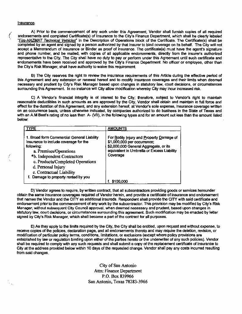
('
Insurance.
A} Prior to the commencement of any work under this Agreement, Vendor shall furnish copies of all required endorsements and completed Certificate(s) of Insurance to the City's Finance Department, which shall be clear1y labeled "Fire-HAZMAT Technical Vehicles- in the Description of Operations block of the Certificate. The Certificate(s) shall be completed by an agent and signed by a person authorized by that insurer to bind coverage on its behalf. The City will not accept a Memorandum of Insurance or Binder as proof of insurance. The certificate(s) must have the agent's signature and phone number, and be mailed, with copies of all applicable endorsements, directly from the insurer's authorized representative to the City. The City shall have no duty to payor perform under this Agreement until such certificate and endorsements have been received and approved by the City's Finance Departrnent. No officer or employee, other than the City's Risk Manager, shall have authority to waive this requirement.
B) The City reserves the right to review the insurance requirements of this Article during the effective period of this Agreement and any extension or renewal hereof and to modify insurance coverages and their limits when deemed necessary and prudent by City's Risk Manager based upon changes in statutory law, court decisions, or circumstances surrounding this Agreement. In no instance will City allow modification whereby City may incur increased risk.
C) A VendOr's financial integrity is of interest to the City; therefore, subject to Vendor's right: to maintain reasonable deductibles in such amounts as are approved by the. City, Vendor shall obtain and maintain in full force and effect for the duration of this Agreement, and any extension hereof, at Vendor's sole expense, insurance. coverage written on an occurrence basis, unless otherwise indicated, by companies authorized to do business in the State of Texas and with an A.M Best's rating of no less than A- (VII), in the following types and for an amount not less than the amount listed below:
TYPE AMOUNTS
1. Broad form Commercial General Liability For !!odily Injury and froperty l2amage of Insurance to include coverage for the $1,000,000 per occurrence; following: $2,000,000 General Aggregatei or its
a. Premises/Operations equivalent in Umbrella or Excess Liability
*b. Independent Contractors Coverage
c. Products/Completed Operations d. Personal Injury e. Contractual Liability
f.. Damage to property rented by you f. $100,000
D) Vendor agrees to require, by written contract, that all subcontractors providing goods or services hereunder obtain the same insurance coverages required of Vendor herein, and provide a certificate of insurance and endorsement that names the Vendor and the CITY as additional insureds. Respondent shall provide the CITY with said certificate and endorsement prior to the commencement of any work by the subcontractor. This provision may be modified by City's Risk Manager, without subsequent City Council approval. when deemed necessary and prudent. based upon changes in statutory law, court decisions, or circumstances surrounding this agreement. Such modification may be enacted by letter signed by City's Risk Manager, which shall become a part of the contract for all purposes.
E) As they apply to the limits required by the City, the City shall be entitled, upon request and without expense, to receive copies of the poliCies, declaration page, and all endorsements thereto and may require the deletion, revision, or modification of particular policy terms, conditions. limitations; or exclusions (except where policy proviSions are established by law or regulation binding upon either of the parties hereto or the underwriter of any such policies). Vendor shall be required to comply with any such requests and shall submit a copy of the replacement certificate of insurance to City at the address provided below within 10 days of the requested change. Vendor shall pay any costs incurred resulting from said changes.
City of San Antonio Attn: Finance Department
P.O. Box 839966 San Antonio, Texas 78283-3966
F) Vendor agrees that.with respect to the above required insurance. all insurance policies are to contain or be endorsed to contain the following provisions:
• Name the City, its officers. officials, employees, volunteers, and elected representatives as additional insureds by endorsement, as respects operations and activities of, or on behalf of, the named insured performed under contract with the City. with the exception of the workers' compensation and professional liabifity policies;
• Provide for an endorsement that the "other insurance- clause shall not apply to the City of San Antonio where the City is an additional insured shown on the policy;
• Workers' compensation, employers' liability, general liability and automobile liability policies will provide a waiver of subrogation in favor of the City.
• Provide advance written notice directly to City of any suspension. cancellation, non-renewal or material change in coverage, and not less than ten (10) calendar days advance notice for nonpayment of premium.
G) Within five (5) calendar days of a suspension, cancellation or non-renewal of coverage, Vendor shall provide a replacement Certificate of Insurance and applicable endorsements to City. City shall have the option to suspend Vendor's performance should there be a lapse in coverage at any time during this contract. Failure to provide and to maintain the required insurance shall constitute a material breach of this Agreement.
H} .In addition to any other remedies the City may have upon Vendor's failure to provide and maintain any insurance or policy endorsements to the extent and within the time herein required, the City shall have the right to order Vendor to stop work hereunder, and/or withhold any paytnent(s) Which become due to Vendor hereunder until Vendor demonstrates compliance with the requirements hereof.
I} Nothing herein contained shall be construed as limiting in any way the extent to which Vendor may be held responsible for payments of damages to persons or property resulting from Vendor's or its subcontractors' performance of the work covered under this Agreement. .
J) It is agreed that Vendor's insurance shall be deemed primary and non-contributory with respect to any (
insurance or self insurance carried by the City of San Antonio for liability ariSing out of operations under this Agreement.
K) It is understood and agreed that the insurance required is in addition to and separate from any other obligation contained in this Agreement and that no claim or action by or on behalf of the City shall be limited to insurance coverage
provided ..
L) Vendor and any Subcontractors are responsible for all damage to their own equipment and/or property.
Incorporation of Attachments.
Each of the attachments listed below is an essential part of this contract, which governs the rights and duties of the parties, incorporated herein by reference, and shall be interpreted in the order of priority as appears below, with this document taking priority over all attachments:
Attachment A - PRICE SCHEDULE Attachment B- SUPPLEMENTAL INFORMATION RELATED TO STATE OF TEXAS CONFLICT OF INTEREST
REQUIREMENT Attachment C- VETERAN-OWNED SMALL BUSINESS TRACKING FORM
'-
006 - GENERAL TERMS & CONDITIONS
Electronic Offer Equals Original. If Vendor is submitting an electronic offer, City and Vendor each agree that this transaction may be conducted by electronic means, as authorized by Chapter 322, Texas Business & Commerce Code, known as the Electronic Transactions Act.
Delivery of Goods/Services.
Destination Contract. Vendor shall deliver all goods and materials F.O.B .• City of San Antonio's designated facility, inside delivery, freight prepaid, to the address provided in this RFO or, if different, in the Purchase Order. Vendor shall bear the risk of loss until delivery. Freight charges will be paid only when expedited delivery is requested and approved in writing by City. Vendor shall be responsible for furnishing necessary personnel or equipment and/or making necessary arrangements to off load at City of San Antonio facility, unless otherwise noted herein.
Failure to Deliver. When delivery is not met as provided for in the contract, City may make the purchase on the open market, with any cost in excess of the contract price paid by Vendor, in addition to any other direct, indirect, consequential or incidental damages incurred by City as a result thereof. In addition, Vendor may be removed from City's list of eligible bidders.
Purchase Orders. Each time a City department wishes to place an order against this contract, it will issue Vendor a purchase order. Vendor must have the purchase order before making any delivery.
Acceptance by Cib!. City shall have a reasonable time (but not less than 30 days) after receipt to inspect the goods and services tendered by Vendor. City at its option may reject all or any portion of such goods or services which do not, in City's sole discretion, comply in every respect With all terms and conditions of the contract. City may elect to reject the entire goods and services tendered even if only a portion thereof is nonconforming. If City elects to accept nonconforming goods and services, City, in addition to its other remedies, shall be entitled to deduct a reasonable amount from the price thereof to compensate City for the nonconformity. Any acceptance. by City, even if non-conditional, shall not be deemed a waiver or settlement of any defect in such goods and services.
Testing. After award of contract, City may, at its sole option, test the product delivered to ensure it meets specifications. Initial testing shall be at City's expense. However, if the product does not to meet specifications, Vendor shall reimburse City for the costs of testing. City may withhold the cost of testing from any amounts owed to Vendor under this or any other contract, or invoice Vendor for same. If invoiced, Vendor shall pay City within 30 calendar days' of the invoice.
Invoicing and Payment.
Address for Invoices. All original invoices must be sent to: City of San Antonio, Attn: Accounts Payable, P.O. Box 839976, San Antonio, Texas 78283-3976.
Infonnation Required On Invoice.
All invoices must be in a fonn and content approved by City. City may require modification of invoices if necessary in order to satisfy City that all billing is proper and pursuant to the tenns of the contract. Invoices are required to show each City Purchase Order Number. Invoices must be legible. Items billed on invoices must be specific as to applicable stock, manufacturer, catalog or part number (if any). All invoices must show unit prices for each item being billed, the quantity of items being billed and the total for each item, as well as the total for all items on th~ illVOice, 11 priGes are based on list prices basis, then the list prices, the percentage discount or percentage surcharge, net unit prices. extensions and net total prices must be shown. Prompt payment discounts offered shat! be shown separately on the invoice.
Payment by City.
In accordance with the Texas Prompt Payment Act, City shall have not less than 30 days to pay for goods or services. TIme for payment. including paym~nt under discount terms, will be computed from the later of: (1) the date City receives conforming goods under the contract; (2) the date performance of the service under the contract is completed; or (3) the date City receives a correct and valid invoICe for the goods or services. Payment is deemed to be made on the date of mailing of the check. Payment is made in US dollars only.

This provision shall not apply where there is a bona fide dispute between City and Vendor about the goods delivered or the service performed that causes the payment to be late, or where the invoice is not mailed to the address provided herein. ('
\~ The payment amount due on invoices may not be manually altered by City personnel. Once disputed items are reconciled, Vendor must submit a corrected invoice or a credit memorandum for the disputed amount. City will not make partial payments on an invoice where there is a dispute.
NECESSITY OF TIMELY INVOICE I WAIVER OF PAYMENT. NOlWlTHSTANDING THE FORGOING, CITY CANNOT PAY FOR ANY GOODS OR SERVICES WITHOUT AN INVOICE. VENDOR MUST INVOICE CITY NO LATER THAN 90 CAlENDAR DAYS FROM THE DATE GOODS ARE DELIVERED OR SERVICES RENDERED. FAILURE TO SUBMIT AN INVOICE WITHIN SAID 90 DAY SHALL NEGATE ANY LIABILITY ON THE PART OF CITY AND CONSTITUTE A WAIVER BY vENDOR OF ANY AND ALL RIGHT OR CLAIMS TO COLLECT MONEYS THAT VENDOR MAY RIGHTFULLY BE OTHERWISE ENTITLED TO FOR GOODS OR SERVICES PERFORMED.
The total price for all goods andlor services is shown on the Price Schedule. No additional fees or expenses of Vendor shall be charged by Vendor nor be payable by City. The parties hereby agree that all compensable expenses of Vendor are shown on the Price Schedule. If there is a discrepancy on the Price Schedule between the unit price for an item, and the extended price, the unit price shall govern.
Amendments. Except where the terms of this contract expressly provide otherwise, any alterations, additions, or deletions to the terms hereof; shall be effected by amendment, in writing. executed by both City and Vendor. The Director of the Purchasing and General Services Department, or Director's designee, shall have authority to execute amendments on behalf of City without further action by the San Antonio City Council, subject to and contingent upon appropriation of funds for any increase in expenditures by City.
Termination.
Termination-Breach. Should vendor fail to fulfill in a timely and proper manner, as determined solely by the Director, its material obligations under this contract, or violate any of the material terms of this contract, City shall have the right to immediately terminate the contract in whole or in part. Notice of termination shall be provided in writing to the Vendor, (~ effective upon the date set forth in the notice. City may, in City's sale discretion, provide an opportunity for Vendor to cure the default. If City elects to offer an opportunity to cure, City shall provide notice to Vendor specifying the matters ~ in default and the cure period. If Vendor fails to cure the default within the cure period, City shall have the right, without further notice, to terminate the contract in whole or in part. Such termination shall not relieve Vendor of any liability to the City for damages sustained by virtue of any breach by Vendor.
Termination-Notice. City may terminate this contract, in whole or in part, without cause. City shall be required to give Vendor notice ten days prior to the date of termination of the contract without cause.
Tennination-Funding. City retains the right to terminate this contract at the expiration of each of City's budget perjods. This contract is conditioned on a best efforts attempt by City to obtain and appropriate funds for payment of any debt due by City herein.
Termination by City may be effected by Director, without further action by the San Antonio City Council.
Independent Contractor. Vendor covenants and agrees that it is an independent contractor and not an officer, agent, servant or employee of City. City shall not be liable for any claims which may be asserted by any third party occurring in connection with the services to be performed by Vendor under this contract and that Vendor has no authority to bind City. The doctrine of respondeat superior shall not apply as between City and Vendor.
INDEMNIFICATION.
VENDOR covenants and agrees to FULLY INDEMNIFY, DEFEND and HOLD HARMLESS, CITY and the elected officials, employees, officers, directors, volunteers and representatiVes of CITY, individually and collectively, from and against any and. all costs, claims, liens, damages, lOSSes, expenses, fees, fines, penalties. proceedings, actions, demands, causes of action, liability and suits of any kind and nature. Including but not limited to. personal or bodily injury, death and property damage, made upon CITY directly or indirectly arising out of, resulting from or related to VENDOR'S activities under this Agreement, including any acts or i omissions of VENDOR. any agent. officer, director, representative, employee, consultant or subcontractor of '<~ VENDOR, and their respective officers, agents employees, directors and representatives while in the exercise of the rights or performance of the dutieS under this Agreement. The indemnity provided for in this paragraph

shall not apply to any liability resulting from the negllge~ce of CITY, it s officers or employ~. in il1$I1.~8$ where such negligence causes personal injury, death, or property damage. IN THE EVENT VENDOR AND CITY ARE FOUND JOINTLY LIABLE BY A COURT OF COMPETENT JURISDICTION, LIABILITY SHALL BE APPORTIONED COMPARATIVELY IN ACCORDANCE WITH THE LAWS FOR THE STATE OF TEXAS, WITHOUT, HOWEVER, WAIVING ANY GOVERNMENTAL IMMUNITY AVAILABLE TO CITY UNDER TEXAS LAW AND WITHOUT WAIVING ANY DEFENSES OF THE PARTIES UNDER TEXAS LAW. In addition. Vendor agrees to indemnify, defend, and hold City harmless from any claim involving patent infringement, trademarks. trade secrets, and copyrights on goods supplied.
The provisions of this INDEMNITY are solely for the benefit of the parties hereto and not intended to create or grant any rights, contractual or otherwise, to any other person or entity. VENDOR shall adVise CITY in writing within 24 hours of any claim or demand against CITY or VENDOR known to VENDOR related to or arising out of VENDOR's activities under this AGREEMENT and shall see to the investigation and defense of such claim or demand at VENDOR's cost. CITY shall have the right, at its option and at its own expense, to partiCipate in such defense without relieving VENDOR of any of its obligations under this paragraph. .
Assignment. Except as otherwise stated herein, Vendor may not sell, assign, pledge, transfer or convey any interest in this contract, nor delegate the performance of any duties hereunder, by transfer, by subcontracting or any other means, without the consent of Director. As a condition of such consent, if such consent is granted, Vendor shall remain liable for completion of the services and proVision of goods outlined in this contract in the event of default by the successor vendor, assignee, transferee or subcontractor. Any attempt to transfer, pledge or otherwise assign this Contract without said written approval, shall be void ab initio and shall confer no rights upon any third person.
Ownership of Documents. Pursuant to Texas Local Government Code Chapter 201, any and all Records produced by Vendor pursuant to the provisions of this contract are the exclusive property of City; and no such Record shall be the subject of any copyright or proprietary claim by Vendor. The term -Record- as used herein shall mean any document, paper, letter, book, map, photograph, sound or vid~ recording, microfilm, magnetic tape, electronic medium, or other information recording medium, regardless of physical form or characteristic. Vendor understcmds and acknowledges that as the er.:clusive owner of any and all such Records, City has the right to use all such Records as City desires, without restriction,
Records Retention.
Vendor and its subcontractors, if any, shall properly, accurately and completely maintain all documents, papers, and records, and other eVidence pertaining to the services rendered hereunder (gDocuments~); and shall make such Documents available to City at their respective offices, at all reasonable times and as often as City may deem necessary during the contract period, including any extension or renewal hereof, and the record retention period established herein, for purposes of audit, inspection, examination, and making excerpts or copies of same by City and any of its authorized representatives.
Vendor shall retain any and all Documents produced as a result of services provided hereunder for a period of four years ("Retention Period") from the date of termination of the contract. If, at the end of the Retention Penod, there is litigation or other questions arising from. involving or concerning these Documents or the services provided hereunder, Vendor shall retain the records until the resolution of such litigation or other such questions. Vendor acknowledges and agrees that City shall have access to any and all such Documents at any and all times, as deemed necessary by City, during said Retention Period. City may, at its election, require Vendor to return the documents to City at Vendor's expense prior to or at the conclusion of the Retention Period. In such event, Vendor may retain a copy of the documents.
Vendor shall notify City, immediately, in the event Vendor receives any requests for information from a third party, which pertain to the Documents referenced herein. Vendor understands and agrees that City will process and handle all such requests.
Severability. If any clause or proVision of this contract is held invalid, illegal or unenforceable under present or future federal, state or local laws, including but not limited to the City Charter, City Code, or ordinances of the City of San Antonio, Texas, then and in that event it is the intention of the parties hereto that such invalidity, illegality or unenforceability shall not affect any other cl.ause or proVi~ion hereof an(j that the remainder of this contract shall be construed as if such invalid, illegal or unenforceable clause or provision was never contained herein. It is also the intention of the parties hereto that in lieu of each clause or proVision of this contract that is invalid, illegal, or unenforceable, there be added as a part of the contract a clause or prOVision as similar in terms to such invalid, illegal or unenforceable clause or provision as may be possible, legal, valid and enforceable.
Compliance with Law. Vendor shall provide and perform all services required under this Agreement in compliance with all applicable federal, state and local laws, rules and regulations.
Certifications. Vendor warrants and certifies that Vendor and any other person designated to provide services hereunder ( has the requisite training, license and/or certification to provide said services, and meets all competence standards " promulgated by all other authoritative bodies, as applicable to the services provided herein.
Non-waiver of Performance. Unless otherwise specifically provided for in this Agreement, a waiver by either Party of a breach of any of the terms, conditions, covenants or guarantees of this Agreement shan not be construed or held to be a waiver of any succeeding or preceding breach of the same or any other term, condition, covenant or guarantee herein contained. Further, any failure of either Party to insist in anyone or more cases upon the strict performance of any of the covenants of this Agreement, or to exercise any option herein contained, shall in no event be construed c;tS a waiver or relinquishment for the future of such covenant or option. In fact, no waiver, change, modification or discharge by either
. party hereto of any provision of this Agreement shall be deemed to have been made or shall be effective unless expressed in writing and signed by the party to be charged. No act or omission by a Party shall in any manner impair or prejudice any right, power, privilege, or remedy available to that Party hereunder or by law or in equity, such rights, powers, privileges, or remedies to be always specifically preserved hereby.
Venue. Venue of any court action brought directly or indirectly by reason of this contract shall be in Bexar County, Texas. This contract is made and is to be perfonned in Bexar County, Texas, and is governed by the laws of the State of Texas.
Non-discrimination. As a condition of entering into this agreement, Vendor represents and warrants that it will comply with City's Commeroial Nondiscrimination Policy, as descnbed under Section IILC.1 of the SBEDA Ordinance, As part of such compliance, Vendor shall not discriminate on the basis. of race, color, religion, ancestry or national origin, sex, age, marital status, sexual orientation, or on the basis of disability or other unlawful forms of discrimination in the solicitation, selection, hiring or commercial treatment of subcontractors, vendors, suppliers, Qr commercial customers, nor shall Vendor retaliate against any person for reporting instances of such discrimination. Vendor shall provide equal opportunity for subcontractors, vendors and suppliers to participate in all of its public sector and private sector subcontracting and supply opportunities, provided that nothing contained in this clause shall prohibit or limit otherwise lawful efforts to remedy the effects of marketplace discrimination that have occurred or are occuning in City's Relevant Marketplace. Vendor (. understands and agrees that a material violation of this clause shall be considered a material breach of this agreement .. and may result in termination of this agreement, disqualification of Vendor from participating in City contracts, or other ' sanctions. This clause is not enforceable by or for the benefit of, and creates no obligation to, any third party. Vendor shall include this nondiscrimination clause in all subcontracts forthe performance of this contract.
Non-Discrimination. As a party to this contract, Vendor understands and agrees to comply with the Non-Discrimination Poficy of the City of San Antonio contained in Chapter 2, Article X of the City Code and further, shall not discriminate on the basis of race, color, religion, national origin, sex, sexual orientation, gender identity, veteran status, age or disability, unless exempted by state or feclerallaw, or as otherwise established herein.
Delinquent Taxes. In the event that Vendor is or subsequently becomes delinquent in the payment of taxes owed to the City of San Antonio, City reserves the right to deduct any delinquent taxes from payments that City may owe to the delinquent Vendor as a result of this contract.
Binding Contract. This contract shall be binding on and inure to the benefit of the parties hereto and their respective heirs, executors, administrators, legal representatives, and successors and assigns, except as otherwise expressly provided for herein.
Entire Agreement. This contract, including City's final electronically posted online version, together with its authorizing ordinance, and its price schedule(s), attachments, purchase orders, and exhibits, if any, constitutes the final and entire agreement between the parties hereto and contains all of the terms and conditions agreed upon. No other agreements, oral or otherwise, regarding the subject matter of this contract shall be deemed to exist or to bind the parties hereto, unless same be in writing; dated subsequent to the date hereof, and be duly executed by the parties, in accordance with the Amendment provision herein. Parties agree that City's final electronically posted online version of this soJicitation contains the agreed upon specifications, scope of services, and tenns and conditions of this contract, and shall control in the event of a conflict with any printed version signed and submitted by Vendor.
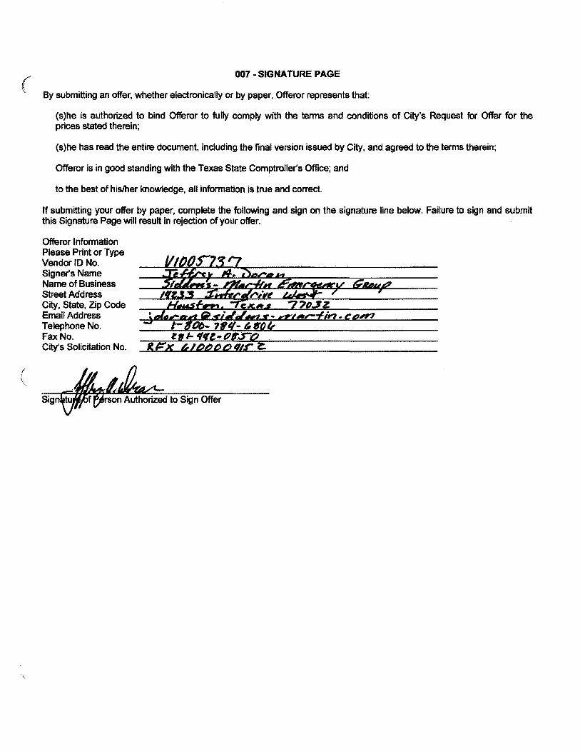
(
007 - SIGNATURE PAGE
By submitting an offer, whether electronically or by paper, Offeror represents that:
(s)he is authorized to bind Offeror to fully comply with the terms and conditions of City's Request for Offer for the prices stated therein;
(s)he has read the entire document, including the final version issued by City, and agreed to the terms therein;
Offeror is in good standing with the Texas State Comptroller's Office; and
to the best of his/her knowledge, all information is true and correct.
If submitting your offer by paper, complete the following and sign on the signature line below. Failure to sign and submit this Signature Page will result in rejection of your offer.
Offeror Information Please Print or Type Vendor JD No. Signer's Name Name of Business Street Address City, State, Zip Code Email Address Telephone No. Fax No. City's Solicitation No.

008 - STANDARD DEFINITIONS
Whenever a term defined by the Uniform Commercial Code (·UCC·), as enacted by the State of Texas, is used in the ( Contract, the UCC definition shall control, unless otherwise defined in the Contract.
All-or-None Offer - an RFO in which City will award the entire contract to one offeror only.
Alternate Offer - two or more offers with substantive variations in the item or service offered from the same offeror in response to a solicitation.
Assignment - a transfer of claims, rights or interests in goods, services or property.
Bid Bond - security to ensure that Offeror (a) will not withdraw the offer within the period specified for acceptance, and (b) will furnish any required bonds and any necessary insurance within the time specified in the solicitation.
~ - the City of San Antonio, a Texas home-rule municipal corporation.
Contractor - the offeror whose offer is accepted by City and is, therefore, the perSon, firm or entity providing goods or services to City under a contract.
. .... Director - the Director of City's Purchasing & General Services Department, .or. Director's dEisignee.
line Item - a listing of items in an offer for: which an offeror is expected to provide.~~parate pricing. '"
Offer - a complete, signed response to an RFO that, if accepted, would bind Offeror to perform the resultant contract. ,. .....
Offeror - a person, firm or entity that submits an offer in response to a solicitation. The offeror whose offer is accepted by City may also be referred to herein as Contractor, Vendor or Supplier.
Payment Bond - a particular form of security provided by the contractor to protect City against loss due to· the ~GQntractor's failure to pay suppliers and subcontractors.
Performance Bond - a particular form of security provided by the contractor to protect City against loss due to the contractor's inability or unwillingness to complete the contract as agreed.
Performance DePQsit - security provided by the contractor to protect City against loss due to the contractor's inability or unwillingness to complete the contract as agreed.
Pre-$ubmittal Conference - a meeting conducted by City, held in order to allow offerors to ask questions about the proposed contract and particularly, the contract specifications.
Purchase Order - a validly issued order placed by an authorized City department for the purchase of goods or services, written on City's standard purchase order form, and which is the vendor's authority to deliver to and invoice City for the goods or services specified in an RFO for the price stated in vendor's offer.
Specifications - a description of what City requires and what Offeror must offer, a description of the physical or functional characteristics of a product or material, or the nature of a service or construction item.
Subcontractor - a person, firm or entity providing goods or services to a vendor to be used in the performance of the vendor's obligations under the contract with City.
Supplier - the offeror whose offer is accepted by City and is, therefore, the person, firm or entity providing goods or services to City under a contract.
Vendor - the offeror whose offer is accepted by City and is, therefore, the person, firm or entity providing goods or
( ,.
services to City under a contract. { , ...:; . ...... ,.,
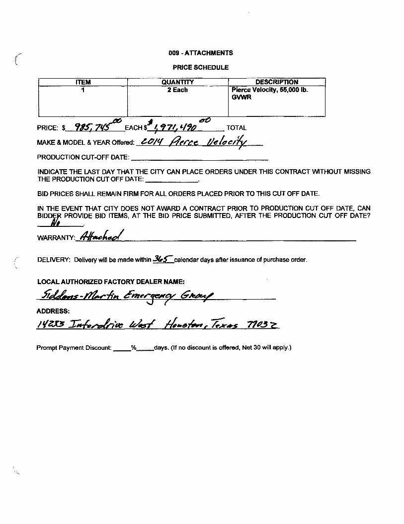
ITEM
009 - ATTACHMENTS
PRICE SCHEDULE
QUANTITY DESCRIPTION 1 2 Each Pierce Velocity, 55,000 lb.
GVWR
6C PRICE: $ 985; 7~ EACH $" (, ~7f., 'I?o TOTAL
MAKE & MODEL & YEAR Offered: .....;;;;..~..;;;.b,-=-"'-Lo/---Ia:...L..!:t;-=-~ .... e:~c:"-w.IA..;:;e~k=e.:..l,t}'-J( V<::-__
PRODUCTION CUT-OFF DATE: _____________ _
INDICATE THE LAST DAY THAT THE CITY CAN PLACE ORDERS UNDER THIS CONTRACT WITHOUT MISSING THE PRODUCTION CUT OFF DATE: _____ ~
BID PRICES SHALL REMAIN FIRM FOR ALL ORDERS PLACED PRIOR TO THIS CUT OFF DATE.
IN THE EVENT THAT CITY DOES NOT AWARD A CONTRACT PRIOR TO PRODUCTION CUT OFF DATE, CAN BIDDr PROVl.DE BID ITEMS, AT THE BID PRICE SUBMITTED, AFTER THE PRODUCTION CUT OFF DATE?
WARRANTY: &hd
'" DELIVERY: Delivery will be made within :J(,S-calendar days after issuance of purchase order.
LOCAL AUTHORIZED FACTORY DEALER NAME:
J'iUAlr/s-d't.cin Ent,,..~pc G~/ ADDRESS:
,I/e.D T".f,,·'!c//A: v£ 4.6(,.", h-.... s 71P.3?:..
Prompt Payment Discount: _% __ days. (If no discount is offered, Net 30 will apply.)
(
/
City of San Antonio
Veteran.()wned Small Business Program Tracking Form
Authority. The City of San Antonio Veteran-OwilE:K! SrTia".,~u,sin~~Preference PrOgram Ordinance 2013· 12-05-0864 adopted a veteran-owned small business preference program for specific contracting categories for soliCita!ioi'ls issued .after January 15, 2014.
., . ,. '
Tracking. This solicitation is not eligible for a preference based on status as a veteran-owned small business (VOSB). Nevertheless, fn order todetermlne~whether the prOgram can be expanded at a later date, the City tracks VOSB partiCipation at both p~me contract and subcontract levels.
Certification. The citY relies on lnciusion in the database of veteran-owned small businesses (VOSB) ,maintaj,n~'bythe U.S. Small J;3us.i.n.ess'Administration to verify VOSB status; however, veteran status may also be confirmed by certiflcation by another publiC or private entity that uses similar certification procedures.
Definitions. The prOgram uses the federal definitions of veteran and veteran-owned small business found in 38 CFR Part 74.
• The term ·veteran" means a person who served on active duty with the U.S. Army, Air Force, Navy, Markle Corps, Coast Guard, for any length of time and at any place anti who was diSCharged or reieased under conditions other than dishonorable. ReserviSts or members of the National Guard called to federal active duty or disabled from a disease or injury incUrred or aggravated in line of duty or while in ttainilig status.
• A veteran-owned small business is a business that is not less than 51 percent owned by one or more veterans, or in the case of any publicly owned business, not less than 51 percent of the stock of which is owned by one or more veterans; the management and daily business operations of which are controlled by one or more veterans and qualifies as ·sma"" for Federal business size stand purposes.
The program does not distinguish between a veteran and a service-disabled veteran-owned business and is not limited geographically.
COMPLETE THE FOLLOWING FORM AND SUBMIT IT WITH YOUR BIDJPROPOSAL
Veteran-Owned Small Business Program Tracking Form 1115114
Page 1 of3
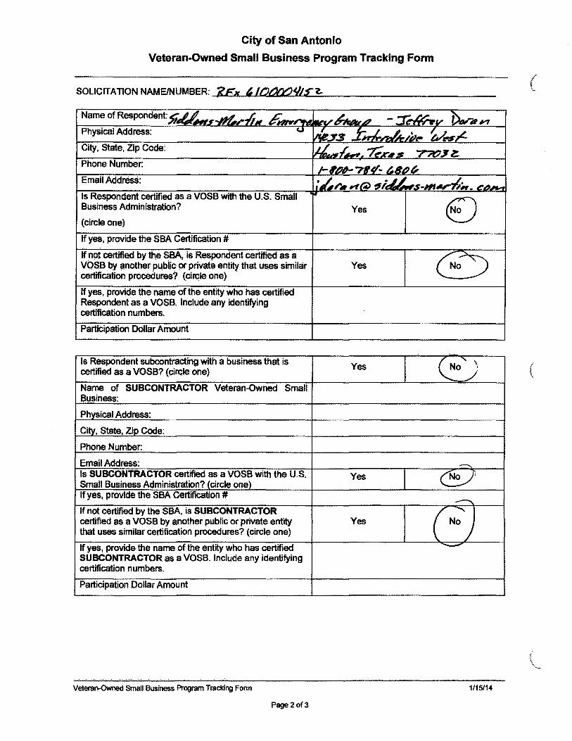
City of San Antonio
Veteran-Owned Small Business Program Tracking Form
SOLICITATION NAMEINUMBER: ~'l~FL",;·.a.¥....lI'&.£,IoIa.-'I~,-£' W' "'-"I/..LI'I£L......=~:...--__________ _ ( \.,.
Name of Respondent:1k.~ ~ ~_ ,J, ,!k,r,- ,4~.lA - :::r~V PtV""4P1 Physical Address: <.J
MJ3 f";,L 'L ~;';_ ~I!"S''''£ City, State, Zip Code: d .£ ~K"I----s' 7W/~z:. Phone Number.
/-'I/d-?~ ~81/)" Email Address: 1:.1,;-.. rlt;L ~i. .11_ -Hf",,.-tN. --Is Respondent certified as a VOSB with the U.S. Small
EJ Business Administration? Yes (circle one)
If yes, provide the SSA Certification #
If not certified by the SBA, is Respondent certified as a
~~ VOSB by ~nother pubiic or private entity that uses similar Yes certification procedures? (circle one)
If yes, provide the name of the entity who has certified Respondent as a VOSB. Include any identifying certification numbers.
Participation Dollar Amount
Is Respondent subcontracting with a business that is ~' certified as a VOSS? (circle one) Yes No ) ( '.
Name of SUBCONTRACTOR Veteran-Owned Small Business:
Phvsical Address:
City, State, Zip Code:
Phone Number:
Email Address: ---.. Is SUBCONTRACTOR certified as a VOSS with the U.S. Yes ~ Small Business Administration? (circle one) If yes, provide the SBA Certification # ---.. If not certified by the SSA, is SUBCONTRACTOR
(N~l certified as a VOSB by another public or private entity Yes that uses similar certification procedures? (circle one)
If yes, provide the name of the entity who has certified ~
SUBCONTRACTOR as a VOSS. Include any identifying certification numbers.
Participation Dollar Amount
Veteran-Owned Small Business Program Tracking Form 1/15114
Page2of3
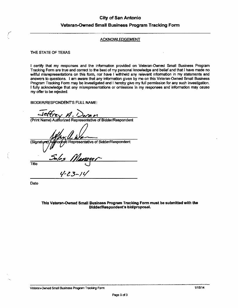
City of San Antonio
Veteran-Owned Small Business Program Tracking Form
ACKNOWLEDGEMENT
THE STATE OF TEXAS
I certify that my responses and the information provided on Veteran-Owned Small Business Program Tracking Form are true and correct to the best of my personal knowledge and belief and that I have made no willful misrepresentations on this form, nor have I withheld any relevant information in my statements and answers to questions. I am aware that any information given by me on this Veteran-Owned Small Business Program Tracking Form may be investigated and I hereby give my full permission for any such investigation. I fully acknowledge that any misrepresentations or omissions in my responses and information may cause my offer to be rejected.
BIDDERIRESPONDENT'S FULL NAME:
(Print Name) A orized Representative of Bidder/Respondent
(Signat
Title
Date
This Veteran-Owned Small Business Program Tracking Form must be submitted with the BldderlRespondent's bid/proposal.
Veteran-OWned Small Business Program Tracking Form 1/15114
Page30f3


