Embed Size (px)
Citation preview
Missouri University of Science and Technology Missouri University of Science and Technology
Scholars' Mine Scholars' Mine
Electrical and Computer Engineering Faculty Research & Creative Works Electrical and Computer Engineering
01 Jan 2009
An Improved UPFC Control for Oscillation Damping An Improved UPFC Control for Oscillation Damping
Jagannathan Sarangapani Missouri University of Science and Technology, [email protected]
Mariesa Crow Missouri University of Science and Technology, [email protected]
Jianjun Guo
Follow this and additional works at: https://scholarsmine.mst.edu/ele_comeng_facwork
Part of the Computer Sciences Commons, and the Electrical and Computer Engineering Commons
Recommended Citation Recommended Citation J. Sarangapani et al., "An Improved UPFC Control for Oscillation Damping," IEEE Tranactions on Power Systems, vol. 24, no. 1, pp. 288-296, Institute of Electrical and Electronics Engineers (IEEE), Jan 2009. The definitive version is available at https://doi.org/10.1109/TPWRS.2008.2008676
This Article - Journal is brought to you for free and open access by Scholars' Mine. It has been accepted for inclusion in Electrical and Computer Engineering Faculty Research & Creative Works by an authorized administrator of Scholars' Mine. This work is protected by U. S. Copyright Law. Unauthorized use including reproduction for redistribution requires the permission of the copyright holder. For more information, please contact [email protected].
288 IEEE TRANSACTIONS ON POWER SYSTEMS, VOL. 24, NO. 1, FEBRUARY 2009
An Improved UPFC Control for Oscillation DampingJ. Guo, Student Member, IEEE, M. L. Crow, Senior Member, IEEE, and
Jagannathan Sarangapani, Senior Member, IEEE
Abstract—This paper proposes a new control approach for aunified power flow controller (UPFC) for power system oscillationdamping. This control is simple to implement, yet is valid overa wide range of operating conditions. It is also effective in thepresence of multiple modes of oscillation. The proposed controlis implemented in several test systems and is compared against atraditional PI control.
Index Terms—Oscillation damping, power system stability, uni-fied power flow controller (UPFC).
I. INTRODUCTION
O NE of the most promising network controllers for thebulk power system is the family of power electronics-
based controllers, known as “flexible ac transmission system”(FACTS) devices. FACTS devices work by modifying powerflow in individual lines of the power grid, maintaining voltagestability, and damping oscillations. The DOE National Trans-mission Grid Study released in May 2002 identified FACTSdevices as playing a significant role in the “Intelligent EnergySystem” of the future. This rapid control has been shown tobe effective in achieving voltage support and stability improve-ment, thus allowing the transmission system to be operated moreefficiently with a smaller stability margin. The rapid develop-ment of the power electronics industry has made FACTS devicesincreasingly attractive for utility deployment due to their flexi-bility and ability to effectively control power system dynamics.The primary function of the FACTS is to control the transmis-sion line power flow; the secondary functions of the FACTS canbe voltage control, transient stability improvement and oscilla-tion damping. The unified power flow controller (UPFC) is themost versatile FACTS device. The UPFC is able to simultane-ously provide both series and shunt compensation to a transmis-sion line providing separate control of the active and reactivepowers on the transmission line.
In recent years, the use of the UPFC for oscillation dampinghas received increased attention. Several approaches have beentaken to the modeling and control of the UPFC. Perhaps themost common approach is to model the UPFC as a power in-jection model [1]–[3]. The power injection model neglects thedynamics of the UPFC and uses the UPFC active and reactivepower injection as the control inputs into the power system. Thisapproach has the advantages of simplicity and computationalefficiency since the fast dynamics of the UPFC are neglected.
Manuscript received November 07, 2006; revised July 29, 2008. First pub-lished January 09,2009; current version published January 21, 2009. Paper no.TPWRS-00782-2006.
The authors are with the Electrical and Computer Engineering Department,Missouri University of Science and Technology, Rolla, MO 65409-0810 USA.
Digital Object Identifier 10.1109/TPWRS.2008.2008676
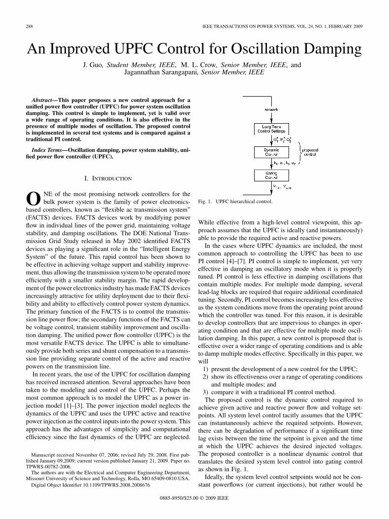
Fig. 1. UPFC hierarchical control.
While effective from a high-level control viewpoint, this ap-proach assumes that the UPFC is ideally (and instantaneously)able to provide the required active and reactive powers.
In the cases where UPFC dynamics are included, the mostcommon approach to controlling the UPFC has been to usePI control [4]–[7]. PI control is simple to implement, yet veryeffective in damping an oscillatory mode when it is properlytuned. PI control is less effective in damping oscillations thatcontain multiple modes. For multiple mode damping, severallead-lag blocks are required that require additional coordinatedtuning. Secondly, PI control becomes increasingly less effectiveas the system conditions move from the operating point aroundwhich the controller was tuned. For this reason, it is desirableto develop controllers that are impervious to changes in oper-ating condition and that are effective for multiple mode oscil-lation damping. In this paper, a new control is proposed that iseffective over a wider range of operating conditions and is ableto damp multiple modes effective. Specifically in this paper, wewill
1) present the development of a new control for the UPFC;2) show its effectiveness over a range of operating conditions
and multiple modes; and3) compare it with a traditional PI control method.The proposed control is the dynamic control required to
achieve given active and reactive power flow and voltage set-points. All system level control tacitly assumes that the UPFCcan instantaneously achieve the required setpoints. However,there can be degradation of performance if a significant timelag exists between the time the setpoint is given and the timeat which the UPFC achieves the desired injected voltages.The proposed controller is a nonlinear dynamic control thattranslates the desired system level control into gating controlas shown in Fig. 1.
Ideally, the system level control setpoints would not be con-stant powerflows (or current injections), but rather would be
0885-8950/$25.00 © 2009 IEEE
GUO et al.: AN IMPROVED UPFC CONTROL FOR OSCILLATION DAMPING 289
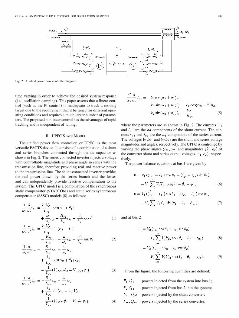
Fig. 2. Unified power flow controller diagram.
time varying in order to achieve the desired system response(i.e., oscillation damping). This paper asserts that a linear con-trol (such as the PI control) is inadequate to track a movingtarget due to the requirement that it be tuned for different oper-ating conditions and requires a much larger number of parame-ters. The proposed nonlinear control has the advantages of rapidtracking and is independent of tuning.
II. UPFC STATE MODEL
The unified power flow controller, or UPFC, is the mostversatile FACTS device. It consists of a combination of a shuntand series branches connected through the dc capacitor asshown in Fig. 2. The series connected inverter injects a voltagewith controllable magnitude and phase angle in series with thetransmission line, therefore providing real and reactive powerto the transmission line. The shunt-connected inverter providesthe real power drawn by the series branch and the lossesand can independently provide reactive compensation to thesystem. The UPFC model is a combination of the synchronousstatic compensator (STATCOM) and static series synchronouscompensator (SSSC) models [8] as follows:
(1)
(2)
(3)
(4)
(5)
where the parameters are as shown in Fig. 2. The currentsand are the components of the shunt current. The cur-rents and are the components of the series current.The voltages and are the shunt and series voltagemagnitudes and angles, respectively. The UPFC is controlled byvarying the phase angles and magnitudes ofthe converter shunt and series output voltages , respec-tively.
The power balance equations at bus 1 are given by
(6)
(7)
and at bus 2
(8)
(9)
From the figure, the following quantities are defined:
powers injected from the system into bus 1;
powers injected from bus 2 into the system;
powers injected by the shunt converter;
powers injected by the series converter;
290 IEEE TRANSACTIONS ON POWER SYSTEMS, VOL. 24, NO. 1, FEBRUARY 2009
active power from shunt to series converter lesslosses;
powers injected by the series transformerwhere .
III. NEW UPFC CONTROL
A. Series Control
The control objective for the series portion of the UPFC isinject a variable series voltage into the line such that the linepowers track a desired active line power and desired reactivepower . The target values are chosen for the particular powersystem application and may be chosen to be a constant value orto damp oscillations. In addition, the shunt portion of the UPFCis utilized to maintain the bus voltage at the sending end (bus 1 inFig. 2) and the dc link capacitor voltage. The inputsand are controlled to achieve these objectives.
Starting with the series portion of the UPFC, the desiredpowers are converted into desired currents and through
(10)
Note that in per unit, the current in both windings of the seriestransformer are the same value, therefore the desired line powerflows are used to calculate the target series currents.
To track the target, new state variables and are definedsuch that
(11)
(12)
leading to new state equations
(13)
(14)
Let control inputs be defined as
(15)
(16)
A positive definite Lyapunov function is given by
(17)
The derivative of is given by
(18)
where
The derivative is guaranteed to be negative if
(19)
Therefore from Lyapunov’s second theorem on stability [9],this system is asymptotically stable if (19) is satisfied providedthe control inputs are selected as
(20)
where
Equations (15) and (16) can be solved for and from
(21)
and
(22)
Both and are limited to bound the magnitude of the in-jected current and therefore limit the injected active and reactivepowers. The parameter is usually chosen to be a large numberand may be tuned to obtain the desired damping time frame.
GUO et al.: AN IMPROVED UPFC CONTROL FOR OSCILLATION DAMPING 291
A finer control may be achieved however, by introducing anadditional parameter such that (20) becomes
(23)
By splitting into two separate parameters ( and ),a weighted control is possible whereby or can be moretightly controlled, and subsequently or .
B. Shunt Control
The control objective for the shunt portion of the UPFC istwo-fold. The first objective is to regulate the shunt bus voltagemagnitude at the reference value. This is similar to the voltagecontrol aspect of a STATCOM. The second objective is to main-tain the dc link capacitor voltage. The control of many voltagesourced converters (such as the STATCOM and SSSC) requiresa near constant dc link voltage to have effective control. Whilethe dc link capacitor may discharge briefly during transients toprovide active power to the system, a significant voltage sag mayresult in severe control degradation as the converter is no longerable to inject the desired current into the system.
The voltage magnitude at the shunt bus is primarily impactedby injected reactive power, whereas the dc link voltage is pri-marily impacted by the active power absorbed by the shunt con-verter to charge the capacitor. Therefore a similar control ap-proach for the STATCOM can be derived such that
(24)
The desired reactive power is the reactive power requiredfor voltage support at the shunt bus and may be chosen indepen-dently. The desired active power however is not indepen-dent of . The shunt active power must account for the lossesin the shunt and series branches of the UPFC and is therefore
(25)
where
(26)
It is not possible to a priori designate an exact target value for, but a target value can be estimated. From the series con-
trol, values for and can be obtained. One objective of theshunt portion is to maintain at a constant value, thus canalso be specified. Thus
(27)
The last term in (27) reflects the dependence of on .The constant is a nonnegative number. Substituting thesevalues into (24) yields
(28)
(29)
These equations can then be solved for and . Sincethese equations are nonlinear, to have an exact solution forand requires the iterative solution of (28) and (29). In mostcases however, a fairly close approximation can be obtained bysolving
where and are the initial shunt current values.Following the same procedure above, new state variables
and are defined
(30)
(31)
and
(32)
where
and
from which and can be determined similar to (21) and(22).
IV. CONTROL IMPLEMENTATION
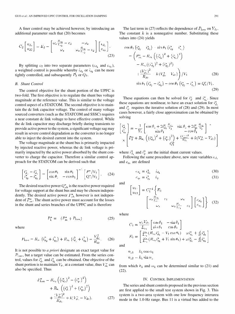
The series and shunt controls proposed in the previous sectionare first applied to the small test system shown in Fig. 3. Thissystem is a two-area system with one low frequency interareamode in the 1.0-Hz range. Bus 11 is a virtual bus added to the
292 IEEE TRANSACTIONS ON POWER SYSTEMS, VOL. 24, NO. 1, FEBRUARY 2009
Fig. 3. Two-area test system.
Fig. 4. Control framework.
system. The generators are modeled as two-axis generators witha simple dc exciter, voltage regulator, and turbine/governor. Thegenerator and network equations are given in the Appendix.
The primary objective of the UPFC is to damp the resultinginterarea oscillations. Additional objectives are to maintain thedc link capacitor voltage and the voltage at bus 6. The pro-posed controller is compared against a PI controller where
(33)
(34)
The PI parameters were initially chosen via standard procedures[10] and then further refined using a genetic algorithm to pro-duce the best results possible [11].
For an even comparison, both the PI controller and the pro-posed controller are based on the same control scheme shownin Fig. 4. This control is based on series and shunt currentinjections as determined by (10) and (24). Fig. 4 shows the con-trol diagram for the controllers. The only difference between theproposed controller and the PI controller is the shaded blocks, inwhich (23) is replaced by (33) and (32) is replaced by (34). How-ever, note that the PI controller requires 16 parameters whereasthe proposed controller has three parameters . The pa-rameters for the proposed control are chosen to be large posi-tive constants and require very little tuning. The parameters forboth controllers are given in Tables I and II for Cases I and II.
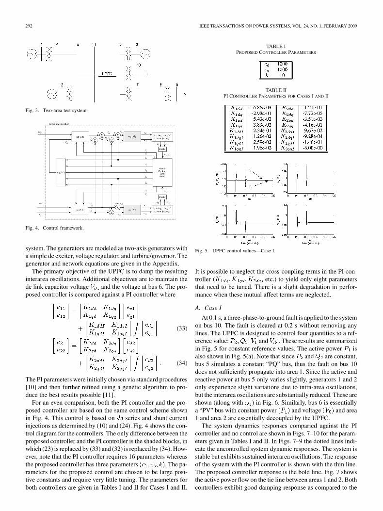
TABLE IPROPOSED CONTROLLER PARAMETERS
TABLE IIPI CONTROLLER PARAMETERS FOR CASES I AND II
Fig. 5. UPFC control values—Case I.
It is possible to neglect the cross-coupling terms in the PI con-troller ( etc.) to yield only eight parametersthat need to be tuned. There is a slight degradation in perfor-mance when these mutual affect terms are neglected.
A. Case I
At 0.1 s, a three-phase-to-ground fault is applied to the systemon bus 10. The fault is cleared at 0.2 s without removing anylines. The UPFC is designed to control four quantities to a ref-erence value: and . These results are summarizedin Fig. 5 for constant reference values. The active power isalso shown in Fig. 5(a). Note that since and are constant,bus 5 simulates a constant “PQ” bus, thus the fault on bus 10does not sufficiently propagate into area 1. Since the active andreactive power at bus 5 only varies slightly, generators 1 and 2only experience slight variations due to intra-area oscillations,but the interarea oscillations are substantially reduced. These areshown (along with ) in Fig. 6. Similarly, bus 6 is essentiallya “PV” bus with constant power and voltage and area1 and area 2 are essentially decoupled by the UPFC.
The system dynamics responses comparied against the PIcontroller and no control are shown in Figs. 7–10 for the param-eters given in Tables I and II. In Figs. 7–9 the dotted lines indi-cate the uncontrolled system dynamic responses. The system isstable but exhibits sustained interarea oscillations. The responseof the system with the PI controller is shown with the thin line.The proposed controller response is the bold line. Fig. 7 showsthe active power flow on the tie line between areas 1 and 2. Bothcontrollers exhibit good damping response as compared to the
GUO et al.: AN IMPROVED UPFC CONTROL FOR OSCILLATION DAMPING 293
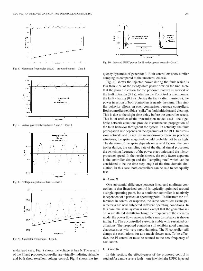
Fig. 6. Generator frequencies (rad/s)—proposed control—Case I.
Fig. 7. Active power between buses 5 and 6—Case I.
Fig. 8. Voltage magnitude at bus 6—Case I.
Fig. 9. Generator frequencies—Case I.
undamped case. Fig. 8 shows the voltage at bus 6. The resultsof the PI and proposed controller are virtually indistinguishableand both show excellent voltage control. Fig. 9 shows the fre-
Fig. 10. Injected UPFC power for PI and proposed control—Case I.
quency dynamics of generator 3. Both controllers show similardamping as compared to the uncontrolled case.
Fig. 10 shows the injected power during the fault which isless than 20% of the steady-state power flow on the line. Notethat the power injection for the proposed control is greatest atthe fault initiation (0.1 s), whereas the PI control is maximum atthe fault clearing (0.2 s). During the fault (after transients), thepower injection of both controllers is nearly the same. This sim-ilar behavior allows an even comparison between controllers.Both controllers exhibit a “spike” at fault initiation and clearing.This is due to the slight time delay before the controller reacts.This is an artifact of the transmission model used—the alge-braic network equations provide instantaneous propagation ofthe fault behavior throughout the system. In actuality, the faultpropagation rate depends on the dynamics of the RLC transmis-sion network and is not instantaneous—therefore in practicalsituations, the spike magnitude would probably not be as high.The duration of the spike depends on several factors: the con-troller design, the sampling rate of the digital signal processor,the switching frequency of the power electronics, and the micro-processor speed. In the results shown, the only factor apparentis the controller design and the “sampling rate” which can beconsidered to be the time step length of the time domain sim-ulation. In this case, both controllers can be said to act equallyfast.
B. Case II
One substantial difference between linear and nonlinear con-trollers is that linearized control is typically optimized arounda single operating point, but a nonlinear controller is relativelyindependent of a particular operating point. To illustrate the dif-ferences in controller response, the same controllers (same pa-rameters) are now subjected different operating conditions. Inthis case, the same system is used except that the generator in-ertias are altered slightly to change the frequency of the interareamode. the power flow response to the same disturbance is shownin Fig. 11. The uncontrolled system is stable with sustained os-cillations. The proposed controller still exhibits good dampingcharacteristics with very rapid damping. The PI controller stilldamps the oscillations but at a much slower rate. To be effec-tive, the PI controller must be retuned to the new frequency ofoscillation.
C. Case III
In this section, the effectiveness of the proposed control isstudied for a more severe fault—one in which the UPFC injected
294 IEEE TRANSACTIONS ON POWER SYSTEMS, VOL. 24, NO. 1, FEBRUARY 2009
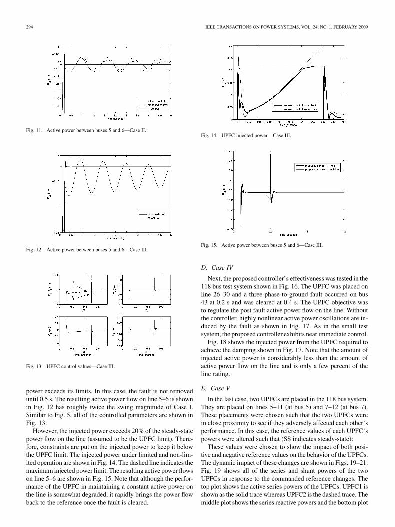
Fig. 11. Active power between buses 5 and 6—Case II.
Fig. 12. Active power between buses 5 and 6—Case III.
Fig. 13. UPFC control values—Case III.
power exceeds its limits. In this case, the fault is not removeduntil 0.5 s. The resulting active power flow on line 5–6 is shownin Fig. 12 has roughly twice the swing magnitude of Case I.Similar to Fig. 5, all of the controlled parameters are shown inFig. 13.
However, the injected power exceeds 20% of the steady-statepower flow on the line (assumed to be the UPFC limit). There-fore, constraints are put on the injected power to keep it belowthe UPFC limit. The injected power under limited and non-lim-ited operation are shown in Fig. 14. The dashed line indicates themaximum injected power limit. The resulting active power flowson line 5–6 are shown in Fig. 15. Note that although the perfor-mance of the UPFC in maintaining a constant active power onthe line is somewhat degraded, it rapidly brings the power flowback to the reference once the fault is cleared.
Fig. 14. UPFC injected power—Case III.
Fig. 15. Active power between buses 5 and 6—Case III.
D. Case IV
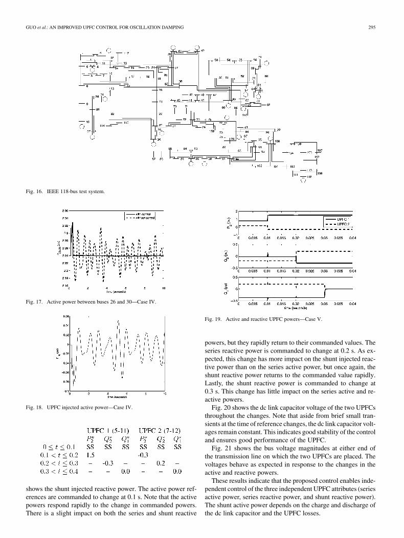
Next, the proposed controller’s effectiveness was tested in the118 bus test system shown in Fig. 16. The UPFC was placed online 26–30 and a three-phase-to-ground fault occurred on bus43 at 0.2 s and was cleared at 0.4 s. The UPFC objective wasto regulate the post fault active power flow on the line. Withoutthe controller, highly nonlinear active power oscillations are in-duced by the fault as shown in Fig. 17. As in the small testsystem, the proposed controller exhibits near immediate control.
Fig. 18 shows the injected power from the UPFC required toachieve the damping shown in Fig. 17. Note that the amount ofinjected active power is considerably less than the amount ofactive power flow on the line and is only a few percent of theline rating.
E. Case V
In the last case, two UPFCs are placed in the 118 bus system.They are placed on lines 5–11 (at bus 5) and 7–12 (at bus 7).These placements were chosen such that the two UPFCs werein close proximity to see if they adversely affected each other’sperformance. In this case, the reference values of each UPFC’spowers were altered such that (SS indicates steady-state):
These values were chosen to show the impact of both posi-tive and negative reference values on the behavior of the UPFCs.The dynamic impact of these changes are shown in Figs. 19–21.Fig. 19 shows all of the series and shunt powers of the twoUPFCs in response to the commanded reference changes. Thetop plot shows the active series powers of the UPFCs. UPFC1 isshown as the solid trace whereas UPFC2 is the dashed trace. Themiddle plot shows the series reactive powers and the bottom plot
GUO et al.: AN IMPROVED UPFC CONTROL FOR OSCILLATION DAMPING 295
Fig. 16. IEEE 118-bus test system.
Fig. 17. Active power between buses 26 and 30—Case IV.
Fig. 18. UPFC injected active power—Case IV.
shows the shunt injected reactive power. The active power ref-erences are commanded to change at 0.1 s. Note that the activepowers respond rapidly to the change in commanded powers.There is a slight impact on both the series and shunt reactive
Fig. 19. Active and reactive UPFC powers—Case V.
powers, but they rapidly return to their commanded values. Theseries reactive power is commanded to change at 0.2 s. As ex-pected, this change has more impact on the shunt injected reac-tive power than on the series active power, but once again, theshunt reactive power returns to the commanded value rapidly.Lastly, the shunt reactive power is commanded to change at0.3 s. This change has little impact on the series active and re-active powers.
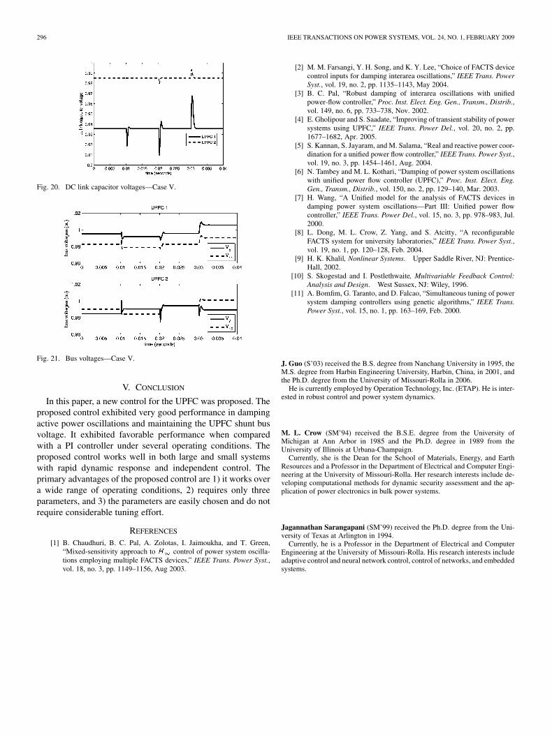
Fig. 20 shows the dc link capacitor voltage of the two UPFCsthroughout the changes. Note that aside from brief small tran-sients at the time of reference changes, the dc link capacitor volt-ages remain constant. This indicates good stability of the controland ensures good performance of the UPFC.
Fig. 21 shows the bus voltage magnitudes at either end ofthe transmission line on which the two UPFCs are placed. Thevoltages behave as expected in response to the changes in theactive and reactive powers.
These results indicate that the proposed control enables inde-pendent control of the three independent UPFC attributes (seriesactive power, series reactive power, and shunt reactive power).The shunt active power depends on the charge and discharge ofthe dc link capacitor and the UPFC losses.
296 IEEE TRANSACTIONS ON POWER SYSTEMS, VOL. 24, NO. 1, FEBRUARY 2009
Fig. 20. DC link capacitor voltages—Case V.
Fig. 21. Bus voltages—Case V.
V. CONCLUSION
In this paper, a new control for the UPFC was proposed. Theproposed control exhibited very good performance in dampingactive power oscillations and maintaining the UPFC shunt busvoltage. It exhibited favorable performance when comparedwith a PI controller under several operating conditions. Theproposed control works well in both large and small systemswith rapid dynamic response and independent control. Theprimary advantages of the proposed control are 1) it works overa wide range of operating conditions, 2) requires only threeparameters, and 3) the parameters are easily chosen and do notrequire considerable tuning effort.
REFERENCES
[1] B. Chaudhuri, B. C. Pal, A. Zolotas, I. Jaimoukha, and T. Green,“Mixed-sensitivity approach to � control of power system oscilla-tions employing multiple FACTS devices,” IEEE Trans. Power Syst.,vol. 18, no. 3, pp. 1149–1156, Aug 2003.
[2] M. M. Farsangi, Y. H. Song, and K. Y. Lee, “Choice of FACTS devicecontrol inputs for damping interarea oscillations,” IEEE Trans. PowerSyst., vol. 19, no. 2, pp. 1135–1143, May 2004.
[3] B. C. Pal, “Robust damping of interarea oscillations with unifiedpower-flow controller,” Proc. Inst. Elect. Eng. Gen., Transm., Distrib.,vol. 149, no. 6, pp. 733–738, Nov. 2002.
[4] E. Gholipour and S. Saadate, “Improving of transient stability of powersystems using UPFC,” IEEE Trans. Power Del., vol. 20, no. 2, pp.1677–1682, Apr. 2005.
[5] S. Kannan, S. Jayaram, and M. Salama, “Real and reactive power coor-dination for a unified power flow controller,” IEEE Trans. Power Syst.,vol. 19, no. 3, pp. 1454–1461, Aug. 2004.
[6] N. Tambey and M. L. Kothari, “Damping of power system oscillationswith unified power flow controller (UPFC),” Proc. Inst. Elect. Eng.Gen., Transm., Distrib., vol. 150, no. 2, pp. 129–140, Mar. 2003.
[7] H. Wang, “A Unified model for the analysis of FACTS devices indamping power system oscillations—Part III: Unified power flowcontroller,” IEEE Trans. Power Del., vol. 15, no. 3, pp. 978–983, Jul.2000.
[8] L. Dong, M. L. Crow, Z. Yang, and S. Atcitty, “A reconfigurableFACTS system for university laboratories,” IEEE Trans. Power Syst.,vol. 19, no. 1, pp. 120–128, Feb. 2004.
[9] H. K. Khalil, Nonlinear Systems. Upper Saddle River, NJ: Prentice-Hall, 2002.
[10] S. Skogestad and I. Postlethwaite, Multivariable Feedback Control:Analysis and Design. West Sussex, NJ: Wiley, 1996.
[11] A. Bomfim, G. Taranto, and D. Falcao, “Simultaneous tuning of powersystem damping controllers using genetic algorithms,” IEEE Trans.Power Syst., vol. 15, no. 1, pp. 163–169, Feb. 2000.
J. Guo (S’03) received the B.S. degree from Nanchang University in 1995, theM.S. degree from Harbin Engineering University, Harbin, China, in 2001, andthe Ph.D. degree from the University of Missouri-Rolla in 2006.
He is currently employed by Operation Technology, Inc. (ETAP). He is inter-ested in robust control and power system dynamics.
M. L. Crow (SM’94) received the B.S.E. degree from the University ofMichigan at Ann Arbor in 1985 and the Ph.D. degree in 1989 from theUniversity of Illinois at Urbana-Champaign.
Currently, she is the Dean for the School of Materials, Energy, and EarthResources and a Professor in the Department of Electrical and Computer Engi-neering at the University of Missouri-Rolla. Her research interests include de-veloping computational methods for dynamic security assessment and the ap-plication of power electronics in bulk power systems.
Jagannathan Sarangapani (SM’99) received the Ph.D. degree from the Uni-versity of Texas at Arlington in 1994.
Currently, he is a Professor in the Department of Electrical and ComputerEngineering at the University of Missouri-Rolla. His research interests includeadaptive control and neural network control, control of networks, and embeddedsystems.


