Embed Size (px)
Citation preview
An Algebraic Model for Parameterized Shape Editing
Martin BokelohStanford University
Michael WandSaarland University and
Max-Planck-Institut Informatik
Hans-Peter SeidelMax-Planck-Institut Informatik
Vladlen KoltunStanford University
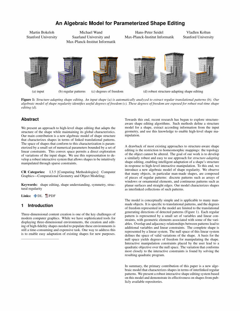
(a) input (b) regular patterns (c) degrees of freedom (d) robust structure-adapting shape editing
Figure 1: Structure-adapting shape editing. An input shape (a) is automatically analyzed to extract regular translational patterns (b). Ouralgebraic model of shape regularity identifies useful degrees of freedom (c). These degrees of freedom are exposed for robust real-time shapeediting (d).
Abstract
We present an approach to high-level shape editing that adapts thestructure of the shape while maintaining its global characteristics.Our main contribution is a new algebraic model of shape structurethat characterizes shapes in terms of linked translational patterns.The space of shapes that conform to this characterization is param-eterized by a small set of numerical parameters bounded by a set oflinear constraints. This convex space permits a direct explorationof variations of the input shape. We use this representation to de-velop a robust interactive system that allows shapes to be intuitivelymanipulated through sparse constraints.
CR Categories: I.3.5 [Computing Methodologies]: ComputerGraphics—Computational Geometry and Object Modeling;
Keywords: shape editing, shape understanding, symmetry, struc-tural regularity
Links: DL PDF
1 Introduction
Three-dimensional content creation is one of the key challenges ofmodern computer graphics. While we have sophisticated tools fordisplaying three-dimensional environments, the creation and edit-ing of high-fidelity shapes needed to populate these environments isstill a time-consuming and expensive task. One way to address thisis to enable easy adaptation of existing shapes for new purposes.
Towards this end, recent research has begun to explore structure-aware shape editing algorithms. Such methods define a structuremodel for a shape, extract according information from the inputgeometry, and use this knowledge to enable high-level shape ma-nipulation.
A drawback of most existing approaches to structure-aware shapeediting is the restriction to homeomorphic mappings: the topologyof the object cannot be altered. The goal of our work is to developa similarly robust and easy to use approach for structure-adaptingshape editing, enabling intelligent adaptation of a shape’s structurein response to high-level interactive manipulation. To this end, weintroduce a new algebraic model of shape regularity. We observethat many objects, in particular man-made shapes, are composedof pieces of regular patterns: discrete patterns such as arrays ofwindows or ornamental elements, and continuous patterns such asplanar surfaces and straight edges. Our model characterizes shapesas interlinked collections of such patterns.
The model is conceptually simple and is applicable to many man-made objects. It is specific to translational patterns, and the degreesof freedom represented in the model are limited to the translationalgenerating directions of detected patterns (Figure 1). Each regularpattern is represented by a small set of variables and linear con-straints, with geometric elements associated with some of the vari-ables. Overlap and adjacency relationships between patterns lead toadditional variables and linear constraints. The complete shape isrepresented by a linear system. The null space of this linear systemdefines the space of valid variations of the shape. A basis for thenull space yields degrees of freedom for manipulating the shape.Interactive manipulation constraints placed by the user lead to aquadratic objective over the null space. The variation that conformsmost closely to the interactive constraints is found by solving theresulting quadratic program.
In summary, the primary contribution of this paper is a new alge-braic model that characterizes shapes in terms of interlinked regularpatterns. We present a robust interactive shape editing system basedon this model and demonstrate its effectiveness on shapes from pub-licly available repositories.
������
vvvvvvvvvvvvssssssssssssssssss
s -s6s
���
��
o0t0l0 o1
t1l1
o2
t2l2
-
x∆0,1
o0 + t0l0 − o1 = ∆0,1
o1 + t1l1 − o2 = ∆1,2
o2 + t2l2 − o0 = ∆2,0
0@ A
1A0B@o0
...l2
1CA =
0@∆0,1
∆1,2
∆2,0
1A=⇒ x(λ) = x0 + Ker (A)λ
a) regular patterns b) representation c) links d) equations e) null space analysis
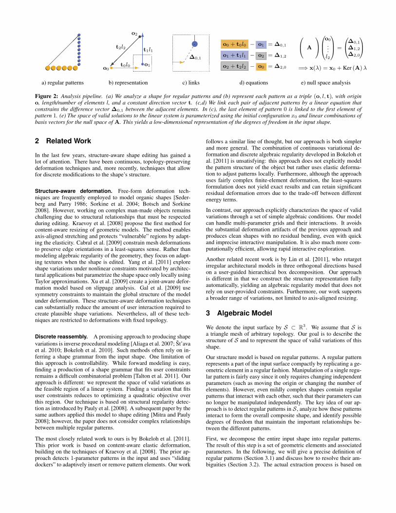
Figure 2: Analysis pipeline. (a) We analyze a shape for regular patterns and (b) represent each pattern as a triple (o, l, t), with origino, length/number of elements l, and a constant direction vector t. (c,d) We link each pair of adjacent patterns by a linear equation thatconstrains the difference vector ∆0,1 between the adjacent elements. In (c), the last element of pattern 0 is linked to the first element ofpattern 1. (e) The space of valid solutions to the linear system is parameterized using the initial configuration x0 and linear combinations ofbasis vectors for the null space of A. This yields a low-dimensional representation of the degrees of freedom in the input shape.
2 Related Work
In the last few years, structure-aware shape editing has gained alot of attention. There have been continuous, topology-preservingdeformation techniques and, more recently, techniques that allowfor discrete modifications to the shape’s structure.
Structure-aware deformation. Free-form deformation tech-niques are frequently employed to model organic shapes [Seder-berg and Parry 1986; Sorkine et al. 2004; Botsch and Sorkine2008]. However, working on complex man-made objects remainschallenging due to structural relationships that must be respectedduring editing. Kraevoy et al. [2008] propose the first method forcontent-aware resizing of geometric models. The method enablesaxis-aligned stretching and protects “vulnerable” regions by adapt-ing the elasticity. Cabral et al. [2009] constrain mesh deformationsto preserve edge orientations in a least-squares sense. Rather thanmodeling algebraic regularity of the geometry, they focus on adapt-ing textures when the shape is edited. Yang et al. [2011] exploreshape variations under nonlinear constraints motivated by architec-tural applications but parametrize the shape space only locally usingTaylor approximations. Xu et al. [2009] create a joint-aware defor-mation model based on slippage analysis. Gal et al. [2009] usesymmetry constraints to maintain the global structure of the modelunder deformation. These structure-aware deformation techniquescan substantially reduce the amount of user interaction required tocreate plausible shape variations. Nevertheless, all of these tech-niques are restricted to deformations with fixed topology.
Discrete reassembly. A promising approach to producing shapevariations is inverse procedural modeling [Aliaga et al. 2007; St’avaet al. 2010; Bokeloh et al. 2010]. Such methods often rely on in-ferring a shape grammar from the input shape. One limitation ofthis approach is controllability. While forward modeling is easy,finding a production of a shape grammar that fits user constraintsremains a difficult combinatorial problem [Talton et al. 2011]. Ourapproach is different: we represent the space of valid variations asthe feasible region of a linear system. Finding a variation that fitsuser constraints reduces to optimizing a quadratic objective overthis region. Our technique is based on structural regularity detec-tion as introduced by Pauly et al. [2008]. A subsequent paper by thesame authors applied this model to shape editing [Mitra and Pauly2008]; however, the paper does not consider complex relationshipsbetween multiple regular patterns.
The most closely related work to ours is by Bokeloh et al. [2011].This prior work is based on content-aware elastic deformation,building on the techniques of Kraevoy et al. [2008]. The prior ap-proach detects 1-parameter patterns in the input and uses “slidingdockers” to adaptively insert or remove pattern elements. Our work
follows a similar line of thought, but our approach is both simplerand more general. The combination of continuous variational de-formation and discrete algebraic regularity developed in Bokeloh etal. [2011] is unsatisfying: this approach does not explicitly modelthe pattern structure of the object but rather uses elastic deforma-tion to adjust patterns locally. Furthermore, although the approachuses fairly complex finite-element deformation, the least-squaresformulation does not yield exact results and can retain significantresidual deformation errors due to the trade-off between differentenergy terms.
In contrast, our approach explicitly characterizes the space of validvariations through a set of simple algebraic conditions. Our modelcan handle multi-parameter grids and their interactions. It avoidsthe substantial deformation artifacts of the previous approach andproduces clean shapes with no residual bending, even with quickand imprecise interactive manipulation. It is also much more com-putationally efficient, allowing rapid interactive exploration.
Another related recent work is by Lin et al. [2011], who retargetirregular architectural models in three orthogonal directions basedon a user-guided hierarchical box decomposition. Our approachis different in that we construct the structure representation fullyautomatically, yielding an algebraic regularity model that does notrely on user-provided constraints. Furthermore, our work supportsa broader range of variations, not limited to axis-aligned resizing.
3 Algebraic Model
We denote the input surface by S ⊂ R3. We assume that S isa triangle mesh of arbitrary topology. Our goal is to describe thestructure of S and to represent the space of valid variations of thisshape.
Our structure model is based on regular patterns. A regular patternrepresents a part of the input surface compactly by replicating a ge-ometric element in a regular fashion. Manipulation of a single regu-lar pattern is fairly easy since it only requires changing independentparameters (such as moving the origin or changing the number ofelements). However, even mildly complex shapes contain regularpatterns that interact with each other, such that their parameters canno longer be manipulated independently. The key idea of our ap-proach is to detect regular patterns in S, analyze how these patternsinteract to form the overall composite shape, and identify possibledegrees of freedom that maintain the important relationships be-tween the different patterns.
First, we decompose the entire input shape into regular patterns.The result of this step is a set of geometric elements and associatedparameters. In the following, we will give a precise definition ofregular patterns (Section 3.1) and discuss how to resolve their am-biguities (Section 3.2). The actual extraction process is based on
algorithms developed in prior work and is discussed in Section 5.1.After pattern analysis, we investigate the interaction of patterns andset up linear equations that constrain neighboring patterns in orderto maintain important pairwise relationships (Section 3.3). This re-sults in an underconstrained linear system, the null space of whichyields a direct parameterization of the degrees of freedom in theinput shape (Section 3.4). A schematic overview of the analysis isprovided in Figure 2.
3.1 Regular Patterns
Regularity in shapes appears in many different forms. In this work,we consider the type of regularity induced by a set of genera-tor transformations {T1, . . . , Tk} that generate a symmetry groupG = {T i1
1 ◦ · · · ◦ Tikk |i1, . . . , ik ∈ Z}. We restrict the genera-
tor transformations to be translations. For a detailed introductionplease refer to [Pauly et al. 2008].
Typically, a single regular pattern covers only a small part of ashape whereas symmetry groups describe global structures. Con-sequently, we consider regular patterns as structures with limitedspatial support that we express by an element E ⊂ S that is repli-cated using transformations of a finite subset GP ⊂ G. We define aregular pattern as Π = (GP , E). In the following, we will describedifferent types of regular patterns and their parameterization.
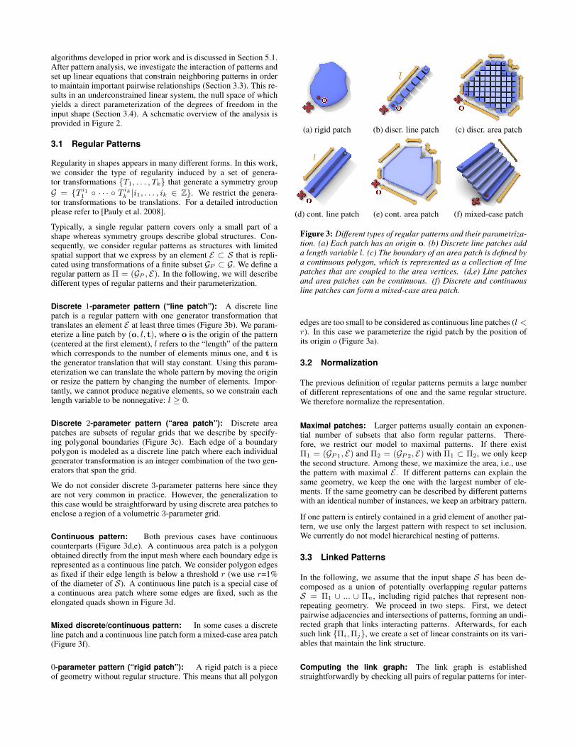
Discrete 1-parameter pattern (“line patch”): A discrete linepatch is a regular pattern with one generator transformation thattranslates an element E at least three times (Figure 3b). We param-eterize a line patch by (o, l, t), where o is the origin of the pattern(centered at the first element), l refers to the “length” of the patternwhich corresponds to the number of elements minus one, and t isthe generator translation that will stay constant. Using this param-eterization we can translate the whole pattern by moving the originor resize the pattern by changing the number of elements. Impor-tantly, we cannot produce negative elements, so we constrain eachlength variable to be nonnegative: l ≥ 0.
Discrete 2-parameter pattern (“area patch”): Discrete areapatches are subsets of regular grids that we describe by specify-ing polygonal boundaries (Figure 3c). Each edge of a boundarypolygon is modeled as a discrete line patch where each individualgenerator transformation is an integer combination of the two gen-erators that span the grid.
We do not consider discrete 3-parameter patterns here since theyare not very common in practice. However, the generalization tothis case would be straightforward by using discrete area patches toenclose a region of a volumetric 3-parameter grid.
Continuous pattern: Both previous cases have continuouscounterparts (Figure 3d,e). A continuous area patch is a polygonobtained directly from the input mesh where each boundary edge isrepresented as a continuous line patch. We consider polygon edgesas fixed if their edge length is below a threshold r (we use r=1%of the diameter of S). A continuous line patch is a special case ofa continuous area patch where some edges are fixed, such as theelongated quads shown in Figure 3d.
Mixed discrete/continuous pattern: In some cases a discreteline patch and a continuous line patch form a mixed-case area patch(Figure 3f).
0-parameter pattern (“rigid patch”): A rigid patch is a pieceof geometry without regular structure. This means that all polygon
(a) rigid patch (b) discr. line patch (c) discr. area patch
(d) cont. line patch (e) cont. area patch (f) mixed-case patch
Figure 3: Different types of regular patterns and their parametriza-tion. (a) Each patch has an origin o. (b) Discrete line patches adda length variable l. (c) The boundary of an area patch is defined bya continuous polygon, which is represented as a collection of linepatches that are coupled to the area vertices. (d,e) Line patchesand area patches can be continuous. (f) Discrete and continuousline patches can form a mixed-case area patch.
edges are too small to be considered as continuous line patches (l <r). In this case we parameterize the rigid patch by the position ofits origin o (Figure 3a).
3.2 Normalization
The previous definition of regular patterns permits a large numberof different representations of one and the same regular structure.We therefore normalize the representation.
Maximal patches: Larger patterns usually contain an exponen-tial number of subsets that also form regular patterns. There-fore, we restrict our model to maximal patterns. If there existΠ1 = (GP 1, E) and Π2 = (GP 2, E) with Π1 ⊂ Π2, we only keepthe second structure. Among these, we maximize the area, i.e., usethe pattern with maximal E . If different patterns can explain thesame geometry, we keep the one with the largest number of ele-ments. If the same geometry can be described by different patternswith an identical number of instances, we keep an arbitrary pattern.
If one pattern is entirely contained in a grid element of another pat-tern, we use only the largest pattern with respect to set inclusion.We currently do not model hierarchical nesting of patterns.
3.3 Linked Patterns
In the following, we assume that the input shape S has been de-composed as a union of potentially overlapping regular patternsS = Π1 ∪ ... ∪ Πn, including rigid patches that represent non-repeating geometry. We proceed in two steps. First, we detectpairwise adjacencies and intersections of patterns, forming an undi-rected graph that links interacting patterns. Afterwards, for eachsuch link {Πi,Πj}, we create a set of linear constraints on its vari-ables that maintain the link structure.
Computing the link graph: The link graph is establishedstraightforwardly by checking all pairs of regular patterns for inter-
section or adjacency. We link those pairs of patterns whose distanceis smaller than a constant ε that corresponds to modeling accuracy.
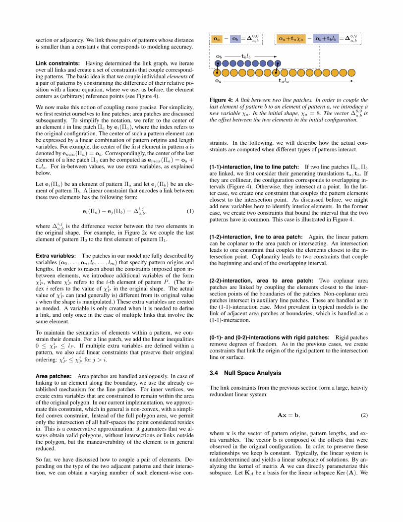
Link constraints: Having determined the link graph, we iterateover all links and create a set of constraints that couple correspond-ing patterns. The basic idea is that we couple individual elements ofa pair of patterns by constraining the difference of their relative po-sition with a linear equation, where we use, as before, the elementcenters as (arbitrary) reference points (see Figure 4).
We now make this notion of coupling more precise. For simplicity,we first restrict ourselves to line patches; area patches are discussedsubsequently. To simplify the notation, we refer to the center ofan element i in line patch Πa by ei(Πa), where the index refers tothe original configuration. The center of such a pattern element canbe expressed by a linear combination of pattern origins and lengthvariables. For example, the center of the first element in pattern a isdenoted by emin(Πa) = oa. Correspondingly, the center of the lastelement of a line patch Πa can be computed as emax(Πa) = oa +tala. For in-between values, we use extra variables, as explainedbelow.
Let ei(Πa) be an element of pattern Πa and let ej(Πb) be an ele-ment of pattern Πb. A linear constraint that encodes a link betweenthese two elements has the following form:
ei(Πa)− ej(Πb) = ∆i,ja,b, (1)
where ∆i,ja,b is the difference vector between the two elements in
the original shape. For example, in Figure 2c we couple the lastelement of pattern Π0 to the first element of pattern Π1.
Extra variables: The patches in our model are fully described byvariables (o0, . . . ,on, l0, . . . , lm) that specify pattern origins andlengths. In order to reason about the constraints imposed upon in-between elements, we introduce additional variables of the formχi
P , where χiP refers to the i-th element of pattern P . (The in-
dex i refers to the value of χiP in the original shape. The actual
value of χiP can (and generally is) different from its original value
i when the shape is manipulated.) These extra variables are createdas needed. A variable is only created when it is needed to definea link, and only once in the case of multiple links that involve thesame element.
To maintain the semantics of elements within a pattern, we con-strain their domain. For a line patch, we add the linear inequalities0 ≤ χi
P ≤ lP . If multiple extra variables are defined within apattern, we also add linear constraints that preserve their originalordering: χi
P ≤ χjP for j > i.
Area patches: Area patches are handled analogously. In case oflinking to an element along the boundary, we use the already es-tablished mechanism for the line patches. For inner vertices, wecreate extra variables that are constrained to remain within the areaof the original polygon. In our current implementation, we approxi-mate this constraint, which in general is non-convex, with a simpli-fied convex constraint. Instead of the full polygon area, we permitonly the intersection of all half-spaces the point considered residesin. This is a conservative approximation: it guarantees that we al-ways obtain valid polygons, without intersections or links outsidethe polygon, but the maneuverability of the element is in generalreduced.
So far, we have discussed how to couple a pair of elements. De-pending on the type of the two adjacent patterns and their interac-tion, we can obtain a varying number of such element-wise con-
z z z z z z z z z z z z z z z z zj j j j j j j j j j j j j j j j joa tala -
yyyyyyyyyh h h h h h h h hob tblb -
rr rroa − ob =∆0,0
a,b oa+taχa − ob+tblb =∆8,9a,b
Figure 4: A link between two line patches. In order to couple thelast element of pattern b to an element of pattern a, we introduce anew variable χa. In the initial shape, χa = 8. The vector ∆8,9
a,b isthe offset between the two elements in the initial configuration.
straints. In the following, we will describe how the actual con-straints are computed when different types of patterns interact.
(1-1)-interaction, line to line patch: If two line patches Πa,Πb
are linked, we first consider their generating translations ta, tb. Ifthey are collinear, the configuration corresponds to overlapping in-tervals (Figure 4). Otherwise, they intersect at a point. In the lat-ter case, we create one constraint that couples the pattern elementsclosest to the intersection point. As discussed before, we mightadd new variables here to identify interior elements. In the formercase, we create two constraints that bound the interval that the twopatterns have in common. This case is illustrated in Figure 4.
(1-2)-interaction, line to area patch: Again, the linear patterncan be coplanar to the area patch or intersecting. An intersectionleads to one constraint that couples the elements closest to the in-tersection point. Coplanarity leads to two constraints that couplethe beginning and end of the overlapping interval.
(2-2)-interaction, area to area patch: Two coplanar areapatches are linked by coupling the elements closest to the inter-section points of the boundaries of the patches. Non-coplanar areapatches intersect in auxiliary line patches. These are handled as inthe (1-1)-interaction case. Most prevalent in typical models is thelink of adjacent area patches at boundaries, which is handled as a(1-1)-interaction.
(0-1)- and (0-2)-interactions with rigid patches: Rigid patchesremove degrees of freedom. As in the previous cases, we createconstraints that link the origin of the rigid pattern to the intersectionline or surface.
3.4 Null Space Analysis
The link constraints from the previous section form a large, heavilyredundant linear system:
Ax = b, (2)
where x is the vector of pattern origins, pattern lengths, and ex-tra variables. The vector b is composed of the offsets that wereobserved in the original configuration. In order to preserve theserelationships we keep b constant. Typically, the linear system isunderdetermined and yields a linear subspace of solutions. By an-alyzing the kernel of matrix A we can directly parameterize thissubspace. Let KA be a basis for the linear subspace Ker (A). We
can now express all possible solutions as a function of a parametervector λ:
x(λ) = x0 + KAλ. (3)
Each column of KA points in a direction that corresponds to chang-ing a set of pattern parameters while still maintaining the pattern re-lationships. The vector λ parameterizes these changes. To producesolutions for equation (2) we need to translate the linear subspaceby an arbitrary solution x0 (in this work, we simply choose the ini-tial state). We call λ ∈ Λ the parameter representation of a shapeand Λ the parameter domain.
Inequalities: Not all solutions to equation (3) correspond tovalid shapes because only a subset meet the inequalities that con-strain the original variables. These inequalities include nonnegativ-ity constraints on pattern lengths and extra variables, and orderingconstraints on the variables. We project all inequalities into the nullspace, which allows us to perform all computations in this low-dimensional space. Let Mx ≥ m be all inequalities. Expressingthe inequalities in parameter domain yields:
[M KA]| {z }=M′
λ ≥m−Mx0| {z }=m′
. (4)
Choosing a basis for the null space: In simple cases, the ker-nel of A can be computed by row reduction techniques such asGaussian elimination. These approaches are numerically unstableand therefore not advisable in general, however we use them to re-move trivial redundancy. We iteratively apply three basic types ofoperations: remove constant variables, remove identical rows, andsubstitute variables by other dependent variables. However, we donot perform substitutions if they are not well-conditioned, i.e., if theomitted variable cannot be stably computed from the substitution.
A numerically stable method to compute the null space is basedon the singular value decomposition (SVD). Let A = UΛVT bethe decomposition. A basis KA for the null space is formed bythe columns of VT that are associated with singular values thatare equal to zero. To compensate for numerical noise and smallinaccuracies in the linear system we consider singular values to bezero if their value is below 0.01% of the largest singular value.
4 Shape Editing
The algebraic model defined in the previous section provides a di-rect parameterization of the degrees of freedom in the shape anda set of inequalities that define the set of valid parameters. In thissection, we utilize this model for shape editing. First, we describeindividual types of interactive constraints used in our shape edit-ing system, which lead to a quadratic objective over the parameterspace. Then, we formulate the complete quadratic program.
4.1 Interactive Constraints
Our implementation supports two types of interactive manipulationconstraints: point constraints and difference constraints. For pointconstraints, the user selects a pattern element and drags it to a spe-cific target point y. We select the pattern origin eclosest closest tothe selection point and formulate a quadratic objective term:
Epoint(x) = (eclosest − y)2 . (5)
Difference constraints are defined similarly. The user selects twopattern elements ec0 and ec1 , and specifies their difference vectorδc0,c1 . The corresponding objective term is defined to be
Ediff (x) = (ec0 − ec1 − δc0,c1)2 . (6)
4.2 Regularization
With only a few sparse user constraints, the optimization problemstated in Equation 9 is still underconstrained and admits many un-reasonable solutions. We therefore introduce a regularization ob-jective that aims to keep the original values of the length variables.This regularization term is weighted very weakly in comparisonwith the interactive constraints. Let li be a length variable of pat-tern i and l0i be its original value. The regularization objective isdefined as
Ereg(x) = wreg
Xi
`li − l0i
´2. (7)
4.3 Quadratic Program
We sum all of the above terms into a quadratic objective:
E(x) = Epoint(x) + Ediff (x) + Ereg(x)
= xT Q x + xT q.
This objective is formulated in the original domain and then pro-jected into the parameter domain:
E′(λ) = λT“
(KA)T Q KA
”λ+ λT (KAq) . (8)
Overall, we minimize the quadratic objective (8) subject to the in-equalities (4) in the parameter domain:
Minimize E′(λ)subject to M′λ ≥m′.
(9)
A significant advantage of this formulation is that it separates themodeling of the space of valid variations of the shape, which ischaracterized through linear equations and inequalities, from theinteractive constraints and the regularization term, which are ex-pressed as quadratic objectives. User constraints are typicallysomewhat imprecise. The same is true for the regularization term,which defines a general default behavior for the shape. On the otherhand, modeling the space of valid shapes requires precise alignmentof adjacent patterns in order to avoid gaps or holes. If we were toformulate this with strong quadratic constraints we would end upwith conflicting objectives where shape validity is traded off againstimprecise user input. In our approach, the interactive constraints donot compromise the correctness of the shape (Figure 5).
5 Implementation
5.1 Pattern Detection
In order to implement the framework described in the precedingsections, we still need a technique for detecting symmetries andregular grids in 3D shapes. Our implementation follows the ap-proach of Bokeloh et al. [2011], which is based on the RANSACtechnique. We randomly sample generator transformations frommesh features and evaluate the number of elements that belong to
the pattern defined by the generator. This is repeated a number oftimes (up to 500 in our implementation) and only the dominant pat-tern (with the greatest number of elements) is kept and removedfrom the sampling set. The whole process is iterated until no pat-terns can be found. The remainder of this section describes thisprocess in more detail.
Pattern primitives and cascaded detection: An important dif-ference from the implementation described by Bokeloh et al. [2011]is that we do not cut triangles. Our method operates directly onthe mesh structure and uses three types of pattern primitives: con-nected components, polygons, and polygon edges. We apply ourdetection techniques in a top-down manner. First, we perform pat-tern detection on connected components only and remove all el-ements that belong to a pattern. Then, we extract all polygonsfrom the remaining set and repeat the same process on the poly-gon level. Polygon extraction is done by clustering adjacent trian-gles with similar normal vectors into polygons, which need not beconvex. Finally, we search for patterns within polygons by consid-ering edges as primitives. This top-down approach is not only fasterthan non-hierarchical methods but also produces better results. Theconnected components often carry important information from themodeling process of the original shape. Additionally, detecting dis-crete boundary patterns of polygon edges avoids heuristic cutting oftriangles into repeating elements and yields a persistent representa-tion that maintains mesh quality.
For the following detection modules we equip each pattern prim-itive with a small descriptor that consists of the centroid dc, theradius dr of the bounding sphere centered at dc, and the numberof vertices dn associated with that primitive. We cluster primi-tives based on dr and dn into classes and perform pattern detectionwithin these classes of primitives. Polygon edges are not sharedacross different polygons. We observed that additional classifica-tion of polygons based on their parent (a connected component)yields more meaningful decompositions in practice.
Discrete 1-parameter pattern detection: We randomly selecttwo primitives (referred to as first and second sample) and definea line through their centroids. Then, we gather all primitives withcentroids close to the defined line. In this subset we again per-form random sampling to find generators with the maximal numberof consecutive elements. In order to be robust against impreciselyplaced elements with slightly varying generators, we allow the el-ements to be misplaced by 3% of the generator’s length. We alsoneed to make sure that all elements have the same geometry and thesame orientation. Therefore, we compare each primitive with thefirst selected primitive before adding it to the subset. To comparetwo primitive we align both by aligning their centroids and test ifeach vertex has a counterpart within modeling accuracy ε.
We repeat this process several times and extract only the patternwith the highest number of elements. For each detected patternwe mark each associated primitive and prohibit a new pattern fromstarting with one of these primitives. (However, the second sam-ple can still be drawn from the set of marked primitives.) Thisensures that we extract a pattern only once but still allow patternsto share elements. To improve the recognition performance we usean octree-based sampling strategy that draws the second sample inproximity to the first one.
Discrete 2-parameter pattern detection: For 2-parameter pat-terns we use a similar sampling approach to the 1-parameter case.We select three primitives, create a plane, and gather primitives nearthat plane. In contrast to the 1-parameter case, instead of randomlysampling two generator transformations from the subset, we apply a
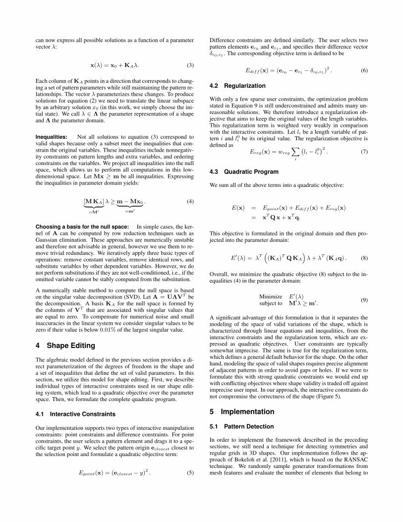
a) Bokeloh et al. [2011] b) our method
Figure 5: Badly placed interactive constraints force the prior tech-nique of Bokeloh et al. [2011] to distort the shape. In contrast, ourmethod always produces a valid shape that is as close as possibleto the interactive constraints.
generator voting technique first to retrieve a set of possible genera-tors [Pauly et al. 2008]. Then, we randomly sample from this set ofgenerators to obtain area patches where we choose the area patchwith the highest number of elements. Since 1-parameter patternsare included in 2-parameter patterns, we search for area patchesbefore searching for line patches.
5.2 Instantiating Models
Producing the mesh that corresponds to the manipulated shape iseasy with our representation. For discrete patterns we round thenumber of elements to the next integer, create the desired number ofelements, and apply affine scaling to match the given pattern length.Discrete area patches are rasterized without scaling. Complex poly-gons, for example with a discrete pattern along the boundary, aretriangulated using a standard quadtree-based polygon meshing al-gorithm [de Berg et al. 2008].
6 Results
We have implemented a prototype shape editing system based onthe representation and algorithms introduced in this paper. Our im-plementation is single-threaded. The experiments were performedon a consumer-grade workstation with a 2GHz Intel Xeon E5335processor and 4GB of main memory. We use MOSEK for quadraticprogramming.
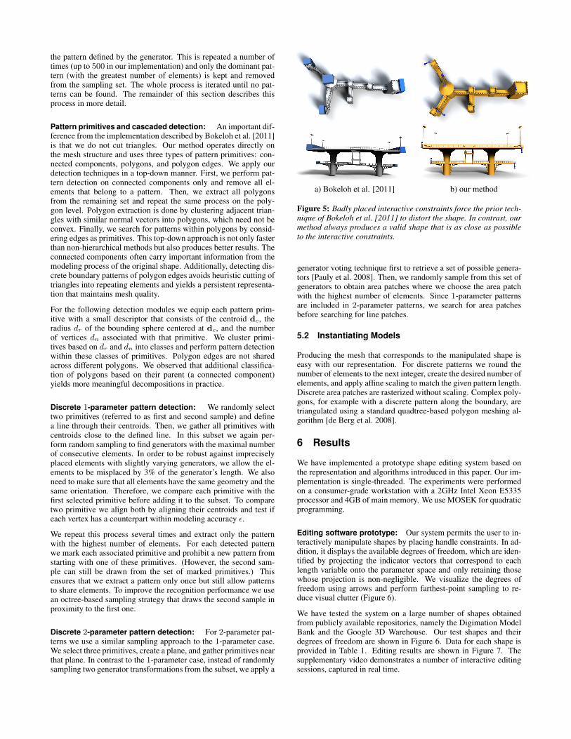
Editing software prototype: Our system permits the user to in-teractively manipulate shapes by placing handle constraints. In ad-dition, it displays the available degrees of freedom, which are iden-tified by projecting the indicator vectors that correspond to eachlength variable onto the parameter space and only retaining thosewhose projection is non-negligible. We visualize the degrees offreedom using arrows and perform farthest-point sampling to re-duce visual clutter (Figure 6).
We have tested the system on a large number of shapes obtainedfrom publicly available repositories, namely the Digimation ModelBank and the Google 3D Warehouse. Our test shapes and theirdegrees of freedom are shown in Figure 6. Data for each shape isprovided in Table 1. Editing results are shown in Figure 7. Thesupplementary video demonstrates a number of interactive editingsessions, captured in real time.
(a) canvas chair (b) cottage (c) platform (heliport) (d) Spanish mission (e) synagogue (f) school
(g) castle (h) downtown hotel (i) stairs (j) modern house (k) pavilion (l) cabin
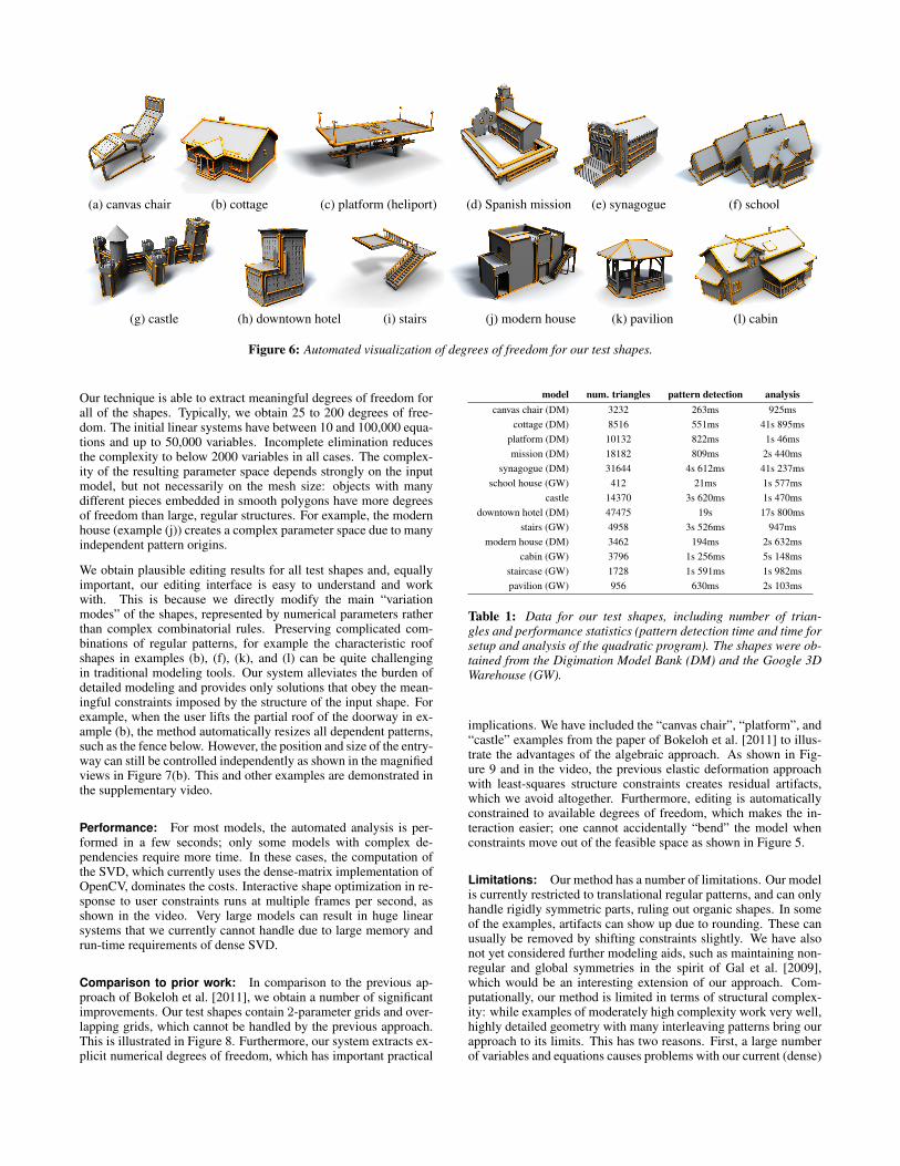
Figure 6: Automated visualization of degrees of freedom for our test shapes.
Our technique is able to extract meaningful degrees of freedom forall of the shapes. Typically, we obtain 25 to 200 degrees of free-dom. The initial linear systems have between 10 and 100,000 equa-tions and up to 50,000 variables. Incomplete elimination reducesthe complexity to below 2000 variables in all cases. The complex-ity of the resulting parameter space depends strongly on the inputmodel, but not necessarily on the mesh size: objects with manydifferent pieces embedded in smooth polygons have more degreesof freedom than large, regular structures. For example, the modernhouse (example (j)) creates a complex parameter space due to manyindependent pattern origins.
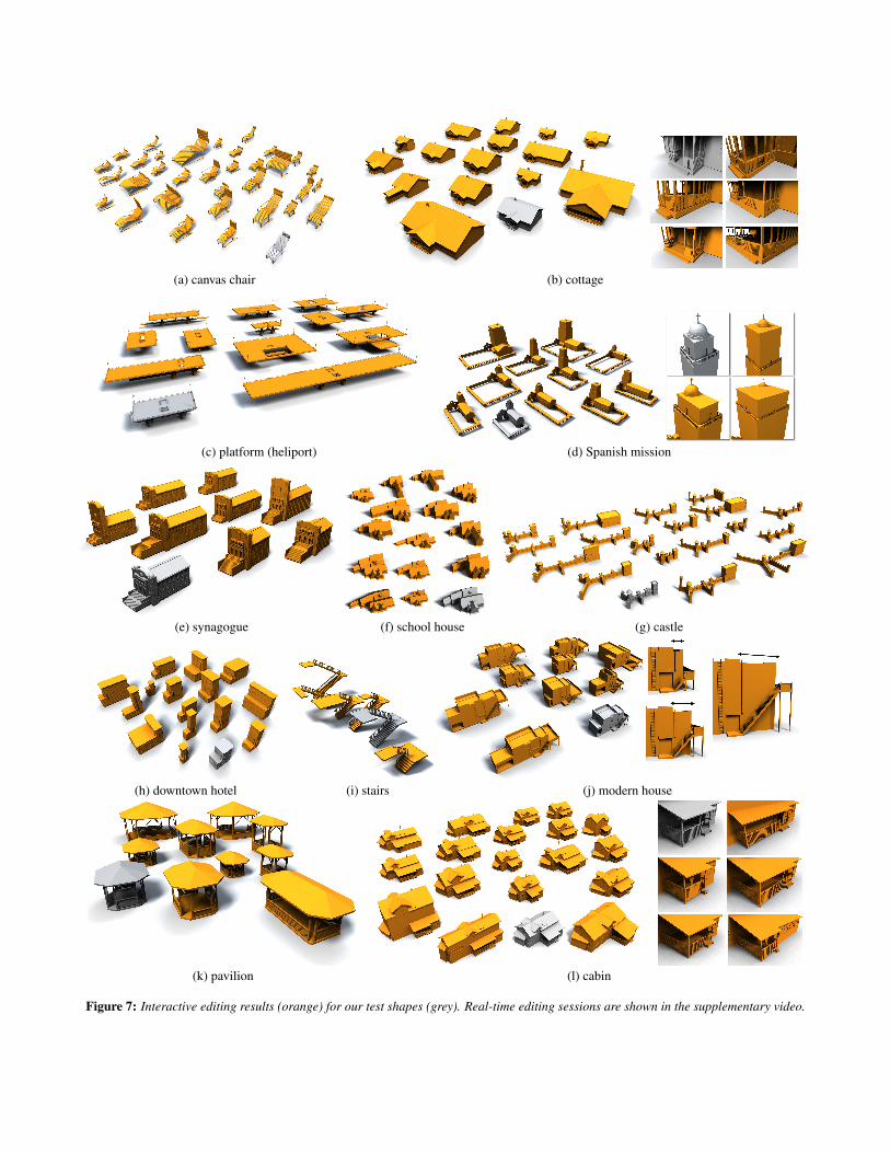
We obtain plausible editing results for all test shapes and, equallyimportant, our editing interface is easy to understand and workwith. This is because we directly modify the main “variationmodes” of the shapes, represented by numerical parameters ratherthan complex combinatorial rules. Preserving complicated com-binations of regular patterns, for example the characteristic roofshapes in examples (b), (f), (k), and (l) can be quite challengingin traditional modeling tools. Our system alleviates the burden ofdetailed modeling and provides only solutions that obey the mean-ingful constraints imposed by the structure of the input shape. Forexample, when the user lifts the partial roof of the doorway in ex-ample (b), the method automatically resizes all dependent patterns,such as the fence below. However, the position and size of the entry-way can still be controlled independently as shown in the magnifiedviews in Figure 7(b). This and other examples are demonstrated inthe supplementary video.
Performance: For most models, the automated analysis is per-formed in a few seconds; only some models with complex de-pendencies require more time. In these cases, the computation ofthe SVD, which currently uses the dense-matrix implementation ofOpenCV, dominates the costs. Interactive shape optimization in re-sponse to user constraints runs at multiple frames per second, asshown in the video. Very large models can result in huge linearsystems that we currently cannot handle due to large memory andrun-time requirements of dense SVD.
Comparison to prior work: In comparison to the previous ap-proach of Bokeloh et al. [2011], we obtain a number of significantimprovements. Our test shapes contain 2-parameter grids and over-lapping grids, which cannot be handled by the previous approach.This is illustrated in Figure 8. Furthermore, our system extracts ex-plicit numerical degrees of freedom, which has important practical
model num. triangles pattern detection analysiscanvas chair (DM) 3232 263ms 925ms
cottage (DM) 8516 551ms 41s 895msplatform (DM) 10132 822ms 1s 46msmission (DM) 18182 809ms 2s 440ms
synagogue (DM) 31644 4s 612ms 41s 237msschool house (GW) 412 21ms 1s 577ms
castle 14370 3s 620ms 1s 470msdowntown hotel (DM) 47475 19s 17s 800ms
stairs (GW) 4958 3s 526ms 947msmodern house (DM) 3462 194ms 2s 632ms
cabin (GW) 3796 1s 256ms 5s 148msstaircase (GW) 1728 1s 591ms 1s 982mspavilion (GW) 956 630ms 2s 103ms
Table 1: Data for our test shapes, including number of trian-gles and performance statistics (pattern detection time and time forsetup and analysis of the quadratic program). The shapes were ob-tained from the Digimation Model Bank (DM) and the Google 3DWarehouse (GW).
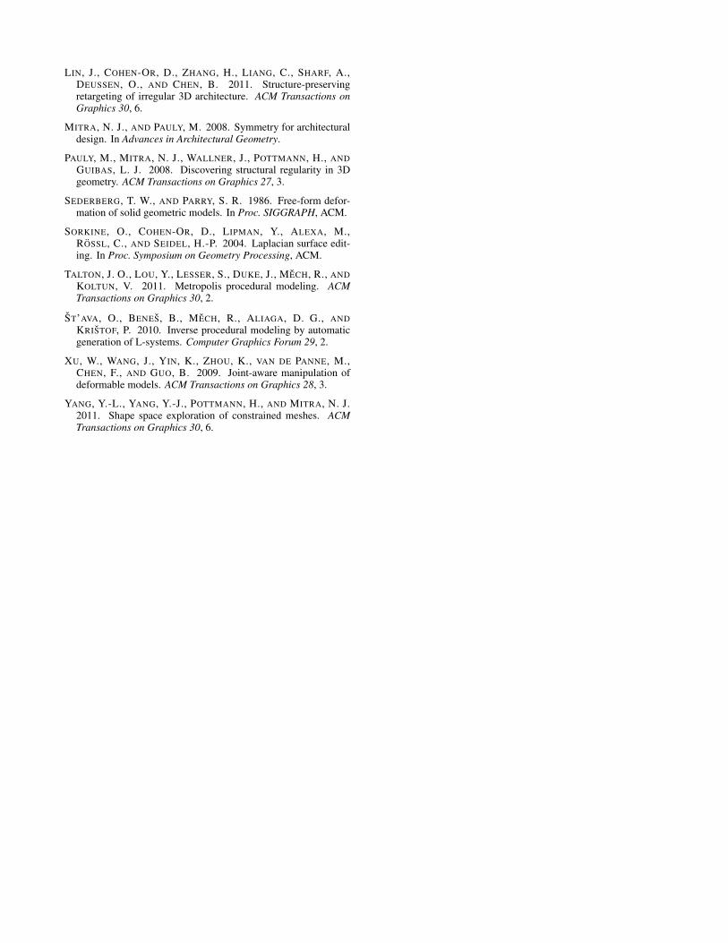
implications. We have included the “canvas chair”, “platform”, and“castle” examples from the paper of Bokeloh et al. [2011] to illus-trate the advantages of the algebraic approach. As shown in Fig-ure 9 and in the video, the previous elastic deformation approachwith least-squares structure constraints creates residual artifacts,which we avoid altogether. Furthermore, editing is automaticallyconstrained to available degrees of freedom, which makes the in-teraction easier; one cannot accidentally “bend” the model whenconstraints move out of the feasible space as shown in Figure 5.
Limitations: Our method has a number of limitations. Our modelis currently restricted to translational regular patterns, and can onlyhandle rigidly symmetric parts, ruling out organic shapes. In someof the examples, artifacts can show up due to rounding. These canusually be removed by shifting constraints slightly. We have alsonot yet considered further modeling aids, such as maintaining non-regular and global symmetries in the spirit of Gal et al. [2009],which would be an interesting extension of our approach. Com-putationally, our method is limited in terms of structural complex-ity: while examples of moderately high complexity work very well,highly detailed geometry with many interleaving patterns bring ourapproach to its limits. This has two reasons. First, a large numberof variables and equations causes problems with our current (dense)
(a) canvas chair (b) cottage
(c) platform (heliport) (d) Spanish mission
(e) synagogue (f) school house (g) castle
(h) downtown hotel (i) stairs (j) modern house
(k) pavilion (l) cabin
Figure 7: Interactive editing results (orange) for our test shapes (grey). Real-time editing sessions are shown in the supplementary video.
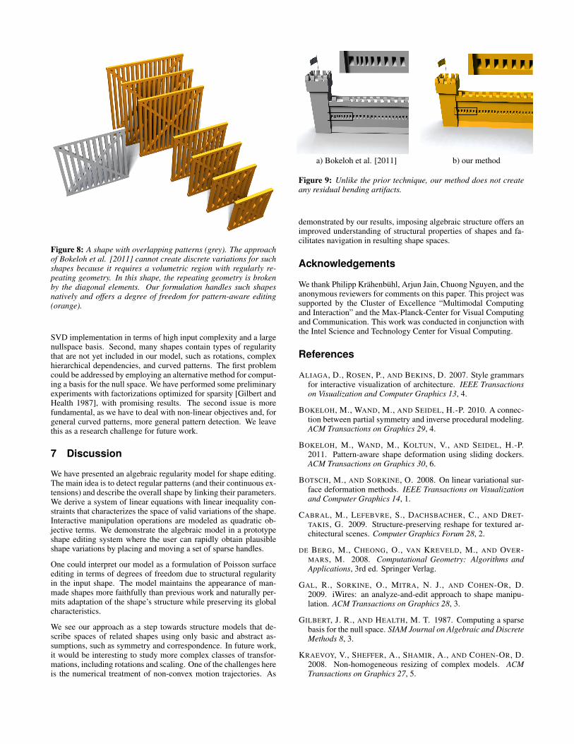
Figure 8: A shape with overlapping patterns (grey). The approachof Bokeloh et al. [2011] cannot create discrete variations for suchshapes because it requires a volumetric region with regularly re-peating geometry. In this shape, the repeating geometry is brokenby the diagonal elements. Our formulation handles such shapesnatively and offers a degree of freedom for pattern-aware editing(orange).
SVD implementation in terms of high input complexity and a largenullspace basis. Second, many shapes contain types of regularitythat are not yet included in our model, such as rotations, complexhierarchical dependencies, and curved patterns. The first problemcould be addressed by employing an alternative method for comput-ing a basis for the null space. We have performed some preliminaryexperiments with factorizations optimized for sparsity [Gilbert andHealth 1987], with promising results. The second issue is morefundamental, as we have to deal with non-linear objectives and, forgeneral curved patterns, more general pattern detection. We leavethis as a research challenge for future work.
7 Discussion
We have presented an algebraic regularity model for shape editing.The main idea is to detect regular patterns (and their continuous ex-tensions) and describe the overall shape by linking their parameters.We derive a system of linear equations with linear inequality con-straints that characterizes the space of valid variations of the shape.Interactive manipulation operations are modeled as quadratic ob-jective terms. We demonstrate the algebraic model in a prototypeshape editing system where the user can rapidly obtain plausibleshape variations by placing and moving a set of sparse handles.
One could interpret our model as a formulation of Poisson surfaceediting in terms of degrees of freedom due to structural regularityin the input shape. The model maintains the appearance of man-made shapes more faithfully than previous work and naturally per-mits adaptation of the shape’s structure while preserving its globalcharacteristics.
We see our approach as a step towards structure models that de-scribe spaces of related shapes using only basic and abstract as-sumptions, such as symmetry and correspondence. In future work,it would be interesting to study more complex classes of transfor-mations, including rotations and scaling. One of the challenges hereis the numerical treatment of non-convex motion trajectories. As
a) Bokeloh et al. [2011] b) our method
Figure 9: Unlike the prior technique, our method does not createany residual bending artifacts.
demonstrated by our results, imposing algebraic structure offers animproved understanding of structural properties of shapes and fa-cilitates navigation in resulting shape spaces.
Acknowledgements
We thank Philipp Krahenbuhl, Arjun Jain, Chuong Nguyen, and theanonymous reviewers for comments on this paper. This project wassupported by the Cluster of Excellence “Multimodal Computingand Interaction” and the Max-Planck-Center for Visual Computingand Communication. This work was conducted in conjunction withthe Intel Science and Technology Center for Visual Computing.
References
ALIAGA, D., ROSEN, P., AND BEKINS, D. 2007. Style grammarsfor interactive visualization of architecture. IEEE Transactionson Visualization and Computer Graphics 13, 4.
BOKELOH, M., WAND, M., AND SEIDEL, H.-P. 2010. A connec-tion between partial symmetry and inverse procedural modeling.ACM Transactions on Graphics 29, 4.
BOKELOH, M., WAND, M., KOLTUN, V., AND SEIDEL, H.-P.2011. Pattern-aware shape deformation using sliding dockers.ACM Transactions on Graphics 30, 6.
BOTSCH, M., AND SORKINE, O. 2008. On linear variational sur-face deformation methods. IEEE Transactions on Visualizationand Computer Graphics 14, 1.
CABRAL, M., LEFEBVRE, S., DACHSBACHER, C., AND DRET-TAKIS, G. 2009. Structure-preserving reshape for textured ar-chitectural scenes. Computer Graphics Forum 28, 2.
DE BERG, M., CHEONG, O., VAN KREVELD, M., AND OVER-MARS, M. 2008. Computational Geometry: Algorithms andApplications, 3rd ed. Springer Verlag.
GAL, R., SORKINE, O., MITRA, N. J., AND COHEN-OR, D.2009. iWires: an analyze-and-edit approach to shape manipu-lation. ACM Transactions on Graphics 28, 3.
GILBERT, J. R., AND HEALTH, M. T. 1987. Computing a sparsebasis for the null space. SIAM Journal on Algebraic and DiscreteMethods 8, 3.
KRAEVOY, V., SHEFFER, A., SHAMIR, A., AND COHEN-OR, D.2008. Non-homogeneous resizing of complex models. ACMTransactions on Graphics 27, 5.
LIN, J., COHEN-OR, D., ZHANG, H., LIANG, C., SHARF, A.,DEUSSEN, O., AND CHEN, B. 2011. Structure-preservingretargeting of irregular 3D architecture. ACM Transactions onGraphics 30, 6.
MITRA, N. J., AND PAULY, M. 2008. Symmetry for architecturaldesign. In Advances in Architectural Geometry.
PAULY, M., MITRA, N. J., WALLNER, J., POTTMANN, H., ANDGUIBAS, L. J. 2008. Discovering structural regularity in 3Dgeometry. ACM Transactions on Graphics 27, 3.
SEDERBERG, T. W., AND PARRY, S. R. 1986. Free-form defor-mation of solid geometric models. In Proc. SIGGRAPH, ACM.
SORKINE, O., COHEN-OR, D., LIPMAN, Y., ALEXA, M.,ROSSL, C., AND SEIDEL, H.-P. 2004. Laplacian surface edit-ing. In Proc. Symposium on Geometry Processing, ACM.
TALTON, J. O., LOU, Y., LESSER, S., DUKE, J., MECH, R., ANDKOLTUN, V. 2011. Metropolis procedural modeling. ACMTransactions on Graphics 30, 2.
ST’AVA, O., BENES, B., MECH, R., ALIAGA, D. G., ANDKRISTOF, P. 2010. Inverse procedural modeling by automaticgeneration of L-systems. Computer Graphics Forum 29, 2.
XU, W., WANG, J., YIN, K., ZHOU, K., VAN DE PANNE, M.,CHEN, F., AND GUO, B. 2009. Joint-aware manipulation ofdeformable models. ACM Transactions on Graphics 28, 3.
YANG, Y.-L., YANG, Y.-J., POTTMANN, H., AND MITRA, N. J.2011. Shape space exploration of constrained meshes. ACMTransactions on Graphics 30, 6.


