Embed Size (px)
Citation preview
SEQ Water Supply and Sewerage
Design & Construction Code
(SEQ WS&S D&C Code)
Amendment to
Pressure Sewerage Code of Australia
(WSA 07 – 2007 V1.1)
April 2020

This document contains information which is proprietary to the SEQ service providers and may not be used for purposes other than those intended without written consent from the SEQ service providers.
Version 1.1 – April 2020SEQ WS&S D&C Code – WSA 07- 2007 V1.1 Pressure Sewerage Code of Australia 2 of 22
Document History Version Description Date
1.0 Initial Publication 01 July 2013
Redland Water and Gold Coast City Council Logos were replaced with the Redland City Council and City of Gold Coast Logos respectively.
Amendments to Clauses 10.7.2, 13.5.2 1.1 Amendments to GLOSSARY OF TERMS, and FIGURE l AND FIGURE ll of
PART 0 and Clauses 3.13, 5.3.4, 6.6, 7.1, 10.6.1, 10.7.2, 13.5.2, 17.3, 17.4, 18.1, 18.10, 18.11, 21.7, 21.9, 24.1, 24.2
April 2020
This document contains information which is proprietary to the SEQ service providers and may not be used for purposes other than those intended without written consent from the SEQ service providers.
Version 1.1 – April 2020SEQ WS&S D&C Code – WSA 07- 2007 V1.1 Pressure Sewerage Code of Australia 3 of 22
SEQ Amendment to Pressure Sewerage Code of Australia
WSA 07 – 2007 V1.1 Reference:
Amendment to WSA 07- 2007 V1. 1
CONTENTS
Part 4: Standard drawings
Contents- number 27, replace the reference to PSS-1000 Series Drawings with the SEQ-PSS-1000
Series Drawings.
INTRODUCTION
Code Purpose
Insert the following paragraphs at the end of this section:
The SEQ Design & Construction Code sets out SEQ Amendments to The Pressure Sewerage Code of Australia. The SEQ Amendments include:
• The SEQ-SPs requirements for specific detail which the Code anticipates individual water agencies will address, and
• Additions, deletions and variations to the Code where the Code’s requirements are not compatible with the SEQ-SPs current requirements (due to local practice, climate, geographic and topographic conditions and statutory requirements, etc) or where the Code is otherwise silent.
Any reference to the Pressure Sewerage Code of Australia (“the Code”) shall be deemed to refer to the SEQ Design & Construction Pressure Sewer Code which contains the SEQ Amendments. The Code specifies mandatory requirements for the design and construction of Pressure Sewer that are to become the responsibility of the SEQ-SPs. The SEQ-SPs reserve the right to specify or approve other design and/or construction requirements for particular projects and/or developments. Before commencement of any construction, the SEQ-SPs approval shall be obtained to any design and/or installation that do not comply with the Code.
Scope of Code The second sentence of the second paragraph is amended to read:
"However, where those drains are likely to be maintained by the Water Agency or its contractor, it is recommended that the SEQ Code Edition of WSA 02 (Gravity) Sewerage Code of Australia be adopted as an alternative solution for the sanitary drainage systems specified in the Plumbing Code of Australia."
New Subheading Drawings and Figures
Insert the following title and note after “Mandatory and Informative” section:
Drawings and Figures Drawing references are added throughout the Code. In the event of a clash between the individual drawings and the figures in the Code – the details shown on the individual standard drawings take precedence.
Proposed Amendments
Insert the following note at the end of this section:
Users of the SEQ Design & Construction Code are invited to suggest amendments or improvements to the technical content and format or style of the document by contacting the individual SEQ-SPs.
New Sub-heading Conditions of Supply of SEQ Design and Construction Code
Insert the following title and wording after “Using of SEQ Integrated Code ” section:
Conditions of Supply of SEQ Design and Construction Code SEQ Design & Construction Code is supplied subject to the following understandings and conditions:
• SEQ Design & Construction Code is copyright and apart from any use as permitted under the Copyright Act 1968, no parts of the documents may be sold, reproduced, stored in a retrieval system or transmitted in any form or by any means without the prior permission in writing of SEQ-SPs.
This document contains information which is proprietary to the SEQ service providers and may not be used for purposes other than those intended without written consent from the SEQ service providers.
Version 1.1 – April 2020SEQ WS&S D&C Code – WSA 07- 2007 V1.1 Pressure Sewerage Code of Australia 4 of 22
Reference:
Amendment to WSA 07- 2007 V1. 1
• SEQ Design & Construction Code is intended for use in connection with SEQ-SPs related projects only.
• SEQ-SPs do not warrant the applicability of SEQ Design & Construction Code to climates, topography, soil types, water and sewage characteristics and other local conditions and factors that may be encountered outside SEQ-SPs area of operations.
• The holder of SEQ Design & Construction Code acknowledges that they may contain errors and/or omissions.
• SEQ-SPs accept no responsibility for any works or parts thereof which may contain design and/or construction defects due to errors or omissions in any part of a SEQ Design & Construction Code which has not been prepared or formatted by SEQ-SPs.
• SEQ-SPs accept no responsibility for the incorrect application of SEQ Design & Construction Code by the holder or any other party.
Part 0 : GLOSSARY OF TERMS, ABBREVIATIONS AND REFERNCES
GLOSSARY OF TERMS
Add the following term and definition in alphabetical order: Design & Construction Code The SEQ Design and Construction Code is required by legislation and is an instrument—
• made jointly by the SEQ-SPs; and
• that provides for technical standards relating to the design and construction of pressure sewerage infrastructure in the SEQ region.
on-property components of pressure sewer system Assets owned by the property owner for the collection of wastewater within the property boundary for connection to the sewerage system including the sanitary drain, grinder (or macerator) pump(s), collection tank, electrical works, control / alarm panels, property discharge line and boundary kit (up to but not including the property isolation valve). property isolation valve Valve located on public property immediately outside the boundary of the private property being serviced. It serves to connect the property boundary kit (private components) to the pressure sewer lateral (public components). SEQ Service Provider (SEQ –SP) Providers of water services to individual customers/groups of customers. Services to the South East Corner are specified in the South-East Queensland Water (Distribution and Retail Restructuring) Act and Natural Resources Provisions Act 2009 and service providers include City of Gold Coast, Redland City Council, Logan City Council, Urban Utilities and Unitywater.
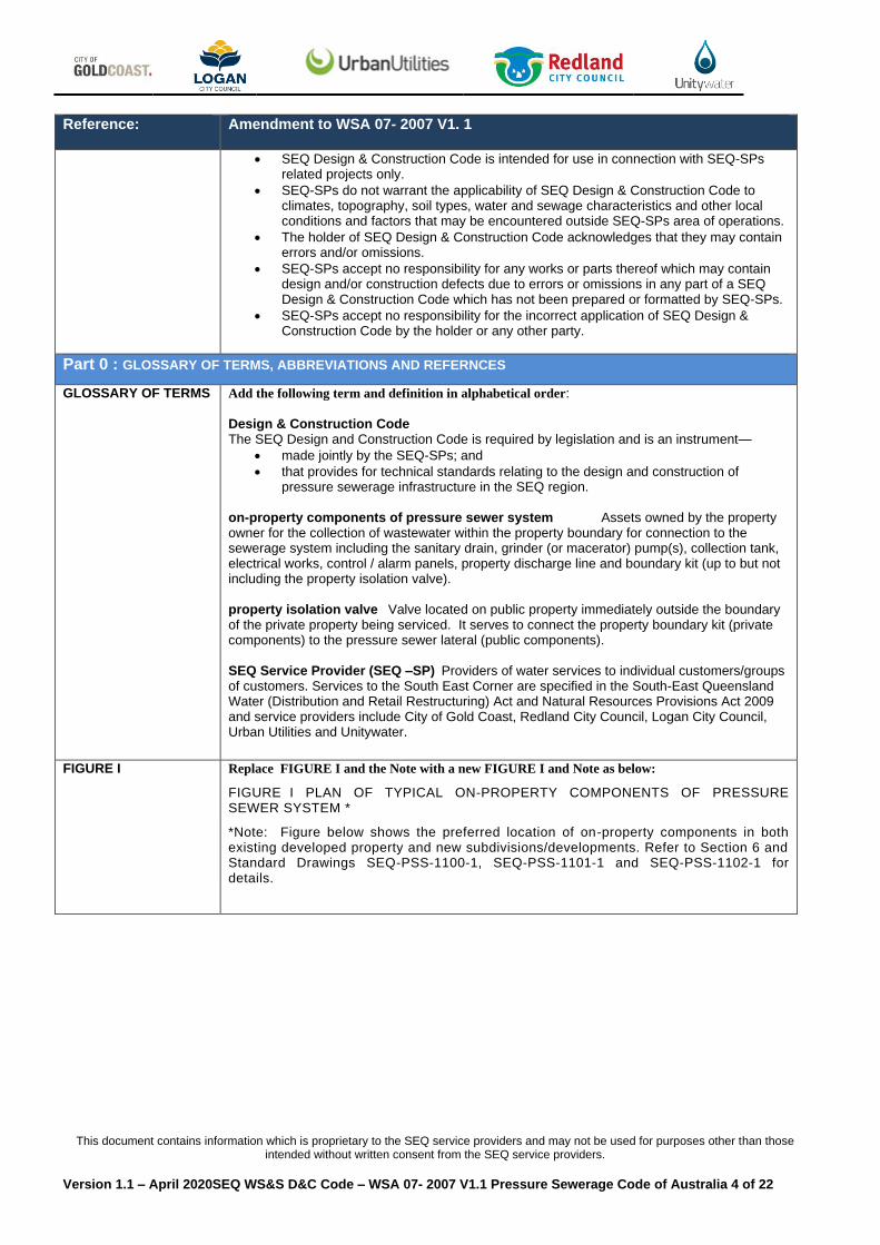
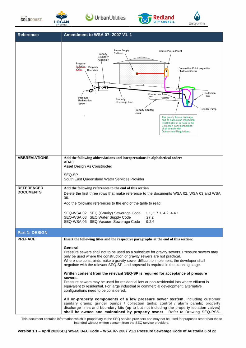
FIGURE I
Replace FIGURE I and the Note with a new FIGURE I and Note as below:
FIGURE I PLAN OF TYPICAL ON-PROPERTY COMPONENTS OF PRESSURE SEWER SYSTEM *
*Note: Figure below shows the preferred location of on-property components in both existing developed property and new subdivisions/developments. Refer to Section 6 and Standard Drawings SEQ-PSS-1100-1, SEQ-PSS-1101-1 and SEQ-PSS-1102-1 for details.
This document contains information which is proprietary to the SEQ service providers and may not be used for purposes other than those intended without written consent from the SEQ service providers.
Version 1.1 – April 2020SEQ WS&S D&C Code – WSA 07- 2007 V1.1 Pressure Sewerage Code of Australia 5 of 22
Reference:
Amendment to WSA 07- 2007 V1. 1
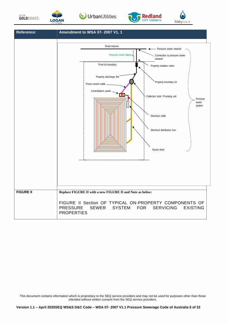
FIGURE II
Replace FIGURE II with a new FIGURE II and Note as below:
FIGURE II Section OF TYPICAL ON-PROPERTY COMPONENTS OF
PRESSURE SEWER SYSTEM FOR SERVICING EXISTING
PROPERTIES
Electrical cable
Property boundary kit
House drain
Electrical distribution box
Pump control cable
Collection tank / Pumping unit
Control/alarm panel
Pressure sewer network
Property discharge line
Front lot boundary
Connection to pressure sewer
network
Pressure sewer lateral
Pressure
sewer
system
Road reserve
Property isolation valvex
This document contains information which is proprietary to the SEQ service providers and may not be used for purposes other than those intended without written consent from the SEQ service providers.
Version 1.1 – April 2020SEQ WS&S D&C Code – WSA 07- 2007 V1.1 Pressure Sewerage Code of Australia 6 of 22
Reference:
Amendment to WSA 07- 2007 V1. 1
ABBREVIATIONS Add the following abbreviations and interpretations in alphabetical order: ADAC Asset Design As Constructed SEQ-SP South East Queensland Water Services Provider
REFERENCED DOCUMENTS
Add the following references to the end of this section
Delete the first three rows that make reference to the documents WSA 02, WSA 03 and WSA 06.
Add the following references to the end of the table to read:
SEQ-WSA 02 SEQ (Gravity) Sewerage Code 1.1, 1.7.1, 4.2, 4.4.1 SEQ-WSA 03 SEQ Water Supply Code 27.2 SEQ-WSA 06 SEQ Vacuum Sewerage Code 9.2.6
Part 1: DESIGN
PREFACE Insert the following titles and the respective paragraphs at the end of this section:
General Pressure sewers shall not to be used as a substitute for gravity sewers. Pressure sewers may only be used where the construction of gravity sewers are not practical. Where site constraints make a gravity sewer difficult to implement, the developer shall negotiate with the relevant SEQ-SP, and approval is required in the planning stage. Written consent from the relevant SEQ-SP is required for acceptance of pressure sewers. Pressure sewers may be used for residential lots or non-residential lots where effluent is equivalent to residential. For large industrial or commercial development, alternative configurations need to be considered. All on-property components of a low pressure sewer system, including customer sanitary drains; grinder pumps / collection tanks; control / alarm panels; property discharge lines and boundary kits (up to but not including the property isolation valves) shall be owned and maintained by property owner. Refer to Drawing SEQ-PSS-
This document contains information which is proprietary to the SEQ service providers and may not be used for purposes other than those intended without written consent from the SEQ service providers.
Version 1.1 – April 2020SEQ WS&S D&C Code – WSA 07- 2007 V1.1 Pressure Sewerage Code of Australia 7 of 22
Reference:
Amendment to WSA 07- 2007 V1. 1
1101-1 for the typical components layout. All on-property designs shall be submitted to Council’s Plumbing Services Group for acceptance. The property isolation valves provide a boundary between public reticulation components and private on-property components in terms of ownerships, licensing of installers and inspection of work etc. All reticulation components outside the serviced properties shall be owned and maintained by the relevant SEQ-SP. The detail design with design calculations of the reticulation system shall be supplied to the relevant SEQ-SP for review. Where Pressure Sewerage Systems are the means of Reticulated Sewerage for a property, the on-property components of the Pressure Sewerage System shall comply with the requirements of SEQ-WSA-07. The Plumbing Application shall be made with the specific components defined so that the SEQ Water Service Provider can review and advise the Council Plumbing Department of the compliance or not of the proposal. Innovative Solutions SEQ-SPs encourage any innovation that offers enhanced productivity and serviceability; however, the relevant SEQ-SP input and endorsement must be obtained before acceptance of any innovative system. Responsibilities The nominated Registered Professional Engineer of Queensland (RPEQ) is responsible to ensure that the design aspects and the constructed works comply with the requirements set out in the SEQ Pressure Sewerage Code. The RPEQ must ensure that SEQ-SPs’s endorsement is obtained for any variations from these requirements. Any change of the nominated RPEQ shall be accompanied with the transfer of responsibilities for all works including works completed prior to the change of RPEQ. Disclaimer Whilst SEQ-SPs endeavours to ensure that the accuracy of the information contained in this document, the SEQ-SPs will not be liable for any loss or damage that may occur as a result of using the information contained herein.
GENERAL Insert notes that:
On-property components of pressure sewer system are owned and maintained by residents/landowner. Developer to provide a ten year maintenance plan as a condition for obtaining planning approval.
1.1 PLANNING In the first two paragraphs, change the reference to WSA 02 as follows:
"WSA 02 Sewerage Code of Australia" to "SEQ Code edition of WSA 02 (Gravity) Sewerage Code of Australia"
and
"WSA 02" to "SEQ Code edition of WSA 02"
1.5.2 Planning responsibilities
Delete the whole second sentence as below:
“The Water Agency is generally responsible for overall planning for the provision of sewerage services to its customers. Unless otherwise agreed between relevant parties, the Water Agency should provide a Concept Plan setting out essential inputs to be used in design, such as catchment area, flows, flow estimating methodology, collection/pump unit type, discharge point, recommended staging, pressure sewer network layout, or particular requirements of the Water Agency.”
1.5.3 Design responsibilities
Replace the third paragraph with the following paragraphs
In the design of a pressure sewer system, a significant amount of the system, critical to the operation, actually takes place on the individual homeowner's private properties. This increases the level of detailed on-site information needed to complete the design of the system. It is necessary to consider the operational involvement associated with accessing, maintaining and repairing the on-site components to ensure a continually reliable system.
This document contains information which is proprietary to the SEQ service providers and may not be used for purposes other than those intended without written consent from the SEQ service providers.
Version 1.1 – April 2020SEQ WS&S D&C Code – WSA 07- 2007 V1.1 Pressure Sewerage Code of Australia 8 of 22
Reference:
Amendment to WSA 07- 2007 V1. 1
These circumstances warrant a system of the highest quality that balances cost, performance, safety, customer satisfaction, and operational reliability. The design of the low pressure system including pressure mains and associated components shall be undertaken and certified by a Registered Professional Engineer of Queensland (RPEQ) with minimum of 3 years continuous experience of the design and installation on low pressure sewer systems. Pressure sewer design shall be separated into two components, reticulation design and on-property design. Refer to Clause ‘General’ in ‘Preface’ of Part 1 for the ownerships and responsibilities of the two components. Reticulation Design concerns the design of the actual pressure sewer reticulation system including all components outside the serviced property, i.e. pressure sewer laterals (including property isolation valves), isolation valves and flushing points etc. On-Property Design concerns the design of the property boundary assemblies and discharge lines (up to but not including property isolation valves), collection tanks / pump units, control / alarm panel, electrical cables and property sanitary drains etc. The property isolation valves provide a boundary between public reticulation components and private on-property components in terms of ownerships, licensing of installers and inspection of work etc. Replace the words “the Water Agency’s” with the words “an agreed” in item (a) of this clause. So
it reads as
a) translating the planning output into a detailed system/network design. The Designer shall undertake the necessary design and prepare Design Drawings compatible with an agreed Concept Plan and the design parameters (as detailed in this Code and/or Water Agency requirements)
Add the words “and gas valves” at the end of item (iv) (H). So this item read as:
(h) Locations of cleanouts, flushing points, isolation valves and gas valves.
1.7.1 Concept plan
Amend the reference to Clause 1.5, and the reference to the WSA 02:
In the first sentence of this Clause, change the reference of Clause 1.5 to Clause 1.3 and change the reference to "WSA 02" to "SEQ Code edition of WSA 02".
1.7.3 Detail design
Add the following additional requirement at the end of this clause:
The Designer is to ensure that all services within the area of work are shown on the Design Plans and the Contractor is to protect services in accordance with the Clause 13.5.2.
2.9 Odour control
Add the following paragraphs after the second paragraph:
SEQ-SPs will require the designer to provide a report detailing the odour generation potential. This analysis shall take into consideration the sewage detention time both within collection units and the pressure pipe lines. Such analysis including odour calculation shall be submitted to SEQ-SPs for review. Odour control to be installed in accordance with the outcomes of the designers odour management study (options may include ventilation, chemical dosing or other approved solutions). For vent pole details refer to Drawing SEQ-SPS-1405-2. For properties below flood level (e.g. 1 in 100yr) where tank lid is sealed, the ventilation needs to be located well away from residential areas as agreed with the relevant SEQ–SP.
This document contains information which is proprietary to the SEQ service providers and may not be used for purposes other than those intended without written consent from the SEQ service providers.
Version 1.1 – April 2020SEQ WS&S D&C Code – WSA 07- 2007 V1.1 Pressure Sewerage Code of Australia 9 of 22
Reference:
Amendment to WSA 07- 2007 V1. 1
2.13.1 General
Add the following additional requirement to the end of this clause:
Ownership of on-property components (up to but not including the property isolation valve) will not transfer to SEQ-SPs. Refer to Clause ‘General’ in ‘Preface’ of Part 1 this Code.
3.2 Design tolerances
Add as the last sentence of (b) (i):
The maximum cover over reticulation mains shall be 1500 mm. Replace the reference to Standard Drawing PSS-1000 in item (b) (i) with SEQ-PSS-1000-1.
3.6.5 Tidal Zone
Change the title of this clause to read :
3.6.5 Tidal Zones and High Water Table. Add new item C to the end of this clause:
Item c) Tank installation to be in accordance with the manufacturer’s recommendations (specifically for addressing buoyancy).
3.7.1 Reticulation Sewers
Replace the 2nd paragraph with:
All pressure reticulation sewers shall be located in a dedicated public road reserve or access way.
3.7.2 On-property Components
Add the following as the last paragraph in this clause:
The property discharge line for a given property shall not cross onto any adjacent property, or collect the discharge from any other property. Exceptions may include where the property discharge line crosses a common area. Approval by SEQ-SPs will be required for these exceptions.
3.8 Railway Reserves
Replace the reference to Standard Drawing PSS-1004 with SEQ-PSS-1004-1
3.10 Mechanical Protection of Pipelines
Replace the reference to Standard Drawings PSS-1001 and PSS-1002 with SEQ-PSS-1001-1 and
SEQ-PSS-1002-1 respectively.
3.12.2 Deviation of pipelines around structures
Add to the last paragraph:
The use of 90-degree bends will not be permitted. 90-degree bends shall be accomplished by installing two 45-degree bends with a separation of minimum 300 mm. Where the PE100 PN16 pipeline is curved on site, the minimum radius shall be as per POP 202.
3.12.3 Clearance from structures
Add the following as the last paragraph in this clause:
All mains (including privately owned Property Discharge Lines) shall be located with sufficient clearance to structures to allow for maintenance and operation activities. Where practicable, SEQ-SPs preferred clearances will be as shown in Table 5.5 of the SEQ Water Supply Code and as defined in the separate SEQ Building Over Adjacent Assets document.
This document contains information which is proprietary to the SEQ service providers and may not be used for purposes other than those intended without written consent from the SEQ service providers.
Version 1.1 – April 2020SEQ WS&S D&C Code – WSA 07- 2007 V1.1 Pressure Sewerage Code of Australia 10 of 22
Reference:
Amendment to WSA 07- 2007 V1. 1
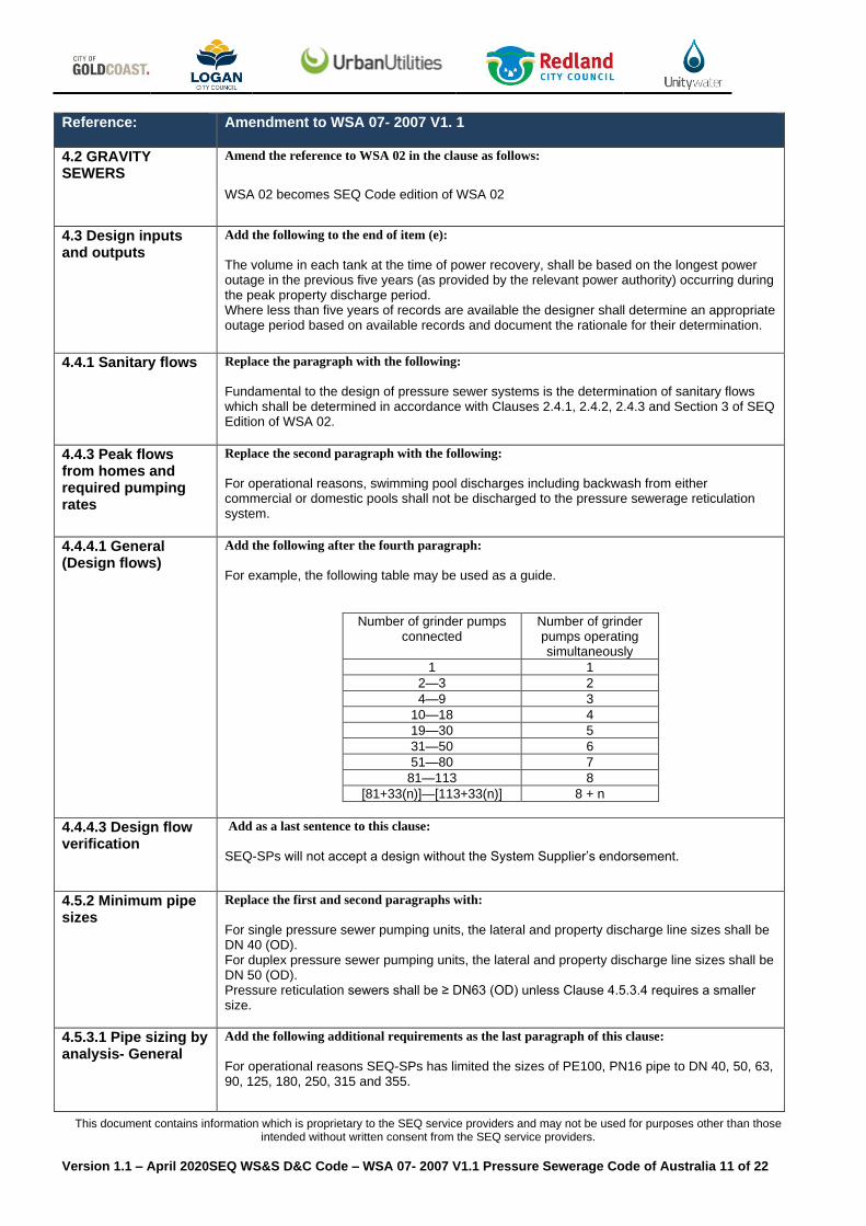
3.12.4 Clearance requirements
Amend the Table 3.1 as :
TABLE 3.1
CLEARANCES BETWEEN PIPELINES AND OTHER UNDERGROUND SERVICES
Utility
(Existing or
proposed)
Minimum horizontal clearance
mm Minimum vertical
clearance1
mm Pipeline size NB
200 mm > 200 mm
Water mains
375 mm
10002 10002 5005
Water mains > 375 mm
10002 10002 5005
Gravity sewers
300 mm
3003 600 5005
Gravity sewers > 300 mm
3003 600 5005
Sewers – pressure
3003 600 5005
Sewers – vacuum
3003 600 5005
Gas mains 3003 600 500
Telecommunication conduits and
cables
3003 600 300
Electricity conduits and
cables
500 1000 500
Stormwater drains
300 mm
3003 600 150
Stormwater drains
> 300 mm
3003 600 300
Kerbs 150 6004 150 (where possible)
Amend Notes 3 and 4 of Table 3.1 to read as:
Note 3 Clearances can be further reduced to 150 mm for distances up to 2 m when
passing installations such as concrete bases for poles, pits and small structures,
providing the structure is not destabilised in the process.
Note 4 Clearance from kerbs shall be measured from the nearest point of the kerb. For
pressure sewers 375 mm clearances from kerbs can be progressively reduced
until the minimum of 150 mm is reached for sewers 200 mm.
3.12.5 Crossings
Insert the following after the first paragraph:
Pressure pipes which cross roadways shall be installed in accordance with the requirements of the relevant road authority. Pressure pipes which traverse creek crossings shall be in accordance with the DERM requirements. Replace the reference to Standard Drawings PSS-1002 and PSS-1003 with SEQ-PSS-1002-1 and
SEQ-PSS-1003-1 respectively.
3.15.1 Septicity
Remove “where necessary” at the end of Item (iii) of this clause:
This document contains information which is proprietary to the SEQ service providers and may not be used for purposes other than those intended without written consent from the SEQ service providers.
Version 1.1 – April 2020SEQ WS&S D&C Code – WSA 07- 2007 V1.1 Pressure Sewerage Code of Australia 11 of 22
Reference:
Amendment to WSA 07- 2007 V1. 1
4.2 GRAVITY SEWERS
Amend the reference to WSA 02 in the clause as follows:
WSA 02 becomes SEQ Code edition of WSA 02
4.3 Design inputs and outputs
Add the following to the end of item (e):
The volume in each tank at the time of power recovery, shall be based on the longest power outage in the previous five years (as provided by the relevant power authority) occurring during the peak property discharge period. Where less than five years of records are available the designer shall determine an appropriate outage period based on available records and document the rationale for their determination.
4.4.1 Sanitary flows
Replace the paragraph with the following:
Fundamental to the design of pressure sewer systems is the determination of sanitary flows which shall be determined in accordance with Clauses 2.4.1, 2.4.2, 2.4.3 and Section 3 of SEQ Edition of WSA 02.
4.4.3 Peak flows from homes and required pumping rates
Replace the second paragraph with the following:
For operational reasons, swimming pool discharges including backwash from either commercial or domestic pools shall not be discharged to the pressure sewerage reticulation system.
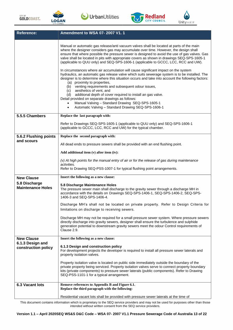
4.4.4.1 General (Design flows)
Add the following after the fourth paragraph:
For example, the following table may be used as a guide.
Number of grinder pumps connected
Number of grinder pumps operating simultaneously
1 1
2—3 2
4—9 3
10—18 4
19—30 5
31—50 6
51—80 7
81—113 8
[81+33(n)]—[113+33(n)] 8 + n
4.4.4.3 Design flow verification
Add as a last sentence to this clause:
SEQ-SPs will not accept a design without the System Supplier’s endorsement.
4.5.2 Minimum pipe sizes
Replace the first and second paragraphs with:
For single pressure sewer pumping units, the lateral and property discharge line sizes shall be DN 40 (OD). For duplex pressure sewer pumping units, the lateral and property discharge line sizes shall be DN 50 (OD). Pressure reticulation sewers shall be ≥ DN63 (OD) unless Clause 4.5.3.4 requires a smaller size.
4.5.3.1 Pipe sizing by analysis- General
Add the following additional requirements as the last paragraph of this clause:
For operational reasons SEQ-SPs has limited the sizes of PE100, PN16 pipe to DN 40, 50, 63, 90, 125, 180, 250, 315 and 355.

This document contains information which is proprietary to the SEQ service providers and may not be used for purposes other than those intended without written consent from the SEQ service providers.
Version 1.1 – April 2020SEQ WS&S D&C Code – WSA 07- 2007 V1.1 Pressure Sewerage Code of Australia 12 of 22
Reference:
Amendment to WSA 07- 2007 V1. 1
5.1.3 Location of network system
Add the following additional requirements as the last paragraph of this clause:
The reticulation pressure sewers shall be located in the approved services corridor as specified by the relevant authority.
5.1.4 Alignment of pressure sewers
Replace item (iii) with the following:
(iii) Refer to Clause 3.7 for any easement requirements.
New Clause
5.1.7 Bends
Insert the following as a new clause:
5.1.7 Bends Reticulation pressure sewers will achieve any bend greater than 45 degrees by use of multiple bends (i.e. two 45 degree bends instead of one 90 degree bend) or a long radius bend with a minimum radius for cold bending as per POP202. Bends are not to be achieved by using multiple butt welds.
5.3.4 Installation
Replace clause with:
Typical valve installation and chamber details are shown in Standard Drawing SEQ-PSS-1005-1.
5.4.1 General
Delete the first two lines.
Replace the third paragraph and “NOTE” with:
Isolation valves ≥ DN80 shall be resilient seated gate valves. Isolation valves < DN80 shall be ball valves.
5.4.2 Isolation valve locations
Replace item a) with the following:
The maximum spacing of isolation valves on reticulation mains shall be:
a. 200 m for DN 100 and 150 mains; b. 300 m for DN 200, DN 250 and DN 300 mains.
Add additional items after item (c):
(d) at the end of the Lateral immediately adjacent to pressure sewer mains, where the property service connection crosses a roadway, to isolate the section of property service connection across the road from the Service Provider network, (e) at the end of the Lateral immediately outside the property being serviced. This Property Isolation Valve services as the connection between the Property Discharge Line (including boundary kit) and the Lateral. Refer to Standard Drawing SEQ-PSS-1101-1, (f)at each incoming reticulation pressure main branch, i.e. at Tee’s. (g) immediately upstream of the discharge MH at the connection to the gravity sewer, and (h) at other positions on the network pressure mains to provide operational flexibility for system operation, repair, line flushing and the like. These requirements will necessitate the installation of two isolation valves where a property service connection crosses a roadway.
5.5 Air release and vacuum break valves
Replace the word “air” with “gas” in the title of this clause.
5.5.1 Installation design criteria
Replace the word “air” with “gas” in this clause.
Delete the “Note: Air also includes sewer gases” following the first paragraph.
Replace the reference to Standard Drawings PSS-1006 with SEQ-SPS-1605-1 (applicable to QUU
only) and SEQ-SPS-1606-1 (applicable to GCCC, LCC, RCC and UW).
Insert the following additional requirement at the end of this clause :
This document contains information which is proprietary to the SEQ service providers and may not be used for purposes other than those intended without written consent from the SEQ service providers.
Version 1.1 – April 2020SEQ WS&S D&C Code – WSA 07- 2007 V1.1 Pressure Sewerage Code of Australia 13 of 22
Reference:
Amendment to WSA 07- 2007 V1. 1
Manual or automatic gas release/anti vacuum valves shall be located at parts of the main where the designer considers gas may accumulate over time. However, the design shall ensure that where possible the pressure sewer is designed to avoid the use of gas valves. Gas valve shall be located in pits with appropriate covers as shown in drawings SEQ-SPS-1605-1 (applicable to QUU only) and SEQ-SPS-1606-1 (applicable to GCCC, LCC, RCC and UW). In circumstances where air accumulation will cause significant impact on the system hydraulics, an automatic gas release valve which suits sewerage system is to be installed. The designer is to determine where this situation occurs and take into account the following factors:
(a) proximity to properties, (b) venting requirements and subsequent odour issues, (c) aesthetics of vent, and (d) additional depth of cover required to install an gas valve.
Detail provided on separate drawings as follows:
• Manual Valving – Standard Drawing SEQ-SPS-1605-1
• Automatic Valving – Standard Drawing SEQ-SPS-1606-1
5.5.5 Chambers
Replace the last paragraph with:
Refer to Drawings SEQ-SPS-1605-1 (applicable to QUU only) and SEQ-SPS-1606-1 (applicable to GCCC, LCC, RCC and UW) for the typical chamber.
5.6.2 Flushing points and scours
Replace the second paragraph with:
All dead ends to pressure sewers shall be provided with an end flushing point. Add additional item (v) after item (iv):
(v) At high points for the manual entry of air or for the release of gas during maintenance activities. Refer to Drawing SEQ-PSS-1007-1 for typical flushing point arrangements.
New Clause
5.8 Discharge Maintenance Holes
Insert the following as a new clause:
5.8 Discharge Maintenance Holes The pressure sewer main shall discharge to the gravity sewer through a discharge MH in accordance with the details on Drawings SEQ-SPS-1406-1, SEQ-SPS-1406-2, SEQ-SPS-1406-3 and SEQ-SPS-1406-4.
Discharge MH’s shall not be located on private property. Refer to Design Criteria for
limitations on discharge to receiving sewers.
Discharge MH may not be required for a small pressure sewer system. Where pressure sewers directly discharge into gravity sewers, designer shall ensure the turbulence and sulphide generation potential to downstream gravity sewers meet the odour Control requirements of Clause 2.9.
New Clause 6.1.3 Design and construction policy
Insert the following as a new clause:
6.1.3 Design and construction policy For development projects the developer is required to install all pressure sewer laterals and property isolation valves. Property isolation valve is located on public side immediately outside the boundary of the private property being serviced. Property isolation valves serve to connect property boundary kits (private components) to pressure sewer laterals (public components). Refer to Drawing SEQ-PSS-1101-1 for a typical arrangement.
6.3 Vacant lots
Remove references to Appendix B and Figure 6.1.
Replace the third paragraph with the following:
Residential vacant lots shall be provided with pressure sewer laterals at the time of
This document contains information which is proprietary to the SEQ service providers and may not be used for purposes other than those intended without written consent from the SEQ service providers.
Version 1.1 – April 2020SEQ WS&S D&C Code – WSA 07- 2007 V1.1 Pressure Sewerage Code of Australia 14 of 22
Reference:
Amendment to WSA 07- 2007 V1. 1
construction of the reticulation system. The lateral shall be terminated at the property isolation valve and finished with a threaded cap. The property isolation valve shall be located immediately outside the front property boundary line. The location of the property isolation valve shall be identified with detectable marking tape secured to the last fitting and terminated above ground.
Delete the last sentence of this clause.
Delete Figure 6.1.
6.4 Existing property data collection
Insert additional item to the end of this clause:
(q) Significant vegetation.
6.6 Control and alarm panels
Insert the following additional requirements at the end of this clause:
All control/alarm panels shall have an emergency generator connection point.
All control/alarm panels shall be clear of 1-in-100 year flood level as advised by relevant
local authority.
The visible and audible alarm shall be activated on pump fault and collection tank high-
level.
7.1 General design requirements
Insert the following at the end of this clause:
Design of collection/pump units is the responsibility of the on-property designer. The designer shall certify, to Council Plumbing Section, that the work have been designed and installed to approved plan and manufacture’s specification to ensure that the system will perform satisfactorily. Collection/pump units must be sized to ensure that their operation does not overwhelm or compromise the system (new and existing) in any way. Retrofitting of septic tanks as collection tanks is not permitted.
7.2.1 General
Insert the following requirement at the end of the first paragraph of this clause:
Pressure sewer collection tank shall be designed to provide a minimum of 24hours of emergency storage at Average Dry Weather Flow for the property being served. Delete reference to Appendix B at the end of the first paragraph.
7.4 Maximum flows to collection/pump units
Include the following as a last paragraph:
For operational and hydraulic reasons, flow, backwash or other discharge from a pool or spa shall not be connected to a collection/pump unit and then into reticulation system.
7.7 Connection to customer sanitary drain
Replace reference to Standard Drawing PSS-1101 with SEQ-PSS-1101-1.
Delete the last paragraph.
8 Service connection pipe work
Include the following into this clause:
Design of service connection pipe work (not the lateral) is the responsibility of the on-property designer.
8.2 Laterals
Replace the second paragraph with the following:
A property isolation valve shall be installed immediately outside property boundary between laterals and property boundary kits.
8.4 Depth of pipework
Replace this clause with the following:
The minimum and maximum depths of service connection pipework shall be in accordance with the Standard Drawing SEQ-PSS-1000-1.
This document contains information which is proprietary to the SEQ service providers and may not be used for purposes other than those intended without written consent from the SEQ service providers.
Version 1.1 – April 2020SEQ WS&S D&C Code – WSA 07- 2007 V1.1 Pressure Sewerage Code of Australia 15 of 22
Reference:
Amendment to WSA 07- 2007 V1. 1
9.2.2 Pipe cover Replace the reference to Standard Drawing PSS 1000 with SEQ-PSS-1000-1.
9.2.3 Trench design Replace the reference to Standard Drawings PSS 1000 and PSS 1001 with SEQ-PSS-1000-1 and
SEQ-PSS-1001-1
9.2.5 Pipe embedment
Replace the reference to Standard Drawing PSS 1000 with SEQ-PSS-1000-1
9.2.6 Other structural design considerations
Amend the reference to WSA 06 in the second paragraph of the clause as follows:
WSA 06 becomes SEQ Code edition of WSA 06
Part 2 : PRODUCTS AND MATERIALS
10.6.1 Collection tank/ pump units - General
Add the following additional requirement as a second paragraph:
Where Pressure Sewerage Systems are the means of Reticulated Sewerage for a property, the on-lot components of the Pressure Sewerage System shall comply with the requirements of SEQ-WSA-07. The Plumbing Application shall be made with the specific components defined so that the SEQ Water Service Provider can review and advise the Council Plumbing Department of the compliance or not of the proposal. Add the following as the last paragraphs:
The pump system supplier shall provide a pre-assembled package of the low pressure sewer on-property components, including pumps, collection tanks, associated piping and valves, liquid level sensors, electrical control panel, electrical distribution box, and all other associated
components. Pump motors shall be continuous rated, IP68 electrical rating. A pre-assembled package has distinct advantages that the assembly has been refined, as dictated by previous experience. The pre-assembled package also provides a single source of responsibility in the event of malfunction, and for component replacements.
The pump system supplier shall provide the property owner with an owner’s manual which
includes a service and maintenance plan covering civil, electrical and mechanical assets along
with design specification and as installed / constructed plans.
This document contains information which is proprietary to the SEQ service providers and may not be used for purposes other than those intended without written consent from the SEQ service providers.
Version 1.1 – April 2020SEQ WS&S D&C Code – WSA 07- 2007 V1.1 Pressure Sewerage Code of Australia 16 of 22
Reference:
Amendment to WSA 07- 2007 V1. 1
10.7.2 Polyethylene (PE) pipes and fittings
Amend the first sentence of this clause to read as:
DN40, 50, 63, 90, 125 180, 250, 315 and 355 PE 100 pipes and fittings suitable for jointing with electrofusion fittings or butt fusion welding shall be used for pressure sewers, laterals and property discharge lines.
Add the following requirement to the end of the first paragraph:
De-beading is not to be carried out for butt welding joints unless otherwise specified by SEQ-SPs. A mechanical/ rotational scraper shall be used to remove oxidised layers during electro-fusion joint preparation. The use of hand scrapers is not permitted.
Replace the fourth paragraph with:
For operational reasons SEQ-SPs has limited the sizes of PE100, PN16 pipe within its pressure sewer systems to DN 40, 50, 63, 90, 125,180, 250, 315 and 355.
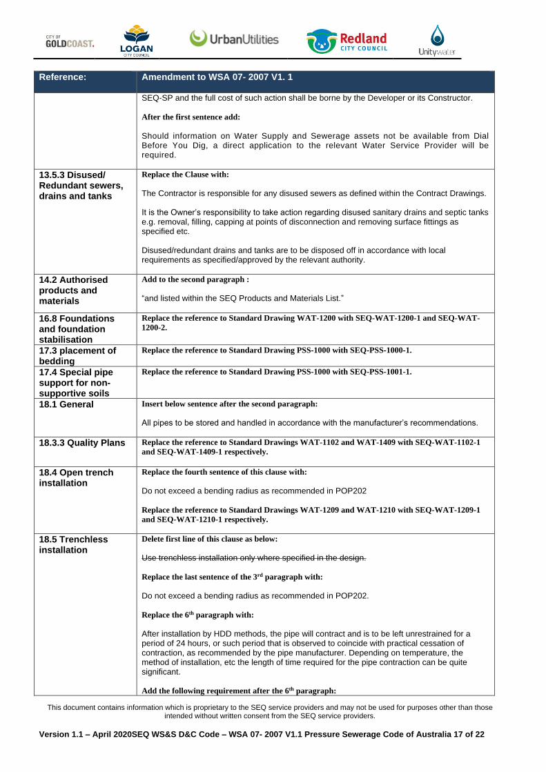
Amend the Table 10.2 - Internal Diameters of PE Pipes as:
Pipe Size DN PE100, PN16/SDR11
Internal Diameter mm
40 32
50 40
63 51
90 73
125 102
180 146
250 203
315 256
355 289
Part 3 : CONSTRUCTION
12.2 Personnel qualifications
Add the following requirement after the second paragraph:
Personnel carrying out or supervising the installation of pressure sewer shall hold minimum qualifications as required by AS2033 Installation of Polyethylene Pipe Systems. The minimum PE accreditation is PMBWELD301B and PMBWELD302B. On-property works are Regulated Plumbing and shall be carried out by a Licensed Person.
13.5.1 Safety of people
Replace the second last paragraph with:
Adhere at all times to the Queensland Works Health and Safety Act 2011 (WHS Act) and the Work Health and Safety Regulation 2011 (WHS Regulation).
13.5.2 Protection of other services
Insert the following at the start of this clause.
The Developer or its Constructor/s shall be responsible for any damage they cause to existing services. If the Developer or its constructor damages any existing services, they shall arrange for the relevant service authority to make good such damage and the cost thereof shall be borne by the Developer or its constructor. If in the opinion of the relevant SEQ-SP, the failure or damage causes an emergency situation, then remedial action will be taken by the relevant
This document contains information which is proprietary to the SEQ service providers and may not be used for purposes other than those intended without written consent from the SEQ service providers.
Version 1.1 – April 2020SEQ WS&S D&C Code – WSA 07- 2007 V1.1 Pressure Sewerage Code of Australia 17 of 22
Reference:
Amendment to WSA 07- 2007 V1. 1
SEQ-SP and the full cost of such action shall be borne by the Developer or its Constructor.
After the first sentence add:
Should information on Water Supply and Sewerage assets not be available from Dial Before You Dig, a direct application to the relevant Water Service Provider will be required.
13.5.3 Disused/ Redundant sewers, drains and tanks
Replace the Clause with:
The Contractor is responsible for any disused sewers as defined within the Contract Drawings. It is the Owner’s responsibility to take action regarding disused sanitary drains and septic tanks e.g. removal, filling, capping at points of disconnection and removing surface fittings as specified etc. Disused/redundant drains and tanks are to be disposed off in accordance with local requirements as specified/approved by the relevant authority.
14.2 Authorised products and materials
Add to the second paragraph :
“and listed within the SEQ Products and Materials List.”
16.8 Foundations and foundation stabilisation
Replace the reference to Standard Drawing WAT-1200 with SEQ-WAT-1200-1 and SEQ-WAT-
1200-2.
17.3 placement of bedding
Replace the reference to Standard Drawing PSS-1000 with SEQ-PSS-1000-1.
17.4 Special pipe support for non-supportive soils
Replace the reference to Standard Drawing PSS-1000 with SEQ-PSS-1001-1.
18.1 General
Insert below sentence after the second paragraph:
All pipes to be stored and handled in accordance with the manufacturer’s recommendations.
18.3.3 Quality Plans Replace the reference to Standard Drawings WAT-1102 and WAT-1409 with SEQ-WAT-1102-1
and SEQ-WAT-1409-1 respectively.
18.4 Open trench installation
Replace the fourth sentence of this clause with:
Do not exceed a bending radius as recommended in POP202
Replace the reference to Standard Drawings WAT-1209 and WAT-1210 with SEQ-WAT-1209-1
and SEQ-WAT-1210-1 respectively.
18.5 Trenchless installation
Delete first line of this clause as below:
Use trenchless installation only where specified in the design. Replace the last sentence of the 3rd paragraph with: Do not exceed a bending radius as recommended in POP202. Replace the 6th paragraph with:
After installation by HDD methods, the pipe will contract and is to be left unrestrained for a period of 24 hours, or such period that is observed to coincide with practical cessation of contraction, as recommended by the pipe manufacturer. Depending on temperature, the method of installation, etc the length of time required for the pipe contraction can be quite significant. Add the following requirement after the 6th paragraph:
This document contains information which is proprietary to the SEQ service providers and may not be used for purposes other than those intended without written consent from the SEQ service providers.
Version 1.1 – April 2020SEQ WS&S D&C Code – WSA 07- 2007 V1.1 Pressure Sewerage Code of Australia 18 of 22
Reference:
Amendment to WSA 07- 2007 V1. 1
Electrofusion welding shall not be permitted on lengths of PE pipe pulled through a HDD bore unless an appropriate design for the coupling’s oversize & stress has been carried out and approved
18.6 Jointing
Replace the 2nd & 3rd paragraph with:
Either electrofusion, butt welding or mechanical “gripper” joints shall be used for PE pipe jointing. All jointing shall comply with AS2033 and rated PN16 as a minimum. For PE pipes of different SDRs, use only electrofusion jointing to the thinner pipe. Butt welding shall not be used for pipes of different SDRs. Electrofusion jointing shall comply with POP001. Butt welding jointing shall comply with POP003. All jointing shall be performed under controlled conditions by skilled and experienced operators using approved equipment. All operators to be used on the work shall be accredited by a registered training organisation.
18.7 Thrust and anchor blocks and restrained joints
Replace the reference to Standard Drawings WAT-1205, WAT-1206, WAT-1207 and WAT-1208
with SEQ-WAT-1205-1, SEQ-WAT-1206-1, SEQ-WAT-1207-1 and SEQ-WAT-1208-1
respectively.
18.8 Pressure sewer laterals, Property boundary assemblies
Replace 1st paragraph with:
At the time of construction of the reticulation system, install pressure sewer laterals including property isolation valves as specified, refer to Clauses 1.5.3, 6.1.3 and 6.3. Only SS316 valves may be used on services (brass or plastic valves are not acceptable).
Replace the reference to Standard Drawings WAT-1102, WAT-1106, WAT-1107, WAT-1108 and
WAT-1109 with SEQ-WAT-1102-1 and SEQ-WAT-1200-2.
18.9.1 Collection/pump units
Replace the 1st paragraph with:
Install the collection/pump units in accordance with the Design Drawings, the manufacturer’s recommended installation instructions and Council Plumbing Section’s requirements. The tank shall be filled, up to the inlet pipe invert level, with water prior to pouring the concrete anchor to prevent the tank from “floating” before the concrete sets.
18.9.2 Customer sanitary drains
Replace the reference to Standard Drawing PSS-1101 with SEQ-PSS-1101-1.
18.9.3 Property discharge lines
Replace the reference to Standard Drawing PSS-1000 with SEQ-PSS-1000-1.
18.10 Pipeline tracer wires and detectable marking tapes
Replace the 3rd paragraph with the following:
When installing pipes in cavities, attach a tracer wire secured to the obvert of the pipe.
Replace the reference to Standard Drawing PSS-1000 with SEQ-PSS-1000-1.
18.11 Mechanical protection of pipelines
Replace the first sentence of the clause with the following:
Ensure any pipeline constructed above ground or under or near structures and major roadways or at non-standard shallow depth is mechanically protected to minimize future maintenance.
Replace the reference to the Standard Drawings PSS-1001, PSS-1002 and PSS-1003 with
SEQ-PSS-1001-1, SEQ-PSS-1002-1 and SEQ-PSS-1003-1 respectively.

This document contains information which is proprietary to the SEQ service providers and may not be used for purposes other than those intended without written consent from the SEQ service providers.
Version 1.1 – April 2020SEQ WS&S D&C Code – WSA 07- 2007 V1.1 Pressure Sewerage Code of Australia 19 of 22
Reference:
Amendment to WSA 07- 2007 V1. 1
Add the following requirement as a last sentence of this clause:
Any mechanical protection shall be approved by SEQ-SPs.
18.13 Valves, valve chambers, scours and surface fittings
Replace the reference to Standard Drawing WAT-1307 with SEQ-WAT-1307-3.
18.14 Crossings Replace the reference to Standard Drawings PSS-1003 and WAT-1312 with SEQ-PSS-1003-1 and
SEQ-WAT-1312-1 respectively.
18.15 Location markers
Insert the following paragraph at the end of this clause:
Location markers are also required where pressure sewer pipes are installed at varying offsets or in locations that may make it difficult to locate the pipes in the future. Location markers are generally required at changes of direction/crossings.
19.2 Embedment Materials
Replace Clause 19.2 (a) with:
“Listed in the SEQ Accepted Product and Material List” Delete Table 19.1.
Replace the reference to Standard Drawings PSS-1000 and PSS-1001 with SEQ-PSS-1000-1 and
SEQ-PSS-1001-1 respectively.
19.4 Special bedding and embedments / geotextile surround and pillow
Replace the reference to Standard Drawing PSS-1001 with the SEQ-PSS-1001-1
19.7 Concrete embedment and encasement
Replace the reference to Standard Drawings PSS-1001, PSS-1002, PSS-1003 and PSS-1004 with
SEQ-PSS-1001-1, SEQ-PSS-1002-1, SEQ-PSS-1003-1 and SEQ-PSS-1004-1 respectively.
20 Fill
Insert the following into this clause:
Where the trench exists within a Roadway, the requirements of the relevant road authority take precedence over this Section.
20.1.1 Placement Replace the reference to Standard Drawings PSS-1000 and PSS-1001 with SEQ-PSS-1000-1 and
SEQ-PSS-1001-1 respectively.
21.1 General
Add the following requirements at the end of this clause:
All the installations of on-property components for new or existing houses shall be inspected and approved (including final inspection and acceptance) by the relevant Council Plumbing Section. SEQ-SPs are responsible for the reticulation system outside the serviced property, refer Part 1 Preface and Clause 1.5.3.
21.3.3.1 Applicable pipe sizes
Replace the reference to Standard Drawing WAT-1200 with SEQ-WAT-1200-1.
21.3.4 Trench fill compaction testing
Insert the following into this clause:
Where the Trench exists within a Roadway, the requirements of the relevant road authority shall take precedence over this Clause.
21.3.4.1 Trafficable areas test zone
Replace the reference to Standard Drawing PSS-1000 with SEQ-PSS-1000-1.
21.7 Collection Pump Unit
Replace the first paragraph with the following:
Ensure the manufacturer’s recommended start-up and commissioning procedure is completed

This document contains information which is proprietary to the SEQ service providers and may not be used for purposes other than those intended without written consent from the SEQ service providers.
Version 1.1 – April 2020SEQ WS&S D&C Code – WSA 07- 2007 V1.1 Pressure Sewerage Code of Australia 20 of 22
Reference:
Amendment to WSA 07- 2007 V1. 1
by certified personnel in accordance with manufacturer’s warranty conditions, and evidence
provided to the Water Agency for acceptance.
21.9 Polyethylene pipelines installed using HDD techniques
Add new clause as follows:
An additional 3 m length of pipeline shall be butt welded to the leading end of the pipe string prior to placement. After the pipeline has been pulled through sufficiently to expose the additional 3 m length, the Superintendent and the Contractor shall jointly examine it. If the pipe length is significantly damaged, as defined below, complete replacement of the entire pipeline will be required. Significant damage is defined as:
a) Scratches deeper than 10% of the pipe wall thickness evident; and/or b) Any evidence of plastic failure of the pipe due to tensile forces (e.g. necking or
reduction in outside circumference compared with the supplied pipe).
24.1 Asset documentation
Replace bullet point (a) with the following:
(a) Address and allotment details, including roadways and easements
Replace the last paragraph with: Submit documents to the Council Plumbing Section and relevant SEQ-SP upon completion of construction.
24.2 Work as constructed details
Amend the first sentence of this clause as below:
Prepare and submit work as constructed drawings and documentation in accordance with the SEQ Asset information Specification. Replace (a), (e) (h) and (i) with the followings:
(a) The Asset Register Table for all components. (e) Regular offset for the pressure reticulation sewer from property boundaries (either prolongations of side boundaries and buildings or ties from front boundaries). (h) The total length of pressure sewer main for each pipe diameter. (i) The number and the total length of each size of pressure sewer lateral.
Add items (j), (k) and (l) after (i) as below: (j) Construction start and completion dates. (k) Any variations to the fitting list. (l) Location and dimensions of all on-property assets and components relative to
property boundaries and building outlines.
Add the following requirement at the end of this clause:
All “As Constructed” drawings shall have a text block as shown in the SEQ Total Asset Information Specification which shall be signed by an RPEQ to certify that they represent a true record of works.
Part 4 : STANDARD DRAWINGS
26 Listing of standard drawings
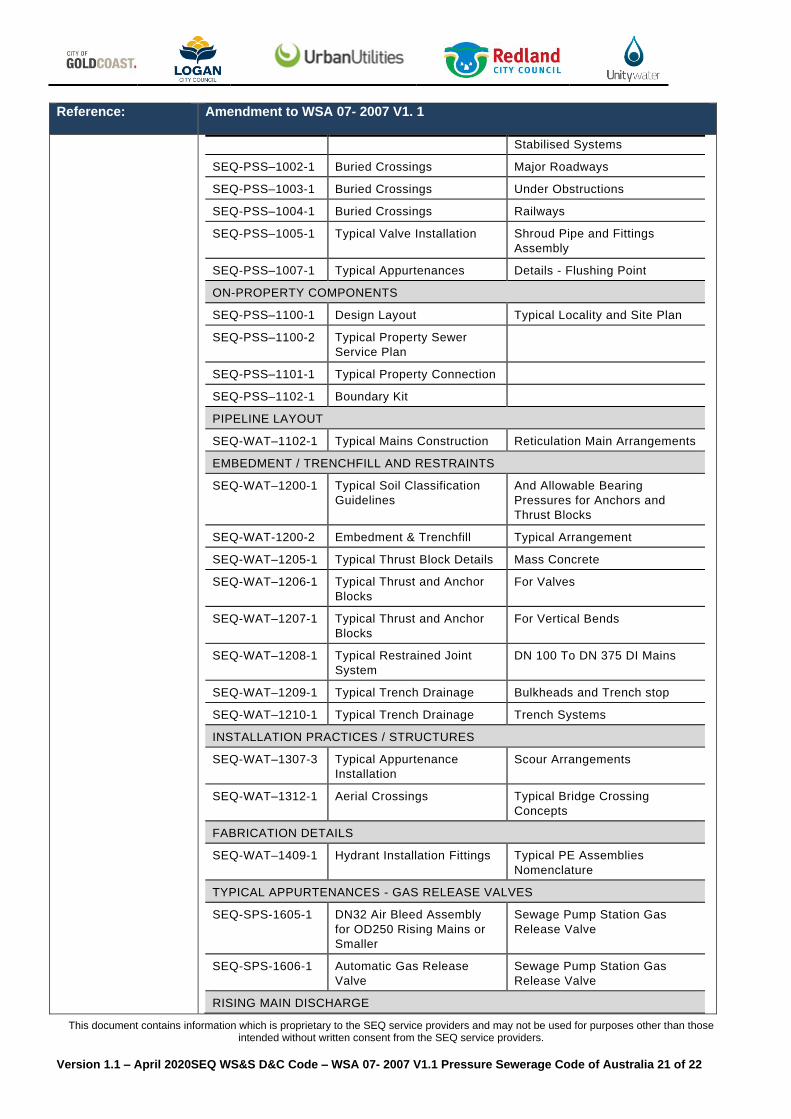
Amend Table in this clause as below:
LISTING OF STANDARD DRAWINGS
DRAWING
NUMBER ACTIVITY TITLE
PRESSURE SEWERAGE NETWORK
SEQ-PSS-1000-1 Embedment and Trench Fill Typical Arrangement
SEQ-PSS–1001-1 Special Embedments Concrete and Cement
This document contains information which is proprietary to the SEQ service providers and may not be used for purposes other than those intended without written consent from the SEQ service providers.
Version 1.1 – April 2020SEQ WS&S D&C Code – WSA 07- 2007 V1.1 Pressure Sewerage Code of Australia 21 of 22
Reference:
Amendment to WSA 07- 2007 V1. 1
Stabilised Systems
SEQ-PSS–1002-1 Buried Crossings Major Roadways
SEQ-PSS–1003-1 Buried Crossings Under Obstructions
SEQ-PSS–1004-1 Buried Crossings Railways
SEQ-PSS–1005-1 Typical Valve Installation Shroud Pipe and Fittings
Assembly
SEQ-PSS–1007-1 Typical Appurtenances Details - Flushing Point
ON-PROPERTY COMPONENTS
SEQ-PSS–1100-1 Design Layout Typical Locality and Site Plan
SEQ-PSS–1100-2 Typical Property Sewer
Service Plan
SEQ-PSS–1101-1 Typical Property Connection
SEQ-PSS–1102-1 Boundary Kit
PIPELINE LAYOUT
SEQ-WAT–1102-1 Typical Mains Construction Reticulation Main Arrangements
EMBEDMENT / TRENCHFILL AND RESTRAINTS
SEQ-WAT–1200-1 Typical Soil Classification
Guidelines
And Allowable Bearing
Pressures for Anchors and
Thrust Blocks
SEQ-WAT-1200-2 Embedment & Trenchfill Typical Arrangement
SEQ-WAT–1205-1 Typical Thrust Block Details Mass Concrete
SEQ-WAT–1206-1 Typical Thrust and Anchor
Blocks
For Valves
SEQ-WAT–1207-1 Typical Thrust and Anchor
Blocks
For Vertical Bends
SEQ-WAT–1208-1 Typical Restrained Joint
System
DN 100 To DN 375 DI Mains
SEQ-WAT–1209-1 Typical Trench Drainage Bulkheads and Trench stop
SEQ-WAT–1210-1 Typical Trench Drainage Trench Systems
INSTALLATION PRACTICES / STRUCTURES
SEQ-WAT–1307-3 Typical Appurtenance
Installation
Scour Arrangements
SEQ-WAT–1312-1 Aerial Crossings Typical Bridge Crossing
Concepts
FABRICATION DETAILS
SEQ-WAT–1409-1 Hydrant Installation Fittings Typical PE Assemblies
Nomenclature
TYPICAL APPURTENANCES - GAS RELEASE VALVES
SEQ-SPS-1605-1 DN32 Air Bleed Assembly
for OD250 Rising Mains or
Smaller
Sewage Pump Station Gas
Release Valve
SEQ-SPS-1606-1 Automatic Gas Release
Valve
Sewage Pump Station Gas
Release Valve
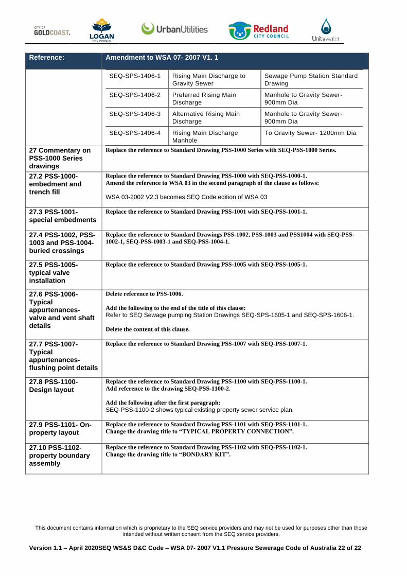
RISING MAIN DISCHARGE
This document contains information which is proprietary to the SEQ service providers and may not be used for purposes other than those intended without written consent from the SEQ service providers.
Version 1.1 – April 2020SEQ WS&S D&C Code – WSA 07- 2007 V1.1 Pressure Sewerage Code of Australia 22 of 22
Reference:
Amendment to WSA 07- 2007 V1. 1
SEQ-SPS-1406-1 Rising Main Discharge to
Gravity Sewer
Sewage Pump Station Standard
Drawing
SEQ-SPS-1406-2 Preferred Rising Main
Discharge
Manhole to Gravity Sewer-
900mm Dia
SEQ-SPS-1406-3 Alternative Rising Main
Discharge
Manhole to Gravity Sewer-
900mm Dia
SEQ-SPS-1406-4 Rising Main Discharge
Manhole
To Gravity Sewer- 1200mm Dia
27 Commentary on PSS-1000 Series drawings
Replace the reference to Standard Drawing PSS-1000 Series with SEQ-PSS-1000 Series.
27.2 PSS-1000- embedment and trench fill
Replace the reference to Standard Drawing PSS-1000 with SEQ-PSS-1000-1.
Amend the reference to WSA 03 in the second paragraph of the clause as follows:
WSA 03-2002 V2.3 becomes SEQ Code edition of WSA 03
27.3 PSS-1001- special embedments
Replace the reference to Standard Drawing PSS-1001 with SEQ-PSS-1001-1.
27.4 PSS-1002, PSS-1003 and PSS-1004- buried crossings
Replace the reference to Standard Drawings PSS-1002, PSS-1003 and PSS1004 with SEQ-PSS-
1002-1, SEQ-PSS-1003-1 and SEQ-PSS-1004-1.
27.5 PSS-1005- typical valve installation
Replace the reference to Standard Drawing PSS-1005 with SEQ-PSS-1005-1.
27.6 PSS-1006- Typical appurtenances- valve and vent shaft details
Delete reference to PSS-1006.
Add the following to the end of the title of this clause:
Refer to SEQ Sewage pumping Station Drawings SEQ-SPS-1605-1 and SEQ-SPS-1606-1.
Delete the content of this clause.
27.7 PSS-1007- Typical appurtenances-flushing point details
Replace the reference to Standard Drawing PSS-1007 with SEQ-PSS-1007-1.
27.8 PSS-1100- Design layout
Replace the reference to Standard Drawing PSS-1100 with SEQ-PSS-1100-1.
Add reference to the drawing SEQ-PSS-1100-2.
Add the following after the first paragraph:
SEQ-PSS-1100-2 shows typical existing property sewer service plan.
27.9 PSS-1101- On-property layout
Replace the reference to Standard Drawing PSS-1101 with SEQ-PSS-1101-1.
Change the drawing title to “TYPICAL PROPERTY CONNECTION”.
27.10 PSS-1102- property boundary assembly
Replace the reference to Standard Drawing PSS-1102 with SEQ-PSS-1102-1.
Change the drawing title to “BONDARY KIT”.


