Embed Size (px)
Citation preview
Bulletin 1525 Product Selection Guide
A REGAL-BELOIT COMPANY
Than Just a Motor CompanyMore
ALL STAINLESS STEELMOTORS, GEARMOTORS, AND DRIVES
1
PREMIUM STAINLESS STEELWASHGUARD MOTORS
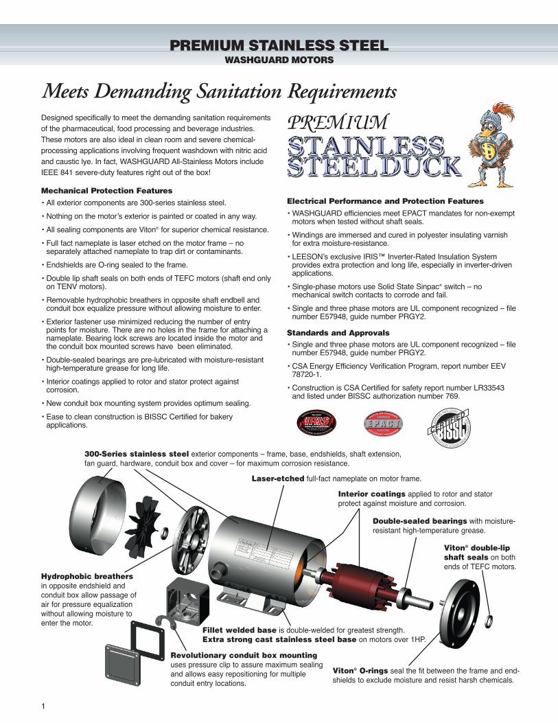
Viton® O-rings seal the fit between the frame and end-shields to exclude moisture and resist harsh chemicals.
Viton® double-lipshaft seals on bothends of TEFC motors.
Hydrophobic breathersin opposite endshield and conduit box allow passage of air for pressure equalizationwithout allowing moisture toenter the motor.
Double-sealed bearings with moisture-resistant high-temperature grease.
Revolutionary conduit box mountinguses pressure clip to assure maximum sealingand allows easy repositioning for multiple conduit entry locations.
Fillet welded base is double-welded for greatest strength. Extra strong cast stainless steel base on motors over 1HP.
PREMIUM
Laser-etched full-fact nameplate on motor frame.
Interior coatings applied to rotor and statorprotect against moisture and corrosion.
• All exterior components are 300-series stainless steel.
• Nothing on the motor’s exterior is painted or coated in any way.
• All sealing components are Viton® for superior chemical resistance.
• Full fact nameplate is laser etched on the motor frame – no separately attached nameplate to trap dirt or contaminants.
• Endshields are O-ring sealed to the frame.
• Double lip shaft seals on both ends of TEFC motors (shaft end only on TENV motors).
• Removable hydrophobic breathers in opposite shaft endbell and conduit box equalize pressure without allowing moisture to enter.
• Exterior fastener use minimized reducing the number of entry points for moisture. There are no holes in the frame for attaching a nameplate. Bearing lock screws are located inside the motor and the conduit box mounted screws have been eliminated.
• Double-sealed bearings are pre-lubricated with moisture-resistant high-temperature grease for long life.
• Interior coatings applied to rotor and stator protect against corrosion.
• New conduit box mounting system provides optimum sealing.
• Ease to clean construction is BISSC Certified for bakery applications.
• WASHGUARD efficiencies meet EPACT mandates for non-exempt motors when tested without shaft seals.
• Windings are immersed and cured in polyester insulating varnish for extra moisture-resistance.
• LEESON’s exclusive IRIS™ Inverter-Rated Insulation System provides extra protection and long life, especially in inverter-driven applications.
• Single-phase motors use Solid State Sinpac® switch – no mechanical switch contacts to corrode and fail.
• Single and three phase motors are UL component recognized – filenumber E57948, guide number PRGY2.
Electrical Performance and Protection Features
Designed specifically to meet the demanding sanitation requirementsof the pharmaceutical, food processing and beverage industries.These motors are also ideal in clean room and severe chemical-processing applications involving frequent washdown with nitric acidand caustic lye. In fact, WASHGUARD All-Stainless Motors includeIEEE 841 severe-duty features right out of the box!
300-Series stainless steel exterior components – frame, base, endshields, shaft extension,fan guard, hardware, conduit box and cover – for maximum corrosion resistance.
Meets Demanding Sanitation Requirements
Mechanical Protection Features
Standards and Approvals• Single and three phase motors are UL component recognized – file
number E57948, guide number PRGY2.
• CSA Energy Efficiency Verification Program, report number EEV 78720-1.
• Construction is CSA Certified for safety report number LR33543 and listed under BISSC authorization number 769.
2
PREMIUM STAINLESS STEELWASHGUARD MOTORS
TENV/TEFC • C FACE LESS BASERPM App. F.L. % “C”60 NEMA Catalog Disc. Wgt. Amps F.L. Dim.
HP Hz Frame Number Sym. (lbs.) Voltage 230V Eff. (Inches)
1/2 3450 56C 116316� A 35 208-230/460 1.6 82.5 12.04
1750 56C 116166� A 34 208-230/460 1.6 78.5 12.54
3/4 3450 56C 116317� A 40 208-230/460 2.4 84.0 12.54
1750 56C 116168� A 40 208-230/460 2.3 80.0 13.04
1 3450 56C 116318� A 43 208-230/460 2.6 85.5 13.04
1750 56C 116170� A 44 208-230/460 3.0 81.5 13.541750 56HC 116675 A 45 208-230/460 3.1 82.5 13.131750 143TC 121523� B 44 208-230/460 3.0 81.5 13.611750 143TC 121659 B 46 208-230/460 3.1 82.5 13.19
11⁄2 3450 143TC 121560 B 45 208-230/460 4.0 82.5 12.69
1750 56C 116448 B 49 208-230/460 4.4 84.0 13.631750 145TC 121525 B 49 208-230/460 4.4 84.0 13.69
2 3450 145TC 121561 B 48 208-230/460 5.2 84.0 13.19
1750 56C 116449 B 49 208-230/460 5.6 84.0 13.631750 145TC 121527 B 54 208-230/460 5.6 84.0 13.69
3 3450 145TC 121562 B 49 208-230/460 7.6 85.5 13.69
1750 182TC 131923 B 82 208-230/460 8.2 87.5 14.77
5 3450 184TC 131949 B 90 208-230/460 12.0 87.5 14.77
1750 184TC 131924 B 94 208-230/460 13.0 87.5 15.27
TENV/TEFC • C FACE WITH BASERPM App. Over- F.L. “C”60 NEMA Catalog Disc. Wgt. load Amps Dim.
HP Hz Frame Number Sym. (lbs.) Voltage Prot. 230V (Inches)
1/3 1750 56HC 116343�� A 35 115/208-230 None 2.7 12.20
1/2 3450 56HC 116344�� A 38 115/208-230 None 3.8 12.20
1750 56HC 116345�� A 38 115/208-230 None 3.3 12.70
3/4 1750 56HC 116346�� A 42 115/208-230 None 3.8 12.70
1 3450 56HC 116347�� A 49 115/208-230 None 6.0 13.70
1750 56HC 116348�� A 49 115/208-230 None 4.5 13.70
11⁄2 3450 56HC 116482� A 49 115/208-230 None 6.8 13.81
1750 145TC 121622 B 53 115/208-230 None 7.4 14.81
2 3450 145TC 121623 B 57 115/208-230 None 8.8 14.81
1750 145TC 121632 B 57 115/208-230 None 10.0 14.81
TENV/TEFC • C FACE LESS BASERPM App. Over- F.L. “C”60 NEMA Catalog Disc. Wgt. load Amps Dim.
HP Hz Frame Number Sym. (lbs.) Voltage Prot. 230V (Inches)
1/3 1750 56C 116349� A 35 115/208-230 None 2.7 11.70
1/2 1750 56C 116350� A 38 115/208-230 None 3.3 12.70
3/4 1750 56C 116351� A 42 115/208-230 None 3.8 12.70
1 1750 56C 116352� A 49 115/208-230 None 4.5 13.70
11⁄2 1750 145TC 121624 B 53 115/208-230 None 7.4 14.87
2 1750 145TC 121633 B 57 115/208-230 None 10.0 14.87
TEFC • JM PUMPRPM App. F.L. % “C”60 NEMA Catalog Disc. Wgt. Amps F.L. Dim.
HP Hz Frame Number Sym. (lbs.) Voltage 230V Eff. (Inches)
1 1750 143JM 121626 B 53 208-230/460 3.1 82.5 16.00
11⁄2 3450 143JM 121627 B 46 208-230/460 4.0 82.5 16.00
1750 145JM 121628 B 49 208-230/460 4.4 84.0 16.00
2 3450 145JM 121629 B 52 208-230/460 5.2 84.0 16.00
1750 145JM 121630 B 50 208-230/460 5.6 84.0 16.50
3 3450 145JM 121631 B 53 208-230/460 7.6 85.5 16.50
1750 182JM 131996 B 85 208-230/460 8.2 87.5 16.20
5 3450 184JM 131997 B 89 208-230/460 12.0 87.5 16.20
1750 184JM 131998 B 96 208-230/460 13.0 87.5 16.77
71⁄2 3450 213JM 140740 B 153 208-230/460 18.4 88.5 16.81
1750 213JM 140741 B 156 208-230/460 20.4 89.5 19.81
10 3450 215JM 140742 B 155 208-230/460 24.0 89.5 19.81
1750 215JM 140743 B 173 208-230/460 26.0 89.5 19.81
TENV/TEFC • C FACE WITH BASERPM App. F.L. % “C”60 NEMA Catalog Disc. Wgt. Amps F.L. Dim.
HP Hz Frame Number Sym. (lbs.) Voltage 230V Eff. (Inches)
1/2 3450 56HC 116165�� A 35 208-230/460 1.6 82.5 12.04
1750 56HC 115633�� A 35 208-230/460 1.6 78.5 12.54
1140 56HC 116297�� A 35 208-230/460 2.3 77.0 12.54
3/4 3450 56HC 116167�� A 40 208-230/460 2.4 84.0 12.54
1750 56HC 115634�� A 41 208-230/460 2.3 80.0 13.04
1140 56HC 116298�� A 46 208-230/460 3.0 78.5 14.04
1 3450 56HC 116169�� A 43 208-230/460 2.6 85.5 13.04
1750 56HC 115635�� A 44 208-230/460 3.0 81.5 13.541750 56HC 116674 A 39 208-230/460 3.1 82.5 13.131750 143TC 121419�� B 44 208-230/460 3.0 81.5 13.611750 143TC G121658 B 50 208-230/460 3.1 82.5 13.19
1140 56HC 116299� B 48 208-230/460 4.0 77.0 13.13
11⁄2 3450 143TC G121524 B 45 208-230/460 4.0 82.5 13.69
1750 56HC 116450� B 49 208-230/460 4.4 84.0 13.631750 145TC G121420 B 49 208-230/460 4.4 84.0 13.69
1140 56HC 116300� B 51 208-230/460 5.4 80.0 14.13
2 3450 145TC G121526 B 49 208-230/460 5.2 84.0 13.69
1750 56HC 116451� B 50 208-230/460 5.6 84.0 13.631750 145TC G121421 B 50 208-230/460 5.6 84.0 13.69
3 3450 145TC G121528 B 53 208-230/460 7.6 85.5 13.69
1750 182TC G131900 B 85 208-230/460 8.2 87.5 14.77
5 3450 184TC G131901 B 90 208-230/460 12.0 87.5 14.77
1750 184TC G131902 B 96 208-230/460 13.0 87.5 15.27
71⁄2 3450 213TC G140698 B 160 208-230/460 18.4 88.5 18.69
1750 213TC G140675 B 160 208-230/460 20.4 89.5 18.69
10 3450 215TC G140699 B 165 208-230/460 24.0 89.5 18.69
1750 215TC G140676 B 173 208-230/460 26.0 89.5 18.69
Catalog numbers in green are EPACT motors.
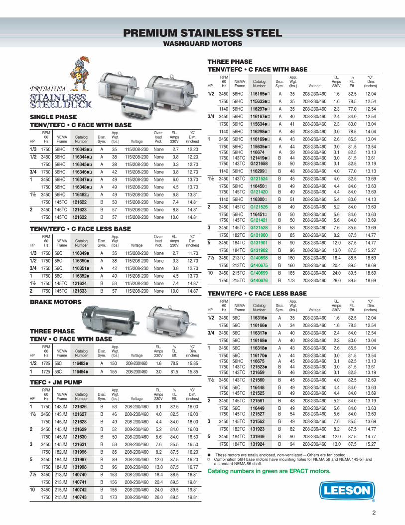
THREE PHASE
SINGLE PHASE
BRAKE MOTORS
TENV • C FACE WITH BASERPM App. F.L. % “C”60 NEMA Catalog Disc. Wgt. Amps F.L. Dim.
HP Hz Frame Number Sym. (lbs.) Voltage 230V Eff. (Inches)
1/2 1725 56C 116483� A 150 208-230/460 1.6 78.5 15.85
1 1725 56C 116484� A 155 208-230/460 3.0 81.5 15.85
THREE PHASE
� These motors are totally enclosed, non-ventilated—Others are fan cooled.� Combination 56H base motors have mounting holes for NEMA 56 and NEMA 143-5T and
a standard NEMA 56 shaft.
PREMIUM
3
WASHGUARD SSTSTAINLESS STEEL MOTORS
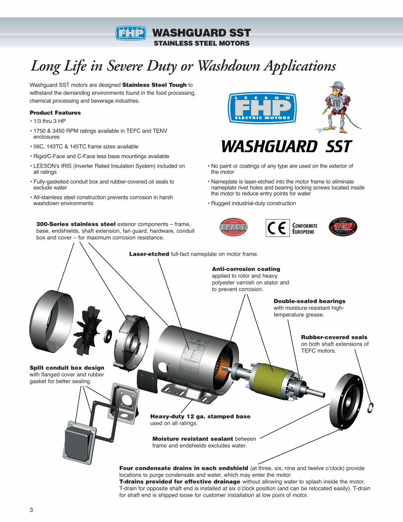
300-Series stainless steel exterior components – frame,base, endshields, shaft extension, fan guard, hardware, conduitbox and cover – for maximum corrosion resistance.
Laser-etched full-fact nameplate on motor frame.
Moisture resistant sealant betweenframe and endshields excludes water.
Rubber-covered sealson both shaft extensions ofTEFC motors.
Four condensate drains in each endshield (at three, six, nine and twelve o’clock) providelocations to purge condensate and water, which may enter the motor.T-drains provided for effective drainage without allowing water to splash inside the motor. T-drain for opposite shaft end is installed at six o’clock position (and can be relocated easily). T-drainfor shaft end is shipped loose for customer installation at low point of motor.
Double-sealed bearingswith moisture-resistant high-temperature grease.
Anti-corrosion coatingapplied to rotor and heavypolyester varnish on stator andto prevent corrosion.
Split conduit box designwith flanged cover and rubbergasket for better sealing.
Heavy-duty 12 ga. stamped baseused on all ratings.
Washguard SST motors are designed Stainless Steel Tough towithstand the demanding environments found in the food processing,chemical processing and beverage industries.
Product Features
CONFORMITEEUROPEENE
Long Life in Severe Duty or Washdown Applications
• 1/3 thru 3 HP
• 1750 & 3450 RPM ratings available in TEFC and TENV enclosures
• 56C, 143TC & 145TC frame sizes available
• Rigid/C-Face and C-Face less base mountings available
• LEESON’s IRIS (Inverter Rated Insulation System) included on all ratings
• Fully-gasketed conduit box and rubber-covered oil seals to exclude water
• All-stainless steel construction prevents corrosion in harsh washdown environments
• No paint or coatings of any type are used on the exterior of the motor
• Nameplate is laser-etched into the motor frame to eliminate nameplate rivet holes and bearing locking screws located inside the motor to reduce entry points for water
• Rugged industrial-duty construction
4
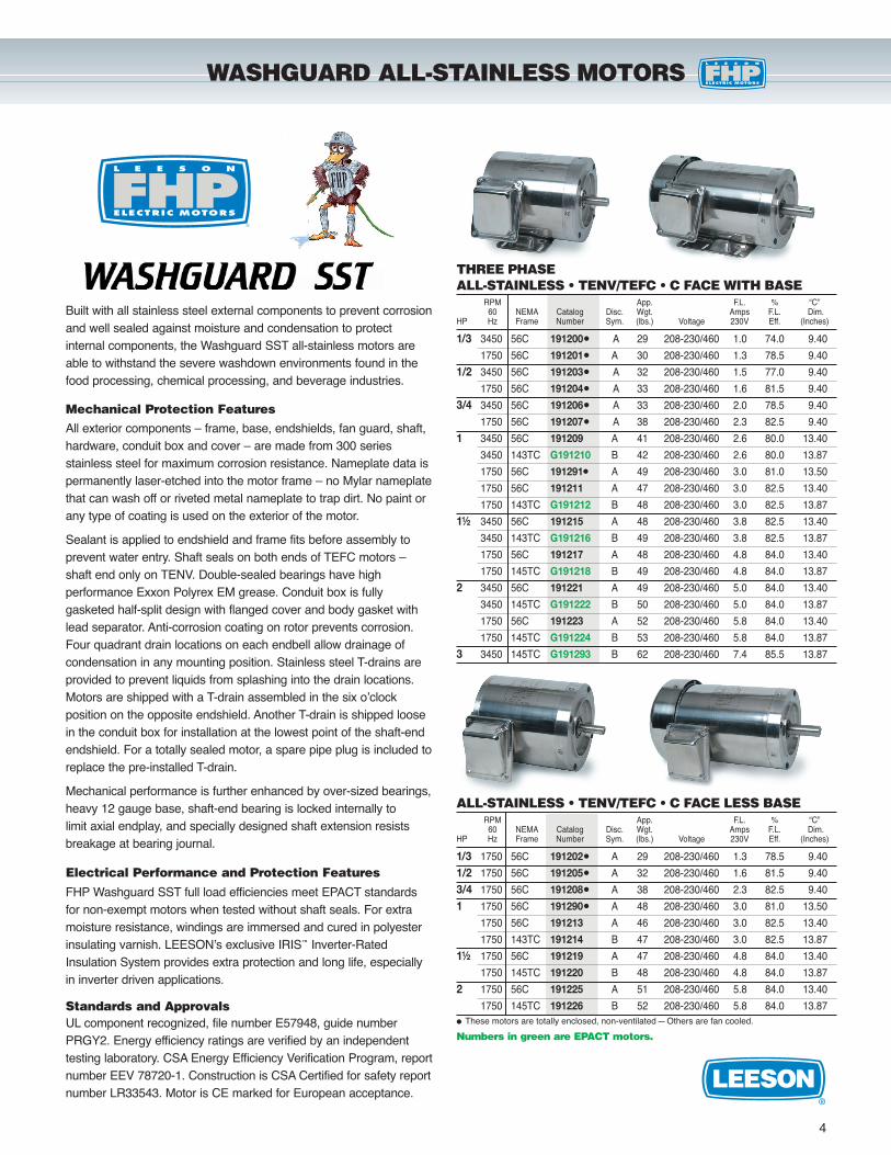
WASHGUARD ALL-STAINLESS MOTORS
THREE PHASEALL-STAINLESS • TENV/TEFC • C FACE WITH BASE
RPM App. F.L. % “C”60 NEMA Catalog Disc. Wgt. Amps F.L. Dim.
HP Hz Frame Number Sym. (lbs.) Voltage 230V Eff. (Inches)
1/3 3450 56C 191200� A 29 208-230/460 1.0 74.0 9.40
1750 56C 191201� A 30 208-230/460 1.3 78.5 9.40
1/2 3450 56C 191203� A 32 208-230/460 1.5 77.0 9.40
1750 56C 191204� A 33 208-230/460 1.6 81.5 9.40
3/4 3450 56C 191206� A 33 208-230/460 2.0 78.5 9.40
1750 56C 191207� A 38 208-230/460 2.3 82.5 9.40
1 3450 56C 191209 A 41 208-230/460 2.6 80.0 13.40
3450 143TC G191210 B 42 208-230/460 2.6 80.0 13.87
1750 56C 191291� A 49 208-230/460 3.0 81.0 13.50
1750 56C 191211 A 47 208-230/460 3.0 82.5 13.40
1750 143TC G191212 B 48 208-230/460 3.0 82.5 13.87
11⁄2 3450 56C 191215 A 48 208-230/460 3.8 82.5 13.40
3450 143TC G191216 B 49 208-230/460 3.8 82.5 13.87
1750 56C 191217 A 48 208-230/460 4.8 84.0 13.40
1750 145TC G191218 B 49 208-230/460 4.8 84.0 13.87
2 3450 56C 191221 A 49 208-230/460 5.0 84.0 13.40
3450 145TC G191222 B 50 208-230/460 5.0 84.0 13.87
1750 56C 191223 A 52 208-230/460 5.8 84.0 13.40
1750 145TC G191224 B 53 208-230/460 5.8 84.0 13.87
3 3450 145TC G191293 B 62 208-230/460 7.4 85.5 13.87
Numbers in green are EPACT motors.
ALL-STAINLESS • TENV/TEFC • C FACE LESS BASERPM App. F.L. % “C”60 NEMA Catalog Disc. Wgt. Amps F.L. Dim.
HP Hz Frame Number Sym. (lbs.) Voltage 230V Eff. (Inches)
1/3 1750 56C 191202� A 29 208-230/460 1.3 78.5 9.40
1/2 1750 56C 191205� A 32 208-230/460 1.6 81.5 9.40
3/4 1750 56C 191208� A 38 208-230/460 2.3 82.5 9.40
1 1750 56C 191290� A 48 208-230/460 3.0 81.0 13.50
1750 56C 191213 A 46 208-230/460 3.0 82.5 13.40
1750 143TC 191214 B 47 208-230/460 3.0 82.5 13.87
11⁄2 1750 56C 191219 A 47 208-230/460 4.8 84.0 13.40
1750 145TC 191220 B 48 208-230/460 4.8 84.0 13.87
2 1750 56C 191225 A 51 208-230/460 5.8 84.0 13.40
1750 145TC 191226 B 52 208-230/460 5.8 84.0 13.87� These motors are totally enclosed, non-ventilated—Others are fan cooled.
Built with all stainless steel external components to prevent corrosionand well sealed against moisture and condensation to protect internal components, the Washguard SST all-stainless motors areable to withstand the severe washdown environments found in thefood processing, chemical processing, and beverage industries.
Mechanical Protection FeaturesAll exterior components – frame, base, endshields, fan guard, shaft,hardware, conduit box and cover – are made from 300 series stainless steel for maximum corrosion resistance. Nameplate data ispermanently laser-etched into the motor frame – no Mylar nameplatethat can wash off or riveted metal nameplate to trap dirt. No paint orany type of coating is used on the exterior of the motor.
Sealant is applied to endshield and frame fits before assembly toprevent water entry. Shaft seals on both ends of TEFC motors –shaft end only on TENV. Double-sealed bearings have high performance Exxon Polyrex EM grease. Conduit box is fully gasketed half-split design with flanged cover and body gasket withlead separator. Anti-corrosion coating on rotor prevents corrosion.Four quadrant drain locations on each endbell allow drainage of condensation in any mounting position. Stainless steel T-drains areprovided to prevent liquids from splashing into the drain locations.Motors are shipped with a T-drain assembled in the six o’clock position on the opposite endshield. Another T-drain is shipped loosein the conduit box for installation at the lowest point of the shaft-endendshield. For a totally sealed motor, a spare pipe plug is included toreplace the pre-installed T-drain.
Mechanical performance is further enhanced by over-sized bearings,heavy 12 gauge base, shaft-end bearing is locked internally to limit axial endplay, and specially designed shaft extension resists breakage at bearing journal.
Electrical Performance and Protection Features
FHP Washguard SST full load efficiencies meet EPACT standards for non-exempt motors when tested without shaft seals. For extramoisture resistance, windings are immersed and cured in polyesterinsulating varnish. LEESON’s exclusive IRIS™ Inverter-RatedInsulation System provides extra protection and long life, especiallyin inverter driven applications.
Standards and ApprovalsUL component recognized, file number E57948, guide numberPRGY2. Energy efficiency ratings are verified by an independenttesting laboratory. CSA Energy Efficiency Verification Program, reportnumber EEV 78720-1. Construction is CSA Certified for safety reportnumber LR33543. Motor is CE marked for European acceptance.
5
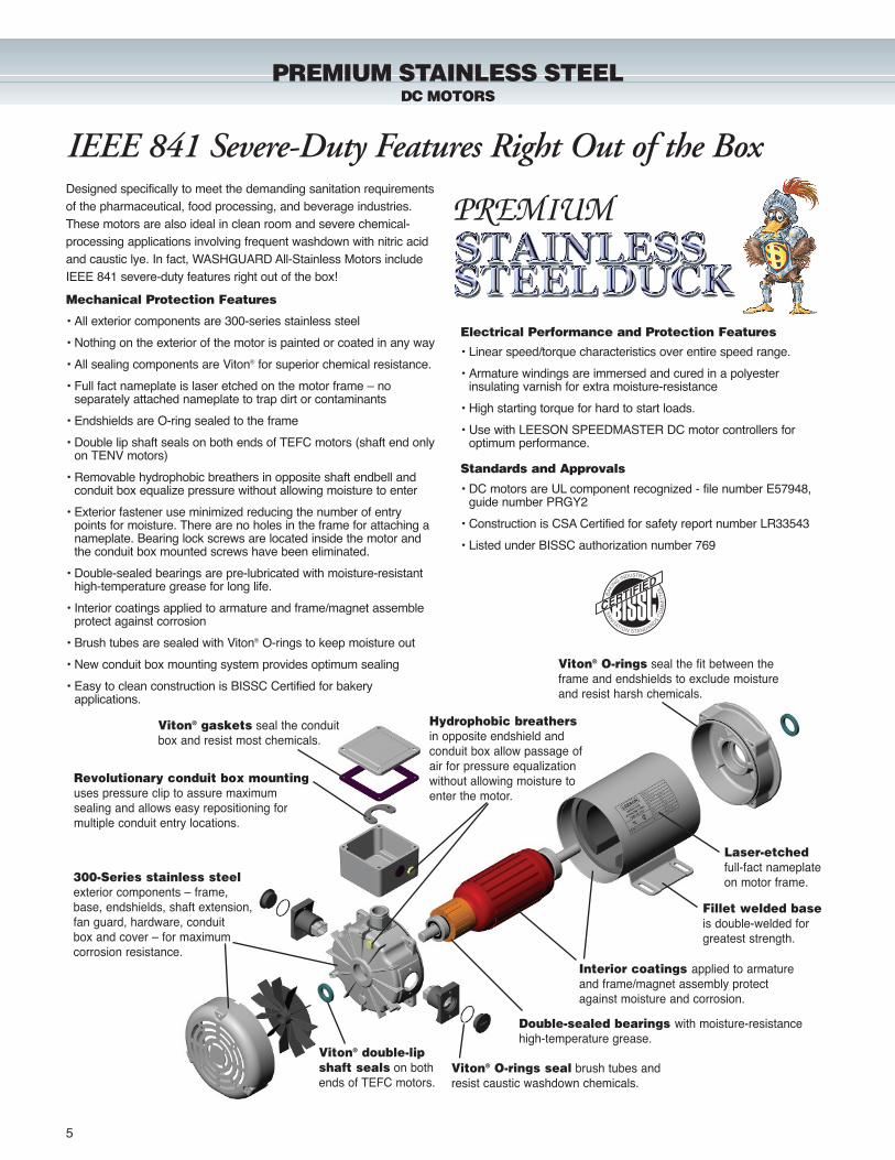
PREMIUM STAINLESS STEELDC MOTORS
Revolutionary conduit box mountinguses pressure clip to assure maximum sealing and allows easy repositioning formultiple conduit entry locations.
Viton® gaskets seal the conduitbox and resist most chemicals.
Designed specifically to meet the demanding sanitation requirementsof the pharmaceutical, food processing, and beverage industries.These motors are also ideal in clean room and severe chemical-processing applications involving frequent washdown with nitric acidand caustic lye. In fact, WASHGUARD All-Stainless Motors includeIEEE 841 severe-duty features right out of the box!
300-Series stainless steelexterior components – frame,base, endshields, shaft extension,fan guard, hardware, conduit box and cover – for maximum corrosion resistance.
Viton® double-lipshaft seals on bothends of TEFC motors.
Viton® O-rings seal the fit between theframe and endshields to exclude moistureand resist harsh chemicals.
Viton® O-rings seal brush tubes andresist caustic washdown chemicals.
Double-sealed bearings with moisture-resistancehigh-temperature grease.
Interior coatings applied to armatureand frame/magnet assembly protectagainst moisture and corrosion.
Laser-etchedfull-fact nameplateon motor frame.
Fillet welded baseis double-welded forgreatest strength.
Hydrophobic breathersin opposite endshield andconduit box allow passage ofair for pressure equalizationwithout allowing moisture toenter the motor.
PREMIUM
IEEE 841 Severe-Duty Features Right Out of the Box
• All exterior components are 300-series stainless steel
• Nothing on the exterior of the motor is painted or coated in any way
• All sealing components are Viton® for superior chemical resistance.
• Full fact nameplate is laser etched on the motor frame – no separately attached nameplate to trap dirt or contaminants
• Endshields are O-ring sealed to the frame
• Double lip shaft seals on both ends of TEFC motors (shaft end onlyon TENV motors)
• Removable hydrophobic breathers in opposite shaft endbell and conduit box equalize pressure without allowing moisture to enter
• Exterior fastener use minimized reducing the number of entry points for moisture. There are no holes in the frame for attaching a nameplate. Bearing lock screws are located inside the motor and the conduit box mounted screws have been eliminated.
• Double-sealed bearings are pre-lubricated with moisture-resistant high-temperature grease for long life.
• Interior coatings applied to armature and frame/magnet assemble protect against corrosion
• Brush tubes are sealed with Viton® O-rings to keep moisture out
• New conduit box mounting system provides optimum sealing
• Easy to clean construction is BISSC Certified for bakery applications.
• Linear speed/torque characteristics over entire speed range.
• Armature windings are immersed and cured in a polyester insulating varnish for extra moisture-resistance
• High starting torque for hard to start loads.
• Use with LEESON SPEEDMASTER DC motor controllers for optimum performance.
Mechanical Protection Features
Electrical Performance and Protection Features
Standards and Approvals
• DC motors are UL component recognized - file number E57948, guide number PRGY2
• Construction is CSA Certified for safety report number LR33543
• Listed under BISSC authorization number 769
6
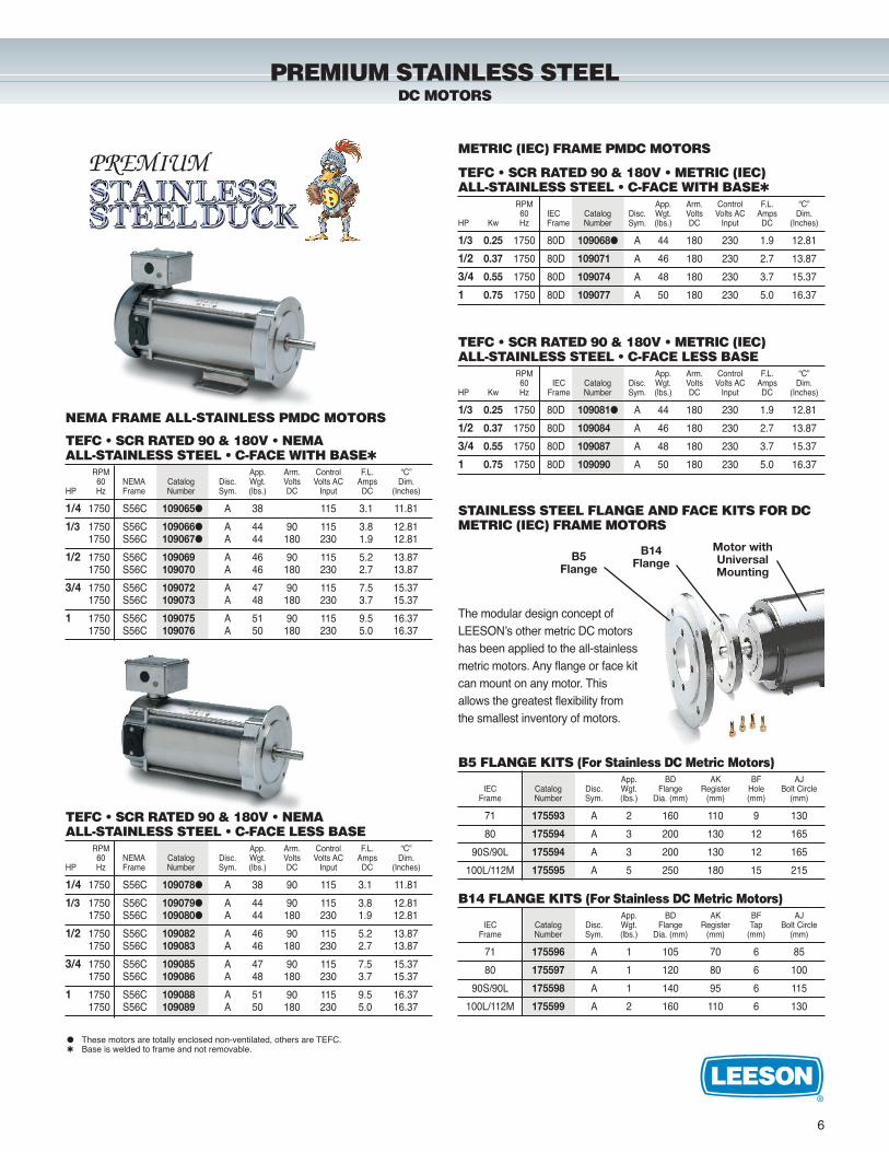
PREMIUM STAINLESS STEELDC MOTORS
TEFC • SCR RATED 90 & 180V • METRIC (IEC)ALL-STAINLESS STEEL • C-FACE WITH BASE�
RPM App. Arm. Control F.L. “C”60 IEC Catalog Disc. Wgt. Volts Volts AC Amps Dim.
HP Kw Hz Frame Number Sym. (lbs.) DC Input DC (Inches)
1/3 0.25 1750 80D 109068� A 44 180 230 1.9 12.81
1/2 0.37 1750 80D 109071 A 46 180 230 2.7 13.87
3/4 0.55 1750 80D 109074 A 48 180 230 3.7 15.37
1 0.75 1750 80D 109077 A 50 180 230 5.0 16.37
TEFC • SCR RATED 90 & 180V • METRIC (IEC)ALL-STAINLESS STEEL • C-FACE LESS BASE
RPM App. Arm. Control F.L. “C”60 IEC Catalog Disc. Wgt. Volts Volts AC Amps Dim.
HP Kw Hz Frame Number Sym. (lbs.) DC Input DC (Inches)
1/3 0.25 1750 80D 109081� A 44 180 230 1.9 12.81
1/2 0.37 1750 80D 109084 A 46 180 230 2.7 13.87
3/4 0.55 1750 80D 109087 A 48 180 230 3.7 15.37
1 0.75 1750 80D 109090 A 50 180 230 5.0 16.37
METRIC (IEC) FRAME PMDC MOTORS
� These motors are totally enclosed non-ventilated, others are TEFC.� Base is welded to frame and not removable.
The modular design concept ofLEESON’s other metric DC motorshas been applied to the all-stainlessmetric motors. Any flange or face kitcan mount on any motor. Thisallows the greatest flexibility fromthe smallest inventory of motors.
NEMA FRAME ALL-STAINLESS PMDC MOTORS
TEFC • SCR RATED 90 & 180V • NEMAALL-STAINLESS STEEL • C-FACE WITH BASE�
RPM App. Arm. Control F.L. “C”60 NEMA Catalog Disc. Wgt. Volts Volts AC Amps Dim.
HP Hz Frame Number Sym. (lbs.) DC Input DC (Inches)
1/4 1750 S56C 109065� A 38 115 3.1 11.81
1/3 1750 S56C 109066� A 44 90 115 3.8 12.811750 S56C 109067� A 44 180 230 1.9 12.81
1/2 1750 S56C 109069 A 46 90 115 5.2 13.871750 S56C 109070 A 46 180 230 2.7 13.87
3/4 1750 S56C 109072 A 47 90 115 7.5 15.371750 S56C 109073 A 48 180 230 3.7 15.37
1 1750 S56C 109075 A 51 90 115 9.5 16.371750 S56C 109076 A 50 180 230 5.0 16.37
TEFC • SCR RATED 90 & 180V • NEMAALL-STAINLESS STEEL • C-FACE LESS BASE
RPM App. Arm. Control F.L. “C”60 NEMA Catalog Disc. Wgt. Volts Volts AC Amps Dim.
HP Hz Frame Number Sym. (lbs.) DC Input DC (Inches)
1/4 1750 S56C 109078� A 38 90 115 3.1 11.81
1/3 1750 S56C 109079� A 44 90 115 3.8 12.811750 S56C 109080� A 44 180 230 1.9 12.81
1/2 1750 S56C 109082 A 46 90 115 5.2 13.871750 S56C 109083 A 46 180 230 2.7 13.87
3/4 1750 S56C 109085 A 47 90 115 7.5 15.371750 S56C 109086 A 48 180 230 3.7 15.37
1 1750 S56C 109088 A 51 90 115 9.5 16.371750 S56C 109089 A 50 180 230 5.0 16.37
B5 FLANGE KITS (For Stainless DC Metric Motors)App. BD AK BF AJ
IEC Catalog Disc. Wgt. Flange Register Hole Bolt CircleFrame Number Sym. (lbs.) Dia. (mm) (mm) (mm) (mm)
71 175593 A 2 160 110 9 130
80 175594 A 3 200 130 12 165
90S/90L 175594 A 3 200 130 12 165
100L/112M 175595 A 5 250 180 15 215
B14 FLANGE KITS (For Stainless DC Metric Motors)App. BD AK BF AJ
IEC Catalog Disc. Wgt. Flange Register Tap Bolt CircleFrame Number Sym. (lbs.) Dia. (mm) (mm) (mm) (mm)
71 175596 A 1 105 70 6 85
80 175597 A 1 120 80 6 100
90S/90L 175598 A 1 140 95 6 115
100L/112M 175599 A 2 160 110 6 130
STAINLESS STEEL FLANGE AND FACE KITS FOR DCMETRIC (IEC) FRAME MOTORS
B14Flange
Motor withUniversalMounting
B5Flange
PREMIUM
7
• Programs and reads-out in plain English.• Intelligent Power Module-IGBT’s with a 16 bit Intel microprocessor.• User choice programming with:
� Choice of “Quick Start” factory presets.� Built-In English programmable options via the key touch-pad.
• Output Frequency: 0-120 Hz.• Overload Current Capacity: 150% for one minute, based on
nominal output of the control.• Speed reference signal. Choice of potentiometer, 0-10VDC or
4-20mA inputs.• Analog output signal, 0-10VDC, speed or load.• Two auxiliary contacts: One form C relay and two open collector
output.• Preset speeds: Four.• Slip compensation.• Adjustable carrier frequency.• Adjustable acceleration and deceleration times.• Forward/Reverse.• DC braking–time and voltage adjustable.• Password protected.• Constant torque–with adjustable current limit.• 150% overload capacity for one minute based on nominal output
rating of the control.• Rugged, heavy-gauge steel enclosures with barrier type terminal
strips.• Underwriters Laboratories Listed.
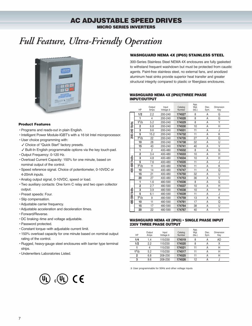
WASHGUARD NEMA 4X (IP65) • SINGLE PHASE INPUT230V THREE PHASE OUTPUT
App.Output Input Catalog Wgt. Disc. Dimension
HP Amps Voltage� Number (lbs.) Sym. Key
1/4 1.4 115/230 174519 8 A AD1/2 2.2 115/230 174520 8 A X 1 4 115/230 174521 11 A H
11/2 5.2 115/230 174517 11 A H2 6.8 208-230 174525 11 A H3 9.6 208-230 174526 12 A J
WASHGUARD NEMA 4X (IP65)THREE PHASEINPUT/OUTPUT
App.Output Input Catalog Wgt. Disc. Dimension
HP Amps Voltage� Number (lbs.) Sym. Key
1/2 2.2 200-240 174527 8 A G1 4 200-240 174528 8 A G
11/2 5.2 200-240 174529 8 A Y2 6.8 200-240 174530 10 A H3 9.6 200-240 174531 11 A J5 15.2 200-240 174732 11 A K
71/2 22 200-240 174735 27 A Q10 28 200-240 174738 32 A U15 43 200-240 174741 40 A V1 2 400-480 174532 8 A G2 3.4 400-480 174533 10 A H3 4.8 400-480 174534 10 A H5 7.6 400-480 174535 11 A J
71/2 11 400-480 174745 11 A K10 14 400-480 174747 11 A Q15 21 400-480 174750 32 A U20 27 400-480 174753 36 A V1 1.6 480-590 174536 8 A G2 2.7 480-590 174537 10 A H3 3.9 480-590 174538 10 A H5 6.1 480-590 174539 11 A J
71/2 9 480-590 174759 13 A K10 11 480-590 174761 17 A Q15 17 480-590 174764 38 A U20 22 480-590 174767 40 A V
200-
240
Volts
400-
480
Volts
480-
590
Volts
� User programmable for 50Hz and other voltage inputs
WASHGUARD NEMA 4X (IP65) STAINLESS STEEL
300-Series Stainless Steel NEMA 4X enclosures are fully gasketedto withstand frequent washdown but must be protected from causticagents. Paint-free stainless steel, no external fans, and anodizedaluminum heat sinks provide superior heat transfer and greaterstructural integrity compared to plastic or fiberglass enclosures.
Full Feature, Ultra-Friendly Operation
Product Features
AC ADJUSTABLE SPEED DRIVESMICRO SERIES INVERTERS
8
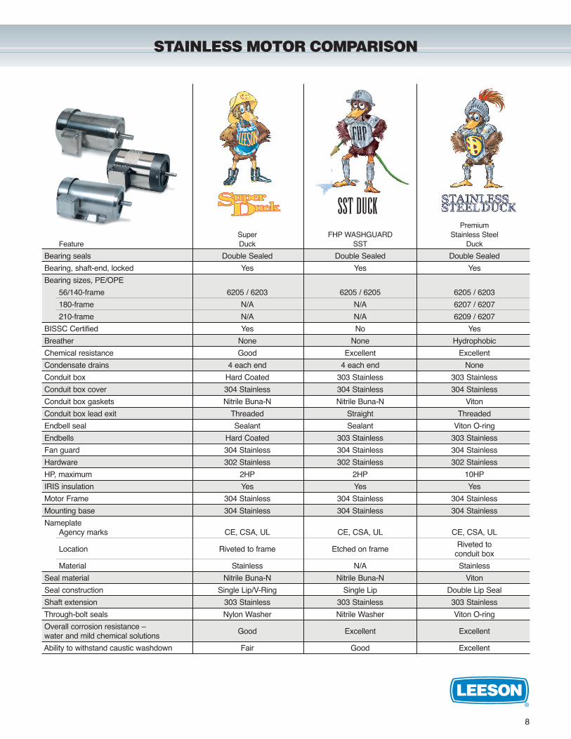
STAINLESS MOTOR COMPARISON
PremiumSuper FHP WASHGUARD Stainless Steel
Feature Duck SST Duck
Bearing seals Double Sealed Double Sealed Double Sealed
Bearing, shaft-end, locked Yes Yes Yes
Bearing sizes, PE/OPE
56/140-frame 6205 / 6203 6205 / 6205 6205 / 6203
180-frame N/A N/A 6207 / 6207
210-frame N/A N/A 6209 / 6207
BISSC Certified Yes No Yes
Breather None None Hydrophobic
Chemical resistance Good Excellent Excellent
Condensate drains 4 each end 4 each end None
Conduit box Hard Coated 303 Stainless 303 Stainless
Conduit box cover 304 Stainless 304 Stainless 304 Stainless
Conduit box gaskets Nitrile Buna-N Nitrile Buna-N Viton
Conduit box lead exit Threaded Straight Threaded
Endbell seal Sealant Sealant Viton O-ring
Endbells Hard Coated 303 Stainless 303 Stainless
Fan guard 304 Stainless 304 Stainless 304 Stainless
Hardware 302 Stainless 302 Stainless 302 Stainless
HP, maximum 2HP 2HP 10HP
IRIS insulation Yes Yes Yes
Motor Frame 304 Stainless 304 Stainless 304 Stainless
Mounting base 304 Stainless 304 Stainless 304 Stainless
NameplateAgency marks CE, CSA, UL CE, CSA, UL CE, CSA, UL
Location Riveted to frame Etched on frameRiveted to
conduit box
Material Stainless N/A Stainless
Seal material Nitrile Buna-N Nitrile Buna-N Viton
Seal construction Single Lip/V-Ring Single Lip Double Lip Seal
Shaft extension 303 Stainless 303 Stainless 303 Stainless
Through-bolt seals Nylon Washer Nitrile Washer Viton O-ring
Overall corrosion resistance –water and mild chemical solutions
Good Excellent Excellent
Ability to withstand caustic washdown Fair Good Excellent
SST DUCK
10
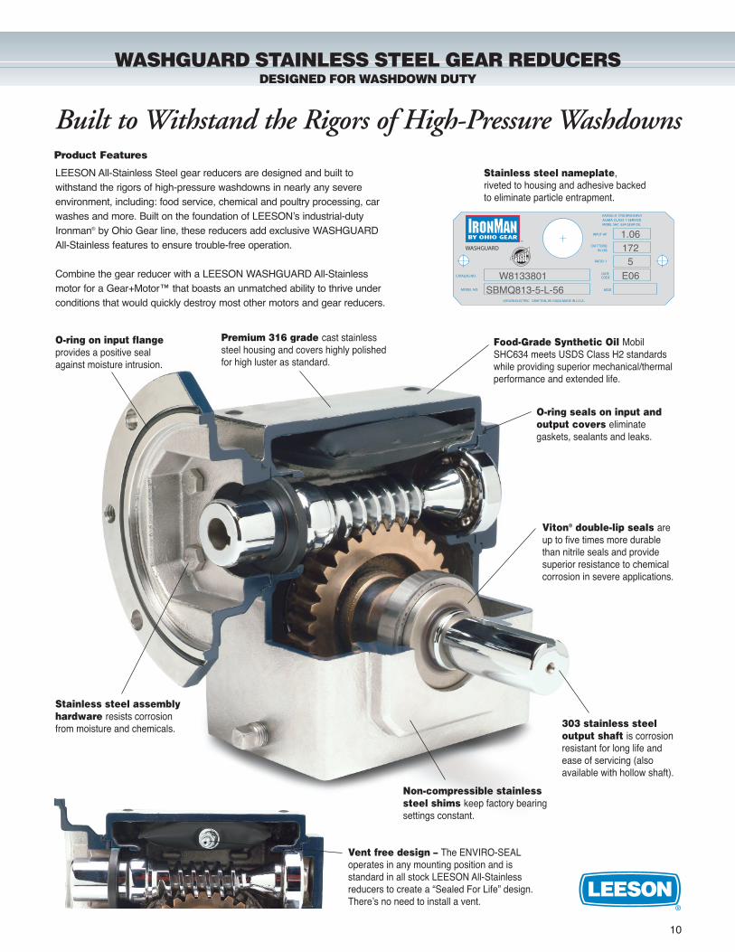
Built to Withstand the Rigors of High-Pressure Washdowns
Vent free design – The ENVIRO-SEALoperates in any mounting position and is standard in all stock LEESON All-Stainlessreducers to create a “Sealed For Life” design.There’s no need to install a vent.
LEESON All-Stainless Steel gear reducers are designed and built to withstand the rigors of high-pressure washdowns in nearly any severe environment, including: food service, chemical and poultry processing, carwashes and more. Built on the foundation of LEESON’s industrial-dutyIronman® by Ohio Gear line, these reducers add exclusive WASHGUARDAll-Stainless features to ensure trouble-free operation.
Combine the gear reducer with a LEESON WASHGUARD All-Stainlessmotor for a Gear+Motor™ that boasts an unmatched ability to thrive under conditions that would quickly destroy most other motors and gear reducers.
Product Features
WASHGUARD STAINLESS STEEL GEAR REDUCERSDESIGNED FOR WASHDOWN DUTY
Food-Grade Synthetic Oil MobilSHC634 meets USDS Class H2 standardswhile providing superior mechanical/thermalperformance and extended life.
Premium 316 grade cast stainlesssteel housing and covers highly polishedfor high luster as standard.
O-ring on input flangeprovides a positive sealagainst moisture intrusion.
O-ring seals on input andoutput covers eliminategaskets, sealants and leaks.
Stainless steel assemblyhardware resists corrosion from moisture and chemicals. 303 stainless steel
output shaft is corrosionresistant for long life andease of servicing (also available with hollow shaft).
Viton® double-lip seals areup to five times more durablethan nitrile seals and providesuperior resistance to chemicalcorrosion in severe applications.
Non-compressible stainlesssteel shims keep factory bearingsettings constant.
Stainless steel nameplate,riveted to housing and adhesive backedto eliminate particle entrapment.
WASHGUARD
MODEL NO.
LEESON ELECTRIC GRAFTON, WI 53024 MADE IN U.S.A.
MOBIL SHC 634 GEAR OIL
CATALOG NO.
RATING @ 1750 RPM INPUTAGMA CLASS 1 SERVICE
INPUT HP
OUT TORQIN-LBS
RATIO :1
DATE
MOD
CODEW8133801SBMQ813-5-L-56
1.06172
5E06
11
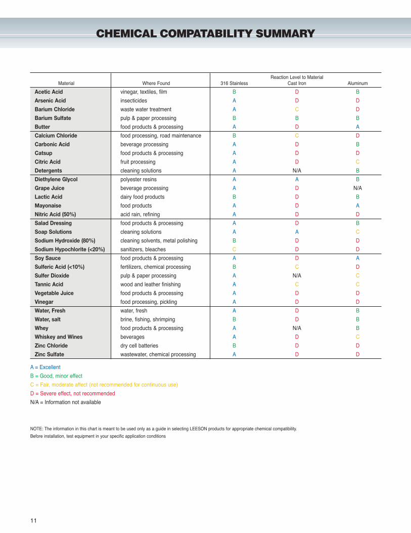
CHEMICAL COMPATABILITY SUMMARY
Reaction Level to MaterialMaterial Where Found 316 Stainless Cast Iron Aluminum
Acetic Acid vinegar, textiles, film B D B
Arsenic Acid insecticides A D D
Barium Chloride waste water treatment A C D
Barium Sulfate pulp & paper processing B B B
Butter food products & processing A D A
Calcium Chloride food processing, road maintenance B C D
Carbonic Acid beverage processing A D B
Catsup food products & processing A D D
Citric Acid fruit processing A D C
Detergents cleaning solutions A N/A B
Diethylene Glycol polyester resins A A B
Grape Juice beverage processing A D N/A
Lactic Acid dairy food products B D B
Mayonaise food products A D A
Nitric Acid (50%) acid rain, refining A D D
Salad Dressing food products & processing A D B
Soap Solutions cleaning solutions A A C
Sodium Hydroxide (80%) cleaning solvents, metal polishing B D D
Sodium Hypochlorite (<20%) sanitizers, bleaches C D D
Soy Sauce food products & processing A D A
Sulferic Acid (<10%) fertilizers, chemical processing B C D
Sulfer Dioxide pulp & paper processing A N/A C
Tannic Acid wood and leather finishing A C C
Vegetable Juice food products & processing A D D
Vinegar food processing, pickling A D D
Water, Fresh water, fresh A D B
Water, salt brine, fishing, shrimping B D B
Whey food products & processing A N/A B
Whiskey and Wines beverages A D C
Zinc Chloride dry cell batteries B D D
Zinc Sulfate wastewater, chemical processing A D D
A = Excellent
B = Good, minor effect
C = Fair, moderate affect (not recommended for continuous use)
D = Severe effect, not recommended
N/A = Information not available
NOTE: The information in this chart is meant to be used only as a guide in selecting LEESON products for appropriate chemical compatibility.
Before installation, test equipment in your specific application conditions
9
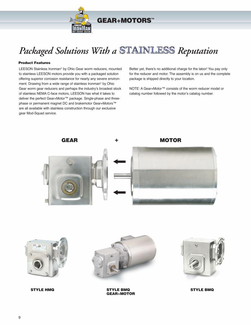
Product Features
GEAR+MOTORS™
LEESON Stainless Ironman® by Ohio Gear worm reducers, mountedto stainless LEESON motors provide you with a packaged solutionoffering superior corrosion resistance for nearly any severe environ-ment. Drawing from a wide range of stainless Ironman® by OhioGear worm gear reducers and perhaps the industry’s broadest stockof stainless NEMA C-face motors, LEESON has what it takes todeliver the perfect Gear+Motor™ package. Single-phase and three-phase or permanent magnet DC and brakemotor Gear+Motors™are all available with stainless construction through our exclusivegear Mod-Squad service.
Better yet, there’s no additional charge for the labor! You pay onlyfor the reducer and motor. The assembly is on us and the completepackage is shipped directly to your location.
NOTE: A Gear+Motor™ consists of the worm reducer model or catalog number followed by the motor’s catalog number.
Packaged Solutions With a Reputation
wash guard
STAIN LESSwash guard
washguard stainless
LEE
SON
LEESON
WASHGUARD
MOTOR+GEAR
STYLE BMQSTYLE BMQ GEAR+MOTOR
STYLE HMQ
12
STAINLESS STEEL GEAR REDUCER
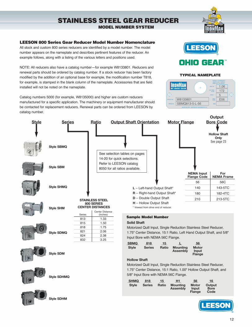
LEESON 800 Series Gear Reducer Model Number NomenclatureAll stock and custom 800 series reducers are identified by a model number. The modelnumber appears on the nameplate and describes pertinent features of the reducer. Anexample follows, along with a listing of the various letters and positions used.
NOTE: All reducers also have a catalog number—for example W8133801. Reducers andrenewal parts should be ordered by catalog number. If a stock reducer has been factorymodified by the addition of an optional base for example, the modification number T818,for example, is stamped in the blank column of the nameplate. Accessories that are fieldinstalled will not be noted on the nameplate.
Catalog numbers 5000 (for example, W8135000) and higher are custom reducers manufactured for a specific application. The machinery or equipment manufacturer shouldbe contacted for replacement reducers. Renewal parts can be ordered from LEESON bycatalog number.
NEMA Input For Flange Code NEMA Frame
56 56C
140 143-5TC
180 182-4TC
210 213-5TC
Style SBM
Style SBMQ
Style SHMQ
Style SDM
Style SDMQ
Style SDHMQ
Style SDHM
L – Left-hand Output Shaft*
R – Right-hand Output Shaft*
D – Double Output Shaft
H – Hollow Output Shaft* Viewed from drive end of reducer.
Hollow ShaftOnly
See page 23
STAINLESS STEEL800 SERIES
CENTER DISTANCESCenter Distance
Series (Inches)
813 1.33815 1.50818 1.75821 2.06824 2.38832 3.25
OutputStyle Series Ratio Output Shaft Orientation Motor Flange Bore Code
MODEL NO.
LEESON ELECTRIC GRAFTON, WI 53024 MADE IN U.S.A.
MOBIL SHC 634 GEAR OIL
CATALOG NO.
RATING @ 1750 RPM INPUTAGMA CLASS 1 SERVICE
INPUT HP
OUT TORQIN-LBS
RATIO :1
DATE
MOD
CODEW8133801SBMQ813-5-L-56
1.061725E06
TYPICAL NAMEPLATE
SBMQ 818 15 L 56 Style Series Ratio Mounting Motor
Assembly InputFlange
SHMQ 818 15 H1 56 16 Style Series Ratio Mounting Motor Output
Assembly Input BoreFlange Code
Sample Model Number
Solid ShaftMotorized Quill Input, Single Reduction Stainless Steel Reducer,1.75" Center Distance, 15:1 Ratio, Left Hand Output Shaft, and 5/8"Input Bore with NEMA 56C Flange.
Hollow ShaftMotorized Quill Input, Single Reduction Stainless Steel Reducer,1.75" Center Distance, 15:1 Ratio, 1.00" Hollow Output Shaft, and5/8" Input Bore with NEMA 56C Flange.
See selection tables on pages14-20 for quick selections.Refer to LEESON catalog8050 for all ratios available.
Style SHM
MODEL NUMBER SYSTEM
wash guard
STAIN LESSwash guard
washguard stainless
LEE
SON
LEESON
WASHGUARD
13
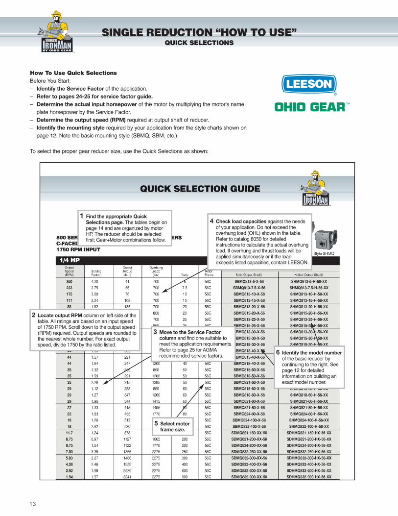
SINGLE REDUCTION “HOW TO USE”QUICK SELECTIONS
How To Use Quick SelectionsBefore You Start:– Identify the Service Factor of the application.– Refer to pages 24-25 for service factor guide.– Determine the actual input horsepower of the motor by multiplying the motor's name
plate horsepower by the Service Factor.– Determine the output speed (RPM) required at output shaft of reducer.– Identify the mounting style required by your application from the style charts shown on
page 12. Note the basic mounting style (SBMQ, SBM, etc.).
To select the proper gear reducer size, use the Quick Selections as shown:
1 Find the appropriate QuickSelections page. The tables begin onpage 14 and are organized by motorHP. The reducer should be selectedfirst; Gear+Motor combinations follow.
5 Select motorframe size.
2 Locate output RPM column on left side of thetable. All ratings are based on an input speedof 1750 RPM. Scroll down to the output speed(RPM) required. Output speeds are rounded tothe nearest whole number. For exact outputspeed, divide 1750 by the ratio listed.
3 Move to the Service Factorcolumn and find one suitable tomeet the application requirements.Refer to page 25 for AGMArecommended service factors.
4 Check load capacities against the needsof your application. Do not exceed theoverhung load (OHL) shown in the table.Refer to catalog 8050 for detailedinstructions to calculate the actual overhungload. If overhung and thrust loads will beapplied simultaneously or if the loadexceeds listed capacities, contact LEESON.
6 Identify the model numberof the basic reducer bycontinuing to the right. Seepage 12 for detailedinformation on building anexact model number.
wash guard
STAIN LESSwash guard
washguard stainless
LEE
SON
LEESON
WASHGUARD
1/4 HP
14
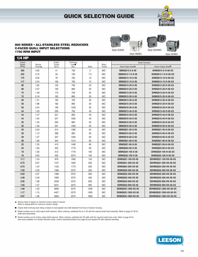
800 SERIES • ALL-STAINLESS STEEL REDUCERSC-FACED QUILL INPUT SELECTIONS1750 RPM INPUT
Output Output Overhung Model NumbersSpeed Service Torque Load� Motor(RPM) Factor� (lb-in) (lbs.) Ratio Frame Solid Output Shaft� Hollow Output Shaft�
350 4.20 41 700 5 56C SBMQ813-5-X-56 SHMQ813-5-H-56-XX
233 3.75 56 700 7.5 56C SBMQ813-7.5-X-56 SHMQ813-7.5-H-56-XX
175 3.00 76 700 10 56C SBMQ813-10-X-56 SHMQ813-10-H-56-XX
117 2.24 108 700 15 56C SBMQ813-15-X-56 SHMQ813-15-H-56-XX
88 1.82 135 700 20 56C SBMQ813-20-X-56 SHMQ813-20-H-56-XX
88 2.57 136 860 20 56C SBMQ815-20-X-56 SHMQ815-20-H-56-XX
70 1.48 170 700 25 56C SBMQ813-25-X-56 SHMQ813-25-H-56-XX
70 2.18 162 860 25 56C SBMQ815-25-X-56 SHMQ815-25-H-56-XX
58 1.31 192 700 30 56C SBMQ813-30-X-56 SHMQ813-30-H-56-XX
58 1.88 182 860 30 56C SBMQ815-30-X-56 SHMQ815-30-H-56-XX
58 2.44 199 1200 30 56C SBMQ818-30-X-56 SHMQ818-30-H-56-XX
44 1.03 239 700 40 56C SBMQ813-40-X-56 SHMQ813-40-H-56-XX
44 1.57 221 860 40 56C SBMQ815-40-X-56 SHMQ815-40-H-56-XX
44 1.94 247 1200 40 56C SBMQ818-40-X-56 SHMQ818-40-H-56-XX
35 1.32 256 860 50 56C SBMQ815-50-X-56 SHMQ815-50-H-56-XX
35 1.59 291 1200 50 56C SBMQ818-50-X-56 SHMQ818-50-H-56-XX
35 2.29 315 1385 50 56C SBMQ821-50-X-56 SHMQ821-50-H-56-XX
29 1.12 288 860 60 56C SBMQ815-60-X-56 SHMQ815-60-H-56-XX
29 1.27 347 1200 60 56C SBMQ818-60-X-56 SHMQ818-60-H-56-XX
29 1.96 344 1415 60 56C SBMQ821-60-X-56 SHMQ821-60-H-56-XX
22 1.33 415 1495 80 56C SBMQ821-80-X-56 SHMQ821-80-H-56-XX
22 1.83 453 1770 80 56C SBMQ824-80-X-56 SHMQ824-80-H-56-XX
18 1.26 513 1770 100 56C SBMQ824-100-X-56 SHMQ824-100-H-56-XX
18 2.92 530 2275 100 56C SBMQ832-100-X-56 SHMQ832-100-H-56-XX
11.7 1.24 878 1065 150 56C SDMQ821-150-XX-56 SDHMQ821-150-HX-56-XX
8.75 0.97 1127 1065 200 56C SDMQ821-200-XX-56 SDHMQ821-200-HX-56-XX
8.75 1.54 1122 1770 200 56C SDMQ824-200-XX-56 SDHMQ824-200-HX-56-XX
7.00 3.35 1366 2275 250 56C SDMQ832-250-XX-56 SDHMQ832-250-HX-56-XX
5.83 3.27 1486 2275 300 56C SDMQ832-300-XX-56 SDHMQ832-300-HX-56-XX
4.38 2.46 1959 2275 400 56C SDMQ832-400-XX-56 SDHMQ832-400-HX-56-XX
2.92 1.98 2539 2275 600 56C SDMQ832-600-XX-56 SDHMQ832-600-HX-56-XX
1.94 1.57 3241 2275 900 56C SDMQ832-900-XX-56 SDHMQ832-900-HX-56-XX
1.46 1.32 3890 2275 1200 56C SDMQ832-1200-XX-56 SDHMQ832-1200-HX-56-XX
1.17 1.15 4457 2275 1500 56C SDMQ832-1500-XX-56 SDHMQ832-1500-HX-56-XX
0.97 1.06 4862 2275 1800 56C SDMQ832-1800-XX-56 SDHMQ832-1800-HX-56-XX
� Service factor is based on maximum torque rating of reducer.Refer to catalog 8050 for maximum reducer ratings.
� Output shaft overhung load rating is based on load applied one shaft diameter from face of reducer housing.
� Model numbers are for solid output shaft reducers. When ordering, substitude the X or XX with the required shaft hand assembly. Refer to pages 21-22 for shaft hand assemblies.
� Model numbers are for hollow output shaft reducers. When ordering, substitute the XX suffix with the required output bore code. Refer to page 23 for bore sizes available. For double reduction styles, confirm assembly position from page 22 and replace HX with required assembly.
QUICK SELECTION GUIDE
Style SBMQ
Style SDMQ Style SDHMQ
Style SHMQ
wash guard
STAIN LESSwash guard
washguard stainless
LEE
SON
LEESON
WASHGUARD
1/3 HP
15
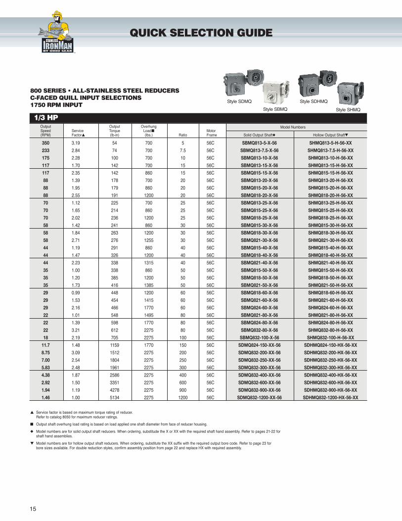
QUICK SELECTION GUIDE
800 SERIES • ALL-STAINLESS STEEL REDUCERSC-FACED QUILL INPUT SELECTIONS1750 RPM INPUT
Output Output Overhung Model NumbersSpeed Service Torque Load� Motor(RPM) Factor� (lb-in) (lbs.) Ratio Frame Solid Output Shaft� Hollow Output Shaft�
350 3.19 54 700 5 56C SBMQ813-5-X-56 SHMQ813-5-H-56-XX
233 2.84 74 700 7.5 56C SBMQ813-7.5-X-56 SHMQ813-7.5-H-56-XX
175 2.28 100 700 10 56C SBMQ813-10-X-56 SHMQ813-10-H-56-XX
117 1.70 142 700 15 56C SBMQ813-15-X-56 SHMQ813-15-H-56-XX
117 2.35 142 860 15 56C SBMQ815-15-X-56 SHMQ815-15-H-56-XX
88 1.39 178 700 20 56C SBMQ813-20-X-56 SHMQ813-20-H-56-XX
88 1.95 179 860 20 56C SBMQ815-20-X-56 SHMQ815-20-H-56-XX
88 2.55 191 1200 20 56C SBMQ818-20-X-56 SHMQ818-20-H-56-XX
70 1.12 225 700 25 56C SBMQ813-25-X-56 SHMQ813-25-H-56-XX
70 1.65 214 860 25 56C SBMQ815-25-X-56 SHMQ815-25-H-56-XX
70 2.02 236 1200 25 56C SBMQ818-25-X-56 SHMQ818-25-H-56-XX
58 1.42 241 860 30 56C SBMQ815-30-X-56 SHMQ815-30-H-56-XX
58 1.84 263 1200 30 56C SBMQ818-30-X-56 SHMQ818-30-H-56-XX
58 2.71 276 1255 30 56C SBMQ821-30-X-56 SHMQ821-30-H-56-XX
44 1.19 291 860 40 56C SBMQ815-40-X-56 SHMQ815-40-H-56-XX
44 1.47 326 1200 40 56C SBMQ818-40-X-56 SHMQ818-40-H-56-XX
44 2.23 338 1315 40 56C SBMQ821-40-X-56 SHMQ821-40-H-56-XX
35 1.00 338 860 50 56C SBMQ815-50-X-56 SHMQ815-50-H-56-XX
35 1.20 385 1200 50 56C SBMQ818-50-X-56 SHMQ818-50-H-56-XX
35 1.73 416 1385 50 56C SBMQ821-50-X-56 SHMQ821-50-H-56-XX
29 0.99 448 1200 60 56C SBMQ818-60-X-56 SHMQ818-60-H-56-XX
29 1.53 454 1415 60 56C SBMQ821-60-X-56 SHMQ821-60-H-56-XX
29 2.16 466 1770 60 56C SBMQ824-60-X-56 SHMQ824-60-H-56-XX
22 1.01 548 1495 80 56C SBMQ821-80-X-56 SHMQ821-80-H-56-XX
22 1.39 598 1770 80 56C SBMQ824-80-X-56 SHMQ824-80-H-56-XX
22 3.21 612 2275 80 56C SBMQ832-80-X-56 SHMQ832-80-H-56-XX
18 2.19 705 2275 100 56C SBMQ832-100-X-56 SHMQ832-100-H-56-XX
11.7 1.48 1159 1770 150 56C SDMQ824-150-XX-56 SDHMQ824-150-HX-56-XX
8.75 3.09 1512 2275 200 56C SDMQ832-200-XX-56 SDHMQ832-200-HX-56-XX
7.00 2.54 1804 2275 250 56C SDMQ832-250-XX-56 SDHMQ832-250-HX-56-XX
5.83 2.48 1961 2275 300 56C SDMQ832-300-XX-56 SDHMQ832-300-HX-56-XX
4.38 1.87 2586 2275 400 56C SDMQ832-400-XX-56 SDHMQ832-400-HX-56-XX
2.92 1.50 3351 2275 600 56C SDMQ832-600-XX-56 SDHMQ832-600-HX-56-XX
1.94 1.19 4278 2275 900 56C SDMQ832-900-XX-56 SDHMQ832-900-HX-56-XX
1.46 1.00 5134 2275 1200 56C SDMQ832-1200-XX-56 SDHMQ832-1200-HX-56-XX
� Service factor is based on maximum torque rating of reducer.Refer to catalog 8050 for maximum reducer ratings.
� Output shaft overhung load rating is based on load applied one shaft diameter from face of reducer housing.
� Model numbers are for solid output shaft reducers. When ordering, substitude the X or XX with the required shaft hand assembly. Refer to pages 21-22 for shaft hand assemblies.
� Model numbers are for hollow output shaft reducers. When ordering, substitute the XX suffix with the required output bore code. Refer to page 23 for bore sizes available. For double reduction styles, confirm assembly position from page 22 and replace HX with required assembly.
Style SBMQ
Style SDMQ Style SDHMQ
Style SHMQ
wash guard
STAIN LESSwash guard
washguard stainless
LEE
SON
LEESON
WASHGUARD
1/2 HP
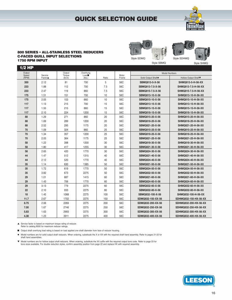
16
800 SERIES • ALL-STAINLESS STEEL REDUCERS C-FACED QUILL INPUT SELECTIONS1750 RPM INPUT
Output Output Overhung Model NumbersSpeed Service Torque Load� Motor(RPM) Factor� (lb-in) (lbs.) Ratio Frame Solid Output Shaft� Hollow Output Shaft�
350 2.12 81 700 5 56C SBMQ813-5-X-56 SHMQ813-5-H-56-XX
233 1.88 112 700 7.5 56C SBMQ813-7.5-X-56 SHMQ813-7.5-H-56-XX
233 2.47 119 860 7.5 56C SBMQ815-7.5-X-56 SHMQ815-7.5-H-56-XX
175 1.51 151 700 10 56C SBMQ813-10-X-56 SHMQ813-10-H-56-XX
175 2.05 153 860 10 56C SBMQ815-10-X-56 SHMQ815-10-H-56-XX
117 1.13 215 700 15 56C SBMQ813-15-X-56 SHMQ813-15-H-56-XX
117 1.55 215 860 15 56C SBMQ815-15-X-56 SHMQ815-15-H-56-XX
117 2.10 224 1200 15 56C SBMQ818-15-X-56 SHMQ818-15-H-56-XX
88 1.29 271 860 20 56C SBMQ815-20-X-56 SHMQ815-20-H-56-XX
88 1.69 289 1200 20 56C SBMQ818-20-X-56 SHMQ818-20-H-56-XX
88 2.52 295 1175 20 56C SBMQ821-20-X-56 SHMQ821-20-H-56-XX
70 1.09 324 860 25 56C SBMQ815-25-X-56 SHMQ815-25-H-56-XX
70 1.34 357 1200 25 56C SBMQ818-25-X-56 SHMQ818-25-H-56-XX
70 2.05 364 1175 25 56C SBMQ821-25-X-56 SHMQ821-25-H-56-XX
58 1.22 398 1200 30 56C SBMQ818-30-X-56 SHMQ818-30-H-56-XX
58 1.80 417 1255 30 56C SBMQ821-30-X-56 SHMQ821-30-H-56-XX
58 2.65 420 1770 30 56C SBMQ824-30-X-56 SHMQ824-30-H-56-XX
44 1.47 512 1315 40 56C SBMQ821-40-X-56 SHMQ821-40-H-56-XX
44 2.12 520 1770 40 56C SBMQ824-40-X-56 SHMQ824-40-H-56-XX
35 1.14 630 1385 50 56C SBMQ821-50-X-56 SHMQ821-50-H-56-XX
35 1.72 619 1770 50 56C SBMQ824-50-X-56 SHMQ824-50-H-56-XX
35 3.82 673 2275 50 56C SBMQ832-50-X-56 SHMQ832-50-H-56-XX
29 1.01 687 1415 60 56C SBMQ821-60-X-56 SHMQ821-60-H-56-XX
29 1.43 706 1770 60 56C SBMQ824-60-X-56 SHMQ824-60-H-56-XX
29 3.13 779 2275 60 56C SBMQ832-60-X-56 SHMQ832-60-H-56-XX
22 2.10 933 2275 80 56C SBMQ832-80-X-56 SHMQ832-80-H-56-XX
18 1.45 1068 2275 100 56C SBMQ832-100-X-56 SHMQ832-100-H-56-XX
11.7 2.67 1702 2275 150 56C SDMQ832-150-XX-56 SDHMQ832-150-HX-56-XX
8.75 2.06 2269 2275 200 56C SDMQ832-200-XX-56 SDHMQ832-200-HX-56-XX
7.00 1.67 2746 2275 250 56C SDMQ832-250-XX-56 SDHMQ832-250-HX-56-XX
5.83 1.63 2993 2275 300 56C SDMQ832-300-XX-56 SDHMQ832-300-HX-56-XX
4.38 1.23 3911 2275 400 56C SDMQ832-400-XX-56 SDHMQ832-400-HX-56-XX
QUICK SELECTION GUIDE
� Service factor is based on maximum torque rating of reducer.Refer to catalog 8050 for maximum reducer ratings.
� Output shaft overhung load rating is based on load applied one shaft diameter from face of reducer housing.
� Model numbers are for solid output shaft reducers. When ordering, substitude the X or XX with the required shaft hand assembly. Refer to pages 21-22 for shaft hand assemblies.
� Model numbers are for hollow output shaft reducers. When ordering, substitute the XX suffix with the required output bore code. Refer to page 23 for bore sizes available. For double reduction styles, confirm assembly position from page 22 and replace HX with required assembly.
Style SBMQ
Style SDMQ Style SDHMQ
Style SHMQ
wash guard
STAIN LESSwash guard
washguard stainless
LEE
SON
LEESON
WASHGUARD
3/4 HP
17
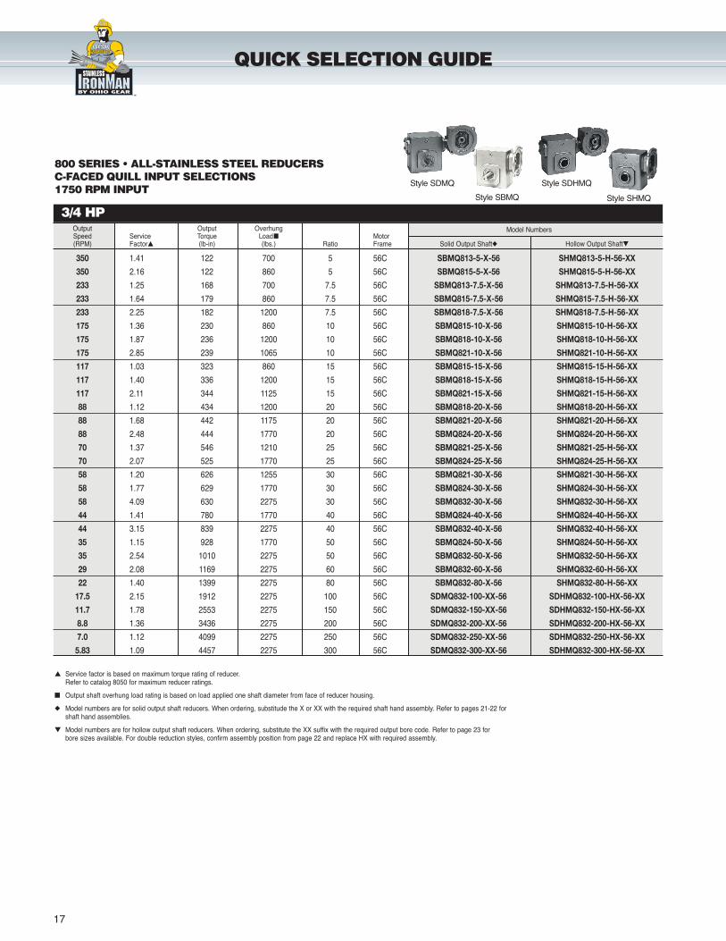
QUICK SELECTION GUIDE
800 SERIES • ALL-STAINLESS STEEL REDUCERS C-FACED QUILL INPUT SELECTIONS1750 RPM INPUT
Output Output Overhung Model NumbersSpeed Service Torque Load� Motor(RPM) Factor� (lb-in) (lbs.) Ratio Frame Solid Output Shaft� Hollow Output Shaft�
350 1.41 122 700 5 56C SBMQ813-5-X-56 SHMQ813-5-H-56-XX
350 2.16 122 860 5 56C SBMQ815-5-X-56 SHMQ815-5-H-56-XX
233 1.25 168 700 7.5 56C SBMQ813-7.5-X-56 SHMQ813-7.5-H-56-XX
233 1.64 179 860 7.5 56C SBMQ815-7.5-X-56 SHMQ815-7.5-H-56-XX
233 2.25 182 1200 7.5 56C SBMQ818-7.5-X-56 SHMQ818-7.5-H-56-XX
175 1.36 230 860 10 56C SBMQ815-10-X-56 SHMQ815-10-H-56-XX
175 1.87 236 1200 10 56C SBMQ818-10-X-56 SHMQ818-10-H-56-XX
175 2.85 239 1065 10 56C SBMQ821-10-X-56 SHMQ821-10-H-56-XX
117 1.03 323 860 15 56C SBMQ815-15-X-56 SHMQ815-15-H-56-XX
117 1.40 336 1200 15 56C SBMQ818-15-X-56 SHMQ818-15-H-56-XX
117 2.11 344 1125 15 56C SBMQ821-15-X-56 SHMQ821-15-H-56-XX
88 1.12 434 1200 20 56C SBMQ818-20-X-56 SHMQ818-20-H-56-XX
88 1.68 442 1175 20 56C SBMQ821-20-X-56 SHMQ821-20-H-56-XX
88 2.48 444 1770 20 56C SBMQ824-20-X-56 SHMQ824-20-H-56-XX
70 1.37 546 1210 25 56C SBMQ821-25-X-56 SHMQ821-25-H-56-XX
70 2.07 525 1770 25 56C SBMQ824-25-X-56 SHMQ824-25-H-56-XX
58 1.20 626 1255 30 56C SBMQ821-30-X-56 SHMQ821-30-H-56-XX
58 1.77 629 1770 30 56C SBMQ824-30-X-56 SHMQ824-30-H-56-XX
58 4.09 630 2275 30 56C SBMQ832-30-X-56 SHMQ832-30-H-56-XX
44 1.41 780 1770 40 56C SBMQ824-40-X-56 SHMQ824-40-H-56-XX
44 3.15 839 2275 40 56C SBMQ832-40-X-56 SHMQ832-40-H-56-XX
35 1.15 928 1770 50 56C SBMQ824-50-X-56 SHMQ824-50-H-56-XX
35 2.54 1010 2275 50 56C SBMQ832-50-X-56 SHMQ832-50-H-56-XX
29 2.08 1169 2275 60 56C SBMQ832-60-X-56 SHMQ832-60-H-56-XX
22 1.40 1399 2275 80 56C SBMQ832-80-X-56 SHMQ832-80-H-56-XX
17.5 2.15 1912 2275 100 56C SDMQ832-100-XX-56 SDHMQ832-100-HX-56-XX
11.7 1.78 2553 2275 150 56C SDMQ832-150-XX-56 SDHMQ832-150-HX-56-XX
8.8 1.36 3436 2275 200 56C SDMQ832-200-XX-56 SDHMQ832-200-HX-56-XX
7.0 1.12 4099 2275 250 56C SDMQ832-250-XX-56 SDHMQ832-250-HX-56-XX
5.83 1.09 4457 2275 300 56C SDMQ832-300-XX-56 SDHMQ832-300-HX-56-XX
� Service factor is based on maximum torque rating of reducer.Refer to catalog 8050 for maximum reducer ratings.
� Output shaft overhung load rating is based on load applied one shaft diameter from face of reducer housing.
� Model numbers are for solid output shaft reducers. When ordering, substitude the X or XX with the required shaft hand assembly. Refer to pages 21-22 for shaft hand assemblies.
� Model numbers are for hollow output shaft reducers. When ordering, substitute the XX suffix with the required output bore code. Refer to page 23 for bore sizes available. For double reduction styles, confirm assembly position from page 22 and replace HX with required assembly.
Style SBMQ
Style SDMQ Style SDHMQ
Style SHMQ
wash guard
STAIN LESSwash guard
washguard stainless
LEE
SON
LEESON
WASHGUARD
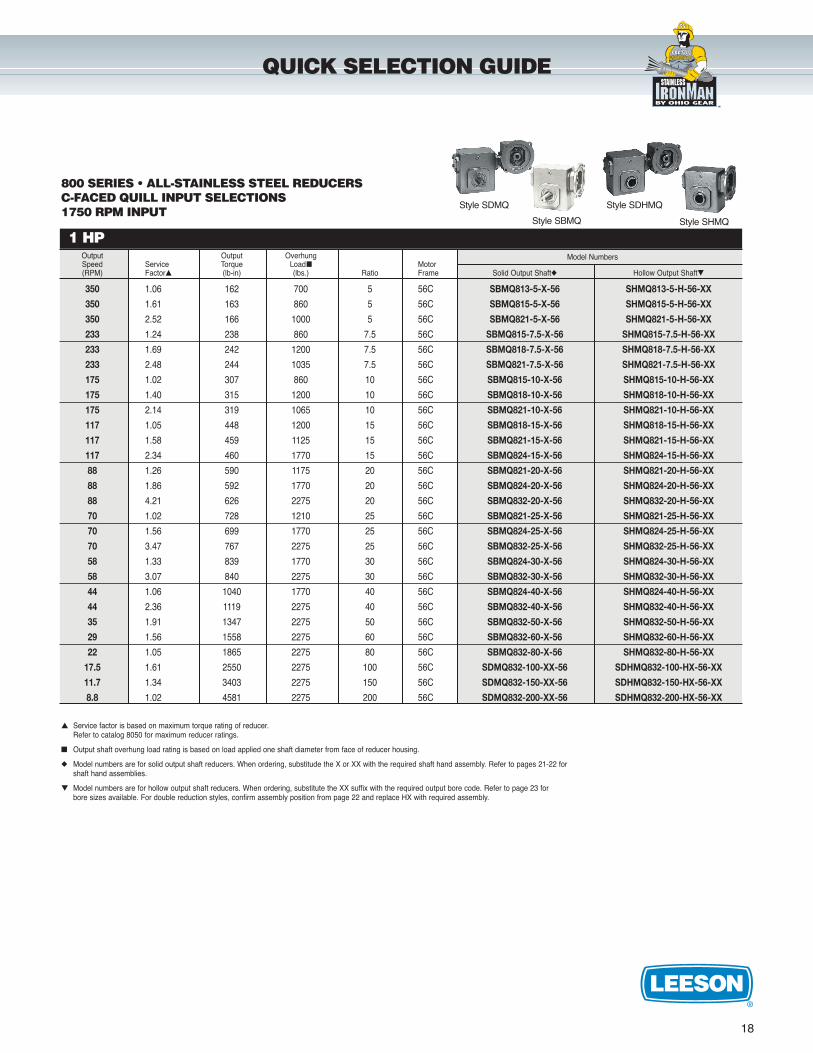
1 HP
18
Output Output Overhung Model NumbersSpeed Service Torque Load� Motor(RPM) Factor� (lb-in) (lbs.) Ratio Frame Solid Output Shaft� Hollow Output Shaft�
350 1.06 162 700 5 56C SBMQ813-5-X-56 SHMQ813-5-H-56-XX
350 1.61 163 860 5 56C SBMQ815-5-X-56 SHMQ815-5-H-56-XX
350 2.52 166 1000 5 56C SBMQ821-5-X-56 SHMQ821-5-H-56-XX
233 1.24 238 860 7.5 56C SBMQ815-7.5-X-56 SHMQ815-7.5-H-56-XX
233 1.69 242 1200 7.5 56C SBMQ818-7.5-X-56 SHMQ818-7.5-H-56-XX
233 2.48 244 1035 7.5 56C SBMQ821-7.5-X-56 SHMQ821-7.5-H-56-XX
175 1.02 307 860 10 56C SBMQ815-10-X-56 SHMQ815-10-H-56-XX
175 1.40 315 1200 10 56C SBMQ818-10-X-56 SHMQ818-10-H-56-XX
175 2.14 319 1065 10 56C SBMQ821-10-X-56 SHMQ821-10-H-56-XX
117 1.05 448 1200 15 56C SBMQ818-15-X-56 SHMQ818-15-H-56-XX
117 1.58 459 1125 15 56C SBMQ821-15-X-56 SHMQ821-15-H-56-XX
117 2.34 460 1770 15 56C SBMQ824-15-X-56 SHMQ824-15-H-56-XX
88 1.26 590 1175 20 56C SBMQ821-20-X-56 SHMQ821-20-H-56-XX
88 1.86 592 1770 20 56C SBMQ824-20-X-56 SHMQ824-20-H-56-XX
88 4.21 626 2275 20 56C SBMQ832-20-X-56 SHMQ832-20-H-56-XX
70 1.02 728 1210 25 56C SBMQ821-25-X-56 SHMQ821-25-H-56-XX
70 1.56 699 1770 25 56C SBMQ824-25-X-56 SHMQ824-25-H-56-XX
70 3.47 767 2275 25 56C SBMQ832-25-X-56 SHMQ832-25-H-56-XX
58 1.33 839 1770 30 56C SBMQ824-30-X-56 SHMQ824-30-H-56-XX
58 3.07 840 2275 30 56C SBMQ832-30-X-56 SHMQ832-30-H-56-XX
44 1.06 1040 1770 40 56C SBMQ824-40-X-56 SHMQ824-40-H-56-XX
44 2.36 1119 2275 40 56C SBMQ832-40-X-56 SHMQ832-40-H-56-XX
35 1.91 1347 2275 50 56C SBMQ832-50-X-56 SHMQ832-50-H-56-XX
29 1.56 1558 2275 60 56C SBMQ832-60-X-56 SHMQ832-60-H-56-XX
22 1.05 1865 2275 80 56C SBMQ832-80-X-56 SHMQ832-80-H-56-XX
17.5 1.61 2550 2275 100 56C SDMQ832-100-XX-56 SDHMQ832-100-HX-56-XX
11.7 1.34 3403 2275 150 56C SDMQ832-150-XX-56 SDHMQ832-150-HX-56-XX
8.8 1.02 4581 2275 200 56C SDMQ832-200-XX-56 SDHMQ832-200-HX-56-XX
QUICK SELECTION GUIDE
800 SERIES • ALL-STAINLESS STEEL REDUCERS C-FACED QUILL INPUT SELECTIONS1750 RPM INPUT
� Service factor is based on maximum torque rating of reducer.Refer to catalog 8050 for maximum reducer ratings.
� Output shaft overhung load rating is based on load applied one shaft diameter from face of reducer housing.
� Model numbers are for solid output shaft reducers. When ordering, substitude the X or XX with the required shaft hand assembly. Refer to pages 21-22 for shaft hand assemblies.
� Model numbers are for hollow output shaft reducers. When ordering, substitute the XX suffix with the required output bore code. Refer to page 23 for bore sizes available. For double reduction styles, confirm assembly position from page 22 and replace HX with required assembly.
Style SBMQ
Style SDMQ Style SDHMQ
Style SHMQ
wash guard
STAIN LESSwash guard
washguard stainless
LEE
SON
LEESON
WASHGUARD
2 HP
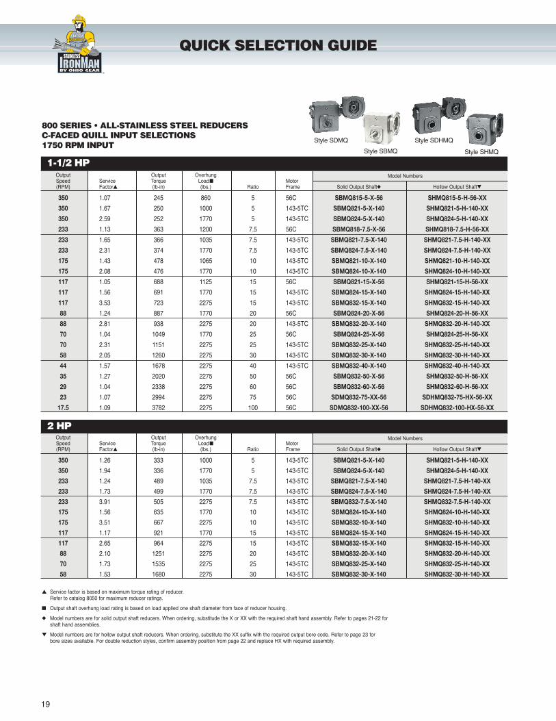
1-1/2 HP
19
QUICK SELECTION GUIDE
800 SERIES • ALL-STAINLESS STEEL REDUCERSC-FACED QUILL INPUT SELECTIONS1750 RPM INPUT
Output Output Overhung Model NumbersSpeed Service Torque Load� Motor(RPM) Factor� (lb-in) (lbs.) Ratio Frame Solid Output Shaft� Hollow Output Shaft�
350 1.07 245 860 5 56C SBMQ815-5-X-56 SHMQ815-5-H-56-XX
350 1.67 250 1000 5 143-5TC SBMQ821-5-X-140 SHMQ821-5-H-140-XX
350 2.59 252 1770 5 143-5TC SBMQ824-5-X-140 SHMQ824-5-H-140-XX
233 1.13 363 1200 7.5 56C SBMQ818-7.5-X-56 SHMQ818-7.5-H-56-XX
233 1.65 366 1035 7.5 143-5TC SBMQ821-7.5-X-140 SHMQ821-7.5-H-140-XX
233 2.31 374 1770 7.5 143-5TC SBMQ824-7.5-X-140 SHMQ824-7.5-H-140-XX
175 1.43 478 1065 10 143-5TC SBMQ821-10-X-140 SHMQ821-10-H-140-XX
175 2.08 476 1770 10 143-5TC SBMQ824-10-X-140 SHMQ824-10-H-140-XX
117 1.05 688 1125 15 56C SBMQ821-15-X-56 SHMQ821-15-H-56-XX
117 1.56 691 1770 15 143-5TC SBMQ824-15-X-140 SHMQ824-15-H-140-XX
117 3.53 723 2275 15 143-5TC SBMQ832-15-X-140 SHMQ832-15-H-140-XX
88 1.24 887 1770 20 56C SBMQ824-20-X-56 SHMQ824-20-H-56-XX
88 2.81 938 2275 20 143-5TC SBMQ832-20-X-140 SHMQ832-20-H-140-XX
70 1.04 1049 1770 25 56C SBMQ824-25-X-56 SHMQ824-25-H-56-XX
70 2.31 1151 2275 25 143-5TC SBMQ832-25-X-140 SHMQ832-25-H-140-XX
58 2.05 1260 2275 30 143-5TC SBMQ832-30-X-140 SHMQ832-30-H-140-XX
44 1.57 1678 2275 40 143-5TC SBMQ832-40-X-140 SHMQ832-40-H-140-XX
35 1.27 2020 2275 50 56C SBMQ832-50-X-56 SHMQ832-50-H-56-XX
29 1.04 2338 2275 60 56C SBMQ832-60-X-56 SHMQ832-60-H-56-XX
23 1.07 2994 2275 75 56C SDMQ832-75-XX-56 SDHMQ832-75-HX-56-XX
17.5 1.09 3782 2275 100 56C SDMQ832-100-XX-56 SDHMQ832-100-HX-56-XX
Output Output Overhung Model NumbersSpeed Service Torque Load� Motor(RPM) Factor� (lb-in) (lbs.) Ratio Frame Solid Output Shaft� Hollow Output Shaft�
350 1.26 333 1000 5 143-5TC SBMQ821-5-X-140 SHMQ821-5-H-140-XX
350 1.94 336 1770 5 143-5TC SBMQ824-5-X-140 SHMQ824-5-H-140-XX
233 1.24 489 1035 7.5 143-5TC SBMQ821-7.5-X-140 SHMQ821-7.5-H-140-XX
233 1.73 499 1770 7.5 143-5TC SBMQ824-7.5-X-140 SHMQ824-7.5-H-140-XX
233 3.91 505 2275 7.5 143-5TC SBMQ832-7.5-X-140 SHMQ832-7.5-H-140-XX
175 1.56 635 1770 10 143-5TC SBMQ824-10-X-140 SHMQ824-10-H-140-XX
175 3.51 667 2275 10 143-5TC SBMQ832-10-X-140 SHMQ832-10-H-140-XX
117 1.17 921 1770 15 143-5TC SBMQ824-15-X-140 SHMQ824-15-H-140-XX
117 2.65 964 2275 15 143-5TC SBMQ832-15-X-140 SHMQ832-15-H-140-XX
88 2.10 1251 2275 20 143-5TC SBMQ832-20-X-140 SHMQ832-20-H-140-XX
70 1.73 1535 2275 25 143-5TC SBMQ832-25-X-140 SHMQ832-25-H-140-XX
58 1.53 1680 2275 30 143-5TC SBMQ832-30-X-140 SHMQ832-30-H-140-XX
� Service factor is based on maximum torque rating of reducer.Refer to catalog 8050 for maximum reducer ratings.
� Output shaft overhung load rating is based on load applied one shaft diameter from face of reducer housing.
� Model numbers are for solid output shaft reducers. When ordering, substitude the X or XX with the required shaft hand assembly. Refer to pages 21-22 for shaft hand assemblies.
� Model numbers are for hollow output shaft reducers. When ordering, substitute the XX suffix with the required output bore code. Refer to page 23 for bore sizes available. For double reduction styles, confirm assembly position from page 22 and replace HX with required assembly.
Style SBMQ
Style SDMQ Style SDHMQ
Style SHMQ
wash guard
STAIN LESSwash guard
washguard stainless
LEE
SON
LEESON
WASHGUARD
7-1/2 HP
5 HP
3 HP
20
QUICK SELECTION GUIDE
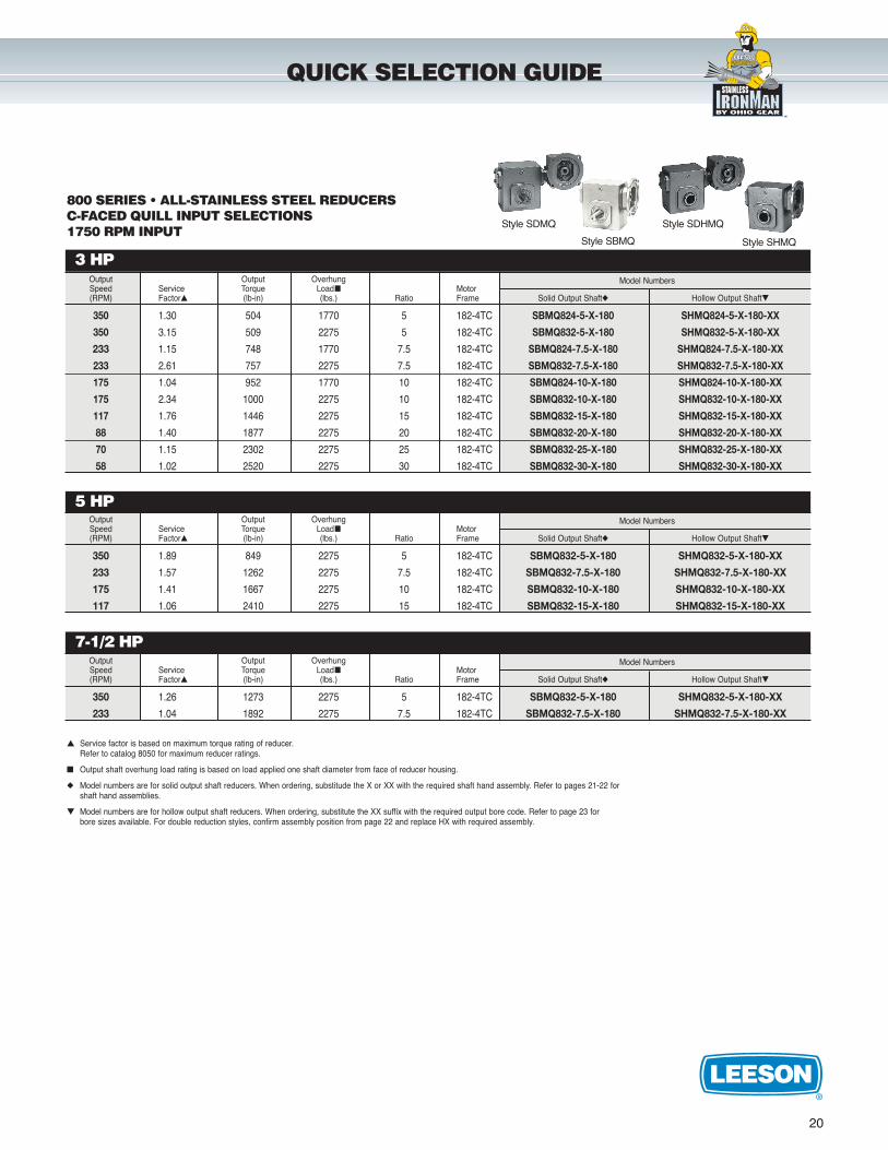
800 SERIES • ALL-STAINLESS STEEL REDUCERS C-FACED QUILL INPUT SELECTIONS1750 RPM INPUT
Output Output Overhung Model NumbersSpeed Service Torque Load� Motor(RPM) Factor� (lb-in) (lbs.) Ratio Frame Solid Output Shaft� Hollow Output Shaft�
350 1.30 504 1770 5 182-4TC SBMQ824-5-X-180 SHMQ824-5-X-180-XX
350 3.15 509 2275 5 182-4TC SBMQ832-5-X-180 SHMQ832-5-X-180-XX
233 1.15 748 1770 7.5 182-4TC SBMQ824-7.5-X-180 SHMQ824-7.5-X-180-XX
233 2.61 757 2275 7.5 182-4TC SBMQ832-7.5-X-180 SHMQ832-7.5-X-180-XX
175 1.04 952 1770 10 182-4TC SBMQ824-10-X-180 SHMQ824-10-X-180-XX
175 2.34 1000 2275 10 182-4TC SBMQ832-10-X-180 SHMQ832-10-X-180-XX
117 1.76 1446 2275 15 182-4TC SBMQ832-15-X-180 SHMQ832-15-X-180-XX
88 1.40 1877 2275 20 182-4TC SBMQ832-20-X-180 SHMQ832-20-X-180-XX
70 1.15 2302 2275 25 182-4TC SBMQ832-25-X-180 SHMQ832-25-X-180-XX
58 1.02 2520 2275 30 182-4TC SBMQ832-30-X-180 SHMQ832-30-X-180-XX
Output Output Overhung Model NumbersSpeed Service Torque Load� Motor(RPM) Factor� (lb-in) (lbs.) Ratio Frame Solid Output Shaft� Hollow Output Shaft�
350 1.89 849 2275 5 182-4TC SBMQ832-5-X-180 SHMQ832-5-X-180-XX
233 1.57 1262 2275 7.5 182-4TC SBMQ832-7.5-X-180 SHMQ832-7.5-X-180-XX
175 1.41 1667 2275 10 182-4TC SBMQ832-10-X-180 SHMQ832-10-X-180-XX
117 1.06 2410 2275 15 182-4TC SBMQ832-15-X-180 SHMQ832-15-X-180-XX
Output Output Overhung Model NumbersSpeed Service Torque Load� Motor(RPM) Factor� (lb-in) (lbs.) Ratio Frame Solid Output Shaft� Hollow Output Shaft�
350 1.26 1273 2275 5 182-4TC SBMQ832-5-X-180 SHMQ832-5-X-180-XX
233 1.04 1892 2275 7.5 182-4TC SBMQ832-7.5-X-180 SHMQ832-7.5-X-180-XX
� Service factor is based on maximum torque rating of reducer.Refer to catalog 8050 for maximum reducer ratings.
� Output shaft overhung load rating is based on load applied one shaft diameter from face of reducer housing.
� Model numbers are for solid output shaft reducers. When ordering, substitude the X or XX with the required shaft hand assembly. Refer to pages 21-22 for shaft hand assemblies.
� Model numbers are for hollow output shaft reducers. When ordering, substitute the XX suffix with the required output bore code. Refer to page 23 for bore sizes available. For double reduction styles, confirm assembly position from page 22 and replace HX with required assembly.
Style SBMQ
Style SDMQ Style SDHMQ
Style SHMQ
wash guard
STAIN LESSwash guard
washguard stainless
LEE
SON
LEESON
WASHGUARD
21
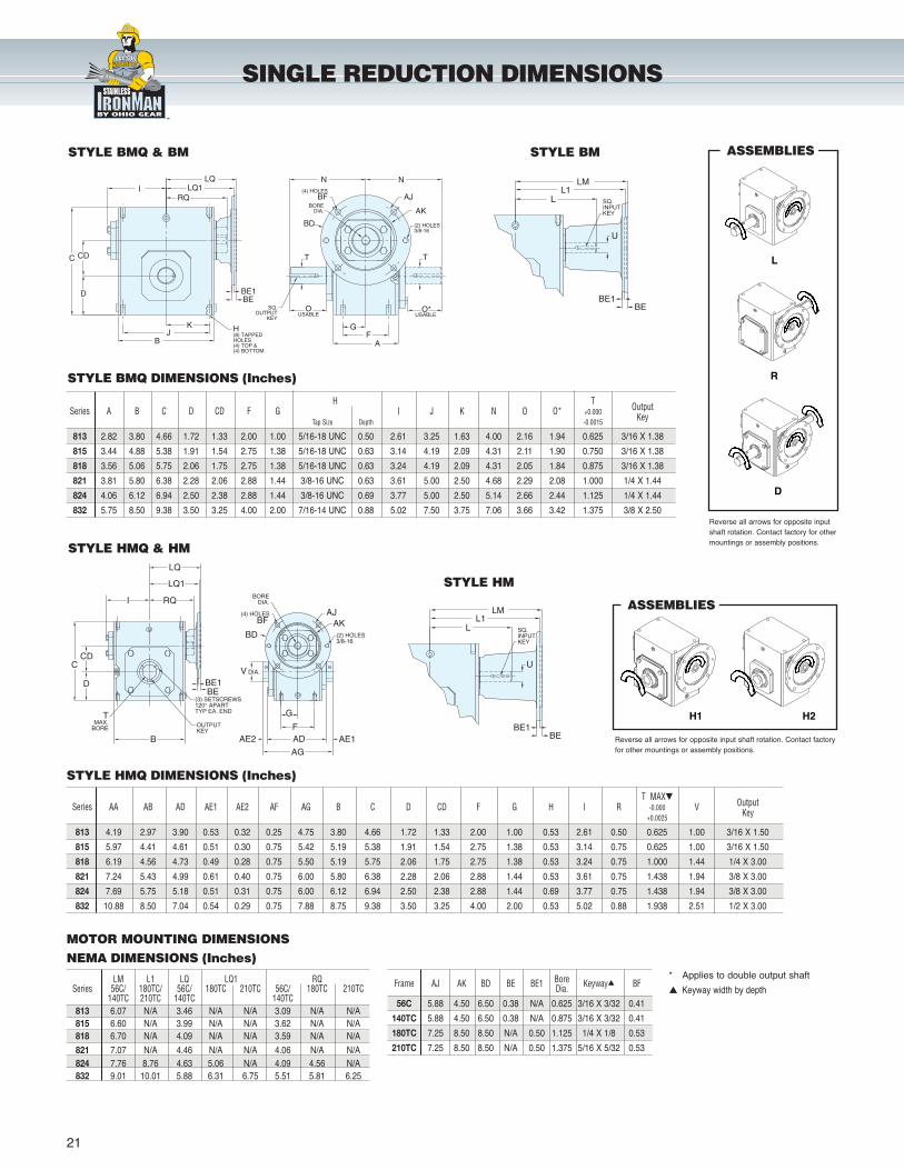
SINGLE REDUCTION DIMENSIONS
STYLE BM
L
ASSEMBLIES
Reverse all arrows for opposite inputshaft rotation. Contact factory for othermountings or assembly positions.
H T OutputSeries A B C D CD F G I J K N O O* +0.000 KeyTap Size Depth -0.0015
813 2.82 3.80 4.66 1.72 1.33 2.00 1.00 5/16-18 UNC 0.50 2.61 3.25 1.63 4.00 2.16 1.94 0.625 3/16 X 1.38
815 3.44 4.88 5.38 1.91 1.54 2.75 1.38 5/16-18 UNC 0.63 3.14 4.19 2.09 4.31 2.11 1.90 0.750 3/16 X 1.38
818 3.56 5.06 5.75 2.06 1.75 2.75 1.38 5/16-18 UNC 0.63 3.24 4.19 2.09 4.31 2.05 1.84 0.875 3/16 X 1.38
821 3.81 5.80 6.38 2.28 2.06 2.88 1.44 3/8-16 UNC 0.63 3.61 5.00 2.50 4.68 2.29 2.08 1.000 1/4 X 1.44
824 4.06 6.12 6.94 2.50 2.38 2.88 1.44 3/8-16 UNC 0.69 3.77 5.00 2.50 5.14 2.66 2.44 1.125 1/4 X 1.44
832 5.75 8.50 9.38 3.50 3.25 4.00 2.00 7/16-14 UNC 0.88 5.02 7.50 3.75 7.06 3.66 3.42 1.375 3/8 X 2.50
STYLE BMQ DIMENSIONS (Inches)
STYLE BMQ & BM
H1 H2
ASSEMBLIES
Reverse all arrows for opposite input shaft rotation. Contact factoryfor other mountings or assembly positions.
STYLE HMQ & HM
STYLE HMQ DIMENSIONS (Inches)
T MAX� OutputSeries AA AB AD AE1 AE2 AF AG B C D CD F G H I R -0.000 V Key+0.0025
813 4.19 2.97 3.90 0.53 0.32 0.25 4.75 3.80 4.66 1.72 1.33 2.00 1.00 0.53 2.61 0.50 0.625 1.00 3/16 X 1.50
815 5.97 4.41 4.61 0.51 0.30 0.75 5.42 5.19 5.38 1.91 1.54 2.75 1.38 0.53 3.14 0.75 0.625 1.00 3/16 X 1.50
818 6.19 4.56 4.73 0.49 0.28 0.75 5.50 5.19 5.75 2.06 1.75 2.75 1.38 0.53 3.24 0.75 1.000 1.44 1/4 X 3.00
821 7.24 5.43 4.99 0.61 0.40 0.75 6.00 5.80 6.38 2.28 2.06 2.88 1.44 0.53 3.61 0.75 1.438 1.94 3/8 X 3.00
824 7.69 5.75 5.18 0.51 0.31 0.75 6.00 6.12 6.94 2.50 2.38 2.88 1.44 0.69 3.77 0.75 1.438 1.94 3/8 X 3.00
832 10.88 8.50 7.04 0.54 0.29 0.75 7.88 8.75 9.38 3.50 3.25 4.00 2.00 0.53 5.02 0.88 1.938 2.51 1/2 X 3.00
MOTOR MOUNTING DIMENSIONSNEMA DIMENSIONS (Inches)
LM L1 LQ LQ1 RQSeries 56C/ 180TC/ 56C/ 180TC 210TC 56C/ 180TC 210TC
140TC 210TC 140TC 140TC813 6.07 N/A 3.46 N/A N/A 3.09 N/A N/A815 6.60 N/A 3.99 N/A N/A 3.62 N/A N/A818 6.70 N/A 4.09 N/A N/A 3.59 N/A N/A
821 7.07 N/A 4.46 N/A N/A 4.06 N/A N/A824 7.76 8.76 4.63 5.06 N/A 4.09 4.56 N/A832 9.01 10.01 5.88 6.31 6.75 5.51 5.81 6.25
Frame AJ AK BD BE BE1 Bore Keyway� BFDia.56C 5.88 4.50 6.50 0.38 N/A 0.625 3/16 X 3/32 0.41
140TC 5.88 4.50 6.50 0.38 N/A 0.875 3/16 X 3/32 0.41
180TC 7.25 8.50 8.50 N/A 0.50 1.125 1/4 X 1/8 0.53
210TC 7.25 8.50 8.50 N/A 0.50 1.375 5/16 X 5/32 0.53
* Applies to double output shaft
� Keyway width by depth
D
R
STYLE HM
wash guard
STAIN LESSwash guard
washguard stainless
LEE
SON
LEESON
WASHGUARD
22
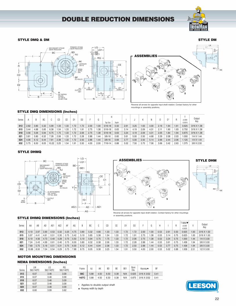
DOUBLE REDUCTION DIMENSIONS
H T OutputSeries A B BC C CD CE D1 D2 F G I J K N O O* R +0.000 KeyTap Size Depth -0.0015
813 2.82 3.80 5.32 5.99 1.33 1.33 1.72 1.72 2.00 1.00 5/16-18 0.50 2.61 3.25 1.63 4.00 2.16 1.94 1.61 0.625 3/16 X 1.38815 3.44 4.88 5.85 6.38 1.54 1.33 1.72 1.91 2.75 1.38 5/16-18 0.63 3.14 4.19 2.09 4.31 2.11 1.90 1.93 0.750 3/16 X 1.38818 3.56 5.06 5.94 6.75 1.75 1.33 1.72 2.06 2.75 1.38 5/16-18 0.63 3.24 4.19 2.09 4.31 2.05 1.84 1.94 0.875 3/16 X 1.38821 3.81 5.80 6.32 7.28 2.06 1.33 1.72 2.28 2.88 1.44 3/8-16 0.60 3.61 5.00 2.50 4.68 2.29 2.08 2.03 1.000 1/4 X 1.44824 4.06 6.12 6.44 7.81 2.38 1.33 1.72 2.50 2.88 1.44 3/8-16 0.69 3.77 5.00 2.50 5.14 2.66 2.44 2.06 1.125 1/4 X 1.44832 5.75 8.50 8.05 10.22 3.25 1.54 1.91 3.50 4.00 2.00 7/16-14 0.88 5.02 7.50 3.75 7.06 3.66 3.42 2.63 1.375 3/8 X 2.50
L
R
D
5
6
4
3
2
1
ASSEMBLIES
Reverse all arrows for opposite input shaft rotation. Contact factory for other mountings or assembly positions.
STYLE DMQ & DM
STYLE DMQ DIMENSIONS (Inches)
1
2
3
4
5
6
H
ASSEMBLIES
Reverse all arrows for opposite input shaft rotation. Contact factory for other mountingsor assembly positions.
STYLE DHMQ
STYLE DHMQ DIMENSIONS (Inches)T MAX� OutputSeries AA AB AD AE1 AE2 AF AG B BC C CD CE D1 D2 F G H I R +0.000 V Key-0.0025
813 4.19 2.97 3.90 0.53 0.32 0.25 4.75 3.80 5.32 4.66 1.33 1.33 1.72 1.72 2.00 1.00 0.53 2.61 0.50 0.625 1.00 3/16 X 1.50815 5.97 4.41 4.61 0.51 0.30 0.75 5.42 5.19 5.85 5.38 1.54 1.33 1.72 1.91 2.75 1.38 0.53 3.14 0.75 0.625 1.00 3/16 X 1.50818 6.19 4.56 4.73 0.49 0.28 0.75 5.50 5.19 5.94 5.75 1.75 1.33 1.72 2.06 2.75 1.38 0.53 3.24 0.75 1.000 1.44 1/4 X 3.00821 7.24 5.43 4.99 0.61 0.40 0.75 6.00 5.80 6.32 6.38 2.06 1.33 1.72 2.28 2.88 1.44 0.53 3.61 0.75 1.438 1.94 3/8 X 3.00824 7.69 5.75 5.18 0.51 0.31 0.75 6.00 6.12 6.44 6.94 2.38 1.33 1.72 2.50 2.88 1.44 0.53 3.77 0.75 1.438 1.94 3/8 X 3.00832 10.88 8.50 7.04 0.54 0.29 0.75 7.88 8.75 8.05 9.38 3.25 1.54 1.91 3.50 4.00 2.00 0.53 5.02 0.88 1.938 2.51 1/2 X 3.00
MOTOR MOUNTING DIMENSIONS
NEMA DIMENSIONS (Inches)
LM LQ RQSeries 56C/140TC 56C/140TC 56C/140TC813 6.07 3.46 3.09815 6.07 3.46 3.09818 6.07 3.46 3.09821 6.07 3.46 3.09824 6.07 3.46 3.09832 6.60 3.99 3.62
Frame AJ AK BD BE BE1 Bore Keyway� BFDia.56C 5.88 4.50 6.50 0.38 N/A 0.625 3/16 X 3/32 0.41
140TC 5.88 4.50 6.50 0.38 N/A 0.875 3/16 X 3/32 0.41
* Applies to double output shaft� Keyway width by depth
STYLE DM
STYLE DHM
wash guard
STAIN LESSwash guard
washguard stainless
LEE
SON
LEESON
WASHGUARD
23
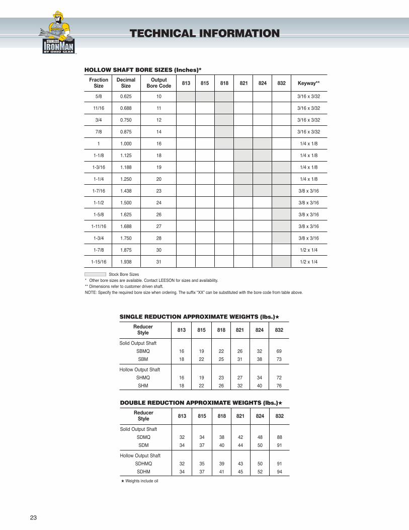
TECHNICAL INFORMATION
Stock Bore Sizes* Other bore sizes are available. Contact LEESON for sizes and availability.** Dimensions refer to customer driven shaft.NOTE: Specify the required bore size when ordering. The suffix “XX” can be substituted with the bore code from table above.
HOLLOW SHAFT BORE SIZES (Inches)*
Fraction Decimal Output813 815 818 821 824 832 Keyway**Size Size Bore Code
5/8 0.625 10 3/16 x 3/32
11/16 0.688 11 3/16 x 3/32
3/4 0.750 12 3/16 x 3/32
7/8 0.875 14 3/16 x 3/32
1 1.000 16 1/4 x 1/8
1-1/8 1.125 18 1/4 x 1/8
1-3/16 1.188 19 1/4 x 1/8
1-1/4 1.250 20 1/4 x 1/8
1-7/16 1.438 23 3/8 x 3/16
1-1/2 1.500 24 3/8 x 3/16
1-5/8 1.625 26 3/8 x 3/16
1-11/16 1.688 27 3/8 x 3/16
1-3/4 1.750 28 3/8 x 3/16
1-7/8 1.875 30 1/2 x 1/4
1-15/16 1.938 31 1/2 x 1/4
SINGLE REDUCTION APPROXIMATE WEIGHTS (lbs.)�
Reducer813 815 818 821 824 832Style
Solid Output Shaft
SBMQ 16 19 22 26 32 69
SBM 18 22 25 31 38 73
Hollow Output Shaft
SHMQ 16 19 23 27 34 72
SHM 18 22 26 32 40 76
DOUBLE REDUCTION APPROXIMATE WEIGHTS (lbs.)�
Reducer813 815 818 821 824 832Style
Solid Output Shaft
SDMQ 32 34 38 42 48 88
SDM 34 37 40 44 50 91
Hollow Output Shaft
SDHMQ 32 35 39 43 50 91
SDHM 34 37 41 45 52 94
� Weights include oil
wash guard
STAIN LESSwash guard
washguard stainless
LEE
SON
LEESON
WASHGUARD
24
Condensed Glossary of Motor and Gearing Terms
Axial Movement - Often called “endplay.” The endwise movement of motor orgear shafts. Usually expressed in thousandths of an inch.
Back Driving - Driving the output shaft of a reducer — using it to increasespeed rather than reduce speed. Worm gear reducers are not suitable for service as speed increasers.
Backlash - Rotational movement of the output shaft clockwise and counterclockwise, while holding the input shaft stationary. Usually expressed in thousandths of an inch and measure at a specific radius at the output shaft.
Center Distance - A basic measurement or size reference for worm gear reducers, measured from the centerline of the worm to the centerline of theworm wheel.
Drip-Proof - Venting in end frame and/or main frame located to prevent dropsof liquid from falling into motor within 15 angle from vertical. Designed for usein areas that are reasonably dry, clean, and well ventilated (usually indoors). Ifinstalled outdoors, it is recommended that the motor be protected with a coverthat does not restrict the flow of air to the motor.
Efficiency - A ratio of the input power compared to the output, usuallyexpressed as a percentage.
Explosion-Proof Motors - These motors meet Underwriters Laboratories andCanadian Standards Association standards for use in hazardous (explosive)locations, as indicated by the UL label affixed to the motor. Locations are considered hazardous because the atmosphere does or may contain gas,vapor, or dust in explosive quantities.
Flanged Reducer - Usually used to refer to a reducer having provisions forclose coupling of a motor either via a hollow (quill) shaft or flexible coupling.Most often a NEMA C face motor is used.
Gear+Motor™ - LEESON’s registered trademark for a separable gear andNEMA C face motor as opposed to an integral gearmotor. Integral gearmotorssuffer from lack of application and availability constraints as well as havinginherent service issues when one or the other component needs replacement.
Input Horsepower - The power applied to the input shaft of a reducer. The inputhorsepower rating of a reducer is the maximum horsepower the reducer cansafely handle.
Mechanical Rating - The maximum power or torque a reducer can transmit.LEESON reducers typically have a safety margin equal to 200% or more of its mechanical rating allowing momentary overloads during start-up or othertransient overload conditions.
Motor Selection - See the technical section of LEESON’s Stock Motor Catalog1050, request LEESON’s book, Practical Motor Basics or contact LEESON’sDistrict Office for expert assistance.
Mounting Position - The relationship of the input and output shafts of a reducerrelative to horizontal.
Output Horsepower - The amount of horsepower available at the output shaft ofthe reducer. Output horsepower is always less than the input horsepower dueto the efficiency of the reducer.
Overhung Load - A force applied at right angles to a shaft beyond the shaft’soutermost bearing. This shaft-bending load must be supported by the bearing.Overhung load ratings are listed for each reducer size and should not beexceeded.
Prime Mover - In industry, the prime mover is most often an electric motor.Occasionally engines, hydraulic or air motors are used. Special applicationconsiderations are called for when other than an electric motor is the primemover.
Self-Locking - The inability of a reducer to be driven backwards by its load. Asa matter of safety, no LEESON reducer should be considered self-locking.
Service Factor for Gearing - A method of adjusting a reducer’s load carryingcharacteristics to reflect the application’s load characteristics. AGMA (AmericanGear Manufacturer’s Association) has established standardized service factorinformation.
Service Factor for Motors - Refers to a motor’s ability to handle a load greaterthan the motor’s rated HP on a continuous basis. Most LEESON motors havea continuous duty service factor of 1.15 or higher. This ability of the motor isintended to handle momentary or transient overloads or unusual service
conditions and should not be utilized when sizing motors for continuous service. For assistance in motor selection please contact your LEESON’sDistrict Office.
Thermal Rating - The power or torque a reducer can transmit continuously. This rating is based upon the reducer’s ability to dissipate the heat caused byfriction.
Thrust Load - Force imposed on a shaft parallel to a shaft’s axis. Thrust loadsare often induced by the driven machine. Take care to be sure the thrust loadrating of the reducer is sufficient that it’s shafts and bearings can absorb theload without premature failure.
Totally Enclosed Non-Ventilated (TENV) - No vent openings, tightly enclosed toprevent the free exchange of air, but not airtight. Has no external cooling fanand relies on convection for cooling. Suitable for use where exposed to dirt ordampness, but not for hazardous (explosive) locations.
Totally Enclosed Fan Cooled (TEFC) - Same as the TENV except has externalfan as an integral part of the motor, to provide cooling by blowing air aroundthe outside frame of the motor.
Worm Gear Reducer Service Factors
Proper determination of an application’s service factor characteristics is criticalfor maximum reducer life and trouble free service. See the definition of servicefactor in the glossary.
All worm reducers and LEESON Gear+Motor motorized reducers are sized forapplications having an AGMA defined service of 1.0, unless otherwise stated.(Alternately, 1.0 service factor is sometimes expressed as “Class I Service”.)Reducers in such applications operate on a continuous duty basis, for 10hours per day or less, and are free of recurrent shock loads. When operatingcharacteristics are different than noted, the input horsepower and torque ratings listed must be divided by the service factor selected from the tablebelow. This table applies to reducers with an electric or hydraulic motor input.
Special Application Considerations
CAUTION: Please contact LEESON for assistance in applications not listed orfor applications with unusual characteristics. Including the following:
• Input speeds not listed in catalog• Frequent starting or repetitive shock applications• Selection of reducers for man lifts or people moving equipment• High energy loads, including stalling• Starting or momentary overloads exceeding 200% of gear reducer
mechanical capacity (100% overload)
Service Factor Table
When a single or multi-cylinder engine is the input power, the service factorselected from the table above should be increased by multiplying the value bythe factor selected from the table below.
Service Factor Conversion Table for Engine Driven Applications
On the next page, AGMA standardized service factor data is listed for a widevariety of applications operating 3 to 10 hours per day and for 10 hours ormore per day.
TECHNICAL INFORMATION
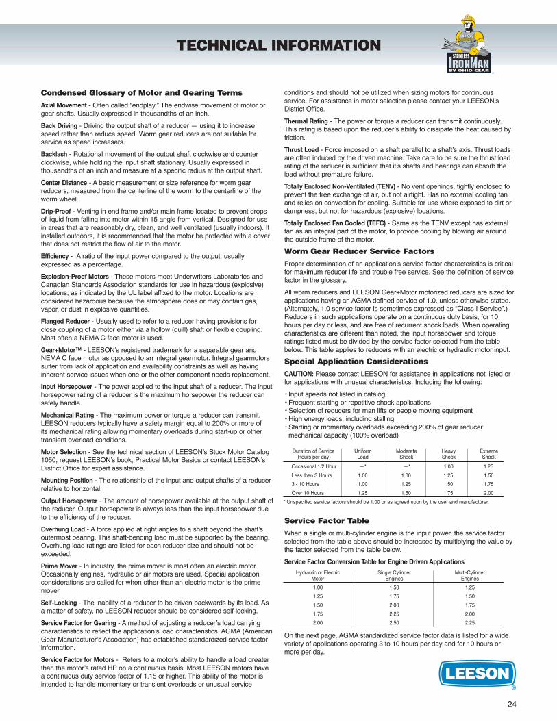
Duration of Service Uniform Moderate Heavy Extreme(Hours per day) Load Shock Shock Shock
Occasional 1/2 Hour —* —* 1.00 1.25
Less than 3 Hours 1.00 1.00 1.25 1.50
3 - 10 Hours 1.00 1.25 1.50 1.75
Over 10 Hours 1.25 1.50 1.75 2.00
* Unspecified service factors should be 1.00 or as agreed upon by the user and manufacturer.
Hydraulic or Electric Single Cylinder Multi-CylinderMotor Engines Engines
1.00 1.50 1.25
1.25 1.75 1.50
1.50 2.00 1.75
1.75 2.25 2.00
2.00 2.50 2.25
wash guard
STAIN LESSwash guard
washguard stainless
LEE
SON
LEESON
WASHGUARD
25
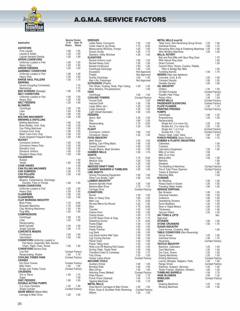
A.G.M.A. SERVICE FACTORS
Service FactorApplication 3-10 Over 10
Hours HoursAGITATORS
Pure Liquids 1.00 1.25Liquids & Solids 1.25 1.50Liquids-Variable Density 1.25 1.50
APRON CONVEYORSUniformly Loaded or Fed 1.00 1.25Heavy Duty 1.25 1.50
APRON FEEDERS 1.25 1.50ASSEMBLY CONVEYORS
Uniformly Loaded or Fed 1.00 1.25Heavy Duty 1.25 1.50
BARGE HAUL PULLERS 1.50 1.75BARKING
Drums (Coupling Connected) 1.75Mechanical 1.75
BAR SCREENS (Sewage) 1.00 1.25BELT CONVEYORS
Uniformly Loaded or Fed 1.00 1.25Heavy Duty 1.25 1.50
BELT FEEDERS 1.25 1.50BLOWERS
Centrifugal 1.00 1.25Lobe 1.25 1.50Vane 1.00 1.25
BOLTING MACHINERY 1.00 1.25BREWING & DISTILLING
Bottling Machinery 1.00 1.25Brew Kettles, Cont. Duty 1.00 1.25Can Filling Machines 1.00 1.25Cookers-Cont. Duty 1.00 1.25Mash Tubs-Cont. Duty 1.00 1.25Scale Hoppers-Frequent Starts 1.25 1.50
BUCKETConveyors Uniform 1.00 1.25Conveyors Heavy Duty 1.25 1.50Elevators Cont. 1.00 1.25Elevators Uniform 1.00 1.25Elevators Heavy Duty 1.25 1.50
CALENDARSRubber 1.50Textile 1.25 1.50
CANE KNIVES 1.50CAN FILLING MACHINES 1.00 1.25CAR DUMPERS 1.50 1.75CAR PULLERS 1.25 1.50CENTRIFUGAL
Blowers, Compressors, Discharge Elevator, Fans or Pumps 1.00 1.25
CHAIN CONVEYORSUniformly Loaded or Fed 1.00 1.25Heavy Duty 1.25 1.50
CLARIFIERS 1.00 1.25CLASSIFIERS 1.25 1.50CLAY WORKING INDUSTRY
Brick Press 1.75 2.00Briquette Machines 1.75 2.00Clay Working Machinery 1.25 1.50Plug Mills 1.25 1.50
COMPRESSORSCentrifugal 1.00 1.25Lobe 1.25 1.50Reciprocating:Multi-Cylinder 1.25 1.50Single Cylinder 1.50 1.75
CONCRETE MIXERSContinuous 1.25 1.50Intermittent 1.25 1.50
CONVEYORS-Uniformly Loaded or Fed Apron, Assembly, Belt, Bucket,Chain, Flight, Oven, Screw 1.00 1.25
CONVEYORS-Severe Duty Live Roll Contact FactoryReciprocating, Shaker 1.50 1.75
COOLING TOWER FANS Contact FactoryCRANES
Dry Dock Cranes Contact Factory Main Hoist 1.00 1.25 Bridge and Trolley Travel Contact Factory
CRUSHERS Ore or Stone 1.50 1.75 Sugar 1.50
DISC FEEDERS 1.00 1.25DOUBLE ACTING PUMPS
2 or more Cylinders 1.25 1.50 Single Cylinder Contact Factory
DRAW BENCH (Metal Mills) Carriage & Main Drive 1.25 1.50
DREDGES Cable Reels, Conveyors 1.25 1.50 Cutter Head & Jig Drives 1.75 2.00 Maneuvering Winches, Pumps 1.25 1.50 Screen Drives 1.50 1.75 Stackers, Utility Winches 1.25 1.50
ELEVATORS Bucket-Uniform Load 1.00 1.25 Bucket-Heavy Duty 1.25 1.50 Bucket-Continuous 1.00 1.25 Centrifugal Discharge 1.00 1.25 Escalators Not Approved Freight Not Approved Gravity Discharge 1.00 1.25 Man Lifts, Passenger Not Approved
EXTRUDERS (Plastic) Film Sheet, Coating, Rods, Pipe Tubing 1.25 1.25 Blow Molders, Pre-plasticizers 1.50
FANS Centrifugal 1.00 1.25
COOLING TOWERS Contact Factory Forced Draft 1.25 Induced Draft 1.25 1.50 Large (Mine, etc.) 1.25 1.50 Large Industrial 1.25 1.50 Light (Small Diameter) 1.00 1.25
FEEDERS Apron, Belt 1.25 1.50 Disc 1.00 1.25 Reciprocating 1.75 2.00 Screw 1.25 1.50
FLIGHTConveyors, Uniform 1.00 1.25 Conveyors, Heavy 1.25 1.50
FOOD INDUSTRYBeet Slicers 1.25 1.50 Bottling, Can Filling Mach. 1.00 1.25 Cereal Cookers 1.00 1.25 Dough Mixers, Meat Grinders 1.25 1.50
HAMMER MILLS 1.50 1.75HOISTS
Heavy Duty 1.75 2.00 Medium Duty 1.25 1.50 Skip Hoist 1.25 1.50
INDUCED DRAFT FANS 1.25 1.50LAUNDRY WASHERS & TUMBLERS 1.25 1.50LINE SHAFTS
Driving Processing Equipment 1.25 1.50 Other Line Shafts, Light 1.00 1.25
LUMBER INDUSTRYBarkers-Spindle Feed 1.25 1.50 Barkers-Main Drive 1.75 1.75 Carriage Drive Contact Factory
CONVEYORS Burner 1.25 1.50 Main or Heavy Duty 1.50 1.50 Main Log 1.75 2.00 Re-saw Merry-Go-Round 1.25 1.50 Slab 1.75 2.00 Transfer 1.25 1.50 Chains-Floor 1.50 1.50 Chains-Green 1.50 1.75 Cut-Off Saws-Chain & Drag 1.50 1.75 Debarking Drums 1.75 2.00 Feeds-Edger 1.25 1.50 Feeds-Gang 1.50 1.50 Feeds-Trimmer 1.25 1.50 Log Deck 1.50 1.50 Log Hauls-Incline Well Type 1.50 1.50 Log Turning Devices 1.50 1.50 Planer Feed 1.25 1.50 Planer Tilting Hoist 1.50 1.50 Rolls-Live-Off Bearing-Roll Cases 1.50 1.50 Sorting Table, Tipple Hoist 1.25 1.50 Transfers-Chain & Craneway 1.50 1.75 Tray Drives 1.25 1.50 Veneer Lathe Drives Contact Factory
MACHINE TOOLS Auxiliary Drives 1.00 1.25 Bending Rolls 1.25 1.50 Main Drives 1.25 1.50 Notching Press (Belted) Contact FactoryPlate Planers 1.50 1.75 Punch Press (Geared) 1.50 1.75 Tapping Machines 1.50 1.75
METAL MILLS Draw Bench Carriages & Main Drives 1.25 1.50 Pinch, Dryer & Scrubber Rolls Reversing Contact FactorySlitters 1.25 1.50
METAL MILLS (cont’d)Table Conv. Non-Reversing Group Drives 1.25 1.50 Individual Drives 1.50 1.75 Reversing Wire Dwg & Flattening Machines 1.25 1.50 Wire Winding Machines 1.25 1.50
MILLS, ROTARY Ball and Rod Mills with Spur Ring Gear 1.75 With Helical Ring Gear 1.50 Direct Connect 1.50 Cement Kilns, Dryers, Coolers, Pebble,
Plain & Wedge Bar Mills 1.50 Tumbling Barrels 1.50 1.75
MIXERS (Also see Agitators) Concrete, Cont. & Int. 1.25 1.50 Constant Density 1.00 1.25 Variable Density 1.25 1.50
OIL INDUSTRYChillers 1.25 1.50 Oil Well Pumping Contact Factory Paraffin Filter Press 1.25 1.50 Rotary Kilns 1.25 1.50
PAPER MILLS Contact FactoryPASSENGER ELEVATORS Contact FactoryPLATE PLANERS 1.50 1.75PRINTING PRESSES Contact FactoryPUMPS
Centrifugal 1.00 1.25 Proportioning 1.25 1.50 Reciprocating
Single Act, 3 or more Cyl. 1.25 1.50 Double Act, 2 or more Cyl. 1.25 1.50 Single Act, 1 or 2 Cyl Contact Factory Double Act, 1 Cyl. Contact Factory
Rotary: Gear, Lobe, Vane 1.00 1.25PUNCH PRESSES (Gear Driven) 1.50 1.75RUBBER & PLASTIC INDUSTRIES
Calendars 1.50 Crackers 1.75 Laboratory Equipment 1.25 1.50 Mills (2 on line) 1.50 Mills (3 on line) 1.25 Mixing Mills 1.50 1.50 Refiners 1.50 Sheeters 1.50 Tire Building & Machines Contact Factory Tire & Tube Press Openers Contact Factory Tubers & Strainers 1.50 Warming Mills 1.50
SCREENS Air Washing 1.00 1.25 Rotary-Sand or Gravel 1.25 1.50 Traveling Water Intake 1.00 1.25
SEWAGE DISPOSAL Bar Screens 1.00 1.25 Chemical Feeders 1.00 1.25 Collectors 1.00 1.25 Dewatering Screens 1.25 1.50 Scum Breakers 1.25 1.50 Slow or Rapid Mixers 1.25 1.50 Thickeners 1.25 1.50 Vacuum Filters 1.25 1.50
SKI TOWS & LIFTS NotApprovedSTOKERS 1.00 1.25STONE CRUSHERS 1.50 1.75SUGAR INDUSTRY
Cane Knives, Crushers, Mills 1.50TABLE CONVEYORS (Non-Reversing)
Group Drives 1.25 1.50 Individual Drives 1.50 1.75 Reversing Contact Factory
TEXTILE INDUSTRY Batchers, Calendars 1.25 1.50 Card Machines 1.25 1.50 Dry Cans, Dryers 1.25 1.50 Dyeing Machinery 1.25 1.50 Knitting Machinery Contact Factory Looms, Mangles, Nappers, Pads 1.25 1.50 Range Drives Contact Factory Slashers, Soapers, Spinners 1.25 1.50 Tenter Frames, Washers, Winders 1.25 1.50
TUMBLING BARRELS 1.50 1.75VANE BLOWERS 1.00 1.25WINDLASS Contact FactoryWIRE
Drawing Machines 1.25 1.50 Winding Machines 1.25 1.50
wash guard
STAIN LESSwash guard
washguard stainless
LEE
SON
LEESON
WASHGUARD
26
DISTRICT SALES OFFICES & WAREHOUSES
� ARKANSAS, Little RockDistrict Mgr., Phil Newby501/568-6468Fax: 501/568-6604
� CALIFORNIA, Los AngelesDistrict Mgr., Felix Wilson323/278-7979Fax: 323/278-7955
� CALIFORNIA, San FranciscoDistrict Mgr., Dave Richardson925/931-0749Fax: 925/931-0759
� COLORADO, DenverDistrict Mgr., Mike Kannawin303/331-6500Fax: 303/331-6510
� CONNECTICUT, HartfordDistrict Mgr., Bob Maher860/646-9665Fax: 860/643-2982
� FLORIDA, TampaDistrict Mgr., Bill Taylor813/740-2571Fax: 813/663-9104
� GEORGIA, AtlantaDistrict Mgr., Walter Brooks770/933-0453Fax: 770/933-0549
� ILLINOIS, ChicagoDistrict Mgr., Mike Miller630/458-9511Fax: 630/458-1923
� INDIANA, IndianapolisDistrict Mgr., Mark Redman317/776-2600Fax: 317/776-2007
� IOWA, Des MoinesDistrict Mgr., John Marshalla952/939-0115Fax: 952/935-8399
� KANSAS, Kansas CityDistrict Mgr., Pat Donnelly913/599-6983Fax: 913/599-6987
� MARYLAND, BaltimoreDistrict Mgr., Craig Brisbane570/325-3684Fax: 570/325-3870
� MICHIGAN, Grand RapidsDistrict Mgr., Greg Norris616/249-8430Fax: 616/249-8628
� MINNESOTA, MinneapolisDistrict Mgr., John Marshalla952/935-8273Fax: 952/935-8399
� MISSOURI, St. LouisDistrict Managers Pat and Ken Anvender314/714-1460Fax: 314/714-1461
�� NEW JERSEY/METRO NEWYORK/LONG ISLAND(Plainfield, NJ 18229)Contact: Dave Beck570/325-3684Fax: 570/325-3870
� NEW YORK, SyracuseDistrict Mgr., Chris Everett315/431-4536Fax: 315/431-4541
� NORTH CAROLINA,Charlotte District Mgrs.,Steve McAbee and Doug Landgraf803/396-8200Fax: 803/396-8208
� OHIO, CincinnatiDistrict Mgr., Ken Simko513/755-1000Fax: 513/755-1081
� OHIO, ClevelandDistrict Mgr., Matt Simko440/951-5117Fax: 440/975-3575800/331-2911 (W.PA, WV)
�� OKLAHOMA, Oklahoma CityContact: Owen Stone405/348-5700Fax: 405/348-0600
� OREGON, PortlandContact: Todd VandeKamp360/573-1418Fax: 360/573-2474
� PENNSYLVANIA,Allentown/PhiladelphiaDistrict Mgr., Craig Brisbane570/325-3684Fax: 570/325-3870
� TEXAS, DallasDistrict Mgr., Homer Rodden972/245-2017Fax: 972/245-2328
� TEXAS, HoustonContact, Donnie Heckler713/952-5337Fax: 972/245-2328
� UTAH, Salt Lake CityDistrict Mgr., Dennis Vest800/730-5290Fax: 303/331-6510
� WASHINGTON, SeattleDistrict Mgr., Amorette Gent425/775-3504Fax: 425/775-6706
� WISCONSIN, MilwaukeeDistrict Mgr., Tom Bares414/475-9222Fax: 414/475-9267
� INTERNATIONALMotors International International Sales Administrator,Sue KastnerWISCONSIN, Grafton(+1) 262/377-8810 Fax: (+1) 262/377-3440
�� ASIACHINA, Shanghai(+86) 21-625-317-00Fax: (+86) 21-625-587-07
� CENTRAL AMERICA, SOUTH AMERICA &CARIBBEANFLORIDA, MiamiContact: Manny Garcia, Jr.(+1) 305/220-4423Fax: (+1) 305/220-5945
� EUROPEITALY, Bologna(+39) 051-731-487Fax: (+39) 051-734-943
� ALBERTA, EdmontonBranch Mgr., Mike Strenkowski780/437-3380Fax: 780/434-3448
� BRITISH COLUMBIA,VancouverBranch Mgr., Jeff Male604/941-0352Fax: 604/941-0659
� MANITOBA, WinnipegBranch Mgr., Charlie Vogel204/786-6802Fax: 204/786-6934
� NEW BRUNSWICK,MonctonBranch Mgr., Ken Sheehan506/383-8883Fax: 506/383-8887
� ONTARIO, TorontoNational Sales Mgr.,Frank Pesce905/670-4770Fax: 905/670-4378
� ONTARIO, HanoverBranch Mgr., Doug Stafford800/463-1797Fax: 800/225-9007
� QUEBEC, MontrealBranch Mgr., Richard Haines514/337-8020Fax: 514/337-0773
LEESON District Sales Offices & Warehouses can provide complete information including price and availability on both standardstock and special motors.
� SALES OFFICE AND WAREHOUSE �� SALES OFFICE ONLY
For the latest warnings & cautions and terms & conditions, see LEESON’s 1050 stock products catalog.
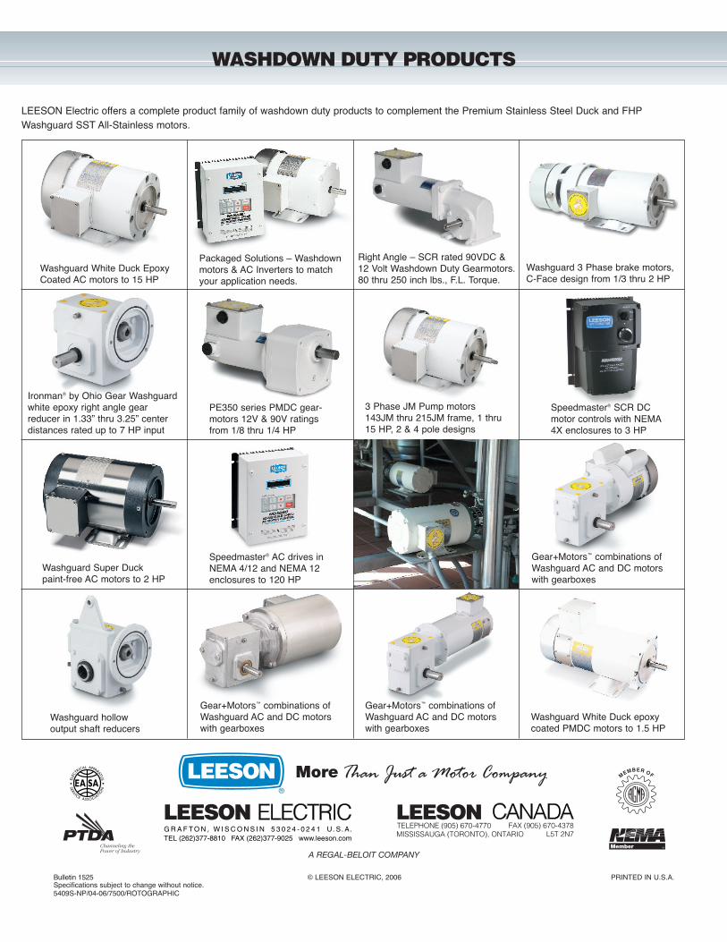
LEESON Electric offers a complete product family of washdown duty products to complement the Premium Stainless Steel Duck and FHPWashguard SST All-Stainless motors.
Gear+Motors™ combinations ofWashguard AC and DC motorswith gearboxes
Washguard hollow output shaft reducers
Washguard White Duck EpoxyCoated AC motors to 15 HP
Washguard Super Duck paint-free AC motors to 2 HP
Washguard White Duck epoxycoated PMDC motors to 1.5 HP
Speedmaster® SCR DCmotor controls with NEMA4X enclosures to 3 HP
Speedmaster® AC drives inNEMA 4/12 and NEMA 12enclosures to 120 HP
PE350 series PMDC gear-motors 12V & 90V ratingsfrom 1/8 thru 1/4 HP
3 Phase JM Pump motors143JM thru 215JM frame, 1 thru15 HP, 2 & 4 pole designs
Ironman® by Ohio Gear Washguardwhite epoxy right angle gear reducer in 1.33” thru 3.25” centerdistances rated up to 7 HP input
Washguard 3 Phase brake motors,C-Face design from 1/3 thru 2 HP
Gear+Motors™ combinations ofWashguard AC and DC motorswith gearboxes
Gear+Motors™ combinations ofWashguard AC and DC motorswith gearboxes
Right Angle – SCR rated 90VDC &12 Volt Washdown Duty Gearmotors.80 thru 250 inch lbs., F.L. Torque.
Packaged Solutions – Washdownmotors & AC Inverters to match your application needs.
Bulletin 1525 © LEESON ELECTRIC, 2006 PRINTED IN U.S.A.Specifications subject to change without notice.5409S-NP/04-06/7500/ROTOGRAPHIC
A REGAL-BELOIT COMPANY
Than Just a Motor CompanyMore
WASHDOWN DUTY PRODUCTS