Embed Size (px)
Citation preview


Part 7: Geotechnical Investigation and Design
GUIDE TO ROAD DESIGN
For Educational Use Only - UNITEC Institute of Technology 2015

Guide to Road Design Part 7: Geotechnical Investigation and Design
For Educational Use Only - UNITEC Institute of Technology 2015

Guide to Road Design Part 7: Geotechnical Investigation and Design Summary The Austroads Guide to Road Design Part 7 – Geotechnical Investigation and Design provides those engaged in road design activities with a basic understanding and appreciation of the importance of geotechnical investigations and how road design outcomes and other design activities are influenced by site conditions, associated ground response, geological hazards and locally available materials. The information also provides assistance in preparing briefs and purchasing geotechnical services. Basic information on laboratory tests and some commonly used special geotechnical treatments associated with geotechnical design activities are contained in appendices. This document should not be used a guide for undertaking geotechnical investigations. Keywords geotechnical, geotechnical investigation, geotechnical design, site conditions information First Published March 2008 © Austroads Inc. 2008 This work is copyright. Apart from any use as permitted under the Copyright Act 1968, no part may be reproduced by any process without the prior written permission of Austroads. ISBN 978-1-921329-48-7 Austroads Project No. TP1158 Austroads Publication No. AGRD07/08 Project Manager Rob Grove Prepared by Ross Paul and Rob Grove Published by Austroads Incorporated Level 9, Robell House 287 Elizabeth Street Sydney NSW 2000 Australia Phone: +61 2 9264 7088 Fax: +61 2 9264 1657 Email: [email protected] This Guide is produced by Austroads as a general guide. Its application is discretionary. Road authorities may vary their practice according to local circumstances and policies. Austroads believes this publication to be correct at the time of printing and does not accept responsibility for any consequences arising from the use of information herein. Readers should rely on their own skill and judgement to apply information to particular issues.
For Educational Use Only - UNITEC Institute of Technology 2015

Guide to Road Design Part 7: Geotechnical Investigation and Design
Sydney 2008
For Educational Use Only - UNITEC Institute of Technology 2015

Austroads profile Austroads’ purpose is to contribute to improved Australian and New Zealand transport outcomes by:
providing expert advice to SCOT and ATC on road and road transport issues facilitating collaboration between road agencies promoting harmonisation, consistency and uniformity in road and related operations undertaking strategic research on behalf of road agencies and communicating outcomes promoting improved and consistent practice by road agencies.
Austroads membership Austroads membership comprises the six state and two territory road transport and traffic authorities and the Commonwealth Department of Transport and Regional Services in Australia, the Australian Local Government Association and Transit New Zealand. It is governed by a council consisting of the chief executive officer (or an alternative senior executive officer) of each of its eleven member organisations:
Roads and Traffic Authority New South Wales Roads Corporation Victoria Department of Main Roads Queensland Main Roads Western Australia Department for Transport, Energy and Infrastructure South Australia Department of Infrastructure, Energy and Resources Tasmania Department of Planning and Infrastructure Northern Territory Department of Territory and Municipal Services Australian Capital Territory Department of Infrastructure, Transport, Regional Development and Local Government Australian Local Government Association Transit New Zealand
The success of Austroads is derived from the collaboration of member organisations and others in the road industry. It aims to be the Australasian leader in providing high quality information, advice and fostering research in the road sector.
For Educational Use Only - UNITEC Institute of Technology 2015

GUID E TO ROAD DESIGN PART 7 : GEOTECHNICAL INVEST IG ATION AND DESIGN
A u s t r o a d s 2 0 0 8
— i —
SUMMARY
Part 7 of the Austroads Guide to Road Design provides information to assist road designers to consider and respond to geotechnical matters that may influence a road design. The Guide does not cover the design of geotechnical investigations for which expert knowledge and experience is required, but provides designers with a basic understanding of the types of investigations and tests available, and their application to road design.
An understanding and appreciation of geotechnical investigations and issues is particularly important for designers as it affects many aspects associated with road design such as the:
horizontal and vertical location of the road and structures
protection of the road against ground water and surface water
strength and stability of various elements of the road
implications that site conditions may have on road construction costs.
Part 7 therefore provides an overview of geotechnical investigations, describes the methods used to obtain information, discusses the way in which geotechnical issues influence road design and stresses the importance of sustainable design practices. Furthermore, it assists road designers to:
Gain an understanding of the geotechnical terminology, concepts, field investigations and laboratory tests.
Be aware of investigation and design services provided by geotechnical service suppliers.
Consider the risks and hazards associated with the site conditions and various design solutions in developing a suitable design.
The Guide also provides advice on the extent of investigation required, reporting, types of tests, and issues associated with road cuttings, embankments, pavements, drainage and foundations for structures. Geotechnical investigations and design can also contribute to sustainable design practices. Consequently, the Guide provides advice on the management of materials (acquisition and use) and water to minimise the affect on the environment by minimising the area disturbed, minimising erosion, preserving topsoil and local seed and plants, and complementing landscaping of the road reservation.
For Educational Use Only - UNITEC Institute of Technology 2015
GUID E TO ROAD DESIGN PART 7 : GEOTECHNICAL INVEST IG ATION AND DESIGN
A u s t r o a d s 2 0 0 8
— i i —
CONTENTS
1 INTRODUCTION ................................................................................................................... 1 1.1 Purpose of Geotechnical Investigations ................................................................................ 1 1.2 Scope of this Part of the Guide to Road Design .................................................................... 2 1.3 Aims of a Geotechnical Investigation and Design ................................................................. 4
1.3.1 General .................................................................................................................... 4 1.3.2 Extent of Geotechnical Investigation ....................................................................... 5 1.3.3 Assess Ground Response to Changes.................................................................... 6 1.3.4 Assess Geological Hazards..................................................................................... 6
2 OVERVIEW OF GEOTECHNICAL INVESTIGATIONS ........................................................ 8 2.1 Preliminary Investigation........................................................................................................ 8
2.1.1 General .................................................................................................................... 8 2.1.2 Desktop Assessment ............................................................................................... 9 2.1.3 Field Reconnaissance ........................................................................................... 12 2.1.4 Preliminary Geotechnical Report ........................................................................... 13
2.2 Approvals for Site Investigations ......................................................................................... 13 2.3 Detailed Geotechnical Investigation .................................................................................... 13
2.3.1 General .................................................................................................................. 13 2.3.2 Identification of Potential Risks.............................................................................. 14 2.3.3 Location and Classification of Rock and Soil ......................................................... 14 2.3.4 Rock Excavation .................................................................................................... 14 2.3.5 Strength and Physical Properties of Soil and Rock ............................................... 14 2.3.6 Ground Water ........................................................................................................ 15 2.3.7 Identification of Areas for Borrow Material ............................................................. 15
2.4 Design of Special Systems.................................................................................................. 16 2.5 Production of Geotechnical Reports .................................................................................... 16
2.5.1 General .................................................................................................................. 16 2.5.2 Part 1 – Site Conditions Information Report .......................................................... 18 2.5.3 Interpretative Report (Part 2) ................................................................................. 19
3 METHODS OF GEOTECHNICAL INVESTIGATION .......................................................... 21 3.1 Seismic Surveys .................................................................................................................. 21 3.2 Auger and Bore Holes ......................................................................................................... 22 3.3 Penetrometer Testing .......................................................................................................... 24 3.4 Installation of Stand Pipes (Piezometers)............................................................................ 29 3.5 Trenching............................................................................................................................. 30 3.6 Sampling of Materials .......................................................................................................... 31
3.6.1 General .................................................................................................................. 31 3.6.2 Test Properties ...................................................................................................... 31
4 DESIGN ELEMENTS .......................................................................................................... 33 4.1 General ................................................................................................................................ 33 4.2 Horizontal Alignment............................................................................................................ 33
4.2.1 Rural Areas............................................................................................................ 33 4.2.2 Horizontal Alignment Urban Areas ........................................................................ 34
4.3 Vertical Alignment................................................................................................................ 34 4.3.1 General .................................................................................................................. 34 4.3.2 Balancing of Earthworks Volume........................................................................... 34 4.3.3 Disposal of Surplus Fill .......................................................................................... 35 4.3.4 Raised Embankments over Wet or Unstable Areas .............................................. 36
For Educational Use Only - UNITEC Institute of Technology 2015
GUID E TO ROAD DESIGN PART 7 : GEOTECHNICAL INVEST IG ATION AND DESIGN
A u s t r o a d s 2 0 0 8
— i i i —
4.4 Cuttings................................................................................................................................ 36 4.4.1 Presence of Rock .................................................................................................. 36 4.4.2 Batter Slopes ......................................................................................................... 37 4.4.3 Suitability of Materials............................................................................................ 38 4.4.4 Interception of Ground Water ................................................................................ 38 4.4.5 Geotechnical Investigations Required for Cuttings................................................ 39
4.5 Embankments...................................................................................................................... 39 4.5.1 Depth of Topsoil..................................................................................................... 39 4.5.2 Stability of Areas on which Fill is to be Placed ...................................................... 40 4.5.3 Slope of Fill Batters................................................................................................ 40 4.5.4 Rock Fill ................................................................................................................. 41 4.5.5 Geotechnical Investigations Required for Embankments ...................................... 42
4.6 Pavements........................................................................................................................... 42 4.6.1 General .................................................................................................................. 42 4.6.2 Rehabilitation and Strengthening of Existing Pavements ...................................... 43 4.6.3 Pavement Design .................................................................................................. 44 4.6.4 Geotechnical Investigations Associated with the Design of Pavements................ 44
4.7 Subsurface Drainage System.............................................................................................. 44 4.7.1 Subsurface Drainage Systems for Interception of Ground Water.......................... 44 4.7.2 Pavement Drains ................................................................................................... 44
4.8 Foundations for Structures .................................................................................................. 46 4.8.1 General .................................................................................................................. 46 4.8.2 Geotechnical Investigations Required for Structural Foundations......................... 47
5 SUSTAINABLE DESIGN PRACTICES............................................................................... 48 5.1 General ................................................................................................................................ 48 5.2 Materials Stewardship ......................................................................................................... 48 5.3 Minimisation of Erosion........................................................................................................ 49 5.4 Water for Construction and Landscaping Purposes ............................................................ 49 5.5 Preservation of Topsoil ........................................................................................................ 50 5.6 Use of Non-standard or Recycled Materials ........................................................................ 50 REFERENCES ............................................................................................................................. 52 APPENDIX A LABORATORY TESTS.................................................................................. 54 APPENDIX B SPECIAL GEOTECHNICAL DESIGN SYSTEMS.......................................... 66
For Educational Use Only - UNITEC Institute of Technology 2015
GUID E TO ROAD DESIGN PART 7 : GEOTECHNICAL INVEST IG ATION AND DESIGN
A u s t r o a d s 2 0 0 8
— i v —
TABLES
Table 1.1: Parts of the guide to road design...................................................................... 3 Table 4.1: Typical bulking factors for rock and soil .......................................................... 35
FIGURES
Figure 1.1: Flow chart of Guide to Road Design................................................................. 1 Figure 2.1: Typical locational and regional geological setting........................................... 10 Figure 2.2: Typical geological map and cross-section of a syncline ................................. 11 Figure 2.3: Aerial photograph showing change in land after a hurricane.......................... 12 Figure 3.1: Schematic representation of seismic refraction .............................................. 21 Figure 3.2: Velocity model for a particular line.................................................................. 22 Figure 3.3: Typical core rack............................................................................................. 22 Figure 3.4: Typical borehole log........................................................................................ 23 Figure 3.5: Material sample from Standard Penetrometer Test ........................................ 24 Figure 3.6: Schematic arrangement of test equipment for the Standard
Penetrometer Test .......................................................................................... 25 Figure 3.7: Schematic of Cone Penetration Test .............................................................. 26 Figure 3.8: Example of output from the Cone Penetration Test........................................ 26 Figure 3.9: Schematic of the Dynamic Cone Penetrometer.............................................. 27 Figure 3.10: Application of Dynamic Cone Penetrometer................................................... 28 Figure 3.11: Californian Bearing Ratio (CBR) chart ............................................................ 28 Figure 3.12: Typical piezometer tube.................................................................................. 29 Figure 3.13: Use of piezometers to establish ground water pressure profiles .................... 30 Figure 3.14: Open trench investigation and test pit ............................................................ 31 Figure 4.1: Interception of ground water ........................................................................... 38 Figure 4.2: Capping layer arrangement ............................................................................ 43 Figure 4.3: Types of subsurface drains............................................................................. 46
For Educational Use Only - UNITEC Institute of Technology 2015

GUID E TO ROAD DESIGN PART 7 : GEOTECHNICAL INVEST IG ATION AND DESIGN
1 INTRODUCTION
1.1 Purpose of Geotechnical Investigations The purpose of a geotechnical investigation is to provide the designer (road designer) with answers to questions such as:
A u s t r o a d s 2 0 0 8
— 1 —
What are the geotechnical characteristics of the ground that could influence the design solution such as the location of rock, ground water or unsuitable materials?
How will the ground respond to changes created by the proposed road design?
What is the suitability of locally available materials for road construction purposes?
Where is the nearest source of suitable pavement material?
Figure 1.1 shows where Part 7: Geotechnical Investigation and Design, fits within the overall design process.
Figure 1.1: Flow chart of Guide to Road Design
Sufficient geotechnical information should be available for the designer to appreciate the limitations (and opportunities) that site conditions and availability of road making materials may have on the final road design solution. The designer should have a basic understanding of the following fundamental geotechnical issues:
an increased load on the ground associated with fill embankments and structural foundations increases stresses on the ground and may induce settlement or bearing failure
reducing the load on the ground such as in cuttings or other excavations reduces side support possibly causing destabilisation of adjacent areas
For Educational Use Only - UNITEC Institute of Technology 2015

GUID E TO ROAD DESIGN PART 7 : GEOTECHNICAL INVEST IG ATION AND DESIGN
A u s t r o a d s 2 0 0 8
— 2 —
excavations intercept or change the level of ground water which can alter the strength or stability of adjacent material
intercepted ground water to be discharged into the surface drainage system may contain dissolved salts or sulphates that would have an adverse affects on the environment
embankments increase the pressure on the embankment foundation whereby water and air is displaced (or squeezed out) leading to consolidation and settlement.
The task of a geotechnical engineer is to predict how the ground is likely to behave under the changes proposed in a road design and associated construction activities, and to recommend how risks associated with such changes can be mitigated.
The results of a geotechnical investigation may influence a number of aspects of a road project. A knowledge of ground conditions and material strengths along the route may influence road design decisions regarding the road profile, the cross-section, or even the alignment if, for example, an isolated area of unstable foundation material is revealed by the geotechnical investigations.
1.2 Scope of this Part of the Guide to Road Design The Austroads Guide to Road Design provides the designer with a framework that is intended to promote efficiency in design, construction, and maintenance of a length of roadway. The scope of Part 7 of the Guide is to enable designers to:
appreciate the importance of geotechnical investigations and how road design outcomes and other design activities are influenced by site conditions, associated ground response, geological hazards and locally available materials
prepare conceptual drawings so that the grade line, cross-sections and the location of various structures can be determined in sufficient detail to facilitate a detailed geotechnical investigation
prepare a brief for a detailed geotechnical investigation or alternatively, provide sufficient information for the geotechnical services supplier to produce a detailed investigation proposal for consideration
be aware of investigation and design services provided by geotechnical service suppliers
consider the risks and hazards associated with the site conditions and to develop a road design solution where risks are kept within acceptable limits having regard to the size of the project and the importance of the road
understand the implications that site conditions may have on road construction costs and to thereby develop cost-effective road designs
gain an understanding of geotechnical terminology, concepts, field investigations, laboratory tests and risks associated with various design solutions.
Table 1.1 below outlines the general content of each of the eight Parts of the Guide to Road Design all of which may be influenced by geotechnical considerations. There are nine other guides spanning the range of Austroads publications that relate to the design of roads (www.austroads.com.au).
For Educational Use Only - UNITEC Institute of Technology 2015

GUID E TO ROAD DESIGN PART 7 : GEOTECHNICAL INVEST IG ATION AND DESIGN
A u s t r o a d s 2 0 0 8
— 3 —
Table 1.1: Parts of the guide to road design
Part Title Content Part 1 Introduction to Road Design Scope
Context of the road design process Road design philosophy and principles Design considerations Design process
Part 2 Design Considerations Design objectives Context sensitive design Design considerations
Part 3 Geometric Design Fundamental considerations Speed parameters Sight distance Coordination of horizontal and vertical
alignment Horizontal alignment Vertical alignment Cross section Auxiliary lanes Other considerations Freeways Urban arterials Rural highways Unsealed roads Tunnels, bridges and retaining walls
Part 4 Intersections and Crossings Selection of intersection type Design process and criteria Unsignalised intersections Signalised intersections Intersections in tunnels and underground Rail crossings Pedestrian and cyclist crossings
Part 4A Roundabouts Design procedure Sight distance Types and design guidelines Pavement markings and signing Roadway lighting Landscaping and street furniture
Part 4B Interchanges Design procedure Forms of interchange Interchange spacing and uniformity Structures Cross section Design speed Sight distance Horizontal alignment Vertical alignment Pavement markings and signing Roadway lighting Landscaping and road furniture Pedestrians and cyclists
For Educational Use Only - UNITEC Institute of Technology 2015

GUID E TO ROAD DESIGN PART 7 : GEOTECHNICAL INVEST IG ATION AND DESIGN
A u s t r o a d s 2 0 0 8
— 4 —
Part Title Content Part 5 Drainage Design Drainage design considerations
Surface drainage Drainage systems Sub-surface drainage Floodways and culverts Treating pollutants
Part 6 Roadside Design Roadside safety Utilities Safety barriers Pedestrian and cycling paths Roadside furniture Road lighting Environmental aspects
Part 7 Geotechnical Design Overview of geotechnical investigations Methods of geotechnical investigation Design elements Sustainable design practices
Part 8 Process and Documentation Principles and processes Issues and resources Selection of schemes and treatments Design of schemes and devices
1.3 Aims of a Geotechnical Investigation and Design 1.3.1 General ‘Geotechnical investigation’ is a term that is applied to the performance assessment of in situ and imported materials that are intended to form part of the project roadworks. This could include an evaluation of:
topsoil stripping requirements
cuttings (e.g. to assess slope stability and rippability of rock)
materials proposed for inclusion in embankments
strength/residual life of existing pavements
subgrade for pavement design purposes
proposed pavement material (e.g. gravel) sources
bridge foundations
the presence and extent of ground water
water quality considerations with respect to compaction, surface drainage or potential detriment to culvert structures.
Whilst some of these aspects can be addressed by knowledge of past performance in similar geological and climatic conditions, these studies should be carefully considered for all road projects. Geotechnical investigations should be initiated as soon as possible in the design phase, particularly where substantial detail is required, so that project construction programs are not adversely affected.
For Educational Use Only - UNITEC Institute of Technology 2015

GUID E TO ROAD DESIGN PART 7 : GEOTECHNICAL INVEST IG ATION AND DESIGN
A u s t r o a d s 2 0 0 8
— 5 —
1.3.2 Extent of Geotechnical Investigation A comprehensive geotechnical investigation of the project site is generally carried out in order to reveal and quantify the site conditions, and to characterise road making materials that will be encountered during the construction and operation of the project. This includes the nature, variability and extent of potential materials, and any special requirements to be observed. The investigation will normally include an evaluation of the local geology and hydrogeology. The detail of the investigation should be commensurate with the potential risks, hazards and complexity of the project. It would typically include:
geological surface mapping
sampling of soils with logging of excavations and boreholes
logging of existing cut slopes and excavations
field and laboratory testing including field monitoring
measurement of ground water levels
moisture regimes
soil strengths and compressibility
analysis and interpretation of the results
preparation of a geotechnical report.
It is not necessary for designers to understand all of the details associated with the provision of a geotechnical investigation, but it is important for them to have an appreciation of the range of tests that can be called upon to assist in developing the most suitable road design solution. It is also good practice to contact a professional in the geotechnical field who can advise of the need for particular types of investigation that may be required to adequately describe the site.
A key output of a geotechnical investigation is the provision of a three-dimensional conceptual representation of subsurface conditions along, and in close proximity to the proposed road alignment. This representation may take the form of a written description, maps and cross-sections to provide the designer with an understanding of the materials and environmental conditions that might be encountered and affected during the proposed road project. The representation should include identification of:
Material properties – the physical characteristics of the subsurface and road building materials. For example, what types of rock or soil are present and what is the spatial distribution.
Mass properties – the physical features within the ground that could influence ground response. Examples include joints in rock, faults, fissures in clay, buried valleys and bedding.
Environmental properties – the environmental effects on the subsurface conditions such as ground water level and flows, and the effects of weathering.
All of these properties will help to explain how the ground is likely to respond and a geotechnical investigation should give due attention to each. For example, highly jointed granite may respond very differently from intact granite, even if the rock classification is identical. If ground water is flowing through the joints, its response will be different again.
For Educational Use Only - UNITEC Institute of Technology 2015

GUID E TO ROAD DESIGN PART 7 : GEOTECHNICAL INVEST IG ATION AND DESIGN
A u s t r o a d s 2 0 0 8
— 6 —
The degree of detail that is required will depend upon the variability of the subsurface conditions, the design stage (e.g. feasibility or detailed design), importance of the road and the level of geological uncertainty (risk) that can be accepted on the project. Further detail on what features are important for various aspects of road design are covered later in this Guide.
Where changes of soil type are encountered, the investigations should be sufficient to enable suitable adjustments to the design elements to be made and the need for any special treatments to be determined.
For a ‘Construct Only’ project where a detailed design is produced in house or under a separate design consultancy agreement in advance of the award of a contract for construction, a comprehensive geological investigation is normally sought. A less comprehensive geological investigation may be undertaken during the conceptual design phase to assist the designer to determine in broad terms the land requirements for a future road solution.
For a ‘Design & Construct’ project where tenderers are required to produce a detailed design of the road and structures within a specified framework, it is common practice to undertake a broad evaluation of the terrain and site conditions to draw attention to potential high risk areas in sufficient detail for tendering purposes. Normally the successful contractor is required to supplement the pre-tender geotechnical investigation with more detailed geotechnical investigations in some areas in order to address specific detailed design requirements (e.g. an overpass instead of an underpass).
1.3.3 Assess Ground Response to Changes Once the site conditions have been established the response of the ground to changes should be assessed. This will generally involve in situ or laboratory testing and, importantly, research of case studies and previous experience in similar terrain. Engineering properties relevant to the proposed changes are assessed including the soil and rock stiffness, friction on discontinuities and hydraulic conductivity to name a few. The engineering properties that need to be determined depend upon the proposed changes (e.g. increased or reduced loading) at a given location on the proposed road alignment.
1.3.4 Assess Geological Hazards The ways in which the ground conditions could influence the design of a road should be determined having regard to the type of hazard, the likelihood of its occurrence and likely consequences. Common geological hazards that should be considered by the designer include landslide, earthquake, reactive or expansive soils and limestone terrain. The likelihood and consequences of hazards may be assessed through desktop studies and geological mapping, but more commonly through previous experience of similar hazards (particularly if problems have been experienced with nearby projects).
The information obtained during the geotechnical investigation can be used by the designer to ensure that ground response is acceptable and geotechnical hazards are mitigated where appropriate. Detailed geotechnical design by an experienced geotechnical practitioner may be necessary to achieve the design objectives. Examples of design and other activities that require consideration of geotechnical information include:
selection of road alignment and location of structures
fixing the road profile, depth of cuttings, height of embankments and minimum batter slopes
defining the new road reservation having regard to depth of cuttings, height of embankments, steepness of batter slopes and special drainage requirements
For Educational Use Only - UNITEC Institute of Technology 2015

GUID E TO ROAD DESIGN PART 7 : GEOTECHNICAL INVEST IG ATION AND DESIGN
A u s t r o a d s 2 0 0 8
— 7 —
determining the excavation characteristics and determining the means of excavation of materials in cuttings
determining the suitability of in situ materials for use as selected fill, capping material or pavement subbase
selecting and designing the road pavement (refer to Austroads, 2008a Guide to Pavement Technology)
designing foundations for structures (refer to Austroads, 2004)
determining the requirements for and design of earth retaining structures
designing subsurface drainage systems and special de-watering systems to intercept and direct ground water to the surface drainage systems
determining the requirement for, and designing of, ground improvement works
predicting the magnitude and rate of settlement of embankments
assessing feasibility and producing cost estimates of alternatives.
For Educational Use Only - UNITEC Institute of Technology 2015

GUID E TO ROAD DESIGN PART 7 : GEOTECHNICAL INVEST IG ATION AND DESIGN
A u s t r o a d s 2 0 0 8
— 8 —
2 OVERVIEW OF GEOTECHNICAL INVESTIGATIONS Geotechnical information is produced at different levels of detail at various stages of the design process. The geotechnical investigation and road design processes are generally iterative starting with broadly defined information as a basis for initial design decisions, after which there may be successive refinements as detailed design proceeds.
The principal stages of a geotechnical investigation are:
preliminary investigation which involves generally non-intrusive and largely desktop investigations
preparation and approval of a site management plan for intrusive geotechnical investigation
detailed geotechnical investigation
production of a geotechnical report including an ‘Information for Tenderers’ document.
2.1 Preliminary Investigation 2.1.1 General The project development phase (project scoping) is the process used to define the general requirements of a road project and to seek approval from stakeholders. A project is normally evaluated on three principal criteria comprising cost and economic benefits, community impacts, and environmental impacts – sometimes known as the ‘triple bottom line’. Geotechnical issues can influence each of these criteria.
Cost and economic benefits The project cost is significantly influenced by geotechnical issues such as the volume and balance of earthworks, difficulty in excavating local materials (rock or soil), foundation conditions, supply of suitable road making materials, management of ground water, and stability of road cuttings and embankments.
Community impacts In the context of site conditions, issues of community concern can include such matters as ground vibration, noise, construction traffic, changes to ground water levels, water quality, local habitat, sustainability, visual appearance of batter slopes and dust generated during construction.
Environmental impacts Environmental impacts include the identification and treatment of ground water, drainage, acid sulphate soils, erosion prone soils such as silt, buried landfill and waste dumps, and impacts of appropriate preventative or remedial treatments as necessary.
All of these design considerations require appropriate geotechnical information that should be sought prior to and during the project scoping phase. It is usual to undertake a preliminary geotechnical investigation or desktop assessment to obtain information that may be used to:
produce conceptual drawings
provide a sound basis for undertaking more detailed geotechnical investigations
identify the type and extent of geotechnical investigations required at various locations.
For Educational Use Only - UNITEC Institute of Technology 2015

GUID E TO ROAD DESIGN PART 7 : GEOTECHNICAL INVEST IG ATION AND DESIGN
A u s t r o a d s 2 0 0 8
— 9 —
2.1.2 Desktop Assessment Every site investigation will normally commence with a desktop assessment directed towards collecting, collating, and reviewing the following data. This is a relatively inexpensive activity but one which may reveal some important information that can supplement, provide focus for, or even remove the need for, parts of the detailed investigation.
Examples of sources of readily available information include:
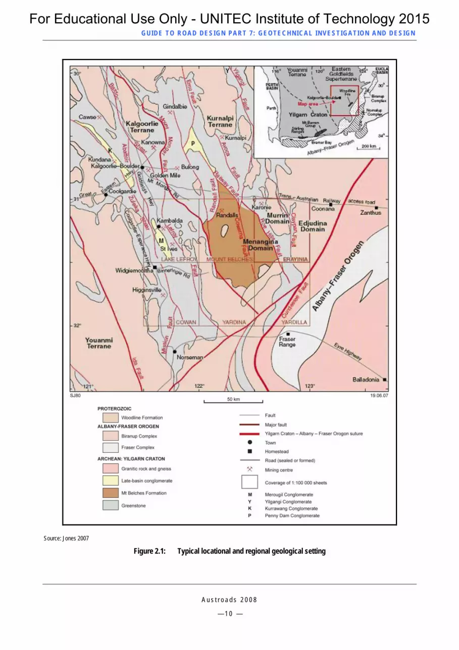
Road design drawings from any earlier work at or near the site showing longitudinal and cross-sections, subsurface drainage and other elements that were successfully (or otherwise) employed on nearby projects previous site investigation reports, borehole logs, penetrometer results and construction experience e.g. piling records geological maps, survey data and records that show rock and soils typically mapped at the ground surface. Most geological maps have accompanying notes which provide further detail on the materials indicated on the map. Figure 2.1 and Figure 2.2 show examples of typical geological maps.
Topographic maps that can provide useful information to the ‘trained eye’ regarding subsurface materials and can also indicate such things as rock outcrops and high ground water levels (e.g. springs or swamps).
Mining records that may be available in some areas and can provide information on the location of underground voids.
Land stability mapping undertaken by some national and state road authorities show the existence of land slips and unstable soil formations along existing roads. This information can be used to identify potentially unstable areas that may require flatter (or special) batter treatments.
Hydrological data obtained from local water authorities to assist with establishing ground water levels and water chemistry. Some government departments maintain a database of ground water bores within an area.
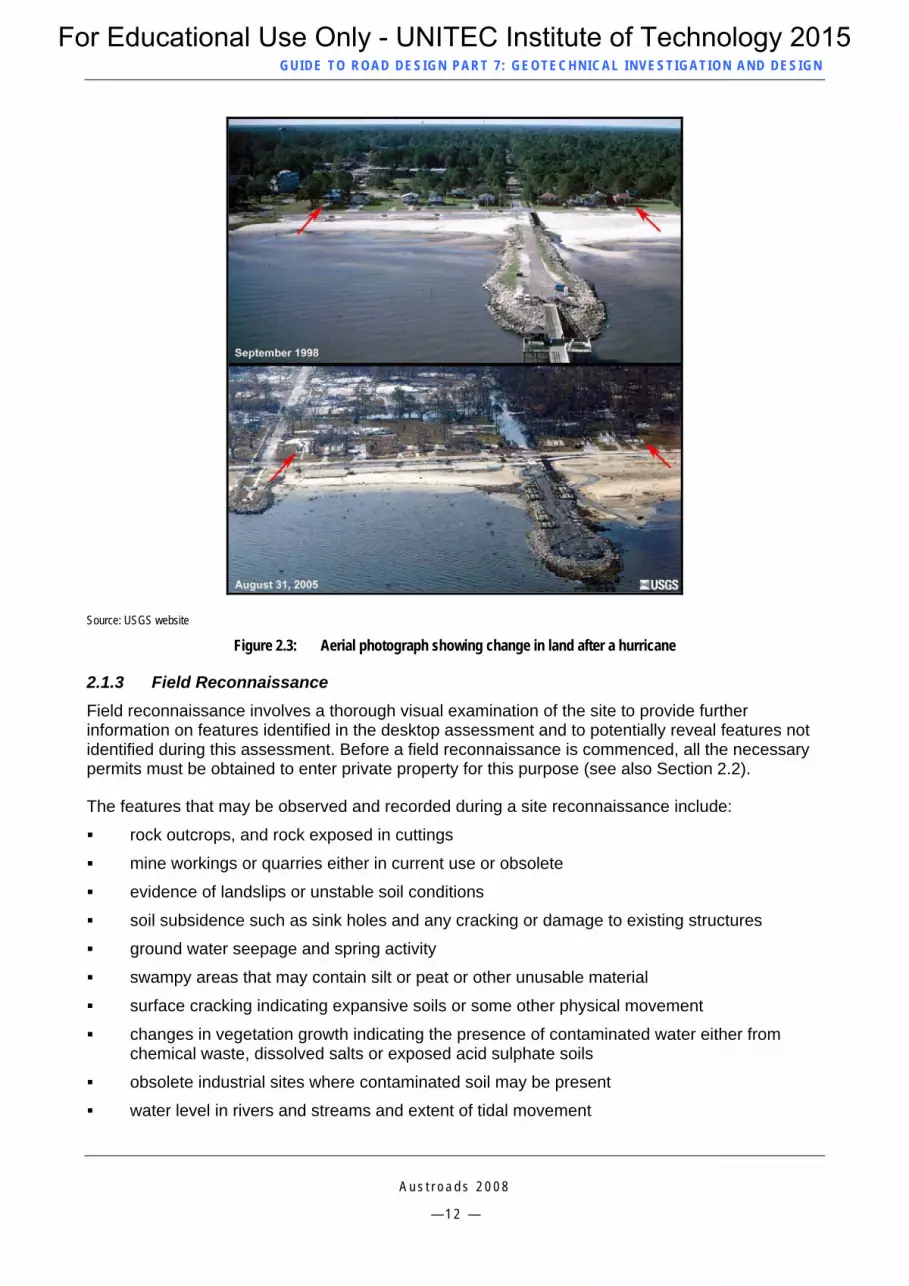
Aerial photographs that can provide important information about the local geology. Aerial photographs of different ages can also be useful in identifying changes that have occurred to the ground in recent times. Such changes may include, for example, the infilling of dams or quarries, erosion, landslip movement, demolition of structures, and previous earthworks. Figure 2.3 shows a change in the land resulting from a hurricane.
Regional seismicity data can reveal the seismic potential in an area of interest. For further information see AS 1170.4 – Structural design actions – Earthquake actions in Australia, (2007) or NZS 1170.5 – Structural design actions – Earthquake actions in New Zealand (2004).
Erosion management overlay or similar reports are produced by many councils and can provide information on the potential for erosion and landslides.
Local knowledge and historical information from the local library or from persons living or working in the area can provide an excellent source of published or anecdotal local information. Even a conversation with local road maintenance personnel can prove to be invaluable.
Where possible, the above information should be collected and collated prior to undertaking the field reconnaissance described in Section 2.1.3.
For Educational Use Only - UNITEC Institute of Technology 2015
GUID E TO ROAD DESIGN PART 7 : GEOTECHNICAL INVEST IG ATION AND DESIGN
Source: Jones 2007
Figure 2.1: Typical locational and regional geological setting
A u s t r o a d s 2 0 0 8
— 1 0 —
For Educational Use Only - UNITEC Institute of Technology 2015

GUID E TO ROAD DESIGN PART 7 : GEOTECHNICAL INVEST IG ATION AND DESIGN
Source: Jones 2007
Figure 2.2: Typical geological map and cross-section of a syncline
A u s t r o a d s 2 0 0 8
— 1 1 —
For Educational Use Only - UNITEC Institute of Technology 2015
GUID E TO ROAD DESIGN PART 7 : GEOTECHNICAL INVEST IG ATION AND DESIGN
Source: USGS website
Figure 2.3: Aerial photograph showing change in land after a hurricane
2.1.3 Field Reconnaissance Field reconnaissance involves a thorough visual examination of the site to provide further information on features identified in the desktop assessment and to potentially reveal features not identified during this assessment. Before a field reconnaissance is commenced, all the necessary permits must be obtained to enter private property for this purpose (see also Section 2.2).
The features that may be observed and recorded during a site reconnaissance include:
rock outcrops, and rock exposed in cuttings
mine workings or quarries either in current use or obsolete
evidence of landslips or unstable soil conditions
soil subsidence such as sink holes and any cracking or damage to existing structures
ground water seepage and spring activity
swampy areas that may contain silt or peat or other unusable material
surface cracking indicating expansive soils or some other physical movement
changes in vegetation growth indicating the presence of contaminated water either from chemical waste, dissolved salts or exposed acid sulphate soils
obsolete industrial sites where contaminated soil may be present
water level in rivers and streams and extent of tidal movement
A u s t r o a d s 2 0 0 8
— 1 2 —
For Educational Use Only - UNITEC Institute of Technology 2015

GUID E TO ROAD DESIGN PART 7 : GEOTECHNICAL INVEST IG ATION AND DESIGN
A u s t r o a d s 2 0 0 8
— 1 3 —
various soil types that are present
various aspects in regard to access to the site for a detailed geotechnical investigation requiring drilling and/or excavation
the type of vegetation in the area which may indicate shallow ground water.
2.1.4 Preliminary Geotechnical Report Information obtained from the desktop assessment and field reconnaissance is used to compile a preliminary report where potential geological hazards are identified and documented. This report should then form an important part of selecting a suitable road alignment and producing conceptual drawings.
2.2 Approvals for Site Investigations Geotechnical fieldwork will typically involve intrusive investigation techniques such as boreholes, test pits and bulldozer trenches and may require the construction of access tracks. The geotechnical investigation is therefore the first real evidence of ‘construction’ activity noticed by the community and it is most important that all activities are undertaken in an environmentally sensitive manner. It would be expected that clearances to permit a geotechnical investigation would address potential impacts those activities may have on flora and fauna, cultural heritage, surface water, ground water, noise, and vibration.
There are various laws, regulations and codes of practice operating in each jurisdiction governing activities that may result in disturbance to the environment and/or discharge of harmful substances. These may all have a similar intent but approval and operational requirements may vary. Geotechnical investigations include activities that are generally regarded by environmental agencies as being similar to road construction activities. Prior approval to enter land and to disturb parts of the site for the purposes of geotechnical investigation will therefore be required. Approval or licence from the local water management or supply authority is usually required to extract water from a stream or water storage for drilling purposes.
Prior to giving approval for work to commence most environmental agencies require a formalised environmental management plan to be produced for geotechnical investigations showing how all environmental hazards and potential impacts are to be addressed.
Where access to private property is required, the land owner should be fully informed of the nature of the work, the effects of that work on the property and its resulting condition after completion of the investigation. It is desirable that a representative of the geotechnical team is present when advice is being provided to land owners.
2.3 Detailed Geotechnical Investigation 2.3.1 General Once the horizontal alignment is defined and conceptual drawings produced, there is often a time delay before the project is approved for detailed design and construction. Conceptual drawings are usually developed to enable the new road reserve boundaries to be defined, cross section and grade line to be notionally set, and areas of geotechnical uncertainty to be identified. There is usually more than sufficient detail in the conceptual drawings to assist the geotechnical engineer to refine the preliminary geotechnical information and provide further (and more detailed) information and advice about specific aspects of the proposed road project.
A detailed geotechnical investigation typically provides the types of information that is summarised in sub-sections 2.3.2 to 2.3.7.
For Educational Use Only - UNITEC Institute of Technology 2015

GUID E TO ROAD DESIGN PART 7 : GEOTECHNICAL INVEST IG ATION AND DESIGN
A u s t r o a d s 2 0 0 8
— 1 4 —
2.3.2 Identification of Potential Risks The risk posed to a road project from geological hazards may influence a number of design aspects including:
requirements for slope support where the potential for natural landslides is identified
determination of design seismic load for structures
requirements for ground treatment/improvement where weak or unstable ground is identified
choice of horizontal and vertical alignment to avoid geological hazards
special treatments required for soils with a high swell potential, higher than permitted content of dissolved salts, acid sulphate reaction, and any other identified hazards that may affect work safety and environment.
2.3.3 Location and Classification of Rock and Soil Generally, the more that is known about site conditions the lower the geotechnical risk. The level of risk that is acceptable is project specific and detailed assessment of risks is beyond the scope of this guide. The geotechnical information should provide the designer with a clear three dimensional picture (i.e. a conceptual model) of the surface and subsurface materials along the route and their basic properties and distribution. Intrusive investigation techniques such as boreholes, test pits, and trenching are the most common means by which this information is gathered.
Information is typically presented as a series of specific reports including supplementary data such as bore logs and geological cross sections preferably in a Geographic Information System (GIS) format. The results of the investigations should clearly identify the three basic properties of the ground (i.e. material, mass and environmental properties) and, where appropriate, recommend solutions for the designer to consider.
2.3.4 Rock Excavation Whether or not rock can be readily ripped and excavated by earthmoving plant without the use of explosives, may have a significant influence upon the:
choice of final horizontal alignment and elevation of the grade line (after geometric requirements are satisfied) to minimise expensive and difficult excavation and to avoid blasting if possible
design of foundations for structures
suitability of ripped rock to form various layers within embankments, selected fill or capping material, structural fill (particularly for piled foundations) or for use as pavement subbase material.
2.3.5 Strength and Physical Properties of Soil and Rock The strength and physical properties of soils and rock are determined by in situ and laboratory testing. Such properties may include:
CBR strength, swell potential and in situ moisture content of materials intended for use at subgrade level or for use as selected subgrade fill or capping material
in situ bearing strength and frictional resistance of material located beneath foundations of structures
unconfined compressive strength of rock
moisture content of materials at or near subgrade level
For Educational Use Only - UNITEC Institute of Technology 2015

GUID E TO ROAD DESIGN PART 7 : GEOTECHNICAL INVEST IG ATION AND DESIGN
A u s t r o a d s 2 0 0 8
— 1 5 —
maximum Dry Density, Optimum Moisture Content and compaction curves for all materials required for use in the road formation or as part of the pavement
permeability of material to be used as a capping layer to be placed over expansive material
the potential aggressiveness of soil and water samples to buried concrete and steel, evaluated through chemical testing
coefficient of consolidation, coefficient of compressibility and modulus of elasticity for materials subject to a change in stress
other project specific parameters that may be recommended by the geotechnical expert or required by the designer.
Reference should be made to Section 3.6 for further information.
These parameters may be used to determine the:
location of areas prone to excessive settlement so that settlement monitoring processes can be initiated, and/or mitigation methods such as ground treatment or the removal and replacement of fill can be developed
properties of materials that influence the selection and design of foundations for structures (e.g. different soil properties are associated with piled and pad foundations)
stability of cut and fill batter slopes
location of contaminated ground and identification of the means to mitigate associated hazards
subgrade strength for the structural design of the pavements
use of materials for embankment and pavement construction.
2.3.6 Ground Water The presence and quality of ground water has an influence on the:
selection and design of subsurface drainage systems to intercept ground water, to lower the water table and to prevent the subgrade and road pavement from wetting-up both during and after construction
design of special systems to treat ground water that contains a higher than recommended amount of dissolved minerals and salts, prior to discharge into the surface drainage system and watercourses
rate and amount of consolidation in locations where stress on the ground is increased, particularly where embankments are to be constructed over soft and/or saturated soils
design of stable batter slopes.
2.3.7 Identification of Areas for Borrow Material Investigation of suitable areas for borrow material on projects where there is a shortfall of cut to fill may require an intrusive investigation at a location some distance from the project site. Investigations of borrow areas usually require boreholes and test pits in conjunction with laboratory testing unless the material comes from a known source such as a quarry site. The location of a borrow area has an influence on the:
cost and environmental impact of haulage if the borrow area is remote from fill embankments
ease of access to and from the borrow area for hauliers
For Educational Use Only - UNITEC Institute of Technology 2015

GUID E TO ROAD DESIGN PART 7 : GEOTECHNICAL INVEST IG ATION AND DESIGN
A u s t r o a d s 2 0 0 8
— 1 6 —
impact on the local road system from haulage of large quantities of borrow material where use of local roads is the only means of access
engineering properties of the borrow material
standard of restoration required for the borrow area on completion of the work.
2.4 Design of Special Systems During the design phase the designer may encounter difficulties in balancing the needs of the design with respect to the terrain characteristics. Special treatments and systems requiring a geotechnical design may be required to:
stabilise cut or fill batters by techniques such as soil nailing, sprayed concrete, rock anchors, reinforced earth and gabion walls
intercept and drain off subsurface water using treatments such as deep formation drains, filter blankets, and ground water purification or retention systems
de-water low lying areas using methods such as wick drains, geotextile matting or mattresses, drainage blankets, provision of lightweight fill incorporating polystyrene blocks, and other special rafting or piling methods
minimise soil erosion by the use of geotextile matting, drop structures, retarding basins, batter stabilisation, and various types of channel lining systems
treat and discharge ground water containing a higher proportion of dissolved salt than permitted by the relevant environment protection agency.
The designer should consult with a geotechnical expert for advice on how best to address such difficulties to suit the specific circumstances of the project and local environment.
Reference should be made to Appendix A for further detail on typical special treatments.
2.5 Production of Geotechnical Reports 2.5.1 General Road authorities may have specific guidelines on the structure and information to be provided in a geotechnical report (e.g. Transit NZ, 2007).
Geotechnical reports are generally produced in two parts:
Part 1 – Site Conditions Information Report A site conditions information report for tendering purposes provides factual site information obtained from the geotechnical investigation including presentation of details of all field and laboratory test data including photographs.
Part 2 – Interpretative Report
The interpretative report provides the Principal with a geotechnical evaluation, interpretation, conclusions and any recommendations necessary to deal with geotechnical risks. For ‘Construct Only’ contracts this information would also be passed on to the designer as it may influence the design of various elements.
There are four main classifications for information covered in a geotechnical report. These are:
For Educational Use Only - UNITEC Institute of Technology 2015

GUID E TO ROAD DESIGN PART 7 : GEOTECHNICAL INVEST IG ATION AND DESIGN
A u s t r o a d s 2 0 0 8
— 1 7 —
1. Facts
The facts given in a geotechnical report include such matters as site observations, bore logs, photographs, laboratory test results, ground water levels and any other information that has been measured or surveyed.
2. Interpretation
The interpretation of the facts can be provided by specialist geologists or engineers to give meaning to factual information such as classification and suitability of materials for various uses and the production of geological strata boundaries interpolated from the spaces between bore logs or from seismic information.
3. Opinions
The opinions from geologists and geotechnical engineers can suggest, for example whether or not a certain material is considered capable of being ripped with a large dozer based on seismic velocity results. An opinion may be expressed as to whether a certain type of gravel is suitable for use as a pavement base course.
Opinions must only be given by those who have the skills, knowledge and experience to provide such advice – generally an expert by reason of specialised training or study.
4. Speculation
To aid the production of conceptual drawings an in-house geotechnical specialist may occasionally be required to speculate on preliminary geotechnical information where there are insufficient ‘facts’ to carry out an interpretation or form an opinion.
Speculation should never be included in a geotechnical report that will be used as a basis for a final design or for undertaking construction works.
Generally all relevant factual information should be made available to tenderers however, if there is a reason for any outlying or non-typical test results, it should be stated. Whether matters of interpretation or opinion are made available should be determined on the merits of each individual case and these are generally referred to internal contractual experts for advice.
The principal objectives in supplying information for tenderers are to:
minimise the cost of preparing tenders
enable tenderers to have a firm basis for estimating costs
reduce risks for the contractor if unforeseen conditions are encountered and thereby minimise the occurrence of contractual claims and disputes (i.e. Latent Conditions Claims).
These objectives can be achieved by ensuring that:
factual information is accurate and sufficiently comprehensive for the scale of the project
any interpretations in regard to the variability in site conditions are soundly based
opinions are provided by a person with appropriate qualifications and extensive relevant experience.
In practice, most of the information provided in a geotechnical report is targeted toward certain design objectives rather than as ‘open ended’ information. Where this is the case it will be necessary to add a qualification to the information.
For Educational Use Only - UNITEC Institute of Technology 2015

GUID E TO ROAD DESIGN PART 7 : GEOTECHNICAL INVEST IG ATION AND DESIGN
A u s t r o a d s 2 0 0 8
— 1 8 —
The Geotechnical Report should provide sufficient information to allow tenderers to prepare bids and to manage the Principal’s risk of any subsequent contractual claims. The alignment, together with the location and results of all investigation, sampling and testing, should be detailed in the report.
2.5.2 Part 1 – Site Conditions Information Report Site Conditions Information (SCI) reports (Information for Tenderers) are generally provided for most road construction projects, particularly ‘Construct Only’ contracts. Typically, they would address on-site conditions, foundation materials, borrow materials, subgrade materials and pavement materials. Some road authorities also require the inclusion of information about water bores, rainfall and river flows. If the designer is responsible for preparing a brief for a geotechnical report it is important that work is properly defined and the standard expected for the SCI report is covered by the brief. Many road authorities have standardised briefs for geotechnical investigations.
The structure and content of an SCI report varies with the size and complexity of the project. However, a typical standardised format is likely to have the following structure, topics, and content.
Introduction
purpose and scope of the investigation
brief description of the project covering location, geometry, structural elements and materials
salient dates (e.g. when field and laboratory testing was undertaken).
Description of site
geographical description of location including street and road names and a mapping grid of GPS references
land usage and/or previous land usage if relevant, particularly the location of any landfill sites and areas of historical interest
description of topographical features.
Geological description
geological description of the site and sources of information
details of any previous geotechnical investigations undertaken in the area.
Field investigation
description of methods used and standards followed and the rationale for adopting a certain frequency or spacing of bore holes, excavations and number of samples extracted for laboratory testing
type, make and model of machines and field equipment used
field observations made during site inspection and field work such as areas of instability, faulting, details of exposed soil or rock strata in quarried or borrow areas, settlement of nearby structures, presence of ground water, difficulty of excavation and information provided by people either living or working in the area
a description of the methodology, standard and scope of field testing including an account of any site restraints encountered
For Educational Use Only - UNITEC Institute of Technology 2015

GUID E TO ROAD DESIGN PART 7 : GEOTECHNICAL INVEST IG ATION AND DESIGN
A u s t r o a d s 2 0 0 8
— 1 9 —
fluctuations in ground water table in boreholes during performance of the field work and in piezometers after completion of field work.
Laboratory testing
description of sampling procedures used for laboratory tests undertaken on soil and rock samples
reference to standard test methods followed
inclusion of NATA endorsed laboratory test reports for all tests undertaken
tabulation of a summary of all test results.
Results of field investigation and laboratory tests
compilation and presentation of field and laboratory test results in a logical sequence using diagrams and tables where possible
description of the types and variability of materials encountered in each proposed cutting, foundations area, and the variability of materials, in situ Californian Bearing Ratio (CBR) of materials at or near subgrade level, location of any soft, wet or unstable areas
factual characteristics and properties of the various materials encountered by coring and bulldozer trenches.
Appendices
details of technical information such as bore hole logging sheets, colour photographs of extracted cores, laboratory test reports, Cone Penetrometer Test (CPT) plots and seismic profiles are normally included in appendices.
Drawings
conceptual drawings should be included showing the proposed horizontal alignment, vertical alignment, major structures and selected cross-sections in deep cuttings to show the location (i.e. co-ordinates and chainage/offsets) and level of all bores, CPT sites, dozer slots and piezometers.
2.5.3 Interpretative Report (Part 2) The purpose of the interpretative part of the report is to provide additional information to the Principal on matters such as predicted settlement, safe batter slopes, recommended design changes, suitability of materials for road construction. It also may identify where further investigation should be considered to reduce potential design and construction risks.
Typical information contained in the interpretative part of a Geotechnical Report falls into two categories, discussion and recommendations
Discussion
Discussion under various headings may cover:
the completeness and reliability of field and laboratory data obtained and identification of data that may not necessarily fully represent the situation likely to be encountered
the suitability of materials in proposed cuttings for use as fill, capping and pavement subbase
batter slopes required to ensure that cuttings are stable (i.e. recommended maximum) and desirable batter slopes for cuttings and embankments to minimise soil erosion
For Educational Use Only - UNITEC Institute of Technology 2015

GUID E TO ROAD DESIGN PART 7 : GEOTECHNICAL INVEST IG ATION AND DESIGN
A u s t r o a d s 2 0 0 8
— 2 0 —
geotechnical risks associated with the extent of field and laboratory testing undertaken, and the identification of locations where further geotechnical investigation should be undertaken if risks appear to be unacceptably high
likely rock and soil profiles in cuttings or other proposed excavations shown on longitudinal sections and selected cross-sections
advice on methodology that may be used to deal with excavation of rock that cannot be excavated by ripping and methods of breaking down and disposing of large mass rock boulders
likely profiles of ground water in cuttings and the identification of where special subsurface drainage systems such as deep formation drains and filter blankets will be needed
identification of elements or locations along the project where additional geotechnical designs are considered necessary such as those listed in Appendix B of this Guide
comments in relation to the design profile, especially where the pavement may be adversely affected by the ingress of water
identification of locations where there are expansive soils that will require removal or provision of a capping layer
identification of locations where unsuitable materials, or unstable areas may cause construction difficulties, or require special treatments such as geotextile separation layers or de-watering systems, or require removal and replacement of soft areas and unsuitable materials with satisfactory material
assignment of appropriate CBR strength for common fill, capping layer material and materials at subgrade level in cuttings.
Recommendations
Recommendations may include:
details of any further geotechnical work required to minimise risks for the client CBR strength for subgrade materials for use in the structural design of pavements
special geotechnical design treatments likely to be required
maximum and desirable batter slopes for cuttings and embankments.
For Educational Use Only - UNITEC Institute of Technology 2015

GUID E TO ROAD DESIGN PART 7 : GEOTECHNICAL INVEST IG ATION AND DESIGN
3 METHODS OF GEOTECHNICAL INVESTIGATION This Section outlines some of the typical site investigation methods that are employed to provide an indication of material properties. Some of the methods involve collection of samples of soil, rock, and ground water during the site investigation for laboratory testing to accurately determine their characteristics.
3.1 Seismic Surveys A seismic refraction survey measures the velocity of sound or vibration through the earth from an impact source. The impact may be generated by an impact hammer or a small charge of explosive. Seismic methods of exploration are based on the fact that shock waves travel at different velocities though different types of material. Transmission of sound vibration through solid massive rock is more rapid than for soft, fractured and weathered rock. Velocity readings are plotted on longitudinal sections and cross sections to provide sound velocity contours indicating the location of hard massive rock. Seismic survey information is generally supplemented with coring to classify rock types and their condition, and to assist with the determination of dip and strike (angle of bedding planes both horizontally and vertically) leading to an assessment of stable cut batter slopes (with or without benching).
Figure 3.1 shows a schematic representation of seismic refraction and Figure 3.2 shows a typical velocity model relating to subsurface materials. Whilst the schematic in Figure 3.1 shows seismic energy being generated by four trucks, experiments may use explosives as the energy source.
Source: Lithoprobe website
Figure 3.1: Schematic representation of seismic refraction
A u s t r o a d s 2 0 0 8
— 2 1 —
For Educational Use Only - UNITEC Institute of Technology 2015

GUID E TO ROAD DESIGN PART 7 : GEOTECHNICAL INVEST IG ATION AND DESIGN
Source: Alluvial Exploration & Mining website
Figure 3.2: Velocity model for a particular line
3.2 Auger and Bore Holes Drilling or coring is one of the most common field investigation methods used to obtain samples for testing, and to produce, for example, a soil/rock profile. For cuttings or foundation excavations an auger is typically used to bore through soft friable soils and highly weathered rock. Material removed by the auger is periodically sampled and ‘logged’, particularly at changes in soil type. Once the auger reaches rock, a diamond tipped core drill is commonly used to recover cylindrical samples of rock which are retained in special core trays (Figure 3.3) for subsequent photographing, classification and strength testing.
In cuttings, sufficient cores must be extracted to enable a reliable assessment to be made of the strength, depth and the dip and strike of soil and rock strata. Core drilling typically extends to at least 1.5 m below the proposed subgrade level, or more if there is a likelihood that the preliminary grade line will be lowered during the detailed design phase. It is usual to measure the ground water level at various time intervals after the core has been extracted (See Section 3.4).
Source: AMC Consultants 2003
Figure 3.3: Typical core rack
A u s t r o a d s 2 0 0 8
— 2 2 —
For Educational Use Only - UNITEC Institute of Technology 2015

GUID E TO ROAD DESIGN PART 7 : GEOTECHNICAL INVEST IG ATION AND DESIGN
Designers and field personnel should be familiar with jurisdictional standards that apply to the drilling of soil and rock so that these requirements are taken into account in planning and undertaking an investigation (e.g. NZS 4411:2001).
Bore log sheets (Figure 3.4) are produced and some of these may be used to plot soil/rock strata against the proposed road longitudinal section and cross-sections. Drilled cores, in addition to ‘bagged’ samples of soft materials are typically retained for a number of years after completion of construction and may be displayed at pre-tender meetings.
Source: Main Roads Western Australia
Figure 3.4: Typical borehole log
A u s t r o a d s 2 0 0 8
— 2 3 —
For Educational Use Only - UNITEC Institute of Technology 2015

GUID E TO ROAD DESIGN PART 7 : GEOTECHNICAL INVEST IG ATION AND DESIGN
3.3 Penetrometer Testing The Standard Penetration Test (SPT) involves the determination of resistance of soils to the penetration of a sampler which is also used to obtain a material sample (refer to Figure 3.5). The test consists of using a hammer falling freely from a fixed height to drive a split spoon sampler into the bottom of a borehole as illustrated in Figure 3.7. The values reported on the borehole logs are the blows required to advance three successive 150 mm increments. The first increment is a seating operation and is not considered in the engineering evaluation of the soils. The sum of the number of blows for the last two increments is the ‘N’ value indicating soil density.
A Cone Penetration Testing (CPT) device consists of a cylindrical probe with a cone-shaped tip (refer to Figure 3.7) with different sensors that allow real time continuous measurement of soil strength and characteristics by pushing the tip into the ground using a thrust machine and reaction system. The typical CPT probe measures the stress on the tip, the sleeve friction, and the pore water pressure. The data is normally read by a field computer that displays the information in real-time and records it at regular depth intervals. A typical output is illustrated in Figure 3.8. The continuous profiles obtained from the CPT allow the geotechnical expert to visualise the stratigraphy, to evaluate the soil type, to estimate soil parameters, and to design shallow and deep foundations subject to vertical load. The CPT is suitable for soils that are finer than gravelly sand. Depending upon the thrust available, the test is generally not suitable for hard clays or dense sands.
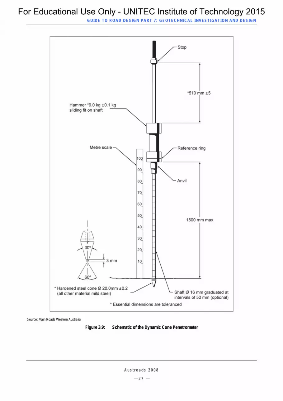
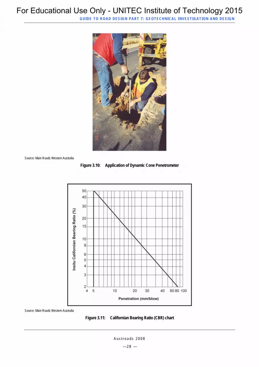
The Dynamic Cone Penetrometer (DCP) shown in Figure 3.9 measures the soil strength attributes of penetrability and compaction. Figure 3.10 shows a field test using the DCP. It is used to measure the in situ Californian Bearing Ratio (CBR) of soil. This test is particularly useful for investigating the variation in subgrade strength with depth. The instrument comprises a metal rod with a hardened steel cone. The penetrometer is driven into the ground by raising the hammer and allowing it to fall freely onto the anvil. The relationship between the penetration and number of blows is determined. A CBR chart is shown in Figure 3.11
The in situ penetration resistance of fine grained cohesive soils determined by DCP is related to the CBR value by means of the relationship given in Austroads Guide to Pavement Technology (refer to Austroads 2008a and 2008b, and NZS 4402 1T07: 1986, Test 6.5.3). The correlation is not suitable for use with non-cohesive sands. The use of DCP should be restricted to fine-grained soils to avoid misleading results due to the influence of rock or gravel.
Source: Main Roads Western Australia
Figure 3.5: Material sample from Standard Penetrometer Test
A u s t r o a d s 2 0 0 8
— 2 4 —
For Educational Use Only - UNITEC Institute of Technology 2015

GUID E TO ROAD DESIGN PART 7 : GEOTECHNICAL INVEST IG ATION AND DESIGN
Source: Main Roads Western Australia
Figure 3.6: Schematic arrangement of test equipment for the Standard Penetrometer Test
A u s t r o a d s 2 0 0 8
— 2 5 —
For Educational Use Only - UNITEC Institute of Technology 2015

GUID E TO ROAD DESIGN PART 7 : GEOTECHNICAL INVEST IG ATION AND DESIGN
Source: Main Roads Western Australia
Figure 3.7: Schematic of Cone Penetration Test
Source: Main Roads Western Australia
Figure 3.8: Example of output from the Cone Penetration Test
A u s t r o a d s 2 0 0 8
— 2 6 —
For Educational Use Only - UNITEC Institute of Technology 2015
GUID E TO ROAD DESIGN PART 7 : GEOTECHNICAL INVEST IG ATION AND DESIGN
Source: Main Roads Western Australia
Figure 3.9: Schematic of the Dynamic Cone Penetrometer
A u s t r o a d s 2 0 0 8
— 2 7 —
For Educational Use Only - UNITEC Institute of Technology 2015
GUID E TO ROAD DESIGN PART 7 : GEOTECHNICAL INVEST IG ATION AND DESIGN
Source: Main Roads Western Australia
Figure 3.10: Application of Dynamic Cone Penetrometer
Source: Main Roads Western Australia
Figure 3.11: Californian Bearing Ratio (CBR) chart
A u s t r o a d s 2 0 0 8
— 2 8 —
For Educational Use Only - UNITEC Institute of Technology 2015
GUID E TO ROAD DESIGN PART 7 : GEOTECHNICAL INVEST IG ATION AND DESIGN
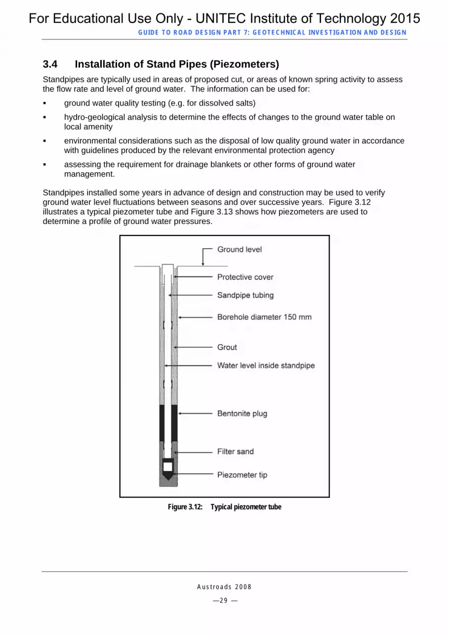
3.4 Installation of Stand Pipes (Piezometers) Standpipes are typically used in areas of proposed cut, or areas of known spring activity to assess the flow rate and level of ground water. The information can be used for:
A u s t r o a d s 2 0 0 8
— 2 9 —
ground water quality testing (e.g. for dissolved salts)
hydro-geological analysis to determine the effects of changes to the ground water table on local amenity
environmental considerations such as the disposal of low quality ground water in accordance with guidelines produced by the relevant environmental protection agency
assessing the requirement for drainage blankets or other forms of ground water management.
Standpipes installed some years in advance of design and construction may be used to verify ground water level fluctuations between seasons and over successive years. Figure 3.12 illustrates a typical piezometer tube and Figure 3.13 shows how piezometers are used to determine a profile of ground water pressures.
Figure 3.12: Typical piezometer tube
For Educational Use Only - UNITEC Institute of Technology 2015

GUID E TO ROAD DESIGN PART 7 : GEOTECHNICAL INVEST IG ATION AND DESIGN
Figure 3.13: Use of piezometers to establish ground water pressure profiles
3.5 Trenching Test pits or trenches provide an economical method of undertaking an on-site examination of near-surface deposits and collecting bulk samples for laboratory testing. The different horizons in a soil profile can be observed in the vertical faces of the trench or pit allowing a complete assessment of the nature of the material. Trenching is also used to obtained additional information to support drilling and seismic refraction surveys. For large projects trenching may be undertaken to provide tenderers with a profile of material.
Test pits (including dozer or backhoe trenches) should be logged and include information relating to the time required to excavate the trench, trench dimensions, descriptions of the in situ and excavated materials and good quality colour photographs of the trench and excavated materials. Information derived from test pits may be used for:
assessment of whether or not rock is capable of being ripped with a large dozer
sampling of in situ material for assessment
producing a map of rock formations (e.g. dip and strike, faults, etc.)
stability assessment of cut batter slopes
assessing the suitability of material for fill
determining the presence and amount of ground water.
Figure 3.14 shows a typical open trench investigation and recording of soil layers.
A u s t r o a d s 2 0 0 8
— 3 0 —
For Educational Use Only - UNITEC Institute of Technology 2015

GUID E TO ROAD DESIGN PART 7 : GEOTECHNICAL INVEST IG ATION AND DESIGN
Source: Main Roads Western Australia
Figure 3.14: Open trench investigation and test pit
3.6 Sampling of Materials Techniques for sampling of materials and the minimum number and size of samples required to provide a reliable assessment of likely performance for the various test methods are specified in AS 1289. All field logging and sampling is normally undertaken by a suitably trained and experienced geotechnical engineer, engineering geologist or soil technician.
3.6.1 General Laboratory testing should be carried out as part of the geotechnical site investigation in order to characterise the engineering and physical properties of materials that are likely to be encountered and/or modified by the road project under consideration.
The test methods that apply to soil testing are generally covered by Australian and New Zealand standard test methods. The AS 1289 series is used for the testing of soils and the AS 1141 series is used for the testing of aggregates. Similarly, NZS 4402 series is used for the testing of soils and the NZS 4407 series is used for the testing of aggregates. Designers in New Zealand are also referred to the New Zealand Geotechnical Society Inc publication, Guideline for the Field Classification and Description of Soil and Rock for Engineering Purposes, 2005. Variations to these methods or alternative test methods are usually covered in test methods issued by each road authority.
The National Association of Testing Authorities (NATA) has an accreditation procedure for both the standard of the laboratory itself, calibration of testing equipment and assessment and certification of laboratory testing personnel to undertake each test. It is important that when receiving test results that the test report makes a clear reference to NATA accreditation and is signed by a testing officer who has the appropriate NATA accreditation.
3.6.2 Test Properties Important properties of soils and rock or a mixture of soil and broken rock are discussed below:
Density
Densification of a material can occur in either of two ways:
compaction – the artificial densification of materials by use of heavy static or vibrating compaction equipment over a relatively short construction period
A u s t r o a d s 2 0 0 8
— 3 1 —
For Educational Use Only - UNITEC Institute of Technology 2015

GUID E TO ROAD DESIGN PART 7 : GEOTECHNICAL INVEST IG ATION AND DESIGN
A u s t r o a d s 2 0 0 8
— 3 2 —
consolidation (or settlement) – the natural densification of a soil brought about by exposing it to a long term static load such as a fill embankment. Consolidation is generally brought about by air and pore water being slowly squeezed out of a soil under sustained static loading.
Strength of materials
The strength (compression or shear strength) is a common engineering property of a rock or soil material considered in the design of foundations and for the assessment of slope stability.
The strength of rock depends on a number of factors such its nature and geological classification, the number and location of discontinuities in the rock structure, the angle and friction between bedding planes and the degree of decomposition by weathering and moisture effects.
The strength of a soil depends on a number of factors such as the density achieved by compaction or consolidation, depth of overlying material, the amount of confining pressure, the particle size distribution (grading), the internal friction or angularity of soil and rock particles, and the moisture content.
Permeability
The permeability of a material is its ability to transmit or prevent transmission of water into or out of the material. The permeability decreases as the density and clay content increases. The permeability is used to specify the porosity of filter materials (minimum requirement) and resistance to transmission of water as applied to a capping layer or the pavement base material (maximum requirement).
Physical properties (Soil and rock classification)
Physical properties (often called the empirical properties) of a material are those used to characterise it. These include such properties as Particle Size Distribution (Grading), Californian Bearing Ratio (CBR), Maximum Dry Density (MDD), Plasticity Index (PI), Optimum Moisture Content (OMC), and various chemical properties. Whilst these properties are not a direct measure of structural performance of a material, when combined with empirically derived test limits from observed or measured field performance and behaviour, they can be termed ‘performance related’ properties. In some cases, empirical charts have been developed that relate test properties to a design requirement or likely field performance. Examples of this are CBR vs. traffic loading (Equivalent Standard Axles) for determining the structural thickness of an unbound pavement, or Moisture/Density/CBR curves to show the interrelationship between these important properties.
Reference should be made to Appendix A for details of individual tests and the information they provide.
Water quality
It may be important that chemical and conductivity testing is undertaken of all ground water proposed to be diverted into the surface drainage system, watercourses, estuaries and streams within or crossing the project boundaries. The presence of dissolved salts can be highly corrosive for steel and reinforced concrete structures (culverts and bridges) and if discharged into fresh water it can kill marine life and vegetation. If water with dissolved salts exceeding 3000 mg/litre is used for watering of construction work it can result in the formation of salt crystals that can cause bituminous surfacing to bubble and lift off the pavement base.
For Educational Use Only - UNITEC Institute of Technology 2015

GUID E TO ROAD DESIGN PART 7 : GEOTECHNICAL INVEST IG ATION AND DESIGN
A u s t r o a d s 2 0 0 8
— 3 3 —
4 DESIGN ELEMENTS
4.1 General The horizontal alignment is considered in conjunction with the vertical alignment and cross section to develop a design line that meets geometric requirements and satisfies major controls on the location of the alignment (refer to Part 2 of the Guide to Road Design – Design Considerations).
Geotechnical information should influence the initial and final choice of the road alignment, profile, and cross section. It is not good practice to complete a geometric design without due recognition of the limitations and advantages provided by the local terrain and site conditions.
In rural areas where a reservation is yet to be defined it is appropriate to choose an alignment that achieves the most economical and direct route with adjustment as necessary to avoid excessive rock excavation and poor foundation conditions, and to minimise stream crossings. In urban areas, the horizontal alignment will generally be confined to a previously defined planning reservation with abutting urban development, and therefore alignment choices will be limited.
The alignment of a road project is usually developed incrementally. Initially, there may be a number of completely different alignment options such as two or more alternative bypass alignments on opposite sides of a town. Choices between these widely differing alternative alignments may in part be made on information obtained from the preliminary geotechnical investigation although there may be some overriding factors such as abutting property development, travel distance, and planning requirements. There may also be various environmental issues such as intrusion into sensitive areas (e.g. adverse effect on flora and fauna), visual intrusion or noise levels.
Once a single route is chosen, a more detailed geotechnical investigation is undertaken after which adjustments may be made to the alignment to optimise project costs and to deal with important community concerns and environmental issues.
4.2 Horizontal Alignment 4.2.1 Rural Areas In rural areas, the horizontal alignment will be influenced by the type of terrain. Terrain can vary from flat to undulating (may involve river flats and swampy areas), undulating to hilly (most common terrain type across Australia) or mountainous terrain.
Flat to undulating terrain
Where the horizontal alignment is to be located in flat to undulating terrain there is a likelihood of poor foundation conditions and the presence of silt (unsuitable as a subgrade or fill material). It may be prudent to shift the alignment to avoid low lying wet areas to achieve drier subgrade conditions during wetter times of the year.
Undulating to hilly terrain
The alignment in undulating to hilly terrain may be influenced by geotechnical information such as:
the location of massive rock requiring extensive blasting
minimum or desirable batter slopes for fixing the limits of earthworks, used to assess whether work can generally be contained within the road or planning reservation or to define an amended road or planning reservation boundary in order to seek subsequent land acquisition
foundation conditions for large culverts and structures which may become control points on the horizontal alignment
For Educational Use Only - UNITEC Institute of Technology 2015

GUID E TO ROAD DESIGN PART 7 : GEOTECHNICAL INVEST IG ATION AND DESIGN
A u s t r o a d s 2 0 0 8
— 3 4 —
problems such as excessive lowering of the water table resulting in batter instability or settlement of adjacent land.
Mountainous terrain
In addition to the factors influencing the alignment in undulating to hilly terrain, geotechnical aspects that may also have an influence in mountainous terrain include:
location of areas prone to land slips
information to enable alignment options to be compared (e.g. very deep cuttings and high embankments compared to tunnelling and/or elevated structures).
4.2.2 Horizontal Alignment Urban Areas In urban areas roadworks are generally confined to a planning reservation in all types of terrain and only minor changes in horizontal alignment may be possible. In urban areas geotechnical information may assist a designer to:
determine the best alignment to minimise the height and type of retaining and noise walls
vary the alignment of structures to avoid poor foundation conditions
vary the alignment of proposed tunnels depending on the nature and stability of soil and rock formations.
4.3 Vertical Alignment 4.3.1 General Once an alignment has been selected that satisfies geometric requirements for the grade line (e.g. minimum elevation above natural surface; desirable maximum grades) and control points such as the level of major structures, flood levels, intersections and rail crossings, other sections of the grade line may be adjusted within the geometric limitations to minimise geotechnical risks or cost. For example, it may be desirable to raise the grade line to avoid rock excavation or to provide a higher embankment over soft, wet or unstable areas.
4.3.2 Balancing of Earthworks Volume Once a grade line is selected that satisfies geometric requirements it may be raised or lowered between control points to achieve a better balance between the volume of cut and the volume of fill (i.e. earthworks balance). If an earthworks balance is not achieved it is necessary to either import material from elsewhere to make up a short fall or dispose of surplus fill which may be difficult in urban or environmentally sensitive areas.
The in situ density of solid rock ranges from 2.6 to 2.9 tonne/m3 but when compacted the density reduces to within the range of 2.0 to 2.4 tonne/m3. This means that solid rock cut excavation will produce a 15% to 25% increase in volume (bulking) as compacted filling depending on the type of rock. If a cutting contains about 50% rock and 50% soil and is thoroughly mixed prior to compaction the amount of volume of cut material may only exceed the volume of filling by about 10%. Typical bulking factors for rock and soils are provided in Table 4.1.
Sands and gravels are about the same volume in cutting as in compacted filling however for expansive clays the compacted density can be higher than the in situ cut density resulting in a loss in volume from cut to fill.
For Educational Use Only - UNITEC Institute of Technology 2015

GUID E TO ROAD DESIGN PART 7 : GEOTECHNICAL INVEST IG ATION AND DESIGN
A u s t r o a d s 2 0 0 8
— 3 5 —
With cut to fill earthworks some allowance must be made for wastage due to spillage, wet weather (e.g. cutting of wet material to waste) and disposal of oversize rock. Wastage can vary between 5% and 15% depending on the topography (more wastage is experienced in hilly country) and the content of large particles of blasted rock excavated material.
Table 4.1: Typical bulking factors for rock and soil
Material Loose volume Compacted volume Solid rock 1.60 1.25 75%/25% rock/soil mixture 1.45 1.20 50%/50% rock/soil mixture 1.35 1.10 25%/75% rock/soil mixture 1.25 1.05 Granitic sand and gravel 1.10 0.90 Dune sand 1.15 0.95 Sandy clay 1.25 0.93 Expansive clay (basaltic) 1.45 0.90 Topsoil 1.45 0.95
Source: VicRoads Technical Bulletin No. 34
The slope of batters also has an influence on the level of the grade line required to achieve an earthworks balance. The comparison in cost of achieving an earthworks balance by raising the grade line and providing steeper batter slopes in rock cuttings to reduce cut volume and/or lowering the grade line and flattening batters in soft rock or soil cuttings to increase cut volume needs to be considered. Rock excavation requiring blasting and loading into dump trucks is significantly more expensive than excavation of materials that are capable of being ripped by a dozer and transported in scrapers.
For an earthworks balance it is important that allowance is made for the backfill of excavations associated with the removal of topsoil and unsuitable material such as silt, peat, vegetable matter, and isolated large boulders.
Broken rock placed in fill has a lower density than massive rock deposits and this can create a gain in volume of material available for disposal. Where massive rock excavation is to be undertaken, it is good practice to identify areas such as sound mounding and fill batter flattening where rock boulders too large to be placed as common fill can be buried as low grade non-structural fill.
Where an earthworks balance cannot be readily achieved and there remains a shortfall of fill, a ready supply must be made available from either borrow areas or from another project or from commercial sources such as a local quarry, sand pit or gravel pit.
4.3.3 Disposal of Surplus Fill If there is excess fill as a result of an imbalance in earthworks it is desirable that it be disposed of within the road reservation by batter flattening, sound mounding or landscaping. The ability to undertake this work depends on the area available and the nature of the excess material. Boulders too large for narrow batter flattening or sound mounds are generally buried, removed to a crushing plant or split with rock hammers or explosives for use in embankments. The amount of unsuitable fill needs to be quantified (refer to Section 4.4).
For Educational Use Only - UNITEC Institute of Technology 2015

GUID E TO ROAD DESIGN PART 7 : GEOTECHNICAL INVEST IG ATION AND DESIGN
A u s t r o a d s 2 0 0 8
— 3 6 —
4.3.4 Raised Embankments over Wet or Unstable Areas Where an embankment is to be constructed over weak compressible soil it may be appropriate to preload the ground well in advance of construction to minimise post construction settlement. Alternatively, or in addition to raising the grade line, consideration could be given to the inclusion of a geotextile (soil support) medium. These can have the effect of distributing the expected imposed loads and construction loads more efficiently thereby reducing the depth of fill that would otherwise be required. Other possible measures include the use of lightweight fill (such as encapsulated polystyrene blocks), drainage blankets, well points, wick drains, or permeable fill.
4.4 Cuttings The ground conditions within cuttings and borrow areas are determined from the geotechnical investigation. Information on ground conditions is required to:
indicate the ease of excavation
design stable batter slopes
design special drainage systems for ground water
assess the quality of excavated material for use in embankments
assess the quality of material and its suitability as structural fill, capping layer material and/or pavement sub-base
determine the depth of topsoil stripping required to expose suitable materials that are essentially free from organic material.
4.4.1 Presence of Rock General considerations
The location of rock not capable of being ripped by a large dozer may have an influence on the horizontal and vertical alignment. Excavation of rock that requires blasting is slow and expensive. It may be possible to avoid rock excavation requiring use of explosives by raising the grade line, particularly if softer material can be obtained elsewhere on the project by flattening cut batters or from convenient borrow areas.
Tenders for construction contracts require a reliable indication of the extent of rock excavation in the Site Conditions Information (SCI) report in order to:
Avoid or reduce the likelihood of prolonged and expensive contractual disputes.
Provide tenderers with an appreciation of the conditions on which to plan and design the project. For example oversize fragments of rock that will not break up under rolling must be either broken up by rock hammers or explosives to the maximum specified nominal size for layered fill construction, or disposed of as unsuitable material.
Rock excavation
The designer should check for local definitions of what constitutes ‘rock’ but essentially it can be described as being material that may be too difficult to loosen by ripping with a 52 tonne dozer with a single ripper (Caterpillar D10 or equivalent) at an economical rate of production (i.e. not less than 100 m3/hr). Rock with a seismic wave velocity of 2500 to 3000 m/sec, depending on rock type, is generally regarded as material that is becoming too difficult to economically rip with a Caterpillar D10 dozer. As road authorities have varying definitions for rock these limits are provided for general guidance only. More information on excavation and performance of earthmoving machinery under various conditions can be obtained from AS 2868-1986.
For Educational Use Only - UNITEC Institute of Technology 2015
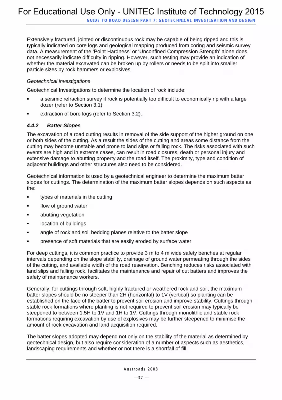
GUID E TO ROAD DESIGN PART 7 : GEOTECHNICAL INVEST IG ATION AND DESIGN
A u s t r o a d s 2 0 0 8
— 3 7 —
Extensively fractured, jointed or discontinuous rock may be capable of being ripped and this is typically indicated on core logs and geological mapping produced from coring and seismic survey data. A measurement of the ‘Point Hardness’ or ‘Unconfined Compression Strength’ alone does not necessarily indicate difficulty in ripping. However, such testing may provide an indication of whether the material excavated can be broken up by rollers or needs to be split into smaller particle sizes by rock hammers or explosives.
Geotechnical investigations
Geotechnical Investigations to determine the location of rock include:
a seismic refraction survey if rock is potentially too difficult to economically rip with a large dozer (refer to Section 3.1)
extraction of bore logs (refer to Section 3.2).
4.4.2 Batter Slopes The excavation of a road cutting results in removal of the side support of the higher ground on one or both sides of the cutting. As a result the sides of the cutting and areas some distance from the cutting may become unstable and prone to land slips or falling rock. The risks associated with such events are high and in extreme cases, can result in road closures, death or personal injury and extensive damage to abutting property and the road itself. The proximity, type and condition of adjacent buildings and other structures also need to be considered.
Geotechnical information is used by a geotechnical engineer to determine the maximum batter slopes for cuttings. The determination of the maximum batter slopes depends on such aspects as the:
types of materials in the cutting
flow of ground water
abutting vegetation
location of buildings
angle of rock and soil bedding planes relative to the batter slope
presence of soft materials that are easily eroded by surface water.
For deep cuttings, it is common practice to provide 3 m to 4 m wide safety benches at regular intervals depending on the slope stability, drainage of ground water permeating through the sides of the cutting, and available width of the road reservation. Benching reduces risks associated with land slips and falling rock, facilitates the maintenance and repair of cut batters and improves the safety of maintenance workers.
Generally, for cuttings through soft, highly fractured or weathered rock and soil, the maximum batter slopes should be no steeper than 2H (horizontal) to 1V (vertical) so planting can be established on the face of the batter to prevent soil erosion and improve stability. Cuttings through stable rock formations where planting is not required to prevent soil erosion may typically be steepened to between 1.5H to 1V and 1H to 1V. Cuttings through monolithic and stable rock formations requiring excavation by use of explosives may be further steepened to minimise the amount of rock excavation and land acquisition required.
The batter slopes adopted may depend not only on the stability of the material as determined by geotechnical design, but also require consideration of a number of aspects such as aesthetics, landscaping requirements and whether or not there is a shortfall of fill.
For Educational Use Only - UNITEC Institute of Technology 2015

GUID E TO ROAD DESIGN PART 7 : GEOTECHNICAL INVEST IG ATION AND DESIGN
If the road reservation is not wide enough to provide safe batter slopes, special treatments such as soil nailing, thatching, sprayed concrete, retaining walls, reinforced earth, gabions or rock walls may be used to provide the required stability or resistance to erosion.
4.4.3 Suitability of Materials It is important that the geotechnical investigation identifies the location and extent of various materials in cuttings and borrow areas that may be suitable for use as select fill, structural fill, capping layer, and pavement subbase, particularly if imported materials are significantly more costly. High quality materials may be nominated for special uses or carted to a stockpile for later use on other stages of the project or on other projects. In cases were significant quantities of sound rock can be won from large cuttings, a contractor may set up a mobile crushing plant to produce crushed rock for a variety of uses.
4.4.4 Interception of Ground Water Road cuttings can attract ground water by lowering the surrounding water table or by intercepting underground water flows such as natural springs or aquifers. A requirement of the geotechnical investigation is to determine the level of the water table, and predict the flow rates of ground water likely to be discharged.
Chemical testing of ground water (see Section A.2.6) is undertaken to check if there is an excessive amount of dissolved salts present that would prevent it from being discharged into the surface drainage system and natural watercourses without treatment or dilution. The effect of lowering the water table beneath land adjacent to the cutting also needs to be considered. To prevent ground water entering and weakening the subgrade and pavement layers it may be necessary to design a special subsurface drainage system to intercept ground water below subgrade level (refer to Figure 4.1). Special subsurface drainage systems include deep formation drains and filter blankets (refer to Part 5 of the Guide to Road Design – Drainage Design, 2008).
Source: VicRoads Technical Bulletin No. 32
Figure 4.1: Interception of ground water
A u s t r o a d s 2 0 0 8
— 3 8 —
For Educational Use Only - UNITEC Institute of Technology 2015

GUID E TO ROAD DESIGN PART 7 : GEOTECHNICAL INVEST IG ATION AND DESIGN
A u s t r o a d s 2 0 0 8
— 3 9 —
4.4.5 Geotechnical Investigations Required for Cuttings Geotechnical investigations that are commonly used for cuttings and borrow areas include:
seismic refraction surveys for cuttings through rock to determine the location of hard massive rock that is likely to be too difficult to economically rip with a large dozer (refer to Section 3.1)
auger holes for soft friable materials and diamond drill coring for rock to determine the soil and rock strata profile both longitudinally and transversely including the strength and quality of materials encountered (refer to Section 3.2)
dozer slots or trenching to obtain larger samples of materials for laboratory testing and provide a more comprehensive assessment of the materials likely to be encountered and their ease of excavation (refer to Section 3.5)
erection of standpipes or piezometers to assess ground water conditions and predicted flow rates and for sampling and testing the chemical composition of ground water (refer to Section 3.5)
penetrometer tests for shallow cuttings through soft soil to determine the resistance to penetration (side friction) and to estimate the in situ CBR strength at various depths down to at least 1.5 m below the proposed subgrade level (refer to Section 3.3).
A variety of equipment such as back hoes, drilling rigs and dozers is used for geotechnical investigations in cuttings. It is important that any underground services are precisely located by a representative of the relevant service authority before any material is excavated. The site engineer will require a preliminary drawing defining the likely extent of excavations to assist in determining the location and depth of bore holes and trenching.
The need for special treatments in cuttings such as retaining walls, batter stabilisation, and deep subsurface drainage systems should also be identified (see Appendix B for more detail on some of the more common special treatments used in cuttings).
4.5 Embankments The ground conditions where fill embankments, particularly embankments exceeding 5 m, are to be placed, require assessment for the likely depth of topsoil stripping, the amount and extent of over-wet or unsuitable material present, the need for special treatments over swampy ground and recommended batter slopes.
4.5.1 Depth of Topsoil Topsoil stripping is generally undertaken to remove any vegetable matter or seed bearing soil prior to the earthworks phase. The depth of stripping may not always be apparent and it may be necessary to vary the depth due to different material types. Accordingly, it may be appropriate to seek geotechnical advice regarding the depth of stripping required along the project length.
A geotechnical assessment can be made of the depth of suitable topsoil available for landscaping of batters, verges and medians. The depth of topsoil typically removed from areas on which fill is to be placed is often substantially greater in low lying areas than on higher ground to be excavated from cuttings. This imbalance can make up for any shortfall of topsoil won from cuttings and needs to be accounted for in the calculation of earthworks quantities and achieving balanced earthworks.
For Educational Use Only - UNITEC Institute of Technology 2015

GUID E TO ROAD DESIGN PART 7 : GEOTECHNICAL INVEST IG ATION AND DESIGN
A u s t r o a d s 2 0 0 8
— 4 0 —
Embankment foundations are normally assessed from test pit or borehole information taken at about 100 m to 500 m intervals along the route depending on the ground conditions.
4.5.2 Stability of Areas on which Fill is to be Placed All embankments and more particularly the material on which fill is placed will experience some settlement during and after construction. The amount of settlement largely depends on the height of the embankment, the type of materials within the embankment and how well these materials have been compacted, but more on particularly the density and moisture condition of the material on which the embankment is constructed. A geotechnical investigation can identify embankment sites that are prone to settlement during and after construction and make a prediction of the rate of consolidation and the point when further consolidation will fall within acceptable limits.
The nature of the materials and the speed of construction will also affect the time at which further settlement due to consolidation of an embankment stabilises. Most initial consolidation takes place during construction of the embankment, but for high embankments and embankments with poor foundation conditions, it may be necessary to wait until the settlement of the embankment stabilises before commencing pavement construction and structural foundations. The rate of consolidation of embankments is typically monitored at a number of strategic points by an accurate survey of levels taken over time.
As the rate of consolidation is largely dependent on the properties of the material on which the embankment is placed, the geotechnical investigation should identify materials beneath the proposed fill that may require removal and replacement with higher quality materials in order to shorten the time required for settlement to stabilise. In extreme cases (e.g. where there is a risk of shear failure of the underlying saturated silts or swamp clays) the geotechnical investigation should recommend whether or not special treatments are necessary to stabilise and/or dry out the underlying material such as the installation of:
rock rafts and drainage blankets
lightweight fill incorporating polystyrene blocks
geotextiles and geogrids (i.e. a reinforcing mesh made of polypropylene)
special de-watering systems such as well points and/or wick drains
surcharging.
4.5.3 Slope of Fill Batters The slope of fill batters is also discussed in Section 4.3.2. From a geotechnical viewpoint all fill batters should be designed with:
slopes no steeper than 2H horizontal to 1V vertical if planting is required to stabilise the sides of the embankment and prevent soil erosion
slopes considerably flatter than 2H to 1V if the road reserve is not confined and there is surplus fill available, particularly if the project has significant surplus volumes of unsuitable low grade fill or rock that is too large to be used as common fill for the structural portion of the embankment.
Embankments steeper than 2H to 1V should not be grassed but planted and mulched as they cannot be mowed or maintained easily.
Road safety considerations generally suggest that much flatter batters will be required. The reader is referred to Parts 3 and 6 of the Guide to Road Design in relation to driveable batter slopes.
For Educational Use Only - UNITEC Institute of Technology 2015

GUID E TO ROAD DESIGN PART 7 : GEOTECHNICAL INVEST IG ATION AND DESIGN
A u s t r o a d s 2 0 0 8
— 4 1 —
The batter line defined by the 1.5H to 1V fill profile is regarded as the structural portion of the embankment where a high standard of compaction is required for soil materials or in the case of rock fill, a strong inter-particle contact.
For erosion prone materials such as dune sand, batters may also need to be flatter than 2H to 1V to enable more rapid establishment of vegetation and to lower the velocity of surface water flowing down the batter particularly after heavy rainfall.
For rock fill that does not require extensive planting for erosion protection, batter slopes may be up to 1.5H to 1V. This also includes ‘spill through’ bridge abutments that are generally faced with rock beaching, slate or concrete blocks.
For embankments where steeper batter slopes than 1.5H to 1V are required, some form of retaining or protection structure is likely to be required for at least part of the embankment near the toe.
Typical structures used to retain embankments are:
reinforced earth (pre-cast concrete panels or masonry blocks held by long steel straps between layers of fill)
gravity gabion walls (rocks in wire baskets placed like bricks)
crib walls (structural framework of concrete or timber interlocking segments with the spaces between the segments filled with soil)
reinforced concrete walls
gravity walls constructed of masonry or rocks.
Reinforced concrete retaining walls and low gravity walls can be constructed with a vertical face, but gravity walls including crib and gabion walls, are typically sloped back at a slight angle depending on the type and height of the wall (refer to Appendix B for more detail and illustrations of special treatments that may be required for steep fill batters).
4.5.4 Rock Fill Rock that is not readily broken down may be placed as rock fill up to a maximum particle size of 400 mm where a vibrating roller may be used to ‘seat’ each rock particle so that sound particle-to- particle contact is achieved. Because of the higher and variable air voids in rock fill, control of density and moisture control is not as necessary as it is for soft rock or soil-like materials.
The hardness of rock can be tested with the Point Load test (refer to Section A.2.5) to indicate whether rock spalls are capable of being broken down during compaction. As a general guide, rock with an IS (50) Point Load Strength (strength of a 50 mm core) of more than 1.5 MPa may indicate that the rock is too hard to break up under rolling. The Point Load Strength tends to be ‘rock type specific’ and other limits may be specified for different rock types.
Aspects that should be considered in placing rock fill are:
Large rock spalls or fragments that will not readily breakdown under rollers will either require pre-splitting to the maximum specified nominal size (typically 400 mm or less) before it is placed as common filling or alternatively, put through a crushing plant and converted to a select fill or lower subbase material.
For Educational Use Only - UNITEC Institute of Technology 2015

GUID E TO ROAD DESIGN PART 7 : GEOTECHNICAL INVEST IG ATION AND DESIGN
A u s t r o a d s 2 0 0 8
— 4 2 —
If practical, large rock spalls or ‘floaters’ need to be separated from soil and may be placed as clean rock fill or crushed to produce select filling or pavement material. Most specifications define the maximum size rock (generally about 400 mm) that can be placed for various types of fill and a minimum depth from subgrade level where larger sized material can be placed.
A geotextile fabric may be specified to separate rock fill from softer friable material (blinding layers) placed between the rock fill and the subgrade.
Larger rock fragments or spalls greater than 400 mm can be used as non-structural fill such as rock protection, batter flattening, noise mounds and landscaping.
Large rock may impact adversely on drainage culverts.
4.5.5 Geotechnical Investigations Required for Embankments The geotechnical investigations and monitoring systems that may be required to determine fill batter slopes include:
cone penetrometer tests to determine the depth, and penetration resistance of soft saturated soils beneath proposed embankments (refer to Section 3.3)
removal of undisturbed samples for consolidation and shear testing (refer to Appendix A)
information to allow the minimum batter slopes to be determined for embankments, having regard to the properties of the soil proposed for embankment construction including resistance to soil erosion
monitoring of horizontal and/or vertical movement during and after placement of the embankment.
4.6 Pavements 4.6.1 General In order to develop the road design it is necessary to have completed the design of the pavements. Large projects often require several pavement designs for different lengths or elements of the project where there are different traffic loadings or subgrade strengths. For example, a different pavement composition may be adopted in rock cuttings than in fill areas constructed on low strength or expansive soils. Freeway ramps, overpass embankments and frontage roads may also have a different structural thickness and composition to that used for the main carriageways.
In situ materials found along the alignment will normally be tested to assess whether they are suitable for use as selected fill, capping layer, pavement subbase or base. Materials won from site generally result in considerable savings compared to materials imported from external commercial sources such as a quarry that may be a considerable distance away from the site. A detailed laboratory evaluation of in situ materials is essential to enable decisions to be made on how these materials are best used.
For pavement design purposes, an assessment is made of the CBR strength and percentage swell of in situ materials used at or near subgrade level including the material to be used for select fill or capping layers, or for the pavement itself where naturally occurring materials are being considered. The pavement designer uses this information together with the traffic loadings to determine the structural thickness of the pavement layers. Generally, it is sound economic practice to provide a good quality capping or select fill layer (refer to Figure 4.2) with a CBR strength significantly higher than the in situ or common fill as this reduces the overall pavement thickness. Supply of additional pavement material is significantly more costly than fill materials won from the site.
For Educational Use Only - UNITEC Institute of Technology 2015

GUID E TO ROAD DESIGN PART 7 : GEOTECHNICAL INVEST IG ATION AND DESIGN
For pavements constructed over highly expansive materials a minimum cover of 0.6 m to 1 m from the finished pavement surface level to the top of the expansive material may be specified. Part of this cover includes the provision of a low permeability capping layer of selected or imported fill with a low swell as a characteristic. The effect of a capping layer is to reduce moisture changes in the expansive material and thereby minimise the potential for volume change and shape loss or deep seated environmental cracking of the pavement. The aim is to maintain the expansive material and capping layer as close as possible to the equilibrium moisture content (EMC) to minimise changes resulting from seasonal variation.
Source: Ross Paul & Associates
Figure 4.2: Capping layer arrangement
Designers are referred to the Austroads (2008a) for further information relating to pavement design.
4.6.2 Rehabilitation and Strengthening of Existing Pavements Pavement investigation for a greenfields site is generally restricted to investigation of potential excavated materials from cuttings for use as capping layer material, selected fill, structural fill, pavement subbase and base as described in the preceding sections.
However, many road projects require upgrading of existing pavements by widening and strengthening with an asphalt overlay, or granular re-sheet using unbound pavement materials. In these cases a pavement investigation is required to determine the CBR strength of the existing subgrade beneath the pavement layers, and the thickness and suitability of materials within the existing pavement for either recycling or to form part of the new pavement structure. The depth of widening and overlay or resheet will be a factor in determining the new finished level of the upgraded pavement. In built-up areas the only option may be re-construction and salvaging the existing pavement for other uses or stockpiling for later use as pavement subbase.
Deflection testing is usually undertaken to determine the strength and stiffness of existing pavements in order to design an appropriate asphalt overlay or granular resheet. Design of asphalt overlays and granular resheets requires an experienced pavements engineer to determine the minimum thickness of asphalt overlay or unbound granular resheet required to provide the upgraded pavement with sufficient structural strength for the future traffic loading. The advantage of deflection testing is that it measures the in situ strength and does not rely on assumptions to be made regarding the strength of the subgrade or materials within the existing pavement.
If there are some very weak areas of pavement in an otherwise sound pavement, a combination of an asphalt overlay or a granular resheet, major patching or cementitious stabilisation may be used.
More information on pavement investigations and design can be obtained from Austroads (2008a) and (2008b).
A u s t r o a d s 2 0 0 8
— 4 3 —
For Educational Use Only - UNITEC Institute of Technology 2015

GUID E TO ROAD DESIGN PART 7 : GEOTECHNICAL INVEST IG ATION AND DESIGN
A u s t r o a d s 2 0 0 8
— 4 4 —
4.6.3 Pavement Design Pavement design is typically undertaken by a specialist with appropriate knowledge and skills in pavement design. It is not uncommon to provide a number of optional pavement designs varying from unbound pavements with a sprayed seal or thin asphalt surfacing, a deep strength or full depth asphalt pavement or various plain or reinforced Portland cement concrete options. The construction team in consultation with their client will usually select the pavement type best suited to each road segment. Generally, heavily trafficked urban roads require fully bound low maintenance pavements that resist higher traffic stresses, whereas for rural roads unbound pavements with sprayed sealed or thin asphalt surfacing are more commonly selected because of their lower cost and relative ease of both routine and periodic maintenance.
For further information, refer to Austroads (2008a).
4.6.4 Geotechnical Investigations Associated with the Design of Pavements Geotechnical investigations that are typically required for pavements include:
Cone penetrometer tests to assess in situ subgrade strength and the variation in subgrade strength along the job, particularly beneath existing pavements.
Sampling and laboratory testing of materials in cuttings and borrow areas for CBR strength and percentage swell and various physical properties such as grading and Plasticity Index.
Test pits dug within existing pavements that are to be strengthened and rehabilitated to progressively expose each pavement layer to determine the thickness of each layer and to obtain samples of each pavement material for laboratory testing. Once the subgrade is exposed, it is sampled and usually subjected to a Dynamic Cone Penetrometer test to provide an in situ CBR strength).
Coring of asphalt, cemented materials or other bound materials to quickly determine the thickness of existing pavement layers at locations where test pits for sampling of materials for laboratory testing are not required.
4.7 Subsurface Drainage System The purpose of subsurface drainage systems is to:
prevent ground water from entering and softening or saturating the subgrade or pavement materials
remove trapped water that enters a pavement either from the side or from beneath the pavement.
4.7.1 Subsurface Drainage Systems for Interception of Ground Water Subsurface drainage systems for cuttings are described in Section 4.3.4. The geotechnical investigation should establish the fluctuations in the water table, the presence of underground springs and permeable aquifers, and predict ground water flows that will occur when cuttings and fill embankments have been constructed. Large cuttings and embankments can cause a significant change in flow of ground water. A geotechnical design may be required to determine suitable deep subsurface drains and filter blankets that will intercept the flow of ground water and distribute it into the surface drainage system.
4.7.2 Pavement Drains The location and configuration of sub-surface drainage systems is covered in Austroads Guide to Road Design, Part 5 – Drainage Design.
For Educational Use Only - UNITEC Institute of Technology 2015

GUID E TO ROAD DESIGN PART 7 : GEOTECHNICAL INVEST IG ATION AND DESIGN
A u s t r o a d s 2 0 0 8
— 4 5 —
Pavement drains are relatively shallow, varying from 300 mm to 400 mm below subgrade level. All pavement drains should start and finish at a drainage pit or end wall. The total continuous length of subsurface drainage pipe without a junction pit or inspection opening should not exceed 100 m to 150 m (depending on gradient) to enable periodic flushing out of fine material that may otherwise build up and cause a blockage.
Pavement drains should be provided where:
There is a ‘boxed’ formation with impermeable verges or unsealed shoulders to contain the pavement. (A sub-surface drain should always be installed on the low side of the boxed pavement in fill areas and on both sides of the ‘boxing’ in cuttings.)
Pavement widening is to be undertaken as water may become trapped against a material of lesser permeability on the low side of the existing pavement (e.g. asphalt widening of an unbound granular pavement).
The in situ material and fill material may have different permeability at cut to fill points.
Pavement drains should have a:
Filter material capable of efficiently transferring water to the drain pipe but which can also filter out fine grained mobile soil or silt material to prevent it entering and blocking drain pipes.
Filter sock wrapped around a perforated drain pipe in locations where fine sand filter material is used in order to prevent the filter material from entering the slots in the pipe.
Geotechnical advice should be sought on the type of pavement drain and filter material to be used in relation to the grain size of the adjacent soil and whether or not a two zone filter is required. The selection of subsurface drainage arrangements will be site specific, but typical indicative treatments are:
In clayey materials where there are typically low flows of subsurface water, a perforated pipe with a filter sock is commonly used with a fine sand filter material (Type D drain in Figure 4.3).
In silty material where higher flows of ground water can cause the silt particles to become mobile, a geotextile fabric is placed against the sides of the trench (Type B drain in Figure 4.3) or a second zone of finer filter material is used (Type A drain Figure 4.3) in conjunction with a very permeable coarse aggregate filter material designed to intercept water and efficiently carry it to the perforated drainage pipe. The Type A drain has largely been superseded by the Type B drain because of the cost of using temporary forms to separate the two filter zones during back filling and their subsequent raising or removal.
For permeable sand and gravel materials where there may be significant flows of subsurface water, a perforated or slotted pipe with a single stage filter of very permeable coarse sand or fine aggregate that is more permeable than the subgrade material may be applied (Type C drain in Figure 4.3).
Where rock material in cuttings is substantially free of soil particles, a perforated pipe with a very permeable coarse aggregate filter material may be used to cut off possible flow of ground water and efficiently deliver it to the pipe (Type C drain in Figure 4.3).
For subsurface drains located directly under or within an existing pavement (particularly in the longitudinal direction), a perforated pipe wrapped in a filter sock and back filled with fine sand and with the remainder of the trench backfilled with a permeable ‘no fines’ concrete filter material may be suitable (a variation of Type D in Figure 4.3).
For Educational Use Only - UNITEC Institute of Technology 2015
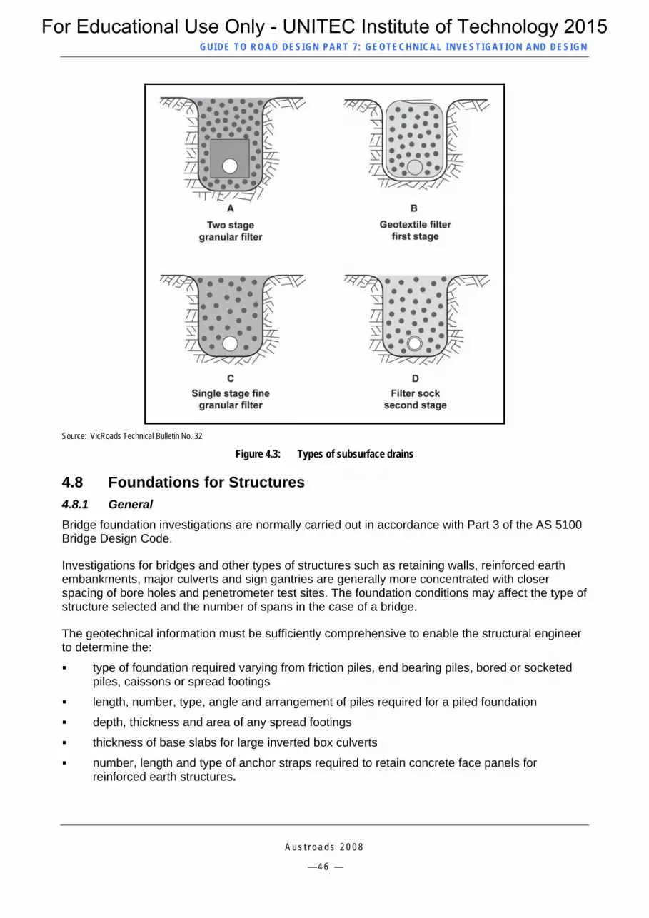
GUID E TO ROAD DESIGN PART 7 : GEOTECHNICAL INVEST IG ATION AND DESIGN
Source: VicRoads Technical Bulletin No. 32
Figure 4.3: Types of subsurface drains
4.8 Foundations for Structures 4.8.1 General Bridge foundation investigations are normally carried out in accordance with Part 3 of the AS 5100 Bridge Design Code.
Investigations for bridges and other types of structures such as retaining walls, reinforced earth embankments, major culverts and sign gantries are generally more concentrated with closer spacing of bore holes and penetrometer test sites. The foundation conditions may affect the type of structure selected and the number of spans in the case of a bridge.
The geotechnical information must be sufficiently comprehensive to enable the structural engineer to determine the:
type of foundation required varying from friction piles, end bearing piles, bored or socketed piles, caissons or spread footings
length, number, type, angle and arrangement of piles required for a piled foundation
depth, thickness and area of any spread footings
thickness of base slabs for large inverted box culverts
number, length and type of anchor straps required to retain concrete face panels for reinforced earth structures.
A u s t r o a d s 2 0 0 8
— 4 6 —
For Educational Use Only - UNITEC Institute of Technology 2015

GUID E TO ROAD DESIGN PART 7 : GEOTECHNICAL INVEST IG ATION AND DESIGN
A u s t r o a d s 2 0 0 8
— 4 7 —
4.8.2 Geotechnical Investigations Required for Structural Foundations An accurate soil and rock profile is required at proposed sites for structures. It is important that the investigation is sufficiently comprehensive to ascertain whether or not there is rock overlying softer rock or clay similar to the case of basalt ‘floaters’.
Investigations include:
CPT (cone penetrometer testing) for softer soils and sands to provide the depth, strength and frictional resistance of soil strata particularly where piled foundations are likely
vane shear testing of soft clay materials
coring through stiffer soils and rock to obtain its depth, consistency and strength
sampling of surface and ground water for dissolved salts or other corrosive chemicals where special protective treatments may be required for steel and reinforced concrete structures particularly steel structures and corrugated steel pipes.
For Educational Use Only - UNITEC Institute of Technology 2015

GUID E TO ROAD DESIGN PART 7 : GEOTECHNICAL INVEST IG ATION AND DESIGN
A u s t r o a d s 2 0 0 8
— 4 8 —
5 SUSTAINABLE DESIGN PRACTICES
5.1 General Road agencies play a central role in the delivery of sustainable outcomes for transport development, with key responsibilities associated with managing substantial lengths of road network, provision of services to promote diversification of transport options and facilitation of community engagement in transport planning.
Sustainable design practices are those leading to road designs that reflect not only the economic and safety aspects of the solution, but also the associated social and environmental improvement. Every opportunity should be taken to enhance social and environmental amenity, particularly if these enhancements come with only a marginal increase in the cost of the project. The focus should not be restricted to compliance with existing guidelines or simply to mitigate the adverse effects of roadwork, but to seek positive ways to enhance the overall outcome in a social and environmental sense.
In the context of geotechnical investigation and design considerations, the following opportunities may be worth pursuing.
5.2 Materials Stewardship One of the major environmental impacts of road construction activity is the clearing of native vegetation. Sometimes it is necessary to clear additional native vegetation to gain access to road building materials. In order to minimise the amount of clearing and to reduce other environmental impacts, sourcing of local materials should be considered in the light of other alternatives. This approach is termed ‘material stewardship’ and should lead to a more sustainable management of existing and future deposits of road making materials.
There are a number of ways where extraction of materials can be undertaken to reduce the impact on local vegetation and habitat. When selecting a suitable location for extraction of road making materials consideration should be given to:
locating gravel pits in paddocks or other cleared areas in preference to areas of native vegetation
avoiding stands of significant native vegetation particularly old growth native trees
locating gravel pits outside the road reserve on adjacent cleared land in cases where the road reserve contains the last remnants of native vegetation prior to adjacent land being cleared for agriculture or other development
avoiding land that is reserved or likely to be reserved for future conservation
minimising the area required for clearing by avoiding shallow gravel deposits in preference to deeper deposits to give a higher yield per hectare of affected land
selection of gravel deposits with a maximum level at least 0.5 m above the water table
location of gravel pits on land with a low environmental significance in preference to undisturbed ecosystems.
Regardless of tenure, areas of cleared land should always be investigated as a source of suitable material prior to considering areas covered with native vegetation.
For Educational Use Only - UNITEC Institute of Technology 2015

GUID E TO ROAD DESIGN PART 7 : GEOTECHNICAL INVEST IG ATION AND DESIGN
A u s t r o a d s 2 0 0 8
— 4 9 —
5.3 Minimisation of Erosion In order to minimise the potential for erosion and land slips, the road alignment should be selected to avoid unstable soils, steep topography, and proximity to parallel streams.
The geotechnical investigation should clearly identify the location of all soil types particularly dispersive materials such as silt, sand and gravel where special treatments may be required to minimise or avoid soil erosion. The maximum sustainable velocity for overland water flow and in open drains should be determined for various materials. Consideration should also be given to the erosive power of stormwater flowing from a culvert outlet so the designer can ensure that the design outflow velocity accounts for local soils and thereby minimises the potential for downstream scouring. Dispersive materials will require very detailed treatments.
The designer should use strategies that minimise the volume of water and sediment flowing off the road pavements and formation. The designer should therefore consider:
Using retarding basins, silt traps and debris racks to minimise deposits of eroded material and debris that may interfere with the natural flow of water in streams.
Limiting the cut and fill batters in soft rock and soil materials to a maximum of 2H to 1V to enable vegetation to be readily re-established.
Using special batter lining systems for soft rock and soil with batters steeper than 2H to 1V.
Thatching or lining of open drains through soils or sands where scour is likely to occur, and installation of rock weirs or drop structures to slow water velocity as necessary.
Locating any appurtenances such as open drains clear of significant stands of trees to minimise clearing.
Where there is sufficient road reserve space, designing batters to be as flat as 6H to 1V to support denser plant growth and further reduce the potential for soil erosion (notwithstanding that use of flat fill batters may avoid the use of safety fencing). However, incorporation of very flat batters may not be the best solution from a soil erosion perspective if it substantially increases the amount of heavy clearing required.
Reference should be made to Section B.5 in Appendix B for further information.
5.4 Water for Construction and Landscaping Purposes Use of water is an increasing concern and it is becoming clear that serious measures are required to conserve water for domestic and industrial use. Use of town water or water extracted from local streams for road construction is being perceived by some sections of the community as being ‘water wasteful’. Therefore alternative water sources such as recycled or bore water should be used.
The geotechnical investigation should identify sources of water for construction, including whether or not underground water can be obtained from bores or natural springs, and whether temporary dams or permanent water features could be established as part of the landscaping.
Landscaping should comprise indigenous species of plants that require less water to establish. In areas where there is a likelihood of water shortage for construction purposes and to establish vegetation, consideration should be given to the inclusion of special features in the design such as:
the creation of ornamental dams or lakes within the road reserve as a feature of the roadside landscaping in locations where the road reserve is wider than required for the road formation
For Educational Use Only - UNITEC Institute of Technology 2015

GUID E TO ROAD DESIGN PART 7 : GEOTECHNICAL INVEST IG ATION AND DESIGN
A u s t r o a d s 2 0 0 8
— 5 0 —
temporary dams in abutting property that would not contravene regulations by the local water management authority
a means of capturing water from underground springs likely to be intercepted by earthworks and drainage, for use as construction watering and for establishing and maintaining new vegetation planted as part of the project landscaping
specifying measures to ensure the effective use of water generally, and specifically to promote the survival of plants and trees (e.g. early mulching of landscaped areas to retain moisture content in soils).
5.5 Preservation of Topsoil The geotechnical investigation should clearly identify the depth of available topsoil in both cut and fill areas. This information can be used by the designer to calculate the depth of stripping required not only to prevent organic material from being mixed with or covered by common fill but to source additional topsoil. Increasing the depth of topsoil excavation beneath fill areas (if available) can make up for potential shortfalls in other areas such as medians, verges and batters. Topsoil is also required to restore borrow pits after completion of materials extraction.
It is important and cost-effective that all stripped topsoil should be used within close proximity to where it is won. The topsoil which is generally stripped as part of the site clearing activity contains local seed and some composted material that will assist with the regeneration of local vegetation. Local topsoil is an important commodity required to sustain and retain grasses and plants to a particular location along the project. Bringing topsoil from remote locations should be avoided if possible as it may result in the importation of undesirable weeds and plants or disease. Maintaining grass and plant species native to the area is not only environmentally sound, it also minimises the spread of noxious weeds, and seeds and plants are likely to be more tolerant of the long term local weather conditions. Imported topsoil should be certified as being free of pathogens, toxic levels of any element and any weeds or their roots.
Flatter fill batter slopes (less than 4H to 1V) will have greater success in retaining topsoil and limiting losses due to scour.
5.6 Use of Non-standard or Recycled Materials Rural roads have traditionally been paved with naturally occurring materials where there are workable quantities within an economic haul distance from the project site. However such materials are becoming scarce. More use is being made of quarried or manufactured materials that are generally more costly than natural materials. However, consideration should always be given to the use of locally available material that may be marginal in quality but has been proven to function well under local conditions particularly in arid areas.
Local knowledge and experience in using non-standard materials may encourage the pavement designer to consider modifying the pavement composition to incorporate such material. Before doing so however, the pavement designer should seek advice from regional staff and a geotechnical expert to devise a suitable testing regime, or quality control system. A field trial of the material could be considered to confirm the likelihood of success, and the cost relative to the provision of a more conventional material.
Many naturally occurring but substandard pavement materials can be blended with a crushed product prior to stabilisation with a cementitious binder to form a material that performs satisfactorily. In some cases blending two materials together can produce a resultant material of sufficient quality in terms of grading and plasticity without the need to add a cementitious binder.
For Educational Use Only - UNITEC Institute of Technology 2015

GUID E TO ROAD DESIGN PART 7 : GEOTECHNICAL INVEST IG ATION AND DESIGN
A u s t r o a d s 2 0 0 8
— 5 1 —
There may also be an opportunity to obtain pavement and fill material from remnant sections of old highway and make use of this material by blending it with a virgin material. This form of granular or mechanical stabilisation is discussed in greater detail in publications such as Ingles (1978) and Austroads (1998).
Most road authorities promote the use of recycled materials in pavements provided that the materials can be used in such a way as to achieve satisfactory field performance. Some of the recycled materials commonly used in road pavements include:
pulverised existing pavement material and bituminous surfacing, stabilised in situ with a cementitious binder to produce a stronger and less moisture sensitive material for use as pavement subbase on major roads or as pavement base on low trafficked roads
recycled crushed concrete produced to a similar specification as crushed rock but with maximum limits on the mass of foreign materials such as crushed brick, glass, wood and other foreign organic materials
blast furnace slag ground into a powder to become a major portion of slow and medium setting cementitious binders
blast furnace slag crushed to a specified grading for use as a cementitious pavement subbase
crumbed rubber added to bitumen to produce a Strain Alleviating Membrane (SAM) seal surfacing
milled asphalt used as granular pavement subbase material
milled or crushed recycled asphalt added to a virgin asphalt mixture in proportions ranging from 10% to 30%
existing asphalt pavement pulverised in situ and treated with foamed bitumen or bitumen emulsion to form a lightly bound pavement base.
The geotechnical investigation should also identify local natural pavement materials that can be stabilised in situ to produce a satisfactory material.
For Educational Use Only - UNITEC Institute of Technology 2015

GUID E TO ROAD DESIGN PART 7 : GEOTECHNICAL INVEST IG ATION AND DESIGN
A u s t r o a d s 2 0 0 8
— 5 2 —
REFERENCES Austroads 1998, Guide to stabilisation in roadworks, by G Youdale, AP-60/98, Austroads, Sydney, NSW.
Austroads 2008a, Guide to pavement technology, part 2 – structural design of road pavements, AGPT02/08, Austroads, Sydney, NSW. (In press)
Austroads 2008b, Guide to pavement technology, part 5 – pavement evaluation and treatment design. AGPT05/08, Austroads, Sydney, NSW. (In press)
Austroads 2004, Bridge design, part 3 – foundations and soil supporting structures, AP-G15/04, Austroads, Sydney, NSW.
Craig, RF 2004, Soil Mechanics, 7th ed, Spon Press, London.
Ingles, OG 1978, ‘Soil stabilisation: the next one hundred years’, Symposium on Soil Reinforcing and Stabilising Techniques In Engineering Practice, 1978, Sydney, Australia, School of Engineering, New South Wales Institute of Technology, Broadway, NSW, pp. 365-83.
Jones, SA 2007, Geology of the Erayinia, 1:100,000 sheet explanatory notes, Geological Survey of Western Australia, East Perth, WA.
New Zealand Geotechnical Society Inc. 2005, Guideline for the Field Classification and Description of Soil and Rock for Engineering Purposes, www.nzgeotechsoc.org.nz/guidelines.cfm.
Standards Australia
AS 1141 (various parts and dates), Methods for sampling and testing aggregates
AS 1170.4:2007, Structural design actions – earthquake actions in Australia
AS 1289 (various parts and dates), Methods of testing soils for engineering purposes
AS 1726:1993, Geotechnical site investigations
AS 1742.13:1991, Manual of uniform traffic control devices, part 13, local area traffic management
AS 2868:1986, Classification of machinery for earthmoving, construction, surface mining and agricultural purposes
Standards New Zealand
NZS 1170.5:2004, Structural design actions – earthquake actions in New Zealand
NZS 4402 1T07:1986 SET, Methods of testing soils for civil engineering purposes – Soil Tests
NZS 4407: 1991, Methods of sampling and testing road aggregates (various parts)
NZS 4411:2001, Environmental standard for drilling of soil and rock
Transit NZ 2007, Standard Professional Services Specification - Investigation and Reporting, Version 9, March 2007, Transit New Zealand, Wellington New Zealand.
For Educational Use Only - UNITEC Institute of Technology 2015

GUID E TO ROAD DESIGN PART 7 : GEOTECHNICAL INVEST IG ATION AND DESIGN
A u s t r o a d s 2 0 0 8
— 5 3 —
VicRoads Technical Bulletins
No 32, Drainage of subsurface water from roads (2004).
No. 34, Proper and economical use of plant (1986).
No. 39, General requirements for unbound pavement materials (1998).
No. 40, Pavement investigation – guide to field inspection and testing (1995).
For Educational Use Only - UNITEC Institute of Technology 2015

GUID E TO ROAD DESIGN PART 7 : GEOTECHNICAL INVEST IG ATION AND DESIGN
APPENDIX A LABORATORY TESTS
A u s t r o a d s 2 0 0 8
— 5 4 —
A.1 Tests Related to Engineering Properties A.1.1 General Testing the engineering properties of rock requires a clear distinction between tests that relate to the discontinuities within the rock and those that are relevant to the solid rock mass. The presence of moisture can also affect the behaviour of discontinuous or fractured rock.
Testing for the engineering properties of soils requires the specification of test conditions such as density, moisture content, drained or undrained state specimens and pre- or post-consolidated state, in an attempt to replicate as far as is possible, the likely field conditions or worst case scenario.
Some of the more common laboratory tests on soil and rock required for design purposes are summarised below.
A.1.2 Unconfined Compression Strength (UCS) Test The UCS is the maximum vertical stress an unconfined cylindrical specimen of rock or highly bound material can withstand before crushing or collapsing. This is a simple test to assess the bearing or shear strength of rock for design of structural elements such as end bearing piles or spread footings, and for assessment of the stability of rock cut batters where discontinuities, fractures, and soft bedding planes are evident.
The specimen, typically with a height to diameter ratio of 2:1 must be capable of standing unsupported in the test machine (refer to Figure A 1).
(a) Compression device (b) Test specimen under load
Source: Professor Krishna Reddy UIC (Website)
Figure A 1: Unconfined compression test
For Educational Use Only - UNITEC Institute of Technology 2015
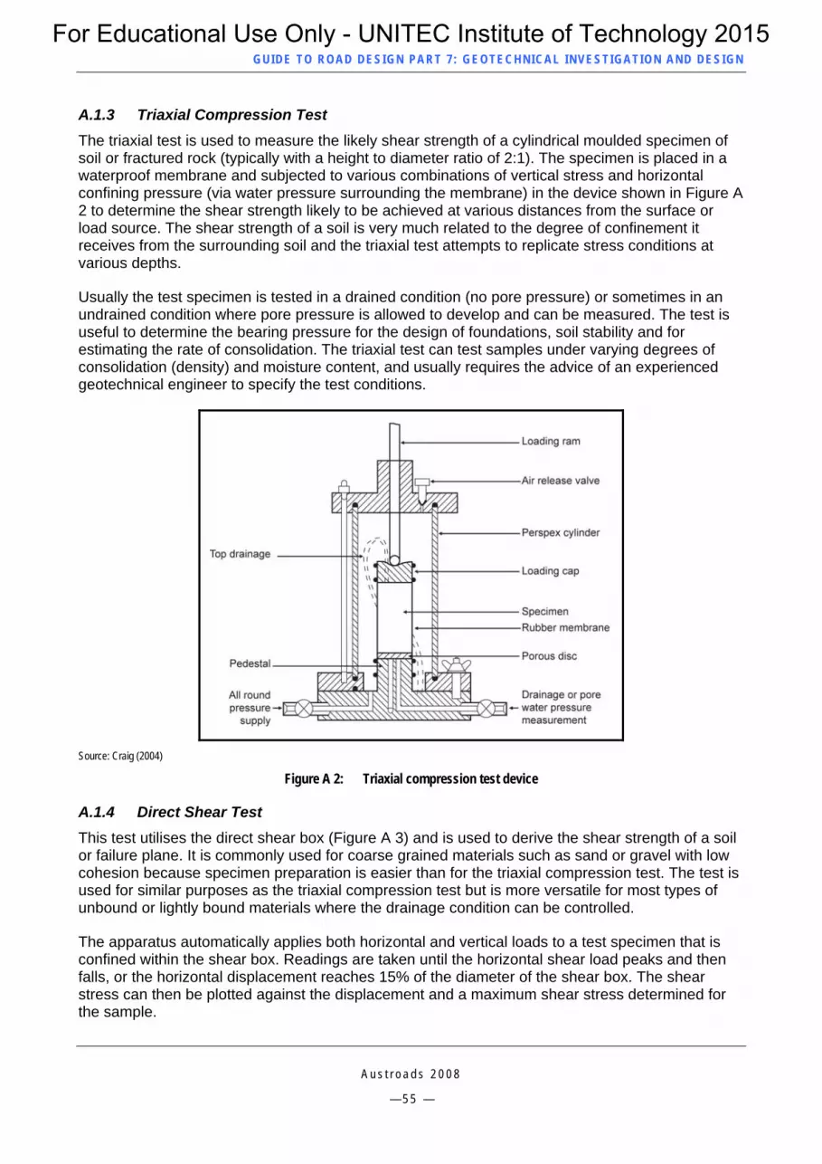
GUID E TO ROAD DESIGN PART 7 : GEOTECHNICAL INVEST IG ATION AND DESIGN
A.1.3 Triaxial Compression Test The triaxial test is used to measure the likely shear strength of a cylindrical moulded specimen of soil or fractured rock (typically with a height to diameter ratio of 2:1). The specimen is placed in a waterproof membrane and subjected to various combinations of vertical stress and horizontal confining pressure (via water pressure surrounding the membrane) in the device shown in Figure A 2 to determine the shear strength likely to be achieved at various distances from the surface or load source. The shear strength of a soil is very much related to the degree of confinement it receives from the surrounding soil and the triaxial test attempts to replicate stress conditions at various depths.
Usually the test specimen is tested in a drained condition (no pore pressure) or sometimes in an undrained condition where pore pressure is allowed to develop and can be measured. The test is useful to determine the bearing pressure for the design of foundations, soil stability and for estimating the rate of consolidation. The triaxial test can test samples under varying degrees of consolidation (density) and moisture content, and usually requires the advice of an experienced geotechnical engineer to specify the test conditions.
Source: Craig (2004)
Figure A 2: Triaxial compression test device
A.1.4 Direct Shear Test This test utilises the direct shear box (Figure A 3) and is used to derive the shear strength of a soil or failure plane. It is commonly used for coarse grained materials such as sand or gravel with low cohesion because specimen preparation is easier than for the triaxial compression test. The test is used for similar purposes as the triaxial compression test but is more versatile for most types of unbound or lightly bound materials where the drainage condition can be controlled.
The apparatus automatically applies both horizontal and vertical loads to a test specimen that is confined within the shear box. Readings are taken until the horizontal shear load peaks and then falls, or the horizontal displacement reaches 15% of the diameter of the shear box. The shear stress can then be plotted against the displacement and a maximum shear stress determined for the sample.
A u s t r o a d s 2 0 0 8
— 5 5 —
For Educational Use Only - UNITEC Institute of Technology 2015

GUID E TO ROAD DESIGN PART 7 : GEOTECHNICAL INVEST IG ATION AND DESIGN
Source: Soil Mechanics – RF Craig
Figure A 3: Direct shear box test
A.1.5 Vane Shear Test This is a simple torsional shear test typically applied to a soft clayey material. The test is commonly used in the field but can be applied to a moulded laboratory sample. The test requires the insertion of a vane into soft clay, usually into the bottom of a 100 mm bore hole. A torsion wrench or some other mechanical means is used to rotate the vane at a rate of 6° to 12° per minute until the soil yields. The peak torque is measured.
The shear stress is determined from the area of the vane and force applied. The advantage of the test is that it can be applied in situ to cohesive clay materials in the natural state of density and moisture content. A laboratory vane shear test can be undertaken on an undisturbed sample of clay from the site or a laboratory prepared sample to a pre–determined density.
The test can be undertaken using a portable kit Figure A 4. The test process is shown in Figure A 5.
Source: Ground test equipment and Gregg Drilling Website
Figure A 4: Portable vane shear test kit
A u s t r o a d s 2 0 0 8
— 5 6 —
For Educational Use Only - UNITEC Institute of Technology 2015

GUID E TO ROAD DESIGN PART 7 : GEOTECHNICAL INVEST IG ATION AND DESIGN
Source: Ground test equipment and Gregg Drilling Website
Figure A 5: Vane shear test process
A.1.6 Permeability Test The permeability test is used to measure the flow rate of water in m/sec through a 150 mm by 100 mm sample of material compacted in a CBR mould under specified test conditions (Figure A 6). The test may be conducted with a constant or variable head of water.
Specifications may require a minimum permeability for filter materials used for drainage blankets and subsurface drains. For a pavement subbase material a minimum permeability may be specified to ensure that the permeability of the pavement increases with depth and that water can drain through the pavement to the sub-surface drainage system. A maximum permeability may be specified for verge fill and crushed rock base material to minimise entry of water to the pavement. In the case of a capping layer a maximum permeability is generally specified to minimise moisture movement and hence the volume change of an underlying expansive material such as basaltic clay.
A u s t r o a d s 2 0 0 8
— 5 7 —
For Educational Use Only - UNITEC Institute of Technology 2015
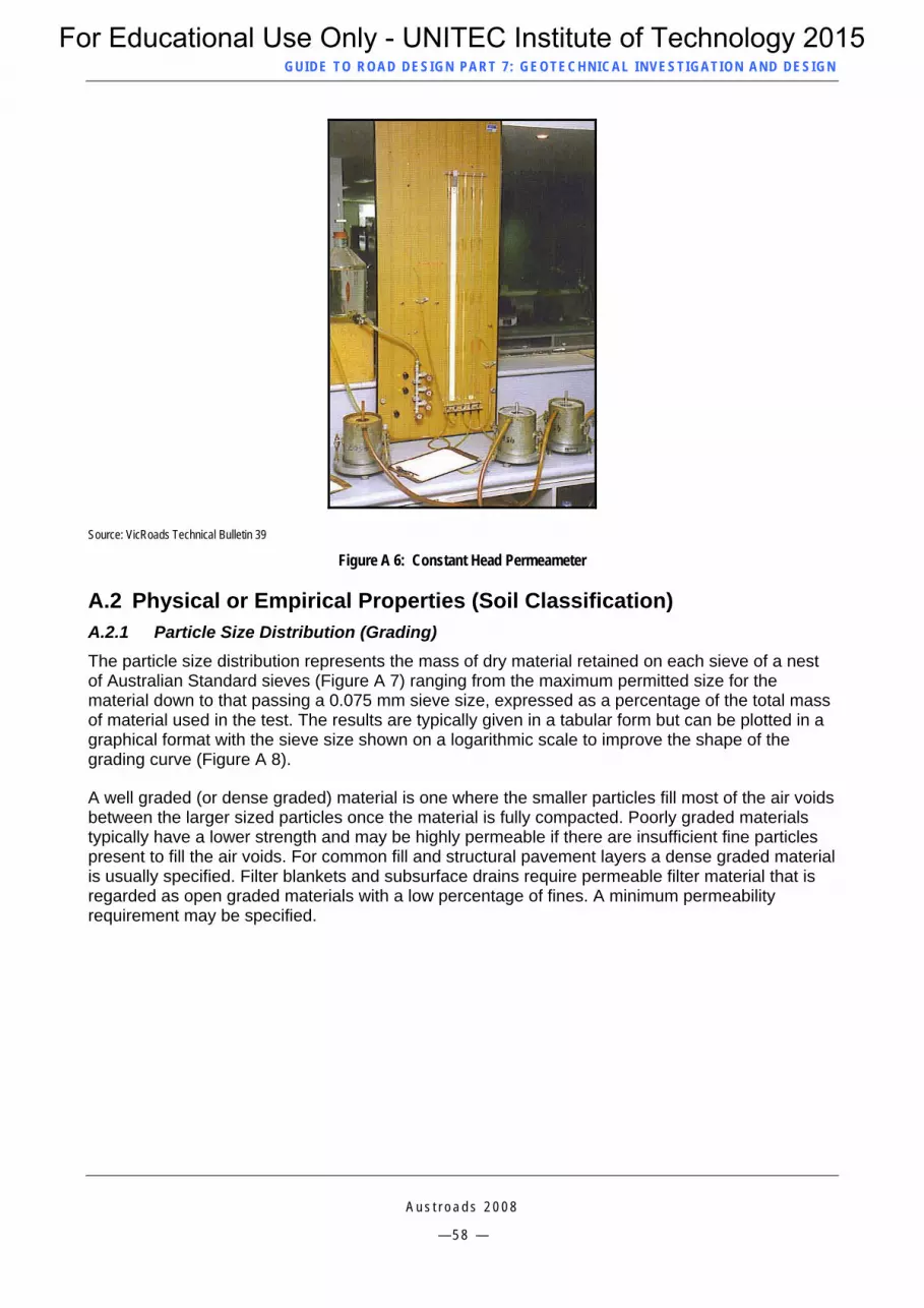
GUID E TO ROAD DESIGN PART 7 : GEOTECHNICAL INVEST IG ATION AND DESIGN
Source: VicRoads Technical Bulletin 39
Figure A 6: Constant Head Permeameter
A.2 Physical or Empirical Properties (Soil Classification) A.2.1 Particle Size Distribution (Grading) The particle size distribution represents the mass of dry material retained on each sieve of a nest of Australian Standard sieves (Figure A 7) ranging from the maximum permitted size for the material down to that passing a 0.075 mm sieve size, expressed as a percentage of the total mass of material used in the test. The results are typically given in a tabular form but can be plotted in a graphical format with the sieve size shown on a logarithmic scale to improve the shape of the grading curve (Figure A 8).
A well graded (or dense graded) material is one where the smaller particles fill most of the air voids between the larger sized particles once the material is fully compacted. Poorly graded materials typically have a lower strength and may be highly permeable if there are insufficient fine particles present to fill the air voids. For common fill and structural pavement layers a dense graded material is usually specified. Filter blankets and subsurface drains require permeable filter material that is regarded as open graded materials with a low percentage of fines. A minimum permeability requirement may be specified.
A u s t r o a d s 2 0 0 8
— 5 8 —
For Educational Use Only - UNITEC Institute of Technology 2015

GUID E TO ROAD DESIGN PART 7 : GEOTECHNICAL INVEST IG ATION AND DESIGN
Source: VicRoads
Figure A 7: Mechanical sieve shaker
Source: VicRoads
Figure A 8: Grading or Particle Size Distribution
A u s t r o a d s 2 0 0 8
— 5 9 —
For Educational Use Only - UNITEC Institute of Technology 2015

GUID E TO ROAD DESIGN PART 7 : GEOTECHNICAL INVEST IG ATION AND DESIGN
A.2.2 Atterberg Tests (Liquid Limit and Plastic Limit) These tests are shown in Figure A 9. As water is added to the fine fraction of a material, the internal cohesion reduces and eventually the mixture becomes a liquid with the material particles in suspension with no effective particle interlock. The moisture content at which this occurs is known as the ‘Liquid Limit’. If the material is allowed to slowly dry out it goes through a plastic stage where it can be moulded into a shape. The moisture content where the material becomes too dry to mould into shape or be rolled into narrow threads is known as the ‘Plastic Limit’.
The Plasticity Index (PI) is the numerical difference between the liquid limit and plastic limit of a soil. The PI is an indicator of the amount of clayey fines in the portion of the material passing the 0.425 mm sieve. Generally, materials with a PI > 10 are regarded as cohesive materials but may be prone to shrinkage cracking and permanent deformation under load. For a pavement base material it is desirable that the material has some cohesion. For this reason a lower limit for PI for a pavement base material of about 2 in addition to an upper limit of about 6 is typically specified. A material with a PI of 0 is regarded as non-cohesive and more permeable than desirable. Such a material can be difficult to handle and it may not be possible to achieve the desired compaction.
The linear shrinkage of a material is the percent of volume loss after oven drying of the fine fraction of a material that has been made into a paste at or near the liquid limit. For a given material, the linear shrinkage is related to the PI and can be compared with the PI test results to cross check for ‘outlier’ PI results.
Liquid limit test Plastic limit test Linear shrinkage test mould
Figure A 9: Atterberg tests
A.2.3 Californian Bearing Ratio (CBR) and Percentage Swell The CBR Test
One of the most common empirical tests used to characterise the strength of subgrade and pavement materials is the CBR. It is both an indirect indicator of shear strength and, to a lesser extent, the bearing strength.
A soil specimen is compacted to a specified density at or near Optimum Moisture Content (OMC) in a 150 mm diameter mould to a depth of approximately 100 mm. The CBR is commonly used to provide a strength characterisation of a material in a saturated (or weakest) state so the test specimen is pre-conditioned by soaking it in a water bath for an appropriate period as shown in Figure A 10a) (typically for four days but can be as high as 10 days for materials with very low permeability).
A u s t r o a d s 2 0 0 8
— 6 0 —
For Educational Use Only - UNITEC Institute of Technology 2015
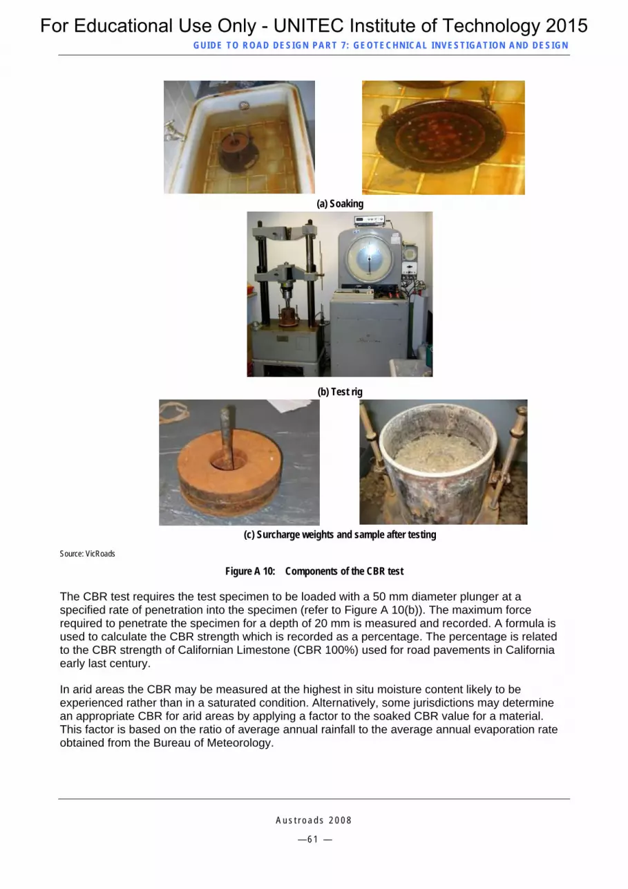
GUID E TO ROAD DESIGN PART 7 : GEOTECHNICAL INVEST IG ATION AND DESIGN
(a) Soaking
(b) Test rig
(c) Surcharge weights and sample after testing
Source: VicRoads
Figure A 10: Components of the CBR test
The CBR test requires the test specimen to be loaded with a 50 mm diameter plunger at a specified rate of penetration into the specimen (refer to Figure A 10(b)). The maximum force required to penetrate the specimen for a depth of 20 mm is measured and recorded. A formula is used to calculate the CBR strength which is recorded as a percentage. The percentage is related to the CBR strength of Californian Limestone (CBR 100%) used for road pavements in California early last century.
In arid areas the CBR may be measured at the highest in situ moisture content likely to be experienced rather than in a saturated condition. Alternatively, some jurisdictions may determine an appropriate CBR for arid areas by applying a factor to the soaked CBR value for a material. This factor is based on the ratio of average annual rainfall to the average annual evaporation rate obtained from the Bureau of Meteorology.
A u s t r o a d s 2 0 0 8
— 6 1 —
For Educational Use Only - UNITEC Institute of Technology 2015
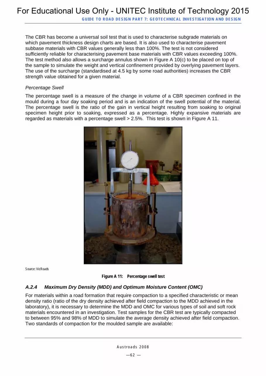
GUID E TO ROAD DESIGN PART 7 : GEOTECHNICAL INVEST IG ATION AND DESIGN
The CBR has become a universal soil test that is used to characterise subgrade materials on which pavement thickness design charts are based. It is also used to characterise pavement subbase materials with CBR values generally less than 100%. The test is not considered sufficiently reliable for characterising pavement base materials with CBR values exceeding 100%. The test method also allows a surcharge annulus shown in Figure A 10(c) to be placed on top of the sample to simulate the weight and vertical confinement provided by overlying pavement layers. The use of the surcharge (standardised at 4.5 kg by some road authorities) increases the CBR strength value obtained for a given material.
Percentage Swell
The percentage swell is a measure of the change in volume of a CBR specimen confined in the mould during a four day soaking period and is an indication of the swell potential of the material. The percentage swell is the ratio of the gain in vertical height resulting from soaking to original specimen height prior to soaking, expressed as a percentage. Highly expansive materials are regarded as materials with a percentage swell > 2.5%. This test is shown in Figure A 11.
Source: VicRoads
Figure A 11: Percentage swell test
A.2.4 Maximum Dry Density (MDD) and Optimum Moisture Content (OMC) For materials within a road formation that require compaction to a specified characteristic or mean density ratio (ratio of the dry density achieved after field compaction to the MDD achieved in the laboratory), it is necessary to determine the MDD and OMC for various types of soil and soft rock materials encountered in an investigation. Test samples for the CBR test are typically compacted to between 95% and 98% of MDD to simulate the average density achieved after field compaction. Two standards of compaction for the moulded sample are available:
A u s t r o a d s 2 0 0 8
— 6 2 —
For Educational Use Only - UNITEC Institute of Technology 2015

GUID E TO ROAD DESIGN PART 7 : GEOTECHNICAL INVEST IG ATION AND DESIGN
A u s t r o a d s 2 0 0 8
— 6 3 —
Standard Compaction effort for earthworks materials using the Standard (or smaller) laboratory impact hammer with a lower height of drop
Modified Compaction effort for pavement materials using the heavier impact hammer with a higher drop to impart more compaction energy to the specimen.
The devices used for compaction are shown in Figure A 12.
Some road authorities use Standard Compaction effort for all materials but specify a higher Density Ratio to be achieved for pavement materials (generally over 100%).
The OMC and MDD are determined from a curve produced from a plot of the Dry Density versus Moisture Content of oven dried soil samples after compaction. At least four different moisture contents are required to be plotted both above and below the estimated OMC. Once the mass of dry soil and mass of water (moisture content) for each of the compacted specimens is known, the moisture ratio of each specimen can be determined. The MDD is the density at the highest point (peak density) on the Density versus Moisture Content curve and the OMC is the moisture content where the peak density (MDD) has occurred as determined on the moisture content axis. A typical graph is shown in Figure A 13.
Source: VicRoads
Figure A 12: Modified (left) and Standard (right) compaction hammers
For Educational Use Only - UNITEC Institute of Technology 2015
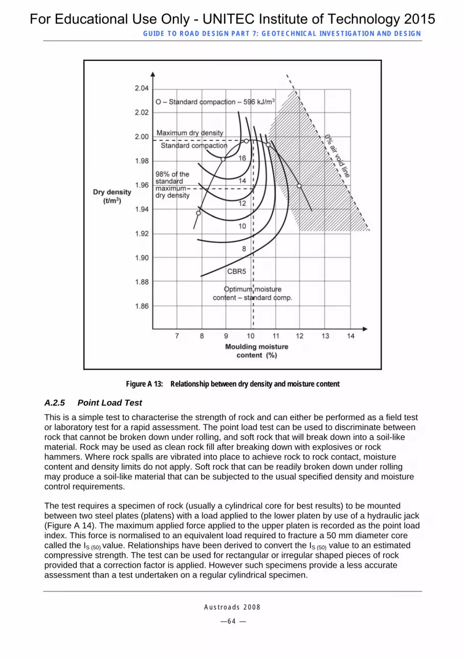
GUID E TO ROAD DESIGN PART 7 : GEOTECHNICAL INVEST IG ATION AND DESIGN
Figure A 13: Relationship between dry density and moisture content
A.2.5 Point Load Test This is a simple test to characterise the strength of rock and can either be performed as a field test or laboratory test for a rapid assessment. The point load test can be used to discriminate between rock that cannot be broken down under rolling, and soft rock that will break down into a soil-like material. Rock may be used as clean rock fill after breaking down with explosives or rock hammers. Where rock spalls are vibrated into place to achieve rock to rock contact, moisture content and density limits do not apply. Soft rock that can be readily broken down under rolling may produce a soil-like material that can be subjected to the usual specified density and moisture control requirements.
The test requires a specimen of rock (usually a cylindrical core for best results) to be mounted between two steel plates (platens) with a load applied to the lower platen by use of a hydraulic jack (Figure A 14). The maximum applied force applied to the upper platen is recorded as the point load index. This force is normalised to an equivalent load required to fracture a 50 mm diameter core called the IS (50) value. Relationships have been derived to convert the IS (50) value to an estimated compressive strength. The test can be used for rectangular or irregular shaped pieces of rock provided that a correction factor is applied. However such specimens provide a less accurate assessment than a test undertaken on a regular cylindrical specimen.
A u s t r o a d s 2 0 0 8
— 6 4 —
For Educational Use Only - UNITEC Institute of Technology 2015

GUID E TO ROAD DESIGN PART 7 : GEOTECHNICAL INVEST IG ATION AND DESIGN
Source: Geotechnical Systems Australia
Figure A 14: Point load test
A.2.6 Chemical Testing of Water and Soils Chemical analysis of soils and water (such as pH and conductivity) is undertaken to determine the presence of dissolved salts, acid sulphates or other undesirable contaminants. Water containing chemicals can leach out of cuttings, stockpiles of excavated fill material or fill embankments and potentially cause harm to the environment (e.g. by killing nearby vegetation). In these cases special provisions are made to contain, treat or dilute discharged water with higher than permitted dissolved salts. Soils that contain acid sulphates can produce a leachate that is harmful to plant life. Such materials must be disposed of to a suitable containment site or in some cases encapsulated deep inside a large embankment.
Water quality testing can be important when corrugated steel pipes are being considered or where salt water is likely to be encountered. For the former, a conductivity test can be undertaken that will assist in determining the propensity for accelerated corrosion of the steel, and for the latter, testing will allow an analysis of the risk to reinforcing steel in concrete pipes.
Generally water that contains more than 3000 mg/L of dissolved salts and has a conductivity > 3500 S/cm is not suitable for watering a pavement base course as excessive salt formed on drying may cause the bituminous surfacing to bubble up and lift off the surface.
A u s t r o a d s 2 0 0 8
— 6 5 —
For Educational Use Only - UNITEC Institute of Technology 2015

GUID E TO ROAD DESIGN PART 7 : GEOTECHNICAL INVEST IG ATION AND DESIGN
A u s t r o a d s 2 0 0 8
— 6 6 —
APPENDIX B SPECIAL GEOTECHNICAL DESIGN SYSTEMS
B.1 General Special geotechnical treatments may be required for abnormally difficult circumstances. Solutions may be quite complex and site specific and these matters should always be referred to a suitably qualified and experienced geotechnical engineer for advice. Special treatments will typically require project specific detailed drawings to be produced. The treatments described and illustrated in this Appendix are not a comprehensive list of all possible available treatments.
Some of the abnormal circumstances that may be encountered and require special geotechnical design systems are:
insufficient road reservation to provide safe batter slopes for cuttings
insufficient road reservation or clearance to contain embankments requiring the use of special containment methods
excavations with excessive flows of ground water
embankments constructed over wet, soft or inaccessible swamp land
situations where ground water contains too high a content of dissolved salts to allow it to be directly discharged into the surface drainage system
situations where fill material contains harmful chemicals such as natural occurring arsenic or acid sulphates, or man-made pollutants as a result of burial of industrial waste prior to stringent controls being introduced
embankments requiring monitoring of settlement
materials that are easily eroded by surface water such as sands and gravels.
B.2 Slope Stability Treatments There are numerous treatments available to treat batter slopes that need to be steeper than the minimum desirable slope for the material in order to prevent land slips, falling rock or soft material from being eroded from the batter surface.
B.2.1 Provision of Benches on Cut Batters A common method of improving the stability of cut batters is to provide benches between 3 m and 6 m wide in the face of the batter (Figure B 1). Benching has the effect of reducing stresses caused by lack of soil containment lower down in a road cutting. Benches also provide the opportunity to intercept water flowing down the batters by installation of concrete drains along the inside of benches to reduce erosion. Benching can also assist maintenance access and worker safety.
For Educational Use Only - UNITEC Institute of Technology 2015
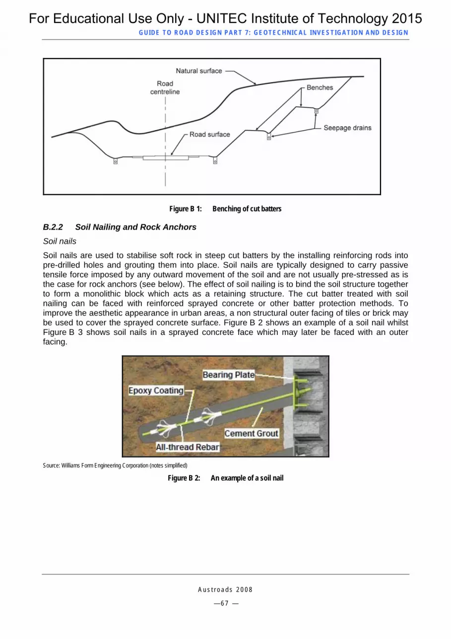
GUID E TO ROAD DESIGN PART 7 : GEOTECHNICAL INVEST IG ATION AND DESIGN
Figure B 1: Benching of cut batters
B.2.2 Soil Nailing and Rock Anchors Soil nails
Soil nails are used to stabilise soft rock in steep cut batters by the installing reinforcing rods into pre-drilled holes and grouting them into place. Soil nails are typically designed to carry passive tensile force imposed by any outward movement of the soil and are not usually pre-stressed as is the case for rock anchors (see below). The effect of soil nailing is to bind the soil structure together to form a monolithic block which acts as a retaining structure. The cut batter treated with soil nailing can be faced with reinforced sprayed concrete or other batter protection methods. To improve the aesthetic appearance in urban areas, a non structural outer facing of tiles or brick may be used to cover the sprayed concrete surface. Figure B 2 shows an example of a soil nail whilst Figure B 3 shows soil nails in a sprayed concrete face which may later be faced with an outer facing.
Source: Williams Form Engineering Corporation (notes simplified)
Figure B 2: An example of a soil nail
A u s t r o a d s 2 0 0 8
— 6 7 —
For Educational Use Only - UNITEC Institute of Technology 2015
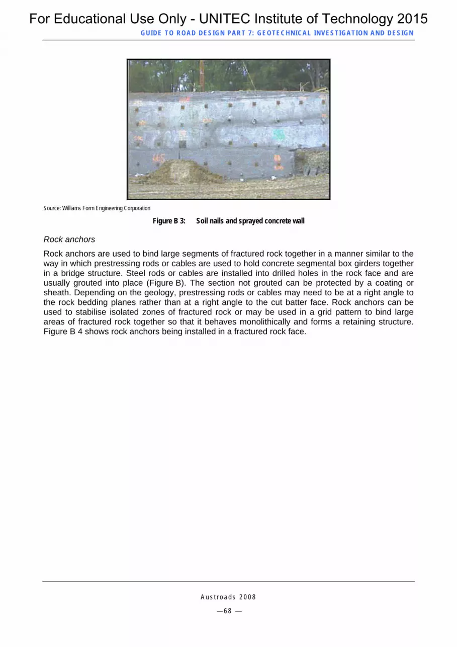
GUID E TO ROAD DESIGN PART 7 : GEOTECHNICAL INVEST IG ATION AND DESIGN
Source: Williams Form Engineering Corporation
Figure B 3: Soil nails and sprayed concrete wall
Rock anchors
Rock anchors are used to bind large segments of fractured rock together in a manner similar to the way in which prestressing rods or cables are used to hold concrete segmental box girders together in a bridge structure. Steel rods or cables are installed into drilled holes in the rock face and are usually grouted into place (Figure B). The section not grouted can be protected by a coating or sheath. Depending on the geology, prestressing rods or cables may need to be at a right angle to the rock bedding planes rather than at a right angle to the cut batter face. Rock anchors can be used to stabilise isolated zones of fractured rock or may be used in a grid pattern to bind large areas of fractured rock together so that it behaves monolithically and forms a retaining structure. Figure B 4 shows rock anchors being installed in a fractured rock face.
A u s t r o a d s 2 0 0 8
— 6 8 —
For Educational Use Only - UNITEC Institute of Technology 2015

GUID E TO ROAD DESIGN PART 7 : GEOTECHNICAL INVEST IG ATION AND DESIGN
Source: Adapted from Williams Form Engineering Corporation
Figure B: An example of a rock anchor
Source: Williams Form Engineering Corporation
Figure B 4: Rock anchors being installed to hold fractured rock together in a solid mass
A u s t r o a d s 2 0 0 8
— 6 9 —
For Educational Use Only - UNITEC Institute of Technology 2015

GUID E TO ROAD DESIGN PART 7 : GEOTECHNICAL INVEST IG ATION AND DESIGN
B.2.3 Reinforced Soil Retaining Walls In urban areas, there may be insufficient road reservation or space to provide 2H to 1V fill batters. Fill batters steeper than this generally require a means of retaining all or part of the fill height. One method of retaining the fill involves the reinforcement of earth. Reinforced soil structures are generally lower in cost than gravity or reinforced concrete retaining walls.
The reinforced soil structure consists of interlocking concrete panels typically anchored by galvanised steel anchor straps (Figure B 5) but in corrosive environments polyethylene straps may be used. Anchor straps are placed progressively between layers of structural fill as the construction of the embankment proceeds. Structural fill must contain sufficient angular particles to provide adequate surface friction against the straps. The straps are designed to take the required tensile loading and develop sufficient ‘pull out’ frictional resistance to prevent any outward movement of the interlocking concrete face panels. Concrete panels may be cast in various colours and patterns to create an architectural feature. Figure B 6 shows examples of reinforced soil retaining structures.
Figure B 5: Typical section through a reinforced soil wall
A u s t r o a d s 2 0 0 8
— 7 0 —
For Educational Use Only - UNITEC Institute of Technology 2015
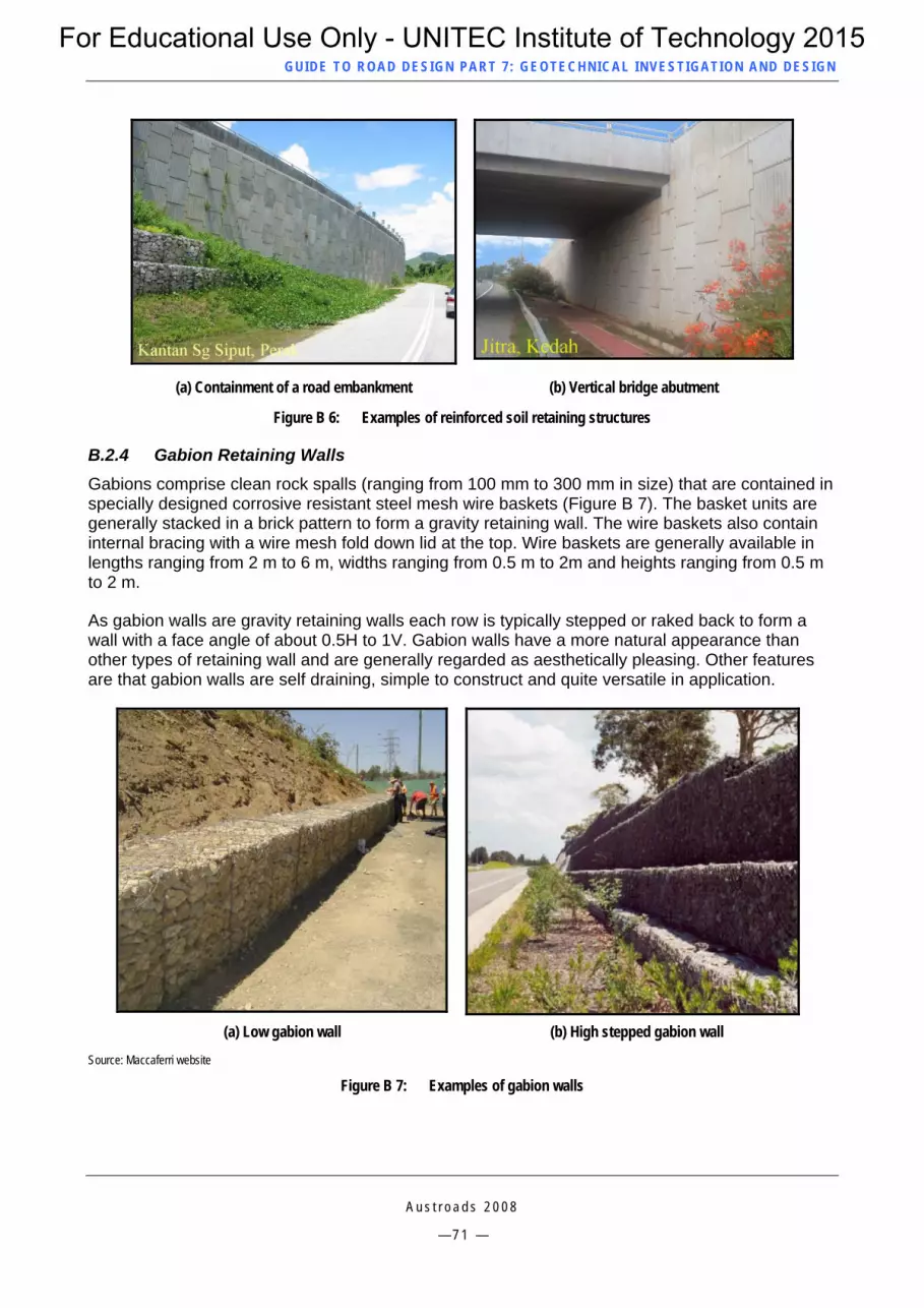
GUID E TO ROAD DESIGN PART 7 : GEOTECHNICAL INVEST IG ATION AND DESIGN
(a) Containment of a road embankment (b) Vertical bridge abutment
Figure B 6: Examples of reinforced soil retaining structures
B.2.4 Gabion Retaining Walls Gabions comprise clean rock spalls (ranging from 100 mm to 300 mm in size) that are contained in specially designed corrosive resistant steel mesh wire baskets (Figure B 7). The basket units are generally stacked in a brick pattern to form a gravity retaining wall. The wire baskets also contain internal bracing with a wire mesh fold down lid at the top. Wire baskets are generally available in lengths ranging from 2 m to 6 m, widths ranging from 0.5 m to 2m and heights ranging from 0.5 m to 2 m.
As gabion walls are gravity retaining walls each row is typically stepped or raked back to form a wall with a face angle of about 0.5H to 1V. Gabion walls have a more natural appearance than other types of retaining wall and are generally regarded as aesthetically pleasing. Other features are that gabion walls are self draining, simple to construct and quite versatile in application.
(a) Low gabion wall (b) High stepped gabion wall
Source: Maccaferri website
Figure B 7: Examples of gabion walls
A u s t r o a d s 2 0 0 8
— 7 1 —
For Educational Use Only - UNITEC Institute of Technology 2015

GUID E TO ROAD DESIGN PART 7 : GEOTECHNICAL INVEST IG ATION AND DESIGN
B.2.5 Crib Retaining Walls A crib wall (Figure B 8) is typically a three-dimensional framework of interlocking 2 m long blocks or slabs of concrete or timber, filled with a rectangular cross-section of around 200 mm x 150 mm x 2 m long concrete or timber slabs, with a permeable crushed rock or gravel used to fill the void in the framework and hold the crib sections in place. The wall is intended to be self draining. Crib walls are essentially designed as a gravity retaining wall and are raked back at an angle of about 0.5H to 1V. The height is generally limited to about 4 m but may be increased by using a twin cell arrangement. A small amount of topsoil is sometimes added to the front face of the wall between the crib units to enable creeping plants to grow down the wall to improve aesthetics. Crib walls are also suitable to provide a temporary retaining wall that can be readily dismantled and salvaged.
Source: Crib retaining Walls Pty Ltd
(a) Crib wall under construction (b) Completed crib wall with planting
Figure B 8: Concrete crib wall
B.3 Treatments for Soft or Swampy Ground beneath Embankments B.3.1 General Construction of embankments over unstable or wet swampy ground presents special design and construction challenges requiring close consultation with a geotechnical expert. Generally, special foundation treatments and construction procedures are required to enable the embankment to be constructed, to control movement and settlement, and to avoid failure of the weak foundation material.
Under these circumstances consideration may be given to:
construction of a permeable rock raft to replace soft, wet, unstable material
excavation of soft material and replacement with permeable sand or gravel encapsulated in a geotextile fabric, if appropriate and permeable rock fill is not economically available
drying out the soft, wet and unstable material beneath the embankment by use of well points and wick drains outside the toe of the embankment which may be sufficient to lower the water table beneath the embankment prior to construction
provision of a permanent fill surcharge to support the toe of the embankment that may reduce the risk of failure of the foundation beneath the toe of the embankment.
The more soft, wet, unstable material that can be removed from the foundation prior to placement of the embankment, the lesser the risk of failure and the greater the reduction in the amount of movement and settlement.
A u s t r o a d s 2 0 0 8
— 7 2 —
For Educational Use Only - UNITEC Institute of Technology 2015

GUID E TO ROAD DESIGN PART 7 : GEOTECHNICAL INVEST IG ATION AND DESIGN
A u s t r o a d s 2 0 0 8
— 7 3 —
B.3.2 Permeable Raft Treatments A permeable mattress can be constructed across a swampy area in a 1 m to 2 m deep face to form a sound foundation for an embankment. The mattress is usually constructed from spalls of hard clean and durable rock fill that is progressively placed from solid ground into the swamp. In order to minimise subsequent embankment settlement, it is important to progressively remove as much unstable or compressible material as practical, particularly decomposed organic material such as swamp grasses and peat. This can be done progressively by use of a hydraulic excavator or drag line and trucks using the mattress as working platform as it is extended into or across the swamp.
The rock fill mattress is required to be completely permeable and free of fine material. It achieves its stability by positive rock-to-rock contact where water can flow freely through it. Blinding layers of smaller size is used to avoid migration (piping) of any fine fill material placed over the rock mattress. A geotextile fabric may also be placed in combination with the blinding layer.
If it is uneconomical to transport rock spalls to the site, a permeable mattress may be constructed from locally available permeable dune sand or gravel. The sand/gravel mattress is constructed in a similar fashion to a rock fill mattress but requires complete encapsulation of the sand or gravel to prevent erosion and migration. A geotextile fabric wrapping is typically used to line the bottom and sides of the excavation in advance of sand/gravel placement. A sand or gravel mattress should be immediately covered with the next layer of filling if surface erosion of the mattress is likely.
As for a permeable rock fill mattress, a sand/gravel mattress does not become unstable due to build up of pore pressure under loading. Permeable sand/gravel materials have low soil suction (capillary action) and are designed to prevent moisture rising beyond the water level or level of the water-table.
B.3.3 De-watering Systems Well points
De-watering systems may be used to dry out an area on which fill is to be placed or to increase the stability of the material under or immediately outside the toe of the embankment. Well points comprise an outer perforated steel pipe shell driven into the ground with an inner suction pipe that is used to pump out air and water and thereby lower the water table and stabilise the area. Filter material may be placed between the outer perforated shell and the suction pipe. Well points placed each side of an over-wet embankment foundation may effectively lower the water table and stabilise the area so that construction plant is able to operate. Figure B 9 illustrates the lowering of a water table using well points and Figure B 10 shows a well point installation.
For Educational Use Only - UNITEC Institute of Technology 2015

GUID E TO ROAD DESIGN PART 7 : GEOTECHNICAL INVEST IG ATION AND DESIGN
Source: Gart Construction Dewatering
Figure B 9: Illustration of well points lowering water table
Source: Griffin Dewatering Corporation
Figure B 10: Well point installation
Wick drains
Consolidation of saturated materials beneath an embankment can be accelerated by installing a grid of prefabricated wick drains to shorten the drainage path for water being expelled from beneath the embankment. A wick drain is a geotextile lined plastic form which can be fed into a rectangular hole. They are installed beneath the embankment and must be linked to a permeable blanket to enable expelled water to escape. The spacing of wick drains is usually 1.5 m to 3 m depending on the permeability of the foundation material. Figure B 11 shows installation aspects of wick drains and Figure B 12 shows a treatment after installation.
A u s t r o a d s 2 0 0 8
— 7 4 —
For Educational Use Only - UNITEC Institute of Technology 2015

GUID E TO ROAD DESIGN PART 7 : GEOTECHNICAL INVEST IG ATION AND DESIGN
Wick drains can reduce construction delays by shortening the waiting time required for embankment settlement to stabilise before various stages of construction can proceed. Use of wick drains limits the build up of pore pressures in the embankment foundation reducing the risk of failure associated with excessive build up or water or in extreme cases, liquefaction of the foundation material.
Source: Frankipile Australia Source: American Drainage Systems
(a) Installing wick drains using a special mandrel (b) Schematic of wick drains expelling water
Figure B 11: Installation of wick drains
Source: American Drainage Systems
Figure B 12: Wick drains after installation
B.3.4 Surcharging Where low embankments are constructed across wet and unstable swampy terrain, the height of the embankment may not induce sufficiently rapid settlement (particularly at bridge abutments). A relatively inexpensive way of accelerating settlement is to construct a higher embankment than is required for the final design grade line in order to provide a surcharge load that can generate more rapid settlement. Once settlement has stabilised the fill surcharge is removed and construction can be completed.
A u s t r o a d s 2 0 0 8
— 7 5 —
For Educational Use Only - UNITEC Institute of Technology 2015

GUID E TO ROAD DESIGN PART 7 : GEOTECHNICAL INVEST IG ATION AND DESIGN
For embankments constructed over a soft, wet and unstable soil foundation, particularly those constructed on the edge of a flood plain with high ground on one side, the embankment foundation can be surcharged by placing additional permanent fill to form a wide berm (refer to Figure B 13). The weight of the berm places downward pressure to support the toe and prevent upward movement of the wet unstable material outside the toe of the embankment. Such a measure can only be taken if the road reservation is sufficiently wide or suitable arrangements can be made with the adjacent property owners.
Figure B 13: Surcharge to stabilise an unstable embankment toe
B.3.5 Lightweight Fill For low embankments constructed across weak, over-wet foundations, consolidation and settlement can be reduced by use of expanded polystyrene (EPS) blocks placed in a brick pattern in the core of the fill (refer to Figure B 14). EPS blocks are only a fraction of the weight of normal fill material and result in a significant reduction in stress on the embankment foundation. There is much reduced or no delay to construction as is the case with prolonged consolidation of conventional fill and the need for surcharging is avoided. Figure B 15 shows a lightweight fill embankment under construction.
It is necessary to encapsulate the EPS blocks with a free flowing material (e.g. sand) and to protect them with sufficient capping material prior to construction plant traversing the lightweight embankment. Cement stabilised crushed rock is often used for this purpose because of its ability to spread loads. EPS blocks are produced in various sizes and with various internal compressive strengths but should be placed above maximum possible flood or inundation levels to avoid any possibility of flotation. Whether or not flotation is an issue depends on the volume of EPS blocks, compared to the volume of fill and pavement material placed above it and how the EPS blocks are encapsulated.
EPS may be used in steep sideling country where land slips have occurred or embankments have been washed away. Access is usually very difficult and restoration works using EPS blocks can provide advantages over other options due to their lightweight. The blocks are placed in a brick pattern and can be used in combination with a very light post and geotextile lined wire mesh retaining structure. The method is a more rapid and less environmentally intrusive method of repair than attempting to use more substantial retaining walls to retain an imported fill embankment.
A u s t r o a d s 2 0 0 8
— 7 6 —
For Educational Use Only - UNITEC Institute of Technology 2015

GUID E TO ROAD DESIGN PART 7 : GEOTECHNICAL INVEST IG ATION AND DESIGN
Source: VicRoads Technical Note 40
Figure B 14: Typical cross section of lightweight fill embankment
Source: Falcom Foam
Figure B 15: Lightweight fill embankment under construction
B.4 Monitoring of Movement in Embankments The geotechnical investigation should identify the ground conditions where movement of embankments is likely to occur. A suitably qualified and experienced geotechnical engineer will be required to make predictions of the likely settlement, initially based on laboratory consolidation testing. Estimates of consolidation will identify those embankments that may be more prone to settlement and movement and which will require monitoring of movement during construction.
Estimation of the amount and rate of settlement (consolidation) from laboratory tests prior to construction is usually regarded as indicative only. To provide a more accurate prediction of the amount of movement or consolidation, it is necessary to monitor the horizontal and vertical movement of the embankment as construction proceeds. This is particularly important for embankments at bridge abutments. In some cases monitoring of embankment settlement may force a delay in the commencement of pavement and structural works until such time as all movement has stabilised. If excessive movement is measured during the course of embankment construction, a cessation of construction may be required to ensure movements and pore pressure under the embankment stabilise before further filling is added. Movement during embankment construction is typically monitored using:
A u s t r o a d s 2 0 0 8
— 7 7 —
For Educational Use Only - UNITEC Institute of Technology 2015

GUID E TO ROAD DESIGN PART 7 : GEOTECHNICAL INVEST IG ATION AND DESIGN
A u s t r o a d s 2 0 0 8
— 7 8 —
inclinometers placed in a cylindrical casing to measure the horizontal movement in the embankment
settlement cells installed within the foundation material supporting the embankment to measure the vertical movement
piezometers to measure pore pressure in foundation material supporting the embankment and thus provide warning of excessive build up of pore pressures that can cause the fill foundation to become unstable and prone to shear failure
permanent survey marks installed after completion of embankments that do not require instrumentation, to ensure that settlement has stabilised prior to pavement construction.
Planning for fill settlement and movement is an important consideration as it could result in delays to critical parts of the project such as a major structure. Conversely, if movements are smaller than expected, pre-planned waiting periods associated with embankment construction, or delays to commence structural or pavement works, may be reduced or eliminated.
B.5 Erosion Protection The geotechnical investigations should identify materials that are prone to significant erosion. Materials with little or no cohesion such as dune sand are particularly vulnerable. Unless batters or grades are very flat, additional preventative measures will need to be considered.
It is important to re-establish vegetation as soon as practicable. To provide additional protection topsoiling may be supplemented by:
Spraying batters with additional seed, fertiliser and bitumen/straw mulch.
Placing biodegradable matting or mesh that allows the passage of light and air and prevents erosion prior to establishment of seeding. Grasses re-establish under the matting which decomposes over time.
Using straw thatching anchored down with wire.
Open drains constructed in erosion prone materials, may be treated with:
rock beaching or concrete lining
rock walls to allow grades to be reduced
reinforced concrete drop structures and energy dissipaters
straw and wire thatching.
Figure B 16 shows some typical treatments to prevent erosion.
For Educational Use Only - UNITEC Institute of Technology 2015

GUID E TO ROAD DESIGN PART 7 : GEOTECHNICAL INVEST IG ATION AND DESIGN
(a) Batter treatment (b) Straw wire and plants
(c) Rock weir (d) Fabric matting
Figure B 16: Typical erosion prevention treatments
B.6 Discharge of Contaminated Water B.6.1 Ground Water Containing Dissolved Salts If the geotechnical investigation identifies that ground water intercepted in cuttings contains higher than normal amounts of dissolved salts and minerals, the local environment protection agency may not permit ground water to be discharged directly into a watercourse unless the water has been treated. The treatment required will depend on the amount of dissolved salts present in the ground water and the flow rate of the stream to which salty water is being discharged.
To permit direct discharge into rivers and streams, the usual method of treating water with a salt content exceeding the limit is retention and dilution. Salty water may be piped to an artificial wetland feature or retarding basin (refer to Figure B 17) where it is mixed with fresh drainage water prior to discharge. Salty water may require longer retention at times when there is a low flow of fresh water into the retarding system or there is low flow in the watercourse into which salty water is to be discharged.
A u s t r o a d s 2 0 0 8
— 7 9 —
For Educational Use Only - UNITEC Institute of Technology 2015

GUID E TO ROAD DESIGN PART 7 : GEOTECHNICAL INVEST IG ATION AND DESIGN
(a) Roadside wetland (b) Roadside retarding basin
Figure B 17: Retarding and treatment of run-off water
B.6.2 Runoff from Contaminated Soils General
It is important that geotechnical investigations identify the extent and depth of any contaminated material that is likely to be excavated or exposed. Contamination may be from man-made activities such as waste burial or past industrial activity such as cyanide used for gold extraction, or more commonly they may be naturally occurring acid sulphate soils or arsenic which can become a significant problem when exposed to air and water. Contaminated materials, ground water and runoff need to be contained to prevent their escape into the environment.
It is preferable that the design is such that it is possible to avoid excavation and exposure of soils containing harmful contaminants. However if this is not feasible, special treatments or procedures will be required.
Acid sulphate soils
One of the more common problems is the presence of acid sulphate soils, often found in coastal areas of Australia that have been previously inundated by the sea. When exposed to air, the iron sulphides contained in the material oxidise to produce sulphuric acid. Once formed, sulphuric acid can be leached from the soil by water in concentrations that are harmful to most forms of vegetation and fish. Sulphuric acid is also extremely corrosive.
Acid sulphate soils are found in the coastal areas of Northern Territory, Queensland and New South Wales but also have been found around Perth (WA), Adelaide (SA) and Western Port Bay (Vic). Some states have geological maps showing the location of acid sulphate soils.
If excavation or disturbance of acid sulphate soil by earthworks and trenching activities is unavoidable, the soil should be removed and covered as quickly as possible either by encapsulation within an embankment or buried in an approved manner. Under no circumstances should acid sulphate soil be stockpiled and exposed to air for a prolonged period. Methods of dealing with acid sulphate soils will become part of an environmental management plan after consultation with the local environment protection agency.
A u s t r o a d s 2 0 0 8
— 8 0 —
For Educational Use Only - UNITEC Institute of Technology 2015

GUID E TO ROAD DESIGN PART 7 : GEOTECHNICAL INVEST IG ATION AND DESIGN
A u s t r o a d s 2 0 0 8
— 8 1 —
Arsenic contaminated soils
Soils containing natural arsenic have been found near mineral deposits in Australia particularly in the gold mining regions of Victoria. Arsenic can be leached out of the soil by ground water and into the general environment if not contained. Soils containing arsenic are generally found in relative small volumes which can be readily treated and removed. One such treatment is the addition of a cementitious binder to neutralise the arsenic prior to disposal of the contaminated soil in a manner approved by the local environmental protection agency.
For Educational Use Only - UNITEC Institute of Technology 2015


