Embed Size (px)
Citation preview

532
© 2010 Pearson Education, Inc., Upper Saddle River, NJ. All rights reserved. This material is protected under all copyright laws as they currentlyexist. No portion of this material may be reproduced, in any form or by any means, without permission in writing from the publisher.
Ans.t = 0.0188 m = 18.8 mm
sallow =
p r
2 t ; 12(106) =
300(103)(1.5)
2 t
8–1. A spherical gas tank has an inner radius of If it is subjected to an internal pressure of determine its required thickness if the maximum normalstress is not to exceed 12 MPa.
p = 300 kPa,r = 1.5 m.
Ans.ro = 75 in. + 0.5 in. = 75.5 in.
ri = 75 in.
sallow =
p r
2 t ; 15(103) =
200 ri
2(0.5)
8–2. A pressurized spherical tank is to be made of 0.5-in.-thick steel. If it is subjected to an internal pressureof determine its outer radius if the maximumnormal stress is not to exceed 15 ksi.
p = 200 psi,
Case (a):
Ans.
Ans.
Case (b):
Ans.
Ans.s2 =
pr
2t ; s2 =
65(4)
2(0.25)= 520 psi
s1 =
pr
t ; s1 =
65(4)
0.25= 1.04 ksi
s2 = 0
s1 =
pr
t ; s1 =
65(4)
0.25= 1.04 ksi
8–3. The thin-walled cylinder can be supported in one oftwo ways as shown. Determine the state of stress in the wallof the cylinder for both cases if the piston P causes theinternal pressure to be 65 psi. The wall has a thickness of0.25 in. and the inner diameter of the cylinder is 8 in.
P
(a) (b)
P
8 in. 8 in.
08 Solutions 46060 5/28/10 8:34 AM Page 532

533
© 2010 Pearson Education, Inc., Upper Saddle River, NJ. All rights reserved. This material is protected under all copyright laws as they currentlyexist. No portion of this material may be reproduced, in any form or by any means, without permission in writing from the publisher.
Normal Stress: Since , thin-wall analysis is valid. For the
spherical tank’s wall,
Ans.
Referring to the free-body diagram shown in Fig. a,
. Thus,
The normal stress developed in each bolt is then
Ans.sb =
Pb
Ab=
35.56 A103 Bpp
4 A0.0252 B
= 228 MPa
Pb = 35.56 A103 Bp N
+ c ©Fy = 0; 32p A106 B - 450Pb - 450Pb = 0
P = pA = 2 A106 B cp
4 A82 B d = 32p A106 B N
s =
pr
2t=
2(4)
2(0.03)= 133 MPa
r
t=
40.03
= 133.33 7 10
•8–5. The spherical gas tank is fabricated by bolting togethertwo hemispherical thin shells of thickness 30 mm. If the gascontained in the tank is under a gauge pressure of 2 MPa,determine the normal stress developed in the wall of the tankand in each of the bolts.The tank has an inner diameter of 8 mand is sealed with 900 bolts each 25 mm in diameter.
Hoop Stress for Cylindrical Vessels: Since , then thin wall
analysis can be used. Applying Eq. 8–1
Ans.
Longitudinal Stress for Cylindrical Vessels: Applying Eq. 8–2
Ans.s2 =
pr
2t=
90(11)
2(0.25)= 1980 psi = 1.98 ksi
s1 =
pr
t=
90(11)
0.25= 3960 psi = 3.96 ksi
r
t=
110.25
= 44 7 10
*8–4. The tank of the air compressor is subjected to aninternal pressure of 90 psi. If the internal diameter ofthe tank is 22 in., and the wall thickness is 0.25 in.,determine the stress components acting at point A. Draw avolume element of the material at this point, and show theresults on the element. A
08 Solutions 46060 5/28/10 8:34 AM Page 533

534
© 2010 Pearson Education, Inc., Upper Saddle River, NJ. All rights reserved. This material is protected under all copyright laws as they currentlyexist. No portion of this material may be reproduced, in any form or by any means, without permission in writing from the publisher.
Normal Stress: For the spherical tank’s wall,
Ans.
Since , thin-wall analysis is valid.
Referring to the free-body diagram shown in Fig. a,
. Thus,
(1)
The allowable tensile force for each bolt is
Substituting this result into Eq. (1),
Ans.n =
32p A106 B
39.0625p A103 B= 819.2 = 820
(Pb)allow = sallowAb = 250 A106 B cp
4A0.0252 B d = 39.0625 A103 BpN
n =
32p A106 B(Pb)allow
+ c ©Fy = 0; 32p A106 B -
n
2 (Pb)allow -
n
2(Pb)allow = 0
P = pA = 2 A106 B cp
4 A82 B d = 32p A106 B N
r
t=
40.02667
= 150 7 10
t = 0.02667 m = 26.7 mm
150 A106 B =
2 A106 B(4)
2t
sallow =
pr
2t
8–6. The spherical gas tank is fabricated by boltingtogether two hemispherical thin shells. If the 8-m innerdiameter tank is to be designed to withstand a gauge pressureof 2 MPa, determine the minimum wall thickness of thetank and the minimum number of 25-mm diameter boltsthat must be used to seal it.The tank and the bolts are madefrom material having an allowable normal stress of 150 MPaand 250 MPa, respectively.
08 Solutions 46060 5/28/10 8:34 AM Page 534
535
© 2010 Pearson Education, Inc., Upper Saddle River, NJ. All rights reserved. This material is protected under all copyright laws as they currentlyexist. No portion of this material may be reproduced, in any form or by any means, without permission in writing from the publisher.
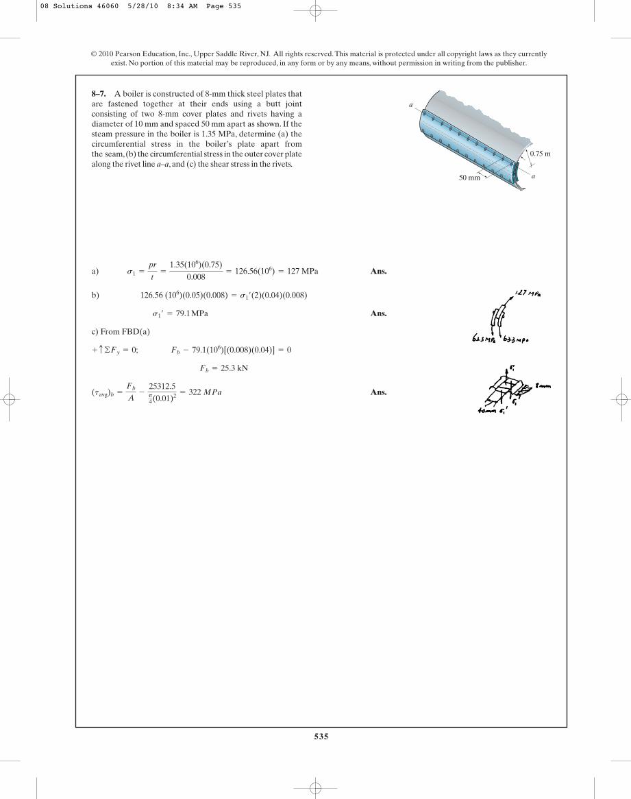
a) Ans.
b)
Ans.
c) From FBD(a)
Ans.(tavg)b =
Fb
A-
25312.5p4(0.01)2 = 322 MPa
Fb = 25.3 kN
+ c ©Fy = 0; Fb - 79.1(106)[(0.008)(0.04)] = 0
s1¿ = 79.1 MPa
126.56 (106)(0.05)(0.008) = s1¿(2)(0.04)(0.008)
s1 =
pr
t=
1.35(106)(0.75)
0.008= 126.56(106) = 127 MPa
8–7. A boiler is constructed of 8-mm thick steel plates thatare fastened together at their ends using a butt jointconsisting of two 8-mm cover plates and rivets having adiameter of 10 mm and spaced 50 mm apart as shown. If thesteam pressure in the boiler is 1.35 MPa, determine (a) thecircumferential stress in the boiler’s plate apart fromthe seam,(b) the circumferential stress in the outer cover platealong the rivet line a–a, and (c) the shear stress in the rivets.
a
8 mm
50 mm a
0.75 m
08 Solutions 46060 5/28/10 8:34 AM Page 535
536
© 2010 Pearson Education, Inc., Upper Saddle River, NJ. All rights reserved. This material is protected under all copyright laws as they currentlyexist. No portion of this material may be reproduced, in any form or by any means, without permission in writing from the publisher.
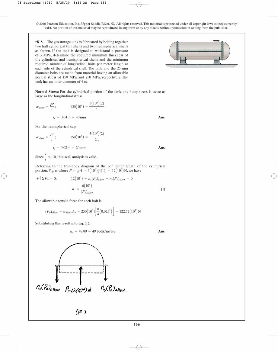
Normal Stress: For the cylindrical portion of the tank, the hoop stress is twice aslarge as the longitudinal stress.
Ans.
For the hemispherical cap,
Ans.
Since , thin-wall analysis is valid.
Referring to the free-body diagram of the per meter length of the cylindricalportion, Fig. a, where , we have
(1)
The allowable tensile force for each bolt is
Substituting this result into Eq. (1),
Ans.nc = 48.89 = 49 bolts>meter
(Pb)allow = sallowAb = 250 A106 B cp
4A0.0252 B d = 122.72 A103 B N
nc =
6 A106 B(Pb)allow
+ c ©Fy = 0; 12 A106 B - nc(Pb)allow - nc(Pb)allow = 0
P = pA = 3 A106 B [4(1)] = 12 A106 B N
r
t6 10
ts = 0.02 m = 20 mm
sallow =
pr
t ; 150 A106 B =
3 A106 B(2)
2ts
tc = 0.04 m = 40 mm
sallow =
pr
t ; 150 A106 B =
3 A106 B(2)
tc
*8–8. The gas storage tank is fabricated by bolting togethertwo half cylindrical thin shells and two hemispherical shellsas shown. If the tank is designed to withstand a pressureof 3 MPa, determine the required minimum thickness ofthe cylindrical and hemispherical shells and the minimumrequired number of longitudinal bolts per meter length ateach side of the cylindrical shell. The tank and the 25 mmdiameter bolts are made from material having an allowablenormal stress of 150 MPa and 250 MPa, respectively. Thetank has an inner diameter of 4 m.
08 Solutions 46060 5/28/10 8:34 AM Page 536

537
© 2010 Pearson Education, Inc., Upper Saddle River, NJ. All rights reserved. This material is protected under all copyright laws as they currentlyexist. No portion of this material may be reproduced, in any form or by any means, without permission in writing from the publisher.
Normal Stress: For the cylindrical portion of the tank, the hoop stress is twice aslarge as the longitudinal stress.
Ans.
For the hemispherical cap,
Ans.
Since , thin-wall analysis is valid.
The allowable tensile force for each bolt is
Referring to the free-body diagram of the hemispherical cap, Fig. b, where
,
(1)
Substituting this result into Eq. (1),
Ans.ns = 307.2 = 308 bolts
ns =
12p A106 B(Pb)allow
:+ ©Fx = 0; 12p A106 B -
ns
2 (Pb)allow -
ns
2 (Pb)allow = 0
P = pA = 3 A106 B cp
4 A42 B d = 12p A106 B N
(Pb)allow = sallowAb = 250 A106 B cp
4A0.0252 B d = 122.72 A103 B N
r
t6 10
ts = 0.02 m = 20 mm
sallow =
pr
t ; 150 A106 B =
3 A106 B(2)
2ts
tc = 0.04 m = 40 mm
sallow =
pr
t ; 150 A106 B =
3 A106 B(2)
tc
•8–9. The gas storage tank is fabricated by bolting togethertwo half cylindrical thin shells and two hemispherical shellsas shown. If the tank is designed to withstand a pressure of3 MPa, determine the required minimum thickness of thecylindrical and hemispherical shells and the minimumrequired number of bolts for each hemispherical cap. Thetank and the 25 mm diameter bolts are made from materialhaving an allowable normal stress of 150 MPa and 250 MPa,respectively. The tank has an inner diameter of 4 m.
08 Solutions 46060 5/28/10 8:34 AM Page 537
538
© 2010 Pearson Education, Inc., Upper Saddle River, NJ. All rights reserved. This material is protected under all copyright laws as they currentlyexist. No portion of this material may be reproduced, in any form or by any means, without permission in writing from the publisher.
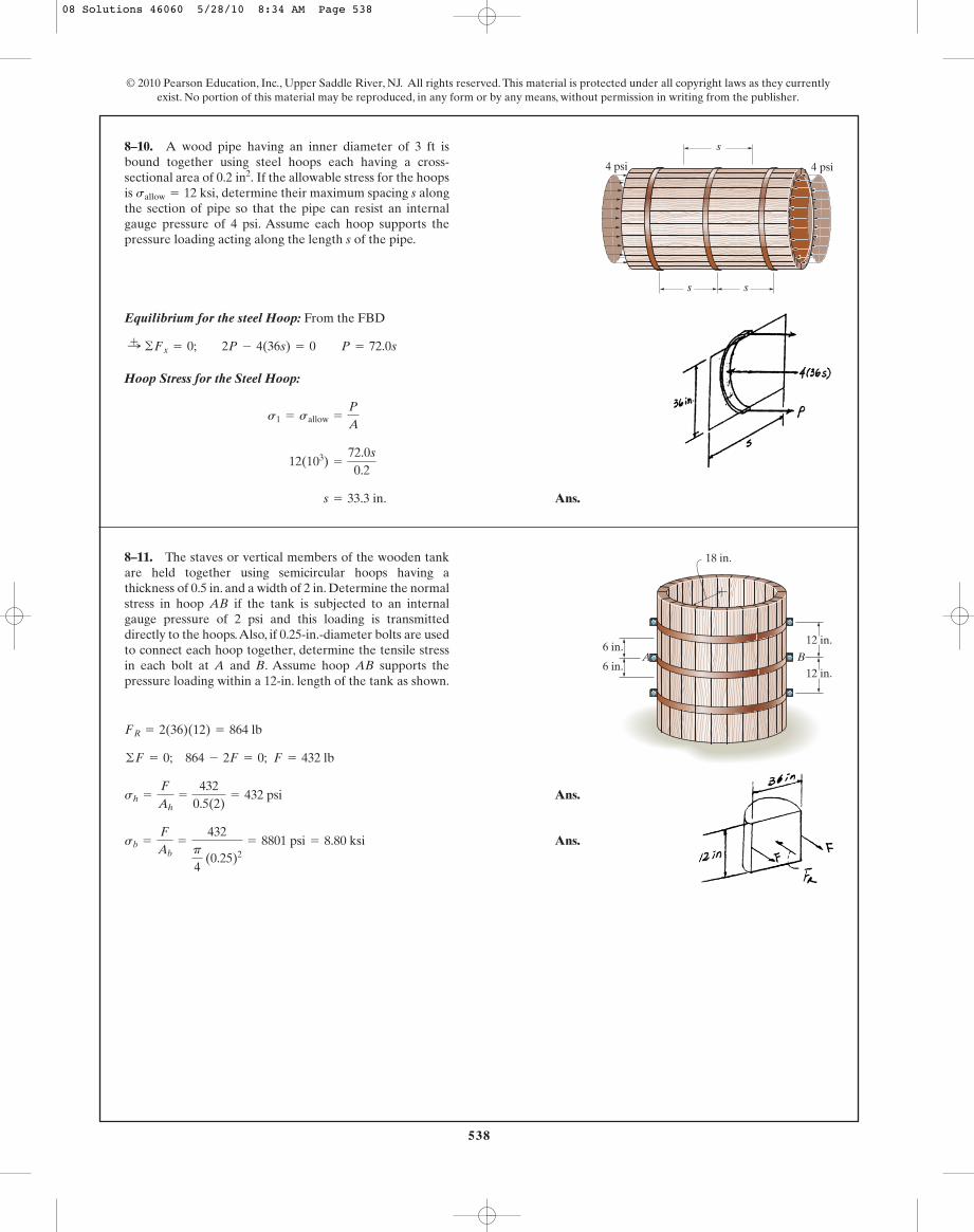
Ans.
Ans.sb =
F
Ab=
432p
4 (0.25)2
= 8801 psi = 8.80 ksi
sh =
F
Ah=
4320.5(2)
= 432 psi
©F = 0; 864 - 2F = 0; F = 432 lb
FR = 2(36)(12) = 864 lb
8–11. The staves or vertical members of the wooden tankare held together using semicircular hoops having athickness of 0.5 in. and a width of 2 in. Determine the normalstress in hoop AB if the tank is subjected to an internalgauge pressure of 2 psi and this loading is transmitteddirectly to the hoops.Also, if 0.25-in.-diameter bolts are usedto connect each hoop together, determine the tensile stressin each bolt at A and B. Assume hoop AB supports thepressure loading within a 12-in. length of the tank as shown.
Equilibrium for the steel Hoop: From the FBD
Hoop Stress for the Steel Hoop:
Ans. s = 33.3 in.
12(103) =
72.0s
0.2
s1 = sallow =
P
A
:+ ©Fx = 0; 2P - 4(36s) = 0 P = 72.0s
8–10. A wood pipe having an inner diameter of 3 ft isbound together using steel hoops each having a cross-sectional area of If the allowable stress for the hoopsis determine their maximum spacing s alongthe section of pipe so that the pipe can resist an internalgauge pressure of 4 psi. Assume each hoop supports thepressure loading acting along the length s of the pipe.
sallow = 12 ksi,0.2 in2.
s
s s
4 psi4 psi
6 in.12 in.
18 in.
12 in.6 in.
A B
08 Solutions 46060 5/28/10 8:34 AM Page 538
539
© 2010 Pearson Education, Inc., Upper Saddle River, NJ. All rights reserved. This material is protected under all copyright laws as they currentlyexist. No portion of this material may be reproduced, in any form or by any means, without permission in writing from the publisher.
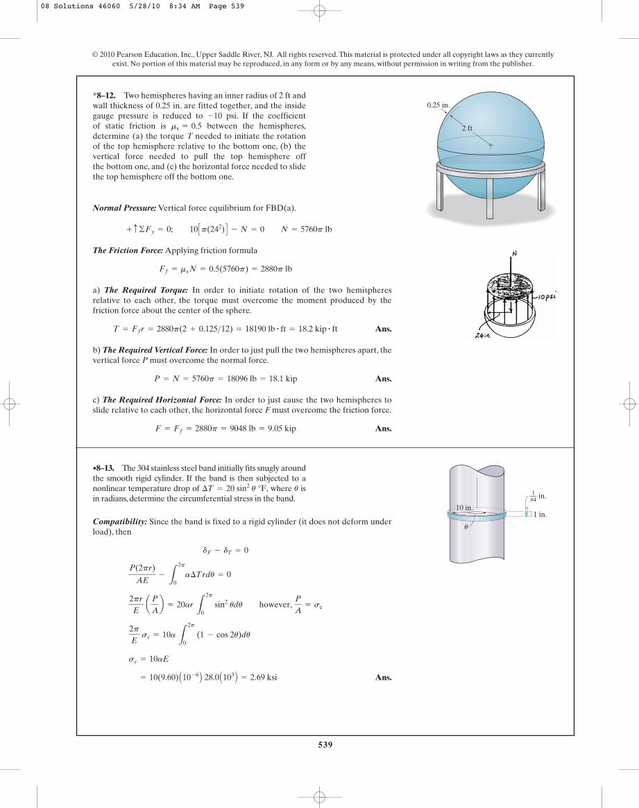
Compatibility: Since the band is fixed to a rigid cylinder (it does not deform underload), then
Ans. = 10(9.60) A10- 6 B 28.0 A103 B = 2.69 ksi
sc = 10aE
2pE
sc = 10a L
2p
0 (1 - cos 2u)du
2pr
E a
P
Ab = 20ar
L
2p
0 sin2 udu however,
P
A= sc
P(2pr)
AE-
L
2p
0a¢Trdu = 0
dF - dT = 0
•8–13. The 304 stainless steel band initially fits snugly aroundthe smooth rigid cylinder. If the band is then subjected to anonlinear temperature drop of where isin radians, determine the circumferential stress in the band.
u¢T = 20 sin2 u °F,
Normal Pressure: Vertical force equilibrium for FBD(a).
The Friction Force: Applying friction formula
a) The Required Torque: In order to initiate rotation of the two hemispheresrelative to each other, the torque must overcome the moment produced by thefriction force about the center of the sphere.
Ans.
b) The Required Vertical Force: In order to just pull the two hemispheres apart, thevertical force P must overcome the normal force.
Ans.
c) The Required Horizontal Force: In order to just cause the two hemispheres toslide relative to each other, the horizontal force F must overcome the friction force.
Ans.F = Ff = 2880p = 9048 lb = 9.05 kip
P = N = 5760p = 18096 lb = 18.1 kip
T = Ffr = 2880p(2 + 0.125>12) = 18190 lb # ft = 18.2 kip # ft
Ff = ms N = 0.5(5760p) = 2880p lb
+ c ©Fy = 0; 10 Cp(242) D - N = 0 N = 5760p lb
*8–12. Two hemispheres having an inner radius of 2 ft andwall thickness of 0.25 in. are fitted together, and the insidegauge pressure is reduced to psi. If the coefficientof static friction is between the hemispheres,determine (a) the torque T needed to initiate the rotationof the top hemisphere relative to the bottom one, (b) thevertical force needed to pull the top hemisphere offthe bottom one, and (c) the horizontal force needed to slidethe top hemisphere off the bottom one.
ms = 0.5-10
2 ft
0.25 in.
10 in.
u
in.
1 in.
164
08 Solutions 46060 5/28/10 8:34 AM Page 539
540
© 2010 Pearson Education, Inc., Upper Saddle River, NJ. All rights reserved. This material is protected under all copyright laws as they currentlyexist. No portion of this material may be reproduced, in any form or by any means, without permission in writing from the publisher.
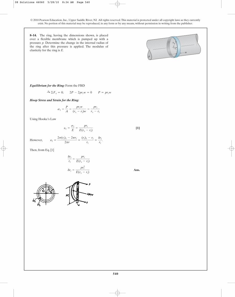
Equilibrium for the Ring: Form the FBD
Hoop Stress and Strain for the Ring:
Using Hooke’s Law
[1]
However, .
Then, from Eq. [1]
Ans.dri =
pri2
E(rs - ri)
dri
ri=
pri
E(rs - ri)
e1 =
2p(ri)1 - 2pri
2pr=
(ri)1 - ri
ri=
dri
ri
e1 =
s1
E=
pri
E(rs - ri)
s1 =
P
A=
pri w
(rs - ri)w=
pri
rs - ri
:+ ©Fx = 0; 2P - 2pri w = 0 P = pri w
8–14. The ring, having the dimensions shown, is placedover a flexible membrane which is pumped up with apressure p. Determine the change in the internal radius ofthe ring after this pressure is applied. The modulus ofelasticity for the ring is E.
p
ro
w
ri
08 Solutions 46060 5/28/10 8:34 AM Page 540
541
© 2010 Pearson Education, Inc., Upper Saddle River, NJ. All rights reserved. This material is protected under all copyright laws as they currentlyexist. No portion of this material may be reproduced, in any form or by any means, without permission in writing from the publisher.
Equilibrium for the Ring: From the FBD
Hoop Stress and Strain for the Ring:
Using Hooke’s law
[1]
However, .
Then, from Eq. [1]
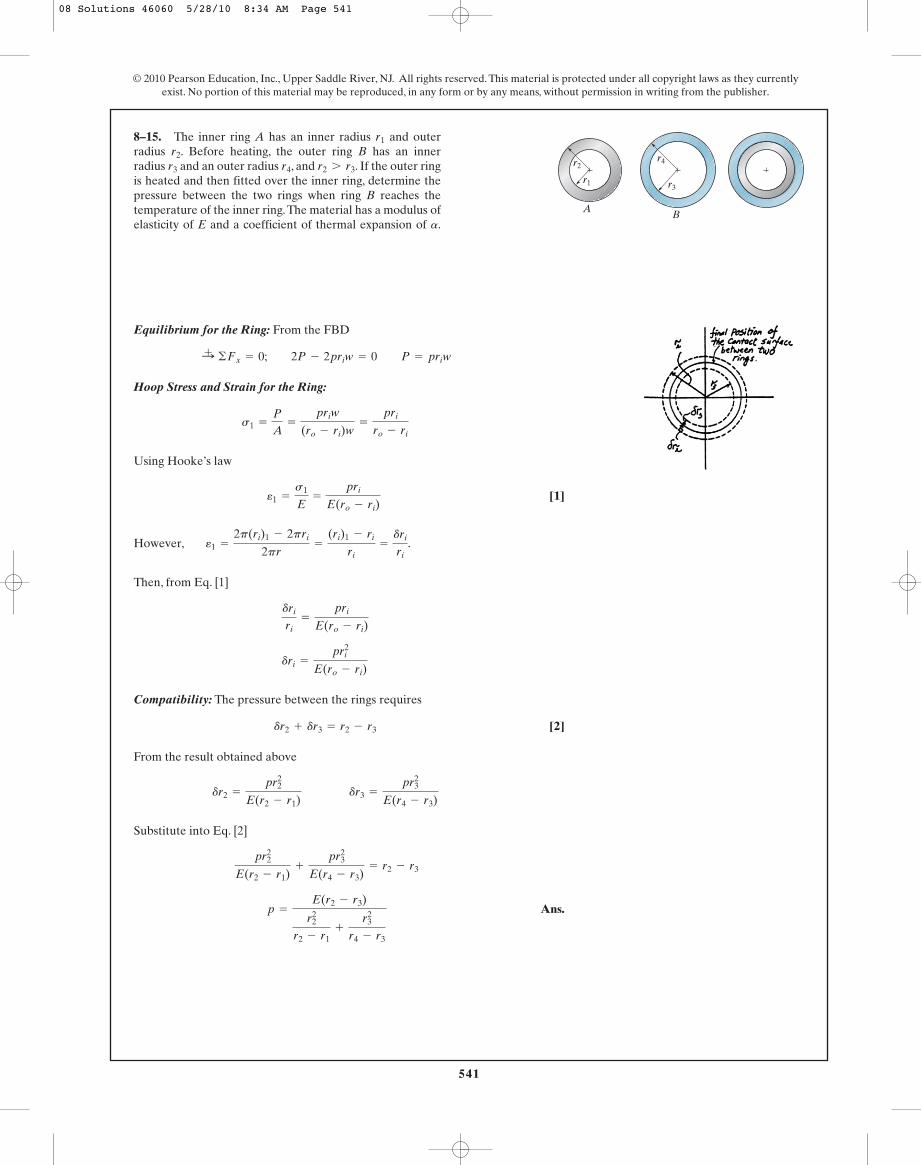
Compatibility: The pressure between the rings requires
[2]
From the result obtained above
Substitute into Eq. [2]
Ans. p =
E(r2 - r3)
r22
r2 - r1+
r32
r4 - r3
pr2
2
E(r2 - r1)+
pr32
E(r4 - r3)= r2 - r3
dr2 =
pr22
E(r2 - r1) dr3 =
pr32
E(r4 - r3)
dr2 + dr3 = r2 - r3
dri =
pri2
E(ro - ri)
dri
ri=
pri
E(ro - ri)
e1 =
2p(ri)1 - 2pri
2pr=
(ri)1 - ri
ri=
dri
ri
e1 =
s1
E=
pri
E(ro - ri)
s1 =
P
A=
priw
(ro - ri)w=
pri
ro - ri
:+ ©Fx = 0; 2P - 2priw = 0 P = priw
8–15. The inner ring A has an inner radius and outerradius . Before heating, the outer ring B has an innerradius and an outer radius , and . If the outer ringis heated and then fitted over the inner ring, determine thepressure between the two rings when ring B reaches thetemperature of the inner ring.The material has a modulus ofelasticity of E and a coefficient of thermal expansion of .a
r2 7 r3r4r3
r2
r1
r1
r2
r3
A B
r4
08 Solutions 46060 5/28/10 8:34 AM Page 541

542
© 2010 Pearson Education, Inc., Upper Saddle River, NJ. All rights reserved. This material is protected under all copyright laws as they currentlyexist. No portion of this material may be reproduced, in any form or by any means, without permission in writing from the publisher.
Normal Stress:
Equilibrium: We will consider the triangular element cut from the stripshown in Fig. a. Here,
sl = s2 =
pr
2t=
p(d>2)
2t=
pd
4t
sh = s1 =
pr
t=
p(d>2)
t=
pd
2t
*8–16. The cylindrical tank is fabricated by welding astrip of thin plate helically, making an angle with thelongitudinal axis of the tank. If the strip has a width w andthickness t, and the gas within the tank of diameter d ispressured to p, show that the normal stress developed alongthe strip is given by .su = (pd>8t)(3 - cos 2u)
u w
u
and . Thus,
and
.
Writing the force equation of equilibrium along the axis,
However, . This equation becomes
Also, , so that
Since , then
(Q.E.D.)su =
pd
8t (3 - cos 2u)
su =
NuAu
=
pwd
8 (3 - cos 2u)
wt
Au = wt
Nu =
pwd
8 (3 - cos 2u)
sin2 u =
12
(1 - cos 2u)
Nu =
pwd
4 Asin2 u + 1 B
sin2 u + cos2
u = 1
Nu =
pwd
4 A2 sin2 u + cos2 u B
©Fx¿= 0; c
pwd
2 sin u d sin u + c
pwd
4 cos u d cos u - Nu = u
x¿
Fl = slAl =
pd
4t (w cos u)t =
pwd
4 cos u
Fh = shAh =
pd
2t (w sin u)t =
pwd
2 sin u
Al = (w cos u)tAh = (w sin u)t
08 Solutions 46060 5/28/10 8:34 AM Page 542

543
© 2010 Pearson Education, Inc., Upper Saddle River, NJ. All rights reserved. This material is protected under all copyright laws as they currentlyexist. No portion of this material may be reproduced, in any form or by any means, without permission in writing from the publisher.
Normal Stress in the Wall and Filament Before the Internal Pressure is Applied:The entire length w of wall is subjected to pretension filament force T. Hence, fromequilibrium, the normal stress in the wall at this state is
and for the filament the normal stress is
Normal Stress in the Wall and Filament After the Internal Pressure is Applied: Thestress in the filament becomes
Ans.
And for the wall,
Ans.sw = sl - (sl¿)w =
p r
(t + t¿)-
T
wt
sfil = sl + (sl¿)fil =
pr
(t + t¿)+
T
wt¿
(sl¿)fil =
T
wt¿
2T - (sl¿)w (2wt) = 0 (sl¿)w =
T
wt
8–17. In order to increase the strength of the pressure vessel,filament winding of the same material is wrapped around thecircumference of the vessel as shown. If the pretension in thefilament is T and the vessel is subjected to an internal pressurep, determine the hoop stresses in the filament and in the wallof the vessel. Use the free-body diagram shown, and assumethe filament winding has a thickness t� and width w for acorresponding length of the vessel.
T
p
w
t ¿
L
t
T
s1
s1
Ans. d = 0.0667 m = 66.7 mm
P(-1000 + 15000 d) = 0
0 =
P
(0.2)(0.01)-
P(0.1 - d)(0.1)112 (0.01)(0.23)
0 =
P
A-
M cI
sA = 0 = sa - sb
8–18. The vertical force P acts on the bottom of the platehaving a negligible weight. Determine the shortest distanced to the edge of the plate at which it can be applied so thatit produces no compressive stresses on the plate at sectiona–a. The plate has a thickness of 10 mm and P acts along thecenter line of this thickness.
a
500 mm
P
a
300 mm
200 mm
d
08 Solutions 46060 5/28/10 8:34 AM Page 543

544
© 2010 Pearson Education, Inc., Upper Saddle River, NJ. All rights reserved. This material is protected under all copyright laws as they currentlyexist. No portion of this material may be reproduced, in any form or by any means, without permission in writing from the publisher.
Consider the equilibrium of the FBD of the top cut segment in Fig. a,
a
The normal stress developed is the combination of axial and bending stress. Thus,
For the left edge fiber, . Then
Ans.
For the right edge fiber, . Then
Ans.sR = - 100 (103)
0.006+
10(103)(0.1)
20.0(10- 6)= 33.3 MPa (T)
y = 0.1 m
= -66.67(106) Pa = 66.7 MPa (C) (Max)
sL = -
100(103)
0.006-
10(103)(0.1)
20.0(10- 6)
y = C = 0.1 m
s =
N
A;
My
I
A = 0.2(0.03) = 0.006 m2 I =
112
(0.03)(0.23) = 20.0(10- 6) m4
+ ©MC = 0; 100(0.1) - M = 0 M = 10 kN # m
+ c ©Fy = 0; N - 100 = 0 N = 100 kN
8–19. Determine the maximum and minimum normalstress in the bracket at section a–a when the load is appliedat x = 0.
100 kN
x
200 mm150 mm
15 mm
15 mm
aa
08 Solutions 46060 5/28/10 8:34 AM Page 544

545
© 2010 Pearson Education, Inc., Upper Saddle River, NJ. All rights reserved. This material is protected under all copyright laws as they currentlyexist. No portion of this material may be reproduced, in any form or by any means, without permission in writing from the publisher.
Consider the equilibrium of the FBD of the top cut segment in Fig. a,
a
The normal stress developed is the combination of axial and bending stress. Thus,
For the left edge fiber, . Then
Ans.
For the right edge fiber, . Thus
Ans. = 117 MPa
sR = -
100(103)
0.006-
20.0(103)(0.1)
20.0(10- 6)
y = C = 0.1 m
= 83.33(106) Pa = 83.3 MPa (T)(Min)
sC = -
100(103)
0.006+
20.0(103)(0.1)
20.0(10- 6)
y = C = 0.1 m
s =
N
A;
My
I
A = 0.2 (0.03) = 0.006 m2 I =
112
(0.03)(0.23) = 20.0(10- 6) m4
+ ©MC = 0; M - 100(0.2) = 0 M = 20 kN # m
+ c ©Fy = 0; N - 100 = 0 N = 100 kN
*8–20. Determine the maximum and minimum normalstress in the bracket at section a–a when the load is appliedat x = 300 mm.
100 kN
x
200 mm150 mm
15 mm
15 mm
aa
08 Solutions 46060 5/28/10 8:34 AM Page 545
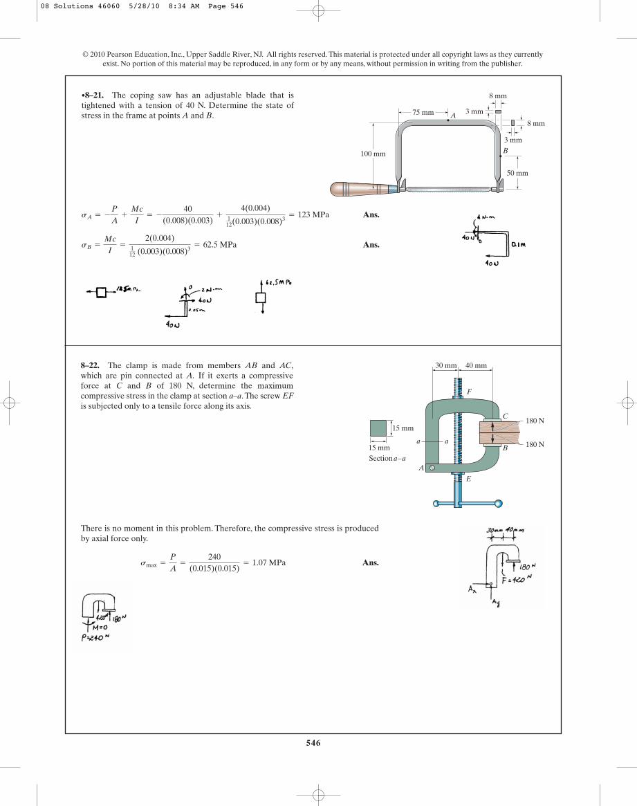
Ans.
Ans.sB =
Mc
I=
2(0.004)112 (0.003)(0.008)3
= 62.5 MPa
sA = -
P
A+
Mc
I= -
40(0.008)(0.003)
+
4(0.004)112(0.003)(0.008)3
= 123 MPa
•8–21. The coping saw has an adjustable blade that istightened with a tension of 40 N. Determine the state ofstress in the frame at points A and B.
546
© 2010 Pearson Education, Inc., Upper Saddle River, NJ. All rights reserved. This material is protected under all copyright laws as they currentlyexist. No portion of this material may be reproduced, in any form or by any means, without permission in writing from the publisher.
75 mm
50 mm
8 mm
3 mm
3 mm
8 mmA
B100 mm
There is no moment in this problem. Therefore, the compressive stress is producedby axial force only.
Ans.smax =
P
A=
240(0.015)(0.015)
= 1.07 MPa
8–22. The clamp is made from members AB and AC,which are pin connected at A. If it exerts a compressiveforce at C and B of 180 N, determine the maximumcompressive stress in the clamp at section a–a.The screw EFis subjected only to a tensile force along its axis.
180 N
180 NB
C
F
E
A
a a
30 mm 40 mm
15 mm
15 mmSectiona – a
08 Solutions 46060 5/28/10 8:34 AM Page 546
547
© 2010 Pearson Education, Inc., Upper Saddle River, NJ. All rights reserved. This material is protected under all copyright laws as they currentlyexist. No portion of this material may be reproduced, in any form or by any means, without permission in writing from the publisher.
There is moment in this problem. Therefore, the compressive stress is produced byaxial force only.
smax =
P
A=
240(0.015)(0.015)
= 1.07 MPa
8–23. The clamp is made from members AB and AC,which are pin connected at A. If it exerts a compressiveforce at C and B of 180 N, sketch the stress distributionacting over section a–a. The screw EF is subjected only toa tensile force along its axis.
180 N
180 NB
C
F
E
A
a a
30 mm 40 mm
15 mm
15 mmSectiona – a
a
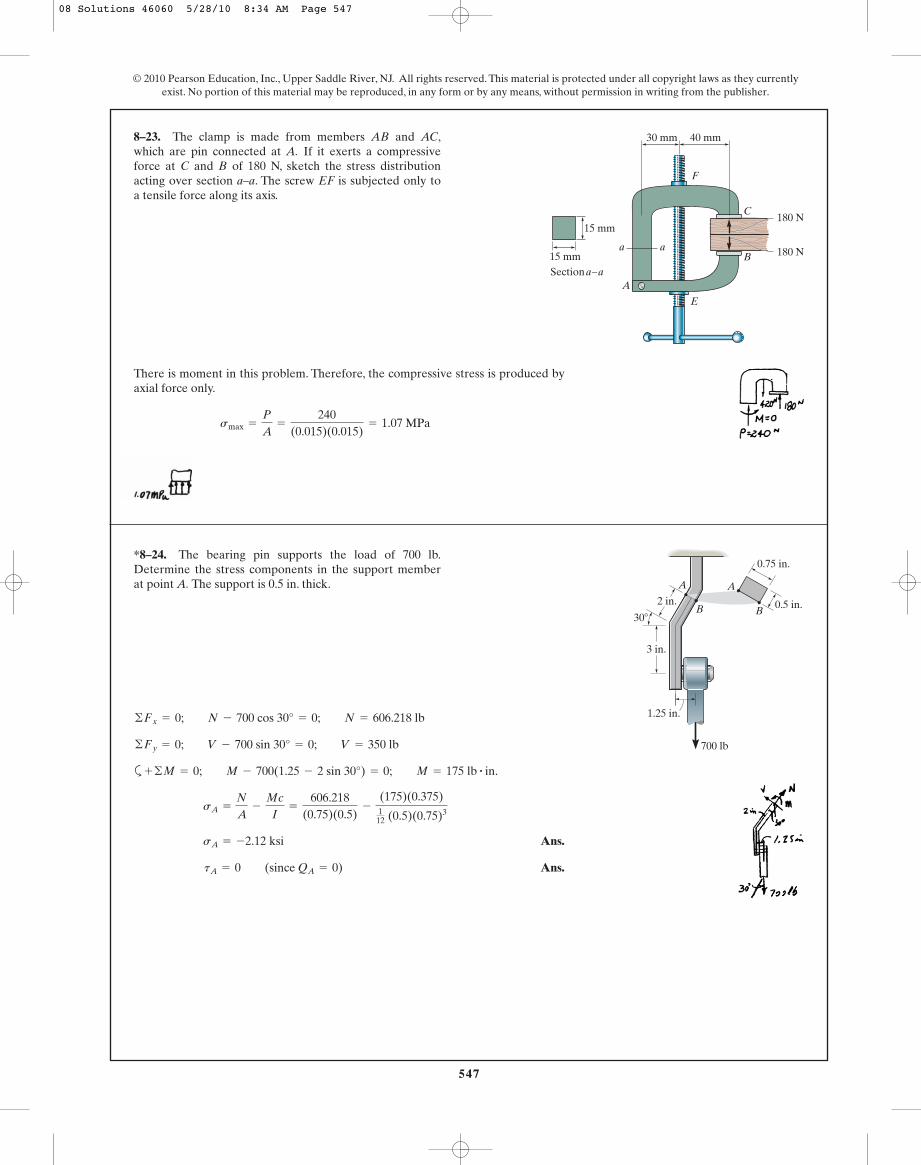
Ans.
Ans. tA = 0 (since QA = 0)
sA = -2.12 ksi
sA =
N
A-
Mc
I=
606.218(0.75)(0.5)
-
(175)(0.375)112 (0.5)(0.75)3
+ ©M = 0; M - 700(1.25 - 2 sin 30°) = 0; M = 175 lb # in.
©Fy = 0; V - 700 sin 30° = 0; V = 350 lb
©Fx = 0; N - 700 cos 30° = 0; N = 606.218 lb
*8–24. The bearing pin supports the load of 700 lb.Determine the stress components in the support member at point A. The support is 0.5 in. thick.
30�
2 in.
A A
B B
3 in.
1.25 in.
700 lb
0.75 in.
0.5 in.
08 Solutions 46060 5/28/10 8:34 AM Page 547
548
© 2010 Pearson Education, Inc., Upper Saddle River, NJ. All rights reserved. This material is protected under all copyright laws as they currentlyexist. No portion of this material may be reproduced, in any form or by any means, without permission in writing from the publisher.
a
Ans.
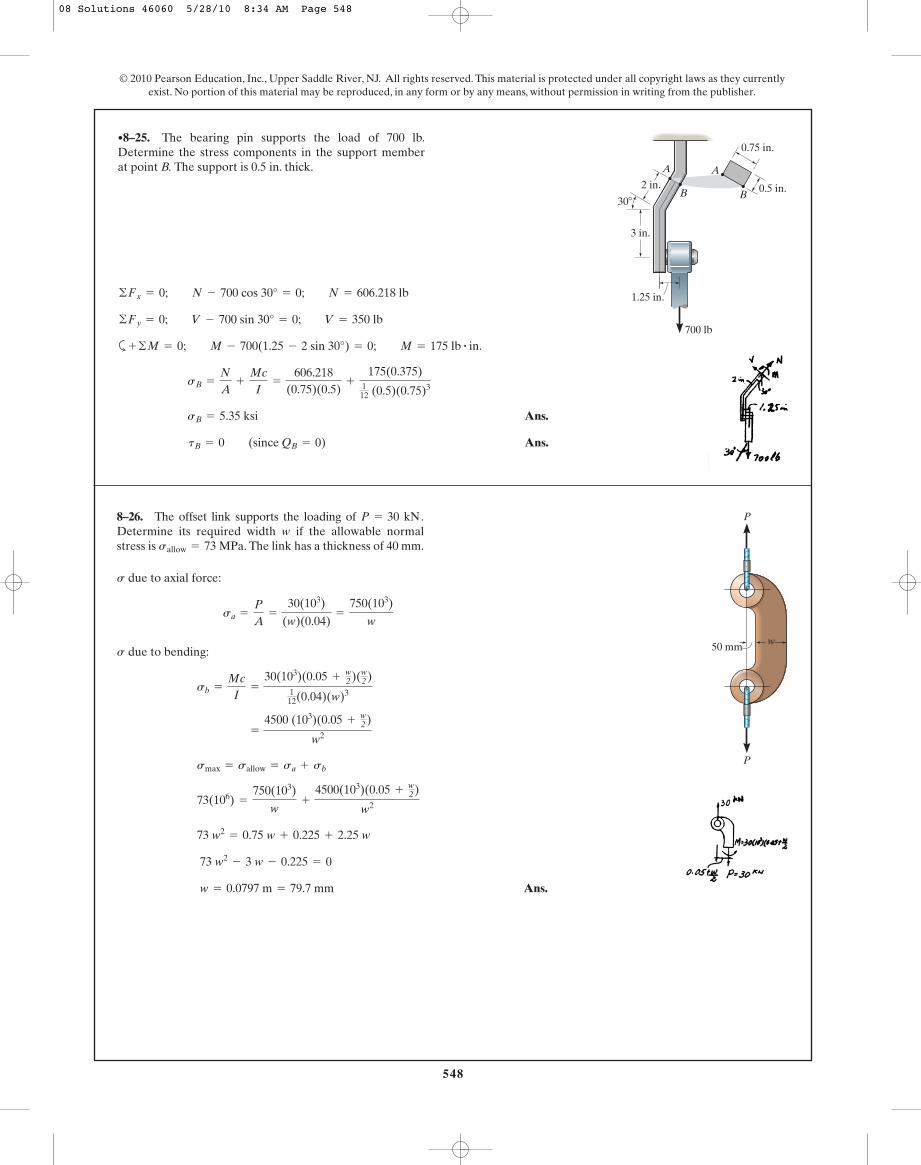
Ans. tB = 0 (since QB = 0)
sB = 5.35 ksi
sB =
N
A+
Mc
I=
606.218(0.75)(0.5)
+
175(0.375)112 (0.5)(0.75)3
+ ©M = 0; M - 700(1.25 - 2 sin 30°) = 0; M = 175 lb # in.
©Fy = 0; V - 700 sin 30° = 0; V = 350 lb
©Fx = 0; N - 700 cos 30° = 0; N = 606.218 lb
•8–25. The bearing pin supports the load of 700 lb.Determine the stress components in the support member at point B. The support is 0.5 in. thick.
30�
2 in.
A A
B B
3 in.
1.25 in.
700 lb
0.75 in.
0.5 in.
due to axial force:
due to bending:
Ans. w = 0.0797 m = 79.7 mm
73 w2- 3 w - 0.225 = 0
73 w2= 0.75 w + 0.225 + 2.25 w
73(106) =
750(103)
w+
4500(103)(0.05 +w2)
w2
smax = sallow = sa + sb
=
4500 (103)(0.05 +w2)
w2
sb =
Mc
I=
30(103)(0.05 +w2)(w
2)112(0.04)(w)3
s
sa =
P
A=
30(103)
(w)(0.04)=
750(103)
w
s
8–26. The offset link supports the loading of Determine its required width w if the allowable normalstress is The link has a thickness of 40 mm.sallow = 73 MPa.
P = 30 kN.
P
P
w50 mm
08 Solutions 46060 5/28/10 8:34 AM Page 548

549
© 2010 Pearson Education, Inc., Upper Saddle River, NJ. All rights reserved. This material is protected under all copyright laws as they currentlyexist. No portion of this material may be reproduced, in any form or by any means, without permission in writing from the publisher.
Ans.P = 109 kN
75(106) =
P
0.008+
0.150 P(0.1)
26.6667(10- 6)
s =
P
A+
Mc
I
I =
112
(0.04)(0.2)3= 26.6667(10- 6) m4
A = 0.2(0.04) = 0.008 m2
8–27. The offset link has a width of and athickness of 40 mm. If the allowable normal stress is
determine the maximum load P that canbe applied to the cables.sallow = 75 MPa,
w = 200 mm
P
P
w50 mm
due to axial force:
due to bending:
Ans.
Ans.
y = 0.267 in.
y
1.28=
(0.5 - y)
1.12
(smax)c = 1200 - 80 = 1120 psi = 1.12 ksi
(smax)t = 80 + 1200 = 1280 psi = 1.28 ksi
s =
Mc
I=
100(0.25)112(2)(0.5)3
= 1200 psi
s
s =
P
A=
80(0.5)(2)
= 80 psi
s
*8–28. The joint is subjected to a force of P � 80 lb andF � 0. Sketch the normal-stress distribution acting oversection a–a if the member has a rectangular cross-sectionalarea of width 2 in. and thickness 0.5 in.
a
2 in.
aA
P
F
1.25 in.
0.5 in.B
08 Solutions 46060 5/28/10 8:34 AM Page 549
550
© 2010 Pearson Education, Inc., Upper Saddle River, NJ. All rights reserved. This material is protected under all copyright laws as they currentlyexist. No portion of this material may be reproduced, in any form or by any means, without permission in writing from the publisher.
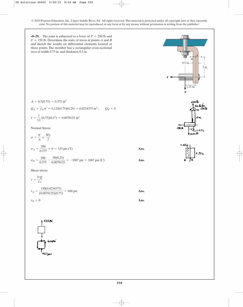
Normal Stress:
Ans.
Ans.
Shear stress:
Ans.
Ans.tB = 0
tA =
150(0.0234375)
(0.0078125)(0.75)= 600 psi
t =
VQ
I t
sB =
2000.375
-
50(0.25)
0.0078125= -1067 psi = 1067 psi (C)
sA =
2000.375
+ 0 = 533 psi (T)
s =
N
A;
My
I
I =
112
(0.75)(0.53) = 0.0078125 in4
QA = yAœ A¿ = 0.125(0.75)(0.25) = 0.0234375 in3 ; QB = 0
A = 0.5(0.75) = 0.375 in2
•8–29. The joint is subjected to a force of and. Determine the state of stress at points A and B
and sketch the results on differential elements located atthese points. The member has a rectangular cross-sectionalarea of width 0.75 in. and thickness 0.5 in.
F = 150 lbP = 200 lb
a
2 in.
aA
P
F
1.25 in.
0.5 in.B
08 Solutions 46060 5/28/10 8:34 AM Page 550

551
© 2010 Pearson Education, Inc., Upper Saddle River, NJ. All rights reserved. This material is protected under all copyright laws as they currentlyexist. No portion of this material may be reproduced, in any form or by any means, without permission in writing from the publisher.
Support Reactions: Referring to the free-body diagram of the entire plank, Fig. a,
a
Internal Loadings: Consider the equilibrium of the free-body diagram of the plank’slower segment, Fig. b,
a
Section Properties: The cross-sectional area and the moment of inertia about thecentroidal axis of the plank’s cross section are
Referring to Fig. c, QA is
Normal Stress: The normal stress is the combination of axial and bending stress.Thus,
For point A, . Then
Ans. = -503.94 kPa = 504 kPa (C)
sA =
-781.730.03
-
238.94(0.0125)
6.25 A10- 6 B
y = 0.0125 m
s =
N
A;
My
I
QA = y¿A¿ = 0.01875(0.0125)(0.6) = 0.140625 A10- 3 B m3
I =
112
(0.6) A0.053 B = 6.25 A10- 6 Bm4
A = 0.6(0.05) = 0.03 m2
M = 238.94 N # mM - 398.24(0.6) = 0+ ©MO = 0;
©Fy¿= 0; 398.24 - V = 0 V = 398.24 N
©Fx¿= 0; 781.73 - N = 0 N = 781.73 N
By¿= 398.24 N
©Fy¿= 0; By¿
+ 477.88 sin 30° - 75(9.81) cos 30° = 0
Bx¿= 781.73 N
©Fx¿= 0; Bx¿
- 75(9.81) sin 30° - 477.88 cos 30° = 0
FC = 477.88 N
+ ©MB = 0; FC sin 30°(2.4) - 75(9.81) cos 30°(0.9) = 0
8–30. If the 75-kg man stands in the position shown,determine the state of stress at point A on the cross sectionof the plank at section a–a. The center of gravity of the manis at G. Assume that the contact point at C is smooth.
Section a – a and b – b
G
a
a
C
B
600 mm
50 mm
12.5 mm
A
300 mm600 mm
30�
1.5 m
08 Solutions 46060 5/28/10 8:34 AM Page 551
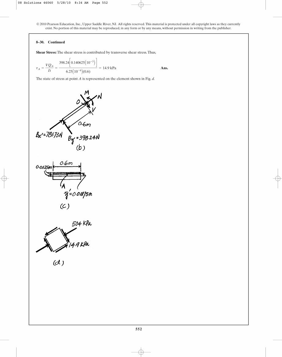
Shear Stress: The shear stress is contributed by transverse shear stress. Thus,
Ans.
The state of stress at point A is represented on the element shown in Fig. d.
tA =
VQA
It=
398.24 c0.140625 A10- 3 B d
6.25 A10- 6 B(0.6)= 14.9 kPa
8–30. Continued
552
© 2010 Pearson Education, Inc., Upper Saddle River, NJ. All rights reserved. This material is protected under all copyright laws as they currentlyexist. No portion of this material may be reproduced, in any form or by any means, without permission in writing from the publisher.
08 Solutions 46060 5/28/10 8:34 AM Page 552

553
© 2010 Pearson Education, Inc., Upper Saddle River, NJ. All rights reserved. This material is protected under all copyright laws as they currentlyexist. No portion of this material may be reproduced, in any form or by any means, without permission in writing from the publisher.
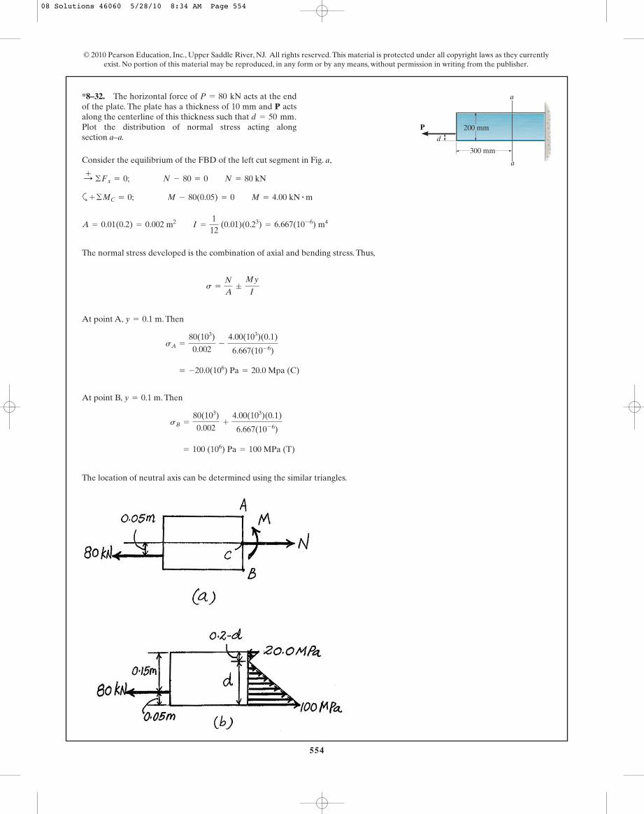
Consider the equilibrium of the FBD of the left cut segment in Fig. a,
a
The normal stress developed is the combination of axial and bending stress. Thus
Since no compressive stress is desired, the normal stress at the top edge fiber must
be equal to zero. Thus,
Ans. d = 0.06667 m = 66.7 mm
0 = 250 P - 7500 P (0.1 - d)
0 =
P
0.004;
P(0.1 - d)(0.1)
13.3333 (10- 6)
s =
N
A;
My
I
A = 0.2 (0.02) = 0.004 m4 I =
112
(0.02)(0.23) = 13.3333(10- 6) m4
+ ©MC = 0; M - P(0.1 - d) = 0 M = P(0.1 - d)
:+ ©Fx = 0; N - P = 0 N = P
8–31. Determine the smallest distance d to the edge of theplate at which the force P can be applied so that it producesno compressive stresses in the plate at section a–a. Theplate has a thickness of 20 mm and P acts along thecenterline of this thickness.
a
P
a
200 mm
300 mm
d
08 Solutions 46060 5/28/10 8:34 AM Page 553
554
© 2010 Pearson Education, Inc., Upper Saddle River, NJ. All rights reserved. This material is protected under all copyright laws as they currentlyexist. No portion of this material may be reproduced, in any form or by any means, without permission in writing from the publisher.
Consider the equilibrium of the FBD of the left cut segment in Fig. a,
a
The normal stress developed is the combination of axial and bending stress. Thus,
At point A, . Then
At point B, . Then
The location of neutral axis can be determined using the similar triangles.
= 100 (106) Pa = 100 MPa (T)
sB =
80(103)
0.002+
4.00(103)(0.1)
6.667(10- 6)
y = 0.1 m
= -20.0(106) Pa = 20.0 Mpa (C)
sA =
80(103)
0.002-
4.00(103)(0.1)
6.667(10- 6)
y = 0.1 m
s =
N
A;
My
I
A = 0.01(0.2) = 0.002 m2 I =
112
(0.01)(0.23) = 6.667(10- 6) m4
+ ©MC = 0; M - 80(0.05) = 0 M = 4.00 kN # m
:+ ©Fx = 0; N - 80 = 0 N = 80 kN
*8–32. The horizontal force of acts at the endof the plate. The plate has a thickness of 10 mm and P actsalong the centerline of this thickness such that Plot the distribution of normal stress acting along section a–a.
d = 50 mm.
P = 80 kN
a
P
a
200 mm
300 mm
d
08 Solutions 46060 5/28/10 8:34 AM Page 554

555
© 2010 Pearson Education, Inc., Upper Saddle River, NJ. All rights reserved. This material is protected under all copyright laws as they currentlyexist. No portion of this material may be reproduced, in any form or by any means, without permission in writing from the publisher.
a
Point B:
Ans.
Ans.
Point C:
Ans.
Shear Stress :
Ans.tC =
VQ
I t=
8.660(4)(10- 3)
1.0667(10- 3)(0.2)= 162 psi
sC =
N
A+
My
I=
-5.00.08
+ 0 = -62.5 psi = 62.5 psi(C)
tB =
VQ
I t= 0
sB =
N
A+
My
I=
-5.00.08
+
30(0.2)
1.0667(10- 3)= 5.56 ksi(T)
QC = y¿A¿ = 0.1(0.2)(0.2) = 4(10- 3) in3
QB = 0
I =
112
(0.2)(0.43) = 1.0667(10- 3) in4
A = 0.2(0.4) = 0.08 in2
+ ©MC = 0; M - 10(3) = 0 M = 30 lb # in.
a+ ©Fy = 0; V - 10 cos 30° = 0; V = 8.660 lb
+
Q ©Fx = 0; N - 10 sin 30° = 0; N = 5.0 lb
•8–33. The pliers are made from two steel parts pinnedtogether at A. If a smooth bolt is held in the jaws and agripping force of 10 lb is applied at the handles, determinethe state of stress developed in the pliers at points B and C.Here the cross section is rectangular, having the dimensionsshown in the figure.
4 in.2.5 in.
10 lb
10 lb
30�3 in.
B
C
A
0.2 in.
0.2 in.B
C
0.2 in.D
E
D
E
0.18 in.
0.2 in.
1.75 in.
0.1 in.
08 Solutions 46060 5/28/10 8:34 AM Page 555

556
© 2010 Pearson Education, Inc., Upper Saddle River, NJ. All rights reserved. This material is protected under all copyright laws as they currentlyexist. No portion of this material may be reproduced, in any form or by any means, without permission in writing from the publisher.
a
Point D:
Ans.
Ans.
Point E:
Ans.
Ans.tE = 0
sE =
My
I=
28(0.1)112 (0.18)(0.2)3
= 23.3 ksi (T)
tD =
VQ
It=
16(0.05)(0.1)(0.18)
[ 112 (0.18)(0.2)3](0.18)
= 667 psi
sD = 0
+ ©MA = 0; -F(2.5) + 4(10) = 0; F = 16 lb
8–34. Solve Prob. 8–33 for points D and E.
4 in.2.5 in.
10 lb
10 lb
30�3 in.
B
C
A
0.2 in.
0.2 in.B
C
0.2 in.D
E
D
E
0.18 in.
0.2 in.
1.75 in.
0.1 in.
08 Solutions 46060 5/28/10 8:34 AM Page 556
557
© 2010 Pearson Education, Inc., Upper Saddle River, NJ. All rights reserved. This material is protected under all copyright laws as they currentlyexist. No portion of this material may be reproduced, in any form or by any means, without permission in writing from the publisher.
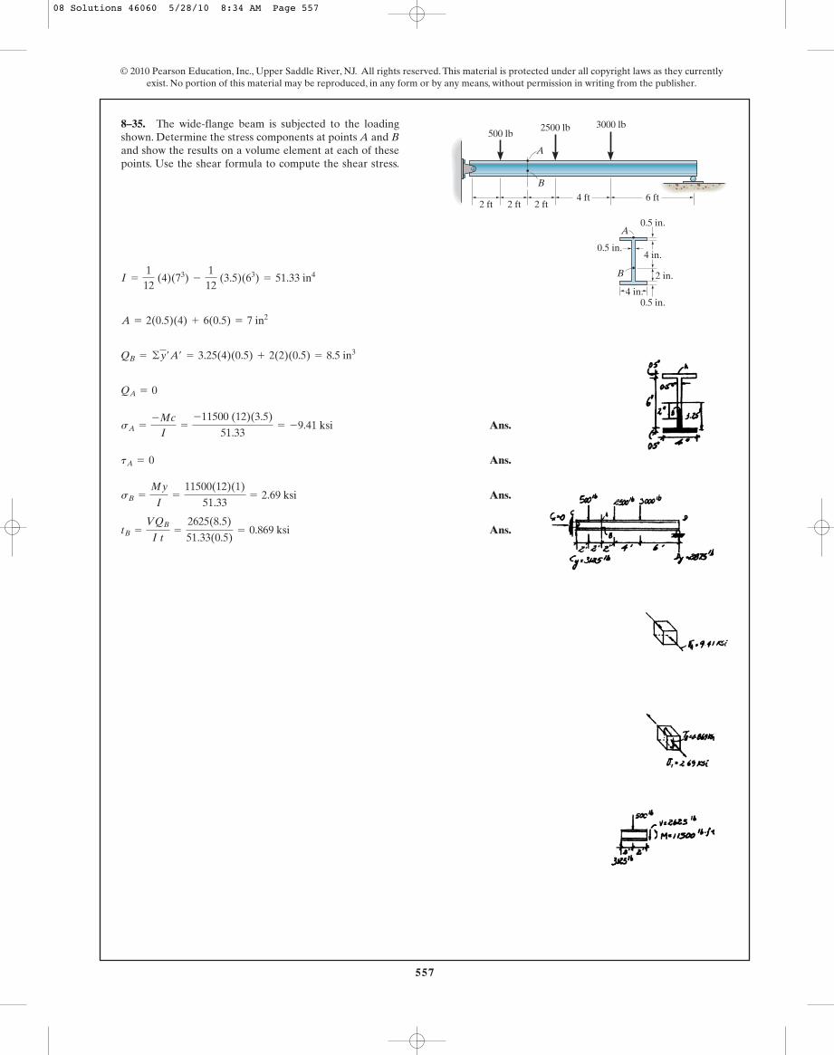
Ans.
Ans.
Ans.
Ans.tB =
VQB
I t=
2625(8.5)
51.33(0.5)= 0.869 ksi
sB =
My
I=
11500(12)(1)
51.33= 2.69 ksi
tA = 0
sA =
-Mc
I=
-11500 (12)(3.5)
51.33= -9.41 ksi
QA = 0
QB = ©y¿A¿ = 3.25(4)(0.5) + 2(2)(0.5) = 8.5 in3
A = 2(0.5)(4) + 6(0.5) = 7 in2
I =
112
(4)(73) -
112
(3.5)(63) = 51.33 in4
8–35. The wide-flange beam is subjected to the loadingshown. Determine the stress components at points A and Band show the results on a volume element at each of thesepoints. Use the shear formula to compute the shear stress.
6 ft4 ft2 ft2 ft2 ft
500 lb2500 lb 3000 lb
A
B
4 in.
4 in.
0.5 in.
0.5 in.
2 in.
0.5 in.
B
A
08 Solutions 46060 5/28/10 8:34 AM Page 557
558
© 2010 Pearson Education, Inc., Upper Saddle River, NJ. All rights reserved. This material is protected under all copyright laws as they currentlyexist. No portion of this material may be reproduced, in any form or by any means, without permission in writing from the publisher.
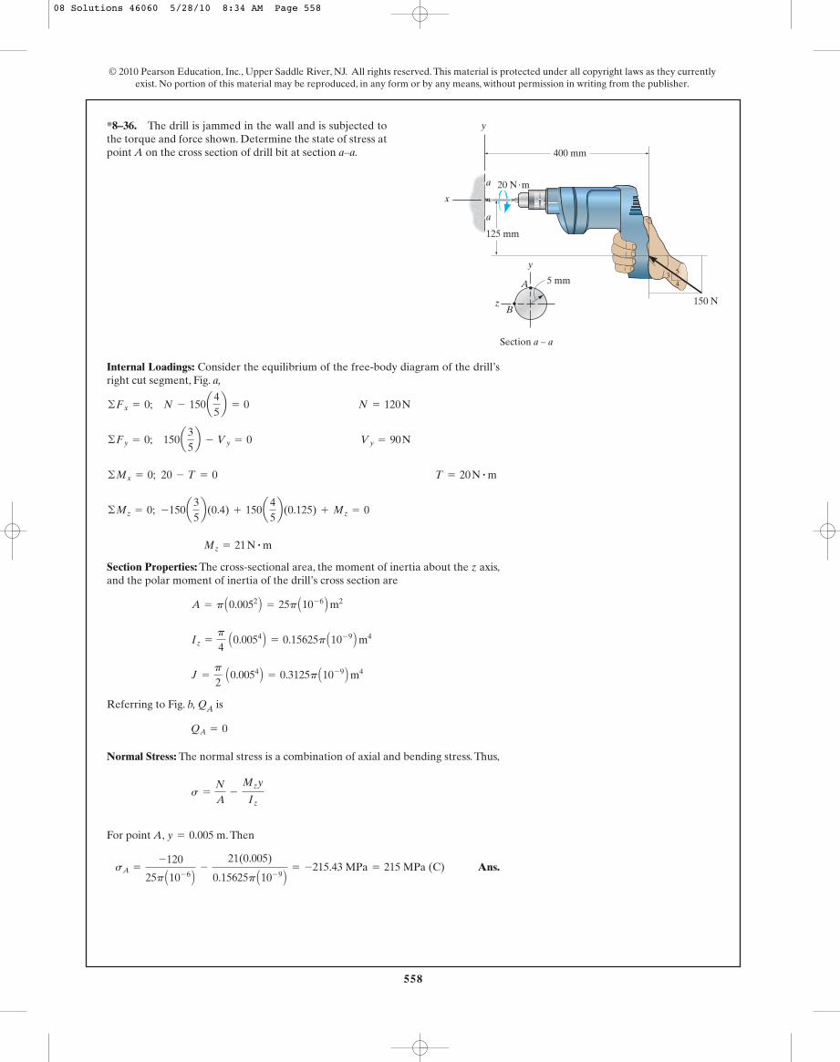
Internal Loadings: Consider the equilibrium of the free-body diagram of the drill’sright cut segment, Fig. a,
Section Properties: The cross-sectional area, the moment of inertia about the z axis,and the polar moment of inertia of the drill’s cross section are
Referring to Fig. b, QA is
Normal Stress: The normal stress is a combination of axial and bending stress. Thus,
For point A, . Then
Ans.sA =
-120
25p A10- 6 B-
21(0.005)
0.15625p A10- 9 B= -215.43 MPa = 215 MPa (C)
y = 0.005 m
s =
N
A-
Mzy
Iz
QA = 0
J =
p
2 A0.0054 B = 0.3125p A10- 9 B m4
Iz =
p
4 A0.0054 B = 0.15625p A10- 9 B m4
A = p A0.0052 B = 25p A10- 6 B m2
Mz = 21 N # m
©Mz = 0; -150a35b(0.4) + 150a
45b(0.125) + Mz = 0
©Mx = 0; 20 - T = 0 T = 20 N # m
©Fy = 0; 150a35b - Vy = 0 Vy = 90 N
©Fx = 0; N - 150a45b = 0 N = 120 N
*8–36. The drill is jammed in the wall and is subjected tothe torque and force shown. Determine the state of stress atpoint A on the cross section of drill bit at section a–a.
150 N
34
5
125 mm
20 N·m
400 mm
a
a
5 mm
B
A
Section a – a
z
x
y
y
08 Solutions 46060 5/28/10 8:34 AM Page 558
559
© 2010 Pearson Education, Inc., Upper Saddle River, NJ. All rights reserved. This material is protected under all copyright laws as they currentlyexist. No portion of this material may be reproduced, in any form or by any means, without permission in writing from the publisher.
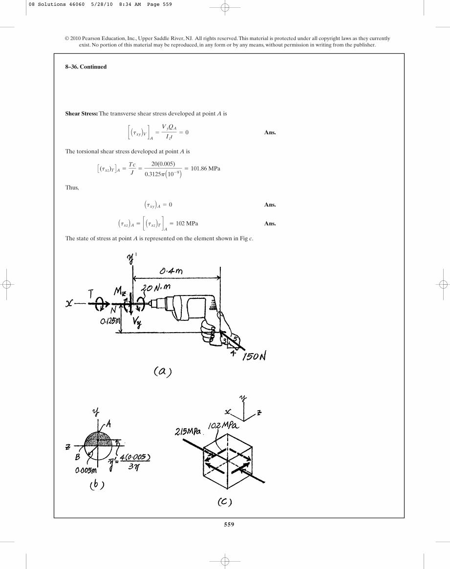
Shear Stress: The transverse shear stress developed at point A is
Ans.
The torsional shear stress developed at point A is
Thus,
Ans.
Ans.
The state of stress at point A is represented on the element shown in Fig c.
Atxz BA = c Atxz BT dA
= 102 MPa
Atxy BA = 0
C(txz)T DA =
Tc
J=
20(0.005)
0.3125p A10- 9 B= 101.86 MPa
c Atxy BV dA
=
VyQA
Izt= 0
8–36. Continued
08 Solutions 46060 5/28/10 8:34 AM Page 559

560
Internal Loadings: Consider the equilibrium of the free-body diagram of the drill’sright cut segment, Fig. a,
©Fy = 0; 150a35b - Vy = 0 Vy = 90 N
©Fx = 0; N - 150a45b = 0 N = 120 N
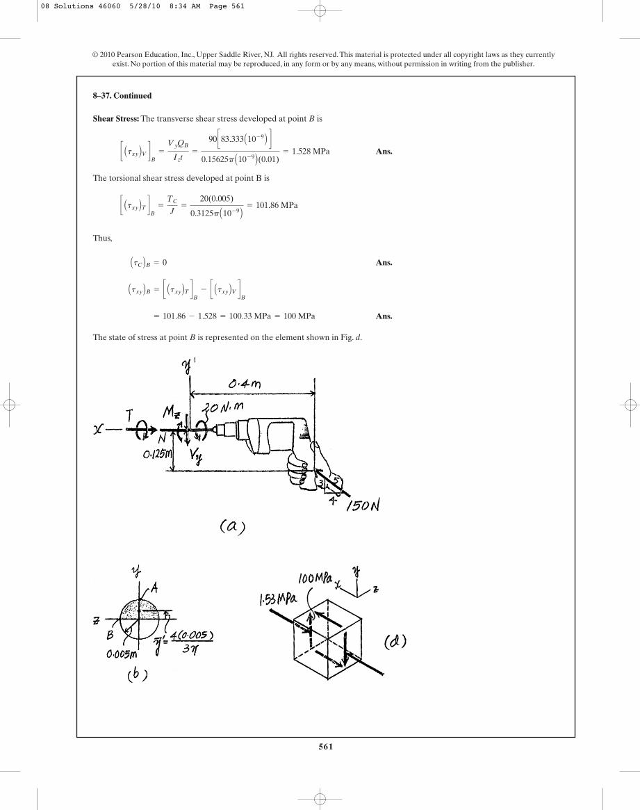
•8–37. The drill is jammed in the wall and is subjected tothe torque and force shown. Determine the state of stress atpoint B on the cross section of drill bit at section a–a.
© 2010 Pearson Education, Inc., Upper Saddle River, NJ. All rights reserved. This material is protected under all copyright laws as they currentlyexist. No portion of this material may be reproduced, in any form or by any means, without permission in writing from the publisher.
150 N
34
5
125 mm
20 N·m
400 mm
a
a
5 mm
B
A
Section a – a
z
x
y
y
©Mx = 0; 20 - T = 0 T = 20 N # m
Section Properties: The cross-sectional area, the moment of inertia about the z axis,and the polar moment of inertia of the drill’s cross section are
Referring to Fig. b, QB is
Normal Stress: The normal stress is a combination of axial and bending stress. Thus,
For point B, . Then
Ans.sB =
-120
25p A10- 6 B- 0 = -1.528 MPa = 1.53 MPa(C)
y = 0
s =
N
A-
Mzy
Iz
QB = y¿A¿ =
4(0.005)
3p cp
2 A0.0052 B d = 83.333 A10- 9 B m3
J =
p
2 A0.0054 B = 0.3125p A10- 9 B m4
Iz =
p
4 A0.0054 B = 0.15625p A10- 9 B m4
A = p A0.0052 B = 25p A10- 6 B m2
Mz = 21 N # m
©Mz = 0; -150a35b(0.4) + 150a
45b(0.125) + Mz = 0
08 Solutions 46060 5/28/10 8:34 AM Page 560
561
© 2010 Pearson Education, Inc., Upper Saddle River, NJ. All rights reserved. This material is protected under all copyright laws as they currentlyexist. No portion of this material may be reproduced, in any form or by any means, without permission in writing from the publisher.
Shear Stress: The transverse shear stress developed at point B is
Ans.
The torsional shear stress developed at point B is
Thus,
Ans.
Ans.
The state of stress at point B is represented on the element shown in Fig. d.
= 101.86 - 1.528 = 100.33 MPa = 100 MPa
Atxy BB = c Atxy BT dB
- c Atxy BV dB
AtC BB = 0
c Atxy BT dB
=
TC
J=
20(0.005)
0.3125p A10- 9 B= 101.86 MPa
c Atxy BV dB
=
VyQB
Izt=
90 c83.333 A10- 9 B d
0.15625p A10- 9 B(0.01)= 1.528 MPa
8–37. Continued
08 Solutions 46060 5/28/10 8:34 AM Page 561
562
© 2010 Pearson Education, Inc., Upper Saddle River, NJ. All rights reserved. This material is protected under all copyright laws as they currentlyexist. No portion of this material may be reproduced, in any form or by any means, without permission in writing from the publisher.
Support Reactions: As shown on FBD.
Internal Force and Moment:
a
Section Properties:
Normal Stress: Requires
Ans. T = 2160 lb = 2.16 kip
0 =
-T
216+
(21600 - 7T)(9)
5832
sA = 0 =
N
A+
Mc
I
sA = 0
I =
112
(12) A183 B = 5832 in4
A = 18(12) = 216 in2
M = 21600 - 7T
+ ©Mo = 0; M + T(7) - 900(24) = 0
:+ ©Fx = 0; T - N = 0 N = T
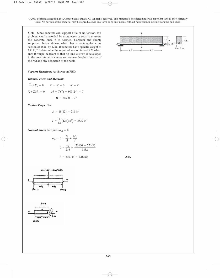
8–38. Since concrete can support little or no tension, thisproblem can be avoided by using wires or rods to prestressthe concrete once it is formed. Consider the simplysupported beam shown, which has a rectangular crosssection of 18 in. by 12 in. If concrete has a specific weight of
determine the required tension in rod AB, whichruns through the beam so that no tensile stress is developedin the concrete at its center section a–a. Neglect the size ofthe rod and any deflection of the beam.
150 lb>ft3,
16 in.
4 ft 4 fta
a
A B18 in.
6 in. 6 in.
2 in.
08 Solutions 46060 5/28/10 8:34 AM Page 562
563
© 2010 Pearson Education, Inc., Upper Saddle River, NJ. All rights reserved. This material is protected under all copyright laws as they currentlyexist. No portion of this material may be reproduced, in any form or by any means, without permission in writing from the publisher.
Support Reactions: As shown on FBD.
Section Properties:
Internal Force and Moment:
a
Normal Stress: Requires
Ans. T = 2163.08 lb = 2.16 kip
0 =
-T
217.3854+
(21600 - 6.9554T)(8.9554)
5899.45
sA = 0 =
N
A+
Mc
I
sA = 0
M = 21600 - 6.9554T
+ ©Mo = 0; M + T(6.9554) - 900(24) = 0
:+ ©Fx = 0; T - N = 0 N = T
= 5899.45 in4
I =
112
(12) A183 B + 12(18)(9.04461 - 9)2+ 1.3854(16 - 9.04461)2
y =
©yA
©A=
9(18)(12) + 16(1.3854)
217.3854= 9.04461 in.
A = 18(12) + 1.3854 = 217.3854 in2
Acon = (n - 1)Aat = (8.0556 - 1)ap
4b A0.52 B = 1.3854 in2
n =
Est
Econ=
29(103)
3.6(103)= 8.0556
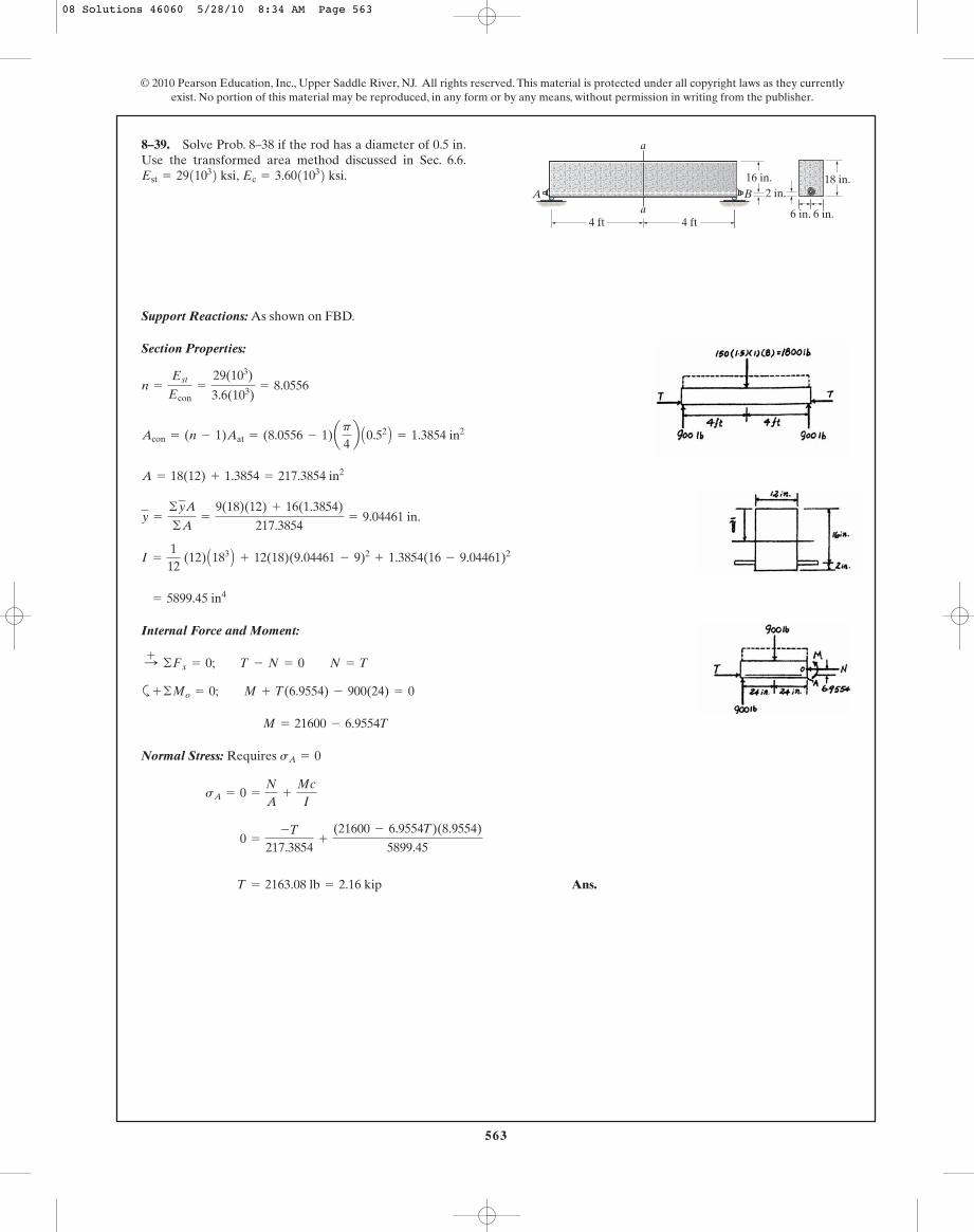
8–39. Solve Prob. 8–38 if the rod has a diameter of 0.5 in.Use the transformed area method discussed in Sec. 6.6.
Ec = 3.6011032 ksi.Est = 2911032 ksi, 16 in.
4 ft 4 fta
a
A B18 in.
6 in. 6 in.
2 in.
08 Solutions 46060 5/28/10 8:34 AM Page 563
564
© 2010 Pearson Education, Inc., Upper Saddle River, NJ. All rights reserved. This material is protected under all copyright laws as they currentlyexist. No portion of this material may be reproduced, in any form or by any means, without permission in writing from the publisher.
Support Reactions:
a
Internal Forces and Moment:
a
Section Properties:
Normal Stress:
Ans.
Shear Stress: Applying shear formula.
Ans. =
0.6667(103) C0.405(10- 3) D82.8(10- 6)(0.015)
= 0.217 MPa
tA =
VQA
It
= 0.444 MPa (T)
sA =
4.00(103)
9.00(10- 3)+
0.6667(103)(0)
82.8(10- 6)
s =
N
A;
My
I
= 0.405 A10- 3 B m3
QA = ©y¿A¿ = 0.11(0.15)(0.02) + 0.05(0.1)(0.015)
I =
112
(0.15) A0.243 B -
112
(0.135) A0.23 B = 82.8 A10- 6 B m4
A = 0.24(0.15) - 0.2(0.135) = 9.00 A10- 3 B m2
+ ©Mo = 0; M - 0.6667(1) = 0 M = 0.6667 kN # m
+ c ©Fy = 0; V - 0.6667 = 0 V = 0.6667 kN
:+ ©Fx = 0; 4.00 - N = 0 N = 4.00 kN
:+ ©Fx = 0; Cx - 4 = 0 Cx = 4.00 kN
Cy = 0.6667 kN
+ ©MD = 0; 4(0.625) - Cy (3.75) = 0
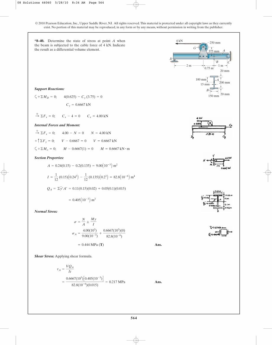
*8–40. Determine the state of stress at point A whenthe beam is subjected to the cable force of 4 kN. Indicatethe result as a differential volume element.
2 m0.75 m
1 m
4 kN
G
250 mm
375 mm
B CD
A
200 mm
20 mm
20 mm150 mm
15 mmA
B
100 mm
08 Solutions 46060 5/28/10 8:34 AM Page 564
565
© 2010 Pearson Education, Inc., Upper Saddle River, NJ. All rights reserved. This material is protected under all copyright laws as they currentlyexist. No portion of this material may be reproduced, in any form or by any means, without permission in writing from the publisher.
Support Reactions:
a
Internal Forces and Moment:
a
Section Properties:
Normal Stress:
Ans.
Shear Stress: Since , then
Ans.tB = 0
QB = 0
= -0.522 MPa = 0.522 MPa (C)
sB =
4.00(103)
9.00(10- 3)-
0.6667(103)(0.12)
82.8(10- 6)
s =
N
A;
My
I
QB = 0
I =
112
(0.15) A0.243 B -
112
(0.135) A0.23 B = 82.8 A10- 6 B m
A = 0.24(0.15) - 0.2(0.135) = 9.00 A10- 3 B m2
+ ©Mo = 0; M - 0.6667(1) = 0 M = 0.6667 kN # m
+ c ©Fy = 0; V - 0.6667 = 0 V = 0.6667 kN
:+ ©Fx = 0; 4.00 - N = 0 N = 4.00 kN
:+ ©Fx = 0; Cx - 4 = 0 Cx = 4.00 kN
Cy = 0.6667 kN
+ ©MD = 0; 4(0.625) - Cy (3.75) = 0
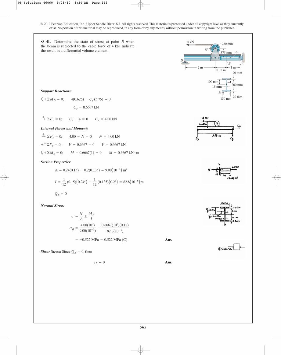
•8–41. Determine the state of stress at point B whenthe beam is subjected to the cable force of 4 kN. Indicatethe result as a differential volume element.
2 m0.75 m
1 m
4 kN
G
250 mm
375 mm
B CD
A
200 mm
20 mm
20 mm150 mm
15 mmA
B
100 mm
08 Solutions 46060 5/28/10 8:34 AM Page 565

566
© 2010 Pearson Education, Inc., Upper Saddle River, NJ. All rights reserved. This material is protected under all copyright laws as they currentlyexist. No portion of this material may be reproduced, in any form or by any means, without permission in writing from the publisher.
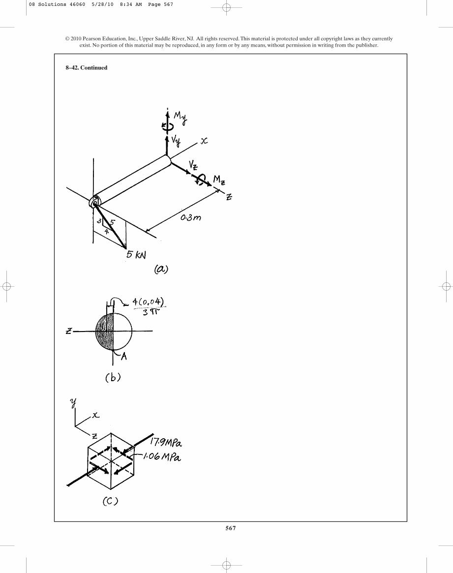
Consider the equilibrium of the FBD of bar’s left cut segment shown in Fig. a,
Referring to Fig. b,
The normal stress is contributed by bending stress only. Thus,
For point A, and . Then
Ans.
The transverse shear stress developed at point A is
Ans.
Ans.
The state of stress for point A can be represented by the volume element shown inFig. c,
= 1.061(106) Pa = 1.06 MPa
Atxz Bv =
Vz(Qz)A
Iy t=
4(103) C42.67(10- 6) D0.64(10- 6)p (0.08)
Atxy Bv =
Vy(Qy)A
Iz t= 0
s = - -0.9(103)(-0.04)
0.64(10- 6)p+ 0 = -17.90(106)Pa = 17.9 MPa (C)
z = 0y = -0.04 m
s = -
Mzy
Iz+
Myz
Iy
(Qz)A = z¿A¿ =
4(0.04)
3p cp
2 (0.042) d = 42.67(10- 6) m3
(Qy)A = 0
Iy = It =
p
4 (0.044) = 0.64(10- 6)p m4
©Mz = 0; Mz + 5a35b(0.3) = 0 Mz = -0.9 kN # m
©My = 0; My + 5a45b(0.3) = 0 My = -1.2 kN # m
©Fz = 0; Vz + 5a45b = 0 Vz = -4 kN
©Fy = 0; Vy - 5a35b = 0 Vy = 3 kN
8–42. The bar has a diameter of 80 mm. Determine thestress components that act at point A and show the resultson a volume element located at this point.
300 mm
200 mm
BA
5 kN
43 5
08 Solutions 46060 5/28/10 8:34 AM Page 566
567
© 2010 Pearson Education, Inc., Upper Saddle River, NJ. All rights reserved. This material is protected under all copyright laws as they currentlyexist. No portion of this material may be reproduced, in any form or by any means, without permission in writing from the publisher.
8–42. Continued
08 Solutions 46060 5/28/10 8:34 AM Page 567
568
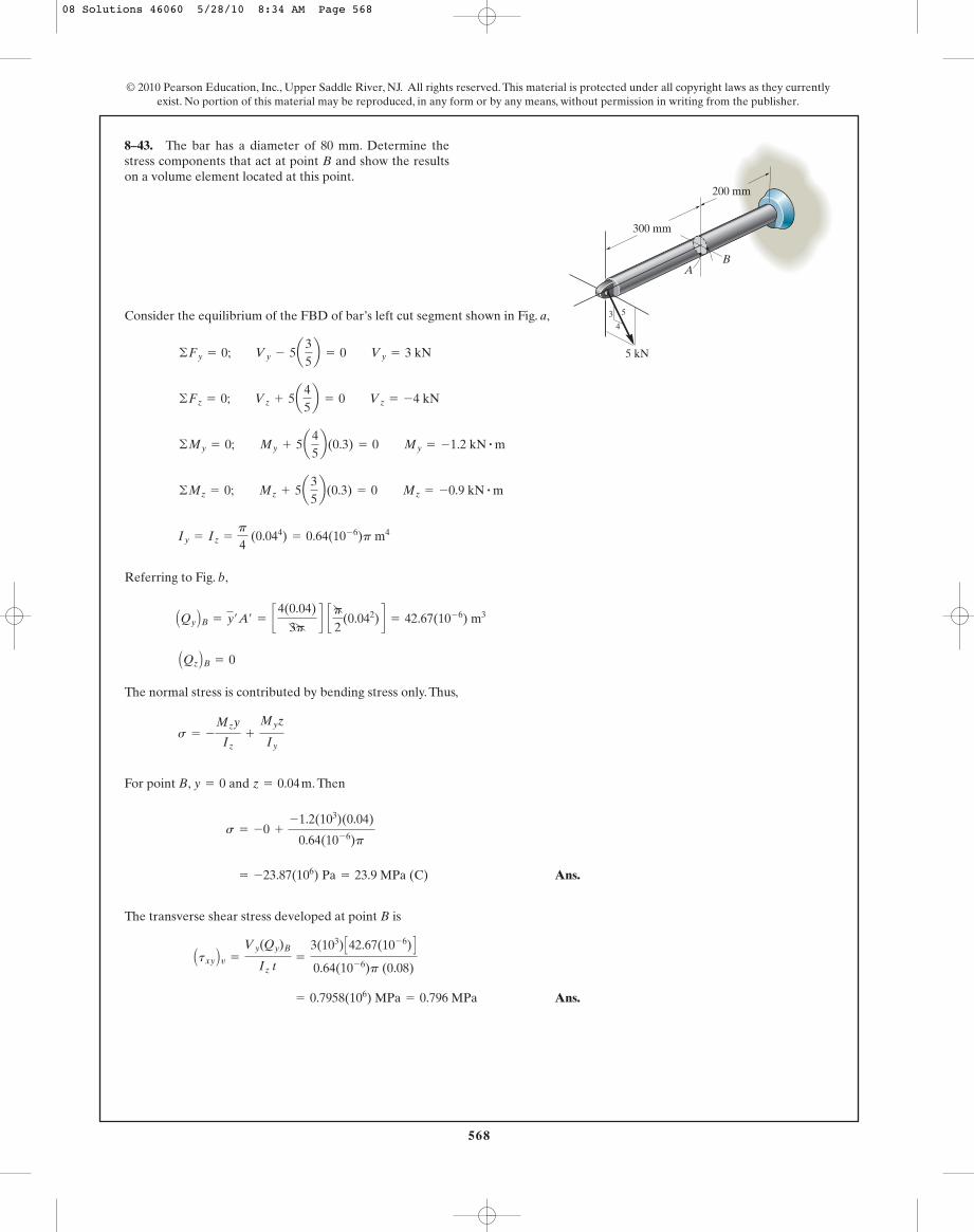
Consider the equilibrium of the FBD of bar’s left cut segment shown in Fig. a,
Referring to Fig. b,
The normal stress is contributed by bending stress only. Thus,
For point B, and . Then
Ans.
The transverse shear stress developed at point B is
Ans. = 0.7958(106) MPa = 0.796 MPa
Atxy Bv =
Vy(Qy)B
Iz t=
3(103) C42.67(10- 6) D0.64(10- 6)p (0.08)
= -23.87(106) Pa = 23.9 MPa (C)
s = -0 +
-1.2(103)(0.04)
0.64(10- 6)p
z = 0.04 my = 0
s = -
Mzy
Iz+
Myz
Iy
AQz BB = 0
AQy BB = y¿A¿ = c4(0.04)
3pd cp
2(0.042) d = 42.67(10- 6) m3
Iy = Iz =
p
4 (0.044) = 0.64(10- 6)p m4
©Mz = 0; Mz + 5a35b(0.3) = 0 Mz = -0.9 kN # m
©My = 0; My + 5a45b(0.3) = 0 My = -1.2 kN # m
©Fz = 0; Vz + 5a45b = 0 Vz = -4 kN
©Fy = 0; Vy - 5a35b = 0 Vy = 3 kN
8–43. The bar has a diameter of 80 mm. Determine thestress components that act at point B and show the resultson a volume element located at this point.
© 2010 Pearson Education, Inc., Upper Saddle River, NJ. All rights reserved. This material is protected under all copyright laws as they currentlyexist. No portion of this material may be reproduced, in any form or by any means, without permission in writing from the publisher.
300 mm
200 mm
BA
5 kN
43 5
08 Solutions 46060 5/28/10 8:34 AM Page 568

569
© 2010 Pearson Education, Inc., Upper Saddle River, NJ. All rights reserved. This material is protected under all copyright laws as they currentlyexist. No portion of this material may be reproduced, in any form or by any means, without permission in writing from the publisher.
Ans.
The state of stress for point B can be represented by the volume element shown inFig. c
Atxz Bv =
Vz (Qz)B
Iy t= 0
8–43. Continued
08 Solutions 46060 5/28/10 8:34 AM Page 569
570
© 2010 Pearson Education, Inc., Upper Saddle River, NJ. All rights reserved. This material is protected under all copyright laws as they currentlyexist. No portion of this material may be reproduced, in any form or by any means, without permission in writing from the publisher.
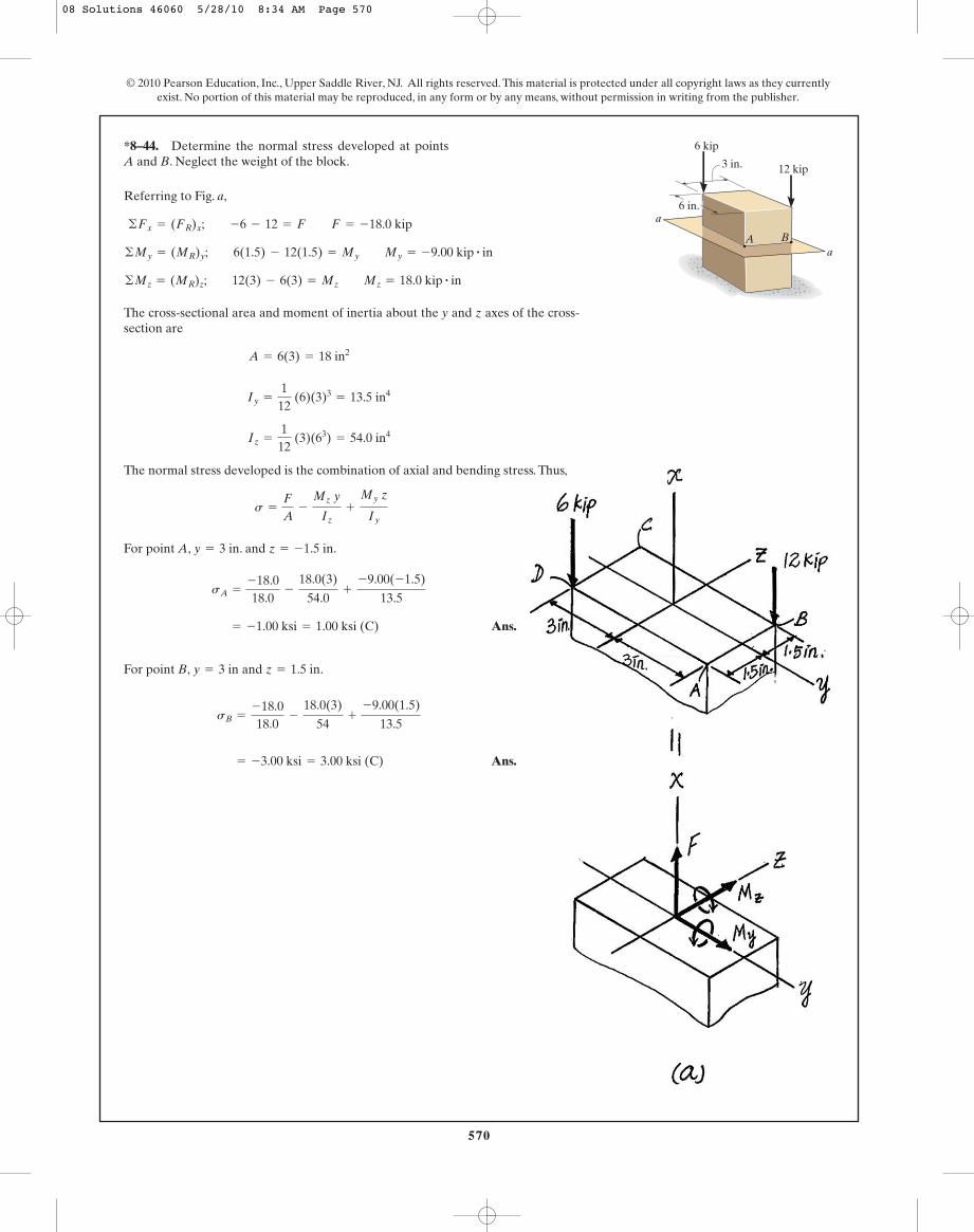
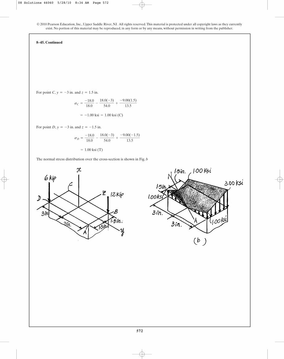
*8–44. Determine the normal stress developed at points A and B. Neglect the weight of the block.
a
a
6 in.
6 kip
12 kip3 in.
A B
Referring to Fig. a,
The cross-sectional area and moment of inertia about the y and z axes of the cross-section are
The normal stress developed is the combination of axial and bending stress. Thus,
For point A, . and .
Ans.
For point B, and .
Ans. = -3.00 ksi = 3.00 ksi (C)
sB =
-18.018.0
-
18.0(3)
54+
-9.00(1.5)
13.5
z = 1.5 iny = 3 in
= -1.00 ksi = 1.00 ksi (C)
sA =
-18.018.0
-
18.0(3)
54.0+
-9.00(-1.5)
13.5
z = -1.5 iny = 3 in
s =
F
A-
Mz y
Iz+
My z
Iy
Iz =
112
(3)(63) = 54.0 in4
Iy =
112
(6)(3)3= 13.5 in4
A = 6(3) = 18 in2
©Mz = (MR)z; 12(3) - 6(3) = Mz Mz = 18.0 kip # in
©My = (MR)y; 6(1.5) - 12(1.5) = My My = -9.00 kip # in
©Fx = (FR)x; -6 - 12 = F F = -18.0 kip
08 Solutions 46060 5/28/10 8:34 AM Page 570
571
© 2010 Pearson Education, Inc., Upper Saddle River, NJ. All rights reserved. This material is protected under all copyright laws as they currentlyexist. No portion of this material may be reproduced, in any form or by any means, without permission in writing from the publisher.
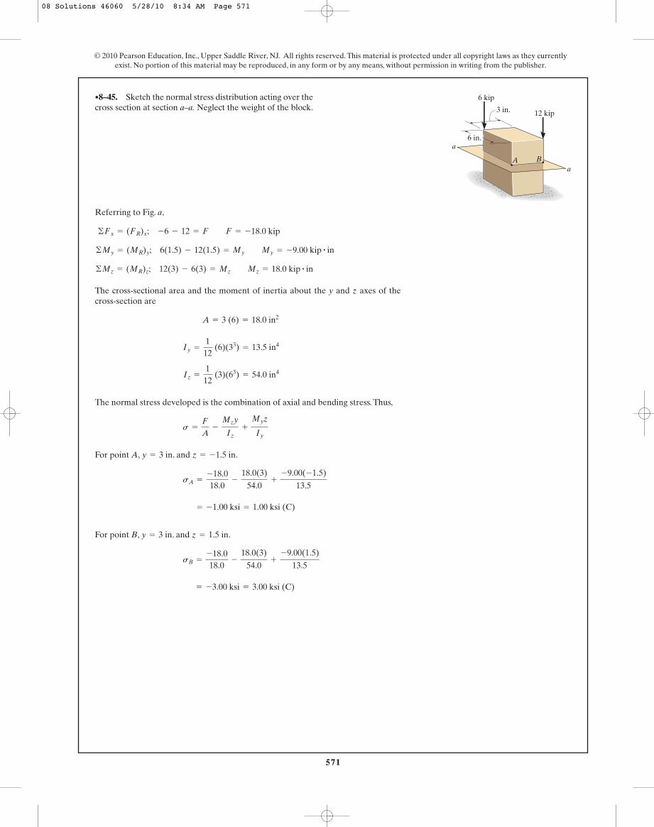
Referring to Fig. a,
The cross-sectional area and the moment of inertia about the y and z axes of thecross-section are
The normal stress developed is the combination of axial and bending stress. Thus,
For point A, . and .
For point B, . and .
= -3.00 ksi = 3.00 ksi (C)
sB =
-18.018.0
-
18.0(3)
54.0+
-9.00(1.5)
13.5
z = 1.5 iny = 3 in
= -1.00 ksi = 1.00 ksi (C)
sA =
-18.018.0
-
18.0(3)
54.0+
-9.00(-1.5)
13.5
z = -1.5 iny = 3 in
s =
F
A-
Mzy
Iz+
Myz
Iy
Iz =
112
(3)(63) = 54.0 in4
Iy =
112
(6)(33) = 13.5 in4
A = 3 (6) = 18.0 in2
©Mz = (MR)z; 12(3) - 6(3) = Mz Mz = 18.0 kip # in
©My = (MR)y; 6(1.5) - 12(1.5) = My My = -9.00 kip # in
©Fx = (FR)x; -6 - 12 = F F = -18.0 kip
•8–45. Sketch the normal stress distribution acting over thecross section at section a–a. Neglect the weight of the block.
a
a
6 in.
6 kip
12 kip3 in.
A B
08 Solutions 46060 5/28/10 8:34 AM Page 571
572
For point C, and .
For point D, . and .
The normal stress distribution over the cross-section is shown in Fig. b
= 1.00 ksi (T)
sD =
-18.018.0
-
18.0(-3)
54.0+
-9.00(-1.5)
13.5
z = -1.5 iny = -3 in
= -1.00 ksi = 1.00 ksi (C)
sC =
-18.018.0
-
18.0(-3)
54.0+
-9.00(1.5)
13.5
z = 1.5 iny = -3 in.
8–45. Continued
© 2010 Pearson Education, Inc., Upper Saddle River, NJ. All rights reserved. This material is protected under all copyright laws as they currentlyexist. No portion of this material may be reproduced, in any form or by any means, without permission in writing from the publisher.
08 Solutions 46060 5/28/10 8:34 AM Page 572

573
© 2010 Pearson Education, Inc., Upper Saddle River, NJ. All rights reserved. This material is protected under all copyright laws as they currentlyexist. No portion of this material may be reproduced, in any form or by any means, without permission in writing from the publisher.
Section Properties:
Internal Forces and Moment: As shown on FBD.
Normal Stress:
[1]
[2]
In order to have maximum normal stress, .
Since , then
2a - 4x = 0 x = 0.500a
P
a(a + x)3 Z 0
- P
a(a + x)3 (2a - 4x) = 0
dsA
dx= -
Pa
B (a + x)2(4) - (4x + a)(2)(a + x)(1)
(a + x)4 R = 0
dsA
dx= 0
=
Pa
B 2x - a
(a + x)2R
sB =
Pa
B -1a + x
+
3x
(a + x)2R = -
Pa
B 4x + a
(a + x)2R sA = -
Pa
B 1a + x
+
3x
(a + x)2R
=
Pa
B -1a + x
;
3x
(a + x)2R
=
-P
a(a + x);
0.5Px C12 (a + x) Da12 (a + x)3
s =
N
A;
Mc
I
I =
112
(a) (a + x)3=
a
12 (a + x)3
A = a(a + x)
w = a + x
8–46. The support is subjected to the compressive load P.Determine the absolute maximum and minimum normalstress acting in the material.
P
a—2
a—2
a—2
a—2
08 Solutions 46060 5/28/10 8:34 AM Page 573

574
Substituting the result into Eq. [1] yields
Ans.
In order to have minimum normal stress, .
Since , then
Substituting the result into Eq. [2] yields
Ans.smin =
Pa
B2(2a) - a
(a + 2a)2 R =
P
3a2 (T)
4a - 2x = 0 x = 2a
P
a(a + x)3 Z 0
P
a(a + x)3 (4a - 2x) = 0
dsB
dx=
Pa
B (a + x)2 (2) - (2x - a)(2)(a + x)(1)
(a + x)4 R = 0
dsB
dx= 0
= - 1.33P
a2 =
1.33P
a2 (C)
smax = - Pa
B4(0.500a) + a
(a + 0.5a)2 R
8–46. Continued
© 2010 Pearson Education, Inc., Upper Saddle River, NJ. All rights reserved. This material is protected under all copyright laws as they currentlyexist. No portion of this material may be reproduced, in any form or by any means, without permission in writing from the publisher.
08 Solutions 46060 5/28/10 8:34 AM Page 574

575
© 2010 Pearson Education, Inc., Upper Saddle River, NJ. All rights reserved. This material is protected under all copyright laws as they currentlyexist. No portion of this material may be reproduced, in any form or by any means, without permission in writing from the publisher.
r
P
Section Properties:
Internal Force and Moment: As shown on FBD.
Normal Stress:
[1]
[2]
In order to have maximum normal stress, .
Since , then
Substituting the result into Eq. [1] yields
Ans. = -
0.368P
r2 =
0.368P
r2 (C)
smax = -
PpB r + 2.5(0.400r)
[r + 0.5(0.400r)]3R
r - 2.5x = 0 x = 0.400r
P
p(r + 0.5x)4 Z 0
-
P
p(r + 0.5x)4 (r - 2.5x) = 0
dsA
dx= -
Pp
B (r + 0.5x)3 (2.5) - (r + 2.5x)(3)(r + 0.5x)2
(0.5)
(r + 0.5x)6R = 0
dsA
dx= 0
=
Pp
B 1.5x - r
(r + 0.5x)3R
sB =
Pp
B –1(r + 0.5x)2 +
2x
(r + 0.5x)3R
= -
Pp
B r + 2.5x
(r + 0.5x)3R
sA = -
Pp
B 1(r + 0.5x)2 +
2x
(r + 0.5x)3R
=
Pp
B –1(r + 0.5x)2 ;
2x
(r + 0.5x)3R
=
–P
p(r + 0.5x)2 ;
0.5Px(r + 0.5x)p4 (r + 0.5)4
s =
N
A;
Mc
I
I =
p
4 (r + 0.5x)4
A = p(r + 0.5x)2
d¿ = 2r + x
8–47. The support is subjected to the compressive load P.Determine the maximum and minimum normal stress actingin the material. All horizontal cross sections are circular.
08 Solutions 46060 5/28/10 8:34 AM Page 575
576
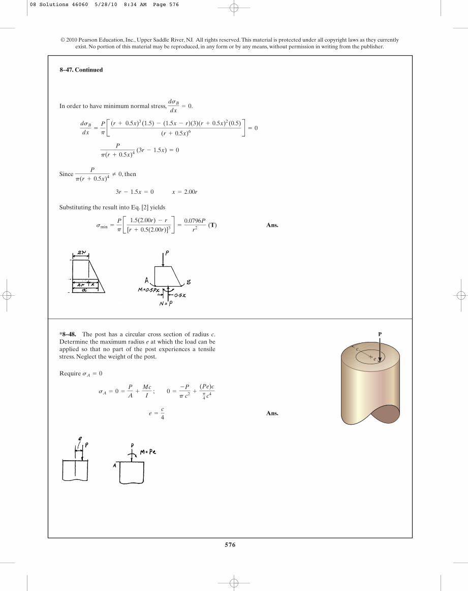
8–47. Continued
© 2010 Pearson Education, Inc., Upper Saddle River, NJ. All rights reserved. This material is protected under all copyright laws as they currentlyexist. No portion of this material may be reproduced, in any form or by any means, without permission in writing from the publisher.
In order to have minimum normal stress, .
Since , then
Substituting the result into Eq. [2] yields
Ans.smin =
Pp
B 1.5(2.00r) - r
[r + 0.5(2.00r)]3R =
0.0796P
r2 (T)
3r - 1.5x = 0 x = 2.00r
P
p(r + 0.5x)4 Z 0
P
p(r + 0.5x)4 (3r - 1.5x) = 0
dsB
dx=
Pp
B (r + 0.5x)3 (1.5) - (1.5x - r)(3)(r + 0.5x)2
(0.5)
(r + 0.5x)6R = 0
dsB
dx= 0
*8–48. The post has a circular cross section of radius c.Determine the maximum radius e at which the load can beapplied so that no part of the post experiences a tensilestress. Neglect the weight of the post.
P
c
e
Require
Ans.e =
c
4
sA = 0 =
P
A+
Mc
I ; 0 =
-P
p c2 +
(Pe)cp4 c4
sA = 0
08 Solutions 46060 5/28/10 8:34 AM Page 576

577
© 2010 Pearson Education, Inc., Upper Saddle River, NJ. All rights reserved. This material is protected under all copyright laws as they currentlyexist. No portion of this material may be reproduced, in any form or by any means, without permission in writing from the publisher.
Section Properties: The location of the neutral surface from the center ofcurvature of the rod, Fig. a, can be determined from
where A = p A0.0062 B = 36p A10- 6 B m2
R =
A
©
LA dAr
•8–49. If the baby has a mass of 5 kg and his center ofmass is at G, determine the normal stress at points A and Bon the cross section of the rod at section a–a. There are tworods, one on each side of the cradle.
Section a–a
75 mm 6 mmG
500 mm
15�
aA Ba
©
LA dAr
= 2p¢r - 2r2- c2≤ = 2p¢0.081 - 20.0812
- 0.0062≤ = 1.398184 A10- 3 Bm
Thus,
Then
Internal Loadings: Consider the equilibrium of the free-body diagram of thecradle’s upper segment, Fig. b,
a
Normal Stress: The normal stress is the combination of axial and bending stress.Thus,
Here, (negative) since it tends to increase the curvature of therod. For point A, . Then,
Ans.
For point B, . Then,
Ans.
LA dAr
= 0.25 ln 54
= 0.055786
= 79.3 kPa (T)
sB =
-24.525
36p A10- 6 B+
-14.2463(0.080889 - 0.087)
36p A10- 6 B(0.111264) A10- 3 B(0.087)
r = rB = 0.087 m
= -89.1 MPa = 89.1 MPa (C)
sA =
-24.525
36p A10- 6 B+
-14.2463(0.080889 - 0.075)
36p A10- 6 B(0.111264) A10- 3 B(0.075)
r = rA = 0.075 mM = -14.1747
s =
N
A+
M(R - r)
Aer
+ ©MO = 0; 5(9.81)(0.5+ 0.080889) - 2M = 0 M = 14.2463 N # m
N = -24.525 N-5(9.81) - 2N = 0+ c ©Fy = 0;
e = r - R = 0.081 - 0.080889 = 0.111264 A10- 3 B m
R =
36p A10- 6 B
1.398184 A10- 3 B= 0.080889 m
08 Solutions 46060 5/28/10 8:34 AM Page 577
578
© 2010 Pearson Education, Inc., Upper Saddle River, NJ. All rights reserved. This material is protected under all copyright laws as they currentlyexist. No portion of this material may be reproduced, in any form or by any means, without permission in writing from the publisher.
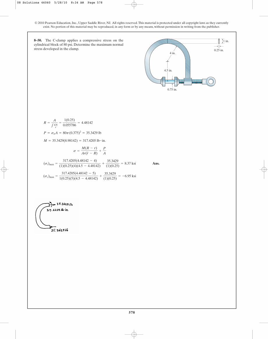
Ans.
(sc)max =
317.4205(4.48142 - 5)
1(0.25)(5)(4.5 - 4.48142)+
35.3429(1)(0.25)
= -6.95 ksi
(st)max =
317.4205(4.48142 - 4)
(1)(0.25)(4)(4.5 - 4.48142)+
35.3429(1)(0.25)
= 8.37 ksi
s =
M(R - r)
Ar(r - R)+
P
A
M = 35.3429(8.98142) = 317.4205 lb # in.
P = sbA = 80p (0.375)2= 35.3429 lb
R =
A
1 dAr
=
1(0.25)
0.055786= 4.48142
8–50. The C-clamp applies a compressive stress on thecylindrical block of 80 psi. Determine the maximum normalstress developed in the clamp.
0.75 in.
4 in.
1 in.
4.5 in.
0.25 in.
08 Solutions 46060 5/28/10 8:34 AM Page 578

579
© 2010 Pearson Education, Inc., Upper Saddle River, NJ. All rights reserved. This material is protected under all copyright laws as they currentlyexist. No portion of this material may be reproduced, in any form or by any means, without permission in writing from the publisher.
Equivalent Force System: As shown on FBD.
Section Properties:
Normal Stress:
At point A where and , we require .
Ans.
When
When
Repeat the same procedures for point B, C and D. The region where P can beapplied without creating tensile stress at points A, B, C and D is shown shaded in thediagram.
ey = 0, ez 6
518
a
ez = 0, ey 6
56
a
6ey + 18ez 6 5a
0 7 -5a+ 6ey + 18ez
0 7
P
30a4 C -5a2- 6(-a) ey + 18(a) ez D
sA 6 0z = ay = -a
=
P
30a4 A -5a2- 6eyy + 18ez z B
=
-P
6a2 -
Peyy
5a4 +
Pez z53 a4
s =
N
A-
Mzy
Iz+
My z
Iy
=
53
a4
Iy =
112
(2a)(2a)3+ 2B 1
36 (2a) a3
+
12
(2a) aaa
3b
2R = 5a4
Iz =
112
(2a)(2a)3+ 2B 1
36 (2a) a3
+
12
(2a) aaa +
a
3b
2R
A = 2a(2a) + 2B12
(2a)aR = 6a2
8–51. A post having the dimensions shown is subjected tothe bearing load P. Specify the region to which this load canbe applied without causing tensile stress to be developed atpoints A, B, C, and D.
x
y
z
A
a a a a
a
a
Dez
eyBC
P
08 Solutions 46060 5/28/10 8:34 AM Page 579
580
© 2010 Pearson Education, Inc., Upper Saddle River, NJ. All rights reserved. This material is protected under all copyright laws as they currentlyexist. No portion of this material may be reproduced, in any form or by any means, without permission in writing from the publisher.
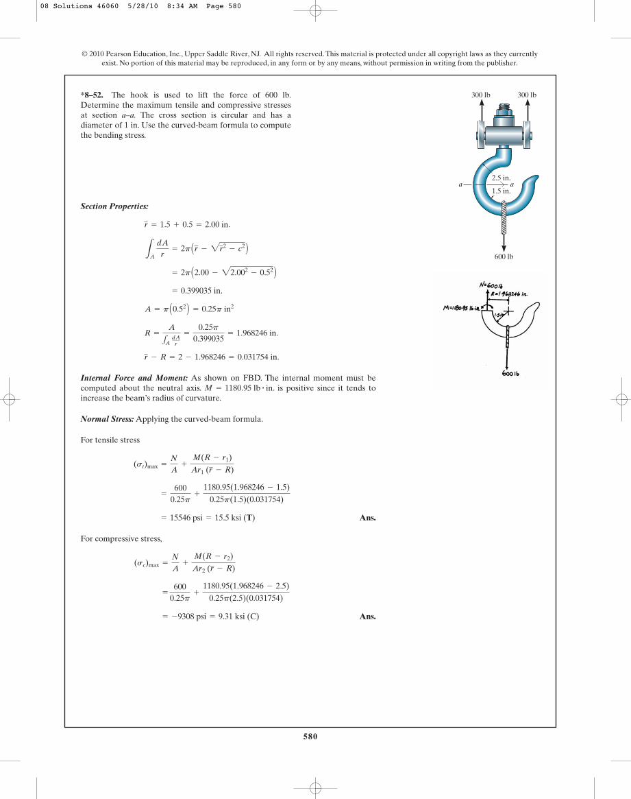
Section Properties:
Internal Force and Moment: As shown on FBD. The internal moment must becomputed about the neutral axis. . is positive since it tends toincrease the beam’s radius of curvature.
Normal Stress: Applying the curved-beam formula.
For tensile stress
Ans.
For compressive stress,
Ans. = -9308 psi = 9.31 ksi (C)
= 600
0.25p+
1180.95(1.968246 - 2.5)
0.25p(2.5)(0.031754)
(sc)max =
N
A+
M(R - r2)
Ar2 (r - R)
= 15546 psi = 15.5 ksi (T)
=
6000.25p
+
1180.95(1.968246 - 1.5)
0.25p(1.5)(0.031754)
(st)max =
N
A+
M(R - r1)
Ar1 (r - R)
M = 1180.95 lb # in
r - R = 2 - 1.968246 = 0.031754 in.
R =
A
1A dAr
=
0.25p0.399035
= 1.968246 in.
A = p A0.52 B = 0.25p in2
= 0.399035 in.
= 2p A2.00 - 22.002- 0.52 B
LA
dAr
= 2p Ar - 2r2- c2 B
r = 1.5 + 0.5 = 2.00 in.
*8–52. The hook is used to lift the force of 600 lb.Determine the maximum tensile and compressive stressesat section a–a. The cross section is circular and has adiameter of 1 in. Use the curved-beam formula to computethe bending stress.
aa2.5 in.
1.5 in.
300 lb 300 lb
600 lb
08 Solutions 46060 5/28/10 8:34 AM Page 580

581
© 2010 Pearson Education, Inc., Upper Saddle River, NJ. All rights reserved. This material is protected under all copyright laws as they currentlyexist. No portion of this material may be reproduced, in any form or by any means, without permission in writing from the publisher.
Normal Stress: Require
Ans.y = 0.75 - 1.5 x
0 = 0.148x + 0.0988y - 0.0741
0 =
-800(103)
13.5+
800(103)y(2.25)
22.78125+
800(103)x(1.5)
10.125
sA =
P
A+
Mxy
Ix+
Myx
Iy
sA = 0
Iy =
112
(4.5)(33) = 10.125 m4
Ix =
112
(3)(4.53) = 22.78125 m4
A = 3(4.5) = 13.5 m2
•8–53. The masonry pier is subjected to the 800-kN load.Determine the equation of the line along whichthe load can be placed without causing a tensile stress in thepier. Neglect the weight of the pier.
y = f1x2
2.25 m
2.25 m1.5 m
1.5 m
AB
C
y
xx
y
800 kN
08 Solutions 46060 5/28/10 8:34 AM Page 581
582
© 2010 Pearson Education, Inc., Upper Saddle River, NJ. All rights reserved. This material is protected under all copyright laws as they currentlyexist. No portion of this material may be reproduced, in any form or by any means, without permission in writing from the publisher.
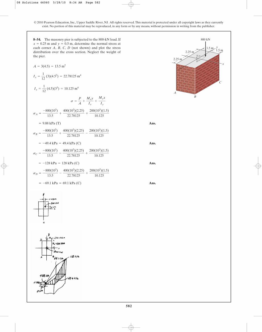
Ans.
Ans.
Ans.
Ans. = -69.1 kPa = 69.1 kPa (C)
sD =
-800(103)
13.5-
400(103)(2.25)
22.78125+
200(103)(1.5)
10.125
= -128 kPa = 128 kPa (C)
sC =
-800(103)
13.5-
400(103)(2.25)
22.78125+
200(103)(1.5)
10.125
= -49.4 kPa = 49.4 kPa (C)
sB =
-800(103)
13.5+
400(103)(2.25)
22.78125-
200(103)(1.5)
10.125
= 9.88 kPa (T)
sA =
-800(103)
13.5+
400(103)(2.25)
22.78125+
200(103)(1.5)
10.125
s =
P
A+
Mxy
Ix+
Myx
Iy
Iy =
112
(4.5)(33) = 10.125 m4
Ix =
112
(3)(4.53) = 22.78125 m4
A = 3(4.5) = 13.5 m2
8–54. The masonry pier is subjected to the 800-kN load. Ifand determine the normal stress at
each corner A, B, C, D (not shown) and plot the stressdistribution over the cross section. Neglect the weight ofthe pier.
y = 0.5 m,x = 0.25 m
2.25 m
2.25 m1.5 m
1.5 m
AB
C
y
xx
y
800 kN
08 Solutions 46060 5/28/10 8:34 AM Page 582

583
© 2010 Pearson Education, Inc., Upper Saddle River, NJ. All rights reserved. This material is protected under all copyright laws as they currentlyexist. No portion of this material may be reproduced, in any form or by any means, without permission in writing from the publisher.
Internal Forces and Moment:
Section Properties:
Normal Stress:
Ans.
Shear Stress: The tranverse shear stress in the z and y directions can be obtained
using the shear formula, .
Ans.
Ans.(txz)A = tVz= 0
= -0.318 MPa
(txy)A = -tVy= -
300 C5.333(10- 6) D40.0(10- 9)p (0.04)
tV =
VQ
It
= 11.9 MPa (T)
sA = 0 -
45.0(0)
40.0(10- 9)p+
75.0(0.02)
40.0(10- 9)p
s =
N
A-
Mzy
Iz+
Myz
Iy
(QA)y =
4(0.02)
3p c
12
p A0.022 B d = 5.333 A10- 6 B m3
(QA)z = 0
J =
p
2 A0.024 B = 80.0 A10- 9 B p m4
Ix = Iy =
p
4 A0.024 B = 40.0 A10- 9 B p m4
A = p A0.022 B = 0.400 A10- 3 B p m2
©Mz = 0; Mz - 300(0.15) = 0 Mz = 45.0 N # m
©My = 0; My - 500(0.15) = 0 My = 75.0 N # m
©Mx = 0; Tx = 0
©Fz = 0; Vz - 500 = 0 Vz = 500 N
©Fy = 0; Vy + 300 = 0 Vy = -300 N
©Fx = 0; Nx = 0
8–55. The bar has a diameter of 40 mm. If it is subjected tothe two force components at its end as shown, determinethe state of stress at point A and show the results on adifferential volume element located at this point. 100 mm
150 mm
y
x
z
BA
300 N
500 N
08 Solutions 46060 5/28/10 8:34 AM Page 583
584
© 2010 Pearson Education, Inc., Upper Saddle River, NJ. All rights reserved. This material is protected under all copyright laws as they currentlyexist. No portion of this material may be reproduced, in any form or by any means, without permission in writing from the publisher.
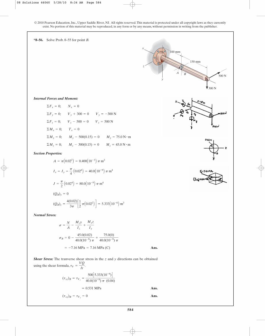
Internal Forces and Moment:
Section Properties:
Normal Strees:
Ans.
Shear Stress: The tranverse shear stress in the z and y directions can be obtained
using the shear formula, .
Ans.
Ans.(txy)B = tVy= 0
= 0.531 MPa
(txz)B = tVz=
500 C5.333(10- 6) D40.0(10- 9) p (0.04)
tV =
VQ
It
= -7.16 MPa = 7.16 MPa (C)
sB = 0 -
45.0(0.02)
40.0(10- 9) p+
75.0(0)
40.0(10- 9) p
s =
N
A-
Mzy
Iz+
Myz
Iy
(QB)z =
4(0.02)
3pc12
p A0.022 B d = 5.333 A10- 6 B m3
(QB)y = 0
J =
p
2 A0.024 B = 80.0 A10- 9 B p m4
Ix = Iy =
p
4 A0.024 B = 40.0 A10- 9 B p m4
A = p A0.022 B = 0.400 A10- 3 B p m2
©Mz = 0; Mz - 300(0.15) = 0 Mz = 45.0 N # m
©My = 0; My - 500(0.15) = 0 My = 75.0 N # m
©Mx = 0; Tx = 0
©Fz = 0; Vz - 500 = 0 Vz = 500 N
©Fy = 0; Vy + 300 = 0 Vy = -300 N
©Fx = 0; Nx = 0
*8–56. Solve Prob. 8–55 for point B.
100 mm
150 mm
y
x
z
BA
300 N
500 N
08 Solutions 46060 5/28/10 8:34 AM Page 584
585
© 2010 Pearson Education, Inc., Upper Saddle River, NJ. All rights reserved. This material is protected under all copyright laws as they currentlyexist. No portion of this material may be reproduced, in any form or by any means, without permission in writing from the publisher.
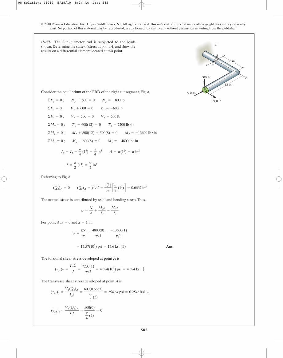
Consider the equilibrium of the FBD of the right cut segment, Fig. a,
Referring to Fig. b,
The normal stress is contributed by axial and bending stress. Thus,
For point A, and
Ans.
The torsional shear stress developed at point A is
The transverse shear stress developed at point A is.
(txy)g =
Vx(Qx)A
Izt=
500(0)
p
4 (2)
= 0
(tyz)g =
Vz(Qz)A
Ixt=
600(0.6667)
p
4 (2)
= 254.64 psi = 0.2546 ksi T
(tyz)T =
TyC
J=
7200(1)
p>2= 4.584(103) psi = 4.584 ksi T
= 17.57(103) psi = 17.6 ksi (T)
s =
800p
-
4800(0)
p>4-
-13600(1)
p>4
x = 1 in.z = 0
s =
N
A+
Mxz
Ix-
Mzx
Iz
(Qx)A = 0 (Qz)A = y¿A¿ =
4(1)
3p cp
2 (12) d = 0.6667 in3
J =
p
2 (14) =
p
2 in4
Ix = Iz =
p
4 (14) =
p
4 in4 A = p(12) = p in2
©Mx = 0 ; Mx + 600(8) = 0 Mx = -4800 lb # in
©Mz = 0 ; Mz + 800(12) + 500(8) = 0 Mz = -13600 lb # in
©My = 0 ; Ty - 600(12) = 0 Ty = 7200 lb # in
©Fx = 0 ; Vx - 500 = 0 Vx = 500 lb
©Fz = 0 ; Vz + 600 = 0 Vz = -600 lb
©Fy = 0 ; Ny + 800 = 0 Ny = -800 lb
•8–57. The 2-in.-diameter rod is subjected to the loadsshown. Determine the state of stress at point A, and show theresults on a differential element located at this point.
B
A
z
y
x
500 lb
12 in.
8 in.
800 lb
600 lb
08 Solutions 46060 5/28/10 8:34 AM Page 585
586
© 2010 Pearson Education, Inc., Upper Saddle River, NJ. All rights reserved. This material is protected under all copyright laws as they currentlyexist. No portion of this material may be reproduced, in any form or by any means, without permission in writing from the publisher.
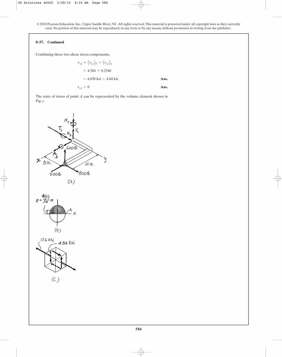
8–57. Continued
Combining these two shear stress components,
Ans.
Ans.
The state of stress of point A can be represented by the volume element shown inFig. c.
txy = 0
= 4.838 ksi = 4.84 ksi
= 4.584 + 0.2546
tyz = Atyz BT + Atyz Bg
08 Solutions 46060 5/28/10 8:34 AM Page 586
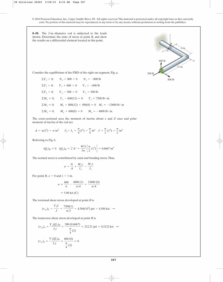
587
© 2010 Pearson Education, Inc., Upper Saddle River, NJ. All rights reserved. This material is protected under all copyright laws as they currentlyexist. No portion of this material may be reproduced, in any form or by any means, without permission in writing from the publisher.
Consider the equilibrium of the FBD of the right cut segment, Fig. a,
The cross-sectional area the moment of inertia about x and Z axes and polarmoment of inertia of the rod are
Referring to Fig. b,
The normal stress is contributed by axial and bending stress. Thus,
For point B, and
The torsional shear stress developed at point B is
The transverse shear stress developed at point B is.
(tyz)v =
Vz(Qz)B
Ixt=
600 (0)
p
4 (2)
= 0
(txy)v =
Vx(Qx)B
Izt=
500 (0.6667)
p
4 (2)
= 212.21 psi = 0.2122 ksi :
(txy)T =
TyC
J=
7200(1)
p>2= 4.584(103) psi = 4.584 ksi :
= 5.86 ksi (C)
s =
800p
-
4800 (1)
p>4+
13600 (0)
p>4
z = 1 in.x = 0
s =
N
A+
Mxz
Ix-
Mzx
Iz
(Qz)B = 0 (Qx)B = z¿A¿ =
4(1)
3p cp
2 (12) d = 0.6667 in4
A = p(12) = p in2 Ix¿
= Iz =
p
4(14) =
p
4 in4 J =
p
2 (14) =
p
2 in4
©Mx = 0; Mx + 600(8) = 0 Mx = -4800 lb # in.
©Mz = 0; Mz + 800(12) + 500(8) = 0 Mz = -13600 lb # in
©My = 0; Ty - 600(12) = 0 Ty = 7200 lb # in
©Fx = 0; Vx - 500 = 0 Vx = 500 lb
©Fz = 0; Vz + 600 = 0 Vz = -600 lb
©Fy = 0; Ny + 800 = 0 Ny = -800 lb
8–58. The 2-in.-diameter rod is subjected to the loadsshown. Determine the state of stress at point B, and showthe results on a differential element located at this point.
B
A
z
y
x
500 lb
12 in.
8 in.
800 lb
600 lb
08 Solutions 46060 5/28/10 8:34 AM Page 587
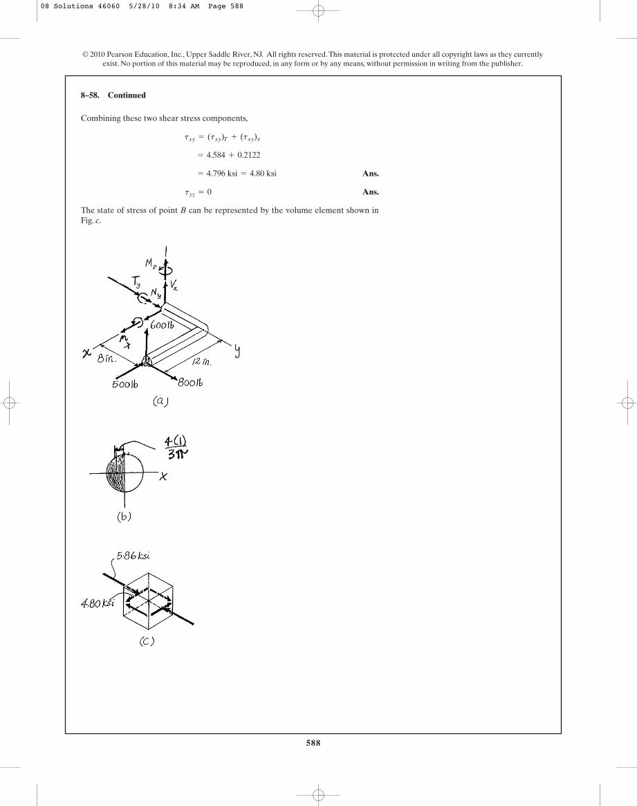
588
© 2010 Pearson Education, Inc., Upper Saddle River, NJ. All rights reserved. This material is protected under all copyright laws as they currentlyexist. No portion of this material may be reproduced, in any form or by any means, without permission in writing from the publisher.
Combining these two shear stress components,
Ans.
Ans.
The state of stress of point B can be represented by the volume element shown inFig. c.
tyz = 0
= 4.796 ksi = 4.80 ksi
= 4.584 + 0.2122
txy = (txy)T + (txy)v
8–58. Continued
08 Solutions 46060 5/28/10 8:34 AM Page 588
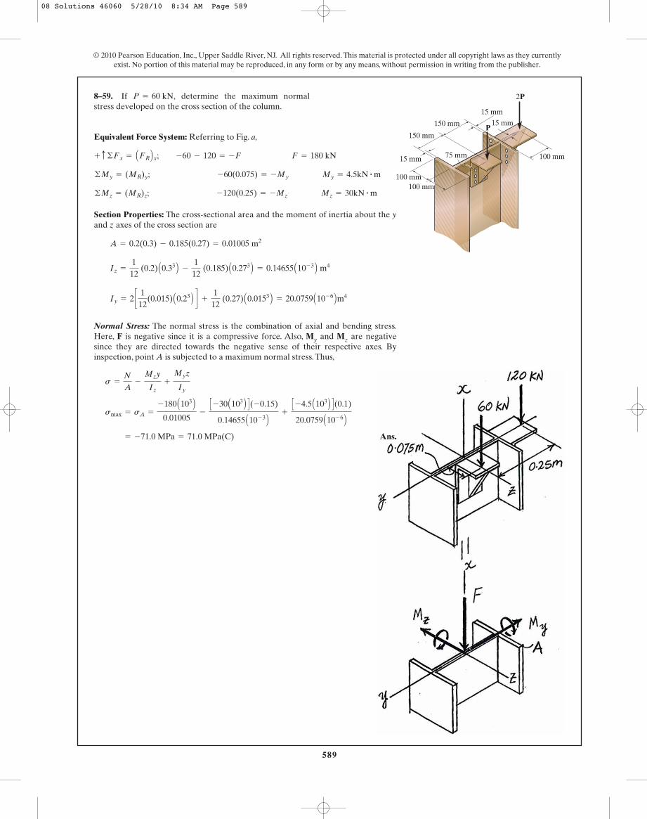
589
© 2010 Pearson Education, Inc., Upper Saddle River, NJ. All rights reserved. This material is protected under all copyright laws as they currentlyexist. No portion of this material may be reproduced, in any form or by any means, without permission in writing from the publisher.
8–59. If determine the maximum normalstress developed on the cross section of the column.
P = 60 kN,
100 mm
15 mm
15 mm
15 mm
75 mm
150 mm
150 mm
100 mm
100 mm
P
2P
Equivalent Force System: Referring to Fig. a,
Section Properties: The cross-sectional area and the moment of inertia about the yand z axes of the cross section are
Normal Stress: The normal stress is the combination of axial and bending stress.Here, F is negative since it is a compressive force. Also, My and Mz are negativesince they are directed towards the negative sense of their respective axes. Byinspection, point A is subjected to a maximum normal stress. Thus,
Ans. = -71.0 MPa = 71.0 MPa(C)
smax = sA =
-180 A103 B0.01005
-
C -30 A103 B D(-0.15)
0.14655 A10- 3 B+
C -4.5 A103 B D(0.1)
20.0759 A10- 6 B
s =
N
A-
Mzy
Iz+
Myz
Iy
Iy = 2 c1
12(0.015) A0.23 B d +
112
(0.27) A0.0153 B = 20.0759 A10- 6 Bm4
Iz =
112
(0.2) A0.33 B -
112
(0.185) A0.273 B = 0.14655 A10- 3 B m4
A = 0.2(0.3) - 0.185(0.27) = 0.01005 m2
©Mz = (MR)z; -120(0.25) = -Mz Mz = 30kN # m
©My = (MR)y; -60(0.075) = -My My = 4.5kN # m
+ c ©Fx = AFR Bx; -60 - 120 = -F F = 180 kN
08 Solutions 46060 5/28/10 8:34 AM Page 589
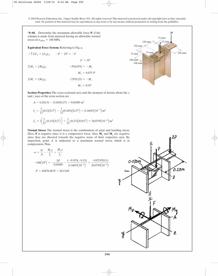
590
© 2010 Pearson Education, Inc., Upper Saddle River, NJ. All rights reserved. This material is protected under all copyright laws as they currentlyexist. No portion of this material may be reproduced, in any form or by any means, without permission in writing from the publisher.
*8–60. Determine the maximum allowable force P, if thecolumn is made from material having an allowable normalstress of sallow = 100 MPa.
100 mm
15 mm
15 mm
15 mm
75 mm
150 mm
150 mm
100 mm
100 mm
P
2P
Equivalent Force System: Referring to Fig. a,
Section Properties: The cross-sectional area and the moment of inertia about the yand z axes of the cross section are
Normal Stress: The normal stress is the combination of axial and bending stress.Here, F is negative since it is a compressive force. Also, My and Mz are negativesince they are directed towards the negative sense of their respective axes. Byinspection, point A is subjected to a maximum normal stress, which is incompression. Thus,
Iy = 2 c1
12 (0.15) A0.23 B d +
112
(0.27) A0.0153 B = 20.0759 A10- 6 B m4
Iz =
112
(0.2) A0.33 B -
112
(0.185) A0.273 B = 0.14655 A10- 3 B m4
A = 0.2(0.3) - 0.185(0.27) = 0.01005 m2
Mz = 0.5P
©Mz = (MR)z; -2P(0.25) = -Mz
My = 0.075 P
©My = (MR)y; -P(0.075) = -My
F = 3P
+ c ©Fx = (FR)x; -P - 2P = -F
Ans.P = 84470.40 N = 84.5 kN
-100 A106 B = -
3P
0.01005-
(-0.5P)(-0.15)
0.14655 A10- 3 B+
-0.075P(0.1)
20.0759 A10- 6 B
s =
N
A-
Mzy
Iz+
Myz
Iy
08 Solutions 46060 5/28/10 8:34 AM Page 590

591
© 2010 Pearson Education, Inc., Upper Saddle River, NJ. All rights reserved. This material is protected under all copyright laws as they currentlyexist. No portion of this material may be reproduced, in any form or by any means, without permission in writing from the publisher.
Ans.
Ans.
Ans.(tA)yz =
Vz(QA)x
It= 0
= -2843 psi = -2.84 ksi
=
125(0.08333)
0.049087 (1)-
600(0.5)
0.098175
=
Vx(QA)z
It-
Tyc
J
(tA)yx = (tA)V - (tA)twist
= 16202 psi = 16.2 ksi (T)
= -
750.7854
+
1600(0.5)
0.049087
(sA)y = - Ny
A+
Mx c
I
(QA)z =
4(0.5)
3p a
12b(p)(0.52) = 0.08333 in3
(QA)x = 0
I =
p
4 (0.54) = 0.049087 in4
J =
p
2 (0.54) = 0.098175 in4
A = p(0.52) = 0.7854 in2
©Mz = 0; Mz + 75(3) - 125(8) = 0; Mz = 775 lb # in.
©My = 0; 200(3) - Ty = 0; Ty = 600 lb # in.
©Mx = 0; 200(8) - Mx = 0; Mx = 1600 lb # in.
©Fz = 0; Vz - 200 = 0; Vz = 200 lb
©Fy = 0; 75 - Ny = 0; Ny = 75 lb
©Fx = 0; Vx - 125 = 0; Vx = 125 lb
•8–61. The beveled gear is subjected to the loads shown.Determine the stress components acting on the shaft atpoint A, and show the results on a volume element locatedat this point. The shaft has a diameter of 1 in. and is fixed tothe wall at C.
C
B
x
zy
A
200 lb
125 lb75 lb
8 in.
3 in.
08 Solutions 46060 5/28/10 8:34 AM Page 591
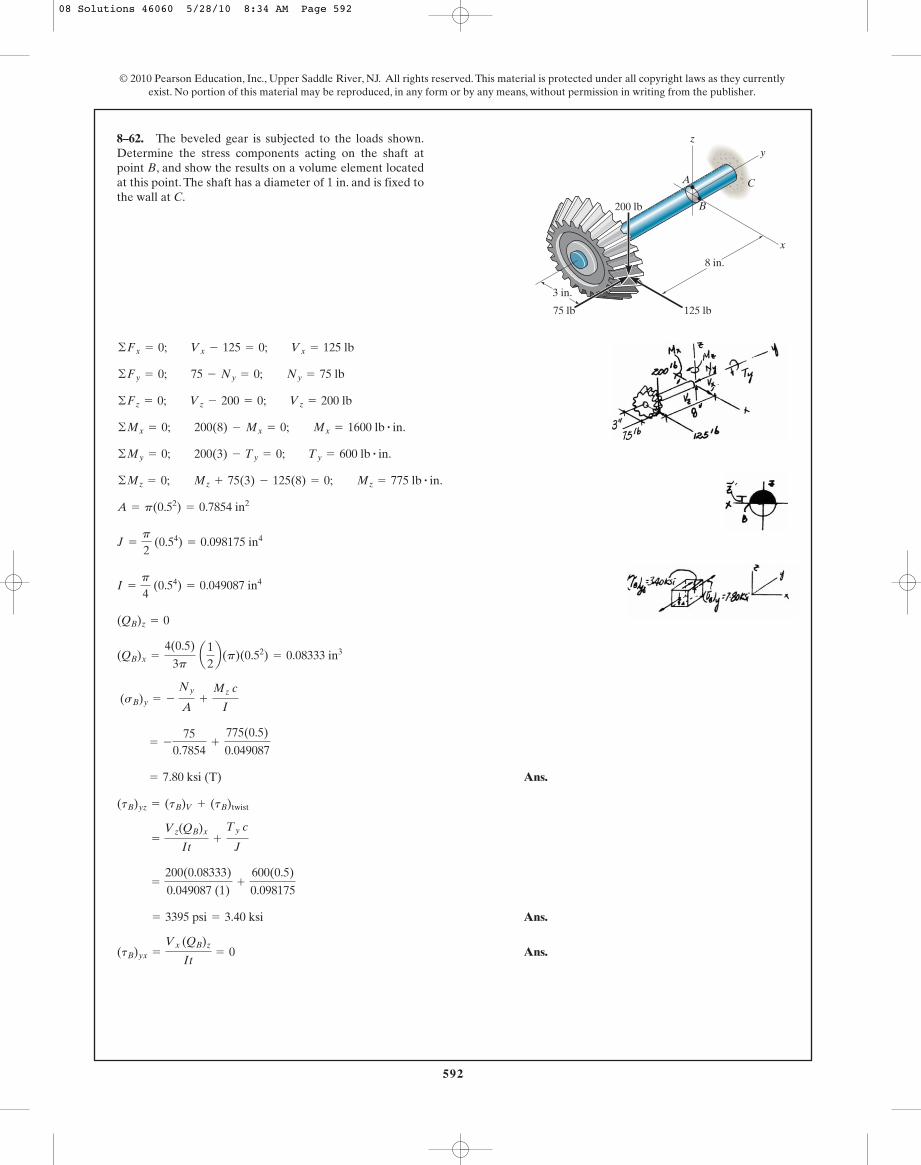
592
© 2010 Pearson Education, Inc., Upper Saddle River, NJ. All rights reserved. This material is protected under all copyright laws as they currentlyexist. No portion of this material may be reproduced, in any form or by any means, without permission in writing from the publisher.
Ans.
Ans.
Ans.(tB)yx =
Vx (QB)z
It= 0
= 3395 psi = 3.40 ksi
=
200(0.08333)
0.049087 (1)+
600(0.5)
0.098175
=
Vz(QB)x
It+
Ty c
J
(tB)yz = (tB)V + (tB)twist
= 7.80 ksi (T)
= -
750.7854
+
775(0.5)
0.049087
(sB)y = - Ny
A+
Mz c
I
(QB)x =
4(0.5)
3p a
12b(p)(0.52) = 0.08333 in3
(QB)z = 0
I =
p
4 (0.54) = 0.049087 in4
J =
p
2 (0.54) = 0.098175 in4
A = p(0.52) = 0.7854 in2
©Mz = 0; Mz + 75(3) - 125(8) = 0; Mz = 775 lb # in.
©My = 0; 200(3) - Ty = 0; Ty = 600 lb # in.
©Mx = 0; 200(8) - Mx = 0; Mx = 1600 lb # in.
©Fz = 0; Vz - 200 = 0; Vz = 200 lb
©Fy = 0; 75 - Ny = 0; Ny = 75 lb
©Fx = 0; Vx - 125 = 0; Vx = 125 lb
8–62. The beveled gear is subjected to the loads shown.Determine the stress components acting on the shaft atpoint B, and show the results on a volume element locatedat this point. The shaft has a diameter of 1 in. and is fixed tothe wall at C.
C
B
x
zy
A
200 lb
125 lb75 lb
8 in.
3 in.
08 Solutions 46060 5/28/10 8:34 AM Page 592
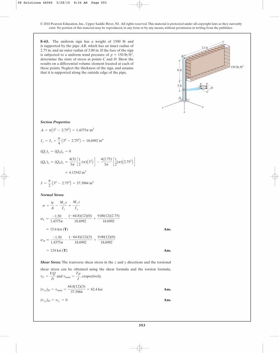
593
© 2010 Pearson Education, Inc., Upper Saddle River, NJ. All rights reserved. This material is protected under all copyright laws as they currentlyexist. No portion of this material may be reproduced, in any form or by any means, without permission in writing from the publisher.
Section Properties:
Normal Stress:
Ans.
Ans.
Shear Stress: The tranverse shear stress in the z and y directions and the torsional
shear stress can be obtained using the shear formula and the torsion formula,
and , respectively.
Ans.
Ans.(txy)D = tVy= 0
(txz)D = ttwist =
64.8(12)(3)
37.3984= 62.4 ksi
ttwist =
Tr
JtV =
VQ
It
= 124 ksi (T)
sD =
-1.501.4375p
-
(-64.8)(12)(3)
18.6992+
9.00(12)(0)
18.6992
= 15.6 ksi (T)
sC =
-1.501.4375p
-
(-64.8)(12)(0)
18.6992+
9.00(12)(2.75)
18.6992
s =
N
A-
Mz y
Iz+
My z
Iy
J =
p
2 A34
- 2.754 B = 37.3984 in4
= 4.13542 in3
(QC)y = (QD)z =
4(3)
3p c
12
(p) A32 B d -
4(2.75)
3p c
12
(p) A2.752 B d
(QC)z = (QD)y = 0
Iy = Iz =
p
4 A34
- 2.754 B = 18.6992 in4
A = p A32- 2.752 B = 1.4375p in2
8–63. The uniform sign has a weight of 1500 lb andis supported by the pipe AB, which has an inner radius of2.75 in. and an outer radius of 3.00 in. If the face of the signis subjected to a uniform wind pressure of determine the state of stress at points C and D. Show theresults on a differential volume element located at each ofthese points. Neglect the thickness of the sign, and assumethat it is supported along the outside edge of the pipe.
p = 150 lb>ft2,
3 ft
6 ft
12 ft
B
A
y
xz
150 lb/ft2
CD
FE
08 Solutions 46060 5/28/10 8:34 AM Page 593
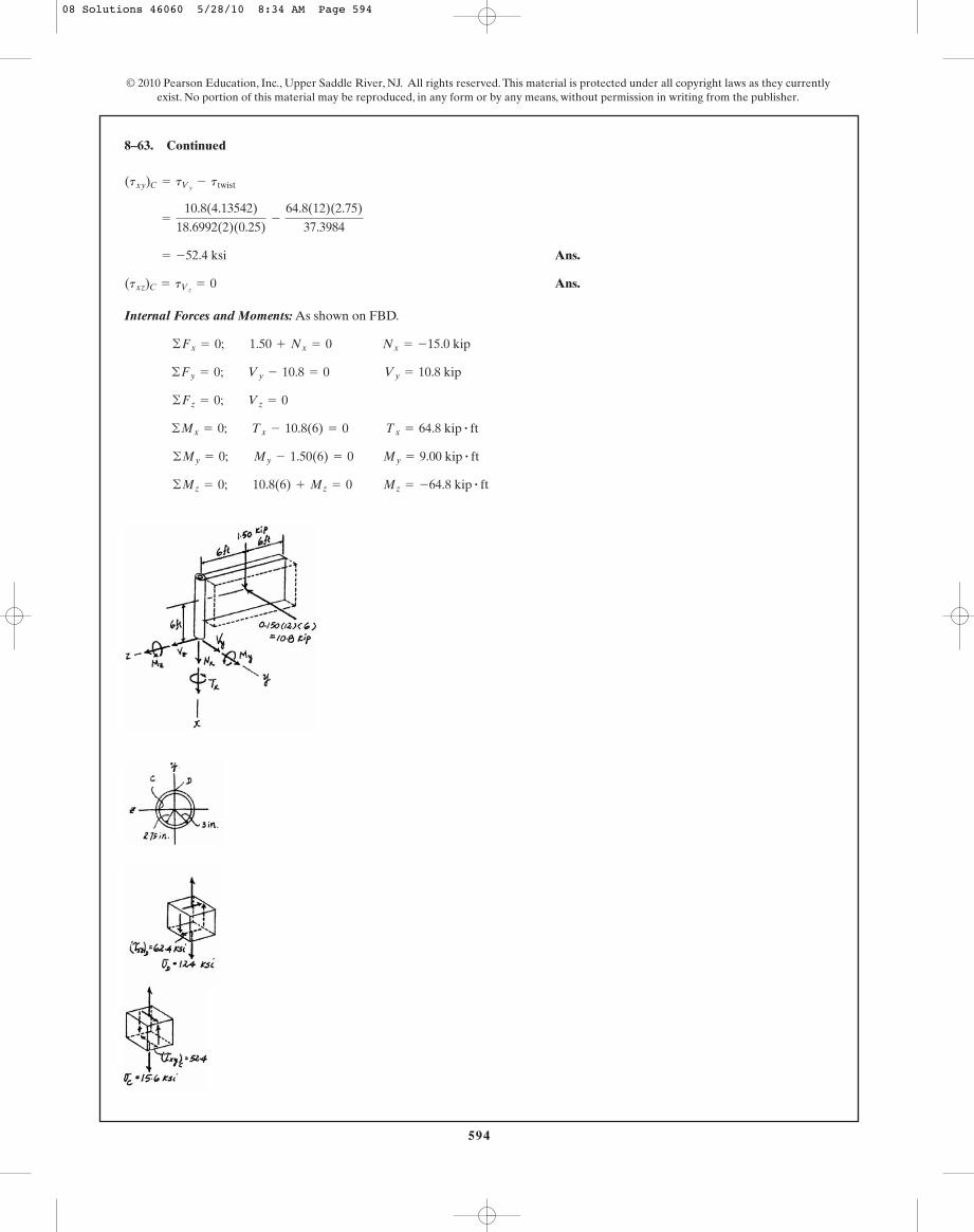
594
Ans.
Ans.
Internal Forces and Moments: As shown on FBD.
Mz = -64.8 kip # ft©Mz = 0; 10.8(6) + Mz = 0
My = 9.00 kip # ft©My = 0; My - 1.50(6) = 0
Tx = 64.8 kip # ft©Mx = 0; Tx - 10.8(6) = 0 ©Fz = 0; Vz = 0
Vy = 10.8 kip©Fy = 0; Vy - 10.8 = 0 ©Fx = 0; 1.50 + Nx = 0 Nx = -15.0 kip
(txz)C = tVz= 0
= -52.4 ksi
=
10.8(4.13542)
18.6992(2)(0.25)-
64.8(12)(2.75)
37.3984
(txy)C = tVy- ttwist
8–63. Continued
© 2010 Pearson Education, Inc., Upper Saddle River, NJ. All rights reserved. This material is protected under all copyright laws as they currentlyexist. No portion of this material may be reproduced, in any form or by any means, without permission in writing from the publisher.
08 Solutions 46060 5/28/10 8:34 AM Page 594
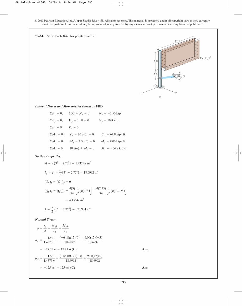
595
© 2010 Pearson Education, Inc., Upper Saddle River, NJ. All rights reserved. This material is protected under all copyright laws as they currentlyexist. No portion of this material may be reproduced, in any form or by any means, without permission in writing from the publisher.
Internal Forces and Moments: As shown on FBD.
Section Properties:
Normal Stress:
Ans.
Ans. = -125 ksi = 125 ksi (C)
sE =
-1.501.4375p
-
(-64.8)(12)(-3)
18.6992+
9.00(12)(0)
18.6992
= -17.7 ksi = 17.7 ksi (C)
sF =
-1.501.4375p
-
(-64.8)(12)(0)
18.6992+
9.00(12)(-3)
18.6992
s =
N
A-
Mzy
Iz+
My z
Iy
J =
p
2 A34
- 2.754 B = 37.3984 in4
= 4.13542 in3
(QC)y = (QD)z =
4(3)
3p c
12
(p) A32 B d -
4(2.75)
3p c
12
(p) A2.752 B d
(QC)z = (QD)y = 0
Iy = Iz =
p
4 A34
- 2.754 B = 18.6992 in4
A = p A32- 2.752 B = 1.4375p in2
Mz = -64.8 kip # ft©Mz = 0; 10.8(6) + Mz = 0
©My = 0; My - 1.50(6) = 0 My = 9.00 kip # ft
Tx = 64.8 kip # ft©Mx = 0; Tx - 10.8(6) = 0
©Fz = 0; Vz = 0
Vy = 10.8 kip©Fy = 0; Vy - 10.8 = 0
©Fx = 0; 1.50 + Nx = 0 Nx = -1.50 kip
*8–64. Solve Prob. 8–63 for points E and F.
3 ft
6 ft
12 ft
B
A
y
xz
150 lb/ft2
CD
FE
08 Solutions 46060 5/28/10 8:34 AM Page 595
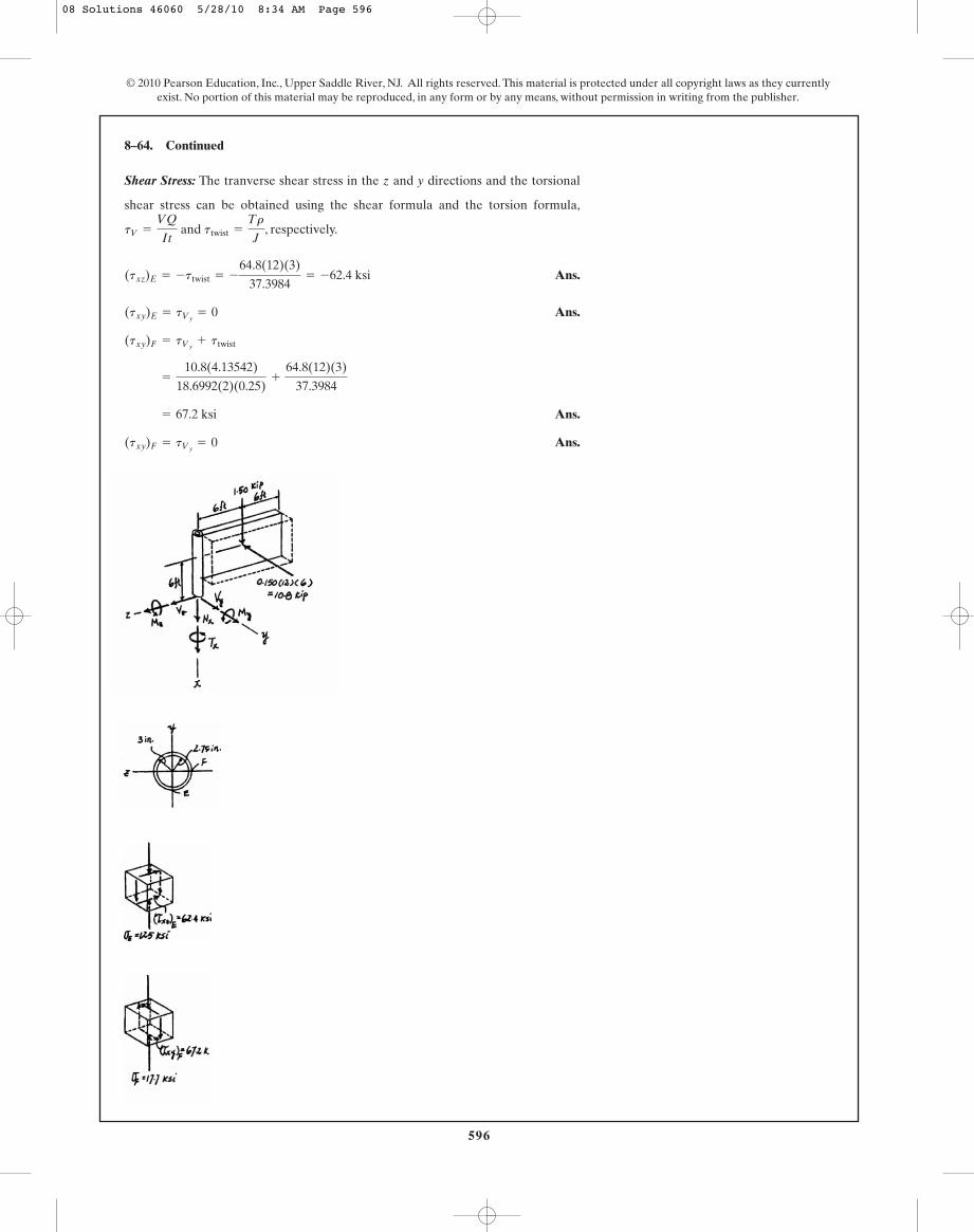
Shear Stress: The tranverse shear stress in the z and y directions and the torsional
shear stress can be obtained using the shear formula and the torsion formula,
and , respectively.
Ans.
Ans.
Ans.
Ans.(txy)F = tVy= 0
= 67.2 ksi
=
10.8(4.13542)
18.6992(2)(0.25)+
64.8(12)(3)
37.3984
(txy)F = tVy+ ttwist
(txy)E = tVy= 0
(txz)E = -ttwist = -
64.8(12)(3)
37.3984= -62.4 ksi
ttwist =
Tr
JtV =
VQ
It
8–64. Continued
596
© 2010 Pearson Education, Inc., Upper Saddle River, NJ. All rights reserved. This material is protected under all copyright laws as they currentlyexist. No portion of this material may be reproduced, in any form or by any means, without permission in writing from the publisher.
08 Solutions 46060 5/28/10 8:34 AM Page 596

597
© 2010 Pearson Education, Inc., Upper Saddle River, NJ. All rights reserved. This material is protected under all copyright laws as they currentlyexist. No portion of this material may be reproduced, in any form or by any means, without permission in writing from the publisher.
Internal Loadings: Referring to the free - body diagram of the pipe’s right segment,Fig. a,
Section Properties: The moment of inertia about the y and z axes and the polarmoment of inertia of the pipe are
Referring to Fig. b,
Normal Stress: The normal stress is contributed by bending stress only. Thus,
For point A, in and . Then
Ans.
Shear Stress: The torsional shear stress developed at point A is
c Atxz BT dA
=
TrA
J=
519.62(0.75)
1.07379= 362.93 psi
sA =
-433.01(0.75)
0.53689+ 0 = 604.89 psi = 605 psi (T)
z = 0y = 0.75
s = - Mzy
Iz+
Myz
Iy
AQz BA = y1œ A1
œ
- y2œ A2
œ
=
4(1)
3pcp
2 A12 B d -
4(0.75)
3p cp
2 A0.752 B d = 0.38542 in3
AQy BA = 0
J =
p
2 A14
- 0.754 B = 1.07379 in4
Iy = Iz =
p
4 A14
- 0.754 B = 0.53689 in4
Mz = -433.01 lb # in©Mz = 0; Mz + 50 sin 60° (10) = 0
My = 250 lb # in©My = 0; My - 50 cos 60°(10) = 0
T = -519.62 lb # in©Mx = 0; T + 50 sin 60°(12) = 0
©Fz = 0; Vz - 50 cos 60° = 0 Vz = 25 lb
©Fy = 0; Vy - 50 sin 60° = 0 Vy = 43.30 lb
•8–65. Determine the state of stress at point A on thecross section of the pipe at section a–a.
50 lbB
A
12 in.10 in.
a
a
60°
0.75 in.
1 in.Section a–a
z
xy
08 Solutions 46060 5/28/10 8:34 AM Page 597
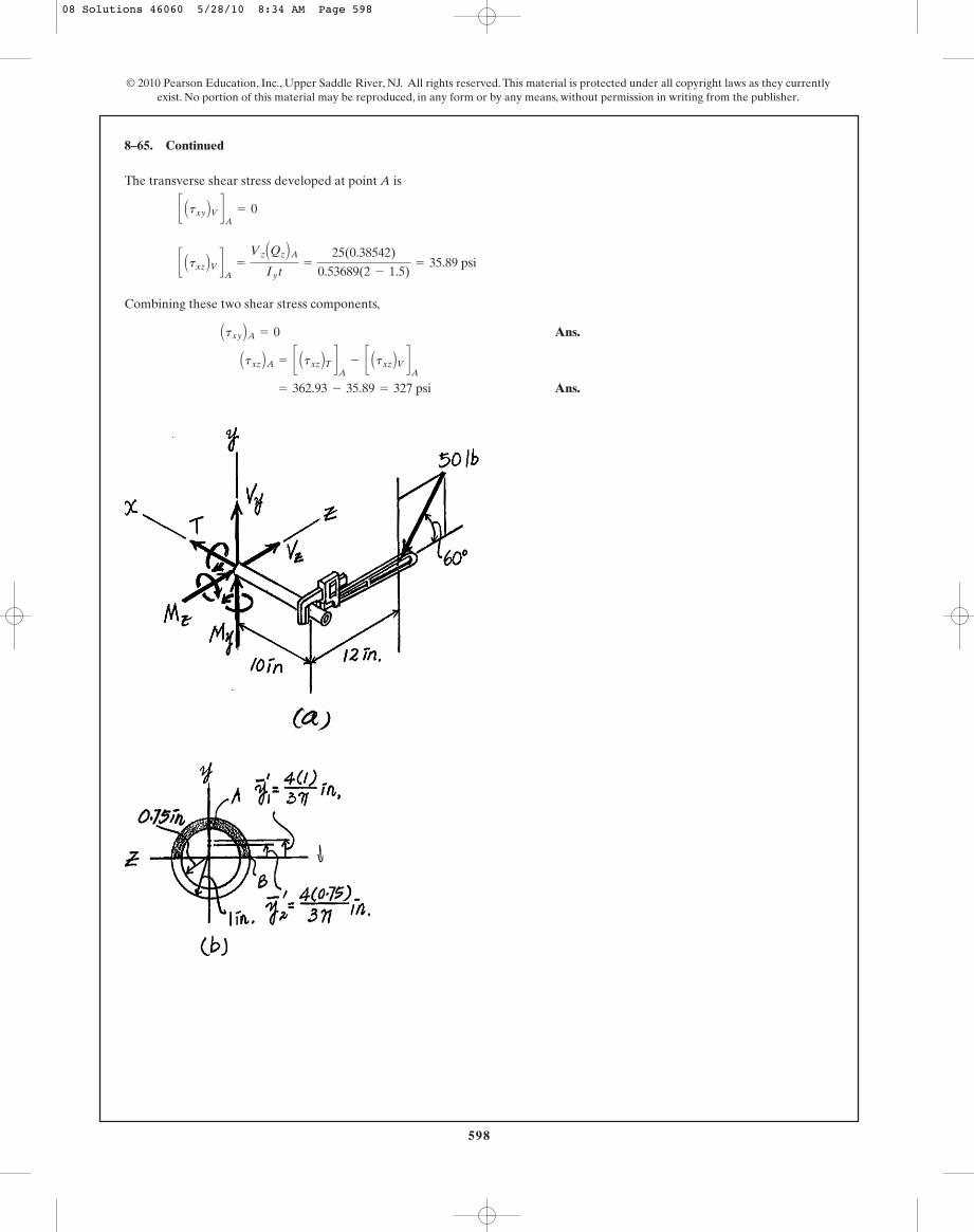
598
The transverse shear stress developed at point A is
Combining these two shear stress components,
Ans.
Ans. = 362.93 - 35.89 = 327 psi
Atxz BA = c Atxz BT dA
- c Atxz BV dA
Atxy BA = 0
c Atxz BV dA
=
Vz AQz BAIy t
=
25(0.38542)
0.53689(2 - 1.5)= 35.89 psi
c Atxy BV dA
= 0
8–65. Continued
© 2010 Pearson Education, Inc., Upper Saddle River, NJ. All rights reserved. This material is protected under all copyright laws as they currentlyexist. No portion of this material may be reproduced, in any form or by any means, without permission in writing from the publisher.
08 Solutions 46060 5/28/10 8:34 AM Page 598

599
© 2010 Pearson Education, Inc., Upper Saddle River, NJ. All rights reserved. This material is protected under all copyright laws as they currentlyexist. No portion of this material may be reproduced, in any form or by any means, without permission in writing from the publisher.
Internal Loadings: Referring to the free - body diagram of the pipe’s right segment,Fig. a,
Vz = 25 lb©Fz = 0; Vz - 50 cos 60° = 0
Vy = 43.30 lb©Fy = 0; Vy - 50 sin 60° = 0
8–66. Determine the state of stress at point B on the crosssection of the pipe at section a–a.
50 lbB
A
12 in.10 in.
a
a
60°
0.75 in.
1 in.Section a–a
z
xy
T = -519.62 lb # in©Mx = 0; T + 50 sin 60°(12) = 0
Section Properties: The moment of inertia about the y and z axes and the polarmoment of inertia of the pipe are
Referring to Fig. b,
Normal Stress: The normal stress is contributed by bending stress only. Thus,
For point B, and . Then
Ans.
Shear Stress: The torsional shear stress developed at point B is
c Atxy BT dB
=
TrC
J=
519.62(1)
1.07379= 483.91 psi
sB = -0 +
250(1)
0.53689= -465.64 psi = 466 psi (C)
z = -1y = 0
s = - Mzy
Iz+
Myz
Iy
AQy BB = y1œ A1
œ
- y2œ A2
œ
=
4(1)
3pcp
2 A12 B d -
4(0.75)
3p cp
2 A0.752 B d = 0.38542 in3
AQz BB = 0
J =
p
2 A14
- 0.754 B = 1.07379 in4
Iy = Iz =
p
4 A14
- 0.754 B = 0.53689 in4
Mz = -433.01 lb # in©Mz = 0; Mz + 50 sin 60°(10) = 0
My = 250 lb # in©My = 0; My - 50 cos 60°(10) = 0
08 Solutions 46060 5/28/10 8:34 AM Page 599

The transverse shear stress developed at point B is
Combining these two shear stress components,
Ans.
Ans. Atxz BB = 0
= 483.91 - 62.17 = 422 psi
Atxy BB = c Atxy BT dB
- c Atxy BV dB
c Atxy BV dB
=
Vy AQy BBIzt
=
43.30(0.38542)
0.53689(2 - 1.5)= 62.17 psi
c Atxz BV dB
= 0
8–66. Continued
600
© 2010 Pearson Education, Inc., Upper Saddle River, NJ. All rights reserved. This material is protected under all copyright laws as they currentlyexist. No portion of this material may be reproduced, in any form or by any means, without permission in writing from the publisher.
08 Solutions 46060 5/28/10 8:34 AM Page 600
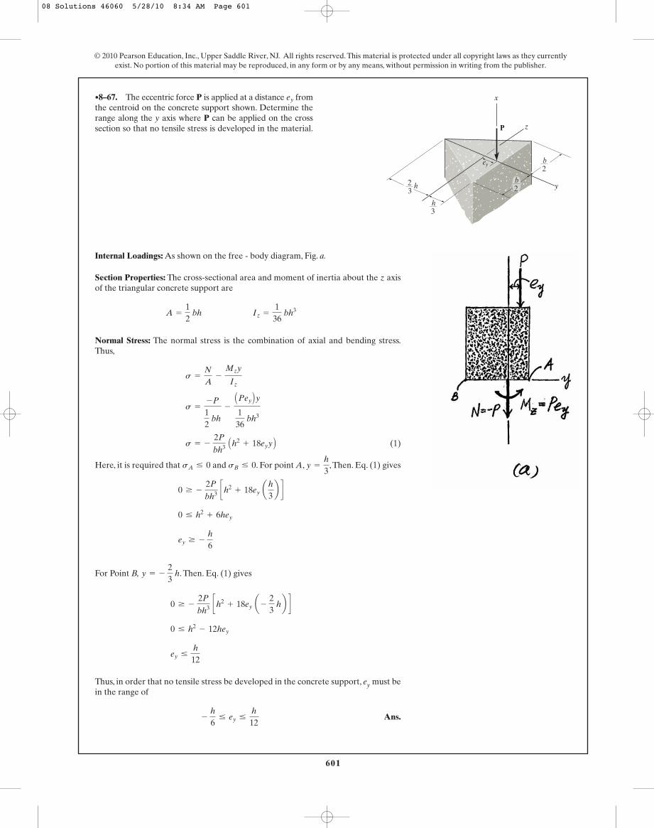
601
© 2010 Pearson Education, Inc., Upper Saddle River, NJ. All rights reserved. This material is protected under all copyright laws as they currentlyexist. No portion of this material may be reproduced, in any form or by any means, without permission in writing from the publisher.
Internal Loadings: As shown on the free - body diagram, Fig. a.
Section Properties: The cross-sectional area and moment of inertia about the z axisof the triangular concrete support are
Normal Stress: The normal stress is the combination of axial and bending stress.Thus,
(1)
Here, it is required that and . For point A, , Then. Eq. (1) gives
For Point B, . Then. Eq. (1) gives
Thus, in order that no tensile stress be developed in the concrete support, ey must bein the range of
Ans.- h
6… ey …
h
12
ey …
h
12
0 … h2- 12hey
0 Ú - 2P
bh3 ch2+ 18ey a -
23
hb d
y = - 23
h
ey Ú - h
6
0 … h2+ 6hey
0 Ú - 2P
bh3 ch2+ 18ey a
h
3b d
y =
h
3sB … 0sA … 0
s = - 2P
bh3 Ah2+ 18eyy B
s =
-P
12
bh
-
APey By136
bh3
s =
N
A-
Mzy
Iz
A =
12
bh Iz =
136
bh3
•8–67. The eccentric force P is applied at a distance fromthe centroid on the concrete support shown. Determine therange along the y axis where P can be applied on the crosssection so that no tensile stress is developed in the material.
ey
2
ey
P
3
h3
b2
b2
h
z
x
y
08 Solutions 46060 5/28/10 8:34 AM Page 601

602
© 2010 Pearson Education, Inc., Upper Saddle River, NJ. All rights reserved. This material is protected under all copyright laws as they currentlyexist. No portion of this material may be reproduced, in any form or by any means, without permission in writing from the publisher.
Ans.
Ans.tA =
VQA
I t=
692.82 (5.3333) (10- 6)
0.1256637 (10- 6)(0.04)= 0.735 MPa
=
4001.256637 (10- 3)
+ 0 = 0.318 MPa
sA =
P
A+
Mz
I
QA = y¿A¿ = a4 (0.02)
3pb ap (0.02)2
2b = 5.3333 (10- 6) m3
A = p r2= p(0.022) = 1.256637 (10- 3) m2
I =
14
p r4=
14
(p)(0.024) = 0.1256637 (10- 6) m4
*8–68. The bar has a diameter of 40 mm. If it is subjectedto a force of 800 N as shown,determine the stress componentsthat act at point A and show the results on a volume elementlocated at this point. 150 mm
200 mm z
yx
BA
800 N
30�
Ans.
Ans.tB = 0
sB =
P
A-
Mc
I=
4001.256637 (10- 3)
-
138.56 (0.02)
0.1256637 (10- 6)= -21.7 MPa
QB = 0
A = p r2= p(0.022) = 1.256637 (10- 3) m2
I =
14
p r4=
14
(p)(0.024) = 0.1256637 (10- 6) m4
•8–69. Solve Prob. 8–68 for point B.
150 mm
200 mm z
yx
BA
800 N
30�
08 Solutions 46060 5/28/10 8:34 AM Page 602

603
© 2010 Pearson Education, Inc., Upper Saddle River, NJ. All rights reserved. This material is protected under all copyright laws as they currentlyexist. No portion of this material may be reproduced, in any form or by any means, without permission in writing from the publisher.
Ans.
Ans.tB =
VzQB
I t=
125(0.035156)
0.015531(0.75)= 0.377 ksi
sB = 0
QB = y¿A¿ =
4(0.375)
3p a
12b(p)(0.3752) = 0.035156 in3
I =
p
4 (0.3754) = 0.015531 in4
A =
p
4 (0.752) = 0.44179 in2
8–71. Solve Prob. 8–70 for the stress components at point B.
Ans.
Ans.sA =
My c
I=
-1250(0.375)
0.015531= -30.2 ksi = 30.2 ksi (C)
tA = 0
QA = 0
I =
p
4 (0.3754) = 0.015531 in4
A =
p
4 (0.752) = 0.44179 in2
8–70. The shaft is subjected to the loadingshown. Determine the stress components at point A. Sketchthe results on a volume element located at this point. Thejournal bearing at C can exert only force components and on the shaft, and the thrust bearing at D can exertforce components and on the shaft.DzDy ,Dx ,
Cz
Cy
34-in.-diameter
x
C
A
B
125 lb
2 in.
8 in.
8 in.
125 lb
D
20 in.
20 in.
10 in.
z
y
2 in.
x
C
A
B
125 lb
2 in.
8 in.
8 in.
125 lb
D
20 in.
20 in.
10 in.
z
y
2 in.
08 Solutions 46060 5/28/10 8:34 AM Page 603

604
© 2010 Pearson Education, Inc., Upper Saddle River, NJ. All rights reserved. This material is protected under all copyright laws as they currentlyexist. No portion of this material may be reproduced, in any form or by any means, without permission in writing from the publisher.
The location of the neutral surface from the center of curvature of the hook, Fig. a,can be determined from
where
Thus,
Then
Referring to Fig. b, I and QA are
Consider the equilibrium of the FBD of the hook’s cut segment, Fig. c,
a
The normal stress developed is the combination of axial and bending stress. Thus,
Here, since it tends to reduce the curvature of the hook. For pointA, . Then
Ans.
The shear stress in contributed by the transverse shear stress only. Thus
Ans.
The state of strees of point A can be represented by the element shown in Fig. d.
t =
VQA
It= 0
= 9.269(103) psi = 9.27 ksi (T)
s =
56.570.0625p
+
(98.49)(1.74103 - 1.5)
0.0625p(0.0089746)(1.5)
r = 1.5 inM = 98.49 lb # in
s =
N
A+
M(R - r)
Ae r
+ ©Mo = 0; M - 80 cos 45°(1.74103) = 0 M = 98.49 lb # in
+ c ©Fy = 0; 80 sin 45° - V = 0 V = 56.57 lb
;+ ©Fx = 0; N - 80 cos 45° = 0 N = 56.57 lb
QA = 0
I =
p
4 (0.254) = 0.9765625(10- 3)p in4
e = r - R = 1.75 - 1.74103 = 0.0089746 in.
R =
0.0625p0.11278
= 1.74103 in.
©
LA
dAr
= 2p Ar - 2r2- c2 B = 2p A1.75 - 21.752
- 0.252 B = 0.11278 in.
A = p(0.252) = 0.0625p in2
R =
A
©
LA
dAr
*8–72. The hook is subjected to the force of 80 lb.Determine the state of stress at point A at section a–a. Thecross section is circular and has a diameter of 0.5 in. Use thecurved-beam formula to compute the bending stress.
a
a
80 lb
1.5 in.
A A
B
B
45�
08 Solutions 46060 5/28/10 8:34 AM Page 604
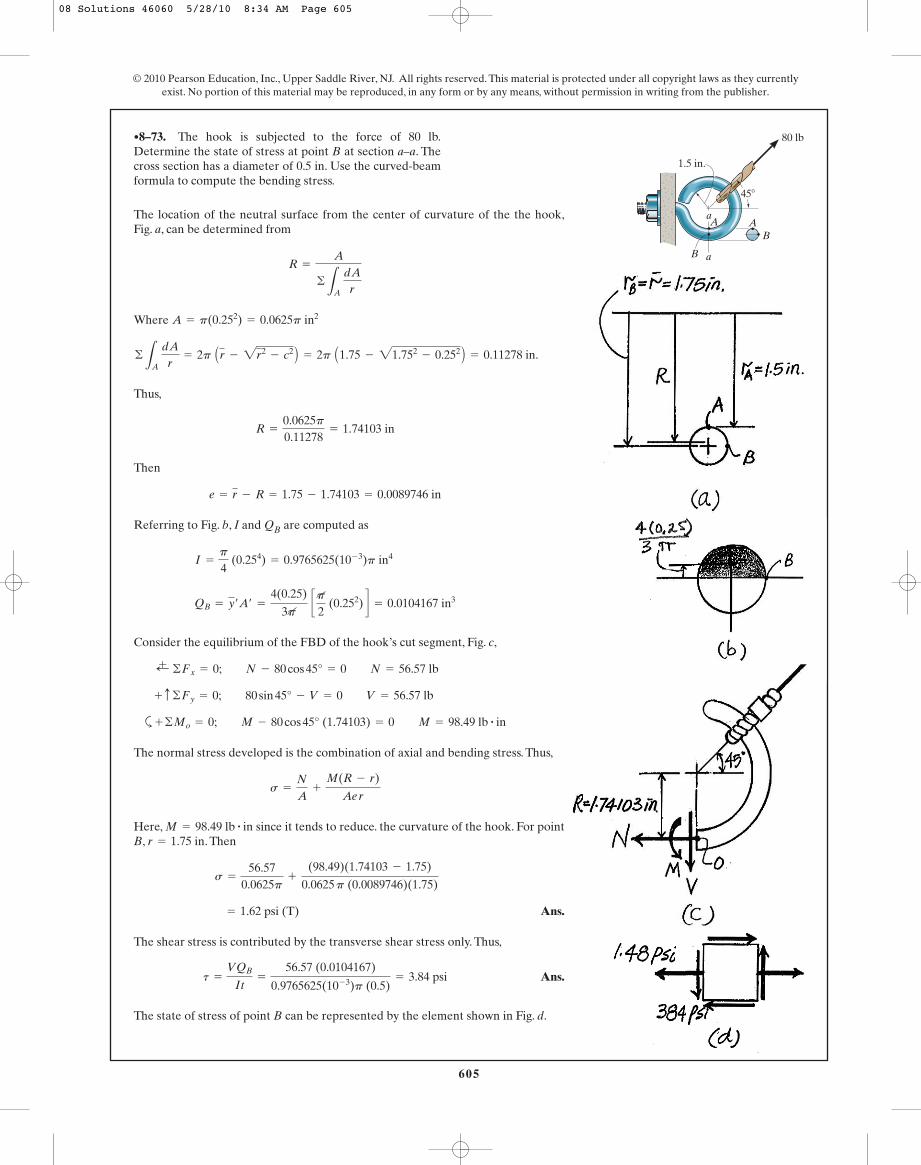
605
© 2010 Pearson Education, Inc., Upper Saddle River, NJ. All rights reserved. This material is protected under all copyright laws as they currentlyexist. No portion of this material may be reproduced, in any form or by any means, without permission in writing from the publisher.
The location of the neutral surface from the center of curvature of the the hook,Fig. a, can be determined from
Where
Thus,
Then
Referring to Fig. b, I and QB are computed as
Consider the equilibrium of the FBD of the hook’s cut segment, Fig. c,
a
The normal stress developed is the combination of axial and bending stress. Thus,
Here, since it tends to reduce. the curvature of the hook. For pointB, . Then
Ans.
The shear stress is contributed by the transverse shear stress only. Thus,
Ans.
The state of stress of point B can be represented by the element shown in Fig. d.
t =
VQB
It=
56.57 (0.0104167)
0.9765625(10- 3)p (0.5)= 3.84 psi
= 1.62 psi (T)
s =
56.570.0625p
+
(98.49)(1.74103 - 1.75)
0.0625 p (0.0089746)(1.75)
r = 1.75 inM = 98.49 lb # in
s =
N
A+
M(R - r)
Ae r
+ ©Mo = 0; M - 80 cos 45° (1.74103) = 0 M = 98.49 lb # in
+ c ©Fy = 0; 80 sin 45° - V = 0 V = 56.57 lb
;+ ©Fx = 0; N - 80 cos 45° = 0 N = 56.57 lb
QB = y¿A¿ =
4(0.25)
3p cp
2 (0.252) d = 0.0104167 in3
I =
p
4 (0.254) = 0.9765625(10- 3)p in4
e = r - R = 1.75 - 1.74103 = 0.0089746 in
R =
0.0625p0.11278
= 1.74103 in
©
LA dAr
= 2p Ar - 2r2- c2 B = 2p A1.75 - 21.752
- 0.252 B = 0.11278 in.
A = p(0.252) = 0.0625p in2
R =
A
©
LA dAr
•8–73. The hook is subjected to the force of 80 lb.Determine the state of stress at point B at section a–a. Thecross section has a diameter of 0.5 in. Use the curved-beamformula to compute the bending stress.
a
a
80 lb
1.5 in.
A A
B
B
45�
08 Solutions 46060 5/28/10 8:34 AM Page 605
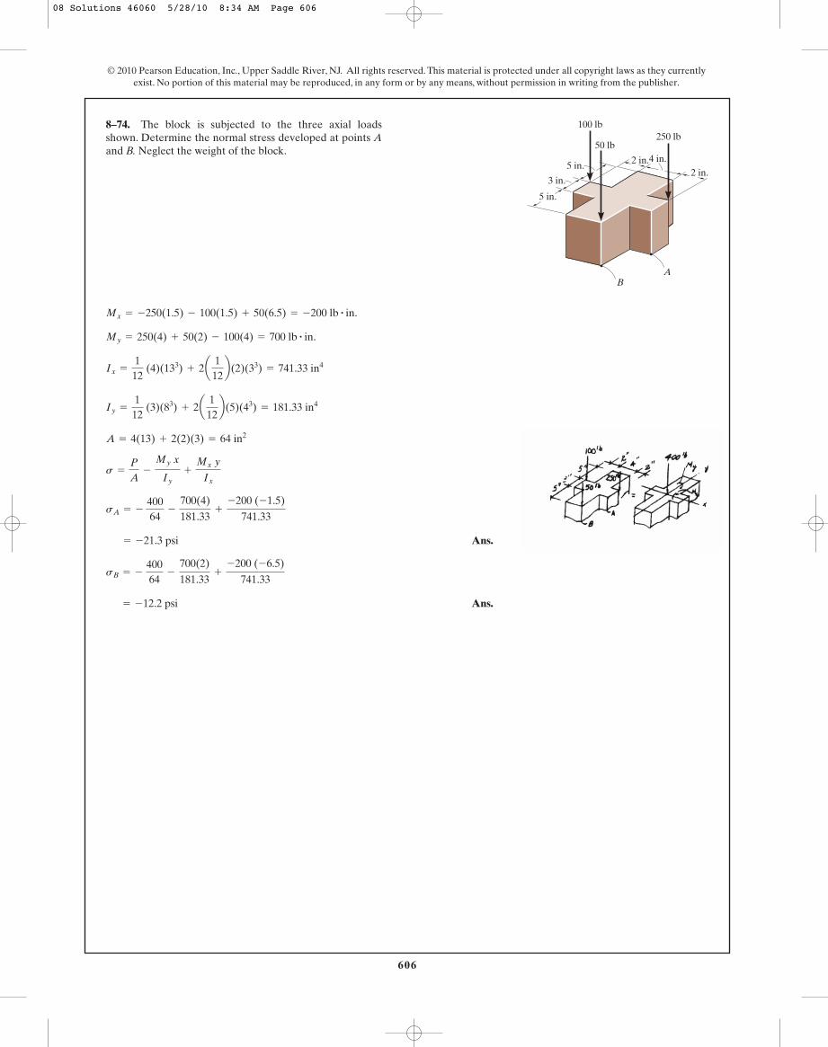
606
© 2010 Pearson Education, Inc., Upper Saddle River, NJ. All rights reserved. This material is protected under all copyright laws as they currentlyexist. No portion of this material may be reproduced, in any form or by any means, without permission in writing from the publisher.
Ans.
Ans. = -12.2 psi
sB = - 40064
-
700(2)
181.33+
-200 (-6.5)
741.33
= -21.3 psi
sA = - 40064
-
700(4)
181.33+
-200 (-1.5)
741.33
s =
P
A-
My x
Iy+
Mx y
Ix
A = 4(13) + 2(2)(3) = 64 in2
Iy =
112
(3)(83) + 2a1
12b(5)(43) = 181.33 in4
Ix =
112
(4)(133) + 2a1
12b(2)(33) = 741.33 in4
My = 250(4) + 50(2) - 100(4) = 700 lb # in.
Mx = -250(1.5) - 100(1.5) + 50(6.5) = -200 lb # in.
8–74. The block is subjected to the three axial loadsshown. Determine the normal stress developed at points Aand B. Neglect the weight of the block.
4 in.2 in.2 in.
5 in.
5 in.
3 in.
50 lb
100 lb250 lb
BA
08 Solutions 46060 5/28/10 8:34 AM Page 606
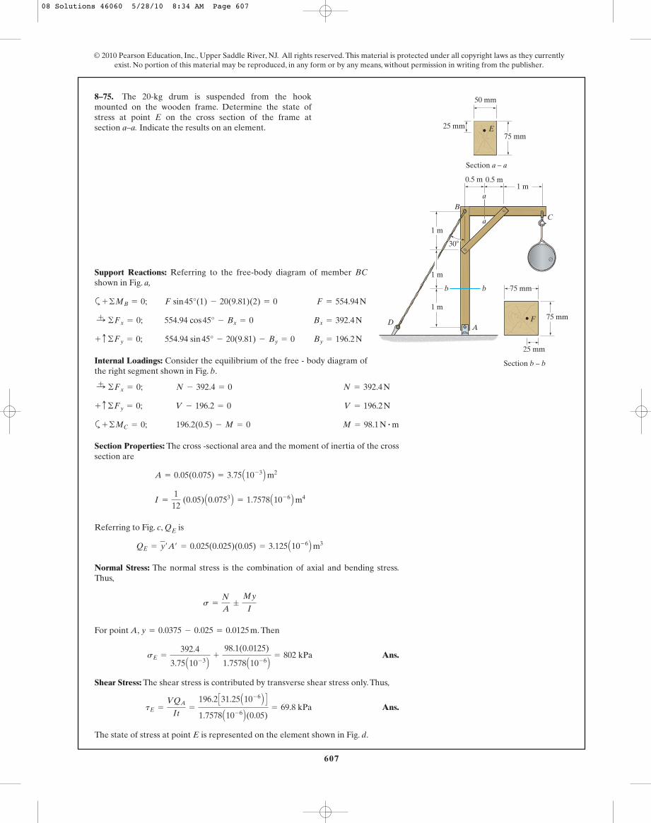
607
© 2010 Pearson Education, Inc., Upper Saddle River, NJ. All rights reserved. This material is protected under all copyright laws as they currentlyexist. No portion of this material may be reproduced, in any form or by any means, without permission in writing from the publisher.
Support Reactions: Referring to the free-body diagram of member BCshown in Fig. a,
a
Internal Loadings: Consider the equilibrium of the free - body diagram ofthe right segment shown in Fig. b.
By = 196.2 N554.94 sin 45° - 20(9.81) - By = 0+ c ©Fy = 0;
Bx = 392.4 N554.94 cos 45° - Bx = 0:+ ©Fx = 0;
F = 554.94 NF sin 45°(1) - 20(9.81)(2) = 0+ ©MB = 0;
8–75. The 20-kg drum is suspended from the hookmounted on the wooden frame. Determine the state ofstress at point E on the cross section of the frame atsection a–a. Indicate the results on an element.
1 m
1 m
1 m
b
a
a
b
CB
A
30�
1 m0.5 m0.5 m
50 mm
75 mm25 mm
Section a – a
E
75 mm
75 mm
25 mm
Section b – b
FD
a M = 98.1 N # m196.2(0.5) - M = 0+ ©MC = 0;
V = 196.2 NV - 196.2 = 0+ c ©Fy = 0;
N = 392.4 NN - 392.4 = 0:+ ©Fx = 0;
Section Properties: The cross -sectional area and the moment of inertia of the crosssection are
Referring to Fig. c, QE is
Normal Stress: The normal stress is the combination of axial and bending stress.Thus,
For point A, . Then
Ans.
Shear Stress: The shear stress is contributed by transverse shear stress only. Thus,
Ans.
The state of stress at point E is represented on the element shown in Fig. d.
tE =
VQA
It=
196.2 C31.25 A10- 6 B D
1.7578 A10- 6 B(0.05)= 69.8 kPa
sE =
392.4
3.75 A10- 3 B+
98.1(0.0125)
1.7578 A10- 6 B= 802 kPa
y = 0.0375 - 0.025 = 0.0125 m
s =
N
A;
My
I
QE = y¿A¿ = 0.025(0.025)(0.05) = 3.125 A10- 6 B m3
I =
112
(0.05) A0.0753 B = 1.7578 A10- 6 B m4
A = 0.05(0.075) = 3.75 A10- 3 B m2
08 Solutions 46060 5/28/10 8:34 AM Page 607
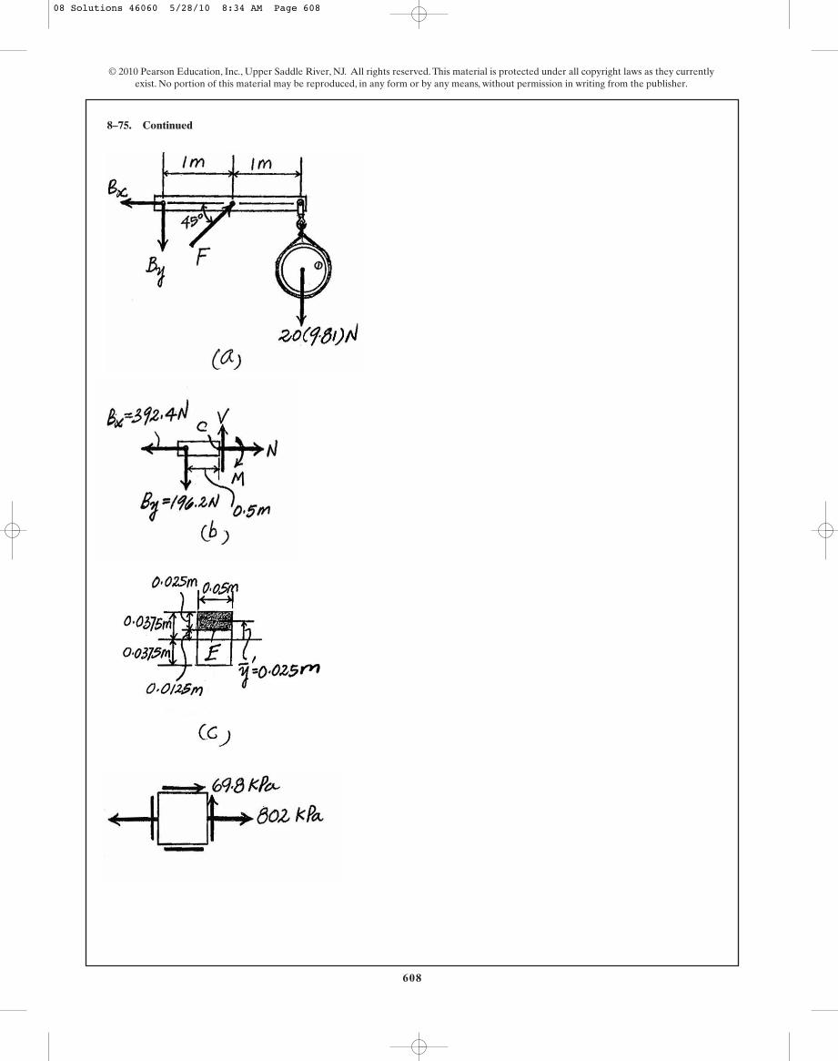
608
8–75. Continued
© 2010 Pearson Education, Inc., Upper Saddle River, NJ. All rights reserved. This material is protected under all copyright laws as they currentlyexist. No portion of this material may be reproduced, in any form or by any means, without permission in writing from the publisher.
08 Solutions 46060 5/28/10 8:34 AM Page 608

609
© 2010 Pearson Education, Inc., Upper Saddle River, NJ. All rights reserved. This material is protected under all copyright laws as they currentlyexist. No portion of this material may be reproduced, in any form or by any means, without permission in writing from the publisher.
Support Reactions: Referring to the free-body diagram of the entire frameshown in Fig. a,
a
Ay = 422.75 NAy - 261.6 cos 30° - 20(9.81) = 0+ c ©Fy = 0;
FBD = 261.6 NFBD sin 30°(3) - 20(9.81)(2) = 0+ ©MA = 0;
*8–76. The 20-kg drum is suspended from the hookmounted on the wooden frame. Determine the state ofstress at point F on the cross section of the frame atsection b–b. Indicate the results on an element.
1 m
1 m
1 m
b
a
a
b
CB
A
30�
1 m0.5 m0.5 m
50 mm
75 mm25 mm
Section a – a
E
75 mm
75 mm
25 mm
Section b – b
FD
Ax = 130.8 NAx - 261.6 sin 30° = 0:+ ©Fx = 0;
Internal Loadings: Consider the equilibrium of the free - body diagram of the lowercut segment, Fig. b,
a M = 130.8 N # m130.8(1) - M = 0+ ©MC = 0;
N = 422.75 N422.75 - N = 0+ c ©Fy = 0;
V = 130.8 N130.8 - V = 0:+ ©Fx = 0;
Section Properties: The cross -sectional area and the moment of inertia about thecentroidal axis of the cross section are
Referring to Fig. c, QE is
Normal Stress: The normal stress is the combination of axial and bending stress.Thus,
For point F, . Then
Ans. = -695.24 kPa = 695 kPa (C)
sF =
-422.75
5.625 A10- 3 B-
130.8(0.0125)
2.6367 A10- 6 B
y = 0.0375 - 0.025 = 0.0125 m
s =
N
A;
My
I
QF = y¿A¿ = 0.025(0.025)(0.075) = 46.875 A10- 6 B m3
I =
112
(0.075) A0.0753 B = 2.6367 A10- 6 B m4
A = 0.075(0.075) = 5.625 A10- 3 B m2
08 Solutions 46060 5/28/10 8:34 AM Page 609
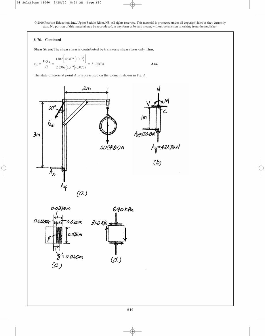
Shear Stress: The shear stress is contributed by transverse shear stress only. Thus,
Ans.
The state of stress at point A is represented on the element shown in Fig. d.
tA =
VQA
It=
130.8 c46.875 A10- 6 B d
2.6367 A10- 6 B(0.075)= 31.0 kPa
8–76. Continued
610
© 2010 Pearson Education, Inc., Upper Saddle River, NJ. All rights reserved. This material is protected under all copyright laws as they currentlyexist. No portion of this material may be reproduced, in any form or by any means, without permission in writing from the publisher.
08 Solutions 46060 5/28/10 8:34 AM Page 610
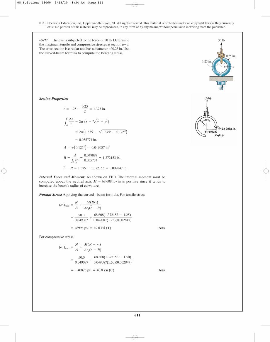
611
© 2010 Pearson Education, Inc., Upper Saddle River, NJ. All rights reserved. This material is protected under all copyright laws as they currentlyexist. No portion of this material may be reproduced, in any form or by any means, without permission in writing from the publisher.
Section Properties:
Internal Force and Moment: As shown on FBD. The internal moment must becomputed about the neutral axis. is positive since it tends toincrease the beam’s radius of curvature.
Normal Stress: Applying the curved - beam formula, For tensile stress
Ans.
For compressive stress
Ans. = -40826 psi = 40.8 ksi (C)
=
50.00.049087
+
68.608(1.372153 - 1.50)
0.049087(1.50)(0.002847)
(sc)max =
N
A+
M(R - r2)
Ar2(r - R)
= 48996 psi = 49.0 ksi (T)
=
50.00.049087
+
68.608(1.372153 - 1.25)
0.049087(1.25)(0.002847)
(st)max =
N
A+
M(Rr1)
Ar1(r - R)
M = 68.608 lb # in
r - R = 1.375 - 1.372153 = 0.002847 in.
R =
A
1A dAr
=
0.0490870.035774
= 1.372153 in.
A = p A0.1252 B = 0.049087 in2
= 0.035774 in.
= 2p A1.375 - 21.3752- 0.1252 B
LA
dAr
= 2p Ar - 2r2- c2 B
r = 1.25 +
0.252
= 1.375 in.
•8–77. The eye is subjected to the force of 50 lb. Determinethe maximum tensile and compressive stresses at sectionThe cross section is circular and has a diameter of 0.25 in. Usethe curved-beam formula to compute the bending stress.
a-a.
1.25 in.
aa
50 lb
0.25 in.
08 Solutions 46060 5/28/10 8:34 AM Page 611

612
© 2010 Pearson Education, Inc., Upper Saddle River, NJ. All rights reserved. This material is protected under all copyright laws as they currentlyexist. No portion of this material may be reproduced, in any form or by any means, without permission in writing from the publisher.
Section Properties:
Internal Force and Moment: As shown on FBD. The internal moment must becomputed about the neutral axis. is positive since it tends toincrease the beam’s radius of curvature.
Normal Stress: Applying the curved -beam formula, For tensile stress
Ans.
For Compressive stress
Ans. = -24011 psi = 24.0 ksi (C)
=
50.00.0625
+
68.560(1.371204 - 1.5)
0.0625(1.5)(0.003796)
(sc)max =
N
A+
M(R - r2)
Ar2 (r - R)
= 28818 psi = 28.8 ksi (T)
=
50.00.0625
+
68.560(1.371204 - 1.25)
0.0625(1.25)(0.003796)
(st)max =
N
A+
M(R - r1)
Ar1(r - R)
M = 68.560 lb # in.
r - R = 1.375 - 1.371204 = 0.003796 in.
R =
A
1A dAr
=
0.06250.045580
= 1.371204 in.
A = 0.25(0.25) = 0.0625 in2
LA dAr
= bln r2
r1= 0.25 ln
1.51.25
= 0.45580 in.
r = 1.25 +
0.252
= 1.375 in.
8–78. Solve Prob. 8–77 if the cross section is square, havingdimensions of 0.25 in. by 0.25 in.
1.25 in.
aa
50 lb
0.25 in.
08 Solutions 46060 5/28/10 8:34 AM Page 612
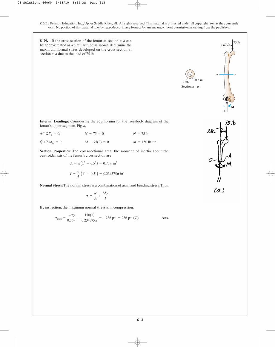
613
© 2010 Pearson Education, Inc., Upper Saddle River, NJ. All rights reserved. This material is protected under all copyright laws as they currentlyexist. No portion of this material may be reproduced, in any form or by any means, without permission in writing from the publisher.
Internal Loadings: Considering the equilibrium for the free-body diagram of thefemur’s upper segment, Fig. a,
N = 75 lbN - 75 = 0+ c ©Fy = 0;
8–79. If the cross section of the femur at section a–a canbe approximated as a circular tube as shown, determine themaximum normal stress developed on the cross section atsection a–a due to the load of 75 lb.
a a
2 in.75 lb
MF
1 in. 0.5 in.
Section a – a
a M = 150 lb # inM - 75(2) = 0+ ©MO = 0;
Section Properties: The cross-sectional area, the moment of inertia about thecentroidal axis of the femur’s cross section are
Normal Stress: The normal stress is a combination of axial and bending stress. Thus,
By inspection, the maximum normal stress is in compression.
Ans.smax =
-750.75p
-
150(1)
0.234375p= -236 psi = 236 psi (C)
s =
N
A+
My
I
I =
p
4 A14
- 0.54 B = 0.234375p in4
A = p A12- 0.52 B = 0.75p in2
08 Solutions 46060 5/28/10 8:34 AM Page 613

614
© 2010 Pearson Education, Inc., Upper Saddle River, NJ. All rights reserved. This material is protected under all copyright laws as they currentlyexist. No portion of this material may be reproduced, in any form or by any means, without permission in writing from the publisher.
Equation of Equilibrium: The absolute pressure developed in the hydraulic
cylinder can be determined by considering the equilibrium of the free-body
diagram of the piston shown in Fig. a. The resultant force of the pressure on the
piston is . Thus,
Normal Stress: For the cylinder, the hoop stress is twice as large as thelongitudinal stress,
Ans.
Since , thin -wall analysis is valid.r
t=
504.24
= 11.78 7 10
t = 4.24 mm
sallow =
pr
t ; 150 A106 B =
12.732 A106 B(50)
t
p = 12.732 A106 B Pa
©Fx¿= 0; 0.0025pp - 100 A103 B = 0
F = pA = p cp
4 A0.12 B d = 0.0025pp
*8–80. The hydraulic cylinder is required to support aforce of If the cylinder has an inner diameterof 100 mm and is made from a material having an allowablenormal stress of determine the requiredminimum thickness t of the wall of the cylinder.
sallow = 150 MPa,
P = 100 kN.
t
100 mm
P
08 Solutions 46060 5/28/10 8:34 AM Page 614

615
© 2010 Pearson Education, Inc., Upper Saddle River, NJ. All rights reserved. This material is protected under all copyright laws as they currentlyexist. No portion of this material may be reproduced, in any form or by any means, without permission in writing from the publisher.
Normal Stress: For the hydraulic cylinder, the hoop stress is twice as large as thelongitudinal stress.
Since , thin-wall analysis can be used.
Ans.
Equation of Equilibrium: The resultant force on the piston is
. Referring to the free-body diagram of
the piston shown in Fig. a,
Ans. P = 94.247 A103 BN = 94.2 kN
©Fx¿= 0; 30 A103 Bp - P = 0
F = pA = 12 A106 B cp
4 A0.12 B d = 30 A103 Bp
p = 12 A106 B MPa
sallow =
pr
t ; 150 A106 B =
p(50)
4
r
t=
504
= 12.5 7 10
•8–81. The hydraulic cylinder has an inner diameter of100 mm and wall thickness of If it is made froma material having an allowable normal stress of
MPa, determine the maximum allowable force P.150sallow =
t = 4 mm.
t
100 mm
P
08 Solutions 46060 5/28/10 8:34 AM Page 615

616
© 2010 Pearson Education, Inc., Upper Saddle River, NJ. All rights reserved. This material is protected under all copyright laws as they currentlyexist. No portion of this material may be reproduced, in any form or by any means, without permission in writing from the publisher.
Internal Force and Moment: As shown on FBD.
Section Properties:
Maximum Normal Stress: Maximum normal stress occurs at point A.
Ans. = 44000 psi = 44.0 ksi (T)
=
5000.375
+
2000(0.375)
0.017578
smax = sA =
N
A+
Mc
I
I =
112
(0.5) A0.753 B = 0.017578 in4
A = 0.5(0.75) = 0.375 in2
8–82. The screw of the clamp exerts a compressive forceof 500 lb on the wood blocks. Determine the maximumnormal stress developed along section The crosssection there is rectangular, 0.75 in. by 0.50 in.
a-a.
4 in.
0.75 in.a
a
Ans.
Ans.
The pressure P is supported by the surface of the pistons in the longitudinaldirection.
s2 = 0
s1 =
p r
t=
314 380.13(0.045)
0.002= 7.07 MPa
p =
P
A=
2(103)
p(0.0452)= 314 380.13 Pa
8–83. Air pressure in the cylinder is increased by exertingforces on the two pistons, each having a radiusof 45 mm. If the cylinder has a wall thickness of 2 mm,determine the state of stress in the wall of the cylinder.
P = 2 kN
47 mm
P
P
Ans.
Ans.P = pA = 133.3 A103 B (p)(0.045)2= 848 N
P = 133.3 kPa
s =
p r
t ; 3(106) =
p(0.045)
0.002
*8–84. Determine the maximum force P that can beexerted on each of the two pistons so that the circumferentialstress component in the cylinder does not exceed 3 MPa.Each piston has a radius of 45 mm and the cylinder has awall thickness of 2 mm.
47 mm
P
P
08 Solutions 46060 5/28/10 8:34 AM Page 616
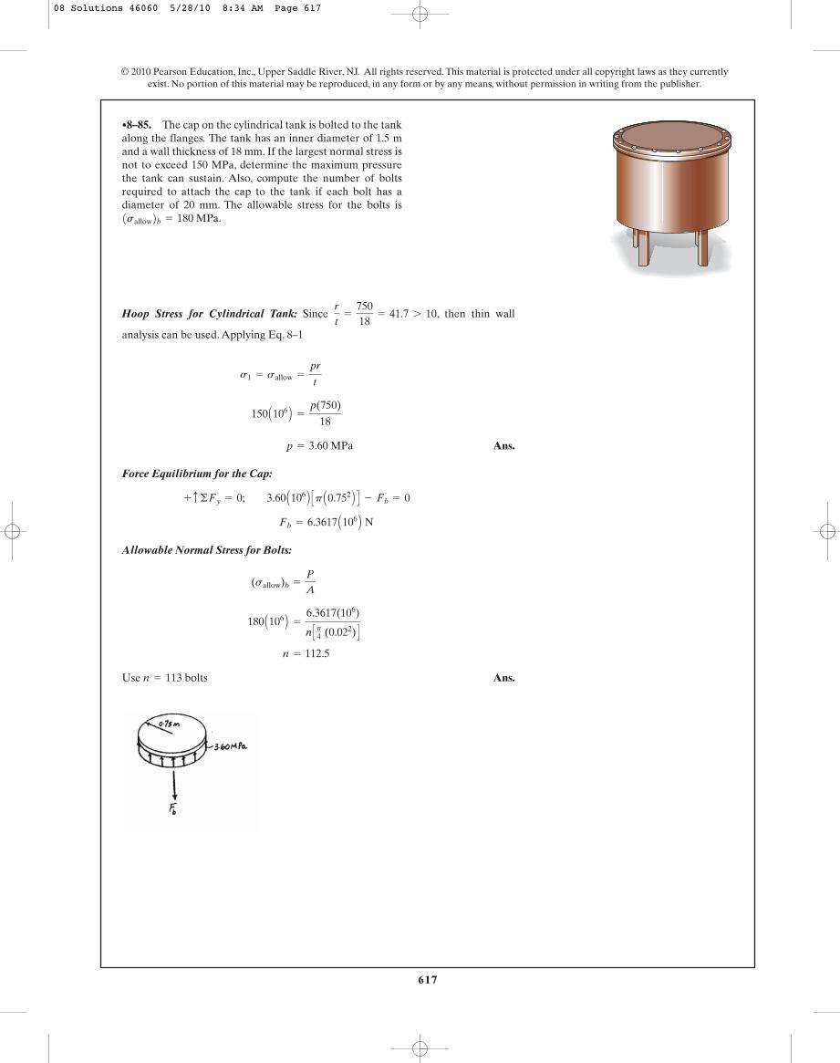
617
© 2010 Pearson Education, Inc., Upper Saddle River, NJ. All rights reserved. This material is protected under all copyright laws as they currentlyexist. No portion of this material may be reproduced, in any form or by any means, without permission in writing from the publisher.
Hoop Stress for Cylindrical Tank: Since , then thin wall
analysis can be used. Applying Eq. 8–1
Ans.
Force Equilibrium for the Cap:
Allowable Normal Stress for Bolts:
Use Ans.n = 113 bolts
n = 112.5
180 A106 B =
6.3617(106)
n Cp4 (0.022) D
(sallow)b =
P
A
Fb = 6.3617 A106 B N
+ c ©Fy = 0; 3.60 A106 B Cp A0.752 B D - Fb = 0
p = 3.60 MPa
150 A106 B =
p(750)
18
s1 = sallow =
pr
t
r
t=
75018
= 41.7 7 10
•8–85. The cap on the cylindrical tank is bolted to the tankalong the flanges. The tank has an inner diameter of 1.5 mand a wall thickness of 18 mm. If the largest normal stress isnot to exceed 150 MPa, determine the maximum pressurethe tank can sustain. Also, compute the number of boltsrequired to attach the cap to the tank if each bolt has adiameter of 20 mm. The allowable stress for the bolts is1sallow2b = 180 MPa.
08 Solutions 46060 5/28/10 8:34 AM Page 617

618
© 2010 Pearson Education, Inc., Upper Saddle River, NJ. All rights reserved. This material is protected under all copyright laws as they currentlyexist. No portion of this material may be reproduced, in any form or by any means, without permission in writing from the publisher.
Hoop Stress for Cylindrical Tank: Since , then thin wall
analysis can be used. Applying Eq. 8–1
Ans.
Longitudinal Stress for Cylindrical Tank:
Ans.
Force Equilibrium for the Cap:
Ans. Fb = 132536 N = 133 kN
+ c ©Fy = 0; 1.20 A106 B Cp A0.752 B D - 16Fb = 0
s2 =
pr
2t=
1.20(106)(750)
2(18)= 25.0 MPa
s1 =
pr
t=
1.20(106)(750)
18= 50.0 MPa
r
t=
75018
= 41.7 7 10
8–86. The cap on the cylindrical tank is bolted to the tankalong the flanges. The tank has an inner diameter of 1.5 mand a wall thickness of 18 mm. If the pressure in the tank is
determine the force in each of the 16 boltsthat are used to attach the cap to the tank. Also, specify thestate of stress in the wall of the tank.
p = 1.20 MPa,
08 Solutions 46060 5/28/10 8:34 AM Page 618


