Embed Size (px)
Citation preview
Agglomeration Processes for Waste Utilization in a Circular Economy

Agglomeration Processes for Waste Utilization in a Circular Economy
Gabriel Borowski
MONOGRAFIENr 167
Warszawa 2020
WYDAWNICTWO POLSKIEJ AKADEMII NAUK
KOMITET INŹYNIERII ŚRODOWISKA
Publishing by Polska Akademia Nauk
© Copyright by Komitet Inżynierii Środowiska PAN, 2020ISBN: 978-83-63714-66-6
Editorial Board Members
prof. Anna Maria Anielakprof. Kazimierz Banasik
prof. Ryszard Błażejewskiprof. Michał Bodzek
dr hab. inż. Andrzej Bogdałdr hab. inż. Klaudia Borowiak
dr hab. inż. Tomasz Ciesielczukdr hab. Lidia Dąbek
dr hab. inż. Wojciech Dąbrowskidr hab. inż. Magdalena Gajewskadr hab. inż. Katarzyna Ignatowicz
prof. Krzysztof Jóźwiakowskiprof. Katarzyna Juda-Rezler
dr hab. inż. Radosław Juszczakdr hab. inż. Tomasz Ryszard Kałuża
dr hab. inż. Agnieszka Karczmarczykdr hab. inż. Piotr Koszelnikdr hab. inż. Leszek Książek
prof. Hanna Obarska-Pempkowiakprof. Krzysztof Pulikowski
dr hab. inż. Stanisław Rybickidr hab. inż. Mariusz Sojkaprof. Kazimierz Szymański
dr hab. inż. Tomasz Tymińskiprof. Józefa Wiater
dr hab. inż. Mirosław Wiatkowskiprof. Tomasz Winnicki
prof. Maria Włodarczyk-Makułaprof. Ewa Wojciechowska
prof. Irena Wojnowska-Baryła
Editor-in-Chiefprof. Lucjan Pawłowski
Reviewersprof. Marek Gromiec
prof. Tomasz Winnicki
Language Editormgr Szymon Obrusiewicz
PrintingTOP Agencja Reklamowa Agnieszka Łuczak
ul. Toruńska 148, 87-800 Włocławekwww.agencjatop.pl
Contents
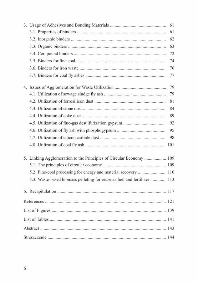
List of Symbols ..................................................................................................... 7
Introduction ........................................................................................................ 9
1. Characterization of Particulate Materials ..................................................... 13 1.1. Particle size distribution ........................................................................ 13 1.2. The behavior of particulate materials .................................................... 15 1.3. Specified physical and mechanical properties of particulate materials 16 1.4. Management of suspensions .................................................................. 19 1.5. Examples of particulate industrial waste ............................................... 19 1.6. The origin of particulate industrial waste .............................................. 20 1.7. Reasons for agglomeration of particulate materials .............................. 21
2. Selected Methods of Agglomeration ............................................................ 23 2.1. Solidification ......................................................................................... 23 2.2. Granulation ............................................................................................ 28 2.2.1. Fine coal granulation ................................................................... 31 2.2.3. Fly ash granulation ...................................................................... 34 2.3. Extrusion ............................................................................................... 35 2.3.1. Charcoal extrusion ....................................................................... 38 2.3.2. Biocomposites extrusion ............................................................. 41 2.4. Briquetting ............................................................................................. 43 2.4.1. Metal fine waste briquetting ........................................................ 44 2.4.2. Stone dust briquetting .................................................................. 45 2.4.3. BBQ fuel briquetting ................................................................... 46 2.4.4. Coal and biomass briquetting ...................................................... 47 2.4.5. Fly ash briquetting ....................................................................... 51 2.5. Agglomeration with high temperature post-treatment .......................... 53 2.5.1. Sintering ...................................................................................... 53 2.5.2. Vitrification .................................................................................. 54
6
3. Usage of Adhesives and Bonding Materials ................................................. 61 3.1. Properties of binders .............................................................................. 61 3.2. Inorganic binders ................................................................................... 62 3.3. Organic binders ..................................................................................... 63 3.4. Compound binders ................................................................................. 72 3.5. Binders for fine coal .............................................................................. 74 3.6. Binders for iron waste ........................................................................... 76 3.7. Binders for coal fly ashes ...................................................................... 77
4. Issues of Agglomeration for Waste Utilization ............................................. 79 4.1. Utilization of sewage sludge fly ash ...................................................... 79 4.2. Utilization of ferrosilicon dust .............................................................. 81 4.3. Utilization of stone dust ........................................................................ 84 4.4. Utilization of coke dust ......................................................................... 89 4.5. Utilization of flue-gas desulfurization gypsum ..................................... 92 4.6. Utilization of fly ash with phosphogypsum .......................................... 95 4.7. Utilization of silicon carbide dust ......................................................... 98 4.8. Utilization of coal fly ash ...................................................................... 101
5. Linking Agglomeration to the Principles of Circular Economy ................... 109 5.1. The principles of circular economy ....................................................... 109 5.2. Fine-coal processing for energy and material recovery ........................ 110 5.3. Waste-based biomass pelleting for reuse as fuel and fertilizer ............. 113
6. Recapitulation ............................................................................................... 117
References ......................................................................................................... 121
List of Figures ................................................................................................... 139
List of Tables ..................................................................................................... 141
Abstract ............................................................................................................. 143
Streszczenie ....................................................................................................... 144
7
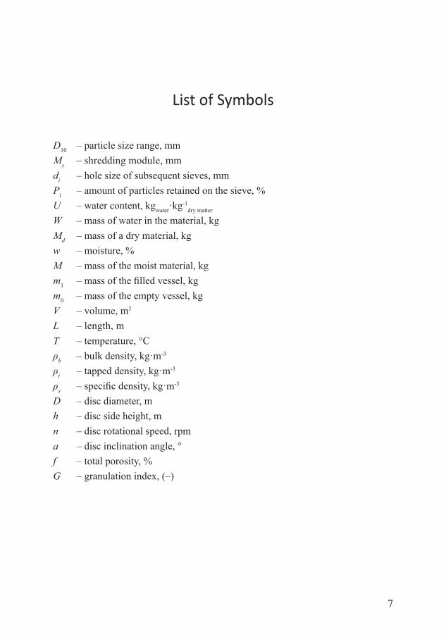
List of Symbols
D10 – particle size range, mmMs – shredding module, mmdi – hole size of subsequent sieves, mmPi – amount of particles retained on the sieve, %U – water content, kgwater·kg-1
dry matter
W – mass of water in the material, kgMd – mass of a dry material, kgw – moisture, %M – mass of the moist material, kgm1 – mass of the filled vessel, kgm0 – mass of the empty vessel, kgV – volume, m3 L – length, mT – temperature, °Cρb – bulk density, kg·m-3
ρt – tapped density, kg·m-3 ρs – specific density, kg·m-3
D – disc diameter, m h – disc side height, m n – disc rotational speed, rpm a – disc inclination angle, °f – total porosity, % G – granulation index, (–)

9
Introduction
In this monograph, the effective methods for the development waste man-agement, especially for the recovery of natural resources, were presented. The book is a concise recapitulation of nearly twenty years of the author’s research activity related to the agglomeration of particulate raw materials and industrial waste for their utilization.
Fine materials and waste from industrial processes are troublesome in storage, transport and utilization, mainly due to their large volume and dusting. Therefore, originally the main reason for developing the agglomeration processes was to eliminate the afore-mentioned disadvantages. However, it was found that the modifications introduced to the merging processes of materials enabled obtaining a new type of products widely used in various applications.
For the agglomeration of the inorganic materials, often containing haz-ardous substances, the disposal and transformation technologies are available for the safe products that can be used, for example, in civil engineering and construction. In turn, the agglomeration of the materials containing organ-ic substances or fine coal, producing alternative fuels for energy recovery. Obviously, the combustion of these fuels results in a subsequent generation of waste in the form of bottom and fly ash, but they can be successfully further agglomerated to produce more valuable products.
The numerous examples of the use of various agglomeration techniques showed the results of the complete utilization of the most commonly used par-ticular materials and waste in Poland. An additional effect of the agglomeration processes was also the fulfilment of the circular economy criteria. The idea of circular economy justifies the material circulation in nature, for example, ag-glomerated ashes are converted to a useful product or material. This concept also matches with the principles of sustainable development of the environment.
The goal of this monograph was a description of selected agglomeration techniques, such as solidification, granulation, extrusion and briquetting. Post-agglomeration high-temperature processing was also discussed, including sinter-ing and vitrification. These techniques were in the interest of the author’s long-time research; therefore, they were discussed on the recapitulation of experiences supported by worldwide literature.
The book consists of six chapters, including the following:
• The characteristics of particulate materials were presented in the first chapter. The content of this chapter focuses on the testing, analysis and characterization
10
Agglomeration Processes for Waste Utilization in a Circular Economy
of particulate materials, including both artificial and natural ones, in the sludge state or dry powders. The testing methods of materials in bulk were covered for a wide range of applications in laboratory and industry. The behavior of particulate materials was discussed depending on particle size, size distribution, shape and bulk properties, and other. The main physical and mechanical proper-ties of particulate materials were specified and described. The examples of by-products and industrial wastes in loose form as well as the disposal processes were discussed in detail. It was noted that using the agglomeration processes can be an effective way of preventing the dusting of particulate materials, also the conglomerates produced can be utilized for waste reduction.
• Chapter two describes the main methods of agglomeration and post-agglom-eration processes in detail. First, solidification was mentioned as the simplest technique that requires the least energy input compared to other agglomera-tion methods. Depending on the specification of the waste to be treated, the final product of the solidification could be reintegrated at site, disposed of and integrated at approved landfills or used for construction. The equipment of the solidification unit and its applications was fully described.
Then, the granulation technique was discussed in accordance with the recent progress and advantages. Two main schemes showed that a disc granulator and a drum granulator can be used to make high quality granules. Typical materials and waste were discussed, such as: silicon carbide dust, stone dust, fine coal, and fly ash. It was noted that favorable structural parameters and mechanical strength of the granules was obtained for the selected types of particulate materials.
Next, extrusion was shown as an example of low-pressure agglomeration of a raw material into a product of uniform shape and density by forcing it through a die under controlled conditions. The design of the extruder was shown with characterization of its main features. The specified parameters, in combination with the screw and die selection, were discussed. Some examples of appli-cations were provided. It was proven that extrusion can be effective for trans-forming raw materials and waste in particulate form into agglomerated products of various sizes, shapes, textures, composition and content.
Further, the briquetting process was shown as a high-pressure agglomeration method, resulting in an increase in the energy expenditure that allows obtain-ing a highly concentrated material lump. The agglomerated products were ob-tained in a specific shape and dimensions, and with high mechanical strength. The briquetting issues for the selected types of particular materials and waste were discussed: metal filings, stone dust, charcoal, coal with biomass, fly ash of lignite and coal. The briquetting of particulate material qualified for obtaining durable products from the processing of most types of industrial waste.
11
Introduction
Finally, the post-treatment processes involving agglomeration with high tem-perature of sintering and vitrification were discussed. Both are quite similar, but differ mostly with temperature maintenance and other specific character-istics of utilizing. Sintering was described for the manufacturing of artificial aggregates from industrial wastes, usually fly ash and bottom ash. It was noted that sintered lightweight aggregates were appropriate for structural applica-tions. Vitrification was approved for the formation of an impermeable and durable structure of glass. This method was used to treat hazardous waste with unfavorable physical properties, on the examples shown. Numerous test show very low levels of toxic metals in the water extracts of the final prod-ucts. It was also recorded that the vitrified radioactive waste was character-ized by a high resistance to mechanical damage, low chemical reactivity, and a minimal release into the environment.
• Chapter three presents the usage of adhesives and bonding materials for ag-glomeration, in order to obtain strong bodies. A detailed characterization of the binding materials was presented, divided into inorganic binders, organic binders, and compound binders. Many examples of the agglomeration effect of binders due to their adhesive and thickening properties show their large influence on the properties and usage of lumps. It was noted that most of the afore-mentioned additives did not pose any threat to the environment, as well as were easily available and relatively cheap.
• The fourth chapter is devoted to the examples of agglomeration processes for waste utilization. The research results were presented on both the laboratory and industrial scale, and pertained to the following processes: solidification of fly ashes from the incineration of sewage sludge, ferrosilicon dust briquetting, the stone dust briquetting, briquetting of coke dust, briquetting of flue-gas des-ulfurization gypsum, granulation of fly ash with phosphogypsum, granulation of silicon carbide dust, and fly ash granulation of lignite and coal. Material, meth-ods and testing procedure were described in each case. The results were shown and discussed, while the most important findings were highlighted.
• In chapter five, the principles of circular economy were explained and the sam-ple processes of waste management were presented in the context of meeting these principles. Two cases of the agglomeration were described: (1) fine-coal processing for energy and material recovery, and (2) waste-based biomass pel-leting for reuse as fuel and fertilizer. These examples show the advantages of complete utilization and waste-free cycle of materials. Owing to the circulat-ing management of the particular materials, no waste that could threaten the natural environment was left. The synergy of the most important policy ob-jectives of the European Community for the particulate materials sustainable management was discussed.
12
Agglomeration Processes for Waste Utilization in a Circular Economy
• Chapter six presents the recapitulation and conclusions related to the research problems described above.
The issues discussed in this monograph show that the agglomeration processes were of great interest to industry both for the utilization of the manufacturing waste and the use of fine raw material resources. The processing of these materials, ow-ing to the existing well-known and systematically modified merging technologies, bring increasingly better results.
The presented book contains fully up-to-date information of great cognitive significance, which may inspire scientists and engineers. They can further inves-tigate the methods of transforming materials by means of various agglomeration processes, to manufacture useful products in accordance with the principles of circular economy.
13
Chapter I
Characterization of Particulate Materials
1. Particle size distribution
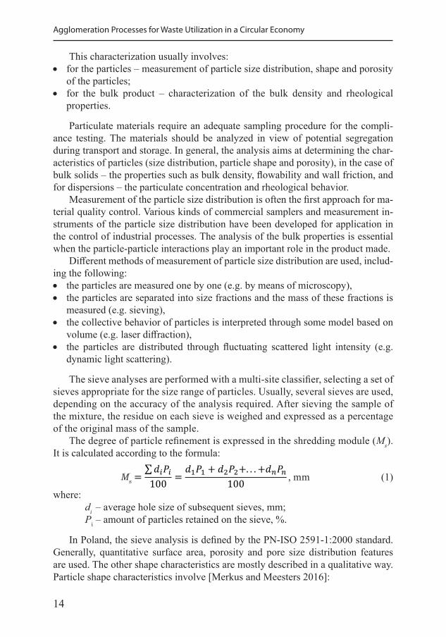
This monograph relates to the particulate raw materials and industrial wastes occurring in the solid and liquid form, containing grains smaller than 10.0 mm (Table 1). These materials often arise with various admixtures and impurities that should be separated.
Due to the grain size relationships, the material structure can be distinguished as plain – in which all grain sizes are approximately equal, and vari-grained – where grains differs in size. On the basis of the shape, the grains with sharp edges, smoothed, and mixed ones, were noted [Lutyński 2005].
The particulate materials are characterized by various properties. One of the most important is the particle size distribution, i.e. the quantitative distribution of material grains in terms of their size (Table 1). The diameter a sphere is easily identified. For the non-spherical particles, the size is typically given in terms of the diameter of an equivalent sphere (D), which depends upon the measurement principle and instrument.
The particle shape of most industrial materials shows almost equal length, width and thickness, having an aspect ratio close to 1. These particles are called isometric or regular. The effect of particle shape may dominate that of size, for example by causing specific strength. The particles can contain pores, which decrease the appar-ent particle density and largely increase the specific surface area. Characterization of particulate materials is required in order to test whether they comply with their required quality and specifications, with respect to the environmental requirements.
Table 1. Fineness of particles and width of particle size distributions [Merkus and Meesters 2016]
Fineness (D90) Width of particle size distribution (D90/D10 ratio)
Nanoparticles <0.1 μm Monosized <1.02
Ultrafine 0.1–1 μm Ultra narrow 1.02–1.05
Fine 1–10 μm Narrow 1.05–1.5
Medium 10–1000 μm Medium 1.5–4
Coarse 1–10 mm Broad 4–10
Very coarse >10 mm Very broad >10
14
Agglomeration Processes for Waste Utilization in a Circular Economy
This characterization usually involves: • for the particles – measurement of particle size distribution, shape and porosity
of the particles; • for the bulk product – characterization of the bulk density and rheological
properties.
Particulate materials require an adequate sampling procedure for the compli-ance testing. The materials should be analyzed in view of potential segregation during transport and storage. In general, the analysis aims at determining the char-acteristics of particles (size distribution, particle shape and porosity), in the case of bulk solids – the properties such as bulk density, flowability and wall friction, and for dispersions – the particulate concentration and rheological behavior.
Measurement of the particle size distribution is often the first approach for ma-terial quality control. Various kinds of commercial samplers and measurement in-struments of the particle size distribution have been developed for application in the control of industrial processes. The analysis of the bulk properties is essential when the particle-particle interactions play an important role in the product made.
Different methods of measurement of particle size distribution are used, includ-ing the following: • the particles are measured one by one (e.g. by means of microscopy), • the particles are separated into size fractions and the mass of these fractions is
measured (e.g. sieving), • the collective behavior of particles is interpreted through some model based on
volume (e.g. laser diffraction), • the particles are distributed through fluctuating scattered light intensity (e.g.
dynamic light scattering).
The sieve analyses are performed with a multi-site classifier, selecting a set of sieves appropriate for the size range of particles. Usually, several sieves are used, depending on the accuracy of the analysis required. After sieving the sample of the mixture, the residue on each sieve is weighed and expressed as a percentage of the original mass of the sample.
The degree of particle refinement is expressed in the shredding module (Ms). It is calculated according to the formula:
𝑀𝑀 =∑𝑑𝑑𝑖𝑖𝑃𝑃𝑖𝑖100 = 𝑑𝑑1𝑃𝑃1 + 𝑑𝑑2𝑃𝑃2+. . . +𝑑𝑑𝑛𝑛𝑃𝑃𝑛𝑛
100
𝑈𝑈 = 𝑊𝑊𝑀𝑀𝑠𝑠
𝑤𝑤 = 100𝑊𝑊𝑀𝑀
𝑤𝑤 = 100 𝑊𝑊𝑀𝑀𝑠𝑠 +𝑊𝑊
𝜌𝜌𝑠𝑠 =𝑚𝑚1 −𝑚𝑚0
𝑉𝑉1
𝑞𝑞𝑢𝑢 =𝑚𝑚1 −𝑚𝑚0𝑉𝑉2 − 𝑉𝑉1
, mm (1)
where: di – average hole size of subsequent sieves, mm; Pi – amount of particles retained on the sieve, %.
In Poland, the sieve analysis is defined by the PN-ISO 2591-1:2000 standard. Generally, quantitative surface area, porosity and pore size distribution features are used. The other shape characteristics are mostly described in a qualitative way.Particle shape characteristics involve [Merkus and Meesters 2016]:
Ms
15
Chapter I. Characterization of Particulate Materials
• macro-shape features, related to the 3-dimensional form of the particles (length, width and thickness), expressed e.g. as aspect ratio;
• meso-shape features, related to the general aspects of roundness and angularity; • micro-shape features, related to roughness and smoothness as well as porosity,
pore size distribution and other structural heterogeneities.
The quality of a material in relation to the specifications for particle size and shape can be expressed as follows: • pore size distribution type; • particle size range, often expressed in D10 and D90 (with an extra subscript re-
lated to the particle size distribution basis, being number, area, volume, etc.); • a weighted mean size; • the maximum allowable oversize (above a stated size), or undersize (below
a stated size), or the minimum and/or maximum amount in one or more stated size classes;
• the parameters of a modeled distribution; • surface area per unit volume or mass; • porosity and pore size distribution; • specified particle shape and shape homogeneity, e.g. spheres, cubes, rounded,
angular.
Additional properties are often laid down in specifications, for example bulk density, color, degree of contamination, flowability and dissolution time.
2. The behavior of particulate materials
The behavior of particulate materials depends upon particle size, size distribu-tion, shape and bulk properties, and other. The quality aspects involve, for example [Merkus and Meesters 2016]: • rheological properties of powders (important for steady flow and dosage), • fluidization behavior (important if a fluid bed is applied in its application), • dusting behavior (related to the health hazards and explosion risks), • particle packing density (e.g. bulk density), • rheological behavior of dispersions, especially at high particulate concentra-
tions (important during processing), • optical properties (e.g. color, gloss, transparency), • surface properties, • dissolution rate.
The behavior of particulate materials may be very complex since the inter-par-ticle distance is often small and the mutual interactions of the particles occur. The mechanical interactions between particles dominate in dry powders. If the particles are regular and have sizes larger than about 20–50 μm in a medium size distribution,
16
Agglomeration Processes for Waste Utilization in a Circular Economy
the powders show a behavior that depends mostly upon bulk density and size dis-tribution. The inter-particle attractive forces are small in comparison to the particle mass, so they can move and segregate easily. Dry powders, where the particles have sizes smaller than about 20 μm, behave quite differently from the powders contain-ing larger, regular particles. They are cohesive enough, as the inter-particle forces are large in comparison to particle mass.
If the particles in a powder show a broad size distribution, then the bulk density strongly depends upon the their consolidation. Consolidation generally results in significantly greater bulk density than in the loose state. This is because the smaller particles may fill the voids in between the larger ones, but only after breaking the attractive inter-particle forces by the induced external forces. Higher bulk density also means that the bed porosity is significantly smaller while the mechanical in-teractions are greater.
In addition to the mechanical interactions between particles, the rheological be-havior is usually of prime importance in relation to material processing. Typically, the rheological behavior is determined in steady-state procedures, which may in-clude some pretreatment to break-up the particulate structures. The rheological be-havior of bulk powders is usually characterized through the measurements of bulk density (free and tapped) and angle of repose [Borowski 2012a].
3. Specified physical and mechanical properties of particulate materials
Humidity significantly affects other physical and mechanical properties of par-ticulate materials, such as the external and internal friction coefficient, strength, elastic properties and others. The measure of humidity is the amount of water con-tained in a mass of material. From the point of view of water movement in moist loose material, the method of water binding is important. There are three ways of binding water: chemical, physicochemical and mechanical binding.
The chemically bound water is included in the chemical compound of which the material is made. This water does not escape from the body when heated above the boiling point. A body containing only the chemically bound water is called dry. The physicochemical bond of water can be an adsorptive, osmotic or structural. This water can be removed during the drying process, which can be accompanied by a change in the existing structure and properties of the material. The mechani-cally bound water can form a thin layer on the surface of the particles, or fill the free spaces between the particles. The materials containing the mechanically bound water are called moist. As a result of natural or artificial drying, the mechanically bound water can be evaporated.
The water content U is the ratio of the mass of water W contained in the mate-rial to the mass of a completely dry material Ms expressed in kilograms of water per kilogram of dry matter [Borowski 2009a]:
17
Chapter I. Characterization of Particulate Materials
𝑀𝑀 =∑𝑑𝑑𝑖𝑖𝑃𝑃𝑖𝑖100 = 𝑑𝑑1𝑃𝑃1 + 𝑑𝑑2𝑃𝑃2+. . . +𝑑𝑑𝑛𝑛𝑃𝑃𝑛𝑛
100
𝑈𝑈 = 𝑊𝑊𝑀𝑀𝑠𝑠
𝑤𝑤 = 100𝑊𝑊𝑀𝑀
𝑤𝑤 = 100 𝑊𝑊𝑀𝑀𝑠𝑠 +𝑊𝑊
𝜌𝜌𝑠𝑠 =𝑚𝑚1 −𝑚𝑚0
𝑉𝑉1
𝑞𝑞𝑢𝑢 =𝑚𝑚1 −𝑚𝑚0𝑉𝑉2 − 𝑉𝑉1
, kgwater·kg-1dry matter (2)
Moisture w, expressed as a percentage, is the ratio of the mass contained in the material of mechanically bound water W to the mass of the moist material M:
𝑀𝑀 =∑𝑑𝑑𝑖𝑖𝑃𝑃𝑖𝑖100 = 𝑑𝑑1𝑃𝑃1 + 𝑑𝑑2𝑃𝑃2+. . . +𝑑𝑑𝑛𝑛𝑃𝑃𝑛𝑛
100
𝑈𝑈 = 𝑊𝑊𝑀𝑀𝑠𝑠
𝑤𝑤 = 100𝑊𝑊𝑀𝑀
𝑤𝑤 = 100 𝑊𝑊𝑀𝑀𝑠𝑠 +𝑊𝑊
𝜌𝜌𝑠𝑠 =𝑚𝑚1 −𝑚𝑚0
𝑉𝑉1
𝑞𝑞𝑢𝑢 =𝑚𝑚1 −𝑚𝑚0𝑉𝑉2 − 𝑉𝑉1
, % (3)
because M = Ms + W, we obtain:
𝑀𝑀 =∑𝑑𝑑𝑖𝑖𝑃𝑃𝑖𝑖100 = 𝑑𝑑1𝑃𝑃1 + 𝑑𝑑2𝑃𝑃2+. . . +𝑑𝑑𝑛𝑛𝑃𝑃𝑛𝑛
100
𝑈𝑈 = 𝑊𝑊𝑀𝑀𝑠𝑠
𝑤𝑤 = 100𝑊𝑊𝑀𝑀
𝑤𝑤 = 100 𝑊𝑊𝑀𝑀𝑠𝑠 +𝑊𝑊
𝜌𝜌𝑠𝑠 =𝑚𝑚1 −𝑚𝑚0
𝑉𝑉1
𝑞𝑞𝑢𝑢 =𝑚𝑚1 −𝑚𝑚0𝑉𝑉2 − 𝑉𝑉1
, % (4)
By the bulk density of particulate material ρb we mean the mass of a unit volume of this material (1 m3) in a loosely packed state. The bulk density is usually expressed in kg·m-3. The bulk density is calculated from the formula:
2
𝜌𝜌𝑏𝑏 =𝑚𝑚1 −𝑚𝑚0
𝑉𝑉1
𝜌𝜌𝑡𝑡 =𝑚𝑚1 −𝑚𝑚0𝑉𝑉2 − 𝑉𝑉1
, kg·m-3 (5)
where: m1 – mass of the filled vessel, kg; m0 – mass of the empty vessel, kg; V1 – volume of the material, m3.
In terms of their bulk density, the particulate materials are: • light, for ρb = 600 kg·m-3; • mid-heavy, for ρb = 600–1100 kg·m-3; • heavy, for ρb = 1100–2000 kg·m-3.
In addition to bulk density, for processing and transporting of materials, it is necessary to know the specific density. The specific density of the material is deter-mined by the average density of the particles it consists of. The experience of the specific density is necessary, among others for designing conveyors, including: • conveyors performance, • type of conveyor, • forces in conveyors, • pressure on the walls and outlets, • filling system.
Another indicator for evaluating the properties of the particulate material is tapped density – ρt. For specific vibration conditions to which the material sample is subjected, this indicator determines the volume reduction, as:
2
𝜌𝜌𝑏𝑏 =𝑚𝑚1 −𝑚𝑚0
𝑉𝑉1
𝜌𝜌𝑡𝑡 =𝑚𝑚1 −𝑚𝑚0𝑉𝑉2 − 𝑉𝑉1
, kg·m-3 (6)
where: V2 – volume of the material after tapping, m3
V1 – volume of the material before tapping, m3
18
Agglomeration Processes for Waste Utilization in a Circular Economy
Caking of some loose materials occurs spontaneously after long-term storage, i.e. they form larger, non-spattering bodies. The tendency to caking increases with the height of the layer of the stored material and the largest lumps are formed primarily in the further part of the layer. Moist loose materials (i.e. the materials containing the mechanically bound water) freeze at ambient temperatures below 0 °C, creating a compact mass which is hard to break down.
Another feature that characterizes the particulate material is its adhesion. High adhesion is shown especially by moist materials. Adhesion can be explained by the interaction of material particles, walls limiting loose particles and water, forming on the surface of particles of wet material. The adhesion of particles can be signifi-cantly reduced by a precise choice of vessel wall and surface smoothness.
When loose materials spill out through the outlets from the tanks, fixed vaults are formed, limiting or even completely preventing further spilling of the material from the tank. The vault formation is influenced by the particle size and the ratio of the particle size to the outlet opening size. The greatest tendency to form vaults is found in easily caking loose materials.
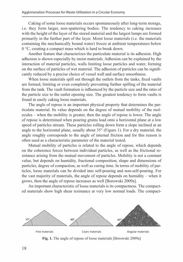
The angle of repose is an important physical property that determines the par-ticulate material. Its value depends on the degree of mutual mobility of the mol-ecules – when the mobility is greater, then the angle of repose is lower. The angle of repose is determined when pouring grains load onto a horizontal plane at a low speed of particles stream. These particles rolling down form a slope inclined at an angle to the horizontal plane, usually about 35° (Figure 1). For a dry material, the angle roughly corresponds to the angle of internal friction and for this reason is often used as a characteristic parameter of the material tested.
Mutual mobility of particles is related to the angle of repose, which depends on the coherence forces between individual particles, as well as the frictional re-sistance arising from the mutual movement of particles. Mobility is not a constant value, but depends on humidity, fractional composition, shape and dimensions of particles, degree of compaction, as well as curing time. In terms of mobility of par-ticles, loose materials can be divided into self-pouring and non-self-pouring. For the vast majority of materials, the angle of repose depends on humidity – when it grows, then the angle of repose increases as well [Borowski 2009a].
An important characteristic of loose materials is its compactness. The compact-ed materials show high shear resistance at very low normal loads. The compact-
Fig. 1. The angle of repose of loose materials [Borowski 2009a]
Fine materials Coars materials Angular materials
19
Chapter I. Characterization of Particulate Materials
ness can be explained by the coherence of its particles. In homogeneous materials, coherence is the result of intermolecular interaction, i.e. cohesion forces, opposing the separation of material particles.
Hygroscopicity, i.e. the ability to easily absorb water vapor and water from the environment, is another characteristic of particulate materials. They should be stored under the conditions that prevent water absorption, i.e. in hermetic contain-ers; ventilation of storage rooms should be ensured as well.
4. Management of suspensions
The particulate materials also occur in the liquid form as contaminated sus-pensions, emulsions and sludges. The main impurities are oils, greases, miner-als as well as metals and their compounds. These sludges, containing significant amounts of water, are very difficult to handle in their original form and require treatment. They are often collected in containers, tanks and storage plots. During such storage, a gradual loss of moisture occurs. For the further use of suspensions and sludges, it is necessary to remove the water almost completely and sepa-rate any impurities using various methods and technical processes. These include the physical and chemical processes. The basic physical processes are: filtration, ultrafiltration, flotation, flocculation, electrocoagulation, osmosis, extraction, mixing, thickening, sedimentation, comminution, centrifugation, adsorption, de-sorption, melting, freezing, drying and distillation. In turn, the most commonly used chemical processes are: ion exchange, neutralization, oxidation, hydrolysis, precipitation, catalytic transformation, electrolysis, absorption and cementation [Borowski and Kuczmaszewski 2005].
The filtration process carried out by a plate filtration press reduces the sludge hydration by about 20–40%. It is commonly used for dewatering sludge in waste-water treatment plants, electroplating plants, tanneries and food industry plants. The filter plates connected together form chambers in which sediment collects. Polypropylene filter cloths are applied between the plates. The filter sediments should be further dried both under the natural conditions on the storage plot and thermally in electric dryers. During drying, the sludge can be transformed into a loose material or granulate.
5. Examples of particulate industrial waste
The examples of by-products and industrial wastes in the loose form are listed below [Hryniewicz et al. 2006]: • coal slurries, • flotation waste, • lead and zinc dust, • copper dust and dross,
20
Agglomeration Processes for Waste Utilization in a Circular Economy
• bronze shavings, • regenerative iron oxide, • zendra, • scale slurry, • slags, • sludge from blast furnace gas treatment plants, • converter sludge, • grinding sludge deposits, • ferromanganese, • ferro-silicon, • zinc oxide, • cadmium sponge, • aluminum dross, • calcium fluoride, • quicklime, • carbide, • flue-gas desulphurization gypsum, • mineral wool waste, • dust from rock aggregate processing.
Most of these by-products and wastes are subjected to recovery or disposal pro-cesses. However, many valuable materials are still directed to landfill. This mainly applies to: • wastes arising from the mining and enrichment of ores and other mineral re-
sources; • residues from agriculture, horticulture, farming, fishing, forestry and food pro-
cessing; • by-products from the production of paper, cardboard, pulp, boards and furniture; • residues from the leather tanneries and textile industry; • waste from the production, preparation and use of inorganic compounds, • waste from the organic synthesis industry; • waste from the production of protective coatings (paints, varnishes, ceramic
enamels), putty, glues, sealants and printing inks; • inorganic products from thermal processes, • waste from shaping and surface machining of metals and plastics, • materials from the construction, renovation and dismantling of building and
road structures.
6. The origin of particulate industrial waste
Dust and sludges from the iron and steel industry. Depending on the place of production, the following wastes are generated in the iron and steel metallurgy: blast furnace and converter slag, blast furnace gas and converter gas, blast furnace
21
Chapter I. Characterization of Particulate Materials
and steel dust, blast furnace and steel slurry, dust from waste gas treatment at the steelworks, dust from the dedusting of blast furnaces, dust from the dedusting of the plant hall, precipitated in the dedusting station of the plant halls, sinter dust and sinter sludge [Plewa and Mysłek 2001]. The iron sludge arises primarily from the wet dedusting of gases and flue gases in the hot sinter mixing plant, blast furnace gas treatment plant and converter gas. In turn, the blast furnace sludge is a fine fraction of charge materials captured during wet blast furnace gas treatment. The sinter sludge is formed by wet reception of dust from sintering belts. The iron dusts are retained in the dust collection room and collected in the tank, and then transported to the storage room. In turn, the blast furnace dust is a fine fraction of the charge materials captured in a static dust collector during the dry blast furnace gas cleaning process.
Dusts from the dedusting devices and sludges from the wet dedusting devices are a valuable materials in metallurgical furnaces due to their chemical composi-tion. However, these dusts remain large problems during storage and transport. The dust from the blast furnace room together with sludge can be dosed into the averag-ing mixture in the iron and steel production. Recycling of iron dust and sludge takes place in electric steel converter [Robak and Matuszek 2008].
Iron waste. The waste containing significant amounts of particulate iron in-clude: zendra, blast furnace dust, mill scale, converter sludge, sludge from wet treatment of blast furnace gas, dusty ferro-manganese and fine ferro-silicon. The grinding sludge, created, among others when grinding bearing balls and other roll-ing bearing components also constitutes an important group.
Coal slurries. Fine coal fractions from the extraction, enrichment and use of hard coal and lignite include: coal sludge, flotation waste, scouring, coke dust, coke breeze from gasification processes and concentrated products of fuel combustion. Significant amounts of fine coal fractions are treated as waste and stored in settling plots or in mining excavations.
Waste from the energy industry. The wastes from the energy industry include slags from hard and brown coal combustion, fly ashes, ash and slag mixtures from wet removal of furnace waste, microspheres, flue-gas desulphurization gypsum, desulfurization products according to the wet or dry cooling method, mixture of fly ash and calcium waste from flue-gas desulfurization and waste from fluidized bed combustion.
7. Reasons for agglomeration of particulate materials
Dusting of particles, both raw materials and industrial waste, poses a threat to living organisms and the environment. Various methods are used to reduce dusting at individual stages of the manufacturing process – production, storage, loading and transport of loose materials. These methods can be divided into [Hycnar et al. 2017]:
22
Agglomeration Processes for Waste Utilization in a Circular Economy
• processing to a non-dusting form, • technical elimination or reduction of dusting, • protection of loose materials against dusting.
In practical applications, bulk materials undergo processing consisting of: • reducing the proportion of dusting fractions in the materials (eg. screening,
mixing), • application of emulsifiers, such as “Paste and thickened tailing”, “Deep cone
paste” and “Deep cone thickener”; • stabilizing materials into blocks with cement binders, • agglomeration of small grains (eg. granulation, briquetting); • thermal processes (eg. sintering, vitrification).
This work focuses on the aspects of using agglomeration processes as an ef-fective way of preventing the dusting of particulate raw materials and waste. Importantly, the produced conglomerates can be fully utilized for waste reduction in material management. Therefore, the agglomeration was proven as an important technique of circular economy. Finally, wider implementation of these processes may contribute to the further progress of environmental protection sciences.
23
Chapter II
Selected Methods of Agglomeration
2.1. Solidification
The solidification, also known under the term stabilization, is based on the physical encapsulation of the contaminants and their chemical fixation in the solid matrix of a newly generated product. The input material and waste are intensively mixed in continuous or batch wise operated mixers with additives like cement, limestone, gypsum, fly ash or blast furnace slag and water (Figure 2). This technique is also widely used for the disposal of radioactive waste [Borowski and Wośko 2013].
In the case of the physical encapsulation, the input material is encapsulated by the binding material and the additives. Thereby, differentiation between mi-cro encapsulation (encapsulation of single particles) and macro encapsulation (encapsulation of agglomerates of particles or the whole waste matter) should be made. In the case of the physical encapsulation, porosity is reduced substantially and the connecting paths to the surface are blocked, preventing water infiltration. The leaching process is limited to the surface or fracture surface of the final solidified product.
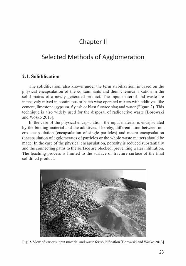
Fig. 2. View of various input material and waste for solidification [Borowski and Wośko 2013]
24
Agglomeration Processes for Waste Utilization in a Circular Economy
In the case of the chemical fixation of the contaminants, the contaminants are integrated into the crystal lattice or the solid matrix of the final solidified product. In the case of the treatment of a heavy metal containing input material, precipita-tion processes are frequently used to transfer the heavy metals to a non-leachable form and to fix the heavy metals in the final solidified product. The alkalinity of cement causes the generation of non-leachable hydroxides and carbonates in the presence of certain heavy metals. To some extent, special precipitation chemicals like sulfides or organic sulfur components are used to immobilize heavy metals.
Generally, solidification is the simple technology and requires the least energy input compared to other agglomeration methods. It does not need large investment outlays and can be carried out even in small production plants. The solidification process can be divided into the following stages [Borowski et al. 2014]: • preparation of mortar, • mixing the mortar with the material/waste, • pouring mortar into matrix and shaking, • curing of solid molds.
Depending on the specification of the waste to be treated and the specification of the final product, the final product of the solidification is reintegrated at site, disposed of, and integrated at approved landfills or used for construction [Borowski and Miłczak 2010]. Furthermore, the cement mortar can be cast to molds as a prod-uct of solidification (Figure 3). The hardened molds can be reused or integrated into a landfill. In order to improve a mortar and obtain specific properties of concrete, various types of additives can be used, as presented in Table 2 [Osiecka 2005].
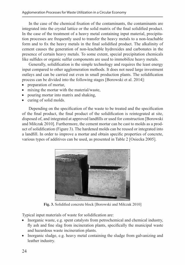
Fig. 3. Solidified concrete block [Borowski and Miłczak 2010]
Typical input materials of waste for solidification are: • Inorganic waste, e.g. spent catalysts from petrochemical and chemical industry,
fly ash and fine slag from incineration plants, specifically the municipal waste and hazardous waste incineration plants.
• Inorganic sludge, e.g. heavy metal containing the sludge from galvanizing and leather industry.
25
Chapter II. Selected Methods of Agglomeration
Solidification units consist of the following parts: • Feed hopper for the waste (including grid for the protection of the downstream
equipment). • Conveyor for the waste, e.g. drag chain conveyor, screw conveyor, sludge and
slurry pumps, etc. • Silo plants for the additives. • Conveyors for the additives, e.g. screw conveyors, pneumatic conveyors, etc. • Dosing units for the waste and the additives (gravimetric or volumetric). • Process water tank and process water system. • Feeding and dosing units for the additive chemicals. • Mixer (continuous or batch operated). • Conveyors and loading facilities for the final solidified product. • Casting facilities for the production, compaction and transport of molds.
According to the applications, the solidification units are equipped with re-quired accessories like air extraction and filter units. Feed hoppers are designed for the filling via wheel loader. Special designs for the filling via truck and skip truck are also available. The design of the feed hopper avoids bridging, even during handling of very difficult input material, like inorganic sludge or sewage sludge. For the protection of the downstream equipment and the retention of larger par-ticles like stones, the feed hopper can be equipped with a grid. The discharge of the material from the feed hopper is carried out via a double screw conveyor. The throughput is adjusted via a manual adjustable gear box or a frequency inverter in accordance with the required throughput and the specification of the input material.
Drag chain conveyors are preferably used for the transportation of the input material. In accordance with the specification of the waste and the layout of the solidification unit, specifically the distance between the feed hopper and mixer, screw conveyors, belt conveyors or sludge or slurry pumps are used as well. Drag
Table 2. Basic types of additives and the effects of their application [Osiecka 2005]
Type of additive Name of additive Effect of application
Plasticizing and liquefying calcium lignosulfonate, melamine resin, polycarboxylates
increase of fluidity or stability of the mix
Accelerating setting or hardening calcium formate rapid increase of toughness
Retarding binding calcium phosphate prolongation of the liquid state of mixture
Aerating sodium trinitate resistance to weather conditions
Antifreeze sodium sulphate increase of frost resistance
Sealing action microsilica reduction of water absorption
• Radioactive sludge. • Municipal and industrial sewage sludge. • Contaminated soil.
26
Agglomeration Processes for Waste Utilization in a Circular Economy
chain conveyors ensure the highest flexibility and robustness for the conveying of various input materials considering the discrepancies in the specification of the in-put material and the layout of the solidification plant. Drag chain conveyors reliably transport bulk materials or sludge with a dry substance content of more than 15%.
The silo plant for the additives is filled pneumatically. A pneumatic pinch valve which is controlled via a level switch protects the silo against overfilling. Silo plants are equipped with automatic pneumatic silo top filters which are activated during the filling process of the silo. The automatic cleaning process is controlled either by time or by differential pressure. The silo plants are equipped with level switches or continuous level monitoring systems, depending on the application. The conical bottom segment in silos is equipped with pneumatic bulking systems, mechanical knocking systems or special vibration bottoms to avoid bridging.
In general, the additives are transported via screw conveyors to the solidifica-tion unit. The screw conveyors with shaft or spiral conveyors without shaft are used depending on the application and the specification of the additives. The screw conveyors are designed either as trough screw conveyors or tube screw conveyors and the throughput is controlled via manual gear boxes or frequency inverters. On the basis of the material selection and the special design, specifically the low ro-tation speed, screw conveyors work with very low abrasion. For highly abrasive additives, the screw conveyors are equipped with the abrasion protection panels.
The input material and additives are dosed via volumetric dosing units or gravimetric weighing drums into the mixer. The selection of volumetric or gravimetric dosing units is based specifically on the required quality of the final solidified product and the selection of the mixer type (continuous or batchwise operated).
The volumetric dosing units consist of a feed hopper and a dosing screw. The type of the dosing screw is adjusted to the specification of the dosing ma-terial. The throughput is controlled either via manual gear boxes or variable speed control via frequency inverter. According to the specification of the dos-ing material, bulking agitators and feeding improvers are installed in the feed hopper to ensure a continuous and homogeneous filling of the dosing screw and an exact dosing of the material.
In general, the gravimetric dosing takes place batchwise via weighing drums, which are located on the weighing cells. Continuous weighing systems are used in special applications only, if the specification of the dosing material enables the use of a continuous weighing system. Specifically for the input material, the use of continuous weighing systems is limited because of the specification of the waste and the variation of the specification of the waste materials.
The process water system consists of a process water tank (break tank), which ensures the independence from the local water supply, the pressure generation and maintenance system, the flow control system and the required dosing valves. The chemical additives are dosed via dosing pumps to the process water. Static mixers ensure the required mixing and homogenization with the process water.
27
Chapter II. Selected Methods of Agglomeration
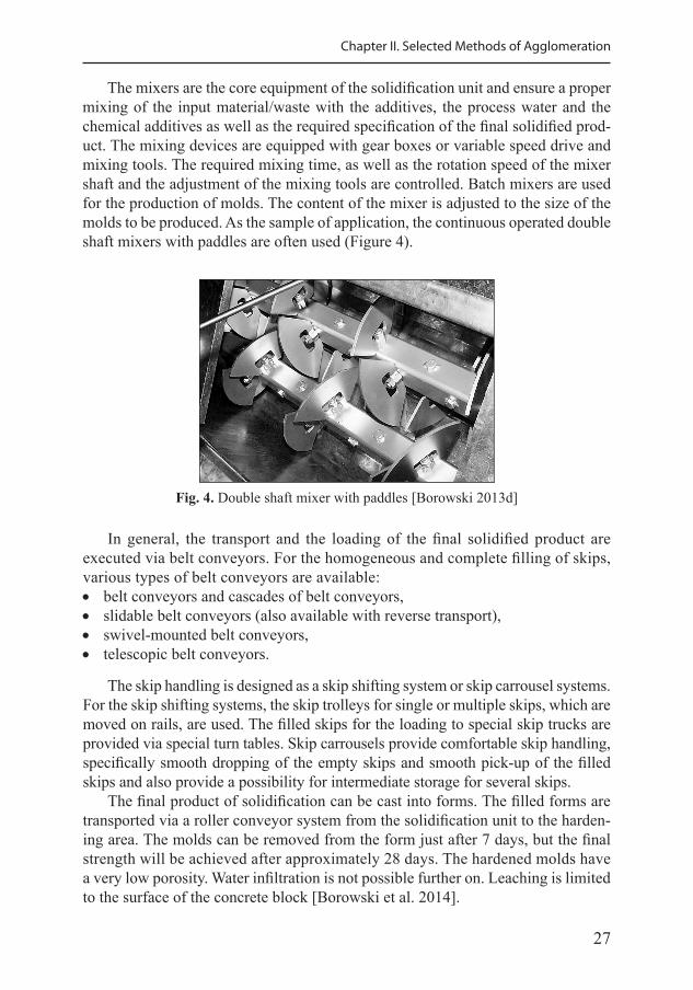
The mixers are the core equipment of the solidification unit and ensure a proper mixing of the input material/waste with the additives, the process water and the chemical additives as well as the required specification of the final solidified prod-uct. The mixing devices are equipped with gear boxes or variable speed drive and mixing tools. The required mixing time, as well as the rotation speed of the mixer shaft and the adjustment of the mixing tools are controlled. Batch mixers are used for the production of molds. The content of the mixer is adjusted to the size of the molds to be produced. As the sample of application, the continuous operated double shaft mixers with paddles are often used (Figure 4).
Fig. 4. Double shaft mixer with paddles [Borowski 2013d]
In general, the transport and the loading of the final solidified product are executed via belt conveyors. For the homogeneous and complete filling of skips, various types of belt conveyors are available: • belt conveyors and cascades of belt conveyors, • slidable belt conveyors (also available with reverse transport), • swivel-mounted belt conveyors, • telescopic belt conveyors.
The skip handling is designed as a skip shifting system or skip carrousel systems. For the skip shifting systems, the skip trolleys for single or multiple skips, which are moved on rails, are used. The filled skips for the loading to special skip trucks are provided via special turn tables. Skip carrousels provide comfortable skip handling, specifically smooth dropping of the empty skips and smooth pick-up of the filled skips and also provide a possibility for intermediate storage for several skips.
The final product of solidification can be cast into forms. The filled forms are transported via a roller conveyor system from the solidification unit to the harden-ing area. The molds can be removed from the form just after 7 days, but the final strength will be achieved after approximately 28 days. The hardened molds have a very low porosity. Water infiltration is not possible further on. Leaching is limited to the surface of the concrete block [Borowski et al. 2014].
28
Agglomeration Processes for Waste Utilization in a Circular Economy
2.2. Granulation
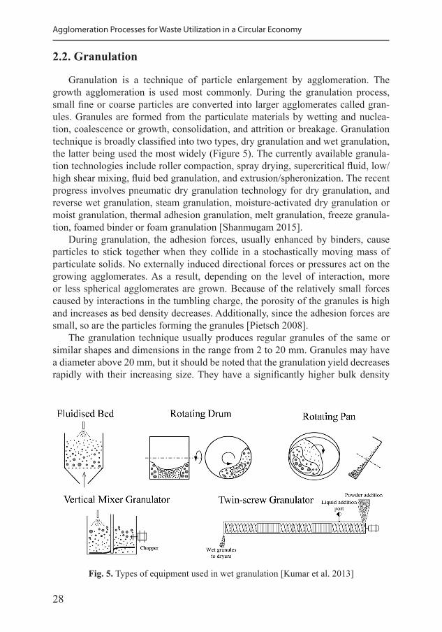
Granulation is a technique of particle enlargement by agglomeration. The growth agglomeration is used most commonly. During the granulation process, small fine or coarse particles are converted into larger agglomerates called gran-ules. Granules are formed from the particulate materials by wetting and nuclea-tion, coalescence or growth, consolidation, and attrition or breakage. Granulation technique is broadly classified into two types, dry granulation and wet granulation, the latter being used the most widely (Figure 5). The currently available granula-tion technologies include roller compaction, spray drying, supercritical fluid, low/high shear mixing, fluid bed granulation, and extrusion/spheronization. The recent progress involves pneumatic dry granulation technology for dry granulation, and reverse wet granulation, steam granulation, moisture-activated dry granulation or moist granulation, thermal adhesion granulation, melt granulation, freeze granula-tion, foamed binder or foam granulation [Shanmugam 2015].
During granulation, the adhesion forces, usually enhanced by binders, cause particles to stick together when they collide in a stochastically moving mass of particulate solids. No externally induced directional forces or pressures act on the growing agglomerates. As a result, depending on the level of interaction, more or less spherical agglomerates are grown. Because of the relatively small forces caused by interactions in the tumbling charge, the porosity of the granules is high and increases as bed density decreases. Additionally, since the adhesion forces are small, so are the particles forming the granules [Pietsch 2008].
The granulation technique usually produces regular granules of the same or similar shapes and dimensions in the range from 2 to 20 mm. Granules may have a diameter above 20 mm, but it should be noted that the granulation yield decreases rapidly with their increasing size. They have a significantly higher bulk density
Fig. 5. Types of equipment used in wet granulation [Kumar et al. 2013]
29
Chapter II. Selected Methods of Agglomeration
than the starting material and do not cause dusting or caking. There is also no seg-regation of ingredients, which guarantees a homogeneous composition of specific products [Hejft and Obidziński 2006].
Individual grains form a stable agglomerate only when there are sufficiently high forces connecting these grains. This requires a high degree of fragmentation of the bulk medium and maintaining its humidity at a constant level. The homogeneity of the mass subjected to granulation has a very large impact on the course of gran-ule formation and their strength. In order to increase the strength of the granulate, specific amounts of binders are added to the mixture [Heim 2005]. The granulation binder should be characterized by: • binding capacity of particulate materials, • giving the granules suitable mechanical strength, • high temperature resistance, • no harmful or toxic substances after dissolution, • low cost of purchase and preparation.
In addition to the preparation method of the material with the addition of a binder, the quality of the granules also depends on the type of device used and the param-eters of its operation, e.g. rotational speed, inclination angle, water spraying capac-ity, as well as the material dispenser capacity.
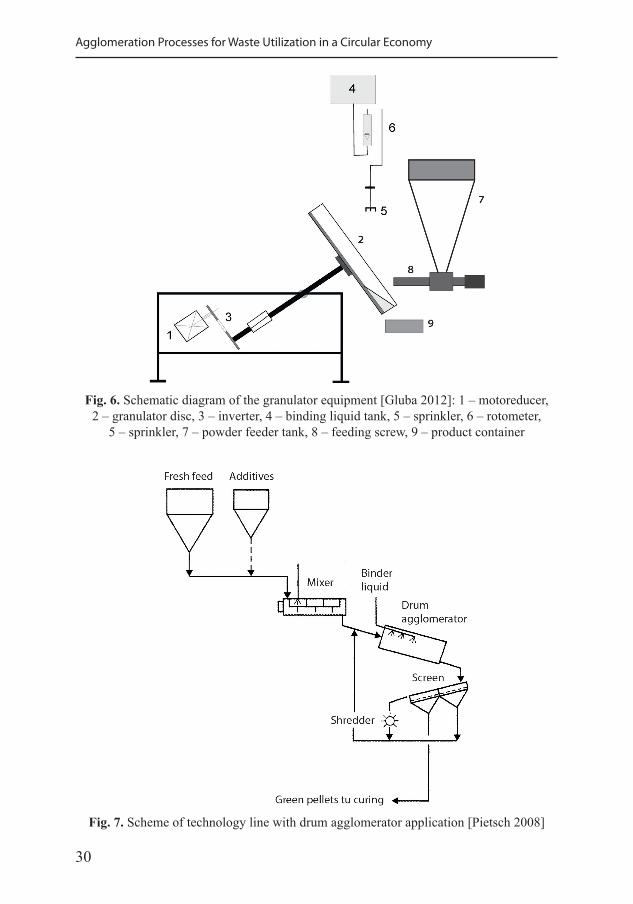
The basic disc agglomerator (pelletizer) is an inclined, flat-bottomed, shallow pan depicted in Figure 6 [Gluba 2012]. The motoreducer (1) drove the shaft attached to the granulator disc by means of a belt transmission (2). The disc rotational speed was controlled by means of an inverter (3) and determined with a tachom-eter. The damping liquid (water) was delivered drop-wise onto the moving granu-lar bed situated on the disc from a tank (4), by means of a hydraulic system ended with a sprinkler (5). A constant intensity of the liquid delivery was determined by means of a rotometer (6). In order to secure uniform damping conditions with vari-able intensity of the damping liquid delivery (droplets of identical size), a varying number of sprinkler outlet nozzles were used (2, 3 and 4), proportionately to the in-tensity of fine-grained material delivery (raw material). The feeder comprised a tank (7) in which the raw material was mixed by means of the built-in stirrer and a feed-ing screw (8) with a continuous regulation of rotational speed. The finished product (wet granulate), tumbling over the rim of the disc, was collected in a container (9).
A drum agglomerator represents a simple type of equipment for growth ag-glomeration by tumbling. They are used in industries for the processing of large amounts of bulk solids. A drum agglomerator normally consists of a cylindrical steel tube with a slight (typically up to 10” from the horizontal) slope a toward the discharge end (Figure 7). Retaining rings are often fitted to the feed and discharge ends of the drum to avoid spill-back and to increase the bed depth of material and/or its residence time, respectively. The tubular shell is fitted with steel tires. The drum rests on forged trunnions with antifriction bearings which are mounted on a heavy structural frame. Sturdy, adjustable thrust rolls keep the inclined drum in
30
Agglomeration Processes for Waste Utilization in a Circular Economy
Fig. 7. Scheme of technology line with drum agglomerator application [Pietsch 2008]
Fig. 6. Schematic diagram of the granulator equipment [Gluba 2012]: 1 – motoreducer, 2 – granulator disc, 3 – inverter, 4 – binding liquid tank, 5 – sprinkler, 6 – rotometer,
5 – sprinkler, 7 – powder feeder tank, 8 – feeding screw, 9 – product container
31
Chapter II. Selected Methods of Agglomeration
place. A roller chain girth drive guarantees a “soft” start and smooth running of the equipment. It consists of a hardened drive sprocket, sectionalized girth sprocket, and rugged roller chain. Gear drives are also available as an alternative. Retaining rings are fitted on both ends of the drum. A liquid feed assembly serves to introduce the binder into the tumbling mass in the drum.
Since the wide distribution of sizes in the discharge from drum agglomerator is not acceptable for most applications, they typically work in a closed circuit. Green agglomerates exiting the drum are sized on vibrating or roller screens. Large pieces are shredded and returned to the drum agglomerator together with the screen fines (Figure 7). The possibilities of granulating selected types of particular materials and waste, i.e. silicon carbide dust, stone dust, fine coal, and fly ash, are discussed below.
2.2.1. Fine coal granulation
The granulation of fine-grained coal and brown coal is usually performed at the place of production of these wastes – on the mining and processing plants. Most often, the granulating materials are [Naumov et al. 2013]: • coal and lignite dust as well as coking dust, creating the furnace charge to the
coking and semi-coking; • coal slurry as solid fuels; • coal dust and slurry as a fuel mixtures with additives for increasing their energy
value; • generator dust, smoke and other carbonaceous dust as materials for the produc-
tion of fuels with specific usable properties.
Fine coal waste and coal dust are the most often processed to produce an al-ternative fuel. The calorific value is the basic criterion. The calorific value of the fuel obtained as a result of processing of coal waste by granulation or with the briquetting method varies from 19 to 23 MJ·kg-1 [Robak and Matuszek 2008]. The estimated amount of coal waste in Poland approximates 0.5 billion tons. Effective energy recovery is possible if the carbon content in the waste exceeds 8%.
One example of an increase in the calorific value is the agglomeration of a mix-ture of fine-grained coal with the addition of biomass. Then, the agglomerates were subjected to heat treatment for 15 minutes at 300–500 °C [Faizal 2017]. As a result of carbonization, an increase in the calorific value of the fuel was observed, com-pared to the calorific value of the fuel without heat treatment.
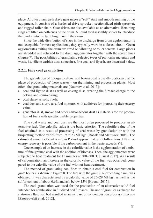
The method of granulating coal fines to obtain a coal fuel for combustion in grate boilers is shown in Figure 8. The fuel with the grain size exceeding 5 mm was obtained; it was characterized by a calorific value of 26–29 MJ·kg-1 as well as the sulfur content of about 0.6% and ash below 15% [Hycnar 2015].
The coal granulation was used for the production of an alternative solid fuel intended for combustion in fluidized bed furnaces. The use of granules as charge for stationary fluidized bed resulted in an increase of the combustion process efficiency [Zaostrovskii et al. 2012].
32
Agglomeration Processes for Waste Utilization in a Circular Economy
Previous laboratory works confirm that fine-grained carbons are preferably con-verted into granules in disk granulators [Feliks 2012]. Lime was used as a binder in the share from 1.0 to 1.5 wt%. The obtained granules ranged in size from 5 to 10 mm. In industrial tests, intensive heating of the mixture of coal and lime should be con-sidered, in order to evaporate the water before the granulation process.
The technology of granulated coal with the addition of lime (CaO) is com-monly used. Calcium oxide, owing to its sorption properties, reduces the moisture content and the SO2 emissions in the combustion process. Coal and lime granules have good energy properties and external resistance as well [Pyssa 2017].
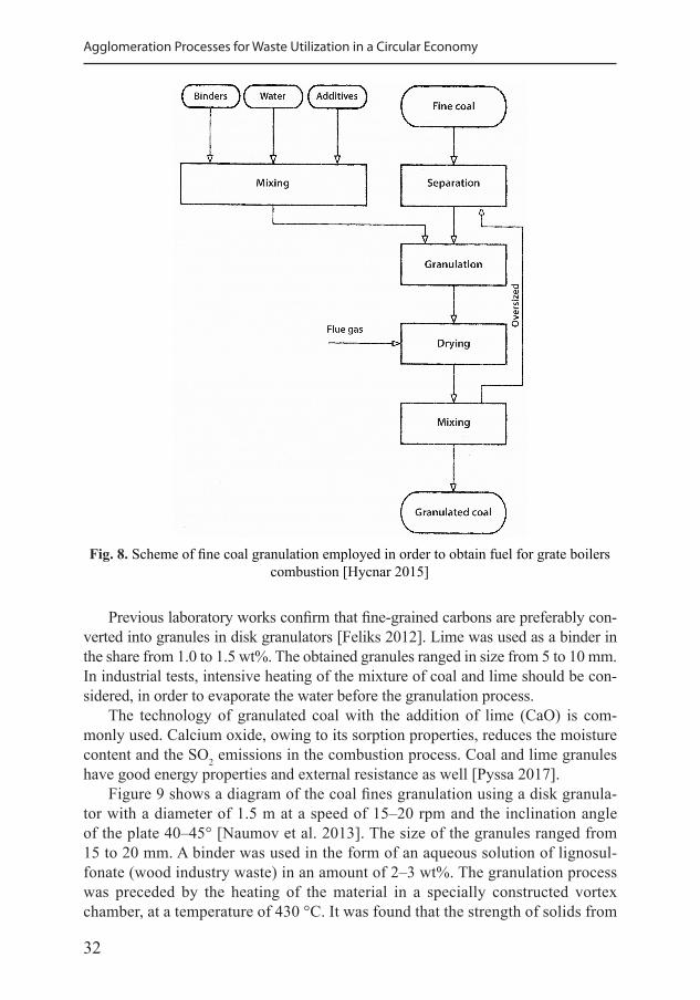
Figure 9 shows a diagram of the coal fines granulation using a disk granula-tor with a diameter of 1.5 m at a speed of 15–20 rpm and the inclination angle of the plate 40–45° [Naumov et al. 2013]. The size of the granules ranged from 15 to 20 mm. A binder was used in the form of an aqueous solution of lignosul-fonate (wood industry waste) in an amount of 2–3 wt%. The granulation process was preceded by the heating of the material in a specially constructed vortex chamber, at a temperature of 430 °C. It was found that the strength of solids from
Fig. 8. Scheme of fine coal granulation employed in order to obtain fuel for grate boilers combustion [Hycnar 2015]
33
Chapter II. Selected Methods of Agglomeration
the coal fines is comparable to the strength of coal nuggets. The agglomerates manufactured are suitable for combustion in domestic heating furnaces, where efficiency was increased by 63–64%, and the harms caused by incomplete com-bustion were reduced.
The use of granulated fine coal as a replacement for aggregates is also possible. The mechanical properties of granules made with coal and ash, with a small addi-tion of cement and water, were investigated [Yoshimoto et al. 2012]. It was found that the crushing strength of bodies depends on the type and size of the coal and ash grains only to a limited extent. However, the value of the internal stress in granules significantly depends on the type and size of the material.
Solovei et al. [2016] showed granulation of fine coal in order to obtain mechan-ically durable spherical granules with a diameter from 1 to 6 mm, but the dominant size was 3 mm. It was presented that the composition of the material fraction for granulation can be significantly changed by the introduction of surfactant during the merging. Due to the favorable structural parameters and mechanical strength of the granules, they can be used as a deposit of moveable and fluidized filler in adsorption processes.
Fig. 9. Diagram of coal fines granulation for the domestic heating fuel [Naumov et al. 2013]
34
Agglomeration Processes for Waste Utilization in a Circular Economy
2.2.2. Fly ash granulation
Due to its dustiness, the fly ash resulting from coal-based energy produc-tion is problematic to transport and store. The present utilization of fly ashes on a worldwide basis varies widely from a minimum of 3% to a maximum of 57% of the total produced, with an average of 16% [Shuming et al. 2014]. Depending on the type of coal being combusted, different types of fly ashes are produced: (1) silica ash – obtained during the combustion of bituminous coal, (2) silica-alumina or silica-calcium ash – formed in the process of lignite com-bustion [Senol et al. 2006]. The granulation process involves the phenomenon of combining through mutual sticking, occurring during rotation as well as the effect of, among others, gravity, centrifugal and capillary forces acting on grains [Yoshimoto et al. 2012].
The addition of a binder such as Silment (a fine hydraulic binder with a large share of active silica) to the ash at a proportion of 10% reduces its dustiness and allows its use in the upper section and substructure of high-quality road construction [Pyssa 2017]. Among other benefits, more efficient dust reduction assists the granulation process in which pellets are formed with a higher density, stability, and more constant size distribution, as compared to the granular material [Karthikeyan et al. 2019]. In order to increase the mechanical strength of the granules the binder is added to the agglomeration process [Makkonen 2002].
In the 1980s, the technology for the granulation of ash with phosphogyp-sum waste in drum granulators was implemented in the Police Factory (West Pomerania, Poland). This enabled to limit the dusting and leaching of water-soluble components [Hycnar 2015b]. A study on the granulation of the ash from fluidized bed boilers from the Czechowice Dziedzice power plant was conduct-ed using a vibrating gutter granulator and satisfactory strength parameters were obtained without the addition of binding agents. A much greater effectiveness of vibrating granulation compared to the typical preparation of grains in a disc granulator was also confirmed [Feliks 2012].
Medici et al. [2000] converted the fly ash and lime into granules to allow their safe transport and utilization as light aggregates for building purposes. Similarly, Cioffi et al. [2011] applied fly ash in the granulation of artificial aggregates, in or-der to produce the concrete blocks for use as a building material. In this process, the coal fly ash was mixed with cement and hydrated lime at room temperature by using water acting as coagulant. However, the bonding process of the powder ma-terials to produce lightweight aggregate was difficult to predict, due to different factors that depend on each other, occurring during the agglomeration [Johnson et al. 2014]. Another application of the fly ash granules consisted in packing them to a trickling filter for treating highly polluted river water. Owing to numerous nanometer pores, these ceramic granules enabled to biodegrade microorganisms and organic compounds; additionally, nitrogen was stripped [Jing et al. 2012].
35
Chapter II. Selected Methods of Agglomeration
2.3. Extrusion
Extrusion is low-pressure agglomeration for the production of caked material. This method is widely used in the pharmaceutical industry, in the agribusiness, and in the polymer industry. Recent developments evaluated extrusion for utilization of selected particulate waste materials, as: wood, plastic, fiber, textile, and biochar. A few works present the extrusion method of producing mixed polymer and plant material biocomposites for use as an alternative disposable product.
Extrusion is the process of converting a raw material into a product of uni-form shape and density by forcing it through a die under controlled conditions. Extrusion can be operated as a continuous process, which is capable of consist-ent product flow at relatively high throughput rates. An extruder consists of two distinct parts: the conveying system which transports the material and imparts a degree of distributive and dispersive mixing, and the die system which forms the material into the required shape. Extrusion may be broadly classified into a molten system under the temperature control or a semisolid viscous system. In molten extrusion, heat is applied to the material in order to control its viscosity and enable it to flow through the die. In turn, semisolid systems are multiphase concentrated dispersions containing a high proportion of solid mixed with liquid phase [Chokshi and Zia 2004].
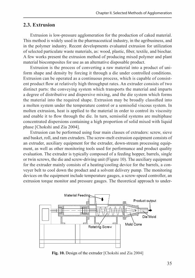
Extrusion can be performed using four main classes of extruders: screw, sieve and basket, roll, and ram extruders. The screw-melt extrusion equipment consists of an extruder, auxiliary equipment for the extruder, down-stream processing equip-ment, as well as other monitoring tools used for performance and product quality evaluation. The extruder is typically composed of a feeding hopper, barrels, single or twin screws, the die and screw-driving unit (Figure 10). The auxiliary equipment for the extruder mainly consists of a heating/cooling device for the barrels, a con-veyer belt to cool down the product and a solvent delivery pump. The monitoring devices on the equipment include temperature gauges, a screw-speed controller, an extrusion torque monitor and pressure gauges. The theoretical approach to under-
Fig. 10. Design of the extruder [Chokshi and Zia 2004]
36
Agglomeration Processes for Waste Utilization in a Circular Economy
standing the melt extrusion process is, therefore, generally presented by dividing the process of flow into four sections: 1) Feeding of the extruder. 2) Conveying of mass (mixing and reduction of particle size). 3) Flow through the die. 4) Exit from the die and down-stream processing.
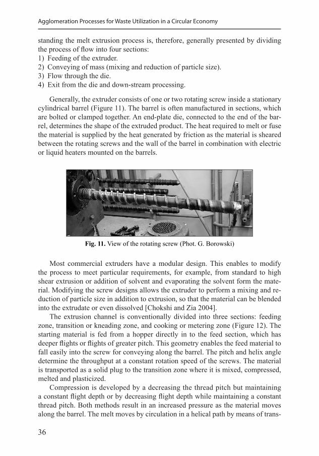
Generally, the extruder consists of one or two rotating screw inside a stationary cylindrical barrel (Figure 11). The barrel is often manufactured in sections, which are bolted or clamped together. An end-plate die, connected to the end of the bar-rel, determines the shape of the extruded product. The heat required to melt or fuse the material is supplied by the heat generated by friction as the material is sheared between the rotating screws and the wall of the barrel in combination with electric or liquid heaters mounted on the barrels.
Fig. 11. View of the rotating screw (Phot. G. Borowski)
Most commercial extruders have a modular design. This enables to modify the process to meet particular requirements, for example, from standard to high shear extrusion or addition of solvent and evaporating the solvent form the mate-rial. Modifying the screw designs allows the extruder to perform a mixing and re-duction of particle size in addition to extrusion, so that the material can be blended into the extrudate or even dissolved [Chokshi and Zia 2004].
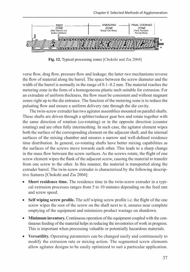
The extrusion channel is conventionally divided into three sections: feeding zone, transition or kneading zone, and cooking or metering zone (Figure 12). The starting material is fed from a hopper directly in to the feed section, which has deeper flights or flights of greater pitch. This geometry enables the feed material to fall easily into the screw for conveying along the barrel. The pitch and helix angle determine the throughput at a constant rotation speed of the screws. The material is transported as a solid plug to the transition zone where it is mixed, compressed, melted and plasticized.
Compression is developed by a decreasing the thread pitch but maintaining a constant flight depth or by decreasing flight depth while maintaining a constant thread pitch. Both methods result in an increased pressure as the material moves along the barrel. The melt moves by circulation in a helical path by means of trans-
37
Chapter II. Selected Methods of Agglomeration
Fig. 12. Typical processing zones [Chokshi and Zia 2004]
verse flow, drag flow, pressure flow and leakage; the latter two mechanisms reverse the flow of material along the barrel. The space between the screw diameter and the width of the barrel is normally in the range of 0.1–0.2 mm. The material reaches the metering zone in the form of a homogeneous plastic melt suitable for extrusion. For an extrudate of uniform thickness, the flow must be consistent and without stagnant zones right up to the die entrance. The function of the metering zone is to reduce the pulsating flow and ensure a uniform delivery rate through the die cavity.
The twin-screw extruder has two agitator assemblies mounted on parallel shafts. These shafts are driven through a splitter/reducer gear box and rotate together with the same direction of rotation (co-rotating) or in the opposite direction (counter rotating) and are often fully intermeshing. In such case, the agitator element wipes both the surface of the corresponding element on the adjacent shaft, and the internal surfaces of the mixing chamber and ensures a narrow and well-defined residence time distribution. In general, co-rotating shafts have better mixing capabilities as the surfaces of the screws move towards each other. This leads to a sharp change in the mass flow between the screw surfaces. As the screws rotate, the flight of one screw element wipes the flank of the adjacent screw, causing the material to transfer from one screw to the other. In this manner, the material is transported along the extruder barrel. The twin-screw extruder is characterized by the following descrip-tive features [Chokshi and Zia 2004]: • Short residence time. The residence time in the twin-screw extruder in a typi-
cal extrusion processes ranges from 5 to 10 minutes depending on the feed rate and screw speed.
• Self wiping screw profile. The self wiping screw profile i.e. the flight of the one screw wipes the root of the screw on the shaft next to it, ensures near complete emptying of the equipment and minimizes product wastage on shutdown.
• Minimum inventory. Continuous operation of the equipment coupled with the con-tinuous feeding of the material helps in reducing the inventories of work in progress. This is important when processing valuable or potentially hazardous materials.
• Versatility. Operating parameters can be changed easily and continuously to modify the extrusion rate or mixing action. The segmented screw elements allow agitator designs to be easily optimized to suit a particular application.
38
Agglomeration Processes for Waste Utilization in a Circular Economy
The die plates can also be easily exchanged to alter the extrudate diameter. This allows processing of many different formulations on a single machine, leading to good equipment utilization. The polymers with a wide range of viscoelastic and melt viscosities may be processed and even fine powders may be directly fed into the system.
• Superior mixing. The screws have various mixing elements which impart two types of mixing, i.e. distributive mixing and dispersive mixing. The distributive mixing ideally maximizes the division and recombining of the material while minimizing energy. The dispersive mixing ideally breaks droplet or solid do-mains to fine morphologies using energy at or slightly above the threshold level needed. This mixing aids in efficient compounding of two or more materials in the twin-screw extruder.
Typical twin-screw laboratory scale machines have a diameter of 1–18 mm and length of four to ten times the diameter. A typical throughput for this type of equip-ment is 0.5–5 mm·min-1. As the residence time in the extruder is rather short and the temperature of all the barrels are independent and can be accurately controlled from low temperatures (30 °C) to high temperatures (300 °C), the degradation by heat can be minimized [Chokshi and Zia 2004].
Extrusion processing requires close monitoring and understanding of various parameters: viscosity and variation of viscosity with shear rate and temperature, elasticity and extensional flow over hot metal surfaces. Today, extruders allow the in-process monitoring and control of parameters, such as the temperature in the extruder, head and die as well as the pressure in extruder and die. The main monitor-ing and controlling parameters are barrel temperatures, feed rate, screw speed, motor load and melt pressure. Barrel temperature, feed rate and screw speed are the control-ling parameters and motor load and melt pressure are the monitoring parameters.
The extrusion technology is a very effective means of transforming raw ma-terials and waste in particulate form into agglomerated products of various sizes, shapes, textures, composition and content. The process parameters, in combination with screw and die selection, allow a high degree flexibility in processing. Some examples of applications are provided below.
2.3.1. Charcoal extrusion
Biochar is a renewable material which can be produced through the pyroly-sis process from a variety of agricultural and forestry wastes. Biochar has re-ceived attention from industry as an effective soil amendment and remediation agent for organic contaminants [Das et al. 2015].
Biochar is strongly recommended for the charcoal fuel production because of many attractive features: it is easy to store and handle, contains almost no sulfur or mercury and is low in nitrogen and ash [Antal and Grønli 2003]. Further applieds of charcoal fuel was presented in the Chapter 2.4.3.
39
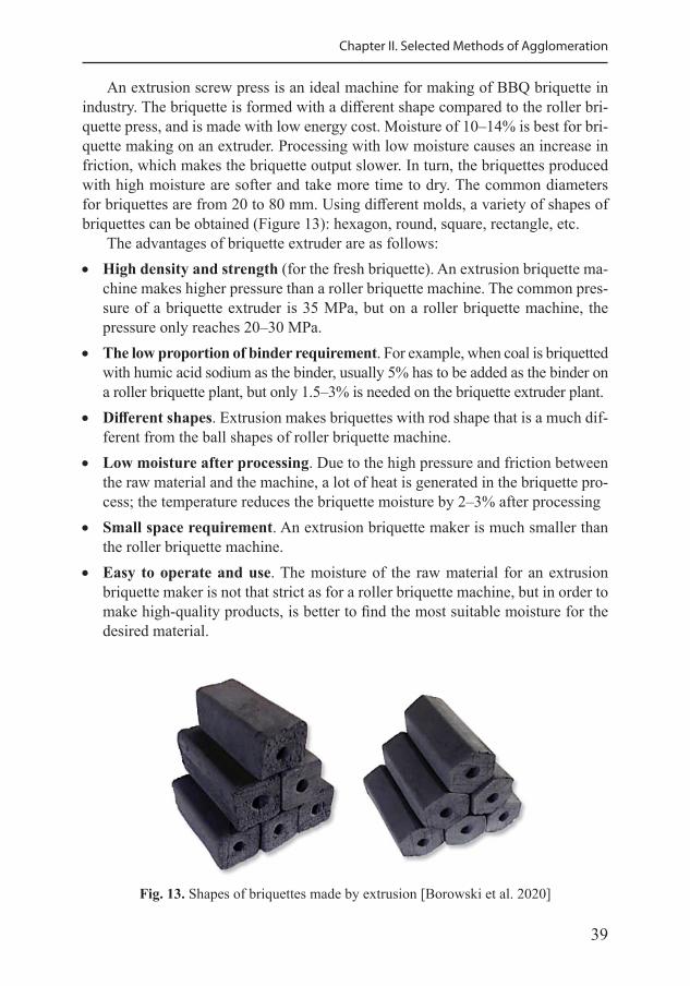
Chapter II. Selected Methods of Agglomeration
An extrusion screw press is an ideal machine for making of BBQ briquette in industry. The briquette is formed with a different shape compared to the roller bri-quette press, and is made with low energy cost. Moisture of 10–14% is best for bri-quette making on an extruder. Processing with low moisture causes an increase in friction, which makes the briquette output slower. In turn, the briquettes produced with high moisture are softer and take more time to dry. The common diameters for briquettes are from 20 to 80 mm. Using different molds, a variety of shapes of briquettes can be obtained (Figure 13): hexagon, round, square, rectangle, etc.
The advantages of briquette extruder are as follows: • High density and strength (for the fresh briquette). An extrusion briquette ma-
chine makes higher pressure than a roller briquette machine. The common pres-sure of a briquette extruder is 35 MPa, but on a roller briquette machine, the pressure only reaches 20–30 MPa.
• The low proportion of binder requirement. For example, when coal is briquetted with humic acid sodium as the binder, usually 5% has to be added as the binder on a roller briquette plant, but only 1.5–3% is needed on the briquette extruder plant.
• Different shapes. Extrusion makes briquettes with rod shape that is a much dif-ferent from the ball shapes of roller briquette machine.
• Low moisture after processing. Due to the high pressure and friction between the raw material and the machine, a lot of heat is generated in the briquette pro-cess; the temperature reduces the briquette moisture by 2–3% after processing
• Small space requirement. An extrusion briquette maker is much smaller than the roller briquette machine.
• Easy to operate and use. The moisture of the raw material for an extrusion briquette maker is not that strict as for a roller briquette machine, but in order to make high-quality products, is better to find the most suitable moisture for the desired material.
Fig. 13. Shapes of briquettes made by extrusion [Borowski et al. 2020]
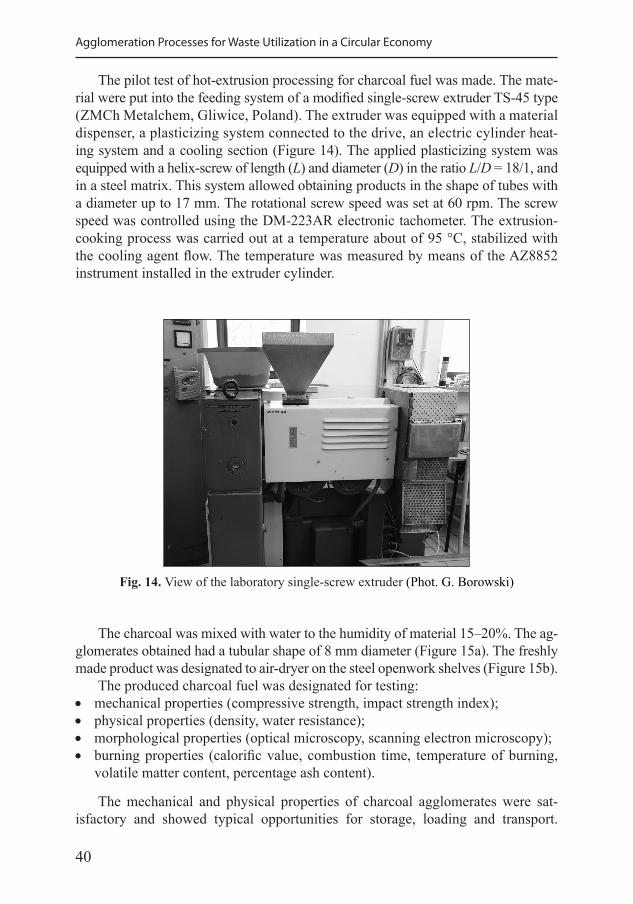
40
Agglomeration Processes for Waste Utilization in a Circular Economy
The pilot test of hot-extrusion processing for charcoal fuel was made. The mate-rial were put into the feeding system of a modified single-screw extruder TS-45 type (ZMCh Metalchem, Gliwice, Poland). The extruder was equipped with a material dispenser, a plasticizing system connected to the drive, an electric cylinder heat-ing system and a cooling section (Figure 14). The applied plasticizing system was equipped with a helix-screw of length (L) and diameter (D) in the ratio L/D = 18/1, and in a steel matrix. This system allowed obtaining products in the shape of tubes with a diameter up to 17 mm. The rotational screw speed was set at 60 rpm. The screw speed was controlled using the DM-223AR electronic tachometer. The extrusion-cooking process was carried out at a temperature about of 95 °C, stabilized with the cooling agent flow. The temperature was measured by means of the AZ8852 instrument installed in the extruder cylinder.
Fig. 14. View of the laboratory single-screw extruder (Phot. G. Borowski)
The charcoal was mixed with water to the humidity of material 15–20%. The ag-glomerates obtained had a tubular shape of 8 mm diameter (Figure 15a). The freshly made product was designated to air-dryer on the steel openwork shelves (Figure 15b).
The produced charcoal fuel was designated for testing: • mechanical properties (compressive strength, impact strength index); • physical properties (density, water resistance); • morphological properties (optical microscopy, scanning electron microscopy); • burning properties (calorific value, combustion time, temperature of burning,
volatile matter content, percentage ash content).
The mechanical and physical properties of charcoal agglomerates were sat-isfactory and showed typical opportunities for storage, loading and transport.
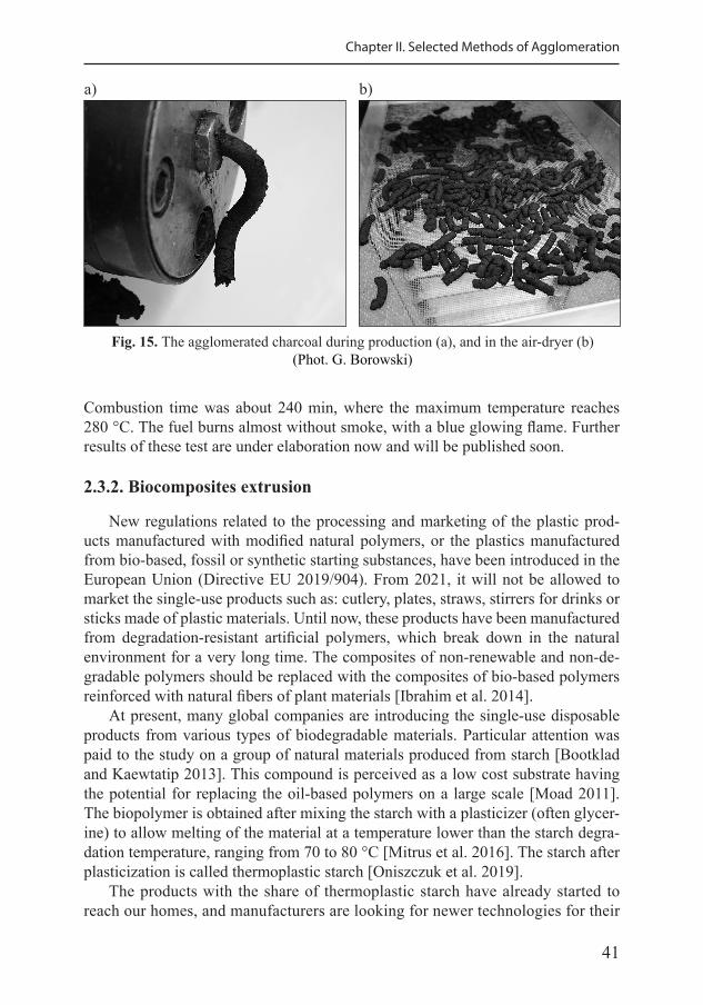
41
Chapter II. Selected Methods of Agglomeration
Combustion time was about 240 min, where the maximum temperature reaches 280 °C. The fuel burns almost without smoke, with a blue glowing flame. Further results of these test are under elaboration now and will be published soon.
2.3.2. Biocomposites extrusion
New regulations related to the processing and marketing of the plastic prod-ucts manufactured with modified natural polymers, or the plastics manufactured from bio-based, fossil or synthetic starting substances, have been introduced in the European Union (Directive EU 2019/904). From 2021, it will not be allowed to market the single-use products such as: cutlery, plates, straws, stirrers for drinks or sticks made of plastic materials. Until now, these products have been manufactured from degradation-resistant artificial polymers, which break down in the natural environment for a very long time. The composites of non-renewable and non-de-gradable polymers should be replaced with the composites of bio-based polymers reinforced with natural fibers of plant materials [Ibrahim et al. 2014].
At present, many global companies are introducing the single-use disposable products from various types of biodegradable materials. Particular attention was paid to the study on a group of natural materials produced from starch [Bootklad and Kaewtatip 2013]. This compound is perceived as a low cost substrate having the potential for replacing the oil-based polymers on a large scale [Moad 2011]. The biopolymer is obtained after mixing the starch with a plasticizer (often glycer-ine) to allow melting of the material at a temperature lower than the starch degra-dation temperature, ranging from 70 to 80 °C [Mitrus et al. 2016]. The starch after plasticization is called thermoplastic starch [Oniszczuk et al. 2019].
The products with the share of thermoplastic starch have already started to reach our homes, and manufacturers are looking for newer technologies for their
Fig. 15. The agglomerated charcoal during production (a), and in the air-dryer (b)(Phot. G. Borowski)
a) b)
42
Agglomeration Processes for Waste Utilization in a Circular Economy
production based on the extrusion processes. These starches are fully biodegrad-able, which solves the problem of utilization of the spent products [Nafchi et al. 2013]. They can be subjected to the composting process and used for the agricul-tural purposes [Feuilloley et al. 2005], or decomposed under anaerobic conditions for obtaining methane used as fuel for the heating purposes [Pagliano et al. 2017] or as fuel for driving motors and generators [Ueno et al. 2007].
In order to improve the physical properties of biocomposites, and sometimes to reduce the price of the finished product, various types of plant fiber fillers are added to starch materials. The most commonly used ones are the fibers from flax, hemp, jute, coconut palm, cotton and wood sawdust [Oniszczuk et al. 2019]. The time, biocomposite materials and associated design methods are sufficiently mature to allow their widespread use related to construction materials. The development of methods, systems and standards could see the biocomposite materials at a distinct advantage over the traditional materials. There is a significant research effort un-derway to develop the biocomposite materials and explore their use as construc-tion materials, especially for the load bearing applications [Burgueno et al. 2005].
In recent years, the major advancement lies within the establishment of nano-technology. As technology improves for the biocomposites reinforced with natural fibers to provide enhanced material and product characteristics, the products will become more diverse and enter the markets that are unexplored as of yet. Today, the natural fiber reinforced biocomposites are commonly found in the automotive sec-tors. Further research is required to overcome such obstacles as moisture absorp-tion, inadequate toughness, and reduced long-term stability for the outdoor applica-tions. In particular, different weathering conditions, such as temperature, humidity, and UV radiation all affect the service life of the product [Faruk et al. 2012].
The agglomerated biocomposite products were produced as a result of ex-trusion-cooking of thermoplastic maize starch with the addition of flax fiber [Borowski et al. 2020]. The investigated material was maize starch of 16% moisture content. The plasticizer was technical glycerin with a purity of 99%, added to the starch in an amount of 20 wt%. The samples were prepared with plant additives in the form of flax fiber waste crushed by a hammer shredder. The materials were mixed using a laboratory ribbon mixer. The share of flax fibers in the prepared samples was 10, 20 and 30 wt% as starch replacement. The blends of materials were put into the feeding system of a modified single-screw extruder shown in the previous chapter.
The studies on the mechanical properties showed that flax fiber mixed with the maize starch can be used successfully as basis of biodegradable composites. The most favorable results of impact tensile test, and three-point bending flexural test were obtained for a biocomposite with flax fiber of 20 wt%. Under anaerobic conditions of 55 °C biodegradation process was finished at the period of 20 days, which fulfils the European standardized tests. The high methane concentration (approx. 67% vol.) in biogas was observed in the experiment. Nevertheless, most biogas was produced in the initial stage of the biodegradation process. A smaller share of plant additives increases the biogas potential and biodegrada-
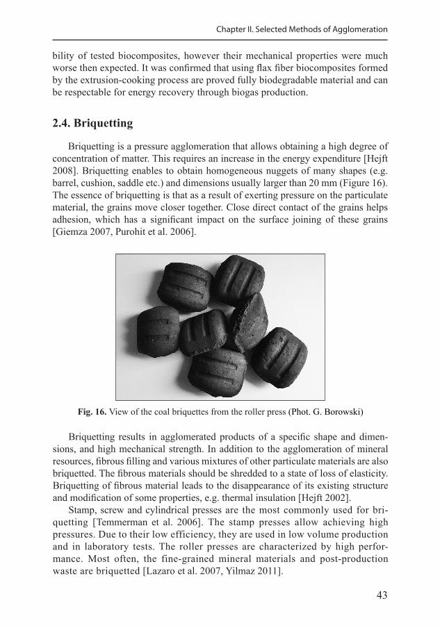
43
Chapter II. Selected Methods of Agglomeration
bility of tested biocomposites, however their mechanical properties were much worse then expected. It was confirmed that using flax fiber biocomposites formed by the extrusion-cooking process are proved fully biodegradable material and can be respectable for energy recovery through biogas production.
2.4. Briquetting
Briquetting is a pressure agglomeration that allows obtaining a high degree of concentration of matter. This requires an increase in the energy expenditure [Hejft 2008]. Briquetting enables to obtain homogeneous nuggets of many shapes (e.g. barrel, cushion, saddle etc.) and dimensions usually larger than 20 mm (Figure 16). The essence of briquetting is that as a result of exerting pressure on the particulate material, the grains move closer together. Close direct contact of the grains helps adhesion, which has a significant impact on the surface joining of these grains [Giemza 2007, Purohit et al. 2006].
Fig. 16. View of the coal briquettes from the roller press (Phot. G. Borowski)
Briquetting results in agglomerated products of a specific shape and dimen-sions, and high mechanical strength. In addition to the agglomeration of mineral resources, fibrous filling and various mixtures of other particulate materials are also briquetted. The fibrous materials should be shredded to a state of loss of elasticity. Briquetting of fibrous material leads to the disappearance of its existing structure and modification of some properties, e.g. thermal insulation [Hejft 2002].
Stamp, screw and cylindrical presses are the most commonly used for bri-quetting [Temmerman et al. 2006]. The stamp presses allow achieving high pressures. Due to their low efficiency, they are used in low volume production and in laboratory tests. The roller presses are characterized by high perfor-mance. Most often, the fine-grained mineral materials and post-production waste are briquetted [Lazaro et al. 2007, Yilmaz 2011].
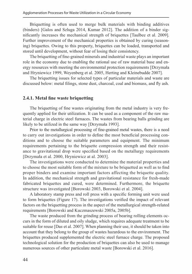
44
Agglomeration Processes for Waste Utilization in a Circular Economy
Briquetting is often used to merge bulk materials with binding additives (binders) [Galos and Szluga 2014, Kumar 2012]. The addition of a binder sig-nificantly increases the mechanical strength of briquettes [Taulbee et al. 2009]. Further improvement of the mechanical properties is obtained by curing (season-ing) briquettes. Owing to this property, briquettes can be loaded, transported and stored until development, without fear of losing their consistency.
The briquetting of fine-grained minerals and industrial waste plays an important role in the economy due to enabling the rational use of raw material base and en-ergy resources with meeting the environmental protection requirements [Drzymała and Hryniewicz 1999, Weyenberg et al. 2005, Herting and Kleinebudde 2007].
The briquetting issues for selected types of particular materials and waste are discussed below: metal filings, stone dust, charcoal, coal and biomass, and fly ash.
2.4.1. Metal fine waste briquetting
The briquetting of fine wastes originating from the metal industry is very fre-quently applied for their utilization. It can be used as a component of the raw ma-terial charge in electric steel furnaces. The wastes from bearing balls grinding are likely to be utilized in the same way [Drzymała 1993].
Prior to the metallurgical processing of fine-grained metal wastes, there is a need to carry out investigations in order to define the most beneficial processing con-ditions and to choose the suitable parameters and equipment. The minimum requirements pertaining to the briquette compression strength and their resist-ance to gravitational drop were specified based on the metallurgy requirements [Drzymała et al. 2000, Hryniewicz at al. 2003].
The investigations were conducted to determine the material properties and to choose the most suitable form of the mixture to be briquetted as well as to find proper binders and examine important factors affecting the briquette quality. In addition, the mechanical strength and gravitational resistance for fresh-made fabricated briquettes and cured, were determined. Furthermore, the briquette structure was investigated [Borowski 2003, Borowski et al. 2004].
A laboratory stamp press and roll press with a specific forming unit were used to form briquettes (Figure 17). The investigations verified the impact of relevant factors on the briquetting process in the aspect of the metallurgical strength-related requirements [Borowski and Kuczmaszewski 2005a, 2005b].
The waste produced from the grinding process of bearing rolling elements oc-curs in the form of diluted and oily sludge, which requires adequate treatment to be suitable for reuse [Das, et al. 2007]. When planning their use, it should be taken into account that they belong to the group of wastes hazardous to the environment. The briquettes produced supplemented the electric steel furnace charge. The proposed technological solution for the production of briquettes can also be used to manage numerous sources of other particulate metal waste [Borowski et al. 2016].
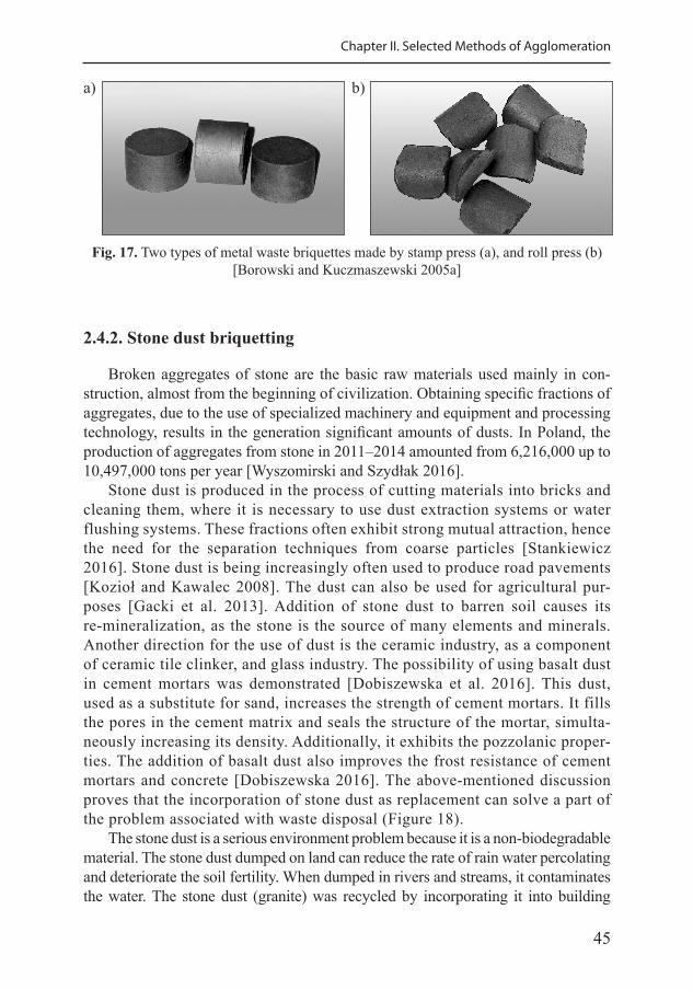
45
Chapter II. Selected Methods of Agglomeration
Fig. 17. Two types of metal waste briquettes made by stamp press (a), and roll press (b)[Borowski and Kuczmaszewski 2005a]
a) b)
2.4.2. Stone dust briquetting
Broken aggregates of stone are the basic raw materials used mainly in con-struction, almost from the beginning of civilization. Obtaining specific fractions of aggregates, due to the use of specialized machinery and equipment and processing technology, results in the generation significant amounts of dusts. In Poland, the production of aggregates from stone in 2011–2014 amounted from 6,216,000 up to 10,497,000 tons per year [Wyszomirski and Szydłak 2016].
Stone dust is produced in the process of cutting materials into bricks and cleaning them, where it is necessary to use dust extraction systems or water flushing systems. These fractions often exhibit strong mutual attraction, hence the need for the separation techniques from coarse particles [Stankiewicz 2016]. Stone dust is being increasingly often used to produce road pavements [Kozioł and Kawalec 2008]. The dust can also be used for agricultural pur-poses [Gacki et al. 2013]. Addition of stone dust to barren soil causes its re-mineralization, as the stone is the source of many elements and minerals. Another direction for the use of dust is the ceramic industry, as a component of ceramic tile clinker, and glass industry. The possibility of using basalt dust in cement mortars was demonstrated [Dobiszewska et al. 2016]. This dust, used as a substitute for sand, increases the strength of cement mortars. It fills the pores in the cement matrix and seals the structure of the mortar, simulta-neously increasing its density. Additionally, it exhibits the pozzolanic proper-ties. The addition of basalt dust also improves the frost resistance of cement mortars and concrete [Dobiszewska 2016]. The above-mentioned discussion proves that the incorporation of stone dust as replacement can solve a part of the problem associated with waste disposal (Figure 18).
The stone dust is a serious environment problem because it is a non-biodegradable material. The stone dust dumped on land can reduce the rate of rain water percolating and deteriorate the soil fertility. When dumped in rivers and streams, it contaminates the water. The stone dust (granite) was recycled by incorporating it into building
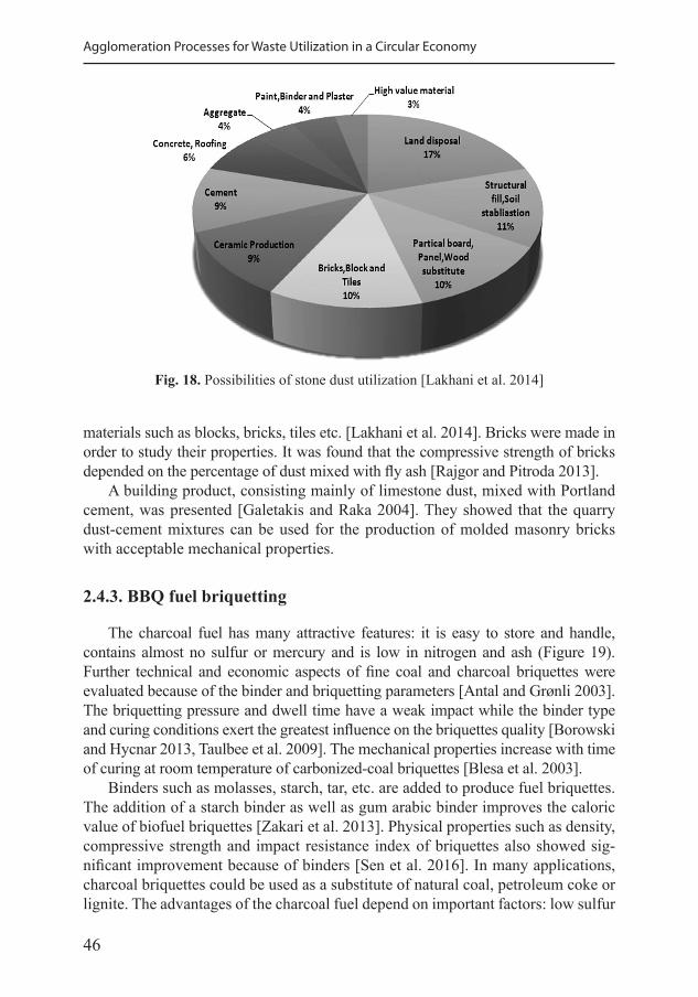
46
Agglomeration Processes for Waste Utilization in a Circular Economy
Fig. 18. Possibilities of stone dust utilization [Lakhani et al. 2014]
materials such as blocks, bricks, tiles etc. [Lakhani et al. 2014]. Bricks were made in order to study their properties. It was found that the compressive strength of bricks depended on the percentage of dust mixed with fly ash [Rajgor and Pitroda 2013].
A building product, consisting mainly of limestone dust, mixed with Portland cement, was presented [Galetakis and Raka 2004]. They showed that the quarry dust-cement mixtures can be used for the production of molded masonry bricks with acceptable mechanical properties.
2.4.3. BBQ fuel briquetting
The charcoal fuel has many attractive features: it is easy to store and handle, contains almost no sulfur or mercury and is low in nitrogen and ash (Figure 19). Further technical and economic aspects of fine coal and charcoal briquettes were evaluated because of the binder and briquetting parameters [Antal and Grønli 2003]. The briquetting pressure and dwell time have a weak impact while the binder type and curing conditions exert the greatest influence on the briquettes quality [Borowski and Hycnar 2013, Taulbee et al. 2009]. The mechanical properties increase with time of curing at room temperature of carbonized-coal briquettes [Blesa et al. 2003].
Binders such as molasses, starch, tar, etc. are added to produce fuel briquettes. The addition of a starch binder as well as gum arabic binder improves the caloric value of biofuel briquettes [Zakari et al. 2013]. Physical properties such as density, compressive strength and impact resistance index of briquettes also showed sig-nificant improvement because of binders [Sen et al. 2016]. In many applications, charcoal briquettes could be used as a substitute of natural coal, petroleum coke or lignite. The advantages of the charcoal fuel depend on important factors: low sulfur
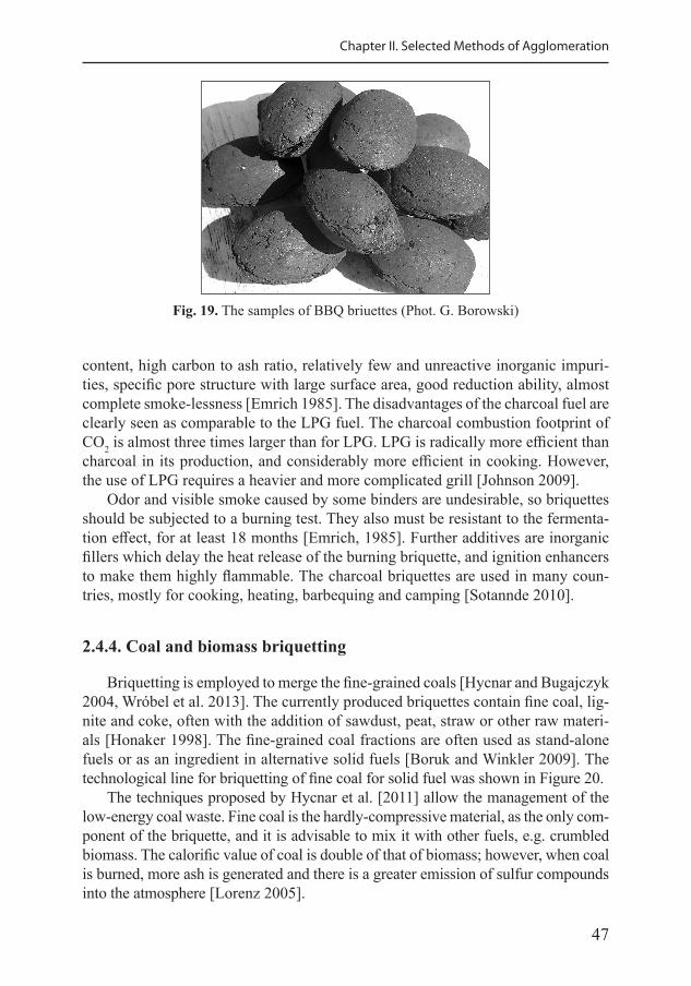
47
Chapter II. Selected Methods of Agglomeration
Fig. 19. The samples of BBQ briuettes (Phot. G. Borowski)
content, high carbon to ash ratio, relatively few and unreactive inorganic impuri-ties, specific pore structure with large surface area, good reduction ability, almost complete smoke-lessness [Emrich 1985]. The disadvantages of the charcoal fuel are clearly seen as comparable to the LPG fuel. The charcoal combustion footprint of CO2 is almost three times larger than for LPG. LPG is radically more efficient than charcoal in its production, and considerably more efficient in cooking. However, the use of LPG requires a heavier and more complicated grill [Johnson 2009].
Odor and visible smoke caused by some binders are undesirable, so briquettes should be subjected to a burning test. They also must be resistant to the fermenta-tion effect, for at least 18 months [Emrich, 1985]. Further additives are inorganic fillers which delay the heat release of the burning briquette, and ignition enhancers to make them highly flammable. The charcoal briquettes are used in many coun-tries, mostly for cooking, heating, barbequing and camping [Sotannde 2010].
2.4.4. Coal and biomass briquetting
Briquetting is employed to merge the fine-grained coals [Hycnar and Bugajczyk 2004, Wróbel et al. 2013]. The currently produced briquettes contain fine coal, lig-nite and coke, often with the addition of sawdust, peat, straw or other raw materi-als [Honaker 1998]. The fine-grained coal fractions are often used as stand-alone fuels or as an ingredient in alternative solid fuels [Boruk and Winkler 2009]. The technological line for briquetting of fine coal for solid fuel was shown in Figure 20.
The techniques proposed by Hycnar et al. [2011] allow the management of the low-energy coal waste. Fine coal is the hardly-compressive material, as the only com-ponent of the briquette, and it is advisable to mix it with other fuels, e.g. crumbled biomass. The calorific value of coal is double of that of biomass; however, when coal is burned, more ash is generated and there is a greater emission of sulfur compounds into the atmosphere [Lorenz 2005].
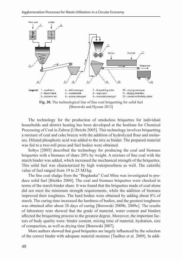
48
Agglomeration Processes for Waste Utilization in a Circular Economy
The technology for the production of smokeless briquettes for individual households and district heating has been developed at the Institute for Chemical Processing of Coal in Zabrze [Ulbricht 2005]. This technology involves briquetting a mixture of coal and coke breeze with the addition of hydrolyzed flour and molas-ses. Diluted phosphoric acid was added to the mix as binder. The prepared material was fed to a two-roll press and fuel bodies were obtained.
Sołtys [2005] described the technology for producing the coal and biomass briquettes with a biomass of share 20% by weight. A mixture of fine coal with the starch binder was added, which increased the mechanical strength of the briquettes. This solid fuel was characterized by high waterproofness as well. The calorific value of fuel ranged from 19 to 25 MJ/kg.
The fine coal sludge from the “Bogdanka” Coal Mine was investigated to pro-duce solid fuel [Bieńko 2004]. The coal and biomass briquettes were checked in terms of the starch binder share. It was found that the briquettes made of coal alone did not meet the minimum strength requirements, while the addition of biomass improved their toughness. The hard bodies were obtained by adding about 8% of starch. The curing time increased the hardness of bodies, and the greatest toughness was obtained after about 28 days of curing [Borowski 2009b, 2009c]. The results of laboratory tests showed that the grade of material, water content and binders affected the briquetting process to the greatest degree. Moreover, the important fac-tors of body quality were: binder content, mixing time of material, hydration, size of compaction, as well as drying time [Borowski 2007].
More authors showed that good briquettes are largely influenced by the selection of the correct binder with adequate material moisture [Taulbee et al. 2009]. In addi-
Fig. 20. The technological line of fine coal briquetting for solid fuel [Borowski and Hycnar 2013]
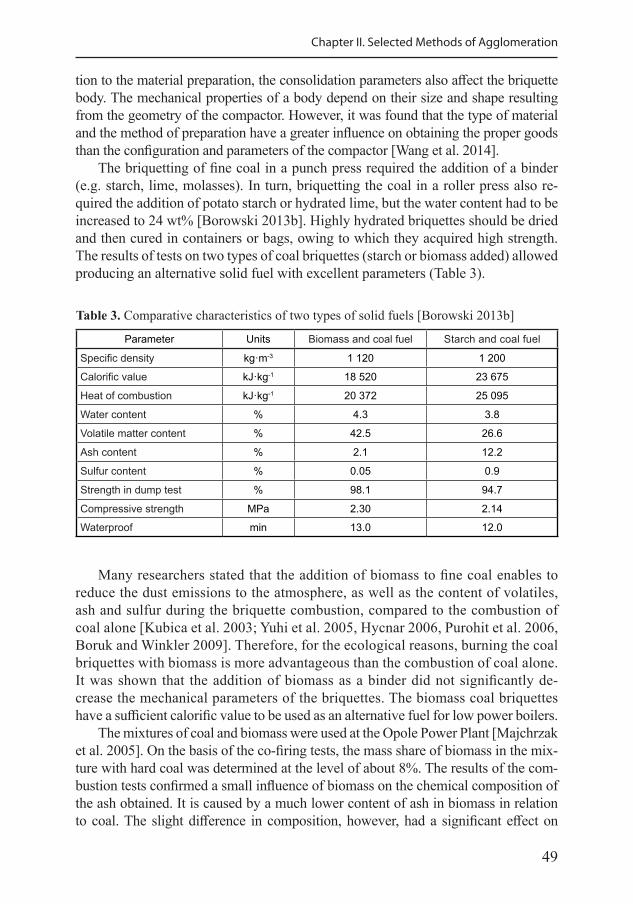
49
Chapter II. Selected Methods of Agglomeration
tion to the material preparation, the consolidation parameters also affect the briquette body. The mechanical properties of a body depend on their size and shape resulting from the geometry of the compactor. However, it was found that the type of material and the method of preparation have a greater influence on obtaining the proper goods than the configuration and parameters of the compactor [Wang et al. 2014].
The briquetting of fine coal in a punch press required the addition of a binder (e.g. starch, lime, molasses). In turn, briquetting the coal in a roller press also re-quired the addition of potato starch or hydrated lime, but the water content had to be increased to 24 wt% [Borowski 2013b]. Highly hydrated briquettes should be dried and then cured in containers or bags, owing to which they acquired high strength. The results of tests on two types of coal briquettes (starch or biomass added) allowed producing an alternative solid fuel with excellent parameters (Table 3).
Table 3. Comparative characteristics of two types of solid fuels [Borowski 2013b]
Parameter Units Biomass and coal fuel Starch and coal fuel
Specific density kg·m-3 1 120 1 200
Calorific value kJ·kg-1 18 520 23 675
Heat of combustion kJ·kg-1 20 372 25 095
Water content % 4.3 3.8
Volatile matter content % 42.5 26.6
Ash content % 2.1 12.2
Sulfur content % 0.05 0.9
Strength in dump test % 98.1 94.7
Compressive strength MPa 2.30 2.14
Waterproof min 13.0 12.0
Many researchers stated that the addition of biomass to fine coal enables to reduce the dust emissions to the atmosphere, as well as the content of volatiles, ash and sulfur during the briquette combustion, compared to the combustion of coal alone [Kubica et al. 2003; Yuhi et al. 2005, Hycnar 2006, Purohit et al. 2006, Boruk and Winkler 2009]. Therefore, for the ecological reasons, burning the coal briquettes with biomass is more advantageous than the combustion of coal alone. It was shown that the addition of biomass as a binder did not significantly de-crease the mechanical parameters of the briquettes. The biomass coal briquettes have a sufficient calorific value to be used as an alternative fuel for low power boilers.
The mixtures of coal and biomass were used at the Opole Power Plant [Majchrzak et al. 2005]. On the basis of the co-firing tests, the mass share of biomass in the mix-ture with hard coal was determined at the level of about 8%. The results of the com-bustion tests confirmed a small influence of biomass on the chemical composition of the ash obtained. It is caused by a much lower content of ash in biomass in relation to coal. The slight difference in composition, however, had a significant effect on
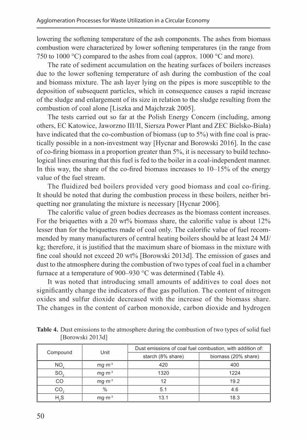
50
Agglomeration Processes for Waste Utilization in a Circular Economy
lowering the softening temperature of the ash components. The ashes from biomass combustion were characterized by lower softening temperatures (in the range from 750 to 1000 °C) compared to the ashes from coal (approx. 1000 °C and more).
The rate of sediment accumulation on the heating surfaces of boilers increases due to the lower softening temperature of ash during the combustion of the coal and biomass mixture. The ash layer lying on the pipes is more susceptible to the deposition of subsequent particles, which in consequence causes a rapid increase of the sludge and enlargement of its size in relation to the sludge resulting from the combustion of coal alone [Liszka and Majchrzak 2005].
The tests carried out so far at the Polish Energy Concern (including, among others, EC Katowice, Jaworzno III/II, Siersza Power Plant and ZEC Bielsko-Biała) have indicated that the co-combustion of biomass (up to 5%) with fine coal is prac-tically possible in a non-investment way [Hycnar and Borowski 2016]. In the case of co-firing biomass in a proportion greater than 5%, it is necessary to build techno-logical lines ensuring that this fuel is fed to the boiler in a coal-independent manner. In this way, the share of the co-fired biomass increases to 10–15% of the energy value of the fuel stream.
The fluidized bed boilers provided very good biomass and coal co-firing. It should be noted that during the combustion process in these boilers, neither bri-quetting nor granulating the mixture is necessary [Hycnar 2006].
The calorific value of green bodies decreases as the biomass content increases. For the briquettes with a 20 wt% biomass share, the calorific value is about 12% lesser than for the briquettes made of coal only. The calorific value of fuel recom-mended by many manufacturers of central heating boilers should be at least 24 MJ/kg; therefore, it is justified that the maximum share of biomass in the mixture with fine coal should not exceed 20 wt% [Borowski 2013d]. The emission of gases and dust to the atmosphere during the combustion of two types of coal fuel in a chamber furnace at a temperature of 900–930 °C was determined (Table 4).
It was noted that introducing small amounts of additives to coal does not significantly change the indicators of flue gas pollution. The content of nitrogen oxides and sulfur dioxide decreased with the increase of the biomass share. The changes in the content of carbon monoxide, carbon dioxide and hydrogen
Table 4. Dust emissions to the atmosphere during the combustion of two types of solid fuel [Borowski 2013d]
Compound UnitDust emissions of coal fuel combustion, with addition of:
starch (8% share) biomass (20% share)NOx mg·m-3 420 400SO2 mg·m-3 1320 1224CO mg·m-3 12 19.2CO2 % 5.1 4.6H2S mg·m-3 13.1 18.3
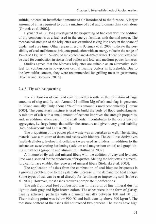
51
Chapter II. Selected Methods of Agglomeration
sulfide indicate an insufficient amount of air introduced to the furnace. A larger amount of air is required to burn a mixture of coal and biomass than coal alone [Gnutek et al. 2002].
Hycnar et al. [2015a] investigated the briquetting of fine coal with the addition of bio-components as a fuel used in the energy facilities with thermal power. The mechanical strength of the briquettes was examined taking into account the share of binder and cure time. Other research results [Giemza et al. 2007] indicate the pos-sibility of coal and biomass briquette production with an energy value in the range of 19–24 MJ·kg-1 with 15–28% of ash content and 4–8% of water. These briquettes can be used for combustion in stoker-fired boilers and low- and medium-power furnaces.
Studies agreed that the biomass briquettes are suitable as an alternative solid fuel for combustion in low-power central heating boilers in households. Due to the low sulfur content, they were recommended for grilling meat in gastronomy [Hycnar and Borowski 2016].
2.4.5. Fly ash briquetting
The combustion of coal and coal briquettes results in the formation of large amounts of slag and fly ash. Around 24 million Mg of ash and slag is generated in Poland annually. Only about 15% of this amount is used economically [Lorenz 2005]. The cement-ash mixture is used to build the body of flood embankments. A mixture of ash with a small amount of cement improves the strength properties, and, in addition, when used in the shaft body, it contributes to the occurrence of aggregates, i.e. large lumps that stiffen the structure and give it very good stability [Kosior-Kazberuk and Lelusz 2010].
The briquetting of the power plant waste was undertaken as well. The starting material was a mixture of dusts and ashes with binders. The cellulose derivatives (methylcellulose, hydroethyl cellulose) were used as binders, in addition to the substances accelerating hardening (calcium and magnesium oxide) and graphitiz-ing substances (graphite and aluminum) [Bultmann 2002].
A mixture of fly ash and mineral fibers with the addition of clay and hydrated lime was also used for the production of briquettes. Melting the briquettes in a metal-lurgical furnace enabled the recovery of mineral fibers [Stolarski et al. 2003].
The application of ashes from the combustion of coal-biomass briquettes is a growing problem due to the systematic increase in the demand for heat energy. Some types of ash can be used directly for fertilizing or improving soil [Isobe et al. 2004]. However, most ashes require appropriate modifications.
The ash from coal fuel combustion was in the form of fine mineral dust in light to dark gray and light brown colors. The ashes were in the form of glassy, usually spherical particles with a diameter usually between 100 and 50 µm. Their melting point was below 900 °C and bulk density above 600 kg·m-3. The moisture content of the ashes did not exceed two percent. The ashes have high
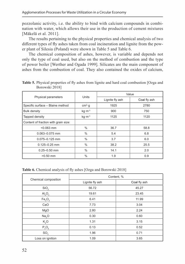
52
Agglomeration Processes for Waste Utilization in a Circular Economy
pozzolanic activity, i.e. the ability to bind with calcium compounds in combi-nation with water, which allows their use in the production of cement mixtures [Mäkelä et al. 2011].
The results pertaining to the physical properties and chemical analysis of two different types of fly ashes taken from coal incineration and lignite from the pow-er plant of Silesia (Poland) were shown in Table 5 and Table 6.
The chemical composition of ashes, however, is variable and depends not only the type of coal used, but also on the method of combustion and the type of power boiler [Werther and Ogada 1999]. Silicates are the main component of ashes from the combustion of coal. They also contained the oxides of calcium,
Table 5. Physical properties of fly ashes from lignite and hard coal combustion [Ozga and Borowski 2018]
Physical parameters UnitsValue
Lignite fly ash Coal fly ash
Specific surface – Blaine method cm2·g 1925 2780
Bulk density kg·m-3 900 750
Tapped density kg·m-3 1125 1120
Content of fraction with grain size:
<0.063 mm % 36.7 58.8
0.063–0.075 mm % 5.4 6.8
0.075–0.125 mm % 3.7 6.0
0.125–0.25 mm % 38.2 25.5
0.25–0.50 mm % 14.1 2.0
>0.50 mm % 1.9 0.9
Table 6. Chemical analysis of fly ashes [Ozga and Borowski 2018]
Chemical compositionContent, %
Lignite fly ash Coal fly ash
SiO2 56.72 45.27
Al2O3 19.61 23.45
Fe2O3 6.41 11.99
CaO 7.73 3.04
MgO 2.80 2.24
Na2O 0.30 0.60
K2O 1.31 3.15
P2O5 0.13 0.52
SO3 1.96 0.71
Loss on ignition 1.09 3.65
53
Chapter II. Selected Methods of Agglomeration
iron, cadmium, manganese and potassium. No dangerous substances were found in the ash samples taken. The research on the ash from coal burning in Germany also confirmed the non-toxicity of this waste [Huth and Kubisa 1996].
The briquetting method, due to the application of pressure in presses, enabled to ob-tain durable fittings from bottom and fly ash. Durable briquettes were obtained, in par-ticular with a two-component binder (hydrated lime with cement) in a total proportion of 8 to 10% and using mixture irrigation up to 6% humidity. The optimal unit pressure of the punch press of 4.25 MPa was also determined. The briquettes of high mechanical strength were achieved after 28 days of curing [Borowski and Hycnar 2013].
The ash briquettes were characterized by good weather tolerance, including frost resistance and waterproofness. These parameters met the requirements set for the mineral and artificial building aggregates [Borowski 2011b]. The briquetting of the analyzed ashes also resulted in a significant reduction in the leaching of water-soluble substances compared with the leaching of the components from loose ashes.
2.5. Agglomeration with high temperature post-treatment
The post-treatment processes of agglomeration with high temperature of sin-tering and vitrification was discussed below. Both are quite similar, but differ in temperature maintenance mostly and other specific characteristic of utilizing.
2.5.1. Sintering
Sintering is a size enlargement process by agglomeration, and a method of post-treatment to create the final characteristics of agglomerated products. Sintering is a binding mechanism and different technologies may be used for agglomeration [Pietsch 2008]: • batch sintering in stationary furnaces for the post-treatment of agglomerated
products. • continuous sintering, mostly in tunnel kilns for ceramics.
The sintering of materials is an effective, simple and economical microstruc-ture refinement method. Thus, the two-step sintering is a promising method for obtaining high-density bodies and smaller grain sizes. The sintering specifications, including the temperatures, heating/cooling rates, sintering holding times and at-mosphere types, were determined for each study to obtain the best features for each material [Lóh et al. 2016]. Microwave sintering has achieved greater acceptance against conventional sintering methods, because of: much lower energy consump-tion, diffusion process intensification, sintering time reduction, and better proper-ties of bodies [Oghbaei and Mirzaee 2010].
The post-treatment sintering is widely used for the agglomerates that grew dur-ing tumbling/pelleting in the presence of a binder and must be cured to achieve a permanent state. This process has been widely studied, for example in the iron
54
Agglomeration Processes for Waste Utilization in a Circular Economy
and steelmaking industry. Achieving an adequate sintered product depends on the adequate raw materials supply and the previous stage the iron ore granulation [Fernández-González et al. 2017].
Sintering of the rubber granules made from used tires can be a source of ‘envi-ronmentally friendlier’ composites. A wide range of these composite materials are characterized by quite good mechanical and functional properties [Sienkiewicz et al. 2017]. Fathi and Kharaziha [2009] investigated compacted bioceramics which were produced at T1 temperature ranging from 1100 to 1300 °C and a 6-min holding time as well as with T2 temperature at 750 and 850 °C for 2–15 h. The heating rate was 10 °C·min-1, and the cooling rate between T1 and T2 was 50 °C·min-1. The best results were obtained with T1 at 1300 °C, T2 at 750 °C, and a 15-h holding time. The obtained bodies were characterized by relative density of approximately 98.5%.
The sintering process is an alternative method to fabricate glass-ceramics from the incinerator residues – mixing bottom ash and fly ash. This process consists of the shaping a powder by cold-compacting, followed by a high temperature heat treatment to sinter the compact for the fabrication of ceramics [Dinh Hieu Vu et al. 2012].
Various processes of sintering can be adapted for the manufacturing of artificial aggregates from industrial wastes, usually fly ash and bottom ash. Sintered light-weight aggregates are appropriate for structural applications [Zhang et al. 2011].
Borowski [2011] produced an artificial aggregates in the process of sintering the previously briquetted fly ashes, in an amount of about 50 wt%, with the addition of silica dust (40 wt%) and milled glass waste (10 wt%). The addition of glass dust is beneficial, because it lowers the temperature of thermal synthesis. After mixing all ingredients, barrel-shaped briquettes were made, which were then heated in a chamber oven at 1100 °C for 1.5 hours. The obtained products proved to be du-rable and resistant to the environmental conditions corresponding to the materials proposed for foundations of paved road surfaces.
2.5.2. Vitrification
Another way of processing particulate material and waste is vitrification, con-sisting in the formation of an impermeable and durable structure of glass. Active ingredients, such as heavy metal compounds, are closed tightly inside the struc-ture, which prevents their migration to the environment. Hazardous components are disposed of either by binding molecules in the crystal structure of the enamel or by hermitization [Bingham and Hand 2006]. Such elements as phosphorus, boron and silicon are permanently bonded. During heating, they are melted into a liquid phase and, after cooling, form an integral part of the crystalline lattice of glass. Another issue is hermitization of waste components such as; cobalt, lead, sodium, magnesium, lithium and cesium. They represent the intrusive additions trapped in the crystal lattice structure. As a result of diffusion-melting the crystal lattice of the compounds, hermitization can take place either during the heating of waste, or dur-ing cooling [Colombo et al. 2003].
55
Chapter II. Selected Methods of Agglomeration
Vitrification is typically used to treat the wastes with complex chemical com-position and unfavorable physical properties, such as medical waste, asbestos, slag, etc., as well as employed in the disposal of radioactive waste. Vitrification of ash is often used to neutralize the hazardous components, including heavy metals [Borowski 2013a, 2013c].
In order to obtain the vitrified form of ash, one should use melting temper-ature of 1150–1450 °C, followed by intense cooling [Kordylewski et al. 2003]. Vitrification of the ash from the incineration of sewage sludge involves the addition of silica (SiO2), the share of which is that waste is insufficient. Effective vitrifica-tion can be achieved by the addition of fly ash from coal combustion, where the share of SiO2 is twice as high [Lelusz 2012]. Another solution may be the addition of shredded glass as powder. Additionally, its presence lowers the temperature of the synthesis reaction, thus reducing the energy requirement [Kępys 2010].
The method of vitrification of ashes obtained from different types of boilers helps the formation of products with irregular or rounded shapes [Bernardo and Dal Maschio 2011]. Their dimensions differ from a few millimeters to tens of centime-ters or more. Vitrification is often used to process the ash from the power plant or from incineration, land tannery sludge and tailings, waste containing sulfur com-pounds, lead and other elements [Bień et al. 2013]. Using waste vitrification of different substances, the products obtained of the properties to their re-use, mainly in ceramic and construction industries [Borowski 2012b].
During the heating, apart from the chemical compounds, the organic compounds contained in the waste are removed as well. The waste may take a form of vitrified blocks in the dish-shape, in which the cooling [Kovacova et. al. 2009] should also apply to the agglomeration of fine-grained fraction of the waste in a closed body, with subsequent heating (sintering) in rotary kilns [Rahman et al. 2012]. After the completion of the transition phase, it is cooled in water causing it to form a coat-ing and sealing the glass. The use of vitrification solves the problem related to the development of certain types of hazardous waste by simultaneously reducing or eliminating their harmful properties and reducing their volume [Pisciella et al. 2001]. An additional advantage is that some of the products are used in commerce and do not need to be sent to storage [Barbieri et al. 2001].
In the industry, there are different types of wastes, including hazardous ones, which can be subjected to vitrification (Table 7). The inactivation of the composites found in the ashes from the incineration of waste and sewage sludge, blast slag, fly ash from coal power stations, medical waste, asbestos and radioactive waste creates a lot of problems [Borowski 2015].
The ash from the incineration of municipal waste can contain very high concen-trations of heavy metal chlorides and alkali chlorides. Prior to the vitrification, the waste requires further processing, usually by precipitation from a solution of hydrox-ides or phosphates. In the case of the vitrification process of the ash from municipal waste incinerator in Rotterdam, no additives were used [Fredericci et al. 2000]. This ash contains mainly silica, calcium oxides, carbonates, sulphates, chlorides,
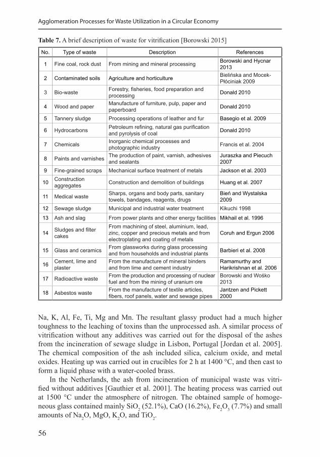
56
Agglomeration Processes for Waste Utilization in a Circular Economy
Na, K, Al, Fe, Ti, Mg and Mn. The resultant glassy product had a much higher toughness to the leaching of toxins than the unprocessed ash. A similar process of vitrification without any additives was carried out for the disposal of the ashes from the incineration of sewage sludge in Lisbon, Portugal [Jordan et al. 2005]. The chemical composition of the ash included silica, calcium oxide, and metal oxides. Heating up was carried out in crucibles for 2 h at 1400 °C, and then cast to form a liquid phase with a water-cooled brass.
In the Netherlands, the ash from incineration of municipal waste was vitri-fied without additives [Gauthier et al. 2001]. The heating process was carried out at 1500 °C under the atmosphere of nitrogen. The obtained sample of homoge-neous glass contained mainly SiO2 (52.1%), CaO (16.2%), Fe2O3 (7.7%) and small amounts of Na2O, MgO, K2O, and TiO2.
Table 7. A brief description of waste for vitrification [Borowski 2015]
No. Type of waste Description References
1 Fine coal, rock dust From mining and mineral processing Borowski and Hycnar 2013
2 Contaminated soils Agriculture and horticulture Bielińska and Mocek-Płóciniak 2009
3 Bio-waste Forestry, fisheries, food preparation and processing Donald 2010
4 Wood and paper Manufacture of furniture, pulp, paper and paperboard Donald 2010
5 Tannery sludge Processing operations of leather and fur Basegio et al. 2009
6 Hydrocarbons Petroleum refining, natural gas purification and pyrolysis of coal Donald 2010
7 Chemicals Inorganic chemical processes and photographic industry Francis et al. 2004
8 Paints and varnishes The production of paint, varnish, adhesives and sealants
Juraszka and Piecuch 2007
9 Fine-grained scraps Mechanical surface treatment of metals Jackson et al. 2003
10 Construction aggregates Construction and demolition of buildings Huang et al. 2007
11 Medical waste Sharps, organs and body parts, sanitary towels, bandages, reagents, drugs
Bień and Wystalska 2009
12 Sewage sludge Municipal and industrial water treatment Kikuchi 1998
13 Ash and slag From power plants and other energy facilities Mikhail et al. 1996
14 Sludges and filter cakes
From machining of steel, aluminium, lead, zinc, copper and precious metals and from electroplating and coating of metals
Coruh and Ergun 2006
15 Glass and ceramics From glassworks during glass processing and from households and industrial plants Barbieri et al. 2008
16 Cement, lime and plaster
From the manufacture of mineral binders and from lime and cement industry
Ramamurthy and Harikrishnan et al. 2006
17 Radioactive waste From the production and processing of nuclear fuel and from the mining of uranium ore
Borowski and Wośko 2013
18 Asbestos waste From the manufacture of textile articles, fibers, roof panels, water and sewage pipes
Jantzen and Pickett 2000
57
Chapter II. Selected Methods of Agglomeration
More often, however, the vitrification process – particularly of hazardous waste – is carried out after mixing with various additives to facilitate the melting process and form a more homogeneous product [Sobiecka et al. 2012]. For example, the ash from coal is mixed with powder glass, feldspars, and alumino-silicates, and heated at a temperature of 1450 °C. The presence of aluminum oxide ensures high chemical resistance of the final product. Ash also requires pretreatment – grinding to a particle size <0.4 mm, and the removal of metallic impurities in a magnetic separator. The mixture prepared for the vitrification comprised about 50% of bot-tom ash, 5% fly ash and 45% cullet. The product was obtained as a clear, dark green glass, characterized by excellent durability and negligible leaching of alkali [Zou et al. 2011].
For the ash from the incineration of sewage sludge, shredded glass cullet and limestone were also added, and then heated at a temperature of 1450 °C. The result-ing glass products were commercially used in the manufacturing of ceramic tiles and as insulation material [Lin 2006].
There were also successful attempts at the vitrification involving furnace slag mixed with sand. A mixture comprising of 50–75% of slag was preheated to a tem-perature of 1100 °C, and then molten at 1450 °C. The products were obtained with good mechanical properties and resistance to external factors. It was proposed to use them in the production of wall and floor tiles [Zhang et al. 2011].
Other reports show the possibility of vitrification of the slag and dust from electric arc furnace with the addition of kaolin clay [Lapa et al. 2006]. It was found that the process of melting occurs at a temperature of about 1200 °C; then, after cooling, the products were vitrified. Pelino [2000] describes the vitrification of zinc dust electric-arc furnace with the addition of cullet and sand. On the other hand, Kim et al. [2007] added calcium borosilicate of 30–50% to the steelmak-ing waste and melted at 1350 °C. The attempts at the vitrification of slag with the addition of sand and dolomite were also conducted by Duca et al. [2002]. They found that the product can be used as a replacement for pottery.
Refining slags with yellow phosphorus mixed with quartz sand, feldspar, calcium carbonate and sodium nitrate were successfully vitrified when heated to a tempera-ture of 1400–1420 °C for 2–3 h in a corundum crucible [Lin et al. 2007]. The resulting glass, containing up to 55% phosphoric slag, can be used to produce glass-ceramic materials. Similarly, the metallurgical dust from the flotation of copper with addition of silica, sodium and calcium carbonates, was vitrified with heating to 1200 °C [Karamanov et al. 2007]. The conducted tests showed very low levels of toxic metals in the water extracts.
Barbieri et al. [2000] vitrified the ash from coal power plant, mixed with up to 50% by weight of glass cullet and dolomite, yielding colored glass and glass-ceramic products. They found that the higher the silica content in the ash, the more readily the process forms the crystalline structures of glass, and for the lower silica content, the structural changes are slower and require a suitable heat treatment. The coal ash melting process was carried out at 1500 °C for 5 hours. Researchers have found that
58
Agglomeration Processes for Waste Utilization in a Circular Economy
the addition of the flux allows reducing the melting temperature of the charge to the range 900–1100 °C, which is sufficient to form a glass material [Barbieri et al. 2001].
Similarly, Francis et al. [2004] mixed 10% to 60% of ash of the El Maghara coal power plant in Egypt with fine-grained cullet of soda-lime glass, which were subse-quently melted at 1500 °C. The products of glass-ceramics were also obtained when fired at 800–1200 °C to compensate for the stress in the crystal structure. Studies pre-sented a comprehensive analysis of the thermal process of heating and melting, where the activation energy of crystallization was stated using a modified Kissinger method.
The vitrification of the asbestos waste is the only presently known way to allow their use as a construction material [Leonelli et al. 2006]. Such waste can be converted into a product by heating with the glass cullet in the electric furnace at a temperature above the decomposition temperature of asbestos [Finucane et al. 2008]. The waste asbestos and fine glass can be delivered to the furnace by a screw mixer, wherein the furnace pressure must be maintained, in order to avoid the possibility of contamina-tion from the outside. The asbestos vitrifying blocks can also be obtained by using a plasma arc heating and melting the liquid phase by microwave radiation [Leonelli 2006]. A pilot trial vitrification of asbestos waste and asbestos-cement waste was also carried out using the resistive Joule’s method [Dellisanti et al. 2009]. In this experi-ment, the asbestos material encapsulated in soil was placed in a stainless steel vessel and graphite electrodes were inserted. High current was applied to melt the material at 1500 °C, which was subsequently cooled and yielded a glassy 100 kg slab.
The vitrification method was also applied successfully for the disposal of medical waste by heating to a temperature of 1550 °C using a plasma torch [Chu et al. 1998]. The waste consisted of combustible parts, such as bandages, gauze, swabs, etc., and non-combustible parts, as fine glass, scalpels, needles and syringes. As a result of the heating of the plasma, two fractions were obtained – slag and glassy form. The analysis confirmed the composition of the vitrified waste, which is mainly com-posed of silica and oxides of Ca, Cr, Al, P, and Zn. An attempt to wash the material showed good resistance to the leaching of heavy metal ions.
Sobiecka [2010] presented a method for vitrification involving mixing the ash from the incineration of medical waste with the chemical preparations containing the following compounds: SiO2, Na2B4O7, CaCO3, KNO3, CaF2, and BaSO4. The melting was carried out in the plasma arc and, depending on the type of additive, occurred at a temperature of approx. 1000 to 1600 °C. In order to produce a stable vitrified product, the effect of SiO2, and Na2B4O7 addition – in a proportion of 2 to 5% – was found beneficial. These additives allowed lowering the heating temperature, obtain-ing a low leaching of heavy metals and high hardness of the vitrified product.
The vitrification technology of high level waste generated in industrial pro-cessing of spent nuclear fuel from light water reactors (pressurized and boiling) has been implemented in France (La Hague), the UK (Sellafield), Japan (Tokai, Rokkashomura) and Russia (RT-1 and RT-2). It involves the delivery of a signifi-cant amount of thermal energy required to form the amorphous structure, and then rapidly cooling the material [Ojovan 2011].
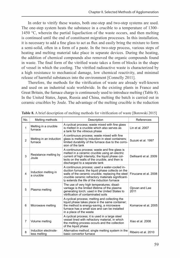
59
Chapter II. Selected Methods of Agglomeration
In order to vitrify these wastes, both one-step and two-step systems are used. The one-step system heats the substance in a crucible to a temperature of 1300–1450 °C, wherein the partial liquefaction of the waste occurs, and then melting is continued until the end of constituent migration processes. In this installation, it is necessary to add a fine glass to act as flux and easily bring the mixture to form a semi-solid, often in a form of a paste. In the two-step process, various steps of heating and melting material take place in separate devices. During the heating, the addition of chemical compounds also removed the organic compounds found in waste. The final form of the vitrified waste takes a form of blocks in the shape of vessel in which the cooling. The vitrified radioactive waste is characterized by a high resistance to mechanical damage, low chemical reactivity, and minimal release of harmful substances into the environment [Connelly 2011].
Therefore, the methods for the vitrification of waste are already well-known and used on an industrial scale worldwide. In the existing plants in France and Great Britain, the furnace charge is continuously used to introduce melting (Table 8). In the United States, Japan, Russia and China, melting the batch is carried out in ceramic crucibles by Joule. The advantage of the melting crucible is the reduction
Table 8. A brief description of melting methods for vitrification of waste [Borowski 2015]
No. Melting methods Description References
1 Melting in a crucible furnace
A cyclical process; waste mixed with fine glass is melted in a crucible which also serves as a tank for the vitreous phase
Lin et al. 2007
2 Melting in an induction furnace
A continuous process; waste mixed with fine glass is melted by induction in steel containers; limited durability of the furnace due to the corro-sion of the tank
Suzuki et al. 1997
3 Resistance melting by Joule
A continuous process; waste and fine glass is melted in a ceramic crucible using an electric current of high intensity; the liquid phase col-lects on the walls of the crucible, and then is discharged to a separate tank
Dellisanti et al. 2009
4 Induction melting in a crucible
A continuous process; used a water-cooled in-duction furnace; the liquid phase collects on the walls of the ceramic crucible; replacing the steel crucible ceramic refractory materials significant-ly extends the life of the induction furnace
Finucane et al. 2008
5 Plasma meltingThe use of very high temperatures; disad-vantage is the limited lifetime of the plasma generating torch; used in the United States to vitrification of contaminated soils
Ojovan and Lee 2011
6 Microwave melting
A cyclical process; melting and collecting the liquid phase takes place in the same container; the method is energy-saving, a microwave furnace has a small size and can be installed in a place of the waste
Komarow et al. 2005
7 Volume meltingA cyclical process; it is used in a large steel vessel lined with refractory material, in which the melting process occurs and the collection of the liquid phase
Xiao et al. 2008
8 Induction electrode-less melting
Alternative method; single melting system in the basic convertor furnace Ribeiro et al. 2010
60
Agglomeration Processes for Waste Utilization in a Circular Economy
and generation of waste gases as well as small amounts of impurities remaining after the process.
There are more studies on determining the specific properties of the resulting products (vitrified waste), in particular regarding the sustainability to ensure safe storage or in specific commercial applications. For example, the processing tech-nology of the fly ash from coal combustion into a small glass spheres developed by Rocktron from the UK [www.rktron.com]. It uses selected ashes rich in silicates to fa-cilitate vitrification without the use of silica additives. The resulting products named MinTron – glass microspheres with a full diameter of 8 to 14 microns and balls with a diameter of 5 to 9 microns are generated. They are used as mineral fillers, functional plastics and rubbers, as additives for processing by extrusion, injection molding and compounding. Glass microspheres have major advantages in comparison with con-ventional fillers, such as composites of polypropylene and polyamide: improved re-sistance to scratches and abrasion. In the near future, empty glass microspheres will also be produced for thermal insulation and weight reduction of plastic components.
There is a method of vitrification of the ashes from the combustion of sewage sludge to achieve a shape of regular balls, referred to as “glass beads”. The technol-ogy for producing glass beads includes [Borowski et al. 2014]: • preparation of the waste material to melting, • heating and melting in a high temperature furnace, • intensive air-cooling, whereas the liquid material forms the glassy phase.
The technological line for the production of glass beads with a screw mixer can operate on the ashes from bed combustion of sewage sludge, as well as from coal power plants. Modifiers (e.g. boric acid) are added to facilitate liquefaction in the furnace. The blend is molten in an induction furnace crucible, and then the liquid phase (spout) is fed into the dryer with an intensive blow of air. Blow air spout dis-integrates into fine particles and cools forming glass beads. Small fractions of beads are carried with the airflow of the upper part of dryer and fall onto a conveyor, and then to the tank. Larger and heavier parts are redirected for re-melting in an induc-tion furnace. Rotary kilns, microwave ovens and plasma furnace can be used for the heating and [Borowski et al. 2013].
The glass beads made from waste materials will be much cheaper than ceramic, and at the same time provide good mechanical properties and chemical stability. Large surface smoothness and regular shapes allow increasing the gas flow effi-ciency and reducing the time needed to complete the extraction of the deposit.
61
Chapter III
Usage of Adhesives and Bonding Materials
3.1. Properties of binders
Binders are widely used in agglomeration of particulate material to obtain strong bodies. The presence of binders affects the formation of the bodies harden-ing process from the freshly-made state. Binders interact with moisture and mineral particles, affecting the capillary forces and viscous forces which bond individual particles together. The presence of binders is beneficial for a variety of reasons [Halt and Kawatra 2014]: • Binders help control the transport of moisture during the wet agglomeration
process. Binders increase the viscosity of moisture within the granule structure, and slow down the transport of moisture. Certain binders can also help lessen the granule spalling during drying. Usually, the thermal shock temperature is increased with binders, so hotter drying gases can be used, which may decrease the drying time.
• Binders help control the excess moisture present in the agglomeration material. The growth of agglomerates depends critically on the moisture content in the material sent to pelletizing drums and discs. Insufficient moisture may prevent nucleated seeds from growing or small clusters of seeds may form that are dif-ficult to enlarge; under these conditions, the final green balls are porous and weak. In turn, excessive moisture produces rough green ball surfaces, enables rapid and uncontrollable green ball coalescence and, in extreme cases, turns the agglomerating material to “mud”. In the second case, certain binders can be added to absorb the excess moisture for a more stable agglomeration process.
The binder used in agglomeration process can be divided into [Zhang et al. 2018]: • Inorganic binder – advantages in abundant resource, low cost, excellent ther-
mostability and good hydrophilicity. A major problem arising from the usage of an inorganic binder is related to the significant increase in the amount of ash produced. Clay, lime, plaster, cement, sodium silicate and sodium silicate are common types of inorganic briquette binders.
• Organic binder – advantages include good bonding, good combustion performance and low ash generation. It is easy to decompose and burn when heated, while the mechanical strength and thermal stability of organic binder agglomeration are poor.
62
Agglomeration Processes for Waste Utilization in a Circular Economy
• Compound binder – are composed of at least two binders; the different binders play different roles. The compound binder can reduce the supplying amount of inorganic binder, reduce the cost of organic binder, improve the quality of ag-glomerates, and obtain better processing performance.
Briquetting requires the addition of a binding material to hold the briquette to-gether for transportation, briquette forming and storage. The binder plays a key role in the process of briquette production. The strength, thermal stability, combustion performance and cost of briquette also depend on the quality of the briquette binder [Altun et al. 2001]. The experiment results showed that various binders exhibit dif-ferent bonding mechanisms of the briquettes. Generally, the properties required of a briquette binder can be summarized as follows [Zhao et al. 2001]: • strong bond, • pollution-free, • no effect on the heat release and combustibility, • no interference on the utilization, • environmentally acceptable, • economically available.
3.2. Inorganic binders
Different materials can be used as inorganic binders, including: • limestone, • clay, • bentonite, • cement, • sodium silicate, • iron oxide and magnesium oxide, • calcium oxide and calcium hydroxide.
The main advantages of inorganic binders used for agglomeration are: good thermal stability, good hydrophilicity, good sulfur retention, low price; whereas the disadvantages are as follows: high ash content, low heat, poor waterproofing properties, and poor water repellency.
Lime and clay are the earliest binders that have been added to briquettes. The amount of lime addition is large, ranging from 25 to 30 wt% when it is used alone. Bentonite clay is the best binder among all clays; the amount of bentonite clay addition is only 6–8 wt%. Bentonite, as a binder, provides strength to pellets at every step of pelletization, as it can withstand high temperature and does not burn away during the induration process. The disadvantage with bentonite is that it con-tains approximately 45 to 65 wt% silica (SiO2) impurity, which is removed dur-ing the upgrading process. A silica addition can increase the energy and flux cost [Srivastava et al. 2013].
63
Chapter III. Usage of Adhesives and Bonding Materials
The inorganic binders tested by Srivastava et al. [2013] were calcium hydroxide (Ca(OH)2), sodium silicate (Na2SiO3), calcium carbonate (CaCO3), sodium carbon-ate (Na2CO3), and calcium chloride (CaCl2). The dosage of binder pellets was from 0.5 to 5 wt%. The dry pellets made using CaCO3 and Na2CO3 could not achieve the acceptable compressive strength. Overall, the strength of indurated pellets made from all the inorganic binders was above the acceptable limit; however, it was not the case for the green and dry pellets. In general, the strength of the green pellets was below the limit for all the inorganic binders.
The inorganic binders were used for agglomeration of stone dust as low cost building material, consisting mainly of limestone and Portland cement. Satisfactory results were obtained for the aggregates with cement content of 15 wt%. Briquettes require curing for a minimum of 48 hours. Because the porosity of the indurated pellets decreased, owing to the application of inorganic binder, the compression strength of the agglomerates increased [Borowski et al. 2017b]. The production of stone cobble cubes is possible with the cement content up to 20 wt%. However, increasing the proportion of binder with stone dust in the compound for agglomera-tion does not always produce positive results [Lakhani et al. 2014].
3.3. Organic binders
The earliest organic binders for pellets were starches, such as corn, wheat, rye, sorghum, and soybean. Starch was used alone or as a gel to equally distribute other binders throughout the body structure. Bentonite clay has traditionally been used to make pellets due to its ability to improve their physical quality at all stages of agglomeration. Molasses, sugar, petroleum coke and oil, sodium silicate were claimed as binders for specific briquettes [Eisele and Kawatra 2003]. Table 9 pro-vides an overview of the different organic binder types.
Organic binders may be used for a variety of reasons, but perhaps the most fre-quently reported benefit is a reduction in the pellet silica content. Organic binders are combusted during the high-temperature firing process, and may leave virtually no ash residue among the pellet structure for slag formation. Lowering the gangue or silica contents in iron ore pellets may be beneficial for a number of reasons: lower silica contents require lesser flux to achieve certain basicity levels, and ultimately reduce the slag volumes in blast furnaces and other iron-making operations. Direct reduction iron-making processes have tight gangue tolerances and limited slag handling capabilities, so strict control over silica is important. It was reported that a reduction in silica can decrease the energy and flux costs [Schmitt, 2005].
A second major reason reported for using organic binders is that organic binders increase the fired pellet porosity and reducibility. Panigrahy et al. [1990] studied the microstructures of iron ore pellets made with peat moss and bentonite binders, and attributed high porosity in the fluxed pellets (basicity from 0.2 to 1.6) to peat moss combustion before a liquid slag phase formed. With lower ash contents and corre-spondingly lower flux levels in the peat moss and other organically bonded pellets,
64
Agglomeration Processes for Waste Utilization in a Circular Economy
insufficient slag quantities are available for bonding; the pellet porosity has been shown to be significantly higher in organic-binder pellets compared to bentonite.
Increasing the pellet porosity typically improves the pellet reducibility. Reducibility can be defined as the ease of oxygen removal from oxides in the pel-let during the reduction process. A higher volume of the macro and micro pores in the pellet microstructure corresponds to more surfaces being in contact with the reducing gases at any time. Consequently, less time is required to achieve a given percent of reduction. For example, replacing bentonite with an organic binder improved the taconite pellet porosity by 29.1% in the pellets prepared for blast
Table 9. An overview of the organic binders [Halt and Kawatra 2014]
Organic binder General dose, % Notes
Guar gum 0.1–1.5
Guar gums are derived from guar beans, and are mainly composed of high molecular weight carbohydrates and proteins. The guar gum binders were used to develop the bonding viscosity theory during agglomeration.
Bitumen 1.0–5.0
Heavy hydrocarbons such as bitumen, occur naturally or are produced during oil and coal refining. The balls made with bitumen can be baked at a temperature 200 °C, which removes volatile components and produces a hardened, cross-linked structure. Agglomeration in drums and discs may require a wetting agent due to the hydrophobic properties of the hydrocarbons.
Starch 0.1–5.0
Starches are natural carbohydrates. Starch occurs in a variety of plants, but corn is a major source for industrial starch products. Starch can be chemically modified to alter properties, or further broken down to form dextrin; even further to the sugar dextrose.
Humic acid 0.5–2.0
Humic acids are products of organic matter decomposition. Common sources include peat moss, carbonaceous shale, lignite and leonardite (which is an oxidized form of lignite). All humic acid binders require the application of a base (usually NaOH).
Polyacrylamide 0.01–0.05
Polyacrylamide binders are petrochemical-based, anionic copolymers. They have been shown to improve the green-ball size distribution, balling drum productivity, and moisture distribution within the green-ball structure.
Whey / lactose 1.0–2.0 Whey / lactose are dairy wastes that serve as a source of sugar and proteins.
Papermill sludge 0.5–5.0 Papermill sludges contain fibers and colloidal particles, with a high content of clay.
Alginate 0.3–0.5 Alginate is alginic acid derived from seaweed.
Lignosulfonate 1.0–2.0 Lignosulfonates are byproducts of pulp and paper processing.
Molasses 3.0–5.0Molasses is a byproduct of sugar manufacturing, and contains sugars unrecovered during processing and inorganic minerals found in the crop.
Carboxymethyl cellulose 0.1–0.5
Carboxymethyl cellulose (CMC) is made water-soluble by incorporating carboxymethyl groups into the organic structure. CMC produces round green balls with smooth, shiny surfaces.
65
Chapter III. Usage of Adhesives and Bonding Materials
furnace iron making [Lyons et al. 1986]. Correspondingly, the pellet reducibility increased by 16.7%.
The drawbacks to organic binder use include higher levels of fines before tum-ble and weak fired pellets. Historically, the fired pellets made with organic binders have had low compression strength and abrasion resistance. This could be due to higher porosities and less glassy phases in those pellets. The pellet strength gener-ally increases with decreasing porosity, lowering the volume of large macropores, which concentrate stress fields in pellet structures [Ranade et al. 1986].
The use of sodium carboxymethylcellulose (Na-CMC) binder during agglom-eration led to a narrower ball size distribution. The narrow size distribution and organic binder burn-out improved the bed and pellet permeability to such a degree that the magnetite pellets oxidized on the grate earlier than expected [Ranade et al. 1986]. Consequently, less heat was provided by oxidizing pellets in the firing zone, leading to under-fired pellets. A significant fraction of the process heat available for pellet sintering results from magnetite oxidation.
The granules made with organic binders sometimes grow too fast and have moist, rough surfaces. Slower growth and higher recycling loads in rotary drums (com-monly associated with higher viscosity binders) produce stronger, more spherical balls. Lower surface moistures may enable better classification between the finished balls and little particles on roller decks and screens, resulting in fewer dust issues.
Higher surface moisture has been frequently reported for starch. Excess wa-ter is rapidly exuded to pellet surfaces, where it enables rapid green ball growth, coalescence and dust pickup. These pellets have rough surfaces, which can easily abrade during pellet handling, producing higher levels of fines. Some have claimed to solve this problem by using cross-linked superabsorbent polymers in addition to starch. Starch is easy to modify, but no extensive investigation on the effects of starch structure on the binding properties has been reported.
Qiu et al. [2003b] proposed the general structure of an ideal organic binder, and it should contain: • hydrophilic functional groups to promote binder dispersion into moisture and to
enforce the concentrate wettability; • polar functional groups to promote binder adhesion to ore particles, and • a mechanically strong and thermally stable “backbone”.
The process of agglomeration mechanism with organic binder is shown in Figure 21. Organic binders are often a combination of a particular polymer binder and inorganic additives. Additives such as sodium carbonate (Na2CO3) serve to soften the pellet moisture by precipitating calcium and magnesium out of solution as solid carbonates, and may act as a fluxing agent during sintering [Eisele and Kawatra 2003]. Both the green pellet quality and sintered pellet quality tend to increase when binder additives are used during agglomeration.
There are numerous studies which claim that dispersants and chelating agents im-prove the binding characteristics of certain organic binders. The examples of these ad-
66
Agglomeration Processes for Waste Utilization in a Circular Economy
ditives include sodium citrate, sodium tripolyphosphate and sodium hexametaphosphate as well as sodium silicate [Field and Stocks 2001, Schmitt and Steeghs 2005, Schmitt and Smeink 2007]. Sodium tripolyphosphate (TPP) and sodium citrate may sequester harmful ions (such as calcium and magnesium) in pellet moisture and adsorb them to particle surfaces. This may limit the excessive precipitation or adsorption of organic binders onto particle surfaces and ensure full dispersion into the green-ball moisture.
It has been suggested that the additives disperse colloidal particles into the pellet moisture: the colloidal particles would increase the binder viscosity and be subsequently deposited at contact points in pellets as moisture evaporates during drying [Dilsky et al. 2011]. Wet drop, wet compression and dry compression strengths of CMC-bonded pellets increased after the addition of the TPP disper-sant (0.02%) [de Moraes and Kawatra 2010].
A variety of natural and waste organic materials have been evaluated as pellet binders due to their adhesive and thickening properties, or relatively large supplies in the vicinity of pellet plants. Some of more popular ones are listed below.
Starch
Starch occurs as granules with variable properties depending on its source. Starch can be isolated from corn, potato, wheat, rice and tapioca, with the production from corn being the most prevalent [Swinkels 1985]. Corn has proven to be an abundant, stable supply of starch and dextrin over the years, and is used in a variety of binding applications. The starch granules are not water soluble (which is typically desirable for pellet binders), so they are cooked or causticized to increase solubility and bind-ing power. Dextrins are starch derivatives, produced by hydrolyzing starch in acid, or by roasting unmodified starches [Whistler 1973]. A variety of product solubility and viscosity can be produced, by varying the extent of reaction during decomposition.
In general, about 4–8% of starch is needed to make the briquettes. The starch sources can be corn starch, wheat starch, maize flour, wheat flour, rice flour, cas-sava flour, potato starch, etc. Starch is less frequently used in the briquette industry
Fig. 21. The process of agglomeration mechanism with organic binder [Halt and Kawatra 2014]
Discrete particles Particles are wetted and contacted together
Particles rearrange and agglomerate grows
67
Chapter III. Usage of Adhesives and Bonding Materials
because of its high cost, as well as low waterproofing. The modified starch, such as gelatinized starch and alkaline starch etc, is characterized by good performance. In order to improve the binding property of alkaline starch, researchers added other materials into starch. Manzhai et al. [2013] studied the effect of polyvinyl alcohol on the briquette compressive strength, and found that the compressive strength of briquette increased significantly along with the polyvinyl content. However, poly-vinyl was easy to decompose at high temperature, so the thermal strength of the briquette was lower. Zhong and Cao [2000] studied the effect of carboxyl methyl starch on the briquette caking property, and found that the starch is much better than the original starch in the binding property, and the quality of products by the acid treatment is better than that by the alkali treatment. Thoms et al. [1999] studied the briquette binder using phenolic resins which were synthesized using the whole coal tar acid fraction of the oil from a low temperature carbonization process. It was found that excellent briquettes, in terms of the mechanical strength, water-proofing characteristics and thermal degradation, were produced with both nominally 10% and 9% w/w resole solution and acid concentrations down to 1.8 M, corresponding to the sulfur addition in the briquettes of ca. 0.2 wt%. The briquettes bound with 8% w/w resole solution, however, required stronger acid concentrations to satisfy the test conditions.
Corn starch has been used as an iron ore flocculant [Keranen 1986] and a binder for iron ore concentrate briquettes, indurated pellets [Dingeman and Skagerberg 1994] and cold-bonded pellets. Heinrich and Schierloh [1973] used 0.2–0.5% starch with 2–8% finely ground sponge iron powder as a binder for DRI pellets. Graham [1983] claimed that raw wheat starch can be added to the pelletizing mixture (3–7%) and heated to gelatinize the starch, producing cold strengths in excess of 136 kg (300 lbs) per pellet. Igawa et al. [2008] used wheat flour as a binder for the pellets fed to rotary hearth furnaces. Drying was carried out at 150–200 °C at a low rate, so the starch could sufficiently gelatinize before moisture was evaporated. Wheat wass added at a dose of around 5%, in addition to bentonite (0.1–0.3%) and NaOH (0.01–0.03%). Osmundson [2011] applied starch as a binder for rotary hearth pellets. Starch was added at 0.7–1.2% by mass, and aged for 0.5–4 hours before pelletizing.
Dextrin was also used for the iron concentrate-coal composite pellets for sponge iron production [Agrawal et al. 2001]. Pellet handling in the plant environment re-quired ~30 kg/pellet dry strength; this was met with a 4% dextrin dose. The pellets with 10–12 mm in diameter were prepared on a disc pelletizer and cured in air for 3–4 days. The plant trials were conducted in an 8 t/d rotary kiln. The pellets were air cooled for 4–7 days. Consistent strengths of 35–40 kg/pellet were produced.
Two types of charcoal briquettes were made, with native wheat starch, and modified wheat starch used as binder [Borowski et al. 2017a]. Native wheat starch is a carbohydrate composed of glucose molecules, extracted directly from plants and untreated. It is poorly resistant to the physical conditions. Modified wheat starch is produced from native starch through physical, enzymatic and chemical transformations. These modifications mainly improve the rheological
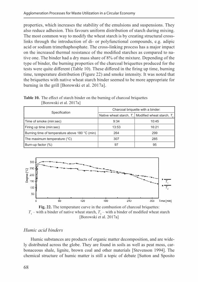
68
Agglomeration Processes for Waste Utilization in a Circular Economy
properties, which increases the stability of the emulsions and suspensions. They also reduce adhesion. This favours uniform distribution of starch during mixing. The most common way to modify the wheat starch is by creating structural cross-links through the introduction of di- or polyfunctional compounds, e.g. adipic acid or sodium trimethaphosphate. The cross-linking process has a major impact on the increased thermal resistance of the modified starches as compared to na-tive one. The binder had a dry mass share of 8% of the mixture. Depending of the type of binder, the burning properties of the charcoal briquettes produced for the tests were quite different (Table 10). These differed in the firing up time, burning time, temperature distribution (Figure 22) and smoke intensity. It was noted that the briquettes with native wheat starch binder seemed to be more appropriate for burning in the grill [Borowski et al. 2017a].
Table 10. The effect of starch binder on the burning of charcoal briquettes [Borowski et al. 2017a]
SpecificationCharcoal briquette with a binder:
Native wheat starch, T1 Modified wheat starch, T2
Time of smoke (min:sec) 9:34 10:45
Firing up time (min:sec) 13:53 16:21
Burning time of temperature above 180 °C (min) 264 299
The maximum temperature (°C) 307 285
Burn-up factor (%) 97 95
Fig. 22. The temperature curve in the combustion of charcoal briquettes: T1 – with a binder of native wheat starch, T2 – with a binder of modified wheat starch
[Borowski et al. 2017a]
Humic acid binders
Humic substances are products of organic matter decomposition, and are wide-ly distributed across the globe. They are found in soils as well as peat moss, car-bonaceous shale, lignite, brown coal and other materials [Stevenson 1994]. The chemical structure of humic matter is still a topic of debate [Sutton and Sposito
T1
T2
69
Chapter III. Usage of Adhesives and Bonding Materials
2005]; one view is that humic substances are a collection of colloidal particles held together by hydrophobic interactions and hydrogen bonds.
Humic substances have historically been characterized into three fractions based on their solubility under various pH conditions: (1) humic substance is the insoluble fraction, (2) humic acid is alkaline soluble but not acid soluble (pH < 2), and (3) fulvic acid is soluble under all pH conditions [Piccolo 2001].
The humic-rich materials such as brown coal, seaweed, and peat moss were causticized before being used as a binder for indurated pellets. The organic mate-rial was reported to form a colloidal gel after treatment [Panigrahy et al. 1995]. Humic acid and fulvic acid, present in varying quantities depending on the binder feedstock, have different thermal stabilities, and interact with ore surfaces to vary-ing degrees, which affects the binder performance [Han et al. 2014]. The binder performance may depend on the source of the humic acid.
Lignin-based binders
Lignin is an important natural biopolymer that helps provide bonding and struc-ture in plant tissues. It has been reported that 12–39% of wood constituents are lignin, which has historically been considered an unwanted product during the pa-per and pulp manufacturing [Hatakeyama and Hatakeyama 2010]. During the pulp production with the sulfite method, insoluble lignin is made soluble by incorporat-ing the SO3
- groups into the lignin structure (Figure 23) and separated from cel-lulose. Lignin is then burned for heat or recovered from solution and sold to other industries for use as a binder.
While the exact lignosulfonate structure is not known, they are considered to be complex polymers. The general features of a lignosulfonate monomer unit include a phenylpropanoid unit (6-carbon aromatic phenyl group with a 3-carbon propene tail) with various amounts of -OH, -CH2OH and -SO3Na groups substituted onto the side groups. The anionic SO3
- group makes the binder water soluble, while the hydrogen and -OH groups lend themselves to hydrogen bonding.
Lignosulfonates were tested in the Bureau of Mines’ organic binder study [Haas et al. 1989] for indurated pellets, as a binding aid for starch [Dingeman and
Fig. 23. General structure of lignin [Hatakeyama and Hatakeyama 2010]
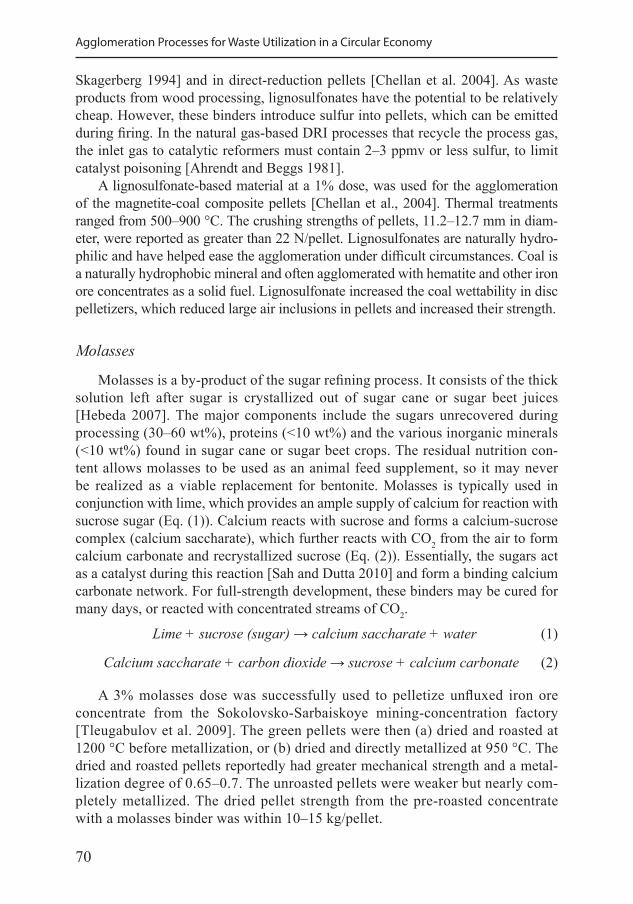
70
Agglomeration Processes for Waste Utilization in a Circular Economy
Skagerberg 1994] and in direct-reduction pellets [Chellan et al. 2004]. As waste products from wood processing, lignosulfonates have the potential to be relatively cheap. However, these binders introduce sulfur into pellets, which can be emitted during firing. In the natural gas-based DRI processes that recycle the process gas, the inlet gas to catalytic reformers must contain 2–3 ppmv or less sulfur, to limit catalyst poisoning [Ahrendt and Beggs 1981].
A lignosulfonate-based material at a 1% dose, was used for the agglomeration of the magnetite-coal composite pellets [Chellan et al., 2004]. Thermal treatments ranged from 500–900 °C. The crushing strengths of pellets, 11.2–12.7 mm in diam-eter, were reported as greater than 22 N/pellet. Lignosulfonates are naturally hydro-philic and have helped ease the agglomeration under difficult circumstances. Coal is a naturally hydrophobic mineral and often agglomerated with hematite and other iron ore concentrates as a solid fuel. Lignosulfonate increased the coal wettability in disc pelletizers, which reduced large air inclusions in pellets and increased their strength.
Molasses
Molasses is a by-product of the sugar refining process. It consists of the thick solution left after sugar is crystallized out of sugar cane or sugar beet juices [Hebeda 2007]. The major components include the sugars unrecovered during processing (30–60 wt%), proteins (<10 wt%) and the various inorganic minerals (<10 wt%) found in sugar cane or sugar beet crops. The residual nutrition con-tent allows molasses to be used as an animal feed supplement, so it may never be realized as a viable replacement for bentonite. Molasses is typically used in conjunction with lime, which provides an ample supply of calcium for reaction with sucrose sugar (Eq. (1)). Calcium reacts with sucrose and forms a calcium-sucrose complex (calcium saccharate), which further reacts with CO2 from the air to form calcium carbonate and recrystallized sucrose (Eq. (2)). Essentially, the sugars act as a catalyst during this reaction [Sah and Dutta 2010] and form a binding calcium carbonate network. For full-strength development, these binders may be cured for many days, or reacted with concentrated streams of CO2.
Lime + sucrose (sugar) → calcium saccharate + water (1)
Calcium saccharate + carbon dioxide → sucrose + calcium carbonate (2)
A 3% molasses dose was successfully used to pelletize unfluxed iron ore concentrate from the Sokolovsko-Sarbaiskoye mining-concentration factory [Tleugabulov et al. 2009]. The green pellets were then (a) dried and roasted at 1200 °C before metallization, or (b) dried and directly metallized at 950 °C. The dried and roasted pellets reportedly had greater mechanical strength and a metal-lization degree of 0.65–0.7. The unroasted pellets were weaker but nearly com-pletely metallized. The dried pellet strength from the pre-roasted concentrate with a molasses binder was within 10–15 kg/pellet.
71
Chapter III. Usage of Adhesives and Bonding Materials
Molasses was also used as a binder in combination with calcium hydroxide or slaked lime, dextrose and sodium polyacrylate [Sah and Dutta 2010]. Pellets were made in a disc pelletizer using 10% calcium hydroxide and 5% molasses. The pellets were then cold bonded by passing the CO2 gas over them for a set period of time. The highest compressive strength using molasses was 299 N/pel-let using slaked lime and reaction under CO2 for 6 min. The authors claim this is just below the required 300 N limit for pellets fed to a rotary kiln or hearth. Using dextrin instead of molasses resulted in the strength of 357 N/pellet under the same conditions.
Biomass binder
Biomass as a source of binder has many excellent advantages, such as exten-sive sources, low price, and high heating values. When this kind of binder is used to produce briquettes, the obtained product has lower ignition temperature, lower slagging index and lower ash content. Thus, the biomass as a binder has recently been brought to the attention of the domestic and foreign industries [Muazu and Stegemann 2017]. Shao et al. [2011] reported a preparation of a binder, which was composed with one or several kinds of biomass, such as agricultural waste, aquatic plant, forestry biomass and aquatic plant. This method not only skill-fully com-bines the renewable and non-renewable energy (coal), but also provides new ways for the exploitation and utilization of biomass energy. Meanwhile, the environmen-tal problems have been solved and the combustion performance of coal improved.
Zhang et al. [2001] studied the possibility of rice straw treatment with sodium hydroxide used as coal briquette binder, and found that the principal factor that influences the binder performance was sodium hydroxide concentration. When the concentration of sodium hydroxide was 2.1%, the crush strength and drop test strength of briquette reached its maximum, 244 N·cm-2 and 82.2%, respectively. Then, with the increasing of concentrations of sodium hydroxide, the crush strength and drop test strength of briquette decreased in different degrees. This is because the undecomposed fibers after alkali treatment can combine and stretch the coal particles together, and decomposition of biomass produce sugars, pectin, tannin and other material also has a certain effect on the binding ability. Moreover, the silicon in the biomass ash reacted with sodium hydroxide to form sodium silicate, which also has a certain influence on binding. The binding ability of the solid compo-nent is higher than the liquor part. When the concentration of sodium hydroxide increased to a certain extent, the binding ability of the solid component as well as the briquette strength decreased [Wang 2004]. Huang et al. [2008] investigated the chemical structures of the biomass briquette binder prepared with corn stalks or treated corn stalks by means of the infrared spectra, and found that there is a great deal of unreacted bio-fiber in the biomass binder, which formed a network structure in briquette and achieved the cohesive action for coal particles. Cohesiveness did not disappear by 24 h after the briquette contacting with water.
72
Agglomeration Processes for Waste Utilization in a Circular Economy
Petroleum bitumen binder
This kind of binders include coal tar pitch, petroleum bitumen, and tar resi-due, which provide agglomerates of satisfactory quality for briquette, because the chemical characteristics and structure of theses binders are similar to coal. The petroleum binders have high wetting capacity for coal, which can bond coal particles together after solidification. However, these binders are typical hot-melt adhesive, and the bond performance declines sharply with the rise of temperature. Thus, the temperature of the briquetting process should not be too high when tar pitch and petroleum bitumen are used as binder.
Zhu and Wu [2011] studied a briquette binder using tar residues and acid tar oil as raw material. This binder was blended to the briquetted coal production, where the compressive strength and the strength in dump test reached 115.48 N·cm-2 and 95.88%, respectively. It can meet the strength requirement of briquetted coal in all stages of production, transport and charging. Using the coal binder, the coke quality was improved. Meanwhile, it not only solved the environmental problem caused by tar residues and acid tar oil, but also had a certain comprehensive ben-efit. Coal tar pitch is one of the most widely used binders. However, the briquettes produced with the pitch and petroleum bitumen give out fumes during combus-tion, due to the volatile matters in the binder; the quantity of volatile matter is high in the case of coal pitch. With the tightening of the environmental protection requirements, this kind of binder is gradually washed out [Iveson et al. 2001].
Lignosulfonate binder
Lignosulfonate is a by-product of the paper mill, which mainly contains sugar, lignin derivatives, organic acids, organic acid salts, free sulfite and free sodium hydroxide. A lignin derivative has strong adhesive strength, so it can be used as a binder. Lignin liquor has the advantages when used as a binder, such as low cost, low ash content, waste utilization and environmental protection. However, at high temperature, the organic matter in lignin liquor would decompose and burn, while the bonding performance would decrease. Thus, lignosulfonate and other binders are combined to produce briquettes in actual production [Karkoska 2011].
3.4. Compound binders
The briquette produced with inorganic binder has excellent thermal proper-ties, but the fixed carbon content and combustion efficiency are lower, while the ash content is added. The briquette produced with organic binder has better cold strength, but its volatility is high, hot strength is poor, while the manufacture pro-cess and combustion products are complex. Compound binders are composed of two or more binders, which combine all advantages of different kind of binders [Steeghs and Schmitt 2002].
73
Chapter III. Usage of Adhesives and Bonding Materials
On the basis of the sodium humate, the effects of adding bentonite clay and kaolin clay on the bonding property were studied by Leokaoke et al. [2018]. The results showed that the high temperature strength and thermal stability of the briquette increased with adding bentonite clay and kaolin clay to so-dium humate. The influence of the bentonite addition on the high-temperature strength and thermal stability of briquette was more remarkable than the ad-dition sodium humate. The addition of kaolin did not improve the briquette performance. However, on the basis of humic acid sodium and bentonite, the addition of kaolin can significantly improve the briquette high temperature per-formance. Under the conditions of 1% kaolin addition, 4% bentonite addition and 3% sodium humate addition, the room temperature strength, high temper-ature strength and thermal stability were 0.99 MPa, 0.47 MPa and 58%, re-spectively. Jia [2010] reported a binder prepared with 85–90% cement, 5–10% hydrated lime and 5–10% polyvinyl alcohol. It was found that the briquette produced with this binder has many advantages, such as high cold and hot strength, high water resistance, easy manufacturing and low cost. Zemlyanoi [2013] reported a binder prepared with humic acid, alumina, suaeda salsa seed and water under certain conditions, and found that the briquette produced with this binder has high strength and low price. Brunerová et al. [2018] reported a binder prepared with bamboo fibre and sugarcane skin, and found that the briquette prepared by this binder not only has high cold and hot strength, but the yield was improved remarkably as well.
Zare-Shahabadi et al. [2010] reported the waterproof and wear-resistant binder preparation methods by adding molet asphalt into the solution of cationic emulsifier and water. Compared with the single emulsified asphalt, the obtained blinder not only improves the waterproof and binding properties, but also en-hances the affinity of the adhesives with pulverized coal. The application range of cationic emulsified asphalt is wide, enabling its utilization with the high qual-ity as well as low quality coal. Wang [2015] reported a briquette binder prepared with sodium lignin sulfonate, carboxymethyl cellulose, carboxymethyl starch, bentonite clay and sodium tetraborate. It was found that the room temperature strength of briquette was highest when adding 1% carboxymethyl starch, 6% bentonite clay and 0.16% sodium tetraborate. Moreover, the content of bentonite clay had a significant effect on the quality of binder. Xie et al. [2014] prepared a briquette binder with humic acid, sodium hydroxide and alumina. It was found that the briquette produced with this binder has many advantages, such as high pellet yield, high fixed carbon content, high strength and low cost. Tong et al. [2013] investigated the effect of alkali concentration, reaction temperature, re-action time and amount of biomass addition on the denatured biomass bond-ing. It was found that the compound binder made from modified biomass and inorganic solidification agent had good performance. The optimum condition of denatured biomass is 1% of the alkali concentration, 80 °C reaction temperature, 2 h reaction time, 10% biomass, 4% curing agent and 25 MPa molding pressure.
74
Agglomeration Processes for Waste Utilization in a Circular Economy
Wang et al. [2013] reported a high strength gasification briquette composite bri-quette binder prepared with thermoplastic phenolic resin, sodium bentonite, corn starch and sodium carboxymethyl cellulose. Under the addition of 0.04% ther-moplastic phenolic resin, 0.04% sodium bentonite, 0.27% corn starch and 3.64% sodium carboxymethyl cellulose, the quality of the produced briquette could sub-stitute that of industrial gasification lump coal. Benk [2010] studied the briquette binder using air blown coal tar pitch and phenolic resins as raw materials. The results showed that the optimum amount of air blown coal tar pitch was 50 wt% in the blended binder. Curing the briquettes at 200 °C for 2 h was found to be sufficient for producing strong briquettes with a tensile strength of 50.45 MN·m-2. When these cured briquettes were carbonized at temperatures 470 °C, 670 °C, and 950 °C, their strength were increasing continuously, reaching up to 71.85 MN·m-2 at the carbonization temperature of 950 °C.
3.5. Binders for fine coal
The binders are used to increase the mechanical strength of the granules made of fine coal. Depending on the binder used, the granulate usually requires con-ditioning or additional heat treatment [Reynolds et al. 2005]. Dehydrators are added when the prepared raw materials contain too much water, hindering or pre-venting the granulation process. The added substances “bind” water and bond the grains of material, which may also help to increase their mechanical resistance [Karthikeyan et al. 2009].
Additives may improve the useful properties of granulate directed to combus-tion as fuel in furnaces, such as: • reducing emissions of SO2 in the exhaust gas, • reduction of iron oxide, • correction of melting point of combustion ash.
The following substances were added to fine coal as additives: asphalt, benton-ite, cement, sodium chloride, calcium chloride, dextrin, clay, organic glue, starch, silica, sulphite lye, molasse, pitch, ferrous sulphate, water glass, synthetic poly-mers, limestones, and lime [Kelbaliyev et al. 2013]. Brief characteristics of the se-lected substances and components which are additives for granulating of fine coals are presented below:
• Bentonite binds the excess water and increases the compressive strength of granules. It consists mainly of montmorillonite, capable of forming gels with a developed surface. Sodium-activated bentonites have a swelling capacity of 600 to 900%, while the not-activated ones – 200%. The amount of bentonite added depends on the material moisture content and usually share is from 0.5 to 1%. The granules with the bentonite achieve the final strength within 4 to 6 hours after production.
75
Chapter III. Usage of Adhesives and Bonding Materials
• Cement is often used as binder to merge multiple mineral materials. In the case of granulation, the cement share ranges from 2 to 15%. The addition of cement to the granulated material reduces the amount of water bound in the granules. For coal granulation, it is advisable to use the Portland cement or ground clinker cement, due to the shortened setting time of products.
• Quicklime (calcium oxide CaO) is a binder often used as a supplement the gran-ular coal. The lime binding properties are based on the formation of calcite skeleton as a result of the reaction of calcium hydroxide with carbon dioxide:
Ca(OH)2 + CO2 = CaCO3 + H2OThe lime oxide reacts with the water to form of calcium hydroxide, with heat released:
CaO + H2O = Ca(OH)2
This process is long-lasting; therefore, the granules require curing (seasoning) of up to 60 days. The conditioning process can be accelerated by placing the granules in CO2. As a result of the conditioning, an increase in the granule strength is achieved, but upon reaching the maximum, a decline of strength followed. Lime contributes to the reduction of the SO2 emissions in combustion gases, as illustrated by the following reactions:1) the process of burning sulfur compounds contained in the fuel
S + O2 = SO2
2) the calcium hydroxide dehydration process Ca(OH)2 = CaO + H2O
3) the process of calcium carbonate decalcintionCaCO3 = CaO + CO2
4) SO2 bonding processCa(OH)2 + SO2 = CaSO3 + H2O
CaCO3 + SO2 = CaSO3 + CO2
CaO + SO2 = CaSO3
CaSO3 + O2 = CaSO4
The share of the produced sulfite and calcium sulfate compounds, contains from 30 to 80%. The amount of SO2 removed from the exhaust is proportional to the lime added [Ozbas et al. 2002].Limestone affects the reduction of the proportion of SO2 in the exhaust, similar-ly to the addition of lime for the granulation of coal. Natural limestone, dolomite and chalk are also used as additives.
• High-sodium water glass is also used as a binding additive. Typically, the addi-tion of phosphoric acid is used for gelation and skeleton formation.
76
Agglomeration Processes for Waste Utilization in a Circular Economy
• Water-asphalt emulsions are added to the agglomerated material in a share of 5 to 10%. This emulsion results in the granules being hydrophobic and resist-ant to frost.
• Molasses, starch and dextrin are additives, which effectively bind the coal grains in the case, where the granules are subjected to thermal treatment.
• Organic resins (carbamide, polyvinyl and acrylic) can be also added in the form of solutions and aqueous suspensions in the agglomeration of fine coal.
The choice of a specific binder to fine coal granulation usually affects the phys-icochemical and functional properties of the granule produced. The afore-men-tioned additives do not pose a threat to the environment, are easily available and relatively cheap [Ozga and Borowski 2018].
3.6. Binders for iron waste
For the briquetting of particulate iron waste from the treatment of metals di-rected to the metallurgical use, it is recommended to use organic binders, such as: asphalts, packets, tars, molasses, cellulose derivatives, dextrins, starches, waxes, paraffins, sulfite lyes and resins. A significant effect of the binder type on the strength of the briquettes of iron waste was found (Figure 24). The addition of molasses solution in the amount of about 8 wt% was relevant. The mixture of fine iron with binder was brought to the humidity range of 4.5–6.5%. The briquettes were cured for at least five days, resulting in a 10 to 15% increase in their me-chanical strength [Borowski and Kuczmaszewski 2005]. The highest toughness of the briquettes with molasses binder is definite by the thermal treatment process (hot briquetting). The sucrose contained in molasses decomposes at a temperature above 185 °C, which causes the formation of caramel. Caramel has much greater adhesive properties than molasses, strengthening the mechanical structure of the briquette. At the temperatures above 220 °C, the process of sugars carbonization and the formation of a very durable briquette structure take place.
Later studies on the briquetting process showed the benefits of the industrial management of particulate iron grinding waste [Borowski et al. 2016]. This mate-rial was collected from a roll-bearing factory in Kraśnik, near Lublin. The follow-ing three types binders were added to the homogenized mixture of waste: molasses, starch and compound binder – dry hydrated lime with molasse. The grinding waste with a binder was mixed in an electric paddle mixer for 3 to 6 minutes with the ad-dition of water spray. The share of binding additives ranged from 2 to 6 wt%. The briquettes with the approximate dimensions of 50×20 mm were obtained. Their mechanical properties were determined in gravitational dump tests. The best bri-quettes were made of a mixture of iron waste with starch as binder in the mass frac-tion of 3%, wherein the moisture content was approx. 8%. The mechanical strength of the briquettes with starch was raised after at least 3-days curing time. These
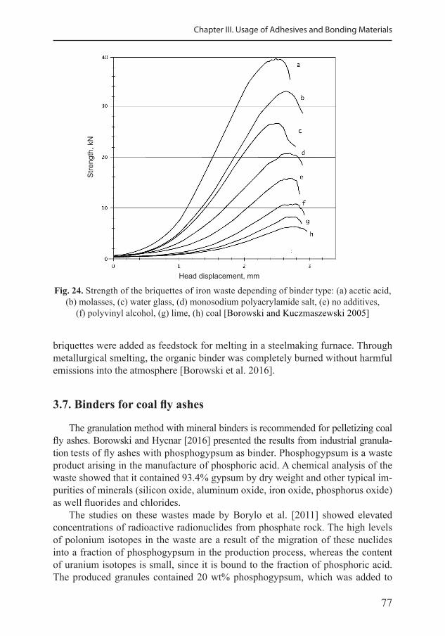
77
Chapter III. Usage of Adhesives and Bonding Materials
Fig. 24. Strength of the briquettes of iron waste depending of binder type: (a) acetic acid, (b) molasses, (c) water glass, (d) monosodium polyacrylamide salt, (e) no additives,
(f) polyvinyl alcohol, (g) lime, (h) coal [Borowski and Kuczmaszewski 2005]
Stre
ngth
, kN
Head displacement, mm
briquettes were added as feedstock for melting in a steelmaking furnace. Through metallurgical smelting, the organic binder was completely burned without harmful emissions into the atmosphere [Borowski et al. 2016].
3.7. Binders for coal fly ashes
The granulation method with mineral binders is recommended for pelletizing coal fly ashes. Borowski and Hycnar [2016] presented the results from industrial granula-tion tests of fly ashes with phosphogypsum as binder. Phosphogypsum is a waste product arising in the manufacture of phosphoric acid. A chemical analysis of the waste showed that it contained 93.4% gypsum by dry weight and other typical im-purities of minerals (silicon oxide, aluminum oxide, iron oxide, phosphorus oxide) as well fluorides and chlorides.
The studies on these wastes made by Borylo et al. [2011] showed elevated concentrations of radioactive radionuclides from phosphate rock. The high levels of polonium isotopes in the waste are a result of the migration of these nuclides into a fraction of phosphogypsum in the production process, whereas the content of uranium isotopes is small, since it is bound to the fraction of phosphoric acid. The produced granules contained 20 wt% phosphogypsum, which was added to
78
Agglomeration Processes for Waste Utilization in a Circular Economy
the clinker after shredding. On the basis of the calculations, it was stated that the concentration of polonium isotopes in the cement with the addition of phosphogyp-sum was up to 28.16 Bq·kg-1 and their radioactive impact was much lower than the permissible amounting to 240 Bq·kg-1. Thus, the addition of phosphogypsum does not constitute a danger to the human health when this material is utilized.
The ash with phosphogypsum was homogenized in a mixer for 5 minutes, and the moisture content reached approx. 5.0%. The maximum diameter of the granules was approx. 20 mm and the average size was 5–15 mm. The products were cured for at least forty-eight hours. The durable granules were produced from fly ashes with the addition of phosphogypsum. They can be transported dust-free, unloaded and stored for further use in the construction industry [Borowski and Hycnar 2016].
The latest research shows the comparison of results of three types of binders that were added to the lignite and coal fly ash blends: • hydrated lime – calcium hydroxide Ca(OH)2, • Portland cement (clinker), and • phosphogypsum.
The share of binders added was 5 or 7 wt%. The optimal moisture content of the fine mixture for granulation was specified – for the lignite fly ash it was 30.62%, and for the coal fly ash it amounted to 24.74%. The results showed the encouraging influence of binders on the mechanical properties of the bodies de-pending on the cure time. The addition of binder to fly ash of 7% improved the durability of granules to a greater extent than the binder share of 5%. However, toughness decreased slightly after a curing of 72 days. The effect of phosphogyp-sum was more intense than that of cement dust, which works similarly to hydrated lime. However, the use of phosphogypsum requires prior heat treatment to impart their binding properties. The results showed that the properties of the granules made from the coal fly ash were better and processing was more effective, than in the case of the granules from the lignite ash [Borowski and Ozga 2020].
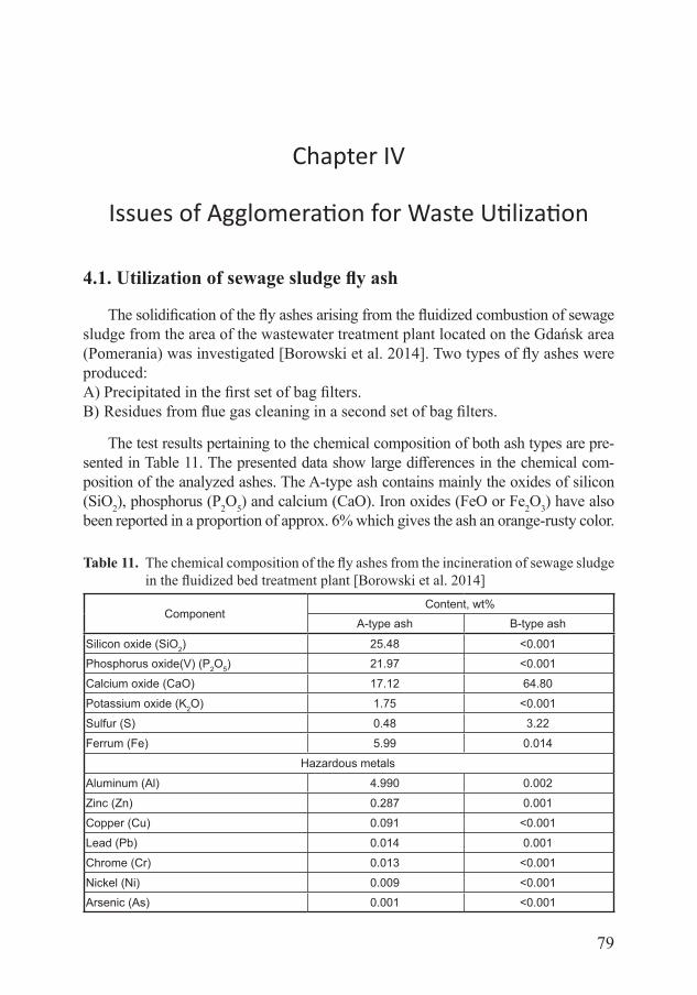
79
Chapter IV
Issues of Agglomeration for Waste Utilization
4.1. Utilization of sewage sludge fly ash
The solidification of the fly ashes arising from the fluidized combustion of sewage sludge from the area of the wastewater treatment plant located on the Gdańsk area (Pomerania) was investigated [Borowski et al. 2014]. Two types of fly ashes were produced:A) Precipitated in the first set of bag filters.B) Residues from flue gas cleaning in a second set of bag filters.
The test results pertaining to the chemical composition of both ash types are pre-sented in Table 11. The presented data show large differences in the chemical com-position of the analyzed ashes. The A-type ash contains mainly the oxides of silicon (SiO2), phosphorus (P2O5) and calcium (CaO). Iron oxides (FeO or Fe2O3) have also been reported in a proportion of approx. 6% which gives the ash an orange-rusty color.
Table 11. The chemical composition of the fly ashes from the incineration of sewage sludge in the fluidized bed treatment plant [Borowski et al. 2014]
ComponentContent, wt%
A-type ash B-type ash
Silicon oxide (SiO2) 25.48 <0.001Phosphorus oxide(V) (P2O5) 21.97 <0.001Calcium oxide (CaO) 17.12 64.80Potassium oxide (K2O) 1.75 <0.001Sulfur (S) 0.48 3.22Ferrum (Fe) 5.99 0.014
Hazardous metalsAluminum (Al) 4.990 0.002Zinc (Zn) 0.287 0.001Copper (Cu) 0.091 <0.001Lead (Pb) 0.014 0.001Chrome (Cr) 0.013 <0.001Nickel (Ni) 0.009 <0.001Arsenic (As) 0.001 <0.001
80
Agglomeration Processes for Waste Utilization in a Circular Economy
The main component of B-type ash was calcium oxide (CaO) – approx. 65%; its presence contributes to the white color of this waste. Such a high content of CaO in these ashes was the result of using a lime preparation in the fluidized bed combustion process of sewage sludge. Its presence in the exhaust gas stream with activated carbon neutralizes acid gases, removes heavy metals and captures furans and dioxins. This ash contained a significantly lower amount of iron, aluminum and zinc, but six times more sulfur compared to the A-type ash (Table 11). Both types of ash were classified as hazardous waste. Further research focused mainly on the B-type ash utilization method.
Utilization of the B-type ash into a harmless shape involved solidification in cement blocks size of approx. 1×1×1 m. The binding materials were CEM III/A 32.5N cement, water and a chemical preparation with surface-active properties. The resulting mix contained about 45% cement, 30% fly ash from sludge incin-eration plants, and 25% fly ash from coal combustion. The process of forming and curing the prepared cement composite was carried out in jute bags and lasted for seven days. It should be mentioned that the combustion of sludge causes a significant reduction in their volume; however, the proposed technol-ogy of ash management causes the volume to increase again (almost three times) in order to be deposited in the landfill.
Table 12 shows the results of the leaching tests carried out in aqueous ex-tracts of the components of solidified cement mixtures with ashes. It was found that the ashes from the combustion of sewage sludge are resistant to the heavy metal leaching. The obtained average values meet the criteria established in the Regulation of the Minister of Economy [Journal of Laws 2013, item 38].
This enabled storing solidified cement blocks with the ashes from fluidized bed combustion of sewage sludge at the landfills for wastes other than hazard-ous and inert. Similar results of ash solidification were obtained by Białowiec et al. [2009].
The permissible leaching concentration of the sulfate and chloride ions as well as the leaching of soluble compounds, including organic carbon and some heavy metals (Se, Pb, Sb, Cu and As) were found to be exceeded. However, these compounds are easily absorbed by plant and animal organisms in nature.
Table 13 presents the results of the tests on the compressive strength of cement composites with a fly ash mixture. It was noticed that the cement composite ob-tained had low compressive strength after seven days of curing. The obtained value (<0.5 MPa) was due to the insufficient amount of calcium aluminates and silicates formed during the hydration process of the prepared cement mix.
The presented method of fly ash solidification obtained from the thermal transformation of sewage sludge enabled the neutralization of harmful sub-stances. Taking into consideration the results of the obtained research, it was found that the solidified ash was fully suitable for safe disposal at the municipal waste landfill [Borowski 2011c].
81
Chapter IV. Issues of Agglomeration for Waste Reduction
Table 12. Results of the leaching of pollutants from the solidified ash samples [Borowski et al. 2014]
No. Component Leaching value, mg·kg-1 d.m.
Acceptable leaching value, mg·kg-1 d.m.
J. Laws 2009. No. 27. item 169
J. Laws 2013. item 38
1 Solid compounds dissolved 55 727 ± 11 491* - 60 0002 Sulfureous (SO4
2) 15 238 ± 3118 500 20 0003 Chloride (Cl–) 2696 ± 527 1000 15 0004 Dissolved organic carbon 518 ± 121 - 8005 Fluoride (F–) 12.0 ± 3.0 25 1506 Barium (Ba) 5.0 ± 1.5 3.0 1007 Selenium (Se) < 5.0 1.0 0.58 Lead (Pb) < 3.0 0.5 109 Antimony (Sb) < 2.0 0.3 0.7
10 Molybdenum (Mo) < 1.0 1.0 1011 Copper (Cu) 0.68 ± 0.18 0.5 5012 Zinc (Zn) 0.63 ± 0.16 2.0 5013 Chromium (Cr) < 0.4 0.5 1014 Nickel (Ni) < 0.4 0.5 1015 Arsenic (As) < 0.2 0.1 216 Cadmium (Cd) < 0.01 0.02 117 Mercury (Hg) < 0.01 0.05 0.2
* mean ± standard deviation.
Table 13. Results of the strength tests of the solidified ash samples [Borowski et al. 2014]
Specification UnitResult
1 2 3 mean
Sample dimensions mm 99.8×100.3 98.9×101.1 98.9×103.5 99.2×101.6
Compressive strength kN·m-2 496.1 486.0 456.2 479.4
Boundary deformations % 2.25 2.44 4.57 3.08
Shear strength kN·m-2 107.9 98.9 88.6 98.5
4.2. Utilization of ferrosilicon dust
Ferrosilicon dust, used in the steel industry and casting, was processed with the briquetting method [Hycnar et al. 2014]. The resulting briquettes could be utilized in the steel industry and iron foundries. The material was ferrosilicon powder grain of size from 0 to 3 mm, mixed with the addition of silicon metal. Two types of bind-ers selected for briquetting were: (a) water glass, and (b) potato starch, as single one and variety of mixtures.
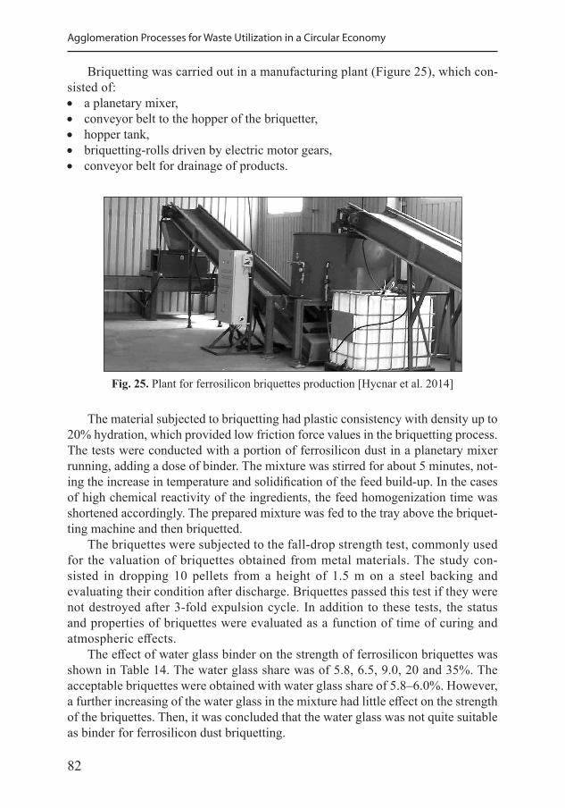
82
Agglomeration Processes for Waste Utilization in a Circular Economy
Briquetting was carried out in a manufacturing plant (Figure 25), which con-sisted of: • a planetary mixer, • conveyor belt to the hopper of the briquetter, • hopper tank, • briquetting-rolls driven by electric motor gears, • conveyor belt for drainage of products.
Fig. 25. Plant for ferrosilicon briquettes production [Hycnar et al. 2014]
The material subjected to briquetting had plastic consistency with density up to 20% hydration, which provided low friction force values in the briquetting process. The tests were conducted with a portion of ferrosilicon dust in a planetary mixer running, adding a dose of binder. The mixture was stirred for about 5 minutes, not-ing the increase in temperature and solidification of the feed build-up. In the cases of high chemical reactivity of the ingredients, the feed homogenization time was shortened accordingly. The prepared mixture was fed to the tray above the briquet-ting machine and then briquetted.
The briquettes were subjected to the fall-drop strength test, commonly used for the valuation of briquettes obtained from metal materials. The study con-sisted in dropping 10 pellets from a height of 1.5 m on a steel backing and evaluating their condition after discharge. Briquettes passed this test if they were not destroyed after 3-fold expulsion cycle. In addition to these tests, the status and properties of briquettes were evaluated as a function of time of curing and atmospheric effects.
The effect of water glass binder on the strength of ferrosilicon briquettes was shown in Table 14. The water glass share was of 5.8, 6.5, 9.0, 20 and 35%. The acceptable briquettes were obtained with water glass share of 5.8–6.0%. However, a further increasing of the water glass in the mixture had little effect on the strength of the briquettes. Then, it was concluded that the water glass was not quite suitable as binder for ferrosilicon dust briquetting.
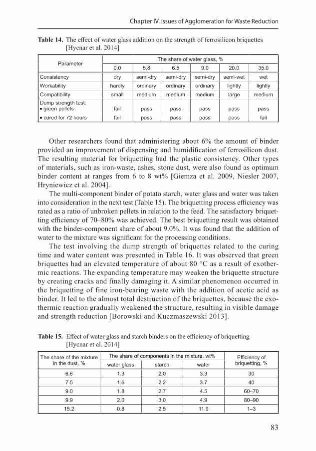
83
Chapter IV. Issues of Agglomeration for Waste Reduction
Table 14. The effect of water glass addition on the strength of ferrosilicon briquettes [Hycnar et al. 2014]
ParameterThe share of water glass, %
0.0 5.8 6.5 9.0 20.0 35.0Consistency dry semi-dry semi-dry semi-dry semi-wet wetWorkability hardly ordinary ordinary ordinary lightly lightlyCompatibility small medium medium medium large mediumDump strength test:•green pellets fail pass pass pass pass pass•cured for 72 hours fail pass pass pass pass fail
Other researchers found that administering about 6% the amount of binder provided an improvement of dispensing and humidification of ferrosilicon dust. The resulting material for briquetting had the plastic consistency. Other types of materials, such as iron-waste, ashes, stone dust, were also found as optimum binder content at ranges from 6 to 8 wt% [Giemza et al. 2009, Niesler 2007, Hryniewicz et al. 2004].
The multi-component binder of potato starch, water glass and water was taken into consideration in the next test (Table 15). The briquetting process efficiency was rated as a ratio of unbroken pellets in relation to the feed. The satisfactory briquet-ting efficiency of 70–80% was achieved. The best briquetting result was obtained with the binder-component share of about 9.0%. It was found that the addition of water to the mixture was significant for the processing conditions.
The test involving the dump strength of briquettes related to the curing time and water content was presented in Table 16. It was observed that green briquettes had an elevated temperature of about 80 °C as a result of exother-mic reactions. The expanding temperature may weaken the briquette structure by creating cracks and finally damaging it. A similar phenomenon occurred in the briquetting of fine iron-bearing waste with the addition of acetic acid as binder. It led to the almost total destruction of the briquettes, because the exo-thermic reaction gradually weakened the structure, resulting in visible damage and strength reduction [Borowski and Kuczmaszewski 2013].
Table 15. Effect of water glass and starch binders on the efficiency of briquetting [Hycnar et al. 2014]
The share of the mixture in the dust, %
The share of components in the mixture, wt% Efficiency of briquetting, %water glass starch water
6.6 1.3 2.0 3.3 307.5 1.6 2.2 3.7 409.0 1.8 2.7 4.5 60–709.9 2.0 3.0 4.9 80–90
15.2 0.8 2.5 11.9 1–3
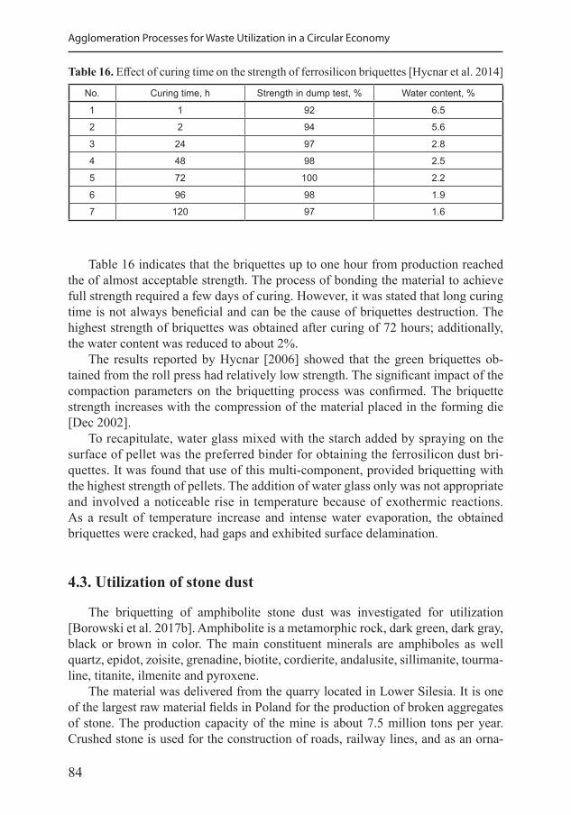
84
Agglomeration Processes for Waste Utilization in a Circular Economy
Table 16 indicates that the briquettes up to one hour from production reached the of almost acceptable strength. The process of bonding the material to achieve full strength required a few days of curing. However, it was stated that long curing time is not always beneficial and can be the cause of briquettes destruction. The highest strength of briquettes was obtained after curing of 72 hours; additionally, the water content was reduced to about 2%.
The results reported by Hycnar [2006] showed that the green briquettes ob-tained from the roll press had relatively low strength. The significant impact of the compaction parameters on the briquetting process was confirmed. The briquette strength increases with the compression of the material placed in the forming die [Dec 2002].
To recapitulate, water glass mixed with the starch added by spraying on the surface of pellet was the preferred binder for obtaining the ferrosilicon dust bri-quettes. It was found that use of this multi-component, provided briquetting with the highest strength of pellets. The addition of water glass only was not appropriate and involved a noticeable rise in temperature because of exothermic reactions. As a result of temperature increase and intense water evaporation, the obtained briquettes were cracked, had gaps and exhibited surface delamination.
4.3. Utilization of stone dust
The briquetting of amphibolite stone dust was investigated for utilization [Borowski et al. 2017b]. Amphibolite is a metamorphic rock, dark green, dark gray, black or brown in color. The main constituent minerals are amphiboles as well quartz, epidot, zoisite, grenadine, biotite, cordierite, andalusite, sillimanite, tourma-line, titanite, ilmenite and pyroxene.
The material was delivered from the quarry located in Lower Silesia. It is one of the largest raw material fields in Poland for the production of broken aggregates of stone. The production capacity of the mine is about 7.5 million tons per year. Crushed stone is used for the construction of roads, railway lines, and as an orna-
Table 16. Effect of curing time on the strength of ferrosilicon briquettes [Hycnar et al. 2014]
No. Curing time, h Strength in dump test, % Water content, %
1 1 92 6.5
2 2 94 5.6
3 24 97 2.8
4 48 98 2.5
5 72 100 2.2
6 96 98 1.9
7 120 97 1.6
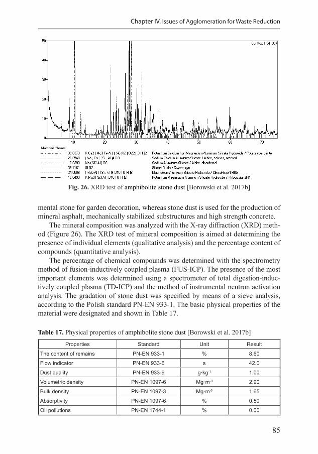
85
Chapter IV. Issues of Agglomeration for Waste Reduction
mental stone for garden decoration, whereas stone dust is used for the production of mineral asphalt, mechanically stabilized substructures and high strength concrete.
The mineral composition was analyzed with the X-ray diffraction (XRD) meth-od (Figure 26). The XRD test of mineral composition is aimed at determining the presence of individual elements (qualitative analysis) and the percentage content of compounds (quantitative analysis).
The percentage of chemical compounds was determined with the spectrometry method of fusion-inductively coupled plasma (FUS-ICP). The presence of the most important elements was determined using a spectrometer of total digestion-induc-tively coupled plasma (TD-ICP) and the method of instrumental neutron activation analysis. The gradation of stone dust was specified by means of a sieve analysis, according to the Polish standard PN-EN 933-1. The basic physical properties of the material were designated and shown in Table 17.
Fig. 26. XRD test of amphibolite stone dust [Borowski et al. 2017b]
Table 17. Physical properties of amphibolite stone dust [Borowski et al. 2017b]
Properties Standard Unit Result
The content of remains PN-EN 933-1 % 8.60
Flow indicator PN-EN 933-6 s 42.0
Dust quality PN-EN 933-9 g·kg-1 1.00
Volumetric density PN-EN 1097-6 Mg·m-3 2.90
Bulk density PN-EN 1097-3 Mg·m-3 1.65
Absorptivity PN-EN 1097-6 % 0.50
Oil pollutions PN-EN 1744-1 % 0.00
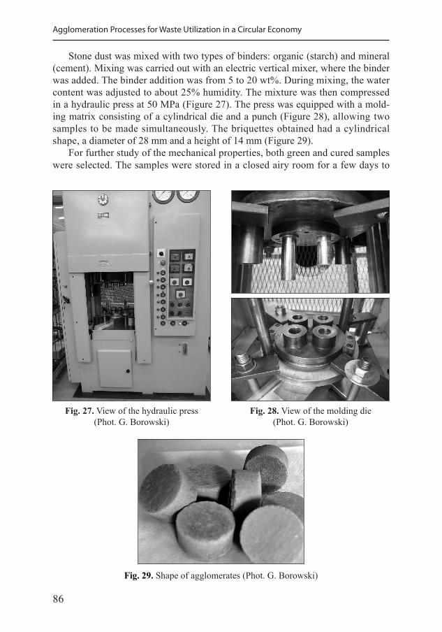
86
Agglomeration Processes for Waste Utilization in a Circular Economy
Stone dust was mixed with two types of binders: organic (starch) and mineral (cement). Mixing was carried out with an electric vertical mixer, where the binder was added. The binder addition was from 5 to 20 wt%. During mixing, the water content was adjusted to about 25% humidity. The mixture was then compressed in a hydraulic press at 50 MPa (Figure 27). The press was equipped with a mold-ing matrix consisting of a cylindrical die and a punch (Figure 28), allowing two samples to be made simultaneously. The briquettes obtained had a cylindrical shape, a diameter of 28 mm and a height of 14 mm (Figure 29).
For further study of the mechanical properties, both green and cured samples were selected. The samples were stored in a closed airy room for a few days to
Fig. 27. View of the hydraulic press(Phot. G. Borowski)
Fig. 28. View of the molding die(Phot. G. Borowski)
Fig. 29. Shape of agglomerates (Phot. G. Borowski)
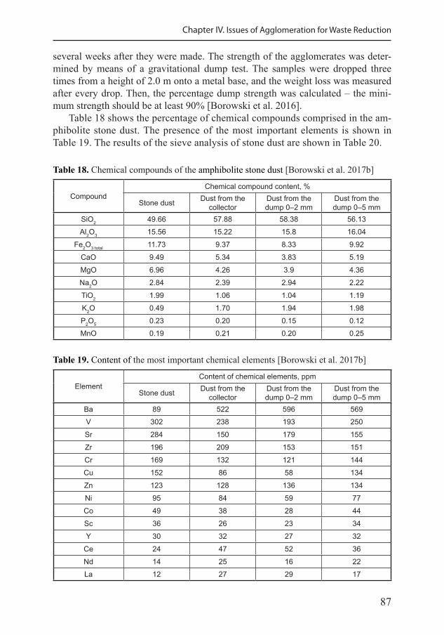
87
Chapter IV. Issues of Agglomeration for Waste Reduction
several weeks after they were made. The strength of the agglomerates was deter-mined by means of a gravitational dump test. The samples were dropped three times from a height of 2.0 m onto a metal base, and the weight loss was measured after every drop. Then, the percentage dump strength was calculated – the mini-mum strength should be at least 90% [Borowski et al. 2016].
Table 18 shows the percentage of chemical compounds comprised in the am-phibolite stone dust. The presence of the most important elements is shown in Table 19. The results of the sieve analysis of stone dust are shown in Table 20.
Table 18. Chemical compounds of the amphibolite stone dust [Borowski et al. 2017b]
CompoundChemical compound content, %
Stone dust Dust from the collector
Dust from the dump 0–2 mm
Dust from the dump 0–5 mm
SiO2 49.66 57.88 58.38 56.13Al2O3 15.56 15.22 15.8 16.04
Fe2O3 total 11.73 9.37 8.33 9.92CaO 9.49 5.34 3.83 5.19MgO 6.96 4.26 3.9 4.36Na2O 2.84 2.39 2.94 2.22TiO2 1.99 1.06 1.04 1.19K2O 0.49 1.70 1.94 1.98P2O5 0.23 0.20 0.15 0.12MnO 0.19 0.21 0.20 0.25
Table 19. Content of the most important chemical elements [Borowski et al. 2017b]
ElementContent of chemical elements, ppm
Stone dust Dust from the collector
Dust from the dump 0–2 mm
Dust from the dump 0–5 mm
Ba 89 522 596 569V 302 238 193 250Sr 284 150 179 155Zr 196 209 153 151Cr 169 132 121 144Cu 152 86 58 134Zn 123 128 136 134Ni 95 84 59 77Co 49 38 28 44Sc 36 26 23 34Y 30 32 27 32
Ce 24 47 52 36Nd 14 25 16 22La 12 27 29 17
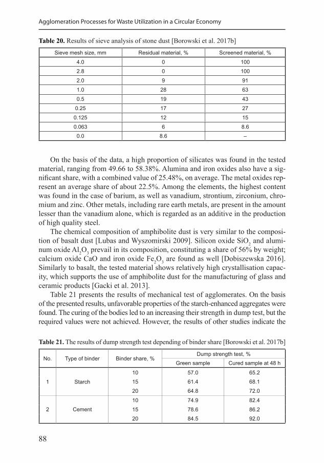
88
Agglomeration Processes for Waste Utilization in a Circular Economy
On the basis of the data, a high proportion of silicates was found in the tested material, ranging from 49.66 to 58.38%. Alumina and iron oxides also have a sig-nificant share, with a combined value of 25.48%, on average. The metal oxides rep-resent an average share of about 22.5%. Among the elements, the highest content was found in the case of barium, as well as vanadium, strontium, zirconium, chro-mium and zinc. Other metals, including rare earth metals, are present in the amount lesser than the vanadium alone, which is regarded as an additive in the production of high quality steel.
The chemical composition of amphibolite dust is very similar to the composi-tion of basalt dust [Lubas and Wyszomirski 2009]. Silicon oxide SiO2 and alumi-num oxide Al2O3 prevail in its composition, constituting a share of 56% by weight; calcium oxide CaO and iron oxide Fe2O3 are found as well [Dobiszewska 2016]. Similarly to basalt, the tested material shows relatively high crystallisation capac-ity, which supports the use of amphibolite dust for the manufacturing of glass and ceramic products [Gacki et al. 2013].
Table 21 presents the results of mechanical test of agglomerates. On the basis of the presented results, unfavorable properties of the starch-enhanced aggregates were found. The curing of the bodies led to an increasing their strength in dump test, but the required values were not achieved. However, the results of other studies indicate the
Table 20. Results of sieve analysis of stone dust [Borowski et al. 2017b]
Sieve mesh size, mm Residual material, % Screened material, %
4.0 0 1002.8 0 1002.0 9 911.0 28 630.5 19 43
0.25 17 270.125 12 150.063 6 8.6
0.0 8.6 –
Table 21. The results of dump strength test depending of binder share [Borowski et al. 2017b]
No. Type of binder Binder share, %Dump strength test, %
Green sample Cured sample at 48 h
1 Starch10 57.0 65.215 61.4 68.120 64.8 72.0
2 Cement10 74.9 82.415 78.6 86.220 84.5 92.0
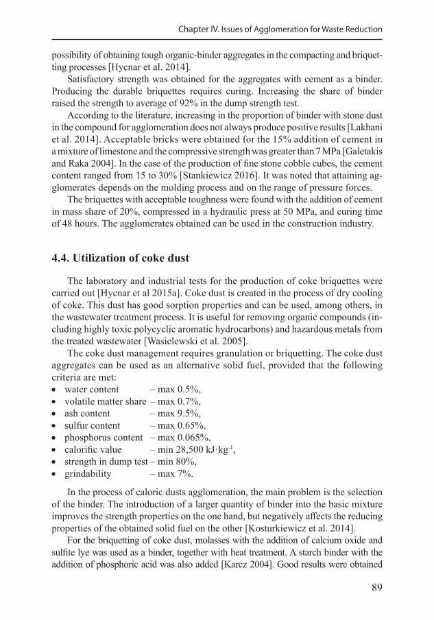
89
Chapter IV. Issues of Agglomeration for Waste Reduction
possibility of obtaining tough organic-binder aggregates in the compacting and briquet-ting processes [Hycnar et al. 2014].
Satisfactory strength was obtained for the aggregates with cement as a binder. Producing the durable briquettes requires curing. Increasing the share of binder raised the strength to average of 92% in the dump strength test.
According to the literature, increasing in the proportion of binder with stone dust in the compound for agglomeration does not always produce positive results [Lakhani et al. 2014]. Acceptable bricks were obtained for the 15% addition of cement in a mixture of limestone and the compressive strength was greater than 7 MPa [Galetakis and Raka 2004]. In the case of the production of fine stone cobble cubes, the cement content ranged from 15 to 30% [Stankiewicz 2016]. It was noted that attaining ag-glomerates depends on the molding process and on the range of pressure forces.
The briquettes with acceptable toughness were found with the addition of cement in mass share of 20%, compressed in a hydraulic press at 50 MPa, and curing time of 48 hours. The agglomerates obtained can be used in the construction industry.
4.4. Utilization of coke dust
The laboratory and industrial tests for the production of coke briquettes were carried out [Hycnar et al 2015a]. Coke dust is created in the process of dry cooling of coke. This dust has good sorption properties and can be used, among others, in the wastewater treatment process. It is useful for removing organic compounds (in-cluding highly toxic polycyclic aromatic hydrocarbons) and hazardous metals from the treated wastewater [Wasielewski et al. 2005].
The coke dust management requires granulation or briquetting. The coke dust aggregates can be used as an alternative solid fuel, provided that the following criteria are met: • water content – max 0.5%, • volatile matter share – max 0.7%, • ash content – max 9.5%, • sulfur content – max 0.65%, • phosphorus content – max 0.065%, • calorific value – min 28,500 kJ·kg-1, • strength in dump test – min 80%, • grindability – max 7%.
In the process of caloric dusts agglomeration, the main problem is the selection of the binder. The introduction of a larger quantity of binder into the basic mixture improves the strength properties on the one hand, but negatively affects the reducing properties of the obtained solid fuel on the other [Kosturkiewicz et al. 2014].
For the briquetting of coke dust, molasses with the addition of calcium oxide and sulfite lye was used as a binder, together with heat treatment. A starch binder with the addition of phosphoric acid was also added [Karcz 2004]. Good results were obtained
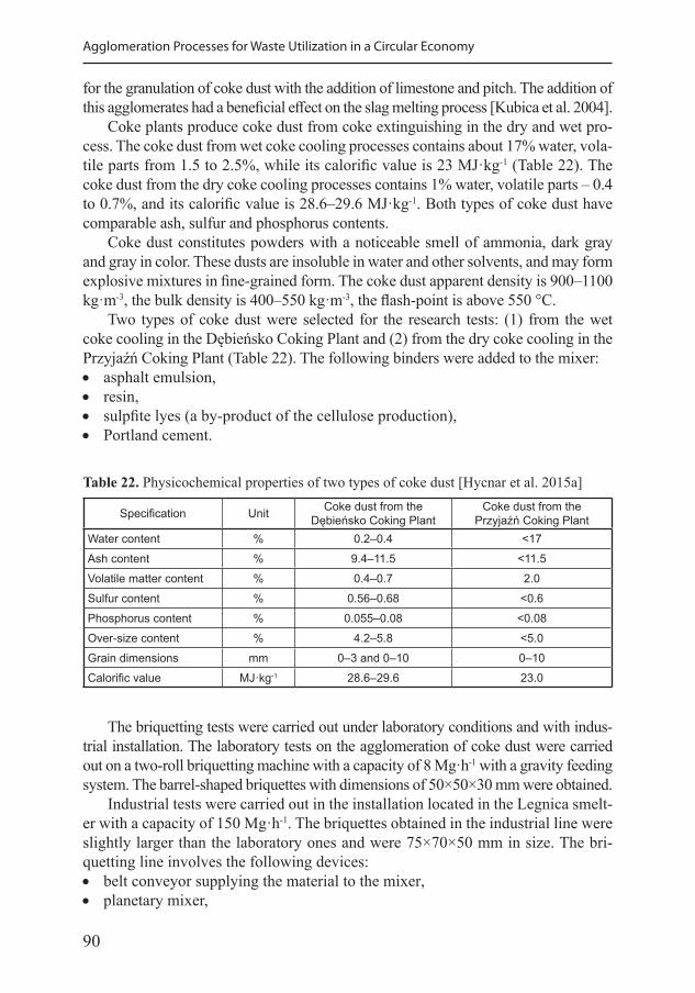
90
Agglomeration Processes for Waste Utilization in a Circular Economy
for the granulation of coke dust with the addition of limestone and pitch. The addition of this agglomerates had a beneficial effect on the slag melting process [Kubica et al. 2004].
Coke plants produce coke dust from coke extinguishing in the dry and wet pro-cess. The coke dust from wet coke cooling processes contains about 17% water, vola-tile parts from 1.5 to 2.5%, while its calorific value is 23 MJ·kg-1 (Table 22). The coke dust from the dry coke cooling processes contains 1% water, volatile parts – 0.4 to 0.7%, and its calorific value is 28.6–29.6 MJ·kg-1. Both types of coke dust have comparable ash, sulfur and phosphorus contents.
Coke dust constitutes powders with a noticeable smell of ammonia, dark gray and gray in color. These dusts are insoluble in water and other solvents, and may form explosive mixtures in fine-grained form. The coke dust apparent density is 900–1100 kg·m-3, the bulk density is 400–550 kg·m-3, the flash-point is above 550 °C.
Two types of coke dust were selected for the research tests: (1) from the wet coke cooling in the Dębieńsko Coking Plant and (2) from the dry coke cooling in the Przyjaźń Coking Plant (Table 22). The following binders were added to the mixer: • asphalt emulsion, • resin, • sulpfite lyes (a by-product of the cellulose production), • Portland cement.
Table 22. Physicochemical properties of two types of coke dust [Hycnar et al. 2015a]
Specification Unit Coke dust from the Dębieńsko Coking Plant
Coke dust from the Przyjaźń Coking Plant
Water content % 0.2–0.4 <17Ash content % 9.4–11.5 <11.5Volatile matter content % 0.4–0.7 2.0Sulfur content % 0.56–0.68 <0.6Phosphorus content % 0.055–0.08 <0.08Over-size content % 4.2–5.8 <5.0Grain dimensions mm 0–3 and 0–10 0–10Calorific value MJ·kg-1 28.6–29.6 23.0
The briquetting tests were carried out under laboratory conditions and with indus-trial installation. The laboratory tests on the agglomeration of coke dust were carried out on a two-roll briquetting machine with a capacity of 8 Mg·h-1 with a gravity feeding system. The barrel-shaped briquettes with dimensions of 50×50×30 mm were obtained.
Industrial tests were carried out in the installation located in the Legnica smelt-er with a capacity of 150 Mg·h-1. The briquettes obtained in the industrial line were slightly larger than the laboratory ones and were 75×70×50 mm in size. The bri-quetting line involves the following devices: • belt conveyor supplying the material to the mixer, • planetary mixer,
91
Chapter IV. Issues of Agglomeration for Waste Reduction
• belt conveyor feeding the mixture to the hopper, • two-roller horizontal briquetting machine, • a conveyor belt receiving briquettes and feeding them to a container, • bulk container for briquettes.
Table 23 presents the results of the first series of tests for the strength of bri-quettes depending on the binder and seasoning time. Unfortunately, tough briquettes with the addition of cement were not obtained, so other binders were used in the further studies. The dry cooling coke dust was used in the second series of tests (Table 24). Insufficient strength of briquettes with the addition of asphalt emulsion and resin as a binder was found. However, positive results of dump strength tests were obtained for the cured briquettes with the addition of sulfite lye in 20 wt% share. As a result of curing, the water content to humidity decreased by 0.5%.
The results of the experimental tests were verified in the industrial tests. The coke dust with a grain size of 0–10 mm was mixed with the addition of 15% sulfite lye, and then heated. The hot mix was fed through a conveyor belt to the tank above the briquetting press and agglomerated under a 300 MPa press. Green briquettes of sufficient strength were obtained. As a result of curing, their strength increased up to five times. Thus, the positive effect of the sulfite lye ad-dition along with the curing of the briquettes was confirmed. It was noted that the briquettes obtained can be a substitute for heating coke in the energy sector.
Table 23. Test results of the strength of the briquettes made of the wet cooling coke dust [Hycnar et al. 2015a]
Sample No.
Binder Dump strength test, %Type Share, % Green sample Cured sample at 144 h
1 Cement 5 10 152 Cement + water 5 + 5 10 203 Cement + sub-grain 5 + 20 40 604 Cement + oversize 5 + 20 40 205 Emulsion (heated to 60 °C) 10 5 106 Emulsion (cold) 10 15 307 Emulsion + ce ment 10 + 5 10 20
Table 24. Test results of the strength of the briquettes made of the dry cooling coke dust [Hycnar et al. 2015a]
Sample No.
Binder Dump strength test, %Type Share, % Green sample Cured sample at 220 h
1 Emulsion (heated to 60 oC) 13 33 502 Emulsion (heated to 60 oC) 18 43 673 Resin 10 10 204 Sulfite lye 10 15 255 Sulfite lye 20 55 78
92
Agglomeration Processes for Waste Utilization in a Circular Economy
4.5. Utilization of flue-gas desulfurization gypsum
Briquetting of fine waste from fluidized bed combustion, which are formed in the flue-gas desulfurization processes using calcium compounds, was carried out by Hycnar et al. [2015b]. The flue-gas desulfurisation (FGD) gypsum (called as well synthetic gypsum) produced in two types of production processes: (1) wet FGD gypsum technology, and (2) dry FGD gypsum technology. The flue-gas desulfuri-sation products are mixtures containing calcium sulfate and calcium sulfite, often mixed with fly ash particles [Hycnar 2006]. Calcium compounds are characterized by high solubility in water, and after drying – by high dusting tendency. Synthetic gypsum is used in construction as a replacement for the traditionally obtained gyp-sum, in particular for the mixtures and production of prefabricated elements. It is often used for the interior finishing of buildings.
The first flue gas desulfurization plant operating in Poland was the Bełchatów plant built in 1994. Currently, all major power plants introduce flue gas desulfuriza-tion standards, thus providing raw material for numerous gypsum calcining plants, usually located in their immediate vicinity. It is estimated that the production of synthetic gypsum in Poland accounts for one-third of the entire domestic gypsum production [Hycnar 2006].
The chemical composition and physical properties of the synthetic gypsum are similar to the gypsum obtained by means of traditional technology. Compared to the natural gypsum, it is characterized by a shorter setting time and faster strength in-crease. Due to the low grain cohesion it is more difficult to process with water. Synthetic gypsum has a dark-cream color. There are techniques that allow significantly changing the parameters of synthetic gypsum through the use of admixtures and additives.
The advantages of the FGD gypsum are: • low hygroscopicity, • low energy consumption in the production process, • short setting and hardening time, • beneficial effect on the indoor microclimate.
In turn, the disadvantages of the synthetic gypsum are as follows: • high water absorption, • relatively low strength, • significant decrease in strength after hydration – up to 80%, • creep when wet, • low impact strength.
In the wet FGD technology, a post-product was obtained – an aqueous suspen-sion (sludge) of gypsum compounds. These sludges were agglomerated with the addition of fly ash [Piszczek et al. 1980]. The resultant briquettes were character-ized by high resistance to water and wind erosion. The strength parameters met the requirements for limestone aggregate, material for hydraulic proppants and mate-rial for reclamation works.
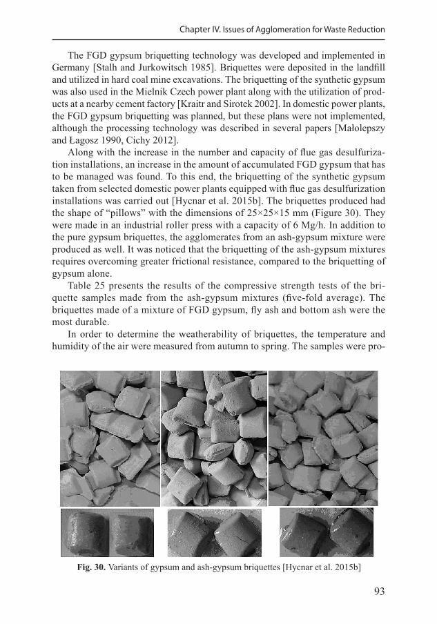
93
Chapter IV. Issues of Agglomeration for Waste Reduction
The FGD gypsum briquetting technology was developed and implemented in Germany [Stalh and Jurkowitsch 1985]. Briquettes were deposited in the landfill and utilized in hard coal mine excavations. The briquetting of the synthetic gypsum was also used in the Mielnik Czech power plant along with the utilization of prod-ucts at a nearby cement factory [Kraitr and Sirotek 2002]. In domestic power plants, the FGD gypsum briquetting was planned, but these plans were not implemented, although the processing technology was described in several papers [Małolepszy and Łagosz 1990, Cichy 2012].
Along with the increase in the number and capacity of flue gas desulfuriza-tion installations, an increase in the amount of accumulated FGD gypsum that has to be managed was found. To this end, the briquetting of the synthetic gypsum taken from selected domestic power plants equipped with flue gas desulfurization installations was carried out [Hycnar et al. 2015b]. The briquettes produced had the shape of “pillows” with the dimensions of 25×25×15 mm (Figure 30). They were made in an industrial roller press with a capacity of 6 Mg/h. In addition to the pure gypsum briquettes, the agglomerates from an ash-gypsum mixture were produced as well. It was noticed that the briquetting of the ash-gypsum mixtures requires overcoming greater frictional resistance, compared to the briquetting of gypsum alone.
Table 25 presents the results of the compressive strength tests of the bri-quette samples made from the ash-gypsum mixtures (five-fold average). The briquettes made of a mixture of FGD gypsum, fly ash and bottom ash were the most durable.
In order to determine the weatherability of briquettes, the temperature and humidity of the air were measured from autumn to spring. The samples were pro-
Fig. 30. Variants of gypsum and ash-gypsum briquettes [Hycnar et al. 2015b]
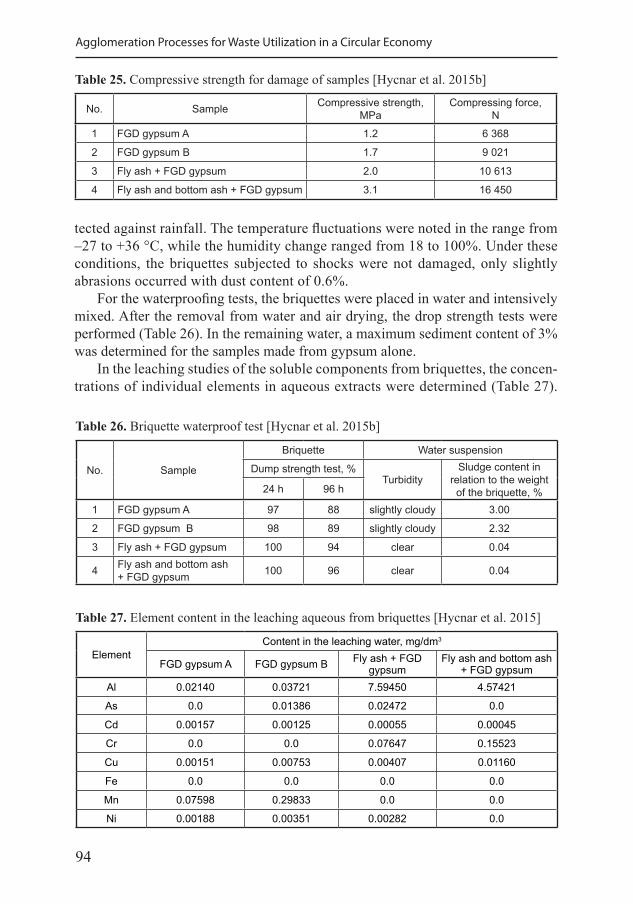
94
Agglomeration Processes for Waste Utilization in a Circular Economy
Table 25. Compressive strength for damage of samples [Hycnar et al. 2015b]
No. Sample Compressive strength, MPa
Compressing force, N
1 FGD gypsum A 1.2 6 368
2 FGD gypsum B 1.7 9 021
3 Fly ash + FGD gypsum 2.0 10 613
4 Fly ash and bottom ash + FGD gypsum 3.1 16 450
tected against rainfall. The temperature fluctuations were noted in the range from –27 to +36 °C, while the humidity change ranged from 18 to 100%. Under these conditions, the briquettes subjected to shocks were not damaged, only slightly abrasions occurred with dust content of 0.6%.
For the waterproofing tests, the briquettes were placed in water and intensively mixed. After the removal from water and air drying, the drop strength tests were performed (Table 26). In the remaining water, a maximum sediment content of 3% was determined for the samples made from gypsum alone.
In the leaching studies of the soluble components from briquettes, the concen-trations of individual elements in aqueous extracts were determined (Table 27).
Table 26. Briquette waterproof test [Hycnar et al. 2015b]
No. Sample
Briquette Water suspension
Dump strength test, %Turbidity
Sludge content in relation to the weight of the briquette, %24 h 96 h
1 FGD gypsum A 97 88 slightly cloudy 3.00
2 FGD gypsum B 98 89 slightly cloudy 2.32
3 Fly ash + FGD gypsum 100 94 clear 0.04
4 Fly ash and bottom ash + FGD gypsum 100 96 clear 0.04
Table 27. Element content in the leaching aqueous from briquettes [Hycnar et al. 2015]
ElementContent in the leaching water, mg/dm3
FGD gypsum A FGD gypsum B Fly ash + FGD gypsum
Fly ash and bottom ash + FGD gypsum
Al 0.02140 0.03721 7.59450 4.57421
As 0.0 0.01386 0.02472 0.0
Cd 0.00157 0.00125 0.00055 0.00045
Cr 0.0 0.0 0.07647 0.15523
Cu 0.00151 0.00753 0.00407 0.01160
Fe 0.0 0.0 0.0 0.0
Mn 0.07598 0.29833 0.0 0.0
Ni 0.00188 0.00351 0.00282 0.0
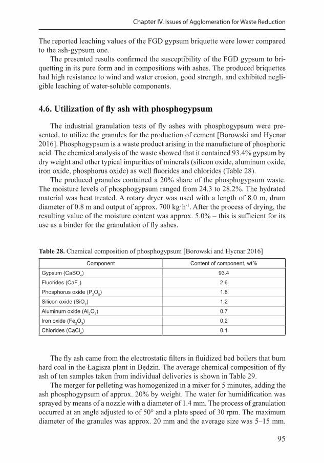
95
Chapter IV. Issues of Agglomeration for Waste Reduction
The reported leaching values of the FGD gypsum briquette were lower compared to the ash-gypsum one.
The presented results confirmed the susceptibility of the FGD gypsum to bri-quetting in its pure form and in compositions with ashes. The produced briquettes had high resistance to wind and water erosion, good strength, and exhibited negli-gible leaching of water-soluble components.
4.6. Utilization of fly ash with phosphogypsum
The industrial granulation tests of fly ashes with phosphogypsum were pre-sented, to utilize the granules for the production of cement [Borowski and Hycnar 2016]. Phosphogypsum is a waste product arising in the manufacture of phosphoric acid. The chemical analysis of the waste showed that it contained 93.4% gypsum by dry weight and other typical impurities of minerals (silicon oxide, aluminum oxide, iron oxide, phosphorus oxide) as well fluorides and chlorides (Table 28).
The produced granules contained a 20% share of the phosphogypsum waste. The moisture levels of phosphogypsum ranged from 24.3 to 28.2%. The hydrated material was heat treated. A rotary dryer was used with a length of 8.0 m, drum diameter of 0.8 m and output of approx. 700 kg·h-1. After the process of drying, the resulting value of the moisture content was approx. 5.0% – this is sufficient for its use as a binder for the granulation of fly ashes.
Table 28. Chemical composition of phosphogypsum [Borowski and Hycnar 2016]
Component Content of component, wt%
Gypsum (CaSO4) 93.4
Fluorides (CaF2) 2.6
Phosphorus oxide (P2O5) 1.8
Silicon oxide (SiO2) 1.2
Aluminum oxide (Al2O3) 0.7
Iron oxide (Fe2O3) 0.2
Chlorides (CaCl2) 0.1
The fly ash came from the electrostatic filters in fluidized bed boilers that burn hard coal in the Łagisza plant in Będzin. The average chemical composition of fly ash of ten samples taken from individual deliveries is shown in Table 29.
The merger for pelleting was homogenized in a mixer for 5 minutes, adding the ash phosphogypsum of approx. 20% by weight. The water for humidification was sprayed by means of a nozzle with a diameter of 1.4 mm. The process of granulation occurred at an angle adjusted to of 50° and a plate speed of 30 rpm. The maximum diameter of the granules was approx. 20 mm and the average size was 5–15 mm.
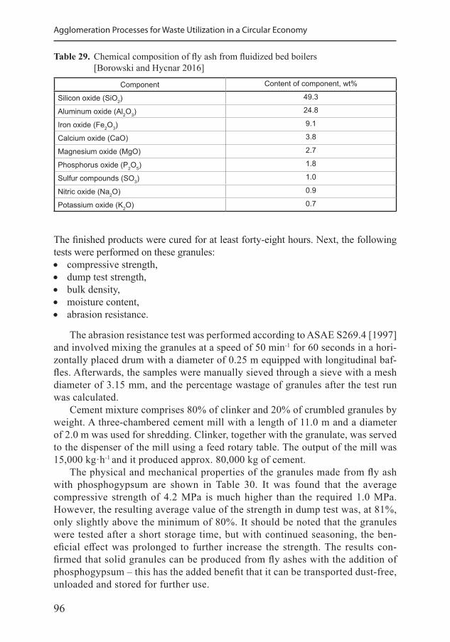
96
Agglomeration Processes for Waste Utilization in a Circular Economy
Table 29. Chemical composition of fly ash from fluidized bed boilers [Borowski and Hycnar 2016]
Component Content of component, wt%
Silicon oxide (SiO2) 49.3
Aluminum oxide (Al2O3) 24.8
Iron oxide (Fe2O3) 9.1
Calcium oxide (CaO) 3.8
Magnesium oxide (MgO) 2.7
Phosphorus oxide (P2O5) 1.8
Sulfur compounds (SO3) 1.0
Nitric oxide (Na2O) 0.9
Potassium oxide (K2O) 0.7
The finished products were cured for at least forty-eight hours. Next, the following tests were performed on these granules: • compressive strength, • dump test strength, • bulk density, • moisture content, • abrasion resistance.
The abrasion resistance test was performed according to ASAE S269.4 [1997] and involved mixing the granules at a speed of 50 min-1 for 60 seconds in a hori-zontally placed drum with a diameter of 0.25 m equipped with longitudinal baf-fles. Afterwards, the samples were manually sieved through a sieve with a mesh diameter of 3.15 mm, and the percentage wastage of granules after the test run was calculated.
Cement mixture comprises 80% of clinker and 20% of crumbled granules by weight. A three-chambered cement mill with a length of 11.0 m and a diameter of 2.0 m was used for shredding. Clinker, together with the granulate, was served to the dispenser of the mill using a feed rotary table. The output of the mill was 15,000 kg·h-1 and it produced approx. 80,000 kg of cement.
The physical and mechanical properties of the granules made from fly ash with phosphogypsum are shown in Table 30. It was found that the average compressive strength of 4.2 MPa is much higher than the required 1.0 MPa. However, the resulting average value of the strength in dump test was, at 81%, only slightly above the minimum of 80%. It should be noted that the granules were tested after a short storage time, but with continued seasoning, the ben-eficial effect was prolonged to further increase the strength. The results con-firmed that solid granules can be produced from fly ashes with the addition of phosphogypsum – this has the added benefit that it can be transported dust-free, unloaded and stored for further use.
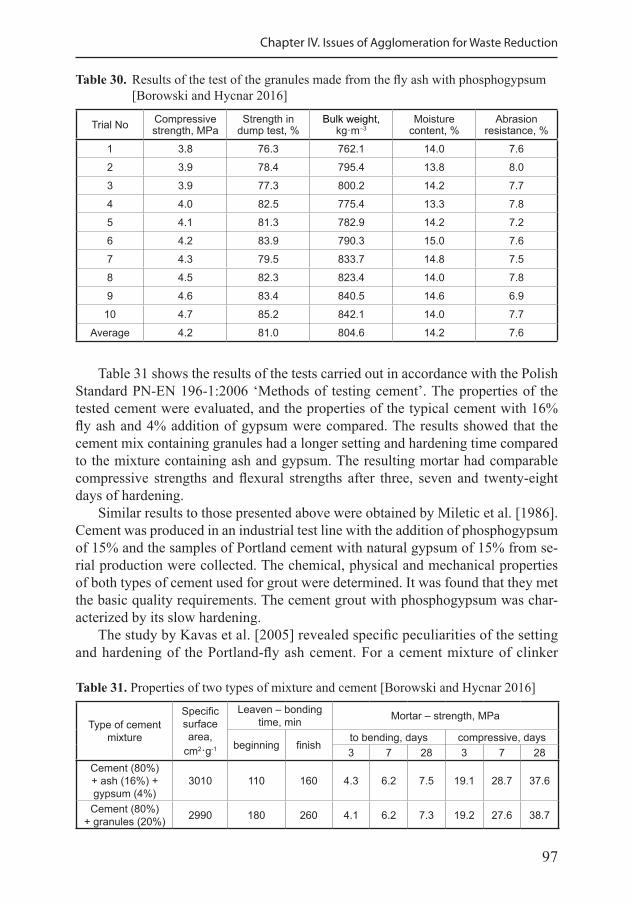
97
Chapter IV. Issues of Agglomeration for Waste Reduction
Table 31 shows the results of the tests carried out in accordance with the Polish Standard PN-EN 196-1:2006 ‘Methods of testing cement’. The properties of the tested cement were evaluated, and the properties of the typical cement with 16% fly ash and 4% addition of gypsum were compared. The results showed that the cement mix containing granules had a longer setting and hardening time compared to the mixture containing ash and gypsum. The resulting mortar had comparable compressive strengths and flexural strengths after three, seven and twenty-eight days of hardening.
Similar results to those presented above were obtained by Miletic et al. [1986]. Cement was produced in an industrial test line with the addition of phosphogypsum of 15% and the samples of Portland cement with natural gypsum of 15% from se-rial production were collected. The chemical, physical and mechanical properties of both types of cement used for grout were determined. It was found that they met the basic quality requirements. The cement grout with phosphogypsum was char-acterized by its slow hardening.
The study by Kavas et al. [2005] revealed specific peculiarities of the setting and hardening of the Portland-fly ash cement. For a cement mixture of clinker
Table 30. Results of the test of the granules made from the fly ash with phosphogypsum [Borowski and Hycnar 2016]
Trial No Compressive strength, MPa
Strength in dump test, %
Bulk weight, kg·m–3
Moisture content, %
Abrasion resistance, %
1 3.8 76.3 762.1 14.0 7.6
2 3.9 78.4 795.4 13.8 8.0
3 3.9 77.3 800.2 14.2 7.7
4 4.0 82.5 775.4 13.3 7.8
5 4.1 81.3 782.9 14.2 7.2
6 4.2 83.9 790.3 15.0 7.6
7 4.3 79.5 833.7 14.8 7.5
8 4.5 82.3 823.4 14.0 7.8
9 4.6 83.4 840.5 14.6 6.9
10 4.7 85.2 842.1 14.0 7.7
Average 4.2 81.0 804.6 14.2 7.6
Table 31. Properties of two types of mixture and cement [Borowski and Hycnar 2016]
Type of cement mixture
Specific surface area,
cm2·g-1
Leaven – bonding time, min Mortar – strength, MPa
beginning finishto bending, days compressive, days3 7 28 3 7 28
Cement (80%)+ ash (16%) + gypsum (4%)
3010 110 160 4.3 6.2 7.5 19.1 28.7 37.6
Cement (80%) + granules (20%) 2990 180 260 4.1 6.2 7.3 19.2 27.6 38.7
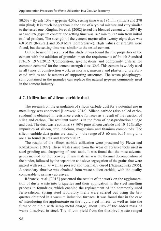
98
Agglomeration Processes for Waste Utilization in a Circular Economy
80.5% + fly ash 15% + gypsum 4.5%, setting time was 186 min (initial) and 270 min (final). It is much longer than in the case of a typical mixture and very similar to the tested one. Xinghua Fu et al. [2002] tested the blended cement with 20% fly ash and 8% gypsum content; the setting time was 162 min to 272 min from initial to final product. The strength of the cement mortar after twenty-eight days was 6.8 MPa (flexural) and 35.0 MPa (compressive). High values of strength were found, but the setting time was similar to the tested cement.
On the basis of the results of this study, it was found that the properties of the cement with the addition of granules meet the requirements of Polish Standard PN-EN 197-1:2012 ‘Composition, specifications and conformity criteria for common cements’ for the cement strength class 32.5. This cement is widely used in all types of construction work: as mortars, masonry and plastering, prefabri-cated articles and basements of supporting structures. The waste phosphogyp-sum contained in the granules can replace the natural gypsum commonly used in the cement industry.
4.7. Utilization of silicon carbide dust
The research on the granulation of silicon carbide dust for a potential use in metallurgy was conducted [Borowski 2016]. Silicon carbide (also called carbo-rundum) is obtained in resistance electric furnaces as a result of the reaction of silica and carbon. The resultant waste is in the form of post-production sludge and dust. The dust waste contains 88–90% pure silicon carbide and 10–12% silky impurities of silicon, iron, calcium, magnesium and titanium compounds. The silicon carbide dust grains are usually in the range of 5–60 nm, but 1 nm grains are also found [Kurcz and Huczko 2012].
The results of the silicon carbide utilization were presented by Plewa and Radzikowski [1999]. These wastes arise from the wear of abrasive tools used in steel grinding and sharpening of steel tools. It was found that the most advanta-geous method for the recovery of raw material was the thermal decomposition of the binder, followed by the separation and sieve segregation of the grains that were mixed with resin, as well as pressed and thermally cured [Niżankowski 2006]. A secondary abrasive was obtained from waste silicon carbide, with the quality comparable to primary abrasives.
Różański et al. [2013] presented the results of the work on the agglomera-tion of dusty waste into briquettes and their application in the steel smelting process in foundries, which enabled the replacement of the commonly used ferro-silicon. Spring steel laboratory melts were carried out using the bri-quettes obtained in a vacuum induction furnace. It was found that in the case of introducing the agglomerate on the liquid steel mirror, as well as into the furnace crucible with scrap metal charge, about 70% of the added mass of waste dissolved in steel. The silicon yield from the dissolved waste ranged
99
Chapter IV. Issues of Agglomeration for Waste Reduction
from 80 to 90%. The tests of the quality of the ingots and the macro- and mi-crostructure of the steel after softening did not reveal the negative impact of the use of waste on the size and retention of the shrinkage cavity and deteriora-tion of the macrostructure.
Depending on the structure and content of additional components, such as iron and carbon, the types of silicon carbide are following [Saddow i Agarwal 2004]: • black silicon carbide, • green silicon carbide, • metallurgical silicon carbide.
The hardness of silicon carbide is between the hardness of diamond and corun-dum, but it is a more brittle material. The advantage of silicon carbide is its high thermal resistance. Silicon carbide is used to the coat friction surfaces operating at high temperatures, e.g. the side surfaces of engine cylinders, as well as thermal shields in space vehicles. One of the silicon carbide applications is the production of microwave transistors [Mueller et al. 2008].
The following parameters and properties of silicon carbide were found [Kurcz and Huczko 2012]: • Mohs hardness: 9.2, • specific density: 3120–3220 kg·m-3, • bulk density: 1340–1480 kg·m-3, • grain shape: angular, • fragile, • high thermal stability, • no reaction with acids, • reaction with bases, • oxidizes at temperatures above 1400 °C forming a protective layer, • high thermal and electrical conductivity.
The granulation tests were carried out in a 100 cm disc granulator under labora-tory conditions in a batch system. The research material contained mainly SiC in the amount of 95–98% and admixtures: Fe2O3, AI2O3, CaO, MnC. This material was supplied to the granulator plate in an amount of 1000–2000 g, then the rota-tional speed of the plate and spraying of water on the flowing bed was provided. The binder was fed simultaneously maintaining a constant proportion to the mass of the raw material.
Six tests were carried out [Borowski 2016]:1) Composition of silicon carbide dust with the addition of modified starch in the
proportion of 5 wt% mixed for 10 min;2) Same composition as above, mixed for 30 minutes;3) Composition of silicon carbide dust with the addition of cement in a proportion
of 8 wt% mixed for 3 minutes;4) While mixing and moistened in the granulator silicon carbide dust was sprayed
with cement in the proportion of 4 wt%;
100
Agglomeration Processes for Waste Utilization in a Circular Economy
5) The same as above, with cement spraying with a proportion of 8 wt%;6) The same as above, with a double spraying of cement at 4 wt%, both during
production and on green granules.
Each test involved the samples for which the binder content, granule diam-eter, structure, brittleness and strength were determined. Brittleness was deter-mined with a comparative method in the range from high to low, while the struc-ture was determined organoleptically in the range from sponge to compact. The mechanical properties were determined using the dump strength test of freshly made and cured granules. The dump strength test was based on dropping 10 granules from a height of 1.0 m onto a concrete slab and assessing their condi-tion following the experiment. After repeating the dropping cycle three times, at least 80% of the granules should be intact. This value meets the requirements due to loading, unloading and transport processes. The strength in dump tests were repeated at curing time: 6, 24, 96, 192 and 432 hours (Table 32).
Table 32. The parameters of the granules made from silicon carbide [Borowski 2016]
ParametrTest No.
1 2 3 4 5 6
Type of binder starch starch cementpowdering
with cement
powdering with
cement
twice powdering
with cementBinder content, % 5.0 5.0 8.0 4.0 8.0 4.0
Diameter of granules, mm 2.0–20.0 2.0–16.0 4.0–8.0 2.0–20.0 4.0–12.0 4.0–12.0
Brittleness high high low low low low
Structure sponge sponge compact sponge compact compactStrenght in dump test of green granules, % 0.0 20.0 40.0 0.0 50.0 60.0
The results showed that the green granules did not achieve the minimum drop strength value in any test. Their strength in dump test increased up to 100% after curing (Figure 31).
The test of silicon carbide granulation was not successful when adding starch as a binder. In order to obtain the durable granules, the addition of ce-ment had a positive effect in the fifth and sixth tests. Finally, powdering (twice) with cement during production as well green granules were the most effective. The stacked granules did not stick together and could easily be separated even after many hours of curing. The cured granules were characterized by high drop strength, compact structure and low brittleness. After curing, no reduction in their mechanical properties was found. On the basis of these results it was stat-ed that it was possible to obtain the silicon carbide granules for utilization as a replacement for ferro-silicon in the steel smelting processes [Borowski 2016].
101
Chapter IV. Issues of Agglomeration for Waste Reduction
4.8. Utilization of coal fly ash
Granulation of two fly ash types was carried out to make the utilization of these materials more efficient. The novelty of this study involves proposing a granulation index enabling to predict the processing conditions of ashes depending of the mass fraction share [Borowski and Ozga 2020]. In the previous studies, such factors as the grains size and mass fraction share were not fully elaborated for a successful granulation of coal fly ashes.
Two different types of fly ash: from (1) lignite combustion, and (2) hard coal combustion, obtained from a power plant in Silesia, Poland, were selected for the tests. The ashes constituted a mixture taken from various zones of the dust collection lines of the electrostatic precipitator tanks. Table 33 presents the physical properties, such as: grain size composition, specific surface area, bulk density, and tapped density. In turn, Table 34 shows the results of the chemical analysis of fly ashes.
The analysis of the ash grain composition was carried out using the sieve method based on the PN-EN 933-1: 2000 standard. The sieve analysis consists in sieving 100 g of ash through a set of sieves, subsequently determining the masses and percentages of individual fractions. The following sieve sizes were used in the sieve analysis: 0.5 mm, 0.25 mm, 0.125 mm, 0.075 mm, 0.063 mm. The specific surface area of ash grains was determined according to the PN-EN 196-6: 2019-01 standard using the Blaine method of air permeability, where the specific surface area is measured as compared to the surface of the standard. The bulk density of ash is defined as the ratio of weight of loosely filled powder to the volume of the vessel in which it is located, determined according to the PN-EN ISO 3923-1: 2018-09 standard.
Three types of binders were added to the ash blends: (1) hydrated lime – cal-cium hydroxide Ca(OH)2, (2) Portland cement (clinker) – hydraulic mineral binder, and (3) phosphogypsum – a by-product from the production of phosphoric acid.
Fig. 31. The strength of the granules depending on the curing time [Borowski 2016]
Curing time, h
Test No. 2
Test No. 3
Test No. 5
Test No. 6
Stre
ngth
in d
ump
test
, %
102
Agglomeration Processes for Waste Utilization in a Circular Economy
Before granulation, the mixtures of ash with binder and addition of water were prepared. The optimal proportion of binder and the amount of water needed to obtain the correct aggregates were determined. The mixing process involved using a disk granulator in which the optimal inclination angle of the plate and rotational speed were selected, taking into account the high efficiency of pelletization.
An experimental technological line was used for pelletizing the powders mix-ture (Figure 32). The line included the following devices: water, ash and binder tanks, pump, mixer, box feeder, belt and cochlear conveyors, disc granulator (ac-cording to the producer’s specification: diameter of disc D = 0.65 m, side height h = 0.16 m, disc rotational speed n = 12–42 rpm, inclination angle of disc a = 10–75°, water spray nozzle with a diameter of 0.13 mm), tunnel dryer with hot air, and stor-age tank for the granules directed to curing.
Table 33. Physical properties of fly ashes [Borowski and Ozga 2020]
Physical parameters UnitsValue
Lignite fly ash Coal fly ash
Specific surface – Blaine method cm2·g 1925 2780
Bulk density kg·m-3 900 750
Tapped density kg·m-3 1125 1120
Content of fraction with grain size: %
<0.063 mm 36.7 58.8
0.063–0.075 mm 5.4 6.8
0.075–0.125 mm 3.7 6.0
0.125–0.25 mm 38.2 25.5
0.25–0.50 mm 14.1 2.0
>0.50 mm 1.9 0.9
Table 34. Chemical analysis of fly ashes [Borowski and Ozga 2020]
Chemical compositionContent, %
Lignite fly ash Coal fly ash
SiO2 56.72 45.27
Al2O3 19.61 23.45
Fe2O3 8.41 11.99
CaO 7.73 6.34
MgO 2.80 2.24
Na2O 0.30 0.60
K2O 1.31 3.15
P2O5 0.13 0.52
SO3 1.90 1.79
Loss on ignition 1.09 4.65
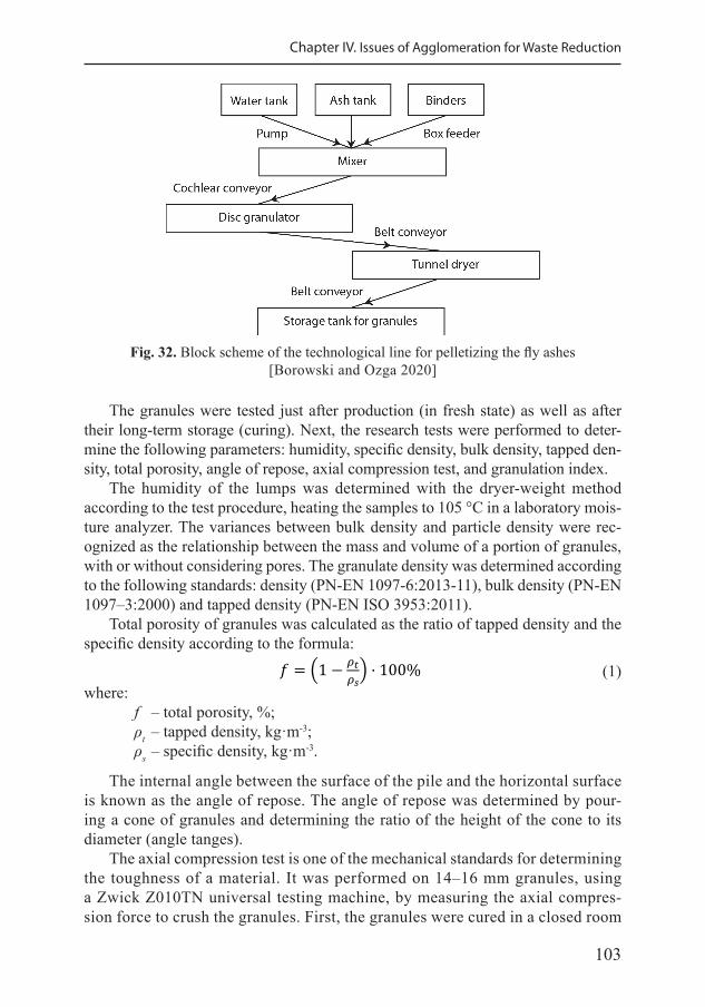
103
Chapter IV. Issues of Agglomeration for Waste Reduction
Fig. 32. Block scheme of the technological line for pelletizing the fly ashes[Borowski and Ozga 2020]
The granules were tested just after production (in fresh state) as well as after their long-term storage (curing). Next, the research tests were performed to deter-mine the following parameters: humidity, specific density, bulk density, tapped den-sity, total porosity, angle of repose, axial compression test, and granulation index.
The humidity of the lumps was determined with the dryer-weight method according to the test procedure, heating the samples to 105 °C in a laboratory mois-ture analyzer. The variances between bulk density and particle density were rec-ognized as the relationship between the mass and volume of a portion of granules, with or without considering pores. The granulate density was determined according to the following standards: density (PN-EN 1097-6:2013-11), bulk density (PN-EN 1097–3:2000) and tapped density (PN-EN ISO 3953:2011).
Total porosity of granules was calculated as the ratio of tapped density and the specific density according to the formula:
1
𝑓𝑓 = (1 − 𝜌𝜌𝑡𝑡𝜌𝜌𝑠𝑠) · 100%
𝐺𝐺 = 𝜌𝜌𝑏𝑏2𝜌𝜌𝑠𝑠·𝜌𝜌𝑡𝑡
(1)where:
f – total porosity, %; ρt – tapped density, kg·m-3; ρs – specific density, kg·m-3.
The internal angle between the surface of the pile and the horizontal surface is known as the angle of repose. The angle of repose was determined by pour-ing a cone of granules and determining the ratio of the height of the cone to its diameter (angle tanges).
The axial compression test is one of the mechanical standards for determining the toughness of a material. It was performed on 14–16 mm granules, using a Zwick Z010TN universal testing machine, by measuring the axial compres-sion force to crush the granules. First, the granules were cured in a closed room
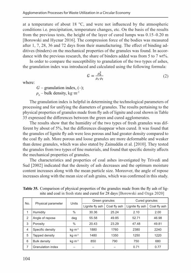
104
Agglomeration Processes for Waste Utilization in a Circular Economy
at a temperature of about 18 °C, and were not influenced by the atmospheric conditions i.e. precipitation, temperature changes, etc. On the basis of the results from the previous tests, the height of the layer of cured lumps was 0.15–0.20 m [Borowski and Hycnar 2016]. The compression force of the bodies was measured after 1, 7, 28, 36 and 72 days from their manufacturing. The effect of binding ad-ditives (binders) on the mechanical properties of the granules was found. In accor-dance with the previous research, the share of binders added was from 5 to 7 wt%.
In order to compare the susceptibility to granulation of the two types of ashes, the granulation index was introduced and calculated using the following formula:
1
𝑓𝑓 = (1 − 𝜌𝜌𝑡𝑡𝜌𝜌𝑠𝑠) · 100%
𝐺𝐺 = 𝜌𝜌𝑏𝑏2𝜌𝜌𝑠𝑠·𝜌𝜌𝑡𝑡
(2)where:
G – granulation index, (–); ρb – bulk density, kg·m-3
The granulation index is helpful in determining the technological parameters of processing and for unifying the diameters of granules. The results pertaining to the physical properties of granules made from fly ash of lignite and coal shown in Table 35 expressed the differences between the green and cured agglomerates.
The results show that the humidity of the two types of fresh granules was dif-ferent by about of 5%, but the differences disappear when cured. It was found that the granules of lignite fly ash were less porous and had greater density compared to the coal fly ash. More porous and loose granules are more deformable and weaker than dense granules, which was also stated by Zainuddin et al. [2010]. They tested the granules from two types of fine materials, and found that specific density affects the mechanical properties of granules.
The characteristics and properties of coal ashes investigated by Trivedi and Sud [2002] indicated that the density of ash decreases and the optimum moisture content increases along with the mean particle size. Moreover, the angle of repose increases along with the mean size of ash grains, which was confirmed in this study.
Table 35. Comparison of physical properties of the granules made from the fly ash of lig-nite and coal in fresh state and cured for 28 days [Borowski and Ozga 2020]
No. Physical parameter UnitsGreen granules Cured granules
Lignite fly ash Coal fly ash Lignite fly ash Coal fly ash
1 Humidity % 30.36 25.24 2.10 2.00
2 Angle of repose deg 55.58 49.85 52.71 46.98
3 Porosity % 20.43 23.29 47.48 49.81
4 Specific density kg·m-3 1880 1760 2380 2240
5 Tapped density kg·m-3 1480 1350 1250 1220
6 Bulk density kg·m-3 850 790 750 680
7 Granulation index – – – 0.71 0.77
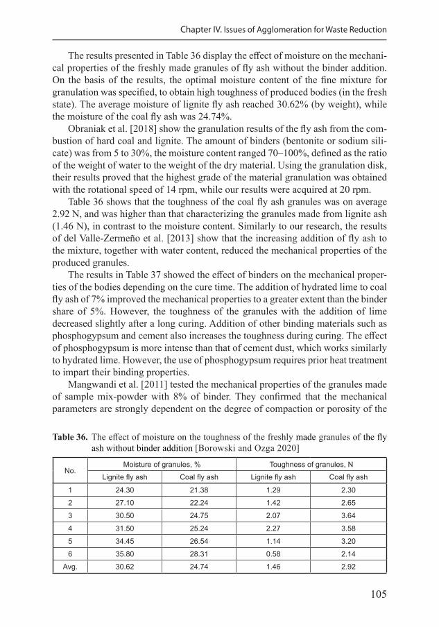
105
Chapter IV. Issues of Agglomeration for Waste Reduction
The results presented in Table 36 display the effect of moisture on the mechani-cal properties of the freshly made granules of fly ash without the binder addition. On the basis of the results, the optimal moisture content of the fine mixture for granulation was specified, to obtain high toughness of produced bodies (in the fresh state). The average moisture of lignite fly ash reached 30.62% (by weight), while the moisture of the coal fly ash was 24.74%.
Obraniak et al. [2018] show the granulation results of the fly ash from the com-bustion of hard coal and lignite. The amount of binders (bentonite or sodium sili-cate) was from 5 to 30%, the moisture content ranged 70–100%, defined as the ratio of the weight of water to the weight of the dry material. Using the granulation disk, their results proved that the highest grade of the material granulation was obtained with the rotational speed of 14 rpm, while our results were acquired at 20 rpm.
Table 36 shows that the toughness of the coal fly ash granules was on average 2.92 N, and was higher than that characterizing the granules made from lignite ash (1.46 N), in contrast to the moisture content. Similarly to our research, the results of del Valle-Zermeño et al. [2013] show that the increasing addition of fly ash to the mixture, together with water content, reduced the mechanical properties of the produced granules.
The results in Table 37 showed the effect of binders on the mechanical proper-ties of the bodies depending on the cure time. The addition of hydrated lime to coal fly ash of 7% improved the mechanical properties to a greater extent than the binder share of 5%. However, the toughness of the granules with the addition of lime decreased slightly after a long curing. Addition of other binding materials such as phosphogypsum and cement also increases the toughness during curing. The effect of phosphogypsum is more intense than that of cement dust, which works similarly to hydrated lime. However, the use of phosphogypsum requires prior heat treatment to impart their binding properties.
Mangwandi et al. [2011] tested the mechanical properties of the granules made of sample mix-powder with 8% of binder. They confirmed that the mechanical parameters are strongly dependent on the degree of compaction or porosity of the
Table 36. The effect of moisture on the toughness of the freshly made granules of the fly ash without binder addition [Borowski and Ozga 2020]
No.Moisture of granules, % Toughness of granules, N
Lignite fly ash Coal fly ash Lignite fly ash Coal fly ash
1 24.30 21.38 1.29 2.30
2 27.10 22.24 1.42 2.65
3 30.50 24.75 2.07 3.64
4 31.50 25.24 2.27 3.58
5 34.45 26.54 1.14 3.20
6 35.80 28.31 0.58 2.14
Avg. 30.62 24.74 1.46 2.92
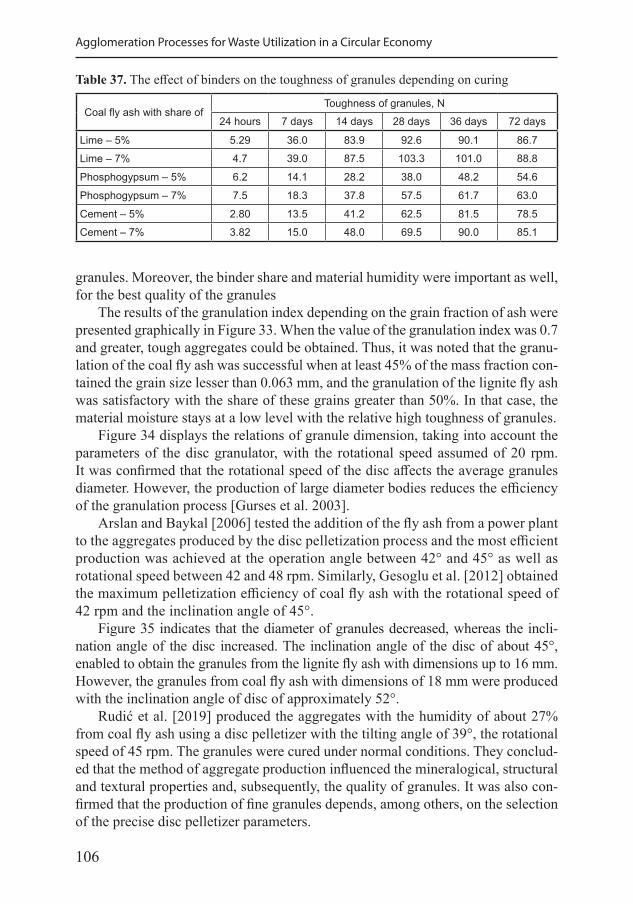
106
Agglomeration Processes for Waste Utilization in a Circular Economy
granules. Moreover, the binder share and material humidity were important as well, for the best quality of the granules
The results of the granulation index depending on the grain fraction of ash were presented graphically in Figure 33. When the value of the granulation index was 0.7 and greater, tough aggregates could be obtained. Thus, it was noted that the granu-lation of the coal fly ash was successful when at least 45% of the mass fraction con-tained the grain size lesser than 0.063 mm, and the granulation of the lignite fly ash was satisfactory with the share of these grains greater than 50%. In that case, the material moisture stays at a low level with the relative high toughness of granules.
Figure 34 displays the relations of granule dimension, taking into account the parameters of the disc granulator, with the rotational speed assumed of 20 rpm. It was confirmed that the rotational speed of the disc affects the average granules diameter. However, the production of large diameter bodies reduces the efficiency of the granulation process [Gurses et al. 2003].
Arslan and Baykal [2006] tested the addition of the fly ash from a power plant to the aggregates produced by the disc pelletization process and the most efficient production was achieved at the operation angle between 42° and 45° as well as rotational speed between 42 and 48 rpm. Similarly, Gesoglu et al. [2012] obtained the maximum pelletization efficiency of coal fly ash with the rotational speed of 42 rpm and the inclination angle of 45°.
Figure 35 indicates that the diameter of granules decreased, whereas the incli-nation angle of the disc increased. The inclination angle of the disc of about 45°, enabled to obtain the granules from the lignite fly ash with dimensions up to 16 mm. However, the granules from coal fly ash with dimensions of 18 mm were produced with the inclination angle of disc of approximately 52°.
Rudić et al. [2019] produced the aggregates with the humidity of about 27% from coal fly ash using a disc pelletizer with the tilting angle of 39°, the rotational speed of 45 rpm. The granules were cured under normal conditions. They conclud-ed that the method of aggregate production influenced the mineralogical, structural and textural properties and, subsequently, the quality of granules. It was also con-firmed that the production of fine granules depends, among others, on the selection of the precise disc pelletizer parameters.
Table 37. The effect of binders on the toughness of granules depending on curing
Coal fly ash with share ofToughness of granules, N
24 hours 7 days 14 days 28 days 36 days 72 days
Lime – 5% 5.29 36.0 83.9 92.6 90.1 86.7
Lime – 7% 4.7 39.0 87.5 103.3 101.0 88.8
Phosphogypsum – 5% 6.2 14.1 28.2 38.0 48.2 54.6
Phosphogypsum – 7% 7.5 18.3 37.8 57.5 61.7 63.0
Cement – 5% 2.80 13.5 41.2 62.5 81.5 78.5
Cement – 7% 3.82 15.0 48.0 69.5 90.0 85.1
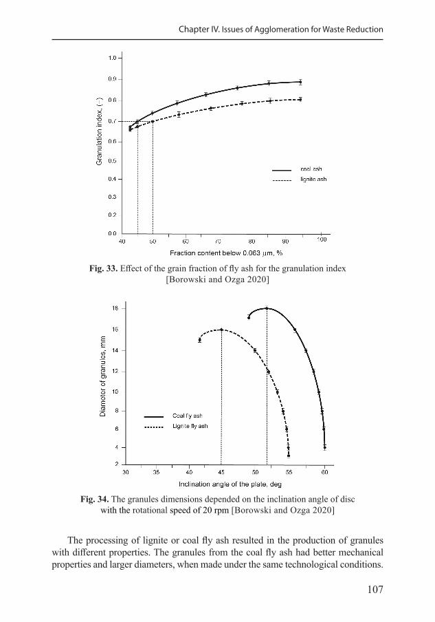
107
Chapter IV. Issues of Agglomeration for Waste Reduction
Fig. 33. Effect of the grain fraction of fly ash for the granulation index [Borowski and Ozga 2020]
The processing of lignite or coal fly ash resulted in the production of granules with different properties. The granules from the coal fly ash had better mechanical properties and larger diameters, when made under the same technological conditions.
Fig. 34. The granules dimensions depended on the inclination angle of disc with the rotational speed of 20 rpm [Borowski and Ozga 2020]
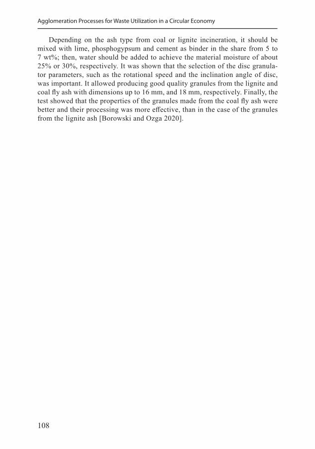
108
Agglomeration Processes for Waste Utilization in a Circular Economy
Depending on the ash type from coal or lignite incineration, it should be mixed with lime, phosphogypsum and cement as binder in the share from 5 to 7 wt%; then, water should be added to achieve the material moisture of about 25% or 30%, respectively. It was shown that the selection of the disc granula-tor parameters, such as the rotational speed and the inclination angle of disc, was important. It allowed producing good quality granules from the lignite and coal fly ash with dimensions up to 16 mm, and 18 mm, respectively. Finally, the test showed that the properties of the granules made from the coal fly ash were better and their processing was more effective, than in the case of the granules from the lignite ash [Borowski and Ozga 2020].
109
Chapter V
Linking Agglomeration to the Principles of Circular Economy
5.1. The principles of circular economy
The purpose of this chapter is to verify whether the conversion of particulate materials to solid agglomerates will meet the objectives of the circular economy. Different terminology may be used for the concepts similar to circular economy, including “closed loop economy” and “zero waste economy”.
The following principles of circular economy have been proposed [Kalmykova et al. 2018]: • material flows keep circulating at a high rate without entering the biosphere un-
less they are biological nutrients; • reducing, reusing and recycling activities are conducted in the process of pro-
duction, circulation and consumption; • the value of products, materials and resources is maintained in the economy for
as long as possible, and the generation of waste is minimized; • an industrial system is restorative – without discarding products before their
values are fully utilized.
In December 2015, the European Commission issued a package supporting the transition of the EU policy to a circular economy. The circular economy has two main components [Rogowska 2018]: • ban on waste landfilling, • total waste-free management.
The work on the circular economy is constantly carried out in the European Commission. A summary document was issued in January 2016, including the legal acts that should be updated [Bourguignon 2016]. Those are: • Directive on waste, • Directive on the landfill of waste, • Directive on packaging and packaging waste, • Directives on end-of-life vehicles, on waste batteries and accumulators and on
waste electrical and electronic equipment.
110
Agglomeration Processes for Waste Utilization in a Circular Economy
The implementation of a waste-free economy involves the use of waste; thus, the waste management is important. The waste hierarchy is the foundation of the EU waste policy and regulations and is crucial for the transition to a circular econ-omy. Its primary goal is to prioritize the effects to minimize the negative environ-mental impacts and optimize effective waste management as part of waste preven-tion and management.
Another circular economy implementation approach is based on focusing on a group of sectors, products, materials or substances. The European Commission’s proposed Action Plan to promote a circular economy includes the legislative pro-posals for the waste management sector regarding reduction of landfilling, increased preparation for reuse and recycling of key waste streams such as municipal waste and packaging waste, as well as the improvement of extended producer responsibil-ity schemes. The products prioritized for circular economy implementation include electric and electronic equipment, textiles, furniture, packaging and tires. The pri-oritized secondary raw materials list includes plastic, metals, paper and cardboard, glass and biodegradable waste.
The circular economy is applied by many industries, including: steelmak-ing, papermaking, emerging industries, process industries, process engineer-ing, leather tannery, mining, chemicals, the construction industry, printed circuit boards industry, agriculture, oil and gas exploitation, as well as power engineer-ing [Heshmati 2015].
The EU commission communication highlights the following main processes for converting waste into energy [COM (2017) 34]: • co-incineration of waste in power facilities; • waste incineration in the facilities designated for this purpose; • anaerobic degradation of biodegradable waste; • production of solid, liquid or gaseous fuels from waste; • other processes, including incineration after pyrolysis or gasification.
The waste to energy processes play a role in the transition to a circular economy provided that the EU waste hierarchy is used as a guiding principle and that the choices made do not prevent higher levels of prevention, reuse and recycling.
The selected energy converting processes are discussed below with a view of meeting the objectives of circular economy, based on the following cases: • fine-coal processing and ash utilization in coal-mines, • waste-based biomass processing and ash utilization in agriculture.
5.2. Fine-coal processing for energy and material recovery
The production of fuels from fine coal is part of the waste-free economy, mainly because the by-products resulting from the combustion of these fuels can be processed to a valuable product. In addition, solid fuels can be sup-
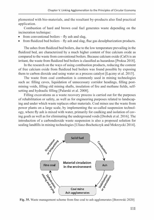
111111
Chapter V. Linking Agglomeration to the Principles of Circular Economy
plemented with bio-materials, and the resultant by-products also find practical application.
Combustion of hard and brown coal fuel generates waste depending on the incineration technique: • from conventional boilers – fly ash and slag, • from fluidized bed boilers – fly ash and slag, flue gas desulphurization products.
The ashes from fluidized bed boilers, due to the low temperature prevailing in the fluidized bed, are characterized by a much higher content of free calcium oxide as compared to the waste from conventional boilers. Because calcium oxide (CaO) is an irritant, the waste from fluidized bed boilers is classified as hazardous [Proksa 2018].
In the research on the ways of using combustion products, reducing the content of free calcium oxide from fluidized bed boilers was found possible by exposing them to carbon dioxide and using water as a process catalyst [Łączny et al. 2015].
The waste from coal combustion is commonly used in mining technologies such as: filling caves, liquidation of unnecessary corridor headings, filling post-mining voids, filling old mining shafts, insulation of fire and methane fields, self-setting and hydraulic filling [Palarski et al. 2008].
Filling excavations as a waste recovery process is carried out for the purposes of rehabilitation or safety, as well as for engineering purposes related to landscap-ing and under which waste replaces other materials. Coal mines use the waste from power plants on a large scale, by implementing the so-called suspension technol-ogy, where fly ash is mixed with water, primarily for caulking and isolation of cav-ing goafs as well as for eliminating the underground voids [Drobek et al. 2016]. The introduction of a carbondioxide waste suspension is also a proposed solution for sealing landfills in mining technologies [Uliasz-Bocheńczyk and Mokrzycki 2014].
Fig. 35. Waste management scheme from fine coal to ash agglomerates [Borowski 2020]
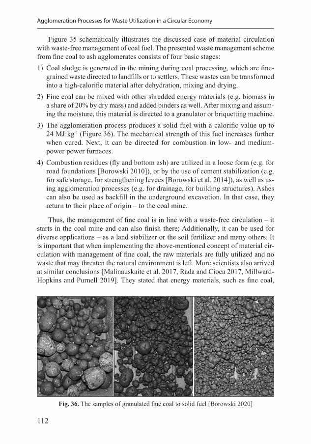
112
Agglomeration Processes for Waste Utilization in a Circular Economy
Figure 35 schematically illustrates the discussed case of material circulation with waste-free management of coal fuel. The presented waste management scheme from fine coal to ash agglomerates consists of four basic stages:1) Coal sludge is generated in the mining during coal processing, which are fine-
grained waste directed to landfills or to settlers. These wastes can be transformed into a high-calorific material after dehydration, mixing and drying.
2) Fine coal can be mixed with other shredded energy materials (e.g. biomass in a share of 20% by dry mass) and added binders as well. After mixing and assum-ing the moisture, this material is directed to a granulator or briquetting machine.
3) The agglomeration process produces a solid fuel with a calorific value up to 24 MJ·kg-1 (Figure 36). The mechanical strength of this fuel increases further when cured. Next, it can be directed for combustion in low- and medium-power power furnaces.
4) Combustion residues (fly and bottom ash) are utilized in a loose form (e.g. for road foundations [Borowski 2010]), or by the use of cement stabilization (e.g. for safe storage, for strengthening levees [Borowski et al. 2014]), as well as us-ing agglomeration processes (e.g. for drainage, for building structures). Ashes can also be used as backfill in the underground excavation. In that case, they return to their place of origin – to the coal mine.
Thus, the management of fine coal is in line with a waste-free circulation – it starts in the coal mine and can also finish there; Additionally, it can be used for diverse applications – as a land stabilizer or the soil fertilizer and many others. It is important that when implementing the above-mentioned concept of material cir-culation with management of fine coal, the raw materials are fully utilized and no waste that may threaten the natural environment is left. More scientists also arrived at similar conclusions [Malinauskaite et al. 2017, Rada and Cioca 2017, Millward-Hopkins and Purnell 2019]. They stated that energy materials, such as fine coal,
Fig. 36. The samples of granulated fine coal to solid fuel [Borowski 2020]
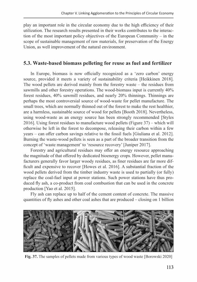
113113
Chapter V. Linking Agglomeration to the Principles of Circular Economy
play an important role in the circular economy due to the high efficiency of their utilization. The research results presented in their works contributes to the interac-tion of the most important policy objectives of the European Community – in the scope of sustainable management of raw materials, for preservation of the Energy Union, as well improvement of the natural environment.
5.3. Waste-based biomass pelleting for reuse as fuel and fertilizer
In Europe, biomass is now officially recognized as a ‘zero carbon’ energy source, provided it meets a variety of sustainability criteria [Heikkinen 2018]. The wood pellets are derived mainly from the forestry waste – the residues from sawmills and other forestry operations. The wood-biomass input is currently 40% forest residues, 40% sawmill residues, and nearly 20% thinnings. Thinnings are perhaps the most controversial source of wood-waste for pellet manufacture. The small trees, which are normally thinned out of the forest to make the rest healthier, are a harmless, sustainable source of wood for pellets [Booth 2018]. Nevertheless, using wood-waste as an energy source has been strongly recommended [Styles 2016]. Using forest residues to manufacture wood pellets (Figure 37) – which will otherwise be left in the forest to decompose, releasing their carbon within a few years – can offer carbon savings relative to the fossil fuels [Giuliana et al. 2012]. Burning the waste-wood pellets is seen as a part of the broader transition from the concept of ‘waste management’ to ‘resource recovery’ [Juniper 2017].
Forestry and agricultural residues may offer an energy resource approaching the magnitude of that offered by dedicated bioenergy crops. However, pellet manu-facturers generally favor larger woody residues, as finer residues are far more dif-ficult and expensive to recover [Howes et al. 2016]. A substantial fraction of the wood pellets derived from the timber industry waste is used to partially (or fully) replace the coal-fuel input at power stations. Such power stations have thus pro-duced fly ash, a co-product from coal combustion that can be used in the concrete production [Yao et al. 2015].
Fly ash can replace up to half of the cement content of concrete. The massive quantities of fly ashes and other coal ashes that are produced – closing on 1 billion
Fig. 37. The samples of pellets made from various types of wood waste [Borowski 2020]
114
Agglomeration Processes for Waste Utilization in a Circular Economy
tons per year globally – can present major disposal problems if they are not utilized. It is no longer appropriate to consider fly ash as waste; it should instead be consid-ered as a resource [Ruhl et al. 2010]. However, the fly ash derived from biomass is typically not suitable to substitute high quantities of cement, mainly due to the high phosphorus content. Phosphorus slows hydration down and extends the setting time of concrete, as well reduces the durability of the concrete [Iacovidou et al. 2017, Kalembkiewicz and Chmielarz 2012].
The use of the ashes from biomass burning as a fertilizer in plant crops was found possible. Adding the ashes from biomass combustion to soil increases the yield of plants, e.g. wheat or rye. The ashes contribute to increasing the phosphorus and potassium content of the plant, while reducing the nitrogen content [Wacławowicz et al. 2017].
The ashes resulting from the combustion of biomass produced in agricultural areas generally do not contain toxic substances (including hazardous metals) and do not pose a threat to the environment [Meller and Bilenda 2012]. Excessive dustiness is the disadvantage of these ashes, so processing them into granular fertilizers is recommended. As a result of fertilizing the soil with granulated fer-tilizers containing ash, a significant improvement in the physical and chemical properties of arable soils can be achieved, manifested by increases in the pH, the content of organic matter, the content of clay fractions in the soil, as well as an in the plant-absorbable forms of macro and microelements [Łabętowicz et al. 2019].
The production technology of biologically active granulated organic-mineral compound fertilizers with slow release has been developed. It involves the intro-duction of ash and sewage sludge mixtures into the mixer. Additives such as bind-ers, biologically active substances and superabsorbents are introduced at the same time. The mixed material is fed into the granulator, then the granulate is transported to the disc paver. After the layering process with the addition of biologically active substances, the granulate is dried and packaged. On the basis of the results from the research on the resulting organic-mineral granulate, it was found that it can be used [Kulikowski et al. 2019]: • for land reclamation, for agricultural and non-agricultural purposes; • when adapting land to specific needs; • for the crops intended for the production of compost; • for growing the crops intended for consumption and feed production.
In another variant of the technological process, high-temperature treatment of processing a mixture of ash and sewage sludge with the addition of lime was introduced. The addition of active lime enables to obtain an appropriate pH, de-hydration of the mixture and removal of unpleasant odors from the deposits. The superabsorbent addition (polymer hydrogel) slows down the leaching of nutrients, acts as a binder in the granulation process and increases the soil water absorption. The obtained granulate can be enriched with a dedicated remedy containing live microorganisms restoring the biological activity, beneficial for the soil environment [Kulikowski et al. 2019].
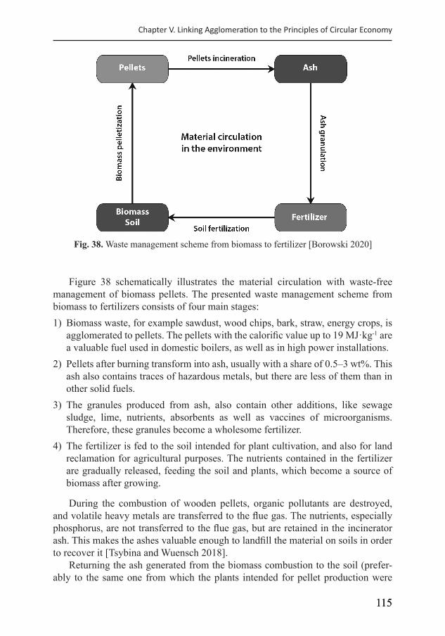
115115
Chapter V. Linking Agglomeration to the Principles of Circular Economy
Figure 38 schematically illustrates the material circulation with waste-free management of biomass pellets. The presented waste management scheme from biomass to fertilizers consists of four main stages:1) Biomass waste, for example sawdust, wood chips, bark, straw, energy crops, is
agglomerated to pellets. The pellets with the calorific value up to 19 MJ·kg-1 are a valuable fuel used in domestic boilers, as well as in high power installations.
2) Pellets after burning transform into ash, usually with a share of 0.5–3 wt%. This ash also contains traces of hazardous metals, but there are less of them than in other solid fuels.
3) The granules produced from ash, also contain other additions, like sewage sludge, lime, nutrients, absorbents as well as vaccines of microorganisms. Therefore, these granules become a wholesome fertilizer.
4) The fertilizer is fed to the soil intended for plant cultivation, and also for land reclamation for agricultural purposes. The nutrients contained in the fertilizer are gradually released, feeding the soil and plants, which become a source of biomass after growing.
During the combustion of wooden pellets, organic pollutants are destroyed, and volatile heavy metals are transferred to the flue gas. The nutrients, especially phosphorus, are not transferred to the flue gas, but are retained in the incinerator ash. This makes the ashes valuable enough to landfill the material on soils in order to recover it [Tsybina and Wuensch 2018].
Returning the ash generated from the biomass combustion to the soil (prefer-ably to the same one from which the plants intended for pellet production were
Fig. 38. Waste management scheme from biomass to fertilizer [Borowski 2020]
116
Agglomeration Processes for Waste Utilization in a Circular Economy
collected) is the most ecological way of their utilization and fully compliant with the Circular Economy assumptions [Hutniczak et al. 2019]. Nutrients are indicated as an especially important category of the secondary raw materials produced out of the biomass-ash.
Summarizing the conducted case studies of circular economy and its basic characteristics, as well as keeping in mind peculiar properties of the considered types of waste, the following features demonstrating the circular nature of activity can be enumerated: • exclusion of waste disposal in landfills; • exclusion of pollutant emissions into the environment; • reuse/recycling/energy recovery out of the waste; • reduced input of primary natural resources and fossil fuels; • exclusion of accumulation of hazardous substances in the environment and
living organisms; • systems thinking, the stages of a product life cycle, different technologies or
enterprises were involved.
117117117
Chapter VI
Recapitulation
In this monograph, the selected agglomeration techniques were described in detail, as solidification, briquetting, extrusion and granulation. Post-agglomeration high-temperature processing was also discussed as sintering and vitrification. The numerous examples show that using the agglomeration processes was an effective way to prevent the dusting of particulate materials and was excellent for the utili-zation of many types of industrial waste. The conglomerates produced were fully utilized for waste reduction in material management. The effect of agglomeration processes was also the fulfillment of the principles of the circular economy. The idea of circular economy justifies the material circulation in nature to reduce the consumption of natural resources and fossil fuels aa well as eliminate waste and pollutant emissions into the environment.
In the case of solidification of the ashes obtained in the process of thermal transformation of sewage sludge in fluidized bed furnaces, the neutralization of harmful substances contained in these ashes was a positive aspect. The ashes solidi-fied into cement blocks were safely disposed of in the landfill. There are also many examples of the use of this ash in cement mortars as well as for the production of precast and cement cubes useful in construction.
Solidification of the ashes obtained from the thermal transformation of sew-age sludge in a fluidized bed boiler was a simple agglomeration method that has enabled the neutralization of harmful substances in this ash. The solidified ashes in cement blocks were suitable for safe storage in a landfill. It was also possible to use this ash for the production of prefabricated building blocks and paving stones. The obtained leaching values of soluble compounds of some heavy metals were within the acceptable standards.
Briquetting of ferrosilicon dust was carried out with use a water glass as a binder or a mixture of water glass with the starch. The maximum efficiency of briquetting was obtained with 1.8 to 2.0% added water glass and 2.7 to 3.0% of starch. The feed preparation process required a particularly comprehensive mixing of the in-gredients, lasting from 5 to 20 minutes. At the end of the mixing, a noticeable rise in temperature was observed. As a result of temperature increase and intense water evaporation, the briquettes were cracking, created gaps and surface delamination occurred, which, however, did not affect the strength. The technology process was applied in industry and employed in the industrial plants that produced the bri-quettes of high quality for the foundries and steel mills.
118
Agglomeration Processes for Waste Utilization in a Circular Economy
The amphibolite stone dust was difficult to agglomerate. Durable briquettes were obtained with the addition of cement 20 wt%, compressed in a hydraulic press at 50 MPa. Curing for 48 hours increased the mechanical properties of the agglom-erates. It was stated that the application of stone dust for utilization as a building material was possible.
Briquetting of the dust from dry cooling of coke was carried out. The most ef-fective binder was sulfite lye in the proportion of 8–15 wt%. Favorable briquetting conditions were obtained at an elevated temperature of 60 °C and pressure of the briquetting press of 300 MPa. Curing influenced the further increase in the strength of briquettes. These products met the requirements as an additive in metallurgical processes and as a substitute for heating coke in the energy sector.
Briquettes from flue-gas desulfurization gypsum were made, with good toler-ance to wind and water erosion, when transported and stored. The gypsum bri-quettes showed high mechanical strength and minimal leaching of water-soluble components; therefore, they did not pose a threat of soil and water pollution. They can be used as hydraulic support and for reclamation works.
Granulated fly ash with phosphogypsum was used for the production of ce-ment and cement mortar. The processing was intended for dust-free transporta-tion, storage and dosage of lose materials. The addition of granules had an effect on drawing out of setting time, as well the hardening of mortar. The compressive strength and flexural strength of the mortar with the addition of ash and phospho-gypsum were comparable to the mortars made from standard cement mixtures. The waste phosphogypsum contained in the granules could replace the natural gypsum commonly used in the cement industry.
Durable granules of silicon carbide were obtained with the addition of cement binder and then curing for a one day. The binder should be added twice by powder-ing, first in a stirred granulator, and again after manufacture. The resulting granules may be used as a replacement of ferrosilicon in the process of steelmaking.
The extrusion technique was used in pilot-scale transforming of biochar into agglomerates that might be alternative fuel. The processing required heating to about 95 °C and bringing the humidity of material to 15–20%. The most important properties of the fuel produced were a long burning time with high temperature generation, as well no harmful emissions to the atmosphere.
Another pioneer research involved using extrusion for producing biocompos-ites as an alternative material for disposable products. The thermoplastic maize starch was tested, both without additives and with the addition of crumbled flax fi-ber. The plasticizer added was technical glycerin and the samples were produced by means of a single-screw extruder. The studies on the mechanical properties showed that flax fiber mixed with the maize starch can be used successfully as a basis of biodegradable composites. The most favorable results of the impact tensile test, and three-point bending flexural test were obtained for a biocompos-ite with flax fiber of 20 wt%. Under anaerobic conditions of 55 °C, the biodegra-dation process was finished at the period of 20 days, which fulfilled the European
119
Chapter VI. Summary and Conclusions
standardized tests. The high methane concentration (approx. 67% vol.) in biogas was observed in the experiment. Nevertheless, the most biogas was produced at the initial stage of the biodegradation process. It was confirmed that the flax fiber biocomposites formed by the extrusion-cooking process are proven fully biode-gradable material and can be successfully employed for energy recovery through biogas production.
The post-treatment processes such as sintering and vitrification were widely used for agglomerates, to achieve the permanent state. The process of sintering of briquettes with fly ashes and silica dust was carried out to produce an artificial ag-gregate. Briquettes were sintered in a chamber oven at 1100 °C for 1.5 hours. The obtained products proved to be durable and resistant to the environmental conditions corresponding to the materials proposed for the foundations of paved road surfaces.
The vitrification method was also applied successfully for the disposal of haz-ardous waste by heating to a temperature from 1350 to 1450 °C. The production of glass beads from fly ashes involved melting the blend in an induction furnace crucible, and then the liquid phase was fed into the dryer with an intensive blow of air. The glass beads made from waste materials were durable and resistant to the environmental conditions, corresponding to the mineral fillers.
The comparable agglomeration of lignite or coal fly ash resulted in the pro-duction of granules with different properties. The granules from the coal fly ash had better mechanical properties and larger diameters, when made under the same technological conditions. A significant influence of some factors, such as grain fraction, material humidity, type and binder share, disc pelletizer tilting angle, and curing time, was observed. Depending on the ash type from coal or lignite incineration, it should be mixed with lime, phosphogypsum and cement as binder in the share from 5 to 7% by weight; then, water should be added to achieve the material moisture of about 25 or 30%, respectively. The granulation index, for suitable properties of granules with desired dimensions, was proposed. On the basis of the effect of the grain fraction for the granulation index, it was stated that the greater fraction content below 0.063 mm is more beneficial for the coal fly ash compared to the lignite fly ash. The disc granulator parameters, such as the rotational speed and the inclination angle of disc, were important. They allowed producing good quality granules from the lignite and coal fly ash with dimensions up to 16 mm, and 18 mm, respectively. It was confirmed that the toughness of aggregates increases greatly when cured. Finally, the comparison showed that the properties of the granules made from the coal fly ash were better and processing was more effective, than in the case of the granules from the lignite ash.
For the granulation of fine coals, including slurries and powders, it is pos-sible to produce solid fuels for boilers combustion. The processing of this waste material was found efficient and not energy-intensive. It was necessary to use the binders, such as: calcium hydroxide, cement, water glass, asphalts, polymers and others. The final mechanical strength of the granules was attained by curing from several hours to several dozen days.
120
Agglomeration Processes for Waste Utilization in a Circular Economy
The addition of biomass to fine coal produces an alternative fuel. It was found that the biomass addition up to 20 wt% improves the combustion process of fuel, particularly by reducing the sulfur and ash content. Thus, it is acceptable as a com-mercial product for the power industry and for individual consumers.
Using the granulation method of fine coal, the fuel with a calorific value of about 19 MJ·kg-1 was obtained; however, in the case of the briquetting method, the calorific value increased to about 24 MJ·kg-1. The utilization of ashes from the combustion of coal bodies is widely relevant in many applications. Importantly, the ashes can be fully used to minimize a waste in material management. Therefore, the fine coal agglomeration techniques remain as a model for meeting the goals of circular economy. The concept of material circulation, like: fine coal – solid fuel – ash – granulated product, completely meets the requirements for sustainable development of the environment.
The waste to energy processes based on biomass pelleting and ash utilization in agriculture showed another case of the sustainable management of raw materials. The technology of granulation involves of high-temperature treatment of a mixture of ash and sewage sludge with the addition of lime. The addition of superabsorbent slows down the leaching of nutrients, acts as a binder in the granulation process and increases the soil water absorption. The granulates produced from ash contain nutrients as well as microorganisms, thus becoming a wholesome fertilizer. The fertilizer was fed to the soil intended for plant cultivation, and also for land rec-lamation for agricultural purposes. The nutrients contained in the fertilizer were gradually released, feeding the soil and plants, which remain a source of biomass after growing. This case of energy recovery and reuse of the nutrients demonstrate the perfect circulation of materials in the nature, and owing to agglomeration, it has been implemented in the circular economy. It should be emphasized that a respec-tive concept of circular waste management should be put into practice with great care, so as not to make the products that may have undesirable properties.
In March, 2020, the European Commission adopted a new Circular Economy Action Plan – one of the main blocks of the European Green Deal, Europe’s new agenda for sustainable growth. The Action Plan announces initiatives along the entire life cycle of products, targeting for example their design, promoting circular economy processes, fostering sustainable consumption, and aiming to ensure that the resources used are kept in the EU economy for as long as possible. The new plan introduces a closed circuit of materials and products into the everyday life of the population, which would accelerate the green transformation of the economy.
121
References
1. Agrawal B.B., Prasak K.K., Sarkar S.B., Ray H.S. 2001. Cold bonded ore-coal com-posite pellets for sponge ironmaking. Ironmaking & Steelmaking, 27(1), 23–26.
2. Ahrendt W.A., Beggs D. 1981. Apparatus for direct reduction of iron using high sulfur gas. Midrex Corporation, US Patent 4,270,739.
3. Altun N.E., Hicyilmaz C., Kok M.V. 2001. Effect of different binders on the combus-tion properties of lignite. Part I. Effect on thermal properties. Journal Thermal Analysis and Calorimetry, 65, 787–795.
4. Antal M.J., Grønli M. 2003. The art, science, and technology of charcoal production. Industrial & Engineering Chemistry Research, 42(8), 1619–1640.
5. Arslan, H., Baykal, G., 2006. Utilization of fly ash as engineering pellet aggregates. Environmental Geology, 50(5), 761–770.
6. ASAE S269.4. Cubes, pellets, and crumbles. Definitions and method for determining density, durability, and moisture. Standards 1997. Am. Soc. Agric. Eng., St. Joseph, MI.
7. Barbieri L., Corradi A., Lancellotti I. 2000. Bulk and sintered glass-ceramics by re-cycling municipal incinerator bottom ash. Journal of the European Ceramic Society, 20(10), 1637–1643.
8. Barbieri L., Karamanov A., Corradi A., Lancellotti I., Pelino M., Rincon J.M. 2008. Structure, chemical durability and crystallization behaviour of incinerator-based glassy systems. Journal of Non-Crystalline Solids, 354, 521–528.
9. Barbieri L., Lancellotti I., Manfredini T., Pellacani G.C., Rincon J.M., Romero M. 2001. Nucleation and crystallization of new glasses from fly ash originating from ther-mal power plants. Journal of the American Ceramic Society, 84(8), 1851–1858.
10. Basegio T., Leao A.P.B., Bernardes A.M., Bergmann C.P. 2009. Vitrification: An alter-native to minimize environmental impact caused by leather industry wastes. Journal of Hazardous Materials, 165, 604–611.
11. Benk BA. 2010. Utilisation of the binders prepared from coal tar pitch and phenolic resins for the production metallurgical quality briquettes from coke breeze and the study of their high temperature carbonization behavior. Fuel Processing Technology, 91, 1152–1161.
12. Bernardo E., Dal Maschio R. 2011. Glass-ceramics from vitrified sewage sludge py-rolysis residues and recycled glasses. Waste Management, 31(11), 2245–2252.
13. Białowiec A., Janczukowicz W., Krzemieniewski M. 2009. Possibilities of manage-ment of waste fly ashes from sewage sludge thermal treatment in the aspect of le-gal regulations (in Polish). Środkowo-Pomorskie Towarzystwo Naukowe Ochrony Środowiska, 11, 959–971.
14. Bielińska E.J., Mocek-Płóciniak A. 2009. Impact of uncontrolled waste dumping on soil chemical and biochemical properties. Archives of Environmental Protection, 35(3), 101–107.
122
Agglomeration Processes for Waste Utilization in a Circular Economy
15. Bień J., Celary P., Morzyk B., Sobik-Szołtysek J., Wystalska K. 2013. Effect of ad-ditives on heavy metal immobilization during vitrification of tannery sewage sludge. Environment Protection Engineering, 39(2), 33–40.
16. Bień J., Wystalska K. 2009. The effects of thermal treatment of slag derived from pyrolisys process of medical wastes (in Polish). Ochrona Środowiska i Zasobów Naturalnych, 41, 437–445.
17. Bieńko W. 2004. Lubelski Węgiel „Bogdanka” S.A. – coal mechanical processing plant technology (in Polish). Inżynieria Mineralna, 2(13), 45–49.
18. Bingham P.A., Hand R.J. 2006. Vitrification of toxic wastes: A brief review. Advances in Applied Ceramics, 105(1), 21–31.
19. Blesa M.J., Miranda J.L., Izquierdo M.T., Moliner R. 2003. Curing time effect on mecha-nical strength of smokeless fuel briquettes. Fuel Processing Technology, 80(2), 155–167.
20. Booth M. 2018. Not carbon neutral: assessing the net emissions impact of residues burned for bioenergy. Environmental Research Letters, 13, 035001.
21. Bootklad M., Kaewtatip K. 2013. Biodegradation of thermoplastic starch/eggshell powder composites. Carbohydrate Polymers, 97(2), 315–320.
22. Borowski G. 2003. Merging of bearing grinding wastes in the aspect of their utilization in metallurgy. Maintenance and Reliability, 2(18), 21–23.
23. Borowski G. 2007. The possibility of utilizing coal briquettes with a biomass. Environment Protection Engineering. 33(2), 79–86.
24. Borowski G. 2009a. Designation of physical and chemical properties of fine-grained materials for their utilization (in Polish). Postępy Nauki i Techniki, 3, 68–82.
25. Borowski G. 2009b. Technological aspects of energy resource briquetting (in Polish). In: Biegańska J., Landrat M. (Eds.) “Fuels from the waste 2009”, Politechnika Śląska w Gliwicach, 209–216.
26. Borowski G. 2009c. Possibilities of utilization of energy briquettes. In: Schwarz H., Leonowicz Z. (Eds.), The Eighth EEEIC International Conference on Environment and Electrical Engineering. Published by IEEE, Germany, Cottbus, 110–113.
27. Borowski G. 2010. Possibilities of using energy waste for road construction (in Polish). Inżynieria Ekologiczna, 22, 52–62.
28. Borowski G. 2011a. Possibilities of utilization of energy briquettes. Electrical Engine-ering Research Report, 1(27), 48–51.
29. Borowski G. 2011b. Processing of ash from the incineration of sewage sludge into building material (in Polish). Inżynieria Ekologiczna, 25, 251–258.
30. Borowski G. 2011c. The use of briquetting for waste management (in Polish). Lubelskie Towarzystwo Naukowe, Lublin, pp. 176.
31. Borowski G. 2012a. Comparison of two ways to determine the strength of briquettes from fine-grained materials (in Polish). Postępy Nauki i Techniki, 12, 115–121.
32. Borowski G. 2012b. Suitability tests of fly ashes vitrification from sewage sludge in-cineration. Archives of Environmental Protection, 38(2), 81–87.
33. Borowski G. 2013a. Application of vitrification method for the disposal of municipal sewage sludge. Annual Set The Environment Protection, 15, 575–583.
34. Borowski G. 2013b. Pilot tests for utilization of fine coal to fuel briquettes production.
123
References
Archives of Waste Management and Environmental Protection, 15(2), 9–18.35. Borowski G. 2013c. Vitrification process for sewage sludge treatment. In: Pawłowski
A., Pawłowska M. & Pawłowski L. (Eds.) “Environmental Engineering. Part IV” CRC Press Taylor & Francis Group, London,185–190.
36. Borowski G. 2013d. Methods of fine-grained waste processing into useful products (in Polish). Wydawnictwo Politechniki Lubelskiej, Lublin, pp. 112.
37. Borowski G. 2015. Using vitrification for sewage sludge combustion ash dispos-al. Polish Journal of Environmental Studies, 24(5), 1889–1896.
38. Borowski G. 2016. Attempts to granulate silicon carbide dust waste for use in metal-lurgy (in Polish). Inżynieria Ekologiczna, 49, 112–116.
39. Borowski G. 2020. Agglomeration of fine coal as an achievement of circular economy. In: Woźniak G. (Ed.) Green Scenarios: Mining industries working with the environ-ment. Taylor & Francis Group (in press).
40. Borowski G., Gajewska M., Haustein E. 2014. Possibilities of ashes utilization from sewage sludge thermal processing in a fluidized bed boiler (in Polish). Inżynieria i Ochrona Środowiska, 17(3), 393–402.
41. Borowski G., Hryniewicz M., Kuczmaszewski J. 2004. Management of Ferrous Metal Wastes. Proceedings of Global Symposium on Recycling, Waste Treatment and Clean Technology “REWAS”, Madryt, 1933–1942.
42. Borowski G., Hycnar J.J. 2013. Utilization of fine coal waste as a fuel briquettes. International Journal of Coal Preparation and Utilization, 33(4), 194–204.
43. Borowski G., Hycnar J.J. 2016. The effect of granulated fly ashes with phosphogyp-sum on the hardening of cement mortar. Technical Transactions – Civil Engineering, 113, 2-B(7), 37–45.
44. Borowski G., Hycnar J.J., Józefiak T. 2016. Industrial briquetting trials for the waste management of bearing grinding. Annual Set The Environment Protection, 18, 205–217.
45. Borowski G., Klepka T., Pawłowska M., Lavagnolo M.C., Oniszczuk T., Wójtowicz A., Combrzyński M., 2020. Effect of the flax fibers addition on the mechanical proper-ties and biodegradability of biocomposites based on thermoplastic starch. Archives of Environmental Protection, Vol. 46 (in print).
46. Borowski G., Kuczmaszewski J. 2005a. Utilization of fine-grained metal waste (in Polish). Politechnika Lubelska, Lublin, pp. 168.
47. Borowski G., Kuczmaszewski J. 2005b. Investigation on briquetting of metal wastes from bearing industry. Waste Management & Research, 5(23), 473–478.
48. Borowski G., Miłczak M. 2010. Tests on the suitability of briquettes from bottom ash as road foundations (in Polish). Postępy Nauki i Techniki, No. 4, 136–143.
49. Borowski G., Ozga M. 2020. Comparison of the processing conditions and the properties of granules made from fly ash of lignite and coal. Waste Management, 104C, 192–197.
50. Borowski G., Stępniewski W., Wójcik-Oliveira K. 2017a. Effect of starch binder for properties of charcoal briquettes. International Agrophysics, 31(4), 571–574.
51. Borowski G., Świderski T., Ozga M. 2017b. Agglomeration the stone dust for utilizing as building material. Advances in Science and Technology Research Journal, 11(4), 168–174.
52. Borowski G., Wośko M. 2013. Ecological and technical requirements of radioactive waste utilization. Journal of Ecological Engineering, 14(1), 40–47.
124
Agglomeration Processes for Waste Utilization in a Circular Economy
53. Boruk S., Winkler I. 2009. Ecologically friendly utilization of coal processing waste as a secondary energy source. In: Energy and Environmental Challenges to Security. Springer Publishers, 251–259.
54. Boryło A., Skwarzec B., Olszewski G., Nowicki W. 2011. The impact of phosphogyp-sum landfill on the environment in Wiślinka, Part I (in Polish). Ochrona Powietrza i Problemy Odpadów, 45(2), 70–79.
55. Bourguignon D. 2016. Closing the Loop – New Circular Economy Package. Available online: http://www.europarl.europa.eu/RegData/etudes/BRIE/2016/573899/EPRS_BRI(2016)573899_EN.pdf
56. Brunerová A., Roubík H., Brožek M. 2018. Bamboo fiber and sugarcane skin as a bio-briquette fuel. Energies, 11(9), 2186.
57. Bultmann J.M. 2002. Multiple compaction of microcrystalline cellulose in a roller compactor. European Journal of Pharmaceutics and Biopharmaceutics, 54, 59–64.
58. Burgueno R., Quagliata M.J., Mohanty A.K., Mehta G., Drzal L.T., Misra M. 2005. Hierarchical cellular designs for load-bearing biocomposite beams and plates. Materials Science and Engineering A, 390, 178–187.
59. Chellan R., Pocock J., Arnold D., 2004, Direct reduction of mixed magnetite and coal pellets using induction heating. Mineral Processing and Extractive Metallurgy Review, 26(1), 63–76.
60. Chokshi R., Zia H. 2004. Hot-melt extrusion technique: A review. Iranian Journal of Pharmaceutical Research, 3, 3–16.
61. Chu J.P., Hwang I.J., Tzeng C.C, Kuo Y.Y, Yu Y.J. 1998. Characterization of vitrified slag from mixed medical waste surrogates treated by a thermal plasma system. Journal of Hazardous Materials, 58, 179–184.
62. Cichy B. 2012. Inorganic waste of the chemical industry (in Polish). Foresight Technologiczny. Gliwice-Warszawa-Kraków.
63. Cioffi R., Colangelo F., Montagnaro F., Santoro L. 2011. Manufacture of artificial ag-gregate using MSWI bottom ash. Waste Management, 31(2), 281–288.
64. Colombo P., Brusatin G., Bernardo E., Scarinci G. 2003. Inertization and reuse of waste materials by vitrification and fabrication of glass-based products. Current Opinion in Solid State and Materials Science, 7(3), 225–239.
65. Connelly A.J., Hand R.J., Bingham P.A., Hyatt N.C. 2011. Mechanical properties of nuclear waste glasses. Journal of Nuclear Materials, 408(2), 188–193.
66. Coruh S., Ergun O.N. 2006. Leaching characteristics of copper flotation waste before and after vitrification. Journal of Environmental Management, 81(4), 333–338.
67. Das B., Prakash S., Reddy P.S.R., Misra V.N. 2007. An overview of utilization of slag and sludge from steel industries. Resources, Conservation and Recycling, 50(1), 40–57.
68. Das O., Sarmah A.K., Bhattacharyya D. 2015. A novel approach in organic waste utilization through biochar addition in wood/polypropylene composites. Waste Management, 38, 132–140.
69. de Moraes S.L., Kawatra S.K. 2010. Laboratory study of an organic binder for pelletiza-tion of a magnetite concentrate. Minerals & Metallurgical Processing, 27(3), 148–153.
70. Dec R.T. 2002. Optimizing and controlling roll press operating parameters. Powder Handling and Processing, 14, 222–225.
125
References
71. del Valle-Zermeño R., Formosa J., Chimenos J.M., Martínez M., Fernández A.I. 2013. Aggregate material formulated with MSWI bottom ash and APC fly ash for use as secondary building material. Waste Management, 33(3), 621–627.
72. Dellisanti E., Rossi P.L., Valdre G. 2009. Remediation of asbestos containing materials by Joule heating vitrification performed in apre-pilot apparatus. International Journal of Mineral Processing, 91, 61–67.
73. Dilsky S., Blasques T.C.A., Arias M.J.A., Bartalini N.M., Santos A.T., Da S.W.C., Cassola M.S. 2011. Binder composition for the agglomeration of fine minerals and pelletizing process using the same. Clariant S.A. Brazil, Clariant International Ltd., European Patent Application 2,548,978A1.
74. Dingeman D.L., Skagerberg W.E. 1994. Modified native starch base binder for pel-letizing mineral material. Oriox Technologies, Inc. US Patent 5,306,327.
75. Dinh Hieu V., Kuen-Sheng W., Jung-Hsing C., Bui Xuan N., Bui Hoang B., 2012. Glass-ceramic from mixtures of bottom ash and fly ash. Waste Management, 32, 2306–2314.
76. Dobiszewska M. 2016. Use of basalt powder in a cementitious mortar and concrete as a substitute of sand. Construction and Architecture, 15(4), 75–85.
77. Dobiszewska M., Franus W., Turbiak S. 2016. Analysis of the possibility of using powder basalt in cement mortar. Journal of Civil Engineering, Environment and Architecture, Vol. XXXIII, 63(1), 107–114.
78. Donald I.W. 2010. Waste immobilization in glass and ceramic based hosts. John Wiley & Sons Ltd. Publication, pp. 507.
79. Drobek L., Kanafek J., Pierzyna P. 2016. UPS management in hard coal mines cur-rent state, consumption forecast for 2016–2020, technological and environmental as-pects (in Polish). In: Proceedings of the 23rd International Conference “Ashes from the Energy”. Zakopane, 19–21 Oct. 2016.
80. Drzymała Z. 1993. Industrial Briquetting – Fundamentals and Methods. Studies in Mechanical Engineering. Elsevier Science Publishers, Amsterdam.
81. Drzymała Z., Hryniewicz M. 1999. On improving the design of the compacting sys-tem of cylindrical presses for the briquetting of fine-grained ferrous waste (in Polish). Przegląd Mechaniczny, 58(14), 8–13.
82. Drzymała Z., Hryniewicz M., Janewicz A. 2000. Studies on the method of disposing of waste zinc oxide (in Polish). Zeszyty Naukowe Politechniki Łódzkiej, Inżynieria Chemiczna i Procesowa, 27, 60–70.
83. Duca V., Duca M., Benea M. 2002. Crystallization of some glasses in CaO-MgO-Al2O3-SiO2 systems. Key Engineering Materials, Vol. 206–213, 2081–2084.
84. Eisele T.C., Kawatra S.K. 2003. A review of binders in iron ore pelletization. Mineral Processing and Extractive Metallurgy Review, 24(1), 1–90.
85. Emrich W. 1985. Handbook of charcoal making. The traditional and industrial meth-ods. Solar Energy R&D in the Eutropean Community, Ser. E: Energy from Biomass, Vol. 7, Springer-Science+Business Media B.V., pp. 278.
86. Faizal M. 2017. Utilization biomass and coal mixture to produce alternative solid fuel for reducing emission of greenhouse gas. International Journal on Advanced Science Engineering Information Technology, 7(3), 950–956.
87. Faruk O., Bledzki A.K., Fink H.P., Sain M. 2012. Biocomposites reinforced with natural
126
Agglomeration Processes for Waste Utilization in a Circular Economy
fibers: 2000–2010. Progress in Polymer Science, 37, 1552–1596.88. Fathi M.H., Kharaziha M., 2009. Two step sintering of dense, nanostructural forsterite.
Materials Letters, 63(17), 1455–1458.89. Feliks J. 2012. Laboratory testing of coal sludge granulation. Chemik, 66(5), 388–395.90. Fernández-González D., Ruiz-Bustinza I., Mochón J., González-Gasca C., Verdeja
L.F. 2017. Iron ore sintering: raw materials and granulation. Mineral Processing and Extractive Metallurgy Review, 38(1), 36–46.
91. Field J.R., Stocks P. 2001. Mineral pelletization. Ciba Specialty Chemicals Water Treatments Ltd., US Patent 6,293,994 B1.
92. Finucane K.G., Thompson L.E., Abuku T., Nakauchi H. 2008. Treatment of asbestos wastes using GeoMelt vitrification process. In: Proceedings of WM’2008 Conference, Phoenix.
93. Francis A.A., Rawlings R.D., Sweeney R., Boccaccini A.R. 2004. Crystallization ki-netics of glass particles prepared from a mixture of coal ash and soda-lime cullet glass. Journal of Non-Crystalline Solids, 333(2), 187–193.
94. Fredericci C., Zanotto E.D., Ziemath E.C. 2000. Crystallization mechanism and prop-erties of a blast furnace slag glass. Journal of Non-Crystalline Solids, 273, 64–75.
95. Gacki F., Feliks J., Wyszomirski P., 2013. Research into the use of waste basalt dust (in Polish). Engineering and Chemical Engineering, 52(3), 174–175.
96. Galetakis M., Raka S. 2004. Utilization of limestone dust for artificial stone produc-tion: an experimental approach. Minerals Engineering, 17, 355–357.
97. Galos K., Szluga J. 2014. Management of hard coal mining and processing wastes in Poland. Gospodarka Surowcami Mineralnymi – Mineral Resources Management, 30(4).
98. Gauthier A., Le Coustumer P., Thomassin J.-H. 2001. Thermostability of ultimate glassy wastes. Annales de Chimie de Science des Materiaux, 26(2), 87–93.
99. Gesoglu M., Güneyisi E., Öz H.Ö. 2012. Properties of lightweight aggregates pro-duced with cold-bonding pelletization of fly ash and ground granulated blast furnace slag. Materials and Structures, 45, 1535–1546.
100. Giemza H., Gruszka G, Hycnar J., Józefiak T., Kiermaszek K. 2007. Optimization of coal sediment management – sediment briquetting technology (in Polish). Polityka Energetyczna, 10(2), 417–429.
101. Giemza H., Gruszka G., Hycnar J.J., Józefiak T., Kiermaszek K. 2009. Technologies for the recovery of fine-grained materials and coal waste for the needs of fuel and en-ergy production (in Polish). In: Proceedings of the 23rd Nationwide Conference “Issues of energy resources and energy in the national economy”. Zakopane, 11–14 Oct. 2009.
102. Giuliana Z., Naomi P., Neil B. 2012. Is woody bioenergy carbon neutral? A compara-tive assessment of emissions from consumption of woody bioenergy and fossil fuel. GCB Bioenergy, 4, 761–772.
103. Gluba T. 2012. Investigations of continuous disc granulation process. Chemik, 66(5), 360–369.
104. Gnutek M., Moroń W., Rybak W. 2002. Ignition and co-ignition of coals and biomass (in Polish). Czysta Energia, 9.
105. Graham R.K. 1983. Cold bonding mineral pelletization. N.B. Love Industries Pty. Ltd., US Patent 4,402,736.
127
References
106. Gurses A., Doymus K., Dogar C., Yalcin M. 2003. Investigation of agglomeration rates of two Turkish lignites. Energy Conversion and Management 44, 1247–1257.
107. Haas L.A., Aldinger J.A., Nigro J.C. 1989. Effectiveness of organic binders for iron ore pelletization. Report of Investigations – U.S. Bureau of Mines, RI 9230, pp. 25.
108. Halt J.A., Kawatra S.K. 2014. Review of organic binders for iron ore concentrate ag-glomeration. Minerals & Metallurgical Processing, 31(2), 73–94.
109. Han G., Huang Y., Li G., Zhang Y., Jiang T. 2014, Detailed adsorption studies of ac-tive humic acid fraction of a new binder on iron ore particles. Mineral Processing and Extractive Metallurgy Review: An International Journal, 35(1), 1–14.
110. Hatakeyama H., Hatakeyama T. 2010. Lignin structure, properties, and applications. Advances in Polymer Science, 232, 1–63.
111. Hebeda R.E. 2007. Syrups. Kirk-Othmer Encyclopedia of Chemical Technology.112. Heikkinen N. 2018. EPA declares biomass plants carbon neutral, amid scientific disa-
greement. (www.scientificamerican.com/article/epa-declares-biomass-plants- carbon-neutral-amid-scientific-disagreement/> (Accessed 4.02.2020).
113. Heim A. 2005. Process and apparatus issues of the agglomeration (in Polish). In: Proceedings of the 9th Nationwide Conference “Comprehensive and detailed problems of environmental engineering”, Politechnika Koszalińska.
114. Heinrich P., Schierloh U. 1973. Method of producing iron ore pellets, Huttenwerk Oberhausen Ag., US Patent 3,765,869.
115. Hejft R. 2002. Pressure agglomeration of plant materials (in Polish). Wydawnictwo Instytutu Technologii Eksploatacji w Radomiu.
116. Hejft R. 2008. Pelleting and briquetting in devices with low efficiency (in Polish). Czysta Energia, 80.
117. Hejft R., Obidziński S. 2006. Production of granules and briquettes in terms of features quality (in Polish). Czysta Energia, 55.
118. Herting M.G., Kleinebudde P. 2007. Roll compaction/dry granulation: Effect of raw material particle size on granule and tablet properties. International Journal of Pharmaceutics, 338, 110–118.
119. Heshmati A. 2015. A review of the circular economy and its implementation. IZA Discussion Paper Series, Paper No. 9611, Bonn, Germany, pp. 61.
120. Honaker R.Q., Parekh B.K., Chunggh Y.P. 1998. Integration of advanced fine particle technologies for efficiency carbon recovery from refuse ponds. In: Proceedings of the 13th International Coal Preparation Congress. 23–27 May 1998, Cracow.
121. Howes P. et al. 2016. Use of North American woody biomass in UK electricity gen-eration: Assessment of high carbon biomass fuel sourcing scenarios. Department of Energy and Climate Change, UK.
122. Hryniewicz M., Borowski G., Kuczmaszewski J. 2003. Research on the method of utilization of grinding waste from the bearing industry (in Polish). In: Proceedings of the 7th International Conference „Recyklace Odpadu”, VŚB–TU Ostrawa, 95–102.
123. Hryniewicz M., Janewicz A., Borowski G., Kuczmaszewski J., 2004. Practical aspects of grinding waste utilization in the bearing industry (in Polish). Monografie Wydziału Inżynierii Mechanicznej i Robotyki AGH, No. 23, 87–93.
128
Agglomeration Processes for Waste Utilization in a Circular Economy
124. Hryniewicz M., Kosturkiewicz B., Janewicz A. 2006. Merging fine-grained waste (in Polish). Zeszyty Naukowe Inżynierii Chemicznej i Procesowej, Politechnika Łódzka, 29, 89–98.
125. Huang GX, Chen LJ, Cao J. 2008. Briquetting mechanism and waterproof perfor-mance of bio-briquette. Journal of China Coal Society, 33, 812–815.
126. Huang S.-C, Chang F.-C, Lo S.-L., Lee M.-Y, Wang C.-F., Lin J.-D. 2007. Production of lightweight aggregates from mining residues, heavy metal sludge, and incinerator fly ash. Journal of Hazardous Materials, 144(1–2), 52–58.
127. Huth H., Kubisa R. 1996. The use of waste from power plants based on German energy (in Polish). In: Proceedings of Scientific and Technical Conference “By-products of coal combustion in the energy sector as a practical raw material”, Świnoujście.
128. Hutniczak A., Borowski G., Woźniak G. 2019. The concept of reclamation in biologi-cal sciences to new environmental challenges (in Polish). In: Siuta J., Borowski G. (Eds.) System of protection and renewal of the biologically active surface ground in Poland. Wydawnictwo Politechniki Lubelskiej, 105–114.
129. Hycnar J.J. 2006. Factors affecting the physicochemical and functional properties of solid fuel combustion products in fluidized bed furnaces (in Polish). Wydawnictwo Górnicze, Katowice, pp. 196.
130. Hycnar J.J. 2015. Methods of increasing the calorific value of fine coal waste. Inżynieria Mineralna – Journal of the Polish Mineral Engineering Society, 16(1), 33–55.
131. Hycnar J.J., Borowski G. 2016. Methods for increasing the calorific value of fine-grained coal waste (in Polish). Wydawnictwo Politechniki Lubelskiej, Lublin, pp. 156.
132. Hycnar J.J., Borowski G., Bugajczyk M. 2015a. Trial production of briquettes from dust coke as an alternative solid fuel (in Polish). Rynek Energii, 3(118), 87–92.
133. Hycnar J.J., Borowski G., Józefiak T., Malec A. 2015b. Granulation and briquetting of solid flue-gas desulphurization products (in Polish). Inżynieria Ekologiczna, 45, 51–58.
134. Hycnar J.J., Borowski G., Józefiak T. 2014. Conditions for the preparation of stable ferrosilicon dust briquettes. Journal of the Polish Mineral Engineering Society, 33(1), 155–162.
135. Hycnar J.J., Borowski G., Mikołajczyk B., Kadlec D. 2017. Methods of dust preven-tion from landfills of raw materials and waste (in Polish). Inżynieria Ekologiczna, 4(18), 89–96.
136. Hycnar J.J., Bugajczyk M. 2004. Directions for rational utilization of fine-grained coal waste (in Polish). Polityka Energetyczna, Vol. 7, Spec. Iss.
137. Hycnar J.J., Fraś A., Przystaś R., Józefiak T., Baic I. 2011. The use of fluidized ash-es to granulate of coal sludge (in Polish). In: Proceedings of the 21st International Conference “Ashes from the Energy”. Zakopane, 19–21 Oct. 2011.
138. Iacovidou E., Hahladakis J., Deans I., Velis C., Purnell P. 2018. Technical properties of biomass and solid recovered fuel (SRF) co-fired with coal: impact on multi-dimen-sional resource recovery value. Waste Management, 73, 535–545.
139. Ibrahim H., Farag M., Megahed H., Mehanny S. 2014. Characteristics of starch-based biodegradable composites reinforced with date palm and flax fibers. Carbohydrate Polymers, 101, 11–19.
140. Igawa Y., Jimbo J., Tanaka H., Kikuchi S., Harada T., Tsuchiya O., Ito S., Kobayashi I.,
129
References
2008, Method of producing iron oxide pellets. Kobe Steel Ltd., US Patent 7,438,730 B2.141. Isobe Y., Wang Q., Sakamoto K. 2004. Utilization of coal-biomass briquette combus-
tion ash for soil improvement. Environmental Science, 17(6), 431–438.142. Iveson S.M., Litster J.D., Hapgood K., Ennis B.J. 2001. Nucleation, growth and break-
age phenomena in agitated wet granulation processes: a review. Powder Technology, 117(1–2), 3–39.
143. Jackson M.J., Mills B., Hitchiner M.P. 2003. Controlled wear of vitrified abrasive ma-terials for precision grinding applications. Sadhana, 28(5), 897–914.
144. Jantzen C.M., Pickett J.B. 2000. How to recycle asbestos containing materials? WSRC-MS-2000-00194, Westinghouse Savannah River Company.
145. Jing Z., Li YY., Cao S., Liu Y. 2012. Performance of double-layer biofilter packed with coal fly ash ceramic granules in treating highly polluted river water. Bioresource Technology, 120, Sept., 212–217.
146. Johnson E. 2009. Charcoal versus LPG grilling: A carbon-footprint comparison. Environmental Impact Assessment Review, 29, 370–378.
147. Johnson O.A., Napiah M., Kamaruddin I., 2014. Potential uses of waste sludge in con-struction industry: A review. Research Journal of Applied Sciences, Engineering and Technology, 8(4), 565–570.
148. Jordan M.M., Almendro-Candel M.B., Romero M., Rincon J.M. 2005, Application of sewage sludge in the manufacturing of ceramic tile bodies. Applied Clay Science, 30, 219–224.
149. Juniper T. 2017. Burning wood instead of coal in power stations makes sense if it’s waste wood. https://www.theguardian.com/environment/2017/dec/19/ (Accessed 4.02.2020).
150. Juraszka B., Piecuch T. 2007. Incineration of adhesives organic sewage and disposal of the resulting ashes (in Polish). Polityka Energetyczna, 10(2), 85–101.
151. Kalembkiewicz J., Chmielarz U. 2012. Ashes from co-combustion of coal and bio-mass: new industrial wastes. Resources, Conservation and Recycling, 69, 109–121.
152. Kalmykova Y., Sadagopan M., Rosado L. 2018. Circular economy – from review of the-ories and practices to development of implementation tools. Resources, Conservation and Recycling, 135, 190–201.
153. Karamanov A., Aloisi M., Pelino M. 2007. Vitrification of copper flotation waste. Journal of Hazardous Materials, 140, 333–339.
154. Karcz A. 2004. Characteristics of the quality of coke dust generated in the dry coke cooling process and directions of their use (in Polish). Karbo, 4, 219–223.
155. Karkoska D. 2011, Organic binders for iron ore pelletization, Advanced Sustainable Iron and Steel Making Center Annual Meeting, August 1–3, Houghton, MI, USA.
156. Karthikeyan M., Zhonghua W., Mujumdar A.S. 2009. Low-rank coal drying technol-ogies – current status and new developments. Drying Technology An International Journal, 27(3), 403–415.
157. Kavas T., Olgun A., Erdogan Y., 2005. Setting and hardening of borogypsum-Portland cement clinker-fly ash blends. Studies on effects of molasses on properties of mortar containing borogypsum, Cement and Concrete Research, 35(4), 711–718.
158. Kelbaliyev G.I., Samedli V.M., Samedov M.M., Kasimova R.K. 2013. Experimental
130
Agglomeration Processes for Waste Utilization in a Circular Economy
study and calculation of the effect of intensifying additives on the strength of super-phosphate granules. Russian Journal of Applied Chemistry, 86(10), 1478–1482.
159. Kępys W. 2010. Aggregates from fine-grained hazardous waste (in Polish). Inżynieria Ekologiczna, 23, 70–76.
160. Keranen C.U. 1986. Reagent preparation, distribution and feeding systems at the Tilden Mine. In: L.A. Mular, M.A. Anderson (Eds.), Design and Installation of Concentration and Dewatering Circuits, Society for Mining, Metallurgy, and Exploration, 308–319.
161. Kikuchi R. 2011. Vitrification process for treatment of sewage sludge and incineration ash. Journal of the Air and Waste Management Association, 48, 1112–1115.
162. Kim H.S., Kim Y.T., Lee G.G., Kim J.H., Kang S.G. 2007. Corrosion of silicate glasses and glass-ceramics containing EAF dust in acidic solution. Solid State Phenomena, 124–126, 1585–1588.
163. Komarow I., Molokhov M.N., Sorokin A.A. et al. 2005. Microwave vitrification of radioactive wastes. Atomic Energy, 98(4).
164. Kordylewski W., Zacharczuk W., Kasprzyk K. 2003. Modification of ash and slag by vitrification method (in Polish). Ochrona Powietrza i Problemy z Odpadami, 37, 84.
165. Kosior-Kazberuk M., Lelusz M. 2010. Assessment of ash from simultaneous combus-tion of biomass and coal as a component of cement composites (in Polish). Materiały Ceramiczne, 62(2), 166–170.
166. Kosturkiewicz B., Janewicz A., Magdzierz A., Hryniewicz M., Bębenek M., Gara P. 2014. The issue of coking coal briquetting (in Polish). Rynek Energii, 2(111), 104–109.
167. Kovacova M., Lovas M., Kakabsky S., Romero M., Rincon J.M. 2009. Microwave vitrification of model heavy metal carriers from wastewaters treatment. In: MRS’09, St Petersburg.
168. Kozioł W., Kawalec P. 2008. Alternative aggregates in construction (in Polish). Projektowanie i Konstrukcje Inżynierskie, 7–8(18), 34–37.
169. Kraitr M., Sirotek V. 2002. Flue gas desulphurization (FGD) at the Melnik Power Plant (CZ) and the use of produced FGD gypsum (DSG). Chemia i Inżynieria Ekologiczna, No. 2-3.
170. Kubica K., Robak Z., Robak J. 2004. Granular auxiliary materials for metallurgy in ICHPW research (in Polish). Archiwum Odlewnictwa, 4(13), 145–150.
171. Kubica K., Ściążko M., Raińczak J. 2003. Co-firing of biomass with coal (in Polish). Polityka Energetyczna, 6, 297–308.
172. Kuczyńska L. 2008. Pelleting – a form of preparing waste for use or disposal (in Polish). Chemik: Nauka – Technika – Rynek, 61(9), 434–438.
173. Kulikowski Ł., Kulikowski E., Gręda-Stempel K., Kiepurski J. 2019. Mobile technol-ogy for processing municipal sewage sludge into fertilizers of agroecological utility (in Polish). In: Siuta J., Borowski G. (Eds.) System of protection and renewal of the biologically active surface ground in Poland. Wydawnictwo Politechniki Lubelskiej, Lublin, 272–284.
174. Kumar A., Gernaey K.V., De Beer T., Nopens I. 2013. Model-based analysis of high shear wet granulation from batch to continuous processes in pharmaceutical produc-tion – A critical review. European Journal of Pharmaceutics and Biopharmaceutics, 85(3)B, 814–832.
131
References
175. Kumar S.A. 2012. Rheological investigation of coal water slurries with and without additive. Thapar University Patiala – 147004, India.
176. Kurcz M., Huczko A. 2012. Silicon carbide. Yesterday, Today, Tomorrow (in Polish). Przemysł Chemiczny, 91(6), 1152–1156.
177. Łabętowicz J., Stępień W., Kobiałak M. 2019. Innovative waste treatment technologies for agroecological utility fertilizers (in Polish). Inżynieria Ekologiczna, 20(1), 13–23.
178. Łączny J.M., Iwaszenko S., Gogola K., Bajerski A., Janoszek T., Klupa A., 2015. Cempa-Balewicz M.: Study on the possibilities of treatment of combustion by-products from fluidized bed boilers into a product devoid of free calcium oxide. Journal of Sustainable Mining, 14(4), 164–172.
179. Lakhani R., Kumar R., Tomar P. 2014. Utilization of stone waste in the development of value added products: A state of the art review. Journal of Engineering Science and Technology Review, 7(3), 180–187.
180. Lapa N., Barbosa R., Camacho S., Monteiro R.C.C., Fernandes M.H.V., Oliveira J.S. 2006. Leaching behavior of a glass produced from a MSWI bottom ash. Materials Science Forum, 514–515, 1736–1741.
181. Lazaro M.J., Boyano A., Galvez M.E., Izquierdo M.T., Moliner R. 2007. Low-cost carbon-based briquettes for the reduction of NO emissions from medium–small sta-tionary sources. Catalysis Today, 119, 175–180.
182. Lelusz M. 2012. Evaluation of active SiO2 content in the fly ash produced by power plant from N-E Poland (in Polish). Inżynieria i Ochrona Środowiska, 3, 179.
183. Leokaoke N.T., Bunt J.R., Neomagus H.W.J.P., Waanders F.B., Strydom C.A., Mthombo T.S. 2018. Manufacturing and testing of briquettes from inertinite-rich low-grade coal fines using various binders. Journal of the Southern African, Institute of Mining and Metallurgy, 118(1), 83–88.
184. Leonelli C., Veronesi P., Boccaccini D.N., Rivasi M.R., Barbieri L., Andreola E., Lancellotti I., Rabitti D., Pellacani G.C. 2006. Microwave thermal inertisation of as-bestos containing waste and its recycling in traditional ceramics. Journal of Hazardous Materials, B135, 149–155.
185. Li N., Ma Z., Zhu Y. 2011. Experimental study on drying and agglomerating moulding of lignite. Advanced Materials Research, 158, 64–70.
186. Lin K.L. 2006. Feasibility study of using brick made from municipal solid waste incin-erator fly ash slag. Journal of Hazardous Materials, 137(3), 1810–1816.
187. Lin Q., Cao J., Fu C, Zhang Y. 2007. Development of glass ceramic by sintering and crystal-lization of glass from phosphorus slag. Key Engineering Materials, 336–338, 1892–1894.
188. Liszka M., Majchrzak H. 2005. Analysis of ecological effects in the process of co-firing coal and biomass on the example of the Opole Power Plant (in Polish). Energetyka, 3.
189. Lóh N.J., Simão L., Faller C.A., De Noni Jr A., Montedo O.R.K. 2016. A review of two-step sintering for ceramics. Ceramics International, 42, 12556–12572.
190. Lorenz U. 2005. The effects of hard coal burning on the natural environment and the possibilities of reducing them (in Polish). In: Proceedings of the School of Underground Exploitation. Symposia and Conferences No. 64. Wydawnictwo Instytutu Gospodarki Surowcami Mineralnymi i Energią PAN, Kraków, 97–112.
132
Agglomeration Processes for Waste Utilization in a Circular Economy
191. Lubas M., Wyszomirski P. 2009. Unconventional application of Lower Silesian am-phibolites. Ceramic Materials, 61(1), 31–34.
192. Lutyński A. 2005. Separation of coal grains from fine-grained waste (in Polish). In: Proceedings of the 7th Nationwide Conference “Comprehensive and detailed problems of environmental engineering”, Politechnika Koszalińska, 651–657.
193. Lyons R.G., Kindrot D.M., Myers J.C., Wise D.A. 1986. Evaluation of taconite pel-lets made with an organic binder. Proceedings of the 5th International Iron and Steel Congress: Ironmaking Proceedings, Washington D.C., 45, 31–36.
194. Majchrzak H., Ściążko M., Zuwała J. 2005. Renewable energy production at Elektrownia Opole S.A. Current status and development prospects (in Polish). Energetyka, 5, 343–351.
195. Mäkelä M., Paananen T., Kokkonen T., Makkonen H., Heino J., Dahl O. 2011. Preliminary evaluation of fly ash and lime for use as supplementary cementing ma-terials in cold-agglomerated blast furnace briquetting. International Science and Investigation Journal, 51(5), 776–781.
196. Makkonen H.T., Heino J., Laitila L., Hiltunen A., Pöyliö E., Härkki J. 2002. Optimisation of steel plant recycling in Finland: dusts, scales and sludge. Resources, Conservation and Recycling, 35(1–2), 77–84.
197. Malinauskaite J., Jouhara H., Czajczyńnska D., Stanchev P., Katsou E., Rostkowski P., Thorne R.J., Colon J., Ponsa S., Al-Mansour F., Anguilano L., Krzyżyńska R., Lopez I.C., Vlasopoulos A., Spencer N. 2017. Municipal solid waste management and waste-to-energy in the context of a circular economy and energy recycling in Europe. Energy, 141, 2013–2044.
198. Małolepszy J., Łagosz A. 1990. Physicochemical properties of waste generated in the semi-dry gas desulphurization method and their use (in Polish). Chemia i Inżynieria Ekologiczna, nr 10.
199. Mangwandi C., Adams M.J., Hounslow M.J., Salman A.D. 2011. Effect of batch size on mechanical properties of granules in high shear granulation. Powder Technology, 206(1–2), 44–52.
200. Manzhai V.N., Fufaeva M.S., Egorova L.A. 2013. Fuel briquettes based on finely dis-persed coke particles and polyvinyl alcohol cryo-gels. Solid Fuel Chemistry, 47, 43–46.
201. Medici F., Piga L., Rinaldi G. 2000. Behaviour of polyaminophenolic additives in the granulation of lime and fly-ash. Waste Management, 20(7), 491–498.
202. Meller E., Bilenda, E. 2012. Effects of biomass ash on the physicochemical properties of light soil. Polityka Energetyczna, 15(3), 287–292.
203. Merkus H.G., Meesters G.M.H. (Eds.) 2016. Production, handling and characteriza-tion of particulate materials. Springer Int. Publ. Switzerland, pp. 548.
204. Mikhail S.A., Turcotte A.M., Aota J. 1996. Thermoanalytical study of EAF dust and its vitrification product. Thermochimica Acta, 287(1), 71–79.
205. Miletic S., Mitrovic N., Rankovic D., Fisang L.J., Penic M. 1986. Investigations into the possibilities of using phosphogypsum as time concrete setting regulator. Cement, 25(1), 21–26.
206. Millward-Hopkins J., Purnell P. 2019. Circulating blame in the circular economy: The case of wood-waste biofuels and coal ash. Energy Policy, 129, 168–172.
133
References
207. Mitrus M., Wójtowicz A., Oniszczuk T., Gondek E., Mościcki L. 2017. Effect of processing conditions on microstructure and pasting properties of extrusion-cooked starches. International Journal of Food Engineering, 13(6), 1–12.
208. Moad G. 2011. Chemical modification of starch by reactive extrusion. Progress in Polymer Science, 36(2), 218–237.
209. Muazu R.I., Stegemann J.A. 2017. Biosolids and microalgae as alternative binders for bio-mass fuel briquetting. Fuel, 194, 339–347.
210. Mueller A., Sokolova S.N. , Vereshagin V.I. 2008. Characteristics of lightweight aggre-gates from primary and recycled raw materials. Construction and Building Materials, 22(4), 703–712.
211. Naumov K.I., Maloletnev A.S., Mazneva O.A. 2013. Advanced processes for manu-facturing agglomerated fuel from fine coals. Solid Fuel Chemistry, 47(1), 47–55.
212. Niesler M. 2007. Laboratory tests of briquetting foundry dusts (in Polish). Prace Instytutu Metalurgii Żelaza, 59(2), 9–14.
213. Niżankowski C. 2006. Utilization of scrap abrasive tools of resin bond (in Polish). Archiwum Odlewnictwa, 6(21), 2/2, 311–321.
214. Obraniak A., Gluba T., Ławińska K., Derbiszewski B. 2018. Minimisation of environ-mental effects related with storing fly ash from combustion of hard coal. Environment Protection Engineering, 44 (4), 177–189.
215. Oghbaei M., Mirzaee O. 2010. Microwave versus conventional sintering: A review of fun-damentals, advantages and applications. Journal of Alloys and Compounds, 494, 175–189.
216. Ojovan M.I., Lee W.E. 2011. Glassy wasteforms for nuclear waste immobilization. Metallurgy and Materials Science, 42A(4), 837–851.
217. Oniszczuk T., Combrzyński M., Matwijczuk A., Oniszczuk A., Gładyszewska B., Podleśny J., Czernel G., Karcz D., Niemczynowicz A., Wójtowicz A. 2019. Physical assessment, spectroscopic and chemometric analysis of starch-based foils with select-ed functional additives. PloS One, 14(2), art. no. e0212070.
218. Osiecka E. 2005. Building materials. Mineral binders – aggregates (in Polish). Politechnika Warszawska.
219. Osmundson M. 2011. Method for producing agglomerated material. Mesabi Nugget LLC, US Patent 7,955,412 B2.
220. Ozga M., Borowski G. 2018. The use of granulation to reduce dusting and manage of fine coal. Journal of Ecological Engineering, 19(3), 218–224.
221. Palarski J., Pierzyna P., Strozik G. 2008. The use of combustion by-products in hard coal mining technologies (in Polish). Proceedings of the International Conference “EuroCoalAsh 2008”, Warszawa, 6–8 Oct. 2008.
222. Panigrahy S.C., Jena B.C., Rigaud M. 1990. Characterization of bonding and crystal-line phases in fluxed pellets using peat moss and bentonite as binders, Metallurgical Transactions B, 21B, 463–474.
223. Panigrahy S.C., Rigaud M., Malinsky I., Tremblay R. 1995., Substitution of bentonite with peat moss and its effect on pellet properties. In: Proceedings of the 4th International Symposium on Agglomeration, Toronto, Canada, June 2–5, 1995, 75–82.
224. Pelino M. 2000. Recycling of zinc-hydrometallurgy wastes in glass and glass ceramic
134
Agglomeration Processes for Waste Utilization in a Circular Economy
materials. Waste Management, 20(7), 561–563.225. Piccolo A. 2001, The supramolecular structure of humic substances. Soil Science, 166,
810–832.226. Pietsch W.B. 2008. Agglomeration processes: Phenomena, technologies, equipment.
John Wiley & Sons, pp. 622.227. Pisciella P., Crisucci S., Karamanov A., Pelino M. 2001. Chemical durability of glasses
obtained by vitrification of industrial wastes. Waste Management, 21(1), 1–9.228. Piszczek L., Zajączkowski J., Adamek E. 1980. Impact of the sludge landfill de-
rived from flue gas desulphurization on the aquatic environment (in Polish). ZPBE Energopomiar. Sprawozdanie nr 41/80. Gliwice.
229. Plewa F., Mysłek Z. 2001. Industrial waste management in underground mining tech-nologies (in Polish). Politechnika Śląska w Gliwicach.
230. Plewa F., Radzikowski W. 1999. Assessment of the possibilities of recovery and use of waste synthetic hard materials for the production of abrasive products (in Polish). Zeszyty Naukowe: Górnictwo, Politechnika Śląska, 244, 219–229.
231. Proksa J. 2018. The circular economy business model on example of combustion by-products management in the migrant system – electro-power (in Polish). Zeszyty Naukowe Politechniki Śląskiej, 117, No. 1996, 447–458.
232. Purohit P., Tripathi A.K., Kandpal T.C. 2006. Energetics of coal substitution by bri-quettes of agricultural residues. Energy, 31, 1321–1331.
233. Pyssa J. 2017. Extractive waste from hard coal mining in Poland – balance, status of management and environmental aspects. E3S Web of Conferences “Energy and Fuels 2016”, 14, 02024.
234. Rada E.C., Cioca L. 2017. Optimizing the methodology of characterization of municipal solid waste in EU under a circular economy perspective. Energy Procedia, 119, 72–85.
235. Rahman M.M., Nor S.S.M., Rahman H.Y, Sopyan I. 2012. Effects of forming para-meters and sintering schedules to the mechanical properties and microstructures of final components. Materials and Design, 33, 153–157.
236. Rajgor M., Pitroda J. 2013. Stone sludge: Economical solution for manufacturing of bricks. International Journal of Innovative Technology and Exploring Engineering, 2(5), 16–20.
237. Ramamurthy K., Harikrishnan K.I. 2003. Influence of binders on properties of sintered fly ash aggregate. Cement and Concrete Composites, 28(1), 33–38.
238. Ranade M.G., Rickets J.A., Blattner J.L., Shusterich F.L. 1986. A blast furnace evalua-tion of iron ore pellets produced with an organic binder. In: Proceedings of 5th Iron & Steel Congress, April 6-9, 1986, Washington D.C., pp. 7.
239. Reynolds G.K., Fu J.S., Cheong Y.S., Hounslow M.J., Salman A.D. 2005. Breakage in granulation: A review. Chemical Engineering Science, 60(14), 3969–3992.
240. Ribeiro A.S.M., Monteiro R.C.C., Davim E.J.R., Fernandes M.H.Y. 2010. Ash from a pulp mill boiler – characterisation and vitrification. Journal of Hazardous Materials, 179(1–3), 303–308.
241. Robak J., Matuszek K. 2008. Granulation of fuel from waste (in Polish). Chemik, 9, 418–424.
242. RockTron Mineral Services Ltd.: www.rktron.com (access 07.02.2020).
135
References
243. Rogowska D. 2018. Biofuel production as part of a circular economy (in Polish). Nafta-Gaz, Vol. LXXIV, 2, 156–163.
244. Różański P., Bulkowski L., Pogorzałek J., Stecko J., Marcisz J. 2013. The use of waste from the electronics industry (silicon carbide and crystalline silicon) in place of ferro-silicon in the steel production process (in Polish). Prace Instytutu Metalurgii Żelaza w Gliwicach, No. 1, 64–65.
245. Rudić O., Ducman V., Malešev M., Radonjanin V., Draganić S., Šupić S., Radeka M. 2019. Aggregates obtained by alkali activation of fly ash: The effect of granulation, pelletization methods and curing regimes. Materials, 12(5), 776–797.
246. Saddow S.E, Agarwal A. (Eds.) 2004. Advances in silicon carbide processing and ap-plications. Artech House Publishers, Boston – London.
247. Sah R., Dutta S.K. 2010. Effects of binder on the properties of iron ore-coal composite pellets. Mineral Processing and Extractive Metallurgy Review, 31(2), 73–85.
248. Schmitt J. 2005. A method for improving the process and quality of iron ore pellets made with organic binders. In: Proceedings of 78th Annual Minnesota Section of SME meeting & 66th Annual University of Minnesota Mining Symposium, April 19–20, 2005, Duluth, MN.
249. Schmitt J.J., Smeink R.G. 2007. Process for producing iron ore agglomerates with use of sodium silicate containing binder. Akzo Nobel Inc., US Patent Application Publication US 2007/0119563 A1.
250. Schmitt J.J., Steeghs H.R.G. 2005. Agglomerating particulate materials. Akzo Nobel Inc., US Patent Application Publication US.
251. Sen R., Wiwatpanyaporn S., Annachhatre A.P. 2016. Influence of binders on physi-cal properties of fuel briquettes produced from cassava rhizome waste. International Journal of Environment and Waste Management, 17(2), 158–175.
252. Senol A., Edil T.B., Bin-Shafique Md.S., Acosta H.A., Benson C.H. 2006. Soft subgrades’ stabilization by using various fly ashes. Resources, Conservation and Recycling, 46(4), 365–376.
253. Shanmugam S. 2015. Granulation techniques and technologies: Recent progresses. Bioimpacts, 5(1), 55–63.
254. Shuming W., Caixing Z., Jundan C. 2014. Utilization of coal fly ash for the produc-tion of glass-ceramics with unique performances: A brief review. Journal of Materials Science & Technology, 30(12), 1208–1212.
255. Sienkiewicz M., Janik H., Borzędowska-Labuda K., Kucińska-Lipka J. 2017. Environ-mentally friendly polymer-rubber composites obtained from waste tyres: A review. Journal of Cleaner Production, 147, 560–571.
256. Siuta J., Borowski G. (Eds.) 2019. System of protection and renewal of the biologically active surface of ground in Poland (in Polish). Wydawnictwo Politechniki Lubelskiej, pp. 328.
257. Sobiecka E., Cedzynska K., Smolinska B. 2010. Vitrification as an alternative method of medical waste stabilization. Fresenius Environmental Bulletin, 19, 3045.
258. Sobiecka E., Izydorczyk M., Maniukiewicz W., Bielski K. 2012. Influence of different chemical compounds addition into medical waste ash to reduce leaching of vitrificates. Fresenius Environmental Bulletin, 21(4), 814.
259. Solovei V.N., Spiridonova E.A., Samonin V.V., Khrylova E.D., Podvyaznikov
136
Agglomeration Processes for Waste Utilization in a Circular Economy
M.L. 2016. Synthesis of spherically shaped granulated carbon sorbent. Russian Journal of Applied Chemistry, 89(7), 1102–1108.
260. Sołtys J. 2005. New fuel – BC briquettes (in Polish). Czysta Energia, 10, p. 32.261. Sotannde O.A., Oluyege A.O., Abah G.B. 2010. Physical and combustion properties
of charcoal briquettes from neem wood residues. International Agrophysics, 24(2), 189–194.
262. Srivastava U., Kawatra S.K., Eisele T.C. 2013. Study of organic and inorganic binders on strength of iron oxide pellets. Metallurgical and Materials Transactions B, 44(4), 1000–1009.
263. Stalh H., Jurkowitsch H. 1985. Briquetting of flue-gas gypsum. Aufbereitungs Technik, No. 8.
264. Stankiewicz J. 2016. Directions of the management of small fraction arising in pro-cessing and extraction of mineral raw materials. Mining Science – Mineral Aggregates, 23(1), 155–166.
265. Steeghs H.R.G., Schmitt J.J. 2002. Process for agglomerating particulate material. Akzo Nobel N.V., US Patent 6,497,746 B1.
266. Stevenson F.J. 1994. Humus Chemistry: Genesis, Composition, Reactions, 2nd Edition. Ch. 1: Organic matter in soils: pools, distribution, transformation, and function, John Wiley and Sons, 1–23.
267. Stolarski M., Szczukowski S., Tworkowski J. 2003. Energetic use of ligno-cellulosic biomass obtained from agricultural land (in Polish). Ekologia Praktyczna, 5(14).
268. Styles 2016. British power stations are burning wood from US forests – to meet re-newables targets. http://theconversation.com/ (Accessed: 4.02.2020).
269. Sutton R., Sposito G. 2005. Molecular structure in soil humic substances: the new view. Environmental Science & Technology, 39(23), 9009–9015.
270. Suzuki S., Tanaka M., Kaneko T. 1997. Glass-ceramic from sewage sludge ash. Journal of Materials Science, 32(7), 1775–1779.
271. Swinkels J.J.M. 1985. Composition and properties of commercial native starches. Starch, 37(1), 1–5.
272. Taulbee D., Patil D.P., Honaker R.Q., Parekh B.K. 2009. Briquetting of coal fines and sawdust. Part I: Binder and briquetting-parameters evaluations. International Journal of Coal Preparation and Utilization, 29(1), 1–22.
273. Temmerman M., Rabier F., Jensen P.D., Hartmann H., Böhm T. 2006. Comparative study of durability test methods for pellets and briquettes. Biomass and Bioenergy, 30, 964–972.
274. Thoms L.J., Snape C.E., Taylor D. 1999. Physical characteristics of cold cured anthra-cite/ coke breeze briquettes prepared from a coal tar acid resin. Fuel, 78, 1691–1695.
275. Tleugabulov S.M., Stepanov A.T., Kiekbaev E.E., Chernyi N.V. 2009. New method of producing pellets from iron-ore concentrate made at the Sokolovsko-Sarbaiskoye mining-concentration combine. Metallurgist, 53(11–12), 657–660.
276. Tong J.B., Wen J.T., Lin Y., Yang G.Z., Jin F.X., Liu D. 2013. Study on denatured bio-mass prepares compound binder of briquette. Journal of Shaanxi University Science Technology, 31, 4–8.
137
References
277. Trivedi A., Sud V.K. 2002. Grain characteristics and engineering properties of coal ash. Granular Matter, 4(3), 93–101.
278. Tsybina A., Wuensch C. 2018. Analysis of sewage sludge thermal treatment methods in the context of circular economy. Detritus, Vol. 2, 3–15.
279. Ulbricht R. (Ed.) 2005. Energetic use of biomass. Post-conference proceedings (in Polish). Wydawnictwo Politechniki Opolskiej.
280. Uliasz-Bocheńczyk A., Mokrzycki E. 2014. Impact of CO2 and exhaust gases on the technological properties of energy waste suspensions (in Polish). Rocznik Ochrona Środowiska, Vol. 16.
281. Wacławowicz R., Pelczar G., Polak J. 2017. Methods for testing ashes from biomass combustion in the aspect of their agricultural use (in Polish). Przemysł Chemiczny, 96(12), 2501–2504.
282. Wang Ch., Harbottle D., Liu Q., Xu Z. 2014. Current State of fine mineral tailings treat-ment: A critical review on theory and practice. Minerals Engineering, 58, 113–131.
283. Wang J.C., Wang J.Q. 2004. Study on biologic briquette binder. Applied Energy Technology, 4, 15–16.
284. Wang J.W. 2015. Research on compound binder of long flame coal briquette. Journal of Jiangxi Coal Science Technology, 1, 81–83.
285. Wang L.C., Ma Y.H., Zhao J.H., Wang J.S., Song C.Y. 2013. Research of a new type of binder for coal for gasification with high strength. Journal of Zhengzhou University, 34, 32–35.
286. Wasielewski R., Sobolewski P., Kosewska M., Wróblewska K. 2005. Research on ther-mal utilization of dehydrated sewage sludge in the coal coking process (in Polish). Archiwum Gospodarki Odpadami i Ochrony Środowiska, 2, 9–16.
287. Werther J., Ogada T. 1999. Sewage sludge combustion. Progress in Energy and Combustion Science, 25(1), 55–116.
288. Weyenberg W., Vermeire A., Vandervoort J., Remon J.P., Ludwig A. 2005. Effects of roller compaction settings on the preparation of bioadhesive granules and ocular mini-tablets. European Journal of Pharmaceutics and Biophar-maceutics, 59, 527–536.
289. Whistler R.L. 1973. Industrial Gums: Polysaccharides and Their Derivatives. 2nd Edition, Academic Press, New York.
290. Wróbel J., Fraś A., Przystaś R., Hycnar J.J., Tora B. 2013. By-products of enrichment of coal as a source of fuels and aggregates. In: Proceedings of the 17th International Coal Preparation Congress, 1–6 October 2013, Istambul, Turkey.
291. Wyszomirski P., Szydłak T. 2016. Fine grain fractions from basalts processing and their usefulness in ceramics. Mining Science – Mineral Aggregates, 23(1), 201–213.
292. Xiao Y., Oorsprong M., Yang Y., Voncken J.H.L. 2008. Vitrification of bottom ash from a municipal solid waste incinerator. Waste Management, 28(6), 1020–1026.
293. Xinghua Fu, Zhi Wang, Wenhong Tao, Chunxia Yang, Wenping Hou, Youjun Dong, Xuequan Wu, 2002. Studies on blended cement with a large amount of fly ash. Cement and Concrete Research, 32(7), 1153–1159.
294. Yao Z.T., Ji X.S., Sarker P.K., Tang J.H., Ge L.Q., Xia M.S., Xi Y.Q. 2015. A comprehen-sive review on the applications of coal fly ash. Earth-Science Reviews, 141, 105–121.
138
Agglomeration Processes for Waste Utilization in a Circular Economy
295. Yilmaz E. 2011. Advances in reducing large volumes of environmentally harmful mine waste rocks and tailings. Gospodarka Surowcami Mineralnymi, 27(2).
296. Yoshimoto N., Hyodo M., Nakata Y., Orense R.P., Hongo T., Ohnaka A. 2012. Evaluation of shear strength and mechanical properties of granulated coal ash based on single particle strength. Soils and Foundations, 52(2), 321–334.
297. Yuhi W., Li B., Li W., Chen H. 2005. Effects of coal characteristics on the properties of coal water slurry. Coal Preparation, 25(4), 239–249.
298. Zainuddin M.I., Tanakaa S., Furushimaa R., Uematsu K. 2010. Correlation between slurry properties and structures and properties of granules. Journal of the European Ceramic Society, 30, 3291–3296.
299. Zakari I.Y., Ismaila A., Sadiq U., Nasiru R. 2013. Investigation on the effects of addi-tion of binder and particle size on the high calorific value of solid biofuel briquettes. Journal of Natural Sciences Research, 3(12), 30–34.
300. Zaostrovskii A.N., Sarychev V.D., Umanskii A.A., Murko V.I. 2012. Thermal analysis of coal and water-coal suspensions. Coke and Chemistry, 55(1), 10–14.
301. Zare-Shahabadi A., Shokuhfar A., Ebrahimi-Nejad S. 2010. Preparation and rheologi-cal characterization of asphalt binders reinforced with layered silicate nanoparticles. Construction and Building Materials, 24, 1239–1244.
302. Zemlyanoi K.G. 2013. Temporary technological binders in industry. Refractories and Industrial Ceramics, 53(5), 283–288.
303. Zhang G., Sun Y., Xu Y. 2018. Review of briquette binders and briquetting mecha-nism. Renewable and sustainable Energy Reviews, 82, 477–487.
304. Zhang H.Y, Zhao Y.C., Qi J.Y. 2011. Utilization of municipal solid waste incineration (MSWI) fly ash in ceramic brick: Product characterization and environmental toxicity. Waste Management, 31(2), 331–341.
305. Zhang X.L., Xu D.P. 2001. The effect of sodium hydroxide treatment on biomass bin-der preparation. Journal of Chinese Coal Society, 26(1), 105–108.
306. Zhao Y., Chang H., Ji D., Liu Y. 2001. The research progress on the briquetting mecha-nism of fine coal. Journal of Coastal Conservation, 24, 12–14.
307. Zhong H., Cao Z. 2000. A study on carboxylmethyl starch as the binder in coal bri-quets. Hunan Chemical Industry, 30, 23–25.
308. Zhu S.K., Wu X.X. 2011. Study on coking waste to prepare the binder for briquette coal. Guangzhou Chemical Industry, 39, 106–108.
309. Zou J.L., Dai Y., Yu X.J., Xu G.R. 2011. Structures and metal leachability of sintered sludge-clay ceramsite affected by raw material basicity. Journal of Environmental Engineering, 137(5), 398–405.
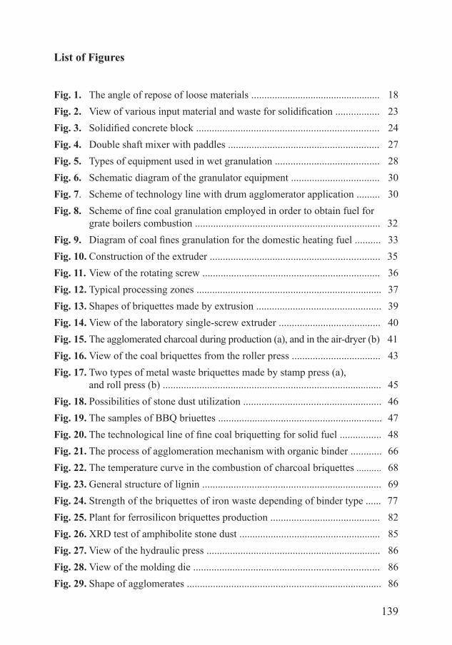
139
List of Figures
Fig. 1. The angle of repose of loose materials .................................................. 18Fig. 2. View of various input material and waste for solidification ................. 23Fig. 3. Solidified concrete block ...................................................................... 24Fig. 4. Double shaft mixer with paddles .......................................................... 27Fig. 5. Types of equipment used in wet granulation ........................................ 28Fig. 6. Schematic diagram of the granulator equipment .................................. 30Fig. 7. Scheme of technology line with drum agglomerator application ......... 30Fig. 8. Scheme of fine coal granulation employed in order to obtain fuel for
grate boilers combustion ....................................................................... 32Fig. 9. Diagram of coal fines granulation for the domestic heating fuel .......... 33Fig. 10. Construction of the extruder ................................................................. 35Fig. 11. View of the rotating screw .................................................................... 36Fig. 12. Typical processing zones ....................................................................... 37Fig. 13. Shapes of briquettes made by extrusion ................................................ 39Fig. 14. View of the laboratory single-screw extruder ....................................... 40Fig. 15. The agglomerated charcoal during production (a), and in the air-dryer (b) 41Fig. 16. View of the coal briquettes from the roller press .................................. 43Fig. 17. Two types of metal waste briquettes made by stamp press (a),
and roll press (b) .................................................................................... 45Fig. 18. Possibilities of stone dust utilization ..................................................... 46Fig. 19. The samples of BBQ briuettes ............................................................... 47Fig. 20. The technological line of fine coal briquetting for solid fuel ................ 48Fig. 21. The process of agglomeration mechanism with organic binder ............ 66Fig. 22. The temperature curve in the combustion of charcoal briquettes .......... 68Fig. 23. General structure of lignin ..................................................................... 69Fig. 24. Strength of the briquettes of iron waste depending of binder type ...... 77Fig. 25. Plant for ferrosilicon briquettes production .......................................... 82Fig. 26. XRD test of amphibolite stone dust ...................................................... 85Fig. 27. View of the hydraulic press ................................................................... 86Fig. 28. View of the molding die ....................................................................... 86Fig. 29. Shape of agglomerates ........................................................................... 86
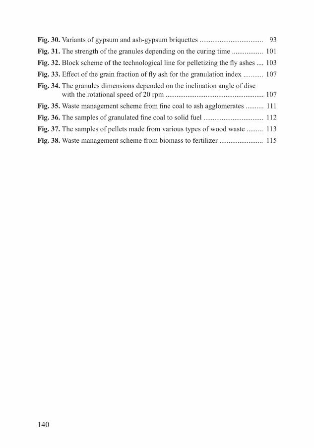
140
Fig. 30. Variants of gypsum and ash-gypsum briquettes ................................... 93Fig. 31. The strength of the granules depending on the curing time ................. 101Fig. 32. Block scheme of the technological line for pelletizing the fly ashes .... 103Fig. 33. Effect of the grain fraction of fly ash for the granulation index ........... 107Fig. 34. The granules dimensions depended on the inclination angle of disc with the rotational speed of 20 rpm ...................................................... 107Fig. 35. Waste management scheme from fine coal to ash agglomerates .......... 111Fig. 36. The samples of granulated fine coal to solid fuel ................................. 112Fig. 37. The samples of pellets made from various types of wood waste ......... 113Fig. 38. Waste management scheme from biomass to fertilizer ........................ 115
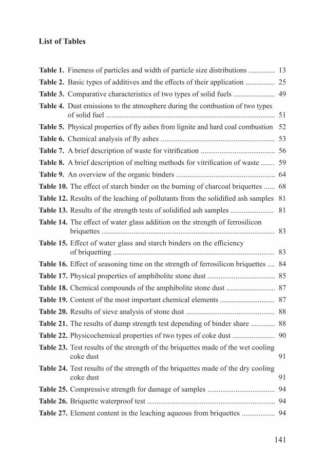
141
List of Tables
Table 1. Fineness of particles and width of particle size distributions .............. 13Table 2. Basic types of additives and the effects of their application ................ 25Table 3. Comparative characteristics of two types of solid fuels ...................... 49Table 4. Dust emissions to the atmosphere during the combustion of two types of solid fuel ........................................................................................... 51Table 5. Physical properties of fly ashes from lignite and hard coal combustion 52Table 6. Chemical analysis of fly ashes ............................................................. 53Table 7. A brief description of waste for vitrification ........................................ 56Table 8. A brief description of melting methods for vitrification of waste ....... 59Table 9. An overview of the organic binders ..................................................... 64Table 10. The effect of starch binder on the burning of charcoal briquettes ...... 68Table 12. Results of the leaching of pollutants from the solidified ash samples 81Table 13. Results of the strength tests of solidified ash samples ....................... 81Table 14. The effect of water glass addition on the strength of ferrosilicon briquettes ............................................................................................. 83Table 15. Effect of water glass and starch binders on the efficiency of briquetting ...................................................................................... 83Table 16. Effect of seasoning time on the strength of ferrosilicon briquettes .... 84Table 17. Physical properties of amphibolite stone dust .................................... 85Table 18. Chemical compounds of the amphibolite stone dust .......................... 87Table 19. Content of the most important chemical elements ............................. 87Table 20. Results of sieve analysis of stone dust ............................................... 88Table 21. The results of dump strength test depending of binder share ............. 88Table 22. Physicochemical properties of two types of coke dust ...................... 90Table 23. Test results of the strength of the briquettes made of the wet cooling coke dust 91Table 24. Test results of the strength of the briquettes made of the dry cooling coke dust 91Table 25. Compressive strength for damage of samples .................................... 94Table 26. Briquette waterproof test .................................................................... 94Table 27. Element content in the leaching aqueous from briquettes .................. 94
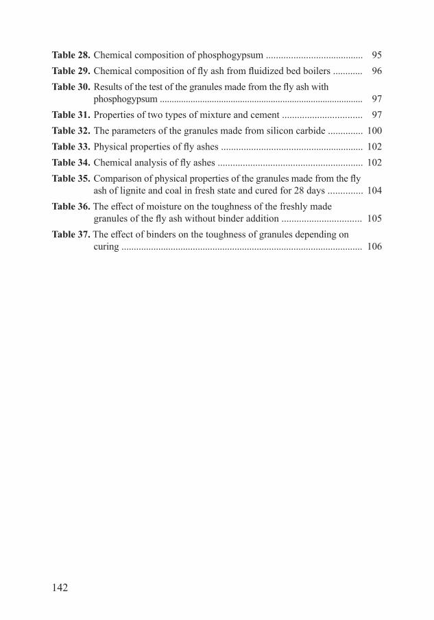
142
Table 28. Chemical composition of phosphogypsum ....................................... 95Table 29. Chemical composition of fly ash from fluidized bed boilers ............ 96Table 30. Results of the test of the granules made from the fly ash with phosphogypsum ...................................................................................... 97Table 31. Properties of two types of mixture and cement ................................ 97Table 32. The parameters of the granules made from silicon carbide .............. 100Table 33. Physical properties of fly ashes ......................................................... 102Table 34. Chemical analysis of fly ashes .......................................................... 102Table 35. Comparison of physical properties of the granules made from the fly ash of lignite and coal in fresh state and cured for 28 days .............. 104Table 36. The effect of moisture on the toughness of the freshly made granules of the fly ash without binder addition ................................ 105Table 37. The effect of binders on the toughness of granules depending on
curing .................................................................................................. 106
143
Abstract
Agglomeration Processes for Waste Utilization in a Circular Economy
Selected agglomeration techniques such as solidification, briquetting, extru-sion and granulation were detailed described in this monograph. The high-tem-perature processing techniques associated with agglomeration processes such as sintering and vitrification were also discussed. On the basis of on numerous examples, it has been shown that the use of agglomeration is effective in the broadly understood waste management processes, in particular for the recovery of natural resources. The agglomerates produced have been fully utilized, bring-ing the effects of waste reduction, dusting prevention, and reuse of many types of particulate materials.
The issues discussed in this book show that agglomeration processes are of great interest for industry to the processing of fine waste materials, owing to the existing well-known and systematically modified merging technologies. The effect of agglomeration processes also involves meeting the principles of a cir-cular economy. The assumptions of this economy have confirmed the legitimacy of using a closed material cycle in nature, both to reduce the consumption of natural resources and fossil fuels, as well as to eliminate pollution and emissions to the environment.
It was found that agglomeration processes are one of the most important tech-niques used in material management. The research and implementation results obtained are model solutions for the problems of waste prevention, reuse and recycling. The widespread implementation of the results presented in the mono-graph may contribute to further scientific progress in environmental engineering, especially in the area of waste management.
144
Streszczenie
Procesy aglomeracji dla wykorzystania odpadów w gospodarce o obiegu zamkniętym
W monografii szczegółowo zaprezentowano wybrane techniki aglomeracji, takie jak zestalanie, brykietowanie, ekstruzja i granulowanie. Omówiono również techniki obróbki wysokotemperaturowej towarzyszące procesom aglomeracji, takie jak spiekanie i zeszkliwienie. Na podstawie licznych przykładów pokazano, że stosowanie procesów aglomeracji jest skuteczne w szeroko rozumianych pro-cesach zagospodarowania odpadów, a w szczególności dla odzyskania zasobów naturalnych. Wytworzone aglomeraty zostały w pełni wykorzystane przynosząc efekty zmniejszenia ilości odpadów, zapobiegania pyleniu oraz ponownego użycia wielu rodzaju materiałów drobnoziarnistych.
Przedstawione w książce zagadnienia wskazały, że przetwarzanie rozdrob-nionych materiałów i odpadów, z wykorzystaniem istniejących dobrze znanych i systematycznie modyfikowanych technik scalania, cieszy się dużym zaintereso-waniem w przemyśle. Efektem zastosowania procesów aglomeracji jest również spełnienie zasad gospodarki o obiegu zamkniętym. Założenia tej gospodarki potwierdziły zasadność stosowania zamkniętego obiegu materiałów w przyrodzie, zarówno dla zmniejszenia zużycia zasobów naturalnych i paliw kopalnych, jak i dla wyeliminowania zanieczyszczeń oraz emisji do środowiska.
Stwierdzono, że procesy aglomeracji stanowią jedną z ważniejszych technik stosowanych w gospodarce materiałowej. Uzyskane rezultaty prac badawczych i wdrożeniowych stanowią modelowe rozwiązania problemów zapobiegania, ponownego użycia i recyklingu odpadów. Powszechne wdrożenie przedstawio-nych w monografii wyników prac może przyczynić się do dalszego postępu nauki w inżynierii środowiska, zwłaszcza w zakresie gospodarki odpadami.
145
MONOGRAFIE KOMITETU INŻYNIERII ŚRODOWISKA Polskiej Akademii Nauk
Nr 1 MIKROORGANIZMY W KSZTAŁTOWANIU JAKOŚCI I UZDATNIANIU WÓD PODZIEMNYCH
Krystyna Olańczuk-Neyman Gdańsk 2001Nr 2 METODY OCENY I PODNOSZENIA NIEZAWODNOŚCI DZIAŁANIA
KOMUNALNYCH SYSTEMÓW ZAOPATRZENIA W WODĘ Artur Wieczysty Kraków 2001Nr 3 UTYLIZACJA ZUŻYTYCH JONITÓW DO REKULTYWACJJI
ZDEGRADOWANYCH UTWORÓW PIASZCZYSTYCH – BADANIA MODELOWE
Mariola Chomczyńska Lublin 2001Nr 4 POJEZIERZE ŁĘCZYŃSKO-WŁODAWSKIE PRZEKSZTAŁCENIE
STRUKTURY EKOLOGICZNEJ KRAJOBRAZU I UWARUNKOWANIA ZAGOSPODAROWANIA PRZESTRZENNEGO
Tadeusz J. Chmielewski Lublin 2001Nr 5 DEGRADACJA ZWIĄZKÓW ORGANICZNYCH ZAWARTYCH
W ODCIEKACH Z WYSYPISK Joanna Surmacz-Górska
Lublin 2001Nr 6 POLICHLOROWANE DIBENZO(P)DIOKSYNY I DIBENZOFURANY
– WŁAŚCIWOŚCI I ODDZIAŁYWANIE NA ŚRODOWISKO Zdzisław Kozak, Marzenna R. Dudzińska
Lublin 2001Nr 7 PESTYCYDY W ŚRODOWISKU I ICH OZNACZENIE METODĄ
CHROMATOGRAFII GAZOWEJ Krystyna Pomorska Lublin 2001Nr 8 ENERGETYCZNE ASPEKTY WYTWARZANIA OZONU DLA
POTRZEB INŻYNIERII ŚRODOWISKA Janusz Ozonek
Lublin 2002Nr 9 INŻYNIERIA ŚRODOWISKA STAN OBECNY I PERSPEKTYWY
ROZWOJU MATERIAŁY NA KONGRES Lublin 2002
146
Nr 10 I KONGRES INŻYNIERII ŚRODOWISKA MATERIAŁY Lublin 2002Nr 11 I KONGRES INŻYNIERII ŚRODOWISKA MATERIAŁY Lublin 2002Nr 12 I KONGRES INŻYNIERII ŚRODOWISKA
RERERATY PROBLEMOWE Lublin 2002
Nr 13 ANALIZA PRCESÓW WYTWARZANIA OZONU DLA POTRZEB OCHRONY ŚRODOWISKA Janusz Ozonek
Lublin 2003Nr 14 WYSTĘPOWANIE I PRZEMIANY POLICHLOROWANYCH
DIBENZO-P-DIOKSYN I DIBENZOFURANÓW W UKŁADACH: OSADY ŚCIEKOWE – GLEBA Marzenna R. Dudzińska
Lublin 2003Nr 15 I KONGRES INŻYNIERII ŚRODOWISKA
MATERIAŁY SUPLEMENT
Lublin 2003Nr 16 FILOZOFICZNE I SPOŁECZNE UWARUNKOWANIA
ZRÓWNOWAŻONEGO ROZWOJU Artur Pawłowski Lublin 2003Nr 17 INŻYNIERSKIE, PRZYRODNICZE I EKONOMICZNE
UWARUNKOWANIA ZRÓWNOWAŻONEGO ROZWOJU Zdzisław Ciećko Lublin 2003Nr 18 POLSKA INŻYNIERIA ŚRODOWISKA INFORMATOR Anna Maria Anielak Lublin 2003Nr 19 UTLENIANIE METANU W WARUNKACH BIOLOGICZNEJ
REKULTYWACJI SKŁADOWISK KOMUNALNYCH PRZYWĘGLOWEJ SKAŁY PŁONNEJ Witold Stępniewski Lublin 2003Nr 20 SPECJACJA W OCHRONIE I INŻYNIERII ŚRODOWISKA Elżbieta Bezak-Mazur Lublin 2004
147
Nr 21 NEW MATERIALS AND TECHNOLOGIES FOR ENVIRONMENTAL ENGINEERING Part I. Syntheses and structure of ion exchange fibers Vladimir Soldatov, Lucjan Pawłowski, Aleksander Shunkevich, Henryk Wasąg Lublin 2004Nr 22 V KONFERENCJA NAUKOWA MEMBRANY I PROCESY MEMBRANOWE W OCHRONIE
ŚRODOWISKA Gliwice 2004Nr 23 HODOWLA SYNCHRONICZNA CHLORELLA VULGARIS W KONTROLI JAKOŚCI WÓD
Anna Czaplicka-Kotas Kraków 2004Nr 24 PROFESOR TOMASZ WINNICKI W NAUCE I ŻYCIU SPOŁECZNYM Lublin 2004Nr 25 OCHRONA I INŻYNIERIA ŚRODOWISKA ZRÓWNOWAŻONY
ROZWÓJ Szkoła Ochrony i Inżynierii Środowiska im. Walerego Goetla Kraków 2004Nr 26 FILOZOFICZNE, SPOŁECZNE I EKONOMICZNE
UWARUNKOWANIA ZRÓWNOWAŻONEGO ROZWOJU Artur Pawłowski Lublin 2004Nr 26 PRZYRODNICZE UWARUNKOWANIA ZRÓWNOWAŻONEGO
ROZWOJU SUPLEMENT Zdzisław Ciećko Lublin 2004Nr 27 PATHWAYS OF POLLUTANTS AND MITIGATION STRATEGIES
OF THEIR IMPACT ON THE ECOSYSTEMS Marzenna R. Dudzińska, Małgorzata Pawłowska Lublin 2004Nr 28 PODSTAWY BEZPIECZEŃSTWA SYSTEMÓW ZAOPATRZENIA
W WODĘ Janusz Rak Lublin 2005Nr 29 TECHNOLOGICZNE PODSTAWY MODERNIZACJI MAŁYCH
OCZYSZCZALNI ŚCIEKÓW Lech Dzienis Białystok 2005
148
Nr 30 XII OGÓLNOPOLSKA KONFERENCJA NAUKOWO-TECHNICZNA Z CYKLU PROBLEMY GOSPODARKI WODNO-ŚCIEKOWEJ W REGIONACH ROLNICZO-PRZEMYSŁOWYCH
MATERIAŁY Lech Dzienis Białystok 2005Nr 31 PROFESOR ANDRZEJ KRÓLIKOWSKI. JUBILEUSZ 50-LECIA PRACY
ZAWODOWEJ, BADAWCZEJ I NAUKOWO-DYDAKTYCZNEJ MATERIAŁY Izabela Bartkowska, Lech Dzienis Białystok 2005Nr 32 II KONGRES INŻYNIERII ŚRODOWISKA MATERIAŁY, TOM I Lublin 2005Nr 33 II KONGRES INŻYNIERII ŚRODOWISKA MATERIAŁY, TOM II Lublin 2005Nr 34 DEVELOPMENT OF INSULATION WITH SPECIALLY DESIGNER
PROPERTIES FOR BUILDING RENOVATION John Grunewald, Henryk Sobczuk Lublin 2005Nr 35 OSADY POWSTAJĄCE W OBIEKTACH SYSTEMU KANALIZACJI
DESZCZOWEJ A. Królikowski, K. Garbarczyk, J. Gwoździej-Mazur, A. Butarewicz Białystok 2005Nr 36 MEMBRANY I PROCESY MEMBRANOWE W OCHRONIE
ŚRODOWISKA Gliwice 2006Nr 37 PODSTAWY MODELOWANIA SYSTEMÓW EKSPLOATACJI
WODOCIĄGÓW I KANALIZACJI Sławczo Danczew Lublin 2006Nr 38 POLSKA INŻYNIERIA ŚRODOWISKA INFORMATOR Anna Maria Anielak Lublin 2007Nr 39 TIME DOMAIN REFLECTOMETRY METHOD IN ENVIRONMENTAL
MEASURMENTS Henryk Sobczuk, Rudolph Plagge Lublin 2007Nr 41 ZINTEGROWANE SYSTEMY ZARZĄDZANIA ENERGIĄ W BUDYNKACH BIUROWYCH Jan Syposz, Piotr Jadwiszczak Lublin 2007
149
Nr 42 BADANIA DOŚWIADCZALNE W ROZWOJU TECHNOLOGII UZDATNIANIA WODY Marek M. Sozański, Peter M. Huck Lublin 2007Nr 43 OCENA WPŁYWU ZABEZPIECZEŃ PRZECIWEROZYJNYCH NA
WARUNKI WILGOTNOŚCIOWE W PROFILU GLEBOWYM Marcin K. Widomski Lublin 2007Nr 44 PROGNOSTYCZNY MODEL URUCHAMIANIA BIOGENNYCH
ZWIĄZKÓW AZOTU I FOSFORU W ERODOWANYCH GLABACH MAŁEJ ZLEWNI LESSOWEJ
Piotr Gliński Lublin 2007Nr 45 BADANIA POLA CIEPLNEGO W HALACH OGRZEWANYCH
PROMIENNIKAMI CERAMICZNYMI Edyta Dudkiewicz, Janusz Jeżowiecki Lublin 2007Nr 46 VI ZJAZD KANALIZATORÓW POLSKICH POLKAN’07 MATERIAŁY M. Zawilski, G. Sakson, G. Mozolewska Lublin 2007Nr 47 ENERGETYCZNE I PROCESOWE ASPEKTY PRODUKCJI I ZASTOSOWAŃ OZONU W TECHNICE J. Ozonek, S. Fijałkowski Lublin 2007Nr 48 OPTOELECTRONIC DIAGNOSTICS OF COMBUSTION PROCESSES.
INSTRUMENTS METHODS OF APPLICATIONS Waldemar Wójcik Lublin 2008Nr 49 MEMBRANY I PROCESY MEMBRANOWE W OCHRONIE
ŚRODOWISKA Krystyna Konieczny, Michał Bodzek Gliwice 2008Nr 50 WYBRANE ZAGADNIENIA Z MODELOWANIA
MATEMATYCZNEGO PROCESU OSADU CZYNNEGO Z. Dymaczewski Poznań 2008Nr 51 ROZWÓJ ZRÓWNOWAŻONY – IDEA, FILOZOFIA, PRAKTYKA Artur Pawłowski Lublin 2008Nr 52 ULTRASŁABA LUMINESCENCJA GLONÓW CHARACEAE JAKO
METODA OCENY ŚRODOWISKA WODNEGO Anna Jaśkowska Lublin 2008
150
Nr 53 PODSTAWY REOLOGII I TRANSPORTU RUROWEGO ZAWIESIN I OSADÓW Z OCZYSZCZANIA WODY I ŚCIEKÓW Zbysław Dymaczewski, Joanna Jeż-Walkowiak, Adam Marlewski, Marek Sozański Poznań 2008Nr 54 PRZYDATNOŚĆ WYBRANYCH BIOINDYKATORÓW DO
OCENY EFEKTYWNOŚCI BIOREMEDIACJI GRUNTÓW ZANIECZYSZCZONYCH WĘGLOWODORAMI
A. Małachowska-Jutsz, K. Miksch Gliwice 2008Nr 55 MECHANIZMY TWORZENIA SIĘ I ROZPRZESTRZENIANIA
ZWIĄZKÓW DIOKSYNOPOCHODNYCH W ŚRODOWISKU Jacek Czerwiński Lublin 2008Nr 56 OGÓLNOPOLSKA KONFERENCJA NAUKOWA. INŻYNIERIA
EKOLOGICZNA Hanna Obarska-Pempkowiak Lublin 2009Nr 57 RETENCJA ZBIRONIKOWA I STEROWANIE DOPŁYWEM ŚCIEKÓW
DO OCZYSZCZALNI Daniel Słyś Lublin, 2009Nr 58 POLSKA INŻYNIERIA ŚRODOWISKA PIĘĆ LAT PO WSTĄPIENIU
DO UNII EUROPEJSKIEJ TOM 1 Janusz Ozonek, Małgorzata Pawłowska Lublin 2009Nr 59 POLSKA INŻYNIERIA ŚRODOWISKA PIĘĆ LAT PO WSTĄPIENIU
DO UNII EUROPEJSKIEJ TOM 2 Janusz Ozonek, Artur Pawłowski Lublin 2009Nr 60 POLSKA INŻYNIERIA ŚRODOWISKA PIĘĆ LAT PO WSTĄPIENIU
DO UNII EUROPEJSKIEJ TOM 3 Marzenna Dudzińska, Lucjan Pawłowski Lublin 2009Nr 61 NOWE METODY REDUKCJI EMISJI ZANIECZYSZCZEŃ I WYKORZYSTANIA PRODUKTÓW UBOCZNYCH OCZYSZCZALNI ŚCIEKÓW Hanna Obarska-Pempkowiak, Lucjan Pawłowski Lublin 2009Nr 62 MEMBRANY I PROCESY MEMBRANOWE W PRACY NAUKOWEJ
PROF. DR HAB. INŻ. MICHAŁA BODZKA Krystyna Konieczny Gliwice 2009
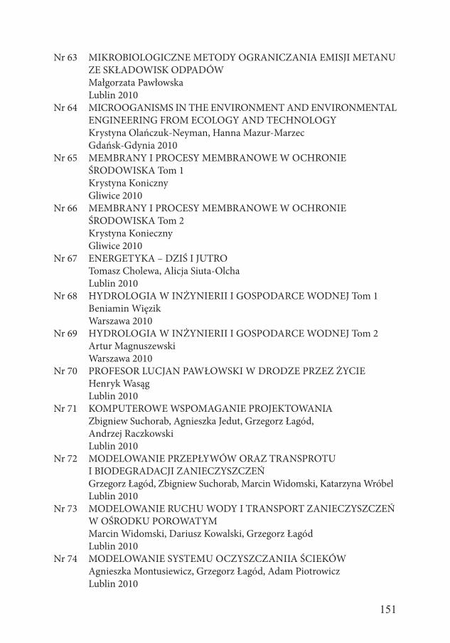
151
Nr 63 MIKROBIOLOGICZNE METODY OGRANICZANIA EMISJI METANU ZE SKŁADOWISK ODPADÓW
Małgorzata Pawłowska Lublin 2010Nr 64 MICROOGANISMS IN THE ENVIRONMENT AND ENVIRONMENTAL
ENGINEERING FROM ECOLOGY AND TECHNOLOGY Krystyna Olańczuk-Neyman, Hanna Mazur-Marzec Gdańsk-Gdynia 2010Nr 65 MEMBRANY I PROCESY MEMBRANOWE W OCHRONIE
ŚRODOWISKA Tom 1 Krystyna Koniczny Gliwice 2010Nr 66 MEMBRANY I PROCESY MEMBRANOWE W OCHRONIE
ŚRODOWISKA Tom 2 Krystyna Konieczny Gliwice 2010Nr 67 ENERGETYKA – DZIŚ I JUTRO Tomasz Cholewa, Alicja Siuta-Olcha Lublin 2010Nr 68 HYDROLOGIA W INŻYNIERII I GOSPODARCE WODNEJ Tom 1 Beniamin Więzik Warszawa 2010Nr 69 HYDROLOGIA W INŻYNIERII I GOSPODARCE WODNEJ Tom 2 Artur Magnuszewski Warszawa 2010Nr 70 PROFESOR LUCJAN PAWŁOWSKI W DRODZE PRZEZ ŻYCIE Henryk Wasąg Lublin 2010Nr 71 KOMPUTEROWE WSPOMAGANIE PROJEKTOWANIA Zbigniew Suchorab, Agnieszka Jedut, Grzegorz Łagód, Andrzej Raczkowski Lublin 2010Nr 72 MODELOWANIE PRZEPŁYWÓW ORAZ TRANSPROTU I BIODEGRADACJI ZANIECZYSZCZEŃ Grzegorz Łagód, Zbigniew Suchorab, Marcin Widomski, Katarzyna Wróbel Lublin 2010Nr 73 MODELOWANIE RUCHU WODY I TRANSPORT ZANIECZYSZCZEŃ
W OŚRODKU POROWATYM Marcin Widomski, Dariusz Kowalski, Grzegorz Łagód Lublin 2010Nr 74 MODELOWANIE SYSTEMU OCZYSZCZANIIA ŚCIEKÓW Agnieszka Montusiewicz, Grzegorz Łagód, Adam Piotrowicz Lublin 2010
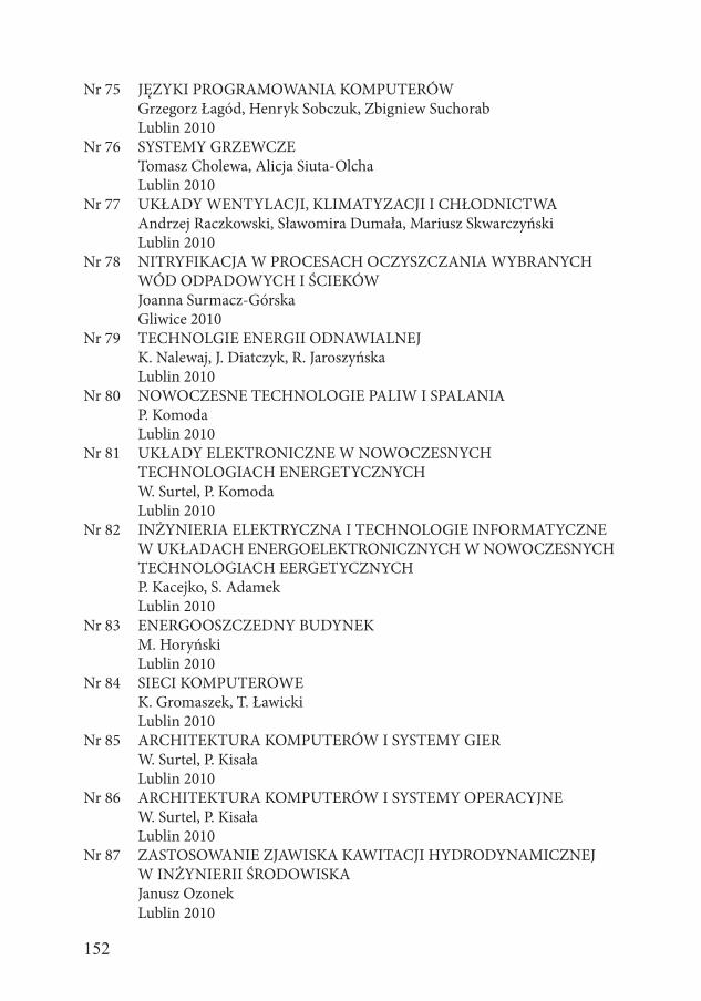
152
Nr 75 JĘZYKI PROGRAMOWANIA KOMPUTERÓW Grzegorz Łagód, Henryk Sobczuk, Zbigniew Suchorab Lublin 2010Nr 76 SYSTEMY GRZEWCZE Tomasz Cholewa, Alicja Siuta-Olcha Lublin 2010Nr 77 UKŁADY WENTYLACJI, KLIMATYZACJI I CHŁODNICTWA Andrzej Raczkowski, Sławomira Dumała, Mariusz Skwarczyński Lublin 2010Nr 78 NITRYFIKACJA W PROCESACH OCZYSZCZANIA WYBRANYCH
WÓD ODPADOWYCH I ŚCIEKÓW Joanna Surmacz-Górska Gliwice 2010Nr 79 TECHNOLGIE ENERGII ODNAWIALNEJ K. Nalewaj, J. Diatczyk, R. Jaroszyńska Lublin 2010Nr 80 NOWOCZESNE TECHNOLOGIE PALIW I SPALANIA P. Komoda Lublin 2010Nr 81 UKŁADY ELEKTRONICZNE W NOWOCZESNYCH
TECHNOLOGIACH ENERGETYCZNYCH W. Surtel, P. Komoda Lublin 2010Nr 82 INŻYNIERIA ELEKTRYCZNA I TECHNOLOGIE INFORMATYCZNE
W UKŁADACH ENERGOELEKTRONICZNYCH W NOWOCZESNYCH TECHNOLOGIACH EERGETYCZNYCH
P. Kacejko, S. Adamek Lublin 2010Nr 83 ENERGOOSZCZEDNY BUDYNEK M. Horyński Lublin 2010Nr 84 SIECI KOMPUTEROWE K. Gromaszek, T. Ławicki Lublin 2010Nr 85 ARCHITEKTURA KOMPUTERÓW I SYSTEMY GIER W. Surtel, P. Kisała Lublin 2010Nr 86 ARCHITEKTURA KOMPUTERÓW I SYSTEMY OPERACYJNE W. Surtel, P. Kisała Lublin 2010Nr 87 ZASTOSOWANIE ZJAWISKA KAWITACJI HYDRODYNAMICZNEJ
W INŻYNIERII ŚRODOWISKA Janusz Ozonek Lublin 2010
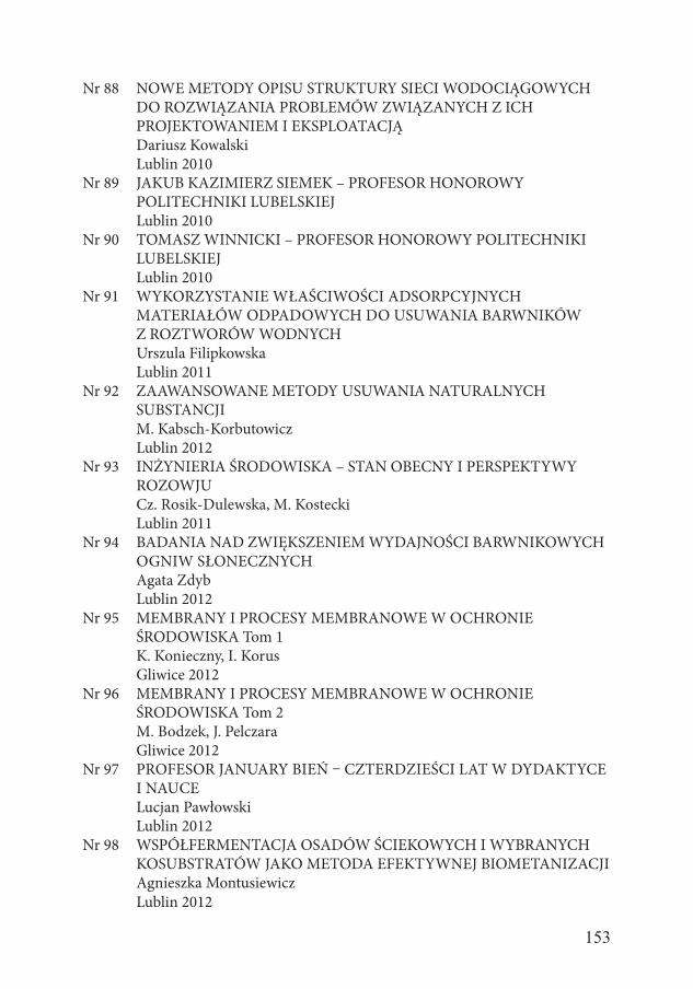
153
Nr 88 NOWE METODY OPISU STRUKTURY SIECI WODOCIĄGOWYCH DO ROZWIĄZANIA PROBLEMÓW ZWIĄZANYCH Z ICH PROJEKTOWANIEM I EKSPLOATACJĄ
Dariusz Kowalski Lublin 2010Nr 89 JAKUB KAZIMIERZ SIEMEK – PROFESOR HONOROWY
POLITECHNIKI LUBELSKIEJ Lublin 2010Nr 90 TOMASZ WINNICKI – PROFESOR HONOROWY POLITECHNIKI
LUBELSKIEJ Lublin 2010Nr 91 WYKORZYSTANIE WŁAŚCIWOŚCI ADSORPCYJNYCH
MATERIAŁÓW ODPADOWYCH DO USUWANIA BARWNIKÓW Z ROZTWORÓW WODNYCH
Urszula Filipkowska Lublin 2011Nr 92 ZAAWANSOWANE METODY USUWANIA NATURALNYCH
SUBSTANCJI M. Kabsch-Korbutowicz Lublin 2012Nr 93 INŻYNIERIA ŚRODOWISKA – STAN OBECNY I PERSPEKTYWY
ROZOWJU Cz. Rosik-Dulewska, M. Kostecki Lublin 2011Nr 94 BADANIA NAD ZWIĘKSZENIEM WYDAJNOŚCI BARWNIKOWYCH
OGNIW SŁONECZNYCH Agata Zdyb Lublin 2012Nr 95 MEMBRANY I PROCESY MEMBRANOWE W OCHRONIE
ŚRODOWISKA Tom 1 K. Konieczny, I. Korus Gliwice 2012Nr 96 MEMBRANY I PROCESY MEMBRANOWE W OCHRONIE
ŚRODOWISKA Tom 2 M. Bodzek, J. Pelczara Gliwice 2012Nr 97 PROFESOR JANUARY BIEŃ – CZTERDZIEŚCI LAT W DYDAKTYCE
I NAUCE Lucjan Pawłowski Lublin 2012Nr 98 WSPÓŁFERMENTACJA OSADÓW ŚCIEKOWYCH I WYBRANYCH
KOSUBSTRATÓW JAKO METODA EFEKTYWNEJ BIOMETANIZACJI Agnieszka Montusiewicz Lublin 2012
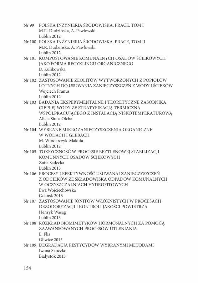
154
Nr 99 POLSKA INŻYNIERIA ŚRODOWISKA. PRACE, TOM I M.R. Dudzińska, A. Pawłowski Lublin 2012Nr 100 POLSKA INŻYNIERIA ŚRODOWISKA. PRACE, TOM II M.R. Dudzińska, A. Pawłowski Lublin 2012Nr 101 KOMPOSTOWANIE KOMUNALNYCH OSADÓW ŚCIEKOWYCH
JAKO FORMA RECYKLINGU ORGANICZNEGO D. Kulikowska Lublin 2012Nr 102 ZASTOSOWANIE ZEOLITÓW WYTWORZONYCH Z POPIOŁÓW
LOTNYCH DO USUWANIA ZANIECZYSZCZEŃ Z WODY I ŚCIEKÓW Wojciech Franus Lublin 2012Nr 103 BADANIA EKSPERYMENTALNE I TEORETYCZNE ZASOBNIKA CIEPŁEJ WODY ZE STRATYFIKACJĄ TERMICZNĄ
WSPÓŁPRACUJĄCEGO Z INSTALACJĄ NISKOTEMPERATUROWĄ Alicja Siuta-Olcha Lublin 2012Nr 104 WYBRANE MIKROZANIECZYSZCZENIA ORGANICZNE W WODACH I GLEBACH M. Włodarczyk-Makuła Lublin 2012Nr 105 TOKSYCZNOŚĆ W PROCESIE BEZTLENOWEJ STABILIZACJI
KOMUNNYCH OSADÓW ŚCIEKOWYCH Zofia Sadecka Lublin 2013Nr 106 PROCESY I EFEKTYWNOŚĆ USUWANAI ZANIECZYSZCZEŃ Z ODCIEKÓW ZE SKŁADOWISKA ODPADÓW KOMUNALNYCH W OCZYSZCZALNIACH HYDROFITOWYCH Ewa Wojciechowska Gdańsk 2013Nr 107 ZASTOSOWANIE JONITÓW WŁÓKNISTYCH W PROCESACH
DEZODORYZACJI I KONTROLI JAKOŚCI POWIETRZA Henryk Wasąg Lublin 2013Nr 108 ROZKŁAD BIOMIMETYKÓW HORMONALNYCH ZA POMOCĄ
ZAAWANSOWANYCH PROCESÓW UTLENIANIA E. Flis Gliwice 2013Nr 109 DEGRADACJA PESTYCYDÓW WYBRANYMI METODAMI Iwona Skoczko Białystok 2013
155
Nr 110 WYKORZYSTANIE SYNTETYCZNYCH ŻYWIC JONOWYMIENNYCH W REKULTYWACJI TERENÓW ZDEGRADOWANYCH
Mariola Chomczyńska Lublin 2013Nr 111 COMPUTER AIDED DESIGNING – 3D MODELING G. Łagód, Z. Suchorab Lublin 2013Nr 112 AEROZOLE W POWIETRZU WEWNĘTRZNYM: ŹRÓDŁA – POZIOMY – PROBLEMY Marzanna Dudzińska Lublin 2013Nr 113 SEPARACJA UCIĄŻLIWYCH ZANIECZYSZCZEŃ ORGANICZNYCH
Z WYKORZYSTANIEM TECHNIK MEMBRANOWYCH Katarzyna Majewska-Nowak WROCŁAW 2013Nr 114 ŻRÓDŁA WĘGLA W PROCESACH BIOLOGICZNEGO USUWANIA
AZOTU I FOSFORU W. Janczukowicz, J. Rodziewicz Lublin 2013Nr 115 WSKAŹNIKI JAKOŚCIOWE SUBSTANCJI ORGANICZNEJ GLEB
ZRÓŻNICOWANYM NAWOŻENIU I ZMIANOWANIU Grażyna Żukowska Lublin 2013Nr 116 ZANIECZYSZCZENIA A JAKOŚĆ POWIETRZA WEWNETRZNEGO
W WYBRANYCH POMIESZCZENIACH Bernard Połednik Lublin 2013Nr 117 BIOSURFACTANTS: GREEN SURFACTANTS Grażyna Płaza Lublin 2014Nr 118 MEMBRANES AND MEMBRANE PROCESSES IN
ENVIRONMENTAL PROTECTION, VOL. I K. Konieczny, I. Korus Lublin 2014Nr 119 MEMBRANES AND MEMBRANE PROCESSES IN
ENVIRONMENTAL PROTECTION, VOL. II M. Bodzek, J. Pelczar Lublin 2014Nr 120 ZASTOSOWANIE ZEOLITÓW DO SEPARACJI CO2 I Hg Z GAZÓW ODLOTOWYCH W PROCESACH WYCHWYTYWANIA I SKŁADOWANIA DITLENKU WĘGLA Magdalena Wdowin Lublin 2015
156
Nr 121 WYKORZYSTANIE TUFÓW ZEOLITOWYCH W INŻYNIERII ŚRODOWISKA
W. Franus, A. Pawłowski Lublin 2015Nr 122 OBIEG WYBRANYCH MAKROPIERWIASTKÓW I ZWIĄZKÓW
BIOGENNYCH W SYSTEMIE RZECZNO-JEZIORNYM NA PRZYKŁADZIE GÓRNEJ PASŁĘKI Jolanta Grochowska Lublin 2015Nr 123 INCINERATION OF WASTE IN A ROTARY KILN Janusz W. Bujak Lublin 2015Nr 124 PIENIĄDZE I ZRÓWNOWAŻONY ROZWÓJ: BRAKUJĄCE OGNIWO Lublin 2016Nr 125 OCENA ZRÓWNOWAŻONOŚCI SYSTEMÓW SOLARNYCH
OPARTA NA ANALIZIE CYKLU ŻYCIA Agnieszka Żelazna Lublin 2016Nr 126 NEW MATERIAL SOLUTIONS FOR PLASMA REACTOR Sebastian Gnapowski Lublin 2017Nr 127 SUSTAINABILITY OF COMPACTED CLAY LINERS AND SELECTED
PROPERTIES OF CLAY Marcin Widomski Lublin 2016Nr 128 DROGA PRZEZ ŻYCIE PROFESORA TADEUSZA PIECUCHA: 70 ROCZNICA URODZIN 4.06.2016 r. Lublin 2016Nr 129 INFORMATOR INŻYNIERII ŚRODOWISKA A. Anielak, M. Cimochowicz-Rybicka Lublin 2016Nr 130 METODY POMIARU GĘSTOŚCI STRUMIENIA CIEPŁA I STRAT
CIEPŁA W BUDOWNICTIWE I CIEPŁOWNICTWIE Krzysztof Wojdyga Warszawa 2016Nr 131 OKREŚLENIE POZIOMU AKTYWNOŚCI SZTUCZNEGO 137Cs I NATURLANEGO 40K ORAZ WYBRANYCH METALI CIĘŻKICH W GLEBACH, NIEKTÓRYCH ROŚLINACH I W OSADACH
DENNYCH AKWENÓW WODNYCH NA OBSZARACH POLSKI POŁUDNIOWEJ Barbara Kubica Lublin 2016
157
Nr 132 UTYLIZACJA WYBRANYCH ODPADÓW W PRODUKCJI SPIEKANYCH KRUSZYW LEKKICH
Małgorzata Franus Lublin 2016Nr 133 ZASTOSOWANIE TECHNIKI REFLAKTOMETRII W DOMENIE
CZASU DO OCENY STANU ZAWILGOCENIA PRZEGRÓD BUDOWLANYCH Zbigniew Suchorab Lublin 2016Nr 134 DEPOZYCJA PM10 PODCZAS OPADÓW ATMOSFERYCZNYCH Tomasz Olszowski Lublin 2017Nr 135 ZASTOSOWANIE ZEOLITÓW SYNTETYCZNYCH Z POPIOŁÓW
LOTNYCH W INŻYNIERII ŚRODOWISKA Wojciech Franus Lublin 2017Nr 136 BIOINDYKACJA W KONTROLI PROCESU OCZYSZCZANIA ŚCIEKÓW Grzegorz Łagód Lublin 2017Nr 137 ANALIZA OPADÓW ATMOSFERYCZNYCH DLA POTRZEB PROJEKTOWANIA SYSTEMÓW ODWODNIENIA Paweł Licznar Lublin 2018Nr 138 METALE CIĘŻKIE W ODCIEKACH I ŚCIEKACH TECHNOLO- GICZNYCH ZE SKŁADOWISK ODPADÓW KOMUNALNYCH W ASPEKCIE ZMIAN SPOSOBÓW ICH ZAGOSPODAROWANIA Eliza Kulbat GDAŃSK 2018Nr 139 EFEKTYWNOŚĆ EKONOMICZNA I ENERGETYCZNA W BUDOWNICTWIE JEDNORODZINNYM Jan Danielewicz Lublin 2018Nr 140 FOSFOR W INTERFAZIE WODA-OSADY DENNE JEZIOR
ZMIENIONYCH ANTROPOGENICZNIE NA TLE WYBRANYCH FIZYKO-CHEMICZNYCH I MIKROBIOLOGICZNYCH CZYNNIKÓW
ŚRODOWISKOWYCH KSZTAŁTUJĄCYCH PROCESY JEGO WYMIANY POMIĘDZY OSADAMI A WODĄ Renata Augustyniak Lublin 2018Nr 141 BAKTERIOCENOZA PŁYTKIEGO LITORALU ZATOKI PUCKIEJ W REJONIE WYSTĘPOWANIA PODMORSKIEGO DRENAŻU WÓD
PODZIEMNYCH Katarzyna Jankowska Gdańsk 2018
158
Nr 142 ZDOLNOŚCI SORPCYJNE WYBRANYCH SUBSTANCJI BOGATYCH W MATERIĘ ORGANICZNĄ W STOSUNKU DO BARWNIKÓW
A. Dzieniszewska, J. Kyzioł-Komosińska Lublin 2018Nr 143 ZANIECZYSZCZENIE OSADÓW DENNYCH METALAMI CIĘŻKIMI
– METODY OCENY E. Kulbat, A. Sokołowska Lublin 2018Nr 144 ZANIECZYSZCZENIA POWIETRZA W POLSCE: STAN, PRZYCZYNY,
SKUTKI Lucjan Pawłowski Lublin 2018Nr 145 ZASTOSOWANIE ZIELONEJ INFRASTRUKTURY DO OGRANICZANIA ZANIECZYSZCZEŃ POWIERZCHNIOWYCH W ZLEWNI MIEJSKIEJ Ewa Wojciechowska Lublin 2018Nr 146 METODY WYZNACZANIA ZASIĘGU STREF ZAGROŻENIA
POWODOWANEGO PRZEZ ROZSZCZELNIENIE PODZIEMNYCH PRZEWODÓW WODOCIĄGOWYCH
Małgorzata Iwanek Lublin 2018Nr 147 ZASTOSOWANIE SPEKTROSKOPII IR W INŻYNIERII ŚRODOWISKA Sylwia Pasieczna-Padkowska Lublin 2019Nr 148 REKULTYWACJA JEZIOR – TEORIA I PRAKTYKA Julita A. Dunalska Olsztyn 2019Nr 149 USUWANIE ZANIECZYSZCZEŃ I STABILIZACJA OSADÓW
ŚCIEKOWYCH W SYSTEMACH TRZCINOWYCH Katarzyna Kołecka Gdańsk 2019Nr 150 ZŁOŻA HYDROFITOWE Z PIONOWYM PRZEPŁYWEM ŚCIEKÓW. CHARAKTERYSTYKA PROCESÓW I ZASTOSOWAŃ Magdalena Gajewska Gdańsk 2019Nr 151 FILTRACJA WODY W TEORII I PRAKTYCE Iwona Skoczko Warszawa 2019Nr 152 OPERATION FLEXIBILITY OF HEAT PUMPS IN SMART DISTRICT
HEATING Marderos Ara Sayegh Lublin 2019
159
Nr 153 ANALIZA MOŻLIWOŚCI WYKORZYSTANIA POFERMENTU JAKO ŹRÓDŁA BIODOSTĘPNEGO FOSFORU Agnieszka Tuszyńska Warszawa 2019Nr 154 ANALIZA TERMICZNEJ PRZERÓBKI BIOMASY Paweł Komada Warszawa 2019Nr 155 ANALIZA I ZASTOSOWANIE MODELU ADM1 DO SYMULACJI
FERMENTACJI I WSPÓŁFERMENTACJI KISZONEK ROŚLINNYCH I WYBRANYCH KOSUBSTRATÓW Katarzyna Bułkowska Warszawa 2019Nr 156 DIFFERENT MATERIAL SOLUTIONS FOR THE REACTOR
ELECTRODES Sebastian Gnapowski Warszawa 2019Nr 157 NASTĘPCZY WPŁYW KOMPOSTÓW Z OSADU I OSADOWO-
-POPIOŁOWYCH NA KSZTAŁTOWANIE WŁAŚCIWOŚCI REKULTYWOWANEJ GLEBY INDUSTRIOZIEMNEJ
Marta Bik-Małodzińska Warszawa 2019Nr 158 MATERIAL-RELATED IMPACT OF THERMOPLASTIC PIPES ON
QUALITY OF DISTRIBUTED WATER Beata Kowalska Warszawa 2019Nr 159 STEROWANIE PROGNOZOWE DOSTAWĄ CIEPŁA NA POTRZEBY
OGRZEWANIA Tomasz Cholewa Warszawa 2019Nr 160 DYNAMIKA ZMIAN WYBRANYCH GRUP BAKTERII AKTYWNYCH
W OCZYSZCZANIU ODCIEKÓW SKŁADOWISKOWYCH W REAKTORZE SBR Łukasz Jurczyk Warszawa 2019Nr 161 ŹRÓDŁA ZANIECZYSZCZEŃ MIKROBIOLOGICZNYCH WÓD
RZEKI ŁYNY Anna Gotkowska-Płachta Warszawa 2019Nr 162 PROFESOR JAN OLCHOWIK WE WSPOMNIENIACH PRZYJACIÓŁ Lucjan Pawłowski Warszawa 2019Nr 163 INNOWACJE W INŻYNIERII ŚRODOWISKA Hanna Obarska-Pempkowiak Warszawa 2019
160
Nr 164 ZANIECZYSZCZENIA WÓD W POLSCE. STAN, PRZYCZYNY, SKUTKI
Marek Gromiec, Lucjan Pawłowski Warszawa 2019Nr 165 ZAAWANSOWANE TECHNOLOGIE USUWANIA
FARMACEUTYKÓW ZE ŚCIEKÓW A. Łuczkiewicz, S. Fudala-Książek, K. Jankowska, M. Szopińska, O. Svahn,
T.J. Ränckner, A. Kaiser, G. Garnaga-Budrė, V. Langas, E. Björklund Warszawa 2019Nr 166 OCENA GOSPODARKI W ZAKRESIE ŚCIEKÓW I OSADÓW
ŚCIEKOWYCH W POLSCE Marek Gromiec, Lucjan Pawłowski Warszawa 2020


