Embed Size (px)
Citation preview
AMIT RAMJI 10241445 A2
AMIT RAMJI – A2 – 10241445 – AEROSPACE DESIGN – MAJOR TASK 2 – DIVE BRAKE
%AMIT RAMJI - 10241445 - A2 - UNIVERSITY OF HERTFORDSHIRE
%Aerospace Design Major Task 2 - Dive Brake Calculations
clear %clear all variables
clc %clear command window
%%%Projected Area Calculations
theta=0:5:45;%setting up row array of operating angles in degrees
L=1.864; %length in meters of dive brake from pivot to tip, for dive brake
area and hinge block
W=1.365; %width of dive brake in meters, constant.
H=L*sind(theta); %working in degrees, vertical distance between tip and
meeting fuselage
A=W*H; %projected area of cross section from 5 to 45 degrees in m^2
%%%Force Calculations
%to calculate drag force, F=Cd*0.5*p*v^2*A where Cd is the drag
coefficient, p is the fluid density, v is velocity of fluid (or object
travelling through it) and A is the projected cross sectional area.
p=1.226; %density of air (assumed at operating altitude-but shouldn't make
much difference) in kg/m^3
Cd=0.7; %drag coefficient
V=180; %max velocity in m/s
F=(1/2)*Cd*p*(V^2)*A; %calculated drag force in Newton’s due to movement
through air at 0 to 45 degrees
%%%Centroid Calculations, Dive brake assumed to be an equivalent
rectangular shape.
Wc=W/2; %position of centroid across width of dive brake
Lc=L/2; %position of centroid along length of dive brake
Hc=H/2; %position of centroid along height
%%%Moment calculations
g=9.81; %ms^-2;
mass=15; %kg
M=(F.*Hc+(mass*g*(1/2)*L*cosd(theta))); %moment about hinge pivot due to
drag force at centroid. Using ".*" for element wise multiplication. With
the sum of force added for the mass of dive brake,15kg
%The mg component's distance can also be found using (1/2)*H/tan(theta),
but since we just calculated the distance for H, we will not use this for
best practice to avoid errors.
Phi=[9.029,19.820,30.732,41.799,53.066,64.608,76.546,89.108,102.809,119.451
]; %angle which jack arm makes with spine rail.
G=2.40289; %GradientBetweenthetaAndPhi
C=9.029; %constant (i.e. value of phi at theta=0)
%Phi=[G*theta()+C] %Can Also use this line instead of above Phi but we have
measured phi so why not use it, so we will not need to go back to change
the theta matrix above.
%Phi is actually a function of theta, when theta changes, so does Phi, by a
predictable amount.
Lj=0.498; %Distance from hinge pivot to jack arm pivot
B=Lj*sind(Phi); % Perpendicular distance from line of force to pivot
%F*Hc=Fj*B, To balance moments about Hinge pivot,
(ForceDueToDrag*PerpendicularDistanceOfForceToHingePivot =
JackForce*PependicularDistanceOfForceToHingePivot)
%Perpendicular as moment calculations are cross product vectors.
%So now Arm Jack force required is; F=M(drag)/B
Fja=M./B;% Arm Jack force, which is made up of x and y coordinates, this
jack will be place in the x direction so the jack force must be made up of
entirely vectors in x direction.
Psi=180-(90-theta)-Phi; %angle the jack arm makes with vertical axis
(yaxis).
Psi=90-(theta-Phi); %equivalent angle to the above Psi
%now Psi can be used along with force of jack arm and work out x component,
%as the y component is provided by the rails and underneath structure.
Fjx=Fja.*sind(Psi); %Jack force made up only of horizontal component
AMIT RAMJI – A2 – 10241445 – AEROSPACE DESIGN – MAJOR TASK 2 – DIVE BRAKE
Fjy=Fja.*cosd(90-Psi); %NON ESSENTIAL BUT TO GIVE AN IDEA %Forces in member
in the y direction, provided by brackets and structure
FYstructure=max(Fjy) %%NON ESSENTIAL BUT TO GIVE AN IDEA %MAX Force in
member in the y direction, provided by brackets and structure
% Stress analysis and bending moment of steel rail was carried out, gave
sag of 1.729mm which meant increasing rail height(cross section)and adding
bracket.
%%% Efficiency Calculations.
X0=535.499; %distance of trolley from datum (forward end of rod)
x=[X0-X0,X0-524.847,X0-505.547,X0-477.394,X0-440.122,X0-393.308,X0-
336.191,X0-267.209,X0-182.552,X0-68.363]; %distance travveled by jack, it
is x0-value due to direction chosen as positive.
FJack=Fjx/1000; %to get jack force in KN (kilo Newtons)
%when plotting for efficiency it does not
matter which units are used as a ratio of
areas are to be used, but for convenience
let us use mm for
%extension and KN for jack force.
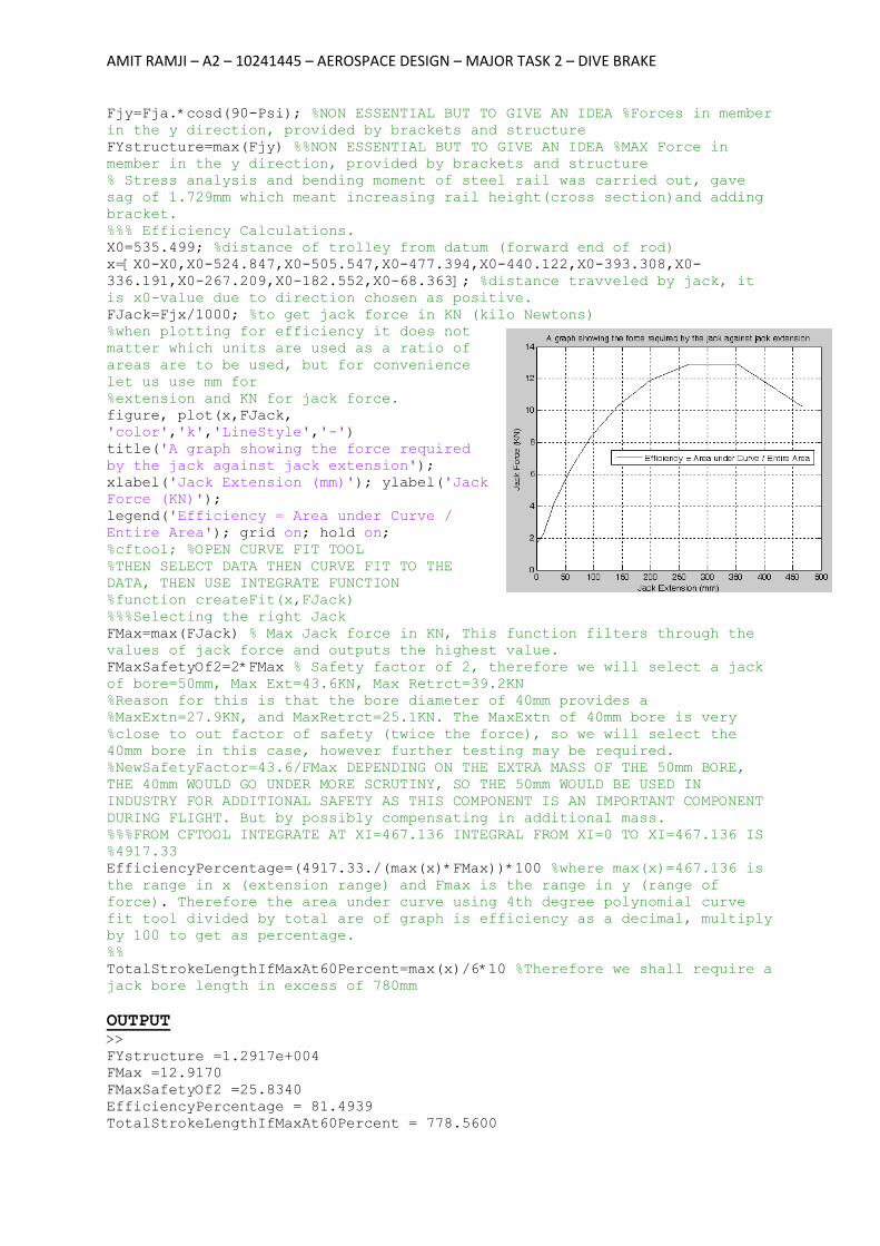
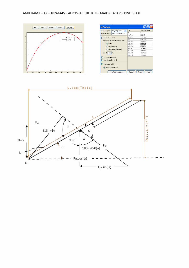
figure, plot(x,FJack,
'color','k','LineStyle','-')
title('A graph showing the force required
by the jack against jack extension');
xlabel('Jack Extension (mm)'); ylabel('Jack
Force (KN)');
legend('Efficiency = Area under Curve /
Entire Area'); grid on; hold on;
%cftool; %OPEN CURVE FIT TOOL
%THEN SELECT DATA THEN CURVE FIT TO THE
DATA, THEN USE INTEGRATE FUNCTION
%function createFit(x,FJack)
%%%Selecting the right Jack
FMax=max(FJack) % Max Jack force in KN, This function filters through the
values of jack force and outputs the highest value.
FMaxSafetyOf2=2*FMax % Safety factor of 2, therefore we will select a jack
of bore=50mm, Max Ext=43.6KN, Max Retrct=39.2KN
%Reason for this is that the bore diameter of 40mm provides a
%MaxExtn=27.9KN, and MaxRetrct=25.1KN. The MaxExtn of 40mm bore is very
%close to out factor of safety (twice the force), so we will select the
40mm bore in this case, however further testing may be required.
%NewSafetyFactor=43.6/FMax DEPENDING ON THE EXTRA MASS OF THE 50mm BORE,
THE 40mm WOULD GO UNDER MORE SCRUTINY, SO THE 50mm WOULD BE USED IN
INDUSTRY FOR ADDITIONAL SAFETY AS THIS COMPONENT IS AN IMPORTANT COMPONENT
DURING FLIGHT. But by possibly compensating in additional mass.
%%%FROM CFTOOL INTEGRATE AT XI=467.136 INTEGRAL FROM XI=0 TO XI=467.136 IS
%4917.33
EfficiencyPercentage=(4917.33./(max(x)*FMax))*100 %where max(x)=467.136 is
the range in x (extension range) and Fmax is the range in y (range of
force). Therefore the area under curve using 4th degree polynomial curve
fit tool divided by total are of graph is efficiency as a decimal, multiply
by 100 to get as percentage.
%%
TotalStrokeLengthIfMaxAt60Percent=max(x)/6*10 %Therefore we shall require a
jack bore length in excess of 780mm
OUTPUT >>
FYstructure =1.2917e+004
FMax =12.9170
FMaxSafetyOf2 =25.8340
EfficiencyPercentage = 81.4939
TotalStrokeLengthIfMaxAt60Percent = 778.5600
AMIT RAMJI – A2 – 10241445 – AEROSPACE DESIGN – MAJOR TASK 2 – DIVE BRAKE
θ
φ φ
180-(90-θ)-φ
90-θ ψ
Lj.Sin(φ)
Lj
Fja
Fja.sin(ψ)
Fja.cos(ψ)
Hc/2
Fair
O
AH BG
DE CF BG AH
33
22
44
11
This drawing is our property; it can't be reproduced or communicated without our written agreement.
SCALE
1:1WEIGHT (kg) DRAWING NUMBER
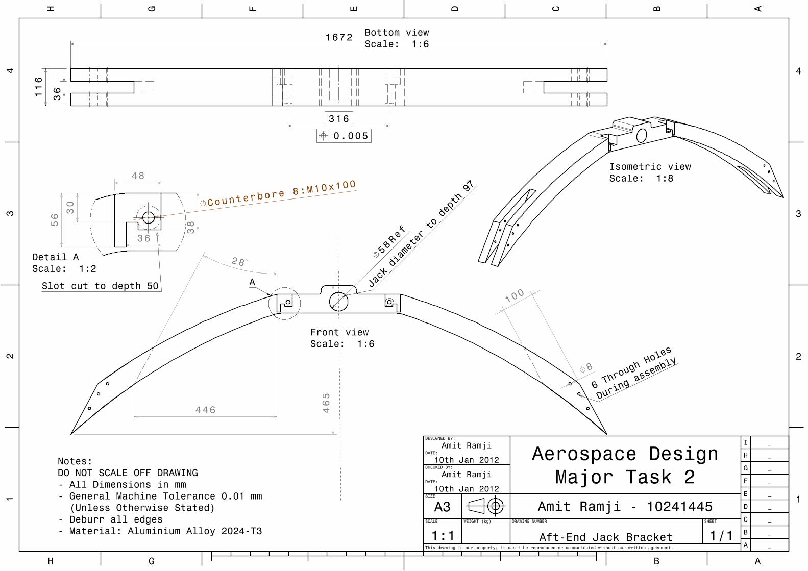
Aft-End Jack Bracket
SHEET
1/1
SIZE
A3 Amit Ramji - 10241445
CHECKED BY:
Amit RamjiDATE:
10th Jan 2012
DESIGNED BY:
Amit RamjiDATE:
10th Jan 2012 Aerospace Design Major Task 2
A _
B _
C _
D _
E _
F _
G _
H _
I _
Notes:DO NOT SCALE OFF DRAWING- All Dimensions in mm- General Machine Tolerance 0.01 mm (Unless Otherwise Stated)- Deburr all edges- Material: Aluminium Alloy 2024-T3
Isometric viewScale: 1:8
58Ref
28
446
100
8
465
Front viewScale: 1:6
6 Thro
ugh Ho
les
During
assem
bly
Jack diameter to depth 97
A
36
1672116
316
Bottom viewScale: 1:6
0.005
56
36
48
Counterbore 8:
M10x100
30
38
Detail AScale: 1:2
Slot cut to depth 50
AH BG
DE CF BG AH
33
22
44
11
This drawing is our property; it can't be reproduced or communicated without our written agreement.
SCALE
1:1WEIGHT (kg) DRAWING NUMBER
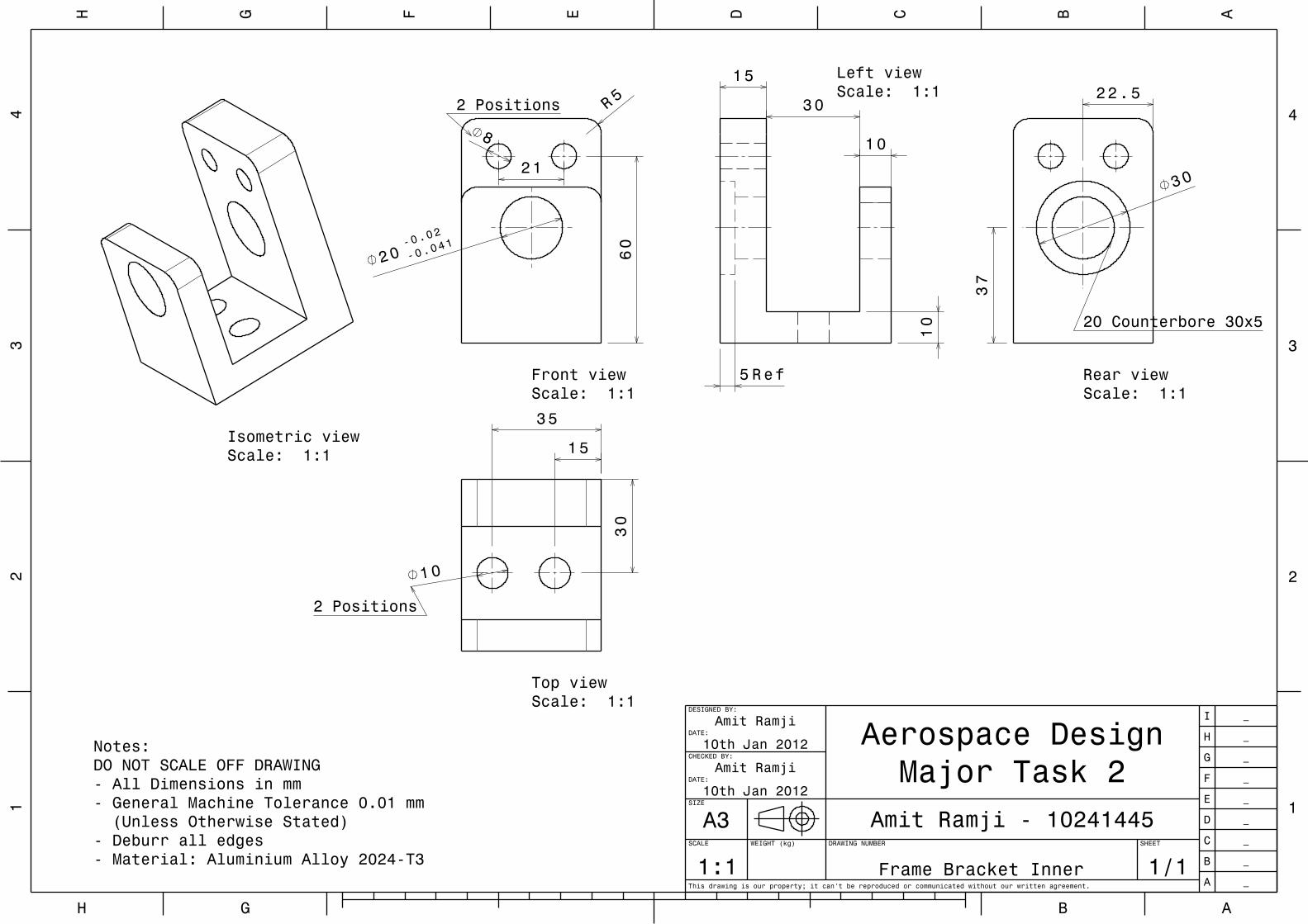
Frame Bracket Inner
SHEET
1/1
SIZE
A3 Amit Ramji - 10241445
CHECKED BY:
Amit RamjiDATE:
10th Jan 2012
DESIGNED BY:
Amit RamjiDATE:
10th Jan 2012 Aerospace Design Major Task 2
A _
B _
C _
D _
E _
F _
G _
H _
I _
Notes:DO NOT SCALE OFF DRAWING- All Dimensions in mm- General Machine Tolerance 0.01 mm (Unless Otherwise Stated)- Deburr all edges- Material: Aluminium Alloy 2024-T3
Isometric viewScale: 1:1
5R
20-0.
02
-0.041
8
21
60
Front viewScale: 1:1
2 Positions 30
10
10
15
5 Ref
Left viewScale: 1:1
30
37
22.5
Rear viewScale: 1:1
20 Counterbore 30x5
10
30
15
35
Top viewScale: 1:1
2 Positions
AH BG
DE CF BG AH
33
22
44
11
This drawing is our property; it can't be reproduced or communicated without our written agreement.
SCALE
1:1WEIGHT (kg) DRAWING NUMBER
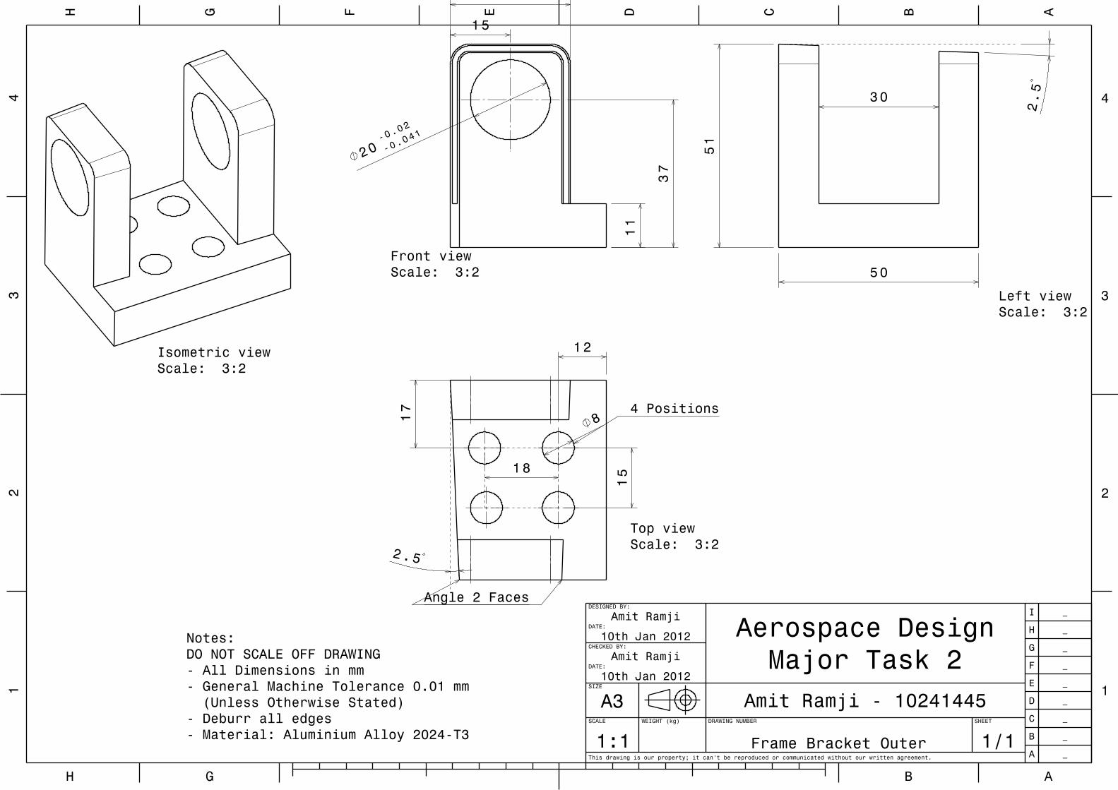
Frame Bracket Outer
SHEET
1/1
SIZE
A3 Amit Ramji - 10241445
CHECKED BY:
Amit RamjiDATE:
10th Jan 2012
DESIGNED BY:
Amit RamjiDATE:
10th Jan 2012 Aerospace Design Major Task 2
A _
B _
C _
D _
E _
F _
G _
H _
I _
Notes:DO NOT SCALE OFF DRAWING- All Dimensions in mm- General Machine Tolerance 0.01 mm (Unless Otherwise Stated)- Deburr all edges- Material: Aluminium Alloy 2024-T3
Isometric viewScale: 3:2
20-0
.02
-0.0
41
11
3 0
37
15
Front viewScale: 3:2
2.5
30
51
50
Left viewScale: 3:2
2.5
8
12
15
17
1 8
Top viewScale: 3:2
4 Positions
Angle 2 Faces
AH BG
DE CF BG AH
33
22
44
11
This drawing is our property; it can't be reproduced or communicated without our written agreement.
SCALE
1:1WEIGHT (kg) DRAWING NUMBER
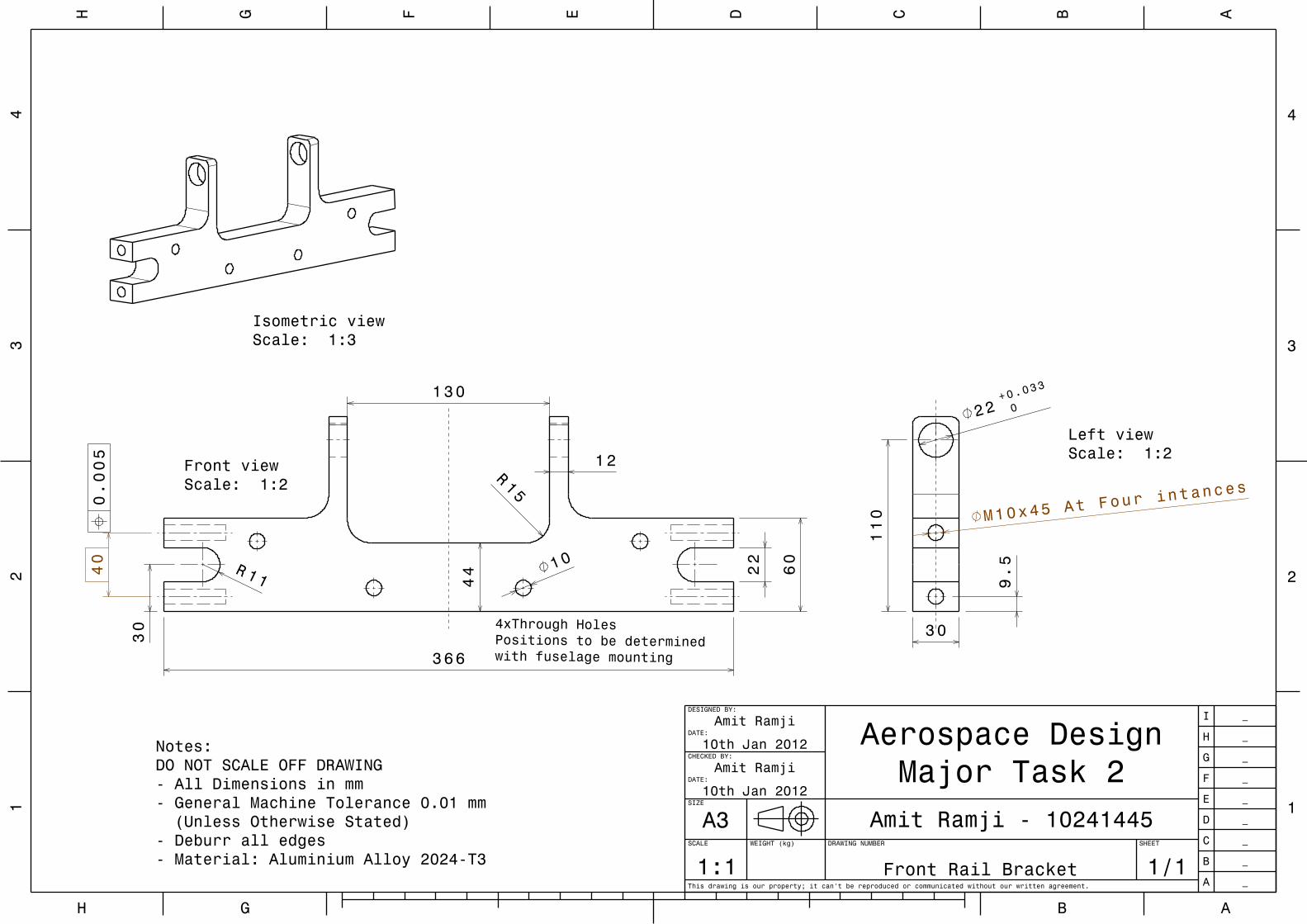
Front Rail Bracket
SHEET
1/1
SIZE
A3 Amit Ramji - 10241445
CHECKED BY:
Amit RamjiDATE:
10th Jan 2012
DESIGNED BY:
Amit RamjiDATE:
10th Jan 2012 Aerospace Design Major Task 2
A _
B _
C _
D _
E _
F _
G _
H _
I _
Notes:DO NOT SCALE OFF DRAWING- All Dimensions in mm- General Machine Tolerance 0.01 mm (Unless Otherwise Stated)- Deburr all edges- Material: Aluminium Alloy 2024-T3
Isometric viewScale: 1:3
366
60
2210
130
44
15R
11R
12
30
40
Front viewScale: 1:2
4xThrough HolesPositions to be determined with fuselage mounting
0.005
3 0
9.5
22+0.
033
0
M10x45 At Four i
ntances
110
Left viewScale: 1:2
AH BG
DE CF BG AH
33
22
44
11
This drawing is our property; it can't be reproduced or communicated without our written agreement.
SCALE
1:1WEIGHT (kg) DRAWING NUMBER
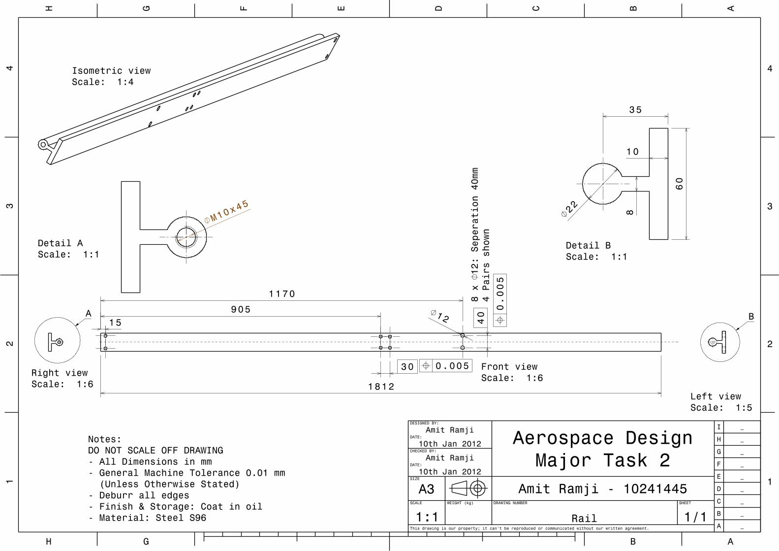
Rail
SHEET
1/1
SIZE
A3 Amit Ramji - 10241445
CHECKED BY:
Amit RamjiDATE:
10th Jan 2012
DESIGNED BY:
Amit RamjiDATE:
10th Jan 2012 Aerospace Design Major Task 2
A _
B _
C _
D _
E _
F _
G _
H _
I _
Notes:DO NOT SCALE OFF DRAWING- All Dimensions in mm- General Machine Tolerance 0.01 mm (Unless Otherwise Stated)- Deburr all edges- Finish & Storage: Coat in oil- Material: Steel S96
1812
30
90515
1170
4012
Front viewScale: 1:6
8 x 12: Seperation 40mm
4 Pairs shown
0.005
0 .005
Isometric viewScale: 1:4
Left viewScale: 1:5
B
Right viewScale: 1:6
A
M10x45
Detail AScale: 1:1
35
60
822
10
Detail BScale: 1:1
AH BG
DE CF BG AH
33
22
44
11
This drawing is our property; it can't be reproduced or communicated without our written agreement.
SCALE
1:1WEIGHT (kg) DRAWING NUMBER
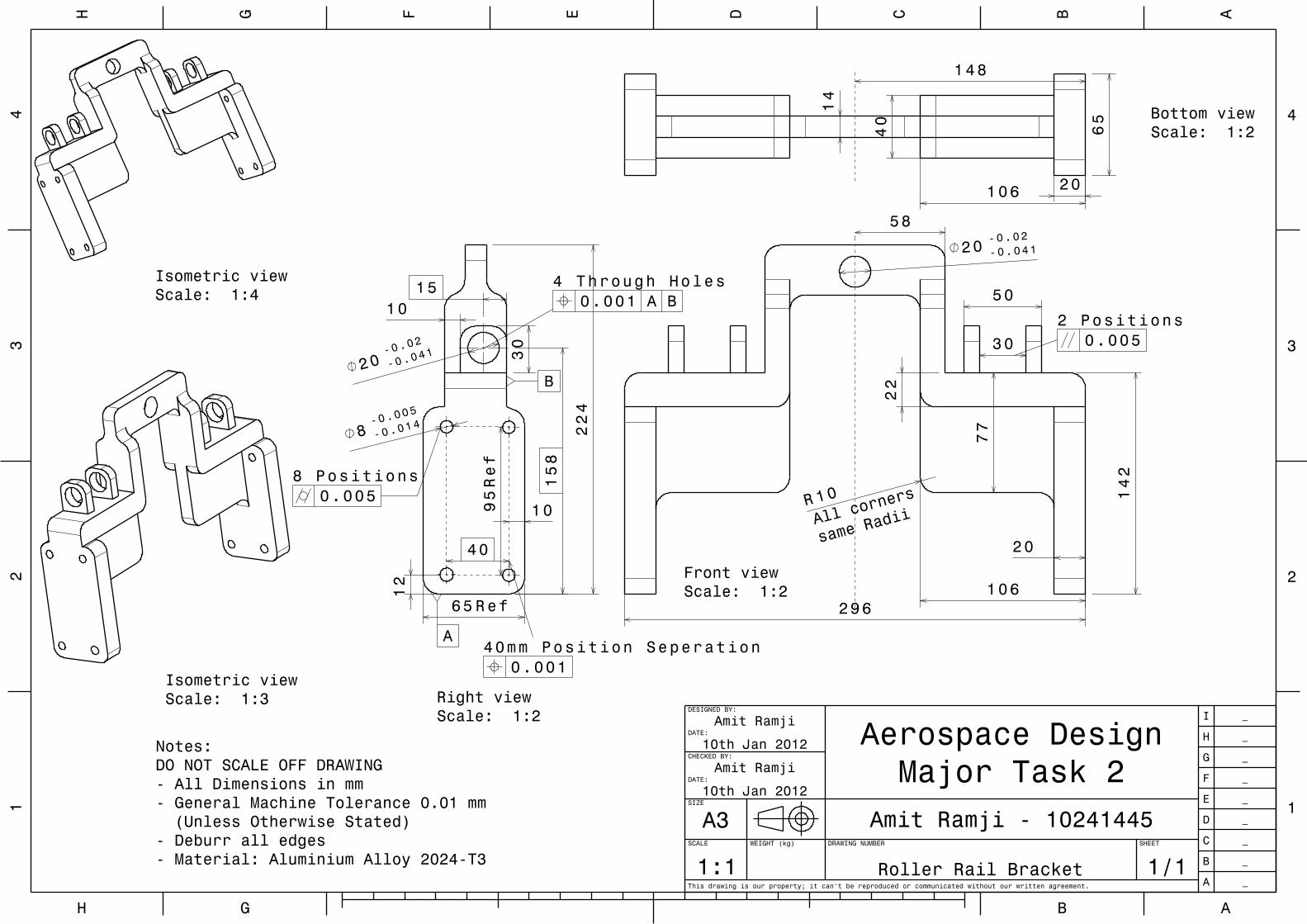
Roller Rail Bracket
SHEET
1/1
SIZE
A3 Amit Ramji - 10241445
CHECKED BY:
Amit RamjiDATE:
10th Jan 2012
DESIGNED BY:
Amit RamjiDATE:
10th Jan 2012 Aerospace Design Major Task 2
A _
B _
C _
D _
E _
F _
G _
H _
I _
Notes:DO NOT SCALE OFF DRAWING- All Dimensions in mm- General Machine Tolerance 0.01 mm (Unless Otherwise Stated)- Deburr all edges- Material: Aluminium Alloy 2024-T3
Isometric viewScale: 1:4
296
20
142
50
30
20-0.02-0.041
22
77
5 8
106
10R
Front viewScale: 1:2
All corn
ers
same Rad
ii
2 Positions0.005
65 Ref
224
30
8-0.0
05
-0.014
40
95Ref
2 0-0.
02
-0.041
158
1 0
10
12
15
Right viewScale: 1:2
8 Positions0.005
40mm Position Seperation0.001
4 Through Holes0.001 A B
A
B
14
40
65
1 48
20106
Bottom viewScale: 1:2
Isometric viewScale: 1:3
AH BG
DE CF BG AH
33
22
44
11
This drawing is our property; it can't be reproduced or communicated without our written agreement.
SCALE
1:1WEIGHT (kg) DRAWING NUMBER
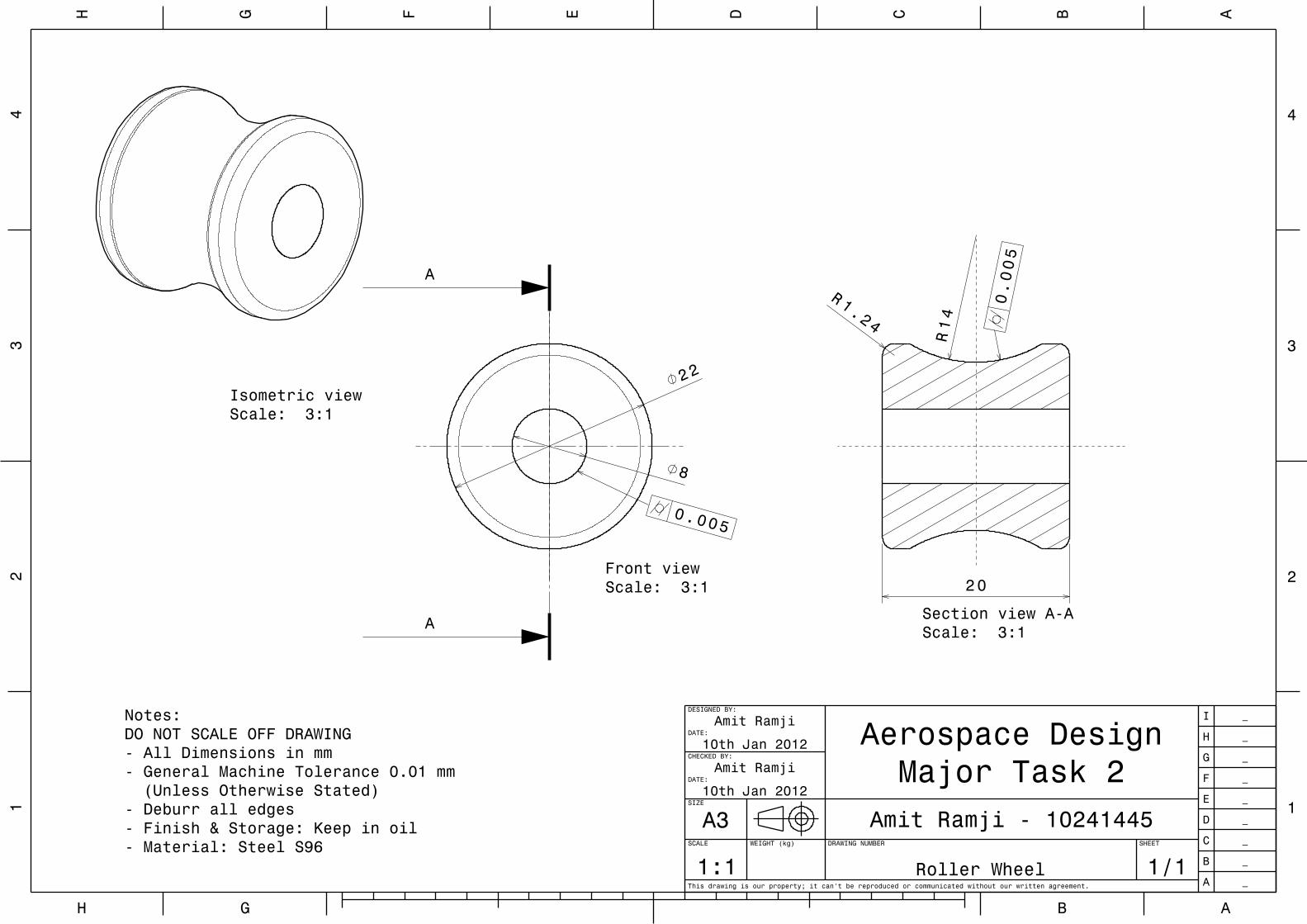
Roller Wheel
SHEET
1/1
SIZE
A3 Amit Ramji - 10241445
CHECKED BY:
Amit RamjiDATE:
10th Jan 2012
DESIGNED BY:
Amit RamjiDATE:
10th Jan 2012 Aerospace Design Major Task 2
A _
B _
C _
D _
E _
F _
G _
H _
I _Notes:DO NOT SCALE OFF DRAWING- All Dimensions in mm- General Machine Tolerance 0.01 mm (Unless Otherwise Stated)- Deburr all edges- Finish & Storage: Keep in oil- Material: Steel S96
Isometric viewScale: 3:1
22
8
Front viewScale: 3:1
0.005
A
A
14
R
1.24
R
Section view A-AScale: 3:1
0.005
20
AH BG
DE CF BG AH
33
22
44
11
This drawing is our property; it can't be reproduced or communicated without our written agreement.
SCALE
1:1WEIGHT (kg) DRAWING NUMBER
Rail Jack Bracket
SHEET
1/1
SIZE
A3 Amit Ramji - 10241445
CHECKED BY:
Amit RamjiDATE:
10th Jan 2012
DESIGNED BY:
Amit RamjiDATE:
10th Jan 2012 Aerospace Design Major Task 2
A _
B _
C _
D _
E _
F _
G _
H _
I _
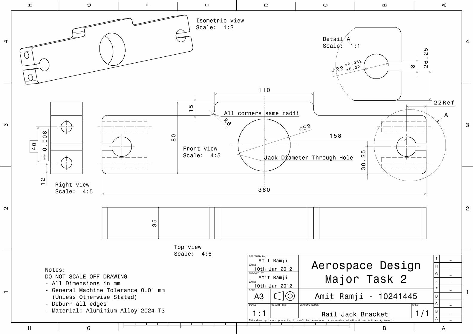
Notes:DO NOT SCALE OFF DRAWING- All Dimensions in mm- General Machine Tolerance 0.01 mm (Unless Otherwise Stated)- Deburr all edges- Material: Aluminium Alloy 2024-T3
Isometric viewScale: 1:2
360
58
110
80
15
30.25
2 2 Ref
158
6R
Front viewScale: 4:5
All corners same radii
Jack Diameter Through Hole
A
35
Top viewScale: 4:5
8
22+0.0
52
+0.02 2
6.25
Detail AScale: 1:1
40
12
Right viewScale: 4:5
0.008
AH BG
DE CF BG AH
33
22
44
11
This drawing is our property; it can't be reproduced or communicated without our written agreement.
SCALE
1:1WEIGHT (kg) DRAWING NUMBER
Vertical Y-Arm
SHEET
1/1
SIZE
A3 Amit Ramji - 10241445
CHECKED BY:
Amit RamjiDATE:
10th Jan 2012
DESIGNED BY:
Amit RamjiDATE:
10th Jan 2012 Aerospace Design Major Task 2
A _
B _
C _
D _
E _
F _
G _
H _
I _
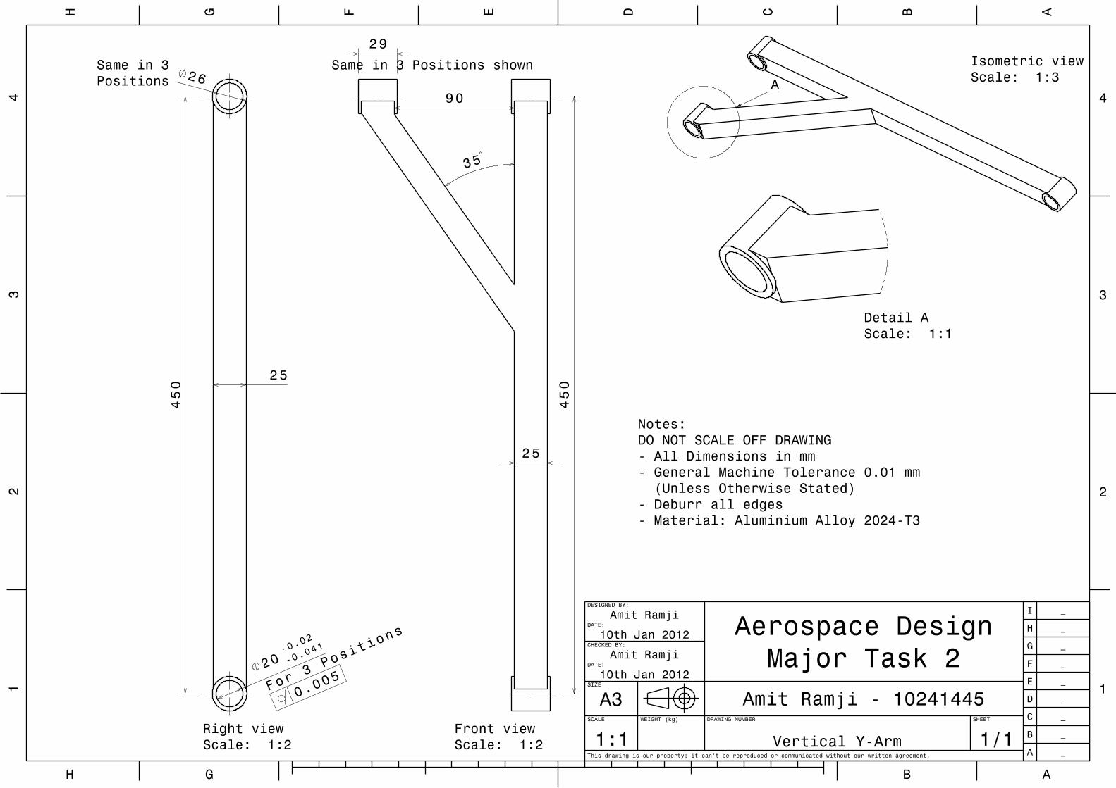
Notes:DO NOT SCALE OFF DRAWING- All Dimensions in mm- General Machine Tolerance 0.01 mm (Unless Otherwise Stated)- Deburr all edges- Material: Aluminium Alloy 2024-T3
Isometric viewScale: 1:3A
29
90
25
35
450
Front viewScale: 1:2
Same in 3 Positions shown
450
20-0.
02
-0.041
26
25
Right viewScale: 1:2
For 3
Positi
ons
0.005
Same in 3Positions
Detail AScale: 1:1
AH BG
DE CF BG AH
33
22
44
11
This drawing is our property; it can't be reproduced or communicated without our written agreement.
SCALE
1:1WEIGHT (kg) DRAWING NUMBER
Dive Brake Assembly
SHEET
1/1
SIZE
A3 Amit Ramji - 10241445
CHECKED BY:
Amit RamjiDATE:
10th Jan 2012
DESIGNED BY:
Amit RamjiDATE:
10th Jan 2012 Aerospace Design Major Task 2
A _
B _
C _
D _
E _
F _
G _
H _
I _
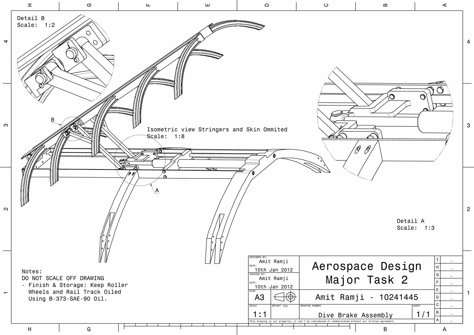
Notes:DO NOT SCALE OFF DRAWING- Finish & Storage: Keep Roller Wheels and Rail Track Oiled Using B-373-SAE-90 Oil.
Isometric view Stringers and Skin OmmitedScale: 1:8
A
B
Detail AScale: 1:3
Detail BScale: 1:2
AH BG
DE CF BG AH
33
22
44
11
This drawing is our property; it can't be reproduced or communicated without our written agreement.
SCALE
1:1WEIGHT (kg) DRAWING NUMBER
Dive Brake Assembly 2
SHEET
1/1
SIZE
A3 Amit Ramji - 10241445
CHECKED BY:
Amit RamjiDATE:
10th Jan 2012
DESIGNED BY:
Amit RamjiDATE:
10th Jan 2012 Aerospace Design Major Task 2
A _
B _
C _
D _
E _
F _
G _
H _
I _
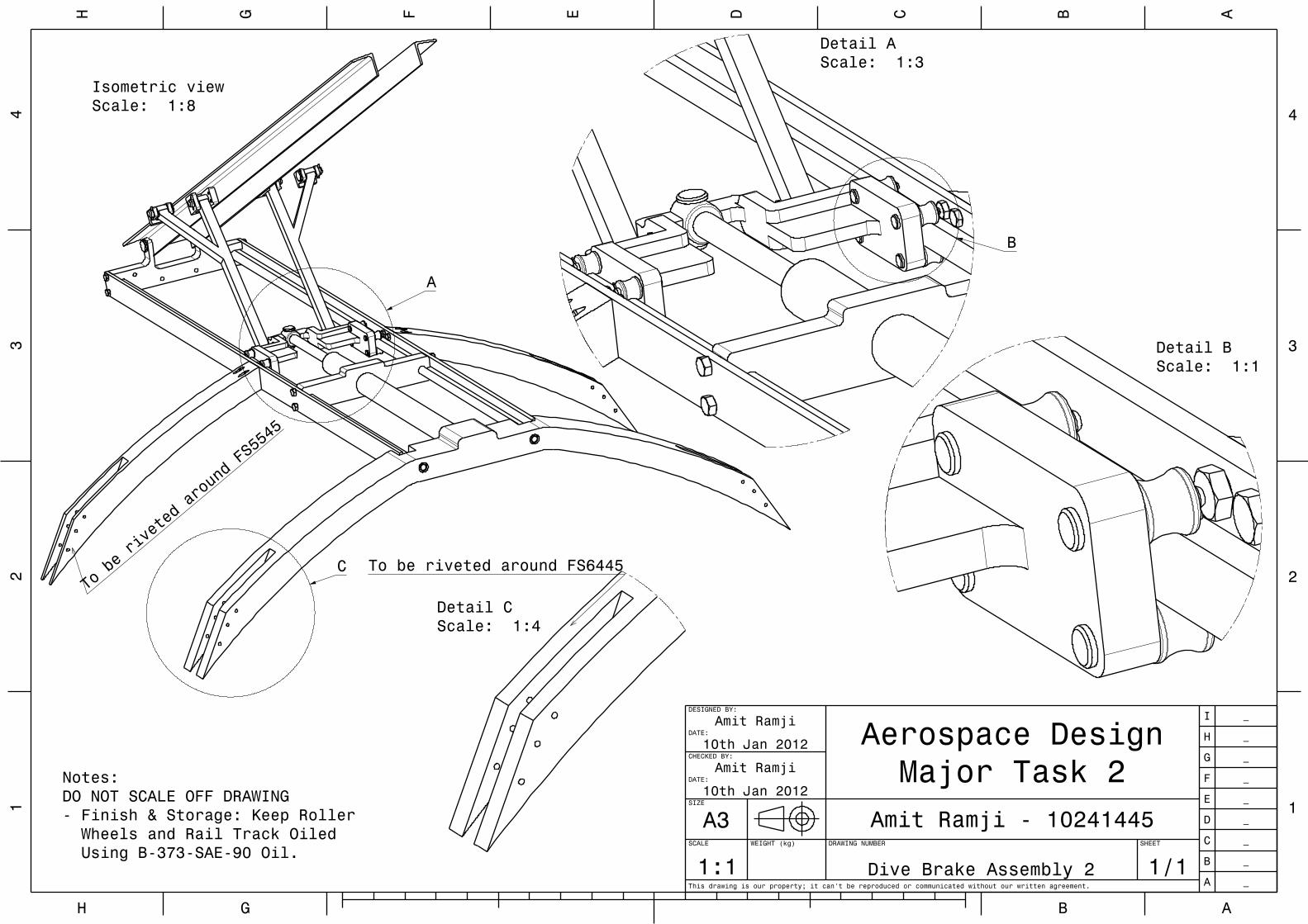
Notes:DO NOT SCALE OFF DRAWING- Finish & Storage: Keep Roller Wheels and Rail Track Oiled Using B-373-SAE-90 Oil.
Isometric viewScale: 1:8
To be riveted around FS6445To be riveted around FS5545
A
C
Detail AScale: 1:3
B
Detail BScale: 1:1
Detail CScale: 1:4
AH BG
DE CF BG AH
33
22
44
11
This drawing is our property; it can't be reproduced or communicated without our written agreement.
SCALE
1:1WEIGHT (kg) DRAWING NUMBER
Dive Brake Assembly
SHEET
1/1
SIZE
A3 Amit Ramji - 10241445
CHECKED BY:
Amit RamjiDATE:
10th Jan 2012
DESIGNED BY:
Amit RamjiDATE:
10th Jan 2012 Aerospace Design Major Task 2
A _
B _
C _
D _
E _
F _
G _
H _
I _
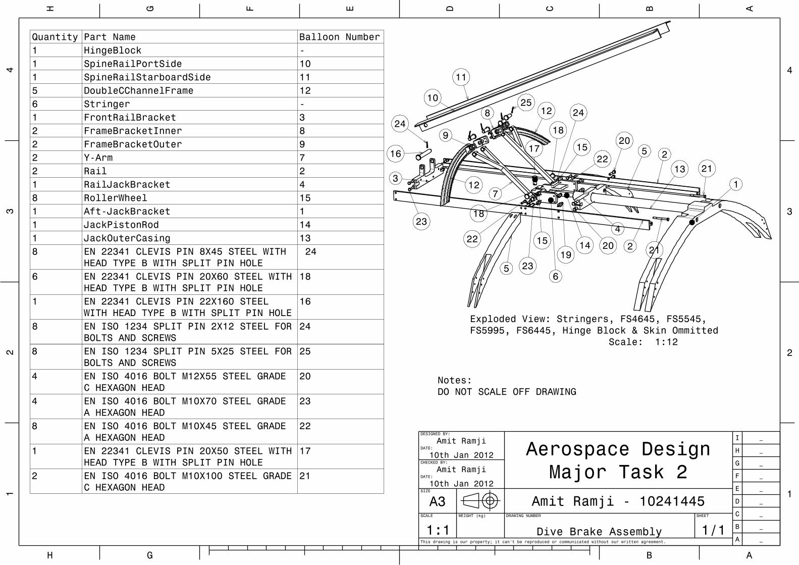
Notes:DO NOT SCALE OFF DRAWING
Exploded View: Stringers, FS4645, FS5545, FS5995, FS6445, Hinge Block & Skin Ommitted Scale: 1:12
1
2
2
3
4
5
5
6
7
8
9
10
11
12
12
13
1415
1516 17
18
18
1920 21
22
23
24
20
2122
23
2425
Quantity Part Name Balloon Number1 HingeBlock -1 SpineRailPortSide 101 SpineRailStarboardSide 115 DoubleCChannelFrame 126 Stringer -1 FrontRailBracket 32 FrameBracketInner 82 FrameBracketOuter 92 Y-Arm 72 Rail 21 RailJackBracket 48 RollerWheel 151 Aft-JackBracket 11 JackPistonRod 141 JackOuterCasing 138 EN 22341 CLEVIS PIN 8X45 STEEL WITH
HEAD TYPE B WITH SPLIT PIN HOLE 24
6 EN 22341 CLEVIS PIN 20X60 STEEL WITHHEAD TYPE B WITH SPLIT PIN HOLE
18
1 EN 22341 CLEVIS PIN 22X160 STEELWITH HEAD TYPE B WITH SPLIT PIN HOLE
16
8 EN ISO 1234 SPLIT PIN 2X12 STEEL FORBOLTS AND SCREWS
24
8 EN ISO 1234 SPLIT PIN 5X25 STEEL FORBOLTS AND SCREWS
25
4 EN ISO 4016 BOLT M12X55 STEEL GRADEC HEXAGON HEAD
20
4 EN ISO 4016 BOLT M10X70 STEEL GRADEA HEXAGON HEAD
23
8 EN ISO 4016 BOLT M10X45 STEEL GRADEA HEXAGON HEAD
22
1 EN 22341 CLEVIS PIN 20X50 STEEL WITHHEAD TYPE B WITH SPLIT PIN HOLE
17
2 EN ISO 4016 BOLT M10X100 STEEL GRADEC HEXAGON HEAD
21
AH BG
DE CF BG AH
33
22
44
11
This drawing is our property; it can't be reproduced or communicated without our written agreement.
SCALE
1:1WEIGHT (kg) DRAWING NUMBER
Dive Brake Assembly
SHEET
1/1
SIZE
A3 Amit Ramji - 10241445
CHECKED BY:
Amit RamjiDATE:
10th Jan 2012
DESIGNED BY:
Amit RamjiDATE:
10th Jan 2012 Aerospace Design Major Task 2
A _
B _
C _
D _
E _
F _
G _
H _
I _
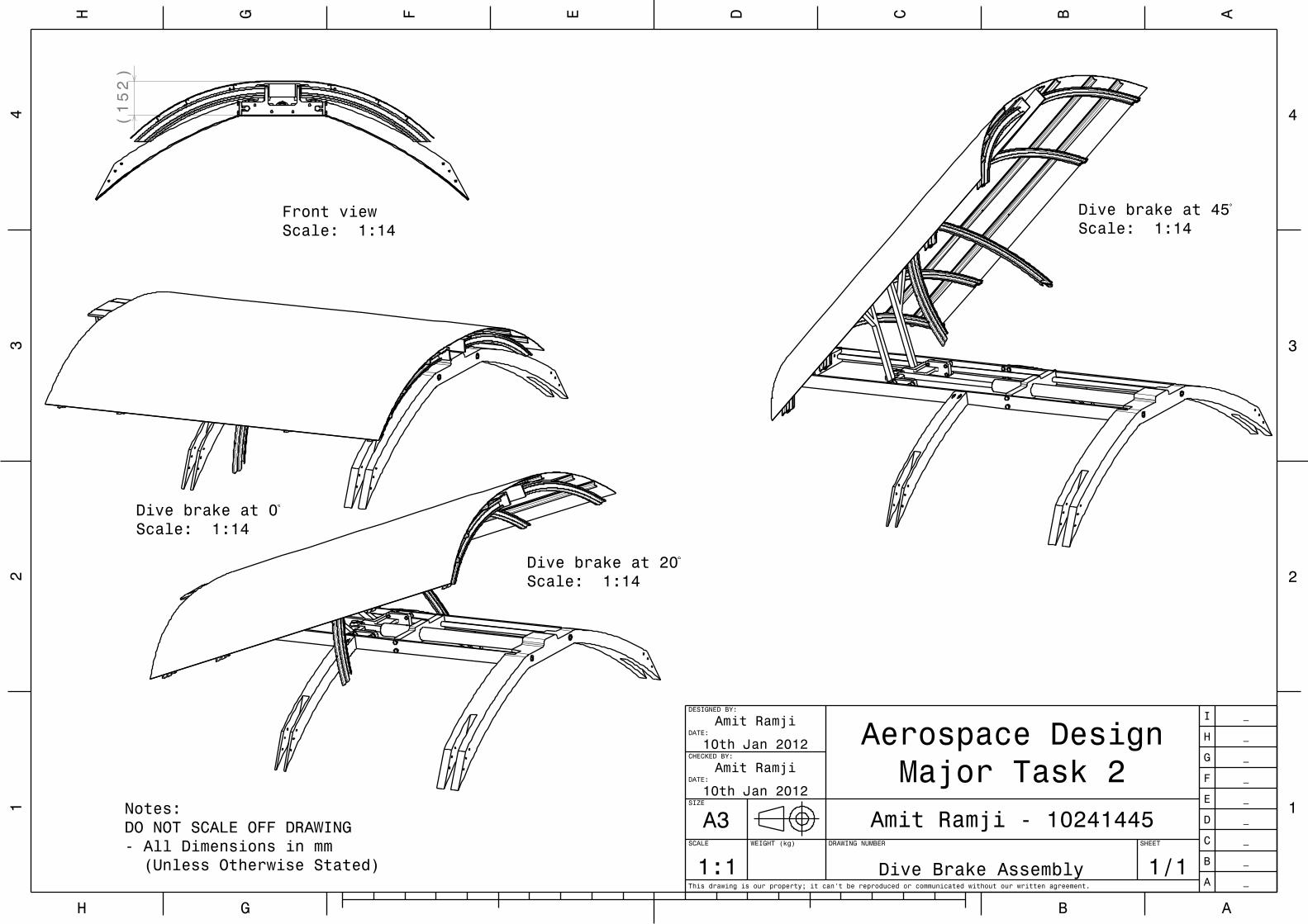
Notes:DO NOT SCALE OFF DRAWING- All Dimensions in mm (Unless Otherwise Stated)
Dive brake at 45Scale: 1:14
Dive brake at 20Scale: 1:14
Dive brake at 0Scale: 1:14
152
()
Front viewScale: 1:14