Embed Size (px)
Citation preview
IN DEGREE PROJECT ,SECOND CYCLE, 30 CREDITS
, STOCKHOLM SWEDEN 2016
Achieving Performance for Compute Intensive Services in Cloud SaaS
JAWAD MUSTAFA
KTH ROYAL INSTITUTE OF TECHNOLOGYSCHOOL OF INFORMATION AND COMMUNICATION TECHNOLOGY
Achieving Performance forCompute Intensive Services in
Cloud SaaSUppna prestanda for berakningsintensiva tjanster i Cloud SaaS
Jawad [email protected]
Master of Science Thesis
External Supervisor: Mats BergstromExaminer and Internal Supervisor: Johan Montelius
Software Engineering of Distributed SystemsSchool of Information and Communication Technology
KTH Royal Institute of TechnologyStockholm, Sweden
June 18, 2016

List of Acronyms
CIS Compute Intensive Services
IaaS Infrastructure as a Service
PaaS Platform as a Service
SaaS Software as a Service
AWS Amazon Web Services
API Application Programming Interface
SLA Service Level Agreement
EC2 Elastic Compute Cloud
ELB Elastic Load Balancing
ASG Auto Scaling Group
CF Cloud Formation
LC Launch Configuration
AMI Amazon Machine Images
S3 AWS Simple Storage Service
CRT Cache Routing Table
EU European Union
2
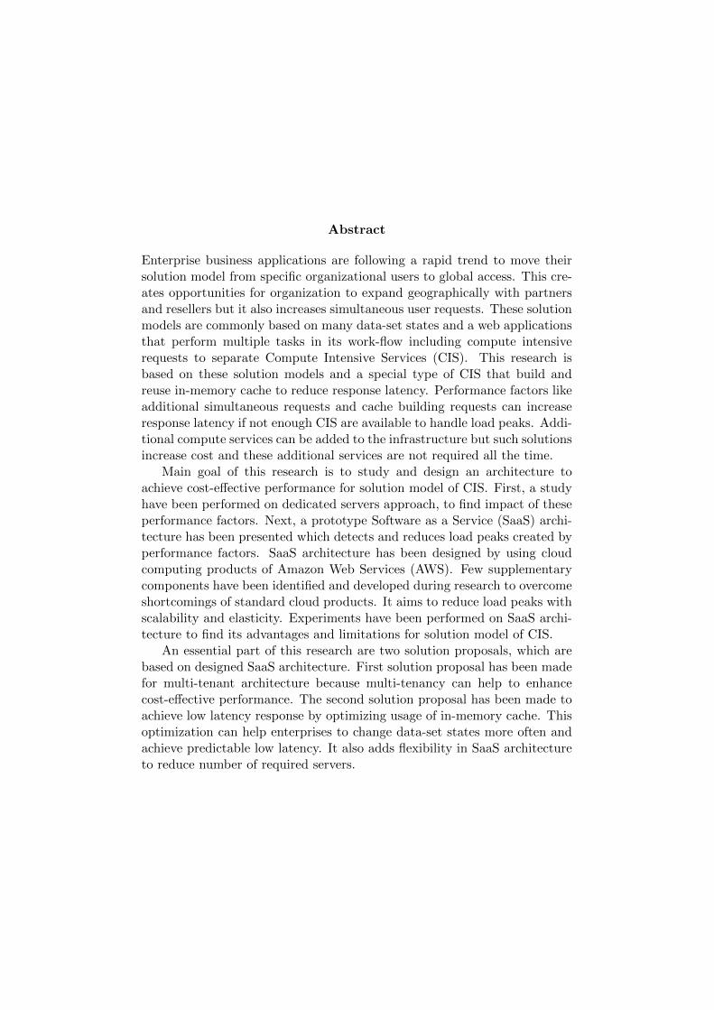
Abstract
Enterprise business applications are following a rapid trend to move theirsolution model from specific organizational users to global access. This cre-ates opportunities for organization to expand geographically with partnersand resellers but it also increases simultaneous user requests. These solutionmodels are commonly based on many data-set states and a web applicationsthat perform multiple tasks in its work-flow including compute intensiverequests to separate Compute Intensive Services (CIS). This research isbased on these solution models and a special type of CIS that build andreuse in-memory cache to reduce response latency. Performance factors likeadditional simultaneous requests and cache building requests can increaseresponse latency if not enough CIS are available to handle load peaks. Addi-tional compute services can be added to the infrastructure but such solutionsincrease cost and these additional services are not required all the time.
Main goal of this research is to study and design an architecture toachieve cost-effective performance for solution model of CIS. First, a studyhave been performed on dedicated servers approach, to find impact of theseperformance factors. Next, a prototype Software as a Service (SaaS) archi-tecture has been presented which detects and reduces load peaks created byperformance factors. SaaS architecture has been designed by using cloudcomputing products of Amazon Web Services (AWS). Few supplementarycomponents have been identified and developed during research to overcomeshortcomings of standard cloud products. It aims to reduce load peaks withscalability and elasticity. Experiments have been performed on SaaS archi-tecture to find its advantages and limitations for solution model of CIS.
An essential part of this research are two solution proposals, which arebased on designed SaaS architecture. First solution proposal has been madefor multi-tenant architecture because multi-tenancy can help to enhancecost-effective performance. The second solution proposal has been made toachieve low latency response by optimizing usage of in-memory cache. Thisoptimization can help enterprises to change data-set states more often andachieve predictable low latency. It also adds flexibility in SaaS architectureto reduce number of required servers.
Sammanfattning
Enterprise affarsapplikationer foljer en snabb trend att flytta sin losningmodell fran specifika organisatoriska anvandare att global tillgang. Dettaskapar mojligheter for organisationen att expandera geografiskt med part-ners och aterforsaljare, men det okar ocksa samtidiga anvandarkrav. Dessalosningsmodeller ar vanligtvis baserade pa manga datauppsattning stateroch en webbapplikationer som utfor flera uppgifter i arbetsflodet inklusiveberakna intensiva forfragningar for att atskilja ac CIS. Denna forskningbygger pa dessa losningsmodeller och en speciell typ av ac CIS som byggeroch ateranvanda i minnet cache att minska responslatens. Prestanda fak-torer som okar samtidiga forfragningar fran anvandare och forfragningar medcache uppbyggnad kan oka responslatens om inte tillrackligt ac CIS finnsfor att hantera toppbelastning. Ytterligare berakna tjanster kan laggas tillinfrastruktur, men detta okar kostnaderna och dessa tjanster behover intehela tiden.
Huvudsyftet med denna forskning ar att studera och utforma en arkitek-tur for att uppna en kostnadseffektiv prestanda for denna losning modellac CIS. For det forsta har en studie utforts pa tillvagagangssatt dediker-ade servrar for att hitta effekten av dessa resultatfaktorer. Darefter haren prototyp ac SaaS arkitektur presenterats som detekterar och minskarbelastningstoppar som skapas pa grund av prestandafaktorer. SaaS arkitek-tur har utformats med hjalp av molnprodukter av ac AWS. Fa komplet-terande komponenter har identifierats och utvecklats under forskning for attovervinna bristerna hos vanliga molnprodukter. Det syftar till att minskabelastningstoppar med skalbarhet och elasticitet. Experiment har utfortspa SaaS arkitektur for att hitta sina fordelar och begransningar for losningmodell ac CIS.
En vasentlig del av denna forskning ar losningsforslag som bygger pautformade SaaS arkitektur. Forsta losningsforslag har gjorts for flera organ-isationer arkitektur eftersom flera organisationer kan bidra till att forbattrakostnadseffektiv prestanda. Det andra forslaget losningen har gjorts for attuppna lag respons svar genom att optimera anvandningen av cache i minnet.Denna optimering kan hjalpa foretag att andra data-set tillstand oftare ochdet kan bidra till att ge forutsagbara lag latens for slutanvandaren fran acCIS. Det kan ocksa lagga till flexibilitet i SaaS arkitektur for att minskaantalet nodvandiga servrar.

Acknowledgements
First of all, thanks to ALLAH, the most merciful and the most beneficentfor giving me strength, courage and wisdom that allowed me to completethis thesis.
I would like to express my gratitude to Johan Montelius for giving mean opportunity to work under his supervision. His valuable guidance andfeedback helped me to pass through all problems and phases of this thesisproject. I would also like to thank Mats Bergstrom and other senior membersfor their valuable technical support and guidance throughout the project.
Finally, I would like to thank my family for their encouragement andsupport during whole thesis project.
1
List of Figures
1.1 using compute intensive service . . . . . . . . . . . . . . . . . 61.2 cache building impact on latency . . . . . . . . . . . . . . . . 81.3 work load graph . . . . . . . . . . . . . . . . . . . . . . . . . 9
2.1 servers of web application and compute intensive service . . . 152.2 in-memory cache usage . . . . . . . . . . . . . . . . . . . . . . 162.3 in-memory cache latency . . . . . . . . . . . . . . . . . . . . . 182.4 multiple infrastructure graph . . . . . . . . . . . . . . . . . . 192.5 scale-up and scale-out . . . . . . . . . . . . . . . . . . . . . . 232.6 scale-out and compute intensive demand . . . . . . . . . . . . 242.7 multi-tenant architecture . . . . . . . . . . . . . . . . . . . . 24
3.1 each region load . . . . . . . . . . . . . . . . . . . . . . . . . . 273.2 region specific demand with in-memory cache . . . . . . . . . 283.3 single infrastructure for all regions . . . . . . . . . . . . . . . 293.4 single infrastructure demand . . . . . . . . . . . . . . . . . . 30
4.1 ASG Scaling . . . . . . . . . . . . . . . . . . . . . . . . . . . 344.2 saas basic architecture . . . . . . . . . . . . . . . . . . . . . . 364.3 queue-time(MMC) . . . . . . . . . . . . . . . . . . . . . . . . 384.4 scaling service colaboration . . . . . . . . . . . . . . . . . . . 394.5 aws conceptual support high availability . . . . . . . . . . . . 404.6 SaaS Architecture for CIS . . . . . . . . . . . . . . . . . . . . 434.7 saas experiment single scaling, fast scale-out . . . . . . . . . . 454.8 saas experiment multiple scaling, lazy scale-out . . . . . . . . 454.9 saas experiment heavy cache building . . . . . . . . . . . . . 464.10 multi tenant usage . . . . . . . . . . . . . . . . . . . . . . . . 494.11 state heavy proposal . . . . . . . . . . . . . . . . . . . . . . . 53
B.1 CRT Table 2 . . . . . . . . . . . . . . . . . . . . . . . . . . . 62
2
Contents
1 Introduction 51.1 Performance Factors of Compute Intensive
Services for Enterprise Web Application . . . . . . . . . . . . 71.2 Research Approach and Methods . . . . . . . . . . . . . . . . 101.3 Motivating Scenario . . . . . . . . . . . . . . . . . . . . . . . 111.4 Boundaries and Assumptions . . . . . . . . . . . . . . . . . . 12
2 Background 132.1 Load Trends of Enterprise Web Application . . . . . . . . . . 132.2 Load Balancing For Compute Services . . . . . . . . . . . . . 142.3 In-Memory Cache Usage and Benefits . . . . . . . . . . . . . 152.4 Performance Impact of In-Memory Cache . . . . . . . . . . . 172.5 Performance Impact of Simultaneous Requests . . . . . . . . 192.6 Infrastructure Choices for Compute Intensive . . . . . . . . . 20
3 Experiments and Analysis of Dedicated Servers 263.1 Study of Region Specific Servers . . . . . . . . . . . . . . . . 273.2 Study of Single Infrastructure Servers . . . . . . . . . . . . . 293.3 Evaluation and Limitations . . . . . . . . . . . . . . . . . . . 31
4 SaaS Architecture Design And Performance Analysis 334.1 Applicable Cloud IaaS Products . . . . . . . . . . . . . . . . 334.2 Basic SaaS Architecture . . . . . . . . . . . . . . . . . . . . . 354.3 Supplementary Features and Components . . . . . . . . . . . 354.4 Implementation . . . . . . . . . . . . . . . . . . . . . . . . . . 404.5 Architecture and Runtime View . . . . . . . . . . . . . . . . . 424.6 Experiment and Solution Evaluation . . . . . . . . . . . . . . 444.7 Evaluation and Proposal for Multi Tenant
(Future Work) . . . . . . . . . . . . . . . . . . . . . . . . . . . 494.8 Evaluation for State Heavy Scenarios . . . . . . . . . . . . . . 514.9 Achieving Low Latency with SaaS Scalability
(Future Work) . . . . . . . . . . . . . . . . . . . . . . . . . . . 52
Appendices 58
3

A AWS CloudFormation for Scaling Policy and Alarms 59
B CRT For Achieving Low Latency Proposal 61
4
Chapter 1
Introduction
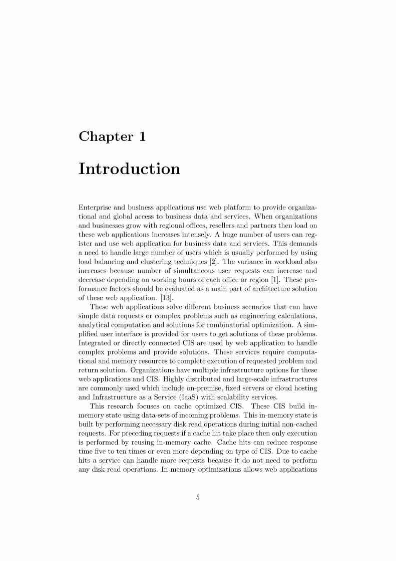
Enterprise and business applications use web platform to provide organiza-tional and global access to business data and services. When organizationsand businesses grow with regional offices, resellers and partners then load onthese web applications increases intensely. A huge number of users can reg-ister and use web application for business data and services. This demandsa need to handle large number of users which is usually performed by usingload balancing and clustering techniques [2]. The variance in workload alsoincreases because number of simultaneous user requests can increase anddecrease depending on working hours of each office or region [1]. These per-formance factors should be evaluated as a main part of architecture solutionof these web application. [13].
These web applications solve different business scenarios that can havesimple data requests or complex problems such as engineering calculations,analytical computation and solutions for combinatorial optimization. A sim-plified user interface is provided for users to get solutions of these problems.Integrated or directly connected CIS are used by web application to handlecomplex problems and provide solutions. These services require computa-tional and memory resources to complete execution of requested problem andreturn solution. Organizations have multiple infrastructure options for theseweb applications and CIS. Highly distributed and large-scale infrastructuresare commonly used which include on-premise, fixed servers or cloud hostingand Infrastructure as a Service (IaaS) with scalability services.
This research focuses on cache optimized CIS. These CIS build in-memory state using data-sets of incoming problems. This in-memory state isbuilt by performing necessary disk read operations during initial non-cachedrequests. For preceding requests if a cache hit take place then only executionis performed by reusing in-memory cache. Cache hits can reduce responsetime five to ten times or even more depending on type of CIS. Due to cachehits a service can handle more requests because it do not need to performany disk-read operations. In-memory optimizations allows web applications
5
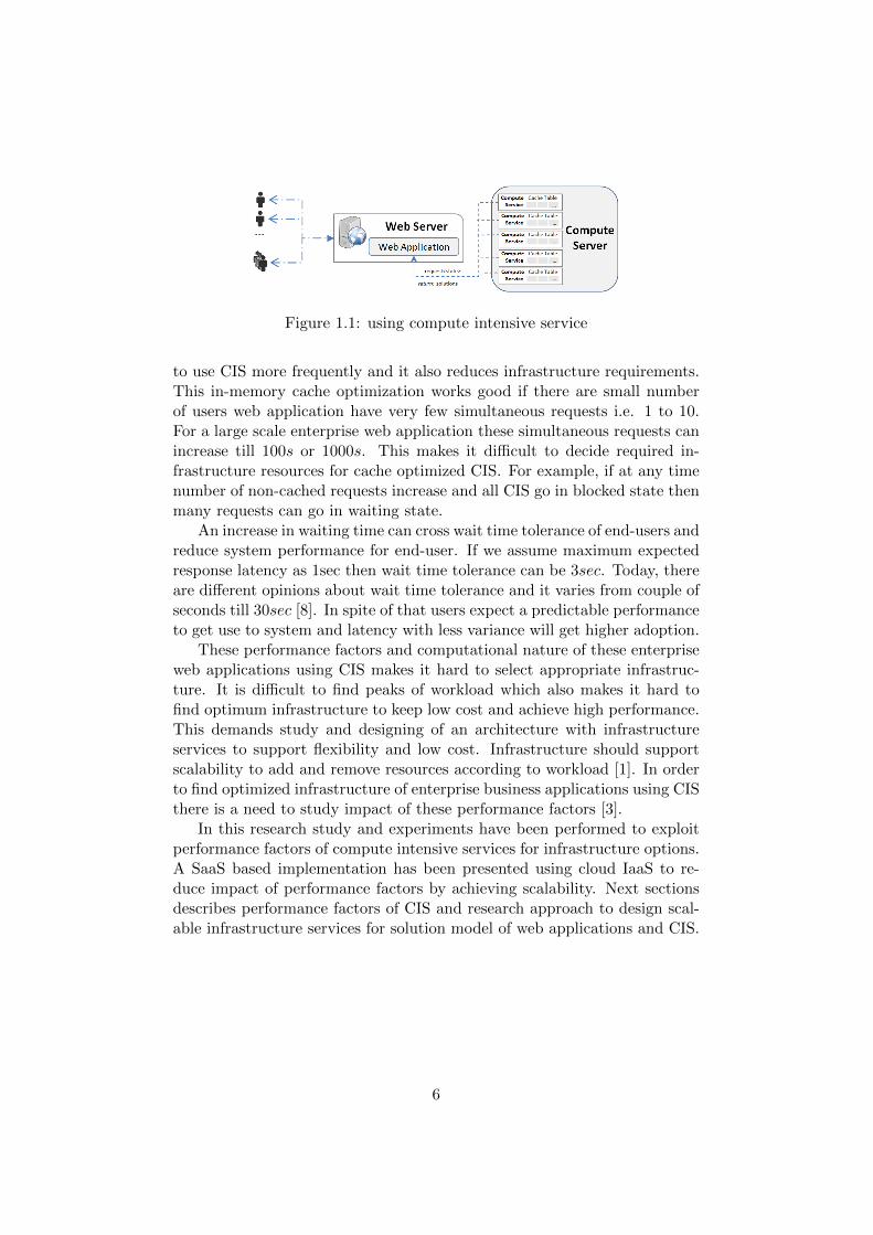
Figure 1.1: using compute intensive service
to use CIS more frequently and it also reduces infrastructure requirements.This in-memory cache optimization works good if there are small numberof users web application have very few simultaneous requests i.e. 1 to 10.For a large scale enterprise web application these simultaneous requests canincrease till 100s or 1000s. This makes it difficult to decide required in-frastructure resources for cache optimized CIS. For example, if at any timenumber of non-cached requests increase and all CIS go in blocked state thenmany requests can go in waiting state.
An increase in waiting time can cross wait time tolerance of end-users andreduce system performance for end-user. If we assume maximum expectedresponse latency as 1sec then wait time tolerance can be 3sec. Today, thereare different opinions about wait time tolerance and it varies from couple ofseconds till 30sec [8]. In spite of that users expect a predictable performanceto get use to system and latency with less variance will get higher adoption.
These performance factors and computational nature of these enterpriseweb applications using CIS makes it hard to select appropriate infrastruc-ture. It is difficult to find peaks of workload which also makes it hard tofind optimum infrastructure to keep low cost and achieve high performance.This demands study and designing of an architecture with infrastructureservices to support flexibility and low cost. Infrastructure should supportscalability to add and remove resources according to workload [1]. In orderto find optimized infrastructure of enterprise business applications using CISthere is a need to study impact of these performance factors [3].
In this research study and experiments have been performed to exploitperformance factors of compute intensive services for infrastructure options.A SaaS based implementation has been presented using cloud IaaS to re-duce impact of performance factors by achieving scalability. Next sectionsdescribes performance factors of CIS and research approach to design scal-able infrastructure services for solution model of web applications and CIS.
6
1.1 Performance Factors of Compute IntensiveServices for Enterprise Web Application
Large scale web application that use CIS can have performance impact dueto uncertain request types and simultaneous requests. Each request fromuser is accepted in a separate thread of web application and available com-pute intensive service is used to get solutions for user requests as shown infigure 1.1. This separates request handling from computational executionand allows web application to accept all requests without blocking state. Allcomputational execution is performed by CIS. This research considers CISwhich are optimized to use in-memory cache.
In order to build and use in-memory cache, a compute intensive serviceverifies state identifier of data-set for each request. When a service receiverequest of a specific state of a data-set for first time then it performs diskread operations and it builds state in memory. In order to improve perfor-mance the compute intensive service keep this state in fast memory. Thisin-memory cache can be reused by CIS for preceding similar requests. Ifa cache hit is found for given identifier of data-set state then only execu-tion step is performed and response is sent back to web application withlow latency. If a service cannot find in-memory cache for given identifier ofdata-set state then service need to perform disk read operations and statebuilding. A service can go in blocked state when it performs disk read op-eration and builds cache. Due to blocking state of services, web applicationmay put next calls in waiting state if all services are found busy. Mostlythis service blocking problem is solved by running multiple services and byusing a load balancer that maintains list of available services.
For example; if there is a specific data-set DSA with state identifier0101A then a user will get higher response latency if it is the first requestsent to service S001 due to cache build action for state of data-set DSA. Allpreceding requests for data-set DSA with state 0101A will get low responselatency from service S001 because in-memory cache will be reused. If an-other user send request for same data-set DSA and state identifier 0101Aand request is routed to service S001 then in-memory cache will be reusedand this user will also get response with low latency. Below is and exampleof request sequence;
• User-1 send request-1001 for DSA with state identifier 0101A. Ser-vice perform complete execution and send response back to User-1.Latency = 1000ms
• User-1 send request-1002 for DSA with state identifier 0101A.Serviceperforms only execution by reusing cache and send response back toUser-1. Latency = 100ms
• User-2 send request-2001 for DSA with state identifier 0101A. Service
7
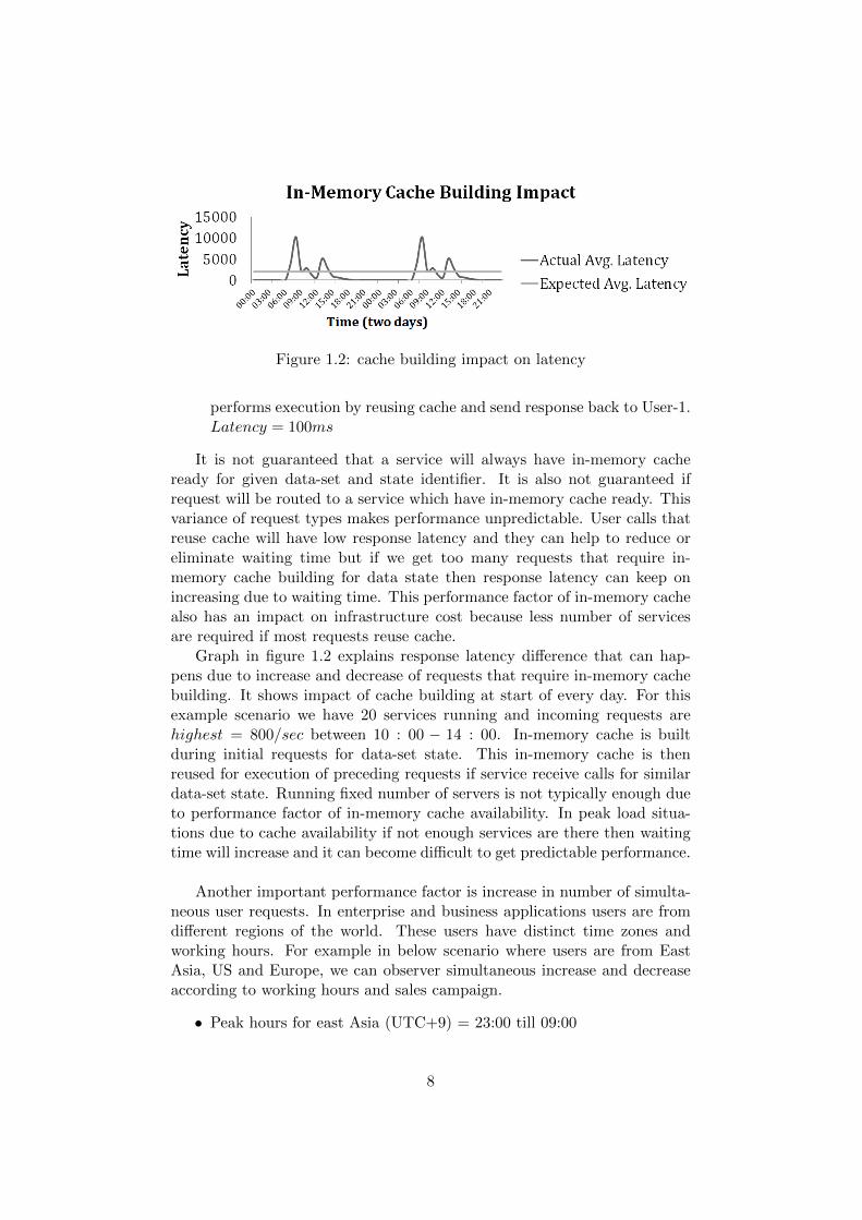
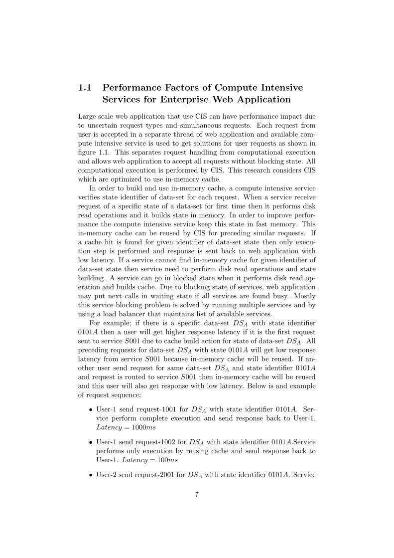
Figure 1.2: cache building impact on latency
performs execution by reusing cache and send response back to User-1.Latency = 100ms
It is not guaranteed that a service will always have in-memory cacheready for given data-set and state identifier. It is also not guaranteed ifrequest will be routed to a service which have in-memory cache ready. Thisvariance of request types makes performance unpredictable. User calls thatreuse cache will have low response latency and they can help to reduce oreliminate waiting time but if we get too many requests that require in-memory cache building for data state then response latency can keep onincreasing due to waiting time. This performance factor of in-memory cachealso has an impact on infrastructure cost because less number of servicesare required if most requests reuse cache.
Graph in figure 1.2 explains response latency difference that can hap-pens due to increase and decrease of requests that require in-memory cachebuilding. It shows impact of cache building at start of every day. For thisexample scenario we have 20 services running and incoming requests arehighest = 800/sec between 10 : 00 − 14 : 00. In-memory cache is builtduring initial requests for data-set state. This in-memory cache is thenreused for execution of preceding requests if service receive calls for similardata-set state. Running fixed number of servers is not typically enough dueto performance factor of in-memory cache availability. In peak load situa-tions due to cache availability if not enough services are there then waitingtime will increase and it can become difficult to get predictable performance.
Another important performance factor is increase in number of simulta-neous user requests. In enterprise and business applications users are fromdifferent regions of the world. These users have distinct time zones andworking hours. For example in below scenario where users are from EastAsia, US and Europe, we can observer simultaneous increase and decreaseaccording to working hours and sales campaign.
• Peak hours for east Asia (UTC+9) = 23:00 till 09:00
8
Figure 1.3: work load graph
• Peak hours Europe (UTC) = 08:00 till 18:00
• Peak hours USA (EST) (UTC-5) = 14:00 till 23:00
During working hours system will receive higher number of requests andin other time slots we expect low number of requests. Each region doesnot need servers/resources 24hr. Overlapping working hours represent peakload, for example 08.00 − 09 : 00 and 14 : 00 − 18 : 00 when working hoursfor one region are still not finished but working hours of another region hasbeen started. Different business scenarios also increases concurrent systemaccess, for example a sales campaign or addition of more users to the system.Graph in figure 1.3 explains peak load for a specific region i.e. EU. It has anexample scenario of a sales campaign in Europe between 09:00 till 13:00. Itshows that we have peak load of 500 requests whereas average load duringwork hours is from 100 till 200 concurrent user requests. This increase ofsimultaneous requests in working hours can include cache building requestswhich can increase performance impact. If number of requests increase andall services are found busy then all next calls will go in waiting state andwaiting time will keep on increasing.
Due to these performance factors response latency can increase and loadpeaks can appear. Organisations have a demand to handle these load peakswith low cost by running required services on sufficient number of servers.Unpredictable performance problem can become an obstacle for organisationto use features of compute intensive services with more freedom for regionaland community users. For example, allowing open user registration or usesystem with more requests and speed during sales campaign.
Multi tenant SaaS providers that use compute intensive services canget even higher impact of performance and cost due to these performancefactors. An increase or decrease of simultaneous user requests or in-memorycache availability can effect waiting time and server usage more rapidly. Abig infrastructure requirement raises to support multiple organizations eachwith hundreds of concurrent user requests in peak load time. It is difficultfor SaaS providers to tolerate big variance in performance because this willeffect end-user experience and they may not prefer unpredictable latency.
9
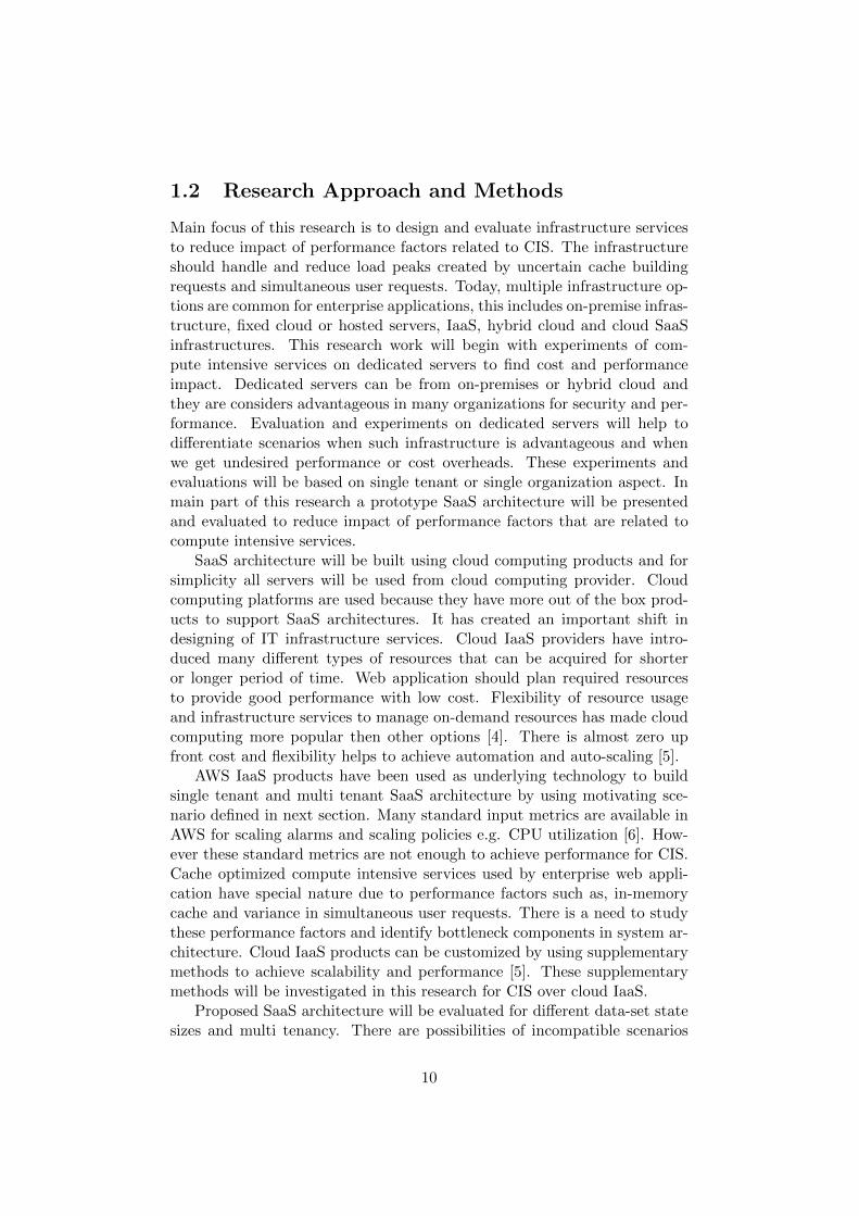
1.2 Research Approach and Methods
Main focus of this research is to design and evaluate infrastructure servicesto reduce impact of performance factors related to CIS. The infrastructureshould handle and reduce load peaks created by uncertain cache buildingrequests and simultaneous user requests. Today, multiple infrastructure op-tions are common for enterprise applications, this includes on-premise infras-tructure, fixed cloud or hosted servers, IaaS, hybrid cloud and cloud SaaSinfrastructures. This research work will begin with experiments of com-pute intensive services on dedicated servers to find cost and performanceimpact. Dedicated servers can be from on-premises or hybrid cloud andthey are considers advantageous in many organizations for security and per-formance. Evaluation and experiments on dedicated servers will help todifferentiate scenarios when such infrastructure is advantageous and whenwe get undesired performance or cost overheads. These experiments andevaluations will be based on single tenant or single organization aspect. Inmain part of this research a prototype SaaS architecture will be presentedand evaluated to reduce impact of performance factors that are related tocompute intensive services.
SaaS architecture will be built using cloud computing products and forsimplicity all servers will be used from cloud computing provider. Cloudcomputing platforms are used because they have more out of the box prod-ucts to support SaaS architectures. It has created an important shift indesigning of IT infrastructure services. Cloud IaaS providers have intro-duced many different types of resources that can be acquired for shorteror longer period of time. Web application should plan required resourcesto provide good performance with low cost. Flexibility of resource usageand infrastructure services to manage on-demand resources has made cloudcomputing more popular then other options [4]. There is almost zero upfront cost and flexibility helps to achieve automation and auto-scaling [5].
AWS IaaS products have been used as underlying technology to buildsingle tenant and multi tenant SaaS architecture by using motivating sce-nario defined in next section. Many standard input metrics are available inAWS for scaling alarms and scaling policies e.g. CPU utilization [6]. How-ever these standard metrics are not enough to achieve performance for CIS.Cache optimized compute intensive services used by enterprise web appli-cation have special nature due to performance factors such as, in-memorycache and variance in simultaneous user requests. There is a need to studythese performance factors and identify bottleneck components in system ar-chitecture. Cloud IaaS products can be customized by using supplementarymethods to achieve scalability and performance [5]. These supplementarymethods will be investigated in this research for CIS over cloud IaaS.
Proposed SaaS architecture will be evaluated for different data-set statesizes and multi tenancy. There are possibilities of incompatible scenarios
10
that may not achieve desired performance in proposed architecture. Addi-tional application specific or architectural methodologies will be proposedfor these incompatible scenarios to achieve balanced performance and costin SaaS. There are many technical challenges involved in SaaS development.One of them is multi-tenancy, which allows single instance of software toserve multiple organizations by accommodating their unique requirementsthrough configuration at the same time [7]. The proposed solution will beevaluated for multi tenant SaaS solution considerations and advantages.
1.3 Motivating Scenario
In this research we have considered a web application that has supplemen-tary open user access on enterprise level. This web application uses computeintensive services to handle requests. Each request contains a dataSetName,stateId and dataV alues of the problem to get a solution. To illustrate actualworkload pattern of simultaneous requests for compute intensive services weneed to find request frequency. If we consider that each active user makesrequest every 5th second with frequency (F) = 0.2/sec;
• Registered Users (U) = 10000
• Active users in peak working hours (P) = 2500
• Peak requests load ’P-Load’ = (P) * (F) = 2500∗0.2 = 500requests/sec
Latency of response depends on data-set prepare time and in-memorycache state. For simplicity of this research below cases have been considered.This latency can be much higher in many other scenarios.
• Response latency when no cache hit happens and cache has to be built= 1000ms
• Response latency when there is a cache hit and only execution step isperformed = 100ms
If cache hit happens then latency to deliver response has been usedas 100ms, this can be called as cached request. If there is no-cache andapplication service has to build and deliver the response then it can take1000ms, this can be called as non-cached request. These are recommendedresponse latencies in web application used in this research but there can beseveral cases with higher response latencies. Experiment and evaluation willalso be performed for higher latency services in this research.
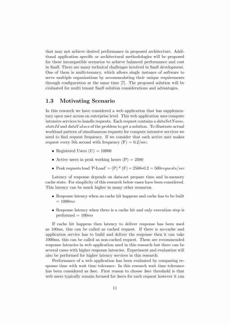
Performance of a web application has been evaluated by comparing re-sponse time with wait time tolerance. In this research wait time tolerancehas been considered as 3sec. First reason to choose 3sec threshold is thatweb users typically remain focused for 3secs for each request however it can
11
vary for different systems and it can be higher then 3sec. Second reasonis that highest response latency of a single request in this motivating sce-nario is 1000ms so threshold latency has been taken three times higher thenhighest possible latency.
1.4 Boundaries and Assumptions
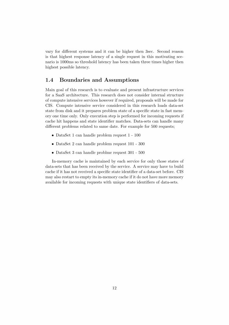
Main goal of this research is to evaluate and present infrastructure servicesfor a SaaS architecture. This research does not consider internal structureof compute intensive services however if required, proposals will be made forCIS. Compute intensive service considered in this research loads data-setstate from disk and it prepares problem state of a specific state in fast mem-ory one time only. Only execution step is performed for incoming requests ifcache hit happens and state identifier matches. Data-sets can handle manydifferent problems related to same date. For example for 500 requests;
• DataSet 1 can handle problem request 1 - 100
• DataSet 2 can handle problem request 101 - 300
• DataSet 3 can handle problme request 301 - 500
In-memory cache is maintained by each service for only those states ofdata-sets that has been received by the service. A service may have to buildcache if it has not received a specific state identifier of a data-set before. CISmay also restart to empty its in-memory cache if it do not have more memoryavailable for incoming requests with unique state identifiers of data-sets.
12
Chapter 2
Background
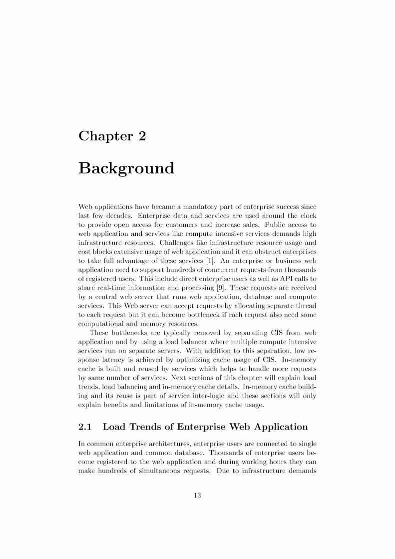
Web applications have became a mandatory part of enterprise success sincelast few decades. Enterprise data and services are used around the clockto provide open access for customers and increase sales. Public access toweb application and services like compute intensive services demands highinfrastructure resources. Challenges like infrastructure resource usage andcost blocks extensive usage of web application and it can obstruct enterprisesto take full advantage of these services [1]. An enterprise or business webapplication need to support hundreds of concurrent requests from thousandsof registered users. This include direct enterprise users as well as API calls toshare real-time information and processing [9]. These requests are receivedby a central web server that runs web application, database and computeservices. This Web server can accept requests by allocating separate threadto each request but it can become bottleneck if each request also need somecomputational and memory resources.
These bottlenecks are typically removed by separating CIS from webapplication and by using a load balancer where multiple compute intensiveservices run on separate servers. With addition to this separation, low re-sponse latency is achieved by optimizing cache usage of CIS. In-memorycache is built and reused by services which helps to handle more requestsby same number of services. Next sections of this chapter will explain loadtrends, load balancing and in-memory cache details. In-memory cache build-ing and its reuse is part of service inter-logic and these sections will onlyexplain benefits and limitations of in-memory cache usage.
2.1 Load Trends of Enterprise Web Application
In common enterprise architectures, enterprise users are connected to singleweb application and common database. Thousands of enterprise users be-come registered to the web application and during working hours they canmake hundreds of simultaneous requests. Due to infrastructure demands
13
of CIS, usually enterprise users have restricted access to compute intensiveservices. This stops enterprise to take full advantage of compute intensivefeatures. Organisations can acquire more intelligence and more users canperform intelligent operations if they can get access to CIS with a simplifiedor guided layer. For CIS providers it is also important to support Applica-tion Programming Interface (API) requests where API requests can increaseand decrease execution load at various times [9].
In order to solve these infrastructure and scalability problems differentload balancing and in-memory cache optimizations are used. Many CIS needto run together to handle simultaneous requests. A basic load balancer canbe used inside or with web application to maintain list of available servicesand use them to share load. This basic load balancing can remove bottleneckfrom web application but it is not sufficient to achieve performance.
2.2 Load Balancing For Compute Services
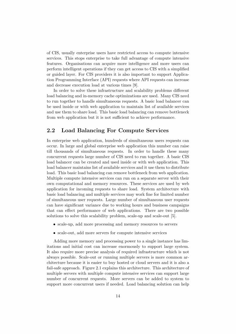
In enterprise web application, hundreds of simultaneous users requests canoccur. In large and global enterprise web application this number can raisetill thousands of simultaneous requests. In order to handle these manyconcurrent requests large number of CIS need to run together. A basic CISload balancer can be created and used inside or with web application. Thisload balancer maintains list of available services and it use them to distributeload. This basic load balancing can remove bottleneck from web application.Multiple compute intensive services can run on a separate server with theirown computational and memory resources. These services are used by webapplication for incoming requests to share load. System architecture withbasic load balancing and multiple services may work fine for limited numberof simultaneous user requests. Large number of simultaneous user requestscan have significant variance due to working hours and business campaignsthat can effect performance of web applications. There are two possiblesolutions to solve this scalability problem, scale-up and scale-out [5].
• scale-up, add more processing and memory resources to servers
• scale-out, add more servers for compute intensive services
Adding more memory and processing power to a single instance has lim-itations and initial cost can increase enormously to support large system.It also require more precise analysis of required infrastructure which is notalways possible. Scale-out or running multiple servers is more common ar-chitecture because it is easier to buy hosted or cloud servers and it is also afail-safe approach. Figure 2.1 explains this architecture. This architecture ofmultiple servers with multiple compute intensive services can support largenumber of concurrent requests. More servers can be added to system tosupport more concurrent users if needed. Load balancing solution can help
14
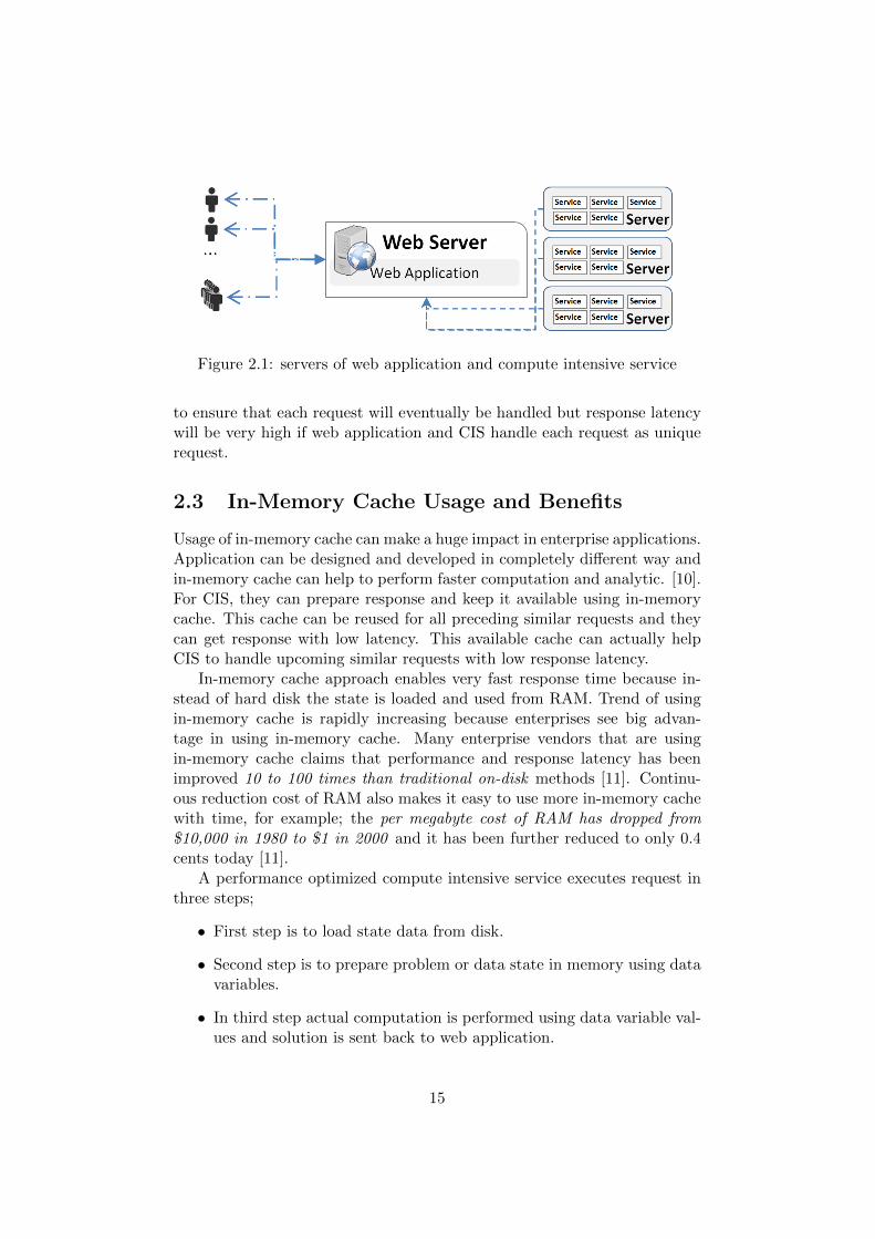
Figure 2.1: servers of web application and compute intensive service
to ensure that each request will eventually be handled but response latencywill be very high if web application and CIS handle each request as uniquerequest.
2.3 In-Memory Cache Usage and Benefits
Usage of in-memory cache can make a huge impact in enterprise applications.Application can be designed and developed in completely different way andin-memory cache can help to perform faster computation and analytic. [10].For CIS, they can prepare response and keep it available using in-memorycache. This cache can be reused for all preceding similar requests and theycan get response with low latency. This available cache can actually helpCIS to handle upcoming similar requests with low response latency.
In-memory cache approach enables very fast response time because in-stead of hard disk the state is loaded and used from RAM. Trend of usingin-memory cache is rapidly increasing because enterprises see big advan-tage in using in-memory cache. Many enterprise vendors that are usingin-memory cache claims that performance and response latency has beenimproved 10 to 100 times than traditional on-disk methods [11]. Continu-ous reduction cost of RAM also makes it easy to use more in-memory cachewith time, for example; the per megabyte cost of RAM has dropped from$10,000 in 1980 to $1 in 2000 and it has been further reduced to only 0.4cents today [11].
A performance optimized compute intensive service executes request inthree steps;
• First step is to load state data from disk.
• Second step is to prepare problem or data state in memory using datavariables.
• In third step actual computation is performed using data variable val-ues and solution is sent back to web application.
15
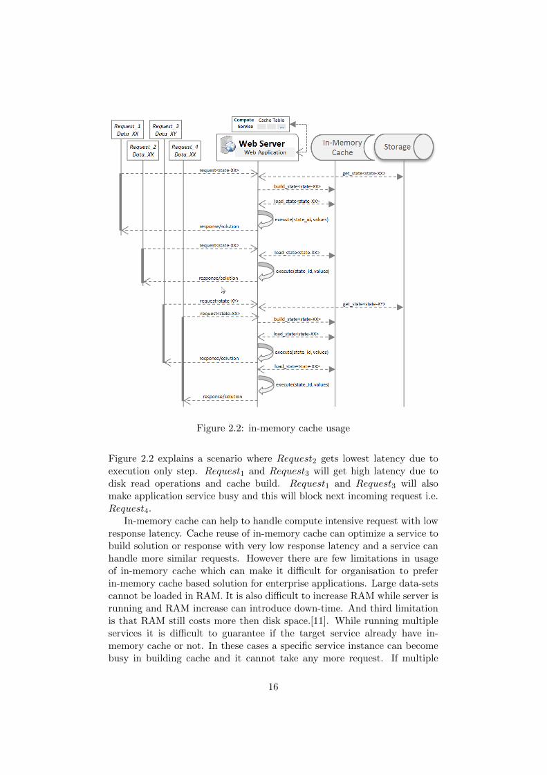
Figure 2.2: in-memory cache usage
Figure 2.2 explains a scenario where Request2 gets lowest latency due toexecution only step. Request1 and Request3 will get high latency due todisk read operations and cache build. Request1 and Request3 will alsomake application service busy and this will block next incoming request i.e.Request4.
In-memory cache can help to handle compute intensive request with lowresponse latency. Cache reuse of in-memory cache can optimize a service tobuild solution or response with very low response latency and a service canhandle more similar requests. However there are few limitations in usageof in-memory cache which can make it difficult for organisation to preferin-memory cache based solution for enterprise applications. Large data-setscannot be loaded in RAM. It is also difficult to increase RAM while server isrunning and RAM increase can introduce down-time. And third limitationis that RAM still costs more then disk space.[11]. While running multipleservices it is difficult to guarantee if the target service already have in-memory cache or not. In these cases a specific service instance can becomebusy in building cache and it cannot take any more request. If multiple
16
service instances are running then request will be routed to another serviceinstance but it can also become busy in building cache if it does not alreadyhave in-memory cache for state of given data-set.
These limitations can create big performance impact for enterprise webapplications. This architecture of in-memory cache and load balancing withmultiple servers can help to ensure that each request will eventually be han-dled but response latency can vary for requests and it can become difficultto get predictable performance. In next sections performance impact of in-memory cache and increasing concurrent requests has been explained forthis architecture.
2.4 Performance Impact of In-Memory Cache
Performance impact due to in-memory can become important if varianceof incoming requests is bigger. Too many requests requiring cache buildingcan make compute intensive services blocking and increase waiting time.Similarly too many requests reusing in-memory cache need less number ofcompute intensive services and can improve performance. There are threemain cases when a service has to build cache for incoming request;
• No Cache; no cache hit found for state of given data-set in servicecache table. This can happen if it is the first service that has receivedrequest for given data-set or if service that previously has received therequest is busy and request has been routed to a new service.
• Invalid Cache; in-memory cache is invalid and new state of data-sethas to be loaded from disk. A new state identifier of data-set canindicate that data is invalid.
• Cache Refresh; cache has been removed due to a cache refresh. This ismostly required to remove unused cache. A service restart can removeall existing cache entries to allow new cache entries to be loaded.
Request3 in figure 2.2 shows the case of no-cache due to busy service.Common web applications do not have cache information about each service.If a service is found busy then request will be routed to next available service.This can create an increasing performance impact if many requests for samedata-set are received because each request may will get its own service andeach service may perform cache build. This process has been explained infigure 2.3. Each time the service will build cache it will become busy and thiswill effect overall waiting time. Too many occurrences of cache building canmake system performance unpredictable at that specific time. It is a goodapproach to use cache whenever possible but for large scale web applicationsit demands to handle cache building impact on performance.
17
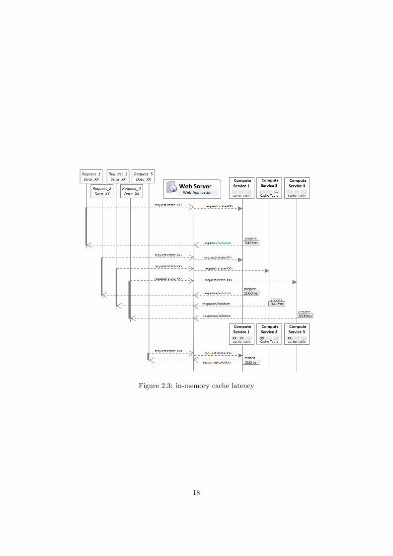
Figure 2.3: in-memory cache latency
18
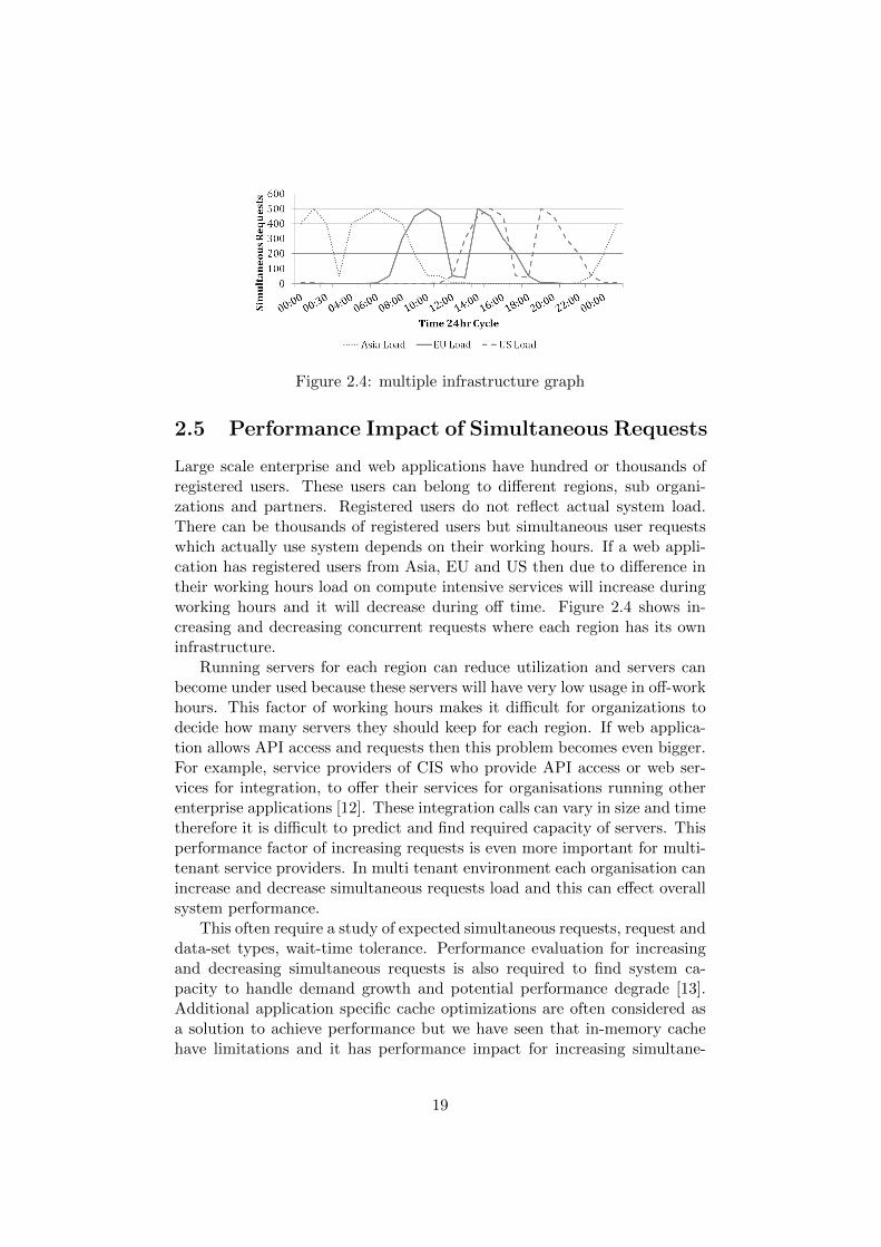
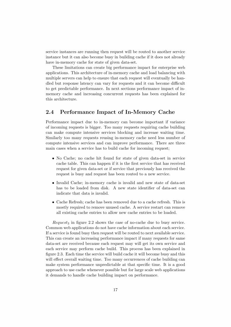
Figure 2.4: multiple infrastructure graph
2.5 Performance Impact of Simultaneous Requests
Large scale enterprise and web applications have hundred or thousands ofregistered users. These users can belong to different regions, sub organi-zations and partners. Registered users do not reflect actual system load.There can be thousands of registered users but simultaneous user requestswhich actually use system depends on their working hours. If a web appli-cation has registered users from Asia, EU and US then due to difference intheir working hours load on compute intensive services will increase duringworking hours and it will decrease during off time. Figure 2.4 shows in-creasing and decreasing concurrent requests where each region has its owninfrastructure.
Running servers for each region can reduce utilization and servers canbecome under used because these servers will have very low usage in off-workhours. This factor of working hours makes it difficult for organizations todecide how many servers they should keep for each region. If web applica-tion allows API access and requests then this problem becomes even bigger.For example, service providers of CIS who provide API access or web ser-vices for integration, to offer their services for organisations running otherenterprise applications [12]. These integration calls can vary in size and timetherefore it is difficult to predict and find required capacity of servers. Thisperformance factor of increasing requests is even more important for multi-tenant service providers. In multi tenant environment each organisation canincrease and decrease simultaneous requests load and this can effect overallsystem performance.
This often require a study of expected simultaneous requests, request anddata-set types, wait-time tolerance. Performance evaluation for increasingand decreasing simultaneous requests is also required to find system ca-pacity to handle demand growth and potential performance degrade [13].Additional application specific cache optimizations are often considered asa solution to achieve performance but we have seen that in-memory cachehave limitations and it has performance impact for increasing simultane-
19
ous requests. Development of infrastructure services is becoming a commonsolution to handle scalability and resource requirements. Infrastructure ser-vices are required to address special characteristics of CIS and provide aflexible system with low cost but high performance.
2.6 Infrastructure Choices for Compute Intensive
Compute intensive services need high processing and memory resources ifthey need to handle hundred or thousands of simultaneous requests comingthrough web application. Today, there are multiple infrastructure optionssuch as on premises dedicated servers, cloud or hosted dedicated servers andcloud computing with IaaS.
On premise dedicated servers are considered as first option in manyorganisations because this approach have one-time cost and low mainte-nance is expected. In this architecture resources are bought and placedon-premises and IT administrators take care of this infrastructure to main-tain upgrades, backups and replacements. These servers are maintained byusing on-premises tools. These tools are also installed and maintained byIT administrators. This architecture is most suitable if all users are in samebuilding or use VPN. It is also considered as a secure and more long-termapproach. For web applications that are built for large number of users ormultiple organisations these advantages may lose their actual significance.This approach has a big on-front cost. Maintenance cost can increase andit can become difficult to maintain this architecture for a web applicationwhere we have hundreds and thousands of users. Maintenance cost of on-premise can also change if an upgrade is planned due to software upgradesor hardware upgrades to support more users. It is also difficult to reducedowntime during system upgrades.
A relatively better and more common approach is hosted or cloud servers.These servers can be added and removed at any time and they usually havefixed cost per month which include maintenance cost of actual hardware.In this approach initial cost can be reduced and servers can be purchasedon monthly basis or for a specific time. Some maintenance cost will still bethere but it is much reduced because IT administrator can use on-line toolsto maintain servers, perform backups, add or remove servers. However theseactions are manually performed and they are mostly based on predictions.Due to manual nature of these actions it is also difficult to perform themoften and before required time.
Cloud computing has been emerged as services oriented way of using ITinfrastructure resources [4]. Enterprises are shifting towards cloud comput-ing and it is reshaping IT industry [15]. Users can access cloud resources viaservices offered by cloud computing providers and they can achieve benefitslike cost saving, high availability and easy scalability [15]. Cloud computing
20
providers offer virtual resources as a service by hiding infrastructure details[16]. Elasticity has became one of the most important advantage in cloudcomputing. Cloud computing providers link elasticity to different types ofresources which includes server instances, storage, RAM, CPU resources andnetwork capacity [1]. In next sub-sections different cloud computing serviceshave been discussed with their advantages and challenges for CIS.
2.6.1 Cloud Computing and IaaS Providers
Cloud computing providers offer a wide variety of cloud services to make iteasy for different types of enterprises to use cloud resources. In public cloudall cloud resources are managed by cloud provider. It depends on cloudprovider how they manage different customers but usually cloud resourcesare shared among customers with privileges to reserve and release sourcesaccording to usage requirements [15]. Private clouds are built completelyon private networks and a single customer is the owner. Private cloudscan be managed by a cloud provider or IT department of customer but isbecoming more cost effective to use services of cloud provider [15]. Hybridcloud mostly have on premises resources and cloud resources are acquired tofulfil on demand elasticity requirements. Hybrid clouds are sometimes morecomplex to manage but cloud computing providers are also focusing moreto provide services for hybrid cloud [15].
Cloud computing is a collection of services and mostly these services aredivided in three different types IaaS, Platform as a Service (PaaS) and SaaS.Cloud services that allow to manage cloud resources are mostly consideredas IaaS. PaaS creates an extra layer of IaaS with some specific software orapplication [15]. For providers of CIS, SaaS is an interesting area becausein SaaS whole application runs on cloud. End-user access is performed by athin client like browser and API access is allowed for integration application.
There are several challenges in adopting cloud computing, such as se-curity, performance, availability, integration with in-house infrastructurewhere security and performance being most significant [17]. Security chal-lenges are mostly part of organizational processes but performance chal-lenges need to be studied. Due to special characteristics of web applicationsthat use compute intensive services there is a need of flexible yet inexpensiveinfrastructure services. A scalable infrastructure can help to handle perfor-mance impacts of in-memory cache and increase number of concurrent userrequests.
Today, there are many cloud computing vendors that provides flexibil-ity and out of the box infrastructure services such as scalability. AWS isone of leading cloud computing vendor and AWS services like auto scalingcan be used to add and remove servers when needed. In AWS standardfeatures, an auto scaling group can be created and on-demand servers canbe added and removed by scaling policies which can be triggered by using
21
CloudWatch alarms. These CloudWatch alarms can be configured to trig-ger scaling polices according to system load and resource demand. Manystandard metrics are available for CloudWatch alarms and scaling policiese.g. CPU utilization [6]. One of the main advantage of cloud computingis scalable architecture. Therefore, it is very important that applicationarchitecture have components for scalability. If components are not easilyscalable then usage of cloud computing services like AWS auto scaling willnot help to their full potential. A scalable application supports resourceincrements and it has heterogeneous components [5].
Private cloud, hybrid or public cloud infrastructure services can be se-lected according to requirements but web applications need to provide SaaSbased architecture and solution to become enterprise ready. Enterprises andorganisations need standard approach of infrastructure features and servicesto get predictable performance, fixed cost and smooth upgrades. Cloud IaaSproviders such as AWS has many useful products to build a SaaS solution.
2.6.2 SaaS Solution Challenges for Compute Intensive
Performance evaluation and scalability is one of the most important chal-lenge for applications that run on cloud computing [18]. Cloud computingproviders claim elasticity and scalability as one of major advantage but itis difficult to validate this claim for different type of applications includingweb applications using CIS [18]. SaaS applications running on cloud com-puting are becoming popular and providers of CIS have an opportunity tosolve their limitations with a SaaS based offering. CIS providers can selltheir services with SaaS model and Service Level Agreement (SLA) to makea more standard solution offering [18]. Performance indicators like largenumber of simultaneous user requests and in-memory cache have big impacton performance and due to these factors it can become hard to define acommon SLA for SaaS users. A thorough study of cloud IaaS features forSaaS and designing of multi tenant SaaS solution is required for computeintensive services.
Predictable performance of compute intensive services require scalabilityin order to easily add and remove servers when needed. Scale-out approachis considered a better choice because it does not rely on high performancecomputational equipment. It can save big on-front investments which arerequired in scale-up approach. Adding more servers horizontally helps toscale in distributed way and therefore it does not need huge up-front cost.This approach still require demand predictions on regular intervals. CloudIaaS features help to automate this instead of manual monitoring. Scale-out approach can have several challenges for web application that use CISwhich can handle more requests for cache hits but they can become blockeddue to cache building requests. From performance aspect such requests canincrease waiting time on overall system and response latency can increase
22
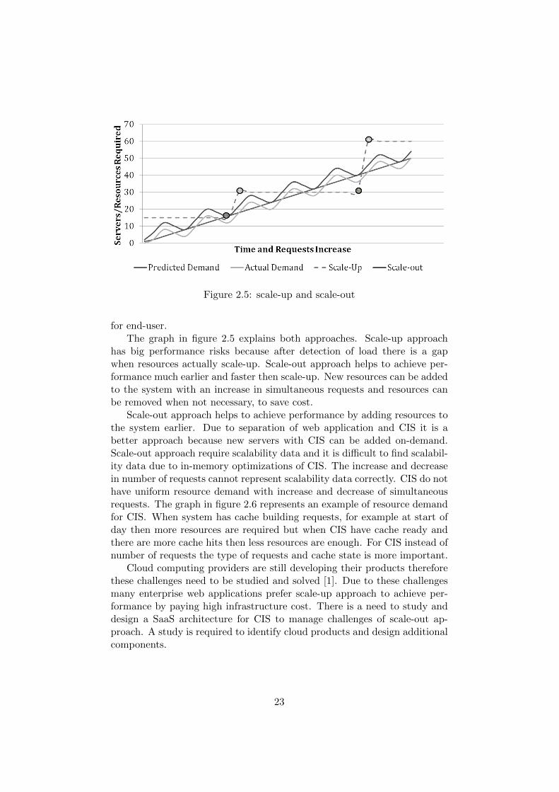
Figure 2.5: scale-up and scale-out
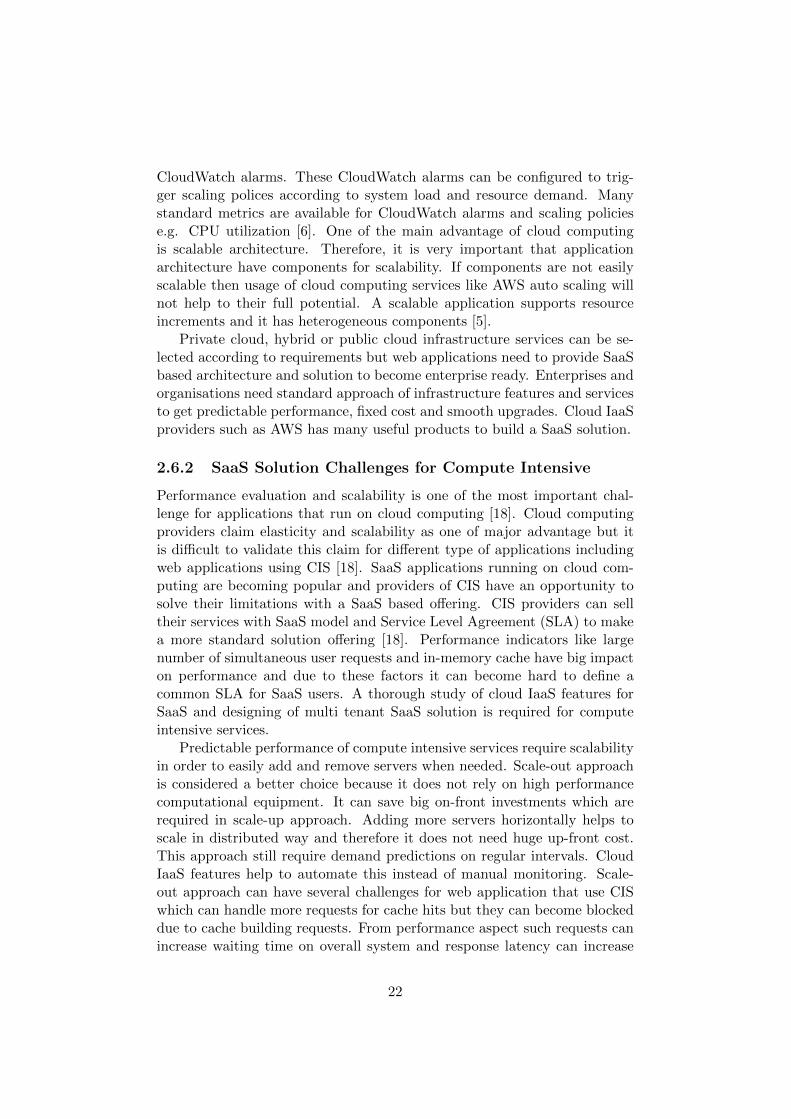
for end-user.The graph in figure 2.5 explains both approaches. Scale-up approach
has big performance risks because after detection of load there is a gapwhen resources actually scale-up. Scale-out approach helps to achieve per-formance much earlier and faster then scale-up. New resources can be addedto the system with an increase in simultaneous requests and resources canbe removed when not necessary, to save cost.
Scale-out approach helps to achieve performance by adding resources tothe system earlier. Due to separation of web application and CIS it is abetter approach because new servers with CIS can be added on-demand.Scale-out approach require scalability data and it is difficult to find scalabil-ity data due to in-memory optimizations of CIS. The increase and decreasein number of requests cannot represent scalability data correctly. CIS do nothave uniform resource demand with increase and decrease of simultaneousrequests. The graph in figure 2.6 represents an example of resource demandfor CIS. When system has cache building requests, for example at start ofday then more resources are required but when CIS have cache ready andthere are more cache hits then less resources are enough. For CIS instead ofnumber of requests the type of requests and cache state is more important.
Cloud computing providers are still developing their products thereforethese challenges need to be studied and solved [1]. Due to these challengesmany enterprise web applications prefer scale-up approach to achieve per-formance by paying high infrastructure cost. There is a need to study anddesign a SaaS architecture for CIS to manage challenges of scale-out ap-proach. A study is required to identify cloud products and design additionalcomponents.
23
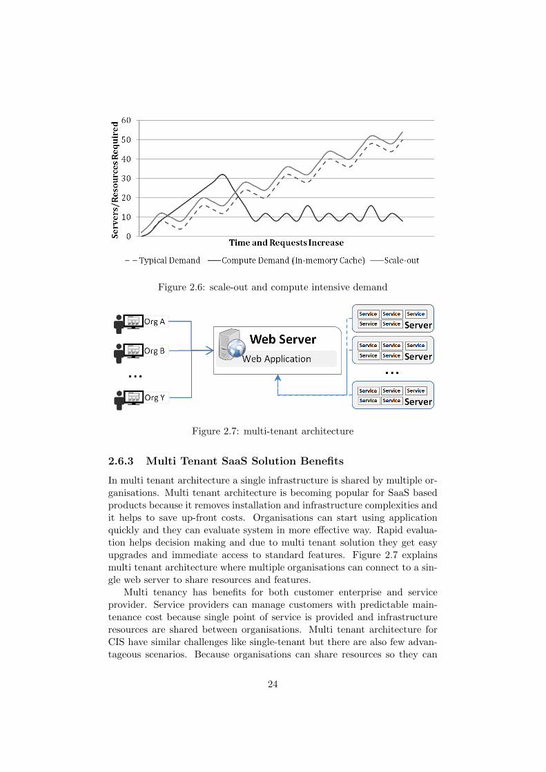
Figure 2.6: scale-out and compute intensive demand
Figure 2.7: multi-tenant architecture
2.6.3 Multi Tenant SaaS Solution Benefits
In multi tenant architecture a single infrastructure is shared by multiple or-ganisations. Multi tenant architecture is becoming popular for SaaS basedproducts because it removes installation and infrastructure complexities andit helps to save up-front costs. Organisations can start using applicationquickly and they can evaluate system in more effective way. Rapid evalua-tion helps decision making and due to multi tenant solution they get easyupgrades and immediate access to standard features. Figure 2.7 explainsmulti tenant architecture where multiple organisations can connect to a sin-gle web server to share resources and features.
Multi tenancy has benefits for both customer enterprise and serviceprovider. Service providers can manage customers with predictable main-tenance cost because single point of service is provided and infrastructureresources are shared between organisations. Multi tenant architecture forCIS have similar challenges like single-tenant but there are also few advan-tageous scenarios. Because organisations can share resources so they can
24

borrow and release shared resources on demand. This can make scalingfaster but it is difficult to identify when organisations should borrow re-sources and when they should scale-out. For CIS there is a need to designa methodology for multi-tenancy to make sure that it do not effect per-formance of organisations and it help to achieve performance with fasterscalability.
Cloud computing vendors like AWS provide logical modules to distributeresources and servers among organisations. For example AWS: Auto ScalingGroup (ASG), an ASG contains its own servers and it can add and removethem according to need. ASG can be created for each tier of organizationthat require auto scaling. Organisations can also share ASG but for CIS astudy and proposal is required to avoid performance impact.
25
Chapter 3
Experiments and Analysis ofDedicated Servers
Dedicated server approach are one of main infrastructure choice for enter-prises to run web applications for enterprise users. Dedicated servers run-ning on-premises are consider one of best solution to achieve performanceand keep enterprise data in secure architecture. These servers can be boughtand run on premises but this require big on-front investment. Not all or-ganisations can prefer this architecture. Hosted or cloud servers are betteralternative where user pay per month or for a specific time-period. This ap-proach includes maintenance cost and manual actions to perform upgradesand scalability.
In this chapter motivational scenario 1.3 has been used with experimentalload patterns to find different values of required services and servers. Theseexperiments have been performed to identify required number of CIS andservers for a specific load and time. These results help to identify cost andperformance impact of dedicated servers. Below assumption have been usedin these experiments;
• We can run 5 services on each server
• Server execution capacity per second (SC)= milliseconds per second * services = 1000 * 5 = 5000
• Application service can serve 10 cached dataset requests per second
• Application service can serve 1 non-cached dataset requests/second
Organisations that have global users from different regions or partnerscan run single infrastructure of dedicated servers for all regions or theycan allocate separate servers to each region. In next sections experimentdetails has been described for both approaches to find performance and costimpact. These experiments can help to identify limitations of dedicatedserver architecture for CIS .
26
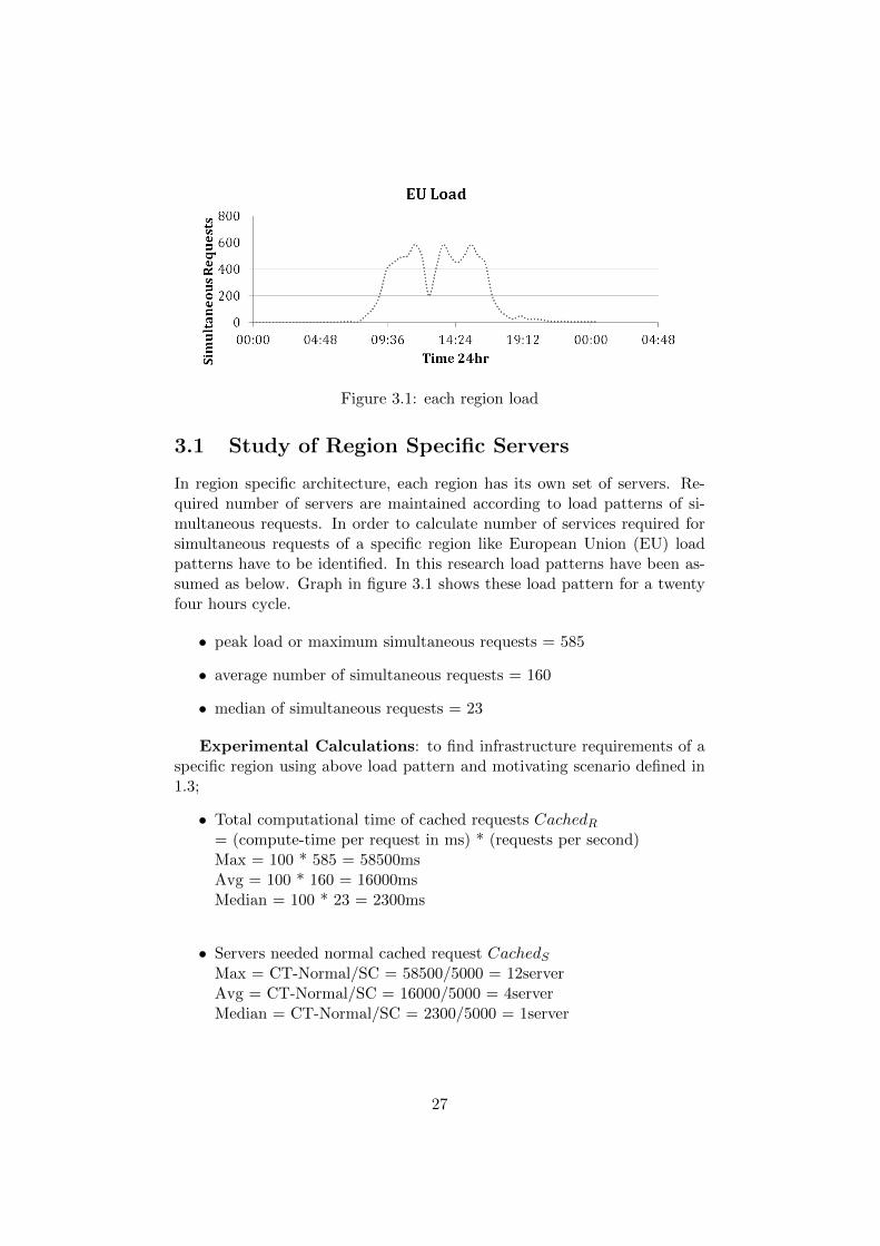
Figure 3.1: each region load
3.1 Study of Region Specific Servers
In region specific architecture, each region has its own set of servers. Re-quired number of servers are maintained according to load patterns of si-multaneous requests. In order to calculate number of services required forsimultaneous requests of a specific region like European Union (EU) loadpatterns have to be identified. In this research load patterns have been as-sumed as below. Graph in figure 3.1 shows these load pattern for a twentyfour hours cycle.
• peak load or maximum simultaneous requests = 585
• average number of simultaneous requests = 160
• median of simultaneous requests = 23
Experimental Calculations: to find infrastructure requirements of aspecific region using above load pattern and motivating scenario defined in1.3;
• Total computational time of cached requests CachedR= (compute-time per request in ms) * (requests per second)Max = 100 * 585 = 58500msAvg = 100 * 160 = 16000msMedian = 100 * 23 = 2300ms
• Servers needed normal cached request CachedSMax = CT-Normal/SC = 58500/5000 = 12serverAvg = CT-Normal/SC = 16000/5000 = 4serverMedian = CT-Normal/SC = 2300/5000 = 1server
27
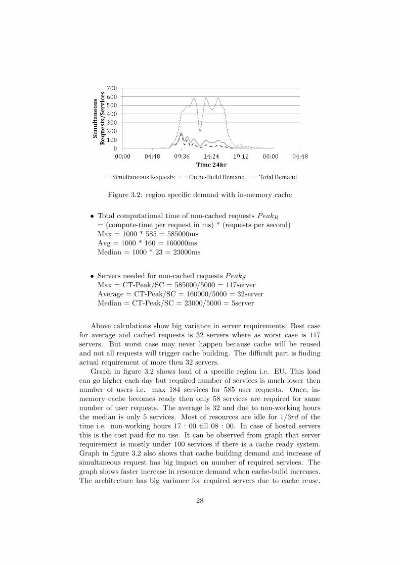
Figure 3.2: region specific demand with in-memory cache
• Total computational time of non-cached requests PeakR= (compute-time per request in ms) * (requests per second)Max = 1000 * 585 = 585000msAvg = 1000 * 160 = 160000msMedian = 1000 * 23 = 23000ms
• Servers needed for non-cached requests PeakSMax = CT-Peak/SC = 585000/5000 = 117serverAverage = CT-Peak/SC = 160000/5000 = 32serverMedian = CT-Peak/SC = 23000/5000 = 5server
Above calculations show big variance in server requirements. Best casefor average and cached requests is 32 servers where as worst case is 117servers. But worst case may never happen because cache will be reusedand not all requests will trigger cache building. The difficult part is findingactual requirement of more then 32 servers.
Graph in figure 3.2 shows load of a specific region i.e. EU. This loadcan go higher each day but required number of services is much lower thennumber of users i.e. max 184 services for 585 user requests. Once, in-memory cache becomes ready then only 58 services are required for samenumber of user requests. The average is 32 and due to non-working hoursthe median is only 5 services. Most of resources are idle for 1/3rd of thetime i.e. non-working hours 17 : 00 till 08 : 00. In case of hosted serversthis is the cost paid for no use. It can be observed from graph that serverrequirement is mostly under 100 services if there is a cache ready system.Graph in figure 3.2 also shows that cache building demand and increase ofsimultaneous request has big impact on number of required services. Thegraph shows faster increase in resource demand when cache-build increases.The architecture has big variance for required servers due to cache reuse.
28
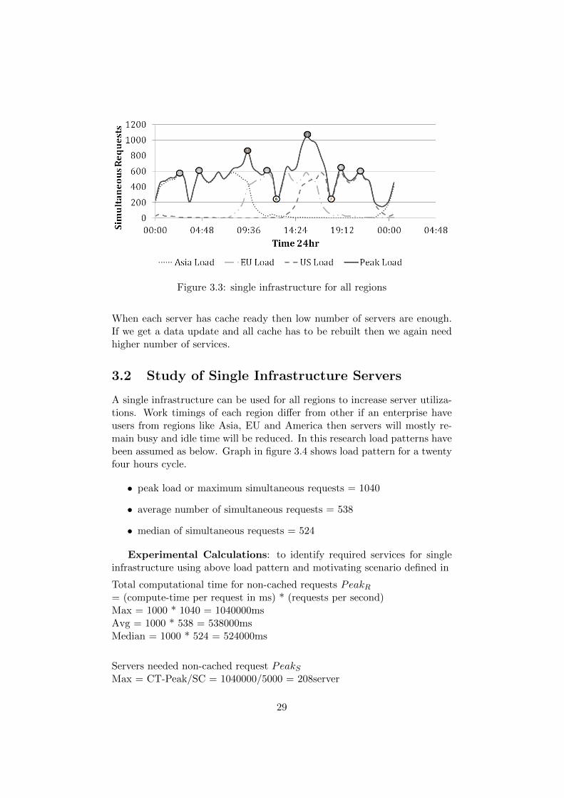
Figure 3.3: single infrastructure for all regions
When each server has cache ready then low number of servers are enough.If we get a data update and all cache has to be rebuilt then we again needhigher number of services.
3.2 Study of Single Infrastructure Servers
A single infrastructure can be used for all regions to increase server utiliza-tions. Work timings of each region differ from other if an enterprise haveusers from regions like Asia, EU and America then servers will mostly re-main busy and idle time will be reduced. In this research load patterns havebeen assumed as below. Graph in figure 3.4 shows load pattern for a twentyfour hours cycle.
• peak load or maximum simultaneous requests = 1040
• average number of simultaneous requests = 538
• median of simultaneous requests = 524
Experimental Calculations: to identify required services for singleinfrastructure using above load pattern and motivating scenario defined in
Total computational time for non-cached requests PeakR= (compute-time per request in ms) * (requests per second)Max = 1000 * 1040 = 1040000msAvg = 1000 * 538 = 538000msMedian = 1000 * 524 = 524000ms
Servers needed non-cached request PeakSMax = CT-Peak/SC = 1040000/5000 = 208server
29
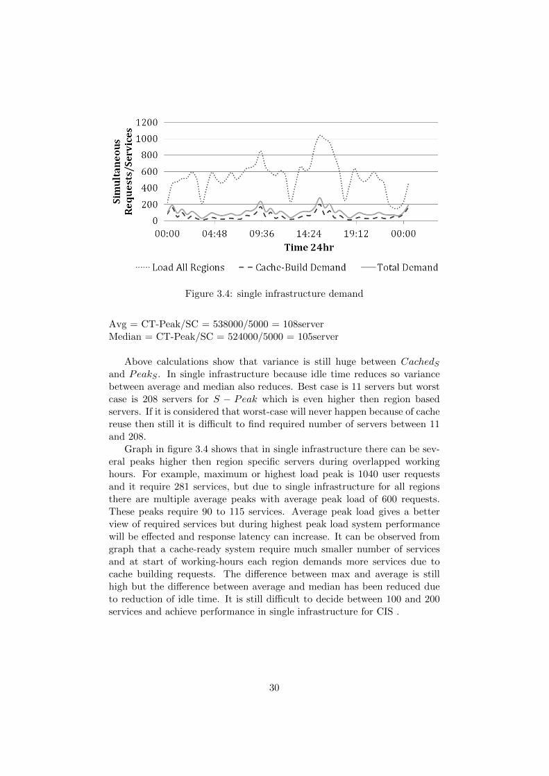
Figure 3.4: single infrastructure demand
Avg = CT-Peak/SC = 538000/5000 = 108serverMedian = CT-Peak/SC = 524000/5000 = 105server
Above calculations show that variance is still huge between CachedSand PeakS . In single infrastructure because idle time reduces so variancebetween average and median also reduces. Best case is 11 servers but worstcase is 208 servers for S − Peak which is even higher then region basedservers. If it is considered that worst-case will never happen because of cachereuse then still it is difficult to find required number of servers between 11and 208.
Graph in figure 3.4 shows that in single infrastructure there can be sev-eral peaks higher then region specific servers during overlapped workinghours. For example, maximum or highest load peak is 1040 user requestsand it require 281 services, but due to single infrastructure for all regionsthere are multiple average peaks with average peak load of 600 requests.These peaks require 90 to 115 services. Average peak load gives a betterview of required services but during highest peak load system performancewill be effected and response latency can increase. It can be observed fromgraph that a cache-ready system require much smaller number of servicesand at start of working-hours each region demands more services due tocache building requests. The difference between max and average is stillhigh but the difference between average and median has been reduced dueto reduction of idle time. It is still difficult to decide between 100 and 200services and achieve performance in single infrastructure for CIS .
30
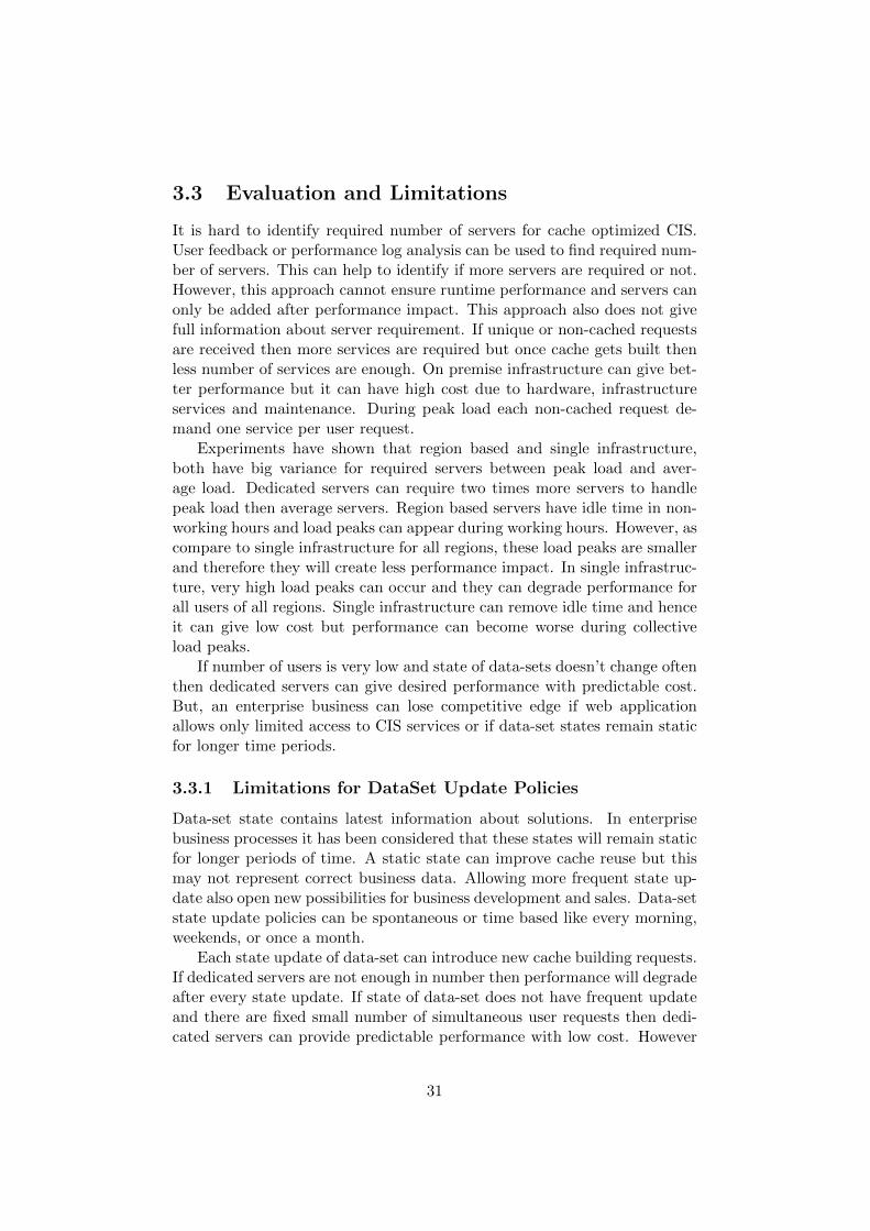
3.3 Evaluation and Limitations
It is hard to identify required number of servers for cache optimized CIS.User feedback or performance log analysis can be used to find required num-ber of servers. This can help to identify if more servers are required or not.However, this approach cannot ensure runtime performance and servers canonly be added after performance impact. This approach also does not givefull information about server requirement. If unique or non-cached requestsare received then more services are required but once cache gets built thenless number of services are enough. On premise infrastructure can give bet-ter performance but it can have high cost due to hardware, infrastructureservices and maintenance. During peak load each non-cached request de-mand one service per user request.
Experiments have shown that region based and single infrastructure,both have big variance for required servers between peak load and aver-age load. Dedicated servers can require two times more servers to handlepeak load then average servers. Region based servers have idle time in non-working hours and load peaks can appear during working hours. However, ascompare to single infrastructure for all regions, these load peaks are smallerand therefore they will create less performance impact. In single infrastruc-ture, very high load peaks can occur and they can degrade performance forall users of all regions. Single infrastructure can remove idle time and henceit can give low cost but performance can become worse during collectiveload peaks.
If number of users is very low and state of data-sets doesn’t change oftenthen dedicated servers can give desired performance with predictable cost.But, an enterprise business can lose competitive edge if web applicationallows only limited access to CIS services or if data-set states remain staticfor longer time periods.
3.3.1 Limitations for DataSet Update Policies
Data-set state contains latest information about solutions. In enterprisebusiness processes it has been considered that these states will remain staticfor longer periods of time. A static state can improve cache reuse but thismay not represent correct business data. Allowing more frequent state up-date also open new possibilities for business development and sales. Data-setstate update policies can be spontaneous or time based like every morning,weekends, or once a month.
Each state update of data-set can introduce new cache building requests.If dedicated servers are not enough in number then performance will degradeafter every state update. If state of data-set does not have frequent updateand there are fixed small number of simultaneous user requests then dedi-cated servers can provide predictable performance with low cost. However
31
this stops organisations to scale and therefore partners and enterprise userscannot get freedom to use system with latest data-set states which can in-clude inventory, pricing and sales information.
3.3.2 Limitations for Additional Users and API Requests
Regional and partner offices have their own set of users that can use webapplication. In dedicated server approach, it is difficult to allow additionalusers without proper planning. Introduction of new users can increase simul-taneous requests and existing system capacity will not be enough to support.Usually organisations prohibit bulk user registration to avoid performancedegradation but delay in new users can reduce potential use of CIS.
Additional users and variance in simultaneous requests is an even biggerproblem for service providers of CIS. They commonly have to find expectedresource requirements for their customers. If providers of CIS recommendtoo many dedicated servers then not all enterprises will accept it due to highcost. If they recommend less dedicated servers then enterprise users mayget unpredictable performance and they may complain about it. Enterprisespecific solutions can be created for each complain case but providers of CISstill need a more general approach to add and remove servers when requiredto achieve performance with low cost.
32
Chapter 4
SaaS Architecture DesignAnd Performance Analysis
Solution model of web application with CIS requires a standard infrastruc-ture offering for enterprise customers. Large enterprises are more interestedin cloud based architecture that is flexible and elastic to save upfront costand pay according to usage [14]. In this chapter a prototype SaaS archi-tecture has been presented for single tenant and multi-tenant organisation.This architecture provides a general solution and standard offering. SaaS of-fering can help organisations to get standard architecture, immediate accessand they can pay according to usage [14].
In next sections of this chapter cloud IaaS products has been identified tobuild this prototype SaaS architecture. Due to special characteristics of CISthese cloud products cannot be used directly. Later in this chapter, supple-mentary components has been identified and developed to fill shortcomingsof these cloud products.
4.1 Applicable Cloud IaaS Products
Cloud providers offer infrastructure services over cloud resources to managethe architecture. These services help to deploy web based solution withmore flexibility and minimal administration cost [5]. Today, many of theseservices are free to use and they can become building blocks for a SaaSsolution. Below list shows few of AWS products that has been used in thisresearch to build the SaaS architecture.
• AWS Elastic Compute Cloud (EC2), virtual servers in the cloud
• AWS ASG, container for servers with dynamic elasticity
• AWS Elastic Load Balancing (ELB), high scale load balancing
• AWS CloudWatch, monitor resources and applications
33
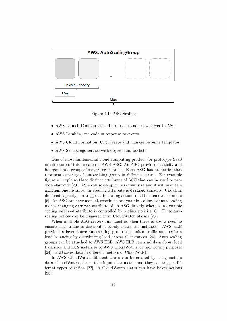
Figure 4.1: ASG Scaling
• AWS Launch Configuration (LC), used to add new server to ASG
• AWS Lambda, run code in response to events
• AWS Cloud Formation (CF), create and manage resource templates
• AWS S3, storage service with objects and buckets
One of most fundamental cloud computing product for prototype SaaSarchitecture of this research is AWS ASG. An ASG provides elasticity andit organises a group of servers or instance. Each ASG has properties thatrepresent capacity of auto-sclaing group in different states. For examplefigure 4.1 explains three distinct attributes of ASG that can be used to pro-vide elasticity [20]. ASG can scale-up till maximum size and it will maintainminimum one instance. Interesting attribute is desired capacity. Updatingdesired capacity can trigger auto scaling action to add or remove instances[6]. An ASG can have manual, scheduled or dynamic scaling. Manual scalingmeans changing desired attribute of an ASG directly whereas in dynamicscaling desired attribute is controlled by scaling policies [6]. These autoscaling polices can be triggered from CloudWatch alarms [23].
When multiple ASG servers run together then there is also a need toensure that traffic is distributed evenly across all instances. AWS ELBprovides a layer above auto-scaling group to monitor traffic and performload balancing by distributing load across all instances [24]. Auto scalinggroups can be attached to AWS ELB. AWS ELB can send data about loadbalancers and EC2 instances to AWS CloudWatch for monitoring purposes[24]. ELB saves data in different metrics of CloudWatch.
In AWS CloudWatch different alarm can be created by using metricsdata. CloudWatch alarms take input data metric and they can trigger dif-ferent types of action [22]. A CloudWatch alarm can have below actions[23];
34
• Notification
• AutoScaling Action: trigger auto scaling policy of an ASG
• EC2 Action: stop or reboot specific instance
ASG scaling policies can be triggered by CloudWatch alarms with spe-cific alarm condition [23]. Each alarm can trigger actions, for example when-ever a specific metric values goes above a specific threshold then triggerscale-up to change ASG desired attribute. AWS provides standard metricsto support dynamic scaling based on metrics data uploaded by ELB [23].This metrics data includes many interesting metrics like ELB request count,EC2 CPU usage and many more. In dynamic scaling of ASG the Cloud-Watch metrics data can also be loaded from customized or supplementarysources [22]. It is recommended to create at least two scaling policies tofacilitate scale-up and scale-down events [20].
4.2 Basic SaaS Architecture
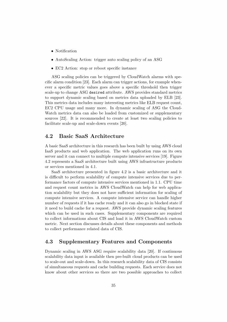
A basic SaaS architecture in this research has been built by using AWS cloudIaaS products and web application. The web application runs on its ownserver and it can connect to multiple compute intensive services [19]. Figure4.2 represents a SaaS architecture built using AWS infrastructure productsor services mentioned in 4.1.
SaaS architecture presented in figure 4.2 is a basic architecture and itis difficult to perform scalability of compute intensive services due to per-formance factors of compute intensive services mentioned in 1.1. CPU timeand request count metrics in AWS CloudWatch can help for web applica-tion scalability but they does not have sufficient information for scaling ofcompute intensive services. A compute intensive service can handle highernumber of requests if it has cache ready and it can also go in blocked state ifit need to build cache for a request. AWS provide dynamic scaling featureswhich can be used in such cases. Supplementary components are requiredto collect informations about CIS and load it in AWS CloudWatch custommetric. Next section discusses details about these components and methodsto collect performance related data of CIS.
4.3 Supplementary Features and Components
Dynamic scaling in AWS ASG require scalability data [20]. If continuousscalability data input is available then pre-built cloud products can be usedto scale-out and scale-down. In this research scalability data of CIS consistsof simultaneous requests and cache building requests. Each service does notknow about other services so there are two possible approaches to collect
35
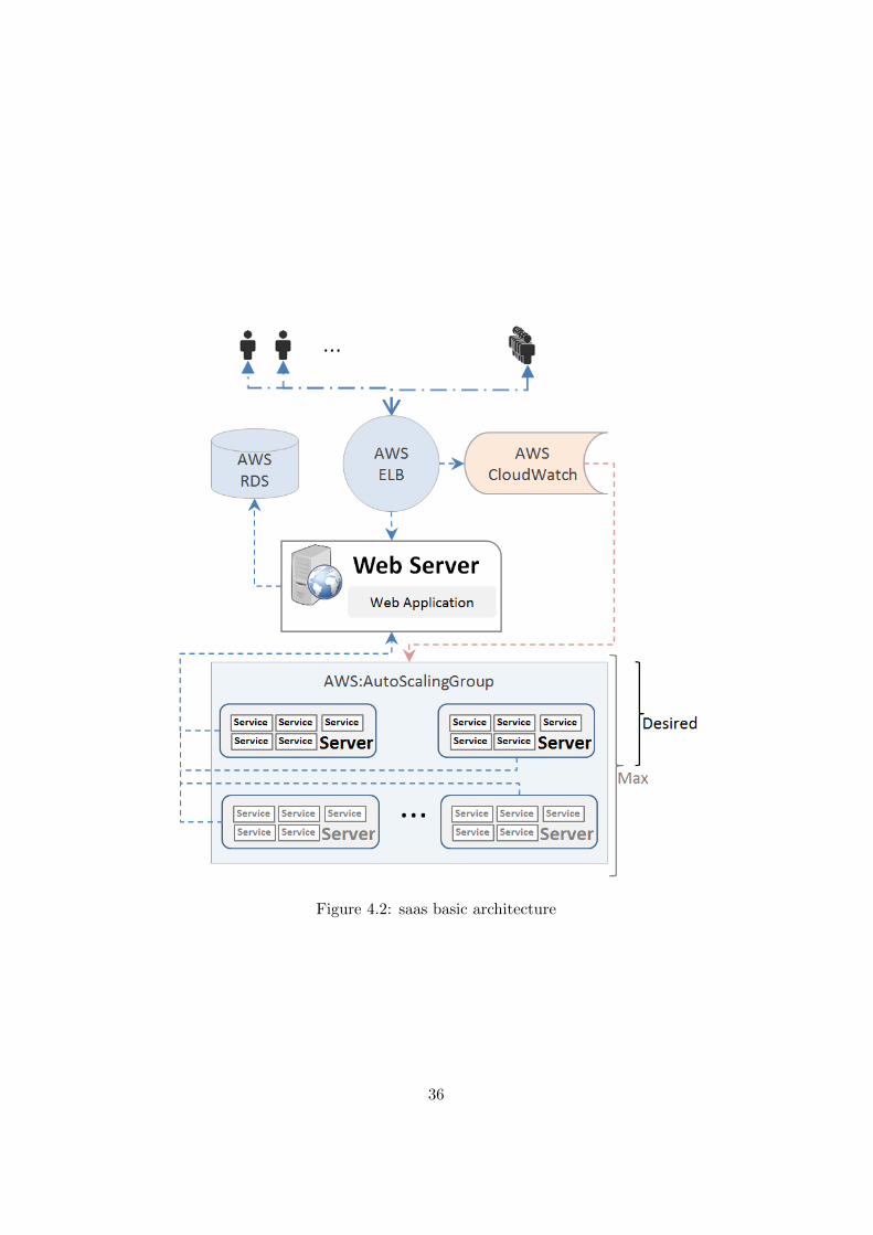
Figure 4.2: saas basic architecture
36
scalability data. In first approach, specific data about cache hit can beloaded from each CIS whereas in second approach web application can trackoverall cache hit details and simultaneous requests. In this research we haveused second approach because we had a possibility to identify impact ofcache-hits and simultaneous requests as waiting-time in web application.
Web application receives user request and it forwards it to availablecompute services. If a service is not available due to previous cache buildingrequest then web application will try to use another service. If all servicesbecome blocked for longer period then request waiting time will increase forincoming requests. Similarly, this waiting time will also increase if too manysimultaneous request are received. This waiting time can be aggregated byweb application as queue time. This queue-time will increases and decreasesaccording to cache hits and simultaneous requests. This queue-time canrepresent performance impact and it can be used to perform scalability.Next sub sections explain supplementary methods and components to collectand use queue-time for scalability. These supplementary components arerequired for SaaS architecture.
4.3.1 Queue-Time Input For Metric Data
ASG of CIS need scaling if web application cannot find available computeservice and queue is building up. Web application can calculate queue-timeof requests that are waiting for a compute service and this queue-time canbe used as a CloudWatch metric data. If this queue-time remains for longertime then scalability requirement can be identified and more resources canbe added to the system.
CIS have multiple servers queuing model such as M/M/C where arrivalscome from single queue [25]. Each request has a response time and waitingtime. Response time is the total time a request has spent in queue andin service [25]. It is important to consider that Service rate can have bigvariance in CI-services due to variance of non-cached requests. A simplequeue-time calculation can be performed by web application by countingnumber of requests and total time spent by active requests in system.
Example of queue-time calculation; let’s consider that at a specific timeweb application has 15% non-cached requests, system has 10 concurrentrequests and three CIS are running. If three requests are active with totaltime as 2911 then we can divide this total time by not started requests countto get queue-time as 415.
• Waiting requests count Rq = 7
• Active Request R1 total time = 889
• Active Request R2 total time = 767
• Active Request R3 total time = 1255
37
Figure 4.3: queue-time(MMC)
• Queue-Time Wq = (R1+R2+R3)/7 = 415
This is just one way of calculating queue-time and there can be severalother ways. Calculation of queue-time is part of web application and thisresearch assumes that web application calculates queue-time that can beretrieved on regular intervals. If queue-time Wq and waiting requests Rq
remain like this for multiple periods then queue-time will start raising rapidlyas shown in 4.3. A continuous increase in queue-time reduce performanceand response latency can become too high.
If queue-time Wq is greater then threshold response latency and waitingrequests Rq remain like this for multiple periods then scaling requirementcan be identified by using multiple occurrences of Wq. This can help to makea scale-up policy. For example; if cumulative queue-time increase more then3sec for 3mins then add more compute services. Queue-time can representload of simultaneous requests and it gives more precise performance data forCloudWatch metric. If queue-time is zero for longer time then scale-downcan be performed
4.3.2 Scaling Service For Web Application
Web application performs queue-time calculations which helps to get moreprecise performance data. This queue-time has to be updated in AWSCloudWatch metrics on regular intervals. Dynamic scaling can provide scal-ability based on AWS CloudWatch metric data [20]. A scaling service orapplication is required to run beside web application to read queue-timefrom web application and update AWS CloudWatch metric. Scaling appli-cation need to provide inputs for AWS CloudWatch metric as well as for webapplication. For AWS CloudWatch metric input, it will collect queue-timefrom web application on regular intervals and it will update metric data inAWS. This can be done by using API services of AWS. For web application
38
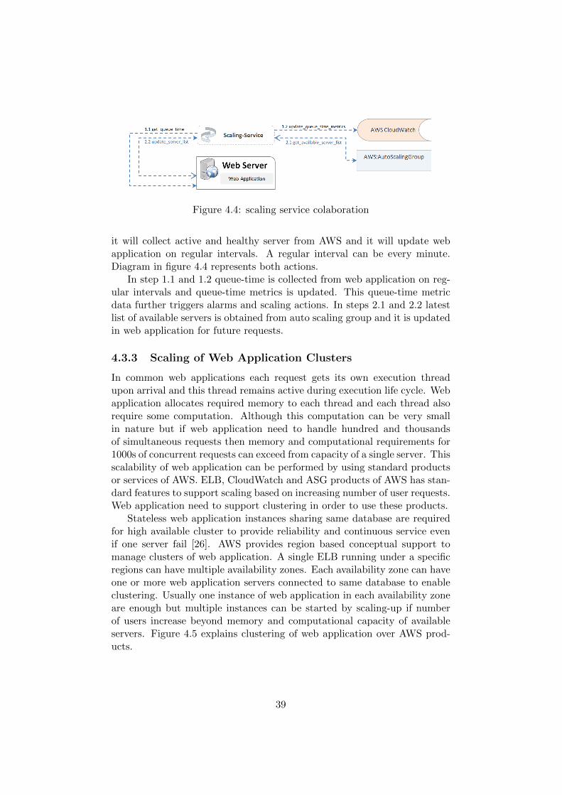
Figure 4.4: scaling service colaboration
it will collect active and healthy server from AWS and it will update webapplication on regular intervals. A regular interval can be every minute.Diagram in figure 4.4 represents both actions.
In step 1.1 and 1.2 queue-time is collected from web application on reg-ular intervals and queue-time metrics is updated. This queue-time metricdata further triggers alarms and scaling actions. In steps 2.1 and 2.2 latestlist of available servers is obtained from auto scaling group and it is updatedin web application for future requests.
4.3.3 Scaling of Web Application Clusters
In common web applications each request gets its own execution threadupon arrival and this thread remains active during execution life cycle. Webapplication allocates required memory to each thread and each thread alsorequire some computation. Although this computation can be very smallin nature but if web application need to handle hundred and thousandsof simultaneous requests then memory and computational requirements for1000s of concurrent requests can exceed from capacity of a single server. Thisscalability of web application can be performed by using standard productsor services of AWS. ELB, CloudWatch and ASG products of AWS has stan-dard features to support scaling based on increasing number of user requests.Web application need to support clustering in order to use these products.
Stateless web application instances sharing same database are requiredfor high available cluster to provide reliability and continuous service evenif one server fail [26]. AWS provides region based conceptual support tomanage clusters of web application. A single ELB running under a specificregions can have multiple availability zones. Each availability zone can haveone or more web application servers connected to same database to enableclustering. Usually one instance of web application in each availability zoneare enough but multiple instances can be started by scaling-up if numberof users increase beyond memory and computational capacity of availableservers. Figure 4.5 explains clustering of web application over AWS prod-ucts.
39
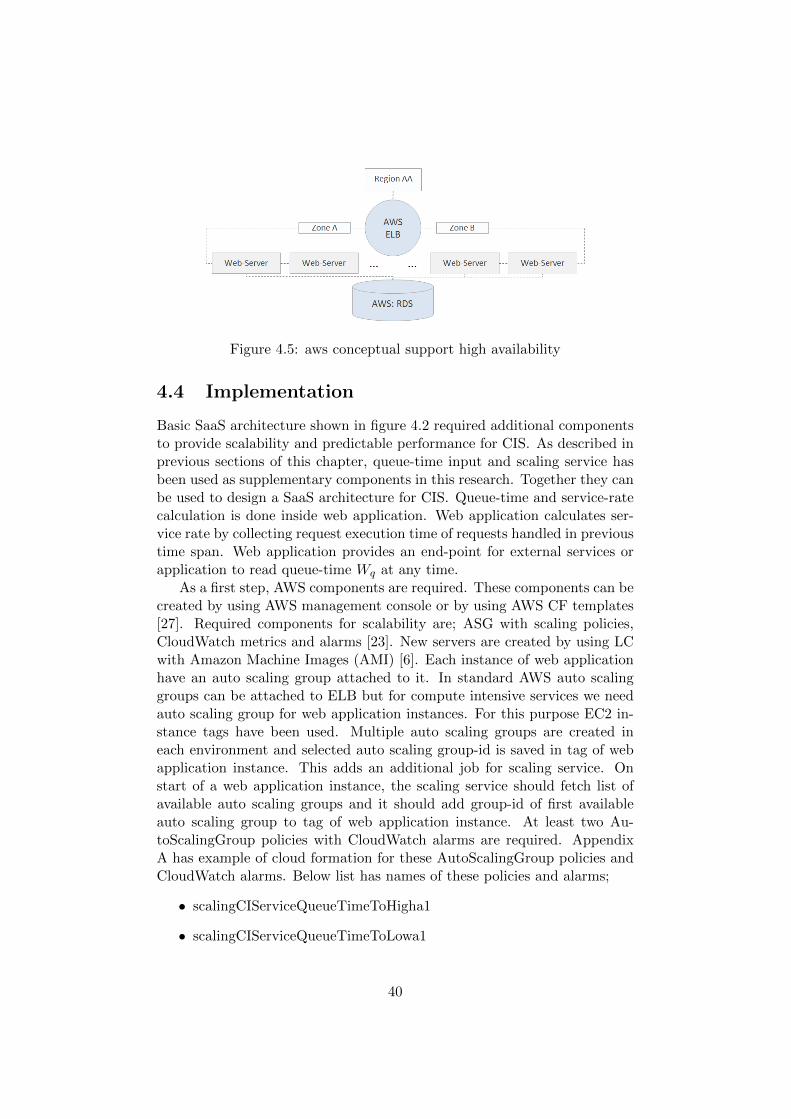
Figure 4.5: aws conceptual support high availability
4.4 Implementation
Basic SaaS architecture shown in figure 4.2 required additional componentsto provide scalability and predictable performance for CIS. As described inprevious sections of this chapter, queue-time input and scaling service hasbeen used as supplementary components in this research. Together they canbe used to design a SaaS architecture for CIS. Queue-time and service-ratecalculation is done inside web application. Web application calculates ser-vice rate by collecting request execution time of requests handled in previoustime span. Web application provides an end-point for external services orapplication to read queue-time Wq at any time.
As a first step, AWS components are required. These components can becreated by using AWS management console or by using AWS CF templates[27]. Required components for scalability are; ASG with scaling policies,CloudWatch metrics and alarms [23]. New servers are created by using LCwith Amazon Machine Images (AMI) [6]. Each instance of web applicationhave an auto scaling group attached to it. In standard AWS auto scalinggroups can be attached to ELB but for compute intensive services we needauto scaling group for web application instances. For this purpose EC2 in-stance tags have been used. Multiple auto scaling groups are created ineach environment and selected auto scaling group-id is saved in tag of webapplication instance. This adds an additional job for scaling service. Onstart of a web application instance, the scaling service should fetch list ofavailable auto scaling groups and it should add group-id of first availableauto scaling group to tag of web application instance. At least two Au-toScalingGroup policies with CloudWatch alarms are required. AppendixA has example of cloud formation for these AutoScalingGroup policies andCloudWatch alarms. Below list has names of these policies and alarms;
• scalingCIServiceQueueTimeToHigha1
• scalingCIServiceQueueTimeToLowa1
40
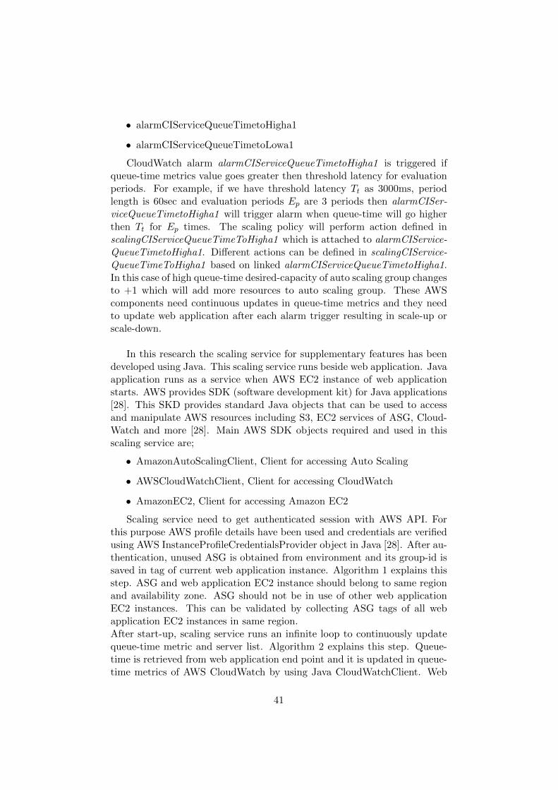
• alarmCIServiceQueueTimetoHigha1
• alarmCIServiceQueueTimetoLowa1
CloudWatch alarm alarmCIServiceQueueTimetoHigha1 is triggered ifqueue-time metrics value goes greater then threshold latency for evaluationperiods. For example, if we have threshold latency Tt as 3000ms, periodlength is 60sec and evaluation periods Ep are 3 periods then alarmCISer-viceQueueTimetoHigha1 will trigger alarm when queue-time will go higherthen Tt for Ep times. The scaling policy will perform action defined inscalingCIServiceQueueTimeToHigha1 which is attached to alarmCIService-QueueTimetoHigha1. Different actions can be defined in scalingCIService-QueueTimeToHigha1 based on linked alarmCIServiceQueueTimetoHigha1.In this case of high queue-time desired-capacity of auto scaling group changesto +1 which will add more resources to auto scaling group. These AWScomponents need continuous updates in queue-time metrics and they needto update web application after each alarm trigger resulting in scale-up orscale-down.
In this research the scaling service for supplementary features has beendeveloped using Java. This scaling service runs beside web application. Javaapplication runs as a service when AWS EC2 instance of web applicationstarts. AWS provides SDK (software development kit) for Java applications[28]. This SKD provides standard Java objects that can be used to accessand manipulate AWS resources including S3, EC2 services of ASG, Cloud-Watch and more [28]. Main AWS SDK objects required and used in thisscaling service are;
• AmazonAutoScalingClient, Client for accessing Auto Scaling
• AWSCloudWatchClient, Client for accessing CloudWatch
• AmazonEC2, Client for accessing Amazon EC2
Scaling service need to get authenticated session with AWS API. Forthis purpose AWS profile details have been used and credentials are verifiedusing AWS InstanceProfileCredentialsProvider object in Java [28]. After au-thentication, unused ASG is obtained from environment and its group-id issaved in tag of current web application instance. Algorithm 1 explains thisstep. ASG and web application EC2 instance should belong to same regionand availability zone. ASG should not be in use of other web applicationEC2 instances. This can be validated by collecting ASG tags of all webapplication EC2 instances in same region.After start-up, scaling service runs an infinite loop to continuously updatequeue-time metric and server list. Algorithm 2 explains this step. Queue-time is retrieved from web application end point and it is updated in queue-time metrics of AWS CloudWatch by using Java CloudWatchClient. Web
41
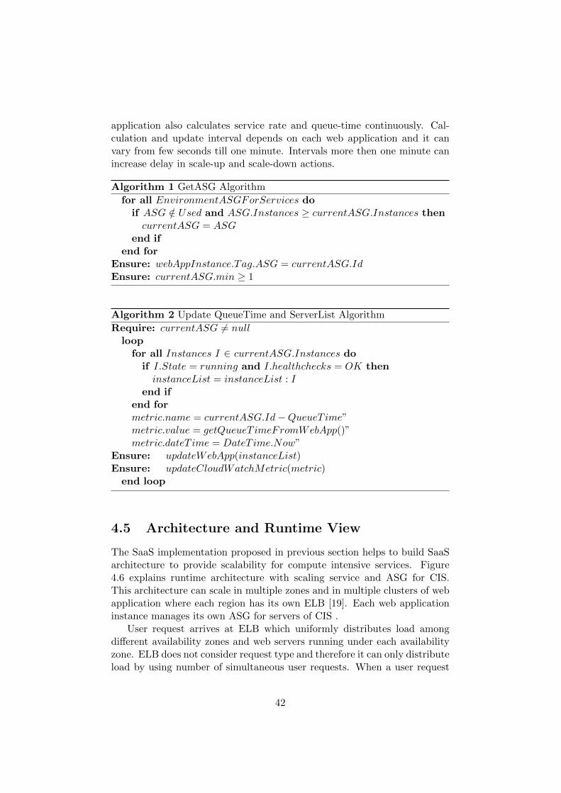
application also calculates service rate and queue-time continuously. Cal-culation and update interval depends on each web application and it canvary from few seconds till one minute. Intervals more then one minute canincrease delay in scale-up and scale-down actions.
Algorithm 1 GetASG Algorithm
for all EnvironmentASGForServices doif ASG /∈ Used and ASG.Instances ≥ currentASG.Instances thencurrentASG = ASG
end ifend for
Ensure: webAppInstance.Tag.ASG = currentASG.IdEnsure: currentASG.min ≥ 1
Algorithm 2 Update QueueTime and ServerList Algorithm
Require: currentASG 6= nullloop
for all Instances I ∈ currentASG.Instances doif I.State = running and I.healthchecks = OK then
instanceList = instanceList : Iend if
end formetric.name = currentASG.Id−QueueT ime”metric.value = getQueueT imeFromWebApp()”metric.dateT ime = DateT ime.Now”
Ensure: updateWebApp(instanceList)Ensure: updateCloudWatchMetric(metric)
end loop
4.5 Architecture and Runtime View
The SaaS implementation proposed in previous section helps to build SaaSarchitecture to provide scalability for compute intensive services. Figure4.6 explains runtime architecture with scaling service and ASG for CIS.This architecture can scale in multiple zones and in multiple clusters of webapplication where each region has its own ELB [19]. Each web applicationinstance manages its own ASG for servers of CIS .
User request arrives at ELB which uniformly distributes load amongdifferent availability zones and web servers running under each availabilityzone. ELB does not consider request type and therefore it can only distributeload by using number of simultaneous user requests. When a user request
42
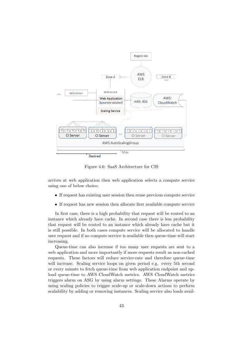
Figure 4.6: SaaS Architecture for CIS
arrives at web application then web application selects a compute serviceusing one of below choice;
• If request has existing user session then reuse previous compute service
• If request has new session then allocate first available compute service
In first case, there is a high probability that request will be routed to aninstance which already have cache. In second case there is less probabilitythat request will be routed to an instance which already have cache but itis still possible. In both cases compute service will be allocated to handleuser request and if no compute service is available then queue-time will startincreasing.
Queue-time can also increase if too many user requests are sent to aweb application and more importantly if more requests result as non-cachedrequests. These factors will reduce service-rate and therefore queue-timewill increase. Scaling service loops on given period e.g. every 5th secondor every minute to fetch queue-time from web application endpoint and up-load queue-time to AWS CloudWatch metrics. AWS CloudWatch metricstriggers alarm on ASG by using alarm settings. These Alarms operate byusing scaling policies to trigger scale-up or scale-down actions to performscalability by adding or removing instances. Scaling service also loads avail-
43
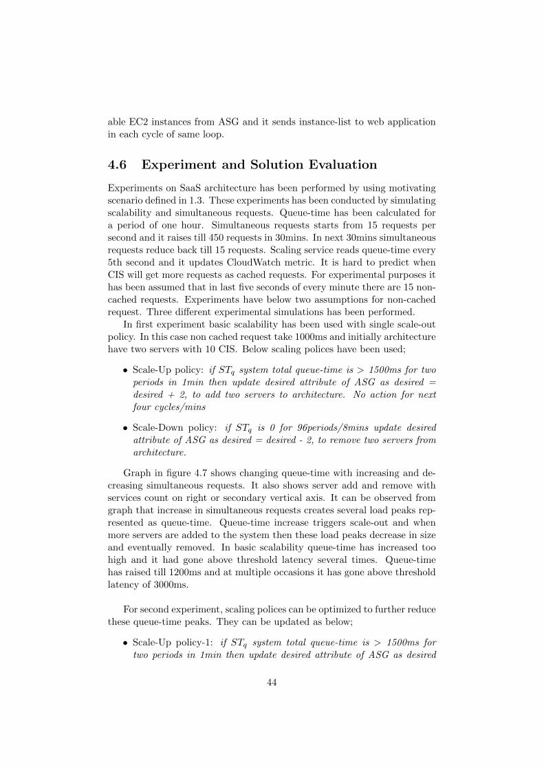
able EC2 instances from ASG and it sends instance-list to web applicationin each cycle of same loop.
4.6 Experiment and Solution Evaluation
Experiments on SaaS architecture has been performed by using motivatingscenario defined in 1.3. These experiments has been conducted by simulatingscalability and simultaneous requests. Queue-time has been calculated fora period of one hour. Simultaneous requests starts from 15 requests persecond and it raises till 450 requests in 30mins. In next 30mins simultaneousrequests reduce back till 15 requests. Scaling service reads queue-time every5th second and it updates CloudWatch metric. It is hard to predict whenCIS will get more requests as cached requests. For experimental purposes ithas been assumed that in last five seconds of every minute there are 15 non-cached requests. Experiments have below two assumptions for non-cachedrequest. Three different experimental simulations has been performed.
In first experiment basic scalability has been used with single scale-outpolicy. In this case non cached request take 1000ms and initially architecturehave two servers with 10 CIS. Below scaling polices have been used;
• Scale-Up policy: if STq system total queue-time is > 1500ms for twoperiods in 1min then update desired attribute of ASG as desired =desired + 2, to add two servers to architecture. No action for nextfour cycles/mins
• Scale-Down policy: if STq is 0 for 96periods/8mins update desiredattribute of ASG as desired = desired - 2, to remove two servers fromarchitecture.
Graph in figure 4.7 shows changing queue-time with increasing and de-creasing simultaneous requests. It also shows server add and remove withservices count on right or secondary vertical axis. It can be observed fromgraph that increase in simultaneous requests creates several load peaks rep-resented as queue-time. Queue-time increase triggers scale-out and whenmore servers are added to the system then these load peaks decrease in sizeand eventually removed. In basic scalability queue-time has increased toohigh and it had gone above threshold latency several times. Queue-timehas raised till 1200ms and at multiple occasions it has gone above thresholdlatency of 3000ms.
For second experiment, scaling polices can be optimized to further reducethese queue-time peaks. They can be updated as below;
• Scale-Up policy-1: if STq system total queue-time is > 1500ms fortwo periods in 1min then update desired attribute of ASG as desired
44
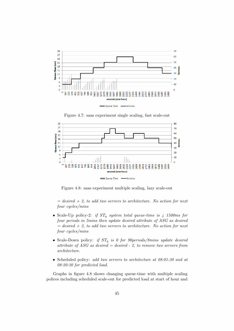
Figure 4.7: saas experiment single scaling, fast scale-out
Figure 4.8: saas experiment multiple scaling, lazy scale-out
= desired + 2, to add two servers to architecture. No action for nextfour cycles/mins
• Scale-Up policy-2: if STq system total queue-time is ¿ 1500ms forfour periods in 5mins then update desired attribute of ASG as desired= desired + 2, to add two servers to architecture. No action for nextfour cycles/mins
• Scale-Down policy: if STq is 0 for 96periods/8mins update desiredattribute of ASG as desired = desired - 2, to remove two servers fromarchitecture.
• Scheduled policy: add two servers to architecture at 08:01:30 and at08:20:30 for predicted load.
Graphs in figure 4.8 shows changing queue-time with multiple scalingpolices including scheduled scale-out for predicted load at start of hour and
45
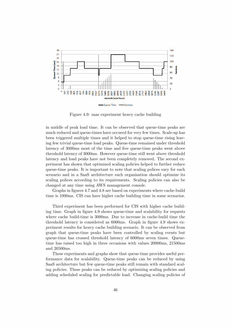
Figure 4.9: saas experiment heavy cache building
in middle of peak load time. It can be observed that queue-time peaks aremuch reduced and queue-times have occured for very few times. Scale-up hasbeen triggered multiple times and it helped to stop queue-time rising leav-ing few trivial queue-time load peaks. Queue-time remained under thresholdlatency of 3000ms most of the time and five queue-time peaks went abovethreshold latency of 3000ms. However queue-time still went above thresholdlatency and load peaks have not been completely removed. The second ex-periment has shown that optimized scaling policies helped to further reducequeue-time peaks. It is important to note that scaling polices vary for eachscenario and in a SaaS architecture each organisation should optimize itsscaling polices according to its requirements. Scaling policies can also bechanged at any time using AWS management console.
Graphs in figures 4.7 and 4.8 are based on experiments where cache-buildtime is 1000ms. CIS can have higher cache building time in some scenarios.
Third experiment has been performed for CIS with higher cache build-ing time. Graph in figure 4.9 shows queue-time and scalability for requestswhere cache build-time is 3000ms. Due to increase in cache-build time thethreshold latency is considered as 6000ms. Graph in figure 4.9 shows ex-periment results for heavy cache building scenario. It can be observed fromgraph that queue-time peaks have been controlled by scaling events butqueue-time has crossed threshold latency of 6000ms seven times. Queue-time has raised too high in three occasions with values 20000ms, 21500msand 26500ms.
These experiments and graphs show that queue-time provides useful per-formance data for scalability. Queue-time peaks can be reduced by usingSaaS architecture but few queue-time peaks still remain with standard scal-ing policies. These peaks can be reduced by optimizing scaling policies andadding scheduled scaling for predictable load. Changing scaling policies of
46
an ASG and changing initial minimum attribute of ASG are trivial andeasy to perform tasks in cloud IaaS although it is still a manual operation.Scaling policy can be changed easily at any time by using AWS consoleand going into EC2 and ASG module. Required ASG can be selected andand then scaling policies can be added or edited. Similarly minimum serverrequirements can be updated at any time by selected details of ASG andchanging Min attribute.
Auto-scaling reduces chances of exponential growth of queue-time. Sched-uled scaling can be performed with ASG scheduled actions in AWS. ASGcan be configured to scale based on defined schedule [20]. Scheduled actionscan be defined by using schedule frequency, start-time and end-time. Forexample; it can be scheduled; set ASG.Min and ASG.Desired equals to threefrom 08:00am till 06:00pm where default ASG.Min and ASG.Desired equalsto two.
4.6.1 Limitations
A SaaS architecture for web application and CIS helps to automate serveradd or remove based on queue-time. The architecture detects queue-timeload peaks which represents load peaks of simultaneous requests and cachebuilding requests. Queue-time load peak growth can be stopped by addingmore servers through CloudWatch alarms and ASG scaling policies. Serversare also successfully removed when not needed to save cost. However fewhigh queue-time load peaks have been observed during experiments. Op-timization of scaling polices and scheduled scaling helps to further reducethese peaks but it is still hard to completely automate and remove thesequeue-time load peaks.
First and most important limitation is AWS delay of server start-up. Itcan take three to five minutes in AWS to attach and start an AWS windowsserver. CloudWatch also triggers to add new server after couple of queue-time alerts and it is required to make sure that we have an actual peak andnot a sudden behaviour due to cache building requests. Both these factorscontribute to delay scale-out and during this time queue-time will keep onincreasing. This creates a small gap between detection and actual scale-out.In this research we have used alarm value as half of threshold latency i.e.1500ms of 3000ms. This helps to initiate early scale-out but there is still apossibility that queue-time peak can go above 3000ms threshold latency inthis gap of four to five minutes. In experiments of this research this increasewas trivial but it can be faster and then it can make more impact on overallsystem performance for a specific period of time.
It is also hard to automate optimization of scaling polices and scheduledscaling according to requirements of each organisation. It is to update scal-ing policies and add scheduled scaling but these are still manual operations.If minimum servers of an ASG are very low in number then a high queue-
47
time peak can occur on very next load. Scheduled scaling can help but it ishard to find or predict precise number of servers for minimum and this re-quirement can change every day. Both scale-out and scale-down actions canbe performed by using SQt (system queue-time) but SQt does not providecomplete information for scale-down. If scale-down is performed only onbasis of SQt then there is a possibility that removing a server will introducequeue-time and next increase of simultaneous requests can create high peakof queue-time. As a part of future work, scale-down can probably be done intwo steps. In Step-1 an instance can be temporarily detached from an ASGand if no new queue-time increase is detected in couple of periods then thisinstance can be terminated else it can be attached back to ASG quickly.
Another limitation is related to data-sets with heavy cache-building time.Architecture cannot guarantee low latency and there can be high queue-timeload peaks if scaling is not fully optimized. In-memory cache reduces latencyif cache hit occur however it is not guaranteed. Whenever user is routed toa compute service which do not have cache ready for given data-set thencache build can happen. If cache build takes many seconds e.g. more then3000ms then it is hard to keep latency under 3000ms because queue-time willbe added over cache build time and it will always be greater then 3000ms.Scalability can reduce impact of cache building requests but low latencycannot be achieved by using only scalability solution. In this research mainscalability solution has been designed and tested for performance factors ofcompute intensive services. Complete details about possible methodologiesof state heavy scenarios is not main part of this research and an overviewwill be discussed in 4.8.
Solution proposed in this research is not appropriate for batch requests.Queue-time does not represent type of incoming requests and a batch re-quest can contain many requests combined in one batch and it can occupyall resources. This can make huge increase in queue-time. Therefore it isimportant to keep batch requests out of regular request. If system has manybatch requests then a scalability solution can be designed for batch requestsqueue. Web application should provide a user interface to separate regularrequests from batch requests. Handling batch request is not part of this re-search but SaaS architecture proposed in this research can be enhanced withmultiple ASG and multiple queue-time metrics to support batch requests.In this way, regular requests can be separated and protected from impactof batch requests. In-memory cache can help to perform batch requestsrapidly. For example; if a batch request contain 2000 requests where eachrequest execution can take 1000ms as non-cached requests and 100ms forcached requests then a batch job running on fiveCIS can take 40sec. Beloware calculations for this example;
• Time to build cache for first request = (1000 * 5)/5 = 1ms
• Time taken for 2000 requests = (100 * 1995)/5 = 39900ms = 39sec
48
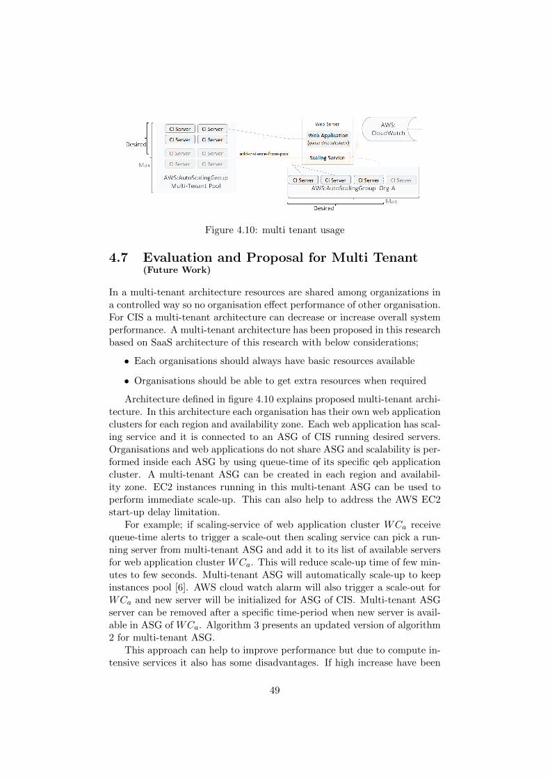
Figure 4.10: multi tenant usage
4.7 Evaluation and Proposal for Multi Tenant(Future Work)
In a multi-tenant architecture resources are shared among organizations ina controlled way so no organisation effect performance of other organisation.For CIS a multi-tenant architecture can decrease or increase overall systemperformance. A multi-tenant architecture has been proposed in this researchbased on SaaS architecture of this research with below considerations;
• Each organisations should always have basic resources available
• Organisations should be able to get extra resources when required
Architecture defined in figure 4.10 explains proposed multi-tenant archi-tecture. In this architecture each organisation has their own web applicationclusters for each region and availability zone. Each web application has scal-ing service and it is connected to an ASG of CIS running desired servers.Organisations and web applications do not share ASG and scalability is per-formed inside each ASG by using queue-time of its specific qeb applicationcluster. A multi-tenant ASG can be created in each region and availabil-ity zone. EC2 instances running in this multi-tenant ASG can be used toperform immediate scale-up. This can also help to address the AWS EC2start-up delay limitation.
For example; if scaling-service of web application cluster WCa receivequeue-time alerts to trigger a scale-out then scaling service can pick a run-ning server from multi-tenant ASG and add it to its list of available serversfor web application cluster WCa. This will reduce scale-up time of few min-utes to few seconds. Multi-tenant ASG will automatically scale-up to keepinstances pool [6]. AWS cloud watch alarm will also trigger a scale-out forWCa and new server will be initialized for ASG of CIS. Multi-tenant ASGserver can be removed after a specific time-period when new server is avail-able in ASG of WCa. Algorithm 3 presents an updated version of algorithm2 for multi-tenant ASG.
This approach can help to improve performance but due to compute in-tensive services it also has some disadvantages. If high increase have been
49
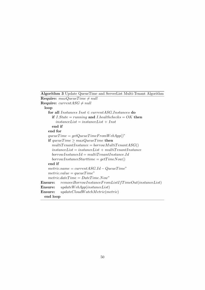
Algorithm 3 Update QueueTime and ServerList Multi-Tenant Algorithm
Require: maxQueueT ime 6= nullRequire: currentASG 6= null
loopfor all Instances Inst ∈ currentASG.Instances do
if I.State = running and I.healthchecks = OK theninstanceList = instanceList + Inst
end ifend forqueueT ime = getQueueT imeFromWebApp()”if queueT ime ≥ maxQueueT ime then
multiTenantInstance = borrowMultiTenantASG()instanceList = instanceList + multiTenantInstanceborrowInstanceId = multiTenantInstance.IdborrowInstanceStarttime = getT imeNow()
end ifmetric.name = currentASG.Id−QueueT ime”metric.value = queueT ime”metric.dateT ime = DateT ime.Now”
Ensure: removeBorrowInstanceFromListIfT imeOut(instanceList)Ensure: updateWebApp(instanceList)Ensure: updateCloudWatchMetric(metric)
end loop
50
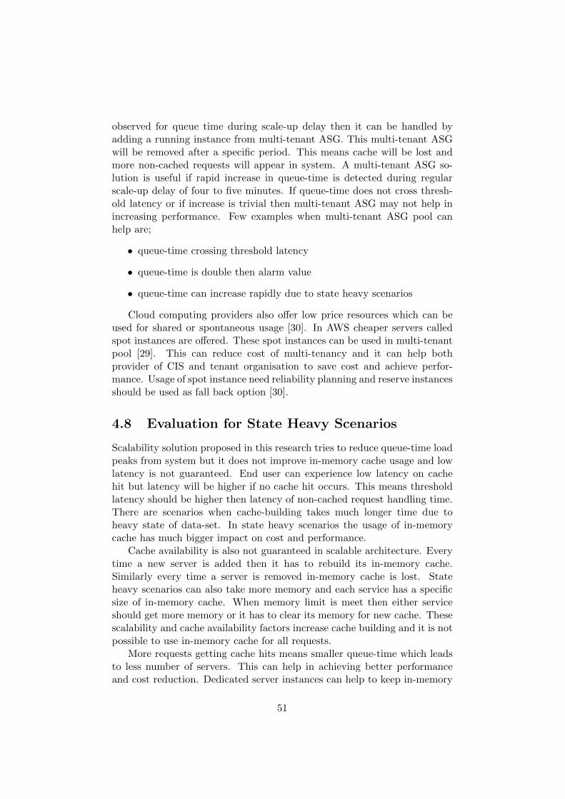
observed for queue time during scale-up delay then it can be handled byadding a running instance from multi-tenant ASG. This multi-tenant ASGwill be removed after a specific period. This means cache will be lost andmore non-cached requests will appear in system. A multi-tenant ASG so-lution is useful if rapid increase in queue-time is detected during regularscale-up delay of four to five minutes. If queue-time does not cross thresh-old latency or if increase is trivial then multi-tenant ASG may not help inincreasing performance. Few examples when multi-tenant ASG pool canhelp are;
• queue-time crossing threshold latency
• queue-time is double then alarm value
• queue-time can increase rapidly due to state heavy scenarios
Cloud computing providers also offer low price resources which can beused for shared or spontaneous usage [30]. In AWS cheaper servers calledspot instances are offered. These spot instances can be used in multi-tenantpool [29]. This can reduce cost of multi-tenancy and it can help bothprovider of CIS and tenant organisation to save cost and achieve perfor-mance. Usage of spot instance need reliability planning and reserve instancesshould be used as fall back option [30].
4.8 Evaluation for State Heavy Scenarios
Scalability solution proposed in this research tries to reduce queue-time loadpeaks from system but it does not improve in-memory cache usage and lowlatency is not guaranteed. End user can experience low latency on cachehit but latency will be higher if no cache hit occurs. This means thresholdlatency should be higher then latency of non-cached request handling time.There are scenarios when cache-building takes much longer time due toheavy state of data-set. In state heavy scenarios the usage of in-memorycache has much bigger impact on cost and performance.
Cache availability is also not guaranteed in scalable architecture. Everytime a new server is added then it has to rebuild its in-memory cache.Similarly every time a server is removed in-memory cache is lost. Stateheavy scenarios can also take more memory and each service has a specificsize of in-memory cache. When memory limit is meet then either serviceshould get more memory or it has to clear its memory for new cache. Thesescalability and cache availability factors increase cache building and it is notpossible to use in-memory cache for all requests.
More requests getting cache hits means smaller queue-time which leadsto less number of servers. This can help in achieving better performanceand cost reduction. Dedicated server instances can help to keep in-memory
51
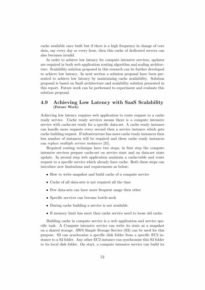
cache available once built but if there is a high frequency in change of coredata, say every day or every hour, then this cache of dedicated servers canalso becomes invalid.
In order to achieve low latency for compute intensive services, updatesare required in both web application routing algorithm and scaling architec-ture. Scalability solution proposed in this research can be further developedto achieve low latency. In next section a solution proposal have been pre-sented to achieve low latency by maintaining cache availability. Solutionproposal is based on SaaS architecture and scalability solution presented inthis report. Future work can be performed to experiment and evaluate thissolution proposal.
4.9 Achieving Low Latency with SaaS Scalability(Future Work)
Achieving low latency requires web application to route request to a cacheready service. Cache ready services means there is a compute intensiveservice with cache-set ready for a specific data-set. A cache ready instancecan handle more requests every second then a service instance which getscache building request. If infrastructure has more cache ready instances thenless number of instances will be required and these cache ready instancescan replace multiple service instances [31].
Required routing technique have two steps; in first step the computeintensive services prepare cache-set on service start and on data-set stateupdate. In second step web application maintain a cache-table and routerequest to a specific service which already have cache. Both these steps canintroduce new limitations and requirements as below;
• How to write snapshot and build cache of a compute service
• Cache of all data-sets is not required all the time
• Few data-sets can have more frequent usage then other
• Specific services can become bottle-neck
• During cache building a service is not available.
• If memory limit has meet then cache service need to loose old cache.
Building cache in compute service is a web application and service spe-cific task. A Compute intensive service can write its state as a snapshoton a shared storage. AWS Simple Storage Service (S3) can be used for thispurpose. S3 can synchronize a specific disk folder from a specific EC2 in-stance to a S3 folder. Any other EC2 instance can synchronize this S3 folderto its local disk folder. On start, a compute intensive service can build its
52
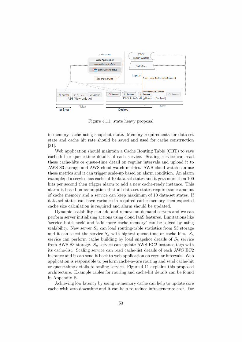
Figure 4.11: state heavy proposal
in-memory cache using snapshot state. Memory requirements for data-setstate and cache hit rate should be saved and used for cache construction[31].
Web application should maintain a Cache Routing Table (CRT) to savecache-hit or queue-time details of each service. Scaling service can readthese cache-hits or queue-time detail on regular intervals and upload it toAWS S3 storage and AWS cloud watch metrics. AWS cloud watch can usethese metrics and it can trigger scale-up based on alarm condition. An alarmexample; if a service has cache of 10 data-set states and it gets more then 100hits per second then trigger alarm to add a new cache-ready instance. Thisalarm is based on assumption that all data-set states require same amountof cache memory and a service can keep maximum of 10 data-set states. Ifdata-set states can have variance in required cache memory then expectedcache size calculation is required and alarm should be updated.
Dynamic scalability can add and remove on-demand servers and we canperform server initializing actions using cloud IaaS features. Limitations like’service bottleneck’ and ’add more cache memory’ can be solved by usingscalability. New server Sn can load routing-table statistics from S3 storageand it can select the service Sh with highest queue-time or cache hits. Sn
service can perform cache building by load snapshot details of Sh servicefrom AWS S3 storage. Sn service can update AWS EC2 instance tags withits cache-list. Scaling service can read cache-list details of each AWS EC2instance and it can send it back to web application on regular intervals. Webapplication is responsible to perform cache-aware routing and send cache-hitor queue-time details to scaling service. Figure 4.11 explains this proposedarchitecture. Example tables for routing and cache-hit details can be foundin Appendix B.
Achieving low latency by using in-memory cache can help to update corecache with zero downtime and it can help to reduce infrastructure cost. For
53
example, if cache building time is 3000ms and 15% requests can triggercache building then at a specific time for 500 requests there is a need of 24servers each running five CIS. Below are calculation details;
• Arrival Execution Load Ae = (75*1000)+(425*100) = 11750000
• Servers Required Sr = Ae / 1000 / 5 = 24 Servers
With low latency solution most requests can be handled by using in-memorycache and latency will be 100ms. For popular requests threshold latency canbe reduced to 1500 with queue-time alarm triggering on 500ms. For 500 re-quests there will be a need of 10 servers each running five CIS. This canreduce infrastructure cost with predictable low latency. Below are calcula-tion details;
• Arrival Execution Load Ae = (0*1000)+(500*100) = 50000
• Servers Required Sr = Ae / 1000 / 5 = 10 Servers
4.9.1 Limitations and Considerations
This solution can increase scale-up delay due to cache building at start.This delay depends on cache building time but it should not be big. Cal-culations in below example shows that cache building time can be less thentwo minutes.
• time required to build a cache Cb = 3000ms
• memory required for data-set build and execute Mr = 30mb
• total memory size of a service Mt = 1000mb
• possible number of data-sets in each service Dp
= Mt / Mr = 1000 / 30 = aprox. 30
• time to build total cache Ct
= Dp * Cb = 3000 * 30 = 90000ms = 90sec
This solution proposal requires at least one cache of each data-set inCIS. Creating at least one cache of each data-set is sometimes not possibledue to usage of old data-sets and only latest or popular data-sets can becached. It is also a business decision if there is a need to create at least onecache of each data-set or only popular data-sets should be cached. In caseof ’popular data-sets’ there are two more considerations. Identification of’popular data-sets’ should be performed on regular basis, for example everymorning. A new ASG should be prepared using latest popular data-setsand it should replace active ASG. At least one server should be available toreceive new unique requests. If number of data-set states sent to a specificserver exceed allocated memory then another server should be added forunique requests using scalability.
54
4.9.2 Alternative Approaches
An alternative approach is shared memory or Inter-Process Communicationsolution [32]. In this approach CIS may share in-memory cache if they are onsame server. Shared memory solutions can require extra development at ap-plication level and shared memory solutions also have limitations which canreduce system performance. Shared memory solutions cannot hold cache fortoo many or large data-sets and cache can also have concurrency issues. Inshared memory solutions cache size have to be increased after sometime andan increase in cache size may raise garbage collector issues in few computerlanguage implementations.
AWS ElastiCache is another approach with scalable cache solution. Itis a cloud service that can be used to deploy, operate, and scale in-memorycache of a compute service [33]. ElastiCache can improve performance byusage of scalable and fast in-memory caches [33]. However, there is a needto run multiple CIS to support simultaneous user requests. AWS Elasti-Cache supports cache scalability for a single compute service which doesnot provide a performance gain for increasing simultaneous requests.
55
Conclusion and Discussion
In this research initial experiments have been conducted on dedicated serversand then a SaaS architecture has been presented for compute intensive ser-vices. Study of dedicated servers has shown that it is difficult to find requirednumber of dedicated servers for cache optimized CIS. If very few servers areused considering cached requests then performance will degrade during loadpeaks but at the same time if many servers are used considering peak loadthen cost becomes too high and servers are also under used in off load time.Dedicated servers can give cost-effective performance if number of simul-taneous requests is very low and cache remains static for longer periods.However, support for both these factors is essential for enterprise business.
SaaS architecture has been built using cloud computing products ofAWS, queue-time metric and scaling service. AWS products like ASG,CloudWatch, LC and ELB has been used to build infrastructure. Experi-ments on SaaS architecture has shown that queue-time can represent perfor-mance data for scalability. Scale-out and scale-down event can be triggeredby using queue-time inputs which helps to reduce load peaks while keepingcost low. It has been observed that proposed approach does not remove allload peaks. Optimizations of scaling polices and scheduled scaling for eachorganisation can help to remove these load peaks further. Server start-uptime has been observed as three to five minutes which does not allow robustand immediate scaling. Single tenant SaaS architecture can help to achievecost-effective performance but there are still possibilities of small load peaksdue to server start-up delay. These load peaks are eventually handled bythe SaaS architecture with a scale-out event but these load peaks can reduceperformance for a small period of time.
The single-tenant SaaS architecture of this research has been used topropose a multi-tenant SaaS architecture. This architecture uses a sharedASG which can help to achieve immediate scalability and it can removesmall peaks created due to server start-up delay. Although in this researchwe have discussed an approach to achieve cost-effective performance for CIS,we believe that this approach can be further developed to achieve low la-tency and usage of in-memory cache can be further optimized. Proposal toachieve low latency is based on CRT and it tries to remove cache buildingrequests. This proposal to achieve low latency for CIS is also based on SaaS
56
architecture of this report.
Future Work
Experiments have shown that queue-time load peaks cannot be com-pletely removed in single tenant SaaS architecture. Optimizations of scalingpolices and scheduled scaling can help to reduce load peaks but it is a man-ual task today. Input for scheduled scaling can be calculated and automatedby using scalability data of last day with machine learning and predictionalgorithms. Dynamic scaling will still provide scalability for unpredictableload of simultaneous requests and cache building requests.
Another reason of these remaining load peaks is early scale-down. Ifscale-down is performed on zero queue-time then it is doubtful if server isstill partially required or not. Scale down can be delayed and performedonly if server is completely free. Sale-down can be developed further toperform delayed scale-down in two steps. In Step-1 an instance can betemporarily detached from an ASG and if no new queue-time increase isdetected in couple of periods then this instance can be terminated else itcan be attached back to ASG quickly.
Experiments in this research have been performed by using generatedqueue-time and it is difficult to perform variety of scalability experiments fordifferent expected scenarios. There is a need to design a simulation systemor framework to test scaling-policies and alarms of SaaS architecture. Itshould take required number of simultaneous and cache building requestsas input and test run given scaling policies and scheduled scaling. It canhelp to understand system performance, optimize architecture and scalingpolicies.
SaaS architecture can be further developed for proposed multi-tenantarchitecture and for batch requests handling. This research has been con-ducted to reduce load peaks but this architecture can be further developed toachieve low latency for CIS. It can help to get predictable and low responselatency and data-sets with large cache building time can also be optimized.
57

Appendices
58
Appendix A
AWS CloudFormation forScaling Policy and Alarms
{” scalingCIServiceQueueTimeToLowa1 ” : {”Type ” : ”AWS: : AutoScal ing : : S c a l i n g P o l i c y ” ,” P r o p e r t i e s ” : {”AdjustmentType ” : ”ChangeInCapacity ” ,”Cooldown ” : ”300” ,” Scal ingAdjustment ” : ”−1”,”AutoScalingGroupName ” : {” Ref ” : ” CIServ icea1 ”}}} ,” scal ingCIServiceQueueTimeNoActiv itya1 ” : {”Type ” : ”AWS: : AutoScal ing : : S c a l i n g P o l i c y ” ,” P r o p e r t i e s ” : {”AdjustmentType ” : ” ExactCapacity ” ,”Cooldown ” : ”10” ,” Scal ingAdjustment ” : ”0” ,”AutoScalingGroupName ” : {” Ref ” : ” CIServ icea1 ”}}} ,” scal ingCIServiceQueueTimeToHigha1 ” : {”Type ” : ”AWS: : AutoScal ing : : S c a l i n g P o l i c y ” ,” P r o p e r t i e s ” : {”AdjustmentType ” : ”ChangeInCapacity ” ,”Cooldown ” : ”300” ,” Scal ingAdjustment ” : ”1” ,”AutoScalingGroupName ” : {” Ref ” : ” CIServ icea1 ”}}} ,” alarmCIServiceQueueTimeNoActiona1 ” : {”Type ” : ”AWS: : CloudWatch : : Alarm ” ,” P r o p e r t i e s ” : {
59
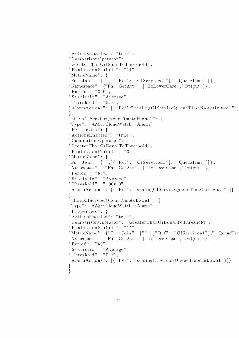
” ActionsEnabled ” : ” t rue ” ,”ComparisonOperator ” :”GreaterThanOrEqualToThreshold ” ,” Eva luat ionPer iods ” : ”11” ,”MetricName ” : {”Fn : : Join ” : [ ” ” , [ { ” Ref ” : ” CIServ icea1 ”} ,”−QueueTime ” ] ] } ,”Namespace ” : {”Fn : : GetAtt ” : [ ” ToLowerCase ” ,” Output ” ]} ,” Per iod ” : ”300” ,” S t a t i s t i c ” : ”Average ” ,” Threshold ” : ”0 .0” ,”AlarmActions ” : [{” Ref ” :” scal ingCIServiceQueueTimeNoActiv itya1 ”} ]}} ,” alarmCIServiceQueueTimetoHigha1 ” : {”Type ” : ”AWS: : CloudWatch : : Alarm ” ,” P r o p e r t i e s ” : {” ActionsEnabled ” : ” t rue ” ,”ComparisonOperator ” :”GreaterThanOrEqualToThreshold ” ,” Eva luat ionPer iods ” : ”3” ,”MetricName ” : {”Fn : : Join ” : [ ” ” , [ { ” Ref ” : ” CIServ icea1 ”} ,”−QueueTime ” ] ] } ,”Namespace ” : {”Fn : : GetAtt ” : [ ” ToLowerCase ” ,” Output ” ]} ,” Per iod ” : ”60” ,” S t a t i s t i c ” : ”Average ” ,” Threshold ” : ”1000 .0” ,”AlarmActions ” : [{” Ref ” : ” scal ingCIServiceQueueTimeToHigha1 ”} ]}} ,”alarmCIServiceQueueTimetoLowa1 ” : {”Type ” : ”AWS: : CloudWatch : : Alarm ” ,” P r o p e r t i e s ” : {” ActionsEnabled ” : ” t rue ” ,”ComparisonOperator ” : ”GreaterThanOrEqualToThreshold ” ,” Eva luat ionPer iods ” : ”15” ,”MetricName ” : {”Fn : : Join ” : [ ” ” , [ { ” Ref ” : ” CIServ icea1 ”} ,”−QueueTime ” ] ] } ,”Namespace ” : {”Fn : : GetAtt ” : [ ” ToLowerCase ” ,” Output ” ]} ,” Per iod ” : ”60” ,” S t a t i s t i c ” : ”Average ” ,” Threshold ” : ”0 .0” ,”AlarmActions ” : [{” Ref ” : ” scalingCIServiceQueueTimeToLowa1 ”} ]}}}
60
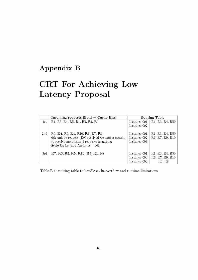
Appendix B
CRT For Achieving LowLatency Proposal
Incoming requests [Bold = Cache Hits] Routing Table1st R1, R3, R4, R5, R1, R3, R4, R5 Instance-001 R1, R3, R4, R50
Instance-002
2nd R6, R4, R9, R1, R10, R3, R7, R5 Instance-001 R1, R3, R4, R506th unique request (R9) received we expect system Instance-002 R6, R7, R9, R10to receive more than 8 requests triggering Instance-003Scale-Up i.e. add Instance− 003
3rd R7, R3, R2, R5, R10, R9, R1, R8 Instance-001 R1, R3, R4, R50Instance-002 R6, R7, R9, R10Instance-003 R2, R8
Table B.1: routing table to handle cache overflow and runtime limitations
61
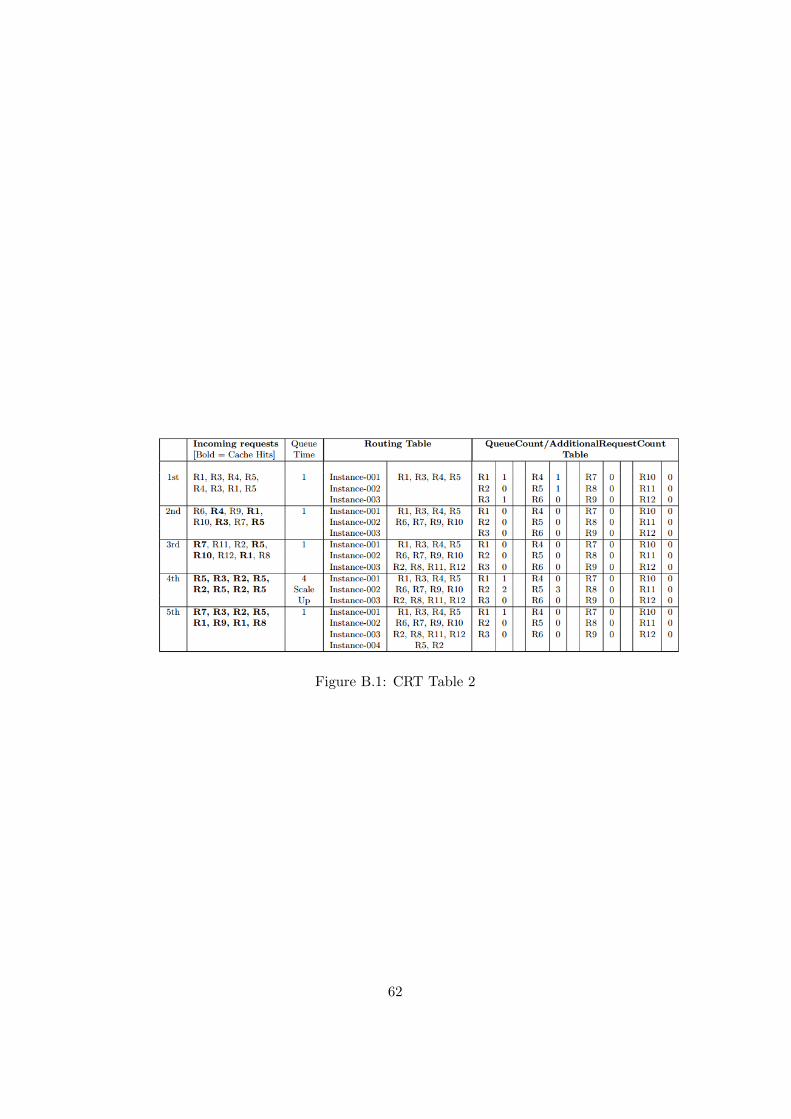
Figure B.1: CRT Table 2
62
Bibliography
[1] Suleiman, Basem, Sherif Sakr, Ross Jeffery, and Anna Liu. ”On Under-standing the Economics and Elasticity Challenges of Deploying BusinessApplications on Public Cloud Infrastructure.” Journal of Internet Servicesand Applications 3, no. 2 (2012): 173.
[2] Karakostas, Bill. ”A Scalable Architecture for Concurrent Online Auc-tions.” Concurrency and Computation: Practice and Experience 26, no.3 (2014): 841-50.
[3] Chapter: Application Performance Concept: Differentiating Perfor-mance from Scalability. Link: http://www.dynatrace.com/en/javabook/performance-and-scalability.html
[4] Lopes, Raquel, Francisco Brasileiro, and Paulo Ditarso Maciel.”Business-driven Capacity Planning of a Cloud-based It Infrastructurefor the Execution of Web Applications.” Parallel and Distributed Pro-cessing, Workshops and Phd Forum (IPDPSW), 2010 IEEE InternationalSymposium on, 2010, 1-8.
[5] Amazon Web Services - Architecting for the Cloud: Best Practices 2010,Jinesh Varia
[6] AWS Auto Scaling, Accessed :2015, Decemberhttps://aws.amazon.com/autoscaling/
[7] Kulkarni, Gurudatt, Rupali Shelke, Rajnikant Palwe, PrasadKhatawkar, Sadanand Bhuse, and Hemant Bankar. ”Multi-tenant SaaSCloud” Computing, Communications and Networking Technologies (IC-CCNT),2013 Fourth International Conference on, 2013, 1-4.
[8] Defining Standards for Web Page Performance in Business ApplicationsRempel, Garret John, Lizy, K. (General Chair) ; Smith, Connie, U. (Gen-eral Chair) ; Sachs, Kai (Program Chair) ; Llado, Catalina, M. (ProgramChair)
[9] Sumit Sharma, Dan Diephouse, Katie Burton. MuleSoft, SaaSProvider Handbook (How to Make Your App Enterprise Ready ), Ac-
63
cessed 2015: https://www.mulesoft.com/lp/ebook/saas/accelerate-saas-adoption-new-enterprise
[10] Plattner, Hasso., and Alexander. Zeier. In-Memory Data ManagementAn Inflection Point for Enterprise Applications. Berlin: Springer BerlinHeidelberg, 2011
[11] Garber, L. ”Using In-Memory Analytics to Quickly Crunch Big Data.”Computer 45, no. 10 (2012): 16-18.
[12] Andukuri, Pratibha V., Jiang Guo, and Raj Pamula. ”Automatic Inte-gration of Web Services.” Internet Technology and Applications (iTAP),2011 International Conference on (2011): 1-4. Web.
[13] Best Practices for web services: Part 9, Web services performance con-siderations, Part 1, Accessed 2015,http://www.ibm.com/developerworks/library/ws-best9/
[14] Mahmood, Zaigham., and Richard. Hill. Cloud Computing for Enter-prise Architectures. Dordrecht: Springer, 2011. Computer Communica-tions and Networks. Web.
[15] Furht, Borko., and Armando. Escalante. Handbook of Cloud Comput-ing. Dordrecht: Springer, 2010. Web.
[16] https://en.wikipedia.org/wiki/Cloud computingInfrastructure as a service .28IaaS.29
[17] Dillon, Tharam, Chen Wu, and Elizabeth Chang. ”Cloud Computing:Issues and Challenges.” Advanced Information Networking and Applica-tions (AINA), 2010 24th IEEE International Conference on (2010): 27-33.Web.
[18] Gao, Jerry, Pushkala Pattabhiraman, Xiaoying Bai, and W. T. Tsai.”SaaS Performance and Scalability Evaluation in Clouds.” Service Ori-ented System Engineering (SOSE), 2011 IEEE 6th International Sympo-sium on (2011): 61-71. Web.
[19] Web Application Hosting in the AWS Cloud Best Practices 2012https://aws.amazon.com/whitepapers/web-application-hosting-best-practices/
[20] Auto Scaling User Guide, Accessed 2015,http://docs.aws.amazon.com/AutoScaling/latest/DeveloperGuide/WhatIsAutoScaling.html
[21] Auto Scaling Developer Resources, Accessed 2015,https://aws.amazon.com/cloudwatch/developer-resources/
[22] Amazon CloudWatch Documentation, Accessed 2015,https://aws.amazon.com/documentation/cloudwatch/
64
[23] Amazon CloudWatch Developer Resources, Accessed 2015,https://aws.amazon.com/cloudwatch/developer-resources/
[24] Amazon Elastic Load Balancing, Accessed 2015,http://docs.aws.amazon.com/ElasticLoadBalancing/latest/DeveloperGuide
[25] M/M/c Queue, accessed 2015,https://en.wikipedia.org/wiki/M/M/c queue
[26] High Availability Cluster, accessed 2015,https://en.wikipedia.org/wiki/High-availability cluster
[27] AWS CloudFormation, accessed 2015,https://aws.amazon.com/cloudformation/
[28] AWS SDK for Java, accessed 2015,https://aws.amazon.com/sdk-for-java/
[29] Amazon EC2 Spot Instances, Accessed 2015,https://aws.amazon.com/ec2/spot/
[30] Voorsluys, William, and Rajkumar Buyya. ”Reliable Provisioning ofSpot Instances for Compute-intensive Applications.” (2011). Web.
[31] Neumann, Robert, Eric Goltzer, Reiner Dumke, and Andreas Schmi-etendorf. ”Caching Highly Compute-Intensive Cloud Applications: AnApproach to Balancing Cost with Performance.” Software Measurement,2011 Joint Conference of the 21st Int’l Workshop on and 6th Int’l Confer-ence on Software Process and Product Measurement (IWSM-MENSURA)(2011): 96-105. Web.
[32] Inter-process communicationhttps://en.wikipedia.org/wiki/Inter-process communication
[33] Amazon ElastiCache, accessed 2015,https://aws.amazon.com/elasticache/
65

TRITA TRITA-ICT-EX-2016:56
www.kth.se


