Embed Size (px)
Citation preview
P r o d u c t C a t a l o g
SMITH BEARING®
accurate bushing co. accurate bushing co.
a
SMITH BEARING®
a registered trademark of
Smith-Trax®
Track Rollers & Guide Rails
IndustrialsCam Followers & Needle Bearings
AerospaceBearings & Components
Stainless SteelCorrosion Resistant Bearings
A c c u ra c y i s O u r B e s t Po l i c y
Cam Followers, Needle Bearings, Track Rollers & Special Assemblies for Aerospace & Industrial Applications

All products in this catalog subject to Accurate Bushing Company terms and conditions, a copy of which is available in theback of this catalog or may be requested from the customer service department.
SMITH Bearing, SMITH-TRAX, & SMITH-ALIGN are registered trademarks of Accurate Bushing Company.Copyright © 2014 Accurate Bushing Company. All rights reserved.
Smith Bearing® is a registered trademark of Accurate Bushing Company. With over 50 years experience in designing and manufacturing precision needle roller bearings, we can handle your re-quirements for aerospace and industrial bearings, as well as custom manufactured special bearings, assemblies, and bushings.
In this catalog you will find our complete range of
precision bearings including:
Cam Follower Needle Roller Bearings in Inch
& Metric sizes, Stainless Steel Cam Followers for
special corrosive applications, Cam Followers with
self-lubricating engineered plastic bushings,
Smith-Trax® with tapered roller bearings and
deep-groove ball bearings for high-thrust load
applications, Aerospace and Military approved
Needle Roller Bearings for engine and airframe
applications, Spherical Plain Bearings, Drill Jig
Bushings and Specialty Aerospace products
and assemblies.
As well as our existing product line, we are ready to assist you with the manufacture of custom made
products, precision machine components and assemblies. ISO 9001 and AS 9100 registered.
Smith Bearing® serves the global market place with a network of Industrial and Aerospace distributors,
manufacturing plants and sales offices throughout the world. The structure of our operation affords us the
ability to give highly personalized attention to every customer. Most importantly, this structure gives us the
ability to respond immediately to our customers request as well as providing highly cost-effective products.
Email: [email protected] Phone: 800.932.0076
Standard & Custom Bearings and Special Assembliesfor Aerospace & Industrial Applications
CORPORATE HEADQUARTERS443 North Avenue
Garwood • NJ • 07027 • USA
tel: 908.789.1121fax: 908.789.9429 800.932.0076www.accuratebushing.com
��
accurate bushing co.SMITH BEARING®i s a r e g i s t e r e d t r a d e m a r k o f
SMITH BEARING ® Needle Rollers, Bushings, Track Rollersand Special Assemblies for
Aerospace & Industrial Applications
SMITH-TRAX® Track Rollers and Smith RailInch Sizes or Metric Sizes • High Quality Bearing Steel or Corrosion Resistant Stainless Steel
Aerospace Bearings AS21438 • AS24461 • AS21439 • AS21432 • AS24465 • AS21447 • AS24466 • AS5927 • AS5928 • AS5929927(MS21438) (MS24461) (MS21439) (MS21432) (MS24465) (MS21447) (MS24466)
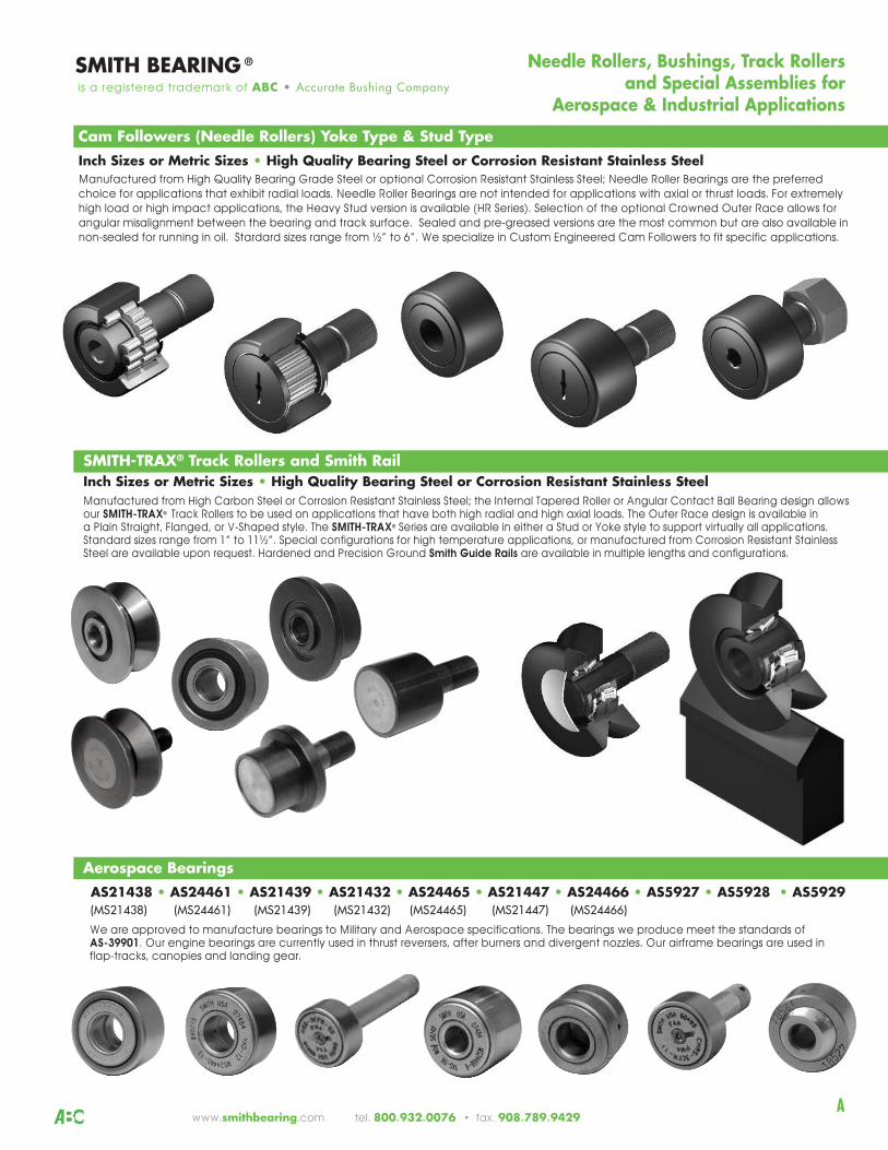
Cam Followers (Needle Rollers) Yoke Type & Stud TypeInch Sizes or Metric Sizes • High Quality Bearing Steel or Corrosion Resistant Stainless Steel Manufactured from High Quality Bearing Grade Steel or optional Corrosion Resistant Stainless Steel; Needle Roller Bearings are the preferred
choice for applications that exhibit radial loads. Needle Roller Bearings are not intended for applications with axial or thrust loads. For extremely
high load or high impact applications, the Heavy Stud version is available (HR Series). Selection of the optional Crowned Outer Race allows for
angular misalignment between the bearing and track surface. Sealed and pre-greased versions are the most common but are also available in
non-sealed for running in oil. Stardard sizes range from ½” to 6”. We specialize in Custom Engineered Cam Followers to fit specific applications.
We are approved to manufacture bearings to Military and Aerospace specifications. The bearings we produce meet the standards of AS-39901. Our engine bearings are currently used in thrust reversers, after burners and divergent nozzles. Our airframe bearings are used inflap-tracks, canopies and landing gear.
is a registered trademark of ABC • Accurate Bushing Company
www.smithbearing.com tel. 800.932.0076 • fax. 908.789.9429A
Manufactured from High Carbon Steel or Corrosion Resistant Stainless Steel; the Internal Tapered Roller or Angular Contact Ball Bearing design allowsour SMITH-TRAX® Track Rollers to be used on applications that have both high radial and high axial loads. The Outer Race design is available in a Plain Straight, Flanged, or V-Shaped style. The SMITH-TRAX® Series are available in either a Stud or Yoke style to support virtually all applications.Standard sizes range from 1” to 11½”. Special configurations for high temperature applications, or manufactured from Corrosion Resistant StainlessSteel are available upon request. Hardened and Precision Ground Smith Guide Rails are available in multiple lengths and configurations.
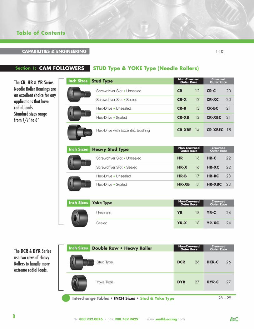
Table of Contents
1
Screwdriver Slot • Unsealed CR 12 CR-C 20
Screwdriver Slot • Sealed CR-X 12 CR-XC 20
Hex-Drive • Unsealed CR-B 13 CR-BC 21
Hex-Drive • Sealed CR-XB 13 CR-XBC 21
CR-XBE 14 CR-XBEC 15
Screwdriver Slot • Unsealed HR 16 HR-C 22
Screwdriver Slot • Sealed HR-X 16 HR-XC 22
Hex-Drive • Unsealed HR-B 17 HR-BC 23
Hex-Drive • Sealed HR-XB 17 HR-XBC 23
Unsealed YR 18 YR-C 24
Sealed YR-X 18 YR-XC 24
Stud Type DCR 26 DCR-C 26
Yoke Type DYR 27 DYR-C 27
Section 1: CAM FOLLOWERS STUD Type & YOKE Type (Needle Rollers)
CAPABILITIES & ENGINEERING 1-10
Non-Crowned Crowned Outer Race Outer Race
Inch Sizes Yoke Type
Inch Sizes Heavy Stud Type
Inch Sizes Stud Type
Inch Sizes Double Row • Heavy Roller
Interchange Tables • INCH Sizes • Stud & Yoke Type 28 – 29
tel. 800.932.0076 • fax. 908.789.9429 www.smithbearing.com B
Non-Crowned Crowned Outer Race Outer Race
Hex-Drive with Eccentric Bushing
Non-Crowned Crowned Outer Race Outer Race
Non-Crowned Crowned Outer Race Outer Race
The CR, HR & YR SeriesNeedle Roller Bearings arean excellent choice for anyapplications that have radial loads. Standard sizes rangefrom 1/2” to 6”
The DCR & DYR Series use two rows of HeavyRollers to handle moreextreme radial loads.
SMITH BEARING® is a registered trademark of ABC • Accurate Bushing Company
www.smithbearing.com tel. 800.932.0076 • fax. 908.789.9429
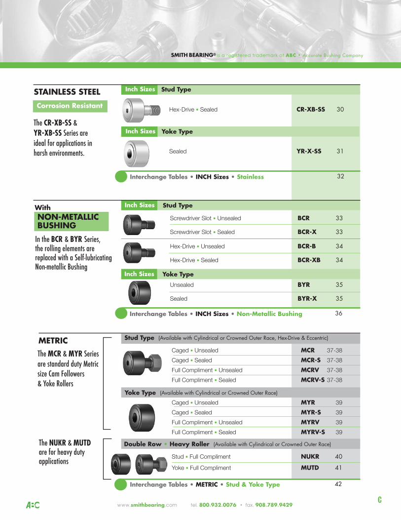
Screwdriver Slot • Unsealed BCR 33
Screwdriver Slot • Sealed BCR-X 33
Hex-Drive • Unsealed BCR-B 34
Hex-Drive • Sealed BCR-XB 34
Unsealed BYR 35
Sealed BYR-X 35
Inch Sizes Stud Type WithNON-METALLICBUSHING
Inch Sizes Yoke Type
Interchange Tables • INCH Sizes • Non-Metallic Bushing 36
Caged • Unsealed MCR 37-38
Caged • Sealed MCR-S 37-38
Full Compliment • Unsealed MCRV 37-38
Full Compliment • Sealed MCRV-S 37-38
Caged • Unsealed MYR 39
Caged • Sealed MYR-S 39
Full Compliment • Unsealed MYRV 39
Full Compliment • Sealed MYRV-S 39
Stud • Full Compliment NUKR 40
Yoke • Full Compliment MUTD 41
Stud Type (Available with Cylindrical or Crowned Outer Race, Hex-Drive & Eccentric) METRIC
Yoke Type (Available with Cylindrical or Crowned Outer Race)
Interchange Tables • METRIC • Stud & Yoke Type 42
Double Row • Heavy Roller (Available with Cylindrical or Crowned Outer Race)
Hex-Drive • Sealed CR-XB-SS 30
Sealed YR-X-SS 31
Inch Sizes Stud Type STAINLESS STEEL
Inch Sizes Yoke Type
Interchange Tables • INCH Sizes • Stainless 32
C
Corrosion Resistant
The CR-XB-SS & YR-XB-SS Series are ideal for applications inharsh environments.
In the BCR & BYR Series, the rolling elements are replaced with a Self-lubricating Non-metallic Bushing
The MCR & MYR Seriesare standard duty Metricsize Cam Followers& Yoke Rollers
The NUKR & MUTDare for heavy dutyapplications
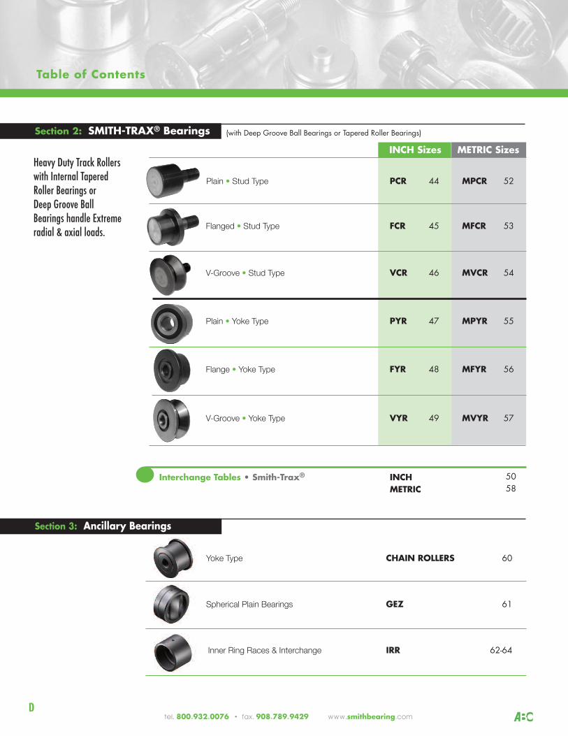
Table of Contents
Plain • Stud Type PCR 44 MPCR 52
Flanged • Stud Type FCR 45 MFCR 53
V-Groove • Stud Type VCR 46 MVCR 54
Plain • Yoke Type PYR 47 MPYR 55
Flange • Yoke Type FYR 48 MFYR 56
V-Groove • Yoke Type VYR 49 MVYR 57
Section 2: SMITH-TRAX® Bearings (with Deep Groove Ball Bearings or Tapered Roller Bearings)
Interchange Tables • Smith-Trax® INCH 50METRIC 58
tel. 800.932.0076 • fax. 908.789.9429 www.smithbearing.com
Section 3: Ancillary Bearings
Yoke Type CHAIN ROLLERS 60
Spherical Plain Bearings GEZ 61
Inner Ring Races & Interchange IRR 62-64
D
INCH Sizes METRIC SizesHeavy Duty Track Rollers with Internal TaperedRoller Bearings or Deep Groove Ball Bearings handle Extreme radial & axial loads.
SMITH BEARING® is a registered trademark of ABC • Accurate Bushing Company
www.smithbearing.com tel. 800.932.0076 • fax. 908.789.9429
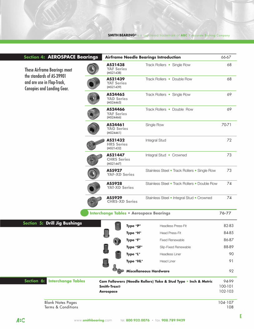
AS21438 Track Rollers • Single Row 68
AS21439 Track Rollers • Double Row 68
AS24465 Track Rollers • Single Row 69
AS24466 Track Rollers • Double Row 69
AS24461 Single Row 70-71
AS21432 Integral Stud 72
AS21447 Integral Stud • Crowned 73
AS5927 Stainless Steel • Track Rollers • Single Row 73
AS5928 Stainless Steel • Track Rollers • Double Row 74
AS5929 Stainless Steel • Integral Stud • Crowned 74
Section 4: AEROSPACE Bearings Airframe Needle Bearings Introduction 66-67
Interchange Tables • Aerospace Bearings 76-77
Section 5: Drill Jig BushingsType “P” Headless Press-Fit 82-83
Type “H” Head Press-Fit 84-85
Type “F” Fixed Renewable 86-87
Type “SF” Slip-Fixed Renewable 88-89
Type “L” Headless Liner 90
Type “HL” Head Liner 91
Miscellaneous Hardware 92
Section 6: Interchange Tables Cam Followers (Needle Rollers) Yoke & Stud Type • Inch & Metric 94-99Smith-Trax® 100-101Aerospace 102-103
Blank Notes Pages 104-107Terms & Conditions 108
E
(MS21438)
(MS21439)
(MS24465)
(MS24466)
(MS24461)
(MS21432)
(MS21447)
YAF Series
YAT Series
YAD Series
YAF Series
YAG Series
HRS Series
CHRS Series
YAF-XD Series
YAT-XD Series
CHRS-XD Series
These Airframe Bearings meetthe standards of AS-39901 and are use in Flap-Track,Canopies and Landing Gear.
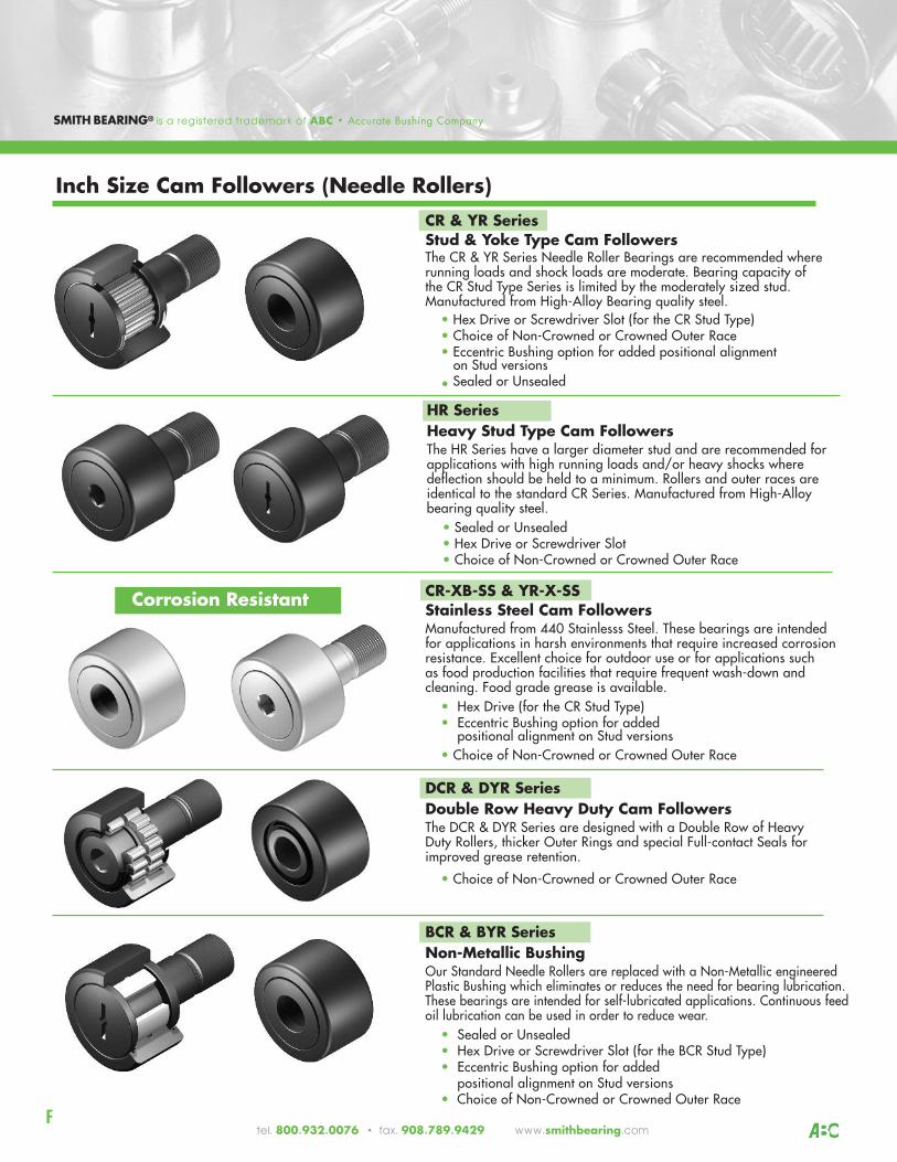
BCR & BYR SeriesNon-Metallic BushingOur Standard Needle Rollers are replaced with a Non-Metallic engineeredPlastic Bushing which eliminates or reduces the need for bearing lubrication.These bearings are intended for self-lubricated applications. Continuous feedoil lubrication can be used in order to reduce wear.
• Sealed or Unsealed• Hex Drive or Screwdriver Slot (for the BCR Stud Type) • Eccentric Bushing option for added
positional alignment on Stud versions• Choice of Non-Crowned or Crowned Outer Race
DCR & DYR SeriesDouble Row Heavy Duty Cam FollowersThe DCR & DYR Series are designed with a Double Row of HeavyDuty Rollers, thicker Outer Rings and special Full-contact Seals for improved grease retention.
• Choice of Non-Crowned or Crowned Outer Race
CR & YR SeriesStud & Yoke Type Cam Followers The CR & YR Series Needle Roller Bearings are recommended whererunning loads and shock loads are moderate. Bearing capacity of the CR Stud Type Series is limited by the moderately sized stud. Manufactured from High-Alloy Bearing quality steel.
• Hex Drive or Screwdriver Slot (for the CR Stud Type)• Choice of Non-Crowned or Crowned Outer Race• Eccentric Bushing option for added positional alignmenton Stud versions
• Sealed or Unsealed
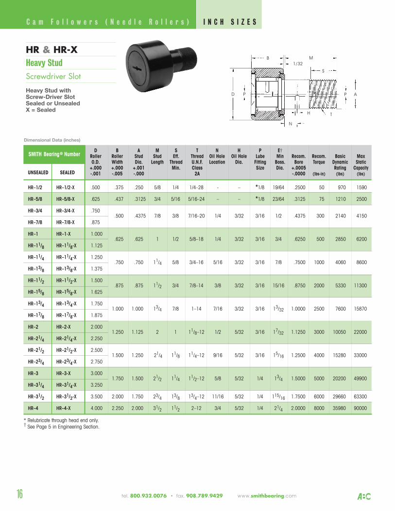
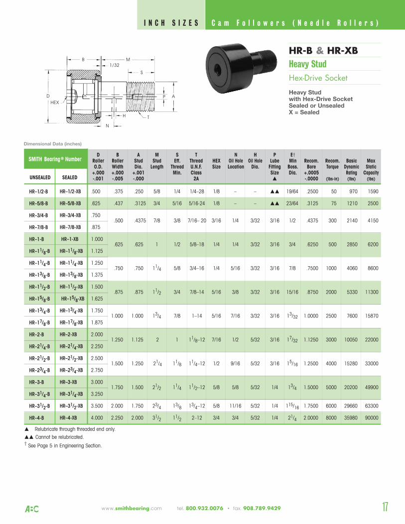
HR SeriesHeavy Stud Type Cam FollowersThe HR Series have a larger diameter stud and are recommended forapplications with high running loads and/or heavy shocks where deflection should be held to a minimum. Rollers and outer races areidentical to the standard CR Series. Manufactured from High-Alloybearing quality steel.
• Sealed or Unsealed• Hex Drive or Screwdriver Slot• Choice of Non-Crowned or Crowned Outer Race
CR-XB-SS & YR-X-SS Stainless Steel Cam FollowersManufactured from 440 Stainlesss Steel. These bearings are intendedfor applications in harsh environments that require increased corrosionresistance. Excellent choice for outdoor use or for applications such as food production facilities that require frequent wash-down andcleaning. Food grade grease is available.
• Hex Drive (for the CR Stud Type) • Eccentric Bushing option for added
positional alignment on Stud versions• Choice of Non-Crowned or Crowned Outer Race
F
Corrosion Resistant
Inch Size Cam Followers (Needle Rollers)
SMITH BEARING® is a registered trademark of ABC • Accurate Bushing Company
tel. 800.932.0076 • fax. 908.789.9429 www.smithbearing.com
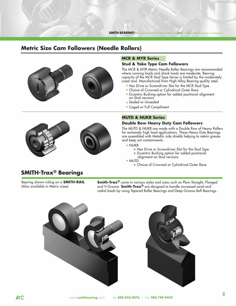
MCR & MYR SeriesStud & Yoke Type Cam Followers The MCR & MYR Metric Needle Roller Bearings are recommendedwhere running loads and shock loads are moderate. Bearing capacity of the MCR Stud Type Series is limited by the moderatelysized stud. Manufactured from High-Alloy Bearing quality steel.
• Hex Drive or Screwdriver Slot for the MCR Stud Type• Choice of Crowned or Cylindrical Outer Race• Eccentric Bushing option for added positional alignmenton Stud versions
• Sealed or Unsealed• Caged or Full Compliment
SMITH BEARING® is a registered trademark of ABC • Accurate Bushing Company
Bearing shown riding on a SMITH-RAIL(Also available in Metric sizes)
Metric Size Cam Followers (Needle Rollers)
SMITH-Trax® Bearings Smith-Trax® come in various styles and sizes such as Plain Straight, Flangedand V-Groove. Smith-Trax® are designed to handle increased axial and radial loads by using Tapered Roller Bearings and Deep-Groove Ball Bearings.
MUTD & NUKR SeriesDouble Row Heavy Duty Cam FollowersThe MUTD & NUKR are made with a Double Row of Heavy Rollersfor extremely high load applications. These Heavy Duty Bearingsare assembled with Metallic side shields helping to retain greaseand keep out containments.
• NUKR u Hex Drive or Screwdriver Slot for the Stud Type u Eccentric Bushing option for added positional alignment on Stud versions• MUTD u Choice of Crowned or Cylindrical Outer Race
Gwww.smithbearing.com tel. 800.932.0076 • fax. 908.789.9429
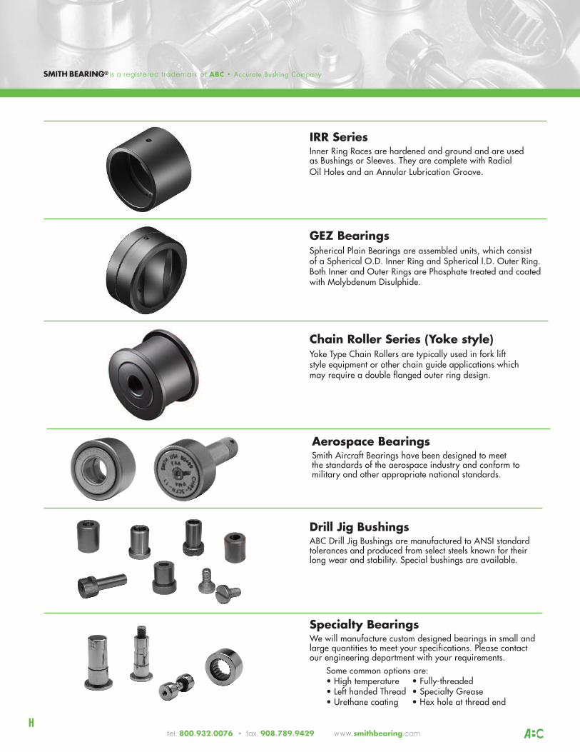
IRR Series Inner Ring Races are hardened and ground and are used as Bushings or Sleeves. They are complete with Radial Oil Holes and an Annular Lubrication Groove.
GEZ BearingsSpherical Plain Bearings are assembled units, which consist of a Spherical O.D. Inner Ring and Spherical I.D. Outer Ring. Both Inner and Outer Rings are Phosphate treated and coatedwith Molybdenum Disulphide.
Specialty BearingsWe will manufacture custom designed bearings in small and large quantities to meet your specifications. Please contact our engineering department with your requirements.
Some common options are:• High temperature • Fully-threaded• Left handed Thread • Specialty Grease• Urethane coating • Hex hole at thread end
Drill Jig BushingsABC Drill Jig Bushings are manufactured to ANSI standard tolerances and produced from select steels known for their long wear and stability. Special bushings are available.
Chain Roller Series (Yoke style)Yoke Type Chain Rollers are typically used in fork lift style equipment or other chain guide applications which may require a double flanged outer ring design.
Aerospace BearingsSmith Aircraft Bearings have been designed to meet the standards of the aerospace industry and conform to military and other appropriate national standards.
Htel. 800.932.0076 • fax. 908.789.9429 www.smithbearing.com
SMITH BEARING® is a registered trademark of ABC • Accurate Bushing Company
C
E N G I N E E R I N G C A P A B I L I T I E S
1
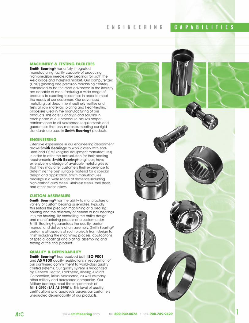
MACHINERY & TESTING FACILITIESSmith Bearing® has a fully-integratedmanufacturing facility capable of producing high-precision needle roller bearings for both theAerospace and Industrial market. Our computerized(CNC) grinding and precision machining centers,considered to be the most advanced in the industryare capable of manufacturing a wide range ofproducts to exacting tolerances in order to meetthe needs of our customers. Our advancedmetallurgical department routinely verifies and tests all raw materials, plating and heat-treatingprocesses used in the manufacturing of ourproducts. This careful analysis and scrutiny in each phase of our procedure assures properconformance to all Aerospace requirements andguarantees that only materials meeting our rigidstandards are used in Smith Bearing® products.
ENGINEERINGExtensive experience in our engineering departmentallows Smith Bearing® to work closely with end-users and OEMS (original equipment manufactures)in order to offer the best solution for their bearingrequirements. Smith Bearing® engineers haveextensive knowledge of available metallurgies sothat they may offer customers their experience todetermine the best suitable material for a specialdesign and application. Smith manufacturesbearings in a wide range of materials includinghigh-carbon alloy steels, stainless steels, tool steels,and other exotic alloys.
CUSTOM ASSEMBLIESSmith Bearing® has the ability to manufacture avariety of custom bearing assemblies. Typically this entails the precision machining of a bearinghousing and the assembly of needle or ball bearingsinto the housing. By controlling the entire design and manufacturing process of a custom order, Smith Bearing® guarantees the quality, perfor-mance, and delivery of an assembly. Smith Bearing®
performs all aspects of such projects from design tofinish including the machining process, applicationsof special coatings and plating, assembling andtesting of the final product.
QUALITY & DEPENDABILITYSmith Bearing® has received both ISO 9001and AS 9100 quality registrations in recognition ofour continued commitment to world-class qualitycontrol systems. Our quality system is recognized by General Electric, Lockheed, Boeing AircraftCorporation, British Aerospace, as well as manyother military and aerospace companies. OurMilitary bearings meet the requirements of Mil-B-3990 (SAE AS 39901). This level of qualitycertifications and approvals assures our customersunequaled dependability of our products.
www.smithbearing.com tel. 800.932.0076 • fax. 908.789.9429
G E N E R A L I N F O R M A T I O N E N G I N E E R I N G
2
SMITH Cam Followers are anti-friction needleroller bearings developed for use in cam ortrack roller applications. They were specificallydesigned and built to handle intermittentshock and heavy loads. Full compliment (non-caged) needle bearings maximize the radialload carrying capability while the soft innercore of the stud gives these cam followers theability to absorb extreme shock loads withoutfracturing.
In addition to standard models, specialbearings are manufactured to customerspecification for unique applications. It is often found that the use of specialbearings reduces machine costs and improves performance. We have the ability to economically manufacture custombearings in small or large volumes. Please call us to discuss your special applications.
Material SelectionThe common material selection for needleroller bearings are high-strength bearing steel(SAE 52100) or carburized low-carbon alloysteels. These materials give us an excellentcombination of strength and economy andare more than sufficient for the majority ofindustrial applications.
High-Temperature & Corrosive Applications:In extreme applications where bearings arebeing subjected to high-temperature orcorrosive environments, alternative materialsor special platings must be considered. Smith Bearing® manufactures needle rollerbearings in a wide variety of high-temperatureand corrosive resistant exotic alloys including440-C stainless steel and M-50, M-2, M-10 tool steels.
Corrosion resistant plating is effective when usingbearings in corrosive environments. Non-bearingsurfaces such as inner races and end washersare cadmium plated to resist corrosion. Theouter races of the bearings are typically hard-chrome plated to resist wear as well as corrosion.
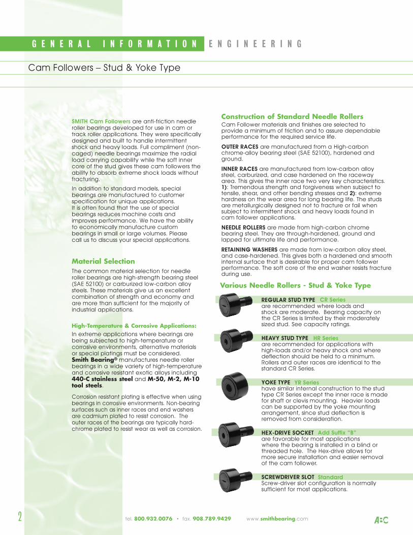
REGULAR STUD TYPEare recommended where loads and shock are moderate. Bearing capacity onthe CR Series is limited by their moderatelysized stud. See capacity ratings.
HEAVY STUD TYPEare recommended for applications withhigh-loads and/or heavy shock and wheredeflection should be held to a minimum.Rollers and outer races are identical to thestandard CR Series.
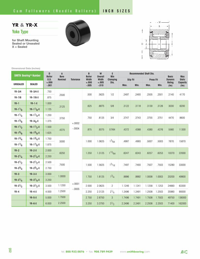
YOKE TYPEhave similar internal construction to the studtype CR Series except the inner race is madefor shaft or clevis mounting. Heavier loadscan be supported by the yoke mountingarrangement, since stud deflection isremoved from consideration.
HEX-DRIVE SOCKET are favorable for most applications where the bearing is installed in a blind orthreaded hole. The Hex-drive allows for more secure installation and easier removalof the cam follower.
SCREWDRIVER SLOT Screw-driver slot configuration is normallysufficient for most applications.
Construction of Standard Needle RollersCam Follower materials and finishes are selected to provide a minimum of friction and to assure dependableperformance for the required service life.
OUTER RACES are manufactured from a High-carbonchrome-alloy bearing steel (SAE 52100), hardened andground.
INNER RACES are manufactured from low-carbon alloy steel, carburized, and case hardened on the raceway area. This gives the inner race two very key characteristics. 1): Tremendous strength and forgiveness when subject totensile, shear, and other bending stresses and 2): extremehardness on the wear area for long bearing life. The studsare metallurgically designed not to fracture or fail whensubject to intermittent shock and heavy loads found in cam follower applications.
NEEDLE ROLLERS are made from high-carbon chromebearing steel. They are through-hardened, ground andlapped for ultimate life and performance.
RETAINING WASHERS are made from low-carbon alloy steel,and case-hardened. This gives both a hardened and smoothinternal surface that is desirable for proper cam followerperformance. The soft core of the end washer resists fractureduring use.
Various Needle Rollers - Stud & Yoke Type
CR Series
HR Series
YR Series
Add Suffix “B”
Cam Followers – Stud & Yoke Type
Standard
tel. 800.932.0076 • fax. 908.789.9429 www.smithbearing.com
E N G I N E E R I N G G E N E R A L I N F O R M A T I O N
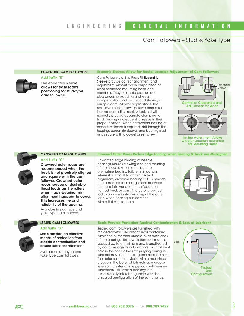
Cam Followers with a Press Fit EccentricSleeve provide correct alignment andadjustment without costly preparation ofclose tolerance mounting holes andmembers. They eliminate problems ofclearances, preloading and wearcompensation and assure load sharing inmultiple cam follower applications. The hex-drive socket allows positive torque forlocking and adjustment. A lock nut willnormally provide adequate clamping tohold bearing and eccentric sleeve in theirproper position. When permanent locking ofeccentric sleeve is required, drill through thehousing, eccentric sleeve, and bearing studand secure with a dowel or set-screw.
In-line Adjustment Allows Greater Location Tolerance
for Mounting Holes
Control of Clearance andAdjustment for Wear
ECCENTRIC CAM FOLLOWERS
Add Suffix “E”
The eccentric sleeveallows for easy radialpositioning for stud-type cam followers.
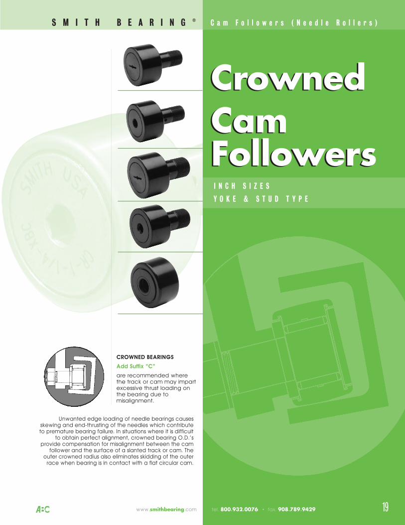
CROWNED CAM FOLLOWERS
Add Suffix “C”
Crowned outer races arerecommended when thetrack is not precisely alignedand square with the camfollower. Crowned outerraces reduce undesirablethrust loads on the rollerswhen track-bearing mis-alignment happens to occur.This increases life andreliability of the bearing.
Available in stud type and yoke type cam followers.
Eccentric Sleeves Allow for Radial Location Adjustment of Cam Followers
Typical Seal
Configuration
SEALED CAM FOLLOWERS
Add Suffix “X”
Seals provide an effectivemeans of protection fromoutside contamination andensure lubricant retention.
Available in stud type and yoke type cam followers.
Sealed cam followers are furnished withmolded-acetyl full-contact seals containedwithin the outer race undercuts at both endsof the bearing. This low-friction seal materialkeeps drag to a minimum and is unaffectedby corrosive agents or lubricants. A small venthole in the seals allows for purging during re-lubrication without causing seal displacement.The outer race is provided with a machinedgroove in the bore, which acts as a greasereservoir to extend time periods between re-lubrication. All sealed bearings aredimensionally interchangeable with theunsealed configuration of the same series.
Unwanted edge loading of needlebearings causes skewing and end-thrustingof the needles which contribute topremature bearing failure. In situationswhere it is difficult to obtain perfectalignment, crowned bearing O.D.’s providecompensation for misalignment betweenthe cam follower and the surface of aslanted track or cam. The outer crownedradius also eliminates skidding of the outerrace when bearing is in contact with a flat circular cam.
Crowned Outer Races Reduce Edge Loading when Bearing & Track are Misaligned
Seals Provide Protection Against Contamination & Loss of Lubricant
3
EccentricSleeve
Seal
Cam Followers – Stud & Yoke Type
www.smithbearing.com tel. 800.932.0076 • fax. 908.789.9429
4
G E N E R A L I N F O R M A T I O N E N G I N E E R I N G
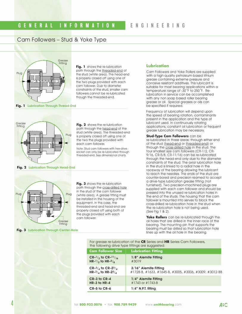
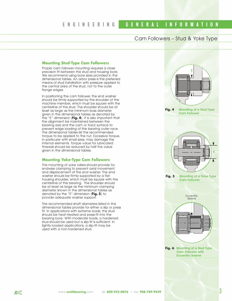
LubricationCam Followers and Yoke Rollers are suppliedwith a high-quality petroleum-based lithiumgrease containing extreme pressure andcorrosive resistant additives. This lubricant issuitable for most bearing applications within atemperature range of -30 ˚F to 250 ˚F. Re-lubrication in service can be accomplished with any non soap based roller bearing grease or oil. Special greases or oils can be specified if required.
Frequency of lubrication will depend upon the speed of bearing rotation, contaminantspresent in the application and the type oflubricant used. In continuously rotatingapplications, constant oil lubrication or frequentgrease lubrication may be necessary.
Stud-Type Cam Followers can be re-lubricated in three areas: through either endof the stud (head-end or threaded-end) orthrough the cross-drilled hole in the stud. Thefour smallest size cam followers (CR-1/2, CR-9/16, CR-5/8, CR-11/16) can be re-lubricatedthrough the head-end only due to the diameterconstraints of the stud. The axial lubrication holein the stud is linked to a radial hole in theraceway of the bearing allowing the lubricantto reach the needles. The ends of the stud arecounter-bored and precision-reamed to accepta drive-type lubrication grease fitting (notfurnished). Two precision-machined plugs aresupplied with each cam follower and should bepressed into the unused re-lubrication holes inthe end of the studs. The housing that the camfollower is mounted into serves to block thecross-drilled re-lubrication hole in the stud whenthe re-lubrication hole is not being used. (See Fig 1 & 2).
Yoke Rollers can be re-lubricated through theoil holes that are drilled in the inner race of thebearing. The mounting pin that supports thebearing must be drilled so that lubrication holelines up with the oil hole in the bearing.
GreaseFitting
Plug
GreaseFitting
Plug Plug
GreaseFitting
Plug
Cam Followers – Stud & Yoke Type
Fig. 1 shows the re-lubrication path through the threaded-end ofthe stud (white area). The head-endis properly closed off using one ofthe two plugs provided with eachcam follower. Due to diameterconstraints of the stud, smaller camfollowers cannot be re-lubricatedthough the threaded-end.
Fig. 1 Lubrication Through Thread-End
Fig. 3 Lubrication Through Center-Hole
Fig. 2 shows the re-lubrication path through the head-end of thestud (white area). The threaded-endis properly closed off using one ofthe two the plugs provided witheach cam follower.
Note: Stud cam followers with hex-drivesocket can only be re-lubricated throughthreaded-end. See dimensional charts.
Fig. 3 shows the re-lubrication path through the cross-drilled holein the stud of the cam follower(white area). A grease fitting mustbe installed in the housing of theequipment. In this case, thethreaded-end and head-end areproperly closed off using both of the plugs provided with each cam follower.
For grease re-lubrication of the CR Series and HR Series Cam Followers, the following drive type fittings are suggested:
Cam Follower Size Lubrication Fitting
CR–1/2 to CR–11/16 1/8” Alemite FittingHR–1/2 to HR–5/8 #3019
CR–3/4 to CR–23/4 3/16” Alemite FittingHR–3/4 to HR–23/4
CR–3 to CR–4 1/4” Alemite FittingHR–3 to HR–4 #1743 or #1743-B
CR–5 to CR–6 1/4” N.P.T. fitting
tel. 800.932.0076 • fax. 908.789.9429 www.smithbearing.com
Fig. 2 Lubrication Through Head-End
#1728-B, #1633, #1645-B, #3005, #3006, #3009, #3012-BB
5
E N G I N E E R I N G G E N E R A L I N F O R M A T I O N
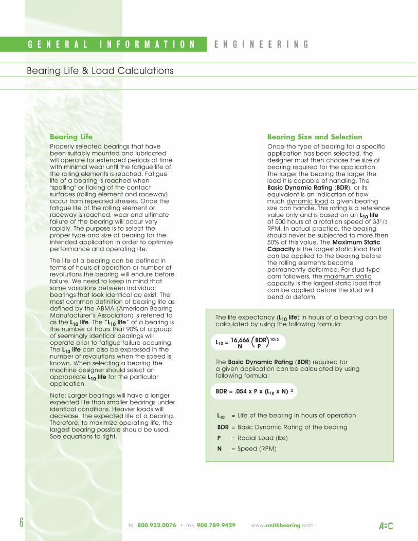
Mounting Stud-Type Cam FollowersProper cam follower mounting requires a closeprecision fit between the stud and housing bore.We recommend using bore sizes provided in thedimensional tables. An arbor press is the preferredmeans of stud installation with pressure applied tothe central area of the stud, not to the outerflange edges.
In positioning the cam follower, the end washershould be firmly supported by the shoulder of themachine member, which must be square with thecenterline of the stud. The shoulder should be atleast as large as the minimum boss diametergiven in the dimensional tables as denoted by the “E” dimension (Fig. 4). It is also important thatthe alignment be maintained between thebearing axis and the cam or track surface toprevent edge loading of the bearing outer race.The dimensional tables list the recommendedtorque to be applied to the nut. Excessive torque,in particular with small sizes, may damage theinternal elements. Torque value for lubricatedthreads should be reduced by half the valuegiven in the dimensional tables.
Mounting Yoke-Type Cam FollowersThe mounting of yoke rollers should provide forendwise clamping to prevent axial movementand displacement of the end washer. The endwasher should be firmly supported by a flathousing shoulder, which must be square with thecenterline of the bearing. The shoulder should be at least as large as the minimum clampingdiameter shown in the dimensional tables asdenoted by the “E” dimension (Fig. 5) to provide adequate washer support.
The recommended shaft diameters listed in thedimensional tables provide for either a slip or pressfit. In applications with extreme loads, the studshould be heat-treated and press-fit into thebearing bore. With moderate loads, a hardenedstud should be used but a slip-fit is sufficient. Inlightly loaded applications, a slip-fit may be used with a non-hardened stud.
E
E
EccentricSleeve
Fig. 4 Mounting of a Stud Type
Cam Follower
Cam Followers – Stud & Yoke Type
www.smithbearing.com tel. 800.932.0076 • fax. 908.789.9429
Fig. 5 Mounting of a Yoke Type
Cam Follower
Fig. 6 Mounting of a Stud Type
Cam Follower with
Eccentric Sleeve
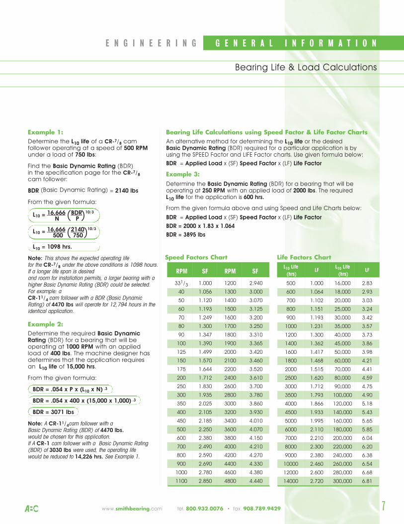
Bearing LifeProperly selected bearings that havebeen suitably mounted and lubricatedwill operate for extended periods of timewith minimal wear until the fatigue life ofthe rolling elements is reached. Fatiguelife of a bearing is reached when"spalling" or flaking of the contactsurfaces (rolling element and raceway)occur from repeated stresses. Once thefatigue life of the rolling element orraceway is reached, wear and ultimatefailure of the bearing will occur veryrapidly. The purpose is to select theproper type and size of bearing for theintended application in order to optimizeperformance and operating life.
The life of a bearing can be defined interms of hours of operation or number ofrevolutions the bearing will endure beforefailure. We need to keep in mind thatsome variations between individualbearings that look identical do exist. Themost common definition of bearing life asdefined by the ABMA (American BearingManufacturer’s Association) is referred toas the L10 life. The “L10 life” of a bearing isthe number of hours that 90% of a groupof seemingly identical bearings willoperate prior to fatigue failure occurring.The L10 life can also be expressed in thenumber of revolutions when the speed isknown. When selecting a bearing themachine designer should select anappropriate L10 life for the particularapplication.
Note: Larger bearings will have a longerexpected life than smaller bearings underidentical conditions. Heavier loads willdecrease the expected life of a bearing.Therefore, to maximize operating life, thelargest bearing possible should be used.See equations to right.
G E N E R A L I N F O R M A T I O N E N G I N E E R I N G
6
Bearing Life & Load Calculations
tel. 800.932.0076 • fax. 908.789.9429 www.smithbearing.com
The life expectancy (L10 life) in hours of a bearing can becalculated by using the following formula:
L10 = 16,666 BDR 10/3
N P
The Basic Dynamic Rating (BDR) required for a given application can be calculated by using following formula:
BDR = .054 x P x (L10 x N) .3
L10 = Life of the bearing in hours of operation
BDR = Basic Dynamic Rating of the bearing
P = Radial Load (lbs)
N = Speed (RPM)
( )
Bearing Size and SelectionOnce the type of bearing for a specificapplication has been selected, thedesigner must then choose the size ofbearing required for the application. The larger the bearing the larger the load it is capable of handling. The Basic Dynamic Rating (BDR), or itsequivalent is an indication of how much dynamic load a given bearing size can handle. This rating is a referencevalue only and is based on an L10 lifeof 500 hours at a rotation speed of 331/3
RPM. In actual practice, the bearingshould never be subjected to more then50% of this value. The Maximum StaticCapacity is the largest static load thatcan be applied to the bearing beforethe rolling elements becomepermanently deformed. For stud typecam followers, the maximum staticcapacity is the largest static load thatcan be applied before the stud will bend or deform.
L10 LifeLF
L10 LifeLF
(hrs) (hrs)
500 1.000 16,000 2.83
600 1.064 18,000 2.93
700 1.102 20,000 3.03
800 1.151 25,000 3.24
900 1.193 30,000 3.42
1000 1.231 35,000 3.57
1200 1.300 40,000 3.73
1400 1.362 45,000 3.86
1600 1.417 50,000 3.98
1800 1.468 60,000 4.21
2000 1.515 70,000 4.41
2500 1.620 80,000 4.59
3000 1.712 90,000 4.75
3500 1.793 100,000 4.90
4000 1.866 120,000 5.18
4500 1.933 140,000 5.43
5000 1.995 160,000 5.65
6000 2.110 180,000 5.85
7000 2.210 200,000 6.04
8000 2.300 220,000 6.20
9000 2.380 240,000 6.38
10000 2.460 260,000 6.54
12000 2.600 280,000 6.68
14000 2.720 300,000 6.81
Speed Factors Chart Life Factors Chart
Example 1:Determine the L10 life of a CR-7/8 camfollower operating at a speed of 500 RPMunder a load of 750 lbs:
Find the Basic Dynamic Rating (BDR)in the specification page for the CR-7/8
cam follower:
BDR (Basic Dynamic Rating) = 2140 lbs
From the given formula:
L10 = 16,666 BDR 10/3
N P
L10 = 16,666 2140 10/3
500 750
L10 = 1098 hrs.
Note: This shows the expected operating life for the CR-7/8 under the above conditions is 1098 hours.If a longer life span is desiredand room for installation permits, a larger bearing with ahigher Basic Dynamic Rating (BDR) could be selected.For example: a CR-11/4 cam follower with a BDR (Basic DynamicRating) of 4470 lbs will operate for 12,794 hours in theidentical application.
Example 2:Determine the required Basic DynamicRating (BDR) for a bearing that will beoperating at 1000 RPM with an applied load of 400 lbs. The machine designer hasdetermines that the application requires an L10 life of 15,000 hrs.
From the given formula:
BDR = .054 x P x (L10 x N) .3
BDR = .054 x 400 x (15,000 x 1,000) .3
BDR = 3071 lbs
Note: A CR-11/4cam follower with a Basic Dynamic Rating (BDR) of 4470 lbs. would be chosen for this application. If A CR-1 cam follower with a Basic Dynamic Rating(BDR) of 3030 lbs were used, the operating life would be reduced to 14,226 hrs. See Example 1.
( )
( )
Bearing Life Calculations using Speed Factor & Life Factor ChartsAn alternative method for determining the L10 life or the desired Basic Dynamic Rating (BDR) required for a particular application is by using the SPEED Factor and LIFE Factor charts. Use given formula below:
BDR = Applied Load x (SF) Speed Factor x (LF) Life Factor
Example 3:Determine the Basic Dynamic Rating (BDR) for a bearing that will beoperating at 250 RPM with an applied load of 2000 lbs. The required L10 life for the application is 600 hrs.
From the given formula above and using Speed and Life Charts below:
BDR = Applied Load x (SF) Speed Factor x (LF) Life Factor
BDR = 2000 x 1.83 x 1.064
BDR = 3895 lbs
RPM SF RPM SF
331/3 1.000 1200 2.940
40 1.056 1300 3.000
50 1.120 1400 3.070
60 1.193 1500 3.125
70 1.249 1600 3.200
80 1.300 1700 3.250
90 1.347 1800 3.310
100 1.390 1900 3.365
125 1.499 2000 3.420
150 1.570 2100 3.460
175 1.644 2200 3.520
200 1.712 2400 3.610
250 1.830 2600 3.700
300 1.935 2800 3.780
350 2.025 3000 3.860
400 2.105 3200 3.930
450 2.185 3400 4.010
500 2.250 3600 4.070
600 2.380 3800 4.150
700 2.490 4000 4.210
800 2.590 4200 4.270
900 2.690 4400 4.330
1000 2.780 4600 4.380
1100 2.850 4800 4.440
E N G I N E E R I N G G E N E R A L I N F O R M A T I O N
7
Bearing Life & Load Calculations
www.smithbearing.com tel. 800.932.0076 • fax. 908.789.9429
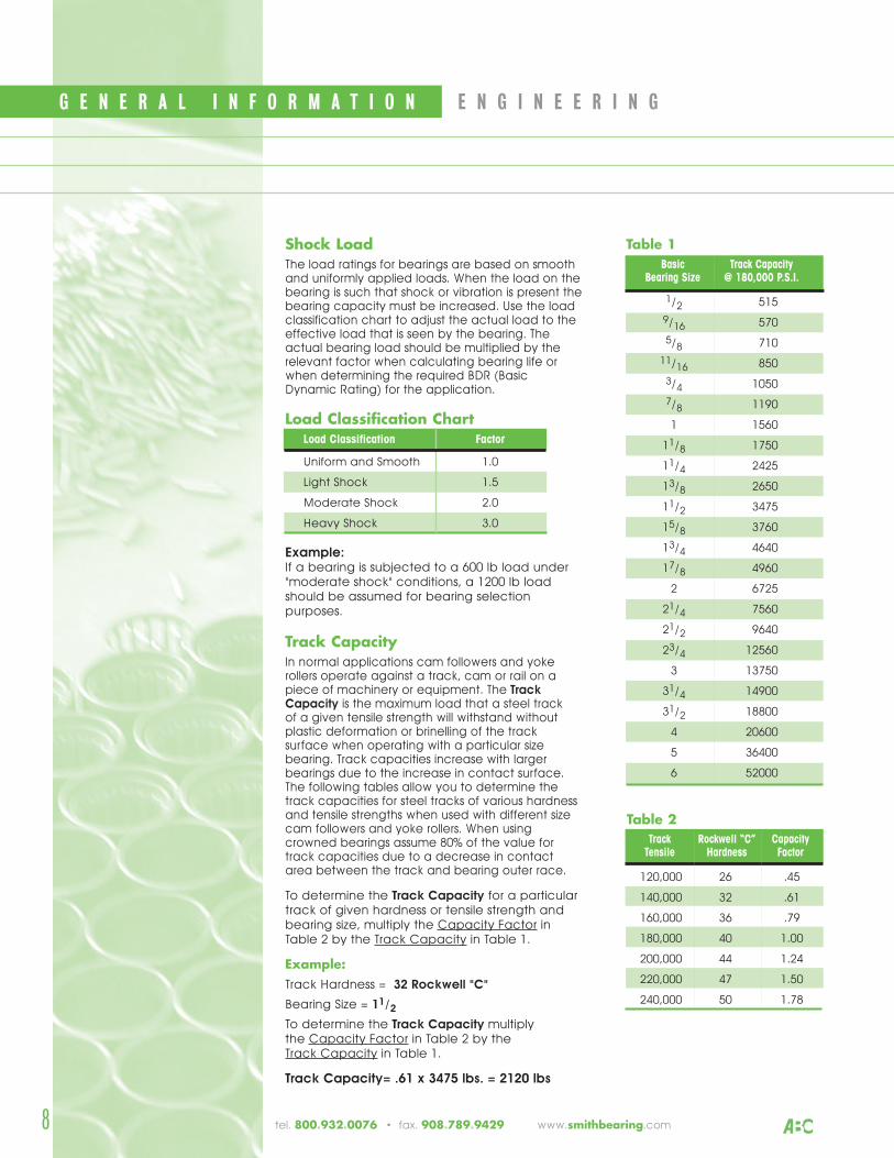
Shock LoadThe load ratings for bearings are based on smoothand uniformly applied loads. When the load on thebearing is such that shock or vibration is present thebearing capacity must be increased. Use the loadclassification chart to adjust the actual load to theeffective load that is seen by the bearing. Theactual bearing load should be multiplied by therelevant factor when calculating bearing life orwhen determining the required BDR (Basic Dynamic Rating) for the application.
Load Classification Chart
Example:If a bearing is subjected to a 600 lb load under"moderate shock" conditions, a 1200 lb loadshould be assumed for bearing selectionpurposes.
Track CapacityIn normal applications cam followers and yokerollers operate against a track, cam or rail on apiece of machinery or equipment. The TrackCapacity is the maximum load that a steel trackof a given tensile strength will withstand withoutplastic deformation or brinelling of the tracksurface when operating with a particular sizebearing. Track capacities increase with largerbearings due to the increase in contact surface.The following tables allow you to determine thetrack capacities for steel tracks of various hardnessand tensile strengths when used with different sizecam followers and yoke rollers. When usingcrowned bearings assume 80% of the value fortrack capacities due to a decrease in contactarea between the track and bearing outer race.
To determine the Track Capacity for a particulartrack of given hardness or tensile strength andbearing size, multiply the Capacity Factor inTable 2 by the Track Capacity in Table 1.
Example:Track Hardness = 32 Rockwell "C"
Bearing Size = 11/2
To determine the Track Capacity multiplythe Capacity Factor in Table 2 by the Track Capacity in Table 1.
Track Capacity= .61 x 3475 lbs. = 2120 lbs
Basic Track CapacityBearing Size @ 180,000 P.S.I.
1/2 515
9/16 570
5/8 710
11/16 850
3/4 1050
7/8 1190
1 1560
11/8 1750
11/4 2425
13/8 2650
11/2 3475
15/8 3760
13/4 4640
17/8 4960
2 6725
21/4 7560
21/2 9640
23/4 12560
3 13750
31/4 14900
31/2 18800
4 20600
5 36400
6 52000
Table 1
Track Rockwell “C” CapacityTensile Hardness Factor
120,000 26 .45
140,000 32 .61
160,000 36 .79
180,000 40 1.00
200,000 44 1.24
220,000 47 1.50
240,000 50 1.78
Load Classification Factor
Uniform and Smooth 1.0
Light Shock 1.5
Moderate Shock 2.0
Heavy Shock 3.0
8
Table 2
G E N E R A L I N F O R M A T I O N E N G I N E E R I N G
tel. 800.932.0076 • fax. 908.789.9429 www.smithbearing.com
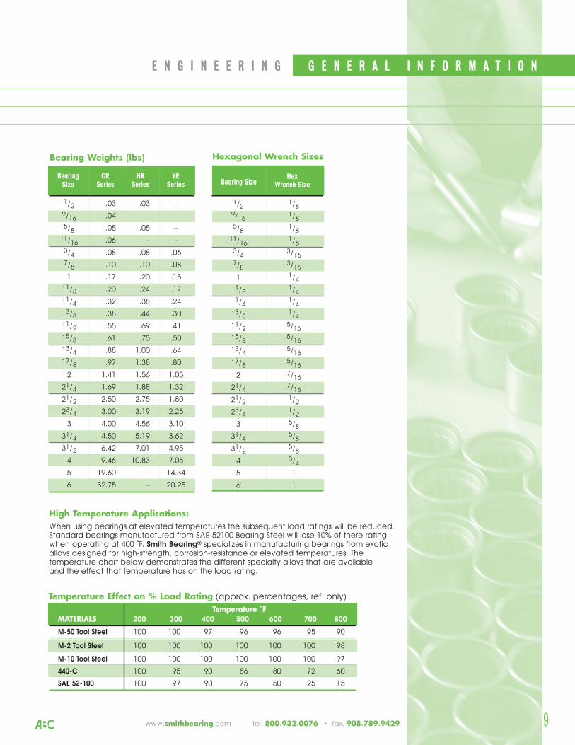
Bearing CR HR YRSize Series Series Series
1/2 .03 .03 –
9/16 .04 – –
5/8 .05 .05 –
11/16 .06 – –
3/4 .08 .08 .06
7/8 .10 .10 .08
1 .17 .20 .15
11/8 .20 .24 .17
11/4 .32 .38 .24
13/8 .38 .44 .30
11/2 .55 .69 .41
15/8 .61 .75 .50
13/4 .88 1.00 .64
17/8 .97 1.38 .80
2 1.41 1.56 1.05
21/4 1.69 1.88 1.32
21/2 2.50 2.75 1.80
23/4 3.00 3.19 2.25
3 4.00 4.56 3.10
31/4 4.50 5.19 3.62
31/2 6.42 7.01 4.95
4 9.46 10.83 7.05
5 19.60 – 14.34
6 32.75 – 20.25
Bearing Weights (lbs)
9
Bearing SizeHex
Wrench Size
1/21/8
9/161/8
5/81/8
11/161/8
3/43/16
7/83/16
1 1/4
11/81/4
11/41/4
13/81/4
11/25/16
15/85/16
13/45/16
17/85/16
2 7/16
21/47/16
21/21/2
23/41/2
3 5/8
31/45/8
31/25/8
4 3/4
5 1
6 1
Hexagonal Wrench Sizes
High Temperature Applications:When using bearings at elevated temperatures the subsequent load ratings will be reduced.Standard bearings manufactured from SAE-52100 Bearing Steel will lose 10% of there ratingwhen operating at 400 ˚F. Smith Bearing® specializes in manufacturing bearings from exoticalloys designed for high-strength, corrosion-resistance or elevated temperatures. Thetemperature chart below demonstrates the different specialty alloys that are available and the effect that temperature has on the load rating.
MATERIALS 200 300 400 500 600 700 800
M-50 Tool Steel 100 100 97 96 96 95 90
M-2 Tool Steel 100 100 100 100 100 100 98
M-10 Tool Steel 100 100 100 100 100 100 97
440-C 100 95 90 86 80 72 60
SAE 52-100 100 97 90 75 50 25 15
Temperature ˚F
E N G I N E E R I N G G E N E R A L I N F O R M A T I O N
Temperature Effect on % Load Rating (approx. percentages, ref. only)
www.smithbearing.com tel. 800.932.0076 • fax. 908.789.9429
10
G E N E R A L I N F O R M A T I O N E N G I N E E R I N G
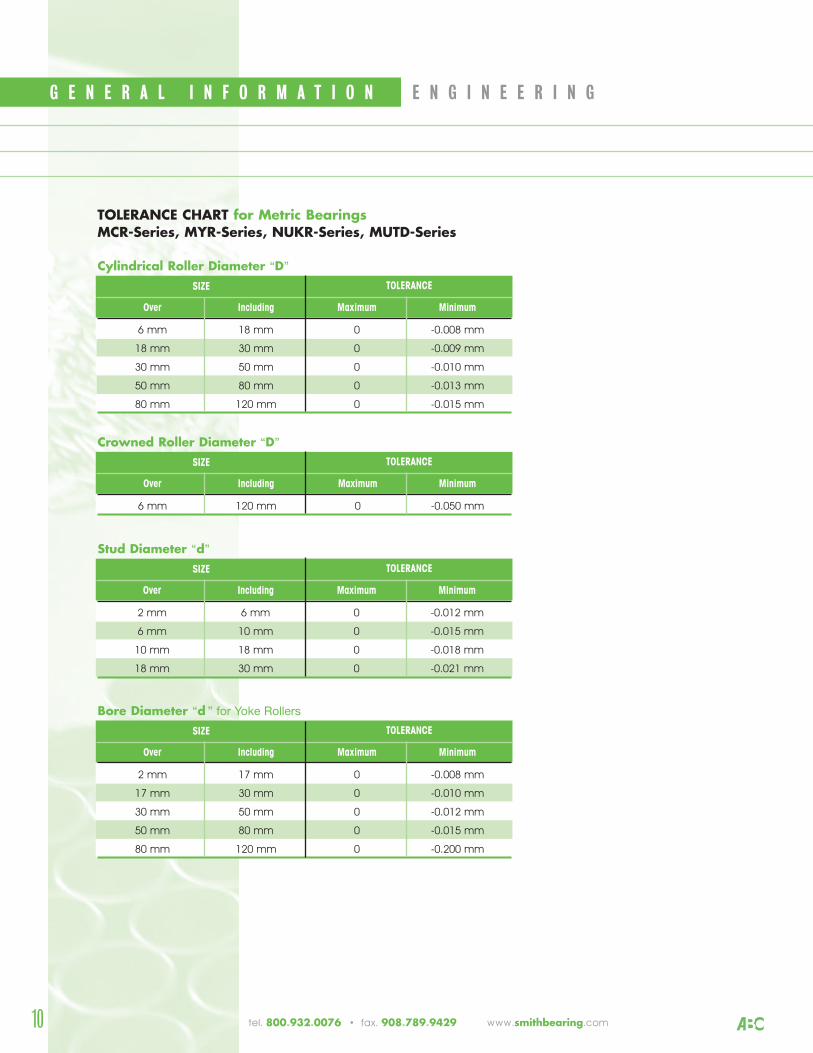
Over Including Maximum Minimum
6 mm 18 mm 0 -0.008 mm
18 mm 30 mm 0 -0.009 mm
30 mm 50 mm 0 -0.010 mm
50 mm 80 mm 0 -0.013 mm
80 mm 120 mm 0 -0.015 mm
Cylindrical Roller Diameter “D”
TOLERANCESIZE
Over Including Maximum Minimum
6 mm 120 mm 0 -0.050 mm
Crowned Roller Diameter “D”
TOLERANCESIZE
Over Including Maximum Minimum
2 mm 6 mm 0 -0.012 mm
6 mm 10 mm 0 -0.015 mm
10 mm 18 mm 0 -0.018 mm
18 mm 30 mm 0 -0.021 mm
Stud Diameter “d”
TOLERANCESIZE
TOLERANCE CHART for Metric BearingsMCR-Series, MYR-Series, NUKR-Series, MUTD-Series
Over Including Maximum Minimum
2 mm 17 mm 0 -0.008 mm
17 mm 30 mm 0 -0.010 mm
30 mm 50 mm 0 -0.012 mm
50 mm 80 mm 0 -0.015 mm
80 mm 120 mm 0 -0.200 mm
Bore Diameter “d ” for Yoke Rollers
TOLERANCESIZE
tel. 800.932.0076 • fax. 908.789.9429 www.smithbearing.com
11
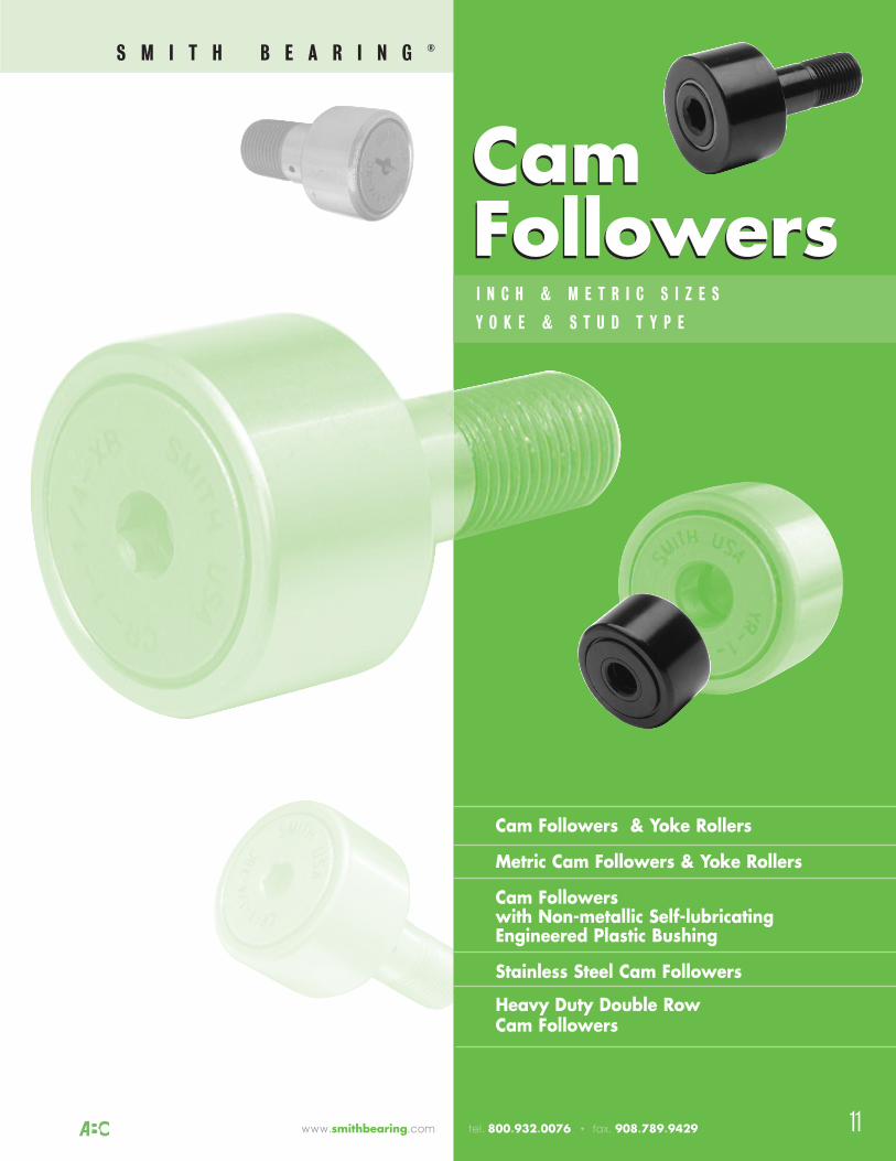
Cam Followers & Yoke Rollers
Metric Cam Followers & Yoke Rollers
Cam Followers with Non-metallic Self-lubricatingEngineered Plastic Bushing
Stainless Steel Cam Followers
Heavy Duty Double RowCam Followers
I N C H & M E T R I C S I Z E S
Y O K E & S T U D T Y P E
CamFollowersCamFollowers
www.smithbearing.com tel. 800.932.0076 • fax. 908.789.9429
S M I T H B E A R I N G ®
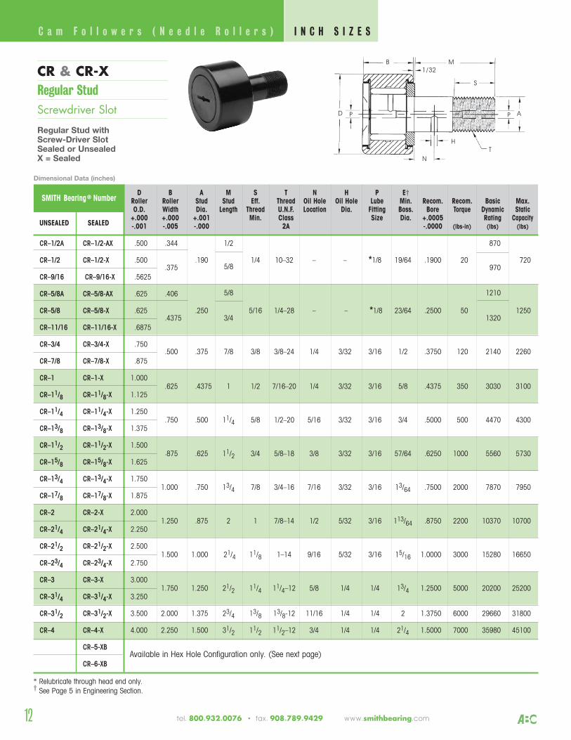
CR & CR-XRegular StudScrewdriver Slot
Regular Stud withScrew-Driver SlotSealed or UnsealedX = Sealed
12
SMITH Bearing ® NumberD B A M S T N H P E†
Roller Roller Stud Stud Eff. Thread Oil Hole Oil Hole Lube Min. Recom. Recom. Basic Max.O.D. Width Dia. Length Thread U.N.F. Location Dia. Fitting Boss. Bore Torque Dynamic Static
+.000 +.000 +.001 Min. Class Size Dia. +.0005 Rating CapacityUNSEALED SEALED -.001 -.005 -.000 2A -.0000 (lbs-in) (lbs) (lbs)
C a m F o l l o w e r s ( N e e d l e R o l l e r s )
CR–1/2A CR–1/2-AX .500 .344 1/2 870
CR–1/2 CR–1/2-X .500.375
.1905/8
1/4 10–32 – – *1/8 19/64 .1900 20970
720
CR–9/16 CR–9/16-X .5625
CR–5/8A CR–5/8-AX .625 .406 5/8 1210
CR–5/8 CR–5/8-X .625.4375
.250 3/4
5/16 1/4–28 – – *1/8 23/64 .2500 501320
1250
CR–11/16 CR–11/16-X .6875
CR–3/4 CR–3/4-X .750.500 .375 7/8 3/8 3/8–24 1/4 3/32 3/16 1/2 .3750 120 2140 2260
CR–7/8 CR–7/8-X .875
CR–1 CR–1-X 1.000.625 .4375 1 1/2 7/16–20 1/4 3/32 3/16 5/8 .4375 350 3030 3100
CR–11/8 CR–11/8-X 1.125
CR–11/4 CR–11/4-X 1.250.750 .500 11/4 5/8 1/2–20 5/16 3/32 3/16 3/4 .5000 500 4470 4300
CR–13/8 CR–13/8-X 1.375
CR–11/2 CR–11/2-X 1.500.875 .625 11/2 3/4 5/8–18 3/8 3/32 3/16 57/64 .6250 1000 5560 5730
CR–15/8 CR–15/8-X 1.625
CR–13/4 CR–13/4-X 1.7501.000 .750 13/4 7/8 3/4–16 7/16 3/32 3/16 13/64 .7500 2000 7870 7950
CR–17/8 CR–17/8-X 1.875
CR–2 CR–2-X 2.0001.250 .875 2 1 7/8–14 1/2 5/32 3/16 113/64 .8750 2200 10370 10700
CR–21/4 CR–21/4-X 2.250
CR–21/2 CR–21/2-X 2.5001.500 1.000 21/4 11/8 1–14 9/16 5/32 3/16 15/16 1.0000 3000 15280 16650
CR–23/4 CR–23/4-X 2.750
CR–3 CR–3-X 3.0001.750 1.250 21/2 11/4 11/4–12 5/8 1/4 1/4 13/4 1.2500 5000 20200 25200
CR–31/4 CR–31/4-X 3.250
CR–31/2 CR–31/2-X 3.500 2.000 1.375 23/4 13/8 13/8-12 11/16 1/4 1/4 2 1.3750 6000 29660 31800
CR–4 CR–4-X 4.000 2.250 1.500 31/2 11/2 11/2–12 3/4 1/4 1/4 21/4 1.5000 7000 35980 45100
CR–5-XBAvailable in Hex Hole Configuration only. (See next page)
CR–6-XB
* Relubricate through head end only.† See Page 5 in Engineering Section.
B M
S
AP
T
N
H
D P
1/32
Dimensional Data (inches)
I N C H S I Z E S
tel. 800.932.0076 • fax. 908.789.9429 www.smithbearing.com
13
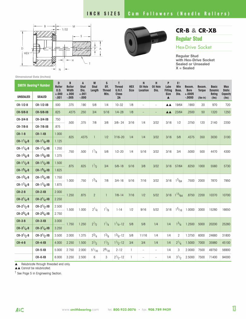
CR-B & CR-XBRegular StudHex-Drive Socket
Regular Studwith Hex-Drive SocketSealed or UnsealedX = Sealed
SMITH Bearing ® NumberD B A M S T N H P E†
Roller Roller Stud Stud Eff. Thread HEX Oil Hole Oil Hole Lube Min Recom. Recom. Basic MaxO.D. Width Dia. Length Thread U.N.F. Size Location Dia. Fitting Boss. Bore Torque Dynamic Static
+.000 +.000 +.001 Min. Class Size Dia. +.0005 Rating CapacityUNSEALED SEALED -.001 -.005 -.000 2A -.0000 (lbs-in) (lbs) (lbs)
CR–1/2-B CR–1/2-XB .500 .375 .190 5/8 1/4 10–32 1/8 – – 19/64 .1900 20 970 720
CR–5/8-B CR–5/8-XB .625 .4375 .250 3/4 5/16 1/4–28 1/8 – – 23/64 .2500 50 1320 1250
CR–3/4-B CR–3/4-XB .750.500 .375 7/8 3/8 3/8– 24 3/16 1/4 3/32 3/16 1/2 .3750 120 2140 2200
CR–7/8-B CR–7/8-XB .875
CR–1-B CR–1-XB 1.000.625 .4375 1 1/2 7/16–20 1/4 1/4 3/32 3/16 5/8 .4375 350 3030 3100
CR–11/8-B CR–11/8-XB 1.125
CR–11/4-B CR–11/4-XB 1.250.750 .500 11/4 5/8 1/2–20 1/4 5/16 3/32 3/16 3/4 .5000 500 4470 4300
CR–13/8-B CR–13/8-XB 1.375
CR–11/2-B CR–11/2-XB 1.500.875 .625 11/2 3/4 5/8–18 5/16 3/8 3/32 3/16 57/64 .6250 1000 5560 5730
CR–15/8-B CR–15/8-XB 1.625
CR–13/4-B CR–13/4-XB 1.7501.000 .750 13/4 7/8 3/4–16 5/16 7/16 3/32 3/16 13/64 .7500 2000 7870 7950
CR–17/8-B CR–17/8-XB 1.875
CR–2-B CR–2-XB 2.0001.250 .875 2 1 7/8–14 7/16 1/2 5/32 3/16 113/64 .8750 2200 10370 10700
CR–21/4-B CR–21/4-XB 2.250
CR–21/2-B CR–21/2-XB 2.5001.500 1.000 21/4 11/8 1-14 1/2 9/16 5/32 3/16 15/16 1.0000 3000 15280 16650
CR–23/4-B CR–23/4-XB 2.750
CR–3-B CR–3-XB 3.0001.750 1.250 21/2 11/4 11/4–12 5/8 5/8 1/4 1/4 13/4 1.2500 5000 20200 25260
CR–31/4-B CR–31/4-XB 3.250
CR–31/2-B CR–31/2-XB 3.500 2.000 1.375 23/4 13/8 13/8–12 5/8 11/16 1/4 1/4 2 1.3750 6000 24660 31800
CR–4-B CR–4-XB 4.000 2.250 1.500 31/2 11/2 11/2–12 3/4 3/4 1/4 1/4 21/4 1.5000 7000 35980 45100
CR–5-XB 5.000 2.750 2.000 51/16 29/16 2–12 1 – – 1/4 3 2.0000 7500 49750 56900
CR–6-XB 6.000 3.250 2.500 6 3 21/2–12 1 – – 1/4 31/2 2.5000 7500 71400 94000
Relubricate through threaded end only. Cannot be relubricated.† See Page 5 in Engineering Section.
B M
AP
T
N
H
D
HEX
1/32
C a m F o l l o w e r s ( N e e d l e R o l l e r s ) I N C H S I Z E S
Dimensional Data (inches)
www.smithbearing.com tel. 800.932.0076 • fax. 908.789.9429
S
14
SMITH Bearing ®
NumberD B A G E M T P
Roller Roller Eccentric Eccentric Eccentricity Stud Thread Lube BasicO.D. Width Bushing Bushing + .005 Length U.N.F. HEX Fitting Dynamic
+ .000 + .000 0.D. † Length Class Size RatingSEALED – .001 – .005 + .001 + .000 2A (lbs)
– .010
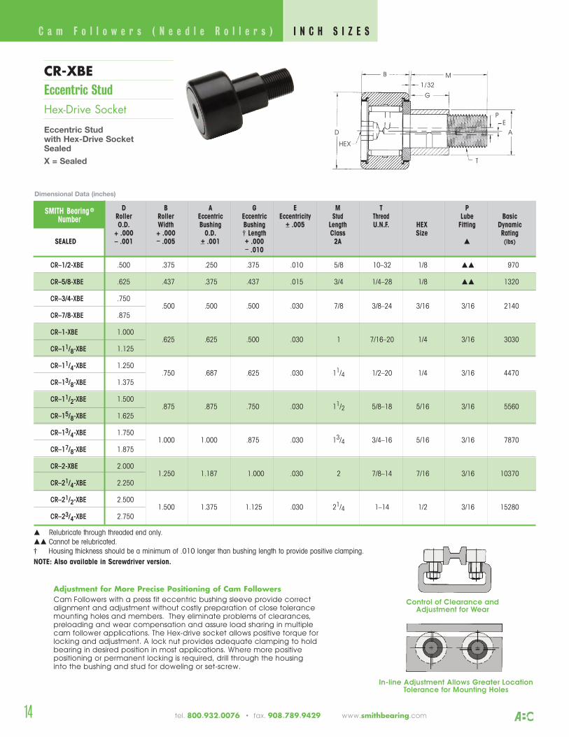
CR–1/2-XBE .500 .375 .250 .375 .010 5/8 10–32 1/8 970
CR–5/8-XBE .625 .437 .375 .437 .015 3/4 1/4–28 1/8 1320
CR–3/4-XBE .750.500 .500 .500 .030 7/8 3/8–24 3/16 3/16 2140
CR–7/8-XBE .875
CR–1-XBE 1.000.625 .625 .500 .030 1 7/16–20 1/4 3/16 3030
CR–11/8-XBE 1.125
CR–11/4-XBE 1.250.750 .687 .625 .030 11/4 1/2–20 1/4 3/16 4470
CR–13/8-XBE 1.375
CR–11/2-XBE 1.500.875 .875 .750 .030 11/2 5/8–18 5/16 3/16 5560
CR–15/8-XBE 1.625
CR–13/4-XBE 1.7501.000 1.000 .875 .030 13/4 3/4–16 5/16 3/16 7870
CR–17/8-XBE 1.875
CR–2-XBE 2.0001.250 1.187 1.000 .030 2 7/8–14 7/16 3/16 10370
CR–21/4-XBE 2.250
CR–21/2-XBE 2.5001.500 1.375 1.125 .030 21/4 1–14 1/2 3/16 15280
CR–23/4-XBE 2.750
Relubricate through threaded end only. Cannot be relubricated.† Housing thickness should be a minimum of .010 longer than bushing length to provide positive clamping.NOTE: Also available in Screwdriver version.
B M
A
T
D
HEX
1/32
E
G
Adjustment for More Precise Positioning of Cam FollowersCam Followers with a press fit eccentric bushing sleeve provide correctalignment and adjustment without costly preparation of close tolerancemounting holes and members. They eliminate problems of clearances,preloading and wear compensation and assure load sharing in multiple cam follower applications. The Hex-drive socket allows positive torque forlocking and adjustment. A lock nut provides adequate clamping to holdbearing in desired position in most applications. Where more positive positioning or permanent locking is required, drill through the housing into the bushing and stud for doweling or set-screw.
In-line Adjustment Allows Greater LocationTolerance for Mounting Holes
Control of Clearance andAdjustment for Wear
CR-XBEEccentric StudHex-Drive Socket
Eccentric Stud with Hex-Drive SocketSealed
X = Sealed
Dimensional Data (inches)
C a m F o l l o w e r s ( N e e d l e R o l l e r s ) I N C H S I Z E S
P
tel. 800.932.0076 • fax. 908.789.9429 www.smithbearing.com
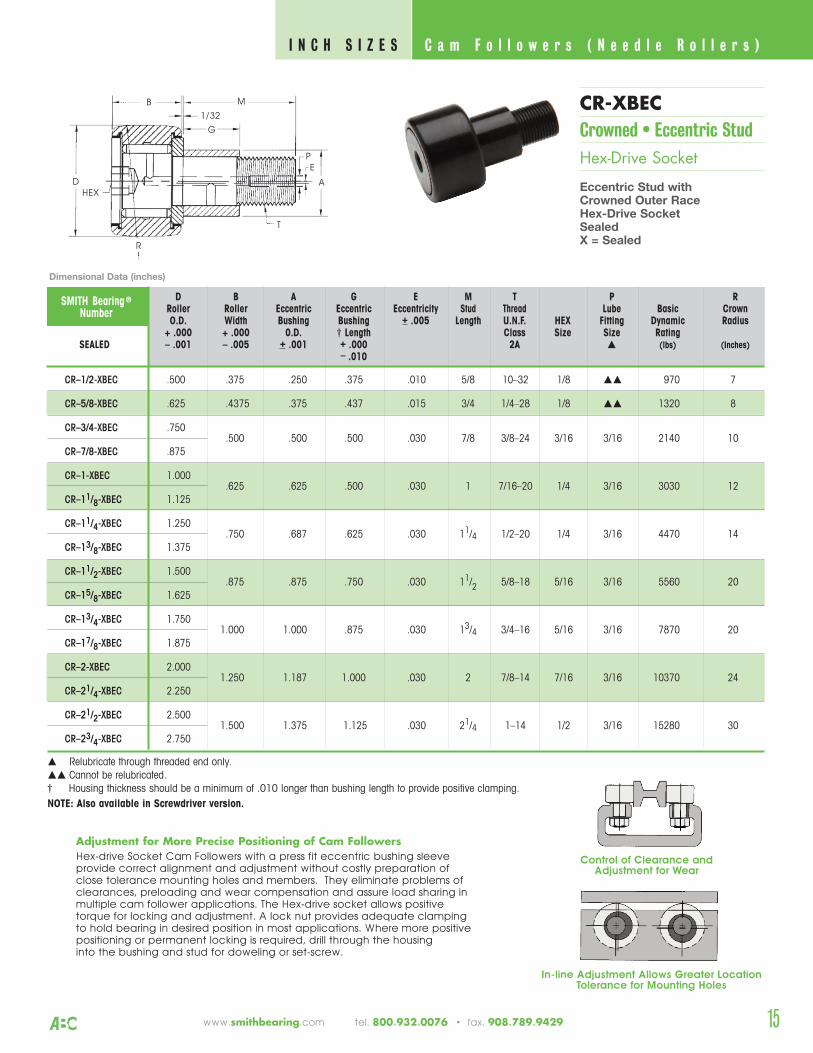
CR–1/2-XBEC .500 .375 .250 .375 .010 5/8 10–32 1/8 970 7
CR–5/8-XBEC .625 .4375 .375 .437 .015 3/4 1/4–28 1/8 1320 8
CR–3/4-XBEC .750.500 .500 .500 .030 7/8 3/8–24 3/16 3/16 2140 10
CR–7/8-XBEC .875
CR–1-XBEC 1.000.625 .625 .500 .030 1 7/16–20 1/4 3/16 3030 12
CR–11/8-XBEC 1.125
CR–11/4-XBEC 1.250.750 .687 .625 .030 11/4 1/2–20 1/4 3/16 4470 14
CR–13/8-XBEC 1.375
CR–11/2-XBEC 1.500.875 .875 .750 .030 11/2 5/8–18 5/16 3/16 5560 20
CR–15/8-XBEC 1.625
CR–13/4-XBEC 1.7501.000 1.000 .875 .030 13/4 3/4–16 5/16 3/16 7870 20
CR–17/8-XBEC 1.875
CR–2-XBEC 2.0001.250 1.187 1.000 .030 2 7/8–14 7/16 3/16 10370 24
CR–21/4-XBEC 2.250
CR–21/2-XBEC 2.5001.500 1.375 1.125 .030 21/4 1–14 1/2 3/16 15280 30
CR–23/4-XBEC 2.750
Relubricate through threaded end only. Cannot be relubricated.† Housing thickness should be a minimum of .010 longer than bushing length to provide positive clamping.NOTE: Also available in Screwdriver version.
SMITH Bearing ®
NumberD B A G E M T P R
Roller Roller Eccentric Eccentric Eccentricity Stud Thread Lube Basic CrownO.D. Width Bushing Bushing + .005 Length U.N.F. HEX Fitting Dynamic Radius
+ .000 + .000 0.D. † Length Class Size Size RatingSEALED – .001 – .005 + .001 + .000 2A (lbs) (Inches)
– .010
Adjustment for More Precise Positioning of Cam FollowersHex-drive Socket Cam Followers with a press fit eccentric bushing sleeveprovide correct alignment and adjustment without costly preparation of close tolerance mounting holes and members. They eliminate problems ofclearances, preloading and wear compensation and assure load sharing inmultiple cam follower applications. The Hex-drive socket allows positive torque for locking and adjustment. A lock nut provides adequate clamping to hold bearing in desired position in most applications. Where more positivepositioning or permanent locking is required, drill through the housing into the bushing and stud for doweling or set-screw.
B M
G
T
DHEX
1/32
A
E
R
P
15
CR-XBECCrowned • Eccentric Stud Hex-Drive Socket
Eccentric Stud withCrowned Outer Race Hex-Drive SocketSealedX = Sealed
C a m F o l l o w e r s ( N e e d l e R o l l e r s ) I N C H S I Z E S
Dimensional Data (inches)
In-line Adjustment Allows Greater LocationTolerance for Mounting Holes
Control of Clearance andAdjustment for Wear
www.smithbearing.com tel. 800.932.0076 • fax. 908.789.9429
16
SMITH Bearing ® NumberD B A M S T N H P E†
Roller Roller Stud Stud Eff. Thread Oil Hole Oil Hole Lube Min Recom. Recom. Basic MaxO.D. Width Dia. Length Thread U.N.F. Location Dia. Fitting Boss. Bore Torque Dynamic Static
+.000 +.000 +.001 Min. Class Size Dia. +.0005 Rating CapacityUNSEALED SEALED -.001 -.005 -.000 2A -.0000 (lbs-in) (lbs) (lbs)
HR–1/2 HR–1/2-X .500 .375 .250 5/8 1/4 1/4–28 - – *1/8 19/64 .2500 50 970 1590
HR–5/8 HR–5/8-X .625 .437 .3125 3/4 5/16 5/16–24 – – *1/8 23/64 .3125 75 1210 2500
HR–3/4 HR–3/4-X .750.500 .4375 7/8 3/8 7/16–20 1/4 3/32 3/16 1/2 .4375 300 2140 4150
HR–7/8 HR–7/8-X .875
HR–1 HR–1-X 1.000.625 .625 1 1/2 5/8–18 1/4 3/32 3/16 3/4 .6250 500 2850 6200
HR–11/8 HR–11/8-X 1.125
HR–11/4 HR–11/4-X 1.250.750 .750 11/4 5/8 3/4–16 5/16 3/32 3/16 7/8 .7500 1000 4060 8600
HR–13/8 HR–13/8-X 1.375
HR–11/2 HR–11/2-X 1.500.875 .875 11/2 3/4 7/8–14 3/8 3/32 3/16 15/16 .8750 2000 5330 11300
HR–15/8 HR–15/8-X 1.625
HR–13/4 HR–13/4-X 1.7501.000 1.000 13/4 7/8 1–14 7/16 3/32 3/16 13/32 1.0000 2500 7600 15870
HR–17/8 HR–17/8-X 1.875
HR–2 HR–2-X 2.0001.250 1.125 2 1 11/8–12 1/2 5/32 3/16 17/32 1.1250 3000 10050 22000
HR–21/4 HR–21/4-X 2.250
HR–21/2 HR–21/2-X 2.5001.500 1.250 21/4 11/8 11/4–12 9/16 5/32 3/16 15/16 1.2500 4000 15280 33000
HR–23/4 HR–23/4-X 2.750
HR–3 HR–3-X 3.0001.750 1.500 21/2 11/4 11/2–12 5/8 5/32 1/4 13/4 1.5000 5000 20200 49900
HR–31/4 HR–31/4-X 3.250
HR–31/2 HR–31/2-X 3.500 2.000 1.750 23/4 13/8 13/4–12 11/16 5/32 1/4 115/16 1.7500 6000 29660 63300
HR–4 HR–4-X 4.000 2.250 2.000 31/2 11/2 2–12 3/4 5/32 1/4 21/4 2.0000 8000 35980 90000
* Relubricate through head end only.† See Page 5 in Engineering Section.
B M
S
AP
T
N
H
D P
1/32
HR & HR-XHeavy StudScrewdriver Slot
Heavy Stud withScrew-Driver SlotSealed or UnsealedX = Sealed
Dimensional Data (inches)
C a m F o l l o w e r s ( N e e d l e R o l l e r s ) I N C H S I Z E S
tel. 800.932.0076 • fax. 908.789.9429 www.smithbearing.com
17
D B A M S T N H P E†Roller Roller Stud Stud Eff. Thread HEX Oil Hole Oil Hole Lube Min Recom. Recom. Basic MaxO.D. Width Dia. Length Thread U.N.F. Size Location Dia. Fitting Boss. Bore Torque Dynamic Static
+.000 +.000 +.001 Min. Class Size Dia. +.0005 Rating CapacityUNSEALED SEALED -.001 -.005 -.000 2A -.0000 (lbs-in) (lbs) (lbs)
SMITH Bearing ® Number
HR–1/2-XB .500 .375 .250 5/8 1/4 1/4–28 1/8 – – 19/64 .2500 50 970 1590
HR–5/8-XB .625 .437 .3125 3/4 5/16 5/16-24 1/8 – – 23/64 .3125 75 1210 2500
HR–3/4-XB .750.500 .4375 7/8 3/8 7/16– 20 3/16 1/4 3/32 3/16 1/2 .4375 300 2140 4150
HR–7/8-XB .875
HR–1-XB 1.000.625 .625 1 1/2 5/8–18 1/4 1/4 3/32 3/16 3/4 .6250 500 2850 6200
HR–11/8-XB 1.125
HR–11/4-XB 1.250.750 .750 11/4 5/8 3/4–16 1/4 5/16 3/32 3/16 7/8 .7500 1000 4060 8600
HR–13/8-XB 1.375
HR–11/2-XB 1.500.875 .875 11/2 3/4 7/8–14 5/16 3/8 3/32 3/16 15/16 .8750 2000 5330 11300
HR–15/8-XB 1.625
HR–13/4-XB 1.7501.000 1.000 13/4 7/8 1–14 5/16 7/16 3/32 3/16 13/32 1.0000 2500 7600 15870
HR–17/8-XB 1.875
HR–2-XB 2.0001.250 1.125 2 1 11/8–12 7/16 1/2 5/32 3/16 17/32 1.1250 3000 10050 22000
HR–21/4-XB 2.250
HR–21/2-XB 2.5001.500 1.250 21/4 11/8 11/4–12 1/2 9/16 5/32 3/16 15/16 1.2500 4000 15280 33000
HR–23/4-XB 2.750
HR–3-XB 3.0001.750 1.500 21/2 11/4 11/2–12 5/8 5/8 5/32 1/4 13/4 1.5000 5000 20200 49900
HR–31/4-XB 3.250
HR–31/2-XB 3.500 2.000 1.750 23/4 13/8 13/4–12 5/8 11/16 5/32 1/4 115/16 1.7500 6000 29660 63300
HR–4-XB 4.000 2.250 2.000 31/2 11/2 2–12 3/4 3/4 5/32 1/4 21/4 2.0000 8000 35980 90000
Relubricate through threaded end only.
Cannot be relubricated.† See Page 5 in Engineering Section.
HR–1/2-B
HR–5/8-B
HR–3/4-B
HR–7/8-B
HR–1-B
HR–11/8-B
HR–11/4-B
HR–13/8-B
HR–11/2-B
HR–15/8-B
HR–13/4-B
HR–17/8-B
HR–2-B
HR–21/4-B
HR–21/2-B
HR–23/4-B
HR–3-B
HR–31/4-B
HR–31/2-B
HR–4-B
B M
AP
T
N
H
D
HEX
1/32
S
HR-B & HR-XBHeavy StudHex-Drive Socket
Heavy Studwith Hex-Drive SocketSealed or UnsealedX = Sealed
C a m F o l l o w e r s ( N e e d l e R o l l e r s ) I N C H S I Z E S
Dimensional Data (inches)
www.smithbearing.com tel. 800.932.0076 • fax. 908.789.9429
18
SMITH Bearing ® NumberD A B W E Recommended Shaft Dia.
Roller Bore Roller Overall Min Basic MaxO.D. Nominal Tolerance Width Width Clamping Dynamic Static
+.000 +.000 +.005 Dia. Rating CapacityUNSEALED SEALED -.001 -.005 -.010 (lbs) (lbs)
Slip Fit Press Fit
Max. Min. Max. Min.
1.1250
1.2500
1.7500
2.2500
.2500
.3125
.3750
.4375
.5000
.6250
.7500
1.0000
YR–3/4 YR–3/4-X .750.500 .5625 1/2 .2497 .2493 .2505 .2501 2140 4170
YR–7/8 YR–7/8-X .875
YR–1 YR–1-X 1.000.625 .6875 5/8 .3122 .3118 .3130 .3126 3030 6200
YR–11/8 YR–11/8-X 1.125
YR–11/4 YR–11/4-X 1.250.750 .8125 3/4 .3747 .3743 .3755 .3751 4470 8600
YR–13/8 YR–3/8-X 1.375
YR–11/2 YR–11/2-X 1.500.875 .9375 57/64 .4372 .4368 .4380 .4376 5560 11300
YR–15/8 YR–15/8-X 1.625
YR–13/4 YR–13/4-X 1.7501.000 1.0625 13/64 .4997 .4993 .5007 .5003 7870 15870
YR–17/8 YR–17/8-X 1.875
YR–2 YR–2-X 2.0001.250 1.3125 113/64 .6247 .6243 .6257 .6253 10370 22000
YR–21/4 YR–21/4-X 2.250
YR–21/2 YR–21/2-X 2.5001.500 1.5625 15/16 .7497 .7493 .7507 .7503 15280 33000
YR–23/4 YR–23/4-X 2.750
YR–3 YR–3-X 3.0001.750 1.8125 13/4 .9996 .9992 1.0008 1.0003 20200 49900
YR–31/4 YR–31/4-X 3.250
YR–31/2 YR–31/2-X 3.500 2.000 2.0625 2 1.1246 1.1241 1.1258 1.1253 24660 63300
YR–4 YR–4-X 4.000 2.250 2.3125 21/4 1.2496 1.2491 1.2508 1.2503 35980 90000
YR–5-X 5.000 2.750 2.750 2.8750 3 1.7496 1.7491 1.7508 1.7503 49750 136000
YR–6-X 6.000 3.250 3.250 3.3750 31/2 2.2496 2.2491 2.2508 2.2503 71400 162000
+.0002
–.0004
+.0001
–.0005
W
A ED
BYR & YR-XYoke Type
for Shaft MountingSealed or UnsealedX = Sealed
Dimensional Data (inches)
C a m F o l l o w e r s ( N e e d l e R o l l e r s ) I N C H S I Z E S
tel. 800.932.0076 • fax. 908.789.9429 www.smithbearing.com
19
CROWNED BEARINGS
Add Suffix “C”
are recommended where the track or cam may impartexcessive thrust loading onthe bearing due tomisalignment.
CrownedCamFollowers
CrownedCamFollowersI N C H S I Z E S
Y O K E & S T U D T Y P E
www.smithbearing.com tel. 800.932.0076 • fax. 908.789.9429
S M I T H B E A R I N G ® C a m F o l l o w e r s ( N e e d l e R o l l e r s )
Unwanted edge loading of needle bearings causes skewing and end-thrusting of the needles which contributeto premature bearing failure. In situations where it is difficult
to obtain perfect alignment, crowned bearing O.D.’sprovide compensation for misalignment between the cam
follower and the surface of a slanted track or cam. Theouter crowned radius also eliminates skidding of the outer
race when bearing is in contact with a flat circular cam.
20
SMITH Bearing ® NumberD B A M S T N H P E† R
Roller Roller Stud Stud Eff. Thread Oil Hole Oil Hole Lube Min. Recom. Recom. Basic Max CrownO.D. Width Dia. Length Thread U.N.F. Location Dia. Fitting Boss. Bore Torque Dynamic Static Radius
+.000 +.000 +.001 Min. Class Size Dia. +.0005 Rating Capacity (Inches)UNSEALED SEALED -.001 -.005 -.000 2A -.0000 (lbs-in) (lbs) (lbs)
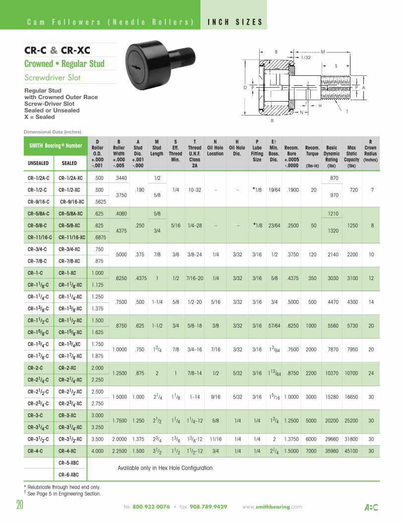
CR–1/2A-C CR–1/2A-XC .500 .3440 1/2 870
CR–1/2-C CR–1/2-XC .500.3750
.1905/8
1/4 10–32 – – *1/8 19/64 .1900 20970
720 7
CR–9/16-C CR–9/16-XC .5625
CR–5/8A-C CR–5/8A-XC .625 .4060 5/8 1210
CR–5/8-C CR–5/8-XC .625.4375
.250 3/4
5/16 1/4–28 – – *1/8 23/64 .2500 501320
1250 8
CR–11/16-C CR–11/16-XC .6875
CR–3/4-C CR–3/4-XC .750.5000 .375 7/8 3/8 3/8–24 1/4 3/32 3/16 1/2 .3750 120 2140 2200 10
CR–7/8-C CR–7/8-XC .875
CR–1-C CR–1-XC 1.000.6250 .4375 1 1/2 7/16–20 1/4 3/32 3/16 5/8 .4375 350 3030 3100 12
CR–11/8-C CR–11/8-XC 1.125
CR–11/4-C CR–11/4-XC 1.250.7500 .500 1-1/4 5/8 1/2–20 5/16 3/32 3/16 3/4 .5000 500 4470 4300 14
CR–13/8-C CR–13/8-XC 1.375
CR–11/2-C CR–11/2-XC 1.500.8750 .625 1-1/2 3/4 5/8–18 3/8 3/32 3/16 57/64 .6250 1000 5560 5730 20
CR–15/8-C CR–15/8-XC 1.625
CR–13/4-C CR–13/4XC 1.7501.0000 .750 13/4 7/8 3/4–16 7/16 3/32 3/16 13/64 .7500 2000 7870 7950 20
CR–17/8-C CR–17/8-XC 1.875
CR–2-C CR–2-XC 2.0001.2500 .875 2 1 7/8–14 1/2 5/32 3/16 113/64 .8750 2200 10370 10700 24
CR–21/4-C CR–21/4-XC 2.250
CR–21/2-C CR–21/2-XC 2.5001.5000 1.000 21/4 11/8 1–14 9/16 5/32 3/16 15/16 1.0000 3000 15280 16650 30
CR–23/4-C CR–23/4-XC 2.750
CR–3-C CR–3-XC 3.0001.7500 1.250 21/2 11/4 11/4–12 5/8 1/4 1/4 13/4 1.2500 5000 20200 25200 30
CR–31/4-C CR–31/4-XC 3.250
CR–31/2-C CR–31/2-XC 3.500 2.0000 1.375 23/4 13/8 13/8-12 11/16 1/4 1/4 2 1.3750 6000 29660 31800 30
CR–4-C CR–4-XC 4.000 2.2500 1.500 31/2 11/2 11/2–12 3/4 1/4 1/4 21/4 1.5000 7000 35980 45100 30
CR–5-XBCAvailable only in Hex Hole Configuration.
CR–6-XBC
* Relubricate through head end only.† See Page 5 in Engineering Section.
B M
S
AP
TN
H
D
1/32
R
P
CR-C & CR-XCCrowned • Regular Stud Screwdriver SlotRegular Stud with Crowned Outer RaceScrew-Driver SlotSealed or UnsealedX = Sealed
Dimensional Data (inches)
C a m F o l l o w e r s ( N e e d l e R o l l e r s ) I N C H S I Z E S
tel. 800.932.0076 • fax. 908.789.9429 www.smithbearing.com
21
SMITH Bearing ® Number D B A M S T N H P E† RRoller Roller Stud Stud Eff. Thread HEX Oil Hole Oil Hole Lube Min Recom. Recom. Basic Max CrownO.D. Width Dia. Length Thread U.N.F. Size Location Dia. Fitting Boss. Bore Torque Dynamic Static Radius
+.000 +.000 +.001 Min. Class Size Dia. +.0005 Rating Capacity (Inches)UNSEALED SEALED -.001 -.005 -.000 2A -.0000 (lbs-in) (lbs) (lbs)
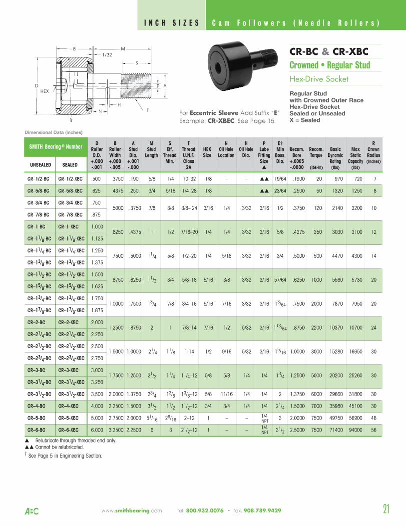
CR–1/2-BC CR–1/2-XBC .500 .3750 .190 5/8 1/4 10–32 1/8 – – 19/64 .1900 20 970 720 7
CR–5/8-BC CR–5/8-XBC .625 .4375 .250 3/4 5/16 1/4–28 1/8 – – 23/64 .2500 50 1320 1250 8
CR–3/4-BC CR–3/4-XBC .750.5000 .3750 7/8 3/8 3/8– 24 3/16 1/4 3/32 3/16 1/2 .3750 120 2140 3200 10
CR–7/8-BC CR–7/8-XBC .875
CR–1-BC CR–1-XBC 1.000.6250 .4375 1 1/2 7/16–20 1/4 1/4 3/32 3/16 5/8 .4375 350 3030 3100 12
CR–11/8-BC CR–11/8-XBC 1.125
CR–11/4-BC CR–11/4-XBC 1.250.7500 .5000 11/4 5/8 1/2–20 1/4 5/16 3/32 3/16 3/4 .5000 500 4470 4300 14
CR–13/8-BC CR–13/8-XBC 1.375
CR–11/2-BC CR–11/2-XBC 1.500.8750 .6250 11/2 3/4 5/8–18 5/16 3/8 3/32 3/16 57/64 .6250 1000 5560 5730 20
CR–15/8-BC CR–15/8-XBC 1.625
CR–13/4-BC CR–13/4-XBC 1.7501.0000 .7500 13/4 7/8 3/4–16 5/16 7/16 3/32 3/16 13/64 .7500 2000 7870 7950 20
CR–17/8-BC CR–17/8-XBC 1.875
CR–2-BC CR–2-XBC 2.0001.2500 .8750 2 1 7/8–14 7/16 1/2 5/32 3/16 113/64 .8750 2200 10370 10700 24
CR–21/4-BC CR–21/4-XBC 2.250
CR–21/2-BC CR–21/2-XBC 2.5001.5000 1.0000 21/4 11/8 1-14 1/2 9/16 5/32 3/16 15/16 1.0000 3000 15280 16650 30
CR–23/4-BC CR–23/4-XBC 2.750
CR–3-BC CR–3-XBC 3.0001.7500 1.2500 21/2 11/4 11/4–12 5/8 5/8 1/4 1/4 13/4 1.2500 5000 20200 25260 30
CR–31/4-BC CR–31/4-XBC 3.250
CR–31/2-BC CR–31/2-XBC 3.500 2.0000 1.3750 23/4 13/8 13/8–12 5/8 11/16 1/4 1/4 2 1.3750 6000 29660 31800 30
CR–4-BC CR–4-XBC 4.000 2.2500 1.5000 31/2 11/2 11/2–12 3/4 3/4 1/4 1/4 21/4 1.5000 7000 35980 45100 30
CR–5-BC CR–5-XBC 5.000 2.7500 2.0000 51/16 29/16 2–12 1 – – 1/4 3 2.0000 7500 49750 56900 48
CR–6-BC CR–6-XBC 6.000 3.2500 2.2500 6 3 21/2–12 1 – – 1/4 31/2 2.5000 7500 71400 94000 56
Relubricate through threaded end only. Cannot be relubricated.† See Page 5 in Engineering Section.
NPT
NPT
B M
A
T
DHEX
1/32
H
S
N
R
P
CR-BC & CR-XBCCrowned • Regular Stud Hex-Drive Socket
Regular Studwith Crowned Outer RaceHex-Drive SocketSealed or UnsealedX = Sealed
C a m F o l l o w e r s ( N e e d l e R o l l e r s ) I N C H S I Z E S
Dimensional Data (inches)
www.smithbearing.com tel. 800.932.0076 • fax. 908.789.9429
For Eccentric Sleeve Add Suffix “E”
Example: CR-XBEC. See Page 15.

22
SMITH Bearing ® Number D B A M S T N H P E† RRoller Roller Stud Stud Eff. Thread Oil Hole Oil Hole Lube Min. Recom. Recom. Basic Max RadiusO.D. Width Dia. Length Thread U.N.F. Location Dia. Fitting Boss. Bore Torque Dynamic Static Crown
+.000 +.000 +.001 Min. Class Size Dia. +.0005 Rating Capacity (Inches)UNSEALED SEALED-.001 -.005 -.000 2A -.0000 (lbs-in) (lbs) (lbs)
HR–1/2-C HR–1/2-XC .500 .375 .250 5/8 1/4 1/4–28 - – *1/8 19/64 .2500 50 970 1590 7
HR–5/8-C HR–5/8-XC .625 .437 .3125 3/4 5/16 5/16–24 – – *1/8 23/64 .3125 75 1210 2500 8
HR–3/4-C HR–3/4-XC .750.500 .4375 7/8 3/8 7/16–20 1/4 3/32 3/16 1/2 .4375 300 2140 4150
10
HR–7/8-C HR–7/8-XC .875
HR–1-C HR–1-XC 1.000.625 .625 1 1/2 5/8–18 1/4 3/32 3/16 3/4 .6250 500 2850 6200 12
HR–11/8-C HR–11/8-XC 1.125
HR–11/4-C HR–11/4-XC 1.250.750 .750 11/4 5/8 3/4–16 5/16 3/32 3/16 7/8 .7500 1000 4060 8690 14
HR–13/8-C HR–13/8-XC 1.375
HR–11/2-C HR–11/2-XC 1.500.875 .875 11/2 3/4 7/8–14 3/8 3/32 3/16 15/16 .8750 2000 5330 11300 20
HR–15/8-C HR–15/8-XC 1.625
HR–13/4-C HR–13/4-XC 1.7501.000 1.000 13/4 7/8 1–14 7/16 3/32 3/16 13/32 1.000 2500 7600 15870 20
HR–17/8-C HR–17/8-XC 1.875
HR–2-C HR–2-XC 2.0001.250 1.125 2 1 11/8–12 1/2 5/32 3/16 17/32 1.1250 3000 10050 22000 24
HR–21/4-C HR–21/4-XC 2.250
HR–21/2-C HR–21/2-XC 2.5001.500 1.250 21/4 11/8 11/4–12 9/16 5/32 3/16 15/16 1.2500 4000 15280 33000 30
HR–23/4-C HR–23/4-XC 2.750
HR–3-C HR–3-XC 3.0001.750 1.500 21/2 11/4 11/2–12 5/8 5/32 1/4 13/4 1.5000 5000 20200 49900 30
HR–31/4-C HR–31/4-XC 3.250
HR–31/2-C HR–31/2-XC 3.500 2.000 1.750 23/4 13/8 13/4–12 11/16 5/32 1/4 115/16 1.7500 6000 29660 63300 30
HR–4-C HR–4-XC 4.000 2.250 2.000 31/2 11/2 2–12 3/4 5/32 1/4 21/4 2.0000 8000 35980 90000 30
* Cannot be relubricated through threaded end.† See Page 5 in Engineering Section.
B M
S
AP
T
N
H
D P
1/32
R
HR-C & HR-XCCrowned • Heavy Stud Screwdriver Slot
Heavy Studwith Crowned Outer RaceScrew-Driver SlotSealed or UnsealedX = Sealed
Dimensional Data (inches)
C a m F o l l o w e r s ( N e e d l e R o l l e r s ) I N C H S I Z E S
tel. 800.932.0076 • fax. 908.789.9429 www.smithbearing.com
23
D B A M S T N H P † RRoller Roller Stud Stud Eff. Thread HEX Oil Hole Oil Hole Lube Min Recom. Recom. Basic Max CrownO.D. Width Dia. Length Thread U.N.F. Size Location Dia. Fitting Boss. Bore Torque Dynamic Static Radius
+.000 +.000 +.001 Min. Class Size Dia. +.0005 Rating Capacity (Inches)UNSEALED SEALED -.001 -.005 -.000 2A -.0000 (lbs-in) (lbs) (lbs)
SMITH Bearing ® Number
HR–1/2-BC
HR–5/8-BC
HR–3/4-BC
HR–7/8-BC
HR–1-BC
HR–11/8-BC
HR–11/4-BC
HR–13/8-BC
HR–11/2-BC
HR–15/8-BC
HR–13/4-BC
HR–17/8-BC
HR–2-BC
HR–21/4-BC
HR–21/2-BC
HR–23/4-BC
HR–3-BC
HR–31/4-BC
HR–31/2-BC
HR–4-BC
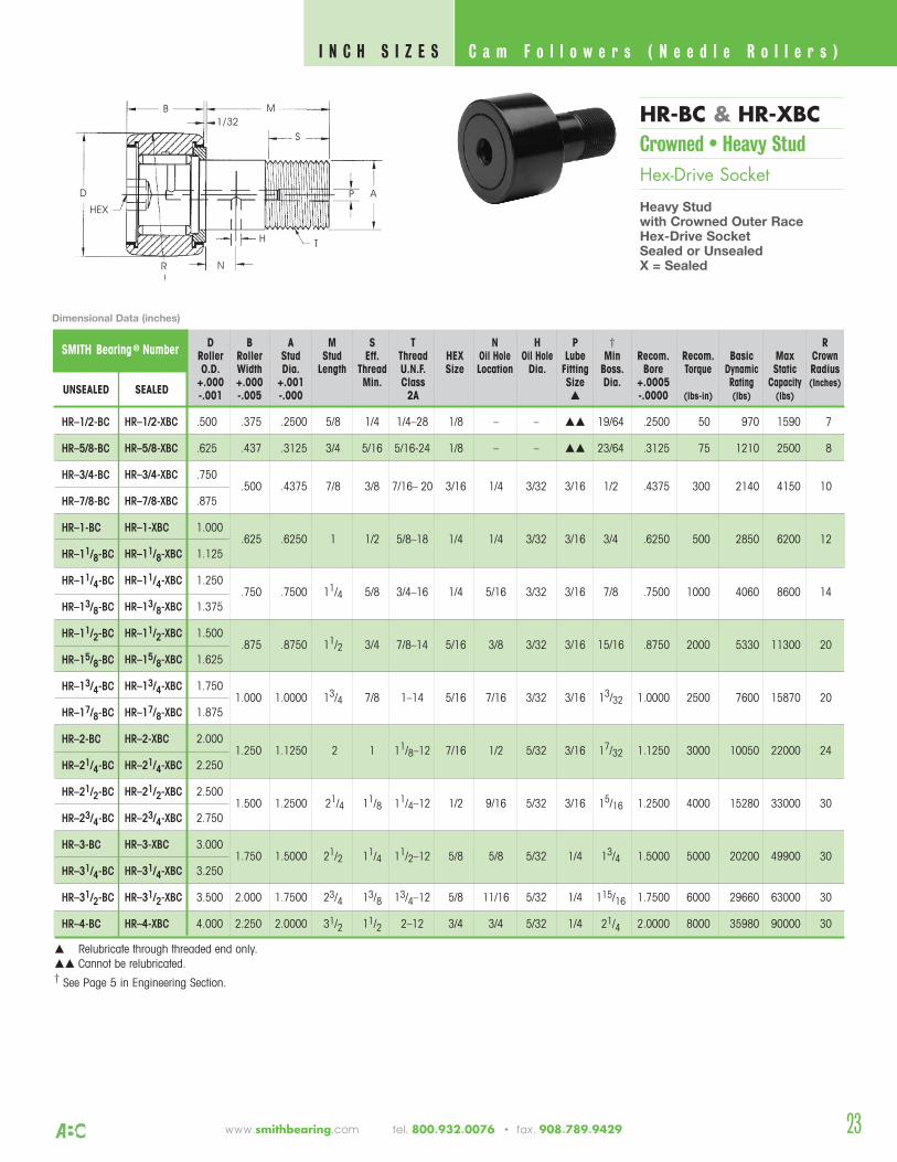
HR–1/2-XBC .500 .375 .2500 5/8 1/4 1/4–28 1/8 – – 19/64 .2500 50 970 1590 7
HR–5/8-XBC .625 .437 .3125 3/4 5/16 5/16-24 1/8 – – 23/64 .3125 75 1210 2500 8
HR–3/4-XBC .750.500 .4375 7/8 3/8 7/16– 20 3/16 1/4 3/32 3/16 1/2 .4375 300 2140 4150 10
HR–7/8-XBC .875
HR–1-XBC 1.000.625 .6250 1 1/2 5/8–18 1/4 1/4 3/32 3/16 3/4 .6250 500 2850 6200 12
HR–11/8-XBC 1.125
HR–11/4-XBC 1.250.750 .7500 11/4 5/8 3/4–16 1/4 5/16 3/32 3/16 7/8 .7500 1000 4060 8600 14
HR–13/8-XBC 1.375
HR–11/2-XBC 1.500.875 .8750 11/2 3/4 7/8–14 5/16 3/8 3/32 3/16 15/16 .8750 2000 5330 11300 20
HR–15/8-XBC 1.625
HR–13/4-XBC 1.7501.000 1.0000 13/4 7/8 1–14 5/16 7/16 3/32 3/16 13/32 1.0000 2500 7600 15870 20
HR–17/8-XBC 1.875
HR–2-XBC 2.0001.250 1.1250 2 1 11/8–12 7/16 1/2 5/32 3/16 17/32 1.1250 3000 10050 22000 24
HR–21/4-XBC 2.250
HR–21/2-XBC 2.5001.500 1.2500 21/4 11/8 11/4–12 1/2 9/16 5/32 3/16 15/16 1.2500 4000 15280 33000 30
HR–23/4-XBC 2.750
HR–3-XBC 3.0001.750 1.5000 21/2 11/4 11/2–12 5/8 5/8 5/32 1/4 13/4 1.5000 5000 20200 49900 30
HR–31/4-XBC 3.250
HR–31/2-XBC 3.500 2.000 1.7500 23/4 13/8 13/4–12 5/8 11/16 5/32 1/4 115/16 1.7500 6000 29660 63000 30
HR–4-XBC 4.000 2.250 2.0000 31/2 11/2 2–12 3/4 3/4 5/32 1/4 21/4 2.0000 8000 35980 90000 30
Relubricate through threaded end only. Cannot be relubricated.† See Page 5 in Engineering Section.
B M
A
T
D
HEX
1/32
H
S
N
P
HR-BC & HR-XBCCrowned • Heavy Stud Hex-Drive Socket
Heavy Studwith Crowned Outer RaceHex-Drive SocketSealed or UnsealedX = Sealed
C a m F o l l o w e r s ( N e e d l e R o l l e r s ) I N C H S I Z E S
Dimensional Data (inches)
R
www.smithbearing.com tel. 800.932.0076 • fax. 908.789.9429
24
SMITH Bearing ® Number D A B W E Recommended Shaft Dia. RRoller Bore Roller Overall Min Basic Max CrownO.D. Nominal Tolerance Width Width Clamping Dynamic Static Radius
+.000 +.000 +.005 Dia. Rating Capacity (Inches)UNSEALED SEALED -.001 -.005 -.010 (lbs) (lbs)
Slip Fit Press Fit
Max. Min. Max. Min.
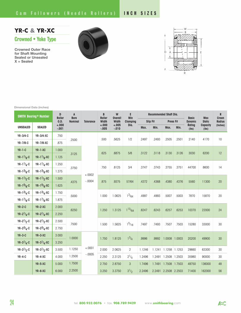
YR–3/4-C YR–3/4-XC .750.500 .5625 1/2 .2497 .2493 .2505 .2501 2140 4170 10
YR–7/8-C YR–7/8-XC .875
YR–1-C YR–1-XC 1.000.625 .6875 5/8 .3122 .3118 .3130 .3126 3030 6200 12
YR–11/8-C YR–11/8-XC 1.125
YR–11/4-C YR–11/4-XC 1.250.750 .8125 3/4 .3747 .3743 .3755 .3751 44700 8600 14
YR–13/8-C YR–13/8-XC 1.375
YR–11/2-C YR–11/2-XC 1.500.875 .9375 57/64 .4372 .4368 .4380 .4376 5560 11300 20
YR–15/8-C YR–15/8-XC 1.625
YR–13/4-C YR–13/4-XC 1.7501.000 1.0625 13/64 .4997 .4993 .5007 .5003 7870 15870 20
YR–17/8-C YR–17/8-XC 1.875
YR–2-C YR–2-XC 2.0001.250 1.3125 113/64 .6247 .6243 .6257 .6253 10370 22000 24
YR–21/4-C YR–21/4-XC 2.250
YR–21/2-C YR–21/2-XC 2.5001.500 1.5625 15/16 .7497 .7493 .7507 .7503 15280 33000 30
YR–23/4-C YR–23/4-XC 2.750
YR–3-C YR–3-XC 3.0001.750 1.8125 13/4 .9996 .9992 1.0008 1.0003 20200 49900 30
YR–31/4-C YR–31/4-XC 3.250
YR–31/2-C YR–31/2-XC 3.500 2.000 2.0625 2 1.1246 1.1241 1.1258 1.1253 29660 63300 30
YR–4-C YR–4-XC 4.000 2.250 2.3125 21/4 1.2496 1.2491 1.2508 1.2503 35980 90000 30
YR–5-XC 5.000 2.750 2.8750 3 1.7496 1.7491 1.7508 1.7503 49750 136000 48
YR–6-XC 6.000 3.250 3.3750 31/2 2.2496 2.2491 2.2508 2.2503 71400 162000 56
+.0002
–.0004
.2500
.3125
.3750
.4375
.5000
.6250
.7500
1.0000
1.1250
1.2500
1.7500
2.2500
+.0001
–.0005
W
A ED
B
R
YR-C & YR-XCCrowned • Yoke Type
Crowned Outer Racefor Shaft MountingSealed or UnsealedX = Sealed
Dimensional Data (inches)
C a m F o l l o w e r s ( N e e d l e R o l l e r s ) I N C H S I Z E S
tel. 800.932.0076 • fax. 908.789.9429 www.smithbearing.com
25www.smithbearing.com tel. 800.932.0076 • fax. 908.789.9429
D o u b l e R o wC a m F o l l o w e r s N e e d l e R o l l e r sI N C H S I Z E S
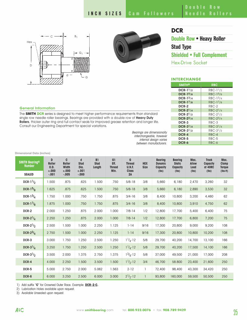
DCR-11/2 1.500 .875 .625 1.500 .750 5/8-18 3/8 5,660 6,180 2,470 3,260 32
DCR-15/8 1.625 .875 .625 1.500 .750 5/8-18 3/8 5,660 6,180 2,890 3,530 32
DCR-13/4 1.750 1.000 .750 1.750 .875 3/4-16 3/8 8,400 10,800 3,200 4,460 62
DCR-17/8 1.875 1.000 .750 1.750 .875 3/4-16 3/8 8,400 10,800 3,910 4,750 62
DCR-2 2.000 1.250 .875 2.000 1.000 7/8-14 1/2 12,800 17,700 5,400 6,400 75
DCR-21/4 2.250 1.250 .875 2.000 1.000 7/8-14 1/2 12,800 17,700 6,800 7,200 75
DCR-21/2 2.500 1.500 1.000 2.250 1.125 1-14 9/16 17,300 20,800 9,000 9,200 108
DCR-23/4 2.750 1.500 1.000 2.250 1.125 1-14 9/16 17,300 20,800 10,800 10,200 108
DCR-3 3.000 1.750 1.250 2.500 1.250 11/4-12 5/8 29,700 40,200 14,700 13,100 166
DCR-31/4 3.250 1.750 1.250 2.500 1.250 11/4-12 5/8 29,700 40,200 17,500 14,100 166
DCR-31/2 3.500 2.000 1.375 2.750 1.375 13/8-12 5/8 37,000 49,500 21,000 17,000 208
DCR-4 4.000 2.250 1.500 3.500 1.500 11/2-12 3/4 46,700 58.800 23,400 21,600 250
DCR-5 5.000 2.750 2.000 5.062 1.563 2-12 1 72,400 98,400 43,300 34,420 250
DCR-6 6.000 3.250 2.500 6.000 3.000 21/2-12 1 93,800 160,000 59,500 50,500 250
General Information
The SMITH DCR series is designed to meet higher performance requirements than standardsingle row needle roller bearings. Bearings are provided with a double row of Heavy DutyRollers, thicker outer ring and full contact seals for improved grease retention and longer life.Consult our Engineering Department for special variations.
D C d B1 G1 G Bearing Bearing Max. Track Max.Roller Roller Stud Stud Eff. Thread HEX Dynamic Static Allow Capacity ClampO.D. Width Dia. Length Thread U.N.F. Size Capacity Capacity Load at 40RC Torque
+.000 +.000 +.001 Min. Class (lbs) (lbs) (lbs) (lbs) (lbs-ft)SEALED -.001 -.005 -.000 2A
SMITH Bearing®
Number
1) Add suffix “C” for Crowned Outer Race. Example: DCR–2-C. 2) Lubrication Holes available upon request.3) Available Unsealed upon request.
B1C
D
d
G1
G
Hex
DCRDouble Row • Heavy Roller Stud TypeShielded • Full ComplementHex-Drive Socket
Dimensional Data (inches)
INTERCHANGESMITH® RBC
DCR-11/2 RBC-11/2
DCR-15/8 RBC-15/8
DCR-13/4 RBC-13/4
DCR-17/8 RBC-17/8
DCR-2 RBC-2DCR-21/4 RBC-21/4
DCR-21/2 RBC-21/2
DCR-23/4 RBC-23/4
DCR-3 RBC-3DCR-31/4 RBC-31/4
DCR-31/2 RBC-31/2
DCR-4 RBC-4DCR-5 RBC-5DCR-6 RBC-6
Bearings are dimensionallyinterchangeable, however
internal design variesbetween manufacturers.
26
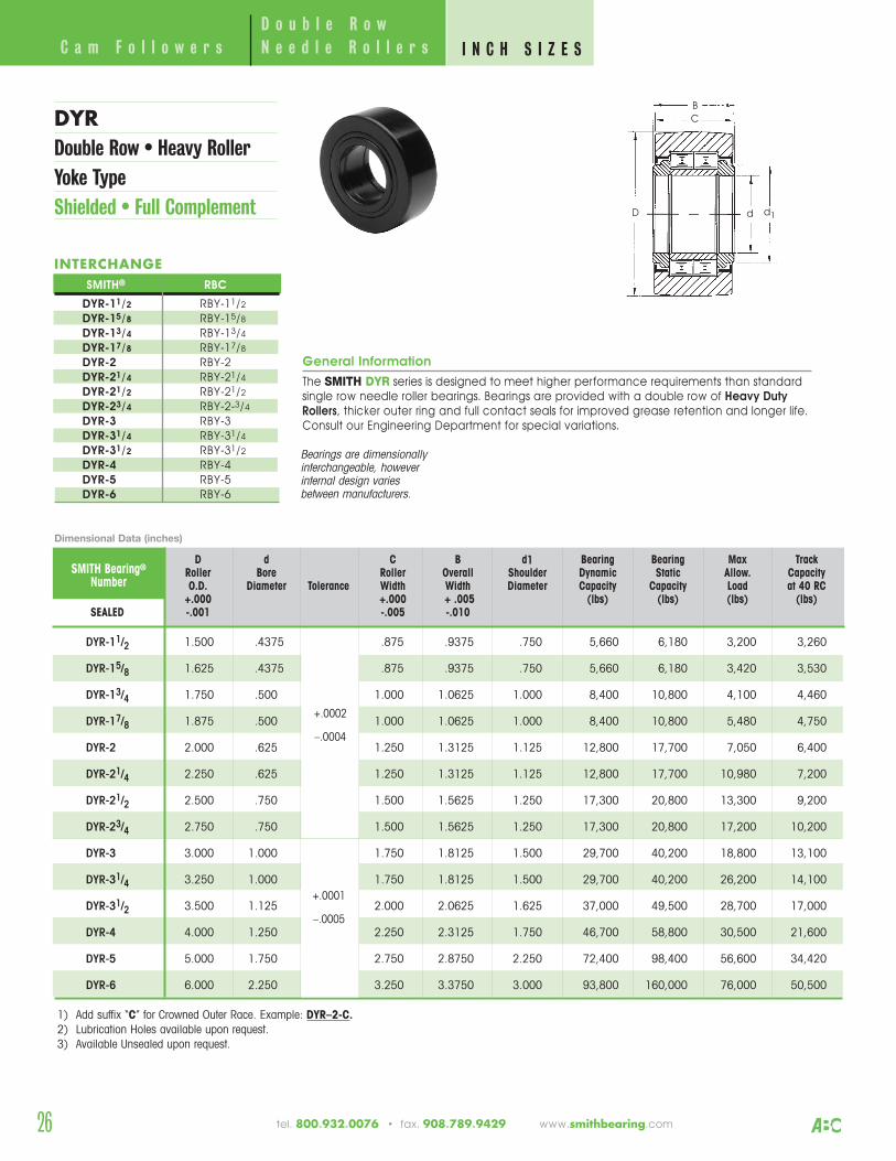
General Information
The SMITH DYR series is designed to meet higher performance requirements than standardsingle row needle roller bearings. Bearings are provided with a double row of Heavy DutyRollers, thicker outer ring and full contact seals for improved grease retention and longer life.Consult our Engineering Department for special variations.
D d C B d1 Bearing Bearing Max TrackRoller Bore Roller Overall Shoulder Dynamic Static Allow. CapacityO.D. Diameter Tolerance Width Width Diameter Capacity Capacity Load at 40 RC
+.000 +.000 + .005 (lbs) (lbs) (lbs) (lbs)SEALED -.001 -.005 -.010
DYR-11/2 1.500 .4375 .875 .9375 .750 5,660 6,180 3,200 3,260
DYR-15/8 1.625 .4375 .875 .9375 .750 5,660 6,180 3,420 3,530
DYR-13/4 1.750 .500 1.000 1.0625 1.000 8,400 10,800 4,100 4,460
DYR-17/8 1.875 .500 1.000 1.0625 1.000 8,400 10,800 5,480 4,750
DYR-2 2.000 .625 1.250 1.3125 1.125 12,800 17,700 7,050 6,400
DYR-21/4 2.250 .625 1.250 1.3125 1.125 12,800 17,700 10,980 7,200
DYR-21/2 2.500 .750 1.500 1.5625 1.250 17,300 20,800 13,300 9,200
DYR-23/4 2.750 .750 1.500 1.5625 1.250 17,300 20,800 17,200 10,200
DYR-3 3.000 1.000 1.750 1.8125 1.500 29,700 40,200 18,800 13,100
DYR-31/4 3.250 1.000 1.750 1.8125 1.500 29,700 40,200 26,200 14,100
DYR-31/2 3.500 1.125 2.000 2.0625 1.625 37,000 49,500 28,700 17,000
DYR-4 4.000 1.250 2.250 2.3125 1.750 46,700 58,800 30,500 21,600
DYR-5 5.000 1.750 2.750 2.8750 2.250 72,400 98,400 56,600 34,420
DYR-6 6.000 2.250 3.250 3.3750 3.000 93,800 160,000 76,000 50,500
SMITH Bearing®
Number
1) Add suffix “C” for Crowned Outer Race. Example: DYR–2-C. 2) Lubrication Holes available upon request.3) Available Unsealed upon request.
C
D
B
d1d
DYRDouble Row • Heavy Roller Yoke TypeShielded • Full Complement
Dimensional Data (inches)
D o u b l e R o wC a m F o l l o w e r s N e e d l e R o l l e r s I N C H S I Z E S
+.0002
–.0004
+.0001
–.0005
tel. 800.932.0076 • fax. 908.789.9429 www.smithbearing.com
INTERCHANGESMITH® RBC
DYR-11/2 RBY-11/2
DYR-15/8 RBY-15/8
DYR-13/4 RBY-13/4
DYR-17/8 RBY-17/8
DYR-2 RBY-2DYR-21/4 RBY-21/4
DYR-21/2 RBY-21/2
DYR-23/4 RBY-2-3/4
DYR-3 RBY-3DYR-31/4 RBY-31/4
DYR-31/2 RBY-31/2
DYR-4 RBY-4DYR-5 RBY-5DYR-6 RBY-6
Bearings are dimensionallyinterchangeable, howeverinternal design variesbetween manufacturers.
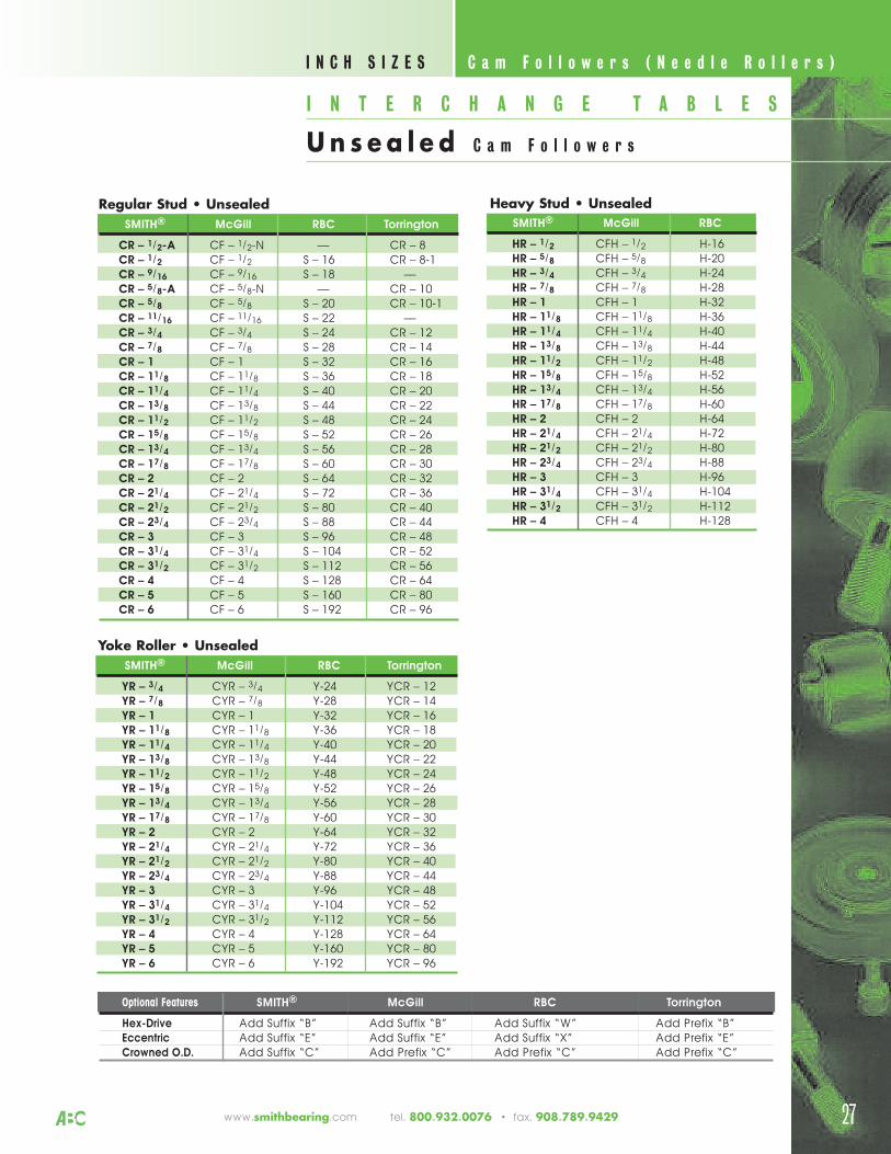
C a m F o l l o w e r s ( N e e d l e R o l l e r s ) I N C H S I Z E S
I N T E R C H A N G E T A B L E S
Un s e a l e d C a m F o l l o w e r s
27www.smithbearing.com tel. 800.932.0076 • fax. 908.789.9429
Regular Stud • Unsealed SMITH® McGill RBC Torrington
CR – 1/2-A CF – 1/2-N –– CR – 8CR – 1/2 CF – 1/2 S – 16 CR – 8-1CR – 9/16 CF – 9/16 S – 18 ––CR – 5/8-A CF – 5/8-N –– CR – 10CR – 5/8 CF – 5/8 S – 20 CR – 10-1CR – 11/16 CF – 11/16 S – 22 ––CR – 3/4 CF – 3/4 S – 24 CR – 12CR – 7/8 CF – 7/8 S – 28 CR – 14CR – 1 CF – 1 S – 32 CR – 16CR – 11/8 CF – 11/8 S – 36 CR – 18CR – 11/4 CF – 11/4 S – 40 CR – 20CR – 13/8 CF – 13/8 S – 44 CR – 22CR – 11/2 CF – 11/2 S – 48 CR – 24CR – 15/8 CF – 15/8 S – 52 CR – 26CR – 13/4 CF – 13/4 S – 56 CR – 28CR – 17/8 CF – 17/8 S – 60 CR – 30CR – 2 CF – 2 S – 64 CR – 32CR – 21/4 CF – 21/4 S – 72 CR – 36CR – 21/2 CF – 21/2 S – 80 CR – 40CR – 23/4 CF – 23/4 S – 88 CR – 44CR – 3 CF – 3 S – 96 CR – 48CR – 31/4 CF – 31/4 S – 104 CR – 52CR – 31/2 CF – 31/2 S – 112 CR – 56CR – 4 CF – 4 S – 128 CR – 64CR – 5 CF – 5 S – 160 CR – 80CR – 6 CF – 6 S – 192 CR – 96
Yoke Roller • Unsealed SMITH® McGill RBC Torrington
YR – 3/4 CYR – 3/4 Y-24 YCR – 12YR – 7/8 CYR – 7/8 Y-28 YCR – 14YR – 1 CYR – 1 Y-32 YCR – 16YR – 11/8 CYR – 11/8 Y-36 YCR – 18YR – 11/4 CYR – 11/4 Y-40 YCR – 20YR – 13/8 CYR – 13/8 Y-44 YCR – 22YR – 11/2 CYR – 11/2 Y-48 YCR – 24YR – 15/8 CYR – 15/8 Y-52 YCR – 26YR – 13/4 CYR – 13/4 Y-56 YCR – 28YR – 17/8 CYR – 17/8 Y-60 YCR – 30YR – 2 CYR – 2 Y-64 YCR – 32YR – 21/4 CYR – 21/4 Y-72 YCR – 36YR – 21/2 CYR – 21/2 Y-80 YCR – 40YR – 23/4 CYR – 23/4 Y-88 YCR – 44YR – 3 CYR – 3 Y-96 YCR – 48YR – 31/4 CYR – 31/4 Y-104 YCR – 52YR – 31/2 CYR – 31/2 Y-112 YCR – 56YR – 4 CYR – 4 Y-128 YCR – 64YR – 5 CYR – 5 Y-160 YCR – 80YR – 6 CYR – 6 Y-192 YCR – 96
Heavy Stud • Unsealed SMITH® McGill RBC
HR – 1/2 CFH – 1/2 H-16HR – 5/8 CFH – 5/8 H-20HR – 3/4 CFH – 3/4 H-24HR – 7/8 CFH – 7/8 H-28HR – 1 CFH – 1 H-32HR – 11/8 CFH – 11/8 H-36HR – 11/4 CFH – 11/4 H-40HR – 13/8 CFH – 13/8 H-44HR – 11/2 CFH – 11/2 H-48HR – 15/8 CFH – 15/8 H-52HR – 13/4 CFH – 13/4 H-56HR – 17/8 CFH – 17/8 H-60HR – 2 CFH – 2 H-64HR – 21/4 CFH – 21/4 H-72HR – 21/2 CFH – 21/2 H-80HR – 23/4 CFH – 23/4 H-88HR – 3 CFH – 3 H-96HR – 31/4 CFH – 31/4 H-104HR – 31/2 CFH – 31/2 H-112HR – 4 CFH – 4 H-128
Optional Features SMITH® McGill RBC Torrington
Hex-Drive Add Suffix “B” Add Suffix “B” Add Suffix “W” Add Prefix “B”Eccentric Add Suffix “E” Add Suffix “E” Add Suffix “X” Add Prefix “E”Crowned O.D. Add Suffix “C” Add Prefix “C” Add Prefix “C” Add Prefix “C”
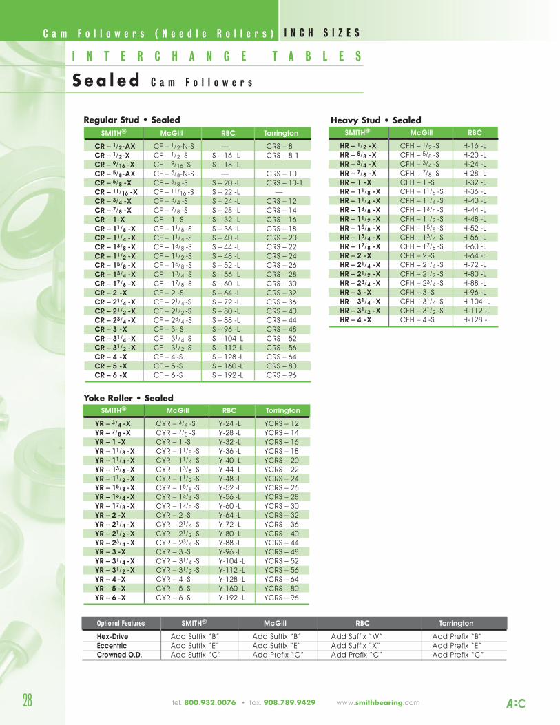
Regular Stud • SealedSMITH® McGill RBC Torrington
CR – 1/2-AX CF – 1/2-N-S –– CRS – 8CR – 1/2-X CF – 1/2 -S S – 16 -L CRS – 8-1CR – 9/16 -X CF – 9/16 -S S – 18 -L ––CR – 5/8-AX CF – 5/8-N-S –– CRS – 10CR – 5/8 -X CF – 5/8 -S S – 20 -L CRS – 10-1CR – 11/16 -X CF – 11/16 -S S – 22 -L ––CR – 3/4 -X CF – 3/4 -S S – 24 -L CRS – 12CR – 7/8 -X CF – 7/8 -S S – 28 -L CRS – 14CR – 1-X CF – 1 -S S – 32 -L CRS – 16CR – 11/8 -X CF – 11/8 -S S – 36 -L CRS – 18CR – 11/4 -X CF – 11/4 -S S – 40 -L CRS – 20CR – 13/8 -X CF – 13/8 -S S – 44 -L CRS – 22CR – 11/2 -X CF – 11/2 -S S – 48 -L CRS – 24CR – 15/8 -X CF – 15/8 -S S – 52 -L CRS – 26CR – 13/4 -X CF – 13/4 -S S – 56 -L CRS – 28CR – 17/8 -X CF – 17/8 -S S – 60 -L CRS – 30CR – 2 -X CF – 2 -S S – 64 -L CRS – 32CR – 21/4 -X CF – 21/4 -S S – 72 -L CRS – 36CR – 21/2 -X CF – 21/2 -S S – 80 -L CRS – 40CR – 23/4 -X CF – 23/4 -S S – 88 -L CRS – 44CR – 3 -X CF – 3- S S – 96 -L CRS – 48CR – 31/4 -X CF – 31/4 -S S – 104 -L CRS – 52CR – 31/2 -X CF – 31/2 -S S – 112 -L CRS – 56CR – 4 -X CF – 4 -S S – 128 -L CRS – 64CR – 5 -X CF – 5 -S S – 160 -L CRS – 80CR – 6 -X CF – 6 -S S – 192 -L CRS – 96
Yoke Roller • Sealed SMITH® McGill RBC Torrington
YR – 3/4 -X CYR – 3/4 -S Y-24 -L YCRS – 12YR – 7/8 -X CYR – 7/8 -S Y-28 -L YCRS – 14YR – 1 -X CYR – 1 -S Y-32 -L YCRS – 16YR – 11/8 -X CYR – 11/8 -S Y-36 -L YCRS – 18YR – 11/4 -X CYR – 11/4 -S Y-40 -L YCRS – 20YR – 13/8 -X CYR – 13/8 -S Y-44 -L YCRS – 22YR – 11/2 -X CYR – 11/2 -S Y-48 -L YCRS – 24YR – 15/8 -X CYR – 15/8 -S Y-52 -L YCRS – 26YR – 13/4 -X CYR – 13/4 -S Y-56 -L YCRS – 28YR – 17/8 -X CYR – 17/8 -S Y-60 -L YCRS – 30YR – 2 -X CYR – 2 -S Y-64 -L YCRS – 32YR – 21/4 -X CYR – 21/4 -S Y-72 -L YCRS – 36YR – 21/2 -X CYR – 21/2 -S Y-80 -L YCRS – 40YR – 23/4 -X CYR – 23/4 -S Y-88 -L YCRS – 44YR – 3 -X CYR – 3 -S Y-96 -L YCRS – 48YR – 31/4 -X CYR – 31/4 -S Y-104 -L YCRS – 52YR – 31/2 -X CYR – 31/2 -S Y-112 -L YCRS – 56YR – 4 -X CYR – 4 -S Y-128 -L YCRS – 64YR – 5 -X CYR – 5 -S Y-160 -L YCRS – 80YR – 6 -X CYR – 6 -S Y-192 -L YCRS – 96
Heavy Stud • SealedSMITH® McGill RBC
HR – 1/2 -X CFH – 1/2 -S H-16 -LHR – 5/8 -X CFH – 5/8 -S H-20 -LHR – 3/4 -X CFH – 3/4 -S H-24 -LHR – 7/8 -X CFH – 7/8 -S H-28 -LHR – 1 -X CFH – 1 -S H-32 -LHR – 11/8 -X CFH – 11/8 -S H-36 -LHR – 11/4 -X CFH – 11/4 -S H-40 -LHR – 13/8 -X CFH – 13/8 -S H-44 -LHR – 11/2 -X CFH – 11/2 -S H-48 -LHR – 15/8 -X CFH – 15/8 -S H-52 -LHR – 13/4 -X CFH – 13/4 -S H-56 -LHR – 17/8 -X CFH – 17/8 -S H-60 -LHR – 2 -X CFH – 2 -S H-64 -LHR – 21/4 -X CFH – 21/4 -S H-72 -LHR – 21/2 -X CFH – 21/2 -S H-80 -LHR – 23/4 -X CFH – 23/4 -S H-88 -LHR – 3 -X CFH – 3 -S H-96 -LHR – 31/4 -X CFH – 31/4 -S H-104 -LHR – 31/2 -X CFH – 31/2 -S H-112 -LHR – 4 -X CFH – 4 -S H-128 -L
28
C a m F o l l o w e r s ( N e e d l e R o l l e r s ) I N C H S I Z E S
I N T E R C H A N G E T A B L E S
S e a l e d C a m F o l l o w e r s
tel. 800.932.0076 • fax. 908.789.9429 www.smithbearing.com
Optional Features SMITH® McGill RBC Torrington
Hex-Drive Add Suffix “B” Add Suffix “B” Add Suffix “W” Add Prefix “B”Eccentric Add Suffix “E” Add Suffix “E” Add Suffix “X” Add Prefix “E”Crowned O.D. Add Suffix “C” Add Prefix “C” Add Prefix “C” Add Prefix “C”
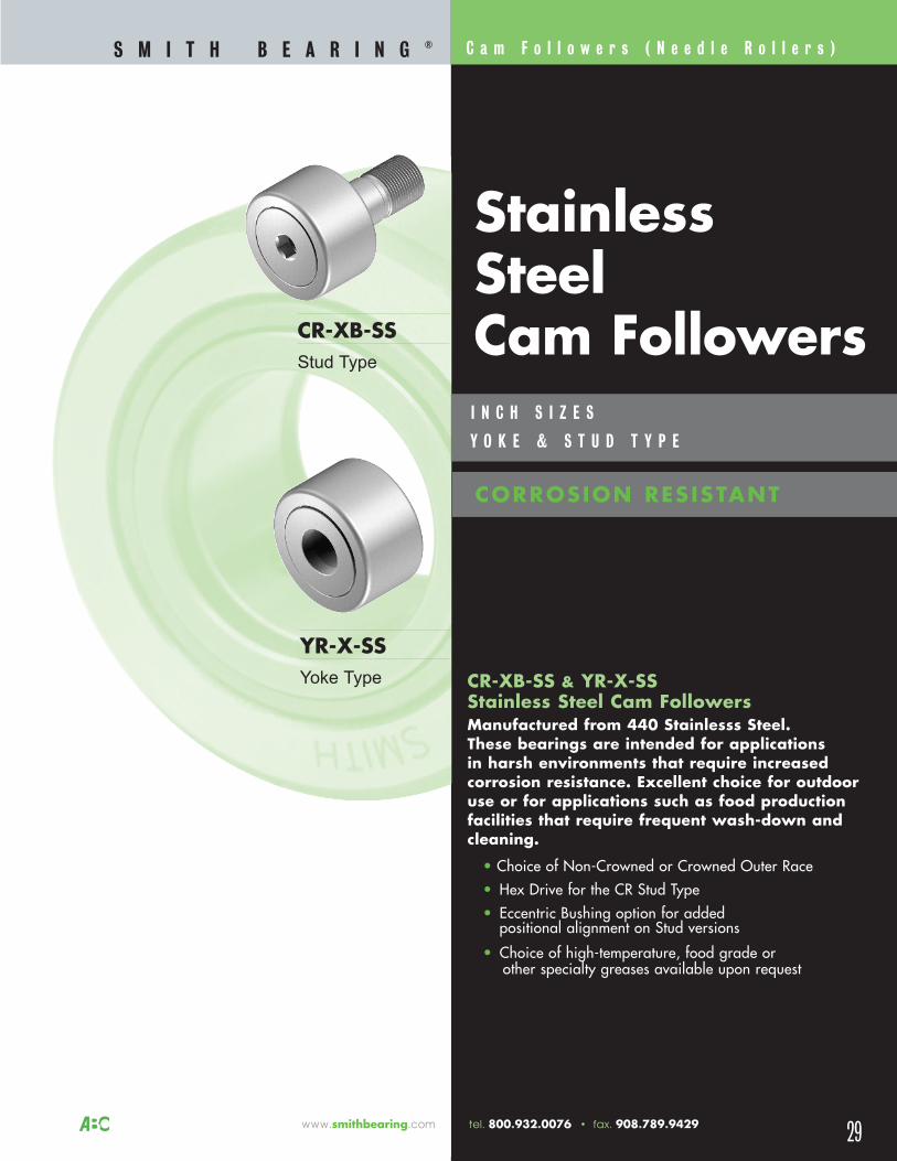
C a m F o l l o w e r s ( N e e d l e R o l l e r s )
29
CR-XB-SSStud Type
YR-X-SSYoke Type
S M I T H B E A R I N G ®
I N C H S I Z E S
Y O K E & S T U D T Y P E
www.smithbearing.com tel. 800.932.0076 • fax. 908.789.9429
StainlessSteelCam Followers
CORROSION RESISTANT
CR-XB-SS & YR-X-SS Stainless Steel Cam FollowersManufactured from 440 Stainlesss Steel. These bearings are intended for applicationsin harsh environments that require increasedcorrosion resistance. Excellent choice for outdooruse or for applications such as food productionfacilities that require frequent wash-down andcleaning.
• Choice of Non-Crowned or Crowned Outer Race• Hex Drive for the CR Stud Type • Eccentric Bushing option for added
positional alignment on Stud versions
• Choice of high-temperature, food grade orother specialty greases available upon request
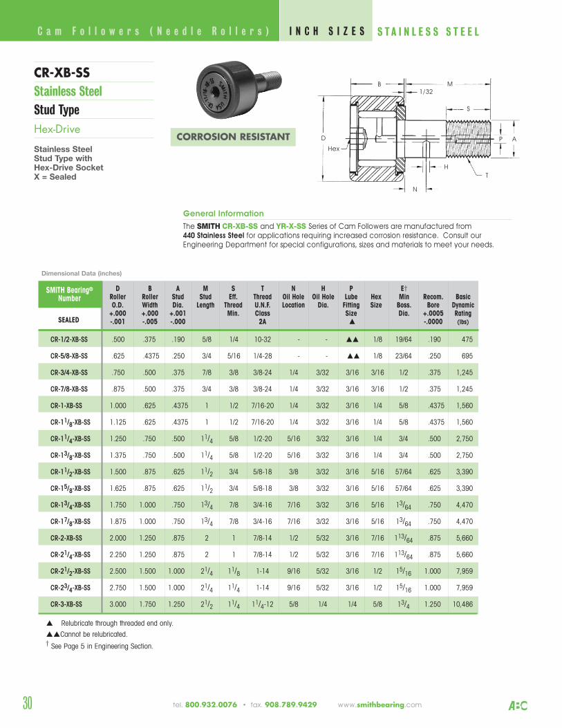
B
D
N
Hex
M
H
T
AP
1/32
R-1/2-B-SS CR-1/2-XB-SS .500 .375 .190 5/8 1/4 10-32 - - 1/8 19/64 .190 475
R-5/8-B-SS CR-5/8-XB-SS .625 .4375 .250 3/4 5/16 1/4-28 - - 1/8 23/64 .250 695
R-3/4-B-SS CR-3/4-XB-SS .750 .500 .375 7/8 3/8 3/8-24 1/4 3/32 3/16 3/16 1/2 .375 1,245
R-7/8-B-SS CR-7/8-XB-SS .875 .500 .375 3/4 3/8 3/8-24 1/4 3/32 3/16 3/16 1/2 .375 1,245
R-1-B-SS CR-1-XB-SS 1.000 .625 .4375 1 1/2 7/16-20 1/4 3/32 3/16 1/4 5/8 .4375 1,560
R-11/8-B-SS CR-11/8-XB-SS 1.125 .625 .4375 1 1/2 7/16-20 1/4 3/32 3/16 1/4 5/8 .4375 1,560
R-11/4-B-SS CR-11/4-XB-SS 1.250 .750 .500 11/4 5/8 1/2-20 5/16 3/32 3/16 1/4 3/4 .500 2,750
R-13/8-B-SS CR-13/8-XB-SS 1.375 .750 .500 11/4 5/8 1/2-20 5/16 3/32 3/16 1/4 3/4 .500 2,750
R-11/2-B-SS CR-11/2-XB-SS 1.500 .875 .625 11/2 3/4 5/8-18 3/8 3/32 3/16 5/16 57/64 .625 3,390
R-15/8-B-SS CR-15/8-XB-SS 1.625 .875 .625 11/2 3/4 5/8-18 3/8 3/32 3/16 5/16 57/64 .625 3,390
R-13/4-B-SS CR-13/4-XB-SS 1.750 1.000 .750 13/4 7/8 3/4-16 7/16 3/32 3/16 5/16 13/64 .750 4,470
R-17/8-B-SS CR-17/8-XB-SS 1.875 1.000 .750 13/4 7/8 3/4-16 7/16 3/32 3/16 5/16 13/64 .750 4,470
R-2-B-SS CR-2-XB-SS 2.000 1.250 .875 2 1 7/8-14 1/2 5/32 3/16 7/16 113/64 .875 5,660
R-21/4-B-SS CR-21/4-XB-SS 2.250 1.250 .875 2 1 7/8-14 1/2 5/32 3/16 7/16 113/64 .875 5,660
R-21/2-B-SS CR-21/2-XB-SS 2.500 1.500 1.000 21/4 11/8 1-14 9/16 5/32 3/16 1/2 15/16 1.000 7,959
R-23/4-B-SS CR-23/4-XB-SS 2.750 1.500 1.000 21/4 11/4 1-14 9/16 5/32 3/16 1/2 15/16 1.000 7,959
R-3-B-SS CR-3-XB-SS 3.000 1.750 1.250 21/2 11/4 11/4-12 5/8 1/4 1/4 5/8 13/4 1.250 10,486
Relubricate through threaded end only.
Cannot be relubricated.† See Page 5 in Engineering Section.
General Information
The SMITH CR-XB-SS and YR-X-SS Series of Cam Followers are manufactured from440 Stainless Steel for applications requiring increased corrosion resistance. Consult ourEngineering Department for special configurations, sizes and materials to meet your needs.
CR-XB-SS Stainless SteelStud TypeHex-Drive
Stainless SteelStud Type withHex-Drive SocketX = Sealed
Dimensional Data (inches)
C a m F o l l o w e r s ( N e e d l e R o l l e r s ) I N C H S I Z E S S T A I N L E S S S T E E L
30 tel. 800.932.0076 • fax. 908.789.9429 www.smithbearing.com
CORROSION RESISTANT
S
SMITH Bearing®
NumberD B A M S T N H P E†
Roller Roller Stud Stud Eff. Thread Oil Hole Oil Hole Lube Hex Min Recom. BasicO.D. Width Dia. Length Thread U.N.F. Location Dia. Fitting Size Boss. Bore Dynamic
+.000 +.000 +.001 Min. Class Size Dia. +.0005 RatingUNSEALED SEALED -.001 -.005 -.000 2A -.0000 (lbs)
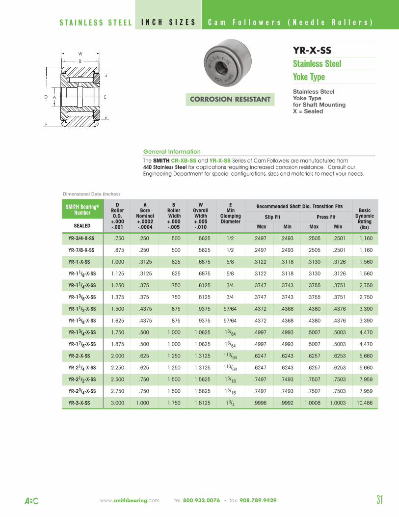
General Information
The SMITH CR-XB-SS and YR-X-SS Series of Cam Followers are manufactured from440 Stainless Steel for applications requiring increased corrosion resistance. Consult ourEngineering Department for special configurations, sizes and materials to meet your needs.
31
YR-X-SSStainless SteelYoke Type
Stainless SteelYoke Typefor Shaft MountingX = Sealed
C a m F o l l o w e r s ( N e e d l e R o l l e r s ) I N C H S I Z E SS T A I N L E S S S T E E L
www.smithbearing.com tel. 800.932.0076 • fax. 908.789.9429
D A B W E Roller Bore Roller Overall Min BasicO.D. Nominal Width Width Clamping Dynamic
+.000 +.0002 +.000 +.005 Diameter RatingUNSEALED SEALED -.001 -.0004 -.005 -.010 (lbs)
Recommended Shaft Dia. Transition Fits
Slip Fit Press Fit
Max Min Max Min
YR-3/4-SS YR-3/4-X-SS .750 .250 .500 .5625 1/2 .2497 .2493 .2505 .2501 1,160
YR-7/8-SS YR-7/8-X-SS .875 .250 .500 .5625 1/2 .2497 .2493 .2505 .2501 1,160
YR-1-SS YR-1-X-SS 1.000 .3125 .625 .6875 5/8 .3122 .3118 .3130 .3126 1,560
YR-11/8-SS YR-11/8-X-SS 1.125 .3125 .625 .6875 5/8 .3122 .3118 .3130 .3126 1,560
YR-11/4-SS YR-11/4-X-SS 1.250 .375 .750 .8125 3/4 .3747 .3743 .3755 .3751 2,750
YR-13/8-SS YR-13/8-X-SS 1.375 .375 .750 .8125 3/4 .3747 .3743 .3755 .3751 2,750
YR-11/2-SS YR-11/2-X-SS 1.500 .4375 .875 .9375 57/64 .4372 .4368 .4380 .4376 3,390
YR-15/8-SS YR-15/8-X-SS 1.625 .4375 .875 .9375 57/64 .4372 .4368 .4380 .4376 3,390
YR-13/4-SS YR-13/4-X-SS 1.750 .500 1.000 1.0625 13/64 .4997 .4993 .5007 .5003 4,470
YR-17/8-SS YR-17/8-X-SS 1.875 .500 1.000 1.0625 13/64 .4997 .4993 .5007 .5003 4,470
YR-2-SS YR-2-X-SS 2.000 .625 1.250 1.3125 113/64 .6247 .6243 .6257 .6253 5,660
YR-21/4-SS YR-21/4-X-SS 2.250 .625 1.250 1.3125 113/64 .6247 .6243 .6257 .6253 5,660
YR-21/2-SS YR-21/2-X-SS 2.500 .750 1.500 1.5625 15/16 .7497 .7493 .7507 .7503 7,959
YR-23/4-SS YR-23/4-X-SS 2.750 .750 1.500 1.5625 15/16 .7497 .7493 .7507 .7503 7,959
YR-3-SS YR-3-X-SS 3.000 1.000 1.750 1.8125 13/4 .9996 .9992 1.0008 1.0003 10,486
SMITH Bearing®
Number
Dimensional Data (inches)
AD
W
E
B
CORROSION RESISTANT
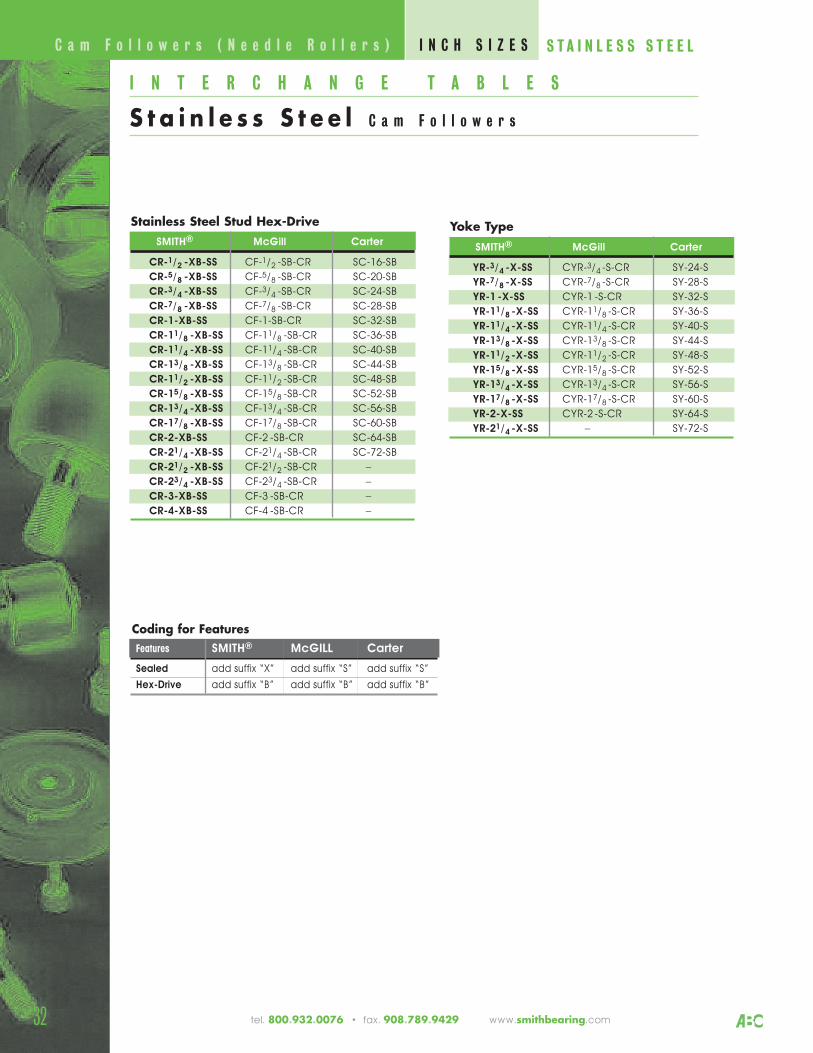
32
I N T E R C H A N G E T A B L E S
S t a i n l e s s S t e e l C a m F o l l o w e r s
C a m F o l l o w e r s ( N e e d l e R o l l e r s ) I N C H S I Z E S S T A I N L E S S S T E E L
tel. 800.932.0076 • fax. 908.789.9429 www.smithbearing.com
Stainless Steel Stud Hex-DriveSMITH® McGill Carter
CR-1/2 -XB-SS CF-1/2 -SB-CR SC-16-SB
CR-5/8 -XB-SS CF-5/8 -SB-CR SC-20-SB
CR-3/4 -XB-SS CF-3/4 -SB-CR SC-24-SB
CR-7/8 -XB-SS CF-7/8 -SB-CR SC-28-SB
CR-1-XB-SS CF-1-SB-CR SC-32-SB
CR-11/8 -XB-SS CF-11/8 -SB-CR SC-36-SB
CR-11/4 -XB-SS CF-11/4 -SB-CR SC-40-SB
CR-13/8 -XB-SS CF-13/8 -SB-CR SC-44-SB
CR-11/2 -XB-SS CF-11/2 -SB-CR SC-48-SB
CR-15/8 -XB-SS CF-15/8 -SB-CR SC-52-SB
CR-13/4 -XB-SS CF-13/4 -SB-CR SC-56-SB
CR-17/8 -XB-SS CF-17/8 -SB-CR SC-60-SB
CR-2-XB-SS CF-2 -SB-CR SC-64-SB
CR-21/4 -XB-SS CF-21/4 -SB-CR SC-72-SB
CR-21/2 -XB-SS CF-21/2 -SB-CR –
CR-23/4 -XB-SS CF-23/4 -SB-CR –
CR-3-XB-SS CF-3 -SB-CR –
CR-4-XB-SS CF-4 -SB-CR –
Coding for FeaturesFeatures SMITH® McGILL Carter
Sealed add suffix “X” add suffix “S” add suffix “S”
Hex-Drive add suffix “B” add suffix “B” add suffix “B”
Yoke TypeSMITH® McGill Carter
YR-3/4 -X-SS CYR-3/4 -S-CR SY-24-S
YR-7/8 -X-SS CYR-7/8 -S-CR SY-28-S
YR-1 -X-SS CYR-1 -S-CR SY-32-S
YR-11/8 -X-SS CYR-11/8 -S-CR SY-36-S
YR-11/4 -X-SS CYR-11/4 -S-CR SY-40-S
YR-13/8 -X-SS CYR-13/8 -S-CR SY-44-S
YR-11/2 -X-SS CYR-11/2 -S-CR SY-48-S
YR-15/8 -X-SS CYR-15/8 -S-CR SY-52-S
YR-13/4 -X-SS CYR-13/4 -S-CR SY-56-S
YR-17/8 -X-SS CYR-17/8 -S-CR SY-60-S
YR-2-X-SS CYR-2 -S-CR SY-64-S
YR-21/4 -X-SS – SY-72-S
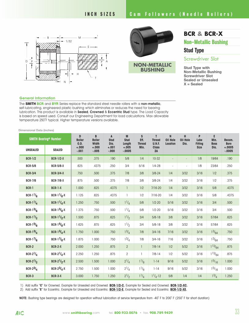
33
C a m F o l l o w e r s ( N e e d l e R o l l e r s ) I N C H S I Z E S
www.smithbearing.com tel. 800.932.0076 • fax. 908.789.9429
General Information
The SMITH BCR and BYR Series replace the standard steel needle rollers with a non-metallic, self-lubricating, engineered plastic bushing which eliminates or reduces the need for bearinglubrication. This product is available in Sealed, Crowned & Eccentric Stud type. The Load Capacityis based on speed used. Consult our Engineering Department for load calculations. Max allowabletemperature 250˚F typical. Higher temperature versions available.
BCR & BCR-XNon-Metallic BushingStud TypeScrewdriver Slot
Stud Type withNon-Metallic Bushing Screwdriver SlotSealed or UnsealedX = Sealed
NON-METALLICBUSHING
B
D
N
M
H
T
AP
1/32
S
P
SMITH Bearing® NumberD B A M S T N H P E
Roller Roller Stud Stud Eff. Thread Oil Hole Oil Hole Lube Min. Recom.O.D. Width Dia. Length Thread U.N.F. Location Dia. Fitting Boss Bore
+.000 +.000 +.001 +.005 Min. Class Size Dia. +.0005UNSEALED SEALED -.001 -.005 -.000 -.0005 2A -.0005
BCR-1/2 BCR-1/2-X .500 .375 .190 5/8 1/4 10-32 - - 1/8 19/64 .190
BCR-5/8 BCR-5/8-X .625 .4375 .250 3/4 5/16 1/4-28 - - 1/8 23/64 .250
BCR-3/4 BCR-3/4-X .750 .500 .375 7/8 3/8 3/8-24 1/4 3/32 3/16 1/2 .375
BCR-7/8 BCR-7/8-X .875 .500 .375 7/8 3/8 3/8-24 1/4 3/32 3/16 1/2 .375
BCR-1 BCR-1-X 1.000 .625 .4375 1 1/2 7/16-20 1/4 3/32 3/16 5/8 .4375
BCR-11/8 BCR-11/8-X 1.125 .625 .4375 1 1/2 7/16-20 1/4 3/32 3/16 5/8 .4375
BCR-11/4 BCR-11/4-X 1.250 .750 .500 11/4 5/8 1/2-20 5/16 3/32 3/16 3/4 .500
BCR-13/8 BCR-13/8-X 1.375 .750 .500 11/4 5/8 1/2-20 5/16 3/32 3/16 3/4 .500
BCR-11/2 BCR-11/2-X 1.500 .875 .625 11/2 3/4 5/8-18 3/8 3/32 3/16 57/64 .625
BCR-15/8 BCR-15/8-X 1.625 .875 .625 11/2 3/4 5/8-18 3/8 3/32 3/16 57/64 .625
BCR-13/4 BCR-13/4-X 1.750 1.000 .750 13/4 7/8 3/4-16 7/16 3/32 3/16 13/64 .750
BCR-17/8 BCR-17/8-X 1.875 1.000 .750 13/4 7/8 3/4-16 716 3/32 3/16 13/64 .750
BCR-2 BCR-2-X 2.000 1.250 .875 2 1 7/8-14 1/2 5/32 3/16 113/64 .875
BCR-21/4 BCR-21/4-X 2.250 1.250 .875 2 1 7/8-14 1/2 5/32 3/16 113/64 .875
BCR-21/2 BCR-21/2-X 2.500 1.500 1.000 21/4 11/8 1-14 9/16 5/32 3/16 15/16 1.000
BCR-23/4 BCR-23/4-X 2.750 1.500 1.000 21/4 11/8 1-14 9/16 5/32 3/16 15/16 1.000
BCR-3 BCR-3-X 3.000 1.750 1.250 21/2 11/4 11/4-12 5/8 1/4 1/4 13/4 1.250
1) Add suffix “C” for Crowned. Example for Unsealed and Crowned: BCR-1/2-C. Example for Sealed and Crowned: BCR-1/2-XC.2) Add suffix “E” for Eccentric. Example for Unsealed and Eccentric: BCR-1/2-E. Example for Sealed and Eccentric: BCR-1/2-XE.
NOTE: Bushing type bearings are designed for operation without lubrication at service temperature from -40˚ F to 200˚ F (250˚ F for short duration)
Dimensional Data (inches)
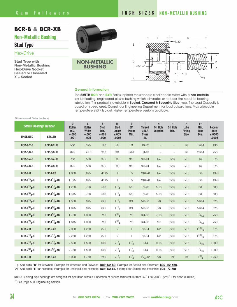
SMITH Bearing® NumberD B A M S T N H P E†
Roller Roller Stud Stud Eff. Thread Oil Hole Oil Hole Lube Min. Recom.O.D. Width Dia. Length Thread U.N.F. Location Dia. Fitting Boss Bore
+.000 +.000 +.001 +.005 Min. Class Size Dia. +.0005UNSEALED SEALED -.001 -.005 -.000 -.0005 2A -.0005
BCR-1/2-B BCR-1/2-XB .500 .375 .190 5/8 1/4 10-32 - - 1/8 19/64 .190
BCR-5/8-B BCR-5/8-XB .625 .4375 .250 3/4 5/16 1/4-28 - - 1/8 23/64 .250
BCR-3/4-B BCR-3/4-XB .750 .500 .375 7/8 3/8 3/8-24 1/4 3/32 3/16 1/2 .375
BCR-7/8-B BCR-7/8-XB .875 .500 .375 7/8 3/8 3/8-24 1/4 3/32 3/16 1/2 .375
BCR-1-B BCR-1-XB 1.000 .625 .4375 1 1/2 7/16-20 1/4 3/32 3/16 5/8 .4375
BCR-11/8-B BCR-11/8-XB 1.125 .625 .4375 1 1/2 7/16-20 1/4 3/32 3/16 5/8 .4375
BCR-11/4-B BCR-11/4-XB 1.250 .750 .500 11/4 5/8 1/2-20 5/16 3/32 3/16 3/4 .500
BCR-13/8-B BCR-13/8-XB 1.375 .750 .500 11/4 5/8 1/2-20 5/16 3/32 3/16 3/4 .500
BCR-11/2-B BCR-11/2-XB 1.500 .875 .625 11/2 3/4 5/8-18 3/8 3/32 3/16 57/64 .625
BCR-15/8-B BCR-15/8-XB 1.625 .875 .625 11/2 3/4 5/8-18 3/8 3/32 3/16 57/64 .625
BCR-13/4-B BCR-13/4-XB 1.750 1.000 .750 13/4 7/8 3/4-16 7/16 3/32 3/16 13/64 .750
BCR-17/8-B BCR-17/8-XB 1.875 1.000 .750 13/4 7/8 3/4-16 716 3/32 3/16 13/64 .750
BCR-2-B BCR-2-XB 2.000 1.250 .875 2 1 7/8-14 1/2 5/32 3/16 113/64 .875
BCR-21/4-B BCR-21/4-XB 2.250 1.250 .875 2 1 7/8-14 1/2 5/32 3/16 113/64 .875
BCR-21/2-B BCR-21/2-XB 2.500 1.500 1.000 21/4 11/8 1-14 9/16 5/32 3/16 15/16 1.000
BCR-23/4-B BCR-23/4-XB 2.750 1.500 1.000 21/4 11/8 1-14 9/16 5/32 3/16 15/16 1.000
BCR-3-B BCR-3-XB 3.000 1.750 1.250 21/2 11/4 11/4-12 5/8 1/4 1/4 13/4 1.250
General Information
The SMITH BCR and BYR Series replace the standard steel needle rollers with a non-metallic, self-lubricating, engineered plastic bushing which eliminates or reduces the need for bearinglubrication. This product is available in Sealed, Crowned & Eccentric Stud type. The Load Capacity isbased on speed used. Consult our Engineering Department for load calculations. Max allowabletemperature 250˚F typical. Higher temperature versions available.
34
BCR-B & BCR-XBNon-Metallic BushingStud TypeHex-Drive
Stud Type withNon-Metallic Bushing Hex-Drive SocketSealed or UnsealedX = Sealed
Dimensional Data (inches)
C a m F o l l o w e r s I N C H S I Z E S NON-META L L I C BUSH I NG
1) Add suffix “C” for Crowned. Example for Unsealed and Crowned: BCR-1/2-BC. Example for Sealed and Crowned: BCR-1/2-XBC.2) Add suffix “E” for Eccentric. Example for Unsealed and Eccentric: BCR-1/2-BE. Example for Sealed and Eccentric: BCR-1/2-XBE.
NOTE: Bushing type bearings are designed for operation without lubrication at service temperature from -40˚ F to 200˚ F (250˚ F for short duration)† See Page 5 in Engineering Section.
B
D
N
M
H
T
AP
1/32
S
HEX
tel. 800.932.0076 • fax. 908.789.9429 www.smithbearing.com
NON-METALLICBUSHING
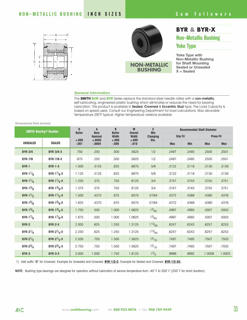
General Information
The SMITH BCR and BYR Series replace the standard steel needle rollers with a non-metallic, self-lubricating, engineered plastic bushing which eliminates or reduces the need for bearinglubrication. This product is available in Sealed, Crowned & Eccentric Stud type. The Load Capacity isbased on speed used. Consult our Engineering Department for load calculations. Max allowabletemperature 250˚F typical. Higher temperature versions available
35
BYR & BYR-X Non-Metallic BushingYoke Type
Yoke Type withNon-Metallic Bushingfor Shaft MountingSealed or UnsealedX = Sealed
C a m F o l l o w e r sI N C H S I Z E SN O N - M E T A L L I C B U S H I N G
www.smithbearing.com tel. 800.932.0076 • fax. 908.789.9429
NON-METALLICBUSHING
AD
W
E
B
D A B W ERoller Bore Roller Overall Min
Nominal Width Width Clamping+.000 +.0002 +.000 +.005 Dia.
UNSEALED SEALED -.001 -.0004 -.005 -.010 Max Min Max Max
BYR-3/4 BYR-3/4-X .750 .250 .500 .5625 1/2 .2497 .2493 .2505 .2501
BYR-7/8 BYR-7/8-X .875 .250 .500 .5625 1/2 .2497 .2493 .2505 .2501
BYR-1 BYR-1-X 1.000 .3125 .625 .6875 5/8 .3122 .3118 .3130 .3126
BYR-11/8 BYR-11/8-X 1.125 .3125 .625 .6875 5/8 .3122 .3118 .3130 .3126
BYR-11/4 BYR-11/4-X 1.250 .375 .750 .8125 3/4 .3747 .3743 .3755 .3751
BYR-13/8 BYR-13/8-X 1.375 .375 .750 .8125 3/4 .3747 .3743 .3755 .3751
BYR-11/2 BYR-11/2-X 1.500 .4375 .875 .9375 57/64 .4372 .4368 .4380 .4376
BYR-15/8 BYR-15/8-X 1.625 .4375 .875 .9375 57/64 .4372 .4368 .4380 .4376
BYR-13/4 BYR-13/4-X 1.750 .500 1.000 1.0625 13/64 .4997 .4993 .5007 .5003
BYR-17/8 BYR-17/8-X 1.875 .500 1.000 1.0625 13/64 .4997 .4993 .5007 .5003
BYR-2 BYR-2-X 2.000 .625 1.250 1.3125 113/64 .6247 .6243 .6257 .6253
BYR-21/4 BYR-21/4-X 2.250 .625 1.250 1.3125 113/64 .6247 .6243 .6257 .6253
BYR-21/2 BYR-21/2-X 2.500 .750 1.500 1.5625 15/16 .7497 .7493 .7507 .7503
BYR-23/4 BYR-23/4-X 2.750 .750 1.500 1.5625 15/16 .7497 .7493 .7507 .7503
BYR-3 BYR-3-X 3.000 1.000 1.750 1.8125 13/4 .9996 .9992 1.0008 1.0003
Recommended Shaft Diameter
Slip Fit Press FitSMITH Bearing ® Number
1) Add suffix “C” for Crowned. Example for Unsealed and Crowned: BYR-1/2-C. Example for Sealed and Crowned: BYR-1/2-XC.
NOTE: Bushing type bearings are designed for operation without lubrication at service temperature from -40˚ F to 200˚ F (250˚ F for short duration)
Dimensional Data (inches)
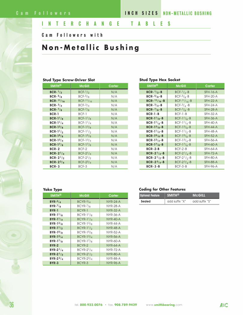
36
Stud Type Screw-Driver SlotSMITH® McGill Carter
BCR- 1/2 BCF-1/2 N/A
BCR- 5/8 BCF-5/8 N/A
BCR- 11/16 BCF-11/16 N/A
BCR- 3/4 BCF-3/4 N/A
BCR- 7/8 BCF-7/8 N/A
BCR-1 BCF-1 N/A
BCR-11/8 BCF-11/8 N/A
BCR-11/4 BCF-11/4 N/A
BCR-13/8 BCF-13/8 N/A
BCR-11/2 BCF-11/2 N/A
BCR-15/8 BCF-15/8 N/A
BCR-13/4 BCF-13/4 N/A
BCR-17/8 BCF-17/8 N/A
BCR- 2 BCF-2 N/A
BCR- 2 1/4 BCF-21/4 N/A
BCR- 2 1/2 BCF-21/2 N/A
BCR- 2 3/4 BCF-23/4 N/A
BCR- 3 BCF-3 N/A
Coding for Other FeaturesOptional Feature SMITH® McGILL
Sealed add suffix “X” add suffix “S”
Yoke TypeSMITH® McGill Carter
BYR-3/4 BCYR-3/4 NYR-24-A
BYR-7/8 BCYR-7/8 NYR-28-A
BYR-1 BCYR-1 NYR-32-A
BYR-11/8 BCYR-11/8 NYR-36-A
BYR-11/4 BCYR-11/4 NYR-40-A
BYR-13/8 BCYR-13/8 NYR-44-A
BYR-11/2 BCYR-11/2 NYR-48-A
BYR-15/8 BCYR-15/8 NYR-52-A
BYR-13/4 BCYR-13/4 NYR-56-A
BYR-17/8 BCYR-17/8 NYR-60-A
BYR-2 BCYR-2 NYR-64-A
BYR-2 1/4 BCYR-21/4 NYR-72-A
BYR-2 1/2 BCYR-21/2 NYR-80-A
BYR-2 3/4 BCYR-23/4 NYR-88-A
BYR-3 BCYR-3 NYR-96-A
Stud Type Hex SocketSMITH® McGill Carter
BCR- 1/2 -B BCF-1/2 -B SFH-16-A
BCR- 5/8 -B BCF-5/8 -B SFH-20-A
BCR- 11/16 -B BCF-11/16 -B SFH-22-A
BCR- 3/4 -B BCF-3/4 -B SFH-24-A
BCR- 7/8 -B BCF-7/8 -B SFH-28-A
BCR-1 -B BCF-1 -B SFH-32-A
BCR-11/8 -B BCF-11/8 -B SFH-36-A
BCR-11/4 -B BCF-11/4 -B SFH-40-A
BCR-13/8 -B BCF-13/8 -B SFH-44-A
BCR-11/2 -B BCF-11/2 -B SFH-48-A
BCR-15/8 -B BCF-15/8 -B SFH-52-A
BCR-13/4 -B BCF-13/4 -B SFH-56-A
BCR-17/8 -B BCF-17/8 -B SFH-60-A
BCR- 2-B BCF-2 -B SFH-64-A
BCR- 2 1/4 -B BCF-2 1/4 -B SFH-72-A
BCR- 2 1/2 -B BCF-2 1/2 -B SFH-80-A
BCR- 2 3/4 -B BCF-2 3/4 -B SFH-88-A
BCR- 3 -B BCF-3 -B SFH-96-A
I N T E R C H A N G E T A B L E S
C a m F o l l o w e r s w i t h
Non -Me t a l l i c B u s h i n g
C a m F o l l o w e r s I N C H S I Z E S NON-META L L I C BUSH I NG
tel. 800.932.0076 • fax. 908.789.9429 www.smithbearing.com

37www.smithbearing.com tel. 800.932.0076 • fax. 908.789.9429
MCR & MCR-SMCRV & MCRV-SSingle RowStud TypeMCR Caged Unsealed
MCR-S Caged Sealed
MCRV Full Complement Unsealed
MCRV-S Full Complement Sealed
C a m F o l l o w e r s ( N e e d l e R o l l e r s ) M E T R I C S I Z E S
B2
M1
C
M
G
D M
B1
d
d2
B
RAD 500mm
C1
G1
rs
SMITH Bearing ®
NumberMax
Dimensions (mm) Speed* Massdyn stat dyn stat (rpm) (grams)Newtons Newtons
D d C** rs B B1 B2 G G1 M M1 C1 d2 C C0 Cw Cow n g
MCR–13 MCR–13-B2450 2300 2100 1700
20000
MCR–13-S MCR–13-SB13 5 9 0.3 23 13 - M5 x 0.8 7.5 3.1† - 0.6 9
1600020
MCRV–13 MCRV–13-B4600 4200 3700 3400
9000
MCRV–13-S MCRV–13-SB 900022
MCR–16 MCR–16-B3800 3750 3150 3300
22000
MCR–16-S MCR–16-SB16 6 11 0.15 28 16 - M6 x 1 8 4† - 0.6 12
1600020
MCRV–16 MCRV–16-B6400 8500 4850 6500
8500
MCRV–16-S MCRV–16-SB 850022
MCR–19 MCR–19-B4250 4600 3500 3900
20000
MCR–19-S MCR–19-SB19 8 11 0.15 32 20 - M8 x 1.25 10 4† - 0.6 14
1400031
MCRV–19 MCRV–19-B 7000
MCRV–19-S MCRV–19-SB7300 10800 5500 7900
700035
MCR–22 MCR–22-B5700 6500 4450 5200
16000
MCR–22-S MCR–22-SB22 10 12 0.30 36 23 - M10 x 1 12 4 - 0.6 17
1100048
MCRV–22 MCRV–22-B 6000
MCRV–22-S MCRV–22-SB8600 12900 6300 9100
600049
MCR–26 MCR–26-B 5700 6500 5100 6200
16000
MCR–26-S MCR–26-SB 26 10 12 0.30 36 23 - M10 x 1 12 4 - 0.6 17
1100062
MCRV–26 MCRV–26-B 6000
MCRV–26-S MCRV–26-SB 8600 12900 7300 11300
600065
MCR–30 MCR–30-B8100 9700 6800 8400
11000
MCR–30-S MCR–30-SB30 12 14 0.60 40 25 6 M12 x 1.5 13 6 3 0.6 23
830092
MCRV–30 MCRV–30-B12200 19000 9500 14600
4500
MCRV–30-S MCRV–30-SB 450095
MCR–32 MCR–32-B 8100 9700 7100 9000
11000
MCR–32-S MCR–32-SB32 12 14 0.60 40 25 6 M12 x 1.5 13 6 3 0.6 23
8300104
MCRV–32 MCRV–32-B12200 19000 10000 15800
4500
MCRV–32-S MCRV–32-SB 4500105
MCR–35 MCR–35-B12900 19000 9700 14100
7000
MCR–35-S MCR–35-SB35 16 18 0.60 52 32.5 8 M16 x 1.5 17 6 3 0.8 27
7000182
MCRV–35 MCRV–35-B18300 35000 12800 23000
3400
MCRV–35-S MCRV–35-SB 3400184
MCR–40 MCR–40-B14200 20400 10900 15500
6000
MCR–40-S MCR–40-SB40 18 20 1.00 58 36.5 8 M18 x1.5 19 6 3 0.8 32
6000262.8
MCRV–40 MCRV–40-B21000 39500 14800 26500
2900
MCRV–40-S MCRV–40-SB 2900264.8
† Relubricate through head end only.
(For Tolerances, See chart in Engineering Section)
SCREWDRIVER HEXSLOT DRIVE
Track Roller
Basic Load Ratings
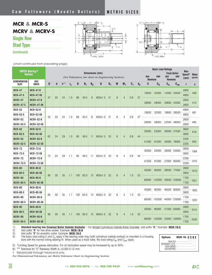
SMITH Bearing ®
Number
MCR–47 MCR–47-B19500 32000 15500 25500
4900
MCR–47-S MCR–47-SB47 20 24 1.0 66 40.5 9 M20x1.5 21 8 4 0.8 37
4900406
MCRV–47 MCRV–47-B28000 59000 20600 42000
2600
MCRV–47-S MCRV–47-SB 2600410
MCR–52 MCR–52-B19500 32000 16800 28500
4900
MCR–52-S MCR–52-SB 52 20 24 1.0 66 40.5 9 M20x1.5 21 8 4 0.8 37
4900481
MCRV–52 MCRV–52-B 2600
MCRV–52-S MCRV–52-SB28000 59000 22500 48000
2600485
MCR–62 MCR–62-B30500 53000 26500 47500
3800
MCR–62-S MCR–62-SB62 24 29 1.0 80 49.5 11 M24x1.5 25 8 4 0.8 44
3800818
MCRV–62 MCRV–62-B 2200
MCRV–62-S MCRV–62-SB41500 91000 34000 76000
2200830
MCR–72 MCR–72-B30500 53000 28000 53000
3800
MCR–72-S MCR–72-SB 72 24 29 1.1 80 49.5 11 M24x1.5 25 8 4 0.8 44
38001068
MCRV–72 MCRV–72-B 2200
MCRV–72-S MCRV–72-SB41500 91000 37000 85000
22001073
MCR–80 MCR–80-B 45000 85000 39500 77000
2600
MCR–80-S MCR–80-SB80 30 35 1.1 100 63.0 15 M30x1.5 32 8 4 1.0 53
26001610
MCRV–80 MCR–80-B60000 142000 49500 120000
1700
MCRV–80-S MCRV–80-SB 17001621
MCR–85 MCR–85-B45000 85000 40500 80000
2600
MCR–85-S MCR–85-SB 85 30 35 1.1 100 63.0 15 M30x1.5 32 8 4 1.0 53
26001800
MCRV–85 MCRV–85-B60000 142000 44000 120000
1700
MCRV–85-S MCRV–85-SB 17001820
MCR–90 MCR–90-B45000 85000 41500 83000
2600
MCR–90-S MCR–90-SB90 30 35 1.1 100 63.0 15 M30x1.5 32 8 4 1.0 53
26002010
MCRV–90 MCRV–90-B60000 142000 53000 130000
1700
MCRV–90-S MCRV–90-SB 17002030
1) Standard bearing has Crowned Roller Outside Diameter – For Straight Cylindrical Outside Roller Diameter, add suffix “C.” Example: MCR-16-C2) Add suffix “B” for hex-drive socket. Example: MCR-16-B3) Add suffix “E” for eccentric collar. Example: MCR-16-E4) The basic load rating C and Co apply if the bearing outer ring (with cylindrical outside surface) is mounted in a housing
bore with the normal rolling bearing fit. When used as a track roller, the load rating Cw and Cow apply.
5) *Limiting Speed for grease lubrication: For oil lubrication speed may be increased by up to 30%.6) ** Tolerance for “C” Raceway Width is +0.00/-0.12 mm† Relubricate through head end only.For Dimensional Tolerances, see Metric Tolerance Chart in Engineering Section.
38
MCR & MCR-SMCRV & MCRV-SSingle RowStud Type(continued)
C a m F o l l o w e r s ( N e e d l e R o l l e r s ) M E T R I C S I Z E S
Options: MCR-16- S C B ESEALED
STRAIGHT O.D.HEX-DRIVEECCENTRIC
(For Tolerances, See chart in Engineering Section)
(chart continued from preceding page)
tel. 800.932.0076 • fax. 908.789.9429 www.smithbearing.com
Basic Load RatingsMax
Dimensions (mm) Speed* Massdyn stat dyn stat (rpm) (grams)
Newtons Newtons
D d c** rs B B1 B2 G G1 M M1 C1 d2 C C0 Cw Cow n g
Track Roller
SCREWDRIVER HEXSLOT DRIVE
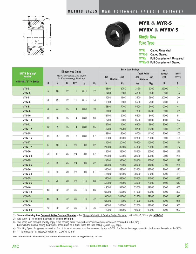
39
MYR & MYR-SMYRV & MYRV-SSingle RowYoke Type
MYR Caged Unsealed
MYR-S Caged Sealed
MYRV Full Complement Unsealed
MYRV-S Full Complement Sealed
C a m F o l l o w e r s ( N e e d l e R o l l e r s ) M E T R I C S I Z E S
www.smithbearing.com tel. 800.932.0076 • fax. 908.789.9429
C
D
B
RAD500mm
rs
d1d
SMITH Bearing®
Number
MYR–5 3800 3750 3150 3300 22000 14
MYRV–5 5 16 12 11 0.15 12
6400 8500 4850 6500 8500 15
MYR–6 4250 4600 3500 3900 20000 20
MYRV–66 19 12 11 0.15 14
7300 10800 5500 7900 7000 21
MYR–8 6800 7700 5500 6400 15000 41
MYRV–8 8 24 15 14 0.30 19
10400 15600 7800 11400 5500 42
MYR–10 8100 9700 6800 8400 11000 64
MYRV–1010 30 15 14 0.60 23
12200 19000 9500 14600 4500 65
MYR–12 8700 11000 6900 8800 9000 71
MYRV–1212 32 15 14 0.60 25
13200 21700 9700 15400 3900 72
MYR–15 12900 19000 9700 14100 7000 103
MYRV–1515 35 19 18 0.60 27
18300 35000 12800 23000 3400 105
MYR–17 14200 20400 10900 15500 6000 144
MYRV–1717 40 21 20 1.00 32
21000 39500 14800 26500 2900 152
MYR–20 19500 32000 15500 25500 4900 246
MYRV–2020 47 25 24 1.00 37
28000 59000 20600 42000 2600 254
MYR–25 21200 38000 15400 26500 3600 275
MYRV–25 25 52 25 24 1.00 42
31000 72000 20500 44000 2100 285
MYR–30 34000 59000 23600 38500 2600 470
MYRV–30 30 62 29 28 1.00 51
48500 108000 30500 63000 1700 481
MYR–35 37000 69000 25500 44500 2000 635
MYRV–35 35 72 29 28 1.10 58
53000 127000 33000 73000 1400 647
MYR–40 49000 94000 33000 59000 1700 805
MYRV–40 40 80 32 30 1.10 66
66000 159000 41000 90000 1300 890
MYR–45 51000 101000 32500 59000 1500 910
MYRV–45 45 85 32 30 1.10 72
61000 112000 41000 90000 1200 935
MYR–50 52000 108000 32000 59000 1300 960
MYRV–50 50 90 32 30 1.10 76
72000 191000 40500 93000 1000 990
1) Standard bearing has Crowned Roller Outside Diameter – For Straight Cylindrical Outside Roller Diameter, add suffix “C.” Example: MYR-5-C2) Add suffix “S” for sealed. Example for Sealed: MYR-5-S3) The basic load rating C and Co apply if the bearing outer ring (with cylindrical outside surface) is mounted in a housing
bore with the normal rolling bearing fit. When used as a track roller, the load rating Cw and Cow apply.4) *Limiting Speed for grease lubrication: For oil lubrication speed may be increased by up to 30%. For Sealed bearings, speed in chart should be reduced by 30%.5) ** Tolerance for “C” Raceway Width is +0.00/-0.12 mm
For Dimensional Tolerances, see Metric Tolerance Chart in Engineering Section.
Basic Load Ratings MaxTrack Roller Speed* Mass
dyn stat dyn stat (rpm) (grams)Newtons Newtons
d D B C** rs d1 C Co Cw Cow n gAdd suffix “S” for Sealed
(For Tolerances, See chartin Engineering Section)
Dimensions (mm)
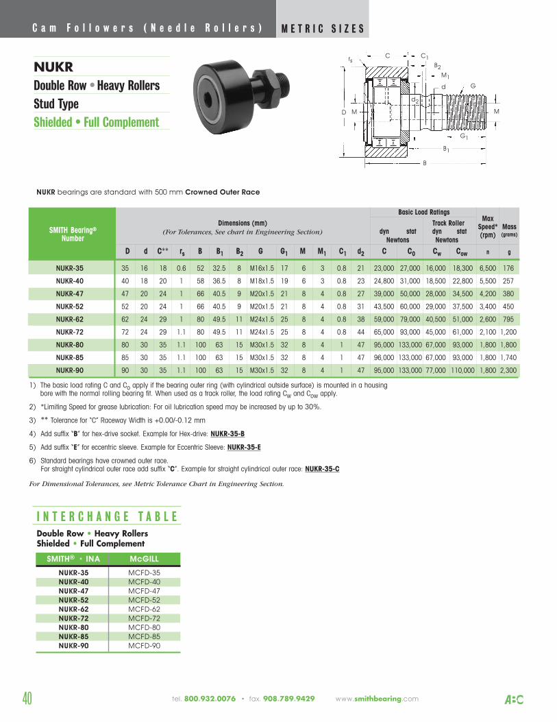
40
NUKRDouble Row • Heavy RollersStud TypeShielded • Full Complement
C a m F o l l o w e r s ( N e e d l e R o l l e r s ) M E T R I C S I Z E S
SMITH Bearing®
Number
Track RollerMax
Dimensions (mm) Speed* Massdyn stat dyn stat (rpm) (grams)
Newtons Newtons
D d C** rs B B1 B2 G G1 M M1 C1 d2 C C0 Cw Cow n g
NUKR-35 35 16 18 0.6 52 32.5 8 M16x1.5 17 6 3 0.8 21 23,000 27,000 16,000 18,300 6,500 176
NUKR-40 40 18 20 1 58 36.5 8 M18x1.5 19 6 3 0.8 23 24,800 31,000 18,500 22,800 5,500 257
NUKR-47 47 20 24 1 66 40.5 9 M20x1.5 21 8 4 0.8 27 39,000 50,000 28,000 34,500 4,200 380
NUKR-52 52 20 24 1 66 40.5 9 M20x1.5 21 8 4 0.8 31 43,500 60,000 29,000 37,500 3,400 450
NUKR-62 62 24 29 1 80 49.5 11 M24x1.5 25 8 4 0.8 38 59,000 79,000 40,500 51,000 2,600 795
NUKR-72 72 24 29 1.1 80 49.5 11 M24x1.5 25 8 4 0.8 44 65,000 93,000 45,000 61,000 2,100 1,200
NUKR-80 80 30 35 1.1 100 63 15 M30x1.5 32 8 4 1 47 95,000 133,000 67,000 93,000 1,800 1,800
NUKR-85 85 30 35 1.1 100 63 15 M30x1.5 32 8 4 1 47 96,000 133,000 67,000 93,000 1,800 1,740
NUKR-90 90 30 35 1.1 100 63 15 M30x1.5 32 8 4 1 47 95,000 133,000 77,000 110,000 1,800 2,300
1) The basic load rating C and Co apply if the bearing outer ring (with cylindrical outside surface) is mounted in a housingbore with the normal rolling bearing fit. When used as a track roller, the load rating Cw and Cow apply.
2) *Limiting Speed for grease lubrication: For oil lubrication speed may be increased by up to 30%.
3) ** Tolerance for “C” Raceway Width is +0.00/-0.12 mm
4) Add suffix “B” for hex-drive socket. Example for Hex-drive: NUKR-35-B
5) Add suffix “E” for eccentric sleeve. Example for Eccentric Sleeve: NUKR-35-E
6) Standard bearings have crowned outer race. For straight cylindrical outer race add suffix “C”. Example for straight cylindrical outer race: NUKR-35-C
For Dimensional Tolerances, see Metric Tolerance Chart in Engineering Section.
SMITH® • INA McGILL
NUKR-35 MCFD-35NUKR-40 MCFD-40NUKR-47 MCFD-47NUKR-52 MCFD-52NUKR-62 MCFD-62NUKR-72 MCFD-72NUKR-80 MCFD-80NUKR-85 MCFD-85NUKR-90 MCFD-90
I N T E R C H A N G E T A B L EDouble Row • Heavy RollersShielded • Full Complement
B2
M1
C
MD M
B1
d
d2
B
C1
G1
rs
G
(For Tolerances, See chart in Engineering Section)
NUKR bearings are standard with 500 mm Crowned Outer Race
Basic Load Ratings
tel. 800.932.0076 • fax. 908.789.9429 www.smithbearing.com
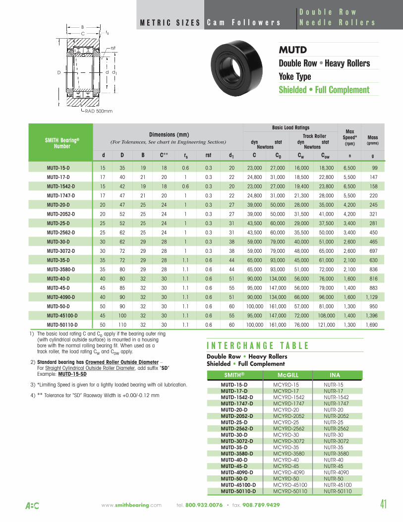
MUTDDouble Row • Heavy RollersYoke TypeShielded • Full Complement
41
D o u b l e R o wC a m F o l l o w e r s N e e d l e R o l l e r sM E T R I C S I Z E S
www.smithbearing.com tel. 800.932.0076 • fax. 908.789.9429
C
D
B
RAD 500mm
rs
d1d
rst
SMITH Bearing®
Number
Track RollerMax
Speed* Massdyn stat dyn stat (rpm) (grams)
Newtons Newtons
d D B C** rs rst d1 C C0 Cw Cow n g
MUTD-15-D 15 35 19 18 0.6 0.3 20 23,000 27,000 16,000 18,300 6,500 99
MUTD-17-D 17 40 21 20 1 0.3 22 24,800 31,000 18,500 22,800 5,500 147
MUTD-1542-D 15 42 19 18 0.6 0.3 20 23,000 27,000 19,400 23,800 6,500 158
MUTD-1747-D 17 47 21 20 1 0.3 22 24,800 31,000 21,300 28,000 5,500 220
MUTD-20-D 20 47 25 24 1 0.3 27 39,000 50,000 28,000 35,000 4,200 245
MUTD-2052-D 20 52 25 24 1 0.3 27 39,000 50,000 31,500 41,000 4,200 321
MUTD-25-D 25 52 25 24 1 0.3 31 43,500 60,000 29,000 37,500 3,400 281
MUTD-2562-D 25 62 25 24 1 0.3 31 43,500 60,000 35,500 50,000 3,400 450
MUTD-30-D 30 62 29 28 1 0.3 38 59,000 79,000 40,000 51,000 2,600 465
MUTD-3072-D 30 72 29 28 1 0.3 38 59,000 79,000 48,000 65,000 2,600 697
MUTD-35-D 35 72 29 28 1.1 0.6 44 65,000 93,000 45,000 61,000 2,100 630
MUTD-3580-D 35 80 29 28 1.1 0.6 44 65,000 93,000 51,000 72,000 2,100 836
MUTD-40-D 40 80 32 30 1.1 0.6 51 90,000 134,000 56,000 76,000 1,600 816
MUTD-45-D 45 85 32 30 1.1 0.6 55 95,000 147,000 56,000 79,000 1,400 883
MUTD-4090-D 40 90 32 30 1.1 0.6 51 90,000 134,000 66,000 96,000 1,600 1,129
MUTD-50-D 50 90 32 30 1.1 0.6 60 100,000 161,000 57,000 81,000 1,300 950
MUTD-45100-D 45 100 32 30 1.1 0.6 55 95,000 147,000 72,000 108,000 1,400 1,396
MUTD-50110-D 50 110 32 30 1.1 0.6 60 100,000 161,000 76,000 121,000 1,300 1,690
1) The basic load rating C and Co apply if the bearing outer ring (with cylindrical outside surface) is mounted in a housingbore with the normal rolling bearing fit. When used as a track roller, the load rating Cw and Cow apply.
2) Standard bearing has Crowned Roller Outside Diameter – For Straight Cylindrical Outside Roller Diameter, add suffix “SD” Example: MUTD-15-SD
3) *Limiting Speed is given for a lightly loaded bearing with oil lubrication.
4) ** Tolerance for “SD” Raceway Width is +0.00/-0.12 mm
Dimensions (mm)Basic Load Ratings
(For Tolerances, See chart in Engineering Section)
SMITH® McGILL INA
MUTD-15-D MCYRD-15 NUTR-15MUTD-17-D MCYRD-17 NUTR-17MUTD-1542-D MCYRD-1542 NUTR-1542MUTD-1747-D MCYRD-1747 NUTR-1747MUTD-20-D MCYRD-20 NUTR-20MUTD-2052-D MCYRD-2052 NUTR-2052MUTD-25-D MCYRD-25 NUTR-25MUTD-2562-D MCYRD-2562 NUTR-2562MUTD-30-D MCYRD-30 NUTR-30MUTD-3072-D MCYRD-3072 NUTR-3072MUTD-35-D MCYRD-35 NUTR-35MUTD-3580-D MCYRD-3580 NUTR-3580MUTD-40-D MCYRD-40 NUTR-40MUTD-45-D MCYRD-45 NUTR-45MUTD-4090-D MCYRD-4090 NUTR-4090MUTD-50-D MCYRD-50 NUTR-50MUTD-45100-D MCYRD-45100 NUTR-45100MUTD-50110-D MCYRD-50110 NUTR-50110
I N T E R C H A N G E T A B L EDouble Row • Heavy RollersShielded • Full Complement
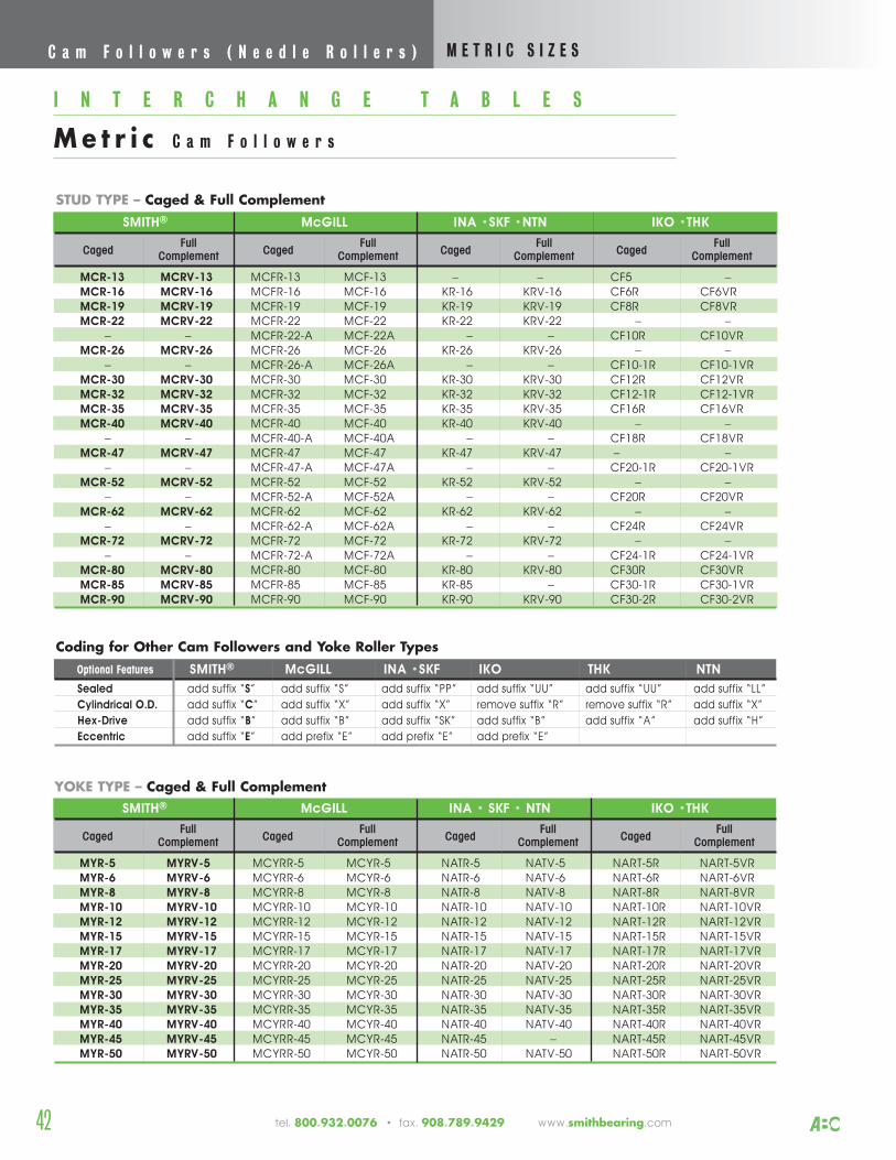
STUD TYPE – Caged & Full Complement
I N T E R C H A N G E T A B L E S
Me t r i c C a m F o l l o w e r s
SMITH® McGILL INA • SKF • NTN IKO •THK
CagedFull
CagedFull
CagedFull
CagedFull
Complement Complement Complement Complement
MYR-5 MYRV-5 MCYRR-5 MCYR-5 NATR-5 NATV-5 NART-5R NART-5VRMYR-6 MYRV-6 MCYRR-6 MCYR-6 NATR-6 NATV-6 NART-6R NART-6VRMYR-8 MYRV-8 MCYRR-8 MCYR-8 NATR-8 NATV-8 NART-8R NART-8VRMYR-10 MYRV-10 MCYRR-10 MCYR-10 NATR-10 NATV-10 NART-10R NART-10VRMYR-12 MYRV-12 MCYRR-12 MCYR-12 NATR-12 NATV-12 NART-12R NART-12VRMYR-15 MYRV-15 MCYRR-15 MCYR-15 NATR-15 NATV-15 NART-15R NART-15VRMYR-17 MYRV-17 MCYRR-17 MCYR-17 NATR-17 NATV-17 NART-17R NART-17VRMYR-20 MYRV-20 MCYRR-20 MCYR-20 NATR-20 NATV-20 NART-20R NART-20VRMYR-25 MYRV-25 MCYRR-25 MCYR-25 NATR-25 NATV-25 NART-25R NART-25VRMYR-30 MYRV-30 MCYRR-30 MCYR-30 NATR-30 NATV-30 NART-30R NART-30VRMYR-35 MYRV-35 MCYRR-35 MCYR-35 NATR-35 NATV-35 NART-35R NART-35VRMYR-40 MYRV-40 MCYRR-40 MCYR-40 NATR-40 NATV-40 NART-40R NART-40VRMYR-45 MYRV-45 MCYRR-45 MCYR-45 NATR-45 – NART-45R NART-45VRMYR-50 MYRV-50 MCYRR-50 MCYR-50 NATR-50 NATV-50 NART-50R NART-50VR
YOKE TYPE – Caged & Full Complement
Coding for Other Cam Followers and Yoke Roller Types
Optional Features SMITH® McGILL INA •SKF IKO THK NTN
Sealed add suffix “S” add suffix “S” add suffix “PP” add suffix “UU” add suffix “UU” add suffix “LL”
Cylindrical O.D. add suffix “C” add suffix “X” add suffix “X” remove suffix “R” remove suffix “R” add suffix “X”
Hex-Drive add suffix “B” add suffix “B” add suffix “SK” add suffix “B” add suffix “A” add suffix “H”
Eccentric add suffix “E” add prefix “E” add prefix “E” add prefix “E”
SMITH® McGILL INA •SKF •NTN IKO •THK
CagedFull
CagedFull
CagedFull
CagedFull
Complement Complement Complement Complement
MCR-13 MCRV-13 MCFR-13 MCF-13 – – CF5 –MCR-16 MCRV-16 MCFR-16 MCF-16 KR-16 KRV-16 CF6R CF6VRMCR-19 MCRV-19 MCFR-19 MCF-19 KR-19 KRV-19 CF8R CF8VRMCR-22 MCRV-22 MCFR-22 MCF-22 KR-22 KRV-22 – –
– – MCFR-22-A MCF-22A – – CF10R CF10VRMCR-26 MCRV-26 MCFR-26 MCF-26 KR-26 KRV-26 – –
– – MCFR-26-A MCF-26A – – CF10-1R CF10-1VRMCR-30 MCRV-30 MCFR-30 MCF-30 KR-30 KRV-30 CF12R CF12VRMCR-32 MCRV-32 MCFR-32 MCF-32 KR-32 KRV-32 CF12-1R CF12-1VRMCR-35 MCRV-35 MCFR-35 MCF-35 KR-35 KRV-35 CF16R CF16VRMCR-40 MCRV-40 MCFR-40 MCF-40 KR-40 KRV-40 – –
– – MCFR-40-A MCF-40A – – CF18R CF18VRMCR-47 MCRV-47 MCFR-47 MCF-47 KR-47 KRV-47 – –
– – MCFR-47-A MCF-47A – – CF20-1R CF20-1VRMCR-52 MCRV-52 MCFR-52 MCF-52 KR-52 KRV-52 – –
– – MCFR-52-A MCF-52A – – CF20R CF20VRMCR-62 MCRV-62 MCFR-62 MCF-62 KR-62 KRV-62 – –
– – MCFR-62-A MCF-62A – – CF24R CF24VRMCR-72 MCRV-72 MCFR-72 MCF-72 KR-72 KRV-72 – –
– – MCFR-72-A MCF-72A – – CF24-1R CF24-1VRMCR-80 MCRV-80 MCFR-80 MCF-80 KR-80 KRV-80 CF30R CF30VRMCR-85 MCRV-85 MCFR-85 MCF-85 KR-85 – CF30-1R CF30-1VRMCR-90 MCRV-90 MCFR-90 MCF-90 KR-90 KRV-90 CF30-2R CF30-2VR
C a m F o l l o w e r s ( N e e d l e R o l l e r s ) M E T R I C S I Z E S
42 tel. 800.932.0076 • fax. 908.789.9429 www.smithbearing.com
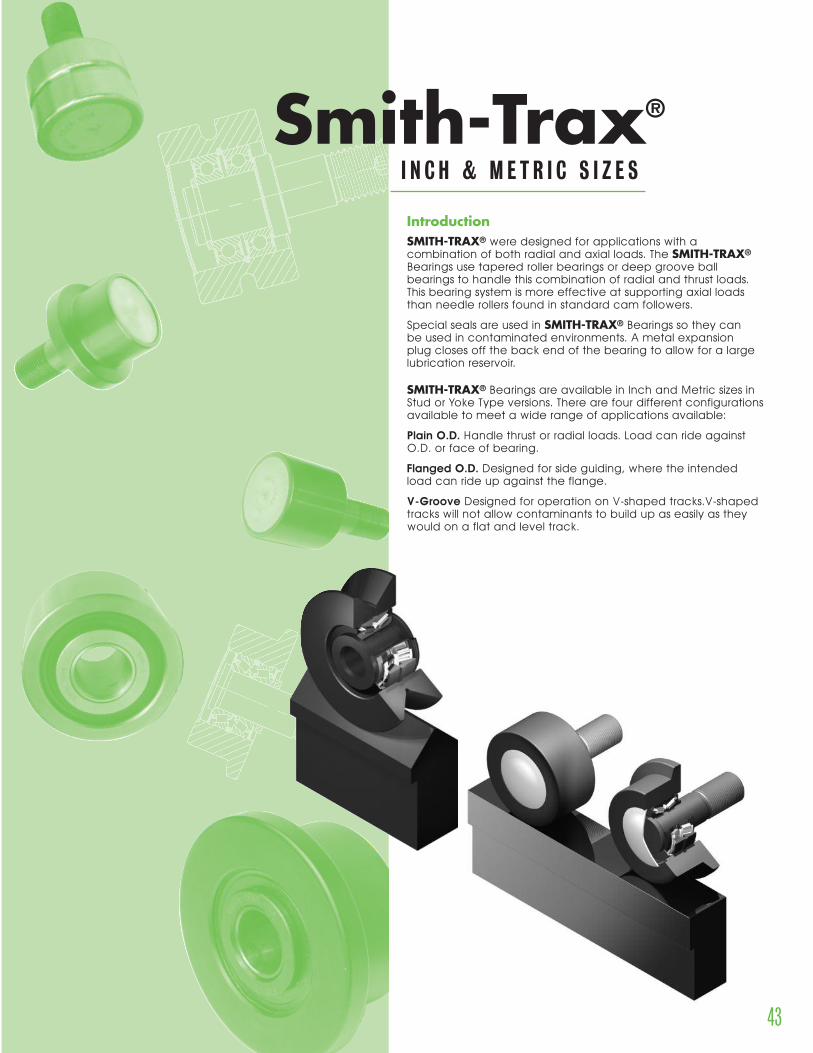
43www.smithbearing.com tel. 800.932.0076 • fax. 908.789.9429
IntroductionSMITH-TRAX® were designed for applications with acombination of both radial and axial loads. The SMITH-TRAX®
Bearings use tapered roller bearings or deep groove ballbearings to handle this combination of radial and thrust loads.This bearing system is more effective at supporting axial loadsthan needle rollers found in standard cam followers.
Special seals are used in SMITH-TRAX® Bearings so they can be used in contaminated environments. A metal expansion plug closes off the back end of the bearing to allow for a largelubrication reservoir.
SMITH-TRAX® Bearings are available in Inch and Metric sizes in Stud or Yoke Type versions. There are four different configurationsavailable to meet a wide range of applications available:
Plain O.D. Handle thrust or radial loads. Load can ride againstO.D. or face of bearing.
Flanged O.D. Designed for side guiding, where the intendedload can ride up against the flange.
V-Groove Designed for operation on V-shaped tracks.V-shapedtracks will not allow contaminants to build up as easily as theywould on a flat and level track.
I N C H & M E T R I C S I Z E S
Smith-Trax®
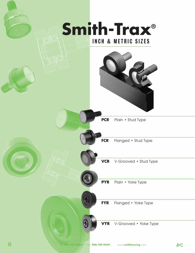
44
PCR Plain • Stud Type
FCR Flanged • Stud Type
VCR V-Grooved • Stud Type
PYR Plain • Yoke Type
FYR Flanged • Yoke Type
VYR V-Grooved • Yoke Type
I N C H & M E T R I C S I Z E S
Smith-Trax®
tel. 800.932.0076 • fax. 908.789.9429 www.smithbearing.com
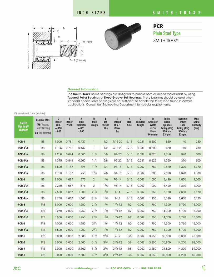
45www.smithbearing.com tel. 800.932.0076 • fax. 908.789.9429
PCRPlain Stud TypeSMITH-TRAX®
S M I T H - T R A X ® I N C H S I Z E S
General Information
The Smith-Trax® Series bearings are designed to handle both axial and radial loads by usingTapered Roller Bearings or Deep Groove Ball Bearings. These bearings should be used whenstandard needle roller bearings are not sufficient to handle the thrust load found in certainapplications. Consult our Engineering Department for special requirements.
D B A M S T H C R Radial Dynamic Max Roller Roller Stud Stud Eff. Thread Hex Shoulder Shoulder Basic Thrust StaticO.D. Width Diameter Length Thread U.N.F. Size Length Width Dynamic Load Capacity
+.000 +.001 Min Class or End Rating (lbs) Rating (lbs) (lbs)-.001 -.000 2A Plate 500 hrs. 500 hrs.
Diameter 33 rpm. 33 rpm.
SMITHBearing ®
Number
PCR-1 BB 1.000 0.781 0.437 1 1/2 7/16-20 3/16 0.031 0.500 630 140 230
PCR-11/8 BB 1.125 0.781 0.437 1 1/2 7/16-20 3/16 0.031 0.500 630 140 230
PCR-11/4 BB 1.250 0.844 0.500 11/4 5/8 1/2-20 5/16 0.031 0.625 1,350 370 600
PCR-13/8 BB 1.375 0.844 0.500 11/4 5/8 1/2-20 5/16 0.031 0.625 1,350 370 600
PCR-11/2 BB 1.500 1.187 .625 11/2 3/4 5/8-18 5/16 0.062 1.750 2,520 1,320 1,370
PCR-13/4 BB 1.750 1.187 .750 13/4 7/8 3/4-16 5/16 0.062 1.000 2,520 1,320 1,370
PCR-2 BB 2.000 1.687 .875 2 11/8 7/8-14 5/16 0.062 1.000 3,490 1,830 2,000
PCR-21/4 BB 2.250 1.687 .875 2 11/8 7/8-14 5/16 0.062 1.000 3,490 1,830 2,000
PCR-21/2 BB 2.500 1.687 1.000 21/4 11/2 1-14 7/16 0.062 1.250 5,120 2,680 3,120
PCR-23/4 BB 2.750 1.687 1.000 21/4 11/2 1-14 7/16 0.062 1.250 5,120 2,680 3,120
PCR-3 TRB 3.000 2.000 1.250 21/2 13/4 11/4-12 1/2 0.062 1.750 14,300 5,790 16,000
PCR-31/4 TRB 3.250 2.000 1.250 21/2 13/4 11/4-12 1/2 0.062 1.750 14,300 5,790 16,000
PCR-31/2 TRB 3.500 2.000 1.250 23/4 13/4 11/4-12 1/2 0.062 1.750 14,300 5,790 16,000
PCR-4 TRB 4.000 2.000 1.250 23/4 13/4 11/4-12 1/2 0.062 1.750 14,300 5,790 16,000
PCR-41/2 TRB 4.500 2.000 1.250 23/4 13/4 11/4-12 1/2 0.062 1.750 14,300 5,790 16,000
PCR-5 TRB 5.000 3.000 2.000 41/2 21/2 2-12 5/8 0.062 3.250 35,800 13,300 40,000
PCR-6 TRB 6.000 3.000 2.500 51/2 31/4 21/2-12 5/8 0.062 3.250 35,800 14,200 62,000
PCR-7 TRB 7.000 3.000 2.500 51/2 31/4 21/2-12 5/8 0.062 3.250 35,800 14,200 62,000
PCR-8 TRB 8.000 3.000 2.500 51/2 31/4 21/2-12 5/8 0.062 3.250 35,800 14,200 62,000
BEARING TYPE
TRB-TaperedRoller Bearing
BB-Ball Bearing
Dimensional Data (inches)
B
CM
D
R
A
H (Hex)
T (Thread)
S
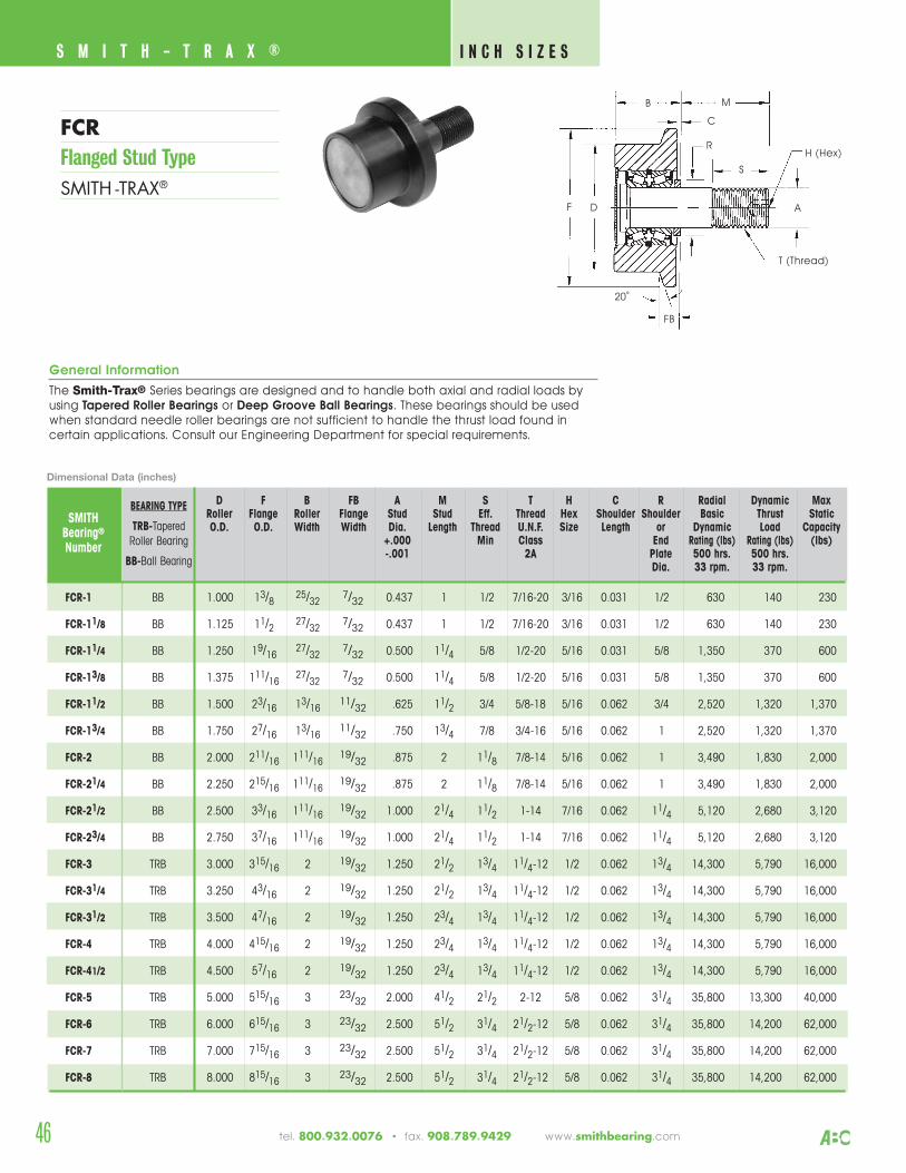
S M I T H - T R A X ® I N C H S I Z E S
46 tel. 800.932.0076 • fax. 908.789.9429 www.smithbearing.com
FCRFlanged Stud TypeSMITH -TRAX®
B M
D
R
F
H (Hex)
T (Thread)
FB
S
A
20˚
C
General Information
The Smith-Trax® Series bearings are designed and to handle both axial and radial loads by using Tapered Roller Bearings or Deep Groove Ball Bearings. These bearings should be used when standard needle roller bearings are not sufficient to handle the thrust load found in certain applications. Consult our Engineering Department for special requirements.
D F B FB A M S T H C R Radial Dynamic MaxRoller Flange Roller Flange Stud Stud Eff. Thread Hex Shoulder Shoulder Basic Thrust StaticO.D. O.D. Width Width Dia. Length Thread U.N.F. Size Length or Dynamic Load Capacity
+.000 Min Class End Rating (lbs) Rating (lbs) (lbs)-.001 2A Plate 500 hrs. 500 hrs.
Dia. 33 rpm. 33 rpm.
SMITHBearing®
Number
FCR-1 BB 1.000 13/8 25/32 7/32 0.437 1 1/2 7/16-20 3/16 0.031 1/2 630 140 230
FCR-11/8 BB 1.125 11/2 27/32 7/32 0.437 1 1/2 7/16-20 3/16 0.031 1/2 630 140 230
FCR-11/4 BB 1.250 19/16 27/32 7/32 0.500 11/4 5/8 1/2-20 5/16 0.031 5/8 1,350 370 600
FCR-13/8 BB 1.375 111/16 27/32 7/32 0.500 11/4 5/8 1/2-20 5/16 0.031 5/8 1,350 370 600
FCR-11/2 BB 1.500 23/16 13/16 11/32 .625 11/2 3/4 5/8-18 5/16 0.062 3/4 2,520 1,320 1,370
FCR-13/4 BB 1.750 27/16 13/16 11/32 .750 13/4 7/8 3/4-16 5/16 0.062 1 2,520 1,320 1,370
FCR-2 BB 2.000 211/16 111/16 19/32 .875 2 11/8 7/8-14 5/16 0.062 1 3,490 1,830 2,000
FCR-21/4 BB 2.250 215/16 111/16 19/32 .875 2 11/8 7/8-14 5/16 0.062 1 3,490 1,830 2,000
FCR-21/2 BB 2.500 33/16 111/16 19/32 1.000 21/4 11/2 1-14 7/16 0.062 11/4 5,120 2,680 3,120
FCR-23/4 BB 2.750 37/16 111/16 19/32 1.000 21/4 11/2 1-14 7/16 0.062 11/4 5,120 2,680 3,120
FCR-3 TRB 3.000 315/16 2 19/32 1.250 21/2 13/4 11/4-12 1/2 0.062 13/4 14,300 5,790 16,000
FCR-31/4 TRB 3.250 43/16 2 19/32 1.250 21/2 13/4 11/4-12 1/2 0.062 13/4 14,300 5,790 16,000
FCR-31/2 TRB 3.500 47/16 2 19/32 1.250 23/4 13/4 11/4-12 1/2 0.062 13/4 14,300 5,790 16,000
FCR-4 TRB 4.000 415/16 2 19/32 1.250 23/4 13/4 11/4-12 1/2 0.062 13/4 14,300 5,790 16,000
FCR-41/2 TRB 4.500 57/16 2 19/32 1.250 23/4 13/4 11/4-12 1/2 0.062 13/4 14,300 5,790 16,000
FCR-5 TRB 5.000 515/16 3 23/32 2.000 41/2 21/2 2-12 5/8 0.062 31/4 35,800 13,300 40,000
FCR-6 TRB 6.000 615/16 3 23/32 2.500 51/2 31/4 21/2-12 5/8 0.062 31/4 35,800 14,200 62,000
FCR-7 TRB 7.000 715/16 3 23/32 2.500 51/2 31/4 21/2-12 5/8 0.062 31/4 35,800 14,200 62,000
FCR-8 TRB 8.000 815/16 3 23/32 2.500 51/2 31/4 21/2-12 5/8 0.062 31/4 35,800 14,200 62,000
Dimensional Data (inches)
BEARING TYPE
TRB-TaperedRoller Bearing
BB-Ball Bearing
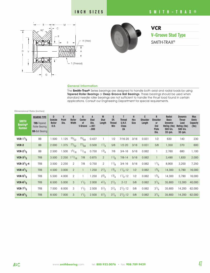
47
S M I T H - T R A X ® I N C H S I Z E S
www.smithbearing.com tel. 800.932.0076 • fax. 908.789.9429
VCRV-Groove Stud TypeSMITH-TRAX®
General Information
The Smith-Trax® Series bearings are designed to handle both axial and radial loads by usingTapered Roller Bearings or Deep Groove Ball Bearings. These bearings should be used whenstandard needle roller bearings are not sufficient to handle the thrust load found in certainapplications. Consult our Engineering Department for special requirements.
D V B G A M S T H C R Radial Dynamic Max Outside Point Roller Center Stud Stud Eff. Thread Hex Shoulder Shoulder Basic Thrust StaticRoller Dia. Width of Dia. Length Thread U.N.F. Size Length or Dynamic Load CapacityO.D. V-Groove +.001 Min Class End Rating (lbs) Rating (lbs) (lbs)
-.000 2A Plate 500 hrs. 500 hrs.Dia. 33 rpm. 33 rpm.
SMITHBearing®
Number
VCR-11/2 BB 1.500 1.125 25/32 25/64 0.437 1 1/2 7/16-20 3/16 0.031 1/2 630 140 230
VCR-2 BB 2.000 1.375 27/32 27/64 0.500 11/4 5/8 1/2-20 3/16 0.031 5/8 1,350 370 600
VCR-21/2 BB 2.500 1.500 15/16 11/16 0.750 13/4 7/8 3/4-16 5/16 0.062 1 2,760 680 1,100
VCR-31/2 TRB 3.500 2.250 111/16 7/8 0.875 2 11/8 7/8-14 5/16 0.062 1 3,490 1,830 2,000
VCR-31/2-4 TRB 3.500 2.250 2 7/8 0.750 2 11/8 3/4-16 5/16 0.062 11/4 8,900 3,200 7,250
VCR-41/2 TRB 4.500 3.000 2 1 1.250 21/2 13/4 11/4-12 1/2 0.062 13/4 14,300 5,790 16,000
VCR-51/2 TRB 5.500 4.000 2 1 1.250 23/4 13/4 11/4-12 1/2 0.062 13/4 14,300 5,790 16,000
VCR-61/2 TRB 6.500 5.000 3 11/2 2.000 41/2 21/2 2-12 5/8 0.062 31/4 35,800 13,300 40,000
VCR-71/2 TRB 7.500 6.000 3 11/2 2.500 51/2 31/4 21/2-12 5/8 0.062 31/4 35,800 14,200 62,000
VCR-81/2 TRB 8.500 7.000 3 11/2 2.500 51/2 31/4 21/2-12 5/8 0.062 31/4 35,800 14,200 62,000
B M
D
R
A
H (Hex)
T (Thread)
S
G
90˚
V
C
Dimensional Data (inches)
BEARING TYPE
TRB-TaperedRoller Bearing
BB-Ball Bearing
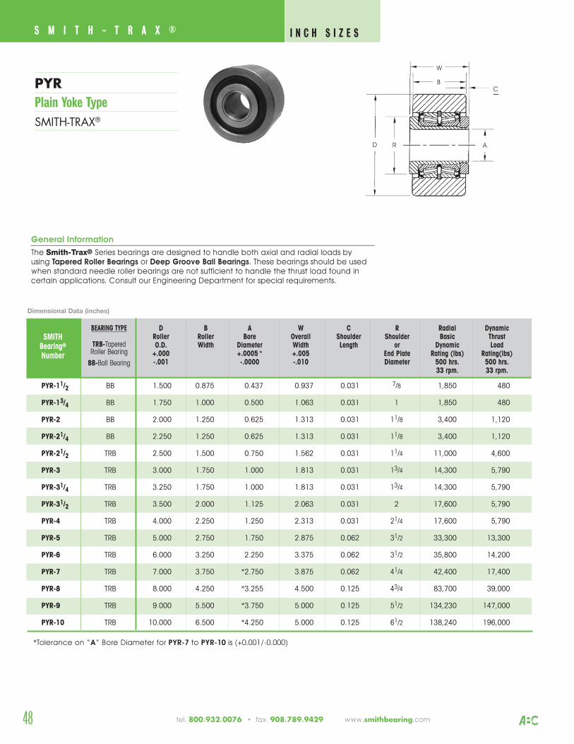
48
S M I T H - T R A X ® I N C H S I Z E S
tel. 800.932.0076 • fax. 908.789.9429 www.smithbearing.com
PYRPlain Yoke TypeSMITH-TRAX®
CB
D R A
W
C
General Information
The Smith-Trax® Series bearings are designed to handle both axial and radial loads by using Tapered Roller Bearings or Deep Groove Ball Bearings. These bearings should be used when standard needle roller bearings are not sufficient to handle the thrust load found in certain applications. Consult our Engineering Department for special requirements.
PYR-11/2 BB 1.500 0.875 0.437 0.937 0.031 7/8 1,850 480
PYR-13/4 BB 1.750 1.000 0.500 1.063 0.031 1 1,850 480
PYR-2 BB 2.000 1.250 0.625 1.313 0.031 11/8 3,400 1,120
PYR-21/4 BB 2.250 1.250 0.625 1.313 0.031 11/8 3,400 1,120
PYR-21/2 TRB 2.500 1.500 0.750 1.562 0.031 11/4 11,000 4,600
PYR-3 TRB 3.000 1.750 1.000 1.813 0.031 13/4 14,300 5,790
PYR-31/4 TRB 3.250 1.750 1.000 1.813 0.031 13/4 14,300 5,790
PYR-31/2 TRB 3.500 2.000 1.125 2.063 0.031 2 17,600 5,790
PYR-4 TRB 4.000 2.250 1.250 2.313 0.031 21/4 17,600 5,790
PYR-5 TRB 5.000 2.750 1.750 2.875 0.062 31/2 33,300 13,300
PYR-6 TRB 6.000 3.250 2.250 3.375 0.062 31/2 35,800 14,200
PYR-7 TRB 7.000 3.750 *2.750 3.875 0.062 41/4 42,400 17,400
PYR-8 TRB 8.000 4.250 *3.255 4.500 0.125 43/4 83,700 39,000
PYR-9 TRB 9.000 5.500 *3.750 5.000 0.125 51/2 134,230 147,000
PYR-10 TRB 10.000 6.500 *4.250 5.000 0.125 61/2 138,240 196,000
*Tolerance on “A” Bore Diameter for PYR-7 to PYR-10 is (+0.001/-0.000)
D B A W C R Radial DynamicRoller Roller Bore Overall Shoulder Shoulder Basic ThrustO.D. Width Diameter Width Length or Dynamic Load
+.000 +.0005* +.005 End Plate Rating (lbs) Rating(lbs)-.001 -.0000 -.010 Diameter 500 hrs. 500 hrs.
33 rpm. 33 rpm.
SMITHBearing®
Number
Dimensional Data (inches)
BEARING TYPE
TRB-TaperedRoller Bearing
BB-Ball Bearing
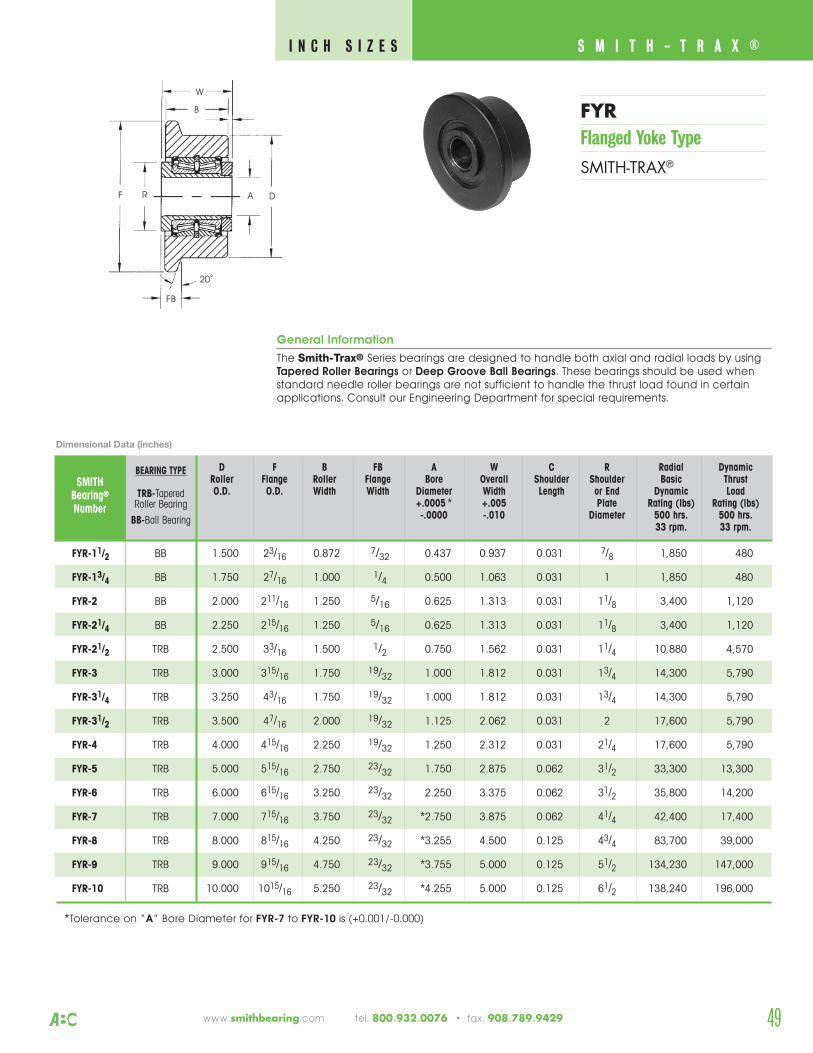
49
S M I T H - T R A X ® I N C H S I Z E S
www.smithbearing.com tel. 800.932.0076 • fax. 908.789.9429
D F B FB A W C R Radial DynamicRoller Flange Roller Flange Bore Overall Shoulder Shoulder Basic ThrustO.D. O.D. Width Width Diameter Width Length or End Dynamic Load
+.0005 * +.005 Plate Rating (lbs) Rating (lbs)-.0000 -.010 Diameter 500 hrs. 500 hrs.
33 rpm. 33 rpm.
SMITHBearing®
Number
FYR-11/2 BB 1.500 23/16 0.872 7/32 0.437 0.937 0.031 7/8 1,850 480
FYR-13/4 BB 1.750 27/16 1.000 1/4 0.500 1.063 0.031 1 1,850 480
FYR-2 BB 2.000 211/16 1.250 5/16 0.625 1.313 0.031 11/8 3,400 1,120
FYR-21/4 BB 2.250 215/16 1.250 5/16 0.625 1.313 0.031 11/8 3,400 1,120
FYR-21/2 TRB 2.500 33/16 1.500 1/2 0.750 1.562 0.031 11/4 10,880 4,570
FYR-3 TRB 3.000 315/16 1.750 19/32 1.000 1.812 0.031 13/4 14,300 5,790
FYR-31/4 TRB 3.250 43/16 1.750 19/32 1.000 1.812 0.031 13/4 14,300 5,790
FYR-31/2 TRB 3.500 47/16 2.000 19/32 1.125 2.062 0.031 2 17,600 5,790
FYR-4 TRB 4.000 415/16 2.250 19/32 1.250 2.312 0.031 21/4 17,600 5,790
FYR-5 TRB 5.000 515/16 2.750 23/32 1.750 2.875 0.062 31/2 33,300 13,300
FYR-6 TRB 6.000 615/16 3.250 23/32 2.250 3.375 0.062 31/2 35,800 14,200
FYR-7 TRB 7.000 715/16 3.750 23/32 *2.750 3.875 0.062 41/4 42,400 17,400
FYR-8 TRB 8.000 815/16 4.250 23/32 *3.255 4.500 0.125 43/4 83,700 39,000
FYR-9 TRB 9.000 915/16 4.750 23/32 *3.755 5.000 0.125 51/2 134,230 147,000
FYR-10 TRB 10.000 1015/16 5.250 23/32 *4.255 5.000 0.125 61/2 138,240 196,000
FYRFlanged Yoke Type
SMITH-TRAX®
Dimensional Data (inches)
*Tolerance on “A” Bore Diameter for FYR-7 to FYR-10 is (+0.001/-0.000)
B
R A
W
F
FB
20˚
General Information
The Smith-Trax® Series bearings are designed to handle both axial and radial loads by usingTapered Roller Bearings or Deep Groove Ball Bearings. These bearings should be used whenstandard needle roller bearings are not sufficient to handle the thrust load found in certainapplications. Consult our Engineering Department for special requirements.
D
BEARING TYPE
TRB-TaperedRoller Bearing
BB-Ball Bearing
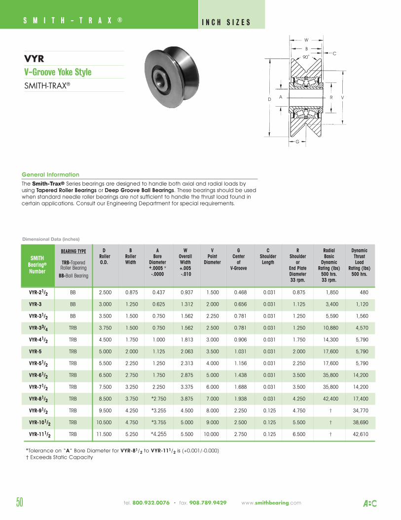
50
S M I T H - T R A X ® I N C H S I Z E S
VYRV-Groove Yoke StyleSMITH-TRAX®
General Information
The Smith-Trax® Series bearings are designed to handle both axial and radial loads byusing Tapered Roller Bearings or Deep Groove Ball Bearings. These bearings should be usedwhen standard needle roller bearings are not sufficient to handle the thrust load found incertain applications. Consult our Engineering Department for special requirements.
B
D RA
W
G
90˚
V
C
D B A W V G C R Radial DynamicRoller Roller Bore Overall Point Center Shoulder Shoulder Basic ThrustO.D. Width Diameter Width Diameter of Length or Dynamic Load
+.0005 * +.005 V-Groove End Plate Rating (lbs) Rating (lbs)-.0000 -.010 Diameter 500 hrs. 500 hrs.
33 rpm. 33 rpm.
SMITHBearing®
Number
VYR-21/2 BB 2.500 0.875 0.437 0.937 1.500 0.468 0.031 0.875 1,850 480
VYR-3 BB 3.000 1.250 0.625 1.312 2.000 0.656 0.031 1.125 3,400 1,120
VYR-31/2 BB 3.500 1.500 0.750 1.562 2.250 0.781 0.031 1.250 5,590 1,560
VYR-33/4 TRB 3.750 1.500 0.750 1.562 2.500 0.781 0.031 1.250 10,880 4,570
VYR-41/2 TRB 4.500 1.750 1.000 1.813 3.000 0.906 0.031 1.750 14,300 5,790
VYR-5 TRB 5.000 2.000 1.125 2.063 3.500 1.031 0.031 2.000 17,600 5,790
VYR-51/2 TRB 5.500 2.250 1.250 2.313 4.000 1.156 0.031 2.250 17,600 5,790
VYR-61/2 TRB 6.500 2.750 1.750 2.875 5.000 1.438 0.031 3.500 35,800 14,200
VYR-71/2 TRB 7.500 3.250 2.250 3.375 6.000 1.688 0.031 3.500 35,800 14,200
VYR-81/2 TRB 8.500 3.750 *2.750 3.875 7.000 1.938 0.031 4.250 42,400 17,400
VYR-91/2 TRB 9.500 4.250 *3.255 4.500 8.000 2.250 0.125 4.750 † 34,770
VYR-101/2 TRB 10.500 4.750 *3.755 5.000 9.000 2.500 0.125 5.500 † 38,690
VYR-111/2 TRB 11.500 5.250 *4.255 5.500 10.000 2.750 0.125 6.500 † 42,610
*Tolerance on “A” Bore Diameter for VYR-81/2 to VYR-111/2 is (+0.001/-0.000)† Exceeds Static Capacity
Dimensional Data (inches)
BEARING TYPE
TRB-TaperedRoller Bearing
BB-Ball Bearing
tel. 800.932.0076 • fax. 908.789.9429 www.smithbearing.com
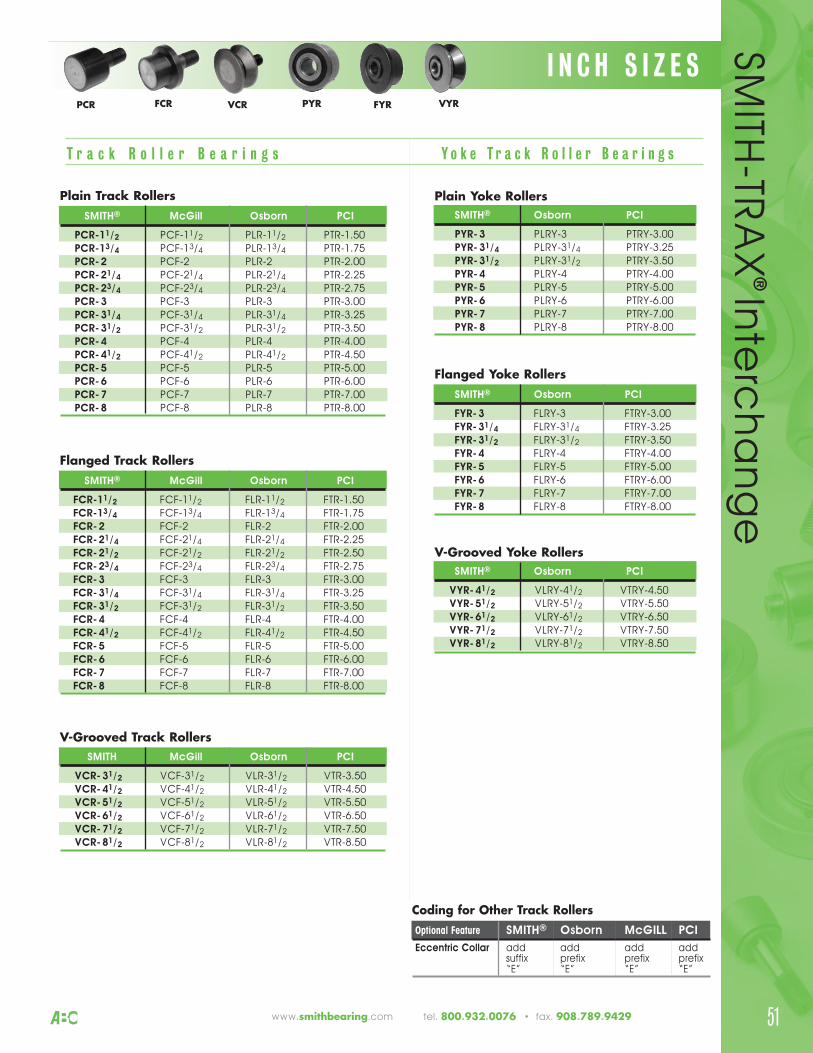
51www.smithbearing.com tel. 800.932.0076 • fax. 908.789.9429
T r a c k R o l l e r B e a r i n g s Y o k e T r a c k R o l l e r B e a r i n g s
Coding for Other Track RollersOptional Feature SMITH® Osborn McGILL PCI
Eccentric Collar add add add addsuffix prefix prefix prefix“E” “E” “E” “E”
I N C H S I Z E SSM
ITH-TR
AX
® In
terc
ha
ng
ePCR FCR VCR PYR FYR VYR
Plain Track RollersSMITH® McGill Osborn PCI
PCR-11/2 PCF-11/2 PLR-11/2 PTR-1.50PCR-13/4 PCF-13/4 PLR-13/4 PTR-1.75PCR-2 PCF-2 PLR-2 PTR-2.00PCR-21/4 PCF-21/4 PLR-21/4 PTR-2.25PCR-23/4 PCF-23/4 PLR-23/4 PTR-2.75PCR-3 PCF-3 PLR-3 PTR-3.00PCR-31/4 PCF-31/4 PLR-31/4 PTR-3.25PCR-31/2 PCF-31/2 PLR-31/2 PTR-3.50PCR-4 PCF-4 PLR-4 PTR-4.00PCR-41/2 PCF-41/2 PLR-41/2 PTR-4.50PCR-5 PCF-5 PLR-5 PTR-5.00PCR-6 PCF-6 PLR-6 PTR-6.00PCR-7 PCF-7 PLR-7 PTR-7.00PCR-8 PCF-8 PLR-8 PTR-8.00
V-Grooved Track RollersSMITH McGill Osborn PCI
VCR-31/2 VCF-31/2 VLR-31/2 VTR-3.50VCR-41/2 VCF-41/2 VLR-41/2 VTR-4.50VCR-51/2 VCF-51/2 VLR-51/2 VTR-5.50VCR-61/2 VCF-61/2 VLR-61/2 VTR-6.50VCR-71/2 VCF-71/2 VLR-71/2 VTR-7.50VCR-81/2 VCF-81/2 VLR-81/2 VTR-8.50
Plain Yoke RollersSMITH® Osborn PCI
PYR-3 PLRY-3 PTRY-3.00PYR-31/4 PLRY-31/4 PTRY-3.25PYR-31/2 PLRY-31/2 PTRY-3.50PYR-4 PLRY-4 PTRY-4.00PYR-5 PLRY-5 PTRY-5.00PYR-6 PLRY-6 PTRY-6.00PYR-7 PLRY-7 PTRY-7.00PYR-8 PLRY-8 PTRY-8.00
V-Grooved Yoke RollersSMITH® Osborn PCI
VYR-41/2 VLRY-41/2 VTRY-4.50VYR-51/2 VLRY-51/2 VTRY-5.50VYR-61/2 VLRY-61/2 VTRY-6.50VYR-71/2 VLRY-71/2 VTRY-7.50VYR-81/2 VLRY-81/2 VTRY-8.50
Flanged Yoke RollersSMITH® Osborn PCI
FYR-3 FLRY-3 FTRY-3.00FYR-31/4 FLRY-31/4 FTRY-3.25FYR-31/2 FLRY-31/2 FTRY-3.50FYR-4 FLRY-4 FTRY-4.00FYR-5 FLRY-5 FTRY-5.00FYR-6 FLRY-6 FTRY-6.00FYR-7 FLRY-7 FTRY-7.00FYR-8 FLRY-8 FTRY-8.00
Flanged Track RollersSMITH® McGill Osborn PCI
FCR-11/2 FCF-11/2 FLR-11/2 FTR-1.50FCR-13/4 FCF-13/4 FLR-13/4 FTR-1.75FCR-2 FCF-2 FLR-2 FTR-2.00FCR-21/4 FCF-21/4 FLR-21/4 FTR-2.25FCR-21/2 FCF-21/2 FLR-21/2 FTR-2.50FCR-23/4 FCF-23/4 FLR-23/4 FTR-2.75FCR-3 FCF-3 FLR-3 FTR-3.00FCR-31/4 FCF-31/4 FLR-31/4 FTR-3.25FCR-31/2 FCF-31/2 FLR-31/2 FTR-3.50FCR-4 FCF-4 FLR-4 FTR-4.00FCR-41/2 FCF-41/2 FLR-41/2 FTR-4.50FCR-5 FCF-5 FLR-5 FTR-5.00FCR-6 FCF-6 FLR-6 FTR-6.00FCR-7 FCF-7 FLR-7 FTR-7.00FCR-8 FCF-8 FLR-8 FTR-8.00
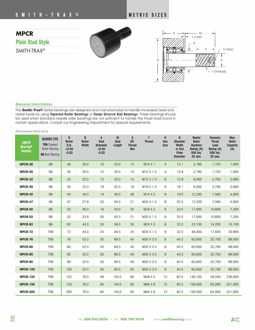
52 tel. 800.932.0076 • fax. 908.789.9429 www.smithbearing.com
MPCRPlain Stud StyleSMITH-TRAX®
S M I T H - T R A X ® M E T R I C S I Z E S
B
1.6 Ref.M
D
R
A
H (Hex)
T (Thread)
S
General Information
The Smith-Trax® Series bearings are designed and manufactured to handle increased axial andradial loads by using Tapered Roller Bearings or Deep Groove Ball Bearings. These bearings shouldbe used when standard needle roller bearings are not sufficient to handle the thrust load found incertain applications. Consult our Engineering Department for special requirements.
D B A M S T H R Radial Dynamic Max Roller Roller Stud Stud Eff. Thread Hex Shoulder Basic Thrust StaticO.D. Width Diameter Length Thread Size Width Dynamic Load Capacity
+0.00 +0.00 Min or End Rating (N) Rating (N) (N)-0.02 -0.02 Plate 500 hrs. 500 hrs.
Diameter 33 rpm. 33 rpm.
SMITHBearing®
Number
MPCR-26 BB 26 20.0 10 23.0 13 M10 X 1 4 13.1 2,790 1,720 1,000
MPCR-30 BB 30 20.0 12 25.0 14 M12 X 1.5 4 15.9 2,790 1,720 1,000
MPCR-32 BB 32 22.0 12 25.0 14 M12 X 1.5 8 15.9 6,000 3,700 2,680
MPCR-35 BB 35 22.0 16 32.5 18 M16 X 1.5 8 19.1 6,000 3,700 2,680
MPCR-40 BB 40 30.0 14 40.0 26 M14 X 2 8 18.0 12,200 7,560 4,900
MPCR-47 BB 47 27.6 20 40.5 21 M20 X 1.5 8 25.5 12,200 7,560 4,900
MPCR-50 BB 50 40.0 16 50.0 35 M16 X 2 8 23.0 17,000 10,600 7,200
MPCR-52 BB 52 33.6 20 40.5 21 M20 X 1.5 8 25.5 17,000 10,600 7,200
MPCR-62 BB 62 44.0 24 58.0 35 M24 X 3 8 32.0 23,100 14,200 10,100
MPCR-72 TRB 72 44.0 24 49.5 25 M24 X 1.5 8 32.0 48,400 17,840 33,900
MPCR-76 TRB 76 52.0 30 69.5 40 M30 X 3.5 8 44.5 63,600 25,700 89,000
MPCR-80 TRB 80 52.0 30 69.5 40 M30 X 3.5 8 44.5 63,600 25,700 89,000
MPCR-85 TRB 85 52.0 30 69.5 40 M30 X 3.5 8 44.5 63,600 25,700 89,000
MPCR-90 TRB 90 52.0 30 69.5 40 M30 X 3.5 8 44.5 63,600 25,700 89,000
MPCR-100 TRB 100 52.0 30 80.0 50 M30 X 3.5 8 44.5 63,600 25,700 89,000
MPCR-125 TRB 125 76.0 48 105.0 60 M48 X 5 12 82.5 148,100 58,500 238,000
MPCR-150 TRB 150 76.0 64 140.0 82 M64 X 6 12 82.5 159,000 63,000 251,000
MPCR-200 TRB 200 76.0 64 140.0 82 M64 X 6 12 82.5 159,000 63,000 251,000
Dimensional Data (mm)
BEARING TYPE
TRB-TaperedRoller Bearing
BB-Ball Bearing
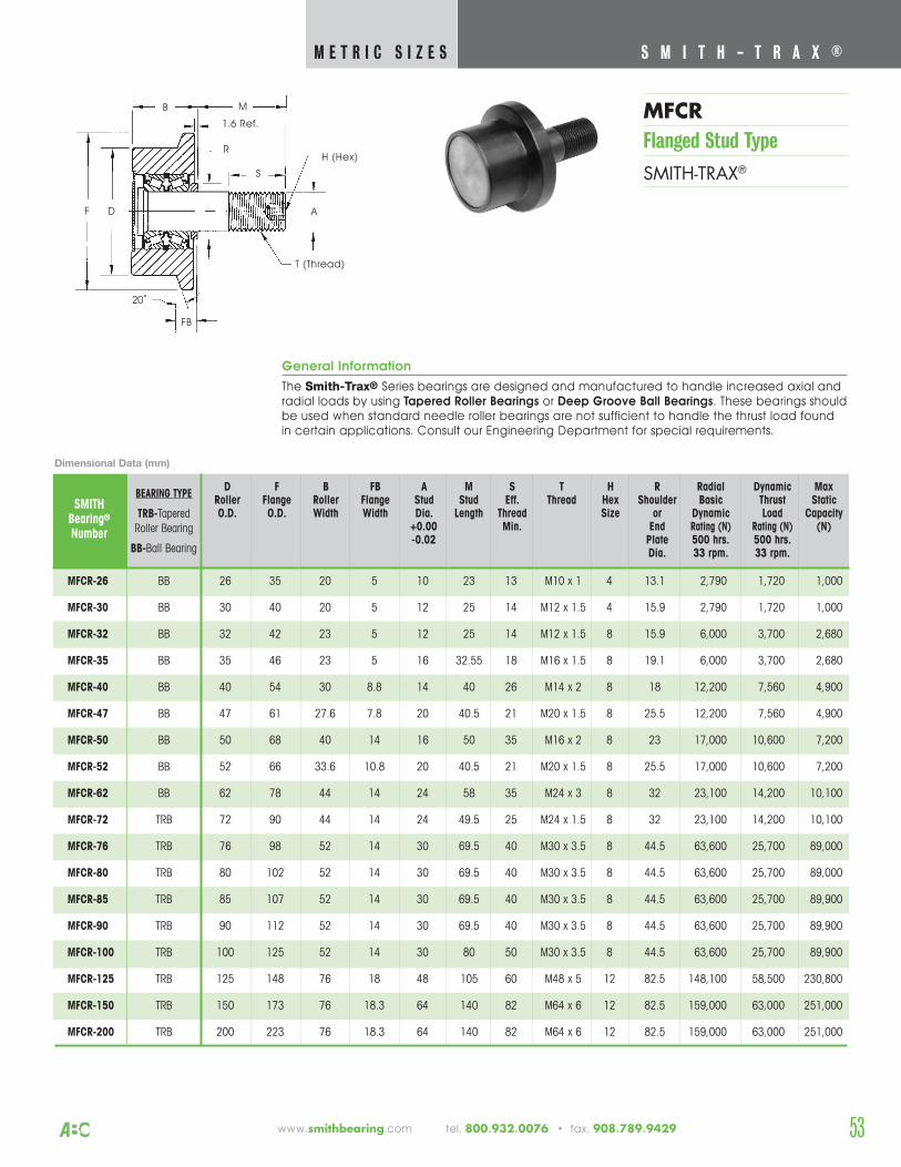
53
General Information
The Smith-Trax® Series bearings are designed and manufactured to handle increased axial andradial loads by using Tapered Roller Bearings or Deep Groove Ball Bearings. These bearings shouldbe used when standard needle roller bearings are not sufficient to handle the thrust load foundin certain applications. Consult our Engineering Department for special requirements.
D F B FB A M S T H R Radial Dynamic Max Roller Flange Roller Flange Stud Stud Eff. Thread Hex Shoulder Basic Thrust StaticO.D. O.D. Width Width Dia. Length Thread Size or Dynamic Load Capacity
+0.00 Min. End Rating (N) Rating (N) (N)-0.02 Plate 500 hrs. 500 hrs.
Dia. 33 rpm. 33 rpm.
SMITHBearing®
Number
MFCR-26 BB 26 35 20 5 10 23 13 M10 x 1 4 13.1 2,790 1,720 1,000
MFCR-30 BB 30 40 20 5 12 25 14 M12 x 1.5 4 15.9 2,790 1,720 1,000
MFCR-32 BB 32 42 23 5 12 25 14 M12 x 1.5 8 15.9 6,000 3,700 2,680
MFCR-35 BB 35 46 23 5 16 32.55 18 M16 x 1.5 8 19.1 6,000 3,700 2,680
MFCR-40 BB 40 54 30 8.8 14 40 26 M14 x 2 8 18 12,200 7,560 4,900
MFCR-47 BB 47 61 27.6 7.8 20 40.5 21 M20 x 1.5 8 25.5 12,200 7,560 4,900
MFCR-50 BB 50 68 40 14 16 50 35 M16 x 2 8 23 17,000 10,600 7,200
MFCR-52 BB 52 66 33.6 10.8 20 40.5 21 M20 x 1.5 8 25.5 17,000 10,600 7,200
MFCR-62 BB 62 78 44 14 24 58 35 M24 x 3 8 32 23,100 14,200 10,100
MFCR-72 TRB 72 90 44 14 24 49.5 25 M24 x 1.5 8 32 23,100 14,200 10,100
MFCR-76 TRB 76 98 52 14 30 69.5 40 M30 x 3.5 8 44.5 63,600 25,700 89,000
MFCR-80 TRB 80 102 52 14 30 69.5 40 M30 x 3.5 8 44.5 63,600 25,700 89,000
MFCR-85 TRB 85 107 52 14 30 69.5 40 M30 x 3.5 8 44.5 63,600 25,700 89,900
MFCR-90 TRB 90 112 52 14 30 69.5 40 M30 x 3.5 8 44.5 63,600 25,700 89,900
MFCR-100 TRB 100 125 52 14 30 80 50 M30 x 3.5 8 44.5 63,600 25,700 89,900
MFCR-125 TRB 125 148 76 18 48 105 60 M48 x 5 12 82.5 148,100 58,500 230,800
MFCR-150 TRB 150 173 76 18.3 64 140 82 M64 x 6 12 82.5 159,000 63,000 251,000
MFCR-200 TRB 200 223 76 18.3 64 140 82 M64 x 6 12 82.5 159,000 63,000 251,000
MFCRFlanged Stud Type
SMITH-TRAX®
S M I T H - T R A X ® M E T R I C S I Z E S
Dimensional Data (mm)
BEARING TYPE
TRB-TaperedRoller Bearing
BB-Ball Bearing
B M
D
R
F
H (Hex)
T (Thread)
FB
S
A
20˚
1.6 Ref.
www.smithbearing.com tel. 800.932.0076 • fax. 908.789.9429
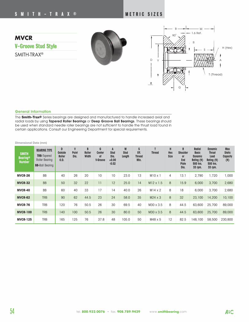
S M I T H - T R A X ® M E T R I C S I Z E S
54
MVCRV-Groove Stud StyleSMITH-TRAX®
tel. 800.932.0076 • fax. 908.789.9429 www.smithbearing.com
B M
D
R
A
H (Hex)
T (Thread)
S
G
90˚
V
1.6 Ref.
General Information
The Smith-Trax® Series bearings are designed and manufactured to handle increased axial andradial loads by using Tapered Roller Bearings or Deep Groove Ball Bearings. These bearings shouldbe used when standard needle roller bearings are not sufficient to handle the thrust load found incertain applications. Consult our Engineering Department for special requirements.
D V B G A M S T H R Radial Dynamic Max Outside Point Roller Center Stud Stud Eff. Thread Hex Shoulder Basic Thrust StaticRoller Dia. Width of Dia. Length Thread Size or Dynamic Load CapacityO.D. V-Groove +0.00 Min. End Rating (N) Rating (N) (N)
-0.02 Plate 500 hrs. 500 hrs.Dia. 33 rpm. 33 rpm.
SMITHBearing®
Number
MVCR-26 BB 40 26 20 10 10 23.0 13 M10 x 1 4 13.1 2,790 1,720 1,000
MVCR-32 BB 50 32 22 11 12 25.0 14 M12 x 1.5 8 15.9 6,000 3,700 2,680
MVCR-40 BB 60 40 33 17 14 40.0 26 M14 x 2 8 18 6,000 3,700 2,680
MVCR-62 TRB 90 62 44.5 23 24 58.0 35 M24 x 3 8 32 23,100 14,200 10,100
MVCR-76 TRB 120 76 50.5 26 30 69.5 40 M30 x 3.5 8 44.5 63,600 25,700 89,000
MVCR-100 TRB 140 100 50.5 26 30 80.0 50 M30 x 3.5 8 44.5 63,600 25,700 89,000
MVCR-125 TRB 165 125 76 37.8 48 105.0 50 M48 x 5 12 82.5 148,100 58,500 230,800
Dimensional Data (mm)
BEARING TYPE
TRB-TaperedRoller Bearing
BB-Ball Bearing
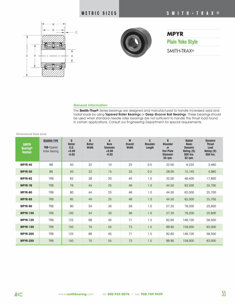
55
S M I T H - T R A X ® M E T R I C S I Z E S
www.smithbearing.com tel. 800.932.0076 • fax. 908.789.9429
MPYR-40 BB 40 22 10 23 0.5 22.00 8,220 3,460
MPYR-50 BB 50 32 15 33 0.5 28.00 15,140 4,980
MPYR-62 TRB 62 38 20 40 1.0 32.00 48,400 17,800
MPYR-76 TRB 76 44 25 46 1.0 44.50 63,500 25,700
MPYR-80 TRB 80 44 25 46 1.0 44.50 63,500 25,700
MPYR-85 TRB 85 44 25 46 1.0 44.50 63,500 25,700
MPYR-90 TRB 90 54 30 56 1.0 57.20 78,200 25,600
MPYR-100 TRB 100 54 30 56 1.0 57.20 78,200 25,600
MPYR-125 TRB 125 68 45 71 1.5 82.60 148,100 58,500
MPYR-150 TRB 150 70 55 73 1.5 88.90 159,000 63,000
MPYR-200 TRB 125 68 45 71 1.5 82.60 148,100 58,500
MPYR-250 TRB 150 70 55 73 1.5 88.90 159,000 63,000
SMITHBearing®
Number
General Information
The Smith-Trax® Series bearings are designed and manufactured to handle increased axial andradial loads by using Tapered Roller Bearings or Deep Groove Ball Bearings. These bearings shouldbe used when standard needle roller bearings are not sufficient to handle the thrust load foundin certain applications. Consult our Engineering Department for special requirements.
D B A W C R Radial DynamicRoller Roller Bore Overall Shoulder Shoulder Basic ThrustO.D. Width Diameter Width Length or Dynamic Load
+0.00 +0.00 End Plate Rating (N) Rating (N)-0.02 -0.02 Diameter 500 hrs. 500 hrs.
33 rpm. 33 rpm.
MPYRPlain Yoke Style
SMITH-TRAX®
Dimensional Data (mm)
BEARING TYPE
TRB-TaperedRoller Bearing
B
D R A
W
C
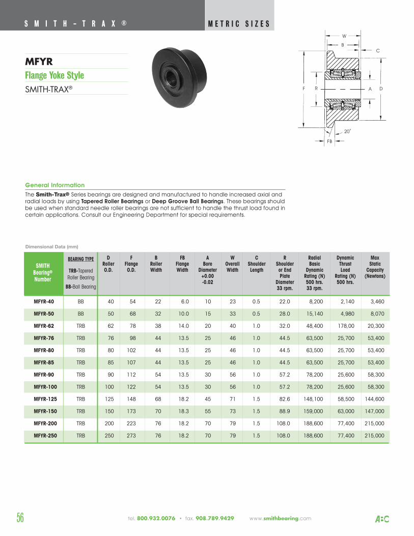
56
S M I T H - T R A X ® M E T R I C S I Z E S
tel. 800.932.0076 • fax. 908.789.9429 www.smithbearing.com
MFYRFlange Yoke StyleSMITH-TRAX®
B
DR A
W
F
FB
20˚
C
General Information
The Smith-Trax® Series bearings are designed and manufactured to handle increased axial andradial loads by using Tapered Roller Bearings or Deep Groove Ball Bearings. These bearings shouldbe used when standard needle roller bearings are not sufficient to handle the thrust load found incertain applications. Consult our Engineering Department for special requirements.
SMITHBearing®
Number
D F B FB A W C R Radial Dynamic Max Roller Flange Roller Flange Bore Overall Shoulder Shoulder Basic Thrust StaticO.D. O.D. Width Width Diameter Width Length or End Dynamic Load Capacity
+0.00 Plate Rating (N) Rating (N) (Newtons)-0.02 Diameter 500 hrs. 500 hrs.
33 rpm. 33 rpm.
MFYR-40 BB 40 54 22 6.0 10 23 0.5 22.0 8,200 2,140 3,460
MFYR-50 BB 50 68 32 10.0 15 33 0.5 28.0 15,140 4,980 8,070
MFYR-62 TRB 62 78 38 14.0 20 40 1.0 32.0 48,400 178,00 20,300
MFYR-76 TRB 76 98 44 13.5 25 46 1.0 44.5 63,500 25,700 53,400
MFYR-80 TRB 80 102 44 13.5 25 46 1.0 44.5 63,500 25,700 53,400
MFYR-85 TRB 85 107 44 13.5 25 46 1.0 44.5 63,500 25,700 53,400
MFYR-90 TRB 90 112 54 13.5 30 56 1.0 57.2 78,200 25,600 58,300
MFYR-100 TRB 100 122 54 13.5 30 56 1.0 57.2 78,200 25,600 58,300
MFYR-125 TRB 125 148 68 18.2 45 71 1.5 82.6 148,100 58,500 144,600
MFYR-150 TRB 150 173 70 18.3 55 73 1.5 88.9 159,000 63,000 147,000
MFYR-200 TRB 200 223 76 18.2 70 79 1.5 108.0 188,600 77,400 215,000
MFYR-250 TRB 250 273 76 18.2 70 79 1.5 108.0 188,600 77,400 215,000
Dimensional Data (mm)
BEARING TYPE
TRB-TaperedRoller Bearing
BB-Ball Bearing

57www.smithbearing.com tel. 800.932.0076 • fax. 908.789.9429
General Information
The Smith-Trax® Series bearings are designed and manufactured to handle increased axial and radial loads by using Tapered Roller Bearings or Deep Groove Ball Bearings. These bearingsshould be used when standard needle roller bearings are not sufficient to handle the thrust loadfound in certain applications. Consult our Engineering Department for special requirements.
D B A W V G C R Radial DynamicRoller Groove Bore Overall Point Center Shoulder Shoulder Basic ThrustO.D. Dia. Diameter Width Diameter of Length or Dynamic Load
+0.00 V-Groove End Plate Rating (N) Rating (N)-0.02 Diameter 500 hrs. 500 hrs.
33 rpm. 33 rpm.
SMITHBearing®
Number
MVYR-40 BB 60 22 10 23 40 11.5 0.5 22.0 8,220 2,140
MVYR-50 BB 75 32 15 33 50 16.5 0.5 28.0 15,140 4,980
MVYR-62 TRB 90 38 20 40 62 22 1.0 32.0 48,400 17,800
MVYR-76 TRB 110 44 25 46 76 23 1.0 44.5 63,600 25,700
MVYR-100 TRB 140 54 30 56 100 28 1.0 57.2 78,200 25,600
MVYR-125 TRB 165 68 45 71 125 36 1.5 82.6 148,100 58,500
MVYR-150 TRB 190 70 55 73 150 37 1.5 88.9 159,200 63,000
MVYR-200 TRB 240 76 70 79 200 40 1.5 108.0 188,600 77,400
MVYR-250 TRB 290 76 70 79 250 40 1.5 108.0 188,600 77,400
Dimensional Data (mm)
B
D RA
W
G
90˚
V
C
BEARING TYPE
TRB-TaperedRoller Bearing
BB-Ball Bearing
S M I T H - T R A X ® M E T R I C S I Z E S
MVYRV-Groove Yoke StyleSMITH-TRAX®
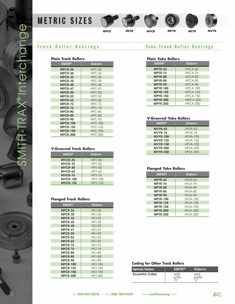
M E T R I C S I Z E S
Plain Track RollersSMITH® Osborn
MPCR-26 HPC-26MPCR-30 HPC-30MPCR-32 HPC-32MPCR-35 HPC-35MPCR-40 HPC-40MPCR-47 HPC-47MPCR-50 HPC-50MPCR-52 HPC-52MPCR-62 HPC-62MPCR-72 HPC-72MPCR-76 HPC-76MPCR-80 HPC-80MPCR-85 HPC-85MPCR-90 HPC-90MPCR-100 HPC-100MPCR-125 HPC-125MPCR-150 HPC-150MPCR-200 HPC-200
V-Grooved Track RollersSMITH® Osborn
MVCR-26 HPV-26MVCR-32 HPV-32MVCR-40 HPV-40MVCR-62 HPV-62MVCR-76 HPV-76MVCR-100 HPV-100MVCR-125 HPV-125
Plain Yoke RollersSMITH® Osborn
MPYR-62 HPCA-62MPYR-76 HPCA-76MPYR-80 HPCA-80MPYR-85 HPCA-85MPYR-90 HPCA-90MPYR-100 HPCA-100MPYR-125 HPCA-125MPYR-150 HPCA-150MPYR-200 HIPCA-200MPYR-250 HPCA-250
V-Grooved Yoke RollersSMITH® Osborn
MVYR-62 HPVA-62MVYR-76 HPVA-76MVYR-100 HPVA-100MVYR-125 HPVA-125MVYR-150 HPVA-150MVYR-200 HPVA-200MVYR-250 HPVA-250
Flanged Yoke RollersSMITH® Osborn
MFYR-62 HPJA-62MFYR-76 HPJA-76MFYR-80 HPJA-80MFYR-85 HPJA-85MFYR-90 HPJA-90MFYR-100 HPJA-100MFYR-125 HPJA-125MFYR-150 HPJA-150MFYR-200 HPJA-200MFYR-250 HPJA-250
Flanged Track RollersSMITH® Osborn
MFCR-26 HPJ-26MFCR-30 HPJ-30MFCR-32 HPJ-32MFCR-35 HPJ-35MFCR-40 HPJ-40MFCR-47 HPJ-47MFCR-50 HPJ-50MFCR-52 HPJ-52MFCR-62 HPJ-62MFCR-72 HPJ-72MFCR-76 HPJ-76MFCR-80 HPJ-80MFCR-85 HPJ-85MFCR-90 HPJ-90MFCR-100 HPJ-100MFCR-125 HPJ-125MFCR-150 HPJ-150MFCR-200 HPJ-200
Coding for Other Track RollersOptional Feature SMITH® Osborn
Eccentric Collar add addsuffix prefix“E” “E”
T r a c k R o l l e r B e a r i n g s Y o k e T r a c k R o l l e r B e a r i n g s
SMIT
H-T
RA
X® In
terc
ha
ng
e MPCR MFCR MVCR MPYR MFYR MVYR
58 tel. 800.932.0076 • fax. 908.789.9429 www.smithbearing.com
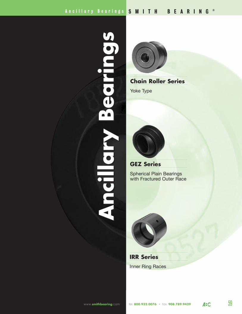
A n c i l l a r y B e a r i n g s
Ancillary Bearings
Ancillary Bearings
IRR SeriesInner Ring Races
GEZ SeriesSpherical Plain Bearings with Fractured Outer Race
Chain Roller SeriesYoke Type
S M I T H B E A R I N G ®
59www.smithbearing.com tel. 800.932.0076 • fax. 908.789.9429
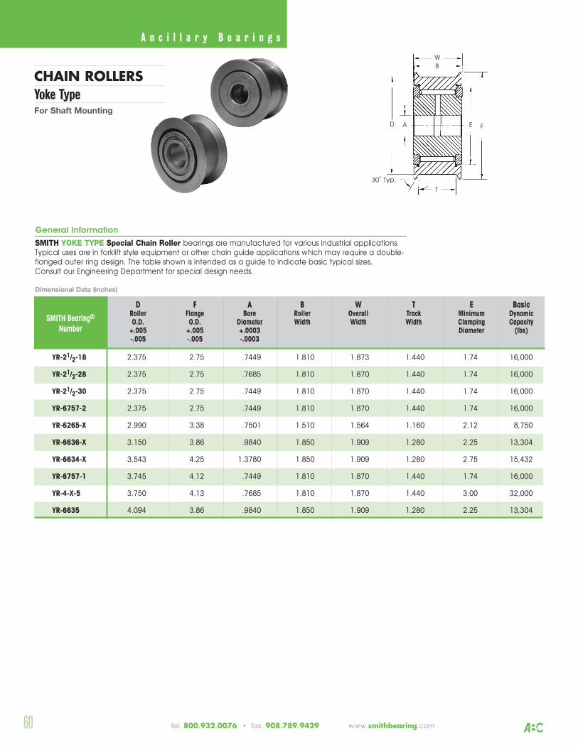
60 tel. 800.932.0076 • fax. 908.789.9429 www.smithbearing.com
CHAIN ROLLERSYoke TypeFor Shaft Mounting
A n c i l l a r y B e a r i n g s
General Information
SMITH YOKE TYPE Special Chain Roller bearings are manufactured for various industrial applications. Typical uses are in forklift style equipment or other chain guide applications which may require a double-flanged outer ring design. The table shown is intended as a guide to indicate basic typical sizes. Consult our Engineering Department for special design needs.
D F A B W T E BasicRoller Flange Bore Roller Overall Track Minimum DynamicO.D. O.D. Diameter Width Width Width Clamping Capacity
+.005 +.005 +.0003 Diameter (Ibs)-.005 -.005 -.0003
YR-21/2-18 2.375 2.75 .7449 1.810 1.873 1.440 1.74 16,000
YR-21/2-28 2.375 2.75 .7685 1.810 1.870 1.440 1.74 16,000
YR-21/2-30 2.375 2.75 .7449 1.810 1.870 1.440 1.74 16,000
YR-6757-2 2.375 2.75 .7449 1.810 1.870 1.440 1.74 16,000
YR-6265-X 2.990 3.38 .7501 1.510 1.564 1.160 2.12 8,750
YR-6636-X 3.150 3.86 .9840 1.850 1.909 1.280 2.25 13,304
YR-6634-X 3.543 4.25 1.3780 1.850 1.909 1.280 2.75 15,432
YR-6757-1 3.745 4.12 .7449 1.810 1.870 1.440 1.74 16,000
YR-4-X-5 3.750 4.13 .7685 1.810 1.870 1.440 3.00 32,000
YR-6635 4.094 3.86 .9840 1.850 1.909 1.280 2.25 13,304
SMITH Bearing®
Number
ED
WB
F
T
A
30˚ Typ.
Dimensional Data (inches)
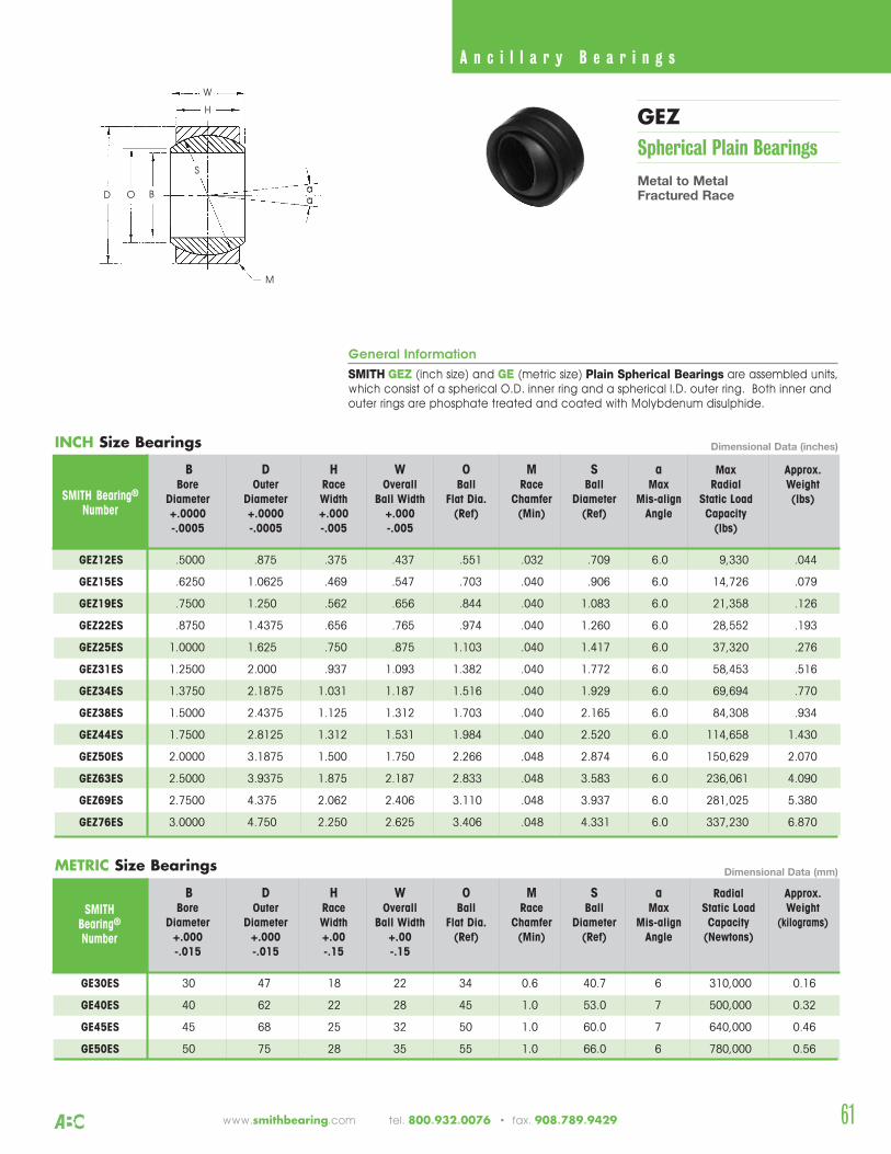
2561www.smithbearing.com tel. 800.932.0076 • fax. 908.789.9429
General Information
SMITH GEZ (inch size) and GE (metric size) Plain Spherical Bearings are assembled units,which consist of a spherical O.D. inner ring and a spherical I.D. outer ring. Both inner andouter rings are phosphate treated and coated with Molybdenum disulphide.
B D H W O M S a Max Approx.Bore Outer Race Overall Ball Race Ball Max Radial Weight
Diameter Diameter Width Ball Width Flat Dia. Chamfer Diameter Mis-align Static Load (lbs)+.0000 +.0000 +.000 +.000 (Ref) (Min) (Ref) Angle Capacity-.0005 -.0005 -.005 -.005 (lbs)
SMITH Bearing®
Number
GEZ12ES .5000 .875 .375 .437 .551 .032 .709 6.0 9,330 .044
GEZ15ES .6250 1.0625 .469 .547 .703 .040 .906 6.0 14,726 .079
GEZ19ES .7500 1.250 .562 .656 .844 .040 1.083 6.0 21,358 .126
GEZ22ES .8750 1.4375 .656 .765 .974 .040 1.260 6.0 28,552 .193
GEZ25ES 1.0000 1.625 .750 .875 1.103 .040 1.417 6.0 37,320 .276
GEZ31ES 1.2500 2.000 .937 1.093 1.382 .040 1.772 6.0 58,453 .516
GEZ34ES 1.3750 2.1875 1.031 1.187 1.516 .040 1.929 6.0 69,694 .770
GEZ38ES 1.5000 2.4375 1.125 1.312 1.703 .040 2.165 6.0 84,308 .934
GEZ44ES 1.7500 2.8125 1.312 1.531 1.984 .040 2.520 6.0 114,658 1.430
GEZ50ES 2.0000 3.1875 1.500 1.750 2.266 .048 2.874 6.0 150,629 2.070
GEZ63ES 2.5000 3.9375 1.875 2.187 2.833 .048 3.583 6.0 236,061 4.090
GEZ69ES 2.7500 4.375 2.062 2.406 3.110 .048 3.937 6.0 281,025 5.380
GEZ76ES 3.0000 4.750 2.250 2.625 3.406 .048 4.331 6.0 337,230 6.870
B D H W O M S a Radial Approx.Bore Outer Race Overall Ball Race Ball Max Static Load Weight
Diameter Diameter Width Ball Width Flat Dia. Chamfer Diameter Mis-align Capacity (kilograms)+.000 +.000 +.00 +.00 (Ref) (Min) (Ref) Angle (Newtons)-.015 -.015 -.15 -.15
SMITHBearing®
Number
GE30ES 30 47 18 22 34 0.6 40.7 6 310,000 0.16
GE40ES 40 62 22 28 45 1.0 53.0 7 500,000 0.32
GE45ES 45 68 25 32 50 1.0 60.0 7 640,000 0.46
GE50ES 50 75 28 35 55 1.0 66.0 6 780,000 0.56
INCH Size Bearings
METRIC Size Bearings
S
D
W
O
H
M
B
GEZSpherical Plain Bearings
Metal to MetalFractured Race
A n c i l l a r y B e a r i n g s
Dimensional Data (inches)
Dimensional Data (mm)
aa
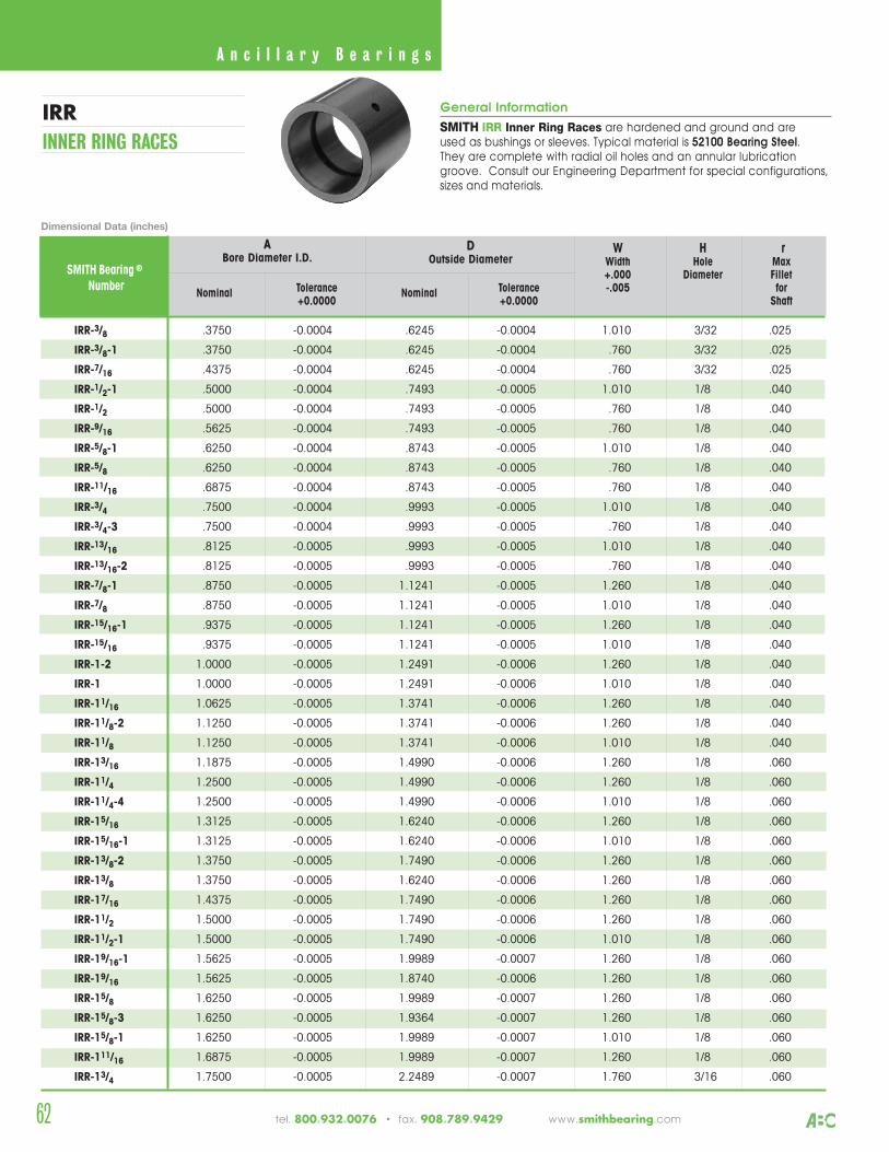
62
General Information
SMITH IRR Inner Ring Races are hardened and ground and areused as bushings or sleeves. Typical material is 52100 Bearing Steel. They are complete with radial oil holes and an annular lubricationgroove. Consult our Engineering Department for special configurations,sizes and materials.
W H rWidth Hole Max+.000 Diameter Fillet
Nominal Tolerance Nominal Tolerance -.005 for+0.0000 +0.0000 Shaft
ABore Diameter I.D.
SMITH Bearing ®
Number
IRR-3/8 .3750 -0.0004 .6245 -0.0004 1.010 3/32 .025
IRR-3/8-1 .3750 -0.0004 .6245 -0.0004 .760 3/32 .025
IRR-7/16 .4375 -0.0004 .6245 -0.0004 .760 3/32 .025
IRR-1/2-1 .5000 -0.0004 .7493 -0.0005 1.010 1/8 .040
IRR-1/2 .5000 -0.0004 .7493 -0.0005 .760 1/8 .040
IRR-9/16 .5625 -0.0004 .7493 -0.0005 .760 1/8 .040
IRR-5/8-1 .6250 -0.0004 .8743 -0.0005 1.010 1/8 .040
IRR-5/8 .6250 -0.0004 .8743 -0.0005 .760 1/8 .040
IRR-11/16 .6875 -0.0004 .8743 -0.0005 .760 1/8 .040
IRR-3/4 .7500 -0.0004 .9993 -0.0005 1.010 1/8 .040
IRR-3/4-3 .7500 -0.0004 .9993 -0.0005 .760 1/8 .040
IRR-13/16 .8125 -0.0005 .9993 -0.0005 1.010 1/8 .040
IRR-13/16-2 .8125 -0.0005 .9993 -0.0005 .760 1/8 .040
IRR-7/8-1 .8750 -0.0005 1.1241 -0.0005 1.260 1/8 .040
IRR-7/8 .8750 -0.0005 1.1241 -0.0005 1.010 1/8 .040
IRR-15/16-1 .9375 -0.0005 1.1241 -0.0005 1.260 1/8 .040
IRR-15/16 .9375 -0.0005 1.1241 -0.0005 1.010 1/8 .040
IRR-1-2 1.0000 -0.0005 1.2491 -0.0006 1.260 1/8 .040
IRR-1 1.0000 -0.0005 1.2491 -0.0006 1.010 1/8 .040
IRR-11/16 1.0625 -0.0005 1.3741 -0.0006 1.260 1/8 .040
IRR-11/8-2 1.1250 -0.0005 1.3741 -0.0006 1.260 1/8 .040
IRR-11/8 1.1250 -0.0005 1.3741 -0.0006 1.010 1/8 .040
IRR-13/16 1.1875 -0.0005 1.4990 -0.0006 1.260 1/8 .060
IRR-11/4 1.2500 -0.0005 1.4990 -0.0006 1.260 1/8 .060
IRR-11/4-4 1.2500 -0.0005 1.4990 -0.0006 1.010 1/8 .060
IRR-15/16 1.3125 -0.0005 1.6240 -0.0006 1.260 1/8 .060
IRR-15/16-1 1.3125 -0.0005 1.6240 -0.0006 1.010 1/8 .060
IRR-13/8-2 1.3750 -0.0005 1.7490 -0.0006 1.260 1/8 .060
IRR-13/8 1.3750 -0.0005 1.6240 -0.0006 1.260 1/8 .060
IRR-17/16 1.4375 -0.0005 1.7490 -0.0006 1.260 1/8 .060
IRR-11/2 1.5000 -0.0005 1.7490 -0.0006 1.260 1/8 .060
IRR-11/2-1 1.5000 -0.0005 1.7490 -0.0006 1.010 1/8 .060
IRR-19/16-1 1.5625 -0.0005 1.9989 -0.0007 1.260 1/8 .060
IRR-19/16 1.5625 -0.0005 1.8740 -0.0006 1.260 1/8 .060
IRR-15/8 1.6250 -0.0005 1.9989 -0.0007 1.260 1/8 .060
IRR-15/8-3 1.6250 -0.0005 1.9364 -0.0007 1.260 1/8 .060
IRR-15/8-1 1.6250 -0.0005 1.9989 -0.0007 1.010 1/8 .060
IRR-111/16 1.6875 -0.0005 1.9989 -0.0007 1.260 1/8 .060
IRR-13/4 1.7500 -0.0005 2.2489 -0.0007 1.760 3/16 .060
DOutside Diameter
IRRINNER RING RACES
Dimensional Data (inches)
A n c i l l a r y B e a r i n g s
tel. 800.932.0076 • fax. 908.789.9429 www.smithbearing.com
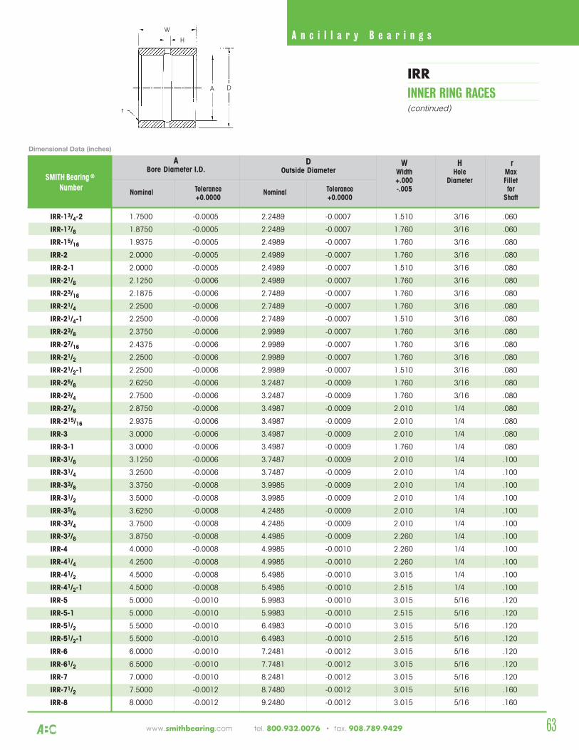
W H rWidth Hole Max+.000 Diameter Fillet
Nominal Tolerance Nominal Tolerance -.005 for+0.0000 +0.0000 Shaft
ABore Diameter I.D.
SMITH Bearing ®
Number
IRR-13/4-2 1.7500 -0.0005 2.2489 -0.0007 1.510 3/16 .060
IRR-17/8 1.8750 -0.0005 2.2489 -0.0007 1.760 3/16 .060
IRR-15/16 1.9375 -0.0005 2.4989 -0.0007 1.760 3/16 .080
IRR-2 2.0000 -0.0005 2.4989 -0.0007 1.760 3/16 .080
IRR-2-1 2.0000 -0.0005 2.4989 -0.0007 1.510 3/16 .080
IRR-21/8 2.1250 -0.0006 2.4989 -0.0007 1.760 3/16 .080
IRR-23/16 2.1875 -0.0006 2.7489 -0.0007 1.760 3/16 .080
IRR-21/4 2.2500 -0.0006 2.7489 -0.0007 1.760 3/16 .080
IRR-21/4-1 2.2500 -0.0006 2.7489 -0.0007 1.510 3/16 .080
IRR-23/8 2.3750 -0.0006 2.9989 -0.0007 1.760 3/16 .080
IRR-27/16 2.4375 -0.0006 2.9989 -0.0007 1.760 3/16 .080
IRR-21/2 2.2500 -0.0006 2.9989 -0.0007 1.760 3/16 .080
IRR-21/2-1 2.2500 -0.0006 2.9989 -0.0007 1.510 3/16 .080
IRR-25/8 2.6250 -0.0006 3.2487 -0.0009 1.760 3/16 .080
IRR-23/4 2.7500 -0.0006 3.2487 -0.0009 1.760 3/16 .080
IRR-27/8 2.8750 -0.0006 3.4987 -0.0009 2.010 1/4 .080
IRR-215/16 2.9375 -0.0006 3.4987 -0.0009 2.010 1/4 .080
IRR-3 3.0000 -0.0006 3.4987 -0.0009 2.010 1/4 .080
IRR-3-1 3.0000 -0.0006 3.4987 -0.0009 1.760 1/4 .080
IRR-31/8 3.1250 -0.0006 3.7487 -0.0009 2.010 1/4 .100
IRR-31/4 3.2500 -0.0006 3.7487 -0.0009 2.010 1/4 .100
IRR-33/8 3.3750 -0.0008 3.9985 -0.0009 2.010 1/4 .100
IRR-31/2 3.5000 -0.0008 3.9985 -0.0009 2.010 1/4 .100
IRR-35/8 3.6250 -0.0008 4.2485 -0.0009 2.010 1/4 .100
IRR-33/4 3.7500 -0.0008 4.2485 -0.0009 2.010 1/4 .100
IRR-37/8 3.8750 -0.0008 4.4985 -0.0009 2.260 1/4 .100
IRR-4 4.0000 -0.0008 4.9985 -0.0010 2.260 1/4 .100
IRR-41/4 4.2500 -0.0008 4.9985 -0.0010 2.260 1/4 .100
IRR-41/2 4.5000 -0.0008 5.4985 -0.0010 3.015 1/4 .100
IRR-41/2-1 4.5000 -0.0008 5.4985 -0.0010 2.515 1/4 .100
IRR-5 5.0000 -0.0010 5.9983 -0.0010 3.015 5/16 .120
IRR-5-1 5.0000 -0.0010 5.9983 -0.0010 2.515 5/16 .120
IRR-51/2 5.5000 -0.0010 6.4983 -0.0010 3.015 5/16 .120
IRR-51/2-1 5.5000 -0.0010 6.4983 -0.0010 2.515 5/16 .120
IRR-6 6.0000 -0.0010 7.2481 -0.0012 3.015 5/16 .120
IRR-61/2 6.5000 -0.0010 7.7481 -0.0012 3.015 5/16 .120
IRR-7 7.0000 -0.0010 8.2481 -0.0012 3.015 5/16 .120
IRR-71/2 7.5000 -0.0012 8.7480 -0.0012 3.015 5/16 .160
IRR-8 8.0000 -0.0012 9.2480 -0.0012 3.015 5/16 .160
DOutside Diameter
r
D
W
A
H
IRRINNER RING RACES(continued)
A n c i l l a r y B e a r i n g s
Dimensional Data (inches)
63www.smithbearing.com tel. 800.932.0076 • fax. 908.789.9429
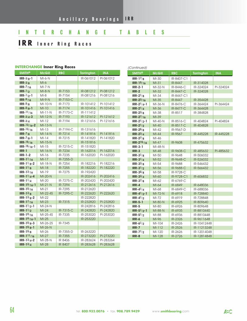
64 tel. 800.932.0076 • fax. 908.789.9429 www.smithbearing.com
INTERCHANGE Inner Ring RacesSMITH® McGill RBC Torrington INA
IRR-3/8-1 MI-6-N IR-061012 PI-061012IRR-3/8 MI-6IRR-7/16 MI-7-NIRR-1/2 MI-8-N IR-7153 IR-081212 PI-081212IRR-1/2-1 MI-8 IR-7154 IR-081216 PI-081216IRR-9/16 MI-9-N IR-7153-CIRR-5/8 MI-10-N IR-7173 IR-101412 PI-101412IRR-5/8-1 MI-10 IR-7174 IR-101416 PI-101416IRR-11/16 MI-11-N IR-7173-C IR-111412IRR-3/4-3 MI-12-N IR-7193 IR-121612 PI-121612IRR-3/4 MI-12 IR-7194 IR-121616 PI-121616IRR-13/16-2 MI-13-NIRR-13/16 MI-13 IR-7194-C IR-131616IRR-7/8 MI-14-N IR-7214 IR-141816 PI-141816IRR-7/8-1 MI-14 IR-7215 IR-141820 PI-141820IRR-15/16 MI-15-N IR-151816IRR-15/16-1 MI-15 IR-7215-C IR-151820IRR-1 MI-16-N IR-7234 IR-162016 PI-162016IRR-1-2 MI-16 IR-7235 IR-162020 PI-162020IRR-11/16 MI-17 IR-7255-DIRR-11/8-2 MI-18-N IR-7254 IR-182216 PI-182216IRR-11/8 MI-18 IR-7255 IR-182220 PI-182220IRR-13/16 MI-19 IR-7275 IR-192420IRR-11/4-4 MI-20-N IR-202416 PI-202416IRR-11/4 MI-20 IR-7275-C IR-202420 PI-202420IRR-15/16-1 MI-21-N IR-7294 IR-212616 PI-212616IRR-15/16 MI-21 IR-7295 IR-212620IRR-13/8 MI-22-4S IR-7295-C IR-222620 PI-222620IRR-13/8-2 MI-22 IR-222820IRR-17/16 MI-23 IR-7315 IR-232820 PI-232820IRR-11/2-1 MI-24-N IR-242816 PI-242816IRR-11/2 MI-24 IR-7315-C IR-242820 PI-242820IRR-19/16 MI-25-4S IR-7335 IR-253020 PI-253020IRR-19/16-1 MI-25 IR-253220IRR-15/8-3 MI-26-2S IR-7345IRR-15/8-1 MI-26-NIRR-15/8 MI-26 IR-7355-D IR-263220IRR-111/16 MI-27 IR-7355 IR-273220 PI-273220 IRR-13/4-2 MI-28-N IR 8406 IR-283624 PI-283264IRR-13/4 MI-28 IR 8407 IR-283628 PI-283628
(Continued)
SMITH® McGill RBC Torrington INA
IRR-17/8 MI-30 IR-8407-C1IRR-15/16 MI-31 IR-8447 IR-314028IRR-2-1 MI-32-N IR-8446-C IR-324024 PI-324024IRR-2 MI-32 IR-8447-C IR-324028IRR-21/8 MI-34 IR-8447-C1IRR-23/16 MI-35 IR-8447 IR-354428IRR-21/4-1 MI-36-N IR-8476-C IR-364424 PI-364424IRR-21/4 MI-36 IR-8477-C IR-364428IRR-23/8 MI-38 IR-8517 IR-384828IRR-27/16 MI-39IRR-21/2-1 MI-40-N IR-8516-C IR-404824 PI-404824IRR-21/2 MI-40 IR-8517-C IR-404828IRR-25/8 MI-42 IR-9567-DIRR-23/4 MI-44 IR-9567 IR-445228 IR-445228IRR-27/8 MI-46IRR-215/16 MI-47 IR-9608 IR-475632IRR-3-1 MI-48-NIRR-3 MI-48 IR-9608-C IR-485632 PI-485632IRR-31/8 MI-50 IR-9648 IR-506032IRR-31/4 MI-52 IR-9648-C IR-526032IRR-33/8 MI-54 IR-9688 IR-546432IRR-31/2 MI-56 IR-9688-C IR-566432IRR-35/8 MI-58 IR-9728-CIRR-33/4 MI-60 IR-9728-C1 IR-606832IRR-37/8 MI-62 IR-6769-CIRR-4 MI-64 IR-6849 IR-648036IRR-41/4 MI-68 IR-6849-C IR-688036IRR-41/2-1 MI-72-N IR-6918 IR-728840IRR-41/2 MI-72 IR-6919 IR-728848IRR-5-1 MI-80-N IR-6925 IR-809640IRR-5 MI-80 IR-6926 IR-809648IRR-51/2-1 MI-88-N IR-6935 IR-8810440IRR-51/2 MI-88 IR-6936 IR-8810448IRR-6 MI-96 IR-2326 IR-9611648IRR-61/2 MI-104 IR-2426 IR-10412448IRR-7 MI-112 IR-2526 IR-11213248IRR-71/2 MI-120 IR-2626 IR-12014048IRR-8 MI-128 IR-2726 IR-12814848
I N T E R C H A N G E T A B L E S
I R R I n n e r R i n g R a c e s
A n c i l l a r y B e a r i n g s I R R

65www.smithbearing.com tel. 800.932.0076 • fax. 973.789.9429
Aerospace Bearings
AS21438
AS21439
AS24465
AS24466
AS24461
AS21432
AS21447
AS5927
AS5928
AS5929
YAF Series
YAT Series
YAD Series
YAF Series
YAG Series
HRS Series
CHRS Series
YAF-XD Series
YAT-XD Series
CHRS-XD Series
(MS21438)
(MS21439)
(MS24465)
(MS24466)
(MS24461)
(MS21432)
(MS21447)

IntroductionSmith Aircraft Bearings presented inthis section have been designed tomeet the standards of the aerospaceindustry and conform to military andother appropriate national standards.When selecting these bearings for yourapplication, it is recommended that youreview the engineering data provided,along with any appropriate military ornational specifications.
Smith Bearing® has been a leader inthe design and manufacture ofspecialized bearings for the uniquerequirements of jet engines. We havekept pace with the ever increasingdemands for anti-friction bearings tooperate at higher temperatures. Thrustreversers, afterburners, and divergentnozzles are some of the areas in whichSmith Bearing® Bearings are currentlyfunctioning. Contact our engineeringdepartment for recommendations anddesign assistance.
Military QualificationsThe products listed meet the military requirements of SAE AS 39901
Smith Aircraft Bearings are marked with the bearing designation includingbearing type code. Many of thesebearings are supplied pre-lubricated tomeet the OEM's special requirements.When ordering, attention must be paidto the original manufacturers parts listrequirements so that properidentification can be provided.
Federal AviationAdministration PartsManufacturing ApprovalFAA PMASmith manufactures bearings to meetthe provisions of the Federal AviationRegulations (FAR) for PartsManufacturing Approval (PMA).Smith Bearing® maintains an activelist identifying all of our FAA PMA partsand where they are applicable. This listis available upon request.
Aerospace Bearings
Bearing SelectionYAF (AS21438) & YAT (AS21439)
YAF and YAT Series Yoke Type bearings have heavy outer ring sections and were designedfor application as track rollers where the bearingO.D. is unsupported. These bearings will supportheavy rolling or oscillating loads in cam or trackroller applications. The YAF-Series (single row)needle bearings have a crowned outer race. TheYAT-Series (double row) needle bearings havelarge blended outside corner radiuses to helpdistribute stresses. The outer race is hard-chromeplated and all other exposed surfaces arecadmium plated for corrosion protection. Thesebearings can be re-lubricated thru the inner ringbore. When mounting, care should be taken toproperly support the end plates to eliminate thepossibility of bearing separation due to thrust loads.These bearings are dimensionally interchangeablewith the corresponding YAD and YAS Series.
YAD (AS24465) & YAS (AS24466)
YAD and YAS Series Yoke Type bearings aredimensionally similar to the YAF and YAT Series. These bearings were designed for track rollerapplications where the outer race of the bearingis unsupported. They will handle heavy rolling oroscillating motion. The outer race is hard-chromeplated and all other exposed surfaces arecadmium plated for corrosion protection. Thebearing is held together using a swedged ringinserted around the inside of the end washers.These bearings are generally considered forreplacement in existing applications. For newapplications and current designs use the YAF and YAT Series.
YAG (AS24461)
YAG Series Yoke Type bearings were designed forapplications where the bearing is mounted insidethe housing. These bearings handle slow rotating oroscillating motions. All external surfaces except thebore are cadmium plated for corrosion protection.The bearing is held together using a swedged ringinserted around the inside of the end washer.
HRS (AS21432) & CHRS (AS21447)
HRS and CHRS Series Stud Type bearings are of non-separable construction and are used inapplications involving high-static loads or oscillatingmotion. The HRS-Series - straight cylindrical outerrace and the CHRS-Series - crowned outer racewere designed for airframe usage in flap tracks,canopies, and landing gear. When misalignment isa concern, the CHRS (crowned) Series is preferred.The outer races are hard-chrome plated and allother exposed surfaces are cadmium plated forcorrosion protection.
66 tel. 800.932.0076 • fax. 908.789.9429 www.smithbearing.com
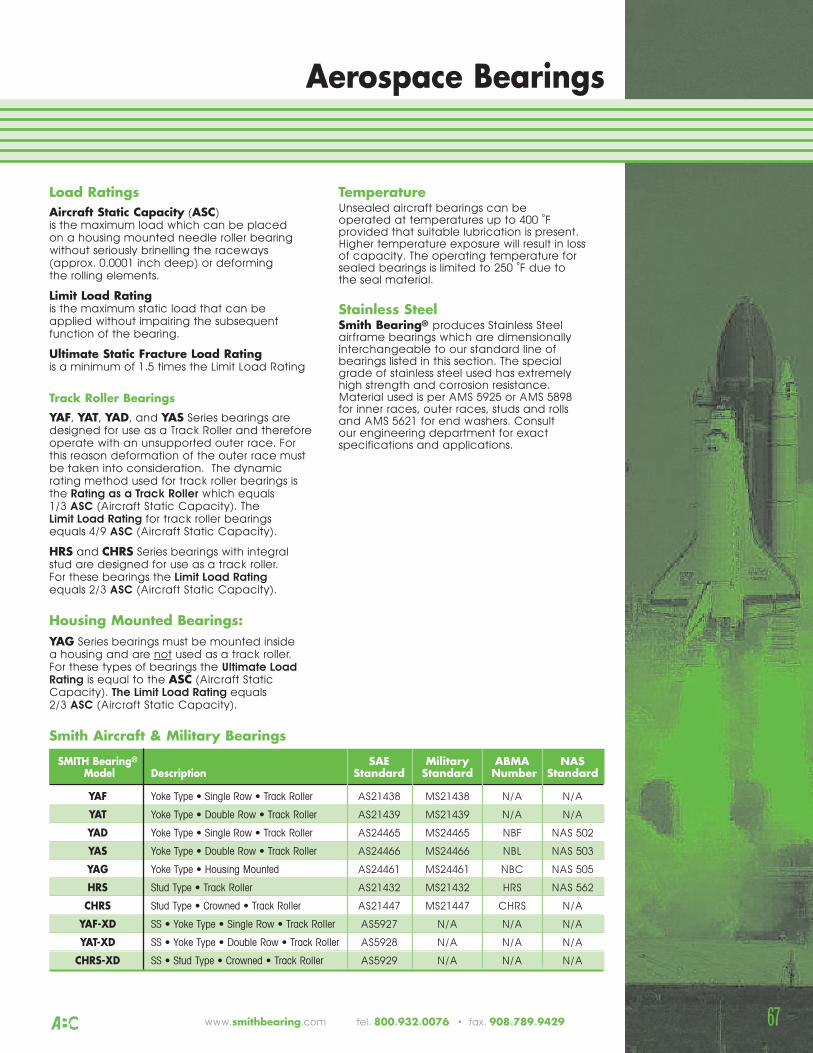
Load RatingsAircraft Static Capacity (ASC)is the maximum load which can be placedon a housing mounted needle roller bearingwithout seriously brinelling the raceways(approx. 0.0001 inch deep) or deformingthe rolling elements.
Limit Load Ratingis the maximum static load that can be applied without impairing the subsequentfunction of the bearing.
Ultimate Static Fracture Load Ratingis a minimum of 1.5 times the Limit Load Rating
Track Roller Bearings
YAF, YAT, YAD, and YAS Series bearings aredesigned for use as a Track Roller and thereforeoperate with an unsupported outer race. Forthis reason deformation of the outer race mustbe taken into consideration. The dynamicrating method used for track roller bearings isthe Rating as a Track Roller which equals 1/3 ASC (Aircraft Static Capacity). The Limit Load Rating for track roller bearings equals 4/9 ASC (Aircraft Static Capacity).
HRS and CHRS Series bearings with integralstud are designed for use as a track roller.For these bearings the Limit Load Ratingequals 2/3 ASC (Aircraft Static Capacity).
Housing Mounted Bearings:YAG Series bearings must be mounted insidea housing and are not used as a track roller.For these types of bearings the Ultimate LoadRating is equal to the ASC (Aircraft StaticCapacity). The Limit Load Rating equals2/3 ASC (Aircraft Static Capacity).
TemperatureUnsealed aircraft bearings can be operated at temperatures up to 400 ˚Fprovided that suitable lubrication is present.Higher temperature exposure will result in lossof capacity. The operating temperature forsealed bearings is limited to 250 ˚F due tothe seal material.
Stainless SteelSmith Bearing® produces Stainless Steelairframe bearings which are dimensionallyinterchangeable to our standard line ofbearings listed in this section. The specialgrade of stainless steel used has extremelyhigh strength and corrosion resistance.Material used is per AMS 5925 or AMS 5898 for inner races, outer races, studs and rollsand AMS 5621 for end washers. Consult our engineering department for exactspecifications and applications.
Aerospace Bearings
SMITH Bearing® SAE Military ABMA NASModel Description Standard Standard Number Standard
YAF Yoke Type • Single Row • Track Roller AS21438 MS21438 N/A N/A
YAT Yoke Type • Double Row • Track Roller AS21439 MS21439 N/A N/A
YAD Yoke Type • Single Row • Track Roller AS24465 MS24465 NBF NAS 502
YAS Yoke Type • Double Row • Track Roller AS24466 MS24466 NBL NAS 503
YAG Yoke Type • Housing Mounted AS24461 MS24461 NBC NAS 505
HRS Stud Type • Track Roller AS21432 MS21432 HRS NAS 562
CHRS Stud Type • Crowned • Track Roller AS21447 MS21447 CHRS N/A
YAF-XD SS • Yoke Type • Single Row • Track Roller AS5927 N/A N/A N/A
YAT-XD SS • Yoke Type • Double Row • Track Roller AS5928 N/A N/A N/A
CHRS-XD SS • Stud Type • Crowned • Track Roller AS5929 N/A N/A N/A
Smith Aircraft & Military Bearings
67www.smithbearing.com tel. 800.932.0076 • fax. 908.789.9429
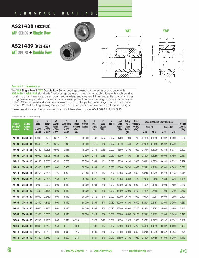
68
A D W C T Cr d P r Limit Rating TrackSMITH AS/MS Bore Roller Overall Outer Race Track Crown Min. Lube Radius Load As A Capacity Weight
Bearing® Number O.D. Width Width Contact radius Clamp Groove Rating Track 40HRC Approx.Number Military +.0000 +.0000 +.000 +.000 Width Dia. Width (lbf) Roller (lbf) (lbs)
-.0007 -.0010 -.005 -.005 Min. (lbf)
Recommended Shaft Diameter
Slip Fit Press Fit
Max Min Max Min
YAF-03 21438-103 0.1900 0.7500 0.312 0.280 - 10.000 0.438 3/32 0.022 1200 900 290 0.1894 0.1889 0.1902 0.1897 0.030
YAF-04 21438-104 0.2500 0.8750 0.375 0.345 - 10.000 0.516 1/8 0.022 1910 1430 575 0.2494 0.2489 0.2502 0.2497 0.051
YAF-06 21438-106 0.3750 1.0625 0.500 0.455 - 10.000 0.672 3/16 0.022 3600 2700 1000 0.3744 0.3739 0.3752 0.3747 0.103
YAF-08 21438-108 0.5000 1.3125 0.625 0.580 - 12.500 0.844 3/16 0.032 5780 4300 1785 0.4994 0.4989 0.5002 0.4997 0.187
YAF-10 21438-110 0.6250 1.5000 0.750 0.705 - 17.500 0.953 1/4 0.032 8530 6400 2600 0.6244 0.6239 0.6252 0.6247 0.279
YAF-12 21438-112 0.7500 1.7500 1.000 0.950 - 25.000 1.109 1/4 0.032 14200 10700 4050 0.7494 0.7489 0.7502 0.7497 0.520
YAF-14 21438-114 0.8750 2.0000 1.125 1.075 - 27.500 1.219 1/4 0.032 19300 14400 5350 0.8744 0.8739 87,526 0.8747 0.749
YAF-20 21438-120 1.2500 2.5000 1.250 1.200 - 30.000 1.625 3/8 0.032 25300 18900 7100 1.2494 1.2488 1.2503 1.2497 1.160
YAF-24 21438-124 1.5000 3.0000 1.500 1.440 - 60.000 1.984 3/8 0.032 37900 28400 10900 1.4994 1.4988 1.5003 1.4997 2.360
YAF-28 21438-128 1.7500 3.4375 1.500 1.440 - 60.000 2.281 3/8 0.032 44100 33000 12400 1.7494 1.7488 1.7503 1.7497 2.710
YAF-32 21438-132 2.0000 3.8750 1.500 1.440 - 60.000 2.562 3/8 0.032 48900 36700 14000 1.9994 1.9987 2.0003 1.9996 3.420
YAF-36 21438-136 2.2500 4.3125 1.500 1.440 - 60.000 2.859 3/8 0.032 55000 41200 15600 2.2494 2.2487 2.2503 2.2496 4.230
YAF-40 21438-140 2.5000 4.7500 1.500 1.440 - 60.000 3.109 3/8 0.032 59900 44900 17200 2.4994 2.4987 2.5003 2.4996 5.140
YAF-44 21438-144 2.7500 5.0000 1.500 1.440 - 60.000 3.344 3/8 0.032 64800 48600 18100 2.7494 2.7487 2.7503 2.7496 5.490
YAT-06 21439-106 0.3750 1.1250 1.000 0.940 0.750 - 0.672 3/16 0.032 7130 5370 2600 0.3744 0.3739 0.3752 0.3747 0.239
YAT-08 21439-108 0.5000 1.3750 1.250 1.190 1.000 - 0.891 1/4 0.032 12500 9370 4250 0.4994 0.4989 0.5002 0.4997 0.437
YAT-10 21439-110 0.6250 1.6250 1.500 1.440 1.125 - 1.109 3/8 0.032 19900 15000 5650 0.6244 0.6239 0.6252 0.6247 0.728
YAT-12 21439-112 0.7500 1.8750 1.750 1.690 1.375 - 1.281 3/8 0.032 28500 21400 7950 0.7494 0.7489 0.7502 0.7497 1.130
C
D
W
Cr
r
dA
P
C
D
W
P
r
d A
P
T
r
YAFYAT
A E R O S P A C E B E A R I N G S
AS21438 (MS21438)YAF SERIES • Single Row
AS21439 (MS21439)YAT SERIES • Double Row
General Information
The YAF Single Row & YAT Double Row Series bearings are manufactured in accordance withAS21438 & AS21439 standards. The bearings are used in track roller applications with each bearingconsisting of an inner race, outer race, needle rollers, end washers & thrust seals. Relubrication holesand grooves are provided. For wear and corrosion protection the outer ring surface is hard-chromeplated. Other exposed surfaces are cadmium or zinc-nickel plated. Inner rings may be black-oxidecoated. Consult our Engineering Department for further specific requirements and special designs.
These bearings can be produced from stainless steel grade AMS 5898 & AMS 5925.
Dimensional Data (inches)
tel. 800.932.0076 • fax. 908.789.9429 www.smithbearing.com
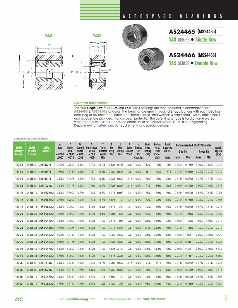
69www.smithbearing.com tel. 800.932.0076 • fax. 908.789.9429
General Information
The YAD Single Row & YAS Double Row Series bearings are manufactured in accordance withAS24465 & AS24466 standards. The bearings are used in track roller applications with each bearingconsisting of an inner race, outer race, needle rollers, end washers & thrust seals. Relubrication holesand grooves are provided. For corrosion protection the outer ring surface is hard chrome plated while all other exposed surfaces are cadmium or zinc-nickel plated. Consult our EngineeringDepartment for further specific requirements and special designs.
A D W C T E d P r Limit Rating TrackSMITH AS/MS ABMA Bore Roller Overall Outer Race Track End Min. Lube Radius Load As A Capacity Weight
Bearing® Military Number O.D. Width Width Contact Ring Clamp Groove or Rating Track 40HRC Approx.Number Number +.0000 +.0000 +.000 +.000 Width Dia. Dia. Width 45° (lbf) Roller (lbs)
-.0007 -.0010 -.005 -.005 Min Chamfer (lbf) (lbf)
Recommended Shaft Diameter
Slip Fit Press Fit
Max Min Max Min
YAD-03 24465-3 3NBF512YJ 0.1900 0.7500 0.312 0.218 0.125 0.688 0.438 3/32 0.022 1200 900 290 0.1894 0.1889 0.1902 0.1897 0.029
YAD-04 24465-4 4NBF614YJ 0.2500 0.8750 0.375 0.281 0.218 0.750 0.516 1/8 0.022 1910 1430 575 0.2494 0.2489 0.2502 0.2497 0.049
YAD-06 24465-6 6NBF817YJ 0.3750 1.0625 0.500 0.375 0.312 0.938 0.672 3/16 0.022 3600 2700 1000 0.3744 0.3739 0.3752 0.3747 0.980
YAD-08 24465-8 8NBF1021YJ 0.5000 1.3125 0.625 0.500 0.438 1.188 0.844 3/16 0.032 5780 4300 1785 0.4994 0.4989 0.5002 0.4997 0.178
YAD-10 24465-10 10NBF1224YJ 0.6250 1.5000 0.750 0.625 0.562 1.375 0.953 1/4 0.032 8530 6400 2600 0.6244 0.6239 0.6252 0.6247 0.266
YAD-12 24465-12 12NBF1628YJ 0.7500 1.7500 1.000 0.875 0.750 1.625 1.109 1/4 0.032 14200 10700 4050 0.7494 0.7489 0.7502 0.7497 0.495
YAD-14 24465-14 14NBF1832YJ 0.8750 2.0000 1.125 1.000 0.875 1.875 1.219 1/4 0.032 19300 14400 5350 0.8744 0.8739 0.8752 0.8747 0.713
YAD-20 24465-20 20NBF2040YJ 1.2500 2.5000 1.250 1.049 0.938 1.906 1.625 3/8 0.032 25300 18900 7100 1.2494 1.2488 1.2503 1.2497 1.060
YAD-24 24465-24 24NBF2448YJ 1.5000 3.0000 1.500 1.229 1.172 2.875 1.984 3/8 0.032 37900 28400 10900 1.4994 1.4988 1.5003 1.4997 2.070
YAD-28 24465-28 28NBF2455YJ 1.7500 3.4375 1.500 1.229 1.172 3.312 2.281 3/8 0.032 44100 33000 12400 1.7494 1.7488 1.7503 1.7497 2.710
YAD-32 24465-32 32NBF2462YJ 2.0000 3.8750 1.500 1.229 1.172 3.750 2.562 3/8 0.032 48900 36700 14000 1.9994 1.9987 2.0003 1.9996 3.420
YAD-36 24465-36 36NBF2469YJ 2.2500 4.3125 1.500 1.229 1.172 4.188 2.859 3/8 0.032 55000 41200 15600 2.2494 2.2487 2.2503 2.2496 4.230
YAD-40 24465-40 40NBF2476YJ 2.5000 4.7500 1.500 1.229 1.172 4.625 3.109 3/8 0.032 59900 44900 17200 2.4994 2.4987 2.5003 2.4996 5.140
YAD-44 24465-44 44NBF2480YJ 2.7500 5.0000 1.500 1.229 1.172 4.875 3.344 3/8 0.032 64800 48600 18100 2.7494 2.7487 2.7503 2.7496 5.490
YAS-06 24466-6 6NBL1618YJ 0.3750 1.1250 1.000 0.875 0.750 1.000 0.672 3/16 0.032 7130 5370 2600 0.3744 0.3739 0.3752 0.3747 0.228
YAS-08 24466-8 8NBL2022YJ 0.5000 1.3750 1.250 1.125 1.000 1.250 0.891 1/4 0.032 12500 9370 4250 0.4994 0.4989 0.5002 0.4997 0.416
YAS-10 24466-10 10NBL2426YJ 0.6250 1.6250 1.500 1.375 1.125 1.500 1.109 3/8 0.032 19900 15000 5650 0.6244 0.6239 0.6252 0.6247 0.693
YAS-12 24466-12 12NBL2830YJ 0.7500 1.8750 1.750 1.625 1.375 1.750 1.281 3/8 0.032 28500 21400 7950 0.7494 0.7489 0.7502 0.7497 1.180
C
T
W
E d A
P
C
D
W
P
r
d A
P
T
E
YAS YAD
A E R O S P A C E B E A R I N G S
Dimensional Data (inches)
AS24465 (MS24465)YAD SERIES • Single Row
AS24466 (MS24466)YAS SERIES • Double Row
D
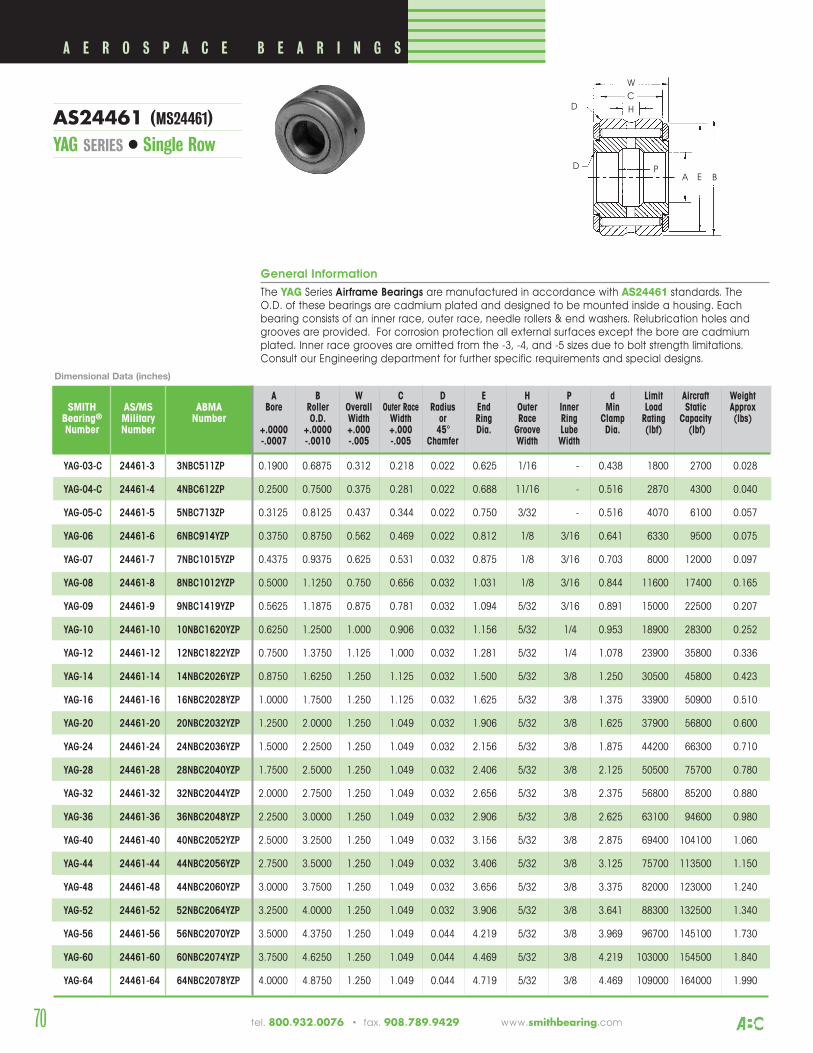
General Information
The YAG Series Airframe Bearings are manufactured in accordance with AS24461 standards. The O.D. of these bearings are cadmium plated and designed to be mounted inside a housing. Eachbearing consists of an inner race, outer race, needle rollers & end washers. Relubrication holes andgrooves are provided. For corrosion protection all external surfaces except the bore are cadmiumplated. Inner race grooves are omitted from the -3, -4, and -5 sizes due to bolt strength limitations.Consult our Engineering department for further specific requirements and special designs.
A B W C D E H P d Limit Aircraft WeightSMITH AS/MS ABMA Bore Roller Overall Outer Race Radius End Outer Inner Min Load Static Approx
Bearing® Military Number O.D. Width Width or Ring Race Ring Clamp Rating Capacity (lbs)Number Number +.0000 +.0000 +.000 +.000 45° Dia. Groove Lube Dia. (lbf) (lbf)
-.0007 -.0010 -.005 -.005 Chamfer Width Width
YAG-03-C 24461-3 3NBC511ZP 0.1900 0.6875 0.312 0.218 0.022 0.625 1/16 - 0.438 1800 2700 0.028
YAG-04-C 24461-4 4NBC612ZP 0.2500 0.7500 0.375 0.281 0.022 0.688 11/16 - 0.516 2870 4300 0.040
YAG-05-C 24461-5 5NBC713ZP 0.3125 0.8125 0.437 0.344 0.022 0.750 3/32 - 0.516 4070 6100 0.057
YAG-06 24461-6 6NBC914YZP 0.3750 0.8750 0.562 0.469 0.022 0.812 1/8 3/16 0.641 6330 9500 0.075
YAG-07 24461-7 7NBC1015YZP 0.4375 0.9375 0.625 0.531 0.032 0.875 1/8 3/16 0.703 8000 12000 0.097
YAG-08 24461-8 8NBC1012YZP 0.5000 1.1250 0.750 0.656 0.032 1.031 1/8 3/16 0.844 11600 17400 0.165
YAG-09 24461-9 9NBC1419YZP 0.5625 1.1875 0.875 0.781 0.032 1.094 5/32 3/16 0.891 15000 22500 0.207
YAG-10 24461-10 10NBC1620YZP 0.6250 1.2500 1.000 0.906 0.032 1.156 5/32 1/4 0.953 18900 28300 0.252
YAG-12 24461-12 12NBC1822YZP 0.7500 1.3750 1.125 1.000 0.032 1.281 5/32 1/4 1.078 23900 35800 0.336
YAG-14 24461-14 14NBC2026YZP 0.8750 1.6250 1.250 1.125 0.032 1.500 5/32 3/8 1.250 30500 45800 0.423
YAG-16 24461-16 16NBC2028YZP 1.0000 1.7500 1.250 1.125 0.032 1.625 5/32 3/8 1.375 33900 50900 0.510
YAG-20 24461-20 20NBC2032YZP 1.2500 2.0000 1.250 1.049 0.032 1.906 5/32 3/8 1.625 37900 56800 0.600
YAG-24 24461-24 24NBC2036YZP 1.5000 2.2500 1.250 1.049 0.032 2.156 5/32 3/8 1.875 44200 66300 0.710
YAG-28 24461-28 28NBC2040YZP 1.7500 2.5000 1.250 1.049 0.032 2.406 5/32 3/8 2.125 50500 75700 0.780
YAG-32 24461-32 32NBC2044YZP 2.0000 2.7500 1.250 1.049 0.032 2.656 5/32 3/8 2.375 56800 85200 0.880
YAG-36 24461-36 36NBC2048YZP 2.2500 3.0000 1.250 1.049 0.032 2.906 5/32 3/8 2.625 63100 94600 0.980
YAG-40 24461-40 40NBC2052YZP 2.5000 3.2500 1.250 1.049 0.032 3.156 5/32 3/8 2.875 69400 104100 1.060
YAG-44 24461-44 44NBC2056YZP 2.7500 3.5000 1.250 1.049 0.032 3.406 5/32 3/8 3.125 75700 113500 1.150
YAG-48 24461-48 44NBC2060YZP 3.0000 3.7500 1.250 1.049 0.032 3.656 5/32 3/8 3.375 82000 123000 1.240
YAG-52 24461-52 52NBC2064YZP 3.2500 4.0000 1.250 1.049 0.032 3.906 5/32 3/8 3.641 88300 132500 1.340
YAG-56 24461-56 56NBC2070YZP 3.5000 4.3750 1.250 1.049 0.044 4.219 5/32 3/8 3.969 96700 145100 1.730
YAG-60 24461-60 60NBC2074YZP 3.7500 4.6250 1.250 1.049 0.044 4.469 5/32 3/8 4.219 103000 154500 1.840
YAG-64 24461-64 64NBC2078YZP 4.0000 4.8750 1.250 1.049 0.044 4.719 5/32 3/8 4.469 109000 164000 1.990
C
D
W
AP
H
E
D
B
A E R O S P A C E B E A R I N G S
Dimensional Data (inches)
AS24461 (MS24461)YAG SERIES • Single Row
70 tel. 800.932.0076 • fax. 908.789.9429 www.smithbearing.com
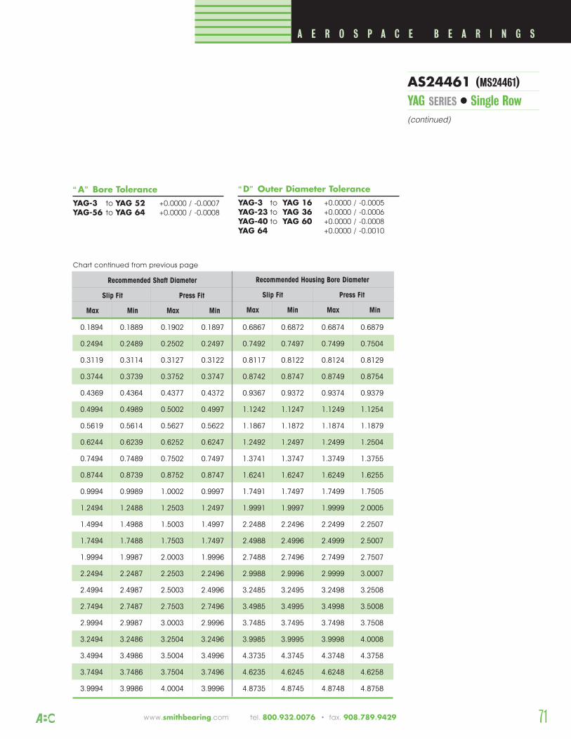
Recommended Shaft Diameter
Slip Fit Press Fit
Max Min Max Min
0.1894 0.1889 0.1902 0.1897 0.6867 0.6872 0.6874 0.6879
0.2494 0.2489 0.2502 0.2497 0.7492 0.7497 0.7499 0.7504
0.3119 0.3114 0.3127 0.3122 0.8117 0.8122 0.8124 0.8129
0.3744 0.3739 0.3752 0.3747 0.8742 0.8747 0.8749 0.8754
0.4369 0.4364 0.4377 0.4372 0.9367 0.9372 0.9374 0.9379
0.4994 0.4989 0.5002 0.4997 1.1242 1.1247 1.1249 1.1254
0.5619 0.5614 0.5627 0.5622 1.1867 1.1872 1.1874 1.1879
0.6244 0.6239 0.6252 0.6247 1.2492 1.2497 1.2499 1.2504
0.7494 0.7489 0.7502 0.7497 1.3741 1.3747 1.3749 1.3755
0.8744 0.8739 0.8752 0.8747 1.6241 1.6247 1.6249 1.6255
0.9994 0.9989 1.0002 0.9997 1.7491 1.7497 1.7499 1.7505
1.2494 1.2488 1.2503 1.2497 1.9991 1.9997 1.9999 2.0005
1.4994 1.4988 1.5003 1.4997 2.2488 2.2496 2.2499 2.2507
1.7494 1.7488 1.7503 1.7497 2.4988 2.4996 2.4999 2.5007
1.9994 1.9987 2.0003 1.9996 2.7488 2.7496 2.7499 2.7507
2.2494 2.2487 2.2503 2.2496 2.9988 2.9996 2.9999 3.0007
2.4994 2.4987 2.5003 2.4996 3.2485 3.2495 3.2498 3.2508
2.7494 2.7487 2.7503 2.7496 3.4985 3.4995 3.4998 3.5008
2.9994 2.9987 3.0003 2.9996 3.7485 3.7495 3.7498 3.7508
3.2494 3.2486 3.2504 3.2496 3.9985 3.9995 3.9998 4.0008
3.4994 3.4986 3.5004 3.4996 4.3735 4.3745 4.3748 4.3758
3.7494 3.7486 3.7504 3.7496 4.6235 4.6245 4.6248 4.6258
3.9994 3.9986 4.0004 3.9996 4.8735 4.8745 4.8748 4.8758
Recommended Housing Bore Diameter
Slip Fit Press Fit
Max Min Max Min
Chart continued from previous page
A E R O S P A C E B E A R I N G S
“A” Bore ToleranceYAG-3 to YAG 52 +0.0000 / -0.0007YAG-56 to YAG 64 +0.0000 / -0.0008
“D” Outer Diameter ToleranceYAG-3 to YAG 16 +0.0000 / -0.0005YAG-23 to YAG 36 +0.0000 / -0.0006YAG-40 to YAG 60 +0.0000 / -0.0008YAG 64 +0.0000 / -0.0010
AS24461 (MS24461)YAG SERIES • Single Row(continued)
71www.smithbearing.com tel. 800.932.0076 • fax. 908.789.9429
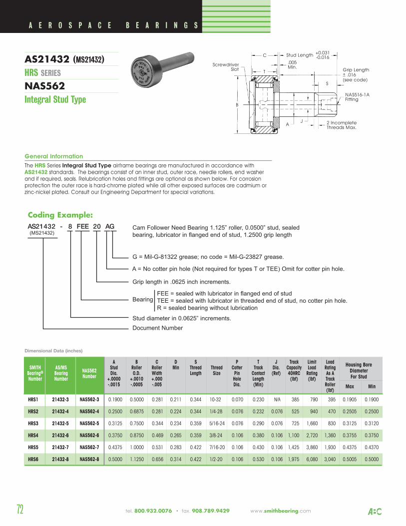
72 tel. 800.932.0076 • fax. 908.789.9429 www.smithbearing.com
A B C D S P T J Track Limit LoadSMITH AS/MS Stud Roller Roller Min Thread Thread Cotter Track Dia. Capacity Load Rating
Bearing® Bearing Dia. O.D. Width Length Size Pin Contact (Ref) 40HRC Rating As ANumber Number +.0000 +.0010 +.000 Hole Length (lbf) (lbf) Track
-.0015 -.0005 -.005 Dia. (Min) Roller (lbf)
Housing BoreDiameter For Stud
Max Min
HRS1 21432-3 0.1900 0.5000 0.281 0.211 0.344 10-32 0.070 0.230 N/A 385 790 395 0.1905 0.1900
HRS2 21432-4 0.2500 0.6875 0.281 0.224 0.344 1/4-28 0.076 0.232 0.076 525 940 470 0.2505 0.2500
HRS3 21432-5 0.3125 0.7500 0.344 0.234 0.359 5/16-24 0.076 0.290 0.076 725 1,660 830 0.3125 0.3120
HRS4 21432-6 0.3750 0.8750 0.469 0.265 0.359 3/8-24 0.106 0.380 0.106 1,100 2,720 1,360 0.3755 0.3750
HRS5 21432-7 0.4375 1.0000 0.531 0.283 0.422 7/16-20 0.106 0.430 0.106 1,425 3,860 1,930 0.4375 0.4370
HRS6 21432-8 0.5000 1.1250 0.656 0.314 0.422 1/2-20 0.106 0.530 0.106 1,975 6,080 3,040 0.5005 0.5000
B
T
A
S
C
ScrewdriverSlot
2 IncompleteThreads Max.
NAS516-1AFitting
Grip Length+ .016(see code)
.005Min.
Stud Length +0.031-0.016
J
General Information
The HRS Series Integral Stud Type airframe bearings are manufactured in accordance withAS21432 standards. The bearings consist of an inner stud, outer race, needle rollers, end washerand if required, seals. Relubrication holes and fittings are optional as shown below. For corrosionprotection the outer race is hard-chrome plated while all other exposed surfaces are cadmium orzinc-nickel plated. Consult our Engineering Department for special variations.
Dimensional Data (inches)
NAS562Number
NAS562-3
NAS562-4
NAS562-5
NAS562-6
NAS562-7
NAS562-8
A E R O S P A C E B E A R I N G S
AS21432 (MS21432)HRS SERIES
NAS562Integral Stud Type
Coding Example:AS21432 - 8 FEE 20 AG Cam Follower Need Bearing 1.125” roller, 0.0500” stud, sealed
bearing, lubricator in flanged end of stud, 1.2500 grip length
G = Mil-G-81322 grease; no code = Mil-G-23827 grease.
A = No cotter pin hole (Not required for types T or TEE) Omit for cotter pin hole.
Grip length in .0625 inch increments.
FEE = sealed with lubricator in flanged end of studTEE = sealed with lubricator in threaded end of stud, no cotter pin hole.R = sealed bearing without lubrication
Stud diameter in 0.0625” increments.Document Number
Bearing
(MS21432)
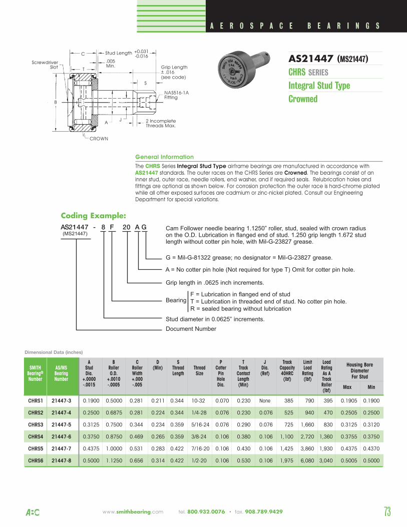
Coding Example:
73www.smithbearing.com tel. 800.932.0076 • fax. 908.789.9429
A B C D S P T J Track Limit LoadSMITH AS/MS Stud Roller Roller (Min) Thread Thread Cotter Track Dia. Capacity Load Rating
Bearing® Bearing Dia. O.D. Width Length Size Pin Contact (Ref) 40HRC Rating As ANumber Number +.0000 +.0010 +.000 Hole Length (lbf) (lbf) Track
-.0015 -.0005 -.005 Dia. (Min) Roller(lbf)
Housing BoreDiameter For Stud
CHRS1 21447-3 0.1900 0.5000 0.281 0.211 0.344 10-32 0.070 0.230 None 385 790 395 0.1905 0.1900
CHRS2 21447-4 0.2500 0.6875 0.281 0.224 0.344 1/4-28 0.076 0.230 0.076 525 940 470 0.2505 0.2500
CHRS3 21447-5 0.3125 0.7500 0.344 0.234 0.359 5/16-24 0.076 0.290 0.076 725 1,660 830 0.3125 0.3120
CHRS4 21447-6 0.3750 0.8750 0.469 0.265 0.359 3/8-24 0.106 0.380 0.106 1,100 2,720 1,360 0.3755 0.3750
CHRS5 21447-7 0.4375 1.0000 0.531 0.283 0.422 7/16-20 0.106 0.430 0.106 1,425 3,860 1,930 0.4375 0.4370
CHRS6 21447-8 0.5000 1.1250 0.656 0.314 0.422 1/2-20 0.106 0.530 0.106 1,975 6,080 3,040 0.5005 0.5000
General Information
The CHRS Series Integral Stud Type airframe bearings are manufactured in accordance withAS21447 standards. The outer races on the CHRS Series are Crowned. The bearings consist of aninner stud, outer race, needle rollers, end washer, and if required seals. Relubrication holes andfittings are optional as shown below. For corrosion protection the outer race is hard-chrome platedwhile all other exposed surfaces are cadmium or zinc-nickel plated. Consult our EngineeringDepartment for special variations.
B
T
A
S
C
ScrewdriverSlot
2 IncompleteThreads Max.
NAS516-1AFitting
Grip Length+ .016(see code)
.005Min.
Stud Length +0.031-0.016
J
CROWN
A E R O S P A C E B E A R I N G S
Dimensional Data (inches)
AS21447 (MS21447)CHRS SERIES
Integral Stud TypeCrowned
Max Min
AS21447 - 8 F 20 A G Cam Follower needle bearing 1.1250” roller, stud, sealed with crown radius on the O.D. Lubrication in flanged end of stud. 1.250 grip length 1.672 studlength without cotter pin hole, with Mil-G-23827 grease.
G = Mil-G-81322 grease; no designator = Mil-G-23827 grease.
A = No cotter pin hole (Not required for type T) Omit for cotter pin hole.
Grip length in .0625 inch increments.
F = Lubrication in flanged end of studT = Lubrication in threaded end of stud. No cotter pin hole.R = sealed bearing without lubrication
Stud diameter in 0.0625” increments.Document Number
Bearing
(MS21447)
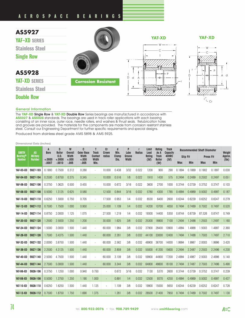
74 tel. 800.932.0076 • fax. 908.789.9429 www.smithbearing.com
A D W C T Cr d P r Limit Rating TrackSMITH AS Bore Roller Overall Outer Race Track Crown Min. Lube Radius Load As A Capacity Weight
Bearing® Military O.D. Width Width Contact radius Clamp Groove Rating Track 40HRC Approx.Number Number +.0000 +.0000 +.000 +.000 Width Dia. Width (lbf) Roller (lbf) (lbs)
-.0007 -.0010 -.005 -.005 Min. (lbf)
Recommended Shaft Diameter
Slip Fit Press Fit
Max Min Max Min
YAF-03-XD 5927-103 0.1900 0.7500 0.312 0.280 - 10.000 0.438 3/32 0.022 1200 900 290 0.1894 0.1889 0.1902 0.1897 0.030
YAF-04-XD 5927-104 0.2500 0.8750 0.375 0.345 - 10.000 0.516 1/8 0.022 1910 1430 575 0.2494 0.2489 0.2502 0.2497 0.051
YAF-06-XD 5927-106 0.3750 1.0625 0.500 0.455 - 10.000 0.672 3/16 0.022 3600 2700 1000 0.3744 0.3739 0.3752 0.3747 0.103
YAF-08-XD 5927-108 0.5000 1.3125 0.625 0.580 - 12.500 0.844 3/16 0.032 5780 4300 1785 0.4994 0.4989 0.5002 0.4997 0.187
YAF-10-XD 5927-110 0.6250 1.5000 0.750 0.705 - 17.500 0.953 1/4 0.032 8530 6400 2600 0.6244 0.6239 0.6252 0.6247 0.279
YAF-12-XD 5927-112 0.7500 1.7500 1.000 0.950 - 25.000 1.109 1/4 0.032 14200 10700 4050 0.7494 0.7489 0.7502 0.7497 0.520
YAF-14-XD 5927-114 0.8750 2.0000 1.125 1.075 - 27.500 1.219 1/4 0.032 19300 14400 5350 0.8744 0.8739 87,526 0.8747 0.749
YAF-20-XD 5927-120 1.2500 2.5000 1.250 1.200 - 30.000 1.625 3/8 0.032 25300 18900 7100 1.2494 1.2488 1.2503 1.2497 1.160
YAF-24-XD 5927-124 1.5000 3.0000 1.500 1.440 - 60.000 1.984 3/8 0.032 37900 28400 10900 1.4994 1.4988 1.5003 1.4997 2.360
YAF-28-XD 5927-128 1.7500 3.4375 1.500 1.440 - 60.000 2.281 3/8 0.032 44100 33000 12400 1.7494 1.7488 1.7503 1.7497 2.710
YAF-32-XD 5927-132 2.0000 3.8750 1.500 1.440 - 60.000 2.562 3/8 0.032 48900 36700 14000 1.9994 1.9987 2.0003 1.9996 3.420
YAF-36-XD 5927-136 2.2500 4.3125 1.500 1.440 - 60.000 2.859 3/8 0.032 55000 41200 15600 2.2494 2.2487 2.2503 2.2496 4.230
YAF-40-XD 5927-140 2.5000 4.7500 1.500 1.440 - 60.000 3.109 3/8 0.032 59900 44900 17200 2.4994 2.4987 2.5003 2.4996 5.140
YAF-44-XD 5927-144 2.7500 5.0000 1.500 1.440 - 60.000 3.344 3/8 0.032 64800 48600 18100 2.7494 2.7487 2.7503 2.7496 5.490
YAT-06-XD 5928-106 0.3750 1.1250 1.000 0.940 0.750 - 0.672 3/16 0.032 7130 5370 2600 0.3744 0.3739 0.3752 0.3747 0.239
YAT-08-XD 5928-108 0.5000 1.3750 1.250 1.190 1.000 - 0.891 1/4 0.032 12500 9370 4250 0.4994 0.4989 0.5002 0.4997 0.437
YAT-10-XD 5928-110 0.6250 1.6250 1.500 1.440 1.125 - 1.109 3/8 0.032 19900 15000 5650 0.6244 0.6239 0.6252 0.6247 0.728
YAT-12-XD 5928-112 0.7500 1.8750 1.750 1.690 1.375 - 1.281 3/8 0.032 28500 21400 7950 0.7494 0.7489 0.7502 0.7497 1.130
C
D
W
Cr
r
dA
P
C
D
W
P
r
d A
P
T
r
YAF-XDYAT-XD
A E R O S P A C E B E A R I N G S
AS5927 YAF-XD SERIES
Stainless SteelSingle Row
AS5928YAT-XD SERIES
Stainless SteelDouble Row
General Information
The YAF-XD Single Row & YAT-XD Double Row Series bearings are manufactured in accordance withAS5927 & AS5928 standards. The bearings are used in track roller applications with each bearingconsisting of an inner race, outer race, needle rollers, end washers & thrust seals. Relubrication holesand grooves are provided. The materials for the components are made from corrosion resistant stainlesssteel. Consult our Engineering Department for further specific requirements and special designs.
Produced from stainless steel grade AMS 5898 & AMS 5925.
Dimensional Data (inches)
Corrosion Resistant
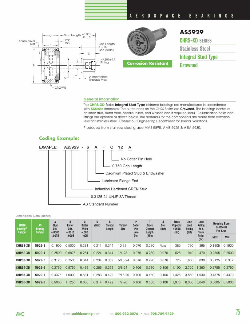
75www.smithbearing.com tel. 800.932.0076 • fax. 908.789.9429
A B C D S P T J Track Limit LoadSMITH AS Stud Roller Roller (Min) Thread Thread Cotter Track Dia. Capacity Load Rating
Bearing® Bearing Dia. O.D. Width Length Size Pin Contact (Ref) 40HRC Rating As ANumber Number +.0000 +.0010 +.000 Hole Length (lbf) (lbf) Track
-.0015 -.0005 -.005 Dia. (Min) Roller(lbf)
Housing BoreDiameter For Stud
CHRS1-XD 5929-3 0.1900 0.5000 0.281 0.211 0.344 10-32 0.070 0.230 None 385 790 395 0.1905 0.1900
CHRS2-XD 5929-4 0.2500 0.6875 0.281 0.224 0.344 1/4-28 0.076 0.230 0.076 525 940 470 0.2505 0.2500
CHRS3-XD 5929-5 0.3125 0.7500 0.344 0.234 0.359 5/16-24 0.076 0.290 0.076 725 1,660 830 0.3125 0.312
CHRS4-XD 5929-6 0.3750 0.8750 0.469 0.265 0.359 3/8-24 0.106 0.380 0.106 1,100 2,720 1,360 0.3755 0.3750
CHRS5-XD 5929-7 0.4375 1.0000 0.531 0.283 0.422 7/16-20 0.106 0.430 0.106 1,425 3,860 1,930 0.4375 0.4370
CHRS6-XD 5929-8 0.5000 1.1250 0.656 0.314 0.422 1/2-20 0.106 0.530 0.106 1,975 6,080 3,040 0.5005 0.5000
Coding Example:
General Information
The CHRS-XD Series Integral Stud Type airframe bearings are manufactured in accordance with AS5929 standards. The outer races on the CHRS Series are Crowned. The bearings consist of an inner stud, outer race, needle rollers, end washer, and if required seals. Relubrication holes andfittings are optional as shown below. The materials for the components are made from corrosionresistant stainless steel. Consult our Engineering Department for special variations.
Produced from stainless steel grade AMS 5898, AMS 5925 & ASM 5930.
B
T
A
S
C
ScrewdriverSlot
2 IncompleteThreads Max.
NAS516-1AFitting
Grip Length+ .016(see code)
.005Min.
Stud Length +0.031-0.016
J
CROWN
A E R O S P A C E B E A R I N G S
Dimensional Data (inches)
AS5929CHRS-XD SERIES
Stainless SteelIntegral Stud TypeCrowned
Max Min
EXAMPLE: AS5929 - 6 A F C 12 A
No Cotter Pin Hole
0.750 Grip Length
Cadmium Plated Stud & Endwasher
Lubricator Flange End
Induction Hardened CREN Stud
0.3125-24 UNJF-3A Thread
AS Standard Number
Corrosion Resistant
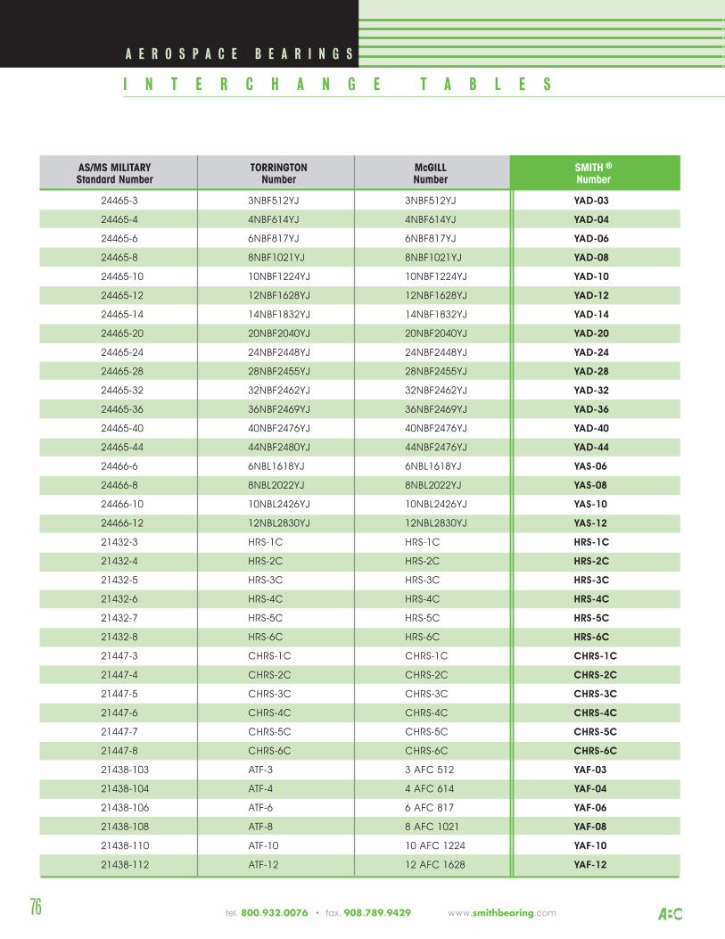
AS/MS MILITARY TORRINGTON McGILL SMITH ®
Standard Number Number Number Number
24465-3 3NBF512YJ 3NBF512YJ YAD-03
24465-4 4NBF614YJ 4NBF614YJ YAD-04
24465-6 6NBF817YJ 6NBF817YJ YAD-06
24465-8 8NBF1021YJ 8NBF1021YJ YAD-08
24465-10 10NBF1224YJ 10NBF1224YJ YAD-10
24465-12 12NBF1628YJ 12NBF1628YJ YAD-12
24465-14 14NBF1832YJ 14NBF1832YJ YAD-14
24465-20 20NBF2040YJ 20NBF2040YJ YAD-20
24465-24 24NBF2448YJ 24NBF2448YJ YAD-24
24465-28 28NBF2455YJ 28NBF2455YJ YAD-28
24465-32 32NBF2462YJ 32NBF2462YJ YAD-32
24465-36 36NBF2469YJ 36NBF2469YJ YAD-36
24465-40 40NBF2476YJ 40NBF2476YJ YAD-40
24465-44 44NBF2480YJ 44NBF2476YJ YAD-44
24466-6 6NBL1618YJ 6NBL1618YJ YAS-06
24466-8 8NBL2022YJ 8NBL2022YJ YAS-08
24466-10 10NBL2426YJ 10NBL2426YJ YAS-10
24466-12 12NBL2830YJ 12NBL2830YJ YAS-12
21432-3 HRS-1C HRS-1C HRS-1C
21432-4 HRS-2C HRS-2C HRS-2C
21432-5 HRS-3C HRS-3C HRS-3C
21432-6 HRS-4C HRS-4C HRS-4C
21432-7 HRS-5C HRS-5C HRS-5C
21432-8 HRS-6C HRS-6C HRS-6C
21447-3 CHRS-1C CHRS-1C CHRS-1C
21447-4 CHRS-2C CHRS-2C CHRS-2C
21447-5 CHRS-3C CHRS-3C CHRS-3C
21447-6 CHRS-4C CHRS-4C CHRS-4C
21447-7 CHRS-5C CHRS-5C CHRS-5C
21447-8 CHRS-6C CHRS-6C CHRS-6C
21438-103 ATF-3 3 AFC 512 YAF-03
21438-104 ATF-4 4 AFC 614 YAF-04
21438-106 ATF-6 6 AFC 817 YAF-06
21438-108 ATF-8 8 AFC 1021 YAF-08
21438-110 ATF-10 10 AFC 1224 YAF-10
21438-112 ATF-12 12 AFC 1628 YAF-12
A E R O S P A C E B E A R I N G S
I N T E R C H A N G E T A B L E S
tel. 800.932.0076 • fax. 908.789.9429 www.smithbearing.com 76
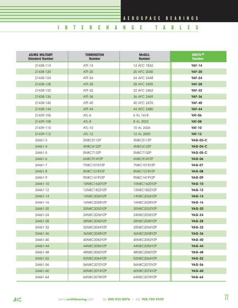
AS/MS MILITARY TORRINGTON McGILL SMITH ®
Standard Number Number Number Number
21438-114 ATF-14 14 AFC 1832 YAF-14
21438-120 ATF-20 20 AFC 2040 YAF-20
21438-124 ATF-24 24 AFC 2448 YAF-24
21438-128 ATF-28 28 AFC 2455 YAF-28
21438-132 ATF-32 32 AFC 2462 YAF-32
21438-136 ATF-36 36 AFC 2469 YAF-36
21438-140 ATF-40 40 AFC 2476 YAF-40
21438-144 ATF-44 44 AFC 2480 YAF-44
21439-106 ATL-6 6 AL 1618 YAT-06
21439-108 ATL-8 8 AL 2022 YAT-08
21439-110 ATL-10 10 AL 2426 YAT-10
21439-112 ATL-12 12 AL 2830 YAT-12
24461-3 3NBC511ZP 3NBC511ZP YAG-03-C
24461-4 4NBC612ZP 4NBC612ZP YAG-04-C
24461-5 5NBC713ZP 5NBC713ZP YAG-05-C
24461-6 6NBC914YZP 6NBC914YZP YAG-06
24461-7 7NBC1015YZP 7NBC1015YZP YAG-07
24461-8 8NBC1218YZP 8NBC1218YZP YAG-08
24461-9 9NBC1419YZP 9NBC1419YZP YAG-09
24461-10 10NBC1620YZP 10NBC1620YZP YAG-10
24461-12 12NBC1822YZP 12NBC1822YZP YAG-12
24461-14 14NBC2026YZP 14NBC2026YZP YAG-14
24461-16 16NBC2028YZP 16NBC2028YZP YAG-16
24461-20 20NBC2032YZP 20NBC2032YZP YAG-20
24461-24 24NBC2036YZP 24NBC2036YZP YAG-24
24461-28 28NBC2040YZP 28NBC2040YZP YAG-28
24461-32 32NBC2044YZP 32NBC2044YZP YAG-32
24461-36 36NBC2048YZP 36NBC2048YZP YAG-36
24461-40 40NBC2052YZP 40NBC2052YZP YAG-40
24461-44 44NBC2056YZP 44NBC2056YZP YAG-44
24461-48 48NBC2060YZP 48NBC2060YZP YAG-48
24461-52 52NBC2064YZP 52NBC2064YZP YAG-52
24461-56 56NBC2070YZP 56NBC2070YZP YAG-56
24461-60 60NBC2074YZP 60NBC2074YZP YAG-60
24461-64 64NBC2078YZP 64NBC2078YZP YAG-64
A E R O S P A C E B E A R I N G S
I N T E R C H A N G E T A B L E S
77www.smithbearing.com tel. 800.932.0076 • fax. 908.789.9429

78 tel. 800.932.0076 • fax. 908.789.9429 www.smithbearing.com
ABC • ACCURATE BUSHING COMPANY
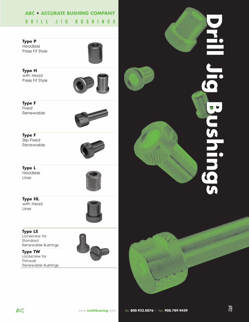
79
Type P HeadlessPress Fit Style
Type H with HeadPress Fit Style
Type F FixedRenewable
Type F Slip-FixedRenewable
Type L HeadlessLiner
Type HL with HeadLiner
Type LSLockscrew forStandardRenewable Bushings
Type TWLockscrew forThinwallRenewable Bushings
Drill Jig
Bushing
sDrill Jig
Bushing
s
www.smithbearing.com tel. 800.932.0076 • fax. 908.789.9429
ABC • ACCURATE BUSHING COMPANY
D R I L L J I G B U S H I N G S
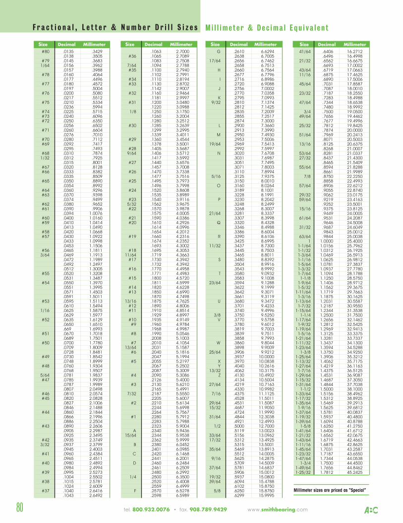
Size Decimal Millimeter#80 .0135 .3429
.0138 .3505#79 .0145 .36831/64 .0156 .3962
.0157 .3988#78 .0160 .4064
.0177 .4496#77 .0180 .4572
.0197 .5004#76 .0200 .5080
.0217 .5512#75 .0210 .5334
.0236 .5994#74 .0225 .5715#73 .0240 .6096#72 .0250 .6350
.0256 .6502#71 .0260 .6604
.0276 .7010#70 .0280 .7112#69 .0292 .7417
.0295 .7493#68 .0310 .78741/32 .0312 .7925
.0315 .8001#67 .0320 .8128#66 .0333 .8382
.0335 .8509#65 .0350 .8890
.0354 .8992#64 .0360 .9296#63 .0370 .9398
.0374 .9499#62 .0380 .9652#61 .0390 .9906
.0394 1.0076#60 .0400 1.0160#59 .0410 1.0414
.0413 1.0490#58 .0420 1.0668#57 .0430 1.0922
.0433 1.0998
.0453 1.1506#56 .0465 1.18113/64 .0469 1.1913
.0472 1.1989
.0492 1.2497
.0512 1.3005#55 .0520 1.3208
.0531 1.3487#54 .0550 1.3970
.0551 1.3995
.0571 1.4503
.0591 1.5011#53 .0595 1.5113
.0610 1.54941/16 .0625 1.5875
.0629 1.5977#52 .0635 1.6129
.0650 1.6510
.669 1.6993#51 .0670 1.7018
.0689 1.7501#50 .0700 1.7780
.0709 1.8009
.0728 1.8481#49 .0730 1.8542
.0748 1.8999#48 .0760 1.9304
.0768 1.95075/64 .0781 1.9837#47 .0785 1.9939
.0787 1.9989
.0807 2.0498#46 .0810 2.0574#45 .0820 2.0828
.0827 2.1006
.0846 2.1488#44 .0860 2.1844
.0866 2.1996
.0886 2.2504#43 .0890 2.2606
.0905 2.2987
.0925 2.3495#42 .0935 2.37493/32 .0937 2.3799
.0945 2.4003#41 .0960 2.4384
.0965 2.4511#40 .0980 2.4892
.0984 2.4994#39 .0995 2.5273
.1004 2.5502#38 .1015 2.5781
.1024 2.6009#37 .1040 2.6416
.1043 2.6492
Size Decimal Millimeter.1063 2.7000
#36 .1065 2.7089.1083 2.7508
7/64 .1094 2.7788#35 .1100 2.7940
.1102 2.7991#34 .1110 2.8194#33 .1130 2.8702
.1142 2.9007#32 .1160 2.9464
.1181 2.9997#31 .1200 3.0480
.1220 3.09881/8 .1250 3.1750
.1260 3.2004
.1280 3.2512#30 .1285 3.2639
.1299 3.2995
.1339 3.4011#29 .1360 3.4544
.1378 3.5001#28 .1405 3.56879/64 .1406 3.5712
.1417 3.5992#27 .1440 3.6576
.1457 3.7008#26 .1470 3.7338
.1477 3.7516#25 .1495 3.7973
.1496 3.7998#24 .1520 3.8608
.1535 3.8989#23 .1540 3.91165/32 .1562 3.9675#22 .1570 3.9878
.1575 4.0005#21 .1590 4.0386#20 .1610 4.2926
.1614 4.0996
.1654 4.2012#19 .1660 4.2316
.1674 4.2352
.1693 4.3002#18 .1695 4.3053
11/64 .1719 4.3663#17 .1730 4.3942
.1732 4.3942#16 .1770 4.4958
.1771 4.4983#15 .1800 4.5720
.1811 4.5999#14 .1820 4.6228#13 .1850 4.6990
.1870 4.749813/16 .1875 4.7625
#12 .1890 4.8006#11 .1910 4.8514
.1929 4.8997#10 .1935 4.9149#9 .1960 4.9784
.1968 4.9987#8 .1990 5.0546
.2008 5.1003#7 .2010 4.1054
13/64 .2031 5.1587#6 .2040 5.1816
.2047 5.1994#5 .2055 5.2197
.2067 5.2502
.2087 5.3009#4 .2090 5.3086
.2126 5.4000#3 .2130 5.6210
.2165 5.49917/32 .2187 5.5550
.2205 5.6007#2 .2210 5.6134
.2244 5.6998
.2264 5.7567#1 .2280 5.7912
.2283 5.7988
.2323 5.9004A .2340 5.9436
15/64 .2344 5.9538.2362 5.9999
B .2380 6.0452.2401 6.0985
C .2420 6.1468.2441 6.2001
D .2460 6.2484.2461 6.2509.2480 6.2992
1/4 .2500 6.3500.2520 6.4008.2559 6.4999
F .2570 6.5278.2598 6.5989
Size Decimal MillimeterG .2610 6.6294
.2638 6.700517/64 .2656 6.7462
.2658 6.7513H .2660 6.7564
.2677 6.7796I .2716 6.8986
.2720 6.9088J .2756 7.0002
.2770 7.0358K .2795 7.0993
9/32 .2810 7.1374.2812 7.1425.2835 7.2009.2855 7.2517.2874 7.3000
L .2900 7.3660.2913 7.3990
M .2950 7.4930.2953 7.5006
19/64 .2969 7.5413.2992 7.5997
N .3020 7.6708.3031 7.6987.3051 7.7495.3071 7.8003.3110 7.8994
5/16 .3125 7.9375.3150 8.0010
O .3160 8.0264.3189 8.1001.3228 8.1991
P .3230 8.2042.3248 8.2499.3268 8.3007
21/64 .3281 8.3337.3307 8.3998
Q .3320 8.4328.3346 8.4988.3386 8.6004
R .3390 8.6106.3425 8.6995
11/32 .3437 8.7300.3445 8.7503.3465 8.8011
S .3480 8.8392.3504 8.9916.3543 8.9992
T .3580 9.0932.3583 9.1008
23/64 .3594 9.1288.3622 9.1999.3642 9.3071.3661 9.3119
U .3680 9.3472.3701 9.4233.3740 9.4996
3/8 .3750 9.5250V .3770 9.5758
.3780 9.6012
.3819 9.7003
.3839 9.7511
.3858 9.7993W .3860 9.8044
.3898 9.900925/64 .3906 9.9212
.3937 10.0000X .3970 10.0838Y .4040 10.2616
13/32 .4062 10.3175Z .4130 10.4902
.4134 10.500427/64 .4219 10.7163
.4330 10.99827/16 .4375 11.1125
.4528 11.501129/64 .4531 11.508715/32 .4687 11.9050
.4724 11.999031/64 .4844 12.3038
.4921 12.49931/2 .5000 12.7000
.5119 13.002333/64 .5156 13.096217/32 .5312 13.4925
.5315 13.500135/64 .5469 13.8913
.5512 14.00059/16 .5625 14.2875
.5709 14.500937/64 .5781 14.6837
.5906 15.001219/32 .5937 15.080039/64 .6094 15.4788
.6102 15.87505/8 .6250 15.8750
.6299 15.9995
Size Decimal Millimeter41/64 .6406 16.2712
.6496 16.499821/32 .6562 16.6675
.6693 17.000243/64 .6719 17.066311/16 .6875 17.4625
.6890 17.500645/64 .7031 17.8587
.7087 18.001023/32 .7187 18.2550
.7283 18.498847/64 .7344 18.6538
.7480 18.99923/4 .7500 19.0500
49/64 .7656 19.4462.7677 19.4996
25/32 .7812 19.8425.7874 20.0000
51/64 .7969 20.2413.8071 20.5003
13/16 .8125 20.6375.8268 21.0007
53/64 .8281 21.033727/32 .8437 21.4300
.8465 21.540955/64 .8594 21.8288
.8661 21.99897/8 .8750 22.2250
.8858 22.499357/64 .8906 22.6212
.9055 22.874029/32 .9062 23.017559/64 .9219 23.4163
.9252 23.500115/16 .9375 23.8125
.9449 24.000561/64 .9531 24.2087
.9646 24.500831/32 .9687 24.6049
.9843 25.001263/64 .9844 25.0038
1 1.0000 25.40001-1/64 1.0156 25.79621-1/32 1.0312 26.19251-3/64 1.0469 26.59131-1/16 1.0625 26.98121-5/64 1.0781 27.38371-3/32 1.0937 27.77801-7/64 1.1094 28.17881-1/8 1.1250 28.5750
1-9/64 1.1406 28.97121-5/32 1.1562 29.3675
1-11/64 1.1719 29.76631-3/16 1.1875 30.1625
1-13/64 1.2031 30.55871-7/32 1.2187 30.9550
1-15/64 1.2344 31.35381-1/4 1.2500 31.7500
1-17/64 1.2656 32.14621-9/32 1.2812 32.5425
1-19/64 1.2969 32.94131-5/16 1.3125 33.3375
1-21/64 1.3281 33.73371-11/32 1.3437 34.13001-23/64 1.3594 34.5288
1-3/8 1.3750 34.92501-25/64 1.3906 35.32121-13/32 1.4062 35.71751-27/64 1.4219 36.11631-7/16 1.4375 36.5125
1-29/64 1.4531 36.90871-15/32 1.4687 37.30501-31/64 1.4844 37.7038
1-1/2 1.5000 38.10001-33/64 1.5156 38.49621-17/32 1.5312 38.89251-35/64 1.5469 39.29131-9/16 1.5625 39.6812
1-37/64 1.5781 40.08371-19/32 1.5937 40.48001-39/64 1.6094 40.8788
1-5/8 1.6250 41.27501-41/64 1.6406 41.67121-21/32 1.6562 42.06751-43/64 1.6719 42.46631-11/16 1.6875 42.86251-45/64 1.7031 43.25871-23/32 1.7187 43.65501-47/64 1.7344 44.0538
1-3/4 1.7500 44.45001-49/64 1.7656 44.84621-25/32 1.7812 45.2425
Millimeter sizes are priced as “Special”
80
F r a c t i o n a l , L e t t e r & N u m b e r D r i l l S i z e s M i l l im e te r & D e c ima l E q u i v a l e n t
tel. 800.932.0076 • fax. 908.789.9429 www.smithbearing.com
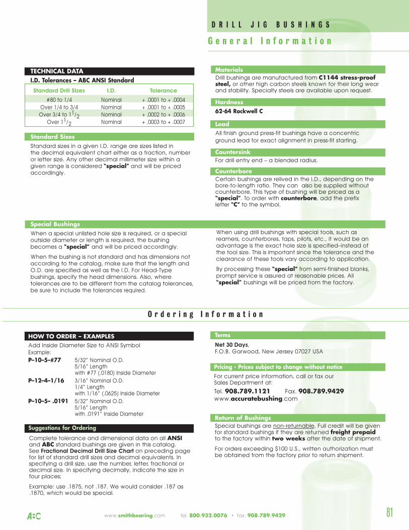
81
TECHNICAL DATAI.D. Tolerances – ABC ANSI Standard
Standard Drill SIzes I.D. Tolerance
#80 to 1/4 Nominal + .0001 to + .0004Over 1/4 to 3/4 Nominal + .0001 to + .0005Over 3/4 to 11/2 Nominal + .0002 to + .0006
Over 11/2 Nominal + .0003 to + .0007
Standard SizesStandard sizes in a given I.D. range are sizes listed in the decimal equivalent chart either as a fraction, numberor letter size. Any other decimal millimeter size within agiven range is considered “special” and will be pricedaccordingly.
Special BushingsWhen a special unlisted hole size is required, or a specialoutside diameter or length is required, the bushingbecomes a “special” and will be priced accordingly.
When the bushing is not standard and has dimensions notaccording to the catalog, make sure that the length andO.D. are specified as well as the I.D. For Head-Typebushings, specify the head dimensions. Also, wheretolerances are to be different from the catalog tolerances,be sure to include the tolerances required.
Suggestions for Ordering
Complete tolerance and dimensional data on all ANSIand ABC standard bushings are given in this catalog. See Fractional Decimal Drill Size Chart on preceding page for list of standard drill sizes and decimal equivalents. Inspecifying a drill size, use the number, letter, fractional ordecimal size. In specifying decimally, indicate the size infour places;
Example: use .1875, not .187. We would consider .187 as.1870, which would be special.
Terms
Net 30 Days,F.O.B. Garwood, New Jersey 07027 USA
Pricing - Prices subject to change without noticeFor current price information, call or fax our Sales Department at:
Tel. 908.789.1121 Fax. 908.789.9429www.accuratebushing.com
Return of BushingsSpecial bushings are non-returnable. Full credit will be givenfor standard bushings if they are returned freight prepaidto the factory within two weeks after the date of shipment.
For orders exceeding $100 U.S., written authorization mustbe obtained from the factory prior to return shipment.
HOW TO ORDER – EXAMPLESAdd Inside Diameter Size to ANSI SymbolExample:
P–10–5–#77 5/32” Nominal O.D.5/16” Lengthwith #77 (.0180) Inside Diameter
P–12–4–1/16 3/16” Nominal O.D.1/4” Lengthwith 1/16” (.0625) Inside Diameter
P–10–5– .0191 5/32” Nominal O.D.5/16” Length with .0191” Inside Diameter
G e n e r a l I n f o r m a t i o n
MaterialsDrill bushings are manufactured from C1144 stress-proofsteel, or other high carbon steels known for their long wearand stability. Specialty steels are available upon request.
Hardness62-64 Rockwell C
LeadAll finish ground press-fit bushings have a concentric ground lead for exact alignment in press-fit starting.
CountersinkFor drill entry end – a blended radius.
CounterboreCertain bushings are relived in the I.D., depending on the bore-to-length ratio. They can also be supplied without counterbore. This type of bushing will be priced as a “special”. To order with counterbore, add the prefix letter “C” to the symbol.
When using drill bushings with special tools, such as reamers, counterbores, taps, pilots, etc., it would be anadvantage is the exact hole size is specified–instead of the tool size. This is important since the tolerance and theclearance of these tools vary according to application.
By processing these “special” from semi-finished blanks,prompt service is assured at reasonable prices. All“special” bushings will be priced from the factory.
O r d e r i n g I n f o r m a t i o n
D R I L L J I G B U S H I N G S
www.smithbearing.com tel. 800.932.0076 • fax. 908.789.9429
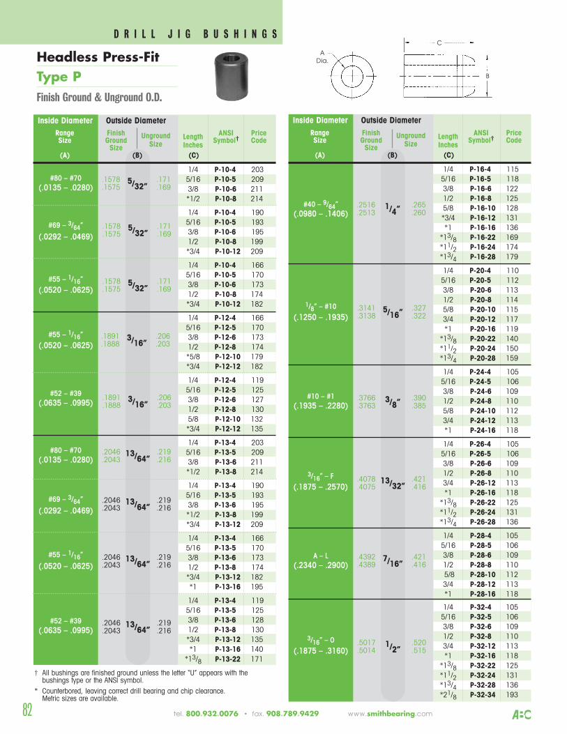
82
Inside Diameter Outside Diameter
1/4 P-16-4 1155/16 P-16-5 1183/8 P-16-6 1221/2 P-16-8 1255/8 P-16-10 128*3/4 P-16-12 131*1 P-16-16 136
*13/8 P-16-22 169*11/2 P-16-24 174*13/4 P-16-28 179
1/4 P-20-4 1105/16 P-20-5 1123/8 P-20-6 1131/2 P-20-8 1145/8 P-20-10 1153/4 P-20-12 117*1 P-20-16 119
*13/8 P-20-22 140*11/2 P-20-24 150*13/4 P-20-28 159
1/4 P-24-4 1055/16 P-24-5 1063/8 P-24-6 1091/2 P-24-8 1105/8 P-24-10 1123/4 P-24-12 113*1 P-24-16 118
1/4 P-26-4 1055/16 P-26-5 1063/8 P-26-6 1091/2 P-26-8 1103/4 P-26-12 113*1 P-26-16 118
*13/8 P-26-22 125*11/2 P-26-24 131*13/4 P-26-28 136
1/4 P-28-4 1055/16 P-28-5 1063/8 P-28-6 1091/2 P-28-8 1105/8 P-28-10 1123/4 P-28-12 113*1 P-28-16 118
1/4 P-32-4 1055/16 P-32-5 1063/8 P-32-6 1091/2 P-32-8 1103/4 P-32-12 113*1 P-32-16 118
*13/8 P-32-22 125*11/2 P-32-24 131*13/4 P-32-28 136*21/8 P-32-34 193
.2516 .2651/4”.2513 .260
Range Finish ANSI PriceSize Ground
Unground Length Symbol† CodeSize Size Inches
(A) (B) (C)
.5017 .5201/2”.5014 .515
.4392 .4217/16”.4389 .416
.4078 .42113/32”.4075 .416
.3766 .3903/8”.3763 .385
.3141 .3275/16”.3138 .322
#40 – 9/64”(.0980 – .1406)
1/8” – #10(.1250 – .1935)
#10 – #1(.1935 – .2280)
3/16” – F(.1875 – .2570)
A – L(.2340 – .2900)
3/16” – O(.1875 – .3160)
Inside Diameter Outside Diameter
1/4 P-10-4 2035/16 P-10-5 2093/8 P-10-6 211*1/2 P-10-8 214
1/4 P-10-4 1905/16 P-10-5 1933/8 P-10-6 1951/2 P-10-8 199*3/4 P-10-12 209
1/4 P-10-4 1665/16 P-10-5 1703/8 P-10-6 1731/2 P-10-8 174*3/4 P-10-12 182
1/4 P-12-4 1665/16 P-12-5 1703/8 P-12-6 1731/2 P-12-8 174*5/8 P-12-10 179*3/4 P-12-12 182
1/4 P-12-4 1195/16 P-12-5 1253/8 P-12-6 1271/2 P-12-8 1305/8 P-12-10 132*3/4 P-12-12 135
1/4 P-13-4 2035/16 P-13-5 2093/8 P-13-6 211*1/2 P-13-8 214
1/4 P-13-4 1905/16 P-13-5 1933/8 P-13-6 195*1/2 P-13-8 199*3/4 P-13-12 209
1/4 P-13-4 1665/16 P-13-5 1703/8 P-13-6 1731/2 P-13-8 174*3/4 P-13-12 182*1 P-13-16 195
1/4 P-13-4 1195/16 P-13-5 1253/8 P-13-6 1281/2 P-13-8 130*3/4 P-13-12 135*1 P-13-16 140
*13/8 P-13-22 171
.1578 .1715/32”.1575 .169
Range Finish ANSI PriceSize Ground
Unground Length Symbol† CodeSize Size Inches
(A) (B) (C)
.1578 .1715/32”.1575 .169
.1578 .1715/32”.1575 .169
.1891 .2063/16”.1888 .203
.2046 .21913/64”.2043 .216
.2046 .21913/64”.2043 .216
.2046 .21913/64”.2043 .216
.2046 .21913/64”.2043 .216
.1891 .2063/16”.1888 .203
#80 – #70(.0135 – .0280)
#69 – 3/64”
(.0292 – .0469)
#55 – 1/16”(.0520 – .0625)
#55 – 1/16”(.0520 – .0625)
#52 – #39(.0635 – .0995)
#80 – #70(.0135 – .0280)
#69 – 3/64”
(.0292 – .0469)
#55 – 1/16”
(.0520 – .0625)
#52 – #39(.0635 – .0995)
† All bushings are finished ground unless the letter “U” appears with the bushings type or the ANSI symbol.
* Counterbored, leaving correct drill bearing and chip clearance. Metric sizes are available.
C
B
A Dia.Headless Press-Fit
Type PFinish Ground & Unground O.D.
tel. 800.932.0076 • fax. 908.789.9429 www.smithbearing.com
D R I L L J I G B U S H I N G S
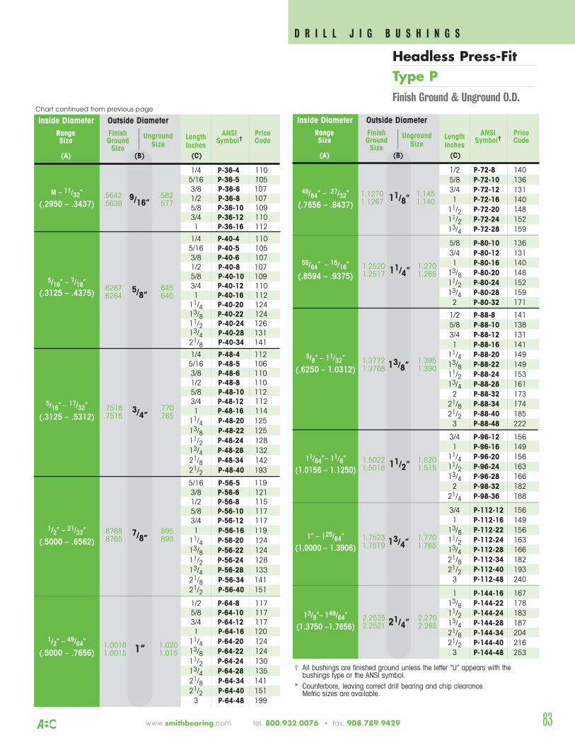
Inside Diameter Outside Diameter
1/2 P-72-8 1405/8 P-72-10 1363/4 P-72-12 1311 P-72-16 140
11/2 P-72-20 14811/2 P-72-24 15213/4 P-72-28 159
5/8 P-80-10 1363/4 P-80-12 1311 P-80-16 140
13/8 P-80-20 14811/2 P-80-24 15213/4 P-80-28 1592 P-80-32 171
1/2 P-88-8 1415/8 P-88-10 1383/4 P-88-12 1311 P-88-16 141
11/4 P-88-20 14913/8 P-88-22 14911/2 P-88-24 15313/4 P-88-28 1612 P-88-32 173
21/8 P-88-34 17421/2 P-88-40 1853 P-88-48 222
3/4 P-96-12 1561 P-96-16 149
11/4 P-96-20 15611/2 P-96-24 16313/4 P-96-28 1662 P-98-32 182
21/4 P-98-36 188
3/4 P-112-12 1561 P-112-16 149
13/8 P-112-22 15611/2 P-112-24 16313/4 P-112-28 16621/8 P-112-34 18221/2 P-112-40 1933 P-112-48 240
1 P-144-16 16713/8 P-144-22 17811/2 P-144-24 18313/4 P-144-28 18721/8 P-144-34 20421/2 P-144-40 2163 P-144-48 253
1.1270 1.14511/8”1.1267 1.140
Range Finish ANSI PriceSize Ground
Unground Length Symbol† CodeSize Size Inches
(A) (B) (C)
2.2525 2.27021/4”2.2521 2.265
1.7523 1.77013/4”1.7519 1.765
1.5022 1.52011/2”1.5018 1.515
1.3772 1.39513/8”1.3768 1.390
1.2520 1.27011/4”1.2517 1.265
49/64” – 27/32”
(.7656 – .8437)
55/64” – 15/16”
(.8594 – .9375)
5/8” – 11/32”
(.6250 – 1.0312)
11/64”– 11/8”
(1.0156 – 1.1250)
1” – 125/64”
(1.0000 – 1.3906)
13/8”– 149/64”
(1.3750 –1.7656)
Inside Diameter Outside Diameter
1/4 P-36-4 1105/16 P-36-5 1053/8 P-36-6 1071/2 P-36-8 107
1/4 5/8 P-36-10 1093/4 P-36-12 1101 P-36-16 112
1/4 P-40-4 1105/16 P-40-5 1053/8 P-40-6 1071/2 P-40-8 1075/8 P-40-10 1093/4 P-40-12 1101 P-40-16 112
11/4 P-40-20 12413/8 P-40-22 12411/2 P-40-24 12613/4 P-40-28 13121/8 P-40-34 141
1/4 P-48-4 1125/16 P-48-5 1063/8 P-48-6 1101/2 P-48-8 1105/8 P-48-10 1123/4 P-48-12 1121 P-48-16 114
11/4 P-48-20 12513/8 P-48-22 12511/2 P-48-24 12813/4 P-48-28 13221/8 P-48-34 14221/2 P-48-40 193
5/16 P-56-5 1193/8 P-56-6 1211/2 P-56-8 1155/8 P-56-10 1173/4 P-56-12 1171 P-56-16 119
11/4 P-56-20 12413/8 P-56-22 12411/2 P-56-24 12813/4 P-56-28 13321/8 P-56-34 14121/2 P-56-40 151
1/2 P-64-8 1175/8 P-64-10 1173/4 P-64-12 1171 P-64-16 120
11/4 P-64-20 12413/8 P-64-22 12411/2 P-64-24 13013/4 P-64-28 13521/8 P-64-34 14121/2 P-64-40 1513 P-64-48 199
.5642 .5829/16”.5639 .577
Range Finish ANSI PriceSize Ground
Unground Length Symbol† CodeSize Size Inches
(A) (B) (C)
.6267 .6455/8”.6264 .640
.7518 .7703/4”.7515 .765
1.0018 1.0201”1.0015 1.015
.8768 .8957/8”.8765 .890
M – 11/32”
(.2950 – .3437)
5/16” – 7/16”(.3125 – .4375)
5/16” – 17/32”
(.3125 – .5312)
1/2” – 21/32”
(.5000 – .6562)
1/2” – 49/64”
(.5000 – .7656)
† All bushings are finished ground unless the letter “U” appears with the bushings type or the ANSI symbol.
* Counterbore, leaving correct drill bearing and chip clearance. Metric sizes are available.
83
Chart continued from previous page
D R I L L J I G B U S H I N G S
Headless Press-FitType PFinish Ground & Unground O.D.
www.smithbearing.com tel. 800.932.0076 • fax. 908.789.9429
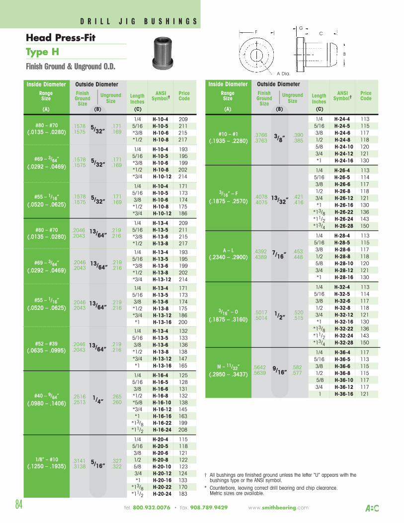
Inside Diameter Outside Diameter
1/4 H-24-4 1135/16 H-24-5 1153/8 H-24-6 1171/2 H-24-8 1185/8 H-24-10 1203/4 H-24-12 121*1 H-24-16 130
1/4 H-26-4 1135/16 H-26-5 1143/8 H-26-6 1171/2 H-26-8 1183/4 H-26-12 121*1 H-26-16 130
*13/8 H-26-22 136*11/2 H-26-24 143*13/4 H-26-28 150
1/4 H-28-4 1135/16 H-28-5 1153/8 H-28-6 1171/2 H-28-8 1185/8 H-28-10 1203/4 H-28-12 121*1 H-28-16 130
1/4 H-32-4 1135/16 H-32-5 1143/8 H-32-6 1171/2 H-32-8 1183/4 H-32-12 121*1 H-32-16 130
*13/8 H-32-22 136*11/2 H-32-24 143*13/4 H-32-28 150
1/4 H-36-4 1175/16 H-36-5 1133/8 H-36-6 1151/2 H-36-8 1155/8 H-36-10 1173/4 H-36-12 1171 H-36-16 121
.3766 .3903/8”.3763 .385
Range Finish ANSI PriceSize Ground
Unground Length Symbol† CodeSize Size Inches
(A) (B) (C)
.5642 .5829/16”.5639 .577
.5017 .5201/2”.5014 .515
.4392 .4537/16”.4389 .448
.4078 .42113/32”.4075 .416
#10 – #1(.1935 – .2280)
3/16” – F(.1875 – .2570)
A – L(.2340 – .2900)
3/16” – O(.1875 – .3160)
M – 11/32”(.2950 – .3437)
Inside Diameter Outside Diameter
1/4 H-10-4 2095/16 H-10-5 211*3/8 H-10-6 215*1/2 H-10-8 217
1/4 H-10-4 1935/16 H-10-5 195*3/8 H-10-6 199*1/2 H-10-8 202*3/4 H-10-12 214
1/4 H-10-4 1715/16 H-10-5 1733/8 H-10-6 174*1/2 H-10-8 175*3/4 H-10-12 186
1/4 H-13-4 2095/16 H-13-5 211*3/8 H-13-6 215*1/2 H-13-8 217
1/4 H-13-4 1935/16 H-13-5 195*3/8 H-13-6 199*1/2 H-13-8 202*3/4 H-13-12 214
1/4 H-13-4 1715/16 H-13-5 1733/8 H-13-6 174*1/2 H-13-8 175*3/4 H-13-12 186*1 H-13-16 200
1/4 H-13-4 1325/16 H-13-5 1333/8 H-13-6 136*1/2 H-13-8 138*3/4 H-13-12 147*1 H-13-16 165
1/4 H-16-4 1255/16 H-16-5 1283/8 H-16-6 131*1/2 H-16-8 132*5/8 H-16-10 138*3/4 H-16-12 145*1 H-16-16 163
*13/8 H-16-22 199*11/2 H-16-24 208
1/4 H-20-4 1155/16 H-20-5 1183/8 H-20-6 1211/2 H-20-8 1225/8 H-20-10 1233/4 H-20-12 124*1 H-20-16 133
*13/8 H-20-22 170*11/2 H-20-24 183
.1578 .1715/32”.1575 .169
Range Finish ANSI PriceSize Ground
Unground Length Symbol† CodeSize Size Inches
(A) (B) (C)
.1578 .1715/32”.1575 .169
.1578 .1715/32”.1575 .169
.2046 .21913/64”.2043 .216
.3141 .3275/16”.3138 .322
.2516 .2651/4”.2513 .260
.2046 .21913/64”.2043 .216
.2046 .21913/64”.2043 .216
#80 – #70(.0135 – .0280)
#69 – 3/64”(.0292 – .0469)
#55 – 1/16”(.0520 – .0625)
#80 – #70(.0135 – .0280)
#69 – 3/64”(.0292 – .0469)
#55 – 1/16”(.0520 – .0625)
#40 – 9/64”(.0980 – .1406)
1/8” – #10(.1250 – .1935)
† All bushings are finished ground unless the letter “U” appears with the bushings type or the ANSI symbol.
* Counterbore, leaving correct drill bearing and chip clearance. Metric sizes are available.
.2046 .21913/64”.2043 .216#52 – #39
(.0635 – .0995)
84
CG
A Dia.
F
B
Head Press-FitType HFinish Ground & Unground O.D.
Head Press-FitType HFinish Ground & Unground O.D.
tel. 800.932.0076 • fax. 908.789.9429 www.smithbearing.com
D R I L L J I G B U S H I N G S
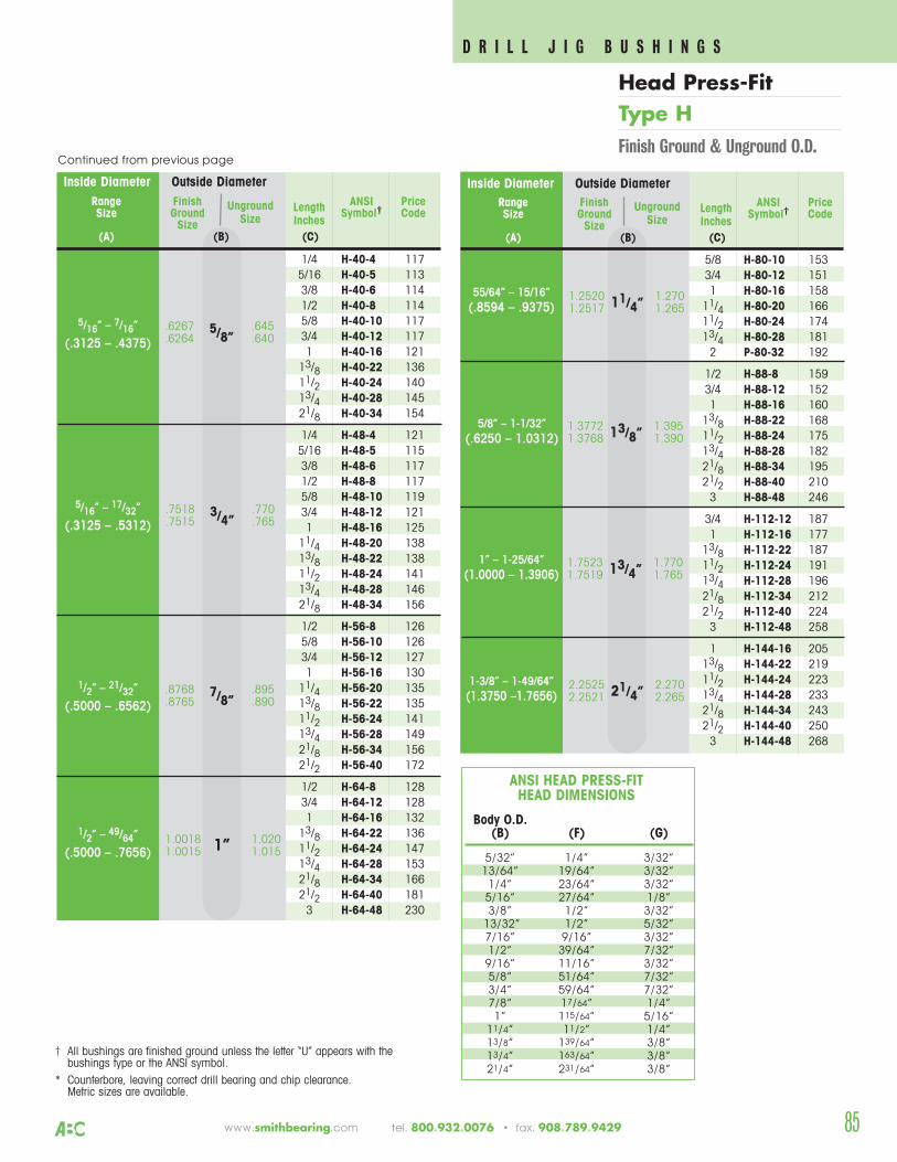
www.smithbearing.com tel. 800.932.0076 • fax. 908.789.9429
Inside Diameter Outside Diameter
5/8 H-80-10 1533/4 H-80-12 1511 H-80-16 158
11/4 H-80-20 16611/2 H-80-24 17413/4 H-80-28 1812 P-80-32 192
1/2 H-88-8 1593/4 H-88-12 1521 H-88-16 160
13/8 H-88-22 16811/2 H-88-24 17513/4 H-88-28 18221/8 H-88-34 19521/2 H-88-40 2103 H-88-48 246
3/4 H-112-12 1871 H-112-16 177
13/8 H-112-22 18711/2 H-112-24 19113/4 H-112-28 19621/8 H-112-34 21221/2 H-112-40 2243 H-112-48 258
1 H-144-16 20513/8 H-144-22 21911/2 H-144-24 22313/4 H-144-28 23321/8 H-144-34 24321/2 H-144-40 2503 H-144-48 268
Range Finish ANSI PriceSize Ground
Unground Length Symbol† CodeSize Size Inches
(A) (B) (C)
2.2525 2.27021/4”2.2521 2.265
1.7523 1.77013/4”1.7519 1.765
1.3772 1.39513/8”1.3768 1.390
1.2520 1.27011/4”1.2517 1.26555/64” – 15/16”
(.8594 – .9375)
5/8” – 1-1/32”(.6250 – 1.0312)
1” – 1-25/64”(1.0000 – 1.3906)
1-3/8” – 1-49/64”(1.3750 –1.7656)
Inside Diameter Outside Diameter
1/4 H-40-4 1175/16 H-40-5 1133/8 H-40-6 1141/2 H-40-8 1145/8 H-40-10 1173/4 H-40-12 1171 H-40-16 121
13/8 H-40-22 13611/2 H-40-24 14013/4 H-40-28 14521/8 H-40-34 154
1/4 H-48-4 1215/16 H-48-5 1153/8 H-48-6 1171/2 H-48-8 1175/8 H-48-10 1193/4 H-48-12 1211 H-48-16 125
11/4 H-48-20 13813/8 H-48-22 13811/2 H-48-24 14113/4 H-48-28 14621/8 H-48-34 156
1/2 H-56-8 1265/8 H-56-10 1263/4 H-56-12 1271 H-56-16 130
11/4 H-56-20 13513/8 H-56-22 13511/2 H-56-24 14113/4 H-56-28 14921/8 H-56-34 15621/2 H-56-40 172
1/2 H-64-8 1283/4 H-64-12 1281 H-64-16 132
13/8 H-64-22 13611/2 H-64-24 14713/4 H-64-28 15321/8 H-64-34 16621/2 H-64-40 1813 H-64-48 230
Range Finish ANSI PriceSize Ground
Unground Length Symbol† CodeSize Size Inches
(A) (B) (C)
.6267 .6455/8”.6264 .640
.7518 .7703/4”.7515 .765
1.0018 1.0201”1.0015 1.015
.8768 .8957/8”.8765 .890
5/16” – 7/16”
(.3125 – .4375)
5/16” – 17/32”
(.3125 – .5312)
1/2” – 21/32”
(.5000 – .6562)
1/2” – 49/64”
(.5000 – .7656)
† All bushings are finished ground unless the letter “U” appears with the bushings type or the ANSI symbol.
* Counterbore, leaving correct drill bearing and chip clearance. Metric sizes are available.
Body O.D.(B) (F) (G)
5/32” 1/4” 3/32”13/64” 19/64” 3/32”
1/4” 23/64” 3/32”5/16” 27/64” 1/8”3/8” 1/2” 3/32”
13/32” 1/2” 5/32”7/16” 9/16” 3/32”1/2” 39/64” 7/32”
9/16” 11/16” 3/32”5/8” 51/64” 7/32”3/4” 59/64” 7/32”7/8” 17/64” 1/4”1” 115/64” 5/16”
11/4” 11/2” 1/4”13/8” 139/64” 3/8”13/4” 163/64” 3/8”21/4” 231/64” 3/8”
ANSI HEAD PRESS-FIT HEAD DIMENSIONS
Continued from previous page
D R I L L J I G B U S H I N G S
Head Press-FitType HFinish Ground & Unground O.D.
85
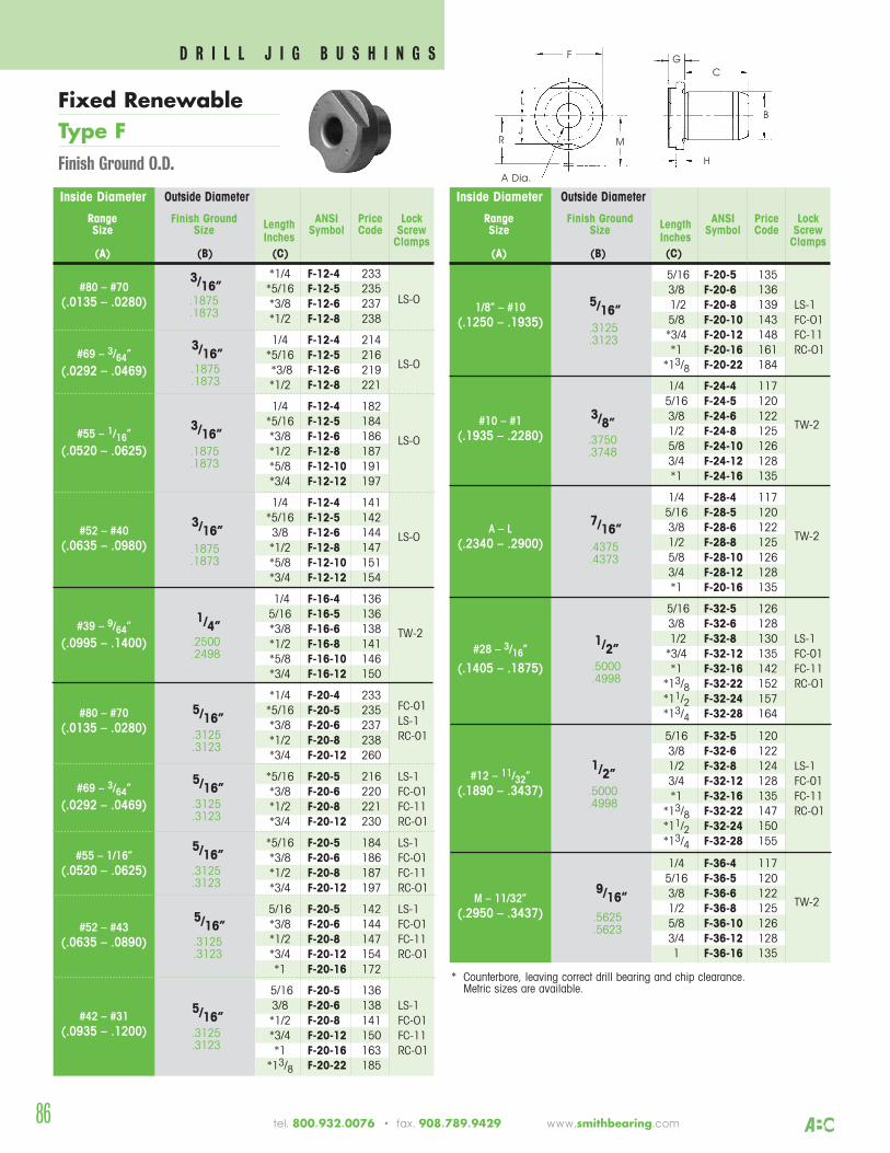
86
Inside Diameter Outside Diameter
*1/4 F-12-4 233*5/16 F-12-5 235*3/8 F-12-6 237 LS-O
*1/2 F-12-8 238
1/4 F-12-4 214*5/16 F-12-5 216*3/8 F-12-6 219 LS-O
*1/2 F-12-8 221
1/4 F-12-4 182*5/16 F-12-5 184*3/8 F-12-6 186 LS-O*1/2 F-12-8 187*5/8 F-12-10 191*3/4 F-12-12 197
1/4 F-12-4 141*5/16 F-12-5 1423/8 F-12-6 144 LS-O*1/2 F-12-8 147*5/8 F-12-10 151*3/4 F-12-12 154
1/4 F-16-4 1365/16 F-16-5 136*3/8 F-16-6 138 TW-2*1/2 F-16-8 141*5/8 F-16-10 146*3/4 F-16-12 150
*1/4 F-20-4 233*5/16 F-20-5 235 FC-01
*3/8 F-20-6 237 LS-1
*1/2 F-20-8 238 RC-01
*3/4 F-20-12 260
*5/16 F-20-5 216 LS-1*3/8 F-20-6 220 FC-O1*1/2 F-20-8 221 FC-11*3/4 F-20-12 230 RC-O1
*5/16 F-20-5 184 LS-1*3/8 F-20-6 186 FC-O1*1/2 F-20-8 187 FC-11*3/4 F-20-12 197 RC-O1
5/16 F-20-5 142 LS-1*3/8 F-20-6 144 FC-O1*1/2 F-20-8 147 FC-11*3/4 F-20-12 154 RC-O1*1 F-20-16 172
5/16 F-20-5 1363/8 F-20-6 138 LS-1*1/2 F-20-8 141 FC-O1*3/4 F-20-12 150 FC-11*1 F-20-16 163 RC-O1
*13/8 F-20-22 185
3/16”
Range Finish Ground ANSI Price LockSize Size Length Symbol Code Screw
Inches Clamps(A) (B) (C)
.1875
.1873
#80 – #70(.0135 – .0280)
#69 – 3/64”(.0292 – .0469)
#55 – 1/16”(.0520 – .0625)
#52 – #40(.0635 – .0980)
#39 – 9/64”(.0995 – .1400)
#55 – 1/16”(.0520 – .0625)
#42 – #31(.0935 – .1200)
* Counterbore, leaving correct drill bearing and chip clearance. Metric sizes are available.
3/16”.1875.1873
3/16”.1875.1873
3/16”.1875.1873
1/4”.2500.2498
#80 – #70(.0135 – .0280)
5/16”.3125.3123
#69 – 3/64”(.0292 – .0469)
5/16”.3125.3123
#52 – #43(.0635 – .0890)
Inside Diameter Outside Diameter
5/16 F-20-5 1353/8 F-20-6 1361/2 F-20-8 139 LS-15/8 F-20-10 143 FC-O1*3/4 F-20-12 148 FC-11*1 F-20-16 161 RC-O1
*13/8 F-20-22 184
1/4 F-24-4 1175/16 F-24-5 1203/8 F-24-6 122
TW-21/2 F-24-8 1255/8 F-24-10 1263/4 F-24-12 128*1 F-24-16 135
1/4 F-28-4 1175/16 F-28-5 1203/8 F-28-6 122
TW-21/2 F-28-8 1255/8 F-28-10 1263/4 F-28-12 128*1 F-20-16 135
5/16 F-32-5 1263/8 F-32-6 1281/2 F-32-8 130 LS-1*3/4 F-32-12 135 FC-01*1 F-32-16 142 FC-11
*13/8 F-32-22 152 RC-O1*11/2 F-32-24 157*13/4 F-32-28 164
5/16 F-32-5 1203/8 F-32-6 1221/2 F-32-8 124 LS-13/4 F-32-12 128 FC-01*1 F-32-16 135 FC-11
*13/8 F-32-22 147 RC-O1*11/2 F-32-24 150*13/4 F-32-28 155
1/4 F-36-4 1175/16 F-36-5 1203/8 F-36-6 122
TW-21/2 F-36-8 1255/8 F-36-10 1263/4 F-36-12 1281 F-36-16 135
5/16”
Range Finish Ground ANSI Price LockSize Size Length Symbol Code Screw
Inches Clamps(A) (B) (C)
.3125
.3123
1/8” – #10(.1250 – .1935)
#10 – #1(.1935 – .2280)
A – L(.2340 – .2900)
#28 – 3/16”
(.1405 – .1875)
3/8”.3750.3748
7/16”.4375.4373
#12 – 11/32”(.1890 – .3437)
M – 11/32”(.2950 – .3437)
1/2”.5000.4998
9/16”.5625.5623
CG
A Dia.
F
B
H
M
L
RJ
Fixed RenewableType FFinish Ground O.D.
5/16”.3125.3123
5/16”.3125.3123
5/16”.3125.3123
1/2”.5000.4998
tel. 800.932.0076 • fax. 908.789.9429 www.smithbearing.com
D R I L L J I G B U S H I N G S
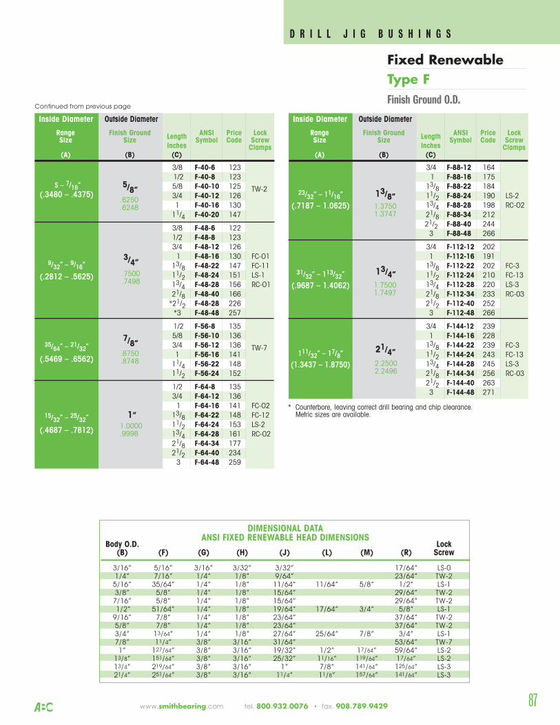
www.smithbearing.com tel. 800.932.0076 • fax. 908.789.9429 87
Body O.D. Lock(B) (F) (G) (H) (J) (L) (M) (R) Screw
3/16” 5/16” 3/16” 3/32” 3/32” 17/64” LS-01/4” 7/16” 1/4” 1/8” 9/64” 23/64” TW-2
5/16” 35/64” 1/4” 1/8” 11/64” 11/64” 5/8” 1/2” LS-13/8” 5/8” 1/4” 1/8” 15/64” 29/64” TW-2
7/16” 5/8” 1/4” 1/8” 15/64” 29/64” TW-21/2” 51/64” 1/4” 1/8” 19/64” 17/64” 3/4” 5/8” LS-1
9/16” 7/8” 1/4” 1/8” 23/64” 37/64” TW-25/8” 7/8” 1/4” 1/8” 23/64” 37/64” TW-23/4” 13/64” 1/4” 1/8” 27/64” 25/64” 7/8” 3/4” LS-17/8” 11/4” 3/8” 3/16” 31/64” 53/64” TW-71” 127/64” 3/8” 3/16” 19/32” 1/2” 17/64” 59/64” LS-2
13/8” 151/64” 3/8” 3/16” 25/32” 11/16” 119/64” 17/64” LS-213/4” 219/64” 3/8” 3/16” 1” 7/8” 141/64” 125/64” LS-321/4” 251/64” 3/8” 3/16” 11/4” 11/8” 157/64” 141/64” LS-3
* Counterbore, leaving correct drill bearing and chip clearance. Metric sizes are available.
Inside Diameter Outside Diameter
3/8 F-40-6 1231/2 F-40-8 1235/8 F-40-10 125 TW-23/4 F-40-12 1261 F-40-16 130
11/4 F-40-20 147
3/8 F-48-6 1221/2 F-48-8 1233/4 F-48-12 1261 F-48-16 130 FC-O1
13/8 F-48-22 147 FC-1111/2 F-48-24 151 LS-113/4 F-48-28 156 RC-O121/8 F-48-40 166*21/2 F-48-28 226*3 F-48-48 257
1/2 F-56-8 1355/8 F-56-10 1363/4 F-56-12 136 TW-71 F-56-16 141
11/4 F-56-22 14811/2 F-56-24 152
1/2 F-64-8 1353/4 F-64-12 1361 F-64-16 141 FC-O2
13/8 F-64-22 148 FC-1211/2 F-64-24 153 LS-213/4 F-64-28 161 RC-O221/8 F-64-34 17721/2 F-64-40 2343 F-64-48 259
\
5/8”
Range Finish Ground ANSI Price LockSize Size Length Symbol Code Screw
Inches Clamps(A) (B) (C)
.6250
.6248
S – 7/16”(.3480 – .4375)
9/32” – 9/16”
(.2812 – .5625)
35/64” – 21/32”
(.5469 – .6562)
15/32” – 25/32”
(.4687 – .7812)
3/4”.7500.7498
7/8”.8750.8748
1”1.0000.9998
3/4 F-88-12 1641 F-88-16 175
13/8 F-88-22 18411/2 F-88-24 190 LS-213/4 F-88-28 198 RC-O221/8 F-88-34 21221/2 F-88-40 2443 F-88-48 266
3/4 F-112-12 2021 F-112-16 191
13/8 F-112-22 202 FC-311/2 F-112-24 210 FC-1313/4 F-112-28 220 LS-321/8 F-112-34 233 RC-0321/2 F-112-40 2523 F-112-48 266
3/4 F-144-12 2391 F-144-16 228
13/8 F-144-22 239 FC-311/2 F-144-24 243 FC-1313/4 F-144-28 245 LS-321/8 F-144-34 256 RC-0321/2 F-144-40 2633 F-144-48 271
13/8”1.37501.3747
23/32” – 11/16”
(.7187 – 1.0625)
31/32” – 113/32”
(.9687 – 1.4062)
111/32” – 17/8”
(1.3437 – 1.8750)
13/4”1.75001.7497
21/4”2.25002.2496
DIMENSIONAL DATAANSI FIXED RENEWABLE HEAD DIMENSIONS
Continued from previous page
Range Finish Ground ANSI Price LockSize Size Length Symbol Code Screw
Inches Clamps(A) (B) (C)
Inside Diameter Outside Diameter
D R I L L J I G B U S H I N G S
Fixed RenewableType FFinish Ground O.D.
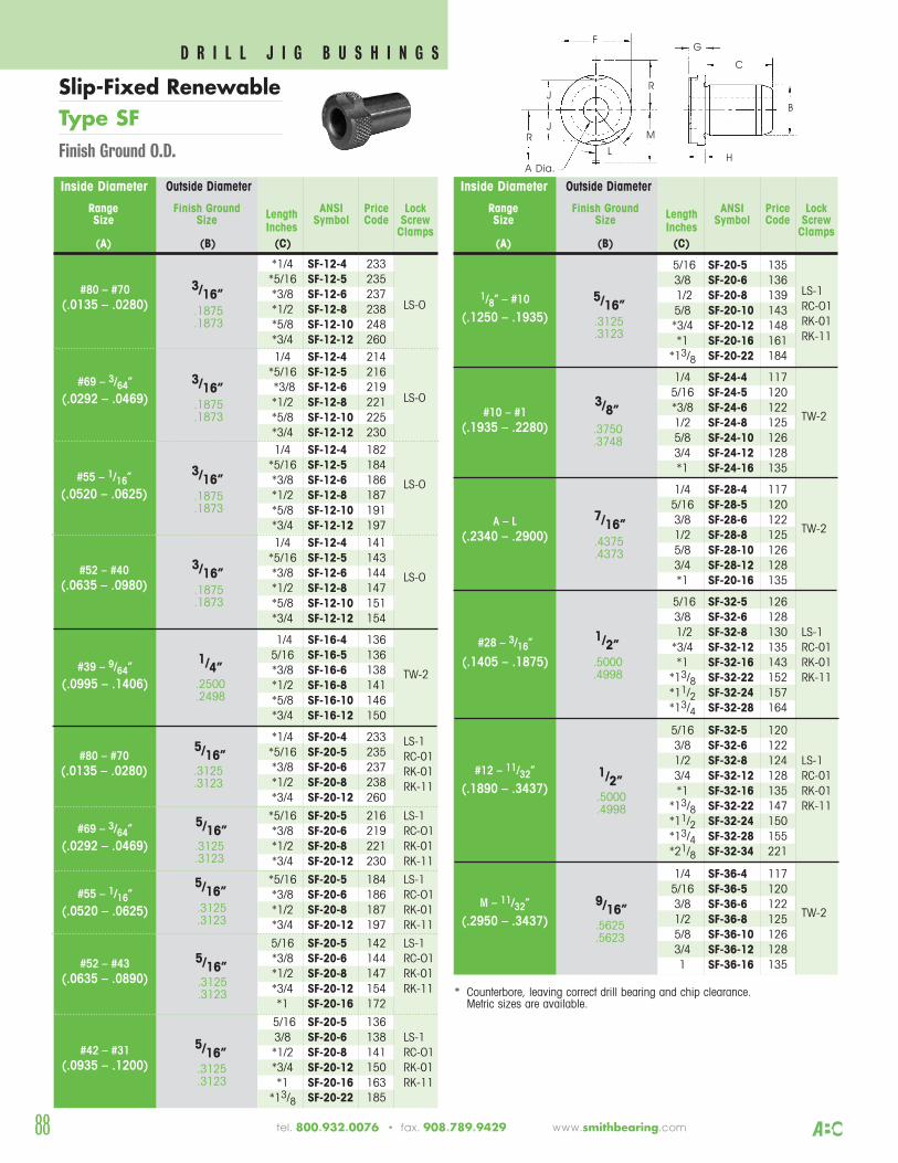
88
Inside Diameter Outside Diameter
*1/4 SF-12-4 233*5/16 SF-12-5 235*3/8 SF-12-6 237*1/2 SF-12-8 238 LS-O
*5/8 SF-12-10 248*3/4 SF-12-12 2601/4 SF-12-4 214
*5/16 SF-12-5 216*3/8 SF-12-6 219*1/2 SF-12-8 221 LS-O
*5/8 SF-12-10 225*3/4 SF-12-12 2301/4 SF-12-4 182
*5/16 SF-12-5 184*3/8 SF-12-6 186 LS-O*1/2 SF-12-8 187*5/8 SF-12-10 191*3/4 SF-12-12 1971/4 SF-12-4 141
*5/16 SF-12-5 143*3/8 SF-12-6 144 LS-O*1/2 SF-12-8 147*5/8 SF-12-10 151*3/4 SF-12-12 154
1/4 SF-16-4 1365/16 SF-16-5 136*3/8 SF-16-6 138 TW-2*1/2 SF-16-8 141*5/8 SF-16-10 146*3/4 SF-16-12 150
*1/4 SF-20-4 233 LS-1*5/16 SF-20-5 235 RC-01*3/8 SF-20-6 237 RK-01*1/2 SF-20-8 238 RK-11*3/4 SF-20-12 260
*5/16 SF-20-5 216 LS-1*3/8 SF-20-6 219 RC-O1*1/2 SF-20-8 221 RK-01*3/4 SF-20-12 230 RK-11
*5/16 SF-20-5 184 LS-1*3/8 SF-20-6 186 RC-O1*1/2 SF-20-8 187 RK-01*3/4 SF-20-12 197 RK-11
5/16 SF-20-5 142 LS-1*3/8 SF-20-6 144 RC-O1*1/2 SF-20-8 147 RK-01*3/4 SF-20-12 154 RK-11*1 SF-20-16 172
5/16 SF-20-5 1363/8 SF-20-6 138 LS-1*1/2 SF-20-8 141 RC-O1*3/4 SF-20-12 150 RK-01*1 SF-20-16 163 RK-11
*13/8 SF-20-22 185
Range Finish Ground ANSI Price LockSize Size Length Symbol Code Screw
Inches Clamps(A) (B) (C)
#80 – #70(.0135 – .0280)
#69 – 3/64”(.0292 – .0469)
#55 – 1/16”(.0520 – .0625)
#52 – #40(.0635 – .0980)
#39 – 9/64”(.0995 – .1406)
#55 – 1/16”(.0520 – .0625)
#42 – #31(.0935 – .1200)
* Counterbore, leaving correct drill bearing and chip clearance. Metric sizes are available.
1/4”.2500.2498
#80 – #70(.0135 – .0280)
#69 – 3/64”(.0292 – .0469)
5/16”.3125.3123
5/16”.3125.3123
#52 – #43(.0635 – .0890)
5/16”.3125.3123
5/16”.3125.3123
Inside Diameter Outside Diameter
5/16 SF-20-5 1353/8 SF-20-6 1361/2 SF-20-8 139 LS-1
5/8 SF-20-10 143 RC-O1
*3/4 SF-20-12 148 RK-01
*1 SF-20-16 161 RK-11
*13/8 SF-20-22 184
1/4 SF-24-4 1175/16 SF-24-5 120*3/8 SF-24-6 122
TW-21/2 SF-24-8 1255/8 SF-24-10 1263/4 SF-24-12 128*1 SF-24-16 135
1/4 SF-28-4 1175/16 SF-28-5 1203/8 SF-28-6 122
TW-21/2 SF-28-8 1255/8 SF-28-10 1263/4 SF-28-12 128*1 SF-20-16 135
5/16 SF-32-5 1263/8 SF-32-6 1281/2 SF-32-8 130 LS-1*3/4 SF-32-12 135 RC-01*1 SF-32-16 143 RK-01
*13/8 SF-32-22 152 RK-11*11/2 SF-32-24 157*13/4 SF-32-28 164
5/16 SF-32-5 1203/8 SF-32-6 1221/2 SF-32-8 124 LS-13/4 SF-32-12 128 RC-01*1 SF-32-16 135 RK-01
*13/8 SF-32-22 147 RK-11*11/2 SF-32-24 150*13/4 SF-32-28 155*21/8 SF-32-34 221
1/4 SF-36-4 1175/16 SF-36-5 1203/8 SF-36-6 122
TW-21/2 SF-36-8 1255/8 SF-36-10 1263/4 SF-36-12 1281 SF-36-16 135
5/16”
Range Finish Ground ANSI Price LockSize Size Length Symbol Code Screw
Inches Clamps(A) (B) (C)
.3125
.3123
1/8” – #10
(.1250 – .1935)
#10 – #1(.1935 – .2280)
A – L(.2340 – .2900)
#28 – 3/16”
(.1405 – .1875)
3/8”.3750.3748
7/16”.4375.4373
#12 – 11/32”
(.1890 – .3437)
M – 11/32”
(.2950 – .3437)
1/2”.5000.4998
1/2”.5000.4998
9/16”.5625.5623
3/16”.1875.1873
5/16”.3125.3123
C
G
A Dia.
F
B
H
R
M
J
RJ
L
Slip-Fixed RenewableType SFFinish Ground O.D.
3/16”.1875.1873
3/16”.1875.1873
3/16”.1875.1873
tel. 800.932.0076 • fax. 908.789.9429 www.smithbearing.com
D R I L L J I G B U S H I N G S
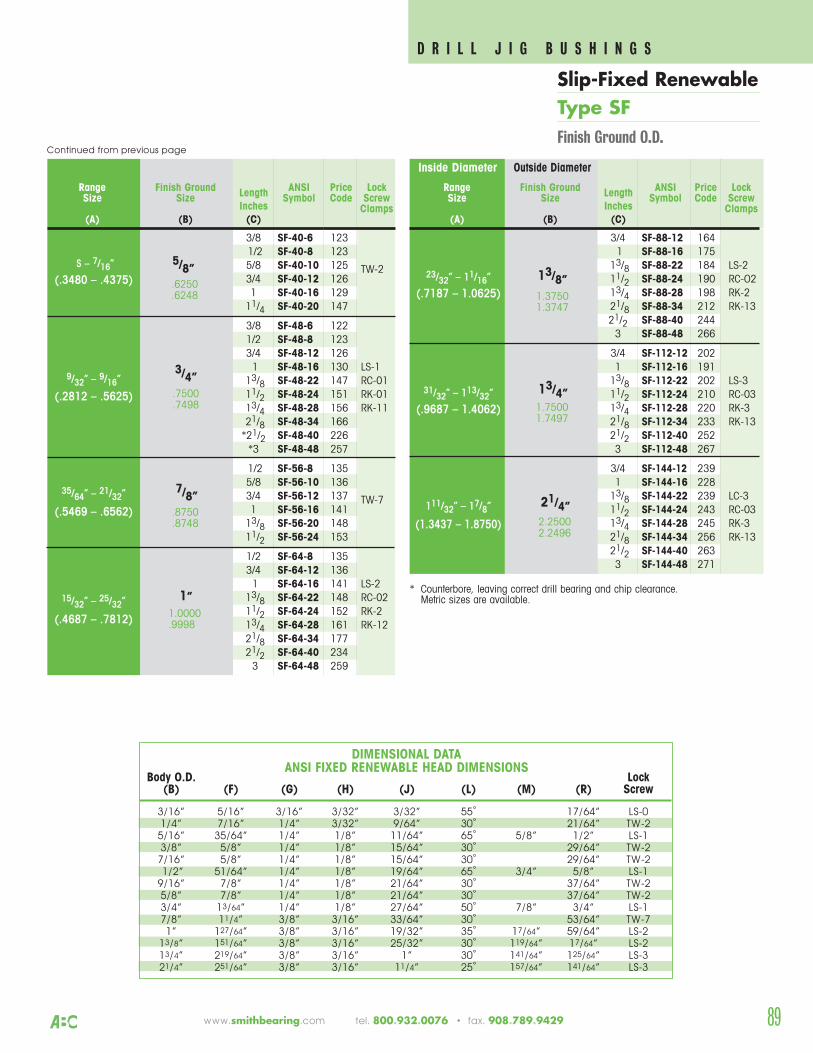
www.smithbearing.com tel. 800.932.0076 • fax. 908.789.9429 89
* Counterbore, leaving correct drill bearing and chip clearance. Metric sizes are available.
3/8 SF-40-6 1231/2 SF-40-8 1235/8 SF-40-10 125 TW-23/4 SF-40-12 1261 SF-40-16 129
11/4 SF-40-20 147
3/8 SF-48-6 1221/2 SF-48-8 1233/4 SF-48-12 1261 SF-48-16 130 LS-1
13/8 SF-48-22 147 RC-0111/2 SF-48-24 151 RK-0113/4 SF-48-28 156 RK-1121/8 SF-48-34 166*21/2 SF-48-40 226*3 SF-48-48 257
1/2 SF-56-8 1355/8 SF-56-10 1363/4 SF-56-12 137 TW-71 SF-56-16 141
13/8 SF-56-20 14811/2 SF-56-24 153
1/2 SF-64-8 1353/4 SF-64-12 1361 SF-64-16 141 LS-2
13/8 SF-64-22 148 RC-0211/2 SF-64-24 152 RK-213/4 SF-64-28 161 RK-1221/8 SF-64-34 17721/2 SF-64-40 2343 SF-64-48 259
5/8”
Range Finish Ground ANSI Price LockSize Size Length Symbol Code Screw
Inches Clamps(A) (B) (C)
.6250
.6248
S – 7/16”
(.3480 – .4375)
9/32” – 9/16”
(.2812 – .5625)
35/64” – 21/32”
(.5469 – .6562)
15/32” – 25/32”
(.4687 – .7812)
3/4”.7500.7498
7/8”.8750.8748
1”1.0000.9998
Inside Diameter Outside Diameter
3/4 SF-88-12 1641 SF-88-16 175
13/8 SF-88-22 184 LS-211/2 SF-88-24 190 RC-O213/4 SF-88-28 198 RK-221/8 SF-88-34 212 RK-1321/2 SF-88-40 2443 SF-88-48 266
3/4 SF-112-12 2021 SF-112-16 191
13/8 SF-112-22 202 LS-311/2 SF-112-24 210 RC-0313/4 SF-112-28 220 RK-321/8 SF-112-34 233 RK-1321/2 SF-112-40 2523 SF-112-48 267
3/4 SF-144-12 2391 SF-144-16 228
13/8 SF-144-22 239 LC-311/2 SF-144-24 243 RC-0313/4 SF-144-28 245 RK-321/8 SF-144-34 256 RK-1321/2 SF-144-40 2633 SF-144-48 271
13/8”
Range Finish Ground ANSI Price LockSize Size Length Symbol Code Screw
Inches Clamps(A) (B) (C)
1.37501.3747
23/32” – 11/16”
(.7187 – 1.0625)
31/32” – 113/32”
(.9687 – 1.4062)
111/32” – 17/8”
(1.3437 – 1.8750)
13/4”1.75001.7497
21/4”2.25002.2496
Body O.D. Lock(B) (F) (G) (H) (J) (L) (M) (R) Screw
3/16” 5/16” 3/16” 3/32” 3/32” 55˚ 17/64” LS-01/4” 7/16” 1/4” 3/32” 9/64” 30˚ 21/64” TW-2
5/16” 35/64” 1/4” 1/8” 11/64” 65˚ 5/8” 1/2” LS-13/8” 5/8” 1/4” 1/8” 15/64” 30˚ 29/64” TW-2
7/16” 5/8” 1/4” 1/8” 15/64” 30˚ 29/64” TW-21/2” 51/64” 1/4” 1/8” 19/64” 65˚ 3/4” 5/8” LS-1
9/16” 7/8” 1/4” 1/8” 21/64” 30˚ 37/64” TW-25/8” 7/8” 1/4” 1/8” 21/64” 30˚ 37/64” TW-23/4” 13/64” 1/4” 1/8” 27/64” 50˚ 7/8” 3/4” LS-17/8” 11/4” 3/8” 3/16” 33/64” 30˚ 53/64” TW-71” 127/64” 3/8” 3/16” 19/32” 35˚ 17/64” 59/64” LS-2
13/8” 151/64” 3/8” 3/16” 25/32” 30˚ 119/64” 17/64” LS-213/4” 219/64” 3/8” 3/16” 1” 30˚ 141/64” 125/64” LS-321/4” 251/64” 3/8” 3/16” 11/4” 25˚ 157/64” 141/64” LS-3
DIMENSIONAL DATAANSI FIXED RENEWABLE HEAD DIMENSIONS
Continued from previous page
D R I L L J I G B U S H I N G S
Slip-Fixed RenewableType SFFinish Ground O.D.
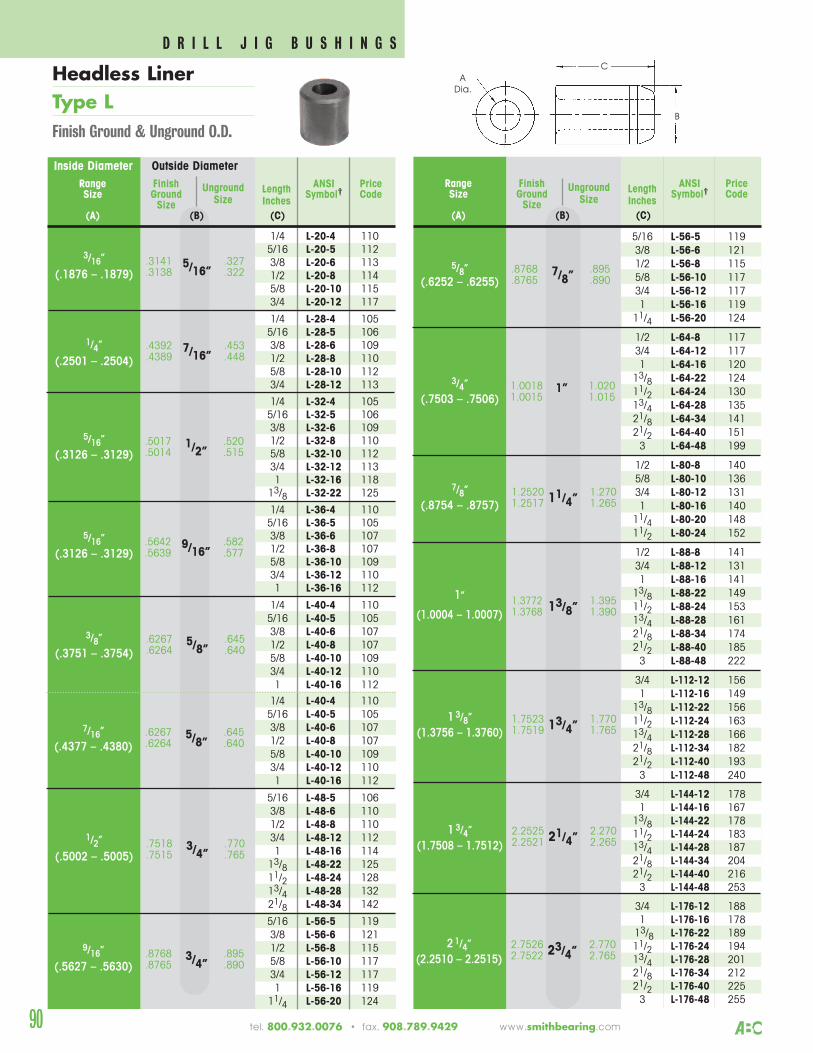
90
5/16 L-56-5 1193/8 L-56-6 1211/2 L-56-8 1155/8 L-56-10 1173/4 L-56-12 1171 L-56-16 119
11/4 L-56-20 124
1/2 L-64-8 1173/4 L-64-12 1171 L-64-16 120
13/8 L-64-22 12411/2 L-64-24 13013/4 L-64-28 13521/8 L-64-34 14121/2 L-64-40 1513 L-64-48 199
1/2 L-80-8 1405/8 L-80-10 1363/4 L-80-12 1311 L-80-16 140
11/4 L-80-20 14811/2 L-80-24 152
1/2 L-88-8 1413/4 L-88-12 1311 L-88-16 141
13/8 L-88-22 14911/2 L-88-24 15313/4 L-88-28 16121/8 L-88-34 17421/2 L-88-40 1853 L-88-48 222
3/4 L-112-12 1561 L-112-16 149
13/8 L-112-22 15611/2 L-112-24 16313/4 L-112-28 16621/8 L-112-34 18221/2 L-112-40 1933 L-112-48 240
3/4 L-144-12 1781 L-144-16 167
13/8 L-144-22 17811/2 L-144-24 18313/4 L-144-28 18721/8 L-144-34 20421/2 L-144-40 2163 L-144-48 253
3/4 L-176-12 1881 L-176-16 178
13/8 L-176-22 18911/2 L-176-24 19413/4 L-176-28 20121/8 L-176-34 21221/2 L-176-40 2253 L-176-48 255
.8768 .8957/8”.8765 .890
Range Finish ANSI PriceSize Ground
Unground Length Symbol† CodeSize Size Inches
(A) (B) (C)
2.2525 2.27021/4”2.2521 2.265
1.7523 1.77013/4”1.7519 1.765
1.3772 1.39513/8”1.3768 1.390
1.2520 1.27011/4”1.2517 1.265
1.0018 1.0201”1.0015 1.015
5/8”(.6252 – .6255)
3/4”(.7503 – .7506)
7/8”(.8754 – .8757)
1”
(1.0004 – 1.0007)
1 3/8”(1.3756 – 1.3760)
1 3/4”(1.7508 – 1.7512)
Inside Diameter Outside Diameter
1/4 L-20-4 1105/16 L-20-5 1123/8 L-20-6 1131/2 L-20-8 1145/8 L-20-10 1153/4 L-20-12 117
1/4 L-28-4 1055/16 L-28-5 1063/8 L-28-6 1091/2 L-28-8 1105/8 L-28-10 1123/4 L-28-12 113
1/4 L-32-4 1055/16 L-32-5 1063/8 L-32-6 1091/2 L-32-8 1105/8 L-32-10 1123/4 L-32-12 1131 L-32-16 118
13/8 L-32-22 125
1/4 L-36-4 1105/16 L-36-5 1053/8 L-36-6 1071/2 L-36-8 1075/8 L-36-10 1093/4 L-36-12 1101 L-36-16 112
1/4 L-40-4 1105/16 L-40-5 1053/8 L-40-6 1071/2 L-40-8 1075/8 L-40-10 1093/4 L-40-12 1101 L-40-16 112
1/4 L-40-4 1105/16 L-40-5 1053/8 L-40-6 1071/2 L-40-8 1075/8 L-40-10 1093/4 L-40-12 1101 L-40-16 112
5/16 L-48-5 1063/8 L-48-6 1101/2 L-48-8 1103/4 L-48-12 1121 L-48-16 114
13/8 L-48-22 12511/2 L-48-24 12813/4 L-48-28 13221/8 L-48-34 142
5/16 L-56-5 1193/8 L-56-6 1211/2 L-56-8 1155/8 L-56-10 1173/4 L-56-12 1171 L-56-16 119
11/4 L-56-20 124
.3141 .3275/16”.3138 .322
Range Finish ANSI PriceSize Ground
Unground Length Symbol† CodeSize Size Inches
(A) (B) (C)
.4392 .4537/16”.4389 .448
.5017 .5201/2”.5014 .515
.7518 .7703/4”.7515 .765
.6267 .6455/8”.6264 .640
.5642 .5829/16”.5639 .577
3/16”
(.1876 – .1879)
1/4”
(.2501 – .2504)
5/16”(.3126 – .3129)
5/16”(.3126 – .3129)
3/8”(.3751 – .3754)
1/2”
(.5002 – .5005)
.6267 .6455/8”.6264 .6407/16”
(.4377 – .4380)
.8768 .8953/4”.8765 .890
9/16”
(.5627 – .5630)
2.7526 2.77023/4”2.7522 2.7652 1/4”
(2.2510 – 2.2515)
B
CA
Dia.Headless LinerType LFinish Ground & Unground O.D.
90 tel. 800.932.0076 • fax. 908.789.9429 www.smithbearing.com
D R I L L J I G B U S H I N G S
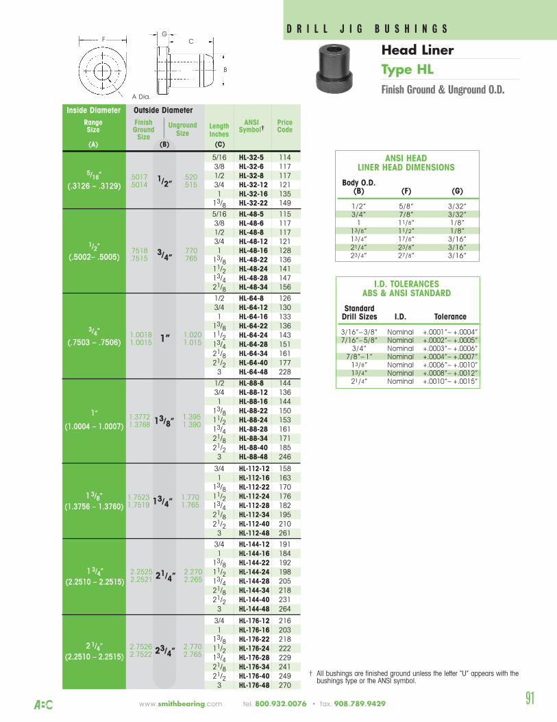
www.smithbearing.com tel. 800.932.0076 • fax. 908.789.9429 91
Inside Diameter Outside Diameter
5/16 HL-32-5 1143/8 HL-32-6 1171/2 HL-32-8 1173/4 HL-32-12 1211 HL-32-16 135
13/8 HL-32-22 149
5/16 HL-48-5 1153/8 HL-48-6 1171/2 HL-48-8 1173/4 HL-48-12 1211 HL-48-16 128
13/8 HL-48-22 13611/2 HL-48-24 14113/4 HL-48-28 14721/8 HL-48-34 156
1/2 HL-64-8 1263/4 HL-64-12 1301 HL-64-16 133
13/8 HL-64-22 13611/2 HL-64-24 14313/4 HL-64-28 15121/8 HL-64-34 16121/2 HL-64-40 1773 HL-64-48 228
1/2 HL-88-8 1443/4 HL-88-12 1361 HL-88-16 144
13/8 HL-88-22 15011/2 HL-88-24 15313/4 HL-88-28 16121/8 HL-88-34 17121/2 HL-88-40 1853 HL-88-48 246
3/4 HL-112-12 1581 HL-112-16 163
13/8 HL-112-22 17011/2 HL-112-24 17613/4 HL-112-28 18221/8 HL-112-34 19521/2 HL-112-40 2103 HL-112-48 261
3/4 HL-144-12 1911 HL-144-16 184
13/8 HL-144-22 19211/2 HL-144-24 19813/4 HL-144-28 20521/8 HL-144-34 21821/2 HL-144-40 2313 HL-144-48 264
3/4 HL-176-12 2161 HL-176-16 203
13/8 HL-176-22 21811/2 HL-176-24 22213/4 HL-176-28 22921/8 HL-176-34 24121/2 HL-176-40 2493 HL-176-48 270
.5017 .5201/2”.5014 .515
Range Finish ANSI PriceSize Ground
Unground Length Symbol† CodeSize Size Inches
(A) (B) (C)
.7518 .7703/4”.7515 .765
1.0018 1.0201”1.0015 1.015
5/16”
(.3126 – .3129)
1/2”(.5002– .5005)
3/4”
(.7503 – .7506)
† All bushings are finished ground unless the letter “U” appears with the bushings type or the ANSI symbol.
1.7523 1.77013/4”1.7519 1.7651 3/8”
(1.3756 – 1.3760)
1.3772 1.39513/8”1.3768 1.390
1”
(1.0004 – 1.0007)
2.2525 2.27021/4”2.2521 2.2651 3/4”
(2.2510 – 2.2515)
2.7526 2.77023/4”2.7522 2.7652 1/4”
(2.2510 – 2.2515)
Body O.D.(B) (F) (G)
1/2” 5/8” 3/32”3/4” 7/8” 3/32”
1 11/8” 1/8”13/8” 11/2” 1/8”13/4” 17/8” 3/16”21/4” 23/8” 3/16”23/4” 27/8” 3/16”
ANSI HEAD LINER HEAD DIMENSIONS
StandardDrill Sizes I.D. Tolerance
3/16”– 3/8” Nominal +.0001”– +.0004”7/16”– 5/8” Nominal +.0002”– +.0005”
3/4” Nominal +.0003”– +.0006”7/8”– 1” Nominal +.0004”– +.0007”
13/8” Nominal +.0006”– +.0010”13/4” Nominal +.0008”– +.0012”21/4” Nominal +.0010”– +.0015”
I.D. TOLERANCESABS & ANSI STANDARD
D R I L L J I G B U S H I N G SC
G
A Dia.
F
B
Head LinerType HLFinish Ground & Unground O.D.
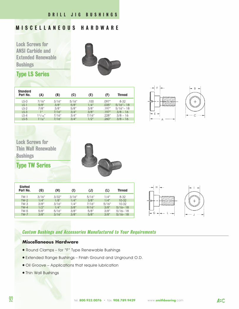
M I S C E L L A N E O U S H A R D W A R E
Lock Screws forANSI Carbide andExtended Renewable Bushings
Type LS Series
Custom Bushings and Accessories Manufactured to Your Requirements
Lock Screws forThin Wall Renewable Bushings
Type TW Series
Miscellaneous Hardware
• Round Clamps – for “F” Type Renewable Bushings
• Extended Range Bushings – Finish Ground and Unground O.D.
• Oil Groove – Applications that require lubrication
• Thin Wall Bushings
StandardPart No. (A) (B) (C) (E) (F) Thread
LS-0 7/16” 3/16” 5/16” .100 .097” 8-32LS-1 5/8” 3/8” 5/8” 1/4” .035” 5/16”– 18LS-2 7/8” 3/8” 5/8” 3/8” .197” 5/16”– 18LS-3 1” 7/16” 3/4” 3/8” .197” 3/8 – 16LS-4 11/16” 7/16” 3/4” 7/16” .228” 3/8 – 16LS-5 11/8” 7/16” 3/4” 1/2” .260” 3/8 – 16
SlottedPart No. (G) (H) (I) (J) (L) Thread
TW-1 3/16” 3/32” 3/16” 5/16” 1/4” 8-32TW-2 1/4” 1/8” 1/4” 3/8” 1/4” 10-32TW-3 3/8” 3/16” 1/4” 7/16” 5/16” 10-32TW-4 1/2” 1/4” 3/8” 9/16” 3/8” 5/16– 18TW-5 5/8” 5/16” 3/8” 5/8” 3/8” 5/16– 18TW-7 3/8” 3/16” 3/8” 5/8” 3/8” 5/16– 18
BF
E
A
C
IH
G LJ
92 tel. 800.932.0076 • fax. 908.789.9429 www.smithbearing.com
D R I L L J I G B U S H I N G S
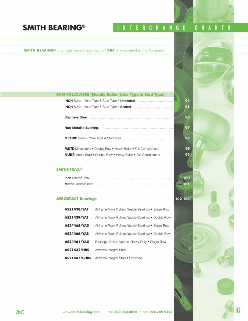
www.smithbearing.com tel. 800.932.0076 • fax. 908.789.9429
I N T E R C H A N G E C H A R T S
1CAM FOLLOWERS (Needle Roller Yoke Type & Stud Type)
INCH Sizes - Yoke Type & Stud Type • Unsealed ......................................... 94
INCH Sizes - Yoke Type & Stud Type • Sealed ............................................. 95
Stainless Steel ............................................................................................. 96
Non-Metallic Bushing................................................................................... 97
METRIC Sizes - Yoke Type & Stud Type ........................................................ 98
MUTD Metric Yoke • Double Row • Heavy Roller • Full Complement 99
NUKR Metric Stud • Double Row • Heavy Roller • Full Complement 99
SMITH-TRAX®
Inch Smith®-Trax ........................................................................................... 100
Metric Smith®-Trax ........................................................................................ 101
AEROSPACE Bearings 102-103
AS21438/YAF Airframe Track Rollers Needle Bearings • Single Row
AS21439/YAT Airframe Track Rollers Needle Bearings • Double Row
AS24465/YAD Airframe Track Rollers Needle Bearings • Single Row
AS24466/YAS Airframe Track Rollers Needle Bearings • Double Row
AS24461/YAG Bearings, Roller, Needle, Heavy Duty • Single Row
AS21432/HRS Airframe Integral Stud
AS21447/CHRS Airframe Integral Stud • Crowned
SMITH BEARING®
SMITH BEARING® is a registered trademark of ABC • Accurate Bushing Company
93
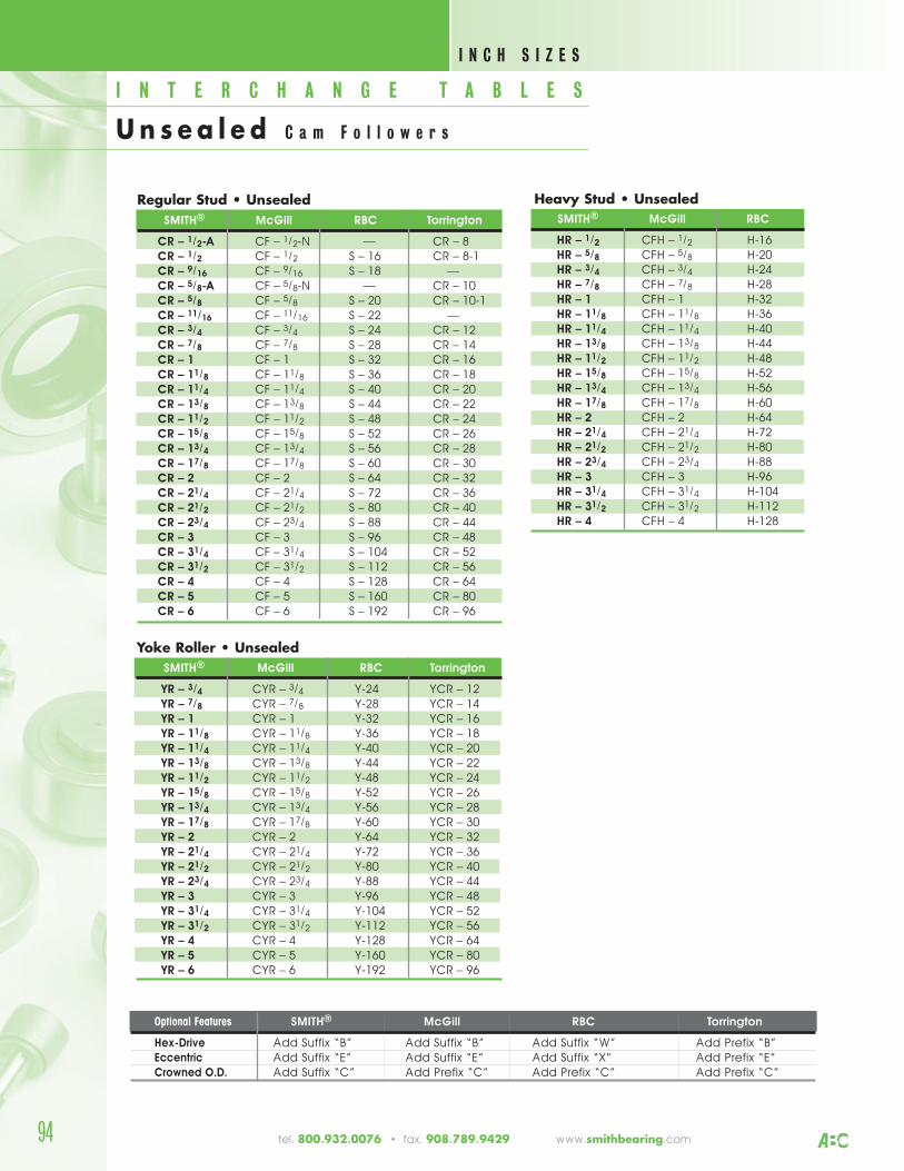
Regular Stud • Unsealed SMITH® McGill RBC Torrington
CR – 1/2-A CF – 1/2-N –– CR – 8CR – 1/2 CF – 1/2 S – 16 CR – 8-1CR – 9/16 CF – 9/16 S – 18 ––CR – 5/8-A CF – 5/8-N –– CR – 10CR – 5/8 CF – 5/8 S – 20 CR – 10-1CR – 11/16 CF – 11/16 S – 22 ––CR – 3/4 CF – 3/4 S – 24 CR – 12CR – 7/8 CF – 7/8 S – 28 CR – 14CR – 1 CF – 1 S – 32 CR – 16CR – 11/8 CF – 11/8 S – 36 CR – 18CR – 11/4 CF – 11/4 S – 40 CR – 20CR – 13/8 CF – 13/8 S – 44 CR – 22CR – 11/2 CF – 11/2 S – 48 CR – 24CR – 15/8 CF – 15/8 S – 52 CR – 26CR – 13/4 CF – 13/4 S – 56 CR – 28CR – 17/8 CF – 17/8 S – 60 CR – 30CR – 2 CF – 2 S – 64 CR – 32CR – 21/4 CF – 21/4 S – 72 CR – 36CR – 21/2 CF – 21/2 S – 80 CR – 40CR – 23/4 CF – 23/4 S – 88 CR – 44CR – 3 CF – 3 S – 96 CR – 48CR – 31/4 CF – 31/4 S – 104 CR – 52CR – 31/2 CF – 31/2 S – 112 CR – 56CR – 4 CF – 4 S – 128 CR – 64CR – 5 CF – 5 S – 160 CR – 80CR – 6 CF – 6 S – 192 CR – 96
Yoke Roller • Unsealed SMITH® McGill RBC Torrington
YR – 3/4 CYR – 3/4 Y-24 YCR – 12YR – 7/8 CYR – 7/8 Y-28 YCR – 14YR – 1 CYR – 1 Y-32 YCR – 16YR – 11/8 CYR – 11/8 Y-36 YCR – 18YR – 11/4 CYR – 11/4 Y-40 YCR – 20YR – 13/8 CYR – 13/8 Y-44 YCR – 22YR – 11/2 CYR – 11/2 Y-48 YCR – 24YR – 15/8 CYR – 15/8 Y-52 YCR – 26YR – 13/4 CYR – 13/4 Y-56 YCR – 28YR – 17/8 CYR – 17/8 Y-60 YCR – 30YR – 2 CYR – 2 Y-64 YCR – 32YR – 21/4 CYR – 21/4 Y-72 YCR – 36YR – 21/2 CYR – 21/2 Y-80 YCR – 40YR – 23/4 CYR – 23/4 Y-88 YCR – 44YR – 3 CYR – 3 Y-96 YCR – 48YR – 31/4 CYR – 31/4 Y-104 YCR – 52YR – 31/2 CYR – 31/2 Y-112 YCR – 56YR – 4 CYR – 4 Y-128 YCR – 64YR – 5 CYR – 5 Y-160 YCR – 80YR – 6 CYR – 6 Y-192 YCR – 96
Heavy Stud • Unsealed SMITH® McGill RBC
HR – 1/2 CFH – 1/2 H-16HR – 5/8 CFH – 5/8 H-20HR – 3/4 CFH – 3/4 H-24HR – 7/8 CFH – 7/8 H-28HR – 1 CFH – 1 H-32HR – 11/8 CFH – 11/8 H-36HR – 11/4 CFH – 11/4 H-40HR – 13/8 CFH – 13/8 H-44HR – 11/2 CFH – 11/2 H-48HR – 15/8 CFH – 15/8 H-52HR – 13/4 CFH – 13/4 H-56HR – 17/8 CFH – 17/8 H-60HR – 2 CFH – 2 H-64HR – 21/4 CFH – 21/4 H-72HR – 21/2 CFH – 21/2 H-80HR – 23/4 CFH – 23/4 H-88HR – 3 CFH – 3 H-96HR – 31/4 CFH – 31/4 H-104HR – 31/2 CFH – 31/2 H-112HR – 4 CFH – 4 H-128
94
C a m F o l l o w e r s ( N e e d l e R o l l e r s ) I N C H S I Z E S
tel. 800.932.0076 • fax. 908.789.9429 www.smithbearing.com
I N T E R C H A N G E T A B L E S
Un s e a l e d C a m F o l l o w e r s
Optional Features SMITH® McGill RBC Torrington
Hex-Drive Add Suffix “B” Add Suffix “B” Add Suffix “W” Add Prefix “B”Eccentric Add Suffix “E” Add Suffix “E” Add Suffix “X” Add Prefix “E”Crowned O.D. Add Suffix “C” Add Prefix “C” Add Prefix “C” Add Prefix “C”
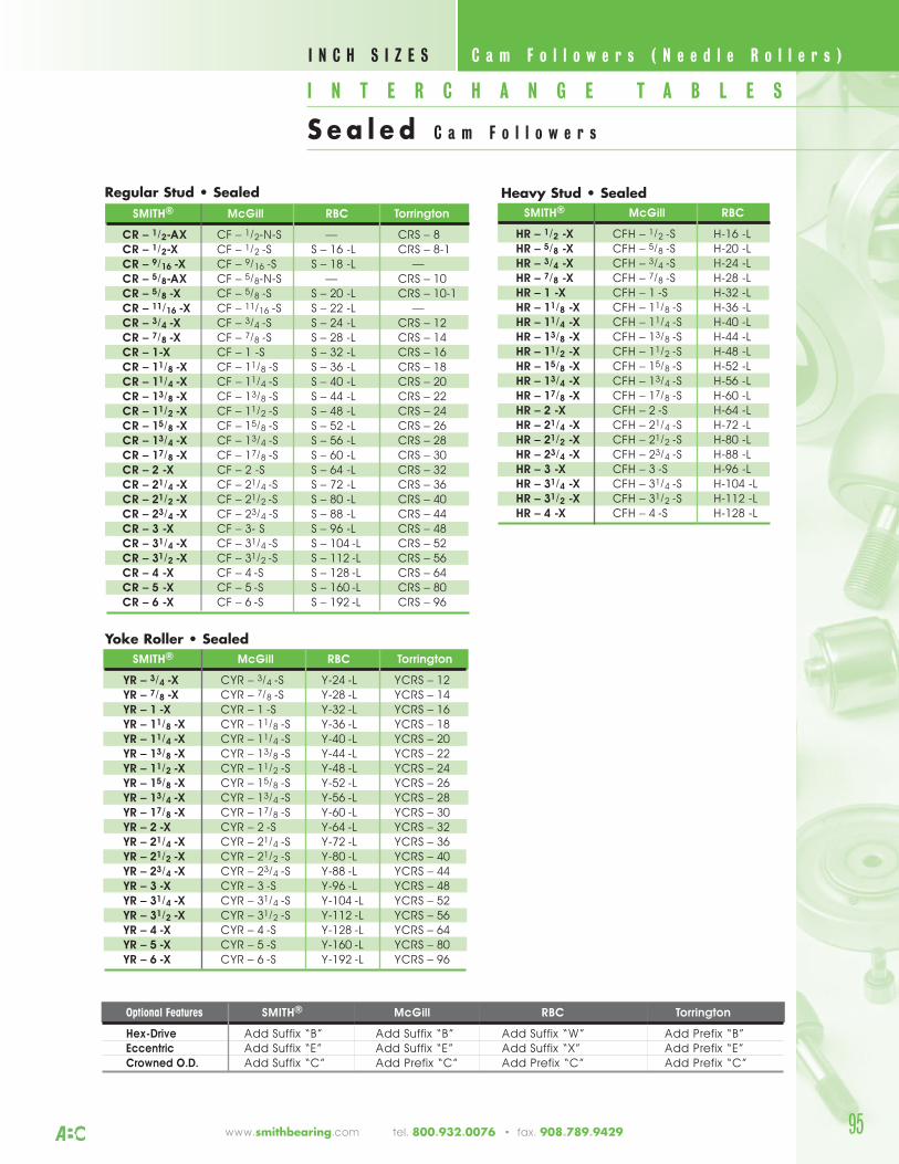
I N T E R C H A N G E T A B L E S
S e a l e d C a m F o l l o w e r s
C a m F o l l o w e r s ( N e e d l e R o l l e r s ) I N C H S I Z E S
www.smithbearing.com tel. 800.932.0076 • fax. 908.789.9429 95
Regular Stud • SealedSMITH® McGill RBC Torrington
CR – 1/2-AX CF – 1/2-N-S –– CRS – 8CR – 1/2-X CF – 1/2 -S S – 16 -L CRS – 8-1CR – 9/16 -X CF – 9/16 -S S – 18 -L ––CR – 5/8-AX CF – 5/8-N-S –– CRS – 10CR – 5/8 -X CF – 5/8 -S S – 20 -L CRS – 10-1CR – 11/16 -X CF – 11/16 -S S – 22 -L ––CR – 3/4 -X CF – 3/4 -S S – 24 -L CRS – 12CR – 7/8 -X CF – 7/8 -S S – 28 -L CRS – 14CR – 1-X CF – 1 -S S – 32 -L CRS – 16CR – 11/8 -X CF – 11/8 -S S – 36 -L CRS – 18CR – 11/4 -X CF – 11/4 -S S – 40 -L CRS – 20CR – 13/8 -X CF – 13/8 -S S – 44 -L CRS – 22CR – 11/2 -X CF – 11/2 -S S – 48 -L CRS – 24CR – 15/8 -X CF – 15/8 -S S – 52 -L CRS – 26CR – 13/4 -X CF – 13/4 -S S – 56 -L CRS – 28CR – 17/8 -X CF – 17/8 -S S – 60 -L CRS – 30CR – 2 -X CF – 2 -S S – 64 -L CRS – 32CR – 21/4 -X CF – 21/4 -S S – 72 -L CRS – 36CR – 21/2 -X CF – 21/2 -S S – 80 -L CRS – 40CR – 23/4 -X CF – 23/4 -S S – 88 -L CRS – 44CR – 3 -X CF – 3- S S – 96 -L CRS – 48CR – 31/4 -X CF – 31/4 -S S – 104 -L CRS – 52CR – 31/2 -X CF – 31/2 -S S – 112 -L CRS – 56CR – 4 -X CF – 4 -S S – 128 -L CRS – 64CR – 5 -X CF – 5 -S S – 160 -L CRS – 80CR – 6 -X CF – 6 -S S – 192 -L CRS – 96
Yoke Roller • Sealed SMITH® McGill RBC Torrington
YR – 3/4 -X CYR – 3/4 -S Y-24 -L YCRS – 12YR – 7/8 -X CYR – 7/8 -S Y-28 -L YCRS – 14YR – 1 -X CYR – 1 -S Y-32 -L YCRS – 16YR – 11/8 -X CYR – 11/8 -S Y-36 -L YCRS – 18YR – 11/4 -X CYR – 11/4 -S Y-40 -L YCRS – 20YR – 13/8 -X CYR – 13/8 -S Y-44 -L YCRS – 22YR – 11/2 -X CYR – 11/2 -S Y-48 -L YCRS – 24YR – 15/8 -X CYR – 15/8 -S Y-52 -L YCRS – 26YR – 13/4 -X CYR – 13/4 -S Y-56 -L YCRS – 28YR – 17/8 -X CYR – 17/8 -S Y-60 -L YCRS – 30YR – 2 -X CYR – 2 -S Y-64 -L YCRS – 32YR – 21/4 -X CYR – 21/4 -S Y-72 -L YCRS – 36YR – 21/2 -X CYR – 21/2 -S Y-80 -L YCRS – 40YR – 23/4 -X CYR – 23/4 -S Y-88 -L YCRS – 44YR – 3 -X CYR – 3 -S Y-96 -L YCRS – 48YR – 31/4 -X CYR – 31/4 -S Y-104 -L YCRS – 52YR – 31/2 -X CYR – 31/2 -S Y-112 -L YCRS – 56YR – 4 -X CYR – 4 -S Y-128 -L YCRS – 64YR – 5 -X CYR – 5 -S Y-160 -L YCRS – 80YR – 6 -X CYR – 6 -S Y-192 -L YCRS – 96
Heavy Stud • SealedSMITH® McGill RBC
HR – 1/2 -X CFH – 1/2 -S H-16 -LHR – 5/8 -X CFH – 5/8 -S H-20 -LHR – 3/4 -X CFH – 3/4 -S H-24 -LHR – 7/8 -X CFH – 7/8 -S H-28 -LHR – 1 -X CFH – 1 -S H-32 -LHR – 11/8 -X CFH – 11/8 -S H-36 -LHR – 11/4 -X CFH – 11/4 -S H-40 -LHR – 13/8 -X CFH – 13/8 -S H-44 -LHR – 11/2 -X CFH – 11/2 -S H-48 -LHR – 15/8 -X CFH – 15/8 -S H-52 -LHR – 13/4 -X CFH – 13/4 -S H-56 -LHR – 17/8 -X CFH – 17/8 -S H-60 -LHR – 2 -X CFH – 2 -S H-64 -LHR – 21/4 -X CFH – 21/4 -S H-72 -LHR – 21/2 -X CFH – 21/2 -S H-80 -LHR – 23/4 -X CFH – 23/4 -S H-88 -LHR – 3 -X CFH – 3 -S H-96 -LHR – 31/4 -X CFH – 31/4 -S H-104 -LHR – 31/2 -X CFH – 31/2 -S H-112 -LHR – 4 -X CFH – 4 -S H-128 -L
Optional Features SMITH® McGill RBC Torrington
Hex-Drive Add Suffix “B” Add Suffix “B” Add Suffix “W” Add Prefix “B”Eccentric Add Suffix “E” Add Suffix “E” Add Suffix “X” Add Prefix “E”Crowned O.D. Add Suffix “C” Add Prefix “C” Add Prefix “C” Add Prefix “C”
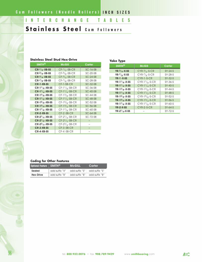
Stainless Steel Stud Hex-DriveSMITH® McGill Carter
CR-1/2 -XB-SS CF-1/2 -SB-CR SC-16-SB
CR-5/8 -XB-SS CF-5/8 -SB-CR SC-20-SB
CR-3/4 -XB-SS CF-3/4 -SB-CR SC-24-SB
CR-7/8 -XB-SS CF-7/8 -SB-CR SC-28-SB
CR-1-XB-SS CF-1-SB-CR SC-32-SB
CR-11/8 -XB-SS CF-11/8 -SB-CR SC-36-SB
CR-11/4 -XB-SS CF-11/4 -SB-CR SC-40-SB
CR-13/8 -XB-SS CF-13/8 -SB-CR SC-44-SB
CR-11/2 -XB-SS CF-11/2 -SB-CR SC-48-SB
CR-15/8 -XB-SS CF-15/8 -SB-CR SC-52-SB
CR-13/4 -XB-SS CF-13/4 -SB-CR SC-56-SB
CR-17/8 -XB-SS CF-17/8 -SB-CR SC-60-SB
CR-2-XB-SS CF-2 -SB-CR SC-64-SB
CR-21/4 -XB-SS CF-21/4 -SB-CR SC-72-SB
CR-21/2 -XB-SS CF-21/2 -SB-CR –
CR-23/4 -XB-SS CF-23/4 -SB-CR –
CR-3-XB-SS CF-3 -SB-CR –
CR-4-XB-SS CF-4 -SB-CR –
Coding for Other FeaturesOptional Feature SMITH® McGILL Carter
Sealed add suffix “X” add suffix “S” add suffix “S”
Hex-Drive add suffix “B” add suffix “B” add suffix “B”
Yoke TypeSMITH® McGill Carter
YR-3/4 -X-SS CYR-3/4 -S-CR SY-24-S
YR-7/8 -X-SS CYR-7/8 -S-CR SY-28-S
YR-1-X-SS CYR-1 -S-CR SY-32-S
YR-11/8 -X-SS CYR-11/8 -S-CR SY-36-S
YR-11/4 -X-SS CYR-11/4 -S-CR SY-40-S
YR-13/8 -X-SS CYR-13/8 -S-CR SY-44-S
YR-11/2 -X-SS CYR-11/2 -S-CR SY-48-S
YR-15/8 -X-SS CYR-15/8 -S-CR SY-52-S
YR-13/4 -X-SS CYR-13/4 -S-CR SY-56-S
YR-17/8 -X-SS CYR-17/8 -S-CR SY-60-S
YR-2-X-SS CYR-2 -S-CR SY-64-S
YR-21/4-X-SS – SY-72-S
96 tel. 800.932.0076 • fax. 908.789.9429 www.smithbearing.com
C a m F o l l o w e r s ( N e e d l e R o l l e r s ) I N C H S I Z E S
I N T E R C H A N G E T A B L E S
S t a i n l e s s S t e e l C a m F o l l o w e r s
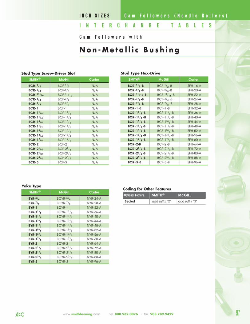
www.smithbearing.com tel. 800.932.0076 • fax. 908.789.9429 97
Stud Type Screw-Driver SlotSMITH® McGill Carter
BCR-1/2 BCF-1/2 N/A
BCR-5/8 BCF-5/8 N/A
BCR-11/16 BCF-11/16 N/A
BCR-3/4 BCF-3/4 N/A
BCR-7/8 BCF-7/8 N/A
BCR-1 BCF-1 N/A
BCR-11/8 BCF-11/8 N/A
BCR-11/4 BCF-11/4 N/A
BCR-13/8 BCF-13/8 N/A
BCR-11/2 BCF-11/2 N/A
BCR-15/8 BCF-15/8 N/A
BCR-13/4 BCF-13/4 N/A
BCR-17/8 BCF-17/8 N/A
BCR-2 BCF-2 N/A
BCR-21/4 BCF-21/4 N/A
BCR-21/2 BCF-21/2 N/A
BCR-23/4 BCF-23/4 N/A
BCR-3 BCF-3 N/A
Coding for Other FeaturesOptional Feature SMITH® McGILL
Sealed add suffix “X” add suffix “S”
Yoke TypeSMITH® McGill Carter
BYR-3/4 BCYR-3/4 NYR-24-A
BYR-7/8 BCYR-7/8 NYR-28-A
BYR-1 BCYR-1 NYR-32-A
BYR-11/8 BCYR-11/8 NYR-36-A
BYR-11/4 BCYR-11/4 NYR-40-A
BYR-13/8 BCYR-13/8 NYR-44-A
BYR-11/2 BCYR-11/2 NYR-48-A
BYR-15/8 BCYR-15/8 NYR-52-A
BYR-13/4 BCYR-13/4 NYR-56-A
BYR-17/8 BCYR-17/8 NYR-60-A
BYR-2 BCYR-2 NYR-64-A
BYR-21/4 BCYR-21/4 NYR-72-A
BYR-21/2 BCYR-21/2 NYR-80-A
BYR-23/4 BCYR-23/4 NYR-88-A
BYR-3 BCYR-3 NYR-96-A
Stud Type Hex-DriveSMITH® McGill Carter
BCR-1/2 -B BCF-1/2 -B SFH-16-A
BCR-5/8 -B BCF-5/8 -B SFH-20-A
BCR-11/16 -B BCF-11/16 -B SFH-22-A
BCR-3/4 -B BCF-3/4 -B SFH-24-A
BCR-7/8 -B BCF-7/8 -B SFH-28-A
BCR-1-B BCF-1 -B SFH-32-A
BCR-11/8 -B BCF-11/8 -B SFH-36-A
BCR-11/4 -B BCF-11/4 -B SFH-40-A
BCR-13/8 -B BCF-13/8 -B SFH-44-A
BCR-11/2 -B BCF-11/2 -B SFH-48-A
BCR-15/8 -B BCF-15/8 -B SFH-52-A
BCR-13/4 -B BCF-13/4 -B SFH-56-A
BCR-17/8 -B BCF-17/8 -B SFH-60-A
BCR-2-B BCF-2 -B SFH-64-A
BCR-21/4 -B BCF-21/4 -B SFH-72-A
BCR-21/2 -B BCF-21/2 -B SFH-80-A
BCR-23/4 -B BCF-23/4 -B SFH-88-A
BCR-3-B BCF-3 -B SFH-96-A
I N T E R C H A N G E T A B L E S
C a m F o l l o w e r s w i t h
Non -Me t a l l i c B u s h i n g
C a m F o l l o w e r s ( N e e d l e R o l l e r s ) I N C H S I Z E S
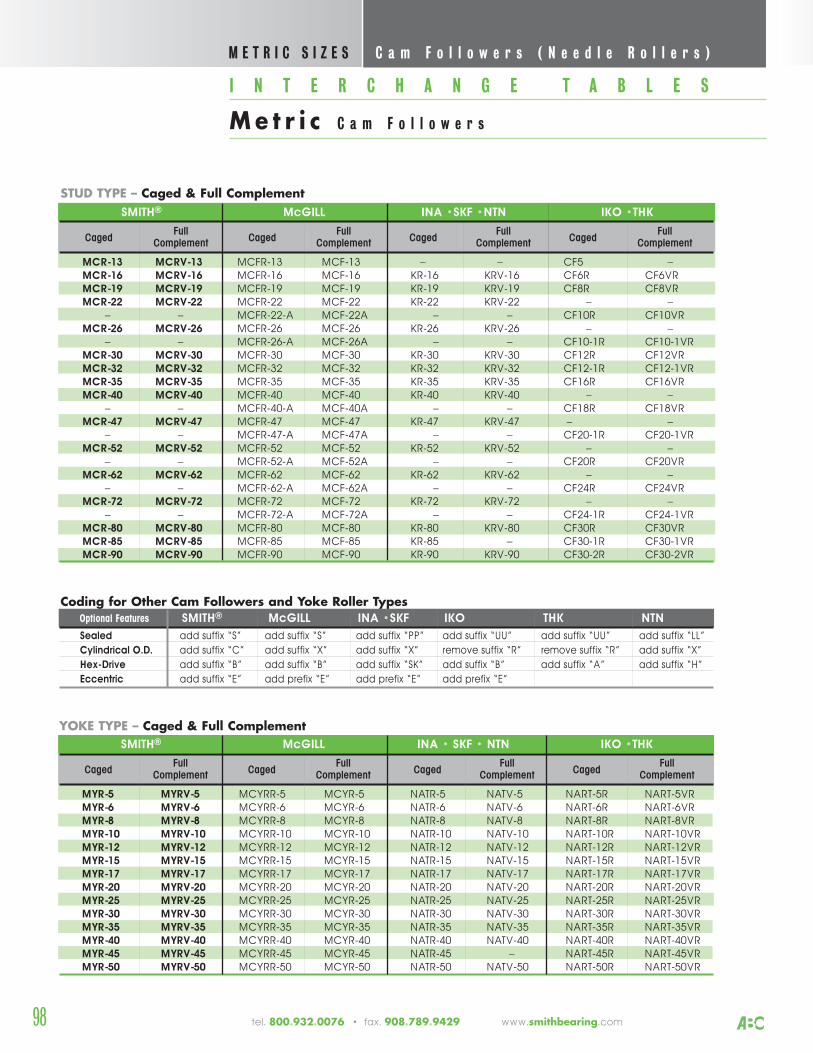
STUD TYPE – Caged & Full Complement
I N T E R C H A N G E T A B L E S
Me t r i c C a m F o l l o w e r s
SMITH® McGILL INA • SKF • NTN IKO •THK
CagedFull
CagedFull
CagedFull
CagedFull
Complement Complement Complement Complement
MYR-5 MYRV-5 MCYRR-5 MCYR-5 NATR-5 NATV-5 NART-5R NART-5VRMYR-6 MYRV-6 MCYRR-6 MCYR-6 NATR-6 NATV-6 NART-6R NART-6VRMYR-8 MYRV-8 MCYRR-8 MCYR-8 NATR-8 NATV-8 NART-8R NART-8VRMYR-10 MYRV-10 MCYRR-10 MCYR-10 NATR-10 NATV-10 NART-10R NART-10VRMYR-12 MYRV-12 MCYRR-12 MCYR-12 NATR-12 NATV-12 NART-12R NART-12VRMYR-15 MYRV-15 MCYRR-15 MCYR-15 NATR-15 NATV-15 NART-15R NART-15VRMYR-17 MYRV-17 MCYRR-17 MCYR-17 NATR-17 NATV-17 NART-17R NART-17VRMYR-20 MYRV-20 MCYRR-20 MCYR-20 NATR-20 NATV-20 NART-20R NART-20VRMYR-25 MYRV-25 MCYRR-25 MCYR-25 NATR-25 NATV-25 NART-25R NART-25VRMYR-30 MYRV-30 MCYRR-30 MCYR-30 NATR-30 NATV-30 NART-30R NART-30VRMYR-35 MYRV-35 MCYRR-35 MCYR-35 NATR-35 NATV-35 NART-35R NART-35VRMYR-40 MYRV-40 MCYRR-40 MCYR-40 NATR-40 NATV-40 NART-40R NART-40VRMYR-45 MYRV-45 MCYRR-45 MCYR-45 NATR-45 – NART-45R NART-45VRMYR-50 MYRV-50 MCYRR-50 MCYR-50 NATR-50 NATV-50 NART-50R NART-50VR
YOKE TYPE – Caged & Full Complement
Coding for Other Cam Followers and Yoke Roller TypesOptional Features SMITH® McGILL INA •SKF IKO THK NTN
Sealed add suffix “S” add suffix “S” add suffix “PP” add suffix “UU” add suffix “UU” add suffix “LL”
Cylindrical O.D. add suffix “C” add suffix “X” add suffix “X” remove suffix “R” remove suffix “R” add suffix “X”
Hex-Drive add suffix “B” add suffix “B” add suffix “SK” add suffix “B” add suffix “A” add suffix “H”
Eccentric add suffix “E” add prefix “E” add prefix “E” add prefix “E”
SMITH® McGILL INA •SKF •NTN IKO •THK
CagedFull
CagedFull
CagedFull
CagedFull
Complement Complement Complement Complement
MCR-13 MCRV-13 MCFR-13 MCF-13 – – CF5 –MCR-16 MCRV-16 MCFR-16 MCF-16 KR-16 KRV-16 CF6R CF6VRMCR-19 MCRV-19 MCFR-19 MCF-19 KR-19 KRV-19 CF8R CF8VRMCR-22 MCRV-22 MCFR-22 MCF-22 KR-22 KRV-22 – –
– – MCFR-22-A MCF-22A – – CF10R CF10VRMCR-26 MCRV-26 MCFR-26 MCF-26 KR-26 KRV-26 – –
– – MCFR-26-A MCF-26A – – CF10-1R CF10-1VRMCR-30 MCRV-30 MCFR-30 MCF-30 KR-30 KRV-30 CF12R CF12VRMCR-32 MCRV-32 MCFR-32 MCF-32 KR-32 KRV-32 CF12-1R CF12-1VRMCR-35 MCRV-35 MCFR-35 MCF-35 KR-35 KRV-35 CF16R CF16VRMCR-40 MCRV-40 MCFR-40 MCF-40 KR-40 KRV-40 – –
– – MCFR-40-A MCF-40A – – CF18R CF18VRMCR-47 MCRV-47 MCFR-47 MCF-47 KR-47 KRV-47 – –
– – MCFR-47-A MCF-47A – – CF20-1R CF20-1VRMCR-52 MCRV-52 MCFR-52 MCF-52 KR-52 KRV-52 – –
– – MCFR-52-A MCF-52A – – CF20R CF20VRMCR-62 MCRV-62 MCFR-62 MCF-62 KR-62 KRV-62 – –
– – MCFR-62-A MCF-62A – – CF24R CF24VRMCR-72 MCRV-72 MCFR-72 MCF-72 KR-72 KRV-72 – –
– – MCFR-72-A MCF-72A – – CF24-1R CF24-1VRMCR-80 MCRV-80 MCFR-80 MCF-80 KR-80 KRV-80 CF30R CF30VRMCR-85 MCRV-85 MCFR-85 MCF-85 KR-85 – CF30-1R CF30-1VRMCR-90 MCRV-90 MCFR-90 MCF-90 KR-90 KRV-90 CF30-2R CF30-2VR
C a m F o l l o w e r s ( N e e d l e R o l l e r s ) M E T R I C S I Z E S
tel. 800.932.0076 • fax. 908.789.9429 www.smithbearing.com 98
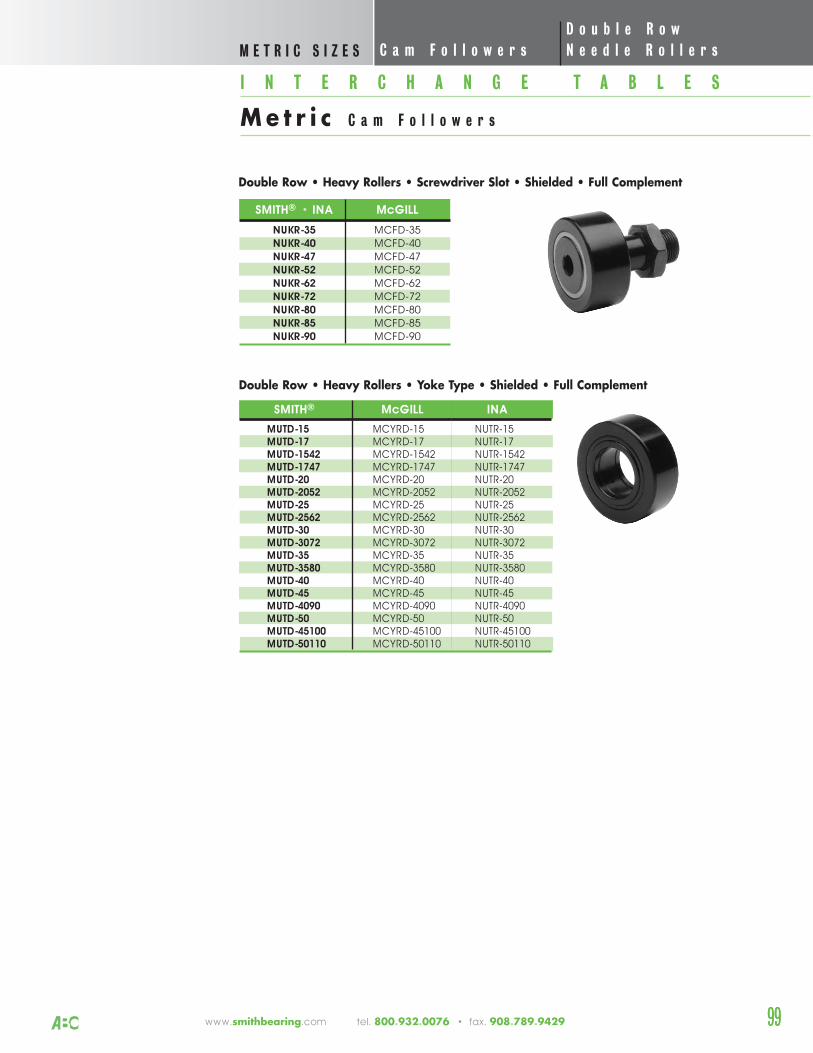
www.smithbearing.com tel. 800.932.0076 • fax. 908.789.9429 99
SMITH® • INA McGILL
NUKR-35 MCFD-35NUKR-40 MCFD-40NUKR-47 MCFD-47NUKR-52 MCFD-52NUKR-62 MCFD-62NUKR-72 MCFD-72NUKR-80 MCFD-80NUKR-85 MCFD-85NUKR-90 MCFD-90
Double Row • Heavy Rollers • Screwdriver Slot • Shielded • Full Complement
SMITH® McGILL INA
MUTD-15 MCYRD-15 NUTR-15MUTD-17 MCYRD-17 NUTR-17MUTD-1542 MCYRD-1542 NUTR-1542MUTD-1747 MCYRD-1747 NUTR-1747MUTD-20 MCYRD-20 NUTR-20MUTD-2052 MCYRD-2052 NUTR-2052MUTD-25 MCYRD-25 NUTR-25MUTD-2562 MCYRD-2562 NUTR-2562MUTD-30 MCYRD-30 NUTR-30MUTD-3072 MCYRD-3072 NUTR-3072MUTD-35 MCYRD-35 NUTR-35MUTD-3580 MCYRD-3580 NUTR-3580MUTD-40 MCYRD-40 NUTR-40MUTD-45 MCYRD-45 NUTR-45MUTD-4090 MCYRD-4090 NUTR-4090MUTD-50 MCYRD-50 NUTR-50MUTD-45100 MCYRD-45100 NUTR-45100MUTD-50110 MCYRD-50110 NUTR-50110
D o u b l e R o wC a m F o l l o w e r s N e e d l e R o l l e r s
I N T E R C H A N G E T A B L E S
Me t r i c C a m F o l l o w e r s
M E T R I C S I Z E S
Double Row • Heavy Rollers • Yoke Type • Shielded • Full Complement
99
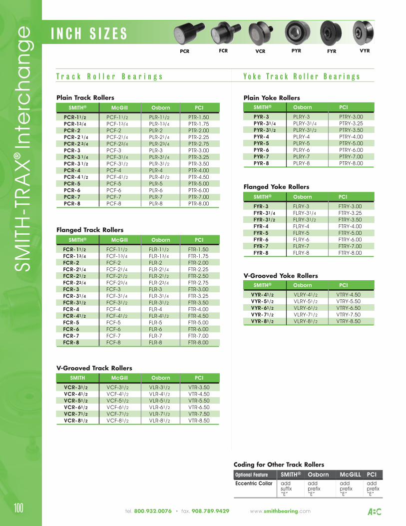
tel. 800.932.0076 • fax. 908.789.9429 www.smithbearing.com
Plain Track RollersSMITH® McGill Osborn PCI
PCR-11/2 PCF-11/2 PLR-11/2 PTR-1.50PCR-13/4 PCF-13/4 PLR-13/4 PTR-1.75PCR-2 PCF-2 PLR-2 PTR-2.00PCR-2 1/4 PCF-21/4 PLR-21/4 PTR-2.25PCR-2 3/4 PCF-23/4 PLR-23/4 PTR-2.75PCR-3 PCF-3 PLR-3 PTR-3.00PCR-3 1/4 PCF-31/4 PLR-31/4 PTR-3.25PCR-3 1/2 PCF-31/2 PLR-31/2 PTR-3.50PCR-4 PCF-4 PLR-4 PTR-4.00PCR-4 1/2 PCF-41/2 PLR-41/2 PTR-4.50PCR-5 PCF-5 PLR-5 PTR-5.00PCR-6 PCF-6 PLR-6 PTR-6.00PCR-7 PCF-7 PLR-7 PTR-7.00PCR-8 PCF-8 PLR-8 PTR-8.00
T r a c k R o l l e r B e a r i n g s
V-Grooved Track RollersSMITH McGill Osborn PCI
VCR-31/2 VCF-31/2 VLR-31/2 VTR-3.50VCR-41/2 VCF-41/2 VLR-41/2 VTR-4.50VCR-51/2 VCF-51/2 VLR-51/2 VTR-5.50VCR-61/2 VCF-61/2 VLR-61/2 VTR-6.50VCR-71/2 VCF-71/2 VLR-71/2 VTR-7.50VCR-81/2 VCF-81/2 VLR-81/2 VTR-8.50
Plain Yoke RollersSMITH® Osborn PCI
PYR-3 PLRY-3 PTRY-3.00PYR-31/4 PLRY-31/4 PTRY-3.25PYR-31/2 PLRY-31/2 PTRY-3.50PYR-4 PLRY-4 PTRY-4.00PYR-5 PLRY-5 PTRY-5.00PYR-6 PLRY-6 PTRY-6.00PYR-7 PLRY-7 PTRY-7.00PYR-8 PLRY-8 PTRY-8.00
V-Grooved Yoke RollersSMITH® Osborn PCI
VYR-41/2 VLRY-41/2 VTRY-4.50VYR-51/2 VLRY-51/2 VTRY-5.50VYR-61/2 VLRY-61/2 VTRY-6.50VYR-71/2 VLRY-71/2 VTRY-7.50VYR-81/2 VLRY-81/2 VTRY-8.50
Flanged Yoke RollersSMITH® Osborn PCI
FYR-3 FLRY-3 FTRY-3.00FYR-31/4 FLRY-31/4 FTRY-3.25FYR-31/2 FLRY-31/2 FTRY-3.50FYR-4 FLRY-4 FTRY-4.00FYR-5 FLRY-5 FTRY-5.00FYR-6 FLRY-6 FTRY-6.00FYR-7 FLRY-7 FTRY-7.00FYR-8 FLRY-8 FTRY-8.00
Y o k e T r a c k R o l l e r B e a r i n g s
Flanged Track RollersSMITH® McGill Osborn PCI
FCR-11/2 FCF-11/2 FLR-11/2 FTR-1.50FCR-13/4 FCF-13/4 FLR-13/4 FTR-1.75FCR-2 FCF-2 FLR-2 FTR-2.00FCR-21/4 FCF-21/4 FLR-21/4 FTR-2.25FCR-21/2 FCF-21/2 FLR-21/2 FTR-2.50FCR-23/4 FCF-23/4 FLR-23/4 FTR-2.75FCR-3 FCF-3 FLR-3 FTR-3.00FCR-31/4 FCF-31/4 FLR-31/4 FTR-3.25FCR-31/2 FCF-31/2 FLR-31/2 FTR-3.50FCR-4 FCF-4 FLR-4 FTR-4.00FCR-41/2 FCF-41/2 FLR-41/2 FTR-4.50FCR-5 FCF-5 FLR-5 FTR-5.00FCR-6 FCF-6 FLR-6 FTR-6.00FCR-7 FCF-7 FLR-7 FTR-7.00FCR-8 FCF-8 FLR-8 FTR-8.00
Coding for Other Track RollersOptional Feature SMITH® Osborn McGILL PCI
Eccentric Collar add add add addsuffix prefix prefix prefix“E” “E” “E” “E”
I N C H S I Z E SPCR FCR VCR PYR FYR VYR
SMIT
H-T
RA
X® In
terc
ha
ng
e
100
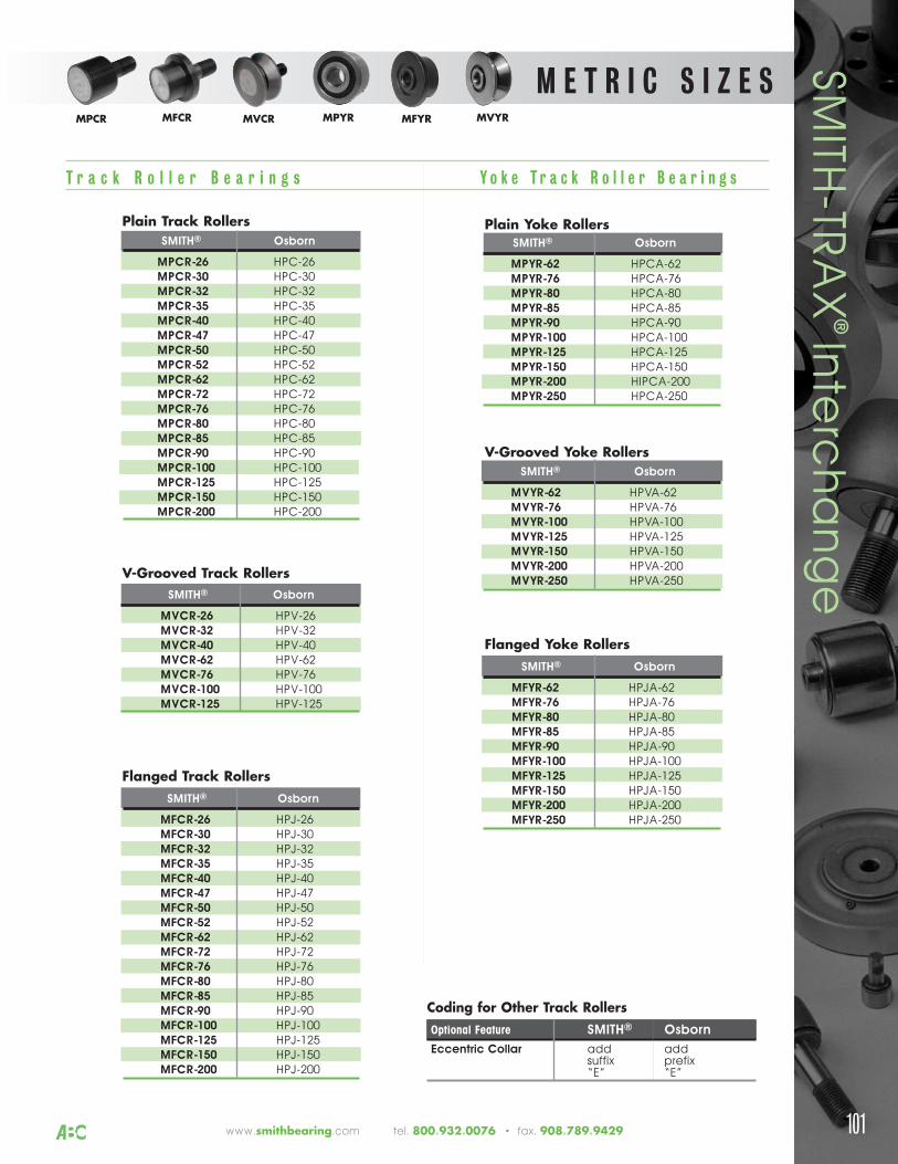
www.smithbearing.com tel. 800.932.0076 • fax. 908.789.9429 101
M E T R I C S I Z E S
Plain Track RollersSMITH® Osborn
MPCR-26 HPC-26MPCR-30 HPC-30MPCR-32 HPC-32MPCR-35 HPC-35MPCR-40 HPC-40MPCR-47 HPC-47MPCR-50 HPC-50MPCR-52 HPC-52MPCR-62 HPC-62MPCR-72 HPC-72MPCR-76 HPC-76MPCR-80 HPC-80MPCR-85 HPC-85MPCR-90 HPC-90MPCR-100 HPC-100MPCR-125 HPC-125MPCR-150 HPC-150MPCR-200 HPC-200
V-Grooved Track RollersSMITH® Osborn
MVCR-26 HPV-26MVCR-32 HPV-32MVCR-40 HPV-40MVCR-62 HPV-62MVCR-76 HPV-76MVCR-100 HPV-100MVCR-125 HPV-125
Plain Yoke RollersSMITH® Osborn
MPYR-62 HPCA-62MPYR-76 HPCA-76MPYR-80 HPCA-80MPYR-85 HPCA-85MPYR-90 HPCA-90MPYR-100 HPCA-100MPYR-125 HPCA-125MPYR-150 HPCA-150MPYR-200 HIPCA-200MPYR-250 HPCA-250
V-Grooved Yoke RollersSMITH® Osborn
MVYR-62 HPVA-62MVYR-76 HPVA-76MVYR-100 HPVA-100MVYR-125 HPVA-125MVYR-150 HPVA-150MVYR-200 HPVA-200MVYR-250 HPVA-250
Flanged Yoke RollersSMITH® Osborn
MFYR-62 HPJA-62MFYR-76 HPJA-76MFYR-80 HPJA-80MFYR-85 HPJA-85MFYR-90 HPJA-90MFYR-100 HPJA-100MFYR-125 HPJA-125MFYR-150 HPJA-150MFYR-200 HPJA-200MFYR-250 HPJA-250
Flanged Track RollersSMITH® Osborn
MFCR-26 HPJ-26MFCR-30 HPJ-30MFCR-32 HPJ-32MFCR-35 HPJ-35MFCR-40 HPJ-40MFCR-47 HPJ-47MFCR-50 HPJ-50MFCR-52 HPJ-52MFCR-62 HPJ-62MFCR-72 HPJ-72MFCR-76 HPJ-76MFCR-80 HPJ-80MFCR-85 HPJ-85MFCR-90 HPJ-90MFCR-100 HPJ-100MFCR-125 HPJ-125MFCR-150 HPJ-150MFCR-200 HPJ-200
Coding for Other Track RollersOptional Feature SMITH® Osborn
Eccentric Collar add addsuffix prefix“E” “E”
T r a c k R o l l e r B e a r i n g s Y o k e T r a c k R o l l e r B e a r i n g s
SMITH
-TRA
X® In
terc
ha
ng
eMPCR MFCR MVCR MPYR MFYR MVYR
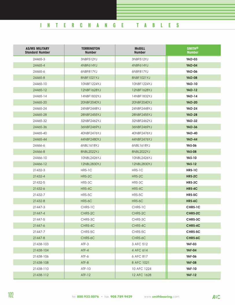
AS/MS MILITARY TORRINGTON McGILL SMITH®
Standard Number Number Number Number
24465-3 3NBF512YJ 3NBF512YJ YAD-03
24465-4 4NBF614YJ 4NBF614YJ YAD-04
24465-6 6NBF817YJ 6NBF817YJ YAD-06
24465-8 8NBF1021YJ 8NBF1021YJ YAD-08
24465-10 10NBF1224YJ 10NBF1224YJ YAD-10
24465-12 12NBF1628YJ 12NBF1628YJ YAD-12
24465-14 14NBF1832YJ 14NBF1832YJ YAD-14
24465-20 20NBF2040YJ 20NBF2040YJ YAD-20
24465-24 24NBF2448YJ 24NBF2448YJ YAD-24
24465-28 28NBF2455YJ 28NBF2455YJ YAD-28
24465-32 32NBF2462YJ 32NBF2462YJ YAD-32
24465-36 36NBF2469YJ 36NBF2469YJ YAD-36
24465-40 40NBF2476YJ 40NBF2476YJ YAD-40
24465-44 44NBF2480YJ 44NBF2476YJ YAD-44
24466-6 6NBL1618YJ 6NBL1618YJ YAS-06
24466-8 8NBL2022YJ 8NBL2022YJ YAS-08
24466-10 10NBL2426YJ 10NBL2426YJ YAS-10
24466-12 12NBL2830YJ 12NBL2830YJ YAS-12
21432-3 HRS-1C HRS-1C HRS-1C
21432-4 HRS-2C HRS-2C HRS-2C
21432-5 HRS-3C HRS-3C HRS-3C
21432-6 HRS-4C HRS-4C HRS-4C
21432-7 HRS-5C HRS-5C HRS-5C
21432-8 HRS-6C HRS-6C HRS-6C
21447-3 CHRS-1C CHRS-1C CHRS-1C
21447-4 CHRS-2C CHRS-2C CHRS-2C
21447-5 CHRS-3C CHRS-3C CHRS-3C
21447-6 CHRS-4C CHRS-4C CHRS-4C
21447-7 CHRS-5C CHRS-5C CHRS-5C
21447-8 CHRS-6C CHRS-6C CHRS-6C
21438-103 ATF-3 3 AFC 512 YAF-03
21438-104 ATF-4 4 AFC 614 YAF-04
21438-106 ATF-6 6 AFC 817 YAF-06
21438-108 ATF-8 8 AFC 1021 YAF-08
21438-110 ATF-10 10 AFC 1224 YAF-10
21438-112 ATF-12 12 AFC 1628 YAF-12
A E R O S P A C E B E A R I N G S
I N T E R C H A N G E T A B L E S
102 tel. 800.932.0076 • fax. 908.789.9429 www.smithbearing.com
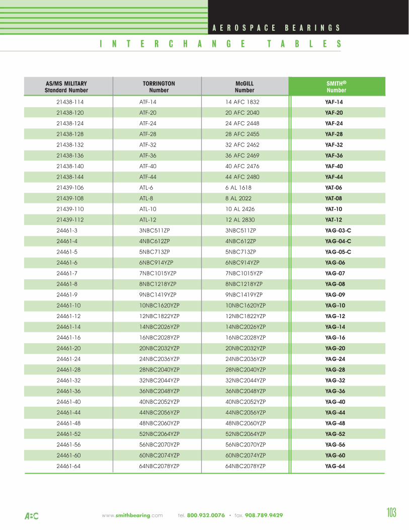
A E R O S P A C E B E A R I N G S
I N T E R C H A N G E T A B L E S
www.smithbearing.com tel. 800.932.0076 • fax. 908.789.9429
AS/MS MILITARY TORRINGTON McGILL SMITH®
Standard Number Number Number Number
21438-114 ATF-14 14 AFC 1832 YAF-14
21438-120 ATF-20 20 AFC 2040 YAF-20
21438-124 ATF-24 24 AFC 2448 YAF-24
21438-128 ATF-28 28 AFC 2455 YAF-28
21438-132 ATF-32 32 AFC 2462 YAF-32
21438-136 ATF-36 36 AFC 2469 YAF-36
21438-140 ATF-40 40 AFC 2476 YAF-40
21438-144 ATF-44 44 AFC 2480 YAF-44
21439-106 ATL-6 6 AL 1618 YAT-06
21439-108 ATL-8 8 AL 2022 YAT-08
21439-110 ATL-10 10 AL 2426 YAT-10
21439-112 ATL-12 12 AL 2830 YAT-12
24461-3 3NBC511ZP 3NBC511ZP YAG-03-C
24461-4 4NBC612ZP 4NBC612ZP YAG-04-C
24461-5 5NBC713ZP 5NBC713ZP YAG-05-C
24461-6 6NBC914YZP 6NBC914YZP YAG-06
24461-7 7NBC1015YZP 7NBC1015YZP YAG-07
24461-8 8NBC1218YZP 8NBC1218YZP YAG-08
24461-9 9NBC1419YZP 9NBC1419YZP YAG-09
24461-10 10NBC1620YZP 10NBC1620YZP YAG-10
24461-12 12NBC1822YZP 12NBC1822YZP YAG-12
24461-14 14NBC2026YZP 14NBC2026YZP YAG-14
24461-16 16NBC2028YZP 16NBC2028YZP YAG-16
24461-20 20NBC2032YZP 20NBC2032YZP YAG-20
24461-24 24NBC2036YZP 24NBC2036YZP YAG-24
24461-28 28NBC2040YZP 28NBC2040YZP YAG-28
24461-32 32NBC2044YZP 32NBC2044YZP YAG-32
24461-36 36NBC2048YZP 36NBC2048YZP YAG-36
24461-40 40NBC2052YZP 40NBC2052YZP YAG-40
24461-44 44NBC2056YZP 44NBC2056YZP YAG-44
24461-48 48NBC2060YZP 48NBC2060YZP YAG-48
24461-52 52NBC2064YZP 52NBC2064YZP YAG-52
24461-56 56NBC2070YZP 56NBC2070YZP YAG-56
24461-60 60NBC2074YZP 60NBC2074YZP YAG-60
24461-64 64NBC2078YZP 64NBC2078YZP YAG-64
103
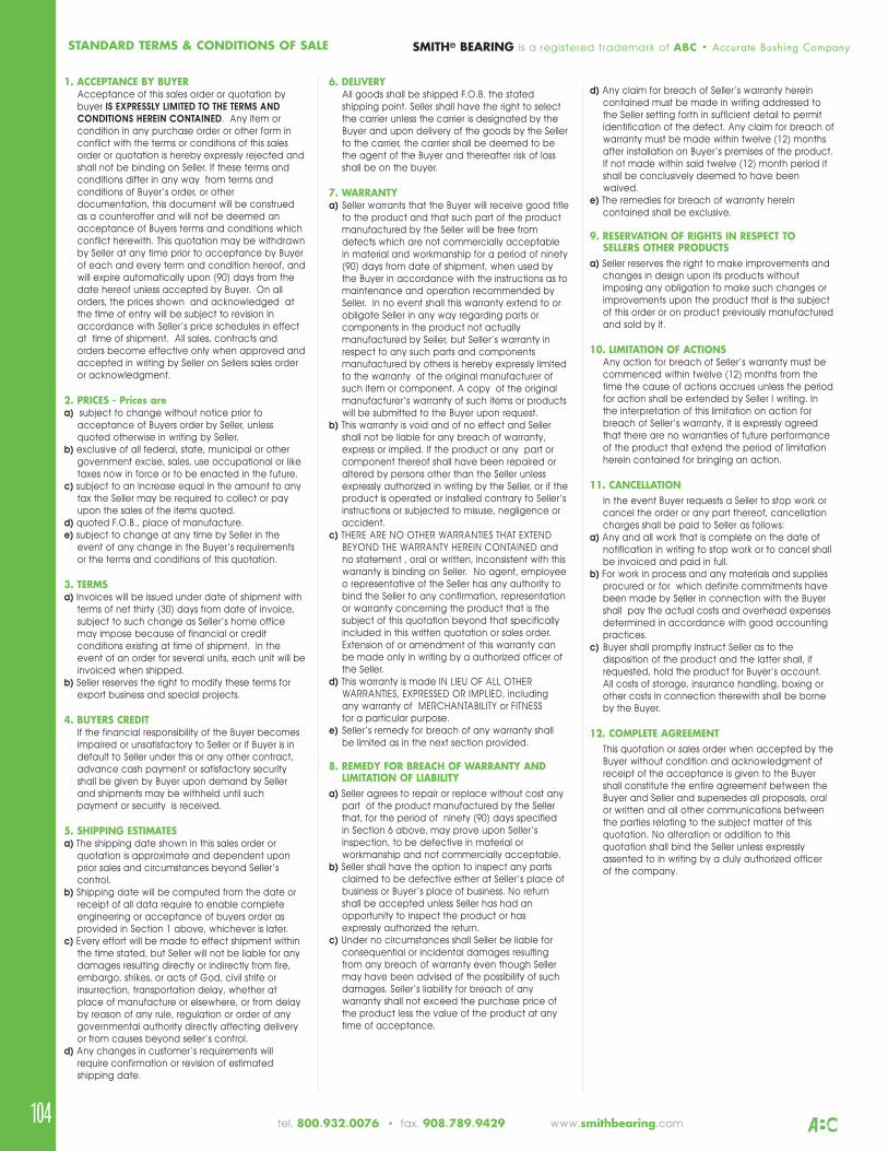
tel. 800.932.0076 • fax. 908.789.9429 www.smithbearing.com 104
d) Any claim for breach of Seller’s warranty hereincontained must be made in writing addressed tothe Seller setting forth in sufficient detail to permitidentification of the defect. Any claim for breach ofwarranty must be made within twelve (12) monthsafter installation on Buyer’s premises of the product.If not made within said twelve (12) month period itshall be conclusively deemed to have beenwaived.
e) The remedies for breach of warranty hereincontained shall be exclusive.
9. RESERVATION OF RIGHTS IN RESPECT TOSELLERS OTHER PRODUCTS
a) Seller reserves the right to make improvements andchanges in design upon its products withoutimposing any obligation to make such changes orimprovements upon the product that is the subjectof this order or on product previously manufacturedand sold by it.
10. LIMITATION OF ACTIONSAny action for breach of Seller’s warranty must becommenced within twelve (12) months from thetime the cause of actions accrues unless the periodfor action shall be extended by Seller I writing. Inthe interpretation of this limitation on action forbreach of Seller’s warranty, it is expressly agreedthat there are no warranties of future performanceof the product that extend the period of limitationherein contained for bringing an action.
11. CANCELLATION In the event Buyer requests a Seller to stop work orcancel the order or any part thereof, cancellationcharges shall be paid to Seller as follows:
a) Any and all work that is complete on the date ofnotification in writing to stop work or to cancel shallbe invoiced and paid in full.
b) For work in process and any materials and suppliesprocured or for which definite commitments havebeen made by Seller in connection with the Buyershall pay the actual costs and overhead expensesdetermined in accordance with good accountingpractices.
c) Buyer shall promptly instruct Seller as to thedisposition of the product and the latter shall, ifrequested, hold the product for Buyer’s account.All costs of storage, insurance handling, boxing orother costs in connection therewith shall be borneby the Buyer.
12. COMPLETE AGREEMENTThis quotation or sales order when accepted by theBuyer without condition and acknowledgment ofreceipt of the acceptance is given to the Buyershall constitute the entire agreement between theBuyer and Seller and supersedes all proposals, oralor written and all other communications betweenthe parties relating to the subject matter of thisquotation. No alteration or addition to thisquotation shall bind the Seller unless expresslyassented to in writing by a duly authorized officer of the company.
1. ACCEPTANCE BY BUYERAcceptance of this sales order or quotation bybuyer IS EXPRESSLY LIMITED TO THE TERMS AND
CONDITIONS HEREIN CONTAINED. Any item orcondition in any purchase order or other form inconflict with the terms or conditions of this salesorder or quotation is hereby expressly rejected andshall not be binding on Seller. If these terms andconditions differ in any way from terms andconditions of Buyer’s order, or otherdocumentation, this document will be construedas a counteroffer and will not be deemed anacceptance of Buyers terms and conditions whichconflict herewith. This quotation may be withdrawnby Seller at any time prior to acceptance by Buyerof each and every term and condition hereof, andwill expire automatically upon (90) days from thedate hereof unless accepted by Buyer. On allorders, the prices shown and acknowledged atthe time of entry will be subject to revision inaccordance with Seller’s price schedules in effectat time of shipment. All sales, contracts andorders become effective only when approved andaccepted in writing by Seller on Sellers sales orderor acknowledgment.
2. PRICES - Prices area) subject to change without notice prior to
acceptance of Buyers order by Seller, unlessquoted otherwise in writing by Seller.
b) exclusive of all federal, state, municipal or othergovernment excise, sales, use occupational or liketaxes now in force or to be enacted in the future.
c) subject to an increase equal in the amount to anytax the Seller may be required to collect or payupon the sales of the items quoted.
d) quoted F.O.B., place of manufacture.e) subject to change at any time by Seller in the
event of any change in the Buyer’s requirementsor the terms and conditions of this quotation.
3. TERMSa) Invoices will be issued under date of shipment with
terms of net thirty (30) days from date of invoice,subject to such change as Seller’s home officemay impose because of financial or creditconditions existing at time of shipment. In theevent of an order for several units, each unit will beinvoiced when shipped.
b) Seller reserves the right to modify these terms forexport business and special projects.
4. BUYERS CREDITIf the financial responsibility of the Buyer becomesimpaired or unsatisfactory to Seller or if Buyer is indefault to Seller under this or any other contract,advance cash payment or satisfactory securityshall be given by Buyer upon demand by Sellerand shipments may be withheld until suchpayment or security is received.
5. SHIPPING ESTIMATESa) The shipping date shown in this sales order or
quotation is approximate and dependent uponprior sales and circumstances beyond Seller’scontrol.
b) Shipping date will be computed from the date orreceipt of all data require to enable completeengineering or acceptance of buyers order asprovided in Section 1 above, whichever is later.
c) Every effort will be made to effect shipment withinthe time stated, but Seller will not be liable for anydamages resulting directly or indirectly from fire,embargo, strikes, or acts of God, civil strife orinsurrection, transportation delay, whether atplace of manufacture or elsewhere, or from delayby reason of any rule, regulation or order of anygovernmental authority directly affecting deliveryor from causes beyond seller’s control.
d) Any changes in customer’s requirements willrequire confirmation or revision of estimatedshipping date.
6. DELIVERYAll goods shall be shipped F.O.B. the statedshipping point. Seller shall have the right to selectthe carrier unless the carrier is designated by theBuyer and upon delivery of the goods by the Sellerto the carrier, the carrier shall be deemed to bethe agent of the Buyer and thereafter risk of lossshall be on the buyer.
7. WARRANTYa) Seller warrants that the Buyer will receive good title
to the product and that such part of the productmanufactured by the Seller will be free fromdefects which are not commercially acceptablein material and workmanship for a period of ninety(90) days from date of shipment, when used bythe Buyer in accordance with the instructions as tomaintenance and operation recommended bySeller. In no event shall this warranty extend to orobligate Seller in any way regarding parts orcomponents in the product not actuallymanufactured by Seller, but Seller’s warranty inrespect to any such parts and componentsmanufactured by others is hereby expressly limitedto the warranty of the original manufacturer ofsuch item or component. A copy of the originalmanufacturer’s warranty of such items or productswill be submitted to the Buyer upon request.
b) This warranty is void and of no effect and Sellershall not be liable for any breach of warranty,express or implied. If the product or any part orcomponent thereof shall have been repaired oraltered by persons other than the Seller unlessexpressly authorized in writing by the Seller, or if theproduct is operated or installed contrary to Seller’sinstructions or subjected to misuse, negligence oraccident.
c) THERE ARE NO OTHER WARRANTIES THAT EXTENDBEYOND THE WARRANTY HEREIN CONTAINED andno statement , oral or written, inconsistent with thiswarranty is binding on Seller. No agent, employeeo representative of the Seller has any authority tobind the Seller to any confirmation, representationor warranty concerning the product that is thesubject of this quotation beyond that specificallyincluded in this written quotation or sales order.Extension of or amendment of this warranty canbe made only in writing by a authorized officer ofthe Seller.
d) This warranty is made IN LIEU OF ALL OTHERWARRANTIES, EXPRESSED OR IMPLIED, includingany warranty of MERCHANTABILITY or FITNESS for a particular purpose.
e) Seller’s remedy for breach of any warranty shallbe limited as in the next section provided.
8. REMEDY FOR BREACH OF WARRANTY ANDLIMITATION OF LIABILITY
a) Seller agrees to repair or replace without cost anypart of the product manufactured by the Sellerthat, for the period of ninety (90) days specifiedin Section 6 above, may prove upon Seller’sinspection, to be defective in material orworkmanship and not commercially acceptable.
b) Seller shall have the option to inspect any partsclaimed to be defective either at Seller’s place ofbusiness or Buyer’s place of business. No returnshall be accepted unless Seller has had anopportunity to inspect the product or has expressly authorized the return.
c) Under no circumstances shall Seller be liable forconsequential or incidental damages resultingfrom any breach of warranty even though Sellermay have been advised of the possibility of suchdamages. Seller’s liability for breach of anywarranty shall not exceed the purchase price ofthe product less the value of the product at anytime of acceptance.
STANDARD TERMS & CONDITIONS OF SALE SMITH® BEARING is a registered trademark of ABC • Accurate Bushing Company

CORPORATE HEADQUARTERS443 North Avenue
Garwood • NJ • 07027 • USA
tel: 908.789.1121fax: 908.789.9429 800.932.0076
www.smithbearing.com
www.accuratebushing.com
Standard & Custom Bearings and Special Assembliesfor Aerospace & Industrial Applications
All products in this catalog subject to Accurate Bushing Company terms and conditions, a copy of which is available in theback of this catalog or may be requested from the customer service department.
SMITH Bearing, SMITH-TRAX, & SMITH-ALIGN are registered trademarks of Accurate Bushing Company.Copyright © 2014 Accurate Bushing Company. All rights reserved.
��
accurate bushing co.SMITH BEARING®i s a r e g i s t e r e d t r a d e m a r k o f
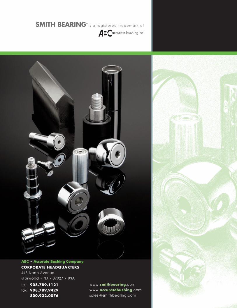
��
accurate bushing co.
SMITH BEARING®i s a r e g i s t e r e d t r a d e m a r k o f
www.smithbearing.com
www.accuratebushing.com
sales @smithbearing.com
ABC • Accurate Bushing CompanyCORPORATE HEADQUARTERS443 North Avenue
Garwood • NJ • 07027 • USA
tel: 908.789.1121fax: 908.789.9429 800.932.0076


