Embed Size (px)
Citation preview
HAL Id: hal-01713616https://hal.archives-ouvertes.fr/hal-01713616v1
Submitted on 20 Feb 2018 (v1), last revised 2 Mar 2018 (v2)
HAL is a multi-disciplinary open accessarchive for the deposit and dissemination of sci-entific research documents, whether they are pub-lished or not. The documents may come fromteaching and research institutions in France orabroad, or from public or private research centers.
L’archive ouverte pluridisciplinaire HAL, estdestinée au dépôt et à la diffusion de documentsscientifiques de niveau recherche, publiés ou non,émanant des établissements d’enseignement et derecherche français ou étrangers, des laboratoirespublics ou privés.
A Multi-Agent Advanced Traveler Information Systemfor Optimal Trip Planning in a Co-Modal Framework
Mariagrazia Dotoli, Hayfa Zgaya, Carmine Russo, Slim Hammadi
To cite this version:Mariagrazia Dotoli, Hayfa Zgaya, Carmine Russo, Slim Hammadi. A Multi-Agent Advanced TravelerInformation System for Optimal Trip Planning in a Co-Modal Framework. IEEE Transactions onIntelligent Transportation Systems, IEEE, 2017, 18 (9), pp.2397 - 2412. �10.1109/TITS.2016.2645278�.�hal-01713616v1�
IEEE TRANSACTIONS ON INTELLIGENT TRANSPORTATION SYSTEMS, VOL. 18, NO. 9, SEPTEMBER 2017 2397
A Multi-Agent Advanced Traveler InformationSystem for Optimal Trip Planning
in a Co-Modal FrameworkMariagrazia Dotoli, Senior Member, IEEE, Hayfa Zgaya, Carmine Russo,
and Slim Hammadi, Senior Member, IEEE
Abstract— We present an advanced traveler informationsystem (ATIS) for public and private transportation, includingvehicle sharing and pooling services. The ATIS uses an agent-based architecture and multi-objective optimization to answertrip planning requests from multiple users in a co-modal setting,considering vehicle preferences and conflicting criteria. At eachset of users’ requests, the transportation network is representedby a co-modal graph that allows decomposing the trip planningproblem into smaller tasks: the shortest routes between the net-work nodes are determined and then combined to obtain possibleitineraries. Using multi-objective optimization, the set of user-vehicle-route combinations according to the users’ preferencesis determined, ranking all possible route agents’ coalitions. TheATIS is tested for the real case study of the Lille metropolitanarea (Nord Pas de Calais, France).
Index Terms— Advanced traveler information system, tripplanning, public transport, private transport, co-modal transport,multi-agent systems, directed graphs, optimization.
I. INTRODUCTION
A. Contribution
SHARED transportation services are emergingconcepts [5]. In multi-modal transportation users
employ at least two different types of means of transport.Co-modality, instead, arises from the need to convey peopleon a single means of transport to reduce the impact onenvironment, costs, and accidents. Hence, co-modality refersto the optimal use of different transportation modes on theirown or in combination, taking advantage of ridesharing(the sharing of vehicles by passengers). Information andcommunication technologies may support the developmentof advanced tools for passengers allowing the effectiveintegration of transportation modalities [11], [25]. As a result,
Manuscript received October 14, 2015; revised March 23, 2016 andAugust 31, 2016; accepted December 18, 2016. Date of publicationJanuary 23, 2017; date of current version August 28, 2017. The AssociateEditor for this paper was D. Chen.
M. Dotoli is with the Department of Electrical and Information Engineering,Politecnico di Bari, 70125 Bari, Italy (e-mail: [email protected]).
H. Zgaya is with the ILIS-Lille Institute of Healthcare Engineering,Université de Lille 2, 59000 Lille, France (e-mail: [email protected]).
C. Russo is with the Magneti Marelli-Powertrain Research, 10135 Torino,Italy (e-mail: [email protected]).
S. Hammadi is with the CRISTAL-Research Centre in Computer Science,Signals and Automatic Systems of Lille, École Centrale de Lille, 59651 Lille,France (e-mail: [email protected]).
Digital Object Identifier 10.1109/TITS.2016.2645278
the field of intelligent transportation systems and particularlyof Advanced Traveler Information Systems (ATISs) is rapidlygrowing [44]. An ATIS may be defined as a system providingpre-trip and real time information on departures, routes, andmodes of travel. However, the related literature in the fieldof passengers’ co-modal transportation services is scarce,showing a need for ATISs supporting sustainability-orienteddecisions.
This paper aims at filling this gap by a multi-agent ATIS forpassengers’ pre-trip planning considering co-modal itinerarieswith multiple preference criteria, taking into account pub-lic and private transportation, and including vehicle sharingand pooling. Users request itineraries to the ATIS, withgiven (eventually different) origin and destination pairs andarrival/departure time windows, specifying their preferencesby an ordered sequence of criteria. The ATIS matches requestswith information in transportation operators’ databases andchooses transportation means and routes. It provides the routesanswering requests and optimizing travel time, travel cost,and gas emissions. To the best of the authors’ knowledge,no ATIS for trip planning exists in the literature for tripplanning both with private and public transport in a co-modaland multi-objective framework, i.e., with multiple users andpreferences. Moreover, with respect to the previous worksby the authors, we remark here that the paper enhances andextends three previous contributions [12], [20], [21]. TheATIS architecture borrows the multi-agent systems paradigmfrom [20], improving the vehicle/operator/route/users associa-tion, which is here determined in a stand-alone way withoutusing an external software as in [2] but rather representing,as in [21], the transportation network by a co-modal graph.With respect to [21], however, here two improvements areprovided. First, we enhance the trip calculation defining routeagents to represent the possible routes composing the itinerarysolution path and employing an agent coalition mechanismto determine the best person-to-vehicle assignment for theconcerned route using genetic optimization. Second, the usercan express his preference among different transportationmeans and define a descending order of priority of multi-ple criteria (cost, time, and emissions in the case study).Finally, we remark that the paper is a deeply revised versionof [12]. Here we detail the multi-agent architecture, onlysketched in [12], by describing all the agents operations.Moreover, we enhance the case study presenting a totally new
1524-9050 © 2017 IEEE. Personal use is permitted, but republication/redistribution requires IEEE permission.See http://www.ieee.org/publications_standards/publications/rights/index.html for more information.
2398 IEEE TRANSACTIONS ON INTELLIGENT TRANSPORTATION SYSTEMS, VOL. 18, NO. 9, SEPTEMBER 2017
urban scenario together with an extra-urban scenario revisitedfrom [12].
B. Related Works and Paper Positioning
Summaries of research contributions on passengers pre-trip route advisory systems are in [8]–[10], [44], and [45].Numerous projects were devoted to systems that recommendtravelers a combination of transportation means for door todoor journeys [6], [13], [16]–[19], [23], [24], [29], [32], [37],[39], [44]. However, all these works neither consider sharedpublic nor pooled private vehicles. Moreover, they solve thepre-trip planning for a single user, disregarding sustainability.
An interesting work is proposed by Zhang et al. [45] whopresent an ATIS for multimodal transport considering bothprivate and public transportation, considering time, cost, effortand comfort attributes. However, the approach is devoted tosingle user trip planning, i.e., it does not take into accountthe co-modal approach. Moreover, private and public networksare modeled separately and integrated only as a last step,determining the trip by a centralized approach, leading to longcomputational times. Other works use artificial intelligenceapproaches to develop an ATIS capable of some adaptability.For instance, Park et al. [30] present an adaptive routechoice system using a rule-based decision-tree approach toincorporate an adaptation process into a user’s route selectionrule. However, this work does not take into account multi-modality. Further, Arentze [3] presents an ATIS for tripplanning on multi-modal transport networks using Bayesianinference to adaptively learn the user’s preference. However,this approach is devoted to answering single users’ requests.More recently, several advanced public transportation informa-tion systems have been developed, determining the shortestitineraries in terms of travel time or cost through onlineweb-based applications (see the review in [46]). However, inall the recalled ATISs the problem is solved by a classicalcentralized approach and without any co-modality objective.In fact, the discussed works typically consider only a userrequest at a time. On the contrary, in our approach theATIS optimizes itineraries considering all requests at the sametime, taking into account the co-modal context, so that theATIS is intrinsically devoted to enhancing sustainable mobility.Further, thanks to the multi-agent systems framework, we areable to consider each mode of transportation and each providerof the transportation network in a distributed way, solving theproblem locally and combining solutions into an optimal set ofglobal solutions, so that we deeply reduce the computationalcomplexity.
In the context of multi-agent approaches [7] for pre-tripplanning, in [33] a personal intelligent traveler assistant fortrain passengers is developed. Using agents to communicatevia PDAs and a wireless network, the ATIS provides theuser with a personalized route advice taking into account hispreferences. In addition, Yin and Griss [42] present an agent-based multi-modal traveler information system that fuses infor-mation from multiple sources on routes, congestion, incidents,weather, alternative transit modes and schedules, resultingin a user-friendly personalized assistant to a single traveler.
However, both [33] and [42] present ATISs for single users.Further, in [35] a multi-agent system is presented addressing aset of requests in a temporal window by a vehicle routing witha time window approach. A tree is built, with the pieces of theoverall path, and the solution is found through a research intothis tree. However, the resulting complexity of the algorithmin [35] is exponential with the number of leaves of the tree.Further, in [47] a multi-agent route planner performs a localoptimization by each agent with respect to different criteria:traffic load, road safety, road type, and weather condition.After the local optimization, a global graph is built and anagent determines the travelling time. Differently from [35]and [47], in our multi-agent ATIS each agent determines apiece of the global solution, so that with the agents’ coalition,an overall solution may be found with a reduced complexitywith respect to the centralized case. Moreover, Adler et al. [2]propose a multi-agent approach for cooperative traffic man-agement that employs negotiation to solve the pre-trip routeassignment in a multi-objective framework, but the systemdoes not take into account sustainability that is essential ina co-modal framework.
Summing up, the cited studies on ATISs typically referto public transportation services, neither taking into accountvehicle sharing services nor vehicle pooling ones. Moreover,previous works typically consider one user, only one trans-portation service and use centralized information. On thecontrary, the ATIS here presented is able to consider anytype of public/private transportation services and operators,including vehicle sharing/pooling services and operators.
II. THE CO-MODAL TRIP PLANNING PROBLEM
A. The Problem Presentation
The scope of the proposed ATIS is to satisfy users’requests for itineraries by answering trip requests respectingpreferences. To this aim, the ATIS employs the notion ofco-modality: combining all possible means of public transportwith private transportations services, i.e., using different modeson their own or in combination to reach an effective andsustainable utilization of resources. To improve sustainability,the ATIS considers for each transportation service multipleoperators that may offer the same service.
We assume that multiple users formulate simultaneously (orin a short time window) a set of requests. Hence, the ATISdetermines feasible decompositions of each itinerary or route,i.e., subroutes, by recognizing similarities in order to associatedifferent users to the same vehicle and transportation service(so as to satisfy the co-modality requirements). For a givenroute or subroute, several transportation possibilities may existwith different vehicles, which may all be available for thatroute through the same time window. The problem is thusto choose the most effective route combination for a givenuser, taking into account his constraints and preferences interms of preferred means of transport and conflicting criteria,while considering the co-modality requirements. We adopt anaggregative approach to obtain the most effective solution bya compromise between criteria (transport time, total cost, andtotal gas emissions). By means of a weighted sum function, the
DOTOLI et al.: MULTI-AGENT ATIS FOR OPTIMAL TRIP PLANNING 2399
aggregation method reduces the number of conflicting criteriaby judiciously choosing the weights combining them into asingle optimization criterion so that two conflicting criteriacannot be improved or deteriorated at the same time.
We remark that in co-modal transport systems the optimiza-tion criteria are typically multiple and conflicting. They dependon the physical situation (geolocalization of transport means),on the topological configuration of the transportation network,as well as on technical capabilities, institutional capacities,financing support, and political decisions. In addition, pas-sengers’ preferences usually imply a conflicting situation inorder to reach low cost, high quality services, rapid itineraries,comfort, safety and security. Here we choose three classicalcriteria that are clearly conflicting: travel time, travel cost,and gas emissions. For example, in the carpooling mode, thedriver can make a detour to pick up new passengers. Thisdetour increases the transport time and decreases the transportcost. In fact, the total cost of the itinerary is cheaper for eachpassenger because the total costs involved are shared. Exactlybecause of the complicated nature of the problem, and due tothe presence of conflicting criteria, we propose a multi-criteriadecision making ATIS.
B. The Mathematical Formulation
The co-modal transportation problem is complex becauseeach transport service has several operators and each transportoperator may offer several means of transport, knowing thatthe same means of transport may be offered by severaldifferent operators. Hence, at the time of the users’ requests,our problem may be defined as follows. The ATIS inputs are:
• a set of n available transportation servicesTS={TS1, . . . , TSi , . . . , TSn} (e.g., public transport,public vehicle sharing, private vehicle pooling, etc.);
• a number oi of transportation operatorsTOi1, . . . , TOij , . . . , T Oioi for each i -th servicewith i ∈ {1, . . . , n};
• a number qi j of available transportation meansT Mij1, . . . , T Mij y , . . . , T Mijqi j ∈ TM for each j -th operator of the i -th service, where TM is the set ofall transportation means (bus, train, subway, car, etc.);
• a set C = {c1, . . . , cγ , . . . , cc} of c criteria according towhich the optimal and co-modal trip planning is to bedetermined;
• a set I = {i1, . . . , ik, . . . , iK } of K itinerary requestseach represented by a five-tuple ik = (dk , ak , Wk , Vk ,Ck)∈I corresponding to the k-th user with k = 1, . . . , K ,from a departure point dk to an arrival point ak andthrough a time window Wk = (tdk , tak) where tdk (tak)is the minimum (maximum) allowed departure (arrival)time by the user from dk (to ak), with Vk ∈TM the listof transportation means allowed by the user and Ck theordered list of the c criteria in a descending order ofimportance for the user.
Given these inputs, the ATIS has to determine in a short time(i.e., before the next set of requests), the outputs:
• the set S = {S1, . . . , Sk, . . . , SK } of route solutions wherethe generic itinerary is such that Sk ∈RCk with RCk
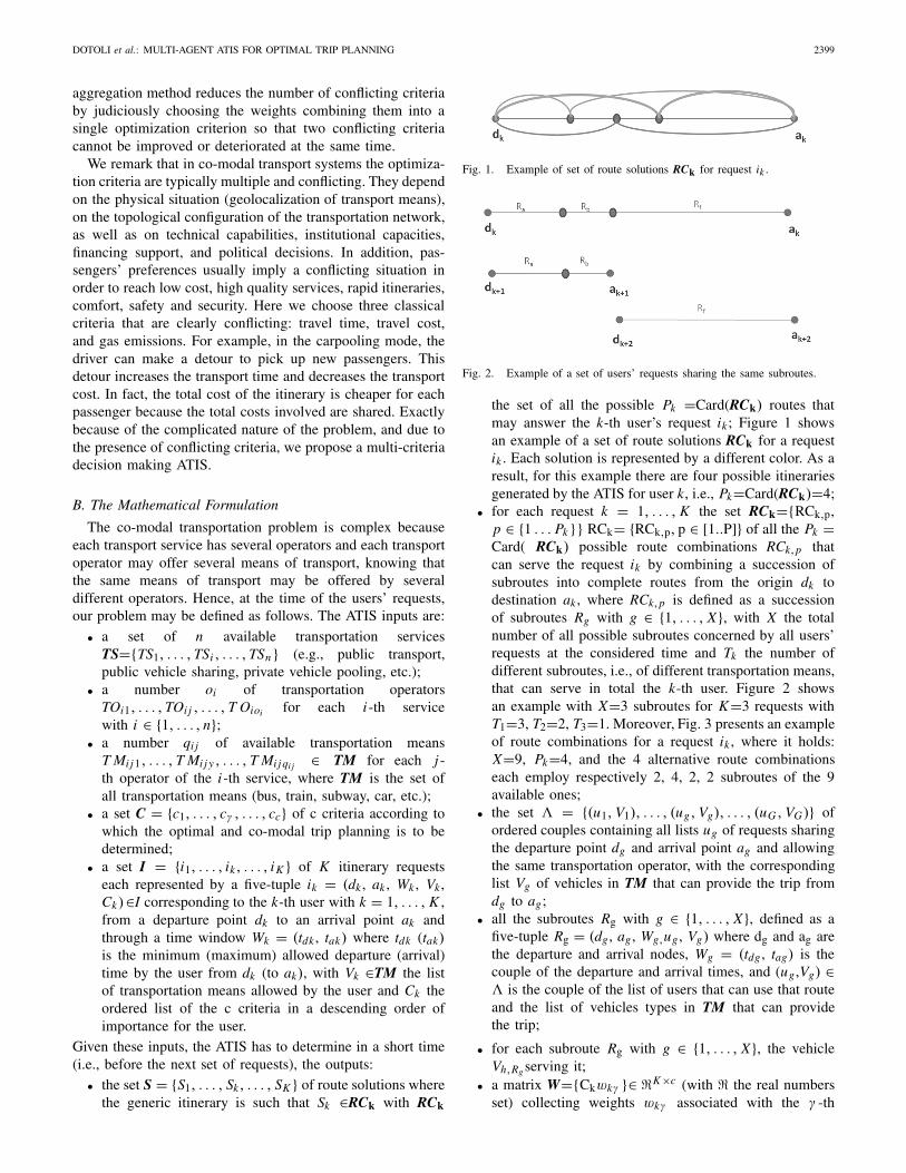
Fig. 1. Example of set of route solutions RCk for request ik .
Fig. 2. Example of a set of users’ requests sharing the same subroutes.
the set of all the possible Pk =Card(RCk) routes thatmay answer the k-th user’s request ik ; Figure 1 showsan example of a set of route solutions RCk for a requestik . Each solution is represented by a different color. As aresult, for this example there are four possible itinerariesgenerated by the ATIS for user k, i.e., Pk=Card(RCk)=4;
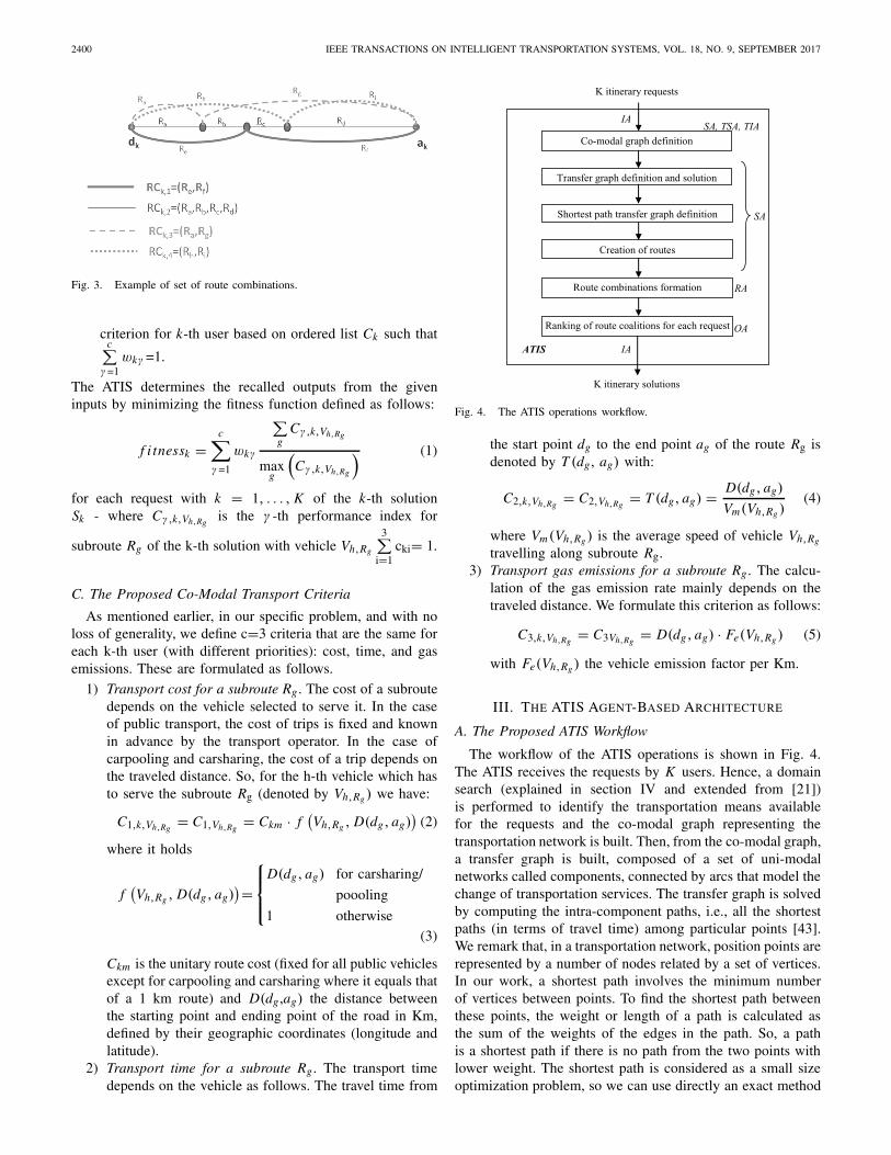
• for each request k = 1, . . . , K the set RCk={RCk,p,p ∈ {1 . . . Pk}} RCk= {RCk,p, p ∈ [1..P]} of all the Pk =Card( RCk) possible route combinations RCk,p thatcan serve the request ik by combining a succession ofsubroutes into complete routes from the origin dk todestination ak , where RCk,p is defined as a successionof subroutes Rg with g ∈ {1, . . . , X}, with X the totalnumber of all possible subroutes concerned by all users’requests at the considered time and Tk the number ofdifferent subroutes, i.e., of different transportation means,that can serve in total the k-th user. Figure 2 showsan example with X=3 subroutes for K=3 requests withT1=3, T2=2, T3=1. Moreover, Fig. 3 presents an exampleof route combinations for a request ik , where it holds:X=9, Pk=4, and the 4 alternative route combinationseach employ respectively 2, 4, 2, 2 subroutes of the 9available ones;
• the set � = {(u1, V1), . . . , (ug, Vg), . . . , (uG , VG)} ofordered couples containing all lists ug of requests sharingthe departure point dg and arrival point ag and allowingthe same transportation operator, with the correspondinglist Vg of vehicles in TM that can provide the trip fromdg to ag;
• all the subroutes Rg with g ∈ {1, . . . , X}, defined as afive-tuple Rg = (dg , ag , Wg,ug , Vg) where dg and ag arethe departure and arrival nodes, Wg = (tdg , tag) is thecouple of the departure and arrival times, and (ug ,Vg) ∈� is the couple of the list of users that can use that routeand the list of vehicles types in TM that can providethe trip;
• for each subroute Rg with g ∈ {1, . . . , X}, the vehicleVh,Rg serving it;
• a matrix W={Ckwkγ }∈ �K×c (with � the real numbersset) collecting weights wkγ associated with the γ -th
2400 IEEE TRANSACTIONS ON INTELLIGENT TRANSPORTATION SYSTEMS, VOL. 18, NO. 9, SEPTEMBER 2017
Fig. 3. Example of set of route combinations.
criterion for k-th user based on ordered list Ck such thatc∑
γ =1wkγ =1.
The ATIS determines the recalled outputs from the giveninputs by minimizing the fitness function defined as follows:
f i tnessk =c∑
γ =1
wkγ
∑
gCγ,k,Vh,Rg
maxg
(Cγ,k,Vh,Rg
) (1)
for each request with k = 1, . . . , K of the k-th solutionSk - where Cγ,k,Vh,Rg
is the γ -th performance index for
subroute Rg of the k-th solution with vehicle Vh,Rg
3∑
i=1cki= 1.
C. The Proposed Co-Modal Transport Criteria
As mentioned earlier, in our specific problem, and with noloss of generality, we define c=3 criteria that are the same foreach k-th user (with different priorities): cost, time, and gasemissions. These are formulated as follows.
1) Transport cost for a subroute Rg . The cost of a subroutedepends on the vehicle selected to serve it. In the caseof public transport, the cost of trips is fixed and knownin advance by the transport operator. In the case ofcarpooling and carsharing, the cost of a trip depends onthe traveled distance. So, for the h-th vehicle which hasto serve the subroute Rg (denoted by Vh,Rg ) we have:
C1,k,Vh,Rg= C1,Vh,Rg
= Ckm · f(Vh,Rg , D(dg, ag)
)(2)
where it holds
f(Vh,Rg , D(dg, ag)
)=
⎧⎪⎨
⎪⎩
D(dg, ag) for carsharing/
poooling
1 otherwise(3)
Ckm is the unitary route cost (fixed for all public vehiclesexcept for carpooling and carsharing where it equals thatof a 1 km route) and D(dg ,ag) the distance betweenthe starting point and ending point of the road in Km,defined by their geographic coordinates (longitude andlatitude).
2) Transport time for a subroute Rg . The transport timedepends on the vehicle as follows. The travel time from
Fig. 4. The ATIS operations workflow.
the start point dg to the end point ag of the route Rg isdenoted by T (dg , ag) with:
C2,k,Vh,Rg= C2,Vh,Rg
= T (dg, ag) = D(dg, ag)
Vm(Vh,Rg )(4)
where Vm(Vh,Rg ) is the average speed of vehicle Vh,Rg
travelling along subroute Rg.3) Transport gas emissions for a subroute Rg . The calcu-
lation of the gas emission rate mainly depends on thetraveled distance. We formulate this criterion as follows:
C3,k,Vh,Rg= C3Vh,Rg
= D(dg, ag) · Fe(Vh,Rg ) (5)
with Fe(Vh,Rg ) the vehicle emission factor per Km.
III. THE ATIS AGENT-BASED ARCHITECTURE
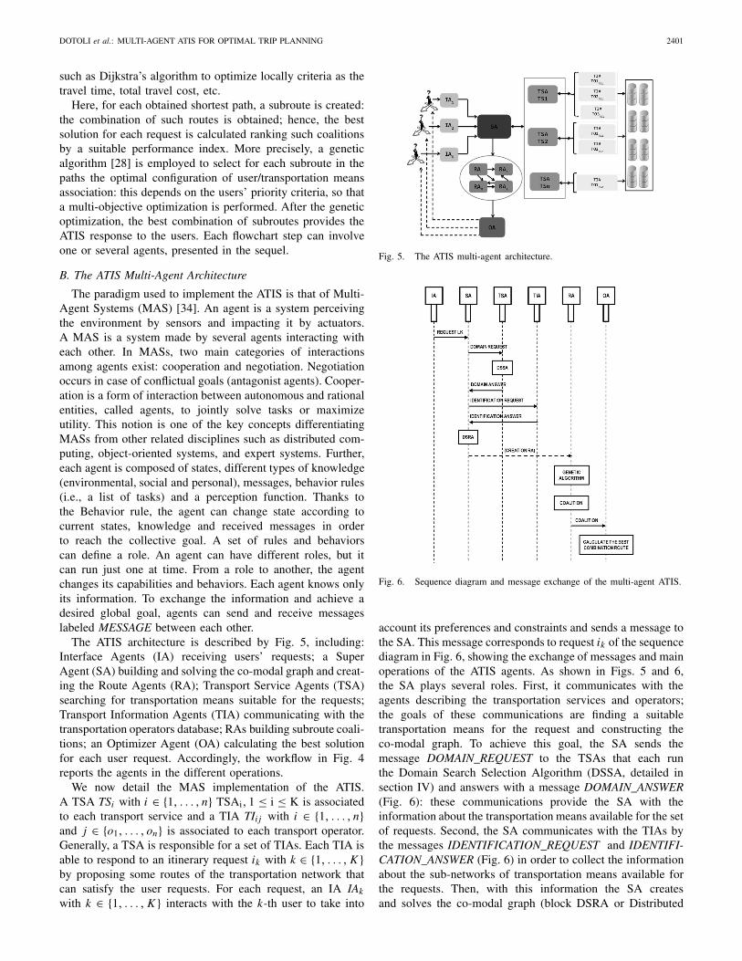
A. The Proposed ATIS Workflow
The workflow of the ATIS operations is shown in Fig. 4.The ATIS receives the requests by K users. Hence, a domainsearch (explained in section IV and extended from [21])is performed to identify the transportation means availablefor the requests and the co-modal graph representing thetransportation network is built. Then, from the co-modal graph,a transfer graph is built, composed of a set of uni-modalnetworks called components, connected by arcs that model thechange of transportation services. The transfer graph is solvedby computing the intra-component paths, i.e., all the shortestpaths (in terms of travel time) among particular points [43].We remark that, in a transportation network, position points arerepresented by a number of nodes related by a set of vertices.In our work, a shortest path involves the minimum numberof vertices between points. To find the shortest path betweenthese points, the weight or length of a path is calculated asthe sum of the weights of the edges in the path. So, a pathis a shortest path if there is no path from the two points withlower weight. The shortest path is considered as a small sizeoptimization problem, so we can use directly an exact method
DOTOLI et al.: MULTI-AGENT ATIS FOR OPTIMAL TRIP PLANNING 2401
such as Dijkstra’s algorithm to optimize locally criteria as thetravel time, total travel cost, etc.
Here, for each obtained shortest path, a subroute is created:the combination of such routes is obtained; hence, the bestsolution for each request is calculated ranking such coalitionsby a suitable performance index. More precisely, a geneticalgorithm [28] is employed to select for each subroute in thepaths the optimal configuration of user/transportation meansassociation: this depends on the users’ priority criteria, so thata multi-objective optimization is performed. After the geneticoptimization, the best combination of subroutes provides theATIS response to the users. Each flowchart step can involveone or several agents, presented in the sequel.
B. The ATIS Multi-Agent Architecture
The paradigm used to implement the ATIS is that of Multi-Agent Systems (MAS) [34]. An agent is a system perceivingthe environment by sensors and impacting it by actuators.A MAS is a system made by several agents interacting witheach other. In MASs, two main categories of interactionsamong agents exist: cooperation and negotiation. Negotiationoccurs in case of conflictual goals (antagonist agents). Cooper-ation is a form of interaction between autonomous and rationalentities, called agents, to jointly solve tasks or maximizeutility. This notion is one of the key concepts differentiatingMASs from other related disciplines such as distributed com-puting, object-oriented systems, and expert systems. Further,each agent is composed of states, different types of knowledge(environmental, social and personal), messages, behavior rules(i.e., a list of tasks) and a perception function. Thanks tothe Behavior rule, the agent can change state according tocurrent states, knowledge and received messages in orderto reach the collective goal. A set of rules and behaviorscan define a role. An agent can have different roles, but itcan run just one at time. From a role to another, the agentchanges its capabilities and behaviors. Each agent knows onlyits information. To exchange the information and achieve adesired global goal, agents can send and receive messageslabeled MESSAGE between each other.
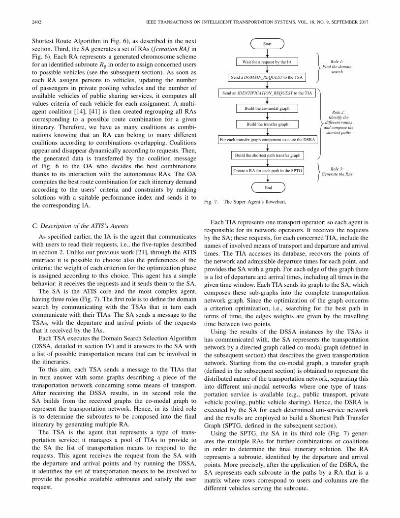
The ATIS architecture is described by Fig. 5, including:Interface Agents (IA) receiving users’ requests; a SuperAgent (SA) building and solving the co-modal graph and creat-ing the Route Agents (RA); Transport Service Agents (TSA)searching for transportation means suitable for the requests;Transport Information Agents (TIA) communicating with thetransportation operators database; RAs building subroute coali-tions; an Optimizer Agent (OA) calculating the best solutionfor each user request. Accordingly, the workflow in Fig. 4reports the agents in the different operations.
We now detail the MAS implementation of the ATIS.A TSA TSi with i ∈ {1, . . . , n} TSAi, 1 ≤ i ≤ K is associatedto each transport service and a TIA TIi j with i ∈ {1, . . . , n}and j ∈ {o1, . . . , on} is associated to each transport operator.Generally, a TSA is responsible for a set of TIAs. Each TIA isable to respond to an itinerary request ik with k ∈ {1, . . . , K }by proposing some routes of the transportation network thatcan satisfy the user requests. For each request, an IA IAk
with k ∈ {1, . . . , K } interacts with the k-th user to take into
Fig. 5. The ATIS multi-agent architecture.
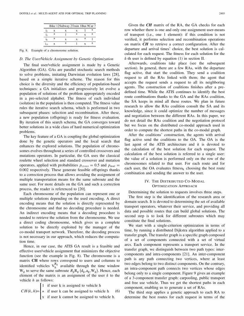
Fig. 6. Sequence diagram and message exchange of the multi-agent ATIS.
account its preferences and constraints and sends a message tothe SA. This message corresponds to request ik of the sequencediagram in Fig. 6, showing the exchange of messages and mainoperations of the ATIS agents. As shown in Figs. 5 and 6,the SA plays several roles. First, it communicates with theagents describing the transportation services and operators;the goals of these communications are finding a suitabletransportation means for the request and constructing theco-modal graph. To achieve this goal, the SA sends themessage DOMAIN_REQUEST to the TSAs that each runthe Domain Search Selection Algorithm (DSSA, detailed insection IV) and answers with a message DOMAIN_ANSWER(Fig. 6): these communications provide the SA with theinformation about the transportation means available for the setof requests. Second, the SA communicates with the TIAs bythe messages IDENTIFICATION_REQUEST and IDENTIFI-CATION_ANSWER (Fig. 6) in order to collect the informationabout the sub-networks of transportation means available forthe requests. Then, with this information the SA createsand solves the co-modal graph (block DSRA or Distributed
2402 IEEE TRANSACTIONS ON INTELLIGENT TRANSPORTATION SYSTEMS, VOL. 18, NO. 9, SEPTEMBER 2017
Shortest Route Algorithm in Fig. 6), as described in the nextsection. Third, the SA generates a set of RAs ({creation RA} inFig. 6). Each RA represents a generated chromosome schemefor an identified subroute Rg in order to assign concerned usersto possible vehicles (see the subsequent section). As soon aseach RA assigns persons to vehicles, updating the numberof passengers in private pooling vehicles and the number ofavailable vehicles of public sharing services, it computes allvalues criteria of each vehicle for each assignment. A multi-agent coalition [14], [41] is then created regrouping all RAscorresponding to a possible route combination for a givenitinerary. Therefore, we have as many coalitions as combi-nations knowing that an RA can belong to many differentcoalitions according to combinations overlapping. Coalitionsappear and disappear dynamically according to requests. Then,the generated data is transferred by the coalition messageof Fig. 6 to the OA who decides the best combinationsthanks to its interaction with the autonomous RAs. The OAcomputes the best route combination for each itinerary demandaccording to the users’ criteria and constraints by rankingsolutions with a suitable performance index and sends it tothe corresponding IA.
C. Description of the ATIS’s Agents
As specified earlier, the IA is the agent that communicateswith users to read their requests, i.e., the five-tuples describedin section 2. Unlike our previous work [21], through the ATISinterface it is possible to choose also the preferences of thecriteria: the weight of each criterion for the optimization phaseis assigned according to this choice. This agent has a simplebehavior: it receives the requests and it sends them to the SA.
The SA is the ATIS core and the most complex agent,having three roles (Fig. 7). The first role is to define the domainsearch by communicating with the TSAs that in turn eachcommunicate with their TIAs. The SA sends a message to theTSAs, with the departure and arrival points of the requeststhat it received by the IAs.
Each TSA executes the Domain Search Selection Algorithm(DSSA, detailed in section IV) and it answers to the SA witha list of possible transportation means that can be involved inthe itineraries.
To this aim, each TSA sends a message to the TIAs thatin turn answer with some graphs describing a piece of thetransportation network concerning some means of transport.After receiving the DSSA results, in its second role theSA builds from the received graphs the co-modal graph torepresent the transportation network. Hence, in its third roleis to determine the subroutes to be composed into the finalitinerary by generating multiple RA.
The TSA is the agent that represents a type of trans-portation service: it manages a pool of TIAs to provide tothe SA the list of transportation means to respond to therequests. This agent receives the request from the SA withthe departure and arrival points and by running the DSSA,it identifies the set of transportation means to be involved toprovide the possible available subroutes and satisfy the userrequest.
Fig. 7. The Super Agent’s flowchart.
Each TIA represents one transport operator: so each agent isresponsible for its network operators. It receives the requestsby the SA; these requests, for each concerned TIA, include thenames of involved means of transport and departure and arrivaltimes. The TIA accesses its database, recovers the points ofthe network and admissible departure times for each point, andprovides the SA with a graph. For each edge of this graph thereis a list of departure and arrival times, including all times in thegiven time window. Each TIA sends its graph to the SA, whichcomposes these sub-graphs into the complete transportationnetwork graph. Since the optimization of the graph concernsa criterion optimization, i.e., searching for the best path interms of time, the edges weights are given by the travellingtime between two points.
Using the results of the DSSA instances by the TSAs ithas communicated with, the SA represents the transportationnetwork by a directed graph called co-modal graph (defined inthe subsequent section) that describes the given transportationnetwork. Starting from the co-modal graph, a transfer graph(defined in the subsequent section) is obtained to represent thedistributed nature of the transportation network, separating thisinto different uni-modal networks where one type of trans-portation service is available (e.g., public transport, privatevehicle pooling, public vehicle sharing). Hence, the DSRA isexecuted by the SA for each determined uni-service networkand the results are employed to build a Shortest Path TransferGraph (SPTG, defined in the subsequent section).
Using the SPTG, the SA in its third role (Fig. 7) gener-ates the multiple RAs for further combinations or coalitionsin order to determine the final itinerary solution. The RArepresents a subroute, identified by the departure and arrivalpoints. More precisely, after the application of the DSRA, theSA represents each subroute in the paths by a RA that is amatrix where rows correspond to users and columns are thedifferent vehicles serving the subroute.
DOTOLI et al.: MULTI-AGENT ATIS FOR OPTIMAL TRIP PLANNING 2403
Fig. 8. Example of a chromosome solution.
D. The User/Vehicle Assignment by Genetic Optimization
The final user/vehicle assignment is made by a GeneticAlgorithm (GA). GAs are parallel stochastic search methodsto solve problems, imitating Darwinian evolution laws [28],based on a simple iterative scheme. The reason for thischoice is the diversity and the efficiency of population-basedtechniques: a GA initializes and progressively let evolve apopulation of solutions of the problem appropriately encodedin a pre-selected alphabet. The fitness of each individual(solution) in the population is then computed. The fitness valuerules the iterative search schema, which is performed in twosubsequent phases: selection and recombination. After these,a new population (offspring) is ready for fitness evaluation.By iteration of this search schema, the GA converges towardbetter solutions in a wide class of hard numerical optimizationproblems.
The key feature of a GA is coupling the global optimizationdone by the genetic operators and the local search thatenhances the explored solutions. The population of chromo-somes evolves throughout a series of controlled crossovers andmutations operators. In particular, the GA uses the classicalroulette wheel selection and standard crossover and mutationoperators, applied with probabilities pcross = 0.5 and pmut =0.002 respectively. These generate feasible offsprings thanksto a correction process that allows avoiding the assignment ofmultiple transportation means for the same subroute and thesame user. For more details on the GA and such a correctionprocess, the reader is referenced to [20].
Each chromosome of the population can represent one ormultiple solutions depending on the used encoding. A directencoding means that the solution is directly represented bythe chromosome and that no decoding procedure is needed.An indirect encoding means that a decoding procedure isneeded to retrieve the solution from the chromosome. We usea direct coding chromosome, which gives us a completesolution to be directly exploited by the manager of theco-modal transport network. Therefore, the decoding processis not necessary in our approach, which reduces the computa-tion time.
Hence, in our case, the ATIS GA result is a feasible andeffective user/vehicle assignment that minimizes the objectivefunction (see the example in Fig. 8). The chromosome is amatrix CH where rows correspond to users and columns toidentified vehicles V
Rgh available through the time window
Wg to serve the same subroute RgRg(dg,ag,Wg
). Hence, each
element of the matrix is an assignment of the user k to thevehicle h as follows:
C H (k, h)=
⎧⎪⎨
⎪⎩
1 if user k is assigned to vehicle h
∗ if user k can be assigned to vehicle h
x if user k cannot be assigned to vehicle h.
(6)
Given the CH matrix of the RA, the GA checks for eachrow whether there is one and only one assignment user-meansof transport (i.e., one 1 element): if this condition is notverified, it performs selection and recombination operationson matrix CH to retrieve a correct configuration. After thedeparture and arrival times’ choice, the best solution is cal-culated for each request. The fitness for each solution for thek-th user is defined by equation (1) in section II.
Afterwards, coalitions take place (see the subsequentsection). In general, there are a few RAs, with the departureflag active, that start the coalition. They send a coalitionrequest to all the RAs linked with them; the agent thataccepts the request sends a request to all its neighboringagents. The construction of coalitions finishes after a pre-defined time. While the ATIS continues to identify the bestroute combinations thanks to the GA and the RAs coalition,the SA keeps in mind all these routes. We plan in futureresearch to allow the RAs coalition consult the SA and itsknowledge, since it could optimize the number of messagesand negotiation between the different RAs. In this paper, wedo not detail the RAs coalition and the negotiation protocolbut we focus on the distributed co-modal approach used inorder to compute the shortest paths in the co-modal graph.
After the coalitions’ construction, the agents with arrivalflag active send the coalitions to the OA. The OA is thelast agent of the ATIS architecture and it is devoted tothe calculation of the best solution for each request. Thecalculation of the best solution is referred to a single user:the value of a solution is performed only on the row of thechromosomes related to that user. For each route and foreach user, the OA evaluates fitnessk choosing the best routecombination and sending the answer to the user.
IV. THE DISTRIBUTED CO-MODAL
OPTIMIZATION APPROACH
Determining the solution to requests involves three steps.The first step is the identification of the research area or
domain search. It is devoted to determining the set of availabletransport operators, whatever their service, and providing alldata and possible routes that can build global solutions. Thesecond step is to look for different subroutes which mayconstitute the final solutions.
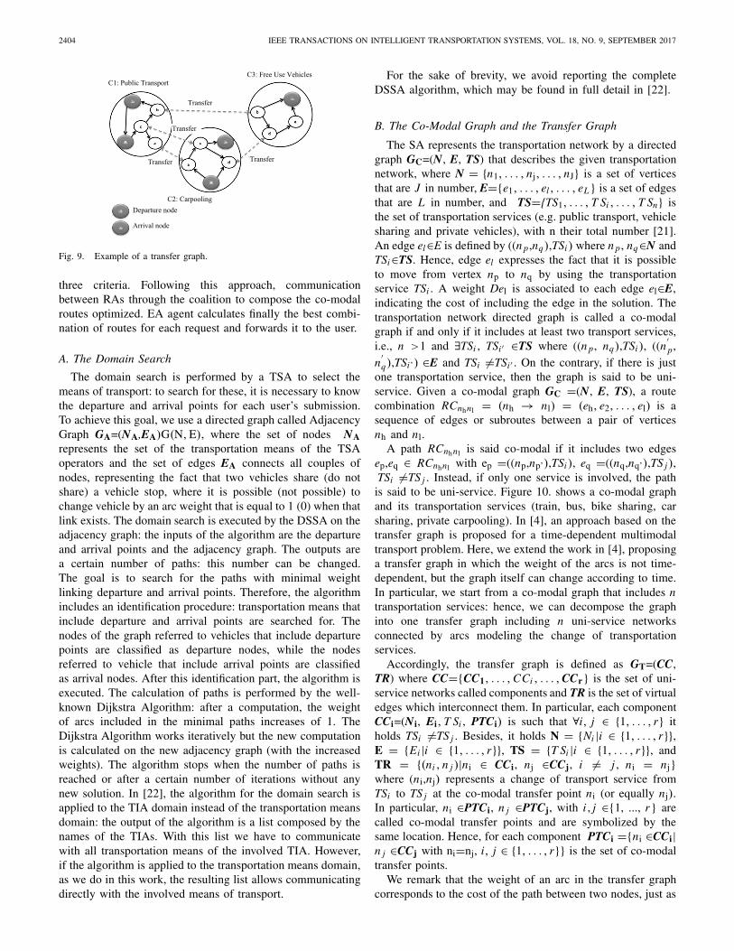
We start with a single-criterion optimization in terms oftime, by running a distributed Dijkstra algorithm applied to atransfer graph. The transfer graph is a specific graph composedof a set of components connected with a set of virtualarcs. Each component represents a transport service. In thetransfer graph, we distinguish between two path types: inter-components and intra-components [21]. An inter-componentpath is any path connecting two vertices, where at leasttwo edges belong to two distinct components. On the contrary,an intra-component path connects two vertices whose edgesbelong only to a single component. Figure 9 gives an exampleof a 3-component transfer graph: carpooling, public transportand free use vehicle. Thus we get the shortest paths in eachcomponent, enabling us to generate a set of RAs.
The third step applies a genetic approach to each RA todetermine the best routes for each request in terms of the
2404 IEEE TRANSACTIONS ON INTELLIGENT TRANSPORTATION SYSTEMS, VOL. 18, NO. 9, SEPTEMBER 2017
Fig. 9. Example of a transfer graph.
three criteria. Following this approach, communicationbetween RAs through the coalition to compose the co-modalroutes optimized. EA agent calculates finally the best combi-nation of routes for each request and forwards it to the user.
A. The Domain Search
The domain search is performed by a TSA to select themeans of transport: to search for these, it is necessary to knowthe departure and arrival points for each user’s submission.To achieve this goal, we use a directed graph called AdjacencyGraph GA=(NA,EA)G(N, E), where the set of nodes NArepresents the set of the transportation means of the TSAoperators and the set of edges EA connects all couples ofnodes, representing the fact that two vehicles share (do notshare) a vehicle stop, where it is possible (not possible) tochange vehicle by an arc weight that is equal to 1 (0) when thatlink exists. The domain search is executed by the DSSA on theadjacency graph: the inputs of the algorithm are the departureand arrival points and the adjacency graph. The outputs area certain number of paths: this number can be changed.The goal is to search for the paths with minimal weightlinking departure and arrival points. Therefore, the algorithmincludes an identification procedure: transportation means thatinclude departure and arrival points are searched for. Thenodes of the graph referred to vehicles that include departurepoints are classified as departure nodes, while the nodesreferred to vehicle that include arrival points are classifiedas arrival nodes. After this identification part, the algorithm isexecuted. The calculation of paths is performed by the well-known Dijkstra Algorithm: after a computation, the weightof arcs included in the minimal paths increases of 1. TheDijkstra Algorithm works iteratively but the new computationis calculated on the new adjacency graph (with the increasedweights). The algorithm stops when the number of paths isreached or after a certain number of iterations without anynew solution. In [22], the algorithm for the domain search isapplied to the TIA domain instead of the transportation meansdomain: the output of the algorithm is a list composed by thenames of the TIAs. With this list we have to communicatewith all transportation means of the involved TIA. However,if the algorithm is applied to the transportation means domain,as we do in this work, the resulting list allows communicatingdirectly with the involved means of transport.
For the sake of brevity, we avoid reporting the completeDSSA algorithm, which may be found in full detail in [22].
B. The Co-Modal Graph and the Transfer Graph
The SA represents the transportation network by a directedgraph GC=(N, E, TS) that describes the given transportationnetwork, where N = {n1, . . . , nj, . . . , nJ} is a set of verticesthat are J in number, E={e1, . . . , el , . . . , eL} is a set of edgesthat are L in number, and TS={TS1, . . . , T Si , . . . , T Sn} isthe set of transportation services (e.g. public transport, vehiclesharing and private vehicles), with n their total number [21].An edge el∈E is defined by ((n p ,nq),TSi ) where n p , nq∈N andTSi∈TS. Hence, edge el expresses the fact that it is possibleto move from vertex np to nq by using the transportationservice TSi . A weight Del is associated to each edge el∈E,indicating the cost of including the edge in the solution. Thetransportation network directed graph is called a co-modalgraph if and only if it includes at least two transport services,i.e., n >1 and ∃TSi , TSi ′ ∈TS where ((n p, nq),TSi ), ((n
′p,
n′q),TSi’) ∈E and TSi �=TSi ′ . On the contrary, if there is just
one transportation service, then the graph is said to be uni-service. Given a co-modal graph GC =(N, E, TS), a routecombination RCnhnl = (nh → nl) = (eh, e2, . . . , el) is asequence of edges or subroutes between a pair of verticesnh and nl.
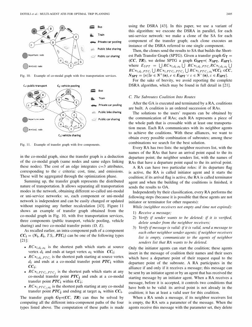
A path RCnhnl is said co-modal if it includes two edgesep,eq ∈ RCnhnl with ep =((np,np’),TSi ), eq =((nq,nq’),TS j ),TSi �=TS j . Instead, if only one service is involved, the pathis said to be uni-service. Figure 10. shows a co-modal graphand its transportation services (train, bus, bike sharing, carsharing, private carpooling). In [4], an approach based on thetransfer graph is proposed for a time-dependent multimodaltransport problem. Here, we extend the work in [4], proposinga transfer graph in which the weight of the arcs is not time-dependent, but the graph itself can change according to time.In particular, we start from a co-modal graph that includes ntransportation services: hence, we can decompose the graphinto one transfer graph including n uni-service networksconnected by arcs modeling the change of transportationservices.
Accordingly, the transfer graph is defined as GT=(CC,TR) where CC={CC1, . . . , CCi , . . . , CCr} is the set of uni-service networks called components and TR is the set of virtualedges which interconnect them. In particular, each componentCCi=(Ni, Ei, T Si , PTCi) is such that ∀i, j ∈ {1, . . . , r} itholds TSi �=TS j . Besides, it holds N = {Ni |i ∈ {1, . . . , r}},E = {Ei |i ∈ {1, . . . , r}}, TS = {T Si |i ∈ {1, . . . , r}}, andTR = {(ni , n j )|ni ∈ CCi, nj ∈CCj, i �= j , ni = nj}where (ni,nj) represents a change of transport service fromTSi to TS j at the co-modal transfer point ni (or equally nj).In particular, ni ∈PTCi, n j ∈PTCj, with i , j ∈{1, ..., r} arecalled co-modal transfer points and are symbolized by thesame location. Hence, for each component PTCi ={ni ∈CCi|n j ∈CCj with ni=nj, i, j ∈ {1, . . . , r}} is the set of co-modaltransfer points.
We remark that the weight of an arc in the transfer graphcorresponds to the cost of the path between two nodes, just as
DOTOLI et al.: MULTI-AGENT ATIS FOR OPTIMAL TRIP PLANNING 2405
Fig. 10. Example of co-modal graph with five transportation services.
Fig. 11. Example of transfer graph with five components.
in the co-modal graph, since the transfer graph is a deductionof the co-modal graph (same nodes and same edges linkingthese nodes). The cost of an edge integrates c=3 attributes,corresponding to the c criteria: cost, time, and emissions.These will be aggregated through the optimization phase.
Summing up, the transfer graph represents the distributednature of transportation. It allows separating all transportationmodes in the network, obtaining different so-called uni-modalor uni-service networks: so, each component or uni-modalnetwork is independent and can be easily changed or updatedwithout requiring any further recalculation [43]. Figure 11shows an example of transfer graph obtained from theco-modal graph in Fig. 10, with five transportation services,three components (public transport, vehicle pooling, vehiclesharing) and two co-modal transfer points (D, E).
As recalled earlier, an intra-component path of a componentCCi = (Ni, Ei, T Si , PTCi) can be one of the following types[21]:
• RC∗i,dk ,ak is the shortest path which starts at sourcevertex dk and ends at target vertex ak within CCi;
• RC∗i,dk ,PT Ci is the shortest path starting at source vertexdk and ends at a co-modal transfer point PTCi withinCCi;
• RC∗i,PT Ci ,PT C j is the shortest path which starts at anyco-modal transfer point PTCj and ends at a co-modaltransfer point PTCi within CCi;
• RC∗i,PT C j ,ak is the shortest path starting at any co-modaltransfer point PTCj and ending at target ak within CCi.
The transfer graph GT=(CC, TR) can thus be solved bycomputing all the different intra-component paths of the fourtypes listed above. The computation of these paths is made
using the DSRA [43]. In this paper, we use a variant ofthis algorithm: we execute the DSRA in parallel, for eachuni-service network: we make a clone of the SA for eachcomponent of the transfer graph; each clone executes aninstance of the DSRA referred to one single component.
Then, the clones send the results to SA that builds the Short-est Path Transfer Graph (SPTG). Given a transfer graph GT =(CC, TR), we define SPTG a graph GSPT=( NSPT, ESPT),where ES PT = ⋃
RC∗i,dk ,ak
⋃RC∗i,dk ,PT Ci RC∗i,dk ,ak
⋃
RC∗i,dk ,PT Ci
⋃RC∗i,PT Ci ,PT C j
⋃RC∗i,PT C j ,ak ∀CCi ∈CC,
NSPT = {n|∃e ∈ N+(n), e ∈ ESPT ∨ ε ∈ N−(n), ε ∈ ESPT}.For the sake of brevity, we avoid reporting the complete
DSRA algorithm, which may be found in full detail in [21].
C. The Subroutes Coalition Into Routes
After the GA is executed and terminated by a RA, coalitionsare built. A coalition is an ordered succession of RAs.
The solutions to the users’ requests can be obtained bythe communication of RAs; each RA represents a piece ofthe whole path that is crossable with at least one transporta-tion mean. Each RA communicates with its neighbor agentsto achieve the coalitions. With these alliances, we want toobtain every possible combination of subroutes; among thesecombinations we search for the best solution.
Every RA has two lists: the neighbor receivers list, with thenames of the RAs that have an arrival point equal to the itsdeparture point; the neighbor senders list, with the names ofRAs that have a departure point equal to the its arrival point.
A RA can have two particular roles: if its departure flagis active, the RA is called initiator agent and it starts thecoalition; if its arrival flag is active, the RA is called terminatoragent and when the building of the coalitions is finished, itsends the results to OA.
Independently by their classification, every RA performs thefollowing steps (because it is possible that these agents are notinitiator or terminator for other requests):
While (neighbor receivers not empty and time not expired):
1) Receive a message;2) Verify if sender wants to be deleted: if it is verified,
delete sender from the neighbor receivers;3) Verify if message is valid: if it is valid, send a message to
each other neighbor sender agents; if neighbor receiverslist is empty, communicate to the agents of neighborsenders list that RA wants to be deleted.
Only the initiator agents can start the coalition; these agentsinsert in the message of coalition their names and their userswhich have a departure point of their request equal to thedeparture point of the subroute. A RA participates in thealliance if and only if it receives a message; this message canbe sent by an initiator agent or by an agent that has received thestarting message by an initiator agent. When a RA receives amessage, before it is accepted, it controls two conditions thathave both to be valid: its arrival point is not already in thecoalition; it has at least a valid user for this coalition.
When a RA sends a message, if its neighbor receivers listis empty, the RA sets a parameter of the message. When theagents receive this message with the parameter set, they delete
2406 IEEE TRANSACTIONS ON INTELLIGENT TRANSPORTATION SYSTEMS, VOL. 18, NO. 9, SEPTEMBER 2017
TABLE I
COMPARISON OF THE TSP WITH THE CO-MODAL TRANSPORT PROBLEM
the sender of the message from their neighbor receivers list.An agent finishes the building process when the neighborreceivers list is empty or the execution time is expired;this time is editable. When a terminator agent finishes thisbehavior, it sends its list of the solutions to the OA. When allthe terminators finish the construction of the solutions, the OAstarts the computation of the best solution for each request.
D. The ATIS Scalability
The proposed ATIS approach is scalable thanks to thedynamicity of the agents’ creations. Indeed, the SA creates anddestroys dynamically the RAs according to the users’ requests.After the creation, the SA assigns to each RA a subroute tooptimize it locally. Each RA uses a GA to choose the bestmeans of transport that will be used to serve locally this routefor each user. Hence, each RA handles an initial populationwith a reasonable number of chromosomes to accelerate theconvergence. In addition, all the RAs work in parallel to findlocally their optimal routes respectively and collaborate withthe other RAs forming coalitions in order to build the optimalglobal route for each request.
E. The ATIS Complexity and Convergence
According to the described formulation, the ATIS receives aset of simultaneous requests. To treat them, the ATIS receivesinformation from different transport operators of differenttransport services. All these responses form a co-modal graphrepresenting the map of the routes of different transport ser-vices. A co-modal graph is dense and contains a lot of nodes,whether connecting nodes for transit, appointments nodesfor carpooling or nodes representing vehicle stations self-service. In the literature, this problem is similar to the well-known Traveling Salesman Problem (TSP). In this context, wepropose a comparative study of the optimization problem ofa co-modal transport system and the TSP (Table I). In short,given a co-modal graph G with n correspondence nodes, anumber of (n−1)!/2 itineraries is possible. If we consider thatthe time itinerary evaluation has a complexity O(n), we obtaina total time complexity of O(n!): for 6 nodes, we have 72.possibilities, for 10 nodes, 3628800 possibilities.
According to this analogy, the TSP is similar to one instanceof our co-modal transport problem (a single user request).However, this comparison takes into account a single userrequest at time t . Instead, in our co-modal transport ATIS,we can receive at time t a set of simultaneous requests.This increases considerably the complexity of the problemin comparison with the TSP problem. We conclude that theATIS transport co-modal problem is a highly combinatorialoptimization problem.
To counteract for this complexity, which increases propor-tionally with the transportation network size, the architec-ture of ATIS is based on a collaborative optimization, usingthe alliance between the meta-heuristics and the multi-agentsystems. This alliance is an original approach, integratingGAs with autonomous and intelligent agents. These entitieswork together in a parallel and distributed manner throughinteraction protocols, by forming intelligent coalitions in orderto solve co-modal itineraries problems.
The main difficulty in the use of multi-agent systems is tocontrol the behavior and the evolution of the overall systemconsisting of autonomous agents: for a given problem, it is notassured that all agents converge to a single common solution.Hence, the proposed ATIS has a distributed architecture con-sisting of several route agents, which cooperate and interactthrough an exchange of messages, according to a decentralizedapproach to build a local route within each agent, so as toconverge at best towards a global solution that meets therequirements adopted collectively (global itineraries). In fact,in a society of agents, initially each agent behaves accordingto an initial strategy, but with passing time, global phenomenaemerge that most agents tend to follow, thus convergingtowards a behavioral strategy called collective synchronization(see the discussions in [14] and [41]).
V. THE CASE STUDY
The ATIS is developed on the JADE platform in theJava agent framework [5]: JADE is a middleware allowinga flexible implementation of multi-agent systems and offer-ing efficient agent communication. Moreover, the ATIS isimplemented based on the real road network using GoogleMaps and its geolocation application programming inter-face. The user path, composed by several subroutes, isprinted on a static Google map [15]. Using Google Maps,travel distances and times are obtained for origins anddestinations.
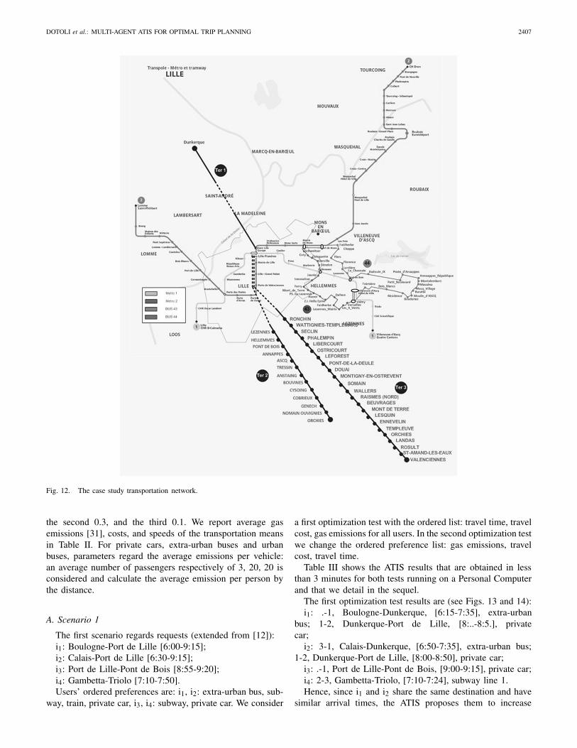
The ATIS is tested for the Lille area (France, Fig. 12)by an extra-urban and urban scenario for n=3 trans-portation services: TS1=public transportation; TS2=vehiclesharing; TS3=private vehicles (car pooling). Operatorsare: TO1TS1=Transpole [38], with subway lines 1, 2and urban buses 43, 44; TO2TS1=S.N.C.F. [36] withtrains Ter1, Ter2 and Ter3; TO3TS1=BCD Ligne [26]with buses running between Boulogne-Calais-Dunkerque;TO1TS2=Lilas [27] with car sharing; TO2TS2=V’Lille [4.]with bike sharing; TO1TS3=carpooling. We consider a[6:00-10:00] a.m. window of a weekday. Weights wkγ areassigned so that the most important criterion has a 0.6 weight,
DOTOLI et al.: MULTI-AGENT ATIS FOR OPTIMAL TRIP PLANNING 2407
Fig. 12. The case study transportation network.
the second 0.3, and the third 0.1. We report average gasemissions [31], costs, and speeds of the transportation meansin Table II. For private cars, extra-urban buses and urbanbuses, parameters regard the average emissions per vehicle:an average number of passengers respectively of 3, 20, 20 isconsidered and calculate the average emission per person bythe distance.
A. Scenario 1
The first scenario regards requests (extended from [12]):i1: Boulogne-Port de Lille [6:00-9:15];i2: Calais-Port de Lille [6:30-9:15];i3: Port de Lille-Pont de Bois [8:55-9:20];i4: Gambetta-Triolo [7:10-7:50].Users’ ordered preferences are: i1, i2: extra-urban bus, sub-
way, train, private car, i3, i4: subway, private car. We consider
a first optimization test with the ordered list: travel time, travelcost, gas emissions for all users. In the second optimization testwe change the ordered preference list: gas emissions, travelcost, travel time.
Table III shows the ATIS results that are obtained in lessthan 3 minutes for both tests running on a Personal Computerand that we detail in the sequel.
The first optimization test results are (see Figs. 13 and 14):i1: .-1, Boulogne-Dunkerque, [6:15-7:35], extra-urban
bus; 1-2, Dunkerque-Port de Lille, [8:..-8:5.], privatecar;
i2: 3-1, Calais-Dunkerque, [6:50-7:35], extra-urban bus;1-2, Dunkerque-Port de Lille, [8:00-8:50], private car;
i3: .-1, Port de Lille-Pont de Bois, [9:00-9:15], private car;i4: 2-3, Gambetta-Triolo, [7:10-7:24], subway line 1.Hence, since i1 and i2 share the same destination and have
similar arrival times, the ATIS proposes them to increase
2408 IEEE TRANSACTIONS ON INTELLIGENT TRANSPORTATION SYSTEMS, VOL. 18, NO. 9, SEPTEMBER 2017
TABLE II
TRANSPORTATION MEANS PARAMETERS
TABLE III
ATIS RESULTS TO ITINERARY REQUESTS IN EXTRA-URBAN SCENARIO
Fig. 13. The paths of i1 (0-1-2) and i2 (3-1-2) under test 1, scenario 1.
Fig. 14. The paths of i3 (0-1) and i4 (2-3) under tests 1 and 2, scenario 1.
co-modality to reach by buses a common point and then sharea private car (see Fig. 13). Moreover, the routes of i3 and i4in the first optimization are independent (see Fig. 14).
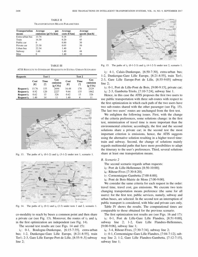
The second test results are (see Figs. 14 and 15):i1: 0-1, Boulogne-Dunkerque, [6:15-7:35], extra-urban
bus; 1-2, Dunkerque-Gare Lille Europe, [8:21-8:55], trainTer1; 2-3, Gare Lille Europe-Port de Lille, [8:55-9:.5] subwayline 2;
Fig. 15. The paths of i1 (0-1-2-3) and i2 (4-1-2-3) under test 2, scenario 1.
i2: 4-1, Calais-Dunkerque, [6:50-7:30], extra-urban bus;1-2, Dunkerque-Gare Lille Europe, [8:21-8:55], train Ter1;2-3, Gare Lille Europe-Port de Lille, [8:55-9:05] subwayline 2;
i3: 0-1, Port de Lille-Pont de Bois, [9:00-9:15], private car;i4: 2-3, Gambetta-Triolo, [7:10-7:24], subway line 1.Hence, in this case the ATIS proposes the first two users to
use public transportation with three sub-routes with respect tothe first optimization in which each path of the two users havetwo sub-routes shared with the other passenger (see Fig. 15).The last two users’ routes are unchanged from the first test.
We enlighten the following issues. First, with the changeof the criteria preferences, some solutions change: in the firsttest, minimization of travel time is more important than theenvironmental criterion; accordingly, the first and the secondsolutions share a private car; in the second test the mostimportant criterion is emissions, hence, the ATIS suggestsusing the alternative solution resulting in a higher travel time:train and subway. Second, the change of solutions mainlyregards multimodal paths that have more possibilities to adaptthe itinerary to the user’s preferences. Third, several solutionsshare at least one transportation means.
B. Scenario 2The second scenario regards urban requests:i5: Port de Lille-Hellemmes [8:50-10:00];i6: Rihour-Fives [7:30-8:20];i7: Cormontaigne-Gambetta [7:00-8:00];i8: Pont de Bois-Mairie de Mons [7:00-9:00].We consider the same criteria for each request in the order:
travel time, travel cost, gas emissions. We execute two testschanging transportation means preference (the same for allusers): for the first test, public services, namely, subway andurban buses, are selected. In the second test an interruption ofpublic transport is considered, with bike and private cars only.
Table IV shows the results. The computational times arecomparable to those obtained for the previous scenario.
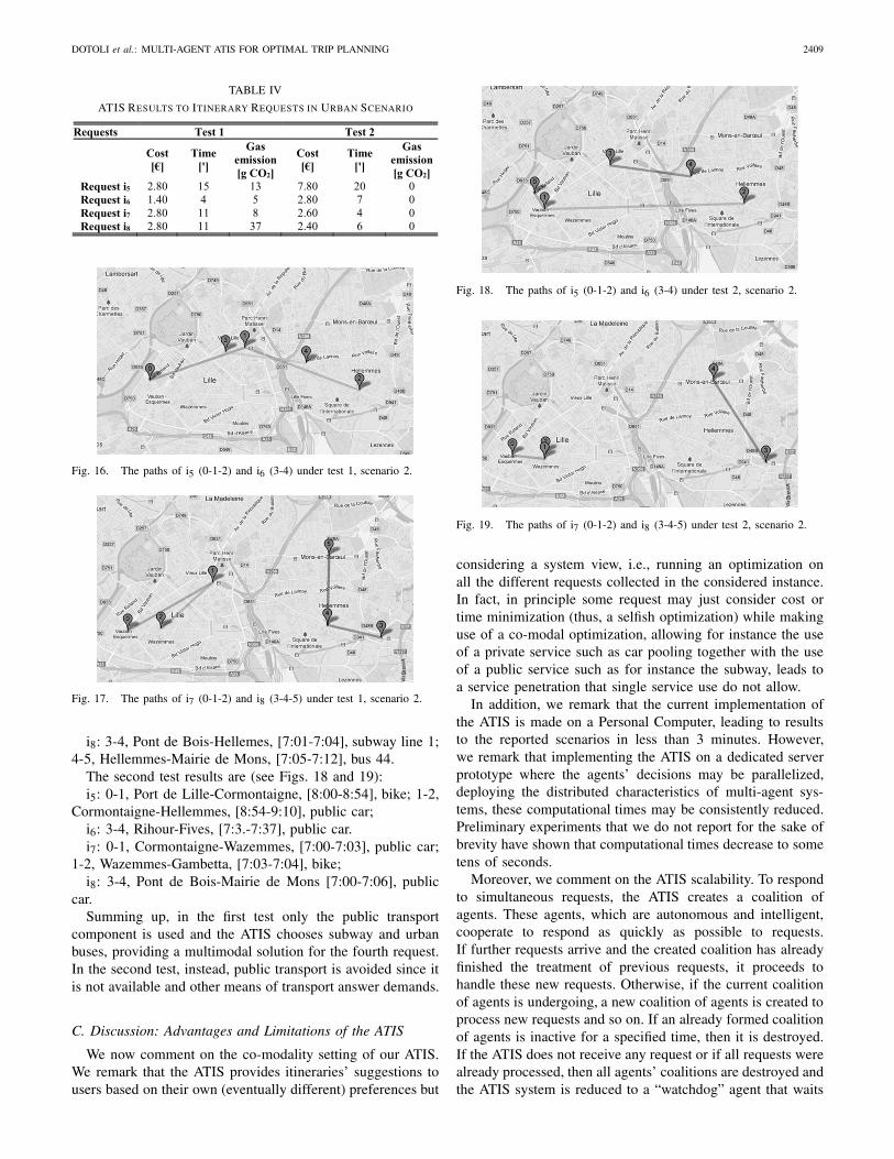
The first optimization test results are (see Figs. 16 and 17):i5: 0-1, Port de Lille-Gare Lille Flandres, [8:51-9:00],
subway line 2; 1-2, Gare Lille Flandres-Hellemmes,[9:00-9:06], subway line 1;
i6: 3-4, Rihour-Fives, [7:30-7:34], subway line 2;i7: 0-1, Cormontaigne-Gare Lille Flandres, [7:04-7:12], sub-
way line 2; 1-2, Gare Lille Flandres-Gambetta, [7:12-7:15],subway line 1;
DOTOLI et al.: MULTI-AGENT ATIS FOR OPTIMAL TRIP PLANNING 2409
TABLE IV
ATIS RESULTS TO ITINERARY REQUESTS IN URBAN SCENARIO
Fig. 16. The paths of i5 (0-1-2) and i6 (3-4) under test 1, scenario 2.
Fig. 17. The paths of i7 (0-1-2) and i8 (3-4-5) under test 1, scenario 2.
i8: 3-4, Pont de Bois-Hellemes, [7:01-7:04], subway line 1;4-5, Hellemmes-Mairie de Mons, [7:05-7:12], bus 44.
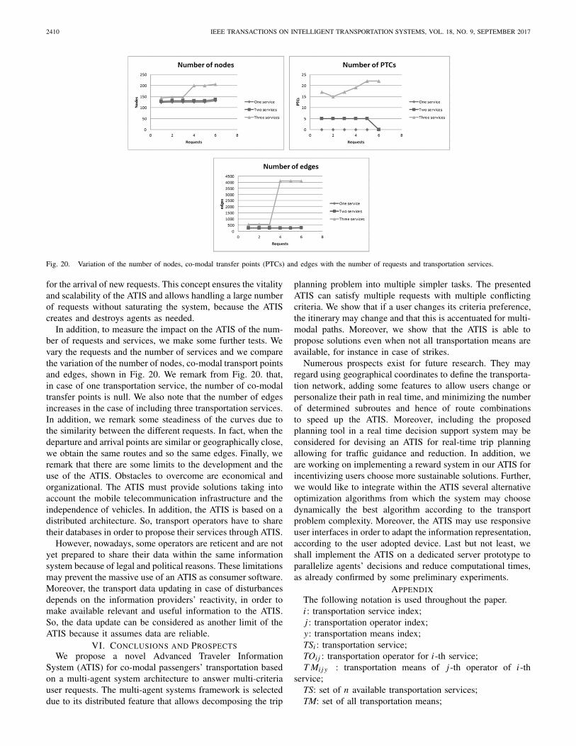
The second test results are (see Figs. 18 and 19):i5: 0-1, Port de Lille-Cormontaigne, [8:00-8:54], bike; 1-2,
Cormontaigne-Hellemmes, [8:54-9:10], public car;i6: 3-4, Rihour-Fives, [7:3.-7:37], public car.i7: 0-1, Cormontaigne-Wazemmes, [7:00-7:03], public car;
1-2, Wazemmes-Gambetta, [7:03-7:04], bike;i8: 3-4, Pont de Bois-Mairie de Mons [7:00-7:06], public
car.Summing up, in the first test only the public transport
component is used and the ATIS chooses subway and urbanbuses, providing a multimodal solution for the fourth request.In the second test, instead, public transport is avoided since itis not available and other means of transport answer demands.
C. Discussion: Advantages and Limitations of the ATIS
We now comment on the co-modality setting of our ATIS.We remark that the ATIS provides itineraries’ suggestions tousers based on their own (eventually different) preferences but
Fig. 18. The paths of i5 (0-1-2) and i6 (3-4) under test 2, scenario 2.
Fig. 19. The paths of i7 (0-1-2) and i8 (3-4-5) under test 2, scenario 2.
considering a system view, i.e., running an optimization onall the different requests collected in the considered instance.In fact, in principle some request may just consider cost ortime minimization (thus, a selfish optimization) while makinguse of a co-modal optimization, allowing for instance the useof a private service such as car pooling together with the useof a public service such as for instance the subway, leads toa service penetration that single service use do not allow.
In addition, we remark that the current implementation ofthe ATIS is made on a Personal Computer, leading to resultsto the reported scenarios in less than 3 minutes. However,we remark that implementing the ATIS on a dedicated serverprototype where the agents’ decisions may be parallelized,deploying the distributed characteristics of multi-agent sys-tems, these computational times may be consistently reduced.Preliminary experiments that we do not report for the sake ofbrevity have shown that computational times decrease to sometens of seconds.
Moreover, we comment on the ATIS scalability. To respondto simultaneous requests, the ATIS creates a coalition ofagents. These agents, which are autonomous and intelligent,cooperate to respond as quickly as possible to requests.If further requests arrive and the created coalition has alreadyfinished the treatment of previous requests, it proceeds tohandle these new requests. Otherwise, if the current coalitionof agents is undergoing, a new coalition of agents is created toprocess new requests and so on. If an already formed coalitionof agents is inactive for a specified time, then it is destroyed.If the ATIS does not receive any request or if all requests werealready processed, then all agents’ coalitions are destroyed andthe ATIS system is reduced to a “watchdog” agent that waits
2410 IEEE TRANSACTIONS ON INTELLIGENT TRANSPORTATION SYSTEMS, VOL. 18, NO. 9, SEPTEMBER 2017
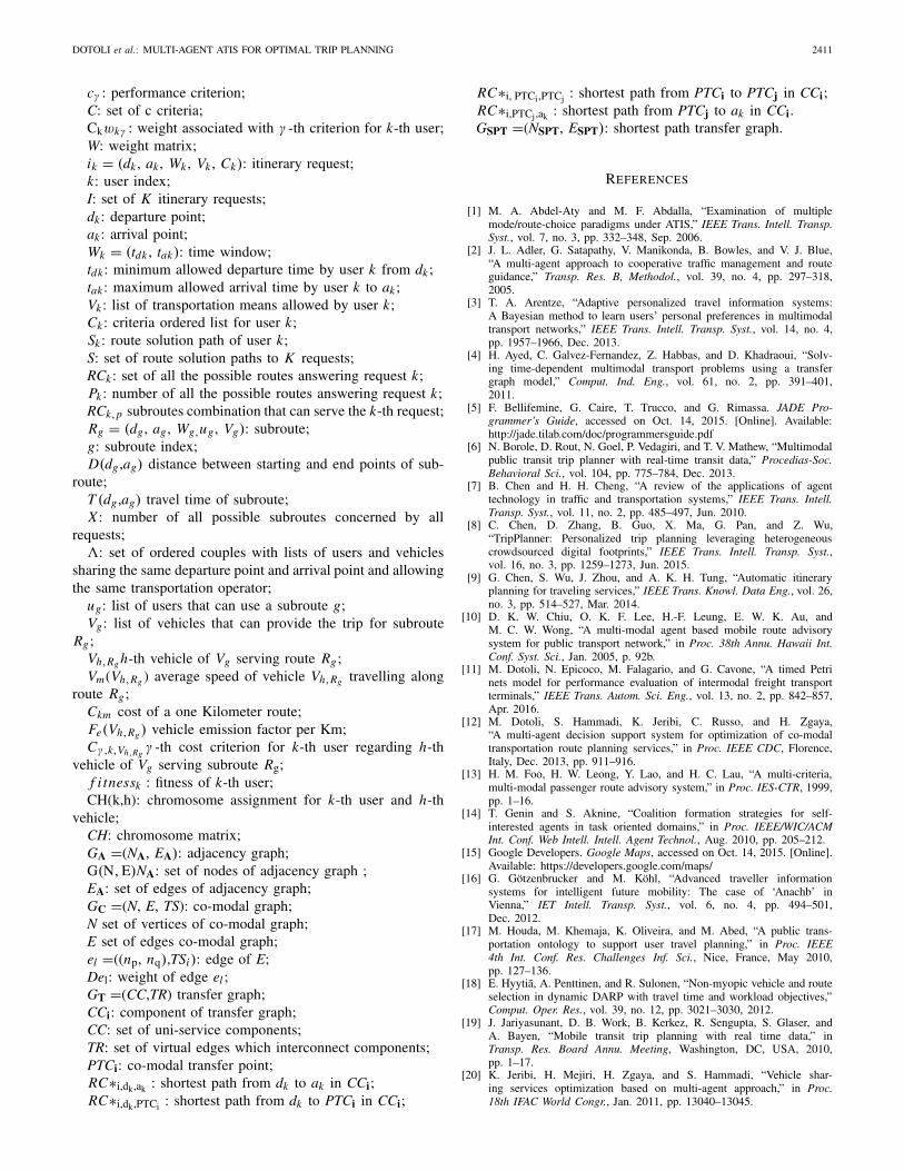
Fig. 20. Variation of the number of nodes, co-modal transfer points (PTCs) and edges with the number of requests and transportation services.
for the arrival of new requests. This concept ensures the vitalityand scalability of the ATIS and allows handling a large numberof requests without saturating the system, because the ATIScreates and destroys agents as needed.
In addition, to measure the impact on the ATIS of the num-ber of requests and services, we make some further tests. Wevary the requests and the number of services and we comparethe variation of the number of nodes, co-modal transport pointsand edges, shown in Fig. 20. We remark from Fig. 20. that,in case of one transportation service, the number of co-modaltransfer points is null. We also note that the number of edgesincreases in the case of including three transportation services.In addition, we remark some steadiness of the curves due tothe similarity between the different requests. In fact, when thedeparture and arrival points are similar or geographically close,we obtain the same routes and so the same edges. Finally, weremark that there are some limits to the development and theuse of the ATIS. Obstacles to overcome are economical andorganizational. The ATIS must provide solutions taking intoaccount the mobile telecommunication infrastructure and theindependence of vehicles. In addition, the ATIS is based on adistributed architecture. So, transport operators have to sharetheir databases in order to propose their services through ATIS.
However, nowadays, some operators are reticent and are notyet prepared to share their data within the same informationsystem because of legal and political reasons. These limitationsmay prevent the massive use of an ATIS as consumer software.Moreover, the transport data updating in case of disturbancesdepends on the information providers’ reactivity, in order tomake available relevant and useful information to the ATIS.So, the data update can be considered as another limit of theATIS because it assumes data are reliable.
VI. CONCLUSIONS AND PROSPECTSWe propose a novel Advanced Traveler Information
System (ATIS) for co-modal passengers’ transportation basedon a multi-agent system architecture to answer multi-criteriauser requests. The multi-agent systems framework is selecteddue to its distributed feature that allows decomposing the trip
planning problem into multiple simpler tasks. The presentedATIS can satisfy multiple requests with multiple conflictingcriteria. We show that if a user changes its criteria preference,the itinerary may change and that this is accentuated for multi-modal paths. Moreover, we show that the ATIS is able topropose solutions even when not all transportation means areavailable, for instance in case of strikes.
Numerous prospects exist for future research. They mayregard using geographical coordinates to define the transporta-tion network, adding some features to allow users change orpersonalize their path in real time, and minimizing the numberof determined subroutes and hence of route combinationsto speed up the ATIS. Moreover, including the proposedplanning tool in a real time decision support system may beconsidered for devising an ATIS for real-time trip planningallowing for traffic guidance and reduction. In addition, weare working on implementing a reward system in our ATIS forincentivizing users choose more sustainable solutions. Further,we would like to integrate within the ATIS several alternativeoptimization algorithms from which the system may choosedynamically the best algorithm according to the transportproblem complexity. Moreover, the ATIS may use responsiveuser interfaces in order to adapt the information representation,according to the user adopted device. Last but not least, weshall implement the ATIS on a dedicated server prototype toparallelize agents’ decisions and reduce computational times,as already confirmed by some preliminary experiments.
APPENDIXThe following notation is used throughout the paper.i : transportation service index;j : transportation operator index;y: transportation means index;TSi : transportation service;TOij : transportation operator for i -th service;T Mij y : transportation means of j -th operator of i -th
service;TS: set of n available transportation services;TM: set of all transportation means;
DOTOLI et al.: MULTI-AGENT ATIS FOR OPTIMAL TRIP PLANNING 2411
cγ : performance criterion;C: set of c criteria;Ckwkγ : weight associated with γ -th criterion for k-th user;W: weight matrix;ik = (dk , ak , Wk , Vk , Ck): itinerary request;k: user index;I: set of K itinerary requests;dk : departure point;ak : arrival point;Wk = (tdk , tak): time window;tdk : minimum allowed departure time by user k from dk ;tak : maximum allowed arrival time by user k to ak ;Vk : list of transportation means allowed by user k;Ck : criteria ordered list for user k;Sk : route solution path of user k;S: set of route solution paths to K requests;RCk : set of all the possible routes answering request k;Pk : number of all the possible routes answering request k;RCk,p subroutes combination that can serve the k-th request;Rg = (dg , ag , Wg,ug , Vg): subroute;g: subroute index;D(dg ,ag) distance between starting and end points of sub-
route;T (dg ,ag) travel time of subroute;X : number of all possible subroutes concerned by all
requests;�: set of ordered couples with lists of users and vehicles
sharing the same departure point and arrival point and allowingthe same transportation operator;
ug: list of users that can use a subroute g;Vg: list of vehicles that can provide the trip for subroute
Rg ;Vh,Rg h-th vehicle of Vg serving route Rg ;Vm(Vh,Rg ) average speed of vehicle Vh,Rg travelling along
route Rg;Ckm cost of a one Kilometer route;Fe(Vh,Rg ) vehicle emission factor per Km;Cγ,k,Vh,Rg
γ -th cost criterion for k-th user regarding h-thvehicle of Vg serving subroute Rg;
f i tnessk : fitness of k-th user;CH(k,h): chromosome assignment for k-th user and h-th
vehicle;CH: chromosome matrix;GA =(NA, EA): adjacency graph;G(N, E)NA: set of nodes of adjacency graph ;EA: set of edges of adjacency graph;GC =(N, E, TS): co-modal graph;N set of vertices of co-modal graph;E set of edges co-modal graph;el =((np, nq),TSi): edge of E;Del: weight of edge el ;GT =(CC,TR) transfer graph;CCi: component of transfer graph;CC: set of uni-service components;TR: set of virtual edges which interconnect components;PTCi: co-modal transfer point;RC∗i,dk,ak : shortest path from dk to ak in CCi;RC∗i,dk,PTCi : shortest path from dk to PTCi in CCi;
RC∗i, PTCi,PTCj : shortest path from PTCi to PTCj in CCi;RC∗i,PTCj,ak : shortest path from PTCj to ak in CCi.GSPT =(NSPT, ESPT): shortest path transfer graph.
REFERENCES
[1] M. A. Abdel-Aty and M. F. Abdalla, “Examination of multiplemode/route-choice paradigms under ATIS,” IEEE Trans. Intell. Transp.Syst., vol. 7, no. 3, pp. 332–348, Sep. 2006.
[2] J. L. Adler, G. Satapathy, V. Manikonda, B. Bowles, and V. J. Blue,“A multi-agent approach to cooperative traffic management and routeguidance,” Transp. Res. B, Methodol., vol. 39, no. 4, pp. 297–318,2005.
[3] T. A. Arentze, “Adaptive personalized travel information systems:A Bayesian method to learn users’ personal preferences in multimodaltransport networks,” IEEE Trans. Intell. Transp. Syst., vol. 14, no. 4,pp. 1957–1966, Dec. 2013.
[4] H. Ayed, C. Galvez-Fernandez, Z. Habbas, and D. Khadraoui, “Solv-ing time-dependent multimodal transport problems using a transfergraph model,” Comput. Ind. Eng., vol. 61, no. 2, pp. 391–401,2011.
[5] F. Bellifemine, G. Caire, T. Trucco, and G. Rimassa. JADE Pro-grammer’s Guide, accessed on Oct. 14, 2015. [Online]. Available:http://jade.tilab.com/doc/programmersguide.pdf
[6] N. Borole, D. Rout, N. Goel, P. Vedagiri, and T. V. Mathew, “Multimodalpublic transit trip planner with real-time transit data,” Procedias-Soc.Behavioral Sci., vol. 104, pp. 775–784, Dec. 2013.
[7] B. Chen and H. H. Cheng, “A review of the applications of agenttechnology in traffic and transportation systems,” IEEE Trans. Intell.Transp. Syst., vol. 11, no. 2, pp. 485–497, Jun. 2010.
[8] C. Chen, D. Zhang, B. Guo, X. Ma, G. Pan, and Z. Wu,“TripPlanner: Personalized trip planning leveraging heterogeneouscrowdsourced digital footprints,” IEEE Trans. Intell. Transp. Syst.,vol. 16, no. 3, pp. 1259–1273, Jun. 2015.
[9] G. Chen, S. Wu, J. Zhou, and A. K. H. Tung, “Automatic itineraryplanning for traveling services,” IEEE Trans. Knowl. Data Eng., vol. 26,no. 3, pp. 514–527, Mar. 2014.
[10] D. K. W. Chiu, O. K. F. Lee, H.-F. Leung, E. W. K. Au, andM. C. W. Wong, “A multi-modal agent based mobile route advisorysystem for public transport network,” in Proc. 38th Annu. Hawaii Int.Conf. Syst. Sci., Jan. 2005, p. 92b.
[11] M. Dotoli, N. Epicoco, M. Falagario, and G. Cavone, “A timed Petrinets model for performance evaluation of intermodal freight transportterminals,” IEEE Trans. Autom. Sci. Eng., vol. 13, no. 2, pp. 842–857,Apr. 2016.
[12] M. Dotoli, S. Hammadi, K. Jeribi, C. Russo, and H. Zgaya,“A multi-agent decision support system for optimization of co-modaltransportation route planning services,” in Proc. IEEE CDC, Florence,Italy, Dec. 2013, pp. 911–916.
[13] H. M. Foo, H. W. Leong, Y. Lao, and H. C. Lau, “A multi-criteria,multi-modal passenger route advisory system,” in Proc. IES-CTR, 1999,pp. 1–16.
[14] T. Genin and S. Aknine, “Coalition formation strategies for self-interested agents in task oriented domains,” in Proc. IEEE/WIC/ACMInt. Conf. Web Intell. Intell. Agent Technol., Aug. 2010, pp. 205–212.
[15] Google Developers. Google Maps, accessed on Oct. 14, 2015. [Online].Available: https://developers.google.com/maps/
[16] G. Götzenbrucker and M. Köhl, “Advanced traveller informationsystems for intelligent future mobility: The case of ‘Anachb’ inVienna,” IET Intell. Transp. Syst., vol. 6, no. 4, pp. 494–501,Dec. 2012.
[17] M. Houda, M. Khemaja, K. Oliveira, and M. Abed, “A public trans-portation ontology to support user travel planning,” in Proc. IEEE4th Int. Conf. Res. Challenges Inf. Sci., Nice, France, May 2010,pp. 127–136.
[18] E. Hyytiã, A. Penttinen, and R. Sulonen, “Non-myopic vehicle and routeselection in dynamic DARP with travel time and workload objectives,”Comput. Oper. Res., vol. 39, no. 12, pp. 3021–3030, 2012.
[19] J. Jariyasunant, D. B. Work, B. Kerkez, R. Sengupta, S. Glaser, andA. Bayen, “Mobile transit trip planning with real time data,” inTransp. Res. Board Annu. Meeting, Washington, DC, USA, 2010,pp. 1–17.
[20] K. Jeribi, H. Mejiri, H. Zgaya, and S. Hammadi, “Vehicle shar-ing services optimization based on multi-agent approach,” in Proc.18th IFAC World Congr., Jan. 2011, pp. 13040–13045.
2412 IEEE TRANSACTIONS ON INTELLIGENT TRANSPORTATION SYSTEMS, VOL. 18, NO. 9, SEPTEMBER 2017
[21] K. Jeribi, H. Mejri, H. Zgaya, and S. Hammadi, “Distributed graphsfor solving co-modal transport problems,” in Proc. IEEE 14th Int. Conf.Intell. Transp. Syst., Oct. 2011, pp. 1150–1155.
[22] K. Jeribi, H. Zgaya, N. Zoghlami, and S. Hammadi, “Distrib-uted architecture for a co-modal transport system,” in Proc. IEEEInt. Conf. Sys., Man, Cybern., Anchorage, AK, USA, Oct. 2011,pp. 2797–2802.
[23] P. Kumar, V. Singh, and D. Reddy, “Advanced traveler informationsystem for Hyderabad city,” IEEE Trans. Intell. Transp. Syst., vol. 6,no. 1, pp. 26–37, Mar. 2005.
[24] Q. Li and C. E. Kurt, “GIS-based itinerary planning system for multi-modal and fixed-route transit network,” in Proc. MID-Continent Transp.Symp., 2000, pp. 47–50.
[25] L. Li, H. Zhang, X. Wang, W. Lu, and Z. Mu, “Urban transit coordinationusing an artificial transportation system,” IEEE Trans. Intell. Transp.Syst., vol. 12, no. 2, pp. 374–383, Jun. 2011.
[26] Ligne BCD, accessed on Oct. 14, 2015. [Online]. Available:http://www.ligne-bcd.com/
[27] Lilas, accessed on Oct. 14, 2015. [Online]. Available: http://www.lilas-autopartage.com/
[28] Z. Michalewicz and D. B. Fogel, How to Solve It: Modern Heuristics.Berlin, Germany: Springer-Verlag, 2004.
[29] A. Nuzzolo, U. Crisalli, A. Comi, and L. Rosati, “Individual behaviouralmodels for personal transit pre-trip planners,” Transp. Res. Procedia,vol. 5, pp. 30–43, Dec. 2015.
[30] K. Park, M. G. H. Bell, L. Kaparias, and K. Bogenberger,“Adaptive route choice model for intelligent route guidance using a rule-based approach,” Transp. Res. Rec., J. Transp. Res. Board, vol. 2000,pp. 88–97, Nov. 2007.
[31] RATP, accessed on Oct. 14, 2015. [Online]. Available:http://www.ratp.fr/
[32] K. Rehrl, S. Bruntsch, and H. J. Mentz, “Assisting multimodal trav-elers: Design and prototypical implementation of a personal travelcompanion,” IEEE Trans. Intell. Transp. Syst., vol. 8, no. 1, pp. 31–42,Mar. 2007.
[33] L. Rothkrantz, D. Datcu, and M. Beelen, “Personal intelligent travelassistant a distributed approach,” in Proc. Int. Conf. Artif. Intell., 2005,pp. 1–7.
[34] S. Russell and P. Norvig, Artificial Intelligence: A Modern Approach.Upper Saddle River, NJ, USA: Pearson Education, 2009.
[35] S. Satunin and E. Babkin, “A multi-agent approach to intelligenttransportation systems modeling with combinatorial auctions,” ExpertSyst. Appl., vol. 41, no. 15, pp. 6622–6633, 2014.
[36] SNCF, accessed on Oct. 14, 2015. [Online]. Available:http://www.sncf.com/en/passengers
[37] J.-M. Su, C.-H. Chang, and W.-C. Ho, “Development of trip planningsystems on public transit in Taiwan,” in Proc. IEEE Int. Conf. Netw.,Sens. Control, Hainan, China, Apr. 2008, pp. 791–795.
[38] Transpole, accessed on Oct. 14, 2015. [Online]. Available:http://www.transpole.fr/
[39] G. Tumas and F. Ricci, “Personalized mobile city transport advisorysystem,” in Information and Communication Technologies in Tourism.Vienna, Austria: Springer, 2009, pp. 173–184.
[40] V’Lille, accessed on Oct. 14, 2015. [Online]. Available:http://www.vlille.fr/
[41] J. Yang and Z. Luo, “Coalition formation mechanism in multi-agentsystems based on genetic algorithms,” J. Appl. Soft Comput., vol. 7,no. 2, 2007, pp. 561–568.
[42] M. Yin and M. Griss, “SCATEAgent: Context-aware software agentsfor multi-modal travel,” in Proc. Appl. Agent Technol. Traffic Transp.,2005, pp. 69–84.
[43] J. Wang and T. Kaempke, “Shortest route computation in distributedsystems,” Comput. Oper. Res., vol. 31, no. 10, pp. 1621–1633, 2004.
[44] F. Y. Wang, P. B. Mirchandani, and S. Tang, “Guest editorial advancedtraveler information systems and vision-based techniques for ITS,” IEEETrans. Intell. Transp. Syst., vol. 6, no. 1, pp. 1–4, Mar. 2005.
[45] J. W. Zhang, F. X. Liao, T. Arentze, and H. Timmermans, “Amultimodal transport network model for advanced traveler informa-tion system,” Proc.–Social Behavioral Sci., vol. 20, pp. 313–322,2011.
[46] K. G. Zografos and K. N. Androutsopoulos, “Algorithms for itineraryplanning in multimodal transportation networks,” IEEE Trans. Intell.Transp. Syst., vol. 9, no. 1, pp. 175–184, Mar. 2008.
[47] M. Zolfpour-Arokhlo, A. Selemat, and S. Z. M. Hashim, “Routeplanning model of multi-agent system for a supply chain man-agement,” Expert Syst. Appl., vol. 40, no. 5, pp. 1505–1518,2013.
Mariagrazia Dotoli (M’96–SM’12) received theLaurea degree (Hons.) in electronic engineering andthe Ph.D. degree in electrical engineering fromthe Politecnico di Bari, Italy, in 1995 and 1999,respectively.
She has been a Visiting Scholar with Paris 6 Uni-versity and Technical University of Denmark. She iscurrently an Associate Professor in automatic controlwith the Department of Electrical and ElectronicEngineering, Politecnico di Bari, where she joined asan Assistant Professor in 1999. In 2014, she received
the Italian National Habilitation to Full Professor of Automatic Control. Shehas been the Vice Rector for research with the Politecnico di Bari andan elected member of its Academic Senate. Her research interests includemodeling, identification, management, control and diagnosis of discrete eventsystems, Petri nets, manufacturing systems, logistics systems, and trafficnetworks.
Dr. Dotoli has authored over 180 peer-reviewed scientific papers. She hasbeen a member of the International Program Committee of over 50 interna-tional conferences. She is the Program Co-Chair of the 2017 IEEE Conferenceon Automation Science and Engineering. She was also the Workshop andTutorial Chair of the 2015 IEEE Conference on Automation Science andEngineering, the Special Session Co-Chair of the 2013 IEEE Conferenceon Emerging Technology and Factory Automation and the Chair of theNational Committee of the 2009 IFAC Workshop on Dependable Control ofDiscrete Systems. She was a Co-Chairman of the Training and EducationCommittee of ERUDIT, the European Commission network of excellencefor fuzzy logic and uncertainty modeling in information technology, and akey node representative of EUNITE, the European Network of excellence onIntelligent Technologies. She is the Editor-in-Chief of the IEEE Systems Manand Cybernetics Society e-Newsletter, and an Associate Editor of the IEEETRANSACTIONS ON AUTOMATION SCIENCE AND ENGINEERING, the IEEEROBOTICS AND AUTOMATION LETTERS, and the IEEE TRANSACTIONS ON
CONTROL SYSTEMS TECHNOLOGY.
Hayfa Zgaya received the master’s degree fromNantes University, France, in 2002, the Ph.D. degreefrom the Engineering French High School,Ecole Centrale de Lille, in 2007, and the highestacademic qualification from University Lille 1,France, in 2014, allowing her to supervise research.She is currently an Associate Professor of ComputerScience with the University of Lille 2, France. Hermain research interests are in optimization, artificialintelligence, and logistics.
Carmine Russo received the Laurea degree (Hons.)in control engineering from the Politecnico diBari, Bari, Italy, in 2012. He has been a VisitingResearcher with the Ecole Centrale de Lille, France,for a stage on multiagent systems for comodaltransportation. He is currently a Consultant forMagneti Marelli-Powertrain Research and Develop-ment, where he is involved in the software designfor automated manual transmission. His researchinterests include optimization, multiagent systems,and transportation networks.
Slim Hammadi (SM’01) is currently a Full Pro-fessor of Modelization, Optimization, and Controlof Complex Systems with the Ecole Centrale deLille (French Grande Ecole). He is also a Directorof the OSL Team, CNRS LAGIS Laboratory. He isSenior Member of the SMC and has served as aReferee for numerous journals, including the IEEETRANSACTIONS ON SMC.
Mr. Hammadi was the President of the Interna-tional Congress on Logistic and Transport LT’2004,MHOSI’2005, LT’2006, LT’2007, and LT’2009.
He has authored 220 peer-reviewed scientific papers. His teaching and researchinterests focus on the areas of production control, production planning, com-puter science, discrete and dynamic programming, and computer integratedmanufacturing.


