Embed Size (px)
Citation preview
Hindawi Publishing CorporationEURASIP Journal on Image and Video ProcessingVolume 2007, Article ID 31319, 12 pagesdoi:10.1155/2007/31319
Research ArticleAMotion-Compensated Overcomplete TemporalDecomposition for Multiple Description ScalableVideo Coding
Christophe Tillier, Teodora Petrisor, and Beatrice Pesquet-Popescu
Signal and Image Processing Department, Ecole Nationale Superieure des Telecommunications (ENST),46 Rue Barrault, 75634 Paris Cedex 13, France
Received 26 August 2006; Revised 21 December 2006; Accepted 23 December 2006
Recommended by James E. Fowler
We present a new multiple-description coding (MDC) method for scalable video, designed for transmission over error-prone net-works. We employ a redundant motion-compensated scheme derived from the Haar multiresolution analysis, in order to buildtemporally correlated descriptions in a t+2D video coder. Our scheme presents a redundancy which decreases with the resolutionlevel. This is achieved by additionally subsampling some of the wavelet temporal subbanbds. We present an equivalent four-bandlifting implementation leading to simple central and side decoders as well as a packet-based reconstruction strategy in order tocope with random packet losses.
Copyright © 2007 Christophe Tillier et al. This is an open access article distributed under the Creative Commons AttributionLicense, which permits unrestricted use, distribution, and reproduction in any medium, provided the original work is properlycited.
1. INTRODUCTION
With the increasing usage of the Internet and other best-effort networks for multimedia communication, there is astringent need for reliable transmission. For a long time, theresearch efforts have been concentrated on enhancing the ex-isting error correction techniques, but during the last decadesan alternative solution has emerged and is gaining more andmore popularity. This solution mainly answers the situationin which immediate data retransmission is either impossible(network congestion or broadcast applications) or undesir-able (e.g., in conversational applications with very low de-lay requirements). We are referring to a specific joint source-channel coding technique known asmultiple-description cod-ing (MDC). A comprehensive presentation of MDC is givenin [1].
The MDC technique leads to several correlated but inde-pendently decodable (preferably with equivalent quality) bit-streams, called descriptions, that are to be sent over as manyindependent channels. In an initial scenario, these channelshave an on-off functioning: either the bitstream is flawlesslyconveyed or it is considered unusable at the so-called side de-coder end if an error had occurred during the transmission.According to this strategy, some amount of redundancy has
to be introduced at the source level such that an acceptablereconstruction can be achieved from any of the bitstreams.Then, the reconstruction quality will be enhanced with everybitstream received.
The application scenario for MDC is different from theone of scalable coding, for example. Indeed, the robustnessof a scalable system relies on the assumption that the infor-mation has been hierarchized and the base layer is receivedwithout errors (which can be achieved, e.g., by adding suffi-cient channel protection). However, if the base layer is lost,the enhancement layers cannot be exploited and nothing canbe decoded. The MDC framework has a complementary ap-proach, trying to cope with the channel failures, and thus al-lowing the decoding of at least one of the descriptions, whenthe other is completely lost.
An ingredient enabling the success of an MDC techniqueis the path diversity, since its usage balances the network loadand reduces the congestion probability.
In wireless networks, for instance, a mobile receptor canbenefit from multiple descriptions if these arrive indepen-dently, for example on two neighbor access points; whenmoving between these access points, it might capture one orthe other, and in some cases both. Another way to take ad-vantage of MDC in a wireless environment is by splitting in
2 EURASIP Journal on Image and Video Processing
frequency the transmission of the two descriptions: for ex-ample, a laptop may be equipped with two wireless cards(e.g., 802.11a and 802.11g), each wireless card receiving a dif-ferent description. Depending on the dynamic changes in thenumber of clients in each network, one of them may becomeoverloaded and the corresponding description may not betransmitted.
In wired networks, the different descriptions can berouted to a receiver through different paths by incorporat-ing this information into the packet header [2]. In this sit-uation, a description might contain several packets and thescenario of on-off channels might no longer be suitable. Thesystem should, in this case, be designed to take into consider-ation individual or bursty packet losses rather than a wholedescription.
An important issue that concerned the researchers overthe years is the amount of introduced redundancy. One hasto consider the tradeoff between this redundancy and the re-sulting distortion. Therefore, a great deal of effort has beenspent on defining the achievable performances with MDCever since the beginning of this technique [3, 4] and untilrecently, for example, [5]. Practical approaches to MDC in-clude scalar quantization [6], correlating transforms [7], andframe expansions [8]. Our work belongs to the last categoryand we concentrate on achieving a tunable low redundancywhile preserving the perfect reconstruction property of ourscheme [9].
In this paper, we present an application of multiple-description coding to robust video transmission over lossynetworks, using redundant wavelet decompositions in thetemporal domain of a t + 2D video coder.
Several directions have already been investigated in theliterature for MD video coding. In [10–13], the proposedschemes mainly involve the spatial domain in hybrid videocoders such as MPEG/H.26x. A very good survey on MDvideo coding for hybrid coders is given in [14].
Only few works investigated the design of MDC schemesallowing to introduce source redundancy in the temporal do-main, although the field is very promising. In [15], a bal-anced interframe multiple-description coder has been pro-posed starting from the popular DPCM technique. In [16],the reported MDC scheme consists in temporal subsamplingof the coded error samples by a factor of 2 so as to obtain 2threads at the encoder, which are further independently en-coded using prediction loops that mimic the decoders (twoside prediction loops and a central one).
Existing work for t + 2D video codecs with temporalredundancy addresses three-band filter banks [17, 18] andtemporal or spatiotemporal splitting of coefficients in 3D-SPIHT sytems [19–21]. Here, we focus on a two-descriptioncoding scheme for scalable video, where temporal and spa-tial scalabilities follow from a classical dyadic subband trans-form. The correlation between the two descriptions is in-troduced in the temporal domain by exploiting an oversam-pled motion-compensated filter bank. An important featureof our proposed scheme is its reduced redundancy whichis achieved by an additional subsampling of a factor of twoof the resulting temporal details. The remaining details are
then distributed in a balanced manner between the two de-scriptions, along with the nondecimated approximation co-efficients. The global redundancy is thus tuned by the num-ber of temporal decomposition levels. We adopt a lifting ap-proach for the temporal filter-bank implementation and fur-ther adapt this scheme in order to design simple central (re-ceiving both descriptions) and side decoders.
This paper relies on some of our previous work whichis presented in [22]. Here, we consider an improved versionof the proposed scheme and detail its application to robustvideo coding. The approximation subbands which partici-pate in each description are decorrelated by an additionalmotion-compensated transform, as it will be explained inSection 5. Moreover we consider two transmission scenarios.In the first one, we tackle the reconstruction when an en-tire description is lost or when both descriptions are receivederror-free, and in the second one we discuss signal recoveryin the event of random packet losses in each description. Forthe random-loss case, we compare our results with a tempo-ral splitting strategy, as in [2], which consists in partitioningthe video sequence into two streams by even/odd temporalsubsampling and reconstructing it at half rate if one of thedescriptions is lost.
An advantage of our scheme is to maintain the scalabil-ity properties for each of the two created descriptions, allow-ing to go further than the classical on-off channel model forMDC and also cope with random packet losses on the chan-nels.
The rest of the paper is organized as follows. In Section 2we present the proposed strategy of building two temporaldescriptions. Section 3 gives a lifting implementation of ourscheme together with an optimized version well suited forHaar filter banks. We explain the generic decoding approachin Section 4. We then discuss the application of the proposedscheme to robust video coding in Section 5 and the resultingdecoding strategy in Section 6. Section 7 gives the simulationresults for the two scenarios: entire description loss and ran-dom packet losses in each description. Finally, Section 8 con-cludes the paper and highlights some directions for furtherwork.
2. TEMPORALMDC SCHEME
The strategy employed to build two temporal descriptionsfrom a video sequence is detailed in this section. We rely ona temporal multiresolution analysis of finite energy signals,associated with a decomposition onto a Riesz wavelet basis.
Throughout the paper, we are using the following nota-tions. The approximation subband coefficients are denotedby a and the detail subband coefficients by d. The resolutionlevel associated with the wavelet decomposition is denotedby j, whereas J stands for the coarsest resolution. The tem-poral index of each image in the temporal subbands of thevideo sequence is designated by n and the spatial indices areomitted in this section in order to simplify the notations.
The main idea of the proposed scheme consists in usingan oversampled decomposition in order to get two waveletrepresentations. The superscript symbols I and II distinguish
Christophe Tillier et al. 3
the coefficients in the first basis from those corresponding tothe second one. For example, dIj,n stands for the detail coeffi-cient in representation I at resolution j and temporal index n.Then a secondary subsampling strategy is applied along withdistributing the remaining coefficients into two descriptions.The redundancy is reduced by this additional subsampling tothe size of an approximation subband (in terms of number ofcoefficients).
Let (hn)n∈Z (resp., (gn)n∈Z) be the impulse responses ofthe analysis lowpass (resp., highpass) filter corresponding tothe considered multiresolution decomposition.
For the first J−1 resolution levels, we perform a standardwavelet decomposition, which is given by
aIj,n =∑
k
h2n−kaIj−1,k (1)
for the temporal approximation subband, and by
dIj,n =∑
k
g2n−kaIj−1,k (2)
for the detail one, where j ∈ {1, . . . , J − 1}.We introduce the redundancy at the coarsest resolution
level J by eliminating the decimation of the approximationcoefficients (as in a shift-invariant analysis). This leads to thefollowing coefficient sequences:
aIJ ,n =∑
k
h2n−kaIJ−1,k,
aIIJ ,n =∑
k
h2n−1−kaIJ−1,k.(3)
Each of these approximation subbands is assigned to a de-scription.
In the following, we need to indicate the detail subbandsinvolved in the two descriptions. At the last decompositionstage, we obtain in the same manner as above two detail co-efficient sequences (as in a nondecimated decomposition):
dIJ ,n =∑
k
g2n−kaIJ−1,k,
dIIJ ,n =∑
k
g2n−1−kaIJ−1,k.(4)
Note that the coefficients in representation II are obtainedwith the same even-subsampling, but using the shifted ver-sions of the filters h and g: hn−1 and gn−1, respectively.
In order to limit the redundancy, we further subsamplethese coefficients by a factor of 2, and we introduce the fol-lowing new notations:
d IJ ,n = dIJ ,2n, (5)
dIIJ ,n = dIIJ ,2n−1. (6)
At each resolution, each description will contain one of thesedetail subsets.
Summing up the above considerations, the two descrip-tions are built as follows.
Description 1. This description contains the even-sampled
detail coefficients (d Ij,n)n for j ∈ {1, . . . , J}, and (aIJ ,n)n,
where, using the same notation as in (5),
d Ij,n = dj,2n. (7)
Description 2. This description contains the odd-sampleddetail coefficients (dIj,n)n for j ∈ {1, . . . , J − 1}, (dIIJ ,n)n, and(aIIJ ,n)n, where, similarly to (6),
dIj,n = dj,2n−1. (8)
Once again, we have not introduced any redundancy inthe detail coefficients, therefore the overall redundancy factor(evaluated in terms of number of coefficients) stems from thelast level approximation coefficients, that is, it is limited to1 + 2−J .
The choice of the subsampled detail coefficients at thecoarsest level in the second description is motivated by theconcern of having balanced descriptions [9].
3. LIFTING-BASED DESIGN OF THE ENCODER
3.1. Two-band lifting approach
Since the first J − 1 levels are obtained from a usual waveletanalysis, in the following we will be interested mainly in thelast resolution level. The corresponding coefficients in thetwo descriptions are computed as follows:
aIn =∑
k
h2n−kxk, (9a)
d In =
∑
k
g4n−kxk, (9b)
aIIn =∑
k
h2n−1−kxk, (9c)
dIIn =∑
k
g4n−3−kxk, (9d)
where, for simplicity, we have denoted by xk the approxima-tion coefficients at the (J−1)th level and we have omitted thesubscript J .
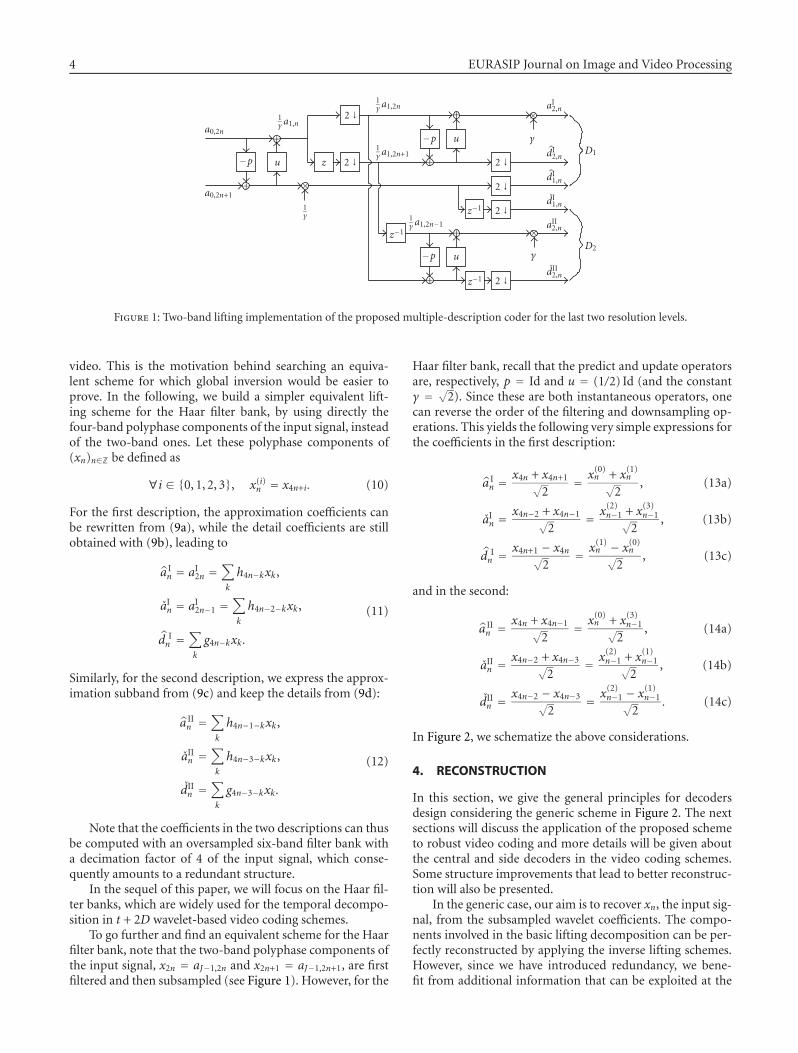
We illustrate our scheme in Figure 1, using a one-stagelifting implementation of the filter bank. The p and u opera-tors in the scheme stand for the predict and update, respec-tively, and γ is a real nonzero multiplicative constant. Notethat the lifting scheme allows a quick and memory-efficientimplementation for biorthogonal filter banks, but especiallyit guarantees perfect reconstruction. For readability, we dis-play a scheme with only two levels of resolution, using a basiclifting core.
3.2. Equivalent four-band lifting implementation
The two-band lifting approach presented above does notyield an immediate inversion scheme, in particular when us-ing nonlinear operators, such as those involving motion esti-mation/compensation in the temporal decomposition of the
4 EURASIP Journal on Image and Video Processing
a0,2n
1γ a1,n
+
+ ×
−p u z 2 ↓
2 ↓
a0,2n+11γ
1γ a1,2n
1γ a1,2n+1
−p u
2 ↓
2 ↓
2 ↓
2 ↓
z−1
−p u
z−1
z−11γ a1,2n−1
+
+
+
+
γ
γ
×
×
aI2,n
dI2,n
dI1,n
dI1,n
aII2,n
dII2,n
D1
D2
Figure 1: Two-band lifting implementation of the proposed multiple-description coder for the last two resolution levels.
video. This is the motivation behind searching an equiva-lent scheme for which global inversion would be easier toprove. In the following, we build a simpler equivalent lift-ing scheme for the Haar filter bank, by using directly thefour-band polyphase components of the input signal, insteadof the two-band ones. Let these polyphase components of(xn)n∈Z be defined as
∀i ∈ {0, 1, 2, 3}, x(i)n = x4n+i. (10)
For the first description, the approximation coefficients canbe rewritten from (9a), while the detail coefficients are stillobtained with (9b), leading to
a In = aI2n =
∑
k
h4n−kxk,
aIn = aI2n−1 =∑
k
h4n−2−kxk,
d In =
∑
k
g4n−kxk.
(11)
Similarly, for the second description, we express the approx-imation subband from (9c) and keep the details from (9d):
a IIn =
∑
k
h4n−1−kxk,
aIIn =∑
k
h4n−3−kxk,
dIIn =∑
k
g4n−3−kxk.
(12)
Note that the coefficients in the two descriptions can thusbe computed with an oversampled six-band filter bank witha decimation factor of 4 of the input signal, which conse-quently amounts to a redundant structure.
In the sequel of this paper, we will focus on the Haar fil-ter banks, which are widely used for the temporal decompo-sition in t + 2D wavelet-based video coding schemes.
To go further and find an equivalent scheme for the Haarfilter bank, note that the two-band polyphase components ofthe input signal, x2n = aJ−1,2n and x2n+1 = aJ−1,2n+1, are firstfiltered and then subsampled (see Figure 1). However, for the
Haar filter bank, recall that the predict and update operatorsare, respectively, p = Id and u = (1/2) Id (and the constantγ = √2). Since these are both instantaneous operators, onecan reverse the order of the filtering and downsampling op-erations. This yields the following very simple expressions forthe coefficients in the first description:
a In =
x4n + x4n+1√2
= x(0)n + x(1)n√2
, (13a)
aIn =x4n−2 + x4n−1√
2= x(2)n−1 + x(3)n−1√
2, (13b)
d In =
x4n+1 − x4n√2
= x(1)n − x(0)n√2
, (13c)
and in the second:
a IIn =
x4n + x4n−1√2
= x(0)n + x(3)n−1√2
, (14a)
aIIn =x4n−2 + x4n−3√
2= x(2)n−1 + x(1)n−1√
2, (14b)
dIIn =x4n−2 − x4n−3√
2= x(2)n−1 − x(1)n−1√
2. (14c)
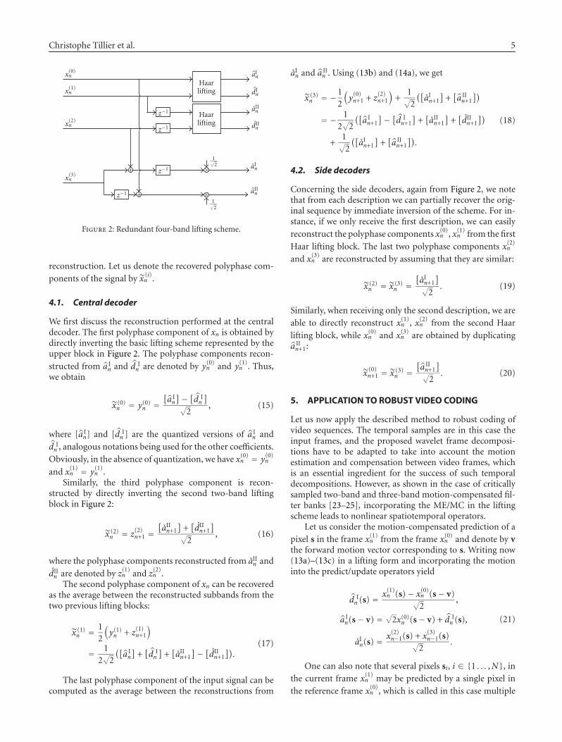
In Figure 2, we schematize the above considerations.
4. RECONSTRUCTION
In this section, we give the general principles for decodersdesign considering the generic scheme in Figure 2. The nextsections will discuss the application of the proposed schemeto robust video coding and more details will be given aboutthe central and side decoders in the video coding schemes.Some structure improvements that lead to better reconstruc-tion will also be presented.
In the generic case, our aim is to recover xn, the input sig-nal, from the subsampled wavelet coefficients. The compo-nents involved in the basic lifting decomposition can be per-fectly reconstructed by applying the inverse lifting schemes.However, since we have introduced redundancy, we bene-fit from additional information that can be exploited at the
Christophe Tillier et al. 5
x(0)n
x(1)n
x(2)n
x(3)n
z−1
z−1
z−1
z−1+
+
Haarlifting
Haarlifting
1√2
1√2
aIn
dIn
aIIn
dIIn
aIn
aIIn
×
×
Figure 2: Redundant four-band lifting scheme.
reconstruction. Let us denote the recovered polyphase com-
ponents of the signal by x (i)n .
4.1. Central decoder
We first discuss the reconstruction performed at the centraldecoder. The first polyphase component of xn is obtained bydirectly inverting the basic lifting scheme represented by theupper block in Figure 2. The polyphase components recon-
structed from a In and d I
n are denoted by y(0)n and y(1)n . Thus,we obtain
x (0)n = y(0)n =
[a In
]− [d In
]√2
, (15)
where [a In] and [d I
n ] are the quantized versions of a In and
d In , analogous notations being used for the other coefficients.
Obviously, in the absence of quantization, we have x(0)n = y(0)n
and x(1)n = y(1)n .Similarly, the third polyphase component is recon-
structed by directly inverting the second two-band liftingblock in Figure 2:
x (2)n = z(2)n+1 =
[aIIn+1
]+[dIIn+1
]√2
, (16)
where the polyphase components reconstructed from aIIn and
dIIn are denoted by z(1)n and z(2)n .The second polyphase component of xn can be recovered
as the average between the reconstructed subbands from thetwo previous lifting blocks:
x (1)n = 1
2
(y(1)n + z(1)n+1
)
= 12√2
([a In
]+[d In
]+[aIIn+1
]− [dIIn+1]).
(17)
The last polyphase component of the input signal can becomputed as the average between the reconstructions from
aIn and a IIn . Using (13b) and (14a), we get
x (3)n = −1
2
(y(0)n+1 + z(2)n+1
)+
1√2
([aIn+1
]+[a IIn+1
])
= − 12√2
([a In+1
]− [d In+1
]+[aIIn+1
]+[dIIn+1
])
+1√2
([aIn+1
]+[a IIn+1
]).
(18)
4.2. Side decoders
Concerning the side decoders, again from Figure 2, we notethat from each description we can partially recover the orig-inal sequence by immediate inversion of the scheme. For in-stance, if we only receive the first description, we can easily
reconstruct the polyphase components x(0)n , x(1)n from the first
Haar lifting block. The last two polyphase components x(2)n
and x(3)n are reconstructed by assuming that they are similar:
x (2)n = x (3)
n =[aIn+1
]√2
. (19)
Similarly, when receiving only the second description, we are
able to directly reconstruct x(1)n , x(2)n from the second Haar
lifting block, while x(0)n and x(3)n are obtained by duplicatinga IIn+1:
x (0)n+1 = x (3)
n =[a IIn+1
]√2
. (20)
5. APPLICATION TO ROBUST VIDEO CODING
Let us now apply the described method to robust coding ofvideo sequences. The temporal samples are in this case theinput frames, and the proposed wavelet frame decomposi-tions have to be adapted to take into account the motionestimation and compensation between video frames, whichis an essential ingredient for the success of such temporaldecompositions. However, as shown in the case of criticallysampled two-band and three-band motion-compensated fil-ter banks [23–25], incorporating the ME/MC in the liftingscheme leads to nonlinear spatiotemporal operators.
Let us consider the motion-compensated prediction of apixel s in the frame x(1)n from the frame x(0)n and denote by vthe forward motion vector corresponding to s. Writing now(13a)–(13c) in a lifting form and incorporating the motioninto the predict/update operators yield
d In (s) =
x(1)n (s)− x(0)n (s− v)√2
,
a In(s− v) = √2x(0)n (s− v) + d I
n (s),
aIn(s) =x(2)n−1(s) + x(3)n−1(s)√
2.
(21)
One can also note that several pixels si, i ∈ {1 . . . ,N}, inthe current frame x(1)n may be predicted by a single pixel in
the reference frame x(0)n , which is called in this case multiple
6 EURASIP Journal on Image and Video Processing
connected [26]. Then, for the pixels si and their correspond-ing motion vectors vi, we have s1 − v1 = · · · = si − vi =· · · = sN −vN . After noting that the update step may involve
all the details d In (si), i ∈ {1, . . . ,N}, while preserving the per-
fect reconstruction property, we have shown that the updatestep minimizing the reconstruction error is the one averag-ing all the detail contributions from the connected pixels si[27]. With this remark, one can write (21) as follows:
d In
(si) = x(1)n
(si)− x(0)n
(si − vi
)√2
, i ∈ {1, . . . ,N},(22a)
a In
(si − vi
) = √2x(0)n
(si − vi
)+
∑N�=1 d I
n
(s�)
N, (22b)
aIn(s) =x(2)n−1(s) + x(3)n−1(s)√
2, (22c)
and with similar notations for multiple connections in thesecond description:
dIIn(si) = x(2)n−1
(si)− x(1)n−1
(si − vi
)√2
, i ∈ {1, . . . ,M},(23a)
aIIn(si − vi
) = √2x(1)n−1(si − vi
)+
∑M�=1 dIIn
(s�)
M, (23b)
a IIn (s) =
x(0)n (s) + x(3)n−1(s)√2
. (23c)
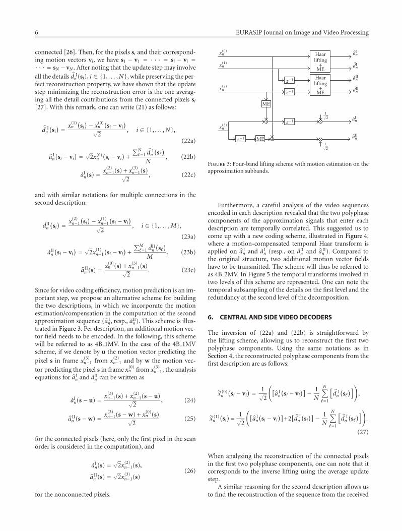
Since for video coding efficiency, motion prediction is an im-portant step, we propose an alternative scheme for buildingthe two descriptions, in which we incorporate the motionestimation/compensation in the computation of the secondapproximation sequence (a I
n, resp., aIIn ). This scheme is illus-
trated in Figure 3. Per description, an additional motion vec-tor field needs to be encoded. In the following, this schemewill be referred to as 4B 1MV. In the case of the 4B 1MVscheme, if we denote by u the motion vector predicting the
pixel s in frame x(3)n−1 from x(2)n−1 and by w the motion vec-
tor predicting the pixel s in frame x(0)n from x(3)n−1, the analysisequations for a I
n and aIIn can be written as
aIn(s− u) = x(3)n−1(s) + x(2)n−1(s− u)√2
, (24)
a IIn (s−w) = x(3)n−1(s−w) + x(0)n (s)√
2(25)
for the connected pixels (here, only the first pixel in the scanorder is considered in the computation), and
aIn(s) =√2x(2)n−1(s),
a IIn (s) =
√2x(3)n−1(s)
(26)
for the nonconnected pixels.
x(0)n
x(1)n
x(2)n
x(3)n
ME
MEz−1
z−1
z−1
z−1+
+
Haarlifting+ME
Haarlifting+ME
1√2
1√2
aIn
dIn
aIIn
dIIn
aIn
aIIn
×
×
Figure 3: Four-band lifting scheme with motion estimation on theapproximation subbands.
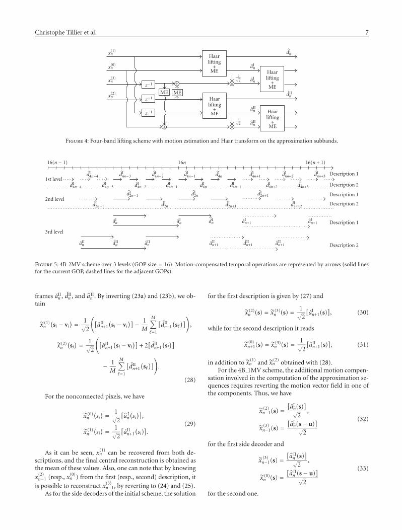
Furthermore, a careful analysis of the video sequencesencoded in each description revealed that the two polyphasecomponents of the approximation signals that enter eachdescription are temporally correlated. This suggested us tocome up with a new coding scheme, illustrated in Figure 4,where a motion-compensated temporal Haar transform isapplied on a I
n and aIn (resp., on aIIn and a IIn ). Compared to
the original structure, two additional motion vector fieldshave to be transmitted. The scheme will thus be referred toas 4B 2MV. In Figure 5 the temporal transforms involved intwo levels of this scheme are represented. One can note thetemporal subsampling of the details on the first level and theredundancy at the second level of the decomposition.
6. CENTRAL AND SIDE VIDEO DECODERS
The inversion of (22a) and (22b) is straightforward bythe lifting scheme, allowing us to reconstruct the first twopolyphase components. Using the same notations as inSection 4, the reconstructed polyphase components from thefirst description are as follows:
x (0)n
(si − vi
) = 1√2
([a In
(si − vi
)]− 1N
N∑
�=1
[d In
(s�)]),
x (1)n
(si)= 1√
2
([a In
(si − vi
)]+2[d In
(si)]− 1
N
N∑
�=1
[d In
(s�)]).
(27)
When analyzing the reconstruction of the connected pixelsin the first two polyphase components, one can note that itcorresponds to the inverse lifting using the average updatestep.
A similar reasoning for the second description allows usto find the reconstruction of the sequence from the received
Christophe Tillier et al. 7
x(1)n
x(0)n
x(3)n
x(2)nME ME
z−1
z−1
z−1
+
+
Haarlifting+ME
Haarlifting+ME
Haarlifting+ME
Haarlifting+ME
1√2
1√2
×
×
dIn
aIn
aIn
dIIn
aIIn
aIIn
Figure 4: Four-band lifting scheme with motion estimation and Haar transform on the approximation subbands.
16(n− 1) 16n 16(n + 1)
1st leveldI4n−4 dI4n−3 dI4n−2 dI4n−1 dI4n dI4n+1 dI4n+2 dI4n+3 Description 1
dI4n−4 dI4n−3 dI4n−2 dI4n−1 dI4n dI4n+1 dI4n+2 dI4n+3 Description 2
2nd leveldI2n−1 dI2n dI2n+1 Description 1
dI2n−1 dI2n dI2n+1 dI2n+2 Description 2
3rd level
aIn aIn dIn aIn+1 aIn+1 Description 1
aIIn dIIn aIIn aIIn+1 dIIn+1 aIIn+1 Description 2
Figure 5: 4B 2MV scheme over 3 levels (GOP size = 16). Motion-compensated temporal operations are represented by arrows (solid linesfor the current GOP, dashed lines for the adjacent GOPs).
frames aIIn , dIIn , and a II
n . By inverting (23a) and (23b), we ob-tain
x (1)n
(si − vi
) = 1√2
([aIIn+1
(si − vi
)]− 1M
M∑
�=1
[dIIn+1
(s�)]),
x (2)n
(si) = 1√
2
([aIIn+1
(si − vi
)]+ 2[dIIn+1
(si)]
− 1M
M∑
�=1
[dIIn+1
(s�)]).
(28)
For the nonconnected pixels, we have
x (0)n
(si) = 1√
2
[a In
(si)],
x (1)n
(si) = 1√
2
[aIIn+1
(si)].
(29)
As it can be seen, x(1)n can be recovered from both de-scriptions, and the final central reconstruction is obtained asthe mean of these values. Also, one can note that by knowing
x(2)n−1 (resp., x(0)n ) from the first (resp., second) description, it
is possible to reconstruct x(3)n−1, by reverting to (24) and (25).As for the side decoders of the initial scheme, the solution
for the first description is given by (27) and
x (2)n (s) = x (3)
n (s) = 1√2
[aIn+1(s)
], (30)
while for the second description it reads
x (0)n+1(s) = x (3)
n (s) = 1√2
[aIIn+1(s)
], (31)
in addition to x (1)n and x (2)
n obtained with (28).For the 4B 1MV scheme, the additional motion compen-
sation involved in the computation of the approximation se-quences requires reverting the motion vector field in one ofthe components. Thus, we have
x (2)n−1(s) =
[aIn(s)
]√2
,
x (3)n−1(s) =
[aIn(s− u)
]√2
(32)
for the first side decoder and
x (3)n−1(s) =
[a IIn (s)
]√2
,
x (0)n (s) =
[a IIn (s− u)
]√2
(33)
for the second one.
8 EURASIP Journal on Image and Video Processing
For the scheme 4B 2MV, the temporal Haar transformbeing revertible, no additional difficulties appear for the cen-tral or side decoders.
Note that the reconstruction by one central and two sidedecoders corresponds to a specific application scenario, inwhich the user receives the two descriptions from two differ-ent locations (e.g., two WiFi access points), but dependingon its position, it can receive both or only one of the descrip-tions. In a more general scenario, the user may be in the re-ception zone of both access points, but packets may be lostfrom both descriptions (due to network congestion, trans-mission quality, etc.). In this case, the central decoder will tryto reconstruct the sequence by exploiting the information inall the received packets. It is therefore clear that an importantissue for the reconstruction quality will be the packetizationstrategy. Even though the complete description of the differ-ent situations which can appear in the decoding (dependingon the type of the lost packets) cannot be done here, it isworth noting that in a number of cases, an efficient usageof the received information can be employed: for instance,even if we do not receive the spatiotemporal subbands of oneof the descriptions, but only a packet containing its motionvectors, these vectors can be exploited in conjunction withthe other description for improving the fluidity of the recon-structed video. We also take advantage of the redundancy ex-isting at the last level to choose, for the frames which can bedecoded from both descriptions, the version which has thebest quality, and thus to limit the degradations appearing inone of the descriptions.
7. SIMULATIONS RESULTS
The Haar lifting blocks in Figure 4 are implemented by amotion-compensated lifting decomposition [23]. The mo-tion estimation is performed using hierarchical variable sizeblock-matching (HVBSM) algorithm with block sizes rang-ing from 64 × 64 to 4 × 4. An integer-pel accuracy is usedfor motion compensation. The resulting temporal subbandsare spatially decomposed with biorthogonal 9/7 Daubechieswavelets over 5 resolution levels. Spatiotemporal coefficientsand motion vectors (MVs) are encoded within the MC-EZBC framework [26, 28], where MV fields are first repre-sented as quad-tree maps and MV values are encoded with azero-order arithmetic coder, in raster-scan order.
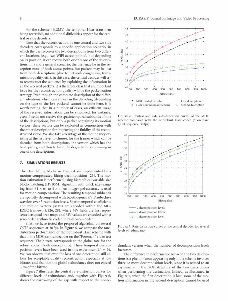
First, we have tested the proposed algorithm on severalQCIF sequences at 30 fps. In Figure 6, we compare the rate-distortion performance of the nonrobust Haar scheme withthat of theMDC central decoder on the “Foreman” video testsequence. The bitrate corresponds to the global rate for therobust codec (both descriptions). Three temporal decom-position levels have been used in this experiment (J = 3).We can observe that even the loss of one description still al-lows for acceptable quality reconstruction especially at lowbitrates and also that the global redundancy does not exceed30% of the bitrate.
Figure 7 illustrates the central rate-distortion curves fordifferent levels of redundancy and, together with Figure 6,shows the narrowing of the gap with respect to the nonre-
26
28
30
32
34
36
38
40
42
44
y-PSN
R(dB)
100 200 300 400 500 600 700 800 900 1000
Bitrate (kbs)
MDC central decoderHaar nonredundant scheme
First descriptionSecond description
Figure 6: Central and side rate-distortion curves of the MDCscheme compared with the nonrobust Haar codec (“Foreman”QCIF sequence, 30 fps).
24
26
28
30
32
34
36
38
40
42
y-PSN
R(dB)
100 200 300 400 500 600 700 800 900 1000
Bitrate (kbs)
3 decomposition levels
2 decomposition levels
1 decomposition level
Figure 7: Rate-distortion curves at the central decoder for severallevels of redundancy.
dundant version when the number of decomposition levelsincreases.
The difference in performance between the two descrip-tions is a phenomenon appearing only if the scheme involvesthree or more decomposition levels, since it is related to anasymmetry in the GOF structure of the two descriptionswhen performing the decimation. Indeed, as illustrated inFigure 5, when the first description is lost, some of the mo-tion information in the second description cannot be used
Christophe Tillier et al. 9
26
28
30
32
34
36
38
40
42
44
y-PSN
R(dB)
100 200 300 400 500 600 700 800 900 1000
Bitrate (kbs)
Haar nonredundant schemeInitial 4B scheme
4B 1MV scheme4B 2MV scheme
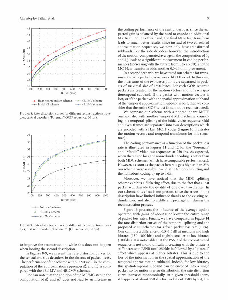
Figure 8: Rate-distortion curves for different reconstruction strate-gies, central decoder (“Foreman” QCIF sequence, 30 fps).
26
27
28
29
30
31
32
33
34
y-PSN
R(dB)
100 200 300 400 500 600 700 800 900 1000
Bitrate (kbs)
Initial 4B scheme
4B 1MV scheme
4B 2MV scheme
Figure 9: Rate-distortion curves for different reconstruction strate-gies, first side decoder (“Foreman” QCIF sequence, 30 fps).
to improve the reconstruction, while this does not happenwhen loosing the second description.
In Figures 8-9, we present the rate-distortion curves forthe central and side decoders, in the absence of packet losses.The performance of the scheme withoutME/MC in the com-putation of the approximation sequences aIn and a II
n is com-pared with the 4B 1MV and 4B 2MV schemes.
One can note that the addition of the ME/MC step in thecomputation of aIn and a II
n does not lead to an increase in
the coding performance of the central decoder, since the ex-pected gain is balanced by the need to encode an additionalMV field. On the other hand, the final MC-Haar transformleads to much better results, since instead of two correlatedapproximation sequences, we now only have transformedsubbands. For the side decoders however, the introductionof themotion-compensated average in the computation of aInand a II
n leads to a significant improvement in coding perfor-mances (increasing with the bitrate from 1 to 2.5 dB), and theMC-Haar transform adds another 0.3 dB of improvement.
In a second scenario, we have tested our scheme for trans-mission over a packet loss network, like Ethernet. In this case,the bitstreams of the two descriptions are separated in pack-ets of maximal size of 1500 bytes. For each GOP, separatepackets are created for the motion vectors and for each spa-tiotemporal subband. If the packet with motion vectors islost, or if the packet with the spatial approximation subbandof the temporal approximation subband is lost, then we con-sider that the entire GOP is lost (it cannot be reconstructed).
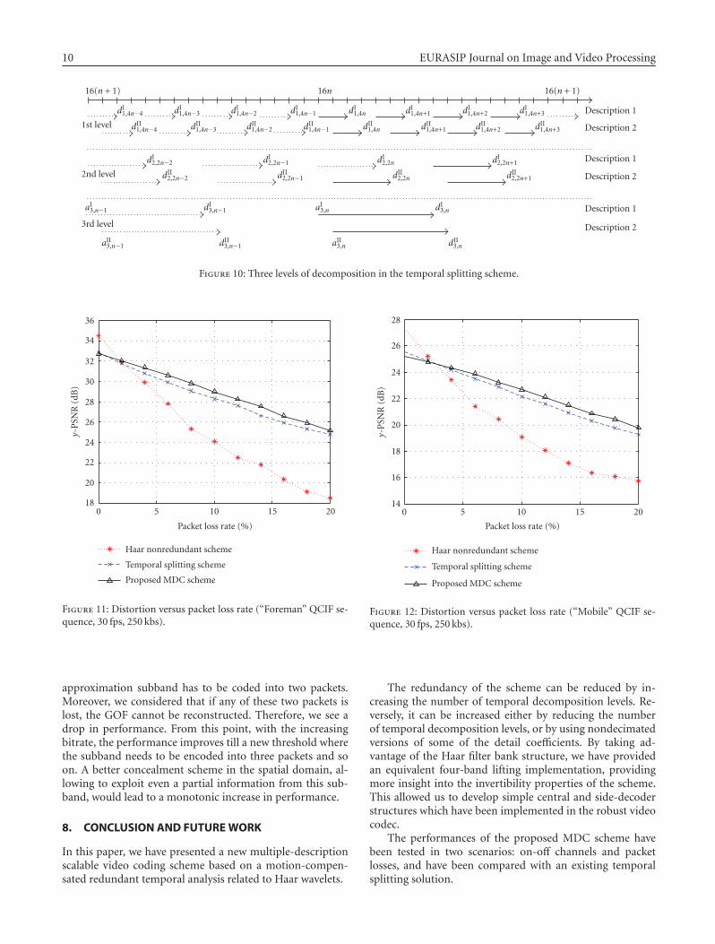
We compare our scheme with a nonredundant MCTFone and also with another temporal MDC scheme, consist-ing in a temporal splitting of the initial video sequence. Oddand even frames are separated into two descriptions whichare encoded with a Haar MCTF coder (Figure 10 illustratesthe motion vectors and temporal transforms for this struc-ture).
The coding performance as a function of the packet lossrate is illustrated in Figures 11 and 12 for the “Foreman”and “Mobile” video test sequences at 250 kbs. As expected,when there is no loss, the nonredundant coding is better thanbothMDC schemes (which have comparable performances).However, as soon as the packet loss rate gets higher than 2%,our scheme overpasses by 0.5–1 dB the temporal splitting andthe nonrobust coding by up to 4 dB.
Moreover, we have noticed that the MDC splittingscheme exhibits a flickering effect, due to the fact that a lostpacket will degrade the quality of one over two frames. Inour scheme, this effect is not present, since the errors in onedescription have limited influence thanks to the existing re-dundancies, and also to a different propagation during thereconstruction process.
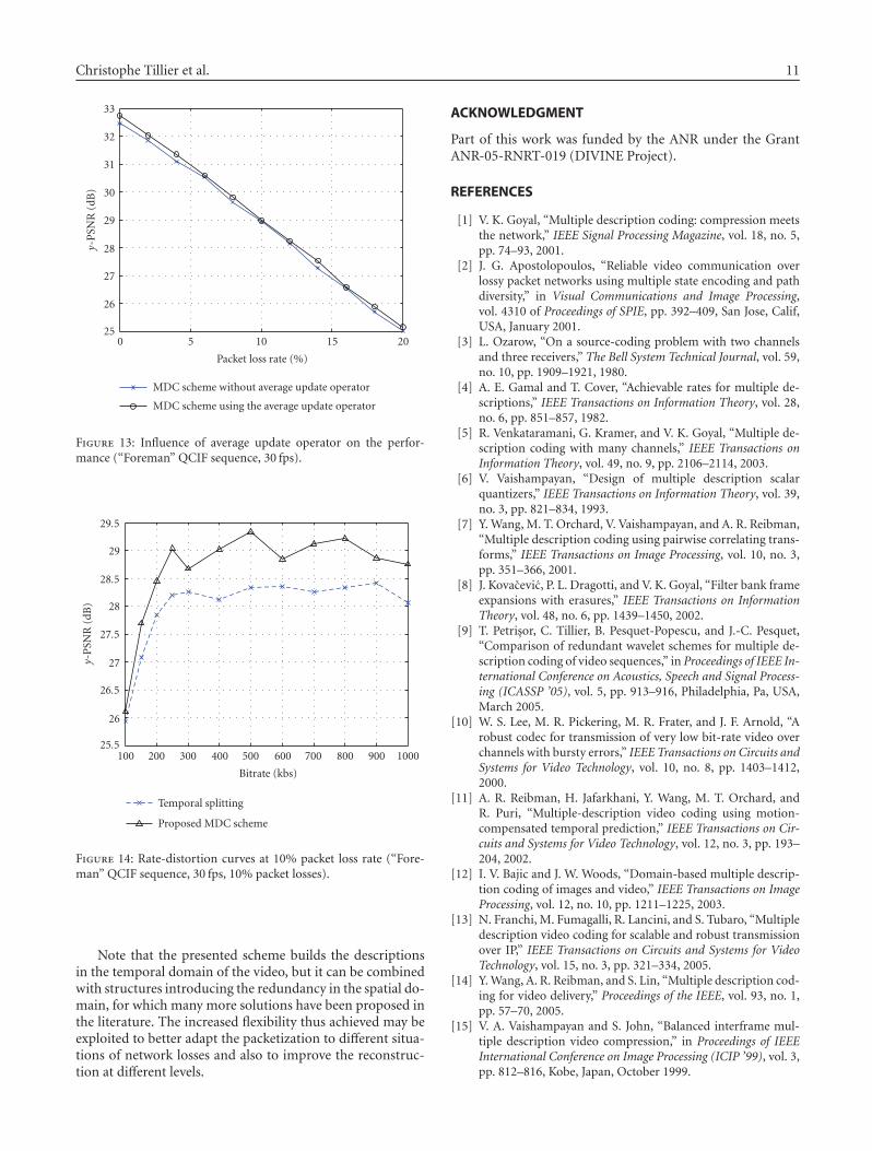
Figure 13 presents the influence of the average updateoperator, with gains of about 0.2 dB over the entire rangeof packet loss rates. Finally, we have compared in Figure 14the rate-distortion curves of the temporal splitting and theproposed MDC schemes for a fixed packet loss rate (10%).One can note a difference of 0.5–1.3 dB at medium and highbitrates (150–1000 kbs) and slightly smaller at low bitrates(100 kbs). It is noticeable that the PSNR of the reconstructedsequence is not monotonically increasing with the bitrate: astiff increase in PSNR until 250 kbs is followed by a “plateau”effect which appears at higher bitrates. This is due to theloss of the information in the spatial approximation of thetemporal approximation subband. Indeed, for low bitrates,this spatiotemporal subband can be encoded into a singlepacket, so for uniform error distribution, the rate-distortioncurve increases monotonically. At a given threshold (here,it happens at about 250 kbs for packets of 1500 bytes), the
10 EURASIP Journal on Image and Video Processing
16(n + 1) 16n 16(n + 1)
1st level
dI1,4n−4 dI1,4n−3 dI1,4n−2 dI1,4n−1 dI1,4n dI1,4n+1 dI1,4n+2 dI1,4n+3 Description 1
dII1,4n−4 dII1,4n−3 dII1,4n−2 dII1,4n−1 dII1,4n dII1,4n+1 dII1,4n+2 dII1,4n+3 Description 2
2nd level
dI2,2n−2 dI2,2n−1 dI2,2n dI2,2n+1 Description 1
dII2,2n−2 dII2,2n−1 dII2,2n dII2,2n+1 Description 2
3rd level
aI3,n−1 dI3,n−1 aI3,n dI3,n Description 1
aII3,n−1 dII3,n−1 aII3,n dII3,n
Description 2
Figure 10: Three levels of decomposition in the temporal splitting scheme.
18
20
22
24
26
28
30
32
34
36
y-PSN
R(dB)
0 5 10 15 20
Packet loss rate (%)
Haar nonredundant scheme
Temporal splitting scheme
Proposed MDC scheme
Figure 11: Distortion versus packet loss rate (“Foreman” QCIF se-quence, 30 fps, 250 kbs).
approximation subband has to be coded into two packets.Moreover, we considered that if any of these two packets islost, the GOF cannot be reconstructed. Therefore, we see adrop in performance. From this point, with the increasingbitrate, the performance improves till a new threshold wherethe subband needs to be encoded into three packets and soon. A better concealment scheme in the spatial domain, al-lowing to exploit even a partial information from this sub-band, would lead to a monotonic increase in performance.
8. CONCLUSION AND FUTUREWORK
In this paper, we have presented a new multiple-descriptionscalable video coding scheme based on a motion-compen-sated redundant temporal analysis related to Haar wavelets.
14
16
18
20
22
24
26
28
y-PSN
R(dB)
0 5 10 15 20
Packet loss rate (%)
Haar nonredundant scheme
Temporal splitting scheme
Proposed MDC scheme
Figure 12: Distortion versus packet loss rate (“Mobile” QCIF se-quence, 30 fps, 250 kbs).
The redundancy of the scheme can be reduced by in-creasing the number of temporal decomposition levels. Re-versely, it can be increased either by reducing the numberof temporal decomposition levels, or by using nondecimatedversions of some of the detail coefficients. By taking ad-vantage of the Haar filter bank structure, we have providedan equivalent four-band lifting implementation, providingmore insight into the invertibility properties of the scheme.This allowed us to develop simple central and side-decoderstructures which have been implemented in the robust videocodec.
The performances of the proposed MDC scheme havebeen tested in two scenarios: on-off channels and packetlosses, and have been compared with an existing temporalsplitting solution.
Christophe Tillier et al. 11
25
26
27
28
29
30
31
32
33
y-PSN
R(dB)
0 5 10 15 20
Packet loss rate (%)
MDC scheme without average update operator
MDC scheme using the average update operator
Figure 13: Influence of average update operator on the perfor-mance (“Foreman” QCIF sequence, 30 fps).
25.5
26
26.5
27
27.5
28
28.5
29
29.5
y-PSN
R(dB)
100 200 300 400 500 600 700 800 900 1000
Bitrate (kbs)
Temporal splitting
Proposed MDC scheme
Figure 14: Rate-distortion curves at 10% packet loss rate (“Fore-man” QCIF sequence, 30 fps, 10% packet losses).
Note that the presented scheme builds the descriptionsin the temporal domain of the video, but it can be combinedwith structures introducing the redundancy in the spatial do-main, for which many more solutions have been proposed inthe literature. The increased flexibility thus achieved may beexploited to better adapt the packetization to different situa-tions of network losses and also to improve the reconstruc-tion at different levels.
ACKNOWLEDGMENT
Part of this work was funded by the ANR under the GrantANR-05-RNRT-019 (DIVINE Project).
REFERENCES
[1] V. K. Goyal, “Multiple description coding: compression meetsthe network,” IEEE Signal Processing Magazine, vol. 18, no. 5,pp. 74–93, 2001.
[2] J. G. Apostolopoulos, “Reliable video communication overlossy packet networks using multiple state encoding and pathdiversity,” in Visual Communications and Image Processing,vol. 4310 of Proceedings of SPIE, pp. 392–409, San Jose, Calif,USA, January 2001.
[3] L. Ozarow, “On a source-coding problem with two channelsand three receivers,” The Bell System Technical Journal, vol. 59,no. 10, pp. 1909–1921, 1980.
[4] A. E. Gamal and T. Cover, “Achievable rates for multiple de-scriptions,” IEEE Transactions on Information Theory, vol. 28,no. 6, pp. 851–857, 1982.
[5] R. Venkataramani, G. Kramer, and V. K. Goyal, “Multiple de-scription coding with many channels,” IEEE Transactions onInformation Theory, vol. 49, no. 9, pp. 2106–2114, 2003.
[6] V. Vaishampayan, “Design of multiple description scalarquantizers,” IEEE Transactions on Information Theory, vol. 39,no. 3, pp. 821–834, 1993.
[7] Y.Wang, M. T. Orchard, V. Vaishampayan, and A. R. Reibman,“Multiple description coding using pairwise correlating trans-forms,” IEEE Transactions on Image Processing, vol. 10, no. 3,pp. 351–366, 2001.
[8] J. Kovacevic, P. L. Dragotti, and V. K. Goyal, “Filter bank frameexpansions with erasures,” IEEE Transactions on InformationTheory, vol. 48, no. 6, pp. 1439–1450, 2002.
[9] T. Petrisor, C. Tillier, B. Pesquet-Popescu, and J.-C. Pesquet,“Comparison of redundant wavelet schemes for multiple de-scription coding of video sequences,” in Proceedings of IEEE In-ternational Conference on Acoustics, Speech and Signal Process-ing (ICASSP ’05), vol. 5, pp. 913–916, Philadelphia, Pa, USA,March 2005.
[10] W. S. Lee, M. R. Pickering, M. R. Frater, and J. F. Arnold, “Arobust codec for transmission of very low bit-rate video overchannels with bursty errors,” IEEE Transactions on Circuits andSystems for Video Technology, vol. 10, no. 8, pp. 1403–1412,2000.
[11] A. R. Reibman, H. Jafarkhani, Y. Wang, M. T. Orchard, andR. Puri, “Multiple-description video coding using motion-compensated temporal prediction,” IEEE Transactions on Cir-cuits and Systems for Video Technology, vol. 12, no. 3, pp. 193–204, 2002.
[12] I. V. Bajic and J. W. Woods, “Domain-based multiple descrip-tion coding of images and video,” IEEE Transactions on ImageProcessing, vol. 12, no. 10, pp. 1211–1225, 2003.
[13] N. Franchi, M. Fumagalli, R. Lancini, and S. Tubaro, “Multipledescription video coding for scalable and robust transmissionover IP,” IEEE Transactions on Circuits and Systems for VideoTechnology, vol. 15, no. 3, pp. 321–334, 2005.
[14] Y.Wang, A. R. Reibman, and S. Lin, “Multiple description cod-ing for video delivery,” Proceedings of the IEEE, vol. 93, no. 1,pp. 57–70, 2005.
[15] V. A. Vaishampayan and S. John, “Balanced interframe mul-tiple description video compression,” in Proceedings of IEEEInternational Conference on Image Processing (ICIP ’99), vol. 3,pp. 812–816, Kobe, Japan, October 1999.
12 EURASIP Journal on Image and Video Processing
[16] Y. Wang and S. Lin, “Error-resilient video coding using mul-tiple description motion compensation,” IEEE Transactions onCircuits and Systems for Video Technology, vol. 12, no. 6, pp.438–452, 2002.
[17] M. van der Schaar and D. S. Turaga, “Multiple descriptionscalable coding using wavelet-based motion compensatedtemporal filtering,” in Proceedings of IEEE International Con-ference on Image Processing (ICIP ’03), vol. 3, pp. 489–492,Barcelona, Spain, September 2003.
[18] C. Tillier, B. Pesquet-Popescu, and M. van der Schaar, “Multi-ple descriptions scalable video coding,” in Proceedings of 12thEuropean Signal Processing Conference (EUSIPCO ’04), Vienna,Austria, September 2004.
[19] J. Kim, R. M. Mersereau, and Y. Altunbasak, “Network-adaptive video streaming using multiple description codingand path diversity,” in Proceedings of International Conferenceon Multimedia and Expo (ICME ’03), vol. 2, pp. 653–656, Bal-timore, Md, USA, July 2003.
[20] S. Cho and W. A. Pearlman, “Error resilient compression andtransmission of scalable video,” inApplications of Digital ImageProcedding XXIII, vol. 4115 of Proceedings of SPIE, pp. 396–405, San Diego, Calif, USA, July-August 2000.
[21] N. Franchi, M. Fumagalli, G. Gatti, and R. Lancini, “A novelerror-resilience scheme for a 3-D multiple description videocoder,” in Proceedings of Picture Coding Symposium (PSC ’04),pp. 373–376, San Francisco, Calif, USA, December 2004.
[22] T. Petrisor, C. Tillier, B. Pesquet-Popescu, and J.-C. Pesquet,“Redundant multiresolution analysis for multiple descriptionvideo coding,” in Proceedings of IEEE 6th Workshop on Mul-timedia Signal Processing, pp. 95–98, Siena, Italy, September-October 2004.
[23] B. Pesquet-Popescu and V. Bottreau, “Three-dimensional lift-ing schemes for motion compensated video compression,”in Proceedings of IEEE International Conference on Acoustics,Speech and Signal Processing (ICASSP ’01), vol. 3, pp. 1793–1796, Salt Lake, Utah, USA, May 2001.
[24] C. Tillier and B. Pesquet-Popescu, “3D, 3-band, 3-tap tempo-ral lifting for scalable video coding,” in Proceedings of IEEE In-ternational Conference on Image Processing (ICIP ’03), vol. 2,pp. 779–782, Barcelona, Spain, September 2003.
[25] G. Pau, C. Tillier, B. Pesquet-Popescu, and H. Heijmans, “Mo-tion compensation and scalability in lifting-based video cod-ing,” Signal Processing: Image Communication, vol. 19, no. 7,pp. 577–600, 2004.
[26] S.-J. Choi and J. W. Woods, “Motion-compensated 3-D sub-band coding of video,” IEEE Transactions on Image Processing,vol. 8, no. 2, pp. 155–167, 1999.
[27] C. Tillier, B. Pesquet-Popescu, and M. van der Schaar, “Im-proved update operators for lifting-based motion-compensa-ted temporal filtering,” IEEE Signal Processing Letters, vol. 12,no. 2, pp. 146–149, 2005.
[28] “3D MC-EZBC Software package,” http://www.cipr.rpi.edu/ftp pub/personal/chen/MC EZBC.zip.


