Embed Size (px)
Citation preview
3470 JOURNAL OF LIGHTWAVE TECHNOLOGY, VOL. 29, NO. 22, NOVEMBER 15, 2011
A Microwave Bandpass Differentiator ImplementedBased on a Nonuniformly-Spaced Photonic
Microwave Delay-Line FilterYichen Han, Student Member, IEEE, Ze Li, and Jianping Yao, Senior Member, IEEE, Fellow, OSA
Abstract—A microwave bandpass differentiator implementedbased on a finite impulse response (FIR) photonic microwavedelay-line filter with nonuniformly-spaced taps is proposed andexperimentally demonstrated. To implement a microwave band-pass differentiator, the coefficients of the photonic microwavedelay-line filter should have both positive and negative coeffi-cients. In the proposed approach, the negative coefficients areequivalently achieved by introducing an additional time delay toeach of the taps, leading to a phase shift to the tap. Comparedwith a uniformly-spaced photonic microwave delay-line filter withtrue negative coefficients, the proposed differentiator featuresa greatly simplified implementation. A microwave bandpassdifferentiator based on a six-tap nonuniformly-spaced photonicmicrowave delay-line filter is designed, simulated, and experi-mentally demonstrated. The reconfigurability of the microwavebandpass differentiator is experimentally investigated. The em-ployment of the differentiator to perform differentiation of abandpass microwave signal is also experimentally demonstrated.
Index Terms—Differentiator, finite impulse response (FIR),microwave photonics, nonuniformly-spaced delay-line filter.
I. INTRODUCTION
M ICROWAVE signal processing based on photonic tech-niques has been a topic of interest in the past few years
[1]. Due to the limited speed of the currently available dig-ital electronics, the processing of high-frequency and broad-band signal based on photonic techniques has been considereda promising solution. Among the numerous signal processingschemes, the one based on a delay-line architecture with a finiteimpulse response (FIR) has been widely investigated, which canfind applications such as spectral filtering, phase coding, chirpedmicrowave signal generation, and chirped pulse compression.To avoid optical interference, a photonic microwave delay-linefilter is usually operating in the incoherent regime. The majorlimitation of a photonic microwave delay-line filter operatingin the incoherent regime is that the tap coefficients are all posi-tive, which makes the FIR delay-line filter to be low-pass only.For many applications, however, a bandpass filter with negativeor complex coefficients is needed [1].
Manuscript received April 24, 2011; revised August 25, 2011; acceptedSeptember 20, 2011. Date of publication September 29, 2011; date of currentversion November 16, 2011. This work was supported by Natural Sciences andEngineering Research Council of Canada (NSERC).The authors are with the Microwave Photonics Research Laboratory, School
of Electrical Engineering and Computer Science, University of Ottawa, Ottawa,ON K1N 6N5, Canada (e-mail: [email protected]).Color versions of one or more of the figures in this paper are available online
at http://ieeexplore.ieee.org.Digital Object Identifier 10.1109/JLT.2011.2169939
Numerous techniques have been proposed to achieve a pho-tonic microwave delay-line filter with positive and negative tapcoefficients [2]–[5]. A microwave photonic filter with positiveand negative coefficients can be implemented based on cross-gain modulation (XGM) [2] or cross-polarization modulation(XPolM) [3] in a semiconductor optical amplifier (SOA). Pos-itive and negative tap coefficients can also be realized using apair of Mach–Zehnder modulators (MZMs) that are biased atthe positive and negative linear slopes of the transfer functionsto achieve amplitude inversion [4]. A pair of positive and neg-ative tap coefficients can be generated based on phase modu-lation and phase-modulation to intensity-modulation (PM-IM)conversion by passing a phase-modulated optical signal througha pair of chirped fiber Bragg gratings (CFBGs) with comple-mentary group velocity dispersion (GVD) responses [5]. Pho-tonic microwave delay-line filters with complex tap coefficientshave also been proposed [6], [7]. In [6], a complex coefficient isgenerated by introducing a phase shift to the microwave signalto be processed, which is realized based on a combined use ofoptical single-sideband modulation (SSB) and stimulated Bril-louin scattering (SBS). In [7], a complex coefficient is generatedusing a wideband tunable optical microwave phase shifter thatconsists of two electro-optic MZMs. A continuous tuning of aphase shift from to was demonstrated. A com-prehensive review of photonic microwave filters with negativeor complex coefficients can be found in [8].A photonic microwave delay-line filter with complex coeffi-
cients can have an arbitrary spectral response, which is highlyneeded for advanced signal processing. Although the schemesin [6], [7] can provide complex coefficients, the implementa-tion is extremely complicated, especially when the number oftaps is large. To solve this problem, we have recently developeda concept to design and realize a bandpass microwave photonicdelay-line filter with equivalent negative or complex tap coeffi-cients [9], [10] with nonuniformly-spaced taps. By introducingan additional time delay to a tap, an additional phase shift will beintroduced to the tap coefficient, making the tap have an equiv-alent negative or complex coefficient. Based on this concept,advanced signal processing functions, such as phase coding,chirped microwave signal generation and chirped pulse com-pression, have been demonstrated [10].Due to the wide applications in radar and modern communi-
cation systems, temporal differentiation is one of the most im-portant signal analyzing and processing functions. A temporaldifferentiator can be implemented using digital electronics, butat a lower speed and narrower wideband compared with the im-plementation in the optical domain. Numerous photonically as-sisted temporal differentiators have been proposed and demon-
0733-8724/$26.00 © 2011 IEEE
HAN et al.: MICROWAVE BANDPASS DIFFERENTIATOR 3471
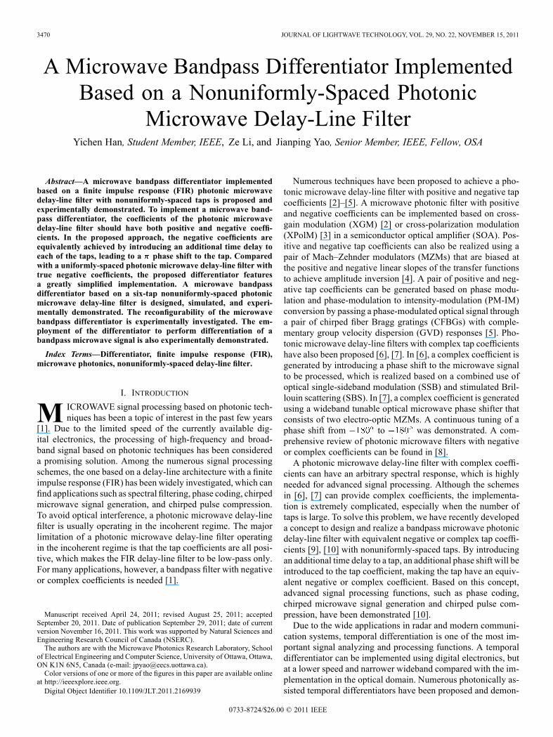
Fig. 1. Frequency response of a bandpass microwave differentiator.
strated. In general, depending on the applications, temporal dif-ferentiators [11]–[17] can be classified into two categories: op-tical differentiators [11]–[13], [17] and microwave differentia-tors [14]–[16]. A photonic microwave temporal differentiatorcould be achieved based on PM and PM-IM conversion in anFBG serving as a frequency discriminator [14], [15]. A tem-poral differentiator using other schemes such as the XGM [16]and the XPolM [17] in a SOA has also been reported.In this paper, we propose and experimentally demonstrate
a microwave bandpass differentiator based on a photonic mi-crowave delay-line filter. A first-order bandpass temporal dif-ferentiator has a transfer function of the form given by ,where is the angular frequency of the microwave carrier,which can be implemented using a photonic microwave delay-line filter with a linear magnitude response within the bandwidthand a phase shift at . A photonic microwave delay-line filterwith such a spectral response should have both positive and neg-ative coefficients [18]. The techniques proposed for the gener-ation of negative coefficients in [2]–[5] can be employed forthe implementation of a temporal differentiator, but the systemis very complicated and costly. Although the filter structure in[4] is relatively simpler, an additional MZM is still needed.In addition, the requirement for a strict match of the branchlengths at the outputs of the two MZMs and a perfect matchof the two MZMs would also increase the complexity of thesystem. In this paper, we propose to implement a temporal dif-ferentiator based on a photonic microwave delay-line filter withnonuniformly-spaced taps. The negative taps are equivalentlyachieved through nonuniform spacing. The key advantage ofa photonic microwave filter with nonuniformly-spaced taps isits simple structure. A microwave bandpass differentiator basedon a six-tap nonuniformly-spaced microwave delay-line filter isdesigned. Its performance is evaluated based on numerical sim-ulations. An experimental demonstration of the differentiator isalso performed. The reconfigurability of the differentiator is in-vestigated. The differentiation of a bandpass microwave signalusing the differentiator is also experimentally demonstrated.The remainder of the paper is organized as follows. In
Section II, the principle of a microwave bandpass differen-tiator based on a nonuniformly-spaced photonic microwavedelay-line filter is presented. A microwave bandpass differ-entiator based on a six-tap nonuniformly-spaced photonicmicrowave delay-line filter is designed and its performanceis evaluated based on numerical simulations. In Section III,a proof-of-concept experiment is performed, in which a
microwave bandpass differentiator based on a six-tap nonuni-formly-spaced photonic microwave filter is demonstrated. InSection IV, the differentiation of a bandpass microwave signalusing the differentiator is experimentally demonstrated. InSection V, a conclusion is drawn.
II. PRINCIPLE
A temporal differentiator can be implemented using a filterhaving a frequency response given by
(1)
where is the angular frequency of the microwave carrier.From (1) we can see that the temporal differentiator has a linearmagnitude frequency response and a phase jump at .Considering that a differentiator should always have a finitebandwidth, the transfer function can be further defined by ap-plying a window function, with the magnitude response shownin Fig. 1, where a window function with a width of 2 GHz isapplied to the magnitude response.The impulse response of a temporal differentiator imple-
mented based on a regular FIR filter can be written by
(2)
where is the number of taps, is the tap coefficient of the-th tap, and is the time delay between adjacent taps. If weapply Fourier transform to (2), we have the frequency responseof the FIR filter,
(3)
From (3) we can see that the FIR filter has multiple spectralchannels and any adjacent channels are separated by a FSRgiven by . The center frequency of the -th channelof the filter is . If the FSR of the filter is set to be 9.95 GHz,the time delay between adjacent taps is ps.The impulse response of a regular FIR filter with six uni-
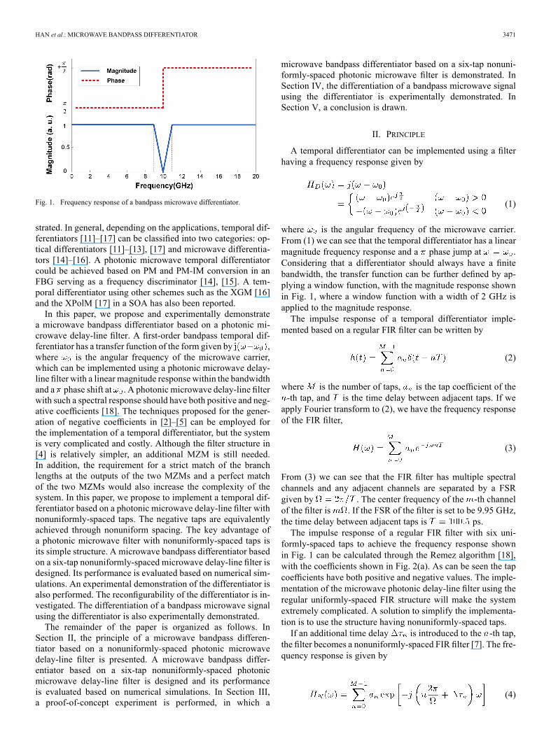
formly-spaced taps to achieve the frequency response shownin Fig. 1 can be calculated through the Remez algorithm [18],with the coefficients shown in Fig. 2(a). As can be seen the tapcoefficients have both positive and negative values. The imple-mentation of the microwave photonic delay-line filter using theregular uniformly-spaced FIR structure will make the systemextremely complicated. A solution to simplify the implementa-tion is to use the structure having nonuniformly-spaced taps.If an additional time delay is introduced to the -th tap,
the filter becomes a nonuniformly-spaced FIR filter [7]. The fre-quency response is given by
(4)
3472 JOURNAL OF LIGHTWAVE TECHNOLOGY, VOL. 29, NO. 22, NOVEMBER 15, 2011
Fig. 2. Design of the temporal differentiator based on a six-tap FIR filter.(a) Impulse response of the six-tap uniformly-spaced FIR filter. (b) Impulseresponse of the six-tap nonuniformly-spaced FIR filter.
Assume the passband of interest is narrow and the central fre-quency is , then the frequency response in (4) can be approx-imated as
(5)
where we have .An equivalent phase shift introduced by the additional time
delay at the passband of interest is
(6)
If the FIR filter is implemented using all positive coefficients,the phase term of -th tap can be equivalently realized by anadditional time delay, with the time delay of the -th tap givenby
(7)
Based on (7), an FIR filter with all-positive coefficients toachieve the same function as a regular FIR filter can be de-signed. Fig. 2(b) shows the tap coefficients of a six-tap FIR filterwith nonuniformly-spaced taps for the implementation of themicrowave bandpass differentiator shown in Fig. 1. It can beseen from Fig. 2(b) that the tap coefficients are all positive, butwith nonuniformly-spaced taps.The frequency responses of the six-tap FIR filter with uni-
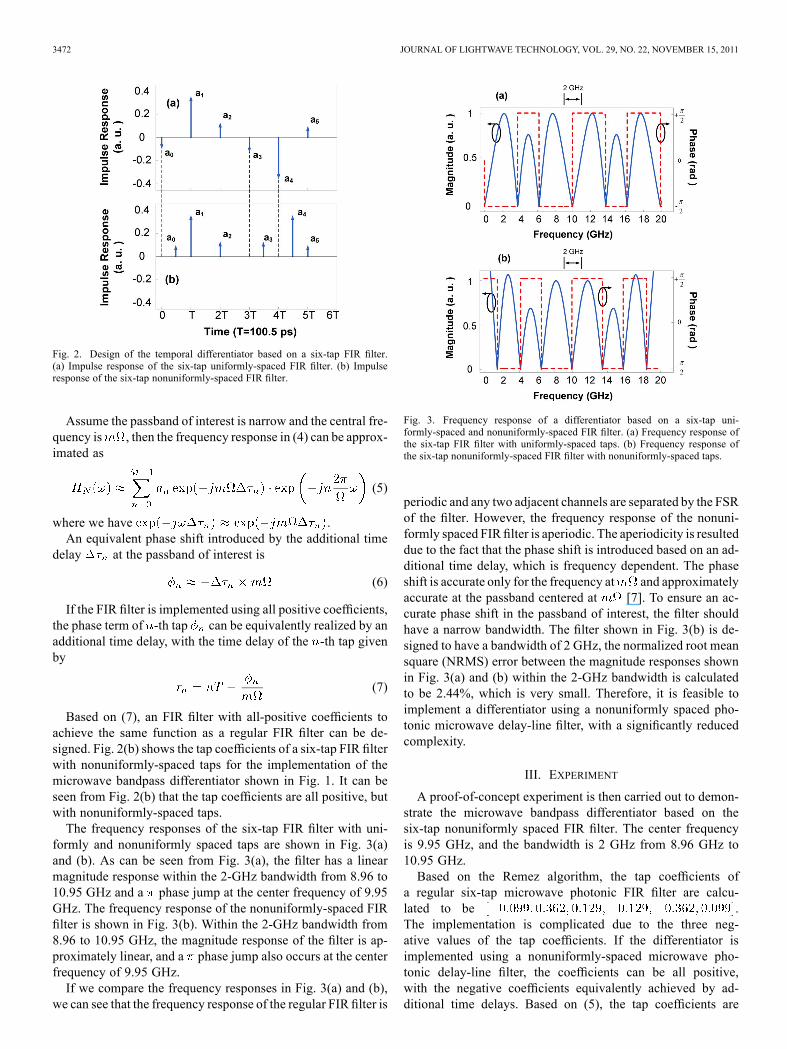
formly and nonuniformly spaced taps are shown in Fig. 3(a)and (b). As can be seen from Fig. 3(a), the filter has a linearmagnitude response within the 2-GHz bandwidth from 8.96 to10.95 GHz and a phase jump at the center frequency of 9.95GHz. The frequency response of the nonuniformly-spaced FIRfilter is shown in Fig. 3(b). Within the 2-GHz bandwidth from8.96 to 10.95 GHz, the magnitude response of the filter is ap-proximately linear, and a phase jump also occurs at the centerfrequency of 9.95 GHz.If we compare the frequency responses in Fig. 3(a) and (b),
we can see that the frequency response of the regular FIR filter is
Fig. 3. Frequency response of a differentiator based on a six-tap uni-formly-spaced and nonuniformly-spaced FIR filter. (a) Frequency response ofthe six-tap FIR filter with uniformly-spaced taps. (b) Frequency response ofthe six-tap nonuniformly-spaced FIR filter with nonuniformly-spaced taps.
periodic and any two adjacent channels are separated by the FSRof the filter. However, the frequency response of the nonuni-formly spaced FIR filter is aperiodic. The aperiodicity is resulteddue to the fact that the phase shift is introduced based on an ad-ditional time delay, which is frequency dependent. The phaseshift is accurate only for the frequency at and approximatelyaccurate at the passband centered at [7]. To ensure an ac-curate phase shift in the passband of interest, the filter shouldhave a narrow bandwidth. The filter shown in Fig. 3(b) is de-signed to have a bandwidth of 2 GHz, the normalized root meansquare (NRMS) error between the magnitude responses shownin Fig. 3(a) and (b) within the 2-GHz bandwidth is calculatedto be 2.44%, which is very small. Therefore, it is feasible toimplement a differentiator using a nonuniformly spaced pho-tonic microwave delay-line filter, with a significantly reducedcomplexity.
III. EXPERIMENT
A proof-of-concept experiment is then carried out to demon-strate the microwave bandpass differentiator based on thesix-tap nonuniformly spaced FIR filter. The center frequencyis 9.95 GHz, and the bandwidth is 2 GHz from 8.96 GHz to10.95 GHz.Based on the Remez algorithm, the tap coefficients of
a regular six-tap microwave photonic FIR filter are calcu-lated to be .The implementation is complicated due to the three neg-ative values of the tap coefficients. If the differentiator isimplemented using a nonuniformly-spaced microwave pho-tonic delay-line filter, the coefficients can be all positive,with the negative coefficients equivalently achieved by ad-ditional time delays. Based on (5), the tap coefficients are
HAN et al.: MICROWAVE BANDPASS DIFFERENTIATOR 3473
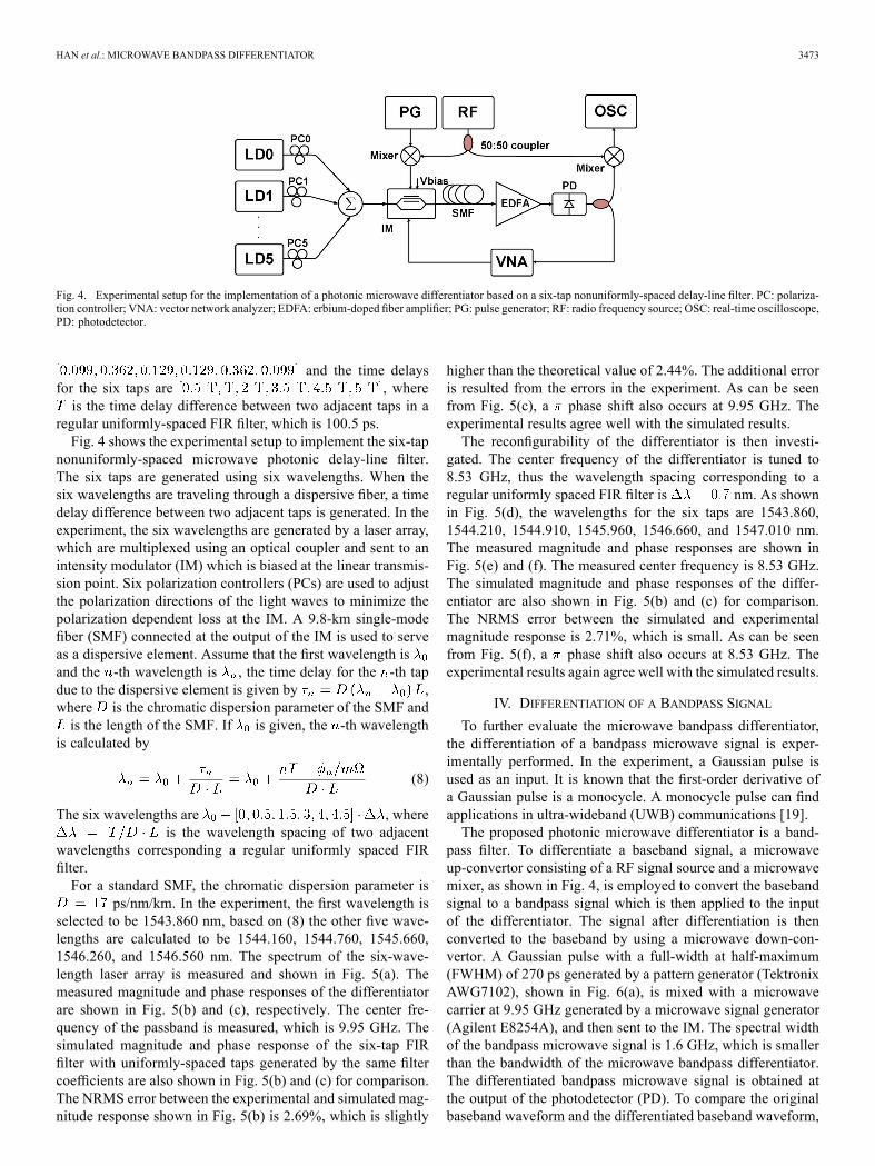
Fig. 4. Experimental setup for the implementation of a photonic microwave differentiator based on a six-tap nonuniformly-spaced delay-line filter. PC: polariza-tion controller; VNA: vector network analyzer; EDFA: erbium-doped fiber amplifier; PG: pulse generator; RF: radio frequency source; OSC: real-time oscilloscope,PD: photodetector.
and the time delaysfor the six taps are , whereis the time delay difference between two adjacent taps in a
regular uniformly-spaced FIR filter, which is 100.5 ps.Fig. 4 shows the experimental setup to implement the six-tap
nonuniformly-spaced microwave photonic delay-line filter.The six taps are generated using six wavelengths. When thesix wavelengths are traveling through a dispersive fiber, a timedelay difference between two adjacent taps is generated. In theexperiment, the six wavelengths are generated by a laser array,which are multiplexed using an optical coupler and sent to anintensity modulator (IM) which is biased at the linear transmis-sion point. Six polarization controllers (PCs) are used to adjustthe polarization directions of the light waves to minimize thepolarization dependent loss at the IM. A 9.8-km single-modefiber (SMF) connected at the output of the IM is used to serveas a dispersive element. Assume that the first wavelength isand the -th wavelength is , the time delay for the -th tapdue to the dispersive element is given by ,where is the chromatic dispersion parameter of the SMF andis the length of the SMF. If is given, the -th wavelength
is calculated by
(8)
The six wavelengths are , whereis the wavelength spacing of two adjacent
wavelengths corresponding a regular uniformly spaced FIRfilter.For a standard SMF, the chromatic dispersion parameter is
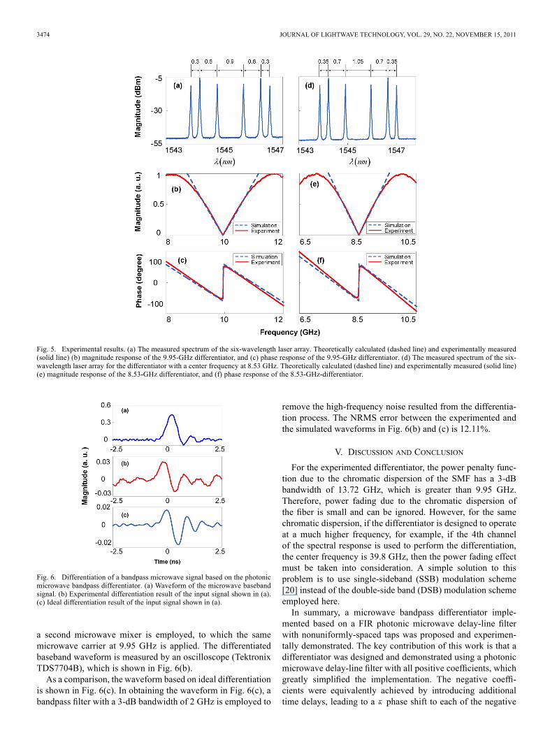
ps/nm/km. In the experiment, the first wavelength isselected to be 1543.860 nm, based on (8) the other five wave-lengths are calculated to be 1544.160, 1544.760, 1545.660,1546.260, and 1546.560 nm. The spectrum of the six-wave-length laser array is measured and shown in Fig. 5(a). Themeasured magnitude and phase responses of the differentiatorare shown in Fig. 5(b) and (c), respectively. The center fre-quency of the passband is measured, which is 9.95 GHz. Thesimulated magnitude and phase response of the six-tap FIRfilter with uniformly-spaced taps generated by the same filtercoefficients are also shown in Fig. 5(b) and (c) for comparison.The NRMS error between the experimental and simulated mag-nitude response shown in Fig. 5(b) is 2.69%, which is slightly
higher than the theoretical value of 2.44%. The additional erroris resulted from the errors in the experiment. As can be seenfrom Fig. 5(c), a phase shift also occurs at 9.95 GHz. Theexperimental results agree well with the simulated results.The reconfigurability of the differentiator is then investi-
gated. The center frequency of the differentiator is tuned to8.53 GHz, thus the wavelength spacing corresponding to aregular uniformly spaced FIR filter is nm. As shownin Fig. 5(d), the wavelengths for the six taps are 1543.860,1544.210, 1544.910, 1545.960, 1546.660, and 1547.010 nm.The measured magnitude and phase responses are shown inFig. 5(e) and (f). The measured center frequency is 8.53 GHz.The simulated magnitude and phase responses of the differ-entiator are also shown in Fig. 5(b) and (c) for comparison.The NRMS error between the simulated and experimentalmagnitude response is 2.71%, which is small. As can be seenfrom Fig. 5(f), a phase shift also occurs at 8.53 GHz. Theexperimental results again agree well with the simulated results.
IV. DIFFERENTIATION OF A BANDPASS SIGNAL
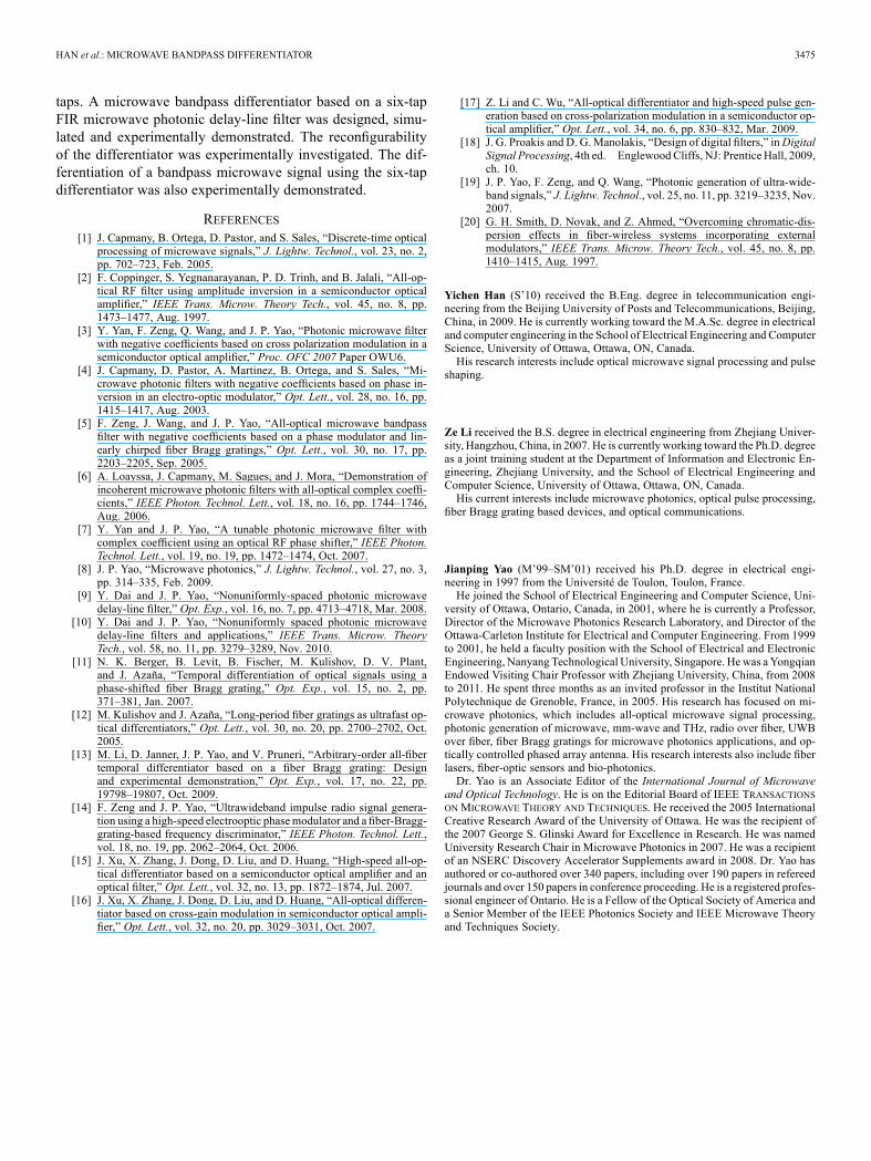
To further evaluate the microwave bandpass differentiator,the differentiation of a bandpass microwave signal is exper-imentally performed. In the experiment, a Gaussian pulse isused as an input. It is known that the first-order derivative ofa Gaussian pulse is a monocycle. A monocycle pulse can findapplications in ultra-wideband (UWB) communications [19].The proposed photonic microwave differentiator is a band-
pass filter. To differentiate a baseband signal, a microwaveup-convertor consisting of a RF signal source and a microwavemixer, as shown in Fig. 4, is employed to convert the basebandsignal to a bandpass signal which is then applied to the inputof the differentiator. The signal after differentiation is thenconverted to the baseband by using a microwave down-con-vertor. A Gaussian pulse with a full-width at half-maximum(FWHM) of 270 ps generated by a pattern generator (TektronixAWG7102), shown in Fig. 6(a), is mixed with a microwavecarrier at 9.95 GHz generated by a microwave signal generator(Agilent E8254A), and then sent to the IM. The spectral widthof the bandpass microwave signal is 1.6 GHz, which is smallerthan the bandwidth of the microwave bandpass differentiator.The differentiated bandpass microwave signal is obtained atthe output of the photodetector (PD). To compare the originalbaseband waveform and the differentiated baseband waveform,
3474 JOURNAL OF LIGHTWAVE TECHNOLOGY, VOL. 29, NO. 22, NOVEMBER 15, 2011
Fig. 5. Experimental results. (a) The measured spectrum of the six-wavelength laser array. Theoretically calculated (dashed line) and experimentally measured(solid line) (b) magnitude response of the 9.95-GHz differentiator, and (c) phase response of the 9.95-GHz differentiator. (d) The measured spectrum of the six-wavelength laser array for the differentiator with a center frequency at 8.53 GHz. Theoretically calculated (dashed line) and experimentally measured (solid line)(e) magnitude response of the 8.53-GHz differentiator, and (f) phase response of the 8.53-GHz-differentiator.
Fig. 6. Differentiation of a bandpass microwave signal based on the photonicmicrowave bandpass differentiator. (a) Waveform of the microwave basebandsignal. (b) Experimental differentiation result of the input signal shown in (a).(c) Ideal differentiation result of the input signal shown in (a).
a second microwave mixer is employed, to which the samemicrowave carrier at 9.95 GHz is applied. The differentiatedbaseband waveform is measured by an oscilloscope (TektronixTDS7704B), which is shown in Fig. 6(b).As a comparison, the waveform based on ideal differentiation
is shown in Fig. 6(c). In obtaining the waveform in Fig. 6(c), abandpass filter with a 3-dB bandwidth of 2 GHz is employed to
remove the high-frequency noise resulted from the differentia-tion process. The NRMS error between the experimented andthe simulated waveforms in Fig. 6(b) and (c) is 12.11%.
V. DISCUSSION AND CONCLUSION
For the experimented differentiator, the power penalty func-tion due to the chromatic dispersion of the SMF has a 3-dBbandwidth of 13.72 GHz, which is greater than 9.95 GHz.Therefore, power fading due to the chromatic dispersion ofthe fiber is small and can be ignored. However, for the samechromatic dispersion, if the differentiator is designed to operateat a much higher frequency, for example, if the 4th channelof the spectral response is used to perform the differentiation,the center frequency is 39.8 GHz, then the power fading effectmust be taken into consideration. A simple solution to thisproblem is to use single-sideband (SSB) modulation scheme[20] instead of the double-side band (DSB) modulation schemeemployed here.In summary, a microwave bandpass differentiator imple-
mented based on a FIR photonic microwave delay-line filterwith nonuniformly-spaced taps was proposed and experimen-tally demonstrated. The key contribution of this work is that adifferentiator was designed and demonstrated using a photonicmicrowave delay-line filter with all positive coefficients, whichgreatly simplified the implementation. The negative coeffi-cients were equivalently achieved by introducing additionaltime delays, leading to a phase shift to each of the negative
HAN et al.: MICROWAVE BANDPASS DIFFERENTIATOR 3475
taps. A microwave bandpass differentiator based on a six-tapFIR microwave photonic delay-line filter was designed, simu-lated and experimentally demonstrated. The reconfigurabilityof the differentiator was experimentally investigated. The dif-ferentiation of a bandpass microwave signal using the six-tapdifferentiator was also experimentally demonstrated.
REFERENCES[1] J. Capmany, B. Ortega, D. Pastor, and S. Sales, “Discrete-time optical
processing of microwave signals,” J. Lightw. Technol., vol. 23, no. 2,pp. 702–723, Feb. 2005.
[2] F. Coppinger, S. Yegnanarayanan, P. D. Trinh, and B. Jalali, “All-op-tical RF filter using amplitude inversion in a semiconductor opticalamplifier,” IEEE Trans. Microw. Theory Tech., vol. 45, no. 8, pp.1473–1477, Aug. 1997.
[3] Y. Yan, F. Zeng, Q. Wang, and J. P. Yao, “Photonic microwave filterwith negative coefficients based on cross polarization modulation in asemiconductor optical amplifier,” Proc. OFC 2007 Paper OWU6.
[4] J. Capmany, D. Pastor, A. Martinez, B. Ortega, and S. Sales, “Mi-crowave photonic filters with negative coefficients based on phase in-version in an electro-optic modulator,” Opt. Lett., vol. 28, no. 16, pp.1415–1417, Aug. 2003.
[5] F. Zeng, J. Wang, and J. P. Yao, “All-optical microwave bandpassfilter with negative coefficients based on a phase modulator and lin-early chirped fiber Bragg gratings,” Opt. Lett., vol. 30, no. 17, pp.2203–2205, Sep. 2005.
[6] A. Loayssa, J. Capmany, M. Sagues, and J. Mora, “Demonstration ofincoherent microwave photonic filters with all-optical complex coeffi-cients,” IEEE Photon. Technol. Lett., vol. 18, no. 16, pp. 1744–1746,Aug. 2006.
[7] Y. Yan and J. P. Yao, “A tunable photonic microwave filter withcomplex coefficient using an optical RF phase shifter,” IEEE Photon.Technol. Lett., vol. 19, no. 19, pp. 1472–1474, Oct. 2007.
[8] J. P. Yao, “Microwave photonics,” J. Lightw. Technol., vol. 27, no. 3,pp. 314–335, Feb. 2009.
[9] Y. Dai and J. P. Yao, “Nonuniformly-spaced photonic microwavedelay-line filter,” Opt. Exp., vol. 16, no. 7, pp. 4713–4718, Mar. 2008.
[10] Y. Dai and J. P. Yao, “Nonuniformly spaced photonic microwavedelay-line filters and applications,” IEEE Trans. Microw. TheoryTech., vol. 58, no. 11, pp. 3279–3289, Nov. 2010.
[11] N. K. Berger, B. Levit, B. Fischer, M. Kulishov, D. V. Plant,and J. Azaña, “Temporal differentiation of optical signals using aphase-shifted fiber Bragg grating,” Opt. Exp., vol. 15, no. 2, pp.371–381, Jan. 2007.
[12] M. Kulishov and J. Azaña, “Long-period fiber gratings as ultrafast op-tical differentiators,” Opt. Lett., vol. 30, no. 20, pp. 2700–2702, Oct.2005.
[13] M. Li, D. Janner, J. P. Yao, and V. Pruneri, “Arbitrary-order all-fibertemporal differentiator based on a fiber Bragg grating: Designand experimental demonstration,” Opt. Exp., vol. 17, no. 22, pp.19798–19807, Oct. 2009.
[14] F. Zeng and J. P. Yao, “Ultrawideband impulse radio signal genera-tion using a high-speed electrooptic phasemodulator and a fiber-Bragg-grating-based frequency discriminator,” IEEE Photon. Technol. Lett.,vol. 18, no. 19, pp. 2062–2064, Oct. 2006.
[15] J. Xu, X. Zhang, J. Dong, D. Liu, and D. Huang, “High-speed all-op-tical differentiator based on a semiconductor optical amplifier and anoptical filter,” Opt. Lett., vol. 32, no. 13, pp. 1872–1874, Jul. 2007.
[16] J. Xu, X. Zhang, J. Dong, D. Liu, and D. Huang, “All-optical differen-tiator based on cross-gain modulation in semiconductor optical ampli-fier,” Opt. Lett., vol. 32, no. 20, pp. 3029–3031, Oct. 2007.
[17] Z. Li and C. Wu, “All-optical differentiator and high-speed pulse gen-eration based on cross-polarization modulation in a semiconductor op-tical amplifier,” Opt. Lett., vol. 34, no. 6, pp. 830–832, Mar. 2009.
[18] J. G. Proakis and D. G.Manolakis, “Design of digital filters,” inDigitalSignal Processing, 4th ed. Englewood Cliffs, NJ: Prentice Hall, 2009,ch. 10.
[19] J. P. Yao, F. Zeng, and Q. Wang, “Photonic generation of ultra-wide-band signals,” J. Lightw. Technol., vol. 25, no. 11, pp. 3219–3235, Nov.2007.
[20] G. H. Smith, D. Novak, and Z. Ahmed, “Overcoming chromatic-dis-persion effects in fiber-wireless systems incorporating externalmodulators,” IEEE Trans. Microw. Theory Tech., vol. 45, no. 8, pp.1410–1415, Aug. 1997.
Yichen Han (S’10) received the B.Eng. degree in telecommunication engi-neering from the Beijing University of Posts and Telecommunications, Beijing,China, in 2009. He is currently working toward the M.A.Sc. degree in electricaland computer engineering in the School of Electrical Engineering and ComputerScience, University of Ottawa, Ottawa, ON, Canada.His research interests include optical microwave signal processing and pulse
shaping.
Ze Li received the B.S. degree in electrical engineering from Zhejiang Univer-sity, Hangzhou, China, in 2007. He is currently working toward the Ph.D. degreeas a joint training student at the Department of Information and Electronic En-gineering, Zhejiang University, and the School of Electrical Engineering andComputer Science, University of Ottawa, Ottawa, ON, Canada.His current interests include microwave photonics, optical pulse processing,
fiber Bragg grating based devices, and optical communications.
Jianping Yao (M’99–SM’01) received his Ph.D. degree in electrical engi-neering in 1997 from the Université de Toulon, Toulon, France.He joined the School of Electrical Engineering and Computer Science, Uni-
versity of Ottawa, Ontario, Canada, in 2001, where he is currently a Professor,Director of the Microwave Photonics Research Laboratory, and Director of theOttawa-Carleton Institute for Electrical and Computer Engineering. From 1999to 2001, he held a faculty position with the School of Electrical and ElectronicEngineering, Nanyang Technological University, Singapore. Hewas a YongqianEndowed Visiting Chair Professor with Zhejiang University, China, from 2008to 2011. He spent three months as an invited professor in the Institut NationalPolytechnique de Grenoble, France, in 2005. His research has focused on mi-crowave photonics, which includes all-optical microwave signal processing,photonic generation of microwave, mm-wave and THz, radio over fiber, UWBover fiber, fiber Bragg gratings for microwave photonics applications, and op-tically controlled phased array antenna. His research interests also include fiberlasers, fiber-optic sensors and bio-photonics.Dr. Yao is an Associate Editor of the International Journal of Microwave
and Optical Technology. He is on the Editorial Board of IEEE TRANSACTIONSON MICROWAVE THEORY AND TECHNIQUES. He received the 2005 InternationalCreative Research Award of the University of Ottawa. He was the recipient ofthe 2007 George S. Glinski Award for Excellence in Research. He was namedUniversity Research Chair in Microwave Photonics in 2007. He was a recipientof an NSERC Discovery Accelerator Supplements award in 2008. Dr. Yao hasauthored or co-authored over 340 papers, including over 190 papers in refereedjournals and over 150 papers in conference proceeding. He is a registered profes-sional engineer of Ontario. He is a Fellow of the Optical Society of America anda Senior Member of the IEEE Photonics Society and IEEE Microwave Theoryand Techniques Society.


