Embed Size (px)
Citation preview

adfa, p. 1, 2011.
© Springer-Verlag Berlin Heidelberg 2011
A Method for Single Hand Fist Gesture Input to Enhance
Human Computer Interaction
Tao Ma1, William Wee
1, Chia Yung Han
2, Xuefu Zhou
1
1School of Electronic and Computing Systems, University of Cincinnati, USA 2School of Computing Sciences and Informatics, University of Cincinnati, USA
[email protected], [email protected], [email protected], [email protected]
Abstract. The study of detecting and tracking hand gestures in general has been
widely explored, yet the focus on fist gesture in particular has been neglected.
Methods for processing fist gesture would allow more natural user experience
in human-machine interaction (HMI), however, it requires a deeper understand-
ing of fist kinematics. For the purpose of achieving grasping-moving-rotating
activity with single hand (SH-GMR), the extraction of fist rotation is necessary.
In this paper, a feature-based Fist Rotation Detector (FRD) is proposed to bring
more flexibility to interactions with hand manipulation in the virtual world. By
comparing to other candidate methods, edge-based methods are shown to be a
proper way to tackle the detection. We find a set of "fist lines" that can be easily
extracted and be used steadily to determine the fist rotation. The proposed FRD
is described in details as a two-step approach: fist shape segmentation and fist
rotation angle retrieving process. A comparison with manually measured
ground truth data shows that the method is robust and accurate. A virtual reality
application using hand gesture control with the FRD shows that the hand ges-
ture interaction is enhanced by the SH-GMR.
1 Introduction
Hand gesture recognition is a mathematization of the interpolation of human hand
gestures assisted by modern computer technology. The purpose is to replace tradition-
al input devices, keyboard and mouse, with a new fashion that makes human interact
with computer in a way that is as natural as in the real world [1]. In spatial domain,
static hand gestures are recognized due to the different spatial distribution of fingers
with respect to palms. A "thumb-up" gesture in sign language means "good". A "fist"
gesture might stands for "stop" [2] or other meanings [3]. Laura et al presented a joint
segmentation and adaptive classifier that can discriminate 4 static hand gestures under
slight occlusion condition [4]. Yi et al.'s classifier that combined both supervised and
unsupervised training process recognizes 14 hand gestures [5]. On the other hand, in
temporal domain, hand kinematics under various gestures is meaningful as well. Yi
and Thomas [6] described articulated hand local motion for a 16 rigid object 3D hand
model with inverse kinematics. Human hand motions are very complicated and al-

ways occur in both spatial and temporal domain. A well representation of hand ges-
ture patterns and their kinematics lies in the improvement of natural user experience-
as if users interact with the real world. However, current gesture recognition methods
can hardly capture all subtle movements for manipulation in the virtual world.
Holding an object and moving it with single hand is a common activity in daily
life. Clenching fingers together to form a fist is a natural gesture, which represents
grasping [7]. The ability to map this activity in designing interactions that allow in-
puts for software applications can be very useful. However, the processing of images
of hand fist and characterization of the various motions as input to computer is not
straightforward. We term this motion behavior as single hand grasping-moving-
rotating (SH-GMR). These three actions always occur simultaneously. The detection
of moving, or simple translation, is fairly easy, attested by the fact that a variety of
algorithms already exist [8]. However, the detecting and tracking on fist rotation has
been lacking for a long time. The existing compromised solution of rotating a virtual
object is to make use of two hands to decide the rotation angle, which includes rota-
tion about an axis and "steering wheel" rotation [9]. The drawbacks are obvious. Two
hands have to grasp the same object at the same time. For tiny objects, it needs sup-
plementary visual guidance for users to hold, such as virtual handles attached on the
objects. More importantly, this two-hand gesture prevents users to interact with two
objects at a time, which makes the interaction manners of many kinds quite awkward
and inefficient. Thus, user experience suffers greatly. With these concerns, we argue
that the single hand rotation is better than the two-hand rotation. Moreover, the study
of fist rotation is crucial to achieve SH-GMR.
From the image and vision perspective, the fist rotation is defined as a 3 dimen-
sional (yaw, pitch and roll) rotations of a deformable, scale variable and intensity
variable object with associated translation movements. It is necessary to distinguish
fist from other gestures because other gestures extend at least one finger out [10]. But
fist gesture is defined as a hand with all fingers clenched into the palm [11]. Within
certain angle of view, fingers are still visible, but they are fully folded and placed side
by side with each other. In the following sections, we discuss several methods that
can potentially be used for the fist rotation extraction and then give a proper solution
to tackle this problem.
2 Related research
There are several methods that could potentially be used as fundamental methods of
FRD. They are skeletal model, volume model, optical flow, local features, and edge
features. We review them below and give examples if necessary.
Current skeletal models for kinematic representation of hand are applied for the
open handed gesture that at least one finger is stretched out. Lee and Kunii [12] intro-
duced a 27 DOFs hierarchical skeletal hand model with constraints on joint move-
ments, which makes some hand configurations impossible so as to reduce the shape
ambiguity. Du and Charbon proposed a 30 DOFs skeletal model for depth image fit-
ting [13].These models are suitable for describing the clenched fist, but they did not
propose how to apply the model fitting algorithms in extracting the fist rotation using
their internal constraints and external image forces.
3D dense map, sometimes called point cloud generated by structured light [14],
TOF camera or stereo camera, can be used to solve the ambiguity in certain degree.
But huge computational cost of 3D fitting prevents them from being applied in real-
time tracking [15]. We have not seen any solution that can handle the fist rotation
problem. Besides, the depth map captured by current cameras cannot provide enough
details in resolution to extract individual fingers from a clenched fist.
Due to the complexity of hand movements, local features should be found that are
invariant to hand translation, scaling, rotation, and invariant to illumination changes
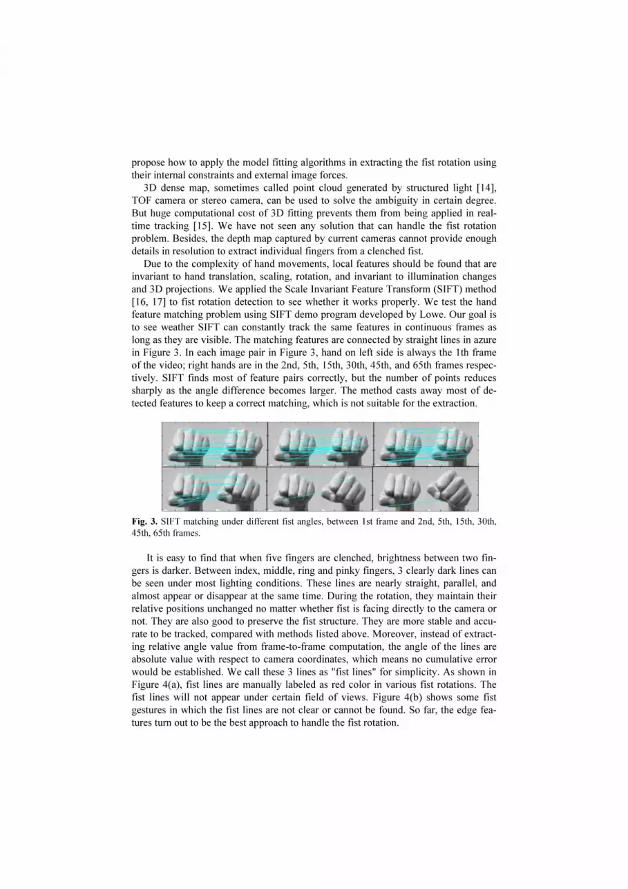
and 3D projections. We applied the Scale Invariant Feature Transform (SIFT) method
[16, 17] to fist rotation detection to see whether it works properly. We test the hand
feature matching problem using SIFT demo program developed by Lowe. Our goal is
to see weather SIFT can constantly track the same features in continuous frames as
long as they are visible. The matching features are connected by straight lines in azure
in Figure 3. In each image pair in Figure 3, hand on left side is always the 1th frame
of the video; right hands are in the 2nd, 5th, 15th, 30th, 45th, and 65th frames respec-
tively. SIFT finds most of feature pairs correctly, but the number of points reduces
sharply as the angle difference becomes larger. The method casts away most of de-
tected features to keep a correct matching, which is not suitable for the extraction.
Fig. 3. SIFT matching under different fist angles, between 1st frame and 2nd, 5th, 15th, 30th,
45th, 65th frames.
It is easy to find that when five fingers are clenched, brightness between two fin-
gers is darker. Between index, middle, ring and pinky fingers, 3 clearly dark lines can
be seen under most lighting conditions. These lines are nearly straight, parallel, and
almost appear or disappear at the same time. During the rotation, they maintain their
relative positions unchanged no matter whether fist is facing directly to the camera or
not. They are also good to preserve the fist structure. They are more stable and accu-
rate to be tracked, compared with methods listed above. Moreover, instead of extract-
ing relative angle value from frame-to-frame computation, the angle of the lines are
absolute value with respect to camera coordinates, which means no cumulative error
would be established. We call these 3 lines as "fist lines" for simplicity. As shown in
Figure 4(a), fist lines are manually labeled as red color in various fist rotations. The
fist lines will not appear under certain field of views. Figure 4(b) shows some fist
gestures in which the fist lines are not clear or cannot be found. So far, the edge fea-
tures turn out to be the best approach to handle the fist rotation.

(a) (b)
Fig. 4. Edge features on fists. (a) Manually labeled fist lines under different rotations. (b) Hand
gestures that do not fully show the fist lines.
3 Approach
In this paper, it is assumed that human arms have been segmented from the whole
images, and also hands are in fist shape. Arm segmentation from other parts of the
human body and fist shape classification from other gestures are beyond the scope of
our interests.
3.1 Fist Shape Segmentation
Observation shows that, if seeing along a human arm, the width of the fist is always
larger than that of the forearm under all camera views. Values of the width would
have a suddenly drop down if sliding from fist side to arm side. This geometrical
characteristic is feasible for the fist segmentation. Arm shapes in 2D are first trans-
formed to 1D representation through a dimension reduction process, and then a clas-
sifier is used to decide the fist position along the arm.
A contour retrieving algorithm is applied to topologically extract all possible con-
tours in the image [18]. Contour C with the largest number of point set is the outer-
most contour of the arm, shown as Figure 5 (a). Using the data set of the contour C, a
convex hull and its vertex set P [19] are computed. Sometimes image noise causes
trivial boundary so that the number of vertices is sharply increased. In this case, a
polygon approximation routine is used to reduce the excessive details along the boun-
dary. The number of vertex should better be in the range of 8 to 15 considering both
computational cost and accuracy. We compute the Euler distances of all vertex pairs
except those who are adjacent. Then we find the longest two distances ar
and br
. The
direction of the main axis l is set to be the bisector of the angle of the two vectors:
⋅=
ba
baa
ma
r
r
cos2
1θ
(1)
Two longest distances are used to decide the main axis to prevent the value oscillation
introduced by noise. Then, the whole points in contour C are rotated and translated:
TcontourCcontourC
mama
mama +
−=
θθ
θθ
cossin
sincos'
(2)

(a) (b) (c)
Fig. 5. Fist segmentation. (a) the arm contour, convex hull, main axis, and the search window
marked on the contour image, (b) a fist contour that has been rotated and translated to horizon-
tal position, (c) width curve of the contour in (b).
The rotated main axis l' is located on x-coordinate, shown in Figure 5 (b). Given a x
on the rotated contour, two y values are corresponded: one negative and one positive.
The difference of these two y values indicates the width of the fist along l'. Compu-
ting all the widths along l', we get a smoothed width curve of the contour C', as
shown in Figure 5(c). So far, we convert a 2D shape clustering problem to 1D. It is
easy to classify fists from forearms by looking at features along the width curve. Var-
ious clustering methods can be used, such as K-means, area-based, and etc. The curve
on Figure 5 (c) shows that the fist is located at the first half of the contour of Figure 5
(b). Going back to the original contour C, a fist bounding box is found according to
the result of the width curve, shown in Figure 5 (a) in a magenta rectangle. The
bounding box is served as the search window for the fist detection.
3.2 Fist Rotation Detection.
Finding the three fist lines is a challenging task for the reason that there are many line
and curve features in the search window. Inspired by the observation shown in Figure
4, we find the fist lines are basically straight, parallel, and almost appear or disappear
at the same time. Thus, three parallel straight lines with the interval of d are used as
the theoretical model to fit the selected feature point data. 3 parameters need to be
decided: the slope of the lines θ, the intercept of the middle line b, and the interval d.
Note that even though the fist lines are equidistant, their distances appearing on im-
ages may not be the same due to the perspective from 3D space to the camera plane.
But in this paper, we particularly see the roll rotation as the major direction mean-
while ignoring other DOFs. The mathematical model is:
9090
cos/tan
;tan
;cos/tan
<<−
−+=
+=
++=
θ
θθ
θ
θθ
where
dbxy
bxy
dbxy (3)
Edge feature extraction We use Laplacian of Gaussian (LOG) [20] method to
extract features in the search window because it is scale sensitive to blobs that has the
similar size. It has strong response to features of extent σ2 , where σ is the variance
of Gaussian function. The LOG kernel can be pre-computed before the convolution
on the original image:
2
22
2
2
22
4
2
21
1),( σ
σπσ
yx
eyx
yxG
+−
+−−=∇
(4)
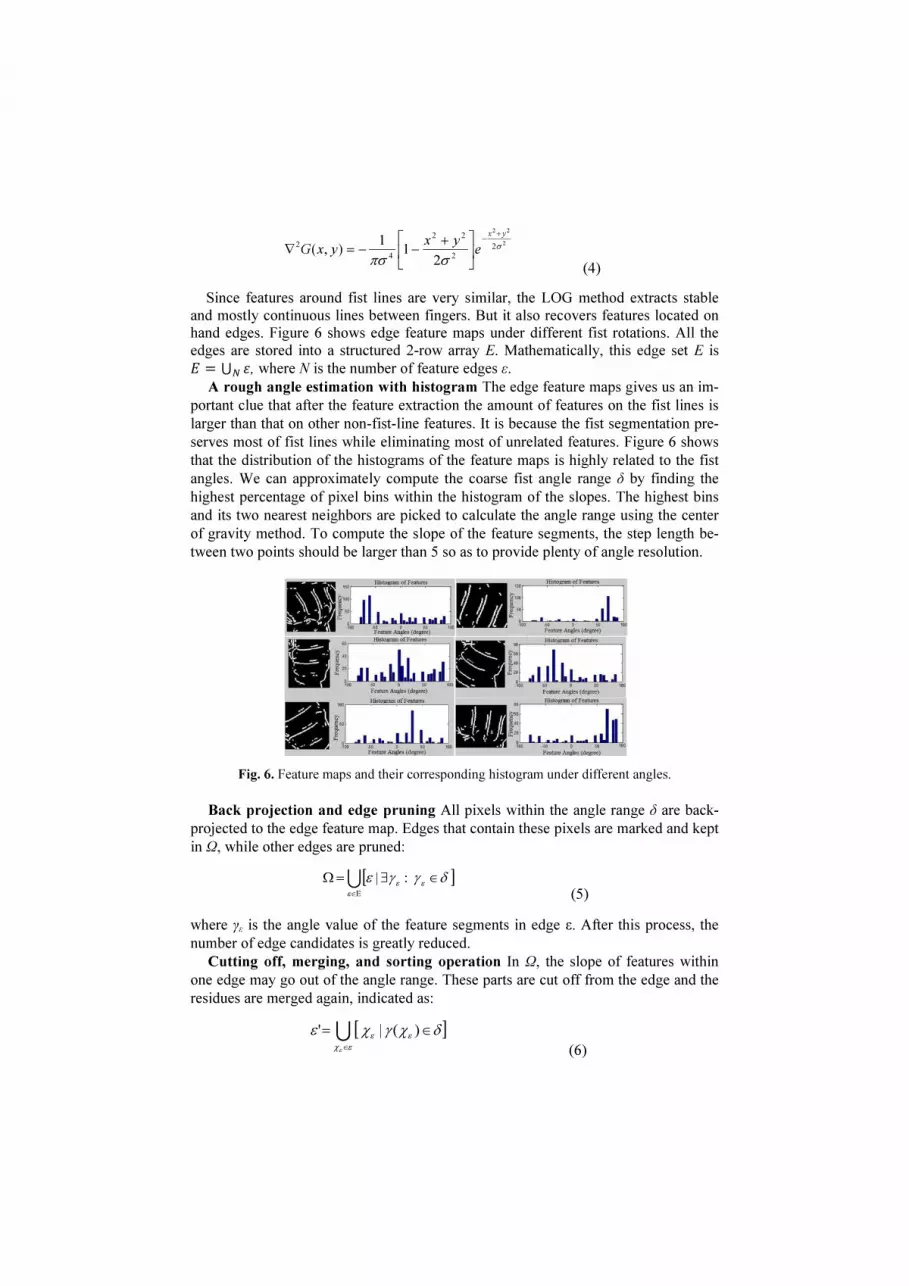
Since features around fist lines are very similar, the LOG method extracts stable
and mostly continuous lines between fingers. But it also recovers features located on
hand edges. Figure 6 shows edge feature maps under different fist rotations. All the
edges are stored into a structured 2-row array E. Mathematically, this edge set E is
= ⋃ , where N is the number of feature edges ε.
A rough angle estimation with histogram The edge feature maps gives us an im-
portant clue that after the feature extraction the amount of features on the fist lines is
larger than that on other non-fist-line features. It is because the fist segmentation pre-
serves most of fist lines while eliminating most of unrelated features. Figure 6 shows
that the distribution of the histograms of the feature maps is highly related to the fist
angles. We can approximately compute the coarse fist angle range δ by finding the
highest percentage of pixel bins within the histogram of the slopes. The highest bins
and its two nearest neighbors are picked to calculate the angle range using the center
of gravity method. To compute the slope of the feature segments, the step length be-
tween two points should be larger than 5 so as to provide plenty of angle resolution.
Fig. 6. Feature maps and their corresponding histogram under different angles.
Back projection and edge pruning All pixels within the angle range δ are back-
projected to the edge feature map. Edges that contain these pixels are marked and kept
in Ω, while other edges are pruned:
[ ]δγγεεε
ε
∈∃=Ω
Ε∈
:|U (5)
where γε is the angle value of the feature segments in edge ε. After this process, the
number of edge candidates is greatly reduced.
Cutting off, merging, and sorting operation In Ω, the slope of features within
one edge may go out of the angle range. These parts are cut off from the edge and the
residues are merged again, indicated as:
[ ]δχγχεεε
εχε
∈=
∈
)(|' U (6)

where χε is a feature point in ε, and γ(χε) is the angle value of χε .
If two edges are almost collinear as if they are in the same fist line, they are
merged into one edge, described as:
)],(:,|,[
212121
22
11
12 εεεεεε
εχ
εχ
χχχχχχε
ε
ε
collinear∀∀=
∈
∈
U
(7)
where ε12 is the merged feature set from ε1 and ε2, and collinear( ) is a function that
decide whether two feature points are basically collinear.
Last, all the existing edges are sorted according to their positions, and then stored
in set ϒ. So far, the number of edges in ϒ is slightly more than 3, which is very cost
effective for the following angle refining process.
Fitting the mathematical model with the 3 selected edges For any given 3 edges,
φ1, φ2, φ3 in ϒ, parameters θ, b, and d can be calculated by fitting the theoretical mod-
el described in equation (3) to the three edges. To convert equation (3) into linear
equations, we let k = tanθ, and c = d/cosθ. Then the equations can be expressed with
linear equations as:
.),(,),(,),(
],,,,,[~
1
1
1
1
0
1
0
1
1
1
1
1~],,,[
,~~
333222111
323122211211
323122211211
ϕϕϕ ∈∈∈
=
−−
==
=
iiiiiiyxyxyx
yyyyyyy
xxxxxx
xcbkA
whereyxA
LLL
LLL
(8)
Several methods can be used to solve this over-determined, multiple linear regres-
sion problem, such as least square, Gauss elimination, and Singular value decomposi-
tion (SVD). The fitting error E(φ1, φ2, φ3) can be derived from the sum of absolute
difference (SAD) between fitted lines and edge pixels:
∑ ∑= ∈ +
−++−
=
3
1 ),(2321
1
)2(),,(
j yx
jiji
jjiji k
cjbyxkE
ϕ
ϕϕϕ
(9)
Optimized fist lines with minimum error We compute all the combinations of 3
possible fist lines in ϒ. The number of combination is given by 3
nC , where n is num-
ber of edges in ϒ. A correct choice of the fist lines is indicated by *)*,*,(321
ϕϕϕ that
has the minimum fitting error:
),,(minarg*)*,*,(321
,,321
321
ϕϕϕϕϕϕϕϕϕ
EΥ∈
=
(10)
Its angle θ* = atan(k
*) is the optimized fist rotation angle within (-90
o, 90
o). A large
amount of pixel involved in the fitting process guarantees an accurate and stable out-
come. Figure 7(a) shows the three fitting lines are found, marked with red, blue, and
magenta.

(a) (b)
Fig. 7. (a) Three fitting lines that minimum the fitting error. (b) Feature points out of the angle
range marked with green color.
Deciding the fist rotation within 360o
As mentioned above, the line model can
only decide rotation within (-90o, 90
o). Due to the special finger position with relation
to the palm, more features can be found near the palm side rather than the back side of
the fist. These features mostly have different directions with the fist lines. We empiri-
cally discriminate between the palm side and the back side by measuring the distribu-
tion difference of features that are out of the range of the rough rotation angle δ. They
are marked as green color in Figure 7(b). The center of gravity of the selected 3 fist
lines are first computed. Then, through this point, a straight line (the orange line in
Figure 7(b)) that is perpendicular to the fist lines splits the search window into two
parts. The palm side and back side of hands must be located in these two parts respec-
tively. The part that has more green pixels is the palm side, and vice versa. With the
angle θ* computed in the previous steps, the final rotation angle can be decided within
360o
.
4 Experiment and Application
We pay mostly attention to the accuracy and stability of the proposed FRD. One expe-
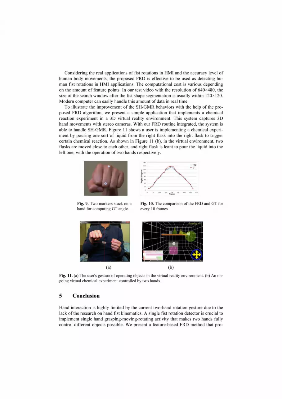
riment is implemented to test these two aspects. To generate ground truth (GT) data,
two markers in cross shape are stuck on the middle finger so that they can be manual-
ly labeled afterwards and be used to calculate hand rotations, shown as Figure 9. Then
the GT angle is compared with the angle generated by the FRD every 10 frames.
The GT angle is manually computed every 10 frames. Then it is compared with the
FRD output within the same frame, shown as Figure 10. The maximum angle value is
140o
due to the physical limit of human hands. The result shows that the proposed
FRD method is stable and consistent with the GT data, with the absolute mean differ-
ence of 3.27o
(0.9% of 360o
), and standard deviation of 2.81o
(0.8% of 360 o
). The
largest error occurs between 110o
and 140o
.
There are several reasons that cause the error. First, the manually labeled GT value
may not be accurate due to the image quality. Then, remember that hand is a deform-
able object. The rotation of the markers may not fully represent that of the fist lines,
especially when the hand is twisted almost to its physical limit. Last, as analyzed in
previous sections, hand rotation always happens in 3 DOFs. The proposed FRD and
the GT measurement only consider one major movement while ignoring others. This
will also introduce difference in the comparison.
Considering the real applications of fist rotations in HMI and the accuracy level of
human body movements, the proposed FRD is effective to be used as detecting hu-
man fist rotations in HMI applications. The computational cost is various depending
on the amount of feature points. In our test video with the resolution of 640×480, the
size of the search window after the fist shape segmentation is usually within 120×120.
Modern computer can easily handle this amount of data in real time.
To illustrate the improvement of the SH-GMR behaviors with the help of the pro-
posed FRD algorithm, we present a simple application that implements a chemical
reaction experiment in a 3D virtual reality environment. This system captures 3D
hand movements with stereo cameras. With our FRD routine integrated, the system is
able to handle SH-GMR. Figure 11 shows a user is implementing a chemical experi-
ment by pouring one sort of liquid from the right flask into the right flask to trigger
certain chemical reaction. As shown in Figure 11 (b), in the virtual environment, two
flasks are moved close to each other, and right flask is leant to pour the liquid into the
left one, with the operation of two hands respectively.
(a) (b)
Fig. 11. (a) The user's gesture of operating objects in the virtual reality environment. (b) An on-
going virtual chemical experiment controlled by two hands.
5 Conclusion
Hand interaction is highly limited by the current two-hand rotation gesture due to the
lack of the research on hand fist kinematics. A single fist rotation detector is crucial to
implement single hand grasping-moving-rotating activity that makes two hands fully
control different objects possible. We present a feature-based FRD method that pro-
Fig. 10. The comparison of the FRD and GT for
every 10 frames
Fig. 9. Two markers stuck on a
hand for computing GT angle.

vides accurate and stable detection of the fist rotation problem for the purpose of
enriching hand gesture databases with finer hand motion sequences. Except the fist
rotation, there are plenty of hand gestures and their kinematics that we have not fully
utilized. Deeply digging into this area will greatly benefit the hand gesture interaction
and also bring user experience to a brand new level.
References
1. Beale, R. and Edwards, A.D.N., Gestures and Neural Networks in Human-computer Inte-
raction. In IEE Colloq. Neural Nets in HCI, 1990.
2. Manresa, C., Varona, J., Mas, R., and Perales, F. J. Real-Time Hand Tracking and Gesture
Recognition for Human-Computer Interaction. In ELCVIA, 2000.
3. Binh, N. D., Shuichi, E., Ejima, T., Real-Time Hand Tracking and Gesture Recognition
System. In GVIP, 2005.
4. Gui, L., Thiran, J. P., and Paragios, N., Joint Object Segmentation and Behavior Classifi-
cation in Image Sequences. In CVPR, 2007.
5. Wu, Y. and Huang, T. S., View-independent Recognition of Hand Postures. In CVPR,
2:88-94, 2000.
6. Wu, Y. and Huang, T. S., Capturing Articulated Human Hand motion: A Divide-and-
conquer Approach. In ICCV, 1:606-611, 1999.
7. D. Hooker, The Origin of the Grasping Movement in Man. In Proceedings of APS,
79(4):597-606, 1938.
8. Bradski, G. and Kaehler, A., Learning OpenCV, 2nd Edition. O'Reilly Media, 2008.
9. Hinckley, K., Pausch, R., Proffitt, D., and Kassell, N. F., Two-Handed Virtual Manipula-
tion. In ACM Trans. CHI, 5(3):260-302, 1998.
10. Triesch, J. and Malsburg, C. V. D., A System for Person-Independent Hand Posture Rec-
ognition against Complex Backgrounds. In IEEE Trans. PAMI, 23(12):1449-1453, 2001.
11. Kingston, B., Understanding Joints: A Practical Guide to Their Structure and Function, 2nd Edition, Nelson Thornes, 2000.
12. Du, H.; Charbon, E., 3D Hand Model Fitting for Virtual Keyboard System. Applications of
Computer Vision, IEEE WACV, 2007.
13. Rosales, R., Athitsos, V., Sigal, L., and Sclaroff, S., 3D Hand Pose Reconstruction Using Specialized Mappings. In ICCV, 1(200):378-385, 2001.
14. Kollorz, E., Penne, J., Hornegger, J., and Barke, A., Hand Gesture Recognition with A Novel IR Time-of-Flight Range Camera-A pilot study. Int. Journal of Intelligent Systems
Technologies and Applications archive, 5(3/4):pp.334-343, 2008.
15. Bruce, L. D., Takeo, K., An Iterative Image Registration Technique With An Application
to Stereo Vision. Proceeding IJCAI, 2:6474-679, 1981.
16. Lowe, D. G., Object Recognition from Local Scale-invariant Features. IEEE conf. CV,
2:150-1157, 1999.
17. Lowe, D. G., Distinctive Image Features from Scale-Invariant Keypoints, Int. Journal of
Intelligent Systems Technologies and Applications archive, 60(2):91-110, 2004.
18. Homma, K. and Takenaka, E. I., An Image Processing Method for Feature Extraction of
Space-occupying Lesions. In JNM, 26:1472–1477, 1985.
19. Marr, D. and Hildreth, E., Theory of Edge Detection, Defense Technical Information Cen-
ter, 1979.
20. Suzuki, S., Topological Structural Analysis of Digitized Binary Images by Border Follow-
ing. In ACM CVGIP, 30(1): 32–46, 1985.


