Embed Size (px)
Citation preview

Mechanism and Machine Theory 44 (2009) 1176–1191
Contents lists available at ScienceDirect
Mechanism and Machine Theory
journal homepage: www.elsevier .com/locate /mechmt
A continuous model approach for cross-coupled bending vibrationsof a rotor-bearing system with a transverse breathing crack
A.C. Chasalevris, C.A. Papadopoulos *
Department of Mechanical Engineering and Aeronautics, University of Patras, GR-265.04 Patras, Greece
a r t i c l e i n f o
Article history:Received 27 July 2007Received in revised form 1 August 2008Accepted 1 September 2008Available online 15 October 2008
Keywords:Continuum rotor modelTransverse crackRotating crackCouplingBreathingRotor-bearing systemResilient bearing
0094-114X/$ - see front matter � 2008 Elsevier Ltddoi:10.1016/j.mechmachtheory.2008.09.001
* Corresponding author. Tel.: +30 261 096 9426;E-mail address: [email protected] (
a b s t r a c t
In this paper, the cross-coupled bending vibrations of a rotating shaft, with a breathingcrack, mounted in resilient bearings are investigated. The equations of motion of the con-tinuum and isotropic rotating model of the shaft follow the theory of Rayleigh. The govern-ing equations are coupled in the two main directions, and the partial solution is obtainedby solving a linear system of equations, for each time step, taking into account the non-lin-earity due to the breathing crack. The coupling is introduced in three different ways: theequations of motion, the resilient bearings and the crack.
A main focus is made in the coupling introduction due to crack compliance variancewhile rotation with the cross-coupling terms of the local compliance matrix due to thecrack to be calculated analytically as functions of the rotational angle.
The three causes of coupling between the vertical and horizontal vibrations should bedistinguished with regard to the effects that each one of them has on the dynamic responseof the rotor. Inversely, the existence of each type of coupling in the frequency responsecould be used to identify the respective cause.
� 2008 Elsevier Ltd. All rights reserved.
1. Introduction
The vibration of cracked rotors is an issue that has been continuously investigated since 1970. Many turbine rotors fail-ures started appearing in the 1970s in the USA and elsewhere, because many of them were approaching an operating life of30 years. Such a case was that observed by Dimarogonas in [1,2] and Pafelias [3] at the turbine department of the GeneralElectric Company in Schenectady. That failure was due to a fatigue propagating crack. Since that time many researchers haveinvestigated the dynamic behavior of rotors with open cracks that as phenomenon are close enough to the case of rotors withdissimilar moments of inertia, as Dimentberg [4] and Tondl [5] have extensively treated them. Dimarogonas [6] suggestedthat the existence of higher harmonics and sub-harmonics, as well as the presence of longitudinal and torsional harmonics inthe start-up lateral vibration spectrum due to the coupling, as potential methods for crack detection.
It is known that when a cracked shaft rotates, the stiffness in a fixed direction changes with time due to the local com-pliance that the crack introduces. The precise computational of local flexibility was confronted by Dimarogonas [1,2] and hegave functions for the change of local compliance during rotation. Chondros and Dimarogonas [7] modeled a transverse crackas a local elasticity and related the crack depth to the decrease in the natural frequency, and Gounaris and Dimarogonas [8]developed a finite cracked Euler–Bernoulli element. The precise model of the crack compliance and the shaft vibration aretwo objects that have been researched in strong relationship with each other, in order for more precise theories of crackedshaft vibration to be found and a better approximation to the problem of crack identification to be feasible. Jun and Kim [9]
. All rights reserved.
fax: +30 261 099 6258.C.A. Papadopoulos).
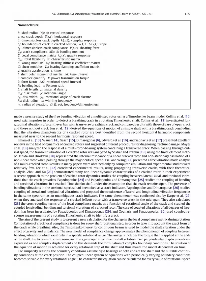
Nomenclature
R: shaft radius Y(x, t): vertical responsea, ax: crack depth Z(x, t): horizontal response�a: dimensionless crack depth U(x, t): complex responsebi: boundaries of crack in cracked section, i = 1,2 H(x, t): slope�cij: dimensionless crack compliance V(x, t): shearing forceCij: crack compliance M(x, t): bending momentC: Local compliance matrix Ug(x): gravity responseCtot: total flexibility P: characteristic matrixE: Young modulus Kb: bearing stiffness coefficient matrixG: shear modulus Cb: bearing damping coefficient matrixg: gravity acceleration t: timeI: shaft polar moment of inertia Dt: time intervali: complex quantity T: power transmission torquek: form factor DX: rotational speed intervalPi: bending load m: Poisson ratioL: shaft length q: material densitymd: disk mass u: rotational angleLd: disk width ucl: rotational angle of crack closureRd: disk radius x: whirling frequencyr0: radius of gyration, X;X: rot, frequency/dimensionless
A.C. Chasalevris, C.A. Papadopoulos / Mechanism and Machine Theory 44 (2009) 1176–1191 1177
made a precise study of the free bending vibration of a multi-step rotor using a Timoshenko beam model. Collins et al. [10]used axial impulses in order to detect a breathing crack in a rotating Timoshenko shaft. Collins et al. [11] investigated lon-gitudinal vibrations of a cantilever bar with transverse breathing crack and compared results with those of case of open crackand those without crack. Jun et al. [12] derived the equations of motion of a simple shaft with a breathing crack concludingthat the vibration characteristics of a cracked rotor are best identified from the second horizontal harmonic componentsmeasured near to the second harmonic resonant speed.
Imam et al. [13], Wauer [14], Gasch [15], Dimarogonas [6], Edwards et al. [16], and Sabnavis et al. [17] presented excellentreviews in the field of dynamics of cracked rotors and suggested different procedures for diagnosing fracture damage. Mayeset al. [18] analyzed the response of a multi-rotor-bearing system containing a transverse crack. When passing through crit-ical speed, the transient vibration of a cracked rotor was analyzed by Sekhar and Prabhu [19], using the finite element meth-od. Ishida and Hirokawa [20] represented the internal resonance of a linear cracked rotor and non-stationary oscillation of anon-linear rotor when passing through the major critical speed. Tsai and Wang [21] presented a free vibration mode analysisof a multi-cracked rotor. Results in many papers were obtained only by computer simulation and experimental studies wererelatively few. Lee et al. [22] correlated experimental results, using propagating transverse cracks, with their theoreticalanalysis. Zhou and Xu [23] demonstrated many non-linear dynamic characteristics of a cracked rotor in their experiment.A recent approach to the problem of cracked rotor dynamics studies the coupling between lateral, axial, and torsional vibra-tions that the crack provokes. Papadopoulos [24] and Papadopoulos and Dimarogonas [25] studied the coupling of bendingand torsional vibrations in a cracked Timoshenko shaft under the assumption that the crack remains open. The presence ofbending vibrations in the torsional spectra had been cited as a crack indicator. Papadopoulos and Dimarogonas [26] studiedcoupling of lateral and longitudinal vibrations and proposed the coexistence of lateral and longitudinal vibration frequenciesin the same spectrum as an unambiguous crack indicator. The same phenomenon was confirmed also by Darpe et al. [27]when they analyzed the response of a cracked Jeffcott rotor with a transverse crack in the mid-span. They also calculated[28] the cross-coupling terms of the local compliance matrix as a function of rotational angle of the crack and studied thecoupled longitudinal bending and torsional vibrations of a cracked rotor. The case of coupled vibrations of all degrees of free-dom has been investigated by Papadopoulos and Dimarogonas [29], and Gounaris and Papadopoulos [30] used coupled re-sponse measurements of a rotating Timoshenko shaft to identify a crack.
The aim of the present study is to present a new calculation for the change in the local compliance matrix during rotation.Computation of crack local compliance is done for every shaft rotational step, in order to take into account the exact form ofthe crack while breathing. Also, the Timoshenko theory for continuous beams is used to model the shaft vibration under theeffect of gravity and unbalance. The new model of compliance change approximates the phenomenon of coupling betweenbending vibrations which exist only in a specific rotational range. The analysis includes the torque that is applied at the endsof the shaft due to power transmission, and the gyroscopic effect due to shaft rotation. Two perpendicular displacements areexpressed as one complex displacement and this demands the formulation of complex boundary conditions. The solution ofthe equation of motion is achieved for every rotational step of the shaft and thus makes the model dependent on time.
For simplicity reasons, the boundary conditions assume rigid bearings at both ends of the shaft and the suitable continu-ity conditions at the crack position. The coupled linear system of equations with periodically varying boundary conditionsbecomes solvable for every rotational angle. The characteristic equation can be calculated for every value of rotational speed

1178 A.C. Chasalevris, C.A. Papadopoulos / Mechanism and Machine Theory 44 (2009) 1176–1191
and the natural frequencies are obtained. The natural frequency is dependent on the variation of the stiffness coefficients dueto the crack. The frequency response and the orbit of the shaft in the cross-section of the disk are also calculated for variablecrack depths. The aim is to show the differences in the dynamic properties of the model, due to the existence of the couplingphenomenon the crack provokes, and also the effect of a deeper crack on the amplitude of vibration under the action of cou-pling, and to distinguish this coupling from these of the coupled differential equations and of the coupling due to the anisot-ropy of the bearings. The resulting diagrams of response and natural frequency as functions of crack depth present thedynamic behavior of this continuous cracked rotating shaft model.
2. The model of the breathing crack
It is known from the literature that the existence of a transverse crack in a shaft induces a local compliance that differs ineach direction. A cracked shaft under two bending loads is shown in Fig. 1; one load is applied in the vertical direction andthe other in the horizontal direction. The planes of bending are defined as plane ZOX (load index 5) and plane YOX (loadindex 4) correspondently. Compliance cij is the additional transposition, due to the crack, in the direction i caused by a bend-ing load in the j direction. When the crack is located in a non-symmetric location to the plane of loading (here, the verticalplane), it induces an additional coupling between the vertical and horizontal vibrations. These vibrations are already cou-pled, as will be described by the complex differential equations presented below. The coupling due to the crack is introducedin the model by the non-diagonal (cross-coupled) terms of the compliance matrix C (bar indicates dimensionless quantities).The coupling effects are proportional to the magnitude of the above coupling terms. For the problem of bending in two direc-tions, the following matrix is defined as a local bending compliance matrix:
C ¼�c44 �c45
�c54 �c55
� �
As the shaft rotates, the crack takes on different angular positions at the cracked section (Fig. 2) and the breathing can besimply expressed as the crack opening when it is located under the centroidal axis (Fig. 1), and closing when the crack islocated over the centroidal axis. The strain energy release rate (SERR) is used here to calculate the local compliance matrixthat is used to model the crack. The material of the shaft is considered to be homogeneous and isotropic. The radius of thecross-section is R and the shaft is subjected to vertical P5 and horizontal P4 bending loads. The crack depth is �a ¼ a=R indimensionless form. The crack can be bounded in the Z direction by �b1ð�a;uÞ and b2ð�a;uÞ, and in the y direction by(k + h2) andffiffiffiffiffiffiffiffiffiffiffiffiffi1� �z2p
(Fig. 3), where, from the geometry of Fig. 3, one can obtain
b1 ¼ b cos u� s; b2 ¼ b cos uþ s; s ¼ ðR� aÞ sin u; k ¼ ðb2 � zÞ sinuh1 ¼ b sin uþ ðR� aÞ cos u; h2 ¼ �b sinuþ ðR� aÞ cos u
It is shown in the same figure that the boundaries of integration depend on values of �a and u. The values of local complianceare calculated as functions of �a and u using the strain energy density factor expressed by Eqs. (1)–(6). The calculation is fea-sible only for some regions of the rotational angle u. This is due to the restrictions introduced by the assumption made aboutthe compliance calculation: the circular cracked cross-section is divided into vertical orthogonal cracked cross-sections(strips) that are not assumed to interact with each other. The compliance due to the crack is calculated for each crack depthand for each angle of rotation (bold line in Fig. 3b), following the way described below. In some transient locations (normal
Fig. 1. The model of the cracked shaft.

Fig. 2. The breathing condition of crack section while rotation under bending moment of gravity.
Fig. 3. The geometry of cracked section.
A.C. Chasalevris, C.A. Papadopoulos / Mechanism and Machine Theory 44 (2009) 1176–1191 1179
line of Fig. 3b) the functions used (F1 and F2), that describe the strain energy density, are not accurate enough, due thefact that the crack passes from stress state caused by the vertical moment to that of horizontal moment. For these tran-sient locations, the compliance functions are interpolated using B-splines interpolation [31], in an attempt to achievemore exact calculation of local compliances. A different approach is given by Jun et al. [12], where the sign of the totalstress intensity factor, KI ¼ KI
n þ KIg at each point along the crack front determines whether the crack is open or closed
at the point. Jun’s results are compared with current approach in Figs. 5a and b, giving thus the comparison of bothapproaches. The diagram in Fig. 4 shows the change in four compliances as a function of rotational angle for the crackdepth �a ¼ 0:4.

Fig. 4. Compliance variation as a function of rotational angle and comparison with two different approximation for: (a) c55, (b) c44 and (c) c45 in the case of40% crack depth.
1180 A.C. Chasalevris, C.A. Papadopoulos / Mechanism and Machine Theory 44 (2009) 1176–1191
If one defines �y1 ¼ �y� 1þ �a, and k�y ¼ �y1=�hz, then the following double integrals for the compliance are obtained
�c55ð�a;uÞ ¼ c55ð�a;uÞER3
1� m2 ¼32p
Z f��b1ð�a;uÞ
�f��b2ð�a;uÞ
Z ffiffiffiffiffiffiffiffi1��z2p
�kþ�h2
1� �z2� ��y1F2
2 k�y� �
d�yd�z ð1Þ
�c44ð�a;uÞ ¼ c44ð�a;uÞER3
1� m2 ¼16p
Z f��b2ð�a;uÞ
�f��b1ð�a;uÞ
Z ffiffiffiffiffiffiffiffi1��z2p
�kþ�h2
�z2�y1F21 k�y� �
d�yd�z ð2Þ
�c45ð�a;uÞ ¼ c45ð�a;uÞER3
1� m2 ¼32p
Z f�b2ð�a;uÞ
�f�b1ð�a;uÞ
Z ffiffiffiffiffiffiffiffi1��z2p
�kþ�h2
�z�y1
ffiffiffiffiffiffiffiffiffiffiffiffiffi1� �z2p
F1 k�y� �
F2 k�y� �
d�yd�z ð3Þ
where f = 1 for a/R 6 1 and f = 0.95 for a/R > 1 [32], and the bar on each distance variable indicates normalization in respectto R.
F0 k�y� �
¼ffiffiffiffiffiffiffiffiffiffiffiffiffiffiffiffiffiffiffiffiffiffiffiffiffiffiffiffiffiffiffiffiffiffiffiffiffiffiffiffiffiffiffiffiffitan pk�y=2
� �= pk�y=2� �q
= cos pk�y=2� �
ð4Þ
F1 k�y� �
¼ F0 k�y� �
0:752þ 2:02 k�y� �
þ 0:37 1� sin pk�y=2� �� �3
h ið5Þ
F2 k�y� �
¼ F0 k�y� �
0:923þ 0:199 1� sin pk�y=2� �� �4
h ið6Þ
Using Fig. 4, matrix C can be determined for every value of u = Xt. See Table 1 and [31] for specific angles. The local com-pliance values of current approach are compared in Figs. 4 and 5, to the respective approaches of the literature, giving goodagreement.
The value of the total flexibility Ctot of the cracked shaft can be calculated for every value of time t so as to define thebreathing of the crack. The flexibility of the uncracked shaft is defined for every direction (vertical and horizontal) asCuncr�55 = Cuncr�44 = =L3/48EI, and the additional flexibility due to the crack is defined for the vertical and horizontal direc-tions as C55 = c55L2/16 and C44 = c44L2/16 respectively. Also, the additional flexibility due to the coupling the crack provokes

Fig. 5. Total stiffness of the shaft, as a function of the rotational angle of the crack.
A.C. Chasalevris, C.A. Papadopoulos / Mechanism and Machine Theory 44 (2009) 1176–1191 1181
is related to the compliances, defined as C54 = c54L2/16 for the vertical plane and as C45 = c45L2/16 for the horizontal plane. Thetotal direct flexibility is defined as Ctotii
¼ Cuncriiþ Cii for both main directions, the vertical (5) and the horizontal (4), consid-
ering that the shaft and the crack are springs in a sequence. The cross-coupled total stiffness is expressed as Ctotij¼ Cij since
the initial cross-coupled stiffness of the intact system does not exist. The inverse of total flexibility (total stiffness) is plottedin Fig. 5 in dimensionless form and presents the breathing of a crack of depth a/R = 0.4. A comparison is made in Fig. 5 withcorresponding results from [12]. The dimensionless stiffness value is expressed as ðCtotii
=Cuncrii�1. A small deviation is noticed
between current approximation and reference [12] during the breathing due to the different assumption of crack geometrywhile rotation. In the cases that the crack is assumed as fully open the agreement is good since both approximations of crackcompliance are based in the same assumptions.
3. A continuous model approach for the rotating cracked shaft
3.1. Equation of motion
In this approach to the motion of the rotating shaft, the rotary inertia, the shear deformation, the torque of power trans-mission and the gyroscopic effect are taken into consideration. Assume a uniform homogenous and cracked rotating Timo-shenko shaft (Fig. 1) of Young’s modulus of elasticity E = 205.8 GPa, shear modulus G = 79.76 GPa, moment of inertia of thecross-section about X axis I = 3.06 � 10�7 m4, mass density q = 7860 kg m�3, shear factor k = 10/9 for circular cross-section,length L = 2 m, radius of cross-section R = 0.025 m, radius of gyration r0 ¼
ffiffiffiffiffiffiffiI=A
p¼ 0:0125 m, and Poisson ratio m = 0.29. The
shaft is rotating with a rotational speed X, whirling with a frequency x, and transmitting a power with an axial torque T. Alsoconsider a transversely located disk in the mid-span (x = L/2) of the shaft of the same material, with radius Rd = =0.15 m, massmd = 27.78 kg, and thickness Ld = 0.05 m. The breathing crack, of depth �a ¼ a=R, exists in the mid-span, just next to the disk. IfY(x, t) and Z(x, t) are the vertical and horizontal response of the axial coordinate x and time t, respectively, then by supposingthe complex notation Ui(x, t) = Yj(x, t) + i Zj (x, t), the coupled governing equation of motion is written as [9,33]:
EIo4Uj
ox4 � iTo3Uj
ox3 �EIqkGþ qAr2
0
� �o4Uj
ox2ot2 þ 2iqAr20X
o3Uj
ox2otþ i
TqkG
o3Uj
oxot2 þq2Ar2
0
kGo4Uj
ot4 � 2iq2Ar2
0XkG
o3Uj
ot3 þ qAo2Uj
ot2 ¼ 0
ð7Þ
where j = 1 for the first part of the shaft from the left end up to the crack and j = 2 for the part from the crack up to the rightend (Fig. 1). Eq. (7) is a fourth order complex partial differential equation that has a solution of the form:
Ujðx; tÞ ¼ ujðxÞeixt ¼ pjekjxeixt ð8Þ
Substitution of Eq. (8) into Eq. (7) yields the complex characteristic Eq. (9), a fourth degree polynomial equation of kj,
x2 �iRTkj þ q EIk2j þ Ar2
0qx x� 2Xð Þ
þ kG �Aqx2 þ k2j �iTkj þ EIk2
j þ Ar20qx x� 2Xð Þ
¼ 0 ð9Þ
Two of the roots of (9) are complex numbers; meanwhile, the other two are imaginary. Actually the two imaginary roots arecomplex with near zero real parts. Let us set the roots as kj,1, kj,2, kj,3, kj,4. Then the partial solution becomes [9],
ujðxÞ ¼ qj;1ekj;1 �x þ qj;2ekj;2 �x þ qj;3ekj;3 �x þ qj;4ekj;4 �x; j ¼ 1;2 ð10Þ
1182 A.C. Chasalevris, C.A. Papadopoulos / Mechanism and Machine Theory 44 (2009) 1176–1191
Coefficients qj,1, qj,2, qj,3, and qj,4, are also complex numbers that are defined using the boundary conditions for displace-ment, slope, bending moment, and shearing force, which in a Timoshenko shaft with gyroscopic effect are defined as in[9,33] and [34],
Displacement: Uj(x, t)
Slope: Hjðx; tÞ ¼oUjðx;tÞ
ox
Shearing force: Vjðx; tÞ ¼ EI o3Ujðx;tÞox3 � iT o2Ujðx;tÞ
ox2 � qAr20
o3Ujðx;tÞoxot2 � 2iX o2Ujðx;tÞ
oxot
Bending moment: Mjðx; tÞ ¼ EI o2Ujðx;tÞ
ox2 � iT oUjðx;tÞox
3.2. Boundary conditions
The cracked rotor is assumed to be mounted in hinged supports at both ends. The disk and the crack are assumed to be inthe mid-span (L1 = L/2 = 1 m) with the crack in the right side of the disk. Also Ip ¼ 0:5mdR2
d ¼ 0:31252 kg m2 and
Is ¼ 0:25mdR2d þ 1=12mdL2
d ¼ 0:162 kg m2 are the mass polar moments of inertia about axis Ox and diametric axis of the disk
respectively (see Fig. 1); Hj
_
ðx; tÞ and Mj
_
ðx; tÞ are the conjugate complex numbers of Hj(x, t) and Mj(x, t), respectively. For thisspecific problem, mu = 0.01 kg, ru = 0.1 m, and uu are the unbalance mass, the distance from the centre of the rotation, and theangle between the vector of unbalance and the horizontal axis, respectively. For simplicity, ru is a constant distance anduu = 0. Due to the fact that the excitation of the system is the unbalance force, the whirling of the shaft is synchronous withthe rotation, which means x = X. Therefore the boundary condition (BC) of shearing force, for the case of a disk with andwithout unbalance, becomes as in Eqs. (11) and (12), respectively.
V2ðL1; tÞ ¼ V1ðL1; tÞ � mdx2� �U1ðL1; tÞ þmurux2eixt ð11Þ
V2ðL1; tÞ ¼ V1ðL1; tÞ � mdx2� �U1ðL1; tÞ ð12Þ
At both ends, the displacement and the bending moment are equal to zero:
U1ð0; tÞ ¼ U2ðL; tÞ ¼ 0 ð13ÞM1ð0; tÞ ¼ M2ðL; tÞ ¼ 0 ð14Þ
In the mid-span: (a) The bending moment at the left side of the crack (the same as the right side of the disk) results in a slopediscontinuity in the two parts of the shaft which is described by Eq. (15):
eþ idð ÞM1ðL1; tÞ þ bþ icð ÞM1
_
ðL1; tÞ ¼ H2ðL1; tÞ �H1ðL1; tÞð Þ ð15Þ
where e = 0.5(c55 + c44), b = 0.5(c55 � c44), c = 0.5(c45 + c54), and d = 0.5(c45 � c54)(b) The bending moment on both sides of the disk follows the equation:M2ðL1; tÞ ¼ M1ðL1; tÞ þ i H1
_
ðL1; tÞðIpXx� Isx2Þ ð16Þ
(c) The displacements at both sides of the disk are equal:
U1ðL1; tÞ ¼ U2ðL1; tÞ ð17Þ
When the crack is closed (see Figs. 2 and 4), the local compliances become zero and the boundary condition of Eq. (15) istransformed into Eq. (18), describing the continuity in slopes at both sides of the disk:H1ðL1; tÞ ¼ H2ðL1; tÞ ð18Þ
3.3. Calculation of gravity response
As mentioned above, the crack breathes due to a gravity effect in the elastodynamic behavior of the shaft. The gravityresponse is assumed to surpass the unbalance response so as to set the crack condition (breathing). In theory, this hap-pens when the rotational speed is not near the critical speed, but in practice the crack breathing due to gravity can beobserved at every speed under special geometric characteristics of large rotating machines. In this paper, the gravity isassumed to be static (independent of time) and the gravity response Ugi(x) is obtained by the ordinary differential equa-tion (19) as in [34]:
EId4UgjðxÞ
dx4 � iTd3UgjðxÞ
dx3 ¼ �qAg; i ¼ 1;2 ð19Þ
By neglecting the torque for simplicity, when the response due to the gravity is evaluated, and for hinged-hinged boundaryconditions with the disk at the mid-span, the solution for the two parts of the shaft becomes
Ug1ðxÞ ¼ �qAg24EI
x4 þ gmd þ 2AgLq12EI
x3 � 3gL2md þ 4AgL3q12EI
x ð20Þ

A.C. Chasalevris, C.A. Papadopoulos / Mechanism and Machine Theory 44 (2009) 1176–1191 1183
for 0 6 x 6 L=2
Ug2ðxÞ ¼ �qAg24EI
x4 � gmd � 2AgLq12EI
x3 þ gLmd
2EIx2 � 9gL2md þ 4AgL3q
12EIxþ gL3md
6EIð21Þ
for L=2 6 x 6 L:
4. Dynamic analysis
4.1. Calculation of critical speeds
In order to present the effect of coupling at critical speeds, the cracked and the uncracked models are analyzed. When nocrack exists, the boundary condition of Eq. (15) is substituted by Eq. (18). By substituting the general solution
Ujðx; tÞ ¼ ðqj;1ekj;1x þ qj;2ekj;2x þ qj;3ekj;3x þ qj;4ekj;4xÞeixt ð22Þ
into the eight boundary conditions, Eqs. (11)–(18) the homogeneous system (8 � 8) for the variables qj,1 qj,2 qj,3 qj,4 for j = 1,2of Eq. (23) is obtained
½P� q1;1 q1;2 q1;3 q1;4 q2;1 q2;2 q2;3 q2;4� �T ¼ 0 0 . . . 0f g|fflfflfflfflfflfflfflfflfflfflfflfflffl{zfflfflfflfflfflfflfflfflfflfflfflfflffl}T
8
ð23Þ
The real and imaginary roots of jPj = 0 for x = X are the critical speeds. The roots of real part of characteristic equation arethe vertical critical speeds, and the roots of the imaginary part of the characteristic equation are the critical speeds corre-sponding to the horizontal plane. For the cracked model, the boundary condition of Eq. (15) introduces the parameter of timeinto the model. Time is a factor that specifies the crack local compliance in accordance with the breathing condition. This factmakes the characteristic determinant also a function of time. For example, if t = 1/4 (2p/X), the crack is semi-closed (Fig. 2,u = 90�) and the local compliances have different values from those of any other value of time in the same period. As shownin Fig. 4, there is no value of time for which all compliances are equal to each other, except if t 2 [�ucl/X,ucl/X] whereucl = 36� is the angle of rotation in which a crack of �a ¼ 0:4 starts to open. The characteristic determinant is calculated fora specific value of time (i.e in the 1/4 of period), and plotted as real parts in Fig. 6a and as imaginary parts in Fig. 6b as afunction of X/x0. The value x0 is used in this paper to express frequency in dimensionless form and is defined asx0 = (EI/qAL4)1/2. For the geometry of this section x0 � 16. The zero crossing values express the eigenfrequencies for the in-stant form of the crack (here the crack is instantaneous semi-open in the 1/4 of period) and the logarithmic magnitude isused here so as to achieve the visibility of function progress since in areas near roots it tends rapidly from �/ to +/.
4.2. Calculation of the frequency response
The response in the frequency domain is calculated by an iterative procedure. In each iteration a rotating/whirling fre-quency value is defined and the time response for one period of time, in steps of Dt = 0.01(2p/X)s, is calculated. In each timeresponse, the amplitude is measured and diagrams of amplitude as a function of frequency are obtained. The cases for theuncracked and cracked shaft are investigated. The procedure is repeated for a frequency range higher than the third criticalspeed with a frequency step change of DX = 1 rad s�1, so as to define the frequency areas of critical speeds (see Fig. 7), andthen a step change of DX = 0.001 rad/s is used in order to examine the effect of coupling from both sides of first critical speed(see Fig. 8). Note that the resonance in the 2nd critical speed does not appear in this response because the measurement is
Fig. 6. (a) Real and (b) imaginary part of the characteristic determinant as a function of X.
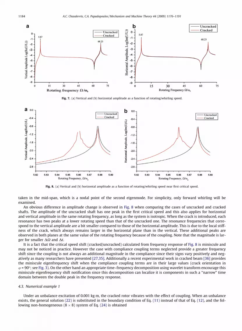
Fig. 7. (a) Vertical and (b) horizontal amplitude as a function of rotating/whirling speed.
Fig. 8. (a) Vertical and (b) horizontal amplitude as a function of rotating/whirling speed near first critical speed.
1184 A.C. Chasalevris, C.A. Papadopoulos / Mechanism and Machine Theory 44 (2009) 1176–1191
taken in the mid-span, which is a nodal point of the second eigenmode. For simplicity, only forward whirling will beexamined.
An obvious difference in amplitude change is observed in Fig. 8 when comparing the cases of uncracked and crackedshafts. The amplitude of the uncracked shaft has one peak in the first critical speed and this also applies for horizontaland vertical amplitude in the same rotating frequency, as long as the system is isotropic. When the crack is introduced, eachresonance has two peaks at a lower rotating speed than that of the uncracked one. The resonance frequencies that corre-spond to the vertical amplitude are a bit smaller compared to those of the horizontal amplitude. This is due to the local stiff-ness of the crack, which always remains larger in the horizontal plane than in the vertical. These additional peaks areobserved in both planes at the same value of the rotating frequency because of the coupling. Note that the magnitude is lar-ger for smaller DX and Dt.
It is a fact that the critical speed shift (cracked/uncracked) calculated from frequency response of Fig. 8 is miniscule andmay not be noticed in practice. However the case with compliance coupling terms neglected provide a greater frequencyshift since the coupling is not always an additional magnitude in the compliance since their signs vary positively and neg-atively as many researchers have presented [27,35]. Additionally a recent experimental work in cracked beam [36] providesthe miniscule eigenfrequency shift when the compliance coupling terms are in their large values (crack orientation inu = 90�; see Fig. 3). On the other hand an appropriate time–frequency decomposition using wavelet transform encourage thisminiscule eigenfrequency shift notification since this decomposition can localize it is components in such a ‘‘narrow” timedomain between the double peak in the frequency response.
4.3. Numerical example 1
Under an unbalance excitation of 0.001 kg m, the cracked rotor vibrates with the effect of coupling. When an unbalanceexists, the general solution (22) is substituted in the boundary condition of Eq. (11) instead of that of Eq. (12), and the fol-lowing non-homogeneous (8 � 8) system of Eq. (24) is obtained

Fig. 9. (a) Vertical and (b) horizontal time response in mid-span for the two cases, in rotational speed X = x = 90.0 rad/s.
A.C. Chasalevris, C.A. Papadopoulos / Mechanism and Machine Theory 44 (2009) 1176–1191 1185
½P� q1;1 q1;2 q1;3 q1;4 q2;1 q2;2 q2;3 q2;4� �T ¼ 0 0 . . . 0|fflfflfflfflfflfflfflfflfflfflffl{zfflfflfflfflfflfflfflfflfflfflffl}
7
murux2� �T
ð24Þ
As in Section 4.2, the cracked and uncracked cases are compared. For each case, the forward synchronous (X = x) whirlingtime response is calculated in the mid-span for both planes of vibration and for rotational speeds different from the first crit-ical, in order to avoid singularities. The rotational speed is set to X ¼ 5:625 (Fig. 9), X ¼ 5:831 (a speed very close to critical(Fig. 10)), and X ¼ 5:937 (a speed after the first critical (Fig. 11)). It is clear that the response due to coupling is observed forcrack rotational angles near 90, 180 and 270� (Fig. 2) or 1/4, 1/2 and 3/4 of the time period. In these angles of rotation, thecoupling terms �c54 and �c45 get the higher absolute values. This difference due to coupling has been also observed by Darpeet al. [27] in 2002. The opening of the crack permits an additional response in the vertical direction near 180�, but also anadditional response near 90 and 270� as shown in Figs. 9–11.
The time response, treated as a signal, can be analyzed in its components with the fast Fourier transform (FFT) in order tomore clearly observe the effect of the coupling in additional harmonic development. Each of the signals of Fig. 9, are trans-
Fig. 10. (a) Vertical and (b) horizontal time response in mid-span for the two cases, in rotational speed X = x = 93.3 rad/s.

Fig. 11. (a) Vertical and (b) horizontal time response in mid-span for the two cases, in rotational speed X = x = 95.0 rad/s.
1186 A.C. Chasalevris, C.A. Papadopoulos / Mechanism and Machine Theory 44 (2009) 1176–1191
formed using FFT and the respective results are shown in Fig. 12. The component of X ¼ 5:625, is synchronous with the rota-tional/whirling frequency and, as a result, has the highest amplitude. Also, the components with frequencies of 2/rev, 3/rev,4/rev and more are seen to have lower amplitudes as the frequency increases [28]. It is known that a crack introduces suchharmonics as in [28], but in the case where the crack introduces a coupling, these harmonics have higher amplitudes. Thecoupling effect and the additional harmonic development become more intense as the vibration amplitude increases and thishappens as the system gets near to resonance. At these speeds the coupling phenomenon provokes additional componentswith their amplitude is greater with respect to this of synchronous component than this of cases far from resonance. Thedomination of synchronous response is of course observed but the relative amplitude becomes greater. The same resultsare also verified in the signals of Fig. 10, (see Fig. 13) where the highest amplitude is observed at the synchronous frequencyX ¼ 5:831, while the other components appear in higher harmonics with lower amplitude. The FFT of signals for X ¼ 5:937,in Fig. 11, are judged as not necessary for plotting such as those of Fig. 9. Note that at the speed of X ¼ 5:937 there is a phaseinversion in the time domain response. A general conclusion derived from spectra given in Figs. 12 and 13 is that since thecoupling is introduced mainly two times in the period duration the 2Xrev harmonic is mainly amplified. The development/amplification of the 2Xrev harmonic is of course the main result of the crack breathing no matter what modeling of breathingis used but the co-existence of coupling increases the amplification/development of 2Xrev.
5. The resilient bearing model
In the previous numerical example, the bearing was assumed to be rigid in order to focus on the crack effect. The couplingintroduced by the crack is presented in the same way as the coupling due to the cross-coupled bearing stiffness and damping
Fig. 12. FFT of (a) vertical and (b) horizontal response for X = x = 90.0 rad/s.

Fig. 13. FFT of (a) horizontal and (b) vertical response for X = x = 93.3 rad/s.
Fig. 14. The resilient bearing model.
A.C. Chasalevris, C.A. Papadopoulos / Mechanism and Machine Theory 44 (2009) 1176–1191 1187
coefficients. This is also shown in the frequency response domain by double peaks. In this numerical example, a cracked rotormodel in resilient bearings is analyzed, and results for frequency response are obtained. In Fig. 14, the rotor-bearing systemcharacteristics are shown, as given by Hong and Park [37] for comparison purposes.
A shaft of diameter D = 25 mm, length L = 1200 mm, made of steel with E = 200 GPa and density q = 8000 kg m�3, is sup-ported by two bearings at its two ends, with the following dynamic properties:
Kb ¼kyy kyz
kzy kzz
� �¼ 1:2� 106 0
0 1:2� 106
" #Nm�1
Cb ¼cyy cyz
czy czz
� �¼
6 00 6
� �Nsm�1
In this model, the boundary conditions at both ends of the shaft are calculated in complex form by combining the boundaryconditions for the spring and damper given as in (25) and (26). The forces applied by the bearing are proportional to the dis-placement Ui(x, t) = Yj(x, t) + i Zj (x, t), as well as to its first time derivative. Finally, the two boundary conditions take the formas in (25) and (26).
V1ð0; tÞ ¼ s1 � is4ð ÞU1ð0; tÞ þ s2 þ is3ð ÞU1
_
ð0; tÞ þ p1 � ip4ð Þ o
otU1ð0; tÞ þ p2 þ ip3ð Þ o
otU1
_
ð0; tÞ ð25Þ
V2ðL; tÞ ¼ s1 � is4ð ÞU2ðL; tÞ þ s2 þ is3ð ÞU2
_
ðL; tÞ þ p1 � ip4ð Þ o
otU2ðL; tÞ þ p2 þ ip3ð Þ o
otU2
_
ðL; tÞ ð26Þ
where, s1 = 0.5(kyy + kzz), s2 = 0.5(kyy � kzz), s3 = 0.5(kyz + kzy), s4 = 0.5(kyz � kzy), p1 = 0.5(cyy + czz), p2 = 0.5(cyy � czz), p3 = 0.5(cyz + czy), p4 = 0.5(cyz � czy) and Ui
_
ðx; tÞ ¼ Yjðx; tÞ � iZjðx; tÞ is the complex conjugate value of the displacement Ui(x, t).In the present case, where an unbalance excitation is taken at the right end, the respective boundary condition of Eq. (26)
becomes
V2ðL; tÞ ¼ s1 � is4ð ÞU2ðL; tÞ þ s2 þ is3ð ÞU2
_
ðL; tÞ þ p1 � ip4ð Þ o
otU2ðL; tÞ þ p2 þ ip3ð Þ o
otU2
_
ðL; tÞ �murux2eixt ð27Þ
If a crack is introduced in the isotropic system of Fig. 14, then the frequency response obtained (Fig. 15) has double peaks inthe 1st, the 3rd and the 5th resonance, as presented in Fig. 16 (these figures zoom in on the respective resonances). Due tothe location of crack at the mid-span, the crack has no effect in the 2nd and the 4th modes since the mid-span in these modesis a nodal point.

Fig. 15. Left journal amplitude (continuous line: uncracked, dotted line: cracked 40% of the radius).
Fig. 16. Left journal amplitude for the case of isotropic system (continuous line: uncracked, dotted line: cracked 40% of the radius) for (a) the 1st, (b) the 3rdand (c) the 5th resonance.
1188 A.C. Chasalevris, C.A. Papadopoulos / Mechanism and Machine Theory 44 (2009) 1176–1191

Fig. 17. Left journal amplitude for the case of anisotropic system without crack (continuous line: vertical, dashed line: horizontal).
Fig. 18. Left journal amplitude for the case of anisotropic system with a crack (continuous line: vertical, dashed line: horizontal).
Fig. 19. Left journal amplitude for the case of anisotropic system (continuous line: uncracked, dotted line: cracked 40%).
A.C. Chasalevris, C.A. Papadopoulos / Mechanism and Machine Theory 44 (2009) 1176–1191 1189

1190 A.C. Chasalevris, C.A. Papadopoulos / Mechanism and Machine Theory 44 (2009) 1176–1191
5.1. Numerical example 2
In the case where the bearing coefficients are not equal to each other in the two main directions, the frequency responsedisplays double peaks, as in the case of the crack, but at much different eigenfrequencies since the system stiffness shift dueto bearing anisotropy is much more greater than that due to crack rotation. If the horizontal stiffness is changed tokzz = 8 � 105 Nm�1, the frequency response is changed to that of Fig. 17. When the crack is introduced, then the frequencyresponse is formed as in Fig. 18. A detailed look at Fig. 18 shows that when the crack is introduced, the existing coupling (dueto anisotropy) is presented in a different way combined with that due to crack coupling. In Fig. 19, zooming in on the 3rdresonance shows that when no crack exists, the coupling due to anisotropy is shown by two peaks. Note that this couplingdoes not need cross-coupling bearing properties in order to be provoked, but can be provoked even with zero cross-couplingbearing properties due to the coupled equations of the shaft motion. When the crack is present, the additional coupling dueto the crack arises by introducing two more peaks in the frequency response (see Fig. 19). Then, there are a total of four peaksin each resonance; two of them are present due to crack breathing coupling and two due to coupled bearing properties andcoupled equations of motion.
6. Conclusions
In this paper, the problem of coupled bending vibrations in a cracked rotor mounted in resilient bearings was investi-gated. The phenomenon of coupling introduced by a transverse crack forces a significant change to the dynamic propertiesthat are already affected by the crack existence. As was shown, the total stiffness in the two main directions experiences achange dependent on the crack local compliance change during rotation, making thus the system non-linear. The proposedmethod in this study offers a continuous model for a cracked rotor-bearing system, including three parameters of coupling:the coupled equations of motion, the coupling due to the breathing crack and the coupling due to cross-coupled bearing coef-ficients for stiffness and damping.
The observations and the conclusions made from current analysis can be regarded as in following:
1. The coupling affects the response in the time and frequency domains and amplifies the higher harmonics that the crackintroduces as components in the vibration.
2. The resilient bearing analysis, including cross-coupling stiffness and damping coefficients, provides evidence that thecoupling due to a crack is negligible in respect to the coupling that the bearings introduce.
3. The higher harmonics that are introduced in the vibration spectrum due to the stiffness change caused by the breathing ofthe crack clearly indicate the existence of a crack since the amplification of 2Xrev harmonic amplitude is increased fromthe crack cross-coupling compliances.
Future work combining the current continuous shaft model with finite bearings could investigate the effect of the cou-pling due to a breathing crack when the stiffness and damping properties of the bearing are not set for a specific equilibriumposition, but instead for a real journal trajectory inside the bearing, since this motion is much more closer to the reality whenthe system passes through a critical speed.
References
[1] A.D. Dimarogonas, Dynamic Response of Cracked Rotors, General Electric, Schenectady, NY, USA, 1970.[2] A.D. Dimarogonas, Dynamics of Cracked Shafts, General Electric, Schenectady, NY, USA, 1971.[3] T. Pafelias, Dynamic Behavior of Cracked Rotor, General Electric, Schenectady, NY, USA, 1974.[4] F.M. Dimentberg, Flexural Vibrations of Rotating Shafts, Butterworths, 1961.[5] A. Tondl, Some Problems in Rotor Dynamics, Chapman and Hall, London, 1965.[6] A.D. Dimarogonas, Vibration of cracked structures: a state of the art review, Engineering Fracture Mechanics 55 (5) (1996) 831–857.[7] T.G. Chondros, A.D. Dimarogonas, Identification of cracks in welded joints of complex structures, Journal of Sound and Vibration 69 (4) (1980) 531–538.[8] G. Gounaris, A. Dimarogonas, A finite element of a cracked prismatic beam for structural analysis, Computers and Structures 28 (3) (1988) 309–313.[9] O.S. Jun, J.O. Kim, Free bending vibration of a multi-step rotor, Journal of Sound and Vibration 224 (4) (1999) 625–642.
[10] K.R. Collins, R.H. Plaut, J. Wauer, Detection of cracks in rotating Timoshenko shafts using axial impulses, ASME, Journal of Vibration Acoustics 113(1991) 74–78.
[11] K.R. Collins, R.H. Plaut, J. Wauer, Free and forced longitudinal vibrations of a cantilevered bar with a crack, ASME, Journal of Vibration Acoustics 114(1992) 171–177.
[12] O.S. Jun, H.J. Eun, Y.Y. Earmme, C.W. Lee, Modeling and vibration analysis of a simple rotor with a breathing crack, Journal of Sound and Vibration 155(1992) 273–290.
[13] I. Imam, S.H. Azzaro, R.J. Bankert, Development of an on-line rotor crack detection and monitoring system, Journal of Vibration, Acoustics, Stress, andReliability in Design 111 (3) (1989) 241–250.
[14] J. Wauer, On the dynamics of cracked rotors: a literature survey, Applied Mechanics Review 43 (1) (1990) 13–17.[15] R. Gasch, A survey of the dynamic behaviour of a simple rotating shaft with a transverse crack, Journal of Sound and Vibration 160 (2) (1993) 313–332.[16] S. Edwards, A.W. Lees, M.I. Friswell, Fault diagnosis of rotating machinery, The Shock and Vibration Digest 30 (1) (1998) 4–13.[17] G. Sabnavis, R.G. Kirk, M. Kasarda, Cracked shaft detection and diagnostics: a literature review, Shock and Vibration Digest 36 (4) (2004).[18] I.W. Mayes, W.G.R. Davies, Analysis of the response of a multi-rotor-bearing system containing a transverse crack in a rotor, Journal of Vibration
Acoustics Stress, and Reliability in Design – Transactions of the ASME 106 (1) (1984) 139–145.[19] A.S. Sekhar, B.S. Prabhu, Transient analysis of a cracked rotor passing through critical speed, Journal of Sound and Vibration 173 (3) (1994) 415–421.[20] Y. Ishida, K. Hirokawa, Internal resonances of a cracked rotor – major critical speed and critical speeds in precritical range, JSME International Journal
Series C – Dynamics Control Robotics Design and Manufacturing 39 (2) (1996) 225–233.

A.C. Chasalevris, C.A. Papadopoulos / Mechanism and Machine Theory 44 (2009) 1176–1191 1191
[21] T.C. Tsai, Y.Z. Wang, The vibration of a multi-crack rotor, International Journal of Mechanical Sciences 39 (9) (1997) 1037–1053.[22] C.W. Lee, J.S. Yun, O.S. Jun, Modeling of a simple rotor with a switching crack and its experimental verification, Journal of Vibration and Acoustics –
Transactions of the ASME 114 (2) (1992) 217–225.[23] T. Zhou, J.X. Xu, Fault diagnosis of a turbine generator with a crack in time and frequency domain, Power Engineering 21 (2) (2001) 1099–1104.[24] C.A. Papadopoulos, Coupled vibrations of cracked shafts, 1987, pp. 1–235 (in Greek) <http://thesis.Ekt.gr/0551>.[25] C.A. Papadopoulos, A.D. Dimarogonas, Coupling of bending and torsional vibration of a cracked Timoshenko shaft, Archive of Applied Mechanics
(Ingenieur Archiv) V57 (4) (1987) 257–266.[26] C.A. Papadopoulos, A.D. Dimarogonas, Coupled longitudinal and bending vibrations of a cracked shaft, Journal of Vibration, Acoustics, Stress, and
Reliability in Design 110 (1) (1988) 1–8.[27] A.K. Darpe, A. Chawla, K. Gupta, Analysis of the response of a cracked Jeffcott rotor to axial excitation, Journal of Sound and Vibration 249 (3) (2002)
429–445.[28] A.K. Darpe, K. Gupta, A. Chawla, Coupled bending, longitudinal and torsional vibrations of a cracked rotor, Journal of Sound and Vibration 269 (1–2)
(2004) 33–60.[29] C.A. Papadopoulos, A.D. Dimarogonas, Coupled vibration of cracked shafts, Journal of Vibration and Acoustics – Transactions of the ASME 114 (4)
(1992) 461–467.[30] G.D. Gounaris, C.A. Papadopoulos, Crack identification in rotating shafts by coupled response measurements, Engineering Fracture Mechanics 69 (3)
(2002) 339–352.[31] A.C. Chasalevris, C.A. Papadopoulos, Identification of multiple cracks in beams under bending, Mechanical Systems and Signal Processing 20 (7) (2006)
1631–1673.[32] C.A. Papadopoulos, Some comments on the calculation of the local flexibility of cracked shafts, Journal of Sound and Vibration 278 (4–5) (2004) 1205–
1211.[33] C. Lee, Vibration Analysis of Rotors, Kluwer Academic Publishers, The Netherlands, 1993.[34] T. Yamamoto, Y. Ishida, Linear and Nonlinear Rotor Dynamics, John Wiley & Sons, 2001.[35] W. Theis, Langs- Und Torsions-Schwingungen Bei Quer Angerissenen Rotoren Untersuchungen Auf Der Grundlage Eines Ribmodells Mit 6
Balkenfreiheitsgraden, Fortschritt-Berichte VDI 11 (131) (1990) 1–140.[36] A.C. Chasalevris, C.A. Papadopoulos, Coupled horizontal and vertical bending vibrations of a stationary shaft with two cracks, Journal of Sound and
Vibration 309 (2008) 507–528.[37] S.W. Hong, J.H. Park, Dynamic analysis of multi-stepped distributed parameter rotor-bearing systems, Journal of Sound and Vibration 227 (4) (1999)
769–785.


