Embed Size (px)
Citation preview

Nuclear Instruments and Methods in Physics Research A 414 (1998) 466—476
A Cockcroft—Walton base for the FEU84-3 photomultiplier tube
A. Brunner, R.R. Crittenden, A.R. Dzierba, J. Gunter, R.W. Gardner, C. Hamm,R. Lindenbusch, D.R. Rust, E. Scott, P.T. Smith*, C. Steffen, T. Sulanke, S. Teige
Department of Physics, Indiana University, Swain Hall West 117, Bloomington, IN 47405, USA
Received 23 January 1998; received in revised form 5 May 1998
Abstract
The design and construction of a Cockcroft—Walton-type base for the Russian FEU84-3 photomultiplier are described.Several unique features are emphasized. Results from the tests of prototypes are presented. ( 1998 Elsevier ScienceB.V. All rights reserved.
PACS: 29.40.Vj; 84.30.-r; 84.70.#P; 85.60.Ha
Keywords: Photomultiplier; Calorimeter; Cockcroft—Walton; Voltage multiplier
*Corresponding author. Tel.: #1 812 855 4554; fax:#1 812 855 0440; e-mail: [email protected].
1. Introduction
Several photomultiplier tube (PMT) base designshave been implemented which use the so-calledCockcroft—Walton voltage multiplier circuit togenerate a graded series of voltages [1—3]. This typeof circuit has the advantage of dissipating much lesspower than a resistive voltage divider. Minimalpower dissipation is critical in the detectors inwhich PMTs are densely packed.
We have designed a PMT base for an electro-magnetic calorimeter to be used in an experiment(Radphi) to measure rare radiative decays of the/ meson at the Thomas Jefferson National Acceler-
ator Facility. We have produced 328 of these bases,which were used in an engineering run of that experi-ment. The main features of these PMT bases are:
z The only input power required is a single 15VDC supply.
z The voltage setting of each base can be controlledremotely via a daisy-chained serial data line.
z The voltages can be set individually, in groups, orall together.
z The base can produce a self-test pulse propor-tional to its generated high voltage to make cer-tain the base is operating correctly.
z The cathode to first dynode voltage is maintainedat a relatively constant voltage independent ofthe cathode to anode voltage.
The main parameters of the design are listed inTable 1.
0168-9002/98/$19.00 ( 1998 Elsevier Science B.V. All rights reserved.PII: S 0 1 6 8 - 9 0 0 2 ( 9 8 ) 0 0 6 5 1 - 2

Fig. 1. Block diagram of the photomultiplier base.
Table 1Main parameters of the photomultiplier base
Photocathode voltage 1000V$2%P2023V $2%adjustable in 1V$3% steps
CathodePfirst dynode voltage 250—300VMaximum average anodecurrent
100lA
Supply voltage 15—16VSwitching noise at anode ;0.25 pC rms in a 250ns gateTypical power consumption 60mW(at photocathode setting of2 kV)Maximum power consumption 150mW(when ramping to a highersetting)Time to send a base command 3.2msSelf-test pulse amplitude 250pCP500 pC
2. Physical description
The base circuit is entirely contained in a cylin-drical delrin housing, 3.8 cm in diameter by 15.5 cmin length. A 3.9 cm square aluminum cap serves toaffix the base and photomultiplier to a wall with3.9 cm holes on 4 cm centers. This wall is locatedjust downstream of a stack of lead glass blocks,
each 45 cm long with a 4]4 cm2 cross section.A calorimeter of similar construction built by ourgroup is described in Ref. [4].
The end cap of the housing has holes for twoconnectors. A lemo connector outputs the photo-multiplier anode signal. A 10-pin mass terminationheader connects to a daisy-chained ribbon cable.The clock and data are each transmitted differen-tially on two pins. Three pins carry the #15Vsupply, and three pins are grounded. Four hexa-decimal switches, accessible through holes in thehousing, set a 16 bit address for the base.
3. Circuit description
Refer to the block diagram shown in Fig. 1.A step down regulator converts the 15V to 5V forthe use by the logic circuitry. A dual comparatorreceives the clock and data signals. A programm-able gate array (PGA) compares the incoming ser-ial address to the address set on the four switches todetermine if the base should respond to the trans-mitted address. Eight bits are allotted to addressa row in the stack of detector modules, and eight
A. Brunner et al. /Nucl. Instr. and Meth. in Phys. Res. A 414 (1998) 466—476 467
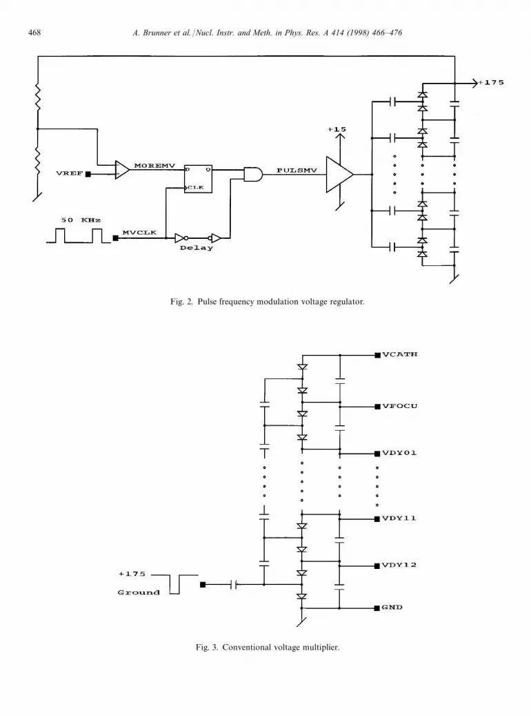
Fig. 2. Pulse frequency modulation voltage regulator.
Fig. 3. Conventional voltage multiplier.
468 A. Brunner et al. /Nucl. Instr. and Meth. in Phys. Res. A 414 (1998) 466—476
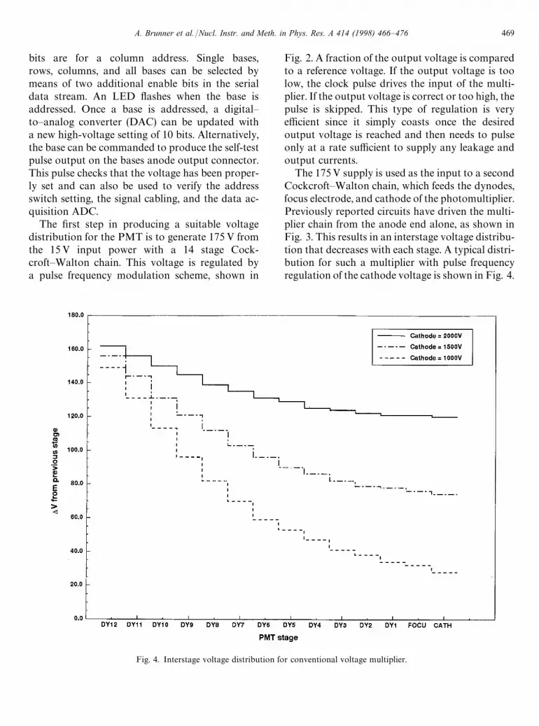
Fig. 4. Interstage voltage distribution for conventional voltage multiplier.
bits are for a column address. Single bases,rows, columns, and all bases can be selected bymeans of two additional enable bits in the serialdata stream. An LED flashes when the base isaddressed. Once a base is addressed, a digital—to—analog converter (DAC) can be updated witha new high-voltage setting of 10 bits. Alternatively,the base can be commanded to produce the self-testpulse output on the bases anode output connector.This pulse checks that the voltage has been proper-ly set and can also be used to verify the addressswitch setting, the signal cabling, and the data ac-quisition ADC.
The first step in producing a suitable voltagedistribution for the PMT is to generate 175 V fromthe 15V input power with a 14 stage Cock-croft—Walton chain. This voltage is regulated bya pulse frequency modulation scheme, shown in
Fig. 2. A fraction of the output voltage is comparedto a reference voltage. If the output voltage is toolow, the clock pulse drives the input of the multi-plier. If the output voltage is correct or too high, thepulse is skipped. This type of regulation is veryefficient since it simply coasts once the desiredoutput voltage is reached and then needs to pulseonly at a rate sufficient to supply any leakage andoutput currents.
The 175V supply is used as the input to a secondCockcroft—Walton chain, which feeds the dynodes,focus electrode, and cathode of the photomultiplier.Previously reported circuits have driven the multi-plier chain from the anode end alone, as shown inFig. 3. This results in an interstage voltage distribu-tion that decreases with each stage. A typical distri-bution for such a multiplier with pulse frequencyregulation of the cathode voltage is shown in Fig. 4.
A. Brunner et al. /Nucl. Instr. and Meth. in Phys. Res. A 414 (1998) 466—476 469

Fig. 5. Voltage multiplier with split drive.
470 A. Brunner et al. /Nucl. Instr. and Meth. in Phys. Res. A 414 (1998) 466—476

Fig. 6. Interstage voltage distribution for multiplier with split drive.
The stage-to-stage voltages are lowest at the cath-ode end of the photomultiplier leading to a lowphotoelectron collection efficiency, especially inthe presence of magnetic fields. To remedy this, thedrive capacitor string is split into two parts,as shown in Fig. 5, which keeps the interstagevoltages high at both the anode and cathode ends,as shown in Fig. 6. (A similar effect is achievedin the more common resistive divider bases byincluding zener diodes at each end.) The cathodeand first dynode voltages are fed back to the pulsefrequency modulators that produce the drive sig-nals for the two ends of the Cockcroft—Waltonmultiplier string. The sixth dynode voltage isdivided to produce a voltage level for the self-testpulser circuit connected in parallel with the anodeoutput signal.
4. Construction
Most of the circuitry is contained on a four layerprinted circuit. All components are surface moun-ted except the 10-pin header and lemo connector.Bypass capacitors for the last two dynodes and theselftest pulser circuit are on a printed circuit moun-ted on the back of the tube socket. Fig. 7 shows thevarious assembly stages of the base.
One side of the printed circuit contains the pro-grammable gate array, address switches, oscillator,DAC, and 175V multiplier. This side of the boardwill operate by itself and is tested before the secondside is assembled.
The other side of the printed circuit contains thedrivers and high-voltage multiplier. The drivers areassembled first and tested. Next, the high-voltage
A. Brunner et al. /Nucl. Instr. and Meth. in Phys. Res. A 414 (1998) 466—476 471
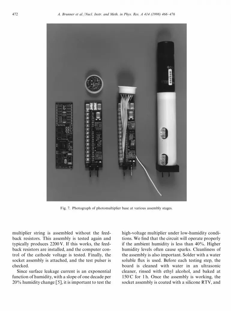
Fig. 7. Photograph of photomultiplier base at various assembly stages.
multiplier string is assembled without the feed-back resistors. This assembly is tested again andtypically produces 2200V. If this works, the feed-back resistors are installed, and the computer con-trol of the cathode voltage is tested. Finally, thesocket assembly is attached, and the test pulser ischecked.
Since surface leakage current is an exponentialfunction of humidity, with a slope of one decade per20% humidity change [5], it is important to test the
high-voltage multiplier under low-humidity condi-tions. We find that the circuit will operate properlyif the ambient humidity is less than 40%. Higherhumidity levels often cause sparks. Cleanliness ofthe assembly is also important. Solder with a watersoluble flux is used. Before each testing step, theboard is cleaned with water in an ultrasoniccleaner, rinsed with ethyl alcohol, and baked at150"C for 1 h. Once the assembly is working, thesocket assembly is coated with a silicone RTV, and
472 A. Brunner et al. /Nucl. Instr. and Meth. in Phys. Res. A 414 (1998) 466—476

Fig. 8. Photomultiplier anode output current linearity. Fig. 10. Self-test pulse amplitude versus cathode voltage.
Fig. 9. Photomultiplier gain versus cathode voltage.
the main circuit board is coated with an acrylicpaint. Once coated, the base will operate reliably inrelative humidity levels over 60%.
5. Performance
5.1. Linearity test
Any PMT base will have a maximum anode out-put current after which the response becomes nonlin-ear due to changing potentials at the last few dynodes.Light from a green LED was measured by a photo-diode and compared to the PMT output current. Theresults are shown in Fig. 8, and are linear up to'100lA. In our application detector channels nearthe beam axis experience a rate of &10KHz, withtypical signal pulses containing a charge of&100pC,yielding an average output current of 1lA.
If a higher average output current were desired,the Cockcroft—Walton multiplier chain could besplit into three sections and the voltages on the lastfew dynodes could be regulated in addition to thecathode and first dynode voltages. It might also benecessary, in that case, to use larger capacitorsand/or a higher switching frequency.
5.2. Pulsed laser tests
Prototype bases were tested in a 25 element leadglass calorimeter. A 5]5 array of lead glass blockswas wrapped in an aluminized mylar that optically
A. Brunner et al. /Nucl. Instr. and Meth. in Phys. Res. A 414 (1998) 466—476 473

Fig. 11. Typical pedestal event distribution (ADC response"0.25 pC/count).
Fig. 12. Pedestal width versus cathode voltage.
isolated each block. A nitrogen laser excited a scin-tillator producing light pulses which were sentthrough a fiber optic cable attached to a plexiglasssheet that illuminated the entire front face of theglass [4].
The bases were exercised in the above setupunder computer control. Tests were conducted atsix different voltage settings within the optimumoperating range (between 1500 and 2000V) of eachbase. The gain of each channel was determined byestimating the number of photoelectrons from thewidths of the laser response distributions. A typicalgain versus high-voltage plot is shown in Fig. 9.The selftest pulse height of each base was examined,as were the pedestal widths. The behavior seen inthese tests is shown in Figs. 10—12.
During long-term runs, light pulse events, baseself-test events, and pedestal events were recordedevery 20min. The variations of these characteristicsduring a long run are shown in Fig. 13.
5.3. Beam test
The first engineering runs of the Radphi experi-ment used the Cockcroft—Walton bases and tookplace at the Thomas Jefferson National AcceleratorFacility’s Hall B. A tagged Brehmstrahlung photonbeam was generated from a 4.045GeV electronbeam.
The photon beam interacted in an 8% radiationlength berylium target. A double row of scintil-lators detected the recoil proton for reactions of thesort cpPX
/%653!-p, positioned to optimize for X be-
ing a /. The electromagnetic calorimeter waslocated 1.1m downstream of the target. A veto wallof scintillator paddles just in front of the lead glassvetoed all events with a charged particle.
The trigger required a recoil proton, no chargedparticles in the veto wall, a coincidence from thephoton tagger, and a minimum energy deposited inthe calorimeter. Fig. 14 shows a plot of the two-photon effective mass for events in which two clus-ters were reconstructed. Additional software cutswere applied: '1GeV total energy was requiredin the glass, each cluster was required to be'0.15GeV, and the events with clusters within
474 A. Brunner et al. /Nucl. Instr. and Meth. in Phys. Res. A 414 (1998) 466—476
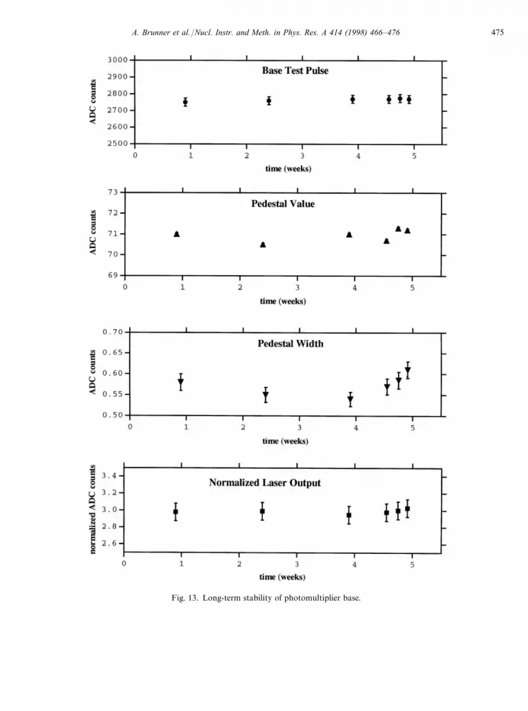
Fig. 13. Long-term stability of photomultiplier base.
A. Brunner et al. /Nucl. Instr. and Meth. in Phys. Res. A 414 (1998) 466—476 475
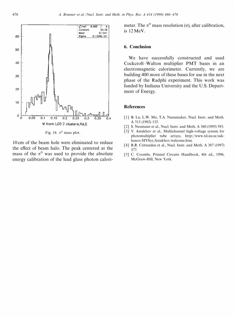
Fig. 14. n0 mass plot.
10 cm of the beam hole were eliminated to reducethe effect of beam halo. The peak centered at themass of the n0 was used to provide the absoluteenergy calibration of the lead glass photon calori-
meter. The n0 mass resolution (p), after calibration,is 12MeV.
6. Conclusion
We have successfully constructed and usedCockcroft—Walton multiplier PMT bases in anelectromagnetic calorimeter. Currently, we arebuilding 400 more of these bases for use in the nextphase of the Radphi experiment. This work wasfunded by Indiana University and the U.S. Depart-ment of Energy.
References
[1] B. Lu, L.W. Mo, T.A. Nunamaker, Nucl. Instr. and Meth.A 313 (1992) 135.
[2] S. Neumaier et al., Nucl. Instr. and Meth. A 360 (1995) 593.[3] V. Astakhov et al., Multichannel high-voltage system for
photomultiplier tube arrays, http://www.tsl.uu.se/suk-hanov/HVSys/Astakhov/welcome.htm.
[4] R.R. Crittenden et al., Nucl. Instr. and Meth. A 387 (1997)377.
[5] C. Coombs, Printed Circuits Handbook, 4th ed., 1996,McGraw-Hill, New York.
476 A. Brunner et al. /Nucl. Instr. and Meth. in Phys. Res. A 414 (1998) 466—476