Embed Size (px)
Citation preview
Industrial Tube Fittings EuropeTechnical handbook/Catalogue 4100-9/UK
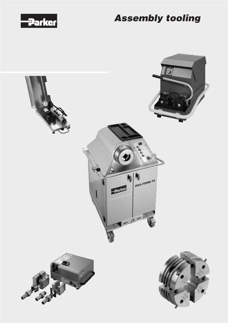
Assembly tooling
Assembly tooling
H2 Catalogue 4100-9/UK
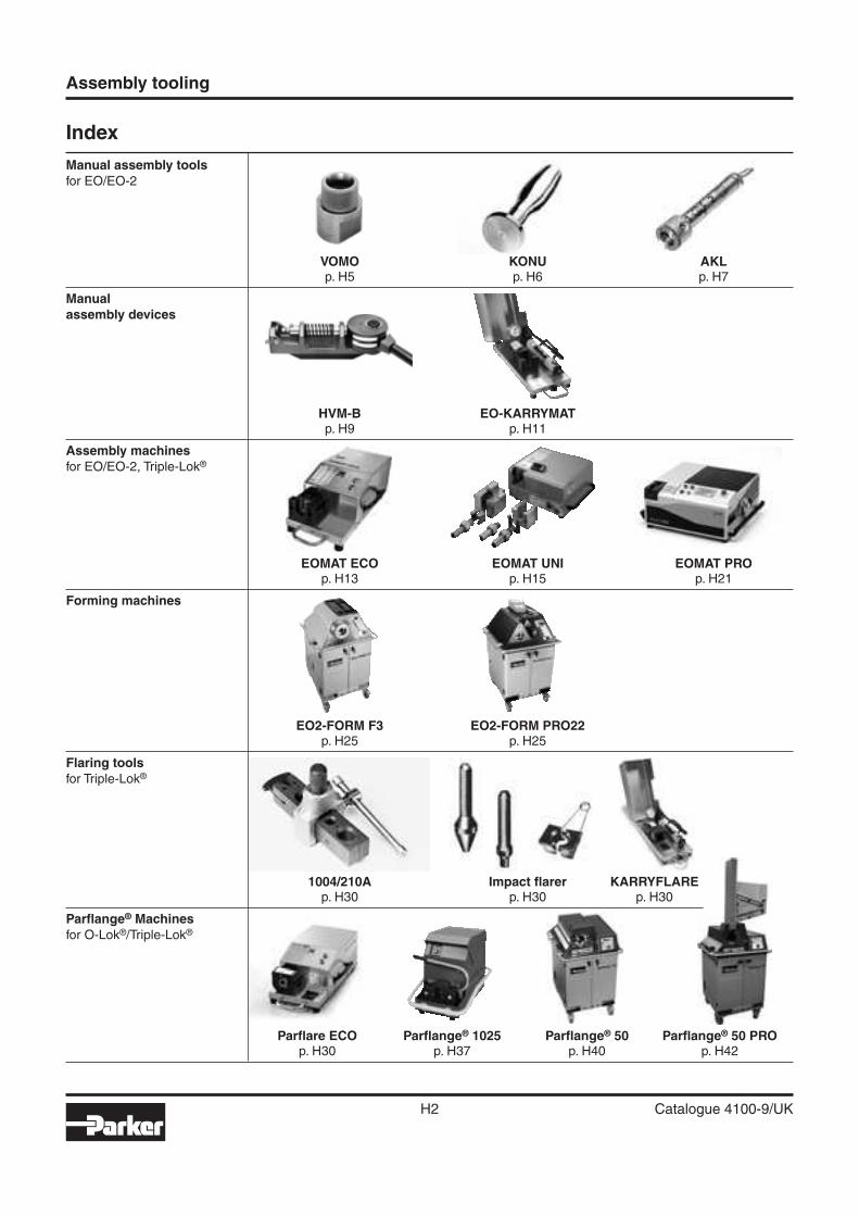
Index
Manual assembly toolsfor EO/EO-2
VOMO KONU AKL p. H5 p. H6 p. H7
Manualassembly devices
HVM-B EO-KARRYMAT p. H9 p. H11
Assembly machinesfor EO/EO-2, Triple-Lok®
EOMAT ECO EOMAT UNI EOMAT PRO p. H13 p. H15 p. H21
Forming machines
EO2-FORM F3 EO2-FORM PRO22 p. H25 p. H25
Flaring toolsfor Triple-Lok®
1004/210A Impact fl arer KARRYFLARE p. H30 p. H30 p. H30
Parfl ange® Machinesfor O-Lok®/Triple-Lok®
Parfl are ECO Parfl ange® 1025 Parfl ange® 50 Parfl ange® 50 PRO p. H30 p. H37 p. H40 p. H42
H
Assembly tooling
H3 Catalogue 4100-9/UK
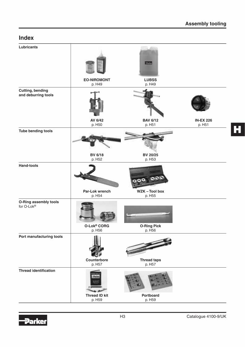
Index
Lubricants
EO-NIROMONT LUBSS p. H49 p. H49
Cutting, bendingand deburring tools
AV 6/42 BAV 6/12 IN-EX 226 p. H50 p. H51 p. H51
Tube bending tools
BV 6/18 BV 20/25 p. H52 p. H53
Hand-tools
Par-Lok wrench WZK – Tool box p. H54 p. H55
O-Ring assembly toolsfor O-Lok®
O-Lok® CORG O-Ring Pick p. H56 p. H56
Port manufacturing tools
Counterbore Thread taps p. H57 p. H57
Thread identifi cation
Thread ID kit Portboard p. H59 p. H59
Assembly tooling
H4 Catalogue 4100-9/UK
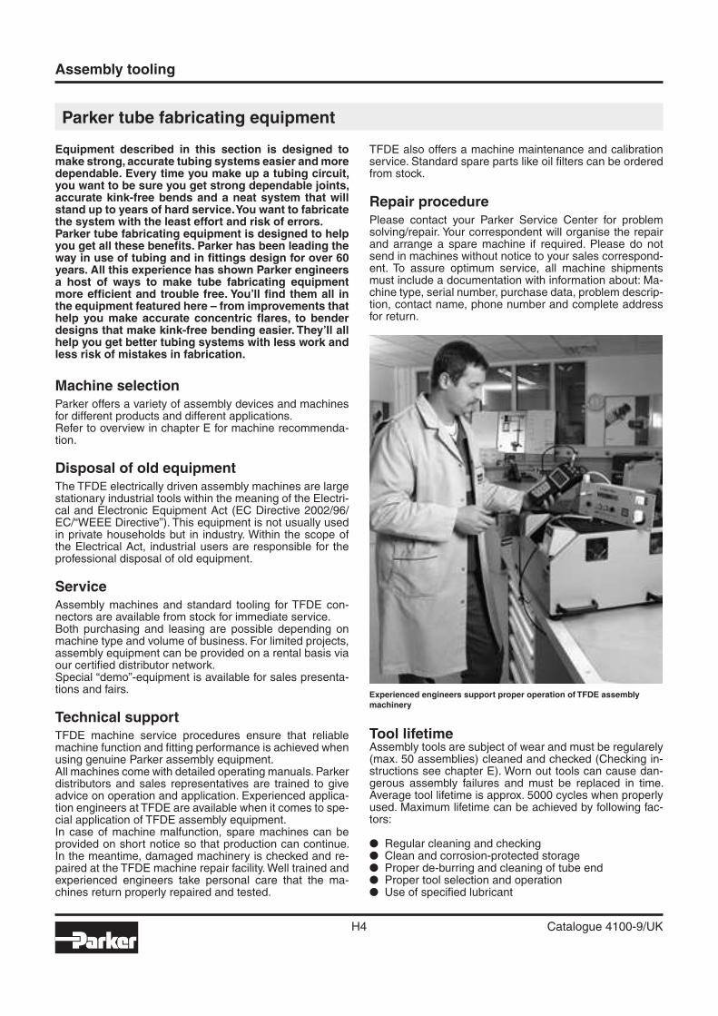
Experienced engineers support proper operation of TFDE assembly machinery
Parker tube fabricating equipment
Equipment described in this section is designed to make strong, accurate tubing systems easier and more dependable. Every time you make up a tubing circuit, you want to be sure you get strong dependable joints, accurate kink-free bends and a neat system that will stand up to years of hard service. You want to fabricate the system with the least effort and risk of errors.Parker tube fabricating equipment is designed to help you get all these benefi ts. Parker has been leading the way in use of tubing and in fi ttings design for over 60 years. All this experience has shown Parker engineers a host of ways to make tube fabricating equipment more effi cient and trouble free. You’ll fi nd them all in the equipment featured here – from improvements that help you make accurate concentric fl ares, to bender designs that make kink-free bending easier. They’ll all help you get better tubing systems with less work and less risk of mistakes in fabrication.
Machine selectionParker offers a variety of assembly devices and machines for different products and different applications.Refer to overview in chapter E for machine recommenda-tion.
Disposal of old equipmentThe TFDE electrically driven assembly machines are large stationary industrial tools within the meaning of the Electri-cal and Electronic Equipment Act (EC Directive 2002/96/EC/“WEEE Directive”). This equipment is not usually used in private households but in industry. Within the scope of the Electrical Act, industrial users are responsible for the professional disposal of old equipment.
ServiceAssembly machines and standard tooling for TFDE con-nectors are available from stock for immediate service.Both purchasing and leasing are possible depending on machine type and volume of business. For limited projects, assembly equipment can be provided on a rental basis via our certifi ed distributor network.Special “demo”-equipment is available for sales presenta-tions and fairs.
Technical supportTFDE machine service procedures ensure that reliable machine function and fi tting performance is achieved when using genuine Parker assembly equipment. All machines come with detailed operating manuals. Parker distributors and sales representatives are trained to give advice on operation and application. Experienced applica-tion engineers at TFDE are available when it comes to spe-cial application of TFDE assembly equipment.In case of machine malfunction, spare machines can be provided on short notice so that production can continue. In the meantime, damaged machinery is checked and re-paired at the TFDE machine repair facility. Well trained and experienced engineers take personal care that the ma-chines return properly repaired and tested.
TFDE also offers a machine maintenance and calibration service. Standard spare parts like oil fi lters can be ordered from stock.
Repair procedurePlease contact your Parker Service Center for problem solving/repair. Your correspondent will organise the repair and arrange a spare machine if required. Please do not send in machines without notice to your sales correspond-ent. To assure optimum service, all machine shipments must include a documentation with information about: Ma-chine type, serial number, purchase data, problem descrip-tion, contact name, phone number and complete address for return.
Tool lifetimeAssembly tools are subject of wear and must be regularely (max. 50 assemblies) cleaned and checked (Checking in-structions see chapter E). Worn out tools can cause dan-gerous assembly failures and must be replaced in time. Average tool lifetime is approx. 5000 cycles when properly used. Maximum lifetime can be achieved by following fac-tors:
� Regular cleaning and checking� Clean and corrosion-protected storage� Proper de-burring and cleaning of tube end� Proper tool selection and operation� Use of specifi ed lubricant
H
Assembly tooling
H5 Catalogue 4100-9/UK
1) Cone-templates for tube O.D.6 to 12 mm are identical in series L and S.
Manual assembly tools for EO/EO-2
VOMO – Pre-assembly tools for EO/EO-2 tube connections
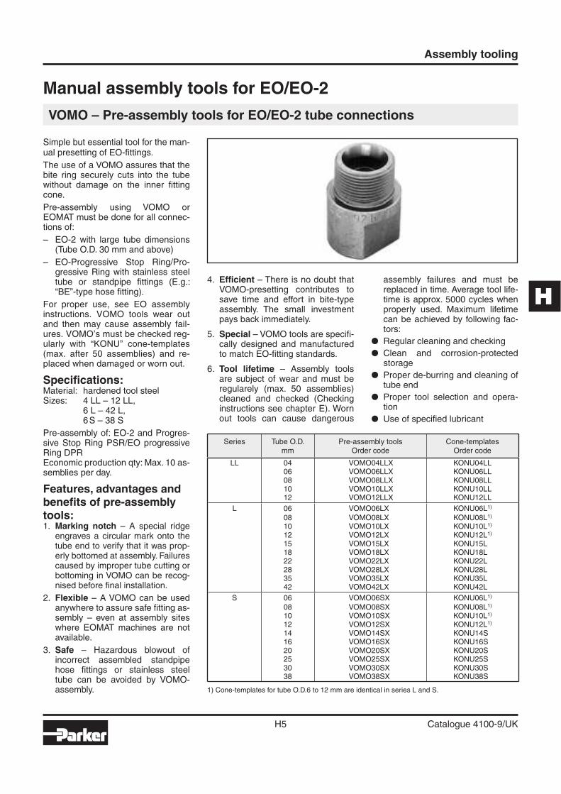
Simple but essential tool for the man-ual presetting of EO-fi ttings.
The use of a VOMO assures that the bite ring securely cuts into the tube without damage on the inner fi tting cone.
Pre-assembly using VOMO orEOMAT must be done for all connec-tions of:
– EO-2 with large tube dimensions (Tube O.D. 30 mm and above)
– EO-Progressive Stop Ring/Pro-gressive Ring with stainless steel tube or standpipe fi ttings (E.g.: “BE”-type hose fi tting).
For proper use, see EO assembly instructions. VOMO tools wear out and then may cause assembly fail-ures. VOMO’s must be checked reg-ularly with “KONU” cone-templates (max. after 50 assemblies) and re-placed when damaged or worn out.
Specifi cations:Material: hardened tool steelSizes: 4 LL – 12 LL,
6 L – 42 L,6 S – 38 S
Pre-assembly of: EO-2 and Progres-sive Stop Ring PSR/EO progressive Ring DPREconomic production qty: Max. 10 as-semblies per day.
Features, advantages and benefi ts of pre-assembly tools:1. Marking notch – A special ridge
engraves a circular mark onto the tube end to verify that it was prop-erly bottomed at assembly. Failures caused by improper tube cutting or bottoming in VOMO can be recog-nised before fi nal installation.
2. Flexible – A VOMO can be used anywhere to assure safe fi tting as-sembly – even at assembly sites where EOMAT machines are not available.
3. Safe – Hazardous blowout of incorrect assembled standpipe hose fi ttings or stainless steel tube can be avoided by VOMO-assembly.
4. Effi cient – There is no doubt that VOMO-presetting contributes to save time and effort in bite-type assembly. The small investment pays back immediately.
5. Special – VOMO tools are specifi -cally designed and manufactured to match EO-fi tting standards.
6. Tool lifetime – Assembly tools are subject of wear and must be regularely (max. 50 assemblies) cleaned and checked (Checking instructions see chapter E). Worn out tools can cause dangerous
assembly failures and must be replaced in time. Average tool life-time is approx. 5000 cycles when properly used. Maximum lifetime can be achieved by following fac-tors:
� Regular cleaning and checking
� Clean and corrosion-protected storage
� Proper de-burring and cleaning of tube end
� Proper tool selection and opera-tion
� Use of specifi ed lubricant
Series Tube O.D.mm
Pre-assembly toolsOrder code
Cone-templatesOrder code
LL 04 VOMO04LLX KONU04LL06 VOMO06LLX KONU06LL08 VOMO08LLX KONU08LL10 VOMO10LLX KONU10LL12 VOMO12LLX KONU12LL
L 06 VOMO06LX KONU06L1)
08 VOMO08LX KONU08L1)
10 VOMO10LX KONU10L1)
12 VOMO12LX KONU12L1)
15 VOMO15LX KONU15L18 VOMO18LX KONU18L22 VOMO22LX KONU22L28 VOMO28LX KONU28L35 VOMO35LX KONU35L42 VOMO42LX KONU42L
S 06 VOMO06SX KONU06L1)
08 VOMO08SX KONU08L1)
10 VOMO10SX KONU10L1)
12 VOMO12SX KONU12L1)
14 VOMO14SX KONU14S16 VOMO16SX KONU16S20 VOMO20SX KONU20S25 VOMO25SX KONU25S30 VOMO30SX KONU30S38 VOMO38SX KONU38S
Assembly tooling
H6 Catalogue 4100-9/UK
1) Cone-templates for tube o.d. 6 to 12 are identical in series L and S.
KONU – Cone-template for tools VOMO/MOK/MOSI
Selection guide: Checking equipment for EO assembly
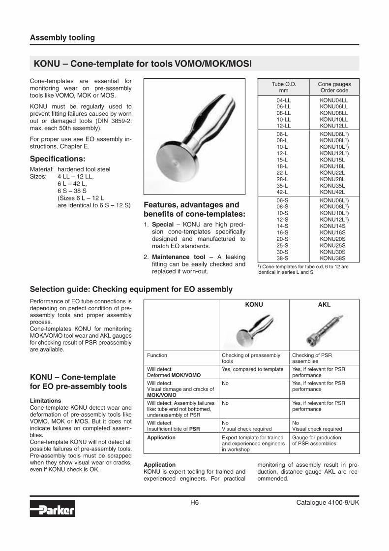
Cone-templates are essential for monitoring wear on pre-assembly tools like VOMO, MOK or MOS.
KONU must be regularly used to prevent fi tting failures caused by worn out or damaged tools (DIN 3859-2: max. each 50th assembly).
For proper use see EO assembly in-structions, Chapter E.
Specifi cations:
Material: hardened tool steelSizes: 4 LL – 12 LL, 6 L – 42 L, 6 S – 38 S (Sizes 6 L – 12 L are identical to 6 S – 12 S) Features, advantages and
benefi ts of cone-templates:
1. Special – KONU are high preci-sion cone-templates specifi cally designed and manufactured to match EO standards.
2. Maintenance tool – A leaking fi tting can be easily checked and replaced if worn-out.
Performance of EO tube connections is depending on perfect condition of pre-assembly tools and proper assembly process.Cone-templates KONU for monitoring MOK/VOMO tool wear and AKL gauges for checking result of PSR preassembly are available.
Tube O.D.mm
Cone gaugesOrder code
04-LL KONU04LL06-LL KONU06LL08-LL KONU08LL10-LL KONU10LL12-LL KONU12LL
06-L KONU06L1)08-L KONU08L1)10-L KONU10L1)12-L KONU12L1)15-L KONU15L18-L KONU18L22-L KONU22L28-L KONU28L35-L KONU35L42-L KONU42L
06-S KONU06L1)08-S KONU08L1)10-S KONU10L1)12-S KONU12L1)14-S KONU14S16-S KONU16S20-S KONU20S25-S KONU25S30-S KONU30S38-S KONU38S
KONU – Cone-templatefor EO pre-assembly tools
LimitationsCone-template KONU detect wear and deformation of pre-assembly tools like VOMO, MOK or MOS. But it does not indicate failures on completed assem-blies.Cone-template KONU will not detect all possible failures of pre-assembly tools. Pre-assembly tools must be scrapped when they show visual wear or cracks, even if KONU check is OK.
ApplicationKONU is expert tooling for trained and experienced engineers. For practical
monitoring of assembly result in pro-duction, distance gauge AKL are rec-ommended.
KONU AKL
Function Checking of preassembly tools
Checking of PSRassemblies
Will detect:Deformed MOK/VOMO
Yes, compared to template Yes, if relevant for PSR performance
Will detect:Visual damage and cracks of MOK/VOMO
No Yes, if relevant for PSR performance
Will detect: Assembly failures like: tube end not bottomed, underassembly of PSR
No Yes, if relevant for PSR performance
Will detect:Insuffi cient bite of PSR
NoVisual check required
NoVisual check required
Application Expert template for trained and experienced engineers in workshop
Gauge for productionof PSR assemblies
H
Assembly tooling
H7 Catalogue 4100-9/UK
Distance Gauge for Assembly AKL
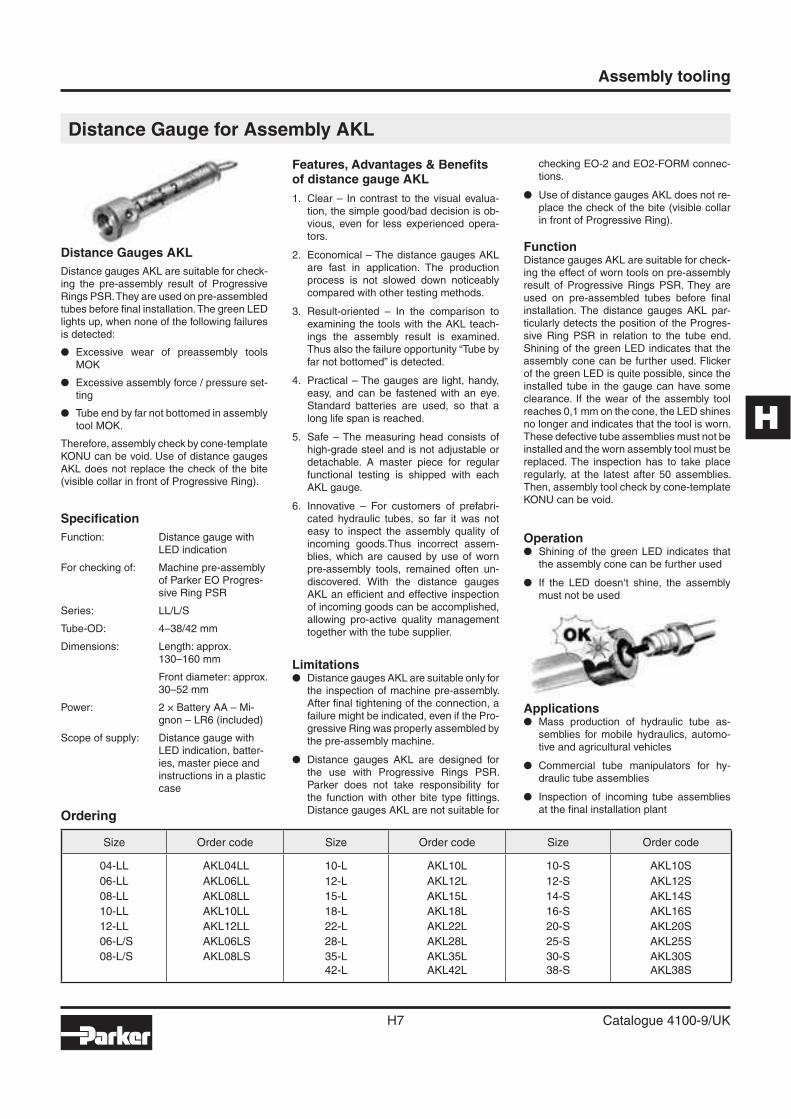
Distance Gauges AKL
Distance gauges AKL are suitable for check-ing the pre-assembly result of Progressive Rings PSR. They are used on pre-assembled tubes before fi nal installation. The green LED lights up, when none of the following failures is detected:
� Excessive wear of preassembly tools MOK
� Excessive assembly force / pressure set-ting
� Tube end by far not bottomed in assembly tool MOK.
Therefore, assembly check by cone-template KONU can be void. Use of distance gauges AKL does not replace the check of the bite (visible collar in front of Progressive Ring).
Specifi cation
Function: Distance gauge with LED indication
For checking of: Machine pre-assembly of Parker EO Progres-sive Ring PSR
Series: LL/L/S
Tube-OD: 4–38/42 mm
Dimensions: Length: approx. 130–160 mm
Front diameter: approx. 30–52 mm
Power: 2 × Battery AA – Mi-gnon – LR6 (included)
Scope of supply: Distance gauge with LED indication, batter-ies, master piece and instructions in a plastic case
Features, Advantages & Benefi ts of distance gauge AKL
1. Clear – In contrast to the visual evalua-tion, the simple good/bad decision is ob-vious, even for less experienced opera-tors.
2. Economical – The distance gauges AKL are fast in application. The production process is not slowed down noticeably compared with other testing methods.
3. Result-oriented – In the comparison to examining the tools with the AKL teach-ings the assembly result is examined. Thus also the failure opportunity “Tube by far not bottomed” is detected.
4. Practical – The gauges are light, handy, easy, and can be fastened with an eye. Standard batteries are used, so that a long life span is reached.
5. Safe – The measuring head consists of high-grade steel and is not adjustable or detachable. A master piece for regular functional testing is shipped with each AKL gauge.
6. Innovative – For customers of prefabri-cated hydraulic tubes, so far it was not easy to inspect the assembly quality of incoming goods.Thus incorrect assem-blies, which are caused by use of worn pre-assembly tools, remained often un-discovered. With the distance gauges AKL an effi cient and effective inspection of incoming goods can be accomplished, allowing pro-active quality management together with the tube supplier.
Limitations� Distance gauges AKL are suitable only for
the inspection of machine pre-assembly. After fi nal tightening of the connection, a failure might be indicated, even if the Pro-gressive Ring was properly assembled by the pre-assembly machine.
� Distance gauges AKL are designed for the use with Progressive Rings PSR. Parker does not take responsibility for the function with other bite type fi ttings. Distance gauges AKL are not suitable for
checking EO-2 and EO2-FORM connec-tions.
� Use of distance gauges AKL does not re-place the check of the bite (visible collar in front of Progressive Ring).
FunctionDistance gauges AKL are suitable for check-ing the effect of worn tools on pre-assembly result of Progressive Rings PSR. They are used on pre-assembled tubes before fi nal installation. The distance gauges AKL par-ticularly detects the position of the Progres-sive Ring PSR in relation to the tube end. Shining of the green LED indicates that the assembly cone can be further used. Flicker of the green LED is quite possible, since the installed tube in the gauge can have some clearance. If the wear of the assembly tool reaches 0,1 mm on the cone, the LED shines no longer and indicates that the tool is worn. These defective tube assemblies must not be installed and the worn assembly tool must be replaced. The inspection has to take place regularly, at the latest after 50 assemblies. Then, assembly tool check by cone-template KONU can be void.
Operation� Shining of the green LED indicates that
the assembly cone can be further used
� If the LED doesn‘t shine, the assembly must not be used
Applications� Mass production of hydraulic tube as-
semblies for mobile hydraulics, automo-tive and agricultural vehicles
� Commercial tube manipulators for hy-draulic tube assemblies
� Inspection of incoming tube assemblies at the fi nal installation plant
Ordering
Size Order code Size Order code Size Order code
04-LL AKL04LL 10-L AKL10L 10-S AKL10S
06-LL AKL06LL 12-L AKL12L 12-S AKL12S
08-LL AKL08LL 15-L AKL15L 14-S AKL14S
10-LL AKL10LL 18-L AKL18L 16-S AKL16S
12-LL AKL12LL 22-L AKL22L 20-S AKL20S
06-L/S AKL06LS 28-L AKL28L 25-S AKL25S
08-L/S AKL08LS 35-L AKL35L 30-S AKL30S
42-L AKL42L 38-S AKL38S
Assembly tooling
H8 Catalogue 4100-9/UK
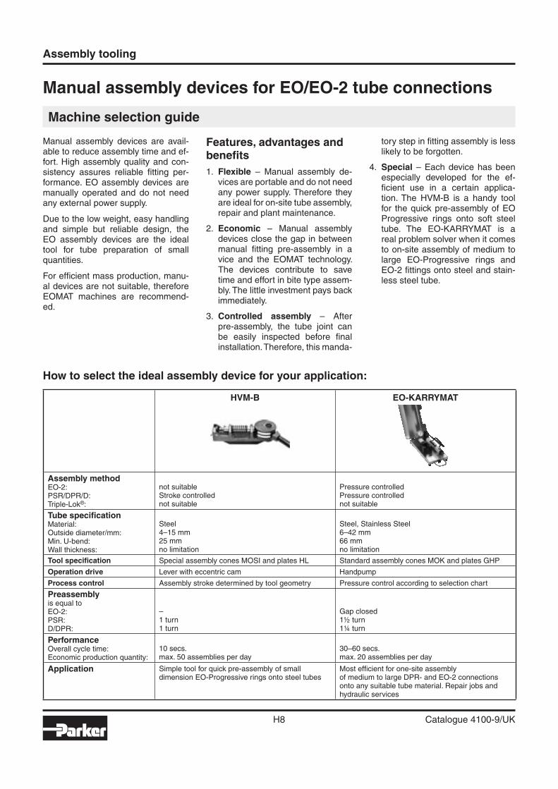
How to select the ideal assembly device for your application:
Manual assembly devices for EO/EO-2 tube connections
Machine selection guide
Manual assembly devices are avail-able to reduce assembly time and ef-fort. High assembly quality and con-sistency assures reliable fi tting per-formance. EO assembly devices are manually operated and do not need any external power supply.
Due to the low weight, easy handling and simple but reliable design, the EO assembly devices are the ideal tool for tube preparation of small quantities.
For effi cient mass production, manu-al devices are not suitable, therefore EOMAT machines are recommend-ed.
Features, advantages and benefi ts
1. Flexible – Manual assembly de-vices are portable and do not need any power supply. Therefore they are ideal for on-site tube assembly, repair and plant maintenance.
2. Economic – Manual assembly devices close the gap in between manual fi tting pre-assembly in a vice and the EOMAT technology. The devices contribute to save time and effort in bite type assem-bly. The little investment pays back immediately.
3. Controlled assembly – After pre-assembly, the tube joint can be easily inspected before fi nal installation. Therefore, this manda-
tory step in fi tting assembly is less likely to be forgotten.
4. Special – Each device has been especially developed for the ef-fi cient use in a certain applica-tion. The HVM-B is a handy tool for the quick pre-assembly of EO Progressive rings onto soft steel tube. The EO-KARRYMAT is a real problem solver when it comes to on-site assembly of medium to large EO-Progressive rings and EO-2 fi ttings onto steel and stain-less steel tube.
HVM-B EO-KARRYMAT
Assembly methodEO-2:PSR/DPR/D:Triple-Lok®:
not suitableStroke controllednot suitable
Pressure controlledPressure controllednot suitable
Tube specifi cationMaterial:Outside diameter/mm:Min. U-bend:Wall thickness:
Steel4–15 mm25 mmno limitation
Steel, Stainless Steel6–42 mm66 mmno limitation
Tool specifi cation Special assembly cones MOSI and plates HL Standard assembly cones MOK and plates GHP
Operation drive Lever with eccentric cam Handpump
Process control Assembly stroke determined by tool geometry Pressure control according to selection chart
Preassemblyis equal toEO-2:PSR:D/DPR:
–1 turn1 turn
Gap closed1½ turn1¼ turn
PerformanceOverall cycle time:Economic production quantity:
10 secs.max. 50 assemblies per day
30–60 secs.max. 20 assemblies per day
Application Simple tool for quick pre-assembly of smalldimension EO-Progressive rings onto steel tubes
Most effi cient for one-site assemblyof medium to large DPR- and EO-2 connectionsonto any suitable tube material. Repair jobs andhydraulic services
H
Assembly tooling
H9 Catalogue 4100-9/UK
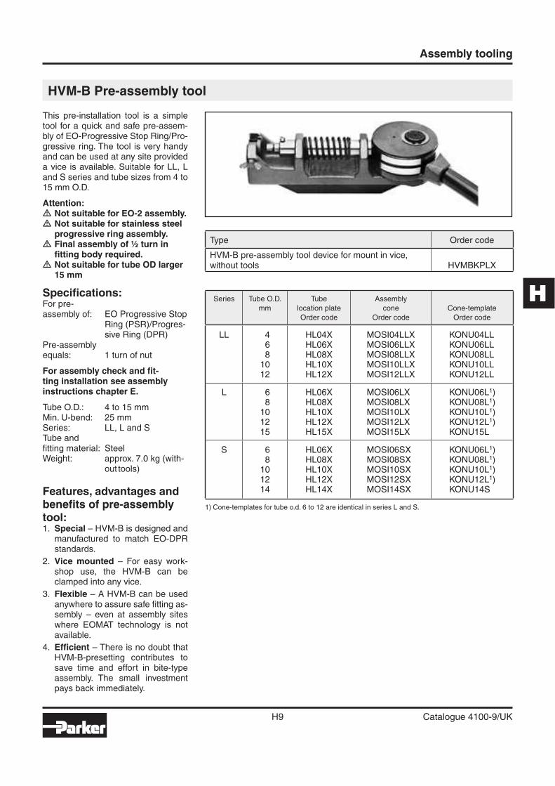
This pre-installation tool is a simple tool for a quick and safe pre-assem-bly of EO-Progressive Stop Ring/Pro-gressive ring. The tool is very handy and can be used at any site provided a vice is available. Suitable for LL, L and S series and tube sizes from 4 to 15 mm O.D.
Attention:� Not suitable for EO-2 assembly.� Not suitable for stainless steel progressive ring assembly.
� Final assembly of ½ turn in fi tting body required.
� Not suitable for tube OD larger 15 mm
Specifi cations:For pre-assembly of: EO Progressive Stop
Ring (PSR)/Progres-sive Ring (DPR)
Pre-assemblyequals: 1 turn of nut
For assembly check and fi t-ting installation see assembly instructions chapter E.
Tube O.D.: 4 to 15 mmMin. U-bend: 25 mmSeries: LL, L and STube andfi tting material: SteelWeight: approx. 7.0 kg (with-
out tools)
Features, advantages and benefi ts of pre-assembly tool:1. Special – HVM-B is designed and
manufactured to match EO-DPR standards.
2. Vice mounted – For easy work-shop use, the HVM-B can be clamped into any vice.
3. Flexible – A HVM-B can be used anywhere to assure safe fi tting as-sembly – even at assembly sites where EOMAT technology is not available.
4. Effi cient – There is no doubt that HVM-B-presetting contributes to save time and effort in bite-type assembly. The small investment pays back immediately.
HVM-B Pre-assembly tool
1) Cone-templates for tube o.d. 6 to 12 are identical in series L and S.
Type Order code
HVM-B pre-assembly tool device for mount in vice, without tools HVMBKPLX
Series Tube O.D.
mm
Tube
location plate
Order code
Assembly
cone
Order code
Cone-template
Order code
LL 4 HL04X MOSI04LLX KONU04LL6 HL06X MOSI06LLX KONU06LL8 HL08X MOSI08LLX KONU08LL
10 HL10X MOSI10LLX KONU10LL12 HL12X MOSI12LLX KONU12LL
L 6 HL06X MOSI06LX KONU06L1)8 HL08X MOSI08LX KONU08L1)
10 HL10X MOSI10LX KONU10L1)12 HL12X MOSI12LX KONU12L1)15 HL15X MOSI15LX KONU15L
S 6 HL06X MOSI06SX KONU06L1)8 HL08X MOSI08SX KONU08L1)
10 HL10X MOSI10SX KONU10L1)12 HL12X MOSI12SX KONU12L1)14 HL14X MOSI14SX KONU14S
1
2
3
4
5
Assembly tooling
H10 Catalogue 4100-9/UK
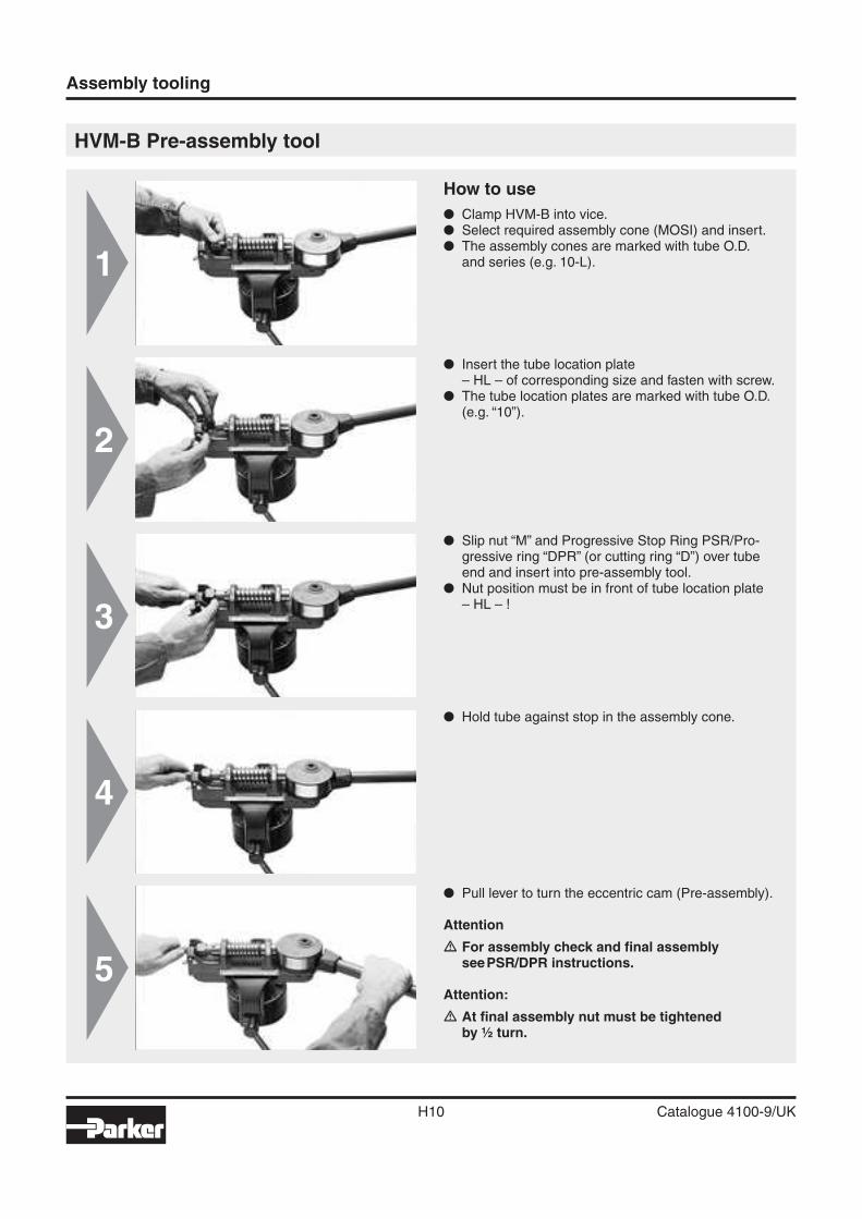
HVM-B Pre-assembly tool
� Hold tube against stop in the assembly cone.
How to use
� Clamp HVM-B into vice.� Select required assembly cone (MOSI) and insert.� The assembly cones are marked with tube O.D.
and series (e.g. 10-L).
� Slip nut “M” and Progressive Stop Ring PSR/Pro-gressive ring “DPR” (or cutting ring “D”) over tube end and insert into pre-assembly tool.
� Nut position must be in front of tube location plate– HL – !
� Insert the tube location plate– HL – of corresponding size and fasten with screw.
� The tube location plates are marked with tube O.D. (e.g. “10”).
� Pull lever to turn the eccentric cam (Pre-assembly).
Attention
� For assembly check and fi nal assembly see PSR/DPR instructions.
Attention:
� At fi nal assembly nut must be tightenedby ½ turn.
H
~ 30°
Assembly tooling
H11 Catalogue 4100-9/UK
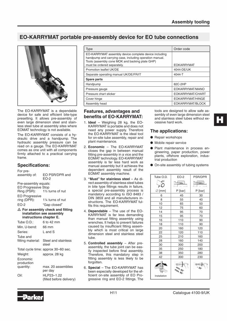
EO-KARRYMAT portable pre-assembly device for EO tube connections
The EO-KARRYMAT is a dependable device for safe and effi cient bite-type presetting. It allows pre-assembly of even large dimension steel and stain-less steel tube at assembly sites where EOMAT technology is not available.
The EO-KARRYMAT consists of a hy-draulic drive and a handpump. The hydraulic assembly pressure can be read on a gauge. The EO-KARRYMAT comes as one unit with all components fi rmly attached to a practical carrying frame.
Specifi cations:For pre-assembly of: EO PSR/DPR and
EO-2
Pre-assembly equals:EO Progressive StopRing (PSR): 1½ turns of nut
EO Progressivering (DPR): 1¼ turns of nut
EO-2 “Gap closed”
� For assembly check and fi tting installation see assembly instructions chapter E.
Tube O.D.: 6 to 42 mm
Min. U-bend: 66 mm
Series: L and S
Tube andfi tting material: Steel and stainless
steel
Total cycle time: approx 30–60 sec.
Weight: approx. 28 kg
Economicproductionquantity: max. 20 assemblies
per day
Oil: HLP23–1.22(fi lled before delivery)
Features, advantages and benefi ts of EO-KARRYMAT:1. Ideal – Weighing 28 kg, the EO-
KARRYMAT is portable and does not need any power supply. Therefore the EO-KARRYMAT is the ideal tool for on-site tube assembly, repair and plant maintenance.
2. Economic – The EO-KARRYMAT closes the gap in between manual fi tting pre-assembly in a vice and theEOMAT technology. EO- KARRYMAT assembly is far less hard work as manual assembly but it achieves the dependent assembly result of the EOMAT assembly machine.
3. “Must” for stainless steel – As di-rect assembly of stainless steel tubes in bite type fi ttings results in failure, a special pre-assembly process is mandatory according to ISO 8483 / DIN 3859 and all manufacturers in-structions. The EO-KARRY MAT ful-fi ls this requirement.
4. Dependable – The use of the EO-KARRYMAT is far less demanding than manual fi tting assembly using wrenches. It helps to prevent failures caused by insuffi ciant fi tting assem-bly which is most critical on large dimension steel and stainless steel tube.
5. Controlled assembly – After pre-assembly, the tube joint can be eas-ily inspected before fi nal assembly. Therefore, this mandatory step in fi tting assembly is less likely to be forgotten.
6. Special – The EO-KARRYMAT has been especially developed for the ef-fi cient on-site assembly of EO Pro-gressive ring and EO-2 fi ttings. The
tools are designed to allow safe as-sembly of even large dimension steel and stainless steel tubes without ex-cessive hard work.
The applications:
� Repair workshops
� Mobile repair service
� Plant maintenance in process en-gineering, paper production, power plants, offshore exploration, indus-trial production
� On-site assembly of tubing systems
min. 60°max. 90°
Type Order code
EO-KARRYMAT assembly device complete device includinghandpump and carrying case, including operation manual.Tools (assembly cone MOK and backing plate GHP)must be ordered separately. EOKARRYMAT
Promotion leafl et UK/DE 4044-DE/UK
Separate operating manual UK/DE/FR/IT 4044-T
Spare parts
Handpump 82C-2HP
Pressure gauge EOKARRYMAT/MANO
Pressure chart sticker EOKARRYMAT/CHART
Cover hinge EOKARRYMAT/HINGE
Assembly head EOKARRYMAT/BLOCK
Tube O.D.
� [mm]
EO-2
P [bar]
PSR/DPR
P [bar]
6 45 30
8 55 40
10 65 50
12 75 60
14 95 70
15 95 70
16 110 90
18 110 90
20 160 120
22 120 110
25 210 160
28 160 140
30 300 200
35 250 180
38 350 280
42 300 230
Installation
Assembly tooling
H12 Catalogue 4100-9/UK
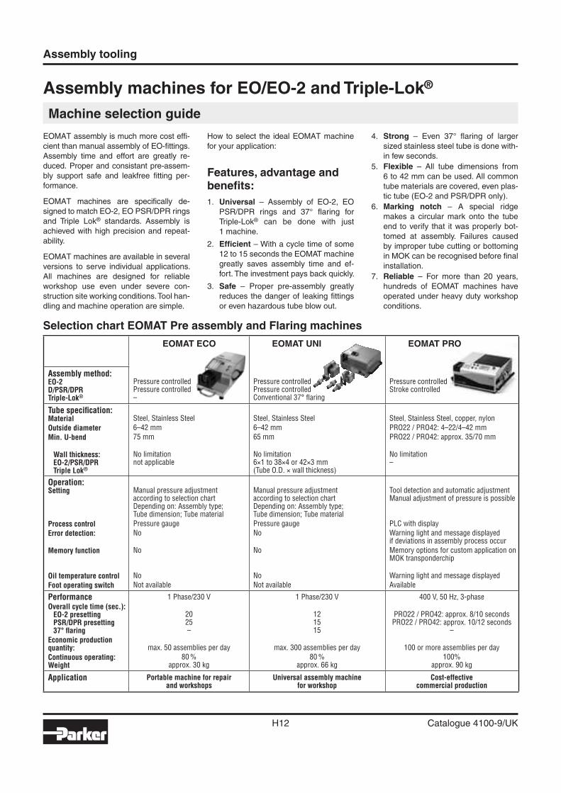
Assembly machines for EO/EO-2 and Triple-Lok®
Machine selection guide
EOMAT assembly is much more cost effi -
cient than manual assembly of EO-fi ttings.
Assembly time and effort are greatly re-
duced. Proper and consistant pre-assem-
bly support safe and leakfree fi tting per-
formance.
EOMAT machines are specifi cally de-
signed to match EO-2, EO PSR/DPR rings
and Triple Lok® standards. Assembly is
achieved with high precision and repeat-
ability.
EOMAT machines are available in several
versions to serve individual applications.
All machines are designed for reliable
workshop use even under severe con-
struction site working conditions. Tool han-
dling and machine operation are simple.
How to select the ideal EOMAT machine
for your application:
Features, advantage and benefi ts:
1. Universal – Assembly of EO-2, EO
PSR/DPR rings and 37° fl aring for
Triple-Lok® can be done with just
1 machine.
2. Effi cient – With a cycle time of some
12 to 15 seconds the EOMAT machine
greatly saves assembly time and ef-
fort. The investment pays back quickly.
3. Safe – Proper pre-assembly greatly
reduces the danger of leaking fi ttings
or even hazardous tube blow out.
4. Strong – Even 37° fl aring of larger
sized stainless steel tube is done with-
in few seconds.
5. Flexible – All tube dimensions from
6 to 42 mm can be used. All common
tube materials are covered, even plas-
tic tube (EO-2 and PSR/DPR only).
6. Marking notch – A special ridge
makes a circular mark onto the tube
end to verify that it was properly bot-
tomed at assembly. Failures caused
by improper tube cutting or bottoming
in MOK can be recog nised before fi nal
installation.
7. Reliable – For more than 20 years,
hundreds of EOMAT ma chines have
operated under heavy duty workshop
conditions.
Selection chart EOMAT Pre assembly and Flaring machines
EOMAT ECO EOMAT UNI EOMAT PRO
Assembly method:EO-2D/PSR/DPRTriple-Lok®
Pressure controlledPressure controlled–
Pressure controlledPressure controlledConventional 37° fl aring
Pressure controlledStroke controlled
Tube specifi cation:Material
Outside diameter
Min. U-bend
Wall thickness:EO-2/PSR/DPRTriple Lok®
Steel, Stainless Steel
6–42 mm
75 mm
No limitationnot applicable
Steel, Stainless Steel
6–42 mm
65 mm
No limitation6×1 to 38×4 or 42×3 mm(Tube O.D. × wall thickness)
Steel, Stainless Steel, copper, nylon
PRO22 / PRO42: 4–22/4–42 mm
PRO22 / PRO42: approx. 35/70 mm
No limitation–
Operation:Setting
Process control
Error detection:
Memory function
Oil temperature control
Foot operating switch
Manual pressure adjustmentaccording to selection chartDepending on: Assembly type;Tube dimension; Tube material
Pressure gauge
No
No
No
Not available
Manual pressure adjustmentaccording to selection chartDepending on: Assembly type;Tube dimension; Tube material
Pressure gauge
No
No
No
Not available
Tool detection and automatic adjustmentManual adjustment of pressure is possible
PLC with display
Warning light and message displayedif deviations in assembly process occur
Memory options for custom application on MOK transponderchip
Warning light and message displayed
Available
PerformanceOverall cycle time (sec.):EO-2 presettingPSR/DPR presetting37° fl aring
Economic productionquantity:
Continuous operating:Weight
1 Phase/230 V
2025–
max. 50 assemblies per day
80 %approx. 30 kg
1 Phase/230 V
121515
max. 300 assemblies per day
80 %approx. 66 kg
400 V, 50 Hz, 3-phase
PRO22 / PRO42: approx. 8/10 secondsPRO22 / PRO42: approx. 10/12 seconds
–
100 or more assemblies per day
100%approx. 90 kg
Application Portable machine for repairand workshops
Universal assembly machinefor workshop
Cost-effectivecommercial production
H
Assembly tooling
H13 Catalogue 4100-9/UK
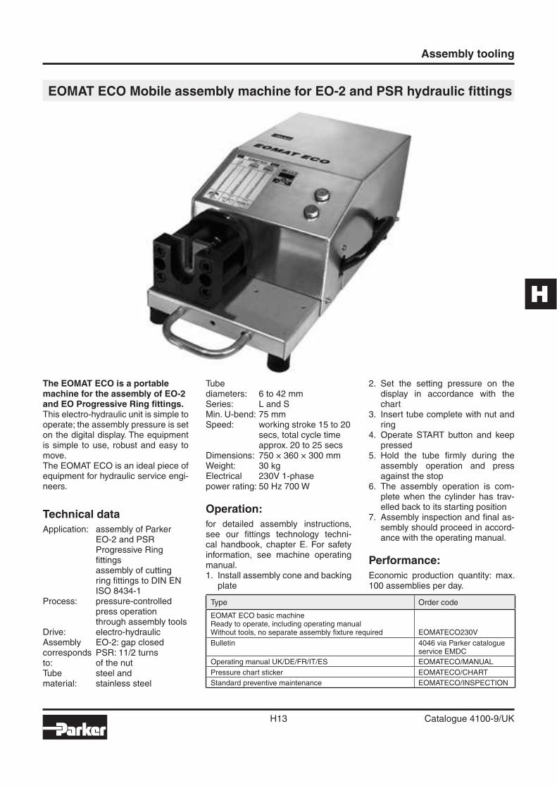
EOMAT ECO Mobile assembly machine for EO-2 and PSR hydraulic fi ttings
The EOMAT ECO is a portable machine for the assembly of EO-2 and EO Progressive Ring fi ttings.This electro-hydraulic unit is simple to operate; the assembly pressure is set on the digital display. The equipment is simple to use, robust and easy to move.The EOMAT ECO is an ideal piece of equipment for hydraulic service engi-neers.
Technical data
Application: assembly of Parker EO-2 and PSRProgressive Ring fi ttingsassembly of cutting ring fi ttings to DIN EN ISO 8434-1
Process: pressure-controlled press operation through assembly tools
Drive: electro-hydraulicAssembly EO-2: gap closedcorresponds PSR: 11/2 turnsto: of the nutTube steel andmaterial: stainless steel
Tubediameters: 6 to 42 mmSeries: L and SMin. U-bend: 75 mmSpeed: working stroke 15 to 20
secs, total cycle time approx. 20 to 25 secs
Dimensions: 750 × 360 × 300 mmWeight: 30 kgElectrical 230V 1-phasepower rating: 50 Hz 700 W
Operation:
for detailed assembly instructions, see our fi ttings technology techni-cal handbook, chapter E. For safety information, see machine operating manual.1. Install assembly cone and backing
plate
2. Set the setting pressure on the display in accordance with the chart
3. Insert tube complete with nut and ring
4. Operate START button and keep pressed
5. Hold the tube fi rmly during the assembly operation and press against the stop
6. The assembly operation is com-plete when the cylinder has trav-elled back to its starting position
7. Assembly inspection and fi nal as-sembly should proceed in accord-ance with the operating manual.
Performance:
Economic production quantity: max. 100 assemblies per day.
Type Order code
EOMAT ECO basic machineReady to operate, including operating manualWithout tools, no separate assembly fi xture required EOMATECO230V
Bulletin 4046 via Parker catalogueservice EMDC
Operating manual UK/DE/FR/IT/ES EOMATECO/MANUAL
Pressure chart sticker EOMATECO/CHART
Standard preventive maintenance EOMATECO/INSPECTION
~ 30°
Assembly tooling
H14 Catalogue 4100-9/UK
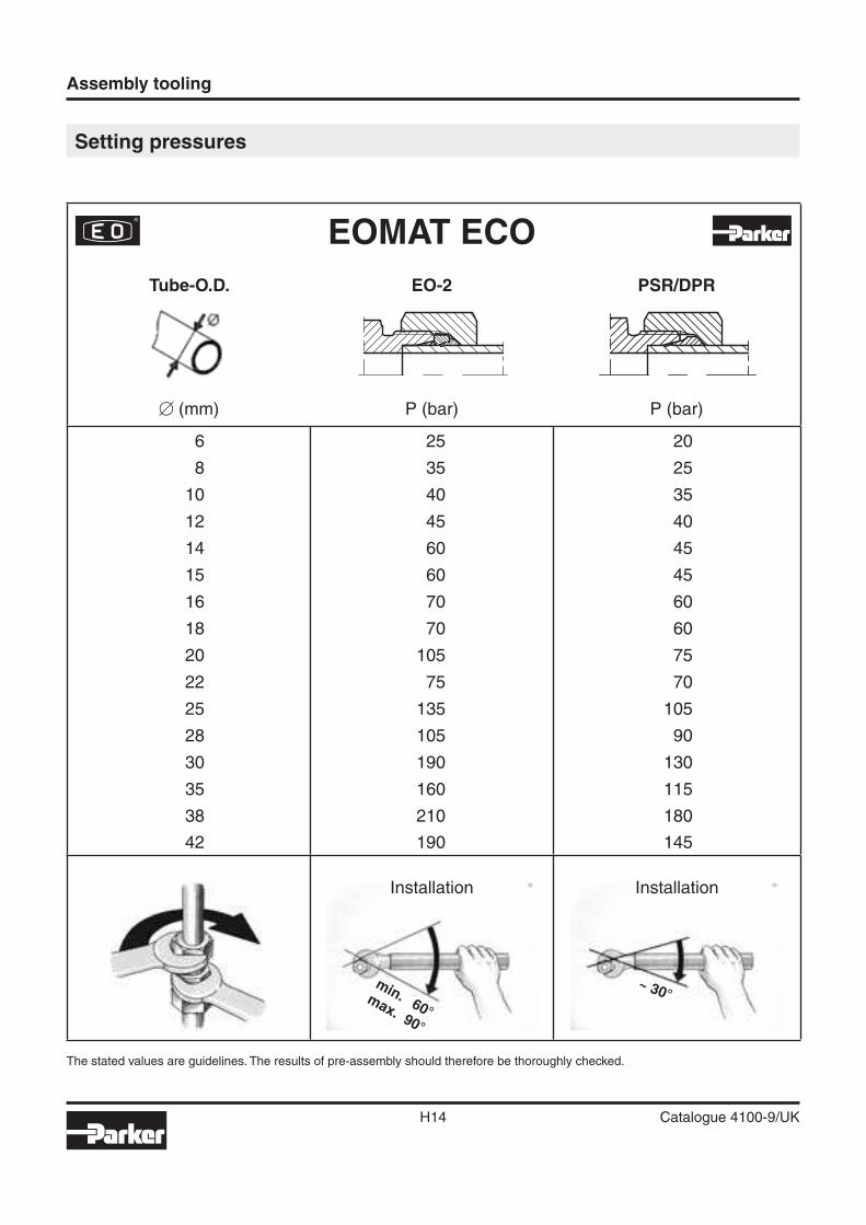
Setting pressures
The stated values are guidelines. The results of pre-assembly should therefore be thoroughly checked.
min. 60°max. 90°
EOMAT ECO
Tube-O.D.
� (mm)
EO-2
P (bar)
PSR/DPR
P (bar)
6 25 20
8 35 25
10 40 35
12 45 40
14 60 45
15 60 45
16 70 60
18 70 60
20 105 75
22 75 70
25 135 105
28 105 90
30 190 130
35 160 115
38 210 180
42 190 145
Installation Installation
H
Assembly tooling
H15 Catalogue 4100-9/UK
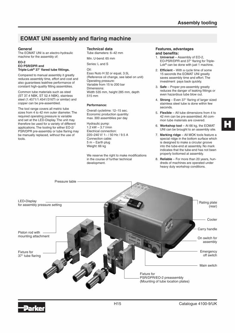
EOMAT UNI assembly and fl aring machine
GeneralThe EOMAT UNI is an electro-hydraulic machine for the assembly of:
EO-2EO PSR/DPR and Triple-Lok® 37° fl ared tube fi ttings.
Compared to manual assembly it greatly reduces assembly time, effort and cost and also guarantees leakfree performance of constant high-quality fi tting assemblies.
Common tube materials such as steel (ST 37.4 NBK, ST 52.4 NBK), stainless steel (1.4571/1.4541/316Ti or similar) and copper can be pre-assembled.
The tool range covers all metric tube sizes from 4 to 42 mm outer diameter. The required operating pressure is variable and set at the LED-Display. The unit may therefore be used for a variety of different applications. The tooling for either EO-2/PSR/DPR pre-assembly or tube fl aring may be manually replaced, without the use of tools.
Technical dataTube diameters: 6–42 mm
Min. U-bend: 65 mm
Series: L and S
Oil: Esso Nuto H 32 or equal, 3.5L (Reference oil change, see label on unit)Operating pressure:Variable from 15 to 200 barDimensions: Width 535 mm, height 285 mm, depth 515 mm
Performance:
Overall cycletime: 12–15 sec.Economic production quantity:max. 300 assemblies per day
Hydraulic pump:1.2 kW – 3.7 l/minElectrical connection:220–240 V/ 1~ / 50 Hz / 9.5 AConnection cable:5 m – Earth plugWeight: 66 kg
We reserve the right to make modifi cations in the course of further technical development.
Features, advantagesand benefi ts:1. Universal – Assembly of EO-2,
EO-PSR/DPR and 37° fl aring for Triple-Lok® can be done with just 1 machine.
2. Effi cient – With a cycle time of some 15 seconds the EOMAT UNI greatly saves assembly time and effort. The investment pays back quickly.
3. Safe – Proper pre-assembly greatly reduces the danger of leaking fi ttings or even hazardous tube blow out.
4. Strong – Even 37° fl aring of larger sized stainless steel tube is done within few seconds.
5. Flexible – All tube dimensions from 4 to 42 mm can be pre-assembled. All com-mon tube materials are covered.
6. Workshop tool – At 66 kg, the EOMAT UNI can be brought to an assembly site.
7. Marking ridge – All MOK tools feature a special ridge in the bottom surface which is designed to make a circular groove into the tube-end at assembly. No mark indicates that the tube-end has not been properly bottomed at assembly.
8. Reliable – For more than 20 years, hun-dreds of machines are operated under heavy duty workshop conditions.
Pressure table
LED-Displayfor assembly pressure setting
Piston rod withmounting attachment
Fixture for37° tube fl aring
Rating plate(rear)
Cooler
Carry handle
On switch forassembly
Emergencyoff switch
Main switch
Fixture forPSR/DPR/EO-2 preassembly(Mounting of tube location plates)
Assembly tooling
H16 Catalogue 4100-9/UK
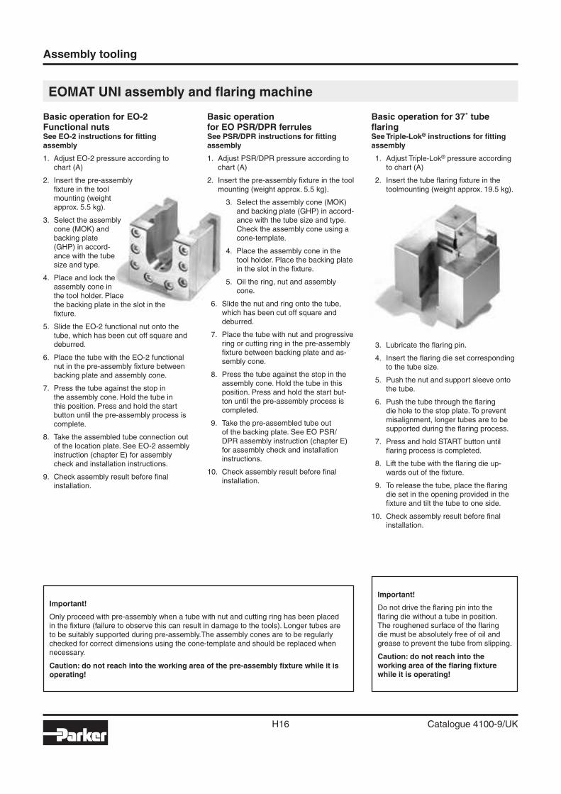
Basic operation for EO-2Functional nutsSee EO-2 instructions for fi tting assembly
1. Adjust EO-2 pressure according to chart (A)
2. Insert the pre-assemblyfi xture in the toolmounting (weightapprox. 5.5 kg).
3. Select the assemblycone (MOK) andbacking plate(GHP) in accord-ance with the tubesize and type.
4. Place and lock theassembly cone inthe tool holder. Placethe backing plate in the slot in thefi xture.
5. Slide the EO-2 functional nut onto the tube, which has been cut off square and deburred.
6. Place the tube with the EO-2 functional nut in the pre-assembly fi xture between backing plate and assembly cone.
7. Press the tube against the stop in the assembly cone. Hold the tube in this position. Press and hold the start button until the pre-assembly process is complete.
8. Take the assembled tube connection out of the location plate. See EO-2 assembly instruction (chapter E) for assembly check and installation instructions.
9. Check assembly result before fi nal installation.
Basic operationfor EO PSR/DPR ferrulesSee PSR/DPR instructions for fi tting assembly
1. Adjust PSR/DPR pressure according to chart (A)
2. Insert the pre-assembly fi xture in the tool mounting (weight approx. 5.5 kg).
3. Select the assembly cone (MOK) and backing plate (GHP) in accord-ance with the tube size and type. Check the assembly cone using a cone-template.
4. Place the assembly cone in the tool holder. Place the backing plate in the slot in the fi xture.
5. Oil the ring, nut and assembly cone.
6. Slide the nut and ring onto the tube, which has been cut off square and deburred.
7. Place the tube with nut and progressive ring or cutting ring in the pre-assembly fi xture between backing plate and as-sembly cone.
8. Press the tube against the stop in the assembly cone. Hold the tube in this position. Press and hold the start but-ton until the pre-assembly process is completed.
9. Take the pre-assembled tube out of the backing plate. See EO PSR/DPR assembly instruction (chapter E) for assembly check and installation instructions.
10. Check assembly result before fi nal installation.
Basic operation for 37˚ tube fl aringSee Triple-Lok® instructions for fi tting assembly
1. Adjust Triple-Lok® pressure according to chart (A)
2. Insert the tube fl aring fi xture in the toolmounting (weight approx. 19.5 kg).
3. Lubricate the fl aring pin.
4. Insert the fl aring die set corresponding to the tube size.
5. Push the nut and support sleeve onto the tube.
6. Push the tube through the fl aring die hole to the stop plate. To prevent misalignment, longer tubes are to be supported during the fl aring process.
7. Press and hold START button until fl aring process is completed.
8. Lift the tube with the fl aring die up-wards out of the fi xture.
9. To release the tube, place the fl aring die set in the opening provided in the fi xture and tilt the tube to one side.
10. Check assembly result before fi nal installation.
EOMAT UNI assembly and fl aring machine
Important!
Only proceed with pre-assembly when a tube with nut and cutting ring has been placed in the fi xture (failure to observe this can result in damage to the tools). Longer tubes are to be suitably supported during pre-assembly.The assembly cones are to be regularly checked for correct dimensions using the cone-template and should be replaced when necessary.
Caution: do not reach into the working area of the pre-assembly fi xture while it is operating!
Important!
Do not drive the fl aring pin into the fl aring die without a tube in position. The roughened surface of the fl aring die must be absolutely free of oil and grease to prevent the tube from slipping.
Caution: do not reach into the working area of the fl aring fi xture while it is operating!
H
~ 30°
Assembly tooling
H17 Catalogue 4100-9/UK
EOMAT UNI assembly and fl aring machine
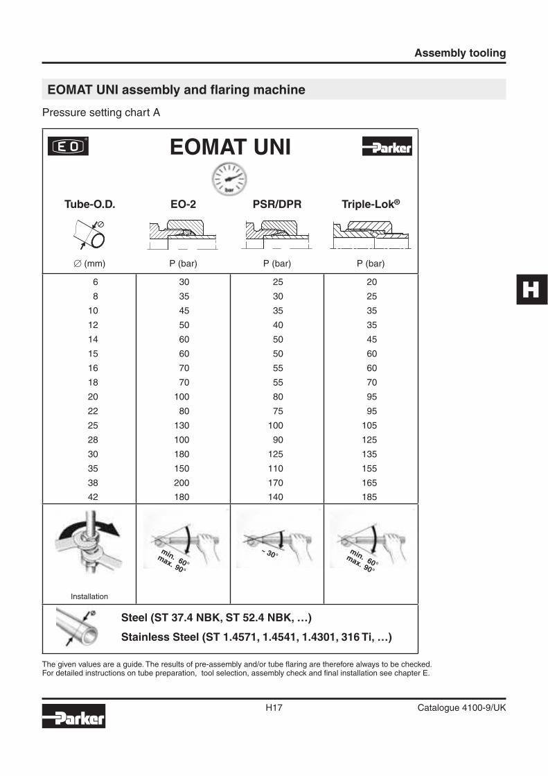
Pressure setting chart A
The given values are a guide. The results of pre-assembly and/or tube fl aring are therefore always to be checked.For detailed instructions on tube preparation, tool selection, assembly check and fi nal installation see chapter E.
min. 60°max. 90°
min. 60°max. 90°
EOMAT UNI
Tube-O.D.
� (mm)
EO-2
P (bar)
PSR/DPR
P (bar)
Triple-Lok®
P (bar)
6 30 25 20
8 35 30 25
10 45 35 35
12 50 40 35
14 60 50 45
15 60 50 60
16 70 55 60
18 70 55 70
20 100 80 95
22 80 75 95
25 130 100 105
28 100 90 125
30 180 125 135
35 150 110 155
38 200 170 165
42 180 140 185
Installation
Steel (ST 37.4 NBK, ST 52.4 NBK, …)
Stainless Steel (ST 1.4571, 1.4541, 1.4301, 316 Ti, …)
Assembly tooling
H18 Catalogue 4100-9/UK
EOMAT UNI assembly and fl aring machine
Ordering
Type Order code
EOMAT UNI Basic machineReady to use, including operation manualFilled with hydraulic oilWithout EO assembly fi xture/Flaring fi xtureWithout tools for EO-assembly/37˚ fl aringBasic machine 230 V, 1 Phase, 50 Hz EOMATUNI230V
Fixture for PSR/DPR/EO-2 assembly EOMATSCHNEIDRX
37° Flaring fi xture for Triple-Lok® including fl aring pin EOMATBOERDELBX
EOMAT UNI promotion leafl et UK 4042/UK
EOMAT UNI promotion leafl et DE 4042/DE
EOMAT UNI operating manual UK/DE/FR/IT EOMATUNI/MANUAL
Standard preventive maintenance EOMATUNI/INSPECTION
Assembly fi xtures, tools, cone-templates, and lubricant must be ordered separately
Assembly tools for PSR/DPR/EO-2 see page H19–H20.
37° fl aring tools for Triple-Lok® see page H30.
Spare parts
Type Order code
Fixing clip for MOK EOMAT/CLIP
37° fl aring pin EOMAT/FLAREPIN
O-ring for fl aring pin EOMAT/0212500
Tube stop assembly for fl aring block EOMAT/0213800
Pressure chart sticker EOMATUNI/CHART
Spring for fl aring block EOMAT/0213500
LED Display for pressure adjustment SCE-025-01
H
Assembly tooling
H19 Catalogue 4100-9/UK
EO PSR/DPR and EO-2 assembly tools for EOMAT/EO-KARRYMAT
Flaring tools see KARRYFLARE1) Backing plates, cone-templates and fl aring die sets for series L and S for tube outer diameter 6, 8, 10 and 12
are the same.2) Note: Two-part backing plates for tube OD 35 and 42.3) Assembly tools for LL-series for EOMAT UNI on request.4) Special MOK for easy tube insertion. MOK for EO-2 are marked with groove.
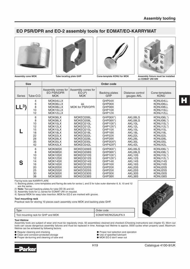
Tool mounting rackPractical rack for storing 10 pieces each assembly cone MOK and backing plate GHP.
Assembly cone MOK Tube locating plate GHP Cone-template KONU for MOK Assembly fi xture must be installed on EOMAT UNI II/III
Tool lifetime Assembly tools are subject of wear and must be regularely (max. 50 assemblies) cleaned and checked (Checking instructions see chapter E). Worn out tools can cause dangerous assembly failures and must be replaced in time. Average tool lifetime is approx. 5000 cycles when properly used. Maximum lifetime can be achieved by following factors:
� Regular cleaning and checking� Clean and corrosion-protected storage� Proper de-burring and cleaning of tube end
� Proper tool selection and operation� Use of specifi ed lubricant� MOK EO-2 don’t wear out
Type Order code
Tool mounting rack for GHP and MOK EOMATWERKZGAUFN.X
Size Order code
Series Tube-O.D.
Assembly cones forEO PSR/DPR
MOK
Assembly cones forEO-24)MOK
Backing platesGHP
Distance controlgauges AKL
Cone-templatesKONU
LL3)
4 MOK04LLX GHP04X KONU04LL6 MOK06LLX as GHP06X KONU06LL8 MOK08LLX MOK for PSR/DPR GHP08X KONU08LL
10 MOK10LLX GHP10X KONU10LL12 MOK12LLX GHP12X KONU12LL
L
6 MOK06LX MOKEO206L GHP06X1) AKL06LS KONU06L1)8 MOK08LX MOKEO208L GHP08X1) AKL08LS KONU08L1)
10 MOK10LX MOKEO210L GHP10X1) AKL10L KONU10L1)12 MOK12LX MOKEO212L GHP12X1) AKL12L KONU12L1)15 MOK15LX MOKEO215L GHP15X AKL15L KONU15L18 MOK18LX MOKEO218L GHP18X AKL18L KONU18L22 MOK22LX MOKEO222L GHP22X AKL22L KONU22L28 MOK28LX MOKEO228L GHP28X AKL28L KONU28L35 MOK35LX MOKEO235L GHP35X2) AKL35L KONU35L42 MOK42LX MOKEO242L GHP42X2) AKL42L KONU42L
S
6 MOK06SX MOKEO206S GHP06X1) AKL06LS KONU06L1)8 MOK08SX MOKEO208S GHP08X1) AKL08LS KONU08L1)
10 MOK10SX MOKEO210S GHP10X1) AKL10S KONU10L1)12 MOK12SX MOKEO212S GHP12X1) AKL12S KONU12L1)14 MOK14SX MOKEO214S GHP14X AKL14S KONU14S16 MOK16SX MOKEO216S GHP16X AKL16S KONU16S20 MOK20SX MOKEO220S GHP20X AKL20S KONU20S25 MOK25SX MOKEO225S GHP25X AKL25S KONU25S30 MOK30SX MOKEO230S GHP30X AKL30S KONU30S38 MOK38SX MOKEO238S GHP38X AKL38S KONU38S
Assembly tooling
H20 Catalogue 4100-9/UK
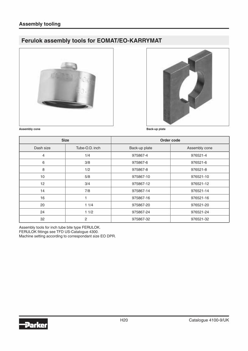
Ferulok assembly tools for EOMAT/EO-KARRYMAT
Assembly cone Back-up plate
Size Order code
Dash size Tube-O.D. inch Back-up plate Assembly cone
4 1/4 975867-4 976521-4
6 3/8 975867-6 976521-6
8 1/2 975867-8 976521-8
10 5/8 975867-10 976521-10
12 3/4 975867-12 976521-12
14 7/8 975867-14 976521-14
16 1 975867-16 976521-16
20 1 1/4 975867-20 976521-20
24 1 1/2 975867-24 976521-24
32 2 975867-32 976521-32
Assembly tools for inch tube bite type FERULOK.FERULOK fi ttings see TFD US-Catalogue 4300.Machine setting according to correspondant size EO DPR.
H
Assembly tooling
H21 Catalogue 4100-9/UK
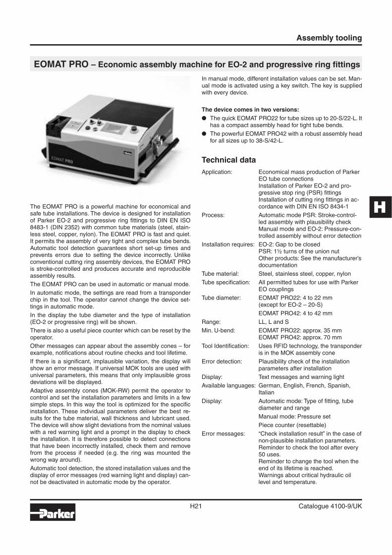
EOMAT PRO – Economic assembly machine for EO-2 and progressive ring fi ttings
The EOMAT PRO is a powerful machine for economical and safe tube installations. The device is designed for installation of Parker EO-2 and progressive ring fi ttings to DIN EN ISO 8483-1 (DIN 2352) with common tube materials (steel, stain-less steel, copper, nylon). The EOMAT PRO is fast and quiet. It permits the assembly of very tight and complex tube bends. Automatic tool detection guarantees short set-up times and prevents errors due to setting the device incorrectly. Unlike conventional cutting ring assembly devices, the EOMAT PRO is stroke-controlled and produces accurate and reproducible assembly results.
The EOMAT PRO can be used in automatic or manual mode.
In automatic mode, the settings are read from a transponder chip in the tool. The operator cannot change the device set-tings in automatic mode.
In the display the tube diameter and the type of installation (EO-2 or progressive ring) will be shown.
There is also a useful piece counter which can be reset by the operator.
Other messages can appear about the assembly cones – for example, notifi cations about routine checks and tool lifetime.
If there is a signifi cant, implausible variation, the display will show an error message. If universal MOK tools are used with universal parameters, this means that only implausible gross deviations will be displayed.
Adaptive assembly cones (MOK-RW) permit the operator to control and set the installation parameters and limits in a few simple steps. In this way the tool is optimized for the specifi c installation. These individual parameters deliver the best re-sults for the tube material, wall thickness and lubricant used. The device will show slight deviations from the nominal values with a red warning light and a prompt in the display to check the installation. It is therefore possible to detect connections that have been incorrectly installed, check them and remove from the process if needed (e.g. the ring was mounted the wrong way around).
Automatic tool detection, the stored installation values and the display of error messages (red warning light and display) can-not be deactivated in automatic mode by the operator.
In manual mode, different installation values can be set. Man-ual mode is activated using a key switch. The key is supplied with every device.
The device comes in two versions:
� The quick EOMAT PRO22 for tube sizes up to 20-S/22-L. It has a compact assembly head for tight tube bends.
� The powerful EOMAT PRO42 with a robust assembly head for all sizes up to 38-S/42-L.
Technical data
Application: Economical mass production of Parker EO tube connectionsInstallation of Parker EO-2 and pro-gressive stop ring (PSR) fi ttingsInstallation of cutting ring fi ttings in ac-cordance with DIN EN ISO 8434-1
Process: Automatic mode PSR: Stroke-control-led assembly with plausibility checkManual mode and EO-2: Pressure-con-trolled assembly without error detection
Installation requires: EO-2: Gap to be closedPSR: 1½ turns of the union nutOther products: See the manufacturer’s documentation
Tube material: Steel, stainless steel, copper, nylon
Tube specifi cation: All permitted tubes for use with Parker EO couplings
Tube diameter: EOMAT PRO22: 4 to 22 mm(except for EO-2 – 20-S)
EOMAT PRO42: 4 to 42 mm
Range: LL, L and S
Min. U-bend: EOMAT PRO22: approx. 35 mmEOMAT PRO42: approx. 70 mm
Tool Identifi cation: Uses RFID technology, the transponder is in the MOK assembly cone
Error detection: Plausibility check of the installation parameters after installation
Display: Text messages and warning light
Available languages: German, English, French, Spanish, Italian
Display: Automatic mode: Type of fi tting, tube diameter and range
Manual mode: Pressure set
Piece counter (resettable)
Error messages: “Check installation result” in the case of non-plausible installation parameters.Reminder to check the tool after every 50 uses.Reminder to change the tool when the end of its lifetime is reached.Warnings about critical hydraulic oil level and temperature.
Assembly tooling
H22 Catalogue 4100-9/UK
Speed: EOMAT PRO 22: ca 1.0 s stroke dis-tance, ca 8–10 s total cycle time
EOMAT PRO 42: ca 2.0 s stroke dis-tance, ca 10–12 s total cycle time
Economicproduction quantity: around 100 assemblies per day
Operating duration: 100%
Noise: Less than 75 dB (A)
Ambienttemperature: 0 °C to +40 °C
Storage temperature: –25 °C to +60 °C
Parameters: No condensing humidity
Dimensions: L 620 mm×W 735 mm×H 340 mm
Weight: approx. 90 kg
Operationalresources: Esso Hydraulic Oil Nuto H32
or equivalent (fi lled for delivery)
Electrical power: 400 V 3-phase 50 Hz 1100 W
Cable: 5 m cable with CEE 16 A phase- inverter plug
Tools: EOMAT PRO 22: MOK PRO assembly cones and MOS compact rear supportsEOMAT PRO 42: MOK PRO assem-bly cones and GHP standard backing plates
Lubricant: EO-NIROMONT
Test equipment: AKL distance gauges
EOMAT PRO – features, advantagesand benefi ts� Low unit costs due to its fast and effi cient hydraulic drive� Compact assembly head for tight and complex bends� Long lifespan of the assembly tools� Settings are automatically read from the tool� Stroke-control achieves a consistently good fi tting result� In automatic mode the operator cannot adjust the installa-
tion parameters� A display showing the number of pieces processed and any
error messages� Adaptive tools for optimal installation parameters and the
best possible error detection� Oil volume and the heat capacity is designed to cope with
mass assembly under continuous or shift working patterns� The foot switch allows the operator a high degree of fl ex-
ibility
OperationDetailed installation instructions and safety information can be found in the operation manual
1. Insert the assembly cone and backing plate2. In automatic mode, the display shows the mounting type
and dimensions3. Fit the tube with the union nut and ring
4. Press and hold the START button5. Hold the tube securely through the whole assembly proc-
ess and push it into the limit stop6. The assembly process is fi nished when the cylinder moves
back to the starting position7. Assembly inspection and fi nal assembly is done according
to the assembly instructions (see chapter E)
Tool lifetimeAssembly tools are subject to wear, and must be periodically (at least every 50 assemblies) cleaned and inspected (inspec-tion instructions, see chapter E) Worn tools can cause danger-ous assembly failures, and need to be replaced in good time. High tool life can be achieved by:
� Regular cleaning and lubrication� Store protected from dirt and corrosion� Careful trimming and cleaning of the tube ends� Proper tool selection and operation� Use of the recommended lubricant
The MOK PRO assembly cones are made from wear-resistant tool steel, and are therefore suited to mass production. If used properly, they should have an average lifespan of approxi-mately 10,000 assemblies. After this lifespan is reached, the display will show that a tool change is needed. The worn tool should be replaced, it will no longer work in automatic mode. Worn assembly cones can be used after the end of their ex-pected lifespan in manual mode with care.
Machine/Item Order code
EOMAT PRO machine,ready to use, with key for selection switch Auto/Manual, with operation manual, fi lled with hydraulic oil, without tooling and accessories
EOMAT PRO22Tube-OD 4–22 mm400 V, 50 Hz, 3 PhaseRenting (monthly rate)Leasing (2 year hire purchase)
EOMATPRO22400V
EOMATPRO/RENTFEEEOMATPRO/LEASEFEE
EOMAT PRO42Tube-OD 4–42 mm400 V, 50 Hz, 3 PhaseRenting (monthly hire rate)Leasing (2 year hire purchase)
EOMATPRO42400V
EOMATPRO/RENTFEEEOMATPRO/LEASEFEE
Accessoires/Item
lubricant for assembly cone250 ccm bottle EONIROMONTFLUESSX
Foot switch FOOTSWITCHSAFETYKIT
Fixing clamp for MOK EOMATPRO/CLIP
Spare key for selection switch EOMATPRO/KEY
EOMAT PRO promotion leafl et UK 4043 via ParkerCatalogueservice EMDC
Operation manual UK/DE/FR/IT/ES EOMATPRO/MANUAL
Standard preventive maintenance EOMATPRO/INSPECTION
H
Assembly tooling
H23 Catalogue 4100-9/UK
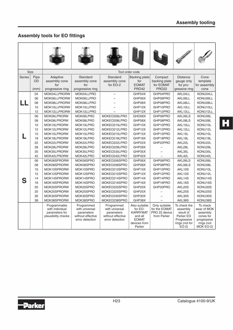
Assembly tools for EO fi ttings
Size Tool order code
Series PipeOD
(mm)
Adaptiveassembly cone
forprogressive ring
Standardassembly cone
forprogressive ring
Standardassembly cone
for EO-2
Backing platefor
EOMATPRO42
Compactbacking platefor EOMAT
PRO22
Distance gauge only
for pro-gressive ring
Conetemplate
for assemblycone
LL
04 MOK04LLPRORW MOK04LLPRO – GHP04X GHP04PRO AKL04LL KONU04LL
06 MOK06LLPRORW MOK06LLPRO – GHP06X GHP06PRO AKL06LL KONU06LL
08 MOK08LLPRORW MOK08LLPRO – GHP08X GHP08PRO AKL08LL KONU08LL
10 MOK10LLPRORW MOK10LLPRO – GHP10X GHP10PRO AKL10LL KONU10LL
12 MOK12LLPRORW MOK12LLPRO – GHP12X GHP12PRO AKL12LL KONU12LL
L
06 MOK06LPRORW MOK06LPRO MOKEO206LPRO GHO06X GHP06PRO AKL06LS KONU06L
08 MOK08LPRORW MOK08LPRO MOKEO208LPRO GHP08X GHP08PRO AKL08LS KONU08L
10 MOK10LPRORW MOK10LPRO MOKEO210LPRO GHP10X GHP10PRO AKL10LL KONU10L
12 MOK12LPRORW MOK12LPRO MOKEO212LPRO GHP12X GHP12PRO AKL12LL KONU12L
15 MOK15LPRORW MOK15LPRO MOKEO215LPRO GHP15X GHP15PRO AKL15L KONU15L
18 MOK18LPRORW MOK18LPRO MOKEO218LPRO GHP18X GHP18PRO AKL18L KONU18L
22 MOK22LPRORW MOK22LPRO MOKEO222LPRO GHP22X GHP22PRO AKL22L KONU22L
28 MOK28LPRORW MOK28LPRO MOKEO228LPRO GHP28X – AKL28L KONU28L
35 MOK35LPRORW MOK35LPRO MOKEO235LPRO GHP35X – AKL35L KONU35L
42 MOK42LPRORW MOK42LPRO MOKEO242LPRO GHP42X – AKL42L KONU42L
S
06 MOK06SPRORW MOK06SPRO MOKEO206SPRO GHP06X GHP06PRO AKL06LS KONU06L
08 MOK08SPRORW MOK08SPRO MOKEO208SPRO GHP08X GHP08PRO AKL08LS KONU08L
10 MOK10SPRORW MOK10SPRO MOKEO210SPRO GHP10X GHP10PRO AKL10S KONU10L
12 MOK12SPRORW MOK12SPRO MOKEO212SPRO GHP12X GHP12PRO AKL12S KONU12L
14 MOK14SPRORW MOK14SPRO MOKEO214SPRO GHP14X GHP14PRO AKL14S KONU14S
16 MOK16SPRORW MOK16SPRO MOKEO216SPRO GHP16X GHP16PRO AKL16S KONU16S
20 MOK20SPRORW MOK20SPRO MOKEO220SPRO GHP20X GHP20PRO AKL20S KONU20S
25 MOK25SPRORW MOK25SPRO MOKEO225SPRO GHP25X – AKL25S KONU25S
30 MOK30SPRORW MOK30SPRO MOKEO230SPRO GHP30X – AKL30S KONU30S
38 MOK38SPRORW MOK38SPRO MOKEO238SPRO GHP38X – AKL38S KONU38S
Programmable with individual parameters for
plausibility checks
Programmed with universal parameters
without effective error detection
Programmed with universal parameters
without effective error detection
Also suitable for EO-
KARRYMAT and all EOMAT
devices from Parker
Only suitable for the EOMAT PRO 22 device
from Parker
To check the assembly result of
Parker EO Progressive rings (not for
EO-2)
To check wear of MOK
assembly cones for
progressive rings (not
MOK EO-2)
Assembly tooling
H24 Catalogue 4100-9/UK
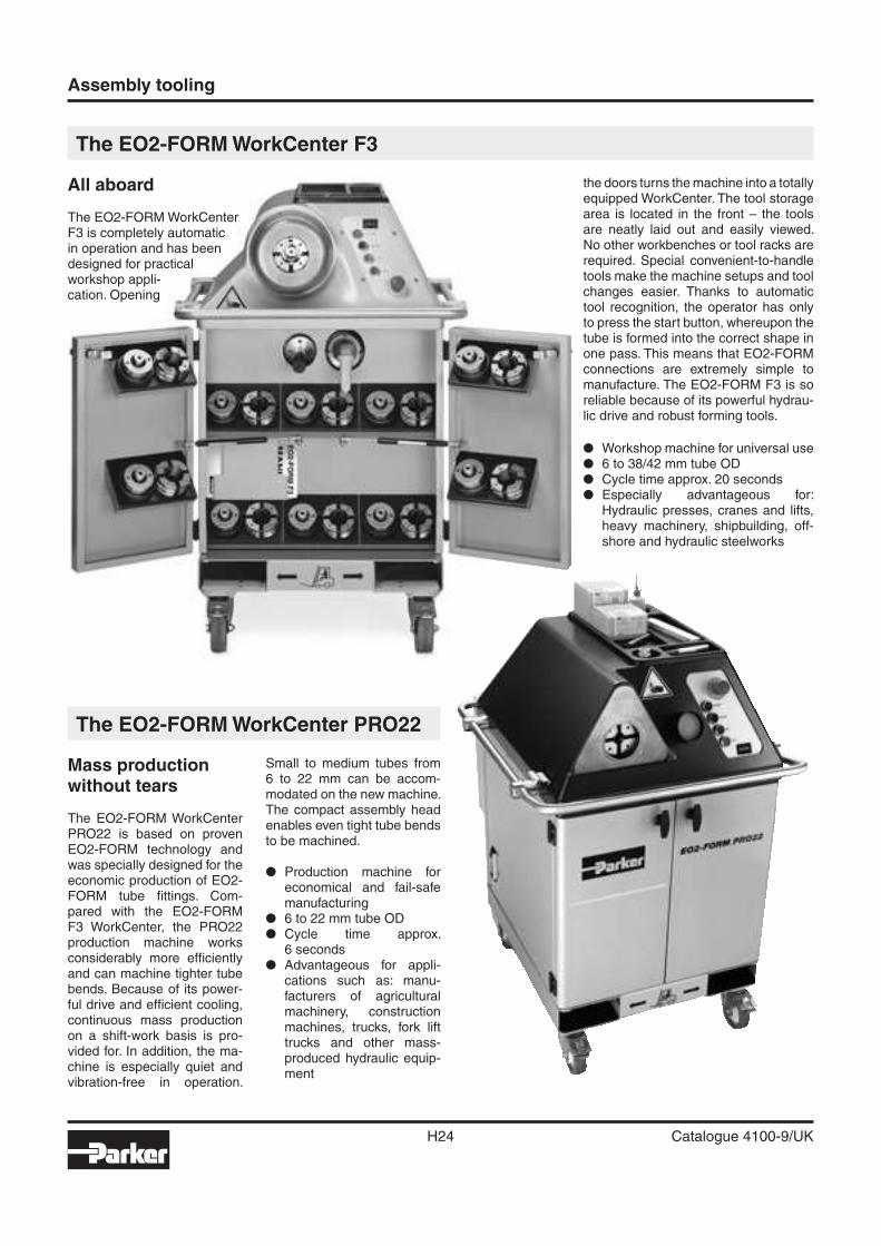
The EO2-FORM WorkCenter F3
All aboard
The EO2-FORM WorkCenterF3 is completely automaticin operation and has beendesigned for practicalworkshop appli-cation. Opening
the doors turns the machine into a totally equipped WorkCenter. The tool storage area is located in the front – the tools are neatly laid out and easily viewed. No other workbenches or tool racks are required. Special convenient-to-handle tools make the machine setups and tool changes easier. Thanks to automatic tool recognition, the operator has only to press the start button, whereupon the tube is formed into the correct shape in one pass. This means that EO2-FORM connections are extremely simple to manufacture. The EO2-FORM F3 is so reliable because of its powerful hydrau-lic drive and robust forming tools.
� Workshop machine for universal use� 6 to 38/42 mm tube OD� Cycle time approx. 20 seconds� Especially advantageous for:
Hydraulic presses, cranes and lifts, heavy machinery, shipbuilding, off-shore and hydraulic steelworks
The EO2-FORM WorkCenter PRO22
Mass productionwithout tears
The EO2-FORM WorkCenter PRO22 is based on proven EO2-FORM technology and was specially designed for the economic production of EO2-FORM tube fi ttings. Com-pared with the EO2-FORM F3 WorkCenter, the PRO22 production machine works considerably more effi ciently and can machine tighter tube bends. Because of its power-ful drive and effi cient cooling, continuous mass production on a shift-work basis is pro-vided for. In addition, the ma-chine is especially quiet and vibration-free in operation.
Small to medium tubes from 6 to 22 mm can be accom-modated on the new machine. The compact assembly head enables even tight tube bends to be machined.
� Production machine for economical and fail-safe manufacturing
� 6 to 22 mm tube OD� Cycle time approx.
6 seconds� Advantageous for appli-
cations such as: manu-facturers of agricultural machinery, construction machines, trucks, fork lift trucks and other mass-produced hydraulic equip-ment
H
Assembly tooling
H25 Catalogue 4100-9/UK
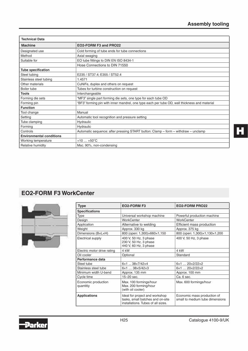
EO2-FORM F3 WorkCenter
Technical Data
Machine EO2-FORM F3 and PRO22
Designated use Cold forming of tube ends for tube connections
Method Axial swaging
Suitable for EO tube fi ttings to DIN EN ISO 8434-1
Hose Connections to DIN 71550
Tube specifi cation
Steel tubing E235 / ST37.4; E355 / ST52.4
Stainless steel tubing 1.4571
Other materials CuNiFe, duplex and others on request
Boiler tube Tubes for turbine construction on request
Tools Interchangeable
Forming die sets “MF3” single part forming die sets, one type for each tube OD
Forming pin “BF3” forming pin with inner mandrel, one type each per tube OD, wall thickness and material
Function
Tool change Manual
Setting Automatic tool recognition and pressure setting
Tube clamping Hydraulic
Forming Hydraulic
Controls Automatic sequence: after pressing START button: Clamp – form – withdraw – unclamp
Environmental conditions
Working temperature +10 … +50°C
Relative humidity Msc. 90%, non-condensing
Type EO2-FORM F3 EO2-FORM PRO22
Specifi cations
Type Universal workshop machine Powerful production machine
Design WorkCenter WorkCenter
Application Alternative to welding Effi cient mass production
Weight Approx. 330 kg Approx. 375 kg
Dimensions (B×L×H) 800 (open: 1,300)×660×1,150 800 (open: 1,300)×1,130×1,200
Electrical supply 400 V, 50 Hz, 3 phase230 V, 50 Hz, 3 phase440 V, 60 Hz, 3 phase
400 V, 50 Hz, 3 phase
Electric motor drive rating 4 kW 4 kW
Oil cooler Optional Standard
Performance data
Steel tube 6×1 ... 38×7/42×4 6×1 … 20×2/22×2
Stainless steel tube 6×1 … 38×5/42×3 6×1 … 20×2/22×2
Minimum width U-bend Approx. 135 mm Approx. 100 mm
Cycle time 15–20 sec. Ca. 6 sec.
Economic productionquantitiy
Max. 100 formings/hourMax. 200 forming/hour(with oil cooler)
Max. 600 formings/hour
Applications Ideal for project and workshop tasks, small batches and on-site installations. Tubes of all sizes.
Economic mass production of small to medium tube dimensions
Assembly tooling
H26 Catalogue 4100-9/UK
Features, advantages and benefi ts
1. Process / Product concept – The EO2-FORM technology is not a stand-alone machine or a new fi tting system. It is a product extension of the EO-2 range which has existed since 1993. Exactly the same, prov-en seal elements are used.
2. Workcenter concept – All tools, handling devices, lubricants and the operator manual are well or-ganised inside the machine. Once the doors are opened, the machine turns into a stand-alone workcenter for tube preparation. On the top shelf, there are practical compart-ments for rules, pens, lubricant andstandard EO-boxes with nuts and sealing rings. No additional work-benches or shelves for tooling are required.
3. Easy operation – One single START-button is all that needs to be operated to run a forming cycle com-pletely. No “zero position” or “reset” activities have to be performed in-between two forming cycles. For effi -cient mass production, a foot switch is available. A label on the machine head shows all operation steps in pictograms and all important dimen-sions in charts.
4. Easy tool change – An ergonom-ic, pistol-like device allows quick and easy change of the one-piece clamping die set without opening the forming head or even touching the tools. Another handle speeds up the setup process of the forming pin in the bayonet mechanism.
5. Easy handling – Standard tools and one set of EO-2 sealing rings are suitable for all common hydraulic tube dimensions. No special sleeves are required for thin wall or small di-ameter tube.
6. Well organised – All tools and ac-cessories are well organised in a practical compartment inside the machine housing. Nothing gets dirty, lost or confused.
7. Easy transport – The machine is equipped with heavy duty wheels so that it can be moved around by
one person without hard work or ad-ditional equipment. Special attach-ments for crane and forklift truck transport are standard. A reeling serves as handle, protection and at-tachment for fi xing belts when trans-ported by truck. Tools and all acces-sories are safely and cleanly stored inside.
8. Easy logistics – EO2-FORM uses the same components as EO-2. Special sets of nuts and sealing rings can be ordered with one part number (FORM …). This reduces ordering effort and contributes to achieve availability with optimum in-ventory.
9. Stainless steel capabilities – Forming pins for stainless steel tubes are specially designed for op-timum forming results and surface coated for maximum lifetime. All forming pins for stainless steel tube are marked with a blue dot. Clamp-ing dies can be used for both, steel and stainless steel tube.
10. Approved functional system – EO2-FORM has been on market for years. It is approved for use in ship-building, offshore industry, hydraulic water lock systems, press and crane manufacturing, heavy mobile equip-ment and general machine building. EO2-FORM is tested and approved from authorities like German Lloyd, DNV or from end-users like Daimler-Chrysler.
11. Cost saving – Compared to weld-ing or brazing, EO2-FORM is much less time consuming. Special tube preparation and fi nishing are not necessary. Cold forming uses only a fraction of the energy needed for brazing or welding.
12. Superior vibration resistance – The EO2-FORM process achieves a smooth structural transformation of the tube wall. There are no sharp edges or notches to reduce the vi-bration resistance.
13. Superior mechanical strength – The working contact area of the EO2-FORM connection is the fl at front surface of the metal support ring which is made of heat-treated, high-strength steel or stainless steel.
This provides superior mechanical strength without settling, loosening or need for re-tightening.
14. Universal – The EO2-FORM ma-chine can cold-form all common steel and stainless steel tube ma-terials for hydraulic pipework. Even exotic materials such as Cu-NiFe or Duplex can be formed. EO2-FORM tools cover metric tube sizes from 6 to 42 mm OD.
15. Short tube ends – The compact clamping device and special dies are suitable for machining complex tube bends.
16. Noise/energy loss reduction – The EO2-FORM process results in a smooth inner contour of the tube. Minimum pressure drop, heat and noise is created. No hidden corners allow the accumulation of air, dirt or other sources of trouble.
17. Clean – The EO2-FORM process is environmental clean and safe. As no heat is used, hazards from fumes or heat do not occur.
18. Zinc plated tubing – The EO2-FORM process allows the use of zinc-plated tubing. The costs of cleaning or painting are saved.
19. Quality – Tube clamping and tool functions are fully automated. Proper joint geometry and seal dimensions are achieved by using standard EO-2 sealing rings. Therefore high and consistent quality is achieved without manual adjustment.
20. Proven Technology – Since 1993, millions of EO-2 fi ttings have operat-ed worldwide under heavy duty con-ditions, providing leak-free hydraulic systems.
21. No restrictions – The process al-lows to use EO-2 elastomeric seal-ing technology even for applications where bite-type connectors are not permitted by safety standards, for example hydraulic presses, cranes, lifts or ship canal systems locks.
H
Assembly tooling
H27 Catalogue 4100-9/UK
F3 Forming machine for EO2-FORM high pressure tube connections
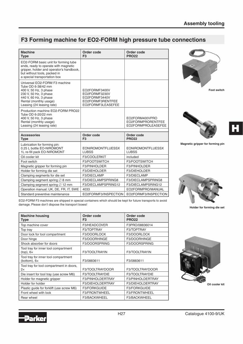
Foot switch
Magnetic gripper for forming pin
Holder for forming die set
Oil cooler kit
EO2-FORM F3 machines are shipped in special containers which should be kept for future transports to avoid
damage. Please don’t dispose the transport boxes!
Machine housingType
Order codeF3
Order codePRO22
Top machine cover F3/HEADCOVER F3PRO/08836014
Top tray F3/TOPTRAY F3/TOPTRAY
Door lock for tool compartment F3/DOORLOCK F3/DOORLOCK
Door hinge F3/DOORHINGE F3/DOORHINGE
Shock absorber for doors F3/DOORSPRING F3/DOORSPRING
Tool tray for inner tool compartment(top), 6× F3/TOOLTRAYIN F3/TOOLTRAYIN
Tool tray for inner tool compartment(bottom), 6× F3/0883611 F3/0883611
Tool tray for tool compartment in doors,2× F3/TOOLTRAYDOOR F3/TOOLTRAYDOOR
Die insert for tool tray (use screw M6) F3/TOOLTRAYDIE F3/TOOLTRAYDIE
Holder for magnetic gripper F3/PINHOLDERTRAY F3/PINHOLDERTRAY
Holder for holder F3/DIEHOLDERTRAY F3/DIEHOLDERTRAY
Plastic guide for forklift (use screw M6) F3/FORKGUIDE F3/FORKGUIDE
Front wheel with lock F3/FRONTWHEEL F3/FRONTWHEEL
Rear wheel F3/BACKWHEEL F3/BACKWHEEL
MachineType
Order codeF3
Order codePRO22
EO2-FORM basic unit for forming tube ends, ready to operate with magnetic gripper, holder and operator’s handbook, but without tools, packed ina special transportation box
Universal EO2-FORM F3 machineTube OD 6-38/42 mm400 V, 50 Hz, 3 phase230 V, 50 Hz, 3 phase440 V, 60 Hz, 3 phaseRental (monthly usage)Leasing (24 leasing rate)
EO2FORMF3400VEO2FORMF3230VEO2FORMF3440VEO2FORMF3RENTFEEEO2FORMF3LEASEFEE
Production machine EO2-FORM PRO22Tube OD 6-20/22 mm400 V, 50 Hz, 3 phaseRental (monthly usage)Leasing (24 leasing rate)
EO2FORM400VPROEO2FORMPRORENTFEEEO2FORMPROLEASEFEE
AccessoriesType
Order codeF3
Order codePRO22
Lubrication for forming pin:0.25 L bottle EO-NIROMONT1L re-fi ll pack EO-NIROMONT
EONIROMONTFLUESSXLUBSS
EONIROMONTFLUESSXLUBSS
Oil cooler kit F3/COOLERKIT included
Foot switch F3/FOOTSWITCH F3/FOOTSWITCH
Magnetic gripper for forming pin F3/PINHOLDER F3/PINHOLDER
Holder for forming die set F3/DIEHOLDER F3/DIEHOLDER
Clamping segments for die set F3/DIECLAMP F3/DIECLAMP
Clamping segment spring � 8 mm F3/DIECLAMPSPRING8 F3/DIECLAMPSPRING8
Clamping segment spring � 12 mm F3/DIECLAMPSPRING12 F3/DIECLAMPSRING12
Operation manual: UK, DE, FR, IT, SWE 4033 EO2FORMPRO/MANUAL
Standard preventive maintenance EO2FORMF3/INSPECTION EO2FORMF3/INSPECTION
Assembly tooling
H28 Catalogue 4100-9/UK
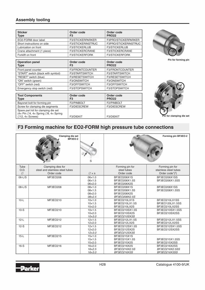
Pin for forming pin
Pin for clamping die set
Tool ComponentsType
Order codeF3
Order codePRO22
Bayonet bolt for forming pin F2/PINBOLT F2/PINBOLT
Screw for clamping die segments F3/DIESCREW F3/DIESCREW
Spare part kit for clamping die set(4× Pin �4, 4× Spring �8, 4× Spring �12, 4× Screws) F3/DIEKIT F3/DIEKIT
Operation panelType
Order codeF3
Order codePRO22
Front panel counter F3/FRONTCOUNTER F3/FRONTCOUNTER
“START” switch (black with symbol) F3/STARTSWITCH F3/STARTSWITCH
“RESET” switch (blue) F3/RESETSWITCH F3/RESETSWITCH
“ON” switch (green) F3/ONSWITCH F3/ONSWITCH
“OFF” switch (red) F3/OFFSWITCH F3/OFFSWITCH
Emergency stop switch (red) F3/STOPSWITCH F3/STOPSWITCH
StickerType
Order codeF3
Order codePRO22
EO2-FORM door label F3/STICKERPARKER F3PRO/STICKERPARKER
Short instructions on side F3/STICKERINSTRUC F3PRO/STICKERINSTRUC
Lubrication on front F3/STICKERLUB F3/STICKERLUB
Crane attachment (1 piece) F3/STICKERCRANE F3/STICKERCRANE
Forklift on front F3/STICKERFORK F3/STICKERFORK
F3 Forming machine for EO2-FORM high pressure tube connections
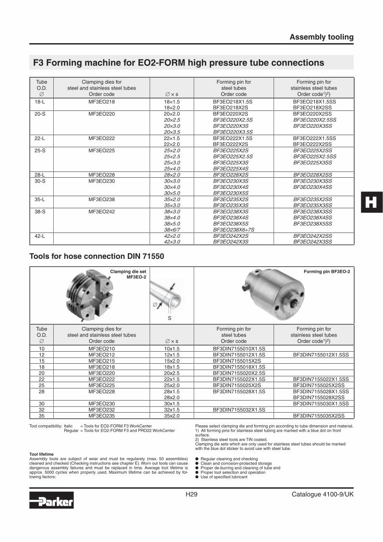
Clamping die setMF3EO-2
�
S
Forming pin BF3EO-2
TubeO.D.
�
Clamping dies forsteel and stainless steel tubes
Order code � × s
Forming pin forsteel tubesOrder code
Forming pin for stainless steel tubes
Order code1)2)
06-L/S MF3EO206 06×1.0 BF3EO206X1S BF3EO206X1SS06×1.5 BF3EO206X1.5S BF3EO206X1.5SS06×2.0 BF3EO206X2S
08-L/S MF3EO208 08×1.0 BF3EO208X1S BF3EO208X1SS08×1.5 BF3EO208X1.5S BF3EO208X1.5SS08×2.0 BF3EO208X2S08×2.5 BF3EO208X2.5S
10-L MF3EO210 10×1.0 BF3EO210LX1S BF3EO210LX1SS10×1.5 BF3EO210LX1.5S BF3EO120LX1.5SS10×2.0 BF3EO210LX2S BF3EO210LX2SS
10-S MF3EO210 10×1.5 BF3EO210SX1.5S BF3EO210SX1.5SS10×2.0 BF3EO210SX2S BF3EO210SX2SS10×3.0 BF3EO210SX3S
12-L MF3EO212 12×1.5 BF3EO212LX1.5S BF3EO212LX1.5SS12×2.0 BF3EO212LX2S BF3EO212LX2SS
12-S MF3EO212 12×1.5 BF3EO212SX1.5S BF3EO212SX1.5SS12×2.0 BF3EO212SX2S BF3EO212SX2SS12×3.0 BF3EO212SX3S
15-L MF3EO215 15×1.0 BF3EO215X1S15×1.5 BF3EO215X1.5S BF3EO215X1.5SS15×2.0 BF3EO215X2S BF3EO215X2SS
16-S MF3EO216 16×2.0 BF3EO216X2S BF3EO216X2SS16×2.5 BF3EO216X2.5S BF3EO216X2.5SS
16×3.0 BF3EO216X3S BF3EO216X3SS
H
Assembly tooling
H29 Catalogue 4100-9/UK
Tool compatibility: Italic = Tools for EO2-FORM F3 WorkCenter Regular = Tools for EO2-FORM F3 and PRO22 WorkCenter
Please select clamping die and forming pin according to tube dimension and material.1) All forming pins for stainless steel tubing are marked with a blue dot on front surface.2) Stainless steel tools are TiN coated.Clamping die sets which are only used for stainless steel tubes should be marked with the blue dot sticker to avoid use with steel tube.
Tool lifetime Assembly tools are subject of wear and must be regularely (max. 50 assemblies) cleaned and checked (Checking instructions see chapter E). Worn out tools can cause dangerous assembly failures and must be replaced in time. Average tool lifetime is approx. 5000 cycles when properly used. Maximum lifetime can be achieved by fol-lowing factors:
� Regular cleaning and checking� Clean and corrosion-protected storage� Proper de-burring and cleaning of tube end� Proper tool selection and operation� Use of specifi ed lubricant
F3 Forming machine for EO2-FORM high pressure tube connections
Tools for hose connection DIN 71550
TubeO.D.
�
Clamping dies forsteel and stainless steel tubes
Order code � × s
Forming pin forsteel tubesOrder code
Forming pin for stainless steel tubes
Order code1)2)
18-L MF3EO218 18×1.5 BF3EO218X1.5S BF3EO218X1.5SS18×2.0 BF3EO218X2S BF3EO218X2SS
20-S MF3EO220 20×2.0 BF3EO220X2S BF3EO220X2SS20×2.5 BF3EO220X2.5S BF3EO220X2.5SS
20×3.0 BF3EO220X3S BF3EO220X3SS
20×3.5 BF3EO220X3.5S
22-L MF3EO222 22×1.5 BF3EO222X1.5S BF3EO222X1.5SS22×2.0 BF3EO222X2S BF3EO222X2SS
25-S MF3EO225 25×2.0 BF3EO225X2S BF3EO225X2SS
25×2.5 BF3EO225X2.5S BF3EO225X2.5SS
25×3.0 BF3EO225X3S BF3EO225X3SS
25×4.0 BF3EO225X4S
28-L MF3EO228 28×2.0 BF3EO228X2S BF3EO228X2SS
30-S MF3EO230 30×3.0 BF3EO230X3S BF3EO230X3SS
30×4.0 BF3EO230X4S BF3EO230X4SS
30×5.0 BF3EO230X5S
35-L MF3EO238 35×2.0 BF3EO235X2S BF3EO235X2SS
35×3.0 BF3EO235X3S BF3EO235X3SS
38-S MF3EO242 38×3.0 BF3EO238X3S BF3EO238X3SS
38×4.0 BF3EO238X4S BF3EO238X4SS
38×5.0 BF3EO238X5S BF3EO238X5SS
38×6/7 BF3EO238X6+7S
42-L 42×2.0 BF3EO242X2S BF3EO242X2SS
42×3.0 BF3EO242X3S BF3EO242X3SS
Clamping die setMF3EO-2
�
S
Forming pin BF3EO-2
TubeO.D.
�
Clamping dies forsteel and stainless steel tubes
Order code � × s
Forming pin forsteel tubesOrder code
Forming pin for stainless steel tubes
Order code1)2)
10 MF3EO210 10x1.5 BF3DIN7155010X1.5S12 MF3EO212 12x1.5 BF3DIN7155012X1.5S BF3DIN7155012X1.5SS15 MF3EO215 15x2.0 BF3DIN7155015X2S18 MF3EO218 18x1.5 BF3DIN7155018X1.5S20 MF3EO220 20x2.5 BF3DIN7155020X2.5S22 MF3EO222 22x1.5 BF3DIN7155022X1.5S BF3DIN7155022X1.5SS25 MF3EO225 25x2.0 BF3DIN7155025X2S BF3DIN7155025X2SS28 MF3EO228 28x1.5 BF3DIN7155028X1.5S BF3DIN7155028X1.5SS
28x2.0 BF3DIN7155028X2SS30 MF3EO230 30x1.5 BF3DIN7155030X1.5SS32 MF3EO232 32x1.5 BF3DIN7155032X1.5S35 MF3EO235 35x2.0 BF3DIN7155035X2SS
Assembly tooling
H30 Catalogue 4100-9/UK
Flaring tools for Triple-Lok® tubes
Flaring tool selection guide
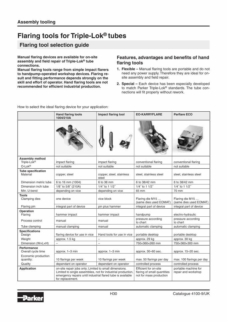
Manual fl aring devices are available for on-site assembly and fi eld repair of Triple-Lok® tube connections.Manual fl aring tools range from simple impact fl arers to handpump-operated workshop devices. Flaring re-sult and fi tting performance depends strongly on the skill and effort of operator. Hand fl aring tools are not recommended for effi cient industrial production.
Features, advantages and benefi ts of hand fl aring tools
1. Flexible – Manual fl aring tools are portable and do not need any power supply. Therefore they are ideal for on-site assembly and fi eld repair.
2. Special – Each device has been especially developed to match Parker Triple-Lok® standards. The tube con-nections will fi t properly without rework.
How to select the ideal fl aring device for your application:
Hand fl aring tools 1004/210A
Impact fl aring tool EO-KARRYFLARE Parfl are ECO
Assembly methodTriple-Lok® impact fl aring impact fl aring conventional fl aring conventional fl aring
O-Lok® not suitable not suitable not suitable not suitable
Tube specifi cationMaterial copper, steel copper, steel, stainless
steelsteel, stainless steel steel, stainless steel
Dimension metric tube 6 to 16 mm (1004) 6 to 38 mm 6 to 38/42 mm 6 to 38/42 mm
Dimension inch tube 1/8˝ to 5/8˝ (210A) 1/4˝ to 1 1/2˝ 1/4˝ to 1 1/2˝ 1/4˝ to 1 1/2˝
Min. U-bend depending on vice depending on vice 65 mm 70 mm
ToolsClamping dies one device vice block Flaring die M15 …
(same dies used EOMAT)Flaring die M15 …(same dies used EOMAT)
Flaring pin integral part of device pin plus hammer integral part of device integral part of device
OperationFlaring hammer impact hammer impact handpump electro-hydraulic
Process control manual manualpressure accordingto chart
pressure accordingto chart
Tube clamping manual clamping manual automatic clamping automatic clamping
Specifi cationsDesign fl aring device for use in vice Hand tools for use in vice portable desktop portable desktop
Weight approx. 1.5 kg – approx. 29 kg approx. 30 kg
Dimension (W×L×H) – – 750×360×260 mm 750×360×300 mm
PerformanceOverall cycle time approx. 1–3 min approx. 1–3 min approx. 30–60 sec. approx. 15–20 sec.
Economic productionquantity: 10 fl arings per week 10 fl arings per week max. 50 fl arings per day max. 100 fl arings per day
Quality dependant on operator dependant on operator controlled process controlled process
Application on-site repair jobs only; Limited to small dimensions.Limited to single assemblies, not for industrial production, emergency repairs until industrial fl ared tube is available for replacement.
Effi cient for on-sitefl aring of small quantitiesnot for mass production
portable machine for repair and workshop
H
Assembly tooling
H31 Catalogue 4100-9/UK
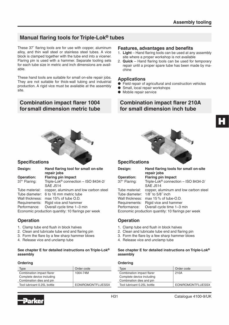
Manual fl aring tools for Triple-Lok® tubes
These 37˚ fl aring tools are for use with copper, aluminum alloy, and thin wall steel or stainless steel tubes. A vice block is clamped together with the tube end into a vicener. Flaring pin is used with a hammer. Separate tooling sets for each tube size in metric and inch dimensions are avail-able.
These hand tools are suitable for small on-site repair jobs. They are not suitable for thick-wall tubing and industrial production. A rigid vice must be available at the assembly site.
Features, advantages and benefi ts1. Light – Hand fl aring tools can be used at any assembly
site where a proper workshop is not available2. Quick – Hand fl aring tools can be used for temporary
repair until a proper spare tube has been made by ma-chine
Applications� Field repair of agricultural and construction vehicles� Small, local repair workshops� Mobile repair service
Combination impact fl arer 1004 for small dimension metric tube
Specifi cations
Design: Hand fl aring tool for small on-site repair jobs
Operation: Flaring pin Impact37° Flaring: Triple-Lok® connection – ISO 8434-2/
SAE J514 Tube material: copper, aluminum and low carbon steelTube diameter: 6 to 16 mm metric tubeWall thickness: max 15% of tube O.D.Requirements: Rigid vice and hammerPerformance: Overall cycle time 1–3 minEconomic production quantity: 10 fl arings per week
Operation
1. Clamp tube end fl ush in block halves2. Clean and lubricate tube end and fl aring pin3. Form the fl are by a few sharp hammer blows4. Release vice and unclamp tube
See chapter E for detailed instructions on Triple-Lok® assembly
Ordering
Type Order code
Combination impact fl arer 1004-74M
Complete device including
Combination dies and pin
Tool lubricant 0.25L bottle EONIROMONTFLUESSX
Combination impact fl arer 210Afor small dimension inch tube
Specifi cations
Design: Hand fl aring tools for small on-site repair jobs
Operation: Flaring pin Impact37° Flaring: Triple-Lok® connection – ISO 8434-2/
SAE J514 Tube material: copper, aluminum and low carbon steelTube diameter: 1/8˝ to 5/8˝ inchWall thickness: max 15 % of tube-O.D.Requirements: Rigid vice and hammerPerformance: Overall cycle time 1–3 minEconomic production quantity: 10 fl arings per week
Operation
1. Clamp tube end fl ush in block halves2. Clean and lubricate tube end and fl aring pin3. Form the fl are by a few sharp hammer blows4. Release vice and unclamp tube
See chapter E for detailed instructions on Triple-Lok® assembly
Ordering
Type Order code
Combination impact fl arer 210A
Complete device including
Combination dies and pin
Tool lubricant 0.25L bottle EONIROMONTFLUESSX
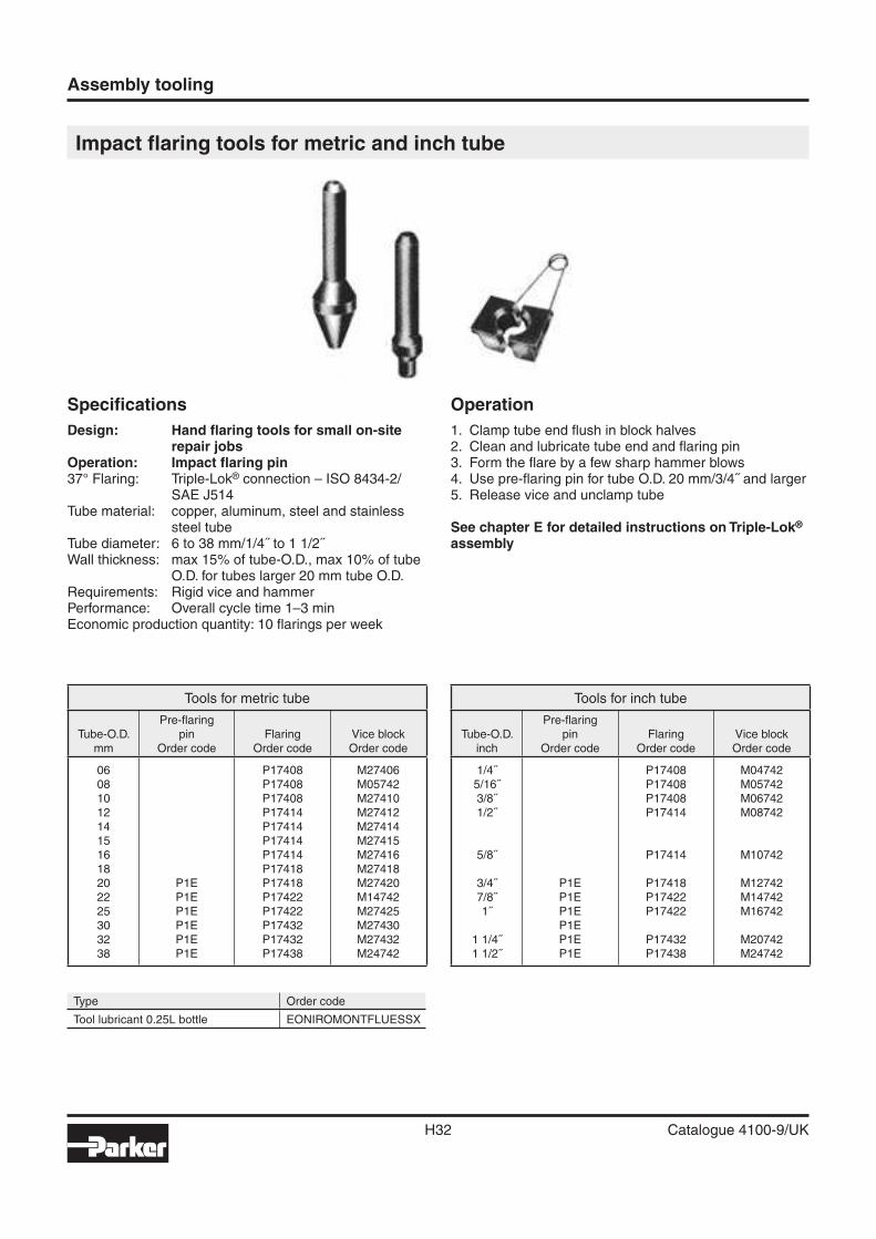
Assembly tooling
H32 Catalogue 4100-9/UK
Impact fl aring tools for metric and inch tube
Specifi cations
Design: Hand fl aring tools for small on-site repair jobs
Operation: Impact fl aring pin37° Flaring: Triple-Lok® connection – ISO 8434-2/
SAE J514 Tube material: copper, aluminum, steel and stainless
steel tubeTube diameter: 6 to 38 mm/1/4˝ to 1 1/2˝Wall thickness: max 15% of tube-O.D., max 10% of tube
O.D. for tubes larger 20 mm tube O.D.Requirements: Rigid vice and hammerPerformance: Overall cycle time 1–3 minEconomic production quantity: 10 fl arings per week
Operation
1. Clamp tube end fl ush in block halves2. Clean and lubricate tube end and fl aring pin3. Form the fl are by a few sharp hammer blows4. Use pre-fl aring pin for tube O.D. 20 mm/3/4˝ and larger5. Release vice and unclamp tube
See chapter E for detailed instructions on Triple-Lok® assembly
Type Order code
Tool lubricant 0.25L bottle EONIROMONTFLUESSX
Tools for metric tube
Tube-O.D.mm
Pre-fl aringpin
Order codeFlaring
Order codeVice blockOrder code
0608101214151618202225303238
P1EP1EP1EP1EP1EP1E
P17408P17408P17408P17414P17414P17414P17414P17418P17418P17422P17422P17432P17432P17438
M27406M05742M27410M27412M27414M27415M27416M27418M27420M14742M27425M27430M27432M24742
Tools for inch tube
Tube-O.D.inch
Pre-fl aringpin
Order codeFlaring
Order codeVice blockOrder code
1/4˝5/16˝3/8˝1/2˝
5/8˝
3/4˝7/8˝1˝
1 1/4˝1 1/2˝
P1EP1EP1EP1EP1EP1E
P17408P17408P17408P17414
P17414
P17418P17422P17422
P17432P17438
M04742M05742M06742M08742
M10742
M12742M14742M16742
M20742M24742
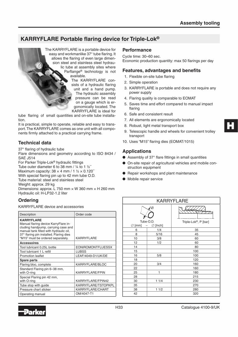
H
Assembly tooling
H33 Catalogue 4100-9/UK
KARRYFLARE Portable fl aring device for Triple-Lok®
The KARRYFLARE is a portable device for easy and workmanlike 37° tube fl aring. It
allows the fl aring of even large dimen-sion steel and stainless steel hydrau-
lic tube at assembly sites where Parfl ange® technology is not
available. The KARRYFLARE con-sists of a hydraulic fl aring
unit and a hand pump. The hydraulic assembly pressure can be read on a gauge which is er-
gonomically located. The KARRYFLARE is ideal for
tube fl aring of small quantities and on-site tube installa-tion.It is practical, simple to operate, reliable and easy to trans-port. The KARRYFLARE comes as one unit with all compo-nents fi rmly attached to a practical carrying frame.
Technical data
37° fl aring of hydraulic tubeFlare dimensions and geometry according to ISO 8434 / SAE J514For Parker Triple-Lok® hydraulic fi ttingsTube outer diameter 6 to 38 mm / ¼ to 1 ½˝Maximum capacity: 38 × 4 mm / 1 ½ × 0.120˝With special fl aring pin up to 42 mm tube O.D.Tube material: steel and stainless steelWeight: approx. 29 kgDimensions: approx. L 750 mm × W 360 mm × H 260 mmHydraulic oil: H-LP32-1.2 liter
Performance
Cycle time: 30–60 sec.Economic production quantity: max 50 fl arings per day
Features, advantages and benefi ts 1. Flexible on-site tube fl aring
2. Simple operation
3. KARRYFLARE is portable and does not require any power supply
4. Flaring quality is comparable to EOMAT
5. Saves time and effort compared to manual impact fl aring
6. Safe and consistent result
7. All elements are ergonomically located
8. Robust, light metal transport box
9. Telescopic handle and wheels for convenient trolley transport
10. Uses “M15” fl aring dies (EOMAT/1015)
Applications� Assembly of 37° fl are fi ttings in small quantities
� On-site repair of agricultural vehicles and mobile con-struction equipment
� Repair workshops and plant maintenance
� Mobile repair service
Ordering
KARRYFLARE device and accessories
Description Order code
KARRYFLAREManual fl aring device KarryFlare in-cluding handpump, carrying case andmanual tank fi lled with hydraulic oil,37° fl aring pin installed. Flaring dies“M15” must be ordered separately. KARRYFLARE
Accessoires
Tool lubricant 0.25L bottle EONIROMONTFLUESSX
Tool lubricant 1 L refi ll LUBSS
Promotion leafl et LEAF/4049-D1/UK/DE
Spare parts
Flaring bloc, complete KARRYFLARE/BLOC
Standard Flaring pin 6–38 mm,with O-ring KARRYFLARE/FPIN
Special Flaring pin 42 mm,with O-ring KARRYFLARE/FPIN42
Tube stop with guide KARRYFLARE/TSTOPKPL
Pressure chart sticker KARRYFLARE/CHART
Operating manual OM/4047-T1
KARRYFLARE
Tube-O.D.� [mm] – � [Inch]
Triple-Lok®, P [bar]
6 1/4 35
8 5/16 45
10 3/8 60
12 1/2 60
14 80
15 100
16 5/8 100
18 120
20 3/4 160
22 160
25 1 180
28 215
30 1 1/4 230
35 270
38 1 1/2 280
42 320

Assembly tooling
H34 Catalogue 4100-9/UK
Parfl are ECO
Mobile fl aring machine for Triple-Lok® hydraulic fi ttings
Parfl are ECOEconomical – Simple – Safe
A full fl edged Triple-Lok® fi tting fl aring machine at an economical price. The Parfl are ECO is a mobile machine that fl ares tubes to 37° for Parker Triple-Lok® hydraulic fi ttings. This electro-hydraulic machine is simple to operate, with the fl aring pressure being set via a digital display. The machine is simple to use, rugged and easy to transport. Because of these features, the Parfl are ECO is the ideal machine for hydraulic service technicians.
Application areas:For the repair and maintenance of hy-draulic tubing systems in both work-shop and fi eld operations.
Advantages for the service technician:� professional fl aring� energy and time savings due to the
electric drive� simple operation� portable and light� rugged and mobile
Purchasing advantages:� inexpensive� economical mode of operation� existing tooling can be used� unbeatable price-to-performance
ratio
The machine is perfectly suited to regu-lar use, but not to high volume produc-tion.
Operation:For detailed assembly instructions, see our fi ttings technology handbook, chap-ter E. For safety information, see ma-chine operating manual.1. Insert die valves and close cover2. Set the recommended fl aring pres-
sure in accordance with the chart on the display
3. Insert tube with retaining nut and sleeve
4. Push START button and keep de-pressed
5. Keep a fi rm hold of the tube throughout the complete fl aring procedure
6. The fl aring procedure is fi nished when the cylinder has returned back to its start position
7. Flaring inspection and fi nal assem-bly should be in accordance with the assembly handbook
Tool lifetimeAssembly tools are subject to wear and must be regularly (max. 50 assem-blies) cleaned and checked (Checking instructions see chapter E). Worn out tools can cause dangerours assembly failures and must be replaced in time. Average tool lifetime is approx. 5000 cycles when properly used. Maximum lifetime can be achieved by following factors:� Regular cleaning and checking� Clean and corrosion-protected stor-
age� Proper de-burring and cleaning of
tube end� Proper tool selection and operation� Use of specifi ed lubricant
Technical Data
Application: Flaring tubes for Parker Triple-Lok® hydraulic connectors
Procedure: Axial forming with fl aring pin
Flaring: 37° to DIN EN ISO 8434-2
Tube material: Steel and stainless steel tubing
Tube diameter: 6 to 42 mm / ¼˝ to 1 ½˝
Minimum width U-bend: 70 mm
Speed: 15 to 20 sec. cycle time/approx. 20 to 30 sec. total cycle time
Economical production quantity: max. 100 assemblies per day
Dimensions: 750×360×300 mm
Weight: 30 kg
Electrical power rating: EU Version: 230 V single phase 50 Hz 700 WUS Version: 110 V single phase 60 Hz 700 W
Type Order code
Parfl are ECO basic machine, ready to operate, including operator’s handbook, without tools
EU Version: PARFLAREECO230VUS Version: PARFLAREECO110V
Brochure BUL/4048/DE viaParker catalogue Service EMDC
Operator’s handbook UK/DE/FR/IT/ES PARFLAREECO/MANUAL
Standard preventive maintenance PARFLAREECO/INSP
Pressure chart sticker PARFLAREECO/CHART
Standard fl aring pin 6–38 mm, with O-ring KARRYFLARE/FPIN
Special fl aring pin 42 mm, with O-ring KARRYFLARE/FPIN42
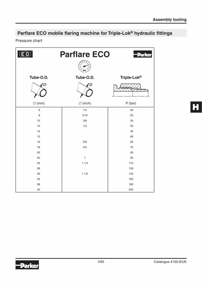
H
Assembly tooling
H35 Catalogue 4100-9/UK
Parfl are ECO mobile fl aring machine for Triple-Lok® hydraulic fi ttings
Pressure chart
Parfl are ECO
Tube-O.D.
� (mm)
Tube-O.D.
� (inch)
Triple-Lok®
P (bar)
6 1/4 20
8 5/16 25
10 3/8 35
12 1/2 35
14 45
15 60
16 5/8 60
18 3/4 70
20 95
22 1 95
25 1 1/4 110
28 130
30 1 1/2 140
35 165
38 180
42 200
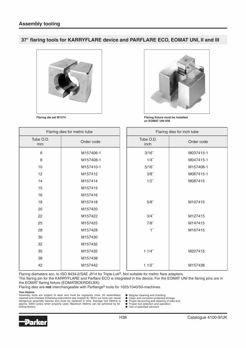
Assembly tooling
H36 Catalogue 4100-9/UK
37° fl aring tools for KARRYFLARE device and PARFLARE ECO, EOMAT UNI, II and III
Flaring fi xture must be installedon EOMAT UNI II/III
Flaring die set M1574
Flaring diameters acc. to ISO 8434-2/SAE J514 for Triple-Lok®. Not suitable for metric fl are adapters.The fl aring pin for the KARRYFLARE and Parfl are ECO is integrated in the device. For the EOMAT UNI the fl aring pins are in the EOMAT fl aring fi xture (EOMATBOERDELBX).Flaring dies are not interchangeable with Parfl ange® tools for 1025/1040/50-machines.
Tool lifetime Assembly tools are subject of wear and must be regularely (max. 50 assemblies) cleaned and checked (Checking instructions see chapter E). Worn out tools can cause dangerous assembly failures and must be replaced in time. Average tool lifetime is approx. 5000 cycles when properly used. Maximum lifetime can be achieved by fol-lowing factors:
� Regular cleaning and checking� Clean and corrosion-protected storage� Proper de-burring and cleaning of tube end� Proper tool selection and operation� Use of specifi ed lubricant
Flaring dies for metric tube
Tube O.D.mm
Order code
6
8
10
12
14
15
16
18
20
22
25
28
30
32
35
38
42
M157406-1
M157408-1
M157410-1
M157412
M157414
M157415
M157416
M157418
M157420
M157422
M157425
M157428
M157430
M157432
M157435
M157438
M157442
Flaring dies for inch tube
Tube O.D.inch
Order code
3/16˝
1/4˝
5/16˝
3/8˝
1/2˝
5/8˝
3/4˝
7/8˝
1˝
1 1/4˝
1 1/2˝
M037415-1
M047415-1
M157408-1
M067415-1
M087415
M107415
M127415
M147415
M167415
M207415
M157438
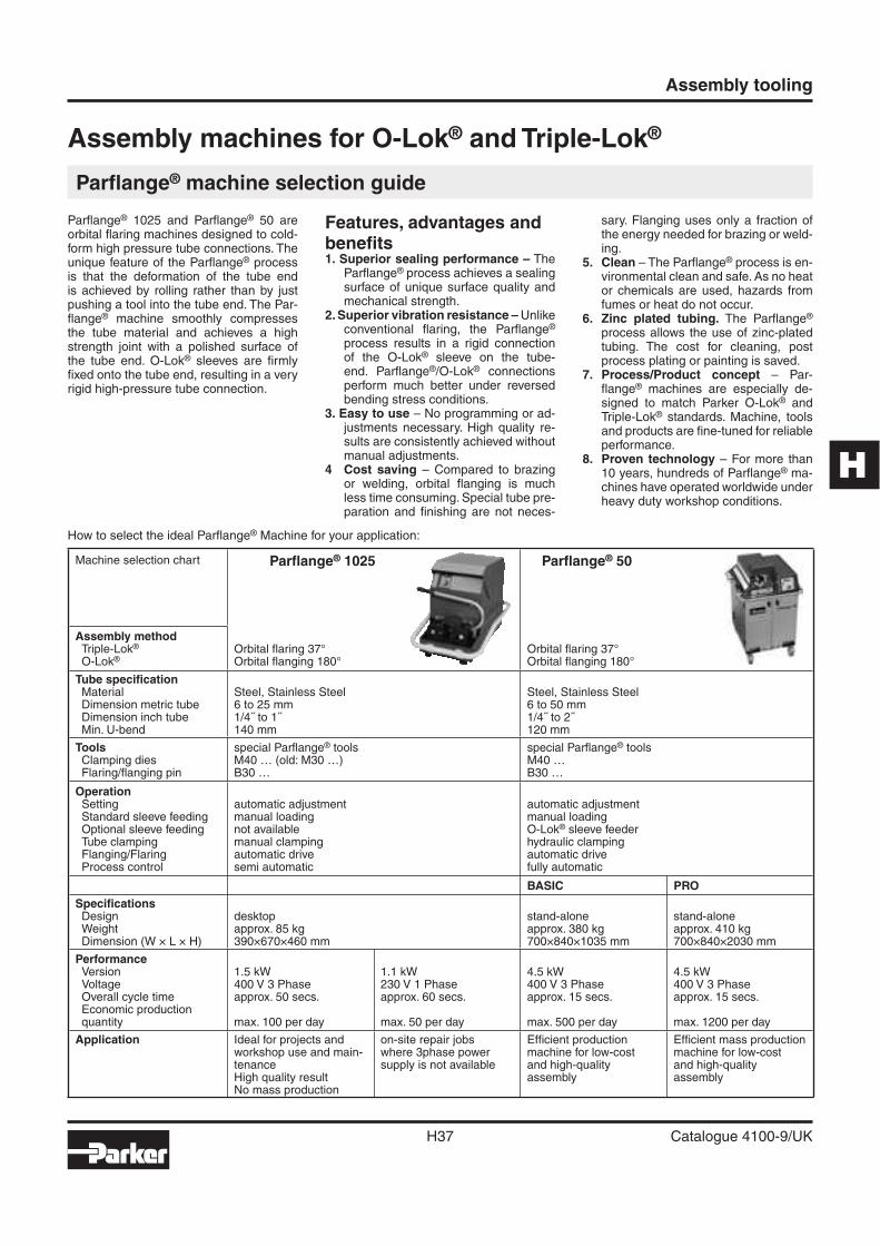
H
Assembly tooling
H37 Catalogue 4100-9/UK
Assembly machines for O-Lok® and Triple-Lok®
Parfl ange® machine selection guide
How to select the ideal Parfl ange® Machine for your application:
Parfl ange® 1025 and Parfl ange® 50 are orbital fl aring machines designed to cold-form high pressure tube connections. The unique feature of the Parfl ange® process is that the deformation of the tube end is achieved by rolling rather than by just pushing a tool into the tube end. The Par-fl ange® machine smoothly compresses the tube material and achieves a high strength joint with a polished surface of the tube end. O-Lok® sleeves are fi rmly fi xed onto the tube end, resulting in a very rigid high-pressure tube connection.
Features, advantages and benefi ts1. Superior sealing performance – The
Parfl ange® process achieves a sealing surface of unique surface quality and mechanical strength.
2. Superior vibration resistance – Unlike conventional fl aring, the Parfl ange® process results in a rigid connection of the O-Lok® sleeve on the tube-end. Parfl ange®/O-Lok® connections perform much better under reversed bending stress conditions.
3. Easy to use – No programming or ad-justments necessary. High quality re-sults are consistently achieved without manual adjustments.
4 Cost saving – Compared to brazing or welding, orbital fl anging is much less time consuming. Special tube pre-paration and fi nishing are not neces-
sary. Flanging uses only a fraction of the energy needed for brazing or weld-ing.
5. Clean – The Parfl ange® process is en-vironmental clean and safe. As no heat or chemicals are used, hazards from fumes or heat do not occur.
6. Zinc plated tubing. The Parfl ange® process allows the use of zinc-plated tubing. The cost for cleaning, post process plating or painting is saved.
7. Process/Product concept – Par-fl ange® machines are especially de-signed to match Parker O-Lok® and Triple-Lok® standards. Machine, tools and products are fi ne-tuned for reliable performance.
8. Proven technology – For more than 10 years, hundreds of Parfl ange® ma-chines have operated worldwide under heavy duty workshop conditions.
Machine selection chart Parfl ange® 1025 Parfl ange® 50
Assembly methodTriple-Lok®
O-Lok®Orbital fl aring 37° Orbital fl anging 180°
Orbital fl aring 37°Orbital fl anging 180°
Tube specifi cationMaterialDimension metric tubeDimension inch tubeMin. U-bend
Steel, Stainless Steel6 to 25 mm1/4˝ to 1˝140 mm
Steel, Stainless Steel6 to 50 mm1/4˝ to 2˝120 mm
ToolsClamping diesFlaring/fl anging pin
special Parfl ange® toolsM40 … (old: M30 …)B30 …
special Parfl ange® toolsM40 …B30 …
OperationSettingStandard sleeve feedingOptional sleeve feedingTube clampingFlanging/FlaringProcess control
automatic adjustmentmanual loadingnot availablemanual clampingautomatic drivesemi automatic
automatic adjustmentmanual loadingO-Lok® sleeve feederhydraulic clampingautomatic drivefully automatic
BASIC PRO
Specifi cationsDesignWeightDimension (W × L × H)
desktopapprox. 85 kg390×670×460 mm
stand-aloneapprox. 380 kg700×840×1035 mm
stand-aloneapprox. 410 kg700×840×2030 mm
PerformanceVersionVoltageOverall cycle timeEconomic productionquantity
1.5 kW400 V 3 Phaseapprox. 50 secs.
max. 100 per day
1.1 kW230 V 1 Phaseapprox. 60 secs.
max. 50 per day
4.5 kW400 V 3 Phaseapprox. 15 secs.
max. 500 per day
4.5 kW400 V 3 Phaseapprox. 15 secs.
max. 1200 per day
Application Ideal for projects andworkshop use and main-tenanceHigh quality resultNo mass production
on-site repair jobswhere 3phase powersupply is not available
Effi cient productionmachine for low-costand high-quality assembly
Effi cient mass productionmachine for low-costand high-qualityassembly
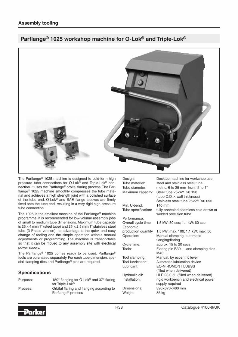
Assembly tooling
H38 Catalogue 4100-9/UK
Parfl ange® 1025 workshop machine for O-Lok® and Triple-Lok®
The Parfl ange® 1025 machine is designed to cold-form high pressure tube connections for O-Lok® and Triple-Lok® con-nection. It uses the Parfl ange® orbital fl aring process. The Par-fl ange® 1025 machine smoothly compresses the tube mate-rial and achieves a high strength joint with a polished surface of the tube end. O-Lok® and SAE fl ange sleeves are fi rmly fi xed onto the tube end, resulting in a very rigid high-pressure tube connection.
The 1025 is the smallest machine of the Parfl ange® machine programme. It is recommended for low-volume assembly jobs of small to medium tube dimensions. Maximum tube capacity is 25 × 4 mm/1˝ (steel tube) and 25 × 2.5 mm/1˝ stainless steel tube (3 Phase version). Its advantage is the quick and easy change of tooling and the simple operation without manual adjustments or programming. The machine is transportable so that it can be moved to any assembly site with electrical power supply.
The Parfl ange® 1025 comes ready to be used. Parfl ange® tools are purchased separately. For each tube dimension, spe-cial clamping dies and Parfl ange® pins are required.
Specifi cations
Purpose: 180° fl anging for O-Lok® and 37° fl aring for Triple-Lok®
Process: Orbital fl aring and fl anging according to Parfl ange® process
Design: Desktop machine for workshop use
Tube material: steel and stainless steel tube
Tube diameter: metric: 6 to 25 mm Inch: ¼ to 1˝
Maximum capacity: Steel tube 25×4/1˝×0.120
(tube O.D. × wall thickness)
Stainless steel tube 25×2/1˝×0.095
Min. U-bend: 140 mm
Tube specifi cation: fully annealed seamless cold drawn or welded precision tube
Performance:Overall cycle time 1.5 kW: 50 sec; 1.1 kW: 60 sec
Economicproduction quantity 1.5 kW: max. 100; 1.1 kW: max. 50
Operation: Manual clamping, automaticfl anging/fl aring
Cycle time: approx. 15 to 20 secs.
Tools: Flaring pin B30 … and clamping dies M40 …
Tool clamping: Manual, by eccentric lever
Tool lubrication: Automatic lubrication device
Lubricant: EO-NIROMONT LUBSS(fi lled when delivered)
Hydraulic oil: HLP 23 0.5L (fi lled when delivered)
Installation: rigid workbench and electrical power supply required
Dimensions: 390×670×460 mm
Weight: 85 kg
H
Assembly tooling
H39 Catalogue 4100-9/UK
Features, advantages and benefi ts
1. Superior sealing performance – The Parfl ange® process achieves a sealing surface of unique surface quality and mechanical strength.
2. Superior vibration resistance – Unlike conventional fl aring, the Parfl ange® process results in a rigid connec-tion of the O-Lok® sleeve on the tube-end. Parfl ange®/O-Lok® connections perform much better under re-versed bending stress conditions.
3. Easy to use – No programming or adjustments nec-essary. High quality results are consistently achieved without manual adjustments.
4. Quality – Machine setting, tool control and even lubri-cation are fully automated so that high and consistent quality results are achieved without manual adjust-ments.
5. Small bending radii – The compact clamping device and special dies are suitable for fl anging short tube ends.
6. Cost saving – Compared to brazing or welding, orbital fl anging is much less time consuming. Special tube preparation and fi nishing are not necessary. Flanging uses only a fraction of the energy needed for brazing or welding.
7. Clean – The Parfl ange® process is environmental clean and safe. As no heat or chemicals are used, hazards from fumes or heat do not occur.
8. Zinc plated tubing – The Parfl ange® process allows the use of zinc-plated tubing. The cost for cleaning or painting can be saved.
9. High tool lifetime – The Parfl ange® 1025 machine is equipped with an automatic lubrication device. The tools will not wear rapidely if the operator does not lu-bricate regularly.
10. Process/Product concept – Parfl ange® machines are especially designed to match Parker O-Lok® and Triple-Lok® standards. Machine, tools and products are fi ne-tuned for reliable performance.
11. Proven technology – Since more than 10 years, hun-dreds of Parfl ange® machines have operated world-wide under heavy duty workshop conditions.
Applications
Workshop use, project work, plant maintenance, on-site assembly.Not for effi cient mass production
Ordering
Type Order code
Parfl ange® 1025 Basic machineReady to use, Including operating manual,Filled with hydraulic oil and lubricantWithout Parfl ange® toolsBasic machine 400 V, 3 Phase, 50 HzBasic machine 230 V, 1 Phase, 50 Hz
1025-380VTRI501025-220VMONO50
1025 promotion leafl et UK 4390/UK
1025 promotion leafl et DE 4390/DE
1025 operating manual UK/DE/FR/IT 1025/MANUAL
Standard preventive maintenance 1025/INSPECTION
Parfl ange® machines are shipped in a special container which should be
kept for all transports to avoid damage.
Spare parts
Type Order code
Tool lubricant qty: 1L EO-NIROMONT LUBSS
Drive belt 1025/028Polyv
Came guide and with screw 1025/0281031
Hydraulic tank seal kit 1025/0281042
Lubrication kit 1025/0281200
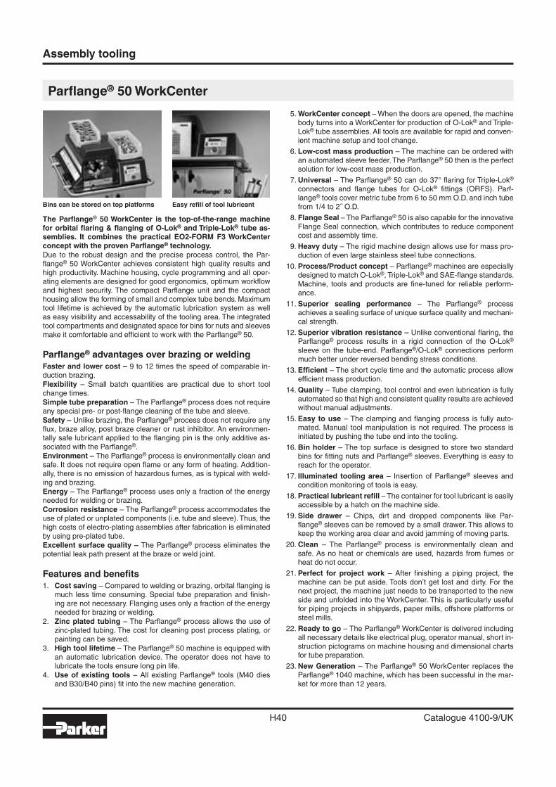
Assembly tooling
H40 Catalogue 4100-9/UK
Parfl ange® 50 WorkCenter
The Parfl ange® 50 WorkCenter is the top-of-the-range machine for orbital fl aring & fl anging of O-Lok® and Triple-Lok® tube as-semblies. It combines the practical EO2-FORM F3 WorkCenter concept with the proven Parfl ange® technology.Due to the robust design and the precise process control, the Par-fl ange® 50 WorkCenter achieves consistent high quality results and high productivity. Machine housing, cycle programming and all oper-ating elements are designed for good ergonomics, optimum workfl ow and highest security. The compact Parfl ange unit and the compact housing allow the forming of small and complex tube bends. Maximum tool lifetime is achieved by the automatic lubrication system as well as easy visibility and accessability of the tooling area. The integrated tool compartments and designated space for bins for nuts and sleeves make it comfortable and effi cient to work with the Parfl ange® 50.
Parfl ange® advantages over brazing or weldingFaster and lower cost – 9 to 12 times the speed of comparable in-duction brazing.Flexibility – Small batch quantities are practical due to short tool change times. Simple tube preparation – The Parfl ange® process does not require any special pre- or post-fl ange cleaning of the tube and sleeve.Safety – Unlike brazing, the Parfl ange® process does not require any fl ux, braze alloy, post braze cleaner or rust inhibitor. An environmen-tally safe lubricant applied to the fl anging pin is the only additive as-sociated with the Parfl ange®.Environment – The Parfl ange® process is environmentally clean and safe. It does not require open fl ame or any form of heating. Addition-ally, there is no emission of hazardous fumes, as is typical with weld-ing and brazing.Energy – The Parfl ange® process uses only a fraction of the energy needed for welding or brazing.Corrosion resistance – The Parfl ange® process accommodates the use of plated or unplated components (i.e. tube and sleeve). Thus, the high costs of electro-plating assemblies after fabrication is eliminated by using pre-plated tube.Excellent surface quality – The Parfl ange® process eliminates the potential leak path present at the braze or weld joint.
Features and benefi ts1. Cost saving – Compared to welding or brazing, orbital fl anging is
much less time consuming. Special tube preparation and fi nish-ing are not necessary. Flanging uses only a fraction of the energy needed for brazing or welding.
2. Zinc plated tubing – The Parfl ange® process allows the use of zinc-plated tubing. The cost for cleaning post process plating, or painting can be saved.
3. High tool lifetime – The Parfl ange® 50 machine is equipped with an automatic lubrication device. The operator does not have to lubricate the tools ensure long pin life.
4. Use of existing tools – All existing Parfl ange® tools (M40 dies and B30/B40 pins) fi t into the new machine generation.
5. WorkCenter concept – When the doors are opened, the machine body turns into a WorkCenter for production of O-Lok® and Triple-Lok® tube assemblies. All tools are available for rapid and conven-ient machine setup and tool change.
6. Low-cost mass production – The machine can be ordered with an automated sleeve feeder. The Parfl ange® 50 then is the perfect solution for low-cost mass production.
7. Universal – The Parfl ange® 50 can do 37° fl aring for Triple-Lok® connectors and fl ange tubes for O-Lok® fi ttings (ORFS). Parf-lange® tools cover metric tube from 6 to 50 mm O.D. and inch tube from 1/4 to 2˝ O.D.
8. Flange Seal – The Parfl ange® 50 is also capable for the innovative Flange Seal connection, which contributes to reduce component cost and assembly time.
9. Heavy duty – The rigid machine design allows use for mass pro-duction of even large stainless steel tube connections.
10. Process/Product concept – Parfl ange® machines are especially designed to match O-Lok®, Triple-Lok® and SAE-fl ange standards. Machine, tools and products are fi ne-tuned for reliable perform-ance.
11. Superior sealing performance – The Parfl ange® process achieves a sealing surface of unique surface quality and mechani-cal strength.
12. Superior vibration resistance – Unlike conventional fl aring, the Parfl ange® process results in a rigid connection of the O-Lok® sleeve on the tube-end. Parfl ange®/O-Lok® connections perform much better under reversed bending stress conditions.
13. Effi cient – The short cycle time and the automatic process allow effi cient mass production.
14. Quality – Tube clamping, tool control and even lubrication is fully automated so that high and consistent quality results are achieved without manual adjustments.
15. Easy to use – The clamping and fl anging process is fully auto-mated. Manual tool manipulation is not required. The process is initiated by pushing the tube end into the tooling.
16. Bin holder – The top surface is designed to store two standard bins for fi tting nuts and Parfl ange® sleeves. Everything is easy to reach for the operator.
17. Illuminated tooling area – Insertion of Parfl ange® sleeves and condition monitoring of tools is easy.
18. Practical lubricant refi ll – The container for tool lubricant is easily accessible by a hatch on the machine side.
19. Side drawer – Chips, dirt and dropped components like Par-fl ange® sleeves can be removed by a small drawer. This allows to keep the working area clear and avoid jamming of moving parts.
20. Clean – The Parfl ange® process is environmentally clean and safe. As no heat or chemicals are used, hazards from fumes or heat do not occur.
21. Perfect for project work – After fi nishing a piping project, the machine can be put aside. Tools don’t get lost and dirty. For the next project, the machine just needs to be transported to the new side and unfolded into the WorkCenter. This is particularly useful for piping projects in shipyards, paper mills, offshore platforms or steel mills.
22. Ready to go – The Parfl ange® WorkCenter is delivered including all necessary details like electrical plug, operator manual, short in-struction pictograms on machine housing and dimensional charts for tube preparation.
23. New Generation – The Parfl ange® 50 WorkCenter replaces the Parfl ange® 1040 machine, which has been successful in the mar-ket for more than 12 years.
Bins can be stored on top platforms Easy refi ll of tool lubricant
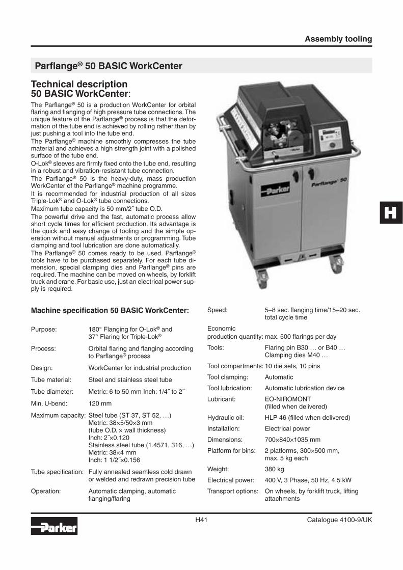
H
Assembly tooling
H41 Catalogue 4100-9/UK
Technical description50 BASIC WorkCenter:The Parfl ange® 50 is a production WorkCenter for orbital fl aring and fl anging of high pressure tube connections. The unique feature of the Parfl ange® process is that the defor-mation of the tube end is achieved by rolling rather than by just pushing a tool into the tube end.
The Parfl ange® machine smoothly compresses the tube material and achieves a high strength joint with a polished surface of the tube end.
O-Lok® sleeves are fi rmly fi xed onto the tube end, resulting in a robust and vibration-resistant tube connection.
The Parfl ange® 50 is the heavy-duty, mass production WorkCenter of the Parfl ange® machine programme.
It is recommended for industrial production of all sizes Triple-Lok® and O-Lok® tube connections.
Maximum tube capacity is 50 mm/2˝ tube O.D.
The powerful drive and the fast, automatic process allow short cycle times for effi cient production. Its advantage is the quick and easy change of tooling and the simple op-eration without manual adjustments or programming. Tube clamping and tool lubrication are done automatically.
The Parfl ange® 50 comes ready to be used. Parfl ange® tools have to be purchased separately. For each tube di-mension, special clamping dies and Parfl ange® pins are required. The machine can be moved on wheels, by forklift truck and crane. For basic use, just an electrical power sup-ply is required.
Parfl ange® 50 BASIC WorkCenter
Machine specifi cation 50 BASIC WorkCenter:
Purpose: 180° Flanging for O-Lok® and37° Flaring for Triple-Lok®
Process: Orbital fl aring and fl anging according to Parfl ange® process
Design: WorkCenter for industrial production
Tube material: Steel and stainless steel tube
Tube diameter: Metric: 6 to 50 mm Inch: 1/4˝ to 2˝
Min. U-bend: 120 mm
Maximum capacity: Steel tube (ST 37, ST 52, …)Metric: 38×5/50×3 mm(tube O.D. × wall thickness)Inch: 2˝×0.120Stainless steel tube (1.4571, 316, …)Metric: 38×4 mmInch: 1 1/2˝×0.156
Tube specifi cation: Fully annealed seamless cold drawn or welded and redrawn precision tube
Operation: Automatic clamping, automatic fl anging/fl aring
Speed: 5–8 sec. fl anging time/15–20 sec. total cycle time
Economic
production quantity: max. 500 fl arings per day
Tools: Flaring pin B30 … or B40 …Clamping dies M40 …
Tool compartments: 10 die sets, 10 pins
Tool clamping: Automatic
Tool lubrication: Automatic lubrication device
Lubricant: EO-NIROMONT(fi lled when delivered)
Hydraulic oil: HLP 46 (fi lled when delivered)
Installation: Electrical power
Dimensions: 700×840×1035 mm
Platform for bins: 2 platforms, 300×500 mm,max. 5 kg each
Weight: 380 kg
Electrical power: 400 V, 3 Phase, 50 Hz, 4.5 kW
Transport options: On wheels, by forklift truck, lifting attachments
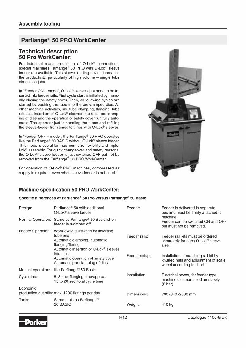
Assembly tooling
H42 Catalogue 4100-9/UK
Technical description50 Pro WorkCenter:For industrial mass production of O-Lok® connections, special machines Parfl ange® 50 PRO with O-Lok® sleeve feeder are available. This sleeve feeding device increases the productivity, particularly of high volume – single tube dimension jobs.
In “Feeder ON – mode”, O-Lok® sleeves just need to be in-serted into feeder rails. First cycle start is initiated by manu-ally closing the safety cover. Then, all following cycles are started by pushing the tube into the pre-clamped dies. All other machine activities, like tube clamping, fl anging, tube release, insertion of O-Lok® sleeves into dies, pre-clamp-ing of dies and the operation of safety cover run fully auto-matic. The operator just is handling the tubes and refi lling the sleeve-feeder from times to times with O-Lok® sleeves.
In “Feeder OFF – mode”, the Parfl ange® 50 PRO operates like the Parfl ange® 50 BASIC without O-Lok® sleeve feeder. This mode is useful for maximum size fl exibility and Triple-Lok® assembly. For quick changeover and safety reasons, the O-Lok® sleeve feeder is just switched OFF but not be removed from the Parfl ange® 50 PRO WorkCenter.
For operation of O-Lok® PRO machines, compressed air supply is required, even when sleeve feeder is not used.
Parfl ange® 50 PRO WorkCenter
Design: Parfl ange® 50 with additionalO-Lok® sleeve feeder
Normal Operation: Same as Parfl ange® 50 Basic when feeder is switched off
Feeder Operation: Work-cycle is initiated by inserting tube endAutomatic clamping, automatic fl anging/fl aringAutomatic insertion of O-Lok® sleeves into diesAutomatic operation of safety coverAutomatic pre-clamping of dies
Manual operation: like Parfl ange® 50 Basic
Cycle time: 5–8 sec. fl anging time/approx.15 to 20 sec. total cycle time
Economicproduction quantity: max. 1200 fl arings per day
Tools: Same tools as Parfl ange®
50 BASIC
Feeder: Feeder is delivered in separate box and must be fi rmly attached to machine.Feeder can be switched ON and OFF but must not be removed.
Feeder rails: Feeder rail kits must be ordered separately for each O-Lok® sleeve size.
Feeder setup: Installation of matching rail kit by knurled nuts and adjustment of scale wheel according to chart
Installation: Electrical power, for feeder type machines: compressed air supply(6 bar)
Dimensions: 700×840×2030 mm
Weight: 410 kg
Machine specifi cation 50 PRO WorkCenter:
Specifi c differences of Parfl ange® 50 Pro versus Parfl ange® 50 Basic
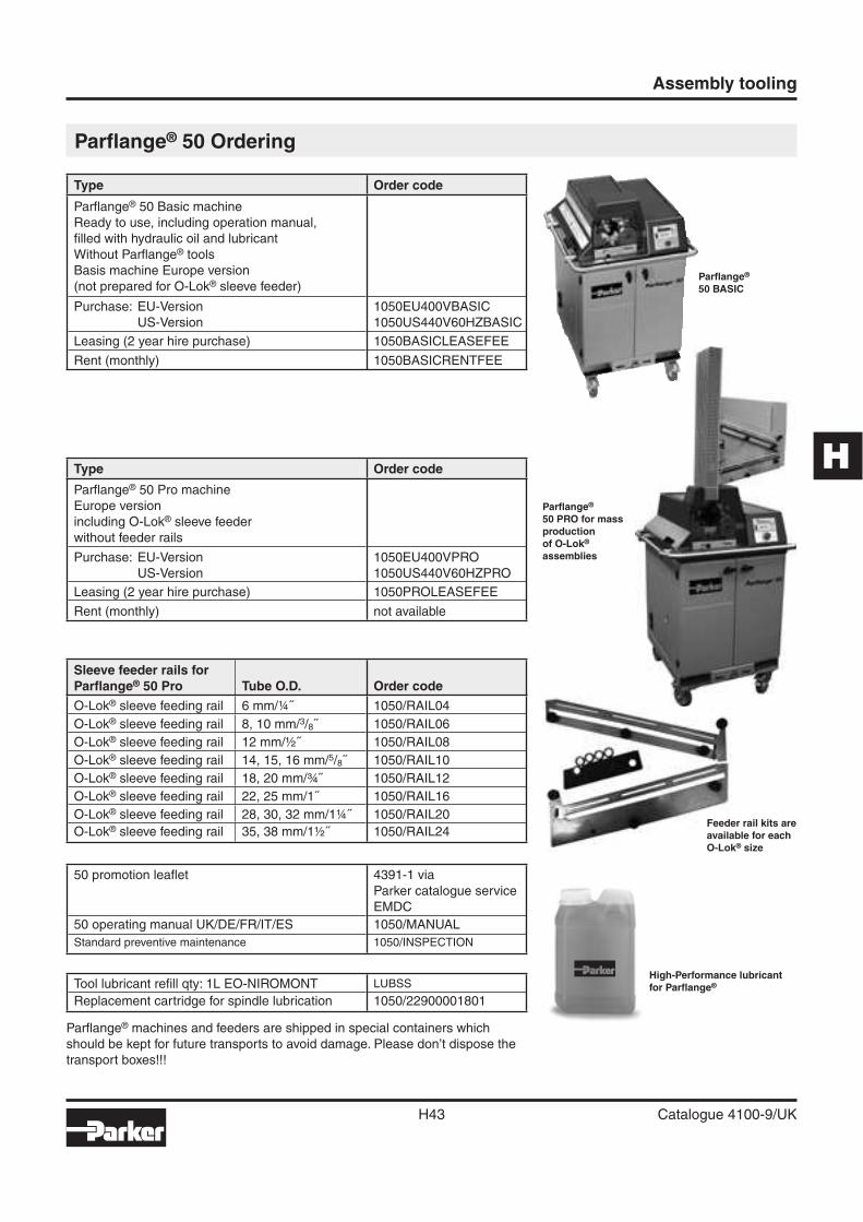
H
Assembly tooling
H43 Catalogue 4100-9/UK
Parfl ange®
50 BASIC
Parfl ange®
50 PRO for mass production of O-Lok® assemblies
Feeder rail kits are available for each O-Lok® size
High-Performance lubricant for Parfl ange®
Parfl ange® 50 Ordering
Type Order code
Parfl ange® 50 Basic machine
Ready to use, including operation manual,
fi lled with hydraulic oil and lubricant
Without Parfl ange® tools
Basis machine Europe version
(not prepared for O-Lok® sleeve feeder)
Purchase: EU-Version
US-Version
1050EU400VBASIC
1050US440V60HZBASIC
Leasing (2 year hire purchase) 1050BASICLEASEFEE
Rent (monthly) 1050BASICRENTFEE
Type Order code
Parfl ange® 50 Pro machine
Europe version
including O-Lok® sleeve feeder
without feeder rails
Purchase: EU-Version
US-Version
1050EU400VPRO
1050US440V60HZPRO
Leasing (2 year hire purchase) 1050PROLEASEFEE
Rent (monthly) not available
Sleeve feeder rails forParfl ange® 50 Pro Tube O.D. Order code
O-Lok® sleeve feeding rail 6 mm/¼˝ 1050/RAIL04
O-Lok® sleeve feeding rail 8, 10 mm/3/8˝ 1050/RAIL06
O-Lok® sleeve feeding rail 12 mm/½˝ 1050/RAIL08
O-Lok® sleeve feeding rail 14, 15, 16 mm/5/8˝ 1050/RAIL10
O-Lok® sleeve feeding rail 18, 20 mm/¾˝ 1050/RAIL12
O-Lok® sleeve feeding rail 22, 25 mm/1˝ 1050/RAIL16
O-Lok® sleeve feeding rail 28, 30, 32 mm/1¼˝ 1050/RAIL20
O-Lok® sleeve feeding rail 35, 38 mm/1½˝ 1050/RAIL24
50 promotion leafl et 4391-1 via
Parker catalogue service
EMDC
50 operating manual UK/DE/FR/IT/ES 1050/MANUAL
Standard preventive maintenance 1050/INSPECTION
Tool lubricant refi ll qty: 1L EO-NIROMONT LUBSS
Replacement cartridge for spindle lubrication 1050/22900001801
Parfl ange® machines and feeders are shipped in special containers which
should be kept for future transports to avoid damage. Please don’t dispose the
transport boxes!!!
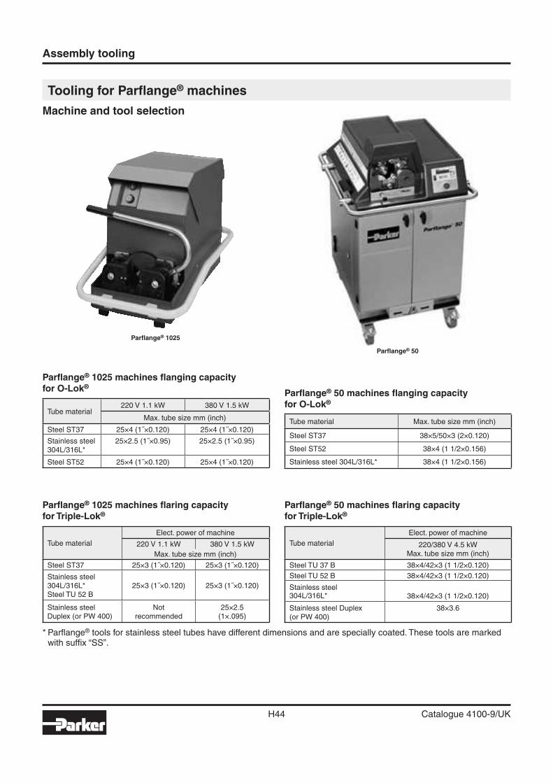
Assembly tooling
H44 Catalogue 4100-9/UK
* Parfl ange® tools for stainless steel tubes have different dimensions and are specially coated. These tools are marked with suffi x “SS”.
Tooling for Parfl ange® machines
Machine and tool selection
Tube material220 V 1.1 kW 380 V 1.5 kW
Max. tube size mm (inch)
Steel ST37 25×4 (1˝×0.120) 25×4 (1˝×0.120)
Stainless steel304L/316L*
25×2.5 (1˝×0.95) 25×2.5 (1˝×0.95)
Steel ST52 25×4 (1˝×0.120) 25×4 (1˝×0.120)
Tube material
Elect. power of machine
220 V 1.1 kW 380 V 1.5 kW
Max. tube size mm (inch)
Steel ST37 25×3 (1˝×0.120) 25×3 (1˝×0.120)
Stainless steel304L/316L*Steel TU 52 B
25×3 (1˝×0.120) 25×3 (1˝×0.120)
Stainless steelDuplex (or PW 400)
Notrecommended
25×2.5(1×.095)
Parfl ange® 1025 machines fl aring capacityfor Triple-Lok®
Tube material
Elect. power of machine
220/380 V 4.5 kWMax. tube size mm (inch)
Steel TU 37 B 38×4/42×3 (1 1/2×0.120)
Steel TU 52 B 38×4/42×3 (1 1/2×0.120)
Stainless steel304L/316L* 38×4/42×3 (1 1/2×0.120)
Stainless steel Duplex(or PW 400)
38×3.6
Parfl ange® 50 machines fl aring capacityfor Triple-Lok®
Parfl ange® 1025 machines fl anging capacityfor O-Lok®
Tube material Max. tube size mm (inch)
Steel ST37 38×5/50×3 (2×0.120)
Steel ST52 38×4 (1 1/2×0.156)
Stainless steel 304L/316L* 38×4 (1 1/2×0.156)
Parfl ange® 50 machines fl anging capacityfor O-Lok®
Parfl ange® 50
Parfl ange® 1025
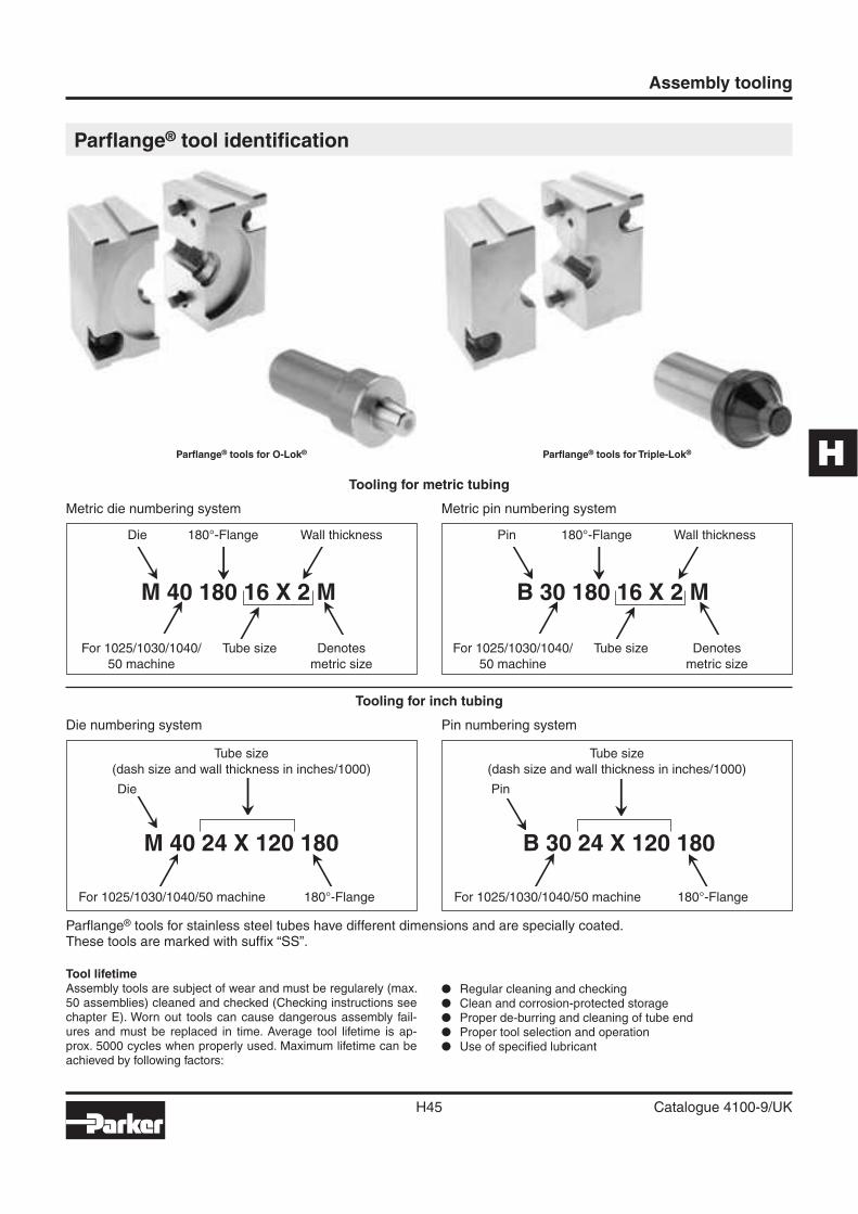
H
Assembly tooling
H45 Catalogue 4100-9/UK
Tooling for metric tubing
Metric die numbering system Metric pin numbering system
Die 180°-Flange Wall thickness Pin 180°-Flange Wall thickness
M 40 180 16 X 2 M B 30 180 16 X 2 M
For 1025/1030/1040/ Tube size Denotes For 1025/1030/1040/ Tube size Denotes
50 machine metric size 50 machine metric size
Parfl ange® tool identifi cation
Parfl ange® tools for O-Lok® Parfl ange® tools for Triple-Lok®
Parfl ange® tools for stainless steel tubes have different dimensions and are specially coated.These tools are marked with suffi x “SS”.
Tool lifetimeAssembly tools are subject of wear and must be regularely (max. 50 assemblies) cleaned and checked (Checking instructions see chapter E). Worn out tools can cause dangerous assembly fail-ures and must be replaced in time. Average tool lifetime is ap-prox. 5000 cycles when properly used. Maximum lifetime can be achieved by following factors:
� Regular cleaning and checking� Clean and corrosion-protected storage� Proper de-burring and cleaning of tube end� Proper tool selection and operation� Use of specifi ed lubricant
Tooling for inch tubing
Die numbering system Pin numbering system
Tube size Tube size
(dash size and wall thickness in inches/1000) (dash size and wall thickness in inches/1000)
Die Pin
M 40 24 X 120 180 B 30 24 X 120 180
For 1025/1030/1040/50 machine 180°-Flange For 1025/1030/1040/50 machine 180°-Flange
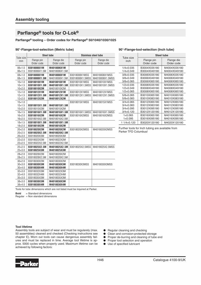
Assembly tooling
H46 Catalogue 4100-9/UK
Parfl ange® tools for O-Lok®
Parfl ange® tooling – Order codes for Parfl ange® 50/1040/1030/1025
Tool lifetimeAssembly tools are subject of wear and must be regularely (max. 50 assemblies) cleaned and checked (Checking instructions see chapter E). Worn out tools can cause dangerous assembly fail-ures and must be replaced in time. Average tool lifetime is ap-prox. 5000 cycles when properly used. Maximum lifetime can be achieved by following factors:
� Regular cleaning and checking� Clean and corrosion-protected storage� Proper de-burring and cleaning of tube end� Proper tool selection and operation� Use of specifi ed lubricant
90°-Flange-tool-selection (Metric tube)
Tube sizemm
Steel tube Stainless steel tube
Flange pinOrder code
Flange dieOrder code
Flange pinOrder code
Flange dieOrder code
06×1.006×1.5
B3018006X1MB3018006X1.5M
M4018006X1MM4018006X1.5M
08×1.008×1.5
B3018008X1MB3018008X1.5M
M4018008X1MM4018008X1.5M
B3018008X1MSSB3018008X1.5MSS
M4018008X1MSSM4018008X1.5MSS
10×1.010×1.510×2.0
B3018010X1MB3018010X1.5MB3018010X2M
M4018010X1MM4018010X1.5MM4018010X2M
B3018010X1MSSB3018010X1.5MSS
M4018010X1MSSM4018010X1.5MSS
12×1.012×1.512×2.0
B3018012X1MB3018012X1.5MB3018012X2M
M4018012X1MM4018012X1.5MM4018012X2M
B3018012X1MSSB3018012X1.5MSS
M4018012X1MSSM4018012X1.5MSS
15×1.015×1.515×2.0
B3018015X1.5MB3018015X2M
M4018015X1.5MM4018015X2M
B3018015X1MSS M4018015X1MSS
16×1.516×2.016×2.5
B3018016X1.5MB3018016X2MB3018016X2.5M
M4018016X1.5MM4018016X2MM4018016X2.5M
B3018016X1.5MSSB3018016X2MSS
M4018016X1.5MSSM4018016X2MSS
18×1.518×2.0
B3018018X1.5MB3018018X2M
M4018018X1.5MM4018018X2M
20×2.020×2.520×3.0
B3018020X2MB3018020X2.5MB3018020X3M
M4018020X2MM4018020X2.5MM4018020X3M
B3018020X2MSS M4018020X2MSS
22×2.022×2.5
B3018022X2MB3018022X2.5M
M4018022X2MM4018022X2.5M
25×2.525×3.0
B3018025X2.5MB3018025X3M
M4018025X2.5MM4018025X3M
B3018025X2.5MSS M4018025X2.5MSS
28×2.028×2.5
B3018028X2MB3018028X2.5M
M4018028X2MM4018028X2.5M
30×2.030×3.030×4.0
B3018030X2MB3018030X3MB3018030X4M
M4018030X2MM4018030X3MM4018030X4M
B3018030X3MSS M4018030X3MSS
32×3.032×4.035×3.0
B3018032X3MB3018032X4MB3018035X3M
M4018032X3MM4018032X4MM4018035X3M
38×3.038×4.0
B3018038X3MB3018038X4M
M4018038X3MM4018038X4M
Tools for tube dimensions which are not listed must be inquired at Parker.
Bold = Standard dimensionsRegular = Non standard dimensions
90°-Flange-tool-selection (Inch tube)
Tube sizeinch
Steel tube
Flange pinOrder code
Flange dieOrder code
1/4×0.0351/4×0.049
B3004X035180B3004X049180
M4004X035180M4004X049180
3/8×0.0353/8×0.0493/8×0.065
B3006X035180B3006X049180B3006X065180
M4006X035180M4006X049180M4006X065180
1/2×0.0351/2×0.0491/2×0.065
B3008X035180B3008X049180B3008X065180
M4008X035180M4008X049180M4008X065180
5/8×0.0655/8×0.083
B3010X065180B3010X083180
M4010X065180M4010X083180
3/4×0.0653/4×0.0833/4×0.0953/4×0.120
B3012X065180B3012X083180B3012X095180B3012X120180
M4012X065180M4012X083180M4012X095180M4012X120180
1×0.0651×0.095
B3016X065180B3016X095180
M4016X065180M4016X095180
1 1/4×0.120 B3020X120180 M4020X120180
Further tools for Inch tubing are available fromParker TFD Columbus!
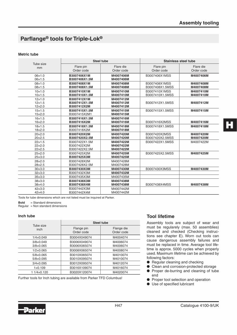
H
Assembly tooling
H47 Catalogue 4100-9/UK
Parfl ange® tools for Triple-Lok®
Tool lifetime
Assembly tools are subject of wear and must be regularely (max. 50 assemblies) cleaned and checked (Checking instruc-tions see chapter E). Worn out tools can cause dangerous assembly failures and must be replaced in time. Average tool life-time is approx. 5000 cycles when properly used. Maximum lifetime can be achieved by following factors:� Regular cleaning and checking� Clean and corrosion-protected storage� Proper de-burring and cleaning of tube
end� Proper tool selection and operation� Use of specifi ed lubricant
Metric tube
Tube sizemm
Steel tube Stainless steel tube
Flare pinOrder code
Flare dieOrder code
Flare pinOrder code
Flare dieOrder code
06×1.006×1.5
B3007406X1MB3007406X1.5M
M4007406MM4007406M
B3007406X1MSS M4007406M
08×1.008×1.5
B3007408X1MB3007408X1.5M
M4007408MM4007408M
B3007408X1MSSB3007408X1.5MSS
M4007408MM4007408M
10×1.010×1.5
B3007410X1MB3007410X1.5M
M4007410MM4007410M
B3007410X1MSSB3007410X1.5MSS
M4007410MM4007410M
12×1.012×1.512×2.0
B3007412X1MB3007412X1.5MB3007412X2M
M4007412MM4007412MM4007412M
B3007412X1.5MSS M4007412M
15×1.515×2.0
B3007415X1.5MB3007415X2M1
M4007415MM4007415M
B3007415X1.5MSS M4007415M
16×1.516×2.0
B3007416X1.5MB3007416X2M
M4007416MM4007416M B3007416X2MSS M4007416M
18×1.518×2.0
B3007418X1.5MB3007418X2M
M4007418MM4007418M
B3007418X1.5MSS M4007418M
20×2.020×2.5
B3007420X2MB3007420X2.5M
M4007420MM4007420M
B3007420X2MSSB3007420X2.5MSS
M4007420MM4007420M
22×1.5 22×2.022×2.5
B3007422X1.5MB3007422X2MB3007422X2.5M
M4007422MM4007422MM4007422M
B3007422X1.5MSS M4007422M
25×2.025×3.0
B3007425X2MB3007425X3M
M4007425MM4007425M
B3007425X2.5MSS M4007425M
28×2.028×2.5
B3007428X2MB3007428X2.5M
M4007428MM4007428M
30×3.0 B3007430X3M M4007430M B3007430X3MSS M4007430M
32×3.0 B3007432X3M M4007432M
35×3.0 B3007435X3M M4007435M
38×3.038×4.0
B3007438X3MB3007438X4M
M4007438MM4007438M B3007438X4MSS M4007438M
42×3.042×4.0
B3007442X3MB3007442X4M
M4007442MM4007442M
Tools for tube dimensions which are not listed must be inquired at Parker.
Bold = Standard dimensionsRegular = Non standard dimensions
Inch tube
Tube sizeinch
Steel tube
Flange pinOrder code
Flange dieOrder code
1/4×0.049 B3004X049074 M4004074
3/8×0.0493/8×0.065
B3006X049074B3006X065074
M4006074M4006074
1/2×0.065 B3008X065074 M4008074
5/8×0.0655/8×0.095
B3010X065074B3010X095074
M4010074M4010074
3/4×0.095 B3012X095074 M4012074
1×0.109 B3016X109074 M4016074
1 1/4×0.120 B3020X120074 M4020074
Further tools for Inch tubing are available from Parker TFD Columbus!
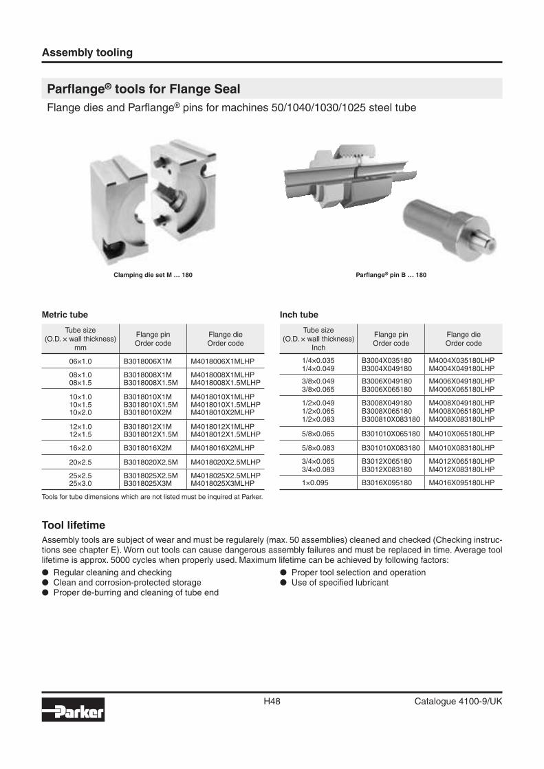
Assembly tooling
H48 Catalogue 4100-9/UK
Parfl ange® tools for Flange Seal
Flange dies and Parfl ange® pins for machines 50/1040/1030/1025 steel tube
Clamping die set M … 180 Parfl ange® pin B … 180
Tool lifetime
Assembly tools are subject of wear and must be regularely (max. 50 assemblies) cleaned and checked (Checking instruc-tions see chapter E). Worn out tools can cause dangerous assembly failures and must be replaced in time. Average tool lifetime is approx. 5000 cycles when properly used. Maximum lifetime can be achieved by following factors:
� Regular cleaning and checking� Clean and corrosion-protected storage� Proper de-burring and cleaning of tube end
� Proper tool selection and operation� Use of specifi ed lubricant
Metric tube
Tube size(O.D. × wall thickness)
mm
Flange pinOrder code
Flange dieOrder code
06×1.0 B3018006X1M M4018006X1MLHP
08×1.008×1.5
B3018008X1MB3018008X1.5M
M4018008X1MLHPM4018008X1.5MLHP
10×1.010×1.510×2.0
B3018010X1MB3018010X1.5MB3018010X2M
M4018010X1MLHPM4018010X1.5MLHPM4018010X2MLHP
12×1.012×1.5
B3018012X1MB3018012X1.5M
M4018012X1MLHPM4018012X1.5MLHP
16×2.0 B3018016X2M M4018016X2MLHP
20×2.5 B3018020X2.5M M4018020X2.5MLHP
25×2.525×3.0
B3018025X2.5MB3018025X3M
M4018025X2.5MLHPM4018025X3MLHP
Tools for tube dimensions which are not listed must be inquired at Parker.
Inch tube
Tube size(O.D. × wall thickness)
Inch
Flange pinOrder code
Flange dieOrder code
1/4×0.0351/4×0.049
B3004X035180B3004X049180
M4004X035180LHPM4004X049180LHP
3/8×0.0493/8×0.065
B3006X049180B3006X065180
M4006X049180LHPM4006X065180LHP
1/2×0.0491/2×0.0651/2×0.083
B3008X049180B3008X065180B300810X083180
M4008X049180LHPM4008X065180LHPM4008X083180LHP
5/8×0.065 B301010X065180 M4010X065180LHP
5/8×0.083 B301010X083180 M4010X083180LHP
3/4×0.0653/4×0.083
B3012X065180B3012X083180
M4012X065180LHPM4012X083180LHP
1×0.095 B3016X095180 M4016X095180LHP
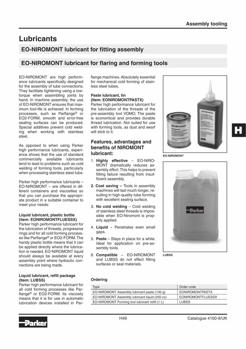
H
Assembly tooling
H49 Catalogue 4100-9/UK
Lubricants
EO-NIROMONT lubricant for fi tting assembly
EO-NIROMONT lubricant for fl aring and forming tools
EO-NIROMONT are high perform-ance lubricants specifi cally designed for the assembly of tube connections. They facilitate tightening using a low-torque when assembling joints by hand. In machine assembly, the use of EO-NIROMONT ensures that max-imum tool-life is achieved. In forming processes, such as Parfl ange® or EO2-FORM, smooth and error-free sealing surfaces can be produced. Special additives prevent cold weld-ing when working with stainlesssteel.
As opposed to when using Parker high performance lubricants, experi-ence shows that the use of standard commercially available lubricants tend to lead to problems such as cold welding of forming tools, particularly when processing stainless steel tube.
Parker high performance lubricants – EO-NIROMONT – are offered in dif-ferent containers and viscosities so that you can purchase the appropri-ate product in a suitable container to meet your needs:
Liquid lubricant, plastic bottle (item: EONIROMONTFLUESSX)Parker high performance lubricant for the lubrication of threads, progressive rings and for all cold forming process-es like Parfl ange® or EO2-FORM. The handy plastic bottle means that it can be applied directly where the lubrica-tion is needed. EO-NIROMONT liquid should always be available at every assembly point where hydraulic con-nections are being made.
Liquid lubricant, refi ll package (Item: LUBSS) Parker high performance lubricant for all cold forming processes like Par-fl ange® or EO2-FORM. Its viscosity means that it is for use in automatic lubrication devices installed in Par-
fl ange machines. Absolutely essential for mechanical cold forming of stain-less steel tubes.
Paste lubricant, tin(Item: EONIROMONTPASTX)Parker high performance lubricant for the lubrication of the threads of the pre-assembly tool VOMO. The paste is economical and provides durable thread lubrication. Not suited for use with forming tools, as dust and swarf will stick to it.
Features, advantages and benefi ts of NIROMONT lubricant:
1. Highly effective – EO-NIRO-MONT dramatically reduces as-sembly effort. This helps to prevent fi tting failure resulting from insuf-fi cient assembly.
2. Cost saving – Tools in assembly machines will last much longer, re-sulting in high-quality tube forming with excellent sealing surface.
3. No cold welding – Cold welding of stainless steel threads is impos-sible when EO-Niromont is prop-erly applied.
4. Liquid – Penetrates even small gaps.
5. Paste – Stays in place for a while. Ideal for application on pre-as-sembly tools.
6. Compatible – EO-NIROMONT and LUBSS do not effect fi tting surfaces or seal materials.
LUBSS
EO-NIROMONT
Ordering
Type Order code
EO-NIROMONT Assembly lubricant paste (130 g) EONIROMONTPASTX
EO-NIROMONT Assembly lubricant liquid (250 cc) EONIROMONTFLUESSX
EO-NIROMONT Forming tool lubricant refi ll (1 L) LUBSS
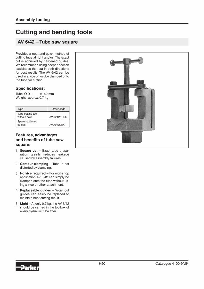
Assembly tooling
H50 Catalogue 4100-9/UK
Provides a neat and quick method of cutting tube at right angles. The exact cut is achieved by hardened guides. We recommend using deeper-section sawblades that cut in both directions for best results. The AV 6/42 can be used in a vice or just be clamped onto the tube for cutting.
Specifi cations:
Tube. O.D.: 6–42 mmWeight: approx. 0.7 kg
Type Order code
Tube cutting toolwithout saw AV06/42KPLX
Spare hardenedguides AV06/4208X
Features, advantages and benefi ts of tube saw square:
1. Square cut – Exact tube prepa-ration greatly reduces leakage caused by assembly failures.
2. Contour clamping – Tube is not distorted by clamping.
3. No vice required – For workshop application AV 6/42 can simply be clamped onto the tube without us-ing a vice or other attachment.
4. Replaceable guides – Worn out guides can easily be replaced to maintain neat cutting result.
5. Light – At only 0.7 kg, the AV 6/42 should be carried in the toolbox of every hydraulic tube fi tter.
Cutting and bending tools
AV 6/42 – Tube saw square
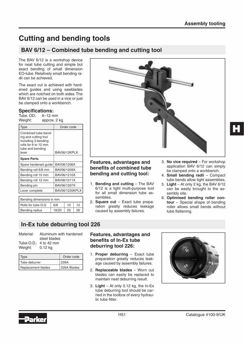
H
Assembly tooling
H51 Catalogue 4100-9/UK
Cutting and bending tools
BAV 6/12 – Combined tube bending and cutting tool
The BAV 6/12 is a workshop device for neat tube cutting and simple but exact bending of small dimension EO-tube. Relatively small bending ra-dii can be achieved.
The exact cut is achieved with hard-ened guides and using sawblades which are notched on both sides. The BAV 6/12 can be used in a vice or just be clamped onto a workbench.
Specifi cations:Tube. OD: 6–12 mmWeight: approx. 2 kg
Type Order code
Combined tube bend-ing and cutting toolincluding 3 bendingrolls for 6 to 12 mmtube and bendinglever BAV06/12KPLX
Spare Parts
Spare hardened guide BAV06/1206X
Bending roll 6/8 mm BAV06/1209X
Bending roll 10 mm BAV06/1210X
Bending roll 12 mm BAV06/1211X
Bending pin BAV06/1207X
Lever complete BAV06/1220KPLX
Bending dimensions in mm
Rolls for tube O.D. 6/8 10 12
Bending radius 19/20 25 26
In-Ex tube deburring tool 226
Material: Aluminum with hardened steel blades
Tube-O.D.: 4 to 42 mmWeight: 0.12 kg
Type Order code
Tube deburrer 226A
Replacement blades 226A Blades
Features, advantages and benefi ts of In-Ex tube deburring tool 226:
1. Proper deburring – Exact tube preparation greatly reduces leak-age caused by assembly failures.
2. Replaceable blades – Worn out blades can easily be replaced to maintain neat deburring result.
3. Light – At only 0.12 kg, the In-Ex tube deburring tool should be car-ried in the toolbox of every hydrau-lic tube fi tter.
Features, advantages and benefi ts of combined tube bending and cutting tool:
1. Bending and cutting – The BAV 6/12 is a light multi-purpose tool for all small dimension tube as-semblies.
2. Square cut – Exact tube prepa-ration greatly reduces leakage caused by assembly failures.
3. No vice required – For workshop application BAV 6/12 can simply be clamped onto a workbench.
4. Small bending radii – Compact tube bends allow tight assemblies.
5. Light – At only 2 kg, the BAV 6/12 can be easily brought to the as-sembly site.
6. Optimised bending roller con-tour – Special shape of bending roller allows small bends without tube fl attening.
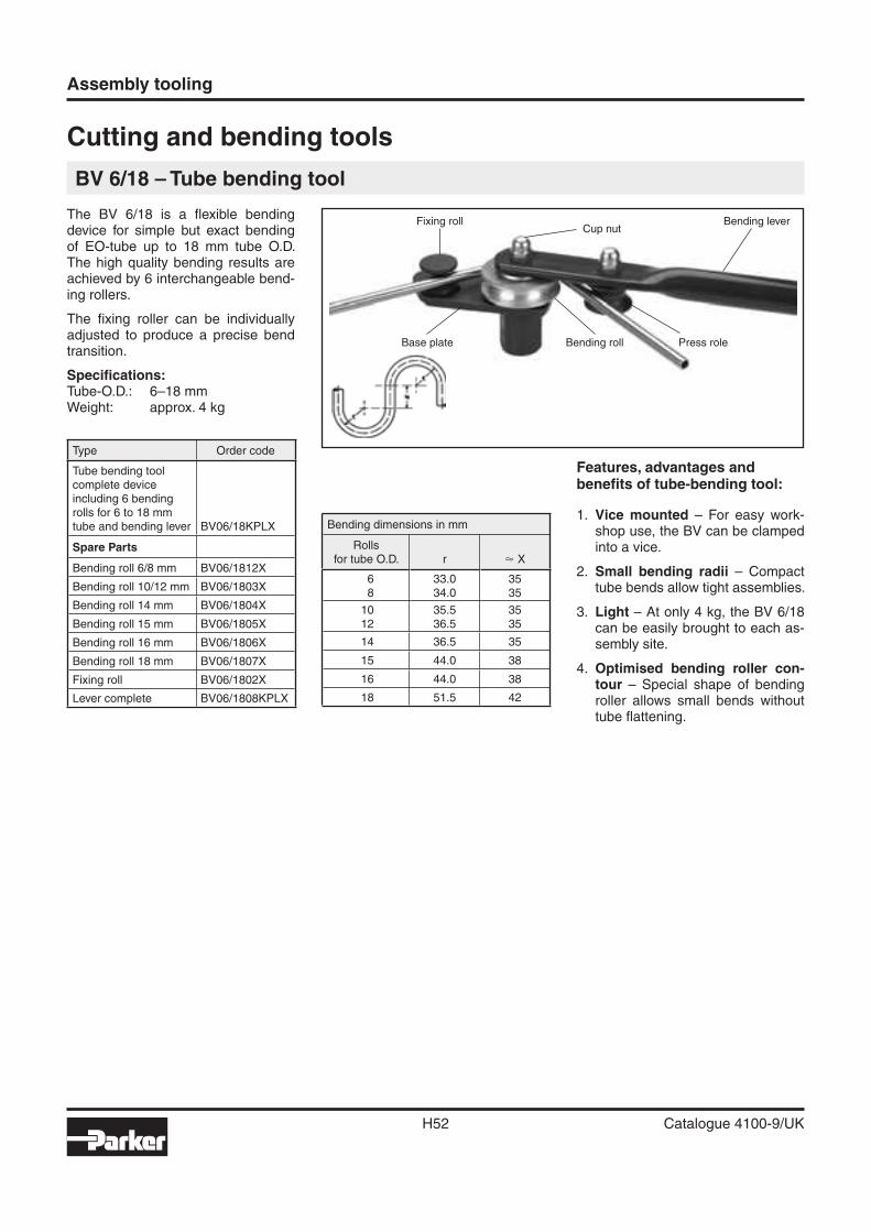
Assembly tooling
H52 Catalogue 4100-9/UK
Cutting and bending tools
BV 6/18 – Tube bending tool
The BV 6/18 is a fl exible bending device for simple but exact bending of EO-tube up to 18 mm tube O.D. The high quality bending results are achieved by 6 interchangeable bend-ing rollers.
The fi xing roller can be individually adjusted to produce a precise bend transition.
Specifi cations:Tube-O.D.: 6–18 mmWeight: approx. 4 kg
Type Order code
Tube bending toolcomplete deviceincluding 6 bendingrolls for 6 to 18 mmtube and bending lever BV06/18KPLX
Spare Parts
Bending roll 6/8 mm BV06/1812X
Bending roll 10/12 mm BV06/1803X
Bending roll 14 mm BV06/1804X
Bending roll 15 mm BV06/1805X
Bending roll 16 mm BV06/1806X
Bending roll 18 mm BV06/1807X
Fixing roll BV06/1802X
Lever complete BV06/1808KPLX
Bending dimensions in mm
Rollsfor tube O.D. r � X
68
33.034.0
3535
1012
35.536.5
3535
14 36.5 35
15 44.0 38
16 44.0 38
18 51.5 42
Features, advantages and benefi ts of tube-bending tool:
1. Vice mounted – For easy work-shop use, the BV can be clamped into a vice.
2. Small bending radii – Compact tube bends allow tight assemblies.
3. Light – At only 4 kg, the BV 6/18 can be easily brought to each as-sembly site.
4. Optimised bending roller con-tour – Special shape of bending roller allows small bends without tube fl attening.
Base plate
Fixing roll
Bending roll
Cup nut
Press role
Bending lever
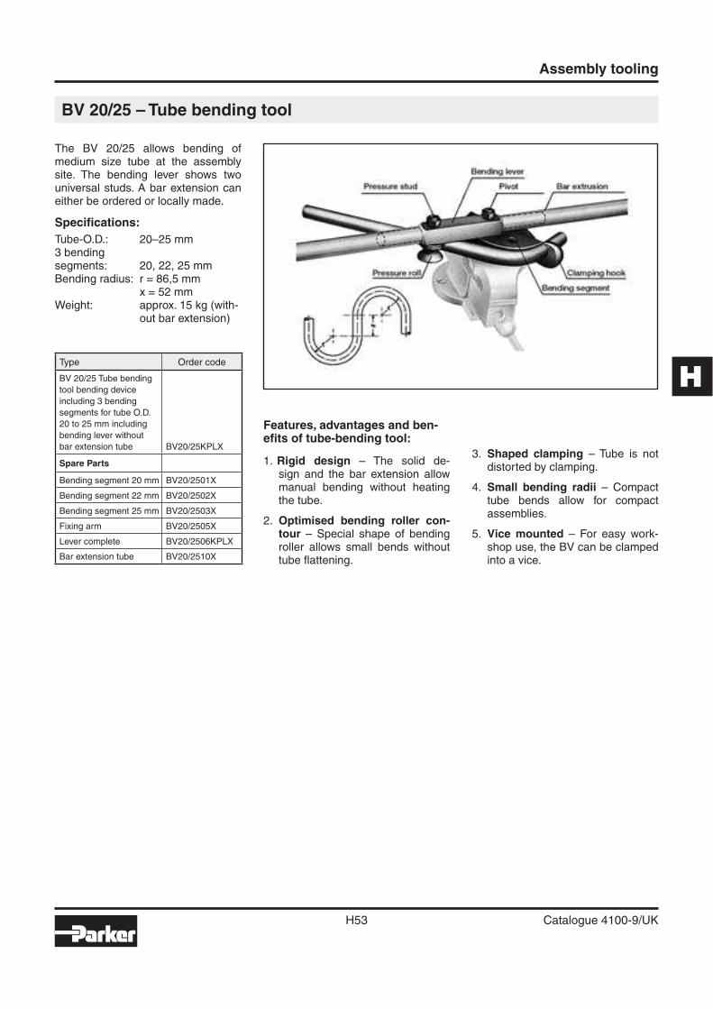
H
Assembly tooling
H53 Catalogue 4100-9/UK
Features, advantages and ben-efi ts of tube-bending tool:
1. Rigid design – The solid de-sign and the bar extension allow manual bending without heating the tube.
2. Optimised bending roller con-tour – Special shape of bending roller allows small bends without tube fl attening.
BV 20/25 – Tube bending tool
The BV 20/25 allows bending of medium size tube at the assembly site. The bending lever shows two universal studs. A bar extension can either be ordered or locally made.
Specifi cations:
Tube-O.D.: 20–25 mm3 bendingsegments: 20, 22, 25 mmBending radius: r = 86,5 mm
x = 52 mmWeight: approx. 15 kg (with-
out bar extension)
Type Order code
BV 20/25 Tube bending
tool bending device
including 3 bending
segments for tube O.D.
20 to 25 mm including
bending lever without
bar extension tube BV20/25KPLX
Spare Parts
Bending segment 20 mm BV20/2501X
Bending segment 22 mm BV20/2502X
Bending segment 25 mm BV20/2503X
Fixing arm BV20/2505X
Lever complete BV20/2506KPLX
Bar extension tube BV20/2510X
3. Shaped clamping – Tube is not distorted by clamping.
4. Small bending radii – Compact tube bends allow for compact assemblies.
5. Vice mounted – For easy work-shop use, the BV can be clamped into a vice.
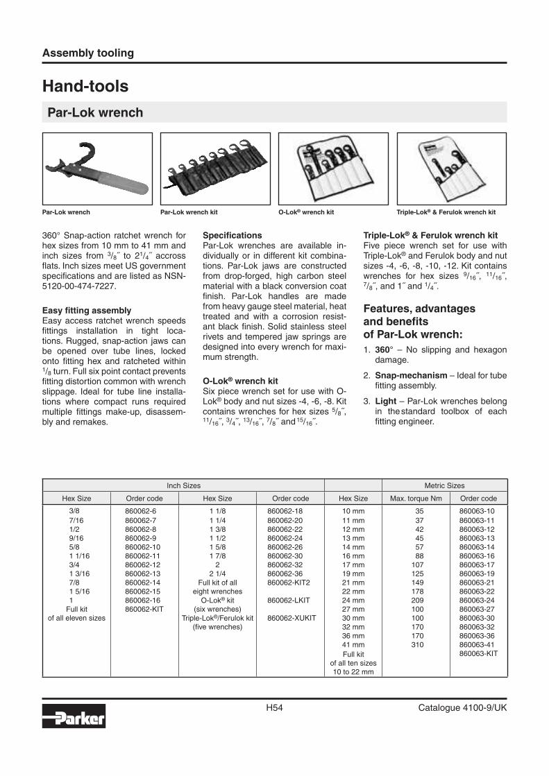
Assembly tooling
H54 Catalogue 4100-9/UK
Hand-tools
Par-Lok wrench
360° Snap-action ratchet wrench for hex sizes from 10 mm to 41 mm and inch sizes from 3/8˝ to 21/4˝ accross fl ats. Inch sizes meet US government specifi cations and are listed as NSN-5120-00-474-7227.
Easy fi tting assemblyEasy access ratchet wrench speeds fi ttings installation in tight loca-tions. Rugged, snap-action jaws can be opened over tube lines, locked onto fi tting hex and ratcheted within1/8 turn. Full six point contact prevents fi tting distortion common with wrench slippage. Ideal for tube line installa-tions where compact runs required multiple fi ttings make-up, disassem-bly and remakes.
Specifi cationsPar-Lok wrenches are available in-dividually or in different kit combina-tions. Par-Lok jaws are constructed from drop-forged, high carbon steel material with a black conversion coat fi nish. Par-Lok handles are made from heavy gauge steel material, heat treated and with a corrosion resist-ant black fi nish. Solid stainless steel rivets and tempered jaw springs are designed into every wrench for maxi-mum strength.
O-Lok® wrench kitSix piece wrench set for use with O-Lok® body and nut sizes -4, -6, -8. Kit contains wrenches for hex sizes 5/8˝, 11/16˝, 3/4˝, 13/16˝, 7/8˝ and 15/16˝.
Triple-Lok® & Ferulok wrench kitFive piece wrench set for use with Triple-Lok® and Ferulok body and nut sizes -4, -6, -8, -10, -12. Kit contains wrenches for hex sizes 9/16˝, 11/16˝, 7/8˝, and 1˝ and 1/4˝.
Features, advantagesand benefi tsof Par-Lok wrench:
1. 360° – No slipping and hexagon damage.
2. Snap-mechanism – Ideal for tube fi tting assembly.
3. Light – Par-Lok wrenches belong in the standard toolbox of each fi tting engineer.
Par-Lok wrench Par-Lok wrench kit O-Lok® wrench kit Triple-Lok® & Ferulok wrench kit
Inch Sizes Metric Sizes
Hex Size Order code Hex Size Order code Hex Size Max. torque Nm Order code
3/8 860062-6 1 1/8 860062-18 10 mm 35 860063-10
7/16 860062-7 1 1/4 860062-20 11 mm 37 860063-111/2 860062-8 1 3/8 860062-22 12 mm 42 860063-129/16 860062-9 1 1/2 860062-24 13 mm 45 860063-135/8 860062-10 1 5/8 860062-26 14 mm 57 860063-141 1/16 860062-11 1 7/8 860062-30 16 mm 88 860063-163/4 860062-12 2 860062-32 17 mm 107 860063-171 3/16 860062-13 2 1/4 860062-36 19 mm 125 860063-197/8 860062-14 Full kit of all
eight wrenches860062-KIT2 21 mm 149 860063-21
1 5/16 860062-15 22 mm 178 860063-221 860062-16 O-Lok® kit
(six wrenches)860062-LKIT 24 mm 209 860063-24
Full kitof all eleven sizes
860062-KIT 27 mm 100 860063-27Triple-Lok®/Ferulok kit
(fi ve wrenches)860062-XUKIT 30 mm 100 860063-30
32 mm 170 860063-3236 mm 170 860063-3641 mm 310 860063-41
Full kitof all ten sizes10 to 22 mm
860063-KIT
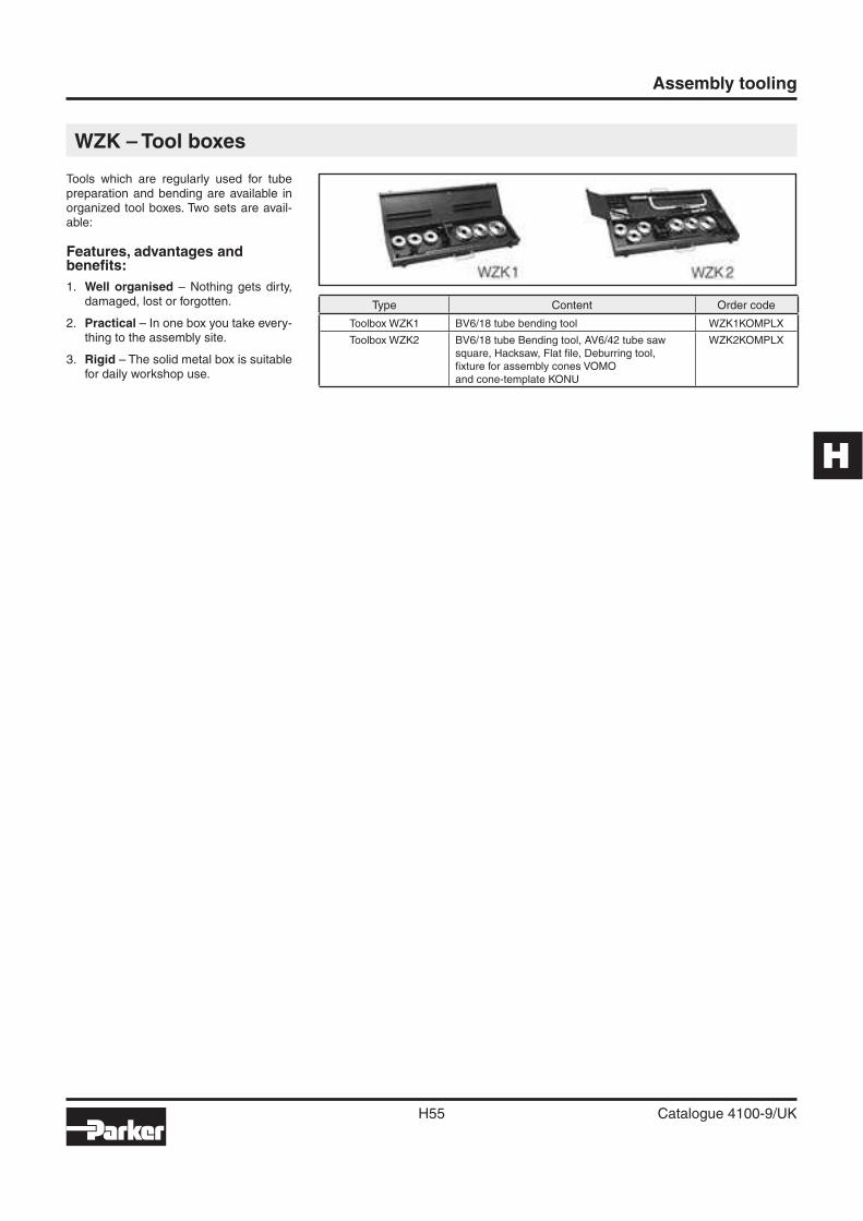
H
Assembly tooling
H55 Catalogue 4100-9/UK
WZK – Tool boxes
Tools which are regularly used for tube preparation and bending are available in organized tool boxes. Two sets are avail-able:
Features, advantages and benefi ts:
1. Well organised – Nothing gets dirty, damaged, lost or forgotten.
2. Practical – In one box you take every-thing to the assembly site.
3. Rigid – The solid metal box is suitable for daily workshop use.
Type Content Order code
Toolbox WZK1 BV6/18 tube bending tool WZK1KOMPLX
Toolbox WZK2 BV6/18 tube Bending tool, AV6/42 tube sawsquare, Hacksaw, Flat fi le, Deburring tool,fi xture for assembly cones VOMOand cone-template KONU
WZK2KOMPLX
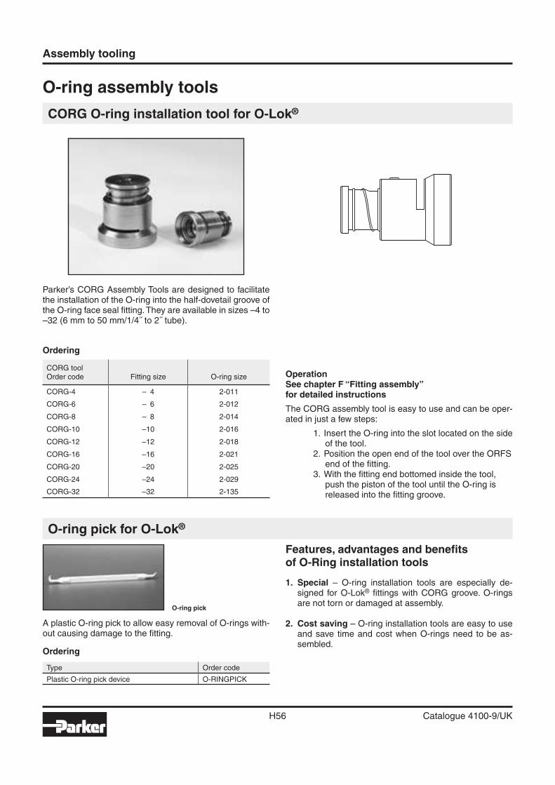
Assembly tooling
H56 Catalogue 4100-9/UK
O-ring assembly tools
CORG O-ring installation tool for O-Lok®
Parker’s CORG Assembly Tools are designed to facilitate the installation of the O-ring into the half-dovetail groove of the O-ring face seal fi tting. They are available in sizes –4 to –32 (6 mm to 50 mm/1/4˝ to 2˝ tube).
OperationSee chapter F “Fitting assembly”for detailed instructions
The CORG assembly tool is easy to use and can be oper-ated in just a few steps:
1. Insert the O-ring into the slot located on the side of the tool.
2. Position the open end of the tool over the ORFS end of the fi tting.
3. With the fi tting end bottomed inside the tool, push the piston of the tool until the O-ring is released into the fi tting groove.
O-ring pick for O-Lok®
A plastic O-ring pick to allow easy removal of O-rings with-out causing damage to the fi tting.
Ordering
Type Order code
Plastic O-ring pick device O-RINGPICK
O-ring pick
Features, advantages and benefi tsof O-Ring installation tools
1. Special – O-ring installation tools are especially de-signed for O-Lok® fi ttings with CORG groove. O-rings are not torn or damaged at assembly.
2. Cost saving – O-ring installation tools are easy to use and save time and cost when O-rings need to be as-sembled.
Ordering
CORG toolOrder code Fitting size O-ring size
CORG-4 – 4 2-011
CORG-6 – 6 2-012
CORG-8 – 8 2-014
CORG-10 –10 2-016
CORG-12 –12 2-018
CORG-16 –16 2-021
CORG-20 –20 2-025
CORG-24 –24 2-029
CORG-32 –32 2-135
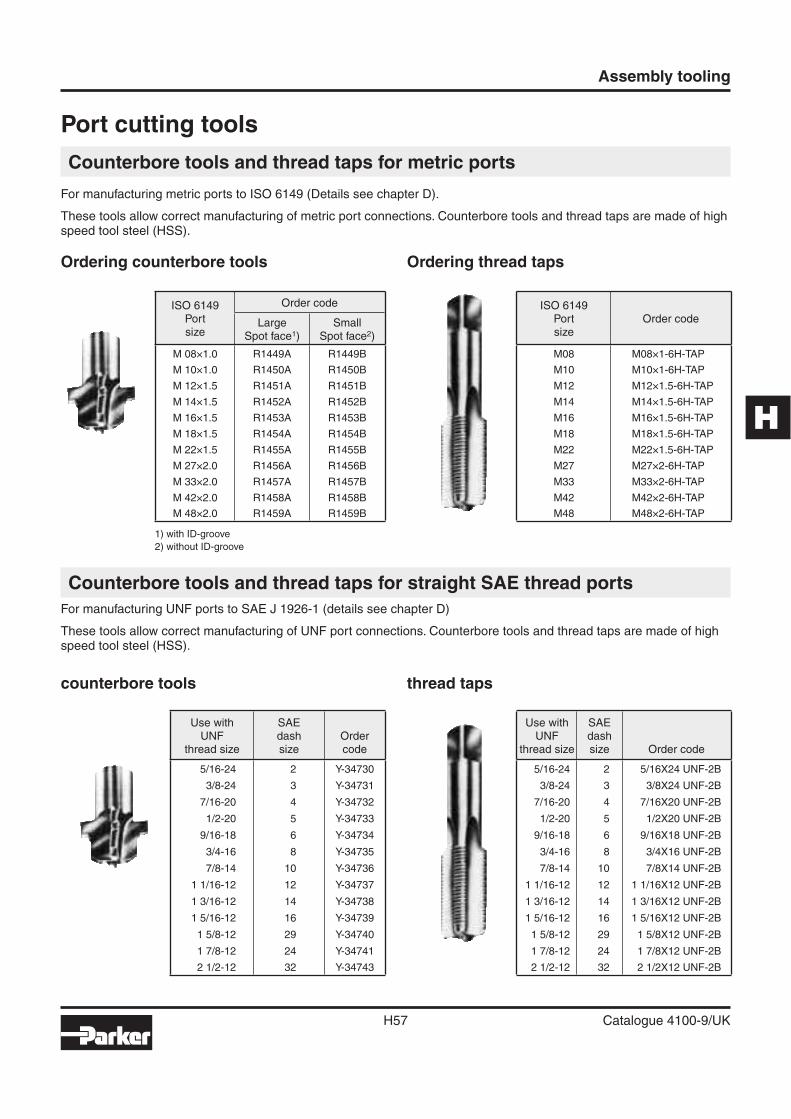
H
Assembly tooling
H57 Catalogue 4100-9/UK
Port cutting tools
Counterbore tools and thread taps for metric ports
For manufacturing metric ports to ISO 6149 (Details see chapter D).
These tools allow correct manufacturing of metric port connections. Counterbore tools and thread taps are made of high speed tool steel (HSS).
Ordering thread tapsOrdering counterbore tools
Counterbore tools and thread taps for straight SAE thread ports
For manufacturing UNF ports to SAE J 1926-1 (details see chapter D)
These tools allow correct manufacturing of UNF port connections. Counterbore tools and thread taps are made of high speed tool steel (HSS).
counterbore tools thread taps
ISO 6149Portsize
Order code
LargeSpot face1)
SmallSpot face2)
M 08×1.0 R1449A R1449B
M 10×1.0 R1450A R1450B
M 12×1.5 R1451A R1451B
M 14×1.5 R1452A R1452B
M 16×1.5 R1453A R1453B
M 18×1.5 R1454A R1454B
M 22×1.5 R1455A R1455B
M 27×2.0 R1456A R1456B
M 33×2.0 R1457A R1457B
M 42×2.0 R1458A R1458B
M 48×2.0 R1459A R1459B
1) with ID-groove
2) without ID-groove
ISO 6149Portsize
Order code
M08 M08×1-6H-TAP
M10 M10×1-6H-TAP
M12 M12×1.5-6H-TAP
M14 M14×1.5-6H-TAP
M16 M16×1.5-6H-TAP
M18 M18×1.5-6H-TAP
M22 M22×1.5-6H-TAP
M27 M27×2-6H-TAP
M33 M33×2-6H-TAP
M42 M42×2-6H-TAP
M48 M48×2-6H-TAP
Use withUNF
thread size
SAEdashsize
Ordercode
5/16-24 2 Y-34730
3/8-24 3 Y-34731
7/16-20 4 Y-34732
1/2-20 5 Y-34733
9/16-18 6 Y-34734
3/4-16 8 Y-34735
7/8-14 10 Y-34736
1 1/16-12 12 Y-34737
1 3/16-12 14 Y-34738
1 5/16-12 16 Y-34739
1 5/8-12 29 Y-34740
1 7/8-12 24 Y-34741
2 1/2-12 32 Y-34743
Use withUNF
thread size
SAEdashsize Order code
5/16-24 2 5/16X24 UNF-2B
3/8-24 3 3/8X24 UNF-2B
7/16-20 4 7/16X20 UNF-2B
1/2-20 5 1/2X20 UNF-2B
9/16-18 6 9/16X18 UNF-2B
3/4-16 8 3/4X16 UNF-2B
7/8-14 10 7/8X14 UNF-2B
1 1/16-12 12 1 1/16X12 UNF-2B
1 3/16-12 14 1 3/16X12 UNF-2B
1 5/16-12 16 1 5/16X12 UNF-2B
1 5/8-12 29 1 5/8X12 UNF-2B
1 7/8-12 24 1 7/8X12 UNF-2B
2 1/2-12 32 2 1/2X12 UNF-2B
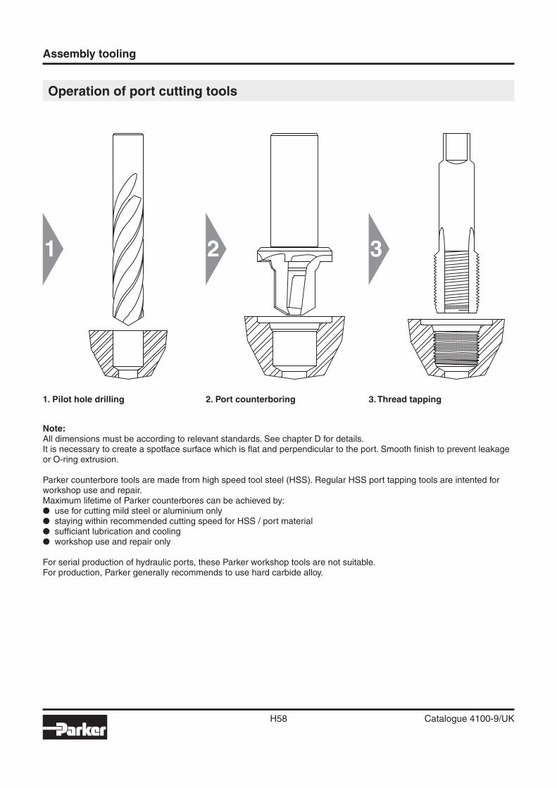
1 2 3
Assembly tooling
H58 Catalogue 4100-9/UK
Operation of port cutting tools
1. Pilot hole drilling 2. Port counterboring 3. Thread tapping
Note:All dimensions must be according to relevant standards. See chapter D for details.It is necessary to create a spotface surface which is fl at and perpendicular to the port. Smooth fi nish to prevent leakage or O-ring extrusion.
Parker counterbore tools are made from high speed tool steel (HSS). Regular HSS port tapping tools are intented for workshop use and repair.Maximum lifetime of Parker counterbores can be achieved by:� use for cutting mild steel or aluminium only� staying within recommended cutting speed for HSS / port material� suffi ciant lubrication and cooling� workshop use and repair only
For serial production of hydraulic ports, these Parker workshop tools are not suitable.For production, Parker generally recommends to use hard carbide alloy.
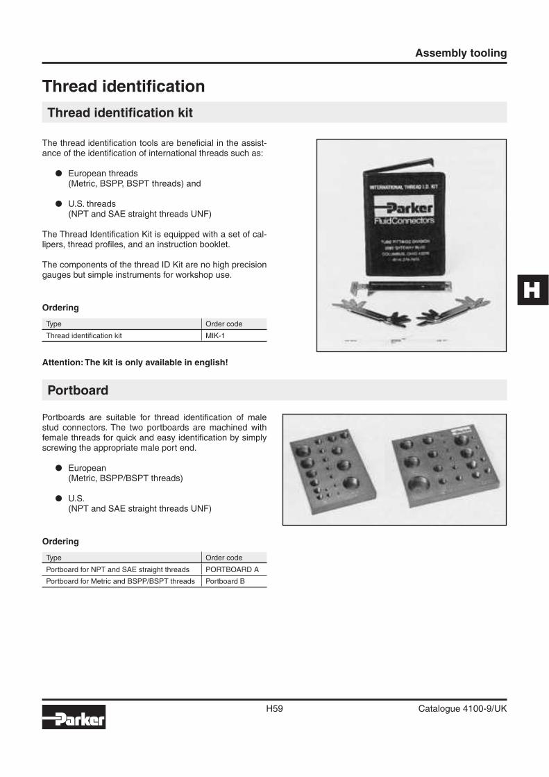
H
Assembly tooling
H59 Catalogue 4100-9/UK
Portboard
Thread identifi cation
Thread identifi cation kit
The thread identifi cation tools are benefi cial in the assist-ance of the identifi cation of international threads such as:
� European threads(Metric, BSPP, BSPT threads) and
� U.S. threads(NPT and SAE straight threads UNF)
The Thread Identifi cation Kit is equipped with a set of cal-lipers, thread profi les, and an instruction booklet.
The components of the thread ID Kit are no high precision gauges but simple instruments for workshop use.
Ordering
Type Order code
Thread identifi cation kit MIK-1
Portboards are suitable for thread identifi cation of male stud connectors. The two portboards are machined with female threads for quick and easy identifi cation by simply screwing the appropriate male port end.
� European(Metric, BSPP/BSPT threads)
� U.S.(NPT and SAE straight threads UNF)
Ordering
Type Order code
Portboard for NPT and SAE straight threads PORTBOARD A
Portboard for Metric and BSPP/BSPT threads Portboard B
Attention: The kit is only available in english!


