Embed Size (px)
Citation preview
7700 MultiFrame Manual 7751TG2-HD Dual HD-SDI Test Signal Generator with Embedded Audio
Revision 1.8
TABLE OF CONTENTS
1. OVERVIEW.......................................................................................................................................... 1
2. INSTALLATION................................................................................................................................... 3
3. SPECIFICATIONS............................................................................................................................... 5
3.1. GENLOCK INPUT....................................................................................................................... 5
3.2. HD SERIAL VIDEO OUTPUTS................................................................................................... 5
3.3. SD SERIAL VIDEO OUTPUTS (7751TG2-CF-HD ONLY)......................................................... 6
3.4. ELECTRICAL ............................................................................................................................. 6
3.5. COMPACT FLASH MEMORY (7751TG2-CF-HD VERSION)..................................................... 6
3.6. PHYSICAL.................................................................................................................................. 6
4. STATUS LEDS.................................................................................................................................... 7
4.1. MODULE STATUS LEDS........................................................................................................... 7
4.2. AUDIO GROUP STATUS LEDS................................................................................................. 7
5. CARD EDGE CONTROLS .................................................................................................................. 8
5.1. SELECTING THE OUTPUT VIDEO FORMAT............................................................................ 8
5.2. SELECTING THE GENLOCK REFERENCE TYPE.................................................................. 10 5.2.1. Selecting the Genlock Source....................................................................................... 10
5.3. SELECTING THE COLOUR SPACE IN 4:4:4 MODE............................................................... 10
5.4. SELECTING THE OUTPUT MODE (4:2:2 OR 4:4:4) ............................................................... 11
5.5. SELECTING THE TEST SIGNAL ............................................................................................. 11 5.5.1. Description of Unique Test Signals ............................................................................... 13
5.5.1.1. Clean Aperture with Graticule .......................................................................... 13 5.5.1.2. Production Aperture ......................................................................................... 13 5.5.1.3. Grey Signals .................................................................................................... 14 5.5.1.4. 4x3 Colour Bars ............................................................................................... 14 5.5.1.5. Long Sequence Signals ................................................................................... 14 5.5.1.6. Bouncing Box................................................................................................... 14 5.5.1.7. Four Frame 24P and 24PsF Signals................................................................ 14
5.5.2. Description of Unique 4:4:4 GBRA Test Signals ........................................................... 15
7700 MultiFrame Manual 7751TG2-HD Dual HD-SDI Test Signal Generator with Embedded Audio
Revision 1.8
5.5.2.1. FS Bars with 2 Scalings ................................................................................... 15 5.5.2.2. FS 10 Step B & W Pluge.................................................................................. 15 5.5.2.3. FS 7 Step B & W Pluge.................................................................................... 15
5.6. CONFIGURING THE TEST GENERATOR USING THE ON SCREEN MENU ......................... 15 5.6.1. Top Level Menu Structure ............................................................................................. 16 5.6.2. Configuring 7751TG2-HD Genlock Input ...................................................................... 16
5.6.2.1. Selecting the Genlock Input Type .................................................................... 17 5.6.2.2. Setting the Timing of the Output Video with Respect to the Genlock Input ..... 17
5.6.3. Configuring 7751TG2-HD Embedded Audio Parameters ............................................. 20 5.6.3.1. Audio Group Selection ..................................................................................... 20 5.6.3.2. Audio Channel Selection.................................................................................. 21 5.6.3.3. Audio Group Embedding.................................................................................. 21 5.6.3.4. Audio Level Control (7751TG2-HD version only)............................................. 21 5.6.3.5. Selecting the Wav File for AES 1 (7751TG2-CF-HD version only) .................. 22 5.6.3.6. Setting the Length of Mute to Insert at the Start of Wav File
(7751TG2-CF-HD version only) ....................................................................... 22 5.6.4. Configuring the On Screen Message Display ............................................................... 23
5.6.4.1. Editing the On Screen Message Display.......................................................... 23 5.6.4.2. Positioning the On Screen Message Display ................................................... 23 5.6.4.3. Setting the Display Time for the Signal Name Display..................................... 24
5.6.5. Configuring the TG/Link A and BLK/Link B (LINK SETUP)........................................... 24 5.6.5.1. Selecting Which Link Has Embedded Audio.................................................... 24 5.6.5.2. Selecting Which Link Will Show the On Screen Display Items ........................ 24 5.6.5.3. Selecting Which Link Will Contain Embedded Test Captions .......................... 25
5.6.6. Selecting the Bitmap or Test Pattern from Compact Flash (7751TG2-CF-HD version only) .................................................................................... 25 5.6.6.1. Selecting the Bitmap to Load from Compact Flash.......................................... 26 5.6.6.2. Selecting the Test Pattern................................................................................ 26 5.6.6.3. Displaying the Currently Loaded Pattern ......................................................... 26 5.6.6.4. Selecting the Link B Output Mode.................................................................... 26 5.6.6.5. Selecting the Link B Output Pattern ................................................................. 27
5.7. LOADING THE COMPACT FLASH (7751TG2-CF-HD VERSION ONLY) .................................... 27
6. JUMPERS.......................................................................................................................................... 31
6.1. SELECTING WHETHER LOCAL FAULTS WILL BE MONITORED BY THE GLOBAL FRAME STATUS ........................................................................................ 31
6.2. CONFIGURING THE MODULE FOR FIRMWARE UPGRADES .............................................. 31
6.3. SELECTING WHETHER THE GENLOCK REFERENCE INPUT IS TERMINATED................. 32
7. MENU QUICK REFERENCE............................................................................................................. 33
8. VistaLINK® REMOTE MONITORING/CONTROL............................................................................. 34
8.1. WHAT IS VISTALINK®? ............................................................................................................... 34
8.2. VISTALINK® MONITORED PARAMETERS .............................................................................. 34
7700 MultiFrame Manual 7751TG2-HD Dual HD-SDI Test Signal Generator with Embedded Audio
Revision 1.8
8.3. VISTALINK® CONTROLLED PARAMETERS ........................................................................... 35
Figures Figure 1-1: 7751TG2-HD Block Diagram............................................................................................. 2 Figure 2-1: 7751TG2-HD Rear Panels ................................................................................................ 3 Figure 5-1: Default Tri-Level Genlock Reference Timing................................................................... 18 Figure 5-2: Default Bi-Level Genlock Reference Timing.................................................................... 18 Figure 5-3: Default Signal Alignment in 59.94 Hz Field Rate Systems.............................................. 19 Figure 5-4: Default Signal Alignment in 50 Hz Field Rate Systems................................................... 19 Figure 5-5: Main Compact Flash Directory Structure......................................................................... 28 Figure 5-6: Audio Directory................................................................................................................ 29 Figure 5-7: The 1080i5994 Video Standard Directory ....................................................................... 30 Figure 6-1: Location of Jumpers ........................................................................................................ 31
Tables
Table 4-1: Audio Group Status LEDs................................................................................................... 7 Table 5-1: DIP Switch Functions – Overview....................................................................................... 8 Table 5-2: Video Format DIP Switch Settings...................................................................................... 9 Table 5-3: Genlock Reference Switch Settings ................................................................................. 10 Table 5-4: 4:4:4 Colour Space Switch Settings ................................................................................. 10 Table 5-5: Output Mode (4:2:2 or 4:4:4) Switch Settings................................................................... 11 Table 5-6: Test Signal Selection........................................................................................................ 12 Table 5-7: Additional 4:4:4 Full Scale RGB Test Signals .................................................................. 13 Table 8-1: VistaLINK® Monitored Parameters ................................................................................... 34 Table 8-2: VistaLINK® Controlled Parameters ................................................................................... 35

7700 MultiFrame Manual 7751TG2-HD Dual HD-SDI Test Signal Generator with Embedded Audio
Revision 1.8
This page left intentionally blank
7700 MultiFrame Manual 7751TG2-HD Dual HD-SDI Test Signal Generator with Embedded Audio
Revision 1.8
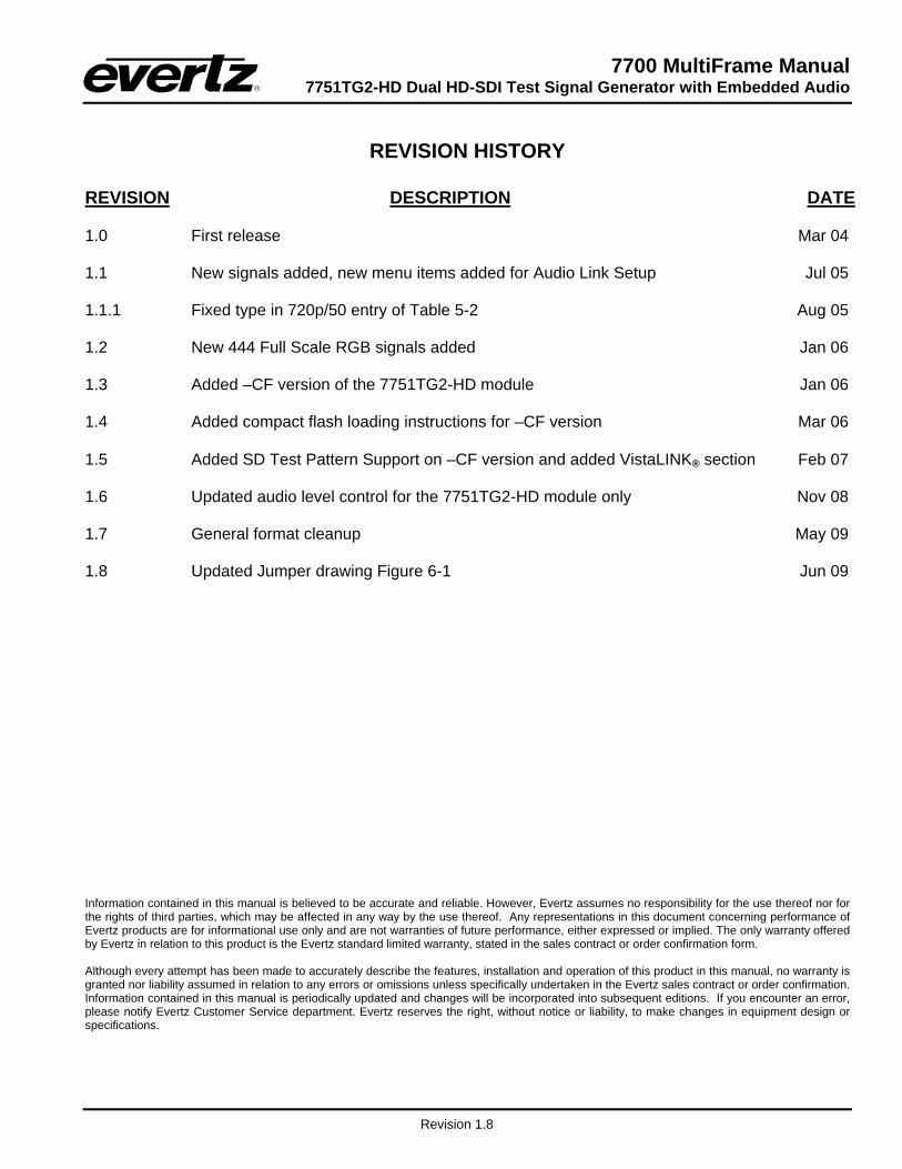
REVISION HISTORY
REVISION DESCRIPTION DATE 1.0 First release Mar 04 1.1 New signals added, new menu items added for Audio Link Setup Jul 05 1.1.1 Fixed type in 720p/50 entry of Table 5-2 Aug 05 1.2 New 444 Full Scale RGB signals added Jan 06 1.3 Added –CF version of the 7751TG2-HD module Jan 06 1.4 Added compact flash loading instructions for –CF version Mar 06 1.5 Added SD Test Pattern Support on –CF version and added VistaLINK® section Feb 07 1.6 Updated audio level control for the 7751TG2-HD module only Nov 08 1.7 General format cleanup May 09 1.8 Updated Jumper drawing Figure 6-1 Jun 09 Information contained in this manual is believed to be accurate and reliable. However, Evertz assumes no responsibility for the use thereof nor for the rights of third parties, which may be affected in any way by the use thereof. Any representations in this document concerning performance of Evertz products are for informational use only and are not warranties of future performance, either expressed or implied. The only warranty offered by Evertz in relation to this product is the Evertz standard limited warranty, stated in the sales contract or order confirmation form. Although every attempt has been made to accurately describe the features, installation and operation of this product in this manual, no warranty is granted nor liability assumed in relation to any errors or omissions unless specifically undertaken in the Evertz sales contract or order confirmation. Information contained in this manual is periodically updated and changes will be incorporated into subsequent editions. If you encounter an error, please notify Evertz Customer Service department. Evertz reserves the right, without notice or liability, to make changes in equipment design or specifications.

7700 MultiFrame Manual 7751TG2-HD Dual HD-SDI Test Signal Generator with Embedded Audio
Revision 1.8
This page left intentionally blank

7700 MultiFrame Manual 7751TG2-HD Dual HD-SDI Test Signal Generator with Embedded Audio
Revision 1.8 Page - 1
1. OVERVIEW
The 7751TG2-HD Test Signal Generator modules provide a cost-effective method of generating 1.5 Gb/s HDTV 4:2:2 and 4:4:4 test signals. The 7751TG2-HD is ideal for checking signal path integrity, or to determine system performance over varying cable lengths. The 7751TG2-HD generates test signals in a wide variety of HDTV video formats. In single link mode, the 7751TG2-HD outputs a SMPTE 292M 4:2:2 test signal on two outputs and a selected SMPTE 292M 4:2:2 black signal on the remaining two outputs. In dual link mode, the 7751TG2-HD outputs a SMPTE 372M 4:4:4 test signal on two dual-link outputs. The 7751TG2-HD provides an analog genlock input that allows you to synchronize the test signals to your facility’s horizontal and vertical timing. The 7751TG2-CF-HD version has the ability to generate both 270 Mb/s SD-SDI and 1.5 Gb/s HD-SDI test signals and provides downloadable bitmaps for trouble slides or test slides. Users may store their own designed bitmaps (trouble slides, test slides, or test signals) into a directory structure on the compact flash. The 7751TG2-CF-HD comes with a 128MB compact flash. All sections of this manual apply to the regular version as well as the 7751TG2-CF-HD unless otherwise noted. Separate audio tones can be embedded into each channel of all four embedded audio groups. The user can independently enable or disable embedding on any of the four audio groups. In dual link mode, the selected audio groups will be embedded into each link. The 7751TG2-HD Audio Level range is controllable from mute (silence), 0dBFS to -28 dBFS in increments of 2dBFS. The Audio level for the 7751TG2-CF-HD is fixed at -20 dB full scale. Features: • Wide variety of 1080i, 1035i, 1080p, 480p and 720p output formats • Supports SMPTE 292M and SMPTE 372M Dual Link • 8 position DIP switch selects output format, single or dual link and genlock reference • Card edge toggle switch selects test signal • Selectable genlock input format – bi-level or tri-level sync, colour black • 16 embedded audio tones, selectable audio group assignment into all four groups • 4 output drivers • On Screen display of test signal names • On Screen setup menu • Tally output upon loss of genlock • Front panel LEDs indicate genlock presence, module fault and embedded audio signal presence on
the output • Embedded SMPTE 334M Closed Caption Test signals
Additional features (7751TG2-CF-HD): • Supports 525 and 625 line formats • Compact flash for user created bitmaps (trouble slides, test slides, or test signals)

7700 MultiFrame Manual 7751TG2-HD Dual HD-SDI Test Signal Generator with Embedded Audio
Page - 2 Revision 1.8
CableDriver
Sync Separator
Gen LockPresent
Gen Lock
AudioPresent
CableDriver
CableDriver
ModuleStatus
Card EdgeControl
Signal Generator
AudioEmbedder
Audio Group
P / S
P / S
Link B
Link A
HDSerial Outputs
1.5 Gb/s
CompactFlash
(7751TG2-CF-HD only)
Control
Embedded Audio Presence
VistaLINK®Interface
AudioEmbedder
Figure 1-1: 7751TG2-HD Block Diagram
From this point forward, the 7751TG2-HD and the 7751TG2-CF-HD modules will be referred to as the “7751TG2-HD”, unless the feature in question is applicable only to one of the modules, in which case the specific model number will be referenced.
7700 MultiFrame Manual 7751TG2-HD Dual HD-SDI Test Signal Generator with Embedded Audio
Revision 1.8 Page - 3
2. INSTALLATION
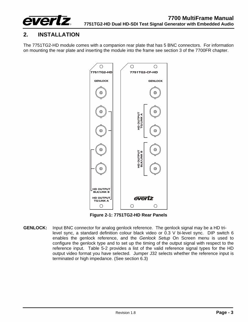
The 7751TG2-HD module comes with a companion rear plate that has 5 BNC connectors. For information on mounting the rear plate and inserting the module into the frame see section 3 of the 7700FR chapter.
Figure 2-1: 7751TG2-HD Rear Panels
GENLOCK: Input BNC connector for analog genlock reference. The genlock signal may be a HD tri-
level sync, a standard definition colour black video or 0.3 V bi-level sync. DIP switch 6 enables the genlock reference, and the Genlock Setup On Screen menu is used to configure the genlock type and to set up the timing of the output signal with respect to the reference input. Table 5-2 provides a list of the valid reference signal types for the HD output video format you have selected. Jumper J32 selects whether the reference input is terminated or high impedance. (See section 6.3)
7700 MultiFrame Manual 7751TG2-HD Dual HD-SDI Test Signal Generator with Embedded Audio
Page - 4 Revision 1.8
HD OUTPUT TG/LINK A: This pair of BNC connectors has serial component video outputs compatible with the SMPTE 292M standard. The 7751TG2-CF-HD model supports 525 and 625 line formats compatible with SMPTE 259M. DIP switches 1 to 5 select the video standard (refer to Table 5-2). When the 7751TG2-HD is operating the 4:2:2 mode, these outputs contain the test signal. When the 7751TG2-HD is operating the 4:4:4 mode, these outputs contain the 4:2:2 channel (YCB(even)CR(even) or GB(even)R(even)) part of the SMPTE 372M test signal known as Link A.
HD OUTPUT BLK/LINK B: This pair of BNC connectors has serial component video outputs compatible
with the SMPTE 292M standard. The 7751TG2-CF-HD model supports 525 and 625 line formats compatible with SMPTE 259M. DIP switches 1 to 5 select the video standard. (See Table 5-2) When the 7751TG2-HD is operating the 4:2:2 mode, these outputs contain a black video signal. When the 7751TG2-HD is operating the 4:4:4 mode, these outputs contain the Alpha channel (ACB(ODD)CR(odd) or AB(ODD)R(odd)) part of the SMPTE 372M test signal known as Link B.

7700 MultiFrame Manual 7751TG2-HD Dual HD-SDI Test Signal Generator with Embedded Audio
Revision 1.8 Page - 5
3. SPECIFICATIONS
3.1. GENLOCK INPUT
Type: Menu selectable - depends on output video format (see Table 5-2) HD Tri-level Sync NTSC or PAL Colour Black 1 V p-p Composite Bi-level sync (525i or 625i) 300 mV Connector: BNC per IEC 61169-8 Annex A Termination: 75 ohm (jumper selectable)
3.2. HD SERIAL VIDEO OUTPUTS
Standard: SMPTE 292M, 4:2:2 YCBCR (single link) SMPTE 372M, 4:4:4 YCBCR or 4:4:4 GBR (dual link) SMPTE 259M, 270Mb/s Selectable as per Table 5-2 Number of Outputs:
Single Link Mode: 2 outputs of selected test signal 2 outputs of Black video
Dual Link Mode: 2 dual link outputs of selected test signal Embedded Audio: Up to 4 tones in one audio group as specified in SMPTE 299M. Selectable tone
frequencies (from 60 Hz to 10 kHz) and audio group. Audio can be embedded on either or both links. For the 7751TG2-HD version, the Audio Level range is controllable from mute (silence), 0dBFS to -28dBFS in increments of 2dBFS. The Audio Level is set to -20 dB Full Scale for the 7751TG2-CF-HD version.
Up to 4 tones in one audio group as specified in SMPTE 272M, available on
7751TG2-CF-HD when in 525 and 625 line mode only Source ID: User programmable On Screen 15 character source ID message – selectable
position. On Screen message can be displayed on either or both links Connectors: 4 BNC per IEC 61169-8 Annex A Signal Level: 800mV nominal V Phasing: Infinite lines H Phasing: Infinite samples DC Offset: 0V ±0.5V Rise and Fall Time: 200ps nominal Overshoot: <10% of amplitude Wide Band Jitter: < 0.2 UI
7700 MultiFrame Manual 7751TG2-HD Dual HD-SDI Test Signal Generator with Embedded Audio
Page - 6 Revision 1.8
3.3. SD SERIAL VIDEO OUTPUTS (7751TG2-CF-HD ONLY)
Selectable as per Table 5-2 Number of Outputs: 4 Standard: SMPTE 259M-C (270 Mb/s) Embedded Audio: Up to 4 tones in one audio group as specified in SMPTE 272M. Selectable tone
frequencies (from 60Hz to 10kHz) and audio group. For the 7751TG2-HD version, the Audio Level range is controllable from mute (silence), 0dBFS to -28dBFS in increments of 2dBFS. The Audio Level is set to -20 dB Full Scale for the 7751TG2-CF-HD version.
Connectors: 4 BNC per IEC 61169-8, Annex A Signal Level: 800mV nominal DC Offset: 0V ±0.5V Rise and Fall Time: 740ps nominal Overshoot: <10% of amplitude Wide Band Jitter: < 0.2 UI
3.4. ELECTRICAL
Voltage: + 12VDC Power: 6 Watts EMI/RFI: Complies with FCC Part 15, class A and EU EMC directive
3.5. COMPACT FLASH MEMORY (7751TG2-CF-HD VERSION)
Size: 128MB Removable Compact Flash
3.6. PHYSICAL
350FR: 1 7700FR-C: 1 7800FR: 1 Stand Alone Enclosure:
Dimensions: 14 “ L x 4.5 “ W x 1.9 “ H (355 mm L x 114 mm W x 48 mm H) Weight: approx. 1.5 lbs. (0.7 Kg)

7700 MultiFrame Manual 7751TG2-HD Dual HD-SDI Test Signal Generator with Embedded Audio
Revision 1.8 Page - 7
4. STATUS LEDS
4.1. MODULE STATUS LEDS
The location of the Status LEDs is shown in Figure 6-1. MODULE OK: This Green LED will be On when the module is operating properly. LOCAL FAULT: This Red LED will blink on and off if the microprocessor is not running. This LED
will be on solid when there is a fault in the module power supply. SIGNAL PRESENT: This Green LED will be On when there is a valid genlock signal present at the
module genlock input.
This LED does not necessarily indicate that the genlock signal is the correct frame rate for the selected output video format. For example, if a 59.94 Hz signal is required for the selected output video format, but a 60 Hz signal is present at the genlock input, the SIGNAL PRESENT LED will be On. In this case, the output video will NOT be properly referenced but will constantly try to re-sync to the genlock frame reference.
AUDIO: This Green LED will be On when there is audio embedded into the outputs.
4.2. AUDIO GROUP STATUS LEDS
Four LEDs located on the lower end of the module (opposite the DIP switch) indicate the presence of embedded audio in the output video. The audio group LED 1 is located closest to the centre of the module.
Group LED Colour Audio Group Status Off There is no group 1 audio on the video output. 1 Green Group 1 audio is being embedded. Off There is no group 2 audio on the video output. 2 Green Group 2 audio is being embedded. Off There is no group 3 audio on the video output. 3 Green Group 3 audio is being embedded. Off There is no group 4 audio on the video output. 4 Green Group 4 audio is being embedded.
Table 4-1: Audio Group Status LEDs
7700 MultiFrame Manual 7751TG2-HD Dual HD-SDI Test Signal Generator with Embedded Audio
Page - 8 Revision 1.8
5. CARD EDGE CONTROLS
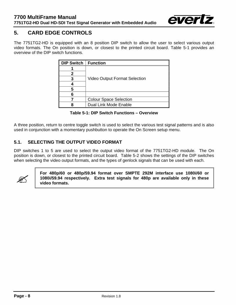
The 7751TG2-HD is equipped with an 8 position DIP switch to allow the user to select various output video formats. The On position is down, or closest to the printed circuit board. Table 5-1 provides an overview of the DIP switch functions.
DIP Switch Function 1 2 3 4 5
Video Output Format Selection
6 7 Colour Space Selection 8 Dual Link Mode Enable
Table 5-1: DIP Switch Functions – Overview A three position, return to centre toggle switch is used to select the various test signal patterns and is also used in conjunction with a momentary pushbutton to operate the On Screen setup menu.
5.1. SELECTING THE OUTPUT VIDEO FORMAT
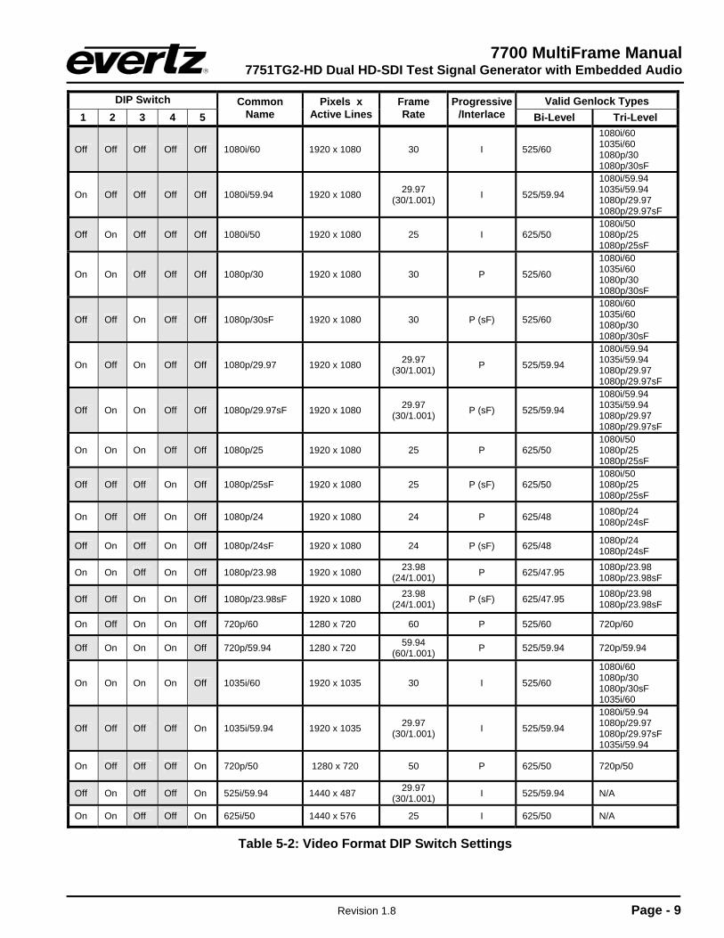
DIP switches 1 to 5 are used to select the output video format of the 7751TG2-HD module. The On position is down, or closest to the printed circuit board. Table 5-2 shows the settings of the DIP switches when selecting the video output formats, and the types of genlock signals that can be used with each.
For 480p/60 or 480p/59.94 format over SMPTE 292M interface use 1080i/60 or 1080i/59.94 respectively. Extra test signals for 480p are available only in these video formats.
7700 MultiFrame Manual 7751TG2-HD Dual HD-SDI Test Signal Generator with Embedded Audio
Revision 1.8 Page - 9
DIP Switch Valid Genlock Types 1 2 3 4 5
Common Name
Pixels x Active Lines
Frame Rate
Progressive /Interlace Bi-Level Tri-Level
Off Off Off Off Off 1080i/60 1920 x 1080 30 I 525/60
1080i/60 1035i/60 1080p/30 1080p/30sF
On Off Off Off Off 1080i/59.94 1920 x 1080 29.97 (30/1.001) I 525/59.94
1080i/59.94 1035i/59.94 1080p/29.97 1080p/29.97sF
Off On Off Off Off 1080i/50 1920 x 1080 25 I 625/50 1080i/50 1080p/25 1080p/25sF
On On Off Off Off 1080p/30 1920 x 1080 30 P 525/60
1080i/60 1035i/60 1080p/30 1080p/30sF
Off Off On Off Off 1080p/30sF 1920 x 1080 30 P (sF) 525/60
1080i/60 1035i/60 1080p/30 1080p/30sF
On Off On Off Off 1080p/29.97 1920 x 1080 29.97 (30/1.001) P 525/59.94
1080i/59.94 1035i/59.94 1080p/29.97 1080p/29.97sF
Off On On Off Off 1080p/29.97sF 1920 x 1080 29.97 (30/1.001) P (sF) 525/59.94
1080i/59.94 1035i/59.94 1080p/29.97 1080p/29.97sF
On On On Off Off 1080p/25 1920 x 1080 25 P 625/50 1080i/50 1080p/25 1080p/25sF
Off Off Off On Off 1080p/25sF 1920 x 1080 25 P (sF) 625/50 1080i/50 1080p/25 1080p/25sF
On Off Off On Off 1080p/24 1920 x 1080 24 P 625/48 1080p/24 1080p/24sF
Off On Off On Off 1080p/24sF 1920 x 1080 24 P (sF) 625/48 1080p/24 1080p/24sF
On On Off On Off 1080p/23.98 1920 x 1080 23.98 (24/1.001) P 625/47.95 1080p/23.98
1080p/23.98sF
Off Off On On Off 1080p/23.98sF 1920 x 1080 23.98 (24/1.001) P (sF) 625/47.95 1080p/23.98
1080p/23.98sF
On Off On On Off 720p/60 1280 x 720 60 P 525/60 720p/60
Off On On On Off 720p/59.94 1280 x 720 59.94 (60/1.001) P 525/59.94 720p/59.94
On On On On Off 1035i/60 1920 x 1035 30 I 525/60
1080i/60 1080p/30 1080p/30sF 1035i/60
Off Off Off Off On 1035i/59.94 1920 x 1035 29.97 (30/1.001) I 525/59.94
1080i/59.94 1080p/29.97 1080p/29.97sF 1035i/59.94
On Off Off Off On 720p/50 1280 x 720 50 P 625/50 720p/50
Off On Off Off On 525i/59.94 1440 x 487 29.97 (30/1.001) I 525/59.94 N/A
On On Off Off On 625i/50 1440 x 576 25 I 625/50 N/A
Table 5-2: Video Format DIP Switch Settings
7700 MultiFrame Manual 7751TG2-HD Dual HD-SDI Test Signal Generator with Embedded Audio
Page - 10 Revision 1.8
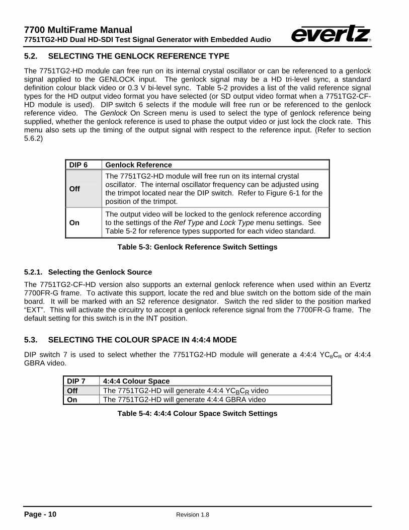
5.2. SELECTING THE GENLOCK REFERENCE TYPE
The 7751TG2-HD module can free run on its internal crystal oscillator or can be referenced to a genlock signal applied to the GENLOCK input. The genlock signal may be a HD tri-level sync, a standard definition colour black video or 0.3 V bi-level sync. Table 5-2 provides a list of the valid reference signal types for the HD output video format you have selected (or SD output video format when a 7751TG2-CF-HD module is used). DIP switch 6 selects if the module will free run or be referenced to the genlock reference video. The Genlock On Screen menu is used to select the type of genlock reference being supplied, whether the genlock reference is used to phase the output video or just lock the clock rate. This menu also sets up the timing of the output signal with respect to the reference input. (Refer to section 5.6.2)
DIP 6 Genlock Reference
Off
The 7751TG2-HD module will free run on its internal crystal oscillator. The internal oscillator frequency can be adjusted using the trimpot located near the DIP switch. Refer to Figure 6-1 for the position of the trimpot.
On The output video will be locked to the genlock reference according to the settings of the Ref Type and Lock Type menu settings. See Table 5-2 for reference types supported for each video standard.
Table 5-3: Genlock Reference Switch Settings
5.2.1. Selecting the Genlock Source The 7751TG2-CF-HD version also supports an external genlock reference when used within an Evertz 7700FR-G frame. To activate this support, locate the red and blue switch on the bottom side of the main board. It will be marked with an S2 reference designator. Switch the red slider to the position marked “EXT”. This will activate the circuitry to accept a genlock reference signal from the 7700FR-G frame. The default setting for this switch is in the INT position.
5.3. SELECTING THE COLOUR SPACE IN 4:4:4 MODE
DIP switch 7 is used to select whether the 7751TG2-HD module will generate a 4:4:4 YCBCR or 4:4:4 GBRA video.
DIP 7 4:4:4 Colour Space Off The 7751TG2-HD will generate 4:4:4 YCBCR video On The 7751TG2-HD will generate 4:4:4 GBRA video
Table 5-4: 4:4:4 Colour Space Switch Settings
7700 MultiFrame Manual 7751TG2-HD Dual HD-SDI Test Signal Generator with Embedded Audio
Revision 1.8 Page - 11
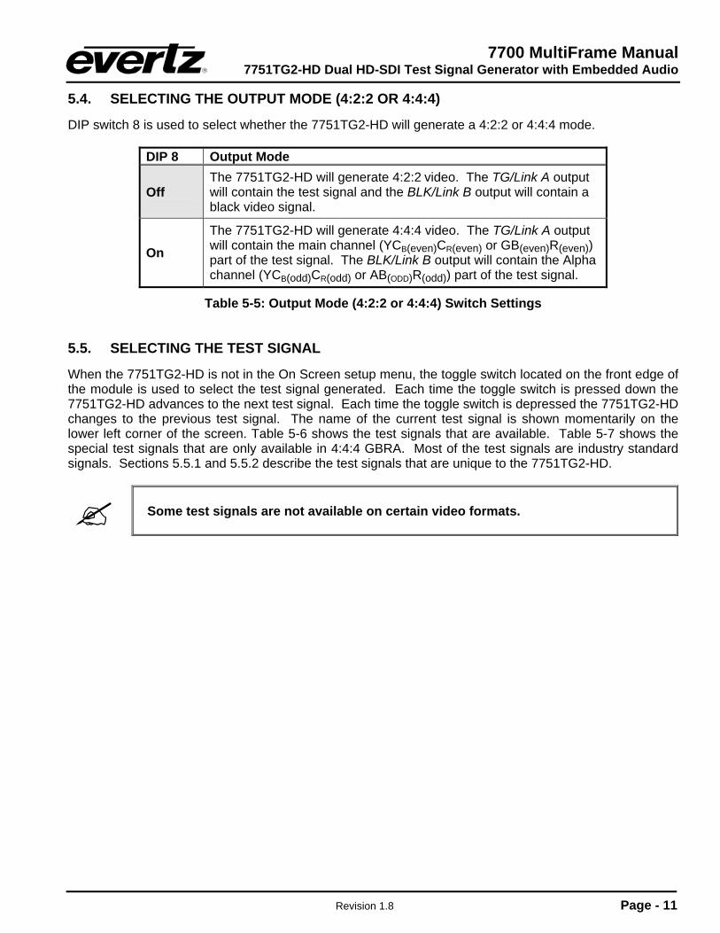
5.4. SELECTING THE OUTPUT MODE (4:2:2 OR 4:4:4)
DIP switch 8 is used to select whether the 7751TG2-HD will generate a 4:2:2 or 4:4:4 mode.
DIP 8 Output Mode
Off The 7751TG2-HD will generate 4:2:2 video. The TG/Link A output will contain the test signal and the BLK/Link B output will contain a black video signal.
On
The 7751TG2-HD will generate 4:4:4 video. The TG/Link A output will contain the main channel (YCB(even)CR(even) or GB(even)R(even)) part of the test signal. The BLK/Link B output will contain the Alpha channel (YCB(odd)CR(odd) or AB(ODD)R(odd)) part of the test signal.
Table 5-5: Output Mode (4:2:2 or 4:4:4) Switch Settings
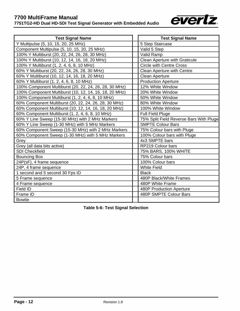
5.5. SELECTING THE TEST SIGNAL
When the 7751TG2-HD is not in the On Screen setup menu, the toggle switch located on the front edge of the module is used to select the test signal generated. Each time the toggle switch is pressed down the 7751TG2-HD advances to the next test signal. Each time the toggle switch is depressed the 7751TG2-HD changes to the previous test signal. The name of the current test signal is shown momentarily on the lower left corner of the screen. Table 5-6 shows the test signals that are available. Table 5-7 shows the special test signals that are only available in 4:4:4 GBRA. Most of the test signals are industry standard signals. Sections 5.5.1 and 5.5.2 describe the test signals that are unique to the 7751TG2-HD.
Some test signals are not available on certain video formats.
7700 MultiFrame Manual 7751TG2-HD Dual HD-SDI Test Signal Generator with Embedded Audio
Page - 12 Revision 1.8
Test Signal Name Test Signal Name
Y Multipulse (5, 10, 15, 20, 25 MHz) 5 Step Staircase Component Multipulse (5, 10, 15, 20, 25 MHz) Valid 5 Step 100% Y Multiburst (20, 22, 24, 26, 28, 30 MHz) Valid Ramp 100% Y Multiburst (10, 12, 14, 16, 18, 20 MHz) Clean Aperture with Graticule 100% Y Multiburst (1, 2, 4, 6, 8, 10 MHz) Circle with Centre Cross 60% Y Multiburst (20, 22, 24, 26, 28, 30 MHz) Clean Aperture with Centre 60% Y Multiburst (10, 12, 14, 16, 18, 20 MHz) Clean Aperture 60% Y Multiburst (1, 2, 4, 6, 8, 10 MHz) Production Aperture 100% Component Multiburst (20, 22, 24, 26, 28, 30 MHz) 12% White Window 100% Component Multiburst (10, 12, 14, 16, 18, 20 MHz) 20% White Window 100% Component Multiburst (1, 2, 4, 6, 8, 10 MHz) 50% White Window 60% Component Multiburst (20, 22, 24, 26, 28, 30 MHz) 80% White Window 60% Component Multiburst (10, 12, 14, 16, 18, 20 MHz) 100% White Window 60% Component Multiburst (1, 2, 4, 6, 8, 10 MHz) Full Field Pluge 60% Y Line Sweep (15-30 MHz) with 2 MHz Markers 75% Split Field Reverse Bars With Pluge60% Y Line Sweep (1-30 MHz) with 5 MHz Markers SMPTE Colour Bars 60% Component Sweep (15-30 MHz) with 2 MHz Markers 75% Colour bars with Pluge 60% Component Sweep (1-30 MHz) with 5 MHz Markers 100% Colour bars with Pluge Grey 4x3 SMPTE bars Grey (all data bits active) RP219 Colour bars SDI Checkfield 75% BARS, 100% WHITE Bouncing Box 75% Colour bars 24P(sF), 4 frame sequence 100% Colour bars 24P, 4 frame sequence White Field 1 second and 5 second 30 Fps ID Black 5 Frame sequence 480P Black/White Frames 4 Frame sequence 480P White Frame Field ID 480P Production Aperture Frame ID 480P SMPTE Colour Bars Bowtie
Table 5-6: Test Signal Selection
7700 MultiFrame Manual 7751TG2-HD Dual HD-SDI Test Signal Generator with Embedded Audio
Revision 1.8 Page - 13
Test Signal Name Test Signal Name FS RP219 Colourbars 1 FS 12% White Window FS Bars with 2 scalings FS 20% White Window FS 75% Colour bars FS 50% White Window FS 100% Colour bars FS 80% White Window FS Y Multipulse FS 100% White Window FS 60% Y Line Sweep (15-30 MHz) with 2 MHz Markers FS 10 Step B & W Pluge FS 60% Y Line Sweep to 30 MHz FS 7 Step B & W Pluge FS Clean Apertue with Graticule FS White FS Circle with centre cross FS Black FS Clean Apertue with Graticule FS Clean Aperture with Centre
Table 5-7: Additional 4:4:4 Full Scale RGB Test Signals
On 7751TG2-CF-HD modules, the toggle switch advances through the available test signals, as well as the bitmaps (or trouble slides) that are on the compact flash for the selected video format.
There is a 10-15 second delay when loading a new bitmap. This delay is applied every time a new bitmap is selected.
During the load of a bitmap the red LED, located behind the compact flash reader, will blink momentarily. This is normal and indicates that the compact flash is being accessed.
5.5.1. Description of Unique Test Signals This section describes features of some of the more unique test signals.
5.5.1.1. Clean Aperture with Graticule This signal contains a number of key physical dimensions of the HDTV active picture area. It divides the 16x9 aspect ratio clean aperture area into an 8x6 graticule grid. The centre 6x6 grid corresponds to a 4x3 aspect ratio rectangle that is concentric with the 16x9 clean aperture. The edges of the 4x3 area have different line patterns to help in identifying it. The clean aperture markers are placed so that the centre of the lines is at the clean aperture. The production aperture markers are placed so that the outsides of the lines are at the production aperture (the extent of the total image). A centre cross marker is also included to mark the middle of the image.
5.5.1.2. Production Aperture Single horizontal lines and single pixel vertical borders around the active picture mark the production aperture. Single pixels and single horizontal lines are not legal for normal pictures but this test signal is designed to test equipment to make sure it is processing/passing the whole image area. If any side of the box is missing, then the device under test is not passing the whole production aperture.

7700 MultiFrame Manual 7751TG2-HD Dual HD-SDI Test Signal Generator with Embedded Audio
Page - 14 Revision 1.8
5.5.1.3. Grey Signals These signals can be used as a 50% full field grey, and they are also designed to provide a best case and a worse case toggle rate on the test signal data bits. The regular Grey signal has both the luminance and the chrominance values set to 200hex, while the Grey with all data bits active signal has both the luminance and the chrominance bits alternating between 200hex and 1FFhex. The latter signal has every data bit toggling every video sample. Most current digital logic designs use CMOS technology, where the power consumed and the heat produced are proportional to the average toggle rate of all of the flip flops in the product. If a product performs a large amount of video processing (in proportion to all processing), then there will be a power consumption difference between a “quiet” signal and a “very active” signal. The grey signals can be used as a best case and a worst case condition for checking such conditions.
5.5.1.4. 4x3 Colour Bars SMPTE RP219 colour bars have a feature that allows the signal to be down converted to standard definition and the signal is still usable. A down converter when in “4x3 side crop” mode will pull out the centre 4x3 picture area of the HD 16x9 image creating a meaningful picture. Also, the signal edge rise and fall times have been reduced to allow proper frequency scaling when decimating to standard definition bandwidths. This will reduce the amount of ringing and overshoot on the signal edges. This same concept has been incorporated in a couple more “4x3” colour bar signals.
5.5.1.5. Long Sequence Signals Five second long signals have been included to aid in troubleshooting delays through equipment. Because memory is cheap and processing delays have grown, these signals may help in timing up long video paths. For instance, apply this signal to two different paths, and then compare the signals at the outputs with two side-by-side monitors. Even a single frame difference will be observable. The five-second-sequence signal also has single frame flashes each second.
5.5.1.6. Bouncing Box A slow moving up and down square box has been included to catch frame grabs and/or repeats. It will also help show improper field interlace/de-interlace sequencing issues. The motion is frame based not field, so it should pass through any processing equipment without distortion.
5.5.1.7. Four Frame 24P and 24PsF Signals The 24 frames per second (fps) digital HD signals are becoming more common in the signal acquisition and editing environment. Conversion from 24fps to 30fps requires a “3:2 pulldown” where 4 frames of 24fps video are mapped to 5 frames of 30fps video. These signals are designed to allow you to observe the “pulldown” sequence. In the 24P signals, a sequence of 4 unique frames is generated. After passing through a device that generates 30fps video, you can observe how each of the 5 output frames is generated from the 4 input frames. Also, the 24P segmented frame (sF) signals uniquely tag the even and the odd lines of the frame to make sure that the processing gear is associating the correct two segments to create one 24P frame.
7700 MultiFrame Manual 7751TG2-HD Dual HD-SDI Test Signal Generator with Embedded Audio
Revision 1.8 Page - 15
5.5.2. Description of Unique 4:4:4 GBRA Test Signals In normal high definition video GBRA colour space (also known as RGB), the three primary colour signals: red, green, and blue (RGB) that together convey all necessary picture information are scaled such that the extreme values are code words 040h (64) and 3ACh (940) in a 10-bit representation. In Full scale RGB, also known as extended range RGB, the three primary components are scaled such that the extreme values are code words 04h (4) and 3FBh (1019) in a 10-bit representation. The Full scale RGB video format is generally used in post production situations where you want to maintain the maximum resolution of the colour components to achieve a larger gamut of colours for theatrical release on film. In addition to the normal complement of test signals available in the 4:2:2 and 4:4:4 YCrCb video formats there are a special group of Full Scale RGB test signals listed in Table 4-1 that are designed specifically for these situations using the Full Scale GBRA video format. Most of these test signals are similar to the normal test signals, except that they have been appropriately scaled to use the full scale minimum and maximum coding values. There are three signals that are unique to the Full scale format.
5.5.2.1. FS Bars with 2 Scalings The top half of this signal is 100% colour bars with the Full Scale RGB coding values. The bottom half of this signal is 100% Colour bars with the normal RGB code values. This signal is useful in testing the conversions in devices that will scale down the Full scale signal to a normal video RGB colour space.
5.5.2.2. FS 10 Step B & W Pluge This signal is a 10 step black and white staircase with each step calibrated to line up with the millivolt scale on a waveform monitor. The 50% step is wider so that it can more easily be identified. Inserted in the black and white steps is a Pluge signal that is 1% and 2% above black and below white to aid in calibrating video projectors and other monitoring devices.
5.5.2.3. FS 7 Step B & W Pluge This signal is a 7 step black and white staircase with each step calibrated to line up with the IRE scale on a waveform monitor. Inserted in the black and white steps is a Pluge signal that is 1% and 2% above black and below white to aid in calibrating video projectors and other monitoring devices.
5.6. CONFIGURING THE TEST GENERATOR USING THE ON SCREEN MENU
An On Screen menu (OSD) is used to configure many of the test generator’s parameters. The three position, return to centre, toggle switch and momentary pushbutton located on the front edge of the module are used to navigate the OSD setup menus and configure the cards various controls. To enter the OSD menu system, press the push button once. This will bring you to the main setup menu where you can use the toggle switch to move up and down the list of available sub-menus. An arrow (>) moves up and down the left hand side of the menu items to indicate which item you are currently choosing. Once the arrow is on the desired item, press the pushbutton to select the next menu. On all menus, there is a selectable item Done. Selecting Done will take you to the previous menu (the one that was used to get into the current menu). If you are at the top level of the menu tree then selecting Done will exit the OSD menu and return the 7751TG2-HD to the normal operating mode. Once you are in a sub-menu, there may be another menu level, or there may be a list of parameters to adjust. If there is another set of menu options, use the toggle switch to select the next option with the same procedure as in the main menu.
7700 MultiFrame Manual 7751TG2-HD Dual HD-SDI Test Signal Generator with Embedded Audio
Page - 16 Revision 1.8
If there is a list of parameters to adjust, use the toggle switch to move up or down to the desired parameter and press the pushbutton. The arrow will move to the right hand side (<) indicating that you can now adjust the parameter. Using the toggle switch, adjust the parameter to its desired value. If the parameter is a numerical value, the number will increase if you lift the toggle switch and decrease if you push down on the toggle switch. If the parameter contains a list of options, you can cycle through the list by pressing the toggle switch in either direction. Throughout this manual, the factory default parameter values will be shown underlined. When you have stopped at the desired value, depress the pushbutton. This will update the parameter with the selected value and move the arrow back to the left side of the parameter list. Continue selecting and adjusting other parameters or use the Done commands to return to the next higher menu level.
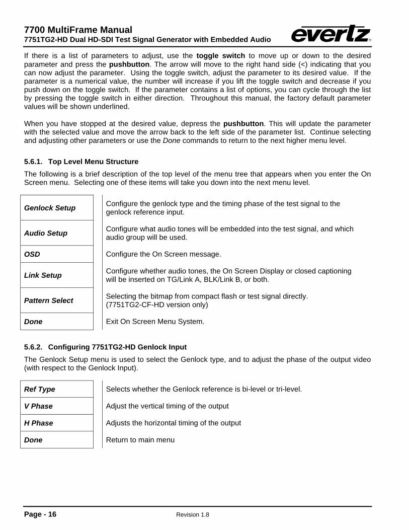
5.6.1. Top Level Menu Structure The following is a brief description of the top level of the menu tree that appears when you enter the On Screen menu. Selecting one of these items will take you down into the next menu level.
Genlock Setup Configure the genlock type and the timing phase of the test signal to the genlock reference input.
Audio Setup Configure what audio tones will be embedded into the test signal, and which audio group will be used.
OSD Configure the On Screen message.
Link Setup Configure whether audio tones, the On Screen Display or closed captioning will be inserted on TG/Link A, BLK/Link B, or both.
Pattern Select Selecting the bitmap from compact flash or test signal directly. (7751TG2-CF-HD version only)
Done Exit On Screen Menu System.
5.6.2. Configuring 7751TG2-HD Genlock Input The Genlock Setup menu is used to select the Genlock type, and to adjust the phase of the output video (with respect to the Genlock Input).
Ref Type Selects whether the Genlock reference is bi-level or tri-level.
V Phase Adjust the vertical timing of the output
H Phase Adjusts the horizontal timing of the output
Done Return to main menu

7700 MultiFrame Manual 7751TG2-HD Dual HD-SDI Test Signal Generator with Embedded Audio
Revision 1.8 Page - 17
5.6.2.1. Selecting the Genlock Input Type The Ref Type parameter selects whether the 7751TG2-HD will accept a Bi-level or tri-level signal as the Genlock reference input. GENLOCK SETUP
REF TYPE Bi-Level Tri-Level
Genlock Reference is a NTSC or PAL standard definition colour black video or a 0.3 V bi-level sync. Genlock Reference is a high definition tri-level sync.
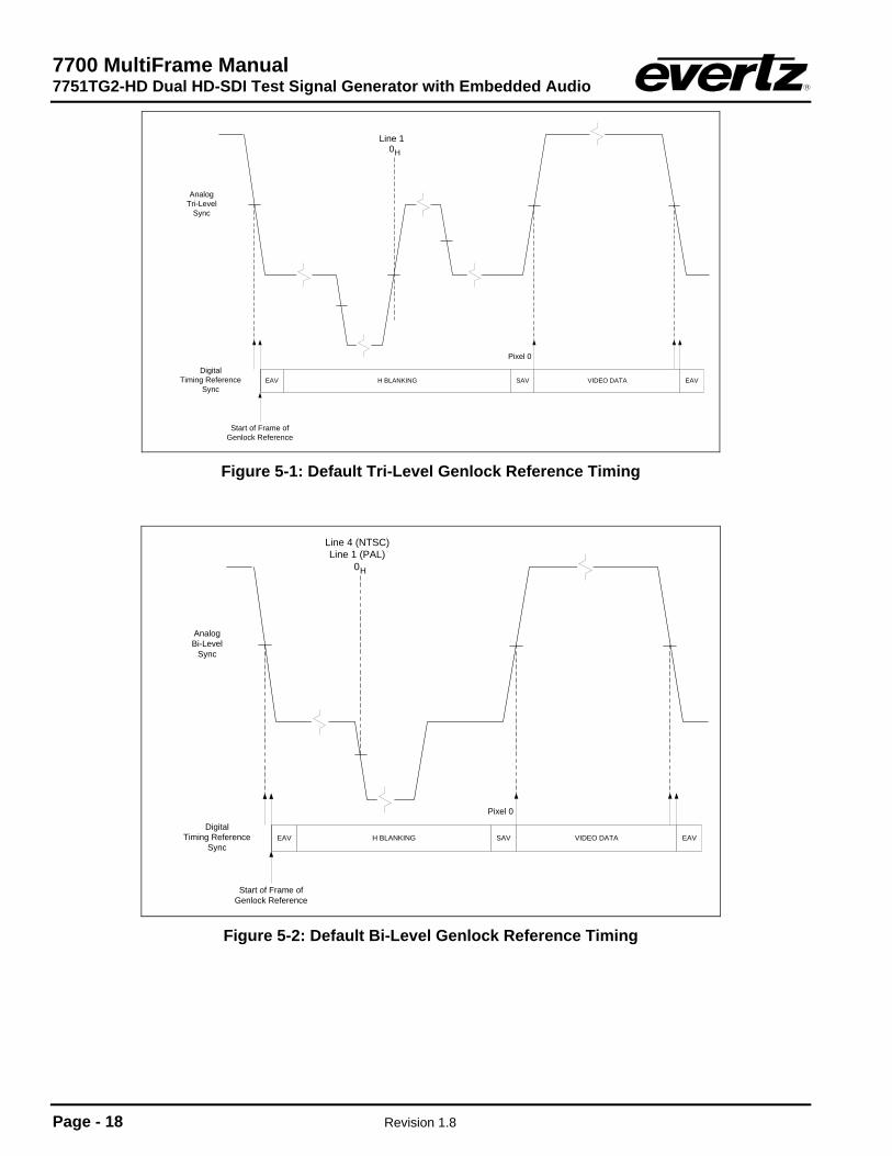
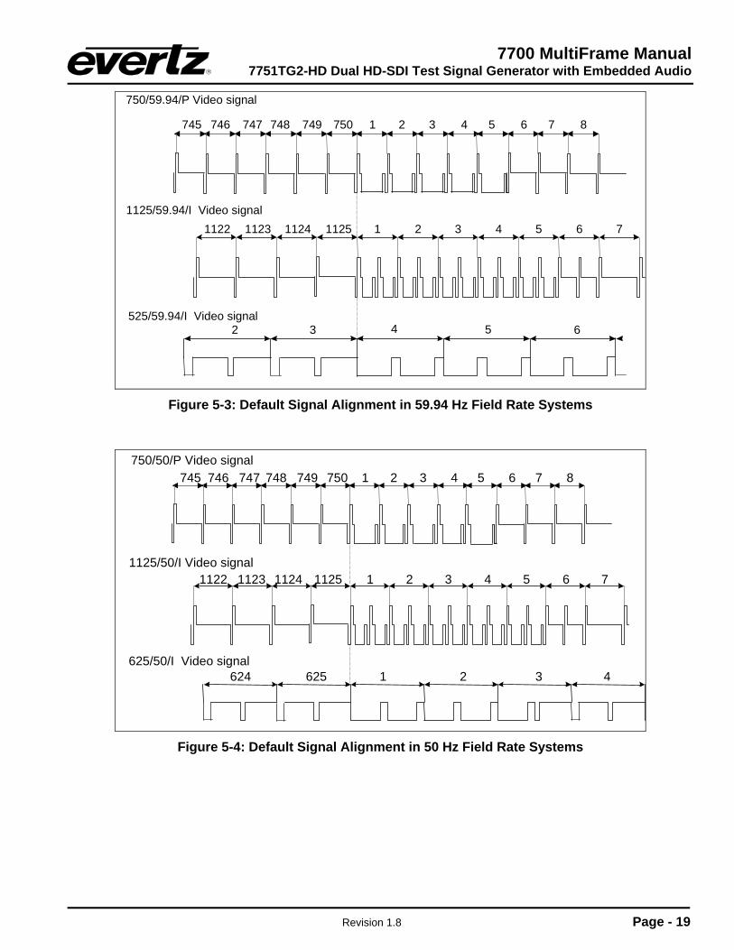
5.6.2.2. Setting the Timing of the Output Video with Respect to the Genlock Input The V Phase and H Phase parameters allow you to control the timing of the output video with respect to the beginning of the frame on the genlock reference input. Phasing of the output is only possible when the frame rate of the genlock reference is the same as the frame rate of the output video format. An internally generated digital video sync structure, locked to the analog genlock reference signal (0H time of line 1 field 1 for PAL or HD Tri-level references or 0H time of line 4 field 1 for NTSC references) is used to genlock the 7751TG2-HD test generator. The EAV of line 1 of this digital reference sync is the point to which all the reference phasing adjustments are made. The default timing relationship of the analog tri-level and bi-level inputs to the digital reference sync frame (when the V Phase and H Phase parameters are set to zero) are set according to SMPTE Recommended Practice RP168-2002 and are shown in Figure 5-1 and Figure 5-2. The V parameter provides a coarse adjustment of timing and sets the delay in lines of line 1 of the test signal frame with respect to the beginning of the genlock reference frame. The H parameter provides a fine adjustment of timing and sets the delay in pixels of the 0H time of line 1 of the test signal frame with respect to the 0H time of the beginning of the reference frame. If adjustments to the H parameter cause it to roll through the pixel number at the start of a new line then the V parameter will change to the next higher or lower line. The factory default is to align the 0H time of Line 1 of the output video with the beginning of the genlock reference frame (0H time of line 1 field 1 for PAL or HD Tri-level references or 0H time of line 4 field 1 for NTSC references) according to SMPTE Recommended Practice RP168-2002. For example, in 59.94Hz frame rate systems, the horizontal reference points of Line 1 of 1125 line, Line 1 of 750 line and Line 4 of 525 line signals shall be coincident (see Figure 5-3). In 50Hz frame rate systems, the horizontal reference points of Line 1 of 1125 line, Line 1 of 750 line and Line 1 of 625 line signals shall be coincident (see Figure 5-4).
7700 MultiFrame Manual 7751TG2-HD Dual HD-SDI Test Signal Generator with Embedded Audio
Page - 18 Revision 1.8
AnalogTri-Level
Sync
EAV H BLANKING
Line 10H
SAV
Pixel 0
VIDEO DATA EAV
Start of Frame ofGenlock Reference
DigitalTiming Reference
Sync
Figure 5-1: Default Tri-Level Genlock Reference Timing
EAV H BLANKING SAV
Pixel 0
VIDEO DATA EAV
Start of Frame ofGenlock Reference
DigitalTiming Reference
Sync
AnalogBi-Level
Sync
Line 4 (NTSC)Line 1 (PAL)
0H
Figure 5-2: Default Bi-Level Genlock Reference Timing
7700 MultiFrame Manual 7751TG2-HD Dual HD-SDI Test Signal Generator with Embedded Audio
Revision 1.8 Page - 19
1125 1 2 3112411231122 4 51125/59.94/I Video signal
6 7
525/59.94/I Video signal
750/59.94/P Video signal 1 2 3 4 5 6 7 8750749748747746745
4 5 632
Figure 5-3: Default Signal Alignment in 59.94 Hz Field Rate Systems
1125 1 2 3112411231122 4 51125/50/I Video signal
6 7
750/50/P Video signal 1 2 3 4 5 6 7 8750749748747746745
625/50/I Video signal 1 2 3 4625624
Figure 5-4: Default Signal Alignment in 50 Hz Field Rate Systems
7700 MultiFrame Manual 7751TG2-HD Dual HD-SDI Test Signal Generator with Embedded Audio
Page - 20 Revision 1.8
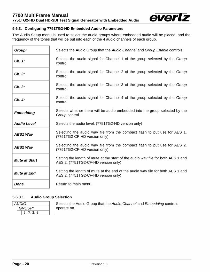
5.6.3. Configuring 7751TG2-HD Embedded Audio Parameters The Audio Setup menu is used to select the audio groups where embedded audio will be placed, and the frequency of the tones that will be put into each of the 4 audio channels of each group.
Group: Selects the Audio Group that the Audio Channel and Group Enable controls.
Ch. 1: Selects the audio signal for Channel 1 of the group selected by the Group control.
Ch. 2: Selects the audio signal for Channel 2 of the group selected by the Group control.
Ch. 3: Selects the audio signal for Channel 3 of the group selected by the Group control.
Ch. 4: Selects the audio signal for Channel 4 of the group selected by the Group control.
Embedding Selects whether there will be audio embedded into the group selected by the Group control.
Audio Level Selects the audio level. (7751TG2-HD version only)
AES1 Wav Selecting the audio wav file from the compact flash to put use for AES 1. (7751TG2-CF-HD version only)
AES2 Wav Selecting the audio wav file from the compact flash to put use for AES 2. (7751TG2-CF-HD version only)
Mute at Start Setting the length of mute at the start of the audio wav file for both AES 1 and AES 2. (7751TG2-CF-HD version only)
Mute at End Setting the length of mute at the end of the audio wav file for both AES 1 and AES 2. (7751TG2-CF-HD version only)
Done Return to main menu.
5.6.3.1. Audio Group Selection AUDIO
GROUP: 1, 2, 3, 4
Selects the Audio Group that the Audio Channel and Embedding controls operate on.
7700 MultiFrame Manual 7751TG2-HD Dual HD-SDI Test Signal Generator with Embedded Audio
Revision 1.8 Page - 21
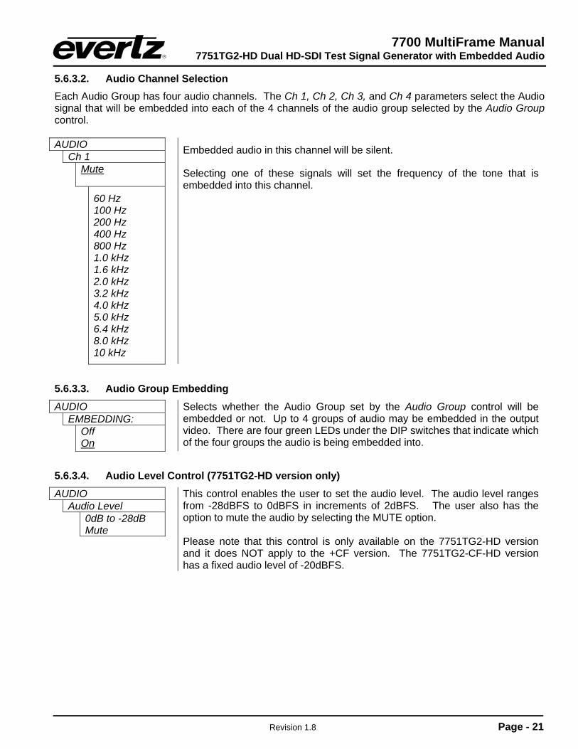
5.6.3.2. Audio Channel Selection Each Audio Group has four audio channels. The Ch 1, Ch 2, Ch 3, and Ch 4 parameters select the Audio signal that will be embedded into each of the 4 channels of the audio group selected by the Audio Group control. AUDIO
Ch 1 Mute
60 Hz 100 Hz 200 Hz 400 Hz 800 Hz 1.0 kHz 1.6 kHz 2.0 kHz 3.2 kHz 4.0 kHz 5.0 kHz 6.4 kHz 8.0 kHz 10 kHz
Embedded audio in this channel will be silent.
Selecting one of these signals will set the frequency of the tone that is embedded into this channel.
5.6.3.3. Audio Group Embedding AUDIO
EMBEDDING: Off On
Selects whether the Audio Group set by the Audio Group control will be embedded or not. Up to 4 groups of audio may be embedded in the output video. There are four green LEDs under the DIP switches that indicate which of the four groups the audio is being embedded into.
5.6.3.4. Audio Level Control (7751TG2-HD version only) AUDIO
Audio Level 0dB to -28dB Mute
This control enables the user to set the audio level. The audio level ranges from -28dBFS to 0dBFS in increments of 2dBFS. The user also has the option to mute the audio by selecting the MUTE option. Please note that this control is only available on the 7751TG2-HD version and it does NOT apply to the +CF version. The 7751TG2-CF-HD version has a fixed audio level of -20dBFS.
7700 MultiFrame Manual 7751TG2-HD Dual HD-SDI Test Signal Generator with Embedded Audio
Page - 22 Revision 1.8
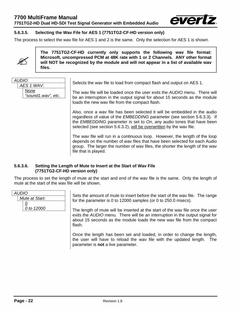
5.6.3.5. Selecting the Wav File for AES 1 (7751TG2-CF-HD version only) The process to select the wav file for AES 1 and 2 is the same. Only the selection for AES 1 is shown.
The 7751TG2-CF-HD currently only supports the following wav file format: Microsoft, uncompressed PCM at 48K rate with 1 or 2 Channels. ANY other format will NOT be recognized by the module and will not appear in a list of available wav files.
AUDIO
AES 1 WAV: None “sound1.wav”, etc.
Selects the wav file to load from compact flash and output on AES 1.
The wav file will be loaded once the user exits the AUDIO menu. There will be an interruption in the output signal for about 15 seconds as the module loads the new wav file from the compact flash.
Also, once a wav file has been selected it will be embedded in the audio regardless of value of the EMBEDDING parameter (see section 5.6.3.3). If the EMBEDDING parameter is set to On, any audio tones that have been selected (see section 5.6.3.2), will be overwritten by the wav file.
The wav file will run in a continuous loop. However, the length of the loop depends on the number of wav files that have been selected for each Audio group. The larger the number of wav files, the shorter the length of the wav file that is played.
5.6.3.6. Setting the Length of Mute to Insert at the Start of Wav File (7751TG2-CF-HD version only)
The process to set the length of mute at the start and end of the wav file is the same. Only the length of mute at the start of the wav file will be shown. AUDIO
Mute at Start: 0 0 to 12000
Sets the amount of mute to insert before the start of the wav file. The range for the parameter is 0 to 12000 samples (or 0 to 250.0 msecs).
The length of mute will be inserted at the start of the wav file once the user exits the AUDIO menu. There will be an interruption in the output signal for about 15 seconds as the module loads the new wav file from the compact flash.
Once the length has been set and loaded, in order to change the length, the user will have to reload the wav file with the updated length. The parameter is not a live parameter.

7700 MultiFrame Manual 7751TG2-HD Dual HD-SDI Test Signal Generator with Embedded Audio
Revision 1.8 Page - 23
5.6.4. Configuring the On Screen Message Display The 7751TG2-HD has a programmable 16-character text message that may be used to display a source identification message or any other information on the screen. The On Screen Display menu is used to enter the text message, to turn it on and off and set the position on the screen. The On Screen Display menu is also used to set the length of time that the signal name display is on after the user changes the test signal.
Message enable Turns the message display on and off.
Message Edits the On Screen message.
Set Message Position Sets the horizontal and vertical position of the message on the screen.
Signal Name Duration Sets the duration that the signal name display is on after test signal changes.
Done Exit On Screen Menu System.
5.6.4.1. Editing the On Screen Message Display The Message sub-menu is used to edit the text message. When you enter the message sub-menu, the actual text message is displayed on the top line.
Text Message Edit the message.
Clear Clears the complete message to space characters.
Justify Used to move the message within the 16 character text message block.
Done Exit On Screen Display Menu System.
To edit the message, press the pushbutton when the > indicator is on the left of the message. The ^ indicator will appear under the left character of the message. Use the toggle switch to change the character indicated by the ^ or press the pushbutton to advance to the next character. When you have finished editing the message the > will automatically appear to the left of the message. Use the toggle switch to select the Clear, Justify or Done menu items and press the pushbutton to exit the Message sub-menu.
5.6.4.2. Positioning the On Screen Message Display The Position Message sub-menu is used to position the text message on the character raster. When you enter the Position Message sub-menu, a box the size of the maximum length message will appear on the screen. Use the toggle switch to move the box horizontally. When you press the pushbutton you will be able to move the box vertically on the screen using the toggle switch. Press the pushbutton quickly twice to exit the Position Message sub-menu. Messages that are shorter than 16 characters can be moved within the 16-character text box using the Justify sub-menu item. This allows shorter messages to be positioned all the way to the left or right side of the screen.
7700 MultiFrame Manual 7751TG2-HD Dual HD-SDI Test Signal Generator with Embedded Audio
Page - 24 Revision 1.8
5.6.4.3. Setting the Display Time for the Signal Name Display The Signal Name Display menu item is used to set the length of time the On Screen signal name is displayed after the user selects a new signal. Use the toggle switch to select a duration in seconds. The signal name display can also be turned permanently On or Off.
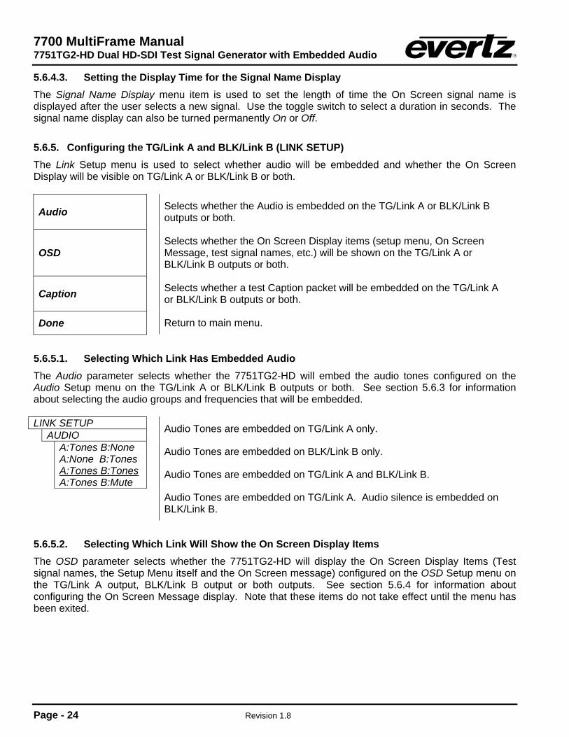
5.6.5. Configuring the TG/Link A and BLK/Link B (LINK SETUP) The Link Setup menu is used to select whether audio will be embedded and whether the On Screen Display will be visible on TG/Link A or BLK/Link B or both.
Audio Selects whether the Audio is embedded on the TG/Link A or BLK/Link B outputs or both.
OSD Selects whether the On Screen Display items (setup menu, On Screen
Message, test signal names, etc.) will be shown on the TG/Link A or BLK/Link B outputs or both.
Caption Selects whether a test Caption packet will be embedded on the TG/Link A or BLK/Link B outputs or both.
Done Return to main menu.
5.6.5.1. Selecting Which Link Has Embedded Audio The Audio parameter selects whether the 7751TG2-HD will embed the audio tones configured on the Audio Setup menu on the TG/Link A or BLK/Link B outputs or both. See section 5.6.3 for information about selecting the audio groups and frequencies that will be embedded. LINK SETUP
AUDIO A:Tones B:None A:None B:Tones A:Tones B:Tones A:Tones B:Mute
Audio Tones are embedded on TG/Link A only.
Audio Tones are embedded on BLK/Link B only.
Audio Tones are embedded on TG/Link A and BLK/Link B.
Audio Tones are embedded on TG/Link A. Audio silence is embedded on BLK/Link B.
5.6.5.2. Selecting Which Link Will Show the On Screen Display Items The OSD parameter selects whether the 7751TG2-HD will display the On Screen Display Items (Test signal names, the Setup Menu itself and the On Screen message) configured on the OSD Setup menu on the TG/Link A output, BLK/Link B output or both outputs. See section 5.6.4 for information about configuring the On Screen Message display. Note that these items do not take effect until the menu has been exited.
7700 MultiFrame Manual 7751TG2-HD Dual HD-SDI Test Signal Generator with Embedded Audio
Revision 1.8 Page - 25
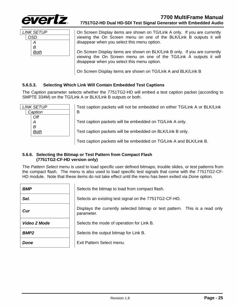
LINK SETUP OSD
A B Both
On Screen Display items are shown on TG/Link A only. If you are currently viewing the On Screen menu on one of the BLK/Link B outputs it will disappear when you select this menu option. On Screen Display items are shown on BLK/Link B only. If you are currently viewing the On Screen menu on one of the TG/Link A outputs it will disappear when you select this menu option. On Screen Display items are shown on TG/Link A and BLK/Link B
5.6.5.3. Selecting Which Link Will Contain Embedded Test Captions The Caption parameter selects whether the 7751TG2-HD will embed a test caption packet (according to SMPTE 334M) on the TG/Link A or BLK/Link B outputs or both. LINK SETUP
Caption Off A B Both
Test caption packets will not be embedded on either TG/Link A or BLK/Link B Test caption packets will be embedded on TG/Link A only. Test caption packets will be embedded on BLK/Link B only. Test caption packets will be embedded on TG/Link A and BLK/Link B.
5.6.6. Selecting the Bitmap or Test Pattern from Compact Flash (7751TG2-CF-HD version only)
The Pattern Select menu is used to load specific user defined bitmaps, trouble slides, or test patterns from the compact flash. The menu is also used to load specific test signals that come with the 7751TG2-CF-HD module. Note that these items do not take effect until the menu has been exited via Done option.
BMP Selects the bitmap to load from compact flash.
Sel. Selects an existing test signal on the 7751TG2-CF-HD.
Cur Displays the currently selected bitmap or test pattern. This is a read only parameter.
Video 2 Mode Selects the mode of operation for Link B.
BMP2 Selects the output bitmap for Link B.
Done Exit Pattern Select menu.
7700 MultiFrame Manual 7751TG2-HD Dual HD-SDI Test Signal Generator with Embedded Audio
Page - 26 Revision 1.8
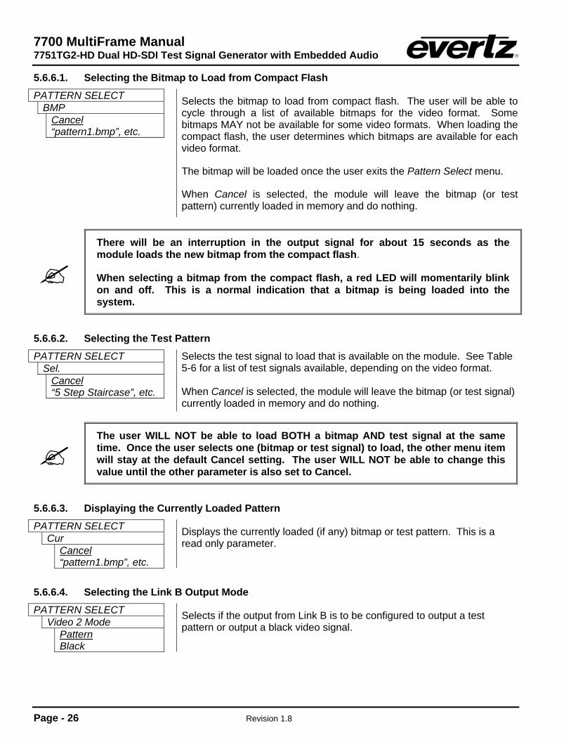
5.6.6.1. Selecting the Bitmap to Load from Compact Flash PATTERN SELECT
BMP Cancel “pattern1.bmp”, etc.
Selects the bitmap to load from compact flash. The user will be able to cycle through a list of available bitmaps for the video format. Some bitmaps MAY not be available for some video formats. When loading the compact flash, the user determines which bitmaps are available for each video format.
The bitmap will be loaded once the user exits the Pattern Select menu.
When Cancel is selected, the module will leave the bitmap (or test pattern) currently loaded in memory and do nothing.
There will be an interruption in the output signal for about 15 seconds as the module loads the new bitmap from the compact flash.
When selecting a bitmap from the compact flash, a red LED will momentarily blink on and off. This is a normal indication that a bitmap is being loaded into the system.
5.6.6.2. Selecting the Test Pattern PATTERN SELECT
Sel. Cancel “5 Step Staircase”, etc.
Selects the test signal to load that is available on the module. See Table 5-6 for a list of test signals available, depending on the video format. When Cancel is selected, the module will leave the bitmap (or test signal) currently loaded in memory and do nothing.
The user WILL NOT be able to load BOTH a bitmap AND test signal at the same time. Once the user selects one (bitmap or test signal) to load, the other menu item will stay at the default Cancel setting. The user WILL NOT be able to change this value until the other parameter is also set to Cancel.
5.6.6.3. Displaying the Currently Loaded Pattern PATTERN SELECT
Cur Cancel “pattern1.bmp”, etc.
Displays the currently loaded (if any) bitmap or test pattern. This is a read only parameter.
5.6.6.4. Selecting the Link B Output Mode PATTERN SELECT
Video 2 Mode Pattern Black
Selects if the output from Link B is to be configured to output a test pattern or output a black video signal.

7700 MultiFrame Manual 7751TG2-HD Dual HD-SDI Test Signal Generator with Embedded Audio
Revision 1.8 Page - 27
5.6.6.5. Selecting the Link B Output Pattern PATTERN SELECT
BMP2 Cancel “pattern1.bmp”
Selects the output bitmap that is to be used on Link B. For this control to function correctly, the Video 2 Mode control needs to be configured to Pattern.
5.7. LOADING THE COMPACT FLASH (7751TG2-CF-HD version only)
The 7751TG2-CF-HD modules are shipped with a 128 Mb compact flash. There are 2 default Evertz designed trouble slides that have been included on the compact flash. These slides have been created for 1080i/59.94, 1080i/60, 720p/59.94, and 720p/60. There is also a default audio file that is provided. In order for users to add their own custom design trouble slide/test signals or audio files, the following equipment is required:
• PC (desktop or laptop) • Compact flash Reader/Writer for the PC
To load or remove bitmaps or audio files from the compact flash, the user should follow these steps:
1. Connect compact flash reader/writer to the PC. 2. Remove 7751TG2-CF-HD module from frame.
3. Carefully eject compact flash from the 7751TG2-CF-HD module, by using the ejector button beside
compact flash holder.
4. Insert compact flash into compact flash reader/writer connected to the PC.
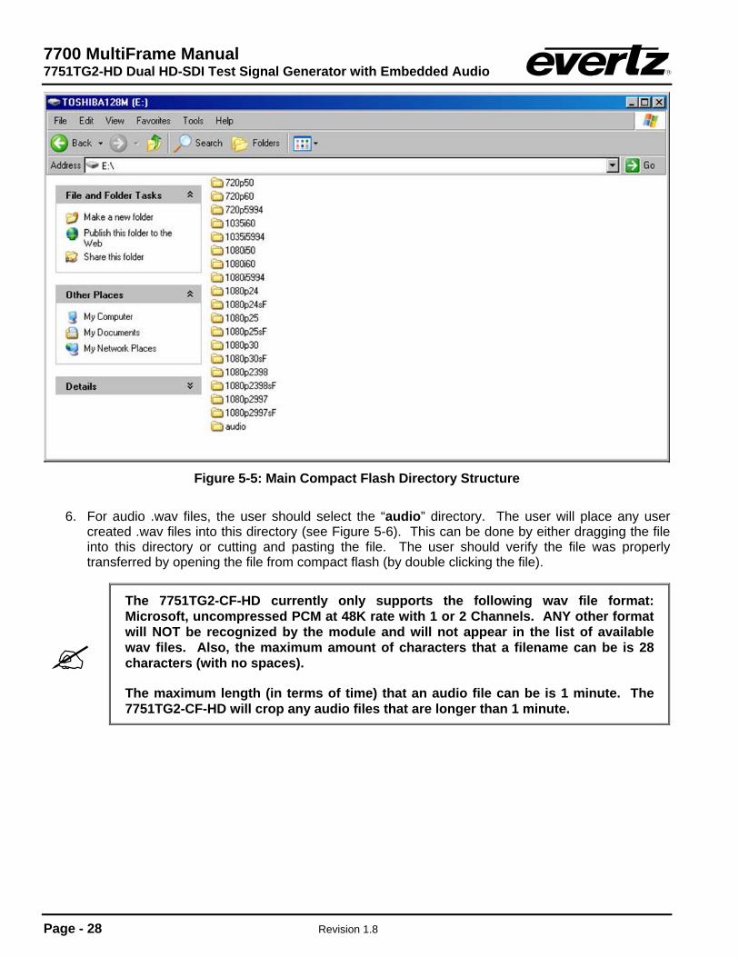
5. Use Windows Explorer (or equivalent) to look at compact flash contents. The contents of the compact flash should look the same as Figure 5-5.
7700 MultiFrame Manual 7751TG2-HD Dual HD-SDI Test Signal Generator with Embedded Audio
Page - 28 Revision 1.8
Figure 5-5: Main Compact Flash Directory Structure
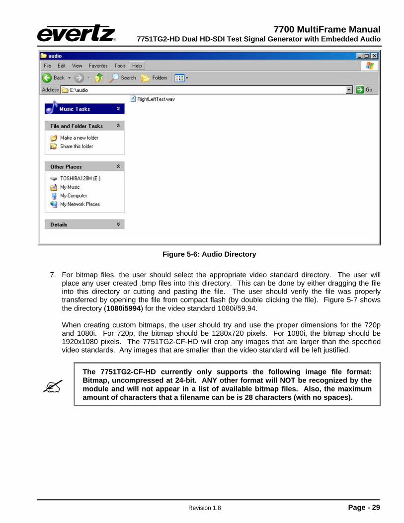
6. For audio .wav files, the user should select the “audio” directory. The user will place any user
created .wav files into this directory (see Figure 5-6). This can be done by either dragging the file into this directory or cutting and pasting the file. The user should verify the file was properly transferred by opening the file from compact flash (by double clicking the file).
The 7751TG2-CF-HD currently only supports the following wav file format: Microsoft, uncompressed PCM at 48K rate with 1 or 2 Channels. ANY other format will NOT be recognized by the module and will not appear in the list of available wav files. Also, the maximum amount of characters that a filename can be is 28 characters (with no spaces).
The maximum length (in terms of time) that an audio file can be is 1 minute. The 7751TG2-CF-HD will crop any audio files that are longer than 1 minute.
7700 MultiFrame Manual 7751TG2-HD Dual HD-SDI Test Signal Generator with Embedded Audio
Revision 1.8 Page - 29
Figure 5-6: Audio Directory
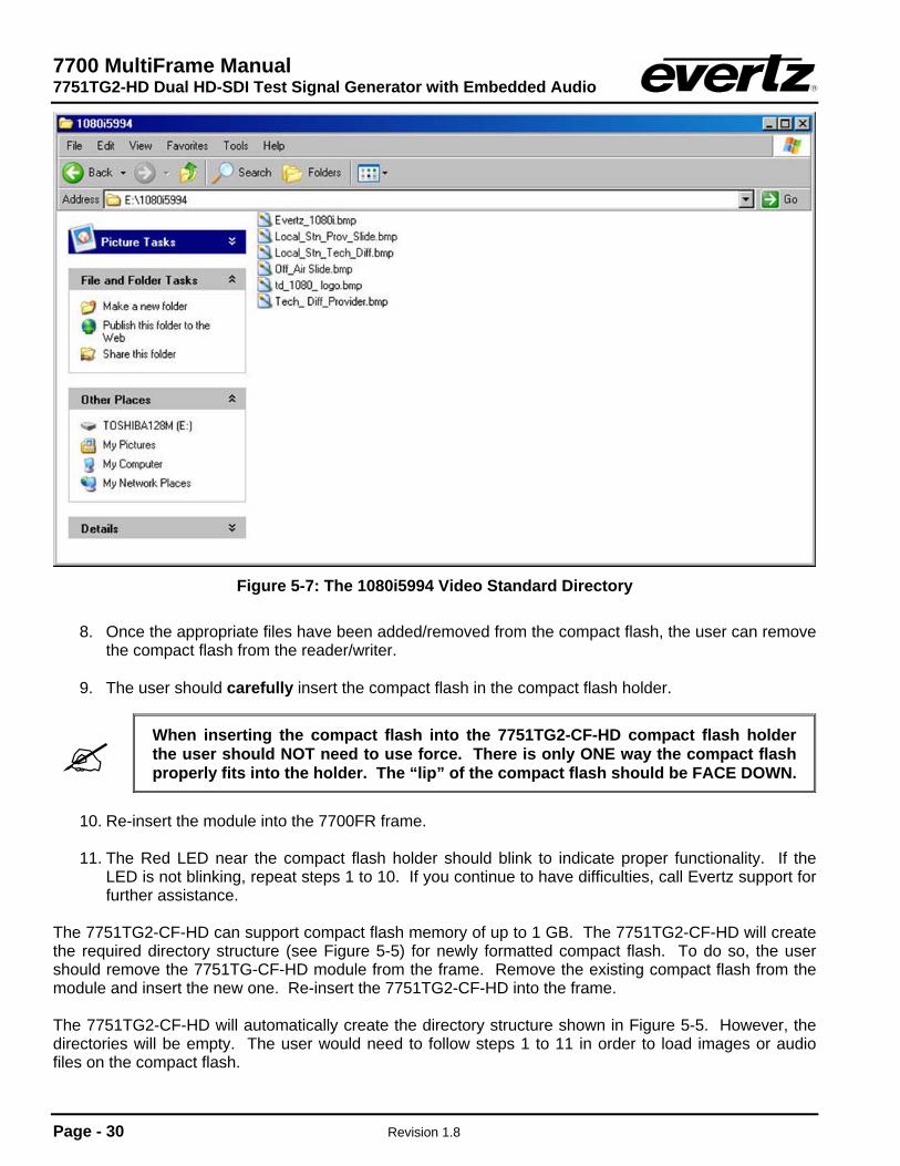
7. For bitmap files, the user should select the appropriate video standard directory. The user will
place any user created .bmp files into this directory. This can be done by either dragging the file into this directory or cutting and pasting the file. The user should verify the file was properly transferred by opening the file from compact flash (by double clicking the file). Figure 5-7 shows the directory (1080i5994) for the video standard 1080i/59.94.
When creating custom bitmaps, the user should try and use the proper dimensions for the 720p and 1080i. For 720p, the bitmap should be 1280x720 pixels. For 1080i, the bitmap should be 1920x1080 pixels. The 7751TG2-CF-HD will crop any images that are larger than the specified video standards. Any images that are smaller than the video standard will be left justified.
The 7751TG2-CF-HD currently only supports the following image file format: Bitmap, uncompressed at 24-bit. ANY other format will NOT be recognized by the module and will not appear in a list of available bitmap files. Also, the maximum amount of characters that a filename can be is 28 characters (with no spaces).
7700 MultiFrame Manual 7751TG2-HD Dual HD-SDI Test Signal Generator with Embedded Audio
Page - 30 Revision 1.8
Figure 5-7: The 1080i5994 Video Standard Directory
8. Once the appropriate files have been added/removed from the compact flash, the user can remove
the compact flash from the reader/writer. 9. The user should carefully insert the compact flash in the compact flash holder.
When inserting the compact flash into the 7751TG2-CF-HD compact flash holder the user should NOT need to use force. There is only ONE way the compact flash properly fits into the holder. The “lip” of the compact flash should be FACE DOWN.
10. Re-insert the module into the 7700FR frame. 11. The Red LED near the compact flash holder should blink to indicate proper functionality. If the
LED is not blinking, repeat steps 1 to 10. If you continue to have difficulties, call Evertz support for further assistance.
The 7751TG2-CF-HD can support compact flash memory of up to 1 GB. The 7751TG2-CF-HD will create the required directory structure (see Figure 5-5) for newly formatted compact flash. To do so, the user should remove the 7751TG-CF-HD module from the frame. Remove the existing compact flash from the module and insert the new one. Re-insert the 7751TG2-CF-HD into the frame. The 7751TG2-CF-HD will automatically create the directory structure shown in Figure 5-5. However, the directories will be empty. The user would need to follow steps 1 to 11 in order to load images or audio files on the compact flash.

7700 MultiFrame Manual 7751TG2-HD Dual HD-SDI Test Signal Generator with Embedded Audio
Revision 1.8 Page - 31
6. JUMPERS
MODULE STATUS
SIGNAL PRESENT
SFF POWER +12V
AUDIORun
UpgradeJ16
J24
J22
FRAME STATUS
ON
OFF
EVERTZ (A) 7700PH4
GND
J17J18
AES 1
AES 2
AES 3
AES 4
J32TERM
TRIM POTENTIOMETER
Figure 6-1: Location of Jumpers
6.1. SELECTING WHETHER LOCAL FAULTS WILL BE MONITORED BY THE GLOBAL FRAME STATUS
FRAME STATUS: The FRAME STATUS jumper J22, located at the front of the module, determines
whether local faults (as shown by the Local Fault indicator) will be connected to the 7700FR frame's global status bus.
To monitor faults on this module with the frame status indicators (on the PS FRAME
STATUS LEDs and on the Frame's Fault Tally output) install this jumper. (Default) When this jumper is removed, local faults on this module will not be monitored. For convenience you may re-install the jumper so that only one side is connected.
6.2. CONFIGURING THE MODULE FOR FIRMWARE UPGRADES
UPGRADE: The UPGRADE jumper J16, located at the front of the module, is used when
firmware upgrades are being performed on the module. For normal operation it should be installed in the RUN position. See the Upgrading Firmware section in the front of the binder for more information.
To upgrade the firmware in the module unit pull it out of the frame. Move Jumper
J16 into the UPGRADE position. Install the Upgrade cable provided (located in the vinyl pouch in the front of this manual) onto header J24 at the card edge. Re-install the module into the frame. Run the upgrade as described in the Upgrading Firmware section in the front of the binder. Once the upgrade is completed, remove the module from the frame, move J16 into the RUN position, remove the upgrade cable and re-install the module. The module is now ready for normal operation.
7700 MultiFrame Manual 7751TG2-HD Dual HD-SDI Test Signal Generator with Embedded Audio
Page - 32 Revision 1.8
6.3. SELECTING WHETHER THE GENLOCK REFERENCE INPUT IS TERMINATED
TERM/UNTERM: The TERM jumper J32, located at the rear of the module, is used to terminate the
genlock input. When it is installed a 75 ohm terminating resistor will connect the input to ground. When it is not installed the genlock input will be high impedance (the jumper can be placed over one of the pins of J32 as a storage location).
7700 MultiFrame Manual 7751TG2-HD Dual HD-SDI Test Signal Generator with Embedded Audio
Revision 1.8 Page - 33
7. MENU QUICK REFERENCE
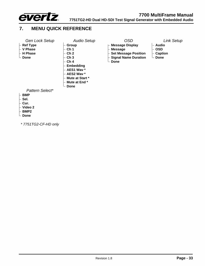
Gen Lock Setup − Ref Type − V Phase − H Phase − Done
Audio Setup − Group − Ch 1 − Ch 2 − Ch 3 − Ch 4 − Embedding − AES1 Wav * − AES2 Wav * − Mute at Start * − Mute at End * − Done
OSD − Message Display − Message − Set Message Position − Signal Name Duration − Done
Link Setup − Audio − OSD − Caption − Done
Pattern Select* − BMP − Sel. − Cur. − Video 2 − BMP2 − Done * 7751TG2-CF-HD only
7700 MultiFrame Manual 7751TG2-HD Dual HD-SDI Test Signal Generator with Embedded Audio
Page - 34 Revision 1.8
8. VistaLINK® REMOTE MONITORING/CONTROL
8.1. What is VistaLINK®?
VistaLINK® is Evertz’s remote monitoring and configuration platform which operates over an Ethernet network using Simple Network Management Protocol (SNMP). SNMP is a standard computer network protocol that enables different devices sharing the same network to communicate with each other. VistaLINK® provides centralized alarm management, which monitors, reports, and logs all incoming alarm events and dispatches alerts to all the VLPro Clients connected to the server. Card configuration through VistaLINK® PRO can be performed on an individual or multi-card basis using simple copy and paste routines, which reduces the time to configure each module separately. Finally, VistaLINK® enables the user to configure devices in the network from a central station and receive feedback that the configuration has been carried out. There are 3 components of SNMP:
1. An SNMP manager, also known as a Network Management System (NMS), is a computer running special software that communicates with the devices in the network. Evertz VistaLINK® Pro Manager graphical user interface (GUI), third-party, or custom manager software may be used to monitor and control Evertz VistaLINK® enabled products.
2. Managed devices (such as 7700R2X2-HD and 7700R2X2-HES), each with a unique address
(OID), communicate with the NMS through an SNMP Agent. Evertz VistaLINK® enabled 7700 series modules reside in the 3RU 7700FR-C MultiFrame and communicate with the manager via the 7700FC VistaLINK® frame controller module, which serves as the Agent.
3. A virtual database, known as the Management Information Base (MIB), lists all the variables being
monitored, which both the Manager and Agent understand. Please contact Evertz for further information about obtaining a copy of the MIB for interfacing to a third party Manager/NMS.
For more information on connecting and configuring the VistaLINK® network, see the 7700FC Frame Controller chapter.
For VistaLINK® SNMP remote control of the 7751TG2-HD modules, all DIP switches must be ON (positioned towards the main PCB).
If all of the DIP switches are not in the ON position, then VistaLINK® will only be able to read the current configuration of the 7751TG2-HD module.
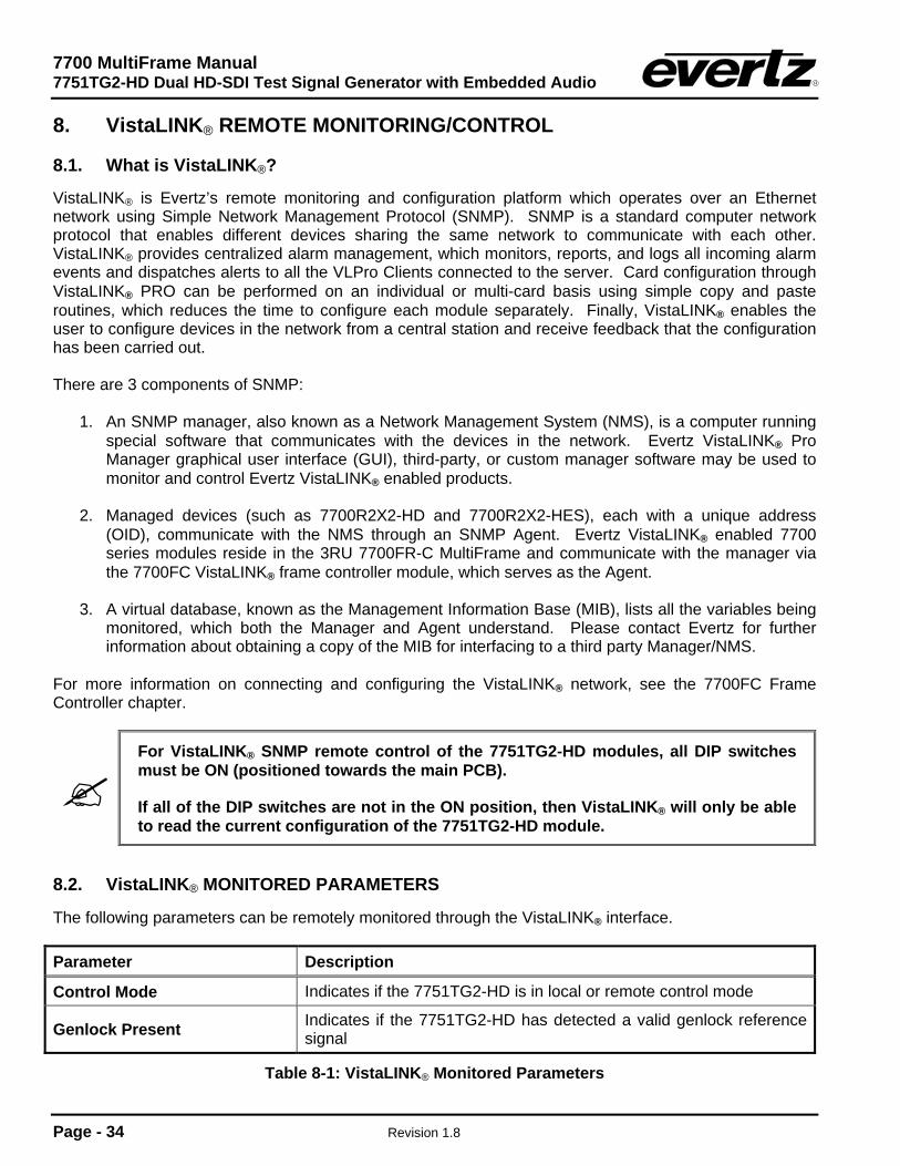
8.2. VistaLINK® MONITORED PARAMETERS
The following parameters can be remotely monitored through the VistaLINK® interface. Parameter Description
Control Mode Indicates if the 7751TG2-HD is in local or remote control mode
Genlock Present Indicates if the 7751TG2-HD has detected a valid genlock reference signal
Table 8-1: VistaLINK® Monitored Parameters
7700 MultiFrame Manual 7751TG2-HD Dual HD-SDI Test Signal Generator with Embedded Audio
Revision 1.8 Page - 35
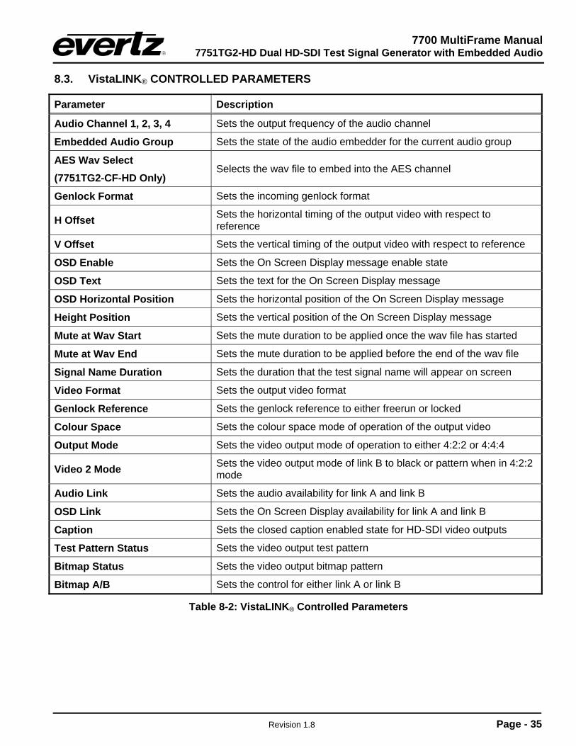
8.3. VistaLINK® CONTROLLED PARAMETERS
Parameter Description
Audio Channel 1, 2, 3, 4 Sets the output frequency of the audio channel
Embedded Audio Group Sets the state of the audio embedder for the current audio group
AES Wav Select (7751TG2-CF-HD Only)
Selects the wav file to embed into the AES channel
Genlock Format Sets the incoming genlock format
H Offset Sets the horizontal timing of the output video with respect to reference
V Offset Sets the vertical timing of the output video with respect to reference
OSD Enable Sets the On Screen Display message enable state
OSD Text Sets the text for the On Screen Display message
OSD Horizontal Position Sets the horizontal position of the On Screen Display message
Height Position Sets the vertical position of the On Screen Display message
Mute at Wav Start Sets the mute duration to be applied once the wav file has started
Mute at Wav End Sets the mute duration to be applied before the end of the wav file
Signal Name Duration Sets the duration that the test signal name will appear on screen
Video Format Sets the output video format
Genlock Reference Sets the genlock reference to either freerun or locked
Colour Space Sets the colour space mode of operation of the output video
Output Mode Sets the video output mode of operation to either 4:2:2 or 4:4:4
Video 2 Mode Sets the video output mode of link B to black or pattern when in 4:2:2 mode
Audio Link Sets the audio availability for link A and link B
OSD Link Sets the On Screen Display availability for link A and link B
Caption Sets the closed caption enabled state for HD-SDI video outputs
Test Pattern Status Sets the video output test pattern
Bitmap Status Sets the video output bitmap pattern
Bitmap A/B Sets the control for either link A or link B
Table 8-2: VistaLINK® Controlled Parameters


