Embed Size (px)
Citation preview

SCHEUERLE-FAHRZEUGFABRIK GMBH
permission.
accessible to third persons without written
use only.It may not be reproduced nor made
It is entrusted to the receiver for the specified
This drawing remains the property of Scheuerle.
dimensions reserved!Alterations to design and
310
620
± 1
30
° -100°
-130°
+130°
+100°
15
00
±3
50
FAHRZEUGFABRIK GmbH
Co
pyr
ight: D
IN 3
4 / IS
O 1
6016
Gez.NameDatum
Bl.
Bl.
Ers.d.Urspr. Ers.f.
6-Achs SPMT 210.12.4 G4
50000390����������
����
��
����
1
D-74629 PfedelbachÖhringer Str. 16
1
Maßstab
6-axle SPMT 210.12.4 G4Gepr. ��������� �����
B
����
Version
1450
2430
700 1400 1400 1400 1400 1400
8730
8400
700
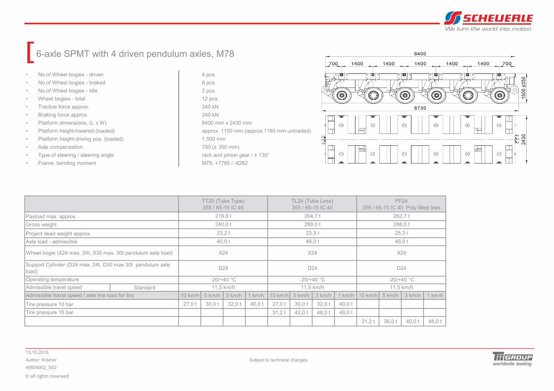
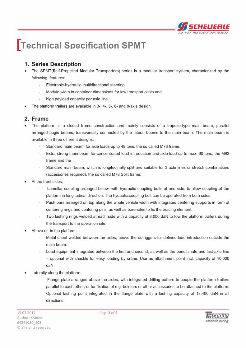
6-axle SPMT with 4 driven pendulum axles, M78
� No.of Wheel bogies - driven 4 pcs.
� No.of Wheel bogies - braked 6 pcs.
� No.of Wheel bogies - idle 2 pcs.
� Wheel bogies - total 12 pcs.
� Tractive force approx. 240 kN
� Braking force approx. 240 kN
� Platform dimensions, (L x W) 8400 mm x 2430 mm
� Platform height-lowered (loaded) approx. 1150 mm (approx.1180 mm unloaded)
� Platform height-driving pos. (loaded)
� Axle compensation 700 (± 350 mm)
� Type of steering / steering angle rack and pinion gear / ± 130°
� Frame, bending moment M78, +7785 / -6262
Standard
10 km/h 5 km/h 3 km/h 1 km/h 10 km/h 5 km/h 3 km/h 1 km/h 10 km/h 5 km/h 3 km/h 1 km/h
27,0 t 30,0 t 32,0 t 40,0 t 27,0 t 30,0 t 32,0 t 40,0 t
31,2 t 42,0 t 48,0 t 48,0 t
31,2 t 36,0 t 40,0 t 48,0 t
© ��������������
TT20 (Tube Type)355 / 65-15 IC 40
TL24 (Tube Less)355 / 65-15 IC 40
PF24355 / 65-15 IC 40 Poly filled tires
Payload max. approx.
Gross weight
216,8 t
240,0 t
264,7 t
288,0 t
Tire pressure 15 bar
Operating temperature
Tire pressure 10 bar
Admissible travel speed / axle line load for tire:
Admissible travel speed
-20/+40 °C
Project dead weight approx.
Axle load - admissible
Wheel bogie (X24 max. 24t, X30 max. 30t pendulum axle load)
Support Cylinder (D24 max. 24t, D30 max 30t pendulum axle load)
23,2 t
40,0 t
X24
D24
-20/+40 °C
23,3 t
48,0 t
X24
13.10.2015
49500002_S02
Subject to technical changes
1.500 mm
Author: Krämer
11,5 km/h 11,5 km/h11,5 km/h
D24D24
-20/+40 °C
262,7 t
288,0 t
25,3 t
48,0 t
X24
We turn the world into motion
[
SCHEUERLE-FAHRZEUGFABRIK GMBH
permission.
accessible to third persons without written
use only.It may not be reproduced nor made
It is entrusted to the receiver for the specified
This drawing remains the property of Scheuerle.
dimensions reserved!Alterations to design and
15
00
±3
50
310 310
-130°
+100°
+130°
-100°
FAHRZEUGFABRIK GmbH
Co
pyr
ight: D
IN 3
4 / IS
O 1
6016
Gez.NameDatum
Bl.
Bl.
Ers.d.Urspr. Ers.f.
4-Achs SPMT 140.8.4 G4
50000492����������
����
���
����
Öhringer Str. 16
1
D-74629 Pfedelbach 1� ���
B
4-axle SPMT 140.8.4 G4Gepr. ����������
����Maßstab
Version
700
5600
140014001400 700
5930
1450
2430
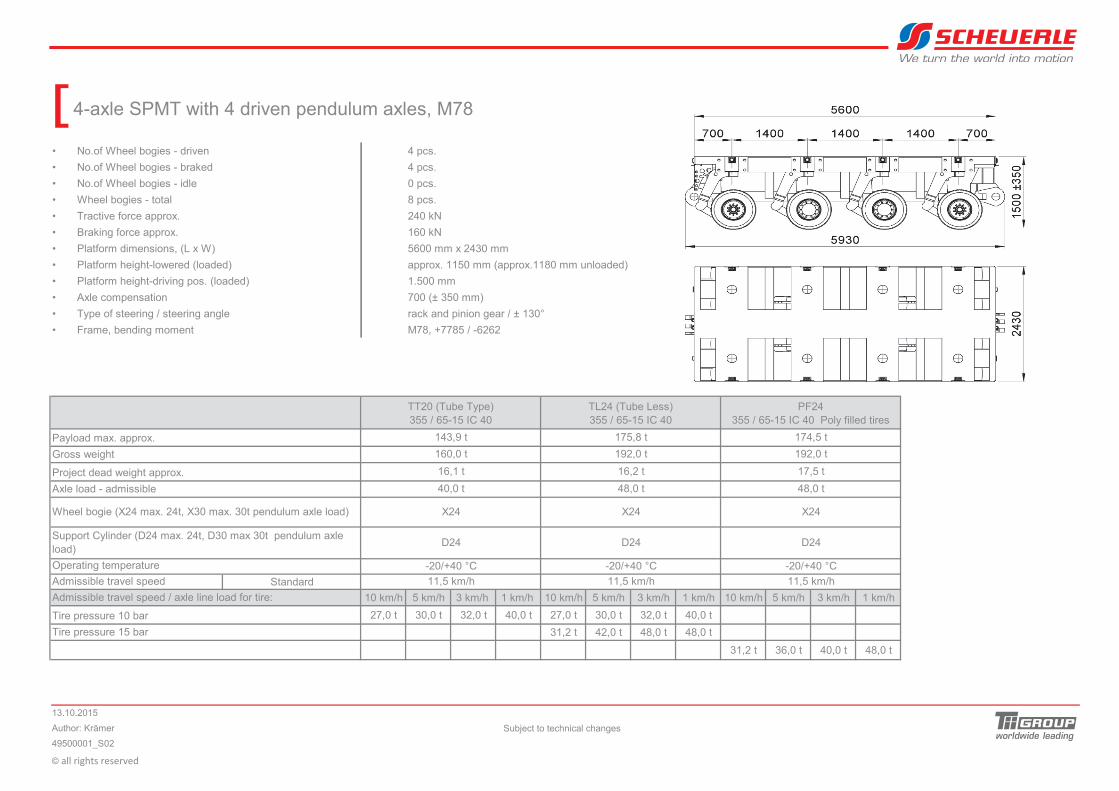
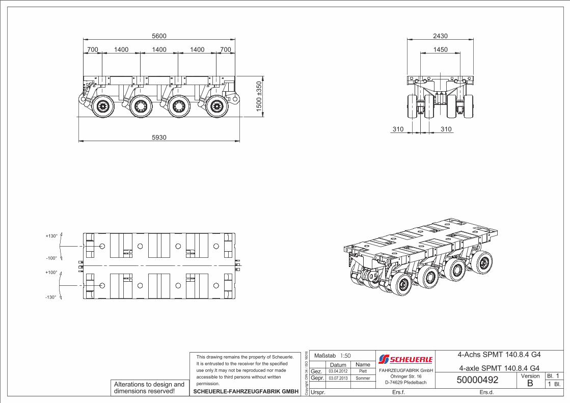
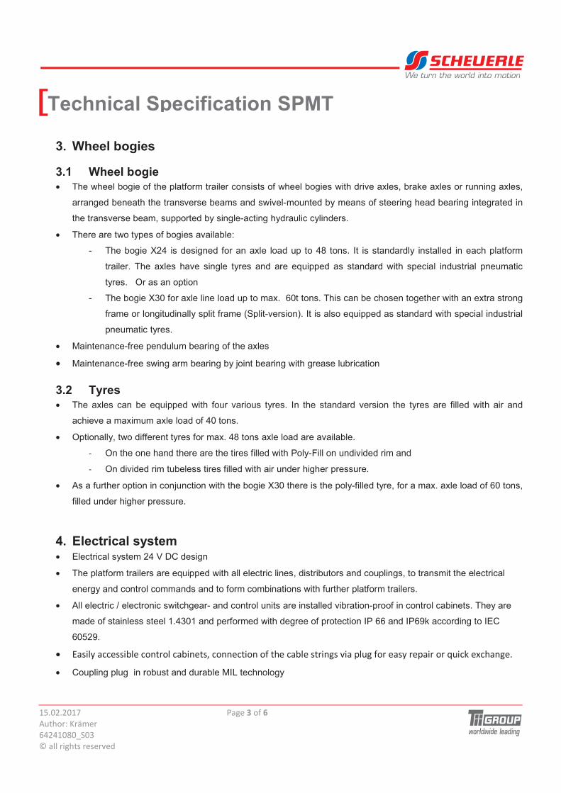
4-axle SPMT with 4 driven pendulum axles, M78
� No.of Wheel bogies - driven 4 pcs.
� No.of Wheel bogies - braked 4 pcs.
� No.of Wheel bogies - idle 0 pcs.
� Wheel bogies - total 8 pcs.
� Tractive force approx. 240 kN
� Braking force approx. 160 kN
� Platform dimensions, (L x W) 5600 mm x 2430 mm
� Platform height-lowered (loaded) approx. 1150 mm (approx.1180 mm unloaded)
� Platform height-driving pos. (loaded)
� Axle compensation 700 (± 350 mm)
� Type of steering / steering angle rack and pinion gear / ± 130°
� Frame, bending moment M78, +7785 / -6262
Standard
10 km/h 5 km/h 3 km/h 1 km/h 10 km/h 5 km/h 3 km/h 1 km/h 10 km/h 5 km/h 3 km/h 1 km/h
27,0 t 30,0 t 32,0 t 40,0 t 27,0 t 30,0 t 32,0 t 40,0 t
31,2 t 42,0 t 48,0 t 48,0 t
31,2 t 36,0 t 40,0 t 48,0 t
© ��������������
TT20 (Tube Type)355 / 65-15 IC 40
TL24 (Tube Less)355 / 65-15 IC 40
PF24355 / 65-15 IC 40 Poly filled tires
Payload max. approx.
Gross weight
143,9 t
160,0 t
175,8 t
192,0 t
Tire pressure 15 bar
Operating temperature
Tire pressure 10 bar
Admissible travel speed / axle line load for tire:
Admissible travel speed
-20/+40 °C
Project dead weight approx.
Axle load - admissible
Wheel bogie (X24 max. 24t, X30 max. 30t pendulum axle load)
Support Cylinder (D24 max. 24t, D30 max 30t pendulum axle load)
16,1 t
40,0 t
X24
D24
-20/+40 °C
16,2 t
48,0 t
X24
13.10.2015
49500001_S02
Subject to technical changes
1.500 mm
Author: Krämer
11,5 km/h 11,5 km/h11,5 km/h
D24D24
-20/+40 °C
174,5 t
192,0 t
17,5 t
48,0 t
X24
We turn the world into motion
[
� � � �
� � �
� � � � �
�
�
�
�
�
����������� ������ ���
���������������
�������������
��������� ��� ��!�"�
We turn the world into motion
Technical Specification SPMT[
�
1.� Series description��������������������������������������������������������������������������������������������������������������������������������������������������
2.� Frame���������������������������������������������������������������������������������������������������������������������������������������������������������������������
3.� Wheel bogies���������������������������������������������������������������������������������������������������������������������������������������������������������
3.1� Wheel bogie���������������������������������������������������������������������������������������������������������������������������������������������������
3.2� Tyres���������������������������������������������������������������������������������������������������������������������������������������������������������������
4.� Electrical system���������������������������������������������������������������������������������������������������������������������������������������������������
5.� Coating and Corossion protection�����������������������������������������������������������������������������������������������������������������������
6.� Functional description�������������������������������������������������������������������������������������������������������������������������������������������
6.1� Hydraulic support�������������������������������������������������������������������������������������������������������������������������������������������
6.2� Hydrostatic drive propulsion�������������������������������������������������������������������������������������������������������������������������
6.3� Brake system�������������������������������������������������������������������������������������������������������������������������������������������������
6.4� Electronic-hydraulic multidirectional steering (SADESS)���������������������������������������������������������������������������
7.� Accessories�����������������������������������������������������������������������������������������������������������������������������������������������������������
7.1� Standard accessories������������������������������������������������������������������������������������������������������������������������������������
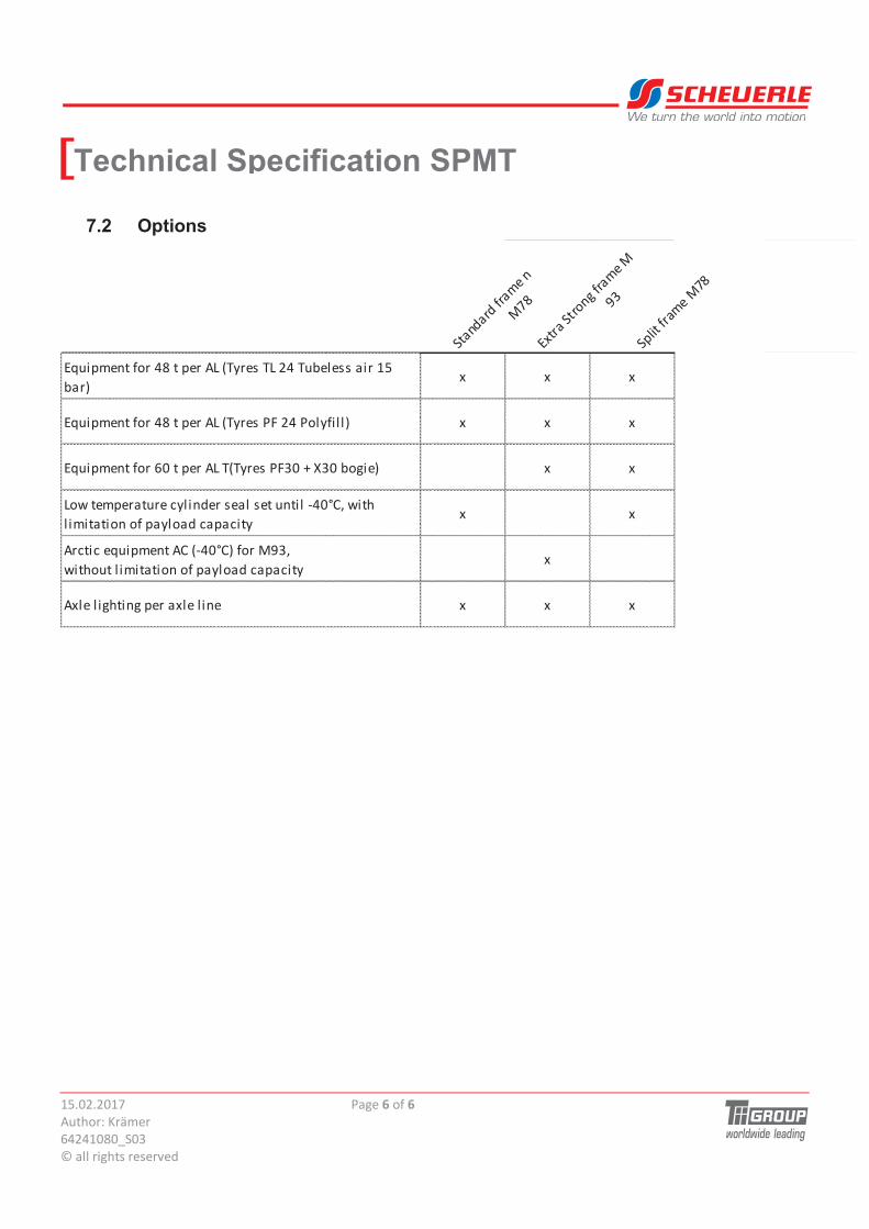
7.2� Options�����������������������������������������������������������������������������������������������������������������������������������������������������������
� � � �
� � �
� � � � �
�
�
�
�
�
����������� ������ ���
���������������
�������������
��������� ��� ��!�"�
We turn the world into motion
Technical Specification SPMT[
1. Series Description • The SPMT(Self-Propelled Modular Transporters) series is a modular transport system, characterized by the
following features:
# Electronic-hydraulic multidirectional steering
# Module width in container dimensions for low transport costs and
# high payload capacity per axle line
• The platform trailers are available in 3-, 4-, 5-, 6- and 8-axle design.
2. Frame • The platform is a closed frame construction and mainly consists of a trapeze-type main beam, parallel
arranged bogie beams, transversally connected by the lateral booms to the main beam. The main beam is
available in three different designs.
# Standard main beam: for axle loads up to 48 tons, the so called M78 frame,
# Extra strong main beam for concentrated load introduction and axle load up to max. 60 tons, the M93
frame and the
# Standard main beam, which is longitudinally split and suitable for 3 axle lines or stretch combinations
(accessories required), the so called M78 Split frame.
• At the front sides,
# Lamellar coupling arranged below, with hydraulic coupling bolts at one side, to allow coupling of the
platform in longitudinal direction. The hydaulic.coupling bolt can be operated from both sides.
# Push bars arranged on top along the whole vehicle width with integrated centering supports in form of
centering rings and centering pins, as well as boreholes to fix the bracing element.
# Two lashing rings welded at each side with a capacity of 8.000 daN to tow the platform trailers during
the transport to the operation site.
• Above or in the platform:
# Metal sheet welded between the axles, above the outriggers for defined load introduction outside the
main beam.
# Load equipment integrated between the first and second, as well as the penultimate and last axle line
� optional with shackle for easy loading by crane. Use as attachment point incl. capacity of 10.000
daN.
• Laterally along the platform:
# Flange plate arranged above the axles, with integrated drilling pattern to couple the platform trailers
parallel to each other; or for fixation of e.g. bolsters or other accessories to be attached to the platform.
Optional lashing point integrated in the flange plate with a lashing capacity of 13.400 daN in all
directions.
� � � �
� � �
� � � � �
�
�
�
�
�
����������� ������ ���
���������������
�������������
��������� ��� ��!�"�
We turn the world into motion
Technical Specification SPMT[
3. Wheel bogies
3.1 Wheel bogie • The wheel bogie of the platform trailer consists of wheel bogies with drive axles, brake axles or running axles,
arranged beneath the transverse beams and swivel-mounted by means of steering head bearing integrated in
the transverse beam, supported by single-acting hydraulic cylinders.
• There are two types of bogies available:
- The bogie X24 is designed for an axle load up to 48 tons. It is standardly installed in each platform
trailer. The axles have single tyres and are equipped as standard with special industrial pneumatic
tyres. Or as an option
- The bogie X30 for axle line load up to max. 60t tons. This can be chosen together with an extra strong
frame or longitudinally split frame (Split-version). It is also equipped as standard with special industrial
pneumatic tyres.
• Maintenance-free pendulum bearing of the axles
• Maintenance-free swing arm bearing by joint bearing with grease lubrication
3.2 Tyres • The axles can be equipped with four various tyres. In the standard version the tyres are filled with air and
achieve a maximum axle load of 40 tons.
• Optionally, two different tyres for max. 48 tons axle load are available.
# On the one hand there are the tires filled with Poly-Fill on undivided rim and
# On divided rim tubeless tires filled with air under higher pressure.
• As a further option in conjunction with the bogie X30 there is the poly-filled tyre, for a max. axle load of 60 tons,
filled under higher pressure.
4. Electrical system • Electrical system 24 V DC design
• The platform trailers are equipped with all electric lines, distributors and couplings, to transmit the electrical
energy and control commands and to form combinations with further platform trailers.
• All electric / electronic switchgear- and control units are installed vibration-proof in control cabinets. They are
made of stainless steel 1.4301 and performed with degree of protection IP 66 and IP69k according to IEC
60529.
• $ ��%�&&� �'���&�(�����&'�(�� )�&�((�&���(�� �����&'��� ���( �!��*��� ���� %���*������+��&,��-&�(����
• Coupling plug in robust and durable MIL technology
� � � �
� � �
� � � � �
�
�
�
�
�
����������� ������ ���
���������������
�������������
��������� ��� ��!�"�
We turn the world into motion
Technical Specification SPMT[
5. Coating and Corossion protection • Coating according to internal coating regulation
• Lower side of the platform and bogies are coated in RAL 7016 (dark grey).
• Topcoat of the vehicle frame (lateral- and loading area) in RAL 3020 (traffic red), different colour according to
customer´s request against additional price in accordance with internal colour chart.
• Rims and wheel hubs in RAL 9006 (silver)
6. Functional description
6.1 Hydraulic support
• Hydraulic axle compensation, hydraulic lifting device of the platform
• Pipe- and protection system in one circuit design in the hydraulic support system
• Each support cylinder can be removed from the system by a shut-off valve (ball valve) with help of an axle
plug. After lowering the platform, the bogie can be mechanically arrested and after relifting the bogie is lifted.
• installed shut-off valves (ball valves) between each axle, this means the single bogies can be divided into 3-
or 4- point support.
6.2 Hydrostatic drive propulsion • The hydrostatic drive propulsion is effected in a so called �closed circuit�. Hydro motors with flanged planetary
gearboxes are installed in the drive axles, which are driven by the hydraulic pumps in the PPU. Speed
adjustment is infinitely variable.
OSP � the drive axles are equipped with an electronic overtwist lock, which prevents overtwisting of the drive
wheels on slippery ground.
6.3 Brake system • Hydraulic-mechanic service- and parking brake
• The hydraulically actuated spring-accumulated brake cylinder and a slack adjuster are used to actuate the
S-cams and the pad is pressed to the brake drum.
• The required hydraulic release pressure is generated by the axial piston adjustment pump of the steering
system in the PPU and the braking is performed via a finely dosed pressure control valve.
• Due to the spring force in the brake cylinder, the combination is still safely braked and held in case of failure
of hydraulic supply,
� � � �
� � �
� � � � �
�
�
�
�
�
����������� ������ ���
���������������
�������������
��������� ��� ��!�"�
We turn the world into motion
Technical Specification SPMT[6.4 Electronic-hydraulic multidirectional steering (SADESS) • The bogies are steered by an electronic-hydraulic multidirectional steering (SADESS Scheuerle All Directional
Electronic Steering System). It consists of the digital steering electronic with several steering programs and
the hydraulic steering device, performed as double rack-gear.
• Such way a steering angle of +/- 130° results.
• For combinations in open compound, the steering pole is freely programmable.
• The infinitely adjustable proportional valves on the bogies are activated by joystick which are installed on the
remote control, thus the hydraulic steering drive is driven.
• The steering propulsion is designed in such a way that during standstill and under full load steering and
change of steering programs are possible.
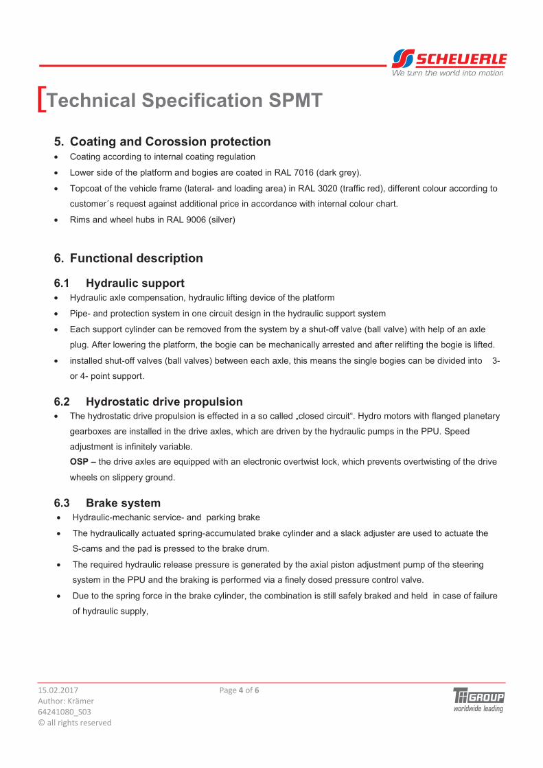
• The following steering programs are at disposal:
- All-wheel steering lengthwise
- All-wheel steering transverse
- Diagonal steering lengthwise
- Diagonal steering transverse
- Truck steering front
- Truck steering rear
- Carousel steering
7. Accessories
7.1 Standard Accessoires
• 1 (one) total documentation in paper
• 1 (one) total documentation on CD
• 1 axle pin per bogie for single axle lifting
• 1 set of mechanic connection elements for coupling in longitudinal direction
• 1 set of electric connection cables for coupling in longitudinal direction
• 1 set of hydraulic piping for coupling at the platform trailer
� � � �
� � �
� � � � �
�
�
�
�
�
����������� ������ ���
���������������
�������������
��������� ��� ��!�"�
We turn the world into motion
Technical Specification SPMT[7.2 Options
��("�"� ��
��(�
.��
$-�������(� ��
��.�
/�
�*���� ��
��.��
$+��*��(�� ��������*����0�12%�� �20����2�'��� �������
'�3- - -
$+��*��(�� ��������*����0�12%�� ��4�������% �� �3 - - -
$+��*��(�� ��������*����0�212%�� ��4���5�6���'���3 - -
0�7����*�������&%��("��� ��� ����(�� � �#��89)�7����
� �������(�� �*%��"�&*&��%- -
��&��&��+��*��(���9�1#��893� ���./�)
7�������� �������(�� �*%��"�&*&��%-
�-���� ����(�*���-�����(� - - -
�
SCHEUERLE-FAHRZEUGFABRIK GMBH
permission.
accessible to third persons without written
use only.It may not be reproduced nor made
It is entrusted to the receiver for the specified
This drawing remains the property of Scheuerle.
dimensions reserved!Alterations to design and
350
1500
-350
+
2798
Öhringer Str. 20FAHRZEUGFABRIK GmbH
Cop
yrig
ht: D
IN 3
4 / I
SO
160
16
Gez.NameDatum
Bl.
Bl.
Ers.d.Urspr. Ers.f.
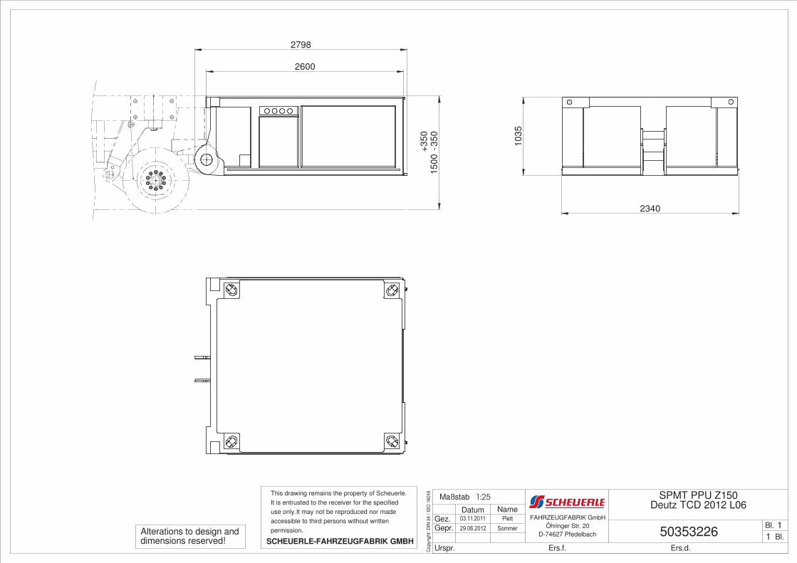
SPMT PPU Z150
50353226����������
����
��
����
1
Deutz TCD 2012 L06
D-74627 Pfedelbach 1�� �
Maßstab
Gepr. ����������
1:25
1035
2340
2600
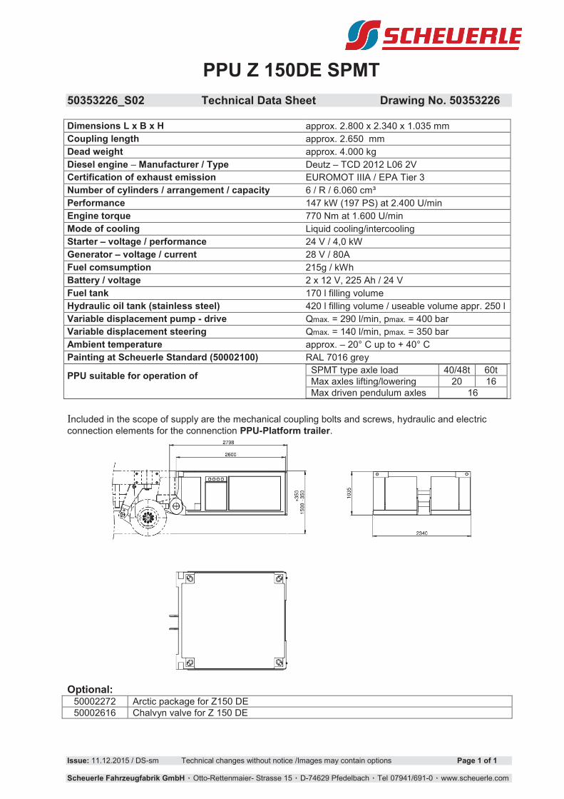
PPU Z 150DE SPMT
50353226_S02 Technical Data Sheet Drawing No. 50353226
Issue: 11.12.2015 / DS-sm Technical changes without notice /Images may contain options Page 1 of 1
Scheuerle Fahrzeugfabrik GmbH !Otto-Rettenmaier- Strasse 15! !D-74629!Pfedelbach! !Tel 07941/691-0! !www.scheuerle.com
Dimensions L x B x H approx. 2.800 x 2.340 x 1.035 mm
Coupling length approx. 2.650 mm
Dead weight approx. 4.000 kg
Diesel engine � Manufacturer / Type Deutz � TCD 2012 L06 2V
Certification of exhaust emission EUROMOT IIIA / EPA Tier 3
Number of cylinders / arrangement / capacity 6 / R / 6.060 cm³
Performance 147 kW (197 PS) at 2.400 U/min
Engine torque 770 Nm at 1.600 U/min
Mode of cooling Liquid cooling/intercooling
Starter � voltage / performance 24 V / 4,0 kW
Generator � voltage / current 28 V / 80A
Fuel comsumption 215g / kWh
Battery / voltage 2 x 12 V, 225 Ah / 24 V
Fuel tank 170 l filling volume
Hydraulic oil tank (stainless steel) 420 l filling volume / useable volume appr. 250 l
Variable displacement pump - drive Qmax. = 290 l/min, pmax. = 400 bar
Variable displacement steering Qmax. = 140 l/min, pmax. = 350 bar
Ambient temperature approx. � 20° C up to + 40° C
Painting at Scheuerle Standard (50002100) RAL 7016 grey
PPU suitable for operation of
SPMT type axle load 40/48t 60t Max axles lifting/lowering 20 16 Max driven pendulum axles 16
Included in the scope of supply are the mechanical coupling bolts and screws, hydraulic and electric connection elements for the connenction PPU-Platform trailer.
Optional:
50002272 Arctic package for Z150 DE 50002616 Chalvyn valve for Z 150 DE
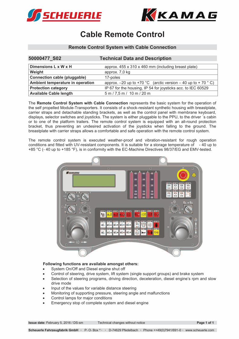
Cable Remote Control
Remote Control System with Cable Connection 50000477_S02 Technical Data and Description
Issue date: February 5, 2016 / DS-sm Technical changes without notice Page 1 of 1
Scheuerle Fahrzeugfabrik GmbH !!!P"!O"!Box!# !! !!!D-74629!Pfedelbach!! !!Phone!++49(0)7941/691-0! !!www.scheuerle.com
Dimensions L x W x H approx. 455 x 310 x 460 mm (including breast plate)
Weight approx. 7,0 kg
Connection cable (pluggable) 17-poles
Ambient temperature in operation approx. �20 up to +70 °C (arctic version � 40 up to + 70 ° C)
Protection category IP 67 for the housing, IP 54 for joysticks acc. to IEC 60529
Available Cable length 5 m / 7,5 m / 10 m / 20 m
The Remote Control System with Cable Connection represents the basic system for the operation of the self propelled Module-Transporters. It consists of a shock-resistant synthetic housing with breastplate, carrier straps and detachable standing brackets, as well as the control panel with membrane keyboard, displays, selector switches and joysticks. The system is either pluggable to the PPU, to the driver ´s cabin or to one of the platform trailers. The remote control system is equipped with an all-round protection bracket, thus preventing an undesired activation of the joysticks when falling to the ground. The breastplate with carrier straps allows a comfortable and safe operation with the remote control system. The remote control system is executed weather-proof and vibration-resistant for rough operation conditions and fitted with UV-resistant components. It is suitable for a storage temperature of - 40 up to +85 °C (- 40 up to +185 °F), is in conformity with the EC-Machine Directives 98/37/EG and EMV-tested.
Following functions are available amongst others:
· System On/Off and Diesel engine shut off
· Control of steering, drive system, lift system (single support groups) and brake system
· Selection!of!steering!programs,!driving!direction,!deceleration,!diesel!engine�s!rpm!and!slow!drive mode
· Input of the values for variable distance steering
· Monitoring of supporting pressure, steering angle and malfunctions
· Control lamps for major conditions
· Emergency stop of complete system and diesel engine
SCHEUERLE-FAHRZEUGFABRIK GMBH
permission.
accessible to third persons without written
use only.It may not be reproduced nor made
It is entrusted to the receiver for the specified
This drawing remains the property of Scheuerle.
dimensions reserved!Alterations to design and
4365
150
0 ±3
50
SPMT
D-74627 PfedelbachÖhringer Str. 20
FAHRZEUGFABRIK GmbH
Cop
yrig
ht: D
IN 3
4 / I
SO
160
16
Gez.NameDatum
Bl.
Bl.
Ers.d.Urspr. Ers.f.
PPU Z350 DA
50000373����������
����
���
����
11
� ��
Maßstab 1:40
0
Gepr. ����������
Version
1100
max. 12°
2310
2310
1100
SPMT Modular Transporter Power Pack Unit Z 350 DA � Standard
50000373_S02 Technical data sheet Drawing No. 50000373
The modular transportation system for payloads up to 15.000 tons
Issue date: 11.12..2015 / DS-sm Technical changes without notice Page 1 of 1
Scheuerle Fahrzeugfabrik GmbH !!!P"!O"!Box!# !! !!!D-74629!Pfedelbach!! !!Phone!++49(0)7941/691-0! !!www.scheuerle.com
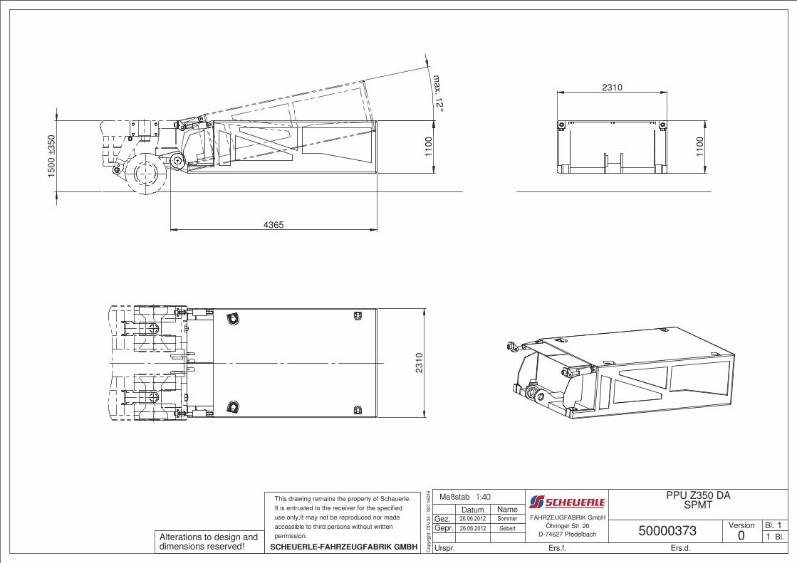
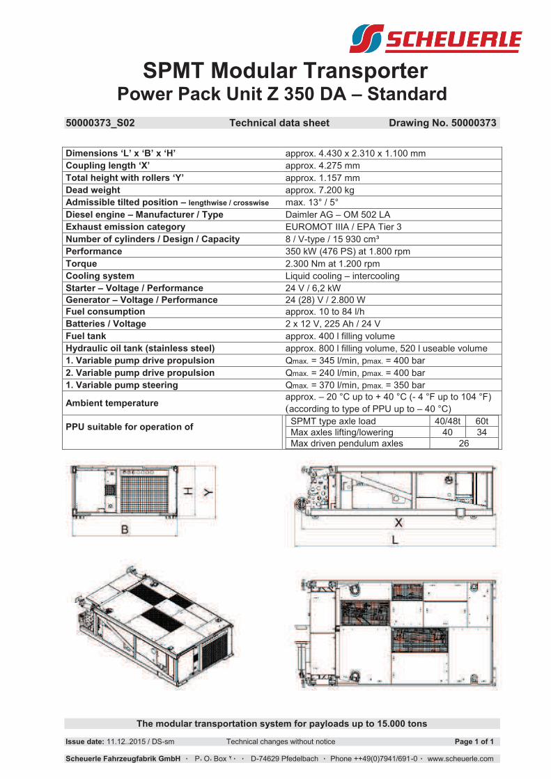
Dimensions �L� x �B� x �H� approx. 4.430 x 2.310 x 1.100 mm
Coupling length �X� approx. 4.275 mm
Total height with rollers �Y� approx. 1.157 mm
Dead weight approx. 7.200 kg
Admissible tilted position � lengthwise / crosswise max. 13° / 5°
Diesel engine � Manufacturer / Type Daimler AG � OM 502 LA
Exhaust emission category EUROMOT IIIA / EPA Tier 3
Number of cylinders / Design / Capacity 8 / V-type / 15 930 cm³
Performance 350 kW (476 PS) at 1.800 rpm
Torque 2.300 Nm at 1.200 rpm
Cooling system Liquid cooling � intercooling
Starter � Voltage / Performance 24 V / 6,2 kW
Generator � Voltage / Performance 24 (28) V / 2.800 W
Fuel consumption approx. 10 to 84 l/h
Batteries / Voltage 2 x 12 V, 225 Ah / 24 V
Fuel tank approx. 400 l filling volume
Hydraulic oil tank (stainless steel) approx. 800 l filling volume, 520 l useable volume
1. Variable pump drive propulsion Qmax. = 345 l/min, pmax. = 400 bar
2. Variable pump drive propulsion Qmax. = 240 l/min, pmax. = 400 bar
1. Variable pump steering Qmax. = 370 l/min, pmax. = 350 bar
Ambient temperature approx. � 20 °C up to + 40 °C (- 4 °F up to 104 °F)
(according to type of PPU up to � 40 °C)
PPU suitable for operation of
SPMT type axle load 40/48t 60t
Max axles lifting/lowering 40 34
Max driven pendulum axles 26
February 15th, 2017 Page 1 of 5
Author: Krämer-sm 64241116_S03 © all rights reserved
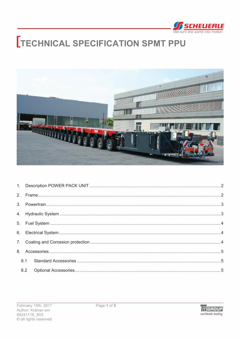
We turn the world into motion
TECHNICAL SPECIFICATION SPMT PPU[
1.� Description POWER PACK UNIT ........................................................................................................... 2�
2.� Frame ..................................................................................................................................................... 2�
3.� Powertrain .............................................................................................................................................. 3�
4.� Hydraulic System ................................................................................................................................... 3�
5.� Fuel System ........................................................................................................................................... 4�
6.� Electrical System .................................................................................................................................... 4�
7.� Coating and Corossion protection .......................................................................................................... 4�
8.� Accessories ............................................................................................................................................ 5�
8.1� Standard Accessories ..................................................................................................................... 5�
8.2� Optional Accessories ....................................................................................................................... 5
February 15th, 2017 Page 2 of 5
Author: Krämer-sm 64241116_S03 © all rights reserved
We turn the world into motion
TECHNICAL SPECIFICATION SPMT PPU[
1. Description POWER PACK UNIT
• The POWER PACK UNIT (PPU) consists of all drive components required to operate an SPMT
combination. The PPU includes:
� The diesel engine with flanged hydraulic pumps,
� Coolers for cooling water, charge air and hydraulic oil
� Hydraulic oil tank and diesel fuel tank,
� Switch boxes for electronic and electric control
� Batteries, filters, control- and regulating valves.
• The Power Pack Unit is designed so that for transport container width is not exceeded and the PPU
dimension is not higher than the loading height of the platform trailer.
2. Frame
• The PPU frame mainly consists of welded square and angled profiles.
• The sides are:
� clad with easily removable or foldable sound-absorbing alu plate sheedings
� equipped with welded-on scrape rails to protect the doors.
• At the front side:
� At the lower side the lamellar coupling with hydraulic coupling bolt is welded to be able to
couple the PPU to the platform trailer
� At the upper side of the PPU there are hydraulic cylinders which fix the PPU by pressure bars
to the platform trailer. Using this cylinder, the PPU can be tilted up to 12° in order to avoid
ground contact when driving on ramps. In addition when the inclination is extreme, the PPU
can be moved horizontally to prevent damage to the motor due to excessive inclination.
� Two storage boxes are integrated at the center on top. One of these is a Zarges box to store
the remote control, in the second box the tools and the emergency control unit are included.
� One each on the right and on the left side a coupling plate is provided to supply the modules
hydraulically and electrically. Here, corresponding connections are provided in order to
connect several PPU�s to electrical supply and control lines or to supply a parallel
combination without PPU hydraulically / electrically.
February 15th, 2017 Page 3 of 5
Author: Krämer-sm 64241116_S03 © all rights reserved
We turn the world into motion
TECHNICAL SPECIFICATION SPMT PPU[• At the rear:
� The radiator is protected by a stable cooling grill
� The main switch board, pressure gauge and coupling point for the remote control is installed.
� Attachments are placed in order to be able to attach further mounting components to the
PPU, such as additional heating aggregate, oil cooler, operating platform or operating seat.
• Upper side of the PPU�s
� Is cladded with walk-on aluminum riffle sheets and closed with latch locks.
� In the corners are provided corresponding anchor points which allow to load the PPU�s alone
or together with another platform trailer (4- or 6- axles).
• Lower side
� Is equipped with 4 plastic rollers, allowing a shifting on firm ground.
3. Powertrain
• User friendly and easy to maintain access by opening the lateral and / or upper maintenance flaps
on top
• Flexible coupling, flange-mounted to the fly-wheel between hydraulic pumps and diesel engine.
This protects the hydraulic pumps from damaging vibrations.
• Complete drive train installed on vibration dampers
• Hydraulic pumps flanged one behind the other, providing maintenance-free access to the individual
hydraulic pumps.
• Spark arrestor integrated in the exhaust system of the internal combustion engine.
• The exhaust pipe is guided laterally outside towards the upper side and can be dismantled for
transport in order to maintain the transport width.
4. Hydraulic System
• Hydraulic tank of stainless steel or coated with anti-corrosive coating, with integrated return filters
and shut-off valves for the suction connections of the various hydraulic circuits.
• Breathing- and venting of the hydraulic tank by desiccant cartridge
• Level indicator for minimum and maximum range led to the outside
• Hydraulic oil tank equipped with electric temperate and level sensor
February 15th, 2017 Page 4 of 5
Author: Krämer-sm 64241116_S03 © all rights reserved
We turn the world into motion
TECHNICAL SPECIFICATION SPMT PPU[• 4 pressure gauges for support pressure, with proportional valve for lifting/lowering situated below.
Installed at the front right side of the PPU.
• Pressure gauge at rear at the PPU for driving, steering and braking.
• Hydraulically driven and speed-controlled fan of the coolers.
5. Fuel System
• Fuel tank of stainless steel or coated with anti-corrosive coating
• Equipped with electric level sensor
• A fuel filter with water separator is installed in the fuel line leading to the diesel engine, which is
protecting the injection system from contamination and water. The water separator is heated as
standard in the PPU Z390, for the PPU Z350 heating is optionally available.
6. Electrical System
• Electrical system in 24 V DC design
• All electrical / electronical switchgear and control units are installed vibration-proof in the switch
boxes. They are made of stainless steel 1.4301 and with degree of protection IP 66 and IP69k
according to IEC 60529.
• Pressure compensation of the switch boxes by desiccant cartridge
• Easily accessible switch boxes, connection of the cable harnesses by plugs for easy repair or quick
exchange.
• Protected display for additional functions for error diagnosis and parameterization in the PPU Z180
and Z390
• Dashboard illumination in LED technology
• Coupling bolt in robust and durable MIL technology
7. Coating and Corossion protection
• Coating according to internal paint regulations
• PPU-frame painted in- and outside in RAL 7016 (grey), other colour according to customers desire
available against additional price according to internal colour chart.
February 15th, 2017 Page 5 of 5
Author: Krämer-sm 64241116_S03 © all rights reserved
We turn the world into motion
TECHNICAL SPECIFICATION SPMT PPU[
8. Accessories
8.1 Standard Accessories
• Operating and maintenance instructions in the language of the operator, spare parts list in 2
languages (german/english), provided as CD ROM
• Operating instruction additionally once as paper documents
• Tool kit for SPMT platform trailer and PPU
• Emergency operating unit SPMT
8.2 Optional Accessories
• Integrated combustion air shut-off valve (Chalwyn Valve) in the suction line which blocks combustion
air supply to the diesel engine at uncontrollable overspeed.
• PPU with low-temperature equipment, for areas with temperatures below -20°C. Equipment
according to data sheet.
• Additional couplings for connecting external auxiliary devices such as oil cooler or heating units.
SCHEUERLE-FAHRZEUGFABRIK GMBH
permission.
accessible to third persons without written
use only.It may not be reproduced nor made
It is entrusted to the receiver for the specified
This drawing remains the property of Scheuerle.
dimensions reserved!Alterations to design and
116
0 2
505
4575
4730
110
0
Öhringer Str. 16FAHRZEUGFABRIK GmbH
Cop
yrig
ht: D
IN 3
4 / I
SO
160
16
Gez.NameDatum
Bl.
Bl.
Ers.d.Urspr. Ers.f.
Power Pack PPU Z390 DA SPMT
50353922����������
����
��
����
1
D-74629 Pfedelbach 1�� �
A
Gepr. ����������
1:30Maßstab
Version
2340
110
0
234
0
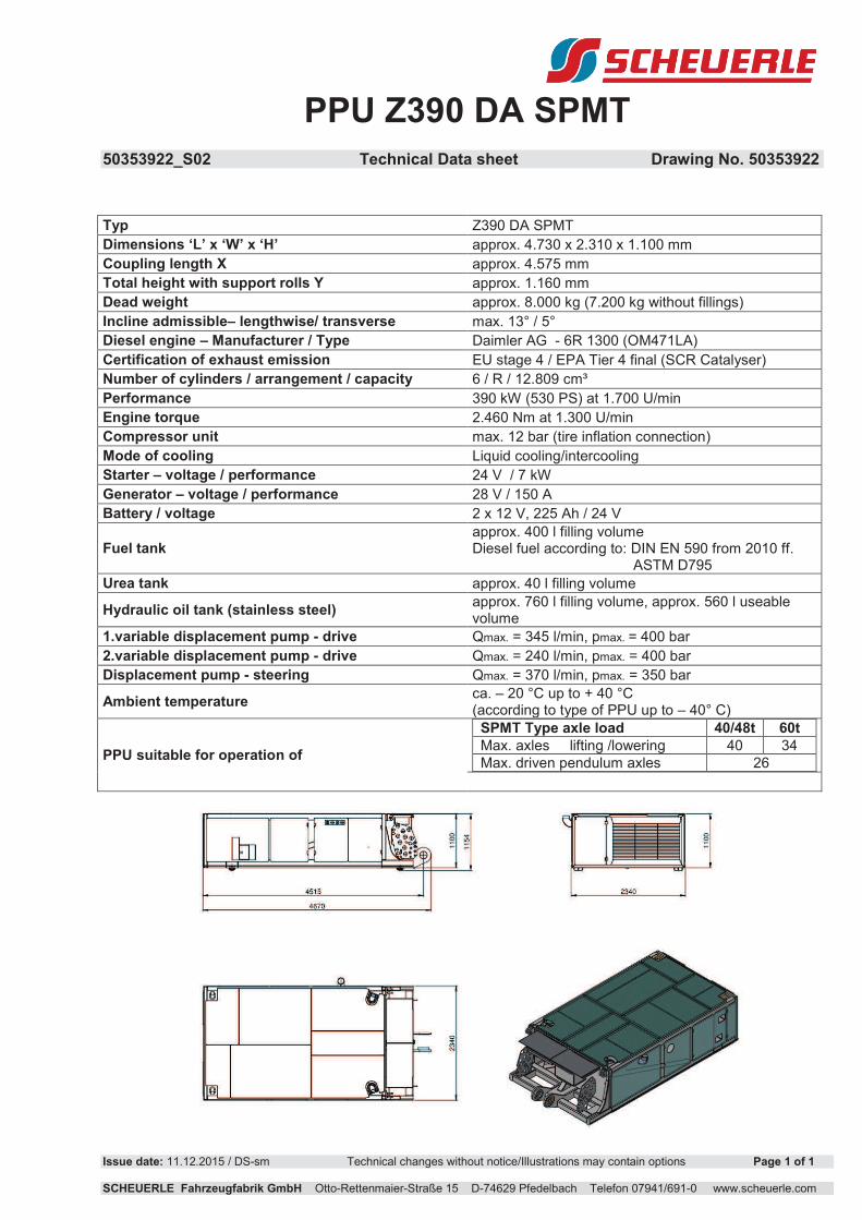
PPU Z390 DA SPMT
50353922_S02 Technical Data sheet Drawing No. 50353922
Issue date: 11.12.2015 / DS-sm Technical changes without notice/Illustrations may contain options Page 1 of 1 SCHEUERLE Fahrzeugfabrik GmbH Otto-Rettenmaier-Straße 15 D-74629 Pfedelbach Telefon 07941/691-0 www.scheuerle.com
Typ Z390 DA SPMT
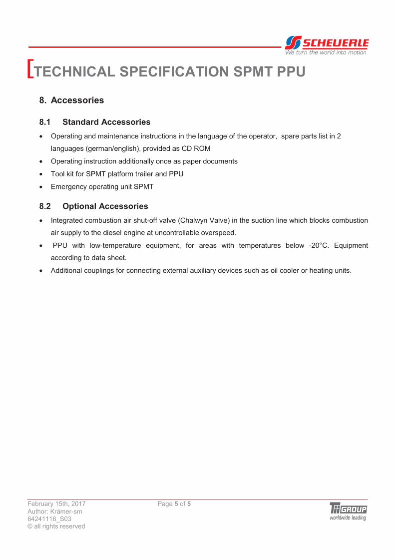
Dimensions ‘L’ x ‘W’ x ‘H’ approx. 4.730 x 2.310 x 1.100 mm
Coupling length X approx. 4.575 mm
Total height with support rolls Y approx. 1.160 mm
Dead weight approx. 8.000 kg (7.200 kg without fillings)
Incline admissible– lengthwise/ transverse max. 13° / 5°
Diesel engine – Manufacturer / Type Daimler AG - 6R 1300 (OM471LA)
Certification of exhaust emission EU stage 4 / EPA Tier 4 final (SCR Catalyser)
Number of cylinders / arrangement / capacity 6 / R / 12.809 cm³
Performance 390 kW (530 PS) at 1.700 U/min
Engine torque 2.460 Nm at 1.300 U/min
Compressor unit max. 12 bar (tire inflation connection)
Mode of cooling Liquid cooling/intercooling
Starter – voltage / performance 24 V / 7 kW
Generator – voltage / performance 28 V / 150 A
Battery / voltage 2 x 12 V, 225 Ah / 24 V
Fuel tank approx. 400 l filling volume Diesel fuel according to: DIN EN 590 from 2010 ff. ASTM D795
Urea tank approx. 40 l filling volume
Hydraulic oil tank (stainless steel) approx. 760 l filling volume, approx. 560 l useable volume
1.variable displacement pump - drive Qmax. = 345 l/min, pmax. = 400 bar
2.variable displacement pump - drive Qmax. = 240 l/min, pmax. = 400 bar
Displacement pump - steering Qmax. = 370 l/min, pmax. = 350 bar
Ambient temperature ca. – 20 °C up to + 40 °C (according to type of PPU up to – 40° C)
PPU suitable for operation of
SPMT Type axle load 40/48t 60t
Max. axles lifting /lowering 40 34
Max. driven pendulum axles 26


![Preparation of [5 + 6]-, [6 + 6]-, and [6 + 7]-Bicyclic Guanidines fromC,C'-Bis(iminophosphoranes)](https://img.dokumen.tips/doc/110x75/6346fe92f88a53192c091c1a/preparation-of-5-6-6-6-and-6-7-bicyclic-guanidines-fromcc-bisiminophosphoranes.jpg)


