Embed Size (px)
Citation preview
Ap.5-128
5.2 Inspection and Maintenance of Railways
5.2.1 Inspection and Maintenance of Civil Structures
(1) Types of Civil Structure
1) Functional Classification
① Earth Roadbed
② Bridges ((River) Bridges, Overbridges, Road Overbridges, Other)
③ Tunnels (Mountain, Under Road, Under River, Undersea, Other)
④ Other (Passenger Platforms, Retaining Walls, Revetments, Wayside (Drainage)
Channels, Cross Drains, etc.)
2) Classification by Structural Material
① Earth Structures
② Concrete Structures
③ Steel Structures
④ Steel and Concrete Structures
⑤ Other (Wood, Synthetic Resin, etc.)
3) Classification by Structural Form (Bridges)
① Girder Structures (Simple Girder, Continuous Girder, etc.)
② Rigid Frame Structures (Viaducts, Box Culverts)
③ Other (Suspension Bridges, Arches, etc.)
4) Classification by Construction Method (Tunnels)
① Mountain Method (Mainly Upper Arch)
② Shield Method (Mainly Circular Section)
③ Open Cut Method (Mainly Rectangular Section)
④ Other (Sinking, etc.)
Above are indicated the major classifications.
Ap.5-129
(2) Features of Civil Structures on Railways in Manila
1) PNR railways mainly consist of earth structures (bare surface), but steel bridges are
adopted on some river crossings.
2) Urban railway lines (Line 1, Line 2, Line 3) mainly consist of concrete structures
(girder viaducts, bridge substructure), but earth structures are adopted for rolling
stock depots, steel bridges are adopted on some river crossings, and open cut tunnels
are adopted in station sections. Moreover, on Line 3, earth structures (bare surface)
are frequently adopted between stations.
(3) Features of Disturbance According to Type of Structure
1) Earth Structure
Earth structures are largely divided into bankings, cuttings and bare surfaces,
however, since most of the earth structures of railways in Metro Manila are bare
surface, features shall be described for this.
In the case of bare surface, as is also true with banking and cutting, track irregularity
caused by roadbed sinkage and liquefaction is a major problem. And, concerning
subgrade and roadbed underneath ballast, as is again true with banking and cutting,
roadbed strengthening to withstand train loads is necessary and, in addition to
selecting the appropriate roadbed material, in cases where ground strength cannot be
expected from subgrade, ground strengthening measures such as ground
improvement, etc. must be carried out in advance. Furthermore, even if good quality
materials are used for subgrade and roadbed, if roadbed drainage is poor, since track
irregularity arising from infiltration of sediment into the subgrade and liquefaction
of the roadbed is apt to occur, it is necessary to constantly maintain roadbed
drainage in good condition and thus reduce the amount of track maintenance.
2) Concrete Structures
Concrete structures are commonly used in railway civil structures such as bridge
superstructures (girders), substructures (abuts, piers) and retaining walls, etc., and
use of such structures has been increasing in recent years due to problems of noise,
etc.
Speaking from the viewpoint of structural management, since concrete structures
adopt material which is prone to cracking (concrete), disturbance of such structures
is commonly found as a result of discovery of cracks. It is almost impossible to
Ap.5-130
completely prevent cracking in concrete structures, and numerous cracks are apt to
occur in sections which are structurally subject to tensile force (under sides midway
between girder spans, etc.). However, when such cracks occur in structures,
rainwater and harmful gases infiltrate the structures in question and cause corrosion,
and this corrosion leads to degradation and disturbance of the structures and further
reduce structural durability.
Therefore, when designing concrete structures, concerning sections which are
subject to the operation of tensile force, it is important to make sure that cracking
only occurs to the extent which leads to an allowable degree of rainwater and
harmful gas infiltration. In the area of management too, it is necessary to monitor
sections which are prone to tensile force to make sure that cracking does not
advance beyond the allowable level. Moreover, in cases where advanced cracking is
found in sections prone to tensile force and cases where cracking is found to have
occurred in sections subject to other forces (contraction, sheathing), it is possible
that some kind of disturbance (displacement, sinkage, etc.) has occurred in girder
bodies, substructures or foundations, or retaining wall bodies or foundations, etc.,
and it is necessary to take appropriate steps including measurement of displacement
volume and examination of causes and countermeasures.
Moreover, although not problems which have an immediate impact on train safety,
as disturbance items which can be visually checked in concrete structures and which
may lead to structural degradation in future, the degradation and peeling of concrete
and corrosion of reinforcing bars and steel can be raised.
3) Foundation Structures (including concrete retaining walls)
Foundations are broadly divided into spread foundations, pile foundations and others
(caisson). Since foundations are buried underground, it is near impossible to directly
check disturbance by eye. Therefore, disturbance is indirectly confirmed through
measuring the following items in abuts, piers, girders and sheathing walls, etc.
① Subsidence and uneven subsidence
② Tilting
③ Movement
④ Irregularity
⑤ Abnormal stress, cracking
Ap.5-131
The following can be pointed to as causes of these problems:
① Roadbed subsidence and movement
② Reduced strength of foundations or reduction of ground bearing capacity
Furthermore, external factors which are generated as a result of the above are as
follows:
① Overloading of banking occurs on weak roadbed or beside lines.
② Groundwater level is lowered as a result of groundwater pumping.
③ Foundations are constructed on unstable slopes containing risk of landslide.
④ Construction works are executed near to lines.
⑤ Strength of foundations is reduced due to structural deterioration.
⑥ Ground bearing force is lowered as a result of subgrade sinkage and adjoining
pit excavation
In addition to measuring manifestations of disturbance in management of foundation
structures, when ascertaining causes, it is necessary to grasp changes over time in
areas around structures.
4) Steel Bridges
Major types and causes of disturbance in steel bridges are as follows.
① Cracking
Cracks are divided into those which can be observed by naked eye and those
which cannot be observed visually, for example, cracks which occur in welded
sections. Cracks which occur in the main members of steel bridges not only
carry the risk of reducing girder strength, they also carry the possibility of
rapidly spreading through total sections. Moreover, when cracks progress and
split secondary members too, overall girder stability and load distribution
deteriorate and this leads to negative impact such as increased vibration of
girders when trains pass, etc.
The following items can be pointed to as causes of cracking: ①stress arising
from repeated load, ② structural faults in member sections, etc., ③
Ap.5-132
concentrated stress and residual stress arising from poor work on welded
sections.
② Corrosion
Corrosion is the most common form of disturbance in steel bridges. Once
corrosion occurs, the section in question does not dry out so easily and this
leads to further progression of the corrosion. Cracking is also caused by
corrosion in some cases.
Iron is inherently prone to oxidation and this occurs when the surface of iron
comes into contact with moisture, oxygen or acid. Moreover, if the surface of
iron is tainted due to attachment by dirt, smoke or salt, the iron becomes less
responsive to drying due to saturated condensation of moisture in the
atmosphere and rust progresses as a result. Therefore, when corrosion is
discovered, it is necessary to implement immediate countermeasures such as
recoating, etc.
③ Deformation
Deformation of girders is caused by clashes with automobiles or vessels and
dropping of objects from overbridges, etc. Moreover, thermal deformation of
girders is sometimes caused by fires on lines. When this deformation occurs on
the compression side or in compression members of girders, since train loads
cause the deformation to increase and damage the safety of girders, it is
necessary to rectify the deformation.
④ Support Displacement
Displacement of girder supports occurs when sinkage, tilting or horizontal
displacement of abuts and piers take place. Girder deformation and alteration of
stress conditions occur in line with this, and if structures continue to be used in
this condition, deformation of all girder members will be induced as a result.
⑤ Abrasion and Looseness
Abrasion of truss moving shoe and sliding shoe sliding parts, and looseness
which frequently occurs in rivets and high tensile bolts, lead to changes in
girder stress conditions and increased vibration and flexure of girders, and over
time they trigger a variety of adverse impacts.
Ap.5-133
5) Open Cut Tunnels
Major types and causes of disturbance in tunnels are as follows.
① Cracking
Some cracks are caused by the drying contraction of lining concrete, while
others appear as a result of tunnel lining deformation caused by the action of
load on tunnels (biased pressure or changes in load conditions, etc.). If cracking
is allowed to progress, it eventually leads to peeling and separation of lining
surfaces and destruction of tunnels. Moreover, on sections of concentrated
stress or lining joints, etc., irregularity is apt to occur. In the same way as with
general concrete structures, it is necessary to monitor the progress of cracking.
Since there is little or no allowance between the outer sides of rolling stock and
inner sides of tunnels, separation of concrete and displacement of tunnel bodies
immediately have an impact on train operating safety, and therefore it is
necessary to practice caution.
② Water Leakage
If leaking water inside tunnels is properly collected and drained away, it does
not have a major impact on tunnels. However, constructing a tunnel triggers the
same phenomena which occur when digging a large-scale well. In urban areas
where open cut tunnels are constructed, since such works lower the
groundwater level, they also sometimes lead to ground subsidence and
parching.
Moreover, in cases where leakage increases in tunnels which are normally
hardly affected by leakage because of low surrounding groundwater level, since
raising of the groundwater level leads to tunnel floating, it is necessary to
examine the issue of tunnel stability in tunnels which have a thin earth
covering.
③ Sediment Flow Behind Lining Surfaces
Flow of sediment behind lining inside tunnels leads to the occurrence of gaps in
the ground around tunnels and this not only leads to changes in load conditions
working on tunnels and adverse impact on tunnel bodies themselves, but since
it also triggers deformation in nearby houses, etc. and leads to major problems,
it is necessary to take immediate countermeasures.
Ap.5-134
④ Corrosion of Track Materials
On sections of extreme water leakage in tunnels on electrified sections (for
example, cases where water containing impurities is always lying on rails),
electric corrosion leads to corrosion of rails and fasteners and it is necessary to
carry out replacement of materials more frequently than normal.
This brings to an end the description of types and manifestations of disturbance
in railways.
(4) Control and Inspection Flow in Civil Structures
1) Maintenance Procedure
Maintenance of civil structures is carried out based on the following thinking upon
first gaining a full understanding of the characteristics of the structures in question.
① Implement inspections which enable disturbance to be discovered quickly.
② Gain an early understanding of the degree of progression of the disturbance in
question.
③ Make as accurate an estimation of the time when disturbance occurred as
possible.
④ Correctly judge the cause and future progression of the disturbance based on its
form and position, and arrive at a proper judgment of integrity.
⑤ Where necessary, compile a detailed inspection plan.
⑥ Implement appropriate steps based on correct understanding of the method and
effect of the steps in question.
In particular, even though disturbances and faults in the foundations of bridges, etc.
cannot be directly identified, since these often have a major impact on main
structure functions and require drastic countermeasures, initial minor disturbances
must be gauged as early as possible to allow appropriate measures to be taken in
time.
2) Inspection Procedure
Below is given an example inspection procedure.
Ap.5-135
① Compilation of Inspection Plan
Since structural disturbances take a wide range of forms, determine inspection
frequency and measurement methods, etc. based on careful consideration of the
type, location, size and importance of the structure in question.
② Data Collection and Appearance Inspection
The main data to be collected are as follows.
a) History of the structure
Year of construction, changes in carried load, past record of earthquake
and fire damage, etc., changes in environmental conditions, past
maintenance and repair history, conditions of use under girders (in cases of
bridges), geological data
b) Design documents and works records
Design drawings, design calculation sheets, strength, used materials and
material quality, allowable stress, works records
c) Inspection records
Past inspection records (subsidence, tilting, cracking, rust, drainage
conditions, etc.), disturbance drawings, follow-up drawings of disturbance,
riverbed alteration (in cases of river bridges), etc.
③ Visual Inspection
Carry out necessary inspection for cracking, etc.
④ Dynamic Inspection
Measure vibrations and sinkage, etc. which occur in structures when trains pass
by, and confirm any disturbances.
⑤ Materials Strength Inspection
The Schmidt hammer test is a method for measuring concrete strength, and
where necessary, strength testing is carried out on samples obtained through
boring cores, etc.
Ap.5-136
⑥ Integrity Judgment
Judgment of integrity is made based on the above results, and countermeasures
are examined if problems are found to exist.
(5) Inspection and Maintenance Standards for Civil Engineering Structures and Tracks
1) Track maintenance standards
① Definition: gauge, cross level, longitudinal level, alignment, (torsion), others
② Maintenance standard values: limit values, target values and so forth of gauge,
cross level, longitudinal level, alignment, (torsion), and other irregularities
2) Track inspection standards
① Definition: patrol inspection, track maintenance inspection, material inspection,
others
② Inspection cycle: cycles of respective inspections
③ Inspection method: inspection items, inspection points, system of reporting
inspection results
3) Building (civil engineering structures) maintenance standards
① Definition: building, civil engineering structures, rolling stock, others
② Construction gauge: basic construction gauge; construction gauge expansion;
margin outside of construction gauge
③ Building design: permissible stress of materials, permissible volume of
displacement
4) Building (civil engineering structures) inspection standards
① Definition: inspection objects, inspection classification
② Inspection cycle: regular inspection, non-regular inspection
③ Treatment after inspection: data recording; reporting; judgment on necessity of
construction works
Ap.5-137
5.2.2 Inspection and Maintenance of Electric Power Facilities and Operational
Safety Facilities
(1) Basic Policy of Facility Maintenance
In executing facility maintenance, it is essential to clarify the plans, methods, and
procedures of work, so as to enhance work efficiency.
(2) Definition of Words
1) The word “maintenance” means: to maintain functions of facilities in good
conditions; to restore lost functions of facilities; and to improve and reinforce
facilities so as to enhance their reliability. The contents of “maintenance” consist of
“ inspection” and “repairs”.
2) The word “inspection” means: to inspect and measure the degree of deterioration of
facilities as well as the changes in their situations for preventive treatment; to judge
the necessity of treatment for maintaining the facility functions in normal and stable
conditions; and to execute repairs when necessary.
3) The word “repairs” means to mend, replace, and adjust facilities which are defective
or presumed to be defective.
(3) Recording of maintenance
Dates and results of each facility maintenance should be recorded after its execution, in
order to clarify its situation.
(4) Kinds of inspection
1) Overall inspection of facilities
Overall inspection of facilities in action: functional inspection; and visual check by
the five senses concerning general situations and environmental conditions and the
like of facilities
2) Detailed inspection of facilities
Detailed inspection of facilities (conducted at specified intervals) entailing
suspension of their operation)
Ap.5-138
3) Non-regular inspection
Inspection extraordinarily conducted depending upon the need
• When facilities have been newly installed, remodeled, or repaired
• When the use of facilities is suspended and resumed
• When an abnormality has been detected in facilities, or when there is a possibility
of occurrence of an abnormality
(5) Execution of Inspection
It is essential to establish the contents and cycles of inspection by kind of facilities
(substation facilities, catenary facilities, signal facilities, etc.) and by kind of devices
(transformer, rectifier, trolling wire, interlocking device, etc.)
The contents of the above should be utilized as the “maintenance standards” of facilities.
(6) Arrangement and Custody of Drawings and Data Books
The drawings and data books necessary for facility maintenance should always be
properly arranged and kept in custody.
(7) Adequate Administration of Measurement Devices
The measurement devices used for facilities maintenance should always be kept in good
conditions.
(8) Adequate administration of emergency materials and spare parts
Emergency materials and spare parts should always be stored in good conditions at
specified places, so that they can be put into use at any time.
(9) Standardization of maintenance work
Efforts should be made to standardize facility maintenance work in order to ensure
efficient work execution.
Ap.5-139
5.2.3 Inspection and Maintenance of Rolling Stock
(1) Inspection Items and Inspection Methods for Rolling Stock for Ordinary Railway
Applications
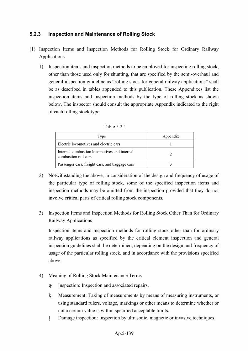
1) Inspection items and inspection methods to be employed for inspecting rolling stock,
other than those used only for shunting, that are specified by the semi-overhaul and
general inspection guideline as “rolling stock for general railway applications” shall
be as described in tables appended to this publication. These Appendixes list the
inspection items and inspection methods by the type of rolling stock as shown
below. The inspector should consult the appropriate Appendix indicated to the right
of each rolling stock type:
Table 5.2.1
Type Appendix
Electric locomotives and electric cars 1
Internal combustion locomotives and internalcombustion rail cars
2
Passenger cars, freight cars, and baggage cars 3
2) Notwithstanding the above, in consideration of the design and frequency of usage of
the particular type of rolling stock, some of the specified inspection items and
inspection methods may be omitted from the inspection provided that they do not
involve critical parts of critical rolling stock components.
3) Inspection Items and Inspection Methods for Rolling Stock Other Than for Ordinary
Railway Applications
Inspection items and inspection methods for rolling stock other than for ordinary
railway applications as specified by the critical element inspection and general
inspection guidelines shall be determined, depending on the design and frequency of
usage of the particular rolling stock, and in accordance with the provisions specified
above.
4) Meaning of Rolling Stock Maintenance Terms
① Inspection: Inspection and associated repairs.
② Measurement: Taking of measurements by means of measuring instruments, or
using standard rulers, voltage, markings or other means to determine whether or
not a certain value is within specified acceptable limits.
③ Damage inspection: Inspection by ultrasonic, magnetic or invasive techniques.
Ap.5-140
5) Ultrasonic Damage Inspection
Ultrasonic damage inspection of wheel axles of rolling stock must be performed at
each of the following times:
① Prior to use of a new product, either newly developed or purchased
② At each general inspection
③ As required
(2) When to Start Counting Time to Next Inspection
For periodic inspections of the condition and functioning of rolling stock, counting
should begin immediately after the completion date of the preceding inspection. For a
semi-overhaul or general inspection, counting should proceed from the month subsequent
to the month the preceding inspection is completed.
(3) Method of inspection
The following methods are available:
1) Visual: Conformance judged by sight
2) Auditory: Conformance judged by hearing
3) Olfactory: Conformance judged by odor
4) Tactile: Conformance judged by hand touch.
5) Tapping: Conformance judged through tapping on a surface and listening to sound
from the surface or sensing the resistance of the tapping tool or vibrations by hand
placed on the surface.
6) Operation: Conformance judged by control devices
7) Measurement: Conformance judged by measurement
8) Conduction: Conformance judged by making devices conductive
9) As mounted: Inspection made with devices in place
10) Dismounted: Where a device is inaccessible due to, for example, adjacent
equipment, the device must be dismounted from the rolling stock for inspection
11) Overhauled as mounted: Some parts of a device are overhauled as the device is
mounted on the rolling stock
12) Dismounted and overhauled: The device is dismounted and then overhauled
Ap.5-141
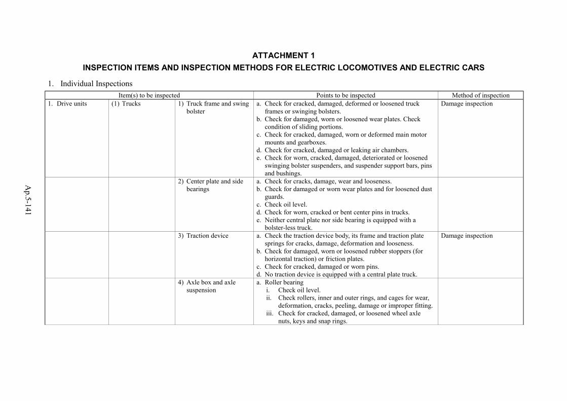
ATTACHMENT 1
INSPECTION ITEMS AND INSPECTION METHODS FOR ELECTRIC LOCOMOTIVES AND ELECTRIC CARS
1. Individual Inspections
Item(s) to be inspected Points to be inspected Method of inspection1. Drive units (1) Trucks 1) Truck frame and swing
bolstera. Check for cracked, damaged, deformed or loosened truck
frames or swinging bolsters.b. Check for damaged, worn or loosened wear plates. Check
condition of sliding portions.c. Check for cracked, damaged, worn or deformed main motor
mounts and gearboxes.d. Check for cracked, damaged or leaking air chambers.e. Check for worn, cracked, damaged, deteriorated or loosened
swinging bolster suspenders, and suspender support bars, pinsand bushings.
Damage inspection
2) Center plate and sidebearings
a. Check for cracks, damage, wear and looseness.b. Check for damaged or worn wear plates and for loosened dust
guards.c. Check oil level.d. Check for worn, cracked or bent center pins in trucks.e. Neither central plate nor side bearing is equipped with a
bolster-less truck.
3) Traction device a. Check the traction device body, its frame and traction platesprings for cracks, damage, deformation and looseness.
b. Check for damaged, worn or loosened rubber stoppers (forhorizontal traction) or friction plates.
c. Check for cracked, damaged or worn pins.d. No traction device is equipped with a central plate truck.
Damage inspection
4) Axle box and axlesuspension
a. Roller bearingi. Check oil level.ii. Check rollers, inner and outer rings, and cages for wear,
deformation, cracks, peeling, damage or improper fitting.iii. Check for cracked, damaged, or loosened wheel axle
nuts, keys and snap rings.
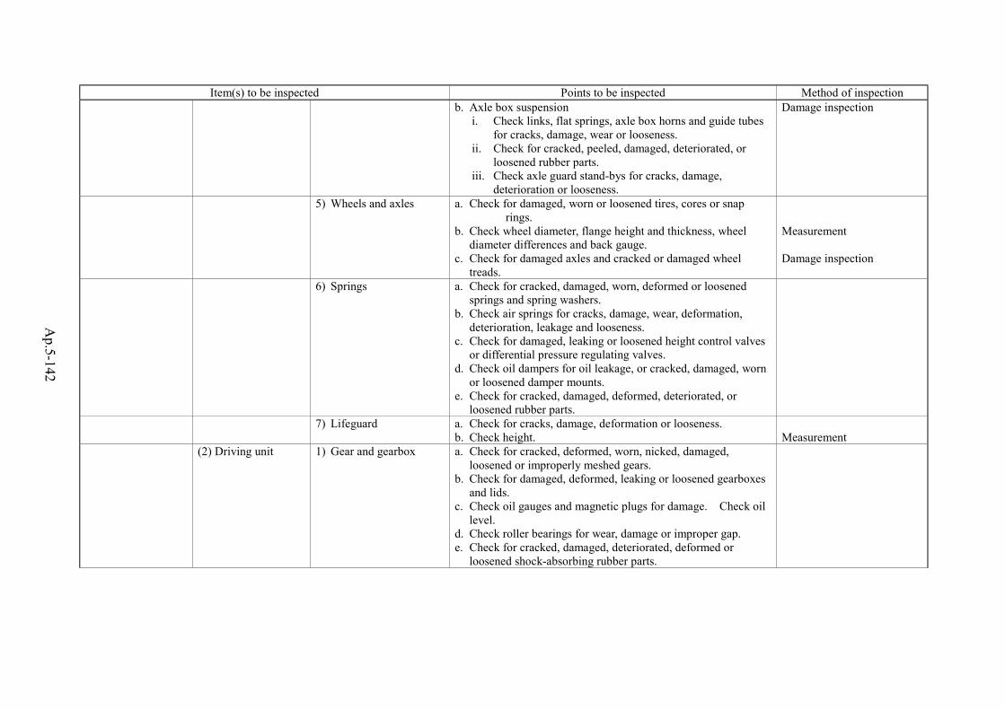
Ap.5-142
Item(s) to be inspected Points to be inspected Method of inspectionb. Axle box suspension
i. Check links, flat springs, axle box horns and guide tubesfor cracks, damage, wear or looseness.
ii. Check for cracked, peeled, damaged, deteriorated, orloosened rubber parts.
iii. Check axle guard stand-bys for cracks, damage,deterioration or looseness.
Damage inspection
5) Wheels and axles a. Check for damaged, worn or loosened tires, cores or snap rings.
b. Check wheel diameter, flange height and thickness, wheeldiameter differences and back gauge.
c. Check for damaged axles and cracked or damaged wheeltreads.
Measurement
Damage inspection
6) Springs a. Check for cracked, damaged, worn, deformed or loosenedsprings and spring washers.
b. Check air springs for cracks, damage, wear, deformation,deterioration, leakage and looseness.
c. Check for damaged, leaking or loosened height control valvesor differential pressure regulating valves.
d. Check oil dampers for oil leakage, or cracked, damaged, wornor loosened damper mounts.
e. Check for cracked, damaged, deformed, deteriorated, orloosened rubber parts.
7) Lifeguard a. Check for cracks, damage, deformation or looseness.b. Check height. Measurement
(2) Driving unit 1) Gear and gearbox a. Check for cracked, deformed, worn, nicked, damaged,loosened or improperly meshed gears.
b. Check for damaged, deformed, leaking or loosened gearboxesand lids.
c. Check oil gauges and magnetic plugs for damage. Check oillevel.
d. Check roller bearings for wear, damage or improper gap.e. Check for cracked, damaged, deteriorated, deformed or
loosened shock-absorbing rubber parts.
Ap.5-143
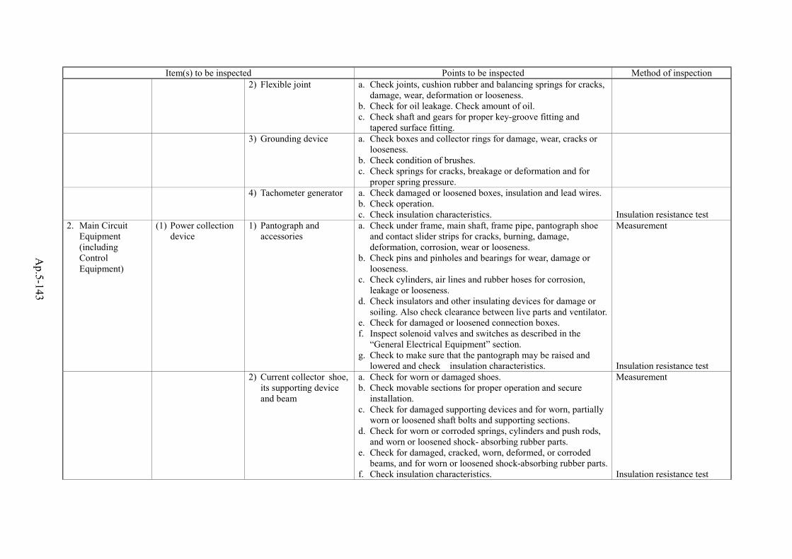
Item(s) to be inspected Points to be inspected Method of inspection2) Flexible joint a. Check joints, cushion rubber and balancing springs for cracks,
damage, wear, deformation or looseness.b. Check for oil leakage. Check amount of oil.c. Check shaft and gears for proper key-groove fitting and
tapered surface fitting.3) Grounding device a. Check boxes and collector rings for damage, wear, cracks or
looseness.b. Check condition of brushes.c. Check springs for cracks, breakage or deformation and for
proper spring pressure.4) Tachometer generator a. Check damaged or loosened boxes, insulation and lead wires.
b. Check operation.c. Check insulation characteristics. Insulation resistance test
2. Main CircuitEquipment(includingControlEquipment)
(1) Power collectiondevice
1) Pantograph andaccessories
a. Check under frame, main shaft, frame pipe, pantograph shoeand contact slider strips for cracks, burning, damage,deformation, corrosion, wear or looseness.
b. Check pins and pinholes and bearings for wear, damage orlooseness.
c. Check cylinders, air lines and rubber hoses for corrosion,leakage or looseness.
d. Check insulators and other insulating devices for damage orsoiling. Also check clearance between live parts and ventilator.
e. Check for damaged or loosened connection boxes.f. Inspect solenoid valves and switches as described in the
“General Electrical Equipment” section.g. Check to make sure that the pantograph may be raised and
lowered and check insulation characteristics.
Measurement
Insulation resistance test2) Current collector shoe,
its supporting deviceand beam
a. Check for worn or damaged shoes.b. Check movable sections for proper operation and secure
installation.c. Check for damaged supporting devices and for worn, partially
worn or loosened shaft bolts and supporting sections.d. Check for worn or corroded springs, cylinders and push rods,
and worn or loosened shock- absorbing rubber parts.e. Check for damaged, cracked, worn, deformed, or corroded
beams, and for worn or loosened shock-absorbing rubber parts.f. Check insulation characteristics.
Measurement
Insulation resistance test
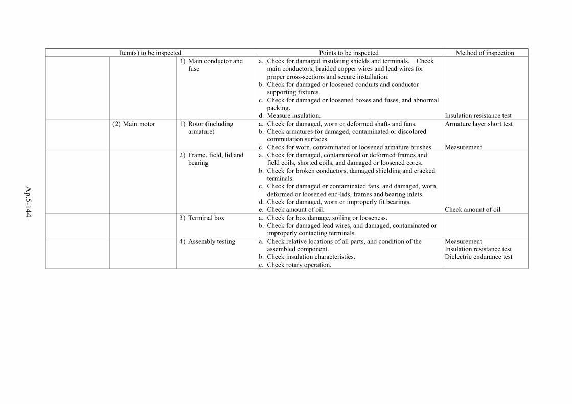
Ap.5-144
Item(s) to be inspected Points to be inspected Method of inspection3) Main conductor and
fusea. Check for damaged insulating shields and terminals. Check
main conductors, braided copper wires and lead wires forproper cross-sections and secure installation.
b. Check for damaged or loosened conduits and conductorsupporting fixtures.
c. Check for damaged or loosened boxes and fuses, and abnormalpacking.
d. Measure insulation. Insulation resistance test(2) Main motor 1) Rotor (including
armature)a. Check for damaged, worn or deformed shafts and fans.b. Check armatures for damaged, contaminated or discolored
commutation surfaces.c. Check for worn, contaminated or loosened armature brushes.
Armature layer short test
Measurement2) Frame, field, lid and
bearinga. Check for damaged, contaminated or deformed frames and
field coils, shorted coils, and damaged or loosened cores.b. Check for broken conductors, damaged shielding and cracked
terminals.c. Check for damaged or contaminated fans, and damaged, worn,
deformed or loosened end-lids, frames and bearing inlets.d. Check for damaged, worn or improperly fit bearings.e. Check amount of oil. Check amount of oil
3) Terminal box a. Check for box damage, soiling or looseness.b. Check for damaged lead wires, and damaged, contaminated or
improperly contacting terminals.4) Assembly testing a. Check relative locations of all parts, and condition of the
assembled component.b. Check insulation characteristics.c. Check rotary operation.
MeasurementInsulation resistance testDielectric endurance test
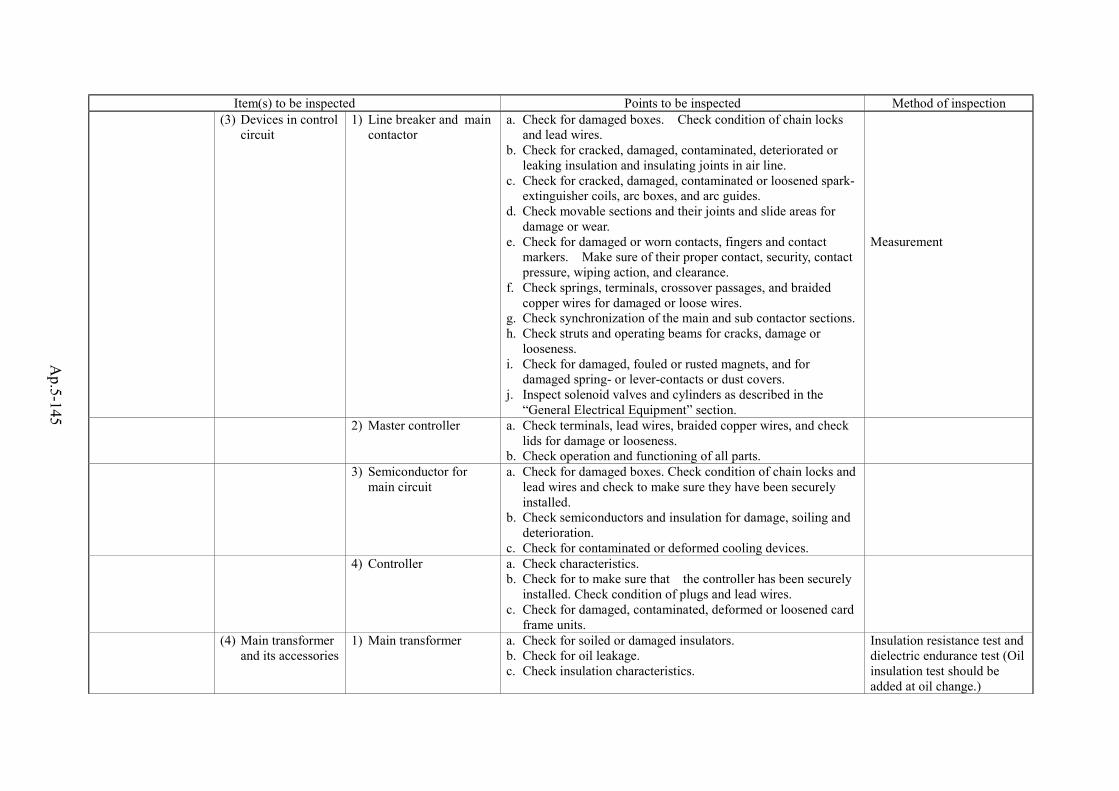
Ap.5-145
Item(s) to be inspected Points to be inspected Method of inspection(3) Devices in control
circuit1) Line breaker and main
contactora. Check for damaged boxes. Check condition of chain locks
and lead wires.b. Check for cracked, damaged, contaminated, deteriorated or
leaking insulation and insulating joints in air line.c. Check for cracked, damaged, contaminated or loosened spark-
extinguisher coils, arc boxes, and arc guides.d. Check movable sections and their joints and slide areas for
damage or wear.e. Check for damaged or worn contacts, fingers and contact
markers. Make sure of their proper contact, security, contactpressure, wiping action, and clearance.
f. Check springs, terminals, crossover passages, and braidedcopper wires for damaged or loose wires.
g. Check synchronization of the main and sub contactor sections.h. Check struts and operating beams for cracks, damage or
looseness.i. Check for damaged, fouled or rusted magnets, and for
damaged spring- or lever-contacts or dust covers.j. Inspect solenoid valves and cylinders as described in the
“General Electrical Equipment” section.
Measurement
2) Master controller a. Check terminals, lead wires, braided copper wires, and checklids for damage or looseness.
b. Check operation and functioning of all parts.3) Semiconductor for
main circuita. Check for damaged boxes. Check condition of chain locks and
lead wires and check to make sure they have been securelyinstalled.
b. Check semiconductors and insulation for damage, soiling anddeterioration.
c. Check for contaminated or deformed cooling devices.4) Controller a. Check characteristics.
b. Check for to make sure that the controller has been securelyinstalled. Check condition of plugs and lead wires.
c. Check for damaged, contaminated, deformed or loosened cardframe units.
(4) Main transformerand its accessories
1) Main transformer a. Check for soiled or damaged insulators.b. Check for oil leakage.c. Check insulation characteristics.
Insulation resistance test anddielectric endurance test (Oilinsulation test should beadded at oil change.)
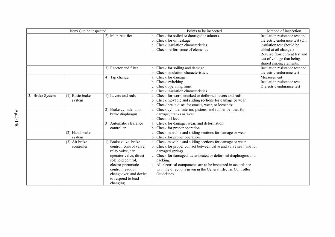
Ap.5-146
Item(s) to be inspected Points to be inspected Method of inspection2) Main rectifier a. Check for soiled or damaged insulators.
b. Check for oil leakage.c. Check insulation characteristics.d. Check performance of elements.
Insulation resistance test anddielectric endurance test (Oilinsulation test should beadded at oil change.)Reverse flow current test andtest of voltage that beingshared among elements.
3) Reactor and filter a. Check for soiling and damage.b. Check insulation characteristics.
Insulation resistance test anddielectric endurance test
4) Tap changer a. Check for damage.b. Check switching.c. Check operating time.d. Check insulation characteristics.
MeasurementInsulation resistance testDielectric endurance test
3. Brake System (1) Basic brakesystem
1) Levers and rods a. Check for worn, cracked or deformed levers and rods.b. Check movable and sliding sections for damage or wear.c. Check brake discs for cracks, wear, or looseness.
2) Brake cylinder andbrake diaphragm
a. Check cylinder interior, pistons, and rubber bellows fordamage, cracks or wear.
b. Check oil level.3) Automatic clearance
controllera. Check for damage, wear, and deformation.b. Check for proper operation.
(2) Hand brakesystem
a. Check movable and sliding sections for damage or wear.b. Check for proper operation.
(3) Air brakecontroller
1) Brake valve, brakecontrol, control valve,relay valve, caroperator valve, directsolenoid control,electro-pneumaticcontrol, readoutchangeover, and deviceto respond to loadchanging
a. Check movable and sliding sections for damage or wear.b. Check for proper contact between valve and valve seat, and for
damaged springs.c. Check for damaged, deteriorated or deformed diaphragms and
packing.d. All electrical components are to be inspected in accordance
with the directions given in the General Electric ControllerGuidelines.
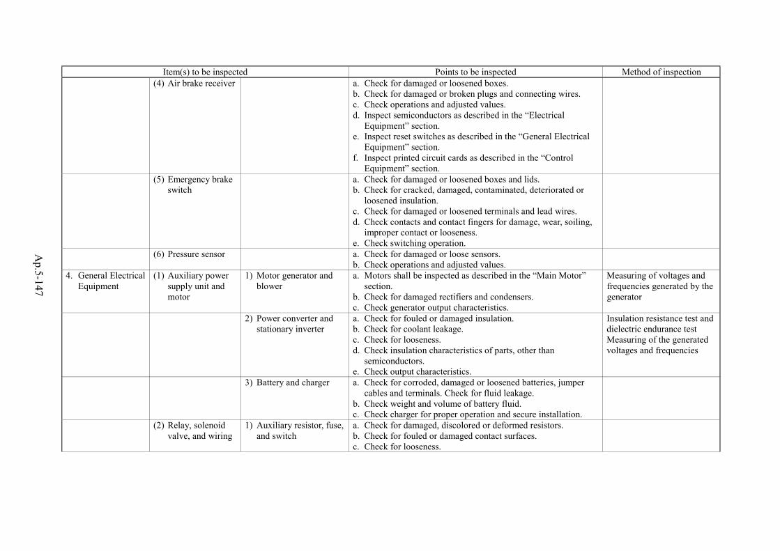
Ap.5-147
Item(s) to be inspected Points to be inspected Method of inspection(4) Air brake receiver a. Check for damaged or loosened boxes.
b. Check for damaged or broken plugs and connecting wires.c. Check operations and adjusted values.d. Inspect semiconductors as described in the “Electrical
Equipment” section.e. Inspect reset switches as described in the “General Electrical
Equipment” section.f. Inspect printed circuit cards as described in the “Control
Equipment” section.(5) Emergency brake
switcha. Check for damaged or loosened boxes and lids.b. Check for cracked, damaged, contaminated, deteriorated or
loosened insulation.c. Check for damaged or loosened terminals and lead wires.d. Check contacts and contact fingers for damage, wear, soiling,
improper contact or looseness.e. Check switching operation.
(6) Pressure sensor a. Check for damaged or loose sensors.b. Check operations and adjusted values.
4. General ElectricalEquipment
(1) Auxiliary powersupply unit andmotor
1) Motor generator andblower
a. Motors shall be inspected as described in the “Main Motor”section.
b. Check for damaged rectifiers and condensers.c. Check generator output characteristics.
Measuring of voltages andfrequencies generated by thegenerator
2) Power converter andstationary inverter
a. Check for fouled or damaged insulation.b. Check for coolant leakage.c. Check for looseness.d. Check insulation characteristics of parts, other than
semiconductors.e. Check output characteristics.
Insulation resistance test anddielectric endurance testMeasuring of the generatedvoltages and frequencies
3) Battery and charger a. Check for corroded, damaged or loosened batteries, jumpercables and terminals. Check for fluid leakage.
b. Check weight and volume of battery fluid.c. Check charger for proper operation and secure installation.
(2) Relay, solenoidvalve, and wiring
1) Auxiliary resistor, fuse,and switch
a. Check for damaged, discolored or deformed resistors.b. Check for fouled or damaged contact surfaces.c. Check for looseness.
Ap.5-148
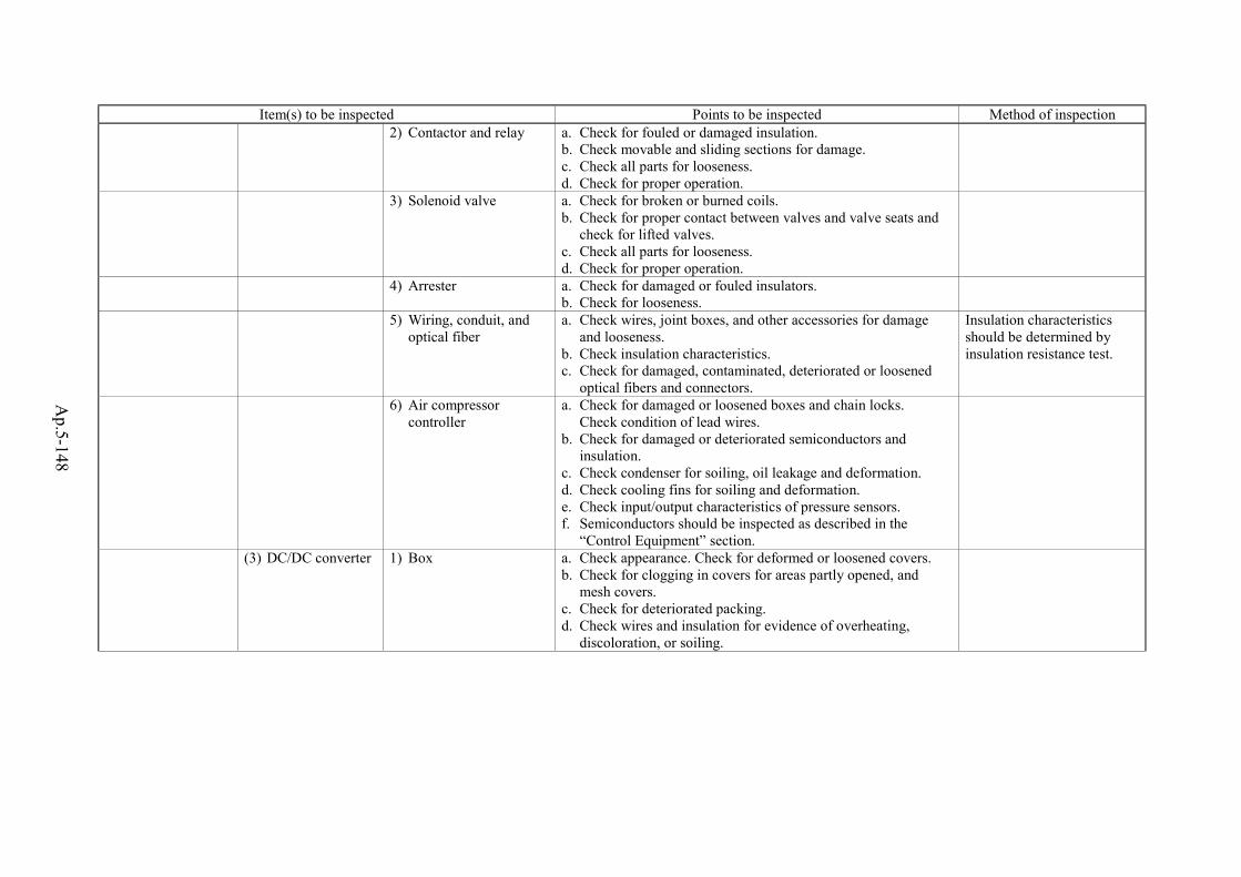
Item(s) to be inspected Points to be inspected Method of inspection2) Contactor and relay a. Check for fouled or damaged insulation.
b. Check movable and sliding sections for damage.c. Check all parts for looseness.d. Check for proper operation.
3) Solenoid valve a. Check for broken or burned coils.b. Check for proper contact between valves and valve seats and
check for lifted valves.c. Check all parts for looseness.d. Check for proper operation.
4) Arrester a. Check for damaged or fouled insulators.b. Check for looseness.
5) Wiring, conduit, andoptical fiber
a. Check wires, joint boxes, and other accessories for damageand looseness.
b. Check insulation characteristics.c. Check for damaged, contaminated, deteriorated or loosened
optical fibers and connectors.
Insulation characteristicsshould be determined byinsulation resistance test.
6) Air compressorcontroller
a. Check for damaged or loosened boxes and chain locks.Check condition of lead wires.
b. Check for damaged or deteriorated semiconductors andinsulation.
c. Check condenser for soiling, oil leakage and deformation.d. Check cooling fins for soiling and deformation.e. Check input/output characteristics of pressure sensors.f. Semiconductors should be inspected as described in the
“Control Equipment” section.(3) DC/DC converter 1) Box a. Check appearance. Check for deformed or loosened covers.
b. Check for clogging in covers for areas partly opened, andmesh covers.
c. Check for deteriorated packing.d. Check wires and insulation for evidence of overheating,
discoloration, or soiling.
Ap.5-149
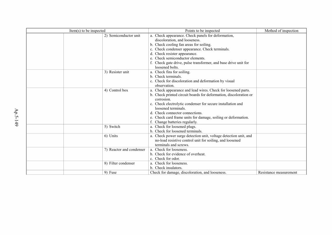
Item(s) to be inspected Points to be inspected Method of inspection2) Semiconductor unit a. Check appearance. Check panels for deformation,
discoloration, and looseness.b. Check cooling fan areas for soiling.c. Check condenser appearance. Check terminals.d. Check resister appearance.e. Check semiconductor elements.f. Check gate drive, pulse transformer, and base drive unit for
loosened bolts.3) Resister unit a. Check fins for soiling.
b. Check terminals.c. Check for discoloration and deformation by visual
observation.4) Control box a. Check appearance and lead wires. Check for loosened parts.
b. Check printed circuit boards for deformation, discoloration orcorrosion.
c. Check electrolytic condenser for secure installation andloosened terminals.
d. Check connector connections.e. Check card frame units for damage, soiling or deformation.f. Change batteries regularly.
5) Switch a. Check for loosened plugs.b. Check for loosened terminals.
6) Units a. Check power surge detection unit, voltage detection unit, andno-load resistive control unit for soiling, and loosenedterminals and screws.
7) Reactor and condenser a. Check for looseness.b. Check for evidence of overheat.c. Check for odor.
8) Filter condenser a. Check for looseness.b. Check insulators.
9) Fuse Check for damage, discoloration, and looseness. Resistance measurement
Ap.5-150
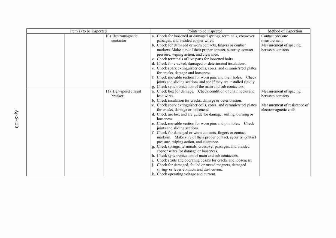
Item(s) to be inspected Points to be inspected Method of inspection10) Electromagnetic
contactora. Check for loosened or damaged springs, terminals, crossover
passages, and braided copper wires.b. Check for damaged or worn contacts, fingers or contact
markers. Make sure of their proper contact, security, contactpressure, wiping action, and clearance.
c. Check terminals of live parts for loosened bolts.d. Check for cracked, damaged or deteriorated insulations.e. Check spark extinguisher coils, cores, and ceramic/steel plates
for cracks, damage and looseness.f. Check movable section for worn pins and their holes. Check
joints and sliding sections and see if they are installed rigidly.g. Check synchronization of the main and sub contactors.
Contact pressuremeasurementMeasurement of spacingbetween contacts
11) High-speed circuitbreaker
a. Check box for damage. Check condition of chain locks andlead wires.
b. Check insulation for cracks, damage or deterioration.c. Check spark extinguisher coils, cores, and ceramic/steel plates
for cracks, damage or looseness.d. Check arc box and arc guide for damage, soiling, burning or
looseness.e. Check movable section for worn pins and pin holes. Check
joints and sliding sections.f. Check for damaged or worn contacts, fingers or contact
markers. Make sure of their proper contact, security, contactpressure, wiping action, and clearance.
g. Check springs, terminals, crossover passages, and braidedcopper wires for damage or looseness.
h. Check synchronization of main and sub contactors.i. Check struts and operating beams for cracks and looseness.j. Check for damaged, fouled or rusted magnets, damaged
spring- or lever-contacts and dust covers.k. Check operating voltage and current.
Measurement of spacingbetween contacts
Measurement of resistance ofelectromagnetic coils
Ap.5-151
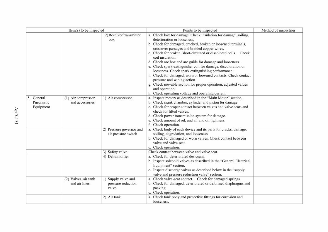
Item(s) to be inspected Points to be inspected Method of inspection12) Receiver/transmitter
boxa. Check box for damage. Check insulation for damage, soiling,
deterioration or looseness.b. Check for damaged, cracked, broken or loosened terminals,
crossover passages and braided copper wires.c. Check for broken, short-circuited or discolored coils. Check
coil insulation.d. Check arc box and arc guide for damage and looseness.e. Check spark extinguisher coil for damage, discoloration or
looseness. Check spark extinguishing performance.f. Check for damaged, worn or loosened contacts. Check contact
pressure and wiping action.g. Check movable section for proper operation, adjusted values
and operation.h. Check operating voltage and operating current.
5. GeneralPneumaticEquipment
(1) Air compressorand accessories
1) Air compressor a. Inspect motors as described in the “Main Motor” section.b. Check crank chamber, cylinder and piston for damage.c. Check for proper contact between valves and valve seats and
check for lifted valves.d. Check power transmission system for damage.e. Check amount of oil, and air and oil tightness.f. Check operation.
2) Pressure governor andair pressure switch
a. Check body of each device and its parts for cracks, damage,soiling, degradation, and looseness.
b. Check for damaged or worn valves. Check contact betweenvalve and valve seat.
c. Check operation.3) Safety valve Check contact between valve and valve seat.4) Dehumidifier a. Check for deteriorated desiccant.
b. Inspect solenoid valves as described in the “General ElectricalEquipment” section.
c. Inspect discharge valves as described below in the “supplyvalve and pressure reduction valve” section.
(2) Valves, air tankand air lines
1) Supply valve andpressure reductionvalve
a. Check valve-seat contact. Check for damaged springs.b. Check for damaged, deteriorated or deformed diaphragms and
packing.c. Check operation.
2) Air tank a. Check tank body and protective fittings for corrosion andlooseness.
Ap.5-152
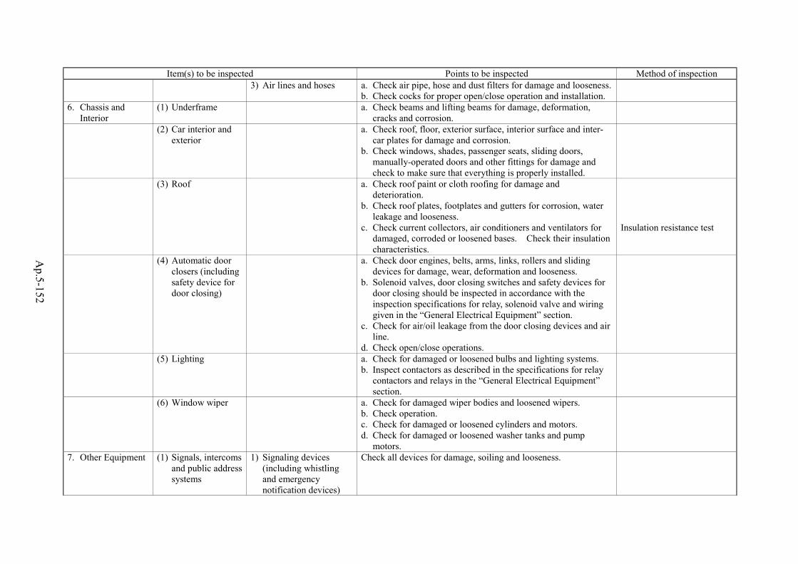
Item(s) to be inspected Points to be inspected Method of inspection3) Air lines and hoses a. Check air pipe, hose and dust filters for damage and looseness.
b. Check cocks for proper open/close operation and installation.6. Chassis and
Interior(1) Underframe a. Check beams and lifting beams for damage, deformation,
cracks and corrosion.(2) Car interior and
exteriora. Check roof, floor, exterior surface, interior surface and inter-
car plates for damage and corrosion.b. Check windows, shades, passenger seats, sliding doors,
manually-operated doors and other fittings for damage andcheck to make sure that everything is properly installed.
(3) Roof a. Check roof paint or cloth roofing for damage anddeterioration.
b. Check roof plates, footplates and gutters for corrosion, waterleakage and looseness.
c. Check current collectors, air conditioners and ventilators fordamaged, corroded or loosened bases. Check their insulationcharacteristics.
Insulation resistance test
(4) Automatic doorclosers (includingsafety device fordoor closing)
a. Check door engines, belts, arms, links, rollers and slidingdevices for damage, wear, deformation and looseness.
b. Solenoid valves, door closing switches and safety devices fordoor closing should be inspected in accordance with theinspection specifications for relay, solenoid valve and wiringgiven in the “General Electrical Equipment” section.
c. Check for air/oil leakage from the door closing devices and airline.
d. Check open/close operations.(5) Lighting a. Check for damaged or loosened bulbs and lighting systems.
b. Inspect contactors as described in the specifications for relaycontactors and relays in the “General Electrical Equipment”section.
(6) Window wiper a. Check for damaged wiper bodies and loosened wipers.b. Check operation.c. Check for damaged or loosened cylinders and motors.d. Check for damaged or loosened washer tanks and pump
motors.7. Other Equipment (1) Signals, intercoms
and public addresssystems
1) Signaling devices(including whistlingand emergencynotification devices)
Check all devices for damage, soiling and looseness.
Ap.5-153
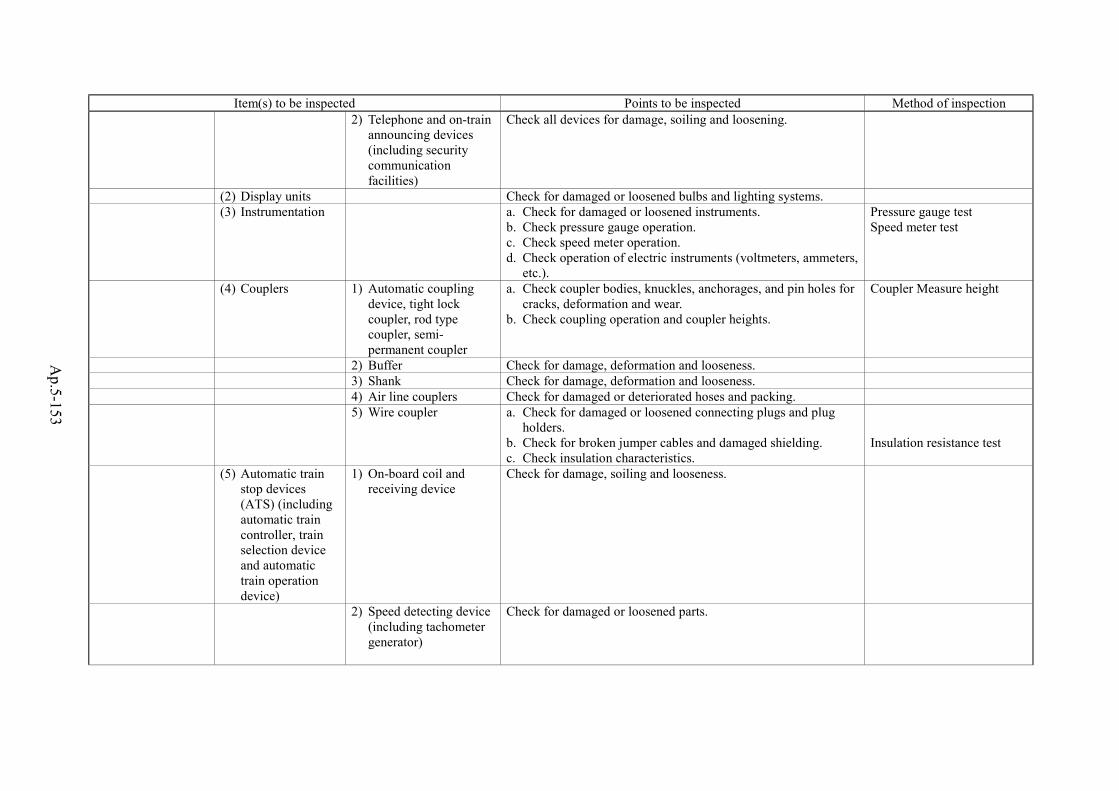
Item(s) to be inspected Points to be inspected Method of inspection2) Telephone and on-train
announcing devices(including securitycommunicationfacilities)
Check all devices for damage, soiling and loosening.
(2) Display units Check for damaged or loosened bulbs and lighting systems.(3) Instrumentation a. Check for damaged or loosened instruments.
b. Check pressure gauge operation.c. Check speed meter operation.d. Check operation of electric instruments (voltmeters, ammeters,
etc.).
Pressure gauge testSpeed meter test
(4) Couplers 1) Automatic couplingdevice, tight lockcoupler, rod typecoupler, semi-permanent coupler
a. Check coupler bodies, knuckles, anchorages, and pin holes forcracks, deformation and wear.
b. Check coupling operation and coupler heights.
Coupler Measure height
2) Buffer Check for damage, deformation and looseness.3) Shank Check for damage, deformation and looseness.4) Air line couplers Check for damaged or deteriorated hoses and packing.5) Wire coupler a. Check for damaged or loosened connecting plugs and plug
holders.b. Check for broken jumper cables and damaged shielding.c. Check insulation characteristics.
Insulation resistance test
(5) Automatic trainstop devices(ATS) (includingautomatic traincontroller, trainselection deviceand automatictrain operationdevice)
1) On-board coil andreceiving device
Check for damage, soiling and looseness.
2) Speed detecting device(including tachometergenerator)
Check for damaged or loosened parts.
Ap.5-154
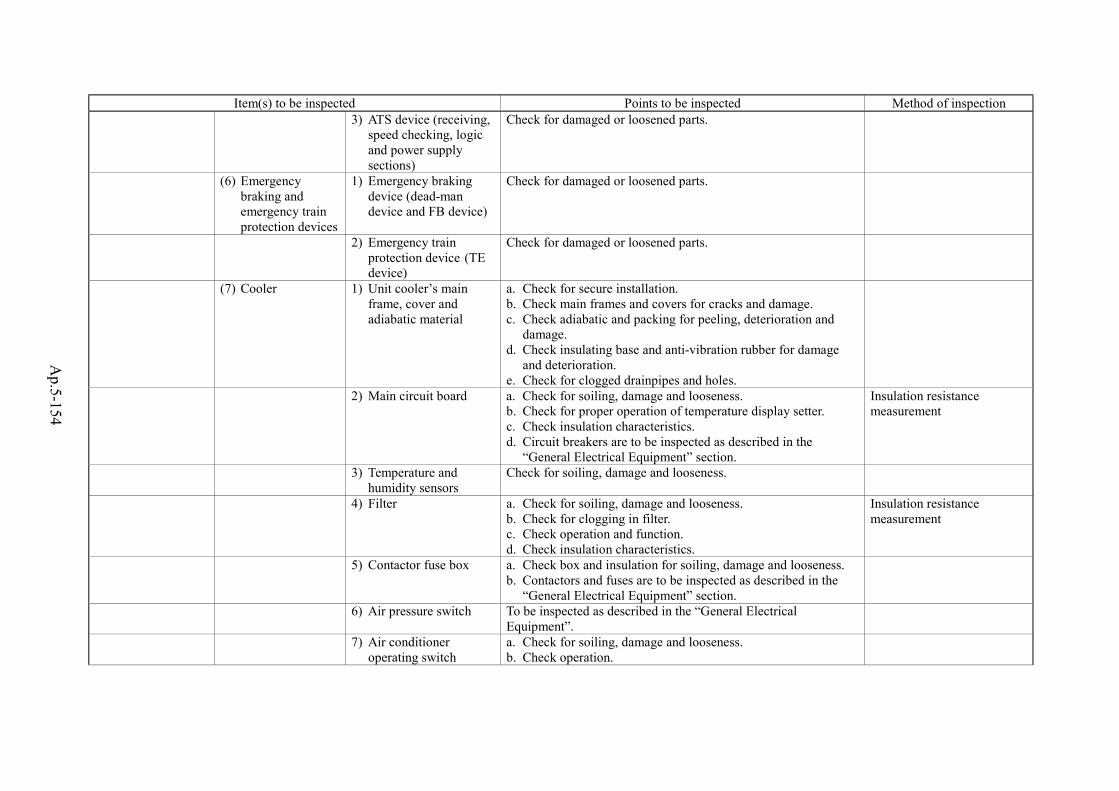
Item(s) to be inspected Points to be inspected Method of inspection3) ATS device (receiving,
speed checking, logicand power supplysections)
Check for damaged or loosened parts.
(6) Emergencybraking andemergency trainprotection devices
1) Emergency brakingdevice (dead-mandevice and FB device)
Check for damaged or loosened parts.
2) Emergency trainprotection device (TEdevice)
Check for damaged or loosened parts.
(7) Cooler 1) Unit cooler’s mainframe, cover andadiabatic material
a. Check for secure installation.b. Check main frames and covers for cracks and damage.c. Check adiabatic and packing for peeling, deterioration and
damage.d. Check insulating base and anti-vibration rubber for damage
and deterioration.e. Check for clogged drainpipes and holes.
2) Main circuit board a. Check for soiling, damage and looseness.b. Check for proper operation of temperature display setter.c. Check insulation characteristics.d. Circuit breakers are to be inspected as described in the
“General Electrical Equipment” section.
Insulation resistancemeasurement
3) Temperature andhumidity sensors
Check for soiling, damage and looseness.
4) Filter a. Check for soiling, damage and looseness.b. Check for clogging in filter.c. Check operation and function.d. Check insulation characteristics.
Insulation resistancemeasurement
5) Contactor fuse box a. Check box and insulation for soiling, damage and looseness.b. Contactors and fuses are to be inspected as described in the
“General Electrical Equipment” section.6) Air pressure switch To be inspected as described in the “General Electrical
Equipment”.7) Air conditioner
operating switcha. Check for soiling, damage and looseness.b. Check operation.
Ap.5-155
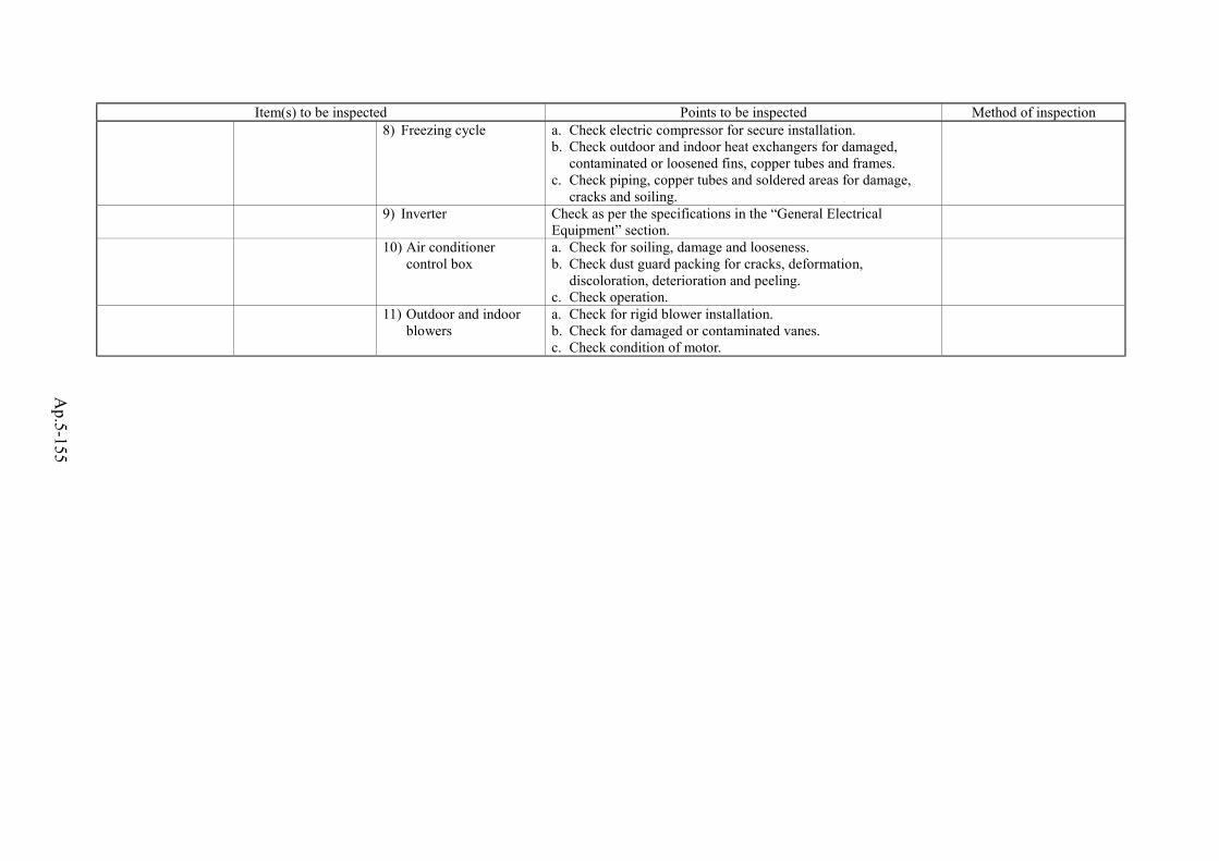
Item(s) to be inspected Points to be inspected Method of inspection8) Freezing cycle a. Check electric compressor for secure installation.
b. Check outdoor and indoor heat exchangers for damaged,contaminated or loosened fins, copper tubes and frames.
c. Check piping, copper tubes and soldered areas for damage,cracks and soiling.
9) Inverter Check as per the specifications in the “General ElectricalEquipment” section.
10) Air conditionercontrol box
a. Check for soiling, damage and looseness.b. Check dust guard packing for cracks, deformation,
discoloration, deterioration and peeling.c. Check operation.
11) Outdoor and indoorblowers
a. Check for rigid blower installation.b. Check for damaged or contaminated vanes.c. Check condition of motor.
Ap.5-156
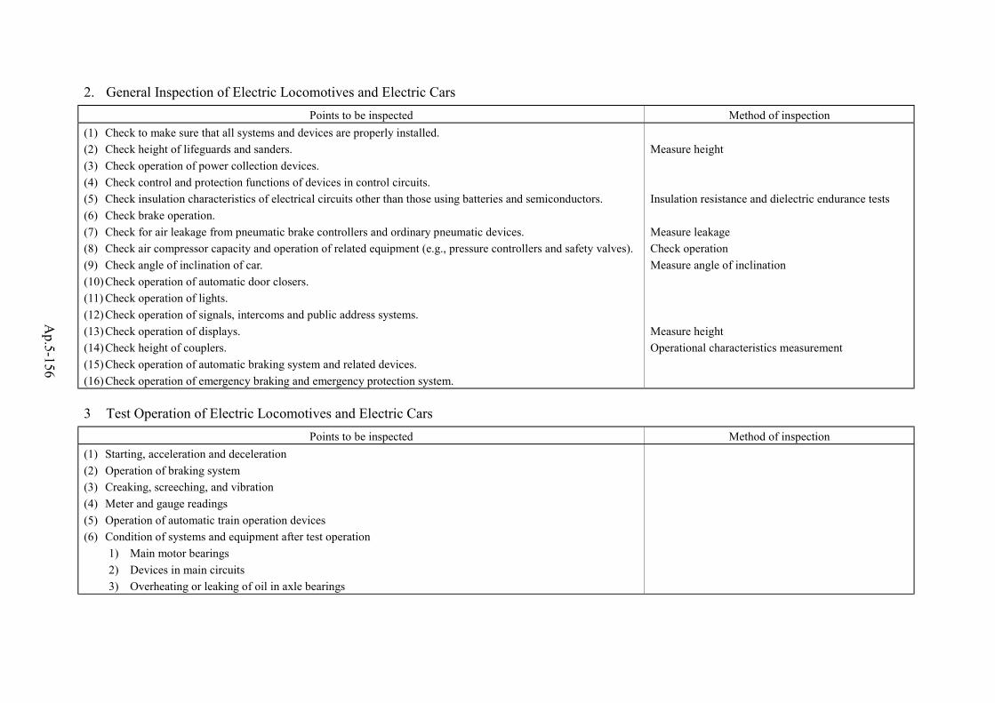
2. General Inspection of Electric Locomotives and Electric Cars
Points to be inspected Method of inspection
(1) Check to make sure that all systems and devices are properly installed.
(2) Check height of lifeguards and sanders.
(3) Check operation of power collection devices.
(4) Check control and protection functions of devices in control circuits.
(5) Check insulation characteristics of electrical circuits other than those using batteries and semiconductors.
(6) Check brake operation.
(7) Check for air leakage from pneumatic brake controllers and ordinary pneumatic devices.
(8) Check air compressor capacity and operation of related equipment (e.g., pressure controllers and safety valves).
(9) Check angle of inclination of car.
(10)Check operation of automatic door closers.
(11) Check operation of lights.
(12)Check operation of signals, intercoms and public address systems.
(13)Check operation of displays.
(14)Check height of couplers.
(15)Check operation of automatic braking system and related devices.
(16)Check operation of emergency braking and emergency protection system.
Measure height
Insulation resistance and dielectric endurance tests
Measure leakage
Check operation
Measure angle of inclination
Measure height
Operational characteristics measurement
3 Test Operation of Electric Locomotives and Electric Cars
Points to be inspected Method of inspection
(1) Starting, acceleration and deceleration
(2) Operation of braking system
(3) Creaking, screeching, and vibration
(4) Meter and gauge readings
(5) Operation of automatic train operation devices
(6) Condition of systems and equipment after test operation
1) Main motor bearings
2) Devices in main circuits
3) Overheating or leaking of oil in axle bearings
Ap.5-157
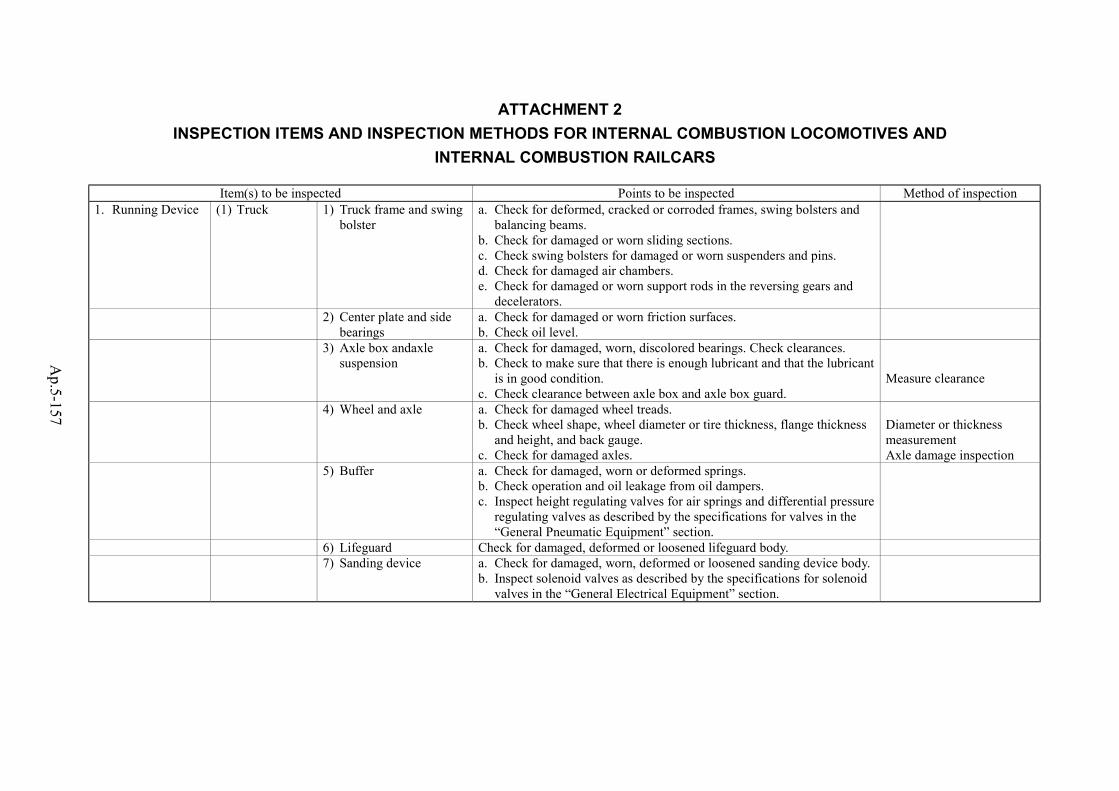
ATTACHMENT 2
INSPECTION ITEMS AND INSPECTION METHODS FOR INTERNAL COMBUSTION LOCOMOTIVES AND
INTERNAL COMBUSTION RAILCARS
Item(s) to be inspected Points to be inspected Method of inspection1. Running Device (1) Truck 1) Truck frame and swing
bolstera. Check for deformed, cracked or corroded frames, swing bolsters and
balancing beams.b. Check for damaged or worn sliding sections.c. Check swing bolsters for damaged or worn suspenders and pins.d. Check for damaged air chambers.e. Check for damaged or worn support rods in the reversing gears and
decelerators.2) Center plate and side
bearingsa. Check for damaged or worn friction surfaces.b. Check oil level.
3) Axle box andaxlesuspension
a. Check for damaged, worn, discolored bearings. Check clearances.b. Check to make sure that there is enough lubricant and that the lubricant
is in good condition.c. Check clearance between axle box and axle box guard.
Measure clearance
4) Wheel and axle a. Check for damaged wheel treads.b. Check wheel shape, wheel diameter or tire thickness, flange thickness
and height, and back gauge.c. Check for damaged axles.
Diameter or thicknessmeasurementAxle damage inspection
5) Buffer a. Check for damaged, worn or deformed springs.b. Check operation and oil leakage from oil dampers.c. Inspect height regulating valves for air springs and differential pressure
regulating valves as described by the specifications for valves in the“General Pneumatic Equipment” section.
6) Lifeguard Check for damaged, deformed or loosened lifeguard body.7) Sanding device a. Check for damaged, worn, deformed or loosened sanding device body.
b. Inspect solenoid valves as described by the specifications for solenoidvalves in the “General Electrical Equipment” section.
Ap.5-158
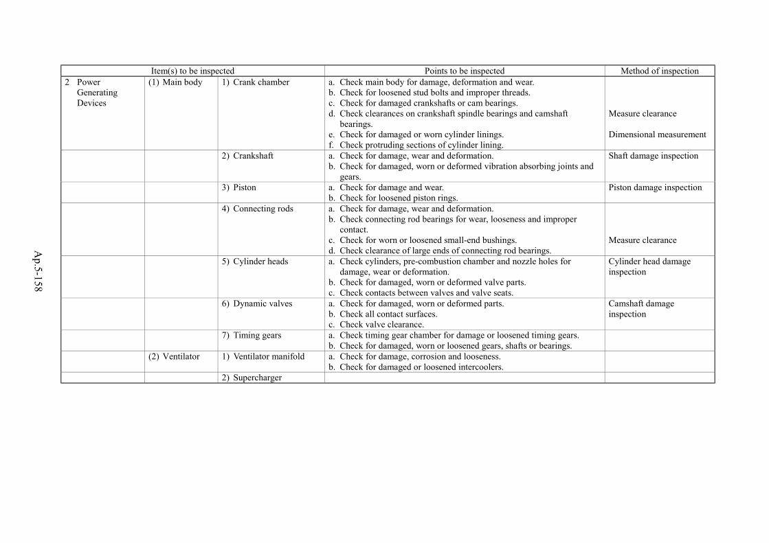
Item(s) to be inspected Points to be inspected Method of inspection2 Power
GeneratingDevices
(1) Main body 1) Crank chamber a. Check main body for damage, deformation and wear.b. Check for loosened stud bolts and improper threads.c. Check for damaged crankshafts or cam bearings.d. Check clearances on crankshaft spindle bearings and camshaft
bearings.e. Check for damaged or worn cylinder linings.f. Check protruding sections of cylinder lining.
Measure clearance
Dimensional measurement
2) Crankshaft a. Check for damage, wear and deformation.b. Check for damaged, worn or deformed vibration absorbing joints and
gears.
Shaft damage inspection
3) Piston a. Check for damage and wear.b. Check for loosened piston rings.
Piston damage inspection
4) Connecting rods a. Check for damage, wear and deformation.b. Check connecting rod bearings for wear, looseness and improper
contact.c. Check for worn or loosened small-end bushings.d. Check clearance of large ends of connecting rod bearings.
Measure clearance
5) Cylinder heads a. Check cylinders, pre-combustion chamber and nozzle holes fordamage, wear or deformation.
b. Check for damaged, worn or deformed valve parts.c. Check contacts between valves and valve seats.
Cylinder head damageinspection
6) Dynamic valves a. Check for damaged, worn or deformed parts.b. Check all contact surfaces.c. Check valve clearance.
Camshaft damageinspection
7) Timing gears a. Check timing gear chamber for damage or loosened timing gears.b. Check for damaged, worn or loosened gears, shafts or bearings.
(2) Ventilator 1) Ventilator manifold a. Check for damage, corrosion and looseness.b. Check for damaged or loosened intercoolers.
2) Supercharger
Ap.5-159
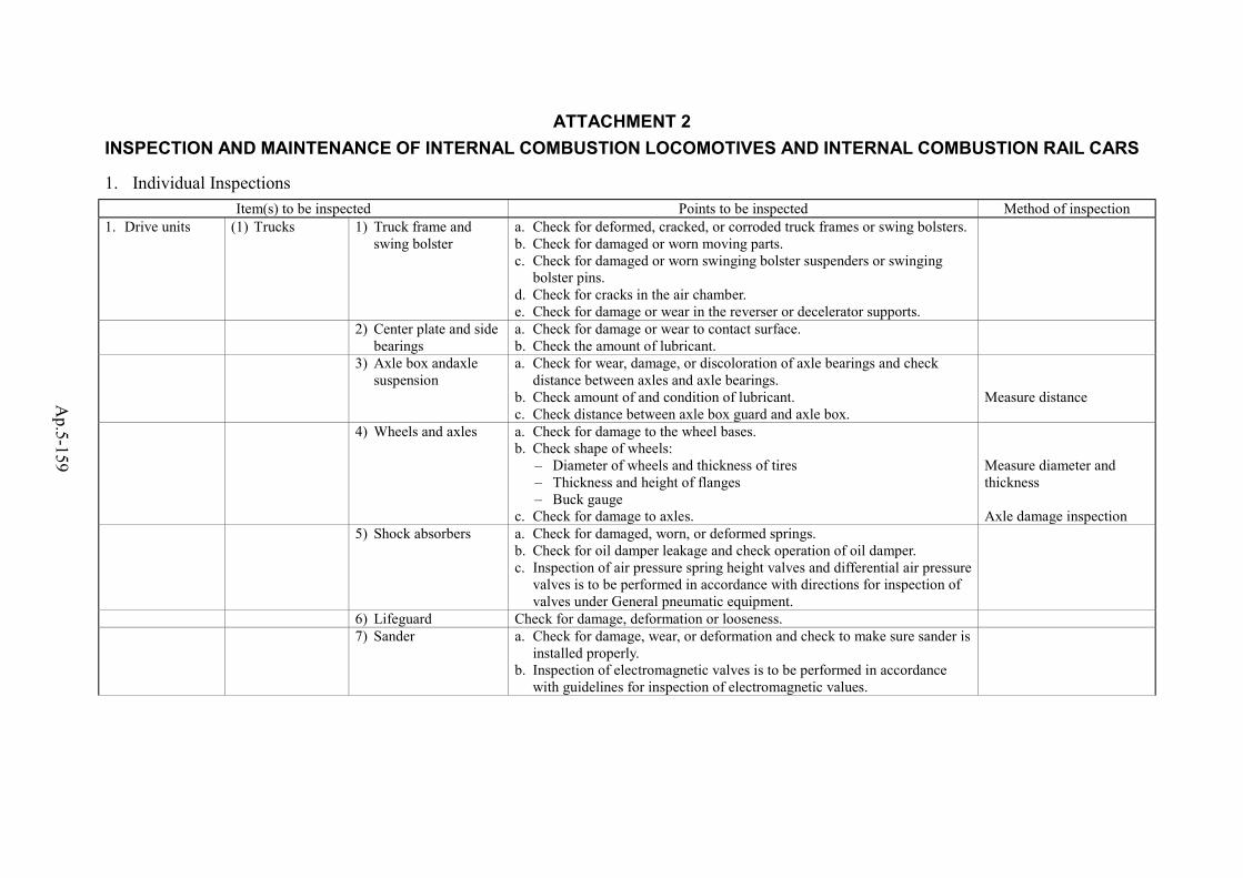
ATTACHMENT 2
INSPECTION AND MAINTENANCE OF INTERNAL COMBUSTION LOCOMOTIVES AND INTERNAL COMBUSTION RAIL CARS
1. Individual Inspections
Item(s) to be inspected Points to be inspected Method of inspection1. Drive units (1) Trucks 1) Truck frame and
swing bolstera. Check for deformed, cracked, or corroded truck frames or swing bolsters.b. Check for damaged or worn moving parts.c. Check for damaged or worn swinging bolster suspenders or swinging
bolster pins.d. Check for cracks in the air chamber.e. Check for damage or wear in the reverser or decelerator supports.
2) Center plate and sidebearings
a. Check for damage or wear to contact surface.b. Check the amount of lubricant.
3) Axle box andaxlesuspension
a. Check for wear, damage, or discoloration of axle bearings and checkdistance between axles and axle bearings.
b. Check amount of and condition of lubricant.c. Check distance between axle box guard and axle box.
Measure distance
4) Wheels and axles a. Check for damage to the wheel bases.b. Check shape of wheels:
– Diameter of wheels and thickness of tires– Thickness and height of flanges– Buck gauge
c. Check for damage to axles.
Measure diameter andthickness
Axle damage inspection5) Shock absorbers a. Check for damaged, worn, or deformed springs.
b. Check for oil damper leakage and check operation of oil damper.c. Inspection of air pressure spring height valves and differential air pressure
valves is to be performed in accordance with directions for inspection ofvalves under General pneumatic equipment.
6) Lifeguard Check for damage, deformation or looseness.7) Sander a. Check for damage, wear, or deformation and check to make sure sander is
installed properly.b. Inspection of electromagnetic valves is to be performed in accordance
with guidelines for inspection of electromagnetic values.
Ap.5-160
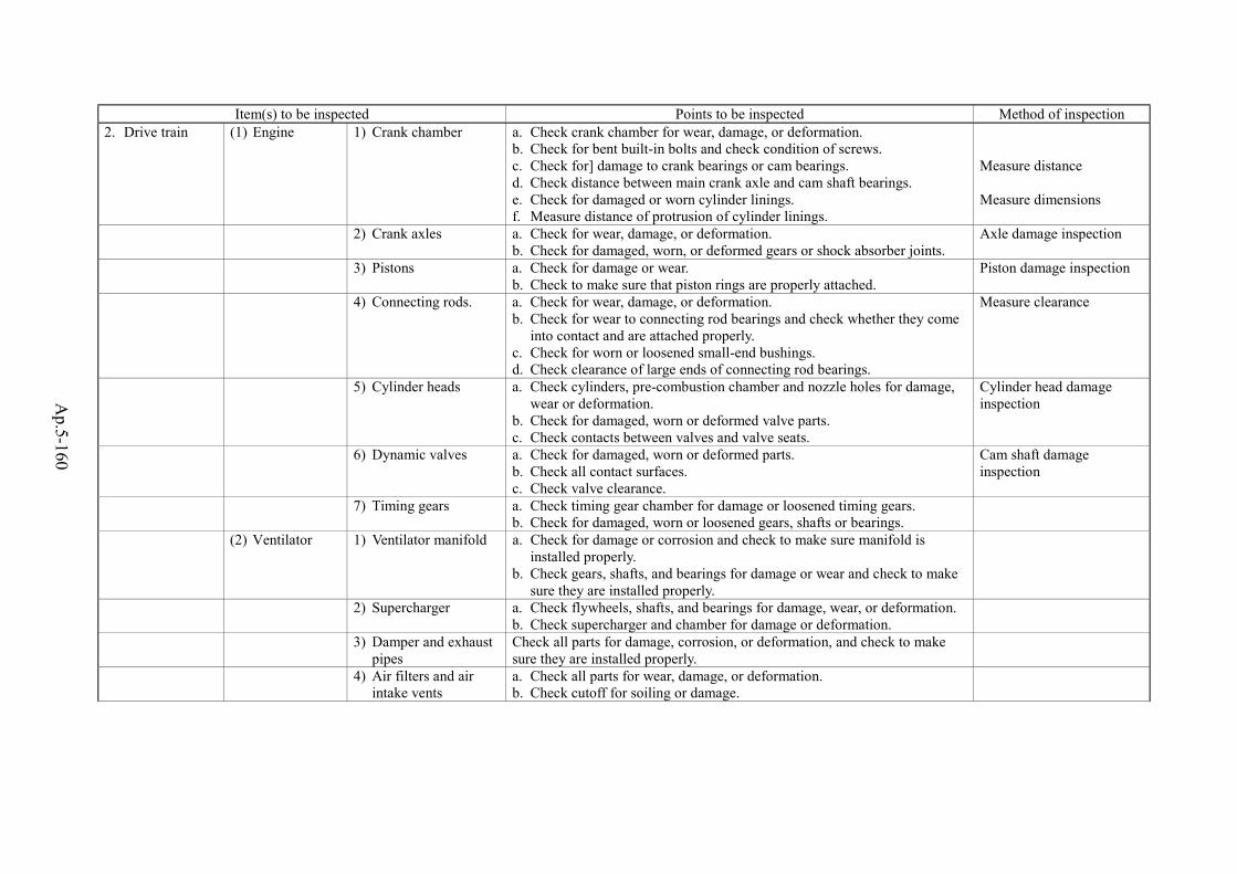
Item(s) to be inspected Points to be inspected Method of inspection2. Drive train (1) Engine 1) Crank chamber a. Check crank chamber for wear, damage, or deformation.
b. Check for bent built-in bolts and check condition of screws.c. Check for] damage to crank bearings or cam bearings.d. Check distance between main crank axle and cam shaft bearings.e. Check for damaged or worn cylinder linings.f. Measure distance of protrusion of cylinder linings.
Measure distance
Measure dimensions
2) Crank axles a. Check for wear, damage, or deformation.b. Check for damaged, worn, or deformed gears or shock absorber joints.
Axle damage inspection
3) Pistons a. Check for damage or wear.b. Check to make sure that piston rings are properly attached.
Piston damage inspection
4) Connecting rods. a. Check for wear, damage, or deformation.b. Check for wear to connecting rod bearings and check whether they come
into contact and are attached properly.c. Check for worn or loosened small-end bushings.d. Check clearance of large ends of connecting rod bearings.
Measure clearance
5) Cylinder heads a. Check cylinders, pre-combustion chamber and nozzle holes for damage,wear or deformation.
b. Check for damaged, worn or deformed valve parts.c. Check contacts between valves and valve seats.
Cylinder head damageinspection
6) Dynamic valves a. Check for damaged, worn or deformed parts.b. Check all contact surfaces.c. Check valve clearance.
Cam shaft damageinspection
7) Timing gears a. Check timing gear chamber for damage or loosened timing gears.b. Check for damaged, worn or loosened gears, shafts or bearings.
(2) Ventilator 1) Ventilator manifold a. Check for damage or corrosion and check to make sure manifold isinstalled properly.
b. Check gears, shafts, and bearings for damage or wear and check to makesure they are installed properly.
2) Supercharger a. Check flywheels, shafts, and bearings for damage, wear, or deformation.b. Check supercharger and chamber for damage or deformation.
3) Damper and exhaustpipes
Check all parts for damage, corrosion, or deformation, and check to makesure they are installed properly.
4) Air filters and airintake vents
a. Check all parts for wear, damage, or deformation.b. Check cutoff for soiling or damage.
Ap.5-161
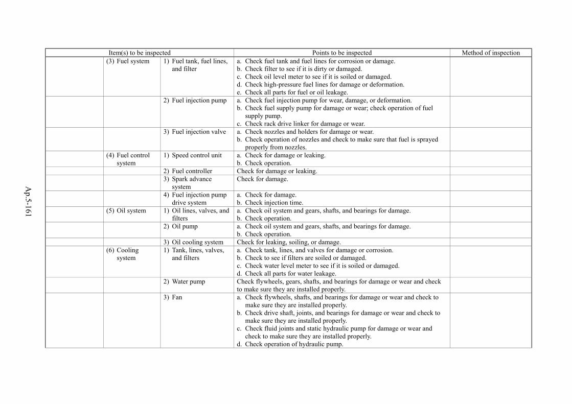
Item(s) to be inspected Points to be inspected Method of inspection(3) Fuel system 1) Fuel tank, fuel lines,
and filtera. Check fuel tank and fuel lines for corrosion or damage.b. Check filter to see if it is dirty or damaged.c. Check oil level meter to see if it is soiled or damaged.d. Check high-pressure fuel lines for damage or deformation.e. Check all parts for fuel or oil leakage.
2) Fuel injection pump a. Check fuel injection pump for wear, damage, or deformation.b. Check fuel supply pump for damage or wear; check operation of fuel
supply pump.c. Check rack drive linker for damage or wear.
3) Fuel injection valve a. Check nozzles and holders for damage or wear.b. Check operation of nozzles and check to make sure that fuel is sprayed
properly from nozzles.(4) Fuel control
system1) Speed control unit a. Check for damage or leaking.
b. Check operation.2) Fuel controller Check for damage or leaking.3) Spark advance
systemCheck for damage.
4) Fuel injection pumpdrive system
a. Check for damage.b. Check injection time.
(5) Oil system 1) Oil lines, valves, andfilters
a. Check oil system and gears, shafts, and bearings for damage.b. Check operation.
2) Oil pump a. Check oil system and gears, shafts, and bearings for damage.b. Check operation.
3) Oil cooling system Check for leaking, soiling, or damage.(6) Cooling
system1) Tank, lines, valves,
and filtersa. Check tank, lines, and valves for damage or corrosion.b. Check to see if filters are soiled or damaged.c. Check water level meter to see if it is soiled or damaged.d. Check all parts for water leakage.
2) Water pump Check flywheels, gears, shafts, and bearings for damage or wear and checkto make sure they are installed properly.
3) Fan a. Check flywheels, shafts, and bearings for damage or wear and check tomake sure they are installed properly.
b. Check drive shaft, joints, and bearings for damage or wear and check tomake sure they are installed properly.
c. Check fluid joints and static hydraulic pump for damage or wear andcheck to make sure they are installed properly.
d. Check operation of hydraulic pump.
Ap.5-162
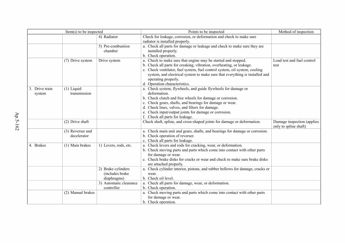
Item(s) to be inspected Points to be inspected Method of inspection4) Radiator Check for leakage, corrosion, or deformation and check to make sure
radiator is installed properly.5) Pre-combustion
chambera. Check all parts for damage or leakage and check to make sure they are
installed properly.b. Check operation.
(7) Drive system Drive system a. Check to make sure that engine may be started and stopped.b. Check all parts for creaking, vibration, overheating, or leakage.c. Check ventilator, fuel system, fuel control system, oil system, cooling
system, and electrical system to make sure that everything is installed andoperating properly.
d. Operation characteristics.
Load test and fuel controltest
3. Drive trainsystem
(1) Liquidtransmission
a. Check system, flywheels, and guide flywheels for damage ordeformation.
b. Check clutch and free wheels for damage or corrosion.c. Check gears, shafts, and bearings for damage or wear.d. Check lines, valves, and filters for damage.e. Check input/output joints for damage or corrosion.f. Check all parts for leakage.
(2) Drive shaft Check shaft, spline, and cross-shaped joints for damage or deformation. Damage inspection (appliesonly to spline shaft)
(3) Reverser anddecelerator
a. Check main unit and gears, shafts, and bearings for damage or corrosion.b. Check operation of reverser.c. Check all parts for leakage.
4. Brakes (1) Main brakes 1) Levers, rods, etc. a. Check levers and rods for cracking, wear, or deformation.b. Check moving parts and parts which come into contact with other parts
for damage or wear.c. Check brake disks for cracks or wear and check to make sure brake disks
are attached properly.2) Brake cylinders
(includes brakediaphragms)
a. Check cylinder interior, pistons, and rubber bellows for damage, cracks orwear.
b. Check oil level.3) Automatic clearance
controllera. Check all parts for damage, wear, or deformation.b. Check operation.
(2) Manual brakes a. Check moving parts and parts which come into contact with other partsfor damage or wear.
b. Check operation.
Ap.5-163
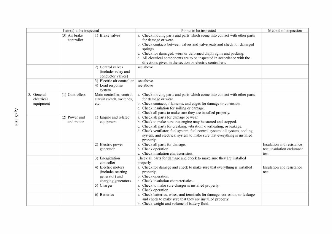
Item(s) to be inspected Points to be inspected Method of inspection(3) Air brake
controller1) Brake valves a. Check moving parts and parts which come into contact with other parts
for damage or wear.b. Check contacts between valves and valve seats and check for damaged
springs.c. Check for damaged, worn or deformed diaphragms and packing.d. All electrical components are to be inspected in accordance with the
directions given in the section on electric controllers.2) Control valves
(includes relay andconductor valves)
see above
3) Electric air controller see above4) Load response
systemsee above
5. Generalelectricalequipment
(1) Controllers Main controller, controlcircuit switch, switches,etc.
a. Check moving parts and parts which come into contact with other partsfor damage or wear.
b. Check contacts, filaments, and edges for damage or corrosion.c. Check insulation for soiling or damage.d. Check all parts to make sure they are installed properly.
(2) Power unitand motor
1) Engine and relatedequipment
a. Check all parts for damage or wear.b. Check to make sure that engine may be started and stopped.c. Check all parts for creaking, vibration, overheating, or leakage.d. Check ventilator, fuel system, fuel control system, oil system, cooling
system, and electrical system to make sure that everything is installedproperly.
2) Electric powergenerator
a. Check all parts for damage.b. Check operation.c. Check insulation characteristics.
Insulation and resistancetest; insulation endurancetest
3) Energizationcontroller
Check all parts for damage and check to make sure they are installedproperly.
4) Electric motors(includes startinggenerator) andcharging generators
a. Check for damage and check to make sure that everything is installedproperly.
b. Check operation.c. Check insulation characteristics.
Insulation and resistancetest
5) Charger a. Check to make sure charger is installed properly.b. Check operation.
6) Batteries a. Check batteries, wires, and terminals for damage, corrosion, or leakageand check to make sure that they are installed properly.
b. Check weight and volume of battery fluid.
Ap.5-164
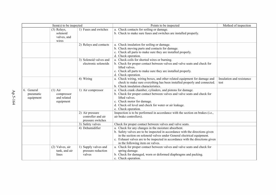
Item(s) to be inspected Points to be inspected Method of inspection(3) Relays,
solenoidvalves, andwires
1) Fuses and switches a. Check contacts for soiling or damage.b. Check to make sure fuses and switches are installed properly.
2) Relays and contacts a. Check insulation for soiling or damage.b. Check moving parts and contacts for damage.c. Check all parts to make sure they are installed properly.d. Check operation.
3) Solenoid valves andelectronic solenoids
a. Check coils for shorted wires or burning.b. Check for proper contact between valves and valve seats and check for
lifted valves.c. Check all parts to make sure they are installed properly.d. Check operation.
4) Wiring a. Check wiring, wiring boxes, and other related equipment for damage andcheck to make sure everything has been installed properly and connected.
b. Check insulation characteristics.
Insulation and resistancetest
6. Generalpneumaticequipment
(1) Aircompressorand relatedequipment
1) Air compressor a. Check crank chamber, cylinders, and pistons for damage.b. Check for proper contact between valves and valve seats and check for
lifted valves.c. Check motor for damage.d. Check oil level and check for water or air leakage.e. Check operation.
2) Air pressurecontroller and airpressure switches
Inspection is to be performed in accordance with the section on brakes (i.e.,air brake controllers).
3) Safety valves Check for proper contact between valves and valve seats.4) Dehumidifier a. Check for any changes in the moisture absorbent.
b. Safety valves are to be inspected in accordance with the directions givenin the section on solenoid valves under General electrical equipment.
c. Exhaust valves are to be inspected in accordance with the directions givenin the following item on valves.
(2) Valves, airtank, and airlines
1) Supply valves andpressure reductionvalves
a. Check for proper contact between valves and valve seats and check forspring damage.
b. Check for damaged, worn or deformed diaphragms and packing.c. Check operation.
Ap.5-165
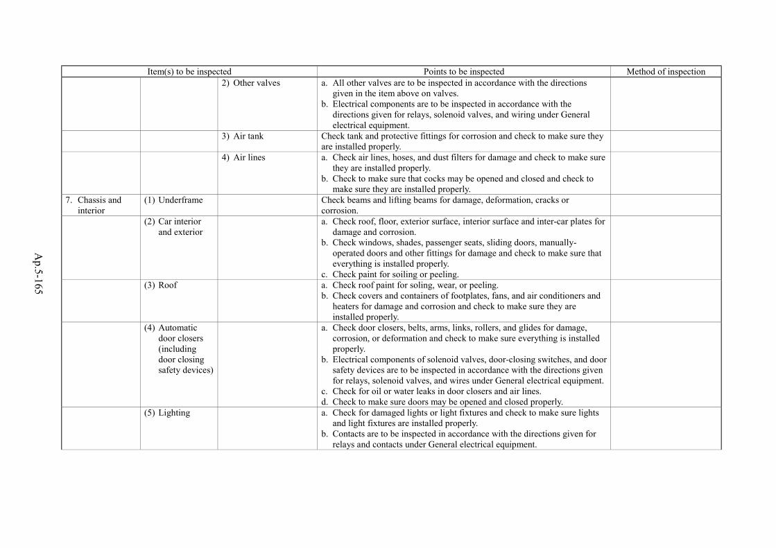
Item(s) to be inspected Points to be inspected Method of inspection2) Other valves a. All other valves are to be inspected in accordance with the directions
given in the item above on valves.b. Electrical components are to be inspected in accordance with the
directions given for relays, solenoid valves, and wiring under Generalelectrical equipment.
3) Air tank Check tank and protective fittings for corrosion and check to make sure theyare installed properly.
4) Air lines a. Check air lines, hoses, and dust filters for damage and check to make surethey are installed properly.
b. Check to make sure that cocks may be opened and closed and check tomake sure they are installed properly.
7. Chassis andinterior
(1) Underframe Check beams and lifting beams for damage, deformation, cracks orcorrosion.
(2) Car interiorand exterior
a. Check roof, floor, exterior surface, interior surface and inter-car plates fordamage and corrosion.
b. Check windows, shades, passenger seats, sliding doors, manually-operated doors and other fittings for damage and check to make sure thateverything is installed properly.
c. Check paint for soiling or peeling.(3) Roof a. Check roof paint for soling, wear, or peeling.
b. Check covers and containers of footplates, fans, and air conditioners andheaters for damage and corrosion and check to make sure they areinstalled properly.
(4) Automaticdoor closers(includingdoor closingsafety devices)
a. Check door closers, belts, arms, links, rollers, and glides for damage,corrosion, or deformation and check to make sure everything is installedproperly.
b. Electrical components of solenoid valves, door-closing switches, and doorsafety devices are to be inspected in accordance with the directions givenfor relays, solenoid valves, and wires under General electrical equipment.
c. Check for oil or water leaks in door closers and air lines.d. Check to make sure doors may be opened and closed properly.
(5) Lighting a. Check for damaged lights or light fixtures and check to make sure lightsand light fixtures are installed properly.
b. Contacts are to be inspected in accordance with the directions given forrelays and contacts under General electrical equipment.
Ap.5-166
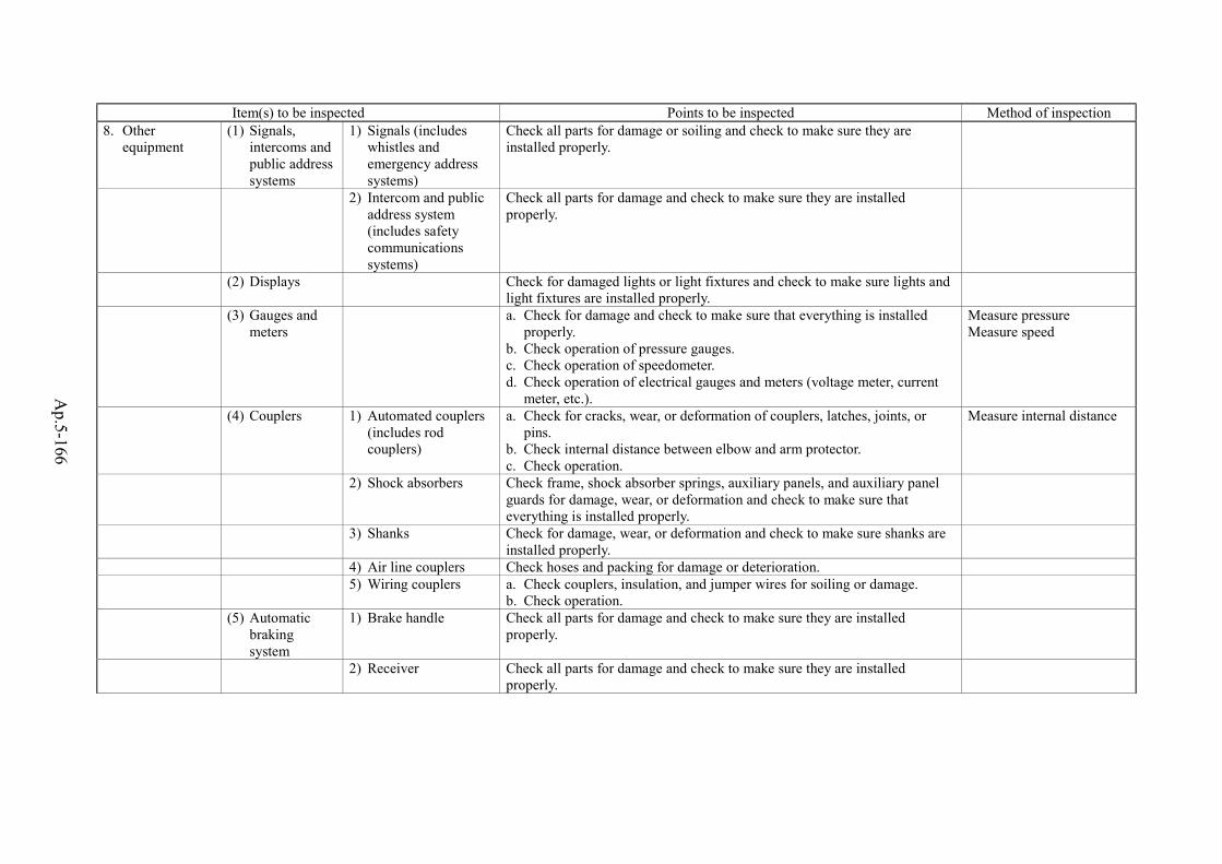
Item(s) to be inspected Points to be inspected Method of inspection8. Other
equipment(1) Signals,
intercoms andpublic addresssystems
1) Signals (includeswhistles andemergency addresssystems)
Check all parts for damage or soiling and check to make sure they areinstalled properly.
2) Intercom and publicaddress system(includes safetycommunicationssystems)
Check all parts for damage and check to make sure they are installedproperly.
(2) Displays Check for damaged lights or light fixtures and check to make sure lights andlight fixtures are installed properly.
(3) Gauges andmeters
a. Check for damage and check to make sure that everything is installedproperly.
b. Check operation of pressure gauges.c. Check operation of speedometer.d. Check operation of electrical gauges and meters (voltage meter, current
meter, etc.).
Measure pressureMeasure speed
(4) Couplers 1) Automated couplers(includes rodcouplers)
a. Check for cracks, wear, or deformation of couplers, latches, joints, orpins.
b. Check internal distance between elbow and arm protector.c. Check operation.
Measure internal distance
2) Shock absorbers Check frame, shock absorber springs, auxiliary panels, and auxiliary panelguards for damage, wear, or deformation and check to make sure thateverything is installed properly.
3) Shanks Check for damage, wear, or deformation and check to make sure shanks areinstalled properly.
4) Air line couplers Check hoses and packing for damage or deterioration.5) Wiring couplers a. Check couplers, insulation, and jumper wires for soiling or damage.
b. Check operation.(5) Automatic
brakingsystem
1) Brake handle Check all parts for damage and check to make sure they are installedproperly.
2) Receiver Check all parts for damage and check to make sure they are installedproperly.
Ap.5-167
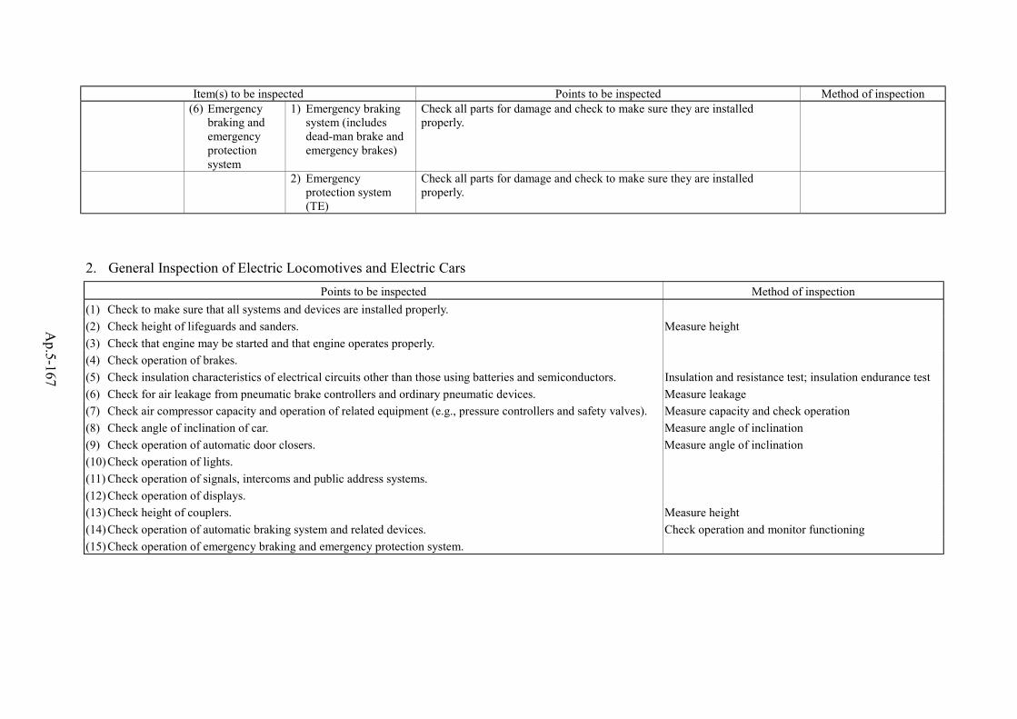
Item(s) to be inspected Points to be inspected Method of inspection(6) Emergency
braking andemergencyprotectionsystem
1) Emergency brakingsystem (includesdead-man brake andemergency brakes)
Check all parts for damage and check to make sure they are installedproperly.
2) Emergencyprotection system(TE)
Check all parts for damage and check to make sure they are installedproperly.
2. General Inspection of Electric Locomotives and Electric Cars
Points to be inspected Method of inspection
(1) Check to make sure that all systems and devices are installed properly.
(2) Check height of lifeguards and sanders. Measure height
(3) Check that engine may be started and that engine operates properly.
(4) Check operation of brakes.
(5) Check insulation characteristics of electrical circuits other than those using batteries and semiconductors. Insulation and resistance test; insulation endurance test
(6) Check for air leakage from pneumatic brake controllers and ordinary pneumatic devices. Measure leakage
(7) Check air compressor capacity and operation of related equipment (e.g., pressure controllers and safety valves). Measure capacity and check operation
(8) Check angle of inclination of car. Measure angle of inclination
(9) Check operation of automatic door closers. Measure angle of inclination
(10)Check operation of lights.
(11) Check operation of signals, intercoms and public address systems.
(12)Check operation of displays.
(13)Check height of couplers. Measure height
(14)Check operation of automatic braking system and related devices. Check operation and monitor functioning
(15)Check operation of emergency braking and emergency protection system.
Ap.5-168
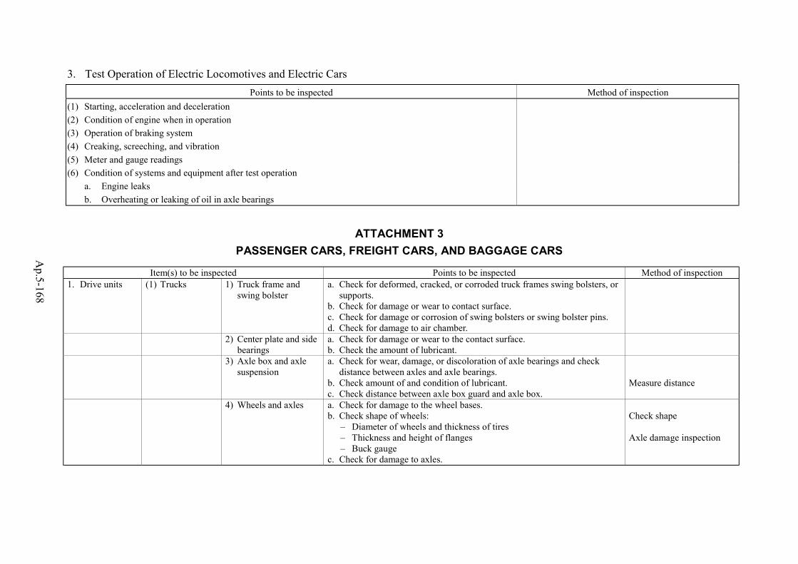
3. Test Operation of Electric Locomotives and Electric Cars
Points to be inspected Method of inspection
(1) Starting, acceleration and deceleration
(2) Condition of engine when in operation
(3) Operation of braking system
(4) Creaking, screeching, and vibration
(5) Meter and gauge readings
(6) Condition of systems and equipment after test operation
a. Engine leaks
b. Overheating or leaking of oil in axle bearings
ATTACHMENT 3
PASSENGER CARS, FREIGHT CARS, AND BAGGAGE CARS
Item(s) to be inspected Points to be inspected Method of inspection1. Drive units (1) Trucks 1) Truck frame and
swing bolstera. Check for deformed, cracked, or corroded truck frames swing bolsters, or
supports.b. Check for damage or wear to contact surface.c. Check for damage or corrosion of swing bolsters or swing bolster pins.d. Check for damage to air chamber.
2) Center plate and sidebearings
a. Check for damage or wear to the contact surface.b. Check the amount of lubricant.
3) Axle box and axlesuspension
a. Check for wear, damage, or discoloration of axle bearings and checkdistance between axles and axle bearings.
b. Check amount of and condition of lubricant.c. Check distance between axle box guard and axle box.
Measure distance
4) Wheels and axles a. Check for damage to the wheel bases.b. Check shape of wheels:
– Diameter of wheels and thickness of tires– Thickness and height of flanges– Buck gauge
c. Check for damage to axles.
Check shape
Axle damage inspection
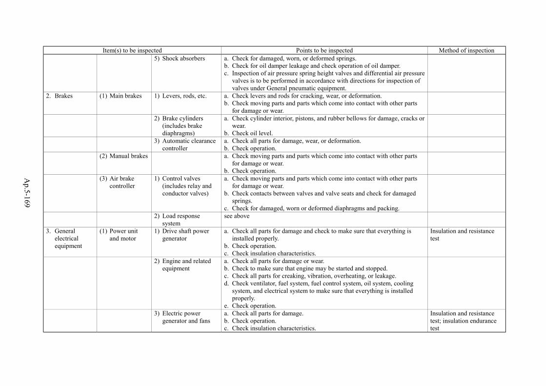
Ap.5-169
Item(s) to be inspected Points to be inspected Method of inspection5) Shock absorbers a. Check for damaged, worn, or deformed springs.
b. Check for oil damper leakage and check operation of oil damper.c. Inspection of air pressure spring height valves and differential air pressure
valves is to be performed in accordance with directions for inspection ofvalves under General pneumatic equipment.
2. Brakes (1) Main brakes 1) Levers, rods, etc. a. Check levers and rods for cracking, wear, or deformation.b. Check moving parts and parts which come into contact with other parts
for damage or wear.2) Brake cylinders
(includes brakediaphragms)
a. Check cylinder interior, pistons, and rubber bellows for damage, cracks orwear.
b. Check oil level.3) Automatic clearance
controllera. Check all parts for damage, wear, or deformation.b. Check operation.
(2) Manual brakes a. Check moving parts and parts which come into contact with other partsfor damage or wear.
b. Check operation.(3) Air brake
controller1) Control valves
(includes relay andconductor valves)
a. Check moving parts and parts which come into contact with other partsfor damage or wear.
b. Check contacts between valves and valve seats and check for damagedsprings.
c. Check for damaged, worn or deformed diaphragms and packing.2) Load response
systemsee above
3. Generalelectricalequipment
(1) Power unitand motor
1) Drive shaft powergenerator
a. Check all parts for damage and check to make sure that everything isinstalled properly.
b. Check operation.c. Check insulation characteristics.
Insulation and resistancetest
2) Engine and relatedequipment
a. Check all parts for damage or wear.b. Check to make sure that engine may be started and stopped.c. Check all parts for creaking, vibration, overheating, or leakage.d. Check ventilator, fuel system, fuel control system, oil system, cooling
system, and electrical system to make sure that everything is installedproperly.
e. Check operation.3) Electric power
generator and fansa. Check all parts for damage.b. Check operation.c. Check insulation characteristics.
Insulation and resistancetest; insulation endurancetest
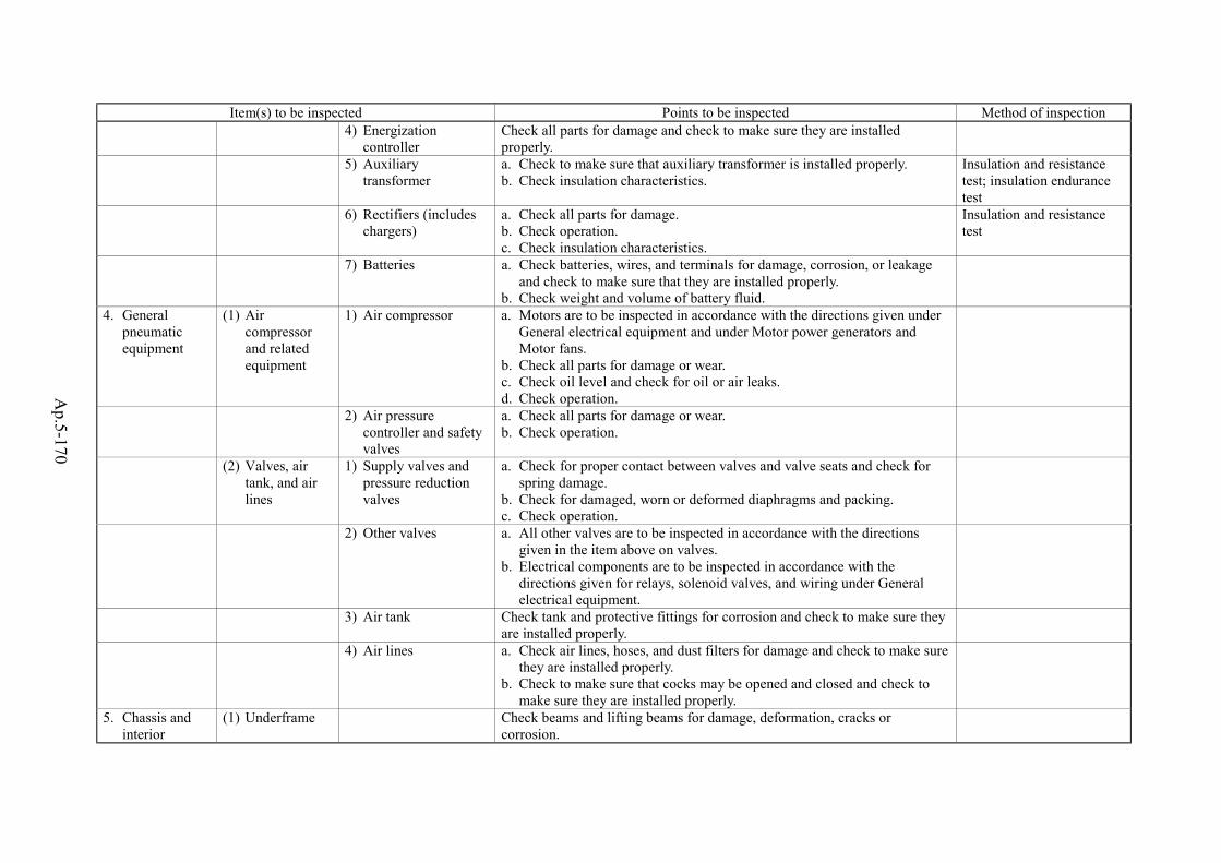
Ap.5-170
Item(s) to be inspected Points to be inspected Method of inspection4) Energization
controllerCheck all parts for damage and check to make sure they are installedproperly.
5) Auxiliarytransformer
a. Check to make sure that auxiliary transformer is installed properly.b. Check insulation characteristics.
Insulation and resistancetest; insulation endurancetest
6) Rectifiers (includeschargers)
a. Check all parts for damage.b. Check operation.c. Check insulation characteristics.
Insulation and resistancetest
7) Batteries a. Check batteries, wires, and terminals for damage, corrosion, or leakageand check to make sure that they are installed properly.
b. Check weight and volume of battery fluid.4. General
pneumaticequipment
(1) Aircompressorand relatedequipment
1) Air compressor a. Motors are to be inspected in accordance with the directions given underGeneral electrical equipment and under Motor power generators andMotor fans.
b. Check all parts for damage or wear.c. Check oil level and check for oil or air leaks.d. Check operation.
2) Air pressurecontroller and safetyvalves
a. Check all parts for damage or wear.b. Check operation.
(2) Valves, airtank, and airlines
1) Supply valves andpressure reductionvalves
a. Check for proper contact between valves and valve seats and check forspring damage.
b. Check for damaged, worn or deformed diaphragms and packing.c. Check operation.
2) Other valves a. All other valves are to be inspected in accordance with the directionsgiven in the item above on valves.
b. Electrical components are to be inspected in accordance with thedirections given for relays, solenoid valves, and wiring under Generalelectrical equipment.
3) Air tank Check tank and protective fittings for corrosion and check to make sure theyare installed properly.
4) Air lines a. Check air lines, hoses, and dust filters for damage and check to make surethey are installed properly.
b. Check to make sure that cocks may be opened and closed and check tomake sure they are installed properly.
5. Chassis andinterior
(1) Underframe Check beams and lifting beams for damage, deformation, cracks orcorrosion.
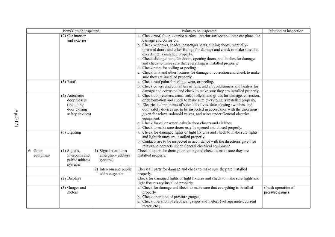
Ap.5-171
Item(s) to be inspected Points to be inspected Method of inspection(2) Car interior
and exteriora. Check roof, floor, exterior surface, interior surface and inter-car plates for
damage and corrosion.b. Check windows, shades, passenger seats, sliding doors, manually-
operated doors and other fittings for damage and check to make sure thateverything is installed properly.
c. Check sliding doors, fan doors, opening doors, and latches for damageand check to make sure that everything is installed properly.
d. Check paint for soiling or peeling.e. Check tank and other fixtures for damage or corrosion and check to make
sure they are installed properly.(3) Roof a. Check roof paint for soling, wear, or peeling.
b. Check covers and containers of fans, and air conditioners and heaters fordamage and corrosion and check to make sure they are installed properly.
(4) Automaticdoor closers(includingdoor closingsafety devices)
a. Check door closers, arms, links, rollers, and glides for damage, corrosion,or deformation and check to make sure everything is installed properly.
b. Electrical components of solenoid valves, door-closing switches, anddoor safety devices are to be inspected in accordance with the directionsgiven for relays, solenoid valves, and wires under General electricalequipment.
c. Check for oil or water leaks in door closers and air lines.d. Check to make sure doors may be opened and closed properly.
(5) Lighting a. Check for damaged lights or light fixtures and check to make sure lightsand light fixtures are installed properly.
b. Contacts are to be inspected in accordance with the directions given forrelays and contacts under General electrical equipment.
6. Otherequipment
(1) Signals,intercoms andpublic addresssystems
1) Signals (includesemergency addresssystems)
Check all parts for damage or soiling and check to make sure they areinstalled properly.
2) Intercom and publicaddress system
Check all parts for damage and check to make sure they are installedproperly.
(2) Displays Check for damaged lights or light fixtures and check to make sure lights andlight fixtures are installed properly.
(3) Gauges andmeters
a. Check for damage and check to make sure that everything is installedproperly.
b. Check operation of pressure gauges.d. Check operation of electrical gauges and meters (voltage meter, current
meter, etc.).
Check operation ofpressure gauges
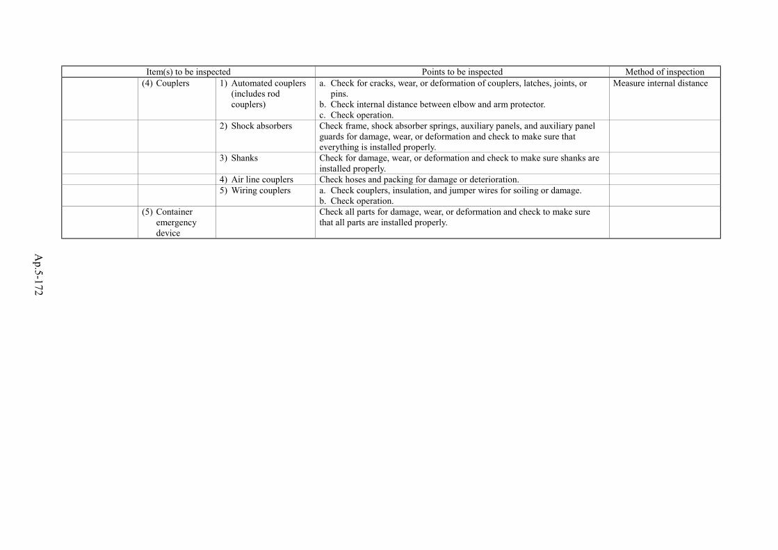
Ap.5-172
Item(s) to be inspected Points to be inspected Method of inspection(4) Couplers 1) Automated couplers
(includes rodcouplers)
a. Check for cracks, wear, or deformation of couplers, latches, joints, orpins.
b. Check internal distance between elbow and arm protector.c. Check operation.
Measure internal distance
2) Shock absorbers Check frame, shock absorber springs, auxiliary panels, and auxiliary panelguards for damage, wear, or deformation and check to make sure thateverything is installed properly.
3) Shanks Check for damage, wear, or deformation and check to make sure shanks areinstalled properly.
4) Air line couplers Check hoses and packing for damage or deterioration.5) Wiring couplers a. Check couplers, insulation, and jumper wires for soiling or damage.
b. Check operation.(5) Container
emergencydevice
Check all parts for damage, wear, or deformation and check to make surethat all parts are installed properly.
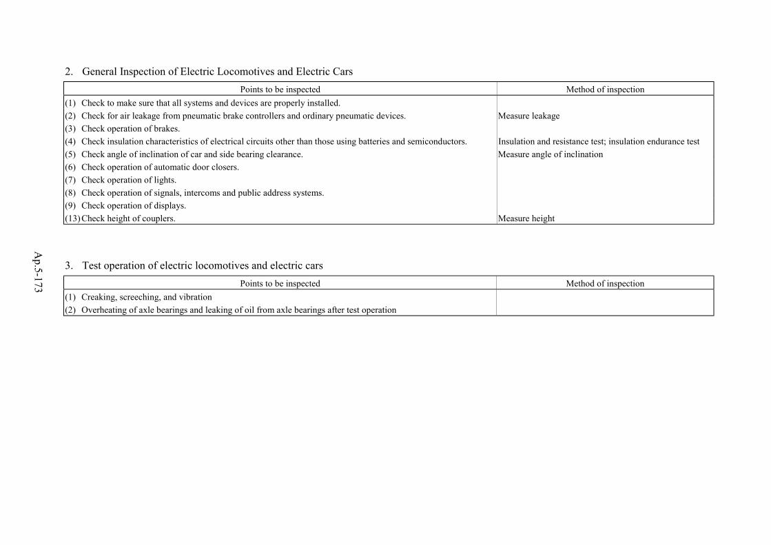
Ap.5-173
2. General Inspection of Electric Locomotives and Electric Cars
Points to be inspected Method of inspection
(1) Check to make sure that all systems and devices are properly installed.
(2) Check for air leakage from pneumatic brake controllers and ordinary pneumatic devices. Measure leakage
(3) Check operation of brakes.
(4) Check insulation characteristics of electrical circuits other than those using batteries and semiconductors. Insulation and resistance test; insulation endurance test
(5) Check angle of inclination of car and side bearing clearance. Measure angle of inclination
(6) Check operation of automatic door closers.
(7) Check operation of lights.
(8) Check operation of signals, intercoms and public address systems.
(9) Check operation of displays.
(13)Check height of couplers. Measure height
3. Test operation of electric locomotives and electric cars
Points to be inspected Method of inspection
(1) Creaking, screeching, and vibration
(2) Overheating of axle bearings and leaking of oil from axle bearings after test operation
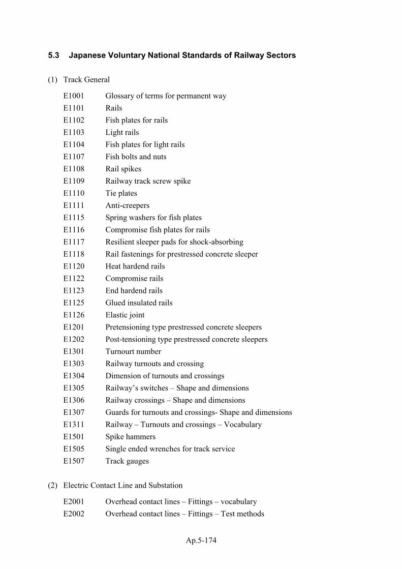
Ap.5-174
5.3 Japanese Voluntary National Standards of Railway Sectors
(1) Track General
E1001 Glossary of terms for permanent way
E1101 Rails
E1102 Fish plates for rails
E1103 Light rails
E1104 Fish plates for light rails
E1107 Fish bolts and nuts
E1108 Rail spikes
E1109 Railway track screw spike
E1110 Tie plates
E1111 Anti-creepers
E1115 Spring washers for fish plates
E1116 Compromise fish plates for rails
E1117 Resilient sleeper pads for shock-absorbing
E1118 Rail fastenings for prestressed concrete sleeper
E1120 Heat hardend rails
E1122 Compromise rails
E1123 End hardend rails
E1125 Glued insulated rails
E1126 Elastic joint
E1201 Pretensioning type prestressed concrete sleepers
E1202 Post-tensioning type prestressed concrete sleepers
E1301 Turnourt number
E1303 Railway turnouts and crossing
E1304 Dimension of turnouts and crossings
E1305 Railway’s switches – Shape and dimensions
E1306 Railway crossings – Shape and dimensions
E1307 Guards for turnouts and crossings- Shape and dimensions
E1311 Railway – Turnouts and crossings – Vocabulary
E1501 Spike hammers
E1505 Single ended wrenches for track service
E1507 Track gauges
(2) Electric Contact Line and Substation
E2001 Overhead contact lines – Fittings – vocabulary
E2002 Overhead contact lines – Fittings – Test methods
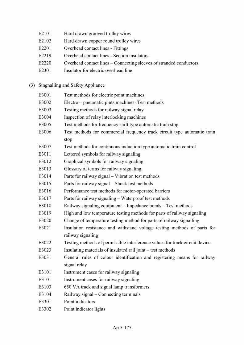
Ap.5-175
E2101 Hard drawn grooved trolley wires
E2102 Hard drawn copper round trolley wires
E2201 Overhead contact lines - Fittings
E2219 Overhead contact lines - Section insulators
E2220 Overhead contact lines – Connecting sleeves of stranded conductors
E2301 Insulator for electric overhead line
(3) Singnalling and Safety Appliance
E3001 Test methods for electric point machines
E3002 Electro – pneumatic pints machines- Test methods
E3003 Testing methods for railway signal relay
E3004 Inspection of relay interlocking machines
E3005 Test methods for frequency shift type automatic train stop
E3006 Test methods for commercial frequency track circuit type automatic train
stop
E3007 Test methods for continuous induction type automatic train control
E3011 Lettered symbols for railway signaling
E3012 Graphical symbols for railway signaling
E3013 Glossary of terms for railway signaling
E3014 Parts for railway signal – Vibration test methods
E3015 Parts for railway signal – Shock test methods
E3016 Performance test methods for motor-operated barriers
E3017 Parts for railway signaling – Waterproof test methods
E3018 Railway signaling equipment – Impedance bonds – Test methods
E3019 High and low temperature testing methods for parts of railway signaling
E3020 Change of temperature testing method for parts of railway signalling
E3021 Insulation resistance and withstand voltage testing methods of parts for
railway signaling
E3022 Testing methods of permissible interference values for track circuit device
E3023 Insulating materials of insulated rail joint – test methods
E3031 General rules of colour identification and registering means for railway
signal relay
E3101 Instrument cases for railway signaling
E3101 Instrument cases for railway signaling
E3103 650 VA track and signal lamp transformers
E3104 Railway signal – Connecting terminals
E3301 Point indicators
E3302 Point indicator lights
Ap.5-176
E3303 Lenses, filters, reflectors and semi-sealed units for railway signals
E3304 Multiple light type color light signals
E3305 Temporary signals
E3307 Train and car stop indicators
E3308 Car stop marker
E3309 Railway- Calling-on signals
E3310 Way side repeating signals
E3311 Route indicators
E3313 Position light shunting signals
E3351 Gauge ties for railway signaling
E3601 Rail bonds
E3602 Signal bonds
E3603 Impedance bonds
E3604 Lead wires for impedance bonds
E3701 Railway crossing equipment – Safety colour code
E3702 Out of order indicators for level crossing signal
E3703 Train proceeding direction indicator
E3704 Operating switch for obstruction warning device of level crossing
(4) Rolling Stock General
E4001 Railway rolling stock – Vocabulary
E4010 Symbols for railway rolling stock and railway rolling stock parts
E4011 Measuring methods for mass of railway rolling stock
E4014 Test methods for insulation resistance and withstand voltage of railway
rolling stock
E4015 Measuring methods for air conditioning and heating temperature of railway
rolling stock
E4016 Illuminance for railway rolling stock – Recommended levels and measuring
methods
E4017 Railway rolling stock – Graphical symbols for electrical apparatus
E4018 Railway rolling stock – Measuring methods of leakage magnetic field
E4021 Railway rolling stock – Test methods inside noise
E4022 Railway rolling stock – Test methods for waterproof
E4023 Vibration characteristics of railway rolling stock – Measuring methods
E4024 Railway rolling stock – Test methods of ventilation
E4031 Railway rolling stock parts – Test methods for vibration
E4032 Railway rolling stock parts – Test methods for shock
Ap.5-177
E4034 Railway rolling stock parts – Test methods of resistibility for moisture and
rainfall
E4035 Railway rolling stock – High and low temperature test methods of parts
E4036 Railway rolling stock component parts – General rules for dust test
E4041 General rules for the inspection of electric railcar on completion of
construction
E4042 General rules for the inspection of electric locomotives on completion of
construction
E4043 General rules for the inspection of diesel railcar on completion of
construction
E4044 General rules for the inspection of diesel locomotives on completion of
construction
E4045 Freight cars – General requirements for the inspection on completion of
construction
E4046 General rules for the inspection of passenger car on completion of
construction
E4047 Design methods of arc welded joints for railway rolling stock
E4048 Railway rolling stock – Spot welded joints of mild steel – Design methods
E4049 Welded joints of stainless steel for railway rolling stock – Design methods
E4050 Welded joints off aluminum alloy for railway rolling stock – Design
methods
E4101 Drain cocks for railway rolling stock
E4102 Angle cocks for railway rolling stock
E4103 Cut-out cocks for railway rolling stock
E4105 Three-way cocks for railway rolling stock
E4106 Railway rolling stock – Screwed type pipe fittings
E4111 Clevis pins with head for railway rolling stock
E4112 Steel bushes and sintered metallic bushes for railway rolling stock
E4113 Railway rolling stock – Split cotters
E4115 Magnet valves for railway rolling stock
E4116 Pneumatic window wipers for railway rolling stock
E4117 Leveling valves for railway rolling stock
E4118 Bourdon tube pressure gauges for railway rolling stock
E4119 Polyurethane bushes for railway rolling stock
E4201 Railway rolling stock – Automatic couplers
E4202 Jumper couplers
E4203 Railway rolling stock – Tight lock couplers
E4202 Jumper couplers
Ap.5-178
E4203 Railway rolling stock – Tight lock couplers
E4204 Rubber draft gears for railway rolling stock
E4205 Oil dampers for railway rolling stock
E4206 Spring rigging for railway rolling stock
E4207 Truck frames for railway rolling stock – General rules for design
E4208 Test methods of static load for track frames and truck blosters of railway
rolling stock
E4301 Air hose couplings
E4302 Dummy hose couplings
E4303 Packing rubbers for hose couplings
E4306 Conductor’s valves for railway rolling stock
E4307 Air reservoirs for railway rolling stock
E4308 Railway rolling stock – Air filters
E4309 Composition brake shoes for railway rolling stock
E4310 Sintered metallic filter elements for railway rolling stock
E4501 Railway rolling stock – Design methods for strength of axles
E4502 Axles for railway rolling stock
E4504 Wheel sets for railway rolling stock
E4603 Electric speedometer equipment for railway rolling stock
E4704 Grease seals for railway rolling stock
E4710 Railway rolling stock – Rubber vibration isolators – General requirement
E4901 DC fuses for railway rolling stock
E4902 Knife switches for railway rolling stock
(5) Motive Power (Rolling Stock)
E5001 Methods of test for line breakers of railway rolling stock
E5002 Air compressors for railway rolling stock – Test methods
E5003 Test methods for direct current surge arresters of railway rolling stock
E5004 Control equipment for electric rolling stock- Test methods
E5005 Railway rolling stock – High speed circuit breaker – Test methods
E5006 General rules for tests of electronic equipment used on railway rolling stock
E5007 Test methods of traction transformers for railway rolling stock
E5008 Main rectifiers for railway rolling stock – Test methods
E5009 Traction reactors of railway rolling stock – Test methods
E5301 Railway rolling stock – Radiator element – Inspection methods
E5302 Propeller shafts for railway rolling stock
E5303 Test methods for diesel engines of railway rolling stock
E5401 Carbon steel tyres for railway rolling stock
Ap.5-179
E5402 Solid rolled wheels for railway rolling stock
E5501 Air whistles for railway rolling stock
E6001 DC electric railcar – Wire code & symbol
E6002 General rules for performance of electric railcars for commuter use
E6003 General rules for design of driving cabs of electric commuter cars
E6004 Electric rolling stock- General rules for performance tests
E6005 Railway rolling stock – Automatic train control and automatic train stop
device on board – Test methods
E6101 Methods of test for DC traction motors of railway rolling stock
E6102 AC traction motors of railway rolling stock – Test methods
E6201 General rules of choppers for electric rolling stock
E6202 Electromagnetic relays for railway rolling stock – General requirement
E6301 Contact strips for pantograph
E6302 Pantographs of railway rolling stock – Inspection methods
E6401 Ohmic resistors for railway rolling stock
E6501 Door engines for railway rolling stock
E6502 Door close switches for railway rolling stock
E6601 Railway rolling stock – Auxiliary rotating electrical – Test methods
E6602 Cooling unit apparatus for electric cars
E6801 Jumper cables for railway rolling stock
(6) Railway Carriage and Wagons
E7101 Tank cars
E7102 Design methods for tanks of tank cars
E7103 Electric railcars for commuter use – General requirement for design of
bodies
E7104 Seats for passengers of railway rolling stock
E7105 Test methods static load for body structures of railway rolling stock
E7501 Railway rolling stock – Cast iron brake shoes
E7701 Safety valves for high pressure gas tank car tanks


