Embed Size (px)
Citation preview
UNITED STATES COAST GUARD OCEAN ENGINEERING DIVISION
WASHINGTON, D.C.
SPECIFICATION FOR 12 VDC SOLID STATE PROGRAMMABLE FLASHER
FOR MARITIME AIDS TO NAVIGATION
SPECIFICATION NO. 493A
CHANGE 1 Make the following changes to the specification: 1. Modify subparagraph 3.9.7.1 as follows to add a description for proper rhythm selector switch placement:
“… to select a rhythm (program the flasher). Regardless of what type selector switch is chosen, ensure that the standard flasher/lampchanger/lantern mounting bracket does not interfere with the switch’s placement and/or operation. The standard lampchanger/flasher assembly uses a 1¼ inch-wide solid plate-steel mounting bracket installed flat between them. If the switch is not positioned with enough clearance from the mounting bracket, normal switch operation and/or proper hardware assembly may be hindered. This requirement is especially important if using a rotary rhythm selector switch. If using a rotary rhythm selector switch, ensure that the top surface of its knob is lower than the top surfaces of the coplanar mounting bosses. Usually, the best location for the switch is offset from top center and away from the terminal side. If desired, please contact the COTR for a mounting bracket sample. If screws are used…”
2. To clarify the prevention-of-spurious-activity requirement in subparagraph 3.10.2, replace the first sentence with the following:
“With a photoresistor conforming to Specification G-EOE-234 connected between the two "S" terminals and pointed directly at the flashing lamp, the flashing lamp shall not spuriously activate the illumination control circuitry or cause the light to flash on a different rhythm when the ambient illumination level is less than the level at which the flasher is turned on.”
3. To clarify the prevention-of-spurious-activity requirement in subparagraph 4.6.7, replace the second sentence with the following:
“With the photoresistor aimed directly at the flashing lamp, verify that the flashing lamp does not spuriously activate the illumination control circuitry or cause the light to flash on a changed rhythm (3.10.2).”
4. To clarify the vibration test, replace subparagraph 4.7.1.1 with the following paragraph:
4.7.1.1 Vibration. Flashers shall be tested in accordance with MIL-STD-202, Method 204-D, Test Condition 'D', except that amplitude must be maintained at 10G's (not 20G peak) and with duration reduced to three 20-minute cycles in each of three mutually perpendicular axes (x, y, & z) for a total of nine complete cycles (180 minutes total). The flasher shall be rigidly attached to a fixture capable of transmitting all of the vibration conditions.
5. To clarify the shock test, replace subparagraph 4.7.1.2 with the following paragraph:
4.7.1.2 Shock. Flashers shall be shock tested in accordance with MIL-STD-202, Method 213-B. Flashers shall be rigidly mounted prior to testing. Shocks shall be applied in only one direction for each of three mutually perpendicular axes (x, y, & z). A total of ten shock pulses of 11 milliseconds duration, 40G peak acceleration, sawtooth waveshape shall be applied to each flasher: three along one axis, three along another axis, and four along the final axis. The axis that receives four blows (instead of three) is chosen at random for each flasher. Use Test Condition 'G' reduced from 50G's to 40G's.
6. To clarify the prevention-of-spurious-activity-at-start requirement in subparagraph 4.7.3.6(c), replace the first two sentences with the following:
“Connect a type “L” photoresistor conforming to Specification G-EOE-234 to the "S" terminals of each flasher. With the ambient illumination above the "turn-on" level, and the photoresistor positioned 6 inches from, and aimed directly at the lamp, verify that reducing the ambient illumination below the "turn-on" level activates the flasher and that the additional illumination from the lamp does not cause it to operate on a different rhythm (3.10.2).”
Prepared by: Reviewed by: /s/ /s/ ____________________________ ___________________________ KAMIL AGI JON T. GRASSON PROJECT ENGINEER TEAM LEADER, SIGNAL AND POWER TEAM Approved by: Date: /s/ ____________________________ March 2, 2004 HARLEY R. CLEVELAND CHIEF, OCEAN ENGINEERING DIVISION
Date: 6/30/00
OFFICE OF CIVIL ENGINEERINGUNITED STATES COAST GUARD
WASHINGTON, D.C.
JUNE 2000
SPECIFICATION FOR12 VDC SOLID STATE PROGRAMMABLE FLASHER
FOR MARITIME AIDS TO NAVIGATION
SPECIFICATION NO. 493A
Date: 6/30/00
1. SCOPE.
1.1 General. This specification establishes the performance and test requirements for 12 volt, directcurrent (DC), solid-state programmable flashers. The flashers are to be used for flashing marine aids tonavigation lamps. In addition, the flashers shall regulate output voltage to the lamps, sense burnt-outlamps, control a 12 volt lampchanger as specified herein, and provide daytime/nighttime illuminationcontrol (when coupled with a photoresistor) for an aids to navigation beacon.
1.1.1 Additional Information. Programmable flashers are normally intended to flash lamps powered by:(1) 10 to 16 volt, air depolarized, primary-batteries; (2) secondary lead-acid batteries; or, (3) DCpower supplies. In normal operational use, flashers will be contained in beacon assemblies on buoys orfixed structures in or around the navigable waters of the United States. Lamps will usually beincandescent tungsten-filament lamps rated at 12 volts and from 0.25 to 3.05 amps. The lamps will bemounted in lampchangers conforming to G-SEC Specification No. 195. Although the flashers aremounted in a lantern assembly, they will nevertheless be exposed to all the elements of weather,including but not limited to rain, snow, and wind, and on occasion they will be immersed in water. Theflashers may also be used to operate other types of aids to navigation equipment with high inputimpedance.
1.2 Precedence. Any ambiguity or conflict between this specification, drawings, and / or applicabledocuments shall be resolved by using the following documents in the precedence shown:
a. The wording of this specification.
b. Drawings contained in or attached to this specification.
c. Applicable documents.
1.3 Government Furnished Property (GFP). The following equipment will be loaned to the contractorfor use in first article testing:
(4) CG-6P Lampchanger
(4) WK-681 Wiring Kit
(4) Type "C" Photoresistor
(4) Type "L" Photoresistor
(10) 12 volt, 0.25 amp Marine Signal Lamps
(10) 12 volt, 0.55 amp Marine Signal Lamps
(10) 12 volt, 3.05 amp Marine Signal Lamps
Date: 6/30/00
1.4 Definitions. The following definitions shall apply to these terms whenever they appear in thisspecification.
1.4.1 Flasher, Solid-State. An electrical device with no moving parts that may interrupt the power to alight beacon according to a specified time-based characteristic, causing the beacon to flash with aspecified rhythm. It may also make the light burn fixed on. A flasher also performs accessory functionsas specified herein and defined below.
1.4.2 Rhythm. The time-based characteristic of flashes of light alternating with eclipses of darknessexhibited by a light beacon during one period.
1.4.3 Beacon assembly, DC-powered. A beacon assembly consisting of a lantern, a lens, a 12 voltlampchanger (containing one lamp in the "burning position" and at least one spare lamp capable ofmoving into the burning position when so controlled), a daylight control or photoresistor, and a flasher.
1.4.4 Accessory Functions. There are three accessory functions in the solid-state programmableflasher required by this specification. They are defined as follows:
a. Lamp-out sensor and control. A circuit that senses lamp filament integrity during the rhythmperiod and, if the filament is open, causes the lampchanger to move a spare lamp into theburning position, or switches a transfer relay that transfers the power from the lantern withthe burnt-out lamp to a spare lantern with an operable lamp.
b. Illumination control. A circuit such that when a photoresistor conforming to Specification G-EOE-234 is connected to it, stops the flow of current to the lamp when the ambientillumination exceeds a certain value, and permits current to flow to the lamp when theillumination falls below a certain value.
c. Voltage regulator. A circuit that limits the output voltage to a specified range of values.
1.4.5 Self-protection features. There are two self-protection features in the programmable flasherrequired by this specification. They are defined as follows:
a. Reverse-polarity protection. An electrical circuit that ensures the flasher will not be impairedin any way if the input terminals are connected across a battery in reverse polarity, providedthat the battery's open-circuit voltage does not exceed the maximum allowable input voltagesspecified for the flasher.
b. Short-circuit protection. An electrical circuit that ensures the operation of the flasher will notbe impaired in any way if either the "F", "L", or "S" terminals are connected to the case, tothe positive or negative power leads, or to each other.
1.4.6 12 volt battery. A secondary, lead-acid battery with a minimum rating of 75 amp-hours.
Date: 6/30/00
1.4.7 Input voltage. The closed circuit voltage (CCIV) observed at the power input terminals when theflasher is operating a 12 volt lamp at rated current.
1.4.8 Output voltage. The closed circuit voltage (CCOV) observed at the "L" and "-" terminals whenthe flasher is operating a 12 volt lamp at rated current.
Date: 6/30/00
2. APPLICABLE DOCUMENTS.
2.1 Government Documents. The following documents of the issues specified form a part of thisspecification to the extent referenced herein. Suffixes denoting the specific issue of each document willbe omitted from future references to the document in this specification.
2.1.1 Military Specifications.
a. MIL-P-15024-E Plates, Tags, and Bands for Identification of Equipment29 Jan 93
b. MIL-T-31000 General Specification for Technical Data Packages15 Dec 89
2.1.2 U.S. Coast Guard Specifications.
a. G-ECV-195-G 12 Volt, Six-place Lampchanger for Maritime Aids toCh 4, 15 Apr 92 Navigation (Type CG-6P)
b. G-EOE-234-C Photoresistors for Solid State FlashersCh 1, 15 Jul 86
c. G-ECV-487 Specification for 12-VDC Marine Signal LampsJun 95
2.1.3 Military Standards.
a. MIL-STD-202-F Test Methods for Electronic and Electrical ComponentChg Notice 12 Parts12 Jul 93
b. MIL-STD-454-N Standard General Requirements for Electronic EquipmentChg Notice 322 Sep 94
2.2 Drawings. The latest revisions of the following U.S. Coast Guard drawing form a part of thisspecification to the extent referenced herein.
a. G-EOE-120006-E 12 Volt, Solid-State Flasher26 Apr 93
2.3 Other Publications. The following documents of the issues specified form a part of this specificationto the extent referenced herein. Suffixes denoting the specific issue of each document will be omitted
Date: 6/30/00
from future references to the document in this specification.
a. ASTM G82-83 Standard Guide for Development and Use of a Galvanic28 Nov 83 Series for Predicting Galvanic Corrosion Performance.
b. ANSI / ASQC C1-1985 American National Standard; Specification of GeneralNov 85 Requirements for a Quality Program.

Date: 6/30/00
3. REQUIREMENTS.
3.1 Design and Construction. The programmable flasher shall be of solid-state design andconstruction, and shall be of quality which will ensure compliance with the requirements of thisspecification. All materials shall be compatible with each other under all conditions encountered in theuse of flashers in Coast Guard aids to navigation.
3.2 Compliance. The contractor shall demonstrate through test and inspection that all flasherspresented to the government (both first article and production) meet the requirements of thisspecification.
3.3 Standardization of Design and Certification. Production programmable flashers that are furnishedunder this specification shall not differ in any way from those that are submitted for first article tests(4.5.1.1) except for changes that have been described in detail to and approved by the SpecificationPreparing Activity (SPA). The manufacturer must submit a certification to this effect covering each lotof flashers furnished under this specification. In the event the manufacturer wishes to introduce anychanges to correct design deficiencies or selection of marginal parts, etc., the SPA may requirerepetition of any or all of the first article tests before the proposed changes are approved.
3.4 Environment. Each programmable flasher shall operate as specified under the followingenvironmental conditions:
3.4.1 Ambient Temperature. From -25°F through 140°F.
3.4.2 Humidity. From 0% through 100% relative humidity.
3.4.3 Salt Air and Saltwater. Each flasher shall be constructed of materials so as to be resistant tocorrosion from continuous exposure to salt air and immersion in saltwater.
3.4.4 Shock and Vibration. Each flasher shall be constructed to withstand the shock and vibrationsincident in transport to and service on lighted buoys and fixed structures.
3.5 Physical Requirements.
3.5.1 Size. The dimensions of each programmable flasher case shall conform to those specified inDrawing G-EOE-120006, attached to this specification.
3.5.2 Mounting Holes and Mounting Surface. Four mounting holes shall be located on the mountingsurface as specified in Drawing G-EOE-120006. The mounting surface shall be two bosses. Thedimensions of the bosses shall not exceed those shown on Drawing G-EOE-120006. The top surfacesshall be coplanar. The mounting holes shall be made of threaded stainless-steel or nickel-plated brassinserts. It shall be possible for a 10-32 screw to enter to a depth of 5/16" or more.
Date: 6/30/00
3.5.3 Terminal and Terminal Insulators. There shall be six external, 8-32 screw terminals located asspecified in Drawing G-EOE-120006. All terminals shall be enclosed in slotted insulators sized toaccept three, 11/32"-wide spade and/or hook lugs for a No. 8 stud. The insulators shall be sized toaccept the lugs from the front and the back. The terminals shall be molded of colored dielectricmaterials in accordance with the color code given in paragraph 3.5.4. With one of the above lugs inplace, the top of the terminal screws shall not project above the top of the insulators. The six 8-32terminal screws shall be slotted or combination Phillips/slotted and be long enough so that they do notfall out when inserting three of the above lugs. The top of the insulators shall not extend above themounting surfaces.
3.5.4 Terminal Arrangement and Marking. Terminals shall be arranged and permanently labeled asshown in Drawing G-EOE-120006. Terminal markings may be incorporated in the nameplate. Theterminal markings have the following meanings:
Terminal Meaning Color
"F" Output terminal for positive voltage to lampchanger actuating Bluemechanism via the lampchanger's "F" terminal.
"L" Output terminal for positive, regulated, time-coded voltage, Redto be connected to lamp via lampchanger's lamp (L) terminal.
"S" The two terminals across which the photoresistor is connected. Yellow
"+" Input terminal for positive battery lead. Black
"-" Input terminal for negative battery lead and negative lead to Whitelampchanger via the lampchanger's negative (-) terminal.
3.6 Programmable Flasher Case. The case shall be of suitable hardness and rigidity, and have lowmoisture absorption under the humidity and temperature conditions specified herein. The case shallretain its design contours without warping, crazing, cracking, or corroding in service or in storage. Thecase shall be sealed to ensure the watertight integrity of the encased electronic circuitry. The case maybe plastic, metal, or a combination of both.
3.6.1 Electrical Isolation. Each flasher terminal shall be electrically isolated from the case by at least500,000 ohms.
3.7 Materials.
3.7.1 Electronic Components. Solid-state components shall be used to accomplish all required
Date: 6/30/00
electrical / electronic functions. There shall be no moving parts.
3.7.2 Potting. The electronic components shall be embedded in potting material to ensure that they areprotected from moisture. The potting shall be of suitable hardness and rigidity, and have low moistureabsorption under the humidity and temperature conditions specified herein. The potting shall retain itsdesign contour without warping, crazing, or cracking in service or in storage.
3.7.3 Dissimilar Metals. Materials used shall be galvanically compatible to minimize electrolytic action.Use of dissimilar metals shall be avoided, with the following exceptions:
a. Use of stainless-steel threaded inserts in combination with an aluminum housing.
b. Use of stainless-steel or nickel-plated brass screws in tinned brass terminals.
Guidelines for developing a predictive model for galvanic corrosion performance are outlined in ASTMG82.
3.8 Workmanship. Workmanship shall conform to Requirement 9, Workmanship, ofMIL-STD-454.
3.9 Electrical. The programmable flasher shall function as specified in this paragraph when operatedwithin the extremes of the environmental conditions.
3.9.1 Input Voltage. The flasher shall be capable of being powered by primary and secondarybatteries and transformer rectified power supplies with less than 3% ripple. The flasher shall operate asspecified with input voltages (CCIV, 1.4.7) ranging from 10.0 VDC to 18.0 VDC (maximum of 16.0VDC for 2.03 amp and 3.05 amp lamps).
3.9.2 Output Voltage. The flasher shall provide a positive, time coded, regulated output voltagebetween the "-" and "L" terminals. The closed circuit output voltage (CCOV, 1.4.8) shall be regulatedas follows:
CCIV (Volts DC) CCOV (Volts DC)10.0 - 12.4 The difference between the input voltage and output
voltage shall be no greater than 0.75 volts.
12.41 - 18.0 11.66 - 12.20
3.9.3 Output Current. The flasher shall flash any 12 VDC, tungsten filament, marine signal lamp with acurrent rating of 0.25 amps to 3.05 amps. The lamps shall achieve full incandescence if the appliedvoltage time exceeds the lamp incandescence time. The flasher shall provide current to any resistiveload that draws between 0.17 amps and 3.44 amps, inclusive.
Date: 6/30/00
3.9.4 Parasitic Current.
3.9.4.1 Daytime. The input current to the flasher when connected to a CG-6P lampchanger with alamp in the operating position and a CG-234 photoresistor idling in daytime operation, shall not exceed20 milliamperes.
3.9.4.2 Nighttime. When operating under nighttime conditions (timing circuit enabled), the input currentto the flasher (as configured in paragraph 3.9.4.1) exclusive of the lamp current, shall not exceed 30milliamperes. The input current to the flasher when the lamp is not energized, but inclusive of the lampcurrent, shall not exceed 20 milliamperes.
3.9.4.3 Daytime/Nighttime. As an alternative to paragraph 3.9.4.1 and 3.9.4.2, the sum of the daytimeand nighttime (during flash, not eclipse) input currents to the flasher exclusive of the lamp current, asmeasured above, shall not exceed 40 milliamperes.
3.9.5 Short-Circuit Protection. Each flasher shall have short-circuit protection so that connecting the"L", "F", or "S" terminals to the "+" or "-" terminals, to the flasher case, or to each other does not affectthe proper operation of the flasher after the short-circuit is removed. This short-circuit protection shallfunction at the same time as the reverse polarity protection.
3.9.6 Reverse-Polarity Protection. Each flasher shall have reverse polarity protection on the positiveand negative terminals. The flasher shall resume proper operation as soon as the correct polarity isapplied. The reverse polarity protection shall function at the same time as the short-circuit protection.
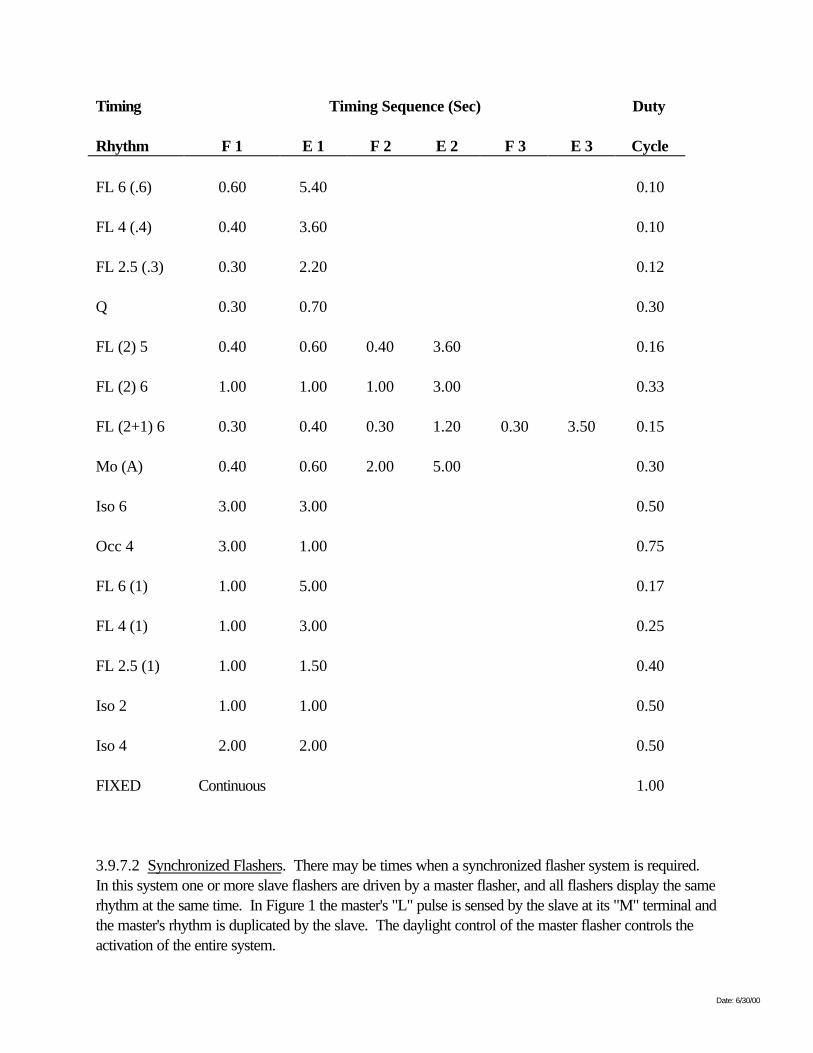
3.9.7 Programmable Timing Rhythms. The output voltage at the "L" and "-" flasher terminals shall betime coded as specified below. The voltage shall be applied to the lamp for flash intervals "F#," andshall not be applied to the lamp during eclipse intervals "E#." The time coding, or rhythm, is defined bycontinuous operation of these intervals. The duty cycle for a rhythm is the total lamp on-time (sum of Fintervals) divided by the period of the rhythm (sum of all the F and E intervals).
3.9.7.1 Programmable Rhythms. The following list of flasher rhythms is the minimum number ofrhythms that shall be pre-programmed and available with each flasher. Each flasher rhythm shall beselectable by the user by some type of switch(es) mounted on the top surface of the flasher. Theswitch(es) shall be protected from the environment. No special tools or equipment shall be required toselect a rhythm (program the flasher). If screws are used to secure a switch cover(s), programmingplates, or other programming hardware, they shall be the same as the 8-32 terminal screws described inparagraph 3.5.3. The rhythm selection process (programming the flasher) shall preclude the removal ofany and all hardware such as screws, plates, covers, jumpers, lenses, etc. The rhythm shall bechangeable (reprogrammable) at any time during the flasher's useful service life without the programminghardware incurring any detrimental effects.
Date: 6/30/00
Timing Timing Sequence (Sec) Duty
Rhythm F 1 E 1 F 2 E 2 F 3 E 3 Cycle
FL 6 (.6) 0.60 5.40 0.10
FL 4 (.4) 0.40 3.60 0.10
FL 2.5 (.3) 0.30 2.20 0.12
Q 0.30 0.70 0.30
FL (2) 5 0.40 0.60 0.40 3.60 0.16
FL (2) 6 1.00 1.00 1.00 3.00 0.33
FL (2+1) 6 0.30 0.40 0.30 1.20 0.30 3.50 0.15
Mo (A) 0.40 0.60 2.00 5.00 0.30
Iso 6 3.00 3.00 0.50
Occ 4 3.00 1.00 0.75
FL 6 (1) 1.00 5.00 0.17
FL 4 (1) 1.00 3.00 0.25
FL 2.5 (1) 1.00 1.50 0.40
Iso 2 1.00 1.00 0.50
Iso 4 2.00 2.00 0.50
FIXED Continuous 1.00
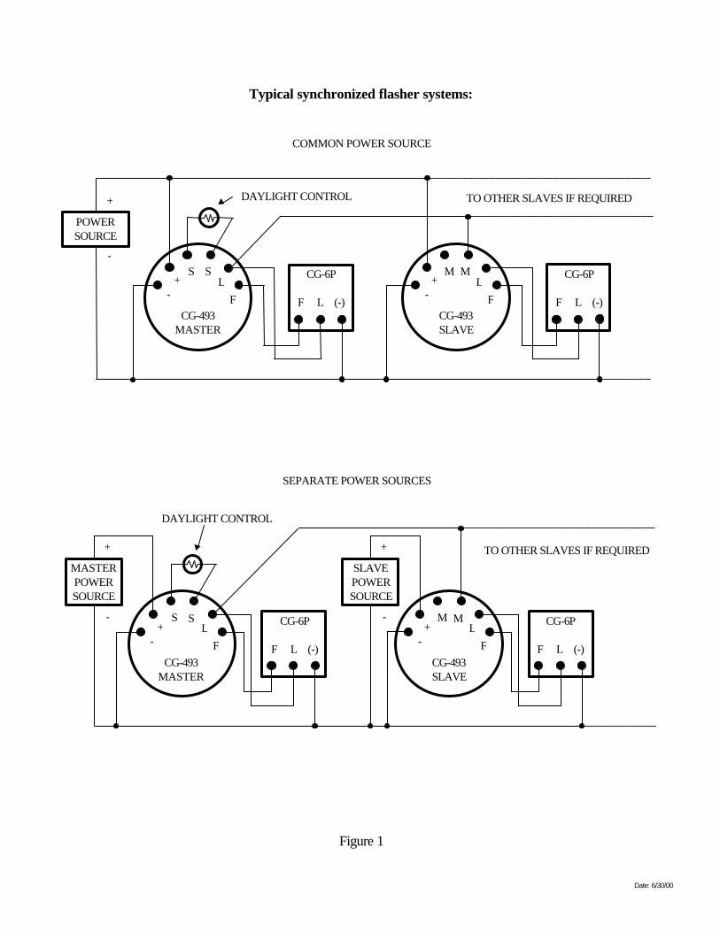
3.9.7.2 Synchronized Flashers. There may be times when a synchronized flasher system is required.In this system one or more slave flashers are driven by a master flasher, and all flashers display the samerhythm at the same time. In Figure 1 the master's "L" pulse is sensed by the slave at its "M" terminal andthe master's rhythm is duplicated by the slave. The daylight control of the master flasher controls theactivation of the entire system.
Date: 6/30/00
Typical synchronized flasher systems:
COMMON POWER SOURCE
DAYLIGHT CONTROL TO OTHER SLAVES IF REQUIRED
CG-6P
F L (-)-
+ LSS
FCG-493
MASTER
-+ L
MM
FCG-493SLAVE
CG-6P
F L (-)
POWERSOURCE
-
+
Figure 1
SEPARATE POWER SOURCES
DAYLIGHT CONTROL
TO OTHER SLAVES IF REQUIRED
CG-6P
F L (-)-
+ LSS
FCG-493
MASTER
-+ L
MM
FCG-493SLAVE
CG-6P
F L (-)
MASTERPOWERSOURCE
-
+
SLAVEPOWERSOURCE
-
+

Date: 6/30/00
Date: 6/30/00
3.9.7.3 Timing Tolerance. The flash intervals, the eclipse intervals, the period and the duty cycle shallbe within 5% of the specified values.
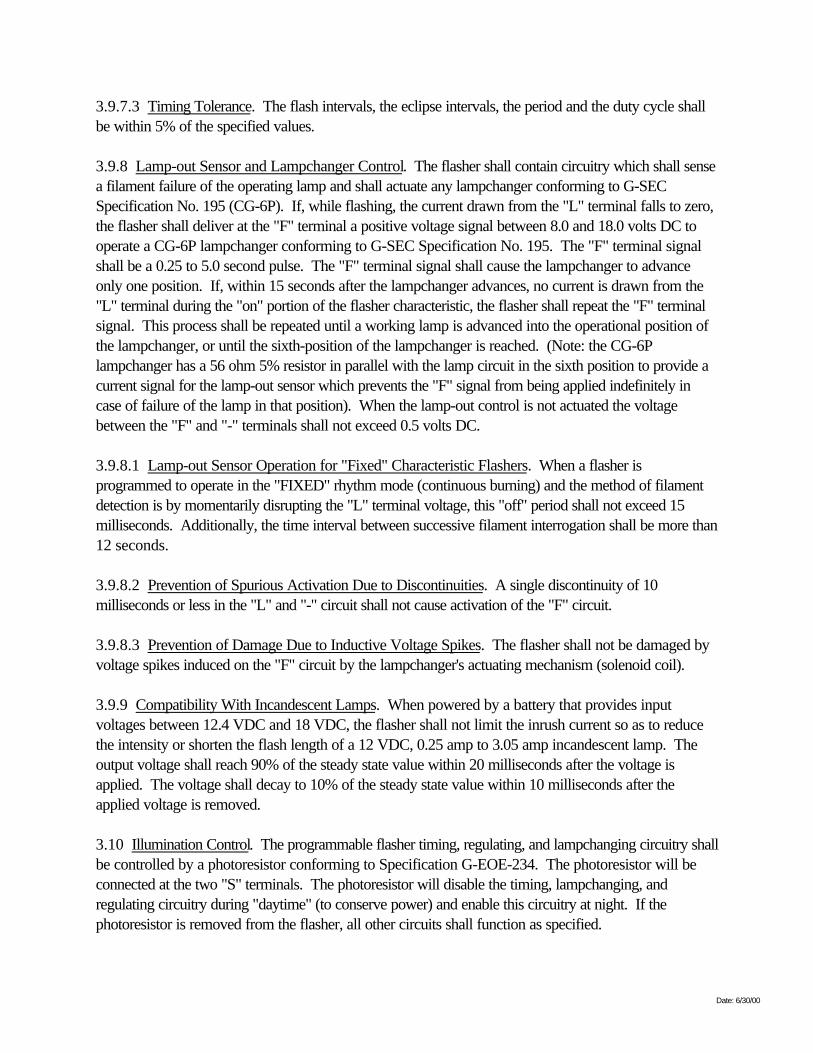
3.9.8 Lamp-out Sensor and Lampchanger Control. The flasher shall contain circuitry which shall sensea filament failure of the operating lamp and shall actuate any lampchanger conforming to G-SECSpecification No. 195 (CG-6P). If, while flashing, the current drawn from the "L" terminal falls to zero,the flasher shall deliver at the "F" terminal a positive voltage signal between 8.0 and 18.0 volts DC tooperate a CG-6P lampchanger conforming to G-SEC Specification No. 195. The "F" terminal signalshall be a 0.25 to 5.0 second pulse. The "F" terminal signal shall cause the lampchanger to advanceonly one position. If, within 15 seconds after the lampchanger advances, no current is drawn from the"L" terminal during the "on" portion of the flasher characteristic, the flasher shall repeat the "F" terminalsignal. This process shall be repeated until a working lamp is advanced into the operational position ofthe lampchanger, or until the sixth-position of the lampchanger is reached. (Note: the CG-6Plampchanger has a 56 ohm 5% resistor in parallel with the lamp circuit in the sixth position to provide acurrent signal for the lamp-out sensor which prevents the "F" signal from being applied indefinitely incase of failure of the lamp in that position). When the lamp-out control is not actuated the voltagebetween the "F" and "-" terminals shall not exceed 0.5 volts DC.
3.9.8.1 Lamp-out Sensor Operation for "Fixed" Characteristic Flashers. When a flasher isprogrammed to operate in the "FIXED" rhythm mode (continuous burning) and the method of filamentdetection is by momentarily disrupting the "L" terminal voltage, this "off" period shall not exceed 15milliseconds. Additionally, the time interval between successive filament interrogation shall be more than12 seconds.
3.9.8.2 Prevention of Spurious Activation Due to Discontinuities. A single discontinuity of 10milliseconds or less in the "L" and "-" circuit shall not cause activation of the "F" circuit.
3.9.8.3 Prevention of Damage Due to Inductive Voltage Spikes. The flasher shall not be damaged byvoltage spikes induced on the "F" circuit by the lampchanger's actuating mechanism (solenoid coil).
3.9.9 Compatibility With Incandescent Lamps. When powered by a battery that provides inputvoltages between 12.4 VDC and 18 VDC, the flasher shall not limit the inrush current so as to reducethe intensity or shorten the flash length of a 12 VDC, 0.25 amp to 3.05 amp incandescent lamp. Theoutput voltage shall reach 90% of the steady state value within 20 milliseconds after the voltage isapplied. The voltage shall decay to 10% of the steady state value within 10 milliseconds after theapplied voltage is removed.
3.10 Illumination Control. The programmable flasher timing, regulating, and lampchanging circuitry shallbe controlled by a photoresistor conforming to Specification G-EOE-234. The photoresistor will beconnected at the two "S" terminals. The photoresistor will disable the timing, lampchanging, andregulating circuitry during "daytime" (to conserve power) and enable this circuitry at night. If thephotoresistor is removed from the flasher, all other circuits shall function as specified.
Date: 6/30/00
3.10.1 Photoresistors. The illumination control circuitry shall disable the flasher before thephotoconductive resistance across the "S" terminals falls below 10,000 ohms. The illumination controlcircuitry shall enable the flasher before the photoconductive resistance across the "S" terminals exceeds40,000 ohms. The illumination control circuitry shall bias the photoresistor no more than 6 volts suchthat the photoresistor dissipates no more than 40 milliwatts.
3.10.2 Prevention of Spurious Activation Due to Illumination Level. With a photoresistor conformingto Specification G-EOE-234 connected between the two "S" terminals, the flashing lamp shall notspuriously activate the illumination control circuitry or cause the light to flash on a different rhythm whenthe ambient illumination level is less than the level at which the flasher is turned on. Spurious activationshall be prevented electronically and shall not depend on the physical shading of the flashing lamp.Consideration of the nigrescence of incandescent lamps and the response time of photoresistorsindicates that the illumination-control circuit should be de-energized for a short time after termination ofthe flash; however, in the "FIXED" characteristic, the illumination-control circuitry shall functioncontinuously and the photoresistor will be located out of the line-of-sight of the lamp.
3.10.3 Effect of Ambient Illumination. The illumination control circuitry, in conjunction with aphotoresistor conforming to Specification G-EOE-234, shall not cause the flasher to operate on achanged rhythm at any level of ambient illumination below its "turn-off" level.
3.10.4 Effect of Artificial Illumination. The flasher shall not malfunction when tested with aphotoresistor conforming to Specification G-EOE-234 under ambient natural daylight, incandescent, orfluorescent lights. The flasher shall perform only as described in paragraphs 3.10 through 3.10.3 forambient natural daylight, incandescent, and fluorescent light.
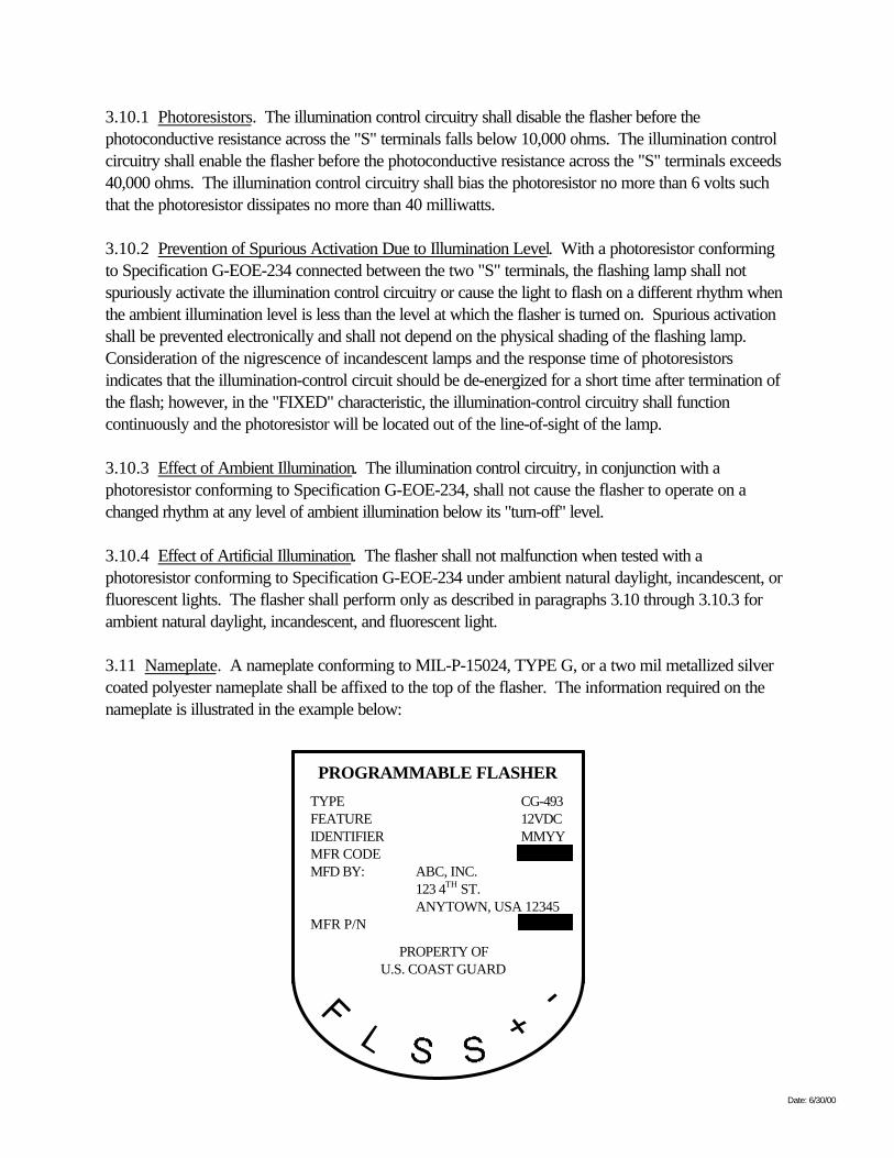
3.11 Nameplate. A nameplate conforming to MIL-P-15024, TYPE G, or a two mil metallized silvercoated polyester nameplate shall be affixed to the top of the flasher. The information required on thenameplate is illustrated in the example below:
PROGRAMMABLE FLASHER
TYPE CG-493FEATURE 12VDCIDENTIFIER MMYYMFR CODEMFD BY: ABC, INC.
123 4TH ST.ANYTOWN, USA 12345
MFR P/N
PROPERTY OFU.S. COAST GUARD
Date: 6/30/00
The manufacturer shall obtain the manufacturer's code from the SPA upon contract award. Theidentifier field shall be the month and year the flasher is delivered. An example is 1197 for November1997. (Note: The terminal markings have been incorporated into the nameplate in this example). Useof the entire address on the "MFD BY:" field of the nameplate is optional. Only the contractor's name isrequired in this field.
3.12 Programmable Rhythm Marking. The programmable flasher rhythms, as specified in the list inparagraph 3.9.7.1, shall be incorporated into a simple "how to" programming guide and permanentlyaffixed to either the top or side of the flasher, or incorporated into the nameplate.
3.13 Bench Test Operation. A production programmable flasher that does not perform as describedby this specification is defective. A production flasher shall function as described below for any benchtest conditions prior to field installation. Programmable flashers shall:
a. Flash a lamp only at a definite, selected rhythm (3.9.7 through 3.9.7.2). However, thisselectable rhythm shall be changeable (reprogrammable) at any time during its useful servicelife;
b. Regulate the output voltage (3.9.1 through 3.9.3);
c. Sense a lamp failure (lamp out sensor) and provide an "F" pulse (3.9.8 through 3.9.8.3); and
d. Have illumination control (3.10 through 3.10.4).
Any other behavior is a malfunction and the flasher is defective.
3.14 Commercial Drawings and Associated Lists. The manufacturer shall develop and maintain atechnical data package (TDP) consisting of commercial drawings and associated lists for the first articleflashers in accordance with MIL-T-31000. The SPA will inspect and approve the TDP. A copy of theapproved TDP shall be signed and dated by the manufacturer and SPA, and then placed in a sealedenvelope which will be kept at the manufacturer's facility. Production flashers shall strictly conform withthe approved, sealed copy of the TDP. The SPA may at any time, in the accompaniment of themanufacturer, open the sealed envelope for the purpose of reviewing the drawings or associated lists orcomparing them to actual circuitry, or parts being used in the manufacture of the flasher.
Date: 6/30/00
4. QUALITY ASSURANCE PROVISIONS.
4.1 Quality System. The contractor's quality assurance program shall meet the minimum requirementsof ANSI / ASQC C-1.
4.2 Contractor's Calibration System. The contractor shall maintain a calibration and maintenancesystem to control the accuracy of measurement and test equipment used in the fulfillment of thisspecification. The system shall include, as a minimum, prescribed calibration intervals and the source ofcalibration. A monitoring system to this requirement shall be readily available to the Coast GuardInspector. Calibration shall be traceable to the National Institute of Standards and Technology.
4.3 Classification of Inspections. The inspection requirements specified herein are classified as follows:
a. First Article: 4.5 through 4.8
b. Production: 4.9
4.4 Responsibility.
4.4.1 First Article Test and Inspection Responsibility. First article testing and inspection is theresponsibility of the contractor and will be conducted at a facility acceptable to the government. Uponcontract award, a First Article Test Plan shall be submitted to the SPA within 30 days for approval. Ata minimum this plan shall include:
a. A chronological listing of the tests to be performed;
b. Location of the test facility;
c. A complete listing of all equipment to be used;
d. Detailed test procedures for each test, including wiring diagrams of test setups and pass/failcriteria;
e. All other pertinent information necessary to fully describe the test; and
f. Test data sheets shall be provided with the test plan and shall be used to record observedperformance data.
4.4.2 Production Inspection Responsibility. The contractor shall conform to all requirements of theFederal Acquisition Regulations (FAR) Part 52.246-1, Contractor Inspection Requirements, and Part52.246-2, Inspection of Supplies, Fixed Price.
Date: 6/30/00
4.5 First Article Inspection.
4.5.1 Inspection. Upon contract award, the contractor shall provide to the SPA a detailed test plan ofthe first article testing, as mentioned in 4.4.1. After approval of the test plan by the SPA, the contractorshall notify the SPA three weeks prior to the commencement of the first article test (4.5.1.1). Agovernment representative may monitor the tests.
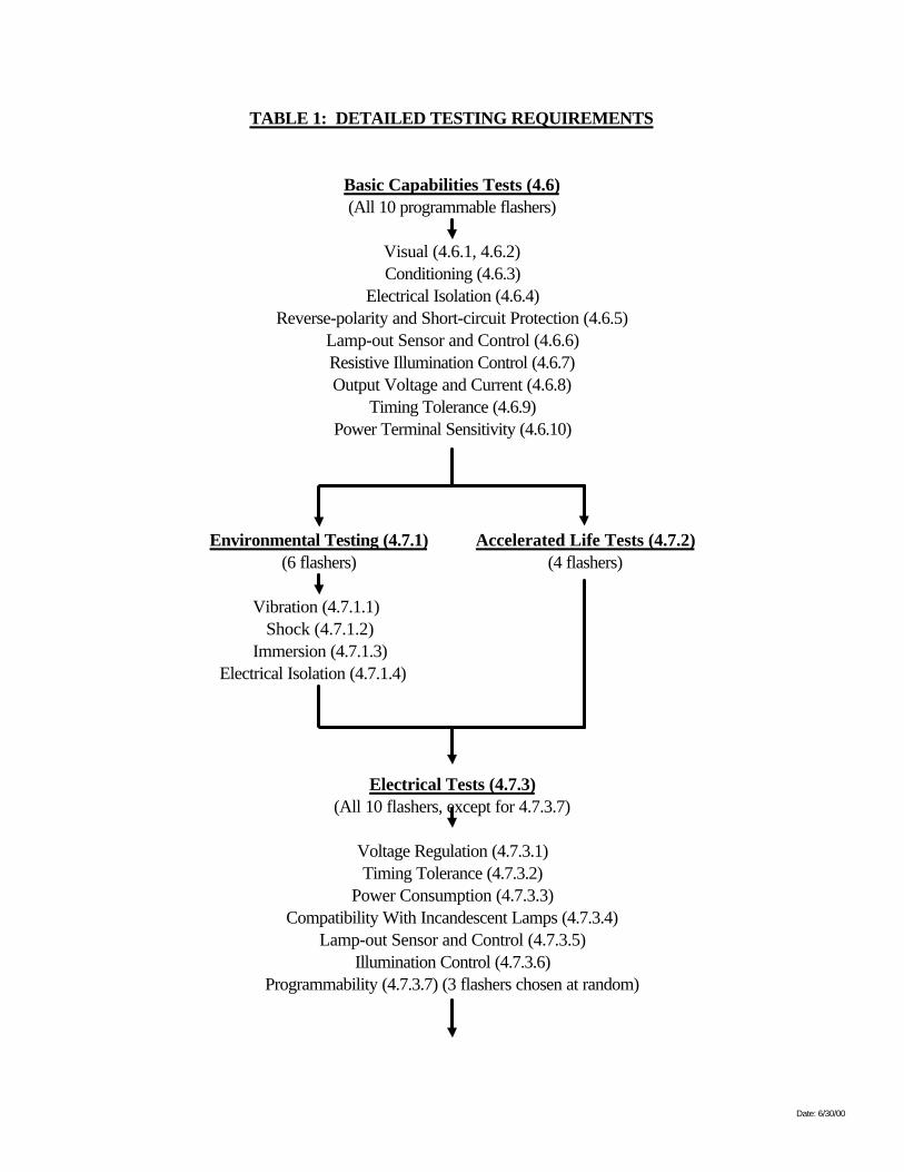
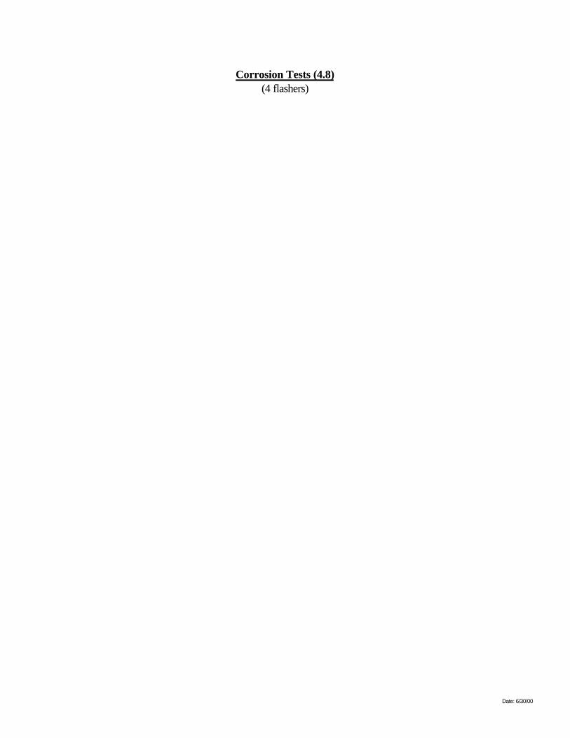
4.5.1.1 First Article Test. Ten programmable flashers shall be submitted for first article testing. All tenflashers shall be subjected to the Basic Capabilities Tests (4.6). At the conclusion of the BasicCapabilities Tests six flashers shall be subjected to the Environmental Tests (4.7.1) and the other fourflashers shall be subjected to the Accelerated Life Tests (4.7.2). At the conclusion of these tests, all tenflashers shall be subjected to the Electrical Tests (4.7.3) except Programmability Test (4.7.3.7); i.e.,three of the ten flashers from 4.7.3 shall be chosen at random and subjected to the ProgrammabilityTest (4.7.3.7). At the conclusion of the Electrical Tests, four flashers shall be subjected to theCorrosion Resistance Tests (4.8). Tests shall be performed on all of the flashers regardless of failures.Table 1 details the first article testing requirements.
Date: 6/30/00
TABLE 1: DETAILED TESTING REQUIREMENTS
Basic Capabilities Tests (4.6)(All 10 programmable flashers)
Visual (4.6.1, 4.6.2)Conditioning (4.6.3)
Electrical Isolation (4.6.4)Reverse-polarity and Short-circuit Protection (4.6.5)
Lamp-out Sensor and Control (4.6.6)Resistive Illumination Control (4.6.7)Output Voltage and Current (4.6.8)
Timing Tolerance (4.6.9)Power Terminal Sensitivity (4.6.10)
Environmental Testing (4.7.1) Accelerated Life Tests (4.7.2)(6 flashers) (4 flashers)
Vibration (4.7.1.1)Shock (4.7.1.2)
Immersion (4.7.1.3)Electrical Isolation (4.7.1.4)
Electrical Tests (4.7.3)(All 10 flashers, except for 4.7.3.7)
Voltage Regulation (4.7.3.1)Timing Tolerance (4.7.3.2)
Power Consumption (4.7.3.3)Compatibility With Incandescent Lamps (4.7.3.4)
Lamp-out Sensor and Control (4.7.3.5)Illumination Control (4.7.3.6)
Programmability (4.7.3.7) (3 flashers chosen at random)
Date: 6/30/00
Corrosion Tests (4.8)(4 flashers)
Date: 6/30/00
4.5.1.2 Flasher Submission. Flashers submitted for first article testing shall be representative of themanufacturer's proposed normal production. The first article test flashers shall be programmed toprovide two samples each of the Iso 6, FL4(.4), FL(2+1)6, and Mo(A) and one sample of the Q andFIXED rhythms as defined in 3.9.7.1. Flashers submitted for testing will become the property of thegovernment.
4.5.1.3 Acceptance Level. All flashers submitted for first article testing must comply with theacceptance/rejection criteria for the Basic Capabilities Tests (4.6), Environmental Tests (4.7.1),Electrical Tests (4.7.3) and Corrosion Resistance Tests (4.8).
4.5.1.4. Approval of First Article Flashers. The contractor shall submit a final test report along with theten first article flashers to the SPA within 15 days of the conclusion of first article testing. The reportshall contain all information in the test plan and all data, including, but not limited to, data gathered fromsubcontractors used in first article testing. Upon receipt of the final test report, the SPA will review itfor completeness and to ensure the flashers have met the requirements of the specification. Uponapproval of the final test report by the SPA, the Contracting Officer (KO) will officially accept the firstarticle flashers and the final test report and allow production to commence.
4.6 Basic Capabilities Tests. Programmable flashers shall be subjected to a series of initial tests toverify the Basic Capabilities of the flasher. Unless otherwise specified, the flashers shall be powered bya DC power supply set at 12.0 ± 0.1 volts input for the Basic Capabilities Tests.
4.6.1 Visual Inspection. Each flasher shall be visually inspected to see that the terminals and terminalmarkings are properly placed and legible (3.5.4).
4.6.2 Mechanical Conformation to Specifications and Drawings. Measure the following features toensure compliance with the specification:
a. Dimensions (3.5.1);
b. Number, location, and depth of screw entrance into mounting holes (3.5.2);
c. Number, thread-type, location, and length of terminal screws (3.5.3); and
d. Size of slotted terminal insulators and compatibility with three, 11/32" spade or hook lugs.Sufficient height to insulate terminals with one lug in place. Terminal insulators not to extendabove the mounting surfaces (3.5.3).
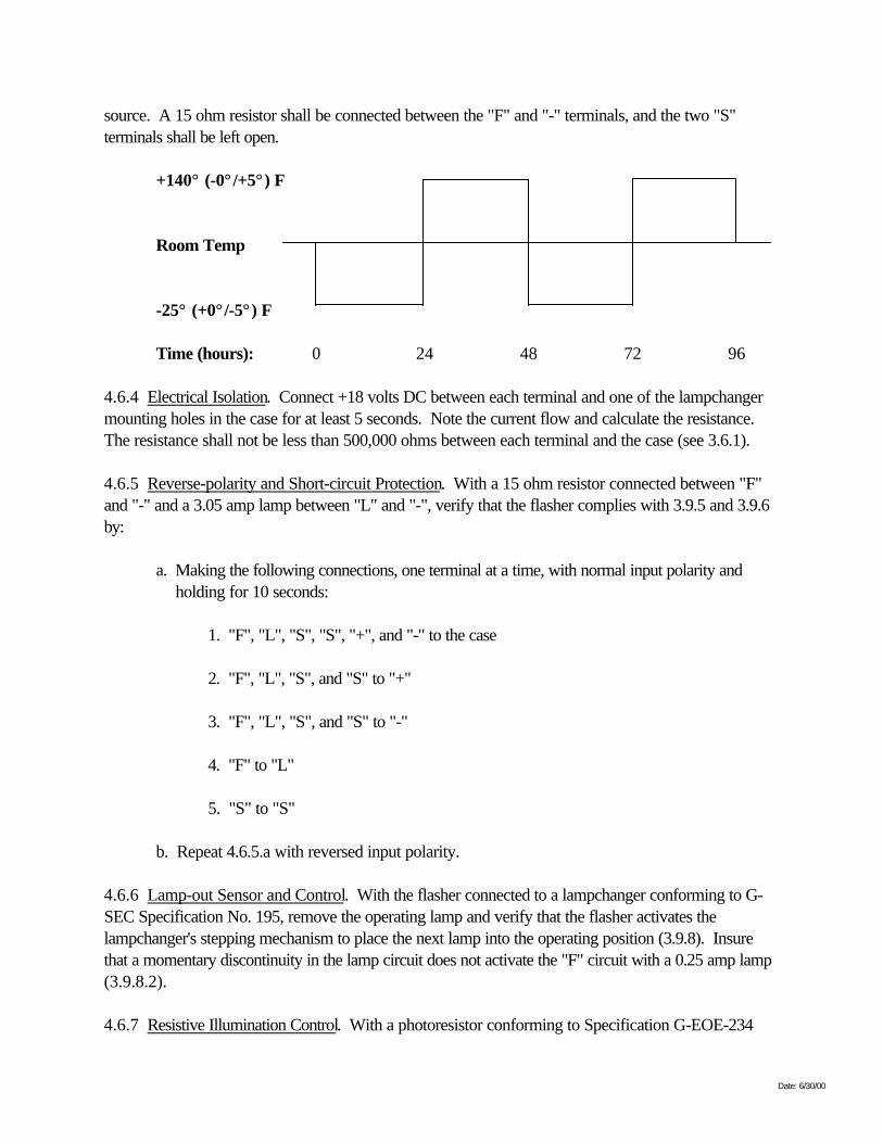
4.6.3 Conditioning. All flashers submitted for first article testing will be conditioned by subjecting themto two 48-hour cycles of temperature variation consisting of 24 hours at -25° (+0°/-5°) F and 24 hoursat 140° (+5°/-0°) F. The transitions between temperature extremes shall be accomplished within a twohour period, which shall commence at the end of each 24 hour segment of the test. During thetemperature cycling, each flasher shall operate a 0.25 amp lamp from a 15 volt DC power supply
Date: 6/30/00
source. A 15 ohm resistor shall be connected between the "F" and "-" terminals, and the two "S"terminals shall be left open.
+140° (-0° /+5° ) F
Room Temp
-25° (+0° /-5° ) F
Time (hours): 0 24 48 72 96
4.6.4 Electrical Isolation. Connect +18 volts DC between each terminal and one of the lampchangermounting holes in the case for at least 5 seconds. Note the current flow and calculate the resistance.The resistance shall not be less than 500,000 ohms between each terminal and the case (see 3.6.1).
4.6.5 Reverse-polarity and Short-circuit Protection. With a 15 ohm resistor connected between "F"and "-" and a 3.05 amp lamp between "L" and "-", verify that the flasher complies with 3.9.5 and 3.9.6by:
a. Making the following connections, one terminal at a time, with normal input polarity andholding for 10 seconds:
1. "F", "L", "S", "S", "+", and "-" to the case
2. "F", "L", "S", and "S" to "+"
3. "F", "L", "S", and "S" to "-"
4. "F" to "L"
5. "S" to "S"
b. Repeat 4.6.5.a with reversed input polarity.
4.6.6 Lamp-out Sensor and Control. With the flasher connected to a lampchanger conforming to G-SEC Specification No. 195, remove the operating lamp and verify that the flasher activates thelampchanger's stepping mechanism to place the next lamp into the operating position (3.9.8). Insurethat a momentary discontinuity in the lamp circuit does not activate the "F" circuit with a 0.25 amp lamp(3.9.8.2).
4.6.7 Resistive Illumination Control. With a photoresistor conforming to Specification G-EOE-234
Date: 6/30/00
connected between the two "S" terminals, verify that the illumination-control circuitry will turn the flasheron and off as required in 3.10. Verify that the flashing lamp does not spuriously activate the illuminationcontrol circuitry or cause the light to flash on a changed rhythm (3.10.2). Using a variable resistorconnected between the "S" terminals, measure the turn on and turn off resistances and verify compliancewith the requirements of 3.10.1.
4.6.8 Output Voltage and Current. For input voltages of 16.0 (18.0 for 0.25 amp lamp), 12.4, and10.0 VDC verify conformance with the requirement for output voltage and output current (3.9.2, 3.9.3)when flashing a 0.25 and 3.05 amp lamp.
4.6.9 Flasher Rhythm Timing Tolerance. For all flashers, measure the flash and eclipse lengths of alltiming rhythms. Measure the rhythms of each flasher while powering 0.25 and 3.05 amp lamps using adigital timer triggering off the positive and negative slopes of the voltage pulse. Calculate the period andduty cycle to verify compliance with the requirements of 3.9.7.3.
4.6.10 Power Terminal Sensitivity. Connect the flasher to a 12 volt DC power source, a CG-6Plampchanger with lamps, and a photoresistor. Turn on the power source and cover the photoresistor,causing the lamp to display the rhythm selected. Next, mechanically disconnect and reconnect thepositive terminal to the power source. Allow two seconds for the flasher circuitry to warm-up and thenrecord the rhythm the flasher displays. Flashers displaying a rhythm different from that selected after thetwo second warm-up period or which cause the lampchanger to advance position are defective.Disconnect and reconnect the positive terminal a minimum of ten times per flasher and record the flasherrhythm and lampchanger action as described above.
4.6.11 Acceptance/Rejection Criteria. Failure of any one flasher to comply with all aspects of theBasic Capabilities Tests (4.6) shall constitute a failure of the entire first article test procedure.
4.7 Laboratory Tests. After completion of the Basic Capabilities Tests (4.6), the ten flashers submittedfor first article testing shall be subjected to a series of Laboratory Tests. Six flashers will be subjectedto Environmental Tests (4.7.1) concurrently with four flashers being subjected to the Accelerated LifeTest (4.7.2). After completion of the Environmental Tests (4.7.1) and the Accelerated Life Test(4.7.2), all ten flashers will be subjected to the Electrical Tests (4.7.3).
4.7.1 Environmental Tests. Six flashers shall undergo Environmental Tests. All six flashers will besubjected to each test in the order listed below.
4.7.1.1 Vibration. Flashers shall be tested in accordance with MIL-STD-202, Method 204-D withthe duration reduced to three 20 minute cycles and the amplitude held at 10 G's in each of threemutually perpendicular directions for a total of 180 minutes. The flasher shall be rigidly attached to afixture capable of transmitting all of the vibration conditions.
4.7.1.2 Shock. Flashers shall be tested in accordance with MIL-STD-202, Method 213-B. Flashersshall be rigidly mounted and subjected to ten blows of 11 milliseconds duration, 40G peak acceleration,
Date: 6/30/00
sawtooth pulse. The ten blows shall be struck three in one direction, three in another direction, and fourin another direction, for a total of three mutually perpendicular directions.
4.7.1.3 Immersion. Flashers shall be completely immersed in tap water at 68° ± 18° F for two hours.The flashers shall be immersed so that the uppermost portion of the case is at least six inches below thesurface of the water. Air dry and inspect the exterior for separation of parts, dissolving of compounds,adhesives, or other deterioration which could cause the flasher to fail.
4.7.1.4 Environmental Test Evaluation. At the conclusion of the Environmental Tests, subject all sixflashers to the Electrical Isolation Test (4.6.4).
4.7.1.5 Acceptance/Rejection Criteria. Two flashers with an isolation between the lampchangermounting holes and any terminal of less than 500,000 ohms at the conclusion of the Environmental Tests(4.7.1) shall constitute a failure of the entire first article test procedure.
4.7.2 Accelerated Life Test. The four flashers not subjected to the Environmental Tests (4.7.1) shallbe subjected to two Accelerated Life Tests. Accelerated Life Test number 1 shall consist of operatingthe four flashers at 140° (+5°/-0°) F and ambient relative humidity for a period of 360 hours (15complete days). The flashers, with a photoresistor conforming to Specification G-EOE-234, and a 15ohm resistor connected between the "F" and "-" terminals, shall be cycled while operating a 0.55 amplamp and powered by 12 volt power supply.
The test procedure is as follows:
a. In a darkened test chamber, with an input voltage of 16.0 volts DC, operate the flasher for120 hours;
b. Decrease the input voltage to 10.0 volts DC and operate in this condition for 120 hours;
c. At the end of a 15-minute shut-down period energize the flashers and operate at 12.4 voltsDC for 120 hours;
d. From the 120th to the 132nd hour and the 240th to the 252nd hour of the test, the ambientillumination in the test chamber shall be raised to 100 foot-candles to insure that all flashersare turned off by their daylight controls.
Accelerated Life Test number 2 shall consist of operating the "F" circuit of the flasher at70° ± 5° F. The four flashers shall be operated with the "S" and "L" terminals open, a 15 ohm, 250millihenry load, such as the solenoid coil in a CG-6P lampchanger (GFP), connected between the "F"and "-" terminals, and 12.0 volts DC input to the "+" and "-" terminals. Voltage pulses between the "F"and "-" terminals shall be monitored with a voltmeter or pulse counter so that resistive-inductive load isenergized 50 times.
Date: 6/30/00
4.7.2.1 Acceptance/Rejection Criteria. There are no pass/fail criteria for the Accelerated Life Tests.Operation in the Electrical Tests (4.7.3) serves to verify flasher performance.
4.7.3 Electrical Tests. All ten flashers will be subjected to a series of Electrical Tests to verify theirability to function within specification at several temperatures with various loads and power sourcecombinations. To simulate a primary battery, use a regulated, transformer-rectified DC power supply.This power supply shall be regulated such that the closed circuit input voltage to a non-fixed modeflasher, when operating a 3.05 amp lamp, remains within 0.1 volts of the no-load power supply voltage.It is recommended that a 40 amp power supply, with an external capacitor bank of 68,000 microfaradsconnected across the output leads, be used to meet this requirement. Test the flashers using thefollowing combinations:
Closed CircuitCombination Input Voltage Lamp Load
I 16.0 VDC 3.05 ampsII 12.4 0.55III 10.0 3.05
To test the flashers' capability to operate with secondary batteries, use a 75-100 amp-hour lead-acidstorage battery in the following combinations:
Combination Lamp Load
IV 0.55 ampsV 3.05
Unless otherwise specified each Electrical Test will be conducted under the following conditions: Attwo temperature levels [-25° (+0°/-5°) F and 140° (+5°/-0°) F] for all five power source and loadcombinations listed above, and with the "S" terminals open, and a 15 ohm resistor between the "F" and"-" terminals.
4.7.3.1 Voltage Regulation. For all conditions, verify that the difference between the input voltage andthe output voltage at the "L" and "-" terminal complies with the requirements of 3.9.2.
4.7.3.2 Timing Tolerance. For all conditions verify that the flash length, eclipse length, duty cycle andperiod complies with the requirements of 3.9.7.3.
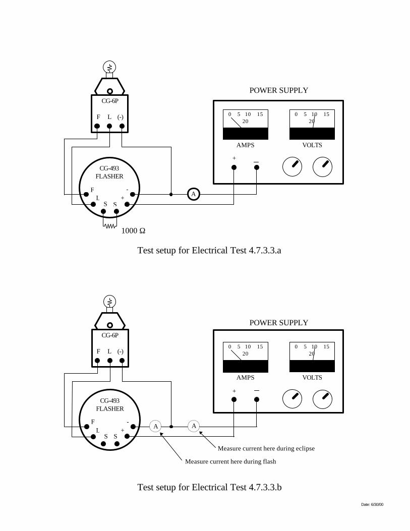
4.7.3.3 Power Consumption. For all conditions, verify that the flasher complies with the powerconsumption requirements of 3.9.4 by completing the following measurements:
a. With a 1000 ohm resistor across the "S" terminals, measure the input current to the "idling"flashers, inclusive of the lamp load.
Date: 6/30/00
b. With the "S" terminals open, measure the parasitic current drawn by the flasher, exclusive oflamp load, with a lamp energized (during flash). Measure the parasitic current with the lampoff (during eclipse), inclusive of the lamp load.
It is recommended that the circuit shown in Figure 2 be used to make these measurements.
Date: 6/30/00
Test setup for Electrical Test 4.7.3.3.a
-+L
SS
F
CG-493FLASHER
A
0 5 10 1520
AMPS
0 5 10 1520
VOLTS
+
POWER SUPPLY
1000 Ω
CG-6P
F L (-)
Test setup for Electrical Test 4.7.3.3.b
CG-6P
F L (-)
-+L
SS
F
CG-493FLASHER
A
0 5 10 1520
AMPS
0 5 10 1520
VOLTS
+
POWER SUPPLY
A
Measure current here during eclipse
Measure current here during flash
Figure 2
Date: 6/30/00
4.7.3.4 Compatibility With Incandescent Lamps. With power and lamp combinations IV and V, verifythat the flashers comply with the voltage rise and decay times required in 3.9.9.
4.7.3.5 Lamp-out Sensor and Control. All Lamp-out Sensor and Control Tests are to be conductedwith a 15 ohm resistive 250 millihenry inductive load, such as the solenoid coil in a CG-6P lampchanger,connected across the "F" and "-" terminals as follows:
a. "F" Signal On. Unless otherwise specified, for each flasher and for input voltages of 18.0and 10.0 volts DC, supplied by a power supply, and with the "S" terminals open:
1. Verify that the "F" circuit is NOT activated with a 0.25 amp lamp or a 56 ohmresistor as the "L" load.
2. Verify activation of the "F" circuit with an open circuit as the "L" load using anormally-closed switch between the flasher and the lamp.
3. Verify that the "F" circuit voltage pulse is between 8.0 and 18.0 volts DC, 0.25 to5.0 seconds in length, and at least one pulse every 15 seconds.
b. No "Daytime" Functioning of Lamp-out Sensor and Control. For input voltages of 10.0 and18.0 volts, a 1,000 ohm resistor across the "S" terminals, and an open-circuit between the"L" and "-" terminals, verify that the potential between the "F" and "-" terminals is less than0.5 volts DC.
4.7.3.6 Illumination Control. Illumination Control Tests shall be conducted at two temperature levels [-25° (+0°/-5°) F and 140° (+5°/-0°) F] for combinations I and III.
a. "Turn-on" and "Turn-off" Resistance. With a variable resistor connected across the "S"terminals, gradually increase the resistance from 5,000 ohms, stopping at and noting the valueat which the lamp begins flashing on rhythm. Gradually reduce the resistance from that value,stopping at and noting the value at which the lamp stops flashing altogether. The resistancesshall comply with requirement of 3.10.1.
b. Bias-voltage. Measure the bias voltage across a 1000 ohm resistor (daytime operation) anda 100,000 ohm resistor (nighttime operation) and verify compliance with the requirements of3.10.1.
c. Spurious Start Operation. Connect a type "C" photoresistor conforming to Specification G-EOE-234 to the "S" terminals of each flasher. With the ambient illumination above the "turn-on" level, and the lamp located 6 inches from the photoresistor, verify that reducing theambient illumination below the "turn-on" level activates the flasher and that the additionalillumination from the lamp does not cause it to operate on a different rhythm (3.10.2).Repeat the above procedure for a total of five times for each condition.
Date: 6/30/00
4.7.3.7 Programmability. Three flashers chosen at random from the ten first article units shall besubjected to the following programmability test:
With a 3.05 amp lamp installed in position one of a CG-6P lampchanger, the DC power supply setat 12.0+0.1 volts, "S" terminals open, and while operating at room temperature (about 25°C), eachsubject flasher shall be swept (programmed) through all sixteen required rhythms while checking for(a) timing tolerance discrepancies (ensure timing is within +5%), and (b) lampchanging functiondiscrepancies (simulate lamp failure by using a normally-closed switch as described in procedure in4.7.3.5-a-2 and verify activation of the "F" circuit).
4.7.3.8 Acceptance/Rejection Criteria. Failure of any flasher to comply with all aspects of the VoltageRegulation (4.7.3.1), Timing Tolerance (4.7.3.2), Power Consumption (4.7.3.3), Compatibility WithIncandescent Lamps (4.7.3.4), Lamp-out Sensor and Control (4.7.3.5), Illumination Control (4.7.3.6),and Programmability (4.7.3.7) Tests shall constitute a failure of the entire first article test procedure.
4.8 Corrosion Resistance. Four flashers, randomly chosen from the ten first article units, shall besubjected to the following test:
4.8.1 Salt Spray (Corrosion). Flashers shall be tested in accordance with MIL-STD-202, usingMethod 101-D, in a 5% salt solution with a 48-hour exposure time. After exposure, exteriors offlashers shall be thoroughly inspected for evidence of susceptibility to corrosion.
4.8.2 Acceptance/Rejection Criteria. Any signs of corrosion or failure of the terminal markings(nameplate) to remain attached to the case on more than one flasher shall constitute failure of the entirefirst article test procedure.
4.9 Production Inspections. The contractor shall maintain an inspection system to ensure each itemoffered to the U.S. Coast Guard for acceptance or approval conforms to the contract requirements.The inspection system shall be documented and available for review by the KO's designatedrepresentative. All items shall meet all requirements of this specification. The inspection set forth in thisspecification shall become a part of the contractor's overall inspection system or quality program. Theabsence of any inspection requirements in the specification shall not relieve the contractor of theresponsibility for ensuring that all deliverables submitted to the U.S. Coast Guard for acceptancecomply with all requirements of the contract. Sampling inspection, as part of manufacturing operations,is an acceptable process to ascertain conformance to requirements. However, this does not authorizesubmission of known defective material, either indicated or actual, nor does it commit the U.S. CoastGuard to accept defective material.
4.9.1 Inspection Lot. A lot shall be all of the flashers from an identifiable production period from onemanufacturer and one plant and submitted for acceptance at one time. The inspection lot shall beinspected for workmanship (3.8), nameplate (3.11), programmable rhythm marking (3.12), subjected tothe Programmability Test (4.7.3.7), and subjected to the Basic Capabilities Tests (4.6) with theexception of Conditioning (4.6.3). Prior to performing any production inspection, including the Basic

Date: 6/30/00
Capabilities Tests and the Programmability Test, each flasher in the production inspection sample shallbe subjected to the following conditioning while powered by a 16 VDC closed circuit input voltage andoperating a 12 VDC, 3.05 amp marine signal lamp: Three hours in an ambient temperature of 140°(+5°/-0°) F, followed by three hours in an ambient temperature of -25° (+0°/-5°) F.
4.9.2 Sampling. The inspection sample size shall be determined using the following table:
Inspection Lot Size Sample Lot Size
16 to 50 351 to 150 5
151 to 500 8501 to 3200 13
3201 to 35000 20
4.9.3 Acceptance/Rejection Criteria. Failure of any flasher in the sample lot shall be cause for rejectionof the entire lot.
4.9.4 Failure Responsibility. If a lot fails to pass production inspection, the contractor shall takecorrective action on the materials or process, or both as warranted, on all items or portions thereofwhich were similarly manufactured and which are subject to the same cause for failure. Depending onthe type and number of failures, the inspection may be discontinued at the discretion of the governmentinspector until all corrective action has been taken. After all corrective action has been taken, theinspection shall be continued or repeated, depending on the reason for which the inspection wasinterrupted. Acceptance shall be withheld until reinspection has shown that the corrective action wassuccessful and the equipment or portion thereof satisfactorily passes all inspections.
4.9.5 Resubmitted Lots. If an inspection lot is rejected, the manufacturer may rework the lot or screenout defectives and resubmit it for inspection. Resubmitted lots shall be kept separate from new lots.
Date: 6/30/00
SPECIFICATION FOR 12VDC SOLID STATE PROGRAMMABLE FLASHER
SPECIFICATION NUMBER: G-SEC-493A
JUNE 2000
Prepared by: Reviewed by:
__________________________ ________________________K. AGI J. T. GRASSONProject Engineer Chief, Signal & Power Team
Approved by:
____________________________ ____________________H. R. CLEVELAND DateChief, Ocean Engineering Division


