Embed Size (px)
Citation preview
THE PERFORMANCE OF BORED MINI PILESIN LONDON CLAY
D R GILLGeotechnical Consulting Group, 52A Cromwell Road, London, SW7 5BE
D J PULLERBachy Soletanche Limited, Units 2 & 5 Prospect Place, Alton, Hampshire, GU34 2SX
H D ST JOHNGeotechnical Consulting Group, 52A Cromwell Road, London, SW7 5BE
SUMMARY: This paper presents the results of loadtesting carried out on the bored mini piles thatwere installed as part of the redevelopment of anoffice building in central London. The testingundertaken included four expendable maintained loadtests and ten Statnamic load tests. The ultimateload capacity in the expendable pile tests wasfound to be lower than was expected in the designand possible reasons for this are discussed inrelation to their method of construction. Statnamicload tests were carried out on the working piles todemonstrate both good workmanship and their load-settlement behaviour. A direct comparison betweenthe Statnamic and maintained load tests wasobtained by carrying out both test methods on thesame working pile. The load-settlement behaviourfrom the Statnamic test has been compared with thestatic load test and its suitability as a reliableproof load test for bored mini piles in stiff clayassessed.
Gill, Puller and St. John. The performance of bored mini piles in London Clay.Proceedings of the BGA International Conference on Foundations, Dundee, Scotland,24 – 27 June 2008. IHS BRE Press, 2008
Keywords: London Clay, maintained load tests, mini piles, pile design, Statnamic test.
INTRODUCTION
Due to reasons of extremely limited headroom, segmentalauger-bored mini piles were selected, to provide the thenew foundations for the redevelopment of an eight storey1950’s reinforced concrete office building at 55 BakerStreet in central London. The mini piling contractcomprised over over 1000 piles, of which the vast majoritywere bored mini piles with the remainder being smalldiameter CFA piles constructed where the headroomconditions allowed. The large number of piles and thisjustified the execution of an extensive pile testing regimewith both expendable and contract pile testing.
In all, four expendable mini pile tests were undertakenand they were found to give lower than expected ultimatecapacity compared with the standard design method for bored piles in London Clay. Mini piles constructed ofboth concrete and grout were load tested and somedifferences in performance were measured. This paperdiscusses possible reasons for the under performance of themini piles, compares the performance of concrete and groutmini piles and makes some recommendations for their design.
The information gained from the expendable pile testingregime on the mini pile ultimate capacity allowed thecontract pile testing to be undertaken using the quickerand cheaper Statnamic test method rather than moretraditional maintained (static) load testing. The Statnamictest is a rapid load test and confidence in the results wasobtained by carrying out both the static and Stanamic testson the same working pile. The performance of the Statnamictest as a proof load test for bored mini piles in stiffclay is evaluated herein.
THE DEVELOPMENT
Gill, Puller and St. John. The performance of bored mini piles in London Clay.Proceedings of the BGA International Conference on Foundations, Dundee, Scotland,24 – 27 June 2008. IHS BRE Press, 2008
The existing structure at 55 Baker Street consisted of aneight storey reinforced concrete office buildingconstructed in the 1950s with a single level basement carpark occupying the entire footprint of the site. Thebuilding is supported on shallow concrete pad foundationsin the London Clay which range in size from about 1.5msquare in plan and 0.9m deep up to 6.7m square in plan and3m deep. The building was in good condition so it wasproposed to redevelop the site by retaining and enhancingthe existing structure rather than completely demolishingit. A central ‘spine’ that connected four separate blocksof the existing building was demolished and this allowedthree new infill structures with glass facades and roofs tobe constructed to link the building. The infill structureswere proposed to be supported on new piles and wererequired to have tight settlement criteria so that therelative settlement between the existing and new structureswould be small. The piling specification required a maximumsettlement of 6mm for a static load test at the designworking load.
Mini piling rather than conventional bored piling wasselected to allow the pile construction to proceed inparallel with the demolition works. The piling took placewithin the basement car park where the existing groundfloor slab provided a protective cover to piling operationsfrom the demolition work taking place above. The headroomin the basement was typically about 3.2m, although thisreduced to 2.5m below the ground floor beams. The minipiling contract was undertaken by Bachy Soletanche inpartnership with System Geotechnique. The GeotechnicalConsulting Group provided geotechnical advice to ExpeditionEngineering, who acted as the Engineer for the project.
GROUND CONDITIONS
The ground conditions below basement slab were typically0.5 to 1.5m of superficial deposits, comprising Made Groundor River Terrace Deposits overlying approximately 35m ofLondon Clay. Groundwater was generally encountered about0.5m below the basement slab level.Gill, Puller and St. John. The performance of bored mini piles in London Clay.Proceedings of the BGA International Conference on Foundations, Dundee, Scotland,24 – 27 June 2008. IHS BRE Press, 2008
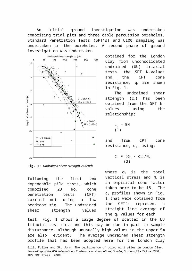
An initial ground investigation was undertakencomprising trial pits and three cable percussion boreholes.Standard Penetration Tests (SPT’s) and U100 sampling wasundertaken in the boreholes. A second phase of groundinvestigation was undertaken
cu = 52+9.5z kPa (z<17m )
cu = 204+5z kPa (z>17m )
0
5
10
15
20
25
30
35
0 50 100 150 200 250 300Undrained shear strength, cu (kPa)
Depth below
basment le
vel (m)
U U TriaxialSPTCPT
SPT: cu = 5N (kPa)CPT: cu = (qc - σv)/N k (kPa) N k = 18
Fig. 1: Undrained shear strength vs depth
following the first twoexpendable pile tests, whichcomprised 23 No. conepenetration tests (CPT)carried out using a lowheadroom rig. The undrainedshear strength values
obtained for the LondonClay from unconsolidatedundrained (UU) triaxialtests, the SPT N-valuesand the CPT coneresistance, qc are shownin Fig. 1.
The undrained shearstrength (cu) has beenobtained from the SPT N-values using therelationship;
cu = 5N(1)
and from CPT coneresistance, qc, using;
cu = (qc - σv)/Nk (2)
where σv is the totalvertical stress and Nk isan empirical cone factortaken here to be 18. Thecu profiles shown in Fig.1 that were obtained fromthe CPT’s represent astraight line average ofthe qc values for each
test. Fig. 1 shows a large degree of scatter in the UUtriaxial test data and this may be due in part to sampledisturbance, although unusually high values in the upper 5mare also evident. The average undrained shear strengthprofile that has been adopted here for the London ClayGill, Puller and St. John. The performance of bored mini piles in London Clay.Proceedings of the BGA International Conference on Foundations, Dundee, Scotland,24 – 27 June 2008. IHS BRE Press, 2008
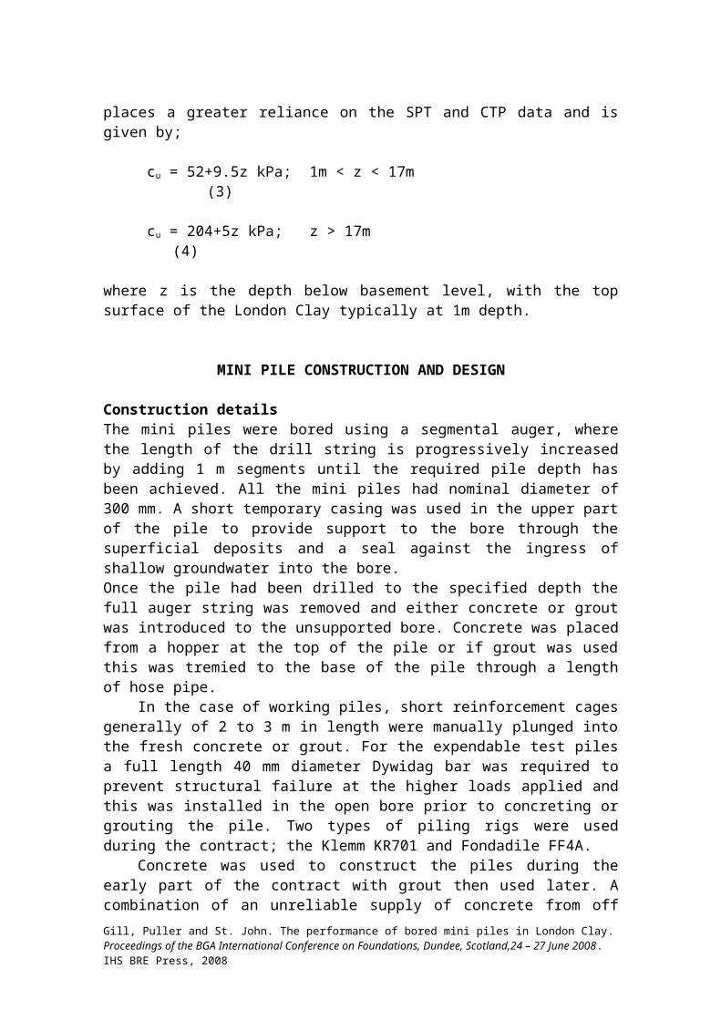
places a greater reliance on the SPT and CTP data and isgiven by;
cu = 52+9.5z kPa; 1m < z < 17m (3)
cu = 204+5z kPa; z > 17m (4)
where z is the depth below basement level, with the topsurface of the London Clay typically at 1m depth.
MINI PILE CONSTRUCTION AND DESIGN
Construction detailsThe mini piles were bored using a segmental auger, wherethe length of the drill string is progressively increasedby adding 1 m segments until the required pile depth hasbeen achieved. All the mini piles had nominal diameter of300 mm. A short temporary casing was used in the upper partof the pile to provide support to the bore through thesuperficial deposits and a seal against the ingress ofshallow groundwater into the bore. Once the pile had been drilled to the specified depth thefull auger string was removed and either concrete or groutwas introduced to the unsupported bore. Concrete was placedfrom a hopper at the top of the pile or if grout was usedthis was tremied to the base of the pile through a lengthof hose pipe.
In the case of working piles, short reinforcement cagesgenerally of 2 to 3 m in length were manually plunged intothe fresh concrete or grout. For the expendable test pilesa full length 40 mm diameter Dywidag bar was required toprevent structural failure at the higher loads applied andthis was installed in the open bore prior to concreting orgrouting the pile. Two types of piling rigs were usedduring the contract; the Klemm KR701 and Fondadile FF4A.
Concrete was used to construct the piles during theearly part of the contract with grout then used later. Acombination of an unreliable supply of concrete from offGill, Puller and St. John. The performance of bored mini piles in London Clay.Proceedings of the BGA International Conference on Foundations, Dundee, Scotland,24 – 27 June 2008. IHS BRE Press, 2008
site and the slowness of transporting the concrete to eachpile in the hopper of low headroom excavators led to theswitch. The grout could be batched on site and easilypumped to piles located in any part of the site.
Pile designThe piles were designed using the conventional approach forstraight shafted bored piles in London Clay as described inthe London District Surveyors’ Association (LDSA) guidancenotes 1. This approach uses the undrained shear strengthmeasured in UU triaxial tests on 100 mm samples tocalculate pile shaft and base capacity. The shaft frictionis related by an empirical adhesion or ‘α’ factor to theaverage undrained shear strength (cu) over the depth of theshaft. The shaft capacity, Qs is therefore given by;
Qs = πDLαcu
(5)
where D is the pile diameter and L is the pile length. Thebase capacity, Qb is given by;
Qb = π(D2/4)Nccub
(6)
where Nc is the bearing capacity factor (Nc = 9) and cub isthe undrained shear strength at the pile base. Fromexperience in London Clay for straight shafted bored pilesα is taken to be 0.5 or 0.6 depending on the pile testingregime undertaken and the Factor of Safety (FoS) applied tothe combined shaft and base capacities.
The piling contractor’s initial design took α = 0.6 andFoS = 2.0 with the design load to be demonstrated bycarrying out two preliminary pile tests, one in thenorthern part of the site and one in the south. This designgave a maximum pile length of 17.5m for a 300 mm diametermini pile with the maximum design working load of 705 kN.The subsequent redesign, which is discussed later, extendedthe maximum pile length to 23m for a design load of 705kN.
Gill, Puller and St. John. The performance of bored mini piles in London Clay.Proceedings of the BGA International Conference on Foundations, Dundee, Scotland,24 – 27 June 2008. IHS BRE Press, 2008
EXPENDABLE PILE TESTING
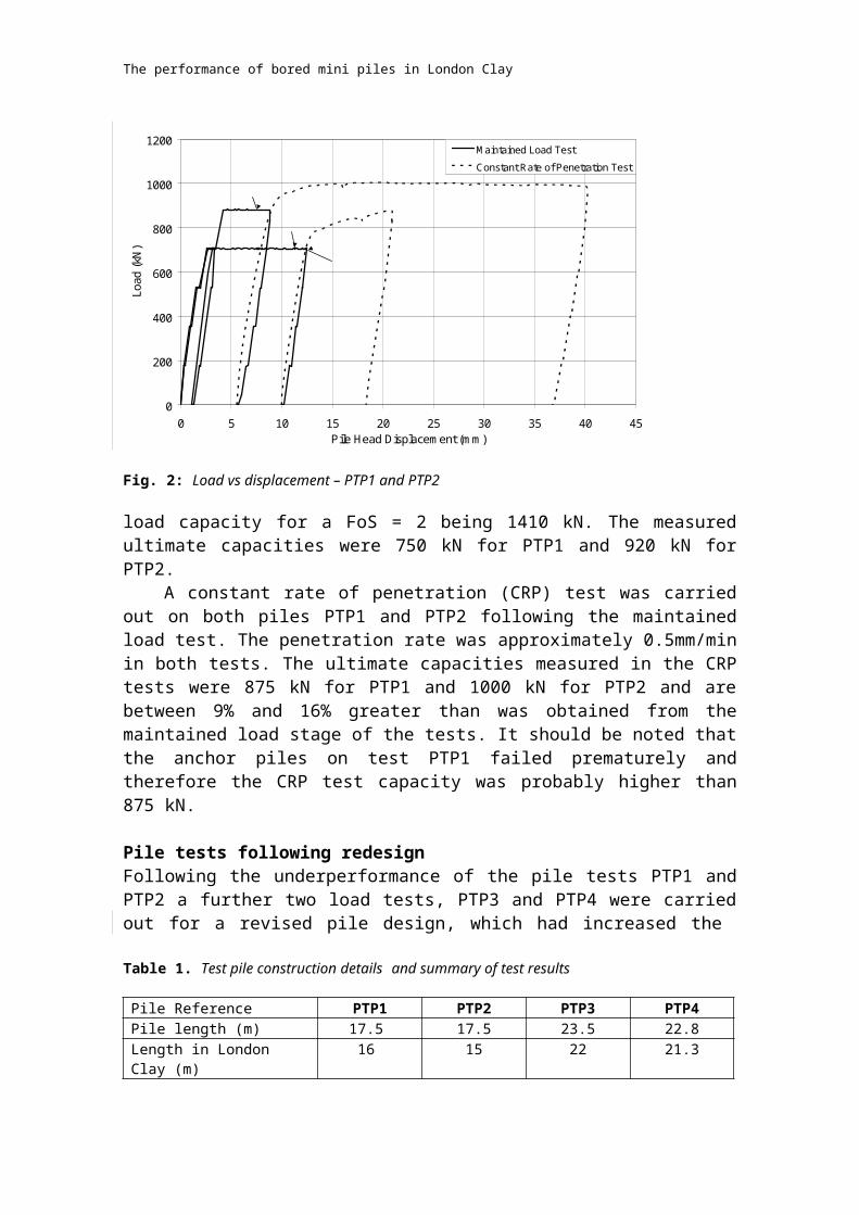
Initial pile testingThe load vs displacement results of the first twopreliminary pile tests, PTP1 and PTP2 are presented in Fig.2 and their as-built construction details are given inTable 1. The design verification load (DVL) for both testswas 705 kN with the required ultimate
Gill, Puller and St. John. The performance of bored mini piles in London Clay.Proceedings of the BGA International Conference on Foundations, Dundee, Scotland,24 – 27 June 2008. IHS BRE Press, 2008
The performance of bored mini piles in London Clay
0
200
400
600
800
1000
1200
0 5 10 15 20 25 30 35 40 45Pile Head Displacem ent (m m )
Load (kN)
M aintained Load TestConstant Rate of Penetration Test
PTP2
PTP1
Pile displacem ent not stabilised
Fig. 2: Load vs displacement – PTP1 and PTP2
load capacity for a FoS = 2 being 1410 kN. The measuredultimate capacities were 750 kN for PTP1 and 920 kN forPTP2.
A constant rate of penetration (CRP) test was carriedout on both piles PTP1 and PTP2 following the maintainedload test. The penetration rate was approximately 0.5mm/minin both tests. The ultimate capacities measured in the CRPtests were 875 kN for PTP1 and 1000 kN for PTP2 and arebetween 9% and 16% greater than was obtained from themaintained load stage of the tests. It should be noted thatthe anchor piles on test PTP1 failed prematurely andtherefore the CRP test capacity was probably higher than875 kN.
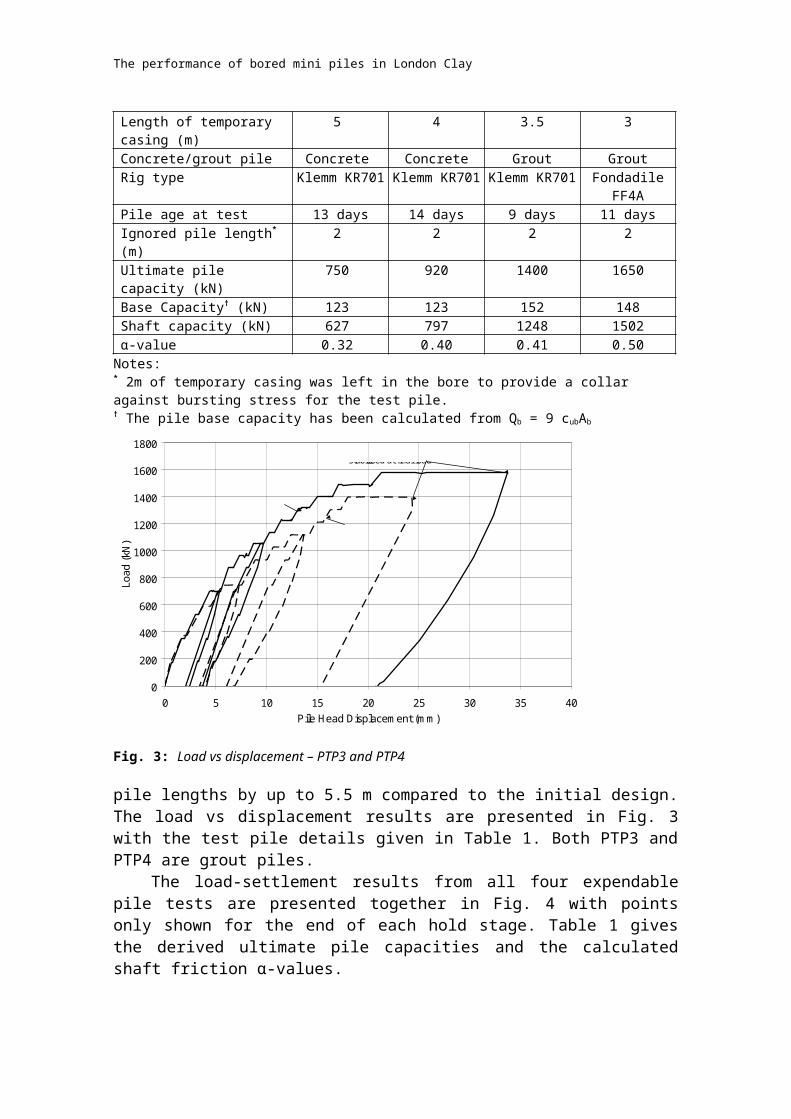
Pile tests following redesignFollowing the underperformance of the pile tests PTP1 andPTP2 a further two load tests, PTP3 and PTP4 were carriedout for a revised pile design, which had increased the
Table 1. Test pile construction details and summary of test results
Pile Reference PTP1 PTP2 PTP3 PTP4Pile length (m) 17.5 17.5 23.5 22.8Length in London Clay (m)
16 15 22 21.3
The performance of bored mini piles in London Clay
Length of temporary casing (m)
5 4 3.5 3
Concrete/grout pile Concrete Concrete Grout GroutRig type Klemm KR701 Klemm KR701 Klemm KR701 Fondadile
FF4APile age at test 13 days 14 days 9 days 11 daysIgnored pile length* (m)
2 2 2 2
Ultimate pile capacity (kN)
750 920 1400 1650
Base Capacity† (kN) 123 123 152 148Shaft capacity (kN) 627 797 1248 1502α-value 0.32 0.40 0.41 0.50Notes: * 2m of temporary casing was left in the bore to provide a collar against bursting stress for the test pile.† The pile base capacity has been calculated from Qb = 9 cubAb
0
200
400
600
800
1000
1200
1400
1600
1800
0 5 10 15 20 25 30 35 40Pile Head Displacem ent (m m )
Load (kN)
Pile displacem ent not stabilised at final load
PTP3
PTP4
Fig. 3: Load vs displacement – PTP3 and PTP4
pile lengths by up to 5.5 m compared to the initial design.The load vs displacement results are presented in Fig. 3with the test pile details given in Table 1. Both PTP3 andPTP4 are grout piles.
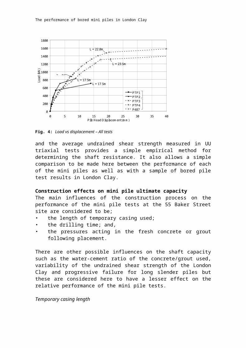
The load-settlement results from all four expendablepile tests are presented together in Fig. 4 with pointsonly shown for the end of each hold stage. Table 1 givesthe derived ultimate pile capacities and the calculatedshaft friction α-values.
The performance of bored mini piles in London Clay
The concrete piles (PTP1 and PTP2) show a stiffer load-settlement response until the ultimate capacity isapproached. This is due to the higher Young’s Modulus (E)of concrete compared to grout. From back-analysis of thepile tests it is estimated that Econcrete ≈ 30 MPa and Egrout ≈16 MPa, with pile settlement approximately 60% greater forthe grout piles at working loads. However, there is someevidence to suggest that the α-values calculated for theconcrete piles are lower than for the grout piles. Theaverage α-value for the concrete piles is 0.36 and for thegrout piles is 0.46. Factors that are considered toinfluence the pile shaft friction are discussed in thefollowing section.
DISCUSSION OF MINI PILE ULTIMATE SHAFT CAPACITY
Design MethodPile shaft resistance is defined here in terms of totalstress using undrained adhesion, the product of theempirical parameter α and undrained shear strength1 sincethis is the most convenient and commonly used design methodfor bored piles in London Clay. It has been recognised by anumber of authors (e.g., Burland and Twine 2) that duringmaintained load tests drainage is able to take place in thethin layer of clay immediately at the interface between thepile shaft and soil. As such, the use of effective stressdesign methods for the design of bored piles in clay havebeen advocated, particularly where significant stresschanges are expected to take place in the ground, forexample due to deep basement excavation following pileconstruction. However, the influence of the pileconstruction process on shaft capacity is complex and theuse of an α-value
The performance of bored mini piles in London Clay
L = 17.5mL = 17.5m
L = 23.5m
L = 22.8m
0
200
400
600
800
1000
1200
1400
1600
1800
0 5 10 15 20 25 30 35 40Pile Head Displacem ent (m m )
Load (kN)
PTP1PTP2PTP3PTP4P487
L = 23m
Grout Piles
Concrete Piles
Fig. 4: Load vs displacement – All tests
and the average undrained shear strength measured in UUtriaxial tests provides a simple empirical method fordetermining the shaft resistance. It also allows a simplecomparison to be made here between the performance of eachof the mini piles as well as with a sample of bored piletest results in London Clay.
Construction effects on mini pile ultimate capacityThe main influences of the construction process on theperformance of the mini pile tests at the 55 Baker Streetsite are considered to be;• the length of temporary casing used; • the drilling time; and,• the pressures acting in the fresh concrete or grout
following placement.
There are other possible influences on the shaft capacitysuch as the water-cement ratio of the concrete/grout used,variability of the undrained shear strength of the LondonClay and progressive failure for long slender piles butthese are considered here to have a lesser effect on therelative performance of the mini pile tests.
Temporary casing length
The performance of bored mini piles in London Clay
Due to the shallow depth to London Clay through thesuperficial deposits at the site it was expected that onlyshort temporary casings of typically 2m in length would berequired. However, as is shown in Table 1, greater casinglengths than this were actually used for the test piles.The additional casing length was required to achieve aneffective seal into the London Clay to prevent shallowgroundwater from entering the bore. The spinning of thecasing into the ground with water present at the casing-clay interface is likely to have both a softening andremoulding effect on the clay surface and will potentially reduce the shaft capacity in the upper part ofthe pile. Test piles PTP1 and PTP2 which required casinglengths of 5 m and 4 m, respectively are potentially mostaffected. However, since this upper part of the pileaccounts for only approximately 10% of the total shaftcapacity this is not nearly sufficient on its own toexplain the low shaft friction measured for these piles.
Gill, Puller and St. John
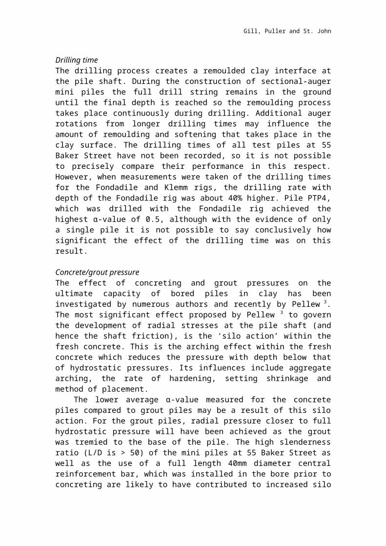
Drilling time The drilling process creates a remoulded clay interface atthe pile shaft. During the construction of sectional-augermini piles the full drill string remains in the grounduntil the final depth is reached so the remoulding processtakes place continuously during drilling. Additional augerrotations from longer drilling times may influence theamount of remoulding and softening that takes place in theclay surface. The drilling times of all test piles at 55Baker Street have not been recorded, so it is not possibleto precisely compare their performance in this respect.However, when measurements were taken of the drilling timesfor the Fondadile and Klemm rigs, the drilling rate withdepth of the Fondadile rig was about 40% higher. Pile PTP4,which was drilled with the Fondadile rig achieved thehighest α-value of 0.5, although with the evidence of onlya single pile it is not possible to say conclusively howsignificant the effect of the drilling time was on thisresult.
Concrete/grout pressureThe effect of concreting and grout pressures on theultimate capacity of bored piles in clay has beeninvestigated by numerous authors and recently by Pellew 3.The most significant effect proposed by Pellew 3 to governthe development of radial stresses at the pile shaft (andhence the shaft friction), is the ‘silo action’ within thefresh concrete. This is the arching effect within the freshconcrete which reduces the pressure with depth below thatof hydrostatic pressures. Its influences include aggregatearching, the rate of hardening, setting shrinkage andmethod of placement.
The lower average α-value measured for the concretepiles compared to grout piles may be a result of this siloaction. For the grout piles, radial pressure closer to fullhydrostatic pressure will have been achieved as the groutwas tremied to the base of the pile. The high slendernessratio (L/D is > 50) of the mini piles at 55 Baker Street aswell as the use of a full length 40mm diameter centralreinforcement bar, which was installed in the bore prior toconcreting are likely to have contributed to increased silo
Gill, Puller and St. John
action. The slow method of placement (i.e., from the top ofthe pile in a series of hopper loads) will also haveallowed some hardening to take place in the concretetowards the base of the pile during the pour.
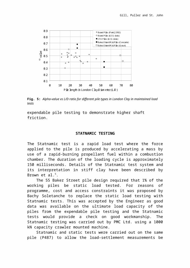
Comparison of bored mini piles with other types of bored pilesFig. 5 plots α-value against the pile length/diameter ratiofor a sample of test pile results in London Clay compiledby Patel 4 and from the Geotechnical Consulting Group’sproject archives. The data allows the comparison of α-values measured in pile tests for conventional bored pilesand continuous flight auger (CFA) piles with the 55 BakerStreet mini piles.
On average the mini pile data plots on the low side ofthe bored pile data. The comparatively small number of CFApile results give the highest α-values. It is likely thatthis is due to both the faster drilling times and thehigher concrete pressures achieved by the CFA method ofconstruction. For example, it is good practice to maintainpositive head pressure during concreting at the point ofmeasurement of a CFA rig. Further, the use of plasticisersin the concrete and the plunging of the reinforcement cagefollowing casting are also likely to increase pressureswithin the fresh concrete and therefore benefit the pileshaft capacity.
Based on the test results from 55 Baker Street it isrecommended that for segmental-auger bored mini piles an α-value of 0.4 should be adopted in the absence of
Gill, Puller and St. John
0.1
0.2
0.3
0.4
0.5
0.6
0.7
0.8
0.9
0 10 20 30 40 50 60 70 80Pile length in London Clay/Diam eter (L/D)
a va
lue
Bored Piles (Patel, 1992)Bored Piles (GCG data)CFA Piles (GCG data)Baker Street M ini Piles (Concrete)Baker Street M ini Piles (Grout)
Fig. 5: Alpha-value vs L/D ratio for different pile types in London Clay in maintained load tests
expendable pile testing to demonstrate higher shaft friction.
STATNAMIC TESTING
The Statnamic test is a rapid load test where the forceapplied to the pile is produced by accelerating a mass byuse of a rapid-burning propellant fuel within a combustionchamber. The duration of the loading cycle is approximately150 milliseconds. Details of the Statnamic test system andits interpretation in stiff clay have been described byBrown et al.5.
The 55 Baker Street pile design required that 1% of theworking piles be static load tested. For reasons ofprogramme, cost and access constraints it was proposed byBachy Soletanche to replace the static load testing withStatnamic tests. This was accepted by the Engineer as gooddata was available on the ultimate load capacity of thepiles from the expendable pile testing and the Statnamictests would provide a check on good workmanship. TheStatnamic testing was carried out by PMC Ltd. using a 1000kN capacity crawler mounted machine.
Statnamic and static tests were carried out on the samepile (P487) to allow the load-settlement measurements be
Gill, Puller and St. John
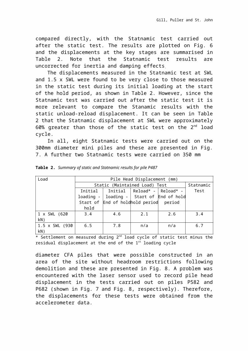
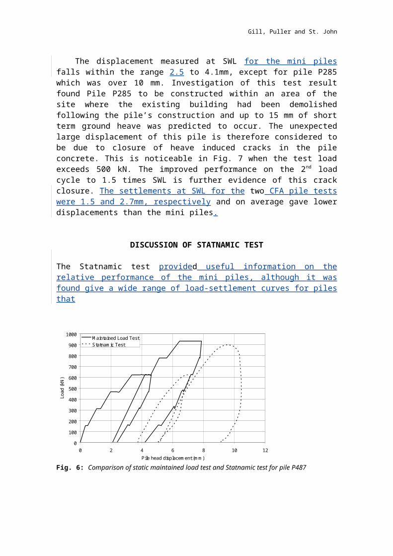
compared directly, with the Statnamic test carried outafter the static test. The results are plotted on Fig. 6and the displacements at the key stages are summarised inTable 2. Note that the Statnamic test results areuncorrected for inertia and damping effects.
The displacements measured in the Statnamic test at SWLand 1.5 x SWL were found to be very close to those measuredin the static test during its initial loading at the startof the hold period, as shown in Table 2. However, since theStatnamic test was carried out after the static test it ismore relevant to compare the Stanamic results with thestatic unload-reload displacement. It can be seen in Table2 that the Statnamic displacement at SWL were approximately60% greater than those of the static test on the 2nd loadcycle.
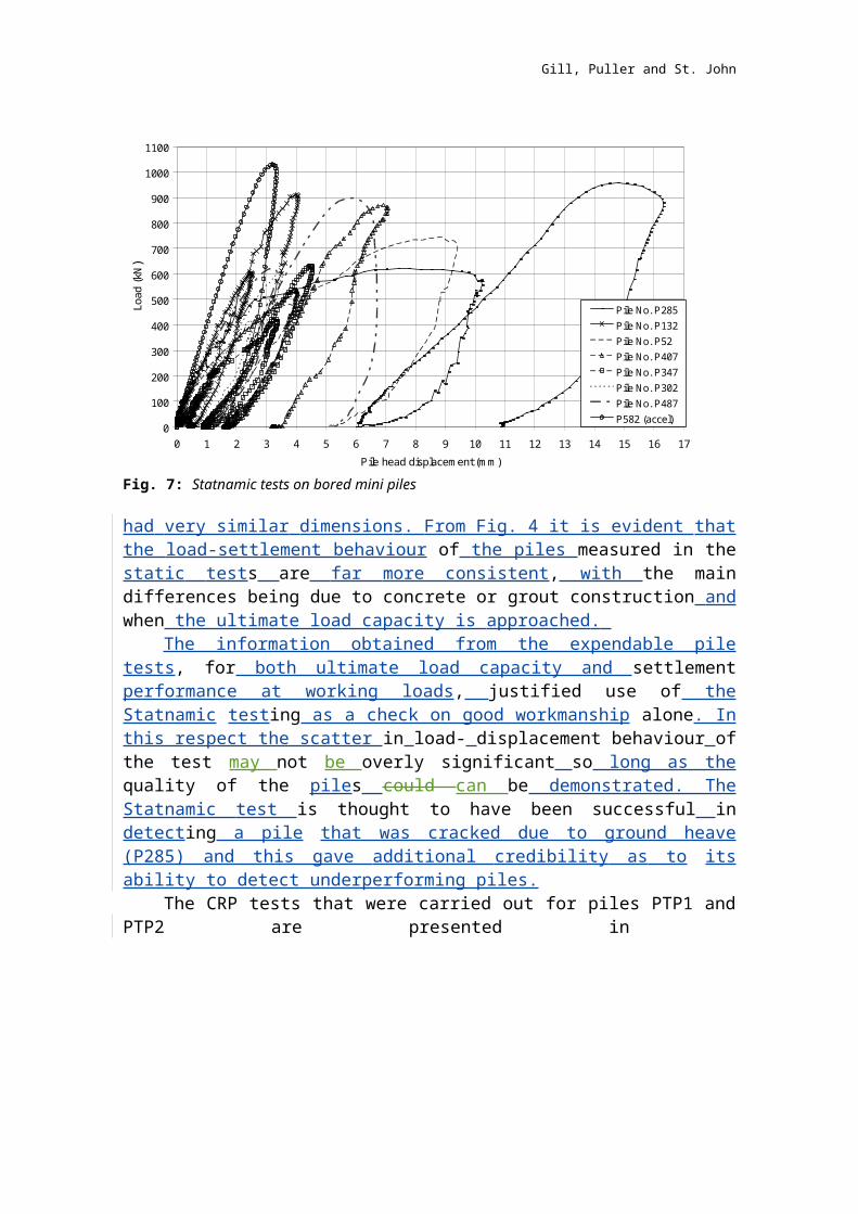
In all, eight Statnamic tests were carried out on the300mm diameter mini piles and these are presented in Fig.7. A further two Statnamic tests were carried on 350 mm
Table 2. Summary of static and Statnamic results for pile P487
Load Pile Head Displacement (mm)Static (Maintained Load) Test Statnamic
TestInitialloading -Start ofhold
Initialloading -End of hold
Reload* -Start of
hold period
Reload* -End of hold
period
1 x SWL (620 kN)
3.4 4.6 2.1 2.6 3.4
1.5 x SWL (930kN)
6.5 7.8 n/a n/a 6.7
* Settlement on measured during 2nd load cycle of static test minus theresidual displacement at the end of the 1st loading cycle
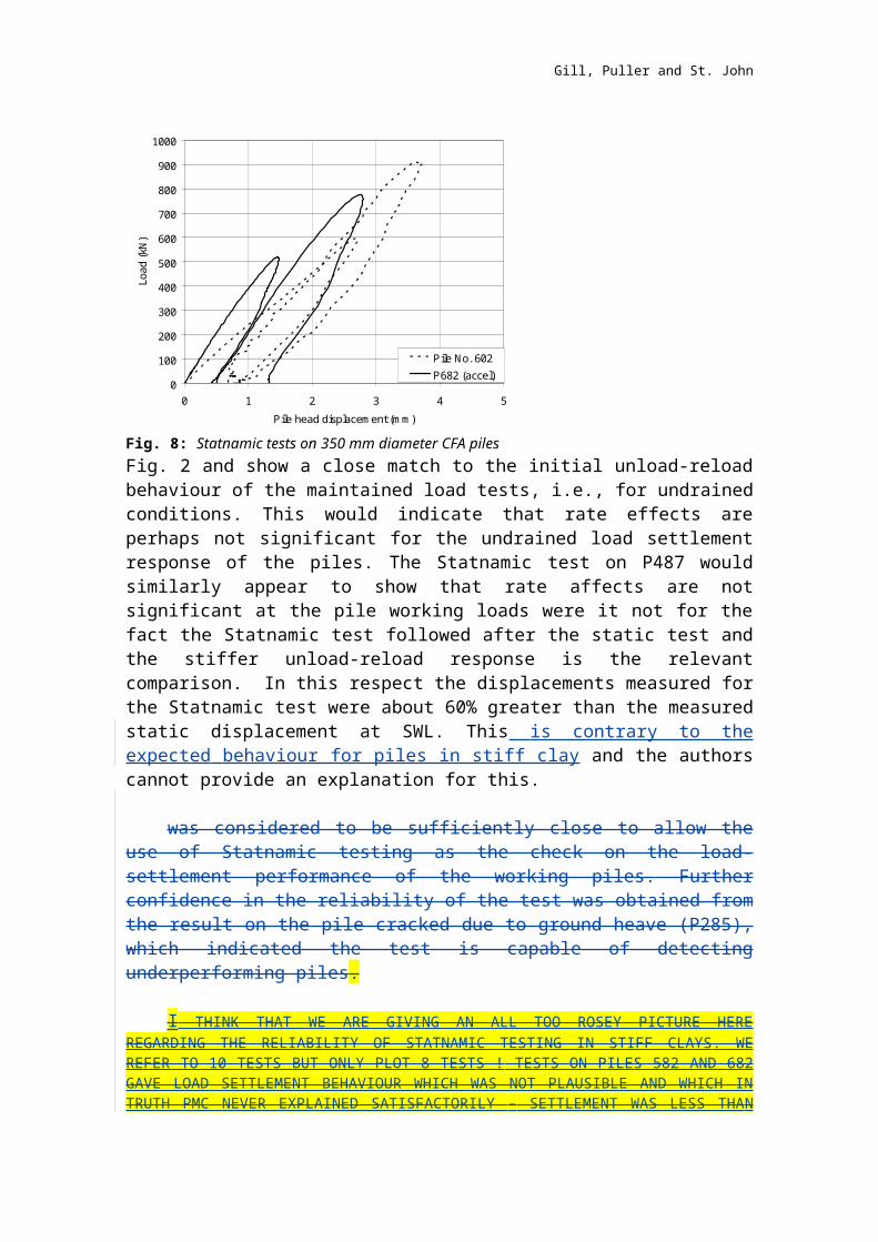
diameter CFA piles that were possible constructed in anarea of the site without headroom restrictions followingdemolition and these are presented in Fig. 8. A problem wasencountered with the laser sensor used to record pile headdisplacement in the tests carried out on piles P582 andP682 (shown in Fig. 7 and Fig. 8, respectively). Therefore,the displacements for these tests were obtained from theaccelerometer data.
Gill, Puller and St. John
The displacement measured at SWL for the mini pilesfalls within the range 2.5 to 4.1mm, except for pile P285which was over 10 mm. Investigation of this test resultfound Pile P285 to be constructed within an area of thesite where the existing building had been demolishedfollowing the pile’s construction and up to 15 mm of shortterm ground heave was predicted to occur. The unexpectedlarge displacement of this pile is therefore considered tobe due to closure of heave induced cracks in the pileconcrete. This is noticeable in Fig. 7 when the test loadexceeds 500 kN. The improved performance on the 2nd loadcycle to 1.5 times SWL is further evidence of this crackclosure. The settlements at SWL for the two CFA pile testswere 1.5 and 2.7mm, respectively and on average gave lowerdisplacements than the mini piles.
DISCUSSION OF STATNAMIC TEST
The Statnamic test provided useful information on therelative performance of the mini piles, although it wasfound give a wide range of load-settlement curves for pilesthat
0
100
200
300
400
500
600
700
800
900
1000
0 2 4 6 8 10 12Pile head displacem ent (m m )
Load (kN)
M aintained Load TestStatnam ic Test
Fig. 6: Comparison of static maintained load test and Statnamic test for pile P487
Gill, Puller and St. John
0
100
200
300
400
500
600
700
800
900
1000
1100
0 1 2 3 4 5 6 7 8 9 10 11 12 13 14 15 16 17Pile head displacem ent (m m )
Load (kN )
Pile No. P285Pile No. P132Pile No. P52Pile No. P407Pile No. P347Pile No. P302Pile No. P487P582 (accel)
Fig. 7: Statnamic tests on bored mini piles
had very similar dimensions. From Fig. 4 it is evident thatthe load-settlement behaviour of the piles measured in thestatic tests are far more consistent, with the maindifferences being due to concrete or grout construction andwhen the ultimate load capacity is approached.
The information obtained from the expendable piletests, for both ultimate load capacity and settlementperformance at working loads, justified use of theStatnamic testing as a check on good workmanship alone. Inthis respect the scatter in load- displacement behaviour ofthe test may not be overly significant so long as thequality of the piles could can be demonstrated. TheStatnamic test is thought to have been successful indetecting a pile that was cracked due to ground heave(P285) and this gave additional credibility as to itsability to detect underperforming piles.
The CRP tests that were carried out for piles PTP1 andPTP2 are presented in
Gill, Puller and St. John
0
100
200
300
400
500
600
700
800
900
1000
0 1 2 3 4 5Pile head displacem ent (m m )
Load (kN)
Pile No. 602P682 (accel)
Fig. 8: Statnamic tests on 350 mm diameter CFA pilesFig. 2 and show a close match to the initial unload-reloadbehaviour of the maintained load tests, i.e., for undrainedconditions. This would indicate that rate effects areperhaps not significant for the undrained load settlementresponse of the piles. The Statnamic test on P487 wouldsimilarly appear to show that rate affects are notsignificant at the pile working loads were it not for thefact the Statnamic test followed after the static test andthe stiffer unload-reload response is the relevantcomparison. In this respect the displacements measured forthe Statnamic test were about 60% greater than the measuredstatic displacement at SWL. This is contrary to theexpected behaviour for piles in stiff clay and the authorscannot provide an explanation for this.
was considered to be sufficiently close to allow theuse of Statnamic testing as the check on the load-settlement performance of the working piles. Furtherconfidence in the reliability of the test was obtained fromthe result on the pile cracked due to ground heave (P285),which indicated the test is capable of detectingunderperforming piles.
I THINK THAT WE ARE GIVING AN ALL TOO ROSEY PICTURE HEREREGARDING THE RELIABILITY OF STATNAMIC TESTING IN STIFF CLAYS. WEREFER TO 10 TESTS BUT ONLY PLOT 8 TESTS ! TESTS ON PILES 582 AND 682GAVE LOAD SETTLEMENT BEHAVIOUR WHICH WAS NOT PLAUSIBLE AND WHICH INTRUTH PMC NEVER EXPLAINED SATISFACTORILY – SETTLEMENT WAS LESS THAN
Gill, Puller and St. John
ELASTIC SHORTENING ALONE. WE NEED A MORE CRITICAL APPRAISAL HERE ITHINK. LANGUAGE LIKE - STATNAMIC GIVES SOME USEFUL INFORMATION BUTTHERE ARE ISSUES WRT RATE EFFECTS AND THERE WAS A VERY WIDE SCATTER OFRESULTS ETC ETC WOULD BE A FAIRER SUMMARY.
CONCLUSIONS
Based on the test results from 55 Baker Street it isrecommended that for segmental-auger bored mini piles an α-value of 0.4 should be adopted in the absence of expendablepile testing to demonstrate higher shaft friction.Minimisation of the duration of drilling and concretingtimes is likely to increase the pile’s ultimate capacity..The grout mini piles were shown to be less stiff underloading than the concrete piles, with settlementapproximately 60% greater than for concrete piles atworking loads.
The Statnamic test was found to provide a quick andconvenient check on pile workmanship in a situation where alarge amount of information on pile performance wasobtained from four preliminary pile tests. However, due tothe large scatter in the Statnamic test results it was notfound to provide a consistent measure of pile load-settlement behaviour for bored mini piles in stiff clay.Therefore, it may not be not be reliable to use Statnamictesting in isolation to static load testing in situationswhere the load-settlement performance is required to bedetermined from the pile testing regime.
The Statnamic test was found to be a reliable proof loadtest of the working piles but was not used to provideinformation on the ultimate load capacity of the piles. TheStatnamic test provided a check on the load-settlementperformance of the working piles and was shown to becapable of detecting underperforming piles.ACKNOWLEDGEMENTS
The authors would like to thank Geoffrey Springer at London& Regional Properties Limited and Sean Walsh at Expedition Engineering Limited for permission to publish the results of the pile testing carried out at 55 Baker Street.
Gill, Puller and St. John
REFERENCES
1. London District Surveyors’ Association. Guidance notes for the design of bored straight shafted piles in London Clay. London District Surveyors Association Pulblications, 2000.
2. Burland J.B. and Twine D., The shaft friction of bored piles in terms of effective strength, Proceeding of the 1st Int. Deep Foundations on Bored and Augered Piles, 1988.
3. Pellew, A. L. Field investigations into pile behaviour in clay, PhD thesis, Imperial College, University of London, 2002
4. Patel, D.C. Interpretation of results of pile tests in London Clay. Piling: European practice and worldwide trends. Thomas Telford, London, 1992.
5. Brown, M.J., Hyde, A.F.L. & Anderson, W.F., Analysis of a rapid load test on an instrumented bored pile in clay. Geotechnique. Vol. 56, No. 9. pp. 627-638, 2006.
Gill, Puller and St. John


