Embed Size (px)
Citation preview
Urban Stormwater Management Manual 39-i
39 EROSION AND SEDIMENT CONTROL MEASURES
39.1 INTRODUCTION................................................................................................. 39-1
39.2 SITE PLANNING CONSIDERATIONS........................................................................ 39-1
39.2.1 Scheduling............................................................................................. 39-1
39.2.2 Preservation of Existing Vegetation............................................................. 39-3
39.3 VEGETATIVE STABILISATION................................................................................ 39-3
39.3.1 Seeding and Planting............................................................................... 39-3
39.3.2 Mulching ............................................................................................... 39-4
39.4 PHYSICAL STABILISATION ................................................................................... 39-5
39.4.1 Geotextiles and Mats............................................................................... 39-5
39.4.2 Dust Control .......................................................................................... 39-5
39.4.3 Temporary Waterway Crossing .................................................................. 39-7
39.4.4 Construction Road Stabilisation.................................................................. 39-7
39.4.5 Construction Access Stabilisation................................................................ 39-8
39.5 DIVERSION OF RUNOFF....................................................................................... 39-9
39.5.1 Earth Bank ............................................................................................ 39-9
39.5.2 Diversion Channel................................................................................... 39-9
39.5.3 Slope Drain............................................................................................ 39-10
39.6 FLOW VELOCITY REDUCT ION............................................................................... 39-11
39.6.1 Drainage Outlet Protection........................................................................ 39-11
39.6.2 Check Dam............................................................................................ 39-11
39.7 SEDIMENT TRAPPING/FILTERING .......................................................................... 39-12
39.7.1 Sediment Fence...................................................................................... 39-12
39.7.2 Sand Bag Barrier..................................................................................... 39-13
39.7.3 Brush or Rock Filter................................................................................. 39-13
39.7.4 Drainage Inlet Protection.......................................................................... 39-14
39.7.5 Sediment Traps ...................................................................................... 39-15
39.7.6 Sediment Basins ..................................................................................... 39-15
APPENDIX 39.A WORKED EXAMPLE.................................................................................. 39-21
39.A.1 Sizing a Dry Sediment Basin ...................................................................... 39-21
39.A.2 Sizing a Wet Sediment Basin ..................................................................... 39-24
APPENDIX 39.B STANDARD DRAWINGS ............................................................................ 39-27

Erosion and Sediment Control Measures
Urban Stormwater Management Manual 39-1
39.1 INTRODUCTION
This chapter describes specific Best Management Practices (BMPs) for common construction activities that result in erosion of construction sites and the generation of sediment , which impacts waterways and off-site property.
Recommended erosion and sediment control measures for construction sites are drawn from Camp Dresser & Mckee et al., (1993). These measures are summarised in Table 39.1 in relation to BMP objectives.
The following information is provided on each BMP:
• a description of the BMP
• suitable applications
• installation/application criteria
• maintenance requirements (where applicable)
• relative cost (where applicable)
• limitations
Standard drawings for the BMP practices described are provided in Appendix 39.B. These are suitable for inclusion in Erosion and Sediment Control Plans (ESCPs) described in Chapter 41. They may be used to supplement and provide details for erosion and sediment control BMPs shown on the project drawings.
39.2 SITE PLANNING CONSIDERATIONS
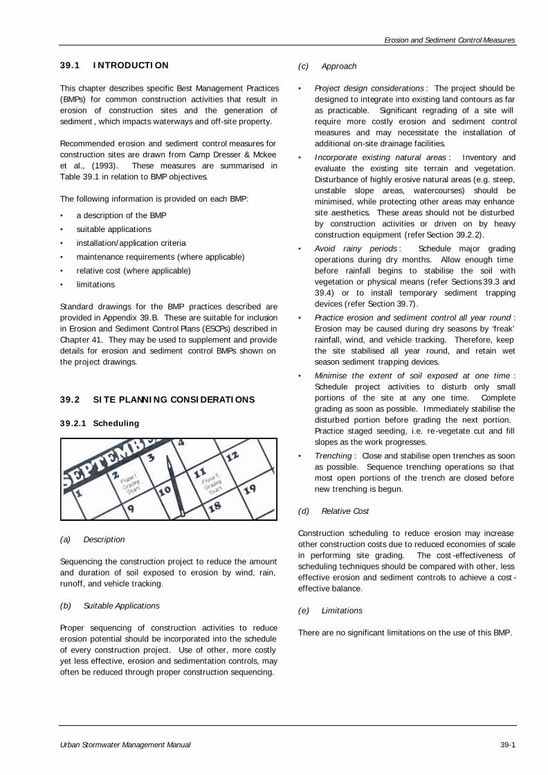
39.2.1 Scheduling
(a) Description
Sequencing the construction project to reduce the amount and duration of soil exposed to erosion by wind, rain, runoff, and vehicle tracking.
(b) Suitable Applications
Proper sequencing of construction activities to reduce erosion potential should be incorporated into the schedule of every construction project. Use of other, more costly yet less effective, erosion and sedimentation controls, may often be reduced through proper construction sequencing.
(c) Approach
• Project design considerations : The project should be designed to integrate into existing land contours as far as practicable. Significant regrading of a site will require more costly erosion and sediment control measures and may necessitate the installation of additional on-site drainage facilities.
• Incorporate existing natural areas : Inventory and evaluate the existing site terrain and vegetation. Disturbance of highly erosive natural areas (e.g. steep, unstable slope areas, watercourses) should be minimised, while protecting other areas may enhance site aesthetics. These areas should not be disturbed by construction activities or driven on by heavy construction equipment (refer Section 39.2.2).
• Avoid rainy periods : Schedule major grading operations during dry months. Allow enough time before rainfall begins to stabilise the soil with vegetation or physical means (refer Sections 39.3 and 39.4) or to install temporary sediment trapping devices (refer Section 39.7).
• Practice erosion and sediment control all year round : Erosion may be caused during dry seasons by ‘freak’ rainfall, wind, and vehicle tracking. Therefore, keep the site stabilised all year round, and retain wet season sediment trapping devices.
• Minimise the extent of soil exposed at one time : Schedule project activities to disturb only small portions of the site at any one time. Complete grading as soon as possible. Immediately stabilise the disturbed portion before grading the next portion. Practice staged seeding, i.e. re-vegetate cut and fill slopes as the work progresses.
• Trenching : Close and stabilise open trenches as soon as possible. Sequence trenching operations so that most open portions of the trench are closed before new trenching is begun.
(d) Relative Cost
Construction scheduling to reduce erosion may increase other construction costs due to reduced economies of scale in performing site grading. The cost -effectiveness of scheduling techniques should be compared with other, less effective erosion and sediment controls to achieve a cost -effective balance.
(e) Limitations
There are no significant limitations on the use of this BMP.
Erosion and Sediment Control Measures
39-2 Urban Stormwater Management Manual
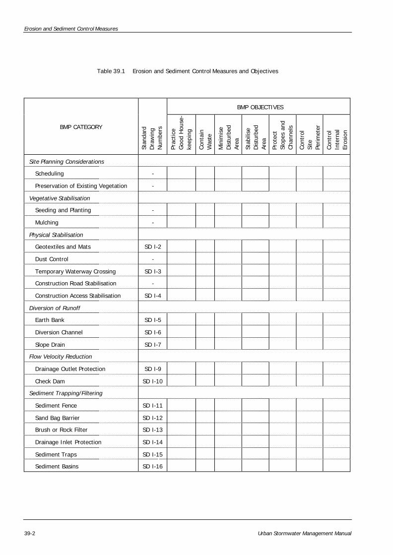
Table 39.1 Erosion and Sediment Control Measures and Objectives
BMP OBJECTIVES
BMP CATEGORY
Stan
dard
D
raw
ing
Num
bers
Prac
tice
Goo
d H
ouse
- ke
epin
g
Con
tain
W
aste
Min
imis
e D
istu
rbed
Ar
ea
Stab
ilise
D
istu
rbed
Ar
ea
Prot
ect
Slop
es a
nd
Cha
nnel
s
Con
trol
Si
te
Perim
eter
Con
trol
In
tern
al
Eros
ion
Site Planning Considerations
Scheduling - � � � � � � �
Preservation of Existing Vegetation - � � � �
Vegetative Stabilisation
Seeding and Planting - � �
Mulching - � �
Physical Stabilisation
Geotextiles and Mats SD I-2 � �
Dust Control - � � � �
Temporary Waterway Crossing SD I-3 � � � �
Construction Road Stabilisation - � � � �
Construction Access Stabilisation SD I-4 � � � �
Diversion of Runoff
Earth Bank SD I-5 � � � �
Diversion Channel SD I-6 � � �
Slope Drain SD I-7 �
Flow Velocity Reduction
Drainage Outlet Protection SD I-9 �
Check Dam SD I-10 �
Sediment Trapping/Filtering
Sediment Fence SD I-11 � �
Sand Bag Barrier SD I-12 � � �
Brush or Rock Filter SD I-13 � � �
Drainage Inlet Protection SD I-14 � �
Sediment Traps SD I-15 �
Sediment Basins SD I-16 �
Erosion and Sediment Control Measures
Urban Stormwater Management Manual 39-3
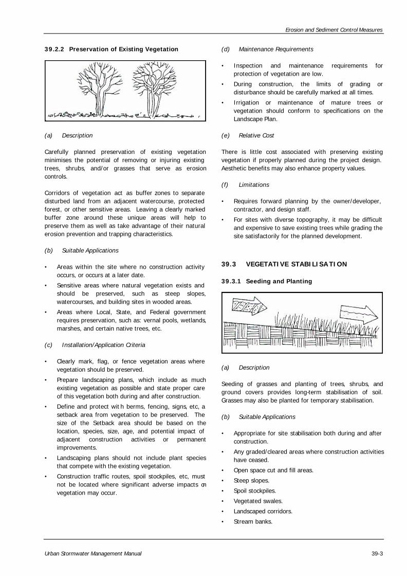
39.2.2 Preservation of Existing Vegetation
(a) Description
Carefully planned preservation of existing vegetation minimises the potential of removing or injuring existing trees, shrubs, and/or grasses that serve as erosion controls.
Corridors of vegetation act as buffer zones to separate disturbed land from an adjacent watercourse, protected forest, or other sensitive areas. Leaving a clearly marked buffer zone around these unique areas will help to preserve them as well as take advantage of their natural erosion prevention and trapping characteristics.
(b) Suitable Applications
• Areas within the site where no construction activity occurs, or occurs at a later date.
• Sensitive areas where natural vegetation exists and should be preserved, such as steep slopes, watercourses, and building sites in wooded areas.
• Areas where Local, State, and Federal government requires preservation, such as: vernal pools, wetlands, marshes, and certain native trees, etc.
(c) Installation/Application Criteria
• Clearly mark, flag, or fence vegetation areas where vegetation should be preserved.
• Prepare landscaping plans, which include as much existing vegetation as possible and state proper care of this vegetation both during and after construction.
• Define and protect wit h berms, fencing, signs, etc, a setback area from vegetation to be preserved. The size of the Setback area should be based on the location, species, size, age, and potential impact of adjacent construction activities or permanent improvements.
• Landscaping plans should not include plant species that compete with the existing vegetation.
• Construction traffic routes, spoil stockpiles, etc, must not be located where significant adverse impacts on vegetation may occur.
(d) Maintenance Requirements
• Inspection and maintenance requirements for protection of vegetation are low.
• During construction, the limits of grading or disturbance should be carefully marked at all times.
• Irrigation or maintenance of mature trees or vegetation should conform to specifications on the Landscape Plan.
(e) Relative Cost
There is little cost associated with preserving existing vegetation if properly planned during the project design. Aesthetic benefits may also enhance property values.
(f) Limitations
• Requires forward planning by the owner/developer, contractor, and design staff.
• For sites with diverse topography, it may be difficult and expensive to save existing trees while grading the site satisfactorily for the planned development.
39.3 VEGETATIVE STABILISA TION
39.3.1 Seeding and Planting
(a) Description
Seeding of grasses and planting of trees, shrubs, and ground covers provides long-term stabilisation of soil. Grasses may also be planted for temporary stabilisation.
(b) Suitable Applications
• Appropriate for site stabilisation both during and after construction.
• Any graded/cleared areas where construction activities have ceased.
• Open space cut and fill areas.
• Steep slopes.
• Spoil stockpiles.
• Vegetated swales.
• Landscaped corridors.
• Stream banks.
Erosion and Sediment Control Measures
39-4 Urban Stormwater Management Manual
(c) Installation/Application Criteria
Type of vegetation, site, and seedbed preparation, planting time, fertiliser, and water requirements should be considered for each application.
(i) Grasses
• Select grasses that are tolerant of short -term temperature extremes and waterlogged soil conditions.
• Soil must be fertilised and mechanically stabilised.
• Use in shallow-based soils with good drainage and ground slope of 2(H):1(V) or flatter.
• Grasses develop well and quickly from seeds.
• Mowing, irrigating, and fertilising are vital for promoting vigorous grass growth.
(ii) Trees and Shrubs
• Select trees and shrubs on the basis of vigor, species, size, shape, and wildlife food source.
• Select species appropriate for soil, drainage, and acidity.
• Other factors that should be considered are wind exposure, temperature extremes, and irrigation needs.
(d) Maintenance Requirements
• Shrubs and trees must be adequately watered, fertilised, and pruned if needed.
• Grasses may need to be watered and mowed.
(e) Limitations
• Permanent and temporary vegetation may not be appropriate in dry periods without irrigation.
• Fertiliser requirements may have the potential to create stormwater pollution if improperly applied.
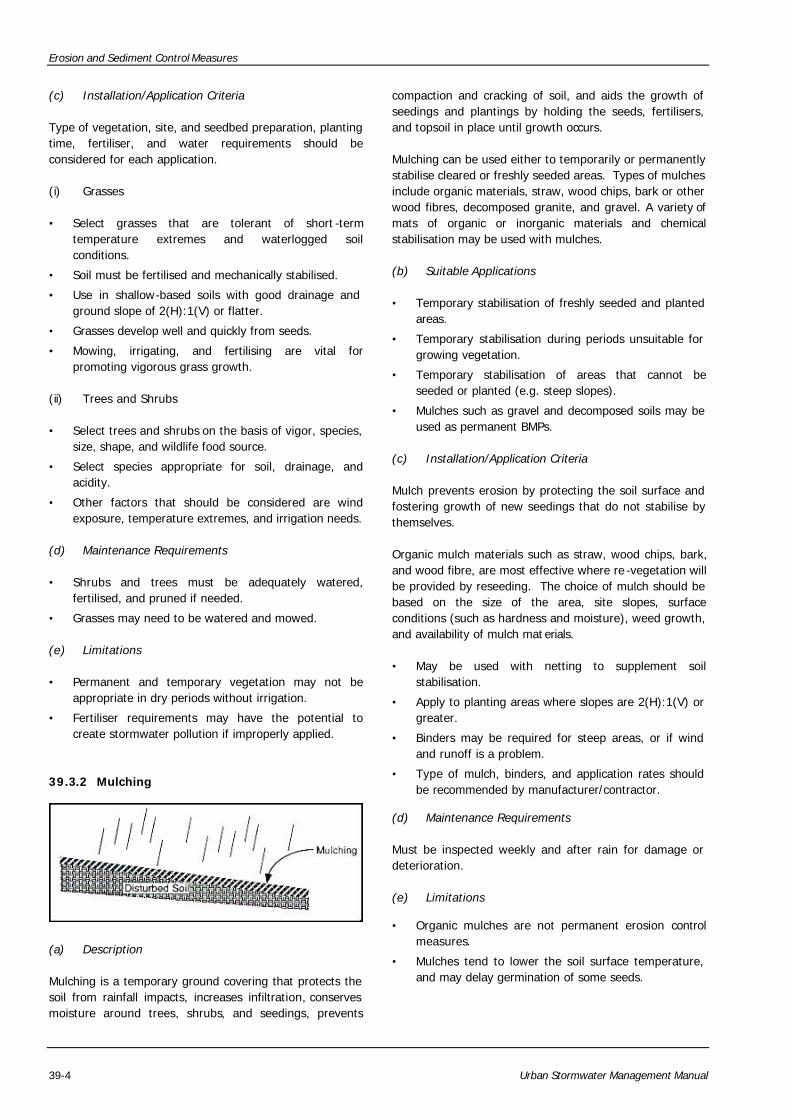
39.3.2 Mulching
(a) Description
Mulching is a temporary ground covering that protects the soil from rainfall impacts, increases infiltration, conserves moisture around trees, shrubs, and seedings, prevents
compaction and cracking of soil, and aids the growth of seedings and plantings by holding the seeds, fertilisers, and topsoil in place until growth occurs.
Mulching can be used either to temporarily or permanently stabilise cleared or freshly seeded areas. Types of mulches include organic materials, straw, wood chips, bark or other wood fibres, decomposed granite, and gravel. A variety of mats of organic or inorganic materials and chemical stabilisation may be used with mulches.
(b) Suitable Applications
• Temporary stabilisation of freshly seeded and planted areas.
• Temporary stabilisation during periods unsuitable for growing vegetation.
• Temporary stabilisation of areas that cannot be seeded or planted (e.g. steep slopes).
• Mulches such as gravel and decomposed soils may be used as permanent BMPs.
(c) Installation/Application Criteria
Mulch prevents erosion by protecting the soil surface and fostering growth of new seedings that do not stabilise by themselves.
Organic mulch materials such as straw, wood chips, bark, and wood fibre, are most effective where re -vegetation will be provided by reseeding. The choice of mulch should be based on the size of the area, site slopes, surface conditions (such as hardness and moisture), weed growth, and availability of mulch mat erials.
• May be used with netting to supplement soil stabilisation.
• Apply to planting areas where slopes are 2(H):1(V) or greater.
• Binders may be required for steep areas, or if wind and runoff is a problem.
• Type of mulch, binders, and application rates should be recommended by manufacturer/contractor.
(d) Maintenance Requirements
Must be inspected weekly and after rain for damage or deterioration.
(e) Limitations
• Organic mulches are not permanent erosion control measures.
• Mulches tend to lower the soil surface temperature, and may delay germination of some seeds.
Erosion and Sediment Control Measures
Urban Stormwater Management Manual 39-5
39.4 PHYSICAL STABILISATION
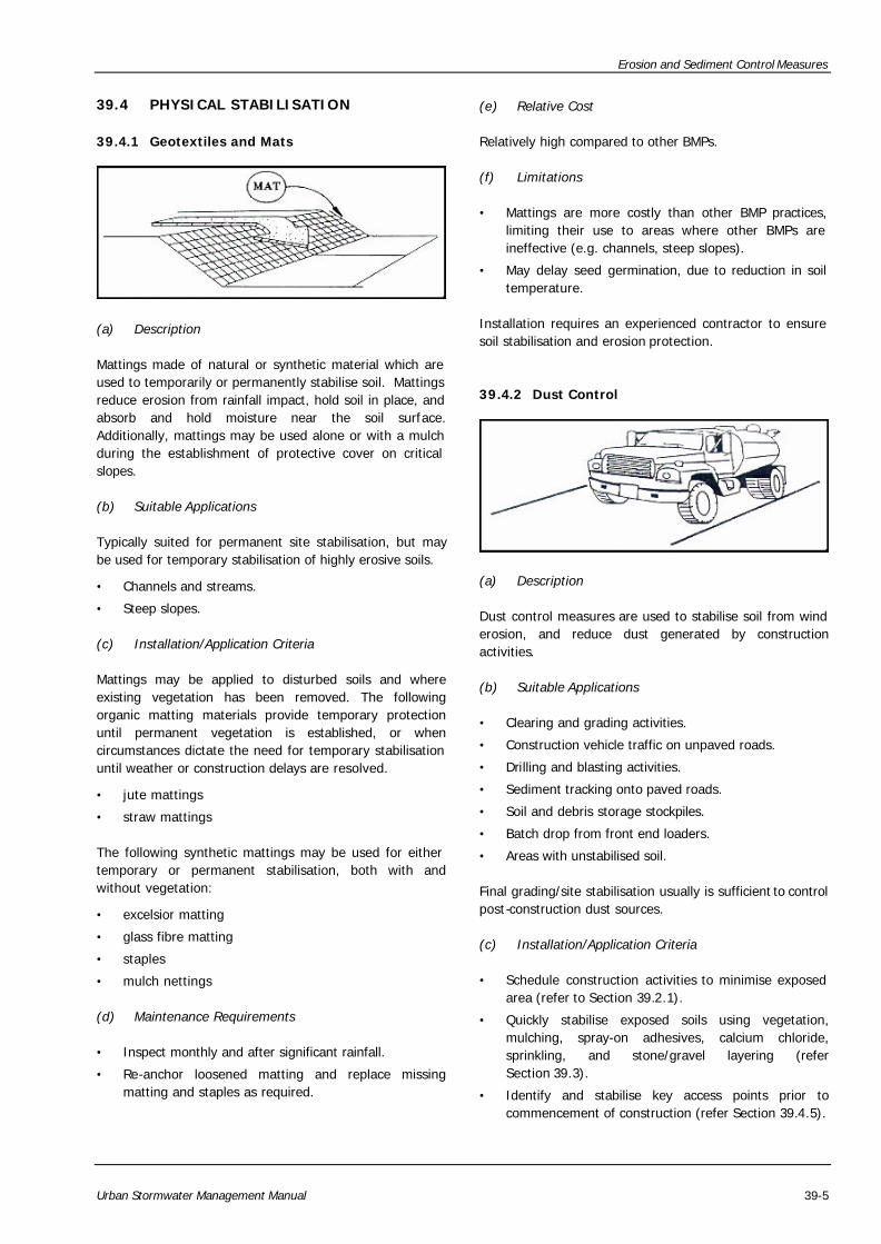
39.4.1 Geotextiles and Mats
(a) Description
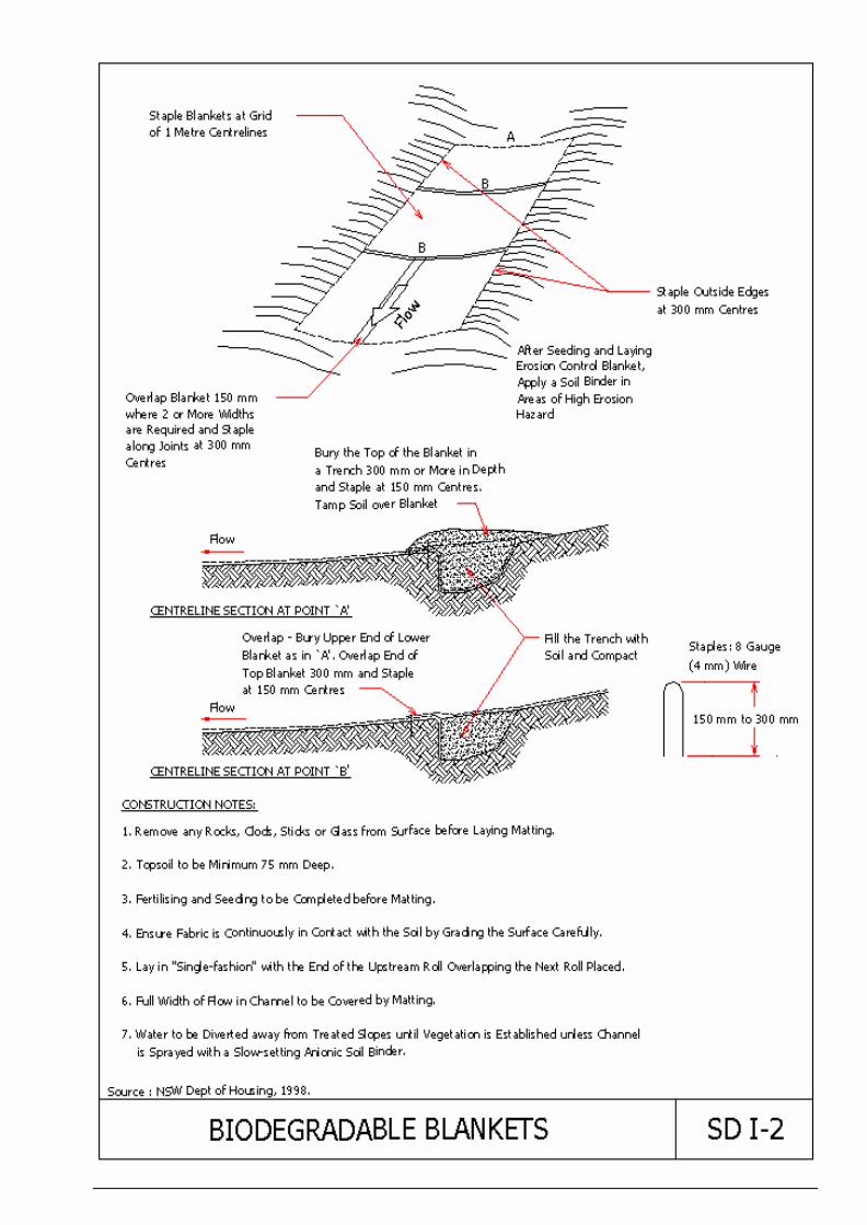
Mattings made of natural or synthetic material which are used to temporarily or permanently stabilise soil. Mattings reduce erosion from rainfall impact, hold soil in place, and absorb and hold moisture near the soil surface. Additionally, mattings may be used alone or with a mulch during the establishment of protective cover on critical slopes.
(b) Suitable Applications
Typically suited for permanent site stabilisation, but may be used for temporary stabilisation of highly erosive soils.
• Channels and streams.
• Steep slopes.
(c) Installation/Application Criteria
Mattings may be applied to disturbed soils and where existing vegetation has been removed. The following organic matting materials provide temporary protection until permanent vegetation is established, or when circumstances dictate the need for temporary stabilisation until weather or construction delays are resolved.
• jute mattings
• straw mattings
The following synthetic mattings may be used for either temporary or permanent stabilisation, both with and without vegetation:
• excelsior matting
• glass fibre matting
• staples
• mulch nettings
(d) Maintenance Requirements
• Inspect monthly and after significant rainfall.
• Re-anchor loosened matting and replace missing matting and staples as required.
(e) Relative Cost
Relatively high compared to other BMPs.
(f) Limitations
• Mattings are more costly than other BMP practices, limiting their use to areas where other BMPs are ineffective (e.g. channels, steep slopes).
• May delay seed germination, due to reduction in soil temperature.
Installation requires an experienced contractor to ensure soil stabilisation and erosion protection.
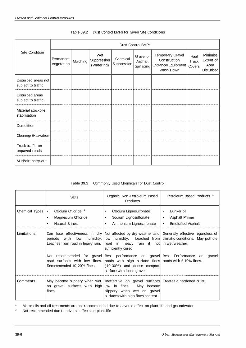
39.4.2 Dust Control
(a) Description
Dust control measures are used to stabilise soil from wind erosion, and reduce dust generated by construction activities.
(b) Suitable Applications
• Clearing and grading activities.
• Construction vehicle traffic on unpaved roads.
• Drilling and blasting activities.
• Sediment tracking onto paved roads.
• Soil and debris storage stockpiles.
• Batch drop from front end loaders.
• Areas with unstabilised soil.
Final grading/site stabilisation usually is sufficient to control post-construction dust sources.
(c) Installation/Application Criteria
• Schedule construction activities to minimise exposed area (refer to Section 39.2.1).
• Quickly stabilise exposed soils using vegetation, mulching, spray-on adhesives, calcium chloride, sprinkling, and stone/gravel layering (refer Section 39.3).
• Identify and stabilise key access points prior to commencement of construction (refer Section 39.4.5).
Erosion and Sediment Control Measures
39-6 Urban Stormwater Management Manual
Table 39.2 Dust Control BMPs for Given Site Conditions
Dust Control BMPs
Site Condition
Permanent Vegetation
Mulching
Wet Suppression (Watering)
Chemical Suppression
Gravel or Asphalt
Surfacing
Temporary Gravel Construction
Entrance/Equipment Wash Down
Haul Truck Covers
Minimise Extent of
Area Disturbed
Disturbed areas not subject to traffic
� � � � � �
Disturbed areas subject to traffic
� � � �
Material stockpile stabilisation
� � �
Demolition � � �
Clearing/Excavation � � �
Truck traffic on unpaved roads
� � � �
Mud/dirt carry-out � �
Table 39.3 Commonly Used Chemicals for Dust Control
Salts Organic, Non-Petroleum Based Products
Petroleum Based Products 1
Chemical Types • Calcium Chloride 2
• Magnesium Chloride
• Natural Brines
• Calcium Lignosulfonate
• Sodium Lignosulfonate
• Ammonium Lignosulfonate
• Bunker oil
• Asphalt Primer
• Emulsified Asphalt
Limitations Can lose effectiveness in dry periods with low humidity. Leaches from road in heavy rain.
Not recommended for gravel road surfaces with low fines. Recommended 10-20% fines.
Not affected by dry weather and low humidity. Leached from road in heavy rain if not sufficiently cured.
Best performance on gravel roads with high surface fines (10-30%) and dense compact surface with loose gravel.
Generally effective regardless of climatic conditions. May pothole in wet weather.
Best Performance on gravel roads with 5-10% fines.
Comments May become slippery when wet on gravel surfaces with high fines.
Ineffective on gravel surfaces low in fines. May become slippery when wet on gravel surfaces with high fines content.
Creates a hardened crust.
1 Motor oils and oil treatments are not recommended due to adverse effect on plant life and groundwater 2 Not recommended due to adverse effects on plant life

Erosion and Sediment Control Measures
Urban Stormwater Management Manual 39-7
(d) Maintenance Requirements
Most dust control measures require frequent, often daily, attention.
(e) Relative Cost
Installation costs for water/chemical dust suppression are low, but annual costs may be quite high since these measures are effective for only a few hours to a few days.
(f) Limitations
• Watering prevents dust for only a short period and should be applied daily (or more often) to be effective.
• Over-watering may cause erosion.
• Oil should not be used for dust control because the oil may migrate into waterways and/or seep into the soil.
• Certain chemically -treated subgrades may make soil water repellant, increasing runoff.
39.4.3 Temporary Waterway Crossing
(a) Description
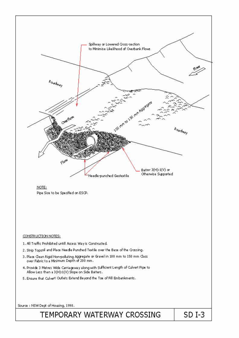
A temporary access waterway crossing is a temporary culvert, ford, or bridge placed across a waterway to provide access for construction purposes for a period of less than one year. Temporary access crossings are not intended to be used by the general public.
The purpose of a temporary crossing is to provide a safe, erosion-free access point across a waterway for construction equipment. An engineer should establish minimum standards and specifications for the design, construction, maintenance, and removal of the structure. Crossings may be necessary to prevent construction equipment from causing erosion of the waterway and tracking of pollutants into the waterway.
Temporary waterway crossings are used to access points on construction sites when other detour routes may be too long or burdensome for the construction equipment, or are too narrow or of poor soil strength for the equipment loadings. Additionally, a temporary stream crossing may be more economical for light-duty vehicles to use for frequent crossings, and may have less environmental impact than construction of a temporary access road.
(b) Suitable Applications
Temporary waterway crossings should be installed at all designated crossings of perennial and intermittent waterways on the construction site, as well as for dry channels which may be significantly eroded by construction traffic.
(c) Installation/Application Criteria
Requires knowledge of stream flows and soil strength and should be designed under the direction of a suitably qualified engineer with knowledge of both hydraulics and construction loading requirements for structures.
(d) Maintenance Requirements
• Inspect weekly and after each significant rainfall, including assessment of foundations.
• Periodically remove silt from crossings.
• Replace lost aggregate from inlets and outlets of culverts.
(e) Limitations
• May be an expensive measure for a temporary improvement.
• Requires other BMPs to minimise soil disturbance during installation and removal.
Fords should only be used in dry weather.
39.4.4 Construction Road Stabilisation
(a) Description
Access roads, subdivision roads, parking areas, and other on-site vehicle transportation routes should be stabilised immediately after grading and frequently maintained to prevent erosion and control dust.
Areas which are graded for construction vehicle transport and parking purposes are especially susceptible to erosion and dust. The exposed soil surface is continually disturbed, leaving no opportunity for vegetative stabilisation. Such areas also tend to collect and transport surface runoff. During wet weather, they often become muddy quagmires which generate significant quantities of sediment that may pollute nearby streams or be
Erosion and Sediment Control Measures
39-8 Urban Stormwater Management Manual
transported off-site on the wheels of construction vehicles. Dirt roads can become so unstable during wet weather that they are virtually unusable.
Efficient construction road stabilisation not only reduces on-site erosion, but can significantly speed on-site work, avoid instances of immobilised equipment and delivery vehicles, and generally improve site efficiency and working conditions during adverse weather.
(b) Suitable Applications
• Temporary construction traffic.
• Phased construction projects and off-site road access.
• Detour roads.
• Construction during wet weather.
(c) Installation/Application Criteria
• Road should follow topographic contours to reduce erosion of the roadway.
• The roadway slope should not exceed 15%.
• Gravel roads should be a minimum 100 mm thick with a 50-75 mm coarse aggregate base, and should be applied immediately after grading or as recommended by a soils engineer.
• Chemical stabilisers or water will normally be required on gravel or dirt roads to prevent dust (refer Section 39.4.2).
(d) Maintenance Requirements
• Periodically apply additional aggregate on gravel roads.
• Dirt construction roads that are in constant use are commonly watered three or more times per day during the dry season.
• Inspect weekly, and after rainfall.
• Repair any eroded areas immediately.
(e) Relative Cost
• Gravel construction roads are moderately expensive, but cost is often balanced by reductions in construction delays.
• No additional costs for dust control on construction roads should be required above that needed to meet local air quality requirements.
(f) Limitations
• The roadway must be removed or paved when construction is complete.
• Certain chemical stabilisation methods may cause stormwater or soil pollution and should not be used (refer Section 39.4.2).
Management of construction traffic is subject to air quality control measures. Contact the Local Authority for specific requirements.
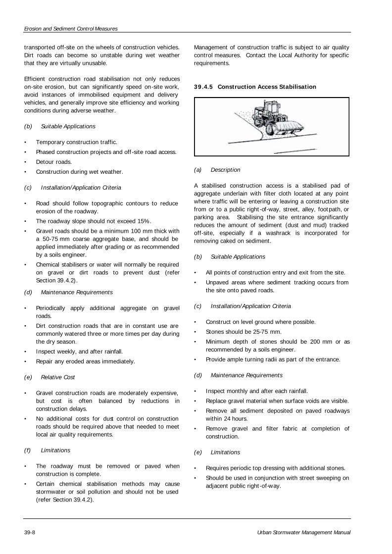
39.4.5 Construction Access Stabilisation
(a) Description
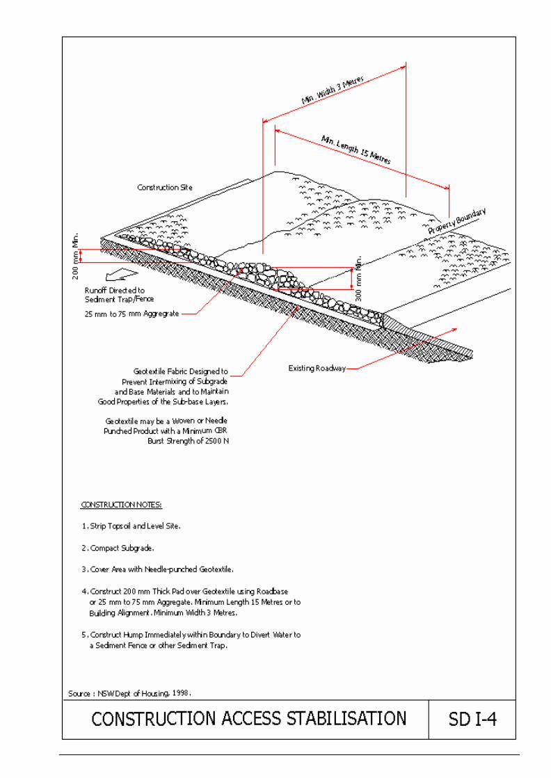
A stabilised construction access is a stabilised pad of aggregate underlain with filter cloth located at any point where traffic will be entering or leaving a construction site from or to a public right-of-way, street, alley, footpath, or parking area. Stabilising the site entrance significantly reduces the amount of sediment (dust and mud) tracked off-site, especially if a washrack is incorporated for removing caked on sediment.
(b) Suitable Applications
• All points of construction entry and exit from the site.
• Unpaved areas where sediment tracking occurs from the site onto paved roads.
(c) Installation/Application Criteria
• Construct on level ground where possible.
• Stones should be 25-75 mm.
• Minimum depth of stones should be 200 mm or as recommended by a soils engineer.
• Provide ample turning radii as part of the entrance.
(d) Maintenance Requirements
• Inspect monthly and after each rainfall.
• Replace gravel material when surface voids are visible.
• Remove all sediment deposited on paved roadways within 24 hours.
• Remove gravel and filter fabric at completion of construction.
(e) Limitations
• Requires periodic top dressing with additional stones.
• Should be used in conjunction with street sweeping on adjacent public right-of-way.
Erosion and Sediment Control Measures
Urban Stormwater Management Manual 39-9
39.5 DIVERSION OF RUNOFF
39.5.1 Earth Bank
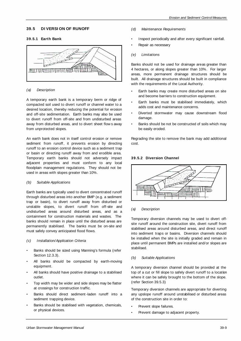
(a) Description
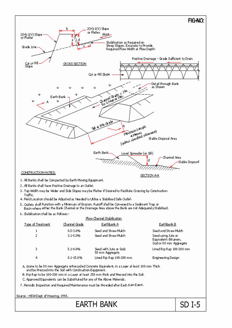
A temporary earth bank is a temporary berm or ridge of compacted soil used to divert runoff or channel water to a desired location, thereby reducing the potential for erosion and off-site sedimentation. Earth banks may also be used to divert runoff from off-site and from undisturbed areas away from disturbed areas, and to divert sheet flow s away from unprotected slopes.
An earth bank does not in itself control erosion or remove sediment from runoff, it prevents erosion by directing runoff to an erosion control device such as a sediment trap or basin or directing runoff away from and erodible area. Temporary earth banks should not adversely impact adjacent properties and must conform to any local floodplain management regulations. They should not be used in areas with slopes greater than 10%.
(b) Suitable Applications
Earth banks are typically used to divert concentrated runoff through disturbed areas into another BMP (e.g. a sediment trap or basin), to divert runoff away from disturbed or unstable slopes, to divert runoff from off-site and undisturbed areas around disturbed areas, and as a containment for construction materials and wastes. The banks should remain in place until the disturbed areas are permanently stabilised. The banks must be on-site and must safely convey anticipated flood flows.
(c) Installation/Application Criteria
• Banks should be sized using Manning’s formula (refer Section 12.3.3).
• All banks should be compacted by earth-moving equipment.
• All banks should have positive drainage to a stabilised outlet.
• Top width may be wider and side slopes may be flatter at crossings for construction traffic.
• Banks should direct sediment -laden runoff into a sediment trapping device.
• Banks should be stabilised with vegetation, chemicals, or physical devices.
(d) Maintenance Requirements
• Inspect periodically and after every significant rainfall.
• Repair as necessary
(e) Limitations
Banks should not be used for drainage areas greater than 4 hectares, or along slopes greater than 10%. For larger areas, more permanent drainage structures should be built. All drainage structures should be built in compliance with the requirements of the Local Authority.
• Earth banks may create more disturbed areas on site and become barriers to construction equipment.
• Earth banks must be stabilised immediately, which adds cost and maintenance concerns.
• Diverted stormwater may cause downstream flood damage.
• Banks should be not be constructed of soils which may be easily eroded.
Regrading the site to remove the bank may add additional cost.
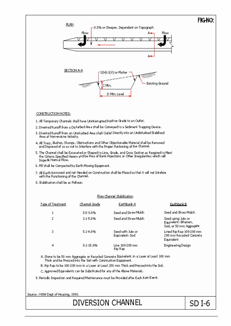
39.5.2 Diversion Channel
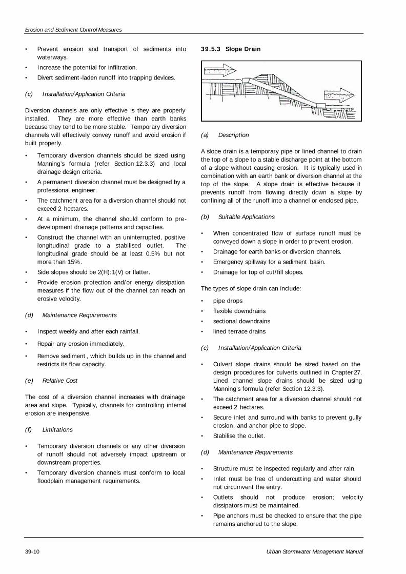
(a) Description
Temporary diversion channels may be used to divert off-site runoff around the construction site, divert runoff from stabilised areas around disturbed areas, and direct runoff into sediment traps or basins. Diversion channels should be installed when the site is initially graded and remain in place until permanent BMPs are installed and/or slopes are stabilised.
(b) Suitable Applications
A temporary diversion channel should be provided at the top of a cut or fill slope to safely divert runoff to a location where it can be safely brought to the bottom of the slope. (refer Section 39.5.3)
Temporary diversion channels are appropriate for diverting any upslope runoff around unstabilised or disturbed areas of the construction site in order to:
• Prevent slope failures.
• Prevent damage to adjacent property.
Erosion and Sediment Control Measures
39-10 Urban Stormwater Management Manual
• Prevent erosion and transport of sediments into waterways.
• Increase the potential for infiltration.
• Divert sediment -laden runoff into trapping devices.
(c) Installation/Application Criteria
Diversion channels are only effective is they are properly installed. They are more effective than earth banks because they tend to be more stable. Temporary diversion channels will effectively convey runoff and avoid erosion if built properly.
• Temporary diversion channels should be sized using Manning’s formula (refer Section 12.3.3) and local drainage design criteria.
• A permanent diversion channel must be designed by a professional engineer.
• The catchment area for a diversion channel should not exceed 2 hectares.
• At a minimum, the channel should conform to pre-development drainage patterns and capacities.
• Construct the channel with an uninterrupted, positive longitudinal grade to a stabilised outlet. The longitudinal grade should be at least 0.5% but not more than 15%.
• Side slopes should be 2(H):1(V) or flatter.
• Provide erosion protection and/or energy dissipation measures if the flow out of the channel can reach an erosive velocity.
(d) Maintenance Requirements
• Inspect weekly and after each rainfall.
• Repair any erosion immediately.
• Remove sediment , which builds up in the channel and restricts its flow capacity.
(e) Relative Cost
The cost of a diversion channel increases with drainage area and slope. Typically, channels for controlling internal erosion are inexpensive.
(f) Limitations
• Temporary diversion channels or any other diversion of runoff should not adversely impact upstream or downstream properties.
• Temporary diversion channels must conform to local floodplain management requirements.
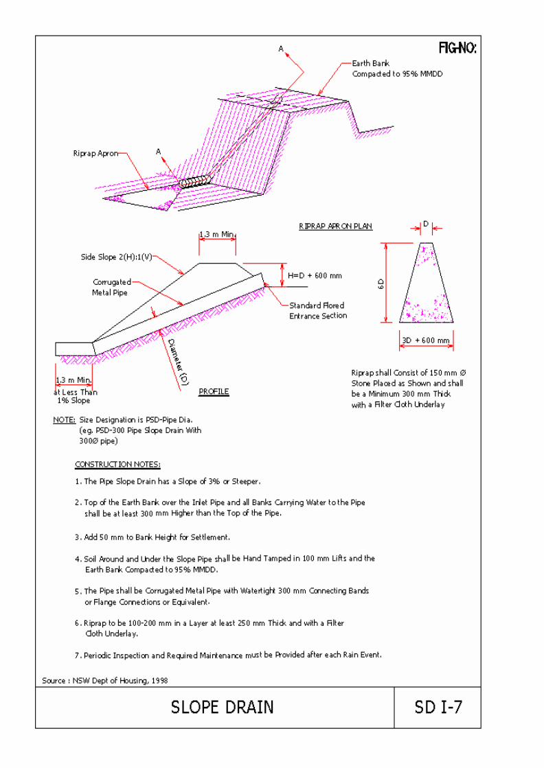
39.5.3 Slope Drain
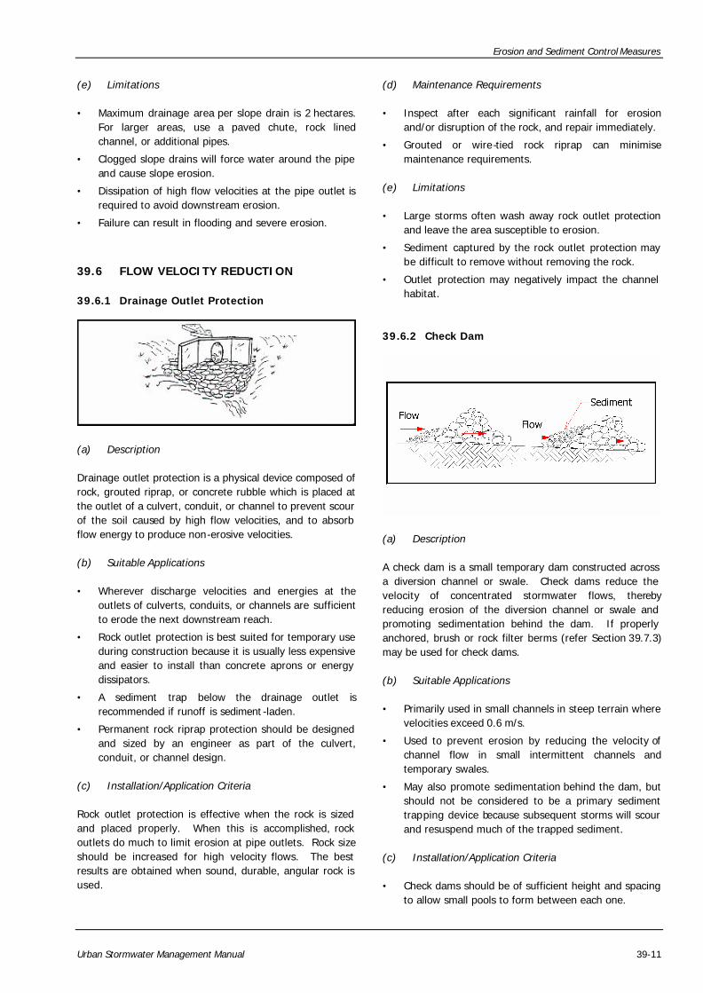
(a) Description
A slope drain is a temporary pipe or lined channel to drain the top of a slope to a stable discharge point at the bottom of a slope without causing erosion. It is typically used in combination with an earth bank or diversion channel at the top of the slope. A slope drain is effective because it prevents runoff from flowing directly down a slope by confining all of the runoff into a channel or enclosed pipe.
(b) Suitable Applications
• When concentrated flow of surface runoff must be conveyed down a slope in order to prevent erosion.
• Drainage for earth banks or diversion channels.
• Emergency spillway for a sediment basin.
• Drainage for top of cut/fill slopes.
The types of slope drain can include:
• pipe drops
• flexible downdrains
• sectional downdrains
• lined terrace drains
(c) Installation/Application Criteria
• Culvert slope drains should be sized based on the design procedures for culverts outlined in Chapter 27. Lined channel slope drains should be sized using Manning’s formula (refer Section 12.3.3).
• The catchment area for a diversion channel should not exceed 2 hectares.
• Secure inlet and surround with banks to prevent gully erosion, and anchor pipe to slope.
• Stabilise the outlet.
(d) Maintenance Requirements
• Structure must be inspected regularly and after rain.
• Inlet must be free of undercutting and water should not circumvent the entry.
• Outlets should not produce erosion; velocity dissipators must be maintained.
• Pipe anchors must be checked to ensure that the pipe remains anchored to the slope.
Erosion and Sediment Control Measures
Urban Stormwater Management Manual 39-11
(e) Limitations
• Maximum drainage area per slope drain is 2 hectares. For larger areas, use a paved chute, rock lined channel, or additional pipes.
• Clogged slope drains will force water around the pipe and cause slope erosion.
• Dissipation of high flow velocities at the pipe outlet is required to avoid downstream erosion.
• Failure can result in flooding and severe erosion.
39.6 FLOW VELOCITY REDUCTION
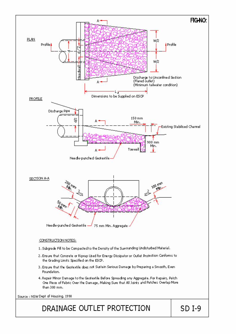
39.6.1 Drainage Outlet Protection
(a) Description
Drainage outlet protection is a physical device composed of rock, grouted riprap, or concrete rubble which is placed at the outlet of a culvert, conduit, or channel to prevent scour of the soil caused by high flow velocities, and to absorb flow energy to produce non-erosive velocities.
(b) Suitable Applications
• Wherever discharge velocities and energies at the outlets of culverts, conduits, or channels are sufficient to erode the next downstream reach.
• Rock outlet protection is best suited for temporary use during construction because it is usually less expensive and easier to install than concrete aprons or energy dissipators.
• A sediment trap below the drainage outlet is recommended if runoff is sediment -laden.
• Permanent rock riprap protection should be designed and sized by an engineer as part of the culvert, conduit, or channel design.
(c) Installation/Application Criteria
Rock outlet protection is effective when the rock is sized and placed properly. When this is accomplished, rock outlets do much to limit erosion at pipe outlets. Rock size should be increased for high velocity flows. The best results are obtained when sound, durable, angular rock is used.
(d) Maintenance Requirements
• Inspect after each significant rainfall for erosion and/or disruption of the rock, and repair immediately.
• Grouted or wire-tied rock riprap can minimise maintenance requirements.
(e) Limitations
• Large storms often wash away rock outlet protection and leave the area susceptible to erosion.
• Sediment captured by the rock outlet protection may be difficult to remove without removing the rock.
• Outlet protection may negatively impact the channel habitat.
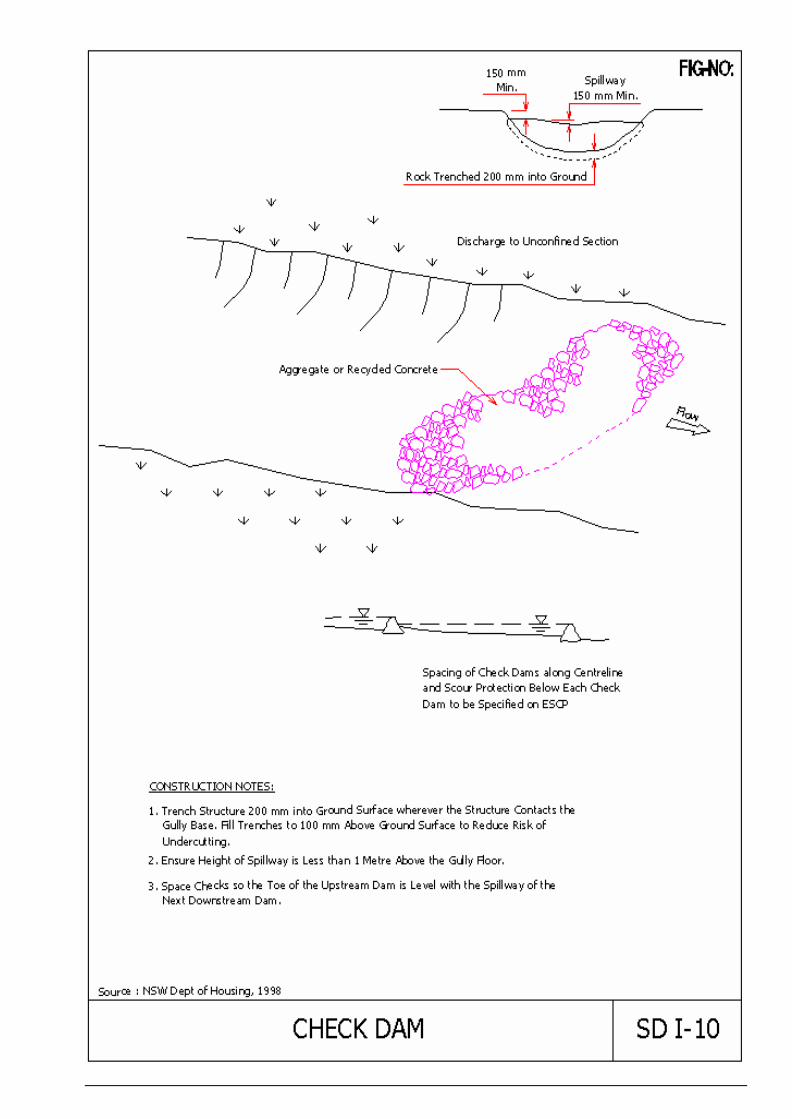
39.6.2 Check Dam
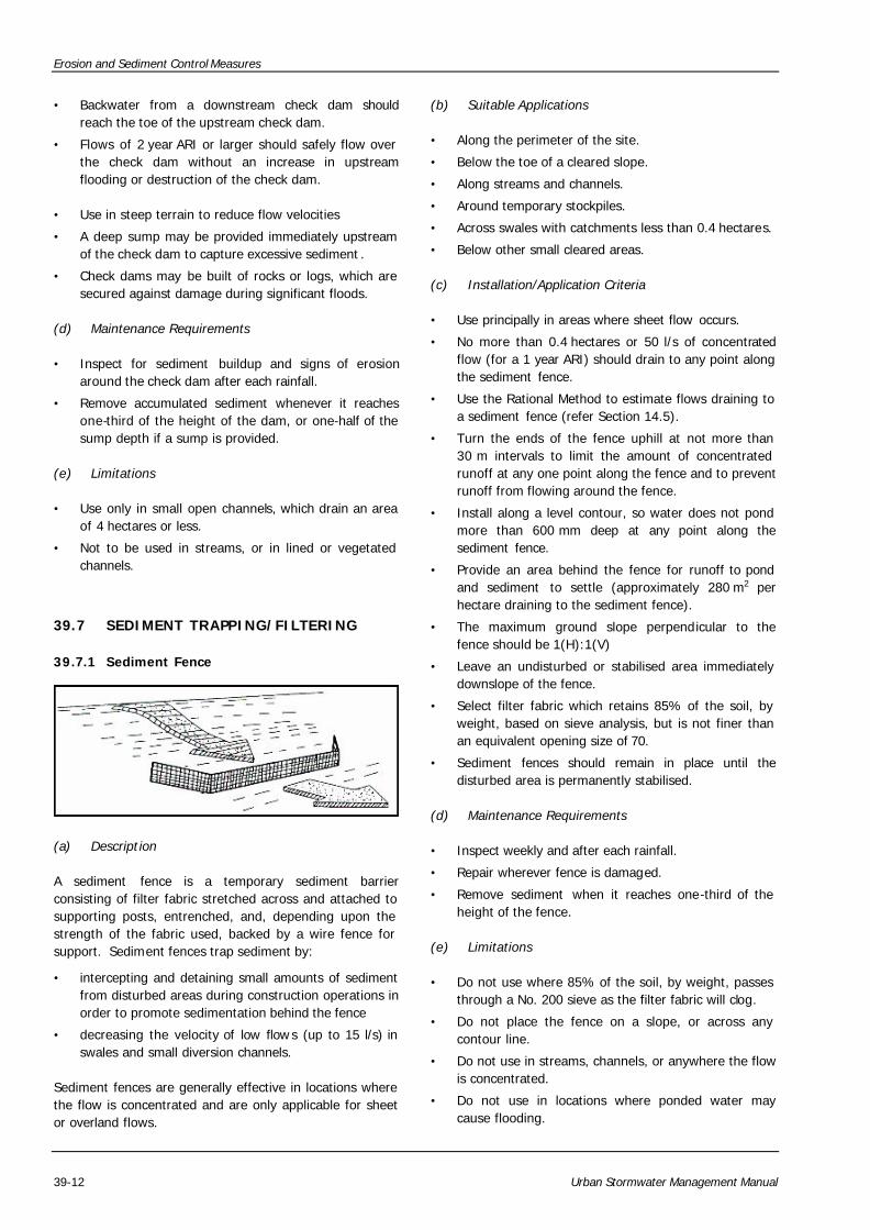
(a) Description
A check dam is a small temporary dam constructed across a diversion channel or swale. Check dams reduce the velocity of concentrated stormwater flows, thereby reducing erosion of the diversion channel or swale and promoting sedimentation behind the dam. If properly anchored, brush or rock filter berms (refer Section 39.7.3) may be used for check dams.
(b) Suitable Applications
• Primarily used in small channels in steep terrain where velocities exceed 0.6 m/s.
• Used to prevent erosion by reducing the velocity of channel flow in small intermittent channels and temporary swales.
• May also promote sedimentation behind the dam, but should not be considered to be a primary sediment trapping device because subsequent storms will scour and resuspend much of the trapped sediment.
(c) Installation/Application Criteria
• Check dams should be of sufficient height and spacing to allow small pools to form between each one.
Erosion and Sediment Control Measures
39-12 Urban Stormwater Management Manual
• Backwater from a downstream check dam should reach the toe of the upstream check dam.
• Flows of 2 year ARI or larger should safely flow over the check dam without an increase in upstream flooding or destruction of the check dam.
• Use in steep terrain to reduce flow velocities
• A deep sump may be provided immediately upstream of the check dam to capture excessive sediment .
• Check dams may be built of rocks or logs, which are secured against damage during significant floods.
(d) Maintenance Requirements
• Inspect for sediment buildup and signs of erosion around the check dam after each rainfall.
• Remove accumulated sediment whenever it reaches one-third of the height of the dam, or one-half of the sump depth if a sump is provided.
(e) Limitations
• Use only in small open channels, which drain an area of 4 hectares or less.
• Not to be used in streams, or in lined or vegetated channels.
39.7 SEDIMENT TRAPPING/FILTERING
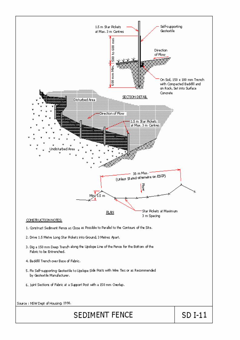
39.7.1 Sediment Fence
(a) Description
A sediment fence is a temporary sediment barrier consisting of filter fabric stretched across and attached to supporting posts, entrenched, and, depending upon the strength of the fabric used, backed by a wire fence for support. Sediment fences trap sediment by:
• intercepting and detaining small amounts of sediment from disturbed areas during construction operations in order to promote sedimentation behind the fence
• decreasing the velocity of low flows (up to 15 l/s) in swales and small diversion channels.
Sediment fences are generally effective in locations where the flow is concentrated and are only applicable for sheet or overland flows.
(b) Suitable Applications
• Along the perimeter of the site.
• Below the toe of a cleared slope.
• Along streams and channels.
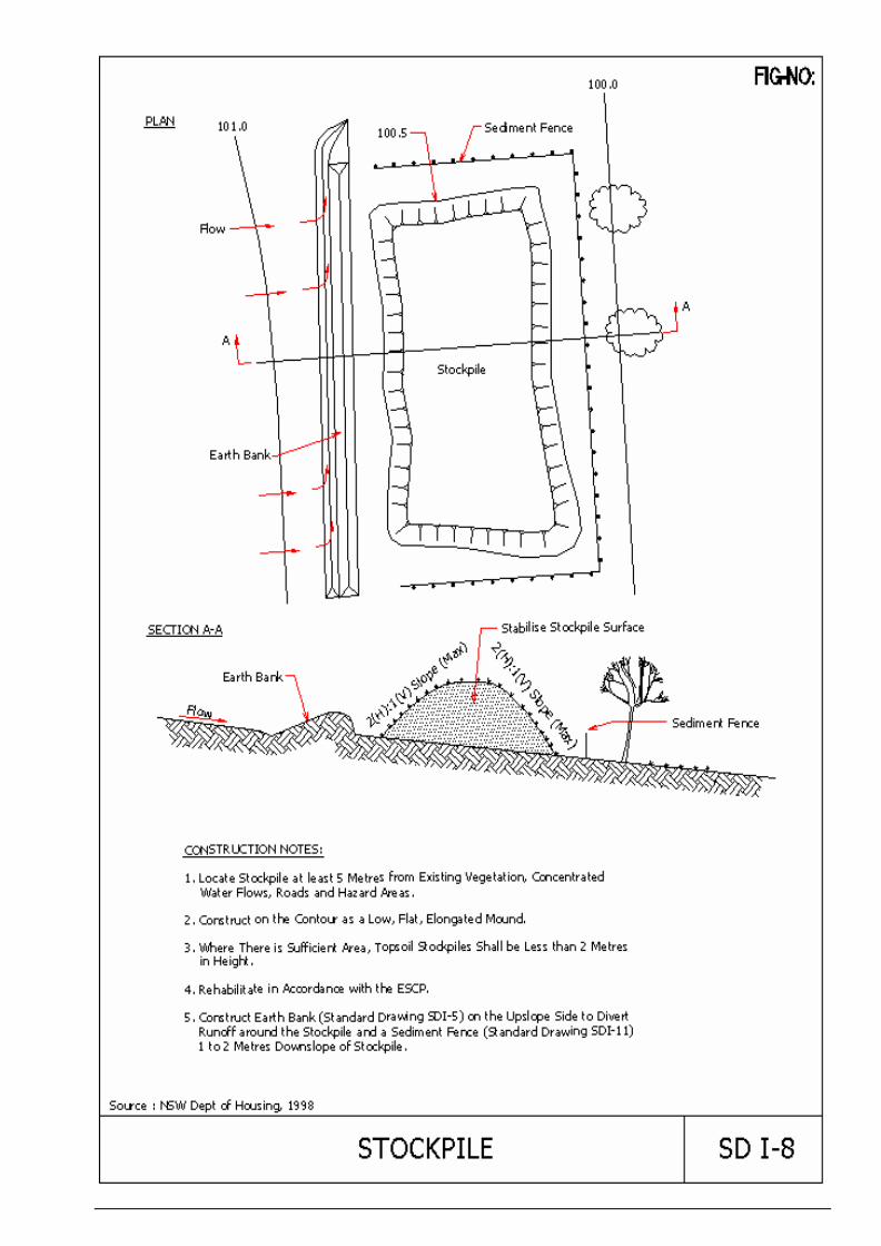
• Around temporary stockpiles.
• Across swales with catchments less than 0.4 hectares.
• Below other small cleared areas.
(c) Installation/Application Criteria
• Use principally in areas where sheet flow occurs.
• No more than 0.4 hectares or 50 l/s of concentrated flow (for a 1 year ARI) should drain to any point along the sediment fence.
• Use the Rational Method to estimate flows draining to a sediment fence (refer Section 14.5).
• Turn the ends of the fence uphill at not more than 30 m intervals to limit the amount of concentrated runoff at any one point along the fence and to prevent runoff from flowing around the fence.
• Install along a level contour, so water does not pond more than 600 mm deep at any point along the sediment fence.
• Provide an area behind the fence for runoff to pond and sediment to settle (approximately 280 m2 per hectare draining to the sediment fence).
• The maximum ground slope perpendicular to the fence should be 1(H):1(V)
• Leave an undisturbed or stabilised area immediately downslope of the fence.
• Select filter fabric which retains 85% of the soil, by weight, based on sieve analysis, but is not finer than an equivalent opening size of 70.
• Sediment fences should remain in place until the disturbed area is permanently stabilised.
(d) Maintenance Requirements
• Inspect weekly and after each rainfall.
• Repair wherever fence is damaged.
• Remove sediment when it reaches one-third of the height of the fence.
(e) Limitations
• Do not use where 85% of the soil, by weight, passes through a No. 200 sieve as the filter fabric will clog.
• Do not place the fence on a slope, or across any contour line.
• Do not use in streams, channels, or anywhere the flow is concentrated.
• Do not use in locations where ponded water may cause flooding.

Erosion and Sediment Control Measures
Urban Stormwater Management Manual 39-13
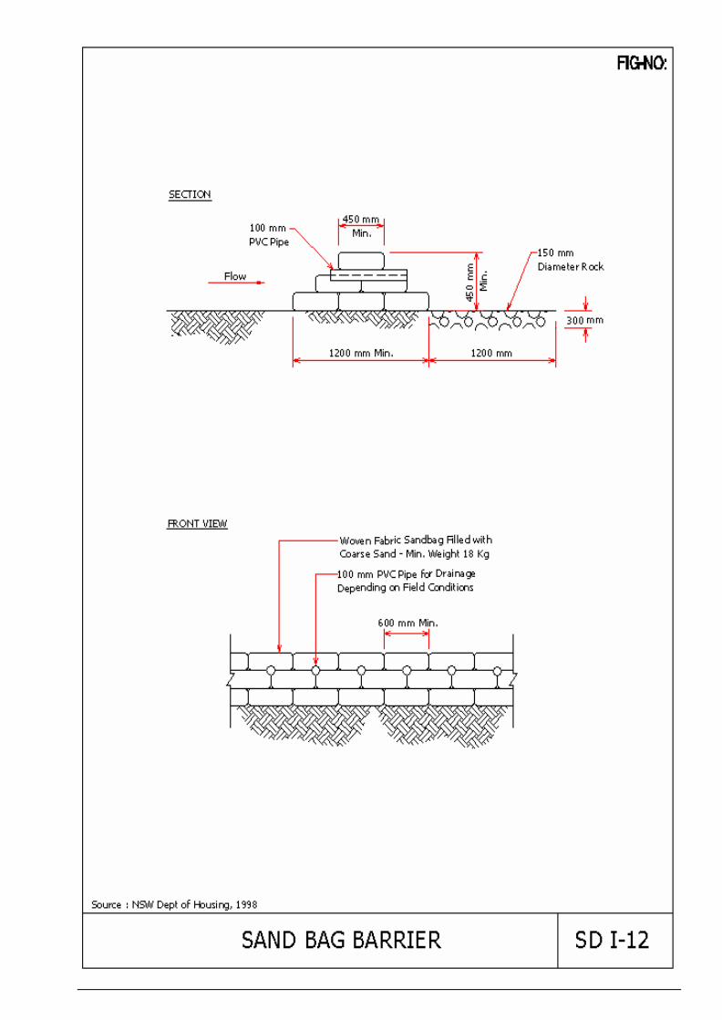
39.7.2 Sand Bag Barrier
(a) Description
Stacking sand bags along a level contour creates a barrier, which detains sediment -laden water by ponding upstream of the barrier water, thereby promoting sedimentation. Sand bags provide a semi-permeable barrier in potentially wet areas and are more permanent than sediment fences. They also allow for easy on-site relocation to meet changing needs during construction.
(b) Suitable Applications
• Along the perimeter of the site.
• As check dams across streams and channels.
• As a barrier for utility trenches in a channel.
• Across swales with small catchments.
• As a diversion channel.
• Below the toe of a cleared slope.
• As a temporary sediment trap.
• Around temporary stockpiles.
• Below other small cleared areas.
(c) Installation/Application Criteria
• May be used in drainage areas up to 2 hectares.
• Use the Rational Method to estimate flows draining to a sand bag barrier (refer Section 14.5).
• Install along a level contour.
• Base of sand bag barrier should be at least 1.2 m wide.
• Height of sand bag barrier should be at least 450 mm.
• 100 mm UPVC pipe may be installed between the top layer of sand bags to drain large flood flows.
• Provide areas behind barrier for runoff to pond and sediment to settle.
• Place below the toe of a slope.
• Use sand bags large enough and sturdy enough to withstand major flooding.
(d) Maintenance Requirements
• Inspect after each rainfall.
• Reshape or replace damaged sand bags immediately.
• Remove sediment when it reaches 150 mm in depth.
(e) Relative Cost
• Sand bag barriers are more costly, but typically have a longer useful life than other barriers.
(f) Limitations
• Sand bags are more expensive than other barriers, but are also more durable.
• Burlap should be used for sand bags.
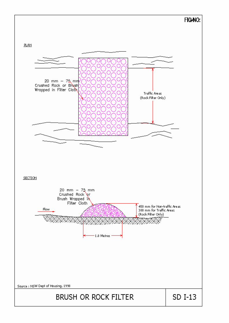
39.7.3 Brush or Rock Filter
(a) Description
A rock filter berm is made of 20 to 75 mm diameter rock placed along a level contour where sheet flow may be detained and ponded to promote sedimentation. A brush barrier is composed of brush (usually obtained during the site clearing) wrapped in filter cloth and anchored to the toe of the slope. If properly anchored, brush or rock filters may be used as a check dam (refer Section 39.6.2) for sediment trapping and velocity reduction.
(b) Suitable Applications
• As check dam across mildly sloped construction roads.
• Below the toe of slopes.
• Along the site perimeter.
• Around temporary soil stockpile areas.
• Below other small cleared areas.
• As sediment traps at culvert/pipe outlets.
(c) Installation/Application Criteria
• Drainage area should not exceed 2 hectares.
• Use the Rational Method to estimate flows draining to a brush or rock filter (refer Section 14.5).
• Use principally in areas where sheet or rill flow occurs.
• For a rock filter, use larger rock and place in a staked, woven wire sheathing if placed where concentrated flow occurs.
• Install along a level contour.
• Leave area behind berm where runoff can pond and sediment can settle.
Erosion and Sediment Control Measures
39-14 Urban Stormwater Management Manual
(d) Maintenance Requirements
• Inspect monthly and after each rainfall.
• If berm is damaged, reshape and replace lost or dislodged rock.
• Remove sediments when depth reaches the lesser of one-third the berm height or 300 mm.
(e) Relative Cost
• Brush filter : Low to moderate cost if debris from on-site clearing and grubbing is used.
• Rock filter : Expensive, since use of off-site materials, hand construction, and demolition/removal are usually required.
(f) Limitations
• Rock berms may be difficult to remove.
• Removal problems limit their usefulness in landscaped areas.
• Not appropriate for drainage areas greater than 2 hectares.
• Runoff will pond upstream of the filter, possibly causing flooding if there is insufficient storage space.
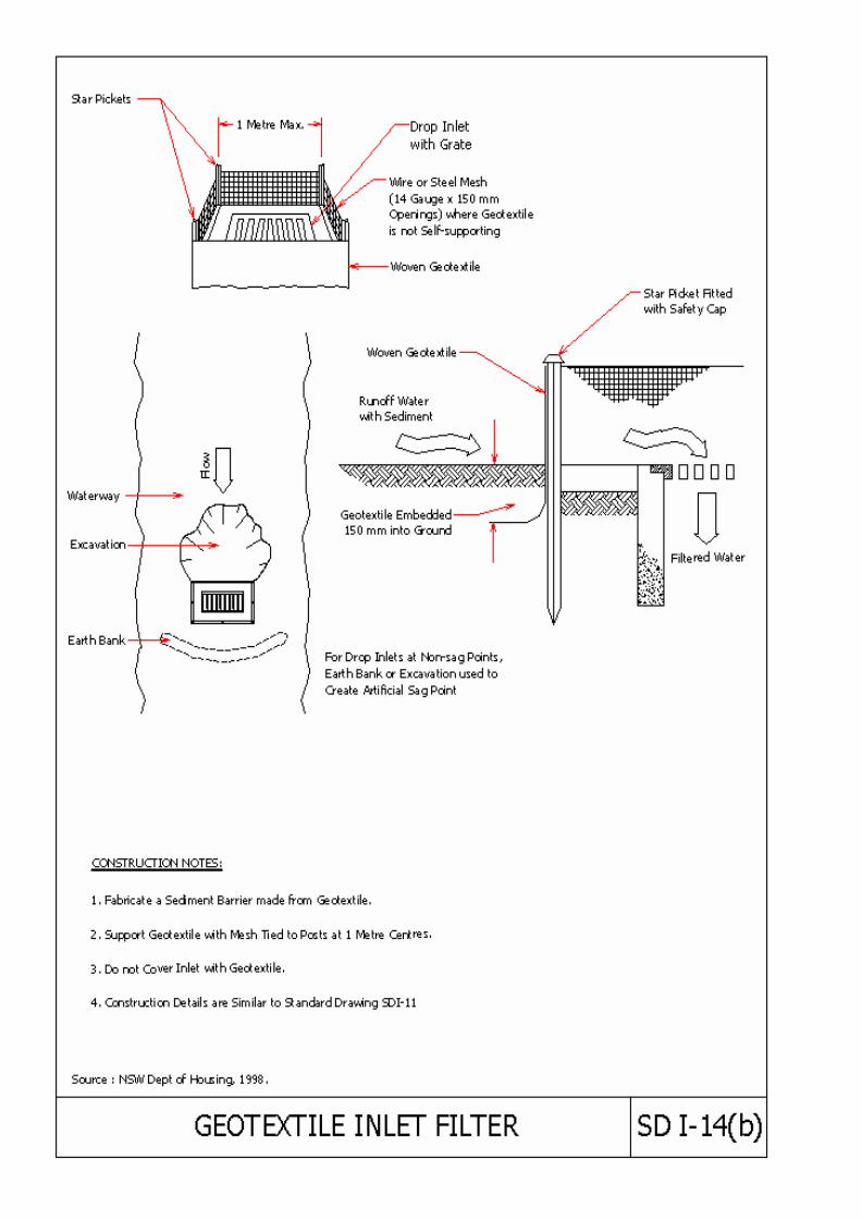
39.7.4 Drainage Inlet Protection
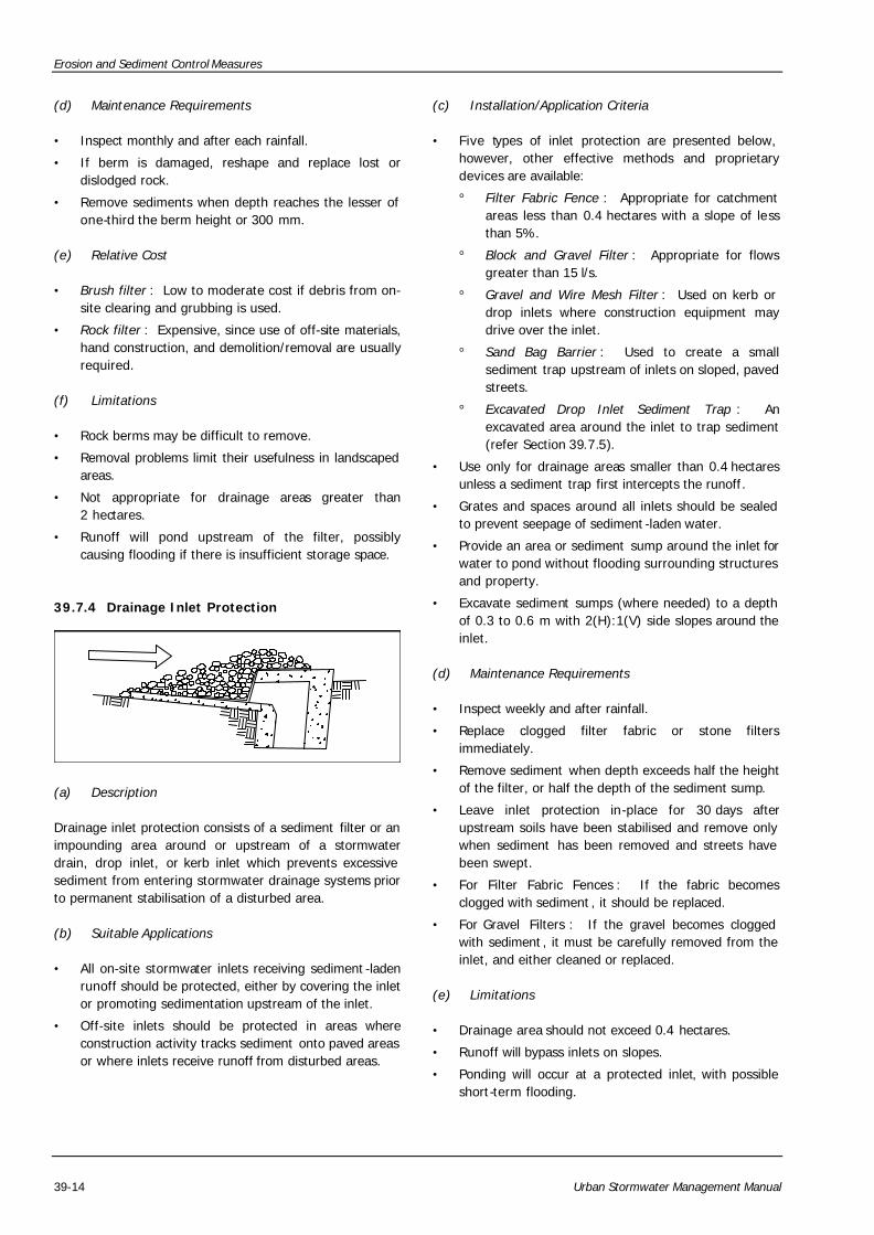
(a) Description
Drainage inlet protection consists of a sediment filter or an impounding area around or upstream of a stormwater drain, drop inlet, or kerb inlet which prevents excessive sediment from entering stormwater drainage systems prior to permanent stabilisation of a disturbed area.
(b) Suitable Applications
• All on-site stormwater inlets receiving sediment -laden runoff should be protected, either by covering the inlet or promoting sedimentation upstream of the inlet.
• Off-site inlets should be protected in areas where construction activity tracks sediment onto paved areas or where inlets receive runoff from disturbed areas.
(c) Installation/Application Criteria
• Five types of inlet protection are presented below, however, other effective methods and proprietary devices are available:
° Filter Fabric Fence : Appropriate for catchment areas less than 0.4 hectares with a slope of less than 5%.
° Block and Gravel Filter : Appropriate for flows greater than 15 l/s.
° Gravel and Wire Mesh Filter : Used on kerb or drop inlets where construction equipment may drive over the inlet.
° Sand Bag Barrier : Used to create a small sediment trap upstream of inlets on sloped, paved streets.
° Excavated Drop Inlet Sediment Trap : An excavated area around the inlet to trap sediment (refer Section 39.7.5).
• Use only for drainage areas smaller than 0.4 hectares unless a sediment trap first intercepts the runoff.
• Grates and spaces around all inlets should be sealed to prevent seepage of sediment -laden water.
• Provide an area or sediment sump around the inlet for water to pond without flooding surrounding structures and property.
• Excavate sediment sumps (where needed) to a depth of 0.3 to 0.6 m with 2(H):1(V) side slopes around the inlet.
(d) Maintenance Requirements
• Inspect weekly and after rainfall.
• Replace clogged filter fabric or stone filters immediately.
• Remove sediment when depth exceeds half the height of the filter, or half the depth of the sediment sump.
• Leave inlet protection in-place for 30 days after upstream soils have been stabilised and remove only when sediment has been removed and streets have been swept.
• For Filter Fabric Fences : If the fabric becomes clogged with sediment , it should be replaced.
• For Gravel Filters : If the gravel becomes clogged with sediment , it must be carefully removed from the inlet, and either cleaned or replaced.
(e) Limitations
• Drainage area should not exceed 0.4 hectares.
• Runoff will bypass inlets on slopes.
• Ponding will occur at a protected inlet, with possible short-term flooding.
Erosion and Sediment Control Measures
Urban Stormwater Management Manual 39-15
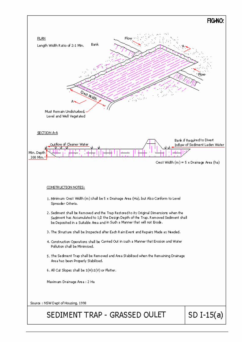
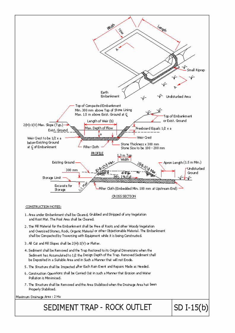
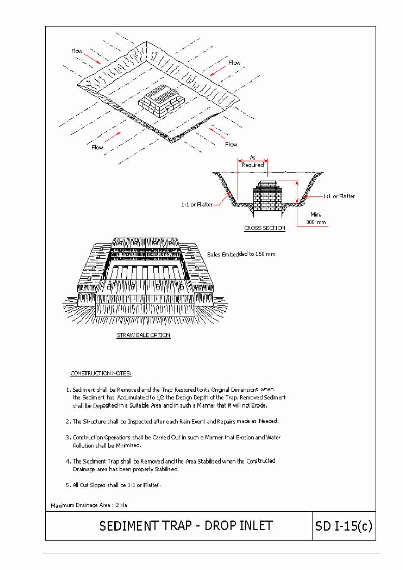
39.7.5 Sediment Traps
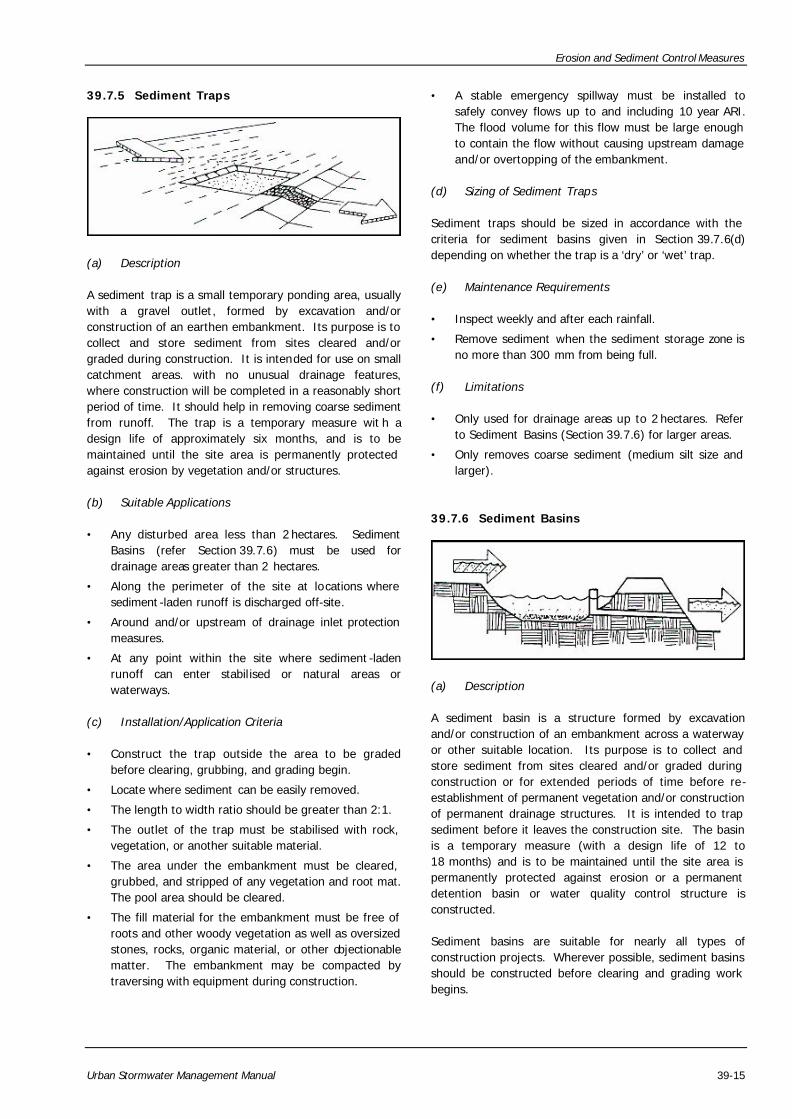
(a) Description
A sediment trap is a small temporary ponding area, usually with a gravel outlet, formed by excavation and/or construction of an earthen embankment. Its purpose is to collect and store sediment from sites cleared and/or graded during construction. It is intended for use on small catchment areas. with no unusual drainage features, where construction will be completed in a reasonably short period of time. It should help in removing coarse sediment from runoff. The trap is a temporary measure wit h a design life of approximately six months, and is to be maintained until the site area is permanently protected against erosion by vegetation and/or structures.
(b) Suitable Applications
• Any disturbed area less than 2 hectares. Sediment Basins (refer Section 39.7.6) must be used for drainage areas greater than 2 hectares.
• Along the perimeter of the site at locations where sediment -laden runoff is discharged off-site.
• Around and/or upstream of drainage inlet protection measures.
• At any point within the site where sediment -laden runoff can enter stabilised or natural areas or waterways.
(c) Installation/Application Criteria
• Construct the trap outside the area to be graded before clearing, grubbing, and grading begin.
• Locate where sediment can be easily removed.
• The length to width ratio should be greater than 2:1.
• The outlet of the trap must be stabilised with rock, vegetation, or another suitable material.
• The area under the embankment must be cleared, grubbed, and stripped of any vegetation and root mat. The pool area should be cleared.
• The fill material for the embankment must be free of roots and other woody vegetation as well as oversized stones, rocks, organic material, or other objectionable matter. The embankment may be compacted by traversing with equipment during construction.
• A stable emergency spillway must be installed to safely convey flows up to and including 10 year ARI. The flood volume for this flow must be large enough to contain the flow without causing upstream damage and/or overtopping of the embankment.
(d) Sizing of Sediment Traps
Sediment traps should be sized in accordance with the criteria for sediment basins given in Section 39.7.6(d) depending on whether the trap is a ‘dry’ or ‘wet’ trap.
(e) Maintenance Requirements
• Inspect weekly and after each rainfall.
• Remove sediment when the sediment storage zone is no more than 300 mm from being full.
(f) Limitations
• Only used for drainage areas up to 2 hectares. Refer to Sediment Basins (Section 39.7.6) for larger areas.
• Only removes coarse sediment (medium silt size and larger).
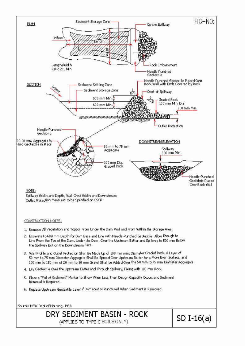
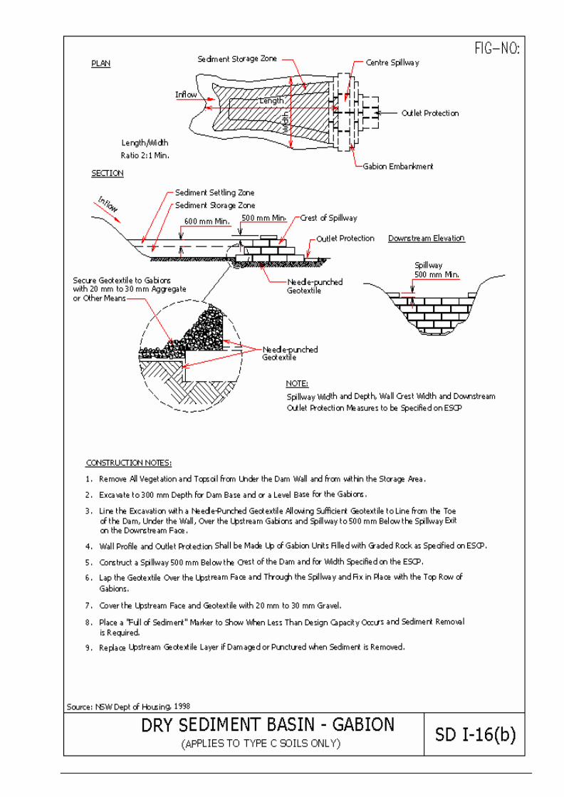
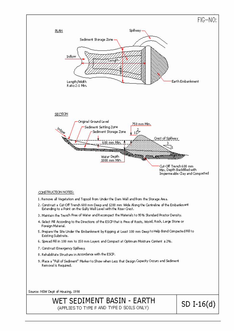
39.7.6 Sediment Basins
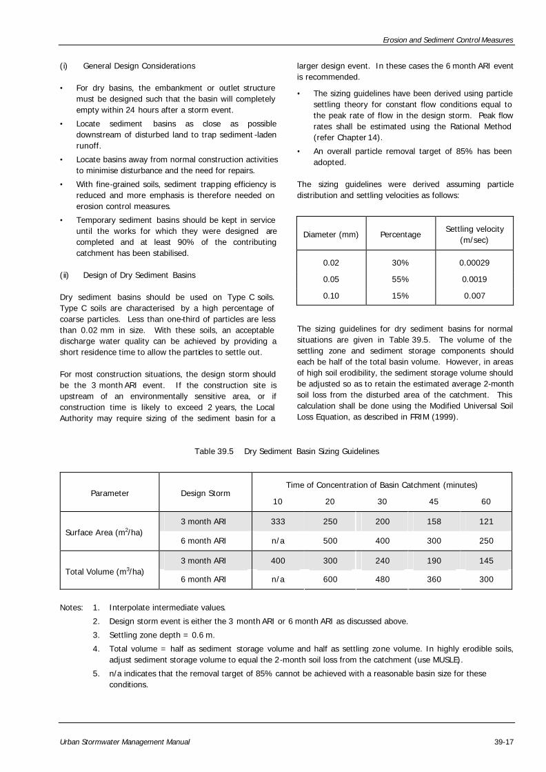
(a) Description
A sediment basin is a structure formed by excavation and/or construction of an embankment across a waterway or other suitable location. Its purpose is to collect and store sediment from sites cleared and/or graded during construction or for extended periods of time before re-establishment of permanent vegetation and/or construction of permanent drainage structures. It is intended to trap sediment before it leaves the construction site. The basin is a temporary measure (with a design life of 12 to 18 months) and is to be maintained until the site area is permanently protected against erosion or a permanent detention basin or water quality control structure is constructed.
Sediment basins are suitable for nearly all types of construction projects. Wherever possible, sediment basins should be constructed before clearing and grading work begins.

Erosion and Sediment Control Measures
39-16 Urban Stormwater Management Manual
(b) Suitable Applications
• At the outlet of all disturbed catchment areas greater than 2 hectares.
• At the outlet of smaller disturbed catchment areas, as necessary.
• Where permanent detention basins or water quality control struct ures will be located.
• Should be used in association with earth banks, diversion channels pipes, and other measures used to divert disturbed areas into the basin and divert undisturbed areas around the basin.
(c) Installation/Application Criteria
• Sediment basins must be installed entirely within the limits of the site.
• Construct before clearing and grading work begins.
• Basins must not be located in a stream.
• All basins should be located where failure of the embankment would not result in loss of life, damage to homes or buildings, or interruption of use or service of public roads or utilities.
• Local ordinances regarding health and safety must be adhered to.
• Large basins may be subject to State and/or Federal dam safety requirements. Refer to Section 35.5 for dam design considerations.
• Sediment traps are attractive to children and can be very dangerous. Adequate safety precautions must be provided by restricting access to the site or access to the basin with suitable fencing.
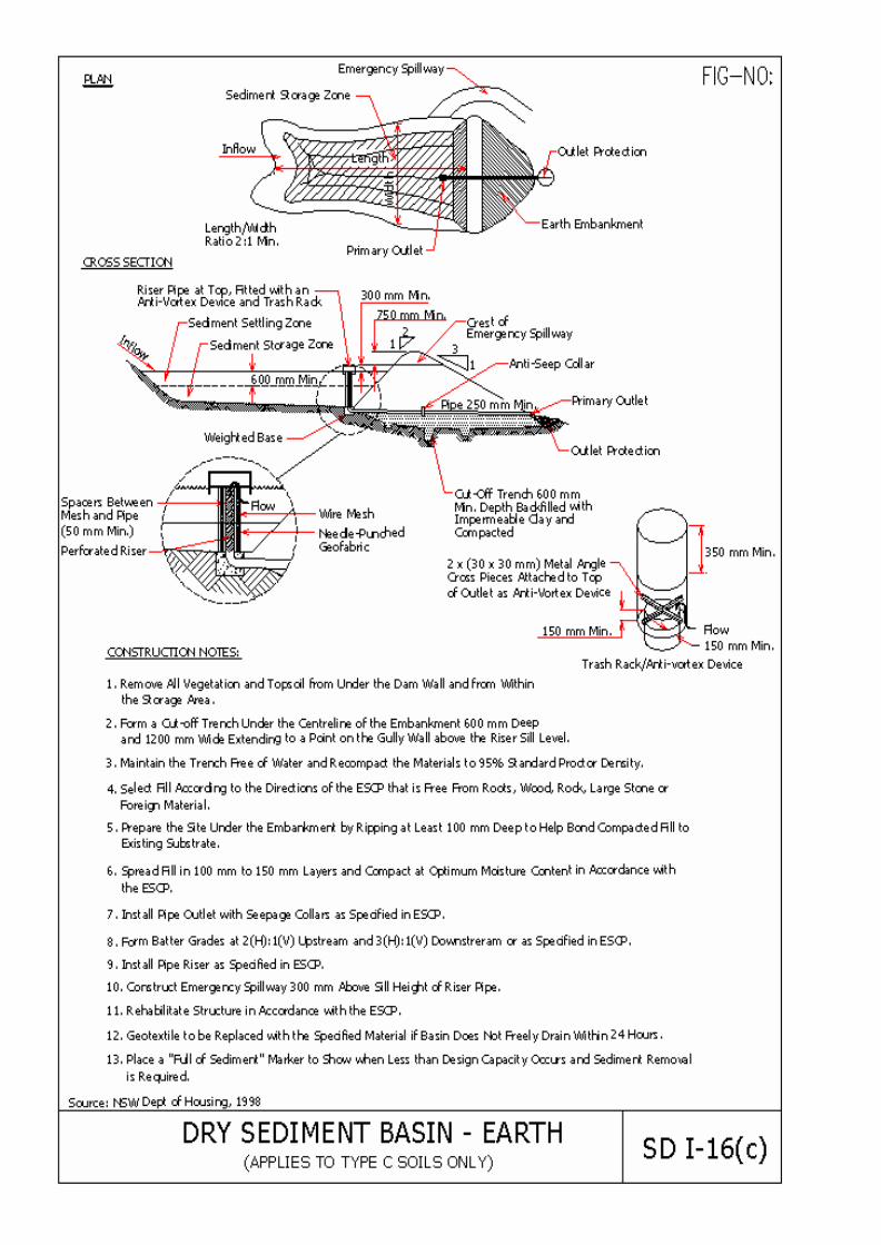
• For dry basins, securely anchor and install an anti-seep collar on the outlet pipe/riser.
• A stable emergency spillway must be installed to safely convey flows up to and including 10 year ARI. The flood volume for this flow must be large enough to contain the flow without causing upstream damage and/or overtopping of the embankment.
• The basin should be sized in accordance with the criteria given in Section (d).
• The basin length to settling depth ratio should be less than 200:1.
• The basin length to width ratio should be greater than 2:1. If not , baffles should be provided to prevent short-circuiting.
• Side slopes should not be steeper than 2(H):1(V) to prevent sloughing.
• Sediment basins may be capable of trapping smaller sediment particles if sufficient detention time is provided. However, they are most effective when used in conjunction with other BMPs to minimise the amount of sediment mobilised and carried to the basin.
(d) Sizing of Sediment Basins
The effective design and operation of sediment basins depends primarily on the nature of the soil materials likely to be eroded and washed into the basin.
The design approach allows for differences in the settling behaviour of different size particles in water. Clearly, coarse-grained sediment will settle quicker than fine-grained sediment, and some types of clay particles never settle at all unaided.
Table 39.4 lists the three different soil types discussed in this section, and the design considerations which apply to sediment basin design and operation for each soil type. This approach is based in part on recommendations from the NSW Department of Housing (1998).
Table 39.4 Sediment Basin Types and Design Considerations
Soil Description Soil
Type Basin Type
Design Considerations
Coarse-grained sand, sandy loam: less than 33% <0.02mm
C Dry Settling velocity, sediment storage
Fine-grained loam, clay: more than 33% < 0.02mm
F Wet Storm impoundment, sediment storage
Dispersible fine-grained clays as per type F, more than 10% of dispersible material
D Wet Storm impoundment, sediment storage, assisted flocculation
The design capacity of a sediment basin is the sum of two components:
• a settling zone at least 0.6 m deep to contain runoff and allow suspended sediment to settle, and
• a sediment storage zone at least 0.3 m deep to store settled sediment until the basin is cleaned out. In some cases, basins may be sized to trap sediment for the life of the construction activity
Where soils of more than one type are present on a site, sediment basins shall be designed to meet the most stringent criterion applicable. Usually, because type F or D soils are more difficult to settle, they will govern the design if present on any significant portion of the basin catchment.
Erosion and Sediment Control Measures
Urban Stormwater Management Manual 39-17
(i) General Design Considerations
• For dry basins, the embankment or outlet structure must be designed such that the basin will completely empty within 24 hours after a storm event.
• Locate sediment basins as close as possible downstream of disturbed land to trap sediment -laden runoff.
• Locate basins away from normal construction activities to minimise disturbance and the need for repairs.
• With fine-grained soils, sediment trapping efficiency is reduced and more emphasis is therefore needed on erosion control measures.
• Temporary sediment basins should be kept in service until the works for which they were designed are completed and at least 90% of the contributing catchment has been stabilised.
(ii) Design of Dry Sediment Basins
Dry sediment basins should be used on Type C soils. Type C soils are characterised by a high percentage of coarse particles. Less than one-third of particles are less than 0.02 mm in size. With these soils, an acceptable discharge water quality can be achieved by providing a short residence time to allow the particles to settle out.
For most construction situations, the design storm should be the 3 month ARI event. If the construction site is upstream of an environmentally sensitive area, or if construction time is likely to exceed 2 years, the Local Authority may require sizing of the sediment basin for a
larger design event. In these cases the 6 month ARI event is recommended.
• The sizing guidelines have been derived using particle settling theory for constant flow conditions equal to the peak rate of flow in the design storm. Peak flow rates shall be estimated using the Rational Method (refer Chapter 14).
• An overall particle removal target of 85% has been adopted.
The sizing guidelines were derived assuming particle distribution and settling velocities as follows:
Diameter (mm) Percentage Settling velocity
(m/sec)
0.02 30% 0.00029
0.05 55% 0.0019
0.10 15% 0.007
The sizing guidelines for dry sediment basins for normal situations are given in Table 39.5. The volume of the settling zone and sediment storage components should each be half of the total basin volume. However, in areas of high soil erodibility, the sediment storage volume should be adjusted so as to retain the estimated average 2-month soil loss from the disturbed area of the catchment. This calculation shall be done using the Modified Universal Soil Loss Equation, as described in FRIM (1999).
Table 39.5 Dry Sediment Basin Sizing Guidelines
Time of Concentration of Basin Catchment (minutes) Parameter Design Storm
10 20 30 45 60
3 month ARI 333 250 200 158 121 Surface Area (m2/ha)
6 month ARI n/a 500 400 300 250
3 month ARI 400 300 240 190 145 Total Volume (m3/ha)
6 month ARI n/a 600 480 360 300
Notes: 1. Interpolate intermediate values.
2. Design storm event is either the 3 month ARI or 6 month ARI as discussed above.
3. Settling zone depth = 0.6 m.
4. Total volume = half as sediment storage volume and half as settling zone volume. In highly erodible soils, adjust sediment storage volume to equal the 2-month soil loss from the catchment (use MUSLE).
5. n/a indicates that the removal target of 85% cannot be achieved with a reasonable basin size for these conditions.

Erosion and Sediment Control Measures
39-18 Urban Stormwater Management Manual
Table 39.6 Wet Sediment Basin Sizing Guidelines
Volume (m3/ha of Catchment)
Magnitude of Design Storm Event in mm (see Appendix 13.C)
Parameter Site Runoff Potential
20 30 40 50 60
Moderate to high runoff 70 127 200 290 380 Settling Zone Volume
Very high runoff 100 167 260 340 440
Moderate to high runoff 105 190 300 435 570 Total Volume
Very high runoff 150 250 390 510 660
Notes: 1. Interpolate intermediate values
2. Design storm event is either the 5-day 75th percentile or 5-day 80th percentile as discussed below.
3. Total volume = one-third as sediment storage volume and two-thirds as settling zone volume. In highly erodible soils, adjust sediment storage volume to equal the 2-month soil loss from the catchment (use MUSLE).
(iii) Design of Wet Sediment Basins
Wet sediment basins should be used on Type F or Type D soils. Recommendations for wet sediment basins are based on the observation that traditional approaches to settling fine sediments, particularly dispersible clays, have been ineffective. The approach adopted is therefore one of storm containment , fully impounding runoff from a nominated design event.
The design event is selected using a risk-based approach. The rainfall and predicted runoff from that design event is then used to size the 'settling' zone of the basin.
• The duration of the design event should be 5 days. This is a reasonable estimate of the time necessary to achieve effective flocculation, settling, and pumpout of the stormwater; allowing for weekends and other days when the site may not be attended.
• For most construction situations, the 75th percentile 5-day rainfall event should be used as the design event. This is the rainfall that is not exceeded in 75% of rainfall events. The figure can be derived by analysis of daily rainfalls. A worked example for deriving 75th percentile 5-day rainfalls is given in Appendix 13.C.
• Where the construction site is upstream of an environmentally sensitive area, or construction is expected to take longer than 2 years, the 80th percentile 5-day event should be used.
• The Volumetric Rational Method (refer Chapter 15) is used to estimate the runoff volume. The appropriate volumetric runoff coefficient is to be selected to suit the soil runoff potential (refer Table 15.4).
Sizing guidelines for wet sediment basins for normal situations are given in Table 39.6. The volume of the sediment storage component for wet sediment basins should be 50% of the settling zone volume. However, in areas of high soil erodibility, the sediment storage volume should be adjusted in a manner similar to that for Type C soils.
(e) Maintenance Requirements
The management and operation of sediment basins also depends primarily on the nature of the soil materials likely to be eroded and washed into the basin.
(i) General
• Inspect weekly and after each rainfall.
• Remove sediment when the sediment storage zone becomes full.
(ii) Dry Sediment Basins
A properly designed and maintained dry sediment basin should drain naturally after heavy rain, through the embankment or outlet riser.
(iii) Wet Sediment Basins
In the case of wet sediment basins, the captured stormwater in the settling zone should be drained or pumped out within the five day period following rainfall, provided that an acceptable water quality has been achieved.

Erosion and Sediment Control Measures
Urban Stormwater Management Manual 39-19
The target water quality should be specified by the Local Authority in terms of the Interim National Water Quality Standards for Malaysia (INWQS). Typically, Class II standards will be required (e.g. TSS < 50 mg/L). If this quality is not achieved by settling, a flocculating agent (e.g. gypsum, enzymes) should be added to the stored water.
A peg or other mark should be placed in the basin to indicate the top of the sediment storage zone. A floating inlet should be used on the pump to ensure that settled sediment is not picked up during the dewatering process.
Because Type D soils contain a significant level of dispersible materials, sediment basins for these soils must
be dosed with a flocculating agent. Supplies of flocculant shall be kept on or near the site for this purpose. Such dosing should occur within 24 hours of a rainfall event.
(f) Limitations
• The basin should have shallow side slopes (maximum 4(H):1(V)) or be fenced to prevent drowning.
• Sites with very fine sediment (fine silt and clay) may require longer detention times for effective sediment removal.
• Basins in excess of certain depth and storage volume criteria must meet State and/or Federal dam safety criteria.
• Standing water may cause mosquitoes or other pests to breed.

Erosion and Sediment Control Measures
24-20
Erosion and Sediment Control Measures
Urban Stormwater Management Manual 39-21
APPENDIX 39.A WORKED EXAMPLE
39.A.1 Sizing a Dry Sediment Basin
Problem: To determine the size of a dry sediment basin and outlet structures required for the Selangor Estate development shown in model plan ESCP2 in Appendix 41.B2. The catchment area for the development is 6 hectares and the following assumptions are made for the sizing of the basin:
• adopted basin type is an earth embankment and perforated outlet as shown in Standard Drawing SD I-16(c)
• most of the surface soil type is sandy loam
• overland sheet flow to the basin will pass over two segments, i.e. Segment A & B with soil types of bare sand and bare clay respectively,
Segment A: LA = 110 m & SA = 0.64%
Segment B: LB = 150 m & SB = 0.80%,
• as the construction period will be less than 2 years, the design storm is 3 month ARI
Solution:
Step (1) : Determine overland flow time of concentration (minutes)
From Equation 14.1, 2.0
333.0107
S
Lnto =
From Equation 14.2(a), t total = t A(LA) + t B(LA +LB) - t B(LA)
For segment A; n = 0.01 (from Table 14.2 for bare sand)
2.0
333.0
AA64.0
110x01.0x107)( =Lt = 5.6 minutes
For segment B; n = 0.02 (from Table 14.2 for bare clay)
2.0
333.0
AB80.0
260x02.0x107)( =+ BLLt = 14.3 minutes
2.0
333.0
AB80.0
110x02.0x107)( =Lt = 10.7 minutes
t total = 5.6 + 14.3 - 10.70 = 9.2 minutes
Adopted time of concentration = 10 minutes
Step (2) : Sizing of sediment basin
From Table 39.4, the predominant soil type is categorised as type C.
From Table 39.5 for a 3 month ARI, the required surface area is 333 m2/ha and the required total volume is 400 m3/ha.
The surface area required for the site = 333 x 6.0 = 1998 m2
(Note: this is the average surface area for the settling zone volume, i.e. at mid-depth)
The total basin volume required for the site = 400 x 6.0 = 2400 m3
(a) Settling Zone:
Erosion and Sediment Control Measures
39-22 Urban Stormwater Management Manual
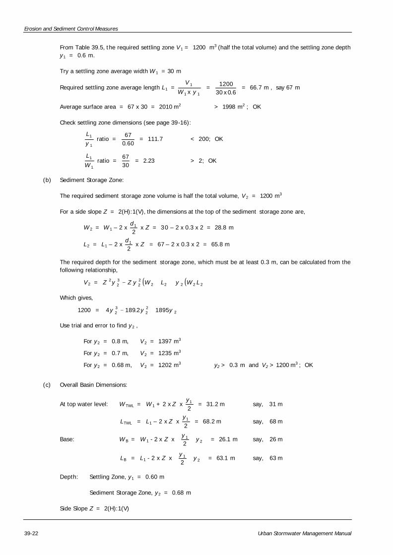
From Table 39.5, the required settling zone V 1 = 1200 m3 (half the total volume) and the settling zone depth y1 = 0.6 m.
Try a settling zone average width W 1 = 30 m
Required settling zone average length L1 = 11
1
x yW
V =
6.0x301200 = 66.7 m , say 67 m
Average surface area = 67 x 30 = 2010 m2 > 1998 m2 ; OK
Check settling zone dimensions (see page 39-16):
1
1
y
L ratio =
60.067
= 111.7 < 200; OK
1
1
W
L ratio =
3067
= 2.23 > 2; OK
(b) Sediment Storage Zone:
The required sediment storage zone volume is half the total volume, V 2 = 1200 m3
For a side slope Z = 2(H):1(V), the dimensions at the top of the sediment storage zone are,
W 2 = W 1 – 2 x 21d
x Z = 30 – 2 x 0.3 x 2 = 28.8 m
L2 = L1 – 2 x 21d
x Z = 67 – 2 x 0.3 x 2 = 65.8 m
The required depth for the sediment storage zone, which must be at least 0.3 m, can be calculated from the following relationship,
V 2 = ( ) ( )2222222
32
2 LWyLWyZyZ ++−
Which gives,
1200 = 222
32 18952.1894 yyy +−
Use trial and error to find y2 ,
For y2 = 0.8 m, V 2 = 1397 m3
For y2 = 0.7 m, V 2 = 1235 m3
For y2 = 0.68 m, V 2 = 1202 m3 y2 > 0.3 m and V2 > 1200 m3 ; OK
(c) Overall Basin Dimensions:
At top water level: W TWL = W 1 + 2 x Z x 21y
= 31.2 m say, 31 m
LTWL = L1 – 2 x Z x 21y
= 68.2 m say, 68 m
Base: W B = W 1 - 2 x Z x
+ 2
1
2y
y = 26.1 m say, 26 m
LB = L1 - 2 x Z x
+ 2
1
2y
y = 63.1 m say, 63 m
Depth: Settling Zone, y1 = 0.60 m
Sediment Storage Zone, y2 = 0.68 m
Side Slope Z = 2(H):1(V)
Erosion and Sediment Control Measures
Urban Stormwater Management Manual 39-23
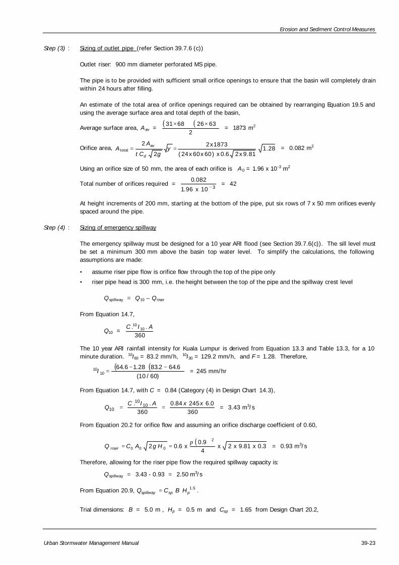
Step (3) : Sizing of outlet pipe (refer Section 39.7.6 (c))
Outlet riser: 900 mm diameter perforated MS pipe.
The pipe is to be provided with sufficient small orifice openings to ensure that the basin will completely drain within 24 hours after filling.
An estimate of the total area of orifice openings required can be obtained by rearranging Equation 19.5 and using the average surface area and total depth of the basin,
Average surface area, A av = ( ) ( )
263266831 ×+×
= 1873 m2
Orifice area, 28.181.9x26.0x)60x60x24(
1873x2
2
2total == y
gCt
AA
d
av = 0.082 m2
Using an orifice size of 50 mm, the area of each orifice is A 0 = 1.96 x 10⁻³ m2
Total number of orifices required = 310x96.1
082.0−
= 42
At height increments of 200 mm, starting at the bottom of the pipe, put six rows of 7 x 50 mm orifices evenly spaced around the pipe.
Step (4) : Sizing of emergency spillway
The emergency spillway must be designed for a 10 year ARI flood (see Section 39.7.6(c)). The sill level must be set a minimum 300 mm above the basin top water level. To simplify the calculations, the following assumptions are made:
• assume riser pipe flow is orifice flow through the top of the pipe only
• riser pipe head is 300 mm, i.e. the height between the top of the pipe and the spillway crest level
Q spillway = Q 10 – Q riser
From Equation 14.7,
Q10 = 360
.. 1010 AIC
The 10 year ARI rainfall intensity for Kuala Lumpur is derived from Equation 13.3 and Table 13.3, for a 10 minute duration. 10I60 = 83.2 mm/h, 10I30 = 129.2 mm/h, and F = 1.28. Therefore,
( )( ))60/10(
6.642.8328.16.6410
10 −⋅−=I = 245 mm/hr
From Equation 14.7, with C = 0.84 (Category (4) in Design Chart 14.3),
3600.624584.0
360.. 10
10
10xxAIC
Q == = 3.43 m3/s
From Equation 20.2 for orifice flow and assuming an orifice discharge coefficient of 0.60,
( )3.0x81.9x2x
49.0
x6.022
000π
== HgACQ riser = 0.93 m3/s
Therefore, allowing for the riser pipe flow the required spillway capacity is:
Q spillway = 3.43 - 0.93 = 2.50 m3/s
From Equation 20.9, 5.1pspspillway HBCQ = .
Trial dimensions: B = 5.0 m , Hp = 0.5 m and Csp = 1.65 from Design Chart 20.2,
Erosion and Sediment Control Measures
39-24 Urban Stormwater Management Manual
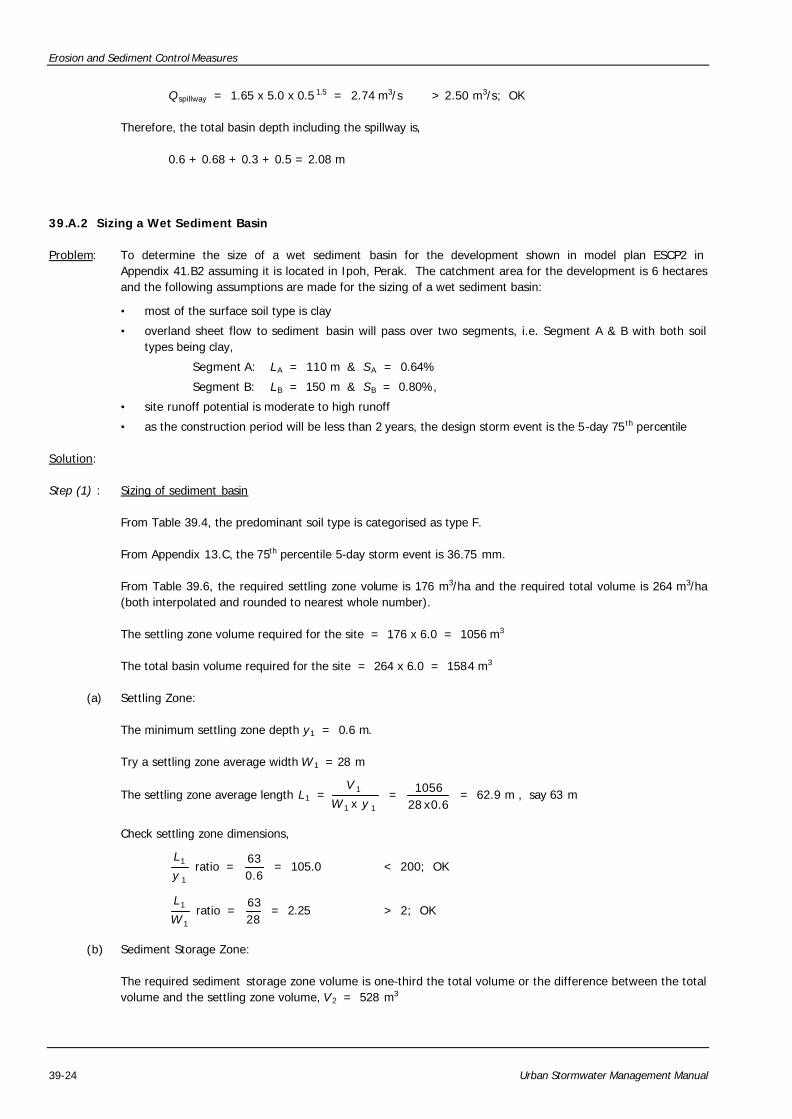
Q spillway = 1.65 x 5.0 x 0.5 1.5 = 2.74 m3/s > 2.50 m3/s; OK
Therefore, the total basin depth including the spillway is,
0.6 + 0.68 + 0.3 + 0.5 = 2.08 m
39.A.2 Sizing a Wet Sediment Basin
Problem: To determine the size of a wet sediment basin for the development shown in model plan ESCP2 in Appendix 41.B2 assuming it is located in Ipoh, Perak. The catchment area for the development is 6 hectares and the following assumptions are made for the sizing of a wet sediment basin:
• most of the surface soil type is clay
• overland sheet flow to sediment basin will pass over two segments, i.e. Segment A & B with both soil types being clay,
Segment A: LA = 110 m & SA = 0.64%
Segment B: LB = 150 m & SB = 0.80%,
• site runoff potential is moderate to high runoff
• as the construction period will be less than 2 years, the design storm event is the 5-day 75th percentile
Solution:
Step (1) : Sizing of sediment basin
From Table 39.4, the predominant soil type is categorised as type F.
From Appendix 13.C, the 75th percentile 5-day storm event is 36.75 mm.
From Table 39.6, the required settling zone volume is 176 m3/ha and the required total volume is 264 m3/ha (both interpolated and rounded to nearest whole number).
The settling zone volume required for the site = 176 x 6.0 = 1056 m3
The total basin volume required for the site = 264 x 6.0 = 1584 m3
(a) Settling Zone:
The minimum settling zone depth y1 = 0.6 m.
Try a settling zone average width W 1 = 28 m
The settling zone average length L1 = 11
1
x yW
V =
6.0x281056 = 62.9 m , say 63 m
Check settling zone dimensions,
1
1
y
L ratio =
6.063
= 105.0 < 200; OK
1
1
W
L ratio =
2863
= 2.25 > 2; OK
(b) Sediment Storage Zone:
The required sediment storage zone volume is one-third the total volume or the difference between the total volume and the settling zone volume, V 2 = 528 m3
Erosion and Sediment Control Measures
Urban Stormwater Management Manual 39-25
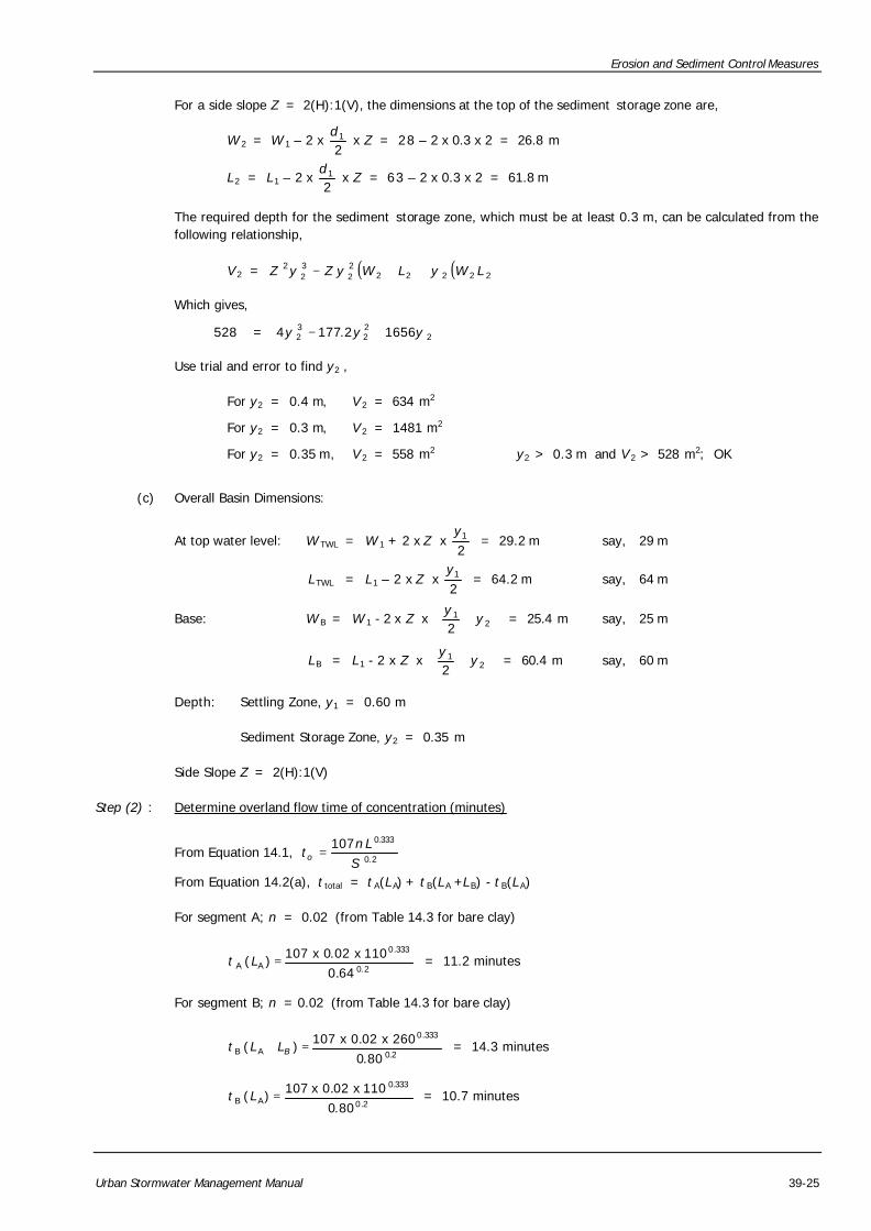
For a side slope Z = 2(H):1(V), the dimensions at the top of the sediment storage zone are,
W 2 = W 1 – 2 x 21d
x Z = 28 – 2 x 0.3 x 2 = 26.8 m
L2 = L1 – 2 x 21d
x Z = 63 – 2 x 0.3 x 2 = 61.8 m
The required depth for the sediment storage zone, which must be at least 0.3 m, can be calculated from the following relationship,
V 2 = ( ) ( )2222222
32
2 LWyLWyZyZ ++−
Which gives,
528 = 222
32 16562.1774 yyy +−
Use trial and error to find y2 ,
For y2 = 0.4 m, V 2 = 634 m2
For y2 = 0.3 m, V 2 = 1481 m2
For y2 = 0.35 m, V 2 = 558 m2 y2 > 0.3 m and V 2 > 528 m2; OK
(c) Overall Basin Dimensions:
At top water level: W TWL = W 1 + 2 x Z x 21y
= 29.2 m say, 29 m
LTWL = L1 – 2 x Z x 21y
= 64.2 m say, 64 m
Base: W B = W 1 - 2 x Z x
+ 2
1
2y
y = 25.4 m say, 25 m
LB = L1 - 2 x Z x
+ 2
1
2y
y = 60.4 m say, 60 m
Depth: Settling Zone, y1 = 0.60 m
Sediment Storage Zone, y2 = 0.35 m
Side Slope Z = 2(H):1(V)
Step (2) : Determine overland flow time of concentration (minutes)
From Equation 14.1, 2.0
333.0107S
Lnto =
From Equation 14.2(a), t total = t A(LA) + t B(LA +LB) - t B(LA)
For segment A; n = 0.02 (from Table 14.3 for bare clay)
2.0
333.0
AA64.0
110x02.0x107)( =Lt = 11.2 minutes
For segment B; n = 0.02 (from Table 14.3 for bare clay)
2.0
333.0
AB80.0
260x02.0x107)( =+ BLLt = 14.3 minutes
2.0
333.0
AB80.0
110x02.0x107)( =Lt = 10.7 minutes
Erosion and Sediment Control Measures
39-26 Urban Stormwater Management Manual
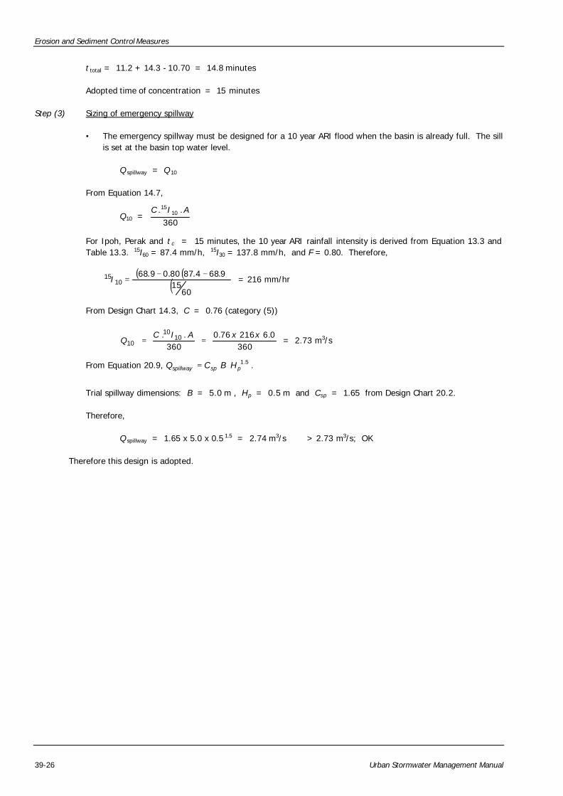
t total = 11.2 + 14.3 - 10.70 = 14.8 minutes
Adopted time of concentration = 15 minutes
Step (3) Sizing of emergency spillway
• The emergency spillway must be designed for a 10 year ARI flood when the basin is already full. The sill is set at the basin top water level.
Q spillway = Q 10
From Equation 14.7,
Q10 = 360
.. 1015 AIC
For Ipoh, Perak and t c = 15 minutes, the 10 year ARI rainfall intensity is derived from Equation 13.3 and Table 13.3. 15I60 = 87.4 mm/h, 15I30 = 137.8 mm/h, and F = 0.80. Therefore,
( )( )( )6015
9.684.8780.09.6810
15 −−=I = 216 mm/hr
From Design Chart 14.3, C = 0.76 (category (5))
3600.621676.0
360.. 10
10
10xxAIC
Q == = 2.73 m3/s
From Equation 20.9, 5.1pspspillway HBCQ = .
Trial spillway dimensions: B = 5.0 m , Hp = 0.5 m and Csp = 1.65 from Design Chart 20.2.
Therefore,
Q spillway = 1.65 x 5.0 x 0.5 1.5 = 2.74 m3/s > 2.73 m3/s; OK
Therefore this design is adopted.
Erosion and Sediment Control Measures
Urban Stormwater Management Manual 39-27
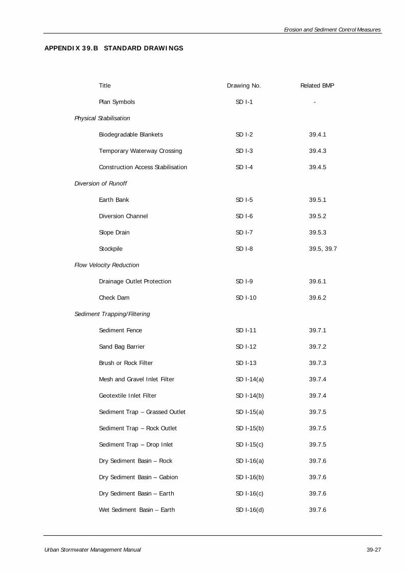
APPENDIX 39.B STANDARD DRAWINGS
Title Drawing No. Related BMP
Plan Symbols SD I-1 -
Physical Stabilisation
Biodegradable Blankets SD I-2 39.4.1
Temporary Waterway Crossing SD I-3 39.4.3
Construction Access Stabilisation SD I-4 39.4.5
Diversion of Runoff
Earth Bank SD I-5 39.5.1
Diversion Channel SD I-6 39.5.2
Slope Drain SD I-7 39.5.3
Stockpile SD I-8 39.5, 39.7
Flow Velocity Reduction
Drainage Outlet Protection SD I-9 39.6.1
Check Dam SD I-10 39.6.2
Sediment Trapping/Filtering
Sediment Fence SD I-11 39.7.1
Sand Bag Barrier SD I-12 39.7.2
Brush or Rock Filter SD I-13 39.7.3
Mesh and Gravel Inlet Filter SD I-14(a) 39.7.4
Geotextile Inlet Filter SD I-14(b) 39.7.4
Sediment Trap – Grassed Outlet SD I-15(a) 39.7.5
Sediment Trap – Rock Outlet SD I-15(b) 39.7.5
Sediment Trap – Drop Inlet SD I-15(c) 39.7.5
Dry Sediment Basin – Rock SD I-16(a) 39.7.6
Dry Sediment Basin – Gabion SD I-16(b) 39.7.6
Dry Sediment Basin – Earth SD I-16(c) 39.7.6
Wet Sediment Basin – Earth SD I-16(d) 39.7.6
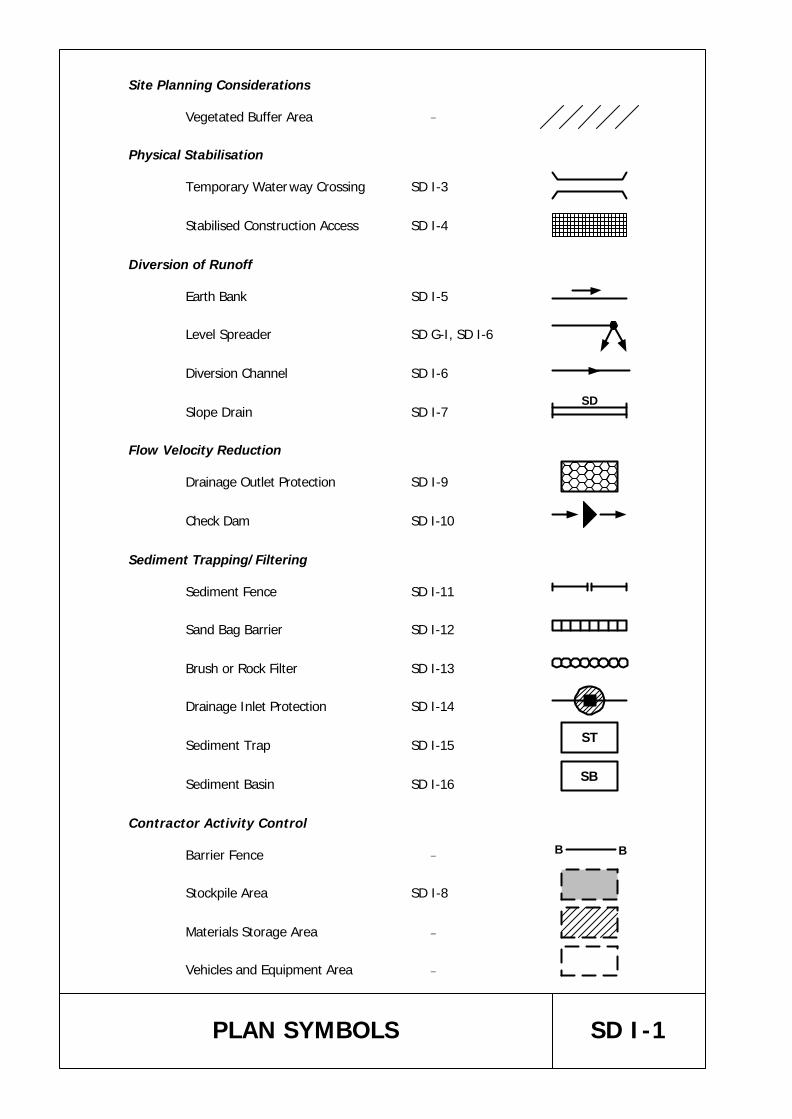
Site Planning Considerations
Vegetated Buffer Area _
Physical Stabilisation
Temporary Waterway Crossing SD I-3
Stabilised Construction Access SD I-4
Diversion of Runoff
Earth Bank SD I-5
Level Spreader SD G-I, SD I-6
Diversion Channel SD I-6
Slope Drain SD I-7
Flow Velocity Reduction
Drainage Outlet Protection SD I-9
Check Dam SD I-10
Sediment Trapping/Filtering
Sediment Fence SD I-11
Sand Bag Barrier SD I-12
Brush or Rock Filter SD I-13
Drainage Inlet Protection SD I-14
Sediment Trap SD I-15
Sediment Basin SD I-16
Contractor Activity Control
Barrier Fence _
Stockpile Area SD I-8
Materials Storage Area _
Vehicles and Equipment Area _
ST
SB
SD I-1PLAN SYMBOLS
SD
B B