Embed Size (px)
Citation preview

2017 Stock Outboard Technical Manual
1
2017 Stock Outboard Technical Manual
(Click on the topic to go directly to the page desired or Ctrl + Home to come back to the first page)
(New rule changes are shaded)
Table of Contents
INSPECTION: .......................................................................................................................................... 4
Inspection Area Requirements .......................................................................................................... 4
The Race committee should: ............................................................................................................. 4
Levels of Inspection .......................................................................................................................... 4
Inspection Tools ................................................................................................................................ 5
Lynco Gage Instructions ................................................................................................................... 5
Fuel Rules ......................................................................................................................................... 5
Fuel Testing Guidelines .................................................................................................................... 6
GENERAL GUIDELINES & RESTRICTIONS .................................................................................... 12
Classes and Motor Eligibility .......................................................................................................... 14
Hulls ................................................................................................................................................ 15
Weight Restrictions ......................................................................................................................... 17
CLASS RULES....................................................................................................................................... 18
A CLASS ........................................................................................................................................ 18
B CLASS ......................................................................................................................................... 22
25SS CLASS ................................................................................................................................... 24
C CLASS ......................................................................................................................................... 30
20SS CLASS ................................................................................................................................... 31
300SS CLASS ................................................................................................................................. 34
D CLASS ........................................................................................................................................ 36
45SS CLASS ................................................................................................................................... 47

2017 Stock Outboard Technical Manual
2
MOTOR SPECIFICATIONS, CHARTS & DIAGRAMS: .................................................................... 48
EVINRUDE/JOHNSON 15 (A CLASS) ........................................................................................ 48
MERCURY/MARINER 15 (A CLASS) ........................................................................................ 53
SIDEWINDER 15S (A CLASS) ..................................................................................................... 58
SIDEWINDER 15H (B CLASS) .................................................................................................... 60
SIDEWINDER 20S (20SSH, B & 25 CLASSES) .......................................................................... 62
HOT ROD 15 (B CLASS) .............................................................................................................. 65
HOT ROD 20 (25 CLASSES) ........................................................................................................ 67
MERCURY 25XS ........................................................................................................................... 70
YAMATO-102, 302 & 321 .............................................................................................................. 73
YAMATO 102 (25SSR, CSR, CSH & 20SSH) .............................................................................. 76
YAMATO 302 - 321 (25SSR, CSR, CSH, 300SSH & 20SSH) ...................................................... 78
YAMATO 302 (300SSH) ................................................................................................................ 80
YAMATO 321 (300SSH) ................................................................................................................ 81
YAMATO 80 (20SSH CLASS) ....................................................................................................... 84
MERCURY 44XS (D CLASS) ....................................................................................................... 88
MERCURY 55H (D CLASS) ......................................................................................................... 91
RAM50 (D CLASS)........................................................................................................................ 94
SUPER THUNDERBOLT (D CLASS) .......................................................................................... 97
MERCURY 402XS (D CLASS) ..................................................................................................... 99
JB – 9/7/17

2017 Stock Outboard Technical Manual
3
Conversion Table
Fraction Decimal Millimeters Fraction Decimal Millimeters
1/64 0.015625 0.3969 33/64 0.515625 13.0969
1/32 0.03125 0.7938 17/32 0.53125 13.4938
3/64 0.046875 1.1906 35/64 0.546875 13.8906
1/16 0.0625 1.5875 9/16 0.5625 14.2875
5/64 0.078125 1.9844 37/64 0.578125 14.6844
3/32 0.09375 2.3813 19/32 0.59375 15.0813
7/64 0.109375 2.7781 39/64 0.609375 15.4781
1/8 0.125 3.1750 5/8 0.625 15.8750
9/64 0.140625 3.5719 41/64 0.640625 16.2719
5/32 0.15625 3.9688 21/32 0.65625 16.6688
11/64 0.171875 4.3656 43/64 0.671875 17.0656
3/16 0.1875 4.7625 11/16 0.6875 17.4625
13/64 0.203125 5.1594 45/64 0.703125 17.8594
7/32 0.21875 5.5563 23/32 0.71875 18.2563
15/64 0.234375 5.9531 47/64 0.734375 18.6531
1/4 0.25 6.3500 3/4 0.75 19.0500
17/64 0.265625 6.7469 49/64 0.765625 19.4469
9/32 0.28125 7.1438 25/32 0.78125 19.8438
19/64 0.296875 7.5406 51/64 0.796875 20.2406
5/16 0.3125 7.9375 13/16 0.8125 20.6375
21/64 0.328125 8.3344 53/64 0.828125 21.0344
11/32 0.34375 8.7313 27/32 0.84375 21.4313
23/64 0.359375 9.1281 55/64 0.859375 21.8281
3/8 0.375 9.5250 7/8 0.875 22.2250
25/64 0.390625 9.9219 57/64 0.890625 22.6219
13/32 0.40625 10.3188 29/32 0.90625 23.0188
27/64 0.421875 10.7156 59/64 0.921875 23.4156
7/16 0.4375 11.1125 15/16 0.9375 23.8125
29/64 0.453125 11.5094 61/64 0.953125 24.2094
15/32 0.46875 11.9063 31/32 0.96875 24.6063
31/64 0.484375 12.3031 63/64 0.984375 25.0031
1/2 0.5 12.7000 1 1 25.4000
Length 1 in = 25.4 mm 1 in = 2.54 cm 1 ft = 0.3048 m
Liquid 1 gal = 3.785 L 1 qt = 0.946 L 1 gal = 231 in3
Volume 1 in3 = 16.387 cm3
1 ft3 = 1728 in3
Weight 1 oz = 23.35 g 1 lb = 4536 g 1 lb = 16 oz

2017 Stock Outboard Technical Manual
4
INSPECTION:
Inspection Area Requirements Inspection of a motor is not a public exhibit. Pit crews are welcome for help in lifting rigs on and off the scales, if
required, but only the driver and the mechanic of the motor being inspected are allowed in the motor teardown area.
The Inspector is in full charge of the entire inspection area. A person representing the Race Committee is
recommended to maintain order and keep outside people from interfering with the Inspector in his work.
The Race committee should: 1. Provide an enclosed area by using either snow fence or roping off the area.
a. Provide at least two tables:
i. One for the Inspectors’ tools
ii. One for engine disassembly
b. Provide motor stands
2. Place the scales in such a position so they are easily accessible to both the drivers and the Inspector.
3. Radio, telephone, or other good communications should be provided between the judge’s stand and the
inspection area. In case of a disqualification the other contestant’s positions have to be recomputed by the
scorers on the basis that the disqualified boat did not participate in the race. Such recompilation does not
always advance all contestants but at times also changes their relative position therefore this information is
required by the Inspector.
4. Provide cardboard boxes for motors that have been torn down along with small plastic bags for the small
parts.
5. Provide a Pit Manager to be in charge of tagging the engines as the rig is weighed. Wired shipping tags are
recommended. The tag should contain class, final position, boat number and weight.
Levels of Inspection 1. Level 1 - Inspection at all races (recommended)
Check height, weight, fuel with Digitron meter, and tuck where applicable.
2. Level 2 – at Divisional, Western & Eastern Championships, Marathon National Championships. (min.)
Level 1 inspection, plus fuel specific gravity or water solubility, cc’s of engine, carburetor dimensions, gear
case dimensions, gear ratios, water inlet (where applicable), stroke & bore with thru spark plug hole
checker.
3. Level 3 – at Summer National Championships and record runs, this will be mandatory.
Level 1 & 2, plus tear down and internal inspection to verify all internal dimensions comply with the current
inspection manual. A level 1 inspection will be conducted prior to sealing a motor.

2017 Stock Outboard Technical Manual
5
Inspection Tools The following is intended only as a guide in the acquisition of tools. The experienced Inspector has frequently substituted other equally satisfactory tools.
1. 0”-1” Micrometer, 1”-2” Micrometer, 2”-3” Micrometer. 2. 6” or 8” Dial or Digital Calipers. 3. Large Outside Calipers. 4. Set of Telescoping Gauges (Lufkin 79-L or equivalent). 5. Depth Vernier (Dial & Digital type are also available). 6. 16’ Flexible Steel Tape Rule (Carlson 416 or equivalent). 7. 50 cc Burette 8. 6” Steel Scale. 9. 5/32”, 11/64”, 1/4”, 0.209” (#4), 0.228 (#1) Drills or Drill Blanks. 10. Penlight. 11. APBA Rule Book and Stock Outboard Inspection Manual. 12. Two parallel blocks about 8” long with several holes to serve as measuring surfaces for some
measurements. 13. “S” shape spark plug hole bore gauge. 14. Engine and Gear case templates and instruction sheets (for OMC “A”, 45SS and Mercury 25SX, 44XS). 15. Fuel meter and related equipment. 16. Lynco port checking gages for class A OMC
Lynco Gage Instructions The Lynco plug gages are designed to be used exactly 90 degrees to the port window opening. This positioning of the gage is crucial to the accurate use of the tool. Although it is possible to use without an additional guide, it is recommended that some type of a guide be used to assist in keeping the gage perpendicular to the window being measured. A small v-block can be used for this purpose. The cut end of the gage is used to inspect each port opening. A set of gages consists of three sizes. (.650, .640, and .635). See Specification chart for proper maximum dimension of each port. As each port is measured, the gage should be rotated and tried at various positions. The proper gage should not pass through the port opening while in a perpendicular position. The SO chief inspector may approve the manufacture of Lynco gages by a source other than Lynco.
Fuel Rules 1. The Stock Outboard Category allows the use of pump gasoline, aviation gasoline and automotive racing
gasoline. They may be used separately or mixed together. Pump gasoline is defined as any product, which is offered to the general public for use in passenger automobiles.
2. The addition of any substance other than oil, which is produced for use in consumer 2-cycle marine or off-road recreational products, is strictly prohibited.
3. The race committee may take samples of any competitor’s fuel to be sent for analysis. 4. The race committee may, when notice is given, have available at the race site, a gasoline product for
purchase at a reasonable price and require competitor’s to purchase and use that gasoline. 5. In addition, the APBA Board of Directors is in process of establishing a list of banned harmful substances
that might be used additives in fuel. The SORC has agreed that this list, when available, will be part of the

2017 Stock Outboard Technical Manual
6
Stock Outboard Category Fuel Rules and any substance contained on the banned list would be treated in the same manner as Dioxane.
6. All fuel tanks must have a minimum sized opening of 1” and be able to accept the Digatron fuel meter probe.
Fuel Testing Guidelines It is recommended that evaluation of fuels be conducted using the following tests, in preference as listed. Additional
tests may be used if deemed necessary.
Digatron DT-15, Digatron DT 47 FT or the Digatron FT 64 Fuel meter Tester
Specific gravity Test
Water Solubility Test
Ceric Nitrate Reagent Test
Germaine Fuel Test
Instructions for each of the above four tests are given below.
Digatron DT-15/47FT Fuel Meter Instructions The purpose of this test is to measure certain electrical properties of the fuel sample and determine if they are within
the permissible limits. The test procedures described herein are in accordance with the instructions supplied by the
Digatron DT15 fuel meter manufacturer. Before performing your fuel testing, ensure that the fuel meter is in good
working order:
1. Sensor Condition -Visually check the sensor and its connecting wire to assure that it has not been damaged.
2. Battery Condition -When the meter is on, the words “LO BAT” will appear in the upper left corner of the
display if the battery needs to be replaced. Do not use the meter if the “LO BAT” is displayed, as its readings
will not be accurate.
3. The recommended fuel test procedure is as indicated below:
a. Turn the meter on and allow it to warm up at least 15 minutes before doing any testing. This will
allow the internal components to stabilize at their normal operating temperature.
b. Attach the sensor’s connecting wire to the meter. Hold the sensor’s connecting wire and lower the
sensor into the calibration liquid—Cyclohexane (C6H12)—such that the sensor is completely
submerged. Take care to assure that the sensor is not in contact with the container. Gently wiggle
the sensor wire to displace any air bubbles that may be trapped between the sensor plates. Using
the knob on the front of the meter, adjust until “-75” is shown on the display.
c. Remove the sensor from the calibration liquid, and blow any excess liquid from between the plates.
Lower the sensor into the fuel sample, in the fashion described in item “b” above.
d. Observe the reading on the meter’s display. If the reading is zero or a negative number, the fuel is
legal. If the reading is greater than zero (a positive number), the fuel is not legal.
4. The electrical characteristics of gasoline change somewhat with temperature. As such, it is important that
the temperature of the calibration liquid and the fuel sample be within about 15 degrees F of each other.
When a fuel sample is found to be illegal, per the above procedure, it is recommended that the following
additional steps be performed:
a. Clean the sensor with some spray-on brake cleaner and allow it to air-dry at least 30 seconds.
b. Re-check the calibration setting (-75) of the meter in Cyclohexane and adjust if necessary.

2017 Stock Outboard Technical Manual
7
c. Allow the fuel sample to stabilize to the same temperature as the Cyclohexane and then repeat the
test as described in item 3 above. During the course of the day, it is recommended that the
calibration setting in Cyclohexane be occasionally checked. It is interesting to note that the
calibration reading of “-75” in Cyclohexane has a corresponding reading when the sensor is in air,
although this corresponding air reading varies somewhat with each particular meter. As such, the
specific corresponding air reading for the particular meter being used can be a useful reference
during the time between occasional Cyclohexane calibration checks.
Specific Gravity Testing Instructions
The purpose of this test is to measure the relative density of a fuel sample and determine if it is within the permissible
limits. Two pieces of special equipment are required to perform this test:
1. Specific gravity hydrometer(s) which cover the range of 0.750 -0.800 (at 60F).
2. A clear glass container, which is at least as tall as the hydrometer. A “graduated cylinder” works well for this
purpose. The recommended fuel testing procedure is as indicated below:
a. Assure that the glass container and hydrometer are clean.
b. Place the glass container on an essentially level surface and fill with the fuel that is to be tested.
The depth of the fuel should be equal to or greater than the length of the hydrometer.
c. Carefully insert the hydrometer into the fuel sample with the weighted end facing down. Take care
to minimize the contact between the hydrometer and the container.
d. When the hydrometer has reached a stable free float in the fuel sample, read the specific gravity
from the scale within the hydrometer. This is done by visually sighting along the upper surface of
the fuel and reading where the scale crosses the fuel’s surface. Record this reading.
e. The specific gravity characteristics of fuel (gasoline and
oil) change somewhat with temperature. As such, the maximum permissible specific gravity reading
will change as the fuel temperature changes. Below is a listing of the maximum permissible specific
gravity readings and their corresponding fuel temperature: The Minimum Specific Gravity reading
for fuel is .700.
Fuel Temperature (F) Maximum Permissible Specific Gravity Reading
40º 50º 60º 70º 80º 90º
100º 110º
0.785 0.780 0.775 0.771 0.776 0.761 0.757 0.752

2017 Stock Outboard Technical Manual
8
Water Solubility Testing Instructions
The purpose of this test is to determine if water-soluble additives are present in a fuel sample. The only piece of
special equipment necessary to perform this test is a graduated container. It is recommended that a good quality
clear glass graduated cylinder be utilized, with a capacity of 100 ml and subdivisions of 0.1 ml (or less). The
recommended fuel testing procedure is as indicated below:
1. Assure that the graduated cylinder is clean.
2. Place the graduated cylinder on an essentially level surface.
3. Pour approximately 60 ml of the fuel sample into the graduated cylinder.
4. Carefully measure and record the amount of fuel in the graduated cylinder using the scale on the cylinder.
5. Slowly pour approximately 35 ml of water into the graduated cylinder.
6. The liquid in the cylinder will separate into two layers. The water will settle to the bottom of the cylinder,
carrying water-soluble additives with it. Froth may form in the lower layer. Allow time for the froth to clear.
7. Measure and record the total amount of liquid in the graduated cylinder using the scale on the cylinder.
8. Subtract the amount of fuel in the cylinder (step 4) from the total liquid (step 7) to determine the exact
amount of water that was added. Record this result.
9. Carefully measure and record the amount of liquid in the lower layer of the graduated cylinder using the
scale on the cylinder.
10. If the amount of liquid in the lower layer (step 9) is greater than the amount of water added (step 8), the fuel
contains water-soluble additives and is not legal.
Ceric Nitrate Reagent Testing Instructions
The purpose of this test is to determine if alcohol is present in a fuel sample.
1. Following is a list of special equipment necessary to perform this test:
50 ml graduated cylinder with subdivisions of 1.0 ml (or less).
100 ml glass beaker.
18 mm X 150 mm clear glass test tube.
2 ounce glass dropper bottle with dropper assembly.
2. Following is a list of the chemicals necessary to perform this test:
Ceric Ammonium Nitrate (NH4)2Ce (NO3)6.
Nitric Acid (HNO3) (70%).
3. The Reagent Solution should be made prior to the race (within a couple of days) and is done as follows:
a. Pour 41 ml of distilled water into the glass beaker.
b. Carefully add 9.0 ml of Nitric Acid to the water in the glass beaker.
c. Add 20 grams of Ceric Ammonium Nitrate to the solution in the glass beaker.

2017 Stock Outboard Technical Manual
9
d. Dissolve the Ceric Ammonium Nitrate by gently stirring. Slight heating of the solution will speed the
process; however, DO NOT BOIL!
e. Pour the Reagent Solution into the dropper bottle and secure the cap. The Reagent Solution should
have a yellow color.
4. Recommended fuel test procedure:
a. Pour approximately 10 ml of the fuel sample into the test tube.
b. Carefully add six (6) drops of the Reagent Solution to the fuel sample in the test tube.
c. Seal the open end of the tube and invert several times.
d. The Reagent Solution should accumulate at the bottom of the test tube. Observe the color of the
accumulated Reagent Solution. If it is the same color (yellow) as the original solution in the dropper
bottle, the fuel sample contains no alcohol. If the accumulated Reagent Solution in the test tube
has changed its original color (yellow) to orange or red, the fuel sample contained alcohol and is
not legal.
Germaine Fuel Test Because of the serious health risks of the agent Dioxane, a very serious penalty has been adopted by the SORC if it
is found at a race. Dioxane is a very powerful carcinogen! The MSDS information is posted on APBA’s website. Anyone
found to have Dioxane in his or her fuel will be suspended for a period of one year from the date of disqualification!
Specifically, the rule is:
“Using the prescribed Germaine Fuel Test as outlined following this rule. If a participant is disqualified for failing the
Germaine fuel test, he/she will be allowed to compete in subsequent races only if their fuel is pre-qualified with
inspection prior to each race. If the official lab results confirm the initial Germaine test results, the one-year suspension
is retroactive to the time of the initial disqualification. Any races that the participant competed in since that initial
disqualification will be re-scored to reflect the suspension. This would mandate an automatic appeal for the driver,
unless the driver specifically requests that the sample not be submitted to the lab”.
1. Equipment required:
Disposable test tubes
Test tube rack suitable to hold test tubes above
Disposable eyedroppers or pipettes
Protective latex or rubber gloves
Bottle of Germaine reagent - The Germaine Reagent is available from John Copeland at Fox Valley
Kart Shop, 520 N 9th St., Lafayette, IN 47904. Phone number 765-7420935 - Fax 765-429-8395
Email: [email protected]
Optional:
Bottle of 1.4 dioxane
A bottle of known legal fuel
Test tubes and pipettes can be purchased from most supply houses. Fisher Scientific part numbers below:
Test Tubes – p/n 14958D – 13 x 100 ml

2017 Stock Outboard Technical Manual
10
Test Tube Rack – p/n 14809A – supports 72 tubes 10-13 ml
Pipettes – p/n 137117 – 7.7 ml Nytril Gloves can be purchased locally. Safety glasses should be worn.
NOTE: Try to keep your chemicals shaded while using, stored in dark container. Reagent is light sensitive and will
turn color.
Germaine Reagent Fuel Test Procedure 1. Using a new, clean pipette or eyedropper, draw a fuel sample from competitor’s tank or fuel line and fill test tube
approximately 2/3 full. Always use a new pipette and a new test tube for each competitor.
2. Wearing protective latex or rubber gloves carefully squeeze one drop of Germaine Reagent directly into the center
of the fuel sample in the test tube. Do not allow reagent to run down the side of the test tube, as it makes reading the
test more difficult.
NOTE: Most users will find the test easier to read by holding the tube up at eye level when the reagent is added
to make viewing any reaction more convenient.
3. When the Germaine reagent drop first hits the fuel sample, any oil dissolved and/or suspended in the gasoline will
come out of solution and fall immediately to the bottom of the test tube. This is not a positive reaction. Different oils
may react differently, but a single, fast falling drop is typical.
4. The formation of a white or light brown precipitate (like little snowflakes) at the point where the Germaine Reagent
hits the fuel sample is a positive indication of the presence of 1.4 dioxane. The precipitate will drift, depending on size
and density, to the bottom of the test tube. Within a few minutes it will darken from contact with oil drop in the bottom
of the tube.
5. It is always advisable to repeat a positive test to insure that no error has been made.
6. It is a good practice to carry a sample of known legal fuel and a sample of 1.4 dioxane to use as a verifying test.
Simply make up 3 test tubes, one containing the known legal fuel, one containing known legal fuel to which you then
add some 1.4 dioxane, and one containing the competitor’s fuel. Then repeat the test, observing any reaction in the
known legal sample, then the known legal sample containing 1.4 dioxane, and finally the competitor’s sample. Having
observed the reaction of the sample known to contain 1.4 dioxane, it will be easier to confirm the reaction in the
competitor’s sample.
Recommended Procedure for Measuring Combustion Chamber Volume 1. The engine should be elevated in such a manner so that the face of the cylinder head is horizontal in position.
2. The piston in the cylinder to be measured should be set at top dead center (TDC).
3. A titrating burette (preferably 50 ml capacity) graduated in 0.1 cc increments should be used.
4. A mixture of 50% mineral spirits and 50% TCW II or III outboard motor oil should be used as the measuring fluid.
This mixture should be prepared in a separate container not the burette.
5. The burette should be filled with the measuring fluid to well above the 0.0 cc marks. Note: The liquid in the burette
should be inspected to insure that there are no bubbles present especially at the location of the meniscus. Air bubbles
will cause an erroneous reading. Gently tapping the side of the burette will disperse the bubbles.
6. The burette should be drained through the use of the stop-cock so as to read exactly 0.0.
2017 Stock Outboard Technical Manual
11
Note: The burette should be read at the bottom of the meniscus (the concave line at the top of the column of fluid).
A reading taken from other than the bottom of the meniscus will be inaccurate.
7. The burette should now be drained into the cylinder containing the piston placed at TDC (step 2) until the fluid
reaches the bottom of the spark plug threads. At this point close the stop-cock and carefully rock the engine slightly
from side to side and top to bottom to evacuate any air from within the cylinder.
Note: Drain the burette slowly so as not to introduce air bubbles into the combustion chamber.
8. Continue to drain the burette until the fluid level reaches the very top of the spark plug threads.
Note: In the case of engines with angled spark plugs the centerline axis of the spark plug should be vertical (i.e.
the OMC A engine).
9. The combustion chamber volume may now be read from the burette. Remember, the reading should again be
taken at the bottom of the meniscus. Your reading should be recorded to within five-hundredths (0.05) of a cc. To
accomplish this you must estimate if the meniscus is half way between two tenth (0.1) cc graduation lines.
10. Compare the reading obtained from the burette to the cc specification of the engine being measured. If the burette
reading is equal to or greater than the minimum cc requirement, then the engine is legal. In the event the burette
reading is less than the minimum cc requirement the engine is not legal.
Note: Should the first cylinder measured be found to be right at or less than the minimum cc specification, the above
process should be repeated on the remaining cylinders. Should it become necessary to repeat this process on a
cylinder that has just been measured, under no circumstances should solvents be used to flush the measuring fluid
from the cylinder. If the engine has a removable cylinder head it is not to be removed to allow cleaning of the
combustion chamber. The only acceptable method of cleaning the measuring fluid from the cylinder is to run the
engine for several minutes. This will restore the combustion chamber to its original state (as raced).
It is recommended that you try to have another Inspector assist you during this procedure. He will be able to verify
the accuracy of the measurements.

2017 Stock Outboard Technical Manual
12
GENERAL GUIDELINES & RESTRICTIONS
1. Responsibility- The driver shall be responsible for the condition of the motor and boat as raced. For
instance, errors on the part of the manufacturer, boat builder, mechanic, or previous owner will not excuse
non-compliance with the rules.
2. Parts comparison- Allowable modifications herein are for either safety reasons or repair purposes. An
Inspector may compare questionable parts to new ones. Use of these rules for an unfair advantage will be
grounds for disqualification.
3. Machining- Internal machined surfaces may be re-machined so long as minimum and maximum
dimensions are met. Cast or forged surfaces must remain as cast with no alterations, bead blasting, sand
blasting, media blasting, or blasting by any other material, or polishing. NOTE: It is not permissible to re-
machine internal machined surfaces that do not have specific dimensions. (See specific class rules for other
restrictions or exceptions).
4. Substitution- There shall be no substitution of components such as lower units, carburetors, etc. unless
replacement components are specifically designated as stock for a particular model by the SORC.
5. Part alteration- Any make of spark plugs or propellers (except 300SSH) may be used provided other parts
are not altered to accommodate them.
6. Broken or damaged parts- may be repaired by welding or the use of plastic compounds, provided that all
internal dimensions, contours, and surfaces remain the same as the original cast or machined surface. The
Inspector will pass repairs which meet the word and spirit of this rule, but will disqualify engines having
repairs which are obviously intended to provide an unfair advantage.
7. Broken skegs and cavitation plates- may be used provided that the edge of the break or breaks have not
been filed or smoothed or otherwise altered, and provided that reasonable time was not available for repair
or replacement. One or two weeks will be considered a reasonable amount of time. At championship events,
the Inspector may rule out the use of broken skegs or cavitation plates.
8. Helicoils- It is permissible to repair stripped threads by tapping oversize or using helicoils or threaded
inserts.
9. Ports- It is permissible to break the edge of the port windows, but it is not legal to chamfer them. (Note:
some of the current motors we race have chamfered ports and it is legal in those class motors to have a
chamfered port. For example, Hot Rod engines).
10. Towing- Each boat must be equipped with a device enabling it to be towed, such as a hole, handle or
screw eye on the bow that is capable of handling a rope.
2017 Stock Outboard Technical Manual
13
11. Replacement parts-
a) Only such parts shall be permitted as are standard production OEM parts used on the motor as the
purchaser may obtain from the dealer as a stock item or products as approved by the Stock Outboard
Technical Committee and the Stock Outboard Racing Commission, and published in the Propeller, and
available to the general public through dealers. These products cannot provide any performance
advantage over original OEM parts.
b) Final approval of non-OEM parts for use in Stock racing shall not be given until the Chairman of the
SORC has advised the Technical Chairman that he or she is satisfied that all provisions of these rules
have been complied with.
c) Non-OEM parts must be submitted for approval to the Chairman of the SORC.
d) The Chairman shall then take those steps as are necessary to insure that the non-OEM parts
substantially comply with the OEM specifications for which the non-OEM part would be used
as a replacement.
e) With such submission, the manufacturer of the non-OEM part shall submit drawings, pictures and
accompanying specifications for the part to the Chairman.
f) The Stock Outboard Technical Committee reserves the right to deny approval of such parts for any
reason and to retain all submitted parts for a period of one year.
g) A list of approved non-OEM parts shall be listed in the Stock Outboard Inspection Manual. This list shall
include the name of the manufacturer and the OEM identification for that part.

2017 Stock Outboard Technical Manual
14
Classes and Motor Eligibility
1) An outboard motor is defined as a complete combustion power and propulsion unit that can be attached to
a boat and which can be lifted bodily by human power from the hull as one unit. Batteries used for ignition
and starting, tachometer, throttle control and steering arrangements are not included in this description.
2) Only one motor shall be used on a hull.
3) There shall be only one propeller of three (3) blades or less.
4) The eligibility rules in situations involving commercial connections are as follows:
i) No equipment can be campaigned as the entry of any corporation or business
concern. Names and advertisements in good taste will be allowed.
ii) No part of this rule is to be construed as a ban on individuals who sell boats and motors through
recognized dealerships.
5) All rules pertaining to the 300SSH class are frozen for a period of three years from November 1, 2014 to
November 1, 2017.
6) Motors shall be divided into classes as follows:
Class
ASR & ASH
BSR & BSH
CSR & CSH
DSR & DSH
20SSH
25SSR
25SSH
300SSH
45SST
Yamato 102 (1/2" or 9/16" restrictor), Mercury 25SS & Sidewinder 20s
Mercury 25SS, Mercury & Mariner 25XS w/o restrictor, Hot Rod 20 ci & Sidewinder 20s
Yamato 302 & Yamato 321
Johnson & Evinrude 45SS
Mercury & Mariner 25XS w/o restrictor, Hot Rod 20 ci, Yamato 302 - 321 (1/2" or 9/16" restrictor),
Permitted Motors (* Motor of choice)
Johnson & Evinrude 'A', Mercury & Mariner 'A' & Sidewinder 15s*
Hot Rod 15ci, Sidewinder 15h & Sidewinder 20s* (3/4" restrictor)
Mercury Mark 55-H, 402XS, Mercury & Mariner 44xs, Tohatsu Ram50* & Super Thunderbolt
Yamato 102, 302* & 321*
Yamato 80, Yamato 102 (7/16" restrictor), Yamato 302 - 321 (7/16" restrictor)* & Sidewinder 20s*

2017 Stock Outboard Technical Manual
15
Hulls
The following hull dimensions shall apply:
“A” Minimum beam measured at widest point where the transom and chine meet, but not to include spray rails or
rub moldings.
“B” Minimum length measuring centerline of hull from trailing edge of bottom to a point perpendicular to stem and
planing surface.
A. A Runabout hull is defined as a racing monoplane as qualified in this rule.
1) The planing surface of a runabout shall be the lowest immersed surface at the aft end of the hull to a point
36 inches forward. Also, the planing surface shall be flat forward for 18 inches at the keel. For purpose of
inspection, all measurements shall be made with a tolerance plus or minus 1/16 inch, as applicable.
2) No part of the immersed surface may have a negative dead rise. The immersed surface may have a
maximum notch of 5/8”, and turning fins may also be added to the immersed surface.
3) Runabouts shall have no through the hull air passages, vented surfaces or wings. The intent of this rule is
to have the air flow over the outside surfaces of the hull.
4) A runabout shall not have a sponson/pod protruding from the side of the boat which interrupts the line of
the side, non-trip, or bottom of the boat.
MOTOR WIDTH "A" LENGTH "B"
ASR Any legal 44” 9’5”
BSR Any legal 44" 9'5"
25SSR Mercury, Hot Rod B 20 ci 44" 9'5"
Sidewinder 20S 46" 10'
Yamato 102, 302, 321 1/2” 48" 11'5"
Yamato 102, 302, 321 9/16” restrictor 48" 11'5"
CSR Any legal 48" 11'5"
DSR Any legal 48" 11'5"
2017 Stock Outboard Technical Manual
16
a) BSR ONLY: With the exception of after-plane fins mounted on the transom, turning fin(s) must be
mounted on the planing surface. When the fin is mounted on the planing surface, the fin blade must be
perpendicular to, and not extend beyond, the vertical plane of the planing surface.
B. Hydroplanes—
1) Hulls primarily defined as Runabout may not compete in a race advertised for Hydroplanes.
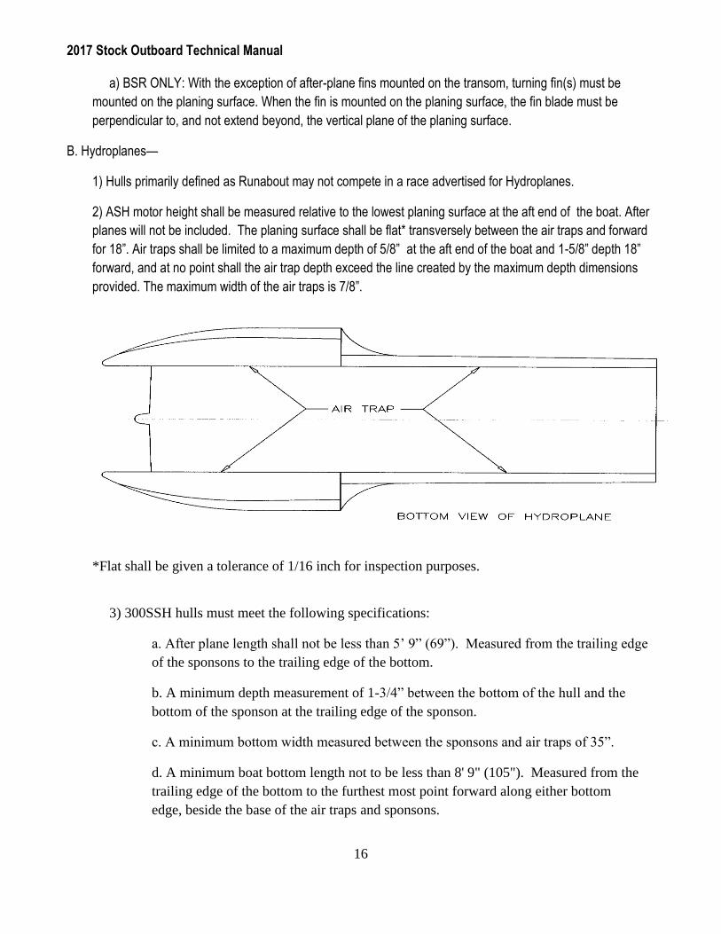
2) ASH motor height shall be measured relative to the lowest planing surface at the aft end of the boat. After
planes will not be included. The planing surface shall be flat* transversely between the air traps and forward
for 18”. Air traps shall be limited to a maximum depth of 5/8” at the aft end of the boat and 1-5/8” depth 18”
forward, and at no point shall the air trap depth exceed the line created by the maximum depth dimensions
provided. The maximum width of the air traps is 7/8”.
*Flat shall be given a tolerance of 1/16 inch for inspection purposes.
3) 300SSH hulls must meet the following specifications:
a. After plane length shall not be less than 5’ 9” (69”). Measured from the trailing edge
of the sponsons to the trailing edge of the bottom.
b. A minimum depth measurement of 1-3/4” between the bottom of the hull and the
bottom of the sponson at the trailing edge of the sponson.
c. A minimum bottom width measured between the sponsons and air traps of 35”.
d. A minimum boat bottom length not to be less than 8' 9" (105"). Measured from the
trailing edge of the bottom to the furthest most point forward along either bottom
edge, beside the base of the air traps and sponsons.

2017 Stock Outboard Technical Manual
17
Weight Restrictions
Minimum Overall Racing Weights (in pounds)
Class Hydro Runabout
A 345
330 with Mercury 15
350 335 with Mercury 15
B 365 360
20SS 400 N/A
25SS 400
102, 302 & 321 With 9/16 Restrictor = 430 102,302 & 321 With ½ Restrictor = 405
Merc 25, Hot Rod, Sidewinder 20 = 395
300SS 420 N/A
C 440 475
D 480 515
45SS 700 N/A
Overall weights shall include driver, hull, motor, steering bar, steering wheel with cables and pulleys, motor
controls, propeller, permanently attached speedometer and tachometer, permanently attached cushions and
hardware, securely fastened weights, securely fastened fuel tank with remaining fuel, helmet, goggles and life
jacket. The overall weight shall not include tools, fire extinguishers, water, or loose equipment in boat or in driver’s
clothing.
2017 Stock Outboard Technical Manual
18
CLASS RULES
A CLASS
1. Permitted Motors
a. Johnson Model # JKT
b. Evinrude Model # EKT
c. Mercury 15
d. Sidewinder Model # 15S
Johnson / Evinrude Specifications The engine should be raced as received from the manufacturer, without modification. Following is a list of
restrictions, descriptions, and modifications, which apply to this engine.
1. It is permissible to leave the gear case unpainted (bare Aluminum). Unpainted gear cases may be polished.
2. The engine shall be operated with the production upper and lower motor covers installed as originally
supplied by the manufacturer. All knobs, grommets and plugs shall remain in place or covered with tape.
3. The mounting of a fuel tank to the engine or steering bar is prohibited.
4. Adjustable high-speed carburetor jets are not permissible. Larger or smaller fixed jets are permissible.
5. The addition or removal of material from any moving part is prohibited, including the flywheel.
6. The addition or removal of material from internal engine components or surfaces is prohibited. However,
the addition of material is permissible in the following circumstances: (1) the water slot hole at the bottom
of the cylinder block and (2) the small hole at the top of the water passages around the exhaust ports.
7. The exhaust passage in the gear case shall retain its original cast surface finish.
8. The gear case may be profiled as long as minimum dimensions and templates are met.
9. It will be permissible to use a thrust bracket of any manufacture, provided the engine is not altered.
10. The steering bar brackets shall have their retainer bolts safety wired as supplied by the manufacturer.
11. Only genuine OMC service parts for this model (1986 or later) will be considered as legal replacement parts.
This includes gear case bolts, connecting rod bolts, throttle plate screws, reed stop screws and cylinder
head gasket. Other than listed above, any make or type of bolt, nut, screw, washer, or gasket may be used,
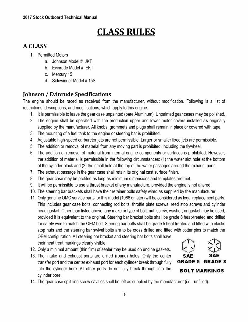
provided it is equivalent to the original. Steering bar bracket bolts shall be grade 8 heat-treated and drilled
for safety wire to match the OEM bolt. Steering bar bolts shall be grade 5 heat treated and fitted with elastic
stop nuts and the steering bar swivel bolts are to be cross drilled and fitted with cotter pins to match the
OEM configuration. All steering bar bracket and steering bar bolts shall have
their heat treat markings clearly visible.
12. Only a minimal amount (thin film) of sealer may be used on engine gaskets.
13. The intake and exhaust ports are drilled (round) holes. Only the center
transfer port and the center exhaust port for each cylinder break through fully
into the cylinder bore. All other ports do not fully break through into the
cylinder bore.
14. The gear case split line screw cavities shall be left as supplied by the manufacturer (i.e. -unfilled).

2017 Stock Outboard Technical Manual
19
15. The only legal cylinder block is OMC part number 396780. The part number is cast on the top of the block
on the exhaust side. Service number 396010 includes block 396780.
16. Any OEM piston manufactured for this model engine is permissible for use in the OMC A engine. These
include part numbers 332364 (standard), 568523 (0.010” oversize), and 393852 (0.030” oversize). The part
number is cast on the under-side of the piston. Service number 397487 includes 332364. Any OEM piston
ring manufactured for this year and model engine is permissible for use in the OMC A engine. This includes
the standard (P.N. 386279) or the 0.030” oversize (P.N. 386288) piston rings. The 0.030” oversize ring may
be used on the 0.010” oversize piston in addition to the 0.030” oversize piston and may be cut down to fit
the cylinder bore for use on the 0.010” oversize piston.
17. It is permissible to hone the wrist pin bores of the pistons to allow for a slip fit of the wrist pin.
18. The factory performs a small de-burring operation on the top of the piston dome to remove flashing at the
mold parting line.
19. The only legal cylinder heads are OMC part numbers 332162 and 336160. The part number is cast on the
back of the head on the lower port side.
20. The only legal flywheels are OMC part numbers 583077 or 583913. The part number is cast on the
underside of the flywheel.
21. OMC Carburetor assembly part number 397653 is stamped into a tag that is fastened to the carburetor.
388275 is stamped into the top of the die-cast carburetor body assembly. Earlier sand-cast carburetors may
also be used as long as they meet all specifications.
22. It is permissible to remove transom cleats, located on the transom surface of the stern bracket.
23. The engine must meet the requirements of OMC inspection templates as listed below:
a. OMC part number 568050, for the gear case.
b. OMC part number 568051, for the shape of the combustion chamber only. (Do not use the template
to measure the top of the piston or the shape of the piston dome.)
c. OMC part number 568052, for the height of the piston and ports.
24. In order to compensate for engines used in the APBA Universal J Class, it is permissible to use two standard
gaskets, OMC part number 318932, between the carburetor and the intake manifold.
25. The only legal transfer port covers are part #328820 #333733, and #336637.
26. It is permissible to machine a portion of the cast surface on the cylinder head adjacent to the head gasket
surface
27. OMC p/n 323497 inner exhaust plate is legal.
28. It is permissible to use plastic reeds—Boyesen #122 and #122R. The shim may be removed provided the
reed stop height is maintained.
29. The screw fastening the carburetor butterfly to the throttle shaft must be furnished by the manufacturer.
With that exception, any make or type of nut, bolt, screw, washer or stud may be used anywhere in the
engine.
30. It is permissible to install replacement solid motor mounts.
31. It is permissible to use an electric starter, as provided by the motor manufacturer and limited to a 12 volt DC
system. The associated electric start flywheel is also allowed
32. It is permissible to secure the water pump impeller to the prop shaft by any means.

2017 Stock Outboard Technical Manual
20
33. Port diameters will be measured with the Lynco plug gauges (520-782-0607). Instructions for use may be
found on page 3. Port openings may have plastic compound added for repair. The entire hole may not be
filled and re-drilled.
34. It is permissible to weld broken carburetors. (Suggested source of repair -Mike Schmidt, Durham, CT. (860)
349-9310). Weld penetration into the throat may be smooth; however, under no circumstances may the ID
be honed. Caution: Original throttle plate screws must be used.
35. Steering Bars, brackets, and throttle linkages of any manufacture are permissible.
36. Re-sleeving of cylinder block for repair purposes is legal.
37. After-market racing components are legal as long as the parts are substantially similar to OEM parts.
38. Pre 1986 Belly Pan and steering bracket are legal. Aftermarket or modified motor mounts are legal.
39. It is permissible to solder or epoxy the hole closed in the OEM service carb butterfly.
40. The use of any bearing or seal is permissible.
41. It is permissible to hone the connecting rod and center main as long as current specs are maintained.
42. Any bowden cable clamp may be used to accommodate the use of an electric starter.
43. Wiseco .040” over pistons and rings are legal. Part no. 3136P4
Mercury Specifications
1. The Carburetor venturi diameter is 1.000 +/- .010” The removal of the OEM fuel connector is permitted.
2. It is permissible to use the Mercury “High energy ignition kit” p.n. 339-7370A40
3. Any fuel fitting may be used on the Mercury 15 A class.
A Class Changes History
o Aft end of the prop shaft or aft end of gear housing motion that the ASH height measurement will be measured at
whichever is higher.
o Motion to accept a detuned Hot Rod as a prototype for 2005 and a probationary engine for 2006 and a legal A motor
for the 2007 year. The SORC will be updated with data yearly on the progress.
o OMC A Engines –
Motion to approve the pre 1986 belly pans and steering bracket. Part #s and specs to follow.
o Mercury A Engines –
Motion to allow after market or modified motor mounts.
Motion to allow the hole in the service butterfly to be soldered closed or closed with epoxy.
Motion to allow the use of any bearing or seal.
Motion to allow the honing of the connecting rod as long as it meets the current specs.
Motion to allow the honing of the center main bearing as long as it meets current specs.
Motion to allow any Bowden cable clamp to accommodate the use of electric start.
2006
o Motion made for the ASH height will be measured at the aft end of the prop shaft (1 3/8 below bottom) and also at
the forward end of the gear case split line. The difference of these measurements shall not exceed ½ inch (of tuck
under).
o Motion made to extend the approval of the Hot Rod A engine for 1 more year.

2017 Stock Outboard Technical Manual
21
2007
o Motion made to approve this ignition kit from Mercury.
o Motion made to approve the use of oversized pistons for the Mercury/mariner.
o Motion to place the A class 15cc sidewinder motor on probationary status for the 2007 season.
2008
o Motion made to make the Sidewinder A engine probationary for 2008 and 2009.
2009
o Motion made to remove the Mercury as an eligible motor in the A class.
o Motion made to accept aftermarket 16-glm pistons as a replacement part for the OMC.
o Motion to remove probationary time period for the sidewinder a, thus leaving it without a probationary end date.
Motion made to accept “ASH” air trap rule 20 section 4 – air traps shall be limited to a maximum depth of 5/8” at the
aft end of the boat and 1-5/8” depth 18” forward, and at no point shall the air trap depth exceed the line created by
the maximum depth dimensions provided. The maximum width of air traps in 7/8” each.
o Motion to extend date of deletion for Mercury motor in a class from November 1, 2009 to November 1, 2010.
2010
o The Mercury 15 is reinstated in the A classes beyond October 31, 2010
o The Mercury water discharge hose can be any length as long as the restrictor in the hose end is left in.
o It is allowable to countersink and use flat head screws in the reed block for ease of changing the restrictor plate on
the Mercury.
o On the Mercury any fuel line may be used from the gas fitting to the carb.
o On the Mercury any piston ring may be used as long as the piston is not altered.
o The Sidewinder 15S motor is off probation on August 15, 2010
2011
o The parity committee changed the minimum cc’s of the Sidewinder 15S to 18.5
o The parity committee changed the carburetor venturi is 15mm (0.590 +/- 0.010 on the 15S Sidewinder
o It is permissible to use an adjustable high speed jet on the 15S Sidewinder
o Any 1/4-20 bolt may be used to attach the gear case on the OMC engine after 11/1/11.
2012
o The OMC power head may be fitted with double ended studs and attached to the drive housing and through the
steering bar brackets and secured with washers and lock nuts.
o The Sidewinder cc’s are changed from 18.5 cc’s to 15.0 cc’s minimum - 16.5 cc’s maximum by the A parity committee.
o The Dellorto PHBG 21mm carburetor, adaptor, and new spray shield have been approved for the Sidewinder 15S by
the A parity committee.
o The fuel fitting may be removed on the Mercury 15 in A classes.
2013
o OMC engine pistons and rings – WSM .030” over Approved. Part no. 100-101-06K
o 8 lb flywheels in the OMC A are no longer a legal part.
o New carb mounting adapter and new intake manifold approved for the 15S.
o The A class parity committee lowered the 15S engine in ASH to 1-3/4” and lowered the weight 15 lbs for entries
using the Mercury 15 engine in both classes.

2017 Stock Outboard Technical Manual
22
2014
o OMC engine pistons and rings – WSM .030” over removed. Part no. 100-101-06K
o OMC engine pistons and rings – Wiseco .040” over approved. Part no. 3136P4
o Sidewinder electric start approved.
o Entries using the Mercury and OMC engines may now race at 1” below the bottom.
2015 – 2016
(no changes)
2017
o Mercury engine adapter plate tolerance thickness is changed from +/- 0.010 to +0.010 / - 0.025.
B CLASS
1. Permitted Motors
a. Hot Rod Model #15
b. Sidewinder Model # 15H
c. Sidewinder Model # 20S
Hot Rod Specifications
1. Polishing and filing of the Hot Rod engines, in general, is permissible.
2. Connecting rods with four oil slots approximately 0.500” wide and 0.062” deep are permissible. Rods may
be polished as long as minimum weights are met. It is not permissible to remove any metal from any flywheel
configuration. Some flywheels are balanced at the factory.
3. Rod caps are nicked at factory for clearance.
4. It is permissible to grind the corners of the head to provide clearance for the top and bottom corners of the
piston deflector. Only American Hot Rod heads with integral cast head catcher are legal.
5. Transfers in block are cast not machined (1984 and up). A small de-burring operation is performed at the
parting line.
6. The Lectron 30MMHV (High Velocity) is also a legal carburetor. The front half is labeled 32 and the back
half is labeled 30. The throat of this carb is fitted with a sleeve. The throat bore behind the restrictor may be
partially machined at the rear.
7. Any make of piston ring, seal, and bearing or magneto parts may be used provided other parts are not
altered to accommodate them.
8. Any type brackets for throttle spark, steering controls and tachometer will be permitted.
9. Flexible fuel lines may be installed on any motor. Any standard hose fittings may be used, but there shall
be no alteration of the threads in the carburetor or fuel pump.

2017 Stock Outboard Technical Manual
23
10. Throttle disks of any manufacture may be used, but must be of sufficient diameter to match the carburetor
throats in which they are used. Any needle valve may be used in any carburetor provided that no change is
made in the threaded section or the pointed end of the needle valve in order to use it. Crossbars may be
added to the exterior end of needle valves to facilitate adjustment.
11. The screw fastening the carburetor butterfly to the throttle shaft must be furnished by the manufacturer.
With that exception, any make or type of nut, bolt, screw, washer, or stud may be used anywhere in the
engine. Gaskets of any make of manufacture, including homemade, are permitted providing they are
equivalent to the original in shape and thickness and, in case of cylinder base gaskets, maintain the cylinder
port dimensions within the limits of the engine specifications.
12. Oversize pistons furnished by the manufacturer of the motor may be used in the mode for which they are
furnished. The bore of the engine may be enlarged by the amount that the oversize piston differs from the
standard piston. An additional total 0.005-inch enlargement of the bore will be allowed due to wear or re-
machining errors, or measuring tolerances. Under no circumstances will the bore be enlarged more than
0.040 inches over the original dimension. It is not legal to coat or plate cylinder walls with chromium or any
other material.
13. Main bearing bores in crankcases may be bored and fitted with bushings to provide a good fit on standard
crankcase main bearings. Alternatively, the crankcase may be re-bored to accept any bearings having
oversize outside diameters but which are otherwise standard. Similarly, on engines having flywheel
magnetos, the magneto neck of the crankcase may be fitted with a sleeve to provide a tight fit in the magneto
stator bore. Conversely, the stator bore may be fitted with a bushing for the same purpose. Magneto stator
plates may be clamped or otherwise fixed in position on the crankcase by any means.
14. It shall be permissible to use studs of larger than standard diameter for the purpose of joining the lower unit
to the exhaust housing. Also, modification of the exhaust housing to accommodate the larger studs is
permissible.
15. The removal of material from aluminum flywheels by drilling or any other method, for any reason, is
specifically prohibited. Weight such as solder, lead or copper may be added to the flywheel for balancing.
16. It is permissible to re-sleeve any block provided engine specifications are maintained.
17. It is permissible to install a lubrication line between the top and bottom bearing.
18. To repair stripped spark plug holes, heli coils, oversize holes, or bushings are permissible.
19. Knurling of pistons is not permitted.
20. Separate fuel tanks may be installed in the hull or on the outside of the transom or on the motor or steering
bar so long as mounted in a safe manner. There shall be no restrictions on design or manufacture of such
tanks other than for safety. Auxiliary fuel lines and connections may be added as needed. A filter or pressure
regulator may be added to any fuel line or fuel tank. Electric fuel pumps may not be used.
21. No drilling or modifications of any type, except repair, may be done on the water jackets to change the
cooling pattern.
22. A shim may be added when using the new style head gasket in order to meet minimum cc’s.
23. The PBL ignition system is an approved system. The single unit ignition coil and new 6HP Flywheel
#3584222 is approved.

2017 Stock Outboard Technical Manual
24
B Class Changes History
2005 Hot Rod - Single unit ignition coil and 6 hp flywheel part #3584222 approved.
2007 Sidewinder 15cc made a probationary motor for the 2007 and a legal motor for 2008.
2008 Hydro height restriction set at 0.50”.
2009 15 cid Sidewinder added to tech manual. Hot Rod horizontal split line gear case skeg & down housing can
be used with the new Sidewinder power heads. These must meet skeg dimensions and specifications for
the Sidewinder.
2011 Reduced the cc’s by 1 in the 15H Sidewinder motor to 11.5. Maximum bore size changed in the 15 cu. in.
Hot Rod to +0.040”.
2012 The short stroke crankshaft is permissible to use in the 15ci Hot Rod engine. The Dellorto VHST 28mm
carburetor, spray shield bracket and velocity tubes are approved for the 15H Sidewinder by the B parity
committee.
2013 New intake manifold approved for the 15H and 20S. 20S Sidewinder approved. The B class parity
committee approved the 3/4” restrictor for the Sidewinder 20S engine using the 30mm Dellorto carburetor
only on 3-25-13. The 20S engine height in BSH was lowered to 1” below.
2014 Sidewinder electric start approved. Balancing of new and old Hot Rod full circle crankshafts is approved
by the addition of material only.
2015 Engine height raised from 1-3/8” to 1” for BSR entries using the Hot Rod engine.
2016 No changes.
2017 No changes.
25SS CLASS
1. Permitted Motors
a. Yamato Model # 102 Runabout only
b. Yamato Model # 302 Runabout only
c. Yamato Model # 321 Runabout only
d. Sidewinder Model # 20S Runabout & Hydro
e. Hot Rod Model # 20 Runabout & Hydro
f. Mercury Model # 25XS Runabout & Hydro
2017 Stock Outboard Technical Manual
25
25SSR Parity Rules
This is a special set of rules that apply to the 25SS Runabout Class only. These rules are current as of 3/1/06, but
are likely to change in the future. Every attempt will be made to update this page in the inspection manual and keep
it current.
1. The mission concept for the 25SSR Class:
o The Mercury and Hot Rod Engines should continue to be competitive in this class.
o The 25SSR class should NOT become only a second class for CSR drivers to race.
o This class should be dedicated to drivers who fit the traditional "B Class" size—drivers’ weight between 175
– 210 lbs.
o If the Hot Rod 20 cu. in. Engine is produced again; this should be the "engine of choice" for this class while
still allowing the Mercury and restricted-Yamato 102 & 302 to be competitive and able to win.
MERCURY / MARINER 25XS SPECIFICATIONS (25 CLASS)
Note: It is the intention of the manufacturer and the SORC that the 25XS engine to be raced as received from the
manufacturer without modification.
No modifications of any kind including grinding, polishing, machining shot peening, bead blasting, etc. will be allowed on
any engine or drive components unless otherwise noted in this section. No material may be added or removed from any
engine or drive components unless otherwise noted in this section.
The paint may be removed from the external cast surfaces of the cylinder block.
Only cylinder blocks, pistons and piston rings manufactured by Mercury Marine are allowed.
The only permissible block is 1986 and newer with a 7 bolt rear water jacket.
The minimum allowable volume of the combustion chamber, at T.D.C., to the top of the spark plug hole for engines with
chrome bores is 21.7 CM. The minimum allowable volume of the combustion chamber, at T.D.C., to the top of the spark
plug hole for engines with Mercosil aluminum bores is 21.2 CM.
Phillips head fasteners may be replaced with hex head screws. Larger diameter starter mounting screws and/or studs,
washers and nuts with rubber isolation washers are permissible. Throttle butterfly screws, connecting rod fasteners and
nuts must be factory original. Gear case mounting studs must be factory original but may be altered to allow increased
clearance.
Any make of seals, bearings, fuel line, throttle bracket, or thrust bracket, may be used provided other parts are not altered
to accommodate them. It is permissible to use an aftermarket water pump impeller that replicates the OEM impeller.
It is not permissible to machine off the mating surfaces of the split crankcase.
The main bearing bores in the crankcase may not be bored to accept oversize bearings or fitted with bushings.
Material may be added to the recoil housing. Internal flywheel to housing clearance must not be changed.
Honing of the cylinder bores and connecting rod journal bores is permitted.
The 25XD 1986 and newer service carburetors are legal for the 25XS engine if it is fitted with a full butterfly.
It is permissible to add a second pair of cross drilled holes, at 90°, to the original fuel inlet holes in the high speed jet holder.
They must be the same diameter (0.096 inches) as the original holes. It is NOT permissible to add an adjustable needle
valve to any of the legal carburetors.

2017 Stock Outboard Technical Manual
26
The following reeds are approved for the 25XS engine:
o Steel reed (Mercury P/N 34-99319 & P/N 34-816806)
o Plastic reed (Mercury P/N 34-814764A1, 34848066)
o Reed cage P/N 14112: use plastic reed 34-848066 or the steel reeds supplied with P/N 14112.
It is permissible to use replacement reeds manufactured by Boyesen. It is highly recommended to use only this reed.
There are two (2) legal flywheels for the 25XS engine.
o P/N 258-8274A6 (9 lb. 7 oz. min. weight)
o P/N 258-8274A11 (7 lb. 8 oz. min. weight)
o It is legal to use the machined flywheel made by Dave Young. (This is the only machined flywheel that is legal!)
There are two legal drive shaft housings for the 25XS engine:
o The “long” housing manufactured before 1986
o The “short” housing manufactured after 1986.
The only legal gear case for the 25XS engine is the larger skeg gear case (P/N 16041116A15). The gear case may be
unpainted or must be completely painted original factory colors (tail cone need not be painted). This gear case must meet
the specifications on the attached page and on the Mercury template (#91-17456). Note: This inspection template must
be checked for dimensional accuracy before each use.
The clamp bracket screw handles may be repaired or replaced with an alternative handle as long as no modifications are
required on the bracket of the drive shaft housing.
The steering arms that come standard on the “short” 25XS drive shaft housing may be replaced with new arms if they
have at least the same minimum cross section dimensions (1.0 inch horizontal X 0.25 inch vertical. Material may be either
steel or aluminum.
The lower tower housing swivel pin bushing may be replaced with any type of bushing provided no modifications are
made to the tower housing, pin or clamp bracket assembly.
It is permissible to remove the plastic baffle in the top of the upper engine cowling on all models.
It is permissible to use replacement ignition parts manufactured by CDI Components
It is permissible to use an electric starter, as provided by the motor manufacturer and is limited to a 12 volt DC system.
Any throttle linkage is allowed as long as the operation is similar to OEM linkage.
Drive Shaft Housings (DSH) manufactured by IAI Performance are legal replacement parts for the Mercury/Mariner 25
XS engines.
OEM Type Restrictors made by Shawn Cavanaugh are legal replacement parts.
It is permissible to repair the cylinder walls. The existing cylinder bore specification of 2.563” +/- .005” must be met.

2017 Stock Outboard Technical Manual
27
20 CU IN Hot Rod Engine Specifications (25SSR & 25SSH Classes)
1. Polishing and filing of the Hot Rod engines, in general, is permissible. 2. Connecting rods with four oil slots approximately 0.500” wide and 0.062” deep are permissible. Rods may be polished as long as minimum weights are met. 3. It is not permissible to remove any metal from any flywheel configuration. Some flywheels are balanced at the factory. 4. Rod caps are nicked at factory for clearance. 5. It is permissible to grind the corners of the head to provide clearance for the top and bottom corners of the piston deflector. 6. Transfers in block are cast not machined (1984 and up). A small de-burring operation is performed at the parting line. 7. Any make of piston ring, seal, and bearing or magneto parts may be used provided other parts are not altered to accommodate them. 8. Any type brackets for throttle spark, steering controls and tachometer will be permitted. 9. Flexible fuel lines may be installed on any motor. Any standard hose fittings may be used, but there shall be no alteration of the threads in the carburetor or fuel pump. 10. Throttle disks of any manufacture may be used, but must be of sufficient diameter to match the carburetor throats in which they are used. Any needle valve may be used in any carburetor provided that no change is made in the threaded section or the pointed end of the needle valve in order to use it. Crossbars may be added to the exterior end of needle valves to facilitate adjustment. 11. The screw fastening the carburetor butterfly to the throttle shaft must be furnished by the manufacturer. With that exception, any make or type of nut, bolt, screw, washer, or stud may be used anywhere in the engine. Gaskets of any make of manufacture, including homemade, are permitted providing they are equivalent to the original in shape and thickness and, in case of cylinder base gaskets, maintain the cylinder port dimensions within the limits of the engine specifications. 12. Oversize pistons furnished by the manufacturer of the motor may be used in the mode for which they are furnished. The bore of the engine may be enlarged by the amount that the oversize piston differs from the standard piston. An additional total 0.005 inch enlargement of the bore will be allowed due to wear or re-machining errors, or measuring tolerances. Under no circumstances will the bore be enlarged more than 0.030 inches over the original dimension. It is not legal to coat or plate cylinder walls with chromium or any other material. 13. Main bearing bores in crankcases may be bored and fitted with bushings to provide a good fit on standard crankcase main bearings. Alternatively, the crankcase may be re-bored to accept any bearings with oversize outside diameters but which are otherwise standard. Similarly, on engines having flywheel magnetos, the magneto neck of the crankcase may be fitted with a sleeve to provide a tight fit in the magneto stator bore. Conversely, the stator bore may be fitted with a bushing for the same purpose. Magneto stator plates may be clamped or otherwise fixed in position on the crankcase by any means. 14. It shall be permissible to use studs of larger than standard diameter to join the lower unit to the exhaust housing. Also, modification of the exhaust housing to accommodate the larger studs is permissible. 15. Removing material from aluminum flywheels by drilling or any other method, for any reason, is specifically prohibited. Weight such as solder, lead or copper may be added to the flywheel for balancing. 16. It is permissible to re-sleeve any block provided engine specifications are maintained. 17. To repair stripped spark plug holes, heli coils, oversize holes, or bushings are permissible. 18. Knurling of pistons is not permitted. 19. Separate fuel tanks may be installed in the hull, on the outside of the transom or on the motor or steering bar so long as mounted in a safe manner. There shall be no restrictions on design or manufacture of such tanks other than for safety. Auxiliary fuel lines and connections may be added as needed. A filter or pressure regulator may be added to any fuel line or fuel tank. Electric fuel pumps may not be used. 20. No drilling or modifications of any type, except repair, may be done on the water jackets to change the cooling pattern. 21. A shim may be added when using the new style head gasket in order to meet minimum cc’s.
2017 Stock Outboard Technical Manual
28
25 Class Changes History
2005 o Motion to remove restrictor from 25SSR.
2006 o OEM Restrictors: Remove Rule 13 from Tech manual and replace with:
“All 25XS engines shall be run with a carburetor restrictor securely in place behind the carburetor which shall conform to the diagram herein. OEM and non-OEM restrictors are legal as long as they conform to the specifications and dimensions of the OEM restrictors.”
o Motion made to approve the OEM restrictors made by wings and things as a legal replacement part. o Flywheels: “The service flywheel may be machined down to the dimensions and size of the racing flywheel, balanced
and bust tested.” o Motion made to approve the machined flywheels made by wings and things. They will need a part identification # for
the tech manual so inspectors know this is the approved flywheel. o Motion made to approve adaptor and tuner plate from wings and things. With a maximum id dimension to be provided
by Mercury technical committee. o Motion made to run the 102/302 with a ½ inch restrictor and have a parity committee set up with the power to make
changes during the racing season. o Motion made to allow the Hot Rod 20 cubic inch to run at 1 inch height restriction. o Allow the use of any replacement block to be run in the 25SS Mercury. Replace Paragraph 4 of Technical Rules with:
“Any Cylinder Block and crank case manufactured by Mercury Marine 1986 or later with thermostat housing is a legal 25XS replacement part. OEM Pistons and Rings for these blocks are also legal.”
o Motion made to approve all blocks manufactured by Mercury since 1986 with thermostat housing for the 25 cubic inch engine.
25SSR Parity Changes
Rule Changes: Effective 3/1/06
o The Yamato 102s and 302s may run a 9/16" restrictor (the current one) at 430 lbs minimum weight. o The Yamato 102s and 302s have the alternative of running a 1/2" restrictor at 405 lbs (the current weight). o The Weight for the Mercury’s, Yamato 80s and Hot Rods is reduced from 405 lbs to 395 lbs. o The Hot Rod engines shall run at a 1.0" height restriction. o The Mercury’s continue to run with NO restrictor.
2007 o Motion to remove the restrictor plate in 25SSH.
2008 o Motion to raise the minimum age to 16 years in 25SSR. o Motion to make the 20 cid sidewinder engine in the 25SSR a probationary engine for 2008 at 395lbs. o Motion to remove the 2008 restriction for the 20 cid sidewinder engine in the 25SSR class. This would make the
engine a probationary one indefinitely. o Motion to make the "a" hull dimension 46” and the "b" dimension 10’ for 25SSR for entries using sidewinder engines
beginning in 2009.

2017 Stock Outboard Technical Manual
29
2009 o Motion to remove probationary time period for the sidewinder 20, thus leaving it without a probationary end date. o Motion made to remove the restricted Yamato restricted motors as of November 1, 2010. o Motion made stating that the Yamato 80 will no longer be legal in 25ssr. Amended motion to state that this will be
effective November 1, 2010. o Motion to accept 25XS an aftermarket impellor as long as it is a replica of the current impellor. o Motion to make the only permissible block 1986 & newer a 7 bolt rear water jacket. o Motioned to change 6.540 + - .030 “k” dimension in inspection manual. o Motion to make 25XS rules previously passed at this meeting to make go into effect 2009. o Motors from the 25SSR class. Amended to remove
2010 o The height for 25SSH is ½” below the bottom of the boat measured at the aft end of the prop shaft centerline. o The Sidewinder 20S is a legal motor for the 2010 season in both 25SSR and 25SSH classes. o The Yamato 102 and 302 were reinstated in the 25SSR class past the November 1, 2010 date. o The BRP flywheel #584222 was approved on the 20 cu. in. Hot Rod.
2012
o The 20S Sidewinder may utilize the Dellorto VHSH 30mm carburetor, new spray shield bracket, and velocity tubes. All approved by the 25 parity committee.
2013
o New intake manifold approved for the 20S.
2014 o Sidewinder electric start approved. o Yamato 302 new style pulley and transistor unit may be used but must be used together.
2015 o Yamato 321 approved for 25SSR, effective November 1, 2015.
2016
o It is permissible to replace the points with an electronic point replacement module, such as the Nova II module on the Model 102.
2017
o It is permissible to have old cylinder walls recoated in the 25xs engine.
o The Yamato Model 300 series ignition may be installed on the Model 102. It is permissible to add a shim or gasket
between the bowl and the crankcase. Note: See the specifics on rope plate size on page 78.
o Water inlet enlargement and grooving rule for cooling added for all approved Yamato engines in this class. o 7-26-17 The restrictor plate shall have a maximum thickness dimension of .0065" without chamfer. All edges of
this plate must be 90 degrees.
2017 Stock Outboard Technical Manual
30
C CLASS 1. Permitted Motors
a. Yamato Model # 102 b. Yamato Model # 302 c. Yamato Model # 321
C Class Changes History
2005 o Yamato 102 and 302 motor: o It is permissible to enlarge the fuel tank or build a complete new tank. If the tank is removed, the tank-mounting
bracket may be also removed. o A fuel filter may be added to the fuel line. o Any type thrust bracket is allowed. o It is permissible to drill two holes at the forward end of the cavitation plate to facilitate the mounting of a thrust bracket
block. o Re-word to read: It is permissible to mill the cylinder head within the H and I dimensions. No changes may be made
to the combustion chamber. (Rule 20)It is legal to re-machine the squish band for repair purposes only. The angle is 15 degrees +/- 2 degrees, 2.612 =/- 0.015.
2006 - No changes
2007
o Motion made to allow the remounting of any coil on a 102. o Motion to set up an advisory committee to monitor the CSH class in 2007 and come up with a solution to make this
class more equally matched and report these findings to the SORC. o Motion to approve the ¾ height restriction for all CSH class using both 102 and 302 o Motion made to allow any aftermarket roping plate on the 102 Yamato roping add the thickness, diameter, and
dimensions for the aftermarket roping plate.
2008 o Motion to remove the h & i dimensions on the Yamato 102 & 302 engines.
2009 to 2011 - No changes
2012
o It is permissible to use gear ratio 14:15 straight cut or helical cut gears in the Yamato 102.
2013- No changes

2017 Stock Outboard Technical Manual
31
2014 o Yamato 302 new style pulley and transistor unit may be used but must be used together.
2015 o Yamato 321 approved, effective November 1, 2015
2016
o It is permissible to replace the points with an electronic point replacement module, such as the Nova II module on the Model 102.
2017
o The Yamato Model 300 series ignition may be installed on the Model 102. It is permissible to add a shim
or gasket between the bowl and the crankcase. Note: See the specifics on rope plate size on page 78.
o Water inlet enlargement and grooving rule for cooling added for all approved Yamato engines in this class.
20SS CLASS 1. Permitted Motors
a. Yamato Model # 80 b. Yamato Model # 102 c. Yamato Model # 302 d. Yamato Model # 321 e. Sidewinder Model # 20S
Yamato-80 Engine Specifications (20 Class)
1. No use of parts other than Yamato 80 parts are allowed, except as approved herein. 2. Any make of spray shield may be used. It is permissible to use any make of gaskets (other than head gaskets), bearings, seals, ignition components, piston rings, or prop shaft, provided no engine modifications are made to accommodate them. 3. Any make of prop shaft may be used. The minimum diameter shall be 9/16”. Only one shear pin hole is permissible. This allows the fabrication of a new 9/16” prop shaft without the forward shear pin hole. The fabricated shaft will be similar to the original but is not required to use metric threads. 4. It is permissible to enlarge the fuel tank or build a complete new tank. If the tank is removed, the tank mounting brackets may also be removed. 5. A fuel pump may be used for racing, but the carburetor shall not be modified in any way. 6. It is permissible to remove the timing knob. The magneto stator plate may be fixed in position on the crankcase by any means. 7. Any type of thrust bracket adjustment is allowed. It is permissible to drill 2 holes at the front of the cavitation plate to facilitate the mounting of a thrust bracket block. 8. Any fuel line or fittings are permissible provided the threads in the fuel tank and on the carburetor are not changed. A fuel filter may be used. 9. No polishing or removal of metal on any internal passages of the carburetor, intake manifold, crankcase, exhaust bypass, or tuned exhaust system is allowed. Bead blasting, sand blasting, or blasting by any other media of any internal engine components is not permissible. 10. A metal head gasket is mandatory (0.5 mm or 1 mm size only).

2017 Stock Outboard Technical Manual
32
11. No modifications are permitted to reed port openings or reeds. 12. It is legal to bore the cylinders one size larger bore size than the standard bore. 13. It is permissible to re-sleeve any block provided engine specifications are maintained. 14. No expanding or knurling of pistons is permitted. 15. The Yamato carburetor butterfly must remain intact. No thinning or tapering is allowed. 16. Except for the butterfly screw, any type, size, or make of nut, bolt, screw, or washer may be used. 17. No balancing of reciprocating or rotating parts is allowed. 18. There shall be no substitution of components such as lower units, carburetors, etc. unless replacement components are specifically designated as stock for a particular model by the SORC. 19. No drilling or modifications of any type, except repair, may be done on the water jackets to change the cooling pattern. 20. It is permissible to grind, file, or polish the lower unit as long as all dimensions and templates are met. The “bulge” may be ground flush with the sides of the skeg. 21. Drilling of water drain holes in the ignition casting (coil plate and crankcase end cap) is permissible, and these holes may be tapped and plugged. 22. One or two water outlet tube(s) on Y-80 are permissible. 23. To measure the Q dimension, lightly depress the reed against the reed block. Next, measure between the top of the reed and the bottom edge of the reed stop.
NOTE: Do not remove the shim from under the reed. 24. In order to compensate for the removal of the “bulge” from gear cases, Inspectors should add an extra 0.275 inches to the template to properly measure a gear case without the “bulge”. 25. It is permissible to use non-OEM crank pins and exhaust stacks. (The inspector may compare to new). 26. The water inlet holes may be repaired with weld or plastic compounds. It is permissible to enlarge the water inlet hole to .310” maximum diameter. It is also permissible to create a concave groove from the port side entrance of the hole to the port side leading-edge of the exhaust snout. This groove shall not exceed a 5/32” radius and must not go past the leading-edge of the exhaust snout. This is permissible on all approved Yamato engines in 25SSR, CSR, CSH and 20SSH. (See photo and restrictions on page 75). 27. It is legal to re-machine squish band area to match Mod rule angle 15° ± 2°, 2.350 ± 0.015. No changes may be made to the combustion chamber. There must be a visible ledge surrounding the squish band. 28. Any aftermarket 14:16 straight cut gears may be used on the Y-80. 29. Any ignition coil may be used on the Y-80 and the mounting may be altered to accommodate the coil. It is permissible to replace the points with an electronic point replacement module, such as the Nova II module.
20 Class Changes History
2005 o Motion to approve any aftermarket 14:16 gears for replacement on the Yamato 80. o Motion to eliminate the exhaust relief hole in the y-80 tuning pipe elbow. It is permissible to have a hole or fill that
hole. o The 16mm Yamato prop shaft may be welded and a new shear pinhole drilled. In any case only one shear pin is
allowed. o Any type thrust bracket is allowed. o It is permissible to drill two holes at the front of the cavitation plate to facilitate the mounting of a thrust bracket block. o It is not permissible to fill holes in the exhaust pipe holder to fit the exhaust pipe. o Mufflers, expansion chambers, or other exhaust system components must remain as furnished by the manufacturer. o It is legal to re-machine the squish band to match the Modified rule angle 15 degrees +/-2 degrees, 2.350 +/- 0.015.

2017 Stock Outboard Technical Manual
33
o No changes may be made to the combustion chamber. There must be a visible ledge surrounding the squish band. o There must be an exhaust relief hole in the exhaust elbow and pipe assembly. The old style elbow may be drilled to
simulate the new style elbow. Minimum diameter for the hole is .187” (3/16). There is no maximum dimension, as the larger hole will only will only diminish performance. For reference the hole is located .500” (1/2) to the rear and .440” (7/16) above the current clamping slot, or the hole may be drilled in the pipe at the top of the clamping slot.
2006 o Motion made to allow any ignition coil and the mounting to be altered to accommodate the coil on a Y-80.
2007 - No changes 2008
o Motion to approve the 20CID Sidewinder engine as a probationary motor in the 20SSH class for 2008. o Motion to remove the 2008 restriction for the 20CID sidewinder engine in the 20SSH class. This would make the
engine a probationary one indefinitely.
2009 o Motion to remove probationary time period for the sidewinder 20, thus leaving it without a probationary end date. o Motion to accept Wiseco pistons, part number 0186m06046. o Motion made for the Yamato 102 to no longer be legal for competition in 20SSH.
2010 o The restricted Yamato 102 was reinstated in the 20SSH class. o The Sidewinder 20S was approved for the 20SSH class November 1, 2010 with a parity committee to be appointed.
2011 o A parity committee was appointed to oversee the Sidewinder 20. They set the prop shaft height at 1 3/8” below the
bottom of the boat.
2012 o The parity committee raised the prop shaft height to 1” below on entries using the Sidewinder 20S and also
approved the Dellorto carburetor for use on the Sidewinder 20S.
2013 o New intake manifold approved for the 20S.
2014 o Yamato 302 new style pulley and transistor unit may be used but must be used together. o Sidewinder electric start approved.
2015 o Yamato 321 approved, effective November 1, 2015
2016
o It is permissible to replace the points with an electronic point replacement module, such as the Nova II module on the Model 80 & 102.
2017
o The Yamato Model 300 series ignition may be installed on the Model 102. It is permissible to add a shim
or gasket between the bowl and the crankcase. Note: See the specifics on rope plate size on page 78.
o Water inlet enlargement and grooving rule for cooling added for all approved Yamato engines in this class. o 7-26-17 The restrictor plate shall have a maximum thickness dimension of .0065" without chamfer. All edges of
this plate must be 90 degrees.
2017 Stock Outboard Technical Manual
34
300SS CLASS Permitted Motors from the Yamato 300 Series. a. Yamato Model # 302 b. Yamato Model # 321
Intent: To have what could be our first ever “stock” outboard class in APBA racing. This class shall lower barriers to entry, have very low startup costs and provide a place for new members to hone their racing skills before making a transition into the faster classes. It will also offer a class to current drivers that no longer wish to race at higher speeds. Governing of class rules: Each year the Stock Outboard Chairman may appoint members to join the Chair on the 300 Super Stock Competition Committee. This committee will act as an advisory board to the SORC to keep the original intent of the class moving forward and address issues as they arise during the racing season. Permitted Motor: Yamato Model # 302 and #321. Before shipping or buyer pickup, the following will be ensured:
a. The following wire and lead seals with his trademark are in place: Intake to crankcase and crankcase to block.
b. All paperwork has been completed: Propeller agreement, EPA compliance, APBA membership card copied and
all documents mailed to the APBA.
c. A kill switch plug has been installed.
d. The reed stops are within tolerance.
e. New piston rings have been installed.
f. The cylinders have been honed.
g. The exhaust housing has been flattened.
h. The gear foot meets all 300SSH measurements with the stock 16mm prop shaft.
i. A 300SSH, stainless steel, two blade propeller is provided.
As of 1/2/16, Model 302 engines may be refreshed only. No additional 302’s will be added to the class.
The 300 series engines may not be bored oversize. Only standard OEM pistons and standard OEM rings are permitted.
No fuel pumps are permitted. Extended OEM gas tanks, aftermarket spark plug wires, fuel lines and fuel filters are
permitted. The 302 spray shield may have one hole on the starboard side for access to the carburetor. This hole may not be
larger than 1.38”. The OEM spark plug protector must remain as received from the manufacturer. The water exit tube must
be stock and in the stock configuration as received. Any additional engine parts that appear to have been altered may be
compared to other engines by the inspector for validation if necessary. Any parts deemed to be altered, will result in a
technical disqualification.
Speed: It is the intent of this class to have a maximum speed of 60 mph. If the class exceeds this speed, restrictions may
be set to reduce the speed by the SORC.
Propellers: All entries must race the APBA 300 Super Stock propellers (stamped with the number 302) provided with the
engines. An engine owner only owns the rights to “a” propeller and not a specific propeller.
a. If an engine has its seals removed, the propeller must be returned to the chief inspector. Once received, the
propeller and shipping cost will be refunded.

2017 Stock Outboard Technical Manual
35
b. At driver’s meeting the day of the race all 300 Super Stock propellers in the pits (whether entered or not) will
be turned in to the race inspector (or a person designated by the inspector). The race inspector (or designee)
will place one propeller each in a bag or box to conceal it. A driver will then pull one new propeller from the
bag or box. Once the propeller is pulled, there will be no trading or trade-ins unless they are deemed
damaged by the Inspector. The propeller pulled must be the propeller raced. Any deviation thereof shall
result in an immediate disqualification for all heats raced with the propeller in question.
c. In the event a second day of racing is scheduled on the same day, the process must be repeated after the first
day of racing. At championship races, this process must occur after each completed heat.
d. Once all racing for the class has been completed, the Inspector will then release any additional propellers in
his or her possession.
e. Any participant who damages, alters or marks on the propeller(s) in order to later identify them will receive a
technical disqualification and be required to return the propeller to the authorized propeller service center for
repair or replacement with all costs incurred by the participant.
Repair Centers: East - Jerry Davids Sr., Northeast – Alex Poliakoff Sr., Midwest - Tom Johnston, Northwest - Ric Montoya
and Southwest - Roger Carr. There will be only five authorized centers and the centers will be appointed each year by the
Stock Outboard Chairman. They will provide all internal mechanical repairs and refresh for the sealed portions of the engine.
It is not permissible for an engine to be certified by the same repair center more two consecutive times. Ric Montoya or Tom
Johnston will conduct the first sealing of all engines. They may also inspect a previously raced 321 engine and detune the
engine (if necessary) to make it legal for this class. Those costs will be determined by the repair center for labor and parts
used. Once their work is completed, they will seal the engine and therefore approve it for racing after notifying the Chief
Inspector that they have done so..
If any of the five repair center member’s wish to participate in this class, another repair center must be used for certification
and initial sealing of the member’s engine. Engine refresh may be done by a member on their own engine as long as two
unrelated current 300SSH owners are in attendance for verification during the entire process.
300SSH Class Changes History
2014 o New Model 321 tower housing approved for the 2015 season. Effective November 1, 2014 all entries must use the
new tower. o Yamato 302 new style pulley and transistor unit may be used but must be used together.
2015 o Model 321 tower housing requirement from last year is removed due to a lack of available engines. o Three year rule freeze begins for 2015, 2016 & 2017 seasons.
2016 o Model 321 is added as a legal engine to the class. The two models will race together as received from the
manufacturer. Engines identified as a Model 302 must have all parts included and the same for the Model 321. Therefore, no swapping of parts except when upgrading a 302 to a 321 completely. Sealing of additional Model 302’s will cease. 14mm spark plug inserts are permitted. Class name will change from 302SSH to 300SSH. Effective January 2, 2016.
2017
o Q = Reed stop heights are established at .272” maximum for both engines.
o The squish band depth on both engines will be .025” minimum.
2017 Stock Outboard Technical Manual
36
D CLASS 1. Permitted Motors
a. Mercury/Mariner 44XS b. Mercury 55H c. Mercury 402XS d. Mercury Thunderbolt e. Tohatsu RAM50
2. D Parity Committee Rules
a. Use of fiber reeds (Boyesen two stage version) is legal in the Tohatsu Engine. b. Weights for the following classes regardless of engine:
1. DSH – 480# 2. DSR –515#
Mercury / Mariner 44XS Specifications NOTE: It is the intention of the manufacturer and the SORC that the 44XS engine to be raced as received from the manufacturer, without modifications. 1. No modifications of any kind, including grinding, polishing, machining, shot peening, bead blasting, etc. will be allowed on any engine or drive components unless otherwise noted in this section. No material may be added or removed from any engine or drive components unless otherwise noted in this section. 2. The engine must retain its original factory color. The engine must display manufacturer’s decals. The cylinder block must retain the original factory finish. 3. It is permissible to add two louvers to the top of the cowl with the opening facing aft. The front cowling cover must remain in position as manufactured. 4. Phillips head fasteners may be replaced with hex head screws. Throttle butterfly screws, connecting rod fasteners and gear case mounting studs and nuts must be factory original. 5. Any make of seals, bearings, fuel line or thrust brackets may be used provided other parts are not altered to accommodate them. It is permissible to use a pressure regulator in the fuel system. 6. It is not permissible to machine off the mating surfaces of the split crankcase. These surfaces must retain their original finish. 7. The main bearing bores in the crankcase may not be bored to accept oversize bearings or fitted with bushings. The outlet water dump tube restrictor must be in place. 8. Legal flywheels for the 44XS engine are P/N 249-6080A27 and flywheels from Mercury / Mariner service motors. It is permissible to assemble 44XS components and SST 120 components as long as all 44XS specs are met. It is permissible to balance the 44XS flywheel. The addition or removal of material from any flywheel by drilling or any other method for any other reason is prohibited. It is not permissible to cut down service flywheels. 9. Honing of the cylinder bores and connecting rod journal bores is permitted. 10. It is permissible to re-sleeve the cylinder block provided that 44XS specifications are maintained.

2017 Stock Outboard Technical Manual
37
11. Only pistons and piston rings manufactured by Mercury/Mariner specifically for this engine are allowed.
Legal parts for three-ring pistons are:
Pistons: o P/N 743-5172A6 (standard) o P/N 743-3366A2 (0.015 oversize) o P/N 743-7716A2 (.030 oversize)
Rings: o P/N 39-27841A12 (standard) o P/N 39-28616A12 (0.015 oversize) o P/N 39-89822A12 (0.030 oversize) Legal parts for two ring pistons are:
Pistons: o P/N 780-9229A7 (standard)
o P/N 780-9229A10 (0.015 oversize) o P/N 780-9229A11 (.030 oversize)
Rings: o P/N 39-18653A12 (standard) o P/N 3918653A1 (0.015 oversize) o P/N 39-18653A2 (0.030) oversize
It is permissible to “collapse” the bottom ring on the older, three-ring pistons if these are used. 12. Mercury / Mariner stock fiber reeds are allowed (P/N 34-16684). It is also permissible to use reeds manufactured by Boyesen (part number 16684).
13. Only one engine cooling water outlet may be used. It may be at either the top of the block or the rear of the block. The stock threaded holes must be used. No holes or fittings may be enlarged. No other modifications of any kind may be made to the water cooling system.
14. There is one legal drive shaft housing for the 44XS engine. It is the “short” housing manufactured in 1986 and later. The part number is 3501-9544A12. 15. It is permissible to use service cylinder block/case assemblies provided that, with the exception of the fuel pump mounting bosses that are cast into the front of the case, they are of the same configuration as Mercury/Mariner 44XS cylinder block/case assemblies and provided that they meet all 44XS specifications. Service cylinder block/case assemblies need not have the fuel pump bosses on the front of the case, but must use the 44XS fuel pump. The 44XS fuel pump may mount on the cast bosses on the front of the case or may be mounted on another part of the engine. If the fuel pump is not mounted on the case bosses on the case, the case may be drilled and tapped to provide an impulse line for the fuel pump. The service block must accept the 44XS upper end cap without modification to the end cap, block, or case. The intent of this rule is to allow only service cylinder block/case assemblies that were produced during the same era as 44XS cylinder block/case assemblies sold by Mercury Performance Products.
NOTE: Currently produced service blocks do not meet 44XS specifications. The appropriate range of blocks begins in 1976 and ends in 1992.) Other legal cylinder blocks are those sold by Mercury Performance Products.
Their serial numbers are:
OB135471 through OB135570
OB290165 through OB290184
OC276360 through OC276379
OB135486 through OB135545

2017 Stock Outboard Technical Manual
38
OC175690 through OC175699
OD937373 through OD937379 (LONG BLOCKS)
89C200 through 89C209
90H400 through 90H409 It is permissible to use the late model 44XS cylinder block/case assemblies that do not have reed block locating bolts. It is permissible to fill the oil gear cavity and the oil pump drive shaft cavity in the crankcase of late model block/case assemblies.
16. The only legal Mercury/Mariner gear case for the 44XS engine is the large skeg gear case (P/N 1603-1148A1). The gear case may be unpainted or must be completely painted original factory color (tail cone need not be painted). The Mercury/Mariner gear case must meet the specifications shown on the attached page and on the Mercury Inspection Template (P/N 91-17708). NOTE: This template must be checked for dimensional accuracy before each use.
It is permissible to use gears manufactured by Phil McDaniel as legal replacement parts for Mercury/Mariner gears. The only legal gear ratio is 14:14. The BASS model 100T gear case is legal; however no modifications
are permitted to any 44XS components to facilitate its installation. Two-piece drive shaft’s are permitted with either the Mercury/Mariner or the Bass gear case.
17. The one piece tail cone manufactured by Lee Tietze is a legal replacement for the Mercury two piece design. 18. Propeller shafts made by Steckbauer Speedmaster Service are legal replacements for the OEM propeller shaft. 19. The clamp bracket screw handles may be repaired or replaced with an alternate handle provided no modifications are required on the bracket or drive shaft housing. Mercury’s transom bracket kit (P/N 1497-8794A5) is a legal replacement part. 20. The standard steering arms may be replaced provided the replacement arms have at least the same minimum cross section dimensions (0.38” vertical X 1.00” horizontal). The material may be either steel or aluminum. The co-pilot may be modified to increase the tension as long as no modifications are made to the tower housing assembly.
21. The lower tower housing swivel pin bushing may be replaced with any type of bushing, provided no modifications are made to the tower housing, pin or clamp bracket assembly.
22. The upper tower housing swivel pin tab washer may be replaced with any type of washer, provided no modifications are made to the tower housing, pin or clamp bracket assembly.
23. The crankcase and cylinder block is furnished by the manufacturer as a matched set. However, it is permissible to mismatch these components. The crankcase to cylinder block dowel pins may be removed.
24. Any Mercury or RAPAIR ignition part which is a direct replacement part for O.E.M. 44XS ignition components may be used on Mercury/Mariner 44XS engines.
25. It is permissible to use an electric starter, as provided by the motor manufacturer; the starter is limited to a 12 volt DC system.
26. It is permissible to lap reed block surfaces. 27. The balance tube must remain in place. The balance tube, balance tube elbows, and the holes in the block where the elbows mount must not be plugged.
28. There are two legal exhaust baffle plates. The Mercury part numbers are:
90421
90421-1 29. There are two legal transfer port covers.
The Mercury part numbers are:
87553A1

2017 Stock Outboard Technical Manual
39
18827A1 30. Internal machined surfaces may be re-machined so long as minimum and maximum dimensions are met. Cast or forged surfaces must remain as cast with no alterations, bead blasting, media blasting or polishing.
NOTE: It is not permissible to re-machine surfaces that do not have specific dimensions. 31. It is permissible to clean reed stops with abrasives or media blasting as long as all original dimensions and contours are maintained. The purpose of this rule is to allow rust removal.
32. It is permissible to replace the 44XS throttle linkage with any throttle linkage similar to the 44XS throttle linkage.
33. It is permissible to use any Mercury connecting rod that meets current 44XS specifications and is compatible with 44XS pistons and crankshaft. Only connecting rods that can be used without modification to the rod, piston, or crankshaft are allowed.
34. It is permissible to use any Walboro WMA series carburetor that meets current 44XS specifications. Service carburetors must use full butterflies.
NOTE: This also requires a change in the table that provides Mercury/Mariner 44XS carburetor specifications. The relevant line should state: “Top/bottom: Any Walboro No. WMA series carburetor. (In the event that the ears are broken off a Walboror WMA series carburetor, the carburetor may be repaired by welding)”.
35. It is permissible to use butterflies from Walboro WMA series service carburetors as replacement butterflies for 44XS full butterflies. When butterflies from service carburetors are used, the idle holes in the butterflies must be soldered shut. These butterflies may be lapped, but must retain a minimum thickness of .025”.
36. Drive shaft housing manufactured by IAI Performance are legal replacement parts for the Mercury/Mariner 44XS engines.
37. It is legal to modify current (new) 44 carbs to meet technical specs of the old carbs. 38. Any starter housing manufactured by Mercury Marine that bolts to the cylinder block/case assembly with no modification to the starter housing or cylinder block/case assembly may be used.
39. Any straight cut 14:14 gears for a Mercury 44XS may be used. 40. The Bass Tohatsu M50D2 racing engine is a legal Class D Stock Outboard Engine. 41. On November 1, 2006, The Mercury “Super Thunderbolt” became a legal Class D engine approved for competition in the Stock Outboard Division. Rules and Specifications are included in the 2006 inspection manual at the end of the Class D section.
42. Aftermarket pistons manufactured by “Vertex” and “Sierra” in OEM sizes are legal replacement parts for the 44XS Mercury.
43. It is permissible to chamfer/break the edge of the ports.
Mercury 55H Specifications
1. Any 4 cylinder magneto used on a Mercury motor is legal. 2. Aluminum reed block 527-16191A1 is a legal replacement for bronze reed blocks. Any reed block is
permissible which meets the specifications. 3. Any curved or straight port covers are permissible. Some have chamfered edges.
Pistons: o 726-1611A2 (std.) o 726-1612A2
(0.015 oversize) o 726-5052A2
(0.030 oversize)
2017 Stock Outboard Technical Manual
40
4. The turning and balancing of pleasure engine flywheels to two lbs. weight minimum with the timing belt pulley on is permissible. It is not permissible to turn and balance the 55-H flywheel.
5. It is permissible to cut the flange off the top main bearing cap so a timing belt can be replaced without taking off the flywheel.
6. It shall be permissible to repair the magneto adapter housing. 7. It shall be permissible to use the old prop shaft which utilizes the C prop nut. 8. Any KA series carburetor can be used as long as the venturi stays at one inch and the throat diameter at
one and one-eighth inches. Any needle and seat is legal. Thread change is not permissible. The allowable Carter carburetors are:
N2150-S
N2537-S 9. All stock 4 cylinder Mercury blocks are allowed to be used for racing excluding padded blocks (larger pads
than MARK 55). The front case may be milled out to 55-H specs so the Carter or Tillotson carburetors can be used. It is not permissible to port the cylinder block. It is permissible to mismatch cylinder block and case.
10. It is permissible to use the KG9H and MK40H tower housings. 11. It is illegal to use two fuel pumps. 12. It is illegal to run the short skeg gear case from the KG9H or MK40H unless the skeg is welded on to match
the 55H skeg as closely as possible. 13. On small port fishing blocks only, add the following port width dimensions: the 5/8” round hole ports to be
0.625 +/-0.020 width only; on the 9/16” oval hole ports to be 0.563 +/-0.020 on width only. Evidence of the ridge between the two milled holes must be present.
14. It is legal to machine the carburetor opening of small reed blocks to match the 55H specs. 15. Replacement gear cases are manufactured with the leading edge of the skeg sharpened. 16. No polishing or balancing is permitted. 17. The 35SS tower housing is a legal replacement part for these engines. 18. The MK-40 small carburetor hole face is legal. 19. It is permissible to use an electric starter, as provided by the motor manufacturer and is limited to a 12 volt
DC system. 20. Any make of piston ring, seal, and bearing or magneto parts may be used provided other parts are not
altered to accommodate them. 21. Any type brackets for throttle spark, steering controls and tachometer will be permitted. 22. Any standard hose fittings may be used, but there shall be no alteration of the threads in the carburetor or
fuel pump. 23. Solid swivel bushings of any make or manufacture may be used on the swivel pins of all motors. 24. Throttle disks of any manufacture may be used, but must be of sufficient diameter to match the carburetor
throats in which they are used and must be of .025” minimum thickness. Any needle valve may be used in any carburetor provided that no change is made in the threaded section or the pointed end of the needle valve in order to use it. Crossbars may be added to the exterior end of needle valves to facilitate adjustment.
25. The screw fastening the carburetor butterfly to the throttle shaft must be furnished by the manufacturer. With that exception, any make or type of nut, bolt, screw, washer, or stud may be used anywhere in the engine. Gaskets of any make of manufacture, including homemade, are permitted providing they are equivalent to the original in shape and thickness.
26. Oversize pistons furnished by the manufacturer of the motor may be used in the model for which they are furnished. The bore of the engine may be enlarged by the amount that the oversize piston differs from the standard piston. An additional total 0.005 inch enlargement of the bore will be allowed due to wear or re-machining errors, or measuring tolerances. Under no circumstances will the bore be enlarged more than

2017 Stock Outboard Technical Manual
41
0.035 inches over the original dimension. It is not legal to coat or plate cylinder walls with chromium or any other material.
27. It shall be permissible to use studs of larger than standard diameter for the purpose of joining the lower unit to the exhaust housing. Also, modification of the exhaust housing to accommodate the larger studs is permissible.
28. Exhaust relief holes may not be added or enlarged. Exhaust plates must be in place and properly secured as designed.
29. It is not permissible to grind the reed block or to re-pin it to line it up with the crankcase. 30. It is permissible to re-sleeve any block provided engine specifications are maintained. 31. To repair stripped spark plug holes, helicoils, oversize holes, or bushings are permissible. 32. Tail cones may be made for replacement of gear cases which require re-bore and rethreading providing
outside dimensions meet those of originals. There is no minimum number of threads for tail cones. Lock screws are allowed.
33. Knurling of pistons is not permitted. 34. Separate fuel tanks may be installed in the hull or on the outside of the transom or on the motor or steering
bar so long as mounted in a safe manner. There shall be no restrictions on design or manufacture of such tanks other than for safety. Auxiliary fuel lines and connections may be added as needed. A filter or pressure regulator may be added to any fuel line or fuel tank. Electric fuel pumps may not be used.
35. No drilling or modifications of any type, except repair, may be done on the water jackets to change the cooling pattern.
36. It is permissible to add an additional needle bearing or to use a roller-type bearing in the Mercury tail cone. 37. Tolerance on reed block port opening dimensions is +/-0.010. 38. Omit all – “minus” dimension tolerances on the “Crankcase Carb Opening Machining Detail” drawing.
MOTOR SPECIFICATIONS Mercury 402XS (D CLASS)
The Mercury 402XS was used in the 35SSR, 35SSH, DSR, and DSH classes. 1. The motor shall remain original factory colors. 2. The motor shall run with all cowlings installed. 3. It is permissible to modify the throttle linkage. 4. It is permissible to remove the air jet from the carburetor. 5. 35SS approved power heads may be mounted on the approved Class D drive shaft housings (55H). The
rear stud holes will have to be relocated to accept the 402 power head. Exhaust housing, clamp bracket assembly, and lower unit must comply with #1 (original factory colors).
6. The 1980 3 port 35 block is a legal replacement part. 7. 1977-1979 Merc 402 power heads are legal replacement parts. 8. Adjustable jet OK.

2017 Stock Outboard Technical Manual
42
Tohatsu RAM50 MOTOR SPECIFICATIONS (D CLASS)
The Tohatsu RAM50 consists of a factory stock power head of type found on Tohatsu M50D or Nissan NS50D series two stroke carbureted motors produced by Tohatsu or the Nissan Company under license to Tohatsu since approximately 1997. The power head is mounted on a Bass Machines tower with an internally provided water pump. The gear foot is a Bass Machines unit designed to drive the water pump and is provided with a 1:1 gear ratio.
1. The engine is exempt under 40CFR 91.704 from emissions standards and related requirements. A placard stating this is affixed to the bottom cowling. The placard MUST remain in place. The top cowling MUST retain the original appearance. As a minimum, the top cowling must display the decals as found on Tohatsu M50D series engine top cowls.
2. Transom attachment methods are optional. Any clamping arrangement may be used from a 40cu in or larger motor.
3. Any throttle linkage and choke system is permissible. 4. Any fuel filter or fuel line may be used as long as it fits into the pump fitting securely. 5. The use of any cowling restraints may be used. 6. Tohatsu head gaskets MUST be used. 7. As long as all dimensions are met, honing of cylinders and rods are permissible. 8. It is permissible to re-sleeve the cylinder block provided that Tohatsu specifications are maintained. 9. The bottom engine cowling may have two 5/8 in. holes drilled at the rear to facilitate head bolt removal. 10. Installation of cowling plugs in the bottom cowl is optional. 11. Any bolt may be used to secure the fuel pump. 12. The use of any steering system is permissible. 13. Boyesen reeds T32 and T32R are legal. Reed stops are optional. 14. Shaping the profile of the gear foot is acceptable as long as all specifications are maintained. 15. The addition of grease fittings to lubricate the pivot pin is permissible. 16. Crank shafts may have the pins welded or fused to prevent the shaft from growing in length or twisting. 17. The ground system for ignition coils may be modified. Ground wires may be attached to the bolts on the
exhaust cover. 18. The spark plug caps may be replaced. 19. The starter rewind housing may have a window cut into it to facilitate the checking of engine timing. 20. The link connecting the throttle cam to the timing plate may be modified to set timing. 21. Carburetor jets may be changed or resized. 22. It is permissible to lap the surface of the reed block which attaches to the intake manifold to achieve flatness. 23. It is permissible to use an electric starter as provided by the manufacturer. Removal of the manual rewind
starter and pulley is optional when an electric starter is installed, as long as the handle opening is sealed closed on manual start top cowls.
24. The cylinder head may be surfaced to remove unevenness. The amount removed shall NOT remove the squish-band on the center cylinder. No material may be added and the cylinder chamber MUST NOT be reshaped.
25. No tuner pipe is permissible for use. 26. The only legal gear ratio permitted is 16/17 & 17:17. 27. The new tower housing has been approved for use in the 2014 season and beyond.

2017 Stock Outboard Technical Manual
43
Mercury “Super Thunderbolt”
1. Blocks must be pre-1968 44 cu. in. service blocks that have “Super Thunderbolt” cast in them. 1968 and newer type blocks with offset spark plug holes are not be allowed.
2. Parts from the “Super Thunderbolt” motors allowed herein may be interchanged. Earlier model small flywheel taper crankshafts are not allowed.
3. The Fairbanks Morse or Mercury 4-cylinder, belt drive magneto ignitions, are the only legal ignition systems. 4. It is permissible to cut the flange off the top main bearing cap so a timing belt can be replaced without taking
off the flywheel. 5. Any KA series carburetor may be used as long as the venturi stays at one inch and the throat diameter
stays at one and one-eighth inches. Any inlet needle and seat, high speed adjusting needle and seat or fixed jets are legal. Thread change is not permissible.
6. Full carburetor butterflies are required. They may be of any manufacture, but must be of sufficient diameter to match the carburetor throats in which they are used.
7. The screw fastening the carburetor butterfly to the throttle shaft must be as furnished by the manufacturer. With that exception, any make or type of nut, bolt, screw, washer, or stud may be used anywhere in the engine. Gaskets of any make of manufacture, including homemade gaskets, are permitted providing they are equivalent to the original in shape and thickness.
8. Replacement flexible fuel lines may be installed on any motor. Any standard hose fittings may be used, but there shall be no alteration of the threads in the carburetor or fuel pump.
9. The original type of fuel pump and mounting location must be used. It is permissible to use either the top inlet or side inlet type fuel pump. It illegal to use two fuel pumps.
10. A steering bar mounted fuel tank is permitted as long as mounted in a safe manner. A filter or pressure regulator may be added to any fuel line or fuel tank. Electric fuel pumps may not be used.
11. The front case on motors with small carburetor openings may be milled out to 55-H specs and the studs reset so the KA carburetor can be used.
12. It is permissible to mismatch cylinder block and case. 13. Any OEM aluminum or brass/bronze reed block that meets specifications is permissible. It is not permissible
to enlarge the reed openings of the brass/bronze or small aluminum reed cages. (See Specification Sheet for reed block opening dimensions and tolerances.) Boyesen reeds, part #16684 are allowed. Only the long type reed stops are permissible on the large (1.300” reed opening) 44XS type aluminum reed cage. Any OEM reed stop is permissible on other reed cage types.
14. It is legal to machine the carburetor opening of small reed blocks to match the55H specification. It is not permissible to grind the reed block or to re-pin it to line it up with the crankcase.
15. Any make of piston ring, seal, and bearing or magneto parts may be used provided other parts are not altered to accommodate them.
16. Any type brackets for throttle, spark advance, steering controls and tachometer will be permitted. 17. Rewind starter and full OEM cowlings are required. This includes lower cowl “pan”, rewind starter top cowl
of either 1959 and newer “square top” or 1958 “round top” type, and any front plate appropriate to the top cowl type and wraparound. Holes may be made to accommodate controls or priming only. The water tube snout may be removed from the lower OEM cowl for fitting the cowl to the Bass drive shaft housing.
18. Any style Mercury (OEM) 44 standard or oversize pistons may be used. Three ring or two ring pistons are allowed. However, only three ring pistons may be used with small wrist pin connecting rods. The bore of the engine may be enlarged by the amount that the oversize piston differs from the standard piston. An additional total 0.005 inch enlargement of the bore will be allowed due to wear or re-machining errors, or
2017 Stock Outboard Technical Manual
44
measuring tolerances. +0.030” will be the largest oversize piston allowed. Knurling of pistons is not permitted. It is not legal to coat or plate pistons or cylinder walls with chromium or any other material.
19. It is permissible to re-sleeve any block provided engine manufacturer’s specifications are maintained. 20. No drilling or modifications of any type, except repair, may be done on the water jackets to change the
cooling pattern. 21. Motors with 1⁄4” exhaust plate bolts may be refitted with 5/16” bolts. Exhaust plates with 1⁄4” mounting holes
maybe enlarged to accommodate 5/16” bolts. Later model exhaust plates with a “splitter” between cylinder pairs 1&2 and 3&4, are not allowed.
22. Later style “fractured” large wristpin rods, that meet specifications are allowed. Lower unit option #1
1. Mercury 55H or 35SS drive shaft housing with the 55H or 44XS gear case assembly, 14:14 gear ratio. 2. Solid swivel bushings of any make or manufacture may be used. 3. Multiple piece drive shafts of any manufacture may be used. 4. No exhaust tuners are allowed. 5. Exhaust relief holes may not be added or enlarged. Exhaust plates must be in place and properly secured
as designed. 6. It is be permissible to use studs of larger than standard diameter for the purpose of joining the lower unit to
the drive shaft housing. Also, drilling of the drive shaft housing to accommodate the larger studs is permissible.
7. Tail cones may be made for replacement, which require re-bore and rethreading of gear cases providing outside dimensions meet those of originals. There is no minimum number of threads for tail cones. Lock screws are allowed.
Lower unit option #2 1. Bass enclosed exhaust housing with the Bass model 100U gear case assembly and water pump kit, 17:17
gear ratio only. 2. A 3⁄4” thick adaptor plate of any manufacture may be used for mounting and to route cooling water to inlet
location on block. 3. External water lines are not allowed. 4. Mercury Mark 55H type cast aluminum saddle and forged clamps must be used. 5. Multiple piece drive shafts of any manufacture may be used. 6. Exhaust relief holes may not be added. 7. No exhaust tuners are allowed.
SEE MERCURY / MARINER 44XS SPECIFICATIONS (D CLASS) and RAM50 Spec Sheet page for drawings.
D Class Changes History
2005 o Motion to approve new Bass/Tohatsu motor with an advisory committee to monitor the progress and parity. o Motion to have Neil Bass send Mike Wienandt a new Bass/Tohatsu motor for dyno testing so the SO commission has
data to review. Testing to be done within 6 months. Shipping costs to be incurred by SORC. o Motion to accept the Super Thunderbolt D motor with the addition of the 44xs tower housing and gear case. Also all
gear ratios will be 1 to 1. o Motion to approve breaking the edge rather than chamfering the engine ports on 44xs engines. o Proposal 1: Add a new specification to the table of the MERCURY/MARINER 44XS SPECIFICATIONS (D CLASS)
of the 2004 Stock Outboard Inspection Manual. The new specification states: Port Chamfer Tolerance: .030.

2017 Stock Outboard Technical Manual
45
o Rationale: Engine builders have been chamfering the ports in Mercury “D” motors for several decades. These engines have consistently passed inspection. However, the SO inspection manual has never explicitly stated that port chamfering is legal.
o Proposal 2: Add the following sentence to the list of specifications for the MERCURY/MARINER 44XS SPECIFICATIONS (D CLASS) of the 2004 Stock Outboard Inspection Manual.
o Motion to approve any starter housing manufactured by Mercury marine that bolts to the cylinder block/case assembly with no modification to the starter housing or cylinder block/case assembly may be used.
o Rationale: Mercury Marine has continued to refine the starter housing. The currently produced starter housing is a better (stronger) housing than the original 44XS starter housing.
o Proposal 3: Add the following sentence to the list of specifications for the MERCURY/MARINER 44XS SPECIFICATIONS (D CLASS) of the 2004 Stock Outboard Inspection Manual. Mercury gears produced by Dennis Hansen are legal replacement parts for Mercury gears. Only gears manufactured in the 14:14 ratio may be used.
o Motion to approve any straight cut 14:14 gears for a Merc 44XS be used.
2006 o Motion made to approve aftermarket pistons for the 44XS from Sierra and Vertex with part #s to be provided for
inspection purposes.
2007 o Clean up to the 44XS rules: Add the work “tell-tale” to the first sentence of number 14 on page 26 of our current
inspection manual. The sentence should state, “Only one engine cooling water tell-tale outlet may be used.” Reason: The first sentence in number 14 is currently incorrect. There is actually a main water outlet into the drive shaft housing and the tell-tale water changed to an alternative outlet in the cylinder head cover.
o D Parity Committee Passed Rules: The use of fiber reeds (Boyesen) New weight for either motor configuration.
DSH – 480 DSR – 515
Keep the 1 inch below bottom measurements for DSH. Only the measurements to be at the aft end of the propeller shaft.
2008 o Motion to approve the D class Superthunderbolt proposed changes. The changes are as follows:
Page numbers are from the 2007 SO Rules. Pg 69 rule #1 Blocks. Change to: Blocks must be 44 cu.in. service blocks that have “Super Thunderbolt”
cast in them. Pg 69 rule #4 Flywheels. Change to: Any flywheel allowable for the 55H motor shall be allowed on the
Super Thunderbolt. Pg 70 rule #18 Cowlings. Add the use of the 44xs cowls with a Super Thunderbolt to the existing OEM
cowls listed as allowable. Pg 70 rule #19 Pistons. Change to: Aftermarket pistons manufactured by Sierra, Vertex, and Wiseco
+.020” part # 1049PS / +.040” 1049P2 as well as Mercury pistons shall be allowed on the Super Thunderbolt. Pg 70 rule # 22 Exhaust splitters. Change to: Exhaust splitters are allowed on a Super Thunderbolt if
originally equipped with one. Pg 70 Lower Unit Option #1 rule #1 Allow the 44xs drive shaft housing on a Super Thunderbolt with either
the 55H gear case or the 44xs gear case with 14:14 gears. Also allowed are the 55H, 402x or 35ss drive shaft housing with either the 55H or 44xs gear case assembly with 14:14 gear ratio. This includes the IAI drive shaft housing.
Pg 70 Lower Unit Option #1 rule #4 Exhaust tuners. Change to: Exhaust tuners are allowed on a Super Thunderbolt if originally equipped with one.
Pg 70 Lower Unit Option #2 rule #7 Exhaust tuners. Change to: Exhaust tuners are allowed on a Super Thunderbolt if originally equipped with one.
o Motion to approve the 55H gear case on the Mercury 44XS in the D stock classes. o Motion to implement the super thunderbolt changes immediately.
2017 Stock Outboard Technical Manual
46
o Motion to implement the use of the 55H gear case on a 44XS in the D classes immediately.
2009 o Proposal 3-DSR height to be ¾ in for any rule. Discussion. Note will be added to tech manual to match the rule book
2010 o The Bass/Tohatsu inspection tech were accepted. o Rub or lifting rails are allowed on the DSR boats. They will be attached to the outside of the boat and not exceed 1
½ inches in depth and width.
2011 o It is legal to seal the holes in the butterflies.
2012 o It is permissible to use foam inside the cowling for floatation. o It is permissible to use standard and oversize Wiseco pistons and matching rings part numbers 3156ps2/2677kd,
3156p2/2697kd, 3156p3/2707kd. o It is permissible to use the new gear foot with larger bearings PN 100T. o The Tohatsu M50 engine previously manufactured by Bass Machines of Bremerton, Washington is now manufactured
by Richmond Aero Marine of Richmond, Maine. The engine is now called the RAM50.
2013 o RAM50 top cowlings must retain their original appearance. o RAM50 cowling front plugs are optional. o RAM50 removal of manual rewind starter and pulley is optional when an electric starter is installed, as long as the
handle opening is sealed closed on the manual start cowl. o RAM50 cylinder head shaving is approved.
2014
o RAM50 cc minimums changed due to different size cylinder volume. o RAM50 new tower has been approved for use.
2015 o RAM50 .005 inch wear allowance added to the maximum bore size.
2016
(no changes)
2017
o RAM50 timing restriction is removed.
o RAM50 reed stop requirement is removed.
o RAM50 one tooth under gears are approved.

2017 Stock Outboard Technical Manual
47
45SS CLASS
OMC 45SS ENGINE SPECIFICATIONS (45SS CLASS)
FOR OMC 45SS ENGINE SPECIFICATIONS, SEE THE
MOST CURRENT OPC CATEGORY INSPECTION
MANUAL.
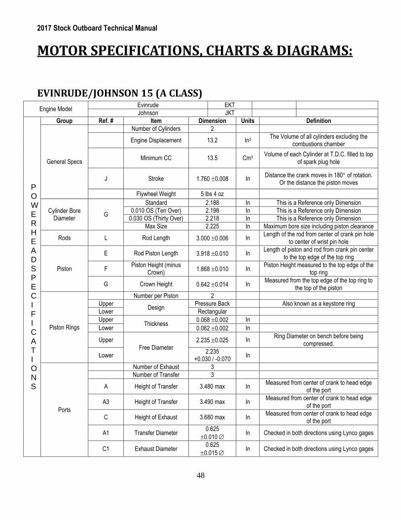
2017 Stock Outboard Technical Manual
48
MOTOR SPECIFICATIONS, CHARTS & DIAGRAMS:
EVINRUDE/JOHNSON 15 (A CLASS)
Engine Model Evinrude EKT
Johnson JKT
POWERHEAD SPECIFICATIONS
Group Ref. # Item Dimension Units Definition
General Specs
Number of Cylinders 2
Engine Displacement 13.2 In3 The Volume of all cylinders excluding the
combustions chamber
Minimum CC 13.5 Cm3 Volume of each Cylinder at T.D.C. filled to top
of spark plug hole
J Stroke 1.760 0.008 In Distance the crank moves in 180 of rotation.
Or the distance the piston moves
Flywheel Weight 5 lbs 4 oz
Cylinder Bore Diameter
G
Standard 2.188 In This is a Reference only Dimension
0.010 OS (Ten Over) 2.198 In This is a Reference only Dimension
0.030 OS (Thirty Over) 2.218 In This is a Reference only Dimension
Max Size 2.225 In Maximum bore size including piston clearance
Rods L Rod Length 3.000 0.006 In Length of the rod from center of crank pin hole
to center of wrist pin hole
Piston
E Rod Piston Length 3.918 0.010 In Length of piston and rod from crank pin center
to the top edge of the top ring
F Piston Height (minus
Crown) 1.868 0.010 In
Piston Height measured to the top edge of the top ring
G Crown Height 0.642 0.014 In Measured from the top edge of the top ring to
the top of the piston
Piston Rings
Number per Piston 2
Upper Design
Pressure Back Also known as a keystone ring
Lower Rectangular
Upper Thickness
0.068 0.002 In
Lower 0.062 0.002 In
Upper
Free Diameter 2.235 0.025 In
Ring Diameter on bench before being compressed.
Lower 2.235
+0.030 / -0.070 In
Ports
Number of Exhaust 3
Number of Transfer 3
A Height of Transfer 3.480 max In Measured from center of crank to head edge
of the port
A3 Height of Transfer 3.490 max In Measured from center of crank to head edge
of the port
C Height of Exhaust 3.680 max In Measured from center of crank to head edge
of the port
A1 Transfer Diameter 0.625
0.010 In Checked in both directions using Lynco gages
C1 Exhaust Diameter 0.625
0.015 In Checked in both directions using Lynco gages

2017 Stock Outboard Technical Manual
49
A2 Transfer Diameter 0.625
0.025 In Checked in both directions using Lynco gages
C2 Exhaust Diameter 0.625
0.025 In Checked in both directions using Lynco gages
Block
K Cylinder Height 4.880 0.015 In Measured from crank center to head surface.
K1 Cylinder Width 4.520 0.025 In Measured from exhaust machined surface to
the intake machined surface
K2 Crankcase Height 1.830 0.020 In Total height of crank case
X Cylinder Base 1.056 min In Measured from bottom of block to bottom of
bottom cylinder
Intake Intake Manifold Height 1.040 0.025 In
Reeds and Reed Plate
Reed Material Stainless Steel or Composite
Reed Thickness 0.011 0.0005 In
Shim Thickness 0.012 0.001 In
H Reed Stop Heights 0.256 0.020 In
H1 Reed Stop Radius 5.000 0.500 In
Y Checking Distance 1.260 0.030 In
N Port Location 1.430 0.015 In
N1 Port Length 1.010 0.030 In
N2 Port Width 0.675 0.025 In
Carb
Carburetor
Venturi Diameter 0.875 0.005 In
Bore Diameter 1.000 0.005 In
Tower
Exhaust Pipe
U Meg Length 10.633 0.050 In
U1 10.510 0.050 In
T Meg. Relief Hole 0.280 0.020 In
P Water Relief Hole 0.040 0.010 In
Tower
D Large Exhaust Outlet 0.880 0.020 In
D1 Small Exhaust Outlet 0.500 0.020 In
Housing Relief Holes 0.310 0.020 In
Gear Case
Impeller Blades 5
Gear Ratio 14:19
Q 11.550 0.200 In
Q1 9.100 0.200 In
R 2.050 Min In
S 0.980 Min In
W 4.765 0.020 In
W1 4.340 0.100 In
V 18.000 0.060 In

2017 Stock Outboard Technical Manual
50
Bearings
1 Roller
2 Roller
3 Ball
4 Roller
w/Retainer
5 Roller
6 Roller
7 Roller/Roller
Thrust
8 Roller/Roller
Thrust
9 Roller/Roller

2017 Stock Outboard Technical Manual
51

2017 Stock Outboard Technical Manual
52

2017 Stock Outboard Technical Manual
53
MERCURY/MARINER 15 (A CLASS) Engine Model Mercury 15
PO
WE
RH
EA
D S
PE
CIF
ICA
TIO
NS
Group Ref. # Item Dimension Units Definition
General Specs
Number of Cylinders
2
Engine
Displacement 15.9 In3
The Volume of all cylinders excluding the combustions chamber
Minimum CC 16 Cm3 Volume of each Cylinder at T.D.C. filled to top of
spark plug hole
J Stroke 1.800 0.010 In Distance the crank moves in 180 of rotation. Or
the distance the piston moves
Flywheel Weight 7 lbs 14.4 oz
Cylinder Bore Diameter G Standard 2.376 In This is a Reference only Dimension Max Size 2.410 In Maximum bore size including piston clearance
Rods L Rod Length 3.100 0.005 In Length of the rod from center of crank pin hole
to center of wrist pin hole
Piston
E Rod Piston Length 4.180 0.015 In Length of piston and rod from crank pin center
to the top edge of the piston
F Piston Height
(minus Crown) 2.653 0.030 In
V Crown Height 0.563 0.005 In
Piston Rings
Number per Piston 2 Upper
Design
Lower Rectangular Upper
Thickness In
Lower In
Ports
Number of Exhaust 3 A1 Length of Transfer 0.630 0.010 In A Height of Transfer 3.640 0.015 In C Height of Exhaust 3.781 0.015 In Width of Transfer 0.950 0.020 In
C1 Length of Exhaust 0.630 0.010 In
C2 Width of Exhaust 2x0.950, 1x0.900
0.020 In
Block H COMB. CH. Corner
HT. 5.713 0.010 In
P Reed Stop Heights 0.325 max In P1 Reed Stop Length 1.230 0.020 In
# of Ports 3 In M Port Length 0.906 0.015 In N Port Width 0.510 0.015 In
Carburetor Venturi Diameter 1.000 0.010 In
Bore Diameter 1.130 0.010 In
Tow
er Exhaust Meg Length 11.375 This is a REF dimension
Meg Length 10.500

2017 Stock Outboard Technical Manual
54
Diameter at large
end 1.540
Diameter at small
end 1.380
D ESH. Adapt. &
Pipe 13.280 0.125
V DS HSC 16.000 0.250 Adapter Plate 0.500 +0.010 / -0.025
Gea
r C
ase
Gear Case Impeller Blades 5 Gear Ratio 14:19 Q 11.550 0.200 Q1 9.100 0.200 R 2.050 Min S 0.980 Min W 4.765 0.020 W1 4.340 0.100 V 16.000 0.250
*See Mercury 25xs for reference number diagrams

2017 Stock Outboard Technical Manual
55
Sidewinder Specifications
It is the intention of the Manufacturer that the engine be raced as received with the following exceptions.
1. Addition or removal of material on any internal engine surface is prohibited with the following exceptions: a. The manufacturer de-burr’s machined edges with a hand scraper, a rotary file or file. b. It is permissible to clearance the corners of the cylinder head for the top and bottom edges of the piston deflector.
2. It is permissible to profile and polish the gear case as long as minimum dimensions and templates are met. 3. Timing, carburetor jets and metering rods may be adjusted or changed. Adjustable main jets (needle valves) are legal. No other modifications to the carburetor are permissible. 4. Steering bars of any make or manufacture are permissible as long as racing association standards are met. The manufacturer does not recommend the mounting of a fuel tank to the steering bar or engine. 5. The use of oversize pistons and boring of cylinders to accept oversized pistons is legal, as long as the cylinder bore does not exceed the maximum allowed cylinder diameter. Oversize pistons are available in +.005, +.010 and +.020” diameter. Oversized pistons must be used as supplied. Finish honing of the cylinder bores is permitted. 6. It is permissible to machine the cylinder head to achieve minimum cc’s and/or to achieve a flat surface. The following descriptions are provided to familiarize you with the Sidewinder engines as manufactured. 1. Crankcase-
Internal crankcase transfer area is CNC machined and matches block transfer area, all other internal surfaces of the crankcase are sand cast and must retain the original finish.
2. Crankshaft/Rods/Bearings- a. Crankshaft: is a full circle multi-piece press together design. There are two lightening holes .825” diameter on early
production parts, .750 diameter on late production parts, the holes are located in each crankshaft disc. b. Crankshaft Bearings: Top main is a heavy duty cased needle bearing. Center main is a split sleeve with 36 loose
needles. Bottom main is a ball bearing. c. Rods: Are forged one piece with the outside diameter of the large end machined for clean up. d. Rod Bearings:
i. Big End- Caged needle bearings in a silver plated race. ii. Small End- 22 loose needles retained by two spacers, one on each side of the rod with the small diameter facing
the needle bearings. Wrist Pin: Ground and Hardened retained by 2 circlips in the piston. e. Piston: Aluminum casting with 2 rings. Skirt is scalloped on the intake side. Wrist pin is a slip fit in wrist pin bore;
grooves are machined in the bore for the retaining clips with a machined relief for clip removal.
3. Cylinder Block- a. Exhaust: The exhaust port openings in the block are machined. There is a 45 degree bevel machined in the exhaust
outlet area between the water jacket rib and the power head mounting whole boss. The remaining exhaust area is sand cast and must be run as cast.
b. Intake: The intake port opening in the blocks is machined. The transfer opening is machined as well as the outer perimeter of the transfer area. The floor of the transfer area is sand cast with a 3/16 radius blending the floor into the perimeter. There is a rectangular window machined through the cylinder sleeve and transfer wall. This window connects the transfer passage to the cylinder below the piston. The intake window is closed by the piston skirt prior to the opening of the intake ports. The aluminum around three sides of the window is chamfered.

2017 Stock Outboard Technical Manual
56
c. Water Passages: Water passages in the block are drilled. The water inlet is a 5/16” hole. A 5/16” diameter hole intersects the inlet and supplies water to the water jacket on the exhaust side of the block. A 3/8” diameter hole intersects the water inlet and supplies water to the cylinder water jacket.
4. Cylinder Sleeves- a. Ports: Ports are machined with a small chamfer on edges of the ports. Exhaust ports are beveled at a 15 degree angle
for the 15S and a 25 degree angle for the 15H & the 20S on the head side. Port timing is measured at the interface of the port edge and cylinder wall. The exhaust port openings of the 15S engine are “D” shaped with the flat facing the head and a radius in the corners transitioning into a round lower half. The 15H and 20S utilize a squared port opening with radius corners.
b. The intake port web on the 15S engine is a radius while the 15H utilizes a squared port web with radius corners. (inspection area to verify 15S/15H sleeve)
5. Cylinder Head and Gasket- a. Cylinder Head Combustion Chamber: The cylinder head combustion chamber is cast, it is permissible to clearance
the corners of the chamber to prevent contact between the piston deflector and the head. b. Cylinder Head Gasket: the cylinder head gasket may be a machined aluminum plate, a Hot Rod style head
gasket or the later production multi-layer steel gasket. The gasket has three 3/16” holes in the top and one 1/16” hole in the bottom. The aluminum gasket may be o-ringed. All listed gasket types are legal as long as cc specifications are met. (The three larger holes must face the top of the cylinder head or overheating will occur.)
6. Intake- a. Intake Housing: The area of the intake housing that extends into the transfer area of the block is fully machined. The
internal passage of the housing is cast with the block side of the opening machined to size. b. Intake Manifold: The internal surface of the manifold is cast with de-burring operations performed on the edges of the
machined surfaces. c. Reed Cage and Reeds: Reed cages are cast with the reed surfaces and the mounting surface machined. Reeds are
of the 2 stage designs.
7. Carburetor- 15H: The Lectron high velocity carburetor is a legal carburetor for the 15H & 20S model Sidewinder. On the 15H, the
throat of this carburetor is fitted with a sleeve. The 15H may also utilize a Dellorto VHST 28mm carburetor. 15S: The 15S Sidewinder will utilize a Dellorto PHBG 21mm carburetor. The carburetor must be run with the plastic Dellorto intake adapter as supplied. Velocity stacks and modifications to the internal areas of the spray shield are not allowed on the 15S engines. 20S: The 20S Sidewinder may utilize a Dellorto VHSH 30 mm carburetor or the 34mm Lectron. The Dellorto 30 mm VHSH is the only legal carburetor for use in the BSR & BSH classes with a .750” restrictor plate. The 34mm Lectron is legal in the 20SSH, 25SSR & 25SSH class. Velocity stacks are legal on the 20S Sidewinder engines. The velocity stack may not pass through the shield and no internal modifications to the shield are allowed. The OEM spray shield must be in place on all Sidewinders. The late style carburetor shield and bracket does not attach to the carburetor. A gasket will be used between the shield bracket and the manifold. The manufacturer would appreciate the retention of the decal on the Sidewinder engine spray shield.
8. Exhaust Housing- Internal surfaces are as cast. There are 4 drilled 1/2” diameter exhaust relief holes in the exhaust housing. These holes are optional. They may be left un-drilled, filled, plugged or covered by any external option. It is permissible to use the previously manufactured Hot Rod tower and clamp handles.

2017 Stock Outboard Technical Manual
57
9. Ignition System- a. Flywheel: The flywheel is cast steel. The number 3584222 is cast on the underside of the flywheel. The minimum
flywheel diameter is 5.990”. b. Power pack: The power pack is identified by a sleeve on the input wires labeled Racing Outboards, LLC Part#60-01-
0001. The ignition cut off wiring harness is integral and terminates with a 2 wire flat plug. c. Armature Plate: The armature plate mounts 2 coils—a sensor coil and a charge coil. d. Ignition Coil: The ignition coil is mounted with 2 bolts and contains 2 individual coils in a single housing. e. Starter: It is permissible to add the aftermarket electric starter supplied by Racing Outboards on all Sidewinder
engines. It is necessary to remove approximately .030” from the bottom of the flywheel to accommodate the ring gear. Once this flywheel is trimmed it will not be legal without the ring gear attached.
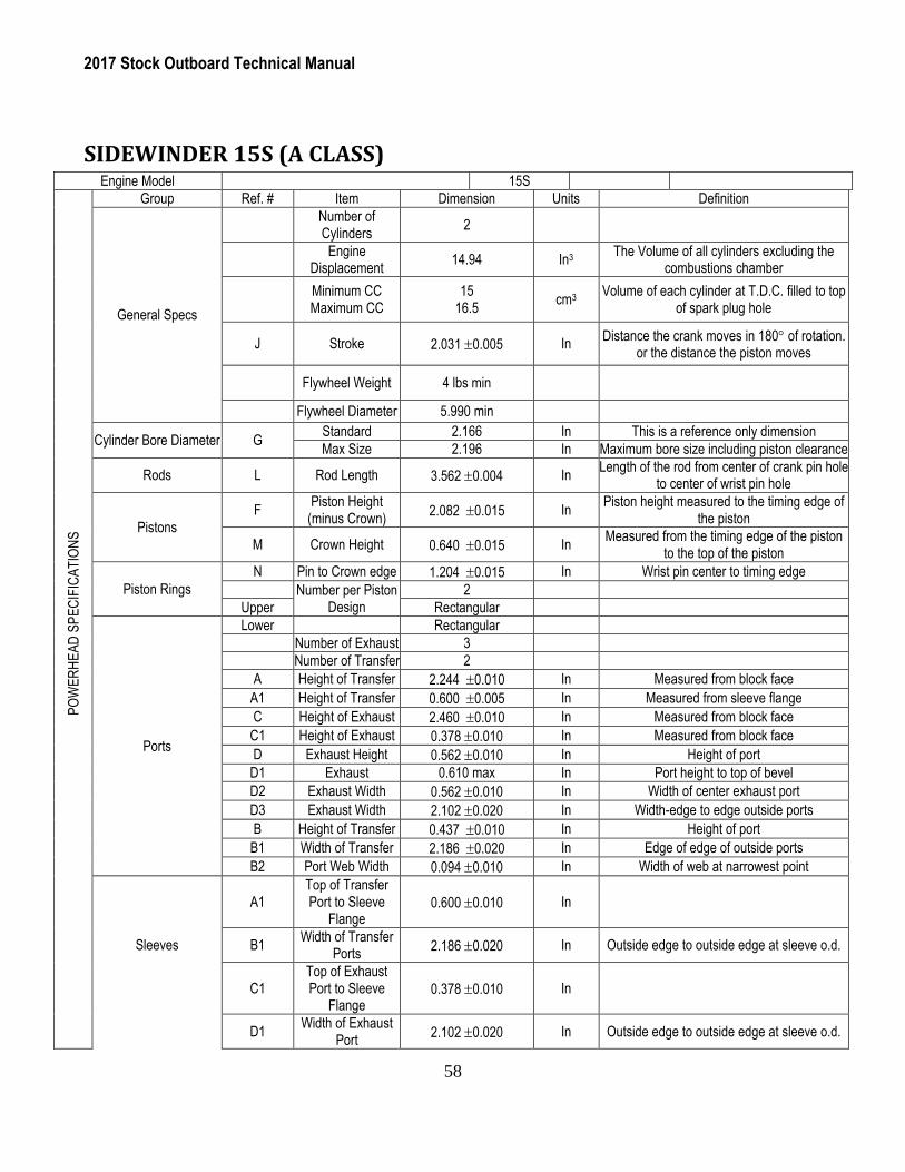
2017 Stock Outboard Technical Manual
58
SIDEWINDER 15S (A CLASS) Engine Model 15S
PO
WE
RH
EA
D S
PE
CIF
ICA
TIO
NS
Group Ref. # Item Dimension Units Definition
General Specs
Number of Cylinders
2
Engine
Displacement 14.94 In3
The Volume of all cylinders excluding the combustions chamber
Minimum CC Maximum CC
15 16.5
cm3 Volume of each cylinder at T.D.C. filled to top
of spark plug hole
J Stroke 2.031 0.005 In Distance the crank moves in 180 of rotation.
or the distance the piston moves
Flywheel Weight 4 lbs min
Flywheel Diameter 5.990 min
Cylinder Bore Diameter G Standard 2.166 In This is a reference only dimension
Max Size 2.196 In Maximum bore size including piston clearance
Rods L Rod Length 3.562 0.004 In Length of the rod from center of crank pin hole
to center of wrist pin hole
Pistons
F Piston Height
(minus Crown) 2.082 0.015 In
Piston height measured to the timing edge of the piston
M Crown Height 0.640 0.015 In Measured from the timing edge of the piston
to the top of the piston
Piston Rings
N Pin to Crown edge 1.204 0.015 In Wrist pin center to timing edge
Number per Piston Design
2
Upper Rectangular
Ports
Lower Rectangular
Number of Exhaust 3
Number of Transfer 2
A Height of Transfer 2.244 0.010 In Measured from block face
A1 Height of Transfer 0.600 0.005 In Measured from sleeve flange
C Height of Exhaust 2.460 0.010 In Measured from block face
C1 Height of Exhaust 0.378 0.010 In Measured from block face
D Exhaust Height 0.562 0.010 In Height of port
D1 Exhaust 0.610 max In Port height to top of bevel
D2 Exhaust Width 0.562 0.010 In Width of center exhaust port
D3 Exhaust Width 2.102 0.020 In Width-edge to edge outside ports
B Height of Transfer 0.437 0.010 In Height of port
B1 Width of Transfer 2.186 0.020 In Edge of edge of outside ports
B2 Port Web Width 0.094 0.010 In Width of web at narrowest point
A1 Top of Transfer Port to Sleeve
Flange 0.600 0.010 In
Sleeves B1 Width of Transfer
Ports 2.186 0.020 In Outside edge to outside edge at sleeve o.d.
C1 Top of Exhaust Port to Sleeve
Flange 0.378 0.010 In
D1 Width of Exhaust
Port 2.102 0.020 In Outside edge to outside edge at sleeve o.d.

2017 Stock Outboard Technical Manual
59
Block K Cylinder Height 3.919 0.010 In
K1 Cylinder Width 5.380 0.015 In
Crankcase
K2 Crankcase Height 1.843 0.010 In
Inta
ke
Intake
T Intake Housing
Height 1.656 0.010 In
U Intake Manifold Reed opening
Early 1.062 0.025
Late 1.012 +/-0.025
In Intake manifold reed opening to inlet face
Reeds
Reed Thickness
Top 0.016 In
Reed Thickness
Bottom 0.032 In
Carburetor
Dellorto Bore Diameter 21mm .826 0.005 mm / in. It is permissible to use an adjustable high
speed main jet
Adapter .850 0.010 In late style adapter chamfer 1.050 max & is
1.062” +/- .062” long
Tow
er
Tower
Relief Holes 4X0.500 dia 0.032
Height 14.562 0.062 Height; power head flange to gear case flange
Gea
r C
ase
Gear Case
Impeller Blades 5
Gear Ratio 14:19
Q 12.000 max
R 2.050 min (See gear case diagram for measurement
locations)
S 0.750 min
W 4.750 0.020 Also: The skeg must meet the template #90-01-0001 available from Racing Outboards,
LLC.
W1 4.350 0.100
Bea
rings
Bearings
1 Caged Roller
2 36 loose Roller
3 205 Ball
4 Roller w/Retainer
5 22 loose Roller
6 Roller
7 Roller/Roller Thrust
8 Roller/Roller Thrust
9 Roller x2/Roller Thrust

2017 Stock Outboard Technical Manual
60
SIDEWINDER 15H (B CLASS) Engine Model 15H
PO
WE
RH
EA
D S
PE
CIF
ICA
TIO
NS
Group Ref. # Item Dimension Units Definition
General Specs
Number of Cylinders
2
Engine
Displacement 14.94 In3
The Volume of all cylinders excluding the combustions chamber
Minimum CC 11.5 cm3 Volume of each Cylinder at T.D.C. filled to top of spark plug hole
J Stroke 2.031 0.005 In Distance the crank moves in 180 of
rotation. Or the distance the piston moves
Flywheel Weight 4 lbs min
Flywheel Dia. 5.990 min
Cylinder Bore Diameter
G Standard 2.166 In This is a Reference only Dimension
Max Size 2.196 In Maximum bore size including piston
clearance
Rods L Rod Length 3.562 0.004 In Length of the rod from center of crank pin
hole to center of wrist pin hole
Pistons F
Piston Height (minus Crown)
2.082 0.015 In Piston Height measured to the timing edge
of the piston
M Crown Height 0.640 0.015 In Measured from the timing edge of the piston
to the top of the piston
Piston Rings
N Pin to Crown
edge 1.204 0.015 In Wrist pin center to timing edge
No. per Piston
2
Upper Design
Rectangular
Lower Rectangular
Ports
Number of Exhaust
3
Number of Transfer
2
A Height of Transfer
2.244 0.010 In measured from block face
A1 Height of Transfer
0.596 0.005 In measured from sleeve flange
C Height of Exhaust 2.466 0.010 In measured from block face
C1 Height of Exhaust 0.378 0.005 In measured from block face
D Exhaust Height 0.594 0.005 In
D1 Exhaust 0.670 max In Height top of Bevel
D2 Exhaust Length 0.696 0.005 In Width Center Port
D3 Exhaust Length 2.186 0.020 In Width-edge to edge outside ports
B Width of Transfer 0.436 0.005
B1 Length of Transfer
2.186 0.020 Edge of edge of outside ports
B2 Port Web Length 0.094 0.005
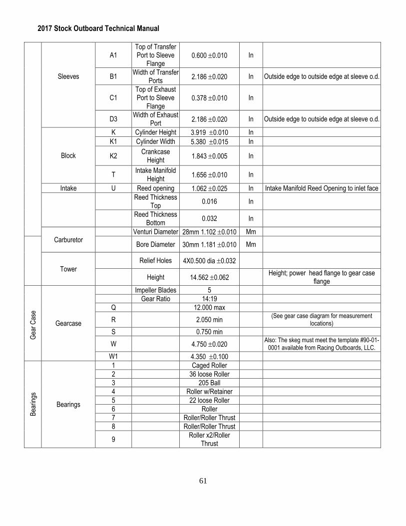
2017 Stock Outboard Technical Manual
61
A1 Top of Transfer Port to Sleeve
Flange 0.600 0.010 In
Sleeves B1 Width of Transfer
Ports 2.186 0.020 In Outside edge to outside edge at sleeve o.d.
C1 Top of Exhaust Port to Sleeve
Flange 0.378 0.010 In
D3 Width of Exhaust
Port 2.186 0.020 In Outside edge to outside edge at sleeve o.d.
Block
K Cylinder Height 3.919 0.010 In
K1 Cylinder Width 5.380 0.015 In
K2 Crankcase
Height 1.843 0.005 In
T Intake Manifold
Height 1.656 0.010 In
Intake U Reed opening 1.062 0.025 In Intake Manifold Reed Opening to inlet face
Reed Thickness Top
0.016 In
Reed Thickness
Bottom 0.032 In
Carburetor Venturi Diameter 28mm 1.102 0.010 Mm
Bore Diameter 30mm 1.181 0.010 Mm
Tower Relief Holes 4X0.500 dia 0.032
Height 14.562 0.062 Height; power head flange to gear case
flange
Gea
r C
ase
Gearcase
Impeller Blades 5
Gear Ratio 14:19
Q 12.000 max
R 2.050 min (See gear case diagram for measurement
locations)
S 0.750 min
W 4.750 0.020 Also: The skeg must meet the template #90-01-
0001 available from Racing Outboards, LLC.
W1 4.350 0.100
Bea
rings
Bearings
1 Caged Roller
2 36 loose Roller
3 205 Ball
4 Roller w/Retainer
5 22 loose Roller
6 Roller
7 Roller/Roller Thrust
8 Roller/Roller Thrust
9 Roller x2/Roller
Thrust

2017 Stock Outboard Technical Manual
62
SIDEWINDER 20S (20SSH, B & 25 CLASSES) Engine Model
20S
PO
WE
RH
EA
D S
PE
CIF
ICA
TIO
NS
Group Ref. # Item Dimension Units Definition
General Specs
Number of Cylinders
2
Engine
Displacement 19.94 In3 The Volume of all cylinders excluding the combustions
chamber
Minimum CC 18.0 cm3 Volume of each Cylinder at T.D.C. filled to top of spark
plug hole
J Stroke 2.031 0.005 In Distance the crank moves in 180 of rotation. Or the
distance the piston moves
Flywheel Weight 4 lbs min
Flywheel Diameter 5.990 min
Cylinder Bore
Diameter G
Standard 2.500 In This is a Reference only Dimension
Max Size 2.530 In Maximum bore size including piston clearance
Rods L Rod Length 3.562 0.004 In Length of the rod from center of crank pin hole to center of
wrist pin hole
F
Piston Height (minus Crown)
2.068 0.015 In Piston Height measured to the timing edge of the piston
M Crown Height 0.740 0.015 In Measured from the timing edge of the piston to the top of
the piston
Piston Rings
N Pin to Crown edge 1.190 0.015 In Wrist pin center to timing edge
Number per Piston Design
2
Upper Rectangular
Ports
Lower Rectangular
Number of Exhaust 3
Number of Transfer 2
A Height of Transfer 2.246 0.010 In measured from block face
A1 Height of Transfer 0.596 0.005 In measured from sleeve flange
C Height of Exhaust 2.466 0.010 In measured from block face
C1 Height of Exhaust 0.378 0.005 In measured from block face
D Exhaust Height 0.5970.005 In
D1 Exhaust 0.675max In Height top of Bevel
D2 Exhaust Length 0.695 0.005 In Width Center Port
D3 Exhaust Length 2..455 0.020 In Width-edge to edge outside ports
B Width of Transfer 0.381 0.005 In
B1 Length of Transfer 2.596 0.010 In Edge of edge of outside ports
B2 Port Web Length 0.100 0.005 In

2017 Stock Outboard Technical Manual
63
A1 Top of Transfer Port to Sleeve
Flange 0.600 0.010 In
B1 Width of Transfer
Ports 2.596 0.020 In Outside edge to outside edge at sleeve o.d.
Sleeves C1 Top of Exhaust Port to Sleeve
Flange 0.385 0.010 In
D3 Width of Exhaust
Port to Sleeve Flange
2.455 0.020 Outside edge to outside edge at sleeve o.d.
Block
K Cylinder Height 3.919 0.010 In
K1 Cylinder Width 5.380 0.015 In
K2 Crankcase Height 1.843 0.005 In
X Cylinder Base 1.062 0.025 In
Intake T Intake Manifold
Height 1.656 0.010 In
U Reed opening 1.062 0.025 In Intake Manifold Reed Opening to inlet face
Reed Thickness 0.016 In (top)
Reed Thickness 0.032 In (bottom)
Car
b Carburetor (Lectron)
Venturi Diameter 32 mm
Bore Diameter 34mm 1.338
0.015 mm
Carburetor (Dellorto)
Bore Diameter 30mm 1.181
0.015 mm
Tow
er
Tower Relief Holes
4X0.500 dia
0.032
Height 14.562 0.062 In Height; power head flange to gear case flange
Gea
r C
ase
Gear Case Impeller Blades 5
Gear Ratio 14:19 Must meet Sidewinder template 90-01-0001
Q 12.000 max In
R 2.050 min In (See gear case diagram for measurement locations)
S 0.750 min In
W 4.750 0.020 Also: The skeg must meet the template #90-01-0001 available
from Racing Outboards, LLC.
W1 4.350 0.100 In
Bea
rings
Bearings
1 Caged Roller
2 36 loose Roller
3 205 Ball
4 Roller with retainer
5 22 loose Roller
6 Roller
7 Roller/Roller Thrust
8 Roller/Roller Thrust
9 Roller x2/Roller Thrust

2017 Stock Outboard Technical Manual
64

2017 Stock Outboard Technical Manual
65
HOT ROD 15 (B CLASS)
Engine Model Hot Rod 15
PO
WE
RH
EA
D S
PE
CIF
ICA
TIO
NS
Group Ref. # Item Dimension Units Definition
General Specs
Number of Cylinders
2
Engine
Displacement 14.94 In3 The Volume of all cylinders excluding the
combustions chamber
Minimum CC 13 Cm3 Volume of each Cylinder at T.D.C. filled to
top of spark plug hole
J Stroke 2.031 0.006 In Distance the crank moves in 180 of
rotation. Or the distance the piston moves
Flywheel Weight
OMC 4 lbs Motoplatt Heavy 3 lb
8 oz Motoplatt Light
7 oz
Flywheel Diameter
5.990 min This is for the Sidewinder Flywheel only
Cylinder Bore Diameter
G Standard 2.166 In This is a Reference only Dimension
Max Size 2.206 In Maximum bore size including piston
clearance
Rods L Length 3.562 0.004 In Length of the rod from center of crank pin
hole to center of wrist pin hole
Weight 4 oz Including bearing and cap screws
Piston
E Position at
Bottom of Stroke 1.890 0.015 In Including 0.031 in gasket
F Piston Height
(minus Crown) 2.062 0.015 In
Piston Height measured to the timing edge of the piston
Weight 4 oz In Including rings, pin and bearings
Piston Rings
Number per
Piston 2
Upper Design
Rectangular Lower Rectangular Upper
Thickness In
Lower In
Ports
Number of Exhaust
3 Per cylinder
Number of Transfer
2
A Height of Transfer
2.280 0.020 In Including 0.031 in gasket
C Height of Exhaust 2.498
+0.020/-0.030 In Including 0.031 in gasket
K Crankcase
Height 1.843 0.005 In
Rotary Value N Opens 1.875 – 1.938 In Distance from TDC when value opens P Close 0.625 – 0.750 In Distance from TDC when value closes

2017 Stock Outboard Technical Manual
66
Car
b
Carburetor
Venturi Diameter HL239A 0.875 Lectron 1.100
In
Bore Diameter
HL239A 1.020
0.030 Lectron 1.180
0.015*
In Measured at crankcase side
Plate 0.500 0.031
Tower Exhaust
Outlet Holes 0.500Ø 0.031
Gea
r C
ase
Gear Case Impeller Blades 5 Gear Ratio 14:19 or 14:15 Q 12.000 max R 2.062 Min S 0.750 Min V 19.312 0.062
1 Ball 2 Ball
3 Needle 4 Ball 5 Roller 6 Roller 7 Roller 8 Roller 9 Ball 10 Roller
11 Old Ball
New Roller
12 Old Ball
New Roller

2017 Stock Outboard Technical Manual
67
HOT ROD 20 (25 CLASSES)
Engine Model Hot Rod 20
PO
WE
RH
EA
D S
PE
CIF
ICA
TIO
NS
Group Ref. # Item Dimension Units Definition
General Specs
Number of Cylinders
2
Engine
Displacement 19.94 In3 The Volume of all cylinders excluding the
combustions chamber
Minimum CC Old 17 New 18
Cm3
Volume of each Cylinder at T.D.C. filled to top of spark plug hole. New style head has
head catchers
J Stroke 2.031 0.006 In Distance the crank moves in 180 of
rotation. Or the distance the piston moves
Flywheel Weight
OMC 4 lbs Motoplatt Heavy 3 lb
8 oz Motoplatt Light
7 oz
Flywheel Diameter
5.990 min This is for the Sidewinder Flywheel only
Cylinder Bore Diameter
G Standard 2.500 ±0.030 In This is a Reference only Dimension
Max Size 2.530 In Maximum bore size including piston
clearance
Rods L Length 3.562 0.004 In Length of the rod from center of crank pin
hole to center of wrist pin hole
Weight 4 oz Including bearing and cap screws
Piston
E Position at
Bottom of Stroke 1.890 0.015 In Including 0.031 in gasket
F Piston Height
(minus Crown) 2.062 0.015 In
Piston Height measured to the timing edge of the piston
Weight 4 oz In Including rings, pin and bearings
Piston Rings
Number per
Piston 2
Upper Design
Rectangular Lower Rectangular
Upper Thickness
In Lower In
Ports
Number of Exhaust
Per cylinder
Number of Transfer
A Height of Transfer
2.280 0.020 In Including 0.031 in gasket
C Height of Exhaust 2.498
+0.020/-0.030 In Including 0.031 in gasket
K Crankcase
Height 1.843 0.005 In
Rotary Value N Opens 1.875 – 1.938 In Distance from TDC when value opens

2017 Stock Outboard Technical Manual
68
P Close 0.625 – 0.750 In Distance from TDC when value closes
Car
b
Carburetor
Venturi Diameter HL168 1.281 ±0.015 In
Bore Diameter HL16 B 1.375 ±0.015
Lectron 1.338 0.015 In Measured at crankcase side
Plate 0.500 0.031
Tower Exhaust
Outlet Holes 0.500Ø 0.031
Gea
r C
ase
Gear Case Impeller Blades 5 Gear Ratio 14:19 or 14:15 Q 12.000 max R 2.062 Min S 0.750 Min V 19.312 0.062
1 Ball 2 Ball 3 Needle 4 Ball
5 Roller 6 Roller 7 Roller 8 Roller 9 Ball 10 Roller
11 Old Ball
New Roller
12 Old Ball
New Roller
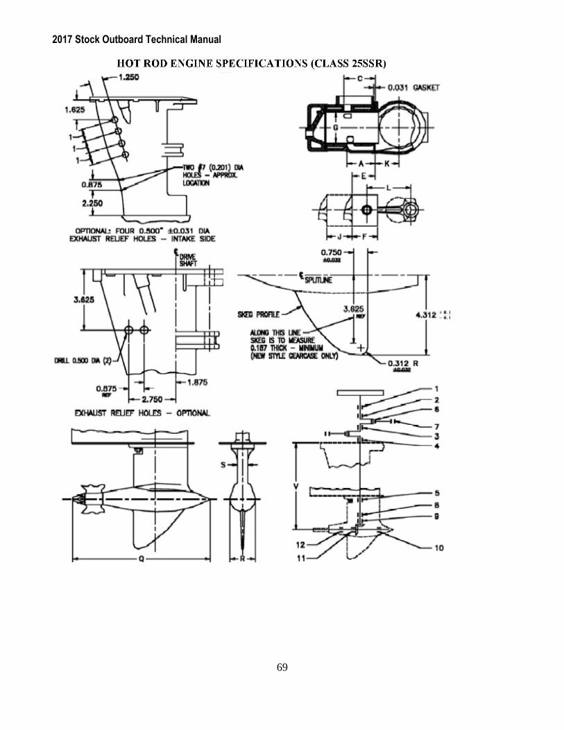
2017 Stock Outboard Technical Manual
69

2017 Stock Outboard Technical Manual
70
MERCURY 25XS
Engine Model Mercury 25XS
Mariner 25XS
PO
WE
RH
EA
D S
PE
CIF
ICA
TIO
NS
Group Ref. # Item Dimension Units Definition
General Specs
Number of Cylinders
2
Engine
Displacement 24.4 In3 The Volume of all cylinders excluding the
combustions chamber
Minimum CC 21.7 Chrome bore
21.2 Mercosil Cm3
Volume of each Cylinder at T.D.C. filled to top of spark plug hole
J Stroke 2.362 0.005 In Distance the crank moves in 180 of
rotation. Or the distance the piston moves
Flywheel Weight 7lbs. 8oz small 9lbs 7oz large
Flywheel Diameter
Cylinder Bore Diameter
G Standard 2.563 0.005 In This is a Reference only Dimension
Max Size 2.566 In Maximum bore size including piston
clearance
Rods L Rod Length 4.062 0.005 In Length of the rod from center of crank pin
hole to center of wrist pin hole
Piston
E Rod Piston
Length 5.277 0.020 In
Length of piston and rod from crank pin center to the top of the piston
F Piston Height 2.525 0.030 In Piston Height measured to the top edge of
the piston
Piston Rings
Number per
Piston 2
Upper Design
Half Keystone Also known as a keystone ring
Lower Rectangular
Upper Thickness
0.060 0.002 In
Lower 0.060 0.002 In
Ports
Number of Exhaust
1
Number of Transfer
3
A Height of Transfer
4.493 0.030 In
A3 Height of Transfer
1.079 0.030 In
C Height of Exhaust 4.863 0.030 In
A1 Transfer Diameter
0.395 0.030 In
C1 Exhaust Diameter
0.750 0.030 In
A2 Transfer Diameter
0.450 0.030 In
C2 Exhaust Diameter
1.448 0.030 In

2017 Stock Outboard Technical Manual
71
A4 0.957 0.030
A5 1.114 0.030
Block K Cylinder Height 6.540 0.030 In
Reeds and Reed Plate
Reed Material Steel or Fiber In
Reed Thickness Steel 0.008 0.0008
Fiber 0.020 0.002 In
P Reed Stop
Heights 0.260 0.030
0.2850.020 In
Y Reed Stop
Radius 0.285 0.020 In
M Port Length 0.700 0.030 In
N2 Port Width 0.550 0.020 In
Car
b
Carburetor Venturi Diameter 1.120 0.015 In
Bore Diameter 1.250 0.015 In
Tow
er Exhaust
D Meg Length 7.120 0.150 From top of adaptor to bottom of pipe
V 14.625 0.060 Measured with exhaust adaptor long
V 9.750 0.060 Short
D Tower Exhaust
Outlet Holes 2.000x2.000 +0.250
Gea
r C
ase
Gear Case Impeller Blades
Gear Ratio 16:21 or 15:15
Q 11.250 max
R 2.090 min
S 0.980 min
W 1.870 min

2017 Stock Outboard Technical Manual
72

2017 Stock Outboard Technical Manual
73
YAMATO-102, 302 & 321 The intent of these rules is for the Yamato 102, 302 & 321 engines to be raced as received from the manufacturer
without modification except as specifically listed below. If a specific dimension is not listed in these rules, the
Inspector may compare the dimensions of a new part to assist in making a decision regarding part legality.
Permissible Modifications
1. It is permissible to use any make of bearings, seals, ignition components, piston rings, steering bar, or prop shaft provided no engine modifications are made to accommodate them. (Except 300SSH)
2. It is permissible to drill water drain holes in the ignition castings (coil plates and crankcase top end cap), and these holes may be tapped and plugged.
3. It is permissible to enlarge the fuel tank or build a complete new tank. If the tank is removed, the tank mounting brackets may also be removed. A fuel filter may be added to the fuel line.
4. A fuel pump may be used for racing, but the carburetor shall not be modified in any way. (Except 300SSH) 5. It is permissible to grind, file, or polish the lower unit as long as all dimensions and templates are met. The
“bulge” may be ground flush with the sides of the skeg. (Except 300SSH) 6. Any type of thrust bracket adjustment is allowed. It is permissible to drill 2 holes at the front of the cavitation
plate to facilitate the mounting of a thrust bracket block. 7. The tilt lock lever and spacer on the tilt bracket bolt may be removed. 8. The magneto stator plate may be locked in position by any means and the stator plate timing knob may be
removed. 9. The spray shield may be modified for use with throttle cable to allow easier access for engine priming and
it may be painted. (Except 300SSH) 10. The prop shaft may be turned down to 9/16 inch minimum diameter or a new propeller shaft may be made
(9/16 inch minimum diameter). In either case, only one shear pinhole is permissible. The prop nut thread size is optional.
11. It is legal to bore the cylinders one size larger than standard bore. It is permissible to re-sleeve any block provided engine specifications are maintained. (Except 300SSH)
12. It is permissible to mill the cylinder head. No changes may be made to the combustion chamber. It is legal to re-machine the squish band for repair purposes only. (angle 15° ± 2°, 2.612 ± 0.015). There must be a visible ledge surrounding the squish band.
13. It is permissible to substitute the Yamato 302 – 321 gear case assembly for use on the 102 engine. The 102 gear case assembly may not be used on the 302 – 321 engine.
14. The 102 exhaust megaphone may have any type of welding, gusset, strap, etc. used on the outside only, to repair or reinforce as long as all other dimensions are met. It will be left to the discretion of the inspector to decide if any changes to the inside of the megaphone were due to welding “melt through” or were done to intentionally change the interior configuration.
15. It is permissible to use non-OEM crank pins and exhaust stacks. (The inspector may compare to new). (Except 300SSH)
16. The water inlet supply holes may be repaired with weld or plastic compounds. It is permissible to enlarge the water inlet hole to .310” maximum diameter. It is also permissible to create a concave groove from the port side entrance of the hole to the port side leading-edge of the exhaust snout. This groove shall not exceed a 5/32” radius and must not go past the leading-edge of the exhaust snout. This is permissible on all approved Yamato engines in 25SSR, CSR, CSH and 20SSH. (See photo and restrictions on page 75).
17. It is permissible to reposition the ring groove stop pin to allow the use of the Model 302 - 321 piston in the 102.
18. It is permissible to use the Yamato Model 202 magneto on the Model 102.

2017 Stock Outboard Technical Manual
74
19. It is permissible to remount any coil on the 102 and to replace the points and condenser with a Nova II. 20. Aftermarket roping plate is legal on the 102 as long as it meets OEM dimensions. 21. Extended length, flexible water outlet “dump” hoses are permissible. 22. The Yamato Model 300 series ignition may be installed on the Model 102. It is permissible to add a shim
or gasket between the bowl and the crankcase. Note: See the specifics on rope plate size on page 78. 23. It is permissible to drill out the Model 321 exhaust nipple that currently has a 4 mm hole to .315” maximum
which is the same as the Model 302 exhaust nipple.
Non-Permissible Modifications
1. With the exception of the inlet supply holes mentioned in the previous rule #16, no drilling or modifications of any type may be made to the cooling system.
2. Addition or removal of metal on any cast or forged internal engine components, surfaces or passages including the intake system, carburetor, or exhaust system is prohibited. Honing of cylinder bores and connecting rods is permitted.
3. Bead blasting, sand blasting, or blasting by any other media of internal engine components is not permissible.
4. Addition or removal of material from any moving parts including the flywheel, crankshaft, and pistons is prohibited.
5. The two water outlet drain holes in the bottom of the cylinder block must not be restricted.
General
1. The volume of the combustion chamber will be measured with all the spark plugs and bushings removed without removing the cylinder head from the engine.
2. Only Yamato parts will be considered as legal replacement parts (except as specifically noted in these rules). This includes (but is not limited to) all engine components, gaskets. etc.
3. To measure the reed stop heights (Q): lightly depress the reed and the bottom edge of the end of the reed stop.
4. For identification of the legal model 102, the outside dimension of the exhaust cover is 3-3/16 inches wide. 5. The 302- 321 gear case assembly can be identified by the snap ring and metal plate on the rear outside of
the prop shaft cone. Some gear cases were supplied by the manufacturer without oil fill plugs. It is not permissible to add oil fill plugs to these units. Also, it is not permissible to eliminate the oil fill plugs from gear cases that were furnished by the manufacturer with oil fill plugs.
6. In compensation for measuring the gear case skeg without the factory “bulge”, an additional 0.250 inches should be added to existing gear case templates in order to properly measure a gear case without the “bulge”.
7. The latest replacement Carburetor has been approved for use on the 102 and 302. 8. The restrictor plate used in all Yamato engine classes shall have a maximum thickness dimension of .0065"
without chamfer. All edges of this plate must be 90 degrees.

2017 Stock Outboard Technical Manual
75
Yamato Engine Cooling The photos below describe what area is permitted to have a concave groove on all approved Yamato engines in 25SSR, CSR, CSH and 20SSH classes.
Restrictions:
It is not permissible to move the location of the
intake hole, only increase the diameter and add
the grooved channel.
In a view from above with the tower upside
down, the compound angle of the intake hole is
22 degrees left and 30 degrees of tilt.
The intake hole may be measured using a
micrometer and a small hole gauge.
The grooved channel may be measured by using
a 5/32” radius gauge.
Any water intake in question may be compared
to other engines to assist in making a decision
regarding legality.
Images of inlet hole with groove installed:

2017 Stock Outboard Technical Manual
76
YAMATO 102 (25SSR, CSR, CSH & 20SSH) Engine Model Yamato 102
PO
WE
RH
EA
D S
PE
CIF
ICA
TIO
NS
Group Ref. # Item Dimension Units Definition
General Specs
Number of Cylinders
2
Engine
Displacement 24
The Volume of all cylinders excluding the combustions chamber
Minimum CC 14mm 25.5 18mm 26
Volume of each Cylinder at T.D.C. filled to
top of spark plug hole
M Stroke 2.286 ±0.010 Distance the crank moves in 180 of
rotation. Or the distance the piston moves
Flywheel Weight 1500 min g
Crank Weight 5200 min g
Roping plate 415 min g
Ignition Magneto (or the 300 series ignition is permissible)
Cylinder Bore Diameter
Max Size 2.625 In Maximum bore size including piston
clearance
Rods K Rod Length 4.204 – 4.221 In
Length of the rod from center of crank pin hole to center of wrist pin hole
Weight 184 min g With both bearings
Piston
Piston Weight 260 min g With rings, wrist pin, and clips
L Piston Height (minus crown)
2.322 – 2.402 In
N Wrist Pin to top (minus crown)
1.291 ±0.010 In
Piston Rings
No. per Piston 2 Upper
Design Rectangular
Lower Rectangular Upper
Thickness In
Lower In
Ports
Number of Exhaust
2 per cylinder
Number of Transfer
2 per cylinder and 1 boost
D Height of Transfer
1.890 – 1.915 In
D1 Height of Transfer
1.855 – 1.900 In
E Height of Exhaust 1.430 – 1.455 In
D2 Transfer Diameter
n/a In
D3 Exhaust Diameter
n/a In
E1 Transfer Diameter
n/a In
Block C Cylinder Height 4.104 ±0.010 In

2017 Stock Outboard Technical Manual
77
F Gasket 0.012±0.004 In
A Crankcase
Height 2.550 ±0.010 In
B 2.545 ±0.010 In
G Head Gasket 0.020 ±0.004
Intake Block water hole
near head 0.140 ±0.005 In
Reeds and Reed Plate
Block water hole
near exhaust man.
0.120 ±0.005 In
# of Holes 8 In
Hole Size 0.793 x 1.041 In Reed Thickness 0.012 ±0.002
Q Reed Stop
Heights 0.289 max In
Q1 Reed Stop
Radius 1.342 – 1.421 In
Car
b Carburetor Mikuni BV-36
Venturi Diameter 1.102 ±0.012 In
Bore Diameter 1.407 ±0.012 In
Tow
er
Exhaust
P Meg Length 11.625 ±0.050 P3 2.180 max
P4 Meg. Relief Hole 1.060 max
P2 Tower Exhaust
Outlet Holes 2.400 ±0.040
P1 Housing Relief
Holes 0.203 Ø max
Water Inlet Hole 0.310 max** **see new rule #16 on page 73
Gea
r ca
se
Gear Ratio 14:15 Helical cut Tower Housing O 18.464 – 18.622
S 1.195 min T 8.465 ±0.050
U 4.724 ±0.050 V 10.800 max W 2.205 min X 2.980 ±0.030 Y 50° Z1 0.190 min Z2 0.190 min Z3 0.150 min Z4 0.150 min Z5 1.949 min CL 1.772 max CD 2.100 min

2017 Stock Outboard Technical Manual
78
YAMATO 302 - 321 (25SSR, CSR, CSH, 300SSH & 20SSH) Engine Model Yamato 302 - 321
PO
WE
RH
EA
D S
PE
CIF
ICA
TIO
NS
Group Ref. # Item Dimension Units Definition
General Specs
Number of Cylinders 2
Engine Displacement 24 The Volume of all cylinders excluding the
combustions chamber
Minimum CC 14mm 25.5 18mm 26
Volume of each Cylinder at T.D.C. filled to
top of spark plug hole
M Stroke 2.276 – 2.291 Distance the crank moves in 180 of
rotation. Or the distance the piston moves
Flywheel Weight 1500 min g
Crank Weight 5300 min g
Roping plate (old style) 360 min g May only be used with old style transistor
Ignition (old style) Transistor Magneto
Part no. BM9101
Roping plate (new style) 315 min g May only be used with new style transistor
Ignition (new style) Transistor Magneto
Part no. BM9103
Cylinder Bore Diameter
Max Size 2.625 In Maximum bore size including piston
clearance
Rods K Rod Length 4.204-4.221 In
Length of the rod from center of crank pin hole to center of wrist pin hole
Weight 191 min g With both bearings
Piston
Piston Weight 260 min g With rings, wrist pin, and clips
L Piston Height (minus crown) 2.346 – 2.378 In
N Wrist Pin to top (minus crown) 1.291 – 1.307 In
Piston Rings
Number per Piston 2
Upper Design
Rectangular
Lower Rectangular
Upper Thickness
In
Lower In
Ports
Number of Exhaust
Number of Transfer
D Height of Transfer 1.890 – 1.913 In
D1 Height of Boost Port 1.772 – 1.827 In
E Height of Exhaust 1.380 – 1.402 In
D2 Transfer Width 1.255 – 1.295 In
D3 Boost Port Width 0.978 – 1.018 In
E1 Exhaust Width 1.791 – 1.831 In
Block
C Cylinder Height 4.102 – 4.114 In
F Gasket 0.012 ±0.004 In
A Crankcase Height 2.827 – 2.843 In
B 2.539 – 2.551 In
G Head Gasket 0.020 ±0.004
Intake Block water hole near head n/a In
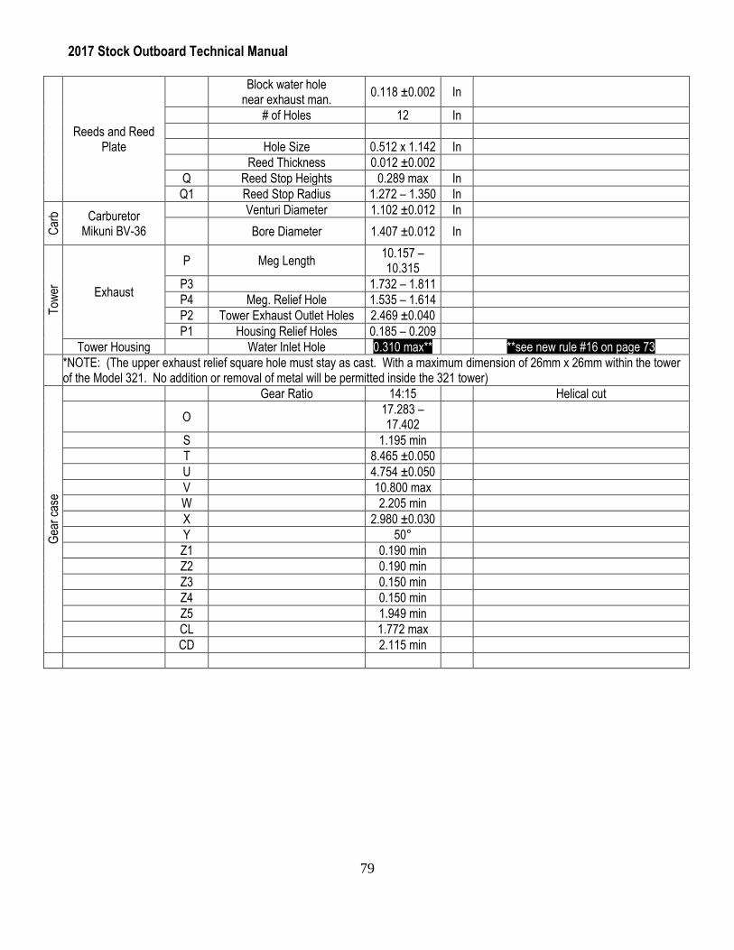
2017 Stock Outboard Technical Manual
79
Reeds and Reed Plate
Block water hole
near exhaust man. 0.118 ±0.002 In
# of Holes 12 In
Hole Size 0.512 x 1.142 In
Reed Thickness 0.012 ±0.002
Q Reed Stop Heights 0.289 max In
Q1 Reed Stop Radius 1.272 – 1.350 In
Car
b Carburetor Mikuni BV-36
Venturi Diameter 1.102 ±0.012 In
Bore Diameter 1.407 ±0.012 In
Tow
er
Exhaust
P Meg Length 10.157 – 10.315
P3 1.732 – 1.811
P4 Meg. Relief Hole 1.535 – 1.614
P2 Tower Exhaust Outlet Holes 2.469 ±0.040
P1 Housing Relief Holes 0.185 – 0.209
Tower Housing Water Inlet Hole 0.310 max** **see new rule #16 on page 73
*NOTE: (The upper exhaust relief square hole must stay as cast. With a maximum dimension of 26mm x 26mm within the tower of the Model 321. No addition or removal of metal will be permitted inside the 321 tower)
Gea
r ca
se
Gear Ratio 14:15 Helical cut
O 17.283 – 17.402
S 1.195 min
T 8.465 ±0.050
U 4.754 ±0.050
V 10.800 max
W 2.205 min
X 2.980 ±0.030
Y 50°
Z1 0.190 min
Z2 0.190 min
Z3 0.150 min
Z4 0.150 min
Z5 1.949 min
CL 1.772 max
CD 2.115 min

2017 Stock Outboard Technical Manual
80
YAMATO 302 (300SSH) Engine Model Yamato 302
General Specs.
Ref. # Item Dimension Units Definition
All current Yamato Model 302 specifications apply except
the following:
PO
WE
R
Cylinder Head I Squish Band thickness 14mm head thickness
.025 min. 1.440 min.
in (Engine must also meet minimum cc
measurement of 27.5)
Tower Housing Water Inlet Hole 0.260 – 0.297 (Min. & Max.)
Gea
r ca
se
W 2.225 min.
Z1 0.200 min.
Z2 0.195 min.
Z3 0.150 min.
Z4 0.150 min.
Bulge Thickness 0.225 min.
Skeg Radius leading and trailing edge
7/64 min.
Nose Cone Radius 7/16 min.
Top of gear foot leading radius
(above nose cone) 7/64 min.
Top of gear foot trailing radius (above
cone nut) 15/64 min.

2017 Stock Outboard Technical Manual
81
YAMATO 321 (300SSH) Engine Model Yamato 321
General Specs.
Ref. # Item Dimension Units Definition
All current Yamato Model 321 specifications apply except
the following:
PO
WE
R
Cylinder Head*
H
18mm head thickness Squish Band thickness
1.265 min. .025 min.
in
(Engine must also meet minimum cc measurement of 28)
Tower Housing Water Inlet Hole 0.260 – 0.297 (Min. & Max.)
W 2.225 min.
Z1 0.200 min.
Z2 0.195 min.
Z3 0.150 min.
Z4 0.150 min.
Bulge Thickness 0.225 min.
Skeg Radius leading and trailing edge
7/64 min.
Nose Cone Radius 7/16 min.
Top of gear foot leading radius
(above nose cone) 7/64 min.
Top of gear foot trailing radius (above
cone nut) 15/64 min.
* It is permissible to use inserts to allow the use of 14mm spark plugs in the 18mm head as long as the minimum cc measurements are not affected.

2017 Stock Outboard Technical Manual
82

2017 Stock Outboard Technical Manual
83

2017 Stock Outboard Technical Manual
84
YAMATO 80 (20SSH CLASS) Engine Model Yamato 80
PO
WE
RH
EA
D S
PE
CIF
ICA
TIO
NS
Group Ref. # Item Dimension Units Definition
General Specs
Number of Cylinders
2
Engine
Displacement 20
The Volume of all cylinders excluding the combustions chamber
Minimum CC 14mm 18
18mm 18.5
Volume of each Cylinder at T.D.C. filled to top of spark plug hole
M Stroke 2.279 – 2.288 Distance the crank moves in 180 of
rotation. Or the distance the piston moves
Flywheel Weight 2.86 min Lbs.
Standard bore
.015 over 2.360 2.375
Cylinder Bore Diameter
J Max Size 2.387 In Maximum bore size including piston
clearance
Rods K Rod Length 4.204 – 4.221 In
Length of the rod from center of crank pin hole to center of wrist pin hole
Weight min g
Piston
Piston Weight min g
KN Rod Piston
Length 5.496 – 5.527
L Piston Height (minus crown)
2.322 – 2.402 In
Piston Rings
Number per
Piston 2
Upper Design
Rectangular
Lower Rectangular
Upper Thickness
In
Lower In
Ports
Number of Exhaust
Number of Transfer
D Height of Transfer
1.800 – 1.830 In
D1 Height of Transfer
1.840 – 1.875 In
E Height of Exhaust 1.420 – 1.460 In
Block
C Cylinder Height 3.885 – 3.906 In
F Gasket 0.010 – 0.020 In
A Crankcase
Height 5.980 – 6.024 In
B 2.752 – 2.760 In
G Head Gasket 0.016 – 0.040
Reed Block # of Holes 8 In

2017 Stock Outboard Technical Manual
85
Hole Size 0.512 x 1.142 In
R1 Reed Thickness 0.012 ±0.002
SR Shim Thickness 0.006 – 0.009
Q Reed Stop
Heights 0.281 max In See item 32
Q1 Reed Stop
Radius 1.350 – 1.420 In
Car
b Carburetor Mikuni BV-36
Venturi Diameter 0.984 ±0.015 In
Butterfly
Thickness 0.058 ±0.005 In
Tow
er
Exhaust
P Meg Length 10.625 ±0.062
P4 Meg. Small Diameter
1.614 ±0.050
P5 Meg Large Diameter
2.598 ±0.050
P2 4.724 ±0.050
Housing Relief
Holes 0.788 – 0.850
Water Inlet Holes 0.310” max.** (**see new rule 26 on page 32)
Gea
r ca
se
Gear Ratio 14:16 Straight cut
Tower Length O 18.464 – 18.622
S 1.195 min
T 8.465 ±0.100
U 4.724 ±0.100
V 11.340 max
W 2.300 min
X 2.874 - 3.031
Y 3.267 – 3.425
Z1 0.185 min
Z2 0.185 min
Z3 0.130 min
Z4 0.130 min
Z5 1.969 ±0.050
CL 1.772 max
CD 2.150 min
1 Oil Seal 25 x 40
2 Needle 30 x 30
3 Needle 28 x 35
4 Ball 25 x 55
5 Oil Seal 25 x 38
6 Needle 28 x 35
7 Needle 15 x 20
8 Oil Seal 16 x 30
9 Ball 15 x 35
10 Needle 17 x 24
11 Ball 15 x 35
12 Needle 17 x 30
13 Oil Seal 16 x 30

2017 Stock Outboard Technical Manual
86

2017 Stock Outboard Technical Manual
87

2017 Stock Outboard Technical Manual
88
MERCURY 44XS (D CLASS)
Engine Model Mercury 44XS
Mariner 44XS
PO
WE
RH
EA
D S
PE
CIF
ICA
TIO
NS
Group Ref. # Item Dimension Units Definition
General Specs
Number of Cylinders
4
Engine
Displacement 43.9 In3 The Volume of all cylinders excluding the
combustions chamber
Minimum CC 23 Cm3 Volume of each Cylinder at T.D.C. filled to
top of spark plug hole
J Stroke 2.125 ±0.010 In Distance the crank moves in 180 of
rotation. Or the distance the piston moves
Flywheel Weight 6 lbs 4 oz
Flywheel Diameter
Cylinder Bore Diameter
G
Standard 2.563 ±0.005 In This is a Reference only Dimension
0.010 OS (Ten Over)
In This is a Reference only Dimension
0.030 OS (Thirty Over)
In This is a Reference only Dimension
Max Size 2.598 In Max bore size including piston clearance
Rods L Rod Length 3.625 ±0.005 In Length of the rod from center of crank pin
hole to center of wrist pin hole
Weight 6.7 oz min With bearings and washers
Piston
E Rod Piston
Length 4.595 ±0.015 In
Length of piston and rod from crank pin center to the top edge of the top ring
Weight 10.2 oz max
F Piston Height 2.756 ±0.031 In Piston Height measured to the top of the
crown
E1 Crown Height 0.562 ±0.005 In Measured from the top edge of the top ring
to the top of the piston
Piston Rings
Number per
Piston
Upper Design
Lower
Upper Thickness
In
Lower In
Ports
Number of Exhaust
3
Number of Transfer
3
A Height of
Transfer upper 4.007 ±0.015 In
C Height of
Exhaust upper 4.221 ±0.015 In
A1 Height of
Transfer Lower 3.382 +0.015/- 0.025 In
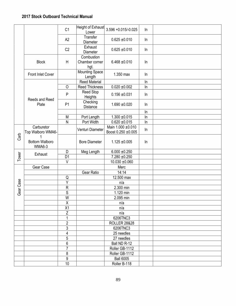
2017 Stock Outboard Technical Manual
89
C1 Height of Exhaust
Lower 3.596 +0.015/-0.025 In
A2 Transfer Diameter
0.625 ±0.010 In
C2 Exhaust Diameter
0.625 ±0.010 In
Block H Combustion
Chamber corner hgt.
6.468 ±0.010 In
Front Inlet Cover Mounting Space
Length 1.350 max In
Reeds and Reed Plate
Reed Material In
O Reed Thickness 0.020 ±0.002 In
P Reed Stop
Heights 0.156 ±0.031 In
P1 Checking Distance
1.690 ±0.020 In
In
M Port Length 1.300 ±0.015 In
N Port Width 0.620 ±0.015 In
Car
b
Carburetor Top Walboro WMA6-
1 Bottom Walboro
WMA6-3
Venturi Diameter Main 1.000 ±0.010 Boost 0.250 ±0.005
In
Bore Diameter 1.125 ±0.005 In
Tow
er
Exhaust D Meg Length 6.000 ±0.250
D1 7.280 ±0.250
V 10.030 ±0.060
Gea
r C
ase
Gear Case Merc
Gear Ratio 14:14
Q 12.500 max
Y n/a
R 2.300 min
S 1.120 min
W 2.095 min
X n/a
X1 n/a
Z n/a
1 6206TNC3
2 ROLLER 28&28
3 6206TNC3
4 25 needles
5 27 needles
6 Ball ND R-12
7 Roller GB-1112
8 Roller GB-1112
9 Ball 6005
10 Roller B-118

2017 Stock Outboard Technical Manual
90

2017 Stock Outboard Technical Manual
91
MERCURY 55H (D CLASS)
Engine Model Mercury 55H
Mercury 55
PO
WE
RH
EA
D S
PE
CIF
ICA
TIO
NS
Group Ref. # Item Dimension Units Definition
General Specs
Number of Cylinders
4
Engine
Displacement 39.6 In3 The Volume of all cylinders excluding the
combustions chamber
Minimum CC 20.5 Cm3 Volume of each Cylinder at T.D.C. filled to
top of spark plug hole
J Stroke 2.125 ±0.004 In Distance the crank moves in 180 of
rotation. Or the distance the piston moves
Flywheel Weight 1 lbs 12 oz
Flywheel Diameter
Cylinder Bore Diameter
G Standard 2.441 ±0.002 In This is a Reference only Dimension
Max Size 2.458 In Maximum bore size including piston
clearance
Rods L Rod Length 3.719 ±0.006 In Length of the rod from center of crank pin
hole to center of wrist pin hole
Weight 6.75 oz min With both bearings and washers
Piston
E Rod Piston
Length 4.412 ±0.018 In
Length of piston and rod from crank pin center to the top edge of the top ring
Weight 7.5 oz min With rings, wrist pin, and clips
F Piston Height
(minus Crown) 2.187 ±0.031 In
Piston Height measured to the top edge of the top ring
E1 Piston Position at
BDC 3.534 ±0.015 In
Piston Rings
Number per
Piston
Upper Design
Lower Upper
Thickness In
Lower In
Ports
Number of Exhaust
Number of
Transfer Upper
A Height of Transfer
55H- 4.076 ±0.010 55- 4.007 ±0.010
In
C Height of Exhaust
Upper 55H- 4.281 ±0.010 55- 4.221 ±0.010
In
A1 Transfer Lower
Height 3.329 ±0.010 In
C1 Exhaust Lower
height 3.543 ±0.010 In

2017 Stock Outboard Technical Manual
92
Block H Cylinder Height 6.307 +0.005/
-0.010 In
O Reed Thickness 0.012 In
P Reed Stop
Heights 0.156 ±0.031 In
M Port Length 1.000 or 1.219 ±0.033 In N Port Width 0.625 ±0.033 In
Carb
Carburetor Tillotson
Venturi Diameter KA 1.000 ±0.015
Carter 0.937 In
Bore Diameter KA 1.125 ±0.015
Carter 1.312 In
To
wer Exhaust D Housing Cast Snout
Drive Shaft Housing V 55H- 17.062 ±0.062 55- 12.062 ±0.062
Ge
ar
Ca
se
Gear Case Merc Gear Ratio 14:14 Q 12.500 max R 2.375 ±0.031 S 1.093 ±0.031 W 4.400 min
X 3.062 min
Y 3.312 min
Z 5.250 min
1 206K
2 ROLLER

2017 Stock Outboard Technical Manual
93

2017 Stock Outboard Technical Manual
94
RAM50 (D CLASS)
Engine Model RAM50 M50
PO
WE
RH
EA
D S
PE
CIF
ICA
TIO
NS
Group Ref. # Item Dimension Units Definition
General Specs
Number of Cylinders
3
Engine
Displacement 42.6 In3 The Volume of all cylinders excluding the
combustions chamber
Minimum CC 25 for #1 & #3
26 for #2 Cm3
Volume of each Cylinder at T.D.C. filled to top of spark plug hole
J Stroke 2.520 ± 0.002 In Distance the crank moves in 180 of
rotation. Or the distance the piston moves
Flywheel Weight 8.818 lbs. Minimum
Flywheel Diameter
Cylinder Bore Diameter
G Standard 2.677 ±0.005 In This is a Reference only Dimension
Max Size 2.707 In Maximum bore size including piston
clearance
Rods L Rod Length 4.587 ±0.007 In Length of the rod from center of crank pin
hole to center of wrist pin hole
Piston F
Piston Height (minus Crown)
2.638 ±0.018 In Piston Height measured to the top edge of
the top ring
M Wrist Pin To Top
Ring 1.260 ±0.008 In
Measured from the top edge of the top ring to the center of the wrist pin
Piston Rings
Number per
Piston 2
Upper Design
Lower Upper
Thickness 0.079 In
Lower 0.0776 ± 0.0015 In
Ports
Number of Exhaust
Number of Transfer
A Height of Transfer
5.000 ±0.039 In
C Height of Exhaust 5.492 ±0.039 In EX EX Width 1.575 ±0.059 In
HE Finger Height 0.413 ±0.059 T Finger Width 0.118 ±0.020
Transfer Width T1- 0.610 ±0.059 T2- 0.827 ±0.059 TB- 0.787 ±0.059
In
Block K Cylinder Height 7.087 ±0.008 In
Head Head Gasket 0.047 ±0.008 In Measured compressed Reed Material Plastic or Steel In

2017 Stock Outboard Technical Manual
95
Reeds and Reed Plate
Reed Thickness 0.008 ±0.001 In Y Reed Length 1.390 ±0.020
T Reed Stop
Heights 0.396 ±0.028 In
Port Length 1.181 ±0.020 In Port Width 0.591 ±0.020 In
Carb
Carburetor
Venturi Diameter 1.024 ±0.020 In
Throttle Housing 1.260 ±0.028 In
Ge
ar
Ca
se
Gear Case Bass Gear Ratio 17:17 Q 11.700 min Y 3.750 min
R 1.950 min
S 1.950 min X 3.000 min T 5.000 min
Prop Shaft Diameter
11/16
Shear Pin Diameter
0.250
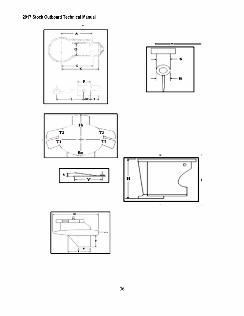
2017 Stock Outboard Technical Manual
96

2017 Stock Outboard Technical Manual
97
SUPER THUNDERBOLT (D CLASS)
Engine Model
PO
WE
RH
EA
D S
PE
CIF
ICA
TIO
NS
Group Ref. # Item Dimension Units Definition
General Specs
Number of Cylinders
4
Engine
Displacement 43.9 In3 The Volume of all cylinders excluding the
combustions chamber
Minimum CC 22 Cm3 Volume of each Cylinder at T.D.C. filled to
top of spark plug hole
J Stroke 2.125 ±0.004 In Distance the crank moves in 180 of
rotation. Or the distance the piston moves
Flywheel Weight 5 lbs With Timing Belt Pulley
Flywheel Diameter
Cylinder Bore Diameter
G Standard 2.565 ±0.003 In This is a Reference only Dimension
Max Size 2.602 In Maximum bore size including piston
clearance
Piston
E 3 Ring Piston
Weight 8.7 oz In With rings, wrist pin, and clips
2 Ring Piston
Weight 10.2 With rings, wrist pin, and clips
F Piston Height
(minus Crown) 2.187 ±0.031 In
Piston Height measured to the top edge of the top ring
E1 Deck Height 3.534 ±0.015 In
Piston Rings
Number per
Piston
Upper Design
Lower Upper
Thickness In
Lower In
Ports
Number of Exhaust
Number of Transfer
A Height of Transfer
4.007 ±0.010 In 3 round ports per cylinder
C Height of Exhaust 4.221 ±0.010 In 3 round ports per cylinder
A1 Transfer Height 3.382 ±0.010 In 3 round ports per cylinder C1 Exhaust Height 3.596 ±0.010 In 3 round ports per cylinder
Block H Combustion
Chamber Corner Height
6.307 +0.005/ -0.010
In
Reed Block O Reed Thickness Metal 0.012 ±0.001 Plastic 0.012 ±0.002
In

2017 Stock Outboard Technical Manual
98
P, P1 Reed Stop
Heights
0.156 ±0.031, Long: 1.690 ±0.020
Short: 1.438 ±0.010 In
M Port Length
1.300 ±0.015 Big Aluminum 1.000 or
1.219 ±0.033 Bass or Small
Aluminum
In
Car
b Carburetor Tillotson
Venturi Diameter 1.000 ±0.015 In
Bore Diameter 1.123 ±0.015 In
Tow
er Exhaust D Housing
Cast Snout Bass 7/8” max
V Housing Height 55H/33SS 17.062
±0.062 Bass 8.500 ±0.062
A Bass Adapter 0.750 ±0.032
Gea
r C
ase
Gear Case Model 55H 44XS Bass Gear Ratio 14:14 14:14 17:17
Q 12.500 max 12.500 max 11.700 min R 2.375 ±0.031 2.300 min 1.950 min S 1.093 ±0.031 1.120 min 1.950 min T 5.000 min U 3.000 min V 3.750 min W 4.400 min 2.095 min X 3.062 min
Y 3.312 min Z 5.250 min 1 206K 2 ROLLERS 3 206K
4 25 rollers 5 22 rollers 55H 44XS Bass 6 5-8K BALL 12-R Roller 7 Roller GB-1112 Ball
8 Roller GB-1112 n/a 9 9105K 6005 Ball & Roller

2017 Stock Outboard Technical Manual
99
MERCURY 402XS (D CLASS)
Engine Model Mercury 402XS
PO
WE
RH
EA
D S
PE
CIF
ICA
TIO
NS
Group Ref. # Item Dimension Units Definition
General Specs
Number of Cylinders
2
Engine
Displacement 33.3 In3 The Volume of all cylinders excluding
the combustions chamber
Minimum CC 28.0 Cm3 Volume of each Cylinder at T.D.C. filled
to top of spark plug hole
J Stroke 2.562 ±0.006 In Distance the crank moves in 180 of rotation. Or the distance the piston
moves
Flywheel Weight
10.0 Steel Min. 7lbs14oz Alum
lbs
K Not Known
Cylinder Bore Diameter
G
Standard 2.875 0.003 In This is a Reference only Dimension
Max Size In Maximum bore size including piston
clearance
Rods L Rod Length 4.062 ±0.006 In Length of the rod from center of crank
pin hole to center of wrist pin hole
Weight 10.9 Min Oz With both bearings and washers
Piston
E Rod Piston
Length 4.279 ±0.025 In
Length of piston and rod from crank pin center to the top edge of the top ring
Weight 13.0 Min Oz With rings, wrist pin, and clips
F Piston Height
(minus Crown) 2.630 ±0.032 In
Piston Height measured to the top edge of the top ring
Piston Rings
No. per Piston Upper
Design
Lower Upper
Thickness In
Lower In
Ports
Number of Exhaust
Number of
Transfer Upper
A Height of Transfer
4.828 0.025 In
C Height of
Exhaust Upper 5.066 0.025 In
A1 Transfer Lower
Height 4.278 ± 0.025 In
C1 Exhaust Lower
height 4.363 ± 0.025 In
C1 Dimensions on 1981 and newer 3
port blocks is 4.328 0.025
Block H Cylinder Height In Reed Block O Reed Thickness In

2017 Stock Outboard Technical Manual
100
P Reed Stop
Heights 0.156 ±0.031 In
N Port Diameter 20 Ports .56 Dia. In N refers to the number and size of reed port openings in reed block
Carb
Carburetor Walbro WMK-21
Venturi
Diameter 1.250 In
Bore Diameter 1.375 In
To
wer Exhaust D Housing Cast Snout
Drive Shaft Housing
V 17.062 .062
Ge
ar
Ca
se
Gear Case Merc Skeg dimensions same as 55H Gear Ratio 14:14 Q 12.500 max R 2.375 ±0.031
S 1.093 ±0.031
W 4.500 min X 3.062 min
Y 3.312 min
Z 5.250 min
1 206K
2 ROLLER

2017 Stock Outboard Technical Manual
101


