Embed Size (px)
Citation preview
Syn-sedimentary shear zones
I. Moretti1, S. Calassou2, P. Victor1,3, M. Molinaro4 and L. Maerten1
1Institut Français du Pétrole, Div Géologie-Géochimie, Av de Bois Préau, 92852 Rueil Malmaison, France(e-mail: [email protected])
2TotalFinaElf, Centre Scientifique et Technique JF, 64000 Pau, France3Present address: University of Hannover, Institut für Geologie und Paläontologie, Callinstr. 30, D-30167 Hannover,
Germany4University of Orsay, Laboratoire Tectonique et Bassins, Université Paris Sud, UMR 8616, 91405 Orsay, France
ABSTRACT: In deltaic and turbiditic deposits along passive margins, such as theLower Congo basin on the West African margin, the main deformation is notinduced by a regional tectonic stress field but by the increase of the sedimentary loadleading to gravitational instabilities. The local stress field in such an environment isdrastically influenced by the lithological discontinuities, which can reorientate theprincipal stresses induced by sedimentary loading. In this paper we document thelocalization of particular faults, called sedimentary shear zones (SSZ); these areformed along the borders of a sandy channel embedded in more fine-grainedsediments, as a function of the lithological contrast. Furthermore we describe thereorientation of the stress field, perpendicular to the channel borders in the channelinterior. Examples from 3D seismic lines and field studies in SW Ireland and Tunisiaare compared with results from analogue and geomechanical models, leading to anintegrated interpretation for the formation of the SSZ.
KEYWORDS: channel, turbidite, gravity gliding, stress orientation
INTRODUCTION
Exploration in the deep offshore and the improved quality of3D seismic data in sedimentary basins along passive marginshas highlighted new features in turbiditic systems. On theseismic data from the West African margin, explorationistsobserve structural discontinuities along the channel boundariesthat cannot be explained by sedimentary processes alone. Thisis especially true in channel-levee complexes, structures whichare defined by lateral or vertical stacking of sandy elementarychannels and finer-grained overbank deposits, as described byKolla et al. (2001) from offshore Angola or Clark et al. (1992). Inthis paper we describe and analyse the observed structures by amultidisciplinary approach, using seismic 3D survey interpret-ation and field observation, as well as results from analogue andgeomechanical modelling.
Gravity spreading context
The stress field, and hence the driving force of the deformation,along passive margins after the cessation of the rifting phasecannot be characterized by a regional stress field, eitherextensional or compressive. Deformation is rather controlledby gravitational instabilities induced by loading of thesedimentary pile due to continuous influx (Calassou & Moretti2003). In addition, along some margins, for example the WestAfrican, regional tilt occurs due to an uplift of the continent.Sediments can spread in various directions because theoffshore borders are unconfined and the displacement can beboth perpendicular and parallel to the margin (Panien et al.2001; Calassou & Moretti 2003; Victor & Moretti 2003).Multidirectional gravitational spreading is also enhanced by
basal décollement horizons like salt or overpressured shales.The importance of the material behaviour of the sediments,especially in localizing compressive deformation, is welldocumented in the Gulf of Mexico (Diegel et al. 1995; Rowanet al. 1999) and in the West African margin (Duval et al. 1992).At the channel-levee complex scale, the material contrastbetween the sandy channel and the finer-grained levee isexpected to influence the local stress field and, therefore, tocontrol the deformation pattern. In this paper, we will describethat this leads to the formation of structural discontinuities.
SEISMIC DATA
The TotalFinaElf seismic data presented here all come from theWest African margin. The seismic data used for channeldescription are 3D high-resolution data. Inter-trace: 6.5 m;Inter-sample: 4 ms. The picking of stratigraphic time lines,sedimentary facies and faults were made by a TotalFinaElfteam. Attribute maps – such as coherency, amplitude,dip-azimuth – were generated.
After the Atlantic break up, the West African margin wasthe site of an evaporitic event (Albian), then the post-riftsubsidence and gravity-glided deformation started. Depositionof carbonates took place during the Turonian to Eocene.Contemporaneously, salt tectonics were active, characterized byraft and growth faults in the proximal domain (extensional) andby diapers, as well as compressive structures such as thrustsunits, in the distal domain. From Oligocene times until nowa more regional sedimentary infilling took place in theZaire/Congo deltas and only few new faults formed in theextensional domain. This regional sedimentary influx was
Petroleum Geoscience, Vol. 9 2003, pp. 221–232 1354-0793/03/$15.00 � 2003 EAGE/Geological Society of London
associated with a major uplift of the African margin. Thesedimentary pile above the salt is more than 6 km thick, withlocally more than 4 km of Oligo-Miocene to Quaternaryturbiditic deposits (Duval et al. 1992; Lundin 1992). Regionalcross-sections can be found in Rouby et al. (2002) and Calassou& Moretti (2003). We will focus our study on the characteristicsof the sandy channel and fine-grained levees in these turbidites,located in the Tertiary translated domain.
Turbidites of the deep-offshore Miocene deposits of thesouthern part of the lower Congo basin show particulargeometries of vertical stacking of channel-levee complexes(CC). The channel-levee complex is defined in cross-section by
+ an axis of high density sedimentary transit and twosymmetrical levees built by overspill low density currents;
+ grain density decrease from the axial/proximal position tothe distal position;
+ 20 km from the axis to the pinch-out of the levees.
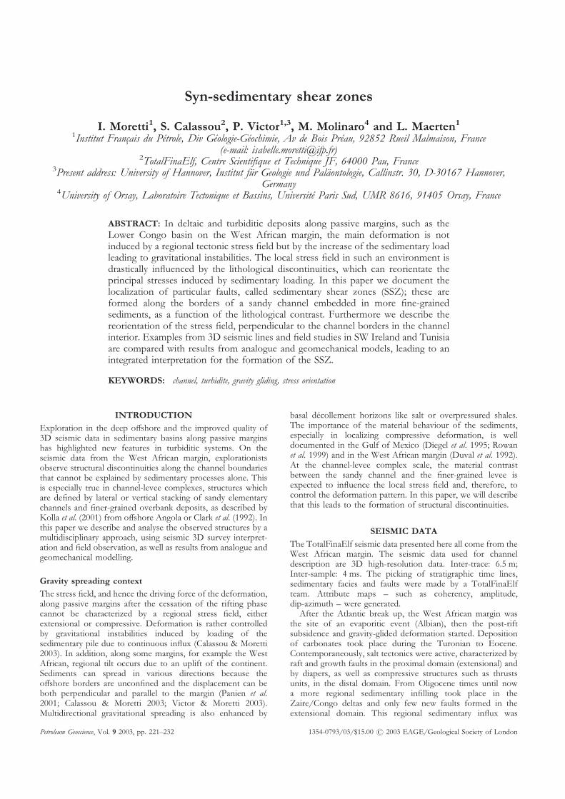
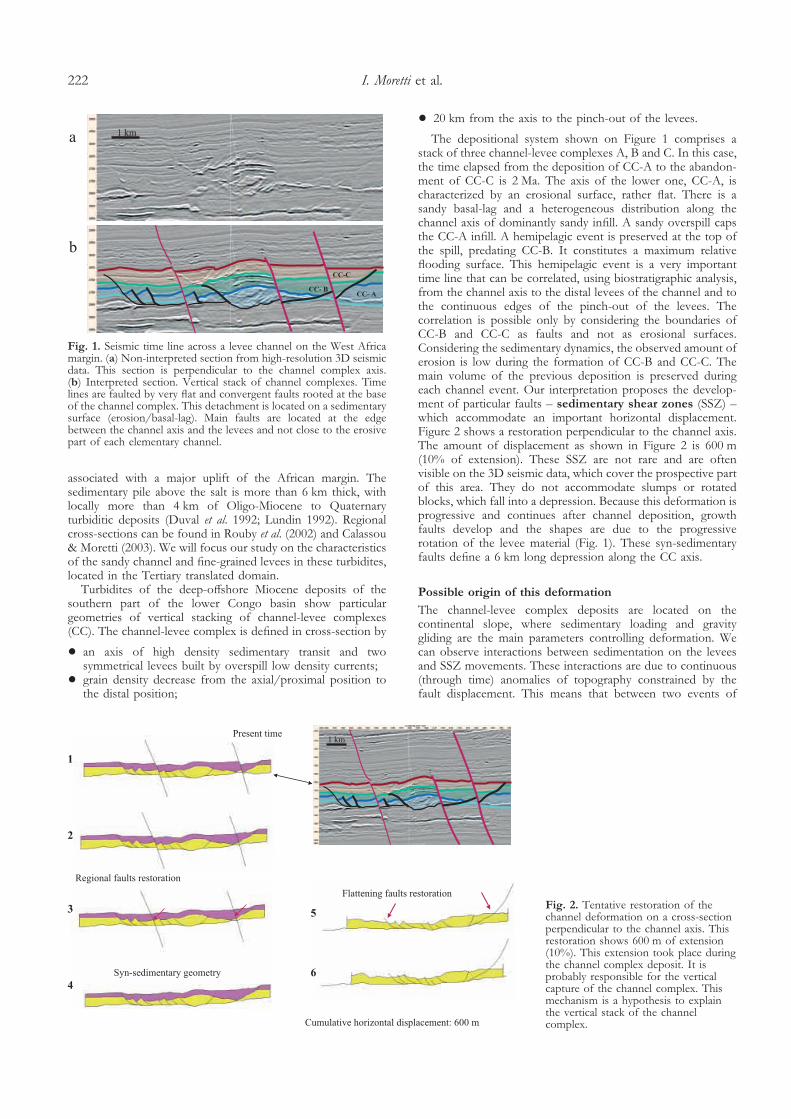
The depositional system shown on Figure 1 comprises astack of three channel-levee complexes A, B and C. In this case,the time elapsed from the deposition of CC-A to the abandon-ment of CC-C is 2 Ma. The axis of the lower one, CC-A, ischaracterized by an erosional surface, rather flat. There is asandy basal-lag and a heterogeneous distribution along thechannel axis of dominantly sandy infill. A sandy overspill capsthe CC-A infill. A hemipelagic event is preserved at the top ofthe spill, predating CC-B. It constitutes a maximum relativeflooding surface. This hemipelagic event is a very importanttime line that can be correlated, using biostratigraphic analysis,from the channel axis to the distal levees of the channel and tothe continuous edges of the pinch-out of the levees. Thecorrelation is possible only by considering the boundaries ofCC-B and CC-C as faults and not as erosional surfaces.Considering the sedimentary dynamics, the observed amount oferosion is low during the formation of CC-B and CC-C. Themain volume of the previous deposition is preserved duringeach channel event. Our interpretation proposes the develop-ment of particular faults – sedimentary shear zones (SSZ) –which accommodate an important horizontal displacement.Figure 2 shows a restoration perpendicular to the channel axis.The amount of displacement as shown in Figure 2 is 600 m(10% of extension). These SSZ are not rare and are oftenvisible on the 3D seismic data, which cover the prospective partof this area. They do not accommodate slumps or rotatedblocks, which fall into a depression. Because this deformation isprogressive and continues after channel deposition, growthfaults develop and the shapes are due to the progressiverotation of the levee material (Fig. 1). These syn-sedimentaryfaults define a 6 km long depression along the CC axis.
Possible origin of this deformation
The channel-levee complex deposits are located on thecontinental slope, where sedimentary loading and gravitygliding are the main parameters controlling deformation. Wecan observe interactions between sedimentation on the leveesand SSZ movements. These interactions are due to continuous(through time) anomalies of topography constrained by thefault displacement. This means that between two events of
Fig. 1. Seismic time line across a levee channel on the West Africamargin. (a) Non-interpreted section from high-resolution 3D seismicdata. This section is perpendicular to the channel complex axis.(b) Interpreted section. Vertical stack of channel complexes. Timelines are faulted by very flat and convergent faults rooted at the baseof the channel complex. This detachment is located on a sedimentarysurface (erosion/basal-lag). Main faults are located at the edgebetween the channel axis and the levees and not close to the erosivepart of each elementary channel.
Fig. 2. Tentative restoration of thechannel deformation on a cross-sectionperpendicular to the channel axis. Thisrestoration shows 600 m of extension(10%). This extension took place duringthe channel complex deposit. It isprobably responsible for the verticalcapture of the channel complex. Thismechanism is a hypothesis to explainthe vertical stack of the channelcomplex.
I. Moretti et al.222
catastrophic turbidites, the system has enough time to readjustthe disequilibrium induced by the previous deposition at thisscale of analysis. Nevertheless, questions remain about therelationships between ‘instantaneous’ deformation and thedeformation of all the sedimentary succession.
Dewatering and the initiation of compaction may beresponsible for a part of the displacement but the 600 m ofextension perpendicular to the axis appears too large to be fullyexplained by these processes.
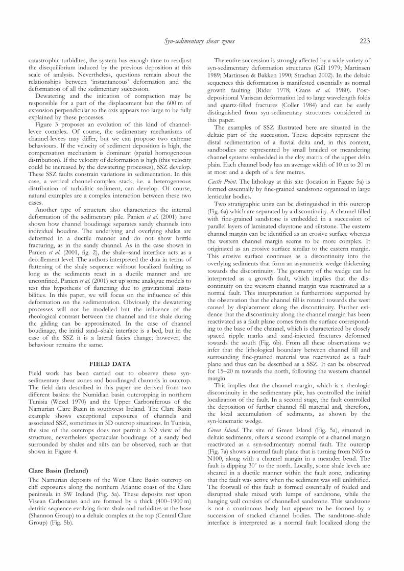
Figure 3 proposes an evolution of this kind of channel-levee complex. Of course, the sedimentary mechanisms ofchannel-levees may differ, but we can propose two extremebehaviours. If the velocity of sediment deposition is high, thecompensation mechanism is dominant (spatial homogeneousdistribution). If the velocity of deformation is high (this velocitycould be increased by the dewatering processes), SSZ develop.These SSZ faults constrain variations in sedimentation. In thiscase, a vertical channel-complex stack, i.e. a heterogeneousdistribution of turbiditic sediment, can develop. Of course,natural examples are a complex interaction between these twocases.
Another type of structure also characterizes the internaldeformation of the sedimentary pile. Panien et al. (2001) haveshown how channel boudinage separates sandy channels intoindividual boudins. The underlying and overlying shales aredeformed in a ductile manner and do not show brittlefracturing, as in the sandy channel. As in the case shown inPanien et al. (2001, fig. 2), the shale–sand interface acts as adecollement level. The authors interpreted the data in terms offlattening of the shaly sequence without localized faulting aslong as the sediments react in a ductile manner and areunconfined. Panien et al. (2001) set up some analogue models totest this hypothesis of flattening due to gravitational insta-bilities. In this paper, we will focus on the influence of thisdeformation on the sedimentation. Obviously the dewateringprocesses will not be modelled but the influence of therheological contrast between the channel and the shale duringthe gliding can be approximated. In the case of channelboudinage, the initial sand–shale interface is a bed, but in thecase of the SSZ it is a lateral facies change; however, thebehaviour remains the same.
FIELD DATA
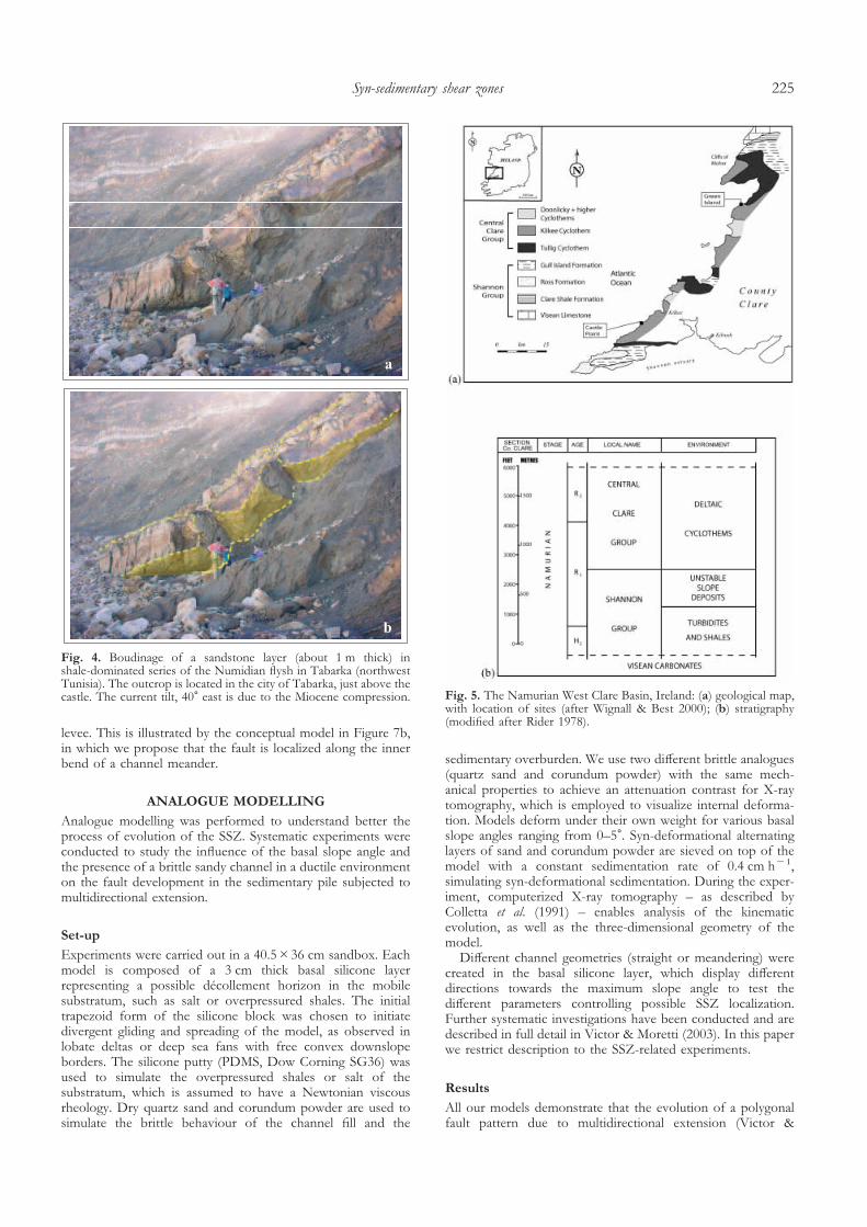
Field work has been carried out to observe these syn-sedimentary shear zones and boudinaged channels in outcrop.The field data described in this paper are derived from twodifferent basins: the Numidian basin outcropping in northernTunisia (Wezel 1970) and the Upper Carboniferous of theNamurian Clare Basin in southwest Ireland. The Clare Basinexample shows exceptional exposures of channels andassociated SSZ, sometimes in 3D outcrop situations. In Tunisia,the size of the outcrops does not permit a 3D view of thestructure, nevertheless spectacular boudinage of a sandy bedsurrounded by shales and silts can be observed, such as thatshown in Figure 4.
Clare Basin (Ireland)
The Namurian deposits of the West Clare Basin outcrop oncliff exposures along the northern Atlantic coast of the Clarepeninsula in SW Ireland (Fig. 5a). These deposits rest uponVisean Carbonates and are formed by a thick (400–1900 m)detritic sequence evolving from shale and turbidites at the base(Shannon Group) to a deltaic complex at the top (Central ClareGroup) (Fig. 5b).
The entire succession is strongly affected by a wide variety ofsyn-sedimentary deformation structures (Gill 1979; Martinsen1989; Martinsen & Bakken 1990; Strachan 2002). In the deltaicsequences this deformation is manifested essentially as normalgrowth faulting (Rider 1978; Crans et al. 1980). Post-depositional Variscan deformation led to large wavelength foldsand quartz-filled fractures (Coller 1984) and can be easilydistinguished from syn-sedimentary structures considered inthis paper.
The examples of SSZ illustrated here are situated in thedeltaic part of the succession. These deposits represent thedistal sedimentation of a fluvial delta and, in this context,sandbodies are represented by small braided or meanderingchannel systems embedded in the clay matrix of the upper deltaplain. Each channel body has an average width of 10 m to 20 mat most and a depth of a few metres.
Castle Point. The lithology at this site (location in Figure 5a) isformed essentially by fine-grained sandstone organized in largelenticular bodies.
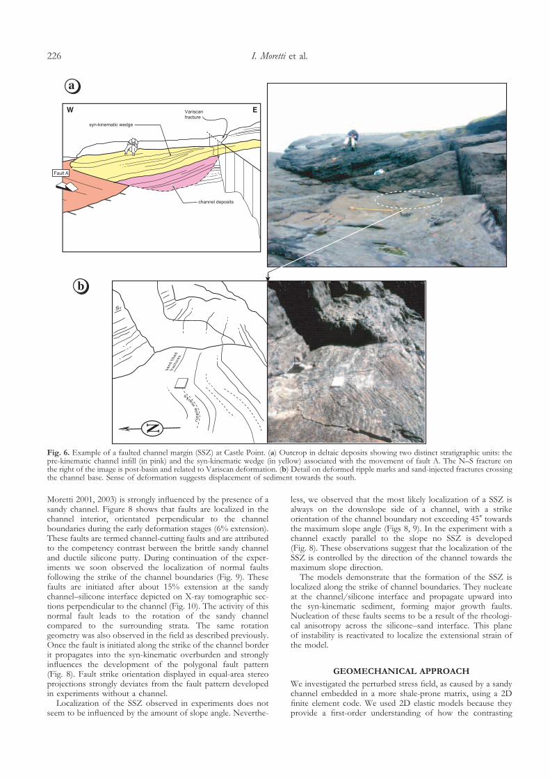
Two stratigraphic units can be distinguished in this outcrop(Fig. 6a) which are separated by a discontinuity. A channel filledwith fine-grained sandstone is embedded in a succession ofparallel layers of laminated claystone and siltstone. The easternchannel margin can be identified as an erosive surface whereasthe western channel margin seems to be more complex. Itoriginated as an erosive surface similar to the eastern margin.This erosive surface continues as a discontinuity into theoverlying sediments that form an asymmetric wedge thickeningtowards the discontinuity. The geometry of the wedge can beinterpreted as a growth fault, which implies that the dis-continuity on the western channel margin was reactivated as anormal fault. This interpretation is furthermore supported bythe observation that the channel fill is rotated towards the westcaused by displacement along the discontinuity. Further evi-dence that the discontinuity along the channel margin has beenreactivated as a fault plane comes from the surface correspond-ing to the base of the channel, which is characterized by closelyspaced ripple marks and sand-injected fractures deformedtowards the south (Fig. 6b). From all these observations weinfer that the lithological boundary between channel fill andsurrounding fine-grained material was reactivated as a faultplane and thus can be described as a SSZ. It can be observedfor 15–20 m towards the north, following the western channelmargin.
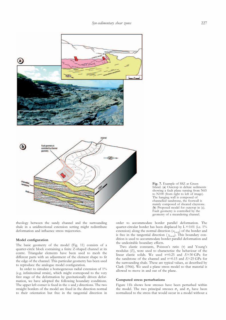
This implies that the channel margin, which is a rheologicdiscontinuity in the sedimentary pile, has controlled the initiallocalization of the fault. In a second stage, the fault controlledthe deposition of further channel fill material and, therefore,the local accumulation of sediments, as shown by thesyn-kinematic wedge.Green Island. The site of Green Island (Fig. 5a), situated indeltaic sediments, offers a second example of a channel marginreactivated as a syn-sedimentary normal fault. The outcrop(Fig. 7a) shows a normal fault plane that is turning from N65 toN100, along with a channel margin in a meander bend. Thefault is dipping 30� to the north. Locally, some shale levels aresheared in a ductile manner within the fault zone, indicatingthat the fault was active when the sediment was still unlithified.The footwall of this fault is formed essentially of folded anddisrupted shale mixed with lumps of sandstone, while thehanging wall consists of channelled sandstone. This sandstoneis not a continuous body but appears to be formed by asuccession of stacked channel bodies. The sandstone–shaleinterface is interpreted as a normal fault localized along the
Syn-sedimentary shear zones 223
channel margin due to the rheological contrast between the twolithological units (channelled sandstone and fine-grained leveematerial).
These observations suggest that the presence and thegeometry of the fault are a direct consequence of the influenceof a meandering sandy channel surrounded by its fine-grained
Fig. 3. Sedimentary flattening and possible schematic evolution of a stack of channel-levee complexes (depositional system). This model is basedon the seismic observations made on channel-levee complexes in offshore Gulf of Guinea. dz, deformation zone.
I. Moretti et al.224
levee. This is illustrated by the conceptual model in Figure 7b,in which we propose that the fault is localized along the innerbend of a channel meander.
ANALOGUE MODELLING
Analogue modelling was performed to understand better theprocess of evolution of the SSZ. Systematic experiments wereconducted to study the influence of the basal slope angle andthe presence of a brittle sandy channel in a ductile environmenton the fault development in the sedimentary pile subjected tomultidirectional extension.
Set-up
Experiments were carried out in a 40.5�36 cm sandbox. Eachmodel is composed of a 3 cm thick basal silicone layerrepresenting a possible décollement horizon in the mobilesubstratum, such as salt or overpressured shales. The initialtrapezoid form of the silicone block was chosen to initiatedivergent gliding and spreading of the model, as observed inlobate deltas or deep sea fans with free convex downslopeborders. The silicone putty (PDMS, Dow Corning SG36) wasused to simulate the overpressured shales or salt of thesubstratum, which is assumed to have a Newtonian viscousrheology. Dry quartz sand and corundum powder are used tosimulate the brittle behaviour of the channel fill and the
sedimentary overburden. We use two different brittle analogues(quartz sand and corundum powder) with the same mech-anical properties to achieve an attenuation contrast for X-raytomography, which is employed to visualize internal deforma-tion. Models deform under their own weight for various basalslope angles ranging from 0–5�. Syn-deformational alternatinglayers of sand and corundum powder are sieved on top of themodel with a constant sedimentation rate of 0.4 cm h�1,simulating syn-deformational sedimentation. During the exper-iment, computerized X-ray tomography – as described byColletta et al. (1991) – enables analysis of the kinematicevolution, as well as the three-dimensional geometry of themodel.
Different channel geometries (straight or meandering) werecreated in the basal silicone layer, which display differentdirections towards the maximum slope angle to test thedifferent parameters controlling possible SSZ localization.Further systematic investigations have been conducted and aredescribed in full detail in Victor & Moretti (2003). In this paperwe restrict description to the SSZ-related experiments.
Results
All our models demonstrate that the evolution of a polygonalfault pattern due to multidirectional extension (Victor &
Fig. 4. Boudinage of a sandstone layer (about 1 m thick) inshale-dominated series of the Numidian flysh in Tabarka (northwestTunisia). The outcrop is located in the city of Tabarka, just above thecastle. The current tilt, 40� east is due to the Miocene compression. Fig. 5. The Namurian West Clare Basin, Ireland: (a) geological map,
with location of sites (after Wignall & Best 2000); (b) stratigraphy(modified after Rider 1978).
Syn-sedimentary shear zones 225
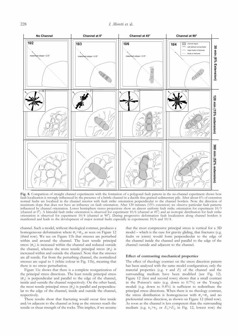
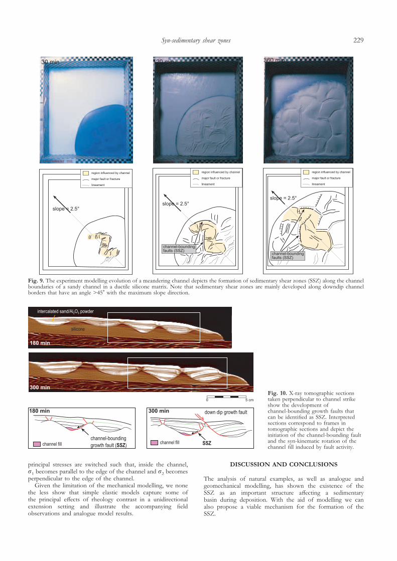
Moretti 2001, 2003) is strongly influenced by the presence of asandy channel. Figure 8 shows that faults are localized in thechannel interior, orientated perpendicular to the channelboundaries during the early deformation stages (6% extension).These faults are termed channel-cutting faults and are attributedto the competency contrast between the brittle sandy channeland ductile silicone putty. During continuation of the exper-iments we soon observed the localization of normal faultsfollowing the strike of the channel boundaries (Fig. 9). Thesefaults are initiated after about 15% extension at the sandychannel–silicone interface depicted on X-ray tomographic sec-tions perpendicular to the channel (Fig. 10). The activity of thisnormal fault leads to the rotation of the sandy channelcompared to the surrounding strata. The same rotationgeometry was also observed in the field as described previously.Once the fault is initiated along the strike of the channel borderit propagates into the syn-kinematic overburden and stronglyinfluences the development of the polygonal fault pattern(Fig. 8). Fault strike orientation displayed in equal-area stereoprojections strongly deviates from the fault pattern developedin experiments without a channel.
Localization of the SSZ observed in experiments does notseem to be influenced by the amount of slope angle. Neverthe-
less, we observed that the most likely localization of a SSZ isalways on the downslope side of a channel, with a strikeorientation of the channel boundary not exceeding 45� towardsthe maximum slope angle (Figs 8, 9). In the experiment with achannel exactly parallel to the slope no SSZ is developed(Fig. 8). These observations suggest that the localization of theSSZ is controlled by the direction of the channel towards themaximum slope direction.
The models demonstrate that the formation of the SSZ islocalized along the strike of channel boundaries. They nucleateat the channel/silicone interface and propagate upward intothe syn-kinematic sediment, forming major growth faults.Nucleation of these faults seems to be a result of the rheologi-cal anisotropy across the silicone–sand interface. This planeof instability is reactivated to localize the extensional strain ofthe model.
GEOMECHANICAL APPROACH
We investigated the perturbed stress field, as caused by a sandychannel embedded in a more shale-prone matrix, using a 2Dfinite element code. We used 2D elastic models because theyprovide a first-order understanding of how the contrasting
Fig. 6. Example of a faulted channel margin (SSZ) at Castle Point. (a) Outcrop in deltaic deposits showing two distinct stratigraphic units: thepre-kinematic channel infill (in pink) and the syn-kinematic wedge (in yellow) associated with the movement of fault A. The N–S fracture onthe right of the image is post-basin and related to Variscan deformation. (b) Detail on deformed ripple marks and sand-injected fractures crossingthe channel base. Sense of deformation suggests displacement of sediment towards the south.
I. Moretti et al.226
rheology between the sandy channel and the surroundingshale in a unidirectional extension setting might redistributedeformation and influence stress trajectories.
Model configuration
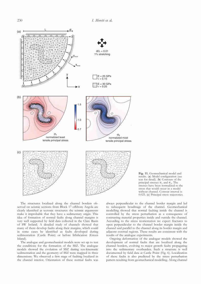
The basic geometry of the model (Fig. 11) consists of aquarter-circle block containing a finite Z-shaped channel at itscentre. Triangular elements have been used to mesh thedifferent parts with an adjustment of the element shape to fitthe edge of the channel. This particular geometry has been usedto reproduce the analogue model configuration.
In order to simulate a homogeneous radial extension of 1%(e.g. infinitesimal strain), which might correspond to the veryfirst stage of the deformation by gravitationally driven defor-mation, we have adopted the following boundary conditions.The upper left corner is fixed in the x and y directions. The twostraight borders of the model are fixed in the direction normalto their orientation but free in the tangential direction in
order to accommodate border parallel deformation. Thequarter-circular border has been displaced by L�0.01 (i.e. 1%extension) along the normal direction (xlocal) of the border andis free in the tangential direction ( ylocal). This boundary con-dition is used to accommodate border parallel deformation andthe undesirable boundary effects.
Two elastic constants, Poisson’s ratio (�) and Young’smodulus (E), were used to characterize the behaviour of thelinear elastic solids. We used �=0.25 and E=30 GPa forthe sandstone of the channel and �=0.15 and E=25 GPa forthe surrounding shale. These are typical values, as described byClark (1966). We used a plane stress model so that material isallowed to move in and out of the plane.
Computed stress perturbations
Figure 11b shows how stresses have been perturbed withinthe model. The two principal stresses �1 and �2 have beennormalized to the stress that would occur in a model without a
Fig. 7. Example of SSZ at GreenIsland. (a) Outcrop in deltaic sedimentsshowing a fault plane turning from N65to N100 (from right to left of image).The hanging wall is composed ofchannelled sandstone, the footwall ismainly composed of sheared claystone.(b) Proposed model for outcrop in (a).Fault geometry is controlled by thegeometry of a meandering channel.
Syn-sedimentary shear zones 227
channel. Such a model, without rheological contrast, produces ahomogeneous deformation where �1=�2, as seen on Figure 12(third row). We see on Figure 11b that stresses are perturbedwithin and around the channel. The least tensile principalstress (�1) is increased within the channel and reduced outsidethe channel, whereas the most tensile principal stress (�2) isincreased within and outside the channel. Note that the stressesare all tensile. Far from the perturbing channel, the normalizedstresses are equal to 1 (white colour in Fig. 11b), meaning thatthere is no stress perturbation.
Figure 11c shows that there is a complete reorganization ofthe principal stress directions. The least tensile principal stress(�1) is perpendicular and parallel to the edge of the channel,inside and outside the channel respectively. On the other hand,the most tensile principal stress (�2) is parallel and perpendicu-lar to the edge of the channel, inside and outside the channel,respectively.
These results show that fracturing would occur first insideand/or adjacent to the channel as long as the stresses reach thetensile or shear strength of the rocks. This implies, if we assume
that the most compressive principal stress is vertical for a 3Dmodel – which is the case for gravity gliding, that fractures (e.g.faults or joints) would form perpendicular to the edge ofthe channel inside the channel and parallel to the edge of thechannel outside and adjacent to the channel.
Effect of contrasting mechanical properties
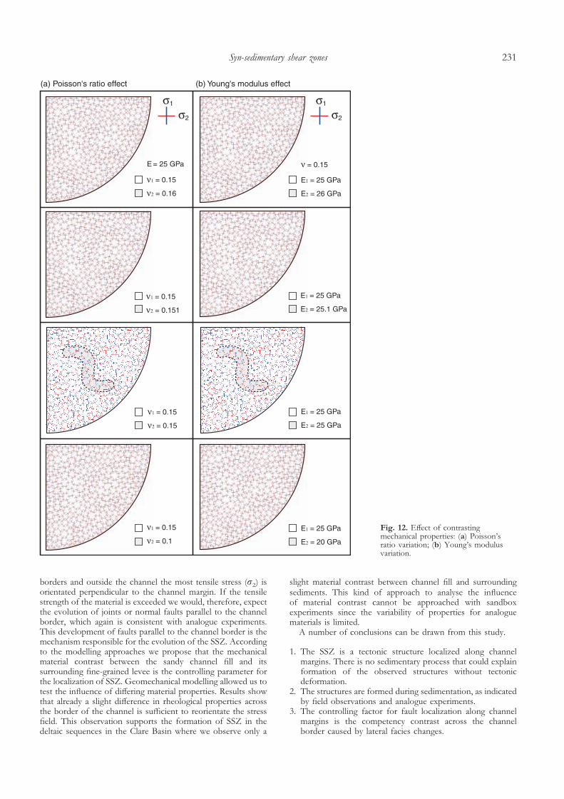
The effect of rheology contrast on the stress direction patternhas been analysed with the same model configuration; only thematerial properties (e.g. � and E) of the channel and thesurrounding medium have been modified (see Fig. 12).Figure 12 (first and second rows) shows that a small contrastin the Poisson’s ratio (e.g. down to 0.7%) or the Young’smoduli (e.g. down to 0.4%) is sufficient to redistribute theprincipal stress directions. When there is no rheology contrast,the stress distribution is homogeneous with �1=�2 and nopreferential stress direction, as shown on Figure 12 (third row).As soon as the channel is less competent than the surroundingmedium (e.g. �1>�2 or E1>E2 in Fig. 12, lowest row) the
Fig. 8. Comparison of straight channel experiments with the formation of a polygonal fault pattern in the no-channel experiment shows howfault localization is strongly influenced by the presence of a brittle channel in a ductile fine-grained sedimentary pile. After about 6% of extensionnormal faults are localized in the channel interior with fault strike orientation perpendicular to the channel borders. Note the direction ofmaximum slope that does not have an influence on fault orientation. After 120 minutes (15% extension) we observe particular fault patternsinfluenced by channel orientation. Lower hemisphere stereo projections show an almost uniform fault strike orientation for experiment 10/3(channel at 0�). A bimodal fault strike orientation is observed for experiment 10/6 (channel at 45�) and an isotropic distribution for fault strikeorientation is observed for experiment 10/4 (channel at 90�). During progressive deformation fault localization along channel borders ismanifested and leads to the development of major normal faults especially in experiments 10/6 and 10/4.
I. Moretti et al.228
principal stresses are switched such that, inside the channel,�1 becomes parallel to the edge of the channel and �2 becomesperpendicular to the edge of the channel.
Given the limitation of the mechanical modelling, we nonethe less show that simple elastic models capture some ofthe principal effects of rheology contrast in a unidirectionalextension setting and illustrate the accompanying fieldobservations and analogue model results.
DISCUSSION AND CONCLUSIONS
The analysis of natural examples, as well as analogue andgeomechanical modelling, has shown the existence of theSSZ as an important structure affecting a sedimentarybasin during deposition. With the aid of modelling we canalso propose a viable mechanism for the formation of theSSZ.
Fig. 9. The experiment modelling evolution of a meandering channel depicts the formation of sedimentary shear zones (SSZ) along the channelboundaries of a sandy channel in a ductile silicone matrix. Note that sedimentary shear zones are mainly developed along downdip channelborders that have an angle >45� with the maximum slope direction.
Fig. 10. X-ray tomographic sectionstaken perpendicular to channel strikeshow the development ofchannel-bounding growth faults thatcan be identified as SSZ. Interpretedsections correspond to frames intomographic sections and depict theinitiation of the channel-bounding faultand the syn-kinematic rotation of thechannel fill induced by fault activity.
Syn-sedimentary shear zones 229
The structures localized along the channel borders ob-served on seismic sections from Block 17 offshore Angola areclearly identified as tectonic structures: the seismic argumentsmake it improbable that they have a sedimentary origin. Thisidea of formation of normal faults along channel margins isvery well supported by field data collected in the Clare Basinof SW Ireland. A detailed study of channels showed thatmany of them develop faults along their margins, which couldin some cases be identified as faults developed duringsedimentation (Castle Point) or before lithification (GreenIsland).
The analogue and geomechanical models were set up to testthe conditions for the formation of the SSZ. The analoguemodels showed the evolution of SSZ during syn-kinematicsedimentation and the geometry of SSZ were mapped in threedimensions. We observed a first stage of faulting localized inthe channel interior. Orientation of these normal faults was
always perpendicular to the channel border margin and ledto subsequent boudinage of the channel. Geomechanicalmodelling showed that normal faulting inside the channel iscontrolled by the stress perturbation as a consequence ofcontrasting material properties inside and outside the channel.According to the stress reorientation we expect fractures toopen perpendicular to the channel border margin inside thechannel and parallel to the channel along its border margin andadjacent external regions. These results are consistent with theresults of the analogue experiments.
Ongoing deformation of the analogue models showed thedevelopment of normal faults that are localized along thechannel borders, evolving to major growth faults propagatinginto the sedimentary overburden. Such a structure is welldocumented by field data at Castle Point (Fig. 6). Localizationof these faults is also predicted by the stress perturbationpattern resulting from geomechanical modelling. Along channel
Fig. 11. Geomechanical model andresults. (a) Model configuration (seetext for detail). (b) Contours of theprincipal stresses �1 and �2. Thestresses have been normalized to thestress that would occur in a modelwithout channel. Contour interval is0.025. (c) Principal stress trajectories.
I. Moretti et al.230
borders and outside the channel the most tensile stress (�2) isorientated perpendicular to the channel margin. If the tensilestrength of the material is exceeded we would, therefore, expectthe evolution of joints or normal faults parallel to the channelborder, which again is consistent with analogue experiments.This development of faults parallel to the channel border is themechanism responsible for the evolution of the SSZ. Accordingto the modelling approaches we propose that the mechanicalmaterial contrast between the sandy channel fill and itssurrounding fine-grained levee is the controlling parameter forthe localization of SSZ. Geomechanical modelling allowed us totest the influence of differing material properties. Results showthat already a slight difference in rheological properties acrossthe border of the channel is sufficient to reorientate the stressfield. This observation supports the formation of SSZ in thedeltaic sequences in the Clare Basin where we observe only a
slight material contrast between channel fill and surroundingsediments. This kind of approach to analyse the influenceof material contrast cannot be approached with sandboxexperiments since the variability of properties for analoguematerials is limited.
A number of conclusions can be drawn from this study.
1. The SSZ is a tectonic structure localized along channelmargins. There is no sedimentary process that could explainformation of the observed structures without tectonicdeformation.
2. The structures are formed during sedimentation, as indicatedby field observations and analogue experiments.
3. The controlling factor for fault localization along channelmargins is the competency contrast across the channelborder caused by lateral facies changes.
Fig. 12. Effect of contrastingmechanical properties: (a) Poisson’sratio variation; (b) Young’s modulusvariation.
Syn-sedimentary shear zones 231
4. Channel boudinage is a second phenomenon of syn-sedimentary deformation in the interior of the sedimentarypile and is also controlled by contrasting material propertiesof the brittle channel and the ductile fine-grained leveematerial.
This study has been carried out under the auspices of the FSH-project CINEMOD between IFP, TFE and GDF. Jean Gerard fromTFE, Laurent Escaré from GDF, Pierre Vergeli and AntonioBenedetto from the Orsay-Paris Sud University participated in thefieldwork in Ireland. Michel Rosener, Jean Marie Mengus and RemyEschard were in the field in Tunisia. We thank Jean Marie Mengus,Camille Schlitter and Corinne Fichen for their help with the X-raytomography acquisition and processing.
REFERENCES
Calassou, S. & Moretti, I. 2003. Sedimentary flattening and multi-extensionaldeformation along the west African margin. Marine and Petroleum Geology, 20,71–82.
Clark, S.P. Jr (ed.) 1966. Handbook of Physical Constants (revised edn).Geological Society of America, Memoir, 97.
Clark, J.D., Kenyon, N.H. & Pickering, K.T. 1992. Quantitative anaylsis ofthe geometry of the submarine channels: implication for the classificationof submarine fans. Geology, 20, 633–636.
Coller, D.W. 1984. Variscan Structures in the upper Palaeozoic rocks of WestCentral Ireland. In: Hutton, D.H.W. & Sanderson, D.J. (eds) VariscanTectonics of the North Atlantic Region. Geological Society, London, SpecialPublications, 14, 185–194.
Colletta, B., Letouzey, J., Pinedo, R., Ballard, J.F. & Balé, P. 1991. Com-puterised X-ray tomography analysis of sandbox models: examples ofthin-skinned thrust systems. Geology, 19, 1063–1067.
Crans, W., Mandl, G. & Haremboure, J. 1980. On the theory of growthfaulting: a geomechanical model based on gravity sliding. Journal of PetroleumGeology, 2(3), 265–307.
Diegel, F.A., Karlo, J.F., Schuster, D.C., Shoup, R.C. & Travers, P.M. 1995.Cenozoic structural evolution and tectono stratigraphic framework of thenorthern Gulf Coast continental margin. In: Jackson, M.P., Roberts, D. &
Snelson, S. (eds) Salt Tectonics, a global perspective. AAPG Memoir, 65,109–151.
Duval, B., Cramez, C. & Jackson, M.P. 1992. Raft tectonics in Kwanza Basin,Angola. Marine and Petroleum Geology, 9, 389–404.
Gill, W.D. 1979. Syndepositional sliding and slumping in the West ClareNamurian Basin, Ireland. Special Papers of the Geological Survey of Ireland, 4.
Kolla, V., Bourges, Ph., Urruty, J-M. & Safa, P. 2001. Evolution ofdeep-water Tertiary sinuous channels offshore Angola (west Africa) andimplications for reservoir architecture. AAPG Bulletin, 85(8), 1373–1405.
Lundin, E. 1992. Thin-skinned extensional tectonics on a salt detachment,northern Kwanza basin, Angola. Marine and Petroleum Geology, 9, 405–411.
Martinsen, O.J. 1989. Styles of soft-sediment deformation on a Namurian(Carboniferous) delta slope, Western Irish Namurian Basin, Ireland. In:Whateley, M.K.G. & Pickering, K.T. (eds) Deltas: Sites and Traps for FossilFuels. Geological Society, London, Special Publications, 41, 167–177.
Martinsen, O.J. & Bakken, B. 1990. Extensional and compressional zones inslumps and slides in the Namurian of County Clare, Ireland. Journal of theGeological Society, London, 147, 153–164.
Panien, M., Moretti, I. & Calassou, S. 2001. Analogical model of thedeformation of sandy submarine channels in shaly pelagic sediments. Oiland Gas Science and Technology, 56, 319–325.
Rider, M.H. 1978. Growth faults in Carboniferous of Western Ireland. AAPGBulletin, 62, 2191–2213.
Rouby, D., Raillard, S., Guillocheau, F., Bouroullec, R. & Nalpas, T. 2002.Kinematics of a growth fault/raft system of the West African margin using3-D Restoration. Journal of Structural Geology, 24, 783–796.
Rowan, M.G., Jackson, M. & Trudgill, B.D. 1999. Salt-related fault familiesand fault welds in the northern Gulf of Mexico. AAPG Bulletin, 83,1454–1484.
Strachan, L. 2002. Slump-initited ands controlled syndepositional sandstoneremobilization: an example from the Namurian of County of Clare,Ireland. Sedimentology, 49, 25–41.
Victor, P. & Moretti, I. 2001. 3D Geometry of polygonal patterns formed bymultidirectional gravitational gliding in analogue experiments. EAPG,Extended abstract.
Victor, P. & Moretti, I. 2003. 3D Geometry of polygonal patterns formed bymultidirectional gravitational gliding in analogue experiments. Marine andPetroleum Geology, in press.
Wezel, F.C. 1970. Numidian flysch: an Oligocene–early Miocene continentalrise deposit off the African platform. Nature, London, 228, 275–276.
Wignall, P.B. & Best, J.L. 2000. The Western Irish Namurian Basinreassessed. Basin Research, 12, 59–78.
Received 8 July 2002; revised typescript accepted 7 April 2003.
I. Moretti et al.232


