Embed Size (px)
Citation preview
2600 Series Microplate Washer Service Manual
Rev. E
© 1993-2006 Awareness Technology, Inc. Unauthorized duplication is strictly prohibited. Information given in this manual is restrictedfor use by authorized personnel and is to be used for the sole purpose of providing routine instrument maintenance and repair services.
1
IntroductionThe 2600 Microplate Washer is a microprocessor-controlled automatic microplate washer thataccepts many types of standard microplates and microstrip trays. The instrument will acceptmicrowells having flat-, round-, or V-bottom configurations. It automatically accommodatespartially filled microstrip trays (dummy wells must be used for partial strips). Plates may be washedin the A to H direction (8 strips of 12 wells each) or in the 1 to 12 direction (12 strips of 8 wells each)depending upon the plate orientation in the carrier and the number of wash probes on the head withuser changeable wash heads. The 8-probe wash head is standard, and the 12-probe and 16-probeheads are available as optional accessories.
Do not attempt to make design changes to the circuitry. Do not install any non-specified replacementparts. All parts must be obtained through Awareness Technology or your dealer. Consult your dealerto make arrangements. Use of a fuse of the improper rating may constitute a fire hazard.
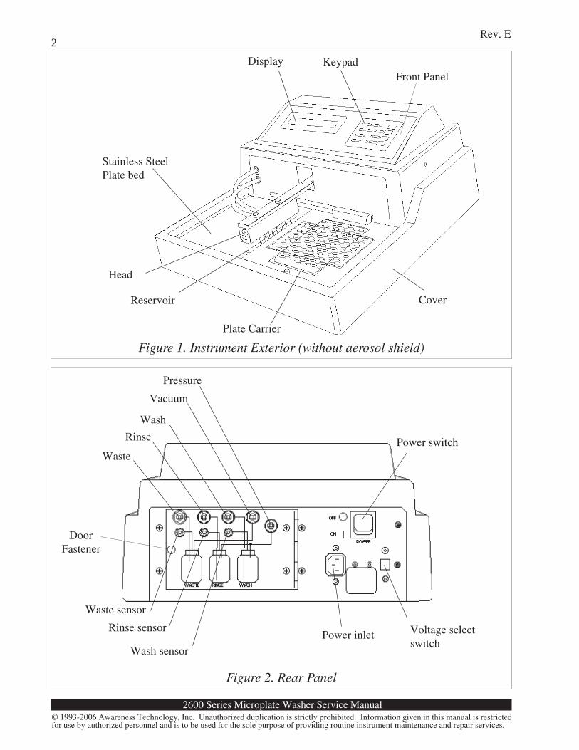
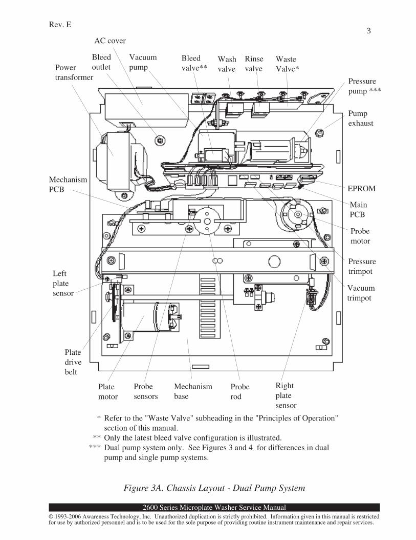
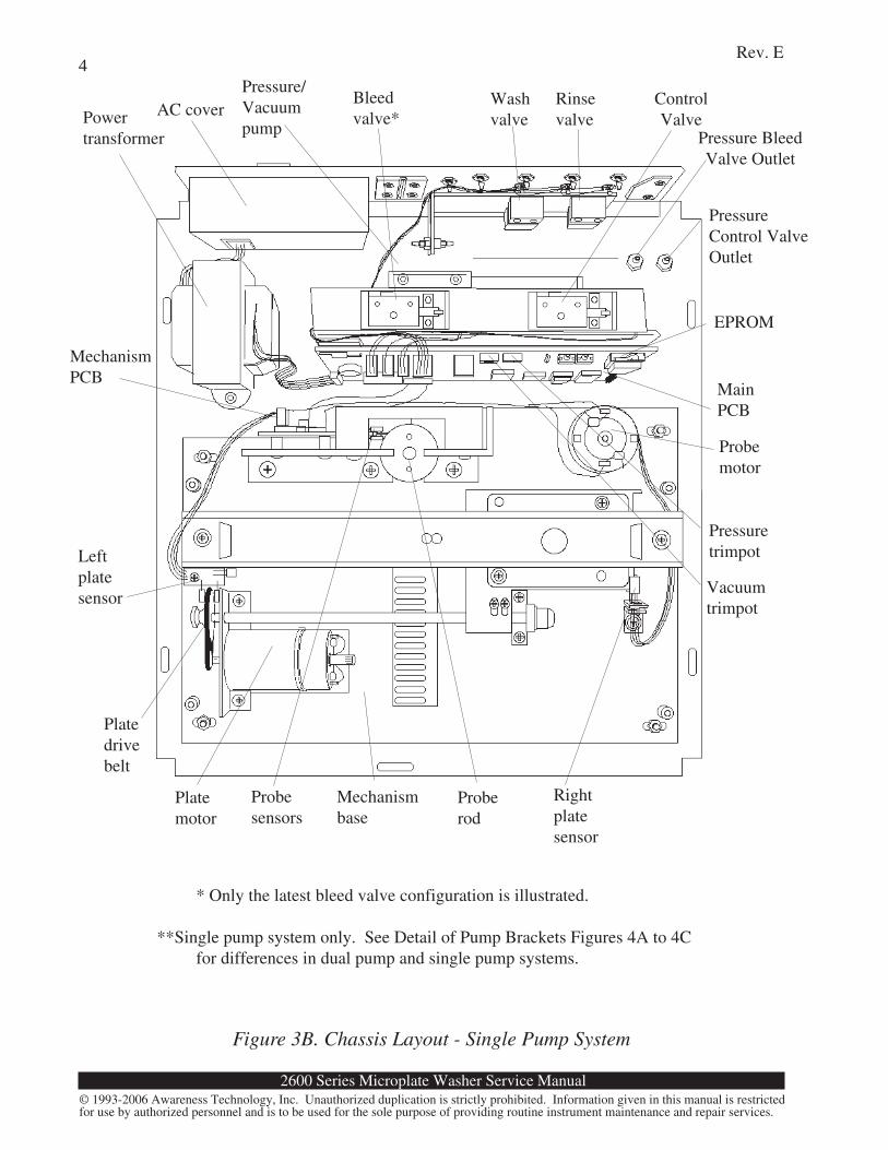
LayoutFigure 1 shows the exterior of the instrument, Figure 2 shows the rear panel, and Figure 3 shows thechassis layout. For clarity of illustration, the aerosol shield is not shown in Figure 1. In Figure 3,the probe arm and plate bed are removed, and the tubing is not shown.
The interface PCB mounted inside the cover behind the front panel connects to the main PCB by a26-conductor ribbon cable and header. Two-conductor cables connect the pressure control valve,the pump, and the pressure relief bleed valve. Four-conductor cables connect the dispense valveassembly and the sensor input jacks to the main PCB. The mechanism PCB connects to the mainPCB via a 14-conductor ribbon cable terminated with IDC 14-pin DIP plugs.
All AC mains (high voltage) circuitry is enclosed behind the AC cover except the step downtransformer primary.
WARNING
Hazardous line voltages are present behind the AC cover.Always disconnect the external AC power cable before
servicing the instrument.
WARNING: Microplate Washers may contain
biohazardous material. Refer to the Owner's Manualfor biohazard warnings.
2600 Series Microplate Washer Service Manual
Rev. E
© 1993-2006 Awareness Technology, Inc. Unauthorized duplication is strictly prohibited. Information given in this manual is restrictedfor use by authorized personnel and is to be used for the sole purpose of providing routine instrument maintenance and repair services.
2
Wash sensor
Rinse sensor
Waste sensor
Power switch
Voltage selectswitch
Power inlet
Reservoir
Plate Carrier
Head
Cover
Stainless SteelPlate bed
KeypadDisplay
Vacuum
Wash
Rinse
Waste
Pressure
Figure 2. Rear Panel
Figure 1. Instrument Exterior (without aerosol shield)
DoorFastener
Front Panel
2600 Series Microplate Washer Service Manual
Rev. E
© 1993-2006 Awareness Technology, Inc. Unauthorized duplication is strictly prohibited. Information given in this manual is restrictedfor use by authorized personnel and is to be used for the sole purpose of providing routine instrument maintenance and repair services.
3
Figure 3A. Chassis Layout - Dual Pump System
* Refer to the "Waste Valve" subheading in the "Principles of Operation"section of this manual.
** Only the latest bleed valve configuration is illustrated.*** Dual pump system only. See Figures 3 and 4 for differences in dual
pump and single pump systems.
Rinsevalve
WasteValve*
Washvalve
MainPCB
Powertransformer
Leftplatesensor
Vacuumtrimpot
Vacuumpump
Probemotor
Pressuretrimpot
Bleedvalve**
Bleedoutlet
AC cover
EPROM
Pressurepump ***
Pumpexhaust
Platemotor
Probesensors
Proberod
Mechanismbase
Platedrivebelt
MechanismPCB
Rightplatesensor
2600 Series Microplate Washer Service Manual
Rev. E
© 1993-2006 Awareness Technology, Inc. Unauthorized duplication is strictly prohibited. Information given in this manual is restrictedfor use by authorized personnel and is to be used for the sole purpose of providing routine instrument maintenance and repair services.
4
Rinsevalve
Washvalve
MainPCB
Powertransformer
Leftplatesensor
Vacuumtrimpot
Pressure/Vacuumpump
Probemotor
Pressuretrimpot
Bleedvalve*AC cover
EPROM
PressureControl ValveOutlet
Platemotor
Probesensors
Proberod
Mechanismbase
Platedrivebelt
MechanismPCB
Rightplatesensor
Figure 3B. Chassis Layout - Single Pump System
* Only the latest bleed valve configuration is illustrated.
**Single pump system only. See Detail of Pump Brackets Figures 4A to 4Cfor differences in dual pump and single pump systems.
ControlValve
Pressure BleedValve Outlet
2600 Series Microplate Washer Service Manual
Rev. E
© 1993-2006 Awareness Technology, Inc. Unauthorized duplication is strictly prohibited. Information given in this manual is restrictedfor use by authorized personnel and is to be used for the sole purpose of providing routine instrument maintenance and repair services.
5
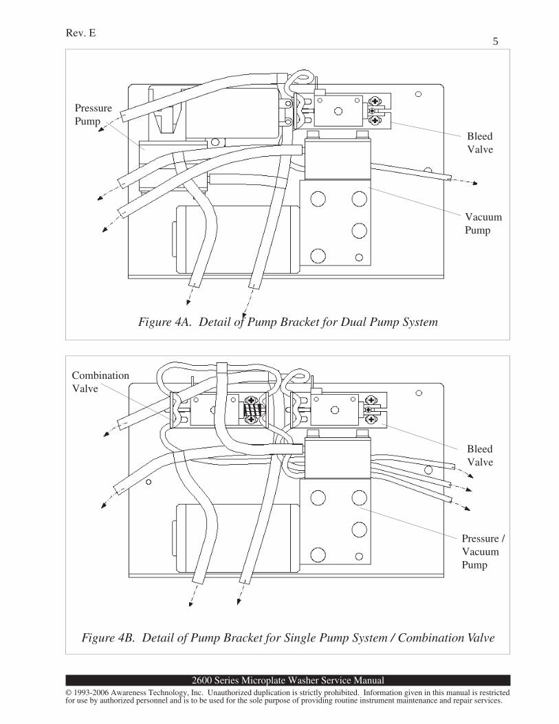
Figure 4A. Detail of Pump Bracket for Dual Pump System
Figure 4B. Detail of Pump Bracket for Single Pump System / Combination Valve
BleedValve
VacuumPump
BleedValve
Pressure /VacuumPump
CombinationValve
PressurePump
2600 Series Microplate Washer Service Manual
Rev. E
© 1993-2006 Awareness Technology, Inc. Unauthorized duplication is strictly prohibited. Information given in this manual is restrictedfor use by authorized personnel and is to be used for the sole purpose of providing routine instrument maintenance and repair services.
6
Principles of Operation
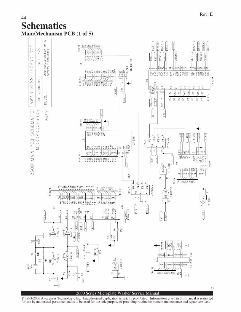
System ControlThe instrument is based on the 8-bit Z80 microprocessor U1. The software is permanently storedin a 27256 EPROM U2. An MK48T08 battery-backed nonvolatile RAM (random access memory)with real-time clock, U3, is used to store data such as calibration and test setups, and also maintainsthe date and time. Almost all digital I/O is accomplished with 8255 Programmable PeripheralInterface U5. Time intervals and pulse widths are measured using the counter channels of 8254programmable timer U4, which drives the Z80 INT input. The Z80 NMI input is driven by TCNT,which is generated by the rotation of the plate transport motor.
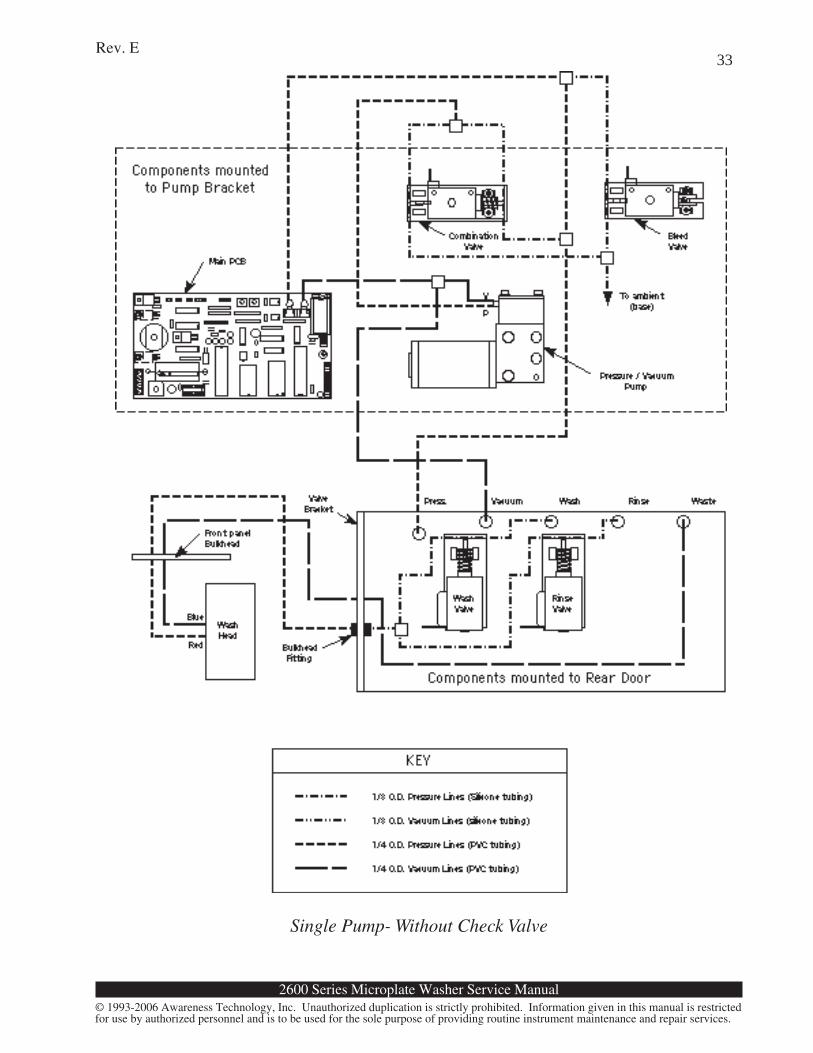
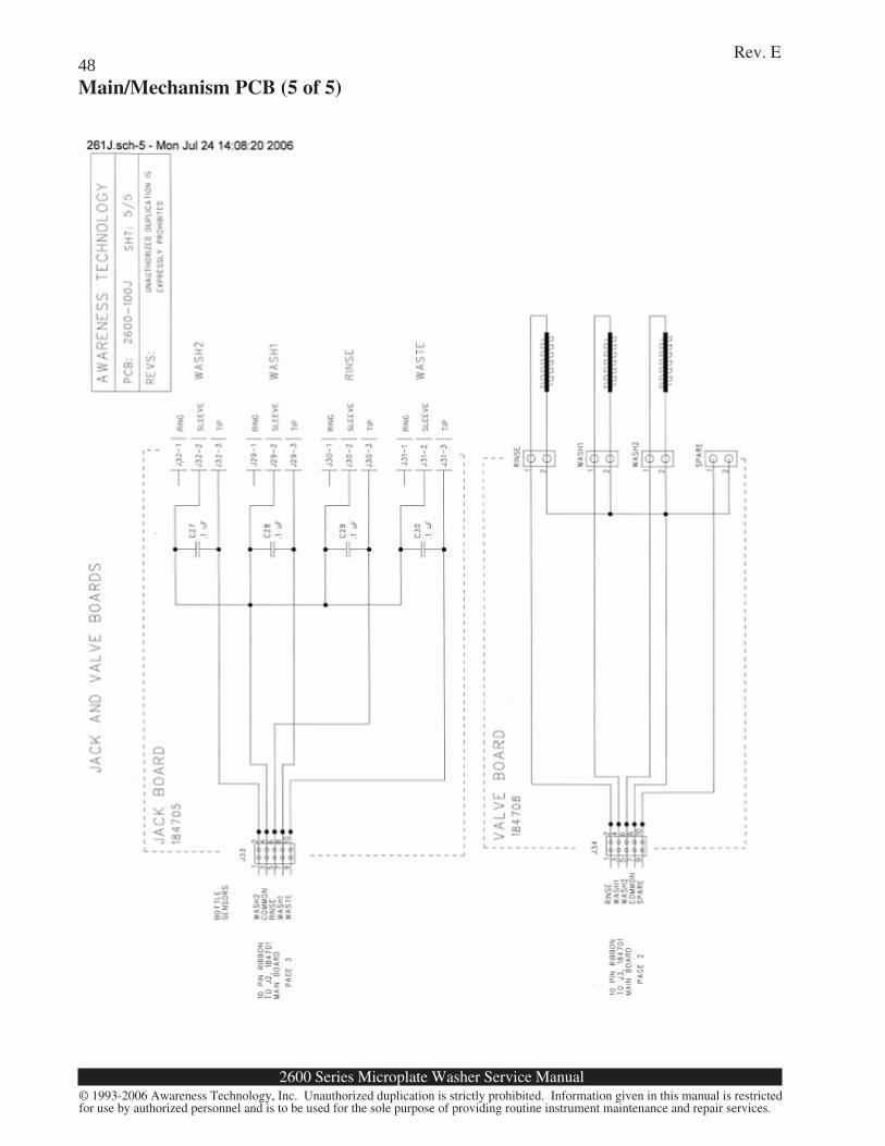
DispenseA DC pressure pump produces 5 psi air pressure (adjustable in software) at the top of the wash andrinse bottles. The fluid is forced up from the bottle but is stopped by a solenoid pinch valve. Thevalve is opened for a precise interval under microprocessor control to allow fluid to flow into thedispense cavity of the wash head, where it is distributed to stainless steel capillary tubes and then intoeight (or the optional twelve or sixteen) microplate wells. A bleed valve allows the instrument torelieve pressure during standby and when power is removed.
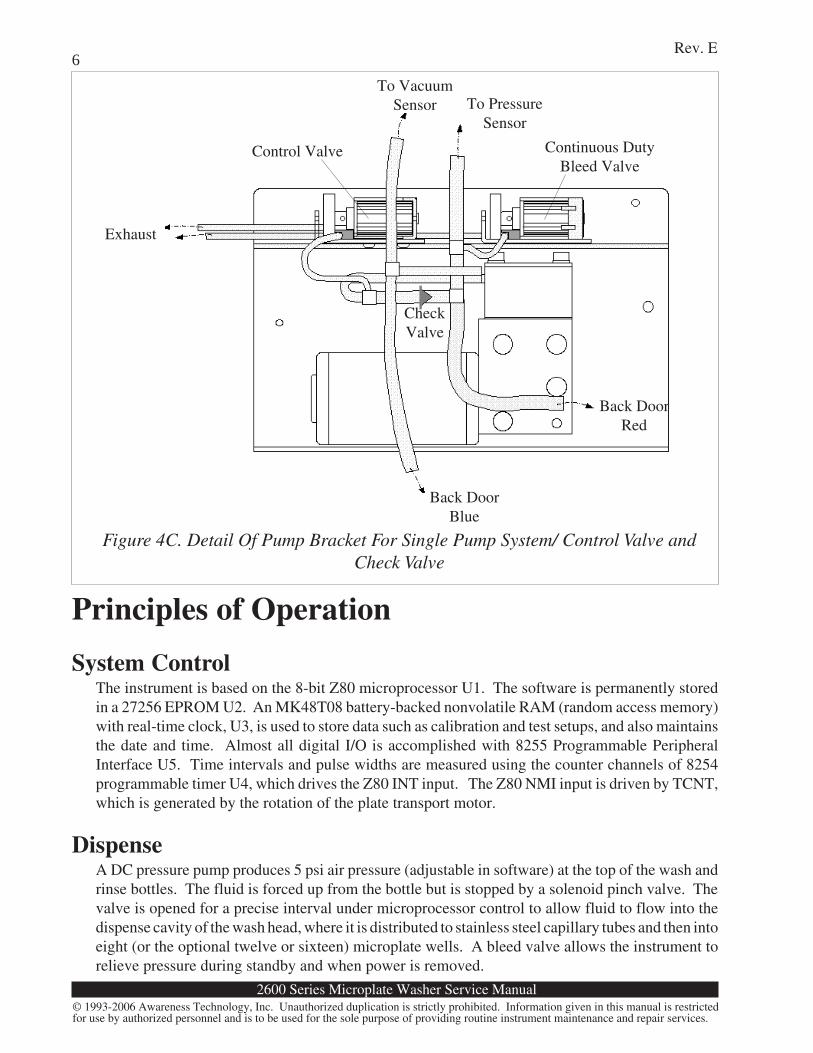
Figure 4C. Detail Of Pump Bracket For Single Pump System/ Control Valve andCheck Valve
To VacuumSensor To Pressure
Sensor
Exhaust
Back DoorRed
Back DoorBlue
Control Valve Continuous DutyBleed Valve
CheckValve
2600 Series Microplate Washer Service Manual
Rev. E
© 1993-2006 Awareness Technology, Inc. Unauthorized duplication is strictly prohibited. Information given in this manual is restrictedfor use by authorized personnel and is to be used for the sole purpose of providing routine instrument maintenance and repair services.
7
AspirateA vacuum is applied to the waste bottle through a fine hydrophobic aerosol filter and the aspiratecavity of the wash head. The vacuum is distributed across stainless steel capillary tubes therebyaspirating the contents of eight (or twelve or sixteen) microplate wells. Early 2600s were configuredwith a waste valve on the inlet side of the waste bottle. See the "Waste Valve" subheading belowfor a discussion.
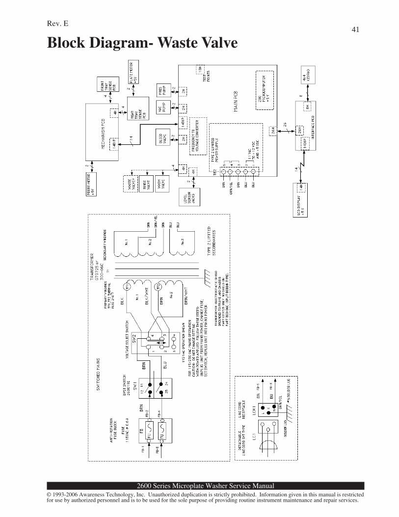
Waste ValveEarly instruments in the 2600 series used a waste valve to isolate the waste bottle from the aspiratingtubes when aspiration was not taking place in order to maintain a vacuum in the waste bottle. Theneed to maintain a vacuum on the waste bottle was eliminated by Software Revision SRO whichchanged the control logic to enable a vacuum cycle on demand only when aspiration is needed. Thissoftware revision allowed the elimination of the waste valve. The software revision and waste valvedeletion was incorporated in production units starting with serial number 2600-1112. In addition,some of the earlier 2600 models have been modified with Software Revision SRO or newer and thewaste valve has either been removed or bypassed in the field by removing the tubing from the pinchbar arrangement on the valve. All other 26XX models (2601, 2602, etc.) began manufacturefollowing the elimination of the waste valve.
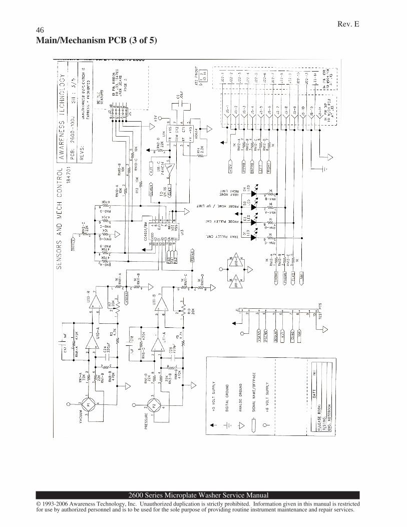
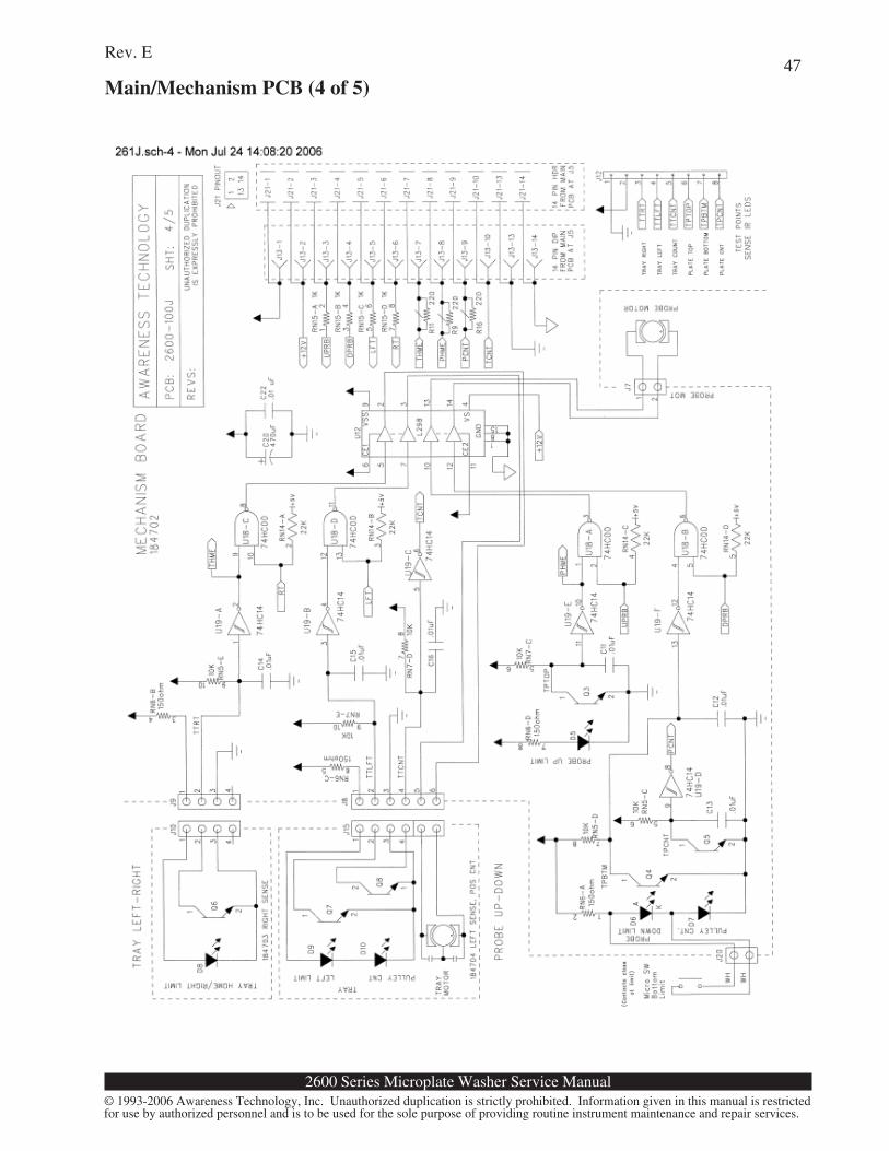
Motion ControlTwo DC motors, under bidirectional microprocessor control, turn 1/4-20 machined aluminum leadscrews via neoprene belts and nylon pulleys. One motor is dedicated to vertical motion of the probearm, the other to the horizontal motion of the plate carrier. Each pulley has several index holes whichcreate pulses when passing between an IR LED and a phototransistor, providing tachometer pulsesto the microprocessor at the NMI input and via the CLK0 input at 8254 U4. Phototransistors Q3, Q4,Q6, and Q7, positioned at extremes of the plate and probe movements, disable the motor drivers U17via NAND gates U18 when the travel limits are reached. Two of these phototransistors, Q3 and Q6,additionally indicate the home positions to the microprocessor. LEDs D1-D4 provide visualfeedback to the service technician of the tach pulses and home positions. See Figure 6. Themechanism PCB holds the motor drivers, index pulse buffers, and limit logic, and connects to themain PCB via a 14-pin DIP cable.
Display and KeypadA 24 x 2 line character Liquid Crystal Display (LCD) is mounted inside the cover. A 4 x 4 membraneswitch keypad is sealed behind the front panel overlay. The LCD connects to an interface PCB viaa 14-pin DIP cable. The tail of the keypad switch layer is fed through the cover and is also connectedto the interface PCB. The interface PCB connects to the main PCB via a 26-conductor header cable.
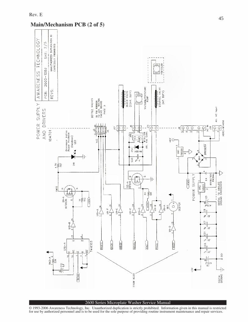
Pressure and VacuumSolid-state sensors P1 and P2 are amplified at U10 and U11 and multiplexed via U13 into V/Fconvertor U14, then measured at 8254 timer U4. This provides feedback to the microprocessor forcoordinating pump activity. The vacuum pump is driven by IRF510 MOSFET Q2A. The pressurepump and control valve are driven by U9A and U9B in parallel.
2600 Series Microplate Washer Service Manual
Rev. E
© 1993-2006 Awareness Technology, Inc. Unauthorized duplication is strictly prohibited. Information given in this manual is restrictedfor use by authorized personnel and is to be used for the sole purpose of providing routine instrument maintenance and repair services.
8Level Sensing
The signal BOTLV is fed through a voltage divider to stainless steel wire probes mounted in the capsof the wash, rinse, and waste bottles. The signals are multiplexed via U13 into V/F convertor U14and the resulting frequency appears at the CLK2 input of 8254 timer U4. The microprocessor readsa change in frequency which corresponds to a change in conductivity of the material between theprobes.
Watchdog CircuitAll valves and pumps are powered through an IRF9530A MOSFET Q1A, which is in turn driven bythe re-triggerable one-shot comprised of C10, RN3A, and U16A. The microprocessor re-triggersU16A at intervals smaller than the one-shot period. Should the microprocessor system "crash" orotherwise malfunction, U16A will time out and shut down the valves and pumps by turning off Q1A.If this occurs, LED D11 will be extinguished to provide a visual indication.
Power SupplyThe power supply consists of a transformer, diode bridges, and two regulators. Line voltage suppliedto the transformer is stepped down to 11VAC (rms) and is fed to diode bridge BR1, which provides+12VDC (raw, 11-13 VDC nominal) to the pumps and valves. VR2 regulates this down to +5VDCfor the logic and control circuits, as well as the plate and probe motors. VR1 regulates down to+6VDC for the vacuum and pressure sensors.
2600 Series Microplate Washer Service Manual
Rev. E
© 1993-2006 Awareness Technology, Inc. Unauthorized duplication is strictly prohibited. Information given in this manual is restrictedfor use by authorized personnel and is to be used for the sole purpose of providing routine instrument maintenance and repair services.
9
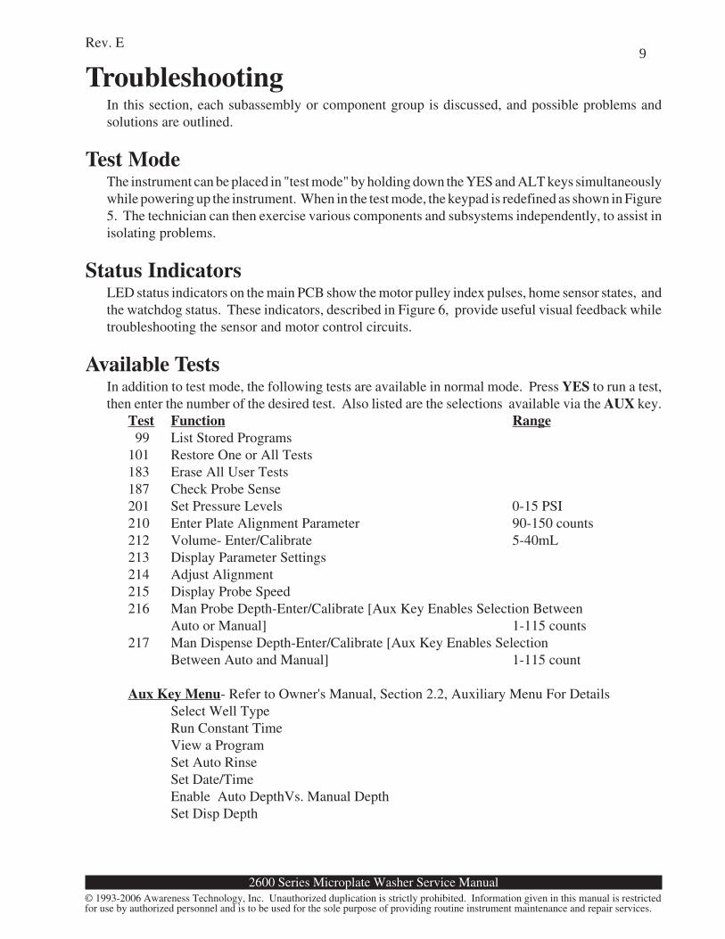
TroubleshootingIn this section, each subassembly or component group is discussed, and possible problems andsolutions are outlined.
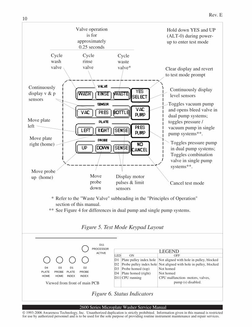
Test ModeThe instrument can be placed in "test mode" by holding down the YES and ALT keys simultaneouslywhile powering up the instrument. When in the test mode, the keypad is redefined as shown in Figure5. The technician can then exercise various components and subsystems independently, to assist inisolating problems.
Status IndicatorsLED status indicators on the main PCB show the motor pulley index pulses, home sensor states, andthe watchdog status. These indicators, described in Figure 6, provide useful visual feedback whiletroubleshooting the sensor and motor control circuits.
Available TestsIn addition to test mode, the following tests are available in normal mode. Press YES to run a test,then enter the number of the desired test. Also listed are the selections available via the AUX key.
Test Function Range 99 List Stored Programs101 Restore One or All Tests183 Erase All User Tests187 Check Probe Sense201 Set Pressure Levels 0-15 PSI210 Enter Plate Alignment Parameter 90-150 counts212 Volume- Enter/Calibrate 5-40mL213 Display Parameter Settings214 Adjust Alignment215 Display Probe Speed216 Man Probe Depth-Enter/Calibrate [Aux Key Enables Selection Between
Auto or Manual] 1-115 counts217 Man Dispense Depth-Enter/Calibrate [Aux Key Enables Selection
Between Auto and Manual] 1-115 count
Aux Key Menu- Refer to Owner's Manual, Section 2.2, Auxiliary Menu For DetailsSelect Well TypeRun Constant TimeView a ProgramSet Auto RinseSet Date/TimeEnable Auto DepthVs. Manual DepthSet Disp Depth
2600 Series Microplate Washer Service Manual
Rev. E
© 1993-2006 Awareness Technology, Inc. Unauthorized duplication is strictly prohibited. Information given in this manual is restrictedfor use by authorized personnel and is to be used for the sole purpose of providing routine instrument maintenance and repair services.
10
D4 PLATE HOME
D3 PROBE HOME
D1 PLATE INDEX
D2 PROBE INDEX
D11 PROCESSOR
ACTIVE
Valve operationis for
approximately0.25 seconds
Hold down YES and UP(ALT-0) during power-up to enter test mode
Display motorpulses & limitsensors
Moveprobedown
Move probeup (home)
Move plateright (home)
Move plateleft
Cyclewashvalve Clear display and revert
to test mode prompt
Cyclewastevalve*
Cyclerinsevalve
Continuouslydisplay v & psensors
Continuously displaylevel sensors
Cancel test mode
Toggles vacuum pumpand opens bleed valve indual pump systems;toggles pressure /vacuum pump in singlepump systems**.
Toggles pressure pumpin dual pump systems;Toggles combinationvalve in single pumpsystems**.
Figure 6. Status Indicators
Viewed from front of main PCB
Figure 5. Test Mode Keypad Layout
* Refer to the "Waste Valve" subheading in the "Principles of Operation"section of this manual.
** See Figure 4 for differences in dual pump and single pump systems.
LEGENDLED ON OFFD1 Plate pulley index hole Not aligned with hole in pulley, blockedD2 Probe pulley index hole Not aligned with hole in pulley, blockedD3 Probe homed (top) Not homedD4 Plate homed (right) Not homedD11 CPU running CPU malfunction- motors, valves,
pump (s) disabled.
2600 Series Microplate Washer Service Manual
Rev. E
© 1993-2006 Awareness Technology, Inc. Unauthorized duplication is strictly prohibited. Information given in this manual is restrictedfor use by authorized personnel and is to be used for the sole purpose of providing routine instrument maintenance and repair services.
11
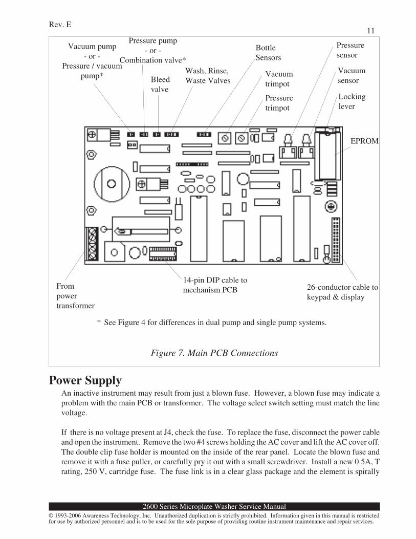
14-pin DIP cable tomechanism PCB
EPROM
Frompowertransformer
26-conductor cable tokeypad & display
Power SupplyAn inactive instrument may result from just a blown fuse. However, a blown fuse may indicate aproblem with the main PCB or transformer. The voltage select switch setting must match the linevoltage.
If there is no voltage present at J4, check the fuse. To replace the fuse, disconnect the power cableand open the instrument. Remove the two #4 screws holding the AC cover and lift the AC cover off.The double clip fuse holder is mounted on the inside of the rear panel. Locate the blown fuse andremove it with a fuse puller, or carefully pry it out with a small screwdriver. Install a new 0.5A, Trating, 250 V, cartridge fuse. The fuse link is in a clear glass package and the element is spirally
Vacuum pump- or -
Pressure / vacuumpump*
Lockinglever
Pressuresensor
Vacuumsensor
Pressuretrimpot
Vacuumtrimpot
BottleSensors
Wash, Rinse,Waste ValvesBleed
valve
Pressure pump- or -
Combination valve*
* See Figure 4 for differences in dual pump and single pump systems.
Figure 7. Main PCB Connections
2600 Series Microplate Washer Service Manual
Rev. E
© 1993-2006 Awareness Technology, Inc. Unauthorized duplication is strictly prohibited. Information given in this manual is restrictedfor use by authorized personnel and is to be used for the sole purpose of providing routine instrument maintenance and repair services.
12wound on a fiberglass core. The fuses must be replaced by a 1 1/4 inch glass cartridge fuse commonlyknown as 3AG or size '0'. The nominal dimensions are 1.25 x .25 inches. (32 x 6.3 mm). The fusesmust be approved to UL and CSA standards or approved for the country of use. Use only therecommended fuse. Do not substitute any other rating. Replace the AC cover.
If voltage is present at J4, check for input voltage on VR1 and VR2. If no voltage is present, diodebridge BR1 may have failed.
Main PCBUnder normal circumstances, there are no adjustments to be made to the main PCB. Circuit failuresare highly unlikely, but if they occur, it is recommended that the repairs be performed by factoryauthorized technicians. There are ten test points at J1 which provide access to a number of vitalsignals. The instrument can be observed in operation with an oscilloscope. The main PCB ismounted to the pump bracket. To remove the main PCB, disconnect all attached connectors andremove the two screws holding the pump bracket assembly to the chassis (from the bottom of theinstrument). Remove the screw holding the main PCB heat sink to the pump bracket (from the pumpside of the bracket). Remove the screw holding the main PCB to the pump bracket (from the mainPCB). Figure 7 shows the main PCB connections and other details.
KeypadThe keypad is a sealed membrane switch layer which is serviceable only by replacement. To test thekeypad (when not in test mode), press YES, then press all keys except NO and YES. Note that eachkey causes the instrument to beep and display a character. Press NO and the display clears. PressYES to end the test.
DisplayThe display is a 24 x 2 line super twisted nematic liquid crystal display (LCD) module with integratedcontroller. The display should be clearly legible at all times, with no dark spots or stray dots. Thereare no adjustments and service is limited to replacement.
ValvesEach valve uses a short length of silicone tubing, which may self-adhere or become clogged withdried residue from fluids. If the valve operates but no fluid is dispensed or aspirated, the valve tubingmay be blocked. You may be able to unblock the tubing. Grasp the tubing on either side of the valvebody and gently stretch it. If needed, pull the tubing from the valve body. Roll the tubing betweenyour fingers and gently stretch it. Reposition and test. If still blocked, see the section “Valve TubingReplacement”.
Motor ControlFailure to move the probe or the plate can probably be attributed to a failure of driver U17. Also,check the logic at U18 and U19. Check the operation of Q3-Q8 and voltage drop across IR LEDsD5-D10.
2600 Series Microplate Washer Service Manual
Rev. E
© 1993-2006 Awareness Technology, Inc. Unauthorized duplication is strictly prohibited. Information given in this manual is restrictedfor use by authorized personnel and is to be used for the sole purpose of providing routine instrument maintenance and repair services.
13
Vacuum and Pressure SystemsRefer to figures 3, and 4 to determine if the unit is configured with a dual pump or single pump system.The pump(s) require no maintenance. If either pump runs frequently or continuously while theinstrument is not in use, there is probably a leak. Check the bottle caps and fittings. Check that thetubing is firmly seated on barbs and all fittings are tight. Turn the fittings only until finger-tight. Donot overtighten the plastic Luer fittings! Check the operation of the valves to ensure they areclosing completely. If the pressure pump (or the pressure / vacuum pump on single pump units) runsfrequently or continuously, check the bleed valve for leakage. It must be completely closed whilethe unit is on.
If the wash or waste bottles are located at a different level than the instrument, such as on a shelf, thepressure and volume calibration may require adjustment. Units which are configured with a wastevalve may also need a vacuum calibration. Refer to the sections of this manual covering “VolumeCalibration,” “Calibrate Pressure,” and “Calibrate Vacuum” as appropriate.
If aspiration is poor or absent, the exhaust filter may be clogged and should be replaced. In the eventthat the exhaust filter gets wet due to a waste bottle spill, it must be replaced for continued operation.See the section “Exhaust Filter Replacement.”
If the pressure pump (dual pump system) or combination valve (single pump system) is inoperative,check inputs and outputs at U9A and U9B. If the vacuum pump (dual pump system) or pressure /vacuum pump (single pump system) is inoperative, check Q2A. If pump(s) and all of the valves aredead (no voltage present at any time), check Q1A and U16A for proper operation. Both should beactive at all times while the instrument is powered. LED D11 should be illuminated.
Incomplete AspirationOne or more aspirate tubes maybe clogged. Clean the aspirate tubes using the cleaning wire. Checkthe tubing path leading from the wash head to the waste bottle for kinked or pinched tubing. Verifythere is a vacuum using a gauge. Check the exhaust filter for clogging.
Incomplete or Inaccurate DispenseOne or more dispense tubes maybe clogged. Clean the dispense tubes using the cleaning wire. Checkthe tubing path leading from the wash (or rinse) bottle to the wash head for kinked or pinched tubing.Check for stuck valves, and clogged or pinched valve tubing. Check the bleed valve for leakage.Verify the pressure using a gauge. Verify specified pressure level by running test 213 to see level.
If the instrument has been stored for an extended period without rinsing, it may be necessary to unclogthe tubing and/or operate the valves manually in order to prime the instrument. See the section"Valves".
Error MessagesError messages are displayed when the instrument fails to operate correctly. They are intended tohelp the operator locate the problem. If error messages appear frequently, a hardware problem is
2600 Series Microplate Washer Service Manual
Rev. E
© 1993-2006 Awareness Technology, Inc. Unauthorized duplication is strictly prohibited. Information given in this manual is restrictedfor use by authorized personnel and is to be used for the sole purpose of providing routine instrument maintenance and repair services.
14usually indicated.The following error messages indicate possible interface or component problems.
Message Possible Causes and SolutionsWait Occurs during normal operation. The instrument
is attempting to build pressure, but has not suc-ceeded. If message persists, check for leaks inpressure system and may indicate vacuum prob-lem on instruments prior to software before SROon 2600s.
Wash Bottle is Low The instrument detected an empty condition onthe
Rinse Bottle is Low wash or rinse bottle. If the bottle is full, check thatthe sensors lead is securely connected to the bottlecap and plugged into the jack on the rear panel.Check the sensor leads for continuity.
Empty the Waste Bottle The instrument detected a full condition on thewaste bottle. If waste bottle is empty, dry wastecap at terminal entry points. Check sensor lead isplugged in properly. Check the sensor lead forshorts.
Check Waste Valve This message applies only to units configuredwith a waste valve. If equipped with a wastevalve, this message indicates that the instrumentdid not detect a vacuum drop after opening thewaste valve. Check for kinked tubing or stuckwaste valve.
Check Vacuum System The instrument was unable to develop vacuumwithin the prescribed length of time. Check forleaks at the waste bottle and at all connections.
Mech must be realigned The well type was changed and the instrumentdetected this condition. Install a plate with thenew well type and press YES to continue.
PROGRAM CANCELED The instrument did not detect the bottom of thefirst row of wells. This could be a result ofincorrect well type setting.
*** MECH. JAM: PROBE *** The motor stalled while the instrument was at-tempting to move the probe. Check for mechani-cal obstructions or broken belts. Check motordriver U17 and associated logic.
*** MECH. JAM: PLATE *** The motor stalled while the instrument was at-tempting to move the plate. Check for mechanicalobstructions or broken belts. Check motor driver
2600 Series Microplate Washer Service Manual
Rev. E
© 1993-2006 Awareness Technology, Inc. Unauthorized duplication is strictly prohibited. Information given in this manual is restrictedfor use by authorized personnel and is to be used for the sole purpose of providing routine instrument maintenance and repair services.
15
Service ProceduresOpening the Instrument
The cover must be removed to allow access to the inside of the instrument.
1. Disconnect the power cable, the tubing, and the sensor leads from the rear panel. Removethe wash head and the plate carrier and set aside. Lower the aerosol shield.
2. Invert the instrument on a soft nonabrasive surface such as a terry cloth towel. Do not allowthe instrument to rest on the probe arm!! Hold the acrylic aerosol shield in place whileinverting the instrument. The instrument should rest on the area at the top of the keypadand the front edge of the aerosol shield.
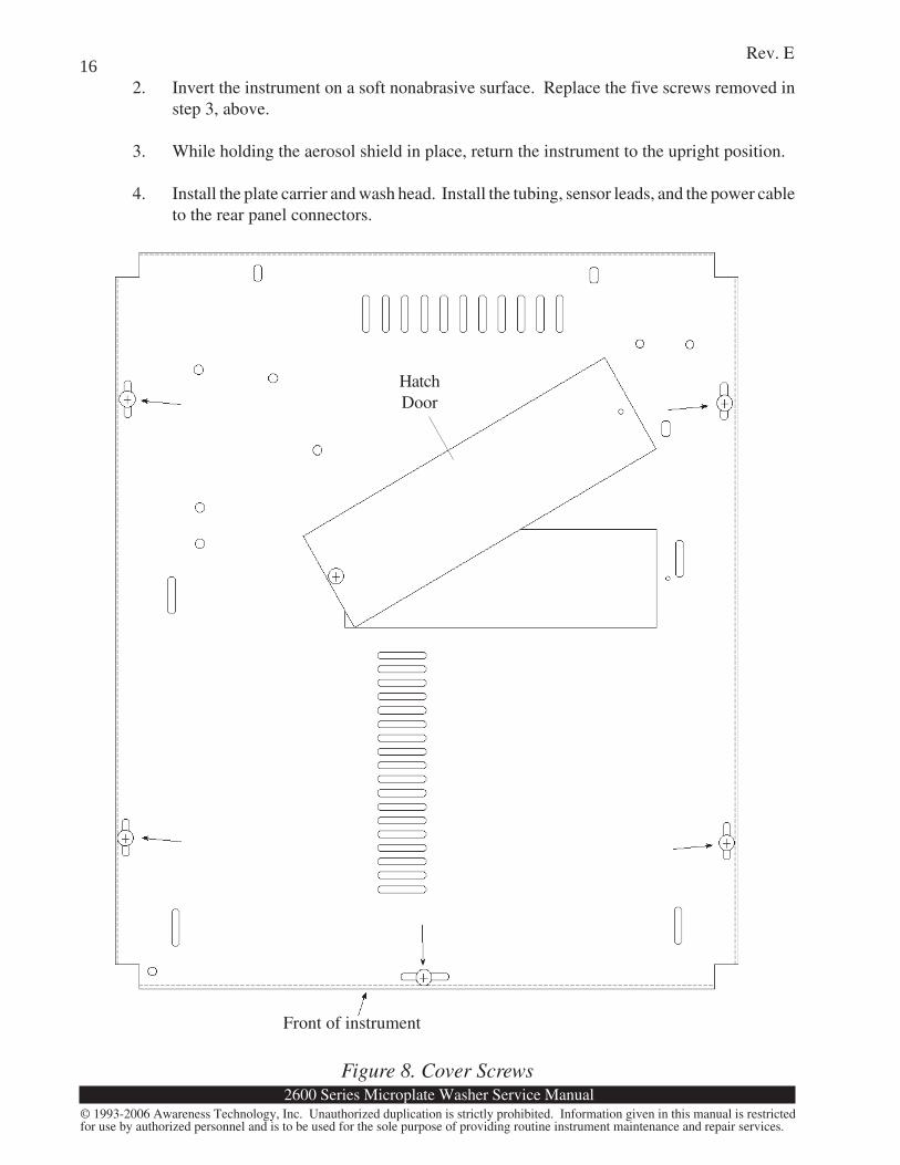
3. Refer to Figure 8. Locate and remove the five screws shown. While holding the cover inplace with both hands, return the instrument to the upright position.
4. Gently lift the cover upward. Do not stretch the 26-conductor cable connecting the mainPCB to the cover assembly. You can prop the cover securely on its right side by placingthe edge of the cover under the chassis base. This allows you to leave the display andkeypad connected while servicing the instrument.
To reinstall the cover, reverse the procedure.
1. Carefully lower the cover until it seats squarely on the plate bed and chassis base, takingcare to not pinch or stretch the 26-conductor cable connecting the main PCB to the coverassembly. The cover should seal tightly against the back of the plate bed.
U17 and associated logic.
The following error messages, if displayed repeatedly, indicate possible failure of the NV RAM U3,which can be checked by substituting a known good device.
*** CHECKSUM ERROR *** Calibration was lost. The display shows:
Enter Plate Align param
Enter the plate alignment parameter from thecalibration label and press YES. The displayshows: Enter measured vol (mL):
Enter the volume from the calibration data labeland press YES.
MEMORY ERROR: Prog Ended A memory error occurred during execution of auser program. The corrupted user program isautomatically deleted.
2600 Series Microplate Washer Service Manual
Rev. E
© 1993-2006 Awareness Technology, Inc. Unauthorized duplication is strictly prohibited. Information given in this manual is restrictedfor use by authorized personnel and is to be used for the sole purpose of providing routine instrument maintenance and repair services.
16
Front of instrument
HatchDoor
2. Invert the instrument on a soft nonabrasive surface. Replace the five screws removed instep 3, above.
3. While holding the aerosol shield in place, return the instrument to the upright position.
4. Install the plate carrier and wash head. Install the tubing, sensor leads, and the power cableto the rear panel connectors.
Figure 8. Cover Screws
2600 Series Microplate Washer Service Manual
Rev. E
© 1993-2006 Awareness Technology, Inc. Unauthorized duplication is strictly prohibited. Information given in this manual is restrictedfor use by authorized personnel and is to be used for the sole purpose of providing routine instrument maintenance and repair services.
17
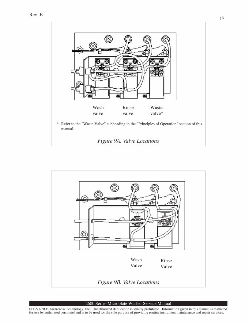
Figure 9A. Valve Locations
Washvalve
Rinsevalve
Wastevalve*
* Refer to the "Waste Valve" subheading in the "Principles of Operation" section of thismanual.
WashValve
RinseValve
Figure 9B. Valve Locations
2600 Series Microplate Washer Service Manual
Rev. E
© 1993-2006 Awareness Technology, Inc. Unauthorized duplication is strictly prohibited. Information given in this manual is restrictedfor use by authorized personnel and is to be used for the sole purpose of providing routine instrument maintenance and repair services.
18
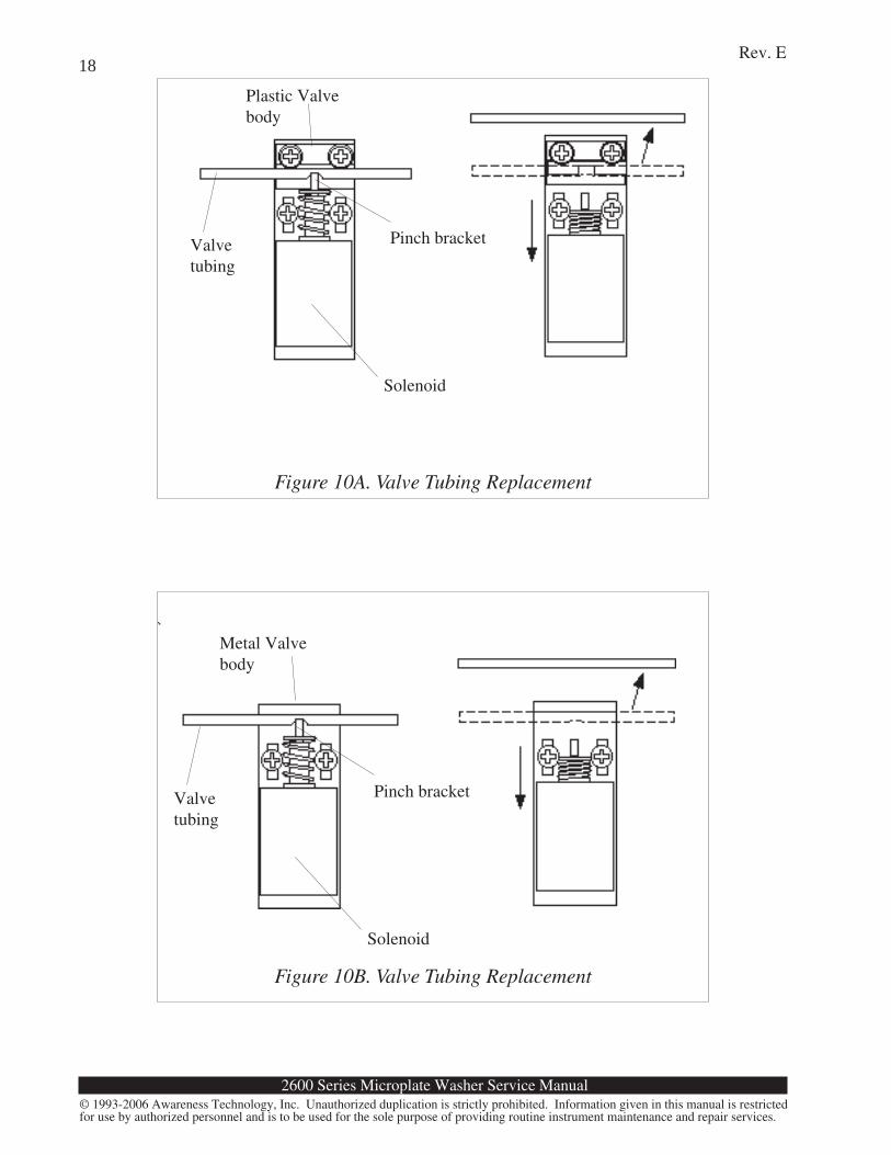
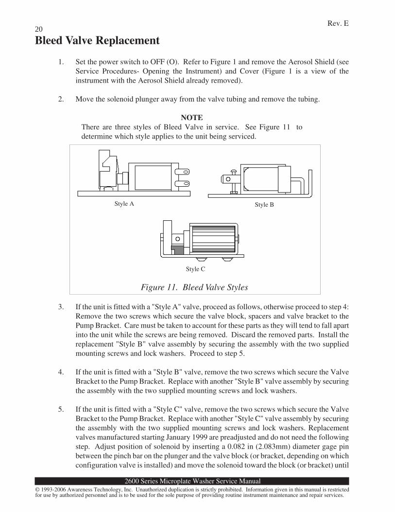
Valvetubing
Plastic Valvebody
Solenoid
Pinch bracket
Figure 10A. Valve Tubing Replacement
Figure 10B. Valve Tubing Replacement
Valvetubing
Metal Valvebody
Solenoid
Pinch bracket
2600 Series Microplate Washer Service Manual
Rev. E
© 1993-2006 Awareness Technology, Inc. Unauthorized duplication is strictly prohibited. Information given in this manual is restrictedfor use by authorized personnel and is to be used for the sole purpose of providing routine instrument maintenance and repair services.
19Valve Tubing Replacement
The silicone tubing used in the valves may become clogged or worn with age. If this occurs, thetubing must be replaced.
1. Set the power switch to OFF (O). Open the valve door by removing the door fastener. Referto Figure 2, Rear Panel.
2. Refer to Figure 9A and 9B. Locate the valve to be serviced.
3. Refer to Figure 10A and 10B. Pull back the pinch bracket and remove the valve tubing fromthe valve body.
4. Disconnect the valve tubing from the fittings at both ends.
5. Cut the replacement tubing to match the length of the original.
6. Install the replacement tubing to the valve body. Push the tubing over the fittings untilseated. If you have trouble sliding the tubing over the fittings, dip ends of tubing inisopropyl alcohol. Be especially careful not to kink, stretch, or tension the tubing. Thereplacement tubing should be routed in exactly the same place as the original.
7. Close the valve door and replace the door fastener. Take special care not to pinch, kink,or stretch any tubing behind the door.
Valve Rebuild(wash, rinse, and/or waste valve)
1. Follow steps 1 through 4 of "Valve Tubing Replacement" procedure above.
2. Remove solenoid, plunger, and spring. Relocate the wiring soldered to the originalsolenoid to the replacement solenoid. Install replacement solenoid, plunger, and spring byloosely installing the solenoid mounting screws to allow for adjustment.
3. Replacement valves manufactured starting January 1999 are preadjusted and do not needstep 3. Adjust position of solenoid by inserting a 0.092 in (2.337 mm) diameter gage pinbetween the pinch bar on the plunger and the valve block (or bracket, depending on whichconfiguration valve is installed) and move the solenoid toward the block (or bracket) untilplunger bottoms in solenoid. Align pinch bracket, valve bracket, and solenoid. Tightenmounting screws and remove gage pin.
4. Reinstall the tubing to the valve body. Push the tubing over the fittings until seated. Beespecially careful not to kink, stretch, or tension the tubing. The replacement tubing shouldbe routed in exactly the same place as the original.
5. Close the valve door and replace the door fastener. Take special care not to pinch, kink,or stretch any tubing behind the door.
2600 Series Microplate Washer Service Manual
Rev. E
© 1993-2006 Awareness Technology, Inc. Unauthorized duplication is strictly prohibited. Information given in this manual is restrictedfor use by authorized personnel and is to be used for the sole purpose of providing routine instrument maintenance and repair services.
20Bleed Valve Replacement
1. Set the power switch to OFF (O). Refer to Figure 1 and remove the Aerosol Shield (seeService Procedures- Opening the Instrument) and Cover (Figure 1 is a view of theinstrument with the Aerosol Shield already removed).
2. Move the solenoid plunger away from the valve tubing and remove the tubing.
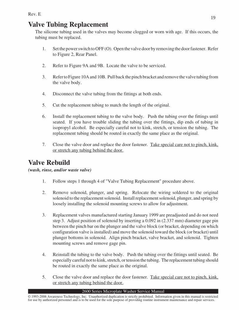
NOTEThere are three styles of Bleed Valve in service. See Figure 11 todetermine which style applies to the unit being serviced.
3. If the unit is fitted with a "Style A" valve, proceed as follows, otherwise proceed to step 4:Remove the two screws which secure the valve block, spacers and valve bracket to thePump Bracket. Care must be taken to account for these parts as they will tend to fall apartinto the unit while the screws are being removed. Discard the removed parts. Install thereplacement "Style B" valve assembly by securing the assembly with the two suppliedmounting screws and lock washers. Proceed to step 5.
4. If the unit is fitted with a "Style B" valve, remove the two screws which secure the ValveBracket to the Pump Bracket. Replace with another "Style B" valve assembly by securingthe assembly with the two supplied mounting screws and lock washers.
5. If the unit is fitted with a "Style C" valve, remove the two screws which secure the ValveBracket to the Pump Bracket. Replace with another "Style C" valve assembly by securingthe assembly with the two supplied mounting screws and lock washers. Replacementvalves manufactured starting January 1999 are preadjusted and do not need the followingstep. Adjust position of solenoid by inserting a 0.082 in (2.083mm) diameter gage pinbetween the pinch bar on the plunger and the valve block (or bracket, depending on whichconfiguration valve is installed) and move the solenoid toward the block (or bracket) until
Figure 11. Bleed Valve Styles
Style BStyle A
Style C
2600 Series Microplate Washer Service Manual
Rev. E
© 1993-2006 Awareness Technology, Inc. Unauthorized duplication is strictly prohibited. Information given in this manual is restrictedfor use by authorized personnel and is to be used for the sole purpose of providing routine instrument maintenance and repair services.
21
Exhaust Filter ReplacementThe filter that removes contaminant particles from the exhaust of the vacuum pump may be replacedif clogged or damaged. If the WAIT message is taking longer to clear, or if the instrument takeslonger to get up to pressure, the filter may be clogged. If the waste bottle is overturned and the filtergets wet, the filter must be replaced.
To replace the filter:
1. Set the power switch to OFF (O). Pull the tubing from the fittings on the filter.
2. Install the new filter with the INLET side pointing toward the waste bottle. Push the tubingon the fittings until seated.
Probe Drive Belt ReplacementThe neoprene drive belt which couples the probe motor to the probe lead screw pulley can becomeworn or loosen with age.
To replace the belt:Section 1:
1. Check to see if your instrument has a hatch door. If not, open the instrument. If yourinstrument does have a hatch door, go to Section 2.
2. Remove the four flat head screws at each corner of the plate bed, and lift the plate bedupward and forward to clear the probe arm.
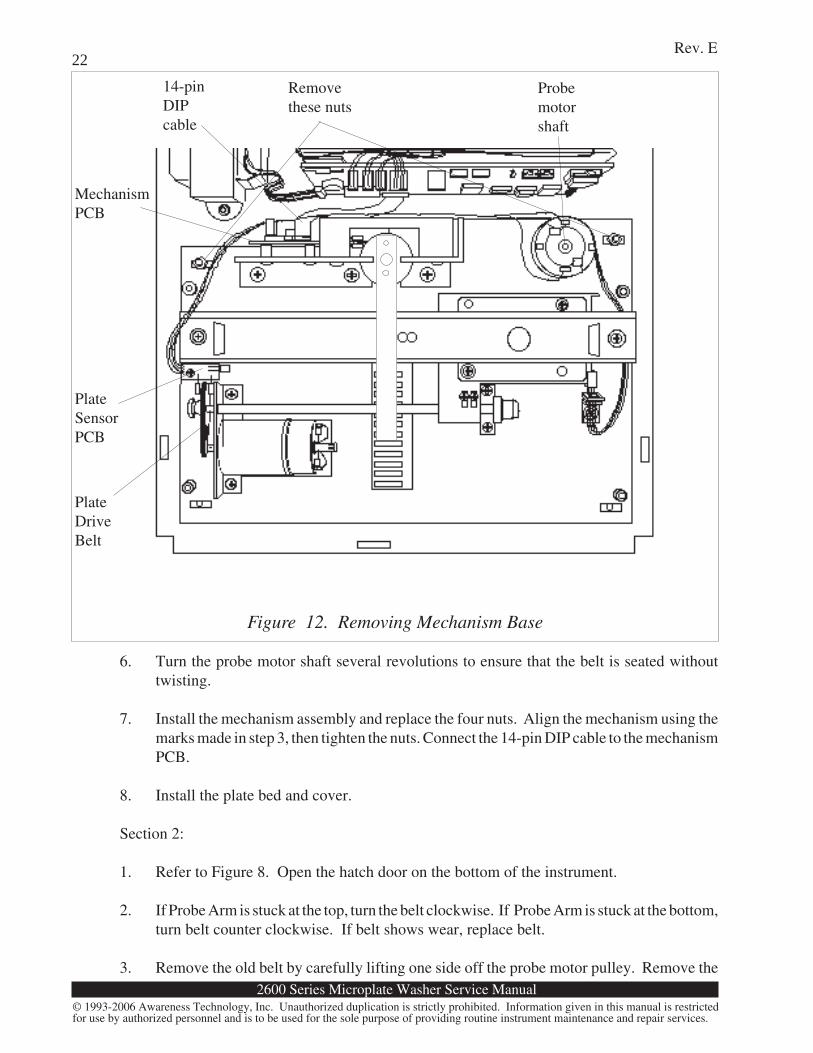
3. Refer to Figure 12. Disconnect the 14-pin DIP cable from the mechanism PCB. Mark thelocation of the mechanism assembly using the four nuts holding the mechanism assemblyto the chassis. You will need these marks to place the mechanism back in proper alignment.Remove the nuts. Lift the mechanism assembly upward and off.
4. Look at the rear of the mechanism assembly. Remove the old belt by carefully lifting oneside off the probe motor pulley. Remove the belt from the other pulley. Do not bend theoptical sensors mounted on the edge of the mechanism PCB.
5. Install the new belt first to the probe lead screw pulley, then to the probe motor pulley. Donot bend the optical sensors mounted on the mechanism PCB. Do not twist the belt.
plunger bottoms in solenoid. Align pinch bracket, valve bracket, and solenoid. Tightenmounting screws and remove gage pin.
6. Move the solenoid plunger away from the valve bracket and insert the tubing between theplunger and the bracket while routing the tubing through the holding slots in the valvebracket.
2600 Series Microplate Washer Service Manual
Rev. E
© 1993-2006 Awareness Technology, Inc. Unauthorized duplication is strictly prohibited. Information given in this manual is restrictedfor use by authorized personnel and is to be used for the sole purpose of providing routine instrument maintenance and repair services.
22
6. Turn the probe motor shaft several revolutions to ensure that the belt is seated withouttwisting.
7. Install the mechanism assembly and replace the four nuts. Align the mechanism using themarks made in step 3, then tighten the nuts. Connect the 14-pin DIP cable to the mechanismPCB.
8. Install the plate bed and cover.
Section 2:
1. Refer to Figure 8. Open the hatch door on the bottom of the instrument.
2. If Probe Arm is stuck at the top, turn the belt clockwise. If Probe Arm is stuck at the bottom,turn belt counter clockwise. If belt shows wear, replace belt.
3. Remove the old belt by carefully lifting one side off the probe motor pulley. Remove the
Figure 12. Removing Mechanism Base
Removethese nuts
Probemotorshaft
14-pinDIPcable
PlateDriveBelt
PlateSensorPCB
MechanismPCB
2600 Series Microplate Washer Service Manual
Rev. E
© 1993-2006 Awareness Technology, Inc. Unauthorized duplication is strictly prohibited. Information given in this manual is restrictedfor use by authorized personnel and is to be used for the sole purpose of providing routine instrument maintenance and repair services.
23belt from the other pulley. Do not bend the optical sensors mounted on the edge of themechanism PCB.
4. Install the new belt first to the probe lead screw pulley, then to the probe motor pulley. Donot bend the optical sensors mounted on the mechanism PCB. Do not twist the belt.
5. Turn the probe motor shaft several revolutions to ensure that the belt is seated withouttwisting.
6. Reinstall hatch door cover.
Plate Drive Belt ReplacementThe neoprene drive belt which couples the plate motor to the plate lead screw pulley can becomeworn or loose with age.
To replace the belt:
1. Open the instrument.
2. Remove the four flat head screws at each corner of the plate bed and lift the plate bed upwardand forward to clear the probe arm. Set the plate bed aside.
4. Refer to Figure 12. Look at the left side of the mechanism assembly. Remove the old platedrive belt by carefully lifting it off the smaller plate motor pulley. Remove the belt fromthe other pulley. Do not bend the optical sensors mounted on the edge of the mechanismPCB.
5. Install the new belt first to the plate lead screw pulley, then to the plate motor pulley. Donot bend the optical sensors mounted on the plate sensor PCB. Do not twist the belt.
6. Turn the plate motor pulley several revolutions to ensure that the belt is seated withouttwisting.
7. Install the plate bed and cover.
EPROM Replacement
The EPROM (Erasable Programmable Read-Only Memory) device U2 holds the microprocessoroperating software. The EPROM label shows the software version number. The EPROM can bereplaced with a newer version to provide new software features (upgrades). See specific informationincluded with EPROMS for further details.
To replace the EPROM:
1. Open the instrument.
2600 Series Microplate Washer Service Manual
Rev. E
© 1993-2006 Awareness Technology, Inc. Unauthorized duplication is strictly prohibited. Information given in this manual is restrictedfor use by authorized personnel and is to be used for the sole purpose of providing routine instrument maintenance and repair services.
242. Refer to Figure 3, Chassis Layout, and Figure 7, Main PCB Connections. Locate the
EPROM at the upper right corner of the Main PCB. Lift the locking lever at the top of theEPROM socket to unlock the EPROM from the socket.
3. Remove the old EPROM. Install the new EPROM in the same orientation. The smallindentation at the end of the EPROM should be oriented as indicated by the whiteorientation label on the ZIF socket. See the following CAUTION. While holding theEPROM in the socket, push the locking lever down toward the PCB. Do not bend theEPROM pins or apply excessive force to the EPROM, socket, or locking lever.
CAUTIONSome early units were configured with ZIF sockets where the lockinglever is located on the opposite end from the notched end of theinstalled EPROM. Be sure to observe the orientation label on the ZIFsocket.
4. Install the cover.
2600 Series Microplate Washer Service Manual
Rev. E
© 1993-2006 Awareness Technology, Inc. Unauthorized duplication is strictly prohibited. Information given in this manual is restrictedfor use by authorized personnel and is to be used for the sole purpose of providing routine instrument maintenance and repair services.
25
CalibrationRestore Calibration Data
The calibration data is stored with a check sum that is recalculated and compared each time a modeis selected. Failure to recover the calibration data properly (checksum failure) will be indicated onthe display:
*** CHECKSUM ERROR ***
In this event, the pressure is set to 5.0 psi. The volume and plate alignment calibration values mustbe entered from the calibration label. The instrument will automatically prompt for these values.Locate the calibration label on the bottom of the unit. There are two values recorded there: Alignmentand Volume. Write down these numbers.
1. The display shows
*** CHECKSUM ERROR ***
2. The display then shows
Ent calibration vol <YES>
Enter the Volume from the calibration data label. Press YES.
3. The display shows
Plate Carrier Alignment
Enter the Alignment from the calibration data label. Press YES.
4. The instrument will now revert to normal operation. Note that all user programs will havebeen deleted from memory. You will need to reenter the user programs from a writtenlisting.
2600 Series Microplate Washer Service Manual
Rev. E
© 1993-2006 Awareness Technology, Inc. Unauthorized duplication is strictly prohibited. Information given in this manual is restrictedfor use by authorized personnel and is to be used for the sole purpose of providing routine instrument maintenance and repair services.
26Volume calibration
Tools and Materials50 mL graduated cylinder.
1. Select test #213. The display shows:
PD 40 DD 28 10/01/97Pl 118 Pres 5.0 Vol 27.0
Note: Your display may vary depending on software revision
The top line shows the Plate Depth, Dispense Depth, and last calibration. The bottom lineshows the plate alignment parameter (Pl), pressure (Pres), and volume (Vol). Values in thedisplay may be different than the example. Write down the display value shown forvolume. Press YES to return to the main prompt.
2. Select test #212. The display shows:
Run a programEnt calibration vol Y/N
3. Press NO. The display shows:
Run a programCalibrate volumes Y/N
4. Press YES. The display shows:
Unplug dispense tubePlace in cyl —> <YES>
5. Unplug the plastic dispense tube from the upper fitting (blue fitting) on the side of the head.Place the end of the tubing in a clean, dry 50 mL graduated cylinder. Position the tubingso that the tubing remains level with the head. Press YES and the unit will dispense arelatively large amount of fluid (but not more than 50mL). When this is complete, thedisplay shows:
Enter measured vol (mL):
6. Read the amount dispensed from the graduated cylinder. Enter the new value read fromthe graduated cylinder and press YES. Otherwise, press NO twice in succession to canceland return to the main prompt. Record the volume each month. If the volume is trendinglower each time, verify the pressure setting.
7. Connect the plastic dispense tube to the fitting on the head. Be sure to PRIME beforeperforming any dispense operation, to remove any trapped air from the head.
2600 Series Microplate Washer Service Manual
Rev. E
© 1993-2006 Awareness Technology, Inc. Unauthorized duplication is strictly prohibited. Information given in this manual is restrictedfor use by authorized personnel and is to be used for the sole purpose of providing routine instrument maintenance and repair services.
27Dispense Volume Repeatability Check
This assures that the probes are not clogged or damaged.
1. Fill the wash bottle with a solution containing a wetting agent (such as a drop of liquidsoap).
2. Press PRIME to prime the instrument.
3. Dispense 250 µL into each well of a clean dry microplate.
4. Remove the plate and examine the wells to see that each all wells appear evenly filled.
If any row of wells has lower volumes than the other rows, suspect a clogged probe. Attempt to cleanthe dispense probe for the affected row with wire. Repeat the test. If the wells do not appear to befilling evenly, replacement of the wash head may be required.
Probe Auto Depth vs. Manual Depth(Plate Sensing, Manual vs. Automatic)Manual is used if you do not want the instrument to sense the well depth and automatically detectpresence or absence of wells.Setting ParameterTo set your manual plate depth parameter, select test #216. The display shows:
Enter Well Depth Y/NIf you have set this value before and are either re-entering it because of a memory failure or a softwarechange, you may press YES to enter the same value as before. Otherwise, install a plate in the platebed and press NO. The instrument will position the probe head with the tips in the first row of wells.The display shows:
Set Well Depth: YES=Done0=+1, .=+5, 1=-1, 2=-5
To make the probe head go lower, press the 0 or . key. To make the probe head go higher, press the1 or 2 key. Press YES when the aspirate tubes are where you desire the depth to be set. Auto-detectionfor partial plates is disabled when in manual mode, so using NUM (to select the number of stripsbeing washed) is automatically selected. If you set the depth so the aspirate tubes are not touchingthe bottom of the wells, you may notice an increased amount of residual liquid after aspirating, anddouble aspiration may not decrease the amount of residual liquid over single aspiration.
Note: This will not enable this setting. To use Manual Depth ,follow the section below.
Enabling ParameterUse the AUX key to select Manual verse Auto-Depth. Select NO until you see "Set Auto Depth",then press YES. Enter 0 for Auto Depth, 1 for Manual Depth. The current manual plate depth valuecan be viewed using test #213.
2600 Series Microplate Washer Service Manual
Rev. E
© 1993-2006 Awareness Technology, Inc. Unauthorized duplication is strictly prohibited. Information given in this manual is restrictedfor use by authorized personnel and is to be used for the sole purpose of providing routine instrument maintenance and repair services.
28Probe Arm Adjustment
This is used if the head is not sitting level to the wells (Z-direction), or if it is out of alignment withthe plate or trough (X-direction). Remove the cover to begin adjustment, and notice the two Phillipshead screws with set screws on each side of the probe rod. Note: Set Depth selection to AUTO forthis process.
If there is a Z-direction alignment problem, depending upon the direction the probe head needs tobe adjusted, loosen the appropriate Phillips head screw approximately 1/4 to 1/2 turn, then retightenthe Phillips head screw. Example: If there is clearance from the bottom of the well to the rear aspiratetube, loosen the Phillips head screw, tighten the set screw 1/4 turn (to bring the arm down in the back,up in the front), then retighten the Phillips head screw. Press key #4 (ALIGN) and watch themovement of the probe head. The aspirate tubes should touch the front wells first, then rock to therear wells. When stopped, the aspirate tubes should be even across the bottom of the wells. Repeatadjustment until alignment is correct.
If there is an X-direction alignment problem (wash head is not parallel to the wells), loosen thePhillips head screws and use a small squaring tool to align the probe. Retighten the screws, and runtest #214 to adjust the X-direction alignment. After performing this alignment, select test #213, andread the PL# value. If this number has changed from the value on the calibration label on the bottomof the instrument, make a note of the new value. If you are running manual depth, be sure to resetusing section Probe Auto Depth vs. Manual Depth and Plate Sensing. If auto, do an align.
Plate Carrier Travel
This is used if the plate carrier moves too far (e.g., jams against the right side of the plate bed).Remove the cover, probe head, and plate bed. Adjust the optical detector on the right of theinstrument until it is positioned where you want the plate carrier to stop- normally just before itreaches the edge of the plate bed. After reassembly, run test #214 to confirm plate alignment: adjustif necessary.
Calibrate Pressure(applies to all configurations)
Tools and MaterialsReference pressure gauge reading at least 34 kPa (5 psi.)15 cm length of 3.1 mm ID flexible tubing3.1 mm barbed “tee” fitting
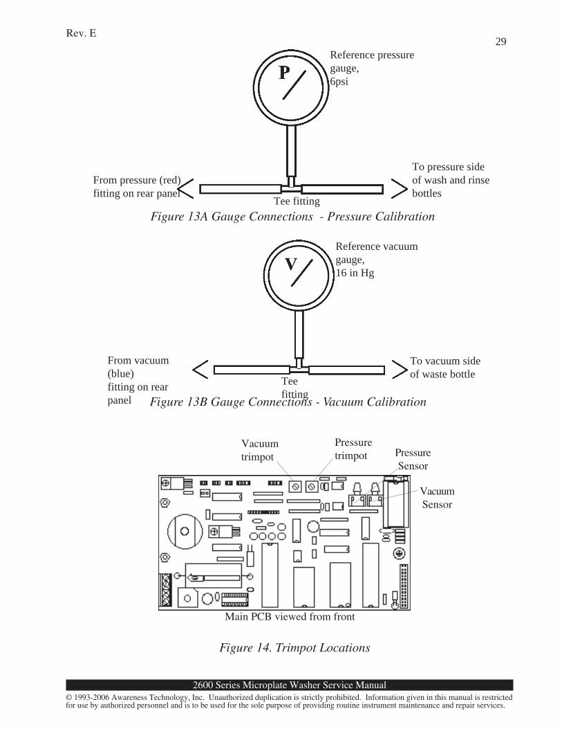
1. Disconnect the pressure line (red Luer fitting) at the rear panel. Refer to Figure 13A.Connect the pressure gauge as shown.
2. Open the instrument. Refer to Figure 14. Locate the pressure trimpot R10. Turn trimpotfully counterclockwise.
3. Set the power switch to ON (1). Wait until the instrument stabilizes and the pumps stoprunning. The pressure gage should read much less than 34 kPa (5 psi.)
2600 Series Microplate Washer Service Manual
Rev. E
© 1993-2006 Awareness Technology, Inc. Unauthorized duplication is strictly prohibited. Information given in this manual is restrictedfor use by authorized personnel and is to be used for the sole purpose of providing routine instrument maintenance and repair services.
29
Figure 14. Trimpot Locations
Vacuumtrimpot
Pressuretrimpot
Main PCB viewed from front
Figure 13A Gauge Connections - Pressure Calibration
Figure 13B Gauge Connections - Vacuum Calibration
PressureSensor
VacuumSensor
Reference pressuregauge,6psi
From pressure (red)fitting on rear panel
To pressure sideof wash and rinsebottles
Tee fitting
Reference vacuumgauge,16 in Hg
From vacuum(blue)fitting on rearpanel
To vacuum sideof waste bottleTee
fitting
2600 Series Microplate Washer Service Manual
Rev. E
© 1993-2006 Awareness Technology, Inc. Unauthorized duplication is strictly prohibited. Information given in this manual is restrictedfor use by authorized personnel and is to be used for the sole purpose of providing routine instrument maintenance and repair services.
304. Slowly turn the pressure trimpot clockwise until gauge reaches 34± 3.4 kPa (5 psi ±0.5.)
When turning the trimpot, pause while the pump runs to maintain pressure.
5. Set the power switch to OFF (O). Set the Vacuum Trimpot at mid-span of its range. Replacethe cover. Disconnect gauge and tubing. Reconnect the pressure fitting.
Calibrate Vacuum(applies only to units configured with waste valve)
Tools and MaterialsReference vacuum gauge reading at least negative 51 kPa (16 inches Hg.)15 cm length of 3.1 mm ID flexible tubing3.1 mm barbed “tee” fitting
1. Disconnect the vacuum line (blue Luer fitting) at the rear panel. Refer to Figure 13B.Connect the vacuum gauge as shown.
2. Open the instrument. Refer to Figure 14. Locate the vacuum trimpot R7. Turn trimpot fullycounterclockwise.
3. Set the power switch to ON (1). Wait until the instrument stabilizes and the pumps stoprunning. The vacuum gauge should read much less than negative 51 kPA (15 in. Hg.)
4. Slowly turn the vacuum trimpot clockwise until gauge reaches negative 51 ± 2 kPa (15 in.Hg ±0.5.) When turning the trimpot, pause while the pump runs to maintain vacuum.
5. Set the power switch to OFF (O). Replace the cover. Disconnect gauge and tubing.Reconnect the pressure and vacuum fittings.
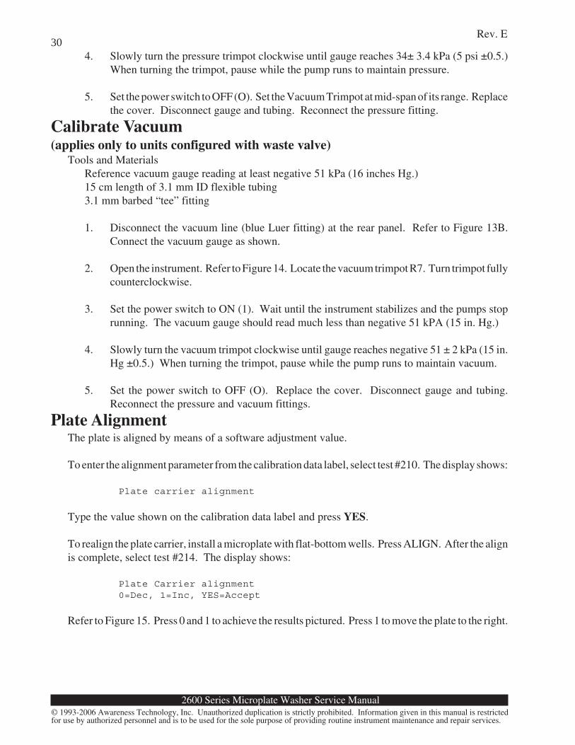
Plate AlignmentThe plate is aligned by means of a software adjustment value.
To enter the alignment parameter from the calibration data label, select test #210. The display shows:
Plate carrier alignment
Type the value shown on the calibration data label and press YES.
To realign the plate carrier, install a microplate with flat-bottom wells. Press ALIGN. After the alignis complete, select test #214. The display shows:
Plate Carrier alignment0=Dec, 1=Inc, YES=Accept
Refer to Figure 15. Press 0 and 1 to achieve the results pictured. Press 1 to move the plate to the right.
2600 Series Microplate Washer Service Manual
Rev. E
© 1993-2006 Awareness Technology, Inc. Unauthorized duplication is strictly prohibited. Information given in this manual is restrictedfor use by authorized personnel and is to be used for the sole purpose of providing routine instrument maintenance and repair services.
31
1. Aspirate tube must beas far to right as possible
2. Aspirate tube mustnot touch side of well
Figure 15. Plate Alignment
Press 0 to move the plate to the left. When the results are as shown, note the alignment valuedisplayed. Press YES to accept the alignment and complete the operation. Update the alignmentvalue on the calibration data label if necessary.
2600 Series Microplate Washer Service Manual
Rev. E
© 1993-2006 Awareness Technology, Inc. Unauthorized duplication is strictly prohibited. Information given in this manual is restrictedfor use by authorized personnel and is to be used for the sole purpose of providing routine instrument maintenance and repair services.
33
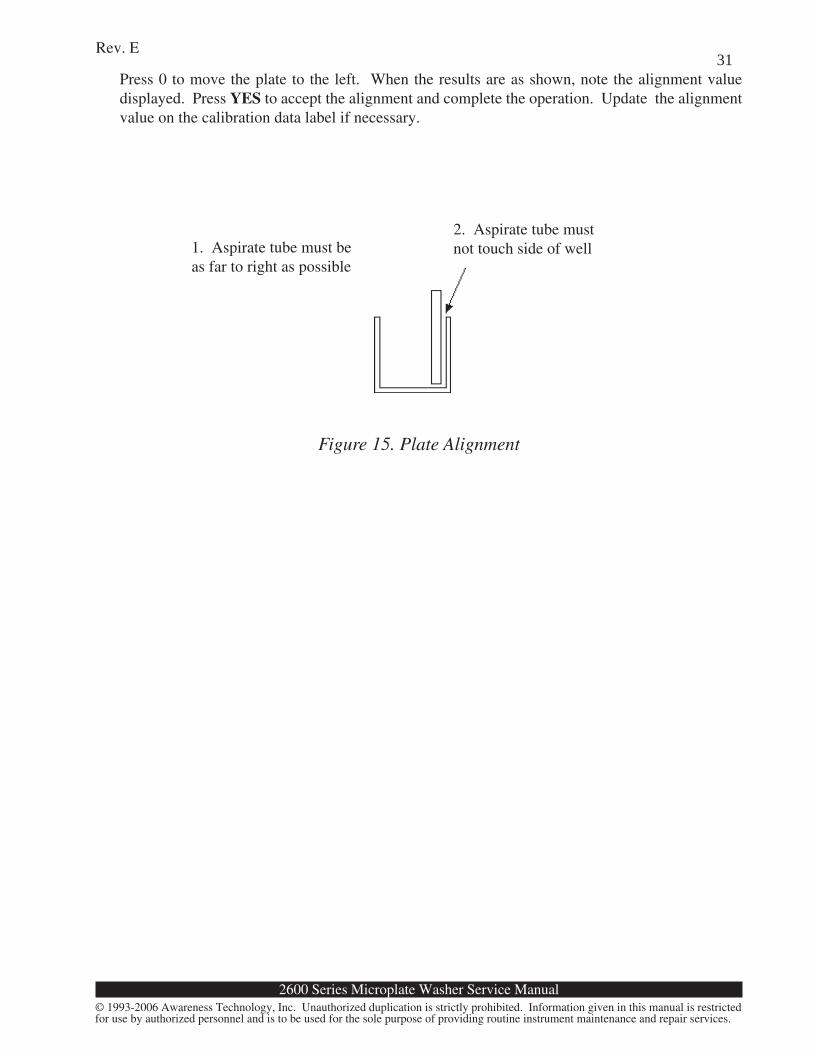
Single Pump- Without Check Valve
2600 Series Microplate Washer Service Manual
Rev. E
© 1993-2006 Awareness Technology, Inc. Unauthorized duplication is strictly prohibited. Information given in this manual is restrictedfor use by authorized personnel and is to be used for the sole purpose of providing routine instrument maintenance and repair services.
34
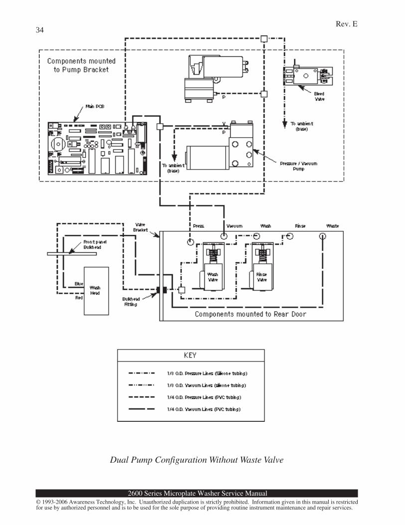
Dual Pump Configuration Without Waste Valve
2600 Series Microplate Washer Service Manual
Rev. E
© 1993-2006 Awareness Technology, Inc. Unauthorized duplication is strictly prohibited. Information given in this manual is restrictedfor use by authorized personnel and is to be used for the sole purpose of providing routine instrument maintenance and repair services.
35
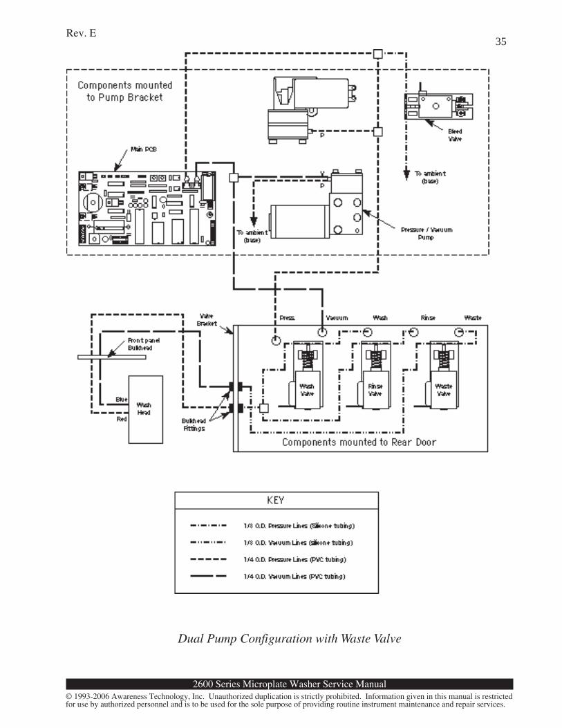
Dual Pump Configuration with Waste Valve
2600 Series Microplate Washer Service Manual
Rev. E
© 1993-2006 Awareness Technology, Inc. Unauthorized duplication is strictly prohibited. Information given in this manual is restrictedfor use by authorized personnel and is to be used for the sole purpose of providing routine instrument maintenance and repair services.
36
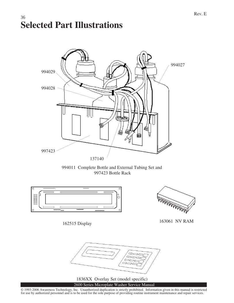
Selected Part Illustrations
994028
994029
994027
997423
137140
994011 Complete Bottle and External Tubing Set and 997423 Bottle Rack
162515 Display 163061 NV RAM
1836XX Overlay Set (model specific)
2600 Series Microplate Washer Service Manual
Rev. E
© 1993-2006 Awareness Technology, Inc. Unauthorized duplication is strictly prohibited. Information given in this manual is restrictedfor use by authorized personnel and is to be used for the sole purpose of providing routine instrument maintenance and repair services.
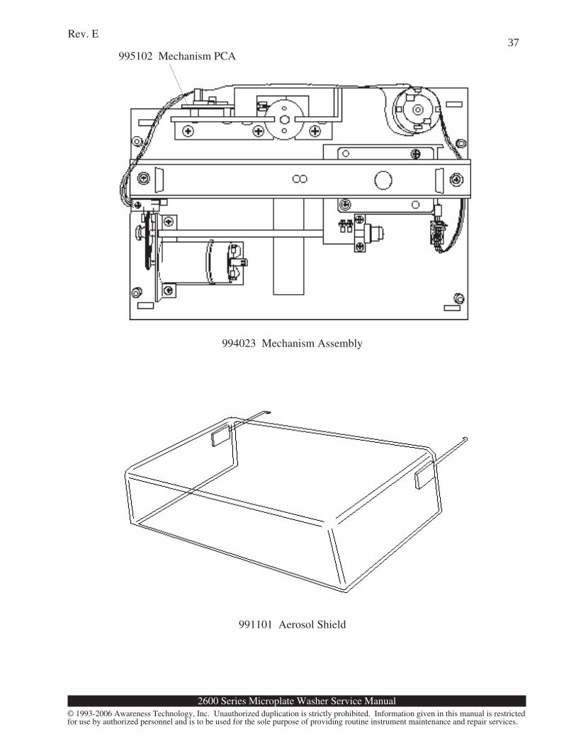
37995102 Mechanism PCA
994023 Mechanism Assembly
991101 Aerosol Shield
2600 Series Microplate Washer Service Manual
Rev. E
© 1993-2006 Awareness Technology, Inc. Unauthorized duplication is strictly prohibited. Information given in this manual is restrictedfor use by authorized personnel and is to be used for the sole purpose of providing routine instrument maintenance and repair services.
38
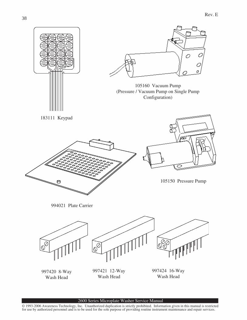
105160 Vacuum Pump(Pressure / Vacuum Pump on Single Pump
Configuration)
105150 Pressure Pump
183111 Keypad
994021 Plate Carrier
997420 8-WayWash Head
997421 12-WayWash Head
997424 16-WayWash Head
2600 Series Microplate Washer Service Manual
Rev. E
© 1993-2006 Awareness Technology, Inc. Unauthorized duplication is strictly prohibited. Information given in this manual is restrictedfor use by authorized personnel and is to be used for the sole purpose of providing routine instrument maintenance and repair services.
39
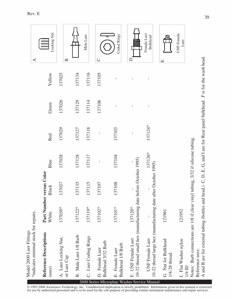
Mod
el 2
600
Lue
r Fi
tting
s*i
ndic
ates
min
imal
sto
ck f
or r
epai
rs.
Ref
eren
ce D
escr
ipti
ons
Par
t N
umbe
r ve
rsus
Col
or(u
ses)
Whi
teB
lack
Blu
eR
edG
reen
Yel
low
A.
Lue
r L
ocki
ng N
ut,
1370
30*
1370
2713
7028
1370
2913
7026
1370
25or
Lue
r C
ap
B.
Mal
e L
uer
1/8
Bar
b13
7122
*13
7135
1371
2813
7127
1371
2913
7134
C.
Lue
r C
odin
g R
ings
1371
19*
1371
1513
7117
1371
1813
7114
1371
16
D.
Fem
ale
Lue
r13
7102
*13
7107
-
-13
7106
1371
05B
ulkh
ead
3/32
Bar
b
E.
Fem
ale
Lue
r13
7101
*13
7108
1371
0413
7103
-
-
Bul
khea
d 1/
8 B
arb
F. U
NF
Fem
ale
Lue
r13
7120
*
-
-
-
-
-
10-3
2 th
read
sm
all h
ex (
man
ufac
turi
ng d
ate
befo
re O
ctob
er 1
995)
U
NF
Fem
ale
Lue
r
-
-13
7126
*13
7124
*
-
-10
-32
thre
ad la
rge
hex
(man
ufac
turi
ng d
ate
afte
r O
ctob
er 1
995)
G.
Nut
for
Bul
khea
d12
1961
1/4-
28 th
read
I. F
lat W
ashe
r ny
lon
1219
521/
4 ID
Not
es:
Bar
b co
nnec
tions
are
1/8
if c
lear
vin
yl tu
bing
, 3/3
2 if
sili
cone
tubi
ng.
Ref
eren
ce u
ses:
A a
nd B
are
for
ext
erna
l tub
ing
(bot
tles
and
head
.) C
, D, E
, G, a
nd I
are
for
Rea
r pa
nel b
ulkh
ead.
F is
for
the
was
h he
ad.
Loc
king
Nut
A B
Mal
e L
uer
C
Cod
ed R
ings
D
Fem
ale
Lue
r B
ulkh
ead
E
UN
F Fe
mal
eL
uer
2600 Series Microplate Washer Service Manual
Rev. E
© 1993-2006 Awareness Technology, Inc. Unauthorized duplication is strictly prohibited. Information given in this manual is restrictedfor use by authorized personnel and is to be used for the sole purpose of providing routine instrument maintenance and repair services.
40
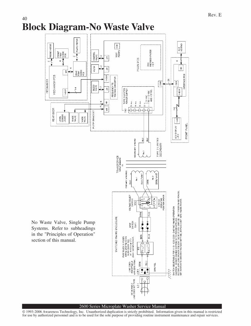
Block Diagram-No Waste Valve
No Waste Valve, Single PumpSystems. Refer to subheadingsin the "Principles of Operation"section of this manual.
2600 Series Microplate Washer Service Manual
Rev. E
© 1993-2006 Awareness Technology, Inc. Unauthorized duplication is strictly prohibited. Information given in this manual is restrictedfor use by authorized personnel and is to be used for the sole purpose of providing routine instrument maintenance and repair services.
41
Block Diagram- Waste Valve
2600 Series Microplate Washer Service Manual
Rev. E
© 1993-2006 Awareness Technology, Inc. Unauthorized duplication is strictly prohibited. Information given in this manual is restrictedfor use by authorized personnel and is to be used for the sole purpose of providing routine instrument maintenance and repair services.
42
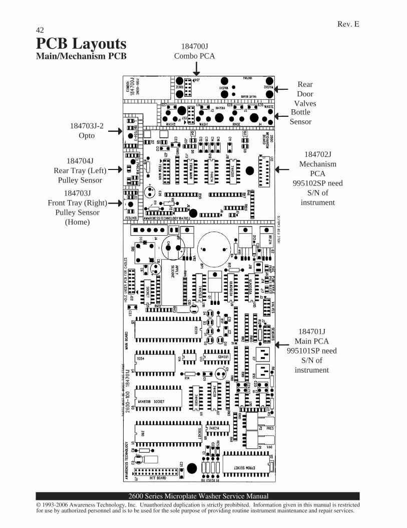
PCB LayoutsMain/Mechanism PCB
184702JMechanism
PCA995102SP need
S/N ofinstrument
184701JMain PCA
995101SP needS/N of
instrument
184700JCombo PCA
RearDoor
ValvesBottleSensor184703J-2
Opto
184704JRear Tray (Left)
Pulley Sensor184703J
Front Tray (Right)Pulley Sensor
(Home)
➝➝➝➝➝
➝➝➝➝➝
➝➝➝➝➝➝➝➝➝➝
➝➝➝➝➝
➝➝➝➝➝
➝➝➝➝➝
➝➝➝➝➝
2600 Series Microplate Washer Service Manual
Rev. E
© 1993-2006 Awareness Technology, Inc. Unauthorized duplication is strictly prohibited. Information given in this manual is restrictedfor use by authorized personnel and is to be used for the sole purpose of providing routine instrument maintenance and repair services.
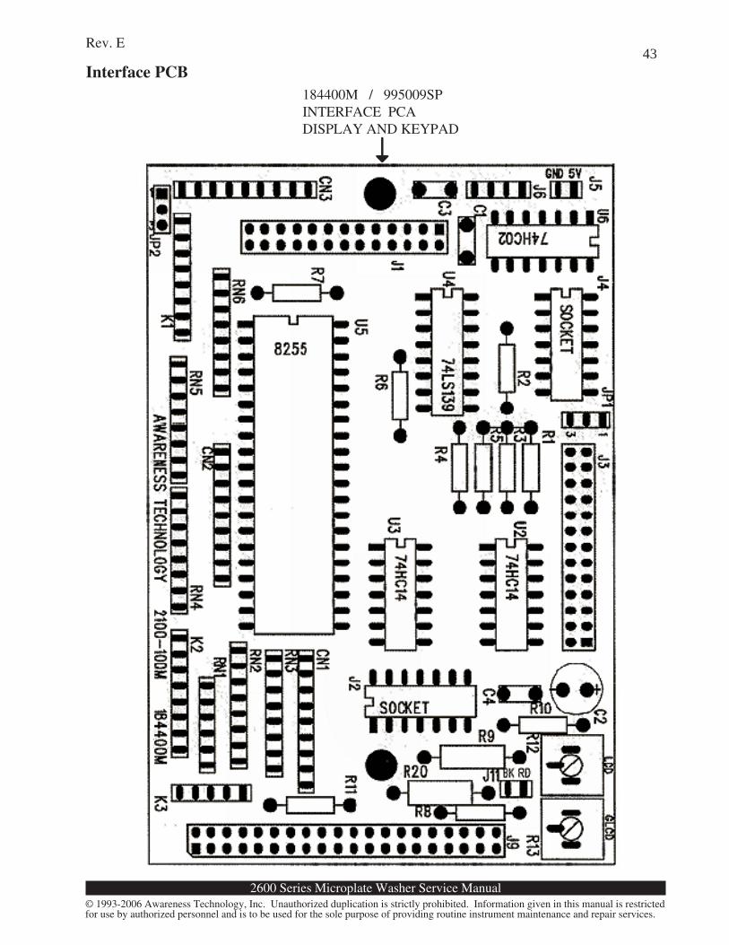
43Interface PCB
184400M / 995009SPINTERFACE PCADISPLAY AND KEYPAD➝➝ ➝➝➝
2600 Series Microplate Washer Service Manual
Rev. E
© 1993-2006 Awareness Technology, Inc. Unauthorized duplication is strictly prohibited. Information given in this manual is restrictedfor use by authorized personnel and is to be used for the sole purpose of providing routine instrument maintenance and repair services.
44
SchematicsMain/Mechanism PCB (1 of 5)
2600 Series Microplate Washer Service Manual
Rev. E
© 1993-2006 Awareness Technology, Inc. Unauthorized duplication is strictly prohibited. Information given in this manual is restrictedfor use by authorized personnel and is to be used for the sole purpose of providing routine instrument maintenance and repair services.
45Main/Mechanism PCB (2 of 5)
2600 Series Microplate Washer Service Manual
Rev. E
© 1993-2006 Awareness Technology, Inc. Unauthorized duplication is strictly prohibited. Information given in this manual is restrictedfor use by authorized personnel and is to be used for the sole purpose of providing routine instrument maintenance and repair services.
46Main/Mechanism PCB (3 of 5)
2600 Series Microplate Washer Service Manual
Rev. E
© 1993-2006 Awareness Technology, Inc. Unauthorized duplication is strictly prohibited. Information given in this manual is restrictedfor use by authorized personnel and is to be used for the sole purpose of providing routine instrument maintenance and repair services.
47Main/Mechanism PCB (4 of 5)
2600 Series Microplate Washer Service Manual
Rev. E
© 1993-2006 Awareness Technology, Inc. Unauthorized duplication is strictly prohibited. Information given in this manual is restrictedfor use by authorized personnel and is to be used for the sole purpose of providing routine instrument maintenance and repair services.
48Main/Mechanism PCB (5 of 5)
2600 Series Microplate Washer Service Manual
Rev. E
© 1993-2006 Awareness Technology, Inc. Unauthorized duplication is strictly prohibited. Information given in this manual is restrictedfor use by authorized personnel and is to be used for the sole purpose of providing routine instrument maintenance and repair services.
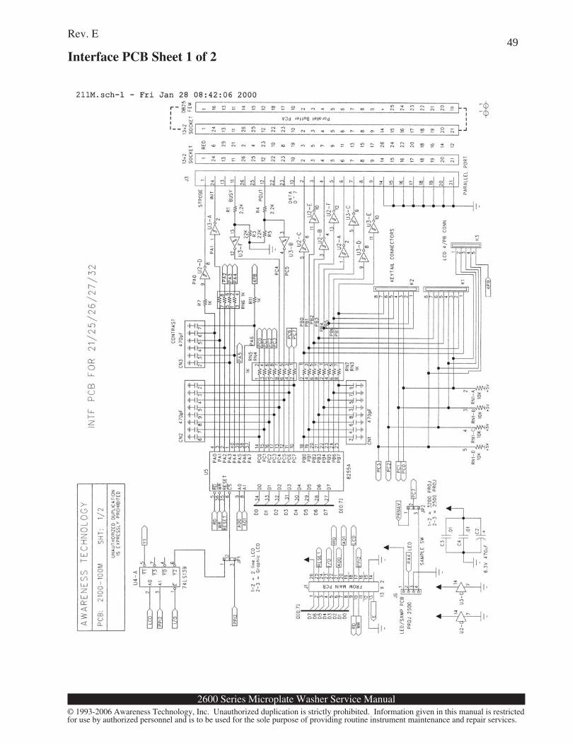
49Interface PCB Sheet 1 of 2
2600 Series Microplate Washer Service Manual
Rev. E
© 1993-2006 Awareness Technology, Inc. Unauthorized duplication is strictly prohibited. Information given in this manual is restrictedfor use by authorized personnel and is to be used for the sole purpose of providing routine instrument maintenance and repair services.
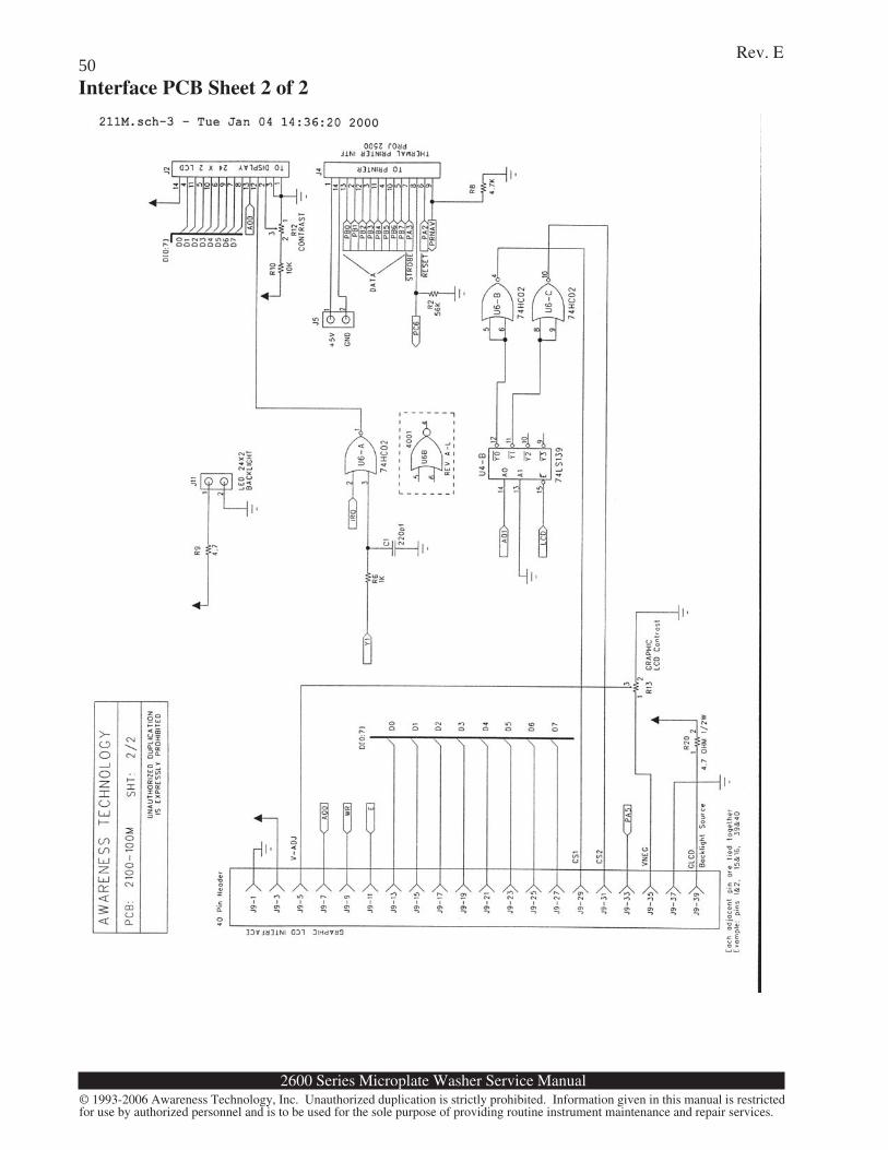
50Interface PCB Sheet 2 of 2

Rev E, 08/06
© 1993-2006 Awareness Technology, Inc. Unauthorized duplication is strictly prohibited. Information given in this manual is restrictedfor use by authorized personnel and is to be used for the sole purpose of providing routine instrument maintenance and repair service. Nopart of this manual may be copied or redistributed without the express consent of Awareness Technology, Inc. There is no transfer oftechnology, copyright, trade name, patent, trade secret, or other proprietary right given or implied.
2600 SeriesMicroplate Washer
Service ManualTable of Contents
Introduction .................................... 1Layout ............................................. 1
Principles of Operation .................. 6System Control ............................... 6Dispense ......................................... 6Aspirate ........................................... 7Waste Valve.................................... 7Motion Control ............................... 7Display and Keypad ....................... 7Pressure and Vacuum ..................... 7Level Sensing ................................. 8Watchdog Circuit ............................ 8Power Supply .................................. 8
Troubleshooting .............................. 9Test Mode ....................................... 9Status Indicators ............................. 9Available Tests ............................... 9Power Supply ................................ 11Main PCB ..................................... 12Keypad .......................................... 12Display .......................................... 12Valves ........................................... 12Motor Control ............................... 12Vacuum and Pressure Systems ..... 13Incomplete Aspiration .................. 13Incomplete or Inaccurate Dispense13Error Messages ............................. 13
Service Procedures ........................ 15Opening the Instrument ................ 15Valve Tubing Replacement .......... 19Valve Rebuild ............................... 19Bleed Valve Replacement ............ 20Exhaust Filter Replacement .......... 21Probe Drive Belt Replacement ..... 21Plate Drive Belt Replacement ...... 23EPROM Replacement .................. 23
Calibration .................................... 25Restore Calibration Data .............. 25Volume calibration ....................... 26Dispense Volume RepeatabilityCheck ............................................ 27Probe Auto Depth vs. ManualDepth ............................................ 27Probe Arm Adjustment ................. 28Plate Carrier Travel ...................... 28Calibrate Pressure ......................... 28Calibrate Vacuum ......................... 30Plate Alignment ............................ 30Internal Plumbing ......................... 32
Selected Part Illustrations ............ 36Block Diagram-No Waste Valve ... 40Block Diagram- Waste Valve........ 41PCB Layouts.................................. 42
Main/Mechanism PCB ................. 42Interface PCB ............................... 43
Schematics ..................................... 44Main/Mechanism PCB (1 of 5) .... 44Main/Mechanism PCB (2 of 5) .... 45Main/Mechanism PCB (3 of 5) .... 46Main/Mechanism PCB (4 of 5) .... 47Main/Mechanism PCB (5 of 5) .... 48Interface PCB Sheet 1 of 2 ........... 49Interface PCB Sheet 2 of 2 ........... 50