Embed Size (px)
Citation preview
DEPARTMENT OF MECHANICAL
ENGINEERING
17MECC93 - HYDRAULICS AND PNEUMATIC
SYSTEM LAB (UG)
LAB MANUAL
Prepared by
A. SENTHILKUMAR, B.E., M.E., ISHRAE (PHD)
ASSISTANT PROFESSOR GRADE-II/MECH
HOD/MECH
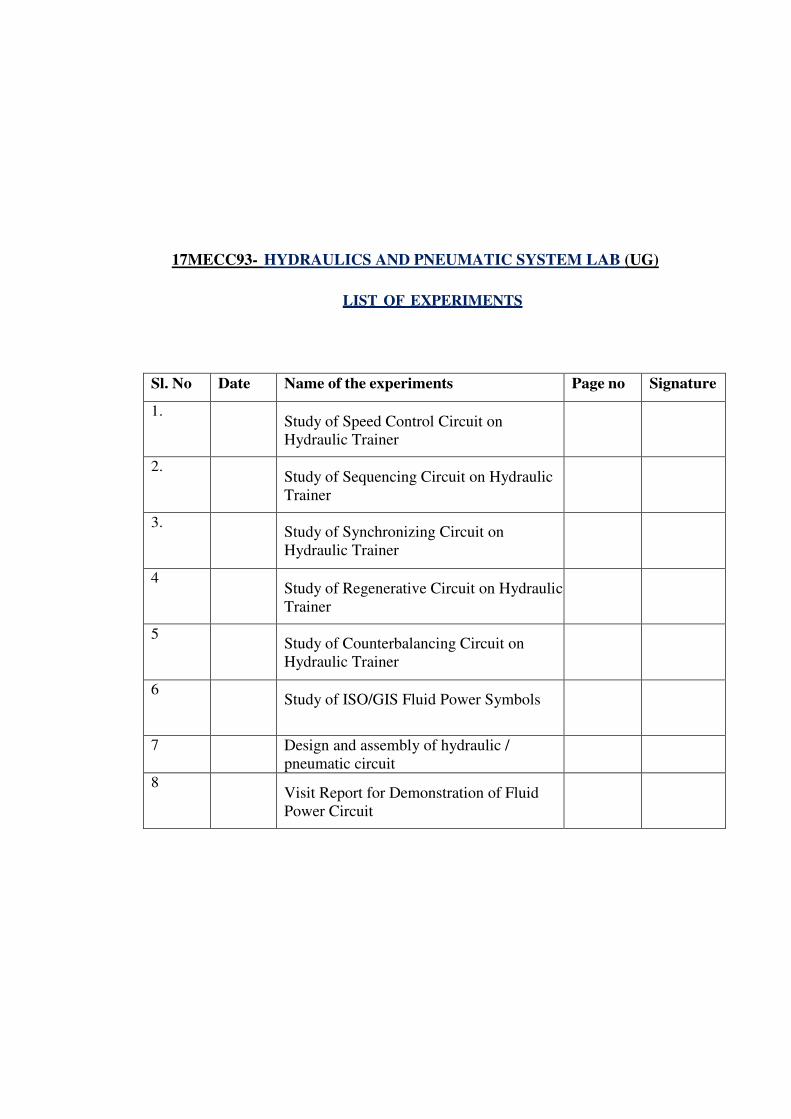
17MECC93- HYDRAULICS AND PNEUMATIC SYSTEM LAB (UG)
LIST OF EXPERIMENTS
Sl. No Date Name of the experiments Page no Signature
1. Study of Speed Control Circuit on
Hydraulic Trainer
2. Study of Sequencing Circuit on Hydraulic
Trainer
3. Study of Synchronizing Circuit on
Hydraulic Trainer
4 Study of Regenerative Circuit on Hydraulic
Trainer
5 Study of Counterbalancing Circuit on
Hydraulic Trainer
6 Study of ISO/GIS Fluid Power Symbols
7 Design and assembly of hydraulic /
pneumatic circuit
8 Visit Report for Demonstration of Fluid
Power Circuit
EXPERIMENT NO. 1
STUDY OF SPEED CONTROL CIRCUIT ON HYDRAULIC TRAINER
Aim :
To study of speed control circuit on hydraulic trainer
Hydraulic circuits :
Hydraulic circuits are used in high power and high load applications such as
earth moving equipment. The pressure used in industrial applications is about 140 bar
or 14 MPa. For more precise control, valves actuated by electrical signals are
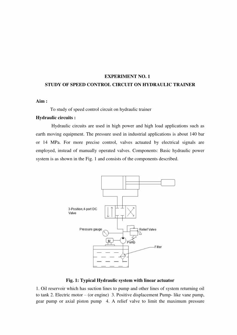
employed, instead of manually operated valves. Components: Basic hydraulic power
system is as shown in the Fig. 1 and consists of the components described.
Fig. 1: Typical Hydraulic system with linear actuator
1. Oil reservoir which has suction lines to pump and other lines of system returning oil
to tank 2. Electric motor – (or engine) 3. Positive displacement Pump- like vane pump,
gear pump or axial piston pump 4. A relief valve to limit the maximum pressure
developed to 5. Directional control valve (DC Valve) which controls direction of high
pressure oil to actuator, and to tank from actuator. 6. Actuator – a hydraulic cylinder for
linear motion of load (connected to piston rod), or a hydraulic motor when load
actuation is rotation. 7. Filter:Oil filter is provided either in pump suction or return line.
8. Pressure gauge to indicate the pressure developed by the pump. 9. Flow lines –
flexible hoses or rigid pipes connecting various system components.
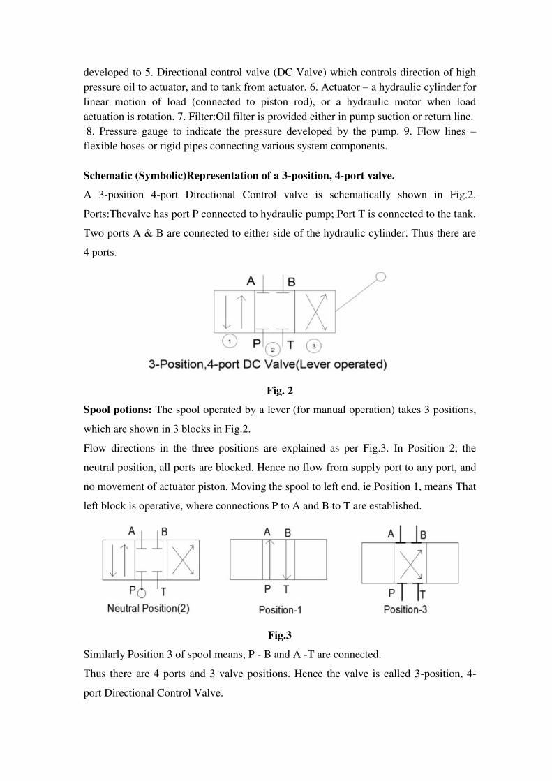
Schematic (Symbolic)Representation of a 3-position, 4-port valve.
A 3-position 4-port Directional Control valve is schematically shown in Fig.2.
Ports:Thevalve has port P connected to hydraulic pump; Port T is connected to the tank.
Two ports A & B are connected to either side of the hydraulic cylinder. Thus there are
4 ports.
Fig. 2
Spool potions: The spool operated by a lever (for manual operation) takes 3 positions,
which are shown in 3 blocks in Fig.2.
Flow directions in the three positions are explained as per Fig.3. In Position 2, the
neutral position, all ports are blocked. Hence no flow from supply port to any port, and
no movement of actuator piston. Moving the spool to left end, ie Position 1, means That
left block is operative, where connections P to A and B to T are established.
Fig.3
Similarly Position 3 of spool means, P - B and A -T are connected.
Thus there are 4 ports and 3 valve positions. Hence the valve is called 3-position, 4-
port Directional Control Valve.
(In the experiment, there are 2 tank ports, and it is a 3-position, 5 port DC valve).
Experiment 1: Control of a Double Acting Cylinder:
A double acting cylinder is one in which the piston rod can be moved forward
or backwards by supplying high pressure fluid to piston or rod side chamber of the
actuator. The fluid flow to the required side is controlled by movement of the spool of
the DC valve (or a lever actuating the spool)
Operation:
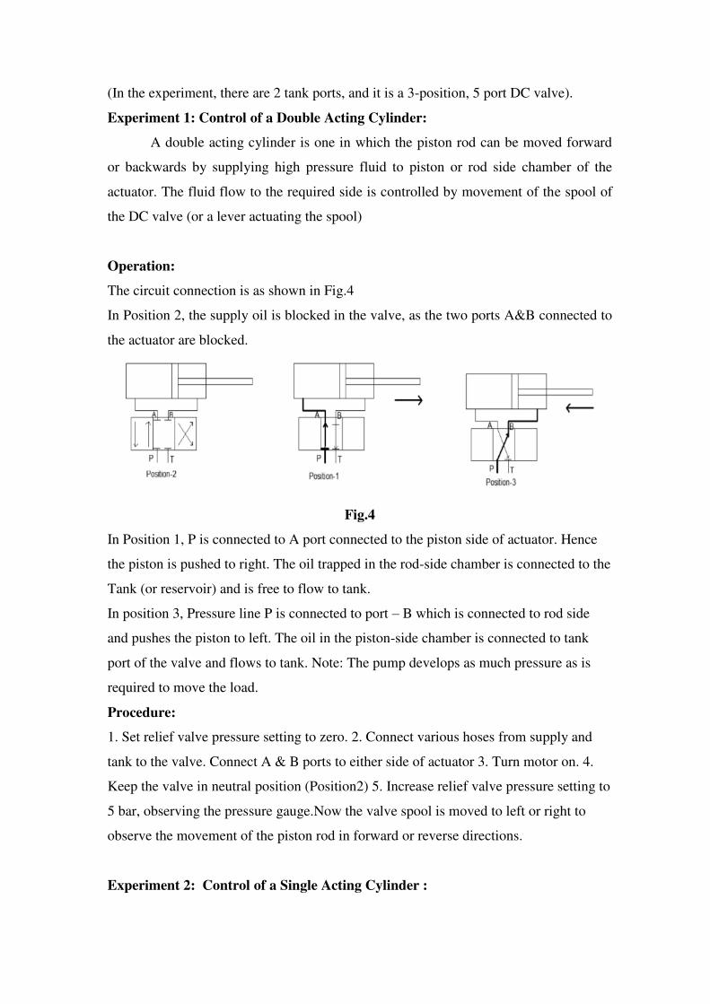
The circuit connection is as shown in Fig.4
In Position 2, the supply oil is blocked in the valve, as the two ports A&B connected to
the actuator are blocked.
Fig.4
In Position 1, P is connected to A port connected to the piston side of actuator. Hence
the piston is pushed to right. The oil trapped in the rod-side chamber is connected to the
Tank (or reservoir) and is free to flow to tank.
In position 3, Pressure line P is connected to port – B which is connected to rod side
and pushes the piston to left. The oil in the piston-side chamber is connected to tank
port of the valve and flows to tank. Note: The pump develops as much pressure as is
required to move the load.
Procedure:
1. Set relief valve pressure setting to zero. 2. Connect various hoses from supply and
tank to the valve. Connect A & B ports to either side of actuator 3. Turn motor on. 4.
Keep the valve in neutral position (Position2) 5. Increase relief valve pressure setting to
5 bar, observing the pressure gauge.Now the valve spool is moved to left or right to
observe the movement of the piston rod in forward or reverse directions.
Experiment 2: Control of a Single Acting Cylinder :
In single acting cylinder, actuator has only one port on the piston side. When high
pressure oil is supplied, piston moves against the force of the spring which is on the rod
side. For backward stroke, the port is connected to tank by the DC valve, and piston
retracts due to spring force.
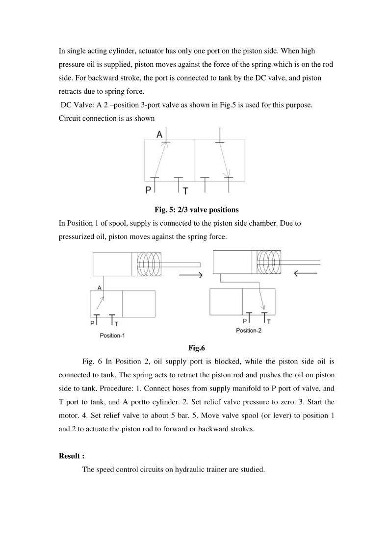
DC Valve: A 2 –position 3-port valve as shown in Fig.5 is used for this purpose.
Circuit connection is as shown
Fig. 5: 2/3 valve positions
In Position 1 of spool, supply is connected to the piston side chamber. Due to
pressurized oil, piston moves against the spring force.
Fig.6
Fig. 6 In Position 2, oil supply port is blocked, while the piston side oil is
connected to tank. The spring acts to retract the piston rod and pushes the oil on piston
side to tank. Procedure: 1. Connect hoses from supply manifold to P port of valve, and
T port to tank, and A portto cylinder. 2. Set relief valve pressure to zero. 3. Start the
motor. 4. Set relief valve to about 5 bar. 5. Move valve spool (or lever) to position 1
and 2 to actuate the piston rod to forward or backward strokes.
Result :
The speed control circuits on hydraulic trainer are studied.
EXPERIMENT NO. 2
STUDY OF SEQUENCING CIRCUIT ON HYDRAULIC TRAINER
Aim :
To study the operation of a sequencing circuit
Components Required
Hydraulic trainer.
Procedure
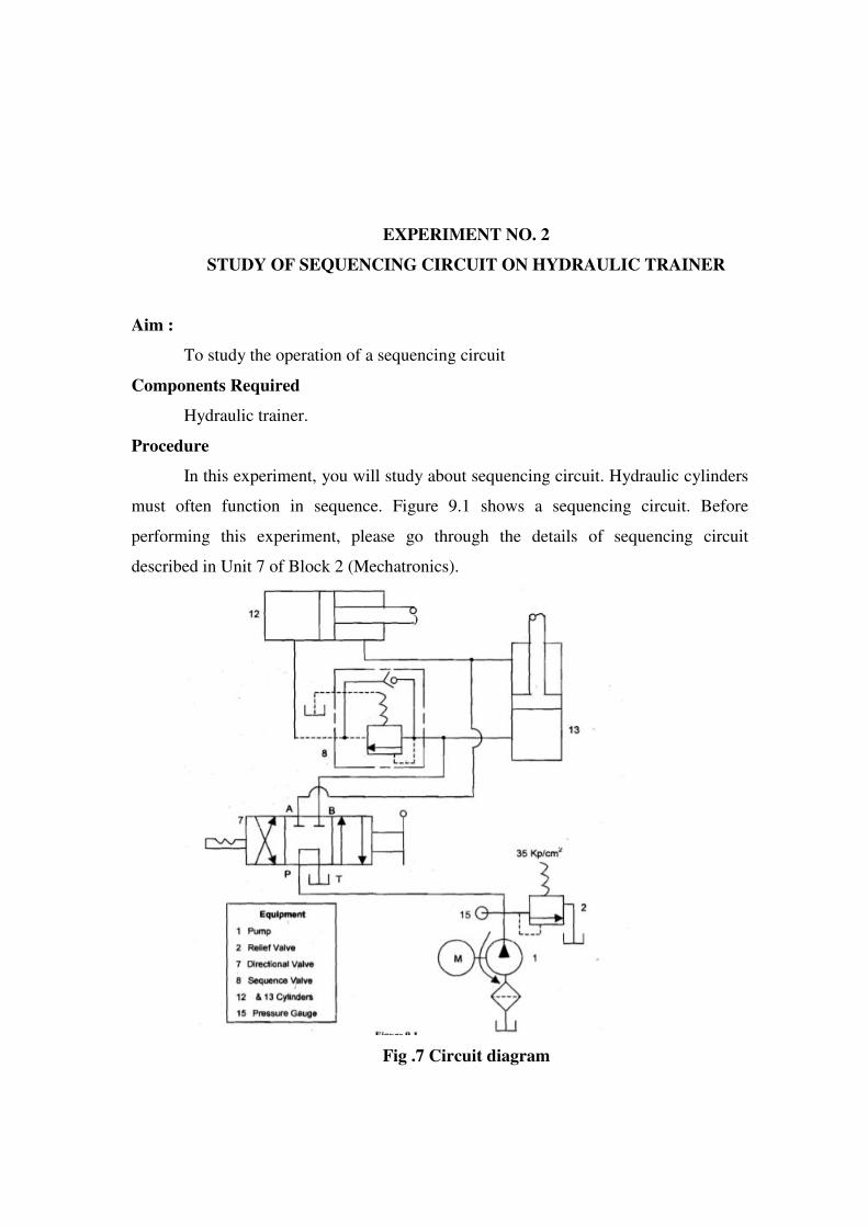
In this experiment, you will study about sequencing circuit. Hydraulic cylinders
must often function in sequence. Figure 9.1 shows a sequencing circuit. Before
performing this experiment, please go through the details of sequencing circuit
described in Unit 7 of Block 2 (Mechatronics).
Fig .7 Circuit diagram
Procedure
1. Arrange the components according to the circuit diagram shown in Figure 7.
2. Put valve 7 in neutral position.
3. Start the pump and shift valve 7 towards right direction
4. Observe the flow of oil towards cylinder 13 and sequence valve 8. The cylinder
23 extends however the cylinder 12 does not move immediately. After
sometime, valve 8 opens and cylinder 12 extend
5. Shift valve 7 towards left direction. Observe that the retraction of cylinders
12 and 13 takes simultaneously.
Result :
The sequencing control circuits on hydraulic trainer is studied.
EXPERIMENT NO. 3
STUDY OF SYNCHRONIZING CIRCUIT ON HYDRAULIC TRAINER
Aim:
To Study Hydraulic Sequencing circuit.
Components required :
Hydraulic cylinders, pump, sequencing valve, 4X3 direction control valve
Hydraulic cylinders can be operated sequentially using a sequence valve.
Procedure:
1] Switch on the three phase connection given to Induction motor
2] Rotate pressure relief valve anticlockwise direction for two minutes
3] By observing the pressure gauge of pressure line adjust pressure between 12 to 15
kgf/cm²
4] Check oil level in tank to be full shown by indicator
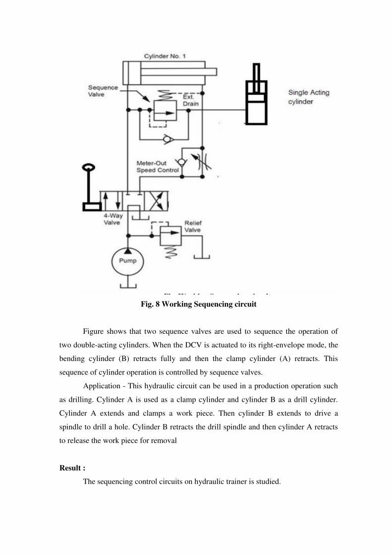
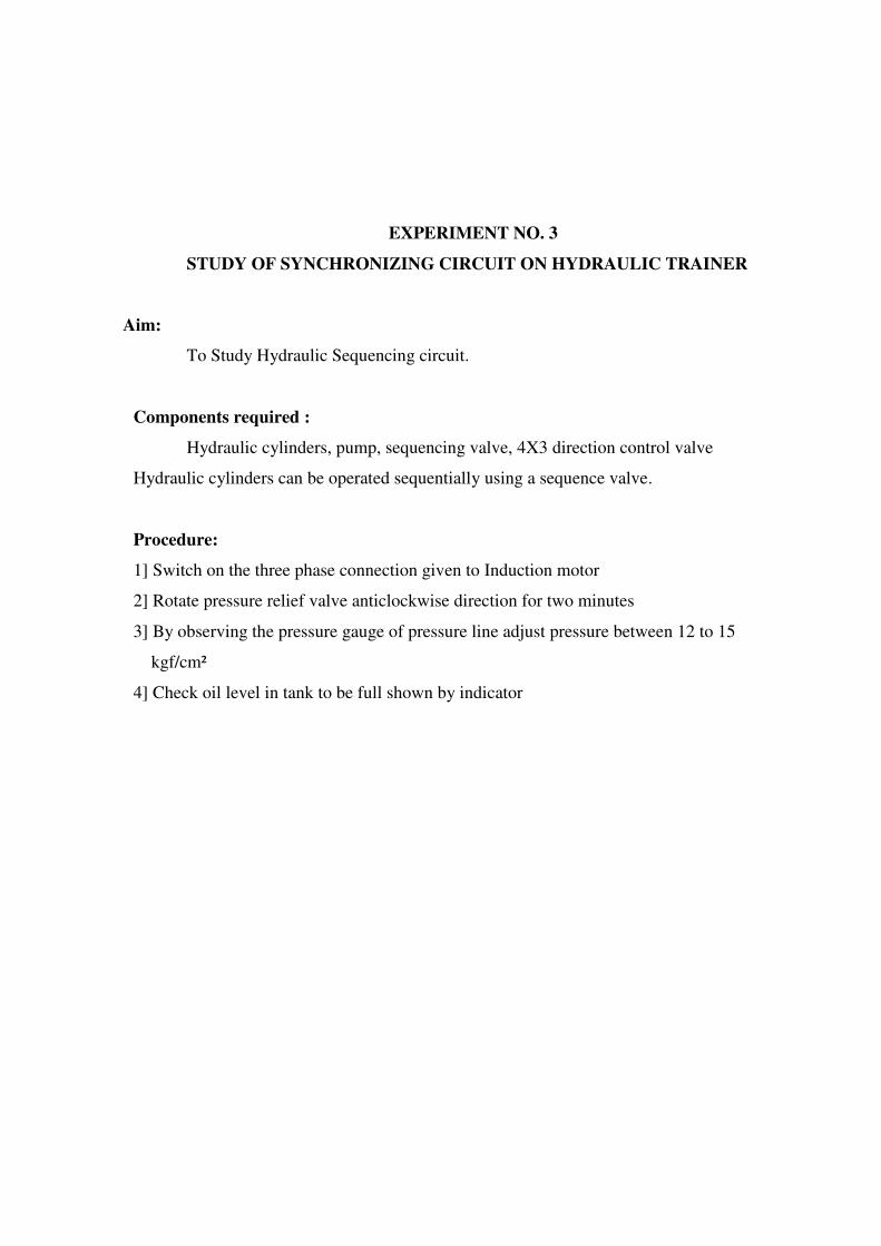
Fig. 8 Working Sequencing circuit
Figure shows that two sequence valves are used to sequence the operation of
two double-acting cylinders. When the DCV is actuated to its right-envelope mode, the
bending cylinder (B) retracts fully and then the clamp cylinder (A) retracts. This
sequence of cylinder operation is controlled by sequence valves.
Application - This hydraulic circuit can be used in a production operation such
as drilling. Cylinder A is used as a clamp cylinder and cylinder B as a drill cylinder.
Cylinder A extends and clamps a work piece. Then cylinder B extends to drive a
spindle to drill a hole. Cylinder B retracts the drill spindle and then cylinder A retracts
to release the work piece for removal
Result :
The sequencing control circuits on hydraulic trainer is studied.
EXPERIMENT NO. 4
STUDY OF REGENERATIVE CIRCUIT ON HYDRAULIC TRAINER
Aim:
Study of Hydraulic Regenerative circuit.
Components required
Hydraulic cylinder, direction control valve, pump, pressure relief valve, oil tank Figure
shows basic concept of a regenerative circuit that is used to speed up the extending
speed of a double-acting cylinder.
Procedure
1] Switch on the three phase connection given to Induction motor
2] Rotate pressure relief valve anticlockwise direction for two minutes
3] By observing the pressure gauge of pressure line adjust pressure between 12 to 15
kgf/cm²
4] Check oil level in tank to be full shown by indicator
Fig .9 Figure connection of a regenerative circuit
Theory:
Figure.9 shows a regenerative circuit that is used to speed up the extending speed of a
double acting cylinder. The pipelines to both ends of the hydraulic cylinder are connected in
parallel and one of the ports of the 4/3 valve is blocked by simply screwing a thread plug
into the port opening. During retraction stroke, the 4/3 valve is configured to the right
envelope. During this stroke, the pump flow bypasses the DCV and enters the rod end of the
cylinder. Oil from the blank end then drains back to the tank through the DCV.
Result :
The hydraulic regenerative circuit is studied.
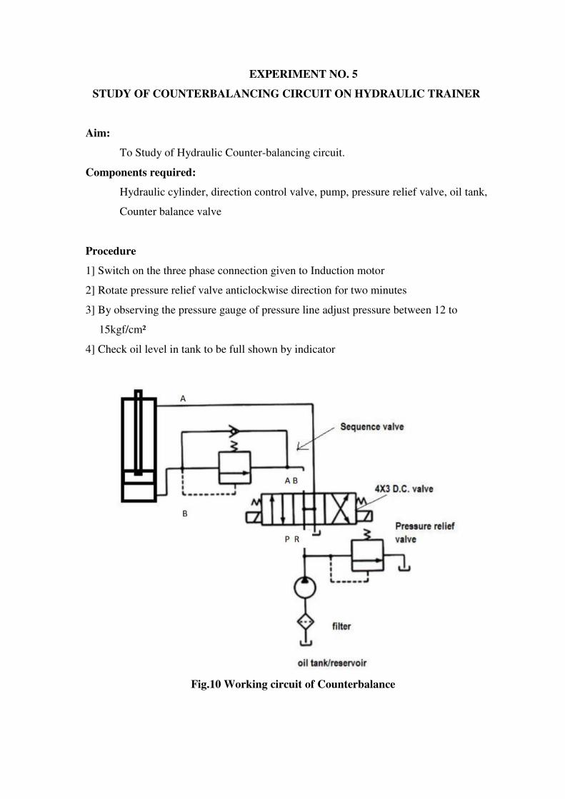
EXPERIMENT NO. 5
STUDY OF COUNTERBALANCING CIRCUIT ON HYDRAULIC TRAINER
Aim:
To Study of Hydraulic Counter-balancing circuit.
Components required:
Hydraulic cylinder, direction control valve, pump, pressure relief valve, oil tank,
Counter balance valve
Procedure
1] Switch on the three phase connection given to Induction motor
2] Rotate pressure relief valve anticlockwise direction for two minutes
3] By observing the pressure gauge of pressure line adjust pressure between 12 to
15kgf/cm²
4] Check oil level in tank to be full shown by indicator
Fig.10 Working circuit of Counterbalance
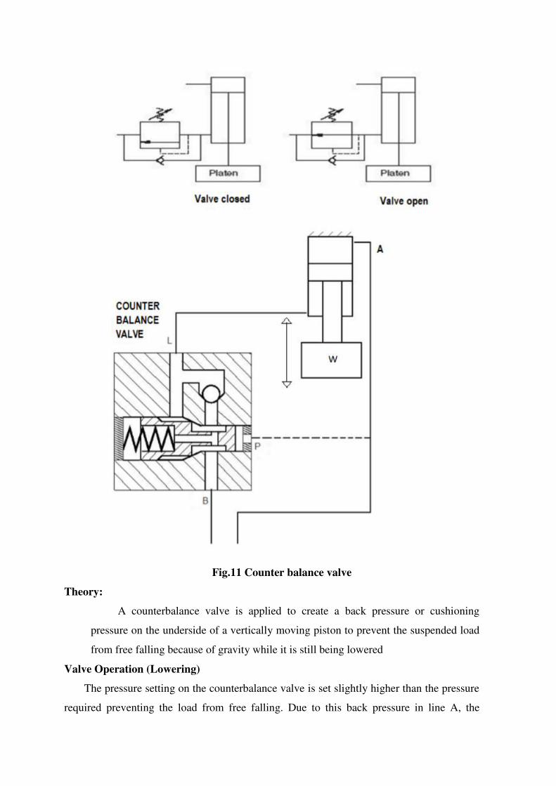
Fig.11 Counter balance valve
Theory:
A counterbalance valve is applied to create a back pressure or cushioning
pressure on the underside of a vertically moving piston to prevent the suspended load
from free falling because of gravity while it is still being lowered
Valve Operation (Lowering)
The pressure setting on the counterbalance valve is set slightly higher than the pressure
required preventing the load from free falling. Due to this back pressure in line A, the
actuator piston must force down when the load is being lowered. This causes the pressure in
line A to increase, which raises the spring-opposed spool, thus providing a flow path to
discharge the exhaust flow from line A to the DCV and then to the tank. The spring-
controlled discharge orifice maintains back pressure in line A during the entire downward
piston stroke.
Valve Operation (Lifting)
As the valve is normally closed, flow in the reverse direction (from port B to port A)
cannot occur without a reverse free-flow check valve. When the load is raised again, the
internal check valve opens to permit flow for the retraction of the actuator.
Valve Operation (Suspension)
When the valve is held in suspension, the valve remains closed. Therefore, its pressure
setting must be slightly higher than the pressure caused by the load. Spool valves tend to
leak internally under pressure. This makes it advisable to use a pilot-operated check valve in
addition to the counterbalance valve if a load must be held in suspension for a prolonged
time.
Result :
The Hydraulic Counter-balancing circuit is studied.
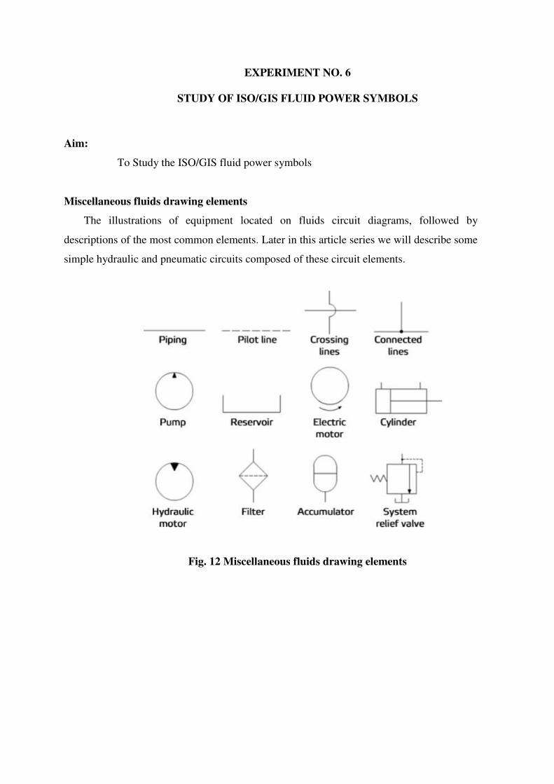
EXPERIMENT NO. 6
STUDY OF ISO/GIS FLUID POWER SYMBOLS
Aim:
To Study the ISO/GIS fluid power symbols
Miscellaneous fluids drawing elements
The illustrations of equipment located on fluids circuit diagrams, followed by
descriptions of the most common elements. Later in this article series we will describe some
simple hydraulic and pneumatic circuits composed of these circuit elements.
Fig. 12 Miscellaneous fluids drawing elements
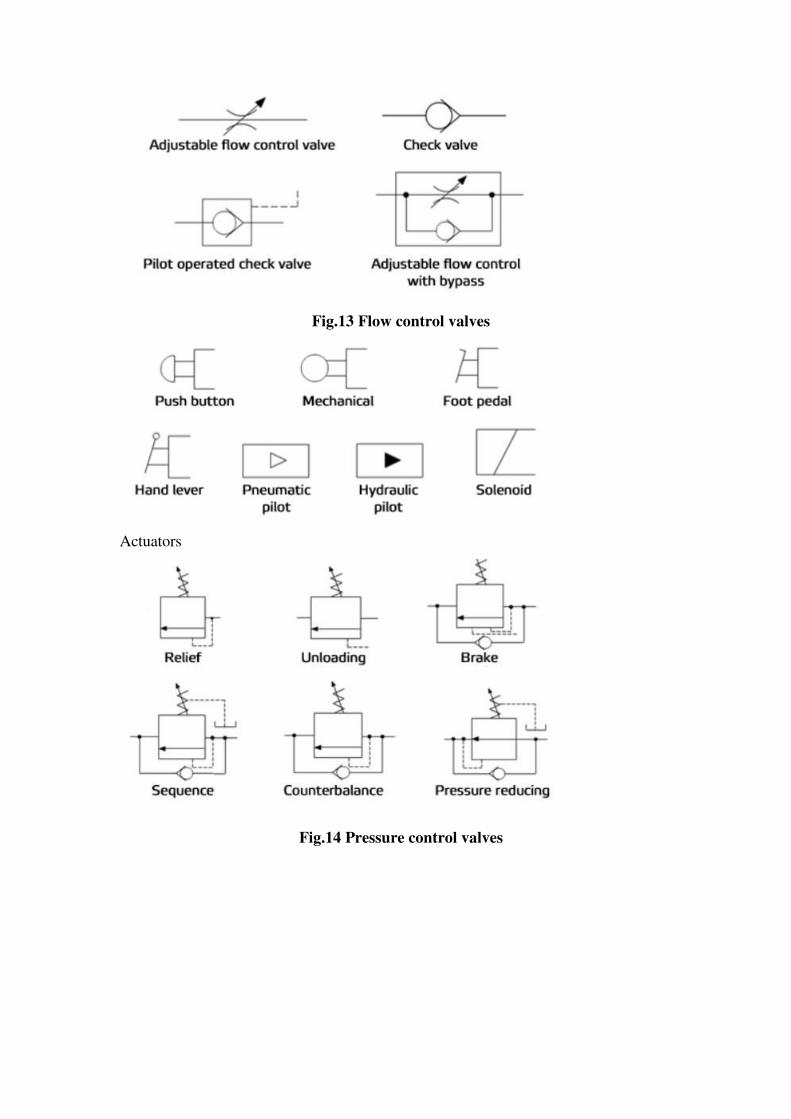
Fig.13 Flow control valves
Actuators
Fig.14 Pressure control valves
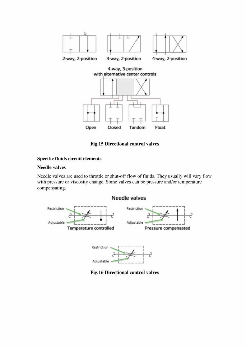
Fig.15 Directional control valves
Specific fluids circuit elements
Needle valves
Needle valves are used to throttle or shut-off flow of fluids. They usually will vary flow
with pressure or viscosity change. Some valves can be pressure and/or temperature
compensating.
Fig.16 Directional control valves
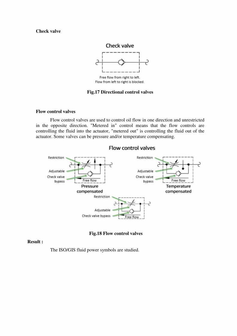
Check valve
Fig.17 Directional control valves
Flow control valves
Flow control valves are used to control oil flow in one direction and unrestricted
in the opposite direction. "Metered in" control means that the flow controls are
controlling the fluid into the actuator, "metered out" is controlling the fluid out of the
actuator. Some valves can be pressure and/or temperature compensating.
Fig.18 Flow control valves
Result :
The ISO/GIS fluid power symbols are studied.
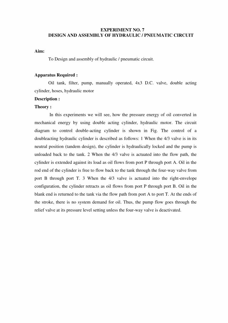
EXPERIMENT NO. 7
DESIGN AND ASSEMBLY OF HYDRAULIC / PNEUMATIC CIRCUIT
Aim:
To Design and assembly of hydraulic / pneumatic circuit.
Apparatus Required :
Oil tank, filter, pump, manually operated, 4x3 D.C. valve, double acting
cylinder, hoses, hydraulic motor
Description :
Theory :
In this experiments we will see, how the pressure energy of oil converted in
mechanical energy by using double acting cylinder, hydraulic motor. The circuit
diagram to control double-acting cylinder is shown in Fig. The control of a
doubleacting hydraulic cylinder is described as follows: 1 When the 4/3 valve is in its
neutral position (tandem design), the cylinder is hydraulically locked and the pump is
unloaded back to the tank. 2 When the 4/3 valve is actuated into the flow path, the
cylinder is extended against its load as oil flows from port P through port A. Oil in the
rod end of the cylinder is free to flow back to the tank through the four-way valve from
port B through port T. 3 When the 4/3 valve is actuated into the right-envelope
configuration, the cylinder retracts as oil flows from port P through port B. Oil in the
blank end is returned to the tank via the flow path from port A to port T. At the ends of
the stroke, there is no system demand for oil. Thus, the pump flow goes through the
relief valve at its pressure level setting unless the four-way valve is deactivated.
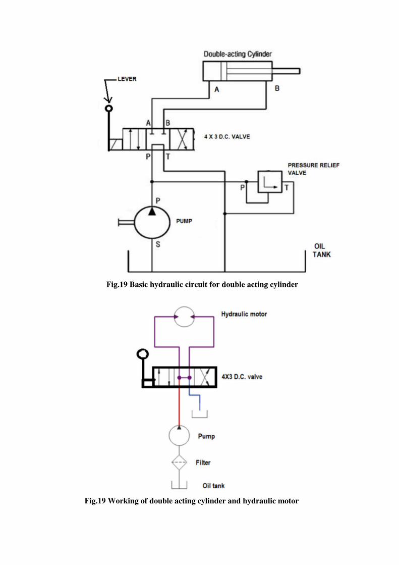
Fig.19 Basic hydraulic circuit for double acting cylinder
Fig.19 Working of double acting cylinder and hydraulic motor
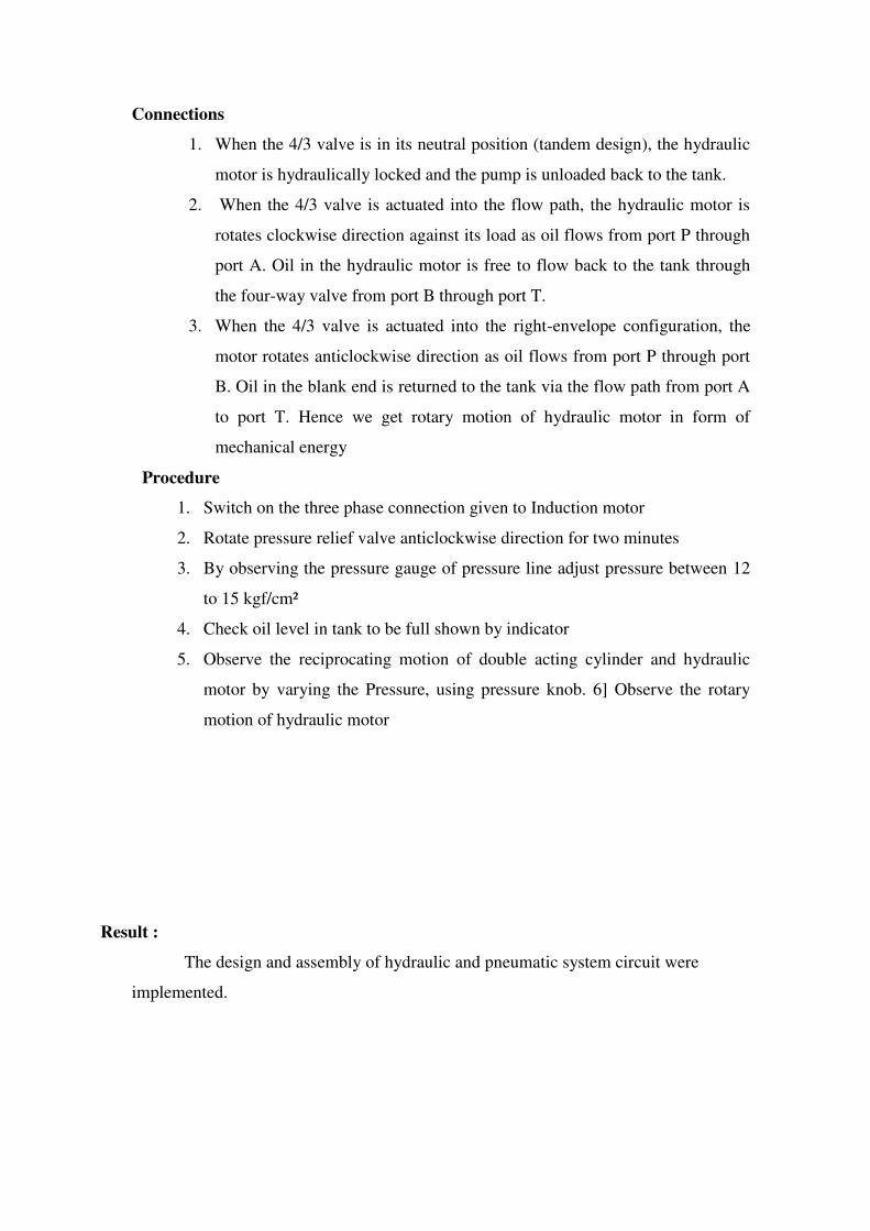
Connections
1. When the 4/3 valve is in its neutral position (tandem design), the hydraulic
motor is hydraulically locked and the pump is unloaded back to the tank.
2. When the 4/3 valve is actuated into the flow path, the hydraulic motor is
rotates clockwise direction against its load as oil flows from port P through
port A. Oil in the hydraulic motor is free to flow back to the tank through
the four-way valve from port B through port T.
3. When the 4/3 valve is actuated into the right-envelope configuration, the
motor rotates anticlockwise direction as oil flows from port P through port
B. Oil in the blank end is returned to the tank via the flow path from port A
to port T. Hence we get rotary motion of hydraulic motor in form of
mechanical energy
Procedure
1. Switch on the three phase connection given to Induction motor
2. Rotate pressure relief valve anticlockwise direction for two minutes
3. By observing the pressure gauge of pressure line adjust pressure between 12
to 15 kgf/cm²
4. Check oil level in tank to be full shown by indicator
5. Observe the reciprocating motion of double acting cylinder and hydraulic
motor by varying the Pressure, using pressure knob. 6] Observe the rotary
motion of hydraulic motor
Result :
The design and assembly of hydraulic and pneumatic system circuit were
implemented.
EXPERIMENT NO. 8
SIMULATION OF PNEUMATIC LOGIC CIRCUITS
AIM :
To design a pneumatic circuit for “AND” gate logic unit using two pressure
valve for single acting cylinder.
APPARATUS REQUIRED:
AND Gate, Double acting cylinder, 5/2 pilot operated spring return dcv
3/2 push button
PROCEDURE :
Ensure sufficient air pressure is available as input in the FRL unit. The
connections are made as per the circuit diagram .The inlet port 1 of the 5/2 DCV (1)
and 3/2 push button (2) is connected from the FRL unit. The outlet port 2 of the 5/2
DCV (1) and 3/2 push button (2) is connected to the two AND Gate AND Gate port is
connected to pilot operated 5/2 DCV 5/2 DCV port is connected to blank end of double
acting cylinder. The forward stroke occurs during the following condition.
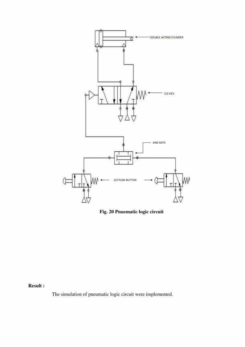
Fig. 20 Pnuematic logic circuit
Result :
The simulation of pneumatic logic circuit were implemented.
VIVA - VOCE 1. What is meant by sensor?
2. What are the various types of control system?
3. Distinguish between closed loop system and open loop system.
4. What are the types of strain gauges?
5. Define - LVDT
6. What is meant by fluid power?
7. What is a check valve?
8. What is a solenoid valve?
9. Define – FRL unit
10. Define – DCV
11. Differentiate between meter-in and meter-out controls.
12. What is the function of an unloading valve?
13. What is the function of a sequence valve?
14. What is the function of a shuttle valve?
15. What is the function of a spool valve?
16. What is the function of a process control valve?
17. What is the function of a 2-way pressure valve?
18. Why hydraulic power is especially used in heavy works?
19. Where are pneumatic systems preferred?
20. Name the basic components of a hydraulic system.
21. What is the function of a relief valve in a hydraulic system?
22. Draw the symbols for a pressure relief valve and a pressure reducing valve.
23. What is meant by NC and NO contacts?
24. What is meant by an actuator?
25. What are the types of actuators?
26. What is a control valve?
27. What are the types of control valves?
28. What is a circuit control valve?
29. What is the function of flow control valve?
30. Distinguish between flow control and needle valve.
31. What is the function of time delay valve?
32. What is the function of pilot operated valve?
33. What is a quick exhaust valve?
34. What is the difference between a strainer and a filter?
35. Distinguish between hydraulics and pneumatics?
36. What is the purpose of a pressure regulator?
37. Why lubricator is used in pneumatic systems?
38. What are the advantages of hydro- pneumatics?
39. What is meant by logic control?
40. Name the different pneumatic position sensors.
41. How do you rate a compressor?
42. What is a programmable logic controller?
43. What are the basic elements of a PLC?
44. What are the various approaches for entering the program for PLC?
45. What is a ladder diagram?
46. What is the purpose of an electrical timer?
47. Draw the general ladder rungs to represent a latch circuit.
48. How does a PLC differ from relay logic?
49. What are the features of a PLC?
50.What is the function of proximity switch?