Embed Size (px)
Citation preview

MAHARASHTRA STATE BOARD OF TECHNICAL EDUCATION (Autonomous)
(ISO/IEC - 27001 - 2005 Certified)
Page 1 of 32
WINTER– 14 EXAMINATIONS Subject Code: Model Answer Page No: ____/ N Important Instructions to examiners: 1) The answers should be examined by key words and not as word-to-word as given in the model answer scheme. 2) The model answer and the answer written by candidate may vary but the examiner may try to assess the understanding level of the candidate. 3) The language errors such as grammatical, spelling errors should not be given more importance. (Not applicable for subject English and Communication Skills) 4) While assessing figures, examiner may give credit for principal components indicated in the figure. The figures drawn by candidate and model answer may vary. The examiner may give credit for any equivalent figure drawn. 5) Credits may be given step wise for numerical problems. In some cases, the assumed constant values may vary and there may be some difference in the candidate’s answers and model answer. 6) In case of some questions credit may be given by judgment on part of examiner of relevant answer based on candidate’s understanding. 7) For programming language papers, credit may be given to any other program based on equivalent concept.

MAHARASHTRA STATE BOARD OF TECHNICAL EDUCATION (Autonomous)
(ISO/IEC - 27001 - 2005 Certified)
Page 2 of 32
Q. NO.
MODEL ANSWER
MARKS T O T A L
1. Attempt any five
a)
1) NEUTRAL FLAME:- A neutral flame is produced when approximately equal volumes of Oxygen acetylene are mixed in the welding torch & burnt at the torch tip. The temperature of the neutral flame is of the order about 5900 F. The flame has a nicely defined inner cone which is light blue in colour. It is surrounded by an outer envelope which is much darker than blue. 2) OXIDISING FLAME:- If after the neutral flame has been established the supply of an oxidising flame can be recognised by the small white cone which is shorter , much blue in colour & more painted than that of the neutral flame. This is because of excess oxygen & which causes the temperature to rise as high as 6300 F. 1) Reducing Flame:- If the volume of oxygen supplied to the neutral flame is reduced, the resulting flame will be a carburising flame or reducing flame which is rich in acetylene. A reducing flame has an approximate temperature of 5500 F. It can be recognised by the acetylene feather which exists in between the inner cone & the outer envelope.
Diag. 2M
2M

MAHARASHTRA STATE BOARD OF TECHNICAL EDUCATION (Autonomous)
(ISO/IEC - 27001 - 2005 Certified)
Page 3 of 32
b)
When using a DC power source, the question of whether to use electrode negative or positive polarity arises. Some electrodes operate on both DC straight and reverse polarity, and others on DC negative or DC positive polarity only. Direct current flows in one direction in an electrical circuit and the direction of current flow and the composition of the electrode coating will have a definite effect on the welding arc and weld bead. Electrode negative (-) produces welds with shallow penetration; however, the electrode melt-off rate is high. The weld bead is rather wide and shallow bead. Electrode positive (+) produces welds with deep penetration and a narrower weld bead. The deepest penetration is usually obtained with the direct current electrode positive (DCEP) polarity which also gives the best surface appearance, bead shape and resistance to porosity.
4M
c) 1. AC and DC welders are both shielded metal arc welders but
differ in the electricity they use. AC welders use electric
voltage directly from an alternating current outlet. DC welders
use the same AC voltage but convert it to direct current
voltage.
2. DC welding electrodes must only be used on a DC machine,
even though AC electrodes can be used with either machine.
3. AC welding can be used to weld magnetized metal, but DC
welding is easier to use and can weld thinner metals.
4. AC welders pulse the arc every time the alternating current
changes polarity, which makes the arc harder to control. DC
welders are more expensive.
5. AC welders are cheaper and can weld thicker metals, while
DC welders strike an arc easier and make a cleaner weld. An
AC welder is fine for most home project jobs, but if welding is
a regular chore, you will probably need AC and DC at some
point.
6. AC continuously changes polarity, since directional of flow is
reversed 120 times per second for common 60 cycle
electricity.With DC straight polarity (DCSP), the electrode is
negative and the current flows in the opposite
direction…electrode to work.
4M (Any 4 Points)

MAHARASHTRA STATE BOARD OF TECHNICAL EDUCATION (Autonomous)
(ISO/IEC - 27001 - 2005 Certified)
Page 4 of 32
7. AC Current ideal for
Downhand Heavy plate, Aluminum TIG Welding with Hi
frequency , Carbon arc torch
DC Straight Polarity ideal for:
Hard facing, Single Carbon Brazing, Build-up Heavy
Deposits, Stainless Steel TIG Welding.
d) The weldability, also known as join ability, of a material refers to its ability to be welded. Many metals and thermoplastics can be welded, but some are easier to weld than others. A material's weld ability is used to determine the welding process and to compare the final weld quality to other materials. Applying an optimum magnetic field to a welding arc on both nonmagnetic and magnetic materials increases welding speed several times at which undercut-free and no porosity welds can be made. It is known the extent of arc deflection is dependent upon the flux density of the applied magnetic field, the arc current, arc length, and so on. To apply magnetic arc oscillation to welding automation such as weld quality control and joint tracking, therefore, quantitative information has to be obtained about the effect of welding conditions on arc deflection.
4M
e)
FOLLOWING ARE THE DEFECTS:- 1.CRACKS 2.INCOMLETE PENETRATION 3.DISTORION INCLUSIONS 4.POOR FUSION 5.POROSITY 6.POOR WELD BEAD APPEARANCE 7.UNDERCUTTING 8.SPATTER 9.OVERLAPPING 10.BLOW HOLES Inclusions There are two types of inclusions: linear inclusions and rounded inclusions. Inclusions can be either isolated or cumulative. Linear inclusions occur when there is slag or flux in the weld. It can also occur if the previous weld left an undercut or an uneven surface profile. Undercut Undercutting is when the weld reduces the cross-sectional thickness of the base metal, which reduces the strength of the
4 M (Any2
defects with its cause)

MAHARASHTRA STATE BOARD OF TECHNICAL EDUCATION (Autonomous)
(ISO/IEC - 27001 - 2005 Certified)
Page 5 of 32
weld and work pieces. One reason for this type of defect is excessive current, causing the edges of the joint to melt and drain into the weld; this leaves a drain-like impression along the length of the weld. Another reason is if a poor technique is used that does not deposit enough filler metal along the edges of the weld. A third reason is using an incorrect filler metal, because it will create greater temperature gradients between the center of the weld and the edges. Other causes include too small of an electrode angle, a dampened electrode, excessive arc length, and slow speed. Cracks Cracks are the most dangerous amongst all types of defects as it reduce the performance of a welded joint drastically and can also cause catastrophic failure. Depending on the position, location and orientation these can be categorised as longitudinal cracks, transverse cracks, crater cracks, under-bead cracks, and toe cracks.
f) Brazing is a metal-joining process whereby a filler metal is heated above melting point and distributed between two or more close-fitting parts by capillary action. The filler metal is brought slightly above its melting (liquidus) temperature while protected by a suitable atmosphere, usually a flux. Advantages:- Since brazing does not melt the base metal of the joint, it allows much tighter control over tolerances and produces a clean joint without the need for secondary finishing. Additionally, dissimilar metals and non-metals (i.e. metalized ceramics) can be brazed In general, brazing also produces less thermal distortion than welding due to the uniform heating of a brazed piece. Complex and multi-part assemblies can be brazed cost-effectively. Limitations:- 1)Size limitation of the parts to be brazed is of major importance.since area to be brazed must be heated, large cast sections or large heavy plates cannot be easily brought up to temperature. 2. Brazing requires tightly mating parts to ensure capillary flow of the filler metal. This involves expensive machining to attain the desired fit. 3. Flux residues if not properly removed can cause corrosion. 4. Brazed joints do not give satisfactory results when used at elevated temperatures. 5. A certain degree of skill is required to perform the brazing
2 M
1m (Any 1)
1m (Any 1)

MAHARASHTRA STATE BOARD OF TECHNICAL EDUCATION (Autonomous)
(ISO/IEC - 27001 - 2005 Certified)
Page 6 of 32
operations; personnel limitations may rule out the process
g) Following are the Heat Treatment processes:- 1.Peening 2.Vibratory stress-relief 3. Thermal treatment 4. Thermo-mechanical treatment 5. Overstressing techique Peening:- Peening is the process of working a metal's surface to improve its material properties, usually by mechanical means such as hammer blows, by blasting with shot (shot peening), or blasts of light beams with laser peening. Peening is normally a cold work process (laser peening being a notable exception It tends to expand the surface of the cold metal, thereby inducing compressive stresses or relieving tensile stresses already present. Peening can also encourage strain hardening of the surface metal
2M
2M
2.
ATTEMPT ANY FOUR
a)
Gas Welding:- Gas welding is a welding process in which an electric arc forms between a consumable wire electrode and the workpiece metal(s), which heats the workpiece metal(s), causing them to melt, and join.
ADVANTAGES OF GAS WELDING 1. It is probably the most versatile process. It can be applied to a wide variety of manufacturing and maintenance situations. 2. Welder has considerable control over the temperature of the metal in the weld zone. When the rate of heat input from the flame is properly coordinated with the speed of welding,
2M
2M (ANY 2)

MAHARASHTRA STATE BOARD OF TECHNICAL EDUCATION (Autonomous)
(ISO/IEC - 27001 - 2005 Certified)
Page 7 of 32
the size, viscosity and surface tension of the weld puddle can be controlled, permitting the pressure of the flame to be used to aid in positioning and shaping the weld. 3. The rate of heating and cooling is relatively slow. In some cases, this is an advantage. 4. Since the sources of heat and of filler metal are separate, the welder has control over filler-metal deposition rates. Heat can be applied prefer entially to the base metal or the filler metal. 5. The equipment is versatile, low cost, self-sufficient and usually portable. Besides gas welding, the equipment can be used for preheating, post heating, braze welding, torch brazing and it is readily converted to oxygen cutting. 6. The cost and maintenance of the welding equipment is low when compared to that of some other welding processes.
b)
Following are the equipment used in gas welding:-
1) Oxygen gas cylinder
2) Acetylene gas cylinder
3) Oxygen gas hose
4) Acetylene gas hose
5) Welding torch
6) Trolley
7) Filler rod
8) Flux
9) Protecting cloths
4 M
(ANY 8)
c) Electric Arc Welding:- Arc welding is a type of welding that uses a welding power supply to create an electric arc between an electrode and the base material to melt the metals at the welding point. They can use either direct (DC) or alternating (AC) current, and consumable or non-consumable electrodes. The welding region is usually protected by some type of shielding gas, vapor, or slag. Arc Length:- An electric arc length, or arc discharge, is an electrical breakdown of a gas that produces an ongoing plasma discharge, resulting from a current through normally
2M
1M

MAHARASHTRA STATE BOARD OF TECHNICAL EDUCATION (Autonomous)
(ISO/IEC - 27001 - 2005 Certified)
Page 8 of 32
nonconductive media such as air. An arc discharge is characterized by a lower voltage than a glow discharge, and relies on thermionic emission of electrons from the electrodes supporting the arc Types of Arc Blow: 1) Forward Arc blow 2) Backward Arc blow 3)Sideward Arc Blow.
1M
d) Weldability is the capacity of a material to be welded under the fabrication conditions imposed into a specific suitably designed structure and to perform satisfactorily in the intended service. Factors effecting are: •Composition of the metal •Brittleness and strength of metal at elevated temperature •Thermal properties of metal •Welding techniques,fluxing material and filler material •Proper heat treatment before and after the deposition of the metal.
2M
2M
e) (1) American (AWS-ASTM) System EXX XX or E 60 1 2 EXXX XX or E 100 1 5 Letter E signifies that electrode is suitable for metal (electric) arc welding. XX/XXX (60/100) . First two or three digits indicate minimum tensile strength of weld metal in thousands of pounds per sq. inch, e.g. 60,000 and 100,000 lbs/sq. inch . Other values of XX and XXX are 45, 70, 80, 90 and 120. X (1)
Last but one digit indicates the welding position. It can be represented by numbers like 1, 2 and 3 which indicate that welding can be carried out in any position, flat and horizontal positions, and flat position respectively. X (2) (5) Last digit which may be 0, 1, 2, 3, 5 or 6 tells about power supply, type of covering, type of arc, penetration characteristics, etc produces medium penetration, heavy slag, a convex weld bead appearance and a medium quality weld deposition.
OR (2 )British (BS) System: L X X X L First 1st 2nd 3rd Last Letter Digit Digit Digit Letter
4M

MAHARASHTRA STATE BOARD OF TECHNICAL EDUCATION (Autonomous)
(ISO/IEC - 27001 - 2005 Certified)
Page 9 of 32
Examples: E 317 M E 145P Various letters and digits indicate the following: 1st Letter- It can be E, R or D. E indicates that it is a solid extruded electrode, R means reinforced electrode and D indicates 'Dipped electrode', i.e. an electrode manufactured by dipping process. 1st letter It indicates the class of covering. It can be 1,2,3,4,5,6 or 9 1.means high cellulose content. 2.means high titania content resulting in fairly viscous slag. 3.means appreciable titania content resulting in a fluid slag. 4.means high iron and/or Mn oxides and/or silicates content resulting in inflated slag. 5.means high iron oxides and/or silicates content resulting in a heavy solid slag. 6.means high calcium carbonate and fluoride content. 9.any other type of covering not mentioned above. 2nd Digit It indicates the position in which electrode can weld satisfactorily. Second digit can be represented by 1, 2, 3, 4, 5, 6
or 9. 1. indicates welding positions like flat, horizontal, inclined, vertical, overhead (i.e. electrode i!.suitable for welding in all positions). 2. flat; horizontal.
3. flat only 5 flat, horizontal, vertical, overhead. 6. vertical, overhead. 9. not classified above. 3rd Digit - It gives an idea of current, polarity and open circuit voltage of the welding power source. Any number like 0, 1, 2, 3, 4, 5,6, 7 or 9 can be the third digit. ° 0 indicates D +, i.e. DCRP 1 'D +, A95, i.e. DCRP or AC with OC voltage over 95 volts. 2 D-, A70, i.e. DCSP or AC with OCV over 70 V. 3 D-, A45, i.e. DCSP or AC with OCV over 45 V. 4 D +, A70, i.e. DCRP or AC with OCV over 70 V. 5 D±, A95, i.e. DCSP, DCRP, AC with OCV over 95V. 6 D±, A70, i.e.DCSP, DCRP, AC with OCV over 70V. 7 D±, A45, i.e. DCSP, DCRP, AC with OCV over 45V 9 Not classified above. Last letter- P indicates deep penetration electrode, and
M means a molybdenum bearing electrode. Example: E 145 P means

MAHARASHTRA STATE BOARD OF TECHNICAL EDUCATION (Autonomous)
(ISO/IEC - 27001 - 2005 Certified)
Page 10 of 32
(a) It is a solid extruded electrode, (b) It has a high cellulose content, (c) It 'can weld in flat, horizontal and inclined positions, (d) It can be operated on DCRP, DCSP or AC with a power source having OCV above 95 volts, and (e) It is a deep penetration electrode
OR (3)Indian (IS) System: L X X X X X X L 1st 1st 2nd 3rd 4th 5th 6th Last letter Letter DIGITS Example: E307411 Various digits and letters indicate the following: 1st Letter -It can be E or R. E indicates that electrode is solid extruded and R means an electrode extruded with reinforcement. 1st Digit - It indicates the Glass of covering. It can be 1, 2, 3, 4, 5, 6 or 9 and has the meaning same as that of the first digit of British system, discussed earlier. 2nd Digit - It indicates the positions in which electrode can weld satisfactorily. Second digit may be 0, 1,2,3,4, or 9. 0 and 1 signify that the electrode can be used for welding in all positions, and in flat, horizontal, overhead and vertical positions respectively.4 indicates flat and horizontal fillet positions. 2, 3 and 9 have the same meaning as in British standard. 3rd Digit - It has the same meaning as that of the third digit of British standard, except that the open circuit voltage is 90 in place of 95 volts, and 50 instead of 45. 4th and - They indicate range of tensile strength and value of minimum 5th Digit yield stress., e.g. 41 (fourth and fifth digits) and 51 mean that tensile strength ranges from 410-510 and 510-610 N/mm2andminimum yield stress is 330 and 360 N/mm2 respectively. 6th Digit - It tells percentage elongation and impact value. Last Letter- P indicates a deep penetration electrode, H hydrogen control led electrode, and J, K, L indicate electrodes with iron powder coating and metal recovery 110-130%, 130-150% and above 150%, respectively. Example: E 307411 means (a) It is a solid extruded electrode. (b) Its covering contains appreciable amount of titania; a fluid slag. (c) It is all position electrode, (d) It can be operated on DCRP, DCSP or AC with a power sourcehaving, open circuit voltage 50 volts,

MAHARASHTRA STATE BOARD OF TECHNICAL EDUCATION (Autonomous)
(ISO/IEC - 27001 - 2005 Certified)
Page 11 of 32
(e) Weld metal tensile strength ranges between 410 and 510 N/rnm2 and minimum yield stress is 330 Nzmm", (10 N/mm2 = 1.02 kgf/mrn2). (f) Minimum percentage elongation of weld metal (in tension) is 20% of 5.65 v'SO and impact value of weld metal at 27°C is 4.8 kgf m (or 47 J). Where Sois the cross-section area of the specimen being tested
f) 1. CRACK: Minimize shrinkage stresses using backstep or block welding sequence Change welding current and travel speed Weld with covered electrode negative; butter the joint faces prior to welding. Change to new electrode; bake electrodes to remove moisture Reduce root opening; build up the edges with weld metal Increase electrode size; raise welding current, reduce travel speed Use filler metal low in sulfur Change to balanced welding on both sides of joint Fill crater before extinguishing the arc; use a welding current decay device when terminating the weld bead. 2 DISTORTION Reducing the metal weld volume to avoid overfill and consider the use of intermittent welding Minimising the number of weld runs Positioning and balancing the welds correctly round the axis Using backstep or skip welding techniques, which involves laying short welds in the opposite direction Making allowance for shrinkage by pre-setting the parts to be welded out of position Planning the welding sequence to ensure that shrinkages are counteracted progressively Shortening the welding time 3 INCOMPLETE PENETRATION/ FUSION: Remedies of incomplete fusion Follow correct welding procedure specification Maintain proper electrode position Reposition work, lower current, or increase weld travel speed Clean weld surface prior to welding 4 INCLUSIONS
4M (ANY 4)

MAHARASHTRA STATE BOARD OF TECHNICAL EDUCATION (Autonomous)
(ISO/IEC - 27001 - 2005 Certified)
Page 12 of 32
This defect can only be repaired by grinding down or gouging out and re-welding. 5 POROSITY AND BLOW HOLES OR GAS POCKETS Use low-hydrogen welding process; filler metals high in deoxidizers; increase shielding gas flow Use preheat or increase heat input Clean joint faces and adjacent surfaces Use specially cleaned and packaged filler wire, and store it in clean area Change welding conditions and techniques Use copper-silicon filler metal; reduce heat input Use E60I0 electrodes and manipulate the arc heat to volatilize the zinc ahead of the molten weld pool Use recommended procedures for baking and storing electrodes Preheat the base metal Use electrodes with basic slagging reactions 6 SPATTER Spatter can be minimized by correcting the welding conditions and should be eliminated by grinding when present. 7 UNDER-CUITING Undercutting can be avoided with careful attention to detail during preparation of the weld and by improving the welding process. It can be repaired in most cases by welding up the resultant groove with a smaller electrode
3. ATTEMPT ANY FOUR
a)
METAL-ARC WELDING OF GRAY CAST IRON Procedure - A Vee joint with included angle of 60° to 90° may be formed (on the workpieccs to be joined) by chipping or machining. Notching or studding may be adopted to increase the strength of the weld joint - The joint is carefully cleaned of all dust, dirt, oil, grease and paint - Electrodes of cast iron, mild steel, austenitic stainless steel, nickel alloys etc., may be employed for welding gray cast iron. - The arc is struck by touching the electrode with the job. As the molten pool forms, the welding is carried out in the normal way. In order to minimize the stresses set up in the workpiece, the welds may be laid in short runs (skip welding) and then each allowed to cool. Peening the weld while hot also relieves
4M

MAHARASHTRA STATE BOARD OF TECHNICAL EDUCATION (Autonomous)
(ISO/IEC - 27001 - 2005 Certified)
Page 13 of 32
stresses. Skip welding technique is very successful in arc welding of cast iron. A short length of weld metal is deposited in one part of the seam (Fig. ), then the next length is done some distance away, keeping the sections as far away from each other as possible thus localizing the heat. Before welding, preheating (600-700C) may be carried out and after the welding is over, the job may be covered with an insulating material to produce good quality welded joints. In some situations post-heat-treatment is carried out immediately after welding. In that case there is no need to cover the weld etc., with an insulating material. An AC or DC power source may be employed for welding. The current required to weld with 6 and 10 mm cast iron electrodes is approximately 300 and 400 Amps respectively.
b)
ELECTRODE COATING Ingredients’ AND THEIR FUNCTIONS The covering/coating on the core wire consists of many materials which perform a number of [unctio'"ns as listed below: 1. Slag forming ingredients, like silicates of sodium", potassium,magnesium, aluminium, iron oxide, china clay, mica etc., produce a slagwhich because of its light weight forms a layer on the molten metal and protects the same from atmospheric contamination: 2.Gassheilding ingredients,like cellulose,wood,wood flour,starch,calcium carbonate etc., form a protective gas shield around the electrode end, arc and weld pool. 3. Deoxidizing elements like ferro-rnanganese, and ferrosilicon, refine the molten metal. 4. Arc stabilizing constituents like calcium carbonate, potassium silicate, titanates, magnesium silicates, etc. add to arc stability and ease of striking the same. 5. Alloying elemekts .like ferro alloys of manganese, molybdenum etc. may be added to impart suitable properties and strength to the weld metal and to make good the loss of some of the elements, which vaporize while welding. 6. Iron powder in the coating improves arc behaviour, bead appearance; helps increase metal deposition rate and arc travel speed. Inaddition, the electrode covering may perform the fallowing functions: 7. The covering improves penetration and surface finish. 8. Core wire melts faster than the covering, thus forming a
4M (ANY 4)

MAHARASHTRA STATE BOARD OF TECHNICAL EDUCATION (Autonomous)
(ISO/IEC - 27001 - 2005 Certified)
Page 14 of 32
sleeve of the coating which constricts and produces an arc with high concentrated heat. 9. It limits spatter, produces a quiet arc and easily removable slag. 10. With proper constituents, the slag may have quick freezing property and thus make overhead and vertical welding easy. 11. Coating saves the welder from the radiations otherwise emitted from a bare electrode while the current flows through it during welding. 12. Suitable coating will improve metal deposition rates. 13. Proper coating ingredients produce weld metals resistant to hot and cold cracking.
c) Effect of welding on properties of metal - Welding involves many metallurgical phenomena. Welding ope ration somewhat resembles to casting. - In all welding processes, except cold welding, heating and cooling 'are essential and integral parts of the process. High degrees of superheat in the weld metal may be obtained in many fusion welding processes. Heat affected zone 1. The grain growth region 2. The grain refined region, . 3. The transition region The grain growth region. - Grain growth region is immediately adjacent to the weld metal zone (fusion boundary). - In this zone parent metal has been heated to a temperature well above the upper critical (A3) temperature. This resulted in grain growth or coarsening of the structure. (b) The grain refined region - Adjacent to the grain growth region is the grain refined zone. - The refined zone indicates that in this region, the parent metal has been heated to just above the A 3 temperature where grain refinement is completed and the finest grain structure exists. (c) The Transition zone In the transition zone. a temperature range exists between the lower critical temperature and upper critical temperature transformation temperatures where partial allotropic recrystallization takes place (c) Unaffected Parent Metal - Outside the heat affected zone is the parent metal that was not heated sufficiently to change its microstructure.
4M

MAHARASHTRA STATE BOARD OF TECHNICAL EDUCATION (Autonomous)
(ISO/IEC - 27001 - 2005 Certified)
Page 15 of 32
OR
Effects of various elements on welding rods is listed below. Carbon During solidification grain growth occurs, resulting to increase in, hardness and residual stresses. The metal shows cracks and brittleness. dutility is poor. Manganese The presence of 1.1% manganese raises the yield point and ultimate tensile strength of the weld to the maxi mum limit. Excessive manganese along with the carbon content increases hardness, hardenability and tendency to cracks. Silicon Silicon is a strong deoxidiser but excess amount acts as impurity in steels. Sulphur Sulphur readily combines with iron'and forms iron sulphide (FeS). It has low melting point and reduces adhesiveness between adjacent grains of the metal. Phosphorus Phosphorus forms iron phosphides steel. It decreases the plasticity of the metal. In cast iron welding phosphorus content from 0.5 to 1.0% is desirable. It increase fluidity of the molten metal and helps the filling grooves properly. Nickel The properties of nickel are similar to maganese.It increases strength, hardness, hardenability.. toughness and ductility of steel. Chromium Chromium forms complex carbides increases the hardness without decreasing the toughness when added in quantities up to 1.5 Vanadium It's a strong oxidizer When used as an alloy it strengthens the weldability and increases hardenability Tungsten Tungsten reacts with iron and forms complex carbides. It affects the properties of steel even in small quantities by increasing harnessand strength. Molybdenum The properties of molybdenum are similar to tungsten and act a cheaper substitute of tungsten.
d) SR.NO. BRAZING SOLDERING
1 These are stronger than
soldering but weaker
than welding. These
can be used to bear the
load up to some extent
These are weakest joint
out of three. Not meant to
bear the load. Use to
make electrical contacts
generally
2 It may go to 600C in
brazing
Temperature requirement
is upto 450C
4M (ANY 4)

MAHARASHTRA STATE BOARD OF TECHNICAL EDUCATION (Autonomous)
(ISO/IEC - 27001 - 2005 Certified)
Page 16 of 32
3 Work pieces are heated
but below their melting
point
No need to heat the work
pieces
4 May change in
mechanical properties
of joint but it is almost
negligible.
No change in mechanical
properties after joining
5 Cost involved and skill
required are in between
others two
Cost involved and skill
requirements are very
low.
6 No heat treatment is
required after brazing.
No heat treatment is
required
7 Preheating is desirable to make strong joint as brazing is carried out at relatively low temperature
Preheating of workpieces before soldering is good for making good quality joint.
8 Cost involved and sill
required are in between
others two
Cost involved and skill
requirements are very
low.
9 No heat treatment is
required after brazing.
No heat treatment is
required
e) OXY ACETYLENE WELDING
- When acetylene is mixed with oxygen in correct proportions in the welding torch and ignited, the flame resulting at the tip of
2M

MAHARASHTRA STATE BOARD OF TECHNICAL EDUCATION (Autonomous)
(ISO/IEC - 27001 - 2005 Certified)
Page 17 of 32
the torch is sufficiently hot to melt and join the parent metal. - The oxy-acetylene flame reaches a temperature of about 3200°C and thus can melt all commercial metals which, during welding, actually flow together to form a complete bond. A ruler metal rod is generally added to the molten metal pool to build up the seam slightly for greater strength - Oxy-acetylene welding does not require the components to be forced together under pressure until the weld forms and solidifies ADVANTAGES :- 1. It is probably the most versatile process. It can be applied to a wide variety of manufacturing and maintenance situations. 2. Welder has considerable control over the temperature of the metal in the weld zone. When the rate of heat input from the flame is properly coordinated with the speed of welding, the size, viscosity and surface tension of the weld puddle can be controlled, permitting the pressure of the flame to be used to aid in positioning and shaping the weld. 3. The rate of heating and cooling is relatively slow. In some cases, this is an advantage. 4. Since the sources of heat and of filler metal are separate, the welder has control over filler-metal deposition rates. Heat can be applied prefer entially to the base metal or the filler metal Applications:- O in stone working for "flaming" where the stone is heated and a top layer crackles and breaks. A steel circular brush is attached to an angle grinder and used to remove the first layer leaving behind a bumpy surface similar to hammered bronze. O in the glass industry for "fire polishing". O in jewelry production for "water welding" using a water torch (an oxyhydrogen torch whose gas supply is generated immediately by electrolysis of water). O in automotive repair, removing a seized bolt
1M 1M
f) Arc welding provides a high quality welds metal at lower cost with less effort on the part of the welder. Excellent weld appearance, smooth and uniform welds, less liable to porosity. It can weld a variety of steels over a wide variety of range. Also it can provide high deposition rates with high current density. Relatively high travels speeds and considerably reduced spatter.
4M
4. ATTEMPT ANY FOUR
a)
Advantages:-

MAHARASHTRA STATE BOARD OF TECHNICAL EDUCATION (Autonomous)
(ISO/IEC - 27001 - 2005 Certified)
Page 18 of 32
1. The welded structures are usually lighter than riveted
structures. This is due to the reason, that in welding, gussets
or other connecting components are not used.
2. The welded joints provide maximum efficiency which is not
possible in case of riveted joints.
3. Alterations and additions can be easily made in the existing
structures.
4. As the welded structure is smooth in appearance, therefore it
looks pleasing.
5. In welded connections, the tension members are not
weakened as in the case of riveted joints.
6. A welded joint has a great strength. Often a welded joint has
the strength of the parent metal itself.
7. Sometimes, the members are of such a shape that they afford
difficulty for riveting. But they can be easily welded.
8. The welding provides very rigid joints. This is in line with the
modern trend of providing rigid frames.
9. It is possible to weld any part of a structure at any point. But
riveting requires enough clearance.
Disadvantages:-
1. Since there is an uneven heating and cooling during
fabrication, therefore the members may get distorted or
additional stresses may develop.
2. It requires a highly skilled labour and supervision.
3. Since no provision is kept for expansion and contraction in
the frame, therefore there is a possibility of cracks developing
in it.
4. The inspection of welding work is more difficult than riveting
work.
2M
(ANY 2)
2M (ANY 2)

MAHARASHTRA STATE BOARD OF TECHNICAL EDUCATION (Autonomous)
(ISO/IEC - 27001 - 2005 Certified)
Page 19 of 32
b)
Shielded metal arc welding (SMAW), also known as manual metal arc welding (MMA or MMAW), flux shielded arc welding[1] or informally as stick welding, is a manual arc welding process that uses a consumable electrode coated in flux to lay the weld. An electric current, in the form of either alternating current or direct current from a welding power supply, is used to form an electric arc between the electrode and the metals to be joined. As the weld is laid, the flux coating of the electrode disintegrates, giving off vapors that serve as a shielding gas and providing a layer of slag, both of which protect the weld area from atmospheric contamination.
2M
2M
c)
1.Aluminum and its alloys are routinely welded and brazed in industry by a variety of methods. 2.As expected they present their own requirements for the welded joint to be a success. 3.Welding aluminum alloys is not more difficult or complicated than welding steel - it is just different and requires specific training. 4.Aluminum and its alloys are easy to weld, but their welding characteristics need to be understood and the proper procedures employed. 5.The most common commercial aluminum and aluminum alloy welding methods use an electric arc with either a continuously fed wire electrode [with DC current, with and without pulsed current] or a permanent tungsten electrode plus filler wire [with AC current]. 6. The arc is protected by argon gas (or argon-helium gas mix) 7.to shield the weld pool and the electrode from the surrounding atmosphere. Arc welding is easy to use, attains a high temperature, provides high heat input and is easy to regulate. 8.To ensure an acceptable weld quality, there are two basic factors to consider - breaking loose and removing the oxide film, and preventing the formation of new oxide during the weld
4M

MAHARASHTRA STATE BOARD OF TECHNICAL EDUCATION (Autonomous)
(ISO/IEC - 27001 - 2005 Certified)
Page 20 of 32
process. 9.It is essential that proper preparations and precautions always be taken before welding commences. 10.The surfaces to be joined and the area around the weld zone [~50 mm] must be degreased using a solvent [acetone or toluene] and a clean cloth. The area must be a completely dry as grease and moisture can form gases and cause pores in the welded joint. 11.The metal surface must be lightly mechanically brushed in and around the weld, after degreasing, to remove surface oxides and to avoid oxide inclusion in the weld.
d)
The solidification of metals is usually considered to be a nucleation and growth process i.e., the transformation of a liquid phase to a solid normally occurs by a process of nucleation and growth Nucleation involves the creation of critical sized particles, (j.e. nuclei) of the new, (i.e., solid) phase and considerable supercoiling is usually necessary before the first solid nuclei are formed from which growth may proceed. This is true in the case of ingots and castings. - In fusion welding processes, however, the nucleation event is not significant since the molten metal is contained in the base metal mold and therefore a solid-liquid interface is always present. This leads to the epitaxial growth of the weld metal from the adjacent, incompletely-melted grains of the base metal.
2M
2M

MAHARASHTRA STATE BOARD OF TECHNICAL EDUCATION (Autonomous)
(ISO/IEC - 27001 - 2005 Certified)
Page 21 of 32
- In all metallic systems, solidification is accompanied by the evolution of heat. In a pure metal the rate of growth is determined solely by the rate of heat extraction from the solid-liquid inter face. This situation, however, is of purely academic interest in welding.
e)
An CARBON arc-brazing process wherein coalescence is produced
by heating with an arc between a carbon electrode and the work.
Current is switched on and by operating the mechanism of arc length
adjustment the the electrode are brought closer.
The two electrodes touch momentarily, then separate and thus an arc
is established.
2M
2M
f) FORCES AFFECTING METAL TRANSFER In general,various forces involved in the phenomena are given below: (1)surface of the drop. It is a retarding force which. tries to keep the dropin its position. The force of surface tension acting on the drop when it is just to detach is given by ndo K where d is the electrode 'diameter, a is surface tension and K is a function dependent upon electrode diameter and capillarity constant of elecJ.xooe material Normally the value of K varies from 0.6 to 1.0. The force of surface tension ranges between 400 to 800 dynes for electrodes from 1.5 to 3 mm diameter. At higher temperatures the surface tension is lowered. (2) Viscosity of The Liquid Metal. It is also a retaining force. (3) The High Velocity Gas Jets striking the job and getting back may retard the movement of the metal drop tending to fall down in the molten pool. (4) Gravity acts as a detaching force when welding in a flat position. and is a retarding force when welding overhead. The force of gravity . equal to Vpg where V is the volume of the globule, p is density of globule material and g is the acceleration due to gravity. Gravitational force . almost negligible on small diameter droplets. (5) Lorentz force. Lorentz force is the result of interaction of the arc current with its self-induced magnetic field. Lorentz force is an electromagnetic force which exercises pinch effect on the
4M (ANY 4)

MAHARASHTRA STATE BOARD OF TECHNICAL EDUCATION (Autonomous)
(ISO/IEC - 27001 - 2005 Certified)
Page 22 of 32
globule, aids in neck formation and drop detachment.the self- induced magnetic field of the plasma results in plasma streaming which carries the detached drop to th.5-3 mm diameter. Surface tension and viscosity of the liquid metal help droplet to grow in size, whereas electromagnetic forces constrict (i.e., neck) the molten end of the electrode to such an extent that the material at the thin neck gets easily atomized and the drop separates from the electrode. Besides other forces, the drop transfer rate also depends upon, arc current, arc length, type of polarity, electrode material and electrode extension (i.e., distance between the electrode tip and the point at which current is fed to it). The drop transfer rate increases, with DCRP, with the increase in.-arc current and electrode extension and with the decrease in arc length.
5. ATTEMPT ANY FOUR
a.
Following are the two techniques:-
1) Leftward Technique
2) Rightward Technique
Leftward Welding
In this method of welding, the blowpipe should be grasped
firmly, ensuring that the wrist is free to move. The weld is
commenced on the right-hand side of the seam; working
towards the left-hand side, as shown in illustration (a) below.
The blowpipe is moved forward with the flame pointing in the
direction of the welding, with the filler rod being held in front of
the flame. The angles of inclination of the blowpipe and Eller
rod are shown clearly in illustration (b). The blowpipe is given
small sideways movements, while the filler red is moved
2M

MAHARASHTRA STATE BOARD OF TECHNICAL EDUCATION (Autonomous)
(ISO/IEC - 27001 - 2005 Certified)
Page 23 of 32
steadily across the weld seam.
The filler rod metal is added using a backward and forward
movement of the rod, allowing the flame to melt the bottom
edges of the plates just ahead of the weld pool. It is important
that the filler rod is not held continuously in contact with the
weld pool, or the heat from the flame cannot reach the bottom
edges of the joint.
Rightward Welding
In this method, the welding is commenced on the left-hand side
of the seam, working towards the right-hand side, as shown in
the top illustration. The blowpipe points in the direction of the
welded seam and moves in a straight line along the seam. The
filler rod is held at an angle of 30/40° (see second illustration)
and describes a series of loops as it is moved forward.
When using this method it is not necessary to bevel the edges
of the plates for thicknesses up to 5/16 in., and for plates over
this size a vee with an included angle of only 60° is required.
The differences in edge preparation, blowpipe direction and
filler rod movement are the major factors to be considered
when comparing the rightward and leftward techniques.
2M

MAHARASHTRA STATE BOARD OF TECHNICAL EDUCATION (Autonomous)
(ISO/IEC - 27001 - 2005 Certified)
Page 24 of 32
b)
Advantages:- 1.Lower equipment cost than GTAW, FCAW and GMAW. (No bottle, gas hose, flowmeter, and tig rig/Wire feeder needed. 2.Quick Change from one material to another. 3.The process lends itself to welding in confined spaces and various positions with few problems. 4.Deposition Rates faster than GTAW Manual 5.Easy to move from one location to another. No Wire Feeder and Bottle. 6.Some special electrodes are made for cutting/gouging 7.Requires no outside shielding gas and can be used outdoors in light to medium wind. Limitations:- 1.Low deposition rate compared to GMAW/FCAW. 2.Filler metal cost per weld can be greater due to a low deposition efficiency that can vary greatly with stub length. 3.Production factor is typically lower (Unless welding on various materials) due to rod changes and chipping slag. 4.Needs more hand eye coordination than GMAW/FCAW. 5.Slag must be removed as compared to GTAW/GMAW Applications:- Because of its versatility and simplicity, it is particularly dominant in the maintenance and repair industry, and is heavily used in the construction of steel structures and in industrial fabrication
2M (ANY 2)
1M (ANY 1)
1M (ANY 1)
c) Arc Stability:-
Arc is said to be stable if it is uniform and steady.
A stable arc will produce good weld bead and a defect free
weld nugget.
Defects commonly introduced by unstable arcslag
entrappment, porosity, blow holes and lack of poor fusion.
Stable arc can be maintained by following factors:
Suitable matching of arc and power source characteristics.
Continious and proper emmisiion of electrons from the electrode and thermal ionisation in the arc column.
2M
2M (ANY 2)

MAHARASHTRA STATE BOARD OF TECHNICAL EDUCATION (Autonomous)
(ISO/IEC - 27001 - 2005 Certified)
Page 25 of 32
Position and movements of cathode and anode spots.
Arc length and arc current
Electrode tip geometry in TIG welding.
Steadiness of current as regards its magnitude and wave shape.
Presence of dampness, oil, grease, etc.on the surface of the workpiece
d Various processes used for welding stainless steels are Oxy-acetylene welding Shielded metal arc welding Inert gas metal arc welding Gas tungsten arc welding Submerged arc welding Plasma arc welding Resistance welding Brazing. Oxy-acetylene Welding - Since gas welding generally heats rather slowly and does not confine the heat to a narrow zone, it is not particularly suitable for welding austenitic stainless steels. oxy-acetylene welding can be employed to some extent to weld materials less than about 3 mm thick. - Nozzle tip one or two sizes smaller than that used for ordinary steel with neutral just slightly reducing flame is employed for welding austenitic stainless steels. Since austenitic stainless steel has 50% higher coefficient of expansion and lower thermal conductivity than carbon steel one important factor is the control of expansion and contraction by the use of suitable jigs, fixtures, and chill plates as well as the use of tack welding. Properly designed joints help this control and avoid warping. - Filler rods for welding may either (i) be obtained by cutting strips from the base metal, or (ii) they may be of columbium 18-8 type. The filler rod should contain 1 to 1.5% more chromium (than the parent metal] to compensate any oxidation losses that occur during welding. OR Shielded Metal Arc Welding Introduction - Shielded metal arc welding is probably the most widely
2M
2M (ANY 1)

MAHARASHTRA STATE BOARD OF TECHNICAL EDUCATION (Autonomous)
(ISO/IEC - 27001 - 2005 Certified)
Page 26 of 32
used process for stainless steels. Its principal advantage is flexibility. The disadvantages, however, are (i) The slag blanket constitutes a potential source of inclusions. (ii) Visibility during welding is impaired by slag. - If the molten pool is not adequately protected from atmospheric oxidation, certain essential alloying elements (such as chromium) may be oxidized and pass into the slag thereby rendering weld metal deficient in corrosion-resisting properties.electrodes, generally, contain a higher percentage of chromium as compared to base metal. -The flux should not contain carbonaceous materials (because they will add carbon in weld metal). Moreover, the flux must have adequate fluidity and dissolving power to fuse undesirable oxides from the molten metal. Surface preparation - Edges to be welded need no preparation unless they are more than 3.2 mm thick. Sheets 4.8 mm thick need only a single bead to be deposited from one side and should be given a Vee angle of 45° to 60° leaving about 1.6 to 2.4 mm (root face) unbevelled at the bottom, and a root gap as wide as the sheet is thick. Sheets over 4.8 mm thick need two beads or more, and about 2.4 mm distance as the root face (or, for double Vees, in the centre). - Depending upon plate thickness, square butt, single V (with or without root face), single U, and double V joints with or without copper chill bar (placed at the bottom of the plates to be welded) may be employed for welding purposes. - For welding thinner sheets tack welds may be employed, the tacks being 50-150 mm apart according to the thickness of the sheet; closer spacing being used with thinner pieces. The tack welds should penetrate right through and be flat on the surface so that it is possible to deposit weld metal upon them without causing irregularity of the weld.
e) Preheating involves heating the base metal, either in its entirety or
just the region surrounding the joint, to a specific desired
temperature, called the preheat temperature, prior to welding. Heating
may be continued during the welding process, but frequently the heat
from welding is sufficient to maintain the desired temperature
without a continuation of the external heat source.
The interpass temperature, defined as the base metal temperature
between the first and last welding passes, cannot fall below the
preheat temperature.
Interpass temperature will not be discussed further here. Preheating
can produce many beneficial effects; however, without a working
4M
MAHARASHTRA STATE BOARD OF TECHNICAL EDUCATION (Autonomous)
(ISO/IEC - 27001 - 2005 Certified)
Page 27 of 32
knowledge of the fundamentals involved, one risks wasting , or even
worse, degrading the integrity of the weldment.
f) BRAZING PROCEDURE - The brazing procedure includes the following steps: 1. Cleaning and preparing the surface to be brazed. 2. Fluxing both the base metal and filler metal surfaces. 3. Aligning the base metal parts to be joined. 4. Heating the joint. 5. Applying brazing filler metal onto the joint. 6. Cooling of the brazed joint. 7. Removing flux residue from the completed joint The Properties of filler metals.
(a) Ability to wet the base metals on which it is used in order to make a strong, sound bond . (b) Proper melting temperature and flow properties that permit distribution in properly prepared joints by capillary action, (c) A composition of sufficient homogeneity and stability to minimize separation by liquation under the brazing conditions to be encountered and free of excessivelyvolatile constituents. (d) Desirable mechanical and physical properties in the joint, such as strength and ductility.
2M
2M
6) ATTEMPT ANY FOUR
a)
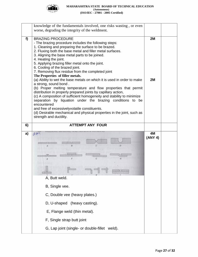
A, Butt weld.
B, Single vee.
C, Double vee (heavy plates.)
D, U-shaped (heavy casting).
E, Flange weld (thin metal).
F, Single strap butt joint
G, Lap joint (single- or double-fillet weld).
4M (ANY 4)

MAHARASHTRA STATE BOARD OF TECHNICAL EDUCATION (Autonomous)
(ISO/IEC - 27001 - 2005 Certified)
Page 28 of 32
H, Joggled lap joint (single or double weld,
I, Tee joint (fillet welds).
J, Edge weld (used on thin plates).
K, Corners weld metal).
L, Plug or rivet butt joint
b)
An Electrode is a piece of wire or a rod (of a metal or alloy), with or without flux covering, which carries current for welding. At one end it is gripped in a holder and an arc is set up at the other
1M
3M
c)
Arc welding is a type of welding that uses a welding power
supply to create an electric arc between an electrode and the
base material to melt the metals at the welding point. They
can use either direct (DC) or alternating (AC) current, and
consumable or non-consumable electrodes. The welding
region is usually protected by some type of shielding gas,
vapor, or slag. Arc welding processes may be manual, semi-
automatic, or fully automated. First developed in the late part
of the 19th century, arc welding became
Advantages:-
Higher welding speeds
2) Greater deposition rates
3) Less post welding cleaning (e.g. no slag to chip off weld)
4) Better weld pool visibility
1M
1.5 M

MAHARASHTRA STATE BOARD OF TECHNICAL EDUCATION (Autonomous)
(ISO/IEC - 27001 - 2005 Certified)
Page 29 of 32
5) No stub end losses or wasted man hours caused by
changing electrodes
6) Low skill factor required to operate M.I.G / M.A.G.S welding
torch
7) Positional welding offers no problems when compared to
other processes. (Use dip or pulsed mode of transfer)
8) The process is easily automated
Limitations:-
1)Higher initial setup cost
2) Atmosphere surrounding the welding process has to be
stable (hence the shielding gasses), therefore this process is
limited to draught free conditions
3) Higher maintenance costs due to extra electronic
components
4) The setting of plant variables requires a high skill level
5) Less efficient where high duty cycle requirements are
necessary
6) Radiation effects are more severe
1.5M
d) -Soldering is a common process for joining steel, copper and other materials at a low temperature. - Soldering is defined as a group of joining processes wherein coalescence is produced by heating to a suitable temperature and by using a filler metal having a liquidus not exceeding 800 F (427°C) and below the solidus of the base metals. The filler metal (i.e., the solder) is usually distributed between the properly fitted surfaces of the joint by capillary attraction
Advantages:- Since soldering does not melt the base metal of the joint, it allows much tighter control over tolerances and produces a clean joint without the need for secondary finishing. Additionally, dissimilar metals and non-metals (i.e. metalized ceramics) can be brazed In general, soldering also produces less thermal distortion than welding due to the uniform heating of a soldered piece. Complex and multi-part assemblies can be brazed cost-effectively.
2M
1M

MAHARASHTRA STATE BOARD OF TECHNICAL EDUCATION (Autonomous)
(ISO/IEC - 27001 - 2005 Certified)
Page 30 of 32
Limitations:- 1)Size limitation of the parts to be SOLDERED is of major importance. since area to be brazed must be heated, large cast sections or large heavy plates cannot be easily brought up to temperature. 2. Soldering requires tightly mating parts to ensure capillary flow of the filler metal. This involves expensive machining to attain the desired fit. 3. Flux residues if not properly removed can cause corrosion. 4. Soldered joints do not give satisfactory results when used at elevated temperatures.
5. A certain degree of skill is required to perform the soldering
1M
e) TORCH BRAZING - Torch brazing is the most versatile method and it finds wide application in industry in both fabrication and repair work. - Heat is usually provided by ordinary gas welding equipment by burning gas combinations such as air and acetylene, oxygen and acetylene, oxygen and hydrogen and air and propane. - Air-gas torches provide the lowest flame temperature as well as the least heat, depending on the size of the torch. Oxy-hydrogen torches are often used for brazing aluminium and other non-ferrous alloys. - To braze, the operator plays the torch flame (which is neutral or slightly reducing) on the thoroughly cleaned parts, being careful to heat the heavier sections first. A flux is applied to the joint area to prevent oxidation of the parts during heating. As the flux becomes molten, it cleans the joint area of oxides etc., and prepares the surfaces for wetting by the filler metal. The filler metal is then hand-fed to the joint area as soon as the joint is up to the brazing temperature. - In many cases filler rods instead of being hand-fed,are preplaced in the form of a ring, washer, or insert to fit the contour of the joint. - Commonly used filler metals need a joint clearance(at brazing temperature) of 0.05 to 0.125 mm for capillary flow. Lap joints are usually preferred. - To bring all members of the assembly to brazing temperature at the same time, torch may be directed more on the heavier member or on the member having greater thermal conductivity. Another method to achieve uniform heating in torch brazing is the employment of multi1lamc torches. Advantages (i) Initial cost of equipment is low. (ii) Localized healing can be obtained. (iii) It is a very flexible process. Disadvantages (i) The method is relatively slow. (ii) Flame cannot be easily applied to assemblies with inaccessible joints. Applications
2M
1M

MAHARASHTRA STATE BOARD OF TECHNICAL EDUCATION (Autonomous)
(ISO/IEC - 27001 - 2005 Certified)
Page 31 of 32
1. Torch brazing can be used to join ferrous and non-ferrous metals, for maintenance as well as fabrication purposes)
1M
f) Welding Processes 1. Oxy-acetylene Welding - The type of filler rod employed depends upon the mechanical properties required. A high tensile steel rod will prove effective. For corrosion resistance, etc., the weld metal must match with the parent metal. - A flux is used to counteract the oxidation of alloying elements. - After welding, a post heat-treatment is necessary for the heat treatable low-alloy steels to refine the grain structure.
OR 2. Flux-shielded Metal Arc Welding - Mild steel electrodes will work very well with steels having a Carbon content under 0.14%. Weld develops tensile strength as high as 80,000 psi (5600 kg/cm") as the result of alloy pick-up from the base steel. - Where higher strength at better ductility is desired, low alloy steel electrodes may be required. Because of greater crack sensitivity of the low alloy steel electrodes, preheating may be necessary. - Where corrosion is a factor, it may be advisable to use core wires of the same composition as the base steel. - Given below are the recommendations for welding some typical low alloy high strength steels.
OR 3. Submerged Arc Welding - Both hot rolled and heat -treated grades of low-alloy steels are welded by using the method very similar to that used for welding low carbon steels.. - Because of deep penetration characteristics of this process, mild steel filler rods are usually satisfactory. - Preheating is generally not necessary.
OR 4. Thermit Welding - Low alloy high strength steels can be thermit-welded. Metallic elements are added to the thermit mixture to obtain composition close to that of the parent metal. Metallic elements are added either as metallic pieces or in the form of combinations of oxides of the required elements with aluminium. Stress-relieving heat-treatments, when required, should be carried out between 595 and 675°C.
OR 5. Resistance Spot Welding - Spot welding can be carried out satisfactorily. For alloys having high hardenability, special treatments such as preheating, grain refinement and tempering heat-treatments may be incorporated in the welding cycle.
4M

MAHARASHTRA STATE BOARD OF TECHNICAL EDUCATION (Autonomous)
(ISO/IEC - 27001 - 2005 Certified)
Page 32 of 32


