Embed Size (px)
Citation preview

12-PULSE RECTIFIER WITH TWO DCM BOOST-TYPEHALF-CONTROLLED BRIDGES FOR VARIABLE-INPUT-FREQUENCY
APPLICATIONS
João Carlos Pelicer Junior1, Angelo César de Lourenço2, Luis De Oro Arenas3, Falcondes Mendes deSeixas4
1Federal Institute of São Paulo - IFSP, Sorocaba - SP, Brazil2Federal Institute of Education, Science, and Technology of Mato Grosso do Sul, Campo Grande - MS, Brazil
3São Paulo State University, Institute of Science and Technology of Sorocaba, Sorocaba - SP, Brazil4São Paulo State University, Ilha Solteira - SP, Brazil
e-mails: [email protected], [email protected], [email protected], [email protected]
Abstract – This paper presents the analysis of theintegration of two three-phase half-controlled boostconverters, operating in discontinuous conduction mode(DCM), to the auto-connected 12-pulse rectifier. Theproposed structure shows a reduced current harmoniccontent compared to the traditional 12-pulse rectifiers,being a simpler and effective alternative to using rectifierswith higher pulse numbers. It also presents a greaterrange of possibilities for regulating the output voltage,without the use of synchronization algorithms or rigorouscontrol techniques, being possible to send to all controlledswitches, the same command signal, resulting in asimpler logic. Another advantage of using the proposedtechnique is the employment of a single-loop voltagecontrol scheme, reducing the computational and financialcost by eliminating some elements such as currentsensors. Moreover, the proposed strategy provides softcommutations (Zero-Current-Switching - ZCS). In thiswork, a small-scale prototype was implemented, aiming toobtain a structure capable to operate in a wide range ofline frequencies, without requiring any additional complextechniques. In this regard, the developed structure iscapable to work as a Power Factor Correction (PFC) stagein a wide range of input frequencies (30Hz - 120Hz) with aTotal Harmonic Distortion of the input current (THDi) ofless than 2.19%.
Keywords – Boost Converter, Discontinuous ConductionMode (DCM), High Power Factor, MEA, MultipulseConverter, Half-Controlled, Frequency Variations.
I. INTRODUCTION
Currently, three-phase AC/DC converters have a widerange of applications for high power systems, such asadjustable-speed drive (ASD), all-electric ships (AES), datacenters, power supply for aircraft, wind power plants and,applications in direct current transmission, induction heating,among others. The AC/DC conversion process can be carriedout using several techniques and equipment, however, for thisprocess not to lead to the degradation of the Power Factor (PF),
Manuscript received 05/17/2021; first revision 09/19/2021; accepted forpublication 11/01/2021, by recommendation of Editor Demercil de SouzaOliveira Jr. http://dx.doi.org/10.18618/REP.2021.4.0011
standards are established to maintain the power quality of thegrid [1], [2].
Among the methodologies employed in Power FactorCorrection (PFC), to attend to these power qualityrequirements, are the use of transformers/autotransformerwith phase shift associated to bridge rectifiers, which areknown as Multipulse Converters [3]–[6]. The main idea ofthe use of these converters is to take advantage of the angulardisplacement, provided by the transformers/autotransformersso that the cancellation of certain harmonic componentsoccurs. In general, it is observed that the higher the orderof the Multipulse Converters, the lower the characteristicharmonic content of the structure. However, this changeusually implies a greater complexity in the transformers’winding construction, as well as greater weight and volume ofthe final structure.
A possible alternative, in order to avoid the employmentof transformers with higher orders, and consequently havingmore complex windings, is the integration of an activestructure, such as a half-controlled (also known as bridgeless)converter (HCC) based on Boost topology, to the traditional12-pulse rectifier, which allows minimizing the harmoniccontent presented by the structure and reducing the numberof elements conducting in each operation stage [7]. Thisintegration aggregates greater flexibility in the adjustment ofthe output voltage, which changes not only according to themagnitude of the grid voltage, but also to the duty cycle (D) ofthe converter and, because it does not employ two controlledswitches on the same branch it does not incur the risk of a shortcircuit on it, making its control and operation simpler.
Although this integration adds some advantages, evenwith great efforts because of the use of control techniquesand synchronization algorithms (PLL), it was verified, thedifficulty in order to shape a sinusoidal waveform to thecurrent signal [8]–[10].
During the design stage of the HCCs structures, two mainstrategies are possible: Operate in continuous conductionmode (CCM) or discontinuous conduction mode (DCM).Choosing the operation mode of the converter to beincorporated is of paramount importance in the specificationsof its parameters. In this manner, it is observed that theoperation in CCM entails great difficulties in modulating thenegative half-cycle of the current, which results not only insignificant Total Harmonic Distortion of the input current

Van
Vbn
Vcn
Wye Autotransformer(step-down)
Half-Controlled Converter 1
Half-Controlled Converter 2
LPF
ir1
ir2
iR1
a
b
c
vR1
vS1
vT1
vR2
vS2
vT2
iR2
LPF
Lin
Lin
C VoR
is1iS1it1iT1
is2iS2it2iT2
ia
ib
ic
* LPF= Low-Pass Filter
SR1 SS1 ST1
SR2 SS2 ST2
DR2 DS2 DT2
DR1 DS1 DT1
La
LcLb
La2
Lb2
Lc2
La1
Lc1
Lb1
VT1
VS1
VR1VR2
VT2
VS2
15°15°
Vc2
Van
VR2
Wye Autotransformer Representation
15°
105°
Fig. 1. Proposed 12-pulse converter with two embedded HCC.
Fig. 2. Operation sectors.
(THDi) but also in the presence of even-order harmoniccomponents. This set of characteristics hinders the mitigationof harmonic content and requires a control circuit of greatercost and complexity [8].
The option of operating in the DCM, in turn, presents afavourable characteristic for applying active correction of thepower factor: At the end of the switching period, all the energystored in the inductor is supplied to the load, so that the peakvalue of the current over the inductor will be proportional tothe applied voltage. In other words, the peak of input currentnaturally tends to follow the input voltage in the discontinuousconduction mode and the switch will begin to conduct with thecurrent value equals to zero, i.e., it will present the ZCS (ZeroCurrent Switching) characteristic, reducing the switching loss.
The incorporation of the HCC operating in the DCM tothe traditional 12-pulse rectifier allows taking advantage of theangular displacement, canceling the most significant harmoniccomponents presented by the structure (5th and 7th) in thismode of conduction [9], as well as to reduce the complexityof the control circuit, making possible the operation even inan open-loop, commanding all active switches by the same
control signal [11].The 12-pulse converter with two embedded HCC, shown
in Fig. 1, presented in computational analysis a THDi of1.73%, significantly below the 14% reported by the onewithout the active switches, which allows concluding thatthe incorporation of HCC can be an alternative to increasethe order of pulses, resulting in harmonic content reduction,without incurring a significant increase in the weight, volumeand complexity of the final structure [11]. In general, theoperation in DCM has the dealing with higher values of peakcurrent in the switches as a downside [12], [13]. The proposedstructure, on the other hand, by employing six branches,divides the current stress among each one of them, makingthe operation in DCM a suitable solution.
The replacement of pneumatic, hydraulic, and mechanicalsystems with electrical systems has been a trend in moreelectric aircraft (MEA) and can provide a weight reductionup to 10% and a consumption reduction of up to 9%[14]–[16]. The MEA concept has required equipment tooperate at growing powers and that are reliable, safe, providesgood performance and can operate in faulty conditions [15].Another challenge provided by applications such as MEA liesin the fact of dealing with a wide range of power frequencyvariation (360 - 800 Hz) [14]. Similarly, in wind turbines(WECS), although it is possible to operate in fixed frequencies,those that can operate in the whole range (0 - 100%) obtainbetter efficiency rates in the conversion of wind energy intoelectrical energy [17].
This paper aims to continue the research proposed by [11],by implementing a small-scale prototype and pushing the stateof art further, adding the analysis of the impact of powersupply frequency variations (30Hz - 120Hz) in the inputcurrent waveform. The possibility of working in a wider rangeof power supply frequencies combined with its structuraladvantages make the 12-pulse HCC-embedded converter moreattractive for applications with higher requirements for inputcurrent harmonic content, meeting, for example, the THDi

Fig. 3. 12-Pulse Autotransformer vs 12-Pulse Transformer (Size).
criteria established in MIL-STD-704F (for aircraft) [14], [18].Additionally, it is worth mentioning that the usage of anautotransformer configuration, instead of a transformer, makespossible a significant reduction of the size and weight ofthe final structure since it processes around one-fifth of totalmagnetic flux processed by the isolated transformer [19]. InFig. 3 is shown the comparison between the sizes of theautotransformer (analyzed in this paper) and a transformer,both designed to operate at the same output power.
II. PROPOSED 12-PULSES CONVERTER WITH 2-HCCS
In this section the main considerations for the designof the 12-pulse converter with two embedded HCC arepresented. As commented, when the proposed structureoperates in discontinuous conduction mode provides a seriesof advantages, once at each end of switching period all theenergy stored in the inductor is transferred to the load, i.e.,by employing a fixed duty cycle and a switching frequency,significantly greater than grid’s voltage frequency, the inductorpeak current will be proportional to its voltage, allowing thestructure to act as a PFC device without the need for anycurrent control circuitry or current sensing.
In this regard, so as to properly design a converter,it is necessary to address two main issues: Specify theinductor value to guarantee the discontinuous conductionmode; Comprehend the operation stages of the converter.Among the elements that constitute the proposed converteris the twelve-pulses phase shift autotransformer, at lowkVA rating, responsible to provide two sets of three-phasesecondary windings, displaced by 30o from each other, asshown in Fig. 1. The proposed structure takes advantage ofthe phase shift provided by this autotransformer to cancel thelower order current harmonics (5th and 7th) on the primaryside.
Once the phase-shift, provided by the 12-pulseautotransformer, cancels the lower order harmonics, thelow-pass filters (L fC f ) shown in Fig. 1, have a cutofffrequency equals to one-tenth of the switching frequency ( fs),being responsible to cancel the switching harmonics, makingpossible to reduce the size of its elements. Thus, the set ofvoltages that supply both HCC structures are shown in Fig. 2,resulting in 12 cyclically repeated operating sectors (I - XII).
By analyzing the Fig. 2 (Operation sectors), one shouldnotice that each one of the sectors is delimited by one crossing
voltage, e.g., the transition from Sector X to Sector XI isdelimited by vT 2 crossing from a positive value to a negativeone. Once each one of these sectors has its own operationstages, which significantly increases the total number of stagesof this structure. For a better understanding of how thesecondary voltages affect the operation stages, let us takeSector X as an example.
Thus, the following analysis presents two transition stagesnamed as "beginning" (transition between Sectors IX and X)and "ending" (transition between sectors X and XI), and thethird stage in which all voltages in the secondary windinghave a non-null value, named as "Sector X". This analysisneglected the small variations on the secondary voltage duringthe switching period (Ts).
Beginning: During the charging stage (DTs) show inFig. 4(a), although the same control signal was sent to allcontrolled switches (same control signal to both HCC1 andHCC2), the voltage vT 1 has null voltage during this stage,resulting in a null current in the elements connected to itsbranch. Thus, the charging stage for HCC1 will happenas follows: The switch SR1 is directed polarized and hasreceived the control signal, making a positive current flowingthrough LR1, and returning through LS1. With regard to HCC2the voltages vR2 and vT 2 are positive, making respectivelyswitches SR2 and ST 2 directed polarized and two currents ir2and it2 flowing through these switches and returning by thediode connected to LS2, which is connected to a secondarywinding having a negative voltage.
During the discharging stage, all energy stored in theinductors will be transfer to the load, and the output capacitor(C). The equivalent circuitry for this stage is shown in Fig.4(b). Once the energy stored in the inductors is transferred, adead time will occur as shown in Fig. 4(g).
During Sector X: During this stage, all secondarywindings have a non-null voltage, i.e., every branch of bothHCC’s will have one semiconductor (controlled switch ordiode) conducting during the charging stage (DT ), whoseequivalent circuitry is shown in Fig. 4(c), and its dischargingstage is shown in Fig. 4(d). Once the proposed converteroperates in DCM, analogously to the previous case, after thedischarging stage, all inductors will have null current and itscircuitry will be as shown in Fig. 3(g).
Ending: At the ending stage, the vT 2 voltage has anull-value therefore, the HCC2 will present a behaviorlikewise the one present by HCC1 at "the beginning", havingthree operational stages shown in Fig. 4(e)-(g). By analyzingFig. 2 (Operation sectors) it is possible to evaluate themoments when each HCC structure is subject to the maximumvoltage (line voltage) and, once it acts as a PFC, when itis subject to the maximum current, providing means to thedesigner to specify the inductor present on them.
Taking the transition between Sector VI to VII, the vT 1voltage is in its maximum value and both vR1 and vS1 havethe same value and opposite signal of vT 1, thus the equivalentcircuitry for the charging stage (DTs) for those conditionsis shown in Fig. 5(a). Additionally, by neglecting thenon-idealities of the switches, one should obtain the equivalentcircuit shown in Fig. 5(b), where an equivalent inductance(Lboost ) for an HCC, under these conditions, may be expressed

iR2iS2iT2
iR2iS2iT2
iR2iS2iT2
Half-Controlled Converter 1
Half-Controlled Converter 2
(d)
Half-Controlled Converter 1
Half-Controlled Converter 2
(e)
Half-Controlled Converter 1
Half-Controlled Converter 2
(f)
iR1iS1iT1
iR1iS1iT1
iR1iS1iT1
iR1iS1iT1
iR1iS1iT1
iR1iS1iT1
ir2is2it2
ir2is2it2
ir2is2it2
ir2is2it2
ir2is2it2
ir2is2it2
RC
RC
RC
Half-Controlled Converter 1
Half-Controlled Converter 2
(b)
Half-Controlled Converter 1
Half-Controlled Converter 2
ir1is1it1
(a)
Half-Controlled Converter 1
Half-Controlled Converter 2
(c)
ir1is1it1
ir1is1it1
RC
RC
RC
Half-Controlled Converter 1
Half-Controlled Converter 2
C
(g)
ir1is1it1
ir1is1it1
ir2is2it2
ir2is2it2
Half-Controlled Converter 1
Half-Controlled Converter 2
RC
(g)
ir1is1it1
ir2is2it2
DS1DR1 DT1 DS2DT2 DR2
SS1SR1 ST1 SS2ST2 SR2
DS1DR1 DT1 DS2DT2 DR2
SS1SR1 ST1 SS2ST2 SR2
DS1DR1 DT1 DS2DT2 DR2
SS1SR1 ST1 SS2ST2 SR2
DS1DR1 DT1 DS2DT2 DR2
SS1SR1 ST1 SS2ST2 SR2
DS1DR1 DT1 DS2DT2 DR2
SS1SR1 ST1 SS2ST2 SR2
DS1DR1 DT1 DS2DT2 DR2
SS1SR1 ST1 SS2ST2 SR2
DS1DR1 DT1 DS2DT2 DR2
SS1SR1 ST1 SS2ST2 SR2
Fig. 4. Simplified operation stages for X Sector.
(a)
(b)
RCo
vR1
vS1
vT1
it1
is1
ir1
RCo
vR1
vS1
vT1
vR1
vT1
vS1
Lin Lin
Lin
Vcenter
vR1
vT1
vS1
Lin Lin
Lin
Vcenter
SR1 SS1 ST1
DR1 DS1 DT1
Fig. 5. Charging state (DT) in Sector X: (a) Equivalent Circuit; (b)Simplified Circuit.
as follows in (1).
Lboost =32
Lin (1)
Once this converter operates as a PFC, the current in eachinductor is proportional to the voltage applied to it, makingthe instant of maximum voltage also the instant of maximumcurrent. Considering the set of voltages supplying bothHCC’s, and the characteristics described, the currents in theinductors will follow (2) and (3).
ir1 (t)+ is1 (t)+ it1 (t) = 0 (2)
ir2 (t)+ is2 (t)+ it2 (t) = 0 (3)
Even so, to providing flexibility in the regulation of theoutput voltage (by adjusting the duty cycle), the proposalof the structure also adds the possibility of using a verysimpler control logic, to deal with power supply frequencyvariations, although this does not imply a compulsoryrequirement. Among the possible logic, the same pulse(without any discrepancies) can be sent to all active switches,simultaneously, with no degradation of the input currentparameters.
To design the inductors, first, it is desirable to understandhow the operation steps of the converter are obtained.Considering the characteristics of the power system, theconverter features 12 cyclically repeating sectors, as shownin Fig. 2, each one enabling a set of operation steps, that areshown in Fig. 4.
The delimitation of the sectors is given when there is thereverse direction of one of the voltages that occurs in thesecondary winding. The sectors are listed sequentially fromI to XII. It should noticed that the switching period Ts is muchsmaller than a given sector duration (e.g. Sector X), thus thestages of a converter working in DCM will be seen multipletimes in every given sector.
Another important issue is that the value of the voltagevaries during the sectors, e.g., voltage VT 2 starts with a positivevalue, at the beginning of Sector X, and at the end has its valueequal to zero, which add more possible operation steps (like

Fig. 6. Experimental set-up.
the ones shown in Fig. 4) in this sector.Considering the number of sectors, to analyze the operation
steps, Sector X was taken as an example. By analyzing thesteps (a) to (g) presented in Fig. 4, a good understanding ofthe converter operation is obtained. It should be noted that theconverter acts as PFC, so the voltage vR1 and the envelope ofthe current ir1 have the same phase.
To properly specify the inductors for the set of cyclicallyrepeated conditions, one should consider two main issues:The maximum line voltage applied to the HCC’s (VLpk ) andthe peak value of inductor current (Ipk). The parameter α
is determined by the quotient between the peak value of linevoltage (VLpk ) with the output voltage (Vo) as shown in (4):
α =VL pk
Vo(4)
During the charging stage, each HCC is compound by aset of three inductors that will be storing energy. To ensurethat they will operate in DCM, the design of the inductancemust consider the maximum value of the current in this set ofinductors. Thus, the inductance Lin must obey (5).
Lin <23
VL pk2
2π fsPo2
(1−α)2
α
√3(
Yo (α)2)
(5)
Where Po is the output power, fs is the switching frequencyand the Yo is determined by (6).
Y0 (α) =−2− π
α+
2α√
1−α2
(π
2+ tan−1
(α√
1−α2
))(6)
III. EXPERIMENTAL RESULTS
Some power applications, such as MEA (More ElectricAircrafts), must deal with a wide range of power supplyfrequencies at the same time they have to meet to the THDistandards. Having these criteria into account, this section aimsto verify if the proposed structure presents itself as a suitablesolution for applications which requires the possibility to deal
with a wide range of power supply frequencies.For this analysis, the reference was made to an application
in which the input frequency varies over a wide range ofvalues. A small-scale prototype was made, shown in Fig. 6,operating in the power supply voltage range from 30Hz to120Hz. The main parameters of the analyzed converter areshown in Table I.
TABLE IMain parameters for the frequency variation analysisParameter ValueC - Output capacitor 100 µFC f - Low-pass filter capacitance 3.3 µFL f - Low-pass filter inductance 2 mHfin - Input frequency range 30 - 120 Hzfs - Switching Frequency 20 kHzLin - HCC Inductor 200 µHP - Load power 800 WR - Equivalent load resistance 200 Ω
Po - Nominal output power 1400 WAutotransformer Step-down factor 0.896Vi - Supply rms phase voltage 84 VACVo - Output voltage 400 VDCD - Nominal duty cycle 0.33Branch switches model SK 35 GAL
The proposal converter employs a Wye step-downautotransformer (auto-connected), which supplies the HCCbridges with 127V (rms line voltage). To verify the behaviorof the proposed structure under power frequency variations,all the results presented in Figs. 7(a)-(e) employed an 800Wload and are displayed at the same time basis, making easierthe comparison between the displayed cases.
By analyzing Figs. 7(a)-(g) and the detail presented inFig. 7(f), one can see that the structure was able to actas PFC, i.e., the line current presents the waveform veryclose to a sinusoidal shape (voltage waveform), maintainingits symmetry and appropriate phase displacement, withoutrequiring any adjustment on its parameters (same set-up for

Fig. 7. Main waveforms of at the grid side, for different input frequency. vcn (yellow), ia (red), ib (blue), ic (green): (a) 30Hz; (b) 45 Hz; (c) 60Hz; (d) 75 Hz; (e) 120Hz; ( f ) Detail of the 120 Hz waveforms.
all cases).Due to its characteristics, the proposed converter did not
require the use of any current loop control, neither requiredany phase displacement between pulses. In this regard, theemployed control strategy is based on a single-loop voltagecontrol, where the control-to-output transfer function Gvd ofthe proposed structure can be approximated to the traditionalthree-phase Boost converter transfer function operating inDCM, as described by (7).
Gvd(s) =Gvd0
1+ sωp
(7)
where
Gvd0(s) =2Vo
D
(M−1
2M−1
)(8)
ωp =2M−1
(M−1)RC(9)
and M is the static gain in DCM, expressed by (10).
M =1+√
1+ 4RD2
fsLboost
2(10)
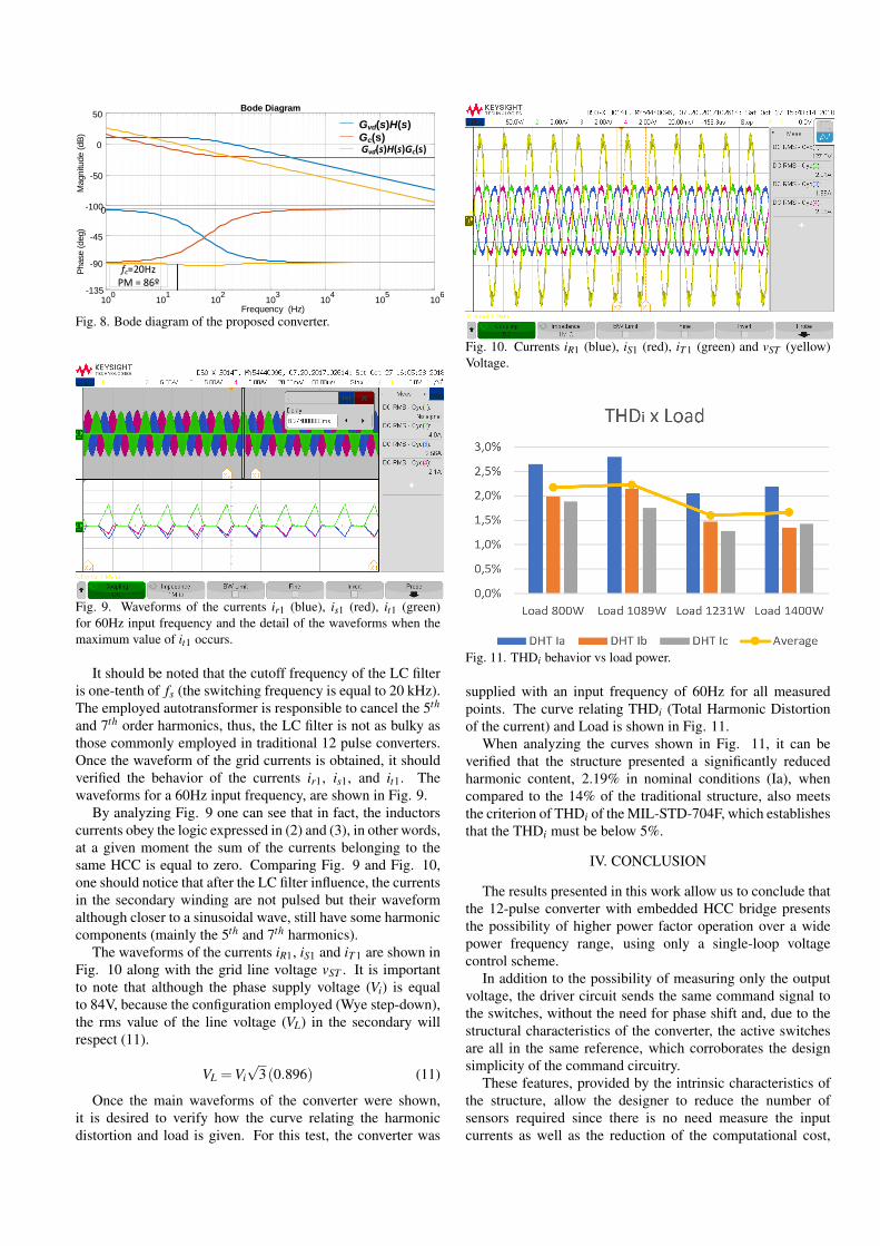
Thus, from Table I, the bode diagram of the transferfunction Gvd , including the gain sensor H = 2.5/400 V/V, isillustrated in Fig. 8 (curve blue in color). Then, a PI controllerwas adopted for the control design and, as shown in Fig. 8(yellow in color), by using a proportional gain Kp=0.09 andan integral gain Ki=38.34, a crossover frequency fc = 20Hzand phase margin PM=86° are achieved from the open-loopvoltage control.
-100
-50
0
50
Magnitu
de
(dB
)
100
101
102
103
104
105
106-135
-90
-45
0
Phase
(deg)
Bode Diagram
Frequency (Hz)
Gvd(s)H(s)Gc(s)Gvd(s)H(s)Gc(s)
fc=20HzPM = 86º
Fig. 8. Bode diagram of the proposed converter.
Fig. 9. Waveforms of the currents ir1 (blue), is1 (red), it1 (green)for 60Hz input frequency and the detail of the waveforms when themaximum value of it1 occurs.
It should be noted that the cutoff frequency of the LC filteris one-tenth of fs (the switching frequency is equal to 20 kHz).The employed autotransformer is responsible to cancel the 5th
and 7th order harmonics, thus, the LC filter is not as bulky asthose commonly employed in traditional 12 pulse converters.Once the waveform of the grid currents is obtained, it shouldverified the behavior of the currents ir1, is1, and it1. Thewaveforms for a 60Hz input frequency, are shown in Fig. 9.
By analyzing Fig. 9 one can see that in fact, the inductorscurrents obey the logic expressed in (2) and (3), in other words,at a given moment the sum of the currents belonging to thesame HCC is equal to zero. Comparing Fig. 9 and Fig. 10,one should notice that after the LC filter influence, the currentsin the secondary winding are not pulsed but their waveformalthough closer to a sinusoidal wave, still have some harmoniccomponents (mainly the 5th and 7th harmonics).
The waveforms of the currents iR1, iS1 and iT 1 are shown inFig. 10 along with the grid line voltage vST . It is importantto note that although the phase supply voltage (Vi) is equalto 84V, because the configuration employed (Wye step-down),the rms value of the line voltage (VL) in the secondary willrespect (11).
VL =Vi√
3(0.896) (11)
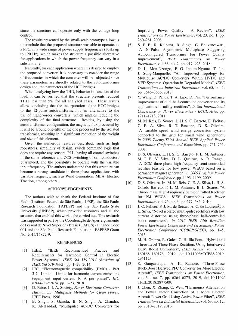
Once the main waveforms of the converter were shown,it is desired to verify how the curve relating the harmonicdistortion and load is given. For this test, the converter was
Fig. 10. Currents iR1 (blue), iS1 (red), iT 1 (green) and vST (yellow)Voltage.
Fig. 11. THDi behavior vs load power.
supplied with an input frequency of 60Hz for all measuredpoints. The curve relating THDi (Total Harmonic Distortionof the current) and Load is shown in Fig. 11.
When analyzing the curves shown in Fig. 11, it can beverified that the structure presented a significantly reducedharmonic content, 2.19% in nominal conditions (Ia), whencompared to the 14% of the traditional structure, also meetsthe criterion of THDi of the MIL-STD-704F, which establishesthat the THDi must be below 5%.
IV. CONCLUSION
The results presented in this work allow us to conclude thatthe 12-pulse converter with embedded HCC bridge presentsthe possibility of higher power factor operation over a widepower frequency range, using only a single-loop voltagecontrol scheme.
In addition to the possibility of measuring only the outputvoltage, the driver circuit sends the same command signal tothe switches, without the need for phase shift and, due to thestructural characteristics of the converter, the active switchesare all in the same reference, which corroborates the designsimplicity of the command circuitry.
These features, provided by the intrinsic characteristics ofthe structure, allow the designer to reduce the number ofsensors required since there is no need measure the inputcurrents as well as the reduction of the computational cost,
since the structure can operate only with the voltage loopcontrol.
The results presented by the small-scale prototype allow usto conclude that the proposed structure was able to operate, asa PFC, in a wide range of power supply frequencies (30Hz upto 120 Hz), which makes the structure a possible alternativefor applications in which the power frequency can vary in asubstantially.
Naturally, for each application where it is desired to employthe proposed converter, it is necessary to consider the rangeof frequencies in which the converter will be subjected sincethese parameters are directly related to the autotransformerdesign and, the parameters of the HCC bridges.
When analyzing how the THDi behavior in function of theload, it can be verified that the structure presents reducedTHDi less than 5% for all analyzed cases. These resultsallow concluding that the incorporation of the HCC bridgesto the 12-pulse autotransformer, is an alternative to theuse of higher-order converters, which implies reducing thecomplexity of the final structure. Besides, by using theautotransformer configuration, the magnetic flux processed byit will be around one-fifth of the one processed by the isolatedtransformer, resulting in a significant reduction of the weightand size of this element.
Given the numerous features described, such as highrobustness, simplicity of design, switch command logic thatdoes not require any sensors, PLL, having all control switchesin the same reference and ZCS switching of semiconductorsguaranteed, and the possibility to operate with the variableinput frequency. The authors understand that this structure canbecome a strong candidate in three-phase applications withvariable frequency, such as Wind Generation, MEA, ElectricTraction, among others.
ACKNOWLEDGEMENTS
The authors wish to thank the Federal Institute of SãoPaulo (Instituto Federal de São Paulo - IFSP), the São PauloResearch Foundation (FAPESP) and the São Paulo StateUniversity (UNESP), which provided resources and all thestructure that enabled this work to be carried out. This researchwas supported in part by the Coordenação de Aperfeiçoamentode Pessoal de Nível Superior - Brasil (CAPES) - Finance Code001 and the São Paulo Research Foundation - FAPESP GrantNo. 2015/15872-9.
REFERENCES
[1] IEEE, “IEEE Recommended Practice andRequirements for Harmonic Control in ElectricPower Systems”, IEEE Std 519-2014 (Revision ofIEEE Std 519-1992), pp. 1–29, 2014.
[2] IEC, “Electromagnetic compatibility (EMC) - Part3-2: Limits - Limits for harmonic current emissions(equipment input current 16 A per phase)”, IEC61000-3-2:2018, pp. 1–73, 2018.
[3] D. Paice, I. I. A. Society, Power Electronic ConverterHarmonics: Multipulse Methods for Clean Power,IEEE Press, 1996.
[4] B. Singh, S. Gairola, B. N. Singh, A. Chandra,K. Al-Haddad, “Multipulse AC-DC Converters for
Improving Power Quality: A Review”, IEEETransactions on Power Electronics, vol. 23, no. 1, pp.260–281, 2008.
[5] S. P. P., R. Kalpana, B. Singh, G. Bhuvaneswari,“A 20-Pulse Asymmetric Multiphase StaggeringAutoconfigured Transformer For Power QualityImprovement”, IEEE Transactions on PowerElectronics, vol. 33, no. 2, pp. 917–925, 2018.
[6] D. L. Mon-Nzongo, P. G. Ipoum-Ngome, T. Jin,J. Song-Manguelle, “An Improved Topology forMultipulse AC/DC Converters Within HVDC andVFD Systems: Operation in Degraded Modes”, IEEETransactions on Industrial Electronics, vol. 65, no. 5,pp. 3646–3656, 2018.
[7] Y. Wang, D. Panda, T. A. Lipo, D. Pan, “Performanceimprovement of dual-half-controlled-converter and itsapplications in utility rectifiers”, in 8th InternationalConference on Power Electronics - ECCE Asia, pp.1711–1718, 2011.
[8] M. M. Reis, B. Soares, L. H. S. C. Barreto, E. Freitas,C. E. A. Silva, R. T. Bascope, D. S. Oliveira,“A variable speed wind energy conversion systemconnected to the grid for small wind generator”,in 2008 Twenty-Third Annual IEEE Applied PowerElectronics Conference and Exposition, pp. 751–755,2008.
[9] D. S. Oliveira, L. H. S. C. Barreto, F. L. M. Antunes,M. I. B. V. Silva, D. L. Queiroz, A. R. Rangel,“A DCM three-phase high frequency semi-controlledrectifier feasible for low power WECS based on apermanent magnet generator”, in 2009 Brazilian PowerElectronics Conference, pp. 1193–1199, 2009.
[10] D. S. Oliveira, Jr., M. M. Reis, C. E. A. Silva, L. H. S.Colado Barreto, F. L. M. Antunes, B. L. Soares, “AThree-Phase High-Frequency Semicontrolled Rectifierfor PM WECS”, IEEE Transactions on PowerElectronics, vol. 25, no. 3, pp. 677–685, 2010.
[11] J. C. Pelicer, F. J. M. de Seixas, A. C. de Lourenço,L. Silva, “Novel isolated multi-pulse rectifiers with lowcurrent distortion using three-phase half-controlledboost converters”, in 2015 IEEE 13th BrazilianPower Electronics Conference and 1st Southern PowerElectronics Conference (COBEP/SPEC), pp. 1–5,2015.
[12] M. H. Granza, R. Gules, C. H. Illa Font, “Hybrid andThree-Level Three-Phase Rectifiers Using InterleavedDCM Boost Converters”, IEEE Access, vol. 7, pp.160168–160176, 2019, doi:10.1109/ACCESS.2019.2951123.
[13] S. Gangavarapu, A. K. Rathore, “Three-PhaseBuck-Boost Derived PFC Converter for More ElectricAircraft”, IEEE Transactions on Power Electronics,vol. 34, no. 7, pp. 6264–6275, 2019, doi:10.1109/TPEL.2018.2877509.
[14] J. Chen, X. Zhang, C. Wen, “Harmonics Attenuationand Power Factor Correction of a More ElectricAircraft Power Grid Using Active Power Filter”, IEEETransactions on Industrial Electronics, vol. 63, no. 12,pp. 7310–7319, 2016.

[15] K. Rajashekara, “More Electric Aircraft Trends[Technology Leaders]”, IEEE ElectrificationMagazine, vol. 2, no. 4, pp. 4–39, 2014.
[16] J. Benzaquen, M. B. Shadmand, A. Stonestreet,B. Mirafzal, “A unity power factor active rectifier withoptimum space-vector predictive DC voltage controlfor variable frequency supply suitable for more electricaircraft applications”, in 2018 IEEE Applied PowerElectronics Conference and Exposition (APEC), pp.1455–1460, 2018.
[17] V. Yaramasu, B. Wu, P. C. Sen, S. Kouro,M. Narimani, “High-power wind energy conversionsystems: State-of-the-art and emerging technologies”,Proceedings of the IEEE, vol. 103, no. 5, pp. 740–788,2015.
[18] D. of Defense, “AIRCRAFT ELECTRIC POWERCHARACTERISTICS”, MIL-STD-704 Rev F, 2004.
[19] F. J. M. d. Seixas, Conversores CA-CC de 12KW com elevado fator de potencia utilizandoautotransformador com conexao diferencial demultiplos pulsos, Ph.D. thesis, Universidade Federalde Santa Catarina, Centro Tecnologico. Programa dePos-Graduacao em Engenharia Eletrica, 2001.
BIOGRAPHIES
João Carlos Pelicer Junior, was born in São Paulo, SP,Brazil, in 1989. He received a B.S. degree in ElectricalEngineering from São Paulo State University (UNESP) in2012, where he also obtained M.S. and Ph.D. degrees in2014 and 2019, respectively. He is currently a Professorat the Federal Institute of São Paulo (IFSP). His researchinterest includes high-power factor rectifiers, multipulseconverter applications, power factor correction, and switchingconverters.
Angelo César de Lourenço, was born in Maringá, Brazil, in1976. He received a B.S. degree in Electrical Engineeringfrom the Federal University of Mato Grosso do Sul, UFMS,Campo Grande, in 1998, the M.S. degree in ElectricalEngineering from Universidade Estadual Paulista, UNESPin 2001, where he also obtained a Ph.D. in 2016. Currentlyhe is a Professor at the Federal Institute of Mato Grosso doSul, IFMS, Campo Grande since 2010. His research interestsinclude electrical power factor correction, renewable energy,electric machines and drives.
Luis De Oro Arenas, was born in Cartagena de Indias,Colombia. He received the B.Sc. degree in electronicengineering from the National University of Colombia,Bogotá D.C, Colombia, in 2012, and the M.Sc. and Ph.D.degrees in electrical engineering from São Paulo StateUniversity (UNESP), Ilha Solteira (SP), Brazil, in 2014 and2019, respectively. He is currently a postdoctoral fellow withthe Group of Automation and Integrated Systems, São PauloState University (UNESP), Sorocaba (SP), Brazil. His currentresearch interests include power electronics, power quality,power theories, smart-metering, and microgrids.
Falcondes José Mendes de Seixas, was born in Jales, SP,Brazil. He received the B.S. degree in electrical engineeringfrom the Engineering School of Lins, Lins, Brazil, in 1988and the M.S. and Ph.D. degrees in electrical engineeringfrom the Federal University of Santa Catarina, Florianpolis,Brazil, in 1993 and 2001, respectively. He is currentlyan Assistant Professor at the Department of ElectricalEngineering, São Paulo State University (UNESP), IlhaSolteira, Brazil. His research interests include high-powerfactor rectifiers, three-state switching cell and multi-pulseconverter applications.


