Embed Size (px)
Citation preview

S-N
r. 2
4835
86 D
/GB
04/
2003
- UniTransPROFIBUS-PA
Betriebsanleitung / Manual

S-N
r. 2
4835
86 D
/GB
04/
2003
Deutsch: Seite 1
- Universal-Drucktransmitter
English: Page 77
IS Universal Pressure Transmitter

� Ex - Universaltransmitter UniTrans-PROFIBUS PAInhaltsverzeichnis
Zumutbare Änderungen aufgrund technischer Verbesserungen vorbehalten. © Copyright WIKA Alexander Wiegand GmbH & Co. KG / Germany
WIKA Alexander Wiegand GmbH & Co. KG · Alexander-Wiegand-Str. · 63911 Klingenberg · � (09372) 132 - 710 · Fax - 706 · E-mail: [email protected] · www.wika.de
2483
586
D/G
B 4
/200
3
1
Inhaltsverzeichnis
1 Allgemeine Sicherheitshinweise . . . . . . . . . . . . . . . . . . . . . . . . . . . . . 4
2 EG-Konformitätserklärung . . . . . . . . . . . . . . . . . . . . . . . . . . . . . . . . . . 5
3 Baumusterprüfbescheinigungen . . . . . . . . . . . . . . . . . . . . . . . . . . . . . 6
4 CSA-Werksbescheinigung (Kanada) . . . . . . . . . . . . . . . . . . . . . . . . . 12
5 Besondere Ex-Schutz Hinweise . . . . . . . . . . . . . . . . . . . . . . . . . . . . . 135.1 Schutz der Membran . . . . . . . . . . . . . . . . . . . . . . . . . . . . . . . . . . . . . . . 135.2 Besondere Massnahmen beim elektrischen Anschluß . . . . . . . . . . . . . 135.3 Anschluß an Zone 0. . . . . . . . . . . . . . . . . . . . . . . . . . . . . . . . . . . . . . . . 135.4 Vorkehrungen zum Einbau in Zone 0 . . . . . . . . . . . . . . . . . . . . . . . . . . 13
6 Produktbeschreibung . . . . . . . . . . . . . . . . . . . . . . . . . . . . . . . . . . . . . 146.1 Aufbau . . . . . . . . . . . . . . . . . . . . . . . . . . . . . . . . . . . . . . . . . . . . . . . . . . 146.1.1 Druckaufnehmer . . . . . . . . . . . . . . . . . . . . . . . . . . . . . . . . . . . . . . . . . . 146.1.2 Auswerteeinheit . . . . . . . . . . . . . . . . . . . . . . . . . . . . . . . . . . . . . . . . . . . 156.1.3 Anzeigeeinheit (Display) . . . . . . . . . . . . . . . . . . . . . . . . . . . . . . . . . . . . 156.2 Funktion . . . . . . . . . . . . . . . . . . . . . . . . . . . . . . . . . . . . . . . . . . . . . . . . . 166.2.1 Funktionalitäten von Geräten mit Display, oder digitaler Befehlsführung 166.3 Einsatzbeispiele . . . . . . . . . . . . . . . . . . . . . . . . . . . . . . . . . . . . . . . . . . . 17
7 Technische Daten . . . . . . . . . . . . . . . . . . . . . . . . . . . . . . . . . . . . . . . . 197.1 Physikalische Eingangs-Kenngrößen . . . . . . . . . . . . . . . . . . . . . . . . . . 197.2 Physikalische Ausgangs-Kenngrößen . . . . . . . . . . . . . . . . . . . . . . . . . . 197.3 Konstruktiver Aufbau . . . . . . . . . . . . . . . . . . . . . . . . . . . . . . . . . . . . . . . 207.4 Umgebungsbedingungen. . . . . . . . . . . . . . . . . . . . . . . . . . . . . . . . . . . . 207.5 Prozessbedingungen . . . . . . . . . . . . . . . . . . . . . . . . . . . . . . . . . . . . . . . 217.6 PROFIBUS-relevante technische Daten . . . . . . . . . . . . . . . . . . . . . . . . 217.7 Typenschild (Beispiel) . . . . . . . . . . . . . . . . . . . . . . . . . . . . . . . . . . . . . . 22
8 Montage . . . . . . . . . . . . . . . . . . . . . . . . . . . . . . . . . . . . . . . . . . . . . . . . 238.1 Montage des Drucktransmitters . . . . . . . . . . . . . . . . . . . . . . . . . . . . . . . 238.2 Nachrüsten der Anzeigeeinheit . . . . . . . . . . . . . . . . . . . . . . . . . . . . . . . 238.3 Umbau des Gehäuses . . . . . . . . . . . . . . . . . . . . . . . . . . . . . . . . . . . . . . 248.4 Elektrischer Anschluss . . . . . . . . . . . . . . . . . . . . . . . . . . . . . . . . . . . . . .258.5 Druckkompensation bei Anschluss eines Relativdrucksensors . . . . . . . 26
9 Manuelle Inbetriebnahme vor Ort von Geräten mit Anzeige . . . . . . 279.1 Die Anzeige (Display) . . . . . . . . . . . . . . . . . . . . . . . . . . . . . . . . . . . . . . 279.2 Die Tastatur und ihre Funktionen. . . . . . . . . . . . . . . . . . . . . . . . . . . . . . 289.3 Der Parametriermodus. . . . . . . . . . . . . . . . . . . . . . . . . . . . . . . . . . . . . . 289.4 Daten der Werkseinstellung. . . . . . . . . . . . . . . . . . . . . . . . . . . . . . . . . . 299.5 Hauptmenü . . . . . . . . . . . . . . . . . . . . . . . . . . . . . . . . . . . . . . . . . . . . . . 309.5.1 Hauptmenü: Anzeige . . . . . . . . . . . . . . . . . . . . . . . . . . . . . . . . . . . . . . . 319.5.2 Hauptmenü: Abgleich (Nullpunkt und Spanne) . . . . . . . . . . . . . . . . . . . 339.5.3 Hauptmenü: Ausgang . . . . . . . . . . . . . . . . . . . . . . . . . . . . . . . . . . . . . . 349.5.4 Hauptmenü: Auswertung . . . . . . . . . . . . . . . . . . . . . . . . . . . . . . . . . . . . 35

� Ex - Universaltransmitter UniTrans-PROFIBUS PAInhaltsverzeichnis
Zumutbare Änderungen aufgrund technischer Verbesserungen vorbehalten. © Copyright WIKA Alexander Wiegand GmbH & Co. KG / Germany
WIKA Alexander Wiegand GmbH & Co. KG · Alexander-Wiegand-Str. · 63911 Klingenberg · � (09372) 132 - 710 · Fax - 706 · E-mail: [email protected] · www.wika.de
2483
586
D/G
B 4
/200
3
2
9.5.5 Hauptmenü: Sprache. . . . . . . . . . . . . . . . . . . . . . . . . . . . . . . . . . . . . . . 359.5.6 Hauptmenü: Service . . . . . . . . . . . . . . . . . . . . . . . . . . . . . . . . . . . . . . . 36
10 Fehlersuche und Service . . . . . . . . . . . . . . . . . . . . . . . . . . . . . . . . . . 37
11 Entsorgung . . . . . . . . . . . . . . . . . . . . . . . . . . . . . . . . . . . . . . . . . . . . . 37
12 PROFIBUS-PA-Profil . . . . . . . . . . . . . . . . . . . . . . . . . . . . . . . . . . . . . . 3812.1 Übertragungstechnik . . . . . . . . . . . . . . . . . . . . . . . . . . . . . . . . . . . . . . . 3812.2 Einführung . . . . . . . . . . . . . . . . . . . . . . . . . . . . . . . . . . . . . . . . . . . . . . . 3812.3 Reference documents . . . . . . . . . . . . . . . . . . . . . . . . . . . . . . . . . . . . . . 3812.4 Expanded Device Type Code . . . . . . . . . . . . . . . . . . . . . . . . . . . . . . . . 38
13 Hardwarebeschreibung. . . . . . . . . . . . . . . . . . . . . . . . . . . . . . . . . . . . 3913.1 PROFIBUS-PA Hardwaretopologie . . . . . . . . . . . . . . . . . . . . . . . . . . . . 3913.2 Elektrischer Anschluss . . . . . . . . . . . . . . . . . . . . . . . . . . . . . . . . . . . . . 4013.3 Eigenschaften des PROFIBUS-PA . . . . . . . . . . . . . . . . . . . . . . . . . . . . 4013.3.1 Busanbindung . . . . . . . . . . . . . . . . . . . . . . . . . . . . . . . . . . . . . . . . . . . . 41
14 Zyklische Datenkommunikation. . . . . . . . . . . . . . . . . . . . . . . . . . . . . 4214.1 Geänderte GSD "PA_9701.GSD" . . . . . . . . . . . . . . . . . . . . . . . . . . . . . 42
15 Azyklische Dienste . . . . . . . . . . . . . . . . . . . . . . . . . . . . . . . . . . . . . . . 44
Nachfolgende Kapitel sind in englischer Sprache, gemäß der PNO-Definition!
16 Schlüsselwörter und verwendete Abkürzungen. . . . . . . . . . . . . . . . 44
17 Device Management . . . . . . . . . . . . . . . . . . . . . . . . . . . . . . . . . . . . . . 4517.1 Directory object header . . . . . . . . . . . . . . . . . . . . . . . . . . . . . . . . . . . . . 4517.2 Composite list directory entry . . . . . . . . . . . . . . . . . . . . . . . . . . . . . . . . 45
18 Standard parameters. . . . . . . . . . . . . . . . . . . . . . . . . . . . . . . . . . . . . . 4618.1 Standard parameter description . . . . . . . . . . . . . . . . . . . . . . . . . . . . . . 4618.2 Standard parameter attributes. . . . . . . . . . . . . . . . . . . . . . . . . . . . . . . . 4718.3 Standard parameter view object table . . . . . . . . . . . . . . . . . . . . . . . . . . 47
19 Physical block . . . . . . . . . . . . . . . . . . . . . . . . . . . . . . . . . . . . . . . . . . . 4819.1 Physical block parameter description . . . . . . . . . . . . . . . . . . . . . . . . . . 4819.2 Physical block manufacturer specific parameter description . . . . . . . . . 5019.3 Physical block parameter attributes. . . . . . . . . . . . . . . . . . . . . . . . . . . . 5019.4 Physical block manufacturer specific parameter attributes . . . . . . . . . . 5119.5 Physical block object . . . . . . . . . . . . . . . . . . . . . . . . . . . . . . . . . . . . . . . 5119.6 Physical block view object table . . . . . . . . . . . . . . . . . . . . . . . . . . . . . . 51
20 Transducer Block Pressure . . . . . . . . . . . . . . . . . . . . . . . . . . . . . . . . 5220.1 Pressure TB standard parameter description . . . . . . . . . . . . . . . . . . . . 5320.2 Pressure TB standard parameter attributes. . . . . . . . . . . . . . . . . . . . . . 5320.3 Pressure TB parameter description . . . . . . . . . . . . . . . . . . . . . . . . . . . . 5320.4 Pressure TB manufacturer specific parameter description . . . . . . . . . . 5520.5 Pressure TB parameter attributes . . . . . . . . . . . . . . . . . . . . . . . . . . . . . 5620.6 Pressure TB block object. . . . . . . . . . . . . . . . . . . . . . . . . . . . . . . . . . . . 58

� Ex - Universaltransmitter UniTrans-PROFIBUS PAInhaltsverzeichnis
Zumutbare Änderungen aufgrund technischer Verbesserungen vorbehalten. © Copyright WIKA Alexander Wiegand GmbH & Co. KG / Germany
WIKA Alexander Wiegand GmbH & Co. KG · Alexander-Wiegand-Str. · 63911 Klingenberg · � (09372) 132 - 710 · Fax - 706 · E-mail: [email protected] · www.wika.de
2483
586
D/G
B 4
/200
3
3
20.7 Pressure TB view object . . . . . . . . . . . . . . . . . . . . . . . . . . . . . . . . . . . . 5820.8 Assignment of dynamic variables for pressure devices . . . . . . . . . . . . . 58
21 Analog input FB 1 (pressure) . . . . . . . . . . . . . . . . . . . . . . . . . . . . . . . 6021.1 Analog input FB 1 standard parameter description . . . . . . . . . . . . . . . . 6021.1.1 Analog input FB 1 standard parameter attributes . . . . . . . . . . . . . . . . . 6021.2 Analog input FB 1 Process parameter . . . . . . . . . . . . . . . . . . . . . . . . . . 6121.3 Analog input FB 1 Alarm parameter. . . . . . . . . . . . . . . . . . . . . . . . . . . . 6121.4 Analog input FB 1 parameter attributes . . . . . . . . . . . . . . . . . . . . . . . . . 6221.5 Analog input FB 1 block object . . . . . . . . . . . . . . . . . . . . . . . . . . . . . . . 6321.6 Analog input FB 1 view object . . . . . . . . . . . . . . . . . . . . . . . . . . . . . . . . 63
22 Analog input FB 2 (Temperature) . . . . . . . . . . . . . . . . . . . . . . . . . . . . 6422.1 Analog input FB 2 standard parameter attributes . . . . . . . . . . . . . . . . . 6422.2 Analog input FB 2 Process parameter . . . . . . . . . . . . . . . . . . . . . . . . . . 6422.3 Analog input FB 2 Alarm parameter. . . . . . . . . . . . . . . . . . . . . . . . . . . . 6422.4 Analog input FB 2 parameter attributes . . . . . . . . . . . . . . . . . . . . . . . . . 6522.5 Analog input FB 2 block object . . . . . . . . . . . . . . . . . . . . . . . . . . . . . . . 6622.6 Analog input FB 2 view object . . . . . . . . . . . . . . . . . . . . . . . . . . . . . . . . 66
23 Diagnosis parameter . . . . . . . . . . . . . . . . . . . . . . . . . . . . . . . . . . . . . . 6723.1 Standard diagnosis parameter . . . . . . . . . . . . . . . . . . . . . . . . . . . . . . . . 6723.2 Extended diagnosis parameters . . . . . . . . . . . . . . . . . . . . . . . . . . . . . . 6823.3 Coding of manufacturer specific error codes . . . . . . . . . . . . . . . . . . . . . 68
24 Anhang . . . . . . . . . . . . . . . . . . . . . . . . . . . . . . . . . . . . . . . . . . . . . . . . . 7024.1 Maßbilder . . . . . . . . . . . . . . . . . . . . . . . . . . . . . . . . . . . . . . . . . . . . . . . . 7024.2 Typenschlüssel, standard Ausführung. . . . . . . . . . . . . . . . . . . . . . . . . . 7424.3 Typenschlüssel, frontbündige Ausführung. . . . . . . . . . . . . . . . . . . . . . . 7524.4 Garantiebedingungen . . . . . . . . . . . . . . . . . . . . . . . . . . . . . . . . . . . . . . 7624.5 Glossar. . . . . . . . . . . . . . . . . . . . . . . . . . . . . . . . . . . . . . . . . . . . . . . . . . 7624.6 Referenzliste der Druckeinheiten. . . . . . . . . . . . . . . . . . . . . . . . . . . . . . 76

� Ex - Universaltransmitter UniTrans-PROFIBUS PAInhaltsverzeichnis
Zumutbare Änderungen aufgrund technischer Verbesserungen vorbehalten. © Copyright WIKA Alexander Wiegand GmbH & Co. KG / Germany
WIKA Alexander Wiegand GmbH & Co. KG · Alexander-Wiegand-Str. · 63911 Klingenberg · � (09372) 132 - 710 · Fax - 706 · E-mail: [email protected] · www.wika.de
2483
586
D/G
B 4
/200
3
4
1 Allgemeine Sicherheitshinweise
Beachten Sie bei allen Arbeiten an dem Drucktransmitter die nationalen Sicherheits- und Unfallverhütungsvorschriften und die nachfolgenden Sicherheitshinweise in dieser Betriebsanleitung.
Ein anderer Betrieb als der in der folgenden Anleitung beschriebene ist bestimmungswidrig und muss deshalb ausgeschlossen werden.
Können Störungen nicht beseitigt werden, ist das Gerät ausser Betrieb zu setzen und gegen versehentliche Inbetriebnahme zu schützen.
Beachten Sie unbedingt vor Montage, Inbetriebnahme und Betrieb, dass das richtige Druckmessgerät hinsichtlich Messbereich, Ausführung und aufgrund der spezifischen Messbedingungen der geeignete messstoffbe-ührte Werkstoff (Korrosion) ausgewählt wurde.
Bei Nichtbeachten entsprechender Vorschriften können schwere Körper-verletzungen und/oder Sachschäden auftreten.
Bei gefährlichen Messstoffen wie z.B. Sauerstoff, Acetylen, brennbaren oder giftigen Stoffen, sowie bei Költeanlagen, Kompressoren etc. müssen über die gesamten allgemeinen Regeln hinaus die jeweils bestehenden einschlägigen Vorschriften beachtet werden.
Messstoffreste in ausgebauten Druckmessgeräten können zur Gefährdung von Menschen, Umwelt und Einrichtung führen. Ausreichende Vorsichts-maßnahmen sind zu ergreifen.
Reparaturen dürfen nur vom Hersteller durchgeführt werden. Eingriffe und Änderungen am Gerät sind unzulässig.
Weitere wichtige Sicherheitshinweise befinden sich in den einzelnen Ab-schnitten dieser Anleitung.

� Ex - Universaltransmitter UniTrans-PROFIBUS PAEG-Konformitätserklärung
Zumutbare Änderungen aufgrund technischer Verbesserungen vorbehalten. © Copyright WIKA Alexander Wiegand GmbH & Co. KG / Germany
WIKA Alexander Wiegand GmbH & Co. KG · Alexander-Wiegand-Str. · 63911 Klingenberg · � (09372) 132 - 710 · Fax - 706 · E-mail: [email protected] · www.wika.de
2483
586
D/G
B 4
/200
3
5
2 EG-Konformitätserklärung
Wir erklären in alleiniger Verantwortung, daß die mit gekennzeichneten Produkte
Typ: IUT-10 und IUT-11
Beschreibung: Eigensichere Universaldrucktransmitter
gemäß gültigem Typenblatt: PE 86.03
die Anforderungen der EMV-Richtlinie 89/336/EWG erfüllen.
Die Prüfung der Geräte wurde entsprechend der EMV-Norm
EN 61326 (1998)
durchgeführt.
Gemäß der Ex-Richtlinie 94/9/EG werden die grundlegenden Sicherheits- und Gesundheitsanforderungen durch Übereinstimmung mit
EN 50014:1997 Allgemeine Bestimmungen
EN 50020:1994 (VDE 0170/0171 Teil 7/4.96) Eigensicherheit ’i’
EN 50284:1999 Gruppe II Kategorie 1 G
erfüllt.
�
Alexander Wiegand GmbH & Co. KG
Klingenberg, 14.4.03
Technische Leitung - Qualitätssicherung
Geschäftsbereich Tronic
i.V. Stefan Richter i.A. Thomas Gerling

� Ex - Universaltransmitter UniTrans-PROFIBUS PABaumusterprüfbescheinigungen
Zumutbare Änderungen aufgrund technischer Verbesserungen vorbehalten. © Copyright WIKA Alexander Wiegand GmbH & Co. KG / Germany
WIKA Alexander Wiegand GmbH & Co. KG · Alexander-Wiegand-Str. · 63911 Klingenberg · � (09372) 132 - 710 · Fax - 706 · E-mail: [email protected] · www.wika.de
2483
586
D/G
B 4
/200
3
6
3 Baumusterprüfbescheinigungen

� Ex - Universaltransmitter UniTrans-PROFIBUS PABaumusterprüfbescheinigungen
Zumutbare Änderungen aufgrund technischer Verbesserungen vorbehalten. © Copyright WIKA Alexander Wiegand GmbH & Co. KG / Germany
WIKA Alexander Wiegand GmbH & Co. KG · Alexander-Wiegand-Str. · 63911 Klingenberg · � (09372) 132 - 710 · Fax - 706 · E-mail: [email protected] · www.wika.de
2483
586
D/G
B 4
/200
3
7

� Ex - Universaltransmitter UniTrans-PROFIBUS PABaumusterprüfbescheinigungen
Zumutbare Änderungen aufgrund technischer Verbesserungen vorbehalten. © Copyright WIKA Alexander Wiegand GmbH & Co. KG / Germany
WIKA Alexander Wiegand GmbH & Co. KG · Alexander-Wiegand-Str. · 63911 Klingenberg · � (09372) 132 - 710 · Fax - 706 · E-mail: [email protected] · www.wika.de
2483
586
D/G
B 4
/200
3
8

� Ex - Universaltransmitter UniTrans-PROFIBUS PABaumusterprüfbescheinigungen
Zumutbare Änderungen aufgrund technischer Verbesserungen vorbehalten. © Copyright WIKA Alexander Wiegand GmbH & Co. KG / Germany
WIKA Alexander Wiegand GmbH & Co. KG · Alexander-Wiegand-Str. · 63911 Klingenberg · � (09372) 132 - 710 · Fax - 706 · E-mail: [email protected] · www.wika.de
2483
586
D/G
B 4
/200
3
9

� Ex - Universaltransmitter UniTrans-PROFIBUS PABaumusterprüfbescheinigungen
Zumutbare Änderungen aufgrund technischer Verbesserungen vorbehalten. © Copyright WIKA Alexander Wiegand GmbH & Co. KG / Germany
WIKA Alexander Wiegand GmbH & Co. KG · Alexander-Wiegand-Str. · 63911 Klingenberg · � (09372) 132 - 710 · Fax - 706 · E-mail: [email protected] · www.wika.de
2483
586
D/G
B 4
/200
3
10

� Ex - Universaltransmitter UniTrans-PROFIBUS PABaumusterprüfbescheinigungen
Zumutbare Änderungen aufgrund technischer Verbesserungen vorbehalten. © Copyright WIKA Alexander Wiegand GmbH & Co. KG / Germany
WIKA Alexander Wiegand GmbH & Co. KG · Alexander-Wiegand-Str. · 63911 Klingenberg · � (09372) 132 - 710 · Fax - 706 · E-mail: [email protected] · www.wika.de
2483
586
D/G
B 4
/200
3
11

� Ex - Universaltransmitter UniTrans-PROFIBUS PACSA-Prüfbescheinigung (Kanada)
Zumutbare Änderungen aufgrund technischer Verbesserungen vorbehalten. © Copyright WIKA Alexander Wiegand GmbH & Co. KG / Germany
WIKA Alexander Wiegand GmbH & Co. KG · Alexander-Wiegand-Str. · 63911 Klingenberg · � (09372) 132 - 710 · Fax - 706 · E-mail: [email protected] · www.wika.de
2483
586
D/G
B 4
/200
3
12
4 CSA-Prüfbescheinigung (Kanada)
siehe englische Version Kapitel 4 (liegt nur in englischer Sprache vor)

� Ex - Universaltransmitter UniTrans-PROFIBUS PABesondere Ex-Schutz Hinweise
Zumutbare Änderungen aufgrund technischer Verbesserungen vorbehalten. © Copyright WIKA Alexander Wiegand GmbH & Co. KG / Germany
WIKA Alexander Wiegand GmbH & Co. KG · Alexander-Wiegand-Str. · 63911 Klingenberg · � (09372) 132 - 710 · Fax - 706 · E-mail: [email protected] · www.wika.de
2483
586
D/G
B 4
/200
3
13
5 Besondere Ex-Schutz Hinweise
5.1 Schutz der Membran
Bei Beschädigung der Gerätemembran ist keinerlei Explosionsschutz mehr gewähr-leistet! Die Membran darf daher unter keinen Umständen mit abrasiven und Medien in Verbindung kommen! Die Membran muß gegen Schläge gesichert werden!
Angaben zu Korrosions- bzw. Diffusionsbeständigkeit der Gerätewerkstoffe entneh-men Sie bitte unserem WIKA-Handbuch zur Druck- und Temperaturmeßtechnik
(deutsch: ISBN 3-9804074-0-3, englisch: ISBN 3-9804074-1-1).
5.2 Besondere Massnahmen beim elektrischen Anschluß
Das Gehäuse muß immer gegen elektromagnetische Felder und elektrostatische Auf-ladungen geerdet werden. Beschädigung an Kabeln und Leitungen, sowie Verbin-dungsstellen müssen vermieden werden.Bei Kabeln für den Einsatz in Zone 1 und 2 muß die Prüfspannung Leiter/Erde, Leiter/Schirm, Schirm/Erde > 500 V Wechselspannung betragen.Feindrähtige Leiterenden müssen mit Aderendhülsen versehen werden (Kabelkonfektionierung).Die innere wirksame Kapazität und Induktivität müssen beachtet werden.Leitende Schirme dürfen nur einseitig und außerhalb des Ex-Bereiches geerdet werden.
5.3 Anschluß an Zone 0
(Zone 0 bedeutet allgemein, daß ein explosionsfähiges Gasgemisch mehr als 1000 Stunden pro Jahr am Gerät vorliegen muß. Der Betrieb des Druckmeßumformers unter Zone 0 Bedingungen ist nur zulässig, wenn der Druckmeßumformer von einem atmosphärischen Druck zwischen 0,8 und 1,1 bar umgeben ist.)Die Stromkreise müssen vom Typ Ex ia sein.Die Dichtigkeit der Installation ist entsprechend IP 67 nach IEC 529 auszuführen.
5.4 Vorkehrungen zum Einbau in Zone 0
Beachten Sie zum Einbau in Zone 0 (Druckanschluß mit IP 67) unbedingt die IEC-Publikation 529!
Bei der Montage in nichtmetallische/n Behälter:
Alle in die Zone 0 reichenden Metallteile müssen mit einem Potentialausgleich verse-hen werden.
Es muß eine galvanische Trennung zwischen dem eigensicheren und dem nichtei-gensicheren Stromkreis bestehen.
Bei einer Entfernung von weniger als 1m vom Eintritt in die Zone 0 muß ein Über-spannungsschutz integriert werden. Dies kann entweder im Gerät (Option Überspannungsschutz), oder außerhalb von Kundenseite erfolgen.

� Ex - Universaltransmitter UniTrans-PROFIBUS PAProduktbeschreibung
Zumutbare Änderungen aufgrund technischer Verbesserungen vorbehalten. © Copyright WIKA Alexander Wiegand GmbH & Co. KG / Germany
WIKA Alexander Wiegand GmbH & Co. KG · Alexander-Wiegand-Str. · 63911 Klingenberg · � (09372) 132 - 710 · Fax - 706 · E-mail: [email protected] · www.wika.de
2483
586
D/G
B 4
/200
3
14
6 Produktbeschreibung
Der Drucktransmitter UniTrans kann sowohl in der Prozessdruckmessung als auch in der Füllstandmessung eingesetzt werden. Unterschiedliche Prozessanschlüsse, Messbereiche, Main-boards und die Displayoption bieten in ihren Kombinationen ein breites Anwendungsspektrum.
6.1 Aufbau
Der UniTrans besteht aus den Baugruppen Druckaufnehmer und Auswerteeinheit, sowie dem Gehäusedeckel mit optionalem Display. Die Baugruppen stehen in ver-schiedenen Varianten zur Verfügung. Durch deren Kombination entstehen verschie-dene Geräteversionen (siehe “Typenschlüssel” auf Seite 40).
6.1.1 Druckaufnehmer
Der Druckaufnehmer beinhaltet je nach Druckbereich eine piezoresistive oder eine Dünnfilm-Messzelle (DMS). Die Messzellen sind temperaturkompensiert. Alle Mess-zellen sind voll verschweißt und Helium Leck geprüft. Interne Dichtungselemente sind nicht vorhanden.
Weiterhin unterscheiden sich die Druckaufnehmer nach dem Messbereich und dem messstoffberührten Werkstoff. Für die unterschiedlichsten Anwendungsbedingungen stehen verschiedene Prozessanschlüsse zur Auswahl.

� Ex - Universaltransmitter UniTrans-PROFIBUS PAProduktbeschreibung
Zumutbare Änderungen aufgrund technischer Verbesserungen vorbehalten. © Copyright WIKA Alexander Wiegand GmbH & Co. KG / Germany
WIKA Alexander Wiegand GmbH & Co. KG · Alexander-Wiegand-Str. · 63911 Klingenberg · � (09372) 132 - 710 · Fax - 706 · E-mail: [email protected] · www.wika.de
2483
586
D/G
B 4
/200
3
15
6.1.2 Auswerteeinheit
Die im Gehäuse integrierte Auswerteeinheit enthält unter anderem die Tastatur, die zum Parametrieren des Gerätes dient. Die vier Drucktasten müssen dazu aktiviert (entsperrt) werden. Im Normalbetrieb ist die Tastatur zum Schutz der eingegebenen-Daten und Funktionen gesperrt. Die Sperrung erfolgt automatisch, wenn 10 Minuten lang keine Taste gedrückt wird. Die Auswerteeinheit wandelt das digitalisierte Mess-signal der Messeinheit in ein digitales PROFIBUS-PA Signal um.
6.1.3 Anzeigeeinheit (Display)
Die Messwertanzeige verfügt über vier Stellen (7-Segment-Anzeige) + Vorzeichen. Darunter befindet sich die Zeile 1 (16-Segment-Anzeige) für Fehlercode und Einheit des Messsignals. Die Einheit kann vom Anwender selbst gewählt werden. Messwerte über 9999 können nicht korrekt angezeigt werden. Bitte beachten Sie dies bei der Wahl der Einheit (z.B. 9999 Pascal entspricht 0,09999 bar).In Anzeigezeile 2 und Zei-le 3 können weitere Zusatzinformationen angezeigt werden (16-Segment-Anzeige). Im Parametriermodus erfolgt über die Anzeigeeinheit die Bedienerführung über eine

� Ex - Universaltransmitter UniTrans-PROFIBUS PAProduktbeschreibung
Zumutbare Änderungen aufgrund technischer Verbesserungen vorbehalten. © Copyright WIKA Alexander Wiegand GmbH & Co. KG / Germany
WIKA Alexander Wiegand GmbH & Co. KG · Alexander-Wiegand-Str. · 63911 Klingenberg · � (09372) 132 - 710 · Fax - 706 · E-mail: [email protected] · www.wika.de
2483
586
D/G
B 4
/200
3
16
menügesteuerte Klartextanzeige.
6.2 Funktion
Die Funktionsweise der Signalumwandlung ist für alle Varianten gleich. Der Druck-aufnehmer wandelt den anstehenden Druck in ein elektrisches Signal um. Die Mikro-elektronik übernimmt die Weiterverarbeitung des Eingangssignals und gibt ein digitales PROFIBUS-PA Signal aus.
6.2.1 Funktionalitäten von Geräten mit Display, oder digitaler Befehlsführung
• Einheit d. Messwertes einstellb. (mbar, bar, psi, mA, %, m, mm WS ...) (s. 8.5.1)
• Anzeige von Temperatur und Min/Max-Werten im Display (siehe 8.5.1)
• Anzeige des Nenndruckbereichs der Messzelle im Display (siehe 8.5.1)
• Abgleich Nullpunkt und Spanne (mit/ohne Druck) (siehe 8.5.2)
• Einstellung der Dämpfung/Integration des Ausgangssignals 0 ... 40 s (siehe 8.5.3)
• Einstellung der Grenzen des Ausgangssignals (siehe 8.5.3)
• Lagekorrektur der Messzelle
• Resetfunktionen (siehe 8.5.6)
• Passwort-Aktivierung (siehe 8.5.6)
• Auswahl der Sprache der Display-Anzeige (siehe 8.5.5)
Anzeigeeinheiten können problemlos nachgerüstet werden (siehe Kapitel 7.2).

� Ex - Universaltransmitter UniTrans-PROFIBUS PAProduktbeschreibung
Zumutbare Änderungen aufgrund technischer Verbesserungen vorbehalten. © Copyright WIKA Alexander Wiegand GmbH & Co. KG / Germany
WIKA Alexander Wiegand GmbH & Co. KG · Alexander-Wiegand-Str. · 63911 Klingenberg · � (09372) 132 - 710 · Fax - 706 · E-mail: [email protected] · www.wika.de
2483
586
D/G
B 4
/200
3
17
6.3 Einsatzbeispiele
Der UniTrans dient der Druckmessung in Rohren, Anlagen und Behältern. Der Druck kann je nach gewähltem Messbereich von 20 mbar bis 1000 bar gemessen werden. Je nach Messzelle wird der Druck absolut (gegen Vakuum) oder relativ (= gegen At-mosphärendruck bzw.Luftdruck) gemessen.
Darüber hinaus wird der UniTrans zur Erfassung des hydrostatischen Drucks in Be-hältern mit Flüssigkeiten (Füllstandmessung) eingesetzt.
Prozessdruckmessung: Prozessdruckmessung:Messung von Drücken von Flüssig- Behälterdruckmessungkeiten oder Gasen in Rohrleitungen
Prozessdruckmessung: Prozessdruckmessung:z.B. hinter Förderpumpen zur Pro- z.B. vor und nach Filter. Differenzdruck-zesssteuerung oder Überwachung messung zwecks Überwachung derder Pumpenfunktion Funktion bzw. des Verschmutzungs-
grades der Filter. Die beiden Ausgangs-signale werden auf einer SPS odereinem Nachschaltgerät verarbeitet.
Profibus PA
012-DS-GB
Profibus PA
011-DS-GB
Profibus PA
013-DS-GB 014-DS-GB

� Ex - Universaltransmitter UniTrans-PROFIBUS PAProduktbeschreibung
Zumutbare Änderungen aufgrund technischer Verbesserungen vorbehalten. © Copyright WIKA Alexander Wiegand GmbH & Co. KG / Germany
WIKA Alexander Wiegand GmbH & Co. KG · Alexander-Wiegand-Str. · 63911 Klingenberg · � (09372) 132 - 710 · Fax - 706 · E-mail: [email protected] · www.wika.de
2483
586
D/G
B 4
/200
3
18
Füllstandmessung: Füllstandmessung:Anbauversion (z.B. mit frontbündiger Anbauversion, GesamtdruckmessungMembran) und Messung des überlagerten Druckes
über je einen Drucktransmitter. Die Aus-wertung und Differenzbildung der beidenMesssignale sind über SPS oder geeig-netes Nachschaltgerät realisiert.
007-DS-GB
Profibus PA
008-DS-GB

� Ex - Universaltransmitter UniTrans-PROFIBUS PATechnische Daten
2483
586
D/G
B 4
/200
3
Zumutbare Änderungen aufgrund technischer Verbesserungen vorbehalten. © Copyright WIKA Alexander Wiegand GmbH & Co. KG / Germany
WIKA Alexander Wiegand GmbH & Co. KG · Alexander-Wiegand-Str. · 63911 Klingenberg · � (09372) 132 - 710 · Fax - 706 · E-mail: [email protected] · www.wika.de 19
6 Technische Daten
6.1 Physikalische Eingangs-Kenngrößen
6.2 Physikalische Ausgangs-Kenngrößen
Druckmessbereiche(auch in Absolutdruck erhältlich)
/ Überlastgrenze / Berstdruck
0 ... 0,4 bar 2 20 ... 1,6 bar 10 100 ... 6 bar 35 350 ... 16 bar 80 800 ... 40 bar 80 4000 ... 100 bar 200 8000 ... 250 bar 500 12000 ... 600 bar 1200 24000 ... 1.000 bar 1500 30000 ... 1.600 bar 2000 40000 ... 2.500 bar 3000 50000 ... 4.000 bar 4400 7000-1 0* 2 2-1 ... +0,6* 10 10-1 ... +3* 35 35-1 ... +5* 35 35-1 ... +15* 80 80*nur RelativdruckMax. Nenndruck nicht überschreiten!
Ausgangssignal PROFIBUS-PA gemäß Profile 3.0
K en n lin ien ab w e ichun g K A [% d . S pa nn e](Linearität, einschl.Hysterese u. Wiederholbarkeit)
< 0,10 bei Messbereichen < 1000 bar< 0,30 bei Messbereichen > 1000 bar
Gesamtfehler (bei +10 ... +40 °C) < 0,15 % der Spanne (Grenzpunktein-stellung)< 0,60 % der Spannebei Messbereichen > 1000 bar
Dämpfung gemäß PROFIBUS PA Profile 3.0
Einstellbereich der Messspanne gemäß PROFIBUS PA Profile 3.0
Integrierter Überspannungsschutz optional
Nullpunktanhebung 0 ... 99 %

2483
586
D/G
B 4
/200
3
� Ex - Universaltransmitter UniTrans-PROFIBUS PATechnische Daten
Zumutbare Änderungen aufgrund technischer Verbesserungen vorbehalten. © Copyright WIKA Alexander Wiegand GmbH & Co. KG / Germany
WIKA Alexander Wiegand GmbH & Co. KG · Alexander-Wiegand-Str. · 63911 Klingenberg · � (09372) 132 - 710 · Fax - 706 · E-mail: [email protected] · www.wika.de20
6.3 Konstruktiver Aufbau
6.4 Umgebungsbedingungen
DruckanschlussTyp IUT-10
Typ IUT-11
Typ IUT-11 gem. EHEDG
G 1/2 B nach DIN 16288 (1/2 NPT)
M 16 x 1,5 innen mit Dichtkonusab 1600 bar
1/4"-28 UNF LH außen M 250-Cab 1600 bar
G 1B frontbündige Membrane mit O-Ring (Bereiche: 0 ... 0,4 bis 0 ... 1,6 bar)
G 1/2 B frontbündige Membrane mit O-Ring (Bereiche: 0 ... 6 bis 0 ... 600 bar)
G 1 1/2 frontbündige Membrane mit O-Ring (Bereiche:0 ... 0,4 bis 0 ... 16 bar)
G 1 frontbündige Membranemit O-Ring (Bereiche:0...0,4 bis 0...16 bar)
WerkstoffeGehäuse
Druckanschl./Membr (IUT-10)Druckanschl./Membr. (IUT-11)
Druckanschl./Membr. (IUT-11 gem. EHEDG)interne Übertragungsflüssigkeit
hochbeständiger, glasfaserverstärkter Kunststoff (PBT); optional AluminiumCrNi-Stahl 1.4571 und 2.4711CrNi-Stahl 1.4571 und O-Ring: NBR {Viton oder EPDM}; {Hastelloy C4}CrNi-Stahl 1.4435
Standard {Halocarbonöl für Sauerstoff-Ausführungen}; {FDA-zugelassen}
elektrischer Anschlussnach EN 60 529/ IEC529
Kabelverschraubung M 20 x 1,5 mit innenliegendem Klemmblock (siehe 7.4)
elektrische Schutzarten Verpolungsschutz, Überspannungs-schutz, Kurzschlussschutz
sicherheitstechnische Werte gemäß EG-Baumusterprüfbescheinigung beachten! (siehe Kapitel 3)

� Ex - Universaltransmitter UniTrans-PROFIBUS PATechnische Daten
2483
586
D/G
B 4
/200
3
Zumutbare Änderungen aufgrund technischer Verbesserungen vorbehalten. © Copyright WIKA Alexander Wiegand GmbH & Co. KG / Germany
WIKA Alexander Wiegand GmbH & Co. KG · Alexander-Wiegand-Str. · 63911 Klingenberg · � (09372) 132 - 710 · Fax - 706 · E-mail: [email protected] · www.wika.de 21
6.5 Prozessbedingungen
6.6 PROFIBUS-relevante technische Daten
Umgebungstemperatur
Sicherheitstechn. Höchstwerte
– 40 °C ... + 85 °C (– 20 °C ... 70 °C mit Anzeige)EEx ia IIC T5/6: -40°C ... +45°C
Lagertemperatur – 40 °C ... + 85 °C (– 35 °C ... 80 °C mit Anzeige)
Klimaklasse D nach DIN IEC 654-1
Schutzart nach EN 60 529 / IEC 529 IP 65 (IP 67 immer mit Aluminium-Gehäuse) {IP 67 auf Anfrage}
elektromagnetische Verträglichkeit nach
EN 50 081-1,EN 50 081-2, EN 50 082-2, NAMUR NE 21
sicherheitstechnische Werte gemäß EG-Baumusterprüfbescheinigung beachten! (siehe Kapitel 3)
MedientemperaturenSicherheitstechn. Höchstwerte
– 40 °C ... + 105 °CEEx ia IIC T5/6: -40°C ... +60°C
Ausgangssignal PROFIBUS PA gemäß Profil 3.0IEC 61158-2 Übertragung gemäß MBP (Manchester Codierung, Bus Powered)
Adressen von 1 bis 126, PNO-Default: 126
Übertragungsrate 31,25 kBit/s
Gerätetyp
Busspannung 9 ... 32 V DC (sicherheitstechnische Werte gemäß EG-Baumusterprüfbe-scheinigung (siehe Kapitel 3)beach-ten!)
Max. Stromaufnahme 12,9 mA (Schaltpunkt Strombegren-zung FDE bei 17 mA)

2483
586
D/G
B 4
/200
3
� Ex - Universaltransmitter UniTrans-PROFIBUS PATechnische Daten
Zumutbare Änderungen aufgrund technischer Verbesserungen vorbehalten. © Copyright WIKA Alexander Wiegand GmbH & Co. KG / Germany
WIKA Alexander Wiegand GmbH & Co. KG · Alexander-Wiegand-Str. · 63911 Klingenberg · � (09372) 132 - 710 · Fax - 706 · E-mail: [email protected] · www.wika.de22
6.7 Typenschild (Beispiel)
Sicherheitstechn. Höchstwerte PROFI-BUS-PA nach FISCO-Modell von PTB
Versorgungsspannung Ui: < 24 V DCStromstärke Ii: < 380 mA
Leistung Pi: < 5,32 WCi / Li: Wirksame innere Kapazität
und Induktivität vernachlässigbar klein

� Ex - Universaltransmitter UniTrans-PROFIBUS PAMontage
Zumutbare Änderungen aufgrund technischer Verbesserungen vorbehalten. © Copyright WIKA Alexander Wiegand GmbH & Co. KG / Germany
WIKA Alexander Wiegand GmbH & Co. KG · Alexander-Wiegand-Str. · 63911 Klingenberg · � (09372) 132 - 710 · Fax - 706 · E-mail: [email protected] · www.wika.de
2483
586
D/G
B 4
/200
3
23
7 Montage
Für das Errichten/Betreiben sind die Vorschriften gemäß ATEX, ElexV und des Gerätesicherheitsgesetzes, sowie die allgemein anerkannten Regeln der Technik und diese Betriebsanleitung maßgebend.
7.1 Montage des Drucktransmitters
Montage mit Einschweißstutzen:
• Fügen Sie ein Passstück (Blindstopfen) in den Einschweißstutzen ein.
• Schweissen Sie den Einschweißstutzen in die Behälterwand/Rohrwand ein (Seg-mentschweissverfahren).
• Entfernen Sie das Passstück.
• Schrauben Sie den Drucktransmitter ein.
7.2 Nachrüsten der Anzeigeeinheit
Das Nachrüsten der Anzeigeeinheit ist jederzeit problemlos durchführbar.
• Schrauben Sie den Gehäusedeckel und das zugehörige Halteseil ab.
• Montieren Sie das Halteseil der Anzeigeeinheit an gleicher Stelle.
• Stecken Sie den Stecker der Anzeigeeinheit in die zugehörige Buchse.
• Die Anzeigeeinheit kann jeweils um 90° gedreht aufgeschraubt werden.
• Schrauben Sie die Anzeigeeinheit fest.
Die Membran des Drucktransmitters darf nicht mit harten oder spitzen Gegenständen berührt werden.
Achten Sie beim Aufsetzen der Anzeigeeinheit darauf, dass Versor-gungskabel und Halteseil weder geknickt noch eingeklemmt werden.

� Ex - Universaltransmitter UniTrans-PROFIBUS PAMontage
Zumutbare Änderungen aufgrund technischer Verbesserungen vorbehalten. © Copyright WIKA Alexander Wiegand GmbH & Co. KG / Germany
WIKA Alexander Wiegand GmbH & Co. KG · Alexander-Wiegand-Str. · 63911 Klingenberg · � (09372) 132 - 710 · Fax - 706 · E-mail: [email protected] · www.wika.de
2483
586
D/G
B 4
/200
3
24
•
Danach ist die volle Funktionalität des Drucktransmitters mit Anzeigeeinheit para-metrierbar. Nach Abnehmen der Anzeigeeinheit bleiben die eingestellten Parametrie-rungen erhalten.
Die Anzeigeeinheit ist um ca. 300° drehbar, so dass das Ablesen bei unterschied-lichen Einbaugegebenheiten möglich ist. Zum Parametrieren kann der Gehäuse-deckel mit eingebautem Display versetzt am Gehäuse montiert werden.
7.3 Umbau des Gehäuses
Um bei waagerechtem Einbau des Drucktransmitters das Display auch von oben ab-lesen zu können, dreht man das Gehäuse der Anzeigeeinheit.
• Lösen Sie die 4 Innen-Sechskant-Schrauben.
• Heben Sie das Gehäuse mit der Anzeigeeinheit leicht an.
• Drehen Sie das Gehäuse vorsichtig um 180°.
• Befestigen Sie die Schrauben wieder.
Achten Sie beim Festziehen der 4 Innensechskantschrauben auf ausreichend festen Sitz der Schrauben, damit die Dichtigkeit des Gerätes gewährleistet ist.
Verbindungskabel
Halteseil

� Ex - Universaltransmitter UniTrans-PROFIBUS PAMontage
Zumutbare Änderungen aufgrund technischer Verbesserungen vorbehalten. © Copyright WIKA Alexander Wiegand GmbH & Co. KG / Germany
WIKA Alexander Wiegand GmbH & Co. KG · Alexander-Wiegand-Str. · 63911 Klingenberg · � (09372) 132 - 710 · Fax - 706 · E-mail: [email protected] · www.wika.de
2483
586
D/G
B 4
/200
3
25
7.4 Elektrischer Anschluss
Die Stromversorgung erfolgt durch einen Segmentkoppler über das zweiadrige Bus-kabel (Kabelaußendurchmesser max. 12 mm, max. Adernquerschnitt 2,5 mm2).
Die ’+’ und ’-’ Klemmen im Transmitter sind jeweils gebrückt.
Beachten Sie die ATEX- und landesspezifischen Installationsvorschriften (Deutschland: VDE-Norm).Die Klemmenspannung darf 24 V nicht überschreiten.

� Ex - Universaltransmitter UniTrans-PROFIBUS PAMontage
Zumutbare Änderungen aufgrund technischer Verbesserungen vorbehalten. © Copyright WIKA Alexander Wiegand GmbH & Co. KG / Germany
WIKA Alexander Wiegand GmbH & Co. KG · Alexander-Wiegand-Str. · 63911 Klingenberg · � (09372) 132 - 710 · Fax - 706 · E-mail: [email protected] · www.wika.de
2483
586
D/G
B 4
/200
3
26
Klemmenbelegung
z.B.
+ freier Eingang (gebrückt)
+ Eingang-Busanbindung
- Ausgang-Busanbindung
- freier Ausgang (gebrückt)
Belegung der Dipschalter
Über Schalter 1 bis 7 wird die Slave Adresse binär kodiert (hier 126).
Mit Schalter 8 wird der Schreibschutz des Transmitters aktiviert, bzw. inaktiviert.
7.5 Druckkompensation bei Anschluss eines Relativdrucksensors
Die Kompensation des atmosphärischen Drucks wird in Schutzart IP 65 über eine integrierte Goretex-Membran realisiert.
Für Schutzart IP 67 übernimmt ein Spezialkabel mit Kapillare zur Relativdruck-belüftung diese Aufgabe.
016a-DS-D
12345678
OFF ON
++

� Ex - Universaltransmitter UniTrans-PROFIBUS PAManuelle Inbetriebnahme vor Ort von Geräten mit Anzeige
Zumutbare Änderungen aufgrund technischer Verbesserungen vorbehalten. © Copyright WIKA Alexander Wiegand GmbH & Co. KG / Germany
WIKA Alexander Wiegand GmbH & Co. KG · Alexander-Wiegand-Str. · 63911 Klingenberg · � (09372) 132 - 710 · Fax - 706 · E-mail: [email protected] · www.wika.de
2483
586
D/G
B 4
/200
3
27
8 Manuelle Inbetriebnahme vor Ort von Geräten mit Anzeige
8.1 Die Anzeige (Display)
Zum Parametrieren (Programmieren) des Gerätes schrauben Sie mit einem Schrau-bendreher das Display ab und fixieren es, wie in der Abbildung dargestellt, wieder am Gehäusedeckel.

� Ex - Universaltransmitter UniTrans-PROFIBUS PAManuelle Inbetriebnahme vor Ort von Geräten mit Anzeige
Zumutbare Änderungen aufgrund technischer Verbesserungen vorbehalten. © Copyright WIKA Alexander Wiegand GmbH & Co. KG / Germany
WIKA Alexander Wiegand GmbH & Co. KG · Alexander-Wiegand-Str. · 63911 Klingenberg · � (09372) 132 - 710 · Fax - 706 · E-mail: [email protected] · www.wika.de
2483
586
D/G
B 4
/200
3
28
8.2 Die Tastatur und ihre Funktionen
8.3 Der Parametriermodus
Das Gerät kann in ein- und ausgebautem Zustand parametriert werden.
Durch gleichzeitiges Drücken der Tasten „esc“ und „ok“ (2 s) wird die Tastatur aktiviert und das Parametrieren des Gerätes ermöglicht. Von der Messwertanzeige gelangt man so zu den Hauptmenüs. Jedes Hauptmenü hat ein oder mehrere Untermenüs, z. T. mit weiteren Untermenüs.
Taste Funktionen
Hauptmenü Untermenü Editierebene
zurück zum voran-gegangenen Menü-punkt
zurück zum voran-gegangenen Menü-punkt
Wert erhöhen
vor zum nächsten Menüpunkt
vor zum nächsten Menüpunkt
Wert verringern
zurück zur Messwert-Anzeige ohne zu Speichern
zurück ins Haupt-menü ohne zu speichern
zurück ins Untermenü ohne zu speichern
zum Untermenü zur Editierebene Wert speichern
Tastatur aktivieren (gleichzeitig betätigen; 2 s)
Wird 10 min. lang keine Taste bedient, wird die Tastatur inaktiv. Die Einstellungen fallen dann auf die zuletzt gespeicherten Werte zurück. Ein-stellungen, die nicht mit „ok“ bestätigt werden, sind nicht gespeichert.Eine Veränderung des Messanfangs (Nullpunktes) hat keinen Einfluss auf die Messspanne. Ebenso hat eine Veränderung der Spanne keinen Ein-fluss auf den Messanfang.Falls Nullpunkt oder Spanneneinstellung beim Abgleich unter Druckbeauf-schlagung außerhalb des Nenndruckbereiches des Sensors liegen, erfolgt eine Fehlermeldung nach Bestätigung der Einstellung. Es werden keine Werte gespeichert.

� Ex - Universaltransmitter UniTrans-PROFIBUS PAManuelle Inbetriebnahme vor Ort von Geräten mit Anzeige
Zumutbare Änderungen aufgrund technischer Verbesserungen vorbehalten. © Copyright WIKA Alexander Wiegand GmbH & Co. KG / Germany
WIKA Alexander Wiegand GmbH & Co. KG · Alexander-Wiegand-Str. · 63911 Klingenberg · � (09372) 132 - 710 · Fax - 706 · E-mail: [email protected] · www.wika.de
2483
586
D/G
B 4
/200
3
29
8.4 Daten der Werkseinstellung
Funktion Werkseinstellung
Anzeige Einheit des Messwertes(Zeile 1)Zeile 2Zeile 3
Druckanzeige (in bar)
Temperaturanzeige (in °C)Nenndruckbereich des Sensors (in bar)
Ausgang DämpfungInvertierung
0 snein
Service Passwort kein Passwort aktiviert
Service Lagekorrektur nicht aktiviert
Sprache englisch
Auswertung linearDichte
ja1 g/cm3
Sondermessbereiche z.B. 4 bar bei einem 6 bar Transmitter werden durch einen werksseitig eingestellten Turn down erzielt. Bei Reset wird der entsprechende Grundbereich (im Bsp. 6 bar) wieder eingestellt.Die werksseitige Einstellung des Sondermessbereiches geht hierbei verloren.
Wichtig

� Ex - Universaltransmitter UniTrans-PROFIBUS PAManuelle Inbetriebnahme vor Ort von Geräten mit Anzeige
Zumutbare Änderungen aufgrund technischer Verbesserungen vorbehalten. © Copyright WIKA Alexander Wiegand GmbH & Co. KG / Germany
WIKA Alexander Wiegand GmbH & Co. KG · Alexander-Wiegand-Str. · 63911 Klingenberg · � (09372) 132 - 710 · Fax - 706 · E-mail: [email protected] · www.wika.de
2483
586
D/G
B 4
/200
3
30
8.5 Hauptmenü
ABGLEICHMESSBEREICH
ANZEIGEOPTIONEN
ABGLEICHMESSBEREICH
AUSG. PADEFINIEREN
AUSWERTUNGFUNKTIONEN
SPRACHEOPTIONEN
SERVICEFUNKTIONEN
siehe 8.5.1
siehe 8.5.2
siehe 8.5.3
siehe 8.5.4
siehe 8.5.5
siehe 8.5.6

� Ex - Universaltransmitter UniTrans-PROFIBUS PAManuelle Inbetriebnahme vor Ort von Geräten mit Anzeige
Zumutbare Änderungen aufgrund technischer Verbesserungen vorbehalten. © Copyright WIKA Alexander Wiegand GmbH & Co. KG / Germany
WIKA Alexander Wiegand GmbH & Co. KG · Alexander-Wiegand-Str. · 63911 Klingenberg · � (09372) 132 - 710 · Fax - 706 · E-mail: [email protected] · www.wika.de
2483
586
D/G
B 4
/200
3
31
8.5.1 Hauptmenü: Anzeige
ANZEIGE
OPTIONEN
ANZEIGE
PA-BEZUG
PA-BEZUG
TBP SECVAL 1
PA-BEZUG
TBP SECVAL 2
PA-BEZUG
TBP PV_VAL
PA-BEZUG
FB1_OUT_VAL
}In Abhängigkeit von dem gewählten
PA-Bezug Wert können verschiedene
Gruppen von Einheiten ausgewählt und
angezeigt werden.
EINHEIT
MESSWERTEinheit des Messwertes wird eingestellt.EINHEIT
EINHEITmmHG
siehe *)
Einheit des Volumenbezugswertes wird eingestellt.
EINHEIT
siehe **)
lVOL_BEZUG100% = 0.0
OK
Einheit des Messwertes wird eingestellt.
siehe ***)
siehe ****)
Bei volumenbezogenen Einheiten
muss ein Bezugswert eingegeben
werden.
(100% = 0,0, Wertebereich 0 ... 3000).
*) **) ***) ****)
mbar Norm % mbar
bar bar
PSI PSI
Pa Pa
hPa hPa
MPa kPa
inHG MPa
inHG
mmWS
mmHG
kg/cm2
%
mm
m
inch
feet
volumenbezogene Einheiten
l
kg
t
m3
gal
lb
EINHEIT
TEMPERATUREinheit des Messwertes wird eingestellt.TEMPERATUR
EINHEIT °C
TEMPERATUR
EINHEIT °F
ANZEIGE
ZEILE 2
ZEILE 2
MESSW. IN %
ZEILE 2
LEER
zweite Zeile zeigtMesswertin %
zweite Zeilebleibt leer
ZEILE 2
MINWERT
ZEILE 2
TEMPERATUR
TEMPERATUR
TEMPERATUR
ZEILE 2
MAXWERTZEILE 2
TEMPERATURTEMPERATUR
TEMPERATUR
zweite Zeile zeigtmin. Temp. in oC
zweite Zeile zeigtmin. Temp. in oF
zweite Zeile zeigtmax. Temp. in oC
zweite Zeile zeigtmax. Temp. in oF
031a1-DS-D
Die ensprechenden min/max.Druckwerte können über denentsprechenden PROFIBUS-PABefehl abgerufen werden.
vgl. Abschnitt 5.1.3Anzeigeeinheit

� Ex - Universaltransmitter UniTrans-PROFIBUS PAManuelle Inbetriebnahme vor Ort von Geräten mit Anzeige
Zumutbare Änderungen aufgrund technischer Verbesserungen vorbehalten. © Copyright WIKA Alexander Wiegand GmbH & Co. KG / Germany
WIKA Alexander Wiegand GmbH & Co. KG · Alexander-Wiegand-Str. · 63911 Klingenberg · � (09372) 132 - 710 · Fax - 706 · E-mail: [email protected] · www.wika.de
2483
586
D/G
B 4
/200
3
32
ANZEIGE
ZEILE 3
ZEILE 3
MESSW. IN %
ZEILE 3
LEER
ZEILE 3
MINWERTZEILE 3
TEMPERATURTEMPERATUR
in oC
TEMPERATUR
in oF
ZEILE 3
MAXWERTZEILE 3
TEMPERATURTEMPERATUR
in oC
TEMPERATUR
in oF
TEMPERATUR
in oC
TEMPERATUR
in oF
ZEILE 3
TEMPERATUR
ZEILE 3
P-RANGE
dritte Zeilezeigt Messwertin %
dritte Zeilebleibt leer
dritte Zeile zeigtmin. Temp.in oC
dritte Zeile zeigtmin. Temp.in oF
dritte Zeile zeigtmax. Temp.in oC
dritte Zeile zeigtmax. Temp.in oF
dritte Zeile
zeigt aktuelleTemp. in oC
dritte Zeile
zeigt aktuelleTemp. in oF
Einblendung desNenndruckbereichesdes Sensors
ZEILE 2
TEMPERATURTEMPERATUR
in oC
TEMPERATUR
in oF
ZEILE 2
P-RANGE
zweite Zeilezeigt aktuelleTemperatur in oC
zweite Zeilezeigt aktuelleTemperatur in oF
Einblendung desNenndruckbereichesdes Sensors
Die ensprechenden min/max.Druckwerte können über denentsprechenden PROFIBUS-PABefehl abgerufen werden.

� Ex - Universaltransmitter UniTrans-PROFIBUS PAManuelle Inbetriebnahme vor Ort von Geräten mit Anzeige
Zumutbare Änderungen aufgrund technischer Verbesserungen vorbehalten. © Copyright WIKA Alexander Wiegand GmbH & Co. KG / Germany
WIKA Alexander Wiegand GmbH & Co. KG · Alexander-Wiegand-Str. · 63911 Klingenberg · � (09372) 132 - 710 · Fax - 706 · E-mail: [email protected] · www.wika.de
2483
586
D/G
B 4
/200
3
33
8.5.2 Hauptmenü: Abgleich (Nullpunkt und Spanne)
Beim Abgleich mit Druck wird für den Nullpunkt bzw. Spannenendpunkt jeweils ein Druckwert innerhalb des Nenndruckbereiches des Sensors eingestellt und dem zugehörigen Ausgangsstromsignal zugeordnet. Falls der anliegende Druck außerhalb des Nenndruckbereichs des Sen-sors liegt, erfolgt eine Fehlermeldung. Der Wert wird dann nicht gespei-chert.
Beim Abgleich ohne Druck (Trockenabgleich) sollte vor oder nach dem Abgleich eine Lagekorrektur des Sensors durchgeführt werden (siehe 8.5.6). Der Sensor muss dazu in die Bezugslage für die Messung (Einbaulage) gebracht werden und drucklos sein.
Beim Abgleich mit Druck (Nassabgleich) kann die Lagekorrektur ent-fallen, oder aber sie muss vor Abspeicherung von Nullpunkt und Span-nenendpunkt erfolgen.
Um die optimale Genauigkeit zu erzielen, wird nach der Spannenein-stellung eine Nullpunktüberprüfung und evtl. eine Nullpunktkorrektur empfohlen.
032-DS-D
ABGLEICHEINHEIT
EINHEITmbar
Die unter "ANZEIGE OPTIONEN" ausgew hlten Einheiten k nnen f r diefolgenden Abgleichschritte eingestellt werden.
0.00
0.00
Wichtig
Wichtig

� Ex - Universaltransmitter UniTrans-PROFIBUS PAManuelle Inbetriebnahme vor Ort von Geräten mit Anzeige
Zumutbare Änderungen aufgrund technischer Verbesserungen vorbehalten. © Copyright WIKA Alexander Wiegand GmbH & Co. KG / Germany
WIKA Alexander Wiegand GmbH & Co. KG · Alexander-Wiegand-Str. · 63911 Klingenberg · � (09372) 132 - 710 · Fax - 706 · E-mail: [email protected] · www.wika.de
2483
586
D/G
B 4
/200
3
34
8.5.3 Hauptmenü: Ausgang
HAUPTMENÜAUSGANG
AUSGANG PADEFINIEREN
033-DS-D
Die Einheit des Ausgangswertes, wie unter demMenü "ANZEIGE PA-BEZUG" beschrieben,kann für die zyklische Datenübertragung ausgewählt werden.
EINHEITmbar
AUSGANG PAEINHEIT FB 1
AUSGANG PADEZ. PUNKT Die Gleitkommastelle kann eingestellt werden.
SKAL. FB 19999
SKAL. FB 19.999
SKAL. FB 1OS EU 0
AUSGANG PASKAL. FB 1
KANAL FB 1TBP PV_VAL.
AUSGANG PAKANAL FB 1
KANAL FB 1TBP SECVAL 1
KANAL FB 1TBP SECVAL 2
Die Dämpfung kann auf 0, 1, 5, 20, oder 40 Sekunden eingestellt werden.DÄMPFUNGAUSGANG
DÄMPFUNG
OS = Output Scale; EU = Engineering UnitDieser Wert kann zwischen 0 und 100 % eingestellt werden.(Einzelheiten hierzu siehe PROFIBUS-Führer)
TBP = Transducer Block Pressure;PV = Pressure Value
TBP = Transducer Block PressureSECVAL = secondary value }Der aktive Messwert für
FB 1 kann ausgewählt werden.

� Ex - Universaltransmitter UniTrans-PROFIBUS PAManuelle Inbetriebnahme vor Ort von Geräten mit Anzeige
Zumutbare Änderungen aufgrund technischer Verbesserungen vorbehalten. © Copyright WIKA Alexander Wiegand GmbH & Co. KG / Germany
WIKA Alexander Wiegand GmbH & Co. KG · Alexander-Wiegand-Str. · 63911 Klingenberg · � (09372) 132 - 710 · Fax - 706 · E-mail: [email protected] · www.wika.de
2483
586
D/G
B 4
/200
3
35
8.5.4 Hauptmenü: Auswertung
8.5.5 Hauptmenü: Sprache
HAUPTMENÜAUSWERTUNG
AUSWERTUNGFUNKTIONEN
AUSWERTUNGSTATUS TAB.
STATUS TABLINEAR AKT.
Die entsprechenden Werte aus der Tabelle könnenüber die PDM Software ausgelesen werden.
HAUPTMENÜSPRACHE
SPRACHEOPTIONEN
LANGUAGEENGLISH
LANGUEFRANCAIS
SPRACHEDEUTSCH
All menus will be displayedin English
Alle Menüs werden aufdeutsch angezeigt
La langue des menuesest Francais.
D

� Ex - Universaltransmitter UniTrans-PROFIBUS PAManuelle Inbetriebnahme vor Ort von Geräten mit Anzeige
Zumutbare Änderungen aufgrund technischer Verbesserungen vorbehalten. © Copyright WIKA Alexander Wiegand GmbH & Co. KG / Germany
WIKA Alexander Wiegand GmbH & Co. KG · Alexander-Wiegand-Str. · 63911 Klingenberg · � (09372) 132 - 710 · Fax - 706 · E-mail: [email protected] · www.wika.de
2483
586
D/G
B 4
/200
3
36
034-DS-D
SLAVE ADR3
Aktuelle Adresseneinstellung.Die Adresse kann über die Dip-Schalter im Gerät eingestellt werden
8.5.6 Hauptmenü: Service
Detailbeschreibung siehe 7.4
(siehe 8.4)

� Ex - Universaltransmitter UniTrans-PROFIBUS PAFehlersuche und Service
Zumutbare Änderungen aufgrund technischer Verbesserungen vorbehalten. © Copyright WIKA Alexander Wiegand GmbH & Co. KG / Germany
WIKA Alexander Wiegand GmbH & Co. KG · Alexander-Wiegand-Str. · 63911 Klingenberg · � (09372) 132 - 710 · Fax - 706 · E-mail: [email protected] · www.wika.de
2483
586
D/G
B 4
/200
3
37
9 Fehlersuche und Service
Auf Geräten mit Display können folgende Fehlermeldungen erscheinen (siehe Kapitel 5.1.3):
10 Entsorgung
Können Störungen nicht beseitigt werden, ist das Gerät außer Betrieb zu setzen und gegen versehentliche Inbetriebnahme zu schützen.Reparaturen dürfen nur vom Hersteller durchgeführt werden. Eingriffe und Änderungen am Gerät sind unzulässig.
Fehlercode Fehlerart Maßnahmen zur Fehlerbeseitigung
E00 ROM-Fehler Gerät zum Hersteller-Service
E01 Fehler Versorgungsspannung Spannungsversorgung prüfen
E03 Kommunikationsfehler EEPROM Versorgungsspannung abklemmen und wieder anklemmen
E04 Temperaturbereich Sensor überschritten
Sensortemperatur in Spezifika-tionsgrenzen zurückbringen
E06 Fehler Sensorerkennung Versorgungsspannung abklemmen und wieder anklemmen
E07 allgemeiner Fehler Kommu-nikation zwischen Sensor und Auswerteeinheit
Steckverbindungen zwischen Sensor und Auswerteeinheit prüfen
E08 Fehler E2PROM Gerät zum Hersteller-Service
Beachten Sie bei der Entsorgung ausgedienter Geräte die dann gültigen gesetzlichen und kommunalen Vorschriften.Führen Sie recyclingfähige Teile der Wiederverwertung zu.Wichtig

2483
586
D/G
B 4
/200
3
� Ex - Universaltransmitter UniTrans-PROFIBUS PAPROFIBUS-PA-Profil
Zumutbare Änderungen aufgrund technischer Verbesserungen vorbehalten. © Copyright WIKA Alexander Wiegand GmbH & Co. KG / Germany
WIKA Alexander Wiegand GmbH & Co. KG · Alexander-Wiegand-Str. · 63911 Klingenberg · � (09372) 132 - 710 · Fax - 706 · E-mail: [email protected] · www.wika.de38
11 PROFIBUS-PA-Profil
Der PROFIBUS-PA (PA = Process Automation) ist eine Variante des in der Fertigung-stechnik weit verbreiteten PROFIBUS DP (DP = Dezentrale Peripherie). Der PROFIBUS (Process Field Bus) ist ein offenes Kommunikationssystem für die Automatisierungstechnik und wird weltweit tausendfach eingesetzt. Er ist in der europäischen Norm EN 50170 spezifiziert.
11.1 Übertragungstechnik
Der PROFIBUS-PA besitzt eine spezielle Übertragungstechnik und wird damit den Belangen der Prozessautomatisierung und Verfahrenstechnik gerecht. Diese Übertragungstechnik ist in der internationalen Norm IEC 61158-2 definiert.
11.2 Einführung
Die aktuelle Profibus-Implementierung orientiert sich an der Profildefinition für "Pro-cess Control Devices" in der Version V3.0 vom Oktober 1999.
Der Druck-Transmitter kommuniziert als Standard DP oder DPV1 Gerät. Zyklische und azyklische Verbindungen (master class 2) sind zulässig. Die folgenden Dienste werden unterstützt:
• initiate
• abort
• read
• write
• rw-data transport (über separaten Slot)
Aus Sicht der Profile gehört der UniTrans zu den class B-Geräten. Die Gerätefunk-tionen unterstützen alle Parameter der class B die mandatory sind und teilweise auch die optionalen. Das PROFIBUS-Geräte-Modell sieht vor:
1 Physical Block
2 Analog input functions block
1 Pressure transducer block
Damit lassen sich alle bisherigen Funktionen und erweiterte PROFIBUS-Funktionen nutzen.
11.3 Reference documents
11.4 Expanded Device Type Code
Document Title Rev. Document NumberDIN-EN50170/2, Band 2/3 Profibus - DIN EN50170/2:1997-07
Technical Guideline, PROFIBUS-DP, Extensions to EN50170 2.0 PNO-Order No. 2.082
PROFIBUS-PA, Profile for Process Control Devices Oktober, 1999
PNO-Order No. 3.042
PROFIBUS-DP, Manfred Popp, Hüthig Verlag 1. Auflage 98 ISBN 3 -7785-26 76-6
Manufacturer's Identification Code: WIKA 107

� Ex - Universaltransmitter UniTrans-PROFIBUS PAHardwarebeschreibung
2483
586
D/G
B 4
/200
3
Zumutbare Änderungen aufgrund technischer Verbesserungen vorbehalten. © Copyright WIKA Alexander Wiegand GmbH & Co. KG / Germany
WIKA Alexander Wiegand GmbH & Co. KG · Alexander-Wiegand-Str. · 63911 Klingenberg · � (09372) 132 - 710 · Fax - 706 · E-mail: [email protected] · www.wika.de 39
12 Hardwarebeschreibung
Der Unitrans mit PROFIBUS-PA erfüllt als Feldbus-Gerät die Anforderungen der PROFIBUS-PA-Spezifikation für 31,25 Kbit/s (IEC 61158-2 bzw. DIN 19245 bzw. DIN EN 61158-2 Übertragung gemäß MBP (Manchester Codierung, Bus Powered)). Die Versorgung des Transmitters erfolgt über den PROFIBUS-PA (Bus-Speisung).
Das PROFIBUS-PA-Gerät enthält eine FDE (Fault Disconnection Electronic), die den Bus vor Überlastung bei einem internen Gerätefehler zuverlässig schützt.
12.1 PROFIBUS-PA Hardwaretopologie
Die Bustopologie kann weitgehend frei gewählt werden, somit sind Linien-, Stern-und Baumstrukturen sowie Mischformen möglich. An den PROFIBUS-PA können alle Arten von Feldgeräten, wie Messumformer, Aktoren, Analysegeräte, usw. angeschlossen werden.
Der wesentliche Nutzen liegt in:
• der Einsparung von Installationskosten
• der Möglichkeit der weitergehenden Diagnose mit Steigerung der Verfügbarkeitvon Anlagenteilen
• der Möglichkeit der automatischen Nachführung der Anlagendokumentation
• der Möglichkeit der Anlagenoptimierung im laufenden Betrieb
In einem Automatisierungssystem sind in der Regel mehrere PROFIBUS-PA-Strängeüber Koppeleinheiten mit dem schnellen PROFIBUS-DP verbunden. An diesem ist auch das Prozessleitsystem angeschlossen.

2483
586
D/G
B 4
/200
3
� Ex - Universaltransmitter UniTrans-PROFIBUS PAHardwarebeschreibung
Zumutbare Änderungen aufgrund technischer Verbesserungen vorbehalten. © Copyright WIKA Alexander Wiegand GmbH & Co. KG / Germany
WIKA Alexander Wiegand GmbH & Co. KG · Alexander-Wiegand-Str. · 63911 Klingenberg · � (09372) 132 - 710 · Fax - 706 · E-mail: [email protected] · www.wika.de40
Beide Bussysteme nutzen eine einheitliche Protokollschicht. Damit ist der PROFI-BUS- PA eine ”kommunikationskompatible” Verlängerung des PROFIBUS-DP insFeld.
12.2 Elektrischer Anschluss
Für das Verlegen des Buskabels gilt allgemein:
• Nur geschirmtes, zweiadriges Kabel verwenden
• Nur empfohlene Kabeltypen verwenden
• Kabel getrennt von Kabel mit Spannungen > 60 V verlegen.
• Nähe von grossen elektrischen Anlagen vermeiden.
• Die Spezifikationen gelten nur für ordnungsgemäss ausgeführte Installationen.
Warnung
Die spezifizierte Störfestigkeit und Störaussendung sind nur dann sichergestellt,wenn die Busschirmung voll wirksam ist.Dazu gehört das Verbinden der Schirme mit den metallischen Anschlüssen desUniTrans-PA, aber auch das Führen der Schirme zu den Klemmkästen, Verteilern,DP/PA-Kopplern oder zu DP/PA-Link.
Um Potentialdifferenzen zwischen den einzelnen Anlagenteilen und damit eineGefährdung oder Funktionsbeeinträchtigung zu vermeiden, ist ein geeigneter Poten-tialausgleich vorzusehen.
Hinweise für Dimensionierung und Ausführung finden sich in DIN VDE 0100 Teil 410 und Teil 540. Beim Errichten elektrischer Anlagen in explosionsgefährdeten Bere-ichen ist die DIN VDE 0165 von 2/91 zu beachten.
12.3 Eigenschaften des PROFIBUS-PA
Der PROFIBUS-PA ermöglicht über eine geschirmte Zweidrahtleitung eine bidirektio-nale Kommunikation von einem Busmaster mit den Feldgeräten. Gleichzeitig erfolgt über die gleichen Leitungen die Hilfsenergieversorgung der Zweileiter-Feldgeräte.
Ergänzend zu der EN-Norm 50170 hat die PNO (PROFIBUS-Nutzerorganisation) dieFunktionalität der einzelnen Feldgerätetypen in einer sogenannten Profilbe-schreibung definiert. Dieses Profil legt funktionale Mindestanforderungen und optionale Erweiterungen fest.
Das geräteinterne "Device Management" liefert dem Konfigurationstool des Leitsystems alle notwendigen Basisinformationen zum Auffinden der Profilparameter. Damit kann ein Parametrierwerkzeug alle profilkonformen Geräte - gleich welchen Typs und Herstellers - bedienen.
Abhängig von der Anlagengrösse und damit der Anzahl der Feldgeräte und demnotwendigen Zeitverhalten, muss das System mit einem oder mehreren PROFIBUS-PA-Strängen realisiert werden.

� Ex - Universaltransmitter UniTrans-PROFIBUS PAHardwarebeschreibung
2483
586
D/G
B 4
/200
3
Zumutbare Änderungen aufgrund technischer Verbesserungen vorbehalten. © Copyright WIKA Alexander Wiegand GmbH & Co. KG / Germany
WIKA Alexander Wiegand GmbH & Co. KG · Alexander-Wiegand-Str. · 63911 Klingenberg · � (09372) 132 - 710 · Fax - 706 · E-mail: [email protected] · www.wika.de 41
12.3.1 Busanbindung
Die Steuerung erfolgt durch das zentrale Prozessleitsytem PLS oder bei geringenAnforderungen durch einen PC.
In der Regel sind die Funktionen Signalumsetzung DP-PA, Busspeisung und Busab-schluss in einer Koppelbaugruppe vereinigt.
Abhängig von der Zahl der im Automatisierungssystem zu betreibenden PROFIBUS-PA-Feldgeräte und dem benötigten Zeitverhalten wird ein DP/PA-Koppler oder bei höheren Anforderungen ein leistungsfähigerer DP/PA-Link eingesetzt.
Aus übertragungstechnischen Gründen muss der Bus am entfernten Ende zusätzlich mit einem Abschlusswiderstand versehen werden. Bei Verwendung des empfohlenen Buskabels ist die theoretisch mögliche Leitungslänge (Summe aller Leitungsstücke) maximal 1900 m. Zusätzlich muss bei der Planung auch der Spannungsabfall über die die Feldgeräte speisenden Leitungen berücksichtigt werden.
Bei der Projektierung ist aber auch der Strombedarf der einzelnen Teilnehmer und der Spannungsabfall am Kabel zu berücksichtigen. Die einzelnen Feldgeräte FG können nahezu an beliebiger Stelle im Bussystem angeschlossen werden.
DP/PA-Koppler oder DP/PA-Link werden aus einem Netzteil mit Schutzkleinspan-nung (SELV safety extra-low voltage) versorgt. Zur Überbrückung kurzzeitiger Netzunterbrechungen muss dieses Netzteil ausreichende Reserven besitzen.
Die maximale Anzahl der an einen Busstrang anschliessbaren Geräte hängt von der-en Stromaufnahme und den jeweiligen Einsatzbedingungen ab. Bei Betrieb im sicher-en Bereich können die Koppler/Links bis zu 400 mA in den Bus einspeisen.
Aus der Summe der maximalen Stromaufnahmen der angeschlossenen Geräteund des zur Verfügung stehenden Stromes, lässt sich die Zahl der an einen Busstrang anschliessbaren Geräte ermitteln.
Aus Sicherheitsgründen sollte eine Stromreserve eingeplant werden, da sonst das Risiko besteht, dass ein defektes Gerät durch eine erhöhte Stromaufnahme den Bus überlastet und damit die Stromversorgung und Kommunikation mit allen ungestörten Teilnehmern zusammenbrechen könnte.
Die Höhe der vorzusehenden Reserve richtet sich nach der vom Gerätehersteller ge-nannten Stromerhöhung im Fehlerfall.

2483
586
D/G
B 4
/200
3
� Ex - Universaltransmitter UniTrans-PROFIBUS PAZyklische Datenkommunikation
Zumutbare Änderungen aufgrund technischer Verbesserungen vorbehalten. © Copyright WIKA Alexander Wiegand GmbH & Co. KG / Germany
WIKA Alexander Wiegand GmbH & Co. KG · Alexander-Wiegand-Str. · 63911 Klingenberg · � (09372) 132 - 710 · Fax - 706 · E-mail: [email protected] · www.wika.de42
13 Zyklische Datenkommunikation
Die Nutzdaten werden über den zyklischen Dienst des PROFIBUS laufend aktualisiert. Beim UniTrans-PA ist dies der Messwert. Je nach Konfiguration ist es ein Temperatur-, Widerstands oder Spannungswert. Der Messwert teilt sich auf in einen Fliesskommawert (4 Byte) und die zugehörige Qualitätsanzeige (1 Byte).
Das zyklische Datentelegramm hat die folgende Struktur:
Der Status ist entsprechend der Spezifikation "PROFIBUS-PA Profile for Process Control Devices" codiert.
Die obige Tabelle stellt den maximalen Inhalt des zyklischen Datentelegramms dar. Dieses Telegramm kann den Anforderungen des Prozesses angepasst werden. Falls nicht alle Ausgangsgrössen angewendet werden, können beliebige Blöcke aus dem zyklischen Telegramm entfernt werden.
Um den korrekten Aufbau des zyklischen Telegramms zu erhalten, muss der PROFIBUS Master die Kennung FREE PLACE (0x00) für die nicht aktiven Blöcke senden.
Die Konfiguration ist in der GSD-Datei enthalten und wird ausgeführt, wenn der Mas-ter die Kommunikation mit dem Slave beginnt.
13.1 Geänderte GSD "PA_9701.GSD"
Filename: P A _ 9 7 0 1 . G S DFunction: GSD-File for Unitrans-PA (Profile specific)Revision: 1.0Manufacturer: WIKA Alexander Wiegand GmbH & Co. KG
Tel: ++49 +9372 132 0Copyright: (C) WIKA, 2001 All Rights Reserved.GSD-Revisons: 1.0 2001-02-09
#Profibus_DPGSD_Revision = 1Vendor_Name = "WIKA";Model_Name = "Unitrans-PA";Ident_Number = 0x9701 Revision = "1.0"Protocol_Ident = 0Station_Type = 0
Byte Daten Zugriff Datenformat
0,1,2,3 FB 1, rel. Index 10 (OUT-value) r PV-Messwert 32-Bit,Gleitkomma (IEEE-754)
4 FB 1, rel. Index 10 (OUT-status) r Status Byte: 0x80 = ok
5,6,7,8 FB 2, rel. Index 10 (OUT-value) r Temp. Messwert 32-Bit, Gleitkomma (IEEE-754)
9 FB 2, rel. Index 10 (OUT-status) r Status Byte: 0x80 = ok

� Ex - Universaltransmitter UniTrans-PROFIBUS PAZyklische Datenkommunikation
2483
586
D/G
B 4
/200
3
Zumutbare Änderungen aufgrund technischer Verbesserungen vorbehalten. © Copyright WIKA Alexander Wiegand GmbH & Co. KG / Germany
WIKA Alexander Wiegand GmbH & Co. KG · Alexander-Wiegand-Str. · 63911 Klingenberg · � (09372) 132 - 710 · Fax - 706 · E-mail: [email protected] · www.wika.de 43
FMS_supp = 0Hardware_Release = "0.0"Software_Release = "0.0"93.75_supp = 1 especially for Pepperl & Fuchs segment coupler31.25_supp = 145.45_supp = 1 especially for SiemensMaxTsdr_45.45 = 200 especially for SiemensMaxTsdr_93.75 = 1000 especially for Pepperl & Fuchs segment couplerMaxTsdr_31.25 = 100 minTsdr = 60Repeater_Ctrl_Sig = 0Implementation_Type = "SPC41/ITEC"
Bitmap_Device = ""Bitmap_Diag = ""Bitmap_SF = ""
Slave specific data
Freeze_Mode_supp= 0Sync_Mode_supp= 0 Auto_Baud_supp= 0 automatic Baudrate Search not supported Set_Slave_Add_supp= 1 SetSlaveAdr supportedMin_Slave_Intervall= 100 in 100 µs
User specific parameterization data
User_Prm_Data_Len = 0
Modular Station
Modular_Station = 0Max_Module = 3Max_Input_Len = 15Max_Output_Len = 0Max_Data_Len = 10Max_Diag_Data_Len = 16Slave_Family = 0Module = "Pressure" 0x42, 0x84, 0x08, 0x05, 0x00EndModuleModule = "Temperature" 0x00, 0x42, 0x84, 0x08, 0x05EndModuleModule = "Pressure+Temp." 0x42, 0x84, 0x08, 0x05, 0x42, 0x84, 0x08, 0x05EndModule

2483
586
D/G
B 4
/200
3
� Ex - Universaltransmitter UniTrans-PROFIBUS PAAzyklische Dienste
Zumutbare Änderungen aufgrund technischer Verbesserungen vorbehalten. © Copyright WIKA Alexander Wiegand GmbH & Co. KG / Germany
WIKA Alexander Wiegand GmbH & Co. KG · Alexander-Wiegand-Str. · 63911 Klingenberg · � (09372) 132 - 710 · Fax - 706 · E-mail: [email protected] · www.wika.de44
14 Azyklische Dienste
Mit Hilfe der azyklischen Dienste können Sie jeden lesbaren Parameter des PROFIBUS-Profils lesen bzw. mit der entsprechenden Zugriffsberechtigung auch jeden schreibbaren Parameter schreiben.
Die Parameter des PROFIBUS und ihre Attribute (lesen und/oder schreiben) sind in den folgenden Kapiteln aufgeführt.
15 Schlüsselwörter und verwendete Abkürzungen
Folgende Abkürzungen werden in der Profilbeschreibung verwendet:Variable: Variable (Name of a parameter)Object Type: Objekttyp (Variable class)Data Type: Datentyp (Type and structure of a variable (see Profibus standards for
additional info). In some cases also the allowed selections are listed inthat column.)
Storage class: C Konstante (Constant (Value is stored in ROM))N nicht flüchtiger Wert (Non-volatile (Value is stored in EEPROM, no
influence on static revision counter))D dynamisch (Dynamic (Value will be calculated on runtime by the slave,
the storage will be in the RAM))S statischer Wert (Static (Value is stored in EEPROM, static revision
counter will be incremented,if write access is carried out to this parameter))
Size: Speichergröße (Number or Bytes)ACC: erlaubter Zugriff (Access, allowed access)r lesen (read)w schreiben (write)rw lesen/schreiben (read/write)
Parameter usage: ParameterverwendungC = intern (C will be used internally within the block)O = extern (O output to function block)I = Eingabe (I Input parameter (from another block))
Type of transport: Datenverkehra azyklisch (acyclic, this parameter is only available in acyclic
communication)cyc zyklisch (cyclic, this parameter is available through cyclic
communication, only possible in the function block)Default Values: Default Werte (The parameter will be set to this value when a factory
reset is carried out.)Man/Opt. m zwingend erforderlich (mandatory (according to the Profil definition of
the PNO))o optional (according to the Profil definition of the PNO)
Indication types: Anzeige ModiR dauerhaft (Indication, remains active as long as the reason for the
message exists.)A automatisch zurückstellend nach 10s. (Indication, will be automatically
reset after 10s.)
Misc: Sonstigesri relative indexai absolute index

� Ex - Universaltransmitter UniTrans-PROFIBUS PADevice Management
2483
586
D/G
B 4
/200
3
Zumutbare Änderungen aufgrund technischer Verbesserungen vorbehalten. © Copyright WIKA Alexander Wiegand GmbH & Co. KG / Germany
WIKA Alexander Wiegand GmbH & Co. KG · Alexander-Wiegand-Str. · 63911 Klingenberg · � (09372) 132 - 710 · Fax - 706 · E-mail: [email protected] · www.wika.de 45
16 Device Management
16.1 Directory object header
16.2 Composite list directory entry
Rel. Index
Variable Object type Data type Store Size Acc. Parameter usage-Type of transport
Default values
Man opt.
0 DIRECTORY_OBJECT_HEADER
directory header Array of unsigned 16
Cst 12 r C/a - m
1 COMPOSITE_LIST_DIRECTORY
Start_PB_RefNo_PBStart_TB_RefNo_TBStart_FB_RefNo_FBSlot/Index_PBNo_PB_ParamSlot/Index_TBNo_TB_ParamSlot/Index_FB1No_FB1_ParamSlot/Index_FB2No_FB2_Param
Array of unsigned 16
Cst 28 r C/a - m
E Element Name Data Type (Index) Size Values
1 Dir_ID Unsigned 16-(6) 2 0; 0
2 Rev-Number Unsigned 16-(6) 2 0; 1
3 Num_Dir_Obj Unsigned 16-(6) 2 0; 1
4 Num_Dir_Entry Unsigned 16-(6) 2 0; 7
5 First_Comp_List_Dir_Entry Unsigned 16-(6) 2 0; 1
6 Num_Comp_List_Dir_Entry Unsigned 16-(6) 2 0; 3
E Element Name Data Type (Index) Size Values
1 Start_PB_Ref Unsigned 16-(6) 2 1; 4
2 No_PB Unsigned 16-(6) 2 0; 1
3 Start_TB_Ref Unsigned 16-(6) 2 1; 5
4 No_TB Unsigned 16-(6) 2 0; 1
5 Start_FB_Ref Unsigned 16-(6) 2 1; 6
6 No_FB Unsigned 16-(6) 2 0; 2
7 Slot/Index_PB 1; 140
8 No_PB_Param 0; 45
9 Slot/Index_TB 1; 70
10 No_TB_Param 0; 61
11 Slot/Index_FB1 1; 16
12 No_FB1_Param 0; 46
13 Slot/Index_FB2 2; 16
14 No_FB2_Param 0; 46

2483
586
D/G
B 4
/200
3
� Ex - Universaltransmitter UniTrans-PROFIBUS PAStandard parameters
Zumutbare Änderungen aufgrund technischer Verbesserungen vorbehalten. © Copyright WIKA Alexander Wiegand GmbH & Co. KG / Germany
WIKA Alexander Wiegand GmbH & Co. KG · Alexander-Wiegand-Str. · 63911 Klingenberg · � (09372) 132 - 710 · Fax - 706 · E-mail: [email protected] · www.wika.de46
17 Standard parameters
17.1 Standard parameter description
Parameter Description
ALARM_SUM It contains the current states of the block alarms.
ALERT_KEY It contains the identification number of the plant unit. It helps to identify the location of an event.
BATCH This parameter is intended to be used in batch applications in line with IEC 61512 Part1. Only function blocks carry this parameter. There is no algorithm necessary within a function block. The batch parameter is necessary in a distributed fieldbus system to identify used and available channels, in addition to identify the current batch in case of alerts.
BLOCK_OBJECT This object contains the characteristics of the blocks.
MODE_BLK It contains the the current mode and the permitted and normal mode of the block.
ST_REV A block has static parameters, that are not changed by the process. Values are assigned to this during the configuration or optimisation. The value of ST_REV must increase by 1 after every change of a static block parameter. This provides a check of the parameter revision.
STRATEGY Grouping of function block. This can be used to group blocks.
TAG_DESC Every block can be assigned a textual TAG description. The TAG_DESC is the address of the block. It must be unambiguous and unique in the fieldbus system.
TARGET_MODE This parameter contains desired mode normally set by a con-trol application or an operator.

� Ex - Universaltransmitter UniTrans-PROFIBUS PAStandard parameters
2483
586
D/G
B 4
/200
3
Zumutbare Änderungen aufgrund technischer Verbesserungen vorbehalten. © Copyright WIKA Alexander Wiegand GmbH & Co. KG / Germany
WIKA Alexander Wiegand GmbH & Co. KG · Alexander-Wiegand-Str. · 63911 Klingenberg · � (09372) 132 - 710 · Fax - 706 · E-mail: [email protected] · www.wika.de 47
17.2 Standard parameter attributes
17.3 Standard parameter view object table
Rel. Index
Variable Object type Data type Store Size Acc. Parameter usage/Type of transport
Default values
Man opt.
0 BLOCK OBJECT Record DS-32 Cst 20 r C/a - m
1 ST_REV Simple unsigned 16 N 2 r C/a 0 m
2 TAG_DESC Simple Octetstring S 32 r,w C/a 32 x ** m
3 STRATEGY Simple unsigned 16 S 2 r,w C/a 0 m
4 ALERT_KEY Simple unsigned 8 S 1 r,w C/a 0 m
5 TARGET MODE Simple unsigned 8 S 1 r,w C/a - m
6 MODE_BLKactualpermittednormal
Record DS-37unsigned 8unsigned 8unsigned 8
DCstCst
3 r C/a8 - auto8 - auto8 - auto
m
7 ALARM_SUMCurrentUnacknowledgedUnreportedDisabled
Record DS_42Bitstring (16 Bits)Bitstring (16 Bits)Bitstring (16 Bits)Bitstring (16 Bits)
D 8 r C/a0,0,0,0,
m
8 BATCHBatch_IDRUPOperationPhase
Structure DS-67 S 10 r,w C/a0,0,0,0,
m
Relative Index
Parameter Mnemonic VIEW_1 VIEW_2 VIEW_3 VIEW_4 VIEW_5
1 ST_REV 2
2 TAG_DESC
3 STRATEGY
4 ALERT_KEY
5 TARGET MODE
6 MODE_BLK
7 ALARM_SUM
- Overall sum of bytes in View object

2483
586
D/G
B 4
/200
3
� Ex - Universaltransmitter UniTrans-PROFIBUS PAPhysical block
Zumutbare Änderungen aufgrund technischer Verbesserungen vorbehalten. © Copyright WIKA Alexander Wiegand GmbH & Co. KG / Germany
WIKA Alexander Wiegand GmbH & Co. KG · Alexander-Wiegand-Str. · 63911 Klingenberg · � (09372) 132 - 710 · Fax - 706 · E-mail: [email protected] · www.wika.de48
18 Physical block
18.1 Physical block parameter description
Parameter Description
DEVICE_CERTIFICATION Certifications of the field device, e.g. IS certificate.
DESCRIPTOR User-definable text (a string) to describe the device within the application.
DEVICE_ID Manufacturer specific identification of the device.
DEVICE_MAN_ID Id-code of the manufacturer of the device
DEVICE_SER_NUM Serial number of the device
DIAGNOSIS Detailed information of the device, bitwise coded. If MSB og byte4 is set to 1, then more diagnosis information is available in the DIAGNOSIS_EXTENSION parameter.
DIAGNOSIS_EXTENSION Additional manufactuer specific information of the device, bitwise coded.
DIAGNOSIS_MASK Definition of supported DIAGNOSIS bits. 0 = not supp. 1 = supp.
DIAGNOSIS_MASK_EXT. Definition of supported DIAGNOSIS_EXTENSION bits. (0 = not supp. / 1 = supp.)
FACTORY_RESET Value = 1 is the command for resetting device to default values, if the device has bus address the setting of bus address remains unchanged.
Value = 2506 is the command for a warm start of the device. All parametrisation remains unchanged.
Value = 2712 resets the bus address only. The Ident_Number parameter is not affected by the Factory_Reset. Other manufacturing specific com-mands for other reset results are possible.
HARDWARE_REVISION Revision number of the hardware of the device.
HW_WRITE_PROTECTION Indicates the position of a hardware jumper which protects all acyclic write access to all writeable parameters of a device.0 – Unprotected1 – Protected (i.e. acyclic write service of all parameters is refused i.e. access is denied)
IDENT_NUMBER_SELECTOR
Each PROFIBUS-DP /EN50170/ device must have an Ident_Number provided by the PNO. The Uni-Trans makes use of the profile specific Ident_Number (SELECTOR=0)

� Ex - Universaltransmitter UniTrans-PROFIBUS PAPhysical block
2483
586
D/G
B 4
/200
3
Zumutbare Änderungen aufgrund technischer Verbesserungen vorbehalten. © Copyright WIKA Alexander Wiegand GmbH & Co. KG / Germany
WIKA Alexander Wiegand GmbH & Co. KG · Alexander-Wiegand-Str. · 63911 Klingenberg · � (09372) 132 - 710 · Fax - 706 · E-mail: [email protected] · www.wika.de 49
LOCAL_OP_ENABLE Local operation enable.0 = disabled, (Local operation not allowed, i.e.change of FB MODE from host device only)1 = enabled, (Local operation is allowed)The operation of the host has higher priority than the local terminal one. If communication is interrupted longer than 30 sec. local operation will be enabled automatically. A communication failure is defined here as absence of cyclic and acyclic communication for the specified time period. If LOCAL_OP_ENA parameter is equal 0 (disabled) and the communication is working again then the device switches back to remote operation.
WRITE_LOCKING Storage location for a password. This password may be read and written by a tool to perform a write pro-tection strategy.
0 - acyclic write service of all parameters, except this WRITE_LOCKING one, are refused, i.e. access is denied
1 - 2456 reserved by PNO
2457 is the default value and means all writeable parameters of a device are writeable.
2458 - 65535 manufacturer specific
SOFTWARE_REVISION Revision number of the software of the field device
DEVICE_INSTALL_DATE Date of installation
DEVICE_MESSAGE User definable text to describe the device within the application or in the plant

2483
586
D/G
B 4
/200
3
� Ex - Universaltransmitter UniTrans-PROFIBUS PAPhysical block
Zumutbare Änderungen aufgrund technischer Verbesserungen vorbehalten. © Copyright WIKA Alexander Wiegand GmbH & Co. KG / Germany
WIKA Alexander Wiegand GmbH & Co. KG · Alexander-Wiegand-Str. · 63911 Klingenberg · � (09372) 132 - 710 · Fax - 706 · E-mail: [email protected] · www.wika.de50
18.2 Physical block manufacturer specific parameter description
18.3 Physical block parameter attributes
Parameter Description
LANGUAGE Language of the displayed text.0 = english1 = german2 = french3 = spanish4 = italian
TOT_HRS_USED Total count of the transmitters operating hours
TOT_HRS_CALIB Total count of hours since last calibration. This parameter is set to 0 if one of the following parameters has changed.: FB1: PV_SCALE & OUT_SCALE, TPB: ZERO_OFFS_ADJUSTMENT.
TOT_HRS_RESET Total count of hours since last reset.
Rel. Index
Variable Object type
Data type
Store Size Acc. Parame-ter usage/
Type of transport
Default values
Man opt.
Slot abs. Index
0-7 Standard Parameters m 1 140-147
8 SOFTWARE_REVISION Simple Octetstring Cst 16 r C/a - m 1 148
9 HARDWARE_REVISION Simple Octetstring Cst !& r C/a - m 1 149
10 DEVICE_MAN_ID Simple unsigned 16 Cst 2 r C/a - m 1 150
11 DEVICE_ID Simple Octetstring Cst 16 r C/a - m 1 151
12 DEVICE_SER_NUM Simple Octetstring Cst 16 r C/a - m 1 152
13 DIAGNOSIS Simple Octetstring D 4 r C/a - m 1 153
14 DIAGNOSIS_EXTENSION Simple Octetstring D 6 r C/a - o 1 154
15 DIAGNOSIS_MASK Simple Octetstring0x10980000
Cst 4 r C/a - m 1 155
16 DIAGNOSIS_MASK_EXT. Simple Octetstring0x000000000000
Cst 6 r C/a - o 1 156
17 DEVICE_CERTIFICATION Simple Octetstring N 16 r,w C/a - o 1 157
18 WRITE_LOCKING Simple Unsigned16 N 2 r,w C/a 2457 o 1 158
19 FACTORY_RESET Simple Unsigned16 S 2 w C/a - o 1 159
20 DESCRIPTOR Simple Octetstring S 32 r,w C/a - m 1 160
21 DEVICE_MESSAGE Simple Octetstring S 32 r,w C/a - m 1 161
22 DEVICE_INSTALL_DATE Simple Octetstring S 16 r,w C/a - m 1 162
23 LOCAL_OP_ENABLE Simple unsigned 81=enabled0=disabled
N 1 r,w C/a 1 m(B) 1 163
24 IDENT_NUMBER_SELECTOR
Simple unsigned 80=Profile
S 1 r,w C/a 0 m(B) 1 164
25 HARDW_WR_PROTECT Simple unsigned 80=unprotected1=protected
D 1 r C/a - o 1 165
26-32 reserved PNO 1 166-172

� Ex - Universaltransmitter UniTrans-PROFIBUS PAPhysical block
2483
586
D/G
B 4
/200
3
Zumutbare Änderungen aufgrund technischer Verbesserungen vorbehalten. © Copyright WIKA Alexander Wiegand GmbH & Co. KG / Germany
WIKA Alexander Wiegand GmbH & Co. KG · Alexander-Wiegand-Str. · 63911 Klingenberg · � (09372) 132 - 710 · Fax - 706 · E-mail: [email protected] · www.wika.de 51
18.4 Physical block manufacturer specific parameter attributes
18.5 Physical block object
18.6 Physical block view object table
Rel. Index
Variable Object type
Data type
Store Size Acc. Parame-ter usage/
Type of transport
Default values
Man opt.
Slot abs. Index
40 LANGUAGE Simple unsigned 80 = english1 = german2 = french3 = spanish4 = italian
N 1 r,w C/a - 1 180
41 TOT_HRS_USED Simple unsigned 32 D 4 r C/a - 1 181
42 TOT_HRS_CALIB Simple unsigned 32 N 4 r C/a - 1 182
43 TOT_HRS_RESET Simple unsigned 32 N 4 r,w C/a - 1 183
E Element Name Data Type (Index) Size Value Notes
1 Reserved Unsigned 8 - (5) 1 250
2 Block type Unsigned 8 - (5) 1 1 Physical block
3 Parent Class Unsigned 8 - (5) 1 1 Transmitter
4 Class Unsigned 8 - (5) 1 250 reserved
5 DD Reference Unsigned 32 - (7) 4 0 for use in the future.
6 DD Revision Unsigned 16 - (6) 2 0 for use in the future.
7 Profile Unsigned 16 - (6) 2 64; 2 Number, Class B
8 Profile Revision Unsigned 16 - (6) 2 3;0
9 Execution Time Unsigned 8 - (5) 1 0
10 Number of Parameter Unsigned 16 - (6) 2 0;45 incl. View_1
11 Index of VIEW_1 Unsigned 16 - (6) 2 01; 184 (Slot-Index)
12 Number of View List Unsigned 8 - (5) 1 1
RelativeIndex
Parameter Mnemonic VIEW_1 VIEW_2 VIEW_3 VIEW_4 VIEW_5
13 DIAGNOSIS 4
- Overall sum of bytes in View object(+13 standard parameter bytes)
4 + 13

2483
586
D/G
B 4
/200
3
� Ex - Universaltransmitter UniTrans-PROFIBUS PATransducer Block Pressure
Zumutbare Änderungen aufgrund technischer Verbesserungen vorbehalten. © Copyright WIKA Alexander Wiegand GmbH & Co. KG / Germany
WIKA Alexander Wiegand GmbH & Co. KG · Alexander-Wiegand-Str. · 63911 Klingenberg · � (09372) 132 - 710 · Fax - 706 · E-mail: [email protected] · www.wika.de52
19 Transducer Block Pressure
Linearisation Functions
Pressure
Pressure
SCALE_IN
No. Lineariz
Lineariz. Table
Square root
or other
SCALE_OUT
AI: ChannelSECONDARY_VALUE_1
AI: ChannelSECONDARY_VALUE_2
AI: ChannelPRIMARY_VALUE
SCALE_IN_0SCALE_IN_100
LIN_TYPE
LOW_FLOW_CUT_OFFFLOW_LIN_SQRT_POINT
SECONDARY_VALUE_2 =SECONDARY_VALUE_1 = h
(PRIMARY_VALUE - SCALE_IN_0) / (SCALE_IN_100 - SCALE_IN_0)as no linearisation function

� Ex - Universaltransmitter UniTrans-PROFIBUS PATransducer Block Pressure
2483
586
D/G
B 4
/200
3
Zumutbare Änderungen aufgrund technischer Verbesserungen vorbehalten. © Copyright WIKA Alexander Wiegand GmbH & Co. KG / Germany
WIKA Alexander Wiegand GmbH & Co. KG · Alexander-Wiegand-Str. · 63911 Klingenberg · � (09372) 132 - 710 · Fax - 706 · E-mail: [email protected] · www.wika.de 53
19.1 Pressure TB standard parameter description
siehe 17.1 standard parameter description
19.2 Pressure TB standard parameter attributes
siehe 17.2 standard parameter attributes
19.3 Pressure TB parameter description
Parameter Description
CAL_MIN_SPAN This parameter contains the minimum calibration span value allowed. This minimum span information is necessary to ensure that when calibration is done, the two calibrated points (high and low) are not too close together.
CAL_POINT_HI This parameter contains the highest calibrated value. For calibration of the high limit point you give the low measurement value (pressure) to the sensor and transfer this point as HIGH to the transmitter.
CAL_POINT_LO This parameter contains the lowest calibrated value. For calibration of the high limit point you give the low measurement value (pressure) to the sensor and transfer this point as LOW to the transmitter.
LIN_TYPE See General Requirements
MAX_SENSOR_VALUE Holds the maximum process SENSOR_VALUE. A write access to this parameter resets to the actual value. The unit is defined in SENSOR_UNIT.
MIN_SENSOR_VALUE Holds the minimum process SENSOR_VALUE. A write access to this parameter resets to the actual value. The unit is defined in SENSOR_UNIT.
MAX_TEMPERATURE Holds the maximum temperature. A write access to this parameter resets to the actual value.
MIN_TEMPERATURE Holds the minimum temperature. A write access to this parameter resets to the actual value.
PRIMARY_VALUE This parameter contains the measured value and status available to the function block.
PRIMARY_VALUE_TYPE This parameter contains the application of the pressure device.0: Pressure1: Flow (not valid)2: Level3: Volume4..127: reserved128: manufacturer specific
PRIMARY_VALUE_UNIT This parameter contains the engineering units index code for the primary value. The minimum set of unit codes for pressure is: kPa (1133), bar (1137), psi (1141), inHg (1155). If the device supports flow or level measurements the corresponding units have to be supported, too. The minimum set of unit codes for volume flow is: m3/h (1349), L/s (1351), CFM - cubic feet per minute (1357), GMP - US gallon per minute (1363).The minimum set of unit codes for mass flow is: kg/s (1322), lb/s (1330).The minimum set of unit codes for level is: % (1342), m (1010), ft (1018).The coding is in accordance to the table of Units Codes given in the General Requirements.
PROCESS_CONNECTION_MATERIAL
This parameter contains the index code for the material of the process connection. The coding is in accordance to the table of Material Codes given in the General Requirements.

2483
586
D/G
B 4
/200
3
� Ex - Universaltransmitter UniTrans-PROFIBUS PATransducer Block Pressure
Zumutbare Änderungen aufgrund technischer Verbesserungen vorbehalten. © Copyright WIKA Alexander Wiegand GmbH & Co. KG / Germany
WIKA Alexander Wiegand GmbH & Co. KG · Alexander-Wiegand-Str. · 63911 Klingenberg · � (09372) 132 - 710 · Fax - 706 · E-mail: [email protected] · www.wika.de54
SCALE_IN This is the input conversion of the Pressure into SECONDARY_VALUE_2 using the high and low scale. The related unit is the SECONDARY_VALUE_1_UNIT.
SCALE_OUT This is the output conversion of the linearized value using the high and low scale. The related unit is the PRIMARY_VALUE_UNIT. It is in accordance to the table of Units Codes given in the General Requirements.
SECONDARY_VALUE_1 This parameter contains the Pressure value and status available to the Function Block.
SECONDARY_VALUE_1_UNIT This parameter contains the pressure units of the SECONDARY_VALUE_1. The minimum set of unit codes for pressure is: kPa (1133), bar (1137), psi (1141), inHg (1155).It is in accordance to the table of Units Codes given in the General Requirements.
SECONDARY_VALUE_2 This parameter contains the measured value after input scaling and status available to the Function Block. The related unit is the SECONDARY_VALUE_UNIT_2.
SECONDARY_VALUE_2_UNIT This parameter contains the units of the SECONDARY_VALUE_2 defined by the manufacturer. It is in accordance to the table of Units Codes given in the General Requirements.
SENSOR_DIAPHRAGM_MATERIAL
This parameter contains the index code for the material of the diaphragm, which comes in contact with the material. The index code is described in the table "Sensor_Diaphragm_Material".
SENSOR_FILL_FLUID This parameter contains the index code for the filling fluid inside the sensor. The index code is described in the table "Sensor_Fill_Fluid".
SENSOR_HI_LIM This parameter contains the sensor upper limit value.
SENSOR_LO_LIM This parameter contains the sensor lower limit value.
SENSOR_MAX_STATIC_PRESSURE
This parameter contains the maximum static pressure value for the sensor. Unit derives from SENSOR_UNIT.
SENSOR_O_RING_MATERIAL This parameter contains the index code for the material of the o-ring between diaphragm and process connection. The index code is described in the table "Sensor_O_Ring_Material".
SENSOR_SERIAL_NUMBER This parameter contains the sensor serial number.
SENSOR_TYPE This parameter contains the index code for the sensor type described in the manufacturer’s specific table.
SENSOR_UNIT This parameter contains the engineering units index code for the calibration values. SENSOR_UNIT must be a subset of the interchangeable part of the pressure unit.
SENSOR_VALUE This parameter contains the raw sensor value. The uncalibrated measurement value from the sensor.
TAB_ENTRY The index parameter identifies which element of the table is in the X_VALUE and Y_VALUE parameter currently
TAB_X_Y_VALUE The X_Y_VALUE parameter contains one value couple of the table
TAB_MIN_NUMBER For device internal reasons (e.g. for calculation), sometimes it is necessary to use a certain number of table values in minimum. This number is provided in the TAB_MIN_NUMBER parameter.

� Ex - Universaltransmitter UniTrans-PROFIBUS PATransducer Block Pressure
2483
586
D/G
B 4
/200
3
Zumutbare Änderungen aufgrund technischer Verbesserungen vorbehalten. © Copyright WIKA Alexander Wiegand GmbH & Co. KG / Germany
WIKA Alexander Wiegand GmbH & Co. KG · Alexander-Wiegand-Str. · 63911 Klingenberg · � (09372) 132 - 710 · Fax - 706 · E-mail: [email protected] · www.wika.de 55
19.4 Pressure TB manufacturer specific parameter description
TAB_MAX_NUMBER TAB_MAX_NUMBER is the maximum size (number of X_VALUE and Y_VALUE values) of the table in the device.
TAB_OP_CODE The modification of a table in a device influences the measurement or actuation algorithms of the device. Therefore an indication of a starting and an end point is necessary. The TAP_OP_CODE controls the transaction of the table.0: not initialised1: new operation characteristic, first value (TAB_ENTRY=1), old curve cleared2: reserved3: last value, end of transmission, check table, swap the old curve with the new curve, actualise ACTUAL_NUMBER.255: clear table(only if WRITE_LOCKING=9478)
TAB_STATUS It is common to provide a plausibility check in the device. The result of this check is indicated in the TAB_STATUS parameter.0: not initialised1: good (new table is valid)2: not monotonous increasing (old table is valid)3: not monotonous decreasing (old table is valid)4: not enough values transmitted (old table is valid)5: too many values transmitted (old table is valid)6: gradient of edge too high (old table is valid)7: Values not excepted (old values are valid)8 - 127 reserved> 128 manufacturer specific
TAB_ACTUAL_NUMBER Contains the actual numbers of entries in the table. It shall be calculated after the transmission of the table is finished.
LIN_TYPE Type of linearisation.0 = no linearisation (mandatory)1 = linearisation table (optional)20 = cylindrical lying container (optional)
TEMPERATURE_UNIT This parameter contains the units of the temperature. The minimum set of unit codes for volume flow is: K (1000), °C (1001), °F (1002). The coding is in accordance to the table of Units Codes given in the General Require-ments.
TRIMMED_VALUE This parameter contains the sensor value after the trim processing. Unit derives from SENSOR_UNIT.
Parameter Description
ZERO OFFSET_ ADJUSTMENT Actual measurement value is the new zero. A write access to this parameter executes the adjustment.

2483
586
D/G
B 4
/200
3
� Ex - Universaltransmitter UniTrans-PROFIBUS PATransducer Block Pressure
Zumutbare Änderungen aufgrund technischer Verbesserungen vorbehalten. © Copyright WIKA Alexander Wiegand GmbH & Co. KG / Germany
WIKA Alexander Wiegand GmbH & Co. KG · Alexander-Wiegand-Str. · 63911 Klingenberg · � (09372) 132 - 710 · Fax - 706 · E-mail: [email protected] · www.wika.de56
19.5 Pressure TB parameter attributes
Rel. Index
Variable Object type
Data type Store Size Access
Parame-terusageType of transport
Default Values Manopt.
Slot abs.Index
0-7 Standard Parameters
m 1 70-77
8 SENSOR_VALUE Simple Float D 4 r C/a 0.0 m 1 78
9 SENSOR_HI_LIM Simple Float N 4 r C/a - m 1 79
10 SENSOR_LO_LIM Simple Float N 4 r C/a - m 1 80
11 CAL_POINT_HI Simple Float N 4 r,w C/a SENS_HI_LIM m 1 81
12 CAL_POINT_LO Simple Float N 4 r,w C/a SENS_LO_LIM m 1 82
13 CAL_MIN_SPAN Simple Float N 4 r C/a 0.05 x SENS_HI_LIM
m 1 83
14 SENSOR_UNIT Simple unsigned16Pressure:1137 = bar
N 2 r,w C/a 1137 - bar m 1 84
15 TRIMMED_VALUE Record DS-33not used
D 5 r C/a - m 1 85
16 SENSOR_TYPE Simple unsigned161 - relative128 - abs.250 -not used
N 2 r C/a 250 m 1 86
17 SENSOR_SERIAL_NUMBER
Simple unsigned32 N 4 r C/a - m 1 87
18 PRIMARY_VALUE Record DS-33 D 5 r C/a 0.0 m 1 88
19 PRIMARY_VALUE_UNIT
Simple unsigned161342=%
N 2 r,w C/a 1342 - % m 1 89
20 PRIMARY_VALUE_TYPE
Simple unsigned163 = Volume
N 2 r C/a 3 - Volume m 1 90
21 SENSOR_DIAPHRAGM _MATERIAL
Simple unsigned16 S 2 r C/a - o 1 91
22 SENSOR_FILL_FLUID
Simple unsigned16 S 2 r C/a - o 1 92
23 SENSOR_MAX_STATIC_PRESSURE
Simple Float N 4 r C/a - o 1 93
24 SENSOR_O_RING_MATERIAL
Simple unsigned16 S 2 r C/a - o 1 94
25 PROCESS_CONNECTION_TYPE
Simple unsigned16 S 2 r C/a - o 1 95

� Ex - Universaltransmitter UniTrans-PROFIBUS PATransducer Block Pressure
2483
586
D/G
B 4
/200
3
Zumutbare Änderungen aufgrund technischer Verbesserungen vorbehalten. © Copyright WIKA Alexander Wiegand GmbH & Co. KG / Germany
WIKA Alexander Wiegand GmbH & Co. KG · Alexander-Wiegand-Str. · 63911 Klingenberg · � (09372) 132 - 710 · Fax - 706 · E-mail: [email protected] · www.wika.de 57
26 PROCESS_CONNECTION_MATERIAL
Simple unsigned16 S 2 r C/a - o 1 96
27 TEMPERATURE simple DS-33 D 5 r C/a 0.0 o 1 97
28 TEMPERATURE_UNIT
simple unsigned161001 = °C1002 = °F
S 2 r,w C/a 1001 - °C o 1 98
29 SECONDARY_VALUE_1
Record DS-33 D 5 r C/a 0.0 o(B) 1 99
30 SECONDARY_VALUE_1_UNIT
Simpel Unsigned161137=bar1138=mbar1141=psi1130=Pa1136=HPA1132=MPA1155=InHg
N 2 r,w C/a 1137 - bar o(B) 1 100
31 SECONDARY_VALUE_2
Record DS-33 D 5 r C/a 0.0 o(B) 1 101
32 SECONDARY_VALUE_2_UNIT
Simple Unsigned161997=none
N 2 r,w C/a 1997 - none o(B) 1 102
33 LIN_TYPE Simple Unsigned80 = no lin-earisation 1 = linearisa-tion table
S 1 r,w C/a 0 - no. lin. m(B) 1 103
34 SCALE_IN Array Float100% - value0% - value
S 8 r,w C/a - o(B) 1 104
35 SCALE_OUT Array Float100% - value0% - value
S 8 r,w C/a - o(B) 1 105
38 TAB_ACTUAL_NUMBER
Simple Unsigned8 N 1 r C/a - o(B) 1 108
39 TAB_ENTRY Simple Unsigned8 D 1 r,w C/a 1 o(B) 1 109
40 TAB_MAX_NUMBER
Simple Unsigned8actual = 32
N 1 r C/a - o(B) 1 110
41 TAB_MIN_NUMBER
Simple Unsigned8actual = 2
N 1 r C/a - o(B) 1 111
42 TAB_OP_CODE Simple Unsigned8 D 1 r,w C/a 0 o(B) 1 112
43 TAB_STATUS Simple Unsigned8 D 1 r C/a 0 o(B) 1 113
44 TAB_X_Y_VALUE Array* Floatx-valuey-value
D 8 r,w C/a - o(B) 1 114
45 MAX_SENSOR_VALUE
simple float N 4 r,w C/a - o(B) 1 115
46 MIN_SENSOR_VALUE
simple float N 4 r,w C/a - o(B) 1 116

2483
586
D/G
B 4
/200
3
� Ex - Universaltransmitter UniTrans-PROFIBUS PATransducer Block Pressure
Zumutbare Änderungen aufgrund technischer Verbesserungen vorbehalten. © Copyright WIKA Alexander Wiegand GmbH & Co. KG / Germany
WIKA Alexander Wiegand GmbH & Co. KG · Alexander-Wiegand-Str. · 63911 Klingenberg · � (09372) 132 - 710 · Fax - 706 · E-mail: [email protected] · www.wika.de58
* first 4 bytes X_VALUE, second 4 bytes Y_VALUE
19.6 Pressure TB block object
19.7 Pressure TB view object
47 MAX_TEMPERATURE
simple float N 4 r,w C/a - o(B) 1 117
48 MIN_TEMPERATURE
simple float N 4 r,w C/a - o(B) 1 118
49-58 reserved PNO 1 119-128
59 ZERO_OFFSET_ADJUSTEMENT
simple float N 4 r,w C/a 0.0 ms 1 129
E Element Name Data Type (Index)
Size Value Notes
1 Reserved Unsigned 8 - (5) 1 250
2 Block type Unsigned 8 - (5) 1 3 Transducer block
3 Parent Class Unsigned 8 - (5) 1 1 Pressure
4 Class Unsigned 8 - (5) 1 5 Pressure+Level
5 DD Reference Unsigned 32 - (7) 4 0 for use in the future.
6 DD Revision Unsigned 16 - (6) 2 0 for use in the future.
7 Profile Class Unsigned 16 - (6) 2 64; 2 Number, Class B
8 Profile Revision Unsigned 16 - (6) 2 3;0
9 Execution Time Unsigned 8 - (5) 1 0
10 Number of Parameter Unsigned 16 - (6) 2 0; 60 incl. View_1
11 Index of VIEW_1 Unsigned 16 - (6) 2 1; 130 (Slot;Index)
12 Number of View List Unsigned 8 - (5) 1 1
Relative Index
Parameter Mnemonic VIEW_1 VIEW_2 VIEW_3 VIEW_4 VIEW_5
18 PRIMARY_VALUE 5
- Overall sum of bytes in View-Object(+13 Standard parameter bytes)
5 + 13

� Ex - Universaltransmitter UniTrans-PROFIBUS PATransducer Block Pressure
2483
586
D/G
B 4
/200
3
Zumutbare Änderungen aufgrund technischer Verbesserungen vorbehalten. © Copyright WIKA Alexander Wiegand GmbH & Co. KG / Germany
WIKA Alexander Wiegand GmbH & Co. KG · Alexander-Wiegand-Str. · 63911 Klingenberg · � (09372) 132 - 710 · Fax - 706 · E-mail: [email protected] · www.wika.de 59
19.8 Assignment of dynamic variables for pressure devices
Application Transducer output
PRIMARY_VALUE_TYPE
PRIMARY_VALUE
SECONDARY_VALUE_1 SECONDARY_VALUE_2 TEMPERATURE
Pressure Pressure - - Temperature
Level Level Pressure - Temperature
Volume Volume Pressure Level Temperature

2483
586
D/G
B 4
/200
3
� Ex - Universaltransmitter UniTrans-PROFIBUS PAAnalog input FB 1 (pressure)
Zumutbare Änderungen aufgrund technischer Verbesserungen vorbehalten. © Copyright WIKA Alexander Wiegand GmbH & Co. KG / Germany
WIKA Alexander Wiegand GmbH & Co. KG · Alexander-Wiegand-Str. · 63911 Klingenberg · � (09372) 132 - 710 · Fax - 706 · E-mail: [email protected] · www.wika.de60
20 Analog input FB 1 (pressure)
20.1 Analog input FB 1 standard parameter description
siehe 17.1 "Standard parameter description".
20.1.1 Analog input FB 1 standard parameter attributes
siehe 17.2 "Standard parameter attributes".

� Ex - Universaltransmitter UniTrans-PROFIBUS PAAnalog input FB 1 (pressure)
2483
586
D/G
B 4
/200
3
Zumutbare Änderungen aufgrund technischer Verbesserungen vorbehalten. © Copyright WIKA Alexander Wiegand GmbH & Co. KG / Germany
WIKA Alexander Wiegand GmbH & Co. KG · Alexander-Wiegand-Str. · 63911 Klingenberg · � (09372) 132 - 710 · Fax - 706 · E-mail: [email protected] · www.wika.de 61
20.2 Analog input FB 1 Process parameter
20.3 Analog input FB 1 Alarm parameter
Parameter Description
CHANNEL Reference to the active transducer block which provides the measurement value to the function block.
FSAVE_TYPE Defines reaction of device, if a fault is detected. The calculated ACTUAL MODE remains in AUTO respectively.
0 = value FSAVE_VALUE is used as OUT Status - Uncertain_Substitute Value,1 = use of stored last valid OUT value Status - Uncertain_LastUsableValue if there is no valid value available, then UNCERTAIN-Inital_Value2 = OUT has the wrong calculated value and status Status - BAD_* (* as calculated)
OUT Process Variable
PV_SCALE Conversion of the process variable into percent using the high and low scale values, engineering units code, and number of digits to the right of the decimal point.
OUT_SCALE Scale of the process variable. It contains the values of the lower limit and upper limit effective range, engineering units code, and number of digits to the right of the decimal point.
PV_FTIME Filter time of the process variable.
Parameter Description
ALARM_HYS Hysteresis (effective to all limits).
HI_ALM State of the upper limit of warnings. It contains the state of the upper limit of an alarm and the relating time stamp. Here time stamp is 1st January 1992.
HI_HI_ALM State of the upper limit of alarms. It contains the state of the upper limit of an alarm and the relating time stamp. Here time stamp is 1st January 1992.
HI_HI_LIM Value of upper limit of alarms. Upper limit value for alarms with engineering unit. If the measured value is equal to or higher than this value the state bit in the state byte of OUT and in the FP parameter ALARM_SUM have to change to 1.
HI_LIM Value of upper limit of warnings. Upper limit value for warnings with engineering unit. If the measured value is equal to or higher than this value the state bit in the state byte of OUT and in the FP parameter ALARM_SUM have to change to 1.
LO_ALM State of the lower limit of warnings. It contains the state of the lower limit of an alarm and the relating time stamp. Here time stamp is 1st January 1992.
LO_LIM Value of lower limit of warnings. Lower limit value for warnings with engineering unit. If the measured value is equal to or lower than this value the state bit in the state byte of OUT and in the FP parameter ALARM_SUM have to change to 1.
LO_LO_ALM State of the lower limit of alarms. It contains the state of the lower limit of an alarm and the relating time stamp. Here time stamp is 1st January 1992.
LO_LO_LIM Value of lower limit of alarms. Lower limit value for alarms with engineering unit. If the measured value is equal to or lower than this value the state bit in the state byte of OUT and in the FP parameter ALARM_SUM have to change to 1.

2483
586
D/G
B 4
/200
3
� Ex - Universaltransmitter UniTrans-PROFIBUS PAAnalog input FB 1 (pressure)
Zumutbare Änderungen aufgrund technischer Verbesserungen vorbehalten. © Copyright WIKA Alexander Wiegand GmbH & Co. KG / Germany
WIKA Alexander Wiegand GmbH & Co. KG · Alexander-Wiegand-Str. · 63911 Klingenberg · � (09372) 132 - 710 · Fax - 706 · E-mail: [email protected] · www.wika.de62
20.4 Analog input FB 1 parameter attributes
SIMULATE For comissioning and test purposes the input from the transducer block can be discon-nected, and the input value and status can be set by the parameter Simulate.
Rel. Index
Variable Object type
Data type Store Size Access Parameterusage-Type of
transport
Default Values Manopt.
Slot abs.Index
0-8 Standard Parameters m 1 16-24
10 OUT record DS-33 D 5 r O/Cyc m 1 26
11 PV_SCALE100%-value0%-value
array float S 8 r,w C/a100% 0%
m 1 27
12 OUT_SCALE100%-value0%-valueUnitDecimal Point
record DS-36floatfloatunsigned16unsigned8
S 11 r,w C/a100%0%1342 - %0
m 28
13 LIN_TYPE simple unsigned80 = no linearis.
S 1 r,w C/a 0 m 1 29
14 CHANNEL simple unsigned16Pressure:PV=0x01008SV1=0x011DSV2=0x011F
S 2 r,w C/a 0x0108 m 1 30
16 PV_FTIME simple float0, 1, 5, 20, 40s
S 4 r,w C/a 0s m 1 32
17 FSAVE_TYPE simple unsigned81 - last out val.
S 1 r,w c/a 1 o 1 33
19 ALARM-_HYS simple float S 4 r,w C/a 0,5% of range m 1 35
21 HI_HI_LIM simple float S 4 r,w C/a SEN_HI_LIM + 5% m 1 37
23 HI_LIM simple float S 4 r,w C/a SENS_HI_LIM m 1 39
25 LO_LIM simple float S 4 r,w C/a SENS_LO_LIM m 1 41
27 LO_LO_LIM simple float S 4 r,w C/a SENS_LO_LIM-2%
m 1 43
30 HI_HI_ALMUnacknowledgeAlarm StateTime_StampSubcodeValue
record DS-39Unsigned8Unsigned8DateUnsigned16Float
D 16 r C/a00000
o 1 46
31 HI_ALM record DS-39 D 16 r C/a 0, 0, 0, 0, 0, 0 o 1 47
32 LO_ALM record DS-39 D 16 r C/a 0, 0, 0, 0, 0, 0 o 1 48
33 LO_LO_ALM record DS-39 D 16 r C/a 0, 0, 0, 0, 0, 0 o 1 49
34 SIMULATEStatusValueEn/Disable
record DS-50Unsigned8floatUnsigned8
S 6 r,w C/a0 0 0 - disable
m 1 50

� Ex - Universaltransmitter UniTrans-PROFIBUS PAAnalog input FB 1 (pressure)
2483
586
D/G
B 4
/200
3
Zumutbare Änderungen aufgrund technischer Verbesserungen vorbehalten. © Copyright WIKA Alexander Wiegand GmbH & Co. KG / Germany
WIKA Alexander Wiegand GmbH & Co. KG · Alexander-Wiegand-Str. · 63911 Klingenberg · � (09372) 132 - 710 · Fax - 706 · E-mail: [email protected] · www.wika.de 63
20.5 Analog input FB 1 block object
20.6 Analog input FB 1 view object
36-44 reserved PNO 1 52-60
E Element Name Data Type (Index)
Size Value Notes
1 Reserved Unsigned 8 - (5) 1 250
2 Block object Unsigned 8 - (5) 1 2 Function block
3 Parent Class Unsigned 8 - (5) 1 1 Input
4 Class Unsigned 8 - (5) 1 1 Analog input
5 DD Reference Unsigned 32 - (7) 4 0 for use in the future
6 DD Revision Unsigned 16 - (6) 2 0 for use in the future
7 Profile Unsigned 16 - (6) 2 64; 2
8 Profile Revision Unsigned 16 - (6) 2 3; 0 Number, Class B
9 Execution Time Unsigned 8 - (5) 1 0
10 Number_of_parameters Unsigned 16 - (6) 2 0;45 incl. View_1
11 Adress of VIEW_1 Unsigned 16 - (6) 2 1; 61 (Slot-Index)
12 Number of Views Unsigned 8 - (5) 1 1
Relative Index
Parameter Mnemonic VIEW_1 VIEW_2 VIEW_3 VIEW_4 VIEW_5
10 OUT 5
- Overall sum of bytes in View-Object (+13 Standard parameter bytes)
5 + 13

2483
586
D/G
B 4
/200
3
� Ex - Universaltransmitter UniTrans-PROFIBUS PAAnalog input FB 2 (Temperature)
Zumutbare Änderungen aufgrund technischer Verbesserungen vorbehalten. © Copyright WIKA Alexander Wiegand GmbH & Co. KG / Germany
WIKA Alexander Wiegand GmbH & Co. KG · Alexander-Wiegand-Str. · 63911 Klingenberg · � (09372) 132 - 710 · Fax - 706 · E-mail: [email protected] · www.wika.de64
21 Analog input FB 2 (Temperature)
Analog input function block standard parameter description
siehe 17.1 standard parameter description.
21.1 Analog input FB 2 standard parameter attributes
siehe 17.2 standard parameter attributes.
21.2 Analog input FB 2 Process parameter
siehe Kapitel 20.2
21.3 Analog input FB 2 Alarm parameter
siehe Kapitel 20.3

� Ex - Universaltransmitter UniTrans-PROFIBUS PAAnalog input FB 2 (Temperature)
2483
586
D/G
B 4
/200
3
Zumutbare Änderungen aufgrund technischer Verbesserungen vorbehalten. © Copyright WIKA Alexander Wiegand GmbH & Co. KG / Germany
WIKA Alexander Wiegand GmbH & Co. KG · Alexander-Wiegand-Str. · 63911 Klingenberg · � (09372) 132 - 710 · Fax - 706 · E-mail: [email protected] · www.wika.de 65
21.4 Analog input FB 2 parameter attributes
* 1. Floatvalue: EU100%, 2. Floatvalue: EU0%
Rel. Index
Variable Object
type
Data type Store Size Access Parameterusage-Type of
transport
Default Values Manopt.
Slot abs.Index
0-8 Standard Parameters m 2 16-24
10 OUT record DS-33 D 5 r O/Cyc m 2 26
11 PV_SCALE100%-value0%-value
array float S 8 r,w C/a100% 0%
m 2 27
12 OUT_SCALE100%-value0%-valueUnitDecimal Point
record DS-36floatfloatunsigned16unsigned8
S 11 r,w C/a100%0%1001 - °C0
m 2 28
13 LIN_TYPE simple unsigned80 = no linearis.
S 1 r,w C/a 0 m 2 29
14 CHANNEL simple unsigned16Temperature:0x011B
S 2 r,w C/a 0x011B m 2 30
16 PV_FTIME simple float0, 1, 5, 20, 40s
S 4 r,w C/a 0s m 2 32
17 FSAVE_TYPE simple unsigned81 - last out val.
S 1 r,w c/a 1 o 2 33
19 ALARM-_HYS simple float S 4 r,w C/a 0,5% of range m 2 35
21 HI_HI_LIM simple float S 4 r,w C/a 105 m 2 37
23 HI_LIM simple float S 4 r,w C/a 100 m 2 39
25 LO_LIM simple float S 4 r,w C/a 0 m 2 41
27 LO_LO_LIM simple float S 4 r,w C/a -2 m 2 43
30 HI_HI_ALMUnacknowledgeAlarm StateTime_StampSubcodeValue
record DS-39Unsigned8Unsigned8DateUnsigned16Float
D 16 r C/a00000
o 2 46
31 HI_ALM record DS-39 D 16 r C/a 0, 0, 0, 0, 0, 0 o 2 47
32 LO_ALM record DS-39 D 16 r C/a 0, 0, 0, 0, 0, 0 o 2 48
33 LO_LO_ALM record DS-39 D 16 r C/a 0, 0, 0, 0, 0, 0 o 2 49
34 SIMULATEStatusValueEn/Disable
record DS-50Unsigned8floatUnsigned8
S 6 r,w C/a0 0 0 - disable
m 2 50
36-44 reserved PNO 52-60

2483
586
D/G
B 4
/200
3
� Ex - Universaltransmitter UniTrans-PROFIBUS PAAnalog input FB 2 (Temperature)
Zumutbare Änderungen aufgrund technischer Verbesserungen vorbehalten. © Copyright WIKA Alexander Wiegand GmbH & Co. KG / Germany
WIKA Alexander Wiegand GmbH & Co. KG · Alexander-Wiegand-Str. · 63911 Klingenberg · � (09372) 132 - 710 · Fax - 706 · E-mail: [email protected] · www.wika.de66
21.5 Analog input FB 2 block object
21.6 Analog input FB 2 view object
E Element Name Data Type (Index)
Size Value Notes
1 Reserved Unsigned 8 - (5) 1 250
2 Block object Unsigned 8 - (5) 1 2 Function block
3 Parent Class Unsigned 8 - (5) 1 1 Input
4 Class Unsigned 8 - (5) 1 1 Analog input
5 DD Reference Unsigned 32 - (7) 4 0 for use in the future
6 DD Revision Unsigned 16 - (6) 2 0 for use in the future
7 Profile Unsigned 16 - (6) 2 64; 2
8 Profile Revision Unsigned 16 - (6) 2 3; 0 Number, Class B
9 Execution Time Unsigned 8 - (5) 1 0
10 Number_of_parameters Unsigned 16 - (6) 2 0;45 incl. View_1
11 Address of VIEW_1 Unsigned 16 - (6) 2 2; 61 (Slot-Index)
12 Number of Views Unsigned 8 - (5) 1 1
Relative Index
Parameter Mnemonic VIEW_1 VIEW_2 VIEW_3 VIEW_4 VIEW_5
10 OUT 5
- Overall sum of bytes in View-Object (+13 Standard parameter bytes)
5 + 13

� Ex - Universaltransmitter UniTrans-PROFIBUS PADiagnosis parameter
2483
586
D/G
B 4
/200
3
Zumutbare Änderungen aufgrund technischer Verbesserungen vorbehalten. © Copyright WIKA Alexander Wiegand GmbH & Co. KG / Germany
WIKA Alexander Wiegand GmbH & Co. KG · Alexander-Wiegand-Str. · 63911 Klingenberg · � (09372) 132 - 710 · Fax - 706 · E-mail: [email protected] · www.wika.de 67
22 Diagnosis parameter
Mit dem Bit EXT_DIAG = 1 signalisiert der Slave, dass anwenderspezifische Diagnosedaten vorliegen. Dadurch wird veranlasst dass ein Diagnosetelegramm zum PROFIBUS_Master gesendet wird. Ist die Diagnoseursache bereinigt, d.h. die entsprechende Bitkombination in den anwenderspezifischen Diagnosedaten ist 0, wird auch das EXT_DIAG-Bit zurückgesetzt.
22.1 Standard diagnosis parameter
Octet Bit Mnemonic Description Supp. Ind.
1 0 DIA_HW_ELECTR Hardware failure of electronic - -
1 DIA_HW_MECH Hardware failure of mechanic - -
2 DIA_TEMP_MOTOR Motor- temperature too high - -
3 DIA_TEMP_ELECTR Electronic temperature out of range - -
4 DIA_MEM_CHECKSUM Memory checksum error yes -
5 DIA_MEASUREMENT Failure in measurement - -
6 DIA_NOT_INIT Device not initialized (no selfcalibration)
- -
7 DIA_INIT_ERROR Selfcalibration failed - -
2 0 DIA_ZERO_ERROR Zero point error - -
1 DIA_SUPPLY Power supply failed - -
2 DIA_CONF_INVALID Configuration not valid - -
3 DIA_WARMSTART Restart up carried out yes A
4 DIA_COLDSTART New startup carried out yes A
5 DIA_MAINTAINANCE Maintenance required - -
6 DIA_CHARACT Characterisation invalid - -
7 IDENT_NUMBER_Violation Set to 1 if the ident number of the running cyclic data transfer and the value of the PB_IDENT_NUMBER parameter are different.
yes
3 0..7 reserved Reserved for use within the PNO
4 0..6 reserved Reserved for use within the PNO - -
7 7 EXTENSION_AVAILABLE More diagnosis information is available - -

2483
586
D/G
B 4
/200
3
� Ex - Universaltransmitter UniTrans-PROFIBUS PADiagnosis parameter
Zumutbare Änderungen aufgrund technischer Verbesserungen vorbehalten. © Copyright WIKA Alexander Wiegand GmbH & Co. KG / Germany
WIKA Alexander Wiegand GmbH & Co. KG · Alexander-Wiegand-Str. · 63911 Klingenberg · � (09372) 132 - 710 · Fax - 706 · E-mail: [email protected] · www.wika.de68
22.2 Extended diagnosis parameters
Über die Extended diagnosis parameter kann der Gerätestatus ermittelt werden.
22.3 Coding of manufacturer specific error codes
Fehler bei der Parametrierung des Gerätes werden, wenn sie nicht durch die Fehler-klassen des Error_Codes_1 verifiziert sind, mit einem anwenderspezifischen Error-Code quittiert. Dieser wird im Error_Code_2 zurückgeliefert. Nachfolgend die Kodierung der Fehlermeldungen:
Bit Mnemonic Description Supp. Ind.
0..48 not used - -
Error_Code_2 Mnemonic Meaning
01H - not used
02H PARAMETER_TOO_LARGE transmitted parameter > than maximum limit value
03H PARAMETER_TOO_SMALL transmitted parameter < than minimum limit value
04H INVALID_SELECT invalid selection out of a given list
05H...0FH - not used

� Ex - Universaltransmitter UniTrans-PROFIBUS PADiagnosis parameter
2483
586
D/G
B 4
/200
3
Zumutbare Änderungen aufgrund technischer Verbesserungen vorbehalten. © Copyright WIKA Alexander Wiegand GmbH & Co. KG / Germany
WIKA Alexander Wiegand GmbH & Co. KG · Alexander-Wiegand-Str. · 63911 Klingenberg · � (09372) 132 - 710 · Fax - 706 · E-mail: [email protected] · www.wika.de 69
Notes:

� Ex - Universaltransmitter UniTrans-PROFIBUS PAAnhang
Zumutbare Änderungen aufgrund technischer Verbesserungen vorbehalten. © Copyright WIKA Alexander Wiegand GmbH & Co. KG / Germany
WIKA Alexander Wiegand GmbH & Co. KG · Alexander-Wiegand-Str. · 63911 Klingenberg · � (09372) 132 - 710 · Fax - 706 · E-mail: [email protected] · www.wika.de
2483
586
D/G
B 4
/200
3
70
23 Anhang
23.1 Maßbilder

� Ex - Universaltransmitter UniTrans-PROFIBUS PAAnhang
Zumutbare Änderungen aufgrund technischer Verbesserungen vorbehalten. © Copyright WIKA Alexander Wiegand GmbH & Co. KG / Germany
WIKA Alexander Wiegand GmbH & Co. KG · Alexander-Wiegand-Str. · 63911 Klingenberg · � (09372) 132 - 710 · Fax - 706 · E-mail: [email protected] · www.wika.de
2483
586
D/G
B 4
/200
3
71

� Ex - Universaltransmitter UniTrans-PROFIBUS PAAnhang
Zumutbare Änderungen aufgrund technischer Verbesserungen vorbehalten. © Copyright WIKA Alexander Wiegand GmbH & Co. KG / Germany
WIKA Alexander Wiegand GmbH & Co. KG · Alexander-Wiegand-Str. · 63911 Klingenberg · � (09372) 132 - 710 · Fax - 706 · E-mail: [email protected] · www.wika.de
2483
586
D/G
B 4
/200
3
72

� Ex - Universaltransmitter UniTrans-PROFIBUS PAAnhang
Zumutbare Änderungen aufgrund technischer Verbesserungen vorbehalten. © Copyright WIKA Alexander Wiegand GmbH & Co. KG / Germany
WIKA Alexander Wiegand GmbH & Co. KG · Alexander-Wiegand-Str. · 63911 Klingenberg · � (09372) 132 - 710 · Fax - 706 · E-mail: [email protected] · www.wika.de
2483
586
D/G
B 4
/200
3
73

� Ex - Universaltransmitter UniTrans-PROFIBUS PAAnhang
Zumutbare Änderungen aufgrund technischer Verbesserungen vorbehalten. © Copyright WIKA Alexander Wiegand GmbH & Co. KG / Germany
WIKA Alexander Wiegand GmbH & Co. KG · Alexander-Wiegand-Str. · 63911 Klingenberg · � (09372) 132 - 710 · Fax - 706 · E-mail: [email protected] · www.wika.de
2483
586
D/G
B 4
/200
3
74
23.2 Typenschlüssel, standard Ausführung
1) nur mit Kennlinienabweichung 0,5%; max. Turndown 2:12) maximale Messstofftemperatur 60 °C
Einheit
B bar
1 S bar absolut bis 16 bar abs
Messbereich
CA -1 bar ... 0 bar BM 0 bar ... 40 bar
CD -1 bar ... 0,6 bar BO 0 bar ... 100 bar
CH -1 bar ... 3 bar BQ 0 bar ... 250 bar
CK -1 bar ... 5 bar BT 0 bar ... 600 bar
CP -1 bar ... 15 bar BU 0 bar ... 1000 bar
BB 0 bar ... 0,4 bar / bar absolut BV 0 bar ... 1600 bar 1)
BE 0 bar ... 1,6 bar / bar absolut BX 0 bar ... 2500 bar 1)
BH 0 bar ... 6 bar / bar absolut BZ 0 bar ... 4000 bar 1)
2 BK 0 bar ... 16 bar / bar absolut
Prozessanschluss
GD G ½ B ML M16 x 1,5 innen, mit Dichtkonus2 ab 1600 barND ½ NPT VS 3/8-25 UNF LH male
3 CS Druckmittler Preise und Ausführungen siehe Druckmittlerprogramm
Besonderheit in der Ausführung
Z ohne
E öl- und fettfrei
A Sauerstoff, öl- und fettfrei3) bis 1600 bar absG lebensmitteltaugliche Ausführung
4 O Überspannungsschutz nach IEC 801-5
Gehäusewerkstoff
M Hochbeständiger glasfaserverstärkter Kunststoff (PBT)
5 A Aluminium Schutzart IP 67
Schutzart
S Standard IP 65 bei Kunststoffgehäuse, IP 67 bei Aluminiumgehäuse
6 L IP 67 für Kunststoffgehäuse, nur mit speziellem Kabel oder abs.-Messbereich
Elektrischer Anschluss
A Kabelverschraubung M20x1,5 mit innenliegendem Klemmblock
7 M Rundsteckverbinder M12 x 1, 4-polig
Digitalanzeige
Z ohne
8 A mit integrierter 4-stelliger LCD-Anzeige
Zulassungen
L EEx ia IIC T4-T6 nach ATEX 100a II 1/2 G geeignet zum Anbau an Zone 0
9 C CSA
Zusätzliche Bestellangaben
JA NEIN
10 1 Z Zeugnisse / Bescheinigungen
11 T Z Zusatztext
Bestellcode:1 2 3 4 5 6 7 8 9 10 11
IUT-10 - 5 - - - -

� Ex - Universaltransmitter UniTrans-PROFIBUS PAAnhang
Zumutbare Änderungen aufgrund technischer Verbesserungen vorbehalten. © Copyright WIKA Alexander Wiegand GmbH & Co. KG / Germany
WIKA Alexander Wiegand GmbH & Co. KG · Alexander-Wiegand-Str. · 63911 Klingenberg · � (09372) 132 - 710 · Fax - 706 · E-mail: [email protected] · www.wika.de
2483
586
D/G
B 4
/200
3
75
23.3 Typenschlüssel, frontbündige Ausführung
1) nur mit Kennlinienabweichung 0,5%; max. Turndown 2:12) maximale Messstofftemperatur 60 °C
Einheit
B bar
1 S bar absolut bis 16 bar abs
Messbereich
CA -1 bar ... 0 bar BH 0 bar ... 6 bar / bar absolut
CD -1 bar ... 0,6 bar BK 0 bar ... 16 bar / bar absolut
CH -1 bar ... 3 bar BM 0 bar ... 40 bar
CK -1 bar ... 5 bar BO 0 bar ... 100 bar
CP -1 bar ... 15 bar BQ 0 bar ... 250 bar
BB 0 bar ... 0,4 bar / bar absolut BT 0 bar ... 600 bar
2 BE 0 bar ... 1,6 bar / bar absolut
Prozessanschluss
85 G 1 B frontbündig mit O-Ring bis 1,6 bar
86 G ½ B frontbündig mit O-Ring > 1,6 bar
G6 G 1 ½ B frontbündig bis 16 bar
3 83 G 1 frontbündig gemäß EHEDG 2) bis 16 barMessstoffberührte Bauteile
1 CrNi-Stahl und O-Ring aus NBR
L CrNi-Stahl und O-Ring aus Viton
B CrNi-Stahl und O-Ring aus EPDM
4 S Hastelloy C4
Besonderheit in der Ausführung
Z ohne
E öl- und fettfrei
A Sauerstoff, öl- und fettfrei 3) bis 100 bar5 O Überspannungsschutz nach IEC 801-5
Gehäusewerkstoff
M Hochbeständiger glasfaserverstärkter Kunststoff (PBT)
6 A Aluminium Schutzart IP 67
Schutzart
S Standard IP 65 bei Kunststoffgehäuse, IP 67 bei Aluminiumgehäuse
7 L IP 67 für Kunststoffgehäuse, nur mit speziellem Kabel oder abs.-Messbereich
Elektrischer Anschluss
A Kabelverschraubung M20x1,5 mit innenliegendem Klemmblock
8 M Rundsteckverbinder M12 x 1, 4-polig
Digitalanzeige
Z ohne
9 A mit integrierter 4-stelliger LCD-Anzeige
Zulassungen
L EEx ia IIC T4-T6 nach ATEX 100a II 1/2 G geeignet zum Anbau an Zone 0
10 C CSA
Zusätzliche Bestellangaben
JA NEIN
11 1 Z Zeugnisse / Bescheinigungen
12 T Z Zusatztext
Bestellcode:1 2 3 4 5 6 7 8 9 10 11 12
IUT-11 - 5 - - - -

� Ex - Universaltransmitter UniTrans-PROFIBUS PAAnhang
Zumutbare Änderungen aufgrund technischer Verbesserungen vorbehalten. © Copyright WIKA Alexander Wiegand GmbH & Co. KG / Germany
WIKA Alexander Wiegand GmbH & Co. KG · Alexander-Wiegand-Str. · 63911 Klingenberg · � (09372) 132 - 710 · Fax - 706 · E-mail: [email protected] · www.wika.de
2483
586
D/G
B 4
/200
3
76
23.4 Garantiebedingungen
Die Garantiezeit für den Drucktransmitter beträgt 24 Monate gemäß den Allgemeinen Lieferbedingungen von WIKA.
23.5 Glossar
Abgleich Zuordnung des Signalausgangsbereiches (4 ... 20 mA) zum gewünschten Druckmessbereich bzw. Füllstandmessbereich
Integration auch Dämpfung: zeitliche Mittelung des Messsignals; Ein-schwingzeit des Stromausgangssignals nach einem Signal-sprung
Invertierung Umstellung des Ausgangssignals von 4 ... 20 mA auf 20 ... 4 mA
Nenndruckbereich Arbeitsdruckbereich, für den das jeweilige Sensorelement aus-gelegt ist
Nullpunkt Messanfang des Druckmessbereichs
Parametrieren auch Konfigurieren, Programmieren: Eingeben der für die jeweilige Anwendung und Messstelle relevanten Parameter und Geräteeinstellungen
Spanne eingestellter Druckmessbereich
Spannenendwert oberer Druckwert der eingestellten Messspanne (Endpunkt der Spanne)
Tanklinearisierung Festlegen von Näherungswerten für das Volumen-/Druck-verhältnis bei nicht linearen Zusammenhängen aufgrund ver-schiedener Behälterformen.
Bei z.B. kugelförmigen Behältern besteht ein nichtlinearer Zusammenhang zwischen Füllhöhe und Füllmenge. Bei der Linearisierung wird über eine Wertetabelle die nichtlineare Füllmenge dem 4 ... 20 mA - Ausgangssignal zugeordnet (Näherungsverfahren über bis zu 32 Stützpunkte).
Werkseinstellung vom Hersteller vorprogrammierte Parameter des Messgerätes
23.6 Referenzliste der Druckeinheiten
1 atm (Atmosphäre) = 760 mm Hg = 760 Torr
= 1,033 kp/cm2 = 0,1013 MPa
1 Torr = 133,3 Pa
1 kp/mm2 = 9,81 N/mm2 = 9,81 MPa
1 bar = 0,1 MPa
1 mbar = 1 hPa (Hektopascal)
1 psi (pound per square inch) = 6,895 · 103 Pa
1 Pa = 1,000· 10-5 bar
1 mmHG = 1,333 mbar
Reparaturen dürfen nur vom Hersteller durchgeführt werden. Eingriffe und Änderungen am Gerät sind unzulässig. Sie führen zum Verlust jeglicher Garantie.

� IS Pressure Transmitter UniTrans-PROFIBUS PAContents
2483
586
04/2
003
Subject to change due to technical modifications. © Copyright WIKA Alexander Wiegand GmbH & Co. KG / Germany
WIKA Alexander Wiegand GmbH & Co. KG · Alexander-Wiegand-Str. · 63911 Klingenberg · � (09372) 132 - 710 · Fax - 706 · E-mail: [email protected] · www.wika.de 77
Contents
1 General Safety Instructions . . . . . . . . . . . . . . . . . . . . . . . . . . . . . . . . 80
2 EC-Declaration of Conformity. . . . . . . . . . . . . . . . . . . . . . . . . . . . . . . 81
3 EC-Type Test Certificate . . . . . . . . . . . . . . . . . . . . . . . . . . . . . . . . . . 82
4 CSA Certificate of Compliance . . . . . . . . . . . . . . . . . . . . . . . . . . . . . . 89
5 Special Intrinsic Safety Instructions . . . . . . . . . . . . . . . . . . . . . . . . . 915.1 Protection of diaphragm . . . . . . . . . . . . . . . . . . . . . . . . . . . . . . . . . . . . . . . . . . . . 915.2 Special wiring advice. . . . . . . . . . . . . . . . . . . . . . . . . . . . . . . . . . . . . . . . . . . . . . . 915.3 Connection to Zone 0 . . . . . . . . . . . . . . . . . . . . . . . . . . . . . . . . . . . . . . . . . . . . . . 915.4 Special precaution for installations in Zone 0 . . . . . . . . . . . . . . . . . . . . . . . . . . . . 91
6 Product Description. . . . . . . . . . . . . . . . . . . . . . . . . . . . . . . . . . . . . . . 926.1 Construction . . . . . . . . . . . . . . . . . . . . . . . . . . . . . . . . . . . . . . . . . . . . . . . . . . . . . 926.1.1 Pressure Transducer . . . . . . . . . . . . . . . . . . . . . . . . . . . . . . . . . . . . . . . . . . . . . . . 926.1.2 Processing Unit . . . . . . . . . . . . . . . . . . . . . . . . . . . . . . . . . . . . . . . . . . . . . . . . . . . 936.1.3 Display Unit . . . . . . . . . . . . . . . . . . . . . . . . . . . . . . . . . . . . . . . . . . . . . . . . . . . . . . 936.2 Function. . . . . . . . . . . . . . . . . . . . . . . . . . . . . . . . . . . . . . . . . . . . . . . . . . . . . . . . . 946.2.1 Functions of Transmitters with Display or digital commands . . . . . . . . . . . . . . . . 946.3 Installation Examples . . . . . . . . . . . . . . . . . . . . . . . . . . . . . . . . . . . . . . . . . . . . . . 95
7 Technical Data . . . . . . . . . . . . . . . . . . . . . . . . . . . . . . . . . . . . . . . . . . . 977.1 Input values . . . . . . . . . . . . . . . . . . . . . . . . . . . . . . . . . . . . . . . . . . . . . . . . . . . . . . 977.2 Output values . . . . . . . . . . . . . . . . . . . . . . . . . . . . . . . . . . . . . . . . . . . . . . . . . . . . 977.3 Construction . . . . . . . . . . . . . . . . . . . . . . . . . . . . . . . . . . . . . . . . . . . . . . . . . . . . . 987.4 Ambient Conditions . . . . . . . . . . . . . . . . . . . . . . . . . . . . . . . . . . . . . . . . . . . . . . . . 987.5 Process Conditions . . . . . . . . . . . . . . . . . . . . . . . . . . . . . . . . . . . . . . . . . . . . . . . . 997.6 PROFIBUS related technical data . . . . . . . . . . . . . . . . . . . . . . . . . . . . . . . . . . . . 997.7 Product label (example) . . . . . . . . . . . . . . . . . . . . . . . . . . . . . . . . . . . . . . . . . . . 100
8 Installation . . . . . . . . . . . . . . . . . . . . . . . . . . . . . . . . . . . . . . . . . . . . . 1018.1 Pressure Transmitter Installation. . . . . . . . . . . . . . . . . . . . . . . . . . . . . . . . . . . . . 1018.2 Display Unit Upgrades. . . . . . . . . . . . . . . . . . . . . . . . . . . . . . . . . . . . . . . . . . . . . 1018.3 Housing Reconfiguration . . . . . . . . . . . . . . . . . . . . . . . . . . . . . . . . . . . . . . . . . . . 1028.4 Electrical Connection. . . . . . . . . . . . . . . . . . . . . . . . . . . . . . . . . . . . . . . . . . . . . . 1038.5 Pressure Compensation when using a Relative Pressure Sensor . . . . . . . . . . . 104
9 Manual on-site Operation of Transmitters with Display. . . . . . . . . 1059.1 The Display . . . . . . . . . . . . . . . . . . . . . . . . . . . . . . . . . . . . . . . . . . . . . . . . . . . . . 1059.2 Key Functions . . . . . . . . . . . . . . . . . . . . . . . . . . . . . . . . . . . . . . . . . . . . . . . . . . . 1069.3 The Programming Mode . . . . . . . . . . . . . . . . . . . . . . . . . . . . . . . . . . . . . . . . . . . 106

2483
586
04/2
003
� IS Pressure Transmitter UniTrans-PROFIBUS PAContents
Subject to change due to technical modifications. © Copyright WIKA Alexander Wiegand GmbH & Co. KG / Germany
WIKA Alexander Wiegand GmbH & Co. KG · Alexander-Wiegand-Str. · 63911 Klingenberg · � (09372) 132 - 710 · Fax - 706 · E-mail: [email protected] · www.wika.de78
9.4 Default Data (factory settings) . . . . . . . . . . . . . . . . . . . . . . . . . . . . . . . . . . . . . . 1079.5 Main Menu . . . . . . . . . . . . . . . . . . . . . . . . . . . . . . . . . . . . . . . . . . . . . . . . . . . . . 1089.5.1 Main Menu: Display . . . . . . . . . . . . . . . . . . . . . . . . . . . . . . . . . . . . . . . . . . . . . . 1099.5.2 Main Menu: Calibration of zero and span . . . . . . . . . . . . . . . . . . . . . . . . . . . . . 1119.5.3 Main Menu: Output . . . . . . . . . . . . . . . . . . . . . . . . . . . . . . . . . . . . . . . . . . . . . . . 1129.5.4 Main Menu: Evaluation . . . . . . . . . . . . . . . . . . . . . . . . . . . . . . . . . . . . . . . . . . . . 1139.5.5 Main Menu: Language . . . . . . . . . . . . . . . . . . . . . . . . . . . . . . . . . . . . . . . . . . . . 1139.5.6 Main Menu: Service . . . . . . . . . . . . . . . . . . . . . . . . . . . . . . . . . . . . . . . . . . . . . . 114
10 Diagnostics and Service . . . . . . . . . . . . . . . . . . . . . . . . . . . . . . . . . . 115
11 Disposal . . . . . . . . . . . . . . . . . . . . . . . . . . . . . . . . . . . . . . . . . . . . . . . 115
12 PROFIBUS-PA-Profile . . . . . . . . . . . . . . . . . . . . . . . . . . . . . . . . . . . . 11612.1 Transmission Technology. . . . . . . . . . . . . . . . . . . . . . . . . . . . . . . . . . . . . . . . . . 11612.2 Introduction . . . . . . . . . . . . . . . . . . . . . . . . . . . . . . . . . . . . . . . . . . . . . . . . . . . . . 11612.3 Reference Documents . . . . . . . . . . . . . . . . . . . . . . . . . . . . . . . . . . . . . . . . . . . . 11612.4 Expanded Device Type Code . . . . . . . . . . . . . . . . . . . . . . . . . . . . . . . . . . . . . . . 116
13 Hardware Description . . . . . . . . . . . . . . . . . . . . . . . . . . . . . . . . . . . . 11713.1 PROFIBUS-PA Hardware Topology . . . . . . . . . . . . . . . . . . . . . . . . . . . . . . . . . . 11713.2 Electrical Connection . . . . . . . . . . . . . . . . . . . . . . . . . . . . . . . . . . . . . . . . . . . . . 11813.3 Properties of PROFIBUS-PA . . . . . . . . . . . . . . . . . . . . . . . . . . . . . . . . . . . . . . . 11813.3.1 Bus Connection . . . . . . . . . . . . . . . . . . . . . . . . . . . . . . . . . . . . . . . . . . . . . . . . . 119
14 Cyclic Data Communication . . . . . . . . . . . . . . . . . . . . . . . . . . . . . . . 12014.1 Modified GSD-file "PA_9701.GSD" . . . . . . . . . . . . . . . . . . . . . . . . . . . . . . . . . . 120
15 Acyclic Services . . . . . . . . . . . . . . . . . . . . . . . . . . . . . . . . . . . . . . . . 122
16 Key Words and Abbreviations . . . . . . . . . . . . . . . . . . . . . . . . . . . . . 122
17 Device Management . . . . . . . . . . . . . . . . . . . . . . . . . . . . . . . . . . . . . 12317.1 Directory Object Header . . . . . . . . . . . . . . . . . . . . . . . . . . . . . . . . . . . . . . . . . . . 12317.2 Composite List Directory Entry . . . . . . . . . . . . . . . . . . . . . . . . . . . . . . . . . . . . . . 123
18 Standard Parameters . . . . . . . . . . . . . . . . . . . . . . . . . . . . . . . . . . . . 12418.1 Standard Parameter Description . . . . . . . . . . . . . . . . . . . . . . . . . . . . . . . . . . . . 12418.2 Standard Parameter Attributes . . . . . . . . . . . . . . . . . . . . . . . . . . . . . . . . . . . . . . 12518.3 Standard Parameter View Object Table . . . . . . . . . . . . . . . . . . . . . . . . . . . . . . . 125
19 Physical Block . . . . . . . . . . . . . . . . . . . . . . . . . . . . . . . . . . . . . . . . . . 12619.1 Physical Block Manufacturer Specific Parameter Description . . . . . . . . . . . . . . 12819.2 Physical Block Parameter Attributes. . . . . . . . . . . . . . . . . . . . . . . . . . . . . . . . . . 128

� IS Pressure Transmitter UniTrans-PROFIBUS PAContents
2483
586
04/2
003
Subject to change due to technical modifications. © Copyright WIKA Alexander Wiegand GmbH & Co. KG / Germany
WIKA Alexander Wiegand GmbH & Co. KG · Alexander-Wiegand-Str. · 63911 Klingenberg · � (09372) 132 - 710 · Fax - 706 · E-mail: [email protected] · www.wika.de 79
19.3 Physical Block Manufacturer Specific Parameter Attributes . . . . . . . . . . . . . . . . 12919.4 Physical Block Object . . . . . . . . . . . . . . . . . . . . . . . . . . . . . . . . . . . . . . . . . . . . . 12919.5 Physical Block View Object Table . . . . . . . . . . . . . . . . . . . . . . . . . . . . . . . . . . . . 129
20 Transducer Block Pressure . . . . . . . . . . . . . . . . . . . . . . . . . . . . . . . 13020.1 Pressure TB Standard Parameter Description . . . . . . . . . . . . . . . . . . . . . . . . . . 13120.2 Pressure TB Standard Parameter Attributes. . . . . . . . . . . . . . . . . . . . . . . . . . . . 13120.3 Pressure TB Parameter Description . . . . . . . . . . . . . . . . . . . . . . . . . . . . . . . . . . 13120.4 Pressure TB Manufacturer Specific Parameter Description . . . . . . . . . . . . . . . . 13420.5 Pressure TB Parameter Attributes . . . . . . . . . . . . . . . . . . . . . . . . . . . . . . . . . . . 13420.6 Pressure TB Block Object . . . . . . . . . . . . . . . . . . . . . . . . . . . . . . . . . . . . . . . . . . 13720.7 Pressure TB View Object . . . . . . . . . . . . . . . . . . . . . . . . . . . . . . . . . . . . . . . . . . 13720.8 Assignment of Dynamic Variables for Pressure Devices . . . . . . . . . . . . . . . . . . 137
21 Analog Input FB 1 (Pressure) . . . . . . . . . . . . . . . . . . . . . . . . . . . . . . 13821.1 Analog Input FB 1 Standard Parameter Description . . . . . . . . . . . . . . . . . . . . . . 13821.2 Analog Input FB 1 Standard Parameter Attributes . . . . . . . . . . . . . . . . . . . . . . . 13821.3 Analog Input FB 1 Process parameter . . . . . . . . . . . . . . . . . . . . . . . . . . . . . . . . 13921.4 Analog Input FB 1 Alarm Parameter . . . . . . . . . . . . . . . . . . . . . . . . . . . . . . . . . . 13921.5 Analog Input FB 1 Parameter Attributes . . . . . . . . . . . . . . . . . . . . . . . . . . . . . . . 14021.6 Analog Input FB 1 Block Object . . . . . . . . . . . . . . . . . . . . . . . . . . . . . . . . . . . . . 14121.7 Analog Input FB 1 View Object . . . . . . . . . . . . . . . . . . . . . . . . . . . . . . . . . . . . . . 141
22 Analog Input FB 2 (Temperature) . . . . . . . . . . . . . . . . . . . . . . . . . . . 14222.1 Analog Input FB 2 Standard Parameter Attributes . . . . . . . . . . . . . . . . . . . . . . . 14222.2 Analog Input FB 2 Process Parameter . . . . . . . . . . . . . . . . . . . . . . . . . . . . . . . . 14222.3 Analog Input FB 2 Alarm Parameter . . . . . . . . . . . . . . . . . . . . . . . . . . . . . . . . . . 14222.4 Analog Input FB 2 Parameter Attributes . . . . . . . . . . . . . . . . . . . . . . . . . . . . . . . 14322.5 Analog Input FB 2 Block Object . . . . . . . . . . . . . . . . . . . . . . . . . . . . . . . . . . . . . 14422.6 Analog Input FB 2 View Object . . . . . . . . . . . . . . . . . . . . . . . . . . . . . . . . . . . . . . 144
23 Diagnosis Parameter . . . . . . . . . . . . . . . . . . . . . . . . . . . . . . . . . . . . . 14523.1 Standard diagnosis parameter . . . . . . . . . . . . . . . . . . . . . . . . . . . . . . . . . . . . . . 14523.2 Extended Diagnosis Parameters. . . . . . . . . . . . . . . . . . . . . . . . . . . . . . . . . . . . . 14523.3 Coding of Manufacturer Specific Error Codes. . . . . . . . . . . . . . . . . . . . . . . . . . . 146
24 Appendix. . . . . . . . . . . . . . . . . . . . . . . . . . . . . . . . . . . . . . . . . . . . . . . 14724.1 Dimension Diagrams . . . . . . . . . . . . . . . . . . . . . . . . . . . . . . . . . . . . . . . . . . . . . . 14724.2 Model Key, Standard version . . . . . . . . . . . . . . . . . . . . . . . . . . . . . . . . . . . . . . . 15124.3 Model Key, Flush diaphragm version . . . . . . . . . . . . . . . . . . . . . . . . . . . . . . . . . 15224.4 Warranty Conditions . . . . . . . . . . . . . . . . . . . . . . . . . . . . . . . . . . . . . . . . . . . . . . 15324.5 Glossary . . . . . . . . . . . . . . . . . . . . . . . . . . . . . . . . . . . . . . . . . . . . . . . . . . . . . . . 15324.6 Units of Pressure Measurement . . . . . . . . . . . . . . . . . . . . . . . . . . . . . . . . . . . . . 153

2483
586
04/2
003
� IS Pressure Transmitter UniTrans-PROFIBUS PAContents
Subject to change due to technical modifications. © Copyright WIKA Alexander Wiegand GmbH & Co. KG / Germany
WIKA Alexander Wiegand GmbH & Co. KG · Alexander-Wiegand-Str. · 63911 Klingenberg · � (09372) 132 - 710 · Fax - 706 · E-mail: [email protected] · www.wika.de80
1 General Safety Instructions
Observe the national regulations about safety and accident prevention , as well as the safety instructions in this operating manual when operating the pressure transmitter.
Any operation not described in the following instructions must not be car-ried out.
If a failure cannot be repaired, the transmitter must be switched off. The operator must then make sure that it is only switched on again after the fail-ure has been repaired.
Prior to installing, starting and operating a pressure measuring instrument, the user must ensure that the appropriate instrument has been selected with regard to scale range and performance and that the wetted parts material is suitable for the specific measuring conditions of the respective application.
Serious injuries and/or damage can occur should the relevant regulations not be observed.
Dangerous pressure media such as oxygen, acetylene, flammable gases or liquids and toxic gases or liquids as well as instruments for refrigeration plants or compressors etc. require attention above the standard regula-tions. Here the specific safety codes or regulations must be considered.
Ramaining pressure medium contained in the pressure element may be hazardous or toxic. This should be considered when handling and storing the removed pressure measuring instrument.
Repairs should only be carried out by the manufacturer. All other repairs or modifications of the transmitter are unauthorized.
Other important safety guidelines can be found in the different sections of this instruction manual.
Warning
Warning
Attention
Warning
Warning
Warning
Warning
Attention

� IS Pressure Transmitter UniTrans-PROFIBUS PAEC-Declaration of Conformity
Subject to change due to technical modifications. © Copyright WIKA Alexander Wiegand GmbH & Co. KG / Germany
WIKA Alexander Wiegand GmbH & Co. KG · Alexander-Wiegand-Str. · 63911 Klingenberg · � (09372) 132 - 710 · Fax - 706 · E-mail: [email protected] · www.wika.de
2483
586
D/G
B 4
/200
3
81
2 EC-Declaration of Conformity
We declare upon our sole responsibility the marked products
Model: IUT-10-5 and IUT-11-5
Description: Intrinsically safe universal pressure transmitters
specified by the valid data sheet:
PE 86.03
fulfills the essential requirements of the directives
97/23/EC (PED), Annex I
89/336/EWG (EMC).
The instruments have been tested in compliance with the EMC-norm
EN 61326 (1998)
According to the IS-guideline 94/9/EG the fundamental safety and health requirements are met in compliance with
EN 50014:1997+A1-A2 General requirements
EN 50020:1994 Intrinsic safety ’i’
EN 50284:1999 Group II Category 1 G
�
Alexander Wiegand GmbH & Co. KG
Klingenberg, 14.04.03
Head of Technical Department - Quality assurance
Company Division Tronic
i.V. Stefan Richter i.A. Thomas Gerling

� IS Pressure Transmitter UniTrans-PROFIBUS PAEC-Type Test Certificate
Subject to change due to technical modifications. © Copyright WIKA Alexander Wiegand GmbH & Co. KG / Germany
WIKA Alexander Wiegand GmbH & Co. KG · Alexander-Wiegand-Str. · 63911 Klingenberg · � (09372) 132 - 710 · Fax - 706 · E-mail: [email protected] · www.wika.de
2483
586
04/2
003
82
3 EC-Type Test Certificate

� IS Pressure Transmitter UniTrans-PROFIBUS PAEC-Type Test Certificate
Subject to change due to technical modifications. © Copyright WIKA Alexander Wiegand GmbH & Co. KG / Germany
WIKA Alexander Wiegand GmbH & Co. KG · Alexander-Wiegand-Str. · 63911 Klingenberg · � (09372) 132 - 710 · Fax - 706 · E-mail: [email protected] · www.wika.de
2483
586
04/2
003
83

� IS Pressure Transmitter UniTrans-PROFIBUS PAEC-Type Test Certificate
Subject to change due to technical modifications. © Copyright WIKA Alexander Wiegand GmbH & Co. KG / Germany
WIKA Alexander Wiegand GmbH & Co. KG · Alexander-Wiegand-Str. · 63911 Klingenberg · � (09372) 132 - 710 · Fax - 706 · E-mail: [email protected] · www.wika.de
2483
586
04/2
003
84

� IS Pressure Transmitter UniTrans-PROFIBUS PAEC-Type Test Certificate
Subject to change due to technical modifications. © Copyright WIKA Alexander Wiegand GmbH & Co. KG / Germany
WIKA Alexander Wiegand GmbH & Co. KG · Alexander-Wiegand-Str. · 63911 Klingenberg · � (09372) 132 - 710 · Fax - 706 · E-mail: [email protected] · www.wika.de
2483
586
04/2
003
85

� IS Pressure Transmitter UniTrans-PROFIBUS PAEC-Type Test Certificate
Subject to change due to technical modifications. © Copyright WIKA Alexander Wiegand GmbH & Co. KG / Germany
WIKA Alexander Wiegand GmbH & Co. KG · Alexander-Wiegand-Str. · 63911 Klingenberg · � (09372) 132 - 710 · Fax - 706 · E-mail: [email protected] · www.wika.de
2483
586
04/2
003
86

� IS Pressure Transmitter UniTrans-PROFIBUS PAEC-Type Test Certificate
Subject to change due to technical modifications. © Copyright WIKA Alexander Wiegand GmbH & Co. KG / Germany
WIKA Alexander Wiegand GmbH & Co. KG · Alexander-Wiegand-Str. · 63911 Klingenberg · � (09372) 132 - 710 · Fax - 706 · E-mail: [email protected] · www.wika.de
2483
586
04/2
003
87
Translation by g
DMT
1st Addendum(addition according to Guideline 94/9/EG, appendix III, number 6)
to the EC TYPE TEST CERTIFICATEDMT 99 ATEX E 091 U
Component: Display model IRU-1*-*
Manufacturer: WIKA Alexander Wiegand GmbH & Co.
Address: D 63911 Klingenberg / Main
DescriptionThe display can also be manufactured in compliance with the test documents mentioned in the relatedtest certificate No. BVS PP 99.2082 EG / N1
Test reportNo. BVS PP 99.2082 EG / N1, edition 04/28/2000, 3 Pages
DMT Deutsche Montan Technologie GmbHDMT Association for Research and Testing GmbH
Essen, April 24, 2000
(Signature illegible) (Signature illegible)DMT certification agency Head of department in charge
Page 1 of 1, of the addendum to the DMT 99 ATEX E 091 UThis certificate may only be distributed in unaltered form.
Am Technologiepark 1, 45307 Essen, Telephone (0201)172-1416, Telefa (0201)172-1716

� IS Pressure Transmitter UniTrans-PROFIBUS PAEC-Type Test Certificate
Subject to change due to technical modifications. © Copyright WIKA Alexander Wiegand GmbH & Co. KG / Germany
WIKA Alexander Wiegand GmbH & Co. KG · Alexander-Wiegand-Str. · 63911 Klingenberg · � (09372) 132 - 710 · Fax - 706 · E-mail: [email protected] · www.wika.de
2483
586
04/2
003
88

� IS Pressure Transmitter UniTrans-PROFIBUS PACSA Certificate of Compliance
Subject to change due to technical modifications. © Copyright WIKA Alexander Wiegand GmbH & Co. KG / Germany
WIKA Alexander Wiegand GmbH & Co. KG · Alexander-Wiegand-Str. · 63911 Klingenberg · � (09372) 132 - 710 · Fax - 706 · E-mail: [email protected] · www.wika.de
2483
586
04/2
003
89
4 CSA Certificate of Compliance

� IS Pressure Transmitter UniTrans-PROFIBUS PACSA Certificate of Compliance
Subject to change due to technical modifications. © Copyright WIKA Alexander Wiegand GmbH & Co. KG / Germany
WIKA Alexander Wiegand GmbH & Co. KG · Alexander-Wiegand-Str. · 63911 Klingenberg · � (09372) 132 - 710 · Fax - 706 · E-mail: [email protected] · www.wika.de
2483
586
04/2
003
90

� IS Pressure Transmitter UniTrans-PROFIBUS PASpecial Intrinsic Safety Instructions
Subject to change due to technical modifications. © Copyright WIKA Alexander Wiegand GmbH & Co. KG / Germany
WIKA Alexander Wiegand GmbH & Co. KG · Alexander-Wiegand-Str. · 63911 Klingenberg · � (09372) 132 - 710 · Fax - 706 · E-mail: [email protected] · www.wika.de
2483
586
04/2
003
91
5 Special Intrinsic Safety Instructions
5.1 Protection of diaphragm
As soon as the diaphragm of an instrument becomes damaged absolutely no intrinsic safety can be guaranteed any longer! Therefore the diaphragm must not come into contact with abrasive substances! The diaphragm must be protected against pressure peaks and must not be touched by tools! Information about material consistency against corrosion and diffusion can be found in the WIKA-Handbook, 'Pressure and Temperature Measurement' (German: ISBN 3-9804074-0-3, English: ISBN 3-9804074-1-1).
5.2 Special wiring advice
The housing must always be grounded to protect the instrument against electromag-netic fields and electrostatic charges.The cables and wires must not be damaged. Cables for applications in Zone 1 and 2 must be checked with a test voltage between conductor/ground, conductor/screen, screen/ground of more than 500 V (AC).Flying leads with fine wires must be covered by an end splice (cable preparation).Both the internal capacity and inductivity must be considered.Conductive screens may only be grounded one-sided and outside the hazardous area.
5.3 Connection to Zone 0
(In general Zone 0 is defined when the instrument is surrounded by a mixture of ex-plosive gases more than 1.000 hours per year = continuous hazard. The transmitter may only be operated under Zone 0 conditions, as long as an atmospherical pressure of 0.8 to 1.1 bar is guaranteed).The circuits must be of type Ex ia.The ingress protection must comply to IP 67 according to IEC 529.
5.4 Special precaution for installations in Zone 0
Make absolutely sure to follow the advice given in the IEC-publication 529 for installations in Zone 0 for IP 67 pressure connections! For installations in Zone 0 it is absolutely necessary to connect the cable screening with the grounding of the connected vessel.
Installation in non-metallic vessels:
All metallic parts reaching into Zone 0 must be grounded.
The intrinsically safe circuit must be decoupled from the regular circuit.
If the mounting position is less than 1m away from the transition into zone 0 an overvoltage protection must be integrated. This can either be done within the transmitter (option: overvoltage protection), or outside the transmitter by the customer himself.

2483
586
04/2
003
� IS Pressure Transmitter UniTrans-PROFIBUS PAProduct Description
Subject to change due to technical modifications. © Copyright WIKA Alexander Wiegand GmbH & Co. KG / Germany
WIKA Alexander Wiegand GmbH & Co. KG · Alexander-Wiegand-Str. · 63911 Klingenberg · � (09372) 132 - 710 · Fax - 706 · E-mail: [email protected] · www.wika.de92
6 Product Description
The UniTrans pressure transmitter can be used in level control applications as well as for pressure measurement applications in process industry. A variety of process con-nections, measurement ranges, main boards and display options result in a product for a wide range of applications.
6.1 Construction
The UniTrans consists of a pressure sensor, a control interface unit and a housing cover with optional display. Due to this modular design, different transmitter versions can be mounted (see chapter 23.2 "Model Key").
6.1.1 Pressure Transducer
The pressure transducer has a piezo-resistive or thinfilm measurement cell depend-ing on the pressure range. The sensors are temperature compensated, and have a hermetically welded membrane which is "helium" leak-tested. The pressure transduc-ers do not have internal sealing elements.
Pressure transducers further distinguish themselves from one another based on their pressure ranges and the different materials of wetted parts. Different process connec-tions can be selected to serve a wide range of applications.
Direct Mounted Processing Unit Housing
002-DS-GB

� IS Pressure Transmitter UniTrans-PROFIBUS PAProduct Description
2483
586
04/2
003
Subject to change due to technical modifications. © Copyright WIKA Alexander Wiegand GmbH & Co. KG / Germany
WIKA Alexander Wiegand GmbH & Co. KG · Alexander-Wiegand-Str. · 63911 Klingenberg · � (09372) 132 - 710 · Fax - 706 · E-mail: [email protected] · www.wika.de 93
6.1.2 Processing Unit
The processing unit, which is integrated in the housing contains the terminal compart-ment and the keypad used for programming the transmitter. The four keys must be activated (unlocked) before use. During normal operation the keypad is locked to pro-tect data and functions previously entered. The keypad is automatically locked when no key is hit for 10 minutes. The processing unit converts the digitalized signal from the measuring unit into a digital PROFIBUS PA signal.
6.1.3 Display Unit
The measured-value indicator has four digits (in a 7-segment display) + symbols. Be-low it, is line 1 (16-segment display) used to display error codes and the signal’s unit of measure. The unit of measure can be selected by the operator. Measurements over 9999 can not be correctly displayed. Please note this when choosing the unit (e.g. 9999 Pascal = 0.09999 bar). Additional information is displayed in lines 2 and 3 (16-segment display). The operator can enter commands in the programming mode on the display unit by means of menu guided, clear-text prompts.
Processing Unit
005-DS-GB
CALIBRATION
RANGE
006-DS-GB

2483
586
04/2
003
� IS Pressure Transmitter UniTrans-PROFIBUS PAProduct Description
Subject to change due to technical modifications. © Copyright WIKA Alexander Wiegand GmbH & Co. KG / Germany
WIKA Alexander Wiegand GmbH & Co. KG · Alexander-Wiegand-Str. · 63911 Klingenberg · � (09372) 132 - 710 · Fax - 706 · E-mail: [email protected] · www.wika.de94
6.2 Function
The mode of operation for signal conversion works in the same way for all versions. The pressure transducer converts the existing pressure into an electrical signal. Mi-croelectronics further process the input signal and produce a digital PROFIBUS PA signal.
6.2.1 Functions of Transmitters with Display or digital commands
• Settable units of measurement (mbar, bar, psi, mA, %, m, mm WS) (see 8.5.1)
• Temperature and Min/Max values shown in display (see 8.5.1)
• Nominal pressure range of the sensor shown in display (see 8.5.1)
• Zero and span calibration (with/without pressure) (see 8.5.2)
• Setting of damping / integration of output signal 0-40 s (see 8.5.3)
• Setting the limits of the output signal (see 8.5.3)
• Mounting correction of the sensor
• Reset functions (see 8.5.6)
• Password activation (see 8.5.6)
• Selecting the language of the display (see 8.5.5)
Display units can be easily upgraded (see chapter 7.2).

� IS Pressure Transmitter UniTrans-PROFIBUS PAProduct Description
2483
586
04/2
003
Subject to change due to technical modifications. © Copyright WIKA Alexander Wiegand GmbH & Co. KG / Germany
WIKA Alexander Wiegand GmbH & Co. KG · Alexander-Wiegand-Str. · 63911 Klingenberg · � (09372) 132 - 710 · Fax - 706 · E-mail: [email protected] · www.wika.de 95
6.3 Installation Examples
The UniTrans is primarily used to monitor the pressure in pipes, technical equipment and tanks. Depending on the pressure range pressures between 20 mbar up to 1000 bar can be measured. The pressure is measured using absolute (against a vacuum) or relative (against external or air pressure) measurement depending on the type of sensor selected.
The UniTrans is also used for hydrostatic pressure measurement within liquid filled pipes and containers.
Process Pressure Measurement: Process Pressure Measurement:Used to measure pressure of liquids Used to measure container pressure.or gases in pipelines.
Process Pressure Measurement: Process Pressure Measurement:Installed behind feed pumps for Installed in front of and behind the filter.process control or monitoring of pump Uses the pressure differential for moni-functions. toring the function or accumulation of dirt
in the filter. Both output signals are pro-cessed by a PLC or digital signal con-verter.
Profibus PA
011-DS-GB
Profibus PA
012-DS-GB
Profibus PA
013-DS-GB 014-DS-GB

2483
586
04/2
003
� IS Pressure Transmitter UniTrans-PROFIBUS PAProduct Description
Subject to change due to technical modifications. © Copyright WIKA Alexander Wiegand GmbH & Co. KG / Germany
WIKA Alexander Wiegand GmbH & Co. KG · Alexander-Wiegand-Str. · 63911 Klingenberg · � (09372) 132 - 710 · Fax - 706 · E-mail: [email protected] · www.wika.de96
Level Control: Level Control:Externally mounted Combined pressure and head pressure (with front flat diaphragm) are measured by two externally mounted
pressure transducers. The two signalsare analyzed and the differential is cal-culated by a PLC or suitable digital signalconverter.
007-DS-GB
Profibus PA
008-DS-GB

� IS Pressure Transmitter UniTrans-PROFIBUS PATechnical Data
2483
586
04/2
003
Subject to change due to technical modifications. © Copyright WIKA Alexander Wiegand GmbH & Co. KG / Germany
WIKA Alexander Wiegand GmbH & Co. KG · Alexander-Wiegand-Str. · 63911 Klingenberg · � (09372) 132 - 710 · Fax - 706 · E-mail: [email protected] · www.wika.de 97
7 Technical Data
7.1 Input values
7.2 Output values
Pressure Ranges(Absolute pressure upon request)
/ overpressure limit / Burst pressure
0 ... 0.4 bar 2 20 ... 1.6 bar 10 100 ... 6 bar 35 350 ... 16 bar 80 800 ... 40 bar 80 4000 ... 100 bar 200 8000 ... 250 bar 500 12000 ... 600 bar 1200 24000 ... 1,000 bar 1500 30000 ... 1,600 bar 2000 40000 ... 2,500 bar 3000 50000 ... 4,000 bar 4400 7000-1 ... 0* 2 2-1 ... +0.6* 10 10-1 ... +3* 35 35-1 ... +5* 35 35-1 ... +15* 80 80*only relative pressureDo not exceed the nominal pressure!
Signal output PROFIBUS PA according to Profile 3.0
Accuracy [% of span](linearity, hysteresis, repeatability)
< 0.10 at ranges of < 1000 bar< 0.30 at ranges of > 1000 bar
Overall deviation(at +10 °C ... +40 °C)
< 0.15 % (limit point calibration)< 0.6 % for pressure ranges of > 1000 bar
Damping According to PROFIBUS PA Profile 3.0
Adjustment of the span According to PROFIBUS PA Profile 3.0
Integrated lightning protection optional
Zero point adjustment 0 ... 99 %

2483
586
04/2
003
� IS Pressure Transmitter UniTrans-PROFIBUS PATechnical Data
Subject to change due to technical modifications. © Copyright WIKA Alexander Wiegand GmbH & Co. KG / Germany
WIKA Alexander Wiegand GmbH & Co. KG · Alexander-Wiegand-Str. · 63911 Klingenberg · � (09372) 132 - 710 · Fax - 706 · E-mail: [email protected] · www.wika.de98
7.3 Construction
7.4 Ambient Conditions
Process connectionsModel IUT-10
Model IUT-11
Model IUT-11 EHEDG version
G 1/2 B per DIN 16288 (1/2 NPT)M 16 x 1,5 with sealing cone
> 1600 bar1/4"-28 UNF LH M 250-C
> 1600 barG 1B flush diaphragm with o-ring
(Ranges: 0 ... 0.4 up to 0 ... 1.6 bar)
G 1/2 B flush diaphragm with o-ring (Ranges: 0 ... 6 bis 0 ... 600 bar)
G 1 1/2 flush diaphragm with o-ring (Ranges:0 ... 0.4 bis 0 ... 16 bar)
G 1 flush diaphragm with o-ring (Ranges:0...0.4 bis 0...16 bar)
MaterialsHousing
Wetted parts (IUT-10) (IUT-11)
Wetted parts (IUT-11 EHEDG ver-sion)Internal transmission fluid
highly resistive, fiberglass-enforced plastic (PBT); optionally aluminiumCrNi-steel 1.4571 and 2.4711CrNi-steel 1.4571, o-ring: NBR {Viton or EPDM}; {Hastelloy C4}CrNi-steel 1.4435
Standard {Halocarbon oil for oxygen-applications}; {FDA-approved}
Electrical connection per EN 60 529/ IEC529
M 20 x 1.5 cable gland with internal ter-minal block (see chapter 7.4)3/4" NPT female conduit (only with alu-minum case)M12x 1 plug, 4-pin (Pin allocation: 1+ 3-)
Electric protection Polarity crossing and short circuit protec-tion {overvoltage protection}
Please consider the safety related val-ues according to EC-Type Test Certifi-cate (see chapter 3)
°F = (°C * 1.8) + 32
Attention

� IS Pressure Transmitter UniTrans-PROFIBUS PATechnical Data
2483
586
04/2
003
Subject to change due to technical modifications. © Copyright WIKA Alexander Wiegand GmbH & Co. KG / Germany
WIKA Alexander Wiegand GmbH & Co. KG · Alexander-Wiegand-Str. · 63911 Klingenberg · � (09372) 132 - 710 · Fax - 706 · E-mail: [email protected] · www.wika.de 99
7.5 Process Conditions
7.6 PROFIBUS related technical data
Max. ambient temperature
Safety-related max. value
– 40 °C ... + 80 °C (– 20 °C ... 70 °C with display)EEx ia IIC T5/6: -40°C ... +45°C
Storage temperature – 40 °C ... + 85 °C (– 35 °C ... 80 °C with display)
Climate class D per DIN IEC 654-1
Ingress protection per EN 60 529 IP 65 (IP 67 always with aluminum case) {IP67}
EMC per EN 50 081-1, EN 50 081-2, EN 50 082-2, NAMUR NE 21
Please consider the safety related val-ues according to EC-Type Test Certifi-cate (see chapter 3)
Max. medium temperaturesSafety-related max. value
– 40 °C ... + 105 °CEEx ia IIC T5/6: -40°C ... +60°C
Signal output PROFIBUS PA according to Profile 3.0IEC 61158-2 transmission according to MBP (Manchester Coding, Bus Pow-ered)
Addresses from 1 to 126, PNO-Default: 126
Bit rate 31.25 kbit/s
Device Type device supplied by bus with a constant current consumption
Bus voltage 9... 32 V DC (pleae consider the safety related values according to EC-type test certificate)
Max. current consumption 12.9 mA (switching points current limit-ing FDE to 17 mA)
Safety related max. values PROFIBUS-PA per FISCO model of PTB (physical-technical institute)
Voltage Ui < 24 V DC
Current Ii < 380 mAPower Pi < 5.32 W
Capacitance Ci negligible
Inductance Li negligible
°F = (°C * 1.8) + 32

2483
586
04/2
003
� IS Pressure Transmitter UniTrans-PROFIBUS PATechnical Data
Subject to change due to technical modifications. © Copyright WIKA Alexander Wiegand GmbH & Co. KG / Germany
WIKA Alexander Wiegand GmbH & Co. KG · Alexander-Wiegand-Str. · 63911 Klingenberg · � (09372) 132 - 710 · Fax - 706 · E-mail: [email protected] · www.wika.de100
7.7 Product label (example)

� IS Pressure Transmitter UniTrans-PROFIBUS PAInstallation
2483
586
04/2
003
Subject to change due to technical modifications. © Copyright WIKA Alexander Wiegand GmbH & Co. KG / Germany
WIKA Alexander Wiegand GmbH & Co. KG · Alexander-Wiegand-Str. · 63911 Klingenberg · � (09372) 132 - 710 · Fax - 706 · E-mail: [email protected] · www.wika.de 101
8 Installation
The device should be installed/operated in accordance with the regulations of ATEX, ElexV, the Device Safety Regulation, this operating manual and generally recognized industry standards.
8.1 Pressure Transmitter Installation
Installation Using a Weld-on Adapter:
• Insert a filler piece (a pressure transmitter dummy) into the weld-on adapter.
• Weld the adapter into the container/pipe wall (section-weld process).
• Remove the filler piece.
• Install the pressure transmitter in the weld-on adapter.
8.2 Display Unit Upgrades
The display unit can be easily upgraded at any time.
• Remove the housing cover and the supporting string.
• Attach the display unit’s supporting string to the same place.
• Plug the display unit’s connector into the appropriate jack.The display unit can be mounted at 90° angles.
• Fasten the display unit with screws.
The pressure transmitter’s diaphram should not come into contact with hard or sharp objects.
The pressure transmitter must not be operated beyond the nominal pres-sure range.
There is no explosion protection if the diaphragm is damaged.
The diaphragm must not come in contact with abrasive media.
When installing the display unit, make sure that the connection cable and the supporting string are not kinked or pinched.
Attention
Attention
Attention
Attention
Attention

2483
586
04/2
003
� IS Pressure Transmitter UniTrans-PROFIBUS PAInstallation
Subject to change due to technical modifications. © Copyright WIKA Alexander Wiegand GmbH & Co. KG / Germany
WIKA Alexander Wiegand GmbH & Co. KG · Alexander-Wiegand-Str. · 63911 Klingenberg · � (09372) 132 - 710 · Fax - 706 · E-mail: [email protected] · www.wika.de102
•
All functions are programmable once the pressure transmitter has been upgraded with a display unit. The adjusted parameters are stored after the display unit is re-moved.
The display unit can be rotated in 300°, so that it can be read under various installation conditions. The housing cover with built-in display can be fastened to the housing at all four side positions.
8.3 Housing Reconfiguration
Rotate the housing of the display unit in order to be able to read the display from above when the pressure transmitter is installed in an upright position.
• Loosen the 4 internal hexagonal screws.
• Lightly lift off the housing with the display unit.
• Carefully turn the housing by 180°.
• Re-tighten the screws.
When tightening the 4 hollow screws, make sure that they are ade-quately and securely seated in order to ensure that the transmitter is properly sealed.
Connection Cable
Supporting String
015-DS-GB
Attention

� IS Pressure Transmitter UniTrans-PROFIBUS PAInstallation
2483
586
04/2
003
Subject to change due to technical modifications. © Copyright WIKA Alexander Wiegand GmbH & Co. KG / Germany
WIKA Alexander Wiegand GmbH & Co. KG · Alexander-Wiegand-Str. · 63911 Klingenberg · � (09372) 132 - 710 · Fax - 706 · E-mail: [email protected] · www.wika.de 103
8.4 Electrical Connection
The power is supplied by a segment coupler and via the two-wire bus cable (max. 12 mm outer diameter, max. 14 AWG).
The ’+’ and ’-’ terminals of the transmitter are respectively connected via bridges.
Please observe ATEX and local installation regulations (Germany: VDE-Standard). The terminal voltage should not exceed 24 V in an intrinsic cur-rent loop.
The electrical connection consists of the connection terminals L+ and L-. The current supply circuit must fulfill the conditions for intrinsic safety mark-ing II 1/2 G EEx ia IIC T4/T6.
017-DS-GB
Attention
Attention

2483
586
04/2
003
� IS Pressure Transmitter UniTrans-PROFIBUS PAInstallation
Subject to change due to technical modifications. © Copyright WIKA Alexander Wiegand GmbH & Co. KG / Germany
WIKA Alexander Wiegand GmbH & Co. KG · Alexander-Wiegand-Str. · 63911 Klingenberg · � (09372) 132 - 710 · Fax - 706 · E-mail: [email protected] · www.wika.de104
Terminal Configuration
e.g.:
+ open input terminal (bridge)
+ bus input signal
- bus output signal
- open output terminal (bridge)
Dip switch configuration
Switch 1 to 7 are needed for the binary coding of the slave address (here 126).
Switch 8 is for activating or inactivating the write protection of the transmitter.
8.5 Pressure Compensation when using a Relative Pressure Sensor
A Goretex diaphragm is used to compensate for the atmospheric pressure under the IP 65 Protection Method.
When the housing material is fiberglass-enforced plastic (PBT), a special cable with capillaries for relative pressurization is necessary for ingress protection IP 67. When the housing material is aluminum, ingress protection is IP 67. No special cable is nec-essary.
016a-DS-GB
12345678
OFF ON
++

� IS Pressure Transmitter UniTrans-PROFIBUS PAManual on-site Operation of Transmitters with Display
2483
586
04/2
003
Subject to change due to technical modifications. © Copyright WIKA Alexander Wiegand GmbH & Co. KG / Germany
WIKA Alexander Wiegand GmbH & Co. KG · Alexander-Wiegand-Str. · 63911 Klingenberg · � (09372) 132 - 710 · Fax - 706 · E-mail: [email protected] · www.wika.de 105
9 Manual on-site Operation of Transmitters with Display
9.1 The Display
In order to program the transmitter, remove the display with a screwdriver and then attach it to the housing as shown in the figure below.
The display may be attached and/or replaced by the user. Only dis-plays which have been approved by Approval No. DMT 99 ATEX E 091 U. The material of the housing and display case must be the same.
029-DS-GB
Important

2483
586
04/2
003
� IS Pressure Transmitter UniTrans-PROFIBUS PAManual on-site Operation of Transmitters with Display
Subject to change due to technical modifications. © Copyright WIKA Alexander Wiegand GmbH & Co. KG / Germany
WIKA Alexander Wiegand GmbH & Co. KG · Alexander-Wiegand-Str. · 63911 Klingenberg · � (09372) 132 - 710 · Fax - 706 · E-mail: [email protected] · www.wika.de106
9.2 Key Functions
9.3 The Programming Mode
The transmitter can be programmed before or after installation.
The keypad is activated and the device can be programmed by simultaneously press-ing the "esc" and "ok" keys (for 2 sec.). This method is used to access the main menus. Each main menu has one or more sub-menus and each sub-menu, may have its own sub-menus.
Button Functions
Main Menu Sub-menu Edit Functions
back to the previous menu option
back to the previous menu option
increase value
forward to next menu option
forward to next menu option
decrease value
back to value display without saving
back to main menu without saving
back to the sub-menu without saving
to the sub-menu to the edit functions save value
activate keypad (push simultaneously; 2 s)
The keypad becomes inactive after 10 min. of disuse. All settings will de-fault to previously stored values. Only settings that have been confirmed with the "OK" function are stored. A change in the starting measurement (zero point) has no effect on the measurement span. Likewise, a change in the span has no effect on the starting measurement.An error signal occurs when the zero point or span settings fall outside of the sensor’s nominal pressure range during calibration with pressure. Nothing is saved.

� IS Pressure Transmitter UniTrans-PROFIBUS PAManual on-site Operation of Transmitters with Display
2483
586
04/2
003
Subject to change due to technical modifications. © Copyright WIKA Alexander Wiegand GmbH & Co. KG / Germany
WIKA Alexander Wiegand GmbH & Co. KG · Alexander-Wiegand-Str. · 63911 Klingenberg · � (09372) 132 - 710 · Fax - 706 · E-mail: [email protected] · www.wika.de 107
9.4 Default Data (factory settings)
Function Defaults
Display Unit of measurement(Line 1)Line 2Line 3
Pressure display (in bar)
Temperature display (in °C)Sensor’s nominal pressure range (in bar)
Output DampingInversion
0 sno
Service password no active password
Service mounting correction not activated
Language English
Evaluation lineardensity
yes1 g/cm3
Calibrated special measurement ranges i. e. 4 bar on a 6 bar transmit-ter can be adjusted by factory pre-setting. A reset to default will reset the sensor back to its nominal range (i. e. 6 bar). The factory pre-setting gets lost.
Important

2483
586
04/2
003
� IS Pressure Transmitter UniTrans-PROFIBUS PAManual on-site Operation of Transmitters with Display
Subject to change due to technical modifications. © Copyright WIKA Alexander Wiegand GmbH & Co. KG / Germany
WIKA Alexander Wiegand GmbH & Co. KG · Alexander-Wiegand-Str. · 63911 Klingenberg · � (09372) 132 - 710 · Fax - 706 · E-mail: [email protected] · www.wika.de108
9.5 Main Menu
CALIBRATIONRANGE
DISPLAYOPTIONS
CALIBRATIONRANGE
OUTPUT PADEFINITION
EVALUATIONFUNCTIONS
LANGUAGEOPTIONS
SERVICEFUNCTIONS
030-DS-GB
see 8.5.1
see 8.5.2
see 8.5.3
see 8.5.4
see 8.5.5
see 8.5.6

� IS Pressure Transmitter UniTrans-PROFIBUS PAManual on-site Operation of Transmitters with Display
2483
586
04/2
003
Subject to change due to technical modifications. © Copyright WIKA Alexander Wiegand GmbH & Co. KG / Germany
WIKA Alexander Wiegand GmbH & Co. KG · Alexander-Wiegand-Str. · 63911 Klingenberg · � (09372) 132 - 710 · Fax - 706 · E-mail: [email protected] · www.wika.de 109
9.5.1 Main Menu: Display
DISPLAY
OPTIONS
DISPLAY
PA-REF.
PA-REF.
TBP SECVAL 1
PA-REF.
TBP SECVAL 2
PA-REF.
TBP PV_VAL
PA-REF.
FB1_OUT_VAL
}depending on the selected PA-REF value
different sets of units can be selected
and displayed
UNIT
DISPLAYEDUnits are set for themeasured value.
UNIT
UNITmmHG
see *)
Units are set for thevolume-related value.
UNIT
see **)
lVOL_REF100% = 0.0
OK
Units are set for themeasured value.
see ***)
see ****)
For volume-related units it is
necessary to enter the reference
value
(100% = 0.0, value range 0 ... 3000).
*) **) ***) ****)
mbar Norm % mbar
bar bar
PSI PSI
Pa Pa
hPa hPa
MPa kPa
inHG MPa
inHG
mmWS
mmHG
kg/cm2
%
mm
m
inch
feet
volume related units
l
kg
t
m3
gal
lb
UNIT
TEMPERATUREUnit is set for themeasured value.
TEMPERATURE
UNIT °C
TEMPERATURE
UNIT °F
DISPLAY
ROW 2
ROW 2
MEASURE
ROW 2
BLANK
Second lineshows measuredvalue in %
Second lineremains empty
ROW 2
MIN VALUE
ROW 2
TEMPERATURE
TEMPERATURE
TEMPERATURE
ROW 2
MAX VALUEROW 2
TEMPERATURETEMPERATURE
TEMPERATURE
Second lineshows minimumTemp. in oC
Second lineshows minimumTemp. in oF
Second lineshows maximumTemp. in oC
Second lineshows maximumTemp. in oF
031a1-DS-GB
The respective min/maxpressure values can be obtainedvia the respective PROFIBUS-PAcommand.
see 6.1.3 display unit

2483
586
04/2
003
� IS Pressure Transmitter UniTrans-PROFIBUS PAManual on-site Operation of Transmitters with Display
Subject to change due to technical modifications. © Copyright WIKA Alexander Wiegand GmbH & Co. KG / Germany
WIKA Alexander Wiegand GmbH & Co. KG · Alexander-Wiegand-Str. · 63911 Klingenberg · � (09372) 132 - 710 · Fax - 706 · E-mail: [email protected] · www.wika.de110
DISPLAY
ROW 3
ROW 3
MEASURE %
ROW 3
BLANK
ROW 3
MIN VALUEROW 3
TEMPERATURETEMPERATURE
in oC
TEMPERATURE
in oF
ROW 3
MAX VALUEROW 3
TEMPERATURETEMPERATURE
in oC
TEMPERATURE
in oF
TEMPERATURE
in oC
TEMPERATURE
in oF
ROW 3
TEMPERATURE
ROW 3
P-RANGE
Third lineshows measuredvalue in %
Third lineremains empty
Third line showsminimum Temp.in oC
Third line showsminimum Temp.in oF
Third line showsmaximum Temp.in oC
Third line showsmaximum Temp.in oF
Third lineshows currentTemp. in oC
Third lineshows currentTemp. in oF
Merger of thesensors's nominalpressure range
ROW 2
TEMPERATURETEMPERATURE
in oC
TEMPERATURE
in oF
ROW 2
P-RANGE
Second lineshows currentTemp. in oC
Second lineshows currentTemp. in oF
Merger of thesensor's nominalpressure range
The respective min/maxpressure values can be obtainedvia the respective PROFIBUS-PAcommand.

� IS Pressure Transmitter UniTrans-PROFIBUS PAManual on-site Operation of Transmitters with Display
2483
586
04/2
003
Subject to change due to technical modifications. © Copyright WIKA Alexander Wiegand GmbH & Co. KG / Germany
WIKA Alexander Wiegand GmbH & Co. KG · Alexander-Wiegand-Str. · 63911 Klingenberg · � (09372) 132 - 710 · Fax - 706 · E-mail: [email protected] · www.wika.de 111
9.5.2 Main Menu: Calibration of zero and span
A single pressure value is set for the zero point or the span end-point within the sensor’s nominal pressure range, and assigned to the associ-ated output current signal when making adjustments with existing pres-sure. An error signal occurs when the existing pressure lies beyond the sensor’s nominal pressure range. The value is not saved in this case.
A mounting correction should be carried out before or after making an adjustment without pressure (dry adjustment) (see 8.5.6). The sensor must therefore be placed in the reference position for the measurement (installation site) without pressure on the diaphragm.
A mounting correction is unnecessary when making an adjustment with pressure (wet adjustment). Otherwise, the mounting correction must be performed before saving the zero point and span end- point.
A test / correction of the zero point is suggested after adjusting the span in order to maintain optimum accuracy.
MAIN MENUCALIBRATION
CALIBRATEWITH PRESSURE
CALIBRATERANGE
CALIBRATESET ZERO
CALIBRATESET SPAN
CALIBRATEWITHOUTPRESSURE
CALIBRATEDEFINE ZERO
CALIBRATEDEFINE SPAN
AdjustmentZero Point
AdjustmentSpan
Adjustment of zero point via entryof a pressure value within thenominal pressure range
Adjustment of span via entryof a pressure value within thenominal pressure range
032-DS-GB
CALIBRAT.UNIT
UNITmbar
Under "DISPLAY OPTIONS"selected units can be set forthe following calibration steps
CALIBRATE0.00
CALIBRATE0.00
Important
Important

2483
586
04/2
003
� IS Pressure Transmitter UniTrans-PROFIBUS PAManual on-site Operation of Transmitters with Display
Subject to change due to technical modifications. © Copyright WIKA Alexander Wiegand GmbH & Co. KG / Germany
WIKA Alexander Wiegand GmbH & Co. KG · Alexander-Wiegand-Str. · 63911 Klingenberg · � (09372) 132 - 710 · Fax - 706 · E-mail: [email protected] · www.wika.de112
MAIN MENUOUTPUT
OUTPUT PADEFINITION
033-DS-GB
Unit of output value as being described inMenu "DISPLAY PA-REF" can be selectedfor cyclic data transmission
UNITmbar
OUTPUT PAUNIT FB 1
OUTPUT PADEC. POINT Floating decimal point can be set
SCAL. FB 19999
SCAL. FB 19.999
SCAL. FB 1OS EU 0
OUTPUT PASCAL. FB 1
CHANNEL FB 1TBP PV_VAL.
OUTPUT PACHANNEL FB 1
CHANNEL FB 1TBP SECVAL 1
CHANNEL FB 1TBP SECVAL 2
Damping can be set as 0, 1, 5, 20, or 40 secondsDAMPINGOUTPUT
DAMPING
OS = Output Scale; EU = Engineering UnitThis value can be set between 0 and 100 %(see details in the PROFIBUS guide)
TBP = Transducer Block Pressure;PV = Pressure Value
TBP = Transducer Block PressureSECVAL = secondary value }Active measuring value for
FB 1 can be selected
9.5.3 Main Menu: Output

� IS Pressure Transmitter UniTrans-PROFIBUS PAManual on-site Operation of Transmitters with Display
2483
586
04/2
003
Subject to change due to technical modifications. © Copyright WIKA Alexander Wiegand GmbH & Co. KG / Germany
WIKA Alexander Wiegand GmbH & Co. KG · Alexander-Wiegand-Str. · 63911 Klingenberg · � (09372) 132 - 710 · Fax - 706 · E-mail: [email protected] · www.wika.de 113
MAIN MENUEVALUATION
EVALUATIONFUCTIONS
EVALUATIONSTATUS TAB
STATUS TABLINEAR ACT
The respective table valuescan be obtained via the PDM software.
9.5.4 Main Menu: Evaluation
9.5.5 Main Menu: Language
MAIN MENULANGUAGE
LANGUAGEOPTIONS
LANGUAGEENGLISH
LANGUEFRANCAIS
SPRACHEDEUTSCH
All menus will be displayedin English
Alle Menüs werden aufdeutsch angezeigt
La langue des menuesest Francais.
GB

2483
586
04/2
003
� IS Pressure Transmitter UniTrans-PROFIBUS PAManual on-site Operation of Transmitters with Display
Subject to change due to technical modifications. © Copyright WIKA Alexander Wiegand GmbH & Co. KG / Germany
WIKA Alexander Wiegand GmbH & Co. KG · Alexander-Wiegand-Str. · 63911 Klingenberg · � (09372) 132 - 710 · Fax - 706 · E-mail: [email protected] · www.wika.de114
9.5.6 Main Menu: Service
MAIN MENUSERVICE
MOUNTINGCORRECTION
Mounting correction is carried out;sensor must be correctly positioned /mounted and without pressure.
SERVICEFUNCTIONS
SERVICEFB 1 SIMUL.
FB 1 SIMUL.0.0
The set FB 1 value isused as the test signal until the"esc" button is pressed
SERVICEDEVICE DATA
SERVICETIMER
RESETTIMER
RESETMIN/MAX VALUES
All values are resetto the factory setting
SERVICEPASSWORD
PASSWORD(DE)ACTIVE
ENTRY
Hrs.-TOTAL
Hrs.-CALIBRATE
Hrs.-RESET
Hrs.-SENSOR
RESETALL
Total number ofoperating hours.
Number of hourssince the lastcalibration.
Number of hourssince the lastsystem Reset.
Number of hourssince the lastReset to zero.
Number of hoursthat sensor was inoperation.
Min/Max valuesare reset.
A digital value between0000 and 9999 is set asthe password.
SERVICERESET
SLAVE ADR3
Actual address setting.Address can be set via the dip switches at the transmitter.
GB
(see 8.4)
for details (see 8.4)

� IS Pressure Transmitter UniTrans-PROFIBUS PADiagnostics and Service
2483
586
04/2
003
Subject to change due to technical modifications. © Copyright WIKA Alexander Wiegand GmbH & Co. KG / Germany
WIKA Alexander Wiegand GmbH & Co. KG · Alexander-Wiegand-Str. · 63911 Klingenberg · � (09372) 132 - 710 · Fax - 706 · E-mail: [email protected] · www.wika.de 115
10 Diagnostics and Service
The following error messages can appear on devices with displays (see chapter 6.1.3):
11 Disposal
If a failure cannot be repaired, the transmitter must be switched off.The op-erator then must make sure, that it is only switched on again after the fail-ure has been repaired.Repairs should only be carried out by the manufacturer. All other repairs or modifications are unauthorized.The display may be attached and/or replaced by the user. Only displays which have been approved by Approval No. DMT 99 ATEX E 091 U. The material of the housing and display case must be the same. (see chapter 9.1)
Error Code Error Error Correction Measures
E00 ROM-error Return device to manufacturer
E01 Power supply error Check power supply
E03 EEPROM communications error Disconnect and reconnect power supply
E04 Sensor’s temperature range was exceeded
Return sensor’s temperature to specified limits
E06 Sensor recognition Disconnect and reconnect power supply
E07 General communications error between the sensor and the con-trol interface unit
Check the connection between the sensor and the control inter-face unit
E08 Error E2PROM send in transmitter for service
Please observe local guidlines and regulations when disposing of trans-mitters that are no longer serviceable.Please turn any recycleable components in to the appropriate local orga-nizations.
Attention
Important
Important

2483
586
04/2
003
� IS Pressure Transmitter UniTrans-PROFIBUS PAPROFIBUS-PA-Profile
Subject to change due to technical modifications. © Copyright WIKA Alexander Wiegand GmbH & Co. KG / Germany
WIKA Alexander Wiegand GmbH & Co. KG · Alexander-Wiegand-Str. · 63911 Klingenberg · � (09372) 132 - 710 · Fax - 706 · E-mail: [email protected] · www.wika.de116
12 PROFIBUS-PA-Profile
PROFIBUS-PA (PA = Process Automation) is a variant of the PROFIBUS DP (DP = Decentral Peripheral) which is widely used in manufacturing technology. PROFIBUS (Process Field Bus) is an open communication system for automation industry and is used in its thousands all over the world. It is specified in the European standard EN 50170.
12.1 Transmission Technology
PROFIBUS PA has a special transmission technology and therefore complies with the requirements of process automation and manufacturing engineering. This transmission technology is defined in the international standard IEC 61158-2. The low transmission speed reduces the power loss in relation to the PROFIBUS-DP and therefore enables an intrinsically safe technique for use in hazardous areas.
12.2 Introduction
The actual PROFIBUS implementation for the IUT-1X is based on the profile definition for "Process Control Devices" in the version V3.0 of October 1999. The pressure transmitter communicates as standard DP or DPV1 instrument. Cyclic as well as acyclic connections (master class 2) can be carried out. The following ser-vices are supported:
• initiate
• abort
• read
• write
• rw-data transport (via separate slot)
Profile-wise the Unitrans is a class B instrument. The device functions support all mandatory and some of the optional class B parameters. The PROFIBUS device model has the following configuration:
1 physical block
2 analog input functions block
1 pressure transducer block
With this configuration all standard and extended PROFIBUS-functions can be used
12.3 Reference Documents
12.4 Expanded Device Type Code
Document Title Rev. Document NumberDIN-EN50170/2, Band 2/3 PROFIBUS - DIN EN50170/2:1997-07
Technical Guideline, PROFIBUS-DP, Extensions to EN50170 2.0 PNO-Order No. 2.082
PROFIBUS-PA, Profile for Process Control Devices Oct., 1999 PNO-Order No. 3.042
PROFIBUS-DP, Manfred Popp, Hüthig Verlag 1. Auflage 98 ISBN 3 -7785-26 76-6
Manufacturer's Identification Code: WIKA 107

� IS Pressure Transmitter UniTrans-PROFIBUS PAHardware Description
2483
586
04/2
003
Subject to change due to technical modifications. © Copyright WIKA Alexander Wiegand GmbH & Co. KG / Germany
WIKA Alexander Wiegand GmbH & Co. KG · Alexander-Wiegand-Str. · 63911 Klingenberg · � (09372) 132 - 710 · Fax - 706 · E-mail: [email protected] · www.wika.de 117
13 Hardware Description
The Unitrans with PROFIBUS-PA is a fieldbus device which complies with the requirements of the PROFIBUS-PA specification for 31.25 Kbit/s (IEC 61158-2 or DIN 19245 or DIN EN 61158-2, transmission according to MBP (Manchester Coding, Bus Powered)). The power supply of the transmitter is provided via the PROFIBUS-PA (bus supply). The PROFIBUS-PA-transmitter has an FDE (Fault Disconnection Elec-tronic), which guarantees an overload protection of the bus in case of an internal fault of the transmitter.
13.1 PROFIBUS-PA Hardware Topology
The bus topology can be carried out in many different ways so that line, star and delta structures as well as mixed forms are possible. All types of field devices such as measuring instruments, actuators, analyzers etc. can be connected.
The main advantages are:
• low installation costs
• further diagnostics functions with increased availability of system parts
• automatic actualisation of system documentation
• possible of system optimization during operation
Several PROFIBUS PA channels are usually connected with the fast PROFIBUS-DP by coupling units in an automation system. The process control system is also connected to this.Both bus systems use a common protocol layer. The PROFIBUS-PA is therefore a

2483
586
04/2
003
� IS Pressure Transmitter UniTrans-PROFIBUS PAHardware Description
Subject to change due to technical modifications. © Copyright WIKA Alexander Wiegand GmbH & Co. KG / Germany
WIKA Alexander Wiegand GmbH & Co. KG · Alexander-Wiegand-Str. · 63911 Klingenberg · � (09372) 132 - 710 · Fax - 706 · E-mail: [email protected] · www.wika.de118
"communication-compatible" expansion of the PROFIBUS-DP in the field.
13.2 Electrical Connection
The following must be considered when laying the bus cable:
• Use only shielded, two-wire cables
• Use only the recommended cable types
• Lay cable apart from cables with voltages higher than 60 V.
• Make sure to keep a possibly long distance to large electrical installations.
• The specifications only apply for properly executed installations.
Warning
Only approved bus terminations, branchers, cables etc. may be used in intrinsically safe circuits.
The specified interference immunity and spurious emission are only guaranteed as long as the bus shield is carried out properly.This includes the connecting of shields with the metallic terminals of the UniTrans-PA but also the laying of shields to the terminal boxes, distributors, DP/PA couplers or DP/PA link.
A suitable potential equalizer must be provided to avoid potential differences between the individual system parts and thus endangering or affecting the function. Tips for dimensioning and mounting can be found in DIN VDE 0100 Part 410 and Part 540.
13.3 Properties of PROFIBUS-PA
PROFIBUS-PA enables bidirectional communication between a bus master and the field devices via a screened two-wire line. At the same time the power is supplied to the two-wire field devices on the same lines.
In addition to the EN standard 50170, the PNO (PROFIBUS User Organisation) has defined the functionality of the individual field device types in a so-called profile description. This profile defines minimum functional requirements and optional extensions. The device-internal ”Device Management” supplies the configuration tool of the control system with all the necessary basic information for finding the profile parameters. With this a parametering tool can operate all profile-conform devices no matter of what type and manufacturer.Depending on the size of the system and thus the number of field devices the system must be implemented with one or more PROFIBUS-PA channels.

� IS Pressure Transmitter UniTrans-PROFIBUS PAHardware Description
2483
586
04/2
003
Subject to change due to technical modifications. © Copyright WIKA Alexander Wiegand GmbH & Co. KG / Germany
WIKA Alexander Wiegand GmbH & Co. KG · Alexander-Wiegand-Str. · 63911 Klingenberg · � (09372) 132 - 710 · Fax - 706 · E-mail: [email protected] · www.wika.de 119
13.3.1 Bus Connection
Control is carried out via the central process supervisory control system or via a PC when the system is less complex.
In general the functionalities signal conversion DP-PA, bus supply and bus termination are combined in one coupling module. Depending on the number of PROFIBUS-PA field devices to be operated in the automation system and the required timing, a DP/PA coupler or a more powerful DP/PA link in the case of a more complex system is used.
For an optimal transmission an additional termination resistor must be connected at the remote end of the bus. When using the recommended bus cable, the theoretically possible maximum line length (sum of all line sections) is 1900 m. Also the voltage drop over the lines supplying the field devices must be considered during the planning.Another point to consider is the current requirements of the individual users and voltage drop on the cable. The individual field devices can be connected at almost any point in the bus system. DP/PA-couplers or DP/PA-Links are supplied by a power supply unit with SELV (Safety Extra Low Voltage). This power supply must have adequate reserve to be able to bridge temporary power cuts.
The maximum number of devices that can be connected to a bus channel depends on their current consumption and the respective application conditions.When operating in the safe area, the couplers/links can feed up to 400 mA into the bus.
The number of devices which can be connected to a bus channel can be determined from the maximum current consumptions of the connected devices and the available current. A current reserve should be planned for safety reasons otherwise there is a risk that a defective device overloads the bus due to increased current consumption and the power supply and communication with all undisturbed users could break down.The size of the reserves depends on the current increase in the event of an error specified by the manufacturer.

2483
586
04/2
003
� IS Pressure Transmitter UniTrans-PROFIBUS PACyclic Data Communication
Subject to change due to technical modifications. © Copyright WIKA Alexander Wiegand GmbH & Co. KG / Germany
WIKA Alexander Wiegand GmbH & Co. KG · Alexander-Wiegand-Str. · 63911 Klingenberg · � (09372) 132 - 710 · Fax - 706 · E-mail: [email protected] · www.wika.de120
14 Cyclic Data Communication
The cyclic data communication of PROFIBUS continuously updates the useful data (e.g. PLC-marker, measuring values). This can be a pressure or temperature value depending on the configuration. The measured value is divided into a floating point value (4 bytes) and the appropriate quality indicator (1 byte).
The cyclic data telegram has got the following structure:
The status is coded according to the specification "PROFIBUS-PA Profile for Process Control Devices".
The table above gives the maximum possible content of the cyclic data telegram. This telegram can be adapted to meet the requirements of the respective process. When not all the output values are needed the respective blocks can be removed from the cyclic telegram.
The PROFIBUS master must send the code FREE PLACE (0x00) for the non-active blocks to guarantee the correct structure of the cyclic telegram.
The configuration which is given in the following GSD-file is carried out when the master starts communicating with the slave.
14.1 Modified GSD-file "PA_9701.GSD"
Filename: P A _ 9 7 0 1 . G S DFunction: GSD-File for Unitrans-PA (Profile specific)Revision: 1.0Manufacturer: WIKA Alexander Wiegand GmbH & Co. KG
Tel: ++49 +9372 132 0Copyright: (C) WIKA, 2001 All Rights Reserved.GSD-Revisons: 1.0 2001-02-09
#Profibus_DPGSD_Revision = 1Vendor_Name = "WIKA";Model_Name = "Unitrans-PA";Ident_Number = 0x9701 Revision = "1.0"Protocol_Ident = 0Station_Type = 0FMS_supp = 0Hardware_Release = "0.0"Software_Release = "0.0"93.75_supp = 1 especially for Pepperl & Fuchs segment coupler
Byte Data Access Data Format
0,1,2,3 FB 1, rel. Index 10 (OUT-value) r PV-measuring value 32-Bit,floating decimal point (IEEE-754)
4 FB 1, rel. Index 10 (OUT-status) r Status byte: 0x80 = ok
5,6,7,8 FB 2, rel. Index 10 (OUT-value) r Temp. measuring value 32-Bit, floating decimal point (IEEE-754)
9 FB 2, rel. Index 10 (OUT-status) r Status byte: 0x80 = ok

� IS Pressure Transmitter UniTrans-PROFIBUS PACyclic Data Communication
2483
586
04/2
003
Subject to change due to technical modifications. © Copyright WIKA Alexander Wiegand GmbH & Co. KG / Germany
WIKA Alexander Wiegand GmbH & Co. KG · Alexander-Wiegand-Str. · 63911 Klingenberg · � (09372) 132 - 710 · Fax - 706 · E-mail: [email protected] · www.wika.de 121
31.25_supp = 145.45_supp = 1 especially for SiemensMaxTsdr_45.45 = 200 especially for SiemensMaxTsdr_93.75 = 1000 especially for Pepperl & Fuchs segment couplerMaxTsdr_31.25 = 100 minTsdr = 60Repeater_Ctrl_Sig = 0Implementation_Type = "SPC41/ITEC"
Bitmap_Device = ""Bitmap_Diag = ""Bitmap_SF = ""
Slave specific data
Freeze_Mode_supp = 0Sync_Mode_supp = 0 Auto_Baud_supp = 0 automatic Baudrate Search not supported Set_Slave_Add_supp = 1 SetSlaveAdr supportedMin_Slave_Intervall = 100 in 100 µs
User specific parameterization data
User_Prm_Data_Len = 0
Modular Station
Modular_Station = 0Max_Module = 3Max_Input_Len = 15Max_Output_Len = 0Max_Data_Len = 10Max_Diag_Data_Len = 16Slave_Family = 0Module = "Pressure" 0x42, 0x84, 0x08, 0x05, 0x00EndModuleModule = "Temperature" 0x00, 0x42, 0x84, 0x08, 0x05EndModuleModule = "Pressure+Temp." 0x42, 0x84, 0x08, 0x05, 0x42, 0x84, 0x08, 0x05EndModule

2483
586
04/2
003
� IS Pressure Transmitter UniTrans-PROFIBUS PAAcyclic Services
Subject to change due to technical modifications. © Copyright WIKA Alexander Wiegand GmbH & Co. KG / Germany
WIKA Alexander Wiegand GmbH & Co. KG · Alexander-Wiegand-Str. · 63911 Klingenberg · � (09372) 132 - 710 · Fax - 706 · E-mail: [email protected] · www.wika.de122
15 Acyclic Services
Using the acyclic services you can read every readable parameter of the PROFIBUS profile or write every writable parameter with the appropriate access authorization. The parameters of the PROFIBUS and its attributes (read and/or write) are listed in the following chapters.
16 Key Words and Abbreviations
The following abbreviations are used in the profile description:
Variable: Name of a parameter
Object Type: Variable class
Data Type: Type and structure of a variable (see PROFIBUS standards for ad-ditional info).In some cases also the allowed selections are listet in that column.
Storage class: C Constant (Value is stored in ROM),N Non-volatile (Value is stored in EEPROM, no influence on static revision counter),D Dynamic (Value will be calculated on runtime by the slave, the storage will be in the RAM)S Static (Value is stored in EEPROM, static revision counter will be incremented, if writeaccess is carried out to this parameter)
Size: Number or Bytes
ACC: Access, allowed accesr readw writerw read/write
Parameter usage: C will be used internally within the block
O output to function block
I Input parameter (from another block)
Type of transport: a acyclic (this parameter is only available in acyclic communication)cyc cyclic (this parameter is available through cyclic communication, only possible in the function block)
Default Values: The parameter will be set to this value when a factory reset is carried out.
Man/Opt. m mandatory (according to the Profil definit ion of the PNO)o optional (according to the Profil definition of the PNO)
Indication types: R Indication, remains active as long as the reason for the message exists.
A Indication, will be automatically reset after 10s.
Misc: ri relative index
ai absolute index

� IS Pressure Transmitter UniTrans-PROFIBUS PADevice Management
2483
586
04/2
003
Subject to change due to technical modifications. © Copyright WIKA Alexander Wiegand GmbH & Co. KG / Germany
WIKA Alexander Wiegand GmbH & Co. KG · Alexander-Wiegand-Str. · 63911 Klingenberg · � (09372) 132 - 710 · Fax - 706 · E-mail: [email protected] · www.wika.de 123
17 Device Management
17.1 Directory Object Header
17.2 Composite List Directory Entry
Rel. Index
Variable Object type Data type Store Size Acc. Parameter usage-Type of transport
Default values
Man opt.
0 DIRECTORY_OBJECT_HEADER
directory header Array of unsigned 16
Cst 12 r C/a - m
1 COMPOSITE_LIST_DIRECTORY
Start_PB_RefNo_PBStart_TB_RefNo_TBStart_FB_RefNo_FBSlot/Index_PBNo_PB_ParamSlot/Index_TBNo_TB_ParamSlot/Index_FB1No_FB1_ParamSlot/Index_FB2No_FB2_Param
Array of unsigned 16
Cst 28 r C/a - m
E Element Name Data Type (Index) Size Values
1 Dir_ID Unsigned 16-(6) 2 0; 0
2 Rev-Number Unsigned 16-(6) 2 0; 1
3 Num_Dir_Obj Unsigned 16-(6) 2 0; 1
4 Num_Dir_Entry Unsigned 16-(6) 2 0; 7
5 First_Comp_List_Dir_Entry Unsigned 16-(6) 2 0; 1
6 Num_Comp_List_Dir_Entry Unsigned 16-(6) 2 0; 3
E Element Name Data Type (Index) Size Values
1 Start_PB_Ref Unsigned 16-(6) 2 1; 4
2 No_PB Unsigned 16-(6) 2 0; 1
3 Start_TB_Ref Unsigned 16-(6) 2 1; 5
4 No_TB Unsigned 16-(6) 2 0; 1
5 Start_FB_Ref Unsigned 16-(6) 2 1; 6
6 No_FB Unsigned 16-(6) 2 0; 2
7 Slot/Index_PB 1; 140
8 No_PB_Param 0; 45
9 Slot/Index_TB 1; 70
10 No_TB_Param 0; 61
11 Slot/Index_FB1 1; 16
12 No_FB1_Param 0; 46
13 Slot/Index_FB2 2; 16
14 No_FB2_Param 0; 46
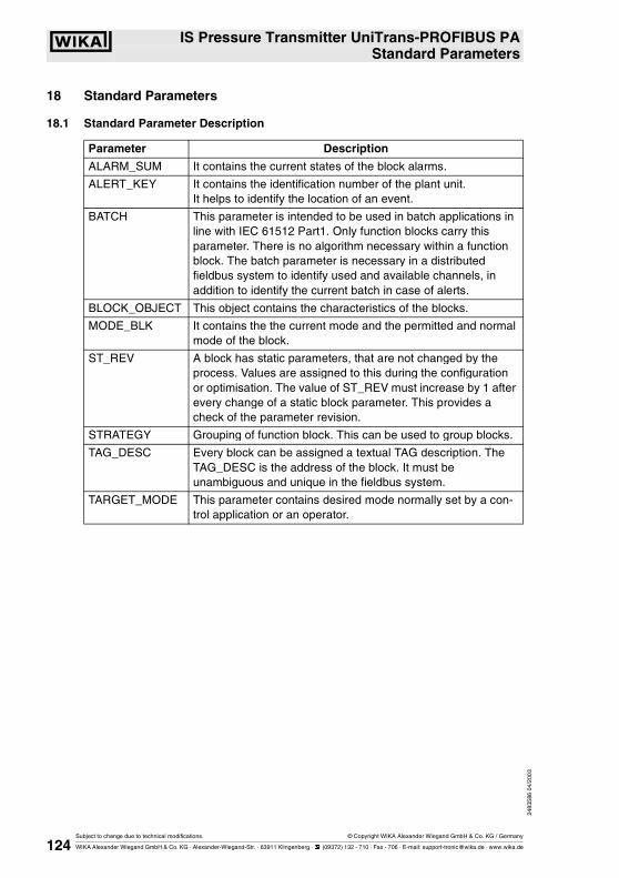
2483
586
04/2
003
� IS Pressure Transmitter UniTrans-PROFIBUS PAStandard Parameters
Subject to change due to technical modifications. © Copyright WIKA Alexander Wiegand GmbH & Co. KG / Germany
WIKA Alexander Wiegand GmbH & Co. KG · Alexander-Wiegand-Str. · 63911 Klingenberg · � (09372) 132 - 710 · Fax - 706 · E-mail: [email protected] · www.wika.de124
18 Standard Parameters
18.1 Standard Parameter Description
Parameter Description
ALARM_SUM It contains the current states of the block alarms.
ALERT_KEY It contains the identification number of the plant unit. It helps to identify the location of an event.
BATCH This parameter is intended to be used in batch applications in line with IEC 61512 Part1. Only function blocks carry this parameter. There is no algorithm necessary within a function block. The batch parameter is necessary in a distributed fieldbus system to identify used and available channels, in addition to identify the current batch in case of alerts.
BLOCK_OBJECT This object contains the characteristics of the blocks.
MODE_BLK It contains the the current mode and the permitted and normal mode of the block.
ST_REV A block has static parameters, that are not changed by the process. Values are assigned to this during the configuration or optimisation. The value of ST_REV must increase by 1 after every change of a static block parameter. This provides a check of the parameter revision.
STRATEGY Grouping of function block. This can be used to group blocks.
TAG_DESC Every block can be assigned a textual TAG description. The TAG_DESC is the address of the block. It must be unambiguous and unique in the fieldbus system.
TARGET_MODE This parameter contains desired mode normally set by a con-trol application or an operator.

� IS Pressure Transmitter UniTrans-PROFIBUS PAStandard Parameters
2483
586
04/2
003
Subject to change due to technical modifications. © Copyright WIKA Alexander Wiegand GmbH & Co. KG / Germany
WIKA Alexander Wiegand GmbH & Co. KG · Alexander-Wiegand-Str. · 63911 Klingenberg · � (09372) 132 - 710 · Fax - 706 · E-mail: [email protected] · www.wika.de 125
18.2 Standard Parameter Attributes
18.3 Standard Parameter View Object Table
Rel. Index
Variable Object type Data type Store Size Acc. Parameter usage/Type of transport
Default values
Man opt.
0 BLOCK OBJECT Record DS-32 Cst 20 r C/a - m
1 ST_REV Simple unsigned 16 N 2 r C/a 0 m
2 TAG_DESC Simple Octetstring S 32 r,w C/a 32 x ** m
3 STRATEGY Simple unsigned 16 S 2 r,w C/a 0 m
4 ALERT_KEY Simple unsigned 8 S 1 r,w C/a 0 m
5 TARGET MODE Simple unsigned 8 S 1 r,w C/a - m
6 MODE_BLKactualpermittednormal
Record DS-37unsigned 8unsigned 8unsigned 8
DCstCst
3 r C/a8 - auto8 - auto8 - auto
m
7 ALARM_SUMCurrentUnacknowledgedUnreportedDisabled
Record DS_42Bitstring (16 Bits)Bitstring (16 Bits)Bitstring (16 Bits)Bitstring (16 Bits)
D 8 r C/a0,0,0,0,
m
8 BATCHBatch_IDRUPOperationPhase
Structure DS-67 S 10 r,w C/a0,0,0,0,
m
Relative Index
Parameter Mnemonic VIEW_1 VIEW_2 VIEW_3 VIEW_4 VIEW_5
1 ST_REV 2
2 TAG_DESC
3 STRATEGY
4 ALERT_KEY
5 TARGET MODE
6 MODE_BLK
7 ALARM_SUM
- Overall sum of bytes in View object

2483
586
04/2
003
� IS Pressure Transmitter UniTrans-PROFIBUS PAPhysical Block
Subject to change due to technical modifications. © Copyright WIKA Alexander Wiegand GmbH & Co. KG / Germany
WIKA Alexander Wiegand GmbH & Co. KG · Alexander-Wiegand-Str. · 63911 Klingenberg · � (09372) 132 - 710 · Fax - 706 · E-mail: [email protected] · www.wika.de126
19 Physical Block
Physical block parameter description
Parameter Description
DEVICE_CERTIFICATION Certifications of the field device, e.g. IS certificate.
DESCRIPTOR User-definable text (a string) to describe the device within the application.
DEVICE_ID Manufacturer specific identification of the device.
DEVICE_MAN_ID Id-code of the manufacturer of the device
DEVICE_SER_NUM Serial number of the device
DIAGNOSIS Detailed information of the device, bitwise coded. If MSB og byte4 is set to 1, then more diagnosis information is available in the DIAGNOSIS_EXTENSION parameter.
DIAGNOSIS_EXTENSION Additional manufactuer specific information of the device, bitwise coded.
DIAGNOSIS_MASK Definition of supported DIAGNOSIS bits. 0 = not supp. 1 = supp.
DIAGNOSIS_MASK_EXT. Definition of supported DIAGNOSIS_EXTENSION bits. (0 = not supp. / 1 = supp.)
FACTORY_RESET Value = 1 is the command for resetting device to default values, if the device has bus address the setting of bus address remains unchanged.
Value = 2506 is the command for a warm start of the device. All parametrisation remains unchanged.
Value = 2712 resets the bus address only. The Ident_Number parameter is not affected by the Factory_Reset. Other manufacturing specific com-mands for other reset results are possible.
HARDWARE_REVISION Revision number of the hardware of the device.
HW_WRITE_PROTECTION Indicates the position of a hardware jumper which protects all acyclic write access to all writeable parameters of a device.0 – Unprotected1 – Protected (i.e. acyclic write service of all parameters is refused i.e. access is denied)
IDENT_NUMBER_SELECTOR
Each PROFIBUS-DP /EN50170/ device must have an Ident_Number provided by the PNO. The Uni-Trans makes use of the profile specific Ident_Number (SELECTOR=0)

� IS Pressure Transmitter UniTrans-PROFIBUS PAPhysical Block
2483
586
04/2
003
Subject to change due to technical modifications. © Copyright WIKA Alexander Wiegand GmbH & Co. KG / Germany
WIKA Alexander Wiegand GmbH & Co. KG · Alexander-Wiegand-Str. · 63911 Klingenberg · � (09372) 132 - 710 · Fax - 706 · E-mail: [email protected] · www.wika.de 127
LOCAL_OP_ENABLE Local operation enable.0 = disabled, (Local operation not allowed, i.e.change of FB MODE from host device only)1 = enabled, (Local operation is allowed)The operation of the host has higher priority than the local terminal one. If communication is interrupted longer than 30 sec. local operation will be enabled automatically. A communication failure is defined here as absence of cyclic and acyclic communication for the specified time period. If LOCAL_OP_ENA parameter is equal 0 (disabled) and the communication is working again then the device switches back to remote operation.
WRITE_LOCKING Storage location for a password. This password may be read and written by a tool to perform a write pro-tection strategy.
0 - acyclic write service of all parameters, except this WRITE_LOCKING one, are refused, i.e. access is denied
1 - 2456 reserved by PNO
2457 is the default value and means all writeable parameters of a device are writeable.
2458 - 65535 manufacturer specific
SOFTWARE_REVISION Revision number of the software of the field device
DEVICE_INSTALL_DATE Date of installation
DEVICE_MESSAGE User definable text to describe the device within the application or in the plant

2483
586
04/2
003
� IS Pressure Transmitter UniTrans-PROFIBUS PAPhysical Block
Subject to change due to technical modifications. © Copyright WIKA Alexander Wiegand GmbH & Co. KG / Germany
WIKA Alexander Wiegand GmbH & Co. KG · Alexander-Wiegand-Str. · 63911 Klingenberg · � (09372) 132 - 710 · Fax - 706 · E-mail: [email protected] · www.wika.de128
19.1 Physical Block Manufacturer Specific Parameter Description
19.2 Physical Block Parameter Attributes
Parameter Description
LANGUAGE Language of the displayed text.0 = english1 = german2 = french3 = spanish4 = italian
TOT_HRS_USED Total count of the transmitters operating hours
TOT_HRS_CALIB Total count of hours since last calibration. This parameter is set to 0 if one of the following parameters has changed.: FB1: PV_SCALE & OUT_SCALE, TPB: ZERO_OFFS_ADJUSTMENT.
TOT_HRS_RESET Total count of hours since last reset.
Rel. Index
Variable Object type
Data type
Store Size Acc. Parame-ter usage/
Type of transport
Default values
Man opt.
Slot abs. Index
0-7 Standard Parameters m 1 140-147
8 SOFTWARE_REVISION Simple Octetstring Cst 16 r C/a - m 1 148
9 HARDWARE_REVISION Simple Octetstring Cst !& r C/a - m 1 149
10 DEVICE_MAN_ID Simple unsigned 16 Cst 2 r C/a - m 1 150
11 DEVICE_ID Simple Octetstring Cst 16 r C/a - m 1 151
12 DEVICE_SER_NUM Simple Octetstring Cst 16 r C/a - m 1 152
13 DIAGNOSIS Simple Octetstring D 4 r C/a - m 1 153
14 DIAGNOSIS_EXTENSION Simple Octetstring D 6 r C/a - o 1 154
15 DIAGNOSIS_MASK Simple Octetstring0x10980000
Cst 4 r C/a - m 1 155
16 DIAGNOSIS_MASK_EXT. Simple Octetstring0x000000000000
Cst 6 r C/a - o 1 156
17 DEVICE_CERTIFICATION Simple Octetstring N 16 r,w C/a - o 1 157
18 WRITE_LOCKING Simple Unsigned16 N 2 r,w C/a 2457 o 1 158
19 FACTORY_RESET Simple Unsigned1635076:Factory reset1: PNO defaultvalues2506: Warm-start2712:Reset Busadr.
S 2 w C/a - o 1 159
20 DESCRIPTOR Simple Octetstring S 32 r,w C/a - m 1 160
21 DEVICE_MESSAGE Simple Octetstring S 32 r,w C/a - m 1 161
22 DEVICE_INSTALL_DATE Simple Octetstring S 16 r,w C/a - m 1 162
23 LOCAL_OP_ENABLE Simple unsigned 81=enabled0=disabled
N 1 r,w C/a 1 m(B) 1 163
24 IDENT_NUMBER_SELECTOR
Simple unsigned 80=Profile
S 1 r,w C/a 0 m(B) 1 164

� IS Pressure Transmitter UniTrans-PROFIBUS PAPhysical Block
2483
586
04/2
003
Subject to change due to technical modifications. © Copyright WIKA Alexander Wiegand GmbH & Co. KG / Germany
WIKA Alexander Wiegand GmbH & Co. KG · Alexander-Wiegand-Str. · 63911 Klingenberg · � (09372) 132 - 710 · Fax - 706 · E-mail: [email protected] · www.wika.de 129
19.3 Physical Block Manufacturer Specific Parameter Attributes
19.4 Physical Block Object
19.5 Physical Block View Object Table
25 HARDW_WR_PROTECT Simple unsigned 80=unprotected1=protected
D 1 r C/a - o 1 165
26-32 reserved PNO 1 166-172
Rel. Index
Variable Object type
Data type
Store Size Acc. Parame-ter usage/
Type of transport
Default values
Man opt.
Slot abs. Index
40 LANGUAGE Simple unsigned 80 = english1 = german2 = french3 = spanish4 = italian
N 1 r,w C/a - 1 180
41 TOT_HRS_USED Simple unsigned 32 D 4 r C/a - 1 181
42 TOT_HRS_CALIB Simple unsigned 32 N 4 r C/a - 1 182
43 TOT_HRS_RESET Simple unsigned 32 N 4 r,w C/a - 1 183
E Element Name Data Type (Index) Size Value Notes
1 Reserved Unsigned 8 - (5) 1 250
2 Block type Unsigned 8 - (5) 1 1 Physical block
3 Parent Class Unsigned 8 - (5) 1 1 Transmitter
4 Class Unsigned 8 - (5) 1 250 reserved
5 DD Reference Unsigned 32 - (7) 4 0 for use in the future.
6 DD Revision Unsigned 16 - (6) 2 0 for use in the future.
7 Profile Unsigned 16 - (6) 2 64; 2 Number, Class B
8 Profile Revision Unsigned 16 - (6) 2 3;0
9 Execution Time Unsigned 8 - (5) 1 0
10 Number of Parameter Unsigned 16 - (6) 2 0;45 incl. View_1
11 Index of VIEW_1 Unsigned 16 - (6) 2 01; 184 (Slot-Index)
12 Number of View List Unsigned 8 - (5) 1 1
RelativeIndex
Parameter Mnemonic VIEW_1 VIEW_2 VIEW_3 VIEW_4 VIEW_5
13 DIAGNOSIS 4
- Overall sum of bytes in View object(+13 standard parameter bytes)
4 + 13

2483
586
04/2
003
� IS Pressure Transmitter UniTrans-PROFIBUS PATransducer Block Pressure
Subject to change due to technical modifications. © Copyright WIKA Alexander Wiegand GmbH & Co. KG / Germany
WIKA Alexander Wiegand GmbH & Co. KG · Alexander-Wiegand-Str. · 63911 Klingenberg · � (09372) 132 - 710 · Fax - 706 · E-mail: [email protected] · www.wika.de130
20 Transducer Block Pressure
Linearisation Functions
Pressure
Pressure
SCALE_IN
No. Lineariz
Lineariz. Table
Square root
or other
SCALE_OUT
AI: ChannelSECONDARY_VALUE_1
AI: ChannelSECONDARY_VALUE_2
AI: ChannelPRIMARY_VALUE
SCALE_IN_0SCALE_IN_100
LIN_TYPE
LOW_FLOW_CUT_OFFFLOW_LIN_SQRT_POINT
SECONDARY_VALUE_2 =SECONDARY_VALUE_1 = h
(PRIMARY_VALUE - SCALE_IN_0) / (SCALE_IN_100 - SCALE_IN_0)as no linearisation function
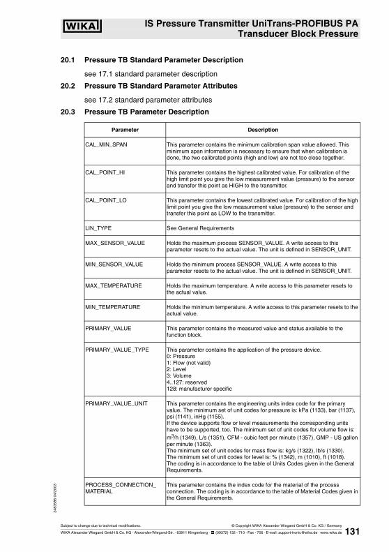
� IS Pressure Transmitter UniTrans-PROFIBUS PATransducer Block Pressure
2483
586
04/2
003
Subject to change due to technical modifications. © Copyright WIKA Alexander Wiegand GmbH & Co. KG / Germany
WIKA Alexander Wiegand GmbH & Co. KG · Alexander-Wiegand-Str. · 63911 Klingenberg · � (09372) 132 - 710 · Fax - 706 · E-mail: [email protected] · www.wika.de 131
20.1 Pressure TB Standard Parameter Description
see 17.1 standard parameter description
20.2 Pressure TB Standard Parameter Attributes
see 17.2 standard parameter attributes
20.3 Pressure TB Parameter Description
Parameter Description
CAL_MIN_SPAN This parameter contains the minimum calibration span value allowed. This minimum span information is necessary to ensure that when calibration is done, the two calibrated points (high and low) are not too close together.
CAL_POINT_HI This parameter contains the highest calibrated value. For calibration of the high limit point you give the low measurement value (pressure) to the sensor and transfer this point as HIGH to the transmitter.
CAL_POINT_LO This parameter contains the lowest calibrated value. For calibration of the high limit point you give the low measurement value (pressure) to the sensor and transfer this point as LOW to the transmitter.
LIN_TYPE See General Requirements
MAX_SENSOR_VALUE Holds the maximum process SENSOR_VALUE. A write access to this parameter resets to the actual value. The unit is defined in SENSOR_UNIT.
MIN_SENSOR_VALUE Holds the minimum process SENSOR_VALUE. A write access to this parameter resets to the actual value. The unit is defined in SENSOR_UNIT.
MAX_TEMPERATURE Holds the maximum temperature. A write access to this parameter resets to the actual value.
MIN_TEMPERATURE Holds the minimum temperature. A write access to this parameter resets to the actual value.
PRIMARY_VALUE This parameter contains the measured value and status available to the function block.
PRIMARY_VALUE_TYPE This parameter contains the application of the pressure device.0: Pressure1: Flow (not valid)2: Level3: Volume4..127: reserved128: manufacturer specific
PRIMARY_VALUE_UNIT This parameter contains the engineering units index code for the primary value. The minimum set of unit codes for pressure is: kPa (1133), bar (1137), psi (1141), inHg (1155). If the device supports flow or level measurements the corresponding units have to be supported, too. The minimum set of unit codes for volume flow is: m3/h (1349), L/s (1351), CFM - cubic feet per minute (1357), GMP - US gallon per minute (1363).The minimum set of unit codes for mass flow is: kg/s (1322), lb/s (1330).The minimum set of unit codes for level is: % (1342), m (1010), ft (1018).The coding is in accordance to the table of Units Codes given in the General Requirements.
PROCESS_CONNECTION_MATERIAL
This parameter contains the index code for the material of the process connection. The coding is in accordance to the table of Material Codes given in the General Requirements.

2483
586
04/2
003
� IS Pressure Transmitter UniTrans-PROFIBUS PATransducer Block Pressure
Subject to change due to technical modifications. © Copyright WIKA Alexander Wiegand GmbH & Co. KG / Germany
WIKA Alexander Wiegand GmbH & Co. KG · Alexander-Wiegand-Str. · 63911 Klingenberg · � (09372) 132 - 710 · Fax - 706 · E-mail: [email protected] · www.wika.de132
SCALE_IN This is the input conversion of the Pressure into SECONDARY_VALUE_2 using the high and low scale. The related unit is the SECONDARY_VALUE_1_UNIT.
SCALE_OUT This is the output conversion of the linearized value using the high and low scale. The related unit is the PRIMARY_VALUE_UNIT. It is in accordance to the table of Units Codes given in the General Requirements.
SECONDARY_VALUE_1 This parameter contains the Pressure value and status available to the Function Block.
SECONDARY_VALUE_1_UNIT This parameter contains the pressure units of the SECONDARY_VALUE_1. The minimum set of unit codes for pressure is: kPa (1133), bar (1137), psi (1141), inHg (1155).It is in accordance to the table of Units Codes given in the General Requirements.
SECONDARY_VALUE_2 This parameter contains the measured value after input scaling and status available to the Function Block. The related unit is the SECONDARY_VALUE_UNIT_2.
SECONDARY_VALUE_2_UNIT This parameter contains the units of the SECONDARY_VALUE_2 defined by the manufacturer. It is in accordance to the table of Units Codes given in the General Requirements.
SENSOR_DIAPHRAGM_MATERIAL
This parameter contains the index code for the material of the diaphragm, which comes in contact with the material. The index code is described in the table "Sensor_Diaphragm_Material".
SENSOR_FILL_FLUID This parameter contains the index code for the filling fluid inside the sensor. The index code is described in the table "Sensor_Fill_Fluid".
SENSOR_HI_LIM This parameter contains the sensor upper limit value.
SENSOR_LO_LIM This parameter contains the sensor lower limit value.
SENSOR_MAX_STATIC_PRESSURE
This parameter contains the maximum static pressure value for the sensor. Unit derives from SENSOR_UNIT.
SENSOR_O_RING_MATERIAL This parameter contains the index code for the material of the o-ring between diaphragm and process connection. The index code is described in the table "Sensor_O_Ring_Material".
SENSOR_SERIAL_NUMBER This parameter contains the sensor serial number.
SENSOR_TYPE This parameter contains the index code for the sensor type described in the manufacturer’s specific table.
SENSOR_UNIT This parameter contains the engineering units index code for the calibration values. SENSOR_UNIT must be a subset of the interchangeable part of the pressure unit.
SENSOR_VALUE This parameter contains the raw sensor value. The uncalibrated measurement value from the sensor.
TAB_ENTRY The index parameter identifies which element of the table is in the X_VALUE and Y_VALUE parameter currently
TAB_X_Y_VALUE The X_Y_VALUE parameter contains one value couple of the table
TAB_MIN_NUMBER For device internal reasons (e.g. for calculation), sometimes it is necessary to use a certain number of table values in minimum. This number is provided in the TAB_MIN_NUMBER parameter.

� IS Pressure Transmitter UniTrans-PROFIBUS PATransducer Block Pressure
2483
586
04/2
003
Subject to change due to technical modifications. © Copyright WIKA Alexander Wiegand GmbH & Co. KG / Germany
WIKA Alexander Wiegand GmbH & Co. KG · Alexander-Wiegand-Str. · 63911 Klingenberg · � (09372) 132 - 710 · Fax - 706 · E-mail: [email protected] · www.wika.de 133
TAB_MAX_NUMBER TAB_MAX_NUMBER is the maximum size (number of X_VALUE and Y_VALUE values) of the table in the device.
TAB_OP_CODE The modification of a table in a device influences the measurement or actuation algorithms of the device. Therefore an indication of a starting and an end point is necessary. The TAP_OP_CODE controls the transaction of the table.0: not initialised1: new operation characteristic, first value (TAB_ENTRY=1), old curve cleared2: reserved3: last value, end of transmission, check table, swap the old curve with the new curve, actualise ACTUAL_NUMBER.255: clear table(only if WRITE_LOCKING=9478)
TAB_STATUS It is common to provide a plausibility check in the device. The result of this check is indicated in the TAB_STATUS parameter.0: not initialised1: good (new table is valid)2: not monotonous increasing (old table is valid)3: not monotonous decreasing (old table is valid)4: not enough values transmitted (old table is valid)5: too many values transmitted (old table is valid)6: gradient of edge too high (old table is valid)7: Values not excepted (old values are valid)8 - 127 reserved> 128 manufacturer specific
TAB_ACTUAL_NUMBER Contains the actual numbers of entries in the table. It shall be calculated after the transmission of the table is finished.
LIN_TYPE Type of linearisation.0 = no linearisation (mandatory)1 = linearisation table (optional)20 = cylindrical lying container (optional)
TEMPERATURE_UNIT This parameter contains the units of the temperature. The minimum set of unit codes for volume flow is: K (1000), °C (1001), °F (1002). The coding is in accordance to the table of Units Codes given in the General Requirements.
TRIMMED_VALUE This parameter contains the sensor value after the trim processing. Unit derives from SENSOR_UNIT.

2483
586
04/2
003
� IS Pressure Transmitter UniTrans-PROFIBUS PATransducer Block Pressure
Subject to change due to technical modifications. © Copyright WIKA Alexander Wiegand GmbH & Co. KG / Germany
WIKA Alexander Wiegand GmbH & Co. KG · Alexander-Wiegand-Str. · 63911 Klingenberg · � (09372) 132 - 710 · Fax - 706 · E-mail: [email protected] · www.wika.de134
20.4 Pressure TB Manufacturer Specific Parameter Description
20.5 Pressure TB Parameter Attributes
Parameter Description
ZERO OFFSET_ ADJUSTMENT Actual measurement value is the new zero. A write access to this parameter executes the adjustment.
Rel. Index
Variable Object type
Data type Store Size Access
Parame-terusageType of transport
Default Values Manopt.
Slot abs.Index
0-7 Standard Parameters
m 1 70-77
8 SENSOR_VALUE Simple Float D 4 r C/a 0.0 m 1 78
9 SENSOR_HI_LIM Simple Float N 4 r C/a - m 1 79
10 SENSOR_LO_LIM Simple Float N 4 r C/a - m 1 80
11 CAL_POINT_HI Simple Float N 4 r,w C/a SENS_HI_LIM m 1 81
12 CAL_POINT_LO Simple Float N 4 r,w C/a SENS_LO_LIM m 1 82
13 CAL_MIN_SPAN Simple Float N 4 r C/a 0.05 x SENS_HI_LIM
m 1 83
14 SENSOR_UNIT Simple unsigned16Pressure:1137 = bar
N 2 r,w C/a 1137 - bar m 1 84
15 TRIMMED_VALUE Record DS-33not used
D 5 r C/a - m 1 85
16 SENSOR_TYPE Simple unsigned161 - relative128 - abs.250 -not used
N 2 r C/a 250 m 1 86
17 SENSOR_SERIAL_NUMBER
Simple unsigned32 N 4 r C/a - m 1 87
18 PRIMARY_VALUE Record DS-33 D 5 r C/a 0.0 m 1 88
19 PRIMARY_VALUE_UNIT
Simple unsigned161342=%
N 2 r,w C/a 1342 - % m 1 89
20 PRIMARY_VALUE_TYPE
Simple unsigned163 = Volume
N 2 r C/a 3 - Volume m 1 90
21 SENSOR_DIAPHRAGM _MATERIAL
Simple unsigned16 S 2 r C/a - o 1 91
22 SENSOR_FILL_FLUID
Simple unsigned16 S 2 r C/a - o 1 92

� IS Pressure Transmitter UniTrans-PROFIBUS PATransducer Block Pressure
2483
586
04/2
003
Subject to change due to technical modifications. © Copyright WIKA Alexander Wiegand GmbH & Co. KG / Germany
WIKA Alexander Wiegand GmbH & Co. KG · Alexander-Wiegand-Str. · 63911 Klingenberg · � (09372) 132 - 710 · Fax - 706 · E-mail: [email protected] · www.wika.de 135
23 SENSOR_MAX_STATIC_PRESSURE
Simple Float N 4 r C/a - o 1 93
24 SENSOR_O_RING_MATERIAL
Simple unsigned16 S 2 r C/a - o 1 94
25 PROCESS_CONNECTION_TYPE
Simple unsigned16 S 2 r C/a - o 1 95
26 PROCESS_CONNECTION_MATERIAL
Simple unsigned16 S 2 r C/a - o 1 96
27 TEMPERATURE simple DS-33 D 5 r C/a 0.0 o 1 97
28 TEMPERATURE_UNIT
simple unsigned161001 = °C1002 = °F
S 2 r,w C/a 1001 - °C o 1 98
29 SECONDARY_VALUE_1
Record DS-33 D 5 r C/a 0.0 o(B) 1 99
30 SECONDARY_VALUE_1_UNIT
Simpel Unsigned161137=bar1138=mbar1141=psi1130=Pa1136=HPA1132=MPA1155=InHg
N 2 r,w C/a 1137 - bar o(B) 1 100
31 SECONDARY_VALUE_2
Record DS-33 D 5 r C/a 0.0 o(B) 1 101
32 SECONDARY_VALUE_2_UNIT
Simple Unsigned161997=none
N 2 r,w C/a 1997 - none o(B) 1 102
33 LIN_TYPE Simple Unsigned80 = no lin-earisation 1 = linearisa-tion table
S 1 r,w C/a 0 - no. lin. m(B) 1 103
34 SCALE_IN Array Float100% - value0% - value
S 8 r,w C/a - o(B) 1 104
35 SCALE_OUT Array Float100% - value0% - value
S 8 r,w C/a - o(B) 1 105
38 TAB_ACTUAL_NUMBER
Simple Unsigned8 N 1 r C/a - o(B) 1 108
39 TAB_ENTRY Simple Unsigned8 D 1 r,w C/a 1 o(B) 1 109
40 TAB_MAX_NUMBER
Simple Unsigned8actual = 32
N 1 r C/a - o(B) 1 110
41 TAB_MIN_NUMBER
Simple Unsigned8actual = 2
N 1 r C/a - o(B) 1 111
42 TAB_OP_CODE Simple Unsigned8 D 1 r,w C/a 0 o(B) 1 112
43 TAB_STATUS Simple Unsigned8 D 1 r C/a 0 o(B) 1 113

2483
586
04/2
003
� IS Pressure Transmitter UniTrans-PROFIBUS PATransducer Block Pressure
Subject to change due to technical modifications. © Copyright WIKA Alexander Wiegand GmbH & Co. KG / Germany
WIKA Alexander Wiegand GmbH & Co. KG · Alexander-Wiegand-Str. · 63911 Klingenberg · � (09372) 132 - 710 · Fax - 706 · E-mail: [email protected] · www.wika.de136
* first 4 bytes X_VALUE, second 4 bytes Y_VALUE
44 TAB_X_Y_VALUE Array* Floatx-valuey-value
D 8 r,w C/a - o(B) 1 114
45 MAX_SENSOR_VALUE
simple float N 4 r,w C/a - o(B) 1 115
46 MIN_SENSOR_VALUE
simple float N 4 r,w C/a - o(B) 1 116
47 MAX_TEMPERATURE
simple float N 4 r,w C/a - o(B) 1 117
48 MIN_TEMPERATURE
simple float N 4 r,w C/a - o(B) 1 118
49-58 reserved PNO 1 119-128
59 ZERO_OFFSET_ADJUSTEMENT
simple float N 4 r,w C/a 0.0 ms 1 129

� IS Pressure Transmitter UniTrans-PROFIBUS PATransducer Block Pressure
2483
586
04/2
003
Subject to change due to technical modifications. © Copyright WIKA Alexander Wiegand GmbH & Co. KG / Germany
WIKA Alexander Wiegand GmbH & Co. KG · Alexander-Wiegand-Str. · 63911 Klingenberg · � (09372) 132 - 710 · Fax - 706 · E-mail: [email protected] · www.wika.de 137
20.6 Pressure TB Block Object
20.7 Pressure TB View Object
20.8 Assignment of Dynamic Variables for Pressure Devices
E Element Name Data Type (Index)
Size Value Notes
1 Reserved Unsigned 8 - (5) 1 250
2 Block type Unsigned 8 - (5) 1 3 Transducer block
3 Parent Class Unsigned 8 - (5) 1 1 Pressure
4 Class Unsigned 8 - (5) 1 5 Pressure+Level
5 DD Reference Unsigned 32 - (7) 4 0 for use in the future.
6 DD Revision Unsigned 16 - (6) 2 0 for use in the future.
7 Profile Class Unsigned 16 - (6) 2 64; 2 Number, Class B
8 Profile Revision Unsigned 16 - (6) 2 3;0
9 Execution Time Unsigned 8 - (5) 1 0
10 Number of Parameter Unsigned 16 - (6) 2 0; 60 incl. View_1
11 Index of VIEW_1 Unsigned 16 - (6) 2 1; 130 (Slot;Index)
12 Number of View List Unsigned 8 - (5) 1 1
Relative Index
Parameter Mnemonic VIEW_1 VIEW_2 VIEW_3 VIEW_4 VIEW_5
18 PRIMARY_VALUE 5
- Overall sum of bytes in View-Object(+13 Standard parameter bytes)
5 + 13
Application Transducer output
PRIMARY_VALUE_TYPE
PRIMARY_VALUE
SECONDARY_VALUE_1 SECONDARY_VALUE_2 TEMPERATURE
Pressure Pressure - - Temperature
Level Level Pressure - Temperature
Volume Volume Pressure Level Temperature

2483
586
04/2
003
� IS Pressure Transmitter UniTrans-PROFIBUS PAAnalog Input FB 1 (Pressure)
Subject to change due to technical modifications. © Copyright WIKA Alexander Wiegand GmbH & Co. KG / Germany
WIKA Alexander Wiegand GmbH & Co. KG · Alexander-Wiegand-Str. · 63911 Klingenberg · � (09372) 132 - 710 · Fax - 706 · E-mail: [email protected] · www.wika.de138
21 Analog Input FB 1 (Pressure)
21.1 Analog Input FB 1 Standard Parameter Description
see 17.1 "Standard parameter description".
21.2 Analog Input FB 1 Standard Parameter Attributes
see 17.2 "Standard parameter attributes".

� IS Pressure Transmitter UniTrans-PROFIBUS PAAnalog Input FB 1 (Pressure)
2483
586
04/2
003
Subject to change due to technical modifications. © Copyright WIKA Alexander Wiegand GmbH & Co. KG / Germany
WIKA Alexander Wiegand GmbH & Co. KG · Alexander-Wiegand-Str. · 63911 Klingenberg · � (09372) 132 - 710 · Fax - 706 · E-mail: [email protected] · www.wika.de 139
21.3 Analog Input FB 1 Process parameter
21.4 Analog Input FB 1 Alarm Parameter
Parameter Description
CHANNEL Reference to the active transducer block which provides the measurement value to the function block.
FSAVE_TYPE Defines reaction of device, if a fault is detected. The calculated ACTUAL MODE remains in AUTO respectively.
0 = value FSAVE_VALUE is used as OUT Status - Uncertain_Substitute Value,1 = use of stored last valid OUT value Status - Uncertain_LastUsableValue if there is no valid value available, then UNCERTAIN-Inital_Value2 = OUT has the wrong calculated value and status Status - BAD_* (* as calculated)
OUT Process Variable
PV_SCALE Conversion of the process variable into percent using the high and low scale values, engineering units code, and number of digits to the right of the decimal point.
OUT_SCALE Scale of the process variable. It contains the values of the lower limit and upper limit effective range, engineering units code, and number of digits to the right of the decimal point.
PV_FTIME Filter time of the process variable.
Parameter Description
ALARM_HYS Hysteresis (effective to all limits).
HI_ALM State of the upper limit of warnings. It contains the state of the upper limit of an alarm and the relating time stamp. Here time stamp is 1st January 1992.
HI_HI_ALM State of the upper limit of alarms. It contains the state of the upper limit of an alarm and the relating time stamp. Here time stamp is 1st January 1992.
HI_HI_LIM Value of upper limit of alarms. Upper limit value for alarms with engineering unit. If the measured value is equal to or higher than this value the state bit in the state byte of OUT and in the FP parameter ALARM_SUM have to change to 1.
HI_LIM Value of upper limit of warnings. Upper limit value for warnings with engineering unit. If the measured value is equal to or higher than this value the state bit in the state byte of OUT and in the FP parameter ALARM_SUM have to change to 1.
LO_ALM State of the lower limit of warnings. It contains the state of the lower limit of an alarm and the relating time stamp. Here time stamp is 1st January 1992.
LO_LIM Value of lower limit of warnings. Lower limit value for warnings with engineering unit. If the measured value is equal to or lower than this value the state bit in the state byte of OUT and in the FP parameter ALARM_SUM have to change to 1.
LO_LO_ALM State of the lower limit of alarms. It contains the state of the lower limit of an alarm and the relating time stamp. Here time stamp is 1st January 1992.
LO_LO_LIM Value of lower limit of alarms. Lower limit value for alarms with engineering unit. If the measured value is equal to or lower than this value the state bit in the state byte of OUT and in the FP parameter ALARM_SUM have to change to 1.
SIMULATE For comissioning and test purposes the input from the transducer block can be discon-nected, and the input value and status can be set by the parameter Simulate.

2483
586
04/2
003
� IS Pressure Transmitter UniTrans-PROFIBUS PAAnalog Input FB 1 (Pressure)
Subject to change due to technical modifications. © Copyright WIKA Alexander Wiegand GmbH & Co. KG / Germany
WIKA Alexander Wiegand GmbH & Co. KG · Alexander-Wiegand-Str. · 63911 Klingenberg · � (09372) 132 - 710 · Fax - 706 · E-mail: [email protected] · www.wika.de140
21.5 Analog Input FB 1 Parameter Attributes
Rel. Index
Variable Object type
Data type Store Size Access Parameterusage-Type of
transport
Default Values Manopt.
Slot abs.Index
0-8 Standard Parameters m 1 16-24
10 OUT record DS-33 D 5 r O/Cyc m 1 26
11 PV_SCALE100%-value0%-value
array float S 8 r,w C/a100% 0%
m 1 27
12 OUT_SCALE100%-value0%-valueUnitDecimal Point
record DS-36floatfloatunsigned16unsigned8
S 11 r,w C/a100%0%1342 - %0
m 28
13 LIN_TYPE simple unsigned80 = no linearis.
S 1 r,w C/a 0 m 1 29
14 CHANNEL simple unsigned16Pressure:PV=0x0108SV1=0x011DSV2=0x011F
S 2 r,w C/a 0x0108 m 1 30
16 PV_FTIME simple float0, 1, 5, 20, 40s
S 4 r,w C/a 0s m 1 32
17 FSAVE_TYPE simple unsigned81 - last out val.
S 1 r,w c/a 1 o 1 33
19 ALARM-_HYS simple float S 4 r,w C/a 0,5% of range m 1 35
21 HI_HI_LIM simple float S 4 r,w C/a SEN_HI_LIM + 5% m 1 37
23 HI_LIM simple float S 4 r,w C/a SENS_HI_LIM m 1 39
25 LO_LIM simple float S 4 r,w C/a SENS_LO_LIM m 1 41
27 LO_LO_LIM simple float S 4 r,w C/a SENS_LO_LIM-2%
m 1 43
30 HI_HI_ALMUnacknowledgeAlarm StateTime_StampSubcodeValue
record DS-39Unsigned8Unsigned8DateUnsigned16Float
D 16 r C/a00000
o 1 46
31 HI_ALM record DS-39 D 16 r C/a 0, 0, 0, 0, 0, 0 o 1 47
32 LO_ALM record DS-39 D 16 r C/a 0, 0, 0, 0, 0, 0 o 1 48
33 LO_LO_ALM record DS-39 D 16 r C/a 0, 0, 0, 0, 0, 0 o 1 49
34 SIMULATEStatusValueEn/Disable
record DS-50Unsigned8floatUnsigned8
S 6 r,w C/a0 0 0 - disable
m 1 50
36-44 reserved PNO 1 52-60

� IS Pressure Transmitter UniTrans-PROFIBUS PAAnalog Input FB 1 (Pressure)
2483
586
04/2
003
Subject to change due to technical modifications. © Copyright WIKA Alexander Wiegand GmbH & Co. KG / Germany
WIKA Alexander Wiegand GmbH & Co. KG · Alexander-Wiegand-Str. · 63911 Klingenberg · � (09372) 132 - 710 · Fax - 706 · E-mail: [email protected] · www.wika.de 141
21.6 Analog Input FB 1 Block Object
21.7 Analog Input FB 1 View Object
E Element Name Data Type (Index)
Size Value Notes
1 Reserved Unsigned 8 - (5) 1 250
2 Block object Unsigned 8 - (5) 1 2 Function block
3 Parent Class Unsigned 8 - (5) 1 1 Input
4 Class Unsigned 8 - (5) 1 1 Analog input
5 DD Reference Unsigned 32 - (7) 4 0 for use in the future
6 DD Revision Unsigned 16 - (6) 2 0 for use in the future
7 Profile Unsigned 16 - (6) 2 64; 2
8 Profile Revision Unsigned 16 - (6) 2 3; 0 Number, Class B
9 Execution Time Unsigned 8 - (5) 1 0
10 Number_of_parameters Unsigned 16 - (6) 2 0;45 incl. View_1
11 Adress of VIEW_1 Unsigned 16 - (6) 2 1; 61 (Slot-Index)
12 Number of Views Unsigned 8 - (5) 1 1
Relative Index
Parameter Mnemonic VIEW_1 VIEW_2 VIEW_3 VIEW_4 VIEW_5
10 OUT 5
- Overall sum of bytes in View-Object (+13 Standard parameter bytes)
5 + 13

2483
586
04/2
003
� IS Pressure Transmitter UniTrans-PROFIBUS PAAnalog Input FB 2 (Temperature)
Subject to change due to technical modifications. © Copyright WIKA Alexander Wiegand GmbH & Co. KG / Germany
WIKA Alexander Wiegand GmbH & Co. KG · Alexander-Wiegand-Str. · 63911 Klingenberg · � (09372) 132 - 710 · Fax - 706 · E-mail: [email protected] · www.wika.de142
22 Analog Input FB 2 (Temperature)
Analog input function block standard parameter description
see chapter 17.1 standard parameter description.
22.1 Analog Input FB 2 Standard Parameter Attributes
see chapter 17.2 standard parameter attributes.
22.2 Analog Input FB 2 Process Parameter
see chapter 20.3
22.3 Analog Input FB 2 Alarm Parameter
see chapter 20.4

� IS Pressure Transmitter UniTrans-PROFIBUS PAAnalog Input FB 2 (Temperature)
2483
586
04/2
003
Subject to change due to technical modifications. © Copyright WIKA Alexander Wiegand GmbH & Co. KG / Germany
WIKA Alexander Wiegand GmbH & Co. KG · Alexander-Wiegand-Str. · 63911 Klingenberg · � (09372) 132 - 710 · Fax - 706 · E-mail: [email protected] · www.wika.de 143
22.4 Analog Input FB 2 Parameter Attributes
* 1. Floatvalue: EU100%, 2. Floatvalue: EU0%
Rel. Index
Variable Object
type
Data type Store Size Access Parameterusage-Type of
transport
Default Values Manopt.
Slot abs.Index
0-8 Standard Parameters m 2 16-24
10 OUT record DS-33 D 5 r O/Cyc m 2 26
11 PV_SCALE100%-value0%-value
array float S 8 r,w C/a100 0
m 2 27
12 OUT_SCALE100%-value0%-valueUnitDecimal Point
record DS-36floatfloatunsigned16unsigned8
S 11 r,w C/a10001001 - °C0
m 2 28
13 LIN_TYPE simple unsigned80 = no linearis.
S 1 r,w C/a 0 m 2 29
14 CHANNEL simple unsigned16Temperature:0x011B
S 2 r,w C/a 0x011B m 2 30
16 PV_FTIME simple float0, 1, 5, 20, 40s
S 4 r,w C/a 0s m 2 32
17 FSAVE_TYPE simple unsigned81 - last out val.
S 1 r,w c/a 1 o 2 33
19 ALARM-_HYS simple float S 4 r,w C/a 0,5% of range m 2 35
21 HI_HI_LIM simple float S 4 r,w C/a 105 m 2 37
23 HI_LIM simple float S 4 r,w C/a 100 m 2 39
25 LO_LIM simple float S 4 r,w C/a 0 m 2 41
27 LO_LO_LIM simple float S 4 r,w C/a -2 m 2 43
30 HI_HI_ALMUnacknowledgeAlarm StateTime_StampSubcodeValue
record DS-39Unsigned8Unsigned8DateUnsigned16Float
D 16 r C/a00000
o 2 46
31 HI_ALM record DS-39 D 16 r C/a 0, 0, 0, 0, 0, 0 o 2 47
32 LO_ALM record DS-39 D 16 r C/a 0, 0, 0, 0, 0, 0 o 2 48
33 LO_LO_ALM record DS-39 D 16 r C/a 0, 0, 0, 0, 0, 0 o 2 49
34 SIMULATEStatusValueEn/Disable
record DS-50Unsigned8floatUnsigned8
S 6 r,w C/a0 0 0 - disable
m 2 50
36-44 reserved PNO 52-60

2483
586
04/2
003
� IS Pressure Transmitter UniTrans-PROFIBUS PAAnalog Input FB 2 (Temperature)
Subject to change due to technical modifications. © Copyright WIKA Alexander Wiegand GmbH & Co. KG / Germany
WIKA Alexander Wiegand GmbH & Co. KG · Alexander-Wiegand-Str. · 63911 Klingenberg · � (09372) 132 - 710 · Fax - 706 · E-mail: [email protected] · www.wika.de144
22.5 Analog Input FB 2 Block Object
22.6 Analog Input FB 2 View Object
E Element Name Data Type (Index)
Size Value Notes
1 Reserved Unsigned 8 - (5) 1 250
2 Block object Unsigned 8 - (5) 1 2 Function block
3 Parent Class Unsigned 8 - (5) 1 1 Input
4 Class Unsigned 8 - (5) 1 1 Analog input
5 DD Reference Unsigned 32 - (7) 4 0 for use in the future
6 DD Revision Unsigned 16 - (6) 2 0 for use in the future
7 Profile Unsigned 16 - (6) 2 64; 2
8 Profile Revision Unsigned 16 - (6) 2 3; 0 Number, Class B
9 Execution Time Unsigned 8 - (5) 1 0
10 Number_of_parameters Unsigned 16 - (6) 2 0;45 incl. View_1
11 Address of VIEW_1 Unsigned 16 - (6) 2 2; 61 (Slot-Index)
12 Number of Views Unsigned 8 - (5) 1 1
Relative Index
Parameter Mnemonic VIEW_1 VIEW_2 VIEW_3 VIEW_4 VIEW_5
10 OUT 5
- Overall sum of bytes in View-Object (+13 Standard parameter bytes)
5 + 13

� IS Pressure Transmitter UniTrans-PROFIBUS PADiagnosis Parameter
2483
586
04/2
003
Subject to change due to technical modifications. © Copyright WIKA Alexander Wiegand GmbH & Co. KG / Germany
WIKA Alexander Wiegand GmbH & Co. KG · Alexander-Wiegand-Str. · 63911 Klingenberg · � (09372) 132 - 710 · Fax - 706 · E-mail: [email protected] · www.wika.de 145
23 Diagnosis Parameter
Via the bit EXT_DIAG = 1 the slave signalises that it is transmitting customer specific data. As a consequence a diagnosis telegram is sent to the PROFIBUS_Master. When the reason for the diagnosis, i.e. the respective bit combination in the customer specific diagnosis data is 0, also the EXT_DIAG-Bit is reset.
23.1 Standard diagnosis parameter
23.2 Extended Diagnosis Parameters
Via the extended diagnosis parameters the device status can be determined.
Octet Bit Mnemonic Description Supp. Ind.
1 0 DIA_HW_ELECTR Hardware failure of electronic - -
1 DIA_HW_MECH Hardware failure of mechanic - -
2 DIA_TEMP_MOTOR Motor- temperature too high - -
3 DIA_TEMP_ELECTR Electronic temperature out of range - -
4 DIA_MEM_CHECKSUM Memory checksum error yes -
5 DIA_MEASUREMENT Failure in measurement - -
6 DIA_NOT_INIT Device not initialized (no self-calibration)
- -
7 DIA_INIT_ERROR Self-calibration failed - -
2 0 DIA_ZERO_ERROR Zero point error - -
1 DIA_SUPPLY Power supply failed - -
2 DIA_CONF_INVALID Configuration not valid - -
3 DIA_WARMSTART Restart up carried out yes A
4 DIA_COLDSTART New startup carried out yes A
5 DIA_MAINTAINANCE Maintenance required - -
6 DIA_CHARACT Characterisation invalid - -
7 IDENT_NUMBER_Violation Set to 1 if the ident number of the running cyclic data transfer and the value of the PB_IDENT_NUMBER parameter are different.
yes
3 0..7 reserved Reserved for use within the PNO
4 0..6 reserved Reserved for use within the PNO - -
7 7 EXTENSION_AVAILABLE More diagnosis information is available - -
Bit Mnemonic Description Supp. Ind.
0..48 not used - -

2483
586
04/2
003
� IS Pressure Transmitter UniTrans-PROFIBUS PADiagnosis Parameter
Subject to change due to technical modifications. © Copyright WIKA Alexander Wiegand GmbH & Co. KG / Germany
WIKA Alexander Wiegand GmbH & Co. KG · Alexander-Wiegand-Str. · 63911 Klingenberg · � (09372) 132 - 710 · Fax - 706 · E-mail: [email protected] · www.wika.de146
23.3 Coding of Manufacturer Specific Error Codes
Parameterisations errors of the device are coded by a customer specific error-code, if not verified by the error classes of Error_Codes_1. This code is then sent back via the Error_Code_2. The error coding is as follows:
Error_Code_2 Mnemonic Meaning
01H - not used
02H PARAMETER_TOO_LARGE transmitted parameter > than maximum limit value
03H PARAMETER_TOO_SMALL transmitted parameter < than minimum limit value
04H INVALID_SELECT invalid selection out of a given list
05H...0FH - not used

� IS Pressure Transmitter UniTrans-PROFIBUS PAAppendix
2483
586
04/2
003
Subject to change due to technical modifications. © Copyright WIKA Alexander Wiegand GmbH & Co. KG / Germany
WIKA Alexander Wiegand GmbH & Co. KG · Alexander-Wiegand-Str. · 63911 Klingenberg · � (09372) 132 - 710 · Fax - 706 · E-mail: [email protected] · www.wika.de 147
24 Appendix
24.1 Dimension Diagrams

2483
586
04/2
003
� IS Pressure Transmitter UniTrans-PROFIBUS PAAppendix
Subject to change due to technical modifications. © Copyright WIKA Alexander Wiegand GmbH & Co. KG / Germany
WIKA Alexander Wiegand GmbH & Co. KG · Alexander-Wiegand-Str. · 63911 Klingenberg · � (09372) 132 - 710 · Fax - 706 · E-mail: [email protected] · www.wika.de148

� IS Pressure Transmitter UniTrans-PROFIBUS PAAppendix
2483
586
04/2
003
Subject to change due to technical modifications. © Copyright WIKA Alexander Wiegand GmbH & Co. KG / Germany
WIKA Alexander Wiegand GmbH & Co. KG · Alexander-Wiegand-Str. · 63911 Klingenberg · � (09372) 132 - 710 · Fax - 706 · E-mail: [email protected] · www.wika.de 149
2483
586
04/2
003
� IS Pressure Transmitter UniTrans-PROFIBUS PAAppendix
Subject to change due to technical modifications. © Copyright WIKA Alexander Wiegand GmbH & Co. KG / Germany
WIKA Alexander Wiegand GmbH & Co. KG · Alexander-Wiegand-Str. · 63911 Klingenberg · � (09372) 132 - 710 · Fax - 706 · E-mail: [email protected] · www.wika.de150

� IS Pressure Transmitter UniTrans-PROFIBUS PAAppendix
2483
586
04/2
003
Subject to change due to technical modifications. © Copyright WIKA Alexander Wiegand GmbH & Co. KG / Germany
WIKA Alexander Wiegand GmbH & Co. KG · Alexander-Wiegand-Str. · 63911 Klingenberg · � (09372) 132 - 710 · Fax - 706 · E-mail: [email protected] · www.wika.de 151
24.2 Model Key, Standard version
1) Only with accuracy 0.5 %; max. Turn down 2:12) Maximum medium temperature of 60 °C (140 °F) must not be exceeded.
Unit
B bar
1 S bar absolut up to 16 bar abs
Pressure range
CA -1 bar ... 0 bar BM 0 bar ... 40 bar
CD -1 bar ... 0,6 bar BO 0 bar ... 100 bar
CH -1 bar ... 3 bar BQ 0 bar ... 250 bar
CK -1 bar ... 5 bar BT 0 bar ... 600 bar
CP -1 bar ... 15 bar BU 0 bar ... 1000 bar
BB 0 bar ... 0,4 bar / bar absolute BV 0 bar ... 1600 bar 1) only with aluminum caseBE 0 bar ... 1,6 bar / bar absolute BX 0 bar ... 2500 bar 1) only with aluminum caseBH 0 bar ... 6 bar / bar absolute BZ 0 bar ... 4000 bar 1) only with aluminum case
2 BK 0 bar ... 16 bar / bar absolute
Process connection
GD G ½ B ML M16x1,5 female, w. sealing cone 2 > 1600 barND ½ NPT VS 3/8-24 UNF LH male
3 CS chemical seal prices and designs according to chemical seals product range
Special design features
Z without
E oil and grease free
A oxygen, oil and grease free up to 1600 bar abs, max. medium temperature 60°C
G suitable for food
4 O overvoltage protection according to IEC 801-5
Case material
M highly resistive, fiberglass-enforced plastic (PBT)
5 A Aluminium Ingress protection IP 67
Ingress protection
S Standard IP 65 for plastic case, IP 67 for aluminium case
6 L IP 67 for plastic case, only with special cable or abs. pressure range
Electrical connection
A Cable gland M20x1.5 with internal terminal block standard
7 M 4-pin locking plug, M12x1
Digital display
Z without
8 A with integrated 4-digit LCD-display
Approvals
L EEx ia IIC T4-T6 in compliance with ATEX 100a
9 C CSAAdditional order info
YES NO10 1 Z quality certificates11 T Z additional text
Order code:
1 2 3 4 5 6 7 8 9 10 11
IUT-10 - 5 - - - -

2483
586
04/2
003
� IS Pressure Transmitter UniTrans-PROFIBUS PAAppendix
Subject to change due to technical modifications. © Copyright WIKA Alexander Wiegand GmbH & Co. KG / Germany
WIKA Alexander Wiegand GmbH & Co. KG · Alexander-Wiegand-Str. · 63911 Klingenberg · � (09372) 132 - 710 · Fax - 706 · E-mail: [email protected] · www.wika.de152
24.3 Model Key, Flush diaphragm version
Unit
B bar
1 S bar absolut up to 16 bar abs
Pressure range
CA -1 bar ... 0 bar BH 0 bar ... 6 bar / bar absolut
CD -1 bar ... 0,6 bar BK 0 bar ... 16 bar / bar absolut
CH -1 bar ... 3 bar BM 0 bar ... 40 bar
CK -1 bar ... 5 bar BO 0 bar ... 100 bar
CP -1 bar ... 15 bar BQ 0 bar ... 250 bar
BB 0 bar ... 0,4 bar / bar absolute BT 0 bar ... 600 bar
2 BE 0 bar ... 1,6 bar / bar absolute
Process connection
85 G 1 B, flush diaphragm with O-ring up to 1.6 bar
86 G ½ B flush diaphragm with O-Ring > 1.6 bar
G6 G 1 ½ B flush diaphragm up to 16 bar
3 83 G 1 flush diaphragm according to EHEDG 1) up to 16 bar
Material of wetted parts
1 stainless steel and O-ring from NBR G 1 1/2 B without O-ring
L stainless steel and O-ring from Viton
B stainless steel and O-ring from EPDM
4 S Hastelloy C4
Special design features
Z without
E oil and grease free
A oxygen, oil and grease free up to 1600 bar abs, max. medium temperature 60°C
5 O overvoltage protection according to IEC 801-5
Case material
M highly resistive, fiberglass-enforced plastic (PBT)
6 A Aluminium Ingress protection IP 67
Ingress protection
S Standard IP 65 for plastic case, IP 67 for aluminium case
7 L IP 67 for plastic case, only with special cable or abs. pressure range
Electrical connection
A Cable gland M20x1.5 with internal terminal block standard
8 M 4-pin locking plug, M12x1
Digital display
Z without
9 A with integrated 4-digit LCD-display
Approvals
L EEx ia IIC T4-T6 in compliance with ATEX 100a II 1/2 G for connection to zone 0
10 C CSA
Additional order infoYES NO
11 1 Z quality certificates12 T Z additional text
1) not with ’’Special design features’’ Code A
Order code:
1 2 3 4 5 6 7 8 9 10 11 12
IUT-11 - 5 - - - -

� IS Pressure Transmitter UniTrans-PROFIBUS PAAppendix
2483
586
04/2
003
Subject to change due to technical modifications. © Copyright WIKA Alexander Wiegand GmbH & Co. KG / Germany
WIKA Alexander Wiegand GmbH & Co. KG · Alexander-Wiegand-Str. · 63911 Klingenberg · � (09372) 132 - 710 · Fax - 706 · E-mail: [email protected] · www.wika.de 153
24.4 Warranty Conditions
The pressure transmitter has a 24 month warranty in accordance with the WIKA General Terms of Delivery.
24.5 Glossary
Adjustment Allocation of the output signal (PROFIBUS PA) to the desired pressure measurement range or level measurement range.
Integration Also damping: timely communication of the measurementsignal; rise time of the current output signal after a signal surge
Nom. pressure range The operating pressure range for which the sensor was de-signed
Zero point Start of the pressure measurement range
Parameterization Also configuration: programming of the relevant parameters and the pressure measurement range specific to the application and measurement location.
Span The programmed pressure measurement range
Span end point The highest pressure value of the programmed measurement span (end-point of the span)
Tank linearization Determination of approximate volume/pressure ratio values with non-linear correlations based on varying container designs
For example, a non-linear correlation exists between the fill lev-el and the volume in spherical containers. During linearization, the non-linear volume is assigned the output signal (PROFI-BUS PA primary value) from a table of values (proximity pro-cess by means of up to 32 support points).
Defaults The sensor parameters are pre-programmed by the manufac-turer
24.6 Units of Pressure Measurement
1 atm (atmospheres) = 760 mm Hg = 760 Torr
= 1.033 kp/cm2 = 0.1013 MPa
1 Torr = 133.3 Pa
1 kp/mm2 = 9.81 N/mm2 = 9.81 MPa
1 bar = 0.1 MPa
1 mbar = 1 hPa (Hektopascal)
1 psi (pound per square inch) = 6.895 · 103 Pa
1 bar = 33.5 feet of water
1 PA = 1.0 x 10⁻⁵ bar
1 mmHG = 1.333 mbar
Repairs may only be carried out by the manufacturer. All other repairs and device modifications are unauthorized and will void the warranty.
Attention