Embed Size (px)
Citation preview

Modern Substation Design

The First Step in designing a Substation is to design an Earthing and Bonding System.
Earthing and Bonding
The function of an earthing and bonding system is to provide an earthing system connection to which
transformer neutrals or earthing impedances may be connected in order to pass the maximum fault current.
The earthing system also ensures that no thermal or mechanical damage occurs on the equipment within the
substation, thereby resulting in safety to operation and maintenance personnel. The earthing system also
guarantees eqipotential bonding such that there are no dangerous potential gradients developed in the
substation.
In designing the substation, three voltage have to be considered.
1. Touch Voltage: This is the difference in potential between the surface potential and the potential at an
earthed
equipment whilst a man is standing and touching the earthed structure.
2. Step Voltage: This is the potential difference developed when a man bridges a distance of 1m with his
feet
while not touching any other earthed equipment.
3. Mesh Voltage: This is the maximum touch voltage that is developed in the mesh of the earthing grid.
Substation Earthing Calculation Methodology
Calculations for earth impedances and touch and step potentials are based on site measurements of ground
resistivity and system fault levels. A grid layout with particular conductors is then analysed to determine
the effective substation earthing resistance, from which the earthing voltage is calculated.
In practice, it is normal to take the highest fault level for substation earth grid calculation purposes.
Additionally, it is necessary to ensure a sufficient margin such that expansion of the system is catered for.
To determine the earth resistivity, probe tests are carried out on the site. These tests are best performed in
dry weather such that conservative resistivity readings are obtained.
Earthing Materials
1. Conductors: Bare copper conductor is usually used for the substation earthing grid. The copper bars
themselves
usually have a cross-sectional area of 95 square millimetres, and they are laid at a shallow
depth
of 0.25-0.5m, in 3-7m squares. In addition to the buried potential earth grid, a separate
above ground
earthing ring is usually provided, to which all metallic substation plant is bonded.
2. Connections: Connections to the grid and other earthing joints should not be soldered because the heat
generated

during fault conditions could cause a soldered joint to fail. Joints are usually bolted, and in
this case, the
face of the joints should be tinned.
3. Earthing Rods: The earthing grid must be supplemented by earthing rods to assist in the dissipation of
earth fault
currents and further reduce the overall substation earthing resistance. These rods are
usually made of
solid copper, or copper clad steel.
4. Switchyard Fence
Earthing: The switchyard fence earthing practices are possible and are used by different utilities.
These are:
(i) Extend the substation earth grid 0.5m-1.5m beyond the fence perimeter. The fence is
then
bonded to the grid at regular intervals.
(ii) Place the fence beyond the perimeter of the switchyard earthing grid and bond the
fence to its
own earthing rod system. This earthing rod system is not coupled to the main
substation earthing
grid.

Layout of Substation
The layout of the substation is very important since there should be a Security of Supply. In an ideal
substation all circuits and equipment would be duplicated such that following a fault, or during
maintenance, a connection remains available. Practically this is not feasible since the cost of implementing
such a design is very high. Methods have been adopted to achieve a compromise between complete
security of supply and capital investment. There are four categories of substation that give varying
securities of supply:
Category 1: No outage is necessary within the substation for either maintenance or fault conditions.
Category 2: Short outage is necessary to transfer the load to an alternative circuit for maintenance
or fault conditions.
Category 3: Loss of a circuit or section of the substation due to fault or maintenance.
Category 4: Loss of the entire substation due to fault or maintenance.
Different Layouts for Substations
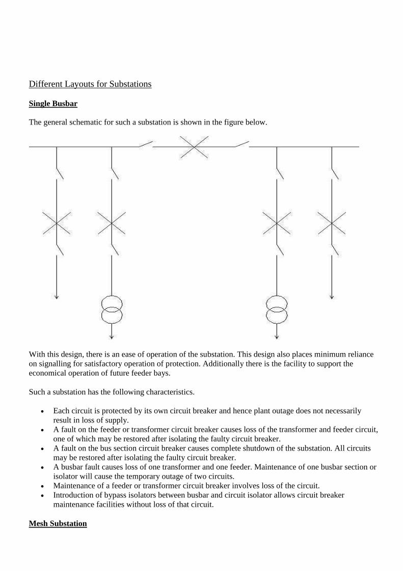
Single Busbar
The general schematic for such a substation is shown in the figure below.
With this design, there is an ease of operation of the substation. This design also places minimum reliance
on signalling for satisfactory operation of protection. Additionally there is the facility to support the
economical operation of future feeder bays.
Such a substation has the following characteristics.
Each circuit is protected by its own circuit breaker and hence plant outage does not necessarily
result in loss of supply.
A fault on the feeder or transformer circuit breaker causes loss of the transformer and feeder circuit,
one of which may be restored after isolating the faulty circuit breaker.
A fault on the bus section circuit breaker causes complete shutdown of the substation. All circuits
may be restored after isolating the faulty circuit breaker.
A busbar fault causes loss of one transformer and one feeder. Maintenance of one busbar section or
isolator will cause the temporary outage of two circuits.
Maintenance of a feeder or transformer circuit breaker involves loss of the circuit.
Introduction of bypass isolators between busbar and circuit isolator allows circuit breaker
maintenance facilities without loss of that circuit.
Mesh Substation

The general layout for a full mesh substation is shown in the schematic below.
The characteristics of such a substation are as follows.
Operation of two circuit breakers is required to connect or disconnect a circuit, and disconnection
involves opening of a mesh.
Circuit breakers may be maintained without loss of supply or protection, and no additional bypass
facilities are required.
Busbar faults will only cause the loss of one circuit breaker. Breaker faults will involve the loss of a
maximum of two circuits.
generally, not more than twice as many outgoing circuits as infeeds are used in order to rationalise
circuit equipment load capabilities and ratings.
One and a half Circuit Breaker layout

The layout of a 1 1/2 circuit breaker substation is shown in the schematic below.
The reason that such a layout is known as a 1 1/2 circuit breaker is due to the fact that in the design, there
are 9 circuit breakers that are used to protect the 6 feeders. Thus, 1 1/2 circuit breakers protect 1 feeder.
Some characteristics of this design are:
There is the additional cost of the circuit breakers together with the complex arrangement.
It is possible to operate any one pair of circuits, or groups of pairs of circuits.
There is a very high security against the loss of supply.
Principle of Substation Layouts
Substation layout consists essentially in arranging a number of switchgear components in an ordered
pattern governed by their function and rules of spatial separation.
Spatial Separation
Earth Clearance: this is the clearance between live parts and earthed structures, walls, screens and
ground.
Phase Clearance: this is the clearance between live parts of different phases.
Isolating Distance: this is the clearance between the terminals of an isolator and the connections
thereto.

Section Clearance: this is the clearance between live parts and the terminals of a work section. The
limits of this work section, or maintenance zone, may be the ground or a platform from which the
man works.
Separation of maintenance zones
Two methods are available for separating equipment in a maintenance zone that has been isolated and
made dead.
1. The provision of a section clearance
2. Use of an intervening earthed barrier
The choice between the two methods depends on the voltage and whether horizontal or vertical clearances
are involved.
A section clearance is composed of a the reach of a man, taken as 8 feet, plus an earth clearance.
For the voltage at which the earth clearance is 8 feet, the space required will be the same whether a
section clearance or an earthed barrier is used.
HENCE:
Separation by earthed barrier = Earth Clearance + 50mm for barrier + Earth Clearance
Separation by section clearance = 2.44m + Earth clearance
For vertical clearances it is necessary to take into account the space occupied by the equipment and
the need for an access platform at higher voltages.
The height of the platform is taken as 1.37m below the highest point of work.
Establishing Maintenance Zones
Some maintenance zones are easily defined and the need for them is self evident as is the case of a circuit
breaker. There should be a means of isolation on each side of the circuit breaker, and to separate it from
adjacent live parts, when isolated, either by section clearances or earth barriers.
Electrical Separations
Together with maintenance zoning, the separation, by isolating distance and phase clearances, of
the substation components and of the conductors interconnecting them constitute the main basis of
substation layouts.
There are at least three such electrical separations per phase that are needed in a circuit:
1. Between the terminals of the busbar isolator and their connections.
2. Between the terminals of the circuit breaker and their connections.
3. Between the terminals of the feeder isolator and their connections.
Components of a Substation
The substation components will only be considered to the extent where they influence substation layout.
Circuit Breakers

There are two forms of open circuit breakers:
1. Dead Tank - circuit breaker compartment is at earth potential.
2. Live Tank - circuit breaker compartment is at line potential.
The form of circuit breaker influences the way in which the circuit breaker is accommodated. This may be
one of four ways.
Ground Mounting and Plinth Mounting: the main advantages of this type of mounting are its
simplicity, ease of erection, ease of maintenance and elimination of support structures. An added
advantage is that in indoor substations, there is the reduction in the height of the building. A
disadvantage however is that to prevent danger to personnel, the circuit breaker has to be
surrounded by an earthed barrier, which increases the area required.
Retractable Circuit Breakers: these have the advantage of being space saving due to the fact that
isolators can be accommodated in the same area of clearance that has to be allowed between the
retractable circuit breaker and the live fixed contacts. Another advantage is that there is the ease and
safety of maintenance. Additionally such a mounting is economical since at least two insulators per
phase are still needed to support the fixed circuit breaker plug contacts.
Suspended Circuit Breakers: at higher voltages tension insulators are cheaper than post or
pedestal insulators. With this type of mounting the live tank circuit breaker is suspended by tension
insulators from overhead structures, and held in a stable position by similar insulators tensioned to
the ground. There is the claimed advantage of reduced costs and simplified foundations, and the
structures used to suspend the circuit breakers may be used for other purposes.
Current Transformers
CT's may be accommodated in one of six manners:
Over Circuit Breaker bushings or in pedestals.
In separate post type housings.
Over moving bushings of some types of insulators.
Over power transformers of reactor bushings.
Over wall or roof bushings.
Over cables.
In all except the second of the list, the CT's occupy incidental space and do not affect the size of the layout.
The CT's become more remote from the circuit breaker in the order listed above. Accommodation of CT's
over isolator bushings, or bushings through walls or roofs, is usually confined to indoor substations.
Isolators
These are essentially off load devices although they are capable of dealing with small charging currents of
busbars and connections. The design of isolators is closely related to the design of substations. Isolator
design is considered in the following aspects:
Space Factor
Insulation Security
Standardisation
Ease of Maintenance
Cost
Some types of isolators include:
Horizontal Isolation types
Vertical Isolation types
Moving Bushing types

Conductor Systems
An ideal conductor should fulfil the following requirements:
Should be capable of carrying the specified load currents and short time currents.
Should be able to withstand forces on it due to its situation. These forces comprise self weight, and
weight of other conductors and equipment, short circuit forces and atmospheric forces such as wind
and ice loading.
Should be corona free at rated voltage.
Should have the minimum number of joints.
Should need the minimum number of supporting insulators.
Should be economical.
The most suitable material for the conductor system is copper or aluminium. Steel may be used but has
limitations of poor conductivity and high susceptibility to corrosion.
In an effort to make the conductor ideal, three different types have been utilized, and these include:
Flat surfaced Conductors
Stranded Conductors
Tubular Conductors
Insulation
Insulation security has been rated very highly among the aims of good substation design. Extensive
research is done on improving flashover characteristics as well as combating pollution. Increased creepage
length, resistance glazing, insulation greasing and line washing have been used with varying degrees of
success.
Power Transformers
EHV power transformers are usually oil immersed with all three phases in one tank. Auto transformers can
offer advantage of smaller physical size and reduced losses. The different classes of power transformers
are:
o.n.: Oil immersed, natural cooling
o.b.: Oil immersed, air blast cooling
o.f.n.: Oil immersed, oil circulation forced
o.f.b.: Oil immersed, oil circulation forced, air blast cooling
Power transformers are usually the largest single item in a substation. For economy of service roads,
transformers are located on one side of a substation, and the connection to switchgear is by bare
conductors. Because of the large quantity of oil, it is essential to take precaution against the spread of fire.
Hence, the transformer is usually located around a sump used to collect the excess oil.
Transformers that are located and a cell should be enclosed in a blast proof room.
Overhead Line Terminations
Two methods are used to terminate overhead lines at a substation.
Tensioning conductors to substation structures or buildings
Tensioning conductors to ground winches.

The choice is influenced by the height of towers and the proximity to the substation.
The following clearances should be observed:
VOLTAGE LEVEL MINIMUM GROUND CLEARANCE
less than 66kV 6.1m
66kV - 110kV 6.4m
110kV - 165kV 6.7m
greater than 165kV 7.0m

Generation, Distribution, Use of Electric
Current - Basic vocational knowledge
(Institut fr Berufliche Entwicklung, 141 p.)
4. Power transmission and distribution in power supply systems
(introduction...)
4.1. Types of networks
4.2. International networks
4.3. Common voltage levels in the flow of electric energy
4.3.1. The importance of the voltage
4.3.2. Voltage levels of the elec-trotechnical networks
4.4. The importance of the electric current as dimensioning
criterion for all transmission elements
(introduction...)
4.4.1. Operating current
4.4.2. Short-circuit current
4.4.3. Environment
4.5. Common technical terms in the field of transmission
and distribution
4.6. Lines and cables as transmission and distribution
elements
4.6.1. Basic terms
4.6.2. Lines for heavy-current installations
4.6.3. Power cables
4.7. Switching and distributing plants and accessories for
the transmission and distribution of electric energy
4.7.1. Switching and distributing plants
4.7.2. Switches
4.7.3. Accessories
4.7.4. Insulating material (insulators)
4.8. Laying of lines and cables
4.8.1. General
4.8.2. Laying of lines
4.8.3. Laying of cables
4.8.4. Electric connections
Generation, Distribution, Use of Electric Current - Basic vocational knowledge (Institut
fr Berufliche Entwicklung, 141 p.)
4. Power transmission and distribution in power supply systems
Electric power system

The whole of electrotechnical installations and networks including all necessary additional devices for the
generation, transmission and use of electric power within one regional unit,
Electrotechnical installation (or plant)
The whole of equipment required for proper functioning of the complete technological unit.
Electrotechnical network (or electric mains)
A system of interconnected electric lines of the same rated voltage for the transmission and distribution of
electric power.
4.1. Types of networks
Supergrids (extra-high voltage systems)
(transmission function)
for power supply to larger areas with transmission voltages of 110 kV, 220 kV and 380 kV.
Medium-voltage systems
(distribution function) for power supply to smaller areas (towns, parts of towns, industrial plants, etc.) with
transmission voltages of 1 to 30 kV.
Low-voltage systems (supply function) for power supply to the majority of consumers (electric household
appliances and motors of low and medium capacity) with transmission voltages of up to 1 kV.
Open systems
have a single feeding point.
Closed systems
have two feeding points which makes the network more fail-safe.

Figure 7. Various types of networks as integral parts of the electric power transmission system - (1)
supergrids (extra-high voltage systems (2) medium-voltage system (3) low-voltage systems - 1 mesh-
operated network, 2 medium-voltage ring-operated network, 3 low-voltage distribution network (closed), 4
open network (multiple lump-loading), 5 star network, 6 feeding

Figure 8. Example of interconnected national networks - 1 transmission levels, 2 distribution levels, 3
international networks, - (1) power station, (2) heat-generating station, (3) industrial power station, (4)
pumped storage power station
Table 2 Open and closed systems (networks)
Type
and
circuit
Advantages and
disadvantages
Examples of
application
Open
systems
with
end-loaded lines
simple circuit, clear
arrangement, very simple
protective system, very easy
planning, good utilization,
low costs, poor operational
reliability, poor voltage
maintenance, high losses
small industrial
plants and local
networks of
small extent
multiple lump-loaded lines

branched lump-loaded lines lighting
installations
Closed
systems
with
lines with double feeding
simple circuit local networks
for long-distance
settlements,
extended factory
halls
Closed
system
of
ring layout
clear arrangement factory plants,
medium-voltage
distribution
networks,
higher-level
supergrids
star layout better voltage maintenance,
less losses, easy planning,
better operational reliability,
poor utilization, acceptable
low-voltage
distribution
networks in big
industrial plants

costs, sophisticated protective
system
meshed layout
very good operational
reliability, very good voltage
maintenance, low losses, very
good utilization, less simple
circuit, less clear
arrangement, very
sophisticated protective
system, less easy planning,
acceptable costs
local networks
for bigger and
large towns, low-
voltage networks
for big
companies
4.2. International networks
The designation of networks and conductors is internationally coded to IEC 445.
The code letters used have the following meaning:
T terre (French) (earth)
I insulation
N neutral wire
C combined
S separated
P protection
E earth
TN-networks
Networks where one point of the network, i.e. one point of the service circuit, is directly earthed (T) and
the casings of the equipment or installations are electrically connected with such point through a protective
conductor (N). They apply the protective measures of connection to neutral or protective earthing with fault
current return through metallic conductors (water pipes, cable sheathings).
- TN-C-network
PEN protective conductor with function of neutral wire.

Figure 9. TN-C-network
- TN-S-network
PE protective conductor carrying no operating current.
Figure 10. TN-S-network
- TN-C-S-network
PE protective conductor carrying no operating current.
Figure 11. TN-C-S-network
TT-networks
Networks where one point of the network is directly earthed (1) and the casings of the equipment or
installations, irrespective of the existence of any neutral wire, are connected with earth leads which are not

electrically connected to the earthed network point (T). Such networks, which are internationally called
TT-networks, apply protective earthing (single earthing) using FI or FU protective circuits.
TT-network
Figure 12. TT-network
IT-networks
Networks where no point of the network is directly earthed (I) but the casings of the equipment or
installations are directly earthed (T). Such networks apply the protective conductor system, protective
earthing, FI and FU protective circuits.
IT-network
Figure 13. IT-network
4.3. Common voltage levels in the flow of electric energy
4.3.1. The importance of the voltage
The amount of voltage is decisive for the thickness of the insulation material (wire insulation) or the size of
the distance of active conductors between each other and the earth. Economically this means the use of
expensive or less expensive insulation material and, with respect to overhead lines, additionally occupation
of ecologically important land. High-voltage overhead lines also involve overhead construction problems.
Depending on the climatic zones, loads due to wind and ice, for example, are material-intensive design
factors.
4.3.2. Voltage levels of the elec-trotechnical networks

The variety of the individual levels shall be demonstrated by means of an example of an installation
Figure 14. Example of possible voltage levels - 1 generator, 2 generator transformer, 3 substation
transformer, 4 distribution transformer, 5 consumers, 6 voltages in kV
To enable efficient transmission of high powers over large distance, the transmission voltages have become
higher and higher in the course of technological development.

Figure 15. Development of transmission voltages worldwide - 1 high-voltage three-phase transmission, 2
high-voltage D.C. transmission
4.4. The importance of the electric current as dimensioning criterion for all transmission
elements
Having dealt with the effects of the voltage on the physical dimensions of all electrotechnical transmission
elements, we now consider the effects of the electric current:
There are three objective factors of influence on the dimensioning.
4.4.1. Operating current
The operating current is important for normal operation which may be of continuous, short-time or
intermittent type.
Continuous operation
Continuous operation means uninterrupted loading of all transmission elements by current of almost
constant intensity which, depending on the current density, results in heating of the active conductors. That
means that all materials and auxiliary materials (insulation) as well as components, which are in direct
contact with the active conductor, absorb heat. The consequences are expansion and aging effects on
busbars, metal-clad cables, wire insulations etc.
Short-time operation/intermittent operation
Short-time operation/intermittent operation mean that, after periods of heating, all transmission elements
undergo periods of cooling. This may be aimed at maximum thermal peak-load on the one hand or at
thermal load below the limit load on the other hand. It depends on the components to be used.
4.4.2. Short-circuit current
Faults normally involve extreme loads for all components, depending on the design of the installation in
terms of protection:
- Instantaneous short-circuit current

The so-called instantaneous or asymmetric short-circuit current involves high electrodynamic loads for the
installation parts immediately on its occurence. The intensive magnetic fields generated as a consequence
of such current can physically destroy busbar installations, current transformer heads (insulator-type
transformer), switching devices etc. Conductor elements of overhead lines may also be affected.
- Sustained short-circuit current
The sustained short-circuit current occuring after the instantaneous short-circuit current has several times
the intensity of the operating current and, with a time lag after the short- circuit, results in heavy or extreme
heating of all components in the fault circuit. Mostly such current destroys the installation parts unless this
is prevented by adequate protective measures.
4.4.3. Environment
The thermal effects of the environment are important for the dimensioning of the installation with respect
to the cross sections of the transmission elements and to the protective elements to be used. High ambient
temperatures physically call for larger cross sections and low ambient temperatures permit smaller cross
sections than normally specified for the operating current. Mutual heating is taken into account in
installation engineering by providing for adequate distances of busbars, stranded conductors, lines and
cables between each other and between components and for air circulation.
4.5. Common technical terms in the field of transmission and distribution
Outdoor plant/installation
Installation exposed to weather conditions without protection (see outdoor).
Open-type plant/installation
Installation with equipment not fully protected against accidental contact.
Outdoor(s)
Limited area in the open air featuring the same temperature and air humidity according to the local climate.
Assembly unit
A combination of several components or devices forming a functional unit.
Component
A single part that can only work in connection with other components.
Subassembly/module
Locally combined group of components which can function independently. Subassembly (in the context of
a project) is a self-contained part of a plant/installation as defined from shipping and installation aspects.
Modular component/module
A component which, because of its specific modular design, can be assembled with other similar modular
components into a consistent whole.
(Component) part
A constructionally and electrically self-contained member of a part of an installation.
Enclosed
Equipment and plants/installations which are protected against environmental influences.
Protected outdoor installation/plant
Outdoor installation which is protected against rainfall up to an angle of incidence of 30 degrees to the
perpendicular.

Main distribution (system)
First distribution system after power feeding.
Information unit
The information unit of an installation or section or part of an installation comprises its locally functionally
combined equipment for the generation, transmission, processing and reception of information, even
though this is implemented according to the rules of heavy-current engineering.
Indoor installation/plant
Installation inside rooms or buildings.
Indoor(s)
Room in buildings which is free from effects of weather conditions
Mesh network
Closed network system consisting of crossing lines which are interconnected and fused at the crossing
points. The crossing points are called “nodal points”, the closed sections between the nodal points a “mesh”
and each part of the line “mesh line”.
Nodal point of a network
A point in the electric energy distribution system where more than two circuits (lines) can be
interconnected.
Potential equalization
Electrically conductive connection between electrically inactive parts, such as water, gas and heater pipes,
steel structures, metallic cable sheathings, foundation earth leads and protective conductors. This measure
prevents a potential difference (voltage) between such parts.
Figure 16. Example of central potential equalization - 1 foundation earthing electrode, 2 heating tube
system, 3 drinking water pipe, 4 gas distribution pipe, 5 house connection box, 6 customer’s meter. 7
potential equalization line (connection point optional), 8 potential equalization bar (if necessary), 9 water
meter (conductively bridged, if the meter is built into a metallic pipe system), 10 structural design
Primary system

It serves the purpose of directly distributing the electric energy and includes all components directly
involved in the transmission of electric energy.
(Main) busbar
A conductor - bar or rope - to which several conductors or lines are connected.
Busbar section
A portion of busbars or busbar systems.
Each section comprises only one part of the switchboard sections.
Busbar system
Busbars with connected switchboard sections.
Figure 17. Double busbar system - I system 1, II system 2
Busbar coupling
Conductive connection between busbar sections.
Figure 18. Longitudinal busbar coupling - I, II, III busbar sections
Switching plant
Distribution system with switching devices which make it possible to electrically connect and disconnect
the outgoing main lines with/from the busbar.
Switchboard section
Local combination of the elements belonging to one branch.
Secondary system
It includes all facilities which are necessary for the protection, control, monitoring, measuring and metering
but are not directly involved in the transmission of electric energy,
Station
Room or part of a building housing one or more electrotechnical installations or parts of installations and
their service facilities for the purpose of distribution and conversion of electric energy.
Conversion
Change of the nominal value of physical quantities which are characteristic of the form of electric energy.
Conversion includes transformation, frequency changing, rectification and inversion.
Subsidiary distributing system
Distribution system following the main distribution system.

Distribution plant
Electrotechnical installation including accessories, such as actuators, transformers, measuring devices etc.,
the main purpose of which is to distribute electric energy to several outgoing lines.
Cubicle (cell)
is a construction of suitable material which stands on the floor and has a degree of protection at least at one
side but not at all sides.
4.6. Lines and cables as transmission and distribution elements
4.6.1. Basic terms
Lines
They serve the purpose of transmission and distribution of electric energy in general and of power supply
and information trans-mision of any kind in particular. They are produced as bare (plain) and insulated
types.
Cables
They have the same functions of energy transmission and distribution. Their particular construction permits
their laying in the media air, soil and water under various external and internal conditions (mechanical,
chemical, physical and electrotechnical).
System earthing and protective earthing wires
They include all conductors which carry off the electric energy to the earth in the event of fault. They have
the potential of the earth. Since they have to be in direct contact with the soil, they are not insulated but
have a high degree of protection against corrosion.
Types of laying
- Fixed laying
is a type of laying where the lines cannot change their position after installation (fixed with clips etc.)
- Movable laying
is a type of laying allowing the line to be frequently moved to another place (relocation of the equipment
connected).
Line resistances
Figure 19. Equivalent connection diagram of a line - RLeit. line resistance, RIso insulation resistance, XL
inductive reactance (inductance), XC capacitative reactacne (capacitance), Z consumer
- Ohmic line resistance RLeit
It depends on the length, material, cross section and temperature:

The conductor cross-section is to be selected so as not to exceed the admissible voltage and conduction
loss:
- Insulation resistance RIso
It depends on the type of insulation, A general rule for cables and lines is
The insulation resistance is reduced by dirty surfaces, cracks in the insulation material, increasing tensional
load and aging.
- Inductive reactance (inductance) XL
It depends on the line inductance and on the frequency:
The inductance per conductor depends on the length of the line “l”, the conductor distance “a” and the
conductor radius “r”. It is calculated as follows:
L 1 a r
H km mm mm
If it is a line with return line, the total inductance of the line is to be calculated using 2.1 for the length.
Because of the small conductor distance “a” of cables, the inductive reactance of cables is considerably
lower than that of overhead lines.
Examples:
- Capacitive reactance (capacitance) XC
Capacitive charges occur between conductor and conductor and between conductor and earth.

Figure 20. Equivalent connection diagram of the capacitances of - a three-phase overhead line, CL
conductor-conductor capacitance, CE conductor-earth capacitance
The mutual capacitance of a three-phase overhead line is calculated as follows:
CB =CE + 3 CL
CB= mutual capacitance
CE = conductor-earth capacitance
CL = conductor-conductor capacitance
Charge current of the three-phase line
The admissible values of capacitance and reactance are
Table 3 Influence of circuit elements on the behaviour of lines with respect to different types of voltage and
current
Elements Low voltage Medium and high
voltage
Direct current Three-phase current
Line
resistance
heating UV, PV heating UV, PV heating UV, PV heating UV , PV
Insulation
resistance
insulation and corona
losses are low
insulation and corona
losses increase with
increasing voltage,
therefore from 110 1<V
bundle conductors for
overhead lines
low corona
losses
insulation between several
conductors to be
considered, e.g. in multi-
conductor cables
Line
inductance
self-inductance effects
in the event of
switching operations,
little inductive phase
shift since short line
length
self-inductance effects
in the event of load
variations, inductive
phase shift increases
with increasing line
length
self-inductance
effects only
when switching
on and off
with 2 three-phase
systems and operating
currents flowing in
opposite directions the
self-inductance effects are
compensated
Line
capacitance
low medium to high capacitance
increases with
increasing line
line capacitance depends
on distance between each
of the three conductors, on

length and
voltage
the insulation and
screening
4.6.2. Lines for heavy-current installations
Bare (plain) lines
Bare lines are non-insulated conductors installed on insulating bodies (insulators), outside the area of
contact on poles, behind protective grids or inside casings. As earth leads, bare lines are layed in the soil
and in the area of contact.
- Bars (rails)
Solid, non-insulated conductors which, because of their shape or cross section, are highly resistant to
deformation. They may be marked by colour codes.
Table 4 Bar (rail) sections and section moduli
No. Section Position of conductor bars to each other Section moduli
1 flat
high compared to 2
2 flat
low compared to 1
3 tubular
very high compared to 4
4 round
low compared to 3 and 1
5 channel
very high compared to 1 to 4
The bars are connected by welded or screwed connections.
They are held by line carriers on porcelain insulators or without carriers on thermoset plastic insulators or
in hard paper fans.
Figure 21. Pin-type (rigid-type) insulator - 1 support, 2 bar carrier for two busbars (laid on edge)
Table 5 Hard paper boards for fixing of busbards

Designation Construction Comments
Hard paper fan
easy mounting
Hard paper fan with end
strip
better hold compared to simple fan
Hard paper board with
recesses
to be used where high bending stresses may occur
(short circuit)
- Busbars
Busbars are bars or ropes to which several conductors or lines for current supply or derivation are
connected. They are selected according to the current load (thermal load) from tables. Painted busbars can
resist higher loads because the paint enables better dissipation of heat. The admissible D.C. load is higher
than the A.C. load. Due to the skin effect of A.C. the cross section is not fully utilized. Therefore, pipe
sections etc. are used in high-voltage installations. In order to avoid the accumulated temperature (ambient
temperature V.. plus conductor temperature V,) to be exceeded, the admissible load current is to be reduced
(load reduction) in the event of a higher ambient temperature. This can also be influenced by the way of
laying.
Table 6 Cooling at flat section
Way of laying Use Cooling
On edge, horizontal busbar current bar outlet good
On edge, vertical busbar good
Flat, horizontal current bar very bad
Flat, vertical outlet good
Load because of temperature changes results in displacement of the busbars. Such temperature difference,
which may be caused by varying heating effect of the current (alternating load) and by varying ambient
temperature of busbars, results in change of length. Busbars are, therefore, fixed in line carriers which
permit sliding and/or expansion joints are included in the course of the line. The slide supports and
expansion joints make the expansion forces ineffective.
Figure 22. Diagram of busbar laying - 1 rigid support, 2 slide support, 3 expansion joint

Figure 23. Expansion joint - 1 expandable portion of a multitude of thin strips, 2 connection piece
Loads by heavy currents, such as in the event of short circuit, generate a heavy magnetic field around the
conductor. Heavy forces may occur between the fields. Their effect depends on the instantaneous short-
circuit current, supporting point distance, conductor section, type of laying and conductor distance.
- Current bars
Current bars are rigid conductors for the transmission of electric energy to portable devices through current
collectors. They are used as series line in low-voltage and high-voltage installations. The main materials
are half-hard rolled copper or aluminium.
Example:
Figure
- Earth leads
Earth leads are bare conductors lying in the soil with a firm an conductive connection with the soil.
The main materials for protective earthing and system earthing lines are:
hot galvanized or copper clad strip steel or round steel with a minimum cross section of 50 mm,
aluminium sections or rope with a minimum section of 35 mm,
copper sections or rope with a minimum cross section of 16 mm,
steel rope with a cross section of 120 mm ²
Table 7 Customary minimum cross sections of earth leads
Type of
earth lead
Semi-finished products Minimum cross
sections/dimensions
Customary size
Strip earth
conductors
strip steel 100 mm² min. thickness: 3 mm 30 mm x 4 mm 40 mm x 5
mm
round steel diameter: 10 mm diameter: 10 mm, 12 mm, 13
mm
Earth rods mild steel tube angular
steel or other similar
sectional or round steel
diameter: 24 mm min. wall
thickness: 3 mm 40 mm x 40 mm
x 4 mm
diameter: 33.5 mm (1”)
diameter: 60 mm (2”) 40 mm
x 40 mm x 4 mm

Earth leads are interconnected by screwed, clamped and welded connections.
- Contact lines.
Contact lines are used for electromobiles with and without longitudinal carriers including safety stop
cables. Conductors of sectional rails in workshops, on ceilings, under bridges, in tunnels and passages are
also belonging to the contact lines.
Table 8 Contact lines, types and use
Designation Material Type of section Purpose of use
Steel-copper
contact line
Contact line with
steel core and
copper sheathing
No high resistance to wear, suitable for
subsidiary routes with normal traffic and low
speeds 1 copper sheathing 2 steel core 3
groove for fixing purposes
Copper
contact wire
Solid copper
section
as above but without steel
core
Ri 80, Ri 100, Ri 120. use for standard-gauge
railways
Steel contact
line
All-steel contact
line
For replacement purposes only, for short
routes with little traffic
0 Steel
current bar
(rail)
Sectional steel rail
with aluminium
reinforcement
High resistance to wear, suitable for city or
underground railway routes as feeder bar
beside the track (only when provided with its
own track bed - self-contained facilities) 1
steel rail section 2 aluminium subsequently or
additionally added to enlarge the cross section
3 pick-up sides
Flat-section
type
Copper or bronze
For small contact wires, crane tracks,
conveyor equipment
Round-
section type
Copper or
copperbase alloys,
bronze etc.
For crane equipment, conveyor equipment
- Overhead lines
These are open-type lines installed overhead in the open air with span lengths of normally more than 20m.
In order to place overhead lines out of reach of man and to ensure freedom of motion for vehicles of any
kind, poles are required for overhead lines. Overhead lines of up to 1000 V, for example, are fixed on pin-
type insulators or shackle insulators. Cap-and-pin insulators or long-rod insulators are used for rated
voltages of more than 1000 V.

Figure 24. Types of poles - (1) supporting pole (straight-line pole), e.g. wooden pole with reinforced
concrete pole footing, (2) angle pole, e.g. wooden pole with anchor, (3) angle pole, e.g. wooden pole with
tie, (4) terminal pole, e.g. wooden A-pole (anchor and terminal pole) 1 wooden pole, 2 reinforced concrete
footing, 3 anchor, 4 tie
Figure 25. Pole head types - 1 use in the voltage range 0.4 to 6 kV as wooden pole or reinforced concrete
pole, 2 use in the voltage range 6 to 20 kV as concrete pole (the central conductor is alternatingly run at the
right-hand and left-hand side of the pole), 3 use for voltages of more than 20 kV up to about 220 kV as
lattice steel pole
Figure 26. Insulators - 1, 2 pin-type (rigid-type) insulators, 3 shackle insulator, 4 cap-and-pin insulator, 5
long-rod insulator
- Open-type lines
Open-type lines include, for example, short connection lines in the area of buildings (over courtyards,
between workshop halls etc.).
- Stranded conductors
Stranded conductors are multi-wire conductors which are movable because of their flexible construction.

- Earthing wires
Earthing wires are used to protect voltage-carrying conductors against direct lightning stroke or to carry off
to the soil over-voltage of atmospheric or other origin and consequently to avoid or reduce step and contact
voltages on poles and scaffoldings.
Marking of bare lines
Table 9 Identification colour codes for power transmission lines
Type of current Conductor Colour code
D.C. L+ red
L- blue
M light-blue
Three-phase current L 1 yellow
L 2 green
L 3 violet
N light-blue
A.C. L 1 yellow
L 2 violet
Table 10 Identification colour codes for protective earthing and system earthing lines
Type of earthing Colour code
Protective earth black
System earth white with black cross-stripes
Joined protective earth and system earth from the point of joining: black with white cross-stripes
Table 11 Identification colour codes for earthing lines from the conductor to the earth
Type of current Conductor Main
colour
Identification colour additional colour as cross-
stripes
Direct current L+ black red
L- blue
M white
Three-phase current L 1 yellow
L 2 green
L 3 violet
N, PE white
PEN
Single-phase A.C. to
IEC
L 1 black yellow
L 2 green
for raiIway facilities L 1 yellow
L 3 violet
Two-phase A.C. L 1 yellow
L 2 green
Insulated lines

- Construction
Insulated lines consist of a single insulated conductor or of multiple conductors insulated from each other
and are provided with protection against impairment of the electric function. Normally they are not allowed
for laying in soil and water.
Conductor
Material: aluminium or copper, Type of conductor: single-wire, multi-wire or poly-wire, fine-wire or extra-
fine wire.
Shape of cross section: round.
Insulating
cover consisting of rubber, plastic material, glass silk or artificial silk.
Sheathing
consisting of rubber or plastic material.
- Wire marking
The insulating covers of multi-wire lines are marked with a colour code for safety reasons and for quicker
working.
Protective conductor
Colour code of protective conductor: green-yellow,
The green-yellow wire may only be used as protective conductor or auxiliary earthing wire.
Multi-wire lines are produced with or without protective conductor
With flat lines, the wire with the relevant colour code is to be used as protective conductor.
Wire marking
Table 12 Wire marking
Number of wires Lines with protective conductor Lines without protective conductor
1 gnge b1
b1 sw or br
sw or br
2 gnge sw (only for fixed laying) b1 sw or br
3 gnge b1 sw or br b1 sw br
4 gnge b1 sw br b1 sw br sw
5 gnge b1 sw br sw
Gnge green-yellow br brown
b1 blue sw black
- Abbreviations
All countries are aiming at standardized abbreviations for marking and identification. The following
markings are an example:

Group markings
A wire line
D triple line
F flat line (ribbon conductor)
Fr overhead line (wire or rope)
H hose line
I installation line (wiring line)
Kr motorcar supply line
L tubular lamp line
N heavy-current line
P testing and measuring line rubber-sheathed line for mines
R X-ray line
S special line
Sch welding line
T trailing line
TS trailing line, multi-wire
TM trailing line, single-wire
W heater line
Z twin line
Z ignition line
Constructional elements
C shield of metallic wires or conductive layer
CE like C, but around each wire
G insulating cover or sheathing of elastic material (rubber)
2G insulating cover or sheathing of silicone rubber
GS insulating cover, protective cover or fibre core of glass silk
St control wire (St) shield of metal foil
T carrying member
TX textile fibre core
U outer braiding
supervisory wire
Y insulating cover or sheathing of PVC
2Y insulating cover of polyethylene
Additionally marked porperties of the line
fl flat
h increased electric strength
k increased resistance to cold
1 specially light-resisting
oil-resisting
u oil-resisting and non-inflammable
s increased wall thickness
t increased heat resistance
u non-inflammable

Additionally marked properties af the conductor
b poly-wire
e single-wire
f fine-wire
m multi-wire
m/v multi-wire/compressed
vz tin-plated
w helical
z increased tensile strength
Colour code abbreviations
b1 blue
br brown
dgn dark-green
el ivory
ge yellow
gn green
gnge green-yellow
gr grey
nf natural-coloured
sw black
ws white
Figure 27. Insulated line - 1 sheathing, 2 insulating cover, 3 conductor