Embed Size (px)
Citation preview

Presented by:
Kiran Gajrani
Dec 10-12, 2013
Presentation
on
4th INTERNATIONAL CONFERENCE ON ADVANCES IN
ENERGY RESEARCH, IIT BOMBAY
Performance Assessment of Offshore Wind Farm Communication Network using MPLS
based Traffic Engineering
Presentation Outline
Introduction
Wind Turbine Virtual Architecture
Fundamentals of Communication Networks
Overview of MPLS TE
Simulation & Results
Conclusion
Introduction
The growing dependence of our energy sector on renewableresources is a mark of transition from its earlier solitarydependence on conventional resources. Depleting fossil fuels andenvironmental concerns are the biggest reasons for this change.
There are multiple renewable energy resources like;solar, ocean, wind, and bio fuel. Among them, wind energy isestablished as a mature, green, clean, and cost effectivetechnology.
The wind energy is generally tapped from land, onshore, andoffshore farm. The number of offshore wind farms is increasingcontinuously to optimally utilize wind resources. However,developing and managing an offshore wind farm is an uphill task,which requires comprehensive planning and execution.
Proper maintenance and functioning requires real timemonitoring of offshore wind farm. It is not possible to place manpower at offshore wind farm due to its remote locations andrough sea conditions. Thus, control center is normally situated atland for real time monitoring.
This requires reliable and high speed communication networkbetween wind farms and control center.
Proper implementation of communication network ensuresuninterrupted real time monitoring, which significantly increaseuptime, improve reliability, and even extend the lifetime of theWind Turbines (WTs).
Communication networks generally face congestion, which delay transfer of data from offshore wind farm to control center, which impact the real time monitoring.
Introduction (continued)
Wind Turbine Virtual Architecture
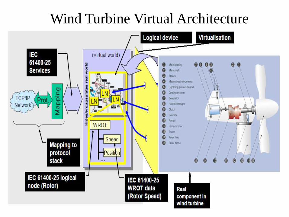
Virtualization provides the right insights on inter-connectedaspects of real devices. IEC 61400-25 has adopted a similarapproach. IEC 61400-25 standard specifies the requirement ofcommunication for monitoring and control of wind farms.
According to IEC 61400-25 standard, a logical nodecorresponds to the specific function of the real physical WT.
Each logical node is defined as a class, which consists ofvarious attributes, and is categorized into different types likestatus, analogue, and control information.
It explains WPP specific information, the mechanism ofinformation exchange and the mapping to communicationprotocols based on client server framework.
Wind Turbine Virtual Architecture (continued)
Logical Node
Class
Function Analogue
signals
Status signals
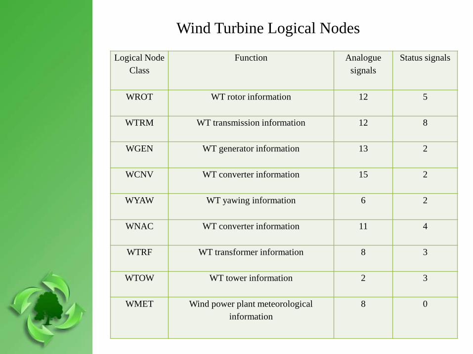
WROT WT rotor information 12 5
WTRM WT transmission information 12 8
WGEN WT generator information 13 2
WCNV WT converter information 15 2
WYAW WT yawing information 6 2
WNAC WT converter information 11 4
WTRF WT transformer information 8 3
WTOW WT tower information 2 3
WMET Wind power plant meteorological
information
8 0
Wind Turbine Logical Nodes
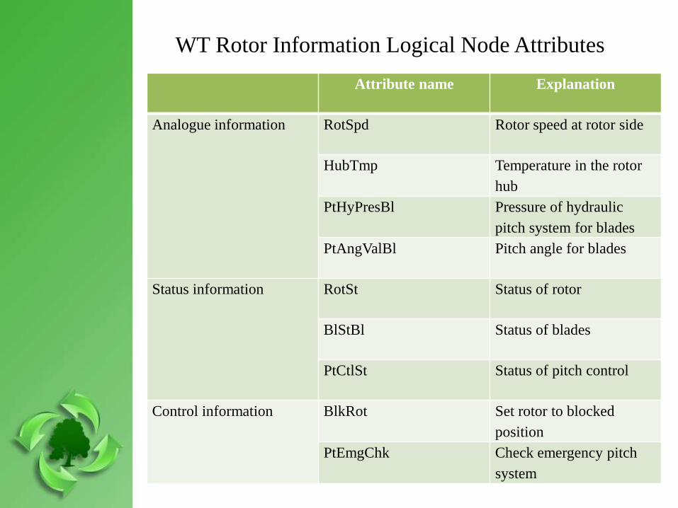
WT Rotor Information Logical Node Attributes
Attribute name Explanation
Analogue information RotSpd Rotor speed at rotor side
HubTmp Temperature in the rotor
hub
PtHyPresBl Pressure of hydraulic
pitch system for blades
PtAngValBl Pitch angle for blades
Status information RotSt Status of rotor
BlStBl Status of blades
PtCtlSt Status of pitch control
Control information BlkRot Set rotor to blocked
position
PtEmgChk Check emergency pitch
system
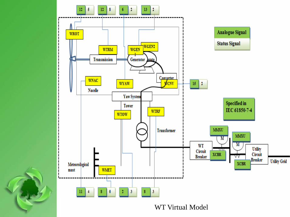
WT Virtual Model
There could be a further division of status and analogue informationbased on some critical parameters. These parameters require real timesupervision and monitoring for a healthy and optimal functioning ofWT.
There are two types of traffic generated within the WT – optional andmandatory.
Optional traffic is generated by non-critical components from afunctionality standpoint like, oil contamination, vibration, temperature,pressure, and humidity. Traffic drop and high latency is acceptable forsuch traffic.
On the other hand, mandatory traffic is generated by critical componentssuch as voltage, current, active power, and reactive power. Hence, thehigh latency and traffic drop is unacceptable for such traffic. Hence,monitoring an offshore wind farm necessarily requires a congestion freecommunication network.
Wind Turbine Virtual Architecture (continued)
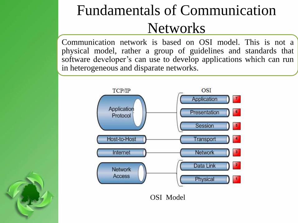
Communication network is based on OSI model. This is not aphysical model, rather a group of guidelines and standards thatsoftware developer’s can use to develop applications which can runin heterogeneous and disparate networks.
Fundamentals of Communication
Networks
OSI Model
The OSI has seven different layers, are segregated into two groups. Thefirst group consists of top three layers, which determine the way theapplications within the end stations will communicate with each other andwith users. The bottom four layers belong to other group, which defineend to end transmission of data.
Top layer is the application layer, which provides an interface between theactual application programs. Next layer is the presentation layer, whichprovides data translation and code formatting. Session layer is the fifthlayer, which keeps track of sessions across different applications.
Transport layer is the fourth layer, which provides flow control,windowing, and connection oriented or connection less sessions with endto end systems. Network layer the third layer, whose main function is toprovide logical addressing and routing to the network.
The second layer is data link layer that provides the physical transmissionof the data and handles error notification. The first layer is physicallayer, which communicates directly with the various types of actualcommunication mediums.
Fundamentals of Communication Networks (continued)
MPLS is a network protocol technology, which successfullyavoids congestion. It also improves scalability and routingflexibility in IP networks. Any conventional IP network usesthe shortest distance path between two hops while creating hotspots. This renders the other alternative paths under-utilized. Insuch situation, there are many possible adverse effects such aslonger delay, throughput degradation, and packet losses.
MPLS TE adopts bandwidth optimization and hence minimizesthe effects of congestion. MPLS TE allows spreading of trafficoptimally while distributing it across the entire networkinfrastructure, hence it is better suited and recommended.
Overview of MPLS TE
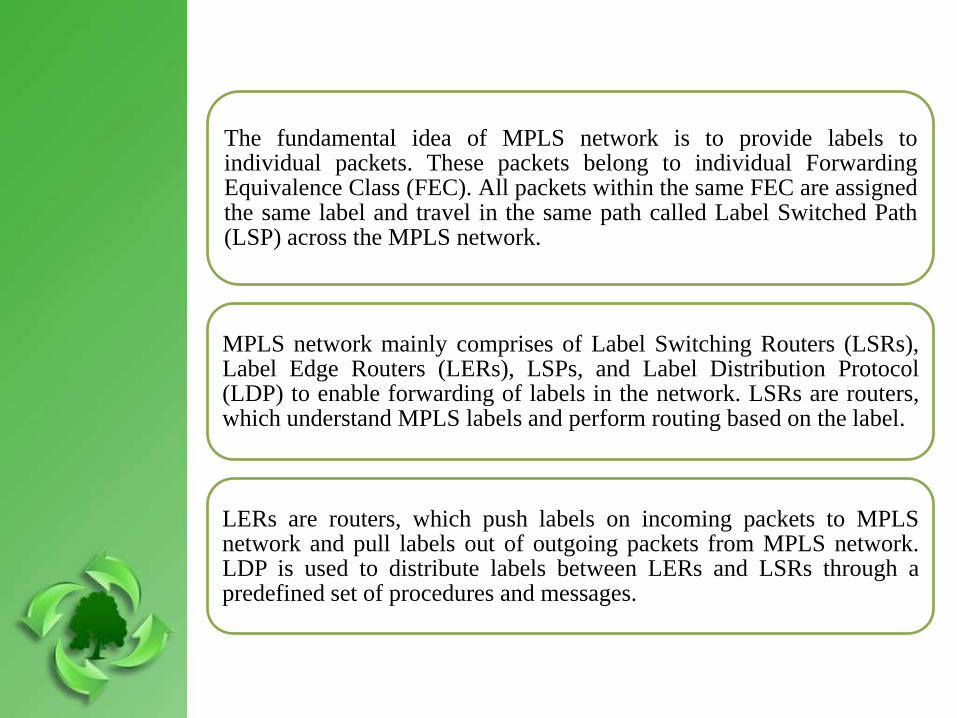
The fundamental idea of MPLS network is to provide labels toindividual packets. These packets belong to individual ForwardingEquivalence Class (FEC). All packets within the same FEC are assignedthe same label and travel in the same path called Label Switched Path(LSP) across the MPLS network.
MPLS network mainly comprises of Label Switching Routers (LSRs),Label Edge Routers (LERs), LSPs, and Label Distribution Protocol(LDP) to enable forwarding of labels in the network. LSRs are routers,which understand MPLS labels and perform routing based on the label.
LERs are routers, which push labels on incoming packets to MPLSnetwork and pull labels out of outgoing packets from MPLS network.LDP is used to distribute labels between LERs and LSRs through apredefined set of procedures and messages.
Simulation and Results
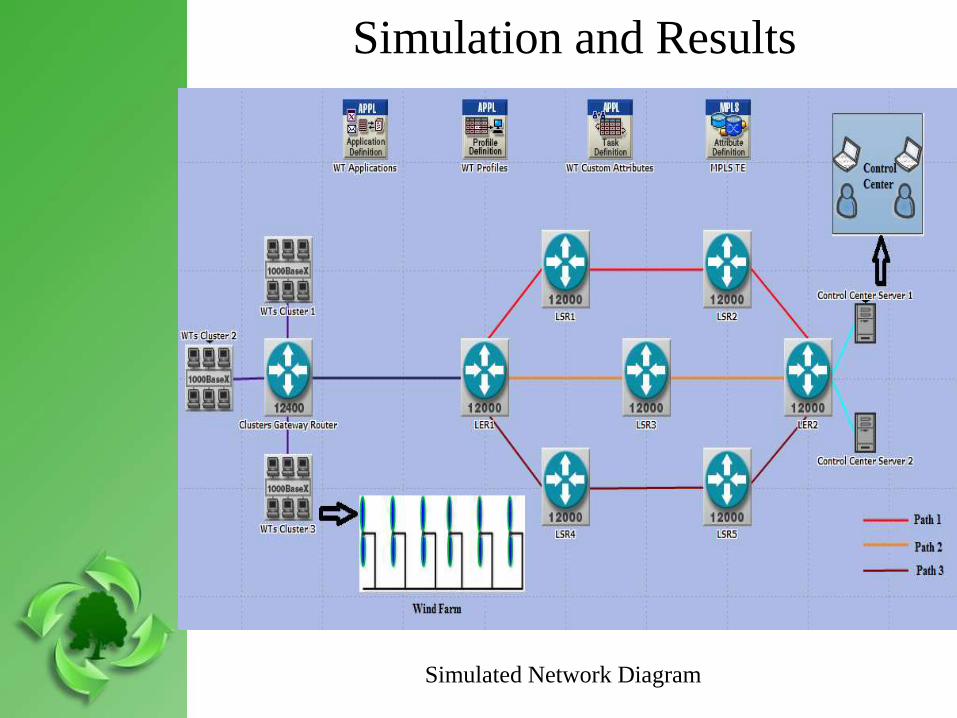
Simulated Network Diagram

Medium scale offshore wind farm of capacity 120 MW,situated 8 km from the shore, has been considered for thestudy. Wind farm consists of three clusters, each having tenWTs.
WTs are connected to a cluster gateway router through1000BASEX gigabit ethernet. Cluster gateway router isconnected to IP core network through SONET OC-12(622.08 Mbit/sec) link.
Core IP network consists of high end Cisco 12000 seriesrouters, which are connected through SONET OC-12.Routing protocol OSPF is used to exchange routing tables.
LER1 and LER2 are ingress and egress routers for corenetwork. Three paths are established between LER1 andLER2. Path 1 is LER1 – LSR1 – LSR2 – LER2. Path 2 isLER1 – LSR3 – LER2. Path 3 is LER1 – LSR4 – LSR5 –LER2.
Simulation and Results(continued)

The total data generated by status signals, mechanical signals, andelectrical signals is 29 bytes/sec (29*1*1), 2550 bytes/sec(51*25*2), and 3600 bytes/sec (36*50*2) respectively. Thecumulative traffic generated by wind farm is 185370 bytes/sec, outof which mandatory traffic is 66030 bytes/sec.
Wind farm traffic is customized and generated. The sampling ratefor WT mechanical parameters is twenty five samples/sec whereasfor electrical parameters is fifty samples/sec; each of the size oftwo bytes. Status signal is of size one byte having sampling rateone per sec. A WT generates twenty nine status signals, fifty onemechanical signals, and thirty six electrical signals.
Three scenarios were simulated to check behavior of IP networkswith wind farm traffic. All three scenarios were simulated for 150seconds and analyzed based on latency, traffic drop, and linkutilization.
Simulation and Results (continued)
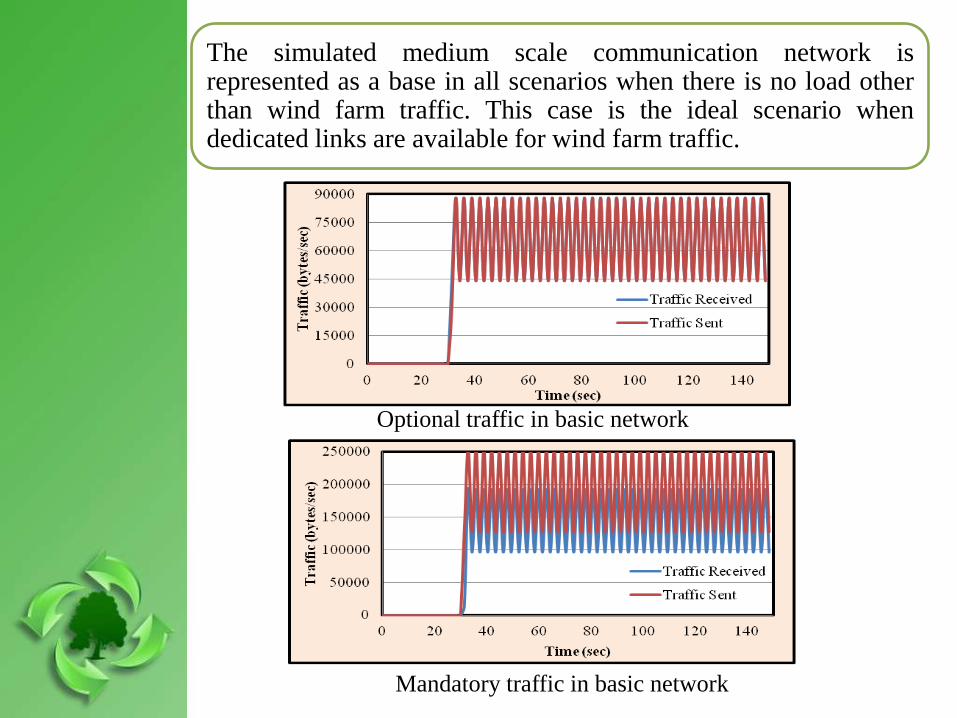
The simulated medium scale communication network isrepresented as a base in all scenarios when there is no load otherthan wind farm traffic. This case is the ideal scenario whendedicated links are available for wind farm traffic.
Optional traffic in basic network
Mandatory traffic in basic network
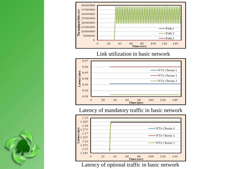
Link utilization in basic network
Latency of mandatory traffic in basic network
Latency of optional traffic in basic network
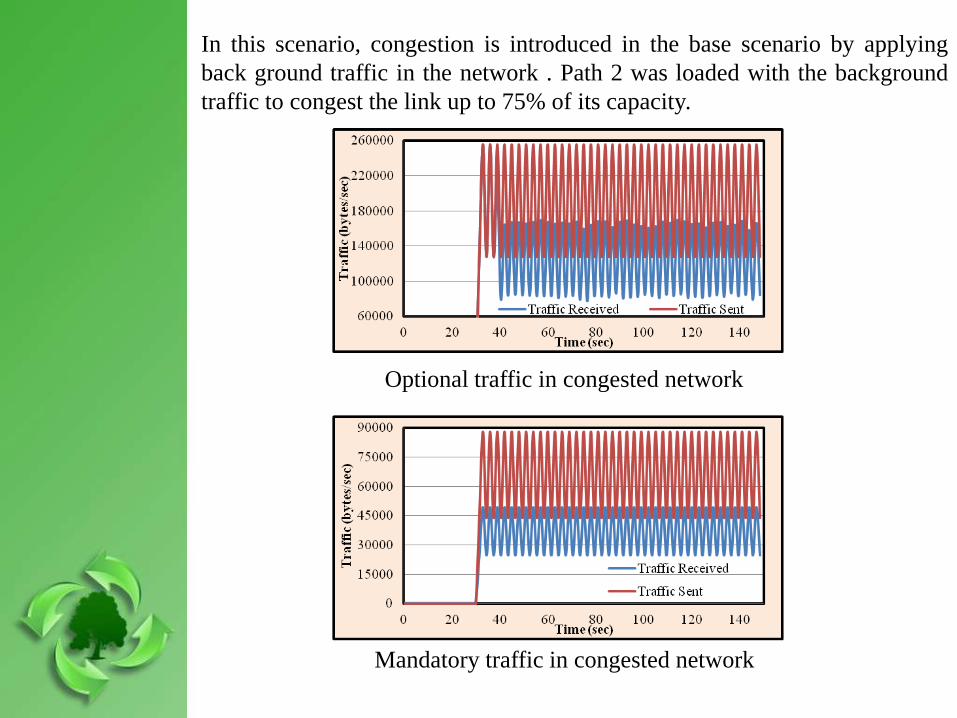
In this scenario, congestion is introduced in the base scenario by applying
back ground traffic in the network . Path 2 was loaded with the background
traffic to congest the link up to 75% of its capacity.
Optional traffic in congested network
Mandatory traffic in congested network
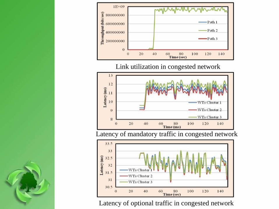
Link utilization in congested network
Latency of mandatory traffic in congested network
Latency of optional traffic in congested network
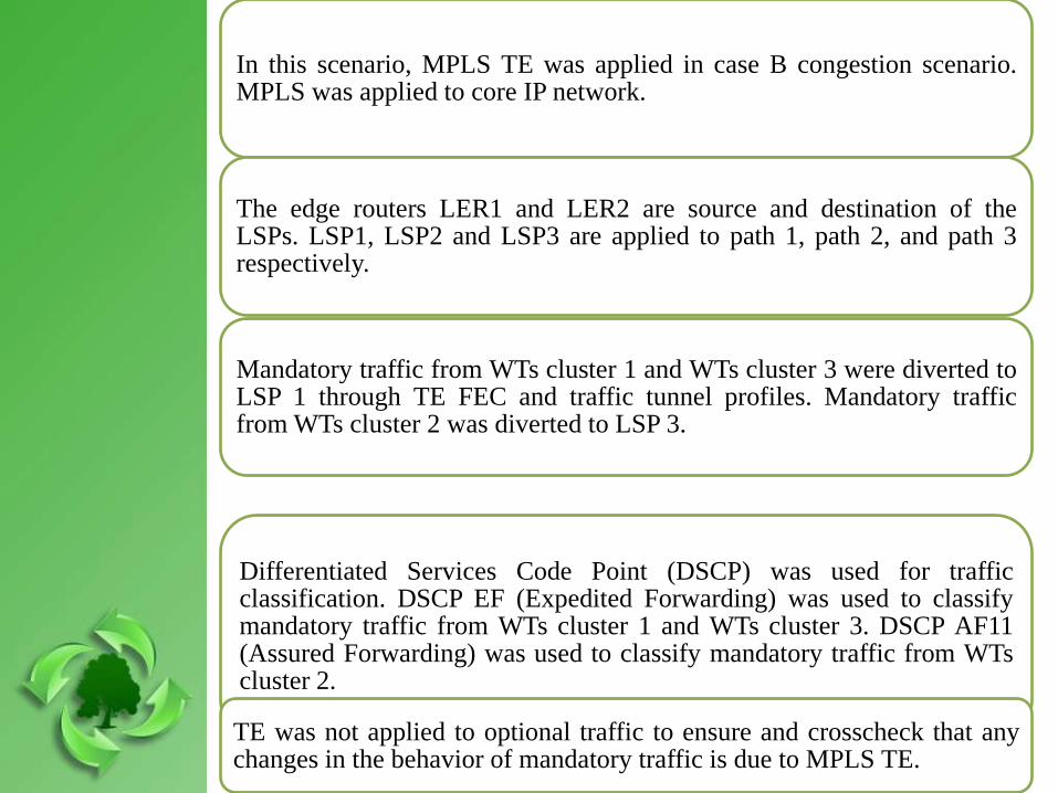
In this scenario, MPLS TE was applied in case B congestion scenario.MPLS was applied to core IP network.
The edge routers LER1 and LER2 are source and destination of theLSPs. LSP1, LSP2 and LSP3 are applied to path 1, path 2, and path 3respectively.
Mandatory traffic from WTs cluster 1 and WTs cluster 3 were diverted toLSP 1 through TE FEC and traffic tunnel profiles. Mandatory trafficfrom WTs cluster 2 was diverted to LSP 3.
Differentiated Services Code Point (DSCP) was used for trafficclassification. DSCP EF (Expedited Forwarding) was used to classifymandatory traffic from WTs cluster 1 and WTs cluster 3. DSCP AF11(Assured Forwarding) was used to classify mandatory traffic from WTscluster 2.
TE was not applied to optional traffic to ensure and crosscheck that anychanges in the behavior of mandatory traffic is due to MPLS TE.
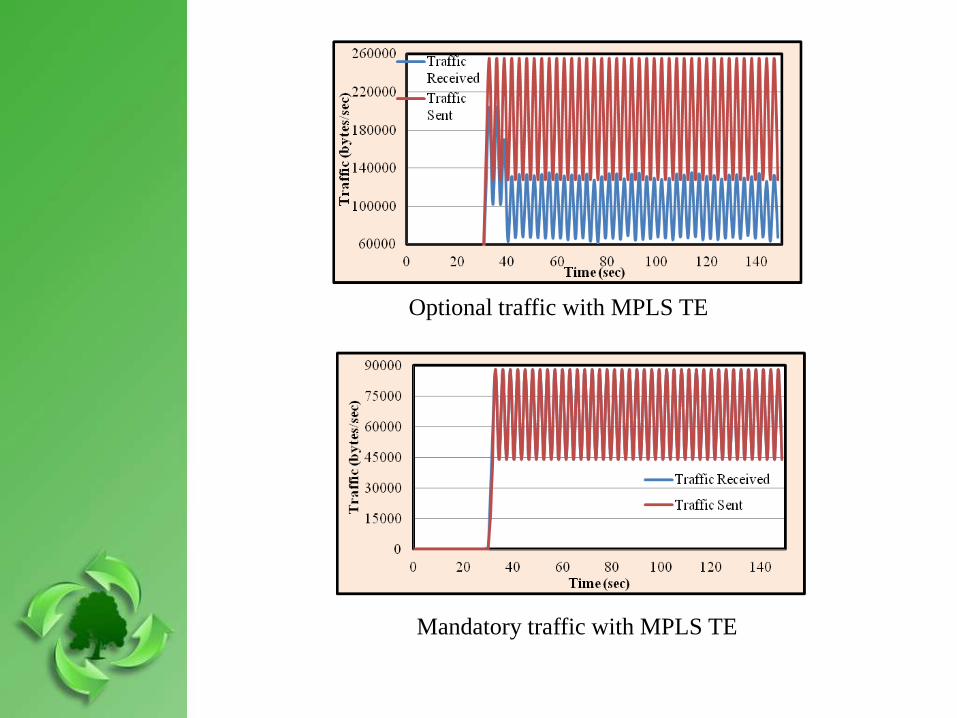
Optional traffic with MPLS TE
Mandatory traffic with MPLS TE
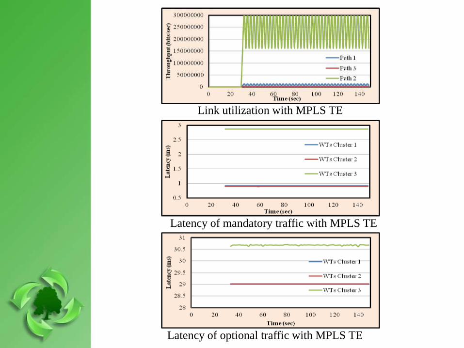
Link utilization with MPLS TE
Latency of mandatory traffic with MPLS TE
Latency of optional traffic with MPLS TE
Conclusion
The basic idea of this paper was to provide congestion management foroffshore wind farm communication network, which was successfullyachieved through MPLS TE.
We simulated a 120 MW medium scale offshore wind farm. TCP/IPbased communication network was used to connect the offshore windfarm to onshore control center.
Network congestion scenarios were simulated and network dynamics wasassessed in terms of latency, traffic drop, and link utilization.
MPLS TE was implemented in the congested network. We observed thatMPLS TE improves the performance of wind farm significantly duringcongestion, since there was no traffic drop observed as well as latencywas within limits for mandatory traffic.
Congestion free wind farm communication network is possible throughappropriate classification of wind farm traffic at initial level and then itsimplementation to the network through proper planning and designing.

Thank You for Kind Attention
Questions ?