Embed Size (px)
Citation preview

Introduction:
Suspension is the term given to the system of shock absorbers and linkages that connects a
vehicle to its wheels. The job of a suspension system is to contribute to the car’s handling
and braking for a better safety driving, and to keep the driver as isolated possible from
bumps, vibrations, etc. It is important for the suspension to keep the wheel in contact with
the road surface as much as possible, since all the forces acting on the vehicle do so through
the tires. The suspension also has the important task to protect the vehicle itself and offers
comfortable to the driver.
Objectives:
• To provide good ride and handling performance such as ensuring the wheels follow
the road profile and very little tire load fluctuation.
• To ensure that steering control is maintained during maneuvering,wheels to be
maintained in the proper position with respect to road surface.
• To ensure that the vehicle responds favourably to control forces produced by the tires
during longitudinal braking, accelerating forces, lateral cornering forces and braking.
And resist squat, dive and roll of the vehicle body.
• To provide isolation from high frequency vibration from tire excitation.

Design methodology
Designing the suspension system is done in two parts:
Part A mechanical design of the system
Part B Analysis of system.
Following steps were followed while designing the system
Part A: Mechanical design
1. Decide type of suspension system to be adapt.
2. Decide basic dimensions such as wheelbase, track width, centre of gravity, height, tyre,
wheels and other suspension parameters.
3. Selecting the coordinates for wishbone and damper mounting points using OPTIMUM
KINEMATICS SOFTWARE.
4. Design wishbones and knuckles.
5. Design springs and damper system.
Part B: Analysis the system
1. Using ANSYS WORKBECH analysis software to check the feasibility and safety of
system
2. Using OPTIMUM KINEMATICS the analysis of the suspension system is done.
Selection of type of suspension system
It is very important to choose suspension type according to the use of vehicle. Most of the
hybrid vehicles are used in the cities, considering the use of this vehicle on roads in cities
double wishbone suspension is selected. This is an independent suspension system, so it
increases the ride comfort, stability of vehicle, traction and also reduces the un-sprung mass.
Also double wishbone suspension system is light, offers easy packaging with high degree of
freedom in design of suspension geometry such as very easy to alter the camber, toe angle
etc. of the vehicle according to the requirements. And nonparallel unequal arms were
selected over nonparallel unequal arms to reduce the height of roll centre.
The basic dimensions
The dimensions are as follows:
1. Wheel track(front) = 1145mm
2. Wheel track(rear) = 1480mm
3. Wheel base =1525mm
4. Camber Angle = -2.5degree.
5. Toe angle = 4 degree.
6. Castor angle = 0 degree.
7. Kingpin angle = 0 degree.
8. Sprung weight =160 kg
9. Weight bias(front : Rear) = 39:61
Suspension system analysis:
Suspension system analysis is done using optimum kinematics software, the co-ordinates
are given in such way that the difference between maximum and minimum kinematic roll
centre must be least in order to avoid the rolling of the vehicle, the negative camber of -2.5
degree is set that will help to have the greater tire contact patch while the vehicle negotiating
the turn, and it is set to toe-out of angle 4 degree to improve cornering properties. For both
front and rear the double wishbone suspension system is used, Thebasic geometry of vehicle
front suspension shown below is created in optimum software with respect to chassis co-
ordinates.

Fig.1 front suspension system
3.1 Suspension analysis results table:
The maximum value of kinematic roll centre is =177.177mm
The minimum value of kinematic roll centre is=167.250mm
The variation in the position kinematic roll centre is=9.927mm
Fig.1 front suspension system
nalysis results table:
1. Analysis table
The maximum value of kinematic roll centre is =177.177mm
The minimum value of kinematic roll centre is=167.250mm
The variation in the position kinematic roll centre is=9.927mm
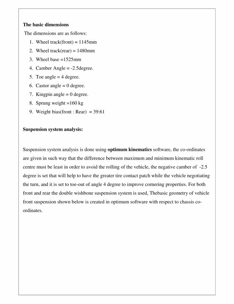
The scrub radius is=85mm
Positive scrub radius increases the steering effort
rolls as the wheel is steered, which reduces the effort when parking and it provides
greater road feel. This also allows greater
some compact sports cars this is why
3.2 Rear suspension system analysis:
Rear suspension system analysis r
The maximum value of kinematic roll centre is =197.207mm
The minimum value of kinematic roll centre is=187.063mm
The variation in the position kinematic roll centre is=10mm
The difference between the position of front and rear kinematic roll centre is =20mm
the steering effort but the advantage of this is that the tire
rolls as the wheel is steered, which reduces the effort when parking and it provides
. This also allows greater width in the engine bay, which is very important in
some compact sports cars this is why itis often the set-up of choice on race cars
Rear suspension system analysis:
Rear suspension system analysis results table
The maximum value of kinematic roll centre is =197.207mm
The minimum value of kinematic roll centre is=187.063mm
The variation in the position kinematic roll centre is=10mm
The difference between the position of front and rear kinematic roll centre is =20mm
the advantage of this is that the tire
rolls as the wheel is steered, which reduces the effort when parking and it provides much
width in the engine bay, which is very important in
up of choice on race cars
The difference between the position of front and rear kinematic roll centre is =20mm

3.2a Camber Angle:
It is the angle between the vertical axis of the wheels used for steering and the vertical axis
of the vehicle when viewed from the front or rear. The negative camber will help in
cornering of the vehicle to have the greater contact patch so the team set a negative camber -
2.5.
3.2b Toe angle:
If the leading edges of the wheel are pointing away from each other then it is called toe out
and if the leading edges of the wheel are pointing towards each other then it is called toe in.
In our vehicle toe out of angle 4 degree is set so as to enhance the cornering properties of the
vehicle.
3.2c Motion ratio:
The spring motion ratio is defined as the ratio of the spring displacement to the wheel
displacement, since the arm rotates around a common pivot, the length between the pivot and
the points of interest also determine the motion ratio. The amount of force transmitted to the
vehicle chassis is reduced when the motion ratio increases. This implies that the wheel rate
will increase as the motion ratio increases so the team has decided to fix the motion ratio as
0.6 in our case distance is measured as d1&d2 as shown in fig 2.
Fig.2 Mathematical model

Mathematically the motion ratio (MR) is defined by the displacement ratio or the length ratio
as below equation.
MR=����
MR=������
MR=0.61
Angle A=23 degrees
And cos (A) is called angle correction factor, cos (24) =0.914
3.2d Wheel rate:
Wheel rate is the actual rate of spring acting at the tire contact patch can be calculated as
WR=suspension spring rate ×(MR) 2×angle correction factor
=35×0.612×cos24
=12N/mm
Design of wishbones & knuckle
Wishbone and knuckle is most important part of the suspension system. Wishbones give
support to spring and help in vertical movement of the system while the knuckle supports the
axel of wheel. The wishbones and knuckle was designed in such a way that the roll centre is
located near the centre of gravity of vehicle and the distance of roll centre from centre of
gravity in minimum when the vehicle undergoes jounce or rebound. The team has decided to
use the front knuckle of fiat palio at front which is well suited with wheel and steering arm
dimensions. At rear we have designed the knuckle for which we have selected the aluminium
6066 material which is light in weight and have very good mechanical properties with good
corrosion resistance.

Mechanical properties of Al6066 are listed in table below
tensile strength 150 Mpa
Yield strength 83 Mpa
Shear strength 97 Mpa
fatigue strength 110 Mpa
Elastic modulus 80 Gpa
Poisions ratio 0.33
Hardness 43
Table . material properties of rear knuckle
Material Selection of A arms
Material consideration for the wishbone becomes the most primary need for design and
fabrication. The strength of the material should be well enough to withstand all the loads
acting on it in dynamic conditions. The material selection also depends on number of factors
such as carbon content, material properties, availability and the most important parameter is
the cost. Initially, three materials are considered based on their availability in the market
AISI 1018, AISI 1040 and AISI 4130, finally we have selected AISI 1040. And mechanical
properties of AISI 1040 is listed below
Carbon content 0.4%
Tensile strength 620 Mpa
Yield strength 415mpa
Hardness 201 BHN
Cast 425/meter

Table.
Dimensions of A arms
Outer diameter 25.4mm
Inner diameter 20mm
Left and right lower A arm oft
link length front
360mm
Left and right lower A arm fore
link length front
312mm
Left and right upper A arm fore
link length front
309mm
Left and right upper A arm fore
link length front
357mm
Left and right lower A arm oft
link length rear
441mm
Left and right lower A arm fore
link length rear
266mm
Left and right upper A arm fore
link length rear
282mm
Left and right upper A arm fore
link length rear
452mm
Angle between two links of A
arm
35degrees
Lower arm angle with horizontal 17degrees

Selection of spring and damper:
Team has decided to adapt passive suspension system because it is always a compromise
between comfort and safety for any given input set of road conditions and a specific stress.
The passive suspension system consists of passive elements, a spring and parallel damper
placed between the vehicle body and each of the wheels as shown as Figure1. The damper
contributes to both driver safety and comfort its task is to damping of body and wheel
oscillations. Spring and damper is designed based on the sprung as well as the unsprung
mass of the vehicle. The value of spring rate of suspension is obtained by considering wheel
ride rate and the tire stiffness of the vehicle.
Fig.1:Spring mass damper system
By the value of wheel ride rate which is vertical force per unit vertical displacement of tire
from ground with respect to chassis and the tire rate we can able to calculate the suspension
spring rate using the following relation
Kr =180lb/inch (31.52 N/mm)
Kt =1855.79lb/inch (325 N/mm)
Kr=���
���� � �……………………………..Eq. (1)
Putting the Kr&Kt in Eq(1)
180 = ������.����������.���
180 Ks+3340142.42=1855.79
Ks =200lb/inch
Ks =35 N/mm

2.1 Chassis Natural Frequency:
Mass of the chassis mc=160kg
Taking factor of safety=2
mc=160kg× 2
=320kg
mc=���
�
=80kg
=176.18 lb
wc= � ���� …………………Eq. (2)
substituting in Eq(2) we get
=� ������.� !�
��"
=20.88 rad/sec
W=2#fn………………………………..Eq. (3)
Fn=$�%
=��.��
�%
fn=3 Hz
2.2 Shock absorber for spring mass:
Chassis will oscillate about the zero reference but with a decreasing amplitude and
eventually reach steady state x = O if we take slightly under damped condition by setting
damping factor § as 0.9.

§=1/2('
√��×��)
C=2× § × √Ks × mc)…………………..Eq. (4)
Putting the values in Eq. (4)
C=2× 0.9 × �200 × ���/.��/���� �
C=2× 0.9 × √200 × 0.46
=18 lb-sec/inch
C=4 N-sec/mm
2.3 Material property of suspension spring:
The material of spring is AISI 1065 and this material can be used upto wire of diameter
16mm
s1. Ultimate tensile strength 635 Mpa
2. Shear stress 190.5 Mpa
3. Modulus of rigidity 79000
4. Young’s modulus 207000
5. Density 7.86 g/cm3
6. Tensile strength yield 490 Mpa
The diameter of the coil spring wire can be calculated using the formula
T= �34 5%�! …………………………….Eq. (5)
Where
D=mean coil diameter in mm
F=force acting on spring in N
K=stress correction factor
d=diameter of the wire in mm

T=shear stress in Mpa
Substituting values of D,F,K,T in …………………..Eq. (5)
6�=�×7×8×�
%×9
=�×���×/�×�
�%����
6�=347× 4
d=12mm
Number of active coils in spring is calculated as
i=:;�<�34! … … … … … … … … … … … … … … … … … … … Eq. �6�
Where ,
i=active number of coils
y=linear deflection in spring under static condition
=�����������<
�����/��!
Number of active coils=18
Number of inactive coils=2
Total number of coils Nt=18+2=20
F=K@
=�����
y=11.42 N/mm
Total gap between adjacent coils can be taken as the 15% of the deflection
=15% of x
Gap=0.15 ×11.42
=1.713

Solid length =Nt×d
=20×12
=240 mm
Free length = solid length +total axial gap+x
= 240+1.73+11.42
=253.15 mm
Eye to eye distance of the front spring and damper assembly is =310mm
Eye to eye distance of the rear spring and damper assembly is =350mm
The spring and damper we have calculated as 35N/mm and damping coefficient as 4N-
sec/mm
But for our suspension system we have selected 45N/mm fluid type damper which is
supplied by republic motors.

Ansys result
Static analysis results of front A arms
Fig total deformation Fig Equivalent stress
Fig factor of safety Fig 3D model
Static analysis is done using Ansys software the results are listed below
Number of nodes 18432
Number of elements 9296
Total deformation 0.28179mm
Equivalent stress 37.92Mpa
Factor of safety
(minimum)
2.27

Static analysis of rear A arms
Fig total deformation Fig Equivalent stress
Fig factor of safety Fig 3D model
Number of nodes 22843
Number of elements 12637
Total deformation 0.11256mm
Equivalent stress 53.251Mpa
Factor of safety
(minimum)
2.0234

Front knuckle static analysis results
Number of nodes 22843
Number of elements 12637
Total deformation 0.11256mm
Equivalent stress 53.251Mpa
Factor of safety
(minimum)
2.0234
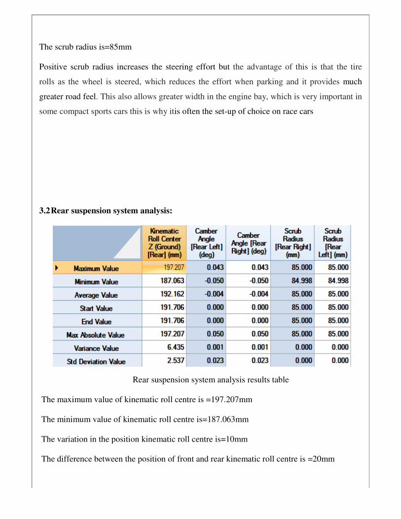
Rear knuckle static analysis results
Number of nodes 22843
Number of elements 12637
Total deformation 0.11256mm
Equivalent stress 53.251Mpa
Factor of safety
(minimum)
2.0234