Embed Size (px)
Citation preview
Owner's Manual forVehicle
THE BMW X3.OWNER'S MANUAL.
The Ultimate DrivingMachine
THE BMW X3.OWNER'S MANUAL.
ContentsA-Z
Online Edition for Part no. 01 40 2 903 813 - 07 12 490

X3 Owner's Manual for VehicleThank you for choosing a BMW.The more familiar you are with your vehicle, the better control youwill have on the road. We therefore strongly suggest:Read this Owner's Manual before starting off in your new BMW.Also use the Integrated Owner's Manual in your vehicle. It con‐tains important information on vehicle operation that will help youmake full use of the technical features available in your BMW. Themanual also contains information designed to enhance operatingreliability and road safety, and to contribute to maintaining thevalue of your BMW.Any updates made after the editorial deadline for the printed orintegrated Owner's Manual are located in the appendix of theprinted quick reference for the vehicle.Supplementary information can be found in the additional bro‐chures in the onboard literature.We wish you a safe and enjoyable drive.BMW AG
Online Edition for Part no. 01 40 2 903 813 - 07 12 490

© 2012 Bayerische Motoren WerkeAktiengesellschaftMunich, GermanyReprinting, including excerpts, only with the writtenconsent of BMW AG, Munich.US English VI/12, 07 12 490Printed on environmentally friendly paper, bleachedwithout chlorine, suitable for recycling.
Online Edition for Part no. 01 40 2 903 813 - 07 12 490

ContentsThe fastest way to find information on a partic‐ular topic or item is by using the index, refer topage 202.
6 Notes
At a glance12 Cockpit16 iDrive23 Voice activation system26 Integrated Owner's Manual in the vehicle
Controls30 Opening and closing46 Adjusting55 Transporting children safely59 Driving72 Displays86 Lamps91 Safety102 Driving stability control systems108 Driving comfort120 Climate control127 Interior equipment134 Storage compartments
Driving tips140 Things to remember when driving143 Loading146 Saving fuel
Mobility152 Refueling154 Fuel155 Wheels and tires163 Engine compartment165 Engine oil167 Coolant168 Maintenance171 Replacing components178 Breakdown assistance183 Care
Reference190 Technical data193 Short commands of the voice act. system202 Everything from A to Z
Online Edition for Part no. 01 40 2 903 813 - 07 12 490
NotesUsing this Owner's ManualThe fastest way to find information on a partic‐ular topic is by using the index.An initial overview of the vehicle is provided inthe first chapter.
Updates made after the editorialdeadlineAny updates made after the editorial deadline forthe Owner's Manuals are located in the appen‐dix of the printed quick reference for the vehicle.
User's manual for Navigation,Entertainment, CommunicationThe topics of Navigation, Entertainment andCommunication are described in a separate us‐er's manual, which is also included with the on‐board literature.
Additional sources of informationShould you have any questions, your servicecenter will be glad to advise you at any time.Information on BMW, e.g., on technology, isavailable on the Internet: bmwusa.com.
Symbols Indicates precautions that must be followed
precisely in order to avoid the possibility of per‐sonal injury and serious damage to the vehicle.◄ Marks the end of a specific item of informa‐tion."..." Identifies Control Display texts used to se‐lect individual functions.›...‹ Verbal instructions to use with the voice ac‐tivation system.››...‹‹ Identifies the answers generated by thevoice activation system.
Refers to measures that can be taken to helpprotect the environment.
Symbols on vehicle components Indicates that you should consult the rele‐
vant section of this Owner's Manual for infor‐mation on a particular part or assembly.
Vehicle equipmentThis Owner's Manual describes all models andall standard, country-specific and optionalequipment that is offered in the model series.Therefore, in this Owner's Manual, equipment isalso described and illustrated that is not availa‐ble in your vehicle, e.g. because of the selectedoptional equipment or the country-specific var‐iants.This also applies for safety-related functionsand systems.For options and equipment not described in thisOwner's Manual, please refer to the Supple‐mentary Owner's Manuals.On right-hand drive vehicles, some controls arearranged differently than shown in the illustra‐tions.
Status of the Owner's ManualThe manufacturer of your vehicle pursues a pol‐icy of constant development that is conceivedto ensure that our vehicles continue to embodythe highest quality and safety standards. In rarecases, therefore, the features described in thisOwner's Manual may differ from those in yourvehicle.
Seite 6
Notes
6Online Edition for Part no. 01 40 2 903 813 - 07 12 490
Updates made after the editorialdeadlineAny updates made after the editorial deadline forthe Owner's Manuals are located in the appen‐dix of the printed quick reference for the vehicle.
For your own safetyMaintenance and repairsAdvanced technology, e.g., the use of modernmaterials and high-performance electronics, re‐quires suitable maintenance and repair meth‐ods.Therefore, have this work performed only by aBMW center or a workshop that works accord‐ing to BMW repair procedures with appropri‐ately trained personnel.If this work is not carried out properly, there isthe danger of subsequent damage and relatedsafety hazards.
Parts and AccessoriesFor your own safety, use genuine parts and ac‐cessories approved by BMW. When you pur‐chase accessories tested and approved byBMW and Genuine BMW Parts, you simultane‐ously acquire the assurance that they have beenthoroughly tested by BMW to ensure optimumperformance when installed on your vehicle.BMW warrants these parts to be free from de‐fects in material and workmanship. BMW will notaccept any liability for damage resulting from in‐stallation of parts and accessories not approvedby BMW. BMW cannot test every product madeby other manufacturers to verify if it can be usedon a BMW safely and without risk to either thevehicle, its operation, or its occupants. GenuineBMW Parts, BMW Accessories and other prod‐ucts approved by BMW, together with profes‐sional advice on using these items, are availablefrom all BMW centers. Installation and operationof non-BMW approved accessories such asalarms, radios, amplifiers, radar detectors,wheels, suspension components, brake dust
shields, telephones, including operation of anymobile phone from within the vehicle withoutusing an externally mounted antenna, or trans‐ceiver equipment, for instance, CBs, walkie-talkies, ham radios or similar accessories, maycause extensive damage to the vehicle, com‐promise its safety, interfere with the vehicle'selectrical system or affect the validity of theBMW Limited Warranty. See your BMW centerfor additional information. Maintenance, re‐placement, or repair of the emission control de‐vices and systems may be performed by any au‐tomotive repair establishment or individualusing any certified automotive part.
California Proposition 65 WarningCalifornia laws require us to state the followingwarning:Engine exhaust and a wide variety of automobilecomponents and parts, including componentsfound in the interior furnishings in a vehicle, con‐tain or emit chemicals known to the State of Cal‐ifornia to cause cancer and birth defects and re‐productive harm. In addition, certain fluidscontained in vehicles and certain products ofcomponent wear contain or emit chemicalsknown to the State of California to cause cancerand birth defects or other reproductive harm.Battery posts, terminals and related accessoriescontain lead and lead compounds. Wash yourhands after handling. Used engine oil containschemicals that have caused cancer in laboratoryanimals. Always protect your skin by washingthoroughly with soap and water.
Service and warrantyWe recommend that you read this publicationthoroughly. Your vehicle is covered by the fol‐lowing warranties:▷ New Vehicle Limited Warranty.▷ Rust Perforation Limited Warranty.▷ Federal Emissions System Defect Warranty.▷ Federal Emissions Performance Warranty.
Seite 7
Notes
7Online Edition for Part no. 01 40 2 903 813 - 07 12 490

▷ California Emission Control System LimitedWarranty.
Detailed information about these warranties islisted in the Service and Warranty InformationBooklet for US models or in the Warranty andService Guide Booklet for Canadian models.Your vehicle has been specifically adapted anddesigned to meet the particular operating con‐ditions and homologation requirements in yourcountry and continental region in order to deliverthe full driving pleasure while the vehicle is op‐erated under those conditions. If you wish to op‐erate your vehicle in another country or region,you may be required to adapt your vehicle tomeet different prevailing operating conditionsand homologation requirements. You shouldalso be aware of any applicable warranty limita‐tions or exclusions for such country or region. Insuch case, please contact Customer Relationsfor further information.
MaintenanceMaintain the vehicle regularly to sustain the roadsafety, operational reliability and the New Vehi‐cle Limited Warranty.Specifications for required maintenance meas‐ures:▷ BMW Maintenance system▷ Service and Warranty Information Booklet
for US models▷ Warranty and Service Guide Booklet for
Canadian modelsIf the vehicle is not maintained according tothese specifications, this could result in seriousdamage to the vehicle. Such damage is not cov‐ered by the BMW New Vehicle Limited War‐ranty.
Reporting safety defectsFor US customersThe following only applies to vehicles ownedand operated in the US.
If you believe that your vehicle has a defectwhich could cause a crash or could cause injuryor death, you should immediately inform the Na‐tional Highway Traffic Safety AdministrationNHTSA, in addition to notifying BMW of NorthAmerica, LLC, P.O. Box 1227, Westwood, NewJersey 07675-1227, Telephone1-800-831-1117.If NHTSA receives similar complaints, it mayopen an investigation, and if it finds that a safetydefect exists in a group of vehicles, it may ordera recall and remedy campaign.However, NHTSA cannot become involved inindividual problems between you, your dealer,or BMW of North America, LLC.To contact NHTSA, you may call the VehicleSafety Hotline toll-free at 1-888-327-4236(TTY: 1-800-424-9153); go to http://www.safe‐rcar.gov; or write to: Administrator, NHTSA, 400Seventh Street, SW., Washington, DC 20590.You can also obtain other information about mo‐tor vehicle safety from http://www.safercar.gov
For Canadian customersCanadian customers who wish to report asafety-related defect to Transport Canada, De‐fect Investigations and Recalls, may telephonethe toll-free hotline 1-800-333-0510. You canalso obtain other information about motor vehi‐cle safety from http://www.tc.gc.ca/roadsafety.
Seite 8
Notes
8Online Edition for Part no. 01 40 2 903 813 - 07 12 490

Seite 9
Notes
9Online Edition for Part no. 01 40 2 903 813 - 07 12 490
Online Edition for Part no. 01 40 2 903 813 - 07 12 490

At a glanceThese overviews of buttons, switches and
displays are intended to familiarize you with yourvehicle. You will also become quickly acquaintedwith the available control concepts and options.
Online Edition for Part no. 01 40 2 903 813 - 07 12 490

CockpitVehicle equipmentAll standard, country-specific and optionalequipment that is offered in the model series isdescribed in this chapter. Therefore, equipment
is also described that is not available in a vehicle,e. g., because of the selected optional equip‐ment or country variant. This also applies forsafety-related functions and systems.
All around the steering wheel
1 Rear window safety switch 432 Power windows 423 Exterior mirror operation 524 Lane departure warning 99
Collision warning 108
5 Lamps
Front fog lamps 89
Parking lamps 86
Low beams 86
Seite 12
At a glance Cockpit
12Online Edition for Part no. 01 40 2 903 813 - 07 12 490
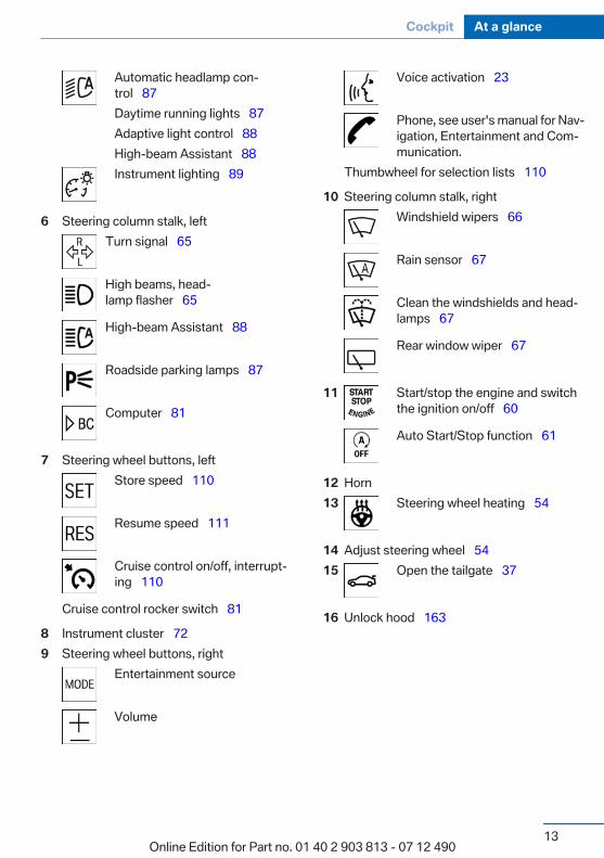
Automatic headlamp con‐trol 87Daytime running lights 87Adaptive light control 88High-beam Assistant 88Instrument lighting 89
6 Steering column stalk, leftTurn signal 65
High beams, head‐lamp flasher 65
High-beam Assistant 88
Roadside parking lamps 87
Computer 81
7 Steering wheel buttons, leftStore speed 110
Resume speed 111
Cruise control on/off, interrupt‐ing 110
Cruise control rocker switch 81
8 Instrument cluster 729 Steering wheel buttons, right
Entertainment source
Volume
Voice activation 23
Phone, see user's manual for Nav‐igation, Entertainment and Com‐munication.
Thumbwheel for selection lists 110
10 Steering column stalk, rightWindshield wipers 66
Rain sensor 67
Clean the windshields and head‐lamps 67
Rear window wiper 67
11 Start/stop the engine and switchthe ignition on/off 60
Auto Start/Stop function 61
12 Horn13 Steering wheel heating 54
14 Adjust steering wheel 5415 Open the tailgate 37
16 Unlock hood 163
Seite 13
Cockpit At a glance
13Online Edition for Part no. 01 40 2 903 813 - 07 12 490
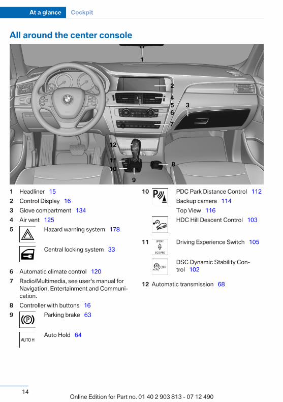
All around the center console
1 Headliner 152 Control Display 163 Glove compartment 1344 Air vent 1255 Hazard warning system 178
Central locking system 33
6 Automatic climate control 1207 Radio/Multimedia, see user's manual for
Navigation, Entertainment and Communi‐cation.
8 Controller with buttons 169 Parking brake 63
Auto Hold 64
10 PDC Park Distance Control 112Backup camera 114Top View 116HDC Hill Descent Control 103
11 Driving Experience Switch 105
DSC Dynamic Stability Con‐trol 102
12 Automatic transmission 68
Seite 14
At a glance Cockpit
14Online Edition for Part no. 01 40 2 903 813 - 07 12 490
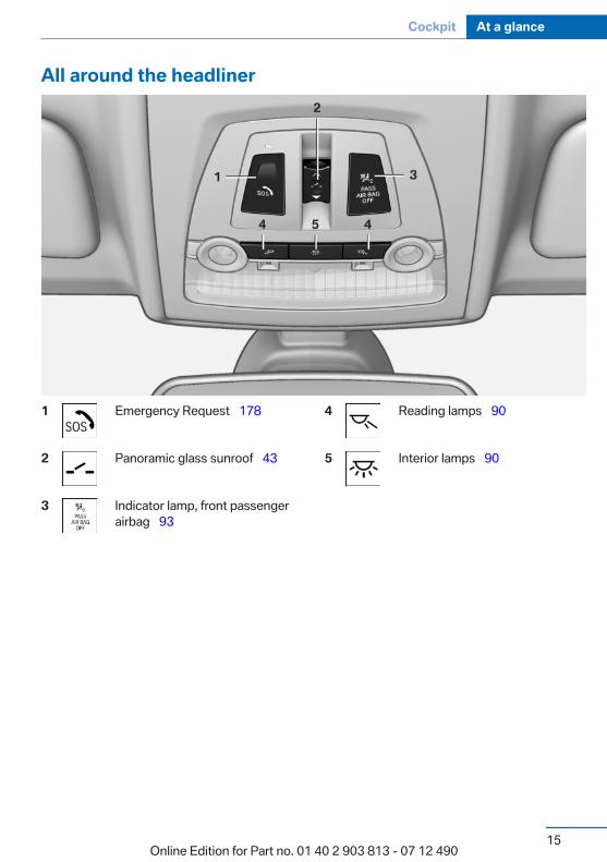
All around the headliner
1 Emergency Request 178
2 Panoramic glass sunroof 43
3 Indicator lamp, front passengerairbag 93
4 Reading lamps 90
5 Interior lamps 90
Seite 15
Cockpit At a glance
15Online Edition for Part no. 01 40 2 903 813 - 07 12 490
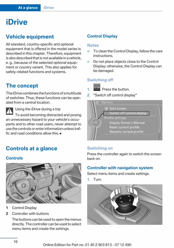
iDriveVehicle equipmentAll standard, country-specific and optionalequipment that is offered in the model series isdescribed in this chapter. Therefore, equipmentis also described that is not available in a vehicle,e. g., because of the selected optional equip‐ment or country variant. This also applies forsafety-related functions and systems.
The conceptThe iDrive combines the functions of a multitudeof switches. Thus, these functions can be oper‐ated from a central location.
Using the iDrive during a tripTo avoid becoming distracted and posing
an unnecessary hazard to your vehicle's occu‐pants and to other road users, never attempt touse the controls or enter information unless traf‐fic and road conditions allow this.◀
Controls at a glanceControls
1 Control Display2 Controller with buttons
The buttons can be used to open the menusdirectly. The controller can be used to selectmenu items and create the settings.
Control Display
Notes▷ To clean the Control Display, follow the care
instructions.▷ Do not place objects close to the Control
Display; otherwise, the Control Display canbe damaged.
Switching off
1. Press the button.2. "Switch off control display"
Switching onPress the controller again to switch the screenback on.
Controller with navigation systemSelect menu items and create settings.1. Turn.
Seite 16
At a glance iDrive
16Online Edition for Part no. 01 40 2 903 813 - 07 12 490
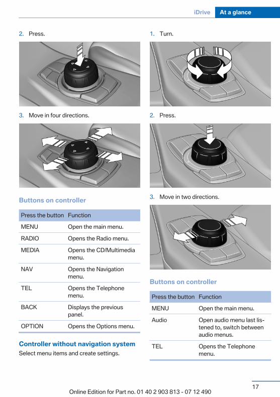
2. Press.
3. Move in four directions.
Buttons on controller
Press the button Function
MENU Open the main menu.
RADIO Opens the Radio menu.
MEDIA Opens the CD/Multimediamenu.
NAV Opens the Navigationmenu.
TEL Opens the Telephonemenu.
BACK Displays the previouspanel.
OPTION Opens the Options menu.
Controller without navigation systemSelect menu items and create settings.
1. Turn.
2. Press.
3. Move in two directions.
Buttons on controller
Press the button Function
MENU Open the main menu.
Audio Open audio menu last lis‐tened to, switch betweenaudio menus.
TEL Opens the Telephonemenu.
Seite 17
iDrive At a glance
17Online Edition for Part no. 01 40 2 903 813 - 07 12 490
Press the button Function
BACK Open previous panel.
OPTION Opens the Options menu.
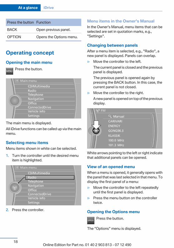
Operating conceptOpening the main menu
Press the button.
The main menu is displayed.All iDrive functions can be called up via the mainmenu.
Selecting menu itemsMenu items shown in white can be selected.
1. Turn the controller until the desired menuitem is highlighted.
2. Press the controller.
Menu items in the Owner's ManualIn the Owner's Manual, menu items that can beselected are set in quotation marks, e.g.,"Settings".
Changing between panelsAfter a menu item is selected, e.g., "Radio", anew panel is displayed. Panels can overlap.▷ Move the controller to the left.
The current panel is closed and the previouspanel is displayed.The previous panel is opened again bypressing the BACK button. In this case, thecurrent panel is not closed.
▷ Move the controller to the right.A new panel is opened on top of the previousdisplay.
White arrows pointing to the left or right indicatethat additional panels can be opened.
View of an opened menuWhen a menu is opened, it generally opens withthe panel that was last selected in that menu. Todisplay the first panel of a menu:▷ Move the controller to the left repeatedly
until the first panel is displayed.▷ Press the menu button on the controller
twice.
Opening the Options menuPress the button.
The "Options" menu is displayed.
Seite 18
At a glance iDrive
18Online Edition for Part no. 01 40 2 903 813 - 07 12 490
Additional options: move the controller to theright repeatedly until the "Options" menu is dis‐played.
Options menuThe "Options" menu consists of various areas:▷ Screen settings, e.g., "Split screen".
This area remains unchanged.▷ Control options for the selected main menu,
e.g., for "Radio".▷ If applicable, further operating options for
the selected menu, e.g., "Store station".
Changing settings1. Select a field.2. Turn the controller until the desired setting
is displayed.
3. Press the controller.
Activating/deactivating the functionsSeveral menu items are preceded by a check‐box. It indicates whether the function is acti‐vated or deactivated. Selecting the menu itemactivates or deactivates the function.
The function is activated.
The function is deactivated.
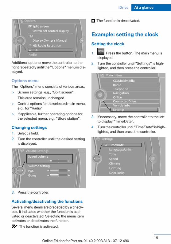
Example: setting the clockSetting the clock
1. Press the button. The main menu isdisplayed.
2. Turn the controller until "Settings" is high‐lighted, and then press the controller.
3. If necessary, move the controller to the leftto display "Time/Date".
4. Turn the controller until "Time/Date" is high‐lighted, and then press the controller.
Seite 19
iDrive At a glance
19Online Edition for Part no. 01 40 2 903 813 - 07 12 490
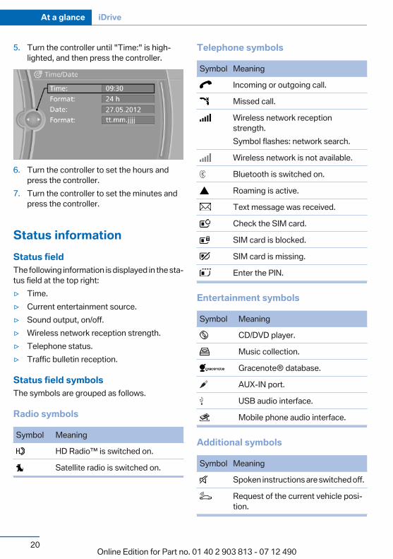
5. Turn the controller until "Time:" is high‐lighted, and then press the controller.
6. Turn the controller to set the hours andpress the controller.
7. Turn the controller to set the minutes andpress the controller.
Status informationStatus fieldThe following information is displayed in the sta‐tus field at the top right:▷ Time.▷ Current entertainment source.▷ Sound output, on/off.▷ Wireless network reception strength.▷ Telephone status.▷ Traffic bulletin reception.
Status field symbolsThe symbols are grouped as follows.
Radio symbols
Symbol Meaning
HD Radio™ is switched on.
Satellite radio is switched on.
Telephone symbols
Symbol Meaning
Incoming or outgoing call.
Missed call.
Wireless network receptionstrength.Symbol flashes: network search.
Wireless network is not available.
Bluetooth is switched on.
Roaming is active.
Text message was received.
Check the SIM card.
SIM card is blocked.
SIM card is missing.
Enter the PIN.
Entertainment symbols
Symbol Meaning
CD/DVD player.
Music collection.
Gracenote® database.
AUX-IN port.
USB audio interface.
Mobile phone audio interface.
Additional symbols
Symbol Meaning
Spoken instructions are switched off.
Request of the current vehicle posi‐tion.
Seite 20
At a glance iDrive
20Online Edition for Part no. 01 40 2 903 813 - 07 12 490
Split screenGeneral informationAdditional information can be displayed on theright side of the split screen, e.g., informationfrom the onboard computer.In the divided screen view, the so-called splitscreen, this information remains visible evenwhen you change to another menu.
Switching the split screen on and off
1. Press the button.2. "Split screen"
Selecting the display
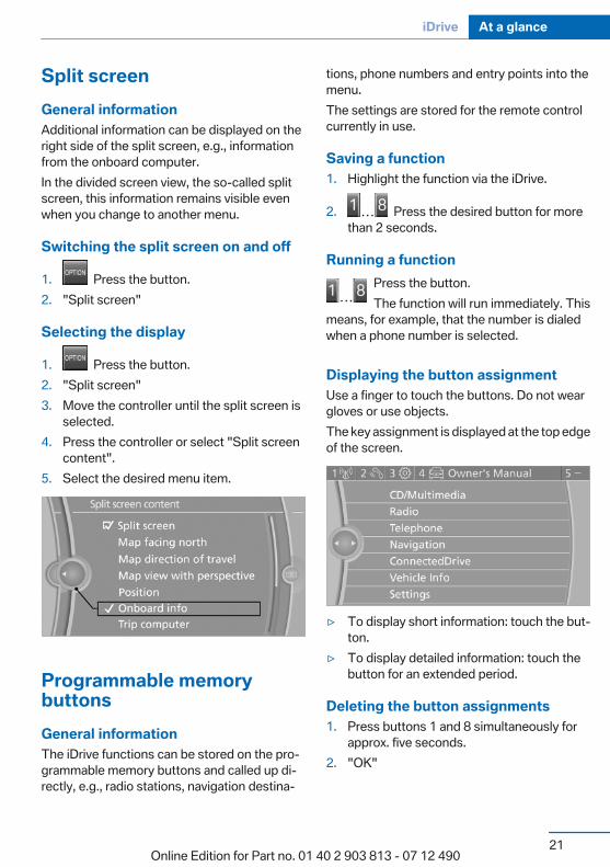
1. Press the button.2. "Split screen"3. Move the controller until the split screen is
selected.4. Press the controller or select "Split screen
content".5. Select the desired menu item.
Programmable memorybuttonsGeneral informationThe iDrive functions can be stored on the pro‐grammable memory buttons and called up di‐rectly, e.g., radio stations, navigation destina‐
tions, phone numbers and entry points into themenu.The settings are stored for the remote controlcurrently in use.
Saving a function1. Highlight the function via the iDrive.
2. Press the desired button for morethan 2 seconds.
Running a functionPress the button.The function will run immediately. This
means, for example, that the number is dialedwhen a phone number is selected.
Displaying the button assignmentUse a finger to touch the buttons. Do not weargloves or use objects.The key assignment is displayed at the top edgeof the screen.
▷ To display short information: touch the but‐ton.
▷ To display detailed information: touch thebutton for an extended period.
Deleting the button assignments1. Press buttons 1 and 8 simultaneously for
approx. five seconds.2. "OK"
Seite 21
iDrive At a glance
21Online Edition for Part no. 01 40 2 903 813 - 07 12 490
Entering letters and numbersGeneral information1. Turn the controller: select letters or num‐
bers.2. Select additional letters or numbers if
needed.3. "OK": confirm the entry.
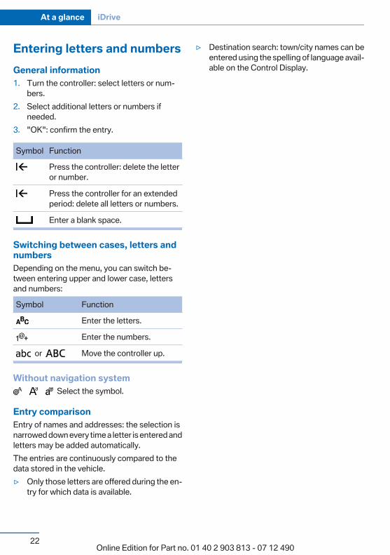
Symbol Function
Press the controller: delete the letteror number.
Press the controller for an extendedperiod: delete all letters or numbers.
Enter a blank space.
Switching between cases, letters andnumbersDepending on the menu, you can switch be‐tween entering upper and lower case, lettersand numbers:
Symbol Function
Enter the letters.
Enter the numbers.
or Move the controller up.
Without navigation system Select the symbol.
Entry comparisonEntry of names and addresses: the selection isnarrowed down every time a letter is entered andletters may be added automatically.The entries are continuously compared to thedata stored in the vehicle.▷ Only those letters are offered during the en‐
try for which data is available.
▷ Destination search: town/city names can beentered using the spelling of language avail‐able on the Control Display.
Seite 22
At a glance iDrive
22Online Edition for Part no. 01 40 2 903 813 - 07 12 490
Voice activation systemVehicle equipmentAll standard, country-specific and optionalequipment that is offered in the model series isdescribed in this chapter. Therefore, equipmentis also described that is not available in a vehicle,e. g., because of the selected optional equip‐ment or country variant. This also applies forsafety-related functions and systems.
The concept▷ Most functions that are displayed on the
Control Display can be operated by spokencommands via the voice activation system.The system prompts you to make your en‐tries.
▷ Functions that can only be used when thevehicle is stationary cannot be operated us‐ing the voice activation system.
▷ The system uses a special microphone onthe driver's side.
▷ ›...‹ Verbal instructions in the Owner'sManual to use with the voice activation sys‐tem.
RequirementsVia the Control Display, set a language that isalso supported by the voice activation systemso that the spoken commands can be identified.Set the language, refer to page 84.
Using voice activationActivating the voice activation system
1. Press the button on the steeringwheel.
2. Wait for the signal.3. Say the command.
The command is displayed in the instrumentcluster.
This symbol in the instrument cluster indi‐cates that the voice activation system is active.If no other commands are available, operate thefunction in this case via iDrive.
Terminating the voice activationsystem
Briefly press the button on the steeringwheel or ›Cancel‹.
Possible commandsMost menu items on the Control Display can bevoiced as commands.The available commands depend on whichmenu is currently displayed on the Control Dis‐play.There are short commands for functions of themain menu.Some list entries, e.g. Phone book entries, canalso be selected via the voice activation system.Speak these list entries exactly as they are dis‐played in the respective list.
Having possible commands read aloudYou can have the available commands read outloud for you: ›Voice commands‹For example, if the "Settings" menu is displayed,the commands for the settings are read out loud.
Executing functions using shortcommandsFunctions on the main menu can be performeddirectly by means of short commands, nearly ir‐
Seite 23
Voice activation system At a glance
23Online Edition for Part no. 01 40 2 903 813 - 07 12 490

respective of which menu item is currently se‐lected, e.g., ›Vehicle status‹.List of short commands of the voice activationsystem, refer to page 193.
Help dialog for the voice activationsystemCalling up help dialog: ›Help‹Additional commands for the help dialog:▷ ›Help with examples‹: information about the
current operating options and the most im‐portant commands for them are announced.
▷ ›Help with voice activation‹: informationabout the principle of operation for the voiceactivation system is announced.
Example: playing back a CD1. Switch on the Entertainment sound output
if necessary.
2. Press the button on the steeringwheel.
3. ›C D and multimedia‹The medium last played is played back.
4. ›C D track ...‹ e.g., CD track 4.
Setting the voice dialogYou can set whether the system should use thestandard dialog or a shorter version.In the shorter variant of the voice dialog, the an‐nouncements from the system are issued in anabbreviated form.On the Control Display:
1. "Settings"2. "Language/Units"
3. "Speech mode:"4. Select the setting.
Adjusting the volumeTurn the volume button while giving an instruc‐tion until the desired volume is set.▷ The volume remains constant even if the
volume of other audio sources is changed.▷ The volume is stored for the remote control
currently in use.
Notes on EmergencyRequestsDo not use the voice activation system to initiatean Emergency Request. In stressful situations,the voice and vocal pitch can change. This canunnecessarily delay the establishment of a tel‐ephone connection.Instead, use the SOS button, refer topage 178, in the vicinity of the interior mirror.
Environmental conditions▷ Say the commands, numbers, and letters
smoothly and with normal volume, empha‐sis, and speed.
▷ Always say commands in the language ofthe voice activation system.
▷ When selecting a radio station, use the com‐mon pronunciation of the station name:
Seite 24
At a glance Voice activation system
24Online Edition for Part no. 01 40 2 903 813 - 07 12 490

›Station ...‹ e. g. Classic Radio station▷ Keep the doors, windows, and glass sunroof
closed to prevent noise interference.▷ Avoid making other noise in the vehicle
while speaking.
Seite 25
Voice activation system At a glance
25Online Edition for Part no. 01 40 2 903 813 - 07 12 490
Integrated Owner's Manual in the vehicleVehicle equipmentAll standard, country-specific and optionalequipment that is offered in the model series isdescribed in this chapter. Therefore, equipmentis also described that is not available in a vehicle,e. g., because of the selected optional equip‐ment or country variant. This also applies forsafety-related functions and systems.
Integrated Owner's Manual inthe vehicleThe integrated Owner's Manual can be dis‐played on the Control Display. The equipmentand functions that are in the vehicle are descri‐bed therein.
Components of the integrated Owner'sManualThe integrated Owner's Manual consists ofthree parts, which offer various levels of infor‐mation or access possibilities.
Quick Reference GuideLocated in the Quick Reference is important in‐formation for the operation of the vehicle, theoperation of basic vehicle functions or for whatto do in the event of a flat tire. This informationcan also be displayed during driving.
Search by picturesInformation and descriptions based on illustra‐tions can be searched via search by pictures.This is helpful, for example, if the description ofan outfitting package that cannot be named isneeded.
Owner's ManualInformation and descriptions can be searchedby direct entry of a search term via the index.
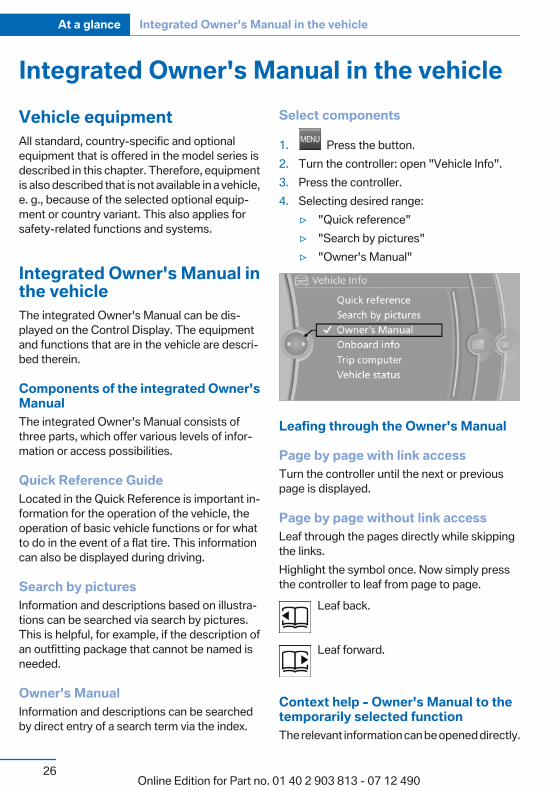
Select components
1. Press the button.2. Turn the controller: open "Vehicle Info".3. Press the controller.4. Selecting desired range:
▷ "Quick reference"▷ "Search by pictures"▷ "Owner's Manual"
Leafing through the Owner's Manual
Page by page with link accessTurn the controller until the next or previouspage is displayed.
Page by page without link accessLeaf through the pages directly while skippingthe links.Highlight the symbol once. Now simply pressthe controller to leaf from page to page.
Leaf back.
Leaf forward.
Context help - Owner's Manual to thetemporarily selected functionThe relevant information can be opened directly.
Seite 26
At a glance Integrated Owner's Manual in the vehicle
26Online Edition for Part no. 01 40 2 903 813 - 07 12 490
Opening via the iDriveTo move directly from the application on theControl Display to the options menu:
1. Press the button or move the controllerto the right repeatedly until the "Options"menu is displayed.
2. "Display Owner's Manual"
Opening when a Check Controlmessage is displayedDirectly from the Check Control message on theControl Display:"Display Owner's Manual"
Changing between a function and theOwner's ManualTo change from a function, e.g., radio, to theOwner's Manual on the Control Display and toswitch between the two displays:
1. Press the button or move the controllerto the right repeatedly until the "Options"menu is displayed.
2. "Display Owner's Manual"3. Select the desired page in the Owner's
Manual.
4. Press the button again to return to thefunction displayed last.
5. Press the button to return to the pageof the Owner's Manual displayed last.
To switch back and forth repeatedly betweenthe function displayed last and the page of theOwner's Manual displayed last, repeat steps 4and 5. This opens a new panel every time.
Programmable memory buttons
General informationThe Owner's Manual can be stored on the pro‐grammable memory buttons and called up di‐rectly.
Storing1. "Owner's Manual" Select via the iDrive.
2. Press the desired button for morethan 2 seconds.
ExecutingPress the button.The Owner's Manual is displayed im‐
mediately.
Seite 27
Integrated Owner's Manual in the vehicle At a glance
27Online Edition for Part no. 01 40 2 903 813 - 07 12 490
Online Edition for Part no. 01 40 2 903 813 - 07 12 490
ControlsThis chapter is intended to provide you with
information that will give you complete control ofyour vehicle. All features and accessories that are
useful for driving and your safety, comfort andconvenience are described here.
Online Edition for Part no. 01 40 2 903 813 - 07 12 490
Opening and closingVehicle equipmentAll standard, country-specific and optionalequipment that is offered in the model series isdescribed in this chapter. Therefore, equipmentis also described that is not available in a vehicle,e. g., because of the selected optional equip‐ment or country variant. This also applies forsafety-related functions and systems.
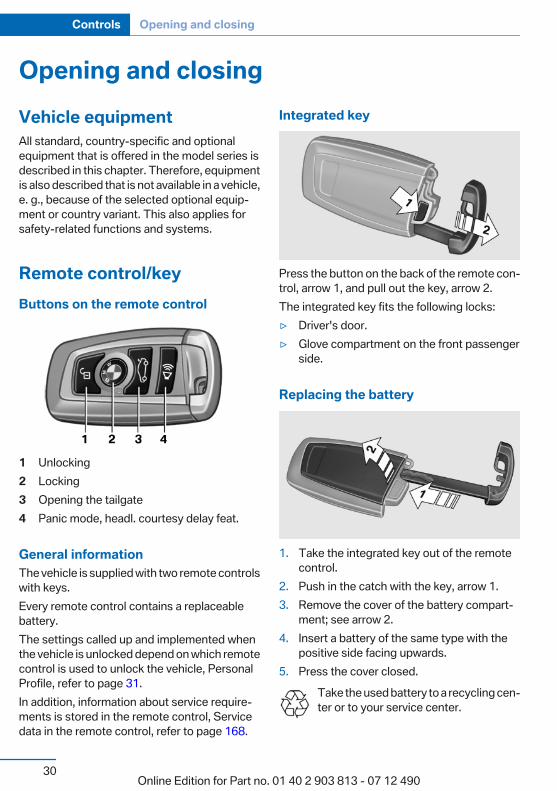
Remote control/keyButtons on the remote control
1 Unlocking2 Locking3 Opening the tailgate4 Panic mode, headl. courtesy delay feat.
General informationThe vehicle is supplied with two remote controlswith keys.Every remote control contains a replaceablebattery.The settings called up and implemented whenthe vehicle is unlocked depend on which remotecontrol is used to unlock the vehicle, PersonalProfile, refer to page 31.In addition, information about service require‐ments is stored in the remote control, Servicedata in the remote control, refer to page 168.
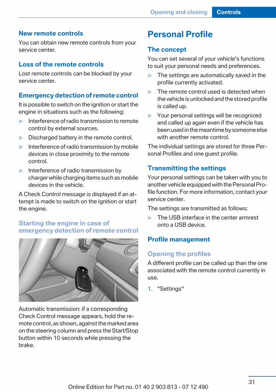
Integrated key
Press the button on the back of the remote con‐trol, arrow 1, and pull out the key, arrow 2.The integrated key fits the following locks:▷ Driver's door.▷ Glove compartment on the front passenger
side.
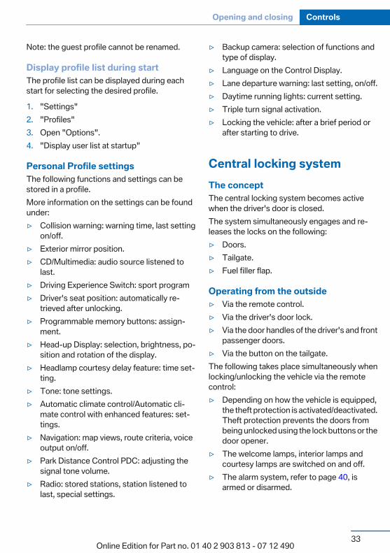
Replacing the battery
1. Take the integrated key out of the remotecontrol.
2. Push in the catch with the key, arrow 1.3. Remove the cover of the battery compart‐
ment; see arrow 2.4. Insert a battery of the same type with the
positive side facing upwards.5. Press the cover closed.
Take the used battery to a recycling cen‐ter or to your service center.
Seite 30
Controls Opening and closing
30Online Edition for Part no. 01 40 2 903 813 - 07 12 490
New remote controlsYou can obtain new remote controls from yourservice center.
Loss of the remote controlsLost remote controls can be blocked by yourservice center.
Emergency detection of remote controlIt is possible to switch on the ignition or start theengine in situations such as the following:▷ Interference of radio transmission to remote
control by external sources.▷ Discharged battery in the remote control.▷ Interference of radio transmission by mobile
devices in close proximity to the remotecontrol.
▷ Interference of radio transmission bycharger while charging items such as mobiledevices in the vehicle.
A Check Control message is displayed if an at‐tempt is made to switch on the ignition or startthe engine.
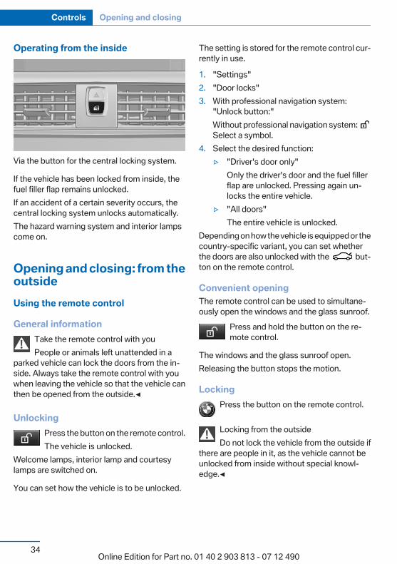
Starting the engine in case ofemergency detection of remote control
Automatic transmission: if a correspondingCheck Control message appears, hold the re‐mote control, as shown, against the marked areaon the steering column and press the Start/Stopbutton within 10 seconds while pressing thebrake.
Personal ProfileThe conceptYou can set several of your vehicle's functionsto suit your personal needs and preferences.▷ The settings are automatically saved in the
profile currently activated.▷ The remote control used is detected when
the vehicle is unlocked and the stored profileis called up.
▷ Your personal settings will be recognizedand called up again even if the vehicle hasbeen used in the meantime by someone elsewith another remote control.
The individual settings are stored for three Per‐sonal Profiles and one guest profile.
Transmitting the settingsYour personal settings can be taken with you toanother vehicle equipped with the Personal Pro‐file function. For more information, contact yourservice center.The settings are transmitted as follows:▷ The USB interface in the center armrest
onto a USB device.
Profile management
Opening the profilesA different profile can be called up than the oneassociated with the remote control currently inuse.
1. "Settings"
Seite 31
Opening and closing Controls
31Online Edition for Part no. 01 40 2 903 813 - 07 12 490

2. "Profiles"
3. Select a profile.The profile that is opened is assigned to the re‐mote control currently in use.
Renaming profiles1. "Settings"2. "Profiles"
The current profile is selected.3. Open "Options".4. "Rename current profile"
Resetting profilesThe settings of the active profile are reset totheir default values.
1. Switch on the ignition.2. "Settings"3. "Profiles"
The current profile is selected.4. Open "Options".5. "Reset current profile"
Importing profilesExisting settings and contacts are overwrittenwith the imported profile.
1. "Settings"2. "Profiles"3. "Import profile"
4. USB interface: "USB device"
Exporting profilesMost settings of the active profile and the savedcontacts can be exported.This can be useful for storing and opening per‐sonal settings, e.g. if settings are accidentallychanged or deleted.
1. "Settings"2. "Profiles"3. "Export profile"4. USB interface: "USB device"
Using the guest profileThe guest profile can be used to make individualsettings without affecting the three PersonalProfiles.This can be useful for drivers who are using thevehicle temporarily and do not have their ownprofile.
1. "Settings"2. "Profiles"3. The current profile is selected.4. Open "Guest".5. Adjust the settings.
Seite 32
Controls Opening and closing
32Online Edition for Part no. 01 40 2 903 813 - 07 12 490
Note: the guest profile cannot be renamed.
Display profile list during startThe profile list can be displayed during eachstart for selecting the desired profile.
1. "Settings"2. "Profiles"3. Open "Options".4. "Display user list at startup"
Personal Profile settingsThe following functions and settings can bestored in a profile.More information on the settings can be foundunder:▷ Collision warning: warning time, last setting
on/off.▷ Exterior mirror position.▷ CD/Multimedia: audio source listened to
last.▷ Driving Experience Switch: sport program▷ Driver's seat position: automatically re‐
trieved after unlocking.▷ Programmable memory buttons: assign‐
ment.▷ Head-up Display: selection, brightness, po‐
sition and rotation of the display.▷ Headlamp courtesy delay feature: time set‐
ting.▷ Tone: tone settings.▷ Automatic climate control/Automatic cli‐
mate control with enhanced features: set‐tings.
▷ Navigation: map views, route criteria, voiceoutput on/off.
▷ Park Distance Control PDC: adjusting thesignal tone volume.
▷ Radio: stored stations, station listened tolast, special settings.
▷ Backup camera: selection of functions andtype of display.
▷ Language on the Control Display.▷ Lane departure warning: last setting, on/off.▷ Daytime running lights: current setting.▷ Triple turn signal activation.▷ Locking the vehicle: after a brief period or
after starting to drive.
Central locking systemThe conceptThe central locking system becomes activewhen the driver's door is closed.The system simultaneously engages and re‐leases the locks on the following:▷ Doors.▷ Tailgate.▷ Fuel filler flap.
Operating from the outside▷ Via the remote control.▷ Via the driver's door lock.▷ Via the door handles of the driver's and front
passenger doors.▷ Via the button on the tailgate.The following takes place simultaneously whenlocking/unlocking the vehicle via the remotecontrol:▷ Depending on how the vehicle is equipped,
the theft protection is activated/deactivated.Theft protection prevents the doors frombeing unlocked using the lock buttons or thedoor opener.
▷ The welcome lamps, interior lamps andcourtesy lamps are switched on and off.
▷ The alarm system, refer to page 40, isarmed or disarmed.
Seite 33
Opening and closing Controls
33Online Edition for Part no. 01 40 2 903 813 - 07 12 490
Operating from the inside
Via the button for the central locking system.
If the vehicle has been locked from inside, thefuel filler flap remains unlocked.If an accident of a certain severity occurs, thecentral locking system unlocks automatically.The hazard warning system and interior lampscome on.
Opening and closing: from theoutsideUsing the remote control
General informationTake the remote control with youPeople or animals left unattended in a
parked vehicle can lock the doors from the in‐side. Always take the remote control with youwhen leaving the vehicle so that the vehicle canthen be opened from the outside.◀
UnlockingPress the button on the remote control.The vehicle is unlocked.
Welcome lamps, interior lamp and courtesylamps are switched on.
You can set how the vehicle is to be unlocked.
The setting is stored for the remote control cur‐rently in use.
1. "Settings"2. "Door locks"3. With professional navigation system:
"Unlock button:"Without professional navigation system: Select a symbol.
4. Select the desired function:▷ "Driver's door only"
Only the driver's door and the fuel fillerflap are unlocked. Pressing again un‐locks the entire vehicle.
▷ "All doors"The entire vehicle is unlocked.
Depending on how the vehicle is equipped or thecountry-specific variant, you can set whetherthe doors are also unlocked with the but‐ton on the remote control.
Convenient openingThe remote control can be used to simultane‐ously open the windows and the glass sunroof.
Press and hold the button on the re‐mote control.
The windows and the glass sunroof open.Releasing the button stops the motion.
LockingPress the button on the remote control.
Locking from the outsideDo not lock the vehicle from the outside if
there are people in it, as the vehicle cannot beunlocked from inside without special knowl‐edge.◀
Seite 34
Controls Opening and closing
34Online Edition for Part no. 01 40 2 903 813 - 07 12 490
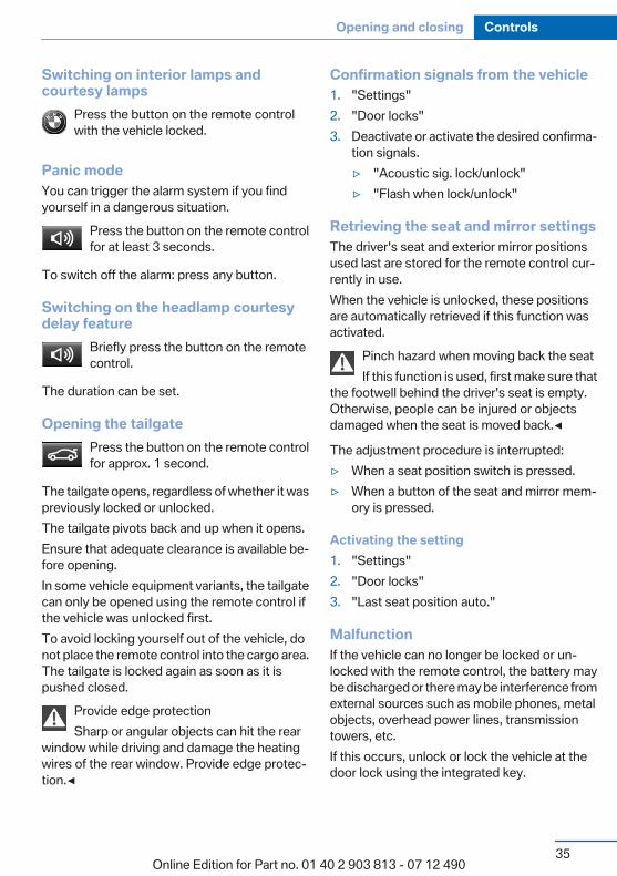
Switching on interior lamps andcourtesy lamps
Press the button on the remote controlwith the vehicle locked.
Panic modeYou can trigger the alarm system if you findyourself in a dangerous situation.
Press the button on the remote controlfor at least 3 seconds.
To switch off the alarm: press any button.
Switching on the headlamp courtesydelay feature
Briefly press the button on the remotecontrol.
The duration can be set.
Opening the tailgatePress the button on the remote controlfor approx. 1 second.
The tailgate opens, regardless of whether it waspreviously locked or unlocked.The tailgate pivots back and up when it opens.Ensure that adequate clearance is available be‐fore opening.In some vehicle equipment variants, the tailgatecan only be opened using the remote control ifthe vehicle was unlocked first.To avoid locking yourself out of the vehicle, donot place the remote control into the cargo area.The tailgate is locked again as soon as it ispushed closed.
Provide edge protectionSharp or angular objects can hit the rear
window while driving and damage the heatingwires of the rear window. Provide edge protec‐tion.◀
Confirmation signals from the vehicle1. "Settings"2. "Door locks"3. Deactivate or activate the desired confirma‐
tion signals.▷ "Acoustic sig. lock/unlock"▷ "Flash when lock/unlock"
Retrieving the seat and mirror settingsThe driver's seat and exterior mirror positionsused last are stored for the remote control cur‐rently in use.When the vehicle is unlocked, these positionsare automatically retrieved if this function wasactivated.
Pinch hazard when moving back the seatIf this function is used, first make sure that
the footwell behind the driver's seat is empty.Otherwise, people can be injured or objectsdamaged when the seat is moved back.◀
The adjustment procedure is interrupted:▷ When a seat position switch is pressed.▷ When a button of the seat and mirror mem‐
ory is pressed.
Activating the setting1. "Settings"2. "Door locks"3. "Last seat position auto."
MalfunctionIf the vehicle can no longer be locked or un‐locked with the remote control, the battery maybe discharged or there may be interference fromexternal sources such as mobile phones, metalobjects, overhead power lines, transmissiontowers, etc.If this occurs, unlock or lock the vehicle at thedoor lock using the integrated key.
Seite 35
Opening and closing Controls
35Online Edition for Part no. 01 40 2 903 813 - 07 12 490
For US owners onlyThe transmitter and receiver units comply withpart 15 of the FCC/Federal CommunicationCommission regulations. Operation is governedby the following:FCC ID:▷ LX8766S.▷ LX8766E.▷ LX8CAS.▷ LX8CAS2.▷ MYTCAS4.Compliance statement:This device complies with part 15 of the FCCRules. Operation is subject to the following twoconditions:▷ This device may not cause harmful interfer‐
ence, and▷ this device must accept any interference re‐
ceived, including interference that maycause undesired operation.
Any unauthorized modifications or changes tothese devices could void the user's authority tooperate this equipment.
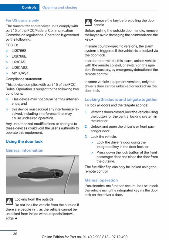
Using the door lock
General information
Locking from the outsideDo not lock the vehicle from the outside if
there are people in it, as the vehicle cannot beunlocked from inside without special knowl‐edge.◀
Remove the key before pulling the doorhandle
Before pulling the outside door handle, removethe key to avoid damaging the paintwork and thekey.◀
In some country-specific versions, the alarmsystem is triggered if the vehicle is unlocked viathe door lock.In order to terminate this alarm, unlock vehiclewith the remote control, or switch on the igni‐tion, if necessary, by emergency detection of theremote control.
In some vehicle equipment versions, only thedriver's door can be unlocked or locked via thedoor lock.
Locking the doors and tailgate togetherTo lock all doors and the tailgate at once:
1. With the doors closed, lock the vehicle usingthe button for the central locking system inthe interior.
2. Unlock and open the driver's or front pas‐senger door.
3. Lock the vehicle.▷ Lock the driver's door using the
integrated key in the door lock, or▷ Press down the lock button of the front
passenger door and close the door fromthe outside.
The fuel filler flap can only be locked using theremote control.
Manual operationIf an electrical malfunction occurs, lock or unlockthe vehicle using the integrated key via the doorlock on the driver's door.
Seite 36
Controls Opening and closing
36Online Edition for Part no. 01 40 2 903 813 - 07 12 490
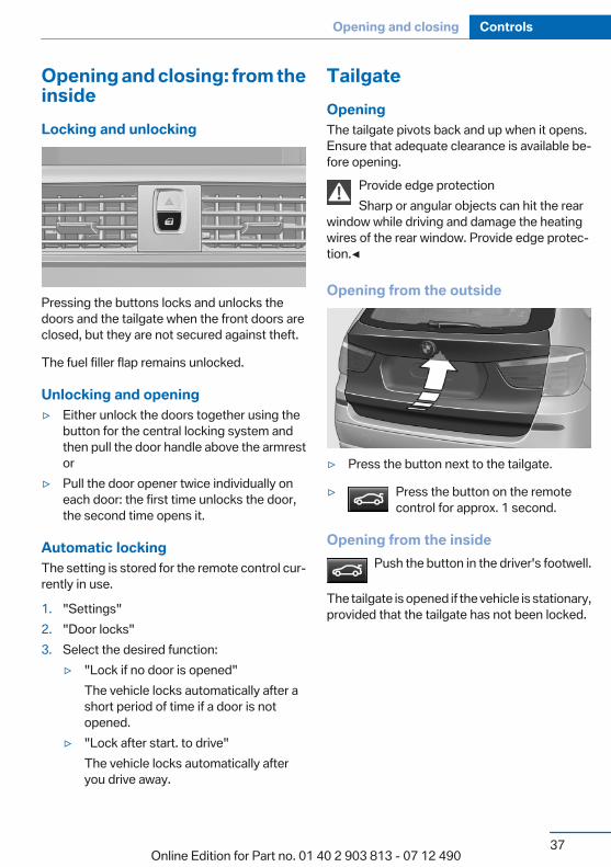
Opening and closing: from theinsideLocking and unlocking
Pressing the buttons locks and unlocks thedoors and the tailgate when the front doors areclosed, but they are not secured against theft.
The fuel filler flap remains unlocked.
Unlocking and opening▷ Either unlock the doors together using the
button for the central locking system andthen pull the door handle above the armrestor
▷ Pull the door opener twice individually oneach door: the first time unlocks the door,the second time opens it.
Automatic lockingThe setting is stored for the remote control cur‐rently in use.
1. "Settings"2. "Door locks"3. Select the desired function:
▷ "Lock if no door is opened"The vehicle locks automatically after ashort period of time if a door is notopened.
▷ "Lock after start. to drive"The vehicle locks automatically afteryou drive away.
TailgateOpeningThe tailgate pivots back and up when it opens.Ensure that adequate clearance is available be‐fore opening.
Provide edge protectionSharp or angular objects can hit the rear
window while driving and damage the heatingwires of the rear window. Provide edge protec‐tion.◀
Opening from the outside
▷ Press the button next to the tailgate.
▷ Press the button on the remotecontrol for approx. 1 second.
Opening from the insidePush the button in the driver's footwell.
The tailgate is opened if the vehicle is stationary,provided that the tailgate has not been locked.
Seite 37
Opening and closing Controls
37Online Edition for Part no. 01 40 2 903 813 - 07 12 490
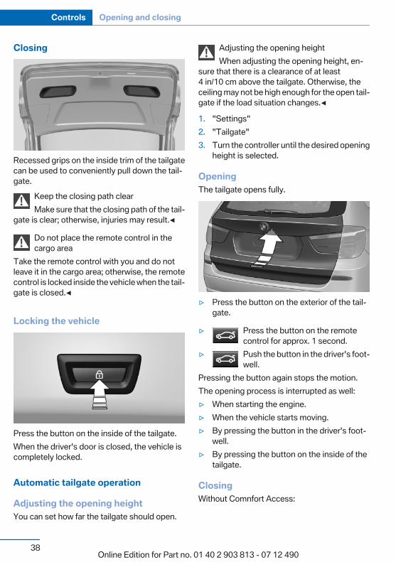
Closing
Recessed grips on the inside trim of the tailgatecan be used to conveniently pull down the tail‐gate.
Keep the closing path clearMake sure that the closing path of the tail‐
gate is clear; otherwise, injuries may result.◀
Do not place the remote control in thecargo area
Take the remote control with you and do notleave it in the cargo area; otherwise, the remotecontrol is locked inside the vehicle when the tail‐gate is closed.◀
Locking the vehicle
Press the button on the inside of the tailgate.When the driver's door is closed, the vehicle iscompletely locked.
Automatic tailgate operation
Adjusting the opening heightYou can set how far the tailgate should open.
Adjusting the opening heightWhen adjusting the opening height, en‐
sure that there is a clearance of at least4 in/10 cm above the tailgate. Otherwise, theceiling may not be high enough for the open tail‐gate if the load situation changes.◀
1. "Settings"2. "Tailgate"3. Turn the controller until the desired opening
height is selected.
OpeningThe tailgate opens fully.
▷ Press the button on the exterior of the tail‐gate.
▷ Press the button on the remotecontrol for approx. 1 second.
▷ Push the button in the driver's foot‐well.
Pressing the button again stops the motion.The opening process is interrupted as well:▷ When starting the engine.▷ When the vehicle starts moving.▷ By pressing the button in the driver's foot‐
well.▷ By pressing the button on the inside of the
tailgate.
ClosingWithout Comnfort Access:
Seite 38
Controls Opening and closing
38Online Edition for Part no. 01 40 2 903 813 - 07 12 490
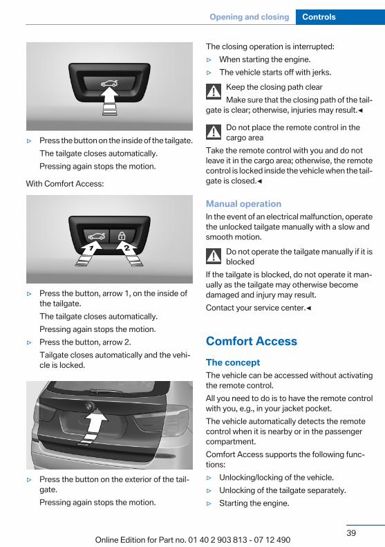
▷ Press the button on the inside of the tailgate.The tailgate closes automatically.Pressing again stops the motion.
With Comfort Access:
▷ Press the button, arrow 1, on the inside ofthe tailgate.The tailgate closes automatically.Pressing again stops the motion.
▷ Press the button, arrow 2.Tailgate closes automatically and the vehi‐cle is locked.
▷ Press the button on the exterior of the tail‐gate.Pressing again stops the motion.
The closing operation is interrupted:▷ When starting the engine.▷ The vehicle starts off with jerks.
Keep the closing path clearMake sure that the closing path of the tail‐
gate is clear; otherwise, injuries may result.◀
Do not place the remote control in thecargo area
Take the remote control with you and do notleave it in the cargo area; otherwise, the remotecontrol is locked inside the vehicle when the tail‐gate is closed.◀
Manual operationIn the event of an electrical malfunction, operatethe unlocked tailgate manually with a slow andsmooth motion.
Do not operate the tailgate manually if it isblocked
If the tailgate is blocked, do not operate it man‐ually as the tailgate may otherwise becomedamaged and injury may result.Contact your service center.◀
Comfort AccessThe conceptThe vehicle can be accessed without activatingthe remote control.All you need to do is to have the remote controlwith you, e.g., in your jacket pocket.The vehicle automatically detects the remotecontrol when it is nearby or in the passengercompartment.Comfort Access supports the following func‐tions:▷ Unlocking/locking of the vehicle.▷ Unlocking of the tailgate separately.▷ Starting the engine.
Seite 39
Opening and closing Controls
39Online Edition for Part no. 01 40 2 903 813 - 07 12 490
Functional requirements▷ There are no external sources of interfer‐
ence nearby.▷ To lock the vehicle, the remote control must
be located outside of the vehicle.▷ The next unlocking and locking cycle is not
possible until after approx. 2 seconds.▷ The engine can only be started if the remote
control is inside the vehicle.
Comparison with ordinary remotecontrolThe functions can be controlled by pressing thebuttons of the remote control or Comfort Ac‐cess.
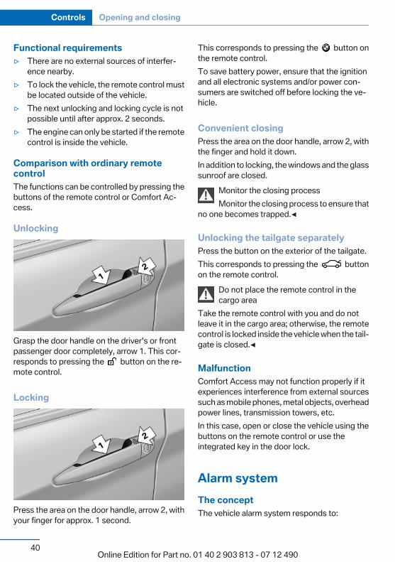
Unlocking
Grasp the door handle on the driver's or frontpassenger door completely, arrow 1. This cor‐responds to pressing the button on the re‐mote control.
Locking
Press the area on the door handle, arrow 2, withyour finger for approx. 1 second.
This corresponds to pressing the button onthe remote control.To save battery power, ensure that the ignitionand all electronic systems and/or power con‐sumers are switched off before locking the ve‐hicle.
Convenient closingPress the area on the door handle, arrow 2, withthe finger and hold it down.In addition to locking, the windows and the glasssunroof are closed.
Monitor the closing processMonitor the closing process to ensure that
no one becomes trapped.◀
Unlocking the tailgate separatelyPress the button on the exterior of the tailgate.This corresponds to pressing the buttonon the remote control.
Do not place the remote control in thecargo area
Take the remote control with you and do notleave it in the cargo area; otherwise, the remotecontrol is locked inside the vehicle when the tail‐gate is closed.◀
MalfunctionComfort Access may not function properly if itexperiences interference from external sourcessuch as mobile phones, metal objects, overheadpower lines, transmission towers, etc.In this case, open or close the vehicle using thebuttons on the remote control or use theintegrated key in the door lock.
Alarm systemThe conceptThe vehicle alarm system responds to:
Seite 40
Controls Opening and closing
40Online Edition for Part no. 01 40 2 903 813 - 07 12 490
▷ Opening of a door, the hood or the tailgate.▷ Movements in the vehicle.▷ Changes in the vehicle tilt, e.g., during at‐
tempts to steal a wheel or when towing thecar.
▷ Interruptions in battery voltage.The alarm system briefly indicates tampering:▷ By sounding an acoustic alarm.▷ By switching on the hazard warning system.▷ By flashing the high beams.
Arming and disarming the alarmsystem
General informationWhen you lock or unlock the vehicle, either withthe remote control, Comfort Access or at thedoor lock the alarm system is armed or disarmedat the same time.
Door lock and armed alarm systemUnlocking via the door lock will trigger the alarmon some country-specific versions.In order to terminate this alarm, unlock vehiclewith the remote control or switch on the ignition,if necessary, by emergency detection of the re‐mote control.
Tailgate and armed alarm systemThe tailgate can be opened using the remotecontrol, even if the alarm system is armed.
Press the button on the remote controlfor approx. 1 second.
After the tailgate is closed, it is locked and moni‐tored again by the alarm system. The hazardwarning system flashes once.In some vehicle equipment variants, the tailgatecan only be opened using the remote control ifthe vehicle was unlocked first.
Panic modePress the button on the remote controlfor at least 3 seconds.
Switching off the alarm▷ Unlock the vehicle using the remote control.▷ With Comfort Access: if you are carrying the
remote control with you, pull on the doorhandle.
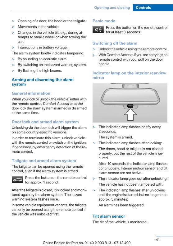
Indicator lamp on the interior rearviewmirror
▷ The indicator lamp flashes briefly every2 seconds:The system is armed.
▷ The indicator lamp flashes after locking:The doors, hood or tailgate is not closedproperly, but the rest of the vehicle is se‐cured.After 10 seconds, the indicator lamp flashescontinuously. Interior motion sensor and tiltalarm sensor are not active.
▷ The indicator lamp goes out after unlocking:The vehicle has not been tampered with.
▷ The indicator lamp flashes after unlockinguntil the engine is started, but no longer thanapprox. 5 minutes:An alarm has been triggered.
Tilt alarm sensorThe tilt of the vehicle is monitored.
Seite 41
Opening and closing Controls
41Online Edition for Part no. 01 40 2 903 813 - 07 12 490
The alarm system responds in situations suchas attempts to steal a wheel or when the car istowed.
Interior motion sensorThe windows and glass sunroof must be closedfor the system to function properly.
Avoiding unintentional alarmsThe tilt alarm sensor and interior motion sensorcan be switched off together, such as in the fol‐lowing situations:▷ In automatic car washes.▷ In duplex garages.▷ During transport on car-carrying trains, at
sea or on a trailer.▷ When animals are to remain in the vehicle.
Switching off the tilt alarm sensor andinterior motion sensor
Press the remote control button againwithin 10 seconds as soon as the vehicle
is locked.The indicator lamp lights up for approx. 2 sec‐onds and then continues to flash.The tilt alarm sensor and interior motion sensorare switched off until the vehicle is locked again.
Power windowsGeneral information
Take the remote control with youTake the remote control with you when
leaving the vehicle so that children, for example,cannot operate the power windows and injurethemselves.◀
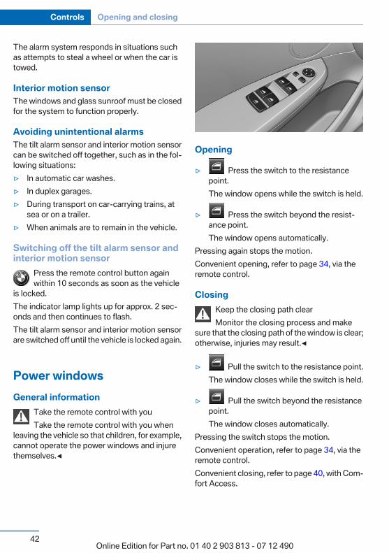
Opening
▷ Press the switch to the resistancepoint.The window opens while the switch is held.
▷ Press the switch beyond the resist‐ance point.The window opens automatically.
Pressing again stops the motion.Convenient opening, refer to page 34, via theremote control.
ClosingKeep the closing path clearMonitor the closing process and make
sure that the closing path of the window is clear;otherwise, injuries may result.◀
▷ Pull the switch to the resistance point.The window closes while the switch is held.
▷ Pull the switch beyond the resistancepoint.The window closes automatically.
Pressing the switch stops the motion.Convenient operation, refer to page 34, via theremote control.Convenient closing, refer to page 40, with Com‐fort Access.
Seite 42
Controls Opening and closing
42Online Edition for Part no. 01 40 2 903 813 - 07 12 490

Pinch protection systemIf the closing force exceeds a specific value as awindow closes, the closing action is interrupted.The window reopens slightly.
Danger of pinching even with pinch pro‐tection
Even with the pinch protection system, checkthat the window's closing path is clear; other‐wise, the closing action may not stop in certainsituations, e.g., if thin objects are present.◀
No window accessoriesDo not install any accessories in the range
of movement of the windows; otherwise, thepinch protection system will be impaired.◀
Closing without the pinch protectionsystem
Keep the closing path clearMonitor the closing process and make
sure that the closing path of the window is clear;otherwise, injuries may result.◀
For example, if there is an external danger or ifice on the windows prevents a window fromclosing normally, proceed as follows:
1. Pull the switch past the resistance point andhold it there.Pinch protection is limited and the windowreopens slightly if the closing force exceedsa certain value.
2. Pull the switch past the resistance pointagain within approx. 4 seconds and hold itthere.The window closes without pinch protec‐tion.
Safety switchThe safety switch in the driver's door can beused to prevent children, for example, fromopening and closing the rear windows using theswitches in the rear.
Switching on and offPress the button.The LED lights up if the safety function
is switched on.
Safety switch for rear operationPress the safety switch when transporting
children in the rear; otherwise, injury may resultif the windows are closed without supervision.◀
Roller sunblindsRoller sunblinds for the rear sidewindowsPull out the roller sunblind at the loop and hookit onto the bracket.
Do not open the window while the rollersunblind is raised.
Do not open the window while the roller sunblindis raised; otherwise, there is a risk of damage athigh speeds that may result in personal injury.◀
Panoramic glass sunroofGeneral informationThe glass sunroof and the sliding visor can beoperated together or separately, using the sameswitch.The glass sunroof is operational when the igni‐tion is switched on.
Keep the closing path clearMonitor the closing process and make
sure that the closing path of the glass sunroof isclear; otherwise, injuries may result.◀
Take the remote control with youTake the remote control with you when
leaving the vehicle so that children, for example,cannot operate the roof and injure themselves.◀
Seite 43
Opening and closing Controls
43Online Edition for Part no. 01 40 2 903 813 - 07 12 490
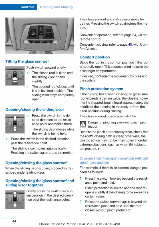
Tilting the glass sunroofPush switch upward briefly.▷ The closed roof is tilted and
the sliding visor opensslightly.
▷ The opened roof closes untilit is in its tilted position. Thesliding visor stays completelyopen.
Opening/closing the sliding visor▷ Press the switch in the de‐
sired direction to the resist‐ance point and hold it there.The sliding visor moves whilethe switch is being held.
▷ Press the switch in the desired directionpast the resistance point.The sliding visor moves automatically.Pressing the switch again stops the motion.
Opening/closing the glass sunroofWhen the sliding visor is open, proceed as de‐scribed under Sliding visor.
Opening/closing the glass sunroof andsliding visor together
Briefly press the switch twice insuccession in the desired direc‐tion past the resistance point.
The glass sunroof and sliding visor move to‐gether. Pressing the switch again stops the mo‐tion.
Convenient operation, refer to page 34, via theremote control.Convenient closing, refer to page 40, with Com‐fort Access.
Comfort positionStops the roof in the comfort position if the roofis not fully open. This reduces wind noise in thepassenger compartment.If desired, continue the movement by pressingthe switch.
Pinch protection systemIf the closing force when closing the glass sun‐roof exceeds a certain value, the closing move‐ment is stopped, beginning at approximately themiddle of the opening in the roof, or from thetilted position during closing.The glass sunroof opens again slightly.
Danger of pinching even with pinch pro‐tection
Despite the pinch protection system, check thatthe roof's closing path is clear; otherwise, theclosing action may not be interrupted in certainextreme situations, such as when thin objectsare present.◀
Closing from the open position withoutpinch protectionFor example, if there is an external danger, pro‐ceed as follows:
1. Press the switch forward beyond the resist‐ance point and hold.Pinch protection is limited and the roof re‐opens slightly if the closing force exceeds acertain value.
2. Press the switch forward again beyond theresistance point and hold until the roofcloses without pinch protection.
Seite 44
Controls Opening and closing
44Online Edition for Part no. 01 40 2 903 813 - 07 12 490

Closing from the raised positionwithout pinch protectionIf there is an external danger, push the switchforward past the resistance point and hold it.The roof closes without pinch protection.
Initializing after a power failureAfter a power failure during the opening or clos‐ing process, the roof can only be operated to alimited extent.
Initializing the systemThe system can be initialized when the vehicleis stationary and the engine is running.During the initialization, the roof closes withoutpinch protection.
Keep the closing path clearMonitor the closing process and make
sure that the closing path of the glass sunroof isclear; otherwise, injuries may result.◀
Press the switch up and hold ituntil the initialization is complete:▷ Initialization begins within
15 seconds and is completedwhen the sunroof and slidingvisor are completely closed.
▷ The roof closes without pinch protection.
Seite 45
Opening and closing Controls
45Online Edition for Part no. 01 40 2 903 813 - 07 12 490
AdjustingVehicle equipmentAll standard, country-specific and optionalequipment that is offered in the model series isdescribed in this chapter. Therefore, equipmentis also described that is not available in a vehicle,e. g., because of the selected optional equip‐ment or country variant. This also applies forsafety-related functions and systems.
Sitting safelyThe ideal seating position can make a vital con‐tribution to relaxed, fatigue-free driving.The seating position plays an important role inan accident in combination with:▷ Safety belts, refer to page 49.▷ Head restraints, refer to page 50.▷ Airbags, refer to page 91.
SeatsGeneral information
Do not adjust the seat while drivingDo not adjust the driver's seat while driv‐
ing, or the seat could respond with unexpectedmovement and the ensuing loss of vehicle con‐trol could lead to an accident.◀
Do not incline the backrest too far to therear
Also on the front passenger side, do not inclinethe backrest on the front passenger side too farto the rear during driving, or there is a risk ofslipping under the safety belt in the event of anaccident. This would eliminate the protectionnormally provided by the belt.◀
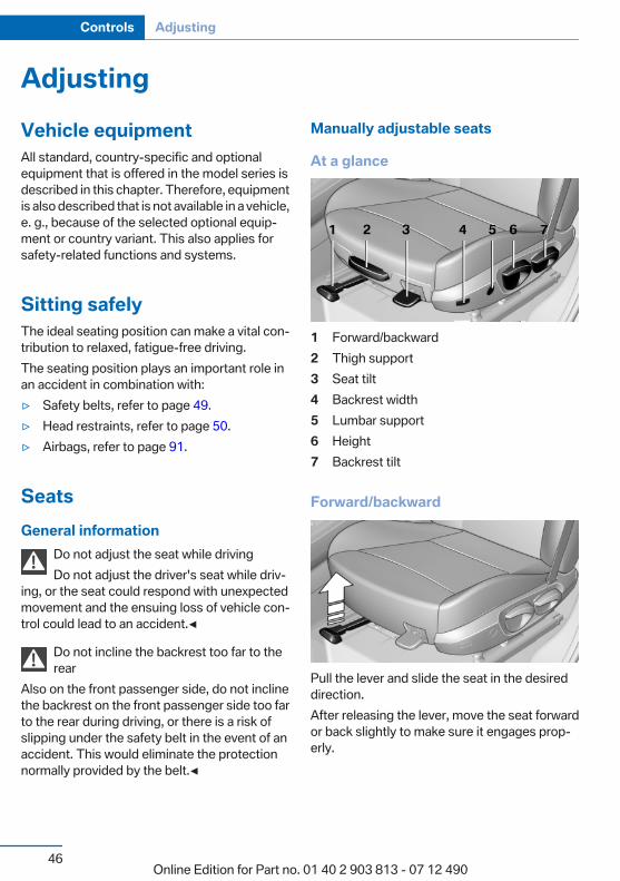
Manually adjustable seats
At a glance
1 Forward/backward2 Thigh support3 Seat tilt4 Backrest width5 Lumbar support6 Height7 Backrest tilt
Forward/backward
Pull the lever and slide the seat in the desireddirection.After releasing the lever, move the seat forwardor back slightly to make sure it engages prop‐erly.
Seite 46
Controls Adjusting
46Online Edition for Part no. 01 40 2 903 813 - 07 12 490
Height
Pull the lever and apply your weight to the seator lift it off, as necessary.
Backrest tilt
Pull the lever and apply your weight to the back‐rest or lift it off, as necessary.
Seat tilt
Pull the lever and move the seat to the desiredtilt. After releasing the lever, apply your weightto the seat or lift it off to make sure the seat en‐gages properly.
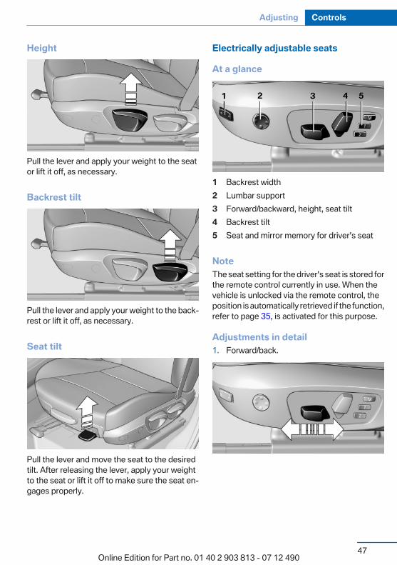
Electrically adjustable seats
At a glance
1 Backrest width2 Lumbar support3 Forward/backward, height, seat tilt4 Backrest tilt5 Seat and mirror memory for driver's seat
NoteThe seat setting for the driver's seat is stored forthe remote control currently in use. When thevehicle is unlocked via the remote control, theposition is automatically retrieved if the function,refer to page 35, is activated for this purpose.
Adjustments in detail1. Forward/back.
Seite 47
Adjusting Controls
47Online Edition for Part no. 01 40 2 903 813 - 07 12 490

2. Height.
3. Seat tilt.
4. Backrest tilt.
Thigh support
Pull the lever at the front of the seat and adjustthe thigh support.
Lumbar supportThe curvature of the seat backrest can be ad‐justed in such a way that it supports the lumbarregion of the spine. The lower back and thespine are supported for upright posture.
▷ Press the front/rear section ofthe switch.The curvature is increased/decreased.
▷ Press the upper/lower sec‐tion of the switch.The curvature is shifted up/down.
Backrest widthChange the width of the backrestusing the side wings to adjust thelateral support.
Seite 48
Controls Adjusting
48Online Edition for Part no. 01 40 2 903 813 - 07 12 490
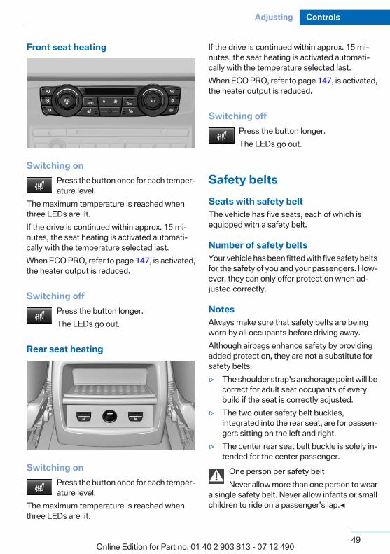
Front seat heating
Switching onPress the button once for each temper‐ature level.
The maximum temperature is reached whenthree LEDs are lit.If the drive is continued within approx. 15 mi‐nutes, the seat heating is activated automati‐cally with the temperature selected last.When ECO PRO, refer to page 147, is activated,the heater output is reduced.
Switching offPress the button longer.The LEDs go out.
Rear seat heating
Switching onPress the button once for each temper‐ature level.
The maximum temperature is reached whenthree LEDs are lit.
If the drive is continued within approx. 15 mi‐nutes, the seat heating is activated automati‐cally with the temperature selected last.When ECO PRO, refer to page 147, is activated,the heater output is reduced.
Switching offPress the button longer.The LEDs go out.
Safety beltsSeats with safety beltThe vehicle has five seats, each of which isequipped with a safety belt.
Number of safety beltsYour vehicle has been fitted with five safety beltsfor the safety of you and your passengers. How‐ever, they can only offer protection when ad‐justed correctly.
NotesAlways make sure that safety belts are beingworn by all occupants before driving away.Although airbags enhance safety by providingadded protection, they are not a substitute forsafety belts.▷ The shoulder strap's anchorage point will be
correct for adult seat occupants of everybuild if the seat is correctly adjusted.
▷ The two outer safety belt buckles,integrated into the rear seat, are for passen‐gers sitting on the left and right.
▷ The center rear seat belt buckle is solely in‐tended for the center passenger.
One person per safety beltNever allow more than one person to wear
a single safety belt. Never allow infants or smallchildren to ride on a passenger's lap.◀
Seite 49
Adjusting Controls
49Online Edition for Part no. 01 40 2 903 813 - 07 12 490
Putting on the beltLay the belt, without twisting, snugly
across the lap and shoulders, as close to thebody as possible. Make sure that the belt lies lowaround the hips in the lap area and does notpress on the abdomen. Otherwise, the belt canslip over the hips in the lap area in a frontal im‐pact and injure the abdomen.The safety belt must not lie across the neck, rubon sharp edges, be routed over solid or breaka‐ble objects, or be pinched.◀
Reduction of restraining effectAvoid wearing clothing that prevents the
belt from fitting properly, and pull the shoulderbelt periodically to readjust the tension acrossyour lap; otherwise, the retention effect of thesafety belt may be reduced.◀
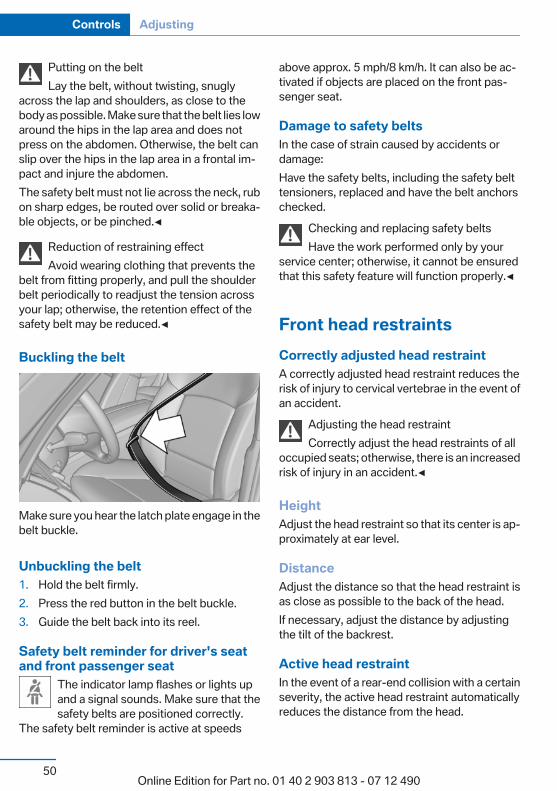
Buckling the belt
Make sure you hear the latch plate engage in thebelt buckle.
Unbuckling the belt1. Hold the belt firmly.2. Press the red button in the belt buckle.3. Guide the belt back into its reel.
Safety belt reminder for driver's seatand front passenger seat
The indicator lamp flashes or lights upand a signal sounds. Make sure that thesafety belts are positioned correctly.
The safety belt reminder is active at speeds
above approx. 5 mph/8 km/h. It can also be ac‐tivated if objects are placed on the front pas‐senger seat.
Damage to safety beltsIn the case of strain caused by accidents ordamage:Have the safety belts, including the safety belttensioners, replaced and have the belt anchorschecked.
Checking and replacing safety beltsHave the work performed only by your
service center; otherwise, it cannot be ensuredthat this safety feature will function properly.◀
Front head restraintsCorrectly adjusted head restraintA correctly adjusted head restraint reduces therisk of injury to cervical vertebrae in the event ofan accident.
Adjusting the head restraintCorrectly adjust the head restraints of all
occupied seats; otherwise, there is an increasedrisk of injury in an accident.◀
HeightAdjust the head restraint so that its center is ap‐proximately at ear level.
DistanceAdjust the distance so that the head restraint isas close as possible to the back of the head.If necessary, adjust the distance by adjustingthe tilt of the backrest.
Active head restraintIn the event of a rear-end collision with a certainseverity, the active head restraint automaticallyreduces the distance from the head.
Seite 50
Controls Adjusting
50Online Edition for Part no. 01 40 2 903 813 - 07 12 490
Reduced protective function▷ Do not use seat or head restraint cov‐
ers.▷ Do not hang objects, e.g., clothes hangers,
on the head restraints.▷ Only attach accessories approved by BMW
to the seat or head restraint.Otherwise, the protective function of the activehead restraint will be impaired and the personalsafety of the occupants will be endangered.◀
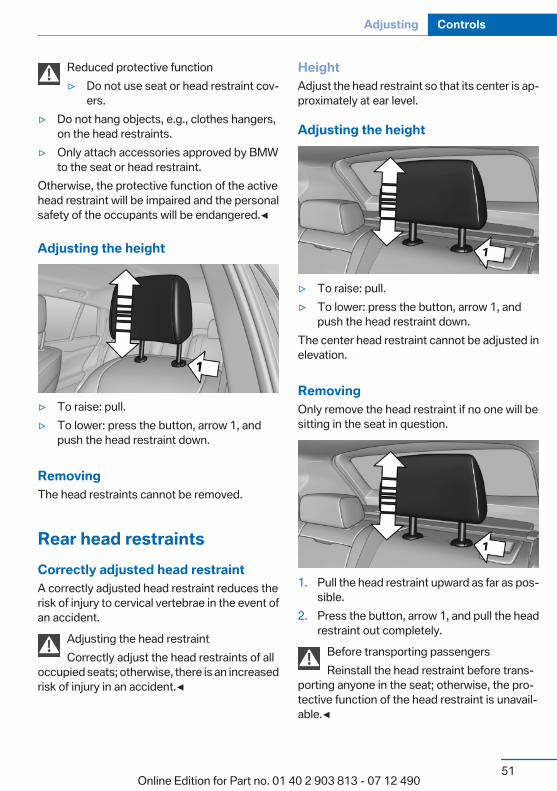
Adjusting the height
▷ To raise: pull.▷ To lower: press the button, arrow 1, and
push the head restraint down.
RemovingThe head restraints cannot be removed.
Rear head restraintsCorrectly adjusted head restraintA correctly adjusted head restraint reduces therisk of injury to cervical vertebrae in the event ofan accident.
Adjusting the head restraintCorrectly adjust the head restraints of all
occupied seats; otherwise, there is an increasedrisk of injury in an accident.◀
HeightAdjust the head restraint so that its center is ap‐proximately at ear level.
Adjusting the height
▷ To raise: pull.▷ To lower: press the button, arrow 1, and
push the head restraint down.The center head restraint cannot be adjusted inelevation.
RemovingOnly remove the head restraint if no one will besitting in the seat in question.
1. Pull the head restraint upward as far as pos‐sible.
2. Press the button, arrow 1, and pull the headrestraint out completely.
Before transporting passengersReinstall the head restraint before trans‐
porting anyone in the seat; otherwise, the pro‐tective function of the head restraint is unavail‐able.◀
Seite 51
Adjusting Controls
51Online Edition for Part no. 01 40 2 903 813 - 07 12 490

Seat and mirror memoryGeneral information
Two different driver's seat and exterior mirrorpositions can be stored and retrieved for eachremote control. Settings for the backrest widthand lumbar support are not stored in memory.
Storing1. Switch on the ignition.2. Set the desired position.
3. Press the button. The LED in thebutton lights up.
4. Press the desired button 1 or 2. The LEDgoes out.
If the M button is pressed accidentally:Press the button again.The LED goes out.
Calling up settingsDo not retrieve the memory while drivingDo not retrieve the memory setting while
driving, as an unexpected movement of the seator steering wheel could result in an accident.◀
Comfort function1. Open the driver's door.2. Switch off the ignition.3. Briefly press the desired button 1 or 2.The corresponding seat position is performedautomatically.
The procedure stops when a switch for adjust‐ing the seat or one of the buttons is pressed.
Safety mode1. Close the driver's door or switch on the ig‐
nition.2. Press and hold the desired button 1 or 2 until
the adjustment procedure is completed.
Calling up of a seat positiondeactivatedAfter a brief period, the calling up of stored seatpositions is deactivated to save battery power.To reactivate calling up of a seat position:▷ Open or close the door or tailgate.▷ Press a button on the remote control.▷ Press the Start/Stop button.
MirrorsExterior mirrors
At a glance
1 Adjusting2 Left/right, Automatic Curb Monitor3 Fold in and out
General informationThe mirror on the passenger side is more curvedthan the driver's side mirror.
Seite 52
Controls Adjusting
52Online Edition for Part no. 01 40 2 903 813 - 07 12 490
Estimating distances correctlyObjects reflected in the mirror are closer
than they appear. Do not estimate the distanceto the traffic behind you based on what you seein the mirror, as this will increase your risk of anaccident.◀
Depending on how the vehicle is equipped, themirror setting is stored for the remote control inuse. When the vehicle is unlocked via the remotecontrol, the position is automatically retrieved ifthe setting for this function is active.
Selecting a mirrorTo change over to the other mirror:Slide the mirror changeover switch.
Adjusting electricallyThe setting corresponds to the directionin which the button is pressed.
Saving positionsSeat and mirror memory, refer to page 52
Adjusting manuallyIf an electrical malfunction occurs, for example,press the edges of the mirror glass.
Automatic Curb MonitorWhen the reverse gear is engaged, the mirrorglass tilts downward slightly on the front pas‐senger side. This improves your view of the curband other low-lying obstacles when parking, forexample.
Activating
1. Slide the mirror changeover switchto the driver's side mirror position.
2. Engage transmission position R.
DeactivatingSlide the mirror changeover switch to the pas‐senger's side mirror position.
Fold in and outPress the button.
Possible up to approx. 15 mph/20 km/h.For example, this is advantageous▷ In car washes.▷ In narrow streets.▷ For folding back mirrors that were folded
away manually.Mirrors that were folded in are folded out auto‐matically at a speed of approx. 25 mph/40 km/h.
Fold in the mirror in a car washBefore entering an automatic car wash,
fold in the exterior mirrors by hand or with thebutton; otherwise, they could be damaged, de‐pending on the width of the vehicle.◀
Automatic heatingBoth exterior mirrors are automatically heatedwhenever the engine is running.
Automatic dimming featureBoth exterior mirrors are automatically dimmed.Photocells are used for control in the Interior rearview mirror, refer to page 54.
Seite 53
Adjusting Controls
53Online Edition for Part no. 01 40 2 903 813 - 07 12 490
Interior rearview mirror
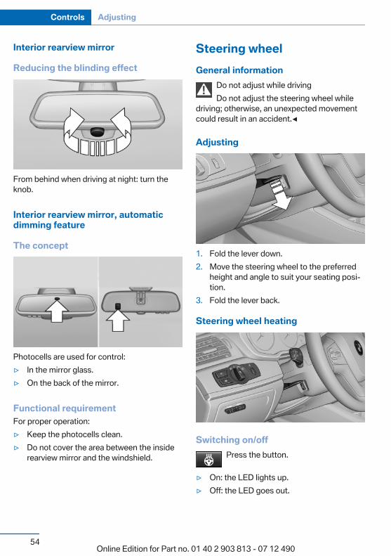
Reducing the blinding effect
From behind when driving at night: turn theknob.
Interior rearview mirror, automaticdimming feature
The concept
Photocells are used for control:▷ In the mirror glass.▷ On the back of the mirror.
Functional requirementFor proper operation:▷ Keep the photocells clean.▷ Do not cover the area between the inside
rearview mirror and the windshield.
Steering wheelGeneral information
Do not adjust while drivingDo not adjust the steering wheel while
driving; otherwise, an unexpected movementcould result in an accident.◀
Adjusting
1. Fold the lever down.2. Move the steering wheel to the preferred
height and angle to suit your seating posi‐tion.
3. Fold the lever back.
Steering wheel heating
Switching on/offPress the button.
▷ On: the LED lights up.▷ Off: the LED goes out.
Seite 54
Controls Adjusting
54Online Edition for Part no. 01 40 2 903 813 - 07 12 490
Transporting children safelyVehicle equipmentAll standard, country-specific and optionalequipment that is offered in the model series isdescribed in this chapter. Therefore, equipmentis also described that is not available in a vehicle,e. g., because of the selected optional equip‐ment or country variant. This also applies forsafety-related functions and systems.
The right place for childrenNote
Children in the vehicleDo not leave children unattended in the
vehicle; otherwise, they could endanger them‐selves and other persons, e.g., by opening thedoors.◀
Children should always be in the rearAccident research shows that the safest placefor children is in the back seat.
Transporting children in the rearOnly transport children younger than
13 years of age or shorter than 5 ft/150 cm in therear in child restraint fixing systems provided inaccordance with the age, weight and size of thechild; otherwise, there is an increased risk of in‐jury in an accident.Children 13 years of age or older must wear asafety belt as soon as a suitable child restraintfixing system can no longer be used, due to theirage, weight and size.◀
Children on the front passenger seatShould it ever be necessary to use a child re‐straint fixing system in the front passenger seat,make sure that the front, knee and side airbagson the front passenger side are deactivated. Au‐
tomatic deactivation of front passenger airbags,refer to page 93.
Deactivating the front passenger airbagsIf a child restraint fixing system is used in
the front passenger seat, the front passengerairbags must be deactivated; otherwise, there isan increased risk of injury to the child when theairbags are triggered, even with a child restraintfixing system.◀
Installing child restraint fixingsystemsBefore mountingBefore mounting child restraint fixing systems,ensure that the rear seat backrests are locked.
NotesManufacturer's information for child re‐straint fixing systems
To select, mount and use child restraint fixingsystems, observe the information provided bythe system manufacturer; otherwise, the pro‐tective effect can be impaired.◀
On the front passenger seat
Deactivating airbagsAfter installing a child restraint fixing system inthe front passenger seat, make sure that thefront, knee and side airbags on the front pas‐senger side are deactivated.Deactivate the front passenger airbags auto‐matically, refer to page 93
Deactivating the front passenger airbagsIf a child restraint fixing system is used in
the front passenger seat, the front passengerairbags must be deactivated; otherwise, there is
Seite 55
Transporting children safely Controls
55Online Edition for Part no. 01 40 2 903 813 - 07 12 490
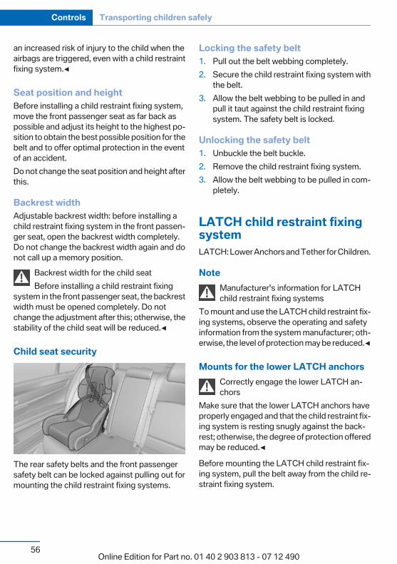
an increased risk of injury to the child when theairbags are triggered, even with a child restraintfixing system.◀
Seat position and heightBefore installing a child restraint fixing system,move the front passenger seat as far back aspossible and adjust its height to the highest po‐sition to obtain the best possible position for thebelt and to offer optimal protection in the eventof an accident.Do not change the seat position and height afterthis.
Backrest widthAdjustable backrest width: before installing achild restraint fixing system in the front passen‐ger seat, open the backrest width completely.Do not change the backrest width again and donot call up a memory position.
Backrest width for the child seatBefore installing a child restraint fixing
system in the front passenger seat, the backrestwidth must be opened completely. Do notchange the adjustment after this; otherwise, thestability of the child seat will be reduced.◀
Child seat security
The rear safety belts and the front passengersafety belt can be locked against pulling out formounting the child restraint fixing systems.
Locking the safety belt1. Pull out the belt webbing completely.2. Secure the child restraint fixing system with
the belt.3. Allow the belt webbing to be pulled in and
pull it taut against the child restraint fixingsystem. The safety belt is locked.
Unlocking the safety belt1. Unbuckle the belt buckle.2. Remove the child restraint fixing system.3. Allow the belt webbing to be pulled in com‐
pletely.
LATCH child restraint fixingsystemLATCH: Lower Anchors and Tether for Children.
NoteManufacturer's information for LATCHchild restraint fixing systems
To mount and use the LATCH child restraint fix‐ing systems, observe the operating and safetyinformation from the system manufacturer; oth‐erwise, the level of protection may be reduced.◀
Mounts for the lower LATCH anchorsCorrectly engage the lower LATCH an‐chors
Make sure that the lower LATCH anchors haveproperly engaged and that the child restraint fix‐ing system is resting snugly against the back‐rest; otherwise, the degree of protection offeredmay be reduced.◀
Before mounting the LATCH child restraint fix‐ing system, pull the belt away from the child re‐straint fixing system.
Seite 56
Controls Transporting children safely
56Online Edition for Part no. 01 40 2 903 813 - 07 12 490
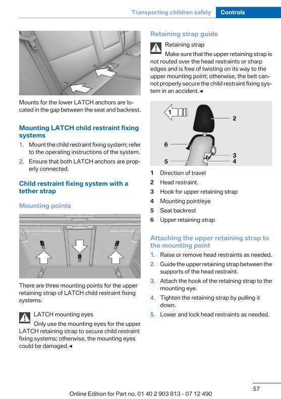
Mounts for the lower LATCH anchors are lo‐cated in the gap between the seat and backrest.
Mounting LATCH child restraint fixingsystems1. Mount the child restraint fixing system; refer
to the operating instructions of the system.2. Ensure that both LATCH anchors are prop‐
erly connected.
Child restraint fixing system with atether strap
Mounting points
There are three mounting points for the upperretaining strap of LATCH child restraint fixingsystems.
LATCH mounting eyesOnly use the mounting eyes for the upper
LATCH retaining strap to secure child restraintfixing systems; otherwise, the mounting eyescould be damaged.◀
Retaining strap guideRetaining strapMake sure that the upper retaining strap is
not routed over the head restraints or sharpedges and is free of twisting on its way to theupper mounting point; otherwise, the belt can‐not properly secure the child restraint fixing sys‐tem in an accident.◀
1 Direction of travel2 Head restraint.3 Hook for upper retaining strap4 Mounting point/eye5 Seat backrest6 Upper retaining strap
Attaching the upper retaining strap tothe mounting point1. Raise or remove head restraints as needed.2. Guide the upper retaining strap between the
supports of the head restraint.3. Attach the hook of the retaining strap to the
mounting eye.4. Tighten the retaining strap by pulling it
down.5. Lower and lock head restraints as needed.
Seite 57
Transporting children safely Controls
57Online Edition for Part no. 01 40 2 903 813 - 07 12 490
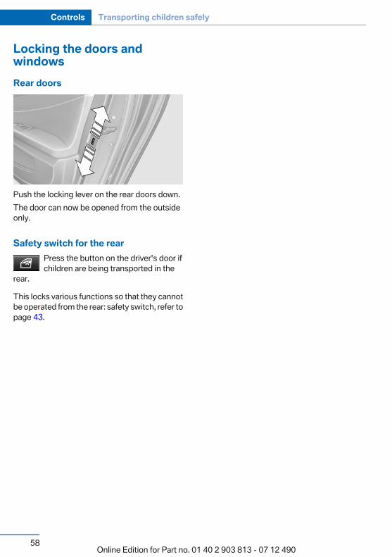
Locking the doors andwindowsRear doors
Push the locking lever on the rear doors down.The door can now be opened from the outsideonly.
Safety switch for the rearPress the button on the driver's door ifchildren are being transported in the
rear.
This locks various functions so that they cannotbe operated from the rear: safety switch, refer topage 43.
Seite 58
Controls Transporting children safely
58Online Edition for Part no. 01 40 2 903 813 - 07 12 490

DrivingVehicle equipmentAll standard, country-specific and optionalequipment that is offered in the model series isdescribed in this chapter. Therefore, equipmentis also described that is not available in a vehicle,e. g., because of the selected optional equip‐ment or country variant. This also applies forsafety-related functions and systems.
Start/Stop buttonThe concept
Pressing the Start/Stop buttonswitches the ignition on or off andstarts the engine.Automatic transmission: The en‐gine starts if the brake is de‐
pressed while pressing the Start/Stop button.
Ignition onAutomatic transmission: Press the Start/Stopbutton but do not depress the brake.All vehicle systems are ready for operation.Most of the indicator and warning lamps in theinstrument cluster light up for varying lengths oftime.To save battery power when the engine is off,switch off the ignition and any unnecessaryelectronic systems/power consumers.The ignition switches off automatically:▷ When the vehicle is locked, if the low beams
are switched on.▷ Shortly before the battery is discharged
completely, so that the engine can still bestarted.
▷ If the engine is switched off and the ignitionis switched on, the system automaticallyswitches to the radio ready state when the
door is opened if the lights are switched offor the daytime running lights are switchedon.
Ignition offAutomatic transmission: Press the Start/Stopbutton again, but do not depress the brake.All indicator lamps in the instrument cluster goout.To save battery power when the engine is off,switch off the ignition and any unnecessaryelectronic systems/power consumers.
Transmission position P with the ignitionoff
When the ignition is switched off, position P isengaged automatically. When in an automaticcar wash, for example, ensure that the ignition isnot switched off accidentally.◀
Ignition automatically cuts off while the vehicleis stationary and the engine is stopped:▷ During locking, also with the low beams ac‐
tivated.▷ Shortly before the battery is discharged
completely, so that the engine can still bestarted. This function is only available whenthe low beams are switched off.
▷ When opening and closing the driver door, ifthe driver's seat belt is unbuckled and thelow beams are switched off.
▷ While the driver's seat belt is unbuckled, ifthe driver's door is open and the low beamsare switched off.
When the ignition is switched off, by opening orclosing the driver's door or unbuckling the driv‐er's seat belt, the radio ready state remains ac‐tive.
Radio ready stateActivate radio ready state:
Seite 59
Driving Controls
59Online Edition for Part no. 01 40 2 903 813 - 07 12 490

▷ When the ignition is switched off: press ON/OFF button on the radio.
▷ When the engine is running: press the Start/Stop button.
Some electronic systems/power consumers re‐main ready for operation.Radio ready state switches off automatically:▷ After approx. 8 minutes.▷ When the vehicle is locked using the central
locking system.▷ Shortly before the battery is discharged
completely, so that the engine can still bestarted.
Starting the engineGeneral information
Enclosed areasDo not let the engine run in enclosed
areas; otherwise, breathing of exhaust fumesmay lead to loss of consciousness and death.The exhaust gases contain carbon monoxide, anodorless and colorless but highly toxic gas.◀
Unattended vehicleDo not leave the vehicle unattended with
the engine running; doing so poses a risk of dan‐ger.Before leaving the vehicle with the engine run‐ning, set the parking brake and place the trans‐mission in position P or neutral to prevent thevehicle from moving.◀
Repeated starting in quick successionAvoid repeated unsuccessful attempts to
start the vehicle or starting the vehicle severaltimes in quick succession. Otherwise, the fuel isnot burned or is inadequately burned, posing arisk of overheating and damage to the catalyticconverter.◀
Do not wait for the engine to warm up while thevehicle remains stationary. Start driving at mod‐erate engine speeds.
Automatic transmission
Starting the engine1. Depress the brake pedal.2. Press the Start/Stop button.The ignition is activated automatically for a cer‐tain time and is stopped as soon as the enginestarts.
Engine stopGeneral information
Take the remote control with youTake the remote control with you when
leaving the vehicle so that children, for example,cannot start the engine.◀
Set the parking brake and further securethe vehicle as required
Set the parking brake firmly when parking; oth‐erwise, the vehicle could roll. On steep upwardand downward inclines, further secure the vehi‐cle, for example, by turning the steering wheel inthe direction of the curb. ◀
Before driving into a car washIn order for the vehicle to be able to roll into a carwash, heed the information regarding Washingin automatic car washes, refer to page 183.
Automatic transmission
Switching off the engine1. Engage transmission position P with the ve‐
hicle stopped.2. Press the Start/Stop button.
The engine is switched off.The radio ready state is switched on.
Seite 60
Controls Driving
60Online Edition for Part no. 01 40 2 903 813 - 07 12 490

3. Set the parking brake.
Auto Start/Stop functionThe conceptThe Auto Start/Stop function helps save fuel.The system switches off the engine during astop, e.g., in a traffic congestion or at trafficlights. The ignition remains switched on. Theengine starts again automatically for driving off.Certain vehicle components may experienceadditional wear as a result of this system.
Automatic modeThe Auto Start/Stop function is operational aftereach engine start.This function is activated at speeds faster thanabout 3 mph, approx. 5 km/h.
Engine stopThe engine is switched off automatically duringa stop under the following conditions:Manual transmission:▷ Neutral is engaged and the clutch pedal is
not pressed.▷ The driver's safety belt is buckled or the
driver's door is closed.Automatic transmission:▷ The selector lever is in transmission position
D.▷ The brake pedal remains pressed while the
vehicle is stationary or the vehicle is held byAutomatic Hold.
▷ The driver's safety belt is buckled or thedriver's door is closed.
The air flow of the air conditioner is reducedwhen the engine is switched off.
Displays in the instrument clusterThe display indicates that theAuto Start/Stop function is readyfor an automatic engine start.
The display indicates that theconditions for an automatic en‐gine stop have not been satisfied.
NoteThe engine is not switched off automatically inthe following situations:▷ External temperature below approx.
+37 ℉/+3 ℃.▷ The external temperature is high and auto‐
matic climate control is running.▷ The passenger compartment has not yet
been heated or cooled to the required level.▷ The engine is not yet at operating tempera‐
ture.▷ The wheels are at a sharp angle or the steer‐
ing wheel is being turned.▷ After driving in reverse.▷ Fogging of the windows when the automatic
climate control is switched on.▷ The vehicle battery charge is very low.▷ The engine compartment lid is unlocked.▷ HDC is activated.▷ Stop-and-go traffic.▷ The transmission selector lever is in position
N or S/M.
Starting the engineThe engine starts automatically under the fol‐lowing conditions:▷ Automatic transmission:
By releasing the brake pedal.
Seite 61
Driving Controls
61Online Edition for Part no. 01 40 2 903 813 - 07 12 490
When Automatic Hold is activated: press theaccelerator.
After the engine starts, accelerate as usual.
Safety modeAfter the engine switches off automatically, itwill not start again automatically if any one of thefollowing conditions are met.▷ The driver's safety belt is unbuckled and the
driver's door is open.▷ The hood was unlocked.Some indicator lamps light up for varyinglengths of time.The engine can only be started via the Start/Stop button.
NoteEven if driving away was not intended, the de‐activated engine starts up automatically in thefollowing situations:▷ Excessive warming of the passenger com‐
partment when the cooling function isswitched on.
▷ The steering wheel is turned.▷ Automatic transmission: the transmission
position is changed from D to N, R, or M/S.▷ Automatic transmission: the transmission
position is changed from P to N, D, R, or M/S.
▷ Fogging of the windows when the automaticclimate control is switched on.
▷ The vehicle battery charge is very low.▷ Excessive cooling of the passenger com‐
partment when the heating is switched on.
Preventing an automatic engine stopwith automatic transmission
The conceptTo make it possible to drive away very quickly,such as at an intersection, the automatic enginestop can be actively prevented.
Preventing an engine stop using thebrake pedalThe engine stop can be actively preventedwithin one second after the vehicle comes to astandstill.▷ Immediately after the vehicle comes to a
standstill, briefly press the brake pedalforcefully.
▷ Then press the brake pedal with normalbraking force.
Activating/deactivating the systemmanually
Using the button
Press the button.
▷ LED comes on: Auto Start Stop function isdeactivated.The engine is started during an automaticengine stop.The engine can only be stopped or startedvia the Start/Stop button.
▷ LED goes out: Auto Start Stop function isactivated.
Switching off the vehicle during anautomatic engine stopDuring an automatic engine stop, the vehiclecan be switched off permanently, e.g., whenleaving it.
1. Press the Start/Stop button. The ignition isswitched off. The Auto Start/Stop functionis deactivated.
Seite 62
Controls Driving
62Online Edition for Part no. 01 40 2 903 813 - 07 12 490
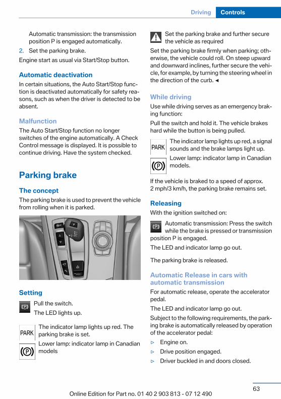
Automatic transmission: the transmissionposition P is engaged automatically.
2. Set the parking brake.Engine start as usual via Start/Stop button.
Automatic deactivationIn certain situations, the Auto Start/Stop func‐tion is deactivated automatically for safety rea‐sons, such as when the driver is detected to beabsent.
MalfunctionThe Auto Start/Stop function no longerswitches of the engine automatically. A CheckControl message is displayed. It is possible tocontinue driving. Have the system checked.
Parking brakeThe conceptThe parking brake is used to prevent the vehiclefrom rolling when it is parked.
SettingPull the switch.The LED lights up.
The indicator lamp lights up red. Theparking brake is set.Lower lamp: indicator lamp in Canadianmodels
Set the parking brake and further securethe vehicle as required
Set the parking brake firmly when parking; oth‐erwise, the vehicle could roll. On steep upwardand downward inclines, further secure the vehi‐cle, for example, by turning the steering wheel inthe direction of the curb. ◀
While drivingUse while driving serves as an emergency brak‐ing function:Pull the switch and hold it. The vehicle brakeshard while the button is being pulled.
The indicator lamp lights up red, a signalsounds and the brake lamps light up.Lower lamp: indicator lamp in Canadianmodels.
If the vehicle is braked to a speed of approx.2 mph/3 km/h, the parking brake remains set.
ReleasingWith the ignition switched on:
Automatic transmission: Press the switchwhile the brake is pressed or transmission
position P is engaged.The LED and indicator lamp go out.
The parking brake is released.
Automatic Release in cars withautomatic transmissionFor automatic release, operate the acceleratorpedal.The LED and indicator lamp go out.Subject to the following requirements, the park‐ing brake is automatically released by operationof the accelerator pedal:▷ Engine on.▷ Drive position engaged.▷ Driver buckled in and doors closed.
Seite 63
Driving Controls
63Online Edition for Part no. 01 40 2 903 813 - 07 12 490
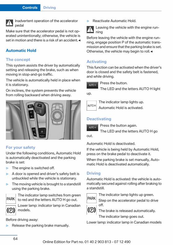
Inadvertent operation of the acceleratorpedal
Make sure that the accelerator pedal is not op‐erated unintentionally; otherwise, the vehicle isset in motion and there is a risk of an accident.◀
Automatic Hold
The conceptThis system assists the driver by automaticallysetting and releasing the brake, such as whenmoving in stop-and-go traffic.The vehicle is automatically held in place whenit is stationary.On inclines, the system prevents the vehiclefrom rolling backward when driving away.
For your safetyUnder the following conditions, Automatic Holdis automatically deactivated and the parkingbrake is set:▷ The engine is switched off.▷ A door is opened and driver's safety belt is
unbuckled while the vehicle is stationary.▷ The moving vehicle is brought to a standstill
using the parking brake.The indicator lamp switches from greento red and the letters AUTO H go out.Lower lamp: indicator lamp in Canadianmodels.
Before driving away:▷ Release the parking brake manually.
▷ Reactivate Automatic Hold.Leaving the vehicle with the engine run‐ning
Before leaving the vehicle with the engine run‐ning, engage position P of the automatic trans‐mission and ensure that the parking brake is set.Otherwise, the vehicle may begin to roll.◀
ActivatingThis function can be activated when the driver'sdoor is closed and the safety belt is fastened,and while driving.
Press the button.The LED and the letters AUTO H light
up.
The indicator lamp lights up.Automatic Hold is activated.
DeactivatingPress the button again.The LED and the letters AUTO H go
out.
Automatic Hold is deactivated.If the vehicle is being held by Automatic Hold,press on the brake pedal to deactivate it.When the parking brake is set manually, Auto‐matic Hold is deactivated automatically.
DrivingAutomatic Hold is activated: the vehicle is auto‐matically secured against rolling after braking toa standstill.
The indicator lamp lights up green.Step on the accelerator pedal to driveoff.The brake is released automatically.The indicator lamp goes out.
Lower lamp: indicator lamp in Canadian models
Seite 64
Controls Driving
64Online Edition for Part no. 01 40 2 903 813 - 07 12 490

Before driving into a car washDeactivate Automatic Hold; otherwise, the
parking brake will be set when the vehicle is sta‐tionary and the vehicle will no longer be able toroll.◀
ParkingThe parking brake is automatically set if the en‐gine is switched off while the vehicle is beingheld by Automatic Hold.
The indicator lamp changes from greento red.The parking brake is not set if the engineis switched off while the vehicle is coast‐ing to a halt. Automatic Hold is deacti‐
vated.Lower lamp: indicator lamp in Canadian models
Automatic Hold remains activated during an en‐gine stop brought about by the Auto Start/Stopfunction.
Take the remote control with youTake the remote control with you when
leaving the vehicle so that children, for example,cannot release the parking brake.◀
MalfunctionIn the event of a failure or malfunction of theparking brake, secure the vehicle against rollingusing a wheel chock, for example, when leavingit.
Turn signal, high beams,headlamp flasherTurn signal
Using turn signals
Press the lever beyond the resistance point.To switch off manually, press the lever to the re‐sistance point.
Unusually rapid flashing of the indicator lamp in‐dicates that a turn signal bulb has failed.
Triple turn signal activationPress the lever to the resistance point.The turn signal flashes three times.The function can be activated or deactivated:
1. "Settings"2. "Lighting"3. "Triple turn signal"
Seite 65
Driving Controls
65Online Edition for Part no. 01 40 2 903 813 - 07 12 490
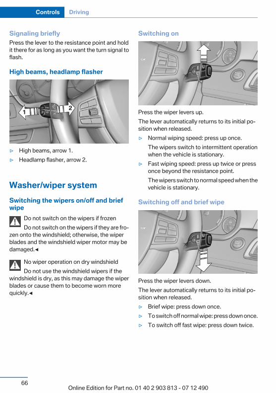
Signaling brieflyPress the lever to the resistance point and holdit there for as long as you want the turn signal toflash.
High beams, headlamp flasher
▷ High beams, arrow 1.▷ Headlamp flasher, arrow 2.
Washer/wiper systemSwitching the wipers on/off and briefwipe
Do not switch on the wipers if frozenDo not switch on the wipers if they are fro‐
zen onto the windshield; otherwise, the wiperblades and the windshield wiper motor may bedamaged.◀
No wiper operation on dry windshieldDo not use the windshield wipers if the
windshield is dry, as this may damage the wiperblades or cause them to become worn morequickly.◀
Switching on
Press the wiper levers up.The lever automatically returns to its initial po‐sition when released.▷ Normal wiping speed: press up once.
The wipers switch to intermittent operationwhen the vehicle is stationary.
▷ Fast wiping speed: press up twice or pressonce beyond the resistance point.The wipers switch to normal speed when thevehicle is stationary.
Switching off and brief wipe
Press the wiper levers down.The lever automatically returns to its initial po‐sition when released.▷ Brief wipe: press down once.▷ To switch off normal wipe: press down once.▷ To switch off fast wipe: press down twice.
Seite 66
Controls Driving
66Online Edition for Part no. 01 40 2 903 813 - 07 12 490

Intermittent operation or rain sensor
The conceptThe rain sensor automatically controls the timebetween wipes depending on the intensity ofthe rainfall. The sensor is located on the wind‐shield, directly behind the interior rearview mir‐ror.
Activating/deactivating
Press the button on the wiper lever.The LED in the steering column stalk lights up.
Deactivate the rain sensor in car washesDeactivate the rain sensor when passing
through an automatic car wash; otherwise, dam‐age could be caused by undesired wiper activa‐tion.◀
Setting the frequency or sensitivity ofthe rain sensor
Turn the thumbwheel.
Clean the windshield, headlamps
Pull the lever.The system sprays washer fluid on the wind‐shield and activates the wipers briefly.
In addition, the headlamps are cleaned at regularintervals when the vehicle lights are switchedon.
Do not use the washer system at freezingtemperatures
Do not use the washers if there is any dangerthat the fluid will freeze on the windshield; oth‐erwise, your vision could be obscured. For thisreason, use antifreeze.Avoid using the washer when the reservoir isempty; otherwise, you could damage thepump.◀
Windshield washer nozzlesThe windshield washer nozzles are automati‐cally heated while the ignition is switched on.
Switching on the rear window wiper
Seite 67
Driving Controls
67Online Edition for Part no. 01 40 2 903 813 - 07 12 490
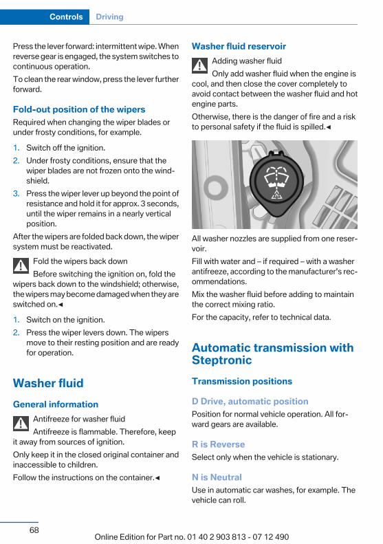
Press the lever forward: intermittent wipe. Whenreverse gear is engaged, the system switches tocontinuous operation.To clean the rear window, press the lever furtherforward.
Fold-out position of the wipersRequired when changing the wiper blades orunder frosty conditions, for example.
1. Switch off the ignition.2. Under frosty conditions, ensure that the
wiper blades are not frozen onto the wind‐shield.
3. Press the wiper lever up beyond the point ofresistance and hold it for approx. 3 seconds,until the wiper remains in a nearly verticalposition.
After the wipers are folded back down, the wipersystem must be reactivated.
Fold the wipers back downBefore switching the ignition on, fold the
wipers back down to the windshield; otherwise,the wipers may become damaged when they areswitched on.◀
1. Switch on the ignition.2. Press the wiper levers down. The wipers
move to their resting position and are readyfor operation.
Washer fluidGeneral information
Antifreeze for washer fluidAntifreeze is flammable. Therefore, keep
it away from sources of ignition.Only keep it in the closed original container andinaccessible to children.Follow the instructions on the container.◀
Washer fluid reservoirAdding washer fluidOnly add washer fluid when the engine is
cool, and then close the cover completely toavoid contact between the washer fluid and hotengine parts.Otherwise, there is the danger of fire and a riskto personal safety if the fluid is spilled.◀
All washer nozzles are supplied from one reser‐voir.Fill with water and – if required – with a washerantifreeze, according to the manufacturer's rec‐ommendations.Mix the washer fluid before adding to maintainthe correct mixing ratio.For the capacity, refer to technical data.
Automatic transmission withSteptronicTransmission positions
D Drive, automatic positionPosition for normal vehicle operation. All for‐ward gears are available.
R is ReverseSelect only when the vehicle is stationary.
N is NeutralUse in automatic car washes, for example. Thevehicle can roll.
Seite 68
Controls Driving
68Online Edition for Part no. 01 40 2 903 813 - 07 12 490

When the ignition is switched off, refer topage 59, position P is engaged automatically.
P ParkSelect only when the vehicle is stationary. Thedrive wheels are blocked.P is engaged automatically:▷ After the engine is switched off when the
vehicle is in radio ready state, refer topage 59, or when the ignition is switched off,refer to page 59, and when position R or D isengaged.
▷ With the ignition is off, if position N is en‐gaged.
▷ If the safety belt is unbuckled, the driver'sdoor is opened, and the brake pedal is notpressed while the vehicle is stationary andtransmission position R or D is engaged.
Before exiting the vehicle, make sure that posi‐tion P of the automatic transmission is engaged.Otherwise, the vehicle may begin to roll.
KickdownKickdown is used to achieve maximum drivingperformance. Press on the gas pedal beyond theresistance point at the full throttle position.
Engaging the transmission position▷ Transmission position P can only be disen‐
gaged if the engine is running and the brakepedal is pressed.
▷ With the vehicle stationary, press on thebrake pedal before shifting out of P or N;otherwise, the shift command will not beexecuted: shift lock.
Depress the brake until you start driv‐ing
To prevent the vehicle from creeping afteryou select a driving position, maintain pres‐sure on the brake pedal until you are readyto start.◀
Engaging D, R and N
Briefly push the selector lever in the desired di‐rection, beyond a resistance point if necessary.After releasing the selector lever, it returns to itscenter position.
Press unlock button, in order to:▷ Engage R.▷ Shift out of P.
Engaging P
Press button P.
Seite 69
Driving Controls
69Online Edition for Part no. 01 40 2 903 813 - 07 12 490
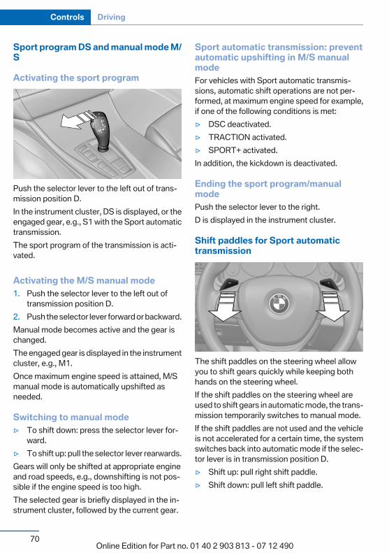
Sport program DS and manual mode M/S
Activating the sport program
Push the selector lever to the left out of trans‐mission position D.In the instrument cluster, DS is displayed, or theengaged gear, e.g., S1 with the Sport automatictransmission.The sport program of the transmission is acti‐vated.
Activating the M/S manual mode1. Push the selector lever to the left out of
transmission position D.2. Push the selector lever forward or backward.Manual mode becomes active and the gear ischanged.The engaged gear is displayed in the instrumentcluster, e.g., M1.Once maximum engine speed is attained, M/Smanual mode is automatically upshifted asneeded.
Switching to manual mode▷ To shift down: press the selector lever for‐
ward.▷ To shift up: pull the selector lever rearwards.Gears will only be shifted at appropriate engineand road speeds, e.g., downshifting is not pos‐sible if the engine speed is too high.The selected gear is briefly displayed in the in‐strument cluster, followed by the current gear.
Sport automatic transmission: preventautomatic upshifting in M/S manualmodeFor vehicles with Sport automatic transmis‐sions, automatic shift operations are not per‐formed, at maximum engine speed for example,if one of the following conditions is met:▷ DSC deactivated.▷ TRACTION activated.▷ SPORT+ activated.In addition, the kickdown is deactivated.
Ending the sport program/manualmodePush the selector lever to the right.D is displayed in the instrument cluster.
Shift paddles for Sport automatictransmission
The shift paddles on the steering wheel allowyou to shift gears quickly while keeping bothhands on the steering wheel.If the shift paddles on the steering wheel areused to shift gears in automatic mode, the trans‐mission temporarily switches to manual mode.If the shift paddles are not used and the vehicleis not accelerated for a certain time, the systemswitches back into automatic mode if the selec‐tor lever is in transmission position D.▷ Shift up: pull right shift paddle.▷ Shift down: pull left shift paddle.
Seite 70
Controls Driving
70Online Edition for Part no. 01 40 2 903 813 - 07 12 490
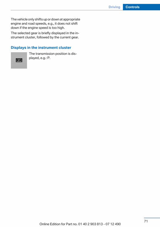
The vehicle only shifts up or down at appropriateengine and road speeds, e.g., it does not shiftdown if the engine speed is too high.The selected gear is briefly displayed in the in‐strument cluster, followed by the current gear.
Displays in the instrument clusterThe transmission position is dis‐played, e.g.: P.
Seite 71
Driving Controls
71Online Edition for Part no. 01 40 2 903 813 - 07 12 490
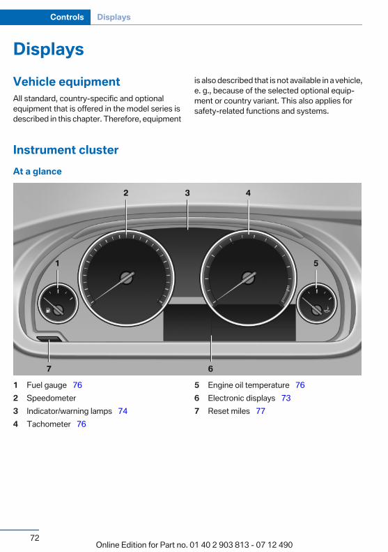
DisplaysVehicle equipmentAll standard, country-specific and optionalequipment that is offered in the model series isdescribed in this chapter. Therefore, equipment
is also described that is not available in a vehicle,e. g., because of the selected optional equip‐ment or country variant. This also applies forsafety-related functions and systems.
Instrument clusterAt a glance
1 Fuel gauge 762 Speedometer3 Indicator/warning lamps 744 Tachometer 76
5 Engine oil temperature 766 Electronic displays 737 Reset miles 77
Seite 72
Controls Displays
72Online Edition for Part no. 01 40 2 903 813 - 07 12 490
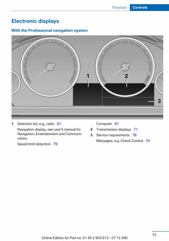
Electronic displaysWith the Professional navigation system
1 Selection list, e.g., radio 81Navigation display, see user's manual forNavigation, Entertainment and Communi‐cation.Speed limit detection 79
Computer 812 Transmission displays 713 Service requirements 78
Messages, e.g. Check Control 74
Seite 73
Displays Controls
73Online Edition for Part no. 01 40 2 903 813 - 07 12 490
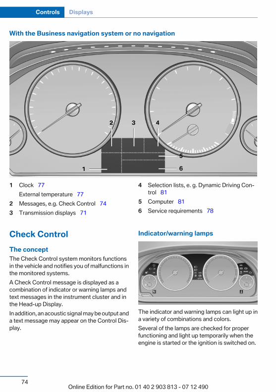
With the Business navigation system or no navigation
1 Clock 77External temperature 77
2 Messages, e.g. Check Control 743 Transmission displays 71
4 Selection lists, e. g. Dynamic Driving Con‐trol 81
5 Computer 816 Service requirements 78
Check ControlThe conceptThe Check Control system monitors functionsin the vehicle and notifies you of malfunctions inthe monitored systems.A Check Control message is displayed as acombination of indicator or warning lamps andtext messages in the instrument cluster and inthe Head-up Display.In addition, an acoustic signal may be output anda text message may appear on the Control Dis‐play.
Indicator/warning lamps
The indicator and warning lamps can light up ina variety of combinations and colors.Several of the lamps are checked for properfunctioning and light up temporarily when theengine is started or the ignition is switched on.
Seite 74
Controls Displays
74Online Edition for Part no. 01 40 2 903 813 - 07 12 490
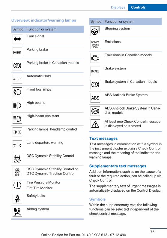
Overview: indicator/warning lamps
Symbol Function or system
Turn signal
Parking brake
Parking brake in Canadian models
Automatic Hold
Front fog lamps
High beams
High-beam Assistant
Parking lamps, headlamp control
Lane departure warning
DSC Dynamic Stability Control
DSC Dynamic Stability Control orDTC Dynamic Traction Control
Tire Pressure MonitorFlat Tire Monitor
Safety belts
Airbag system
Symbol Function or system
Steering system
Emissions
Emissions in Canadian models
Brake system
Brake system in Canadian models
ABS Antilock Brake System
ABS Antilock Brake System in Cana‐dian models
At least one Check Control messageis displayed or is stored
Text messagesText messages in combination with a symbol inthe instrument cluster explain a Check Controlmessage and the meaning of the indicator andwarning lamps.
Supplementary text messagesAddition information, such as on the cause of afault or the required action, can be called up viaCheck Control.The supplementary text of urgent messages isautomatically displayed on the Control Display.
SymbolsWithin the supplementary text, the followingfunctions can be selected independent of thecheck control message.
Seite 75
Displays Controls
75Online Edition for Part no. 01 40 2 903 813 - 07 12 490
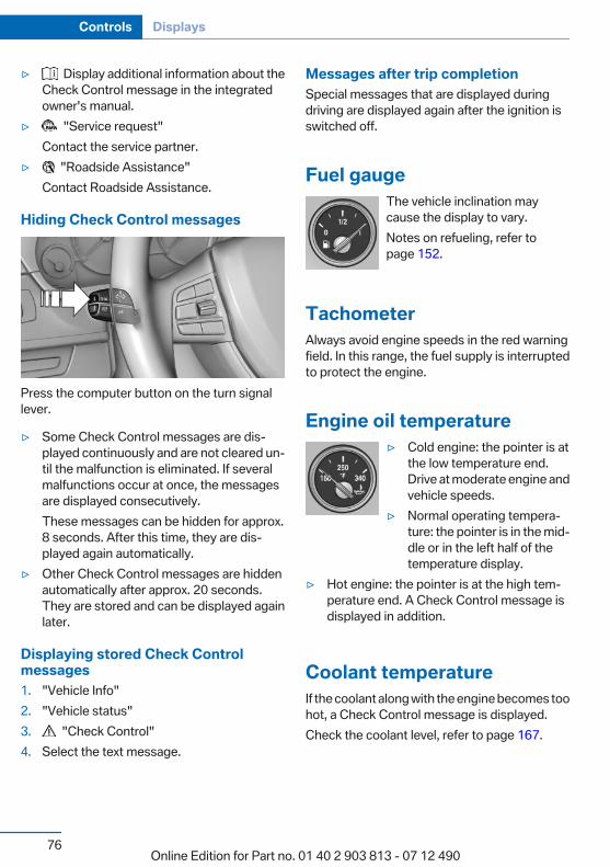
▷ Display additional information about theCheck Control message in the integratedowner's manual.
▷ "Service request"Contact the service partner.
▷ "Roadside Assistance"Contact Roadside Assistance.
Hiding Check Control messages
Press the computer button on the turn signallever.
▷ Some Check Control messages are dis‐played continuously and are not cleared un‐til the malfunction is eliminated. If severalmalfunctions occur at once, the messagesare displayed consecutively.These messages can be hidden for approx.8 seconds. After this time, they are dis‐played again automatically.
▷ Other Check Control messages are hiddenautomatically after approx. 20 seconds.They are stored and can be displayed againlater.
Displaying stored Check Controlmessages1. "Vehicle Info"2. "Vehicle status"3. "Check Control"4. Select the text message.
Messages after trip completionSpecial messages that are displayed duringdriving are displayed again after the ignition isswitched off.
Fuel gaugeThe vehicle inclination maycause the display to vary.Notes on refueling, refer topage 152.
TachometerAlways avoid engine speeds in the red warningfield. In this range, the fuel supply is interruptedto protect the engine.
Engine oil temperature▷ Cold engine: the pointer is at
the low temperature end.Drive at moderate engine andvehicle speeds.
▷ Normal operating tempera‐ture: the pointer is in the mid‐dle or in the left half of thetemperature display.
▷ Hot engine: the pointer is at the high tem‐perature end. A Check Control message isdisplayed in addition.
Coolant temperatureIf the coolant along with the engine becomes toohot, a Check Control message is displayed.Check the coolant level, refer to page 167.
Seite 76
Controls Displays
76Online Edition for Part no. 01 40 2 903 813 - 07 12 490
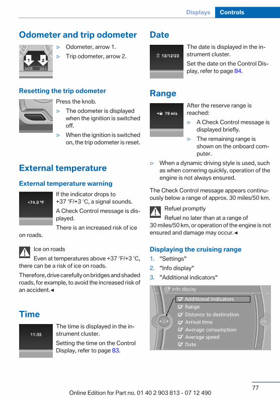
Odometer and trip odometer▷ Odometer, arrow 1.▷ Trip odometer, arrow 2.
Resetting the trip odometerPress the knob.▷ The odometer is displayed
when the ignition is switchedoff.
▷ When the ignition is switchedon, the trip odometer is reset.
External temperatureExternal temperature warning
If the indicator drops to+37 ℉/+3 ℃, a signal sounds.A Check Control message is dis‐played.There is an increased risk of ice
on roads.
Ice on roadsEven at temperatures above +37 ℉/+3 ℃,
there can be a risk of ice on roads.Therefore, drive carefully on bridges and shadedroads, for example, to avoid the increased risk ofan accident.◀
TimeThe time is displayed in the in‐strument cluster.Setting the time on the ControlDisplay, refer to page 83.
DateThe date is displayed in the in‐strument cluster.Set the date on the Control Dis‐play, refer to page 84.
RangeAfter the reserve range isreached:▷ A Check Control message is
displayed briefly.▷ The remaining range is
shown on the onboard com‐puter.
▷ When a dynamic driving style is used, suchas when cornering quickly, operation of theengine is not always ensured.
The Check Control message appears continu‐ously below a range of approx. 30 miles/50 km.
Refuel promptlyRefuel no later than at a range of
30 miles/50 km, or operation of the engine is notensured and damage may occur.◀
Displaying the cruising range1. "Settings"2. "Info display"3. "Additional indicators"
Seite 77
Displays Controls
77Online Edition for Part no. 01 40 2 903 813 - 07 12 490
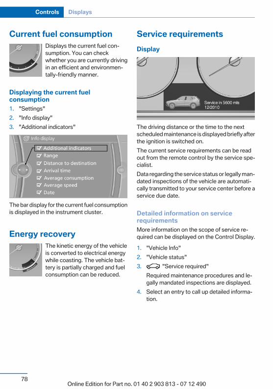
Current fuel consumptionDisplays the current fuel con‐sumption. You can checkwhether you are currently drivingin an efficient and environmen‐tally-friendly manner.
Displaying the current fuelconsumption1. "Settings"2. "Info display"3. "Additional indicators"
The bar display for the current fuel consumptionis displayed in the instrument cluster.
Energy recoveryThe kinetic energy of the vehicleis converted to electrical energywhile coasting. The vehicle bat‐tery is partially charged and fuelconsumption can be reduced.
Service requirementsDisplay
The driving distance or the time to the nextscheduled maintenance is displayed briefly afterthe ignition is switched on.The current service requirements can be readout from the remote control by the service spe‐cialist.Data regarding the service status or legally man‐dated inspections of the vehicle are automati‐cally transmitted to your service center before aservice due date.
Detailed information on servicerequirementsMore information on the scope of service re‐quired can be displayed on the Control Display.
1. "Vehicle Info"2. "Vehicle status"3. "Service required"
Required maintenance procedures and le‐gally mandated inspections are displayed.
4. Select an entry to call up detailed informa‐tion.
Seite 78
Controls Displays
78Online Edition for Part no. 01 40 2 903 813 - 07 12 490
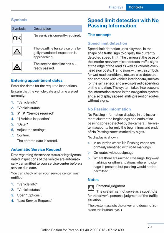
Symbols
Symbols Description
No service is currently required.
The deadline for service or a le‐gally mandated inspection isapproaching.
The service deadline has al‐ready passed.
Entering appointment datesEnter the dates for the required inspections.Ensure that the vehicle date and time are setcorrectly.
1. "Vehicle Info"2. "Vehicle status"3. "Service required"4. "§ Vehicle inspection"5. "Date:"6. Adjust the settings.7. Confirm.
The entered date is stored.
Automatic Service RequestData regarding the service status or legally man‐dated inspections of the vehicle are automati‐cally transmitted to your service center before aservice due date.You can check when your service center wasnotified.
1. "Vehicle Info"2. "Vehicle status"3. Open "Options".4. "Last Service Request"
Speed limit detection with NoPassing InformationThe concept
Speed limit detectionSpeed limit detection uses a symbol in theshape of a traffic sign to display the currentlydetected speed limit. The camera at the base ofthe interior rearview mirror detects traffic signsat the edge of the road as well as variable over‐head sign posts. Traffic signs with extra symbolsfor wet road conditions, etc. are also detectedand compared with vehicle interior data, such asfor the rain sensor, and are displayed dependingon the situation. The system takes into accountthe information stored in the navigation systemand also displays speed limits present on routeswithout signs.
No Passing InformationNo Passing Information displays in the instru‐ment cluster the beginnings and ends of nopassing zones detected by the camera. The sys‐tem accounts for only the beginnings and endsof No Passing zones marked by signs.No display is shown:▷ In countries where No Passing zones are
primarily identified with road markings.▷ On routes without signage.▷ Where there are railroad crossings, highway
markings or other situations where no sig‐nage is present, but passing would not bepermitted.
NotesPersonal judgmentThe system cannot serve as a substitute
for the driver's personal judgment of the trafficsituation.The system assists the driver and does not re‐place the human eye.◀
Seite 79
Displays Controls
79Online Edition for Part no. 01 40 2 903 813 - 07 12 490

At a glance
Camera
The camera is located near the base of the mir‐ror.Keep the windshield in the area behind the in‐terior rear view mirror clean and clear.
Switching on/off1. "Settings"2. "Info display"3. "Speed limit information"If speed limit detection is switched on, it can bedisplayed on the info display in the instrumentcluster via the onboard computer. No PassingInformation is displayed together with activatedspeed limit information.
DisplayThe following is displayed in the instrumentcluster.
Speed limit detectionCurrent speed limit.
Speed limit detection is not avail‐able.
Speed limit detection can also be displayed inthe Head-up Display.
No Passing Information▷ Start of No Passing zone.▷ End of No Passing zone.▷ No Passing Information not
available.
No Passing Information can also be displayed inthe Head-up Display.
System limitsThe system may not be fully functional and mayprovide incorrect information in the followingsituations:▷ In heavy fog, rain or snowfall.▷ When signs are concealed by objects.▷ When driving very close to the vehicle in
front of you.▷ When driving toward bright lights.▷ When the windshield behind the interior
rearview mirror is fogged over, dirty or cov‐ered by a sticker, etc.
▷ In the event of incorrect detection by thecamera.
▷ If the speed limits stored in the navigationsystem are incorrect.
▷ In areas not covered by the navigation sys‐tem.
▷ When roads differ from the navigation, suchas due to changes in the road network.
▷ When passing buses or trucks with a speedsticker.
▷ If the traffic signs are non-conforming.▷ During calibration of the camera immedi‐
ately after vehicle shipment.
Seite 80
Controls Displays
80Online Edition for Part no. 01 40 2 903 813 - 07 12 490
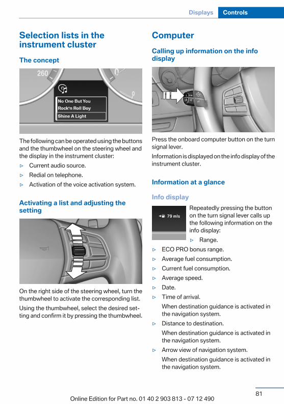
Selection lists in theinstrument clusterThe concept
The following can be operated using the buttonsand the thumbwheel on the steering wheel andthe display in the instrument cluster:▷ Current audio source.▷ Redial on telephone.▷ Activation of the voice activation system.
Activating a list and adjusting thesetting
On the right side of the steering wheel, turn thethumbwheel to activate the corresponding list.Using the thumbwheel, select the desired set‐ting and confirm it by pressing the thumbwheel.
ComputerCalling up information on the infodisplay
Press the onboard computer button on the turnsignal lever.Information is displayed on the info display of theinstrument cluster.
Information at a glance
Info displayRepeatedly pressing the buttonon the turn signal lever calls upthe following information on theinfo display:▷ Range.
▷ ECO PRO bonus range.▷ Average fuel consumption.▷ Current fuel consumption.▷ Average speed.▷ Date.▷ Time of arrival.
When destination guidance is activated inthe navigation system.
▷ Distance to destination.When destination guidance is activated inthe navigation system.
▷ Arrow view of navigation system.When destination guidance is activated inthe navigation system.
Seite 81
Displays Controls
81Online Edition for Part no. 01 40 2 903 813 - 07 12 490
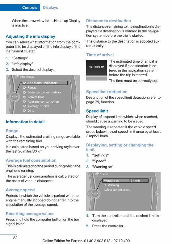
When the arrow view in the Head-up Displayis inactive.
Adjusting the info displayYou can select what information from the com‐puter is to be displayed on the info display of theinstrument cluster.
1. "Settings"2. "Info display"3. Select the desired displays.
Information in detail
RangeDisplays the estimated cruising range availablewith the remaining fuel.It is calculated based on your driving style overthe last 20 miles/30 km.
Average fuel consumptionThis is calculated for the period during which theengine is running.The average fuel consumption is calculated onthe basis of various distances.
Average speedPeriods in which the vehicle is parked with theengine manually stopped do not enter into thecalculation of the average speed.
Resetting average valuesPress and hold the computer button on the turnsignal lever.
Distance to destinationThe distance remaining to the destination is dis‐played if a destination is entered in the naviga‐tion system before the trip is started.The distance to the destination is adopted au‐tomatically.
Time of arrivalThe estimated time of arrival isdisplayed if a destination is en‐tered in the navigation systembefore the trip is started.The time must be correctly set.
Speed limit detectionDescription of the speed limit detection, refer topage 79, function.
Speed limitDisplay of a speed limit which, when reached,should cause a warning to be issued.The warning is repeated if the vehicle speeddrops below the set speed limit once by at least3 mph/5 km/h.
Displaying, setting or changing thelimit1. "Settings"2. "Speed"3. "Warning at:"
4. Turn the controller until the desired limit isdisplayed.
5. Press the controller.
Seite 82
Controls Displays
82Online Edition for Part no. 01 40 2 903 813 - 07 12 490
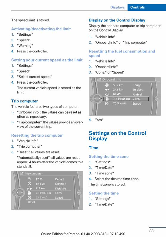
The speed limit is stored.
Activating/deactivating the limit1. "Settings"2. "Speed"3. "Warning"4. Press the controller.
Setting your current speed as the limit1. "Settings"2. "Speed"3. "Select current speed"4. Press the controller.
The current vehicle speed is stored as thelimit.
Trip computerThe vehicle features two types of computer.▷ "Onboard info": the values can be reset as
often as necessary.▷ "Trip computer": the values provide an over‐
view of the current trip.
Resetting the trip computer1. "Vehicle Info"2. "Trip computer"3. "Reset": all values are reset.
"Automatically reset": all values are resetapprox. 4 hours after the vehicle comes to astandstill.
Display on the Control DisplayDisplay the onboard computer or trip computeron the Control Display.
1. "Vehicle Info"2. "Onboard info" or "Trip computer"
Resetting the fuel consumption andspeed1. "Vehicle Info"2. "Onboard info"3. "Cons." or "Speed"
4. "Yes"
Settings on the ControlDisplayTime
Setting the time zone1. "Settings"2. "Time/Date"3. "Time zone"4. Select the desired time zone.The time zone is stored.
Setting the time1. "Settings"2. "Time/Date"
Seite 83
Displays Controls
83Online Edition for Part no. 01 40 2 903 813 - 07 12 490
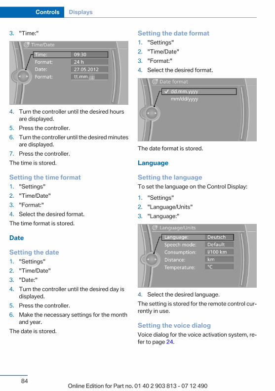
3. "Time:"
4. Turn the controller until the desired hoursare displayed.
5. Press the controller.6. Turn the controller until the desired minutes
are displayed.7. Press the controller.The time is stored.
Setting the time format1. "Settings"2. "Time/Date"3. "Format:"4. Select the desired format.The time format is stored.
Date
Setting the date1. "Settings"2. "Time/Date"3. "Date:"4. Turn the controller until the desired day is
displayed.5. Press the controller.6. Make the necessary settings for the month
and year.The date is stored.
Setting the date format1. "Settings"2. "Time/Date"3. "Format:"4. Select the desired format.
The date format is stored.
Language
Setting the languageTo set the language on the Control Display:
1. "Settings"2. "Language/Units"3. "Language:"
4. Select the desired language.The setting is stored for the remote control cur‐rently in use.
Setting the voice dialogVoice dialog for the voice activation system, re‐fer to page 24.
Seite 84
Controls Displays
84Online Edition for Part no. 01 40 2 903 813 - 07 12 490

Units of measure
Setting the units of measureTo set the units for fuel consumption, route/dis‐tance and temperature:
1. "Settings"2. "Language/Units"3. Select the desired menu item.
4. Select the desired unit.The setting is stored for the remote control cur‐rently in use.
Brightness
Setting the brightnessTo set the brightness of the Control Display:
1. "Settings"2. "Control display"3. "Brightness"
4. Turn the controller until the desired bright‐ness is set.
5. Press the controller.
The setting is stored for the remote control cur‐rently in use.Depending on the light conditions, the bright‐ness control may not be clearly visible.
Seite 85
Displays Controls
85Online Edition for Part no. 01 40 2 903 813 - 07 12 490

LampsVehicle equipmentAll standard, country-specific and optionalequipment that is offered in the model series isdescribed in this chapter. Therefore, equipmentis also described that is not available in a vehicle,e. g., because of the selected optional equip‐ment or country variant. This also applies forsafety-related functions and systems.
At a glance
1 Rear fog lamps2 Front fog lamps3 Automatic headlamp control / Adaptive
Light Control / High-beam Assistant / wel‐come lamps / daytime running lights
4 Lamps off/daytime running lights5 Parking lamps/daytime running lights6 Low beams/welcome lamps / High-beam
Assistant7 Instrument lighting8 Headlamp range control
Parking lamps/low beams,headlamp controlGeneral informationSwitch position: 0, ,
If the driver door is opened with the ignitionswitched off, the exterior lighting is automati‐cally switched off at these switch settings.
Parking lampsSwitch position : the vehicle lamps lightup on all sides, e.g., for parking.Do not use the parking lamps for extended pe‐riods; otherwise, the battery may become dis‐charged and it would then be impossible to startthe engine.When parking, it is preferable to switch on theone-sided roadside parking lamps, refer topage 87.
Low beamsSwitch position with the ignition switchedon: the low beams light up.
Welcome lampsWhen parking the vehicle, leave the switch inposition or : the parking and interiorlamps light up briefly when the vehicle is un‐locked.
Activating/deactivating1. "Settings"2. "Lighting"3. "Welcome light"
The setting is stored for the remote control cur‐rently in use.
Seite 86
Controls Lamps
86Online Edition for Part no. 01 40 2 903 813 - 07 12 490
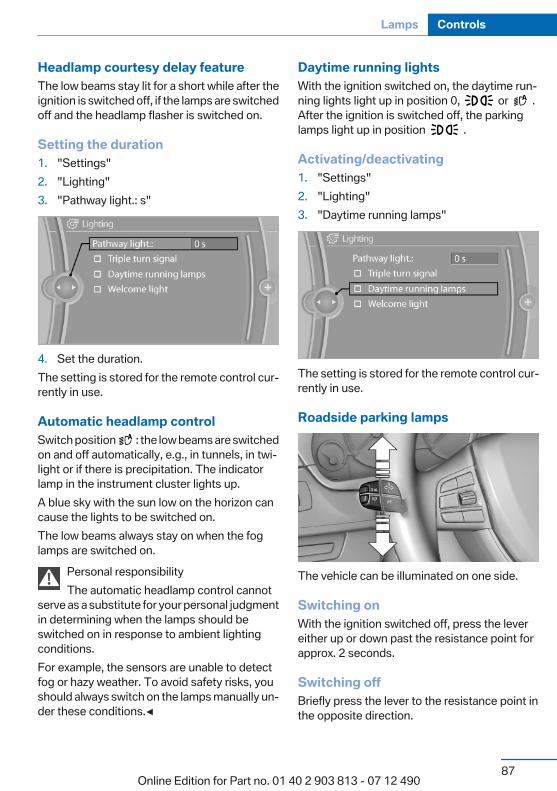
Headlamp courtesy delay featureThe low beams stay lit for a short while after theignition is switched off, if the lamps are switchedoff and the headlamp flasher is switched on.
Setting the duration1. "Settings"2. "Lighting"3. "Pathway light.: s"
4. Set the duration.The setting is stored for the remote control cur‐rently in use.
Automatic headlamp controlSwitch position : the low beams are switchedon and off automatically, e.g., in tunnels, in twi‐light or if there is precipitation. The indicatorlamp in the instrument cluster lights up.A blue sky with the sun low on the horizon cancause the lights to be switched on.The low beams always stay on when the foglamps are switched on.
Personal responsibilityThe automatic headlamp control cannot
serve as a substitute for your personal judgmentin determining when the lamps should beswitched on in response to ambient lightingconditions.For example, the sensors are unable to detectfog or hazy weather. To avoid safety risks, youshould always switch on the lamps manually un‐der these conditions.◀
Daytime running lightsWith the ignition switched on, the daytime run‐ning lights light up in position 0, or .After the ignition is switched off, the parkinglamps light up in position .
Activating/deactivating1. "Settings"2. "Lighting"3. "Daytime running lamps"
The setting is stored for the remote control cur‐rently in use.
Roadside parking lamps
The vehicle can be illuminated on one side.
Switching onWith the ignition switched off, press the levereither up or down past the resistance point forapprox. 2 seconds.
Switching offBriefly press the lever to the resistance point inthe opposite direction.
Seite 87
Lamps Controls
87Online Edition for Part no. 01 40 2 903 813 - 07 12 490
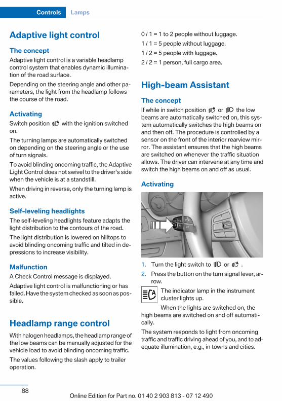
Adaptive light controlThe conceptAdaptive light control is a variable headlampcontrol system that enables dynamic illumina‐tion of the road surface.Depending on the steering angle and other pa‐rameters, the light from the headlamp followsthe course of the road.
ActivatingSwitch position with the ignition switchedon.The turning lamps are automatically switchedon depending on the steering angle or the useof turn signals.To avoid blinding oncoming traffic, the AdaptiveLight Control does not swivel to the driver's sidewhen the vehicle is at a standstill.When driving in reverse, only the turning lamp isactive.
Self-leveling headlightsThe self-leveling headlights feature adapts thelight distribution to the contours of the road.The light distribution is lowered on hilltops toavoid blinding oncoming traffic and tilted in de‐pressions to increase visibility.
MalfunctionA Check Control message is displayed.Adaptive light control is malfunctioning or hasfailed. Have the system checked as soon as pos‐sible.
Headlamp range controlWith halogen headlamps, the headlamp range ofthe low beams can be manually adjusted for thevehicle load to avoid blinding oncoming traffic.The values following the slash apply to traileroperation.
0 / 1 = 1 to 2 people without luggage.1 / 1 = 5 people without luggage.1 / 2 = 5 people with luggage.2 / 2 = 1 person, full cargo area.
High-beam AssistantThe conceptIf while in switch position or the lowbeams are automatically switched on, this sys‐tem automatically switches the high beams onand then off. The procedure is controlled by asensor on the front of the interior rearview mir‐ror. The assistant ensures that the high beamsare switched on whenever the traffic situationallows. The driver can intervene at any time andswitch the high beams on and off as usual.
Activating
1. Turn the light switch to or .2. Press the button on the turn signal lever, ar‐
row.The indicator lamp in the instrumentcluster lights up.When the lights are switched on, the
high beams are switched on and off automati‐cally.The system responds to light from oncomingtraffic and traffic driving ahead of you, and to ad‐equate illumination, e.g., in towns and cities.
Seite 88
Controls Lamps
88Online Edition for Part no. 01 40 2 903 813 - 07 12 490
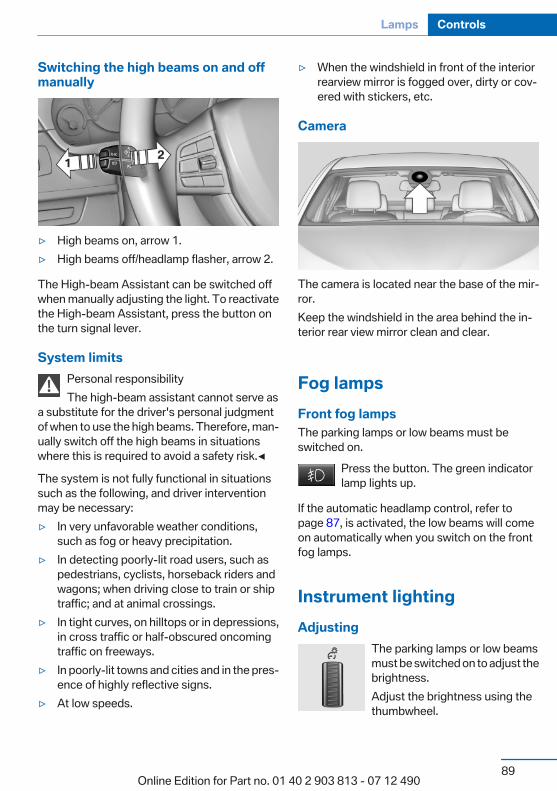
Switching the high beams on and offmanually
▷ High beams on, arrow 1.▷ High beams off/headlamp flasher, arrow 2.
The High-beam Assistant can be switched offwhen manually adjusting the light. To reactivatethe High-beam Assistant, press the button onthe turn signal lever.
System limitsPersonal responsibilityThe high-beam assistant cannot serve as
a substitute for the driver's personal judgmentof when to use the high beams. Therefore, man‐ually switch off the high beams in situationswhere this is required to avoid a safety risk.◀
The system is not fully functional in situationssuch as the following, and driver interventionmay be necessary:▷ In very unfavorable weather conditions,
such as fog or heavy precipitation.▷ In detecting poorly-lit road users, such as
pedestrians, cyclists, horseback riders andwagons; when driving close to train or shiptraffic; and at animal crossings.
▷ In tight curves, on hilltops or in depressions,in cross traffic or half-obscured oncomingtraffic on freeways.
▷ In poorly-lit towns and cities and in the pres‐ence of highly reflective signs.
▷ At low speeds.
▷ When the windshield in front of the interiorrearview mirror is fogged over, dirty or cov‐ered with stickers, etc.
Camera
The camera is located near the base of the mir‐ror.Keep the windshield in the area behind the in‐terior rear view mirror clean and clear.
Fog lampsFront fog lampsThe parking lamps or low beams must beswitched on.
Press the button. The green indicatorlamp lights up.
If the automatic headlamp control, refer topage 87, is activated, the low beams will comeon automatically when you switch on the frontfog lamps.
Instrument lightingAdjusting
The parking lamps or low beamsmust be switched on to adjust thebrightness.Adjust the brightness using thethumbwheel.
Seite 89
Lamps Controls
89Online Edition for Part no. 01 40 2 903 813 - 07 12 490

Interior lampsGeneral informationThe interior lamps, footwell lamps, entry lampsand courtesy lamps are controlled automati‐cally.The brightness of some of these lamps is influ‐enced by the thumbwheel for the instrumentlighting.
1 Interior lamps2 Reading lamp
Switching the interior lamps on and offPress the button.
To switch off permanently: press the button forapprox. 3 seconds.Switch back on: press button.
Reading lampsPress the button.
Reading lamps are located at the front and rearnext to the interior lamps.When the interior lamps are switched off per‐manently, the reading lamps cannot be switchedon.
Seite 90
Controls Lamps
90Online Edition for Part no. 01 40 2 903 813 - 07 12 490
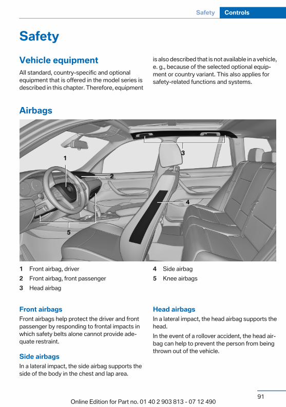
SafetyVehicle equipmentAll standard, country-specific and optionalequipment that is offered in the model series isdescribed in this chapter. Therefore, equipment
is also described that is not available in a vehicle,e. g., because of the selected optional equip‐ment or country variant. This also applies forsafety-related functions and systems.
Airbags
1 Front airbag, driver2 Front airbag, front passenger3 Head airbag
4 Side airbag5 Knee airbags
Front airbagsFront airbags help protect the driver and frontpassenger by responding to frontal impacts inwhich safety belts alone cannot provide ade‐quate restraint.
Side airbagsIn a lateral impact, the side airbag supports theside of the body in the chest and lap area.
Head airbagsIn a lateral impact, the head airbag supports thehead.In the event of a rollover accident, the head air‐bag can help to prevent the person from beingthrown out of the vehicle.
Seite 91
Safety Controls
91Online Edition for Part no. 01 40 2 903 813 - 07 12 490

Knee airbagThe knee airbag supports the legs in a frontalimpact.
Protective actionAirbags are not triggered in every impact situa‐tion, e.g., in less severe accidents or rear-endcollisions.
Information on how to ensure the optimalprotective effect of the airbags
▷ Keep at a distance from the airbags.▷ Always grasp the steering wheel on the
steering wheel rim, holding your hands atthe 3 o'clock and 9 o'clock positions, to keepthe danger of injury to your hands or arms aslow as possible if the airbag is triggered.
▷ There should be no people, animals, or ob‐jects between an airbag and a person.
▷ Do not use the cover of the front airbag onthe front passenger side as a storage area.
▷ Keep the dashboard and window on thefront passenger side clear, i.e., do not coverwith adhesive labels or coverings, and do notattach holders such as for navigation instru‐ments and mobile phones.
▷ Make sure that the front passenger is sittingcorrectly, i.e., keeps his or her feet and legsin the footwell; otherwise, leg injuries canoccur if the front airbag is triggered.
▷ Do not place slip covers, seat cushions orother objects on the front passenger seatthat are not approved specifically for seatswith integrated side airbags.
▷ Do not hang pieces of clothing, such as jack‐ets, over the backrests.
▷ Make sure that occupants keep their headsaway from the side airbag and do not restagainst the head airbag; otherwise, injuriescan occur if the airbags are triggered.
▷ Do not remove the airbag restraint system.▷ Do not remove the steering wheel.
▷ Do not apply adhesive materials to the air‐bag cover panels, cover them or modifythem in any way.
▷ Never modify either the individual compo‐nents or the wiring in the airbag system. Thisalso applies to steering wheel covers, thedashboard, the seats, the roof pillars and thesides of the headliner.◀
Even when all instructions are followed closely,injury from contact with the airbags cannot beruled out in certain situations.The ignition and inflation noise may lead toshort-term and, in most cases, temporary hear‐ing impairment in sensitive individuals.
In the case of a malfunction, deactivationand after triggering of the airbags
Do not touch the individual components imme‐diately after the system has been triggered; oth‐erwise, there is the danger of burns.Only have the airbags checked, repaired or dis‐mantled and the airbag generator scrapped byyour service center or a workshop that has thenecessary authorization for handling explosives.Non-professional attempts to service the sys‐tem could lead to failure in an emergency or un‐desired triggering of the airbag, either of whichcould result in injury.◀
Warnings and information on the airbags arealso found on the sun visors.
Functional readiness of the airbagsystem
When the ignition is switch on, the warn‐ing lamp in the instrument cluster lightsup briefly and thereby indicates the op‐
erational readiness of the entire airbag systemand the belt tensioner.
Airbag system malfunctioning▷ Warning lamp does not come on when the
ignition is turned on.▷ The warning lamp lights up continuously.
Seite 92
Controls Safety
92Online Edition for Part no. 01 40 2 903 813 - 07 12 490
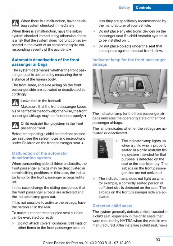
When there is a malfunction, have the air‐bag system checked immediately
When there is a malfunction, have the airbagsystem checked immediately; otherwise, thereis a risk that the system does not function as ex‐pected in the event of an accident despite cor‐responding severity of the accident.◀
Automatic deactivation of the frontpassenger airbagsThe system determines whether the front pas‐senger seat is occupied by measuring the re‐sistance of the human body.The front, knee, and side airbag on the frontpassenger side are activated or deactivated ac‐cordingly.
Leave feet in the footwellMake sure that the front passenger keeps
his or her feet in the footwell; otherwise, the frontpassenger airbags may not function properly.◀
Child restraint fixing system in the frontpassenger seat
Before transporting a child on the front passen‐ger seat, see the safety notes and instructionsunder Children on the front passenger seat.◀
Malfunction of the automaticdeactivation systemWhen transporting older children and adults, thefront passenger airbags may be deactivated incertain sitting positions. In this case, the indica‐tor lamp for the front passenger airbags lightsup.In this case, change the sitting position so thatthe front passenger airbags are activated andthe indicator lamp goes out.If it is not possible to activate the airbags, havethe person sit in the rear.To make sure that the occupied seat cushioncan be evaluated correctly▷ Do not attach covers, cushions, ball mats or
other items to the front passenger seat un‐
less they are specifically recommended bythe manufacturer of your vehicle.
▷ Do not place any electronic devices on thepassenger seat if a child restraint system isto be installed on it.
▷ Do not place objects under the seat thatcould press against the seat from below.
Indicator lamp for the front passengerairbags
The indicator lamp for the front passenger air‐bags indicates the operating state of the frontpassenger airbags.The lamp indicates whether the airbags are ac‐tivated or deactivated.
▷ The indicator lamp lights upwhen a child who is properlyseated in a child restraint fix‐ing system intended for thatpurpose is detected on theseat or the seat is empty. Theairbags on the front passen‐ger side are not activated.
▷ The indicator lamp does not light up when,for example, a correctly seated person ofsufficient size is detected on the seat. Theairbags on the front passenger side are ac‐tivated.
Detected child seatsThe system generally detects children seated ina child seat, especially in the child seats thatwere required by NHTSA when the vehicle wasmanufactured. After installing a child seat, make
Seite 93
Safety Controls
93Online Edition for Part no. 01 40 2 903 813 - 07 12 490

sure that the indicator lamp for the front pas‐senger airbags lights up. This indicates that thechild seat has been detected and the front pas‐senger airbags are not activated.
Strength of the driver's and frontpassenger airbagThe strength with which the driver's and frontpassenger airbags are triggered depends on theposition of the driver's and front passengerseats.To maintain the accuracy of this function overthe long-term, calibrate the front seats when acorresponding message appears on the ControlDisplay.
Calibrating the front seatsA corresponding message appears on the Con‐trol Display.
1. Move the respective seat forward all theway.
2. Move the respective seat forward again. Itmoves forward briefly.
3. Readjust the seat to the desired position.The calibration procedure is completed whenthe message on the Control Display disappears.If the message continues to be displayed, repeatthe calibration.If the message does not disappear after a repeatcalibration, have the system checked as soon aspossible.
Unobstructed area of movementEnsure that the area of movement of the
seats is unobstructed to avoid personal injury ordamage to objects.◀
Tire Pressure Monitor TPMThe conceptThe tire inflation pressure is measured in thefour mounted tires. The system notifies you if
there is a significant loss of pressure in one ormore tires.
Functional requirementsThe system must have been reset when the in‐flation pressure was correct; otherwise, reliablesignaling of a flat tire is not ensured. Always usewheels with TPM electronics to ensure that thesystem will operate properly. Reset the systemafter each correction of the tire inflation pres‐sure and after every tire or wheel change.
System limitsSudden tire damageSudden serious tire damage caused by
external influences cannot be indicated in ad‐vance.◀
The system does not operate correctly if it hasnot been reset. For example, a flat tire may beindicated despite correct tire inflation pres‐sures.The system is inactive and cannot indicate a flattire:▷ For a mounted wheel without TPM electron‐
ics.▷ When the TPM is disturbed by other sys‐
tems or devices with the same radio fre‐quency.
Status displayThe current status of the Tire Pressure MonitorTPM can be displayed on the Control Display,e.g., whether or not the TPM is active.
1. "Vehicle Info"2. "Vehicle status"3. "Tire Pressure Monitor - TPM"The status is displayed.
Status displayThe tire and system status is indicated by thecolor of the tires.
Seite 94
Controls Safety
94Online Edition for Part no. 01 40 2 903 813 - 07 12 490
A change in the tire inflation pressure duringdriving is taken into account.A correction is only necessary if this is indicatedby the TPM
Wheels, greenThe tire inflation pressure is equal to the targetstate.
One wheel is yellowA flat tire or major drop in inflation pressure inthe indicated tire.
All wheels are yellow▷ A flat tire or major drop in inflation pressure
in several tires.▷ The system was not reset after a wheel
change and thus warns based on the infla‐tion pressures initialized last.
▷ A flat tire in one or more tires while the sys‐tem is being reset.
Wheels, grayThe system cannot detect a flat tire. Reasons forthis may be:▷ TPM is being reset.▷ Disturbance by systems or devices with the
same radio frequency.▷ Malfunction.
For Canadian models: AdditionalinformationThe status display additionally shows the cur‐rent tire inflation pressures and tire tempera‐tures.When correcting the tire inflation pressures,note the following:The tire pressure increases as the tire temper‐ature increases.Therefore, only correct the tire inflation pres‐sure when the tire is at the ambient temperature.Compare the displayed tire temperature with
the external temperature in the instrument clus‐ter.
Resetting the systemReset the system after each correction of thetire inflation pressure and after every tire orwheel change.
1. "Vehicle Info"2. "Vehicle status"3. "Reset"4. Start the engine - do not drive away.5. Reset the tire pressure using "Reset".6. Drive away.The tires are shown in gray and "ResettingTPM..." is displayed.After driving for a few minutes, the set tire infla‐tion pressures are applied as set values. The re‐setting process is completed automatically dur‐ing driving. The tires are shown in green and"TPM active" is shown on the Control Display.The trip can be interrupted at any time. If youdrive away again, the process resumes auto‐matically.If a flat tire is detected during a reset, all tires aredisplayed in yellow.
Low tire pressure messageThe yellow warning lamp lights up. ACheck Control message is displayed.▷ There is a flat tire or a major loss in
tire inflation pressure.▷ The system was not reset after a wheel
change and thus warns based on the infla‐tion pressures initialized last.
1. Reduce your speed and stop cautiously.Avoid sudden braking and steering maneu‐vers.
2. Check whether the vehicle is fitted with reg‐ular tires or run-flat tires.
Seite 95
Safety Controls
95Online Edition for Part no. 01 40 2 903 813 - 07 12 490

Run-flat tires, refer to page 162, are labeledwith a circular symbol containing the lettersRSC marked on the tire sidewall.
Do not continue driving without run-flattires
Do not continue driving if the vehicle is notequipped with run-flat tires; continued drivingmay result in serious accidents.◀
When a low inflation pressure is indicated, DSCDynamic Stability Control is switched on if nec‐essary.
Actions in the event of a flat tire
Normal tires1. Identify the damaged tire.
Do this by checking the air pressure in allfour tires.If the tire inflation pressure in all four tires iscorrect, the Tire Pressure Monitor may nothave been initialized. In this case, initializethe system.If an identification is not possible, pleasecontact the service center.
2. Rectify the flat tire on the damaged wheel.Use of tire sealant, e.g., the Mobility System,may damage the TPM wheel electronics. Inthis case, have the electronics checked atthe next opportunity and have them re‐placed if necessary.
Run-flat tires
Maximum speedYou can continue driving with a damaged tire atspeeds up to 50 mph/80 km/h.
Continued driving with a flat tireIf continuing to drive with a damaged tire:
1. Avoid sudden braking and steering maneu‐vers.
2. Do not exceed a speed of 50 mph/80 km/h.
3. Check the air pressure in all four tires at thenext opportunity.If the tire inflation pressure in all four tires iscorrect, the Tire Pressure Monitor may nothave been initialized. In this case, initializethe system.
Possible driving distance with complete loss oftire inflation pressure:The possible driving distance after a loss of tireinflation pressure depends on the cargo loadand the driving style and conditions.For a vehicle containing an average load, thepossible driving distance is approx.50 miles/80 km.When the vehicle is driven with a damaged tire,its handling characteristics change, e.g., re‐duced lane stability during braking, a longerbraking distance, and altered self-steeringproperties. Adjust your driving style accord‐ingly. Avoid abrupt steering maneuvers or driv‐ing over obstacles, e.g., curbs, potholes, etc.Because the possible driving distance dependson how the vehicle is used during the trip, theactual distance may be smaller or greater de‐pending on the driving speed, road conditions,external temperature, cargo load, etc.
Continued driving with a flat tireDrive moderately and do not exceed a
speed of 50 mph/80 km/h.A loss of tire inflation pressure results in achange in the handling characteristics, e.g., re‐duced lane stability during braking, a longerbraking distance and altered self-steering prop‐erties.◀
Final tire failureVibrations or loud noises while driving can
indicate the final failure of the tire. Reduce speedand stop; otherwise, pieces of the tire couldcome loose and cause an accident. Do not con‐tinue driving, and contact your service center.◀
Seite 96
Controls Safety
96Online Edition for Part no. 01 40 2 903 813 - 07 12 490
Message when the system was notresetA Check Control message is displayed.The system detected a wheel change but wasnot reset.Warnings regarding the current tire inflationpressure are not reliable.Check the tire inflation pressure and reset thesystem.
MalfunctionThe yellow warning lamp flashes andthen lights up continuously. A CheckControl message is displayed. No flat
tire can be detected.Display in the following situations:▷ A wheel without TPM electronics is fitted:
have the service center check it if necessary.▷ Malfunction: have the system checked by
your service center.▷ TPM could not be fully reset. Reset the sys‐
tem again.▷ Disturbance by systems or devices with the
same radio frequency: after leaving the areaof the disturbance, the system automaticallybecomes active again.
Declaration according to NHTSA/FMVSS 138 Tire Pressure MonitoringSystemEach tire, including the spare (if provided)should be checked monthly when cold and in‐flated to the inflation pressure recommended bythe vehicle manufacturer on the vehicle placardor tire inflation pressure label. (If your vehicle hastires of a different size than the size indicated onthe vehicle placard or tire inflation pressure la‐bel, you should determine the proper tire infla‐tion pressure for those tires.) As an added safetyfeature, your vehicle has been equipped with atire pressure monitoring system (TPMS) that il‐luminates a low tire pressure telltale when oneor more of your tires is significantly under-in‐
flated. Accordingly, when the low tire pressuretelltale illuminates, you should stop and checkyour tires as soon as possible, and inflate themto the proper pressure. Driving on a significantlyunder-inflated tire causes the tire to overheatand can lead to tire failure. Under-inflation alsoreduces fuel efficiency and tire tread life, andmay affect the vehicle's handling and stoppingability. Please note that the TPMS is not a sub‐stitute for proper tire maintenance, and it is thedriver's responsibility to maintain correct tirepressure, even if under-inflation has not reachedthe level to trigger illumination of the TPMS lowtire pressure telltale. Your vehicle has also beenequipped with a TPMS malfunction indicator toindicate when the system is not operating prop‐erly. The TPMS malfunction indicator is com‐bined with the low tire pressure telltale. Whenthe system detects a malfunction, the telltale willflash for approximately one minute and then re‐main continuously illuminated. This sequencewill continue upon subsequent vehicle start-upsas long as the malfunction exists. When the mal‐function indicator is illuminated, the system maynot be able to detect or signal low tire pressureas intended. TPMS malfunctions may occur fora variety of reasons, including the installation ofreplacement or alternate tires or wheels on thevehicle that prevent the TPMS from functioningproperly. Always check the TPMS malfunctiontelltale after replacing one or more tires orwheels on your vehicle to ensure that the re‐placement or alternate tires and wheels allowthe TPMS to continue to function properly.
FTM Flat Tire MonitorThe conceptThe system does not measure the actual infla‐tion pressure in the tires.It detects a pressure loss in a tire by comparingthe rotational speeds of the individual wheelswhile moving.
Seite 97
Safety Controls
97Online Edition for Part no. 01 40 2 903 813 - 07 12 490
In the event of a pressure loss, the diameter andtherefore the rotational speed of the corre‐sponding wheel change. This is detected andreported as a flat tire.
Functional requirementsThe system must have been initialized when thetire inflation pressure was correct; otherwise,reliable signaling of a flat tire is not ensured. In‐itialize the system after each correction of thetire inflation pressure and after every tire orwheel change.
System limitsSudden tire damageSudden serious tire damage caused by
external influences cannot be indicated in ad‐vance.◀
A natural, even pressure loss in all four tires can‐not be detected. Therefore, check the tire infla‐tion pressure regularly.The system could be delayed or malfunction inthe following situations:▷ When the system has not been initialized.▷ When driving on a snowy or slippery road
surface.▷ Sporty driving style: slip in the drive wheels,
high lateral acceleration.▷ When driving with snow chains.
Status displayThe current status of the Flat Tire Monitor canbe displayed on the Control Display, e.g.,whether or not the FTM is active.
1. "Vehicle Info"2. "Vehicle status"3. "Flat Tire Monitor"The status is displayed.
InitializationThe initialization process adopts the set inflationtire pressures as reference values for the detec‐
tion of a flat tire. Initialization is started by con‐firming the inflation pressures.Do not initialize the system when driving withsnow chains.
1. "Vehicle Info"2. "Vehicle status"3. "Reset"4. Start the engine - do not drive away.5. Start the initialization with "Reset".6. Drive away.The initialization is completed while driving,which can be interrupted at any time.The initialization automatically continues whendriving resumes.
Indication of a flat tireThe yellow warning lamp lights up. ACheck Control message is displayed.There is a flat tire or a major loss in tire
inflation pressure.
1. Reduce your speed and stop cautiously.Avoid sudden braking and steering maneu‐vers.
2. Check whether the vehicle is fitted with reg‐ular tires or run-flat tires.Run-flat tires, refer to page 162, are labeledwith a circular symbol containing the lettersRSC marked on the tire sidewall.
Do not continue driving without run-flattires
Do not continue driving if the vehicle is notequipped with run-flat tires; continued drivingmay result in serious accidents.◀
When a flat tire is indicated, DSC Dynamic Sta‐bility Control is switched on if necessary.
Actions in the event of a flat tire
Normal tires1. Identify the damaged tire.
Seite 98
Controls Safety
98Online Edition for Part no. 01 40 2 903 813 - 07 12 490
Do this by checking the air pressure in allfour tires.If the tire inflation pressure in all four tires iscorrect, the Flat Tire Monitor may not havebeen initialized. In this case, initialize thesystem.If an identification is not possible, pleasecontact the service center.
2. Rectify the flat tire on the damaged wheel.
Run-flat tires
Maximum speedYou can continue driving with a damaged tire atspeeds up to 50 mph/80 km/h.
Continued driving with a flat tireIf continuing to drive with a damaged tire:
1. Avoid sudden braking and steering maneu‐vers.
2. Do not exceed a speed of 50 mph/80 km/h.3. Check the air pressure in all four tires at the
next opportunity.If the tire inflation pressure in all four tires iscorrect, the Flat Tire Monitor may not havebeen initialized. In this case, initialize thesystem.
Possible driving distance with complete loss oftire inflation pressure:The possible driving distance after a loss of tireinflation pressure depends on the cargo loadand the driving style and conditions.For a vehicle containing an average load, thepossible driving distance is approx.50 miles/80 km.When the vehicle is driven with a damaged tire,its handling characteristics change, e.g., re‐duced lane stability during braking, a longerbraking distance, and altered self-steeringproperties. Adjust your driving style accord‐ingly. Avoid abrupt steering maneuvers or driv‐ing over obstacles, e.g., curbs, potholes, etc.
Because the possible driving distance dependson how the vehicle is used during the trip, theactual distance may be smaller or greater de‐pending on the driving speed, road conditions,external temperature, cargo load, etc.
Continued driving with a flat tireDrive moderately and do not exceed a
speed of 50 mph/80 km/h.A loss of tire inflation pressure results in achange in the handling characteristics, e.g., re‐duced lane stability during braking, a longerbraking distance and altered self-steering prop‐erties.◀
Final tire failureVibrations or loud noises while driving can
indicate the final failure of the tire. Reduce speedand stop; otherwise, pieces of the tire couldcome loose and cause an accident. Do not con‐tinue driving, and contact your service center.◀
Lane departure warningThe conceptStarting at a specific speed, this system alertsyou when the vehicle on streets with lane mark‐ings is about to leave the lane. Depending on thecountry-specific version of the vehicle, thespeed is between 35 mph/55 km/h and45 mph/70 km/h. When switching on the systembelow this speed, a message appears in the in‐strument cluster.The steering wheel begins vibrating gently in theevent of warnings. The time of the warning mayvary depending on the current driving situation.The system does not provide a warning if theturn signal is set before leaving the lane.
Seite 99
Safety Controls
99Online Edition for Part no. 01 40 2 903 813 - 07 12 490
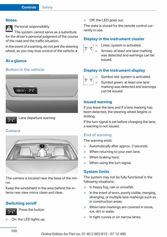
NotesPersonal responsibilityThe system cannot serve as a substitute
for the driver's personal judgment of the courseof the road and the traffic situation.In the event of a warning, do not jerk the steeringwheel, as you may lose control of the vehicle.◀
At a glance
Button in the vehicle
Lane departure warning
Camera
The camera is located near the base of the mir‐ror.Keep the windshield in the area behind the in‐terior rear view mirror clean and clear.
Switching on/offPress the button
▷ On: the LED lights up.
▷ Off: the LED goes out.The state is stored for the remote control cur‐rently in use.
Display in the instrument cluster▷ Lines: system is activated.▷ Arrows: at least one lane marking
was detected and warnings can beissued.
Display in the instrument display▷ Symbol red: system is activated.▷ Symbol green: at least one lane
marking was detected and warningscan be issued.
Issued warningIf you leave the lane and if a lane marking hasbeen detected, the steering wheel begins vi‐brating.If the turn signal is set before changing the lane,a warning is not issued.
End of warningThe warning ends:▷ Automatically after approx. 3 seconds.▷ When returning to your own lane.▷ When braking hard.▷ When using the turn signal.
System limitsThe system may not be fully functional in thefollowing situations:▷ In heavy fog, rain or snowfall.▷ In the event of worn, poorly visible, merging,
diverging, or multiple lane markings such asin construction areas.
▷ When lane markings are covered in snow,ice, dirt or water.
▷ In tight curves or on narrow lanes.
Seite 100
Controls Safety
100Online Edition for Part no. 01 40 2 903 813 - 07 12 490
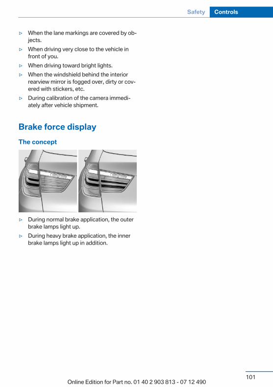
▷ When the lane markings are covered by ob‐jects.
▷ When driving very close to the vehicle infront of you.
▷ When driving toward bright lights.▷ When the windshield behind the interior
rearview mirror is fogged over, dirty or cov‐ered with stickers, etc.
▷ During calibration of the camera immedi‐ately after vehicle shipment.
Brake force displayThe concept
▷ During normal brake application, the outerbrake lamps light up.
▷ During heavy brake application, the innerbrake lamps light up in addition.
Seite 101
Safety Controls
101Online Edition for Part no. 01 40 2 903 813 - 07 12 490

Driving stability control systemsVehicle equipmentAll standard, country-specific and optionalequipment that is offered in the model series isdescribed in this chapter. Therefore, equipmentis also described that is not available in a vehicle,e. g., because of the selected optional equip‐ment or country variant. This also applies forsafety-related functions and systems.
Antilock Brake System ABSABS prevents locking of the wheels during brak‐ing.The vehicle remains steerable even during fullbrake applications, thus increasing activesafety.ABS is operational every time you start the en‐gine.
Brake assistantWhen you apply the brakes rapidly, this systemautomatically produces the maximum brakingforce boost. It thus helps to achieve the shortestpossible braking distance during full braking.This system utilizes all of the benefits providedby ABS.Do not reduce the pressure on the brake pedalfor the duration of the full braking.
DSC Dynamic StabilityControlThe conceptDSC prevents traction loss in the driving wheelswhen driving away and accelerating.DSC also recognizes unstable vehicle condi‐tions, such as fishtailing or nose-diving. Subject
to physical limits, DSC helps to keep the vehicleon a steady course by reducing engine speedand by applying brakes at individual wheels.
Adjust your driving style to the situationAn appropriate driving style is always the
responsibility of the driver.The laws of physics cannot be repealed, evenwith DSC.Therefore, do not reduce the additional safetymargin by driving in a risky manner.◀
Indicator/warning lampsThe indicator lamp flashes: DSC con‐trols the drive forces and brake forces.The indicator lamp lights up: DSC has
failed.
Deactivating DSC: DSC OFFWhen DSC is deactivated, driving stability is re‐duced during acceleration and when driving inbends.To increase vehicle stability, activate DSC againas soon as possible.
Deactivating DSCPress and hold the button, but not lon‐ger than approx. 10 seconds, until the
indicator lamp for DSC OFF lights up in the in‐strument cluster and DSC OFF is displayed.The DSC system is switched off.
Activating DSCPress the button.DSC OFF and the DSC OFF indicator
lamp go out.
Seite 102
Controls Driving stability control systems
102Online Edition for Part no. 01 40 2 903 813 - 07 12 490
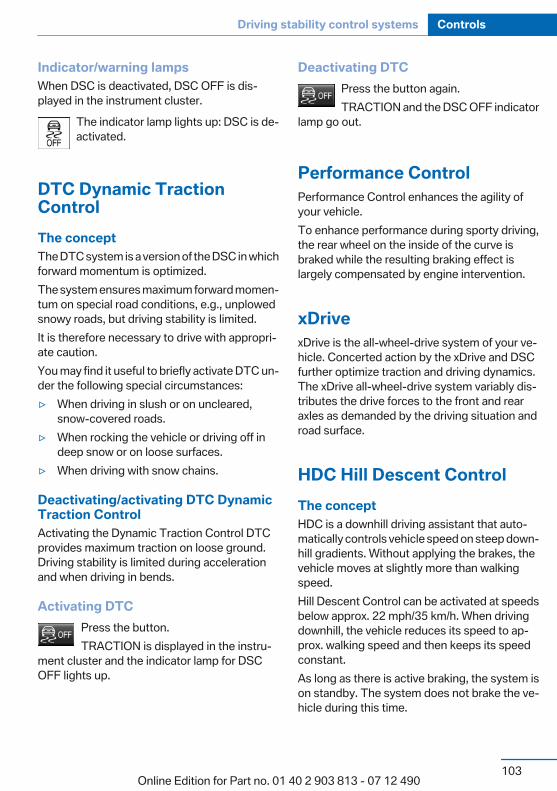
Indicator/warning lampsWhen DSC is deactivated, DSC OFF is dis‐played in the instrument cluster.
The indicator lamp lights up: DSC is de‐activated.
DTC Dynamic TractionControlThe conceptThe DTC system is a version of the DSC in whichforward momentum is optimized.The system ensures maximum forward momen‐tum on special road conditions, e.g., unplowedsnowy roads, but driving stability is limited.It is therefore necessary to drive with appropri‐ate caution.You may find it useful to briefly activate DTC un‐der the following special circumstances:▷ When driving in slush or on uncleared,
snow-covered roads.▷ When rocking the vehicle or driving off in
deep snow or on loose surfaces.▷ When driving with snow chains.
Deactivating/activating DTC DynamicTraction ControlActivating the Dynamic Traction Control DTCprovides maximum traction on loose ground.Driving stability is limited during accelerationand when driving in bends.
Activating DTCPress the button.TRACTION is displayed in the instru‐
ment cluster and the indicator lamp for DSCOFF lights up.
Deactivating DTCPress the button again.TRACTION and the DSC OFF indicator
lamp go out.
Performance ControlPerformance Control enhances the agility ofyour vehicle.To enhance performance during sporty driving,the rear wheel on the inside of the curve isbraked while the resulting braking effect islargely compensated by engine intervention.
xDrivexDrive is the all-wheel-drive system of your ve‐hicle. Concerted action by the xDrive and DSCfurther optimize traction and driving dynamics.The xDrive all-wheel-drive system variably dis‐tributes the drive forces to the front and rearaxles as demanded by the driving situation androad surface.
HDC Hill Descent ControlThe conceptHDC is a downhill driving assistant that auto‐matically controls vehicle speed on steep down‐hill gradients. Without applying the brakes, thevehicle moves at slightly more than walkingspeed.Hill Descent Control can be activated at speedsbelow approx. 22 mph/35 km/h. When drivingdownhill, the vehicle reduces its speed to ap‐prox. walking speed and then keeps its speedconstant.As long as there is active braking, the system ison standby. The system does not brake the ve‐hicle during this time.
Seite 103
Driving stability control systems Controls
103Online Edition for Part no. 01 40 2 903 813 - 07 12 490

Use HDC in low gears or in transmission positionD or R only.
Increasing or decreasing vehicle speedSpecify desired speed in the range from approx.4 mph/6 km/h to approx. 15 mph/25 km/h usingthe rocker switch of the cruise control on thesteering wheel. Vehicle speed can be changedby lightly accelerating.
▷ Press up the rocker switch to the point ofresistance: the speed increases gradually.
▷ Press up the rocker switch past the point ofresistance: the speed increases while therocker switch is pressed.
▷ Press down the rocker switch to the point ofresistance: the speed decreases gradually.
▷ Press down the rocker switch past the pointof resistance: when driving forward, thespeed decreases to approx. 6 mph/10 km/h;when reversing, the speed decreases to ap‐prox. 4 mph/6 km/h.
Activating HDC
Press the button; the LED above the but‐ton lights up.
Deactivating HDCPress the button again and the LED goesout. HDC is automatically deactivated
above approx. 37 mph/60 km/h.
Display in the instrument clusterThe selected speed is displayedin the speedometer.▷ Green: the system is actively
braking the vehicle.▷ Orange: the system is on
standby.
MalfunctionA message is displayed in the instrument clus‐ter. HDC is not available, e.g., due to elevatedbrake temperatures.
Dynamic Damping ControlThe conceptThis system reduces undesirable vehicle mo‐tion when using a dynamic driving style or trav‐eling on uneven road surfaces.The system enhances driving dynamics andcomfort as required for the road surface anddriving style.
ProgramsThe system offers two different programs.The programs can be selected via the DrivingExperience Switch, refer to page 105.
SPORTConsistently sporty control of the shock absorb‐ers for greater driving agility.
SPORT+Consistently sporty control of the shock absorb‐ers for greater driving agility when driving withlimited driving stabilization.
Seite 104
Controls Driving stability control systems
104Online Edition for Part no. 01 40 2 903 813 - 07 12 490
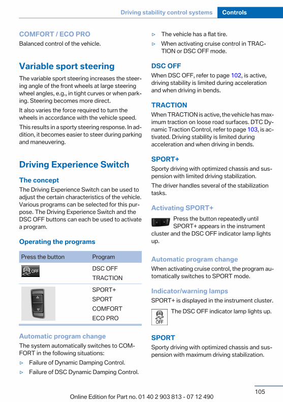
COMFORT / ECO PROBalanced control of the vehicle.
Variable sport steeringThe variable sport steering increases the steer‐ing angle of the front wheels at large steeringwheel angles, e.g., in tight curves or when park‐ing. Steering becomes more direct.It also varies the force required to turn thewheels in accordance with the vehicle speed.This results in a sporty steering response. In ad‐dition, it becomes easier to steer during parkingand maneuvering.
Driving Experience SwitchThe conceptThe Driving Experience Switch can be used toadjust the certain characteristics of the vehicle.Various programs can be selected for this pur‐pose. The Driving Experience Switch and theDSC OFF buttons can each be used to activatea program.
Operating the programs
Press the button Program
DSC OFFTRACTION
SPORT+SPORTCOMFORTECO PRO
Automatic program changeThe system automatically switches to COM‐FORT in the following situations:▷ Failure of Dynamic Damping Control.▷ Failure of DSC Dynamic Damping Control.
▷ The vehicle has a flat tire.▷ When activating cruise control in TRAC‐
TION or DSC OFF mode.
DSC OFFWhen DSC OFF, refer to page 102, is active,driving stability is limited during accelerationand when driving in bends.
TRACTIONWhen TRACTION is active, the vehicle has max‐imum traction on loose road surfaces. DTC Dy‐namic Traction Control, refer to page 103, is ac‐tivated. Driving stability is limited duringacceleration and when driving in bends.
SPORT+Sporty driving with optimized chassis and sus‐pension with limited driving stabilization.The driver handles several of the stabilizationtasks.
Activating SPORT+Press the button repeatedly untilSPORT+ appears in the instrument
cluster and the DSC OFF indicator lamp lightsup.
Automatic program changeWhen activating cruise control, the program au‐tomatically switches to SPORT mode.
Indicator/warning lampsSPORT+ is displayed in the instrument cluster.
The DSC OFF indicator lamp lights up.
SPORTSporty driving with optimized chassis and sus‐pension with maximum driving stabilization.
Seite 105
Driving stability control systems Controls
105Online Edition for Part no. 01 40 2 903 813 - 07 12 490
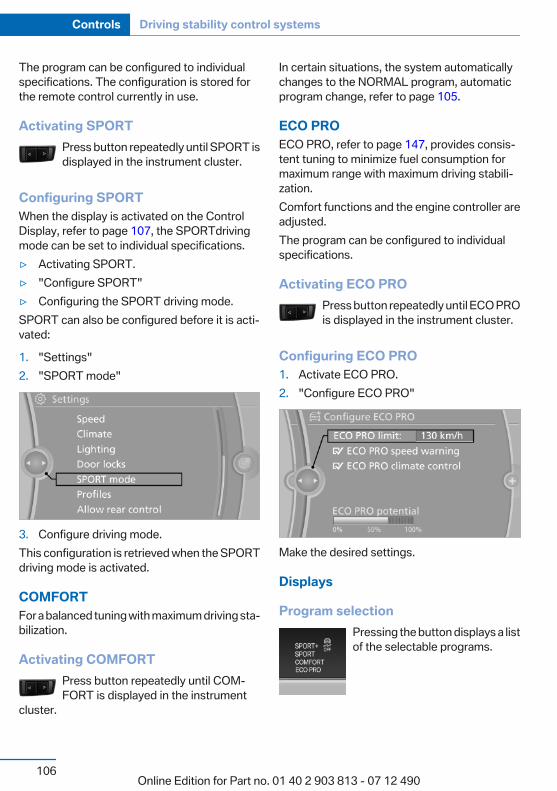
The program can be configured to individualspecifications. The configuration is stored forthe remote control currently in use.
Activating SPORTPress button repeatedly until SPORT isdisplayed in the instrument cluster.
Configuring SPORTWhen the display is activated on the ControlDisplay, refer to page 107, the SPORTdrivingmode can be set to individual specifications.▷ Activating SPORT.▷ "Configure SPORT"▷ Configuring the SPORT driving mode.SPORT can also be configured before it is acti‐vated:
1. "Settings"2. "SPORT mode"
3. Configure driving mode.This configuration is retrieved when the SPORTdriving mode is activated.
COMFORTFor a balanced tuning with maximum driving sta‐bilization.
Activating COMFORTPress button repeatedly until COM‐FORT is displayed in the instrument
cluster.
In certain situations, the system automaticallychanges to the NORMAL program, automaticprogram change, refer to page 105.
ECO PROECO PRO, refer to page 147, provides consis‐tent tuning to minimize fuel consumption formaximum range with maximum driving stabili‐zation.Comfort functions and the engine controller areadjusted.The program can be configured to individualspecifications.
Activating ECO PROPress button repeatedly until ECO PROis displayed in the instrument cluster.
Configuring ECO PRO1. Activate ECO PRO.2. "Configure ECO PRO"
Make the desired settings.
Displays
Program selectionPressing the button displays a listof the selectable programs.
Seite 106
Controls Driving stability control systems
106Online Edition for Part no. 01 40 2 903 813 - 07 12 490
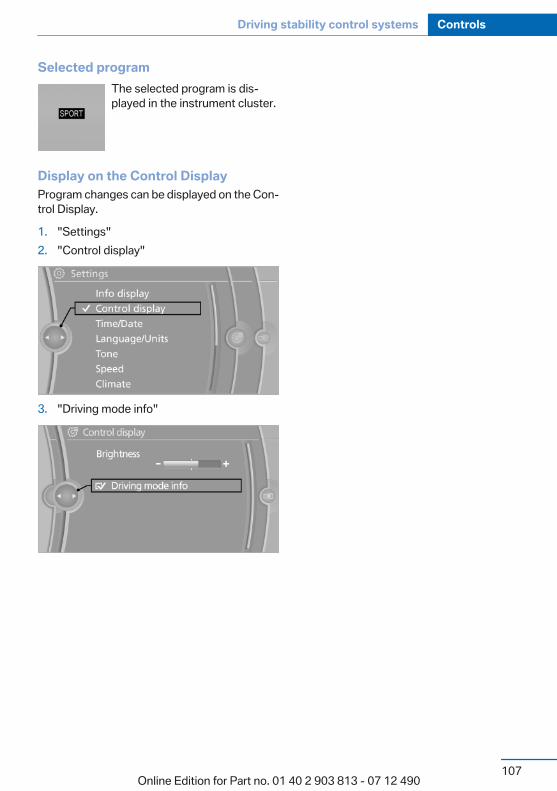
Selected programThe selected program is dis‐played in the instrument cluster.
Display on the Control DisplayProgram changes can be displayed on the Con‐trol Display.
1. "Settings"2. "Control display"
3. "Driving mode info"
Seite 107
Driving stability control systems Controls
107Online Edition for Part no. 01 40 2 903 813 - 07 12 490

Driving comfortVehicle equipmentAll standard, country-specific and optionalequipment that is offered in the model series isdescribed in this chapter. Therefore, equipmentis also described that is not available in a vehicle,e. g., because of the selected optional equip‐ment or country variant. This also applies forsafety-related functions and systems.
Collision warningThe conceptThe system issues a two-phase warning of adanger of collision at speeds above approx.10 mph/15 km/h. The time of these warningsmay vary depending on the current driving sit‐uation.
In the process, vehicles in a similar direction ofmovement are observed if they are locatedwithin the detection range of the system.
When the vehicle is intentionally brought intocontact with a vehicle, the collision warning isdelayed to avoid misleading warnings.
Warning stages
PrewarningThis warning is issued, for example, when thereis the impending danger of a collision or the dis‐tance to the vehicle ahead is too small.
Acute warningWarning of the imminent danger of a collisionwhen the vehicle approaches another vehicle ata relatively high differential speed.
Switching the warning function on/off
Press the button
▷ On: the LED lights up.▷ Off: the LED goes out.The state is stored for the remote control cur‐rently in use.
Setting the warning timeThe warning time can be set via iDrive.
1. Activate collision warning.2. Activate the desired warning time on the
Control Display.The selected channel is stored for the remotecontrol currently in use.
Display in the instrument clusterThe collision warning can be issued in the in‐strument cluster, in the Head-up Display, andacoustically.
Seite 108
Controls Driving comfort
108Online Edition for Part no. 01 40 2 903 813 - 07 12 490
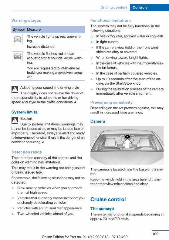
Warning stages
Symbol Measure
The vehicle lights up red: prewarn‐ing.Increase distance.
The vehicle flashes red and anacoustic signal sounds: acute warn‐ing.You are requested to intervene bybraking or making an evasive maneu‐ver.
Adapting your speed and driving styleThe display does not relieve the driver of
the responsibility to adapt his or her drivingspeed and style to the traffic conditions.◀
System limitsBe alertDue to system limitations, warnings may
be not be issued at all, or may be issued late orimproperly. Therefore, always be alert and readyto intervene; otherwise, there is the danger of anaccident occurring.◀
Detection rangeThe detection capacity of the camera and thecollision warning has limitations.This may result in the warning not being issuedor being issued late.For example, the following situations may not bedetected:▷ Slow moving vehicles when you approach
them at high speed.▷ Vehicles that suddenly swerve in front of you
or sharply decelerating vehicles.▷ Vehicles with an unusual rear appearance.▷ Two-wheeled vehicles ahead of you.
Functional limitationsThe system may not be fully functional in thefollowing situations:▷ In heavy fog, rain, sprayed water or snowfall.▷ In tight curves.▷ If the camera view field or the front wind‐
shield are dirty or covered.▷ When driving toward bright lights.▷ In the case of vehicles with insufficiently visi‐
ble tail lamps.▷ In the case of partially covered vehicles.▷ Up to 10 seconds after the start of the en‐
gine, via the Start/Stop knob.▷ During the calibration process of the camera
immediately after vehicle shipment.
Prewarning sensitivityDepending on the set prewarning time, this mayresult in increased false warnings.
Camera
The camera is located near the base of the mir‐ror.Keep the windshield in the area behind the in‐terior rear view mirror clean and clear.
Cruise controlThe conceptThe system is functional at speeds beginning atapprox. 20 mph/30 km/h.
Seite 109
Driving comfort Controls
109Online Edition for Part no. 01 40 2 903 813 - 07 12 490
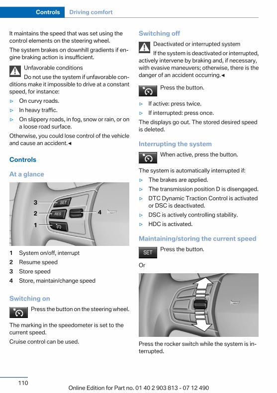
It maintains the speed that was set using thecontrol elements on the steering wheel.The system brakes on downhill gradients if en‐gine braking action is insufficient.
Unfavorable conditionsDo not use the system if unfavorable con‐
ditions make it impossible to drive at a constantspeed, for instance:▷ On curvy roads.▷ In heavy traffic.▷ On slippery roads, in fog, snow or rain, or on
a loose road surface.Otherwise, you could lose control of the vehicleand cause an accident.◀
Controls
At a glance
1 System on/off, interrupt2 Resume speed3 Store speed4 Store, maintain/change speed
Switching onPress the button on the steering wheel.
The marking in the speedometer is set to thecurrent speed.Cruise control can be used.
Switching offDeactivated or interrupted systemIf the system is deactivated or interrupted,
actively intervene by braking and, if necessary,with evasive maneuvers; otherwise, there is thedanger of an accident occurring.◀
Press the button.
▷ If active: press twice.▷ If interrupted: press once.The displays go out. The stored desired speedis deleted.
Interrupting the systemWhen active, press the button.
The system is automatically interrupted if:▷ The brakes are applied.▷ The transmission position D is disengaged.▷ DTC Dynamic Traction Control is activated
or DSC is deactivated.▷ DSC is actively controlling stability.▷ HDC is activated.
Maintaining/storing the current speedPress the button.
Or
Press the rocker switch while the system is in‐terrupted.
Seite 110
Controls Driving comfort
110Online Edition for Part no. 01 40 2 903 813 - 07 12 490
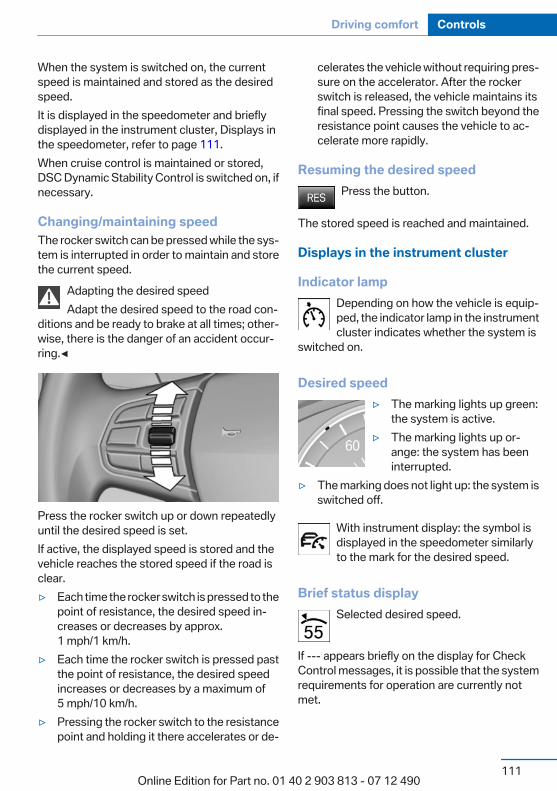
When the system is switched on, the currentspeed is maintained and stored as the desiredspeed.It is displayed in the speedometer and brieflydisplayed in the instrument cluster, Displays inthe speedometer, refer to page 111.When cruise control is maintained or stored,DSC Dynamic Stability Control is switched on, ifnecessary.
Changing/maintaining speedThe rocker switch can be pressed while the sys‐tem is interrupted in order to maintain and storethe current speed.
Adapting the desired speedAdapt the desired speed to the road con‐
ditions and be ready to brake at all times; other‐wise, there is the danger of an accident occur‐ring.◀
Press the rocker switch up or down repeatedlyuntil the desired speed is set.If active, the displayed speed is stored and thevehicle reaches the stored speed if the road isclear.▷ Each time the rocker switch is pressed to the
point of resistance, the desired speed in‐creases or decreases by approx.1 mph/1 km/h.
▷ Each time the rocker switch is pressed pastthe point of resistance, the desired speedincreases or decreases by a maximum of5 mph/10 km/h.
▷ Pressing the rocker switch to the resistancepoint and holding it there accelerates or de‐
celerates the vehicle without requiring pres‐sure on the accelerator. After the rockerswitch is released, the vehicle maintains itsfinal speed. Pressing the switch beyond theresistance point causes the vehicle to ac‐celerate more rapidly.
Resuming the desired speedPress the button.
The stored speed is reached and maintained.
Displays in the instrument cluster
Indicator lampDepending on how the vehicle is equip‐ped, the indicator lamp in the instrumentcluster indicates whether the system is
switched on.
Desired speed▷ The marking lights up green:
the system is active.▷ The marking lights up or‐
ange: the system has beeninterrupted.
▷ The marking does not light up: the system isswitched off.
With instrument display: the symbol isdisplayed in the speedometer similarlyto the mark for the desired speed.
Brief status displaySelected desired speed.
If --- appears briefly on the display for CheckControl messages, it is possible that the systemrequirements for operation are currently notmet.
Seite 111
Driving comfort Controls
111Online Edition for Part no. 01 40 2 903 813 - 07 12 490
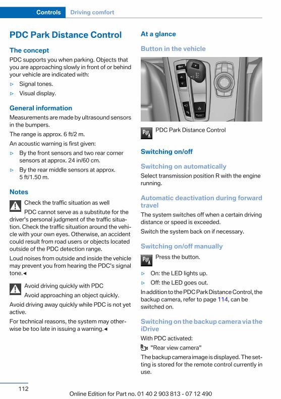
PDC Park Distance ControlThe conceptPDC supports you when parking. Objects thatyou are approaching slowly in front of or behindyour vehicle are indicated with:▷ Signal tones.▷ Visual display.
General informationMeasurements are made by ultrasound sensorsin the bumpers.The range is approx. 6 ft/2 m.An acoustic warning is first given:▷ By the front sensors and two rear corner
sensors at approx. 24 in/60 cm.▷ By the rear middle sensors at approx.
5 ft/1.50 m.
NotesCheck the traffic situation as wellPDC cannot serve as a substitute for the
driver's personal judgment of the traffic situa‐tion. Check the traffic situation around the vehi‐cle with your own eyes. Otherwise, an accidentcould result from road users or objects locatedoutside of the PDC detection range.Loud noises from outside and inside the vehiclemay prevent you from hearing the PDC's signaltone.◀
Avoid driving quickly with PDCAvoid approaching an object quickly.
Avoid driving away quickly while PDC is not yetactive.For technical reasons, the system may other‐wise be too late in issuing a warning.◀
At a glance
Button in the vehicle
PDC Park Distance Control
Switching on/off
Switching on automaticallySelect transmission position R with the enginerunning.
Automatic deactivation during forwardtravelThe system switches off when a certain drivingdistance or speed is exceeded.Switch the system back on if necessary.
Switching on/off manuallyPress the button.
▷ On: the LED lights up.▷ Off: the LED goes out.In addition to the PDC Park Distance Control, thebackup camera, refer to page 114, can beswitched on.
Switching on the backup camera via theiDriveWith PDC activated:
"Rear view camera"The backup camera image is displayed. The set‐ting is stored for the remote control currently inuse.
Seite 112
Controls Driving comfort
112Online Edition for Part no. 01 40 2 903 813 - 07 12 490
Display
Signal tonesWhen approaching an object, an intermittenttone is sounded that indicates the position of theobject. For example, if an object is detected tothe left rear of the vehicle, a signal tone soundsfrom the left rear speaker.The shorter the distance to the object becomes,the shorter the intervals.If the distance to a detected object is less thanapprox. 12 in/30 cm, a continuous tone issounded.If objects are located both in front of and behindthe vehicle, an alternating continuous signal issounded.The intermittent tone is interrupted after approx.3 seconds:▷ If the vehicle stops in front of an object that
is detected by only one of the corner sen‐sors.
▷ If moving parallel to a wall.The signal tone is switched off:▷ When the vehicle moves away from an ob‐
ject by more than approx. 4 in/10 cm.▷ When transmission position P is engaged.
VolumeThe volume of the PDC signal can be adjusted,refer to user's manual for Navigation, Entertain‐ment and Communication.The setting is stored for the remote control cur‐rently in use.
Visual warningThe approach of the vehicle to an object can beshown on the Control Display. Objects that arefarther away are displayed on the Control Dis‐play before a signal tone sounds.A display appears as soon as Park DistanceControl (PDC) is activated.
The range of the sensors is represented in col‐ors: red, green and yellow.If the backup camera image was selected last, itagain appears on the display. To switch to PDC:
1. "Rear view camera" Select the symbolon the Control Display.
2. Press the controller.The setting is stored for the remote control cur‐rently in use.
System limits
Limits of ultrasonic measurementThe detection of objects can reach the physicallimits of ultrasonic measurement, e.g.:▷ With tow bars and trailer hitches.▷ With thin or wedge-shaped objects.▷ With low objects.▷ With objects with corners and sharp edges.Low objects already displayed, e.g., curbs, canmove into the blind area of the sensors before orafter a continuous tone sounds.High, protruding objects such as ledges may notbe detected.
False warningsPDC may issue a warning under the followingconditions even though there is no obstaclewithin the detection range:▷ In heavy rain.▷ When sensors are very dirty or covered in
ice.▷ When sensors are covered in snow.▷ On rough road surfaces.▷ In large buildings with right angles and
smooth walls, e.g., in underground garages.▷ In heavy exhaust.▷ Due to other ultrasound sources, e.g.,
sweeping machines, high pressure steamcleaners or neon lights.
Seite 113
Driving comfort Controls
113Online Edition for Part no. 01 40 2 903 813 - 07 12 490
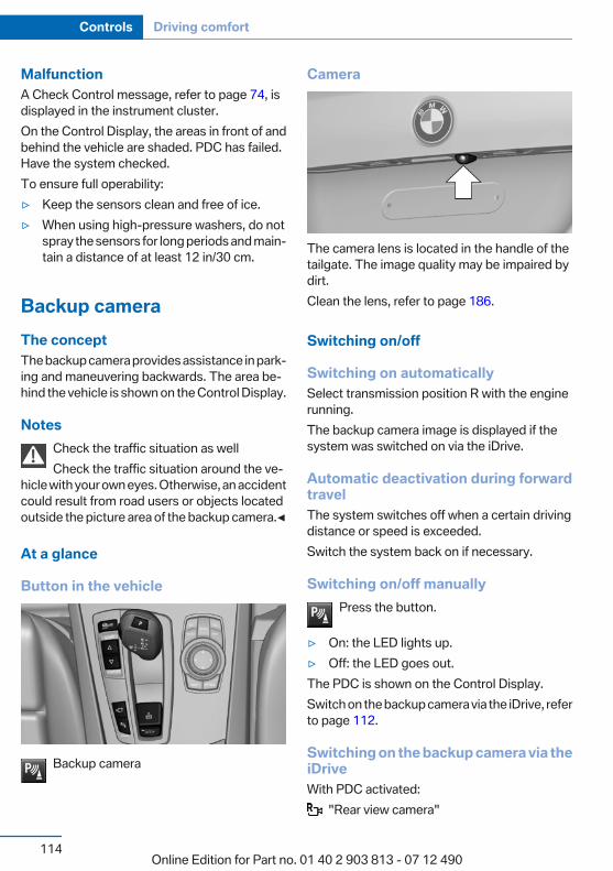
MalfunctionA Check Control message, refer to page 74, isdisplayed in the instrument cluster.On the Control Display, the areas in front of andbehind the vehicle are shaded. PDC has failed.Have the system checked.To ensure full operability:▷ Keep the sensors clean and free of ice.▷ When using high-pressure washers, do not
spray the sensors for long periods and main‐tain a distance of at least 12 in/30 cm.
Backup cameraThe conceptThe backup camera provides assistance in park‐ing and maneuvering backwards. The area be‐hind the vehicle is shown on the Control Display.
NotesCheck the traffic situation as wellCheck the traffic situation around the ve‐
hicle with your own eyes. Otherwise, an accidentcould result from road users or objects locatedoutside the picture area of the backup camera.◀
At a glance
Button in the vehicle
Backup camera
Camera
The camera lens is located in the handle of thetailgate. The image quality may be impaired bydirt.Clean the lens, refer to page 186.
Switching on/off
Switching on automaticallySelect transmission position R with the enginerunning.The backup camera image is displayed if thesystem was switched on via the iDrive.
Automatic deactivation during forwardtravelThe system switches off when a certain drivingdistance or speed is exceeded.Switch the system back on if necessary.
Switching on/off manuallyPress the button.
▷ On: the LED lights up.▷ Off: the LED goes out.The PDC is shown on the Control Display.Switch on the backup camera via the iDrive, referto page 112.
Switching on the backup camera via theiDriveWith PDC activated:
"Rear view camera"
Seite 114
Controls Driving comfort
114Online Edition for Part no. 01 40 2 903 813 - 07 12 490
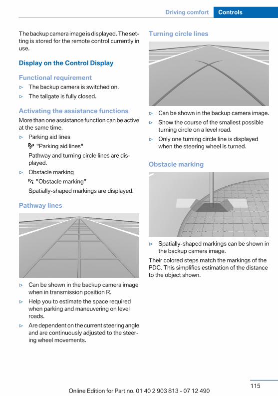
The backup camera image is displayed. The set‐ting is stored for the remote control currently inuse.
Display on the Control Display
Functional requirement▷ The backup camera is switched on.▷ The tailgate is fully closed.
Activating the assistance functionsMore than one assistance function can be activeat the same time.▷ Parking aid lines
"Parking aid lines"Pathway and turning circle lines are dis‐played.
▷ Obstacle marking "Obstacle marking"
Spatially-shaped markings are displayed.
Pathway lines
▷ Can be shown in the backup camera imagewhen in transmission position R.
▷ Help you to estimate the space requiredwhen parking and maneuvering on levelroads.
▷ Are dependent on the current steering angleand are continuously adjusted to the steer‐ing wheel movements.
Turning circle lines
▷ Can be shown in the backup camera image.▷ Show the course of the smallest possible
turning circle on a level road.▷ Only one turning circle line is displayed
when the steering wheel is turned.
Obstacle marking
▷ Spatially-shaped markings can be shown inthe backup camera image.
Their colored steps match the markings of thePDC. This simplifies estimation of the distanceto the object shown.
Seite 115
Driving comfort Controls
115Online Edition for Part no. 01 40 2 903 813 - 07 12 490

Parking using pathway and turningcircle lines1. Position the vehicle so that the turning circle
lines lead to within the limits of the parkingspace.
2. Turn the steering wheel to the point wherethe pathway line covers the correspondingturning circle line.
Display settings
BrightnessWith the backup camera switched on:
1. Select the symbol.2. Turn the controller until the desired setting
is reached and press the controller.
ContrastWith the backup camera switched on:
1. Select the symbol.2. Turn the controller until the desired setting
is reached and press the controller.
System limits
Detection of objectsHigh, protruding objects such as ledges may notbe detected by the backup camera.
Top ViewThe conceptTop View assists you in parking and maneuver‐ing. The area around the doors and the road areaaround the vehicle are shown on the ControlDisplay for this purpose.
General informationThe image is captured by two camerasintegrated in the exterior mirrors and by thebackup camera.The range is approx. 7 ft/2 m to the side and rear.In this way, obstacles up to the height of the ex‐terior mirrors are detected early.
NotesCheck the traffic situation as wellCheck the traffic situation around the ve‐
hicle with your own eyes. Otherwise, an accidentcould result from road users or objects locatedoutside the picture area of the cameras.◀
At a glance
Button in the vehicle
Seite 116
Controls Driving comfort
116Online Edition for Part no. 01 40 2 903 813 - 07 12 490

Top View
Cameras
The lenses of the Top View cameras are locatedat the bottom of the exterior mirror housings.The image quality may be impaired by dirt.Clean the lens, refer to page 186.
Switching on/off
Switching on automaticallySelect transmission position R with the enginerunning.The Top View and PDC images are displayed ifthe system is switched on via iDrive.
Automatic deactivation during forwardtravelThe system switches off when a certain drivingdistance or speed is exceeded.Switch the system back on if necessary.
Switching on/off manuallyPress the button.
▷ On: the LED lights up.▷ Off: the LED goes out.Top View is displayed, switch on the backupcamera via the iDrive, refer to page 117.
Switching on the backup camera via theiDriveWith Top View switched on:
"Rear view camera"The backup camera image is displayed. The set‐ting is stored for the remote control currently inuse.
Display
Visual warningThe approach of the vehicle to an object can beshown on the Control Display.When the distance to an object is small, a red baris shown in front of the vehicle, as it is in the PDCdisplay.
The display appears as soon as Top View is ac‐tivated.
If the backup camera image was selected last, itagain appears on the display when reverse gearis selected. To switch to Top View:
"Rear view camera" Select the symbol onthe Control Display.The setting is stored for the remote control cur‐rently in use.
BrightnessWith Top View switched on:
1. "Brightness"2. Turn the controller until the desired setting
is reached and press the controller.
Seite 117
Driving comfort Controls
117Online Edition for Part no. 01 40 2 903 813 - 07 12 490
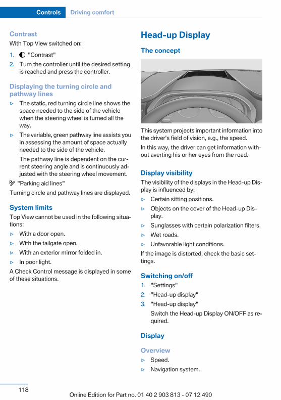
ContrastWith Top View switched on:
1. "Contrast"2. Turn the controller until the desired setting
is reached and press the controller.
Displaying the turning circle andpathway lines▷ The static, red turning circle line shows the
space needed to the side of the vehiclewhen the steering wheel is turned all theway.
▷ The variable, green pathway line assists youin assessing the amount of space actuallyneeded to the side of the vehicle.The pathway line is dependent on the cur‐rent steering angle and is continuously ad‐justed with the steering wheel movement.
"Parking aid lines"Turning circle and pathway lines are displayed.
System limitsTop View cannot be used in the following situa‐tions:▷ With a door open.▷ With the tailgate open.▷ With an exterior mirror folded in.▷ In poor light.A Check Control message is displayed in someof these situations.
Head-up DisplayThe concept
This system projects important information intothe driver's field of vision, e.g., the speed.In this way, the driver can get information with‐out averting his or her eyes from the road.
Display visibilityThe visibility of the displays in the Head-up Dis‐play is influenced by:▷ Certain sitting positions.▷ Objects on the cover of the Head-up Dis‐
play.▷ Sunglasses with certain polarization filters.▷ Wet roads.▷ Unfavorable light conditions.If the image is distorted, check the basic set‐tings.
Switching on/off1. "Settings"2. "Head-up display"3. "Head-up display"
Switch the Head-up Display ON/OFF as re‐quired.
Display
Overview▷ Speed.▷ Navigation system.
Seite 118
Controls Driving comfort
118Online Edition for Part no. 01 40 2 903 813 - 07 12 490
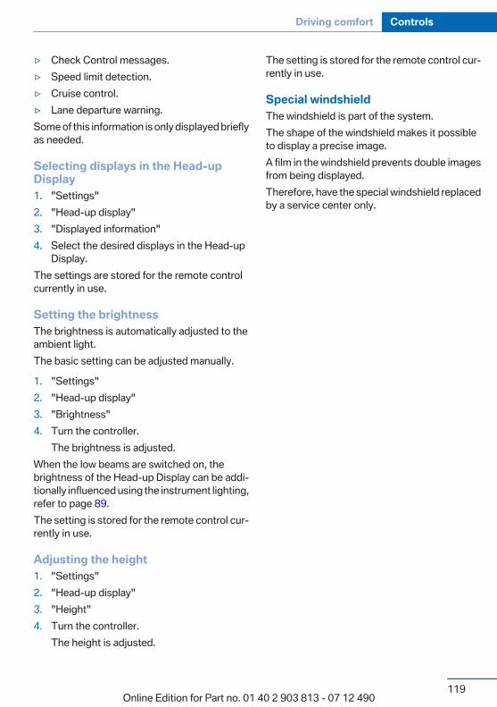
▷ Check Control messages.▷ Speed limit detection.▷ Cruise control.▷ Lane departure warning.Some of this information is only displayed brieflyas needed.
Selecting displays in the Head-upDisplay1. "Settings"2. "Head-up display"3. "Displayed information"4. Select the desired displays in the Head-up
Display.The settings are stored for the remote controlcurrently in use.
Setting the brightnessThe brightness is automatically adjusted to theambient light.The basic setting can be adjusted manually.
1. "Settings"2. "Head-up display"3. "Brightness"4. Turn the controller.
The brightness is adjusted.When the low beams are switched on, thebrightness of the Head-up Display can be addi‐tionally influenced using the instrument lighting,refer to page 89.The setting is stored for the remote control cur‐rently in use.
Adjusting the height1. "Settings"2. "Head-up display"3. "Height"4. Turn the controller.
The height is adjusted.
The setting is stored for the remote control cur‐rently in use.
Special windshieldThe windshield is part of the system.The shape of the windshield makes it possibleto display a precise image.A film in the windshield prevents double imagesfrom being displayed.Therefore, have the special windshield replacedby a service center only.
Seite 119
Driving comfort Controls
119Online Edition for Part no. 01 40 2 903 813 - 07 12 490
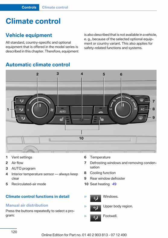
Climate controlVehicle equipmentAll standard, country-specific and optionalequipment that is offered in the model series isdescribed in this chapter. Therefore, equipment
is also described that is not available in a vehicle,e. g., because of the selected optional equip‐ment or country variant. This also applies forsafety-related functions and systems.
Automatic climate control
1 Vent settings2 Air flow3 AUTO program4 Interior temperature sensor — always keep
clear5 Recirculated-air mode
6 Temperature7 Defrosting windows and removing conden‐
sation8 Cooling function9 Rear window defroster10 Seat heating 49
Climate control functions in detail
Manual air distributionPress the buttons repeatedly to select a pro‐gram:
▷ Windows.
▷ Upper body region.
▷ Footwell.
Seite 120
Controls Climate control
120Online Edition for Part no. 01 40 2 903 813 - 07 12 490
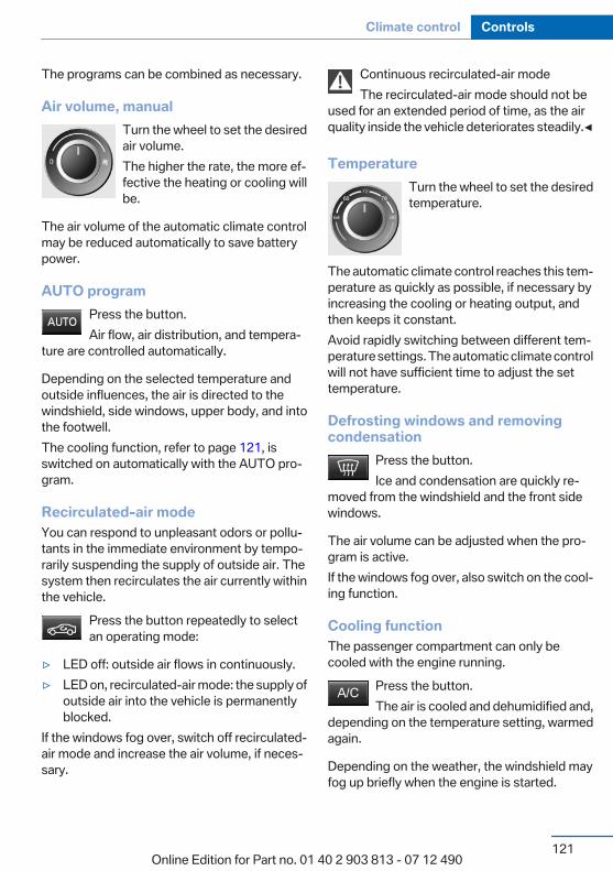
The programs can be combined as necessary.
Air volume, manualTurn the wheel to set the desiredair volume.The higher the rate, the more ef‐fective the heating or cooling willbe.
The air volume of the automatic climate controlmay be reduced automatically to save batterypower.
AUTO programPress the button.Air flow, air distribution, and tempera‐
ture are controlled automatically.
Depending on the selected temperature andoutside influences, the air is directed to thewindshield, side windows, upper body, and intothe footwell.The cooling function, refer to page 121, isswitched on automatically with the AUTO pro‐gram.
Recirculated-air modeYou can respond to unpleasant odors or pollu‐tants in the immediate environment by tempo‐rarily suspending the supply of outside air. Thesystem then recirculates the air currently withinthe vehicle.
Press the button repeatedly to selectan operating mode:
▷ LED off: outside air flows in continuously.▷ LED on, recirculated-air mode: the supply of
outside air into the vehicle is permanentlyblocked.
If the windows fog over, switch off recirculated-air mode and increase the air volume, if neces‐sary.
Continuous recirculated-air modeThe recirculated-air mode should not be
used for an extended period of time, as the airquality inside the vehicle deteriorates steadily.◀
TemperatureTurn the wheel to set the desiredtemperature.
The automatic climate control reaches this tem‐perature as quickly as possible, if necessary byincreasing the cooling or heating output, andthen keeps it constant.Avoid rapidly switching between different tem‐perature settings. The automatic climate controlwill not have sufficient time to adjust the settemperature.
Defrosting windows and removingcondensation
Press the button.Ice and condensation are quickly re‐
moved from the windshield and the front sidewindows.
The air volume can be adjusted when the pro‐gram is active.If the windows fog over, also switch on the cool‐ing function.
Cooling functionThe passenger compartment can only becooled with the engine running.
Press the button.The air is cooled and dehumidified and,
depending on the temperature setting, warmedagain.
Depending on the weather, the windshield mayfog up briefly when the engine is started.
Seite 121
Climate control Controls
121Online Edition for Part no. 01 40 2 903 813 - 07 12 490

The cooling function is switched on automati‐cally with the AUTO program.When using the automatic climate control, con‐densation water, refer to page 142, developsthat exits underneath the vehicle.
Rear window defrosterPress the button.The rear window defroster switches off
automatically after a certain period of time.
Switching the system on/off
Switching offTurn the rotary switch for the air volume, refer topage 121, to 0. The blower and automatic cli‐mate control are switched off entirely.
Switching onSet any air volume.The AUTO program can also be switched on di‐rectly via the AUTO button.
MicrofilterThe microfilter removes dust and pollen fromthe incoming air.This filter should be replaced during scheduledmaintenance, refer to page 168, of your vehicle.
Automatic climate control with enhanced features
1 Vent settings2 Temperature, left3 Maximum cooling4 AUTO program
5 Air flow, AUTO intensity6 Interior temperature sensor — always keep
clear7 Display
Seite 122
Controls Climate control
122Online Edition for Part no. 01 40 2 903 813 - 07 12 490
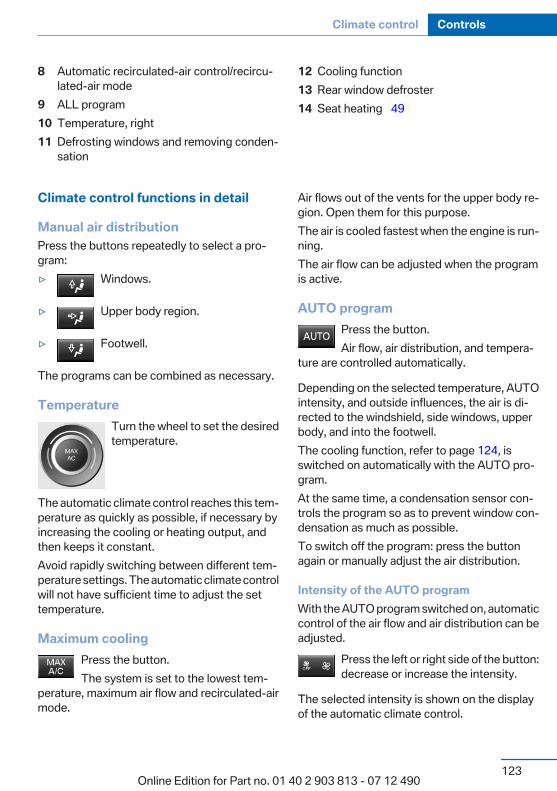
8 Automatic recirculated-air control/recircu‐lated-air mode
9 ALL program10 Temperature, right11 Defrosting windows and removing conden‐
sation
12 Cooling function13 Rear window defroster14 Seat heating 49
Climate control functions in detail
Manual air distributionPress the buttons repeatedly to select a pro‐gram:▷ Windows.
▷ Upper body region.
▷ Footwell.
The programs can be combined as necessary.
TemperatureTurn the wheel to set the desiredtemperature.
The automatic climate control reaches this tem‐perature as quickly as possible, if necessary byincreasing the cooling or heating output, andthen keeps it constant.Avoid rapidly switching between different tem‐perature settings. The automatic climate controlwill not have sufficient time to adjust the settemperature.
Maximum coolingPress the button.The system is set to the lowest tem‐
perature, maximum air flow and recirculated-airmode.
Air flows out of the vents for the upper body re‐gion. Open them for this purpose.The air is cooled fastest when the engine is run‐ning.The air flow can be adjusted when the programis active.
AUTO programPress the button.Air flow, air distribution, and tempera‐
ture are controlled automatically.
Depending on the selected temperature, AUTOintensity, and outside influences, the air is di‐rected to the windshield, side windows, upperbody, and into the footwell.The cooling function, refer to page 124, isswitched on automatically with the AUTO pro‐gram.At the same time, a condensation sensor con‐trols the program so as to prevent window con‐densation as much as possible.To switch off the program: press the buttonagain or manually adjust the air distribution.
Intensity of the AUTO programWith the AUTO program switched on, automaticcontrol of the air flow and air distribution can beadjusted.
Press the left or right side of the button:decrease or increase the intensity.
The selected intensity is shown on the displayof the automatic climate control.
Seite 123
Climate control Controls
123Online Edition for Part no. 01 40 2 903 813 - 07 12 490
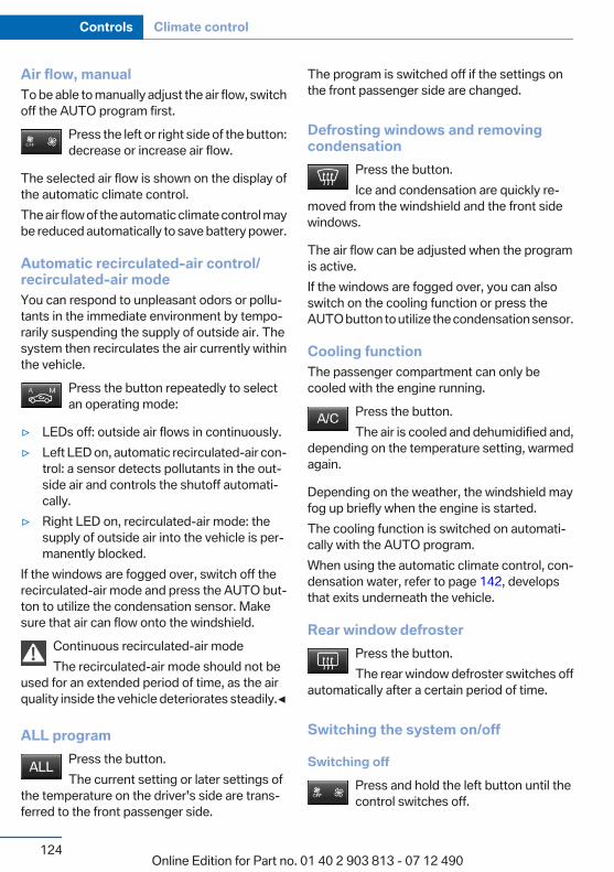
Air flow, manualTo be able to manually adjust the air flow, switchoff the AUTO program first.
Press the left or right side of the button:decrease or increase air flow.
The selected air flow is shown on the display ofthe automatic climate control.The air flow of the automatic climate control maybe reduced automatically to save battery power.
Automatic recirculated-air control/recirculated-air modeYou can respond to unpleasant odors or pollu‐tants in the immediate environment by tempo‐rarily suspending the supply of outside air. Thesystem then recirculates the air currently withinthe vehicle.
Press the button repeatedly to selectan operating mode:
▷ LEDs off: outside air flows in continuously.▷ Left LED on, automatic recirculated-air con‐
trol: a sensor detects pollutants in the out‐side air and controls the shutoff automati‐cally.
▷ Right LED on, recirculated-air mode: thesupply of outside air into the vehicle is per‐manently blocked.
If the windows are fogged over, switch off therecirculated-air mode and press the AUTO but‐ton to utilize the condensation sensor. Makesure that air can flow onto the windshield.
Continuous recirculated-air modeThe recirculated-air mode should not be
used for an extended period of time, as the airquality inside the vehicle deteriorates steadily.◀
ALL programPress the button.The current setting or later settings of
the temperature on the driver's side are trans‐ferred to the front passenger side.
The program is switched off if the settings onthe front passenger side are changed.
Defrosting windows and removingcondensation
Press the button.Ice and condensation are quickly re‐
moved from the windshield and the front sidewindows.
The air flow can be adjusted when the programis active.If the windows are fogged over, you can alsoswitch on the cooling function or press theAUTO button to utilize the condensation sensor.
Cooling functionThe passenger compartment can only becooled with the engine running.
Press the button.The air is cooled and dehumidified and,
depending on the temperature setting, warmedagain.
Depending on the weather, the windshield mayfog up briefly when the engine is started.The cooling function is switched on automati‐cally with the AUTO program.When using the automatic climate control, con‐densation water, refer to page 142, developsthat exits underneath the vehicle.
Rear window defrosterPress the button.The rear window defroster switches off
automatically after a certain period of time.
Switching the system on/off
Switching offPress and hold the left button until thecontrol switches off.
Seite 124
Controls Climate control
124Online Edition for Part no. 01 40 2 903 813 - 07 12 490

Switching onPress any button except:▷ ALL program.▷ Rear window defroster.▷ Left side of Air volume button.▷ Seat heating.
Microfilter/activated-charcoal filterIn external and recirculated air mode the micro‐filter/activated charcoal filter filters dust, pollen,and gaseous pollutants out of the air.This filter should be replaced during scheduledmaintenance, refer to page 168, of your vehicle.
VentilationFront ventilation
▷ Lever for changing the air flow direction, ar‐row 1.
▷ Thumbwheels for opening and closing thevents continuously, arrows 2.
▷ Thumbwheel to vary the temperature, ar‐row 3.Toward blue: colder.Toward red: warmer.
Adjusting the ventilation▷ Ventilation for cooling:
Adjust the vent to direct the air in your di‐rection, such as if the vehicle interior is hotfrom the sun.
▷ Draft-free ventilation:Adjust the vent to let the air flow past you.
Ventilation in the rear
▷ Thumbwheel for continuous opening andclosing of the vents, arrow 1.
▷ Thumbwheel to vary the temperature, ar‐row 2.Toward blue: colder.Toward red: warmer.
▷ Lever for changing the air flow direction, ar‐row 3.
Parked-car ventilationThe conceptThe parked-car ventilation ventilates the vehicleinterior and lowers its temperature, if necessary.The system can be switched on and off at anyexternal temperature, either directly or by usingtwo preset switch-on times. It remains switchedon for 30 minutes.Open the vents to allow air to flow out.Operation can be performed via iDrive.
Switching on/off directly1. "Settings"2. "Climate"3. "Activate parked-car vent."
The symbol on the automatic climate controlflashes if the system is switched on.
Seite 125
Climate control Controls
125Online Edition for Part no. 01 40 2 903 813 - 07 12 490

Preselecting the switch-on time1. "Settings"2. "Climate"3. "Timer 1:" or "Timer 2:"4. Set the desired time.
Activating the switch-on time1. "Settings"2. "Climate"3. "Activate Timer 1" or "Activate Timer 2"
The symbol on the automatic climate controllights up when the switch-on time is activated.
The symbol on the automatic climate controlflashes when the system has been switched on.The system will only be switched on within thenext 24 hours. After that, it needs to reactivated.
Seite 126
Controls Climate control
126Online Edition for Part no. 01 40 2 903 813 - 07 12 490
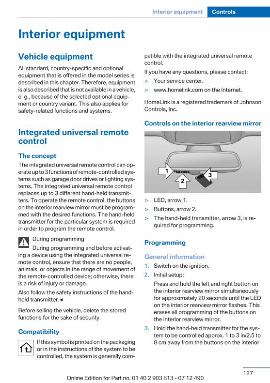
Interior equipmentVehicle equipmentAll standard, country-specific and optionalequipment that is offered in the model series isdescribed in this chapter. Therefore, equipmentis also described that is not available in a vehicle,e. g., because of the selected optional equip‐ment or country variant. This also applies forsafety-related functions and systems.
Integrated universal remotecontrolThe conceptThe integrated universal remote control can op‐erate up to 3 functions of remote-controlled sys‐tems such as garage door drives or lighting sys‐tems. The integrated universal remote controlreplaces up to 3 different hand-held transmit‐ters. To operate the remote control, the buttonson the interior rearview mirror must be program‐med with the desired functions. The hand-heldtransmitter for the particular system is requiredin order to program the remote control.
During programmingDuring programming and before activat‐
ing a device using the integrated universal re‐mote control, ensure that there are no people,animals, or objects in the range of movement ofthe remote-controlled device; otherwise, thereis a risk of injury or damage.Also follow the safety instructions of the hand-held transmitter.◀
Before selling the vehicle, delete the storedfunctions for the sake of security.
CompatibilityIf this symbol is printed on the packagingor in the instructions of the system to becontrolled, the system is generally com‐
patible with the integrated universal remotecontrol.If you have any questions, please contact:▷ Your service center.▷ www.homelink.com on the Internet.
HomeLink is a registered trademark of JohnsonControls, Inc.
Controls on the interior rearview mirror
▷ LED, arrow 1.▷ Buttons, arrow 2.▷ The hand-held transmitter, arrow 3, is re‐
quired for programming.
Programming
General information1. Switch on the ignition.2. Initial setup:
Press and hold the left and right button onthe interior rearview mirror simultaneouslyfor approximately 20 seconds until the LEDon the interior rearview mirror flashes. Thiserases all programming of the buttons onthe interior rearview mirror.
3. Hold the hand-held transmitter for the sys‐tem to be controlled approx. 1 to 3 in/2.5 to8 cm away from the buttons on the interior
Seite 127
Interior equipment Controls
127Online Edition for Part no. 01 40 2 903 813 - 07 12 490
rearview mirror. The required distance de‐pends on the manual transmitter.
4. Simultaneously press and hold the button ofthe desired function on the hand-held trans‐mitter and the button to be programmed onthe interior rearview mirror. The LED on theinterior rearview mirror will begin flashingslowly.
5. Release both buttons as soon as the LEDflashes more rapidly. When the LED is flash‐ing faster, this indicates that the button onthe interior rearview mirror has been pro‐grammed.If the LED does not flash faster after at least60 seconds, change the distance betweenthe interior rearview mirror and the hand-held transmitter and repeat the step. Severalmore attempts at different distances may benecessary. Wait at least 15 seconds be‐tween attempts.Canada: if programming with the hand-heldtransmitter was interrupted, hold down theinterior rearview mirror button and repeat‐edly press and release the hand-held trans‐mitter button for 2 seconds.
6. To program other functions on other but‐tons, repeat steps 3 to 5.
The systems can be controlled using the interiorrearview mirror buttons.
Special feature of the alternating-codewireless systemIf you are unable to operate the system after re‐peated programming, please check if the sys‐tem to be controlled features an alternating-code system.Read the system's operating manual, or pressthe programmed button on the interior rearviewmirror longer. If the LED on the interior rearviewmirror starts flashing rapidly and then stays litconstantly for 2 seconds, the system featuresan alternating-code system. Flashing and con‐tinuous illumination of the LED will repeat forapproximately 20 seconds.
For systems with an alternating-code system,the integrated universal remote control and thesystem also have to be synchronized.Please read the operating manual of the systembeing set up for information on how to syn‐chronize the system.Synchronizing is easier with the aid of a secondperson.To synchronize:
1. Park the vehicle within range of the remote-controlled system.
2. Program the relevant button on the interiorrearview mirror as described.
3. Locate and press the synchronizing buttonon the system being programmed. You haveapprox. 30 seconds for the next step.
4. Hold down the programmed button on theinterior rearview mirror for approximately3 seconds and then release it. If necessary,repeat this work step up to three times in or‐der to finish synchronization. Once synchro‐nization is complete, the programmed func‐tion will be carried out.
Reprogramming individual buttons1. Switch on the ignition.2. Press and hold the interior rearview mirror
button to be programmed.3. As soon as the interior rearview mirror LED
starts flashing slowly, hold the hand-heldtransmitter for the system to be controlledapprox. 1 to 3 in/2.5 to 8 cm away from thebuttons on the interior rearview mirror. Therequired distance depends on the manualtransmitter.
4. Likewise, press and hold the button of thedesired function on the hand-held transmit‐ter.
5. Release both buttons as soon as the interiorrearview mirror LED flashes more rapidly.When the LED is flashing faster, this indi‐cates that the button on the interior rearviewmirror has been programmed. The system
Seite 128
Controls Interior equipment
128Online Edition for Part no. 01 40 2 903 813 - 07 12 490
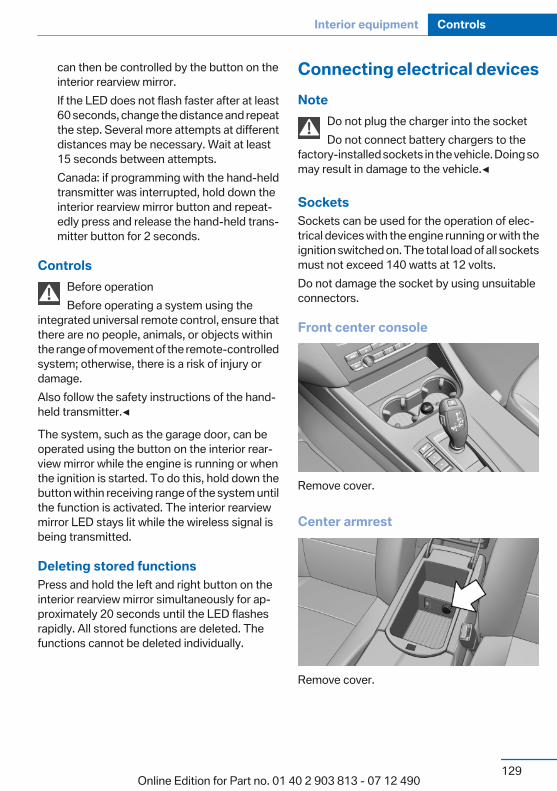
can then be controlled by the button on theinterior rearview mirror.If the LED does not flash faster after at least60 seconds, change the distance and repeatthe step. Several more attempts at differentdistances may be necessary. Wait at least15 seconds between attempts.Canada: if programming with the hand-heldtransmitter was interrupted, hold down theinterior rearview mirror button and repeat‐edly press and release the hand-held trans‐mitter button for 2 seconds.
ControlsBefore operationBefore operating a system using the
integrated universal remote control, ensure thatthere are no people, animals, or objects withinthe range of movement of the remote-controlledsystem; otherwise, there is a risk of injury ordamage.Also follow the safety instructions of the hand-held transmitter.◀
The system, such as the garage door, can beoperated using the button on the interior rear‐view mirror while the engine is running or whenthe ignition is started. To do this, hold down thebutton within receiving range of the system untilthe function is activated. The interior rearviewmirror LED stays lit while the wireless signal isbeing transmitted.
Deleting stored functionsPress and hold the left and right button on theinterior rearview mirror simultaneously for ap‐proximately 20 seconds until the LED flashesrapidly. All stored functions are deleted. Thefunctions cannot be deleted individually.
Connecting electrical devicesNote
Do not plug the charger into the socketDo not connect battery chargers to the
factory-installed sockets in the vehicle. Doing somay result in damage to the vehicle.◀
SocketsSockets can be used for the operation of elec‐trical devices with the engine running or with theignition switched on. The total load of all socketsmust not exceed 140 watts at 12 volts.Do not damage the socket by using unsuitableconnectors.
Front center console
Remove cover.
Center armrest
Remove cover.
Seite 129
Interior equipment Controls
129Online Edition for Part no. 01 40 2 903 813 - 07 12 490
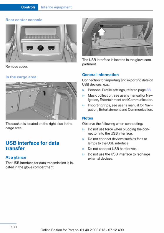
Rear center console
Remove cover.
In the cargo area
The socket is located on the right side in thecargo area.
USB interface for datatransferAt a glanceThe USB interface for data transmission is lo‐cated in the glove compartment.
The USB interface is located in the glove com‐partment
General informationConnection for importing and exporting data onUSB devices, e.g.:▷ Personal Profile settings, refer to page 33.▷ Music collection, see user's manual for Nav‐
igation, Entertainment and Communication.▷ Importing trips, see user's manual for Navi‐
gation, Entertainment and Communication.
NotesObserve the following when connecting:▷ Do not use force when plugging the con‐
nector into the USB interface.▷ Do not connect devices such as fans or
lamps to the USB interface.▷ Do not connect USB hard drives.▷ Do not use the USB interface to recharge
external devices.
Seite 130
Controls Interior equipment
130Online Edition for Part no. 01 40 2 903 813 - 07 12 490
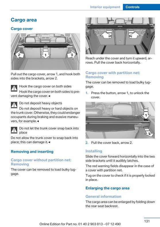
Cargo areaCargo cover
Pull out the cargo cover, arrow 1, and hook bothsides into the brackets, arrow 2.
Hook the cargo cover on both sidesHook the cargo cover on both sides to pre‐
vent damaging the cover.◀
Do not deposit heavy objectsDo not deposit heavy or hard objects on
the trunk cover. Otherwise, they could endangeroccupants during braking and evasive maneu‐vers, for example.◀
Do not let the trunk cover snap back intoplace
Do not allow the trunk cover to snap back intoplace; this can damage it.◀
Removing and inserting
Cargo cover without partition net:RemovingThe cover can be removed to load bulky lug‐gage.
Reach under the cover and turn it upward, ar‐rows. Pull the cover back horizontally.
Cargo cover with partition net:RemovingThe cover can be removed to load bulky lug‐gage.
1. Press the button, arrow 1, to unlock thecover.
2. Pull the cover back, arrow 2.
InstallingSlide the cover forward horizontally into the twoside brackets until it audibly latches.The red warning fields disappear in the case ofa cover with partition net.Tug on the cover to check if it is properly lockedin place.
Enlarging the cargo area
General informationThe cargo area can be enlarged by folding downthe rear seat backrest.
Seite 131
Interior equipment Controls
131Online Edition for Part no. 01 40 2 903 813 - 07 12 490

The rear seat backrest is divided into two partsat a ratio of 60 to 40.If equipped with through-loading system: therear seat backrest is divided in the ratio 40–20–40. The sides and the middle section can befolded down separately.
Danger of pinchingBefore folding down the rear seat backr‐
ests, ensure that the area of movement of thebackrests is clear. In particular, ensure that noone is located in or reaches into the area ofmovement of the rear seat backrests when themiddle section is folded down. Otherwise, injuryor damage may result.◀
Locking the backrestsBefore letting passengers ride in the rear,
engage the seat backrests, locking them inplace. Otherwise, there is the danger of an ac‐cident due to unexpected seat movement.◀
Ensure that the lock is securely engagedWhen folding back the backrest, be sure
that it locks in place securely. The red warningfield in the control display disappears. If it is notproperly engaged, transported cargo could en‐ter the passenger compartment during brakingor evasive maneuvers and endanger the vehicleoccupants.◀
Using the middle safety beltIf the middle safety belt in the rear is used,
the larger section of the backrest must belocked. Otherwise, the safety belt will not havea restraining effect.◀
Folding down the sidesThe right side can be folded down separately.The left side can be folded down in combinationwith the middle section.
Reach into the recess and pull forward.
Folding down the middle section
Reach into the recess and pull forward.
Partition netDo not let the partition net snap back intoplace
Do not allow the partition net to snap back intoplace; otherwise, there is a danger of injury andthe partition net could be damaged.◀
With a normal cargo area1. Fold open the rear covers on the headliner.2. Pull the partition net out of the case by the
strap.3. Insert the bars into the brackets on both
sides in the headliner toward the front, ar‐
Seite 132
Controls Interior equipment
132Online Edition for Part no. 01 40 2 903 813 - 07 12 490
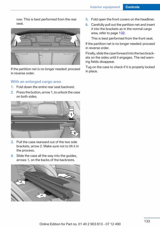
row. This is best performed from the rearseat.
If the partition net is no longer needed: proceedin reverse order.
With an enlarged cargo area1. Fold down the entire rear seat backrest.2. Press the button, arrow 1, to unlock the case
on both sides.
3. Pull the case rearward out of the two sidebrackets, arrow 2. Make sure not to tilt it inthe process.
4. Slide the case all the way into the guides,arrows 1, on the backs of the backrests.
5. Fold open the front covers on the headliner.6. Carefully pull out the partition net and insert
it into the brackets as in the normal cargoarea, refer to page 132.This is best performed from the front seat.
If the partition net is no longer needed: proceedin reverse order.Finally, slide the case forward into the two brack‐ets on the sides until it engages. The red warn‐ing fields disappear.Tug on the case to check if it is properly lockedin place.
Seite 133
Interior equipment Controls
133Online Edition for Part no. 01 40 2 903 813 - 07 12 490
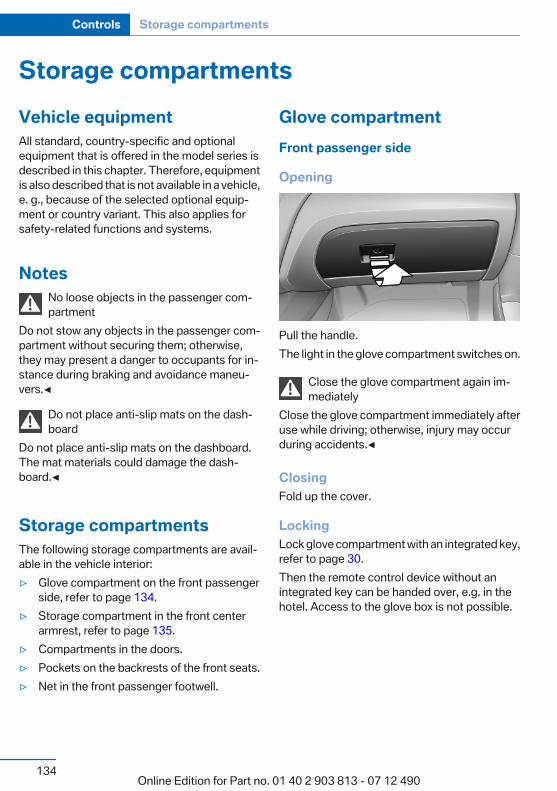
Storage compartmentsVehicle equipmentAll standard, country-specific and optionalequipment that is offered in the model series isdescribed in this chapter. Therefore, equipmentis also described that is not available in a vehicle,e. g., because of the selected optional equip‐ment or country variant. This also applies forsafety-related functions and systems.
NotesNo loose objects in the passenger com‐partment
Do not stow any objects in the passenger com‐partment without securing them; otherwise,they may present a danger to occupants for in‐stance during braking and avoidance maneu‐vers.◀
Do not place anti-slip mats on the dash‐board
Do not place anti-slip mats on the dashboard.The mat materials could damage the dash‐board.◀
Storage compartmentsThe following storage compartments are avail‐able in the vehicle interior:▷ Glove compartment on the front passenger
side, refer to page 134.▷ Storage compartment in the front center
armrest, refer to page 135.▷ Compartments in the doors.▷ Pockets on the backrests of the front seats.▷ Net in the front passenger footwell.
Glove compartmentFront passenger side
Opening
Pull the handle.The light in the glove compartment switches on.
Close the glove compartment again im‐mediately
Close the glove compartment immediately afteruse while driving; otherwise, injury may occurduring accidents.◀
ClosingFold up the cover.
LockingLock glove compartment with an integrated key,refer to page 30.Then the remote control device without anintegrated key can be handed over, e.g. in thehotel. Access to the glove box is not possible.
Seite 134
Controls Storage compartments
134Online Edition for Part no. 01 40 2 903 813 - 07 12 490
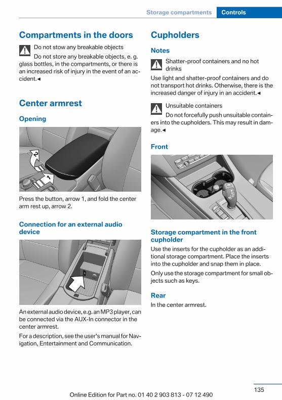
Compartments in the doorsDo not stow any breakable objectsDo not store any breakable objects, e. g.
glass bottles, in the compartments, or there isan increased risk of injury in the event of an ac‐cident.◀
Center armrestOpening
Press the button, arrow 1, and fold the centerarm rest up, arrow 2.
Connection for an external audiodevice
An external audio device, e.g. an MP3 player, canbe connected via the AUX-In connector in thecenter armrest.For a description, see the user's manual for Nav‐igation, Entertainment and Communication.
CupholdersNotes
Shatter-proof containers and no hotdrinks
Use light and shatter-proof containers and donot transport hot drinks. Otherwise, there is theincreased danger of injury in an accident.◀
Unsuitable containersDo not forcefully push unsuitable contain‐
ers into the cupholders. This may result in dam‐age.◀
Front
Storage compartment in the frontcupholderUse the inserts for the cupholder as an addi‐tional storage compartment. Place the insertsinto the cupholder and snap them in place.Only use the storage compartment for small ob‐jects such as keys.
RearIn the center armrest.
Seite 135
Storage compartments Controls
135Online Edition for Part no. 01 40 2 903 813 - 07 12 490
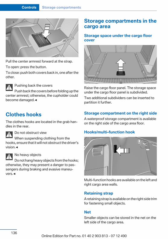
Pull the center armrest forward at the strap.To open: press the button.To close: push both covers back in, one after theother.
Pushing back the coversPush back the covers before folding up the
center armrest; otherwise, the cupholder couldbecome damaged.◀
Clothes hooksThe clothes hooks are located in the grab han‐dles in the rear.
Do not obstruct viewWhen suspending clothing from the
hooks, ensure that it will not obstruct the driver'svision.◀
No heavy objectsDo not hang heavy objects from the hooks;
otherwise, they may present a danger to pas‐sengers during braking and evasive maneu‐vers.◀
Storage compartments in thecargo areaStorage space under the cargo floorcover
Raise the cargo floor panel. The storage spaceunder the cargo floor panel is subdivided.Two additional subdividers can be inserted topartition it further.
Storage compartment on the right sideA waterproof storage compartment is availableon the right side of the cargo area floor.
Hooks/multi-function hook
Multi-function hooks are available on the left andright cargo area walls.
Retaining strapA retaining strap is available on the right side trimfor fastening small objects.
NetSmaller objects can be stored in the net on theleft side of the cargo area.
Seite 136
Controls Storage compartments
136Online Edition for Part no. 01 40 2 903 813 - 07 12 490
Left side storage compartmentTo open: pull the handle.
Lashing eyes in the cargo areaTo secure the cargo, refer to page 144, thereare lashing eyes in the cargo area.
Lashing eyes in the cargo area with railTo secure the cargo, refer to page 144, thereare lashing eyes in the cargo area.
Reversible floor panelThe bottom of the cargo floor panel is coatedwith a water- and dirt-resistant finish.Fold the cargo floor panel up, remove it and flipit over.Hook on the bottom of the cargo floor panel: foreasier loading, the raised cargo floor panel canbe secured on the edge of the roof with the hook.
Cargo net, FlexNetTo secure the cargo, refer to page 144, the flex‐ible cargo net can also be used.
Folding boxA folding box is located under the cargo areafloor.
Seite 137
Storage compartments Controls
137Online Edition for Part no. 01 40 2 903 813 - 07 12 490
Online Edition for Part no. 01 40 2 903 813 - 07 12 490
Driving tipsThis chapter provides you with information useful
in dealing with specific driving and operatingmodes.
Online Edition for Part no. 01 40 2 903 813 - 07 12 490
Things to remember when drivingVehicle equipmentAll standard, country-specific and optionalequipment that is offered in the model series isdescribed in this chapter. Therefore, equipmentis also described that is not available in a vehicle,e. g., because of the selected optional equip‐ment or country variant. This also applies forsafety-related functions and systems.
Breaking-in periodGeneral informationMoving parts need to be broken in to adjust toeach other.The following instructions will help achieve along vehicle life and good economy.
Engine and differentialAlways obey the official speed limit.
Up to 1,200 miles/2,000 kmDo not exceed the maximum engine and roadspeed:▷ For gasoline engine, 4,500 rpm and
100 mph/160 km/h.Avoid full-throttle operation and use of thetransmission's kickdown mode for the initialmiles.
From 1,200 miles/2,000 kmThe engine and vehicle speed can gradually beincreased.
TiresDue to technical factors associated with theirmanufacture, tires do not achieve their full trac‐tion potential until after an initial breaking-in pe‐riod.
Drive conservatively for the first200 miles/300 km.
Brake systemBrakes require an initial break-in period of ap‐prox. 300 miles/500 km to achieve optimizedcontact and wear patterns between brake padsand discs. Drive moderately during this break-inperiod.
Following part replacementThe same breaking in procedures should be ob‐served if any of the components mentionedabove have to be renewed in the course of thevehicle's operating life.
General driving notesClosing the tailgate
Drive with the tailgate closedOnly drive with the tailgate closed; other‐
wise, in the event of an accident or braking orevasive maneuvers, passengers or other roadusers may be injured or the vehicle may be dam‐aged. In addition, exhaust fumes may enter thepassenger compartment.◀
If driving with the tailgate open cannot beavoided:▷ Close all windows and the glass sunroof.▷ Greatly increase the blower speed.▷ Drive moderately.
Hot exhaust systemHot exhaust systemHigh temperatures are generated in the
exhaust system.
Seite 140
Driving tips Things to remember when driving
140Online Edition for Part no. 01 40 2 903 813 - 07 12 490

Do not remove the heat shields installed andnever apply undercoating to them. When driv‐ing, standing at idle and while parking, take careto avoid possible contact between the hot ex‐haust system and any highly flammable materi‐als such as hay, leaves, grass, etc. Such contactcould lead to a fire, and with it the risk of seriouspersonal injury as well as property damage.Do not touch hot exhaust pipes; otherwise, thereis the danger of getting burned.◀
Mobile communication devices in thevehicle
Mobile communication devices in the ve‐hicle
It is advised that you do not use mobile commu‐nication devices, e.g., mobile phones, inside thevehicle without connecting them directly to theexternal antenna. Otherwise, the vehicle elec‐tronics and mobile communication devices caninterfere with each other. In addition, there is noassurance that the radiation generated duringtransmission will be discharged from the vehicleinterior.◀
HydroplaningOn wet or slushy roads, a wedge of water canform between the tires and road surface.This phenomenon is referred to as hydroplan‐ing. It is characterized by a partial or completeloss of contact between the tires and the roadsurface, ultimately undermining your ability tosteer and brake the vehicle.
HydroplaningWhen driving on wet or slushy roads, re‐
duce your speed to prevent hydroplaning.◀
Driving through waterDrive though calm water only if it is not deeperthan 19.6 inches/50 cm, and at this height nofaster than walking speed.
Adhere to water depth and speed limita‐tions
Do not exceed this water depth and walkingspeed; otherwise, the vehicle's engine, the elec‐trical systems and the transmission may bedamaged.◀
Braking safelyYour vehicle is equipped with ABS as a standardfeature.Applying the brakes fully is the most effectiveway of braking in situations when this is neces‐sary.The vehicle maintains steering responsiveness.You can still avoid any obstacles with a minimumof steering effort.Pulsation of the brake pedal and sounds fromthe hydraulic circuits indicate that ABS is in itsactive mode.
Objects in the area around the pedalsNo objects in the area around the pedalsKeep floor mats, carpets, and any other
objects out of the area of motion of the pedals;otherwise, the function of the pedals could beimpeded while drivingDo not place additional floor mats over existingmats or other objects.Only use floor mats that have been approved forthe vehicle and can be properly fixed in place.Ensure that the floor mats are securely fastenedagain after they were removed for cleaning, forexample.◀
Driving in wet conditionsWhen roads are wet or there is heavy rain, brieflyexert gentle pressure on the brake pedal everyfew miles.Ensure that this action does not endanger otherroad users.The heat generated in this process helps dry thebrake discs and pads.
Seite 141
Things to remember when driving Driving tips
141Online Edition for Part no. 01 40 2 903 813 - 07 12 490
In this way braking efficiency will be availablewhen you need it.
HillsDrive long or steep downhill gradients in the gearin which the least braking is required. Otherwise,the brake system may overheat, resulting in areduction in the brake system efficiency.You can increase the engine's braking effect byshifting down, going all the way to first gear, ifnecessary.Automatic transmission:You can increase the engine's braking effect byshifting down in the manual mode of the auto‐matic transmission.
Avoid load on the brakesAvoid placing excessive load on the brake
system. Light but consistent brake pressure canlead to high temperatures, brake wear and pos‐sibly even brake failure.◀
Do not drive in neutralDo not drive in neutral or with the engine
stopped, as doing so disables engine braking. Inaddition, steering and brake assist is unavailablewith the engine stopped.◀
Brake disc corrosionCorrosion on the brake discs and contaminationon the brake pads are furthered by:▷ Low mileage.▷ Extended periods when the vehicle is not
used at all.▷ Infrequent use of the brakes.Corrosion occurs when the minimum pressurethat must be exerted by the pads during brakeapplications to clean the discs is not reached.Should corrosion form on the brake discs, thebrakes will tend to respond with a pulsating ef‐fect that generally cannot be corrected.
Condensation under the parked vehicleWhen using the automatic climate control, con‐densation water develops that exits underneaththe vehicle.Therefore, traces of condensed water under thevehicle are normal.
Roof-mounted luggage rackNoteInstallation only possible with roof rack.Roof racks are available as special accessories.
Attachment to the rackFollow the installation instructions of the roofrack.
MountingBe sure that adequate clearance is maintainedfor tilting and opening the glass sunroof.
LoadingBecause roof racks raise the vehicle's center ofgravity when loaded, they have a major effect onvehicle handling and steering response.Therefore, note the following when loading anddriving:▷ Do not exceed the approved roof/axle loads
and the approved gross vehicle weight.▷ Distribute the roof load uniformly.▷ The roof load should not be too large in area.▷ Always place the heaviest pieces on the bot‐
tom.▷ Secure the roof luggage firmly, e.g., tie with
ratchet straps.▷ Do not let objects project into the opening
path of the tailgate.▷ Drive smoothly. Avoid sudden acceleration
and braking maneuvers. Take corners gen‐tly.
Seite 142
Driving tips Things to remember when driving
142Online Edition for Part no. 01 40 2 903 813 - 07 12 490
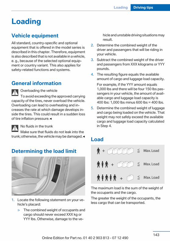
LoadingVehicle equipmentAll standard, country-specific and optionalequipment that is offered in the model series isdescribed in this chapter. Therefore, equipmentis also described that is not available in a vehicle,e. g., because of the selected optional equip‐ment or country variant. This also applies forsafety-related functions and systems.
General informationOverloading the vehicleTo avoid exceeding the approved carrying
capacity of the tires, never overload the vehicle.Overloading can lead to overheating and in‐creases the rate at which damage develops in‐side the tires. This could result in a sudden lossof tire inflation pressure.◀
No fluids in the trunkMake sure that fluids do not leak into the
trunk; otherwise, the vehicle may be damaged.◀
Determining the load limit
1. Locate the following statement on your ve‐hicle’s placard:▷ The combined weight of occupants and
cargo should never exceed XXX kg orYYY lbs. Otherwise, damage to the ve‐
hicle and unstable driving situations mayresult.
2. Determine the combined weight of thedriver and passengers that will be riding inyour vehicle.
3. Subtract the combined weight of the driverand passengers from XXX kilograms or YYYpounds.
4. The resulting figure equals the availableamount of cargo and luggage load capacity.For example, if the YYY amount equals1,000 lbs and there will be four 150 lbs pas‐sengers in your vehicle, the amount of avail‐able cargo and luggage load capacity is400 lbs: 1,000 lbs minus 600 lbs = 400 lbs.
5. Determine the combined weight of luggageand cargo being loaded on the vehicle. Thatweight may not safely exceed the availablecargo and luggage load capacity calculatedin Step 4.
Load
The maximum load is the sum of the weight ofthe occupants and the cargo.The greater the weight of the occupants, theless cargo that can be transported.
Seite 143
Loading Driving tips
143Online Edition for Part no. 01 40 2 903 813 - 07 12 490
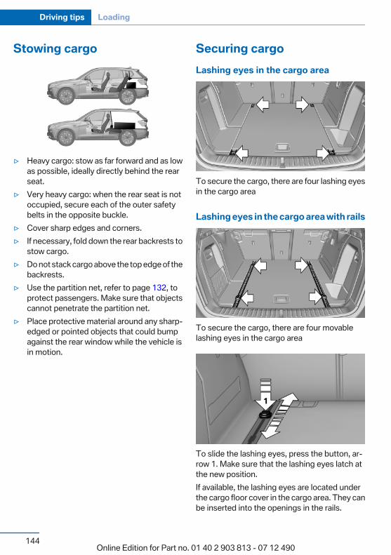
Stowing cargo
▷ Heavy cargo: stow as far forward and as lowas possible, ideally directly behind the rearseat.
▷ Very heavy cargo: when the rear seat is notoccupied, secure each of the outer safetybelts in the opposite buckle.
▷ Cover sharp edges and corners.▷ If necessary, fold down the rear backrests to
stow cargo.▷ Do not stack cargo above the top edge of the
backrests.▷ Use the partition net, refer to page 132, to
protect passengers. Make sure that objectscannot penetrate the partition net.
▷ Place protective material around any sharp-edged or pointed objects that could bumpagainst the rear window while the vehicle isin motion.
Securing cargoLashing eyes in the cargo area
To secure the cargo, there are four lashing eyesin the cargo area
Lashing eyes in the cargo area with rails
To secure the cargo, there are four movablelashing eyes in the cargo area
To slide the lashing eyes, press the button, ar‐row 1. Make sure that the lashing eyes latch atthe new position.If available, the lashing eyes are located underthe cargo floor cover in the cargo area. They canbe inserted into the openings in the rails.
Seite 144
Driving tips Loading
144Online Edition for Part no. 01 40 2 903 813 - 07 12 490
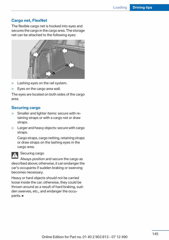
Cargo net, FlexNetThe flexible cargo net is hooked into eyes andsecures the cargo in the cargo area. The storagenet can be attached to the following eyes:
▷ Lashing eyes on the rail system.▷ Eyes on the cargo area wall.The eyes are located on both sides of the cargoarea.
Securing cargo▷ Smaller and lighter items: secure with re‐
taining straps or with a cargo net or drawstraps.
▷ Larger and heavy objects: secure with cargostraps.Cargo straps, cargo netting, retaining strapsor draw straps on the lashing eyes in thecargo area.
Securing cargoAlways position and secure the cargo as
described above; otherwise, it can endanger thecar's occupants if sudden braking or swervingbecomes necessary.Heavy or hard objects should not be carriedloose inside the car; otherwise, they could bethrown around as a result of hard braking, sud‐den swerves, etc., and endanger the occu‐pants.◀
Seite 145
Loading Driving tips
145Online Edition for Part no. 01 40 2 903 813 - 07 12 490
Saving fuelVehicle equipmentAll standard, country-specific and optionalequipment that is offered in the model series isdescribed in this chapter. Therefore, equipmentis also described that is not available in a vehicle,e. g., because of the selected optional equip‐ment or country variant. This also applies forsafety-related functions and systems.
General informationYour vehicle contains advanced technology forthe reduction of fuel consumption and emis‐sions.Fuel consumption depends on a number of dif‐ferent factors.The implementation of certain measures, driv‐ing style and regular maintenance can have aninfluence on fuel consumption and on the envi‐ronmental impact.
Remove unnecessary cargoAdditional weight increases fuel consumption.
Remove attached partsfollowing useRemove auxiliary mirrors, roof or rear luggageracks which are no longer required followinguse.Attached parts on the vehicle impair the aero‐dynamics and increase the fuel consumption.
Close the windows and glasssunroofDriving with the glass sunroof and windowsopen results in increased air resistance andraises fuel consumption.
Check the tire inflationpressure regularlyCheck and, if necessary, correct the tire inflationpressure at least twice a month and before start‐ing on a long trip.Low tire inflation pressure increases rolling re‐sistance and thus raises fuel consumption andtire wear.
Drive away without delayDo not wait for the engine to warm up while thevehicle remains stationary. Start driving rightaway, but at moderate engine speeds.This is the fastest way for the cold engine toreach its operating temperature.
Look well ahead when drivingAvoid unnecessary acceleration and braking.By maintaining a suitable distance to the vehicledriving ahead of you.Driving smoothly and looking ahead reducesfuel consumption.
Use coasting conditionsWhen approaching a red light, take your foot offthe accelerator and let the vehicle coast to a halt.On a downhill gradient, take your foot off the ac‐celerator and let the vehicle roll.
Seite 146
Driving tips Saving fuel
146Online Edition for Part no. 01 40 2 903 813 - 07 12 490
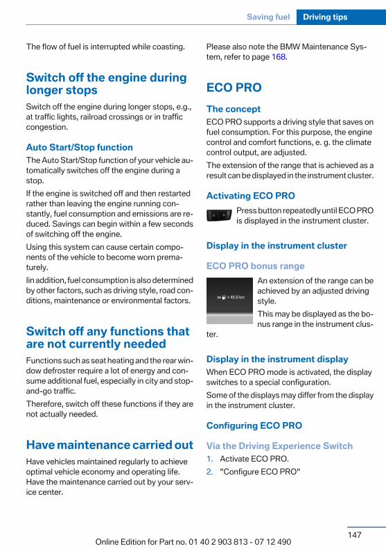
The flow of fuel is interrupted while coasting.
Switch off the engine duringlonger stopsSwitch off the engine during longer stops, e.g.,at traffic lights, railroad crossings or in trafficcongestion.
Auto Start/Stop functionThe Auto Start/Stop function of your vehicle au‐tomatically switches off the engine during astop.If the engine is switched off and then restartedrather than leaving the engine running con‐stantly, fuel consumption and emissions are re‐duced. Savings can begin within a few secondsof switching off the engine.Using this system can cause certain compo‐nents of the vehicle to become worn prema‐turely.Iin addition, fuel consumption is also determinedby other factors, such as driving style, road con‐ditions, maintenance or environmental factors.
Switch off any functions thatare not currently neededFunctions such as seat heating and the rear win‐dow defroster require a lot of energy and con‐sume additional fuel, especially in city and stop-and-go traffic.Therefore, switch off these functions if they arenot actually needed.
Have maintenance carried outHave vehicles maintained regularly to achieveoptimal vehicle economy and operating life.Have the maintenance carried out by your serv‐ice center.
Please also note the BMW Maintenance Sys‐tem, refer to page 168.
ECO PROThe conceptECO PRO supports a driving style that saves onfuel consumption. For this purpose, the enginecontrol and comfort functions, e. g. the climatecontrol output, are adjusted.The extension of the range that is achieved as aresult can be displayed in the instrument cluster.
Activating ECO PROPress button repeatedly until ECO PROis displayed in the instrument cluster.
Display in the instrument cluster
ECO PRO bonus rangeAn extension of the range can beachieved by an adjusted drivingstyle.This may be displayed as the bo‐nus range in the instrument clus‐
ter.
Display in the instrument displayWhen ECO PRO mode is activated, the displayswitches to a special configuration.Some of the displays may differ from the displayin the instrument cluster.
Configuring ECO PRO
Via the Driving Experience Switch1. Activate ECO PRO.2. "Configure ECO PRO"
Seite 147
Saving fuel Driving tips
147Online Edition for Part no. 01 40 2 903 813 - 07 12 490
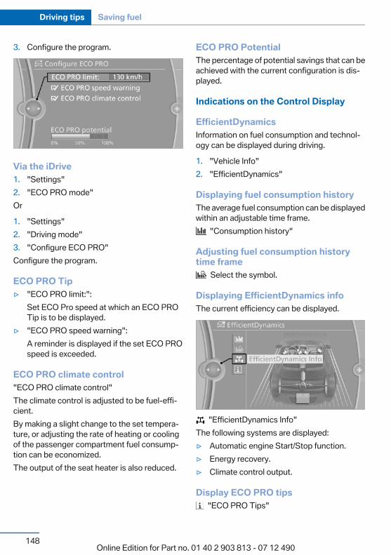
3. Configure the program.
Via the iDrive1. "Settings"2. "ECO PRO mode"Or
1. "Settings"2. "Driving mode"3. "Configure ECO PRO"Configure the program.
ECO PRO Tip▷ "ECO PRO limit:":
Set ECO Pro speed at which an ECO PROTip is to be displayed.
▷ "ECO PRO speed warning":A reminder is displayed if the set ECO PROspeed is exceeded.
ECO PRO climate control"ECO PRO climate control"The climate control is adjusted to be fuel-effi‐cient.By making a slight change to the set tempera‐ture, or adjusting the rate of heating or coolingof the passenger compartment fuel consump‐tion can be economized.The output of the seat heater is also reduced.
ECO PRO PotentialThe percentage of potential savings that can beachieved with the current configuration is dis‐played.
Indications on the Control Display
EfficientDynamicsInformation on fuel consumption and technol‐ogy can be displayed during driving.
1. "Vehicle Info"2. "EfficientDynamics"
Displaying fuel consumption historyThe average fuel consumption can be displayedwithin an adjustable time frame.
"Consumption history"
Adjusting fuel consumption historytime frame
Select the symbol.
Displaying EfficientDynamics infoThe current efficiency can be displayed.
"EfficientDynamics Info"The following systems are displayed:▷ Automatic engine Start/Stop function.▷ Energy recovery.▷ Climate control output.
Display ECO PRO tips "ECO PRO Tips"
Seite 148
Driving tips Saving fuel
148Online Edition for Part no. 01 40 2 903 813 - 07 12 490

The setting is stored for the profile currently inuse.
Seite 149
Saving fuel Driving tips
149Online Edition for Part no. 01 40 2 903 813 - 07 12 490
Online Edition for Part no. 01 40 2 903 813 - 07 12 490
MobilityTo ensure that you remain mobile at all times, this
chapter supplies you with important informationon the topics of fuels and lubricants, wheels and
tires, service, maintenance, and RoadsideAssistance.
Online Edition for Part no. 01 40 2 903 813 - 07 12 490
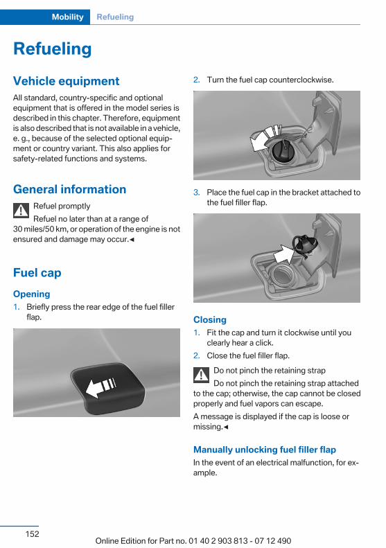
RefuelingVehicle equipmentAll standard, country-specific and optionalequipment that is offered in the model series isdescribed in this chapter. Therefore, equipmentis also described that is not available in a vehicle,e. g., because of the selected optional equip‐ment or country variant. This also applies forsafety-related functions and systems.
General informationRefuel promptlyRefuel no later than at a range of
30 miles/50 km, or operation of the engine is notensured and damage may occur.◀
Fuel capOpening1. Briefly press the rear edge of the fuel filler
flap.
2. Turn the fuel cap counterclockwise.
3. Place the fuel cap in the bracket attached tothe fuel filler flap.
Closing1. Fit the cap and turn it clockwise until you
clearly hear a click.2. Close the fuel filler flap.
Do not pinch the retaining strapDo not pinch the retaining strap attached
to the cap; otherwise, the cap cannot be closedproperly and fuel vapors can escape.A message is displayed if the cap is loose ormissing.◀
Manually unlocking fuel filler flapIn the event of an electrical malfunction, for ex‐ample.
Seite 152
Mobility Refueling
152Online Edition for Part no. 01 40 2 903 813 - 07 12 490
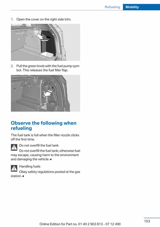
1. Open the cover on the right side trim.
2. Pull the green knob with the fuel pump sym‐bol. This releases the fuel filler flap.
Observe the following whenrefuelingThe fuel tank is full when the filler nozzle clicksoff the first time.
Do not overfill the fuel tankDo not overfill the fuel tank; otherwise fuel
may escape, causing harm to the environmentand damaging the vehicle.◀
Handling fuelsObey safety regulations posted at the gas
station.◀
Seite 153
Refueling Mobility
153Online Edition for Part no. 01 40 2 903 813 - 07 12 490
FuelVehicle equipmentAll standard, country-specific and optionalequipment that is offered in the model series isdescribed in this chapter. Therefore, equipmentis also described that is not available in a vehicle,e. g., because of the selected optional equip‐ment or country variant. This also applies forsafety-related functions and systems.
Fuel qualityGasolineFor the best fuel economy, the gasoline shouldbe sulfur-free or very low in sulfur content.Fuels that are marked on the gas pump as con‐taining metal must not be used.
Refuel only with unleaded gasoline with‐out metallic additives.
Do not refuel with any leaded gasoline or gaso‐line with metallic additives, e. g. manganese oriron, or permanent damage to the catalytic con‐verter and other components.◀
Fuels with a maximum ethanol content of 10 %,i. e., E10, may be used for refueling.Ethanol should satisfy the following qualitystandards:US: ASTM 4806–xxCAN: CGSB-3.511–xxxx: comply with the current standard in eachcase.
Do not refuel with ethanol E85Do not refuel with E85, i.e., fuel with an
ethanol content of 85 %, or with Flex Fuel, as thiswould damage the engine and fuel supply sys‐tem.◀
The engine is knock controlled. Therefore, youcan refuel with different gasoline qualities.
Recommended fuel qualityBMW recommends AKI 91.
Minimum fuel gradeBMW recommends AKI 89.
Minimum fuel gradeDo not use any gasoline below the mini‐
mum fuel grade as this may impair engine per‐formance.◀
If you use gasoline with this minimum AKI Rat‐ing, the engine may produce knocking soundswhen starting at high outside temperatures.This has no effect on the engine life.
Minimum fuel gradeThe use of poor-quality fuels may result in
harmful engine deposits or damage. Addition‐ally, problems relating to drivability, starting andstalling, especially under certain environmentalconditions such as high ambient temperatureand high altitude, may occur.If drivability problems are encountered, we rec‐ommend switching to a high quality gasolinebrand and a higher octane grade — AKI number— for a few tank fills. To avoid harmful enginedeposits, it is highly recommended to purchasegasoline from BP or Top Tier retailers.Failure to comply with these recommendationsmay result in the need for unscheduled mainte‐nance.◀
Seite 154
Mobility Fuel
154Online Edition for Part no. 01 40 2 903 813 - 07 12 490
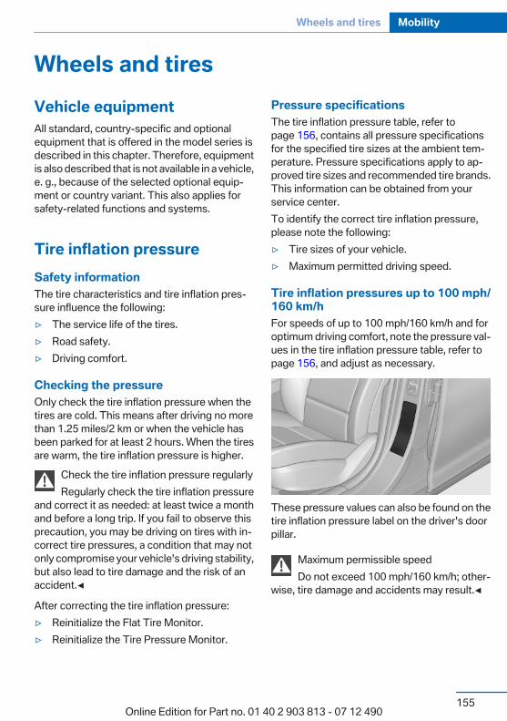
Wheels and tiresVehicle equipmentAll standard, country-specific and optionalequipment that is offered in the model series isdescribed in this chapter. Therefore, equipmentis also described that is not available in a vehicle,e. g., because of the selected optional equip‐ment or country variant. This also applies forsafety-related functions and systems.
Tire inflation pressureSafety informationThe tire characteristics and tire inflation pres‐sure influence the following:▷ The service life of the tires.▷ Road safety.▷ Driving comfort.
Checking the pressureOnly check the tire inflation pressure when thetires are cold. This means after driving no morethan 1.25 miles/2 km or when the vehicle hasbeen parked for at least 2 hours. When the tiresare warm, the tire inflation pressure is higher.
Check the tire inflation pressure regularlyRegularly check the tire inflation pressure
and correct it as needed: at least twice a monthand before a long trip. If you fail to observe thisprecaution, you may be driving on tires with in‐correct tire pressures, a condition that may notonly compromise your vehicle's driving stability,but also lead to tire damage and the risk of anaccident.◀
After correcting the tire inflation pressure:▷ Reinitialize the Flat Tire Monitor.▷ Reinitialize the Tire Pressure Monitor.
Pressure specificationsThe tire inflation pressure table, refer topage 156, contains all pressure specificationsfor the specified tire sizes at the ambient tem‐perature. Pressure specifications apply to ap‐proved tire sizes and recommended tire brands.This information can be obtained from yourservice center.To identify the correct tire inflation pressure,please note the following:▷ Tire sizes of your vehicle.▷ Maximum permitted driving speed.
Tire inflation pressures up to 100 mph/160 km/hFor speeds of up to 100 mph/160 km/h and foroptimum driving comfort, note the pressure val‐ues in the tire inflation pressure table, refer topage 156, and adjust as necessary.
These pressure values can also be found on thetire inflation pressure label on the driver's doorpillar.
Maximum permissible speedDo not exceed 100 mph/160 km/h; other‐
wise, tire damage and accidents may result.◀
Seite 155
Wheels and tires Mobility
155Online Edition for Part no. 01 40 2 903 813 - 07 12 490
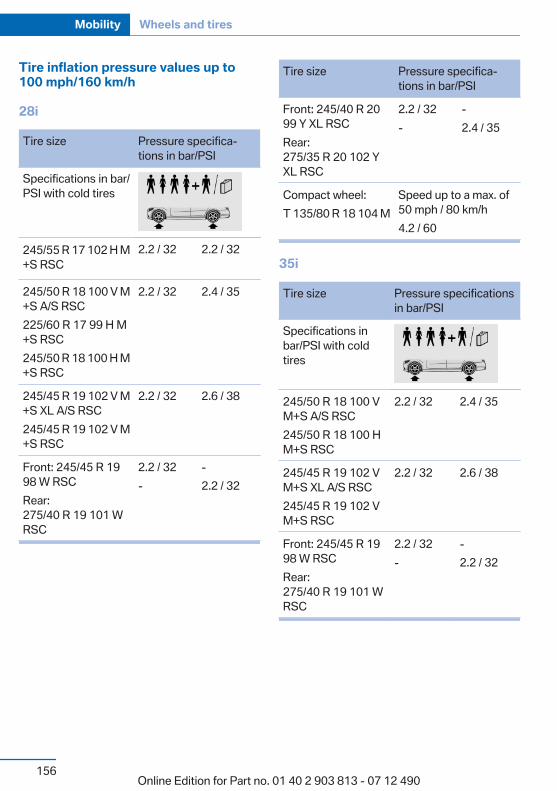
Tire inflation pressure values up to100 mph/160 km/h
28i
Tire size Pressure specifica‐tions in bar/PSI
Specifications in bar/PSI with cold tires
245/55 R 17 102 H M+S RSC
2.2 / 32 2.2 / 32
245/50 R 18 100 V M+S A/S RSC225/60 R 17 99 H M+S RSC245/50 R 18 100 H M+S RSC
2.2 / 32 2.4 / 35
245/45 R 19 102 V M+S XL A/S RSC245/45 R 19 102 V M+S RSC
2.2 / 32 2.6 / 38
Front: 245/45 R 1998 W RSCRear:275/40 R 19 101 WRSC
2.2 / 32-
-2.2 / 32
Tire size Pressure specifica‐tions in bar/PSI
Front: 245/40 R 2099 Y XL RSCRear:275/35 R 20 102 YXL RSC
2.2 / 32-
-2.4 / 35
Compact wheel:T 135/80 R 18 104 M
Speed up to a max. of50 mph / 80 km/h4.2 / 60
35i
Tire size Pressure specificationsin bar/PSI
Specifications inbar/PSI with coldtires
245/50 R 18 100 VM+S A/S RSC245/50 R 18 100 HM+S RSC
2.2 / 32 2.4 / 35
245/45 R 19 102 VM+S XL A/S RSC245/45 R 19 102 VM+S RSC
2.2 / 32 2.6 / 38
Front: 245/45 R 1998 W RSCRear:275/40 R 19 101 WRSC
2.2 / 32-
-2.2 / 32
Seite 156
Mobility Wheels and tires
156Online Edition for Part no. 01 40 2 903 813 - 07 12 490
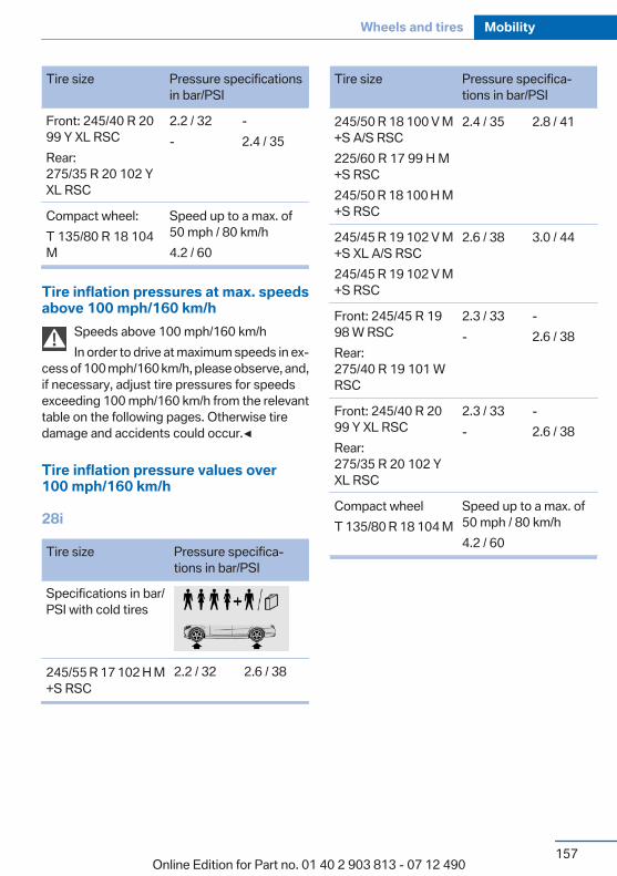
Tire size Pressure specificationsin bar/PSI
Front: 245/40 R 2099 Y XL RSCRear:275/35 R 20 102 YXL RSC
2.2 / 32-
-2.4 / 35
Compact wheel:T 135/80 R 18 104M
Speed up to a max. of50 mph / 80 km/h4.2 / 60
Tire inflation pressures at max. speedsabove 100 mph/160 km/h
Speeds above 100 mph/160 km/hIn order to drive at maximum speeds in ex‐
cess of 100 mph/160 km/h, please observe, and,if necessary, adjust tire pressures for speedsexceeding 100 mph/160 km/h from the relevanttable on the following pages. Otherwise tiredamage and accidents could occur.◀
Tire inflation pressure values over100 mph/160 km/h
28i
Tire size Pressure specifica‐tions in bar/PSI
Specifications in bar/PSI with cold tires
245/55 R 17 102 H M+S RSC
2.2 / 32 2.6 / 38
Tire size Pressure specifica‐tions in bar/PSI
245/50 R 18 100 V M+S A/S RSC225/60 R 17 99 H M+S RSC245/50 R 18 100 H M+S RSC
2.4 / 35 2.8 / 41
245/45 R 19 102 V M+S XL A/S RSC245/45 R 19 102 V M+S RSC
2.6 / 38 3.0 / 44
Front: 245/45 R 1998 W RSCRear:275/40 R 19 101 WRSC
2.3 / 33-
-2.6 / 38
Front: 245/40 R 2099 Y XL RSCRear:275/35 R 20 102 YXL RSC
2.3 / 33-
-2.6 / 38
Compact wheelT 135/80 R 18 104 M
Speed up to a max. of50 mph / 80 km/h4.2 / 60
Seite 157
Wheels and tires Mobility
157Online Edition for Part no. 01 40 2 903 813 - 07 12 490
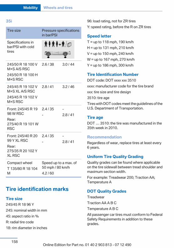
35i
Tire size Pressure specificationsin bar/PSI
Specifications inbar/PSI with coldtires
245/50 R 18 100 VM+S A/S RSC245/50 R 18 100 HM+S RSC
2.6 / 38 3.0 / 44
245/45 R 19 102 VM+S XL A/S RSC245/45 R 19 102 VM+S RSC
2.8 / 41 3.2 / 46
Front: 245/45 R 1998 W RSCRear:275/40 R 19 101 WRSC
2.4 / 35-
-2.8 / 41
Front: 245/40 R 2099 Y XL RSCRear:275/35 R 20 102 YXL RSC
2.4 / 35-
-2.8 / 41
Compact wheelT 135/80 R 18 104M
Speed up to a max. of50 mph / 80 km/h4.2 / 60
Tire identification marksTire size245/45 R 18 96 Y245: nominal width in mm45: aspect ratio in %R: radial tire code18: rim diameter in inches
96: load rating, not for ZR tiresY: speed rating, before the R on ZR tires
Speed letterT = up to 118 mph, 190 km/hH = up to 131 mph, 210 km/hV = up to 150 mph, 240 km/hW = up to 167 mph, 270 km/hY = up to 186 mph, 300 km/h
Tire Identification NumberDOT code: DOT xxxx xxx 3510xxxx: manufacturer code for the tire brandxxx: tire size and tire design3510: tire ageTires with DOT codes meet the guidelines of theU.S. Department of Transportation.
Tire ageDOT … 3510: the tire was manufactured in the35th week in 2010.
RecommendationRegardless of wear, replace tires at least every6 years.
Uniform Tire Quality GradingQuality grades can be found where applicableon the tire sidewall between tread shoulder andmaximum section width.For example: Treadwear 200; Traction AA;Temperature A
DOT Quality GradesTreadwearTraction AA A B CTemperature A B CAll passenger car tires must conform to FederalSafety Requirements in addition to thesegrades.
Seite 158
Mobility Wheels and tires
158Online Edition for Part no. 01 40 2 903 813 - 07 12 490

TreadwearThe treadwear grade is a comparative ratingbased on the wear rate of the tire when testedunder controlled conditions on a specified gov‐ernment test course. For example, a tire graded150 would wear one and one-half, 1 g, times aswell on the government course as a tire graded100. The relative performance of tires dependsupon the actual conditions of their use, however,and may depart significantly from the norm dueto variations in driving habits, service practicesand differences in road characteristics and cli‐mate.
TractionThe traction grades, from highest to lowest, areAA, A, B, and C.Those grades represent the tire's ability to stopon wet pavement as measured under controlledconditions on specified government test surfa‐ces of asphalt and concrete. A tire marked C mayhave poor traction performance.The traction grade assigned to this tire is basedon straight-ahead braking traction tests, anddoes not include acceleration, cornering, hydro‐planing, or peak traction characteristics.
TemperatureThe temperature grades are A, the highest, B,and C, representing the tire's resistance to thegeneration of heat and its ability to dissipateheat when tested under controlled conditionson a specified indoor laboratory test wheel. Sus‐tained high temperature can cause the materialof the tire to degenerate and reduce tire life, andexcessive temperature can lead to sudden tirefailure. The grade C corresponds to a level ofperformance which all passenger car tires mustmeet under the Federal Motor Vehicle SafetyStandard No. 109. Grades Band A representhigher levels of performance on the laboratorytest wheel than the minimum required by law.
Temperature grade for this tireThe temperature grade for this tire is es‐
tablished for a tire that is properly inflated andnot overloaded. Excessive speed, underinfla‐tion, or excessive loading, either separately or incombination, can cause heat buildup and pos‐sible tire failure.If necessary, have the vehicle towed.◀
RSC – Run-flat tiresRun-flat tires, refer to page 162, are labeled witha circular symbol containing the letters RSCmarked on the sidewall.
M+SWinter and all-season tires with better coldweather performance than summer tires.
Tire treadSummer tiresDo not drive with a tire tread depth of less than0.12 in/3 mm.There is an increased danger of hydroplaning ifthe tread depth is less than 0.12 in/3 mm.
Winter tiresDo not drive with a tire tread depth of less than0.16 in/4 mm.Below a tread depth of 0.16 in/4 mm, tires areless suitable for winter operation.
Seite 159
Wheels and tires Mobility
159Online Edition for Part no. 01 40 2 903 813 - 07 12 490
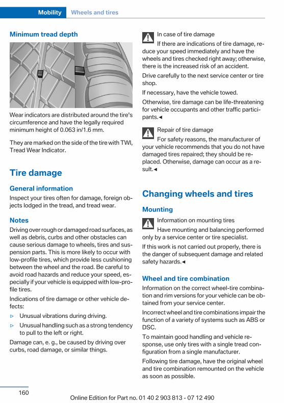
Minimum tread depth
Wear indicators are distributed around the tire'scircumference and have the legally requiredminimum height of 0.063 in/1.6 mm.
They are marked on the side of the tire with TWI,Tread Wear Indicator.
Tire damageGeneral informationInspect your tires often for damage, foreign ob‐jects lodged in the tread, and tread wear.
NotesDriving over rough or damaged road surfaces, aswell as debris, curbs and other obstacles cancause serious damage to wheels, tires and sus‐pension parts. This is more likely to occur withlow-profile tires, which provide less cushioningbetween the wheel and the road. Be careful toavoid road hazards and reduce your speed, es‐pecially if your vehicle is equipped with low-pro‐file tires.Indications of tire damage or other vehicle de‐fects:▷ Unusual vibrations during driving.▷ Unusual handling such as a strong tendency
to pull to the left or right.Damage can, e. g., be caused by driving overcurbs, road damage, or similar things.
In case of tire damageIf there are indications of tire damage, re‐
duce your speed immediately and have thewheels and tires checked right away; otherwise,there is the increased risk of an accident.Drive carefully to the next service center or tireshop.If necessary, have the vehicle towed.Otherwise, tire damage can be life-threateningfor vehicle occupants and other traffic partici‐pants.◀
Repair of tire damageFor safety reasons, the manufacturer of
your vehicle recommends that you do not havedamaged tires repaired; they should be re‐placed. Otherwise, damage can occur as a re‐sult.◀
Changing wheels and tiresMounting
Information on mounting tiresHave mounting and balancing performed
only by a service center or tire specialist.If this work is not carried out properly, there isthe danger of subsequent damage and relatedsafety hazards.◀
Wheel and tire combinationInformation on the correct wheel-tire combina‐tion and rim versions for your vehicle can be ob‐tained from your service center.Incorrect wheel and tire combinations impair thefunction of a variety of systems such as ABS orDSC.To maintain good handling and vehicle re‐sponse, use only tires with a single tread con‐figuration from a single manufacturer.Following tire damage, have the original wheeland tire combination remounted on the vehicleas soon as possible.
Seite 160
Mobility Wheels and tires
160Online Edition for Part no. 01 40 2 903 813 - 07 12 490
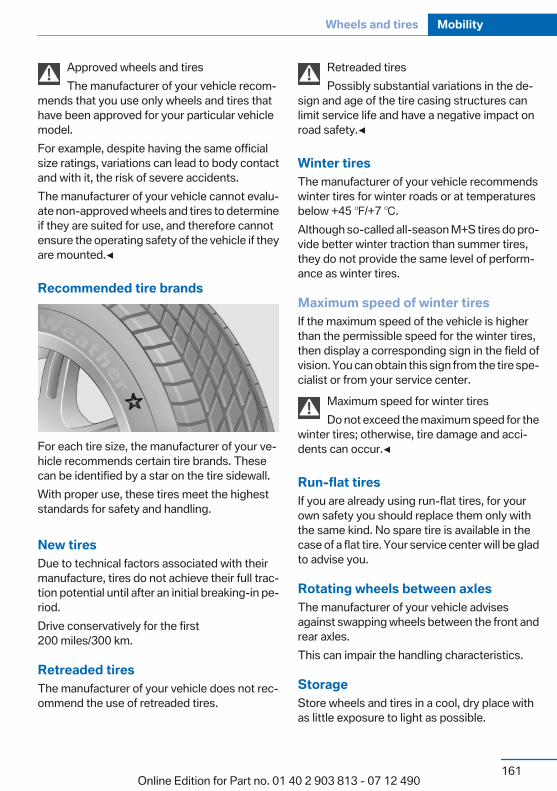
Approved wheels and tiresThe manufacturer of your vehicle recom‐
mends that you use only wheels and tires thathave been approved for your particular vehiclemodel.For example, despite having the same officialsize ratings, variations can lead to body contactand with it, the risk of severe accidents.The manufacturer of your vehicle cannot evalu‐ate non-approved wheels and tires to determineif they are suited for use, and therefore cannotensure the operating safety of the vehicle if theyare mounted.◀
Recommended tire brands
For each tire size, the manufacturer of your ve‐hicle recommends certain tire brands. Thesecan be identified by a star on the tire sidewall.With proper use, these tires meet the higheststandards for safety and handling.
New tiresDue to technical factors associated with theirmanufacture, tires do not achieve their full trac‐tion potential until after an initial breaking-in pe‐riod.Drive conservatively for the first200 miles/300 km.
Retreaded tiresThe manufacturer of your vehicle does not rec‐ommend the use of retreaded tires.
Retreaded tiresPossibly substantial variations in the de‐
sign and age of the tire casing structures canlimit service life and have a negative impact onroad safety.◀
Winter tiresThe manufacturer of your vehicle recommendswinter tires for winter roads or at temperaturesbelow +45 ℉/+7 ℃.Although so-called all-season M+S tires do pro‐vide better winter traction than summer tires,they do not provide the same level of perform‐ance as winter tires.
Maximum speed of winter tiresIf the maximum speed of the vehicle is higherthan the permissible speed for the winter tires,then display a corresponding sign in the field ofvision. You can obtain this sign from the tire spe‐cialist or from your service center.
Maximum speed for winter tiresDo not exceed the maximum speed for the
winter tires; otherwise, tire damage and acci‐dents can occur.◀
Run-flat tiresIf you are already using run-flat tires, for yourown safety you should replace them only withthe same kind. No spare tire is available in thecase of a flat tire. Your service center will be gladto advise you.
Rotating wheels between axlesThe manufacturer of your vehicle advisesagainst swapping wheels between the front andrear axles.This can impair the handling characteristics.
StorageStore wheels and tires in a cool, dry place withas little exposure to light as possible.
Seite 161
Wheels and tires Mobility
161Online Edition for Part no. 01 40 2 903 813 - 07 12 490
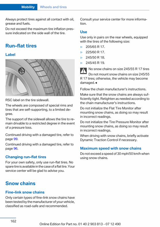
Always protect tires against all contact with oil,grease and fuels.Do not exceed the maximum tire inflation pres‐sure indicated on the side wall of the tire.
Run-flat tiresLabel
RSC label on the tire sidewall.The wheels are composed of special rims andtires that are self-supporting, to a limited de‐gree.The support of the sidewall allows the tire to re‐main drivable to a restricted degree in the eventof a pressure loss.
Continued driving with a damaged tire, refer topage 99.Continued driving with a damaged tire, refer topage 96.
Changing run-flat tiresFor your own safety, only use run-flat tires. Nospare tire is available in the case of a flat tire. Yourservice center will be glad to advise you.
Snow chainsFine-link snow chainsOnly certain types of fine-link snow chains havebeen tested by the manufacturer of your vehicle,classified as road-safe and recommended.
Consult your service center for more informa‐tion.
UseUse only in pairs on the rear wheels, equippedwith the tires of the following size:▷ 205/65 R 17.▷ 225/60 R 17.▷ 245/50 R 18.▷ 245/45 R 19.
No snow chains on size 245/55 R 17 tiresDo not mount snow chains on size 245/55
R 17 tires; otherwise, the vehicle may becomedamaged.◀
Follow the chain manufacturer's instructions.Make sure that the snow chains are always suf‐ficiently tight. Retighten as needed according tothe chain manufacturer's instructions.Do not initialize the Flat Tire Monitor aftermounting snow chains, as doing so may resultin incorrect readings.Do not initialize the Tire Pressure Monitor aftermounting snow chains, as doing so may resultin incorrect readings.When driving with snow chains, briefly activateDynamic Traction Control if necessary.
Maximum speed with snow chainsDo not exceed a speed of 30 mph/50 km/h whenusing snow chains.
Seite 162
Mobility Wheels and tires
162Online Edition for Part no. 01 40 2 903 813 - 07 12 490
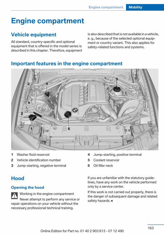
Engine compartmentVehicle equipmentAll standard, country-specific and optionalequipment that is offered in the model series isdescribed in this chapter. Therefore, equipment
is also described that is not available in a vehicle,e. g., because of the selected optional equip‐ment or country variant. This also applies forsafety-related functions and systems.
Important features in the engine compartment
1 Washer fluid reservoir2 Vehicle identification number3 Jump-starting, negative terminal
4 Jump-starting, positive terminal5 Coolant reservoir6 Oil filler neck
HoodOpening the hood
Working in the engine compartmentNever attempt to perform any service or
repair operations on your vehicle without thenecessary professional technical training.
If you are unfamiliar with the statutory guide‐lines, have any work on the vehicle performedonly by a service center.If this work is not carried out properly, there isthe danger of subsequent damage and relatedsafety hazards.◀
Seite 163
Engine compartment Mobility
163Online Edition for Part no. 01 40 2 903 813 - 07 12 490

Never reach into the engine compartmentNever reach into the intermediate spaces
or gaps in the engine compartment. Otherwise,there is risk of injury, e.g. from rotating or hotparts.◀
1. Pull the lever.
2. Press the release handle and open the hood.
3. Be careful of protruding parts on the hood.
Danger of injury when the hood is openThere is a danger of injury from protruding
parts when the hood is open.◀
Closing the hood
Let the hood drop from a height of approx.16 in/40 cm and push down on it to lock it fully.Make sure you hear the engine compartment lidengage.
Hood open when drivingIf you see any signs that the hood is not
completely closed while driving, pull over imme‐diately and close it securely.◀
Danger of pinchingMake sure that the closing path of the
hood is clear; otherwise, injuries may result.◀
Seite 164
Mobility Engine compartment
164Online Edition for Part no. 01 40 2 903 813 - 07 12 490
Engine oilVehicle equipmentAll standard, country-specific and optionalequipment that is offered in the model series isdescribed in this chapter. Therefore, equipmentis also described that is not available in a vehicle,e. g., because of the selected optional equip‐ment or country variant. This also applies forsafety-related functions and systems.
General informationEngine oil consumption depends on drivingstyle and driving conditions, e.g., if your drivingstyle is very sporty engine oil consumption willbe considerably greater.Therefore, regularly check the engine oil levelafter refueling.
Checking the oil levelelectronicallyStatus display
The conceptThe oil level is monitored electronically duringdriving and shown on the Control Display.If the oil level reaches the minimum level, acheck control message is displayed.
RequirementsDepending on the previous displays, the statusdisplay appears when the engine is running orafter the vehicle has been driven for at least 30minutes.
Displaying the oil level1. "Vehicle Info"2. "Vehicle status"
3. "Engine oil level"
Oil level display messagesDifferent messages appear on the display de‐pending on the oil level. Pay attention to thesemessages.If oil level is too low, immediately add 1 USquart/liter of oil.Take care not to add too much engine oil.
Too much engine oilHave the vehicle checked immediately;
otherwise, surplus oil can lead to engine dam‐age.◀
Detailed measurement
The conceptIn the detailed measurement the oil level ischecked and displayed via a scale.During the measurement, the idle speed is in‐creased somewhat.
General informationA detailed measurement is only possible withcertain engines.
Requirements▷ Automatic transmission: selector lever in
transmission position N or P and acceleratornot depressed.
▷ Vehicle is on a level road and the engine isrunning at operating temperature.
Performing a detailed measurementIn order to perform a detailed measurement ofthe engine oil level:
1. "Vehicle Info"2. "Vehicle status"
Seite 165
Engine oil Mobility
165Online Edition for Part no. 01 40 2 903 813 - 07 12 490

3. "Measure engine oil level"4. "Start measurement"The oil level is checked and displayed via a scale.Duration: approx. 1 minute.
Adding engine oilFiller neck
When the indicator lights up in the instrumentcluster, add 1 US quart/liter of engine oil withinthe next 125 miles/200 km.
Protect childrenKeep oil, grease, etc., out of reach of chil‐
dren and heed the warnings on the containersto prevent health risks.◀
Oil types for refillingNotes
No oil additivesOil additives may lead to engine damage.◀
Viscosity grades for engine oilsWhen selecting an engine oil, ensure that
the engine oil belongs to one of the viscositygrades SAE 0W-40, SAE 0W-30, SAE 5W-40,and SAE 5W-30 or malfunctions or engine dam‐age may occur.◀
The engine oil quality is critical for the life of theengine.
Some types of oils in some cases are not avail‐able in all countries.
Approved oil types
Gasoline engine
BMW High Performance SAE 5W-30
BMW Longlife-01
BMW Longlife-01 FE
Additional information about the approvedtypes of oils can be requested from the servicecenter.
Alternative oil typesIf the approved engine oils are not available, upto 1 US quart/liter of an oil with the followingspecification can be added:
Gasoline engine
API SM or superior grade specification
Oil changeAn oil change should be carried out by yourservice center only.
Seite 166
Mobility Engine oil
166Online Edition for Part no. 01 40 2 903 813 - 07 12 490

CoolantVehicle equipmentAll standard, country-specific and optionalequipment that is offered in the model series isdescribed in this chapter. Therefore, equipmentis also described that is not available in a vehicle,e. g., because of the selected optional equip‐ment or country variant. This also applies forsafety-related functions and systems.
General informationDanger of burns from hot engineDo not open the cooling system while the
engine is hot; otherwise, escaping coolant maycause burns.◀
Suitable additivesOnly use suitable additives; otherwise, en‐
gine damage may occur. The additives areharmful to your health.◀
Coolant consists of water and additives.Not all commercially available additives are suit‐able for your vehicle. Ask your service center forsuitable additives.
Coolant levelChecking1. Let the engine cool.2. Turn the cap of the expansion tank slightly
counterclockwise to allow any excess pres‐sure to dissipate, and then open it.
3. The coolant level is correct if it lies betweenthe minimum and maximum marks in thefiller neck.
4. If the coolant is low, slowly add coolant up tothe specified level; do not overfill.
5. Turn the cap until there is an audible click.6. Have the cause of the coolant loss elimi‐
nated as soon as possible.
DisposalComply with the relevant environmentalprotection regulations when disposingof coolant and coolant additives.
Seite 167
Coolant Mobility
167Online Edition for Part no. 01 40 2 903 813 - 07 12 490
MaintenanceVehicle equipmentAll standard, country-specific and optionalequipment that is offered in the model series isdescribed in this chapter. Therefore, equipmentis also described that is not available in a vehicle,e. g., because of the selected optional equip‐ment or country variant. This also applies forsafety-related functions and systems.
BMW Maintenance SystemThe maintenance system directs you to re‐quired maintenance measures and thereby sup‐ports you in maintaining road safety and the op‐erational reliability of the vehicle.
Condition Based Service CBSSensors and special algorithms take into ac‐count the driving conditions of your vehicle.Based on this, Condition Based Service deter‐mines the maintenance requirements.The system makes it possible to adapt theamount of maintenance you need to your userprofile.Detailed information on service requirements,refer to page 78, can be displayed on the ControlDisplay.
Service data in the remote controlInformation on the required maintenance is con‐tinuously stored in the remote control. Yourservice center will read out this data and suggestthe right array of service procedures for your ve‐hicle.Therefore, hand your service specialist the re‐mote control that you used most recently.
Storage periodsStorage periods during which the vehicle bat‐tery was disconnected are not taken into ac‐count.If this occurs, have a service center update thetime-dependent maintenance procedures,such as checking brake fluid and, if necessary,changing the engine oil and the microfilter/acti‐vated-charcoal filter.
Service bookletPerform maintenance work at the service cen‐ter, and record the work in the service booklet.The entries are proof of regular maintenance.
Service and WarrantyInformation Booklet for USmodels and Warranty andService Guide Booklet forCanadian modelsPlease consult your Service and Warranty Infor‐mation Booklet for US models and Warranty andService Guide Booklet for Canadian models foradditional information on service requirements.Maintenance and repair should be performed byyour service center. Make sure to have regularmaintenance procedures recorded in the vehi‐cle's Service and Warranty Information Bookletfor US models, and in the Warranty and ServiceGuide Booklet for Canadian models. These en‐tries are proof of regular maintenance.
Seite 168
Mobility Maintenance
168Online Edition for Part no. 01 40 2 903 813 - 07 12 490
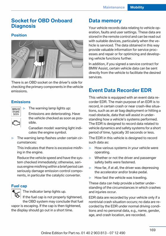
Socket for OBD OnboardDiagnosisPosition
There is an OBD socket on the driver's side forchecking the primary components in the vehicleemissions.
Emissions▷ The warning lamp lights up:
Emissions are deteriorating. Havethe vehicle checked as soon as pos‐sible.Canadian model: warning light indi‐cates the engine symbol.
▷ The warning lamp flashes under certain cir‐cumstances:This indicates that there is excessive misfir‐ing in the engine.Reduce the vehicle speed and have the sys‐tem checked immediately; otherwise, seri‐ous engine misfiring within a brief period canseriously damage emission control compo‐nents, in particular the catalytic converter.
Fuel capThe indicator lamp lights up.If the fuel cap is not properly tightened,the OBD system may conclude that fuel
vapor is escaping. If the cap is then tightened,the display should go out in a short time.
Data memoryYour vehicle records data relating to vehicle op‐eration, faults and user settings. These data arestored in the remote control and can be read outwith suitable devices, particularly when the ve‐hicle is serviced. The data obtained in this wayprovide valuable information for service proc‐esses and repair or for optimizing and develop‐ing vehicle functions further.In addition, if you signed a service contract forBMW Assist, certain vehicle data can be sentdirectly from the vehicle to facilitate the desiredservices.
Event Data Recorder EDRThis vehicle is equipped with an event data re‐corder EDR. The main purpose of an EDR is torecord, in certain crash or near crash-like situa‐tions, such as an air bag deployment or hitting aroad obstacle, data that will assist in under‐standing how a vehicle’s systems performed.The EDR is designed to record data related tovehicle dynamics and safety systems for a shortperiod of time, typically 30 seconds or less.The EDR in this vehicle is designed to recordsuch data as:▷ How various systems in your vehicle were
operating.▷ Whether or not the driver and passenger
safety belts were fastened.▷ How far, if at all, the driver was depressing
the accelerator and/or brake pedal.▷ How fast the vehicle was traveling.These data can help provide a better under‐standing of the circumstances in which crashesand injuries occur.EDR data are recorded by your vehicle only if anontrivial crash situation occurs; no data are re‐corded by the EDR under normal driving condi‐tions and no personal data, e.g., name, gender,age, and crash location, are recorded.
Seite 169
Maintenance Mobility
169Online Edition for Part no. 01 40 2 903 813 - 07 12 490
However, other parties, such as law enforce‐ment, could combine the EDR data with the typeof personally identifying data routinely acquiredduring a crash investigation.To read data recorded by an EDR, special equip‐ment is required, and access to the vehicle or theEDR is needed. In addition to the vehicle manu‐facturer, other parties, such as law enforcement,that have the special equipment, can read theinformation if they have access to the vehicle orthe EDR.
Seite 170
Mobility Maintenance
170Online Edition for Part no. 01 40 2 903 813 - 07 12 490
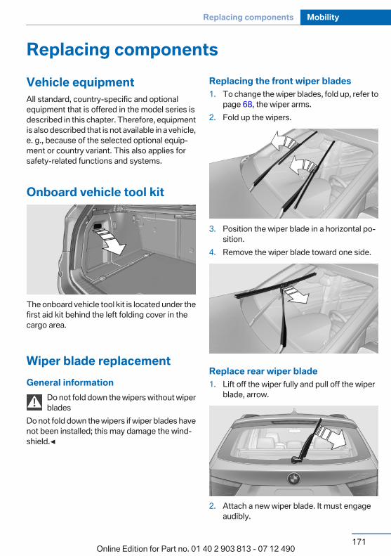
Replacing componentsVehicle equipmentAll standard, country-specific and optionalequipment that is offered in the model series isdescribed in this chapter. Therefore, equipmentis also described that is not available in a vehicle,e. g., because of the selected optional equip‐ment or country variant. This also applies forsafety-related functions and systems.
Onboard vehicle tool kit
The onboard vehicle tool kit is located under thefirst aid kit behind the left folding cover in thecargo area.
Wiper blade replacementGeneral information
Do not fold down the wipers without wiperblades
Do not fold down the wipers if wiper blades havenot been installed; this may damage the wind‐shield.◀
Replacing the front wiper blades1. To change the wiper blades, fold up, refer to
page 68, the wiper arms.2. Fold up the wipers.
3. Position the wiper blade in a horizontal po‐sition.
4. Remove the wiper blade toward one side.
Replace rear wiper blade1. Lift off the wiper fully and pull off the wiper
blade, arrow.
2. Attach a new wiper blade. It must engageaudibly.
Seite 171
Replacing components Mobility
171Online Edition for Part no. 01 40 2 903 813 - 07 12 490

Lamp and bulb replacementNotes
Lamps and bulbsLamps and bulbs make an essential contributionto vehicle safety.The manufacturer of the vehicle recommendsthat you entrust corresponding procedures tothe service center if you are unfamiliar with themor they are not described here.You can obtain a selection of replacement bulbsat the service center.
Danger of burnsOnly change bulbs when they are cool;
otherwise, there is the danger of gettingburned.◀
Working on the lighting systemWhen working on the lighting system, you
should always switch off the lights affected toprevent short circuits.To avoid possible injury or equipment damagewhen replacing bulbs, observe any instructionsprovided by the bulb manufacturer.◀
Do not perform work/bulb replacement onxenon headlamps
Have any work on the xenon lighting system, in‐cluding bulb replacement, performed only by aservice center. Due to the high voltage presentin the system, there is the danger of fatal injuriesif work is carried out improperly.◀
Do not touch the bulbsDo not touch the glass of new bulbs with
your bare hands, as even minute amounts ofcontamination will burn into the bulb's surfaceand reduce its service life.Use a clean tissue, cloth or something similar, orhold the bulb by its base.◀
Light-emitting diodes (LEDs)Light-emitting diodes installed behind a coverserve as the light source for controls, display el‐ements and other equipment.These light-emitting diodes, which are relatedto conventional lasers, are officially designatedas Class 1 light-emitting diodes.
Do not remove the coversDo not remove the covers, and never stare
into the unfiltered light for several hours; other‐wise, irritation of the retina could result.◀
Headlamp glassCondensation can form on the inside of the ex‐ternal lamps in cool or humid weather. Whendriving with the light switched on, the conden‐sation evaporates after a short time. The head‐lamp glasses do not need to be changed.If the headlamps do not dim despite driving withthe light switched on, increasing humidity forms,e. g. water droplets in the light, have the servicecenter check this.
Front lamps, bulb replacement
At a glance
Halogen headlamps
1 High beams/headlamp flasher2 Parking lamps3 Low beams4 Turn signal/side marker light
Seite 172
Mobility Replacing components
172Online Edition for Part no. 01 40 2 903 813 - 07 12 490
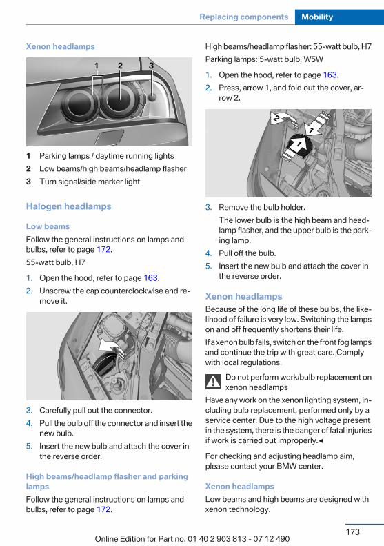
Xenon headlamps
1 Parking lamps / daytime running lights2 Low beams/high beams/headlamp flasher3 Turn signal/side marker light
Halogen headlamps
Low beamsFollow the general instructions on lamps andbulbs, refer to page 172.55-watt bulb, H7
1. Open the hood, refer to page 163.2. Unscrew the cap counterclockwise and re‐
move it.
3. Carefully pull out the connector.4. Pull the bulb off the connector and insert the
new bulb.5. Insert the new bulb and attach the cover in
the reverse order.
High beams/headlamp flasher and parkinglampsFollow the general instructions on lamps andbulbs, refer to page 172.
High beams/headlamp flasher: 55-watt bulb, H7Parking lamps: 5-watt bulb, W5W
1. Open the hood, refer to page 163.2. Press, arrow 1, and fold out the cover, ar‐
row 2.
3. Remove the bulb holder.The lower bulb is the high beam and head‐lamp flasher, and the upper bulb is the park‐ing lamp.
4. Pull off the bulb.5. Insert the new bulb and attach the cover in
the reverse order.
Xenon headlampsBecause of the long life of these bulbs, the like‐lihood of failure is very low. Switching the lampson and off frequently shortens their life.If a xenon bulb fails, switch on the front fog lampsand continue the trip with great care. Complywith local regulations.
Do not perform work/bulb replacement onxenon headlamps
Have any work on the xenon lighting system, in‐cluding bulb replacement, performed only by aservice center. Due to the high voltage presentin the system, there is the danger of fatal injuriesif work is carried out improperly.◀
For checking and adjusting headlamp aim,please contact your BMW center.
Xenon headlampsLow beams and high beams are designed withxenon technology.
Seite 173
Replacing components Mobility
173Online Edition for Part no. 01 40 2 903 813 - 07 12 490

The parking lamps and daylight running lightsare made using LED technology.Contact your service center in the event of amalfunction.
Front fog lampsFollow the general instructions on lamps andbulbs, refer to page 172.Front fog lamps in vehicles equipped with Adap‐tive Light Control: 55-watt bulb, H11Front fog lamps without Adaptive Light Control:35-watt bulb, H8
1. Insert the screwdriver from the onboard ve‐hicle tool kit, with the flat side facing out‐ward, past the removal hook and onto theclip, arrow 1.
2. Turn the screwdriver by 90°, arrow 2.3. Press the removal hook upward, arrow, and
remove the front fog lamp from the front us‐ing the hook.
4. Detach the connector.
5. Turn the bulb bracket and remove it.
6. Remove the bulb and replace it.7. Proceed in reverse order to insert the front
fog lamp. Note the guide rails in doing so.
Turn signalFollow the general instructions on lamps andbulbs, refer to page 172.The turn signals are located next to each lowbeam in the engine compartment.21-watt bulb, PY 21W
1. Open the hood, refer to page 163.2. Unscrew the cap counterclockwise and re‐
move it carefully.
Seite 174
Mobility Replacing components
174Online Edition for Part no. 01 40 2 903 813 - 07 12 490
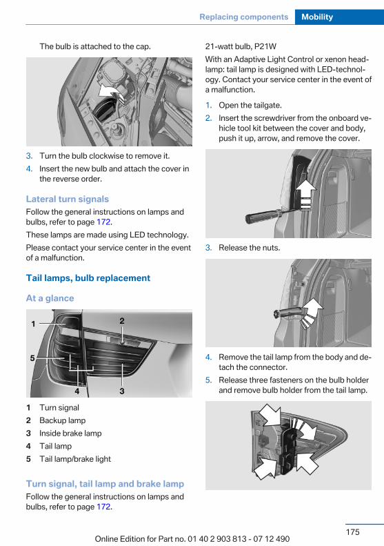
The bulb is attached to the cap.
3. Turn the bulb clockwise to remove it.4. Insert the new bulb and attach the cover in
the reverse order.
Lateral turn signalsFollow the general instructions on lamps andbulbs, refer to page 172.These lamps are made using LED technology.Please contact your service center in the eventof a malfunction.
Tail lamps, bulb replacement
At a glance
1 Turn signal2 Backup lamp3 Inside brake lamp4 Tail lamp5 Tail lamp/brake light
Turn signal, tail lamp and brake lampFollow the general instructions on lamps andbulbs, refer to page 172.
21-watt bulb, P21WWith an Adaptive Light Control or xenon head‐lamp: tail lamp is designed with LED-technol‐ogy. Contact your service center in the event ofa malfunction.
1. Open the tailgate.2. Insert the screwdriver from the onboard ve‐
hicle tool kit between the cover and body,push it up, arrow, and remove the cover.
3. Release the nuts.
4. Remove the tail lamp from the body and de‐tach the connector.
5. Release three fasteners on the bulb holderand remove bulb holder from the tail lamp.
Seite 175
Replacing components Mobility
175Online Edition for Part no. 01 40 2 903 813 - 07 12 490
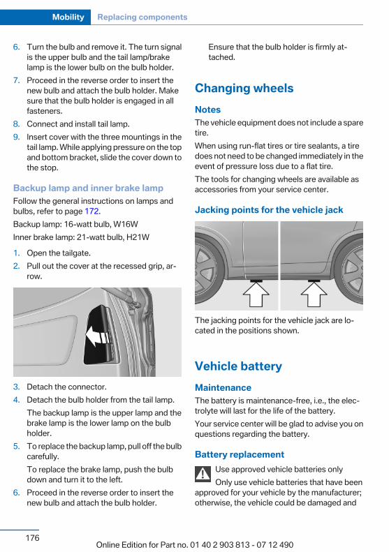
6. Turn the bulb and remove it. The turn signalis the upper bulb and the tail lamp/brakelamp is the lower bulb on the bulb holder.
7. Proceed in the reverse order to insert thenew bulb and attach the bulb holder. Makesure that the bulb holder is engaged in allfasteners.
8. Connect and install tail lamp.9. Insert cover with the three mountings in the
tail lamp. While applying pressure on the topand bottom bracket, slide the cover down tothe stop.
Backup lamp and inner brake lampFollow the general instructions on lamps andbulbs, refer to page 172.Backup lamp: 16-watt bulb, W16WInner brake lamp: 21-watt bulb, H21W
1. Open the tailgate.2. Pull out the cover at the recessed grip, ar‐
row.
3. Detach the connector.4. Detach the bulb holder from the tail lamp.
The backup lamp is the upper lamp and thebrake lamp is the lower lamp on the bulbholder.
5. To replace the backup lamp, pull off the bulbcarefully.To replace the brake lamp, push the bulbdown and turn it to the left.
6. Proceed in the reverse order to insert thenew bulb and attach the bulb holder.
Ensure that the bulb holder is firmly at‐tached.
Changing wheelsNotesThe vehicle equipment does not include a sparetire.When using run-flat tires or tire sealants, a tiredoes not need to be changed immediately in theevent of pressure loss due to a flat tire.The tools for changing wheels are available asaccessories from your service center.
Jacking points for the vehicle jack
The jacking points for the vehicle jack are lo‐cated in the positions shown.
Vehicle batteryMaintenanceThe battery is maintenance-free, i.e., the elec‐trolyte will last for the life of the battery.Your service center will be glad to advise you onquestions regarding the battery.
Battery replacementUse approved vehicle batteries onlyOnly use vehicle batteries that have been
approved for your vehicle by the manufacturer;otherwise, the vehicle could be damaged and
Seite 176
Mobility Replacing components
176Online Edition for Part no. 01 40 2 903 813 - 07 12 490
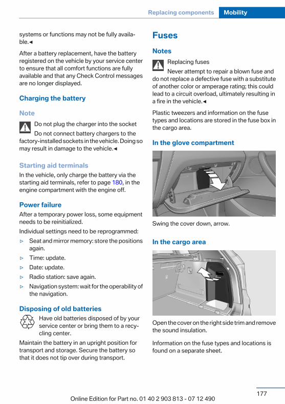
systems or functions may not be fully availa‐ble.◀
After a battery replacement, have the batteryregistered on the vehicle by your service centerto ensure that all comfort functions are fullyavailable and that any Check Control messagesare no longer displayed.
Charging the battery
NoteDo not plug the charger into the socketDo not connect battery chargers to the
factory-installed sockets in the vehicle. Doing somay result in damage to the vehicle.◀
Starting aid terminalsIn the vehicle, only charge the battery via thestarting aid terminals, refer to page 180, in theengine compartment with the engine off.
Power failureAfter a temporary power loss, some equipmentneeds to be reinitialized.Individual settings need to be reprogrammed:▷ Seat and mirror memory: store the positions
again.▷ Time: update.▷ Date: update.▷ Radio station: save again.▷ Navigation system: wait for the operability of
the navigation.
Disposing of old batteriesHave old batteries disposed of by yourservice center or bring them to a recy‐cling center.
Maintain the battery in an upright position fortransport and storage. Secure the battery sothat it does not tip over during transport.
FusesNotes
Replacing fusesNever attempt to repair a blown fuse and
do not replace a defective fuse with a substituteof another color or amperage rating; this couldlead to a circuit overload, ultimately resulting ina fire in the vehicle.◀
Plastic tweezers and information on the fusetypes and locations are stored in the fuse box inthe cargo area.
In the glove compartment
Swing the cover down, arrow.
In the cargo area
Open the cover on the right side trim and removethe sound insulation.
Information on the fuse types and locations isfound on a separate sheet.
Seite 177
Replacing components Mobility
177Online Edition for Part no. 01 40 2 903 813 - 07 12 490
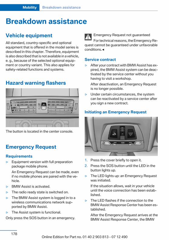
Breakdown assistanceVehicle equipmentAll standard, country-specific and optionalequipment that is offered in the model series isdescribed in this chapter. Therefore, equipmentis also described that is not available in a vehicle,e. g., because of the selected optional equip‐ment or country variant. This also applies forsafety-related functions and systems.
Hazard warning flashers
The button is located in the center console.
Emergency RequestRequirements▷ Equipment version with full preparation
package mobile phone.An Emergency Request can be made, evenif no mobile phones are paired with the ve‐hicle.
▷ BMW Assist is activated.▷ The radio ready state is switched on.▷ The BMW Assist system is logged in to a
wireless communications network sup‐ported by BMW Assist.
▷ The Assist system is functional.Only press the SOS button in an emergency.
Emergency Request not guaranteedFor technical reasons, the Emergency Re‐
quest cannot be guaranteed under unfavorableconditions.◀
Service contract▷ After your contract with BMW Assist has ex‐
pired, the BMW Assist system can be deac‐tivated by the service center without youhaving to visit a workshop.After deactivation, an Emergency Requestis no longer possible.
▷ Under certain circumstances, the systemcan be reactivated by a service center afteryou sign a new contract.
Initiating an Emergency Request
1. Press the cover briefly to open it.2. Press the SOS button until the LED in the
button lights up.▷ The LED lights up: an Emergency Request
was initiated.If the situation allows, wait in your vehicleuntil the voice connection has been estab‐lished.
▷ The LED flashes if the connection to theBMW Assist Response Center has been es‐tablished.After the Emergency Request arrives at theBMW Assist Response Center, the BMW
Seite 178
Mobility Breakdown assistance
178Online Edition for Part no. 01 40 2 903 813 - 07 12 490

Assist Response Center contacts you andtakes further steps to help you.Even if you are unable to respond, the BMWAssist Response Center can take furthersteps to help you under certain circumstan‐ces.For this purpose, data that are used to de‐termine the necessary rescue measures,such as the current position of the vehicle ifit can be established, are transmitted to theBMW Assist Response Center.
▷ If the LED is flashing but the BMW AssistResponse Center cannot be heard on thehands-free system, the hands-free systemmay be malfunctioning. However, the BMWAssist Response Center may still be able tohear you.
Initiating an Emergency RequestautomaticallyUnder certain conditions, an Emergency Re‐quest is automatically initiated immediately aftera severe accident. Automatic Collision Notifica‐tion is not affected by pressing the SOS button.
Warning triangle
The warning triangle is located behind the left-hand cover in the cargo area.To remove, loosen the bracket.
First aid kit
The first aid kit is located behind the left-handcover in the cargo area.
Some of the articles have a limited service life.Check the expiration dates of the contents reg‐ularly and replace any expired items promptly.
Roadside AssistanceService availabilityRoadside Assistance can be reached around theclock in many countries. You can obtain assis‐tance there in the event of a vehicle breakdown.
Roadside AssistanceThe Roadside Assistance phone number can beviewed on the iDrive or a connection to RoadsideAssistance can be established directly.
Jump-startingNotesIf the battery is discharged, an engine can bestarted using the battery of another vehicle andtwo jumper cables. Only use jumper cables withfully insulated clamp handles.To prevent personal injury or damage to bothvehicles, adhere strictly to the following proce‐dure.
Seite 179
Breakdown assistance Mobility
179Online Edition for Part no. 01 40 2 903 813 - 07 12 490
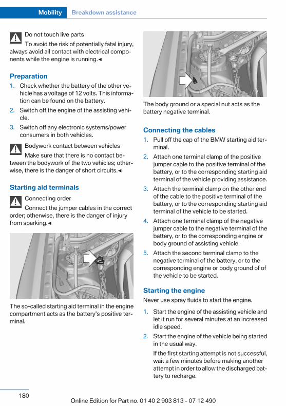
Do not touch live partsTo avoid the risk of potentially fatal injury,
always avoid all contact with electrical compo‐nents while the engine is running.◀
Preparation1. Check whether the battery of the other ve‐
hicle has a voltage of 12 volts. This informa‐tion can be found on the battery.
2. Switch off the engine of the assisting vehi‐cle.
3. Switch off any electronic systems/powerconsumers in both vehicles.
Bodywork contact between vehiclesMake sure that there is no contact be‐
tween the bodywork of the two vehicles; other‐wise, there is the danger of short circuits.◀
Starting aid terminalsConnecting orderConnect the jumper cables in the correct
order; otherwise, there is the danger of injuryfrom sparking.◀
The so-called starting aid terminal in the enginecompartment acts as the battery's positive ter‐minal.
The body ground or a special nut acts as thebattery negative terminal.
Connecting the cables1. Pull off the cap of the BMW starting aid ter‐
minal.2. Attach one terminal clamp of the positive
jumper cable to the positive terminal of thebattery, or to the corresponding starting aidterminal of the vehicle providing assistance.
3. Attach the terminal clamp on the other endof the cable to the positive terminal of thebattery, or to the corresponding starting aidterminal of the vehicle to be started.
4. Attach one terminal clamp of the negativejumper cable to the negative terminal of thebattery, or to the corresponding engine orbody ground of assisting vehicle.
5. Attach the second terminal clamp to thenegative terminal of the battery, or to thecorresponding engine or body ground of ofthe vehicle to be started.
Starting the engineNever use spray fluids to start the engine.
1. Start the engine of the assisting vehicle andlet it run for several minutes at an increasedidle speed.
2. Start the engine of the vehicle being startedin the usual way.If the first starting attempt is not successful,wait a few minutes before making anotherattempt in order to allow the discharged bat‐tery to recharge.
Seite 180
Mobility Breakdown assistance
180Online Edition for Part no. 01 40 2 903 813 - 07 12 490
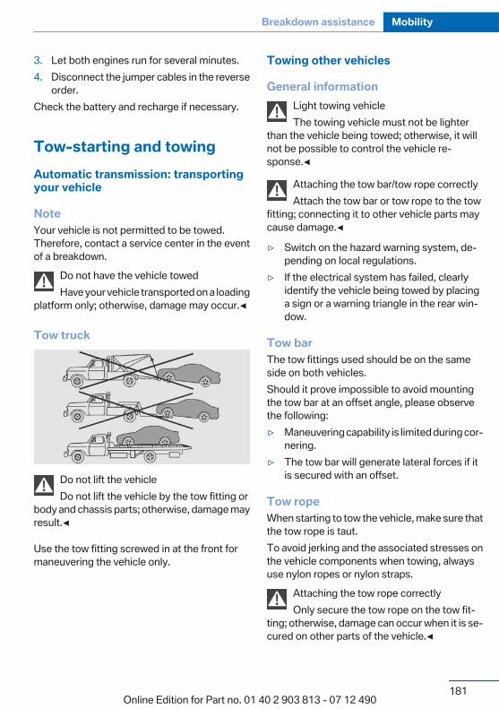
3. Let both engines run for several minutes.4. Disconnect the jumper cables in the reverse
order.Check the battery and recharge if necessary.
Tow-starting and towingAutomatic transmission: transportingyour vehicle
NoteYour vehicle is not permitted to be towed.Therefore, contact a service center in the eventof a breakdown.
Do not have the vehicle towedHave your vehicle transported on a loading
platform only; otherwise, damage may occur.◀
Tow truck
Do not lift the vehicleDo not lift the vehicle by the tow fitting or
body and chassis parts; otherwise, damage mayresult.◀
Use the tow fitting screwed in at the front formaneuvering the vehicle only.
Towing other vehicles
General informationLight towing vehicleThe towing vehicle must not be lighter
than the vehicle being towed; otherwise, it willnot be possible to control the vehicle re‐sponse.◀
Attaching the tow bar/tow rope correctlyAttach the tow bar or tow rope to the tow
fitting; connecting it to other vehicle parts maycause damage.◀
▷ Switch on the hazard warning system, de‐pending on local regulations.
▷ If the electrical system has failed, clearlyidentify the vehicle being towed by placinga sign or a warning triangle in the rear win‐dow.
Tow barThe tow fittings used should be on the sameside on both vehicles.Should it prove impossible to avoid mountingthe tow bar at an offset angle, please observethe following:▷ Maneuvering capability is limited during cor‐
nering.▷ The tow bar will generate lateral forces if it
is secured with an offset.
Tow ropeWhen starting to tow the vehicle, make sure thatthe tow rope is taut.To avoid jerking and the associated stresses onthe vehicle components when towing, alwaysuse nylon ropes or nylon straps.
Attaching the tow rope correctlyOnly secure the tow rope on the tow fit‐
ting; otherwise, damage can occur when it is se‐cured on other parts of the vehicle.◀
Seite 181
Breakdown assistance Mobility
181Online Edition for Part no. 01 40 2 903 813 - 07 12 490
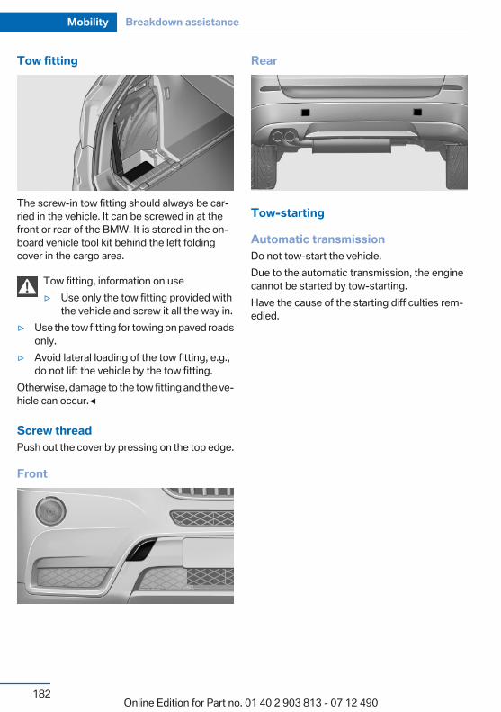
Tow fitting
The screw-in tow fitting should always be car‐ried in the vehicle. It can be screwed in at thefront or rear of the BMW. It is stored in the on‐board vehicle tool kit behind the left foldingcover in the cargo area.
Tow fitting, information on use▷ Use only the tow fitting provided with
the vehicle and screw it all the way in.▷ Use the tow fitting for towing on paved roads
only.▷ Avoid lateral loading of the tow fitting, e.g.,
do not lift the vehicle by the tow fitting.Otherwise, damage to the tow fitting and the ve‐hicle can occur.◀
Screw threadPush out the cover by pressing on the top edge.
Front
Rear
Tow-starting
Automatic transmissionDo not tow-start the vehicle.Due to the automatic transmission, the enginecannot be started by tow-starting.Have the cause of the starting difficulties rem‐edied.
Seite 182
Mobility Breakdown assistance
182Online Edition for Part no. 01 40 2 903 813 - 07 12 490
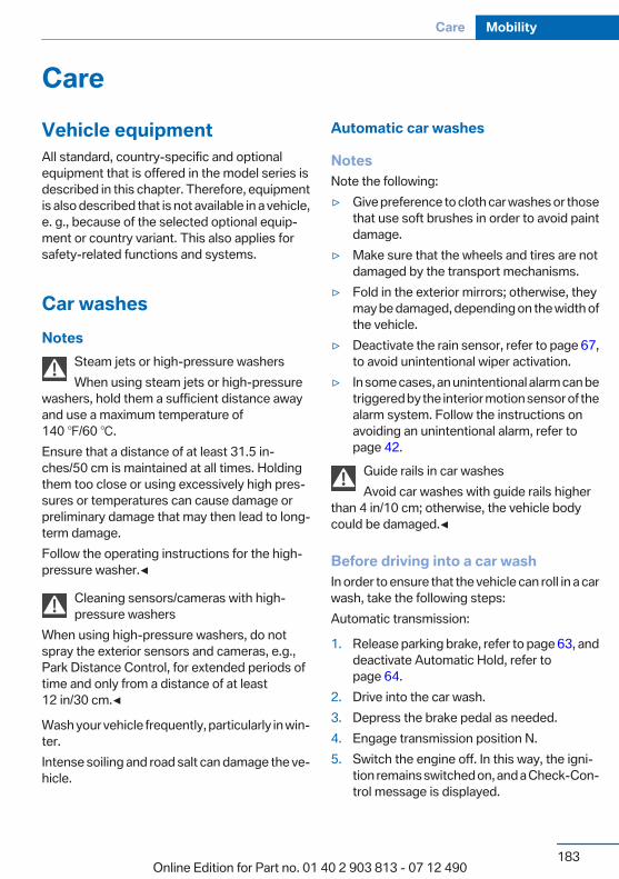
CareVehicle equipmentAll standard, country-specific and optionalequipment that is offered in the model series isdescribed in this chapter. Therefore, equipmentis also described that is not available in a vehicle,e. g., because of the selected optional equip‐ment or country variant. This also applies forsafety-related functions and systems.
Car washesNotes
Steam jets or high-pressure washersWhen using steam jets or high-pressure
washers, hold them a sufficient distance awayand use a maximum temperature of140 ℉/60 ℃.Ensure that a distance of at least 31.5 in‐ches/50 cm is maintained at all times. Holdingthem too close or using excessively high pres‐sures or temperatures can cause damage orpreliminary damage that may then lead to long-term damage.Follow the operating instructions for the high-pressure washer.◀
Cleaning sensors/cameras with high-pressure washers
When using high-pressure washers, do notspray the exterior sensors and cameras, e.g.,Park Distance Control, for extended periods oftime and only from a distance of at least12 in/30 cm.◀
Wash your vehicle frequently, particularly in win‐ter.Intense soiling and road salt can damage the ve‐hicle.
Automatic car washes
NotesNote the following:▷ Give preference to cloth car washes or those
that use soft brushes in order to avoid paintdamage.
▷ Make sure that the wheels and tires are notdamaged by the transport mechanisms.
▷ Fold in the exterior mirrors; otherwise, theymay be damaged, depending on the width ofthe vehicle.
▷ Deactivate the rain sensor, refer to page 67,to avoid unintentional wiper activation.
▷ In some cases, an unintentional alarm can betriggered by the interior motion sensor of thealarm system. Follow the instructions onavoiding an unintentional alarm, refer topage 42.
Guide rails in car washesAvoid car washes with guide rails higher
than 4 in/10 cm; otherwise, the vehicle bodycould be damaged.◀
Before driving into a car washIn order to ensure that the vehicle can roll in a carwash, take the following steps:Automatic transmission:
1. Release parking brake, refer to page 63, anddeactivate Automatic Hold, refer topage 64.
2. Drive into the car wash.3. Depress the brake pedal as needed.4. Engage transmission position N.5. Switch the engine off. In this way, the igni‐
tion remains switched on, and a Check-Con‐trol message is displayed.
Seite 183
Care Mobility
183Online Edition for Part no. 01 40 2 903 813 - 07 12 490
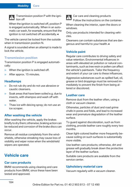
Transmission position P with the igni‐tion off
When the ignition is switched off, position Pis engaged automatically. When in an auto‐matic car wash, for example, ensure that theignition is not switched off accidentally.◀
The vehicle cannot be locked from the outsidewhen in transmission position N.A signal is sounded when an attempt is made tolock the vehicle.
Transmission positionTransmission position P is engaged automati‐cally:▷ When the ignition is switched off.▷ After approx. 15 minutes.
Headlamps▷ Do not rub dry and do not use abrasive or
caustic cleansers.▷ Soak areas that have been soiled e.g. due to
insects, with shampoo and wash off withwater.
▷ Thaw ice with deicing spray; do not use anice scraper.
After washing the vehicleAfter washing the vehicle, apply the brakesbriefly to dry them; otherwise, braking action canbe reduced and corrosion of the brake discs canoccur.Remove all residue completely from the wind‐shields, otherwise streaking may cause loss ofvisibility and wiper noise when the windshieldwipers are operated.
Vehicle careCar care productsBMW recommends using cleaning and careproducts from BMW, since these have beentested and approved.
Car care and cleaning productsFollow the instructions on the container.
When cleaning the interior, open the doors orwindows.Only use products intended for cleaning vehi‐cles.Cleansers can contain substances that are dan‐gerous and harmful to your health.◀
Vehicle paintRegular care contributes to driving safety andvalue retention. Environmental influences inareas with elevated air pollution or natural con‐taminants, such as tree resin or pollen can affectthe vehicle's paintwork. Tailor the frequencyand extent of your car care to these influences.Aggressive substances such as spilled fuel, oil,grease or bird droppings must be removed im‐mediately to prevent the finish from being al‐tered or discolored.
Leather careRemove dust from the leather often, using acloth or vacuum cleaner.Otherwise, particles of dust and road grimechafe in pores and folds, and lead to increasedwear and premature degradation of the leathersurface.To guard against discoloration, such as fromclothing, provide leather care roughly every twomonths.Clean light-colored leather more frequently be‐cause soiling on such surfaces is substantiallymore visible.Use leather care products; otherwise, dirt andgrease will gradually break down the protectivelayer of the leather surface.Suitable care products are available from theservice center.
Upholstery material careVacuum regularly with a vacuum cleaner.
Seite 184
Mobility Care
184Online Edition for Part no. 01 40 2 903 813 - 07 12 490

If they are very dirty, e.g., beverage stains, use asoft sponge or microfiber cloth with a suitableinterior cleaner.Clean the upholstery down to the seams usinglarge sweeping motions. Avoid rubbing the ma‐terial vigorously.
Damage from Velcro® fastenersOpen Velcro® fasteners on pants or other
articles of clothing can damage the seat covers.Ensure that any Velcro® fasteners are closed.◀
Caring for special components
Light-alloy wheelsUse wheel cleaner, particularly during the wintermonths. Do not use aggressive, acidic, stronglyalkaline or abrasive cleaners, or steam jetsabove 140 ℉/60 ℃; follow the manufacturer'sinstructions.
Chrome surfacesCarefully clean components such as the radiatorgrille or door handles with an ample supply ofwater, possibly with shampoo added, particu‐larly when they have been exposed to road salt.
Rubber componentsAside from water, treat only with rubber cleans‐ers.When cleaning rubber seals, do not use any sil‐icon-containing car care products in order toavoid damage or reduced noise damping.
Fine wood partsClean fine wood facing and fine wood compo‐nents only with a moist rag. Then dry with a softcloth.
Plastic componentsThese include:▷ Imitation leather surfaces.▷ Headliner.
▷ Lamp lenses.▷ Instrument cluster cover.▷ Matte black spray-coated components.▷ Painted parts in the interior.Clean with a microfiber cloth.Lightly dampen the cloth with water.Do not soak the headliner.
Do not use cleansers that contain alcoholor solvents
Do not use cleansers that contain alcohol or sol‐vents, such as lacquer thinners, heavy-dutygrease removers, fuel, or such; this could lead tosurface damage.◀
Safety beltsDirty belt straps impede the reeling action andthus have a negative impact on safety.
Chemical cleaningDo not clean chemically; this can destroy
the webbing.◀
Use only a mild soapy solution, with the safetybelts clipped into their buckles.Do not allow the reels to retract the safety beltsuntil they are dry.
Carpets and floor matsNo objects in the area around the pedalsKeep floor mats, carpets, and any other
objects out of the area of motion of the pedals;otherwise, the function of the pedals could beimpeded while drivingDo not place additional floor mats over existingmats or other objects.Only use floor mats that have been approved forthe vehicle and can be properly fixed in place.Ensure that the floor mats are securely fastenedagain after they were removed for cleaning, forexample.◀
Floor mats can be removed from the passengercompartment for cleaning.
Seite 185
Care Mobility
185Online Edition for Part no. 01 40 2 903 813 - 07 12 490
If the floor carpets are very dirty, clean with amicrofiber cloth and water or a textile cleaner. Toprevent matting of the carpet, rub back and forthin the direction of travel only.
Sensors/camerasTo clean sensors and cameras, use a cloth mois‐tened with a small amount of glass cleaner.
Displays/screensClean the displays with an antistatic microfibercloth.
Cleaning displaysDo not use chemical or household cleans‐
ers.Keep all fluids and moisture away from the unit.Otherwise, they could affect or damage surfa‐ces or electrical components.Avoid pressing too hard when cleaning and donot use abrasive materials; otherwise, damagecan result.◀
Long-term vehicle storageYour service center can advise you on what toconsider when storing the vehicle for longerthan three months.
Seite 186
Mobility Care
186Online Edition for Part no. 01 40 2 903 813 - 07 12 490

Seite 187
Care Mobility
187Online Edition for Part no. 01 40 2 903 813 - 07 12 490

Online Edition for Part no. 01 40 2 903 813 - 07 12 490
ReferenceThis chapter contains technical data, short
commands for the voice activation system, and anindex that will quickly take you to the information
you need.
Online Edition for Part no. 01 40 2 903 813 - 07 12 490

Technical dataVehicle equipmentAll standard, country-specific and optionalequipment that is offered in the model series isdescribed in this chapter. Therefore, equipment
is also described that is not available in a vehicle,e. g., because of the selected optional equip‐ment or country variant. This also applies forsafety-related functions and systems.
DimensionsWidth, height
1 Vehicle height: 66 inches/1,675 mm2 Vehicle width without mirrors: 74 inches/
1,881 mm
3 Vehicle width with mirrors: 82.6 in‐ches / 2,098 mm
Seite 190
Reference Technical data
190Online Edition for Part no. 01 40 2 903 813 - 07 12 490
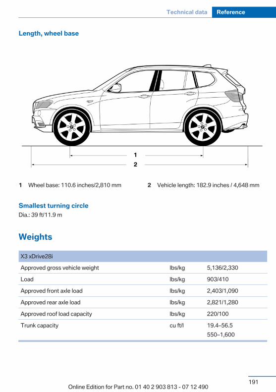
Length, wheel base
1 Wheel base: 110.6 inches/2,810 mm 2 Vehicle length: 182.9 inches / 4,648 mm
Smallest turning circleDia.: 39 ft/11.9 m
Weights
X3 xDrive28i
Approved gross vehicle weight lbs/kg 5,136/2,330
Load lbs/kg 903/410
Approved front axle load lbs/kg 2,403/1,090
Approved rear axle load lbs/kg 2,821/1,280
Approved roof load capacity lbs/kg 220/100
Trunk capacity cu ft/l 19.4–56.5550–1,600
Seite 191
Technical data Reference
191Online Edition for Part no. 01 40 2 903 813 - 07 12 490

X3 xDrive35i
Approved gross vehicle weight lbs/kg 5,214/2,365
Load lbs/kg 903/410
Approved front axle load lbs/kg 2,447/1,110
Approved rear axle load lbs/kg 2,844/1,290
Approved roof load capacity lbs/kg 220/100
Cargo area capacity cu ft/l 19.4–56.5550–1,600
Capacities
US gal/liters Notes
Fuel tank 17.7/67 Fuel quality, refer topage 154
Windshield and headlampwasher system
1.3/5
Seite 192
Reference Technical data
192Online Edition for Part no. 01 40 2 903 813 - 07 12 490
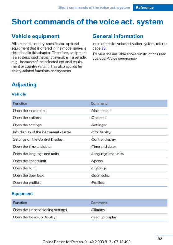
Short commands of the voice act. systemVehicle equipmentAll standard, country-specific and optionalequipment that is offered in the model series isdescribed in this chapter. Therefore, equipmentis also described that is not available in a vehicle,e. g., because of the selected optional equip‐ment or country variant. This also applies forsafety-related functions and systems.
General informationInstructions for voice activation system, refer topage 23.To have the available spoken instructions readout loud: ›Voice commands‹
AdjustingVehicle
Function Command
Open the main menu. ›Main menu‹
Open the options. ›Options‹
Open the settings. ›Settings‹
Info display of the instrument cluster. ›Info Display‹
Settings on the Control Display. ›Control display‹
Open the time and date. ›Time and date‹
Open the language and units. ›Language and units‹
Open the speed limit. ›Speed‹
Open the light. ›Lighting‹
Open the door lock. ›Door locks‹
Open the profiles. ›Profiles‹
Equipment
Function Command
Open the air conditioning settings. ›Climate‹
Open the Head-up Display. ›head up display‹
Seite 193
Short commands of the voice act. system Reference
193Online Edition for Part no. 01 40 2 903 813 - 07 12 490
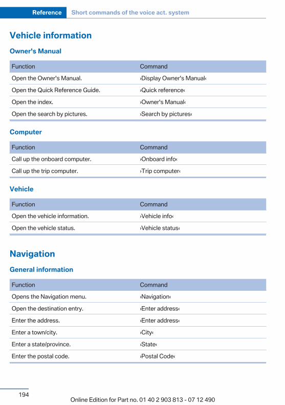
Vehicle informationOwner's Manual
Function Command
Open the Owner's Manual. ›Display Owner's Manual‹
Open the Quick Reference Guide. ›Quick reference‹
Open the index. ›Owner's Manual‹
Open the search by pictures. ›Search by pictures‹
Computer
Function Command
Call up the onboard computer. ›Onboard info‹
Call up the trip computer. ›Trip computer‹
Vehicle
Function Command
Open the vehicle information. ›Vehicle info‹
Open the vehicle status. ›Vehicle status‹
NavigationGeneral information
Function Command
Opens the Navigation menu. ›Navigation‹
Open the destination entry. ›Enter address‹
Enter the address. ›Enter address‹
Enter a town/city. ›City‹
Enter a state/province. ›State‹
Enter the postal code. ›Postal Code‹
Seite 194
Reference Short commands of the voice act. system
194Online Edition for Part no. 01 40 2 903 813 - 07 12 490
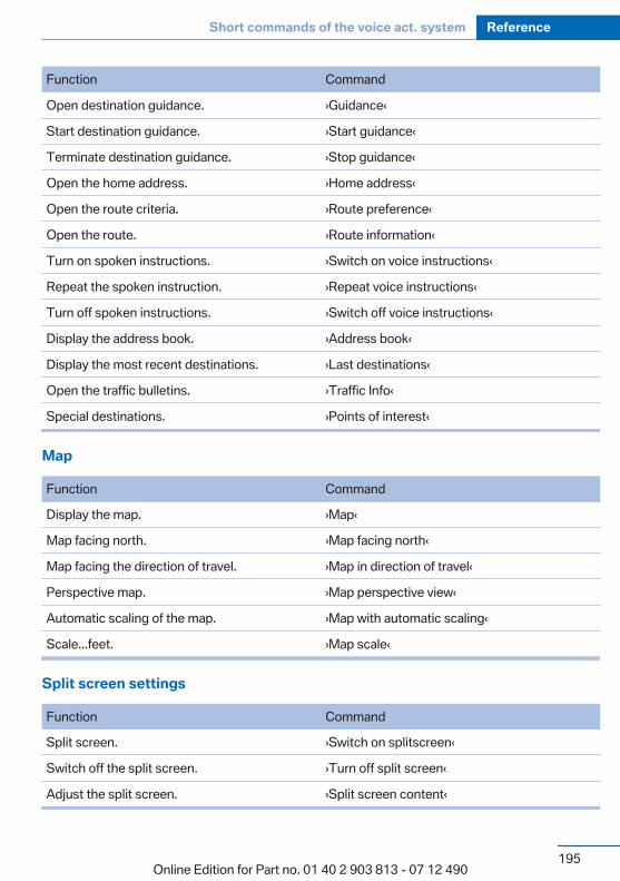
Function Command
Open destination guidance. ›Guidance‹
Start destination guidance. ›Start guidance‹
Terminate destination guidance. ›Stop guidance‹
Open the home address. ›Home address‹
Open the route criteria. ›Route preference‹
Open the route. ›Route information‹
Turn on spoken instructions. ›Switch on voice instructions‹
Repeat the spoken instruction. ›Repeat voice instructions‹
Turn off spoken instructions. ›Switch off voice instructions‹
Display the address book. ›Address book‹
Display the most recent destinations. ›Last destinations‹
Open the traffic bulletins. ›Traffic Info‹
Special destinations. ›Points of interest‹
Map
Function Command
Display the map. ›Map‹
Map facing north. ›Map facing north‹
Map facing the direction of travel. ›Map in direction of travel‹
Perspective map. ›Map perspective view‹
Automatic scaling of the map. ›Map with automatic scaling‹
Scale...feet. ›Map scale‹
Split screen settings
Function Command
Split screen. ›Switch on splitscreen‹
Switch off the split screen. ›Turn off split screen‹
Adjust the split screen. ›Split screen content‹
Seite 195
Short commands of the voice act. system Reference
195Online Edition for Part no. 01 40 2 903 813 - 07 12 490
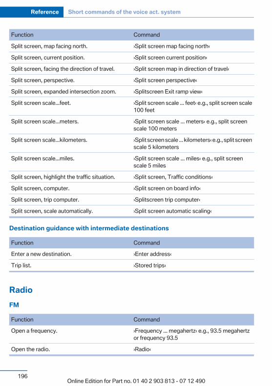
Function Command
Split screen, map facing north. ›Split screen map facing north‹
Split screen, current position. ›Split screen current position‹
Split screen, facing the direction of travel. ›Split screen map in direction of travel‹
Split screen, perspective. ›Split screen perspective‹
Split screen, expanded intersection zoom. ›Splitscreen Exit ramp view‹
Split screen scale...feet. ›Split screen scale ... feet‹ e.g., split screen scale100 feet
Split screen scale...meters. ›Split screen scale ... meters‹ e.g., split screenscale 100 meters
Split screen scale...kilometers. ›Split screen scale ... kilometers‹ e.g., split screenscale 5 kilometers
Split screen scale...miles. ›Split screen scale ... miles‹ e.g., split screenscale 5 miles
Split screen, highlight the traffic situation. ›Split screen, Traffic conditions‹
Split screen, computer. ›Split screen on board info‹
Split screen, trip computer. ›Splitscreen trip computer‹
Split screen, scale automatically. ›Split screen automatic scaling‹
Destination guidance with intermediate destinations
Function Command
Enter a new destination. ›Enter address‹
Trip list. ›Stored trips‹
RadioFM
Function Command
Open a frequency. ›Frequency ... megahertz‹ e.g., 93.5 megahertzor frequency 93.5
Open the radio. ›Radio‹
Seite 196
Reference Short commands of the voice act. system
196Online Edition for Part no. 01 40 2 903 813 - 07 12 490
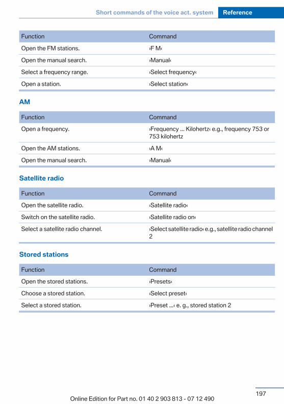
Function Command
Open the FM stations. ›F M‹
Open the manual search. ›Manual‹
Select a frequency range. ›Select frequency‹
Open a station. ›Select station‹
AM
Function Command
Open a frequency. ›Frequency ... Kilohertz‹ e.g., frequency 753 or753 kilohertz
Open the AM stations. ›A M‹
Open the manual search. ›Manual‹
Satellite radio
Function Command
Open the satellite radio. ›Satellite radio‹
Switch on the satellite radio. ›Satellite radio on‹
Select a satellite radio channel. ›Select satellite radio‹ e.g., satellite radio channel2
Stored stations
Function Command
Open the stored stations. ›Presets‹
Choose a stored station. ›Select preset‹
Select a stored station. ›Preset ...‹ e. g., stored station 2
Seite 197
Short commands of the voice act. system Reference
197Online Edition for Part no. 01 40 2 903 813 - 07 12 490
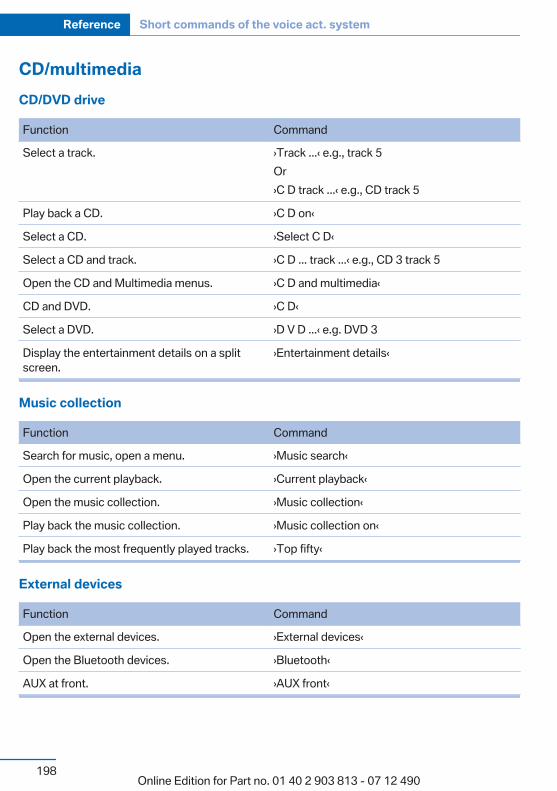
CD/multimediaCD/DVD drive
Function Command
Select a track. ›Track ...‹ e.g., track 5Or›C D track ...‹ e.g., CD track 5
Play back a CD. ›C D on‹
Select a CD. ›Select C D‹
Select a CD and track. ›C D ... track ...‹ e.g., CD 3 track 5
Open the CD and Multimedia menus. ›C D and multimedia‹
CD and DVD. ›C D‹
Select a DVD. ›D V D ...‹ e.g. DVD 3
Display the entertainment details on a splitscreen.
›Entertainment details‹
Music collection
Function Command
Search for music, open a menu. ›Music search‹
Open the current playback. ›Current playback‹
Open the music collection. ›Music collection‹
Play back the music collection. ›Music collection on‹
Play back the most frequently played tracks. ›Top fifty‹
External devices
Function Command
Open the external devices. ›External devices‹
Open the Bluetooth devices. ›Bluetooth‹
AUX at front. ›AUX front‹
Seite 198
Reference Short commands of the voice act. system
198Online Edition for Part no. 01 40 2 903 813 - 07 12 490

Tone
Function Command
Open the tone settings. ›Tone‹
Telephone
Function Command
Dial a phone number. ›Dial number‹
Opens the Telephone menu. ›Telephone‹
Display the phone book. ›Phonebook‹
Redialing. ›Redial‹
Display received calls. ›Received calls‹
List of messages. ›Messages‹
Open the Bluetooth devices. ›Bluetooth‹
Office
Function Command
Open the Office menu. ›Office‹
Display Office Today. ›Current office‹
Display the contacts. ›Contacts‹
Display the messages. ›Messages‹
Display the calendar. ›Calendar‹
Display the tasks. ›Tasks‹
Display the reminders. ›Reminders‹
Seite 199
Short commands of the voice act. system Reference
199Online Edition for Part no. 01 40 2 903 813 - 07 12 490
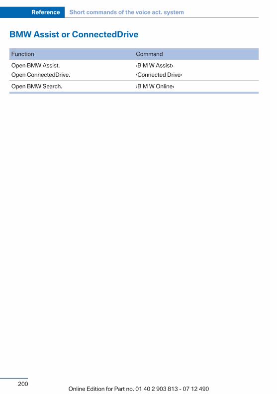
BMW Assist or ConnectedDrive
Function Command
Open BMW Assist.Open ConnectedDrive.
›B M W Assist‹›Connected Drive‹
Open BMW Search. ›B M W Online‹
Seite 200
Reference Short commands of the voice act. system
200Online Edition for Part no. 01 40 2 903 813 - 07 12 490

Seite 201
Short commands of the voice act. system Reference
201Online Edition for Part no. 01 40 2 903 813 - 07 12 490
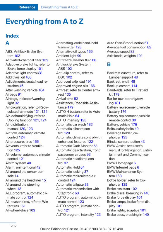
Everything from A to ZIndexAABS, Antilock Brake Sys‐
tem 102 Activated-charcoal filter 125 Adaptive brake lights, refer to
Brake force display 101 Adaptive light control 88 Additives, oil 166 Adjustments, seats/head re‐
straints 46 After washing vehicle 184 Airbags 91 Airbags, indicator/warning
light 92 Air circulation, refer to Recir‐
culated-air mode 121, 124 Air, dehumidifying, refer to
Cooling function 121, 124 Air distribution,
manual 120, 123 Air flow, automatic climate
control 124 Air pressure, tires 155 Air vents, refer to Ventila‐
tion 125 Air volume, automatic climate
control 121 Alarm system 40 Alarm, unintentional 42 All around the center con‐
sole 14 All around the headliner 15 All around the steering
wheel 12 ALL program, automatic cli‐
mate control 124 All-season tires, refer to Win‐
ter tires 161 All-wheel-drive 103
Alternating-code hand-heldtransmitter 128
Alternative oil types 166 Ambient light 90 Antifreeze, washer fluid 68 Antilock Brake System,
ABS 102 Anti-slip control, refer to
DSC 102 Approved axle load 191 Approved engine oils 166 Armrest, refer to Center arm‐
rest 135 Arrival time 82 Assistance, Roadside Assis‐
tance 179 AUTO H button, refer to Auto‐
matic Hold 64 AUTO intensity 123 Automatic car wash 183 Automatic climate con‐
trol 120 Automatic climate control with
enhanced features 122 Automatic Curb Monitor 53 Automatic deactivation, front
passenger airbags 93 Automatic headlamp con‐
trol 87 Automatic Hold 64 Automatic locking 37 Automatic recirculated-air
control 124 Automatic tailgate 38 Automatic transmission with
Steptronic 68 AUTO program, automatic cli‐
mate control 123 AUTO program, climate con‐
trol 121 AUTO program, intensity 123
Auto Start/Stop function 61 Average fuel consumption 82 Average speed 82 Axle loads, weights 191
BBackrest curvature, refer to
Lumbar support 48 Backrest, width 48 Backup camera 114 Band-aids, refer to First aid
kit 179 Bar for tow-starting/tow‐
ing 181 Battery replacement, vehicle
battery 176 Battery replacement, vehicle
remote control 30 Battery, vehicle 176 Belts, safety belts 49 Beverage holder, cu‐
pholder 135 Blinds, sun protection 43 BMW Assist, see user's
manual for Navigation, Enter‐tainment and Communica‐tion
BMW Homepage 6 BMW Internet page 6 BMW Maintenance Sys‐
tem 168 Bottle holder, refer to Cu‐
pholder 135 Brake assistant 102 Brake discs, breaking in 140 Brake force display 101 Brake lamps, brake force dis‐
play 101 Brake lights, adaptive 101 Brake pads, breaking in 140
Seite 202
Reference Everything from A to Z
202Online Edition for Part no. 01 40 2 903 813 - 07 12 490
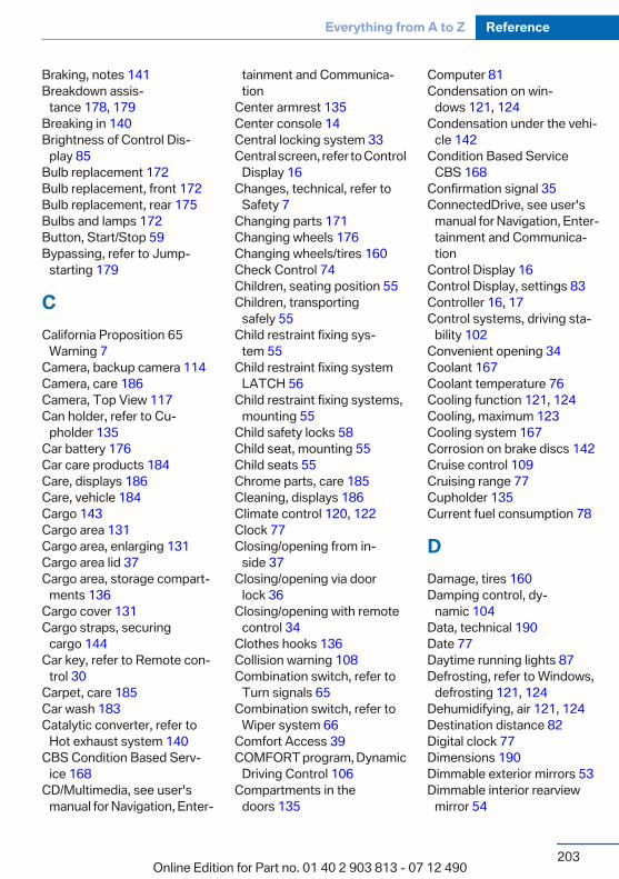
Braking, notes 141 Breakdown assis‐
tance 178, 179 Breaking in 140 Brightness of Control Dis‐
play 85 Bulb replacement 172 Bulb replacement, front 172 Bulb replacement, rear 175 Bulbs and lamps 172 Button, Start/Stop 59 Bypassing, refer to Jump-
starting 179
CCalifornia Proposition 65
Warning 7 Camera, backup camera 114 Camera, care 186 Camera, Top View 117 Can holder, refer to Cu‐
pholder 135 Car battery 176 Car care products 184 Care, displays 186 Care, vehicle 184 Cargo 143 Cargo area 131 Cargo area, enlarging 131 Cargo area lid 37 Cargo area, storage compart‐
ments 136 Cargo cover 131 Cargo straps, securing
cargo 144 Car key, refer to Remote con‐
trol 30 Carpet, care 185 Car wash 183 Catalytic converter, refer to
Hot exhaust system 140 CBS Condition Based Serv‐
ice 168 CD/Multimedia, see user's
manual for Navigation, Enter‐
tainment and Communica‐tion
Center armrest 135 Center console 14 Central locking system 33 Central screen, refer to Control
Display 16 Changes, technical, refer to
Safety 7 Changing parts 171 Changing wheels 176 Changing wheels/tires 160 Check Control 74 Children, seating position 55 Children, transporting
safely 55 Child restraint fixing sys‐
tem 55 Child restraint fixing system
LATCH 56 Child restraint fixing systems,
mounting 55 Child safety locks 58 Child seat, mounting 55 Child seats 55 Chrome parts, care 185 Cleaning, displays 186 Climate control 120, 122 Clock 77 Closing/opening from in‐
side 37 Closing/opening via door
lock 36 Closing/opening with remote
control 34 Clothes hooks 136 Collision warning 108 Combination switch, refer to
Turn signals 65 Combination switch, refer to
Wiper system 66 Comfort Access 39 COMFORT program, Dynamic
Driving Control 106 Compartments in the
doors 135
Computer 81 Condensation on win‐
dows 121, 124 Condensation under the vehi‐
cle 142 Condition Based Service
CBS 168 Confirmation signal 35 ConnectedDrive, see user's
manual for Navigation, Enter‐tainment and Communica‐tion
Control Display 16 Control Display, settings 83 Controller 16, 17 Control systems, driving sta‐
bility 102 Convenient opening 34 Coolant 167 Coolant temperature 76 Cooling function 121, 124 Cooling, maximum 123 Cooling system 167 Corrosion on brake discs 142 Cruise control 109 Cruising range 77 Cupholder 135 Current fuel consumption 78
DDamage, tires 160 Damping control, dy‐
namic 104 Data, technical 190 Date 77 Daytime running lights 87 Defrosting, refer to Windows,
defrosting 121, 124 Dehumidifying, air 121, 124 Destination distance 82 Digital clock 77 Dimensions 190 Dimmable exterior mirrors 53 Dimmable interior rearview
mirror 54
Seite 203
Everything from A to Z Reference
203Online Edition for Part no. 01 40 2 903 813 - 07 12 490
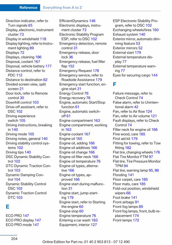
Direction indicator, refer toTurn signals 65
Display, electronic, instrumentcluster 73
Display in windshield 118 Display lighting, refer to Instru‐
ment lighting 89 Displays 72 Displays, cleaning 186 Disposal, coolant 167 Disposal, vehicle battery 177 Distance control, refer to
PDC 112 Distance to destination 82 Divided screen view, split
screen 21 Door lock, refer to Remote
control 30 Downhill control 103 Drive-off assistant, refer to
DSC 102 Driving experience
switch 105 Driving instructions, breaking
in 140 Driving mode 105 Driving notes, general 140 Driving stability control sys‐
tems 102 Driving tips 140 DSC Dynamic Stability Con‐
trol 102 DTC Dynamic Traction Con‐
trol 103 Dynamic Damping Con‐
trol 104 Dynamic Stability Control
DSC 102 Dynamic Traction Control
DTC 103
EECO PRO 147 ECO PRO display 147 ECO PRO mode 147
EfficientDynamics 148 Electronic displays, instru‐
ment cluster 73 Electronic Stability Program
ESP, refer to DSC 102 Emergency detection, remote
control 31 Emergency release, door
lock 36 Emergency release, fuel filler
flap 152 Emergency Request 178 Emergency service, refer to
Roadside Assistance 179 Emergency start function, en‐
gine start 31 Energy Control 78 Energy recovery 78 Engine, automatic Start/Stop
function 61 Engine, automatic switch-
off 61 Engine compartment 163 Engine compartment, working
in 163 Engine coolant 167 Engine oil 165 Engine oil, adding 166 Engine oil additives 166 Engine oil change 166 Engine oil filler neck 166 Engine oil temperature 76 Engine oil types, alterna‐
tive 166 Engine oil types, ap‐
proved 166 Engine start during malfunc‐
tion 31 Engine start, jump-start‐
ing 179 Engine start, refer to Starting
the engine 60 Engine stop 60 Engine temperature 76 Entering a car wash 183 Equipment, interior 127
ESP Electronic Stability Pro‐gram, refer to DSC 102
Exchanging wheels/tires 160 Exhaust system 140 Exterior mirror, automatic dim‐
ming feature 53 Exterior mirrors 52 External start 179 External temperature dis‐
play 77 External temperature warn‐
ing 77 Eyes for securing cargo 144
FFailure message, refer to
Check Control 74 False alarm, refer to Uninten‐
tional alarm 42 Fan, refer to Air flow 124 Fan, refer to Air volume 121 Fault displays, refer to Check
Control 74 Filler neck for engine oil 166 Fine wood, care 185 First aid kit 179 Fitting for towing, refer to Tow
fitting 182 Flat tire, changing wheels 176 Flat Tire Monitor FTM 97 Flat tire, Tire Pressure Monitor
TPM 94 Flat tire, warning lamp 95, 98 Flooding 141 Floor carpet, care 185 Floor mats, care 185 Fold-out position, windshield
wipers 68 Foot brake 141 Front airbags 91 Front fog lamps 89 Front fog lamps, front, bulb re‐
placement 174 Front lamps 172
Seite 204
Reference Everything from A to Z
204Online Edition for Part no. 01 40 2 903 813 - 07 12 490
Front passenger airbags, au‐tomatic deactivation 93
Front passenger airbags, indi‐cator lamp 93
FTM Flat Tire Monitor 97 Fuel cap 152 Fuel consumption, current 78 Fuel consumption, refer to
Average fuel consump‐tion 82
Fuel filler flap 152 Fuel gauge 76 Fuel quality 154 Fuel, tank capacity 192 Fuse 177
GGarage door opener, refer to
Integrated universal remotecontrol 127
Gasoline 154 Gasoline quality 154 Gear change, automatic trans‐
mission 69 General driving notes 140 Glass sunroof, refer to Panor‐
amic glass sunroof 43 Glove compartment 134 Gross vehicle weight, ap‐
proved 191
HHandbrake, refer to Parking
brake 63 Hand-held transmitter, alter‐
nating code 128 Hazard warning flashers 178 HDC Hill Descent Control 103 Head airbags 91 Headlamp control, auto‐
matic 87 Headlamp courtesy delay fea‐
ture 87
Headlamp courtesy delay fea‐ture via remote control 35
Headlamp flasher 66 Headlamp flasher, bulb re‐
placement 173 Headlamp glass 172 Headlamps 172 Headlamps, care 184 Headlamp washer system 66 Headliner 15 Head restraints 46 Head restraints, front 50 Head restraints, rear 51 Head-up Display 118 Head-up Display, care 186 Heavy cargo, stowing 144 Height, vehicle 190 High-beam Assistant 88 High beams 66 High beams/low beams, refer
to High-beam Assistant 88 High beams, bulb replace‐
ment 173 Hill Descent Control HDC 103 Hills 142 Hints 6 Holder for beverages 135 Homepage 6 Hood 163 Horn 12 Hot exhaust system 140 HUD Head-up Display 118 Hydroplaning 141
IIce warning, refer to External
temperature warning 77 Icy roads, refer to External
temperature warning 77 Identification marks, tires 158 Identification number, refer to
Important features in the en‐gine compartment 163
iDrive 16
Ignition key, refer to Remotecontrol 30
Ignition off 59 Ignition on 59 Indication of a flat tire 95, 98 Individual air distribu‐
tion 120, 123 Individual settings, refer to
Personal Profile 31 Inflation pressure, tires 155 Inflation pressure warning,
tires 97 Info display, refer to Com‐
puter 81 Initializing, Flat Tire Monitor
FTM 98 Initializing, Tire Pressure Mon‐
itor TPM 95 Instrument cluster 72 Instrument cluster, electronic
displays 73 Instrument lighting 89 Integrated key 30 Integrated universal remote
control 127 Intensity, AUTO program 123 Interior equipment 127 Interior lamps 90 Interior lamps via remote con‐
trol 35 Interior motion sensor 42 Interior rearview mirror 54 Interior rearview mirror, auto‐
matic dimming feature 54 Internet page 6 Interval display, service re‐
quirements 78
JJacking points for the vehicle
jack 176 Jack, refer to Vehicle jack 176 Joystick, automatic transmis‐
sion 69 Jump-starting 179
Seite 205
Everything from A to Z Reference
205Online Edition for Part no. 01 40 2 903 813 - 07 12 490
KKey/remote control 30 Keyless Go, refer to Comfort
Access 39 Key Memory, refer to Personal
Profile 31 Kickdown, automatic trans‐
mission 69 Knee airbag 92
LLamp replacement 172 Lamp replacement, front 172 Lamp replacement, rear 175 Lamps 86 Lamps and bulbs 172 Lane departure warning 99 Lane margin, warning 99 Language on Control Dis‐
play 84 Lashing eyes, securing
cargo 144 LATCH child restraint fixing
system 56 Leather, care 184 LEDs, light-emitting di‐
odes 172 Length, vehicle 191 Letters and numbers, enter‐
ing 22 Light-alloy wheels, care 185 Light control 88 Light-emitting diodes,
LEDs 172 Lighting 86 Lighting via remote control 35 Light switch 86 Load 143 Loading 143 Lock, door 36 Locking/unlocking from in‐
side 37 Locking/unlocking via door
lock 36
Locking/unlocking with re‐mote control 34
Locking, automatic 37 Locking, central 33 Locking via tailgate 38 Lock, power window 43 Locks, doors, and win‐
dows 58 Low beams 86 Low beams, automatic, refer to
High-beam Assistant 88 Lower back support 48 Luggage compartment roller
cover 131 Luggage rack, refer to Roof-
mounted luggage rack 142 Lumbar support 48
MMaintenance 168 Maintenance require‐
ments 168 Maintenance, service require‐
ments 78 Maintenance system,
BMW 168 Malfunction displays, refer to
Check Control 74 Manual air distribu‐
tion 120, 123 Manual air flow 124 Manual air volume 121 Manual brake, refer to Parking
brake 63 Manual mode, transmis‐
sion 70 Manual operation, backup
camera 114 Manual operation, door
lock 36 Manual operation, exterior mir‐
rors 53 Manual operation, fuel filler
flap 152
Manual operation, Park Dis‐tance Control PDC 112
Manual operation, TopView 117
Marking on approvedtires 161
Marking, run-flat tires 162 Master key, refer to Remote
control 30 Maximum cooling 123 Maximum speed, display 79 Maximum speed, winter
tires 161 Measure, units of 85 Medical kit 179 Memory, seat, mirror 52 Menu, EfficientDynamics 148 Menu in instrument cluster 81 Menus, operating, iDrive 16 Menus, refer to iDrive operat‐
ing concept 18 Microfilter 122, 125 Minimum tread, tires 160 Mirror 52 Mirror memory 52 Mobile communication devi‐
ces in the vehicle 141 Modifications, technical, refer
to Safety 7 Moisture in headlamp 172 Monitor, refer to Control Dis‐
play 16 Mounting of child restraint fix‐
ing systems 55 Multifunction steering wheel,
buttons 12
NNavigation, see user's manual
for Navigation, Entertain‐ment and Communication
Neck restraints, front, refer toHead restraints 50
Neck restraints, rear, refer toHead restraints 51
Seite 206
Reference Everything from A to Z
206Online Edition for Part no. 01 40 2 903 813 - 07 12 490

New wheels and tires 160 No Passing Information 79 Nylon rope for tow-starting/
towing 181
OOBD Onboard Diagnos‐
tics 169 Obstacle marking, backup
camera 115 Octane rating, refer to Gaso‐
line quality 154 Odometer 77 Office, see user's manual for
Navigation, Entertainmentand Communication
Oil 165 Oil, adding 166 Oil additives 166 Oil change 166 Oil change interval, service re‐
quirements 78 Oil filler neck 166 Oil types, alternative 166 Oil types, approved 166 Old batteries, disposal 177 Onboard Diagnostics
OBD 169 Onboard monitor, refer to
Control Display 16 Onboard vehicle tool kit 171 Opening/closing from in‐
side 37 Opening/closing via door
lock 36 Opening/closing with remote
control 34 Operating concept, iDrive 16 Optional equipment, standard
equipment 6 Outside air, refer to Automatic
recirculated-air control 124 Overheating of engine, refer to
Coolant temperature 76 Overtaking prohibitions 79
PPaint, vehicle 184 Panic mode 35 Panoramic glass sunroof 43 Park Distance Control
PDC 112 Parked-car ventilation 125 Parked vehicle, condensa‐
tion 142 Parking aid, refer to PDC 112 Parking brake 63 Parking lamps 86 Parking lamps, bulb replace‐
ment 173 Parking with Auto Hold 64 Partition net 132 Passenger side mirror, tilting
downward 53 Pathway lines, backup cam‐
era 115 PDC Park Distance Con‐
trol 112 Performance Control 103 Personal Profile 31 Pinch protection system, glass
sunroof 44 Pinch protection system, win‐
dows 43 Plastic, care 185 Power failure 177 Power windows 42 Pressure, tire air pres‐
sure 155 Pressure warning, tires 97 Profile, refer to Personal Pro‐
file 31 Programmable memory but‐
tons, iDrive 21 Protective function, glass sun‐
roof 44 Protective function, win‐
dows 43 Push-and-turn switch, refer to
Controller 16, 17
RRadiator fluid 167 Radio-operated key, refer to
Remote control 30 Radio ready state 59 Radio, see user's manual for
Navigation, Entertainmentand Communication
Rain sensor 67 Rear lamps 175 Rear socket 130 Rearview mirror 52 Rear window de‐
froster 122, 124 Recirculated-air filter 125 Recirculated-air
mode 121, 124 Recommended tire
brands 161 Refueling 152 Remaining range 77 Remote control/key 30 Remote control, malfunc‐
tion 35 Remote control, universal 127 Replacement fuse 177 Replacing parts 171 Replacing wheels/tires 160 Reporting safety defects 8 Reserve warning, refer to
Range 77 Resetting, Tire Pressure Mon‐
itor TPM 95 Retaining straps, securing
cargo 144 Retreaded tires 161 Roadside parking lamps 87 Roller sunblinds 43 RON gasoline quality 154 Roof load capacity 191 Roof-mounted luggage
rack 142 Rope for tow-starting/tow‐
ing 181
Seite 207
Everything from A to Z Reference
207Online Edition for Part no. 01 40 2 903 813 - 07 12 490
RSC Run Flat System Compo‐nent, refer to Run-flattires 162
Rubber components,care 185
Run-flat tires 162
SSafe braking 141 Safety 7 Safety belt reminder for driv‐
er's seat and front passengerseat 50
Safety belts 49 Safety belts, care 185 Safety switch, windows 43 Safety systems, airbags 91 Saving fuel 0 Screen, refer to Control Dis‐
play 16 Screwdriver 171 Screw thread for tow fit‐
ting 182 Seat and mirror memory 52 Seat belts, refer to Safety
belts 49 Seat heating, front 49 Seat heating, rear 49 Seating position for chil‐
dren 55 Seats 46 Selection list in instrument
cluster 81 Selector lever, automatic
transmission 69 Sensors, care 186 Service and warranty 7 Service requirements, Condi‐
tion Based Service CBS 168 Service requirements, dis‐
play 78 Service, Roadside Assis‐
tance 179 Settings on Control Dis‐
play 83
Settings, storing for seat, mir‐ror 52
Shifting, automatic transmis‐sion 68
Shift paddles on steeringwheel 70
Short commands 193 Side airbags 91 Signaling, horn 12 Signals when unlocking 35 Sitting safely 46 Size 190 Slide/tilt glass roof 43 Smallest turning circle 191 Snow chains 162 Socket 129 Socket, OBD Onboard Diag‐
nostics 169 SOS button 178 Spare fuse 177 Specified engine oil
types 166 Speed, average 82 Speed limit detection, on‐
board computer 82 Speed limiter, display 79 Speed Limit Information 79 Speed limit in the com‐
puter 82 Split screen 21 SPORT+ - program, Dynamic
Driving Control 105 Sport automatic transmis‐
sion 70 SPORT program, Dynamic
Driving Control 105 Sport program, transmis‐
sion 70 Sport steering, variable 105 Stability control systems 102 Start/stop, automatic func‐
tion 61 Start/Stop button 59 Start function during malfunc‐
tion 31 Starting the engine 60
Status display, tires 94 Status information, iDrive 20 Status of Owner's Manual 6 Steering wheel, adjusting 54 Steering wheel heating 54 Steptronic, automatic trans‐
mission 68 Stopping the engine 60 Storage compartments 134 Storage compartments, loca‐
tions 134 Storage, tires 161 Storing the vehicle 186 Summer tires, tread 159 Supplementary text mes‐
sages 75 Switch for Dynamic Driv‐
ing 105 Switch-on times, parked-car
ventilation 126 Switch, refer to Cockpit 12 Symbols 6
TTachometer 76 Tailgate 37 Tailgate, automatic 38 Tailgate via remote control 35 Tail lamps 175 Technical changes, refer to
Safety 7 Technical data 190 Telephone, see user's manual
for Navigation, Entertain‐ment and Communication
Temperature, automatic cli‐mate control 121, 123
Temperature display, externaltemperature 77
Temperature, engine oil 76 Terminal, jump-starting 180 Text messages, supplemen‐
tary 75 Theft alarm system, refer to
Alarm system 40
Seite 208
Reference Everything from A to Z
208Online Edition for Part no. 01 40 2 903 813 - 07 12 490
Theft protection, refer to Cen‐tral locking system 33
Thigh support 48 Tilt alarm sensor 41 Time of arrival 82 Tire damage 160 Tire identification marks 158 Tire inflation pressure 155 Tire inflation pressure monitor,
refer to FTM 97 Tire Pressure Monitor
TPM 94 Tires, changing 160 Tires, everything on wheels
and tires 155 Tires, run-flat tires 162 Tire tread 159 Tone, see user's manual for
Navigation, Entertainmentand Communication
Tools 171 Top View 116 Total vehicle weight 191 Tow fitting 182 Towing 181 Tow-starting 181 TPM Tire Pressure Moni‐
tor 94 Traction control 103 TRACTION program, Dynamic
Driving Control 103 Transmission, automatic 68 Transporting children
safely 55 Tread, tires 159 Trip computer 83 Triple turn signal activa‐
tion 65 Trip odometer 77 Trunk lid 37 Turning circle 191 Turning circle lines, backup
camera 115 Turn signals, operation 65
UUnintentional alarm 42 Units of measure 85 Universal remote control 127 Unlock button, automatic
transmission 69 Unlocking/locking from in‐
side 37 Unlocking/locking via door
lock 36 Unlocking/locking with remote
control 34 Updates made after the edito‐
rial deadline 7 Upholstery care 184 USB interface 130
VVariable sport steering 105 Vehicle battery 176 Vehicle battery, replacing 176 Vehicle, breaking in 140 Vehicle care 184 Vehicle equipment 6 Vehicle identification number,
refer to Identification numberin the engine compart‐ment 163
Vehicle jack 176 Vehicle paint 184 Vehicle storage 186 Vehicle wash 183 Ventilation 125 Ventilation, refer to Parked-car
ventilation 125 Voice activation, short com‐
mands 193 Voice activation system 23
WWarning messages, refer to
Check Control 74 Warning triangle 179
Washer fluid 68 Washer fluid reservoir, ca‐
pacity 192 Washer nozzles, wind‐
shield 67 Washer system 66 Washing, vehicle 183 Water on roads 141 Weights 191 Welcome lamps 86 Wheel base, vehicle 191 Wheels, changing 160 Wheels, everything on wheels
and tires 155 Wheels, Flat Tire Monitor
FTM 97 Wheels, Tire Pressure Monitor
TPM 94 Width, vehicle 190 Window defroster,
rear 122, 124 Windows, powered 42 Windshield washer fluid 68 Windshield washer noz‐
zles 67 Windshield washer system 66 Windshield wiper 66 Windshield wipers, fold-out
position 68 Winter storage, care 186 Winter tires, suitable tires 161 Winter tires, tread 159 Wiper blades, replacing 171 Wiper fluid 68 Wiper system 66 Wood, care 185 Word match concept, naviga‐
tion 22 Wrench 171
XxDrive 103 Xenon headlamps, bulb re‐
placement 173
Seite 209
Everything from A to Z Reference
209Online Edition for Part no. 01 40 2 903 813 - 07 12 490

More about BMW
bmwusa.comThe Ultimate Driving
Machine
01 4
0 2
903
813
ue
*BL290381300Y*
Online Edition for Part no. 01 40 2 903 813 - 07 12 490