Embed Size (px)
Citation preview
Test and Certification of Pitot
Probes
Ice and Rain Protection Aspects
First Workshop on Aviation Safety (WAS), June 1st and 2nd, Rio de Janeiro, RJ, Brazil
Organization COPPE/UFRJ
Team Members:
Euryale Jorge de Godoy Jesus Zerbini, Prof. Dr.
University of São Paulo
Guilherme Araujo Lima da Silva, Dr.
ATS4i Aero-thermal Solutions for Industry, alumni of University of
São Paulo
Luciano Martinez Stefanini, M.Sc.
PhD candidate at University of São Paulo
Otávio de Mattos Silvares, Prof. Dr.
University of São Paulo and Maua Technology Institute
Introduction
Certification
Testing
Conclusions
Acknowledgments
Table of Contents Introduction Certification Testing Conclusions
Objectives
Perform a bibliographic research and present a basic overview to WAS
audience about certification and testing of de-icing and anti-icing of Pitot
probes:
Technical literature, regulations and standards
Current certification and qualification requirements;
Icing tunnel testing selected topics;
Some aspects of similitude tunnel vs. Flight;
Documents for audience further reading.
Table of Contents Introduction Certification Testing Conclusions
Presentation focus
Current certification documents and standards
Aspects of thermal ice protection of pitot probes
Probes certification is a broader and more complex subject than icing
Main reason Knowledge and specialization of authors
Not covered herein
NO other certification subjects or requirements not related to ice protection
NO safety assessment, failure mode analysis or functional hazard topics
NO aspects of Probes design or Air data system development
NO discussions about new rules or non-standard atmospheric conditions
Table of Contents Introduction Certification Testing Conclusions
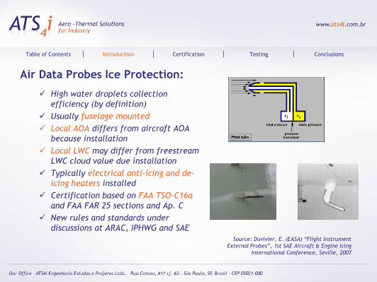
Air Data Probes Ice Protection:
High water droplets collection
efficiency (by definition)
Usually fuselage mounted
Local AOA differs from aircraft AOA
because installation
Local LWC may differ from freestream
LWC cloud value due installation
Typically electrical anti-icing and de-
icing heaters installed
Certification based on FAA TSO-C16a
and FAA FAR 25 sections and Ap. C
New rules and standards under
discussions at ARAC, IPHWG and SAE
Source: Duvivier, E. (EASA) “Flight Instrument
External Probes”, 1st SAE Aircraft & Engine Icing
International Conference, Seville, 2007
Table of Contents Introduction Certification Testing Conclusions
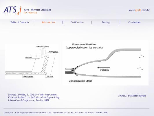
Source2: SAE AS5562 Draft
Table of Contents Introduction Certification Testing Conclusions
Freestream Particles
(supercooled water, ice crystals)
Concentration Effect
Velocity
Source: Duvivier, E. (EASA) “Flight Instrument
External Probes”, 1st SAE Aircraft & Engine Icing
International Conference, Seville, 2007
Certification
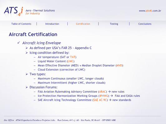
Aircraft Certification
Aircraft Icing Envelope
As defined per USA’s FAR 25 - Appendix C
Icing condition defined by:
– Air temperature (SAT or TAT)
– Liquid Water Content (LWC)
– Mean Effective Diameter (MED) Median Droplet Diameter (MVD)
– Cloud Extension (correction of LWC)
Two types:
– Maximum Continuous (smaller LWC, longer clouds)
– Maximum Intermittent (higher LWC, shorter clouds)
Discussion Forums:
– FAA Aviation Rulemaking Advisory Committee (ARAC) new rules
– Ice Protection Harmonization Working Groups (IPHWG) FAA and EASA rules
– SAE Aircraft Icing Technology Committee (SAE AC-9C) new standards
Table of Contents Introduction Certification Testing Conclusions
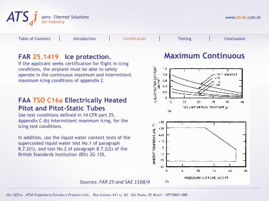
Maximum Continuous
Table of Contents Introduction Certification Testing Conclusions
Sources: FAR 25 and SAE 1168/4
FAR 25.1419 Ice protection.If the applicant seeks certification for flight in icing
conditions, the airplane must be able to safely
operate in the continuous maximum and intermittent
maximum icing conditions of appendix C
FAA TSO C16a Ellectrically Heated
Pitot and Pitot-Static TubesUse test conditions defined in 14 CFR part 25,
Appendix C (b) Intermittent maximum icing, for the
icing test conditions.
In addition, use the liquid water content tests of the
supercooled liquid water test No.1 of paragraph
8.7.2(1), and test No.2 of paragraph 8.7.2(2) of the
British Standards Institution (BSI) 2G 135,
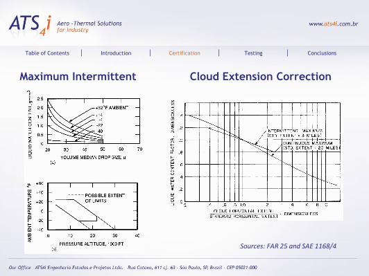
Maximum Intermittent Cloud Extension Correction
Table of Contents Introduction Certification Testing Conclusions
Sources: FAR 25 and SAE 1168/4

Current Probe Qualification Documents
FAA – TSO C16a (refs. AS8006, BS2G.135 and FAR 25 AP. C)
SAE - AS390, AS393, AS403A, AS8006
British Standard Institution - BSI 2G.135
MIL - MIL-T-5421B, MIL-T-5421A, MIL_P-83206, MIL-P-25632B
Coverage
Environmental Conditions:Temperature, Altitude, Vibration, Radio Interference, Magnetic Effect
Detail Requirements: Drainage, Marking, Power Variation, Anti-Icing / De-Icing
Individual Performance Tests: Leakage, Dielectric, Heater Operation, Insulation Resistance,
Aerodynamic Tests
Qualification Tests: Vibration, Endurance, Scale Error @ 0 deg AoA, Scale Error @ various AoA,
Scale Error @ various angles of Yaw, Magnetic Effect, Anti-Icing / De-Icing, Cold soak, Shock,
Salt Spray, Sand and Dust, Humidity, Power Consumption, Heat Conductivity, Status, Weight,
Repeatability
Table of Contents Introduction Certification Testing Conclusions
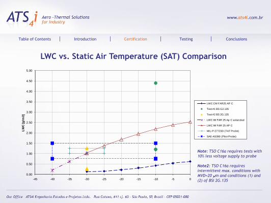
LWC vs. Static Air Temperature (SAT) Comparison
Table of Contents Introduction Certification Testing Conclusions
0.00
0.50
1.00
1.50
2.00
2.50
3.00
3.50
4.00
4.50
5.00
-45 -40 -35 -30 -25 -20 -15 -10 -5 0
LW
C [g
/m3]
SAT [C]
LWC CM FAR25 AP C
Test #1 BS G2.135
Test #2 BS 2G.135
LWC IM FAR 25 Ap C extended
LWC IM FAR 25 AP C
MIL-P-27723D (TAT Probe)
SAE-AS390 (Pitot Probe)
Note: TSO C16a requires tests with
10% less voltage supply to probe
Note2: TSO C16a requires
intermittent max. conditions with
MVD=20 m and conditions (1) and
(2) of BSI 2G.135
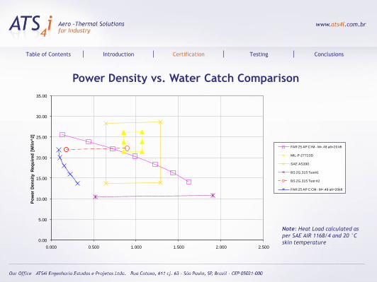
Power Density vs. Water Catch Comparison
Table of Contents Introduction Certification Testing Conclusions
0.00
5.00
10.00
15.00
20.00
25.00
30.00
35.00
0.000 0.500 1.000 1.500 2.000 2.500
Po
wer
Den
sit
y R
eq
uir
ed
[W
/in
^2]
Water Catch [g/s]
FAR 25 AP C IM - M=.48 alt=20 kft
MIL-P-27723D
SAE AS390
BS 2G.315 Test#1
BS 2G.315 Test #2
FAR 25 AP C CM - M=.48 alt=20kft
Note: Heat Load calculated as
per SAE AIR 1168/4 and 20 °C
skin temperature
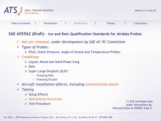
SAE AS5562 (Draft) - Ice and Rain Qualification Standards for Airdata Probes
Not yet released, under development by SAE AC-9C Committee
Types of Probes:
Pitot, Static Pressure, Angle of Attack and Temperature Probes
Conditions
Liquid, Mixed and Solid Phase Icing
Rain
Super Large Droplets (SLD)*
– Freezing Rain
– Freezing Drizzle
Aircraft installation effects, including concentration factor
Testing
Setup Effects
Operational limitations
Test Procedure
Table of Contents Introduction Certification Testing Conclusions
(*) SLD envelope also
under discussions by
FAA and EASA at IPHWG Task 2.
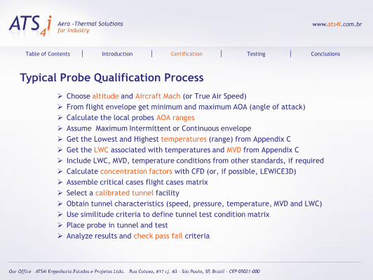
Typical Probe Qualification Process
Choose altitude and Aircraft Mach (or True Air Speed)
From flight envelope get minimum and maximum AOA (angle of attack)
Calculate the local probes AOA ranges
Assume Maximum Intermittent or Continuous envelope
Get the Lowest and Highest temperatures (range) from Appendix C
Get the LWC associated with temperatures and MVD from Appendix C
Include LWC, MVD, temperature conditions from other standards, if required
Calculate concentration factors with CFD (or, if possible, LEWICE3D)
Assemble critical cases flight cases matrix
Select a calibrated tunnel facility
Obtain tunnel characteristics (speed, pressure, temperature, MVD and LWC)
Use similitude criteria to define tunnel test condition matrix
Place probe in tunnel and test
Analyze results and check pass fail criteria
Table of Contents Introduction Certification Testing Conclusions
Testing
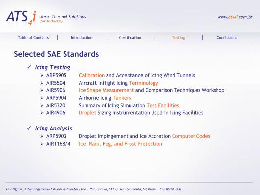
Selected SAE Standards
Icing Testing
ARP5905 Calibration and Acceptance of Icing Wind Tunnels
AIR5504 Aircraft Inflight Icing Terminology
AIR5906 Ice Shape Measurement and Comparison Techniques Workshop
ARP5904 Airborne Icing Tankers
AIR5320 Summary of Icing Simulation Test Facilities
AIR4906 Droplet Sizing Instrumentation Used in Icing Facilities
Icing Analysis
ARP5903 Droplet Impingement and Ice Accretion Computer Codes
AIR1168/4 Ice, Rain, Fog, and Frost Protection
Table of Contents Introduction Certification Testing Conclusions
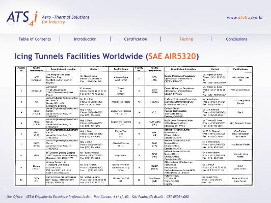
Icing Tunnels Facilities Worldwide (SAE AIR5320)
Table of Contents Introduction Certification Testing Conclusions
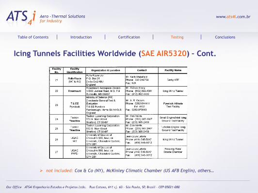
Icing Tunnels Facilities Worldwide (SAE AIR5320) – Cont.
not included: Cox & Co (NY), McKinley Climatic Chamber (US AFB Englin), others…
Table of Contents Introduction Certification Testing Conclusions
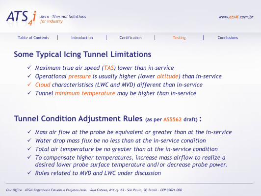
Some Typical Icing Tunnel Limitations
Maximum true air speed (TAS) lower than in-service
Operational pressure is usually higher (lower altitude) than in-service
Cloud characteristiscs (LWC and MVD) different than in-service
Tunnel minimum temperature may be higher than in-service
Tunnel Condition Adjustment Rules (as per AS5562 draft) :
Mass air flow at the probe be equivalent or greater than at the in-service
Water drop mass flux be no less than at the in-service condition
Total air temperature be no greater than at the in-service condition
To compensate higher temperatures, increase mass airflow to realize a
desired lower probe surface temperature and/or decrease probe power.
Rules related to MVD and LWC under discussion
Table of Contents Introduction Certification Testing Conclusions
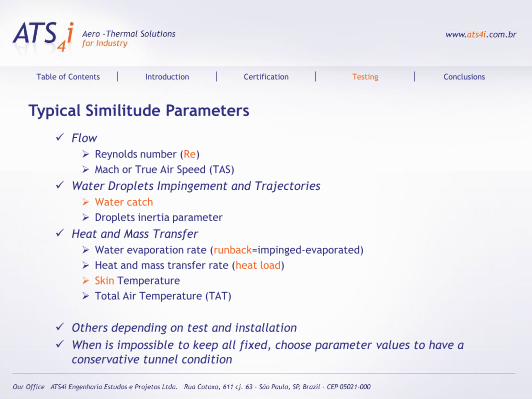
Typical Similitude Parameters
Flow
Reynolds number (Re)
Mach or True Air Speed (TAS)
Water Droplets Impingement and Trajectories
Water catch
Droplets inertia parameter
Heat and Mass Transfer
Water evaporation rate (runback=impinged-evaporated)
Heat and mass transfer rate (heat load)
Skin Temperature
Total Air Temperature (TAT)
Others depending on test and installation
When is impossible to keep all fixed, choose parameter values to have a
conservative tunnel condition
Table of Contents Introduction Certification Testing Conclusions
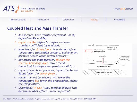
Coupled Heat and Mass Transfer
As expected, heat transfer coefficient (or St)
depends on Re and Pr;
Higher the Re, higher St, higher the mass
transfer coefficient (by analogy);
Mass transfer driven force depends on surface
temperature (saturation pressure) and ambient
pressure (water vapor partial pressure);
But higher the mass transfer, thicker the
thermal boundary layer, lower the St
(important for surface temperature > 40 C) …
Higher the ambient pressure, higher the Re and
St but lower the driven force …
Higher the lost by evaporation, lower the
temperature but lower the evaporation, higher
the temperature…
Solution by 1st Law ! Only thermal analysis will
determine what effect is more important.
Table of Contents Introduction Certification Testing Conclusions
Water film flow (IV)
Air-water vapormixture at T
recAir-water vapor gaseous flow (II)
S
Saturated air-water vapor
mixture at Twater
G
Airfoil solid surface (V)
evaporation
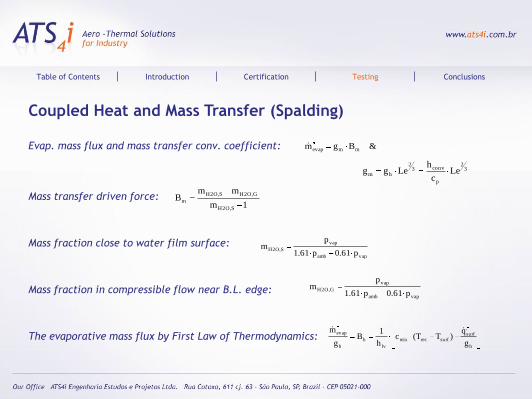
Coupled Heat and Mass Transfer (Spalding)
Evap. mass flux and mass transfer conv. coefficient:
Mass transfer driven force:
Mass fraction close to water film surface:
Mass fraction in compressible flow near B.L. edge:
The evaporative mass flux by First Law of Thermodynamics:
&Bgm mmevap
1m
mmB
S,O2H
G,O2HS,O2H
m
vapamb
vap
S,O2Hp61.0p61.1
pm
vapamb
vap
G,O2Hp61.0p61.1
pm
Table of Contents Introduction Certification Testing Conclusions
h
surfsurfrecmix
lv
h
h
evap
g
q)TT(c
h
1B
g
m
32
p
conv32
hm Lec
hLegg
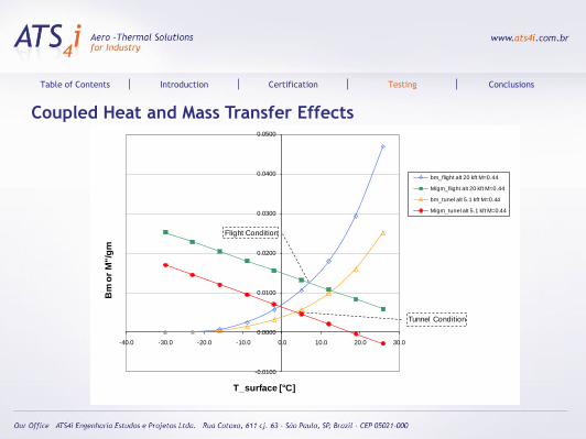
Coupled Heat and Mass Transfer Effects
Table of Contents Introduction Certification Testing Conclusions
-0.0100
0.0000
0.0100
0.0200
0.0300
0.0400
0.0500
-40.0 -30.0 -20.0 -10.0 0.0 10.0 20.0 30.0
Bm
or
M"/g
m
T_surface [°C]
bm_flight alt 20 kft M=0.44
M/gm_flight alt 20 kft M=0.44
bm_tunel alt 5.1 kft M=0.44
M/gm_tunel alt 5.1 kft M=0.44
Flight Condition
Tunnel Condition
Conclusions
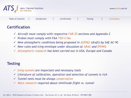
Certification
Aircraft must comply with respective FAR 25 sections and Appendix C
Probes must comply with FAA TSO-C16a
New atmospheric conditions being proposed in AS5562 (draft) by SAE AC-9C
New rules and icing envelope under discussion at ARAC and IPHWG
Atmospheric research has been carried out in USA, Europe and Canada
Testing
Icing tunnels are important and necessary tools
Literature of calibration, operation and selection of tunnels is rich
Tunnel tests must be always conservative
More research required about similitude flight vs. tunnel
Table of Contents Introduction Certification Testing Conclusions
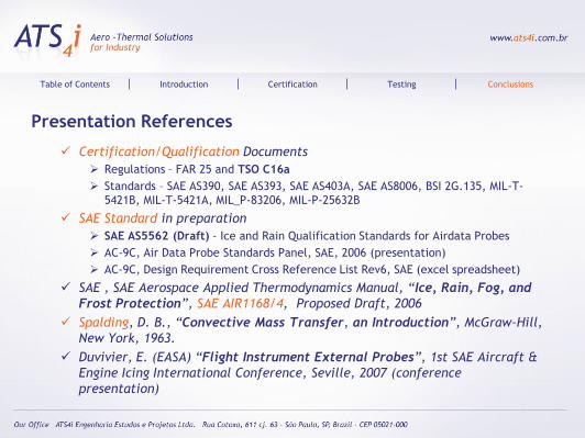
Presentation References
Certification/Qualification Documents
Regulations – FAR 25 and TSO C16a
Standards – SAE AS390, SAE AS393, SAE AS403A, SAE AS8006, BSI 2G.135, MIL-T-
5421B, MIL-T-5421A, MIL_P-83206, MIL-P-25632B
SAE Standard in preparation
SAE AS5562 (Draft) - Ice and Rain Qualification Standards for Airdata Probes
AC-9C, Air Data Probe Standards Panel, SAE, 2006 (presentation)
AC-9C, Design Requirement Cross Reference List Rev6, SAE (excel spreadsheet)
SAE , SAE Aerospace Applied Thermodynamics Manual, “Ice, Rain, Fog, and
Frost Protection”, SAE AIR1168/4, Proposed Draft, 2006
Spalding, D. B., “Convective Mass Transfer, an Introduction”, McGraw–Hill,
New York, 1963.
Duvivier, E. (EASA) “Flight Instrument External Probes”, 1st SAE Aircraft &
Engine Icing International Conference, Seville, 2007 (conference
presentation)
Table of Contents Introduction Certification Testing Conclusions
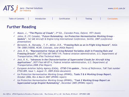
Further Reading
Mason, J., “The Physics of Clouds”, 2nd Ed., Claredon Press, Oxford, 1971 (book)
Johns, D. (TC Canada), “Future Rulemaking – Ice Protection Harmonization Working Group –
Update”, 1st SAE Aircraft & Engine Icing International Conference, Seville, 2007 (conference
presentation)
Bernstein, B., Ratvasky , T. P., Miller, D.R., “Freezing Rain as an in-Flight Icing Hazard”, NASA
TM--2000-210058, NCAR, Colorado, June (NASA Report)
Jeck, R. K., “Representative Values of Icing-Related Variables Aloft in Freezing Rain and
Freezing Drizzle”, DOT/FAA/AR-TN95/119, Federal Aviation Administration, U.S. Department of
Transportation,1996 (FAA Technical Note)
Jeck, R. K., “Advances in the Characterization of Supercooled Clouds for Aircraft Icing
Applications”, DOT/FAA/AR-07/4, Federal Aviation Administration, U.S. Department of
Transportation,2008 (FAA Report)
European Aviation Safety Agency (EASA), ETSO C16 update , Terms of Reference, ToR Task number
ETSO.009, Issue 1, August 31, 2009 (EASA document)
Ice Protection Harmonization Working Group (IPHWG), Tasks 5 & 6 Working Group Report,
October 2006, Rev A March 2007 (IPHWG report)
Ice Protection Harmonization Working Group (IPHWG), “Task 2 Working Group Report on
Supercooled Large Droplet Rulemaking”, December 2005 (IPHWG report)
Table of Contents Introduction Certification Testing Conclusions
Contacts
Euryale Jorge de Godoy Jesus Zerbini, Prof. Dr.
Guilherme Araujo Lima da Silva, Dr.
Luciano Martinez Stefanini, M.Sc.
Otávio de Mattos Silvares, Prof. Dr.
[email protected] e [email protected]
Table of Contents Introduction Certification Testing Conclusions
Acknowledgments
G. da Silva thanks to Engs. Marcos N. Arima e Francisco D. A. de Sousa , his
partners at ATS4i Aero-Thermal Solutions for Industry, for the time
dedicated to this bibliographic research and presentation
E. Zerbini e O. Silvares acknowledges to University of São Paulo
L. Stefanini thanks to CAPES for the PhD grant
The team acknowledges to WAS organization and COPPE-UFRJ for sponsoring
the travel expenses;
Table of Contents Introduction Certification Testing Conclusions