Embed Size (px)
Citation preview

VIRTUAL DESIGN MASTER 3
MARS BASE DESIGN DOCUMENT V1.10 Challenge 1
Steven Viljoen 7-6-2015

1 | P a g e
Contents Revision History ................................................................................................................................................................ 2
Executive summary ........................................................................................................................................................... 3
Requirements .................................................................................................................................................................... 3
Constraints ........................................................................................................................................................................ 3
Risks .................................................................................................................................................................................. 4
Assumptions ...................................................................................................................................................................... 4
Derived Requirements ...................................................................................................................................................... 4
Guiding principles ............................................................................................................................................................. 4
Conceptual design ............................................................................................................................................................. 5
Data centers .................................................................................................................................................................. 5
Air data center .......................................................................................................................................................... 5
Water data center ..................................................................................................................................................... 5
Fire data center ......................................................................................................................................................... 5
Architecture design ........................................................................................................................................................... 6
Storage .......................................................................................................................................................................... 6
Virtual SAN ................................................................................................................................................................ 6
Solid State Devices .................................................................................................................................................... 6
VSAN Disk groups ...................................................................................................................................................... 6
Failures to Tolerate ................................................................................................................................................... 6
Number of hosts ....................................................................................................................................................... 6
Datastores ................................................................................................................................................................. 7
Capacity ..................................................................................................................................................................... 7
Jumbo Frames ........................................................................................................................................................... 7
Storage policies ......................................................................................................................................................... 7
Physical hosts ................................................................................................................................................................ 7
Server specifications ................................................................................................................................................. 7
Operating system ...................................................................................................................................................... 8
Boot devices .............................................................................................................................................................. 8
BIOS settings ............................................................................................................................................................. 8
Compute capacity ..................................................................................................................................................... 8
VSphere design ............................................................................................................................................................. 9
Management Cluster ................................................................................................................................................ 9
LADP services ............................................................................................................................................................ 9
Time Synchronization ................................................................................................................................................ 9
Virtual data center design ....................................................................................................................................... 10
Cluster settings ........................................................................................................................................................ 10
VMware vCenter design .......................................................................................................................................... 10
2 | P a g e
Virtual Machines environments .............................................................................................................................. 10
Guest Operating Systems ........................................................................................................................................ 11
Guest OS deployments ............................................................................................................................................ 11
Guest OS Licensing .................................................................................................................................................. 11
Snapshot management ........................................................................................................................................... 11
Network ...................................................................................................................................................................... 11
Network adapters ................................................................................................................................................... 11
Virtual switches ....................................................................................................................................................... 11
Portgroups............................................................................................................................................................... 12
Vlans ........................................................................................................................................................................ 12
NIOC ........................................................................................................................................................................ 12
Virtual network layout overview ............................................................................................................................ 12
Replication .................................................................................................................................................................. 13
Replication Design ................................................................................................................................................... 13
Offsite backups........................................................................................................................................................ 14
Backup settings ....................................................................................................................................................... 14
Future planning ............................................................................................................................................................... 14
Backups ....................................................................................................................................................................... 14
Sleep ............................................................................................................................................................................ 14
Revision History Date Revision
number Author Comments
1 July 2015 V1.0 S.Viljoen Initial document draft
2 July 2015 V1.1 S.Viljoen Initial document draft rewritten
3 July 2015 V1.2 S.Viljoen Found daughter sitting in front of laptop ‘editing’ my unsaved document. Removed (hopefully) all unapproved changes.
4 July 2015 V1.3, V1.4, V1.5, V1.6, V1.7, V1.8
S.Viljoen “I’m late! I’m late! For a very important date! No time to say hello, goodbye”…or remember to add comments to a revision history.
5 July 2015 (02:17) V1.9 S.Viljoen OCD required formatting changes
6 July 2015 V1.10 S.Viljoen Seriously no idea anymore what has been added since the last update.

3 | P a g e
Executive summary
We are now settled on Mars, and ready to build a more permanent infrastructure. Keep in mind that
power, cooling, and space are extremely expensive resources on Mars.
In order to save space, we have decided not to use a traditional Fibre Channel infrastructure, meaning
there will be no dedicated Fibre Channel Switches.
We do however have plenty of 10G Ethernet switches, with some 40G Ethernet switches.
We have three data centers on the planet, in order to provide high availability for our most critical
applications.
Our most critical system is our Environmental system, which is responsible for production of water and
oxygen, as well as reclamation of waste. Should the environmental systems fail, the pods we live in work in
can be sustained for only 20 minutes with the existing oxygen in the pod.
We rely on this environmental system to control these resources, as well as to warn us when mechanical
components throughout the system are failing or have failed.
Our second most critical system is the system which controls our greenhouses. Any failure in this system
will likely lead to major issues with our food supply.
While we have the ability to communicate via radio if needed, many of the residents on Mars are used to
e-mail and collaborative applications and prefer to use them when possible, since it makes them feel more
at home.
Your infrastructure should also be able to support the deployment of an unknown business critical
application in the future.
Requirements Reference Description
RQ001 Keep everyone alive
RQ002 Reduce power consumption
RQ003 Reduce cooling (heating) requirement
RQ004 Reduce space requirement
RQ005 20min MTD for environmental system
RQ006 Support critical greenhouse system
RQ007 Support for email system
RQ008 Support collaboration applications
RQ009 Support unknown future business critical application
RQ010 Provide future scalability
Constraints Reference Description
CS001 No dedicated fiber channel switches
CS002 3 data centers
CS003 No information about distances between data centers nor connectivity.

4 | P a g e
Risks Reference Description
RI001 Unknown business critical workloads
RI002 Microgravity (0.4) affecting Earth constructed mechanical parts
RI003 No environment growth details are available for planning.
RI004 Global dust storms cutting off physical access to systems
RI005 Obtaining spare parts is difficult\impossible\expensive
RI006 No magnetic shield - fully exposed to Solar flare radiation
Assumptions Reference Description
AS001 Datacenters are connected, with at least 2 sites being able to support asynchronous replication of the environmental, greenhouse and future application.
AS002 Datacenters are powered and cooling is available (or someone is available to open and close the window)
AS003 Sufficient Ethernet ports are available in each data center.
AS004 Earth based Vendor support will not be needed.
AS005 Datacenter provides redundant power source (UPS).
AS006 Microsoft telephone activation system will still be running and any timeouts have been disabled.
Derived Requirements Reference Description Derived from
DREQ-01 Components should be accessible remotely in case onsite support is not possible.
RSK-04
DREQ-02 Environment should use as few mechanical parts as possible.
RSK-02
DREQ-03 Components should be simple to manage using technologies that do not require a steep learning curve.
RQ001
DREQ-04 Parts should be as small and light as possible RI005
Guiding principles Redundancy! Redundancy! Redundancy!
As the environment is literally a matter of life or death the main guiding principles is to have multiple levels
of redundancy built in to protect the critical applications.

5 | P a g e
Conceptual design
Data centers The environment will make use of all 3 data centers with the workloads spread amongst them.
Air data center
Will run the Environmental support systems.
Environmental systems will be replicated to Water data center.
Water data center
Will run the Greenhouse support systems.
Greenhouse systems will be replicated to Air data center.
Fire data center
Will be used as a DR site for both Environmental and Greenhouse systems.
Will run the email and online collaboration systems.
Email and collaboration systems are not replicated.
This approach has the following advantages:
Provides multiple levels of redundancy for the critical applications.
Allows the unknown load of the applications to be spread across the environment.
Reduces the risk of the unknown connectivity between data centers by not relying on synchronous
replication technologies.
Reduces recovery times in the event of a site failure.
Future unknown business critical application
Once current workloads resource utilization and capacity requirements have been identified a decision can be made
as to where to place the next application.

6 | P a g e
Architecture design
NOTE:
Each data center will be setup with the same configuration to provide simplicity through standardization.
For brevity only 1 data center layout is shown below unless specifically mentioned.
Storage Design choices
The following design choices were made:
Virtual SAN Shared storage for this environment will be provided by VMware Virtual SAN 6.0 rather than standalone storage
devices as this would bring the following advantages:
Saves on power, cooling and space when compared to any standalone shared storage solution.
Reduces the need for additional storage related components.[RQ002, RQ003, RQ004]
Saves on shipping\transport costs. [DREQ-04]
Smaller learning curve for new replacement techies in case the current administrators fall asleep at their
desks with a window open and freeze to death.[AS002]
Solid State Devices All flash drives were chosen over regular rotational drives for the following reasons:
1. SSDs will not be effected by the 0.4 microgravity on Mars unlike regular rotational drives that have been
designed and built to function in Earth’s gravity.[RI002]
2. Flash drives are significantly lighter to transport assuming that they can be shipped from Earth.[DREQ-04]
3. SSDs consume much less power than rotational drives.[RQ002]
4. SSDs run cooler than rotational drives.[RQ003]
5. SSDs provide more IOPS per disk which lowers the number of disks needed.[RQ004]
Storage design
VSAN Disk groups As a failure of a caching layer SSD in a disk group would result in all capacity disks being unavailable I have chosen to
go with 2 disk groups per host to increase the overall availability.
Smaller disk groups would also mean that it is more likely that the VSAN cluster will find the spare capacity on
another host\disk to reconfigure the storage objects.
Failures to Tolerate FTT will be set to 1 to retain maximum usable capacity while still providing resiliency.
Number of hosts With FTT set to 1 the minimum number of hosts would be 3, however following the standard N+2 model and taking
into account possible failures during maintenances 4 hosts would be needed at a minimum.

7 | P a g e
Capacity Based on the server choice specified below which allows for a maximum of 6 disks per server and the design choices
above the vSAN layout for each datacenter will be as follows:
Hosts ESXi 1 ESXi 2 ESXi 3 ESXi 4
Disk Groups DG1 DG2 DG1 DG2 DG1 DG2 DG1 DG2
Caching layer 400GB 400GB 400GB 400GB 400GB 400GB 400GB 400GB
Capacity layer 1.6 TB 1.6 TB 1.6 TB 1.6 TB 1.6 TB 1.6 TB 1.6 TB 1.6 TB
1.6 TB 1.6 TB 1.6 TB 1.6 TB 1.6 TB 1.6 TB 1.6 TB 1.6 TB
Per host (Raw) 6.4 TB 6.4 TB 6.4 TB 6.4 TB
per data center (RAW) 25.6 TB
Usable capacity (FTT=1) per datacenter
12.8 TB
Usable capacity (FTT=1) across environment
38.4 TB
Datastores VSAN only creates 1 datastore per VSAN cluster.
Jumbo Frames Jumbo frames will not be enabled given that it doesn’t add much to VSAN performance but does add an extra layer
of complexity and raises the risk that a misconfiguration on any host would prevent vSAN from working.
Storage policies Without further information concerning the workloads of the applications no additional storage policies will be
created. The default storage policy will thus be in effect with the following settings:
Field Setting
Number of failures to tolerate 1
Number of disk stripes per object 1
Force provisioning No
Object space reservation (%) 0
Flash read cache reservation (%) 0.000
Physical hosts Design choices
To save space, power and cooling the 2 options I identified was to use either a blade server system or a high density
rack server setup. [RQ002, RQ003, RQ004]
Based on the following I have chosen to go with a high density rack server setup in each data center:
1) Blade servers are generally only space efficient when you have more than 50% population of blades in the
chassis and become very inefficient when you get to the 17th blade for example.
2) While extremely rare a backplane failure would be as devastating as a complete site failure.
3) Blade servers’ offer limited possibilities for implementing a vSAN infrastructure.
Physical Host Design
Server specifications The server that will be used is a single 2U 4node high density rack server in each data center with the following
specifications.

8 | P a g e
Supermicro SuperServer 2027TR-H72RF - 2U Twin2
Processor 8 x Eight-Core Intel Xeon Processor E5-2650 v2 2.60GHz 20MB Cache (95W)
Memory 64 x 16GB PC3-14900 1866MHz DDR3 ECC Registered DIMM
Hard Drive 16 x 1.6TB Intel SSD DC S3500 Series 2.5" SATA 6.0Gb/s Solid State Drive
8 x 400GB Intel SSD DC S3710 Series 2.5" SATA 6.0Gb/s Solid State Drive
Network Card 4 x Mellanox 40/56-Gigabit Ethernet Adapter ConnectX-3 EN MCX314A (2x QSFP)
Power 1620W high-efficiency redundant power supply w/ PMBus
Operating system All physical ESXi hosts will be installed with VMware vSphere 6.0 Enterprise Plus.
Boot devices All physical hosts will boot from USB.
BIOS settings The following BIOS settings will be configured on all hosts:
Enable all populated processor sockets
Enable all cores
Enable Hyper threading
Disable Node interleaving
Enable VT-x
Set Power management to ‘ OS controlled’
Enable all C-states
Compute capacity The following tables specify the compute capacity available:
Per host
Component Specification
CPU sockets 2
CPU cores (physical) 16
CPU cores (Logical with Hyper threading enabled) 32
RAM 256 GB
Estimated Power: 1388 Watts
Estimated BTU/h: 4733

9 | P a g e
Per data center
Component Specification
CPU sockets 8
CPU cores 64
CPU cores (Logical with Hyper threading enabled) 128
RAM 1024 GB
Environment
Component Specification
CPU sockets 24
CPU cores 192
CPU cores (Logical with Hyper threading enabled) 384
RAM 3072 GB
VSphere design Design choices
Management Cluster While best practice dictates creating a separated management cluster, in this environment it would mean either
adding additional hardware (3 hosts if VSAN will be used or 2 hosts with standalone storage).
As so little is known at this stage about the workloads and environments I have chosen to initially combine the
management and production cluster to save on power, space and cooling. [RQ002, RQ003, RQ004]
LDAP and DNS services 3 domain controllers (1 in each data center) will provide LDAP and DNS services for ‘base.mars’ domain used
throughout the environment.
APDC1.base.mars
WPDC1.base.mars
FPDC1.base.mars
All 3 domain controllers will be configured as Global Catalog Servers.
Time Synchronization Given the obvious lack of an external time server, the domain controllers will also provide NTP services to ensure
that clocks are synchronized across all components in the environment.
Design
10 | P a g e
Virtual data center design Each data center will run a separate vCenter which will host 1 virtual data center with 1 virtual cluster containing
four ESXi hosts as shown below.
Cluster settings
The cluster will be enabled for vSAN.
HA and vMotion on each host will be enabled once the VSAN cluster has been created.
DRS will be enabled (fully automated) once the VSAN cluster has been created.
As there will be only 1 VSAN datastore available in the cluster Datastore heartbeating will be disabled.
VMware EVC mode will be enabled and set to Ivy Bridge.
VSphere HA admission policy will be set to tolerate 1 host failure to match the VSAN FTT level.
VSphere HA isolation response will be set to ‘Power off’ to prevent the possibility of a FDM restart resulting
in 2 instances of the same VM.
VMware vCenter design The 3 vCenter servers will be provisioned as follows:
Provisioned as virtual machines in each data center.
VCenter server installable will be used and will run on a Windows Server 2012 VM.[DRQ-03]
A separate SQL Server 2012 Enterprise will be installed and configured in each data center for the vCenter
database.[RQ010]
The following functions will be co-located on the vCenter server and vCenter Server sizing will be adjusted to
accommodate them:
o VMware Update manager
o VMware Syslog Collector
o vSphere ESXi Dump collector
o VMware web client
VCenter server will be accessible via the web client as well as a locally installed vSphere client on the vCenter
server.
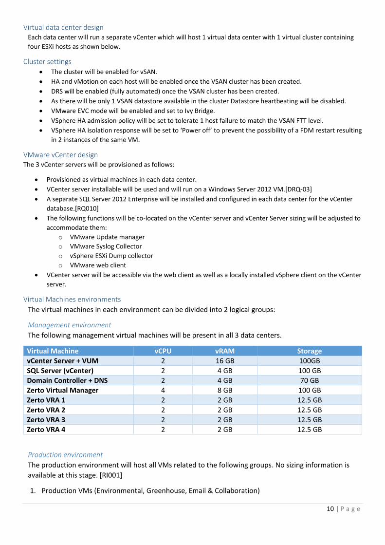
Virtual Machines environments
The virtual machines in each environment can be divided into 2 logical groups:
Management environment
The following management virtual machines will be present in all 3 data centers.
Virtual Machine vCPU vRAM Storage
vCenter Server + VUM 2 16 GB 100GB
SQL Server (vCenter) 2 4 GB 100 GB
Domain Controller + DNS 2 4 GB 70 GB
Zerto Virtual Manager 4 8 GB 100 GB
Zerto VRA 1 2 2 GB 12.5 GB
Zerto VRA 2 2 2 GB 12.5 GB
Zerto VRA 3 2 2 GB 12.5 GB
Zerto VRA 4 2 2 GB 12.5 GB
Production environment
The production environment will host all VMs related to the following groups. No sizing information is
available at this stage. [RI001]
1. Production VMs (Environmental, Greenhouse, Email & Collaboration)

11 | P a g e
2. Recovered VMs from secondary sites
3. Future applications
Guest Operating Systems All manually deployed (excludes appliances) virtual machines will run Microsoft Windows Server 2012.
Windows OS was chosen due to its ‘User friendly’ interface and the fact that most people already have a basic
working knowledge of windows. [DREQ-03]
Guest OS deployments All virtual machines will be deployed from a hardened Microsoft Windows Server 2012 template.
Guest OS Licensing While it remains to be seen how exactly Windows servers on Mars will be able to complete the Activation wizard, I
will be using Windows Server Datacenter edition licenses ‘assigned’ to each host.[AS006]
Snapshot management Snapshots will be made before any Guest OS related changes and deleted again as soon as the change is completed
and standard checks have been performed.
Snapshots should not be made of the ZVM servers in each data center as this can cause issues with the operation of
Zerto according to vendor manuals.
Network Design choices
Network adapters Each host will be fitted with a Mellanox 40/56-Gigabit ConnectX-3 EN MCX314A (2x QSFP) Ethernet Adapter.
Given that uplinks will be limited to 2 with the chosen server hardware I have gone with the following network
setup.
A single virtual distributed switch with 2 uplinks.
Ports groups will be created for:
o Management (VMkernel)
o vMotion (VMkernel)
o vSAN (VMkernel)
o VM traffic
o Zerto replication
Vlans will be used to segregate traffic.
Explicit Failover order will be defined as below
NIOC will be enabled and shares will be assigned to ensure appropriate bandwidth in case of contention.
Each uplink will be connected to a separate switch.
NAT will not be used in the environment as this is not needed and also not supported with the replication
software or the distributed Domain Controller setup.
Virtual Network Design
Virtual switches 1 virtual distributed switch will be used in each data center.
Data center vDS name
Air vDS_Air01
Water vDS_Water01
Fire vDS_Fire01

12 | P a g e
Portgroups The following portgroups will be created on each vDS:
Port Group name Explicit failover order
Primary Uplink Secondary Uplink
Management dvUplink1 dvUplink2
vMotion dvUplink1 dvUplink2
vSAN dvUplink1 dvUplink2
VMTraffic dvUplink2 dvUplink1
ZertoRep dvUplink2 dvUplink1
Vlans The following vlans will be used to segregate traffic:
Vlan ID Traffic
100 Management
120 vMotion
140 vSAN
200 VM traffic
300 Zerto Replication
NIOC NIOC will be enabled on the vDS level and the portgroups will be assigned to specific modified network resource
pools configured as shown in the table below.
Port Group Name Shares Limit
Management 5 N/A
vMotion 15 N/A
vSAN 30 N/A
VMTraffic 20 N/A
ZertoRep 30 N/A
Virtual network layout overview The following diagram presents an overview of the logical network setup in each datacenter.

13 | P a g e
Replication Design choices
The 2 main options were array based replication or hypervisor based replication.
Array based replication is not suitable in this environment as it requires standalone storage arrays in
each data center which are heavy to transport and consume unnecessary space and power. It also has
much more stringent connectivity requirements which might not be available.
With hypervisor based replication the obvious choice would be vSphere Replication but given the
following points it is also not suitable:
a. VSphere Replications has a minimum RPO time of 15 min. [RQ005]
b. VSphere Replication doesn’t provide any bandwidth optimization and compression.[CS003]
c. VSphere Replication has no consistency grouping of VMs.
Instead, this environment will use Zerto Virtual Replication 4.0 as the hypervisor based replication
solution.
Benefits of using Zerto
Built in WAN compression and acceleration
Recovery Point Objective (RPO) of seconds
Point in time recovery with journaling.
Per VM recovery.
Bidirectional replication.
Bitmap change caching in case of WAN outages.
Replication Design Requirements
Zerto requires that the following components are installed in each datacenter.
Zerto Virtual Manager (ZVM)
o Will use an embedded SQL database
1 Zerto Virtual Replication Appliance (VRA) per host

14 | P a g e
Offsite backups Offsite backups of critical VMs will be from both the Air and Water datacenter to the Fire datacenter.
Zerto offsite backup will be used to push these to SMB shares located on the Fire-vcluster01 datastore.
Zerto was chosen given that:
It does not use snapshot technology
Offsite backups are executed at the recovery site so there is no impact to the production sites.
Backup packages contain VM information + metadata so they can be recovered to different sites.
Simplifies administration by using a single solution.
Backup settings
Environmental systems backups
Field Setting
Retention period 1 Month
Job start time 23:00
Weekly (Friday)
Automatic retry Enabled
Retry attempts 3 times
Wait between retries 20 Minutes
Greenhouse systems backups
Field Setting
Retention period 1 Month
Job start time 23:00
Weekly (Saturday)
Automatic retry Enabled
Retry attempts 3 times
Wait between retries 20 Minutes
Future planning
File level Backups As of now no File level restores are possible as it is not a feature with Zerto.
Veeam 8 would be the best choice for most virtual environment backup scenario however as it is dependent on
snapshots this might not always be the case and as such has not been incorporated as a main component of the
design.
Depending on what details are revealed about the current applications and the future applications the backup
strategy might change.
High Level Veeam design would consist of a Veeam backup server located in Fire data center with 2 backup proxies
located in the Air and Water data center. All backups would be made to the local datastores in each datastore with
Zerto offsite backups covering any storage failures.
Sleep Tonight! Finally!

15 | P a g e
References
1. Virtual SAN 6.0 Design and Sizing – Cormac Hogan
http://www.vmware.com/files/pdf/products/vsan/VSAN_Design_and_Sizing_Guide.pdf
2. Zerto Virtual Manager Administration Guide
ftp://ftp.eutelia.it/Zerto/Docs/Zerto%20Virtual%20Manager%20Administration%20Guide.pdf
3. Atmospheric evolution of Mars – David Catling
http://www.atmos.washington.edu/~davidc/papers_mine/Catling-MarsAtmos-inpress2006.pdf