Embed Size (px)
DESCRIPTION
Main Catalogue Power Chucks - Cylinders
Citation preview

biting.
www.roehm.biz
Power Chucks Cylinders - Steady Rests
2013/2014

1www.roehm.bizErrors and corrections are reserved!
POWER CHUCKS - CYLINDERS -Power chucks without through-holeKFD-EC / KFD-F-EC 6013Jaws KFD-EC / KFD-F-EC 6017KFD-HS oil 6021KFD 6025Jaws KFD 6031KFL 6036Jaws KFL 6037KFD-G 6039Diaphragm clamping chucksMSF 6046Jaws MSF 6047Power chucks with through-holeKFD-HS 6053Jaws KFD-HS 6060KFD-HE 6072Jaws KFD-HE 6074Power-operated angle lever chucksKFM / KFG 6083Jaws KFM / KFG 6088Pneumatic operated high-precision chucksPKF 6090Jaws PKF 6092Gripper chuckGF 6094Jaws GF 6095Power chucks with quick-acting jaw change systemDURO-NC 6098Jaws DURO-NC 6102DURO-NCSE 6112Jaws DURO-NCSE 6116Power-operated collet chucks KZF 6125KZZF 6128KZZT 6132KZZT-A 6134KZZT-AF 6136KZF-S 6141Draw-down power chucksKFD-N 6145Power-operated ball lock draw-down chucksKBF-N 6148Jaws KBF-N 6151Power-operated draw bar chucksZFM 6152Jaws ZFM 6153Power-operated compensating chucksKFD-AF 6154Centering inserts KFD-AF 6156KFE 6160Jaws KFE 6163Power-operated combination chucksKKHFR 6166Hydraulically operated indexing chucksHSF 6169Cylinders without through-holeOVS 6178Stroke monitors 6180 EVS 6182LVS 6184Cylinders with through-holeSZS 6186EHS 6190LHS-L 6192Hydraulic operated double piston cylindersOVUSHH 6194Air-operated self-contained chucksLVE 6196Jaws LVE 6200LVE - large through-hole 6204Jaws LVE 6210Stationary power chucksSSP / SSH 6215Jaws SSP / SSH 6218
STEADY RESTS
Power-operated centering vicesKZS-P / KZS-PG 6222Jaws KZS-P / KZS-PG 6225Self-centering steady restsSLZ 6230SLZB 6233SLZ - heavy design 6236SLZW 6237SLZC 6238SLZK 6239SLZR 6240SLZV/SLZ VB 6246Control systems and AccessoriesLSG 6255
General information and guidelinesPower clamping devices 6260

Power chucks - Cylinders - Steady rests
Power chuck without through-hole 6012
Power chuck with through-hole 6050
Power chuck with quick-acting jaw change system 6096
Power-operated collet chuck 6124
Draw-down power chuck 6144
Power-operated compensating chuck 6154
Hydraulically operated indexing chuck 6168
Cylinder 6177
Air-operated self-contained chuck 6196
Stationary power chuck 6215
Steady rest 6226
Hydraulic power unit 6255

KFD
6002
Power chucks without through-hole
KFD-EC KFD-F-EC KFD-HS oil KFD KFL KFD-G
Power transmission
wedge wedge wedge wedge wedge wedge
Feature low-maintenance, quick jaw changing
low-maintenance, quick jaw changing,centrifugal forcecompensation
hermetically sealed with oil bath lubrication
light-weight chuck large jaw stroke
Size 200 - 400 200 - 400 210 - 333 85 - 800 250 - 600 125 - 400
Chucking capacities
16 - 490 16 - 490 4 - 890 40 - 690
Mount DIN 6353 DIN 6353 DIN 6353ISO 702-1(DIN 55026)DIN 55021
DIN 6353similar DIN 6353
Cylindrical centre mount
Cylindrical centre mount
Number of jaws
Type of jaws
Workpiece
Machining
Rotating / Stationary
Clamping force
Speeds
Page 6013 6014 6020 6022 6036 6039
Power chucks without through-hole
Operation guide
90°90° 90°90° 90°
Ope
ratio
n gu
ide
2-jaw chuck
3-jaw chuck
4-jaw chuck
pipe
bar
disc
flange
length machining
asymmetrical workpiece
60°
90°
serration 60°
tongue and groove
M
HSK
module toothing
positive taper lock
collet
serration 90°

KFD
6003
Power chucks with through-hole
Operation guide
without through-hole
Power chucks with through-hole
MSF KFD-HS KFD-HE KFM KFG
Power transmission
diaphragm wedge wedge angle lever angle lever
Feature quick-acting jaw change system HSK centric clamping
large through-hole, medium jaw movement
large through-hole, long jaw movement
Size 210 - 400 110 - 500 110 - 400 130 - 350 160 - 350
Chucking capacities
20 - 345 6 - 580 5 - 484 5 - 462 5 - 472
Mount Cylindrical centre mount,ISO 702-1(DIN 55026)
DIN 6353ISO 702-1(DIN 55026)DIN 55021
DIN 6353ISO 702-1(DIN 55026)DIN 55021
Cylindrical centre mount
Cylindrical centre mount
Number of jaws
Type of jaws
Workpiece
Machining
Rotating / Stationary
Clamping force
Speeds
Page 6045 6051 6068 6081 6084
HSK
Ope
ratio
n gu
ide
side machining
rotating
stationary
90° 90° 60° 60° 60°

KFD
6004
Power chucks with quick-acting jaw change system
Collet chucks
DURO-NC DURO-NCSE KZF KZZF KZZT
Power transmission
wedge wedge draw tube draw tube draw tube
Feature central jaw unlocking central jaw unlocking quick-acting bayonet catch
quick-acting bayonet catch,pull down
solid through-hole, with cylindrical centre
Size 140 - 630 170 - 630 40 - 80 40 - 80 32 - 120
Chucking capacities
5 - 780 8 - 667 2 - 80 2 - 80 4 - 120
Mount DIN 6353ISO 702-1(DIN 55026)DIN 55021
DIN 6353ISO 702-1(DIN 55026)DIN 55021
Cylindrical centre mount, short taper mount
Cylindrical centre mount
short taper mount
Number of jaws
Type of jaws
Workpiece
Machining
Rotating / Stationary
Clamping force
Speeds
Page 6098 6112 6125 6128 6132
Power chucks
Operation guide
Ope
ratio
n gu
ide
2-jaw chuck
3-jaw chuck
4-jaw chuck
pipe
bar
disc
flange
length machining
asymmetrical workpiece
60°
90°
serration 60°
tongue and groove
M
HSK
module toothing
positive taper lock
collet
serration 90°

KFD
6005
Collet chucks Draw-down power chucks
KZZT-A KZZT-AF KZF-S KFD-N KBF-N
Power transmission
draw tube draw tube draw tube wedge wedge
Feature solid through-hole, rigid axial stop
solid through-hole, rigid axial stop, clamping jaws Top Grip
quick-acting bayonet catch, pull down, operation of the mandrel
Active pull down for external chucking
Active pul down, hermetically sealed with oil bath lubrication
Size 32 - 120 32 - 120 80 - 180 220 - 800 170 - 400
Chucking capacities
4 - 120 4 - 120 30 - 180
Mount short taper mount short taper mount Adapter plate ISO 702-1(DIN 55026)DIN 55021
DIN 6353ISO 702-1(DIN 55026)DIN 55021
Number of jaws
Type of jaws
Workpiece
Machining
Rotating / Stationary
Clamping force
Speeds
Page 6134 6136 6141 6145 6148
Power chucks
Operation guide
Ope
ratio
n gu
ide
side machining
rotating
stationary

KFD
6006
Compensating chucks Air-operated self-contained chucks
KFD-AF KFE KKHFR LVE LVE large through-hole
Power transmission
wedge angle lever angle lever wedge wedge
Feature compensating jaws, piston with additional guidance
compensating jaws retractable jaws, piston with additional guidance
incorporated actuating cylinder
incorporated actu-ating cylinder, large through-hole
Size 160 - 315 170 -350 160 - 450 125 - 315 400 - 1000
Chucking capacities
5 - 393 24 - 473 18 - 300 12 - 400 85 - 1135
Mount Cylindrical centre mount, short taper mount, with option for radial fine adjustment
Cylindrical centre mount
ISO 702-1 (DIN 55026)
Cylindrical centre mount,ISO 702-1(DIN 55026), ISO 702-2 (DIN 55029), ISO 702-3 (DIN 55027)
Cylindrical centre mount
Number of jaws
Type of jaws Retractable jaws
Workpiece
Machining
Rotating / Stationary
Clamping force
Speeds
Page 6154 6160 6166 6196 6204
Power chucks
Operation guide
Ope
ratio
n gu
ide
60°90° 90° 90°
2-jaw chuck
3-jaw chuck
4-jaw chuck
pipe
bar
disc
flange
length machining
asymmetrical workpiece
60°
90°
serration 60°
tongue and groove
M
HSK
module toothing
positive taper lock
collet
serration 90°

KFD
6007
Stationary power chucks
Operation guide
Stationary power chucks
SSP SSH KZS-P KZS-PG
Power transmission
wedge wedge wedge wedge
Feature pneumatically, without through-hole
hydraulically, without through-hole
pneumatically, centering vices
pneumatically, centering vices, long jaw movement
Size 160 - 315 160 - 315 64 - 315 100 - 250
Chucking capacities
28 - 400 28 - 400
Mount Adapter plate Adapter plate Clamping sleeveDIN 7346
Clamping sleeveDIN 7346
Number of jaws
Type of jaws
Workpiece
Machining
Rotating / Stationary
Clamping force
Specialty serration 60°, tongue and groove and / or through-hole on request
serration 60°, tongue and groove and / or through-hole on request
Page 6215 6215 6222 6222
90° 90° 60° 60°
Ope
ratio
n gu
ide
side machining
rotating
stationary

6008
Cla
mpi
ng
com
bina
tions
Clamping combinations
Power chucking package with through-hole (hollow-center chucking)
Clamping cylinder with through-hole Power chuck with through-hole
Applicable for shafts and bar work
Power chucking package with partial through-hole (partial hollow-center chucking)
Clamping cylinder without through-hole Power chuck with through-hole
Applicable for parts with flange-type shoulders
Power chucking package without through-hole (closed center chucking)
Clamping cylinder without through-hole Power chuck without through-hole
Applicable for parts similar to flanges
Power chucks/Clamping cylinders
SZSLHS-LEHS
KFD-HSKFD-HEDURO-NCDURO-NCSEKZFKZZT/KZZT-A/KZZT-AFKFE, KFM, KFG ZFMLVE
OVSLVSEVS
KFD-HSKFD-HEDURO-NC DURO-NCSEKZFKZZT/KZZT-A/KZZT-AFKFE, KFM, KFG ZFM
OVSOVUSHHLVSEVS
KFDKFLKFD-ECKFD-F-ECKFD-HS oilKFD-GKFD-NKBF-NKFD-AFKKHFR ** only with OVUSHH

6009
Flex
ibili
ty o
f med
ia
supp
ly
Power chucks
For power chucks with or without through-hole
- with air passage for air sensing, air blocking or blast air - central lubrication - with guided and sealed piston neck- with drainage groove or drainage bore as well as covers resp. inserts for the center bore
Flexibility of media supply
Available on request:
Examples of modified power chucks with connections for:
Central lubrication via distributor flange with dosage valves
Air sensing
Blast air Coolant
Double connections, i. e. for central lubrication and air sensing are possible.

6010
Power chucks
Jaw quick change systemwith central jaw unlocking
Overview clamping systems
DURO-NC
Quick-acting jaw changesystem with individualjaw unlocking.
DURO-NCSE
Wedge systemwithout through-hole
KFD
Wedge systemwith large through-hole,for very high speeds,with minimal loss ofgripping force
KFD-HS
Wedge systemwith large through-hole
KFD-HE
Wedge systemwith large total jawmovement,without through-hole
KFD-G
Centrically clamping,ideally suited forgrinding and hard turningwith high precision, withHSK mounting for swift andsimple chuck
Diaphragm clamping chucks
Ove
rvie
w c
lam
ping
sy
stem
s

6011
Wedge systembase jaw compensating,with interchangeablecentering inserts,without through-hole
KFD-AF
Wedge systemwith draw-down effect,with through-hole
KFD-N
Power chucks
Power operated Ball LockDrawdown Chuck withactive drawdown action,hermetically sealed, oilfilled
Overview clamping systems
KBF-N
Power-operatedcollet chuck (pull)with through-hole,with rapid actionbayonet catch, for steelcollets to DIN 6343
KZZF
Wedge system actuatingcylinder is incorporated inthe chuck body,with through-hole
LVE
Power-operated collet chuck(push) with through-hole,with rapid actionbayonet catch, for steelcollets to DIN 6343
KZF
Pulling collets with fullthrough hole
KZZT
Pulling collets with fullthrough hole and a rigidaxial stop
KZZT-A
Power-operated colletchucks with fixed clampingjaws
KZZT-AF
Ove
rvie
w c
lam
ping
sy
stem
s

6012
Pow
er c
huck
s w
ithou
t thr
ough
-hol
e
OverviewPower chucks without through-hole
KFD-EC from page 6013
Wedge systemLow maintenance3-jaw designOptions: with or without force compensation
KFD-HS oil from page 6020
Wedge system
Almost maintenance-free due to oil bath lubrication
3-jaw design
KFD from page 6022
Wedge system
2-, 3- and 4-jaw design
Options: Weight reduced design
KFL from page 6036
Wedge system
Light weight, Body in aluminium design
3-design design
KFD-G from page 6039
Wedge system
Large jaw stroke
2-jaw design
MSF from page 6045
Diaphragm clamping chuck
Highest precision, with quick-acting jaw change system HSK
3-jaw design

6013
10
KFD
-EC
/ K
FD-F
-EC
Power chucks without through-hole
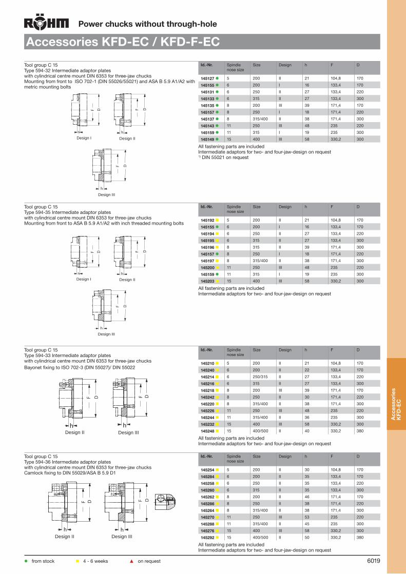
Technical features:
Easy Care: low-maintenance and wear resistant
Abrasionproof coating of the base jaw guidings
Improofed dirt protection by integrated jaw guiding seals
Especially for extreme operation conditions like dry or raw part machining and/or high coolant pressure
Maintenance intervals up to every 600 operation hours, depending on the operation conditions
Wedge system
Used in conjunction with RÖHM actuating cylinders with safety device SZS, OVS, LHS-L, LVS, EHS and EVS the power chucks KFD-EC and KFD-F-EC meet the requirements of the German Employers’ Insurance Association
25155-k006-043 26.04.2007 10:27 Uhr Seite 6043
25155-k006-043 26.04.2007 10:27 Uhr Seite 6043
KFD-EC / KFD-F-EC
4
5
6
8
910
11
4
56
7
8 9
1 2
3
1 BodyEnd coverBase jawFlat sealSquare ringCoverWiper platesO-RingPiston
23
456789
1 BodyEnd coverBase jawFlat sealSquare ringCoverWiper platesSquare ringCentrifugal forcecompensation massO-RingPiston
23
456789
10
11
KFD-F-EC with centrifugal force compensation
KFD-EC without centrifugal force compensation
1 2
3

6014
Power chucks without through-hole
KFD-EC 3-jaw, without force compensation, serration 90°
H
E
T 2,5 (Gr. 400:3,5)
c
B
C X
C1 -0,06
b
QON
K
R S
dV
H7
a
J
G
U
±0,05
A F
D H
6
315 x 90°400 x 90°
Tool group Type 538-00 Low-Maintenance 3 jaw power chuck KFD-EC, with short piston, without force compensation, with serration 90° centric clampingAdaptor recess, mounting dimensions to DIN 6353
Item no. 166183 166184 166185 166186
Size 200 250 315 400
A 200 250 315 400
Jaw travel B 6,7 6,7 8 9,3
C 86 98 113 121
C1-0,06 80 92 107 115
Mount DH6 170 220 300 300
E 6 6 6 6
F 133,4 171,4 235 235
G 3xM12 3xM16 3xM20 3xM20
H 18 23 31 30
J 85 105 120 155
Wedge stroke K 25 25 30 35
N 45 55 60 60
O 40 46 46 55
Q M20 M24 M24 M24
R 45 55 55 55
S min. 30 30 30 30
S max. 55 55 60 65
T±0,05 90 105 120 130
U M12x25 M16x30 M16x30 M20x40
VH7 110 130 160 190
X 7 7 9 9
a min. 43,3 53,3 59,5 77,7
a max. 50 60 67,5 87
b min. 8 10 10 14
c min. 19 25 25 31
c max. 34,5 47,5 70,5 87
d 45 59 84 107
e 35 50 55 60
fH7 17 21 21 25,5
g 14 18 18 22
h 11 13 13 22
i 11 14 14 18
k 25 32 32 40
Maximum draw bar pull kN 45 65 80 95
Max. total clamping force kN 90 140 190 250
Max. admissible speed min-1 4000 3200 2800 2000
Moment of inertia J kgm2 0,1 0,28 0,89 2,02
Weight without jaws approx. kg
19,3 34,8 63,6 88,4
Intermediate flanges for short taper adaption on request
e
f H7
3 x 1
20°
3 x 120°
kh
g
i
Pow
er c
huck
with
out
thro
ugh-
hole
KFD
-EC
from stock 4 - 6 weeks ▲ on request

6015
Power chucks without through-hole
KFD-F-EC 3-jaw, with force compensation, serration 90°
Tool group C15Type 541-00 Low-Maintenance 3 jaw power chuck KFD-F-EC, with short piston, with force compensation, with serration 90°, centric clampingAdaptor recess, mounting dimensions to DIN 6353
Item no. 167329 167330 167331 167332
Size 200 250 315 400
A 200 250 315 400
Jaw travel B 5,3 6,7 6,7 8
C 115 141 155 161
C1-0,06 109 135 149 161
Mount DH6 170 220 300 300
E 6 6 6 6
F 133,4 171,4 235 235
G 3 x M12 3 x M16 3 x M20 3 x M20
H 18 25 31 30
J 85 105 120 155
Wedge stroke K 20 25 25 30
N 45 55 55 55
O 40 46 46 46
Q M20 M24 M24 M24
R 45 55 55 55
S min. 30 30 30 30
S max. 50 55 55 60
T±0,05 122 148 162 180
U M12 x 25 M16 x 30 M16 x 30 M20 x 40
VH7 110 130 160 190
X 7 7 9 9
a min. 40,7 48,3 59,3 79
a max. 46 55 66 87
b 8 10 10 14
d 49 64 85,5 107
e 35 50 55 60
fH7 17 21 21 25,5
g 14 18 18 22
h 11 13 13 22
i 25 32 32 40
k 11 14 14 18
Maximum draw bar pull kN 45 65 75 110
Max. total clamping force kN 95 140 180 250
Max. admissible speed min-1 5000 4000 4000 3000
Moment of inertia J kgm2 0,13 0,4 1,1 2,7
Weight without jawsapprox. kg
25,7 49,3 88,2 152,8
Pow
er c
huck
with
out
thro
ugh-
hole
KFD
-F-E
C
from stock 4 - 6 weeks ▲ on request

6016
Power chucks without through-hole
KFD-F-EC 3-jaw, with force compensation, tongue and groove
Tool group C15Type 541-10 Low-Maintenance 3 jaw power chuck KFD-F-EC, with short piston, with force compensation, with tongue and groove, centric clampingAdaptor recess, mounting dimensions to DIN 6353
Item no. 166187 166188 166189 166190
Size 200 250 315 400
A 200 250 315 400
Jaw travel B 5,3 6,7 6,7 8
C 115 141 155 167
C1-0,06 109 135 149 161
Mount DH6 ZA 170 ZA 220 ZA 220 ZA 300
E 6 6 6 6
F 133,4 171,4 171,4 235
G 3xM12 3xM16 3xM16 3xM20
H 18 25 26 30
J 85 105 105 155
Wedge stroke K 20 25 25 30
N 45 55 55 55
O 40 46 46 46
Q M20 M24 M24 M24
R 45 55 55 55
S min. 30 30 30 30
S max. 50 55 55 60
T±0,05 118 144 158 170
U M12 M16 M16 M20
VH7 110 130 130 190
X 7 7 7 9
a min. 64,7 81,3 103,5 133,5
a max. 70 88 110,5 141,5
b 15 20 25 40
cg6 12 16 16 25
d 55 70 91,5 115
e 35 50 50 60
fH7 16 20 20 25
g 14 18 18 22
h 11 13 13 22
i 25 32 32 40
k 11 14 14 18
l 24 29 39 46
m 18 22 26 30
n 5 5 5 6
o 30 40 50 80
Max. interferences diameter top jaws mm
216,1 269,1 334,8 423,9
Maximum draw bar pull kN 45 65 75 110
Max. total clamping force kN 95 140 180 250
Max. admissible speed min-1 5000 4000 4000 3000
Moment of inertia J kgm2 0,13 0,4 1,1 2,7
Weight without jaws approx. kg
25,7 49,4 88,4 152,1
Intermediate flanges for short taper adaption on request
H
ET
l
B
C X
C1 -0,06b
QON
K
R S
dV
a
J
G
Uc
m
n
o
±0,05
A F
D H
6
e
f H7
3 x 120°
3 x 120
°
kh
g
i
Pow
er c
huck
with
out
thro
ugh-
hole
KFD
-F-E
C
from stock 4 - 6 weeks ▲ on request

6017
Power chucks without through-hole
Jaws KFD-EC / KFD-F-EC
Tool group C 21Type 543/538 Reversible top jaws, 3-jaw set, hardenedSerration 90°- material: 16 MnCr 5
Item no. Chuck Size Jaw length Jaw height Jaw width Serration
118522 200 75 49 36 1/16”x 90°
046414 250/315 103,5 58 50 1/16’’x 90°
037531 400 135 65 68 3/32”x 90°1) one step only2) one step only, extendedHardened jaws, supplied as supplement or as spares, must be ground on the chuck.
Tool group C 21Type 543/538 Soft top jaws, 3-jaw set, can be hardenedSerration 90°- material: 16 MnCr 5
Item no. Chuck Size Jaw length Jaw height Jaw width Serration
133153 200 75 53 36,5 1/16”x 90°
133154 250 95 54,5 45 1/16”x 90°
133155 315 103 80 50 1/16”x 90°
133156 400 130 80 50 3/32”x 90°1) heavy design
Tool group C 21Type 549/538 Soft top jaws, 3-jaw set, can be hardenedtongue and groove 120° bevelled, material: 16 MnCr 5
Item no. Chuck Size Jaw length Jaw height Jaw width
123430 200 90,3 53 36,5
123433 250/315 115,3 54,5 45
129849 315/400 146 80 50
Tool group C 21Type 544-50 Claw-type jaws, 1 piece, hardenedSerration 90° - width of the groove 17
Item no. Chuck Size Jaw length Jaw height Jaw width
137031 200 67 45 53
137032 200 65 45 46
137033 200 55 45 39
137034 200 50 45 31
137035 200 55 45 27
137036 200 65 45 19
137037 200 65 45 26
137038 200 55 45 24
137039 200 55 45 40
Tool group C 21Type 544-50 Claw-type jaws, 1 piece, hardenedSerration 90° - width of the groove 21
Item no. Chuck Size Jaw length Jaw height Jaw width
137041 250/315 95 50 80
137042 250/315 75 50 60
137043 250/315 60 50 43
137044 250/315 70 50 37
137045 250/315 95 50 25
137046 250/315 80 50 30
Jaw
s K
FD-F
-EC
from stock 4 - 6 weeks ▲ on request

6018
Power chucks without through-hole
Jaws KFD-EC / KFD-F-EC
Tool group C 21Type 544-50 Claw-type jaws, 1 piece, hardenedSerration 90° - width of the groove 25,5
Item no. Chuck Size Jaw length Jaw height Jaw width
137051 400 130 65 113
137052 400 90 65 67
137053 400 100 65 45
137054 400 130 65 33
Accessories KFD-EC / KFD-F-ECTool group C 15 Type 538-00 T-nuts
without screwTool group C 15 Type 0040-Y Mounting screws
E
D
Item no. Contents of delivery
D E
241674 piece 17 M12
241675 piece 21 M16
2416761) piece 25,5 M20
Single T-nut1) metric dimensions
Item no. Contents of delivery
Thread Length
227692 piece M12x25
229157 piece M16 30
233047 piece M20x40
Socket head cap screw to DIN 912, 12.9
Tool group C15 Type 1028 Special grease F80 for lathe chucksfor lubrication and conservation of chucking power
Item no. Design Contents
028975 Tin 1 kg
308555 Cartridge 0,5 kg
Tool group A09Type 619-30 Short-taper adapter plate ISO 702-1 (DIN 55026/55021) - ASA B 5.9 (without mounting bolts)finished on machine side, faced on chuck side, especially
Id.-Nr. Spindle nose size
h EH6 M D
144933 ▲ 3 18 40 40 125
145296 ▲ 4 18 40 40 125
145328 ▲ 3 18 40 40 160
145342 ▲ 4 18 40 40 160
145343 ▲ 5 21 50 50 160
145344 ▲ 4 21 50 50 200
145345 ▲ 5 21 50 50 200
145346 ▲ 6 27 50 50 200
145347 ▲ 4 27 63 63 250
145348 ▲ 5 27 63 63 250
145349 ▲ 6 27 63 63 250
145350 ▲ 8 27 63 63 250
145351 ▲ 5 36 63 63 315
145352 ▲ 6 36 63 63 315
145353 ▲ 8 36 63 63 315
145354 ▲ 11 36 63 63 315
145355 ▲ 6 40 63 63 400
145356 ▲ 8 40 63 63 400
145357 ▲ 11 40 63 63 400
145358 ▲ 15 40 63 63 400
145359 ▲ 8 42 80 80 500
145360 ▲ 11 42 80 80 500
145364 ▲ 15 42 80 80 500
Jaw
s K
FD-E
C
from stock 4 - 6 weeks ▲ on request
6019
Power chucks without through-hole
Accessories KFD-EC / KFD-F-EC
Tool group C 15Type 594-32 Intermediate adaptor plates with cylindrical centre mount DIN 6353 for three-jaw chucksMounting from front to ISO 702-1 (DIN 55026/55021) and ASA B 5.9 A1/A2 with metric mounting bolts
Id.-Nr. Spindle nose size
Size Design h F D
145127 5 200 II 21 104,8 170
145155 6 200 I 16 133,4 170
145131 6 250 II 27 133,4 220
145133 6 315 II 27 133,4 300
145135 8 200 III 39 171,4 170
145157 8 250 I 18 171,4 220
145137 8 315/400 II 38 171,4 300
145143 11 250 III 48 235 220
145159 11 315 I 19 235 300
145149 15 400 III 58 330,2 300
All fastening parts are includedIntermediate adaptors for two- and four-jaw-design on request1) DIN 55021 on request
Tool group C 15Type 594-35 Intermediate adaptor plates with cylindrical centre mount DIN 6353 for three-jaw chucksMounting from front to ASA B 5.9 A1/A2 with inch threaded mounting bolts
Id.-Nr. Spindle nose size
Size Design h F D
145192 5 200 II 21 104,8 170
145155 6 200 I 16 133,4 170
145194 6 250 II 27 133,4 220
145195 6 315 II 27 133,4 300
145196 8 315 II 39 171,4 300
145157 8 250 I 18 171,4 220
145197 8 315/400 II 38 171,4 300
145200 11 250 III 48 235 220
145159 11 315 I 19 235 300
145203 15 400 III 58 330,2 300
All fastening parts are includedIntermediate adaptors for two- and four-jaw-design on request
Tool group C 15Type 594-33 Intermediate adaptor plates with cylindrical centre mount DIN 6353 for three-jaw chucksBayonet fixing to ISO 702-3 (DIN 55027)/ DIN 55022
Id.-Nr. Spindle nose size
Size Design h F D
145210 5 200 II 21 104,8 170
145240 6 200 II 22 133,4 170
145214 6 250/315 II 27 133,4 220
145216 6 315 II 27 133,4 300
145218 8 200 III 39 171,4 170
145242 8 250 II 30 171,4 220
145220 8 315/400 II 38 171,4 300
145226 11 250 III 48 235 220
145244 11 315/400 II 36 235 300
145232 15 400 III 58 330,2 300
145248 15 400/500 II 40 330,2 380
All fastening parts are includedIntermediate adaptors for two- and four-jaw-design on request
Tool group C 15Type 594-36 Intermediate adaptor plates with cylindrical centre mount DIN 6353 for three-jaw chucksCamlock fixing to DIN 55029/ASA B 5.9 D1
Id.-Nr. Spindle nose size
Size Design h F D
145254 5 200 II 30 104,8 170
145284 6 200 II 35 133,4 170
145258 6 250 II 35 133,4 220
145260 6 315 II 35 133,4 300
145262 8 200 II 46 171,4 170
145286 8 250 II 38 171,4 220
145264 8 315/400 II 38 171,4 300
145270 11 250 III 53 235 220
145288 11 315/400 II 45 235 300
145276 15 400 III 58 330,2 300
145292 15 400/500 II 50 330,2 380
All fastening parts are includedIntermediate adaptors for two- and four-jaw-design on request
Acc
esso
ries
K
FD-E
C
from stock 4 - 6 weeks ▲ on request
F D
h
F D
hDesign II Design III
F D
h
F D
hDesign II Design III
F D
h
F D
h
h
F D
Design I Design II
Design III
F D
hF D
h
h
F D
Design I Design II
Design III

6020
Pow
er c
huck
with
out
thro
ugh-
hole
KFD
-HS
oil
Power chucks without through-hole
KFD-HS oil
Almost maintenance-free
Hermetically sealed from coolant and filth
All moving parts are oil bathed
Control unit monitoring oil level
High radial and axial true-running accuracy
High clamping forces
Long jaw ways
High speed
Steel design
All parts subject to wear are hardened and ground
Base jaw secured against throw-off
Used in conjunction with RÖHM actuating cylinders with safety device SZS, OVS, LHS-L, LVS, EHS and EVS the power chucks KFD-HS oil meet the requirements of the German Em-ployers’ Insurance Association
2-, 3- or 4-jaw-design
Serration 90° or tongue and groove
Short taper or cylindrical center mount
With or without through-hole
Design principleThe power operated chuck KFD-HS oil is based upon the approved power operated chuck KFD-HS. In contrast with other chucks this design has its advantages in having all moving parts permanently lubricated in an oil bath. That is the reason for the KFD-HS oil being almost maintenance free.An integrated control unit is monitoring the oil level inside the chuck. Specially sealed from coolant and filth.
Technical features:
Design versions (on request):

6021
Power chucks without through-hole
KFD-HS oil bath lubricated, tongue and grooveA F D N
G
E
K
C
H
T
B
d
5
RP S
O Q
5
m
A1
U
oca
b
7° 7'30"
fe
30o
3x120o
3x120o
Tool group C15Type 549 3 jaw power chuck, tongue and groove, oil bath lubricatedshort taper mount
Item no. 426225 421626 421627 421244
Size 210 270 300 333
number of jaws 3 3 3 3
A1 210 270 300 333
A 200 250 280 315
Jaw travel B 4,9 6,2 6,2 6,2
C 110 152 152 165
Mount D Ø 170 8 8 11
E 6 19 19 21
F 133,4 171,4 171,4 235
G M 12 M 16 M 16 M 20
H 18 23 23 33
Wedge stroke K 16 23 23 23
N 40 68 68 118
O 40 46 46 -
P 30 30 30 -
Q M 20 M 24 M 24 M 80 x 2
R 45 55 55 36
S min. 30 15 15 -9
S max. 46 38 38 14
T 110 147 152 165
U M12 M12 M12 M16
a min. 56,6 78,8 73,8 93,8
a max. 61,5 85 80 100
b 15 16 20 23
c 12 16 20 20
d 54 62 76 78
e 32 40 40 42
fH7-0,025 16 20 20 20
m 22 18 18 27
o 30 32 40 46
Maximum draw bar pull kN 45 65 65 80
Max. total clamping force kN 88 150 150 180
Max. admissible speed min-1 3700 3700 3400 3150
Moment of inertia J kgm2 0,14 0,5 0,7 1,2
Weight without jaws approx. kg
27 65 75 95
Top jaws hardened or soft, with serration or draw down body on request
Pow
er c
huck
with
out
thro
ugh-
hole
KFD
-HS
oil
from stock 4 - 6 weeks ▲ on request
Technical features:
6022
Pow
er c
huck
with
out
thro
ugh-
hole
KFD
Power chucks without through-hole
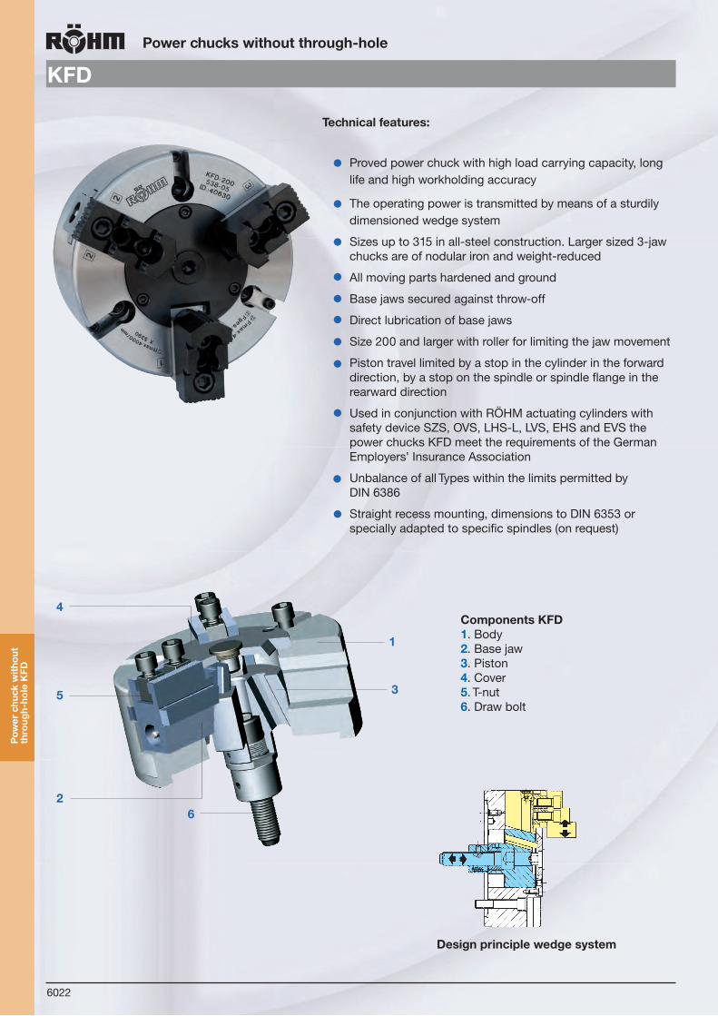
KFD
Components KFD1. Body 2. Base jaw 3. Piston 4. Cover5. T-nut 6. Draw bolt
1
35
4
26
Proved power chuck with high load carrying capacity, long life and high workholding accuracy
The operating power is transmitted by means of a sturdily dimensioned wedge system
Sizes up to 315 in all-steel construction. Larger sized 3-jaw chucks are of nodular iron and weight-reduced
All moving parts hardened and ground
Base jaws secured against throw-off
Direct lubrication of base jaws
Size 200 and larger with roller for limiting the jaw movement
Piston travel limited by a stop in the cylinder in the forward direction, by a stop on the spindle or spindle flange in the rearward direction
Used in conjunction with RÖHM actuating cylinders with safety device SZS, OVS, LHS-L, LVS, EHS and EVS the power chucks KFD meet the requirements of the German Employers’ Insurance Association
Unbalance of all Types within the limits permitted by DIN 6386
Straight recess mounting, dimensions to DIN 6353 or specially adapted to specific spindles (on request)
Technical features:
Design principle wedge system

6023
Power chucks without through-hole
KFD in Special design (with additional sealing)
Pow
er c
huck
with
out
thro
ugh-
hole
KFD
Type 538-40 For stationary mounting,hermetically sealed.Used on transfer lines and rotary indexing tablemachines.
Type 538-41 For stationary or rotary mounting, hermeticallysealed. Used on transfer linesand rotary index-ing table machines, requiring verylittle space.
Type 538-42 Efficient sealing bymeans of wipers.Used on lathes.
Type 538-43 Hermetically sealed, for applications involving particularly high chip andcoolant flows, such as automatics and production ma-chines, rotatingor stationary.
On request:

6024
KFD
Pow
er c
huck
with
out
thro
ugh-
hole
KFD
Power chucks without through-hole
KFD
Gripping force/speed diagrams
The loss of gripping force was determinedexperimentally on a chuck with matchedUB top jaws. It is largely independent ofthe initial gripping force at zero speed.
Upper curve: min. centrifugalforce of top jaw
Lower curve: max. centrifugalforce of top jaw
To obtain the specified gripping forces,the chuck must be in a perfect conditionand lubricated with F 80 lubricant recommendedby Röhm. Measuring point near chuck face. Example: For a KFD chuck size 250 and an applied operating power of 40 kN, the total gripping force is approx. 86 kN.
6082
1000 2000 3000 4000 5000
20
40
60
80
100
120
140
160
180
200 KFD 315
KFD 315
KFD 250
KFD 200
KFD 160
KFD 130
Betätigungskraft kN -- operating power kN
Futter-Größe -- Gesamtspannkraft -- Total gripping force kNChuck size
315
250
200
160
130
10 20 30 40 50 60 70 80 90 100
35
50 70
50 100
50
50 90
140
100 150 190
Betätigungskraft kN -- operating power kN
630/800
500
400
30 40 50 60 70 80 90 100 110 120 130
100
100 150
100 150
150 200 250
200 250
200 250 300 360
300
Futter-Größe -- Gesamtspannkraft -- Total gripping force kNChuck size
Kraf
tspa
nnfu
tter
Pow
er c
huck
s
25155-k006-082 26.04.2007 10:35 Uhr Seite 6082
200 400 600 800 1000 1200 1400 1600 1800 2000
40
80
120
160
200
240
280
320
360
400
KFD 800
KFD 630
KFD 500
KFD 400
25155-k006-082 26.04.2007 10:35 Uhr Seite 6082
Tota
l grip
ping
forc
e kN
Tota
l grip
ping
forc
e kN
Speed min -1
Speed min -11000 2000 3000 4000 5000
Drehzahl – Speed min–1
Ges
amts
pann
kraf
t – T
otal
grip
ping
forc
e kN
20
40
60
80
100
120
140
160
180
200 KFD 315
KFD 315(Flachbauweise)(shallow design)
KFD 250
KFD 200
KFD 160
KFD 130
320
360
400
KFD 800
KFD 630
KFD 500
Spannkraft-Drehzahl-Diagramme -- Gripping force/speed diagrams
Spannkraft-Diagramme für KFD -- Gripping force diagrams
315
250
200
160
130
10 20 30 40 50 60 70 80 90 100
35
50 70
50 100
50
50 90
140
100 150 190
630/800
500
400
30 40 50 60 70 80 90 100 110 120 130
100
100 150
100 150
150 200 250
200 250
200 250 300 360
300
Kraf
tspa
nnfu
tter
Pow
er c
huck
s
25155-k006-082 26.04.2007 10:35 Uhr Seite 6082
Total gripping force kN
Operating power kN
Chuck size
Gripping force/operating power diagram for three-jaw chucks
Total gripping force kN
Operating power kN
Chuck size
(shallow design)

6025
Power chucks without through-hole
KFD, 3-jaw, standard design, serration 90°
Tool group C15Type 538-05 / -55 (shallow design) 3 jaw power chuck, standard design, serration 90° Adaptor recess, mounting dimensions to DIN 6353
Item no. 004250
1284051)
041240
1284061)
023520
040630
144598
1445991)
040653
040660
040669
040676
061163 ▲
Size 110 125 130 140 160 200 250 315 315 400 500 630 800
A 110 125 130 140 160 200 250 315 315 400 500 630 800
Jaw travel B 2,1 3,7 5,3 3,7 5,3 6,7 6,7 6,7 8 9,3 9,3 10,5 10,5
C 31,5 40 69 40 79 87 102 102 117 127 127 140 160
C1-0,06 28,55 37,05 58,05 37,05 66,05 74,05 89,05 89,05 104,05 111,05 111,05 125,05 142,05
Mount DH6 92 105 115 105 140 170 220 220 300 300 380 380 460
E 3 3 6 3 6 6 6 6 6 6 6 8 8
F 80 80 85 80 104,8 133,4 171,4 171,4 235 235 330,2 330,2 380
G 3 x M 8 3 x M 8 3 x M 10 3 x M 8 3 x M 10 3 x M 12 3 x M 16 3 x M 16 3 x M 20 3 x M 20 6 x M 24 6 x M 24 6 x M 24
H 12 14 15 12 17 20 26 26 30 35 35 35 35
J 45 50 58 50 65 85 105 105 120 155 155 180 180
Wedge stroke K 8 14 20 14 20 25 25 25 30 35 35 40 40N - - 35 - 35 45 55 55 60 60 60 80 80
O - - 34 - 34 40 46 46 46 55 55 55 55
P - - 25 - 25 30 30 30 30 30 30 30 30
Q M20x1,5 M20x1,5 M 16 M20x1,5 M 16 M 20 M 24 M 24 M 24 M 24 M 30 M 30 M 30
R 20 20 40 20 40 45 55 55 55 55 55 63 85
S min. 25 25 36 25 25 30 30 30 30 30 30 28 30
S max. 33 39 56 39 45 55 55 55 60 65 65 68 70
T±0,05 34 44 73 44 80 90 105 105 120 130 130 148 161
U M 6x18 M 6x18 M 8x20 M 6x18 M 12x25 M 12x25 M 16x30 M 16x30 M 16x30 M 20x40 M 20x40 M 20x40 M 20x40
VH7 - - 85 - 85 110 130 130 160 190 190 220 220
X 4 6 5 6 3 3 3 3 3 3 3 6 3
a min. 23,9 24,3 25 24,3 26,7 38,3 48,3 48,3 54 72,7 72,7 85,2 84,5
a max. 26 28 30,3 28 32 45 55 55 62 82 82 95,7 95
b min. 8,2 7 6 7 9 8 10 10 10 14 14 18 18
c min. 10 10 14 10 19 19 25 25 25 31 31 31 31
c max. 14,8 25 26 25 36,5 44,5 58,5 89,5 81,5 98 148 197 282
d 28 34,5 34,5 42 48 55 70 102,5 95 118 164 219,3 305
e 25 25 30 25 35 35 50 50 55 60 60 70 70
fH7 10 10 12 10 17 17 21 21 21 25,5 25,5 25,5 25,5
g - - - - 14 14 18 18 18 22 22 22 22
h - - - - 11 11 13 13 13 22 22 22 22
i - - - - 25 25 32 32 32 40 40 40 40
k - - - - 11 11 14 14 14 18 18 18 18
Max. swing top jaws mm
172 192 184 207 215 290 345 410 410 560 660 790 960
Maximum draw bar pull kN
7 9 18 9 35 45 65 75 80 95 110 130 130
Max. total clamping force kN
12 15 35 15 70 90 140 180 190 250 300 360 360
Max. admissible speed min-1
4000 5000 5000 4500 4500 4000 3200 2800 2800 2000 1600 1200 800
Moment of inertia J kgm2
0,003 0,007 0,014 0,011 0,035 0,095 0,28 0,72 0,87 1,96 4,31 13,4 31,2
Weight without jaws approx. kg
2,1 3,6 6,8 4,6 10,9 19 35,5 58,5 70 98 138 270 390
1) Shallow design
from stock 4 - 6 weeks ▲ on request
Design with guided piston available on request.
Pow
er c
huck
with
out
thro
ugh-
hole
KFD
fH7e
8o Size 130
kh
g
i
Size 110, 125, 140
fH7e
8o Size 130
kh
g
i
Size 110, 125, 140

6026
Power chucks without through-hole
KFD 3-jaw, standard design, tongue and groove
Tool group C15Type 538-10 / -60 (shallow design) 3 jaw power chuck, with tongue and grooveAdaptor recess, mounting dimensions to DIN 6353
Item no. 123110 004266 1284271) 041246 1284281) 023529 040639 144604 144605
Size 85 110 125 130 140 160 200 250 315
A 85 110 125 130 140 160 200 250 315
Jaw travel B 2,6 2,1 3,7 5,3 3,7 5,3 6,7 6,7 6,7
C 31,5 31,5 40 69 40 79 87 102 102
C1-0,06 28,55 28,55 37,05 58,05 37,05 66,05 74,05 89,05 89,05
Mount DH6 70 92 105 115 105 140 170 220 220
E 3 3 3 6 3 6 6 6 6
F 54 80 80 85 80 104,8 133,4 171,4 171,4
G 3 x M8 3 x M8 3 x M8 3 x M10 3 x M8 3 x M10 3 x M12 3 x M16 3 x M16
H 12 12 14 15 14 17 20 26 26
J 36 45 50 58 50 65 85 105 105
Wedge stroke K 10 8 14 20 14 20 25 25 25
N 20 - - 35 - 35 45 55 55
O - - - 34 - 34 40 46 46
P - - - 25 - 25 30 30 30
Q M16 x 1,5 M20 x 1,5 M20 x 1,5 M16 M20 x 1,5 M16 M20 M24 M24
R 20 20 20 40 20 40 45 55 55
S min. 25 25 25 36 25 25 30 30 30
S max. 35 33 39 56 39 45 55 55 55
T±0,05 33 33 44 73 44 80 90 105 105
U M8 M6 M6 M12 M12 M12 M12 M16 M16
VH7 - - - 85 - 85 110 130 130
X 4 4 6 5 6 3 3 3 3
a min. 29,4 37,9 40,3 47,5 53,8 46,7 63,3 81,3 93,3
a max. 32 40 44 52,8 57,5 52 70 88 100
b - 7,5 7,5 14,5 14,5 12,5 15 20 25
cg6 8 8 8 13 13 10 12 16 16
d 22 28 34,5 34 42 48 55 70 102
e 20 25 25 30 25 35 35 50 50
fH7 8 8 8 8 8 16 16 20 20
g - - - - - 14 14 18 18
h - - - - - 11 11 13 13
i - - - - - 25 25 32 32
k - - - - - 11 11 14 14
l 7 10 12,75 5,5 6 23 24 29 49
m 14 12 12 20 20 20 20 25 25
n 2,5 2,5 3 3 3 5 5 5 5
o - 15 15 - - 25 30 40 50
Maximum draw bar pull kN
7 7 9 18 9 35 45 65 75
Max. total clamping force kN
12 12 15 35 15 70 90 140 180
Max. admissible speed min-1
5000 4000 5000 5000 4500 4500 4000 3200 2800
Moment of inertia J kgm2
0,001 0,003 0,007 0,0145 0,012 0,035 0,096 0,28 0,73
Weight without jaws approx. kg
1,3 2,1 3,7 6,9 4,7 11 19,2 36 59
1) Shallow design
from stock 4 - 6 weeks ▲ on request
Design with guided piston available on request.
Pow
er c
huck
with
out
thro
ugh-
hole
KFD
Q
S
R
Nf7
Size 85 - 140Ø 1
2, s
ize.
85:
Ø 8
m3 3
b
a
d
u
l
cg6
Size 130 - 140
3,5
U
m
l
a
d
2, 5
cg6
Size 85
e
fH7
8o Size 130, 140
kh
g
i
from size 160
Q
S
R
Nf7
Size 85 - 140Ø 1
2, s
ize.
85:
Ø 8
m3 3
b
a
d
u
l
cg6
Size 130 - 140
3,5
U
m
l
a
d
2, 5
cg6
Size 85
e
fH7
8o Size 130, 140
kh
g
i
from size 160
Q
S
R
Nf7
Size 85 - 140Ø 1
2, s
ize.
85:
Ø 8
m3 3
b
a
d
u
l
cg6
Size 130 - 140
3,5
U
m
l
a
d
2, 5
cg6
Size 85
e
fH7
8o Size 130, 140
kh
g
i
from size 160

6027
Power chucks without through-hole
KFD 3-jaw, weight reduced, serration 90°
Tool group C15Type 538-03 3 jaw power chuck, weight reduced, serration 90°Adaptor recess, mounting dimensions to DIN 6353
Item no. 046730 0467311) 046744 0467451) 144594 1445951) 144596 1445971)
Size 160 160 200 200 250 250 315 315
A 160 160 200 200 250 250 315 315
Jaw travel B 5,3 5,3 6,7 6,7 6,7 6,7 6,7 6,7
C 79 79 87 87 102 102 102 102
C1-0,06 66,05 66,05 74,05 74,05 89,05 89,05 89,05 89,05
Mount DH6 140 150 170 185 220 220 220 220
E 6 6 6 6 6 6 6 6
F 104,8 100 133,4 133,4 171,4 171,4 171,4 171,4
G 3 x M 10 3 x M 12 3 x M 12 3 x M 12 3 x M 16 3 x M 16 3 x M 16 3 x M 16
H 17 20 20 20 26 26 26 26
J 65 65 85 85 105 105 105 105
Wedge stroke K 20 20 25 25 25 25 25 25
N 35 35 45 45 55 55 55 55
O 34 34 40 40 46 46 46 46
P 25 25 30 30 30 30 30 30
Q M16 M 16 M20 M 22 M24 M 22 M24 M 22
R 40 40 45 50 55 50 55 50
S min. 25 25 30 30 30 30 30 30
S max. 45 45 55 55 55 55 55 55
T±0,05 80 80 90 90 105 105 105 105
U M 12 x 25 M 12 x 25 M 12 x 25 M 12 x 25 M 16 x 30 M 16 x 30 M 16 x 30 M 16 x 30
VH7 85 85 110 110 130 130 130 130
X 3 3 3 3 3 3 3 3
a min. 26,7 26,7 38,3 38,3 48,3 48,3 48,3 48,3
a max. 32 32 45 45 55 55 55 55
b min. 9 9 8 8 10 10 10 10
c min. 19 19 19 19 25 25 25 25
c max. 36,5 36,5 44,5 44,5 58,5 58,5 89,5 89,5
d 48 48 55 55 70 70 102,5 102,5
e 35 35 35 35 50 50 50 50
fH7 17 17 17 17 21 21 21 21
Max. swing top jaws mm
215 215 290 290 345 345 410 410
Maximum draw bar pull kN
35 35 45 45 65 65 75 75
Max. total clamping force kN
70 70 90 90 140 140 180 180
Max. admissible speed min-1
4500 4500 4000 4000 3200 3200 2800 2800
Moment of inertia J kgm2
0,027 0,027 0,076 0,076 0,226 0,226 0,496 0,496
Weight without jaws approx. kg
8,5 8,5 15,2 15,2 29 29 40 40
1) Mounting dimensions different to DIN 6353
fH7e
from stock 4 - 6 weeks ▲ on request
Design with guided piston available on request.
Pow
er c
huck
with
out
thro
ugh-
hole
KFD

6028
Power chucks without through-hole
KFD 2-jaw, standard design, serration 90°
Tool group C15Type 528-05 / -15 (shallow design) 2 jaw power chuck, standard design, serration 90°Adaptor recess, mounting dimensions to DIN 6353
Item no. 1284091) 046722 1284121) 046733 046747 144610 1446111) 045563 045574 045582 ▲ 045590 ▲
Size 125 130 140 160 200 250 315 315 400 500 630
A 125 130 140 160 200 250 315 315 400 500 630
Jaw travel B 3,7 5,3 3,7 5,3 6,7 6,7 6,7 8 9,3 9,3 10,5
C 40 69 40 79 87 102 102 117 127 127 140
C1-0,06 37+0,07 58,05 37+0,07 66,05 74,05 89,05 89,05 104,05 111,05 111,05 125,05
Mount DH6 105 115 105 140 170 220 220 300 300 380 380
E 3 6 3 6 6 6 6 6 6 6 8
F 80 85 80 104,8 133,4 171,4 171,4 235 235 330,2 330,2
G 4xM8 4xM10 4xM8 4xM10 4xM12 4xM16 4xM16 4xM20 4xM20 4xM24 6xM24
H 14 15 14 17 20 26 26 26 35 35 35
J 50 58 50 65 85 105 105 120 155 155 180
Wedge stroke K 14 20 14 20 25 25 25 30 35 35 40
N - 35 - 35 45 55 55 60 60 60 80
O - 34 - 34 40 46 46 46 55 55 55
P - 25 - 25 30 30 30 30 30 30 30
Q M20x1,5 M16 M20x1,5 M16 M20 M24 M24 M24 M24 M30 M30
R 20 40 20 40 45 55 55 55 55 55 61
S min. 25 36 5 25 30 30 30 30 30 30 30
S max. 39 56 19 45 55 55 55 60 65 65 70
T±0,05 44 73 44 80 90 105 105 120 130 130 148
U M6x8 M8x20 M6x18 M12x25 M12x25 M16x30 M16x30 M16x30 M20x40 M20x40 M20x40
VH7 - 85 - 85 110 130 130 160 190 190 220
X 6 5 6 3 3 3 3 3 3 3 8
a min. 24,3 25 24,3 26,7 38,3 48,3 48,3 54 72,7 76,7 85,2
a max. 28 30,3 28 32 45 55 55 62 82 86 95,7
b min. 7 6 7 9 8 10 10 10 14 16 18
c min. 10 14 10 19 19 25 25 25 31 31 31
c max. 25 26 32,5 36,5 44,5 58,5 89,5 81,5 98 144 197
d 34,5 34,5 42 48 55 70 102,5 95 118 164 219,3
e 25 30 25 35 35 50 50 55 60 60 70
fH7 10 12 10 17 17 21 21 21 25,5 25,5 25,5
Max. swing top jaws mm
192 184 207 215 290 345 410 410 560 660 770
Maximum draw bar pull kN
6 12 6 23 30 43 50 55 65 75 90
Clamping force/jaw kN
6,5 13 6,5 25 33 48 56 62 75 85 120
Max. admissible speed min-1
5000 4500 4500 4500 4000 3200 2800 2800 2000 1600 1200
Moment of inertia J kgm2
0,007 0,014 0,011 0,035 0,095 0,28 0,72 0,87 2,34 6,10 16,6
Weight without jaws approx. kg
3,6 6,8 4,6 10,9 19 35,5 58,5 70 117 195 335
1) Shallow design
from stock 4 - 6 weeks ▲ on request
Design with guided piston available on request.
Pow
er c
huck
with
out
thro
ugh-
hole
KFD
e
fH7
Size 630: 6x60o
S
Nf7 Q
R
Size 125, 140
Ø 1
2, S
ize.
85:
Ø 8
e
fH7
Size 630: 6x60o
S
Nf7 Q
R
Size 125, 140
Ø 1
2, S
ize.
85:
Ø 8

6029
Power chucks without through-hole
KFD 2-jaw, weight reduced, serration 90°
Tool group C15Type 528-03 / -13 (shallow design) 2 jaw power chuck, weight reduced, serration 90°Adaptor recess, mounting dimensions to DIN 6353
Item no. 046736 046750 144608 1446091) 045566 128421 128422 ▲ 128423 ▲
Size 160 200 250 315 315 400 500 630
A 160 200 250 315 315 400 500 630
Jaw travel B 5,3 6,7 6,7 6,7 8 9,3 9,3 10,5
C 79 87 102 102 117 127 127 140
C1-0,06 66,05 74,05 89,05 89,05 104,05 111,05 111,05 125,05
Mount DH6 140 170 220 220 300 300 380 380
E 6 6 6 6 6 6 6 8
F 104,8 133,4 171,4 171,4 235 235 330,2 330,2
G 4 x M10 4 x M12 4 x M16 4 x M16 4 x M20 4 x M20 4 x M24 6 x M24
H 17 20 26 26 26 35 35 35
J 65 85 105 105 120 155 155 180
Wedge stroke K 20 25 25 25 30 35 35 40
N 35 45 55 55 60 60 60 80
O 34 40 46 46 46 55 55 55
P 25 30 30 30 30 30 30 30
Q M16 M20 M24 M24 M24 M24 M30 M30
R 40 45 55 55 55 55 55 63
S min. 25 30 30 30 30 30 30 28
S max. 45 55 55 55 60 65 65 68
T±0,05 80 90 105 105 120 130 130 148
U M12 x 25 M12 x 25 M16 x 30 M16 x 30 M16 x 30 M20 x 40 M20 x 40 M20 x 40
VH7 85 110 130 130 160 190 190 220
X 3 3 3 3 3 3 3 6
a min. 26,7 38,3 48,3 48,3 54 72,7 76,7 85,2
a max. 32 45 55 55 62 82 86 95,7
b min. 9 8 10 10 10 14 16 18
c min. 19 19 25 25 25 31 31 31
c max. 36,5 44,5 58,5 89,5 81,5 98 144 197
d 48 55 70 102,5 95 118 164 219,3
e 35 35 50 50 55 60 60 70
fH7 17 17 21 21 21 25,5 25,5 25,5
g 95 120 140 140 170 220 240 265
Max. swing top jaws mm 215 290 345 410 410 560 660 790
Maximum draw bar pull kN 23 30 43 50 55 65 75 90
Clamping force/jaw kN 25 33 48 56 62 75 85 120
Max. admissible speed min-1 4500 4000 3200 2800 2800 2000 1600 1200
Moment of inertia J kgm2 0,027 0,075 0,222 0,564 0,62 1,92 5,31 12,9
Weight without jawsapprox. kg
8,5 15 28,5 45,5 53 96 170 200
1) Shallow design
from stock 4 - 6 weeks ▲ on request
Design with guided piston available on request.
Pow
er c
huck
with
out
thro
ugh-
hole
KFD
e
fH7
Size 630: 6x60o
S
Nf7 Q
R
Size 125, 140
Ø 1
2, S
ize.
85:
Ø 8
e
fH7
Size 630: 6x60o
S
Nf7 Q
R
Size 125, 140
Ø 1
2, S
ize.
85:
Ø 8

6030
Power chucks without through-hole
KFD 4-jaw, standard design, serration 90°
Tool group C15Type 548-05 / -15 (shallow design) 4 jaw power chuck, serration 90° Adaptor recess, mounting dimensions to DIN 6353
Item no. 252920 046753 144612 1446131) 045569 045577 045585 ▲ 045593 ▲ 117976 ▲
Size 160 200 250 315 315 400 500 630 800
A 160 200 250 315 315 400 500 630 800
Jaw travel B 4 6,7 6,7 6,7 8 9,3 9,3 10,5 10,5
C 74 87 102 102 117 127 127 140 160
C1-0,06 63,55 74,05 89,05 89,05 104,05 111,05 111,05 125,05 142,05
Mount DH6 140 170 220 220 300 300 380 380 460
E 6 6 6 6 6 6 6 8 8
F 104,8 133,4 171,4 171,4 235 235 330,2 330,2 380
G 4xM10 4xM12 4xM16 4xM16 4xM20 4xM20 4xM24 4xM24 4xM24
H 20 20 26 26 26 35 35 35 35
J 75 85 105 105 120 155 155 180 180
Wedge stroke K 15 25 25 25 30 35 35 40 40
N 35 45 55 55 60 60 60 80 80
O 34 40 46 46 46 55 55 55 55
P 30 30 30 30 30 30 30 30 30
Q M16 M20 M24 M24 M24 M24 M30 M30 M30
R 34 45 55 55 55 55 55 63 85
S min. 30 30 30 30 30 30 30 28 30
S max. 45 55 55 55 60 65 65 68 70
T±0,05 73,5 90 105 105 120 130 130 148 161
U M12x25 M12x25 M16x30 M16x30 M16x30 M20x40 M20x40 M20x40 M20x40
VH7 75 110 130 130 160 190 190 220 220
X 2 3 3 3 3 3 3 6 3
a min. 29 38,3 48,3 48,3 54 72,7 76,7 85,2 84,5
a max. 33 45 55 55 62 82 86 95,7 95
b min. 12,5 8 10 10 10 14 16 18 18
c min. 19 19 25 25 25 31 31 31 31
c max. 31 44,5 58,5 89,5 81,5 98 144 197 282
d 45 55 70 102,5 95 118 164 219,3 305
e 35 35 50 50 55 60 60 70 70
fH7 17 17 21 21 21 25,5 25,5 25,5 25,5
Max. swing top jaws mm
215 290 345 410 410 560 660 790 960
Maximum draw bar pull kN
35 45 65 75 80 95 110 130 130
Max. total clamping force kN
70 90 140 180 190 250 300 360 360
Max. admissible speed min-1
3500 3000 2500 2200 2200 1800 1500 1000 800
Moment of inertia J kgm2
0,035 0,095 0,280 0,72 0,87 2,34 6,10 16,6 45,2
Weight without jaws approx. kg
11 19 35,5 58,5 65,4 117 195 335 565
1) Shallow design
e
fH7
from stock 4 - 6 weeks ▲ on request
Design with guided piston available on request.
Pow
er c
huck
with
out
thro
ugh-
hole
KFD

6031
Power chucks without through-hole
Jaws KFD
Tool group C 21Type 543/538 Reversible top jaws, 2-jaw set, hardenedSerration 90°- material: 16 MnCr 5
Item no. Chuck Size Jaw length Jaw height Jaw width Serration
046545 125/140 56 37,5 26 1/16”x 90°
045796 130 56 37,5 26 1/16”x 90°
046429 160 68 45 34,7 1/16”x 90°
118521 200/250 75 49 36 1/16”x 90°
046435 250/315 103,5 58 50 1/16”x 90°
046447 400/500/630 135 65 68 3/32”x 90°
Hardened jaws, supplied as supplement or as spares, must be ground on the chuck.
Tool group C 21Type 543/538 Reversible top jaws, 3-jaw set, hardenedSerration 90°- material: 16 MnCr 5
Item no. Chuck Size Jaw length Jaw height Jaw width Serration
046544 110/125/140 56 37,5 26 1/16”x 90°
046404 130 56 37,5 26 1/16’’x 90°
046408 160 68 45 34,7 1/16”x 90°
118522 200 75 49 36 1/16”x 90°
046414 250/315 103,5 58 50 1/16’’x 90°
037531 400 135 65 68 3/32”x 90°
Hardened jaws, supplied as supplement or as spares, must be ground on the chuck.
Tool group C 21Type 543/538 Reversible top jaws, 4-jaw set, hardenedSerration 90°- material: 16 MnCr 5
Item no. Chuck Size Jaw length Jaw height Jaw width Serration
046456 160 68 45 34,7 1/16”x 90°
118523 200 75 49 36 1/16”x 90°
046462 250/315 103,5 58 50 1/16”x 90°
046474 400/500/630/800 135 65 68 3/32”x 90°
Hardened jaws, supplied as supplement or as spares, must be ground on the chuck.
Tool group C 21Type 543/538 Soft top jaws, 2-jaw set, can be hardenedSerration 90°- material: 16 MnCr 5
Item no. Chuck Size Jaw length Jaw height Jaw width Serration
045794 125/140 53 30 22,5 1/16”x 90°
045795 130 55 38 26,5 1/16”x 90°
133147 160 66,7 53 36,5 1/16”x 90°
133148 200/250 75 53 36,5 1/16”x 90°
133149 250 95 54,5 45 1/16”x 90°
133150 315 103 80 50 1/16”x 90°
133151 400/500/630 130 80 50 3/32”x 90°
046446 400/500/630 130 89 68 3/32”x90°
from stock 4 - 6 weeks ▲ on request
Jaw
s K
FD
6032
Power chucks without through-hole
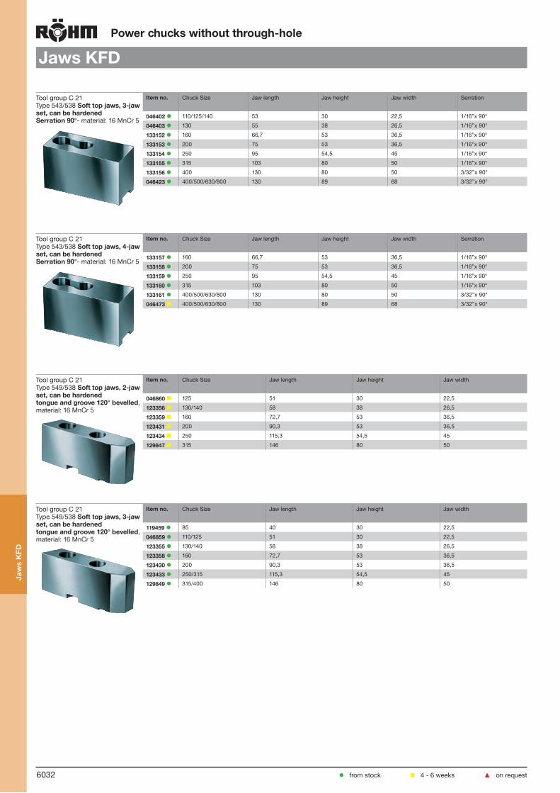
Jaws KFD
Tool group C 21Type 543/538 Soft top jaws, 3-jaw set, can be hardenedSerration 90°- material: 16 MnCr 5
Item no. Chuck Size Jaw length Jaw height Jaw width Serration
046402 110/125/140 53 30 22,5 1/16”x 90°
046403 130 55 38 26,5 1/16’’x 90°
133152 160 66,7 53 36,5 1/16”x 90°
133153 200 75 53 36,5 1/16”x 90°
133154 250 95 54,5 45 1/16”x 90°
133155 315 103 80 50 1/16”x 90°
133156 400 130 80 50 3/32”x 90°
046423 400/500/630/800 130 89 68 3/32”x 90°
Tool group C 21Type 543/538 Soft top jaws, 4-jaw set, can be hardenedSerration 90°- material: 16 MnCr 5
Item no. Chuck Size Jaw length Jaw height Jaw width Serration
133157 160 66,7 53 36,5 1/16”x 90°
133158 200 75 53 36,5 1/16”x 90°
133159 250 95 54,5 45 1/16”x 90°
133160 315 103 80 50 1/16”x 90°
133161 400/500/630/800 130 80 50 3/32”x 90°
046473 400/500/630/800 130 89 68 3/32”x 90°
Tool group C 21Type 549/538 Soft top jaws, 2-jaw set, can be hardenedtongue and groove 120° bevelled, material: 16 MnCr 5
Item no. Chuck Size Jaw length Jaw height Jaw width
046860 125 51 30 22,5
123356 130/140 58 38 26,5
123359 160 72,7 53 36,5
123431 200 90,3 53 36,5
123434 250 115,3 54,5 45
129847 315 146 80 50
Tool group C 21Type 549/538 Soft top jaws, 3-jaw set, can be hardenedtongue and groove 120° bevelled, material: 16 MnCr 5
Item no. Chuck Size Jaw length Jaw height Jaw width
119459 85 40 30 22,5
046859 110/125 51 30 22,5
123355 130/140 58 38 26,5
123358 160 72,7 53 36,5
123430 200 90,3 53 36,5
123433 250/315 115,3 54,5 45
129849 315/400 146 80 50
from stock 4 - 6 weeks ▲ on request
Jaw
s K
FD

6033
Power chucks without through-hole
Jaws KFD
Tool group C 21Type 544-50 Claw-type jaws, 1 piece, hardenedSerration 90° - width of the groove 12
Item no. Chuck Size Jaw length Jaw height Jaw width
144320 130 66 38 52
144321 130 56 38 34
144322 130 66 38 25
Tool group C 21Type 544-50 Claw-type jaws, 1 piece, hardenedSerration 90° - width of the groove 17
Item no. Chuck Size Jaw length Jaw height Jaw width
137031 200 67 45 53
137032 200 65 45 46
137039 200 55 45 40
137034 200 50 45 31
137035 200 55 45 27
137036 200 65 45 19
137037 200 65 45 26
137038 200 55 45 24
137033 200 55 45 39
Tool group C 21Type 544-50 Claw-type jaws, 1 piece, hardenedSerration 90° - width of the groove 21
Item no. Chuck Size Jaw length Jaw height Jaw width
137041 250/315 95 50 80
137042 250/315 75 50 60
137043 250/315 60 50 43
137044 250/315 70 50 37
137045 250/315 95 50 25
137046 250/315 80 50 30
Tool group C 21Type 544-50 Claw-type jaws, 1 piece, hardenedSerration 90° - width of the groove 25,5
Item no. Chuck Size Jaw length Jaw height Jaw width
137051 400 130 65 113
137052 400 90 65 67
137053 400 100 65 45
137054 400 130 65 33
from stock 4 - 6 weeks ▲ on request
Jaw
s K
FD
6034
Power chucks without through-hole
Accessories KFD
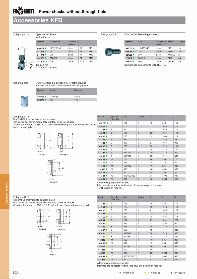
Tool group C 15 Type 538-00 T-nutswithout screw
Tool group C 15 Type 0040-Y Mounting screws
E
D
Item no. Chuck Size Contents of delivery
D E
004254 110/125/140 piece 10 M6
241673 130 piece 12 M8
241674 200 piece 17 M12
241675 250/315 piece 21 M16
2416761) 400 piece 25,5 M20
Single T-nut1) metric dimensions
Item no. Size Contents of delivery
Thread Length
343003 110/125/140 piece M6 18
233058 130 piece M8x20 20
227692 200 piece M12x25 25
229157 250/315 piece M16 30
233047 400 piece M20x40 40
Socket head cap screw to DIN 912, 12.9
Tool group C15 Type 1028 Special grease F80 for lathe chucksfor lubrication and conservation of chucking power
Item no. Design Contents
308555 Cartridge 0,5 kg
028975 Tin 1 kg
Tool group C 15Type 594-32 Intermediate adaptor plates with cylindrical centre mount DIN 6353 for three-jaw chucksMounting from front to ISO 702-1 (DIN 55026/55021) and ASA B 5.9 A1/A2 with metric mounting bolts
Id.-Nr. Spindle nose size
Size Design h F D
1451251) 4 160 II 18 82,6 140
145153 5 175 I 15 104,8 140
145127 5 200 II 21 104,8 170
145129 6 160 III 35 133,4 140
145155 6 200 I 16 133,4 170
145131 6 250 II 27 133,4 220
145133 6 315 II 27 133,4 300
145135 8 200 III 39 171,4 170
145157 8 250 I 18 171,4 220
145137 8 315/400 II 38 171,4 300
145141 8 500/630 II 38 171,4 380
145143 11 250 III 48 235 220
145159 11 315 I 19 235 300
145145 11 500/630 II 40 235 380
151300 11 800 II 40 235 460
145149 15 400 III 58 330,2 300
145161 15 400/500/630 I 21 330,2 380
145151 15 800 II 42 330,2 460
All fastening parts are includedIntermediate adaptors for two- and four-jaw-design on request1) DIN 55021 on request
Tool group C 15Type 594-35 Intermediate adaptor plates with cylindrical centre mount DIN 6353 for three-jaw chucksMounting from front to ASA B 5.9 A1/A2 with inch threaded mounting bolts
Id.-Nr. Spindle nose size
Size Design h F D
145191 4 160 II 18 82,6 140
145153 5 175 I 15 104,8 140
145192 5 200 II 21 104,8 170
145193 6 160 II 35 133,4 140
145155 6 200 I 16 133,4 170
145194 6 250 II 27 133,4 220
145195 6 315 II 27 133,4 300
145196 8 315 II 39 171,4 300
145157 8 250 I 18 171,4 220
145197 8 315/400 II 38 171,4 300
145199 8 500/630 II 38 171,4 380
145200 11 250 III 48 235 220
145159 11 315 I 19 235 300
145201 11 500/630 II 40 235 380
151304 11 800 II 40 235 460
145203 15 400 III 58 330,2 300
145161 15 400/500/630 I 21 330,2 380
145204 15 800 II 42 330,2 460
All fastening parts are includedIntermediate adaptors for two- and four-jaw-design on request
from stock 4 - 6 weeks ▲ on request
Acc
esso
ries
KFD
F D
h
F D
h
h
F D
Design I Design II
Design III
F D
h
F D
h
h
F D
Design I Design II
Design III

6035
Power chucks without through-hole
Accessories KFD
Tool group C 15Type 594-33 Intermediate adaptor plates with cylindrical centre mount DIN 6353 for three-jaw chucksBayonet fixing to ISO 702-3 (DIN 55027)/ DIN 55022
Id.-Nr. Spindle nose size
Size Design h F D
145208 4 160 II 18 82,6 140
145236 5 160 II 21 104,8 140
145210 5 200 II 21 104,8 170
145212 6 160 III 35 133,4 140
145240 6 200 II 22 133,4 170
145214 6 250/315 II 27 133,4 220
145216 6 315 II 27 133,4 300
145218 8 200 III 39 171,4 170
145242 8 250 II 30 171,4 220
145220 8 315/400 II 38 171,4 300
145224 8 500/630 II 38 171,4 380
145226 11 250 III 48 235 220
145244 11 315/400 II 36 235 300
145228 11 500/630 II 40 235 380
151305 11 800 II 40 235 460
145232 15 400 III 58 330,2 300
145248 15 400/500 II 40 330,2 380
145234 15 800 II 42 330,2 460
All fastening parts are includedIntermediate adaptors for two- and four-jaw-design on request
Tool group C 15Type 594-36 Intermediate adaptor plates with cylindrical centre mount DIN 6353 for three-jaw chucksCamlock fixing to DIN 55029/ASA B 5.9 D1
Id.-Nr. Spindle nose size
Size Design h F D
145252 4 160 II 28 82,6 140
145280 5 160 II 30 104,8 140
145254 5 200 II 30 104,8 170
145256 6 160 III 43 133,4 140
145284 6 200 II 35 133,4 170
145258 6 250 II 35 133,4 220
145260 6 315 II 35 133,4 300
145262 8 200 II 46 171,4 170
145286 8 250 II 38 171,4 220
145264 8 315/400 II 38 171,4 300
145268 8 500/630 II 38 171,4 380
145270 11 250 III 53 235 220
145288 11 315/400 II 45 235 300
145272 11 500/630 II 45 235 380
151307 11 800 II 45 235 460
145276 15 400 III 58 330,2 300
145292 15 400/500 II 50 330,2 380
145278 15 800 II 50 330,2 460
All fastening parts are includedIntermediate adaptors for two- and four-jaw-design on request
Tool group A09Type 619-30 Short-taper adapter plate ISO 702-1 (DIN 55026/55021) - ASA B 5.9 (without mounting bolts)finished on machine side, faced on chuck side, especially
Id.-Nr. Spindle nose size
h E M D
144933 ▲ 3 18 40 40 125
145296 ▲ 4 18 40 40 125
145328 ▲ 3 18 40 40 160
145342 ▲ 4 18 40 40 160
145343 ▲ 5 21 50 50 160
145344 ▲ 4 21 50 50 200
145345 ▲ 5 21 50 50 200
145346 ▲ 6 27 50 50 200
145347 ▲ 4 27 63 63 250
145348 ▲ 5 27 63 63 250
145349 ▲ 6 27 63 63 250
145350 ▲ 8 27 63 63 250
145351 ▲ 5 36 63 63 315
145352 ▲ 6 36 63 63 315
145353 ▲ 8 36 63 63 315
145354 ▲ 11 36 63 63 315
145355 ▲ 6 40 63 63 400
145356 ▲ 8 40 63 63 400
145357 ▲ 11 40 63 63 400
145358 ▲ 15 40 63 63 400
145359 ▲ 8 42 80 80 500
145360 ▲ 11 42 80 80 500
145364 ▲ 15 42 80 80 500
from stock 4 - 6 weeks ▲ on request
Acc
esso
ries
KFD
F D
h
F D
hDesign II Design III
F D
hF D
hDesign II Design III

6036
Power chucks without through-hole
KFL light weight, serration 90°
Tool group C15Type 536-20 3 jaw power chuck, light weight, serration 90°cylindrical centre mount
Item no. 119137 119138 119139 ▲ 119140 ▲ 119141 ▲
Size 250 315 400 500 600
A 250 315 400 500 600
Jaw travel B 6,7 6,7 6,7 9,3 9,3
C 87 99 99 117 117
Mount DH6 220 220 300 460 460
E 6 6 6 6 6
F 171,4 171,4 235 300 300
G 3 x M16 3 x M16 3 x M20 3 x M24 3 x M24
H 26 26 35 35 35
J 85 105 105 155 155
Wedge stroke K 25 25 25 35 35
N 45 55 55 60 60
O 40 46 46 55 55
P 30 30 30 30 30
Q M22 M22 M22 M24 M24
R 50 50 50 55 55
S min. 30 30 30 30 30
S max. 55 55 55 65 65
T±0,05 90 102 102 120 120
U M12 x 25 M16 x 30 M16 x 30 M20 x 40 M20 x 40
VH7 105 118 118 176 176
W 35 40 40 60 60
X 6 6 6 7 7
a min. 47,3 54,3 54,3 76,7 76,7
a max. 54 61 61 86 86
b min. 10 11 11 14 14
c min. 19 25 25 35 35
c max. 59 84 126 148 198
d 71 96,5 139 164 214
e 35 45 45 60 60
fH7 17 21 21 25,5 25,5
Max. swing top jaws mm 340 410 515 660 760
Maximum draw bar pull kN 35 50 50 75 75
Max. total clamping force kN 70 110 110 170 170
Max. admissible speed min-1 3500 3000 2100 1800 1500
Moment of inertia J kgm2 0,133 0,353 0,8 2,187 5,175
Weight without jaws approx. kg
17 28,5 40 70 115
400 ≤ 1/16” x 90o
500 ≥ 3/32” x 90o
Pow
er c
huck
with
out
thro
ugh-
hole
KFL
from stock 4 - 6 weeks ▲ on request

6037
Power chucks without through-hole
Jaws KFL
Tool group C 21Type 543/538 Reversible top jaws, 3-jaw set, hardenedSerration 90°- material: 16 MnCr 5
Item no. Chuck Size Jaw length Jaw height Jaw width Serration
118522 200 75 49 36 1/16”x 90°
046414 250/315 103,5 58 50 1/16’’x 90°
037531 400 135 65 68 3/32”x 90°
Hardened jaws, supplied as supplement or as spares, must be ground on the chuck.
Tool group C 21Type 543/538 Soft top jaws, 3-jaw set, can be hardenedSerration 90°- material: 16 MnCr 5
Item no. Chuck Size Jaw length Jaw height Jaw width Serration
133153 200 75 53 36,5 1/16”x 90°
133154 250 95 54,5 45 1/16”x 90°
133155 315 103 80 50 1/16”x 90°
133156 400 130 80 50 3/32”x 90°
Tool group C 21Type 544-50 Claw-type jaws, 1 piece, hardenedSerration 90° - width of the groove 17
Item no. Chuck Size Jaw length Jaw height Jaw width
137031 200 67 45 53
137032 200 65 45 46
137039 200 55 45 40
137034 200 50 45 31
137035 200 55 45 27
137036 200 65 45 19
137037 200 65 45 26
137038 200 55 45 24
137033 200 55 45 39
Tool group C 21Type 544-50 Claw-type jaws, 1 piece, hardenedSerration 90° - width of the groove 21
Item no. Chuck Size Jaw length Jaw height Jaw width
137041 250/315 95 50 80
137042 250/315 75 50 60
137043 250/315 60 50 43
137044 250/315 70 50 37
137045 250/315 95 50 25
137046 250/315 80 50 30
Tool group C 21Type 544-50 Claw-type jaws, 1 piece, hardenedSerration 90° - width of the groove 25,5
Item no. Chuck Size Jaw length Jaw height Jaw width
137051 400 130 65 113
137052 400 90 65 67
137053 400 100 65 45
137054 400 130 65 33
Jaw
s K
FL
from stock 4 - 6 weeks ▲ on request

6038
Power chucks without through-hole
Accessories KFL
Tool group C 15 Type 538-00 T-nutswithout screw
Tool group C 15 Type 0040-Y Mounting screws
E
D
Item no. Chuck Size Contents of delivery
D E
241674 200 piece 17 M12
241675 250/315 piece 21 M16
2416761) 400 piece 25,5 M20
Single T-nut1) metric dimensions
Item no. Size Contents of delivery
Thread
227692 200 piece M12x25
229157 250/315 piece M16
233047 400 piece M20x40
Socket head cap screw to DIN 912, 12.9
Tool group C15 Type 1028 Special grease F80 for lathe chucksfor lubrication and conservation of chucking power
Item no. Design Contents
308555 Cartridge 0,5 kg
028975 Tin 1 kg
Acc
esso
ries
KFL
from stock 4 - 6 weeks ▲ on request

6039
Power chucks without through-hole
KFD-G 2-jaw, large jaw movement, serration 90°
Tool group C15Type 581 2-jaw power chuck KFD-G, with large jaw movement, Adaptor recessWithout disclaiming high clamping forces it is possible to clamp work-pieces with collars or shoulders (i.e. fittings). - Full steel design - weight reduction - direct lubricated - special sealing against dirt and water
Item no. 154025 154026 154027 154028 154029 154030
Size 125 160 200 250 315 400
A 125 160 200 250 315 400
Jaw travel B 8,5 11 14 14,4 14,4 14,4
C 70 81 100 102 102 108
Mount DH6 115 140 185 220 220 300
E 6 6 6 6 6 6
F 92 104,8 133,4 171,4 171,4 250
G 2 x M 12 4 x M 10 4 x M 12 4 x M 16 4 x M 16 4 x M 24
H 15 16 20 25 25 35
J 62 75 98 98 98 120
Wedge stroke K 22 27 30 31 31 31
O - 35 44 44 44 52
Q M 16 M 16 M 22 M 22 M 22 M 24
R - 40 50 50 50 50
S min. 28 33 30 29 29 25
S max. 50 60 60 60 60 55
T±0,05 72 84 103,7 105,7 105,7 111,7
U M 12 M 16 M 16 M 20 M 20 M 20
WMax. 140 180 220 270 334 420
a min. 21,5 32,5 23 22,6 22,6 28,6
a max. 30 43,5 37 37 37 43
b min. 16g6 18g6 14 14 14 14
c min. 21 26 25 31 31 31
c max. 21 26 55,5 77 103 136
d 43 57,5 71,5 96 128,5 165
e 32 35 50 55 55 60
fH7 14 18 21 25,5 25,5 25,5
g 78 91 108 120 120 135
Maximum draw bar pull kN 13 16 35 45 45 57
Max. total clamping force kN 10 12 25 29 29 37
Max. admissible speed min-1 3500 3000 3000 2500 2200 2000
Moment of inertia J kgm2 0,01 0,04 0,09 0,2 0,4 1,1
Weight without jaws approx. kg
5 9 17 25 36,5 60
Pow
er c
huck
with
out
thro
ugh-
hole
KFD
-G
from stock 4 - 6 weeks ▲ on request

6040
Power chucks without through-hole
KFD-G
Tool group C 21Type 581 Soft top jaws, stationary, 2-jaw set, can be hardenedtongue and groove for 2-jaw chucks, material: 16 MnCr 5
Item no. Chuck Size Jaw length Jaw height Jaw width
120321 125 56,5 53 36,5
120320 160 74,5 53 36,5
120318 200 94 89 68
120316 250 110 89 68
120073 315/400 130 89 68
Tool group C 21Type 543/538 Soft top jaws, 2-jaw set, can be hardenedSerration 90°- material: 16 MnCr 5
Item no. Chuck Size Jaw length Jaw height Jaw width Serration
133149 250 95 54,5 45 1/16”x 90°
Pow
er c
huck
with
out
thro
ugh-
hole
KFD
-G
from stock 4 - 6 weeks ▲ on request

6041
Jaw dimensions KFD / KFL / KFD-EC / KFD-F-EC
1) Shallow design
Power chucks without through-hole
Reversible top jaws UB, hardened, serration 90o, modul toothing (size 1000-1600)
Chuck size 110/125/140 130 160 200/250 1) 250/315 400-800 1000-1600
Type 537-02 538-02 538-03 538-04 538-05 538-07 2) 543-61 2)
Item no. 2-jaw 046545 045796 046429 118521 046435 046447 -Item no. 3-jaw 046544 046404 046408 118522 046414 037531 152789
Item no. 4-jaw 046546 046452 046456 118523 046462 046474 -
A 56 56 68 75 103,5 135 200B 26 26 34,7 36 50 68 80C 37,5 37,5 45 49 58 65 85DH7 10 12 17 17 21 25,5 30E 3,5 3,5 5 5 5 5 8F 10 14 17 21,5 33,5 48 78G 12 3) 15 19 19 25 31 42H 29 29 33,5 37,5 45 48 62J 6,4 8,4 13 13 17 21 26K 10,4 13,5 19 19 25 31 40L 20 20 20 24 28 - -M 10 10 10 12 14 26 35N 4 4 5 6 6 6,5 6,5O 4 4 7 7,5 6,5 5,5 9P 5 5 10 18 24,5 34 40Q 5 5 5 7 22,5 40 40R 1/16"x90o 1/16"x90o 1/16"x90o 1/16"x90o 1/16"x90o 3/32"x90o m 2Weight/jaw kg 0,130 0,170 0,350 0,460 1,130 2,000 6,000
1) Size 250: Chuck in flat design2) one step only 3) 4 mounting holes
Soft top jaws AB, serration 90o, modul toothing (size 1000-1600)
Chuck size 110/125/140 130 160 200/250 1) 250 315 400-800 400-800 1000-1600
Type 537-02 538-02 538-03 538-04 538-05 538-06 538-07 538-07 2) 543-62Item no. 2-jaw 045794 045795 133147 133148 133149 133150 133151 046446 -Item no. 3-jaw 046402 046403 133152 133153 133154 133155 133156 046423 152790
Item no. 4-jaw - 046451 133157 133158 133159 133160 133161 046473 461716
A 53 55 66,7 75 95 103 130 130 200B 22,5 26,5 36,5 36,5 45 50 50 68 80C 30 38 53 53 54,5 80 80 89 89D 10 12 17 17 21 21 25,5 25,5 30E 3,5 3,5 5 5 5 5 5 5 8F 20 31 36 44 55 62 79 75 94G 12 3) 15 19 19 25 25 31 35 42 1)
H 20 28 43 43 42,5 67 60 69 69J 6,4 8,4 13 13 17 17 21 21 26K 10,4 13,5 19 19 25 25 31 31 40Q 3 - - - - - - - -R 1/16"x90o 1/16"x90o 1/16"x90o 1/16"x90o 1/16"x90o 1/16"x90o 3/32"x90o 3/32"x90o m 2Weight/jaw kg 0,223 0,320 0,700 0,880 1,400 2,580 3,1 5,120 8,5
Type 537-02Type 543-22
Soft top jaws AB, tongue and groove
Chuck size 85 110/125 1) 130/140 1) 160 200 250 315
Type 538-00 537-03 538-12 538-13 538-14 538-15 538-66Item no. 2-jaw 119458 046860 123356 123359 123431 123434 129847Item no. 3-jaw 119459 046859 123355 123358 123430 123433 129849A 40 51 58 72,7 90,3 115,3 146B 22,5 22,5 26,5 36,5 36,5 45 50C 30 30 38 53 53 54,5 80D-0,03 8 8 8 16 16 20 20E 3 3,5 3,5 5,5 5,5 5,5 5,5F 29 29,5 31,5 32,5 45,3 58,3 63,5G - 15 - 25 30 40 50H 20 20 25 38 38 38 60J 9 6,4 13 13 13 17 17K 15 10,4 19 19 19 25 25L 2,5 2,5 2,5 4,5 4,5 4,5 4,5M+0,03 8 8 13 10 12 16 16N 18 23 23 24,7 35,3 45,3 43O 4 4 3 5 5 5 5P 25 33 39,5 39,7 54,3 70,3 80,5Q 3 3 3 3 6 6 6Weight/jaw kg 0,146 0,200 0,310 0,720 1,000 1,550 3,600
1) Size 250: Chuck in flat design2) heavy design 3) 3 mounting holes
KFD
/ K
FL /
KFD
-EC
/
KFD
-F-E
C

6042
Jaw dimensions KFDPower chucks without through-hole
Claw type jaws KB, serration 90o
Chuck size A B 160 200
Item no. Piece Capacities external137031 67 53 38-56 60-96137032 65 46 51-71 73-111137039 55 40 66-87 88-127137034 50 31 83-102 105-142137035 55 27 97-117 119-157
Capacities internal
137036 65 19 50-70 72-110
137037 65 26 68-85 90-125
137038 55 24 82-104 104-144
137035 55 27 102-116 124-156
137034 50 31 114-123 136-163
137039 55 40 120-135 144-175
137033 55 39 132-165 154-205
137032 65 46 146-178 168-218
Chuck size A B 250 315 1) 315
Item no. Piece Capacities external137041 95 80 53-95 53-160 66-160137042 75 60 92-133 92-198 105-198137043 60 43 125-167 125-232 138-232137044 70 37 156-198 156-263 169-263
Capacities internal
137045 95 25 68-112 68-117 81-177
137046 80 30 108-154 108-219 121-219
137044 70 37 146-186 146-240 159-240
137043 60 43 178-240 178-305 191-305
137042 75 60 212-265 212-330 225-330
Chuck size A B 400 500 630 800
Item no. Piece Capacities external137051 130 113 80-180 80-280 114-410 114-580137052 90 67 170-270 170-370 204-500 204-670137053 100 45 256-390 270-495 290-625 290-790
Capacities internal
137054 130 33 100-215 100-315 134-445 134-615
137053 100 45 260-395 275-500 295-625 295-795
137051 130 113 300-460 300-560 334-690 334-860
1) Shallow design chuck
Chuck size A B 130
Item no. Piece Capacities external144320 66 52 38-82144321 56 34 78-122144322 66 25 120-144
Capacities internal
144322 66 25 70-98
144321 56 34 92-138
144320 66 52 122-178
Pow
er c
huck
s w
ithou
t th
roug
h-ho
le K
FD

6043
Jaw dimensions KFLPower chucks without through-hole
Claw type jaws KB, serration 90o
Size A B 250
Item no. Piece Capacities external137031 67 53 82-146137032 65 46 95-161137039 55 40 110-177137034 50 31 127-192137035 55 27 141-207
Capacities internal
137036 65 19 94-160
137037 65 26 112-175
137038 55 24 126-194
137035 55 27 146-206
137034 50 31 158-213
137039 55 40 166-255
137033 55 39 176-255
137032 65 46 190-268
Size A B 315 400
Item no. Piece Capacities external137041 95 80 67-160 67-245137042 75 60 106-198 106-283137043 60 43 139-232 139-317137044 70 37 170-263 170-348
Capacities internal
137045 95 25 82-177 82-262
137046 80 30 122-219 122-304
137044 70 37 160-240 160-336
137043 60 43 192-305 192-390
137042 75 60 226-330 226-415
Size A B 500 600
Item no. Piece Capacities external137051 130 113 88-280 88-380137052 90 67 178-370 178-470137053 100 45 265-195 265-595
Capacities internal
137054 130 33 108-315 108-415
137053 100 45 270-502 270-602
137051 130 113 308-560 308-660
Pow
er c
huck
s w
ithou
t th
roug
h-ho
le K
FL

6044
Power chucks without through-hole
Chucking capacities KFD
Chucking capacities KFL
Chucking capacities with reversible top jaws UB/ABfor 2- and 3-jaw chucks
Chuck size 110 125 130 140 160 200 250 1) 250 315 1) 315 400 500 630 800
with reversible jaws
Type 537-02 537-02 538-02 537-02 538-03 538-04 538-04 538-05 538-05 538-05 538-07 538-07 538-07 538-07Jaw position
External chucking
A1 4-62 4-78 6-66 4-93 5-73 16-108 16-159 20-124 20-189 34-189 40-225 40-325 60-450 60-620
A2 - - - - - 28-118 28-169 38-152 38-217 52-217 70-280 70-380 108-510 106-680
A3 47-105 75-126 60-119 75-140 70-140 86-173 86-223 120-232 120-297 134-297 - - - -
A4 82-140 110-161 94-151 110-176 110-182 137-224 137-274 200-314 200-379 214-379 275-480 275-580 310-700 310-870
Internal chu-cking
J1 40-95 40-110 42-96 40-125 53-120 70-156 70-208 70-170 70-233 84-233 102-305 102-405 136-530 136-700
J2 74-130 72-145 74-130 72-160 92-163 120-208 120-258 146-251 146-313 160-313 - - - -
J3 112-168 116-190 118-175 116-205 144-200 173-261 173-311 236-328 236-393 250-393 295-490 295-590 328-720 328-890
Chuck size 1000 1250 1400 1600
with reversible jawsType 538-09 538-09 538-09 538-09
Jaw position
External chucking
A1 100-640 100-890 100-1040 100-1240A2 180-720 180-970 180-1120 180-1320
A3 450-1000 450-1250 450-1400 450-1600
Internal chuckingJ1 200-750 200-1000 200-1150 200-1350J2 480-1030 480-1280 480-1430 480-1630
1) Shallow design chuck
Chucking capacities withreversible top jaws UB
Chuck size 250 315 400 500 600
with reversible jaws
Type 538-04 538-05 538-07 538-07 538-07Jaw position
External chucking
A1 40-160 22-189 22-270 37-325 37-425
A2 55-173 51-217 51-302 81-380 81-480
A3 110-225 134-297 134-382 - -
A4 160-276 214-379 214-482 287-580 287-680
Internal chu-cking
J1 88-204 73-233 73-318 108-405 108-505J2 138-256 150-313 150-398 - -J3 192-310 228-393 228-478 305-590 305-690
Pow
er c
huck
s w
ithou
t th
roug
h-ho
le K
FD /
KFL

6045
1. 2. 3. 4. 5. 6.
Power chucks without through-hole
Diaphragm clamping chuck MSF
Flat design
Diaphragms operate for long periods of time almost free of wear and in constantly uniform quality
Quick-acting jaw change system via HSK-interface guarantees high stiffness at highest precision (change precision)
Jaw chucks reground in the system combination of diaphragm and HSK mount achieve change precision values of ≤ 0.005 mm when refitted after a change
Unaffected by dirt
A media feed system, provided as standard, provides the opportunity for coolants or blown air to be conduc-ted through the diaphragm jaw chuck directly to the workpiece, or to accommodate the workpiece air-con-tact monitoring device in the workpiece mounts.
Ideally suited for grinding and hard turning with high accuracy
Used in conjunction with RÖHM actuating cylinders with safety device SZS, OVS, LHS-L, LVS, EHS and EVS the power chucks MSF meet the requirements of the German Employers’ Insurance Association
Technical features:
3
BodyHSK holding clampDiaphragm with HSK mountingPistonSecured against rotationSupport element
Fast and easy jaw change with outstandingly good levels of precision
Dia
phra
gm c
lam
ping
ch
ucks
MS
F
1 2
4
5
6

6046
R
Q2
QNFDA
G
H
R 1
P
Q1
TLE
Re ferenz
L
Re ferenz
k c d
h 1
b
f 2
h 2
g 2
M
g 1
SW
C
C2
C1
E1
T1
D1
f1
Tool group C 15Type 587 Diaphragm jaw chuck MSF, centric clamping, with quick-acting jaw change system HSK, chucking precision 0,005 mmcylindrical centre mount / short taper mount
Item no. 432410 432411 432412 432413 432414 432415 432416 ▲ 432417 ▲
Size 210 210 260 260 315 315 400 400
A 210 210 260 260 315 315 400 400
Mount DH6 / D1 ZA 170 KK 6 ZA 170 KK 6 ZA 220 KK 8 ZA 300 KK 11
Jaw movement (refer to ref.) B
± 1,2 ± 1,2 ± 1,3 ± 1,3 ± 1,5 ± 1,5 ± 1,4 ± 1,4
Aperture angle ± 1°9’ ± 1°9’ ± 1°10’ ± 1°10’ ± 1°13’ ± 1°13’ ± 1° ± 1°
C 60 60 60 60 80 80 80 80
C1 77 (min. 78,5 max. 75,5)
77 (min. 78,5 max. 75,5)
77 (min. 79 max. 75)
77 (min. 79 max. 75)
98 (min. 95,5 max. 100,5)
98 (min. 95,5 max. 100,5)
98 (min. 95 max. 101)
98 (min. 95 max. 101)
C2 70 70 70 70 90 90 90 90
E 6 6 6 6 6 6 6 6
E1 - 15 - 15 - 17 - 19
F ø 133,4 ± 0,2 ø 133,4 ± 0,2 ø 133,4 ± 0,2 ø 133,4 ± 0,2 ø 171,4 ± 0,2 ø 171,4 ± 0,2 ø 235 ± 0,2 ø 235 ± 0,2
G M 12 M 12 M 12 M 12 M 16 M 16 M 20 M 20
H 18 17 18 17 24 22 31 32
J-0,01/-0,02 10 10 10 10 12 12 12 12
Wedge stroke K 3 3 4 4 5 5 6 6
L 5 5 5 5 5 5 5 5
Mg6 ø 45 ø 45 ø 45 ø 45 ø 54 ø 54 ø 54 ø 54
N ø 44 ø 44 ø 44 ø 44 ø 56 ø 56 ø 56 ø 56
P 41 (min. 39,5 max. 42,5)
41 (min. 39,5 max. 42,5)
41 (min. 39 max. 43)
41 (min. 39 max. 43)
42,5 (min. 40 max. 45)
42,5 (min. 40 max. 45)
42,5 (min. 39,5 max. 45,5)
42,5 (min. 39,5 max. 45,5)
Q M 16 M 16 M 16 M 16 M 24 M 24 M 24 M 24
Q1f7 ø 12 ø 12 ø 12 ø 12 ø 20 ø 20 ø 20 ø 20
Q2 ø 5 ø 5 ø 5 ø 5 ø 5 ø 5 ø 5 ø 5
R 50 50 50 50 65 65 65 65
R1 16 16 16 16 20 20 20 20
T 70 70 70 70 90 90 90 90
T1 - 86,2 - 86,2 - 107 - 109,4
Referenz 50 50 50 50 60 60 60 60
b ± 0,01 57 57 75 75 90 90 132,5 132,5
c HSK50 HSK50 HSK50 HSK50 HSK63 HSK63 HSK63 HSK63
d ø 70 ø 70 ø 70 ø 70 ø 80 ø 80 ø 80 ø 80
f1 M 5/9 M 5/9 M 5/9 M 5/9 M 5/9 M 5/9 M 5/9 M 5/9
f2 M 8/15 M 8/15 M 8/15 M 8/15 M 8/15 M 8/15 M 8/15 M 8/15
g1 ± 0,2 ø 28 ø 28 ø 28 ø 28 ø 28 ø 28 ø 28 ø 28
g2 ± 0,2 ø 80 ø 80 ø 90 ø 90 ø 120 ø 120 ø 180 ø 180
h1 H7 ø 15/11 ø 15/11 ø 15/11 ø 15/11 ø 15/11 ø 15/11 ø 15/11 ø 15/11
h2 ø 17 ø 17 ø 17 ø 17 ø 20 ø 20 ø 20 ø 20
k-0,1 ø 25 ø 25 ø 25 ø 25 ø 33 ø 33 ø 33 ø 33
Key-width SW 4 4 4 4 5 5 5 5
Maximum draw bar pull kN 20 20 25 25 30 30 30 30
Min. operating force to open the diaphragm kN
10 10 15 15 20 20 15 15
Max. admissible speed min-1 5500 5500 4500 4500 4000 4000 3000 3000
Moment of inertia J kgm2 0,09 0,09 0,2 0,2 0,56 0,60 1,4 1,5
Weight without base jaws approx. kg
16 17 24 25 45 48 69 74
Further mountings possible with adaptor plates
Power chucks without through-hole
MSF centric clamping, with quick-acting jaw change system HSK
45o75o
3x120 o
3x120 o
3x12
0o
J
Dia
phra
gm c
lam
ping
ch
ucks
MS
F
from stock 4 - 6 weeks ▲ on request

6047
Power chucks without through-hole
Jaws MSF
Tool group C 21Type 587-04 Base jaws for diaphragm jaw chucks
Item no. Chuck Size Clamping insert Jaw length Jaw height Jaw width
499956 210 I 64 20 45
499957 210 II 70 20 45
499958 210 III 73 20 45
499961 260 I 89 20 45
499962 260 II 80 20 45
499963 260 III 90 20 45
499964 315/400 I 103 20 60
499965 315/400 II 90 20 60
499966 315/400 III 107,5 20 60
On request, it is also possible to supply special interchangeable jaws and special base jaws adapted to a specific workpiece.
Tool group C 21Type 587-04 Clamping sets for Base jaws
Item no. Chuck Size Clamping insert Length Height Width
499968 210/260 II 55 20 50
499969 210/260 III 42 20 50
499967 260 I 62 20 50
499970 315/400 I 70 20 60
499971 315/400 II 62 20 60
499972 315/400 III 42 20 60
Clamping insert I not suitable at size 210
Accessories MSF
Tool group C 15Type 587-04 Contact starsContact stars are used as a longitudinal stop for the workpiece. The standard contact stars enable the entire clamping range of the standard jaws to be covered.
Item no. 499874 499875 499876 499877
Size 210 260 315 400
A 150 150 250 335
B 23 23 23 23
C 24 24 24 24
DH7 ø 45 ø 45 ø 54 ø 54
E 10,5 10,5 13 13
F 7,5 15 20 60
G 26 30 36,5 36,5
H 80 90 120 180
J M8 M8 M8 M8
K 11 11 11 11
L 20 20 35 35
Contact area ø 15-150 ø 30-190 ø 40-250 ø 120-335
In addition, special versions are possible with an air contact check for the blast air, pre-centering or adapted to a certain workpiece geometry.
L
3x120o
KB
JD
E 0,5C
GF H A
L
3x120o
KB
JD
E 0,5C
GF H A
Jaw
s M
SF
from stock 4 - 6 weeks ▲ on request

6048
Jaw dimensions MSFPower chucks without through-hole
Chuck size 210 260 315 400
External chucking External chucking External chucking External chuckingClamping insert I II III I II III I II III I II IIIItem no. 499956 499957 499958 499961 499962 499963 499964 499965 499966 499964 499965 499966A 64 70 73 89 80 90 103 90 107,5 103 90 107,5B 45 45 60 60C 35 35 40 40D 20 20 20 20E 20 20 20 20F 40 40 40 40G 21,5 21,5 27 27H HSK 50 HSK 50 HSK 63 HSK 63J -5 25 35 -5 25 35 -6 30 47,5 -6 30 47,5K 20 25 25 50 35 35 61 40 40 61 40 40L 57 75 90 132,5M External chucking 52 82 88 70 100 100 84 120 137,5 126,5 162,5 180N1 30 30 40 40N2 20 20 25 25O1 8,5 8,5 12 12O2 10 10 10 10P - 30 - 30 30 - 36 36 - 36 36 -Q1 M8/12 M8/12 M8/12 M8/12Q2 Ø 6,6/Ø 11 Ø 6,6/Ø 11 Ø 6,6/Ø 11 Ø 6,6/Ø 11
Base jaws for Diaphragm clamping chucks
N1
A P
BCN2
G FO2
H
E
Q1
Q2
JK
LM
O1
D
Chuck size 210 260 315 400
External chucking External chucking External chucking External chucking
Clamping insert I II III I II III I II III I II III
Item no. 1) 499968 499969 499967 499968 499969 499970 499971 499972 499970 499971 499972a - 55 42 62 55 42 70 62 42 70 62 42b 50 50 60 60c 35 35 40 40d 20 20 20 20j - 45 32 52 45 32 60 52 32 60 52 32k 10 10 10 10n1 30 30 40 40n2 20 20 25 25o1 8,5 8,5 12 12o2 10 10 10 10p - - - 30 - - 36 - - 36 - -q1 - Ø 9/15 - - Ø 9/15 - Ø 9/15 Ø 9/15 - Ø 9/15 Ø 9/15 -q2 - - M6/10 - - M6/10 - - M6/10 - - M6/10r - 20/30o - 20/30o 20/30o - 36/30o - - 36/30o - -
Base jaw I - 20-70 45-84 40-5786-110 55-110 80-120 50-70
100-130 66-130 106-150 135-155185-215 151-215 191-235
Base jaw II - 80-130 105-144 100-117145-170 115-170 140-180 122-142
166-202 138-202 188-222 207-227250-287 223-287 273-307
Base jaw III - 92-142 117-160 120-137165-190 135-190 160-200 157-177
200-237 173-237 213-260 242-262285-322 258-322 298-345
Clamping inserts for base jaws
30
c
o 1
b
rn1
j ak
d
q 1
n2q2
o2
1) not suitable at size 210
Chu
ckin
g ca
paci
ties
with
bas
e ja
ws
HS
K
and
clam
ping
inse
rts
Base jaw I - 20-70 45-84 40-5786-110 55-110 80-120 50-70
100-130 66-130 106-150 135-155185-215 151-215 191-235
Base jaw II - 80-130 105-144 100-117145-170 115-170 140-180 122-142
166-202 138-202 188-222 207-227250-287 223-287 273-307
Base jaw III - 92-142 117-160 120-137165-190 135-190 160-200 157-177
200-237 173-237 213-260 242-262285-322 258-322 298-345
Chu
ckin
g ca
paci
ties
with
bas
e ja
ws
HS
K
and
clam
ping
inse
rts
30
c
o 1
b
rn1
j ak
d
q 1
n2q2
o2
Dia
phra
gm c
lam
ping
ch
ucks
MS
F

KFD
6049
Notes
Not
es

KFD
6050
Ove
rvie
w
OverviewPower chucks with through-hole
KFD-HS from page 6051
Wedge system (ring piston)Few loss of centrifugal force, high precision2-, 3- and 4-jaw design
KFD-HE from page 6068
Wedge system (wedge piston)
3-jaw design
Options: With or without draw tube-connector
KFM / KFG from page 6081
Toggle joint leverssystem
Large jaw movement due to Toggle joint leverssystem
2- and 3-jaw design
Options: With medium jaw movement (KFM) or large jaw movement (KFG)
PKF from page 6090
Precision-Wedge system with integrated pneumatic chucking piston Top precision chucking
3-jaw design
The power chucks KFD-EC (from page 6013) and KFD-HS oil (from page 6020) are also available with through-hole. Please contact us.
GF from page 6094
Gripper chuck
Used for moving and positioning bars and tubes

6051
KFD-HS
Pow
er c
huck
s w
ith
thro
ugh-
hole
KFD
-HS
Power chucks with through-hole
Components KFD-HS 1. Body 2. Base jaw 3. Piston 4. Adaptor plate 5. Protective bushing 6. T-nut
The design principle of the power chuck KFD-HS is to absorb most of the centrifugal forces occurring during the machining process in order to minimize their influence on the clamping forces. This will be done by a special wedge-connection, resulting only in a small loss of clamping forces even at high speeds. The screwed connection between chuck body and chuck flange provides a high chuck rigidy. So this chuck type offers an optimum of conditions for precise machining of both shaft and flange typed workpieces.
Technical features:
Wedge hook system with annular piston for highest accuracy in case of loss of centrifugal force
Above-average mechanical efficiency
Very few components, long jaw ways, very large through-hole
Universal design of wedge connection (even in the fully retracted position the wedge neck does not project into the area of the spindle bore)
If necessary, quick conversion to a different spindle nose, by simply exchanging the centering adapter
Use of clamping inserts for bar work (special design)
Base jaw secured against throw-off
Used in conjunction with RÖHM actuating cylinders with safety device SZS, OVS, LHS-L, LVS, EHS and EVS the power chucks KFD-HS meet the requirements of the German Employers’ Insurance Association
Two-, three- and four-jaw chucks, with large through-hole, for very high speeds
Scope of delivery:Chuck and jaw mounting screws, assembly wrench, T-nuts (without top-jaws)
1
3
5
6
2
4

KFD
6052
Power chucks with through-hole
KFD-HS
Pow
er c
huck
with
th
roug
h-ho
le K
FD-H
S
KFD-HS 400
KFD-HS 500
KFD-HS 315
280
260
240
220
200
180
160
140
120
100
80
60
40
20
KFD-HS 250
1000 2000 3000 4000 5000 6000
Kra
ftsp
annf
utte
r K
FD-H
SP
ower
ch
uck
s
KFD-HS 200
KFD-HS 175
KFD-HS 160
KFD-HS 130/140
KFD-HS 110
120
100
80
60
40
20
1000 2000 3000 4000 5000 6000 7000 8000 9000
25155-k006-039 26.04.2007 10:21 Uhr Seite 6039
Drilling areas on frontside of KFD-HS power chucks
Gripping force/speed diagram(three jaw chucks only)
The loss of gripping force was determined experimentallyon a chuck with matched UB top jaws. It is largelyindependent of the initial gripping force at zero speed.
Upper curve: min. centrifugalforce of top jaw Lower curve: max. centrifugalforce of top jaw
To obtain the specified gripping forces, the chuck mustbe in a perfect condition and lubricated with F 80 lubricant recommended by Röhm. Measuring point near chuck face. Example: For a chuck size 250 and an applied operatingpower of 40 kN, the total gripping force is approx. 92 kN.
110 130 140 160 175 200 250 315 400 500
A 36 38 38 50 50 58 73 73 84 84
B - - - - - - - 43 - 62
D1 110 130 140 160 175 200 250 315 400 500
D2 85 98 112 125 134 158 196 196 340 340
D3 56 65 72 86 95 110 140 140 262 262
D4 42 38 46 55 65 74 102 102 185 185
Max. drill depth - Zone l 25 25 25 30 30 40 40 40 40 40
Max. drill depth - Zone lI 8 6 6 9 9 9 12 12 10 10
Weight reduced at size 315 Item no. 144261 Item no. 143748 In the weightsaving areano drillingpermitted
Chuck size Total gripping force kN
Speed min -1
Tota
l grip
ping
forc
e kN
Gripping force/operating power diagram
Speed min -1
Tota
l grip
ping
forc
e kN
Operating power kN

6053
KFD-HS
Power chucks with through-hole
KFD-HS 3-jaw, serration 90°
Tool group C 15Type 549-00/ 549-22 3 jaw power chuck KFD-HS, with tightening thread, serration 90°Adaptor recess, mounting dimensions to DIN 6353/ short taper mount (KK) ISO 702-1 (DIN 55026/55021)
Item no. 149406
149405
144257
142477
144258
142690
143692
142478
144259
143893
143888
142479
Size 110 110 130 130 140 140 160 160 175 175 200 200
number of jaws 3 3 3 3 3 3 3 3 3 3 3 3
A 110 110 130 130 140 140 160 160 175 175 200 200
Jaw travel B 3,2 3,2 3,2 3,2 3,2 3,2 4 4 4 4 5 5
C 78 86 88 90 88 92 102 108 102 108 107 112
Mount D ZA 60 KK 4* ZA 100 KK 4* ZA 120 KK 5 ZA 140 KK 5 ZA 140 KK 5 ZA 170 KK 6
E 6 13 6 13 6 15 6 16 6 16 6 16
F 82,6 82,6 82,6 82,6 104,8 104,8 104,8 104,8 104,8 104,8 133,4 133,4
G 3xM10 3xM10 3xM10 3xM10 3xM10 3xM10 3xM10 3xM10 3xM10 3xM10 3xM12 3xM12
H 15 14 15 14 15 17 15 14 15 14 18 17
Wedge stroke K 12 12 12 12 12 12 15 15 15 15 18,5 18,5
L 2,5 2,5 2,5 2,5 2,5 2,5 2,5 2,5 2,5 2,5 2,5 2,5
M max. 26 26 32 32 37 37 46 46 56 56 66 66
M1H7 32 32 32 32 37 37 46 46 56 56 66 66
N 38 38 42 42 48 48 58 58 68 68 80 80
O min. -1 11 6 12 5 13 6 16 6 16 7,5 16,5
O max. 11 23 18 24 17 25 21 31 21 31 26 35
P 12 12 14 14 14 14 16 16 16 16 15 15
Q M34x1,5 M34x1,5 M38x1,5 M38x1,5 M44x1,5 M44x1,5 M54x1,5 M54x1,5 M65x1,5 M65x1,5 M74x1,5 M74x1,5
T 80 84 84 88 84 90 98 106 98 106 103 110
U M8 M8 M6 M6 M6 M6 M8 M8 M8 M8 M12 M12
a min. 10,8 10,8 14,3 14,3 16,8 16,8 24 24 29 29 35 35
a max. 14 14 17,5 17,5 20 20 28 28 33 33 40 40
b min. 3 3 0 0 0 0 0 0 0 0 8,5 8,5
b max. 23 23 23,5 23,5 26 26 22 22 24,5 24,5 32,5 32,5
c 15 15 2x12 2x12 2x12 2x12 2x15 2x15 2x15 2x15 19 19
d 41 41 47,5 47,5 50 50 52 52 54,5 54,5 60 60
e 24 24 25 25 25 25 32 32 32 32 40 40
fH7-0,025 10 10 10 10 10 10 12 12 12 12 17 17
g 50 50 75 75 68 68 76 76 76 76 84 84
h M5x8 M5x8 M5x8 M5x8 M5x8 M5x8 M6x10 M6x10 M6x10 M6x10 M6x10 M6x10
α 0° 0° 15° 15° 22° 30’ 22° 30’ 20° 20° 20° 20° 20° 20°
Max. swing top jaws mm 113 113 170 170 180 180 195 195 210 210 250 250
Maximum draw bar pull kN 18 18 25 25 25 25 35 35 40 40 48 48
Max. total clamping force kN 48 48 70 70 70 70 86 86 95 95 110 110
Max. admissible speed min-1
8500 8500 8000 8000 8000 8000 8000 8000 7000 7000 6500 6500
Moment of inertia J kgm2 0,007 0,007 0,015 0,015 0,022 0,022 0,0415 0,0415 0,057 0,057 0,1 0,1
Weight without jaws approx. kg
5 5 7 7 9 9 12 12 15 15 20 20
* ISO 702-1 (DIN 55026) only (DIN 55021 on request)
A D F N Q MG
H
C
E T L
U
c d
B
b
a
hg M
1
O P
1/16" x 90
A F D N Q M
G
H
C
T
PO
fH7
e
Pow
er c
huck
with
th
roug
h-ho
le K
FD-H
S
from stock 4 - 6 weeks ▲ on request
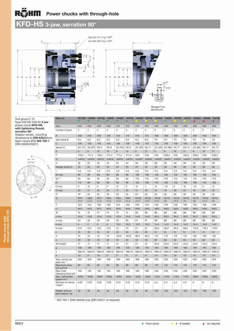
6054
Power chucks with through-hole
KFD-HS 3-jaw, serration 90°
Tool group C 15Type 549-00/ 549-22 3 jaw power chuck KFD-HS, with tightening thread, serration 90°Adaptor recess, mounting dimensions to DIN 6353/short taper mount (KK) ISO 702-1 (DIN 55026/55021)
Item no. 161725
144260
143726
142691
144261
143748
144262
143749
161843
144263
143750
143751
144264 ▲
146228 ▲
143752 ▲
Size 250 250 250 250 315 315 315 315 400 400 400 400 500 500 500
number of jaws 3 3 3 3 3 3 3 3 3 3 3 3 3 3 3
A 250 250 250 250 315 315 315 315 400 400 400 400 500 500 500
Jaw travel B 6,2 6,2 6,2 6,2 6,2 6,2 6,2 6,2 7,5 7,5 7,5 7,5 7,5 7,5 7,5
C 128 128 130 130 128 130 139 143 156 156 156 156 156 156 156
Mount D ZA 170 ZA 220 KK 6 KK 8 ZA 220 KK 8 ZA 300 KK 11 ZA 300 ZA 380 KK 11 KK 15 ZA 380 KK 11 KK 15
E 6 6 15 19 6 19 6 21 6 6 18 21 6 18 21
F 133,4 171,4 133,4 171,4 171,4 171,4 235 235 235 330,2 235 330,2 330,2 235 330,2
G 3xM12 3xM16 3xM12 3xM16 3xM16 3xM16 3xM20 3xM20 3xM20 3xM24 3xM20 3xM24 3xM24 3xM20 3xM24
H 16 24 18 24 24 24 30 30 36 30 30 30 30 30 30
Wedge stroke K 23 23 23 23 23 23 23 23 28 28 28 28 28 28 28
L 2,5 2,5 2,5 2,5 2,5 2,5 2,5 2,5 3,5 3,5 3,5 3,5 3,5 3,5 3,5
M max. 66 86 66 86 86 86 108 108 126 165 126 165 165 165 165
M1H7 94 94 94 94 94 94 115 115 172 172 172 172 172 172 172
N 110 99 80 99 99 99 126 126 142 180 142 180 180 142 180
O min. 0 -6 2 2 -6 2 -9 1 -6 -12 0 -6 -12 0 -6
O max. 23 17 25 25 17 25 14 24 22 16 28 22 16 28 22
P 19 25 25 25 25 25 25 25 35 35 35 35 35 35 35
Q M74x1,5
M94x1,5
M74x1,5
M94x1,5
M94x1,5
M94x1,5
M120x1,5
M120x1,5
M132x1,5
M172x3
M132x1,5
M172x3
M172x3
M132x1,5
M172x3
T 124 124 132 132 124 132 135 145 153 153 159 159 153 159 159
U M12 M12 M12 M12 M16 M16 M16 M16 M20 M20 M20 M20 M20 M20 M20
W 74 74 74 74 74 74 85 85 88 88 88 88 88 88 88
a min. 43,8 43,8 43,8 43,8 43,8 43,8 54,8 54,8 80,5 80,5 80,5 80,5 80,5 80,5 80,5
a max. 50 50 50 50 50 50 61 61 88 88 88 88 88 88 88
b min. 6 6 6 6 10,5 10,5 10,5 10,5 14,5 14,5 14,5 14,5 14,5 14,5 14,5
b max. 47,5 47,5 47,5 47,5 72 72 61 61 66,5 66,5 66,5 66,5 116,5 116,5 116,5
c 19 19 19 19 25 25 25 25 31 31 31 31 31 31 31
d 75 75 75 75 107,5 107,5 96,5 96,5 112 112 112 112 162 162 162
e 50 50 50 50 50 50 50 50 60 60 60 60 60 60 60
fH7-0,025 17 17 17 17 21 21 21 21 25,5 25,5 25,5 25,5 25,5 25,5 25,5
g 108 108 108 108 108 108 136 136 190 190 190 190 190 190 190
h M6x10 M6x10 M6x10 M6x10 M6x10 M6x10 M8x12 M8x12 M8x12 M8x12 M8x12 M8x12 M8x12 M8x12 M8x12
α 15° 0° 15° 0° 0° 0° 0° 0° 15° 15° 15° 15° 15° 15° 15°
Max. swing top jaws mm
305 305 305 305 380 380 380 380 520 520 520 520 620 620 620
Maximum draw bar pull kN
65 65 65 65 80 80 80 80 110 110 110 110 110 110 110
Max. total clamping force kN
150 150 150 150 180 180 180 180 250 250 250 250 250 250 250
Max. admissible speed min-1
5000 5000 5000 5000 4200 4200 4200 4200 3150 3150 3150 3150 2800 2800 2800
Moment of inertia J kgm2
0,35 0,35 0,35 0,35 0,74 0,74 0,74 0,74 2,4 2,4 2,4 2,4 6 6 6
Weight without jaws approx. kg
40 40 40 40 56 56 56 56 120 120 120 120 190 190 190
* ISO 702-1 (DIN 55026) only (DIN 55021 on request)
fH7
e
Pow
er c
huck
with
th
roug
h-ho
le K
FD-H
S
from stock 4 - 6 weeks ▲ on request
A D F N Q MG
H
C
E T L
U
c d
B
b
a
hg M
1
O P W
A F D N Q M
G
H
C
T
O P
21H7
17–0,025U
L
Recessed T-nutsize 250 only
Size 250, 315: 1/16” x 90o
Size 400, 500: 3/32” x 90o

6055
Power chucks with through-hole
KFD-HS 3-jaw, tongue and groove
Tool group C15Type 549-10/549-12 3 jaw power chuck KFD-HS, with tightening thread, with tongue and grooveAdaptor recess, mounting dimensions to DIN 6353/ short taper mount (KK) ISO 702-1 (DIN 55026/55021)
Item no. 149846 149543 151532 156580 153182 157768 154239 155099 153302 157624 160898
Size 110 110 140 140 160 160 200 200 250 250 250
number of jaws 3 3 3 3 3 3 3 3 3 3 3
A 110 110 140 140 160 160 200 200 250 250 250
Jaw travel B 3,2 3,2 3,2 3,2 4 4 5 5 6,2 6,2 6,2
C 80 86 88 92 102 108 107 112 128 132 132
Mount D ZA 60 KK 4* ZA 120 KK 5 ZA 140 KK 5 ZA 170 KK 6 ZA 220 KK 6 KK 8
E 6 13 6 16 6 15 6 16 6 15 19
F 82,6 82,6 104,8 104,8 104,8 104,8 133,4 133,4 171,4 133,4 171,4
G 3xM10 3xM10 3xM10 3xM10 3xM10 3xM10 3xM12 3xM12 3xM16 3xM12 3xM16
H 15 14 15 17 15 14 18 17 24 18 24
Wedge stroke K 12 12 12 12 15 15 18,5 18,5 23 23 23
M max. 26 26 37 37 46 46 66 66 86 66 86
M1H7 32 32 37 37 46 46 66 66 94 94 94
N 38 38 48 48 58 58 80 80 99 80 99
O min. -1 11 5 13 6 16 7,5 16,5 -6 2 2
O max. 11 23 17 25 21 31 26 35 17 25 25
P 12 12 14 14 16 16 15 15 25 25 25
Q M34x1,5 M34x1,5 M44x1,5 M44x1,5 M54x1,5 M54x1,5 M74x1,5 M74x1,5 M94x1,5 M74x1,5 M94x1,5
T 78 80 84 90 98 106 103 110 124 130 130
U M8 M8 M12 M12 M12 M12 M12 M12 M16 M16 M16
W - - - - - - - - 74 74 74
a min. 31,8 31,8 45,3 45,3 43 43 59 59 73,8 73,8 73,8
a max. 35 35 48,5 48,5 47 47 64 64 80 80 80
c 10 10 13 13 10 10 12 12 16 16 16
d 30 30 50 50 56 56 65 65 81 81 81
e 24 24 25 25 32 32 40 40 50 50 50
fH7-0,025 10 10 8 8 16 16 16 16 20 20 20
g 50 50 68 68 76 76 84 84 108 108 108
h M5x8 M5x8 M5x8 M5x8 M6x10 M6x10 M6x10 M6x10 M6x10 M6x10 M6x10
l 6,5 6,5 29 29 15,5 15,5 15 15 23 23 23
m 11 11 19 19 18 18 20 20 28 28 28
n 3 3 3 3 5 5 5 5 5 5 5
α 0° 0° 22° 30’ 22° 30’ 20° 20° 20° 20° 0° 15° 0°
Max. swing top jaws mm
113 113 180 180 170 170 210 210 305 305 305
Maximum draw bar pull kN
18 18 25 25 35 35 48 48 65 65 65
Max. total clamping force kN
48 48 70 70 86 86 110 110 150 150 150
Max. admissible speed min-1
8500 8500 8000 8000 8000 8000 6500 6500 5000 5000 5000
Moment of inertia J kgm2
0,007 0,007 0,022 0,022 0,0415 0,0415 0,1 0,1 0,35 0,35 0,35
Weight without jaws approx. kg
5 5 9 9 12 12 20 20 40 40 40
* ISO 702-1 (DIN 55026) only (DIN 55021 on request)
fH7
e
A D F N Q MG
H
C
E T
U
o d
B
b
a
hg M
1
O P
m
c
l
n
A F D N Q M
G
H
C
T
O P
Pow
er c
huck
with
th
roug
h-ho
le K
FD-H
S
from stock 4 - 6 weeks ▲ on request

6056
Power chucks with through-hole
KFD-HS 2-jaw, serration 90°
Tool group C15Type 549-00/549-02 2 jaw power chuck KFD-HS, with tightening thread, serration 90°Adaptor recess, mounting dimensions to DIN 6353/short taper mount (KK) ISO 702-1 (DIN 55026/55021)
Item no. 147281 147282 147285 147286 148036 148023 148031 162995
Size 160 160 200 200 250 250 250 315
number of jaws 2 2 2 2 2 2 2 2
A 160 160 200 200 250 250 250 315
Jaw travel B 4 4 5 5 6,2 6,2 6,2 6,25
C 102 108 107 112 128 132 132 130
Mount D ZA 140 KK 5 ZA 170 KK 6 ZA 220 KK 6 KK 8 ZA 300
E 6 15 6 16 6 15 19 6
F 104,8 104,8 133,4 133,4 171,4 133,4 171,4 235
G 4xM10 4xM10 4xM12 4xM12 4xM16 4xM12 4xM16 4xM20
H 15 14 18 17 24 18 24 30
Wedge stroke K 15 15 18,5 18,5 23 23 23 23
L 2,5 2,5 2,5 2,5 2,5 2,5 2,5 3,5
M max. 46 46 66 66 86 66 86 108
M1H7 46 46 66 66 94 94 94 115
N 58 58 80 80 99 80 99 126
O min. 6 16 7,5 16,5 -6 2 2 -9
O max. 21 31 26 35 17 25 25 14
P 16 16 15 15 25 25 25 25
Q M54x1,5 M54x1,5 M74x1,5 M74x1,5 M94x1,5 M74x1,5 M94x1,5 M120x1,5
T 98 106 103 110 124 130 130 135
U M8 M8 M 12 M12 M12 M12 M12 M16
W - - - - - 74 74 85
a min. 24 24 35 35 43,8 43,8 43,8 54,8
a max. 28 28 40 40 50 50 50 61
b min. 0 0 8,5 8,5 6 6 6 10,5
b max. 22 22 32,5 32,5 47,5 47,5 47,5 61
c 2x15 2x15 19 19 19 19 19 25
d 52 52 60 60 75 75 75 96,5
e 32 32 40 40 50 50 50 50
fH7-0,025 12 12 17 17 17 17 17 21
g 76 76 84 84 108 108 108 136
h M6x10 M6x10 M6x10 M6x10 M6x10 M6x10 M6x10 M8x12
α 40° 40° 60° 60° 60° 60° 60° 60°
Max. swing top jaws mm 170 170 250 250 305 305 305 380
Maximum draw bar pull kN 20 20 30 30 42 42 42 55
Max. total clamping force kN 45 45 66 66 94 94 94 120
Max. admissible speed min-1 8000 8000 6500 6500 5000 5000 5000 4200
Moment of inertia J kgm2 0,0415 0,0415 0,1 0,1 0,35 0,35 0,35 0,62
Weight without jaws approx. kg
12 12 20 20 40 40 40 60
Further sizes on request
f
e
from stock 4 - 6 weeks ▲ on request
Pow
er c
huck
with
th
roug
h-ho
le K
FD-H
S
A D F N Q MG
H
C
E T L
U
c d
B
b
a
hg M
1
O P
A F D N Q M
G
H
C
T
PO
1/16” x 90o
3/32” x 90o (size 315)

6057
Power chucks with through-hole
KFD-HS 2-jaw, tongue and groove
Tool group C15Type 549-10/549-12 2 jaw power chuck KFD-HS, with tightening thread,with tongue and groove Adaptor recess, mounting dimensions to DIN 6353/ short taper mount (KK) ISO 702-1 (DIN 55026/55021)
Item no. 160899 160900 160901 160902 160903 160904 160905
Size 160 160 200 200 250 250 250
number of jaws 2 2 2 2 2 2 2
A 160 160 200 200 250 250 250
Jaw travel B 4 4 5 5 6,2 6,2 6,2
C 102 108 107 112 128 124 132
Mount D ZA 140 KK 5 ZA 170 KK 6 ZA 220 KK 6 KK 8
E 6 15 6 16 6 15 19
F 104,8 104,8 133,4 133,4 171,4 133,4 171,4
G 4xM10 4xM10 4xM12 4xM12 4xM16 4xM12 4xM16
H 15 14 18 17 24 18 24
Wedge stroke K 15 15 18,5 18,5 23 23 23
M max. 46 46 66 66 86 66 86
M1H7 46 46 66 66 94 94
N 58 58 80 80 99 80 99
O min. 6 16 7,5 16,5 -6 2 2
O max. 21 31 26 35 17 25 25
P 16 16 15 15 25 25 25
Q M54x1,5 M54x1,5 M74x1,5 M74x1,5 M94x1,5 M74x1,5 M94x1,5
T 98 106 103 110 103 130 130
U M12 M12 M12 M12 M12 M12 M12
W - - - - - 74 74
a min. 43 43 59 59 73,8 73,8 73,8
a max. 47 47 64 64 80 80 80
c 10 10 12 12 16 16 16
d 56 56 65 65 81 81 81
e 32 32 40 40 50 50 50
fH7-0,025 16 16 16 16 20 20 20
g 76 76 84 84 108 108 108
h M6x10 M6x10 M6x10 M6x10 M6x10 M6x10 M6x10
l 15,5 15,5 15 15 23 23 23
m 18 18 20 20 28 28 28
n 5 5 5 5 5 5 5
α 40° 40° 60° 60° 60° 60° 60°
Max. swing top jaws mm 170 170 210 210 305 305 305
Maximum draw bar pull kN 20 20 30 30 42 42 42
Max. total clamping force kN 45 45 66 66 94 94 94
Max. admissible speed min-1 8000 8000 6500 6500 5000 5000 5000
Moment of inertia J kgm2 0,0415 0,0415 0,1 0,1 0,35 0,35 0,35
Weight without jaws approx. kg
12 12 20 20 40 40 40
A D F N Q MG
H
C
E T
U
o d
B
b
a
hg M
1
O P
m
c
l
n
A F D N Q M
G
H
C
T
O P
f
e
from stock 4 - 6 weeks ▲ on request
Pow
er c
huck
with
th
roug
h-ho
le K
FD-H
S

6058
Power chucks with through-hole
KFD-HS 4-jaw, serration 90°
Tool group C15Type 549-00/549-02 4 jaw power chuck KFD-HS,with tightening thread, serration 90°Adaptor recess, mounting dimensions to DIN 6353/short taper mount (KK) ISO 702-1 (DIN 55026/55021)
Item no. 147283 147284 147287 147288 148034 147533 148026
Size 160 160 200 200 250 250 250
number of jaws 4 4 4 4 4 4 4
A 160 160 200 200 250 250 250
Jaw travel B 4 4 5 5 6,2 6,2 6,2
C 102 108 103 112 128 132 132
Mount D ZA 140 KK 5 ZA 170 KK 6 ZA 220 KK 6 KK 8
E 6 15 6 16 6 15 19
F 104,8 104,8 133,4 133,4 171,4 133,4 171,4
G 4xM10 4xM10 4xM12 4xM12 4xM16 4xM12 4xM16
H 15 14 18 17 24 18 24
Wedge stroke K 15 15 18,5 18,5 23 23 23
L 2,5 2,5 2,5 2,5 2,5 2,5 2,5
M max. 46 46 66 66 86 66 86
M1H7 46 46 66 66 94 94 94
N 58 58 80 80 99 80 99
O min. 6 16 7,5 16,5 -6 2 2
O max. 21 31 26 35 17 25 25
P 16 16 15 15 25 25 25
Q M54x1,5 M54x1,5 M74x1,5 M74x1,5 M94x1,5 M74x1,5 M94x1,5
T 98 106 107 110 124 130 130
U M8 M8 M12 M12 M12 M12 M12
W - - - - 74 74 74
a min. 24 24 35 35 43,8 43,8 43,8
a max. 28 28 40 40 50 50 50
b min. 0 0 8,5 8,5 6 6 6
b max. 22 22 32,5 32,5 47,5 47,5 47,5
c 2x15 2x15 19 19 19 19 19
d 52 52 60 60 75 75 75
e 32 32 40 40 50 50 50
fH7-0,025 12 12 17 17 17 17 17
g 76 76 - - - - -
h M6x10 M6x10 - - - - -
α 45° 45° - - - - -
Max. swing top jaws mm 170 170 250 250 305 305 305
Maximum draw bar pull kN 30 30 45 45 65 65 65
Max. total clamping force kN 67,5 67,5 100 100 150 150 150
Max. admissible speed min-1 6400 6400 5200 5200 3600 3600 3600
Moment of inertia J kgm2 0,0415 0,0415 0,1 0,1 0,35 0,35 0,35
Weight without jaws approx. kg 12 12 20 20 40 40 40
Further sizes on request
Pow
er c
huck
with
th
roug
h-ho
le K
FD-H
S
from stock 4 - 6 weeks ▲ on request
A D F N Q MG
H
C
E T L
U
c d
B
b
a
hg M
1
O P
A F D N Q M
G
H
C
T
PO
1/16” x 90o
3/32” x 90o (size 315)

6059
Power chucks with through-hole
KFD-HS 4-jaw, tongue and groove
Tool group C15Type 549-10/549-12 4 jaw power chuck KFD-HS, with tightening thread, with tongue and grooveAdaptor recess, mounting dimensions to DIN 6353/short taper mount (KK) ISO 702-1 (DIN 55026/55021)
Item no. 160906 160907 160908 160909 160910 160911 160912
Size 160 160 200 200 250 250 250
number of jaws 4 4 4 4 4 4 4
A 160 160 200 200 250 250 250
Jaw travel B 4 4 5 5 6,2 6,2 6,2
C 102 108 107 112 103 124 132
Mount D ZA 140 KK 5 ZA 170 KK 6 ZA 220 KK 6 KK 8
E 6 15 6 16 6 15 19
F 133,4 104,8 133,4 133,4 171,4 133,4 171,4
G 4xM10 4xM10 4xM12 4xM12 4xM16 4xM12 4xM16
H 15 14 18 17 24 18 24
Wedge stroke K 15 15 18,5 18,5 23 23 23
M max. 46 46 66 66 86 66 86
M1H7 46 46 66 66 94 94 94
N 58 58 80 80 99 80 99
O min. 6 16 7,5 16,5 -6 2 2
O max. 21 31 26 35 17 25 25
P 16 16 15 15 25 25 25
Q M54x1,5 M54x1,5 M74x1,5 M74x1,5 M94x1,5 M74x1,5 M94x1,5
T 98 106 103 110 128 130 130
U M12 M12 M12 M12 M12 M12 M12
W - - - - - 74 74
a min. 43 43 59 59 73,8 73,8 73,8
a max. 47 47 64 64 80 80 80
c 10 10 12 12 16 16 16
d 56 56 65 65 81 81 81
e 32 32 40 40 50 50 50
fH7-0,025 16 16 16 16 20 20 20
g 76 76 - - - - -
h M6x10 M6x10 - - - - -
l 15,5 15,5 15 15 23 23 23
m 18 18 20 20 28 28 28
n 5 5 5 5 5 5 5
α 45° 45° - - - - -
Max. swing top jaws mm
170 170 210 210 305 305 305
Maximum draw bar pull kN
30 30 45 45 65 65 65
Max. total clamping force kN
67,5 67,5 100 100 150 150 150
Max. admissible speed min-1
6400 6400 5200 5200 3600 3600 3600
Moment of inertia J kgm2
0,0415 0,1 0,1 0,35 0,35 0,35 0,35
Weight without jaws approx. kg
12 12 20 20 40 40 40
A D F N Q MG
H
C
E T
U
o d
B
b
a
hg M
1
O P
m
c
l
n
A F D N Q M
G
H
C
T
O P
Pow
er c
huck
with
th
roug
h-ho
le K
FD-H
S
from stock 4 - 6 weeks ▲ on request

6060
Power chucks with through-hole
Jaws KFD-HSTool group C 21Type 543/538 Reversible top jaws, 2-jaw set, hardenedSerration 90°- material: 16 MnCr 5
Item no. Chuck Size Jaw length Jaw height Jaw width Serration
045796 130 56 37,5 26 1/16”x 90°
118521 200/250 75 49 36 1/16”x 90°
046435 250/315 103,5 58 50 1/16”x 90°
Hardened jaws, supplied as supplement or as spares, must be ground on the chuck.
Tool group C 21Type 543/538 Reversible top jaws, 3-jaw set, hardenedSerration 90°- material: 16 MnCr 5
Item no. Chuck Size Jaw length Jaw height Jaw width Serration
149352 110 45 32 26 1/16”x 90°
046544 110/125/140 56 37,5 26 1/16”x 90°
046404 130 56 37,5 26 1/16’’x 90°
351320 160 51,5 26 26 1/16”x 90°
118522 200 75 49 36 1/16”x 90°
609592 200 80 37 36 1/16”x 90°
046414 250/315 103,5 58 50 1/16’’x 90°
037531 400 135 65 68 3/32”x 90°
Hardened jaws, supplied as supplement or as spares, must be ground on the chuck.
Tool group C 21Type 543/538 Reversible top jaws, 4-jaw set, hardenedSerration 90°- material: 16 MnCr 5
Item no. Chuck Size Jaw length Jaw height Jaw width Serration
046452 160 56 37,5 26 1/16”x 90°
118523 200 75 49 36 1/16”x 90°
Hardened jaws, supplied as supplement or as spares, must be ground on the chuck.
Tool group C 21Type 543/538 Soft top jaws, 2-jaw set, can be hardenedSerration 90°- material: 16 MnCr 5
Item no. Chuck Size Jaw length Jaw height Jaw width Serration
045795 130 55 38 26,5 1/16”x 90°
133147 160 66,7 53 36,5 1/16”x 90°
133148 200/250 75 53 36,5 1/16”x 90°
133149 250 95 54,5 45 1/16”x 90°
Tool group C 21Type 543/538 Soft top jaws, 3-jaw set, can be hardenedSerration 90°- material: 16 MnCr 5
Item no. Chuck Size Jaw length Jaw height Jaw width Serration
149353 110 45 38 26,5 1/16”x 90°
046402 110/125/140 53 30 22,5 1/16”x 90°
046403 130 55 38 26,5 1/16’’x 90°
133152 160 66,7 53 36,5 1/16”x 90°
133153 200 75 53 36,5 1/16”x 90°
133154 250 95 54,5 45 1/16”x 90°
133156 400 130 80 50 3/32”x 90°
Jaw
s K
FD-H
S
from stock 4 - 6 weeks ▲ on request

6061
Power chucks with through-hole
Jaws KFD-HS
Tool group C 21Type 543/538 Soft top jaws, 4-jaw set, can be hardenedSerration 90°- material: 16 MnCr 5
Item no. Chuck Size Jaw length Jaw height Jaw width Serration
046451 160 55 38 26,5 1/16”x 90°
133157 160 66,7 53 36,5 1/16”x 90°
133158 200 75 53 36,5 1/16”x 90°1) heavy design
Tool group C 21Type 549/538 Soft top jaws, 2-jaw set, can be hardenedtongue and groove 120° bevelled, material: 16 MnCr 5
Item no. Chuck Size Jaw length Jaw height Jaw width
123359 160 72,7 53 36,5
123431 200 90,3 53 36,5
123434 250 115,3 54,5 45
Tool group C 21Type 549/538 Soft top jaws, 3-jaw set, can be hardenedtongue and groove 120° bevelled, material: 16 MnCr 5
Item no. Chuck Size Jaw length Jaw height Jaw width
144082 110 53 30 22,5
123355 130/140 58 38 26,5
123358 160 72,7 53 36,5
123430 200 90,3 53 36,5
123433 250/315 115,3 54,5 45
Tool group C 21Type 549/538 Soft top jaws for 4-jaw chucks, 2-jaw set (please order 2 sets), can be hardenedtongue and groove 120° bevelled, material: 16 MnCr 5
Item no. Chuck Size Jaw length Jaw height Jaw width
123359 160 72,7 53 36,5
123431 200 90,3 53 36,5
123434 250 115,3 54,5 45
Please order 2 sets
Tool group C 21Type 544-50 Claw-type jaws, 1 piece, hardenedSerration 90° - width of the groove 10
Item no. Chuck Size Jaw length Jaw height Jaw width
149920 110 42 27 37,1
149921 110 42 27 23,4
149922 110 47 27 17,7
Jaw
s K
FD-H
S
from stock 4 - 6 weeks ▲ on request

6062
Power chucks with through-hole
Jaws KFD-HS
Tool group C 21Type 544-50 Claw-type jaws, 1 piece, hardenedSerration 90° - width of the groove 10
Item no. Chuck Size Jaw length Jaw height Jaw width
147259 ▲ 130/140 50 27 41
147261 ▲ 130/140 44 27 22
Tool group C 21Type 544-50 Claw-type jaws, 1 piece, hardenedSerration 90° - width of the groove 12
Item no. Chuck Size Jaw length Jaw height Jaw width
144320 130 66 38 52
144321 130 56 38 34
144322 130 66 38 25
Tool group C 21Type 544-50 Claw-type jaws, 1 piece, hardenedSerration 90° - width of the groove 17
Item no. Chuck Size Jaw length Jaw height Jaw width
137031 200 67 45 53
137032 200 65 45 46
137033 200 55 45 39
137034 200 50 45 31
137035 200 55 45 27
137036 200 65 45 19
137037 200 65 45 26
137038 200 55 45 24
137039 200 55 45 40
Tool group C 21Type 544-50 Claw-type jaws, 1 piece, hardenedSerration 90° - width of the groove 21
Item no. Chuck Size Jaw length Jaw height Jaw width
137041 250/315 95 50 80
137042 250/315 75 50 60
137043 250/315 60 50 43
137044 250/315 70 50 37
137045 250/315 95 50 25
137046 250/315 80 50 30
Tool group C 21Type 544-50 Claw-type jaws, 1 piece, hardenedSerration 90° - width of the groove 25,5
Item no. Chuck Size Jaw length Jaw height Jaw width
137051 400 130 65 113
137052 400 90 65 67
137053 400 100 65 45
137054 400 130 65 33
Jaw
s K
FD-H
S
from stock 4 - 6 weeks ▲ on request
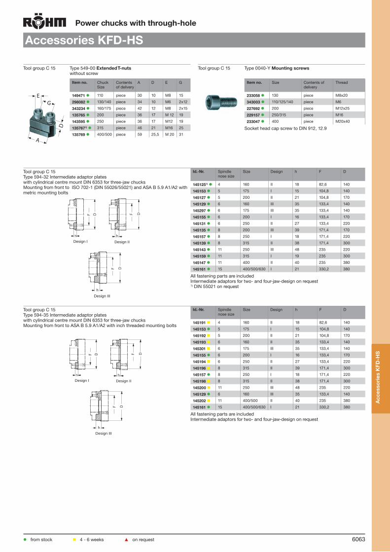
6063
Power chucks with through-hole
Accessories KFD-HS
Tool group C 15 Type 549-00 Extended T-nutswithout screw
Tool group C 15 Type 0040-Y Mounting screws
E
A
D
G
Item no. Chuck Size
Contents of delivery
A D E G
149471 110 piece 30 10 M8 15
298082 130/140 piece 34 10 M6 2x12
343234 160/175 piece 42 12 M8 2x15
135765 200 piece 36 17 M 12 19
143595 250 piece 36 17 M12 19
1357671) 315 piece 46 21 M16 25
135769 400/500 piece 59 25,5 M 20 31
Item no. Size Contents of delivery
Thread
233058 130 piece M8x20
343003 110/125/140 piece M6
227692 200 piece M12x25
229157 250/315 piece M16
233047 400 piece M20x40
Socket head cap screw to DIN 912, 12.9
Tool group C 15Type 594-32 Intermediate adaptor plates with cylindrical centre mount DIN 6353 for three-jaw chucksMounting from front to ISO 702-1 (DIN 55026/55021) and ASA B 5.9 A1/A2 with metric mounting bolts
Id.-Nr. Spindle nose size
Size Design h F D
1451251) 4 160 II 18 82,6 140
145153 5 175 I 15 104,8 140
145127 5 200 II 21 104,8 170
145129 6 160 III 35 133,4 140
145297 6 175 III 35 133,4 140
145155 6 200 I 16 133,4 170
145131 6 250 II 27 133,4 220
145135 8 200 III 39 171,4 170
145157 8 250 I 18 171,4 220
145139 8 315 II 38 171,4 300
145143 11 250 III 48 235 220
145159 11 315 I 19 235 300
145147 11 400 II 40 235 380
145161 15 400/500/630 I 21 330,2 380
All fastening parts are includedIntermediate adaptors for two- and four-jaw-design on request1) DIN 55021 on request
Tool group C 15Type 594-35 Intermediate adaptor plates with cylindrical centre mount DIN 6353 for three-jaw chucksMounting from front to ASA B 5.9 A1/A2 with inch threaded mounting bolts
Id.-Nr. Spindle nose size
Size Design h F D
145191 4 160 II 18 82,6 140
145153 5 175 I 15 104,8 140
145192 5 200 II 21 104,8 170
145193 6 160 II 35 133,4 140
145301 6 175 III 35 133,4 140
145155 6 200 I 16 133,4 170
145194 6 250 II 27 133,4 220
145196 8 315 II 39 171,4 300
145157 8 250 I 18 171,4 220
145198 8 315 II 38 171,4 300
145200 11 250 III 48 235 220
145129 6 160 III 35 133,4 140
145202 11 400/500 II 40 235 380
145161 15 400/500/630 I 21 330,2 380
All fastening parts are includedIntermediate adaptors for two- and four-jaw-design on request
Acc
esso
ries
KFD
-HS
from stock 4 - 6 weeks ▲ on request
F D
h
F D
h
h
F D
Design I Design II
Design III
F D
h
F D
h
h
F D
Design I Design II
Design III

6064
Tool group C 15Type 594-33 Intermediate adaptor plates with cylindrical centre mount DIN 6353 for three-jaw chucksBayonet fixing to ISO 702-3 (DIN 55027)/ DIN 55022
Id.-Nr. Spindle nose size
Size Design h F D
145208 4 160 II 18 82,6 140
145236 5 160 II 21 104,8 140
145238 5 175 II 21 104,8 140
145210 5 200 II 21 104,8 170
145212 6 160 III 35 133,4 140
145303 6 175 III 35 133,4 140
145240 6 200 II 22 133,4 170
145214 6 250/315 II 27 133,4 220
145218 8 200 III 39 171,4 170
145242 8 250 II 30 171,4 220
145222 8 315 II 38 171,4 300
145226 11 250 III 48 235 220
145246 11 315 II 36 235 300
145230 11 400/500 II 40 235 380
145250 15 630 I 40 330,2 380
All fastening parts are includedIntermediate adaptors for two- and four-jaw-design on request
Power chucks with through-hole
Accessories KFD-HS
Tool group C 15Type 594-36 Intermediate adaptor plates with cylindrical centre mount DIN 6353 for three-jaw chucksCamlock fixing to DIN 55029/ASA B 5.9 D1
Id.-Nr. Spindle nose size
Size Design h F D
145252 4 160 II 28 82,6 140
145280 5 160 II 30 104,8 140
145282 5 175 II 30 104,8 140
145254 5 200 II 30 104,8 170
145256 6 160 III 43 133,4 140
145594 6 175 III 43 133,4 140
145284 6 200 II 35 133,4 170
145258 6 250 II 35 133,4 220
145262 8 200 II 46 171,4 170
145286 8 250 II 38 171,4 220
145266 8 315 II 38 171,4 300
145270 11 250 III 53 235 220
145290 11 315 II 45 235 300
145274 11 400/500 II 45 235 380
145294 15 630 I 50 330,2 380
All fastening parts are includedIntermediate adaptors for two- and four-jaw-design on request
Tool group A09Type 619-30 Short-taper adapter plate ISO 702-1 (DIN 55026/55021) - ASA B 5.9 (without mounting bolts)finished on machine side, faced on chuck side, especially
Id.-Nr. Spindle nose size
h E M D
144933 ▲ 3 18 40 40 125
145296 ▲ 4 18 40 40 125
145328 ▲ 3 18 40 40 160
145342 ▲ 4 18 40 40 160
145343 ▲ 5 21 50 50 160
145344 ▲ 4 21 50 50 200
145345 ▲ 5 21 50 50 200
145346 ▲ 6 27 50 50 200
145347 ▲ 4 27 63 63 250
145348 ▲ 5 27 63 63 250
145349 ▲ 6 27 63 63 250
145350 ▲ 8 27 63 63 250
145351 ▲ 5 36 63 63 315
145352 ▲ 6 36 63 63 315
145353 ▲ 8 36 63 63 315
145354 ▲ 11 36 63 63 315
145355 ▲ 6 40 63 63 400
145356 ▲ 8 40 63 63 400
145357 ▲ 11 40 63 63 400
145358 ▲ 15 40 63 63 400
145359 ▲ 8 42 80 80 500
145360 ▲ 11 42 80 80 500
145364 ▲ 15 42 80 80 500
Acc
esso
ries
KFD
-HS
from stock 4 - 6 weeks ▲ on request
F D
h
F D
hDesign II Design III
F D
hF D
hDesign II Design III

6065
Jaw dimensions KFD-HS
Pow
er c
huck
with
th
roug
h-ho
le K
FD-H
S
Power chucks with through-hole
Reversible top jaws UB, hardened, serration 90o,
material 16MnCr5
Chuck size 110 130/140 160/175 160 200 200/250 315 400/500
Type 543-21 537-02 538-02 543 1) 543-09 2) 538-04 538-05 538-07Item no. 2-jaw 149490 046545 045796 - - 118521 046435 046447Item no. 3-jaw 149352 046544 046404 351320 609592 118522 046414 037531
Item no. 4-jaw 155395 046546 046452 - - 118523 046462 046474
A 45 56 56 51,5 80 75 103,5 135B 26 26 26 26 36 36 50 68C 32 37,5 37,5 26 37 49 58 65DH7 10 10 12 12 17 17 21 25,5E 3,5 3,5 3,5 3,5 5 5 5 5F 15 10 14 23 41 21,5 33,5 48G 15 12 3) 15 15 4) 19 4) 19 25 31H 23 29 29 17 25,5 37,5 45 48J 8,4 6,4 8,4 9 13 13 17 21K 13,5 10,4 13,5 14 19 19 25 31L 14 20 20 - - 24 28 -M 7 10 10 8 12 12 14 26N 4 4 4 3 6 6 6 6,5O 4 4 4 4 7,5 7,5 6,5 5,5P 8 5 5 20 - 18 24,5 34Q 5 5 5 3 7 7 22,5 40R 1/16"x90o 1/16"x90o 1/16"x90o 1/16"x90o 1/16"x90o 1/16"x90o 1/16"x90o 3/32"x90o
Weight/jaw kg 0,155 0,130 0,170 0,150 0,235 0,460 1,130 2,000
1) one step only, for 8000 min-1 3) 4 mounting holes2) one step only, extended 4) 2 mounting holes
Soft top jaws AB, serration 90o, material 16MnCr5
Chuck size 110 130/140 160/175 200 250 315 400/500
Type 543-22 537-02 538-02 538-03 538-04 538-05 538-07Item no. 2-jaw 149690 045794 045795 133147 133148 133149 133151Item no. 3-jaw 149353 046402 046403 133152 133153 133154 133156
Item no. 4-jaw - 046450 046451 133157 133158 133159 133161
A 45 53 55 66,7 75 95 130B 26,5 22,5 26,5 36,5 36,5 45 50C 38 30 38 53 53 54,5 80D 10 10 12 17 17 21 25,5E 3,5 3,5 3,5 5 5 5 5F 15 20 31 36 44 55 79G 15 12 1) 15 19 19 25 31H 23 20 28 43 43 42,5 60J 8,4 6,4 8,4 13 13 17 21K 13,5 10,4 13,5 19 19 25 31Q 5 3 - - - - -R 1/16"x90o 1/16"x90o 1/16"x90o 1/16"x90o 1/16"x90o 1/16"x90o 3/32"x90o
Weight/jaw kg 0,210 0,223 0,320 0,700 0,880 1,400 3,100
1) 3 mounting holes
Soft top jaws AB, with tongue and groove, material 16MnCr5
Chuck size 110 130/140 160 200 250
Type 549-10 538-22 538-13 538-14 538-15Item no. 2-jaw 144115 123356 123359 123431 123434Item no. 3-jaw 144082 123355 123358 123430 123433
Item no. 4-jaw 144115 123356 123359 123431 123434
A 53 58 72,7 90,3 115,3B 22,5 26,5 36,5 36,5 45C 30 38 53 53 54,5D-0,03 10 8 16 16 20E 3,5 3,5 5,5 5,5 5,5F 26,5 31,5 32,2 45,3 58,3G 17 - 25 30 40H 20 25 38 38 38J 9 13 13 13 17K 15 19 19 19 25L 2,5 2,5 4,5 4,5 4,5M+0,03 10 13 10 12 16N 20 23 24,7 35,3 45,3O 4 3 5 5 5P 30 39,5 39,7 54,3 70,3Q 3 3 3 6 6Weight/jaw kg 0,21 0,46 0,720 1,0 1,55
Type 537-02Type 543-22
Soft blank top jaws are ideal for high-accuracy chucking. When turning these top jawsfor a specific chucking diameter, be sure to have the jaws under pressure. Top jawswhich are to be hardened must be ground on the chuck after hardening.Note: At high speeds, heavy jaw weights must be avoided because of theirown centrifugal force, resulting in a reduction of gripping force.

6066
Jaw dimensions KFD-HS
Pow
er c
huck
with
th
roug
h-ho
le K
FD-H
S
Power chucks with through-hole
Claw type jaws KBserration 90o,
Type 544-50
Piece A B H KFD-HS 110 External chucking Piece A B KFD-HS 130/140
External chuckingItem no. Item no.
149920 42 37,1 27 20-49 147259 50 41 27-67/35-72149921 42 23,4 27 47-70 147261 44 22 58-108/61-114
149922 47 17,7 27 68-100
Piece A B H KFD-HS 110 Internal chucking Piece A B KFD-HS 130/140
Internal chuckingItem no. Item no.
149922 47 17,7 27 45-75 147261 44 22 58-108/61-114149921 42 23,4 27 56-102 147259 50 41 100-130/106-140149920 42 37,1 27 84-130
Piece A B KFD-HS 160 External chucking
KFD-HS 175 External chucking
Item no.
144320 66 52 38-84 48-100144321 56 34 78-122 88-140
144322 66 25 120-146 130-160
Piece A B KFD-HS 160 Internal chucking
KFD-HS 175 Internal chucking
Item no.
144322 66 25 70-100 70-115144321 56 34 92-140 102-155144320 66 52 122-180 132-195
Piece A B KFD-HS 200 External chucking
KFD-HS 250 External chucking
Item no.
137031 67 53 55-110 68-162137032 65 46 68-124 80-173
137039 55 40 95-150 108-200137034 50 31 102-158 115-206137035 55 27 110-168 125-220
Piece A B KFD-HS 200 Internal chucking
KFD-HS 250 Internal chucking
Item no.
137036 65 19 65-125 80-172137037 65 26 86-142 100-192
137038 55 24 100-156 112-206137035 55 27 120-178 135-228
137034 50 31 132-188 145-236137039 55 40 136-195 150-245
137033 55 39 150-207 165-257137032 65 46 164-222 179-270
Piece A B KFD-HS 315 (86) 1) External chucking
KFD-HS 315 (108) 1) External chucking
Item no.
137041 95 80 46-175 65-175137042 75 60 92-220 104-220
137043 60 43 114-250 135-250137044 70 37 142-275 166-275
Piece A B KFD-HS 315 (86) 1) Internal chucking
KFD-HS 315 (108) 1) Internal chucking
Item no.
137045 95 25 65-200 82-200137046 80 30 108-242 130-242
137044 70 37 142-275 164-275137043 60 43 170-305 195-305
137042 75 60 202-340 224-340
1) chuck through-hole M
Piece A B KFD-HS 400 External chucking
KFD-HS 400 (165) 1) External chucking
KFD-HS 500 External chucking
Item no.
137051 130 113 70-270 94-270 94-370137052 90 67 150-304 183-304 183-404
137053 100 45 175-390 210-390 210-490
Piece A B KFD-HS 400 Internal chucking
KFD-HS 400 (165) 1) Internal chucking
KFD-HS 500 Internal chucking
Item no.
137054 130 33 96-290 110-290 110-390137053 100 45 160-305 195-305 195-405
137051 130 113 280-490 302-490 302-590
* KFD-HS 110+130+140
*
*
**

6067
Power chucks with through-hole
Pow
er c
huck
with
th
roug
h-ho
le K
FD-H
S
Chucking capacities with reversible top jaws UB,for 3-jaw chucks
Chuck size 110 130 140 160 160* 175 200 200** 250 315 400 500
with reversible jaws
Type 543-21 537-02 527-02 538-02 543 538-02 538-04 543-09 538-04 538-05 538-07 538-07Jaw position
External chucking
A1 6-46 5-58 5-68 6-67 4-52 6-82 12-98 4-70 22-144 25-169 30-203 30-303
A2 - - - - 21-73 - 26-112 - 40-156 45-196 47-250 47-350
A3 41-76 52-105 52-115 53-118 - 54-133 82-165 - 94-210 127-280 - -
A4 68-106 87-140 87-150 88-165 94-146 90-180 132-218 112-170 146-262 209-360 245-453 245-553
Internal chu-cking
J1 42-80 35-90 35-100 36-99 32-84 36-114 61-144 60-126 76-192 76-216 96-280 96-380J2 70-108 70-125 70-135 71-134 - 71-149 110-198 - 128-244 150-348 - -J3 96-135 117-192 117-182 118-181 102-157 118-196 162-248 - 182-298 230-380 277-478 277-580
Chucking capacities KFD-HS
* one step only* one step only, extended

KFD
6068
Power chucks with through-hole
KFD-HE
Rugged construction
Large through-hole
High radial and axial true-running accuracy
Direct lubrication of all wearing surfaces
Used in conjunction with RÖHM actuating cylinders with safety device SZS, OVS, LHS-L, LVS, EHS and EVS the power chucks KFD-HE meet the requirements of the German Employers’ Insurance Association
Pow
er c
huck
with
th
roug
h-ho
le K
FD-H
E
Components KFD-HE1. Body 2. Base jaw 3. Piston 4. Adaptor plate 5. Protective bushing 6. Ring nut 7. T-nut
For use on modern lathes. With large through-hole, suitable for both bar work and chucking of flange Type parts. The chucking power is transmitted by means of the proven wedge system.
1
3
6
5
7
2
4
Technical features:

KFD
6069
KFD-HEPower chucks with through-hole
Pow
er c
huck
with
th
roug
h-ho
le K
FD-H
E
Gripping force/speed diagram
The loss of gripping force was determined experimentally on a chuck with matched UB top jaws. It is largely independent of the initial gripping force at zero speed.
Upper curve: min. centrifugalforce of top jaw
Lower curve: max. centrifugalforce of top jaw
To obtain the specified gripping forces, the chuck must be in a perfectcondition and lubricated with F 80 lubricant recommended by Röhm.Measuring point near chuck face. Example: For a chuck size 254 and an applied operating power of 40 kN, the total gripping force is approx. 90 kN.
6056
2000 1000 3000 4000 5000 6000 7000
20
40
60
80
100
120
140
160
180
200
220KFD-HE 400
KFD-HE 315
KFD-HE 254
KFD-HE 170
KFD-HE 130
KFD-HE 210To
tal g
rippi
ng fo
rce
kN
Speed min -1
Gripping force/operating power diagram
6056
2000 1000 3000 4000 5000 6000 7000
20
40
60
80
100
120
140
160
180
200
220KFD-HE 400
KFD-HE 315
KFD-HE 254
KFD-HE 170
KFD-HE 130
KFD-HE 210
Tota
l grip
ping
forc
e kN
Chuck size Total gripping force
Operating power kN
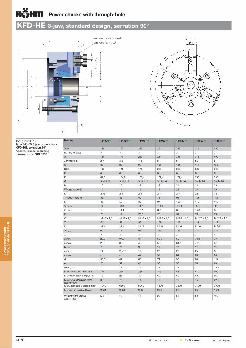
6070
Power chucks with through-hole
KFD-HE 3-jaw, standard design, serration 90°
Tool group C 15Type 440-50 3 jaw power chuck KFD-HE, serration 90°Adaptor recess, mounting dimensions to DIN 6353
Item no. 154806 154384 154031 154032 154810 154829 151554
Size 130 170 210 254 315 315 400
number of jaws 3 3 3 3 3 3 3
A 130 170 210 254 315 315 400
Jaw travel B 2,7 3,2 4,3 5,1 5,3 5,3 8
C 60 82 93 101 104 114 128
DH6 110 140 170 220 220 300 300
E 4 6 6 6 6 6 6
F 82,6 104,8 133,4 171,4 171,4 235 235
G 3 x M 10 3 x M 10 3 x M 12 3 x M 16 3 x M 16 3 x M 20 3 x M 20
H 15 15 19 23 24 28 29
Wedge stroke K 10 14 16 19 23 23 30
L 2,75 2,5 2,5 2,5 2,5 2,5 3,5
Through-hole M 33 43 52 75 91 121 121
N 45 57 66 94 108 143 136
O min. -9 -2,6 -0,7 -10,3 -14,8 -9,4 -21
O max. 1 11,4 15,3 8,7 8,2 13,6 9
P 20 19 20,5 28 32 26 28
Q M 40 x 1,5 M 52 x 1,5 M 58 x 1,5 M 82 x 1,5 M 98 x 1,5 M 126 x 1,5 M 126 x 1,5
T 61 82 93 101 110 114 129
U M 8 M 8 M 12 M 16 M 16 M 16 M 20
VH7-0,05 60 74 92 125 135 170 170
X 3 3 3 3 3 3 4
a min. 23,8 34,8 37,7 50,9 56 72,2 79
a max. 26,5 38 42 56 61,3 77,5 87
b min. 7 7,5 9 10 12 12 19
c min. 14 2 x 15 19 25 25 25 31
c max. - - 47 59 84 69 80
d 38,5 47 63 71 96 80 113
e 25 32 40 50 50 50 60
fH7-0,025 10 12 17 21 21 21 25,5
Max. swing top jaws mm 170 230 290 345 410 410 560
Maximum draw bar pull kN 16 25 40 60 60 60 95
Max. total clamping force approx. kN
36 75 110 135 160 160 220
Max. admissible speed min-1 7000 6300 5000 4500 3500 3500 2000
Moment of inertia J kgm2 0,011 0,038 0,09 0,22 0,8 0,8 1,88
Weight without jaws approx. kg
5,5 12 18 29 53 50 100
from stock 4 - 6 weeks ▲ on request
Pow
er c
huck
with
th
roug
h-ho
le K
FD-H
E
A FD N QG
P
C
T
B
d
U
M
c
a
b
O
H
L
X
K
E
V
Size 130-315 ≤ 1/16” x 90o
Size 400 ≥ 3/32” x 90o

6071
Power chucks with through-hole
KFD-HE 3-jaw, standard design serration 90°
Tool group C 15Type 440-52 3 jaw power chuck KFD-HE, serration 90°Short taper mount for ISO 702-1 (DIN 55026/55021)
Item no. 154807 154385 154034 154037 154811 154831 151553
Size 130 170 210 254 315 315 400
number of jaws 3 3 3 3 3 3 3
A 130 170 210 254 315 315 400
Jaw travel B 2,7 3,2 4,3 5,1 5,3 5,3 8
C 67,5 90,6 103,2 112,8 121,8 127,4 141,4
Short taper D 4 (nur 55026) 5 6 8 8 11 11
E 11,5 15 16 17,8 17,8 19,4 19,4
F 82,6 104,8 133,4 171,4 171,4 235 235
G 3 x M 10 3 x M 10 3 x M 12 3 x M 16 3 x M 16 3 x M 20 3 x M 20
H 13 15 18 23 24 29 30
Wedge stroke K 10 14 16 19 23 23 30
L 2,75 2,5 2,5 2,5 2,5 2,5 3,5
Through-hole M 33 43 52 75 91 121 121
N 45 57 66 94 108 143 136
O min. 2,5 12 15,5 7,5 3 10 -1,6
O max. 12,5 26 31,5 26,5 26 33 28,4
P 20 19 20,5 28 32 26 28
Q M 40 x 1,5 M 52 x 1,5 M 58 x 1,5 M 82 x 1,5 M 98 x 1,5 M 126 x 1,5 M 126 x 1,5
T 72,5 96,6 109,2 118,8 127,8 133,4 128,4
U M 8 M 8 M 12 M 16 M 16 M 16 M 20
VH7-0,05 60 74 92 125 135 170 170
X 3 3 3 3 3 3 4
a min. 23,8 34,8 37,7 50,9 56 72,2 79
a max. 26,5 38 42 56 61,3 77,5 87
b min. 7 7,5 9 10 12 12 19
c min. 14 2 x 15 19 25 25 25 31
c max. - - 47 59 84 69 80
d 38,5 47 63 71 96 80 113
e 25 32 40 50 50 50 60
fH7-0,025 10 12 17 21 21 21 25,5
Max. swing top jaws mm 170 230 290 345 410 410 560
Maximum draw bar pull kN 16 25 40 60 60 60 95
Max. total clamping force approx. kN
36 75 110 135 160 160 220
Max. admissible speed min-1 7000 6300 5000 4500 3500 3500 2000
Moment of inertia J kgm2 0,011 0,038 0,09 0,22 0,8 0,8 1,88
Weight without jaws approx. kg
5,5 12 18 29 53 50 100
from stock 4 - 6 weeks ▲ on request
Pow
er c
huck
with
th
roug
h-ho
le K
FD-H
E
A F D N QG
P
C
T
B
d
U
M
c
a
b
O
H
E
L
X
7° 7'30"
VK
Size 130-315 ≤ 1/16” x 90o
Size 400 ≥ 3/32” x 90o

6072
Power chucks with through-hole
KFD-HE 3-jaw, universal draw tube-connector, serration 90°A
FD N
Q m
axG
P
C
T
B
d
Q
U
M
c
aV
b
O
H
L
X
K
E
1,5 x 60
Tool group C 15Type 440-90 3 jaw power chuck KFD-HE, serration 60°, with pre-machined draw tube-connectorAdaptor recess, mounting dimensions to DIN 6353
Item no. 156844 154808 154390 154391 154392 154812 154830
Size 110 130 170 210 254 315 315
number of jaws 3 3 3 3 3 3 3
A 110 130 170 210 254 315 315
Jaw travel B 2,7 2,7 3,4 4,3 5,1 5,3 5,3
C 58,5 60 82 93 101 104 114
DH6 85 110 140 170 220 220 300
E 4 4 6 6 6 6 6
F 70,6 82,6 104,8 133,4 171,4 171,4 235
G 3 x M 10 3 x M 10 3 x M 10 3 x M 12 3 x M 16 3 x M 16 3 x M 20
H 16 15 15 19 23 24 28
Wedge stroke K 10 10 14 16 19 23 23
L 2,9 2,9 3,2 3,2 3,2 3,2 3,2
Through-hole M 26 33 43 52 75 91 121
N 38 45 57 66 94 108 143
O min. -6,5 -9 -2,6 -0,7 -10,3 -14,8 -9,4
O max. 3,5 1 11,4 15,3 8,7 8,2 13,6
P 10 20 19 20,5 28 32 26
Q Ø 10 Ø 12 Ø 20 Ø 30 Ø 45 Ø 50 Ø 60
Q max. M 34 x 1,5 M 40 x 1,5 M 53 x 1,5 M 60 x 2 M 85 x 2 M 100 x 2 M 130 x 2
T 59,5 61 82 93 101 110 114
U M 8 M 8 M 10 M 12 M 12 M 16 M 16
VH7-0,05 56 60 74 92 125 135 170
X 3 3 3 3 3 3 3
a min. 20,3 23,8 34,8 37,7 50,9 56 72,7
a max. 23 26,5 38 42 56 61,3 77,5
b min. 7 7 4,5 9 8 12 12
c min. 14 14 20 25 30 30 30
d 32 38,5 47 63 71 96 80
e 25 25 32 40 50 50 50
fH7-0,025 10 10 12 14 16 21 21
Max. swing top jaws mm 170 170 230 290 345 410 410
Maximum draw bar pull kN 11 16 25 40 60 60 60
Max. total clamping force approx. kN
25 36 75 110 135 160 160
Max. admissible speed min-1 8000 7000 6300 5000 4500 3500 3500
Moment of inertia J kgm2 0,005 0,011 0,038 0,9 0,22 0,8 0,8
Weight without jaws approx. kg
3,4 5,5 12 18 29 53 50
Interchangeable with Kitagawa B-200A
from stock 4 - 6 weeks ▲ on request
Pow
er c
huck
with
th
roug
h-ho
le K
FD-H
E
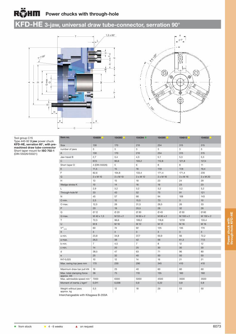
6073
Power chucks with through-hole
KFD-HE 3-jaw, universal draw tube-connector, serration 90°
K
A F D N
Q m
axG
P
C
T
B
d
Q
U
M
c
a
b
O
H
E
L
X
7° 7'30"
1,5 x 60°
V
Tool group C15Type 440-92 3 jaw power chuck KFD-HE, serration 60°, with pre-machined draw tube-connectorShort taper mount for ISO 702-1 (DIN 55026/55021)
Item no. 154809 154393 154394 154395 154813 154832
Size 130 170 210 254 315 315
number of jaws 3 3 3 3 3 3
A 130 170 210 254 315 315
Jaw travel B 2,7 3,4 4,3 5,1 5,3 5,3
C 67,5 90,6 103,2 112,8 121,8 127,4
Short taper D 4 (DIN 55026) 5 6 8 8 11
E 11,5 15 16 17,8 17,8 19,4
F 82,6 104,8 133,4 171,4 171,4 235
G 3 x M 10 3 x M 10 3 x M 12 3 x M 16 3 x M 16 3 x M 20
H 13 15 18 23 24 29
Wedge stroke K 10 14 16 19 23 23
L 2,9 3,2 3,2 3,2 3,2 3,2
Through-hole M 33 43 52 75 91 121
N 45 57 66 94 108 143
O min. 2,5 12 15,5 7,5 3 10
O max. 12,5 26 31,5 26,5 26 33
P 20 19 20,5 28 32 26
Q Ø 12 Ø 20 Ø 30 Ø 45 Ø 50 Ø 60
Q max. M 40 x 1,5 M 53 x 2 M 60 x 2 M 85 x 2 M 100 x 2 M 130 x 2
T 72,5 96,6 109,2 118,8 127,8 133,4
U M 8 M 10 M 12 M 12 M 16 M 16
VH7-0,05 60 74 92 125 135 170
X 3 3 3 3 3 3
a min. 23,8 34,8 37,7 50,9 56 72,2
a max. 26,5 38 42 56 61,3 77,5
b min. 7 4,5 7 8 12 12
c min. 14 20 25 30 30 30
d 38,5 47 63 71 96 80
e 25 32 40 50 50 50
fH7-0,025 10 12 14 16 21 21
Max. swing top jaws mm 170 230 290 345 410 410
Maximum draw bar pull kN 16 25 40 60 60 60
Max. total clamping force approx. kN
36 75 110 135 160 160
Max. admissible speed min-1 7000 6300 5000 4500 3500 3500
Moment of inertia J kgm2 0,011 0,038 0,9 0,22 0,8 0,8
Weight without jaws approx. kg
5,5 12 18 29 53 50
Interchangeable with Kitagawa B-200A
from stock 4 - 6 weeks ▲ on request
Pow
er c
huck
with
th
roug
h-ho
le K
FD-H
E

6074
Power chucks with through-hole
Jaws KFD-HE
Tool group C 21Type 543/538 Reversible top jaws, 3-jaw set, hardenedSerration 90°- material: 16 MnCr 5
Item no. Chuck Size Jaw length Jaw height Jaw width Serration
156446 130 54 27,5 23 1/16”x 90°
046404 130 56 37,5 26 1/16’’x 90°
118522 200 75 49 36 1/16”x 90°
046414 250/315 103,5 58 50 1/16’’x 90°
037531 400 135 65 68 3/32”x 90°
Hardened jaws, supplied as supplement or as spares, must be ground on the chuck.
Tool group C 21Type 543-31Reversible top jaws, 3-jaw set, hardenedSerration 60°- material: 16 MnCr 5
Item no. Chuck Size Jaw length Jaw height Jaw width Serration
154814 130 54 27,5 23 1,5 x 60°
154674 170 66 36 34,7 1,5 x 60°
154676 210 81 49 36 1,5 x 60°
154678 254 99,5 54 44,5 1,5 x 60°
154816 315 103 55,5 50 1,5 x 60°
Hardened jaws, supplied as supplement or as spares, must be ground on the chuck.
Tool group C 21Type 543/538 Soft top jaws, 3-jaw set, can be hardenedSerration 90°- material: 16 MnCr 5
Item no. Chuck Size Jaw length Jaw height Jaw width Serration
156452 130 54 29 23 1/16”x 90°
046403 130 55 38 26,5 1/16’’x 90°
133153 200 75 53 36,5 1/16”x 90°
133154 250 95 54,5 45 1/16”x 90°
133156 400 130 80 50 3/32”x 90°
Tool group C 21Type 543-32 Soft top jaws, 3-jaw set, can be hardenedSerration 60°- material: 16 MnCr 5
Item no. Chuck Size Jaw length Jaw height Jaw width Serration
154863 130/170 54 29 23 1,5 x 60°
154865 170 72 43 30,5 1,5 x 60°
154867 210 95 45,5 35 1,5 x 60°
154869 254 110 45 50 1,5 x 60°
154871 315 130 55,5 50 1,5 x 60°
from stock 4 - 6 weeks ▲ on request
Jaw
s K
FD-H
E

6075
Power chucks with through-hole
Jaws KFD-HE
Tool group C 21Type 543-33 Claw-type jaws, 1 piece, hardenedSerration 60° - width of the groove 16
Item no. Chuck Size Jaw length Jaw height Jaw width
156099 254 95 50 80
156101 254 75 50 60
156103 254 60 50 43
156105 254 70 50 37
Tool group C 21Type 544-50 Claw-type jaws, 1 piece, hardenedSerration 90° - width of thegroove 17
Item no. Chuck Size Jaw length Jaw height Jaw width
137031 200 67 45 53
137032 200 65 45 46
137039 200 55 45 40
137034 200 50 45 31
137035 200 55 45 27
137036 200 65 45 19
137037 200 65 45 26
137038 200 55 45 24
137033 200 55 45 39
Tool group C 21Type 544-50 Claw-type jaws, 1 piece, hardenedSerration 90° - width of the groove 21
Item no. Chuck Size Jaw length Jaw height Jaw width
137041 250/315 95 50 80
137042 250/315 75 50 60
137043 250/315 60 50 43
137044 250/315 70 50 37
137045 250/315 95 50 25
137046 250/315 80 50 30
Tool group C 21Type 544-50 Claw-type jaws, 1 piece, hardenedSerration 90° - width of the groove 25,5
Item no. Chuck Size Jaw length Jaw height Jaw width
137051 400 130 65 113
137052 400 90 65 67
137053 400 100 65 45
137054 400 130 65 33
Tool group C 21Type 543-33 Claw-type jaws, 1 piece, hardenedSerration 60° - width of the groove 12
Item no. Chuck Size Jaw length Jaw height Jaw width
156025 170 67 45 53
156027 170 65 45 46
156029 170 55 45 40
161189 170 55 45 24
from stock 4 - 6 weeks ▲ on request
Jaw
s K
FD-H
E

6076
Power chucks with through-hole
Accessories KFD-HE
Tool group C 15 Type 538-00 T-nutswithout screw, for SV 1/16 “ x 90°
Tool group C 15 Type 440-90 T-nutswithout screw, for SV 1,5” x 60°
E
D
G
Item no. Chuck Size
Contents of delivery
D E G
154033 130 piece 10 M8 14
343234 170 piece 12 M8 2x15
1575691) 210 piece 17 M12 -
1357671) 254/315 piece 21 M16 25
2416761) 400 piece 25,5 M20 -1) single T-nut
E
D
G
Item no. Chuck Size Contents of delivery
D E G
154033 130 piece 10 M8 14
154651 170 piece 12 M10 20
154659 210 piece 14 M12 25
154672 254 piece 16 M12 30
155219 315 piece 21 M16 30
Tool group C 15 Type 0040-Y Mounting screws Tool group C 15 Type 0040-Y Mounting screws
Item no. Size Contents of delivery
Thread Length
2481492) 130 piece M8 20
233058 130 piece M8x20 20
227692 200 piece M12x25 25
229157 250/315 piece M16 30
233047 400 piece M20x40 40
Socket head cap screw to DIN 912, 12.92) two pieces necessary
Item no. Size Contents of delivery
Thread Length
2481492) 130 piece M8 20
2165882) 170 piece M10 25
233030 210/254/315 piece M12x30 30
2165692) 400 piece M16 40
Socket head cap screw to DIN 912, 12.92) two pieces necessary
Tool group C15 Type 1028 Special grease F80 for lathe chucksfor lubrication and conservation of chucking power
Item no. Design Contents
308555 Cartridge 0,5 kg
028975 Tin 1 kg
Tool group A09Type 619-30 Short-taper adapter plate ISO 702-1 (DIN 55026/55021) - ASA B 5.9 (without mounting bolts)finished on machine side, faced on chuck side, especially
Id.-Nr. Spindle nose size
h E M D
144933 ▲ 3 18 40 40 125
145296 ▲ 4 18 40 40 125
145328 ▲ 3 18 40 40 160
145342 ▲ 4 18 40 40 160
145343 ▲ 5 21 50 50 160
145344 ▲ 4 21 50 50 200
145345 ▲ 5 21 50 50 200
145346 ▲ 6 27 50 50 200
145347 ▲ 4 27 63 63 250
145348 ▲ 5 27 63 63 250
145349 ▲ 6 27 63 63 250
145350 ▲ 8 27 63 63 250
145351 ▲ 5 36 63 63 315
145352 ▲ 6 36 63 63 315
145353 ▲ 8 36 63 63 315
145354 ▲ 11 36 63 63 315
145355 ▲ 6 40 63 63 400
145356 ▲ 8 40 63 63 400
145357 ▲ 11 40 63 63 400
145358 ▲ 15 40 63 63 400
145359 ▲ 8 42 80 80 500
145360 ▲ 11 42 80 80 500
145364 ▲ 15 42 80 80 500
from stock 4 - 6 weeks ▲ on request
Acc
esso
ries
KFD
-HE

6077
Power chucks with through-hole
Accessories KFD-HE
Type 594-32 Intermediate adaptor plates with cylindrical centre mount DIN 6353 for three-jaw chucksMounting from front to ISO 702-1 (DIN 55026/55021) and ASA B 5.9 A1/A2 with metric mounting bolts
Id.-Nr. Spindle nose size
Size Design h F D
1451251) 4 160 II 18 82,6 140
145153 5 175 I 15 104,8 140
145127 5 200 II 21 104,8 170
145129 6 160 III 35 133,4 140
145155 6 200 I 16 133,4 170
145131 6 250 II 27 133,4 220
145135 8 200 III 39 171,4 170
145157 8 250 I 18 171,4 220
145139 8 315 II 38 171,4 300
145143 11 250 III 48 235 220
145159 11 315 I 19 235 300
145149 15 400 III 58 330,2 300
All fastening parts are includedIntermediate adaptors for two- and four-jaw-design on request1) DIN 55021 on request
Tool group C 15Type 594-35 Intermediate adaptor plates with cylindrical centre mount DIN 6353 for three-jaw chucksMounting from front to ASA B 5.9 A1/A2 with inch threaded mounting bolts
Id.-Nr. Spindle nose size
Size Design h F D
145191 4 160 II 18 82,6 140
145192 5 200 II 21 104,8 170
145193 6 160 II 35 133,4 140
145194 6 250 II 27 133,4 220
145196 8 315 II 39 171,4 300
145198 8 315 II 38 171,4 300
145200 11 250 III 48 235 220
145203 15 400 III 58 330,2 300
All fastening parts are includedIntermediate adaptors for two- and four-jaw-design on request
Tool group C 15Type 594-33 Intermediate adaptor plates with cylindrical centre mount DIN 6353 for three-jaw chucksBayonet fixing to ISO 702-3 (DIN 55027)/ DIN 55022
Id.-Nr. Spindle nose size
Size Design h F D
145208 4 160 II 18 82,6 140
145236 5 160 II 21 104,8 140
145210 5 200 II 21 104,8 170
145212 6 160 III 35 133,4 140
145240 6 200 II 22 133,4 170
145214 6 250/315 II 27 133,4 220
145218 8 200 III 39 171,4 170
145242 8 250 II 30 171,4 220
145222 8 315 II 38 171,4 300
145226 11 250 III 48 235 220
145246 11 315 II 36 235 300
145230 11 400/500 II 40 235 380
145232 15 400 III 58 330,2 300
All fastening parts are includedIntermediate adaptors for two- and four-jaw-design on request
Tool group C 15Type 594-36 Intermediate adaptor plates with cylindrical centre mount DIN 6353 for three-jaw chucksCamlock fixing to DIN 55029/ASA B 5.9 D1
Id.-Nr. Spindle nose size
Size Design h F D
145252 4 160 II 28 82,6 140
145280 5 160 II 30 104,8 140
145254 5 200 II 30 104,8 170
145256 6 160 III 43 133,4 140
145284 6 200 II 35 133,4 170
145258 6 250 II 35 133,4 220
145262 8 200 II 46 171,4 170
145286 8 250 II 38 171,4 220
145264 8 315/400 II 38 171,4 300
145270 11 250 III 53 235 220
145290 11 315 II 45 235 300
145276 15 400 III 58 330,2 300
All fastening parts are includedIntermediate adaptors for two- and four-jaw-design on request
from stock 4 - 6 weeks ▲ on request
Acc
esso
ries
KFD
-HE
F D
h
F D
hDesign II Design III
F D
h
F D
hDesign II Design III
F D
h
F D
h
h
F D
Design I Design II
Design III
F D
h
F D
h
h
F DDesign I Design II
Design III

6078
Jaw dimensions KFD-HE
Pow
er c
huck
with
th
roug
h-ho
le K
FD-H
E
Power chucks with through-hole
Reversible top jaws UB, hardened, serration 90o,
material 16MnCr5
Chuck size 130 170 210 250 315 400
Type 543-21 537-02 538-03 538-04 538-05 538-07Item no. 2-jaw - 046545 046429 118521 046435 046447Item no. 3-jaw 156446 046544 046408 118522 046414 037531
Item no. 4-jaw - 046546 046456 118523 046462 046474
A 54 56 68 75 103,5 135B 23 26 34,7 36 50 68C 27,5 37,5 45 49 58 65DH7 10 10 17 17 21 25,5E 4 3,5 5 5 5 5F 13 10 17 21,5 33,5 48G 14 12 1) 19 19 25 31H 19 29 33,5 37,5 45 48J 8,4 6,4 13 13 17 21K 13,5 10,4 19 19 25 31L - 20 20 24 28 -M 10 10 10 12 14 26N 3 4 5 6 6 6,5O 3 4 7 7,5 6,5 5,5P - 5 10 18 24,5 34Q 6 5 5 7 22,5 40R 1/16"x90o 1/16"x90o 1/16"x90o 1/16"x90o 1/16"x90o 3/32"x90o
Weight/jaw kg 0,110 0,130 0,350 0,460 1,130 2,000
1) 4 mounting holes
Soft top jaws AB, serration 90o, material 16MnCr5
Chuck size 130 170 210 250/315 400
Type 537-02 538-02 538-04 538-05 538-07Item no. 2-jaw - 045795 133148 133149 133151Item no. 3-jaw 156452 046403 133153 133154 133156
Item no. 4-jaw - 046451 133158 133159 133161
A 54 55 75 95 130B 23 26,5 36,5 45 50C 29 38 53 54,5 80D 10 12 17 21 25,5E 4 3,5 5 5 5F 28 31 44 55 79G 14 15 19 25 31H 20 28 43 42,5 60J 8,4 8,4 13 17 21K 13,5 13,5 19 25 31Q - - - - -R 1/16"x90o 1/16"x90o 1/16"x90o 1/16"x90o 3/32"x90o
Weight/jaw kg 0,220 0,320 0,880 1,400 3,100Type 537-02Type 543-22
Reversible top jaws UB, serration 60o, material 16MnCr5
Chuck size 130 170 210 254 315
Type 543-31 543-31 543-31 543-31 543-31Item no. 3-jaw 154814 1) 154674 1) 154676 154678 154816 1)
A 54 66 81 99,5 103B 23 34,7 36 44,5 50C 27,5 36 49 54 55,5D 10 12 14 16 21F 13 12,5 17,5 25,5 22,5G 14 20 25 30 30H 19 23 36,5 38,5 34J 8,4 11 13 13 17K 13,5 17 19 19 25Serration 1,5 x 60o 1,5 x 60o 1,5 x 60o 1,5 x 60o 1,5 x 60o
Weight/jaw kg 0,16 0,3 0,6 1,2 1,5
1) one step only
Soft top jaws AB, serration 60o, material 16MnCr5
Chuck size 130 170 210 254 315
Type 543-32 543-32 543-32 543-32 543-32Item no. 3-jaw 154863 154865 154867 154869 154871A 54 72 95 110 130B 23 32,5 35 50 50C 29 40 45,5 45 55,5D 10 12 14 16 21F 28 37 46 50 52G 14 20 25 30 30H 20,5 27 33 29 34J 8,4 11 13 13 17K 13,5 17 19 19 25Serration 1,5 x 60o 1,5 x 60o 1,5 x 60o 1,5 x 60o 1,5 x 60o
Weight/jaw kg 0,25 0,5 0,9 1,7 1,9
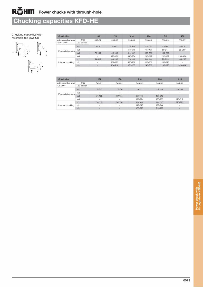
6079
Chucking capacities KFD-HEPower chucks with through-hole
Pow
er c
huck
with
th
roug
h-ho
le K
FD-H
E
Chucking capacities with reversible top jaws UB
Chuck size 130 170 210 254 315 400
with reversible jaws 1/16" x 90o
Type 543-21 538-02 538-04 538-05 538-05 538-07Jaw position
External chucking
A1 5-73 13-83 19-108 25-134 57-189 40-214
A2 - - 36-128 48-162 50-217 86-260
A3 71-130 80-150 94-182 130-226 134-297 -
A4 - 120-192 145-234 210-272 212-332 290-464
Internal chuckingJ1 54-119 63-130 78-156 80-190 70-233 106-280J2 - 102-173 128-209 156-261 146-313 -J3 - 154-210 181-263 246-338 236-393 310-484
Chuck size 130 170 210 254 315
with reversible jaws 1,5 x 60o
Type 543-31 543-31 543-31 543-31 543-31Jaw position
External chucking
A1 5-73 17-100 19-111 25-130 28-190
A2 - - - - -
A3 71-130 97-174 82-170 124-219 -
A4 - - 133-224 170-265 170-317
Internal chuckingJ1 54-119 74-154 63-160 84-197 116-271J2 - - 112-213 129-244 -J3 - - 170-273 211-328 -

6080
Notes
Not
es

6081
KFM
/ K
FG
Power chucks with through-hole
Power-operated angle lever chucks KFM / KFG
Large jaw strokes due to angle lever system
Large through-hole
Made of steel
All moving parts hardened and ground
Large guiding ways for the base jaws
Favorable leverage
Jaw ways lubricated by means of cenveniently accessible grease nipples at the axes of the levers
T-slots in chuck body
Used in conjunction with RÖHM actuating cylinders with safety device SZS, OVS, LHS-L, LVS, EHS and EVS the power chucks KFM / KFG meet the require-ments of the German Employers’ Insurance Associ-ation
Designs: KFM (medium jaw movement), KFG (long jaw movement)
Scope of delivery: Chuck and jaw mounting screws, wrenches, T-nuts, 2 keys for the draw sleeve. Please order top jaws separately.
Technical features:

6082
Power chucks with through-hole
KFM 3-Jaw, larger jaw movement, serration 60°
Tool group C 15Type 531-05 3 jaw lever-type power chucks KFM, larger jaw movement, with serration 60°cylindrical centre mount
Item no. 020616 ▲ 020617 ▲ 020618 ▲ 020619 ▲ 020620 ▲
Size 130 160 215 280 350
Number of jaws 3 3 3 3 3
A 130 160 215 280 350
Jaw travel B 5,5 6 10 10 15
C 63 69,5 90,5 101 126
DH7 110 140 190 255 320
E 4,2 4,2 4,2 5,7 5,7
F 82,6 104,8 133,4 133,4 235
G 3xM10 3xM10 6xM12 6xM12 6xM20
H 17 20 25 25 35
J 46 61 74 102 135
K 25,3 40,5 45,5 66,5 90,5
LH7 50 66 80 105 140
M 2,5 2,5 2,5 2,5 2,5
N 58 76 90 120 156
O M5 M6 M8 M8 M 10
P 2,6 1 1,4 0,5 5,5
Q 3,3 - 3,6 3,2 5,2
R 10 13 15 15 20
S min. 16,7 25,3 25,4 28,8 31,8
S max. 36,7 45,3 50,4 63,8 76,8
T 8 8 12 18 22
U M40x1,25 M54x1,25 M65x1,25 M90x1,25 M112x1,5
VH7 36 50 62 87 109
W 20 23 29 32 37
a min. 24,25 32 39,5 53 69,5
a max. 29,75 38 49,5 63 84,5
b 7 8 10 13 14
c min. 14 16 20 26 28
c max. 24 29 43 56 70
d 38 45 63 82 98
e 27 28 35 45 50
fH8 11 11 14 20 21
g - - 35 63 83
h - - 16 16 22
i - - 10 10 15
k - - 24 24 35
l - - 10 10 17
m M8 M8 M10 M12 M16
n 7 7,5 8,5 13 15
o 1,5 1,5 1,5 2,5 3
Max. swing top jaws mm 190 216 285 365 470
Maximum draw bar pull kN 7,5 24 33,5 43 52
Max. total clamping force approx. kN 16,5 48 51 90 93
Max. admissible speed min-1 3950 5000 3150 2650 1850
Moment of inertia J kgm2 0,011 0,028 0,11 0,38 1,17
Weight without jaws approx. kg 5 8 17 37 71,5
Actuating cylinder hydraulic SZS 27/63 37/72 46/102 67/120 86/213
Actuating cylinder hydraulic OVS 85 105 130 150 150
from stock 4 - 6 weeks ▲ on request
Pow
er-o
pera
ted
angl
e le
ver
chuc
k K
FM
Serration base jaw Clamping groovefrom KFM 215

6083
Power chucks with through-hole
KFM 2-Jaw, larger jaw movement, serration 60°
Tool group C 15Type 521-05 2 jaw lever-type power chucks KFM, medium jaw movement, with serration 60°cylindrical centre mount
Item no. 020641 ▲ 020642 ▲ 020643 ▲ 020644 ▲ 020645 ▲
Size 130 160 215 280 350
Number of jaws 2 2 2 2 2
A 130 160 215 280 350
Jaw travel B 5,5 6 10 10 15
C 63 69,5 90,5 101 126
DH7 110 140 190 255 320
E 4,2 4,2 4,2 5,7 5,7
F 82,6 104,8 133,4 133,4 235
G 4xM10 4xM10 6xM12 4xM12 6xM20
H 17 20 25 25 35
J 46 61 74 102 135
K 25,3 40,5 45,5 66,5 90,5
LH7 50 66 80 105 140
M 2,5 2,5 2,5 2,5 2,5
N 58 76 90 90 156
O M5 M6 M8 M8 M 10
P 2,6 1 1,4 0,5 5,5
Q 3,3 - 3,6 3,2 5,2
R 10 13 15 15 20
S min. 16,7 25,3 25,4 28,8 31,8
S max. 36,7 45,3 50,4 63,8 76,8
T 8 8 12 18 22
U M40x1,25 M54x1,25 M65x1,25 M90x1,25 M112x1,5
VH7 36 50 62 87 109
W 20 23 29 32 37
a min. 24,25 32 39,5 53 69,5
a max. 29,75 38 49,5 63 84,5
b 7 8 10 13 14
c min. 14 16 20 26 28
c max. 24 29 43 56 70
d 38 45 63 82 98
e 27 28 35 45 50
fH8 11 11 14 20 21
g - - 35 63 83
h - - 16 16 22
i - - 10 10 15
k - - 24 24 35
l - - 10 10 17
m M8 M 8 M10 M12 M16
n 7 7,5 8,5 13 15
o 1,5 1,5 1,5 2,5 3
Max. swing top jaws mm 190 216 285 365 470
Maximum draw bar pull kN 5 16 22,5 29 35
Max. total clamping force approx. kN 11 32 34 60 62
Max. admissible speed min-1 3950 5000 3150 2650 1850
Actuating cylinder hydraulic SZS 27/63 37/72 46/102 67/120 86/213
Actuating cylinder hydraulic OVS 85 105 130 150 150
from stock 4 - 6 weeks ▲ on request
Pow
er-o
pera
ted
angl
e le
ver
chuc
k K
FM
Serration base jaw Clamping groovefrom KFM 215

6084
Power chucks with through-hole
KFG 3-jaw, large jaw movement, serration 60°
Tool group C 15Type 532-05 3 jaw lever-type power chucks KFG, large jaw movement, with serration 60°cylindrical centre mount
Item no. 020666 ▲ 020667 ▲ 020668 ▲ 020669 ▲
Size 160 215 280 350
Number of jaws 3 3 3 3
A 160 215 280 350
Jaw travel B 16 20 25 25
C 79 92 116,2 134,7
DH7 140 190 255 320
E 4,2 4,2 5,7 5,7
F 104,8 133,4 133,4 171,4
G 3xM10 6xM12 6xM12 6xM16
H 20 25 25 35
J 54 74 102 135
K 26 45,5 66,5 90,5
LH7 66 80 105 140
M 2,5 2,5 2,5 2,5
N 76 90 120 156
O M6 M 8 M 8 M 10
P 14 16,5 18,7 13,1
Q 3,2 3,7 3,2 4,1
R 13 15 15 20
S min. 19,8 25,3 28,8 32,9
S max. 39,8 50,3 63,8 77,9
T 8 12 18 22
U M46x1,25 M65x1,25 M90x1,25 M112x1,5
VH7 43 62 87 109
W 23 29 32 37
a min. 23 31,5 47,5 69,5
a max. 39 51,5 72,5 94,5
b 8 10 13 14
c min. 16 20 26 28
c max. 41 46 54 65
d 57 66 80 93
e 28 35 45 50
fH8 11 14 20 21
g - 35 63 73,5
h - 16 16 22
i - 10 10 15
k - 24 24 35
l - 10 10 17
m M8 M10 M12 M16
n 7,5 8,5 13 15
o 1,5 1,5 2,5 3
Max. swing top jaws mm 242 295 380 480
Maximum draw bar pull kN 24 33,9 43 52
Max. total clamping force approx. kN 21 30 42 66
Max. admissible speed min-1 3400 2700 1950 1800
Moment of inertia J kgm2 0,031 0,11 0,425 1,22
Weight without jaws approx. kg 9,3 17 41 75
Actuating cylinder hydraulic SZS 27/63 46/102 67/120 86/213
Actuating cylinder hydraulic OVS 105 130 150 150
from stock 4 - 6 weeks ▲ on request
Pow
er-o
pera
ted
angl
e le
ver
chuc
k K
FG
Serration base jaw Clamping groovefrom KFG 215
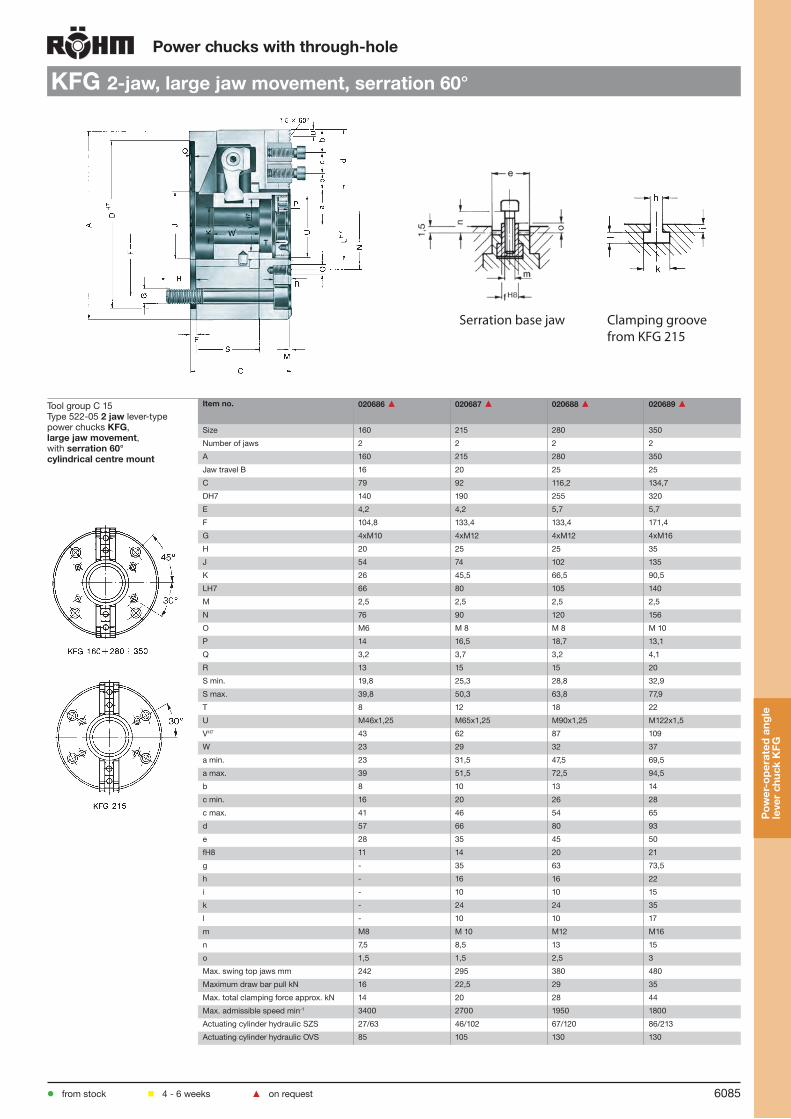
6085
Power chucks with through-hole
KFG 2-jaw, large jaw movement, serration 60°
Tool group C 15Type 522-05 2 jaw lever-type power chucks KFG, large jaw movement, with serration 60°cylindrical centre mount
Item no. 020686 ▲ 020687 ▲ 020688 ▲ 020689 ▲
Size 160 215 280 350
Number of jaws 2 2 2 2
A 160 215 280 350
Jaw travel B 16 20 25 25
C 79 92 116,2 134,7
DH7 140 190 255 320
E 4,2 4,2 5,7 5,7
F 104,8 133,4 133,4 171,4
G 4xM10 4xM12 4xM12 4xM16
H 20 25 25 35
J 54 74 102 135
K 26 45,5 66,5 90,5
LH7 66 80 105 140
M 2,5 2,5 2,5 2,5
N 76 90 120 156
O M6 M 8 M 8 M 10
P 14 16,5 18,7 13,1
Q 3,2 3,7 3,2 4,1
R 13 15 15 20
S min. 19,8 25,3 28,8 32,9
S max. 39,8 50,3 63,8 77,9
T 8 12 18 22
U M46x1,25 M65x1,25 M90x1,25 M122x1,5
VH7 43 62 87 109
W 23 29 32 37
a min. 23 31,5 47,5 69,5
a max. 39 51,5 72,5 94,5
b 8 10 13 14
c min. 16 20 26 28
c max. 41 46 54 65
d 57 66 80 93
e 28 35 45 50
fH8 11 14 20 21
g - 35 63 73,5
h - 16 16 22
i - 10 10 15
k - 24 24 35
l - 10 10 17
m M8 M 10 M12 M16
n 7,5 8,5 13 15
o 1,5 1,5 2,5 3
Max. swing top jaws mm 242 295 380 480
Maximum draw bar pull kN 16 22,5 29 35
Max. total clamping force approx. kN 14 20 28 44
Max. admissible speed min-1 3400 2700 1950 1800
Actuating cylinder hydraulic SZS 27/63 46/102 67/120 86/213
Actuating cylinder hydraulic OVS 85 105 130 130
from stock 4 - 6 weeks ▲ on request
Pow
er-o
pera
ted
angl
e le
ver
chuc
k K
FG
Serration base jaw Clamping groovefrom KFG 215

6086
Power chucks with through-hole
Jaws KFM / KFG
Tool group C 21Type 530 Reversible top jaws, 2-jaw set, hardenedSerration 60°- material: 16 MnCr 5
Item no. Chuck Size Jaw length Jaw height Jaw width Serration
046431 160 62 37,5 26 1,5 x 60°
046433 215 81 52,5 36 1,5 x 60°
046437 280 96 54 44,5 1,5 x 60°
046443 350 112 61 49,5 1,5 x 60°1) Near the serration reduced to 34 mmReversible top jaws: ground to finished size at surcharge
Tool group C 21Type 530 Reversible top jaws, 3-jaw set, hardenedSerration 60°- material: 16 MnCr 5
Item no. Chuck Size Jaw length Jaw height Jaw width Serration
046410 160 62 37,5 26 1,5 x 60°
046412 215 81 52,5 36 1,5 x 60°
046416 280 96 54 44,5 1,5 x 60°
046422 350 112 61 49,5 1,5 x 60°1) Near the serration reduced to 34 mm2) Reversible top jaws: ground to finished size at surcharge
Tool group C 21Type 530 Soft top jaws, 2-jaw set, can be hardenedSerration 60°- material: 16 MnCr 5
Item no. Chuck Size Jaw length Jaw height Jaw width Serration
046430 160 66,7 43 30,5 1,5 x 60°
046432 215 88,9 53 36,5 1,5 x 60°
046436 280 88,9 54,5 45 1,5 x 60°
046442 350 120 80 50 1,5 x 60°
Tool group C 21Type 530 Soft top jaws, 3-jaw set, can be hardenedSerration 60°- material: 16 MnCr 5
Item no. Chuck Size Jaw length Jaw height Jaw width Serration
046409 160 66,7 43 30,5 1,5 x 60°
046411 215 88,9 53 36,5 1,5 x 60°
046415 280 88,9 54,5 45 1,5 x 60°
046421 350 120 80 50 1,5 x 60°Jaw
s K
FG
from stock 4 - 6 weeks ▲ on request

6087
Power chucks with through-hole
Accessories KFM / KFG
Tool group C 15 Type 530-05 T-nutswithout screw
Tool group C 15 Type 0040-Y Mounting screws
E
D
Item no. Chuck Size Contents of delivery
D E
029874 160 piece 11 M8
028329 215 piece 14 M10
009744 ▲ 280 piece 20 M12
031051 ▲ 350 piece 21 M16
Item no. Size Contents of delivery
Thread Length
340015 130/160 piece M8 18
216594 215 piece M10 20
233030 210/254/315 piece M12x30 30
220564 350 piece M16x35 35
Socket head cap screw to DIN 912, 12.9
Acc
esso
ries
KFG
from stock 4 - 6 weeks ▲ on request
Chucking capacities with reversible top jaws UB
Chuck size 160 215 280 350
with reversible jawsType 530-04 530-07 530-09 530-12
Jaw position
External chucking
A1 5-115 5-136 11-185 50-248
A2 58-175 81-220 123-295 159-354
A3 92-208 132-272 190-363 242-438
Internal chuckingJ1 52-159 61-186 70-238 108-301J2 85-193 109-238 133-305 189-385J3 129-240 167-298 202-378 274-472
Chucking capacities KFM / KFG

6088
Jaw dimensions KFM / KFGPower chucks with through-hole
Reversible top jaws UB, hardened, serration 60o,
material 16MnCr5
Chuck size 130 160 215 280 350
Type 530-03 530-05 530-07 530-09 530-12Item no. 2-jaw 045798 046431 046433 046437 046443Item no. 3-jaw 046406 046410 046412 046416 046422A 56 62 81 96 112B 26 26 36 1) 44,5 49,5C 37,5 37,5 52,5 54 61D 11 11 14 20 21E 3,5 3,5 5 5 5,5F 13,5 17,5 25 30 27G 16,5 16,5 21 26 33H 29 29 41 41 47,5J 8,4 8,4 10,5 13 17K 13,5 13,5 16,5 19 25L 20 20 24 24 30M 10 10 12 12 15N 4 4 5 5 6,5O 4 4 7 7 7P 5 5 10 10 13Q 5 5 5 5 13R 1,5 x 60o 1,5 x 60o 1,5 x 60o 1,5 x 60o 1,5 x 60o
Weight/jaw kg 0,165 0,215 0,600 0,750 1,550
1) Near the serration reduced to 34 mm2) Serration 90o
Soft top jaws AB, material 16MnCr5
Chuck size 130 160 215 280 350
Type 530-03 530-05 530-07 530-09 530-12Item no. 2-jaw 045797 046430 046432 046436 046442Item no. 3-jaw 046405 046409 046411 046415 046421A 53 66,7 88,9 88,9 120B 26,5 30,5 36,5 45 50C 38 43 53 54,5 80D 11 11 14 20 21E 3,5 3,5 5 5 5F 29 30 45 45 67G 15 20 26 26 28H 28 33 41 42,5 67J 8,4 8,4 10,5 13 17K 13,5 13,5 16,5 19 25L - - - - -M - 27 34 - -R 1,5 x 60o 1,5 x 60o 1,5 x 60o 1,5 x 60o 1,5 x 60o
Weight/jaw kg 0,320 0,550 1,125 1,400 3,125
AB 530-02AB 530-04 und 530-07
AB 530-02AB 530-04 und 530-07
AB 530-02AB 530-04 und 530-07
1) Serration 90o
AB 530-04 and 530-07
Reversible top jaws: ground to finished size at surcharge
Jaw
s K
FGP
ower
-ope
rate
d an
gle
leve
r ch
uck
KFM
/KFG

KFD
6089
Not
es
Notes

6090
PKFPneumatic operated high-precision chucks
Technical features:
Precision-wedge system
Radial and axial true running accuracy within 0.003 mm (3 micron)
Integrated pneumatic actuation
Low on maintenance because of oil mist lubrication
The special design of the piston with force transmission on both sides, particular to the RÖHM KFD-HS prin-ciple, guarantees a very high chucking precision and an extremely long service life
The wide range of operating pressure from 2 to 10 bar allows an optimal adjusting of the chucking power, e. g. for the deformation-free chucking of thin-walled liners and rings
Self-locking, high safety in the event of a chucking energy failure
RÖHM offers a complete equipment with an air supply tube and a versatile jaw range
Sizes 100-200 with passage for coolant supply.
Used in conjunction with RÖHM actuating cylinders with safety device SZS, OVS, LHS-L, LVS, EHS and EVS the power chucks PKF meet the requirements of the German Employers’ Insurance Association
Note:Air supply tube, service unit, top jaws, control valves, to be ordered separetely.
PK
F

6091
Power chucks with through-hole
PKF
from stock 4 - 6 weeks ▲ on request
Tool group C 15Type 586-00 High-precision pneumatic-operated lathe chuck PKF, concentricity 0,003, repetitive clamping accuracy 0,0015 with through-hole, pneumatic operated, with integrated pneumatic chucking piston, clamping accurancy in the micron range
Item no. 153705 153706 153707 153708 153709 153710
Size 80 100 100 150 150 200
A 79,5 102 102 151 151 202
Jaw travel B 0,75 0,75 1,5 0,75 1,5 1,5
C 39 52,5 62,5 52,5 62,5 85,5
D-0,01 50,8 82,55 82,55 124,97 124,97 167,64
E 1,5 1,5 1,5 1,5 1,5 3,2
F 69,9 88,9 88,9 135,9 135,9 182,9
G 3 x 120° M5 M5 M5 M6 M6 M10
H 5,5 8 8 9 9 16
Wedge stroke K 4,25 4,25 8,5 4,25 8,5 8,5
M - 3,2 3,2 3,2 3,2 3,2
M1 - 19 19 25,4 25,4 25,4
N - 19 19 19 19 19
O min. - 0,5 0,5 0,5 0,5 0,5
O max. - 4,75 9 4,75 9 9
Q 3/8’’ 5/8’’ 5/8’’ 5/8’’ 5/8’’ 5/8’’
W - 19 19 19 19 35
T 39,3 52,8 62,8 52,8 62,3 85,9
a min. 15,5 16,75 16 22,75 22 21,9
a max. 16,25 17,5 17,5 23,5 23,5 23,4
b 5,1 3,9 3,9 14,9 14,9 4,5
c 12,7 2 x 12,7 2 x 12,7 2 x 12,7 2 x 12,7 2 x 31,75
d 23,5 33,5 33,5 52 52 76,1
e 13 16 16 24 24 32
k 1/8” 1/8” 1/8” 1/8” 1/8” 1/4”
l - 12,7 12,7 3 x 12,7 3 x 12,7 31,75
m 11,5 10,25 10,25 8,55 8,55 20,375
u M5 2 x M5 2 x M5 4 x M5 4 x M5 M10
Operating pressure bar 2-10 2-10 2-10 2-10 2-10 2-10
Area A1 clamping cm2 29,3 47,4 47,4 100 100 185,0
Area A2 releasing cm2 15,2 28,9 28,9 69 69 111,5
Total clamping force at 8 bar kN 8 13 13 27 27 31,5
Max. admissible speed at 8 bar min-1 5500 5500 5500 4000 4000 3000
Moment of inertia J kgm2 0,0008 0,0029 0,0029 0,015 0,015 0,08
Weight kg 1 2,3 2,3 5,5 5,5 16
Higher speed on request
PK
F

6092
Power chucks with through-hole
Jaws PKF
Tool group C 21Type 586-00 Soft top jawsSteel design set, jaw set
Item no. Chuck Size Jaw length Jaw height Jaw width
153817 80 38 16 16
153818 100 49 25 18,4
153819 150 74 30 26,5
153820 200 95 46 34,7
Tool group C 21Type 586-00 Soft top jawsAluminium design, jaw set
Item no. Chuck Size Jaw length Jaw height Jaw width
153821 80 38 16 16
153822 100 49 25 18,4
153823 150 74 30 26,5
153824 200 95 46 34,7
Accessories PKF
Air supply tube
Air supply tube 3/8” and 5/8”Type 586-80Max. speeds = 10 000 min-1Central through-hole for airand coolant.Max. air pressure = 10 bar
Ordering indications for air supply tube: Chuck size + spindle length LS + height of flange FH
Jaw
s P
KF
from stock 4 - 6 weeks ▲ on request
Central passage
50
12
76
26 45
R1/4”
135
57
49M6
28,5 3,2 1640
Spindle length LS
Customer’s �ange or by order
Width of slot 4.5 mm
Sel� ubricating socket
only for chuck sizes 100, 150 and 200
1/8” NPT
2x180 o
4
14
FH

6093
Power chucks with through-hole
Accessories PKF
Tool group C 15Type 592-38 Air-operated control LSG R1/4
up to 10 bar, for air-operated power chucks
Id.-Nr. Width Height Depth Control voltage Conn. thread Weigth approx. kg
437107 370 350 140 24 V - 50 Hz R 3/8“ Innengewinde 6,4
Other voltages on request
Tool group C 15Type 592-51 Service unit for air operated controlThis unit consists of: Separator and filtre CKS-08/10 and lubricator CL-08/10
Id.-Nr. Width Height Depth
216084 130 240 102
Max. flow Qn 33m3/h at 6 bar
Tool group C 15Type 592-32 Manually operated air control valve LHV2-position with safety control lever
Id.-Nr. Width Height Depth Conn. thread internal Conn. thread external
418224 66,5 64 38 R ¼ “ M 16 x 1,5
Tool group C 15Type 592-04 Air shut-off valve
Id.-Nr. Width Height Depth Conn. thread
021237 ▲ 51 55 30 R 1/4” internal
Accessories: 2 screw unions pipe thread 1/4”, Id.-Nr. 8096
Acc
esso
ries
PK
F
from stock 4 - 6 weeks ▲ on request

6094
Gripper chuck GFPower chucks with through-hole
To grip the workpiece, the gripper chuck is moved against the chucked round stock, usually by means of thetoolholder provided on the machine. The 30° approach angle chamfer causes the jaws to be positively forced out-ward until the workpiece diameter is reached and the work is gripped on the outside diameter.The gripping force is produced by a floating disk spring package acting on the jaws. The workholding chuck opens to release the round stock which has been gripped by the bar puller and moved into the predetermined position. In this position, the work is chucked again by the workholding chuck while the bar puller is simply pulled off. The jaws are automatically pushed inward by the disk spring package to return them to their initial position.The interchangeable cylindrical shank meets to DIN 69880.
The top jaws have a slight inward inclination, when the chuck is opened. In this position, the serrations have to be positioned (with respect to the workpiece) that the distance between the gripping surfaces of the jaws is 2-3 mm smaller than the workpiece.
Technical features:
2-jaw gripper chuck
For moving and positioning bars and tubes
Ideally suited for the use of turrets
Automatic retraction of the jaws after positioning process
Clamping force via disk spring package
With interchangeable cylindrical shank
Gri
pper
chu
ck G
F
These gripper chucks are mainly used for moving and positioning bars and tubes.
Function:

6095
Tool group C 15Type 546-30 Cylindrical shank DIN 69880
Item no. Initial size Kh6 L M±0,05
359619 20 20 32 18
156806 25 25 48 23,5
141080 30 30 55 27
141081 40 40 63 36
141082 50 50 78 45
141083 60 60 94 55
Power chucks with through-hole
GF for cylindrical shank DIN 69880
Tool group C 15Type 546-00 2-jaw gripper chucks GF for cylindrical shank DIN 69880Chucks without shank, without jaws
Item no. Size A B C D E FH7 H (Stroke) U Clamping force min. kN
Clamping force max. kN
141077 80 80 50,8 46 M8 50 12 3 M8 1,3 1,7
141078 100 100 52,8 48 M 10 60 14 4 M 10 2 2,7
141079 125 125 72,8 67 M 10 65 14 4 M 10 5,3 6
Jaws GF
Tool group C 21Type 546-70 Clamping jaws
Item no. Chuck Size Contents of delivery Jaw length Jaw height Jaw width
141084 80 Satz 28 26 28
141085 100/125 Satz 30 34 30
141086 100/125 Satz 40 42 30
Gri
pper
chu
ck G
F
from stock 4 - 6 weeks ▲ on request
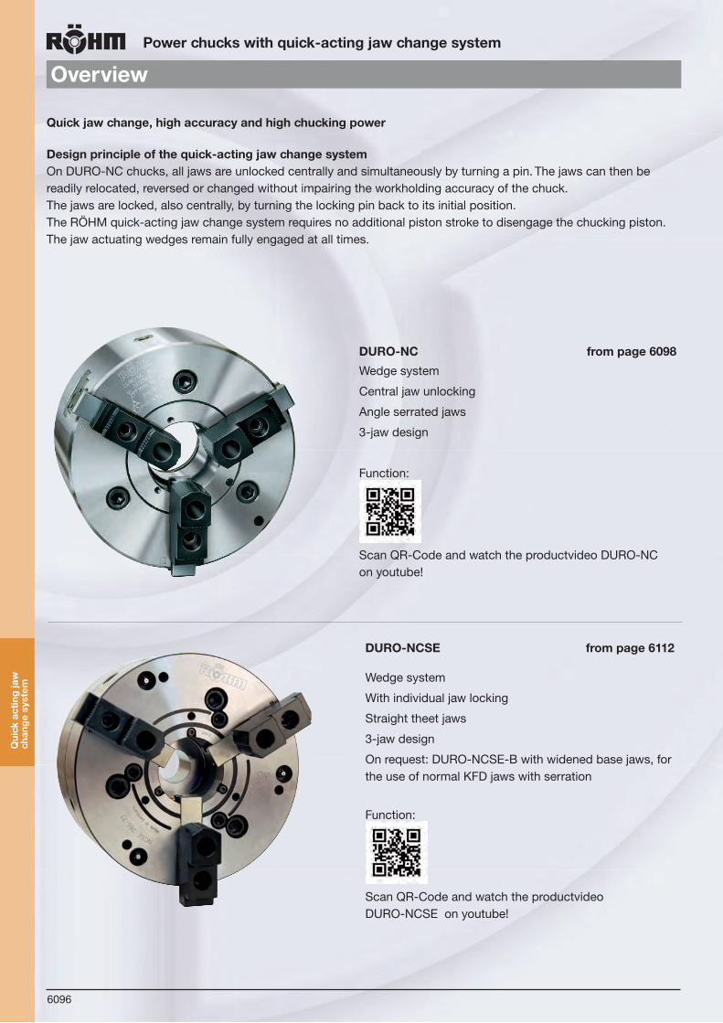
KFD
6096
GFOverviewPower chucks with quick-acting jaw change system
DURO-NC from page 6098
Wedge system
Central jaw unlocking
Angle serrated jaws
3-jaw design
Function:
Scan QR-Code and watch the productvideo DURO-NC on youtube!
DURO-NCSE from page 6112
Wedge system
With individual jaw locking
Straight theet jaws
3-jaw design
On request: DURO-NCSE-B with widened base jaws, for the use of normal KFD jaws with serration
Function:
Scan QR-Code and watch the productvideo DURO-NCSE on youtube!
Quick jaw change, high accuracy and high chucking power
Design principle of the quick-acting jaw change systemOn DURO-NC chucks, all jaws are unlocked centrally and simultaneously by turning a pin. The jaws can then be readily relocated, reversed or changed without impairing the workholding accuracy of the chuck. The jaws are locked, also centrally, by turning the locking pin back to its initial position. The RÖHM quick-acting jaw change system requires no additional piston stroke to disengage the chucking piston. The jaw actuating wedges remain fully engaged at all times.
Qui
ck a
ctin
g ja
w
chan
ge s
yste
m

6097
Power chucks with quick-acting jaw change system
DURO-NCSE AW / DURO-NCSE Flex
Optimally suited for the use of power driven tools
Due to the free area on the front of the chuck reduced interference contour
Properties of the chuck like DURO-NCSE
Quick-acting change system for mandrels, collet chucks and face drivers
Clamping tool change without changing the complete chuck
Properties of the chuck like DURO-NCSE
DURO-NCSE Flex on request
DURO-NCSE AW on request
Base chuck Attachment mandrel Attachment collet chuck Attachment face driver
Qui
ck a
ctin
g ja
w
chan
ge s
yste
m

KFD
6098
Power chucks with quick-acting jaw change system
DURO-NC
Components
1. Body2. Guide jaw 3. Base jaw 4. Adaptor plate 5. Piston 6. Adjusting ring 7. Turnable bolt 8. Rack 9. Protective bush
Technical features:
Central jaw unlocking for moving, changing and turning of jaws
High workholding accuracy and gripping force
Chucking power transmitted by means of the proven wedge system
Light-weight jaws minimize the loss of gripping power at high speeds
For high speeds
The jaws assemblies are identical with those of the manually operated DURO chucks
Made of steel, all wearing parts hardened and ground
Used in conjunction with RÖHM actuating cylinders with safety device SZS, OVS, LHS-L, LVS, EHS and EVS the power chucks DUO-NC meet the require-ments of the German Employers’ Insurance Asso-ciation
The safety key can only be removed when the jaws are locked. This safety key, in conjunction with the key switch integrated in the machine, additionally prevents an unintentional start of the machine spin-dle when the jaws are unlocked
Accessories:Chuck and jaw mounting screws, safety key, assembly wrench, base jaws.
32
5
1
9
8
7
6
4
DURO-NC
DU
RO
-NC

6099
Power chucks with quick-acting jaw change system
Accessories DURO-NC
Gripping force / speed diagrams
The loss of gripping force was determinedexperimentally on a chuck with matchedUB top jaws. It is largely independent ofthe initial gripping force at zero speed.
Upper curve: min. centrifugalforce of top jaw
Lower curve: max. centrifugalforce of top jaw
To obtain the specified gripping forces,the chuck must be in a perfect conditionand lubricated with F 80 lubricant recommendedby Röhm. Measuring point nearchuck face. Example: For a DURO-NC chuck size 250and an applied operating power of 40 kN,the total gripping force is approx. 92 kN.
1000 2000 3000 4000 5000 6000
500 1000 1500 2000 2500 3000
7000
20
40
60
80
100
120
140
160
180
200
320
280
240
200
160
120
80
40
DURO-NC 315
DURO-NC 250
DURO-NC 200
DURO-NC 175
DURO-NC 140
DURO-NC 630
DURO-NC 400
DURO-NC 500
25155-k006-019 26.04.2007 10:15 Uhr Seite 6019
1000 2000 3000 4000 5000 6000
500 1000 1500 2000 2500 3000
7000
20
40
60
80
100
120
140
160
180
200
320
280
240
200
160
120
80
40
DURO-NC 315
DURO-NC 250
DURO-NC 200
DURO-NC 175
DURO-NC 140
DURO-NC 630
DURO-NC 400
DURO-NC 500
Tota
l grip
ping
forc
e kN
Tota
l grip
ping
forc
e kN
Speed min -1
Speed min -1
Chuck size
Gripping force/operating power diagram
Total gripping force
Operating power kN
DU
RO
-NC

6100
Power chucks with quick-acting jaw change system
DURO-NC
N Q O P
C
H
T
bB
M U
am
in/m
ax
V m
ax
G
K
E
A D F J R
Size 250-630
Tool group C 15Type 503-10 3 jaws power chuck DURO-NC, with quick jaw change systems, central jaw unlocking, angle-serratedAdaptor recess, mounting dimensions to DIN 6353
Item no. 159455 159456 159457 159458 159459 159460 159461 159462 ▲
Size 140 175 200 250 315 400 500 630
A 145 175 215 260 320 400 500 630
Jaw travel B 4,9 6,7 7 7 8,25 10,1 11,5 11,5
C 83 99 105 126 152 149 149 169
Mount DH6 120 140 170 220 300 380 380 380
E 6 6 6 6 6 6 6 6
F 104,8 104,8 133,4 171,4 235 330,2 330,2 330,2
G 3 x M 10 3 x M 10 3 x M 12 3 x M 16 3 x M 20 3 x M 24 3 x M 24 6 x M 24
H 18 15 18 21 29 35 35 36
J 80 88 114 147 173 210 210 286
Wedge stroke K 16 22 23 27 33 46 46 46
M 35 43 52 72 91 108 108 140
N - - - - - 124 124 160
O min. 0,5 0 0 0 0 -61 -61 -41
O max. 16,5 22 23 27 33 -15 -15 5
P 9 10 15 15 19 35 35 25
Q M 45 x 1,5 M 50 x 1,5 M 60 x 1,5 M 80 x 1,5 M 100 x 2 M 115 x 2 M 115 x 2 M 148 x 2
R - - - 130 160 169 169 219
T 89 105 112 134 160,6 158,6 158,6 185
U 40 50 62 81 103 120 120 192
V max. 181 236 294 351 423 523 570 771
a min. 31,4 33,2 35,5 42,8 52,3 67,1 73,5 86,8
a max. 53,2 62,3 79,5 91,1 115,7 135,5 159 206,1
b 18 18 20 20 26 30 30 40
e 18 20 22 26 32 45 45 65
Ø g 54 64 76 93 120 140 140 210
h M 5 x 8 M 6 x 10 M 6 x 10 M 6 x 10 M 6 x 10 M 8 x 12 M 8 x 12 M 8 x 12
Maximum draw bar pull kN 25 30 50 65 80 110 110 150
Max. total clamping force approx. kN
49 60 110 140 190 240 240 330
Max. admissible speed min-1 6300 5300 5000 4300 3200 2700 2000 1500
Moment of inertia J kgm2 0,029 0,068 0,162 0,39 1,08 2,5 5 15,4
Weight without jaws approx. kg
11 18 28 46 85 126 185 310
A D F J Q
G
O P
K
C
H
T
bB
M U
am
in/m
ax
V m
ax
E
Size 140-200
Pow
er c
huck
D
UR
O-N
C
from stock 4 - 6 weeks ▲ on request
e
3x120 o
20oh
3x120°
from size 400 weight reduced

6101
Power chucks with quick-acting jaw change system
DURO-NC
QNG
A F J D O P
K
C
H E
T
7° 7'30"
bB
M Ua
min
/max
V m
ax
R
Size 250-630
Tool group C 15Type 503-12 3 jaw power chuck DURO-NC, with quick jaw change system, central jaw unlocking,angle-serratedShort taper mount for ISO 702-1 (DIN 55026/55021)
Item no. 159463 159464 159465 159466 159467 159468 159469 ▲ 159470 ▲
Size 140 175 200 250 315 400 500 630
A 145 175 215 260 320 400 500 630
Jaw travel B 4,9 6,6 7 7 8,25 10,1 11,5 11,5
C 97,6 113,6 121,2 143,8 171,4 189 189 209
Short taper D (KK) 5 5 6 8 11 11 11 15
E 14,6 14,6 16,2 17,8 19,4 40 40 40
F 104,8 104,8 133,4 171,4 235 235 235 330,2
G 3 x M 10 3 x M 10 3 x M 12 3 x M 16 3 x M 20 6 x M 20 6 x M 20 6 x M 24
H 18 15 17 23 30 31,5 31 34,5
J 80 88 114 147 173 210 210 286
Wedge stroke K 16 22 23 27 33 46 46 46
M 35 43 52 72 91 108 108 140
N - - - - - 124 124 160
O min. 15,1 14,6 16,2 17,8 19,4 -21 -21 -1
O max. 31,1 36,6 39,2 44,8 52,4 25 25 45
P 9 10 15 15 19 35 35 25
Q M 45 x 1,5 M 50 x 1,5 M 60 x 1,5 M 80 x 1,5 M 100 x 2 M 115 x 2 M 115 x 2 M 148 x 2
R - - - 130 160 169 169 219
T 103,6 119,6 128,2 151,8 180 198,6 198,6 225
U 40 50 62 81 103 120 120 192
V max. 181 236 294 351 423 523 570 771
a min. 31,4 33,2 35,5 42,8 52,3 67,1 73,5 86,8
a max. 53,2 62,3 79,5 91,1 115,7 135,5 159 206,1
b 18 18 20 20 26 30 30 40
e 18 20 22 26 32 45 45 65
Ø g 54 64 76 93 120 140 140 210
h M 5 x 8 M 6 x 10 M 6 x 10 M 6 x 10 M 6 x 10 M 8 x 12 M 8 x 12 M 8 x 12
Maximum draw bar pull kN 25 30 50 65 80 110 110 150
Max. total clamping force approx. kN
49 60 110 140 190 240 240 330
Max. admissible speed min-1 6300 5300 5000 4300 3200 2700 2000 1500
Moment of inertia J kgm2 0,031 0,073 0,167 0,42 1,15 3 6,6 16,4
Weight without jaws approx. kg
12 19 29 50 90 150 210 330
A F J D QG
O P
K
C
H E
T
7° 7'30"
bB
M Ua
min
/max
V m
ax
Size 140-200
Pow
er c
huck
D
UR
O-N
C
from stock 4 - 6 weeks ▲ on request
e
3x120 o
20oh
3x120°
from size 400 weight reduced

6102
Power chucks with quick-acting jaw change system
Jaws DURO-NC
Tool group A28Type 002 Base jaw GB, setwith mounting bolts
Item no. Chuck Size Number of jaws Contents of delivery Jaw length Jaw width
140636 140 3 set 62 18
094004 175 3 set 74 20
094005 200 3 set 90 22
094006 250 3 set 110 26
094007 315 3 set 125 32
094044 400/500 3 set 160 45
140194 630 3 set 230 65
Tool group A28Type 002 Unstepped top jaw AB, setstandard design, soft,material 16MnCr5
Item no. Chuck Size Number of jaws Contents of delivery Jaw length Jaw height Jaw width
094008 140/175 3 set 85 36,5 20,3
094009 200 3 set 105 40 22
094010 250 3 set 125 50 30,4
094011 315 3 set 145 50 34,3
094046 400/500 3 set 180 73 50,5
140716 630 3 set 260 102 68
Tool group A28Type 003 Reversible top jaw UB, sethardened
Item no. Chuck Size Number of jaws Contents of delivery Jaw length Jaw height Jaw width
094012 140/175 3 set 61,5 32,5 20,4
094013 200 3 set 70,5 38 24,4
094014 250 3 set 92 50 34,4
094015 315 3 set 107 56 35,7
094045 400/500 3 set 130 72 50,4
140715 630 3 Satz 185 102 68
Hardened jaws, supplied as supplement or as spares, must be ground on the chuck.In case of a subsequent jaw delivery please return the chuck.
Tool group A28Type 000 Unstepped Jaw BL, setunstepped, soft, material 16MnCr5
Item no. Chuck Size Number of jaws Contents of delivery Jaw length Jaw height Jaw width
626158 140 3 set 70,5 41,5 18
241699 175 3 set 84,4 45 20
249678 200 3 set 98,4 60 22
249679 250 3 set 118,7 70 26
249680 315 3 set 136,6 79 32
249681 400/500 3 set 173,6 93 45
Tool group A28Type 000 One-piece jaw EB, set; hardened
Item no. Chuck Size Number of jaws Contents of delivery Jaw length Jaw height Jaw width
140764 140 3 set 62 49,5 18
094000 175 3 set 77,7 45 20
094001 200 3 set 94,7 60 22
094002 250 3 set 114 70 26
094003 315 3 set 130 79 32
094043 400/500 3 set 167 93 45
Stepped and hardened jaws, supplied as supplement or as spares, must be ground on the chuck.In case of a subsequent jaw delivery please return the chuck.
Jaw
s D
UR
O-N
C
from stock 4 - 6 weeks ▲ on request
For the complete range of clamping jaws visit our website www.spannbacken.biz

6103
Power chucks with quick-acting jaw change system
Jaws DURO-NC
Tool group C 21Type 544-00 reversible claw-type top jaws, standard design; tongue and groove, large clamp-ing range, 1 piece, hardened
Item no. Chuck Size Jaw length Jaw height Jaw width
137061 140/175 66 37,5 20
137064 200 81 43 24
137108 250 90 55 34
137114 315 100 62 34
137120 400/500 124 62 50
Tool group C 21Type 544-00 reversible claw-type top jaws, standard design; tongue and groove, middle sized clamping range, 1 piece, hardened
Item no. Chuck Size Jaw length Jaw height Jaw width
137062 140/175 56 37,5 20
137065 200 66 43 24
137109 250 72 55 34
137115 315 86 62 34
137121 400/500 100 62 50
Tool group C 21Type 544-05 reversible claw-type top jaws, large design; tongue and groove, small clamp-ing range, 1 piece, hardened
Item no. Chuck Size Jaw length Jaw height Jaw width
137066 200 79 43 34
137110 250 80 55 50
137116 315 93 62 50
Tool group C 21Type 544-05 reversible claw-type top jaws, large designtongue and groove, large clamp-ing range, 1 piece, hardened
Item no. Chuck Size Jaw length Jaw height Jaw width
137067 200 81 43 34
137111 250 90 55 50
137117 315 106 62 50
Tool group C 21Type 544-05 reversible claw-type top jaws, large designtongue and groove, middle sized clamping range, 1 piece, hardened
Item no. Chuck Size Jaw length Jaw height Jaw width
137068 200 66 43 34
137112 250 72 55 50
137118 315 86 62 50
Tool group C 21Type 544-00 reversible claw-type top jaws, standard design, tongue and groove, small clamp-ing range, 1 piece hardened
Item no. Chuck Size Jaw length Jaw height Jaw width
137060 140/175 66 37,5 24
137119 400/500 124 62 50
151289 630 144 78 70
Jaw
s D
UR
O-N
C
from stock 4 - 6 weeks ▲ on request

6104
Power chucks with quick-acting jaw change system
Jaws DURO-NC
Tool group C 21Type 545-00 Draw-down jaws, without clamping insertsdiagonally toothing, 1 piece, without clamping inserts
Item no. Chuck Size Jaw length Jaw height Jaw width
151030 140 63 41,5 18
141037 175 84,4 43,5 20
141039 200 98,4 47,5 22
141041 250 118,7 58,5 26
141043 315 136,4 63,9 32
141045 400/500 173,6 73,4 45
Tool group C 21Type 545-00 Draw-down jaws, additional clamping range, for interchangeable clamping insertsdiagonally toothing, 1 piece, without clamping inserts
Item no. Chuck Size Jaw length Jaw height Jaw width
151031 140 63 41,5 18
141038 175 84,4 43,5 20
141040 200 98,4 47,5 22
141042 250 118,7 58,5 26
141044 315 136,4 63,9 32
141046 400 173,6 73,4 45
141048 500 173,6 73,4 45
Tool group C 15Type 545-60 Interchangeable clamping inserts, 1 piecewith claws
Item no. Chuck Size
151029 140
141049 175/200
141052 250/315
141055 400/500/630
Tool group C 15Type 545-70 Interchangeable clamping inserts, 1 piecewith serrated toothing
Item no. Chuck Size
151039 140
141050 175/200
141053 250/315
141056 400/500
Tool group C 15Type 545-80 Interchangeable clamping inserts, 1 piecewith heat treatable surface
Item no. Chuck Size
151040 140
141051 175/200
141054 250/315
141057 400/500
Jaw
s D
UR
O-N
C
from stock 4 - 6 weeks ▲ on request

6105
Power chucks with quick-acting jaw change system
Accessories DURO-NC
Tool group C 15 Type 0040-Y Mounting screws Tool group C 15 Type 1028 Special grease F80 for lathe chucksfor lubrication and conservation of chucking power
Item no. Size Contents of delivery
Thread
200182 140/175/200 piece M8x1x22
200183 250 piece M12x1,5x30
202402 315 piece M12x1,5x35
227618 400/500 piece M16x1,5x40
249388 630 piece M20x50
Socket head cap screw to DIN 912, 12.9
Item no. Design Contents
308555 Cartridge 0,5 kg
028975 Tin 1 kg
Tool group C 15 Type 544-00 Changeable workpiece rests (in different lengths)
M6
Item no. H M Key-width SW
289188 5 M6 9
138950 10 M6 9
725581 15 M6 9
Tool group A09Type 619-30 Short-taper adapter plate ISO 702-1 (DIN 55026/55021) - ASA B 5.9 (without mounting bolts)finished on machine side, faced on chuck side, especially
Id.-Nr. Spindle nose size
h E M D
144933 ▲ 3 18 40 40 125
145296 ▲ 4 18 40 40 125
145328 ▲ 3 18 40 40 160
145342 ▲ 4 18 40 40 160
145343 ▲ 5 21 50 50 160
145344 ▲ 4 21 50 50 200
145345 ▲ 5 21 50 50 200
145346 ▲ 6 27 50 50 200
145347 ▲ 4 27 63 63 250
145348 ▲ 5 27 63 63 250
145349 ▲ 6 27 63 63 250
145350 ▲ 8 27 63 63 250
145351 ▲ 5 36 63 63 315
145352 ▲ 6 36 63 63 315
145353 ▲ 8 36 63 63 315
145354 ▲ 11 36 63 63 315
145355 ▲ 6 40 63 63 400
145356 ▲ 8 40 63 63 400
145357 ▲ 11 40 63 63 400
145358 ▲ 15 40 63 63 400
145359 ▲ 8 42 80 80 500
145360 ▲ 11 42 80 80 500
145364 ▲ 15 42 80 80 500
Acc
esso
ries
D
UR
O-N
C
from stock 4 - 6 weeks ▲ on request

6106
Power chucks with quick-acting jaw change system
Accessories DURO-NC
from stock 4 - 6 weeks ▲ on request
Type 594-32 Intermediate adaptor plates with cylindrical centre mount DIN 6353 for three-jaw chucksMounting from front to ISO 702-1 (DIN 55026/55021) and ASA B 5.9 A1/A2 with metric mounting bolts
Id.-Nr. Spindle nose size
Size Design h F D
159878 5 140 I 15 104,8 120
145153 5 175 I 15 104,8 140
145297 6 175 III 35 133,4 140
145155 6 200 I 16 133,4 170
145131 6 250 II 27 133,4 220
145135 8 200 III 39 171,4 170
145157 8 250 I 18 171,4 220
145139 8 315 II 38 171,4 300
1049147 8 400 II 56 171,4 380
145143 11 250 III 48 235 220
145159 11 315 I 19 235 300
145147 11 400 II 40 235 380
145161 15 400/500/630 I 21 330,2 380
All fastening parts are includedIntermediate adaptors for two- and four-jaw-design on request
Tool group C 15Type 594-35 Intermediate adaptor plates with cylindrical centre mount DIN 6353 for three-jaw chucksMounting from front to ASA B 5.9 A1/A2 with inch threaded mounting bolts
Id.-Nr. Spindle nose size
Size Design h F D
159878 5 140 I 15 104,8 120
145153 5 175 I 15 104,8 140
145301 6 175 III 35 133,4 140
145155 6 200 I 16 133,4 170
145194 6 250 II 27 133,4 220
145196 8 315 II 39 171,4 300
145157 8 250 I 18 171,4 220
145198 8 315 II 38 171,4 300
145200 11 250 III 48 235 220
145159 11 315 I 19 235 300
145202 11 400/500 II 40 235 380
145161 15 400/500/630 I 21 330,2 380
All fastening parts are includedIntermediate adaptors for two- and four-jaw-design on request
Tool group C 15Type 594-33 Intermediate adaptor plates with cylindrical centre mount DIN 6353 for three-jaw chucksBayonet fixing to ISO 702-3 (DIN 55027)/ DIN 55022
Id.-Nr. Spindle nose size
Size Design h F D
145238 5 175 II 21 104,8 140
145303 6 175 III 35 133,4 140
145240 6 200 II 22 133,4 170
145214 6 250/315 II 27 133,4 220
145218 8 200 III 39 171,4 170
145242 8 250 II 30 171,4 220
145222 8 315 II 38 171,4 300
145226 11 250 III 48 235 220
145246 11 315 II 36 235 300
145230 11 400/500 II 40 235 380
145248 15 400/500 II 40 330,2 380
145250 15 630 I 40 330,2 380
All fastening parts are includedIntermediate adaptors for two- and four-jaw-design on request
Tool group C 15Type 594-36 Intermediate adaptor plates with cylindrical centre mount DIN 6353 for three-jaw chucksCamlock fixing to DIN 55029/ASA B 5.9 D1
Id.-Nr. Spindle nose size
Size Design h F D
145282 5 175 II 30 104,8 140
145594 6 175 III 43 133,4 140
145284 6 200 II 35 133,4 170
145258 6 250 II 35 133,4 220
145262 8 200 II 46 171,4 170
145286 8 250 II 38 171,4 220
145266 8 315 II 38 171,4 300
145270 11 250 III 53 235 220
145290 11 315 II 45 235 300
145274 11 400/500 II 45 235 380
145292 15 400/500 II 50 330,2 380
145294 15 630 I 50 330,2 380
All fastening parts are includedIntermediate adaptors for two- and four-jaw-design on request
Acc
esso
ries
D
UR
O-N
C
F D
h
F D
h
h
F D
Design I Design II
Design III
F D
h
F D
h
h
F D
Design I Design II
Design III
F D
h
F D
hDesign II Design III
F D
h
F D
hDesign II Design III
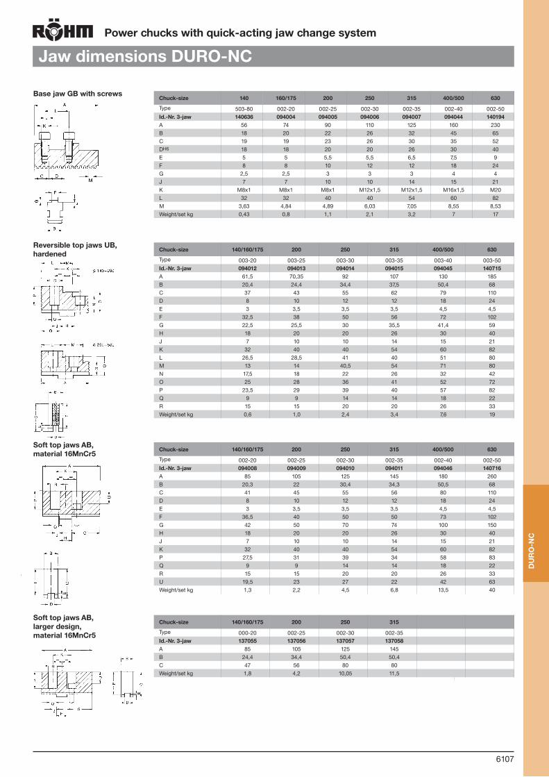
6107
Power chucks with quick-acting jaw change system
Base jaw GB with screwsChuck-size 140 160/175 200 250 315 400/500 630
Type 503-80 002-20 002-25 002-30 002-35 002-40 002-50Id.-Nr. 3-jaw 140636 094004 094005 094006 094007 094044 140194A 56 74 90 110 125 160 230B 18 20 22 26 32 45 65C 19 19 23 26 30 35 52DH6 18 18 20 20 26 30 40E 5 5 5,5 5,5 6,5 7,5 9F 8 8 10 12 12 18 24G 2,5 2,5 3 3 3 4 4J 7 7 10 10 14 15 21K M8x1 M8x1 M8x1 M12x1,5 M12x1,5 M16x1,5 M20L 32 32 40 40 54 60 82M 3,63 4,84 4,89 6,03 7,05 8,55 8,53Weight/set kg 0,43 0,8 1,1 2,1 3,2 7 17
Jaw dimensions DURO-NC
Reversible top jaws UB, hardened
Chuck-size 140/160/175 200 250 315 400/500 630
Type 003-20 003-25 003-30 003-35 003-40 003-50Id.-Nr. 3-jaw 094012 094013 094014 094015 094045 140715A 61,5 70,35 92 107 130 185B 20,4 24,4 34,4 37,5 50,4 68C 37 43 55 62 79 110D 8 10 12 12 18 24E 3 3,5 3,5 3,5 4,5 4,5F 32,5 38 50 56 72 102G 22,5 25,5 30 35,5 41,4 59H 18 20 20 26 30 40J 7 10 10 14 15 21K 32 40 40 54 60 82L 26,5 28,5 41 40 51 80M 13 14 40,5 54 71 80N 17,5 18 22 26 32 42O 25 28 36 41 52 72P 23,5 29 39 40 57 82Q 9 9 14 14 18 22R 15 15 20 20 26 33Weight/set kg 0,6 1,0 2,4 3,4 7,6 19
Soft top jaws AB,material 16MnCr5
Chuck-size 140/160/175 200 250 315 400/500 630
Type 002-20 002-25 002-30 002-35 002-40 002-50Id.-Nr. 3-jaw 094008 094009 094010 094011 094046 140716A 85 105 125 145 180 260B 20,3 22 30,4 34,3 50,5 68C 41 45 55 56 80 110D 8 10 12 12 18 24E 3 3,5 3,5 3,5 4,5 4,5F 36,5 40 50 50 73 102G 42 50 70 74 100 150H 18 20 20 26 30 40J 7 10 10 14 15 21K 32 40 40 54 60 82P 27,5 31 39 34 58 83Q 9 9 14 14 18 22R 15 15 20 20 26 33U 19,5 23 27 22 42 63Weight/set kg 1,3 2,2 4,5 6,8 13,5 40
Soft top jaws AB,larger design,material 16MnCr5
Chuck-size 140/160/175 200 250 315
Type 000-20 002-25 002-30 002-35Id.-Nr. 3-jaw 137055 137056 137057 137058A 85 105 125 145B 24,4 34,4 50,4 50,4C 47 56 80 80Weight/set kg 1,8 4,2 10,05 11,5
DU
RO
-NC

6108
Power chucks with quick-acting jaw change system
One-piece reversible jaws EBChuck size 140 160/175 200 250 315 400/500
Type 503-80 000-20 000-25 000-30 000-35 000-40Item no. 3-jaw 140764 094000 094001 094002 094003 0940043A 62 77,7 94,7 114 130 167B 18 20 22 26 32 45C 49,5 45 60 70 79 93D 16,6 20,6 23 41,5 40,2 50,6E 15,9 18,9 19,5 40,3 54 71F 18 22 28 - - -G 42 37,5 50 56 64 73H 34,5 30 40 - - -J 27 22,5 30 42 49 53K 7 8 10 13 13 20L 16 16 15 19,5 19,5 30M 3,63 4,84 4,89 6,03 7,05 8,55T 29 24 35 41 44,5 54Weight/set kg 1,2 1,5 1,9 3,4 5,5 11
Jaw dimensions DURO-NC
Draw-down jaws NB for interchangeable clamping inserts (jaw without insert)
Chuck size 140 160/175 200 250 315 400 500
Type 545-00 545-00 545-00 545-00 545-00 545-00 545-00Item no. piece 151030 141037 141039 141041 141043 141045 141045A 63 84,4 98,4 118,7 136,4 173,6 173,6B 18 20 22 26 32 45 45C 41,5 43,5 47,5 58,5 63,9 73,4 73,4D 15 15 15 20 20 25 25E 10,5 11 12 12 12 12 12F 22,5 22,5 22,5 29,5 29,5 34,3 34,3Capacities external 40-85 29-80 34-112 38-133 43-170 48-185 48-250Capacities internal 124-168 162-205 190-263 235-325 275-398 360-490 354-556
Soft one-piece jaws BL, material 16MnCr5
Chuck size 140 160/175 200 250 315 400/500
Type 503-80 000-20 000-25 000-30 000-35 000-40Item no. 3-jaw 626158 241699 249678 249679 249680 249681A 70,5 84,5 98,4 118,7 136,6 173,6B 18 20 22 26 32 45C 41,5 45 60 70 79 93T 21 24 35 41 44,5 54Weight/set kg 1,3 1,5 2,7 4,4 7,2 15
Chuck front side
Draw-down jaws NB for interchangeable clamping inserts (jaw without insert)Jaws for further clamping ranges
Chuck size 140 160/175 200 250 315 400 500
Type 545-00 545-00 545-00 545-00 545-00 545-00 545-00Item no. Piece 151031 141038 141040 141042 141044 141046 141048E 31,5 32 48 58 72 77 110Capacities external 80-125 70-120 104-185 128-225 160-290 175-316 240-450Capacities internal 85-126 120-164 120-192 145-236 158-278 230-362 162-360
M6 2
Item no. 289188 138950 725581
M M6
H 5 10 15
SW 9
Accessories: Changeable workpiece rests (in different lengths)
DU
RO
-NC

6109
Power chucks with quick-acting jaw change system
Reversible claw-type top jaws KB, Standard design
Chuck size 140 175 400 500 630
Jaw design Type 544-00 Standard designItem no. Piece 137060 137119 151289A 66 124 144B 24 50 70C 37,5 62 78D 17 39 61Capacities external 115-158 115-209 - - 230-655Capacities internal 50-84 50-136 100-350 100-410 185-610
Jaw dimensions DURO-NC
Jaws for further clamping ranges
Chuck size 140 175 200 250 315 400 500
Jaw design Type 544-00 Standard designItem no. Piece 137061 137064 137108 137114 137120A 66 81 90 100 124B 20 24 34 34 50C 37,5 43 55 62 62D 61 71 78 90 112Capacities external 24-60 24-110 40-130 50-185 50-222 50-270 50-335Capacities internal 142-182 142-236 166-288 180-350 212-410 280-515 280-580
Chuck size 140 175 200 250 315 400 500
Jaw design Type 544-00 Standard designItem no. Piece 137062 137065 137109 137115 137121A 56 66 72 86 100B 20 24 34 34 50C 37,5 43 55 62 62D 29 38,5 38 42 48Capacities external 74-118 47-170 76-200 94-260 120-320 165-400 165-465Capacities internal 80-130 80-176 98-224 104-272 116-315 155-395 155-455
Workpiece stop, can be changed and adjusted
8 mm - Size 140/175
Chuck size 200 250 315
Jaw design Type 544-05 Large designItem no. Piece 137066 137110 137116A 79 80 93B 34 50 50C 43 55 62D 29,5 29 30Capacities external - - -Capacities internal 72-185 70-235 80-275
Chuck size 200 250 315
Jaw design Type 544-05 Large designItem no. Piece 137067 137111 137117A 81 90 100B 34 50 50C 43 55 62D 71 78 90Capacities external 40-130 50-185 50-222Capacities internal 166-288 180-350 212-410
Chuck size 200 250 315
Jaw design Type 544-05 Large designItem no. Piece 137068 137112 137118A 66 72 86B 34 50 50C 43 55 62D 38,5 38 42Capacities external 76-200 94-260 120-320Capacities internal 98-224 104-272 116-315
Reversible claw-type top jaws KB, large designWorkpiece stop, can be changed and adjusted
8 mm - Size 140/175
M6 Id.-Nr. 289188 138950 725581
M M6
H 5 10 15
SW 9
Accessories: Changeable workpiecerests (in different lengths)
Jaws for further clamping ranges
DU
RO
-NC

6110
Power chucks with quick-acting jaw change system
Chucking capacities with reversible top jaws UB
Chuck size 140 160 175 200 250 315 400 500 630
with reversible jaws
Type 003-20 003-20 003-20 003-25 003-30 003-35 003-40 003-40 003-50Jaw position
External chucking
A1 10-58 5-51 5-60 5-65 8-93 30-125 55-156 45-230 42-468
A2 14-62 45-94 45-103 58-118 - - - - -
A3 57-105 89-138 89-147 114-174 82-168 93-210 119-260 122-326 112-487
A4 89-131 115-164 115-173 142-202 163-249 201-317 260-401 264-470 275-650
Internal chuck-ing
J1 65-112 67-108 67-117 71-126 99-178 120-207 155-260 155-460 195-615J2 91-138 93-135 93-144 99-154 178-257 207-313 260-400 265-600 355-780J3 133-182 135-177 135-186 154-209 - - - - -
Chucking capacities DURO-NC
Chuck size 1000 1250 1400 1600
with reversible jawsType 538-09 538-09 538-09 538-09
Jaw position
External chucking
A1 100-640 100-890 100-1040 100-1240A2 180-720 180-970 180-1120 180-1320
A3 450-1000 450-1250 450-1400 450-1600
Internal chuckingJ1 200-750 200-1000 200-1150 200-1350J2 480-1030 480-1280 480-1430 480-1630
1) Shallow design chuck
DU
RO
-NC

6111
Notes
Not
es

6112
Power chucks with quick-acting jaw change system
DURO-NCSE
Technical features:
Scope of delivery:Chuck and jaw mounting screws, safety key, assembly wrench, base jaws.
Individual jaw unlocking for moving, changing and turning of jaws
High workholding accuracy and gripping force
Power transmission via taper bar system
Low loss of clamping forces due to low jaw weight and stabilisation of taper bars in chuck body
For very high speed
Made of steel, all wearing parts hardened and ground
All parts completely case hardened
Base jaw guide lubricated
The toothing of the wedge bar always is in full con-tact with the jaw
Used in conjunction with RÖHM actuating cylinders with safety device SZS, OVS, LHS-L, LVS, EHS and EVS the power chucks DURO-NCSE meet the requirements of the German Employers’ Insurance Association
The safety key can only be removed when the jaws are locked. This safety key, in conjunction with the key switch integrated in the machine, additionally prevents an unintentional start of the machine spin-dle when the jaws are unlocked.
Quick-acting jaw change system with individual jaw unlockingThe individual locking arrangement means that handling is particularly easy with special large jaw pads when the workpiece requires them: Push key till stop, then turn in arrow direction
Components DURO-NCSE1. Body 2. Wedge bar 3. Base jaw 4. Adaptor plate 5. Piston 6. Locking bolt 7. Turnable bolt 8. Turnable adaptor 9. Guiding sleeve
Pow
er c
huck
D
UR
O-N
CS
E
3
2
7
1
96
8
5
4

6113
180
200
220
240
260
280
300
320
400
630500
20
1000 2000 3000 4000 5000 6000
40
60
80
100
120
140
160
180
200
175
210/225
265
315
Tota
l grip
ping
forc
e kN
Tota
l grip
ping
forc
e kN
Speed min -1
Chuck size
Gripping force/operating power diagram
Total gripping force
Operating power kN
1000 2000 3000 4000
Speed min -1
180
200
220
240
260
280
300
320
400
630500
20
1000 2000 3000 4000 5000 6000
40
60
80
100
120
140
160
180
200
175
210/225
265
315
Tota
l grip
ping
forc
e kN
Tota
l grip
ping
forc
e kN
Speed min -1
Chuck size
Gripping force/operating power diagram
Total gripping force
Operating power kN
1000 2000 3000 4000
Speed min -1
Power chucks with quick-acting jaw change system
DURO-NCSE
Gripping force / speed diagram
The loss of gripping force was determinedexperimentally on a chuck with matchedUB top jaws. It is largely independent ofthe initial gripping force at zero speed.
curve: max. centrifugalforce of top jaw
To obtain the specified gripping forces,the chuck must be in a perfect conditionand lubricated with F 80 lubricant recommended by Röhm. Measuring point near chuck face. Example: For a DURO-NC chuck size 250and an applied operating power of 40 kN,the total gripping force is approx. 92 kN.
DURO-NCSE
DURO-NCSE
DURO-NCSE
DURO-NCSE
DURO-NCSE
DURO-NCSE
DURO-NCSE
Pow
er c
huck
D
UR
O-N
CS
E

6114
Power chucks with quick-acting jaw change system
DURO-NCSE with base jaws, individual jaw unlocking, straight teeth
Tool group C 15Type 523-50 (ZA) / -60 (KK) 3 jaw power-chucks DURO-NCSE, quick-acting jaw change system, with individual jaw unlocking, with straight teethadaptor recess DIN 6353 / short taper mount ISO 702-1 (DIN 55026/55021)
Item no. 438403
438404
438405
438406
438407
438408
438409
438410
438411
438412
438413
438414
438415
Size 170 170 170 210 210 210 225 225 225 265 265 265 265
Toothing 4,712 4,712 4,712 4,712 4,712 4,712 4,712 4,712 4,712 5,498 5,498 5,498 5,498
A 170 170 170 210 210 210 225 225 225 265 265 265 265
Jaw travel B 5,6 5,6 5,6 6,3 6,3 6,3 6,3 6,3 6,3 8,8 8,8 8,8 8,8
C 87 99 101 101 115 117 101 115 117 128 128 136 138
D ZA 140 KK 5 KK 6 ZA 170 KK 6 KK 8 ZA 170 KK 6 KK 8 ZA 170 ZA 220 KK 6 KK 8
E 6 16 17 6 17 19 6 17 19 6 6 17 19
F 104,8 104,8 133,4 133,4 133,4 171,4 133,4 133,4 171,4 133,4 171,4 133,4 171,4
G M10 M10 M12 M12 M12 M16 M12 M12 M16 M12 M16 M12 M16
H 19 17 21 17 18 24 17 18 24 21 25 17 24
J 70 70 70 85 85 85 100 100 100 108 108 108 108
Wedge stroke K 18 18 18 20 20 20 20 20 20 28 28 28 28
M 45 45 45 52 52 52 68 68 68 77 77 77 77
O min. 2 14 16 2 15 17 2 15 17 1 1 15 17
O max. 20 32 34 22 39 41 22 39 41 29 29 43 45
P 17 17 17 21 21 21 21 21 21 22 22 22 22
Q M52x1,5 M52x1,5 M52x1,5 M60x1,5 M60x1,5 M60x1,5 M78x1,5 M78x1,5 M78x1,5 M87x1,5 M87x1,5 M87x1,5 M87x1,5
T 93,7 105,7 107,7 105,9 119,9 121,9 105,9 119,9 121,9 130,5 130,5 144,5 146,5
V max. 183,5 183,5 183,5 250 250 250 266 266 266 313 313 313 313
W M64x1,5 M64x1,5 M64x1,5 M75x1,5 M75x1,5 M75x1,5 M92x2 M92x2 M92x2 M98x1,5 M98x1,5 M98x1,5 M98x1,5
a min. 58,1 58,1 58,1 78,1 78,1 78,1 76,8 76,8 76,8 95,9 95,9 95,9 95,9
a max. 72,2 72,2 72,2 101,7 101,7 101,7 109,8 109,8 109,8 128,9 128,9 128,9 128,9
а 2 min. 49,1 49,1 49,1 59,1 59,1 59,1 57,7 57,7 57,7 64,8 64,8 64,8 64,8
а 2 max. 63,2 63,2 63,2 82,7 82,7 82,7 90,7 90,7 90,7 97,8 97,8 97,8 97,8
Index adjustment
3 (x4,712=14,1)
3 (x4,712=14,1)
3 (x4,712=14,1)
5 (x4,712=23,6)
5 (x4,712=23,6)
5 (x4,712=23,6)
7 (x4,712=33)
7 (x4,712=33)
7 (x4,712=33)
6 (x5,5=33)
6 (x5,5=33)
6 (x5,5=33)
6 (x5,5=33)
b 18 18 18 20 20 20 20 20 20 20 20 20 20
e 20 20 20 22 22 22 22 22 22 26 26 26 26
f1 M6 /10 M6 /10 M6 /10 M6 /10 M6 /10 M6 /10 M6 /10 M6 /10 M6 /10 M8 /15 M8 /15 M8 /15 M8 /15
f2 M8 /15 M8 /15 M8 /15 M10 /15 M10 /15 M10 /15 M10 /15 M10 /15 M10 /15 M10 /15 M10 /15 M10 /15 M10 /15
g1 75 75 75 94 94 94 100 100 100 124 124 124 124
g2 142 142 142 190 190 190 205 205 205 220 220 220 220
h1 60° 60° 60° 60° 60° 60° 60° 60° 60° 60° 60° 60° 60°
h2 35° 35° 35° 70° 70° 70° 70° 70° 70° 77° 77° 77° 77°
j1 40° 40° 40° 39° 39° 39° 39° 39° 39° 30° 30° 30° 30°
j2 50,5° 50,5° 50,5° 49° 49° 49° 49° 49° 49° 40° 40° 40° 40°
k 9 9 9 19 19 19 19 19 19 32 32 32 32
Maximum draw bar pull kN
33 33 33 52 52 52 52 52 52 73 73 73 73
Max. total clamping force approx. kN
60 60 60 95 95 95 95 95 95 135 135 135 135
Max. admissible speed min-1
6300 6300 6300 6000 6000 6000 5500 5500 5500 4700 4700 4700 4700
Moment of inertia J kgm2
0,07 0,07 0,07 0,155 0,155 0,155 0,235 0,235 0,235 0,46 0,46 0,46 0,46
Weight without jaws approx. kg
17 17 18 27 28 28 33 33 34 44 44 47 49
Pow
er c
huck
D
UR
O-N
CS
E
from stock 4 - 6 weeks ▲ on request

6115
Power chucks with quick-acting jaw change system
DURO-NCSE with base jaws, individual jaw unlocking, straight teeth
Tool group C 15Type 523-50 (ZA) / -60 (KK) 3 jaw power-chucks DURO-NCSE, quick-acting jaw change system, with individual jaw unlocking, with straight teethadaptor recess DIN 6353 / short taper mount ISO 702-1 (DIN 55026/55021)
Item no. 438366
438367
438368
438369
438370
438371
438372
438373
438374 ▲
438375 ▲
438376 ▲
438377 ▲
438378 ▲
Size 315 315 315 315 400 400 400 400 500 500 500 630 630
Toothing 5,498 5,498 5,498 5,498 5,498 5,498 5,498 5,498 7 7 7 7 7
A 315 315 315 315 400 400 400 400 500 500 500 630 630
Jaw travel B 9,1 9,1 9,1 9,1 9,8 9,8 9,8 9,8 11,4 11,4 11,4 12,6 12,6
C 130 130 146 148 138 138 156 157 162 180 181 179,5 198,5
D ZA 220 ZA 300 KK 8 KK 11 ZA 300 ZA 380 KK 11 KK 15 ZA 380 KK 11 KK 15 ZA 520 KK 15
E 6 6 19 21 8 8 21 23 8 21 23 8 23
F 171,4 235 171,4 235 235 330,2 235 330,2 330,2 235 330,2 463,6 330,2
G M16 M20 M16 M20 M20 M24 M20 M24 M24 M20 M24 M24 M24
H 27 27 26 24 26 36,5 28 37,5 36 30 37 36 37
J 140 140 140 140 175,5 175,5 175,5 175,5 207 207 207 235 235
Wedge stroke K 28 28 28 28 30 30 30 30 35 35 35 40 40
M 104 104 104 104 128 128 128 128 155 155 155 167 167
O min. 1,5 1,5 17,5 19,5 1,5 1,5 19,5 20,5 1,5 19,5 20,5 1,5 20,5
O max. 29,5 29,5 45,5 47,5 31,5 31,5 49,5 50,5 36,5 54,5 55,5 41,5 60,5
P 25 25 25 25 29 29 29 29 29 29 29 35 35
Q M112x2 M112x1,5 M112x1,5 M112x1,5 M138x2 M138,2x2 M138x2 M138x2 M165x2 M165x2 M165x2 M180x2 M180x2
T 139 139 155 157 147 147 165 166 172 190 191 189,5 208,5
V max. 351 351 351 351 424 424 424 424 524 524 524 643 643
W M130x1,5 M130x1,5 M130x1,5 M130x1,5 M160x2 M160x2 M160x2 M160x2 M188x2 M188x2 M188x2 M215x2 M215x2
a min. 110,4 110,4 110,4 110,4 115,5 115,5 115,5 115,5 155,9 155,9 155,9 194,4 194,4
a max. 159,9 159,9 159,9 159,9 181,5 181,5 181,5 181,5 225,9 225,9 225,9 285,4 285,4
а 2 min. 66,4 66,4 66,4 66,4 76,5 76,5 76,5 76,5 94,9 94,9 94,9 94,4 94,4
а 2 max. 115,9 115,9 115,9 115,9 142,5 142,5 142,5 142,5 164,9 164,9 164,9 185,4 185,4
Index adjustment
9 (x5,5=49,5)
9 (x5,5=49,5)
9 (x5,5=49,5)
9 (x5,5=49,5)
12 (x5,5=66)
12 (x5,5=66)
12 (x5,5=66)
12 (x5,5=66)
10 (x7=70)
10 (x7=70)
10 (x7=70)
13 (x7=91)
13 (x7=91)
b 20 20 20 20 26 26 26 26 30 30 30 30 30
e 32 32 32 32 32 32 32 32 45 45 45 45 45
f1 M8/15 M8/15 M8/15 M8/15 M8/15 M8/15 M8/15 M8/15 M8/16 M8/16 M8/16 M8/16 M8/16
f2 M12/20 M12/20 M12/20 M12/20 M16/20 M16/20 M16/20 M16/20 M20/37 M20/37 M20/37 M16/30 M16/30
g1 140 140 140 140 170 170 170 170 200 200 200 245 245
g2 268 238 268 268 330,2 330,2 330,2 330,2 420 420 420 520 520
h1 60° 60° 60° 60° 60° 60° 60° 60° 60° 60° 60° 60° 60°
h2 77° 77° 77° 77° 70° 70° 70° 70° 77° 77° 77° 47° 47°
j1 40° 40° 40° 40° 42,5° 42,5° 42,5° 42,5° 30° 30° 30° 45° 45°
j2 45° 45° 45° 45° 45° 45° 45° 45° 45° 45° 45° 60° 60°
k 43 43 43 43 39 39 39 39 57 57 57 97 97
Maximum draw bar pull kN
100 100 100 100 133 133 133 133 173 173 173 173 173
Max. total clamping force approx. kN
180 180 180 180 240 240 240 240 305 305 305 312 312
Max. admissible speed min-1
4000 4000 4000 4000 3500 3500 3500 3500 2200 2200 2200 1700 1700
Moment of inertia J kgm2
0,96 0,96 0,96 0,96 2,67 2,67 2,67 2,67 16,1 16,1 16,1 22,8 22,8
Weight without jaws approx. kg
66 66 69 70 110 110 118 121 216 233 235 393 430
Balancing quality G 6,3 according to DIN 1940
Pow
er c
huck
D
UR
O-N
CS
E
from stock 4 - 6 weeks ▲ on request

6116
Power chucks with quick-acting jaw change system
Jaws DURO-NCSE
from stock 4 - 6 weeks ▲ on request
Tool group C 21Type 574-11 Base jaws, 3-jaw-set, hardenedstraight toothing, with cylindrical screws DIN 912-12.9
Item no. Chuck Size Jaw length Jaw width
463548 170 65 20
463549 210 85 22
463550 225/265 104 26
463551 315 115 32
463552 400 125 32
463553 500 160 45
463554 630 200 45
Tool group A 36Type 530 Reversible top jaws, 3-jaw set, hardenedtongue and groove, for external and internal chucking material: 16 MnCr 5
Item no. Chuck Size Jaw length Jaw height Jaw width
094012 170 61,5 32,5 20,4
094013 210 70,5 38 24,4
094014 225/265/315 92 50 34,4
094015 400 107 56 35,7
094045 500/630 130 72 50,4
Stepped and hardened jaws, supplied as supplement or as spares, must be ground on the chuck.
Tool group A28Type 002 Unstepped top jaw AB, setstandard design, soft, material 16MnCr5
Item no. Chuck Size Jaw length Jaw height Jaw width
094008 170 85 36,5 20,3
094009 210 105 40 22
094010 225/265/315 125 50 30,4
094011 400 145 50 34,3
094046 500/630 180 73 50,5
Tool group C 21Type 574-27 One-piece reversible jaws, 3-jaw set, hardenedstraight toothing material: 16 MnCr 5
Item no. Chuck Size Jaw length Jaw height Jaw width
463555 170 58 44 20
463556 210 75 51 22
463557 225/265 90 60 26
463558 315 117 66 32
463559 400 137 70 32
463560 500 176 93 45
Hardened jaws, supplied as supplement or as spares, must be ground on the chuck.
Tool group C 21Type 574-37 Soft one-piece jaws, 3-jaw set, can be hardenedstraight toothing, guidance hardened and ground material: 16 MnCr 5
Item no. Chuck Size Jaw length Jaw height Jaw width
463562 170 65 55 20
463563 210 84 65 22
463564 225/265 99 84 26
463565 315 121 90 32
463566 400 148 100 32
463567 500 175 124 45
463568 630 230 134 45
Jaw
s D
UR
O-N
CS
E

6117
Power chucks with quick-acting jaw change system
Jaws DURO-NCSE
from stock 4 - 6 weeks ▲ on request
Tool group C 21Type 544-00 reversible claw-type top jaws, standard designtongue and groove, small clamp-ing range, 1 piece hardened
Item no. Chuck Size Jaw length Jaw height Jaw width
137060 140/175 66 37,5 24
137119 400/500 124 62 50
Tool group C 21Type 544-00 reversible claw-type top jaws, standard designtongue and groove, large clamp-ing range, 1 piece, hardened
Item no. Chuck Size Jaw length Jaw height Jaw width
137061 140/175 66 37,5 20
137064 200 81 43 24
137108 250 90 55 34
137114 315 100 62 34
137120 400/500 124 62 50
Tool group C 21Type 544-00 reversible claw-type top jaws, standard designtongue and groove, middle sized clamping range, 1 piece, hardened
Item no. Chuck Size Jaw length Jaw height Jaw width
137062 140/175 56 37,5 20
137065 200 66 43 24
137109 250 72 55 34
137115 315 86 62 34
137121 400/500 100 62 50
Tool group C 21Type 544-05 reversible claw-type top jaws, large designtongue and groove, small clamp-ing range, 1 piece, hardened
Item no. Chuck Size Jaw length Jaw height Jaw width
137066 200 79 43 34
137110 250 80 55 50
137116 315 93 62 50
Tool group C 21Type 544-05 reversible claw-type top jaws, large designtongue and groove, large clamp-ing range, 1 piece, hardened
Item no. Chuck Size Jaw length Jaw height Jaw width
137067 200 81 43 34
137111 250 90 55 50
137117 315 106 62 50
Tool group C 21Type 544-05 reversible claw-type top jaws, large designtongue and groove, middle sized clamping range, 1 piece, hardened
Item no. Chuck Size Jaw length Jaw height Jaw width
137068 200 66 43 34
137112 250 72 55 50
137118 315 86 62 50
Jaw
s D
UR
O-N
CS
E

6118
Power chucks with quick-acting jaw change system
Jaws DURO-NCSE
Tool group C 21Type 545-30 Draw-down jaws, for interchangeable clamping insertsstraight toothing, 1 piece, without clamping inserts
Item no. Chuck Size Jaw length Jaw height Jaw width
485522 170 65 43 20
485524 210 85 47 22
485526 225/265 104 58 26
485528 315 115 63 32
485530 400 125 63 32
485532 500 160 81 45
Tool group C 21Type 545-30 Draw-down jaws, additional clamping range, for interchangeable clamping insertsstraight toothing, 1 piece, without clamping inserts
Item no. Chuck Size Jaw length Jaw height Jaw width
485523 170 72 43 20
485525 210 95 47 22
485527 225/265 104 58 26
485529 315 123 63 32
485531 400 134 63 32
485533 500 160 81 45
Tool group C 15Type 545-60 Interchangeable clamping inserts, 1 piecewith claws
Item no. Chuck Size
141049 175/200
141052 250/315
141055 400/500/630
Tool group C 15Type 545-70 Interchangeable clamping inserts, 1 piecewith serrated toothing
Item no. Chuck Size
141050 175/200
141053 250/315
141056 400/500
Tool group C 15Type 545-80 Interchangeable clamping inserts, 1 piecewith heat treatable surface
Item no. Chuck Size
141051 175/200
141054 250/315
141057 400/500
Jaw
s D
UR
O-N
CS
E
from stock 4 - 6 weeks ▲ on request
For the complete range of clamping jaws visit our website www.spannbacken.biz

6119
Power chucks with quick-acting jaw change system
Accessories DURO-NCSE
Tool group C 15 Type 0040-Y Mounting screws Tool group C 15 Type 1028 Special grease F80 for lathe chucksfor lubrication and conservation of chucking power
Item no. Size Contents of delivery
Thread
233058 130 piece M8x20
233030 210/254/315 piece M12x30
2165692) 400 piece M16
Socket head cap screw to DIN 912, 12.92) two pieces necessary1) three pieces necessary
Item no. Design Contents
308555 Cartridge 0,5 kg
028975 Tin 1 kg
Tool group C 15 Type 544-00 Changeable workpiece rests (in different lengths)
M6
Item no. H M Key-width SW
289188 5 M6 9
138950 10 M6 9
725581 15 M6 9
Acc
esso
ries
D
UR
O-N
CS
E
from stock 4 - 6 weeks ▲ on request
Type 594-32 Intermediate adaptor plates with cylindrical centre mount DIN 6353 for three-jaw chucksMounting from front to ISO 702-1 (DIN 55026/55021) and ASA B 5.9 A1/A2 with metric mounting bolts
Id.-Nr. Spindle nose size
Size Design h F D
159878 5 140 I 15 104,8 120
145153 5 175 I 15 104,8 140
145297 6 175 III 35 133,4 140
145155 6 200 I 16 133,4 170
145131 6 250 II 27 133,4 220
145135 8 200 III 39 171,4 170
145157 8 250 I 18 171,4 220
145139 8 315 II 38 171,4 300
1049147 8 400 II 56 171,4 380
145143 11 250 III 48 235 220
145159 11 315 I 19 235 300
145147 11 400 II 40 235 380
145161 15 400/500/630 I 21 330,2 380
All fastening parts are includedIntermediate adaptors for two- and four-jaw-design on request
Tool group C 15Type 594-35 Intermediate adaptor plates with cylindrical centre mount DIN 6353 for three-jaw chucksMounting from front to ASA B 5.9 A1/A2 with inch threaded mounting bolts
Id.-Nr. Spindle nose size
Size Design h F D
159878 5 140 I 15 104,8 120
145153 5 175 I 15 104,8 140
145301 6 175 III 35 133,4 140
145155 6 200 I 16 133,4 170
145194 6 250 II 27 133,4 220
145196 8 315 II 39 171,4 300
145157 8 250 I 18 171,4 220
145198 8 315 II 38 171,4 300
145200 11 250 III 48 235 220
145159 11 315 I 19 235 300
145202 11 400/500 II 40 235 380
145161 15 400/500/630 I 21 330,2 380
All fastening parts are includedIntermediate adaptors for two- and four-jaw-design on request
F D
h
F D
h
h
F D
Design I Design II
Design III
F D
h
F D
h
h
F D
Design I Design II
Design III

6120
Power chucks with quick-acting jaw change system
Accessories DURO-NCSE
Tool group A09Type 619-30 Short-taper adapter plate ISO 702-1 (DIN 55026/55021) - ASA B 5.9 (without mounting bolts)finished on machine side, faced on chuck side, especially
Id.-Nr. Spindlenose size
h E M D
144933 ▲ 3 18 40 40 125
145296 ▲ 4 18 40 40 125
145328 ▲ 3 18 40 40 160
145342 ▲ 4 18 40 40 160
145343 ▲ 5 21 50 50 160
145344 ▲ 4 21 50 50 200
145345 ▲ 5 21 50 50 200
145346 ▲ 6 27 50 50 200
145347 ▲ 4 27 63 63 250
145348 ▲ 5 27 63 63 250
145349 ▲ 6 27 63 63 250
145350 ▲ 8 27 63 63 250
145351 ▲ 5 36 63 63 315
145352 ▲ 6 36 63 63 315
145353 ▲ 8 36 63 63 315
145354 ▲ 11 36 63 63 315
145355 ▲ 6 40 63 63 400
145356 ▲ 8 40 63 63 400
145357 ▲ 11 40 63 63 400
145358 ▲ 15 40 63 63 400
145359 ▲ 8 42 80 80 500
145360 ▲ 11 42 80 80 500
145364 ▲ 15 42 80 80 500
Acc
esso
ries
D
UR
O-N
CS
E
from stock 4 - 6 weeks ▲ on request
Tool group C 15Type 594-33 Intermediate adaptor plates with cylindrical centre mount DIN 6353 for three-jaw chucksBayonet fixing to ISO 702-3 (DIN 55027)/ DIN 55022
Id.-Nr. Spindle nose size
Size Design h F D
145238 5 175 II 21 104,8 140
145303 6 175 III 35 133,4 140
145240 6 200 II 22 133,4 170
145214 6 250/315 II 27 133,4 220
145218 8 200 III 39 171,4 170
145242 8 250 II 30 171,4 220
145222 8 315 II 38 171,4 300
145226 11 250 III 48 235 220
145246 11 315 II 36 235 300
145230 11 400/500 II 40 235 380
145248 15 400/500 II 40 330,2 380
145250 15 630 I 40 330,2 380
All fastening parts are includedIntermediate adaptors for two- and four-jaw-design on request
Tool group C 15Type 594-36 Intermediate adaptor plates with cylindrical centre mount DIN 6353 for three-jaw chucksCamlock fixing to DIN 55029/ASA B 5.9 D1
Id.-Nr. Spindle nose size
Size Design h F D
145282 5 175 II 30 104,8 140
145594 6 175 III 43 133,4 140
145284 6 200 II 35 133,4 170
145258 6 250 II 35 133,4 220
145262 8 200 II 46 171,4 170
145286 8 250 II 38 171,4 220
145266 8 315 II 38 171,4 300
145270 11 250 III 53 235 220
145290 11 315 II 45 235 300
145274 11 400/500 II 45 235 380
145292 15 400/500 II 50 330,2 380
145294 15 630 I 50 330,2 380
All fastening parts are includedIntermediate adaptors for two- and four-jaw-design on request
F D
hF D
hDesign II Design III
F D
h
F D
hDesign II Design III

6121
Power chucks with quick-acting jaw change system
Base jaw GB, with screwsChuck size 170 210/225 265 315 400 500 630
Type 574-11 574-11 574-11 574-11 574-11 574-11 574-11Item no. 3-jaw 463548 463549 463550 463551 463552 463553 463554A 65 85 104 115 125 160 200B 20 22 26 32 32 45 45C 19 23 26 26 30 35 35DH7 18 20 20 20 26 30 30E 5 4,5 5,5 6 6 9 9F 8 10 12 12 12 16 18G 2,5 2,5 3 3 3 4 4J 7 10 10 10 14 15 15K M8 M8 M12 M12 M12 M16 M16L 32 40 40 40 54 60 60M 4,712 4,712 5,498 5,498 5,498 7 7Weight/set kg 0,7 1,0 1,8 2,7 3,0 7,1 9
Jaw dimensions DURO-NCSE
Reversible top jaws UB, hardened
Chuck size 170 210/225 265 315 400 500 630
Typ 003-20 003-25 003-30 003-30 003-35 003-40 003-40Item no. 3-jaw 094012 094013 094014 094014 094015 094045 094045A 61,5 70,35 92 92 107 130 130B 20,4 24,4 34,4 34,4 37,5 50,4 50,4C 37 43 55 55 62 79 79D 8 10 12 12 12 18 18E 3 3,5 3,5 3,5 3,5 4,5 4,5F 32,5 38 50 50 56 72 72G 22,5 25,5 30 30 35,5 41,4 41,4H 18 20 20 20 26 30 30J 7 10 10 10 14 15 15K 32 40 40 40 54 60 60L 26,5 28,5 41 41 40 51 51M 13 14 40,5 40,5 54 71 71N 17,5 18 22 22 26 32 32O 25 28 36 36 41 52 52P 23,5 29 39 39 40 57 57Q 9 9 14 14 14 18 18R 15 15 20 20 20 26 26Weight/set kg 0,6 1,0 2,4 2,4 3,4 7,6 7,6
Soft top jaws AB,material 16MnCr5
Chuck size 170 210/225 265 315 400 500 630
Typ 002-20 002-25 002-30 002-30 002-35 002-40 002-40Item no. 3-jaw 094008 094009 094010 094010 094011 094046 094046A 85 105 125 125 145 180 180B 20,3 22 30,4 30,4 34,3 50,5 50,5C 41 45 55 55 56 80 80D 8 10 12 12 12 18 18E 3 3,5 3,5 3,5 3,5 4,5 4,5F 36,5 40 50 50 50 73 73G 42 50 70 70 74 100 100H 18 20 20 20 26 30 30J 7 10 10 10 14 15 15K 32 40 40 40 54 60 60P 27,5 31 39 39 34 58 58Q 9 9 14 14 14 18 18R 15 15 20 20 20 26 26U 19,5 23 27 27 22 42 42Weight/set kg 1,3 2,2 4,5 4,5 6,8 13,2 13,2
Soft top jaws AB,larger design, material 16MnCr5
Chuck size 170 210/225 215 315 400
Typ 002-20 002-25 002-30 002-30 002-35Item no. 3-jaw 137055 137056 137057 137057 137058A 85 105 125 125 145B 24,4 34,4 50,4 50,4 50,4C 47 56 80 80 80Weight/set kg 1,8 4,2 10,0 10,0 11,5
DU
RO
-NC
SE

6122
Power chucks with quick-acting jaw change system
Reversible one-piece jaws EBChuck size 170 210/225 265 315 400 500/630
Type 574-27 574-27 574-27 574-27 574-27 574-27Item no. 3-jaw 463555 463556 463557 463558 463559 463560A 58 75 90 117 137 176B 20 22 26 32 32 45C 44 51 60 66 70 93G 37 43 50 56 59 73H 30 35 40 46 48 -J 23 27 30 36 37 53M 4,712 4,712 5,498 5,498 5,498 7T 23 26 31 32 36 46Weight/set kg 0,6 1,3 2,0 3,4 4,4 11,7
Jaw dimensions DURO-NCSE
Draw-down jaws NBG, Straight toothing, for inter-changeable clamping inserts (jaw without insert)
Chuck size 170 210 225 265 315 400 500
Jaw design Typ 545-30Item no. Piece 485522 485524 485524 485526 485528 485530 485532A 65 85 85 104 115 125 160B 20 22 22 26 32 32 45C 43 47 47 58 63 63 81D 15 15 15 20 20 20 20E 11 12 12 12 12 12 12F 22,5 22,5 22,5 29,5 29,5 29,5 34Capacities external 38-71 38-102 36-118 45-124 42-164 50-190 67-217Capacities internal 125-160 170-223 168-239 207-289 234-344 252-397 346-500Max. swing 197 251 287 306 374 425 524
Soft one-piece jaws BL, material 16MnCr5
Chuck size 170 210/225 265 315 400 500 630
Typ 574-37 574-37 574-37 574-37 574-37 574-37 574-37Item no. 3-jaw 463562 463563 463564 463565 463566 463567 463568A 65 84 99 121 148 175 230B 20 22 26 32 32 45 45C 55 65 84 90 100 124 134D 56 67,5 77 93 120 154 200E 25 27 36 41 41 54 54T 33 38 53 54 64 77 87Weight/set kg 1,3 2,2 4,3 6,7 9,2 20,5 29,2
Chuck front side
Chuck size 170 210 225 265 315 400 500
Jaw design Typ 549-30Item no. Piece 485523 485525 485525 485527 485529 485531 485533A 72 95 95 104 123 134 160E 30 45 45 50,5 61,5 67 96Capacities external 78-110 113-168 111-184 123-202 146-262 160-305 230-384
Capacities internal 98-122 114-166 112-182 131-214 136-245 140-285 180-332
Max. swing 197 271 287 306 390 443 524
E
A
D
M6 D
E
A
C
F
B
Draw-down jaws NBG, for interchangeable clamping inserts (jaw without insert)Jaws for further clamping ranges
Chucking capacities with reversible top jaws UB
Chuck size 170 210 225 265 315 400 500 630
Jaw position
External chucking
A1 8-41 18-71 16-87 23-102 25-163 28-240 30-304 30-425
A2 32-65 56-109 54-125 - - - - -
A3 77-116 113-166 111-182 72-153 111-213 98-243 54-290 55-407
A4 103-132 142-195 140-211 153-234 193-295 206-351 195-430 195-549
Internal chuckingJ1 65-96 103-156 101-172 105-185 143-245 85-230 133-408 133-525J2 91-122 158-211 156-227 185-266 225-327 192-337 233-548 272-667
134-166 198-250 196-266 - - - - -
Chucking capacities DURO-NCSEDU
RO
-NC
SE

6123
Power chucks with quick-acting jaw change system
Reversible claw-type top jaws KB, standard design
Chuck size 170 500 630
Jaw design Type 544-00 Standard designItem no. Piece 137060 137119 137119A 66 124 124
B 24 50 50
C 37,5 62 62D 17 39 39Capacities external 130-159 314-477 390-584Capacities internal 53-84 101-249 101-290
Jaw dimensions DURO-NCSE
Jaws for further clamping ranges
Chuck size 170 210 225 265 315 400 500 630
Jaw design Type 544-00 Standard designItem no. Piece 137061 137064 137064 137108 137114 137114 137120 137120A 66 81 81 90 90 100 124 124B 20 24 24 34 34 34 50 50C 37,5 43 43 55 55 62 62 62D 61 71 71 78 78 90 112 112Capacities external 25-56 41-103 39-119 53-152 48-214 53-237 143-294 216-411Capacities internal 136-188 181-255 179-271 85-238 136-300 240-435 268-420 265-460
Chuck size 170 210 225 265 315 400 500 630
Jaw design Type 544-00 Standard designItem no. Piece 137062 137065 137065 137109 137109 137115 137121 137121A 56 66 66 72 72 86 100 100B 20 24 24 34 34 34 50 50C 37,5 43 43 55 55 62 62 62D 29 38,5 38,5 38 38 42 48 48Capacities external 68-120 94-168 92-184 77-230 127-292 172-333 270-422 345-540Capacities internal 93-126 116-200 114-216 85-238 136-300 168-329 142-293 139-333
Workpiece stop, can be changed and adjusted
8 mm - Size 175
Chuck size 210 225 265 315 400
Jaw design Type 544-05 Large designItem no. Piece 137066 137066 137110 137110 137116A 79 79 80 80 93B 34 34 50 50 50C 43 43 55 55 62D 29,5 29,5 29 29 30Capacities external - - - - -Capacities internal 90-151 88-167 73-203 80-264 130-291
Chuck size 210 225 265 315 400
Jaw design Type 544-05 Large designItem no. Piece 137067 137067 137111 137111 137117A 81 81 90 90 106B 34 34 50 50 50C 43 43 55 55 62D 71 71 78 78 90Capacities external 41-103 39-119 53-152 64-214 76-237Capacities internal 181-255 179-271 163-322 222-384 168-425
Chuck size 210 225 265 315 400
Jaw design Type 544-05 Large designItem no. Piece 137068 137068 137112 137112 137118A 66 66 72 72 86B 34 34 50 50 50C 43 43 55 55 62D 38,5 38,5 38 38 42Capacities external 94-168 92-184 77-230 127-292 172-333Capacities internal 116-200 114-216 85-238 136-300 168-329
Reversible claw-type top jaws KB, large designWorkpiece stop, can be changed and adjusted
8 mm - Size 175
M6 Id.-Nr. 289188 138950 725581
M M6
H 5 10 15
SW 9
Accessories: Interchangeable workpiece stop (different lengths
Jaws for further clamping ranges
DU
RO
-NC
SE
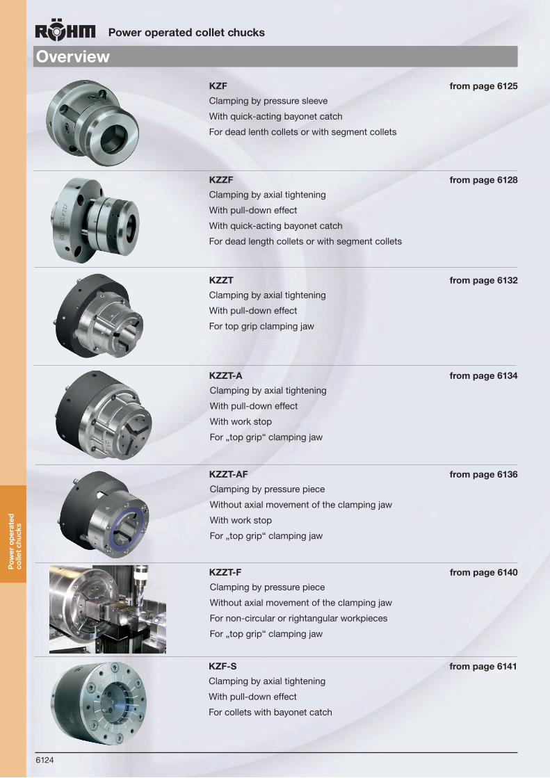
KFD
6124
OverviewPower operated collet chucks
KZF from page 6125
Clamping by pressure sleeve
With quick-acting bayonet catch
For dead lenth collets or with segment collets
KZZF from page 6128
Clamping by axial tightening
With pull-down effect
With quick-acting bayonet catch
For dead length collets or with segment collets
KZZT from page 6132
Clamping by axial tightening
With pull-down effect
For top grip clamping jaw
KZZT-A from page 6134
Clamping by axial tightening
With pull-down effect
With work stop
For „top grip“ clamping jaw
KZZT-A F from page 6136
Clamping by pressure piece
Without axial movement of the clamping jaw
With work stop
For „top grip“ clamping jaw
KZZT-F from page 6140
Clamping by pressure piece
Without axial movement of the clamping jaw
For non-circular or rightangular workpieces
For „top grip“ clamping jaw
KZF-S from page 6141
Clamping by axial tightening
With pull-down effect
For collets with bayonet catch
Pow
er o
pera
ted
colle
t chu
cks

6125
KZF - cap nut with locking screw
Power operated collet chucks
Rapid action bayonet catch helps save time when changing collets
Equipped either with DIN 6343 dead length collets or with segment collets
Adjustable workpiece stop mountable when using segment collets
All moving parts are made of high qualitity mate-rial, hardened and ground
Ideally suited for the machining of bars
Profiles can also be chucked with the appropriate collets
Used in conjunction with RÖHM actuating cylin-ders with safety device SZS, OVS, LHS-L, LVS, EHS and EVS the power chucks KZF meet the requirements of the German Employers’ Insurance Association
Press:Press chuck cover with its entire surface 2 mm against machine spindle
Rotate:Rotate chuck cover at 45o till the mark ”Auf” (open) coincides with the mark on the chuck
Remove:Remove chuck coverRemove collet
Change:Insert new collet Lock cover analog to the description above
Bayonet-System:The chuck cover can beplaced on the chuck at any 90 degree
1. Body
2. Clamping sleeve for steel and segment collets. For twinclamping with segment collets a suitable clamping sleeve is available.
3. Bayonet catch
4. Locking screw
- Adapter must be ordered seperatly. To fit the draw-tube and glued in the pressure sleeve
- Special accessory, not included in the scope of deliv-ery. Workpiece locator, can only be used in conjunction with segment collets
Order separately: Socket head cap screws or studs with locknut to DIN 55027
Clamping with collet and longitudinal workstop
Technical features:
Hollow-center clamping with steelcollet to DIN 6343
KZ
F
31 24

6126
Power operated collet chucks
KZF
Tool group C 15Type 508-11/508-31 power-operated collet chuck KZF, with quick-acting bayonet catch, without colletcylindrical centre mount/ short taper mountdraw tube-connector available on request
Item no. 439989 439990 439991 439992 439993 439994 439995 439996 439997 439998
Size 40 40 40 40 60 60 60 60 80 80
Mount Z-140 Z-88 KK 5 KK 6 Z-115 Z-170 KK 6 KK 8 Z-130 KK 8
D1 160 135 170 170 157 190 210 210 187 210
D2 100 100 100 100 122 122 122 122 150 150
D3 140 88 82,563 106,375 115 170 106,375 139,719 130 139,719
D4 104,8 115 104,8 133,4 136 133,4 133,4 171,4 166 171,4
D5 4xM10 6xM8 4xM10 4xM12 8xM8 6xM12 4xM12 4xM16 8xM8 4xM16
D6 M66x1,5 M66x1,5 M66x1,5 M66x1,5 M88x1,5 M88x1,5 M88x1,5 M88x1,5 M88x1,5 M114x1,5
L1 116 116 127 128 132 132 144 146 156 170
L2 25 25 25 25 25 25 25 25 30 30
L3 5 5 16 18 5 5 18 22 5 22
L4 min. 16 16 32 33 16 16 33 35 17 36
L4 max. 8,5 8,5 24,5 25,5 8,5 8,5 25,5 27,5 9,5 28,5
L5 8,5 8,5 8,5 8,5 8,5 8,5 8,5 8,5 12,5 12,5
Total stroke mm 7,5 7,5 7,5 7,5 7,5 7,5 7,5 7,5 7,5 7,5
Maximum draw bar pull kN
25 25 25 25 30 30 30 30 35 35
Total clamping force kN
50 50 50 50 60 60 60 60 70 70
Adm. speed min-1
8000 8000 8000 8000 5000 5000 5000 5000 4000 4000
Chucking capacity mm
2-42 2-42 2-42 2-42 4-60 4-60 4-60 4-60 20-80 20-80
Moment of inertia J kgm2
0,029 0,029 0,029 0,029 0,038 0,038 0,038 0,038 0,108 0,108
Weight with-out collet kg
7,1 5,3 7,5 7,5 9,2 9,2 10,2 14 17,5 18
Pow
er-o
pera
ted
colle
t ch
uck
KZ
F
from stock 4 - 6 weeks ▲ on request

6127
Power operated collet chucks
Accessories KZF
Pow
er-o
pera
ted
colle
t ch
uck
KZ
F
from stock 4 - 6 weeks ▲ on request
Tool group C 15Type 508-00 Connecting piece for collet chuck KZF
Item no. Size A B C D
683648 40 62 60 8,5 M66x1,5
683649 60 85 60 8,5 M88x1,5
683652 80 100 60 12,5 M114x1,5
KZF KZZF
The use of a workstop in the KZF is possible, if a segment collet is inserted.
Workstop for KZF
The clamping sleeves for double collets apply to any of the normalRoehm KZF collet chucks. Advantage: the twin clamping of bars results in a secure and vibrationfree gripping contact. Available for sizes 40 and 60 only.
Clamping sleeves for double collets for KZF
Chuck size Collets DIN 6343
Type Clamping capacity Tolerance
KZF 40 8206-E DIN 6343 2-42 6-36 6-29 +0,2-0,3
KZF 60 2-42 6-36 6-29 +0,2 7-42 +0,2-0,3
KZF 807037-E DIN 6343
193 E 20-80 18-69 15-56 +0,2-0,3
Matching cylinders
SZS LHS-L
Matching collets
Chuck size Segment-collets DIN 6343
Type Clamping capacity Tolerance
KZF 40 Series R 36 8-42 2±0,3
KZF 60 Series R 52 19-61 2±0,3
KZF 80 - - -
Größe KZF 40/Z 140 40/Z 88 60/Z 115 60/Z 170 80/Z 130 40/5 40/6 60/6 60/8 80/8
SZS hydraulisch Typ 559-10 46/103 46/103 67/150 67/150 86/200 46/103 46/103 67/150 67/150 86/200
LHS-L pneumatisch Typ 565-10 42/289 42/289 62/438 62/438 - 42/289 42/289 62/438 62/438 -

6128
KZZF - cap nut with locking screw
Power operated collet chucks
Rapid action bayonet catch that helps save time when changing collets
With draw-down effect
Mainly for chucking bar work on NC/CNC lathes
Equipped either with dead length collets or with segment collets.
Used in conjunction with RÖHM actuating cylin-ders with safety device SZS, OVS, LHS-L, LVS, EHS and EVS the power chucks KZZF meet the requirements of the German Employers’ Insurance Association
Pow
er-o
pera
ted
colle
t ch
uck
KZ
ZF
Press:Press chuck cover with its entire surface 2 mm against machine spindle
Rotate:Rotate chuck cover at 45o till the mark ”Auf” (open) coincides with the mark on the chuck
Remove:Remove chuck coverRemove collet
Change:Insert new collet Lock cover analog to the description above
Bayonet-System:The chuck cover can beplaced on the chuck at any 90 degree
1. Body
2. Bayonet catch
3. Draw sleeve
4. Spacer
5. Draw ring
- Adapter must be ordered seperatly. To fit the draw-tube and glued in the pressure sleeve
- Special accessory, not included in the scope of de-livery. Workpiece locator Order separately: Socket head cap screws or studs with locknut to DIN 55027.
Hollow-center clamping with steel collet to DIN 6343
Clamping with collet and longitudinal workstop
6121
Span
nzan
genf
utte
r KZF
/ KZ
ZFCo
llet c
huck
s
Größe -- Size 40 60 80
(ohne Spannzange -- without collet) Id.-Nr. 423876 424272 424581
A 160 190 210
B 100 122 150
C 110,5 122,5 150
D 140 150 165
E 125 165 187
0015826F
G 6 x M8 4 x M10 4 x M10
H1 KK5 KK6 KK8
H2 KK6 KK8 130
H3 88 115 --
H4 140 170 --
J1 20 23 32
J2 25 29 23
J3 20 23 --
J4 26 30 --
5,75,75,7mmekortslatoT--buhtmaseG
Max. Betätigungskraft -- Max. draw bar pull kN 25 30 35
Max. zulässige Drehzahl -- Max. admissible min --1 8000 5000 4000
kgm2 0,018 0,044 0,085
kg 7,1 11,8 16,9
Massenträgheitsmoment JMoment o� nertia J
Gewicht ohne SpannzangeWeight without collet
KZZF 40 Aufnahme�ansch -- adapter �ange
KZZF 60 Aufnahme�ansch -- adapter �ange
KZZF 80 Aufnahme�ansch -- adapter �ange
J1 J2 J3
H1
H2
H3
J1 J2 J3
H1
H2
H3
J4
H4
J2
H2
J1
H1
J4
H4
4x
DE F
G
Technical features:
31
24
5

6129
Power operated collet chucks
KZZF - cap nut with locking screw
Tool group C 15Type 508-61 Power-operated collet chuck KZZF, with pull-down effect against workstop, with quick-acting bayonet catch, without colletdraw tube-connector available on request
Item no. 439978 439979 439980 439981 439982 439983 439984 439985 439986 439987 439988
Size 40 40 40 40 60 60 60 60 80 80 80
Mount KK 5 KK 6 Z-88 Z-140 KK 6 KK 8 Z-115 Z-170 KK 8 Z-170 Z-220
D1 160 160 160 160 190 190 190 190 210 210 210
D2 100 100 100 100 125 125 125 125 150 150 150
D3 82,563 106,375 88 140 106,375 139,719 115 170 139,719 170 220
D4 104,8 133,4 115 104,8 133,4 171,4 133,4 171,4 171,4 171,4 171,4
D5 4xM10 4xM12 6xM8 4xM10 4xM12 4xM16 8xM8 6xM12 4xM16 4xM16 4xM16
D6 M66x1,5 M66x1,5 M66x1,5 M66x1,5 M88x1,5 M88x1,5 M88x1,5 M88x1,5 M114x1,5 M114x1,5 M114x1,5
L1 130,5 135,5 124,5 130,5 145,5 151,5 139,5 147,5 182 182 182
L2 94 94 94 94 96 96 96 96 120 120 120
L3 16 18 6 6 18 22 6 6 22 6 6
L4 min. 31,5 30 21 27 29,5 35,5 23,5 31,5 38 38 38
L4 max. 24 22,5 13,5 19,5 22 28 16 24 31,5 31,5 31,5
L5 8,5 8,5 8,5 8,5 8,5 8,5 8,5 8,5 8,5 8,5 8,5
Total stroke mm 7,5 7,5 7,5 7,5 7,5 7,5 7,5 7,5 7,5 7,5 7,5
Maximum draw bar pull kN
25 25 25 25 30 30 30 30 35 35 35
Total clamping force kN
50 50 50 50 60 60 60 60 70 70 70
Adm. speed min-1
8000 8000 8000 8000 5000 5000 5000 5000 4000 4000 4000
Chucking capacity mm
2-42 2-42 2-42 2-42 4-60 4-60 40-60 4-60 20-80 20-80 20-80
Moment of inertia J kgm2
0,018 0,018 0,018 0,018 0,044 0,044 0,044 0,044 0,085 0,085 0,085
Weight with-out collet kg
8 8 8 8 13 13 13 13 19 19 19
Pow
er-o
pera
ted
colle
t ch
uck
KZ
ZF
from stock 4 - 6 weeks ▲ on request

6130
Power operated collet chucks
Size KZZF 40 60 80 40 60 80
SZS hydraulical Typ 559-10 46/103 67/150 86/200 46/103 67/150 86/200
LHS-L pneumatical Typ 565-10 42/289 62/438 - 42/289 62/438 -
Accessories KZZF
Pow
er-o
pera
ted
colle
t ch
uck
KZ
ZF
KZF KZZF
In the KZZF the use of a workstop is possible in any combination withboth Typees of collets: DIN 6343 and segment collets
Workstop for KZZF
Chuck size Collets DIN 6343
Type Clamping capacity Tolerance
KZZF 40 8206-E DIN 6343173 E 2-42 6-36 6-29 +0,2
-0,3
KZZF 60 8207-E DIN 6343185 E 4-60 8-52 7-42 +0,2
-0,3
KZZF 80 7037-E DIN 6343193 E 20-80 18-69 15-56 +0,2
-0,3
Matching cylinders
SZS LHS-L
Matching collets
Chuck size Segment-collets DIN 6343
Type Clamping capacity Tolerance
KZZF 40 Series R 36 8-42 2±0,3
KZZF 60 Series R 52 19-61 2±0,3
KZZF 80 - - -
Tool group C 15Type 508-00 Connecting piece for collet chuck KZZF
Item no. Size A B C D
683648 40 62 60 8,5 M66x1,5
683649 60 85 60 8,5 M88x1,5
683652 80 100 60 12,5 M114x1,5

6131
Power operated collet chucks
KZZT / KZZT-A / KZZT-AF
Top grip clamping jaw for KZZT / KZZT-A / KZZT-AF
High-quality rubber-steel segment clamping jaw
Exchangeable vulcanisate on request
Highest clamping forces and rigidity
Clamping tolerances ± 0,5 mm
Application field:
- turning, milling and grinding
- for bar work and for chucking work.
Simple retooling with manual or pneumatic changing fixture (not included in the scope of delivery)
Special designs on request
design with transverse grooves
smooth design
KZZT
Clamping via pull-down
With draw-down effect
With a full through-hole for bar work
Used in conjunction with RÖHM actuating cylinders with safety device SZS, OVS, LHS-L, LVS, EHS and EVS the power-operated pulling collet chucks meet the re-quirements of the German Employers’ Insurance Association
KZZT-A
Clamping via pull-down
With draw-down effect
With a full through-hole for bar work plus a rigid axial stop for chuck parts.
An additional workpiece support emerges by pulling the component tough against the axial stop while clamping
Perfect with short clamped workpieces
The adaption for the axial stop can vary (changes possible)
KZZT-AF
Clamping via trust piece
No axial movement of clamping jaw
Clamping principle: The thrust piece is pushed over the fixed Top Grip clamping jaw. The fixed jaw ensures a lesser stiffness than achieved with the traction chucks KZZT/KZZT-A
Type with fixed clamping jaw for through as well as stop clamping
Pow
er o
pera
ted
colle
t chu
cks

6132
Power operated collet chucks
KZZT short taper mount
from stock 4 - 6 weeks ▲ on request
Tool group C 15Type 508-71 Power operated collet chuck KZZT, with full through holeShort taper mount
Item no. 432360 429587 429588 432709 432710 439942 429594 439943 432361 432362 ▲ 432363 ▲
Size 32 42 42 52 52 65 65 65 80 100 120
Mount D KK5 KK5 KK6 KK5 KK6 KK5 KK6 KK8 KK8 KK8 KK8
D1 140 140 165 140 165 150 165 205 205 215 240
D2 111 125 125 125 125 - 140 150 180 201 230
D3 75 100 100 100 100 120 120 120 160 - -
D4 M48x1,5 M68x1,5 M68x1,5 M68x1,5 M68x1,5 M78x1,5 M78x1,5 M78x1,5 M94x1,5 M114x1,5 M132x1,5
D5 34 44 44 54 54 67 67 67 82 102 122
D6 104,8 104,8 133,4 171,4 104,8 104,8 133,4 171,4 171,4 171,4 171,4
D7 4xM10 4xM10 4xM12 4xM10 4xM12 4xM10 4xM12 4xM16 4xM16 4xM16 4xM16
L1 88 90 90 115 115 125 95 145 125 125 135
L2 68 68 68 68 68 68 68 68 64 - 65
L3 40 40 40 42 42 60 45 70 54 54 -
L4 min. 34 35,5 35,5 44 44 31,5 31 31,5 52 41 46
L4 max. 39,5 41,5 41,5 49,5 49,5 36 36 36 56,5 49 53,5
Total stroke mm 5,5 6 6 5,5 5,5 4,5 5 4,5 4,5 8 7,5
Maximum draw bar pull kN
25 35 35 40 40 45 45 45 50 65 70
Total clamping force kN
60 70 70 80 80 90 90 90 100 130 140
Adm. speed min-1 8000 7000 7000 6500 6500 6000 6000 6000 5500 5000 4000
Clamping range 4-32 4-42 4-42 4-52 4-52 4-65 4-65 4-65 5-80 16-100 62-120
Pow
er-o
pera
ted
colle
t ch
uck
KZ
ZT

6133
Power operated collet chucks
KZZT cylindrical centre mount
from stock 4 - 6 weeks ▲ on request
Tool group C 15Type 508-72 Power operated collet chuck KZZT, with full through holecylindrical centre mount
Item no. 439944 439945 439946 439947 439948 439949 439950 439951 439952 ▲ 439953 ▲
Size 32 42 42 52 52 65 65 80 100 120
Mount D 140 140 170 140 170 140 170 220 220 220
D1 150 150 180 150 180 150 180 230 230 230
D2 115 125 125 125 125 140 140 210 210 210
D3 75 100 100 100 100 120 120 - - -
D4 M48x1,5 M68x1,5 M68x1,5 M68x1,5 M68x1,5 M78x1,5 M78x1,5 M94x1,5 M114x1,5 M132x1,5
D5 34 44 44 54 54 67 67 82 102 122
D6 104,8 104,8 133,4 104,8 133,4 104,8 133,4 171,4 171,4 171,4
D7 4xM10 4xM10 4xM12 4xM10 4xM12 4xM10 4xM12 4xM16 4xM16 4xM16
L1 80 82 82 105 105 85 85 115 115 125
L2 72 68 68 68 68 68 68 - - -
L3 40 40 40 42 42 45 45 54 54 54
L4 min. 31,5 37 37 44 44 31,5 31,5 52 41 46
L4 max. 37 41,5 41,5 48,5 48,5 36 36 56,5 49 53,5
L5 6 6 6 6 6 6 6 6 6 6
Total stroke mm 5,5 4,5 4,5 4,5 4,5 4,5 4,5 4,5 8 6
Maximum draw bar pull kN
25 35 35 40 40 45 45 50 65 70
Total clamping force kN
60 70 70 80 80 90 90 100 130 140
Adm. speed min-1 8000 7000 7000 6500 6500 6000 6000 5500 5000 4000
Clamping range 4-32 4-42 4-42 4-52 4-52 4-65 4-65 5-80 16-100 62-120P
ower
-ope
rate
d co
llet
chuc
k K
ZZ
T

6134
Power operated collet chucks
KZZT-A short taper mount
from stock 4 - 6 weeks ▲ on request
Tool group C 15Type 508-73 Power operated collet chuck KZZT-A, with full through hole and rigid axial stopShort taper mount
Item no. 432364 429590 429591 432711 432712 439954 429598 439955 432365 432366 ▲ 432367▲
Size 32 42 42 52 52 65 65 65 80 100 120
Mount D KK5 KK5 KK6 KK5 KK6 KK5 KK6 KK8 KK8 KK8 KK8
D1 140 140 165 140 165 140 165 205 210 225 270
D2 114 125 125 140 140 - 149 150 160 206 260
D3 - 100 100 100 100 120 120 120 140 195 210
D4 M48x1,5 M68x1,5 M68x1,5 M72x1,5 M72x1,5 M78x1,5 M78x1,5 M78x1,5 M94x1,5 M114x1,5 M132x1,5
D5 M34x1 M42x1 M42x1 M54x1,5 M54x1,5 M66x1 M66x1 M66x1 M82x1,5 105x1,5 125x1,5
D6 104,8 104,8 133,4 104,8 133,4 104,8 133,4 171,4 171,4 171,4 171,4
D7 4xM10 4xM10 4xM12 4xM10 4xM12 4xM10 4xM12 4xM16 4xM16 4xM16 4xM16
L1 117 120 120 122 122 125 129 145 145 157 165
L2 - 106 106 111 111 68 115 68 129 132 140
L3 63 67,5 67,5 56 56 60 58 70 80 82 90
L4 min. - 39,5 39,5 37 33,5 31,5 31,5 31,5 44 47 48
L4 max. - 45,5 45,5 42,5 39 36 37 36 49 52,5 53,5
Total stroke mm 6 6 6 5,5 5,5 4,5 5,5 4,5 5 5,5 5,5
Maximum draw bar pull kN
25 35 35 40 40 45 45 45 50 65 70
Total clamping force kN
60 70 70 80 80 90 90 90 100 130 140
Adm. speed min-1
8000 7000 7000 6500 6500 6000 6000 6000 5500 5000 4000
Clamping range 4-32 4-42 4-42 4-52 4-52 4-65 4-65 4-65 5-80 16-100 62-120
The adaption for the axial-stop can be varied (changes possible).
Scan QR-Code and watch the product-video of the collet chuck KZZT-A on Youtube!
Pow
er-o
pera
ted
colle
t ch
uck
KZ
ZT-
A
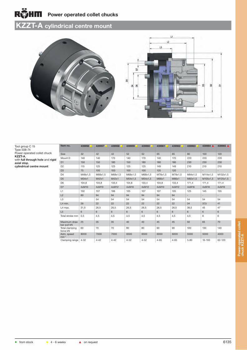
6135
Power operated collet chucks
KZZT-A cylindrical centre mount
from stock 4 - 6 weeks ▲ on request
Tool group C 15Type 508-74 Power operated collet chuck KZZT-A, with full through hole and rigid axial stop, cylindrical centre mount
Item no. 439956 439957 439958 439959 439960 439961 439962 439963 439964 ▲ 439965 ▲
Size 32 42 42 52 52 65 65 80 100 120
Mount D 140 140 170 140 170 140 170 220 220 220
D1 150 150 180 150 180 180 180 230 230 230
D2 115 125 125 125 125 149 149 210 210 210
D3 75 100 100 100 100 120 120 - - -
D4 M48x1,5 M68x1,5 M68x1,5 M68x1,5 M68x1,5 M78x1,5 M78x1,5 M94x1,5 M114x1,5 M132x1,5
D5 M34x1 M42x1 M42x1 M54x1,5 M54x1,5 M66x1 M66x1 M82x1,5 M105x1,5 M125x1,5
D6 104,8 104,8 133,4 104,8 133,4 104,8 133,4 171,4 171,4 171,4
D7 4xM10 4xM10 4xM12 4xM10 4xM12 4xM10 4xM12 4xM16 4xM16 4xM16
L1 102 107 106 105 107 107 105 125 145 155
L2 60 94 94 94 94 94 94 - - -
L3 - 54 54 54 54 54 54 54 54 54
L4 min. 26 22 22 22 22 22 22 34 37,5 41
L4 max. 31,5 26,5 26,5 26,5 26,5 26,5 26,5 38,5 45 47
L5 6 6 6 6 6 6 6 6 6 6
Total stroke mm 5,5 4,5 4,5 4,5 4,5 4,5 4,5 4,5 8 6
Maximum draw bar pull kN
25 35 35 40 40 45 45 50 65 70
Total clamping force kN
60 70 70 80 80 90 90 100 130 140
Adm. speed min-1
8000 7000 7000 6500 6500 6000 6000 5500 5000 4000
Clamping range 4-32 4-42 4-42 4-52 4-52 4-65 4-65 5-80 16-100 62-120P
ower
-ope
rate
d co
llet
chuc
k K
ZZ
T-A

6136
Power operated collet chucks
KZZT-AF short taper mount
from stock 4 - 6 weeks ▲ on request
Tool group C 15Type 508-75 Power operated collet chuck KZZT-AF, with full through hole, rigid axial stop and a fixed Top Grip clamping jawFor through and stop clamping short taper mount
Item no. 432690 432691 432692 432693 432694 439966 432696 439967 432699 432701 ▲ 432702 ▲
Size 32 42 42 52 52 65 65 65 80 100 120
Mount D KK5 KK5 KK6 KK5 KK6 5 KK6 8 KK8 KK8 KK8
D1 135 135 165 140 165 150 165 205 210 215 240
D2 135 135 135 140 140 160 160 160 175 215 240
D3 M52x1,5 M62x1,5 M62x1,5 M78x1,5 M78x1,5 M52x1,5 M90x1,5 M90x1,5 M92x1,5 M125x1,5 M132x1,5
D4 min. 4 4 4 4 4 5 5 5 5 42 42
D4 max. 34 44 44 54 54 67 67 67 82 102 122
D5 M34x1 M42x1 M42x1 M54x1,5 M54x1,5 M66x1 M66x1 M66x1 M82x1,5 M105x1,5 M125x1,5
D6 104,8 104,8 133,4 104,8 133,4 104,8 133,4 171,4 171,4 171,4 171,4
D7 4xM10 4xM10 4xM12 4xM10 4xM12 4xM10 4xM12 4xM16 4xM16 4xM16 4xM16
L1 118 120 120 120 120 125 130 145 145 170 180
L2 - - 42 47 47 68 53 68 58 64 72
L3 min. 32,5 32,5 32,5 33 33 33 37 33 40 44,5 51
L3 max. 38,5 38,5 38,5 37,5 37,5 37,5 43 37,5 44,5 52,5 57
L4 17 17 17 20 20 20 20 20 24 24 24
L5 16 16 18 16 18 16 18 22 22 22 22
Total stroke mm 5,5 6 6 4,5 4,5 4,5 6 4,5 4,5 8 6
Maximum draw bar pull kN
25 35 35 40 40 45 45 45 50 65 70
Total clamping force kN
60 70 70 80 80 90 90 90 100 130 140
Adm. speed min-1 8000 7000 7000 6500 6500 6000 6000 6000 5500 5000 4000
Clamping range 4-32 4-42 4-42 4-52 4-52 4-65 4-65 4-65 5-80 16-100 62-120
Pow
er-o
pera
ted
colle
t ch
uck
KZ
ZT-
AF

6137
Power operated collet chucks
KZZT-AF cylindrical centre mount
from stock 4 - 6 weeks ▲ on request
Tool group C 15Type 508-76 Power operated collet chuck KZZT-A, with full through hole and rigid axial stopCylindrical centre mount
Item no. 439968 439969 439970 439971 439972 439973 439974 439975 439976 ▲ 439977 ▲
Size 32 42 42 52 52 65 65 80 100 120
Mount D 140 140 170 140 170 140 170 220 220 220
D1 150 150 180 150 180 150 180 230 230 230
D2 115 125 125 125 125 140 140 210 210 210
D3 M48x1,5 M68x1,5 M68x1,5 M68x1,5 M68x1,5 M78x1,5 M78x1,5 M94x1,5 M114x1,5 M132x1,5
D4 34 44 44 54 54 67 67 82 102 122
D5 M34x1 M42x1 M42x1 M54x1,5 M54x1,5 M66x1 M66x1 M82x1,5 M105x1,5 M125x1,5
D6 104,8 104,8 133,4 104,8 133,4 104,8 133,4 171,4 171,4 171,4
D7 4xM10 4xM10 4xM12 4xM10 4xM12 4xM10 4xM12 4xM16 4xM16 4xM16
L1 80 82 82 105 105 85 85 115 115 125
L2 72 68 68 68 68 68 68 - - -
L3 40 40 40 42 42 45 45 54 54 54
L4 min. 31,5 37 37 44 44 31,5 31,5 52 41 46
L4 max. 37 41,5 41,5 48,5 48,5 36 36 56,5 49 53,5
L5 6 6 6 6 6 6 6 6 6 6
Total stroke mm 5,5 4,5 4,5 4,5 4,5 4,5 4,5 4,5 8 6
Maximum draw bar pull kN
25 35 35 40 40 45 45 50 65 70
Total clamping force kN
60 70 70 80 80 90 90 100 130 140
Adm. speed min-1 8000 7000 7000 6500 6500 6000 6000 5500 5000 4000
Clamping range 4-32 4-42 4-42 4-52 4-52 4-65 4-65 5-80 16-100 62-120
Pow
er-o
pera
ted
colle
t ch
uck
KZ
ZT-
AF

6138
Top Grip clamping jaw for KZZT / KZZT-A / KZZT-AF
Jaw
s K
ZZ
T /
KZ
ZT-
A /
KZ
ZT-
AF
Power operated collet chucks
GT 32GTG 32GTW 32*
Bore DesignA47
B6
C57,7
D44
E3
Round
SmoothTransverse groovesAxial, transv. grooves*self machining Ø
Clamping range Clamping range
4-78-1011-32
-
4-32--
5/10/20
Square SmoothTransverse grooves
78-30
-
Hexagon Smooth Transverse grooves
78-27
-
Fixture for machining of the Top Grip clamping jaw Item no. 497314
GT 42GTG 42GTW 42*
Bore DesignA47
B9
C79,3
D42
E4
Round
SmoothTransverse groovesAxial, transv. grooves*self machining Ø
Clamping range Clamping range
4-78-1011-42
-
4-42--
5/15/30
Square SmoothTransverse grooves
78-30 -
Hexagon Smooth Transverse grooves
78-32
33-36-
Fixture for machining of the Top Grip clamping jaw Item no. 497315
GT 52GTG 52GTW 52*
Bore DesignA46
B3
C79,2
D46
E3
Round
SmoothTransverse groovesAxial, transv. grooves*self machining Ø
Clamping range Clamping range
4-78-1011-52
-
4-52--
8/15/30
Square SmoothTransverse grooves
8-910-36 -
Hexagon Smooth Transverse grooves
7-910-4242-45
-
Fixture for machining of the Top Grip clamping jaw Item no. 1053342
GT 65GTG 65GTW 65*
Bore DesignA58
B9
C99,5
D53
E4
Round
SmoothTransverse groovesAxial, transv. grooves*self machining Ø
Clamping range Clamping range
5-78-1011-65
-
5-65--
8/20/40
Square SmoothTransverse grooves
8-3233-4041-46
-
Hexagon Smooth Transverse grooves
7-3233-4041-5051-56
-
Fixture for machining of the Top Grip clamping jaw Item no. 497316
GT, extension, grooved bore, at size 80 first groove closed
GTG, reduced extension, smooth bore Bores in 1 mm steps
* face and bore soft
GT GTG
6115
KZZT
/KZZ
T-A
/KZZ
T-A
FPo
wer
ope
rate
d pu
lling
col
lets
A
B
C
DE
DE
A
B
C
A
B
C
DE
A
B
C
DE
25155-k006-115 26.04.2007 10:43 Uhr Seite 6115
6115
KZZT
/KZZ
T-A
/KZZ
T-A
FPo
wer
ope
rate
d pu
lling
col
lets
A
B
C
DE
DE
A
B
C
A
B
C
DE
A
B
C
DE
25155-k006-115 26.04.2007 10:43 Uhr Seite 6115
6115
KZZT
/KZZ
T-A
/KZZ
T-A
FPo
wer
ope
rate
d pu
lling
col
lets
A
B
C
DE
DE
A
BC
A
B
C
DE
A
B
C
DE
25155-k006-115 26.04.2007 10:43 Uhr Seite 6115
6115
KZZT
/KZZ
T-A
/KZZ
T-A
FPo
wer
ope
rate
d pu
lling
col
lets
A
B
C
DE
DE
A
B
C
A
B
C
DE
A
B
C
DE
25155-k006-115 26.04.2007 10:43 Uhr Seite 6115
GT GTG
GT GTG
GT GTG
Clamping jaws Top grip with diameter rising at 0,5mm are available on stock. Other diameters are available in ca. 2 weeks. Special clamping jaws with square bore and hexagon bore on request.

6139
Top Grip clamping jaw for KZZT / KZZT-A / KZZT-AF Top Grip clamping jaw / Changing fixture for KZZT / KZZT-A / KZZT-AF
Jaw
s K
ZZ
T /
KZ
ZT-
A /
KZ
ZT-
AF
Power operated collet chucks
GT 80GTG 80GTW 80*
Bore DesignA53
B4
C114,5
D53
E4
Round
SmoothTransverse groovesAxial, transv. grooves*self machining Ø
Clamping range Clamping range
5-78-1011-80
-
5-80--
20/40/60
Square Transverse grooves
8-3233-4041-4647-56
-
Hexagon Transverse grooves
7-3233-4041-5051-5657-68
-
Fixture for machining of the Top Grip clamping jaw Item no. 497317
GT 100GTG 100GTW 100*
Bore DesignA59
B-
C144,5
D59
E-
Round Längs-und Querrillen*Zum Selbstausdrehen Ø
Clamping range Clamping range
42-100 5-8020/40/60
Square Transverse grooves 50-6061-70
-
Hexagon Transverse grooves50-6061-7071-86
-
Fixture for machining of the Top Grip clamping jaw Item no. 497318
GT 120GTG 120GTW 120*
Bore DesignA61
B3
C180
D61
E3
Round Längs-und Querrillen*Zum Selbstausdrehen Ø
Clamping range Clamping range
65-120 70/90/100
Square Transverse grooves on request -
Hexagon Transverse grooves on request -
Fixture for machining of the Top Grip clamping jaw Item no. 497319
Top Grip clamping jaw, for short clamped workpieces
Size Through-hole
Clamping jaw Top Grip short design
max. clamp.-Ø depth t Tensile force max. N
Speed max.* min-1
32 32 49x6,5 25000 800042 42 68x10 35000 700065 65 87x10 45000 600080 80 90x10 50000 5500100 100 117,2x20 65000 5000120 120 150x18 70000 3200
* Only valid for GTG-typed clamping heads
Changing fixture for pulling collets
Size Item Type
32 435708 manually operated
32 431955 air operated
42/65 429677 manually operated
42/65 006898 air operated
52 1043300 manually operated
52 436285 air operated
80 437301 manually operated
80 001124 air operated
100 006352 air operated
120 006901 air operated
The manual changing fixture is the simplest method of clamping headchangeover by changing the pins.
Pneumatic changing fixture with comfortable handle and integrated valve switch by changing the pins.
A
C
DB E
A
C
D
t
AB
CD
E
25155-k006-116 26.04.2007 10:43 Uhr Seite 6116
A
C
DB E
A
C
D
t
AB
C
DE
25155-k006-116 26.04.2007 10:43 Uhr Seite 6116
A
C
DB E
A
C
D
t
AB
C
DE
25155-k006-116 26.04.2007 10:43 Uhr Seite 6116
GT GTG
GT GTG
GT GTG

6140
KZZT-F
Power operated collet chucks
With passageway for profile bars, with spherical joint - clamping level compensation for a 2/2 centrical clamping mode
The KZZT-F, size 240 mm dia., has dynamical advantages when clamping non-circular or rightangular workpieces
Waste loss reducting, practical and without additional efforts
Clamping via trust piece
No axial movement of clamping jaw
For non-circular and rightangular workpieces
For Top-Grip clamping jaws
The peculiar of this design is the fact that i. e. a right angled part with big tolerances up to +/- 1 mm of its X- and Y-axis will be clamped absolutely centrical in each of its profile axes. And this is managed by a single centri-cal actuation.
Did we arouse your interest? Please contact us!
Machining of complete workpiece
KZ
ZT-
F
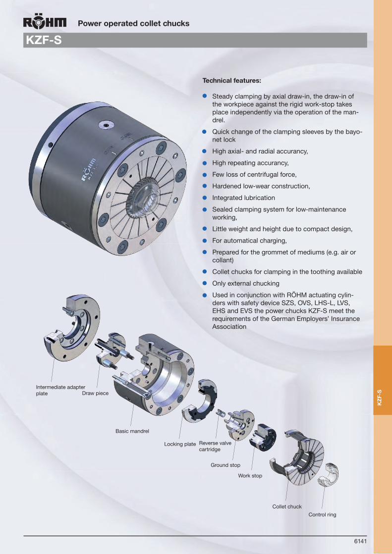
6141
KZZT-F KZF-SPower operated collet chucks
Steady clamping by axial draw-in, the draw-in of the workpiece against the rigid work-stop takes place independently via the operation of the man-drel.
Quick change of the clamping sleeves by the bayo-net lock
High axial- and radial accurancy,
High repeating accurancy,
Few loss of centrifugal force,
Hardened low-wear construction,
Integrated lubrication
Sealed clamping system for low-maintenance working,
Little weight and height due to compact design,
For automatical charging,
Prepared for the grommet of mediums (e.g. air or collant)
Collet chucks for clamping in the toothing available
Only external chucking
Used in conjunction with RÖHM actuating cylin-ders with safety device SZS, OVS, LHS-L, LVS, EHS and EVS the power chucks KZF-S meet the requirements of the German Employers’ Insurance Association
Control ringCollet chuck
Work stop
Ground stop
Reverse valve cartridge
Locking plate
Basic mandrel
Intermediate adapter plate Draw piece
Technical features:
KZ
F-S

6142
Power operated collet chucks
KZF-S
from stock 4 - 6 weeks ▲ on request
Tool group C 18Type 267-10 Power operated collet chuck KZF-S; for external clamping
KZF 80 KZF 120 KZF 180
Body collet 1117832 ▲ 1117830 ▲ 1125403 ▲Base bolt 1117833 ▲ 1072101 ▲ 1125404 ▲Draw piece 1117837 ▲ 1117827 ▲ 1125408 ▲Fastening plate 1117835 ▲ 1072105 ▲ 1125406 ▲Bolt spacer 1117836 ▲ 1072103 ▲ 1072103 ▲Ground stop for reverse valve cartridge
1117839 ▲ 1072113 ▲ 1125410 ▲
Ground stop for ermeto pipe 1117841 ▲ 1117824 ▲ 1125412 ▲Reverse valve cartridge 1 Bar 756641 ▲ 863134 ▲ 863134 ▲Reverse valve cartridge 3 Bar 843866 ▲ 889894 ▲ 889894 ▲F Max, in daN 30 40 40
Speed max, min-1 6000 5000 3500
Stroke 4 4 4
Clamping dia, min, 30 60 100
Clamping dia, max, 80 120 180
Expansion in Ø 1,4 1,4 1,4
Ø G 170 220 285
H 125 136 136
Info: [email protected]
Pow
er-o
pera
ted
colle
t ch
uck
KZ
F-S

6143
Power operated collet chucks
Accessories KZF-S
from stock 4 - 6 weeks ▲ on request
Tool group C 18Type 267-20 Intermediate flange ISO 702-1 (DIN 55028)
A 05 A 05 A 05 A 06 A 06 A 08 A 08 A 08
Intermediate flange 1117843 1072115 1117845 1072117 1125416 1117847 1072119 1125418 For KZF-S 80 KZF-S 80 KZF-S 81 KZF-S 120 KZF-S 180 KZF-S 82 KZF-S 120 KZF -S 180
Short-taper-Ø B 82,563 82,563 106,375 106,375 106,375 139,719 139,719 139,719
Short-taper pitch circle Ø C 104,8 104,8 133,4 133,4 133,4 171,4 171,4 171,4
Flange outer-Ø A 170 220 170 220 285 210 220 285
Ø D 105 135 105 135 200 105 135 200
Ø F 143 186 143 186 250 143 186 250
Ø O 16,3 16,3 19,45 19,45 19,45 24,2 24,2 24,2
Thread-Ø M M10 M10 M12 M12 M12 M16 M16 M16
Total length flange P 35 40 35 40 45 35 40 45
Acc
esso
ries
KZ
F-S

KFD
6144
OverviewDraw-down power chucks
KFD-N from page 6145
Wedge system
Actice pull-down by body and jaws
Only for external chucking
3-jaw design
Pull-down function:
After siting the jaws on the workpiece, the entire front part of the chuck is pulled back. The draw-bar pull ex-erted when the workpiece is clamped, draws it down onto the fixed milling bed. On releasing, built-in compression springs return the workpiece to start postition.
KBF-N from page 6148
Ball lock principle with wedge system
Active pull down by jaws
Oil bath lubrication, hermetically sealed
3-jaw design
Options: with fixed jaws or pendulum jaws
Pull-down function:
After siting the jaws on the workpiece, the jaws are pul-led back. Thus this, the pull-down effect of the workpiece takes the axial stop.
ZFM from page 6152
Draw-bar system
Draw down effect through axial movement of draw rod studs
External gripping only
3-jaw design
Dra
w-d
own
pow
er c
huck
s

KFD
6145
Draw-down power chucks
KFD-N
With this design, workpieces can be chucked in perfect alignment.
Running errors due to jaw displacement and chuckbody deformation, are thus eleminated. The draw-bar pull exerted when the workpiece is clamped, draws it down onto the fixed milling bed. On releasing, built-in compression springs return the workpiece to start position. Work seats can be precisely secured to the support posts firmly attached to the mounting adapter.
Wedge system with draw-down effect, with through-hole
KFD
-N
Wedge system
Active draw-down via body and jaws
High-accuracy chucking
All-steel design; all working parts hardened and ground
Long actuating-piston guideway
Rugged, deep-seated support posts
Rugged universal adapter for work seats included as attachment
Used in conjunction with RÖHM actuating cylin-ders with safety device SZS, OVS, LHS-L, LVS, EHS and EVS the power chucks KFD-N meet the requirements of the German Employers’ Insurance Association
Only for external chucking
Technical features:

6146
Draw-down power chucks
KFD-N
from stock 4 - 6 weeks ▲ on request
Tool group C 15Type 441-12 3 jaw draw-down power chucks KFD-N, only for external chuckingShort taper mount ISO 702-1 (DIN 55026)
Item no. 155024 155025 155026 150792
Size 220 280 350 400
A 220 280 350 400
Jaw travel B 5,3 6,7 8 9,3
C min. 115,5 124,5 144,5 155,5
C max. 116 125 145 156
Short taper D 6 8 11 11
E 17 19 21 21
F 133,4 171,4 235 235
G 3 x M 12 3 x M 16 3 x M 20 3 x M 20
H 20 24 27 27
Wedge stroke K 20 25 30 35
N 45 55 60 60
O 40 46 46 46
P 30 30 30 30
Q M 20 M 24 M 24 M 24
R 45 55 55 55
S min. 20 18 10 10
S max. 40 43 40 45
T min. 121,5 130,5 150,5 163,5
T max. 122 131 151 164
U M 12 x 30 M 16 x 35 M 16 x 35 M 20 x 45
a min. 68,7 88,3 102 119,7
a max. 74 95 110 129
b 9 12 17 27,5
cg6 12 16 16 25
d 55 75 105 118
e 35 50 55 60
fH7 16 20 20 25
g 161 200 230 260
h-0,1 131 140 158 171
i 20 19 22 26
k 25 32 32 45
l 36 45 65 71
m 22 27 26 34
n 5 5 5 6,8
o 30 40 50 80
p M 10 M 12 M 12 M 16
Maximum draw bar pull kN 35 65 80 95
Max. total clamping force approx. kN 70 140 190 250
Max. admissible speed min-1 4000 3200 2400 2200
Moment of inertia J kgm2 0,2 0,54 1,5 2,8
Weight without jaws approx. kg 33 55 100 140
Soft top jaws (set) Id.-Nr. 123430 123433 129849 772864
Adapter plate for work seats on request
Dra
w-d
own
pow
er
chuc
k K
FD-N

6147
Draw-down power chucks
KFD-N
from stock 4 - 6 weeks ▲ on request
Tool group C 15Type 441-60 3 jaw draw-down power chucks, only for external chuckingShort taper mount ISO 702-1 (DIN 55026)
Item no. 150793 ▲ 150794 ▲ 150795 ▲ 150796 ▲
Size 500 500 630 800
A 500 500 630 800
Jaw travel B 9,3 9,3 10,5 10,5
C min. 155,5 155,5 193,5 209,5
C max. 156 156 195 211
Short taper D 11 15 15 15
E 21 23 23 23
F 235 330,2 330,2 330,2
G 6 x M 20 6 x M 24 6 x M 24 6 x M 24
H 30 35 35 35
Wedge stroke K 35 35 40 40
N 60 60 80 80
O 46 46 55 55
P 30 30 30 30
Q M 24 M 24 M 30 M 30
R 55 55 85 85
S min. 10 10 2 18
S max. 45 45 42 58
T min. 163,5 163,5 201,5 218,5
T max. 164 164 203 220
U M 20 M 20 M 20 M 20
a min. 158,2 158,2 195 237
a max. 167,5 167,5 205,5 247,5
b 60 60 90 130
cg6 25 25 25 25
d 168 168 219 305
e 60 60 70 70
fH7 25 25 25 25
g 180 180 225 175
h-0,1 171 171 213 230
k 45 45 100 100
l 70 70 97 140
m 28 28 28 28
n 6 6 6 6
o 120 120 180 280
p M 16 M 16 M 12 M 12
r 8 8 8 8
Maximum draw bar pull kN 110 110 130 130
Max. total clamping force approx. kN 280 280 320 320
Max. admissible speed min-1 1800 1800 1200 800
Moment of inertia J kgm2 6,8 6,8 20 60
Weight without jaws approx. kg 220 220 410 750
Dra
w-d
own
chuc
k K
FD-N

6148
Draw-down power chucks
Ball lock draw-down chuck KBF-N
Technical features:
Ball lock principle with wedge system
Active draw-down via jaws
With fixed jaws or with pendulum jaws
Suitable for internal and external clamping
Wear resistant due to large areas for power transmission
Hermetically sealed against dirt and coolant
The oil filling makes the chuck almost maintenance free at a constant performance
Influences of the speed related centrifugal forces will be minimized by similar masses situated left and right of the ball levers which is leading to high speeds
Used in conjunction with RÖHM actuating cylinders with safety device SZS, OVS, LHS-L, LVS, EHS and EVS the power chucks KBF-N meet the requirements of the German Employers’ Insurance Association
Alternative with floating ball levers for clamping rough and easy deformable workpieces at six clamping spots
Cover
Ball lever
Oil fill/drain
Wedge
Piston Pressure spring
Active draw down action
Body
Scan QR-Code an watch the productvideo KBF-N on Youtube!
Bal
l loc
k dr
aw-d
own
chuc
k K
FB-N

6149
Draw-down power chucks
KBF-N
Tool group C 15Type 582-10/582-30 Power-operated ball lock draw-down chuck KBF-N with fixed jaws or pendulum jaws for internal and external clamping, with pull down effect, hermetically sealed, oil filled, centrical clampingAdaptor recess DIN 6353
Item no. 168355 168357 ▲ 165635 165769 ▲ 165637 165771 ▲ 165639 165773 ▲ 168056 168058 ▲
Size 170 170 200 200 250 250 315 315 400 400
Jaw design Fixed jaws
Pendulum jaws
Fixed jaws
Pendulum jaws
Fixed jaws
Pendulum jaws
Fixed jaws
Pendulum jaws
Fixed jaws
Pendulum jaws
A 178 178 210 210 260 260 325 325 400 400
Jaw travel B 5,4 5,4 5,9 5,9 6,3 6,3 6,4 6,4 7,5 7,5
B° 5,2° 5,2° 4,9° 4,9° 4,4° 4,4° 4,5° 4,5° 4,7° 4,7°
C 94 94 111 111 135 135 135 135 148 148
D ZA 140 ZA 140 ZA 170 ZA 170 ZA 220 ZA 220 ZA 220 ZA 220 ZA 300 ZA 300
F 104,8 104,8 133,4 133,4 171,4 171,4 171,4 171,4 235 235
G 3 x M10 3 x M10 3xM12 3xM12 3xM16 3xM16 3xM16 3xM16 3 x M20 3 x M20
H 15 15 17 17 22 22 22 22 30 30
Total wedge stroke K+K 21 21 25 25 25 25 25 25 30 30
M 14 14 14 14 18 18 25 25 52 52
Ng6 30 30 36 36 38 38 48 48 75 75
O min. 12,5 12,5 12,5 12,5 12,5 12,5 12,5 12,5 10 10
O max. 33,5 33,5 37,5 37,5 37,5 37,5 37,5 37,5 40 40
P 20 20 18 18 20 20 25 25 25 25
Q M22 x 1,5 M22 x 1,5 M28x1,5 M28x1,5 M32x1,5 M32x1,5 M38x1,5 M38x1,5 M60 x 1,5 M60x 1,5
T 116 116 139 139 163 163 163 163 180 180
a 55 55 64 64 82 82 107 107 130 130
bh8 7,94 7,94 7,94 7,94 12,7 12,7 12,7 12,7 12,7 12,7
cH7 12,68 12,68 12,68 12,68 19,03 19,03 19,03 19,03 19,03 19,03
d 60 60 65 65 75 75 80 80 105 105
e 32 32 38 38 44,4 44,4 44,4 44,4 63,5 63,5
f 24 24 32 32 36 36 36 36 48 48
g 27 27 33 33 33 33 33 33 37 37
Reference height h 50 50 60 60 70 70 70 70 80 80
i M10 M10 M12 M12 M12 M12 M12 M12 M16 M16
k M8 M8 M10 M10 M10 M10 M10 M10 M12 M12
l - - 30 30 50 50 60 60 80 80
m 65 65 80 80 102 102 102 102 140 140
n 68 68 50 50 65 65 110 110 144 144
o - - - - - - 135 135 170 170
p M6 M6 M6 M6 M8 M8 M8 M8 M10 M10
q M8 M8 M8 M8 M10 M10 M10 M10 M12 M12
r 16 16 16 16 16 16 16 16 20 20
s - - 25 25 30 30 30 30 36 36
t 36 36 45 45 60 60 60 60 80 80
Floating angle α 5° 5° 5° 5° 3° 3° 3° 3° 3° 3°
Pull-down travel mm 0,3 0,3 0,3 0,3 0,3 0,3 0,3 0,3 0,3 0,3
Max. admissible speed min-1 5000 5000 4500 4500 3800 3800 3000 3000 2200 2200
Maximum draw bar pull kN 18 18 30 30 40 40 45 45 50 50
Max. total clamping force kN 44 44 73 73 93 93 105 105 120 120
Weight approx. kg 18 18 30 30 55 55 80 80 130 130
fb
sr
e f
pq
t
ik
o
n m
l
Ø F
G H
T
D
O
Ø A
Ø FD Q
G
Ø M
O
P
H K
5
5
T
h
g
Ø d
a
C
B B°
K
C
Ø N
Bal
l loc
k dr
aw-d
own
chuc
k K
FB-N
from stock 4 - 6 weeks ▲ on request

6150
Draw-down power chucks
KBF-N
Tool group C 15Type 582-12/582-32 Power-operated ball lock draw-down chuck KBF-N with fixed jaws or pendulum jaws for internal and external clamping, hermetically sealed, oil filled, centrical clampingShort taper mount for ISO 702-1 (DIN 55026/55021)
Item no. 168356 168358 ▲ 165636 165770 165638 165772 ▲ 165640 165774 168057 168059 ▲
Size 170 170 200 200 250 250 315 315 400 400
Jaw design Fixed jaws
Pendulum jaws
Fixed jaws
Pendulum jaws
Fixed jaws
Pendulum jaws
Fixed jaws
Pendulum jaws
Fixed jaws
Pendulum jaws
A 178 178 210 210 260 260 325 325 400 400
Jaw travel B 5,4 5,4 5,9 5,9 6,3 6,3 6,4 6,4 7,5 7,5
B° 5,2° 5,2° 4,9° 4,9° 4,4° 4,4° 4,5° 4,5° 4,7° 4,7°
C 94 94 111 111 135 135 135 135 148 148
D KK 5 KK 5 KK 6 KK 6 KK 8 KK 8 KK 8 KK 8 KK 11 KK 11
F 104,8 104,8 133,4 133,4 171,4 171,4 171,4 171,4 235 235
G 3 x M10 3 x M10 3xM12 3xM12 3xM16 3xM16 3xM16 3xM16 3 x M20 3 x M20
H 15 15 17 17 22 22 22 22 30 30
Total wedge stroke K+K 21 21 25 25 25 25 25 25 30 30
M 14 14 14 14 18 18 25 25 52 52
Ng6 30 30 36 36 38 38 48 48 75 75
O min. 7,5 7,5 7,5 7,5 7,5 7,5 7,5 7,5 5 5
O max. 28,5 28,5 32,5 32,5 32,5 32,5 32,5 32,5 35 35
P 20 20 18 18 20 20 25 25 25 25
Q M22 x 1,5 M22 x 1,5 M28x1,5 M28x1,5 M32x1,5 M32x1,5 M38x1,5 M38x1,5 M60 x 1,5 M60 x 1,5
T 121 121 144 144 168 168 168 168 185 185
a 55 55 64 64 82 82 107 107 130 130
bh8 7,94 7,94 7,94 7,94 12,7 12,7 12,7 12,7 12,7 12,7
cH7 12,68 12,68 12,68 12,68 19,03 19,03 19,03 19,03 19,03 19,03
d 60 60 65 65 75 75 80 80 105 105
e 32 32 38 38 44,4 44,4 44,4 44,4 63,5 63,5
f 24 24 32 32 36 36 36 36 48 48
g 27 27 33 33 33 33 33 33 37 37
Reference height h 50 50 60 60 70 70 70 70 80 80
i M10 M10 M12 M12 M12 M12 M12 M12 M16 M16
k M8 M8 M10 M10 M10 M10 M10 M10 M12 M12
l - - 30 30 50 50 60 60 80 80
m 65 65 80 80 102 102 102 102 140 140
n 68 68 50 50 65 65 110 110 144 144
o - - - - - - 135 135 170 170
p M6 M6 M6 M6 M8 M8 M8 M8 M10 M10
q M8 M8 M8 M8 M10 M10 M10 M10 M12 M12
r 16 16 16 16 16 16 16 16 20 20
s - - 25 25 30 30 30 30 36 36
t 36 36 45 45 60 60 60 60 80 80
Floating angle α 5° 5° 5° 5° 3° 3° 3° 3° 3° 3°
Pull-down travel mm 0,3 0,3 0,3 0,3 0,3 0,3 0,3 0,3 0,3 0,3
Max. admissible speed min-1 5000 5000 4500 4500 3800 3800 3000 3000 2200 2200
Maximum draw bar pull kN 18 18 30 30 40 40 45 45 50 50
Max. total clamping force kN 44 44 73 73 93 93 105 105 120 120
Weight approx. kg 18 18 30 30 55 55 80 80 130 130
fb
sr
e f
pq
t
ik
o
n m
l
Ø F
G H
T
D
O
Ø A
Ø FD Q
G
Ø M
O
P
H K
5
5
T
h
g
Ø d
a
C
B B°
K
C
Ø N
Bal
l loc
k dr
aw-d
own
chuc
k K
FB-N
from stock 4 - 6 weeks ▲ on request

6151
Draw-down power chucks
Jaws KBF-N
Tool group C 21Type 543-12 Soft top jaws, 3-jaw setTongue and groove, material: 16 MnCr 5
Item no. Chuck Size Jaw length Jaw height Jaw width
168383 170 70 26,5 60
165694 200 80 31,5 65
165696 250/315 90 41,5 75
168385 400 125 46,5 105
Workpiece-specific top jaws can be placed on the cross-tenon interface of the ball levers. Six threaded bores are available for fastening.
For exact clamping, it is advantageous to use soft top jaws. They are to be turned under clamping force to the de-sired clamping diameter. If these top jaws are still to be hardened, after hardening it is necessary to regrind them on the chuck.
For rough part clamping, hardened clamping inserts can be worked into the soft top jaws at the corresponding clamping diameter.
Special top jaws adapted to a specific workpiece can also be delivered upon request.
Examples for clamping jaws
Examples for applications:
Fixed Jaws:for exact clamping of flangeTypee workpieces like wheelhubs, gears etc.
Pendulum Jaws:for clamping of easy deformablerough parts such as clutch thrust plates or gear rings.
Chuck size 170 200 250 315 400
A 70 80 90 90 125
B 60 65 75 75 105
C 26,5 31,5 41,5 41,5 46,5
D 20 20 30 30 30
E 25 30 30 30 40
b H7 7,94 7,94 12,7 12,7 12,7
c h6 12,68 12,68 19,03 19,03 19,03
f 24 32 36 36 48
Soft top jaws for KBF-N
c
CD
AbE f
f
B
Jaw
s K
BF-
N
from stock 4 - 6 weeks ▲ on request

6152
Power-operated draw bar chucks
ZFM
Technical features:
Draw rod studs system
Draw down effect through axial movement of draw rod studs
Ideally suited for machining bar stock, pipes and shafts, as well as for flanges with draw down on workstop
Power transmission direct from piston to draw rod studs
Different chucking diameters thanks to interchange-able gripping inserts
Gripping inserts hardened, adapted to suit the work-piece diameter.
External gripping only
Used in conjunction with RÖHM actuating cylinders with safety device SZS, OVS, LHS-L, LVS, EHS and EVS the power chucks ZFM meet the requirements of the German Employers’ Insurance Association
Special designs:
E.g. power operated draw bar chuck ZFM, diameter 220 mm, with clamping inserts with chip flow grooves and threads, for work stops for clamping of aluminum flanges.
ZFM

6153
Jaws ZFM
Power-operated draw bar chucks
ZFM
from stock 4 - 6 weeks ▲ on request
Tool group C 15Type 509-00 Power-operated draw bar chuck ZFM, with gripping insertscylindrical centre mount
Item no. 201979 201980 201981 201982 201983 201984
Size 130 160 200 250 315 350
A 130 160 200 250 315 350
Jaw travel B 5,3 5,3 5,3 5,3 5,3 5,3
C 75 75 82 95 105 105
DH6 115 145 185 235 235 300
F 92 100 140 160 200 240
G 3 x M 12 3 x M 12 3 x M 16 3 x M 20 3 x M 20 3 x M20
H 18 18 20 26 26 26
J 56 71 95 115 160 190
Wedge stroke K 20 20 20 20 20 20
L 38 52 72 95 136 160
M 32,5 45,5 65,5 85,5 125,5 150,5
N 7 7 7 7 7 7
O 12 12 15 15 15 15
P max. 40,65 48,15 64,65 74,65 101,65 116,65
P min. 35,35 42,85 59,35 69,35 96,35 111,35
Q M 8 M 8 M 10 M 10 M 12 M 12
R 30 30 35 40 45 45
SH7 24 24 30 30 35 35
T max. 40 40 40 48 53 53
T min. 20 20 20 28 33 33
U 55 60 85 125 125 125
Z M 48 x 1,25 M 62 x 1,25 M 85 x 1,25 M 105 x 1,25 M 150 x 1,25 M 175 x 1,25
Maximum draw bar pull kN 15 25 35 45 50 70
Max. total clamping force approx. kN 28 46 66 84 90 125
Max. admissible speed min-1 8000 8000 6300 5500 4200 3500
Moment of inertia J kgm2 0,012 0,026 0,072 0,183 0,508 0,760
Weight without jaw inserts approx. kg 5,5 7,5 13 21 35 42
Chucking capacity mm 0-30 0-40 4-70 24-80 30-130 60-160
Actuating cylinder hydraulic OVS 85 105 130 150 150 200
Tool group C 21Type 509 Clamping Jaws, 3-jaw-set, prefabricated, can be hardenedmaterial: 16 MnCr 5
Item no. Chuck Size Jaw length Jaw height Jaw width
210006 ▲ 130 34,7 30 24
210007 160 42,7 30 24
210008 200 51,7 35 30
210009 250 61,7 45 30
210010 ▲ 315/350 85,7 45 35
Pow
er-o
pera
ted
draw
ba
r ch
uck
ZFM

6154
Power-operated compensating chucks
KFD-AF
Note:
When ordering please state size of power chuck, style of centre insert and adapter plate.
The workpiece is located by a center mounted in a housing and chucked by means of compensating jaws. The compensating action is provided by the radially floating chucking piston. This chuck can be readily converted for use as an ordinary self-centering chuck by simply changing the centering insert.
Wedge system
The compensating action is provided by the radially floating chucking piston
Easy converting for use as centering chuck via cen-tering inserts possible
Made of steel, all wear parts hardened and ground
Especial sealed against coolant
Base jaws lubricated
Piston lubricated in self-centering mode
High gripping force
Used in conjunction with RÖHM actuating cylinders with safety device SZS, OVS, LHS-L, LVS, EHS and EVS the power chucks KFD-AF meet the requirements of the German Employers’ Insurance Association
Technical features:
Eccentricity of workpiece
Compensating chucking
Workpiece centering
Interchangeable centering inserts:- with spring-loaded center- with solid center- for self-centering chucking (no compensation)
Interchangeable mounting adapters:- with centering shoulder- with short taper recess- with option for radial fine adjustment, upon request
Com
pens
atin
g ch
uck
KFD
-AF

6155
Power-operated compensating chucks
KFD-AF
from stock 4 - 6 weeks ▲ on request
Tool group C 15Typ 535-00 3-jaw compensation chucks KFD-AF, with serration 90°Interchangeable centering insert and adaption mounting
Item no. 144620 144621 144622 144623
Size 160 200 250 315
A 160 200 250 315
Jaw travel B 4,8 5,6 6,7 6,7
C 78 85 93 111
Dk5 90 115 135 150
E 14 14 14 14
F 104,8 133,4 171,4 171,4
G 3 x ø 12 3 x ø 14 3 x ø 18 3 x ø 18
J 82 103 122 139
Wedge stroke K 18 21 25 25
K1 2 2 3 3
LH6 90 95 120 140
M 10 11 13 13
Ng6 38 42 50 60
O 34 40 46 46
P 25 30 30 30
Q M16 M20 M24 M24
R 40 45 55 55
S min. 56 75 94 94
S max. 74 96 119 119
T 82 90 98 116
U M12 M12 M16 M16
V 72 80 102 102
W 3 x M8 3 x M8 3 x M10 3 x M10
X 12 15 15 15
YH6 32 32 38 48
a min. 27,2 34,4 40,3 46,3
a max. 32 40 47 53
b min. 8 8 10 10
c min. 19 19 25 25
c max. 37 49 64 90
d 48 60 78 104,5
e 35 40 50 50
fH7 17 17 21 21
Maximum draw bar pull kN 25 36 50 65
Max. total clamping force approx. kN 50 72 110 150
Max. admissible speed min-1 3500 3200 3000 2300
Compensation on Ø mm 3 3 4 4
Moment of inertia J kgm2 0,04 0,1 0,218 0,744
Weight without jaws approx. kg 13 20 28 60
Actuating cylinder hydraulic OVS 105-150 105-200 150-200 150-200
Reversible top jaws (set) Id.-Nr. 046408 118522 046414 046414
Soft top jaws (set) Id.-Nr. 133152 133153 133154 133154
Advice: When ordering please state size of power chuck, style of center insert and adaptor plateDia. Ng6 has to be guided in spindle
Com
pens
atin
g ch
uck
KFD
-AF

6156
Power-operated compensating chucks
Centering inserts KFD-AF
from stock 4 - 6 weeks ▲ on request
Tool group C 15Type 535-50 Centering insert with spring-loaded centre
Tool group C 15Type 535-51 Centering insert with fixed centre
Tool group C 15Type 535-52 Centering insert for centric clamping
Tool group C 15Typ 535-60 Workpiece stopfor small shafts
Cen
teri
ng in
sert
s K
FD-A
F
Item no. Size A B C D E Lj6 i-0,05 k Yg6 l m n
144624 160 17,5 90 13 ~30 6 90 30 4 32 40 M 5 8
144625 200 20,5 91 14 ~33 8 95 30 4 32 40 M 5 10
144626 250 25,5 109 16 ~38 10 120 40 4 38 50 M 5 10
144627 315 30,5 125 16 ~42 13 140 45 4 48 60 M 6 12
Item no. Size A B C D Lj6 Yg6
144628 160 ~18 90 13 ~33 90 32
144629 200 ~18 91 14 ~33 95 32
144630 250 ~24 109 16 ~38 120 38
144631 315 ~32 125 16 ~46 140 48
Item no. Size B C Lj6 Yg6
144632 160 90 13 90 32
144633 200 91 14 95 32
144634 250 109 16 120 38
144635 315 125 16 140 48
Item no. Size A B C DH7 E F G
144640 160/200 53 13 8 30 40 5,5 14
144641 250 65 15 16 40 50 5,5 25
144642 315 75 16 16 45 60 6,6 25

6157
Power-operated compensating chucks
Accessories KFD-AF
from stock 4 - 6 weeks ▲ on request
Tool group C 15Type 535-70 Adapter plates with cylindrical centre mount to DIN 6353 complete with mounting screws
Id.-Nr. Size A B C DH6 EH6 F G H
144636 160 160 16 22 140 90 104,8 3 x M 10 14
144637 200 200 16 22 170 115 133,4 3 x M 12 16
144638 250 250 17 23 220 135 171,4 3 x M 16 24
144639 315 280 17 23 220 150 171,4 3 x M 16 24
Tool group C 15Type 535-72 Adapter plates with short taper mount ISO 702-1 (DIN 55026/55021)complete with mounting studs
Id.-Nr. Size Design A B D EH6 F G H
144643 160/5 I 135 29 KK 5 90 104,8 3 x M10 15
144646 160/6 III 165 30 KK 6 90 133,4 3 x M12 18
144649 200/5 II 165 33 KK 5 115 104,8 3 x M10 14
144652 200/6 I 165 30 KK 6 115 133,4 3 x M12 18
144655 250/6 II 210 36 KK 6 135 133,4 3 x M12 18
144658 250/8 I 210 33 KK 8 135 171,4 3 x M16 24
144661 315/8 I 210 34 KK 8 150 171,4 3 x M16 25
144664 315/11 III 280 46 KK 11 150 235 3 x M20 30
Tool group C 15Type 535-73 Adapter plates with short taper mount ISO 702-3 (DIN 55027) / DIN 55022 complete with mounting studs
Id.-Nr. Size Design A B D EH6 F G
144644 160/5 I 135 29 KK 5 90 104,8 Studs
144647 160/6 III 165 30 KK 6 90 133,4 Studs
144650 200/5 II 165 33 KK 5 115 104,8 Studs
144653 200/6 I 165 30 KK 6 115 133,4 Studs
144656 250/6 II 210 36 KK 6 135 133,4 Studs
144659 250/8 I 210 33 KK 8 135 171,4 Studs
144662 315/8 I 210 34 KK 8 150 171,4 Studs
144665 315/11 III 280 46 KK 11 150 235 Studs Acc
esso
ries
KFD
-AF
Design I Design II
Design III
Design I Design II
Design III

6158
Power-operated compensating chucks
Accessories KFD-AF
Tool group C 15Type 535-74 Adapter plates with short taper mount Camlock ASA B5.9Dcomplete with mounting screws
Id.-Nr. Size Design A B D EH6 F G
144645 160/5 I 135 35 KK 5 90 104,8 Studs camlock
144648 160/6 III 165 35 KK 6 90 133,4 Studs camlock
144651 200/5 II 165 40 KK 5 115 104,8 Studs camlock
144654 200/6 I 165 35 KK 6 115 133,4 Studs camlock
144657 250/6 II 210 50 KK 6 135 133,4 Studs camlock
144660 250/8 I 210 40 KK 8 135 171,4 Studs camlock
144663 315/8 I 210 40 KK 8 150 171,4 Studs camlock
144666 315/11 III 280 46 KK 11 150 235 Studs camlock
Acc
esso
ries
KFD
-AF
from stock 4 - 6 weeks ▲ on request
Design I Design II
Design III

KFD
6159
Notes
Not
es

6160
Power-operated compensating chuck
KFE
Eccentricity of workpiece
Compensating chucking
Workpiece centering
Com
pens
atin
g ch
uck
KFE
Toggle joint lever system
Compensation for eccentricities is accomplished by means of a universal ball joint.
Large through-hole
Made of steel
All moving parts hardened and ground
Large guiding ways for the base jaws
Jaw ways lubricated by means of cenveniently acces-sible grease nipples at the axes of the levers
T-slots in chuck body
Used in conjunction with RÖHM actuating cylinders with safety device SZS, OVS, LHS-L, LVS, EHS and EVS the power chucks KFE meet the requirements of the German Employers’ Insurance Association
Scope of delivery: Chuck and jaw mounting screws, wrenches, T-nuts, without top jaws
Techincal features

6161
Power-operated compensating chucks
KFE
from stock 4 - 6 weeks ▲ on request
Tool group C 15Type 534-50 3 jaw compensation chucks KFE with spring load center Type 534-00 3 jaw compensation chucks KFE with through-hole, with serration 60°cylindrical centre mount
Item no. 020706 ▲ 020710 ▲ 020707 ▲ 020711 ▲ 0120091) ▲ 0207121) ▲ 020709 ▲ 020713 ▲
Size 170 170 215 215 280 280 350 350
Design Center Through-hole Center Through-hole Center Through-hole Center Through-hole
A 170 170 215 215 280 280 350 350
Jaw travel B 5 5 10 10 12,5 12,5 15 15
Max. exc. on Ø 4 4 4 4 6 6 10 10
C 99 99 126,2 126,2 154,7 154,7 187,7 187,7
DH7 140 140 190 190 255 255 320 320
E 4 4 4,2 4,2 5,7 5,7 5,7 5,7
F 104,8 104,8 133,4 133,4 171,4 171,4 235 235
G 3xM10 3xM10 6xM12 6xM12 6xM16 6xM16 6xM20 6xM20
H 20 20 25 25 25 25 25 25
J 52 52 57 57 58,5 58,5 110 110
K M45x1,5 M45x1,5 M50x1,5 M50x1,5 M50x1,5 M50x1,5 M90x1,5 M90x1,5
L-0,1 30 30 30 30 40 40 55 55
M 20 20 20 20 20 20 25 25
N 10 10 15 15 20 20 22 22
O 78 78 66 66 71 71 42 42
P 15 15 25 25 30 30 30 30
Q 8 8 -1,5 -1,5 - - 3 3
R 30 30 35 35 60 60 60 60
S 46 46 54 54 75 75 95 95
TH7g6 56 56 68 68 90 90 115 115
U 65 65 82 82 110 110 150 150
V 74 74 97 97 124 124 170 170
W 86 86 112 112 142 142 191 191
X 78 78 102 102 124 124 162 162
YH7g6 24 24 25 25 34 34 30 30
Z M 6 M6 M 8 M 8 M 8 M 8 M 10 M 10
a min. 37,5 37,5 45 45 61,75 61,75 82,5 82,5
a max. 42,5 42,5 55 55 74,25 74,25 97,5 97,5
b 8 8 10 10 13 13 14 14
c min. 16 16 20 20 26 26 28 28
c max. 29 29 37,5 37,5 46 46 62 62
d 45 45 57,5 57,5 72 72 90 90
e 28 28 35 35 45 45 50 50
fH8 11 11 14 14 20 20 21 21
g 10,5 10,5 11,5 11,5 12,5 12,5 15 15
h 6 6 8 8 10 10 12 12
i 7,5 7,5 8,5 8,5 9,5 9,5 12 12
k M 5 M5 M 6 M 6 M 6 M 6 M 8 M 8
m M 8 M 8 M 10 M 10 M 12 M 12 M 16 M 16
n 7,5 7,5 8,5 8,5 13 13 15 15
o 1,5 1,5 1,5 1,5 2,5 2,5 3 3
Max. swing top jaws mm 225 225 280 280 360 360 460 460
Maximum draw bar pull kN 24 24 35 35 43 43 52 52
Max. total clamping force ap-prox. kN
44 44 50 50 60 60 60 60
Max. admissible speed min-1 4400 4400 2900 2900 2050 2050 1400 1400
Moment of inertia J kgm2 0,06 0,06 0,18 0,18 0,597 0,597 1,68 1,68
Weight without jaws approx. kg 15,5 15,5 29,5 29,5 61 61 110 110
Actuating cylinder hydraulic OVS 105 105 130 130 150 150 150 150
1) From contact surface to draw head = 10 mm inward
Com
pens
atin
g ch
uck
KFE

6162
Power-operated compensating chucks
KFE
Tool group C 15Type 524-50 2 jaw compensation chucks KFE with spring load center Type 524-00 2 jaw compensation chucks with through-hole with serration 60°cylindrical centre mount
Item no. 020714 ▲ 020718 ▲ 020715 ▲ 020719 ▲ 0207161) ▲ 0207201) ▲ 020717 ▲ 020721 ▲
Size 170 170 215 215 280 280 350 350
Design Center Through-hole Center Through-hole Center Through-hole Center Through-hole
A 170 170 215 215 280 280 350 350
Jaw travel B 5 5 10 10 12,5 12,5 15 15
Max. exc. on Ø 4 4 4 4 6 6 10 10
C 99 99 126,2 126,2 154,7 154,7 187,7 187,7
DH7 140 140 190 190 255 255 320 320
E 4 4 4,2 4,2 5,7 5,7 5,7 5,7
F 104,8 104,8 133,4 133,4 171,4 171,4 235 235
G 4xM10 4xM10 4xM12 4xM12 4xM16 4xM16 6xM20 6xM20
H 20 20 25 25 25 25 25 25
J 52 52 57 57 58,5 58,5 110 110
K M45x1,5 M45x1,5 M50x1,5 M50x1,5 M50x1,5 M50x1,5 M90x1,5 M90x1,5
L-0,1 30 30 30 30 40 40 55 55
M 20 20 20 20 20 20 25 25
N 10 10 15 15 20 20 22 22
O 78 78 66 66 71 71 42 42
P 15 15 25 25 30 30 30 30
Q 8 8 -1,5 -1,5 - - 3 3
R 30 30 35 35 60 60 60 60
S 46 46 54 54 75 75 95 95
TH7g6 56 56 68 68 90 90 115 115
U 65 65 82 82 110 110 150 150
V 74 74 97 97 124 124 170 170
W 86 86 112 112 142 142 191 191
X 78 78 102 102 124 124 162 162
YH7g6 24 24 25 25 34 34 30 30
Z M 6 M6 M 8 M 8 M 8 M 8 M 10 M 10
a min. 37,5 37,5 45 45 61,75 61,75 82,5 82,5
a max. 42,5 42,5 55 55 74,25 74,25 97,5 97,5
b 8 8 10 10 13 13 14 14
c min. 16 16 20 20 26 26 28 28
c max. 29 29 37,5 37,5 46 46 62 62
d 45 45 57,5 57,5 72 72 90 90
e 28 28 35 35 45 45 50 50
fH8 11 11 14 14 20 20 21 21
g 10,5 10,5 11,5 11,5 12,5 12,5 15 15
h 6 6 8 8 10 10 12 12
i 7,5 7,5 8,5 8,5 9,5 9,5 12 12
k M 5 M5 M 6 M 6 M 6 M 6 M 8 M 8
m M 8 M 8 M 10 M 10 M 12 M 12 M 16 M 16
n 7,5 7,5 8,5 8,5 13 13 15 15
o 1,5 1,5 1,5 1,5 2,5 2,5 3 3
Max. swing top jaws mm 225 225 280 280 360 360 460 460
Maximum draw bar pull kN 16 16 22,5 22,5 29 29 35 35
Max. total clamping force approx. kN 29 29 33,5 33,5 40 40 40 40
Max. admissible speed min-1 4400 4400 2900 2900 2050 2050 1400 1400
Moment of inertia J kgm2 0,06 - 0,18 - 0,597 - 1,68 -
Weight without jaws approx. kg 15,5 - 29,5 - 61 - 110 -
Actuating cylinder hydraulic OVS 85 85 105 105 130 130 130 130
1) From contact surface to draw head = 10 mm inward
Com
pens
atin
g ch
uck
KFE
from stock 4 - 6 weeks ▲ on request

6163
Power-operated compensating chucks
Jaws KFE
from stock 4 - 6 weeks ▲ on request
Tool group C 21Type 530 Reversible top jaws, 2-jaw set, hardenedSerration 60°- material: 16 MnCr 5
Item no. Chuck Size Jaw length Jaw height Jaw width Serration
046431 160 62 37,5 26 1,5 x 60°
046433 215 81 52,5 36 1,5 x 60°
046437 280 96 54 44,5 1,5 x 60°
046443 350 112 61 49,5 1,5 x 60°
Near the serration reduced to 34 mmReversible top jaws: ground to finished size at surcharge
Tool group C 21Type 530 Reversible top jaws, 3-jaw set, hardenedSerration 60°- material: 16 MnCr 5
Item no. Chuck Size Jaw length Jaw height Jaw width Serration
046410 160 62 37,5 26 1,5 x 60°
046412 215 81 52,5 36 1,5 x 60°
046416 280 96 54 44,5 1,5 x 60°
046422 350 112 61 49,5 1,5 x 60°
Near the serration reduced to 34 mm
Tool group C 21Type 530 Soft top jaws, 2-jaw set, can be hardenedSerration 60°- material: 16 MnCr 5
Item no. Chuck Size Jaw length Jaw height Jaw width Serration
046430 160 66,7 43 30,5 1,5 x 60°
046432 215 88,9 53 36,5 1,5 x 60°
046436 280 88,9 54,5 45 1,5 x 60°
046442 350 120 80 50 1,5 x 60°
Tool group C 21Type 530 Soft top jaws, 3-jaw set, can be hardenedSerration 60°- material: 16 MnCr 5
Item no. Chuck Size Jaw length Jaw height Jaw width Serration
046409 160 66,7 43 30,5 1,5 x 60°
046411 215 88,9 53 36,5 1,5 x 60°
046415 280 88,9 54,5 45 1,5 x 60°
046421 350 120 80 50 1,5 x 60° Com
pens
atin
g ch
uck
KFE
For the complete range of clamping jaws visit our website www.spannbacken.biz

6164
Power-operated compensating chucks
Accessories KFE
from stock 4 - 6 weeks ▲ on request
Tool group C 15 Type 530-05 T-nuts without screw Tool group C 15 Type 0040-Y Mounting screws
E
D
Item no. Chuck Size Contents of delivery
D E
029874 160 piece 11 M8
028329 215 piece 14 M10
009744 ▲ 280 piece 20 M12
031051 ▲ 350 piece 21 M16
Item no. Size Contents of delivery
Thread Length
340015 130/160 piece M8 18
216594 215 piece M10 20
233030 210/254/315 piece M12x30 30
220564 350 piece M16x35 35
Socket head cap screw to DIN 912, 12.9
Chucking capacities with revers-ible top jaws UB
Chuck size 170 215 280 350
with reversible jawsType 530-04 530-07 530-09 530-12
Jaw position
External clamping
A1 24-102 20-125 39-173 75-248
A2 84-161 107-210 151-282 182-354
A3 119-195 145-263 218-348 267-438
Internal clampingJ1 70-146 74-176 95-225 132-301J2 104-180 124-228 161-292 213-385J3 148-226 182-288 231-364 298-473
Chucking capacities KFE
Acc
esso
ries
KFE
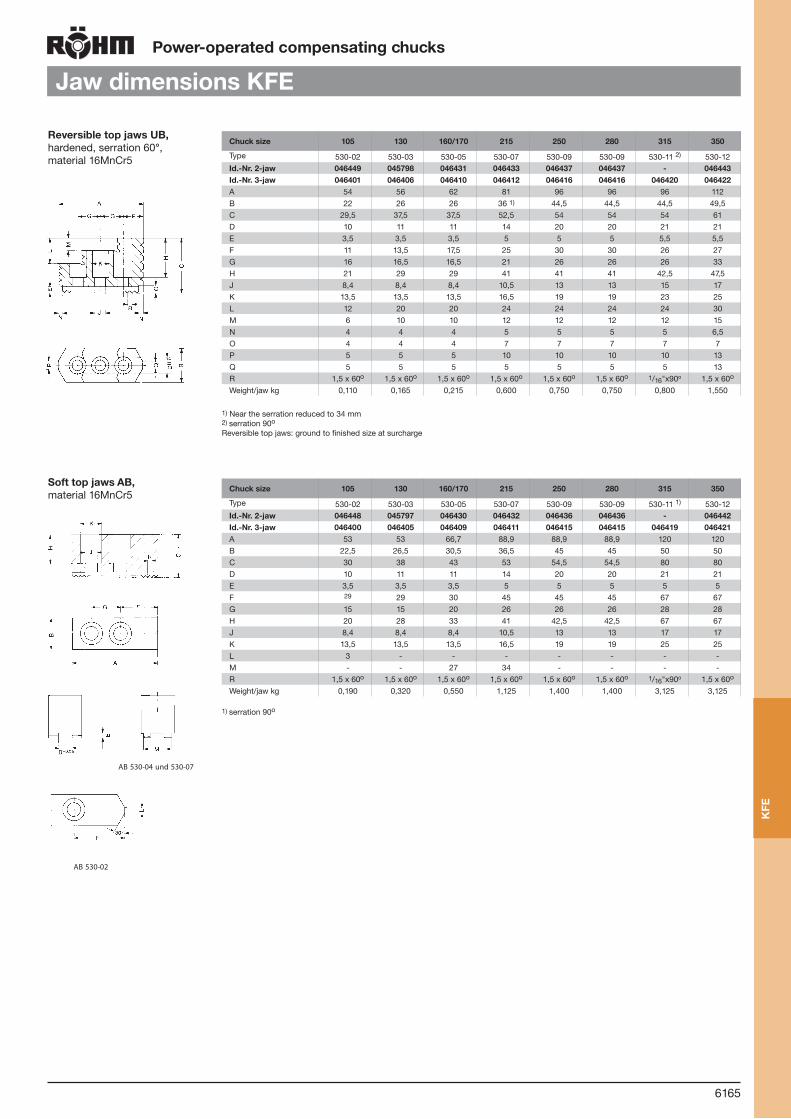
6165
Power-operated compensating chucks
Reversible top jaws UB, hardened, serration 60°,material 16MnCr5
Jaw dimensions KFE
Soft top jaws AB, material 16MnCr5
AB 530-02AB 530-04 und 530-07
AB 530-02AB 530-04 und 530-07
Chuck size 105 130 160/170 215 250 280 315 350
Type 530-02 530-03 530-05 530-07 530-09 530-09 530-11 2) 530-12Id.-Nr. 2-jaw 046449 045798 046431 046433 046437 046437 - 046443Id.-Nr. 3-jaw 046401 046406 046410 046412 046416 046416 046420 046422A 54 56 62 81 96 96 96 112B 22 26 26 36 1) 44,5 44,5 44,5 49,5C 29,5 37,5 37,5 52,5 54 54 54 61D 10 11 11 14 20 20 21 21E 3,5 3,5 3,5 5 5 5 5,5 5,5F 11 13,5 17,5 25 30 30 26 27G 16 16,5 16,5 21 26 26 26 33H 21 29 29 41 41 41 42,5 47,5J 8,4 8,4 8,4 10,5 13 13 15 17K 13,5 13,5 13,5 16,5 19 19 23 25L 12 20 20 24 24 24 24 30M 6 10 10 12 12 12 12 15N 4 4 4 5 5 5 5 6,5O 4 4 4 7 7 7 7 7P 5 5 5 10 10 10 10 13Q 5 5 5 5 5 5 5 13R 1,5 x 60o 1,5 x 60o 1,5 x 60o 1,5 x 60o 1,5 x 60o 1,5 x 60o 1/16"x90o 1,5 x 60o
Weight/jaw kg 0,110 0,165 0,215 0,600 0,750 0,750 0,800 1,550
1) Near the serration reduced to 34 mm2) serration 90o Reversible top jaws: ground to finished size at surcharge
Chuck size 105 130 160/170 215 250 280 315 350
Type 530-02 530-03 530-05 530-07 530-09 530-09 530-11 1) 530-12Id.-Nr. 2-jaw 046448 045797 046430 046432 046436 046436 - 046442Id.-Nr. 3-jaw 046400 046405 046409 046411 046415 046415 046419 046421A 53 53 66,7 88,9 88,9 88,9 120 120B 22,5 26,5 30,5 36,5 45 45 50 50C 30 38 43 53 54,5 54,5 80 80D 10 11 11 14 20 20 21 21E 3,5 3,5 3,5 5 5 5 5 5F 29 29 30 45 45 45 67 67G 15 15 20 26 26 26 28 28H 20 28 33 41 42,5 42,5 67 67J 8,4 8,4 8,4 10,5 13 13 17 17K 13,5 13,5 13,5 16,5 19 19 25 25L 3 - - - - - - -M - - 27 34 - - - -R 1,5 x 60o 1,5 x 60o 1,5 x 60o 1,5 x 60o 1,5 x 60o 1,5 x 60o 1/16"x90o 1,5 x 60o
Weight/jaw kg 0,190 0,320 0,550 1,125 1,400 1,400 3,125 3,125
AB 530-02AB 530-04 und 530-07
1) serration 90o
KFE

6166
Power-operated combination chucks
KKHFR
Components KKHFR1. Body 2. Cover 3. Clamping jaw 4. Face driver 5. Center 6. Retractable jaw 7. Piston
Com
bina
tion
chuc
k K
KH
FR
7
6
3
5
4
2
1
With retractable jaws and face driver
Ideally suited for the complete machining of workpieces
For the finishing operation, the jaws are retracted, the workpiece is moved by the face driver
Outside diameter can be finished on the full length of the shaft
Large workpiece diameter range
Easy change of jaws and face driver according to clamp-ing diameter
The chuck is actuated by means of the hydraulic dual piston cylinder if a power-operated face driver with rigid center is used or by means of the hydraulic closed center cylinder with extra long stroke if the face driver features a spring-loaded center.
The chuck can be centrally lubricated via these cylinders with additional distributors.
Used in conjunction with RÖHM actuating cylinders with safety device SZS, OVS, LHS-L, LVS, EHS and EVS the power chucks KKHFR meet the requirements of the Ger-man Employers’ Insurance Association
KKHFR chuck styles with compensating jaws are avail-able on request.
Technical features:

6167
Power-operated combination chucks
KKHFR
from stock 4 - 6 weeks ▲ on request
Tool group C 15Type 514 Power-operated combinated chucks KKHFR, with retractable jaws, with guide wedge, with central lubricationShort taper mount for ISO 702-1 (DIN 55026)
Item no. 427601 ▲ 428786 ▲ 428222 ▲ 425896 ▲ 427016 ▲ 425642 ▲ 427550 ▲
Size 160 200 230 250 300 400 450
Short-taper 6/55026 6/55026 8/55026 8/55026 11/55026 11/55026 15/55026
A 165 205 230 250 300 400 450
B 170 200 233 225 244 285 325
C 204 231 278 266 292 335 395
D min. 175 203 235 226 251 293 358
D мммм 213 243 290 278 306 348 410
E 106,375 106,375 139,719 139,719 196,869 196,869 285,775
G 133,4 133,4 171,4 171,4 235 235 330,2
H 3 x M 12 3 x M 12 3 x M 16 3 x M 16 6 x M 20 6 x M 20 6 x M 24
J 58 58 58,5 74 74 84 100
K min. 138 126 108 121 66 160 61
K max. 195 191 186 199 141 242 136
L M 32 x 1,5 M 36 x 1,5 M 30 x 1,5 M 40 x 1,5 M 40 x 1,5 M 40 x 1,5 M 40 x 1,5
N 38 40 55 52 55 55 52
Maximum draw bar pull kN 26 38 45 75 80 78 70
Max. total clamping force approx. kN 37 65 75 100 120 130 120
Max. admissible speed min-1 3500 4000 4000 3500 2500 1500 1500
Moment of inertia J kgm2 0,076 0,19 0,42 0,79 1,35 4,9 7,9
Weight without jaws approx. kg 25 48 68 85 120 248 430
Matching cylinder OVUSHHD 105/60 58/10 105/60 65/15 120/80 78/10 160/80 78/10 160/80 80/10 160/80 80/10 160/80 75/10
Clamping capacity Ø 18-60 18-80 20-110 25-110 40-140 90-230 190-300
Face driver Ø 12-30 12-70 12-90 12-100 30-130 80-150 100-210
Power-operated combination chucks in special design on request
Com
bina
tion
chuc
k K
KH
FR

6168
Power operated indexing chucks
Overview
Hydraulically operated indexing chuck with angle correction
The correction pistons enable additional indexing movements of up to approx. 5°
Power operated indexing chucks
central chucking
Suitable for workpieces such as forgings and castings which require greater concentric compensation for diameter tolerances when chuck-ing
Hydraulically operated ring indexing chuck
3 jaws centrically clamping and 3 jaws clamping with compensation
The chucking inserts can be equipped with several chucking points in order to prevent deformation of the workpiece
Ideally suited for machining large bells 7“ and more
Further information:
http://www.roehm.biz/energiesektor/
Hydraulically operated indexing chuck
For machining workpieces with intersecting axes
HSF from page 6169
HSFK on request
KSFZ on request
HSFZ on request
Inde
chu
cks

6169
Power operated indexing chucks
Hydraulically operated indexing chuck HSF
The fully automatic operating sequence through the indexing positions with the machine spindle runningmeans that these chucks are very successful in rationalising processes on relatively simple CNC lathes.The degree of rationalisation can be boosted still further by fitting an automatic workpiece handling system.
An oil distributor or a chucking cylinder is required for operating the indexing chuck. A control block integratedin the machine’s hydraulic system is used for activating the chuck. Alternatively, a separate hydraulic power unitcan be linked up to the machine electronically for use with existing machines.
Inde
chu
cks
HS
F
For machining workpieces with intersecting axes
Indexing axis aligned at 90° to axis of rotation
Workpieces with intersecting axes can be machined in one chucking operation
Oil distributor or a chucking cylinder is required for operating
Equipped with one movable clamping jaw and one swivelling console jaw
Supply via oil distributor at the end of the spindle via 5 respectively 6 hydraulic connections
Used in conjunction with RÖHM actuating cylinders with safety device SZS, OVS, LHS-L, LVS, EHS and EVS the power chucks HSF meet the requirements of the German Employers’ Insurance Association
Technical features:

6170
Power operated indexing chucks
Hydraulically operated indexing chuck HSF
from stock 4 - 6 weeks ▲ on request
Tool group C 15Type 519-00 Hydraulically operated indexing chuck HSFFor machining workpieces with intersecting axes
Item no. 413172 ▲ 413173 ▲ 413174 ▲ 413175 ▲ 413176 ▲ 413177 ▲ 413178 ▲ 413179 ▲
Size 200 230 250 315 400 500 630 800
A 200 230 250 315 400 500 630 800
B min. 30 40 32 57 92,5 120 160 220
B max. 44 54 49 80 119,5 154 205 275
C 157 175 195 245 280 328 405 460
DH6 185 185 210 220 300 380 380 380
E 5 6 6 6 6 6 8 8
F 104,8 133,4 133,4 171,4 235 330,2 330,2 330,2
G M 10 M 12 M 12 M 16 M 20 M 24 M 24 M 24
H 16 20 22 25 30 35 35 40
J 50 55 70 85 100 115 125 145
Wedge stroke K 14 14 17 23 27 34 45 55
L 32 45 41 62 104 135 192 260
M 4 4 4 5 5 6 6 6
N 58 58 58 72 92 92 92 110
Q 32 35 45 50 60 68 75 90
R 80 90 105 135 160 200 260 300
S 170 195 210 260 340 410 530 620
T 125 140 155 195 220 260 330 375
α 30° 30° 30° 30° 30° 30° 60° 60°
Max. operating pressure bar 45 45 45 45 45 45 45 45
Max. clamping pressure bar 60 60 60 60 60 60 60 60
Max. total clamping force at 60 bar approx. kN
23 28 46 68 94 122 147 197
Maximum admissible speed1) min-1 4200 3700 3600 2600 2000 1500 1100 550
Moment of inertia J kgm2 0,15 0,31 0,45 1,36 3,80 10 30,5 66
Weight without jaw inserts approx. kg
27 42 52 95 150 250 450 580
Matching chuck adaptor plate, oil distributors and hydraulic control units on request1) Depending on mass and center of gravity of the clamping inserts
T
E
H
G
C
BL
N
K
A D F
J
R Q
Inde
chu
ck H
SF

6171
Power operated radial indexing chucks
KTF / HTF
Hydraulically operated radial indexing chuck
Indexing via two hydraulically operated racks
Clamping via integrated hydraulic piston
Indexing angle 180°, 4x90°, 5x72°, 6x60°
Power operated radial indexing chuck
Clamping and indexing via rotary piston cylinder with 4-fold oil distributor in combination with cardan rod
Indexing angle 180°
Eccentric dimensions constant or adjustable
KTF on request
HTF on request
Radial indexing chucks are ideally suited for rationally machining workpieces with one centric and one eccentric center of rotation (or several eccentric centers of rotation), like e.g. crank shafts, housings or pistons. Due to the indexing of the chuck, the center which is beeing machined is lying in the axis of rotation. Therefore workpieces can be machined without reclamping.
Application area
Pow
er o
pera
ted
inde
chu
cks

6172
Quick Change System
RMSFor mandrels
For face drivers
For power chuckswith direct mounting DIN 55026
with centre DIN 6353
Type KFS 254-00
Type KFS 256-00
Type 681-85
Typ KFS 254-00
Typ KFR 256-00
Typ 681-85
A tool carrier with an integrated force-transmitting collet is mounted on a lathe spindle. The chucking tool proper is secured to his tool carrier by means of quick-acting bolts with one half turn of the wrench.The collet and the chucking tool are actuated by means of a safety cylinder at the spindle end with no need for any additional equipment.
Description of function:The tool carrier with integrated collet and draw tube adapter with draw tube connection is secured to the spindle by means of 3 mounting screws.Contact with the adapter of the chucking tool (e.g. mandrel, face driver, power chuck) closes the collet and connects the draw rod with the actuating element (e.g. piston).The chucking tool is secured manually by means of 3 quick-acting bolts requiring no more than one half turn of the wrench each. The bayonet nut is locked against rotation by a system of parallel pins.The reliability of this Type of fastening is equivalent to that of conventional systems.The chucking tool is removed by reversing the above procedure.
Function
RM
S
Short taper mounting for accurate holding and posi-tioning of chucking tool
Change accurate to within 0,005 mm
Time required per change approx. 30 seconds
Convenient handling
Chucking tool locked by 3 bayonet nuts and a collet for connection to the draw tube adapter
Bayonet nuts locked against rotation
High chucking accuracy
Actuating cylinder requires no additional equipment
Travel monitored at actuating cylinder
Central lubrication and/or pneumatic seating check on request
Used in conjunction with RÖHM actuating cylinders with safety device SZS, OVS, LHS-L, LVS, EHS and EVS the RMS manual chucking tool quick change system meet the requirements of the German Em-ployers’ Insurance Association
Technical features:

6173
with direct mounting DIN 55026
with centre DIN 6353
Type 681-85
Quick Change System
RMS
RM
S
25155-k006-155 26.04.2007 10:54 Uhr Seite 6155
Draw tube adaptor
Collet
Mounting screw
Tool carrier
Chucking tool
Adapter
Quick-acting bolt
Spindle
Like the automatic and semi-automatic chucking tool change systems, the-manual change system allows a rising number of variants in diminishing batch sizes to be produced more economi-cally. A standard cylinder can be used for actuation with no need for any additional equipment.
Not only mandrels, whose size must be changed frequently for reasons inherent in the design, but also chucking tools such as face drivers or power chucks can be interchanged both quickly and safely.
Move actuating cylinder into forward position
Back off quick-acting bolt 1/2 turn
Remove chucking tool
Design
Changing the chucking tool
Convenient chucking tool changes without the slightest sacrifice to safety.
One and the same tool carrier can be used for virtually any Type of mandrel, face driver or power chuck as long as the connections are identical.
For manual chucking tool change
Collet openQuick-acting bolt backed off 1/2 turn

6174
RMS
RM
S
Größe 8 10 12 14 16 18 20
für Aufnahme DIN 55026 KK5 KK6 KK8
Id.-Nr. 156682 156683 156684 156685 156686 156687 156688
The bolt must alays be matched to the chucking tool / adapter plate to be fastened.e.g. RMS-12SS Item no.156684, L=20,44mm, Ø =12,5mm
When ordering please state!
RMS A B F G H I L
08 14 8,5 8,5 11 7,25 M5 **10 17 10,5 10 13 8,6 M6 **12 19 12,5 13 17,5 10,3 M8 **14 22 14,5 13 17,5 11,4 M8 **16 25 16,5 17 22 13,6 M10 **18 28 18,5 17 22 14,4 M10 **20 31 20,5 17 22 16,2 M10 **
** Dimension ”L” depends on the chucking tool used, but should at least be as long as dimension “B”.
RMS A B C D E F G H I K R
08 19 12,5 19 7 16,1 18,6 7,5 7,25 5,5 2 310 22,5 15 24 7,8 19,1 23 8 8,6 6,5 3 312 25,5 16,7 28,5 10,7 25,2 25,5 11 10,3 8,5 3 414 29,5 18,8 30 10,9 26,4 29,5 11 11,4 8,5 4 416 34 22 34 11,1 29,2 34,2 11 13,6 10,5 4 418 38,5 26 38,5 12,8 30,7 39,8 13 14,4 10,5 4 420 41 28 42 14,1 33,6 16,2 14 16,2 10,5 4 4
Quick Change System
Mating dimensions
6159
Tool carrierWith mounting to ISO 702-1 (DIN 55026). No adapter for direct mounting. Just order quick acting bolt assy. Rework on chucking tool neccessary.
for: - Face drivers - Power chucks (on request)
for: - Power chucks
M1
S1
S1 S2
S1 S3
M
M1
S1
S1 S2
S1 S3
M
With centre mounting to DIN 6353 With mounting to ISO 702-1 (DIN 55026) (on request)
Machine side M1 (DIN 55026) A6 A8
Chucking tool side S2Ø 140 Ø 170 Ø 220
156670 156674 156675 156676
156671 156677 156678 156679Chu
ckin
g to
ol s
lide
S1
ISO
702
-1(D
IN 5
5026
)
A6
A8
I 0,1Fmin
H 0,1
A-A B-B C-C A B C
A B C
M
A
GF
L**
B
Mitte
I
H 0,1
Kx45 o C
E 0,05
D G
BA
R 0,1
Mitte
H 0,1
H 0,1
L
Centre
Centre
Mating dimensions for quick-acting bolt on adapter plate / Rework on chucking tool
Mating dimensions for bayonet nut in tool carrier
Quick acting bolt assy RMS-..SS
Adapter plate
Matching Adapteron request
M1
S1
S1 S2
S1 S3
M
With central lubrication /pneumatic seating check(on request)
Tool carrier
Adapter plate
Adapter
Quick acting bolt assy

6175
Quick Change System
RMS
Further short-taper combinations on request!
Dimensions Tool carrier assy RMS-.. GA, compl. short taper DIN 55026
K
D S N Q
P O
G3x120 o
3x120 o
x1x1
R B
H
7o 7’ 30’’
7o 7’ 30’’
CD F A
T
Typ 461 A5/A5 A6/A6 A8/A8Id.-Nr. 166946 156670 156671
A 135 170 220B 45 52 63,5C 58 66 79,5
D+0,015 82,563 (KK5) 106,375 (KK6) 139,719 (KK8)F 104,8 133,4 171,4G M 10 M 12 M 16H 16 17 24
K max. 20 27 34N 30 36,5 51
O / O min. 10/5 8/3 8/1O max. 30 35 42
P 30 30 30Q M 16 M 20 M 24R 59 89 132S 52 69 88T 5 5 7
max. oper. power 15 kN 33 kN 52 kNmax. min-1 5000 6000 5000
Tool carrier A6 s2 = Ø 140 s2 = Ø 170 s2 = Ø 220
Id.-Nr. 156674 156675** 156676
F2 Ø 104,8 Ø 133,4 Ø 171,4
F3 M 10, 3x120o M 16, 3x120o
A 170 210 250
H 35 16 37
E 75 75 80
Adapter plate assy RMS-./. FShort taper ISO 702-1 (DIN 55026) / Centre mounting DIN 6353
Item No.: I.e. RMS-A6/170 F, Item No. 156675Short taper ISO 702-1 (DIN 55026) / Short taper ISO 702-1 (DIN 55026) (on request)** When ordering, please state:L = ... mm; Ø = ... mm
L**
F1 D1
M
H
F3E
F2
S2 A
**
3x120o
3x120o
Tool carrier A8 s2 = Ø 140 s2 = Ø 170 s2 = Ø 220
Id.-Nr. 156677 156678 156679**
F2 Ø 104,8 Ø 133,4 Ø 171,4
F3 M 10, 3x120o M 12, 3x120o
A 220 220 250
H 42 42 18
E 80 101 101
RMS
RM
S

6176
Notes
Not
es

6177
OverviewCylinders
OVS frompage6178
Oil-operated cylinder without through-holeOptions: with inductive stroke monitoring or inductive proximity switch
EVS frompage6182
Electrical cylinder without through-hole
Safe and energy efficient clamping
Reducing energy, costs and workpiece changing times
LVS frompage6184
Air-operated cylinder without through-hole
SZS frompage6186
Oil-operated cylinder with through-hole
Options: 45 bar and 80 bar design, inductive stroke monitoring
EHS frompage6190
Electrical cylinder with through-hole
Safe and energy efficient clamping
Reducing energy, costs and workpiece changing times
LHS-L frompage6192
Air-operated cylinder with through-hole
Options: inductive proximity switch
OVUSHH frompage6194
Oil-operated double piston cylinder
For power chucks with auxiliary functions (ejectors, retractable stops)
Cyl
inde
rs

6178
OVS
Oil-
oper
ated
cy
linde
rsO
VS
Oil operated actuating cylinders without through-hole OVS available as basic model in steel design, also available with following options:
StrokecontrolwithF90:
High resolution and accuracy
Minimal temperature drift Contactless Teaching mode
Inductive principle of operation
Inductive stroke montoring (limit switch notincluded in scope of delivery)
Linear stroke monitoring F 90 (F 90 system included in scope of delivery)
With high and low pressure chucking the change-over of the safety valve is guaranteed when: chucking pressure : releasing pressure =< 5,5 : 1 (Size 85 - 130)chucking pressure : releasing pressure =< 3,8 : 1 (Size 150 - 200)
Oil-operatedcylinderwithoutthrough-hole
Up to 80 bar
Safety device
Stroke monitor
Minimum leakage
Compact design, low mass moment of inertia
Suitable for horizontal or vertical installation
Additional connection for auxiliary functions, such as pneumatic contact monitoring, coolant supply, central lubrication etc., further rotating unions depending on operating condition on request
Technicalfeatures:
Safety device
Distributor housing Piston housing Cylinder cover
Piston
Lead oil drain

6179
Oil-operatedcylinderwithoutthrough-hole
OVS
from stock 4 - 6 weeks ▲ on request
Tool group C 15Type 453-05 Oil-operated actuating cylinders without through-hole OVSBasicmodel, with safetydevice, upto80bar - Steeldesignfor high speeds, mounting from the rear, with central passage
With high and low pressure chucking the change-over of the safety valve is guaranteed when chucking pressure : releasing pressure ≤ 5,5 : 1 (size 85-130) / chucking pressure : releasing pressure ≤ 3,8 : 1 (size 150-200)
Itemno. 438261 438262 438263 438264 438265
Size 85 105 130 150 200
Design steel steel steel steel steel
A 120 140 165 193 245
A1 135 155 180 208 260
B 120 120 120 147 164
C 85 105 130 150 200
D stroke 32 32 32 45 50
Eh6 50 50 80 95 125
F1 80 80 105 145 170
F2 100 120 145 170 220
G1 M10 (3x120°) M10 (4x90°) M12 (4x90°) M16 (4x90°) M16 (6x60°)
G2 M8 (6x60°) M8 (6x60°) M8 (8x45°) M10 (8x45°) M12 (8x45°)
H1 15 15 18 24 29
H2 13 13 13 14 19
J 30 32 42 50 70
K max. 88 88 82 98 108
K min. 56 56 50 53 58
L M 22 x 1,5 M 22 x 1,5 M 30 x 2 M 36 x 2 M 48 x 2
L1 19 19 26 30 42
L2 23 23 32 38 50
M 70 70 88 105 125
Min. reach of draw bar N 43 43 65 78 90
Q max. 40 40 40 53 58
Q min. 8 8 8 8 8
S max. 252 247 247 307 329
S min. 220 215 215 262 279
T max. 202 202 202 250 272
T min. 170 170 170 205 222
Piston area A cm2 47,1 77 116,8 160,8 298,2
Piston area B cm2 49,7 78,6 118,9 157,1 275,7
Eff. draw bar pull (F=60 bar) kN 29,50 47 71,3 94 165,4
Max. admissible speed min-1 8000 8000 5000 5500 4500
Volume for full double stroke l 0,31 0,5 0,775 1,43 2,87
Moment of inertia J kgm2 0,018 0,03 0,066 0,142 0,36
Weight approx. kg 10 12,7 17,7 31,4 49
Suitable connecting flange for Duoflow Rotating Unions
1022186 1022186 1022187 1022187 1022187
T max/min.
Oil-
oper
ated
cy
linde
rsO
VS
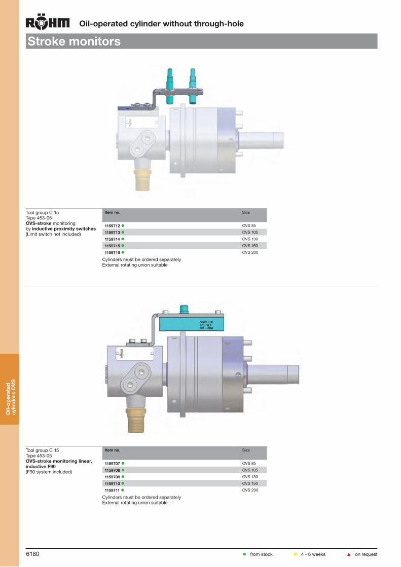
6180
Oil-operatedcylinderwithoutthrough-hole
Strokemonitors
from stock 4 - 6 weeks ▲ on request
Tool group C 15Type 453-05 OVS-stroke monitoring by inductiveproximityswitches(Limit switch not included)
Itemno. Size
1159712 OVS 85
1159713 OVS 105
1159714 OVS 130
1159715 OVS 150
1159716 OVS 200
Cylinders must be ordered separatelyExternal rotating union suitable
Tool group C 15Type 453-05 OVS-strokemonitoringlinear,inductiveF90(F90 system included)
Itemno. Size
1159707 OVS 85
1159708 OVS 105
1159709 OVS 130
1159710 OVS 150
1159711 OVS 200
Cylinders must be ordered separatelyExternal rotating union suitable
Oil-
oper
ated
cy
linde
rsO
VS

6181
Oil-operatedcylinderwithoutthrough-hole
Accessories
from stock 4 - 6 weeks ▲ on request
Tool group C 15Typ 4000-Y 2-PassageRotatingUnions
Itemno. Inner Passage Outer Passage
Connection Media Max. Pressure Connection Media Max. Pressure
1118078 1/4 Hydraulic Oil 100 1/4 Hydraulic Oil 30
1118079 1/4 Hydraulic Oil 70 1/4 Air 10
1118080 1/4 Coolant 70 1/4 Air 10
1118081 3/8 Air 10 1/8 Air 10
1118082 1/4 Air 10 1/4 Hydraulic Oil 40
1118083 1/4 Air 10 1/4 Coolant 40
Optional: 1-Passage Rotating Union for OVS Size 85-105 Item No.: 600599Optional: 1-Passage Rotating Union for OVS Size 130-150 Item No.: 326372Optional: 1-Passage Rotating Union for OVS Size 200 Item No.: 611172Connecting Flange complete for 2-Passage Rotating Union Size 85-105 Item No.: 1022186Connecting Flange complete for 2-Passage Rotating Union Size 130-200 Item No.: 1022187
Oil-
oper
ated
cy
linde
rsO
VS
Overviewpowerchucks-cylindersOVSSize 85 105 130 150 200
3-and 4-jaw chucks
KFD 85-125+140 130 160 160-250 200-1600
KFL 250 250-400 315-600
KFD-G 125+160 200 250 315 400
KFD-HS 110 110-175 200 250 315-500
DURO-NC/SE 140 160 175+200 250-630
KFD-HE 160 160+200 250 315+400
KFM 130 160 215 280+350
KFG 160 215 280+350
KFE 170 215 280+350
LVSSize 85 105 130 150 200 250 300 350
3-and 4-jaw chucks
KFD 85-125+140 85-125+140 130 160 200+250 250-315
KFL 250 315+400 315-600
DURO-NC/SE 160 200+250 250
KFD-HE 160 200+250 300+400
KFM 130 160 215 280 350
KFG 160 215+280 350
KFE 170 215+280 350
OVSSize 85 105 130 150 200
2-jaw chucks
KFD 125-140 130+160 160+200 160-250 200-630
KFD-G 125+160 200 250 315 400
KFM 130 160 215 280+350
KFG 160 215 280+350
KFE 170 215 280+350
LVSSize 105 130 150 200 250 300 350
2-jaw chucks
KFD 125 125+140 130 130+160 200 250+315 250-500
KFD-G 125 160 200 250 250+315 315+400
KFM 130 160 215 280 350
KFG 160 215-350
KFE 170+215 280 350

KFD
6182
Output of hydraulic unit 1,5 kW
Power dissipation from cylinders: 0,9 kW
Total output of an oil-operated clamping cylinder: 2,4 kW
Energy consumption per year: 14.400 kWh
EVSElectricalcylinderwithoutthrough-hole
Ele
ctri
calc
ylin
der
EVS
Electrical cylinder EVS for actuating chucks without through-hole. Especially suitable for safety and energy efficent clamping of work-pieces on lathes and grinding machines.
With through hole Ø 8mm for coolant or other media.Max. clamping force: 50 kN
Scopeofdelivery:Compact electrical cylinder including- Servodrive with a load of 1,0 kW- Complete sensor technology- Mounting plate- Control modul for easy connection by a bus-system into the numerical control- Drive controller- Software for control modul- Lines from control modul to electrical cylinder
Sample calculation for energy savings with an electrical cylinder:
Energyconsumptionofanoil-operatedclampingcylinder
The above assumptions have been based on a standard manufacturing process in three-shift operation and may vary depending on the application involved. Where greater efficiency is achieved in the processing (e.g. by getting the best possible match between the cylinder and the process, or through shorter lift times), even more energy can be saved by indirect means.
Energyconsumptionofanelectricalcylinder:
Total output of the EHS 0,1 kW
Energy consumption per year: 600 kWh
Energy saving potential per year: 13.800 kWh

6183
Electricalcylinderwithoutthrough-hole
EVS
Tool group C 15Type 444-01 Electricalcylinderwithoutthrough-hole EVSwiththrough-holeØ8mmforcoolantorothermedia
Itemno. 1203050▲
Max. pull force kN 50
Total stroke 32
External Ø A 183
Ø B 154,5
Ch6 110
Through-hole D 8
E 43
G M22x1,5
Stroke min/max H 71 / 103
I 33,5
J 182
K 191,5
L 271
M 225
N 105
O 55
P M10x1
Speed max. min-1 6000
Weight approx. kg 32,8
Rotierende Masse kg 23,7
Moment of inertia kg/m2 0,076
Ele
ctri
calc
ylin
der
EVS
from stock 4 - 6 weeks ▲ on request

6184
LVS
Air-
oper
ated
cyl
inde
rLV
S
Air-operatedcylinderwithoutthrough-hole
Up to 10 bar
Air operated cylinder up to max. 10 bar, 2 bar
In case of a sudden decrease of pressure with cylinders LVS safety devices guarantee that the clamping pressure in the piston area will be maintained
Stroke control by means of a single touch limit switch, inductive stroke monitoring, F 90 stroke monitoring system, attachment on the machine side
The cylinders can also be actuated when rota-ting
The max. admissible speed can be run continuously (100 % ED).
On request: with central media feed-through
Technicalfeatures:

6185
Air-operatedcylinderwithoutthrough-hole
LVSupto10bar
from stock 4 - 6 weeks ▲ on request
Tool group C 15Type 555-60 LVS Air-operated cylinders without through-holewith safety device and stroke control
Itemno. 096553 096554 096555 096556 096557 096558 096559 096560
Size 85 105 130 150 200 250 300 350
A 110 130 155 180 240 287 337 387
B 115 115 117 128 125 125 125 148
C 85 105 130 150 200 250 300 350
D stroke 32 32 32 32 32 32 32 45
Eh6 50 50 80 95 95 125 125 125
F 80 80 105 145 145 170 170 170
G 3 x M 10 3 x M 10 3x M 12 4 x M 16 4 x M 16 6 x M 16 6 x M 16 6 x M 16
H 23 23 27 35 35 35 35 35
J 25 25 25 25 35 35 35 35
K max. 62 88 79 74 87 87 82 82
K min. 30 56 47 42 55 55 50 37
L M 12 M 12 M 16 M 16 M 24 M 24 M 24 M 24
M 18 18 24 24 36 36 36 36
Q max. 44 44 44 44 44 44 44 57
Q min. 12 12 12 12 12 12 12 12
S max. 231 231 233 244 241 241 241 277
S min. 199 199 201 212 209 209 209 232
Piston area A cm2 49,7 79,5 125,7 169,6 307,1 483,8 699,8 955
Piston area B cm2 51,8 81,7 127,8 171,8 304,5 481,5 697,2 952,5
Eff. draw bar pull (F=6 bar) kN 3 4,80 7,50 10 18 28,50 41,50 56,50
Max. admissible speed min-1 5000 5000 5000 5000 4500 4000 3200 3200
Air consumption for full double stroke at 6 bar NL
2,8 4,6 6,5 7,5 12,5 18 26 50
Moment of inertia J kgm2 0,007 0,009 0,03 0,06 0,09 0,10 0,237 0,45
Weight approx. kg 5,3 6,5 9 12,5 19,5 23 28,5 32,5A
ir-op
erat
edc
ylin
der
LVS

6186
SZS
Oil-
oper
ated
cyl
inde
rS
ZS
Safety device
Stroke monitor
Pressure control valve
Coolant collector
Low energy dissipation
Mounting from the rear
The piston can also be actuated when the cylinder is rotating
SpecialsalientfeaturesSZS45bar: SpecialsalientfeaturesSZS80bar:
RÖHM actuating cylinders meet the requirements laid down by the German Employer’s Liability Insurance Association by their safety device and stroke control. For their operation we recommend to use hydraulic oil HLP 32 DIN 51525 (32 Centistokes at 40o C or 100o F).
OptionalstrokemonitoringwithF90:
High resolution
Minimal temperature drift
Contactless
Teachable
Inductive effect principle
Oil-operatedcylinderwiththrough-hole
Short design, low mass Stroke monitor beyond coolant collector
Technicalfeatures:
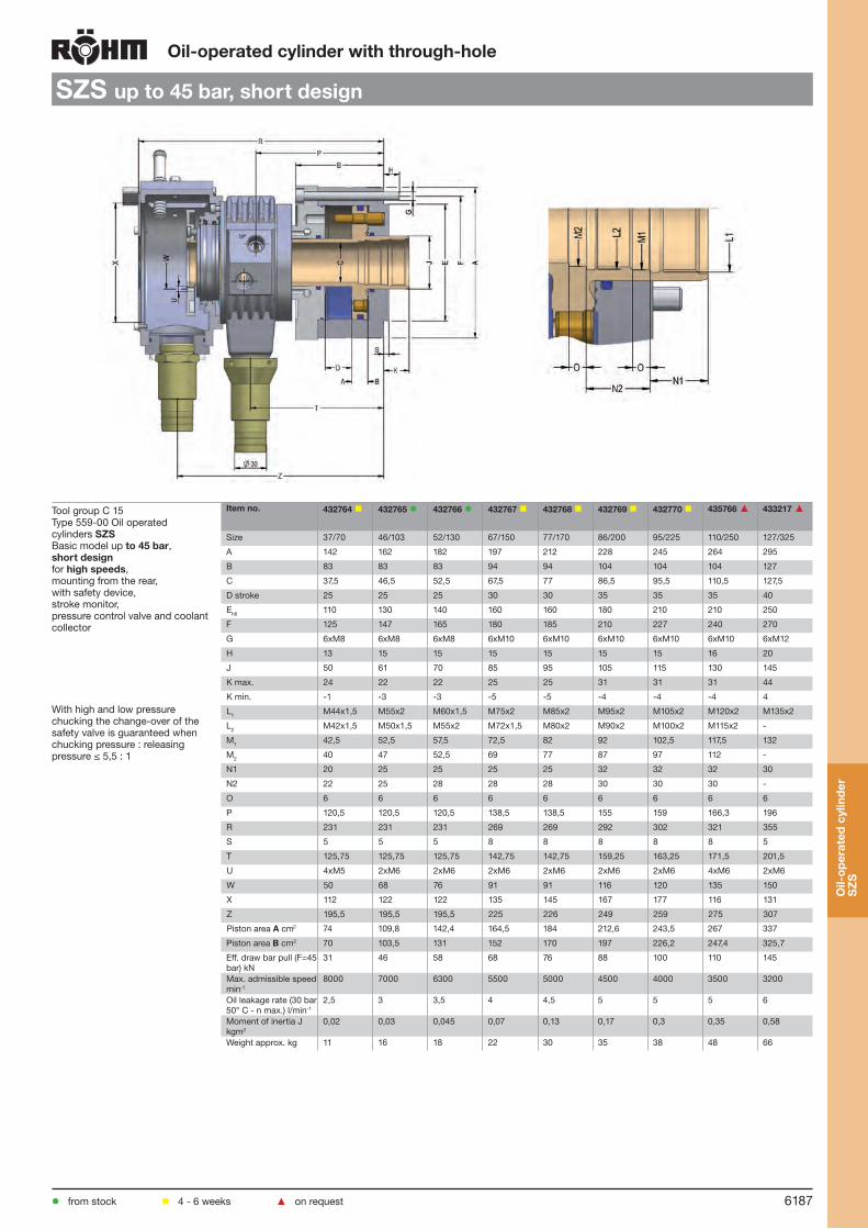
6187
Oil-operatedcylinderwiththrough-hole
SZSupto45bar,shortdesign
Tool group C 15Type 559-00 Oil operated cylinders SZS Basic model up to45bar, shortdesignfor highspeeds, mounting from the rear, with safety device, stroke monitor, pressure control valve and coolant collector
With high and low pressure chucking the change-over of the safety valve is guaranteed when chucking pressure : releasing pressure ≤ 5,5 : 1
Itemno. 432764 432765 432766 432767 432768 432769 432770 435766▲ 433217▲
Size 37/70 46/103 52/130 67/150 77/170 86/200 95/225 110/250 127/325
A 142 162 182 197 212 228 245 264 295
B 83 83 83 94 94 104 104 104 127
C 37,5 46,5 52,5 67,5 77 86,5 95,5 110,5 127,5
D stroke 25 25 25 30 30 35 35 35 40
Eh6 110 130 140 160 160 180 210 210 250
F 125 147 165 180 185 210 227 240 270
G 6xM8 6xM8 6xM8 6xM10 6xM10 6xM10 6xM10 6xM10 6xM12
H 13 15 15 15 15 15 15 16 20
J 50 61 70 85 95 105 115 130 145
K max. 24 22 22 25 25 31 31 31 44
K min. -1 -3 -3 -5 -5 -4 -4 -4 4
L1 M44x1,5 M55x2 M60x1,5 M75x2 M85x2 M95x2 M105x2 M120x2 M135x2
L2 M42x1,5 M50x1,5 M55x2 M72x1,5 M80x2 M90x2 M100x2 M115x2 -
M1 42,5 52,5 57,5 72,5 82 92 102,5 117,5 132
M2 40 47 52,5 69 77 87 97 112 -
N1 20 25 25 25 25 32 32 32 30
N2 22 25 28 28 28 30 30 30 -
O 6 6 6 6 6 6 6 6 6
P 120,5 120,5 120,5 138,5 138,5 155 159 166,3 196
R 231 231 231 269 269 292 302 321 355
S 5 5 5 8 8 8 8 8 5
T 125,75 125,75 125,75 142,75 142,75 159,25 163,25 171,5 201,5
U 4xM5 2xM6 2xM6 2xM6 2xM6 2xM6 2xM6 4xM6 2xM6
W 50 68 76 91 91 116 120 135 150
X 112 122 122 135 145 167 177 116 131
Z 195,5 195,5 195,5 225 226 249 259 275 307
Piston area A cm2 74 109,8 142,4 164,5 184 212,6 243,5 267 337
Piston area B cm2 70 103,5 131 152 170 197 226,2 247,4 325,7
Eff. draw bar pull (F=45 bar) kN
31 46 58 68 76 88 100 110 145
Max. admissible speed min-1
8000 7000 6300 5500 5000 4500 4000 3500 3200
Oil leakage rate (30 bar 50° C - n max.) l/min-1
2,5 3 3,5 4 4,5 5 5 5 6
Moment of inertia J kgm2
0,02 0,03 0,045 0,07 0,13 0,17 0,3 0,35 0,58
Weight approx. kg 11 16 18 22 30 35 38 48 66
Oil-
oper
ated
cyl
inde
rS
ZS
from stock 4 - 6 weeks ▲ on request

6188
Oil-operatedcylinderwiththrough-hole
SZSupto80bar
Tool group C 15Type 559-10 Oil operated cylinders SZS Basic model upto80barfor highspeeds, mounting from the rear, with safety device, stroke monitor, pressure control valve and coolant collector
With high and low pressure chucking the change-over of the safety valve is guaranteed when chucking pressure : releasing pressure ≤ 5,5 : 1
Itemno. 432760 432761 432762 432763▲
Size 46/67 67/86 92/110 104/132
A 157 177 203 245
B 94 95 110 135
C 46 67 92 104
D stroke 20 20 35 50
Eh6 120 125 155 180
F 140 160 185 225
G 6xM8 6xM8 6xM10 6xM10
H 12 12 15 15
J 60 85 115 125
K max. 12 12 25 25
K min. -8 -8 -10 -25
L M54x1,5 M74x1,5 M102x1,5 M116x2
M 55 76 103 117
N 30 40 40 40
P 180 185 215 245
R 295 310 355 400
S 5 5 5 5
T 181 187,5 215 250
U 6xM6 6xM6 6xM6 6xM6
W 70 85 115 125
X 160 180 200 210
Z 262 275 310 350
Piston area A cm2 66,7 86,4 110 131
Piston area B cm2 66,7 86,4 110 131
Eff. draw bar pull (F=60 bar) kN 40 51 66 78
Max. admissible speed min-1 8000 6000 4000 3200
Oil leakage rate (60 bar 50° C - n max.) l/min-1
2,5 3 4,0 4,5
Moment of inertia J kgm2 0,048 0,078 0,23 0,35
Weight approx. kg 22 27 50 66
( ) Bracket values: Sizes 85 - 130
Oil-
oper
ated
cyl
inde
r
SZ
S
from stock 4 - 6 weeks ▲ on request

6189
Oil-operatedcylinderwiththrough-hole
Accessories
Tool group Type 594-19longitudialstop
Itemno. For a Ø b c
1106137▲ SZS 37/70 M20x1,5 105 84,5
1106141▲ SZS 46/103 M20x1,5 110 84,5
1106145▲ SZS 52/130 M20x1,5 115 84,5
1091935▲ SZS 67/150 M20x1,5 130 89,5
1106149▲ SZS 77/170 M20x1,5 140 89,5
1106153▲ SZS 86/200 M20x1,5 162 94,5
1106157▲ SZS 95/225 M20x1,5 172 94,5
1106161▲ SZS 110/250 M20x1,5 200 98
1106165▲ SZS 127/325 M20x1,5 230 99,5
Oil-
oper
ated
cyl
inde
r
SZ
S
from stock 4 - 6 weeks ▲ on request

KFD
6190
Electrical cylinder EHS for actuating chucks with through-hole. Especially suitable for clamping bars with an outside diameter of up to 67 mm on lathes and grinding machines.
Max. clamping force: 68 kN
Scopeofdelivery:Compact electrical cylinder- Servodrive with a load of 1,0 kW- Complete sensor technology- Mounting plate- Control modul for easy connection by a bus-system into the numerical control- Drive controller- Software for control modul- Lines from control modul to electrical cylinder
Electricalcylinderwiththrough-hole
EHS
Ele
ctri
calc
ylin
der
EH
S
Output of hydraulic unit 1,5 kW
Power dissipation from cylinders: 0,9 kW
Total output of an oil-operated clamping cylinder: 2,4 kW
Energy consumption per year: 14.400 kWh
Sample calculation for energy savings with an electrical cylinder:
Energyconsumptionofanoil-operatedclampingcylinder
The above assumptions have been based on a standard manufacturing process in three-shift operation and may vary depending on the application involved. Where greater efficiency is achieved in the processing (e.g. by getting the best possible match between the cylinder and the process, or through shorter lift times), even more energy can be saved by indirect means.
Energyconsumptionofanelectricalcylinder:
Total output of the EHS 0,1 kW
Energy consumption per year: 600 kWh
Energy saving potential per year: 13.800 kWh

6191
Electricalcylinderwiththrough-hole
EHS
from stock 4 - 6 weeks ▲ on request
Tool group C 15Type 444-00 Electricalcylinderwiththrough-hole EHS
Itemno. 1190795▲ 1239541▲
Max. pull force kN 50 68
Total stroke 32 32
External Ø A 193 255,5
Ø B 159,3 209,8
Ch6 130 170
Through-hole D 37 67
E 25 25
G M42x1,5 M75x2
Stroke min/max H 52,5 / 84,5 89 / 57
I 33,5 33,5
J 180 180
K 192,6 226,6
L 279,1 318,1
M 230 260
N 125 130
O 55 55
Speed max. min-1 6000 6000
Weight approx. kg 36,9 70
Rotierende Masse kg 26,2 53
Moment of inertia kg/m2 0,107 0,36
Ele
ctri
calc
ylin
der
EH
S

6192
LHS-L
Air-
oper
ated
cyl
inde
rLH
S-L
Air-operatedcylinderwiththrough-hole
Accessories: Connection for supply and drain hoses Specialaccessories:2 inductive proximity switchesPiece/Item no. 381551 (Opener)or 2 inductive proximity switchesPiece/Item no. 202759 (Closer)
Withtandempistononrequest.
In the case of an accidental pressure drop in the feed lines, the safety device maintains the chucking pressu-re in the cylinder.
Stroke monitor
Coolant collector
Short design
Actuation possible during rotation
Due to large through-hole ideally suited for machining of bars
Longitudinal location of workpiece toward the rear (swallowing) part of the workpiece
As a rule through-hole cylinders can only be used for horizontal machining axes.
Technicalfeatures:

6193
Air-operatedcylinderwiththrough-hole
LHS-L
Tool group C 15Type 565-10 Air-operateed cylinders with through-hole LHS-Lwithsafetyvalve, stroke control and coolant collector, housing stationary - 1,5to8bar - can be actuated during rotation
With sizes 26 and 38 the coolant collector is centrally held by means of a holding device at the machine. With high and low pressure chucking the change-over of the safety valve is guaranteed when chucking pressure : releasing pressure ≤ 2 : 1
Itemno. 417310 417311 417312 417313▲
Size 26/190 38/251 42/289 62/438
A 187 215 235 285
B 76 78 109,7 109,7
B1 110 110 147,5 147,5
C 26,2 38,2 42 62
D stroke 20 20 32 32
E-0,01 70 103 103 125
F 105 132 145 170
G 6 x M 8 6 x M 10 8 x M 8 8 x M 10
H 15 20 20 25
J 38 50 57 82
K max. 20 20 20 20
K min. 0 0 -12 -12
L M 32 x 1,25 M 44 x 1,5 M 52 x 1,5 M 70 x 1,5
M 25 30 30 35
N 5 6 6 6
O 160 185 200 250
P 106 118 140 160
Q 197 198 263,7 263,7
R 275 273 337,7 342
S 210 211 283,5 283,5
T 141 140 188 188
U 23 23 28,5 28,5
V 46 52 60 70
W 42 42 51 70
X 130 151 151 161
Y 73,5 84 84 89
Z 233,5 233 297,7 300
a 78 75 74 80
b 77 101 197 217
c 61 76 - -
d 4 x M 6 4 x M 6 - -
e 7,5 7,5 8 8
f max. 22,5 22,5 135 135
f min. 2,5 2,5 167 167
g 62 72 - -
h - - 114,7 114,7
j - - 115 125
Piston area A cm2 189,7 249,1 288,6 438
Piston area B cm2 190,9 251,4 291,3 447
Eff. draw bar pull (F=6 bar) kN 10,47 13,75 15,90 24,40
Max. admissible speed min-1 6500 6500 4000 4000
Volume for full double stroke l 0,762 1 1,9 2,84
Moment of inertia J kgm2 0,03 0,06 0,102 0,24
Weight approx. kg 11,8 16 25,5 36
The air actuating cylinders LVS are available on request
Air-
oper
ated
cyl
inde
rLH
S-L
from stock 4 - 6 weeks ▲ on request
Fastening
Size 26 and 38

6194
OVUSHH
Dou
ble
pist
onc
ylin
der
OVU
SH
H
For power chucks with additional function (ejectors, retractable dead centers, etc.)
With four-way oil distributor
A modular system permits the same basic cylinder to be offered with different strokes and piston areas and desired safety arrangement.
If an additional connector head is attached to this cylinder, a further fluid (coolant, oil, air etc.) can be passed through the cylinder axis.
As special construction: Dual piston cylinder with rotating piston for swivelling movement.
Scope of delivery: Connections for supply and drain hoses (without touch limit switch, without inductive proximity switches).
Technicalfeatures:
Hydraulicoperateddoublepistoncylinders

6195
Hydraulicoperateddoublepistoncylinders
OVUSHH
from stock 4 - 6 weeks ▲ on request
Tool group C 15Type 455-12 Hydraulic double piston cylinders OVUSHHwithindependentpistons
Itemno. 419724▲ 419727▲ 419725▲ 419726▲
Size 120/80 120/80 140/80 160/80
A 168 168 188 208
B 248 278 248 248
Ø Piston 1 C1 120 120 140 160
Ø Piston 2 (reduction possible down to 50mm) C2 80 80 80 80
Stroke piston 1 (reduction possible down to approx. 10 mm) D1
45 75 45 45
Stroke piston 2 (enlargement possible up to approx. 45 mm) D2
8 8 8 8
K1 min. 40 10 40 40
K1 max. 85 85 85 85
K2 min. 22 -8 22 22
K2 max. 30 0 30 30
Q min. 37 7 37 37
Q max. 82 82 82 82
Piston area Piston 1 A cm2 93,5 93,5 134,5 181,4
Piston area Piston 1 B cm2 103,7 103,7 144,5 191,6
Piston area Piston 2 C cm2 45,4 45,4 45,4 45,4
Piston area Piston 2 D cm2 46,1 46,1 46,1 46,1
Eff. draw bar pull (F=40 bar) 1 kN 38 38 56 74
Eff. draw bar pull (F=40 bar) 2 kN 18 18 18 18
Max. admissible speed min-1 5000 5000 5000 5000
Volume for full double stroke 1 l 0,86 1,42 1,26 1,67
Volume for full double stroke 2 l 0,1 0,1 0,1 0,1
Moment of inertia J kgm2 0,13 0,14 0,18 0,25
Weight approx. kg 42,2 44,7 46,5 51,3
The dimensions E, F, G and H are machine-based and have to be stated for the ordering.
Dou
ble
pist
onc
ylin
der
OVU
SH
H
Connections
Connections

6196
LVE-withintegratedcylinder
With the QR Code you have direct access to our product videos on Youtube.A
ir-op
erat
eds
elf-
cont
aine
dch
uck
LVE
Technicalfeatures:
Compressed air is supplied to one of the piston spaces through the immobilezed floating ring and the dou-ble non-return valve. The force acting on the pressure piston is transmitted to the base jaws by the chucking piston via the proven wedge system . During chucking and unchucking, special seals seal the floating ring against the body . On completi-on of the chucking operation, the chucking pressure is maintained by the nonreturn valve with no pressure existing in the supply lines. The seals rise by their elas-ticity and are not destroyed through the rotating chuck body.
Components:1. 2. 3. 4. 5. 6.
Air-operatedself-containedchucks
Floating ringPressure pistonWedge systemBase jawsSpecial sealsBody
2
4
3
651
2 4
6
Wedge system with integrated clamping cylinder
Large through-hole
Scope of delivery: Chuck and jaw mounting screws, T-nuts (without top jaws)
Unobstructed bore throughout spindle thanks to omission of draw tube
Self-contained
High gripping force even at 6 bar
Chucking and unchucking only while spindle is not rotating
Suitable for machining flanges and bar stock and for chucking pipes
Used in conjunction with RÖHM actuating cylin-ders with safety device SZS, OVS, LHS-L, LVS, EHS and EVS the power chucks LVE meet the requirements of the German Employers’ Insurance Association
Technicalfeatures:
1
1
35

6197
Air-operatedself-containedchucks
LVEupto10bar,withserration90°,cylindricalcentremount
Tool group C 15Type 525-00 3-jaw self-contained chucks LVE, with through-hole, max.operatingpressure10bar, with serrationcylindricalcentremount
Itemno. 420189 420190 420191 420192 420193
Size 125 160 200 250 315
A 136 168 205 255 320
Jaw travel B 3 4,2 4,2 5 5
C 101,5 130,5 134 146 156,5
DH6 120 125 155 185 225
E 6 6,5 6,5 6,5 6,5
F 137 150 180 210 250
G M 8 M 10 M 10 M 10 M 10
H 8 13 14 14 14
J 164 205 248 315 350
K 190 235 285 358 388
L M 6 M 6 M 6 M 6 M 16
M 26 38 52 68 90
N 66,5 80,5 71 78,5 79,5
O 204 250 295 370 400
P R 1/4” R 1/4” R 1/4” R 1/4” R 1/4”
R M 8 M 8 M 12 M 16 M 6
S 32 41 35 37 36
T 103 131,5 134 147,5 158
U 20 20,7 19 19 18
V - 4 15 15,5 25
a min. 24 31,8 41,2 50 61,5
a max. 27 36 45,4 55 66,5
b min. 10 10 13 15 14,5
b max. 21 19,5 35 43 64
c min. 14 / max. 25 2 x 15 19 25 25
d 41 49,5 62 78 99
e 25 32 36 44 44
fH7 12 12 17 21 21
Max. operating pressure bar 8 8 8 8 8
Min. operating pressure bar 2 2,5 2,5 2,5 2,5
Total clamping force at 6 bar kN 20 35 60 95 120
Max. admissible speed min-1 4000 3500 2800 2200 1800
Moment of inertia J kgm2 0,028 0,125 0,262 0,675 1,35
Air consumption/jaw travel at 6 bar NL
1,5 3,6 6,1 9,9 12,3
Weight without jaws approx. kg 13 25 36 57 85
A stationary fastening of the floating ring allows higher speeds
Air-
oper
ated
sel
f-co
ntai
ned
chuc
kLV
E
from stock 4 - 6 weeks ▲ on request

6198
Air-operatedself-containedchucks
LVEupto10bar,withserration90°,ISO702-3
Tool group C 15Type 525-03 3-jaw self-contained chucks LVE, with through-hole, max.operatingpressure10bar, with serration90°ShorttapermountISO702-3 (DIN 55027,studs and locknuts)
Itemno. 421046
421047
421048
421049
421050
421051
421052
421053
421054
421055
421056
421057
421058
421059
Size 125 125 160 160 160 200 200 200 250 250 250 315 315 315
Short-taper 4 5 4 5 6 5 6 8 6 8 11 6 8 11
A 136 136 168 168 168 205 205 205 255 255 255 320 320 320
Jaw travel B 3 3 4,2 4,2 4,2 4,2 4,2 4,2 5 5 5 5 5 5
C 108,5 111 138 138 140 144 143,5 145,5 157 157 159 166 166 168
D 63,513 82,563 63,513 82,563 106,375 82,563 106,375 139,719 106,375 139,719 196,869 106,375 139,719 196,869
E 15 15 15 15 18 15 18 18 18 18 19 18 18 19
F 85 104,8 85 104,8 133,4 104,8 133,4 171,4 133,4 171,4 235 133,4 171,4 235
G 3xM10 4xM10 3xM10 4xM10 4xM12 4xM10 4xM12 4xM16 4xM12 4xM16 6xM20 4xM12 4xM16 6xM20
H 15 15 15 15 18 15 18 24 18 24 30 18 24 30
J 164 164 205 205 205 248 248 248 315 315 315 350 350 350
K 190 190 235 235 235 285 285 285 358 358 358 388 388 388
L M 6 M 6 M 6 M 6 M 6 M 6 M 6 M 6 M 6 M 6 M 6 M 6 M 6 M 6
M 26 26 38 38 38 52 52 52 68 68 68 90 90 90
N 66,5 66,5 80,5 80,5 80,5 71 71 71 78,5 78,5 78,5 79,5 79,5 79,5
O 204 204 250 250 250 295 295 295 370 370 370 400 400 400
P R 1/4’’ R 1/4’’ R 1/4’’ R 1/4’’ R 1/4’’ R 1/4’’ R 1/4’’ R 1/4’’ R 1/4’’ R 1/4’’ R 1/4’’ R 1/4’’ R 1/4’’ R 1/4’’
R M 8 M 8 M 8 M 8 M 8 M 12 M 12 M 12 M 16 M 16 M 16 M 16 M 16 M 16
S 32 32 41 41 41 35 35 35 37 37 37 36 36 36
T 110 112,5 139,5 139,5 - 144 145 147 158,5 158,5 160,5 167,5 167,5 169,5
U 20 20 20,7 20,7 20,7 19 19 19 19 19 19 18 18 18
V 7 9,5 12 12 13,5 23,5 24,5 26,5 26,5 26,5 28,5 34,5 34,5 36,5
a min. 24 24 31,8 31,8 31,8 41,2 41,2 41,2 50 50 50 61,5 61,5 61,5
a max. 27 27 36 36 36 45,4 45,4 45,4 55 55 55 66,5 66,5 66,5
b min. 10 10 10 10 10 13 13 13 15 15 15 14,5 14,5 14,5
b max. 21 21 19,5 19,5 19,5 35 35 35 43 43 43 64 64 64
c min 14 / max 25
min 14 / max 25
2 x 15 2 x 15 2 x 15 19 19 19 25 25 25 25 25 25
d 41 41 49,5 49,5 49,5 62 62 62 78 78 78 99 99 99
e 25 25 32 32 32 36 36 36 44 44 44 44 44 44
fH7 12 12 12 12 12 17 17 17 21 21 21 21 21 21
Max. operating pressure bar
8 8 8 8 8 8 8 8 8 8 8 8 8 8
Min. operating pressure bar
2 2 2,5 2,5 2,5 2,5 2,5 2,5 2,5 2,5 2,5 2,5 2,5 2,5
Total clamping force at 6 bar kN
20 20 35 35 35 60 60 60 95 95 95 120 120 120
Max. admissible speed min-1
4000 4000 3500 3500 3500 2800 2800 2800 2200 2200 2200 1800 1800 1800
Moment of inertia J kgm2
0,028 0,028 0,125 0,125 0,125 0,262 0,262 0,262 0,675 0,675 0,675 1,35 1,35 1,35
Air consumption/jaw travel at 6 bar NL
1,5 1,5 3,6 3,6 3,6 6,1 6,1 6,1 9,9 9,9 9,9 12,3 12,3 12,3
Weight without jaws approx. kg
13 13 25 25 25 36 36 36 57 57 57 85 85 85
A stationary fastening of the floating ring allows higher speeds
Air-
oper
ated
sel
f-co
ntai
ned
chuc
kLV
E
from stock 4 - 6 weeks ▲ on request

6199
Air-operatedself-containedchucks
LVEupto10bar,withserration90°,ISO702-2
Tool group C 15Type 525-04 3-jaw self-contained chucks LVE, with through-hole, max.operatingpressure10bar, with serrationShort taper mount ISO702-2 (DIN 55029, studs for camlock)
Itemno. 421723
421724
421725
421726
421727
421728
421729
421730
421731
421732
421733
421734
421735
421736
Size 125 125 160 160 160 200 200 200 250 250 250 315 315 315
Short-taper 4 5 4 5 6 5 6 8 6 8 11 6 8 11
A 136 136 168 168 168 205 205 205 255 255 255 320 320 320
Jaw travel B 3 3 4,2 4,2 4,2 4,2 4,2 4,2 5 5 5 5 5 5
C 113 113 138 138 144 142,5 148,5 150,5 161 161 166 171 171 171
D 63,513 82,563 63,513 82,563 106,375 82,563 106,375 139,719 106,375 139,719 196,869 106,375 139,719 196,869
E 15 15 15 15 18 15 18 18 18 18 19 18 18 19
F 85 104,8 85 104,8 133,4 104,8 133,4 171,4 133,4 171,4 235 133,4 171,4 235
G 3x7/16-20
6x1/2-20
3x7/16-20
6x1/2-20
6x5/8-18
6x1/2-20
6x5/8-18
6x3/4-16
6x5/8-18
6x3/4-16
6x7/8-14
6x5/8-18
6x3/4-16
6x7/8-14
H 28 30 28 30 35 30 35 38,5 35 38,5 45 35 38,5 45
J 164 164 205 205 205 248 248 248 315 315 315 350 350 350
K 190 190 235 235 235 285 285 285 358 358 358 388 388 388
L M 6 M 6 M 6 M 6 M 6 M 6 M 6 M 6 M 6 M 6 M 6 M 6 M 6 M 6
M 26 26 38 38 38 52 52 52 68 68 68 90 90 90
N 66,5 66,5 80,5 80,5 80,5 71 71 71 78,5 78,5 78,5 79,5 79,5 79,5
O 204 204 250 250 250 295 295 295 370 370 370 400 400 400
P R 1/4’’ R 1/4’’ R 1/4’’ R 1/4’’ R 1/4’’ R 1/4’’ R 1/4’’ R 1/4’’ R 1/4’’ R 1/4’’ R 1/4’’ R 1/4’’ R 1/4’’ R 1/4’’
R M 8 M 8 M 8 M 8 M 8 M 12 M 12 M 12 M 16 M 16 M 16 M 16 M 16 M 16
S 32 32 41 41 41 35 35 35 37 37 37 36 36 36
T 114,5 114,5 139,5 139,5 145,5 144 150 152 162,5 162,5 167,5 172,5 172,5 172,5
U 20 20 20,7 20,7 20,7 19 19 19 19 19 19 18 18 18
V 11,5 11,5 12 12 19 23,5 29,5 31,5 30,5 30,5 35,5 39,5 39,5 39,5
a min. 24 24 31,8 31,8 31,8 41,2 41,2 41,2 50 50 50 61,5 61,5 61,5
a max. 27 27 36 36 36 45,4 45,4 45,4 55 55 55 66,5 66,5 66,5
b min. 10 10 10 10 10 13 13 13 15 15 15 14,5 14,5 14,5
b max. 21 21 19,5 19,5 19,5 35 35 35 43 43 43 64 64 64
c min 14 / max 25
min 14 / max 25
2 x 15 2 x 15 2 x 15 19 19 19 25 25 25 25 25 25
d 41 41 49,5 49,5 49,5 62 62 62 78 78 78 99 99 99
e 25 25 32 32 32 36 36 36 44 44 44 44 44 44
fH7 12 12 12 12 12 17 17 17 21 21 21 21 21 21
Max. operating pressure bar
8 8 8 8 8 8 8 8 8 8 8 8 8 8
Min. operating pressure bar
2 2 2,5 2,5 2,5 2,5 2,5 2,5 2,5 2,5 2,5 2,5 2,5 2,5
Total clamping force at 6 bar kN
20 20 35 35 35 60 60 60 95 95 95 120 120 120
Max. admissible speed min-1
4000 4000 3500 3500 3500 2800 2800 2800 2200 2200 2200 1800 1800 1800
Moment of inertia J kgm2
0,028 0,028 0,125 0,125 0,125 0,262 0,262 0,262 0,675 0,675 0,675 1,35 1,35 1,35
Air consumption/jaw travel at 6 bar NL
1,5 1,5 3,6 3,6 3,6 6,1 6,1 6,1 9,9 9,9 9,9 12,3 12,3 12,3
Weight without jaws approx. kg
13 13 25 25 25 36 36 36 57 57 57 85 85 85
A stationary fastening of the floating ring allows higher speeds
Air-
oper
ated
sel
f-co
ntai
ned
chuc
kLV
E
from stock 4 - 6 weeks ▲ on request
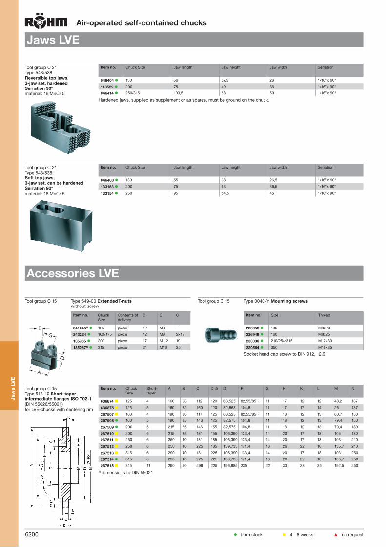
6200
Air-operatedself-containedchucks
JawsLVE
Tool group C 21Type 543/538 Reversibletopjaws,3-jawset,hardenedSerration90° material: 16 MnCr 5
Itemno. Chuck Size Jaw length Jaw height Jaw width Serration
046404 130 56 37,5 26 1/16’’x 90°
118522 200 75 49 36 1/16”x 90°
046414 250/315 103,5 58 50 1/16’’x 90°
Hardened jaws, supplied as supplement or as spares, must be ground on the chuck.
Tool group C 21Type 543/538 Softtopjaws,3-jawset,canbehardenedSerration90° material: 16 MnCr 5
Itemno. Chuck Size Jaw length Jaw height Jaw width Serration
046403 130 55 38 26,5 1/16’’x 90°
133153 200 75 53 36,5 1/16”x 90°
133154 250 95 54,5 45 1/16”x 90°
AccessoriesLVE
Tool group C 15 Type 549-00 ExtendedT-nutswithout screw
Tool group C 15 Type 0040-Y Mountingscrews
E
A
D
G
Itemno. Chuck Size
Contents of delivery
D E G
0412451) 125 piece 12 M8 -
343234 160/175 piece 12 M8 2x15
135765 200 piece 17 M 12 19
1357671) 315 piece 21 M16 25
Itemno. Size Thread
233058 130 M8x20
236949 160 M8x25
233030 210/254/315 M12x30
220564 350 M16x35
Socket head cap screw to DIN 912, 12.9
Tool group C 15Type 518-10 Short-taperintermediateflangesISO702-1 (DIN 55026/55021)for LVE-chucks with centering rim
Itemno. Chuck Size
Short-taper
A B C Dh5 D1 F G H K L M N
636874 125 4 160 28 112 120 63,525 82,55/85 1) 11 17 12 12 48,2 137
636875 125 5 160 32 160 120 82,563 104,8 11 17 17 14 26 137
267507 160 4 190 30 117 125 63,525 82,55/85 1) 11 18 12 13 60,7 150
267508 160 5 190 35 146 125 82,575 104,8 11 18 12 13 79,4 150
267509 200 5 215 35 146 155 82,575 104,8 11 18 12 13 79,4 180
267510 200 6 215 35 181 155 106,390 133,4 14 20 17 13 103 180
267511 250 6 250 40 181 185 106,390 133,4 14 20 17 13 103 210
267512 250 8 250 40 225 185 139,735 171,4 18 26 22 18 135,7 210
267513 315 6 290 40 181 225 106,390 133,4 14 20 17 18 103 250
267514 315 8 290 40 225 225 139,735 171,4 18 26 22 18 135,7 250
267515 315 11 290 50 298 225 196,885 235 22 33 28 35 192,5 2501) dimensions to DIN 55021
Jaw
sLV
E
from stock 4 - 6 weeks ▲ on request

6201
Air-operatedself-containedchucks
AccessoriesLVE
Tool group C 15Type 518-91 Electro-PneumaticSafetyControlBlockfor LVE 125-315
Itemno. voltage
437747 220 V 50 Hz
437748 24 V Dc
Please order accessories and the connection hoses separately
Tool group C 15Type 518-91 Manualpulsegenerator, without cable
Itemno. Contents of delivery
220629 piece
Tool group C 15Type 1025-Q Doublefoot-controlswitch
Itemno. Contents of delivery
249325 piece
Tool group C 15Type 3310-H Serviceunit
Itemno. Contents of delivery
3674441)▲ piece1) Containing filter, separator and oiler, R 3/8”
Tool group C 15Type 3491-Y Metal-coatedhose
Itemno. Chuck Size Design Contents of delivery
7202371) 125-200 Ø 10/6 p. meter piece
7202621) 250-315 Ø 12/9 p. meter piece1) Please indicate the hose length
Tool group C 15Type 30-Y Connector
Itemno. Chuck Size Design Contents of delivery
720233 125-200 snap-on connector CX-R 1/4”-PX-6 piece
720235 125-200 swivel connector LCX-R 1/4”-PX-6 piece
720260 250-315 straight screw-in unions Ø 12/9 R 1/4” piece
720261 250-315 swivel connector Ø 12/9 R 1/4” piece
Acc
esso
ries
LVE
from stock 4 - 6 weeks ▲ on request

6202
Air-
oper
ated
sel
f-co
ntai
ned
chuc
kLV
E
JawdimensionsLVEAir-operatedself-containedchucks
ReversibletopjawsUB, hardened, serration 90o,
material 16MnCr5
Chucksize 125 160 200 250 315
Type 538-02 538-02 538-04 538-05 538-05Itemno.3-jaw 046404 046404 118522 046414 046414A 56 56 75 103,5 103,5B 26 26 36 50 50C 37,5 37,5 49 58 58DH7 12 12 17 21 21E 3,5 3,5 5 5 5F 14 14 21,5 33,5 33,5G 15 15 19 25 25H 29 29 37,5 45 45J 8,4 8,4 13 17 17K 13,5 13,5 19 25 25L 20 20 24 28 28M 10 10 12 14 14N 4 4 6 6 6O 4 4 7,5 6,5 6,5P 5 5 18 24,5 24,5Q 5 5 7 22,5 22,5R 1/16"x90o 1/16"x90o 1/16"x90o 1/16"x90o 1/16"x90o
Weight/jaw kg 0,170 0,170 0,460 1,130 1,130
SofttopjawsAB, material 16MnCr5
Chucksize 125 160 200 250 250
Type 538-02 538-02 538-04 538-05 538-05Itemno.3-jaw 046403 046403 133153 133154 133154A 55 55 75 95 95B 26,5 26,5 36,5 45 45C 38 38 53 54,5 54,5DH7 12 12 17 21 21E 3,5 3,5 5 5 5F 31 31 44 55 55G 15 15 19 25 25H 28 28 43 42,5 42,5J 8,4 8,4 13 17 17K 13,5 13,5 19 25 25R 1/16"x90o 1/16"x90o 1/16"x90o 1/16"x90o 1/16"x90o
Weight/jaw kg 0,320 0,320 0,880 1,400 1,400
Type 537-02
Reversible top jaws: Ground to finished size at surcharge.
Chucking capacities with reversible top jaws UB
Chucksize 125 160 200 250 315
with reversible jawsType 538-02 538-02 538-04 538-05 538-05
Jaw position
External chucking
A1 12-63 28-80 30-115 20-128 41-194
A2 17-69 32-84 44-128 46-154 67-220
A3 67-119 82-132 101-185 128-238 150-303
A4 101-153 118-168 152-236 210-318 231-384
Internal chuckingJ1 49-99 64-116 80-165 70-188 91-244J2 81-131 96-148 130-214 146-255 168-320J3 125-175 140-192 182-266 225-334 246-400
ChuckingcapacitiesLVE

KFD
6203
Not
es
Notes

6204
Air-
oper
ated
sel
f-co
ntai
ned
chuc
kLV
E
LVE-withlargethrough-hole
Application(example)Two chucks are mounted at the frontand rear of the machine spindle. A selectorswitch on our combined pneumatic and electricalcontrol unit, LSV Type 525-91, enables the two chucksto be used together or separately and even withdifferent chucking pressures. These combinationspermit the ends of large pipes to be machined with high stock removal rates and high turning accuracy.
Sizes400-1000For the machining of large and long pipes as frequently used in the oil and gas in-dustry. Flange-type workpieces can of course, be chucked as well. A very reliable chucking tool thanks to high safety and modern production.
- Self-contained unit- Unobstracted bore throughout spindle thanks to the elimination of the draw tube- Quick interchangeability with manually operated chucks- No retooling necessary when changing from bar work to normal chucking- Specially for tube finishing as self- contained chuck
A special feature of this chuck is a pneumatic pis-ton built into the chuck body and which supplies the chucking power. The workpiece is clamped or released by compressed air supplied, with chuck stopped, via the distributor ring and a non-returnvalve to the pneumatic piston.The pneumatic piston is screwed on to the clamping piston, which is itself connected to the base jaws via a wedgesystem.An axial movement of the pneumatic piston thus produces a radial movement of the base jaws.
Air-OperatedSelf-ContainedChucksSizes400-1000
The distributor ring has the function of transmitting the compressed air from outside into the chuck. This means that the ring is always stationary whilst the chuck rotates when the workpiece is being machined. It is therefore supported on the chuck and is prevented from turning with the chuck by means of a fork.The distributor ring bearing is positioned axially via fixed bearings and radially via grooved ball bearings.Special seals seal the gap between ring and chuck during the clamping movement to ensure smooth pressure transmission.Important: To prevent destruction of the sealing ring pressure transmission must only be carried out with chuck stopped.
Distributorring
The control unit has the function of keeping thecompressed air required for clamping within a closed system throughout the whole machining operation.It automatically seals the piston side under pressure, whereby the compressed air is automatically released from the opposite side of the piston. The valve can be dismounted as a complete unit and replaced.
Controlunit
Air-operatedself-containedchucks

6205
LVE-withlargethrough-hole
Air-
oper
ated
sel
f-co
ntai
ned
chuc
kLV
E
Air-operatedself-containedchucks
Clamping efficiency depends very much on the tight-ness of the sealed air chamber. A pressure drop during machining means a drop in clamping force. With the ”RÖHM control” the pressure in the sealed air chamber is monitored. If the pressure drops below a set minimum value, a spring-loaded pin mounted onthe outside diameter of the chuck moves out.
Controlsystem
A proximity sensor is mounted on the same level as the pin at a set radial distance. When the extended pin passes through the magnetic field of the switch, an electric pulse is triggered which can be used to stop the machine.
The transmission and conversion of axial piston force into radial jaw force is effected via the proven wedge system. The large power transmission surfaces guarantes long service life and permanent high precision of clamping. These features apply to both chucks with normal jaw stroke and chucks with rapid and clamping strokes.
Wedgesystem
including, for example, compensating self-contained chucks and chucks that can be converted from self-centering to compensating action and vice versa.
www.roehm.biz
Furtherversionsonrequest
The control unit is designed for LVE chucks with rapid andclamping strokes only for external clamping.For LVE chucks with a normal stroke only pressure control device for the external clamping is provided (on customer demand for internal clamping).
RÖHM-Control system
Pressure control system
Stroke control system
ComponentsLVE
1. Body 2. Base jaw 3. Piston 4. Protective bush 5. Intermediate washer 6. Piston plate 7. Flange 8. Distributor ring 12. Seal 13. T-Nut 14. Air-vent screw 17. Control valve 20. Jaw fixing screws 21. Chuck fixing screws
14
21
20
4
3
12
7
82
1
5
6
13
17

6206
Air-operatedself-containedchucks
LVE-largethrough-hole,standarddesign
Tool group C 15Type 525-00 3-jaw self-contained chucksLVE, with largethrough-hole, max.operatingpressure8bar, with serrationadaptorrecess (standard design)
Itemno. 169400▲ 169401 169402▲ 169403 169404▲ 169405▲ 169406▲ 169407▲ 169408▲ 169409▲ 169410▲
Size 400 400 500 500 600 600 600 700 800 800 1000
LVE LVE 420-140
LVE 480-185
LVE 540-205
LVE 570-230
LVE 600-275
LVE 640-275
LVE 680-325
LVE 730-375
LVE 800-375
LVE 830-410
LVE 1000-570
Jaw travel 7 8,5 8,5 8,5 8,5 10 10 10 12 12 12
A 425 480 540 570 605 640 685 735 800 835 1000
B 140 185 205 230 280 275 325 375 375 410 570
C 470 530 570 570 605 685 685 735 850 850 925
DH6 310 365 415 415 450 510 510 560 700 700 700
E 400 460 500 500 535 610 610 660 775 775 850
F 374 434 474 474 508 580 580 630 745 745 815
G M12 M12 M12 M12 M12 M16 M16 M16 M16 M16 M16
G1 25 25 25 25 25 30 30 30 30 30 30
H 196 225 225 225 225 263 263 263 305 305 315
H1 194 223 223 223 223 261 261 261 303 303 313
J 8 8 8 8 8 8 8 8 8 8 10
K 448 510 550 550 585 666 666 716 830 830 910
L 20 20 20 20 20 20 20 20 25 25 33
M 70 90 100 - - 110 - - 155 155 225
N G 3/8 G 3/8 G 3/8 G 3/8 G 3/8 G 3/8 G 3/8 G 3/8 G 3/8 G 3/8 G 3/8
O 37 37 37 37 37 39,5 39,5 39,5 44,5 44,5 52,5
P 26 26 26 26 26 33 33 33 33 33 33
a 57 57 57 57 57 75 75 75 75 75 75
bH7 25,5 25,5 25,5 25,5 25,5 30 30 30 30 30 30
c 3/32”x90° 3/32”x90° 3/32”x90° 3/32”x90° 3/32”x90° 3/32”x90° 3/32”x90° 3/32”x90° 3/32”x90° 3/32”x90° 3/32”x90°
d M20x50 M20x50 M20x50 M20x50 M20x50 M24x65 M24x65 M24x65 M24x65 M24x65 M24x65
e 20 20 20 20 20 28 28 28 28 28 28
f min. 32 32 32 32 32 42 42 42 42 42 42
f max. 85 85 105 105 105 100 100 100 125 125 125
g 120 120 140 140 135 145 145 145 173 173 173
h min. 94 118.5 131.5 141.5 164 175 195 220 225 242.5 323
h max. 101 127 140 150 172,5 185 205 230 237 254.5 345
α 30° 30° 30° 30° 30° 30° 30° 30° 30° 30° 30°
β 15° 15° 15° 15° 15° 15° 15° 15° 15° 15° 15°
γ 60° 60° 60° 60° 60° 60° 60° 60° 60° 60° 30°
Min. operating pressure bar
2 2 2 2 2 2 2 2 3 3 3
Max. operating pressure bar
8 8 8 8 8 8 8 8 8 8 8
Total clamping force at 6 bar kN
140 155 210 190 200 240 155 175 405 360 180
Cylinder surface area cm2
710 899 1045 940 1010 1414 1181 1307 2382 2121 1075
Air consumption (total stroke) l
20 31 36 32 35 58 49 55 117 104 85
Max. admissible speed min-1
1700 1500 1300 1300 1200 1000 900 800 750 750 450
Moment of inertia kgm2
3,50 7.50 10,65 8.00 15,50 24.25 29.10 45,80 67.80 71.25 157,5
Weight kg 150 215 225 200 275 413 418 560 712 650 950
L
J
H
G1 N
O P
M
H1
B
h
f
d
e
g
A
F
G
EKC
c
D
b
a
ß
α
γ
Air-
oper
ated
sel
f-co
ntai
ned
chuc
kLV
E
from stock 4 - 6 weeks ▲ on request

6207
Air-operatedself-containedchucks
LVE-largethrough-hole,withpressurecontroldevice
Tool group C 15Type 525-10 3-jaw self-contained chucksLVE, with largethrough-hole, max.operatingpressure8bar, with serrationadaptorrecess with pressure control device for external clamping
Itemno. 169411▲ 169412▲ 169413▲ 169414▲ 169415▲ 169416▲ 169417▲ 169418▲ 169419▲ 169420▲ 169421▲
Size 400 400 500 500 600 600 600 700 800 800 1000
LVE LVE 420-140
LVE 480-185
LVE 540-205
LVE 570-230
LVE 600-275
LVE 640-275
LVE 680-325
LVE 730-375
LVE 800-375
LVE 830-410
LVE 1000-570
Jaw travel 7 8,5 8,5 8,5 8,5 10 10 10 12 12 12
A 425 480 540 570 605 640 685 735 800 835 1000
B 140 185 205 230 280 275 325 375 375 410 570
C 470 530 570 570 605 685 685 735 850 850 925
DH6 310 365 415 415 450 510 510 560 700 700 700
E 400 460 500 500 535 610 610 660 775 775 850
F 374 434 474 474 500 580 580 630 745 745 815
G M12 M12 M12 M12 M12 M16 M16 M16 M16 M16 M16
G1 25 25 25 25 25 30 30 30 30 30 30
H 196 225 225 225 225 263 263 263 305 305 315
H1 194 223 223 223 223 261 261 261 303 303 313
J 8 8 8 8 8 8 8 8 8 8 10
K 448 510 550 550 585 666 666 666 830 830 910
L 20 20 20 20 20 20 20 20 25 25 33
M 70 90 100 - - 110 - - - 155 225
N G 3/8 G 3/8 G 3/8 G 3/8 G 3/8 G 3/8 G 3/8 G 3/8 G 3/8 G 3/8 G 3/8
O 37 37 37 37 37 39,5 39,5 39,5 39,5 44,5 52,5
P 26 26 26 26 26 33 33 33 33 33 33
a 57 57 57 57 57 75 75 75 75 75 75
bH7 25,5 25,5 25,5 25,5 25,5 30 30 30 30 30 30
c 3/32”x90° 3/32”x90° 3/32”x90° 3/32”x90° 3/32”x90° 3/32”x90° 3/32”x90° 3/32”x90° 3/32”x90° 3/32”x90° 3/32”x90°
d M20x50 M20x50 M20x50 M20x50 M20x50 M24x65 M24x65 M24x65 M24x65 M24x65 M24x65
e 20 20 20 20 20 28 28 28 28 28 28
f min. 32 32 32 32 32 42 42 42 42 42 42
f max. 85 85 105 105 105 100 100 100 125 125 125
g 120 120 140 140 135 145 145 145 173 173 173
h min. 94 118.5 131.5 141.5 164 175 195 220 225 242.5 323
h max. 101 127 140 150 172,5 185 205 230 237 254.5 345
α 30° 30° 30° 30° 30° 30° 30° 30° 30° 30° 30°
β 15° 15° 15° 15° 15° 15° 15° 15° 15° 15° 15°
γ 60° 60° 60° 60° 60° 60° 60° 60° 60° 60° 60°
Min. operating pressure bar
2 2 2 2 2 2 2 2 3 3 3
Max. operating pressure bar
8 8 8 8 8 8 8 8 8 8 8
Total clamping force at 6 bar kN
140 155 210 190 200 240 155 175 405 360 180
Cylinder surface area cm2
710 899 1045 939 1010 1414 1181 1307 2382 2121 1075
Air consumption (total stroke) l
20 31 36 32 35 58 49 55 117 104 85
Max. admissible speed min-1
1700 1500 1300 1300 1200 1000 900 800 750 750 450
Moment of inertia kgm2
3,50 7.50 10,65 8.00 15,5 24.25 29.10 45,80 67.80 71.25 157,5
Weight kg 150 215 255 200 275 413 418 560 712 650 950
L
J
H
G1 N
O P
M
H1
B
h
f
d
e
g
A
F
G
EKC
c
Db
a
ß
α
γ
Air-
oper
ated
sel
f-co
ntai
ned
chuc
kLV
E
from stock 4 - 6 weeks ▲ on request
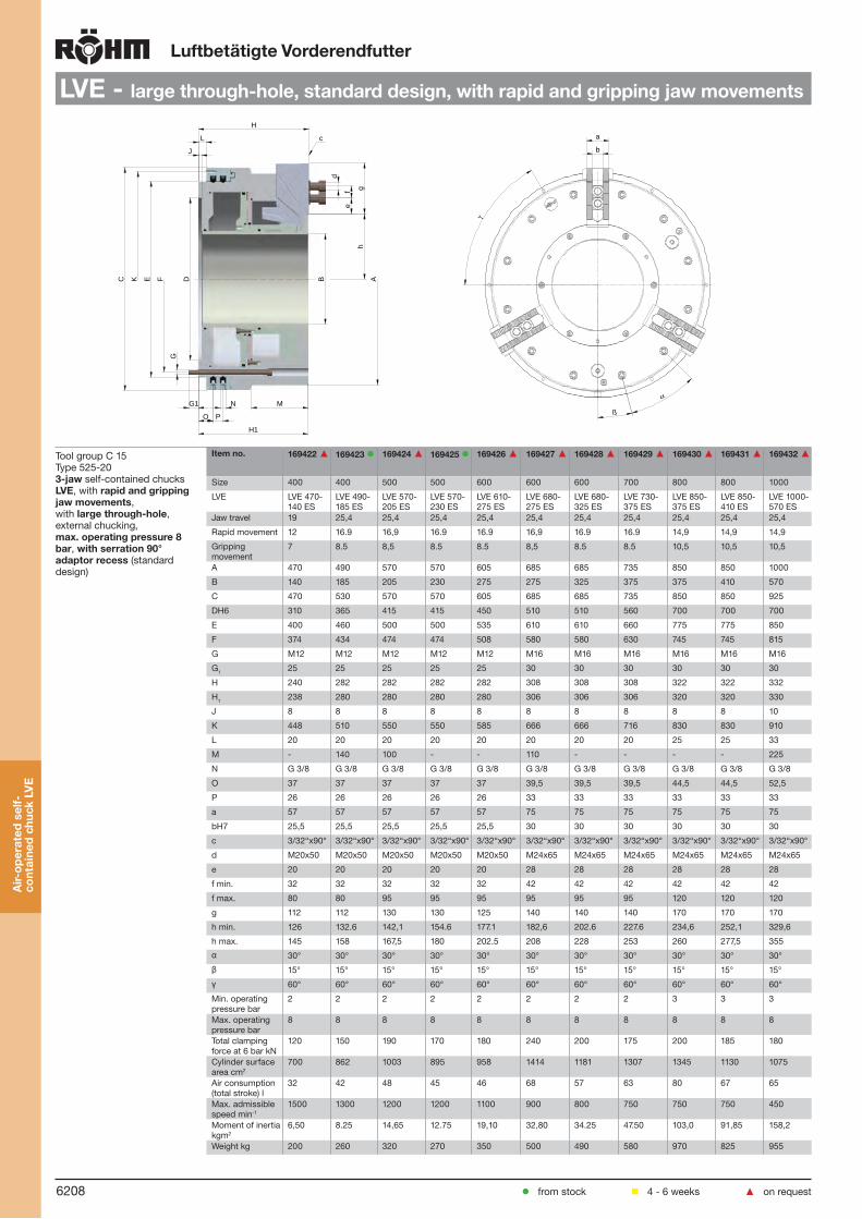
6208
LuftbetätigteVorderendfutter
LVE-largethrough-hole,standarddesign,withrapidandgrippingjawmovements
Tool group C 15Type 525-20 3-jaw self-contained chucks LVE, with rapidandgrippingjawmovements, with largethrough-hole, external chucking, max.operatingpressure8bar, withserration90°adaptorrecess (standard design)
Itemno. 169422▲ 169423 169424▲ 169425 169426▲ 169427▲ 169428▲ 169429▲ 169430▲ 169431▲ 169432▲
Size 400 400 500 500 600 600 600 700 800 800 1000
LVE LVE 470-140 ES
LVE 490-185 ES
LVE 570-205 ES
LVE 570-230 ES
LVE 610-275 ES
LVE 680-275 ES
LVE 680-325 ES
LVE 730-375 ES
LVE 850-375 ES
LVE 850-410 ES
LVE 1000-570 ES
Jaw travel 19 25,4 25,4 25,4 25,4 25,4 25,4 25,4 25,4 25,4 25,4
Rapid movement 12 16.9 16,9 16.9 16.9 16,9 16.9 16.9 14,9 14,9 14,9
Gripping movement
7 8.5 8,5 8.5 8.5 8,5 8.5 8.5 10,5 10,5 10,5
A 470 490 570 570 605 685 685 735 850 850 1000
B 140 185 205 230 275 275 325 375 375 410 570
C 470 530 570 570 605 685 685 735 850 850 925
DH6 310 365 415 415 450 510 510 560 700 700 700
E 400 460 500 500 535 610 610 660 775 775 850
F 374 434 474 474 508 580 580 630 745 745 815
G M12 M12 M12 M12 M12 M16 M16 M16 M16 M16 M16
G1 25 25 25 25 25 30 30 30 30 30 30
H 240 282 282 282 282 308 308 308 322 322 332
H1 238 280 280 280 280 306 306 306 320 320 330
J 8 8 8 8 8 8 8 8 8 8 10
K 448 510 550 550 585 666 666 716 830 830 910
L 20 20 20 20 20 20 20 20 25 25 33
M - 140 100 - - 110 - - - - 225
N G 3/8 G 3/8 G 3/8 G 3/8 G 3/8 G 3/8 G 3/8 G 3/8 G 3/8 G 3/8 G 3/8
O 37 37 37 37 37 39,5 39,5 39,5 44,5 44,5 52,5
P 26 26 26 26 26 33 33 33 33 33 33
a 57 57 57 57 57 75 75 75 75 75 75
bH7 25,5 25,5 25,5 25,5 25,5 30 30 30 30 30 30
c 3/32“x90° 3/32“x90° 3/32“x90° 3/32“x90° 3/32“x90° 3/32“x90° 3/32“x90° 3/32“x90° 3/32“x90° 3/32“x90° 3/32“x90°
d M20x50 M20x50 M20x50 M20x50 M20x50 M24x65 M24x65 M24x65 M24x65 M24x65 M24x65
e 20 20 20 20 20 28 28 28 28 28 28
f min. 32 32 32 32 32 42 42 42 42 42 42
f max. 80 80 95 95 95 95 95 95 120 120 120
g 112 112 130 130 125 140 140 140 170 170 170
h min. 126 132.6 142,1 154.6 177.1 182,6 202.6 227.6 234,6 252,1 329,6
h max. 145 158 167,5 180 202.5 208 228 253 260 277,5 355
α 30° 30° 30° 30° 30° 30° 30° 30° 30° 30° 30°
β 15° 15° 15° 15° 15° 15° 15° 15° 15° 15° 15°
γ 60° 60° 60° 60° 60° 60° 60° 60° 60° 60° 60°
Min. operating pressure bar
2 2 2 2 2 2 2 2 3 3 3
Max. operating pressure bar
8 8 8 8 8 8 8 8 8 8 8
Total clamping force at 6 bar kN
120 150 190 170 180 240 200 175 200 185 180
Cylinder surface area cm2
700 862 1003 895 958 1414 1181 1307 1345 1130 1075
Air consumption (total stroke) l
32 42 48 45 46 68 57 63 80 67 65
Max. admissible speed min-1
1500 1300 1200 1200 1100 900 800 750 750 750 450
Moment of inertia kgm2
6,50 8.25 14,65 12.75 19,10 32,80 34.25 47.50 103,0 91,85 158,2
Weight kg 200 260 320 270 350 500 490 580 970 825 955
J
L
H
d
fe
gh
B A
MNG1
O P
H1
G
DE FKC
c
b
a
ß
α
γ
Air-
oper
ated
sel
f-co
ntai
ned
chuc
kLV
E
from stock 4 - 6 weeks ▲ on request

6209
Air-operatedself-containedchucks
LVE-largethrough-hole,withpressurecontroldevice,withrapidandgrippingjawmovements
Tool group C 15Type 525-303-jaw self-contained chucks LVE, with rapidandgrippingjawmovements, withlargethrough-hole, external chucking, max.operatingpressure8bar, with serrationadaptorrecess with pressure control device for external clamping
Itemno. 169433▲ 169434▲ 169435▲ 169436▲ 169437▲ 169438▲ 169439▲ 169440▲ 169441▲ 169442▲ 169443▲
Size 400 400 500 500 600 600 600 700 800 800 1000
LVE LVE 470-140 ES
LVE 490-185 ES
LVE 570-205 ES
LVE 570-230 ES
LVE 610-275 ES
LVE 680-275 ES
LVE 680-325 ES
LVE 730-375 ES
LVE 850-375 ES
LVE 850-410 ES
LVE 1000-570 ES
Jaw travel 19 25,4 25,4 25,4 25,4 25,4 25,4 25,4 25,4 25,4 25,4
Rapid movement 12 16.9 16,9 16.9 16.9 16,9 16.9 16.9 14,9 14,9 14,9
Gripping movement
7 8.5 8,5 8.5 8.5 8,5 8.5 8.5 10,5 10,5 10,5
A 470 490 570 570 605 685 685 735 850 850 1000
B 140 185 205 230 275 275 325 375 375 410 570
C 470 530 570 570 605 685 685 735 850 850 925
DH6 310 365 415 415 450 510 510 560 700 700 700
E 400 460 500 500 535 610 610 660 775 775 850
F 374 434 474 474 509 580 580 630 745 745 815
G M12 M12 M12 M12 M12 M16 M16 M16 M16 M16 M16
G1 25 25 25 25 25 30 30 30 30 30 30
H 240 282 282 282 282 308 308 308 322 322 332
H1 238 280 280 280 280 306 306 306 320 320 330
J 8 8 8 8 8 8 8 8 8 8 10
K 448 510 550 550 585 666 666 716 830 830 910
L 20 20 20 20 20 20 20 20 25 25 33
M - 140 100 - - 110 - - - - 225
N G 3/8 G 3/8 G 3/8 G 3/8 G 3/8 G 3/8 G 3/8 G 3/8 G 3/8 G 3/8 G 3/8
O 37 37 37 37 37 39,5 39,5 39,5 44,5 44,5 52,5
P 26 26 26 26 26 33 33 33 33 33 33
a 57 57 57 57 57 75 75 75 75 75 75
bH7 25,5 25,5 25,5 25,5 25,5 30 30 30 30 30 30
c 3/32”x90° 3/32”x90° 3/32”x90° 3/32”x90° 3/32”x90° 3/32”x90° 3/32”x90° 3/32”x90° 3/32”x90° 3/32”x90° 3/32”x90°
d M20x50 M20x50 M20x50 M20x50 M20x50 M24x65 M24x65 M24x65 M24x65 M24x65 M24x65
e 20 20 20 20 20 28 28 28 28 28 28
f min. 32 32 32 32 32 42 42 42 42 42 42
f max. 80 80 95 95 95 95 95 95 120 120 120
g 112 112 130 130 125 140 140 140 170 170 170
h min. 126 132.6 142,1 154.6 177.1 182,6 202.6 227.6 234,6 252,1 329,6
h max. 145 158 167,5 180 202.5 208 228 253 260 277,5 355
α 30° 30° 30° 30° 30° 30° 30° 30° 30° 30° 30°
β 15° 15° 15° 15° 15° 15° 15° 15° 15° 15° 15°
γ 60° 60° 60° 60° 60° 60° 60° 60° 60° 60° 60°
Min. operating pressure bar
2 2 2 2 2 2 2 2 3 3 3
Max. operating pressure bar
8 8 8 8 8 8 8 8 8 8 8
Total clamping force at 6 bar kN
120 150 210 170 180 240 200 175 200 185 180
Cylinder surface area cm2
700 862 1024 895 958 1414 1181 1307 1345 1130 1075
Air consumption (total stroke) l
32 42 50 45 46 68 57 63 80 67 65
Max. admissible speed min-1
1500 1300 1200 1200 1100 900 800 750 750 750 450
Moment of inertia kgm2
6,50 8.25 14,65 12.75 19,10 32,80 34.25 47.50 103,0 91,85 158,2
Weight kg 200 260 320 270 350 500 490 580 970 825 955
J
L
H
d
fe
gh
B A
MNG1
O P
H1
G
DE FKC
c b
a
ß
α
γ
Air-
oper
ated
sel
f-co
ntai
ned
chuc
kLV
E
from stock 4 - 6 weeks ▲ on request

6210
Air-operatedself-containedchucks
JawsLVE
Tool group C 21Type 543/538 Reversibletopjaws,3-jawset,hardenedSerration90° material: 16 MnCr 5
Itemno. Chuck Size Jaw length Jaw height Jaw width Serration
037531 400 135 65 68 3/32”x 90°
169464▲ 600/700 170 75 80 3/32”x90°
169466 800/1000 195 85 80 3/32”x90°
Hardened jaws, supplied as supplement or as spares, must be ground on the chuck.
Tool group C 21Type 543/538 Softtopjaws,3-jawset,canbehardenedSerration90° material: 16 MnCr 5
Itemno. Chuck Size Jaw length Jaw height Jaw width Serration
118004 400/500/600 130 80 50 3/32”x90°
137028 400/500/600 180 80 50 3/32”x 90°
169450 600/700 215 89 68 3/32”x90°
169452 600/700/800/1000 245 89 68 3/32”x90°
Tool group C 21Type 543 extentedsofttopjaws,3-jawsetSerration90° material: 16 MnCr 5
Itemno. Chuck Size Jaw length Jaw height Jaw width Serration
137028 400/500/600 180 80 50 3/32”x 90°
169449 500/600 205 80 50 3/32”x90°
169452 600/700/800/1000 245 89 68 3/32”x90°
169456 800/1000 285 89 68 3/32”x90°
Tool group C 21Type 543 extentedhardenedtopjaws,3-jawset Serration90° material: 16 MnCr 5
Itemno. Chuck Size Jaw length Jaw height Jaw width Serration
284627 400 170 80 50 3/32”x 90°
321209 500/600 210 80 50 3/32”x 90°
169458 600/700 225 89 68 3/32”x90°
169460 800 285 89 68 3/32”x90°
169462 1000 325 89 68 3/32”x90°
Jaw
sLV
E
from stock 4 - 6 weeks ▲ on request

6211
Air-operatedself-containedchucks
AccessoriesLVE
Tool group C 15 Type 525-00 T-nutswithout screw
Tool group C 15 Type 0040-Y Mountingscrews
E
D
Itemno. Chuck Size Contents of delivery
D E
588960▲ 400/500/600 piece 25,5 M20
169447▲ 400/500/600 piece 25,5 3/4-10 UNC
588770 600/700/800/1000 piece 30 M24
169448▲ 600/700/800/1000 piece 30 7/8-9 UNC
Itemno. Size Contents of delivery
Thread
249388 630 piece M20x50
243854 400/500/600 piece 3/4-10 UNCx2
236514 600/700/800/1000 piece M24x60
680392 600/700/800/1000 piece 7/8-9 UNCx2-1/4
Socket head cap screw to DIN 912, 12.9
Tool group C 15Type 518-10 Short-taperintermediateflangesISO702-1 (DIN 55026)for LVE-chucks with centering rim
Itemno. LVE Spindle nose size
A B C D E F
169475 400-140 A8 139,719 171,4 400 310 136 40
169477 400-140 A11 196,869 235 400 310 140 40
169479 480-185 A8 139,719 171,4 460 365 136 40
169481 480-185 A11 196,869 235 460 365 185 40
169483 480-185 A15 285,775 330,2 460 365 185 40
169485 540-205 / 570-230 A11 196,869 235 500 415 192 40
169487 540-205/570-230 A15 285,775 330,2 500 415 230 40
169489 540-205/570-230 A20 412,775 463,6 500 415 230 40
169491 600-275 A11 196,869 235 545 415 192 40
169493 600-275 A15 285,775 330,2 545 415 275 40
169495 600-275 A20 412,775 463,6 545 415 275 40
169497 630-275 / 680-325 A11 196,869 235 610 510 192 50
169499 630-275 / 680-325 A15 285,775 330,2 610 510 281 50
169501 630-275 / 680-325 A20 412,775 463,6 610 510 325 50
169503 730-375 A15 285,775 330,2 660 560 281 50
169505 730-375 A20 412,775 463,6 660 560 375 50
169507 800-375 / 830-410 A15 285,775 330,2 775 700 281 50
169509 800-375 / 830-410 A20 412,775 463,6 775 700 407,5 50
169511 1000-570 A20 412,775 463,6 775 700 407,5 50
169513 1000-570 A28 584,225 647,6 775 700 578,5 50
ISO 702-3 (DIN 55027) / ISO 702-2 (DIN 55029) on request
Acc
esso
ries
LVE
from stock 4 - 6 weeks ▲ on request

6212
Air-operatedself-containedchucks
AccessoriesLVE
Tool group C 15Type 525-91 Pneumaticcontrolunitfor LVE 400-1000
Itemno. Width Height Depth Control voltage Connection Weight approx. kg
426560 280 250 100 24 V R ½ “ inside thread 3
Two pneumatic control units are required for dual chucks
Tool group C 15Type 3515-Y TwoConnectinghoseswithscrewcouplings
Itemno. Contents of delivery
3021381) set1) Please indicate the hose length
Tool group C 15Typ 525-60/70 Contolunitsforsinglechuckswith dual foot switch, wired, 6 m cable, for LVE 400-1000
Itemno. Design Width Width with plug Height Depth Control voltage Cable length
426481 without pressure monitoring 300 340 300 120 24 V 6 m
426263 with pressure monitoring 300 340 300 120 24 V 6 m
Supply on request: primary 35-264 V ~, 47-63 HZ - secundary 24V/1,5 A
Tool group C 15Typ 525-80/90 Contolunitsfordualchuckswith dual foot switch, wired, 6 m cable, for LVE 400-1000
Itemno. Design Width Width with plug Height Depth Control voltage Cable length
426482▲ without pressure monitoring 300 340 300 120 24 V 6 m
426264▲ with pressure monitoring 300 340 300 120 24 V 6 m
Supply on request: primary 35-264 V ~, 47-63 HZ - secundary 24V/1,5 A
Acc
esso
ries
LVE
from stock 4 - 6 weeks ▲ on request

6213
Air-
oper
ated
sel
f-co
ntai
ned
chuc
kLV
E
ChuckingcapacitiesundJawdimensionsLVEAir-operatedself-containedchucks
SofttopjawsABserration 90°,material 16MnCr5
Chucksize 400 500 600 700 800 1000
LVE 400-140 480-185 540-205 570-230 600-275 630-275 680-325 730-375 800-375 830-410 1000-570Typ 538-73 518-07 518-07 543-22 543-22 543-22 543-22Itemno.3-jaw 118004 137028 137028 169450 169450 169452 169452A 130 130 180 180 180 215 215 215 245 245 245B 50 50 50 50 50 68 68 68 68 68 68C 80 80 80 80 80 89 89 89 89 89 89D+0,05 25,5 25,5 25,5 25,5 25,5 30,0 30,0 30,0 30,0 30,0 30,0E 5 5 5 5 5 6 6 6 6 6 6F 20 20 20 20 20 25 25 25 25 25 25G 35 35 35+35 35+35 35+35 45+45 45+45 45+45 45+45 45+45 45+45H 60 60 60 60 60 69 69 69 69 69 69J 21 21 21 21 21 25 25 25 25 25 25K 31 31 31 31 31 37 37 37 37 37 37L 130 130 180 180 180 140 140 140 140 140 140M - - - - - 7 7 7 7 7 7Toothing 3/32"x90° 3/32"x90° 3/32"x90° 3/32"x90° 3/32"x90° 3/32"x90° 3/32"x90° 3/32"x90° 3/32"x90° 3/32"x90° 3/32"x90°Weight/jaw kg 3,1 3,1 4,2 4,2 4,2 7,8 7,8 7,8 9,1 9,1 9,1A1 Ø External chucking 85 - 190 130 - 235 60 - 270 80 - 290 125 - 335 120 - 315 160 - 355 210 - 415 165 - 415 200 - 450 360 - 610S Ø max. 460 505 640 660 710 760 800 850 920 955 1150
Chucksize 400 500 600 700 800 1000
LVE 400-140 480-185 540-205 570-230 600-275 630-275 680-325 730-375 800-375 830-410 1000-570Typ 538-07 538-07 538-07 543-21 543-21 543-21 543-21Itemno.3-jaw 037531 037531 037531 169464 169464 169466 169466A 135 135 135 135 135 170 170 170 195 195 195B 68 68 68 68 68 80 80 80 80 80 80C 65 65 65 65 65 75 75 75 85 85 85D+0,05 25,5 25,5 25,5 25,5 25,5 30,0 30,0 30,0 30,0 30,0 30,0E 5 5 5 5 5 6 6 6 6 6 6F 48 48 48 48 48 56 56 56 78 78 78G 31+31 31+31 31+31 31+31 31+31 42+42 42+42 42+42 42+42 42+42 42+42H 48 48 48 48 48 58 58 58 62 62 62J 21 21 21 21 21 26 26 26 26 26 26K 31 31 31 31 31 40 40 40 40 40 40L 26 26 26 26 26 32 32 32 35 35 35M -- -- -- -- -- -- -- -- -- -- --Toothing 3/32"x90°° 3/32"x90° 3/32"x90° 3/32”x90° 3/32”x90° 3/32”x90° 3/32”x90° 3/32”x90° 3/32”x90° 3/32”x90° 3/32”x90°Weight/jaw kg 2,4 2,4 2,4 2,4 2,4 3,6 3,6 3,6 4,5 4,5 4,5
External chuckingA1 85 - 255 135 - 305 160 - 370 180 - 390 220 - 430 225 - 420 265 - 460 315 - 510 280 - 530 315 - 565 500 - 750A2 125 - 295 175 - 345 200 - 410 220 - 430 260 - 470 275 - 470 315 - 510 365 - 560 370 - 620 405 - 655 585 - 835A3 330 - 500 380 - 550 405 - 615 425 - 635 465 - 675 540 - 735 580 - 775 630 - 825 640 - 890 675 - 925 855 - 1105
Internal chuckingJ1 155 - 325 205 - 375 230 - 440 250 - 460 290 - 500 305 - 500 345 - 540 395 - 590 405 - 655 440 - 690 600 - 850J2 350 - 520 405 - 570 430 - 640 450 - 660 490 - 700 565 - 770 605 - 800 655 - 850 670 - 920 705 - 955 865 - 1035
max. -Ø S 570 625 690 710 750 800 840 890 1000 1030 1215
ReversibletopjawsUB serration 90°,material 16MnCr5
ExtentedtopjawsABhardenedserration 90°,material 16MnCr5
Chucksize 400 500 600 700 800 1000
LVE 400-140 480-185 540-205 570-230 600-275 630-275 680-325 730-375 800-375 830-410 1000-570Typ 543-27 543-27 543-27 543-27 543-27 543-27 543-27Itemno.3-jaw 284627 321209 321209 169458 169458 169460 169462A 170 170 210 210 210 225 225 225 285 285 325B 50 50 50 50 50 68 68 68 68 68 68C 80 80 80 80 80 89 89 89 89 89 89D+0,05 25,5 25,5 25,5 25,5 25,5 30,0 30,0 30,0 30,0 30,0 30,0E 5 5 5 5 5 6 6 6 6 6 6F 22 22 20 20 20 25 25 25 30 30 30G 35+35 35+35 45+45 45+45 45+45 45+45 45+45 45+45 50+50 50+50 60+60H 60 60 60 60 60 69 69 69 69 69 69J 22 22 22 22 22 26 26 26 26 26 26K 33 33 33 33 33 40 40 40 40 40 40L 121 121 135 135 135 140 140 140 160 160 180M 6 6 6 6 6 7 7 7 7 7 7Toothing 3/32"x90° 3/32"x90° 3/32"x90° 3/32"x90° 3/32"x90° 3/32"x90° 3/32"x90° 3/32"x90° 3/32"x90° 3/32"x90° 3/32"x90°Weight/jaw kg 3,1 3,1 4,1 4,1 4,1 7,1 7,1 7,1 9,4 9,4 11,0A1 Ø External chucking 20 - 190 60 - 230 30 - 240 50 - 260 90 - 300 100 - 295 140 - 335 190 - 385 105 - 355 140 - 390 230 - 520S Ø max. 540 580 660 680 720 760 800 850 940 975 1200
ExtentedsofttopjawsAB serration 90°,material 16MnCr5
Chucksize 400 500 600 700 800 1000
LVE 400-140 480-185 540-205 570-230 600-275 630-275 680-325 730-375 800-375 830-410 1000-570Typ 518-07 543-22 543-22 543-22 543-22 543-22 543-22Itemno.3-jaw 137028 169449 169449 169452 169452 169456 169456A 180 180 205 205 205 245 245 245 285 285 285B 50 50 50 50 50 68 68 68 68 68 68C 80 80 80 80 80 89 89 89 89 89 89D+0,05 25,5 25,5 25,5 25,5 25,5 30,0 30,0 30,0 30,0 30,0 30,0E 5 5 5 5 5 6 6 6 6 6 6F 20 20 20 20 20 25 25 25 25 25 25G 35+35 35+35 35+35 35+35 35+35 45+45 45+45 45+45 55+55 55+55 55+55H 60 60 60 60 60 69 69 69 69 69 69J 21 21 21 21 21 25 25 25 25 25 25K 31 31 31 31 31 37 37 37 37 37 37L 180 180 190 190 190 140 140 140 160 160 160M -- -- 6 6 6 7 7 7 7 7 7Toothing 3/32"x90° 3/32"x90° 3/32"x90° 3/32"x90° 3/32"x90° 3/32"x90° 3/32"x90° 3/32"x90° 3/32"x90° 3/32"x90° 3/32"x90°Weight/jaw kg 4,2 4,2 5,0 5,0 5,0 9,1 9,1 9,1 10,9 10,9 10,9A1 Ø External chucking 20 - 155 30 - 200 10 - 220 30 - 240 75 - 285 60 - 255 100 - 295 150 - 345 105 - 355 140 - 390 300 - 550S Ø max. 330 575 640 660 710 760 800 850 945 980 1100

6214
OverviewStationarypowerchucks
SSP/SSH frompage6215
Wedge systemPneumatically operated (SSP)
Hydraulically operated (SSH)
Round mounting surface
2- and 3-jaw design
KZS-P frompage6222
Wedge system
Pneumatically operated (KZS-P)
Hydraulically operated (KZS-H) on request 2-jaw designOptions: with large jaw stroke (KZS-PG)
Sta
tiona
ryp
ower
c h
ucks

6215
Sta
tiona
ryp
ower
ch
ucks
SSP/SSH
8
3
4
9
2
1
5
7
6
Stationarypowerchucks
Components1. Body 2. Base jaw 3. Piston 4. Protective bushing 5. Intermediate disc 6. Mount 7. Piston disc 8. T-nut 9. Top jaws
Wedge system
Quick and efficient chucking in stationary use
Concentric gripping of round as well as angular parts
Universal through use of different jaws
Gripping force adjustable by changing the pressure
High chucking accuracy thanks to constant gripping force at constant pressure
Compact design
Blast air terminal against dirt accumulation
Used in conjunction with RÖHM actuating cylinders with safety device SZS, OVS, LHS-L, LVS, EHS and EVS the power chucks SSP / SSH meet the requirements of the German Employers’ Insurance Association
Technicalfeatures:
Designs:
Pneumatically operated (SSP)
Hydraulically operated (SSH)

6216
Stationarypowerchucks
SSP2-/3-jaw,pneumaticallyoperated,withoutthrough-hole
Tool group C 15Type 447-0 Stationary power chucks SSP, pneumaticallyoperated2-jawand3-jaw chucks, withoutthrough-hole,serration1/16”x90°
Itemno. 161852 161505 161853 161506 161854 161507 161855 161508
Size 160 160 200 200 250 250 315 315
Number of jaws 2 3 2 3 2 3 2 3
A 260 260 320 320 380 380 415 415
A1 178 178 205 205 255 255 320 320
A2 210 210 255 255 315 315 350 350
Jaw travel B 4,2 4,2 4,2 4,2 5 5 5 5
C 130,5 130,5 134 134 146 146 156,5 156,5
Mount DH6 55 55 70 70 90 90 110 110
D M8 M8 M12 M12 M16 M16 M16 M16
F 65 65 80 80 100 100 120 120
G 15 15 17 17 17 17 21,5 21,5
H 84,5 84,5 86 86 94 94 104,5 104,5
Wedge stroke K 24 24 23,8 23,8 28,4 28,4 28,4 28,4
Possible through-hole M 38 38 52 52 68 68 90 90
T 131,5 131,5 135,5 135,5 147,5 147,5 158 158
U M8 M8 M12 M12 M16 M16 M16 M16
a min. 31,8 31,8 41,2 41,2 50 50 61,5 61,5
a max. 36 36 45,4 45,4 55 55 66,5 66,5
c 15 15 19 19 25 25 25 25
d 54,5 54,5 62 62 78 78 99 99
e 32 32 36 36 44 44 44 44
fH7 12 12 17 17 21 21 21 21
g 13 13 17 17 17 17 17 17
Piston area cm2 209 209 323 323 532 532 654 654
Min. operating pressure bar
2 2 2 2 2 2 2 2
Max. operating pressure bar
5 8 5 8 5 8 5 8
Max. total clamping force at working pressure - Externalclamping kN
20 (at 5 bar) 36 (at 6 bar) 31 (at 5 bar) 55 (at 6 bar) 50 (at 5 bar) 90 (at 6 bar) 62 (at 5 bar) 111 (at 6 bar)
Max. total clamping force at working pressure -Internalclamping kN
22 (at 5 bar) 38 (at 6 bar) 34 (at 5 bar) 60 (at 5 bar) 54 (at 5 bar) 96 (at 6 bar) 66 (at 5 bar) 118 (at 6 bar)
Weight without jaws approx. kg
25 25 34 34 54 54 65 65
Stationary Power chucks with serration 1,5x60°, tongue and groove and/or through-hole on request available
Sta
tiona
ryp
ower
c h
uck
SS
P
from stock 4 - 6 weeks ▲ on request

6217
Stationarypowerchucks
SSH2-/3-jaw,hydraulicallyoperated,withoutthrough-hole
Tool group C 15Type 447-1 Stationary power chucks SSH, hydraulicallyoperated2-jawand3-jaw chucks, withoutthrough-hole, serration1/16”x90°
Itemno. 161856 161509 161857 161510 161858 161511 161859 161512
Size 160 160 200 200 250 250 315 315
Number of jaws 2 3 2 3 2 3 2 3
A 230 230 280 280 320 320 385 385
A1 178 178 205 205 255 255 320 320
Jaw travel B 4,2 4,2 4,2 4,2 5 5 5 5
C 133,5 133,5 134 134 151 151 159,5 159,5
Mount DH6 55 55 70 70 90 90 110 110
D M8 M8 M12 M12 M16 M16 M16 M16
F 65 65 80 80 100 100 120 120
G 15 15 17 17 19 19 21,5 21,5
Wedge stroke K 24 24 23,8 23,8 28,4 28,4 28,4 28,4
Possible through-hole M 35 35 52 52 60 60 90 90
T 134,5 134,5 135,5 135,5 152,5 152,5 161 161
U M8 M8 M12 M12 M16 M16 M16 M16
a min. 31,8 31,8 41,2 41,2 50 50 61,5 61,5
a max. 36 36 45,4 45,4 55 55 66,5 66,5
c 15 15 19 19 25 25 25 25
d 54,5 54,5 62 62 78 78 99 99
e 32 32 36 36 44 44 44 44
fH7 12 12 17 17 21 21 21 21
g 13 13 17 17 17 17 17 17
Piston area cm2 32,4 32,4 47 47 92 92 118 118
Max. operating pressure / clamping bar
26 40 26 40 26 40 26 40
Max. operating pressure / opening bar
20 30 16 25 20 30 20 30
Max. total clamping force at max. operating pressure - Externalclamping kN
26 40 35 53 70 100 90 134
Max. total clamping force at max. operating pressure - Internalclamping kN
26 40 35 53 70 100 90 134
Weight without jaws approx. kg
22 22 30 30 50 50 60 60
Stationary Power chucks with serration 1,5x60°, tongue and groove and/or through-hole on request available
Sta
tiona
ryp
ower
ch
uck
SS
H
from stock 4 - 6 weeks ▲ on request

6218
Stationarypowerchucks
JawsSSP/SSH
from stock 4 - 6 weeks ▲ on request
Tool group C 21Type 543/538 Reversibletopjaws,2-jawset,hardenedSerration90° material: 16 MnCr 5
Itemno. Chuck Size Jaw length Jaw height Jaw width Serration
045796 130 56 37,5 26 1/16”x 90°
118521 200/250 75 49 36 1/16”x 90°
046435 250/315 103,5 58 50 1/16”x 90°
Hardened jaws, supplied as supplement or as spares, must be ground on the chuck.
Tool group C 21Type 543/538 Reversibletopjaws,3-jawset,hardenedSerration90° material: 16 MnCr 5
Itemno. Chuck Size Jaw length Jaw height Jaw width Serration
046404 130 56 37,5 26 1/16’’x 90°
118522 200 75 49 36 1/16”x 90°
046414 250/315 103,5 58 50 1/16’’x 90°
Hardened jaws, supplied as supplement or as spares, must be ground on the chuck.
Tool group C 21Type 543/538 Softtopjaws,2-jawset,canbehardenedSerration90° material: 16 MnCr 5
Itemno. Chuck Size Jaw length Jaw height Jaw width Serration
045795 130 55 38 26,5 1/16”x 90°
133148 200/250 75 53 36,5 1/16”x 90°
133149 250 95 54,5 45 1/16”x 90°
Tool group C 21Type 543/538 Softtopjaws,3-jawset,canbehardenedSerration90° material: 16 MnCr 5
Itemno. Chuck Size Jaw length Jaw height Jaw width Serration
046403 130 55 38 26,5 1/16’’x 90°
133153 200 75 53 36,5 1/16”x 90°
133154 250 95 54,5 45 1/16”x 90°
Jaw
sS
SP
/S
SH

6219
Stationarypowerchucks
JawsSSP/SSH
from stock 4 - 6 weeks ▲ on request
Tool group C 21Type 544-50 Claw-typejaws, 1 piece, hardenedSerration90° width of the groove 12
Itemno. Chuck Size Jaw length Jaw height Jaw width
144320 130 66 38 52
144321 130 56 38 34
144322 130 66 38 25
Tool group C 21Type 544-50 Claw-typejaws, 1 piece, hardenedSerration90° width of the groove 17
Itemno. Chuck Size Jaw length Jaw height Jaw width
137031 200 67 45 53
137032 200 65 45 46
137039 200 55 45 40
137034 200 50 45 31
137035 200 55 45 27
137036 200 65 45 19
137037 200 65 45 26
137038 200 55 45 24
137033 200 55 45 39
Tool group C 21Type 544-50 Claw-typejaws, 1 piece, hardenedSerration90° width of the groove 21
Itemno. Chuck Size Jaw length Jaw height Jaw width
137041 250/315 95 50 80
137042 250/315 75 50 60
137043 250/315 60 50 43
137044 250/315 70 50 37
137045 250/315 95 50 25
137046 250/315 80 50 30
AccessoriesSSP/SSH
Tool group C 15 Type 549-00 ExtendedT-nutswithout screw
Tool group C 15 Type 0040-Y Mountingscrews
Itemno. Chuck Size
Contents of delivery
A D E G
343234 160/175 piece 42 12 M8 2x15
135765 200 piece 36 17 M 12 19
1357671) 315 piece 46 21 M16 25
Itemno. Size Contents of delivery
Thread
236949 160 piece M8x25
233030 210/254/315 piece M12x30
220564 350 piece M16x35
Socket head cap screw to DIN 912, 12.9
Jaw
sS
SP
/S
SH
E
A
D
G

6220
Sta
tiona
ryp
ower
c h
uck
SS
P/S
SH
JawdimensionsSSP/SSHStationarypowerchucks
ReversibletopjawsUB, hardened, serration 90o Chucksize 160 200 250/315
Type 538-02 538-04 538-05Itemno.2-jaw 045796 118521 046435Itemno.3-jaw 046404 118522 046414A 56 75 103,5B 26 36 50C 37,5 49 58DH7 12 17 21E 3,5 5 5F 14 21,5 33,5G 15 19 25H 29 37,5 45J 8,4 13 17K 13,5 19 25L 20 24 28M 10 12 14N 4 6 6O 4 7,5 6,5P 5 18 24,5Q 5 7 22,5R 1/16"x90o 1/16"x90o 1/16"x90o
Weight/jaw kg 0,170 0,460 1,130
SofttopjawsAB, serration 90o,
Chucksize 160 250 315
Type 538-03 538-05 538-06Itemno.2-jaw 133147 133149 133150Itemno.3-jaw 133152 133154 133155A 66,7 95 103B 36,5 45 50C 53 54,5 80D 17 21 21E 5 5 5F 36 55 62G 19 25 25H 43 42,5 67J 13 17 17K 19 25 25Q - - -R 1/16"x90o 1/16"x90o 1/16"x90o
Weight/jaw kg 0,700 1,400 2,580
SofttopjawsAB, tongue and groove
Chucksize 160 200 250 315
Type 538-13 538-14 538-15 538-66Itemno.2-jaw 123359 123431 123434 129847Itemno.3-jaw 123358 123430 123433 129849A 72,7 90,3 115,3 146B 36,5 36,5 45 50C 53 53 54,5 80D-0,03 16 16 20 20E 5,5 5,5 5,5 5,5F 32,5 45,3 58,3 63,5G 25 30 40 50H 38 38 38 60J 13 13 17 17K 19 19 25 25L 4,5 4,5 4,5 4,5M+0,03 10 12 16 16N 24,7 35,3 45,3 43O 5 5 5 5P 39,7 54,3 70,3 80,5Q 3 6 6 6Weight/jaw kg 0,720 1,000 1,550 3,600

6221
Sta
tiona
ryp
ower
ch
uck
SS
P/S
SH
JawdimensionsSSP/SSHStationarypowerchucks
ClawtypejawsKB, serration 90o
Itemno.Piece A B 200
Capacities external137031 67 53 66-104137032 65 46 80-118137039 55 40 106-144137034 50 31 130-148137035 55 27 126-164
Capacities internal
137036 65 19 82-120
137037 65 26 92-130
137038 55 24 110-148
137035 55 27 132-170
137034 50 31 148-184
137039 55 40 134-190
137033 55 39 164-202
137032 65 46 178-216
Itemno.Piece A B 250 315
Capacities external137041 95 80 54-112 78-186137042 75 60 94-152 118-226137043 60 43 128-186 152-260137044 70 37 158-216 182-290137045 95 25 238-280 262-330
Capacities internal
137045 95 25 72-130 96-204
137046 80 30 110-168 134-242
137044 70 37 152-210 176-284
137043 60 43 182-240 206-314
137042 75 60 216-274 -
Chucksize A B 160
Itemno.piece Capacities external144320 66 52 56-102144321 56 34 96-152144322 66 25 138-184
Capacities internal
144322 66 25 70-116
144321 56 34 112-200
144320 66 52 152-198
Chucking capacities with reversible top jaws UB
Chucksize 160 200 250 315
with reversible jawsType 538-02 538-04 538-05 538-05
Jaw position
External chucking
A1 28-80 30-115 20-128 41-194
A2 32-84 44-128 46-154 67-220
A3 82-132 101-185 128-238 150-303
A4 118-168 152-236 210-318 231-384
Internal chuckingJ1 64-116 80-165 70-188 91-244J2 96-148 130-214 146-255 168-320J3 140-192 182-266 225-334 246-400
ChuckingcapacitiesSSP/SSH

6222
KZ
S-P
/K
ZS
-PG
2 43 65
1. 2. 3. 4. 5. 6.
1
BodyBase jawPistonCover bridgeGuiding railPiston disc
Wedge system with integrated pneumatic actuation
Concentric gripping of round as well as angular parts due to use of different clamping jaws
Gripping force adjustable by changing the pressure
High chucking accuracy thanks to constant grip-ping force at constant pressure
Compact design, large jaw stroke
Rigid, extra tight jaw guidings
High repeating accuracy
For internal and extarnal clamping
Suitable for use in automated work cycles
Technicalfeatures:
Components:
Stationarypowerchucks
KZS-P/KZS-PG

6223
KZS-Pstandarddesign,serration60°
from stock 4 - 6 weeks ▲ on request
Tool group C 15Type 501-00 Pneumatically-operated centering vices KZS-PBase jaws with serration1,5x60° and tongueandgrooveconnection
Itemno. 165092 165093 165094 165455 165095 165096
Size 64 100 160 200 250 315
A 64 100 160 200 250 315
Jaw travel B 2,2 2,5 3,2 3,5 4 5
C 50,5 69 82 90 98 138
Ø D 4 6 8 8 10 12
E±0,01 18 from center 90 146 184 230 280
F±0,01 56 64 106 146 154 210
G±0,04 50 80 125 160 200 250
H±0,04 50 80 125 160 200 250
J (4x) M6 M8 M10 M10 M12 M16
K 8 12 15 15 18 23
Ø L Clamping sleeve 8 11 13 13 16 21
M 2,5 4,5 6,5 6,5 6 9
N 28 35 36 42 52 64
O 17 32 40 50 64 80
P 17 29,5 50 65 75 90
a min. 12 20 23,6 25 28 42
a max. 16,4 25 30 32 36 52
a 1 min. 13 25,5 44,8 54,5 57 88
a 1 max. 15,2 28 48 58 61 93
b 4 5 8 8 11 13,5
c 5 7 10 10 12 15
d 23 37,5 65 84 107 131,5
e 34 55 80 100 125 160
f g6 14 20 32 40 50 60
g 24 35 60 80 90 120
h H7 4 6 8 8 10 12
k 4xM4/6 4xM6/8 5xM8/13 6xM8/13 8xM10/16 8xM12/18
Piston area cm2 22 62 175 250 370 600
Max. operating pressure bar
6 9 9 6 6 6
Max. total clamping force kN
2,5 13 35 35 50 80
Weight kg 1 3 9 19 29,5 73
Air consumption/Double stroke cm3
31 126 420 650 1300 2310
Pow
er-o
pera
ted
cent
erin
gvi
ces
KZ
S-P
Stationarypowerchucks

6224
KZS-PGwithlargestroke,serration60°
Tool group C 15Type 501-10 Air-operated centering vices KZS-PG,largejawmovementBase jaws with serration1,5x60° and tongueandgrooveconnection
Itemno. 165340 165341 165456 165342 165343
Size 100 160 200 250 250
A 100 160 200 250 250
Jaw travel B 6 7,8 8,5 10,1 15
C 69 82 90 98 98
Ø D 6 8 8 10,1 10
E±0,01 90 146 184 230 230
F±0,01 64 106 146 154 154
G±0,04 80 125 160 200 200
H±0,04 80 125 160 200 200
J (4x) M8 M10 M10 M12 M12
K 12 15 15 16 18
Ø L Clamping sleeve 11 13 13 16 16
M 4,5 6,5 6,5 4,5 6
N 35 36 42 52 52
O 32 40 50 64 64
P 29,5 50 65 75 75
a min. 20 23 25 28 33
a max. 32 38,6 42 48,2 63
a 1 min. 25,5 44,8 54,5 57 51,5
a 1 max. 31,5 52,6 63 67,1 66,5
b 5 11,2 11,5 15 15
c 7 10 10 12 12
d 37,5 68,5 87,5 111 103
e 55 80 100 125 125
f g6 20 32 40 50 50
g 35 60 80 90 90
h H7 6 8 8 10 10
k 4xM6/8 5xM8/13 6xM8/13 8xM10/15 8xM12/18
Piston area cm2 62 175 250 370 370
Max. operating pressure bar
6 6 6 6 6
Max. total clamping force kN
4,2 10,5 14 18 15
Weight kg 3 9 19 29,5 29,5
Air consumption/Double stroke cm3
126 420 650 1300 1300
Cen
teri
ngv
ices
K
ZS
-PG
from stock 4 - 6 weeks ▲ on request
Stationarypowerchucks

6225
JawsKZS-P/KZS-PGTool group C 21Type 543-32 Softtopjaws,2-jawset,canbehardenedSerration60° material: 16 MnCr 5
Itemno. Chuck Size Jaw length Jaw height Jaw width
166138 64 25 20 34
166140 100 42 25 55
166142 160 60 40 80
166144 200 75 45 100
166146 250 90 50 125
166148 315 110 60 160
Tool group C 21Type 543-38 Softtopjaws,2-jawsetSerration60°designwithoutholes material: 16 MnCr 5
Itemno. Chuck Size Jaw length Jaw height Jaw width
167774 64 25 20 34
167776 100 42 25 55
167778 160 60 40 80
167780 200 75 45 100
167782 250 90 50 125
167784 315 110 60 160
Tool group C 21Type 543-32Softtopjaws,2-jawsetSerration60° withlonghole material: 16 MnCr 5
Itemno. Chuck Size Jaw length Jaw height Jaw width
167786 64 34 13 20
167788 100 55 16 25
167790 160 80 28 40
167792 200 100 33 45
167794 250 125 32 50
167796 315 160 37 60
Tool group C 21Type 543-12 Softtopjaws,2-jawsettongueandgroove, flatdesign, material: 16 MnCr 5
Itemno. Chuck Size Jaw length Jaw height Jaw width
166114 64 28,5 16 34
166116 100 47 25 55
166118 160 76 40 80
166120 200 96 45 100
166122 250 120 50 125
166124 315 150 60 160
Tool group C 21Type 543-12 Softtopjaws,2-jawsettongueandgroove,highdesign, material: 16 MnCr 5
Itemno. Chuck Size Jaw length Jaw height Jaw width
166126 64 28,5 35 34
166128 100 47 48 55
166130 160 76 77,5 80
166132 200 96 85 100
166134 250 120 100 125
166136 315 150 110 160
Jaw
sK
ZS
-P/
KZ
S-P
G
from stock 4 - 6 weeks ▲ on request
Stationarypowerchucks

6226
Overview
SteadyrestsS
tead
yre
st
Steadyrests,oilorairoperatedOptimal support. High repeatability, high stiffness, easy mounting, small dimensions, air purge to prevent dirt penetration, stroke control and central lubrication are features highlighting the Röhm steady rests.
with mounted cylinder
with side mounted cylinder
extra opening of one arm
extremely compact design,developed for minimum mounting dimensions
SLZ frompage6230
SLZB frompage6233
SLZW frompage6237
SLZC frompage6238
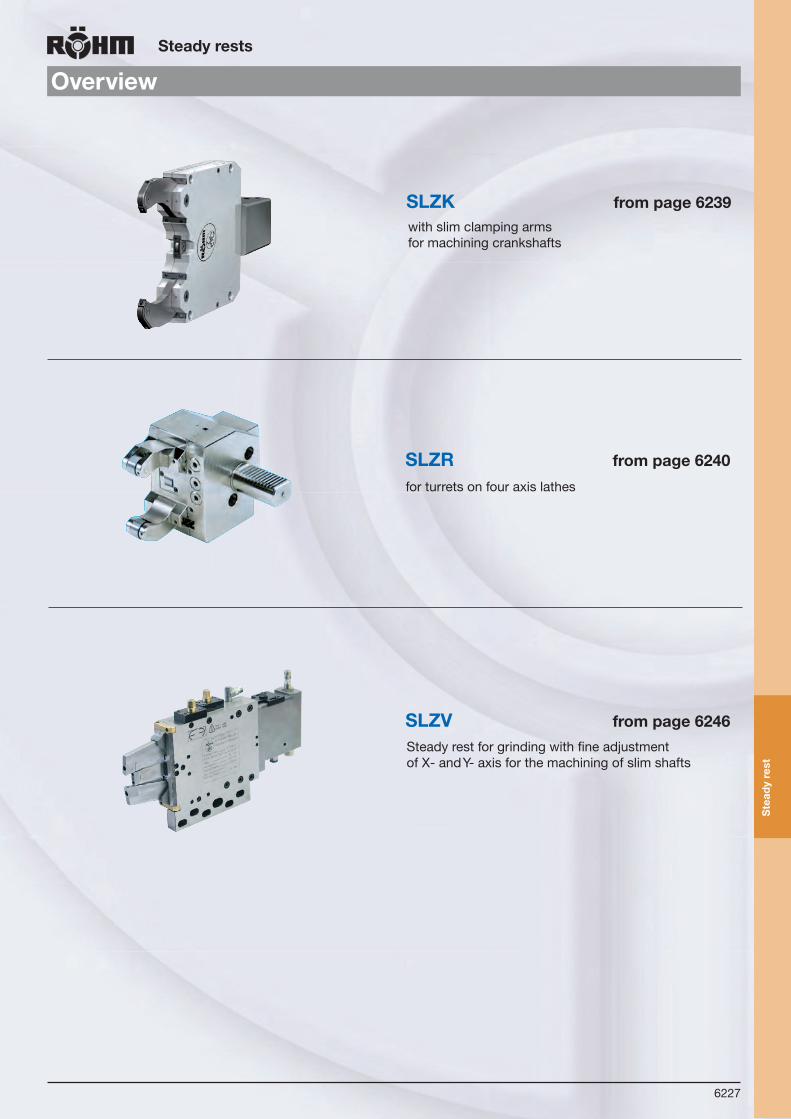
6227
Overview
Steadyrests
Ste
ady
rest
for turrets on four axis lathes
Steady rest for grinding with fine adjustment of X- and Y- axis for the machining of slim shafts
with slim clamping arms for machining crankshafts
SLZK frompage6239
SLZR frompage6240
SLZV frompage6246

6228
Ste
ady
rest
s
Steadyrests
Technicalfeatures
With these steady rests, RÖHM engineers have made an important contribution to solving the problems related to supporting slender work (shafts) on lathes.
The requirements that must be met by modern steady rests can be summarized as follows:
Tomoreefficientturningofslendershafts
Large clamping range with no need for interchangeable elements
Compact (short and robust) construction
High centering accuracy and repeatability throughout the clamping range
No loss of accuracy when changing clamping pressure
Central lubrication
The steady rests of the SLZ range meet all these requirements. The cam-and-lever system has been optimizedin comparison to known solutions and permits the three rollers performing the centering and supporting functionsto be applied to the workpiece almost symmetrically with a spacing of 3 x 120o.
This feature together with an innovative internal compensating system (on request) which compensates for the displacement of the workpiece center occurring under changing pressures in conventional steady rests accounts for the unusually high centering accuracy throughout the working range.
Forcentrallubricationonlyoneconnectionisnecessary.Theproportioningunitsfortherollersareintegratedinthebodyoftherestandassuresufficientgreasingintherespectivegreasinginterval.
Various mounting options permit these steady rests to be used for turning outside diameters, facing, centering, drilling, internal machining, recessing, parting-off, copy turning etc., both as fixed steady rests and following rests, in any desired angular positioning relative to the cutting tool.
Even with a fixed steady rest, the outside diameter of the shaft can be turned on its entire length since the clearancebetween the rollers leaves room for the cutting tool and the rollers are reclamped with self-centering action. As a rule, 2 steady rests should be used for support so that one can support the work on the full width of the rollers at any time.
The attached actuating cylinder can be selected for hydraulic or pneumatic actuation. The only difference is in the size of the piston areas. In the standard version, the cylinder is attached as an axial extension of the steady rest hou-sing. With Type SLZB the cylinder is bolted to the side of the steady rests body.
Depending on requirements and proposed use, the steady rest is available with a stroke monitor or safety device only. The supporting rollers are carried in radial and axial antifriction bearings. Both cylindrical and convex rollers are available as standard equipment. Convex rollers must be used for tapered work and follower rests. Here again, special designs are available on request to complete the range.

6229
Lüne
tten
Steadyrests
Versions
OilcentrallubricationsRÖHM steady rests are normally equipped with central lubrication. The necessary dosage valves are situated in the steady rest body. Lubrication cycles 2 - 5 minutes depending on load at a cycle pressure between 16 - 50 bar.
Lüne
tten
Stea
dy re
sts
ManualLubrication(Option) Steady rest for average load and low dirt quote. Lubrication points and rollers will be greased with grease nipples and a grease gun.Lubrication cycle all 4 to 8 operation hours depending on application.
Lüne
tten
Stea
dy re
sts
CylindricalrollerRoller design for standard cases
Convexroller for conical workpieces andfollowing steady rests
Specialrollers on request
Chipprotector Standard design
Ste
ady
rest
s

6230
Steadyrests
SLZstandarddesign
Tool group C 15Type 576 Self-centering steady rests SLZ oilorairoperatedWith mountedcylinder
ClampingrangesType SLZ047 SLZ08105 SLZN1152 SLZN1517 SLZN40200 SLZ325 SLZ50315 SLZ95360
Clamping range - with chip protection 15-62 16-101 22-140 25-158 40-195 40-240 50-305 95-355
Clamping range - without chip protection 4-70 8-105 11-152 15-170 40-200 35-250 50-315 95-360
Max. radial clamping range - d3 70 105 161 170 200 250 315 360
With chip protectors RZ 685751 685755 1685575 1685579 1685583 685779 685787 1685604With chip protectors RB 685752 685756 1685576 1685580 1685584 685780 685789 1685605Without chip protectors RZ 685753 685757 1685577 1685581 1685585 685781 685790 1685606Without chip protectors RB 685754 685758 1685578 1685582 1685586 685782 685791 1685607d1 4 8 11 15 40 35 50 95
d2 70 105 152 170 200 250 315 360
d3 70 105 161 170 200 250 315 360
A 206 279,5 432,5 440,5 459,5 617,5 699 730,5
B 137 197 306 314 333 451 521,5 553
C 51 70 115 123 138 146 203 234,5
D 69 82,5 126,5 126,5 126,5 166,5 177,5 177,5
E 64 85 135 135 135 240 270 270
F 118 170 262 262 262 365 400 400
G 11 14 18 18 18 23 23 23
H 132 190 290 290 290 400 440 440
K 54 58 85 85 85 110 145 145
L 102 143 223 223 223 331,5 361 361
L1 115,5 164 251 251 251 364 406 406
Clamping arm width M 20 31 48 48 48 60 75 75
Roller width N 11,5/9 20,5/19 30/25 30/25 30/25 40/35 45/40 45/40
O 19 35 47 47 47 52 60 60
P - - 9,5 9,5 9,5 13 21,5 21,5
P1 - - 34 34 34 12,5 12,5 12,5
P2 - - 117,5 117,5 117,5 160 160/175 160/175
R 48,6 74,5 122 130 143,5 183 209 242
S1 8 9,5 - - - - - -
S2 23 33 - - - - - -
S3 10 28 - - - - - -
S4 34,5 28 - - - - - -
K1 - 61,5 85 85 85 98 150 141
K2 - 30 42,5 42,5 42,5 55 59,5 59,5
d 40 50 80 80 80 100 100 100
e 60 68 98 98 98 124 142 142
e1 87 92 145 145 145 156 156 156
T - - - - - 45 31,5 31,5
T1 - - - - - 30° 30° 30°
R1 121 190 291 303 326 394 483 534
Weight kg 7 14,5 47 47 48 115 185 190
ZS M 10x1 M 10x1 M 10x1 M 10x1 M 10x1 M 10x1 M 10x1 M 10x1
SP G 1/8” G 1/8” G 1/8” G 1/8” G 1/8” G 1/8” G 1/8” G 1/8”
* At constant pressure and clamping force
Sel
f-ce
nter
ing
stea
dyr
ests
SLZ
from stock 4 - 6 weeks ▲ on request
T1
S4
S3
T
P2
D
H1
Ød
L
L1
H e1
eK
ØO
M NK2
K1
Ød2
Ød1
ØG
F
A
B
EC
S2
S1
PP1
SP ZS
ZS
SP
d3
R1
R
G 1/4“ Unclamping
G 1/4“ Clamping

6231
Steadyrests
SLZClampingrangesType SLZ047 SLZ08105 SLZN1152 SLZN1517 SLZN40200 SLZ325 SLZ50315 SLZ95360
Cylinder-Ø C40 C50 C80 C80 C80 C100 C100 C100
Cylinder surface area cm2 12,5 19,6 50 50 50 78,5 78,5 78,5
Max. operating pressure bar 25 53 62 68 40 57 80 58
Operating pressure bar 5-20 6-30 6-40 6-44 6-25 8-42 8-58 8-40
Clamping force per roller at max. operating pressure N
830 1960 6500 6500 4160 11000 14000 10460
Max. permissible clamping force per roller N 1040 3500 10000 10000 6670 15000 20000 15000
Clamping force per roller at 20 bar N 830 1300 3230 2800 2800 5200 5200 5000
Centering accurancy over the entire clamping range mm
0,02* 0,02* 0,04* 0,04* 0,04* 0,05* 0,06* 0,06*
Repeat accurancy for the same clamping-Ø at the same operating pressure mm
0,005 0,005 0,005 0,005 0,005 0,005 0,01 0,01
Max. roller peripheral speed m/min 800 800 725 725 725 715 700 700
Max. roller peripheral speed at half the max. clamping force per roller m/min
900 950 875 875 875 860 850 850
Displacement of the geometrical workpiece center in the event of a 20-70% change in the operating pressure /at constant force) mm Compensating system on request
0,02 0,02 0,03 0,03 0,03 0,03 0,03 0,03
* At constant pressure and clamping force
Sel
f-ce
nter
ing
stea
dyr
ests
SLZ
from stock 4 - 6 weeks ▲ on request

6232
Steadyrests
AccessoriesSLZ
Tool group C 15Type 576-ZR Cylindricalrollers
R
ØO
ØE
ØF
B
A
Itemno. For A B Ø F Ø O Ø E R
735120 SLZ 047 20 11,5 6 19 6 500
1831277 SLZ/SLZB 08105 31 20,5 15 35 15 500
649513SLZ/SLZB 1152, SLZ/SLZB 1517, SLZ/SLZB 40200
48 30 20 47 21 1000
649514 SLZ/SLZB 325 60 40 20 52 21 3000
381420 SLZ/SLZB 50315, SLZ/SLZB 95360 75 45 20,1 60 21 3000
Rollers SLZ 047 and 08105 without axle
Tool group C 15Type 576-BR Convexrollers
R
ØO
ØF
ØE
B
A
Itemno. For A B Ø F Ø O Ø E R
735120 SLZ 047 20 11,5 6 19 6 500
6497872) SLZ/SLZB 08105 31 20,5 15 35 15 100
6497801) SLZ/SLZB 08105 31 20,5 15 35 15 100
649515SLZ/SLZB 1152, SLZ/SLZB 1517, SLZ/SLZB 40200
48 30 20 47 21 100
649516 SLZ/SLZB 325 60 40 20 52 21 100
381426 SLZ/SLZB 50315, SLZ/SLZB 95360 75 45 20,1 60 21 500
1) 1x central2) 2x outerSLZW on request
Tool group C 15Type 576-RZCentralscraperRZ
CENTRAL SCRAPER
Ø D
1C
Ø D
2C
Itemno. For Clamping ranges D1C Clamping ranges D2C
836591 SLZ 047 15 62
836604 SLZ/SLZB 08105 16 101
1831222 SLZ/SLZB 1152 22 140
1831134 SLZ/SLZB 1517, SLZ/SLZB 40200 25/40 158/195
735005 SLZ/SLZB 325 40 240
836584 SLZ/SLZB 50315, SLZ/SLZB 95360 50/95 305/355
Scraper RB on request
Tool group C 15Type 576-SSA ChipprotectorouterSet = 2 Pieces
LATERAL CHIP PROTECTION
Ø D
1C
Ø D
2C
Itemno. For Clamping ranges D1C Clamping ranges D2C
836609 SLZ 047 15 62
836610 SLZ/SLZB 08105 16 101
836611 SLZ/SLZB 1152, SLZ/SLZB 1517, SLZ/SLZB 40200 22/25/40 140/158/195
836612 SLZ/SLZB 325 40 240
836613 SLZ/SLZB 50315, SLZ/SLZB 95360 50/95 305/355
Acc
esso
ries
SLZ
from stock 4 - 6 weeks ▲ on request

6233
Steadyrests
SLZBwithsidemountedcylinder
Tool group C 15Type 576 Self-centering steady rests SLZBoilorairoperatedWith sidemountedcylinder
ClampingrangesType SLZB08105 SLZNB1152 SLZNB1517 SLZNB40200 SLZB325 SLZB50315 SLZB95360
Clamping range - with chip protection 16-101 22-140 25-158 40-195 40-240 50-305 95-355
Clamping range - without chip protection 8-105 11-152 15-170 40-200 35-250 50-315 95-360
Max. radial clamping range - d3 105 161 170 200 250 315 360
With chip protectors RZ 685792 1685543 1685547 1685551 685744 685740 1685612With chip protectors RB 685793 1685544 1685548 1685552 685743 685739 1685613Without chip protectors RZ 685794 1685545 1685549 1685553 685742 685738 1685614Without chip protectors RB 685795 1685546 1685550 1685554 685741 685737 1685615d1 8 11 15 40 35 50 95
d2 105 152 170 200 250 315 360
d3 105 161 170 200 250 315 360
A 228 341 349 368 489 566,5 598
B 197 306 314 333 451 521,5 553
C 70 115 123 138 146 203 234,5
D 31 35 35 35 38 45 45
E 85 135 135 135 240 270 270
F 170 262 262 262 365 400 400
G 14 18 18 18 23 23 23
H 190 290 290 280 400 440 440
K 58 85 85 85 110 145 145
L 143 223 223 223 331,5 361 361
L1 164 251 251 251 364 406 406
Clamping arm width M 31 48 48 48 60 75 75
Roller width N 20,5/19 30/25 30/25 30/25 40/35 45/40 45/40
O 35 47 47 47 52 60 60
P - 9,5 9,5 9,5 13 21,5 21,5
P1 - 34 34 34 12,5 12,5 12,5
P2 - 117,5 117,5 117,5 160 160/175 160/175
R 74,5 122 130 143,5 183 209 242
S1 9,5 - - - - - -
S2 33 - - - - - -
S3 28 - - - - - -
S4 28 - - - - - -
K1 61,5 85 85 85 98 150 141
K2 30 42,5 42,5 42,5 55 59,5 59,5
a 95 140 140 140 180/136 180/136 180/136
b 53 100 100 100 106/119 101/114 101/114
d 50 80 80 80 100 100 100
g 69 102 110 135 180 182,5 214
T - - - - 45 31,5 31,5
T1 - - - - 30° 30° 30°
R1 190 281 305 326 394 483 534
Weight kg 14,5 51 51 52 134 194 199
ZS M 10x1 M 10x1 M 10x1 M 10x1 M 10x1 M 10x1 M 10x1
SP G 1/8” G 1/8” G 1/8” G 1/8” G 1/8” G 1/8” G 1/8”
* At constant pressure and clamping force
Sel
f-ce
nter
ing
stea
dyr
ests
SLZ
B
from stock 4 - 6 weeks ▲ on request
T1
R1
S2
S1
b
K M N
ØO
T
S4
S3
A
Ød3
LL1
g
Ød2
Ød1 a
D
ØG
B
F
EC
ØdH
K2
K1P2
PP1
SP
ZS
ZSSP
R
G 1/4“ Unclamping
G 1/4“ (2X) Clamping

6234
Steadyrests
SLZBClampingrangesType SLZB08105 SLZNB1152 SLZNB1517 SLZNB40200 SLZB325 SLZB50315 SLZB95360
Cylinder-Ø C50 C80 C80 C80 C100 C100 C100
Cylinder surface area cm2 19,6 50 50 50 78,5 78,5 78,5
Max. operating pressure bar 53 62 68 40 57 80 58
Operating pressure bar 8-30 8-40 8-44 8-25 8-42 8-58 4-40
Clamping force per roller at max. operating pressure N
1960 6500 6500 4160 11000 1400 10460
Max. permissible clamping force per roller N 3500 10000 10000 6670 15000 2000 15000
Clamping force per roller at 20 bar N 1300 3230 2800 2800 5200 5200 5000
Centering accurancy over the entire clamping range mm
0,02* 0,04* 0,04* 0,04* 0,05* 0,06* 0,06*
Repeat accurancy for the same clamping-Ø at the same operating pressure mm
0,005 0,005 0,005 0,005 0,005 0,01 0,01
Max. roller peripheral speed m/min 800 725 725 725 715 700 700
Max. roller peripheral speed at half the max. clamping force per roller m/min
950 875 875 875 860 850 850
Displacement of the geometrical workpiece center in the event of a 20-70% change in the operating pressure /at constant force) mm Compensating system on request
0,02 0,03 0,03 0,03 0,03 0,03 0,03
* At constant pressure and clamping force
Sel
f-ce
nter
ing
stea
dy
r est
sS
LZB
from stock 4 - 6 weeks ▲ on request

6235
Steadyrests
AccessoriesSLZB
Tool group C 15Type 576-ZR Cylindricalrollers
R
ØO
ØE
ØF
B
A
Itemno. For A B Ø F Ø O Ø E R
1831277 SLZ/SLZB 08105 31 20,5 15 35 15 500
649513SLZ/SLZB 1152, SLZ/SLZB 1517, SLZ/SLZB 40200
48 30 20 47 21 1000
649514 SLZ/SLZB 325 60 40 20 52 21 3000
381420 SLZ/SLZB 50315, SLZ/SLZB 95360 75 45 20,1 60 21 3000
Rollers SLZ 047 and 08105 without axle
Tool group C 15Type 576-BR Convexrollers
R
ØO
ØF
ØE
B
A
Itemno. For A B Ø F Ø O Ø E R
6497872) SLZ/SLZB 08105 31 20,5 15 35 15 100
6497801) SLZ/SLZB 08105 31 20,5 15 35 15 100
649515SLZ/SLZB 1152, SLZ/SLZB 1517, SLZ/SLZB 40200
48 30 20 47 21 100
649516 SLZ/SLZB 325 60 40 20 52 21 100
381426 SLZ/SLZB 50315, SLZ/SLZB 95360 75 45 20,1 60 21 500
1) 1x central2) 2x outerSLZW on request
Tool group C 15Type 576-RZCentralscraperRZ
CENTRAL SCRAPER
Ø D
1C
Ø D
2C
Itemno. For Clamping ranges D1C Clamping ranges D2C
836604 SLZ/SLZB 08105 16 101
1831222 SLZ/SLZB 1152 22 140
1831134 SLZ/SLZB 1517, SLZ/SLZB 40200 25/40 158/195
735005 SLZ/SLZB 325 40 240
836584 SLZ/SLZB 50315, SLZ/SLZB 95360 50/95 305/355
Scraper RB on request
Tool group C 15Type 576-SSA ChipprotectorouterSet = 2 Pieces
LATERAL CHIP PROTECTION
Ø D
1C
Ø D
2C
Itemno. For Clamping ranges D1C Clamping ranges D2C
836610 SLZ/SLZB 08105 16 101
836611 SLZ/SLZB 1152, SLZ/SLZB 1517, SLZ/SLZB 40200 22/25/40 140/158/195
836612 SLZ/SLZB 325 40 240
836613 SLZ/SLZB 50315, SLZ/SLZB 95360 50/95 305/355
Acc
esso
ries
SLZ
B
from stock 4 - 6 weeks ▲ on request

6236
Steadyrests
SLZheavydesign
Tool group C 15Type 576 Self-centering steady rests SLZheavydesign oilorairoperatedHeavydesign for high loads
ClampingrangesType SLZ437 SLZ5040 SLZ1546 SLZ1060 SLZ3580
Clamping range - with chip protection 75-350 75-380 150-430 100-590 350-770
Clamping range - without chip protection 40-375 50-400 150-460 100-600 350-800
With chip protectors RZ 685899 1685722 685897 685896 685895With chip protectors RB 685894 685893 685892 685891 685890Without chip protectors RZ 685889 685888 685887 685886 685885Without chip protectors RB 685884 685883 685882 685881 685880d1 40 50 150 100 350
d2 370 400 460 600 800
A 1086 1100 1110 1465 1810
B 762 800 800 1105 1340
H 730 730 730 1020 1270
K 170 170 170 270 440
Clamping arm width M 90 90 90 170 240
Roller width N 60/50 60/50 60/50 104/95 150/138
O 80 80 80 160 220
d 120 120 120 150 180
e 150 150 150 260 370
e1 240 240 240 280 320
Weight kg 490 500 570 2000 4000
Cylinder-Ø C120 C120 C120 C150 C180
Cylinder surface area cm2 113 113 113 176 254
Max. operating pressure bar 100 100 85 90 98
Operating pressure bar 10-40 10-40 10-40 10-40 10-40
Clamping force per roller at max. operating pressure N
15000 15000 15000 23000 32000
Max. permissible clamping force per roller N 35000 35000 40000 50000 80000
Centering accurancy over the entire clamping range mm
0,04* 0,04* 0,04* 0,04* 0,06*
Repeat accurancy for the same clamping-Ø at the same operating pressure mm
0,01 0,01 0,01 0,01 0,01
Max. roller peripheral speed m/min 725 725 725 725 715
Max. roller peripheral speed at half the max. clamping force per roller m/min
875 875 875 875 860
Displacement of the geometrical workpiece center in the event of a 20-70% change in the operating pressure /at constant force) mm Compensating system on request
0,06 0,06 0,06 0,06 0,06
* At constant pressure and clamping force
Ste
ady
rest
sS
LZ
- he
avy
desi
gn
from stock 4 - 6 weeks ▲ on request
Safety valve
R 1/8“ Air purge connection forsteady rest and for middle roller
H
BA
e1d
Ød1
Ød2
M10x1 Connectionfor central lubrication
N eKM
ØO

6237
Steadyrests
SLZWonearmwithextraopening
Tool group C 15Type 576 Self-centering steady rests SLZW oilorairoperatedOnearmextraopening
ClampingrangesType SLZW445 SLZW890 SLZW12150 SLZW35220 SLZW50270
Clamping range - without chip protection 4-50 8-90 12-150 35-220 50-270
With chip protectors RZ 685555 1685658 685917 685916 685915With chip protectors RB 685914 1685659 685912 685911 685910Without chip protectors RZ 685696 1685660 685907 685906 685905Without chip protectors RB 685904 1685661 685902 685901 685900d1 4 8 12 35 50
d2 50 90 150 220 270
A 206 297 439,5 628 726
B 137 197 314 451 545
C 51 70 123 146 203
D 33 52,5 93 124,5 156
E 64 85 135 240 270
F 118 170 262 365 400
G 11 14 18 23 23
H 132 190 290 400 446
I 104 150 221 329,5 390
K 45 55 80 110 145
L1 119 164 251 364 433
Clamping arm width M 20 31 48 60 75
Roller width N 11,5/9 17,5/14 30/25 40/35 45/40
O 19 30 47 52 60
Z 25 45 75 110 135
U 36,5 62 103,5 143,5 168
T 30° 30° 30° 30° 30°
R 47,5 74,3 128 178 223,5
S 74 111 180 256 310
K1 - 61 85 130 150
K2 - 27 28,5 55 67,5
d 40 50 80 100 100
e 60 68 98 116,5 139
e1 87 92 140 186 156
L2 40 26 28 21 30
L3 11 14,5 9 50 17,5
Weight kg 6 14,5 50 130 190
Cylinder-Ø C40 C50 C80 C100 C100
Cylinder surface area cm2 12,5 19,6 50 78,5 78,5
Max. operating pressure bar 22 45 60 50 70
Operating pressure bar 6-18 8-30 8-40 8-38 8-50
Clamping force per roller at max. operating pressure N 750 1960 6000 9950 12000
Max. permissible clamping force per roller N 900 2900 9400 11000 16000
Clamping force per roller at 20 bar N 83 130 2900 4800 4800
Centering accurancy over the entire clamping range mm 0,02* 0,02* 0,04* 0,05* 0,07*
Repeat accurancy for the same clamping-Ø at the same operating pressure mm
0,005 0,005 0,005 0,005 0,01
Max. roller peripheral speed m/min 800 800 725 715 700
Max. roller peripheral speed at half the max. clamping force per roller m/min
900 950 875 860 850
* At constant pressure and clamping force
Sel
f-ce
nter
ing
stea
dyr
ests
SLZ
W
from stock 4 - 6 weeks ▲ on request
L3
L2 eM N K
ØO
R 1/4“ ClampingR 1/4“Unclamping
R 1/8“ Air purge connection for steady rest and for middle roller
T
L2
ØG
H
K2
K1K1
Ød2
Ød1
ZD
U
L2
S F
L1I
Ød e1
AB
EC
R
M 10 x 1 Connection forCentral lubrication

6238
Steadyrests
SLZCextremelycompactdesign
from stock 4 - 6 weeks ▲ on request
Tool group C 15Type 576 Self-centering steady rests SLZC - oilorairoperatedExtremely compact design, developed for minimummountingdimensions
ClampingrangesType SLZC60280 SLZC80390 SLZC100410 SLZC135460 SLZC215510
Clamping range - without chip protection 60-280 80-390 100-410 135-460 215-520
With chip protectors RZ 1685616 1685620 1685624 1685628 1685632With chip protectors RB 1685617 1685621 1685625 1685629 1685633Without chip protectors RZ 1685618 1685622 1685626 1685630 1685634Without chip protectors RB 1685619 1685623 1685627 1685631 1685635d1 60 80 100 135 215
d2 280 390 410 460 520
A 580 755 763 816 817
B 450 607 617 670 685
C 168 230 240 215 245
D 130 148 146 146 132
E 180 240 240 330 300
F 360 445 445 640 640
F1 360 445 445 610 610
G 23 23 23 27 27
H 400 485 485 680 680
K 125 150 150 150 150
Clamping arm width M 60 75 75 75 75
Roller width N 40/35 45/40 45/40 29 29
O 52 60 60 80 80
R 200 265 275 290 310
d 90 100 100 120 120
e1 184 194 194 215 215
T 100 130 130 150 150
T1 15° 15° 15° 15° 20°
T2 61 50 50 77 85
T3 30° 30° 30° 30° 30°
Weight kg 85 170 170 390 380
ZS G 1/8” G 1/8” G 1/8” G 1/8” G 1/8”
SP G 1/8” G 1/8” G 1/8” G 1/8” G 1/8”
WS G 1/4” G 1/4” G 1/4” G 1/4” G 1/4”
Operating pressure bar 8-70 8-80 8-80 8-80 8-80
Max. permissible clamping force per roller N 14500 20000 20000 25000 25000
Centering accurancy over the entire clamping range mm
0,05* 0,06* 0,06* 0,06* 0,06*
Repeat accurancy mm 0,007* 0,01* 0,01* 0,01* 0,01*
Max. roller peripheral speed m/min 715 700 700 700 700
* At constant pressure and clamping forceWater connection (WS) on request
Sel
f-ce
nter
ing
stea
dyr
ests
SLZ
C
T3GØ
d1Ø
d2R
WS
SPZS
Øde1 H
T2
DT
ØO
FF1
A
B
EC
NMK
G 1/4“ Clamping
G 1/4“ Unclamping
T1
Chip protection with option for water outlet(upon request)

6239
Steadyrests
SLZKwithslimclampingarms
from stock 4 - 6 weeks ▲ on request
Tool group C 15Type 576 Self-centering steady rests SLZK oilorairoperatedWith slimclampingarms, developed for a machining crankshafts
ClampingrangesType SLZK08101-15
SLZK08101-19
SLZK08101-22
SLZK40200-18
SLZK40200-22
SLZK325-19
SLZK325-22
SLZK325-29
Clamping range - with chip protection 16-101 16-101 16-101 30-185 30-185 35-248 35-248 35-248
Clamping range - without chip protection 8-105 8-105 8-105 30-185 30-185 35-250 35-250 35-250
With chip protectors RZ 1685636 1685638 1685640 1685642 1685644 1685646 1685648 1685650Without chip protectors RB 1685637 1685639 1685641 1685643 1685645 1685647 1685649 1685651d1 8 8 8 30 30 35 35 35
d2 105 105 105 185 185 250 250 250
d3 106 106 106 190 190 254 254 254
Max. Ø opening range d4sw 113 113 113 200 200 263 263 263
A 279,5 279,5 279,5 458,5 458,5 617,5 617,5 617,5
B 197 197 197 333 333 451 451 451
C 70 70 70 138 138 146 146 146
D 82,5 82,5 82,5 125,5 125,5 166,5 166,5 166,5
E 85 85 85 135 135 240 240 240
F 170 170 170 262 262 365 365 365
G 14 14 14 18 18 23 23 23
H 190 190 190 290 290 400 400 400
K 50 50 50 85 85 110 110 110
L 143 143 143 223 223 331,5 331,5 331,5
L1 164 164 164 251 251 364 364 364
Clamping arm width M 15 18 22 18 22 19 22 29
Roller width N 8 10 13 11 13 11 13 16
O 35 35 35 47 47 52 52 52
R 74,5 74,5 74,5 143,5 143,5 183 183 183
d 50 50 50 60 60 60 60 60
e 68 68 68 98 98 124 124 124
e1 92 92 92 145 145 156 156 156
T - - - - - 45 45 45
T1 - - - - - 30° 30° 30°
R1 190 190 190 320 320 394 394 394
Weight kg 11,5 11,5 11,5 40 40 80 80 80
ZS G 1/8” G 1/8” G 1/8” G 1/8” G 1/8” G 1/8” G 1/8” G 1/8”
SP G 1/8” G 1/8” G 1/8” G 1/8” G 1/8” G 1/8” G 1/8” G 1/8”
Operating pressure bar 8-32 8-40 8-50 8-60 8-75 8-70 8-80 8-80
Max. permissible clamping force per roller N
2100 2700 3350 5600 7000 6600 7500 7500
Centering accurancy over the entire clamping range mm
0,03* 0,03* 0,03* 0,05* 0,05* 0,06* 0,06* 0,06*
Repeat accurancy mm 0,007* 0,007* 0,007* 0,007* 0,007* 0,01* 0,01* 0,01*
Max. roller peripheral speed m/min 750 750 750 715 715 700 700 700
Clamping force per roller at max. operating pressure N
210 270 335 560 700 660 750 750
Max. operating pressure bar 32 40 50 60 75 70 80 80
* At constant pressure and clamping force
Sel
f-ce
nter
ing
stea
dyr
ests
SLZ
K
T1
SP ZSC
A
F
G
Ød1
Ød2
MK e
e1
L1
TE
ØO
H
LN
D
B
Ød
R
G 1/4“ Clamping
G 1/4“ Unclamping
d3
Not includedR1

6240
Steadyrests
SLZRshaftinaccordancetoDIN69880
Tool group C 15Type 576 Self-centering steady rests SLZR oilorairoperatedWith shafts in accordance with DIN69880, forCNCturningmachineswith4axes
ClampingrangesType SLZR0432M SLZR0752M SLZR0865M
Clamping range - with chip protection 4-32 7-52 8-65
Clamping range - without chip protection 4-32 7-52 8-65
With chip protectors RZ 1685662 685879 685878With chip protectors RB 1685663 685877 685876Without chip protectors RZ 1685664 685875 685874Without chip protectors RB 1685665 685873 685872d1 4 7 8
d2 32 52 65
Ø A 20-30-40-50 30-40-50 30-40-50
B 86 104 112
E 117 138 146
H 80 94 105
I 18 23 23
K 36 50 50
L 54 73 73
Clamping arm width M 15 25 25
Roller width N 9 9 12
O 19 19 19
R 32 40 48
e1 54 60 60
T - - 23
α - - 30°
Weight kg 2,1 3,5 3,5
central lubrication in adaptor plate in steady rest in steady rest
Cylinder-Ø 30 32 32
Operating pressure bar 8-28 8-28 8-28
Max. working pressure bar 35 35 35
Max. permissible clamping force per roller N 950 950 1000
Centering accurancy over the entire clamping range mm
0,02* 0,02* 0,02*
Repeat accurancy for the same clamping-Ø at the same operating pressure mm
0,005 0,005 0,005
Max. roller peripheral speed m/min 950 950 950
* At constant pressure and clamping force
Sel
f-ce
nter
ing
stea
dyr
ests
SLZ
R
from stock 4 - 6 weeks ▲ on request
α
B F
E
T
e1
ØO
M N
ØA DIN 69880
Ød1
Ød2
IKL
H
R
Steady rest central lubrication
C variable
Hydraulic cylinder

6241
Sel
f-ce
nter
ing
stea
dy
rest
sS
LZ/
SLZ
B
Steadyrests
ConstructionprincipleSLZ/SLZB
All steady rests have an engraved identification number. This number must be provided when ordering replacement parts.
Type SLZ047
SLZ/SLZB08105
SLZ/SLZB1152
SLZ/SLZB1517
SLZ/SLZB40200
SLZ/SLZB325
SLZ/SLZB50315
SLZ/SLZB95360
Screw M M 10 M 12 M 16 M 16 M 16 M 20 M 20 M 20
Screw torque daN/m 4 7 12 12 12 19 21 21
Washer thickness S 4 4 4 4 4 5 5 5
Outer diameter of washer D 25 26 34 34 34 48 48 48
17
ØD
18
16 13
12
10
72 5 6
11
1
4
83
15 14
9
MS
ScrewReinforcedwasher
ComponentsSLZ/SLZB1. Body 2. Cam segment 3. Clamping arm outside 4. Clamping arm center 5. Bolt and roller 6. Clamping arm arbor 7. Return lever8. Roller center9. Roller
10. Scraper band11. Axle and rollers12. Cover13. Cylinder housing14. Cylinder flange15. Piston16. Piston rod17. Pressure sleeve18. Scraper center

6242
Ste
ady
rest
sS
LZ
Steadyrests
AccessoriesSLZseries
ZS = Central lubrication of the steady rest SE = Cylinder with safety valveHN = Control via proximity switch (not included in delivery) steady rest in open positionSS = Chip protection outer armsRZ = Cylindrical rollersRB = Convex rollersHK = Stroke monitoring rod
HK-IP5 = Stroke monitoring with 2 proximity switches (opening and closing) with seal housing IP552 (proximity switches not included in delivery)
MS = Manual lubrication, grease/oilRAB = Manual regulation of the opening of the clamping arms
ClampingarmcontrolsystemSLZ-HN
ControlsystemoftheclampingarmsSLZ-HK
Not included
Position only for SLZ-047
There is the option of attaching a sensor(proximity switch) to the steady rests asstandard, which measures the position of theopened steady rest. This option is not availablefor the steady rest of Type SLZ-047.The proximity switch is not included in thedelivery of the steady rest.
All steady rests of Type SLZ, SLZB,and SLZW can be equipped withholders and rods, or rod only, in orderto be able to recognize the closed aswell as the opened clamping armswith a proximity switch.
Cam switch / Position sensor
Not included

6243
Ste
ady
rest
sS
LZ
Steadyrests
AccessoriesSLZseriesEigenschaften der selbstzentrierenden Lünetten der Reihe „SLZ“
CC
G
External attachment forSLZ-047 only (upon request)
SP= Air purge connectionG1/8“ max 4 bar (58 psi)
SafetyvalveSE
Standardconfiguration
Pressurization
SP ZS
SE
HNRZ
SPR
R
G1/8"
All standard steady rests come equipped with a safety valve integrated in the cylinder. If the clamping pressure in the cylinder should be interrupted, the valve prevents the steady rest from opening. With following applications, the safety valve isn‘t necessary.This device is available as an option for the SLZ-047 series.
Thestandardsteadyrestisconfiguredasfollows:– Cylindrical rollers– Pressurization– Central lubrication– Axially extended cylinder with safety valve (except SLZ-047)– Proximity switch component (open steady rest) HN– Device for manual lubrication via grease cup or oiler
All RÖHM steady rests have a G 1/8“ air purge connection. This system protects the body of the steady rest from chip and dust penetration. When the steady rest is completely open, the air consumption is automatically reduced, but not completely interrupted to prevent unnecessary air consumption. The system includes the cleaning of the middle roller bearings. To activate thisoption, the screw „G“, which is located in bottom of the housing, must be removed. The pressure may differ between a minimumof 2 bar and a maximum of 4 bar (58 psi). The steady rest can also be used without the air purge. Drain holes are on the top andbottom part of the steady rest housing. It is recommended that the lower of the two seals is released to allow the coolant to drainand to prevent penetration of contaminants into the body of the steady rest.

6244
Ste
ady
rest
sS
LZ
Steadyrests
AccessoriesSLZseries
2030
40
5010
600 Bar
Ä
Clamping pressure change of 20% to 70%of the max. working pressure
Releasing
Clamping
ControlsystemoftheclampingarmsHK-IP5
This system allows the position of the clamping arms (open/closed on the workpiece) to be controlled via two proximity switches with O-ring seals (IP552), located in the housing. The proximity switch, which signals the closing of the steady rest during changing and the clamping diameter, is set with an external screw. The proximity switch and the bore must be considered by the customer.
Sometimes the opening of the clamping arms must be limited, e.g. to set the supporting roller diameter with the steady rest open or to limit the dimensions of the lateral clamping arms or to reduce the opening and closing times of the steady rest. Here, the „RAB“ cylinder (regulation of the clamping arm opening) can be used. The device limits the cylinder stroke to 75 % of the total stroke. Regulation is done manually. This device can be used with the steady rests of the SLZ and SLZB series. The device doesnot reduce the clamping range of the steady rest.
The steady rest is centered via operating pressure which is selected depending on the work to be done. The center of the workpiece is shifted according to the increasing/decreasing cylinder pressure, depending on the working conditions. The shifting of the workpiece center due to a pressure change is be reduced by the patented system. See the table „Characteristicsof the steady rest series SLZ, SLZB and the SLZ heavy series.
Regulationoftheclampingarmopeningsystem
Compensationrod(onrequest)
Maintaining the centercentering when theclamping pressurechanges
Ope
ning
lim
its o
f the
cla
mpi
ng a
rms

6245
Ste
ady
rest
sS
LZ/
S
LZB
Steadyrests
BracketsforsteadyrestsSLZ/SLZB
Precise steady rest function also depends on its stable and secure fastening to the lathe. The steady rest bracket must be made with corrugated, welded plates and meet the design standards.The bracket design of the steady rest depends on the Typee of steady rest and the application:
The mounting surface of the steady rest bracket must be absolutely flat in order not to distort the steady rest when fastening. The steady rest must be exactly centered along the X and Y axes of the lathe. Max. deviation 0.01 mm.
–
15°~
Lüne
tten
Stea
dy re
sts
–
15°~
Lüne
tten
Stea
dy re
sts
Space available
Height of the turning center
How the steady rest is used (fixed or following)
Position angle of the steady rest in relation to the dimensions of the tools.

6246
Ste
ady
rest
sS
LZV
Steadyrests
The main feature of the SLZV steady rest is that they can retract the arms inside the body, leaving the working area free and allowing, in this way, the loading of the pieces by automatic systems.
The minimum sizes, the high positioning and repeatability accuracy make this accessory the ideal tool for grinding operations on CNC-grinding machines. It can be used as a support for long shafts, for internal machining or when grinding on the clamping seat (follows the diameter).
The SLZV steady rest is equipped with a system for the fine adjustement in X and Y axis. It is generally manufactured with hard metal pads, but it can also be supplied with PKD (Diamond) pads, on request.
Withretractablearms
Technicalfeatures/ApplicationrangesSLZV

6247
Ste
ady
rest
sS
LZV
Steadyrests
Type:SLZV154045°
M 10x1
+/- 0,12
= =
X Y +/- 0,0610
50
1450
77
50
22
9650
23.5
32
83.5
Ø40
Ø15
44
278
11.5
150 94
143.
511
25
15.5
81
16.5
Lüne
tten
Stea
dy re
sts
G 1/8“ Open and arms retract G 1/8“ Air purge connection
Min. 1 Max. 4 bar
G 1/8“ Arms forwardand clamping
Never operate under pressure, in open position onlyNever operate under pressure, in open position only
Fine adjustment for „X-axis“ Fine adjustment for „Y-axis“
SLZVforgrinders

6248
Ste
ady
rest
sS
LZV
Steadyrests
SLZVforgrindersEigenschaften der selbstzentrierenden Lünetten der Reihe „SLZ“
45°
+/- 0,06YX
+/- 0,12
M 10x1
36 164
28
=
1117
6
24 17
22
50
7 7
11
=
50
50 14
32
Ø 6
010
0
140
53
17
130
330
Ø 2
0
34
Type:SLZV2060
G 1/8“ Open andarms retract
G 1/8“ Air purge connection
Min. 1 Max. 4 bar
G 1/8“ Arms forwards and clamping
Never operate under pressure, in open position onlyNever operate under pressure, in open position only
Fine adjustment for „X-axis“ Fine adjustment for „Y-axis“

6249
Ste
ady
rest
sS
LZV
Steadyrests
SLZVforgrinders
Type:SLZV4070
+/- 0,06
+/- 0,06
YX
51
19
357
14
Ø 7
0
Ø 3
5
210
43 198 11695
95 7575
116
80 110
Ø 14
55
G 1/8“ Open and arms retract G 1/8“ Air purge connection
Min. 1 Max. 4 bar
G 1/8“ Arms forward and clamping
Never operate under pressure, in open position only
Fine adjustment for „X-axis“ Fine adjustment for „Y-axis“
Never operate under pressure, in open position only

6250
stea
dyr
ests
SLZ
V
Steadyrests
SLZVforgrinders
Technical featuresType SLZV1540 SLZV2060 SLZV4070 SLZVB2085/180
Itemno.withfineadjustmentoverX.axis 1685730 1685731 1685732 1685733
Clampingdiametermm 15 – 40 20 – 60 40 – 70 20 – 85
Cylinder-Type C32 = 8 cm2 C32 = 8 cm2 C40 = 12 cm2 -
Pistonstrokemm 59 76 85 -
Max.workingpressurebar 40 22 48 -
Operatingpressuremin.bar 5 - 25 3 - 22 8 - 28 -
ClampingpowerperarmN/bar 350 N / 15 bar 350 N / 15 bar 1100 -
Centeringaccuracyoverwholerangemm 0,01 0,01 0,01 0,01
Repeatabilityatsameclampingdiameterandpressuremm 0,002 0,002 0,002 0,002
Type:SLZVB2085/1809
M12
Ø18
0
Ø 8
5
Ø 2
0
+/- 0,12 45.5
353.5
130 120
312
9090 10
310
3
10.5
40
65
10422
4
Lüne
tten
Stea
dy re
sts
Min. 1 Max. 4 bar
G 1/4“ Open and arms retract
G 1/8“ Air purge connection
G 1/4“ Arms forwardsand clamping
Never operate under pressure,in open position only
Fine adjustment „X-axis“
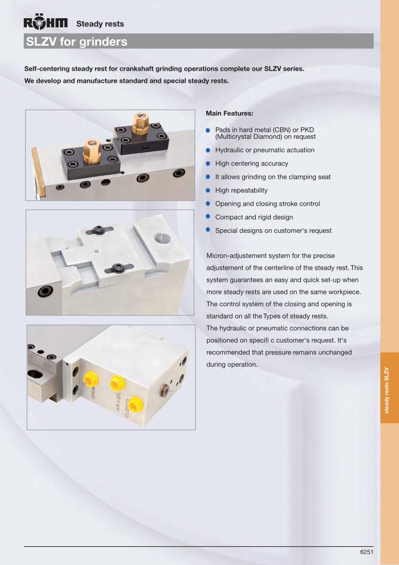
6251
stea
dyr
ests
SLZ
V
Steadyrests
SLZVforgrinders
MainFeatures:
Pads in hard metal (CBN) or PKD(Multicrystal Diamond) on request
Hydraulic or pneumatic actuation
High centering accuracy
It allows grinding on the clamping seat
High repeatability
Opening and closing stroke control
Compact and rigid design
Special designs on customer‘s request
Self-centeringsteadyrestforcrankshaftgrindingoperationscompleteourSLZVseries.
Wedevelopandmanufacturestandardandspecialsteadyrests.
Micron-adjustement system for the precise
adjustement of the centerline of the steady rest. This
system guarantees an easy and quick set-up when
more steady rests are used on the same workpiece.
The control system of the closing and opening is
standard on all the Types of steady rests.
The hydraulic or pneumatic connections can be
positioned on specifi c customer‘s request. It‘s
recommended that pressure remains unchanged
during operation.
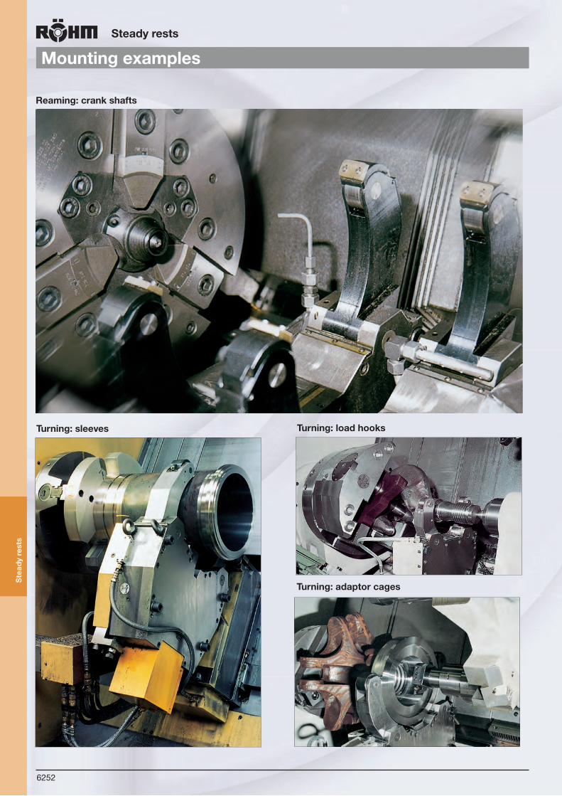
6252
Ste
ady
rest
s
Steadyrests
Mountingexamples
Reaming:crankshafts
Turning:adaptorcages
Turning:sleeves Turning:loadhooks

6253
Ste
ady
rest
s
Steadyrests
Specialdesigns
SpecialsteadyrestformachiningcrankshaftsThese steady rests are made upon request. Together with our customers, we construct the section of the clamping arms for supporting the workpiece individually according to the workpiece to be machined.Due to years of development and experience in this area, the company RÖHM is able to design special rollers with very slim sections, and therefore to design especially slim clamping arm sections.
SpecialsteadyrestformillingwormshaftsThese steady rests are made upon request. The width of the sliding jaws are designed together with our customers. Designed with increased rigidity, the lateral clamping arms and the middle guide rail are reinforced. Upon request, the steady rests can also be equipped with rinsing nozzles.

6254
Ste
ady
rest
s
Steadyrests
Specialdesigns
SteadyrestswithswivelarmsoftheSLserieswiththevibrationdampingdesign, the roller holder diameters of which are not perfectly round, are used for machining „slender“ turn parts.
Steadyrestwithhydraulicrotarydistributorwhichismountedontherevolver.
Eigenschaften der selbstzentrierenden Lünetten der Reihe „SLZ“
Eigenschaften der selbstzentrierenden Lünetten der Reihe „SLZ“

6255
Con
trol
sys
tem
san
dA
cces
sori
es
ControlsystemsandAccessories
Hydraulicpowerunits
1 Oil reservoir 100 ltr.2 Areator3 Self-regulating vane pump, Q = 19 l/min, pmax. = 80 bar4Pump carrier5 Elektronic- Motor P = 2,2 kW, 230/400 V 50 Hz6 Non-return-valve7 Pressure filter, Fineness of filtration 10 µm absolut8+9 Manometer 0-100 bar 10 Decompression valve, 5 – 80 bar adjustable 11 4/2 Control valve NG 6 with detent 24 V DC12+13Pressure switch, 10 – 100 bar adjustable (für internal/ext. clamping)
Itemno.438384
Technicaldata:
Standardpowerunits
The number of connections or consuming devices(e.g. power chuck, tailstocks, steady rests etc.)
The piston area and the stroke of the cylinder, thedesired stroking time and the functional sequenceas a basis for determining the required pumpcapacity.
If desired, these hydraulic power units can be deliveredwired, complete with terminal box or terminal box andprotective motor switch.
Complete hydraulic power units Control blocks
Designvariants:
Forsuchdesigns,thecustomershouldspecify:
1.
2.
Powerunitsinspecialdesign
12 13
9
11
810
7
6
2 43
1
5
Hydraulic power units are required to produce thepressure needed to actuate hydraulic power chuckingtools and cylinders. These power units are compactand equipped with electrically or manually operatedcontrol depending on the application.
Dimensions:Length 640Width 460Height approx. 1000

6256
ControlsystemsandAccessories
LSG
Con
trol
sys
tem
san
dA
cces
sor i
es
from stock 4 - 6 weeks ▲ on request
The air-operated control system LSG includes all components required for the control of rotary (LV, LVS, LT, LTS) or just stationary pneumatic cylinders.
If the directly machine control is not possible, an individual designed switchbox can be purchased from us.
Technicalfeatures:- Combined maintenance unit- 5/2 way solenoid valve- pressure switch- 5/2 way solenoid valve and pressure switch are wired on a clamping gib.
Tool group C 15Type 592-38 Air-operatedcontrolLSGR1/4
upto10bar, for air-operated power chucks
Itemno. Width Height Depth Control voltage Conn. thread
437107▲ 380 380 210 24V DC R 3/8" internal
438208▲ 380 380 210 110V - 50Hz R 3/8" internal
438209▲ 380 380 210 230V - 50Hz R 3/8" internal
Other voltages on request
This unit consits of: Separator & filtre CKS-08/10, Pressure regulator CKS-08/10, Lubricator CL-08/10
Tool group C 15Type 2250-H Airlineoiler&filterassembliesat 6 bar and 1 bar pressure drop
Itemno. Width Height Depth Max. flow
843603▲ 130 240 105 51 NM³/h
680999▲ 130 240 102 33 Nm³/h
All parts of LWE are separately available

6257
ControlsystemsandAccessories
LSGTool group C 15Type 592-32 Manuallyoperatedaircontrolvalve LHV2-position with safety control lever
Itemno. Width Height Depth Conn. thread internal Conn. thread external
418224 66,5 64 38 R ¼ “ M 16 x 1,5
Tool group C 15Type 592-04 Airshut-offvalve
Itemno. Width Height Depth Conn. thread
021237▲ 51 55 30 R 1/4” innen
Accessories: 2 screw unions pipe thread 1/4”, Id.-Nr. 8096
Tool group C 15Type 591-01 Hydrauliclow-pressurehoselineswith end fittings
LM18
×1,
5
L M18
×1,
5
Itemno. Length Thread
021201▲ 250 M18x1,5
021202▲ 500 M18x1,5
021203▲ 750 M18x1,5
021204▲ 1000 M18x1,5
021205▲ 1250 M18x1,5
021206▲ 1500 M18x1,5
021207▲ 1750 M18x1,5
021208▲ 2000 M18x1,5
021209▲ 2250 M18x1,5
021210▲ 2500 M18x1,5
021211▲ 3000 M18x1,5
021212▲ 4000 M18x1,5
Tool group C 15Type 592-00 Pneumaticconnect-inghosesRated pressure 12 bar
LM16
×1,
5
L M16
×1,
5
Itemno. Length
021241▲ 250
021242▲ 500
021243▲ 750
021244▲ 1000
021245▲ 1200
021246▲ 1500
021247▲ 1750
021248▲ 2000
Tool group C 15Type 1310-Q Doublehand-controlswitch
Itemno. Contents of delivery
220629▲ piece
Tool group C 15Type 1025-Q Doublefoot-controlswitch
Itemno. Contents of delivery
249325 piece
Con
trol
sys
tem
san
dA
cces
sori
es
from stock 4 - 6 weeks ▲ on request

KFD
6258
Axial-andRadialToolHeadsDriventools
CompletepartmachiningonCNClathesandmachiningcenters
Thetopqualityrangeoftoolheadsmanufacturedwiththehighestprecision,foryourcompletemachiningprojects.
Compact design of tool heads
High rigidity and roundness precision
High metal-removal rate
Long service life thanks to precision mounting
Maintenance-free operation thanks to
permanent lubrication with grease filling
All parts subject to wear case-hardened
All tools with external coolant supply
More flexible opportunities for operation
Reduction of time for manufacturing, setting-up,
and transport
Added bonus of reduced ancillary costs
Attractively-priced standarddesign
Technicalfeatures:
We offer a broad range of axial and radial tool heads in standard and special design. If we have aroused your interest, please contact us!
Angular tool head with collet reception
Milling unit with adjustable front head
Axial screw driving machine HSK A63
Milling tool head with rotatable millingshaft fork
Weprovideourcustomerswithabroadrangeofspecialdesigntoolheadsforeverymachiningsituation.
Dri
ven
tool
s

6259
Gri
ppin
gm
easu
ring
sy
stem
ED
S
Grippingmeasuringequipment
Contactlesstransmissionofdataandenergyfromandtothemeasuringhead(nocollectorrings)upto12000rpm
Electronic-dynamicalgrippingmeasuringequipmentEDS
MeasuringrangeEDS50 Itemno.161425 0-50kNperjawMeasuringrangeEDS100 Itemno.161426 0-100kNperjawPermittedoverload 110%ofmax.rangevalueMeasuringfrequency 1kHZDisplay1 speedrpmDisplay2 grippingforcekNNumberofjaws 2or3Grippingdia.EDS50 50-138Grippingdia.EDS100 85-175max.speed 12000rpmSpeedmeasuring every2sec.(0,5Hz)Measuringtolerance <3%ofmax.rangevalue
Dynamicmeasuring: Distancebetweenmeasuringheadandstatoraxial10-40mm,radial0-15mmSerialportPC/Laptop RS232CVoltage 220VACWeightmeasuringhead 0,65kg
Display-SoftwareforPC/LaptopData transmission via serial Port RS 232C.
EDS
Two points measuring method
digital LCD displayof clamping force and speed
Stator (non-rotating)
Measuring head (rotating)
Three pointsmeasuring method
EDS 50 + 100complete in a massive case,Itemno.161427
Input:Automatic reading of the measuring values (speed/clamping)Number of measuring step/graph scale freely selectable
Output:Table of speed/clamping forceGraph speed/clamping force
Technicalfeatures:Simple OperationSimple Inserting respective initialising Simple Reading of the valuesSimple Data transmission to the PC

6260
Pow
er-o
pera
ted
clam
ping
dev
ices
Generalinformationandguidelines
Power-operatedclampingdevices
To ensure safe operation of power-operated clamping devices, particularly of chucks, on heavy-duty lathes with high speeds certain criteria must be observed:
1. Whenmounting the power chuck and the clamping cylinder on the lathe, the following safety requirements must be met:
1.1 The machine spindle may only start when the clamping pressure has been built up in the actuating cylinder and the clamping has been carried out in the permissible working area.1.2 Unclamping may only be possible when the machine spindle has completely stopped.1.3 In case of a clamping energy failure, the workpiece must be firmly clamped until the spindle is completely stopped. (The Röhm safety cylindersmeet this requirement.)1.4 In case of a current failure and upon return of the current supply the actual control position may not be changed.1.5 In case of a clamping energy failure the machine spindle must be stopped by a signal.
2. The safety instructions given in the respective operation manual must be precisely followed.
3. After havingmounted the chuck and before starting the operation, the function of the chuck must be checked.Twoimportantpointsare:3.1 ClampingforceThe clamping force (±15%) stated for the clamping devicemust be reached atmax. actuating force/pressure.3.2 Strokecontrol A safety range must be provided for the stroke of the clamping piston in the front and rear end position. The machine spindle may only start after the clamping piston has crossed the safety range. Only limit switches meeting the requirements for safety limit switches in accordance with VDE 0113/12.73 section 7.1.3 may be used for monitoring the clamping path.4. If themax. speed of the lathe exceeds themax. speed of the clamping device or clamping cylinder, the machine must be equipped with a speed limitation device.5. When the clamping device has been changed, the stroke control must be adjusted to the new condition.6. When calculating the required clamping force formachining a workpiece, the centrifugal force of the clamping jaws must be considered.7. A reliable operation of the power chuck can only be guaranteed when themaintenance instructions contained in the instruction manual are precisely followed.Inparticularthefollowingpointsmustbeobserved:7.1 For the lubrication only the lubricants recommended in the operation manual shall be used. (An unsuitable lubricant can reduce the clamping force by more than 50%).7.2 The lubricationmust reach all surfaces to be lubricated. (At the narrow fits of themounting parts a high pressure is required for pressing-in the lubricant. For those purpose a pressure gun must be used).7.3 In order to distribute the grease evenly, actuate the clamping piston several times to its end positions, repeat the lubrication and then check the clamping force.

6261
Pow
er-o
pera
ted
clam
ping
dev
ices
Generalinformationandguidelines
Power-operatedclampingdevices
F spo -- F spzm . rc . a
30.nmax. =
8. Before restarting a serial machining operation and in between the maintenance intervals the clamping force should be checked by means of a load cell. ”Only regular checks ensure optimum reliability”.
9. It is recommended to move the clamping piston several times to its end positions after 500 clamping strokes at the latest. (In this way any lubricant pushed away will be returned to the pressure surfaces. The pressure force is thus maintained for a longer period of time.)
10. When using special clamping jawsthe following instructions must be observed: 10.1 The clamping jaws should be designed in such a way that their weight and height is as low as possible. The clamping point should as possible be as close to the frontside of the chuck. (Clamping points at a larger distancemay cause a higher surface pressure in the jaw guiding mechanism and may thus reduce the clamping force considerably.) 10.2 In case the special jaws are for constructional reasons wider and/or higher than the step jaws assigned to the clamping device, the resulting higher centrifugal forcesmust be considered when calculating the required clamping pressure and the rated speed.
Forcalculatingtheratedspeedforacertainmachiningtaskthefollowingformulaistobeapplied:
Fspo = initial clamping force with the chuck at standstill (N)Fspz = required clamping force with the chuck at standstill for a certain machining task (N) nmax. = max. admissible speed (min 1)m = mass of the entire jaw unit (kg) (base and top jaw)rc = center of gravity radius of the entire jaw unit (m)a = number of jaws
10.3 Welded jaws should not be used. If required, the welding seamsmust be checked as to their centrifugal and clamping force capacity.
10.4 Themounting screwsmust be arranged in such a way that the highest possible useful moment is reached.
11. Themax. speedmay only be used atmax. applied actuating force and with properly functioning chucks.12. In case of high speeds the chucks may only be used below a protective hood with sufficiently large dimensions.13. For power chucks with a jaw quick-change feature internal to the chuck a safety device is required which revents the machine spindle from rotating when the clamping jaws are released.14. After a collision the clamping devicemust be checked for fissures before being used again.15. Worn or damaged jaw fixing bolts must be replaced. Only use bolts of quality 12.9.

6262
Pow
er-o
pera
ted
clam
ping
dev
ices
Determiningtherequiredgrippingforceofapowerchuck
Power-operatedclampingdevices
I) Calculating the gripping force Fspz (without considering the effects of angular speed) required for the job (machining operation).
II) Determining the chuck’s initial gripping force Fspo with spindle stationary (taking into account the centrifugal forces of the jaws).
III) Determining the operating power required to provide the initial gripping force Fspo.
DefinitionofgrippingforceProgress in machining techniques has made it necessary for safety reasons not only to determine the necessarygrippingforce but also to know and consider its change with increasing angular speed.
The forces and moments generated by the machining operation must be properly absorbed and transmitted bythe chuck. The chuck accomplishes this task mainly by producingagrippingforce:
This gripping force is the arithmetic sum of the radial forces exerted on the workpiece by the jaws. The initialgripping force Fspo produced when the chuck is stationary can be measured at any time and is therefore control-lable. (Denoted by ’total gripping force’ in the gripping force / operating power diagrams).
The figures given in the catalogue refer only to chucks that are fully and correctly lubricated and in a properlyserviced condition. Many factors act on the clamping point during any machining operation. A precise specification of these factors in the form of universally applicable tables is not possible in this context.
In most cases it is sufficient in practice to use a simplified formula containing the fundamental determining factors(crude determination).
Determiningtherequiredgrippingforceofapowerchuckandthecorrespondingoperatingpower
Forces and moments acting at the machining and clamping points.
Fs = Main cutting force on radially applied tool
FsBo = Cutting force on axially applied tool (drill)
Fvax = Feeding force on axially applied tool
Fspz = Required total gripping force (without considering the effects of angular speed
Fc = Centrifugal force of the jaws = Loss of gripping force (see gripping force/speed diagram of each chuck TypeeFspo = (Total) initial gripping force with the chuck stationary
lz = Distance betwwen machining and clamping points
dz = Machining diameter
dsp = Chucking diameter
lsp = Chucking length

6263
Pow
er-o
pera
ted
clam
ping
dev
ices
Determiningtherequiredgrippingforceofapowerchuck
Power-operatedclampingdevices
I) Calculating the required gripping force Fspz
The gripping force required depends on the Type of work to be performed.Thecuttingforceontheturningtoolhasthreebasiccomponents: Main cutting force Fs - feeding force Fv - passive force (static force) Fp.During turning, the feeding force Fv and the passive force (static force) Fp are mainly absorbed by the jaw faces in contact with the seated workpiece. The remaining main cutting force produces a moment (Fs x dz/2) which must be absorbed by the chuck and transmitted by friction at the clamping point.Themomentproducedbythemaincuttingforceduringturningdeterminesthegrippingforcerequired:
ATurning
F s . S z dzsp dsp
F spz = .
F s = s . t . kc
The feeding force and passive components, Fv and Fp, are not included in this formula. If necessary for extreme conditions, they are included in the safety factor Sz.
The maincuttingforceFs is calculated from feed, depth of cut and material.
where:s = feed, mm/rev.t = depth of cut, mmkc = specific cutting force, kN/mm2
The product s x t (feed.depth of cut) =chip cross-section(cross sectional area of cut) can be obtained from Table 1.
Determiningthechipcrosssection[mm2]Table1
where: Fspz = gripping force required for a specific job with the chuck stationary Fs = main cutting force chucking ratio = µsp = cucking coefficient (friction between jaw and workpiece)
Sz = safety factor
F s . S z dzsp dsp
F spz = .
F s = s . t . kc
dz
dsp
machining diameter
chucking
(1)
(2)
Feed(mm) Depthofcutt(mm)
2 3 4 5 6 7 8 9 10 12
0,16 0,8 0,96 1,12 1,28 1,44 1,6 1,920,20 0,8 1,0 1,2 1,4 1,6 1,8 2,0 2,40,25 0,75 1,0 1,25 1,5 1,75 2,0 2,25 2,5 3,00,32 0,64 0,96 1,28 1,6 1,96 2,24 2,56 2,88 3,2 3,840,40 0,8 1,2 1,6 2,0 2,4 2,8 3,2 3,6 4,0 4,80,50 1,0 1,5 2,0 2,5 3,0 3,5 4,0 4,5 5,0 6,00,63 1,26 1,89 2,52 3,15 3,78 4,41 5,04 5,67 6,3 7,560,80 1,6 2,4 3,2 4,0 4,8 5,6 6,4 7,2 8,0 9,61,0 2,0 3,0 4,0 5,0 6,0 7,0 8,0 9,0 10,0 12,01,25 2,5 3,75 5,0 6,25 7,5 8,75 10,0 11,25 12,5 15,01,60 3,2 4,8 6,4 8,0 9,6 11,2 12,8 14,4 16,0 19,2
ThespecificcuttingforcekcasafunctionoffeedcanbeobtainedfromTable2.

6264
Pow
er-o
pera
ted
clam
ping
dev
ices
Determiningtherequiredgrippingforceofapowerchuck
Power-operatedclampingdevices
Specificcuttingforcekc[kN/mm2]Table2
The chucking ratio can either be determined from the specified working conditions or obtaines from Table 3.
ChuckingratioTable3
The chucking coefficient µsp accounts for the friction existing between the gripping surface of the jaws and the workpiece in the zone of contact. It is influenced by- the pattern of the gripping surfaces of the jaws - the surface quality of the workpiece- the material. The chucking coefficient can be obtained from Table 4. Note: Forces aremore efficiently transmitted by a snug fit than by edge or saddle-Typee seats.
ChuckingcoefficientµspforsteelpartsTable4
Specificcuttingforcekcatfeedsandasettingangleof45o
Material Strength
Ō BkN/mm2
Feed s [mm]0,16 0,25 0,4 0,63 1,0 1,6
Steels
St 42 sino 0,50 2,60 2,40 2,20 2,05 1,90 1,80St 50 0,52 3,50 3,10 2,75 2,45 2,15 1,95St 60 0,62
3,05
2,80 2,60 2,40 2,20 2,05C 45 0,67
C 60 0,77
St 70 0,724,35
3,80 3,30 2,90 2,50 2,20
18 CrNi 6 0,6342 CrMo 4 0,73 4,35 3,90 3,45 3,10 2,75 2,45
16 MnCr 5 0,77 3,75 3,30 2,95 2,60 2,30 2,05Mn, CrNi 0,85-1,00 3,70 3,40 3,10 2,80 2,55 2,35
Mn-austentic st. 5,40 4,90 4,40 4,00 3,60 3,30
Cast iron materials
St 42 0,30-0,50 2,30 2,10 1,95 1,80 1,70 1,60St 42 0,50-0,70 2,55 2,35 2,20 2,05 1,90 1,80St 42 HB 2,00 1,50 1,35 1,20 1,10 1,00 0,90St 42 HB 2,00-2,50 2,05 1,80 1,60 1,45 1,30 1,15
NE- ferrous metals
Cast bronze 2,55 2,35 2,20 2,05 1,90 1,80Gunmetal 1,10 1,00 0,90 0,80 0,70 0,65
Brass HB 0,80-1,20 1,20 1,10 1,00 0,90 0,80 0,75Cast alumin. 0,30-0,422,60 1,10 1,00 0,90 0,80 0,70 0,65
dz dsp
Surfaceworkpiece smooth GrippingsurfaceofjawsSiamondstyle Serrated
smooth machine finish ground 0,07 0,12 0,20
rough to medium machine finish 0,10 0,20 0,35
unmachined 0,15 0,30 0,45
Corrections: AI, alloy = 0,95 Brass = 0,90 Gray cast iron = 0,80
Depthofcut-Ødz[mm]
Feed-Ø dsp (mm) 20 40 60 80 100 150 200 250 300 350 400 500 600 700 800
20 1,0 2,0 3,0 4,040 0,5 1,0 1,5 2,0 2,5 3,860 0,33 0,67 1,0 1,3 1,7 2,5 3,3 4,280 0,25 0,5 0,75 1,0 1,3 1,9 2,5 3,1 3,8 4,4100 0,2 0,4 0,6 0,8 1,0 1,5 2,0 2,5 3,0 3,5 4,0150 0,13 0,27 0,4 0,53 0,67 1,0 1,3 1,7 2,0 1,3 2,7 3,3 4,0200 0,2 0,3 0,4 0,5 0,75 1,0 1,3 1,5 1,8 2,0 2,5 3,0 3,5 4,0250 0,16 0,24 0,32 0,4 0,6 0,8 1,0 1,2 1,4 1,6 2,0 2,4 2,8 3,2300 0,2 0,27 033 0,5 0,67 0,83 1,0 1,2 1,3 1,7 2,0 2,3 2,7350 0,17 0,23 0,29 0,43 0,57 0,72 0,86 1,0 1,1 1,4 1,7 2,0 2,3400 0,2 0,25 0,38 0,5 0,62 0,75 0,87 1,0 1,3 1,5 1,8 2,0500 0,16 0,2 0,3 0,4 0,5 0,6 0,7 0,8 1,0 1,2 1,4 1,6600 0,17 0,25 0,33 0,42 0,5 0,58 0,67 0,83 1,0 1,2 1,3700 0,21 0,29 0,36 0,43 0,5 0,57 0,71 0,86 1,0 1,1800 0,19 0,25 0,31 0,37 0,44 0,5 0,62 0,75 0,87 1,0

6265
Pow
er-o
pera
ted
clam
ping
dev
ices
Determiningtherequiredgrippingforceofapowerchuck
Power-operatedclampingdevices
SafetyfactorSz
* Lower safety factors can be applied if the workpiece is supported in the tailstock or axially seated against the jaws.
SafetyfactorSz(approximate)Table5
Influencingparameters
SafetyfactorSz
New chucks Older chucks servicedregularly
a) overhung chucking lz ≤ dsp
b) no radial support from tailstock
c) tool applied radially
d) no axial seating of workpiece against jaws
e) ratio: chucking length to distance between cutting and clamping points
The magnitude of the safety factor Sz depends on the degree of accuracy with which the influencing parameters, such as load, chucking coefficient etc., can be determined and on the degree of safety required. It should be 2 wherever possible.=>
lz ≤ 3
lz ≥ 3 ≤ 6
=> 2.0
=> 4.0*
=> 2.4
=> 4.8*
Superimpositions of alternating forces are neglected because their influence is very small in comparison with the total gripping force required.
The safety factors so determined are applicable if the following requirements are met:Chuck in perfect condition, no damage, adequately lubricated (operating instructions followed to the letter).
No allowance has been made for the following loads acting on the chuck:a) Unbalanced forces and moments produced by unsymmetrical workpiecesb) Weight of workpiece
For a precise calculation of the gripping force required for a givenjob, use VDI Recommendation 3106. Available from:Beuth-Verlag GmbH, Kamekestraße 8, D-50672 Köln, Germany.
II) At high speeds, the gripping force of the rotating lathe chuck is greatly influenced by the centrifugal forces ofthe jaws. These forces must be taken into account when determining the initial gripping force Fspo
The applicable formula is:
FSPO=SSPx(FSPZ±FC)
The + sign applies to external gripping.The - sign applies to internal gripping.

6266
Pow
er-o
pera
ted
clam
ping
dev
ices
Determiningtherequiredgrippingforceofapowerchuck
Power-operatedclampingdevices
Where:
Fc = experimentally determined total centrifugal force of the chuck jaws obtained from the gripping forcespeeddiagram. The gripping force curves refer to the hard, stepped jaws of the chuck.
Ssp = safety factor for the initial gripping force in accordance with VDI Recommendation 3106 ≥ 1,5
If extremely heavy top jaws (special jaws) are used, the centrifugal forces Fc can be calculated usingVDI Recommendation 3106.
III) The operating power bears a given relationship to the total gripping force, depending on the Typee of chuckemployed. The values for the operating power can be obtained from the gripping force/operating power diagram.
In special cases where the centrifugal forces of the jaws are very high in comparison with the initialgripping force and power chucks with standard top jaws cannot be used, certain operations can be donewith aluminium top jaws of special strength.
Calculation(example)Having:
2.Chuckdata:KFD 200 power chuck Jaws with diamond style gripping surface Condition of chuck: new (no special influencing parameters)External gripping with UB-538-04 top jaws at mid-position of gripping range.
Find:1) Required gripping force Fspz = total gripping force required (without the effect of angular speed 2) Initial gripping force Fspo = (total) initial gripping force with the chuck stationary 3) Operating power
1.Workpieceandmachiningdata:
Material = C 45 Chucking diameter: dsp = 60 mm Ø (roughed) Machining diameter: dz = 20 mm ØFeed: s = 0,5 mm Depth of cut: t = 5 mm Distance cutting/clamp. points: lz = 50 mm Speed: n = 3000 min-1

6267
Pow
er-o
pera
ted
clam
ping
dev
ices
Determiningtherequiredgrippingforceofapowerchuck
Power-operatedclampingdevices
Solution
1.Workpieceandmachiningdata:
Material = C 45 Chucking diameter: dsp = 60 mm Ø (roughed) Machining diameter: dz = 20 mm ØFeed: s = 0,5 mm Depth of cut: t = 5 mm Distance cutting/clamp. points: lz = 50 mm Speed: n = 3000 min-1
1)Maincuttingforce Fs = s · t · kc (Formula2) = 0,5 · 5 · 2,50 = 6,25 kN
s·t =fromTable1kc =fromTable2
2)Requiredgrippingforce(Formula1)
Fspz = Fs · Sz dz . µsp dsp
6,25 kN · 2,0 · 0,33
0,20= ≈ 21,00 kN
Safetyfactor Sz = from Table 5Chuckingcoeff. µsp = from Table 4
Chuckingratio = from Table 3dzdsp
3) Obtain the loss of the gripping force from the gripping force speed diagram for KFD 200. At a speed of 3000 rpm: Fc = 18 kN. See diagram below.4) Initial gripping force Fspo = Ssp · (Fspz + Fc) (Formula 3) = 1,5 · (21 kN + 18 kN) = 58,50 kN Ssp determined in accordance with VDI Recommendation 3106 Fc obtained from diagram below5) Obtain operating power from ”gripping force/operating power” diagram for KFD 200. For a gripping force of 58,50 kN the operating power is ~ 29,00 kN (next page)
Grippingforce/speeddiagramforKFD3-jawchucks lowercurve:max.centrifugalforceoftopjaw
uppercurve:min.centrifugalforceoftopjaw
1000 2000 3000 4000 5000
20
40
60
80
100
120
140
160
180
}
KFD 315
KFD 315
KFD 250
KFD 200
KFD 130
KFD 160
25155-k006-210 21.05.2007 13:06 Uhr Seite 6210
Tota
l grip
ping
forc
e kN
Speed rpm
Shallow design
Loss of gripping force = Fc (~ 18 kN)

6268
Pow
er-o
pera
ted
clam
ping
dev
ices
Determiningtherequiredgrippingforceofapowerchuck
Power-operatedclampingdevices
Grippingforce/operatingpowerdiagramKFD3-jawchuck
100 150 200 250630/800
500
400
250 300
100 150 200 250 300
100 150 200 250
30 40 50 60 70 80 90 100 110 120
315
250
200
160
130
50 091051001
04100105
50 90
50 70
35
130
30 40 50 60 70 80 90 10010 20
6211
1(m
m)
1(m
m)
B.Drilling1. Drilling in solid material (Top lip twist drill, point angle 120o)>=I) The gripping force required is determined by the Typee of work to be performed. The calculation described belowapplies to freely chucked work, i. e. workpieces which are not axially seated against the jaws. In this situationthe components FsBo (cutting force) and Fvax (feeding force) acting on the workpiece give the resultant FR todetermine the gripping force.
The cutting force FsBo can be calculated from FsBo=s·t·kc (4)
where: s = feed, mm/rev. t = depth of cut, mm = kc = specific cutting force kN/mm2
The feeding force Fvax bears a given relationship to thecutting force and can be directly obtained from Table 6.
40
4,0
25
2,5
16
1,6
10
0,80 1,25 2,0 3,15 5,0 8,0 12,5 20 31,5 50 80
6,3
FeedingforceFvaxTable6
Feed
ing
forc
e fo
r dr
illin
g in
sol
id m
ater
ial u
sing
a tw
ist d
rill
Cutting force FsBO [kN]
Drill diamter d 1
(mm)
Total gripping force kNChuck size
Operating power kN
drill diameter 2

6269
Pow
er-o
pera
ted
clam
ping
dev
ices
Determiningtherequiredgrippingforceofapowerchuck
Power-operatedclampingdevices
ThetwocomponentsFsBoandFvaxgivetheresultantforceFR
The amount of the resultant force FR can be obtained directly from Table 7. Intermediate values will have to be determined by interpolation.
ResultantforceFRKN Table7
5045403530252015109,08,07,06,05,04,54,03,53,02,52,01,81,61,41,21,00,8
1,2 1,4 1,6 1,8 2,0
1,4 1,6 1,8 2,0 2,21,6 1,7 1,9 2,1 2,21,7 1,8 2,0 2,2 2,31,8 2,0 2,1 2,3 2,42,0 2,1
2,32,32,42,6
2,42,52,73,1
2,62,72,83,2
2,82,93,03,13,23,53,94,3
3,43,53,63,94,24,65,05,4
5,8
4,04,34,64,95,35,76,16,9
2,5 3,0 3,5 4,0 4,5 5,0 6,0 7,0 8,0 9,0 10,0 12,0 14,0 16,0 18,0 20,0 25,0 30,0 35,0 40,0
4,75,05,35,76,06,47,28,1
5,15,45,76,06,46,77,58,3
5,86,16,46,77,07,88,69,410,3
7,27,57,88,59,210,010,811,7
9,29,910,611,411,216,6
10,010,611,312,012,817,0
12,012,713,517,521,9
12,813,514,118,022,4
26,9
15,619,223,327,732,3
17,220,524,428,733,137,7
21,925,629,734,038,543,1
26,930,835,039,443,948,5
28,332,0
40,344,749,253,9
36,135,4
43,047,251,555,9
39,146,150,054,158,3
53,257,061,0 64,0
42,4
16,2
FSBoFR
Fvax
Cut
ting
forc
e F
sBo
[kN
]
Feeding force Fvax [kN]
FR =√ FSBo2 + Fvax2
Place resultant force FR for drilling in solid material in the known formula for determining the required gripping force Fspz:
Fspz = .FR . Sz dzµsp dsp
where: Fspz = gripping force required for a given job with the chuck stationary.FR = resultant force of cutting force and feeding force
dz cutting dia. drill dia. dsp chucking dia 2
Chucking ratio = where dz =
µsp = chucking coefficient (friction between jaw and workiece) Sz = safety factor
IIandIIIContinue the calculation - from determination of the initial gripping force Fspo to determinationof operating power and the pressure required - exactly as described in Section A) Turning, II) and III).

6270
Pow
er-o
pera
ted
clam
ping
dev
ices
Determiningtherequiredgrippingforceofapowerchuck
Power-operatedclampingdevices
Calculation(example):
1. Workpieceandmachiningdata. Material = C 45 Chucking dia. dsp (roughed) = 60 mm Drill dia. (in solid mat.) = 30 mm Feed s = 0,3 mm Deepth of cut t = 15 mm Speed n = 200 min-1
2.Chuckdata Power chuck KFD 200 Jaws with diamond style gripping surface External gripping with UB 538-04 top jaws at mid position of gripping range Chuck in new condition (no special influencing parameters)
Find:1. Required gripping force Fspz 2. Initial gripping force Fspo 3. Operating power
Solution:
1. Cuttingforce(Formula4) FsBo = s · t · kc = 0,3 · 15 · 2,70 = 12,10 kN s · t from Table 1 (or calculated) kc from Table 2
2. Requiredgrippingforce
3. Check if any effective centrifugal forces act on the jaws at a speed of n = 200 min-1. As this is not the case in this example, we have:
4. Initial gripping force Fspo = Ssp . Fspz = 1,5 · 39,25 kN Ssp from VDI recommendation 3106 = 59,00 kN 5. Obtain operating power from the ”gripping force/operating power” diagram for KFD 200. For a gripping force of 59,00 kN the operating power is 29 kN
6. For boring (using a boring cutter) the calculation described under ”A. Turning” applies analogously.
Having:
Fspz =.=.0,25 = 39,25 kNFR · Sz dz 15,70 . 2,0µsp dsp 0,2
Obtain resultant force FRfrom Table 7(after first obtaining FChucking ratio from Table 3 (or calculated). dz
dsp

6271
Notes
Not
es

All national and international activities are planned and co-ordinated at the administrative headquarters in Sontheim. Thanks to the excellent infrastructure and transport routes available, this location is ideal for a company relying on perfect product quality as well as maximum flexibility. Furthermore, the region around Sontheim offers another key basis for the success of our company: it is rich in quality awareness and motivated employees with the result that we are ideally prepared for the challenges of the future. The parent plant uniquely unites mass production, serial production and customised individual production under a single roof.
The RÖHM parent plant is located in Sontheim/Brenz. In this ultra-modern production facility comprising
41,000 m², optimum conditions have been achieved in order to solve the extensive range of discerning
construction and production tasks making the company even better, faster and more efficient in the future.
Sontheim/Brenz
The headquarter:our parent plant inSontheim/Brenz.

Key locations forthe company: Dillingenand St. Georgen.
Dillingen/Danube St. Georgen
Such strong growth on the part of the RÖHM Group is also obviously associated with higher requirements
on development and production capacities. The demands of today and tomorrow can be complied with
the two facilities in Dillingen and St. Georgen.
Plant: Dillingen/Danube | This branch plant in Dillingenwas put into operation by the RÖHM Group as early as 1953.Thanks to extremely positive development, the plant issubject to constant expansion and modernisation. For thisreason, new modern production facilities were built in1982 and 1991. In 2007 RÖHM built a new production hallfor two portal turning and milling machines. This enablesmachining of workpieces up to 4 metres in length whichwill secure a leading market position for the RÖHM brandin the future.More than 300 employees are primarily involved inengineering and manufacturing lathe chucks, machinevices and special clamping equipment for turning andmilling machinery as well as for machining centres.
Engineering and sales department St. Georgen | Apartfrom standard mandrels, tailor-made solutions for a widevariety of requirements are also manufactured here in thissmall but accomplished high-tech forge. RÖHM retainsmechanical or power-operated mandrels, sliding jawmandrels and hydraulic mandrels for its customers fortensioning workpieces in drill holes or interior contours.

Manufacturing and distribution
Agents
Key locations forthe company: Dillingenand St. Georgen.
Always close to our customers.With locations all around the world.
Customer orientation at RÖHM has less to do with marketing than with attitude. We consider customer proximityas an intensive dialogue with our partners as well as direct presence on key international markets.The RÖHM manufacturing and distribution bases:
RÖHM Iberica S. A.Spain
ROHM Products of AmericaUSA
ROHM (Great Britain) LTD.Great Britain
ROHM INDIA PVT. LTD.India
RÖHM Værktoj A. S.Denmark
RÖHM S. A. R. L.France
RÖHM Italia S. R. L.Italy
RÖHM Spanntechnik AGSwitzerland
RÖHM IND. E COM. DEFERRAMENTAS DE
FIXAÇÃO LTDA.Brazil
RÖHM SLOVAKIA S.R.O.Slovakia
ROEHM China Co., Ltd. China

Manufacturing and distribution bases
Germany:RÖHM GmbHHeinrich-Röhm-Straße 5089567 Sontheim/BrenzTel 0049 73 25 – 16-0Fax 0049 73 25 – [email protected]
RÖHM GmbHRöhmstraße 689407 DillingenTel 0049 90 71 – 5 08-0Fax 0049 90 71 – 5 [email protected]
RÖHM GmbHFeldbergstr. 578112 St. GeorgenTel 0049 – 77 24 – 94 68 12Fax 0049 – 77 24 – 51 89Mobil 0171 – 7 63 67 [email protected]
Brazil:RÖHM IND. E COM. DEFERRAMENTAS DE FIXAÇÃO LTDA.Rod. Raposo Tavares, Km 14, s/n0
Bloco A e C - Parte -Jardim BandeirantesCEP 05576-900 - São PauloTel 0055 – 11 – 37 32 22 22Fax 0055 – 11 – 37 35 30 [email protected]
China:ROEHM China Co., Ltd.Room 401, Building 22,No. 518 Xinzhuan Road,Songjiang District201612 ShanghaiTel 0086 – 21 – 37 70 53 95 Fax 0086 – 21 – 37 70 53 [email protected]
ROEHM WEIDA MACHINERY (Shandong) Co. Ltd. (Joint Venture)ADD: 2 Zhonghan RoadManshan Town Wendeng ShandongChina 264414Tel 0086 – 631 – 8 54 99 86Fax 0086 – 631 – 8 54 50 [email protected]
Denmark:RÖHM Værktoj A. S.Gunnekær 2,2610 RødovreTel 0045 – 36 – 41 22 66Fax 0045 – 36 – 41 44 [email protected]
France:RÖHM S. A. R. L.325, rue Paul Langevin 60740 St. MaximinTel 0033 – 344 64 10 00Fax 0033 – 344 64 00 [email protected] www.rohm.fr
Great Britain:ROHM (Great Britain) LTD.Unit 12 the ashway centreElm cresent Kingston-upon-ThamesSurrey KT 2 6 HHTel 0044 – 20 85 49 66 47Fax 0044 – 20 85 41 17 [email protected] www.uk.roehm.biz
India:ROHM INDIA PVT. LTD.Plot No. A-53(B), NallekandernahallPeenya 2nd Stage Industrial Area2nd Main Road560058 Bangalore IndiaTel 0091 – 80 – 41 49 29 07Fax 0091 – 80 – 28 36 76 [email protected]
Italy:RÖHM Italia S. R. L. Via Brescia 24/C 20063 Cernusco S. NaviglioTel 0039 – 02 – 92 10 35 31Fax 0039 – 02 – 92 10 17 [email protected] www.roehm-italia.it
Slovakia:RÖHM Slovakia s.r.o.Partizanska 7395701 Banovce nad BebravouSlovakiaTel 00421 – 3 87 60 02 22Fax 00421 – 3 87 60 02 [email protected]
Spain + Portugal:RÖHM Iberica S. A.C/Rejas, No. 9 Nave 11 D28022 MadridTel 0034 – 91 – 3 13 57 90Fax 0034 – 91 – 3 13 57 [email protected] www.roehm-iberica.es
Switzerland:RÖHM Spanntechnik AGFeldstraße 39, 3360 HerzogenbuchseeTel 0041 – 629 56 30 20Fax 0041 – 629 56 30 [email protected]
USA:ROHM Products of America5155 Sugarloaf Parkway, Suite KLawrenceville, GA 30043Tel 001 – 770 – 963 - 8440 Fax 001 – 770 – 963 - [email protected]
Presence on all continents fromA for Australia to V for Venezuela.You can receive the contact informationof our worldwide representations easilythrough www.roehm.biz
Your contacts at RÖHM.
Clamping technology- manual -
Baden-Württemberg: Norbert Schrenk Tel. 0 71 21 / 5 14 76 05, Fax 0 71 21 / 5 14 76 06 Mobil 0152 / 22 88 70 11E-mail: [email protected] Werner Schmautz Tel. 0 78 02 / 98 27 51, Fax 0 78 02 / 7 00 94 27 Mobil 0152 / 22 88 70 23 E-mail: [email protected] Bayern (south): Dieter Rabus Tel. 0 73 54 / 9 37 49 74, Fax 0 73 47 / 9 37 49 75 Mobil 0152 / 22 88 70 24 E-mail: [email protected] Bayern (north): Gerhard HäutleTel. 0 90 71 / 7 22 03Fax 0 90 71 / 7 22 03Mobil 0152 / 22 88 70 15 E-mail: [email protected] Hessen: Joachim Nagel Tel. 0 60 45 / 98 39 00 Fax 0 60 45 / 98 39 01 Mobil 0171 / 6 20 91 59 E-mail: [email protected] Niedersachsen:Reiner Maahs Tel. 0 52 31 / 8 73 26Fax 0 52 31 / 8 73 26 Mobil 0152 / 22 88 70 16 E-mail: [email protected] Nordrhein-Westfalen: Ralf Schnichels Tel. 0 21 61 / 9 99 72 43, Fax 0 21 61 / 9 99 72 47 Mobil 0152 / 22 88 70 25 E-mail: [email protected] Thorsten Nolte Tel. 0 27 21 / 12 01 82 Fax: 0 27 21 / 71 70 69 Mobil 0152 / 22 88 70 31 E-mail: [email protected] Berlin, Mecklenburg-Vorpommern, Brandenburg, Sachsen-Anhalt: Hendrik Seifertplease see - power operated - Sachsen, Sachsen-Anhalt,Thüringen: Thomas Fischer please see - power operated - Hamburg, Bremen, Schleswig-Holstein: Michael Biß Tel. 0 431 / 3 97 09 59, Fax: 0 431 / 3 97 09 60 Mobil 0152 / 22 88 70 27 E-mail: [email protected]
Automation Technology
Germany / Europe Robert Baß Tel. 0 73 22 / 91 13 37Fax 0 73 22 / 91 13 38Mobil 0152 / 22 88 70 33 E-mail: [email protected]
Clamping technology- power operated -
Baden-Württemberg: Michael Schmitz Tel. 00 33 / 388 72 04 03Fax 00 33 / 173 76 87 00 Mobil 00 49 (0)152 / 22 88 70 18E-mail: [email protected] Michael Hartmann Tel. 0 90 73 / 91 41 6 Fax 0 90 73 / 91 41 7 Mobil 0152 / 22 88 70 28 E-mail: [email protected] Frank Stier Tel. 0 74 26 / 91 37 70, Fax: 0 74 26 / 91 38 84 Mobil 0152 / 22 88 70 19 E-mail: [email protected] Richard Sedlak Tel. 0 70 21 / 94 98 97 0 Fax. 0 70 21 / 94 90 72 Mobil 0152 / 22 88 70 30 E-Mail: [email protected]
Bayern (south):Dieter Baz Tel. 08649 / 98 63 75Fax. 08649 / 98 63 76Mobil 0152 / 22 88 70 26E-mail: [email protected] Bayern (north): Christian M. Merkel Tel. 0 91 61 / 66 41 39 Fax 0 91 61 / 66 41 45 Mobil 0152 / 22 88 70 14 E-mail: [email protected] Berlin, Mecklenburg-Vorpommern, Brandenburg, Sachsen-Anhalt: Hendrik Seifert Tel. 0 30 / 70 07 24 59 Fax 0 30 / 70 07 24 59 Mobil 0152 / 22 88 70 32 E-mail: [email protected] Hessen: Klaus Dieter Hofmann Tel. 0 64 06 / 90 67 40 Fax 0 64 06 / 90 67 43 Mobil 0152 / 22 88 70 29 E-mail: [email protected] Niedersachsen: Reiner Maahsplease see - manual - Hamburg, Bremen, Schleswig-Holstein: Michael Bißplease see - manual -
Nordrhein-Westfalen: Friedhelm Schneider Tel. 0 27 62 / 49 07 28 Fax 0 27 62 / 49 07 29 Mobil 0152 / 22 88 70 17 E-mail: [email protected]
Thorsten Nolteplease see - manual -
Sachsen, Sachsen-Anhalt,Thüringen: Thomas Fischer Tel. 0 37 41 / 52 13 56 Fax 0 37 41 / 52 97 70 Mobil 0152 / 22 88 70 10 E-mail: [email protected]
Mandrel Technology
GermanyThomas Haas Tel. 0 77 25 / 91 48 95 Fax 0 77 25 / 91 48 96Mobil 0152 / 22 88 71 20E-mail: [email protected]
Argentina: Himaq S.R.L., Venezuela 3652, 1603 Villa Martelli Prov. Buenos Aires Tel. 00 541 / 147 093 505, Fax 00 541 / 147 093 472 E-mail: [email protected]
Australia: White International Pty. Ltd., PO Box 304 Milperra LPO NSW 2214 Tel. 00 61 / 2 97 83 60 00 Fax 00 61 / 2 97 83 60 01 E-mail: [email protected]
Austria: Richard Schörkhuber Lichtenhof 2 b 8511 St. Stefan ob Stainz Tel. 00 43 / 34 63 / 8 15 10 Fax 00 43 / 34 63 / 8 15 60 Mobil 00 43 / 664 / 9 23 77 10 E-mail: [email protected] Schachermayer GmbH, Schachermayer Str. 2 Postfach 3000, 4021 Linz Tel. 00 43 / 732 / 65 99 - 0, Fax 00 43 / 732 / 65 99 14 44 E-mail: [email protected] Lackner u. Urnitsch GmbH Bahnhofgürtel 37 8020 Graz Tel. 00 43 / 316 / 71 14 80-0 Fax 00 43 / 316 / 71 14 80 39E-mail: [email protected] Haberkorn Ulmer GmbH Hohe Brücke 6961 Wolfurt Tel. 00 43 / 55 74 / 69 5-0Fax 00 43 / 55 74 / 69 5-99 E-mail: [email protected] Metzler GmbH u. Co. KG Oberer Paspelsweg 6-8 6830 Rankweil Tel. 00 43 / 55 22 / 7 79 63 - 0 Fax 00 43 / 55 22 / 7 79 63 - 6E-mail: [email protected] Belgium:(Clamping technology - manual -) BELTRACYBergensesteenweg 1891600 Sint-Pieters-LeeuwTel. 00 32 / 25 43 68 90Fax 00 32 / 25 38 59 10E-mail: [email protected]
(Clamping technology - power operated -)RÖHM S.A.R.L. 325, rue Paul Langevin60740 St. MaximinFranceTel. 0033 / 344 64 10 00Fax. 0033 / 34 64 00 68E-mail: [email protected] Bosnia-Herzegovina: Kruhek d.o.o., Veprinacka 16, 10000 Zagreb (Kroatien) Tel. 00 38 / 513 695 138 Fax 00 38 / 513 639 530 E-mail: [email protected]
Canada:(Clamping technology - manual -) Sowa Tool & Machine CO. LTD 500 Manitou drive N2G 4B6 Kitchener, Ontario Tel. 001 / 519 / 748 / 57 50 Fax 001 / 519 / 748 / 93 04 E-mail: [email protected]
(Clamping technology - power operated -) ROHM Products of America 5155 Sugarloaf Parkway, Suite K Lawrenceville, GA 30043 Tel. 001 / 770 / 963 / 8440 Fax 001 / 770 / 963 / 8407 E-mail: [email protected]
Sales Agents in Germany Agents worldwideChile: Robert Kralemann, SERVICOMP Ltda. Av. Departamental 1595 La Florida - Santiago Tel. 00 56 / 2 / 8 89 47 00 E-mail: [email protected]
Columbia: Imocom S. A. Apartado Aereo 12287, Bogota D. E. 6 Tel. 00 57-1 / 2 62 38 00 Fax 00 57-1 / 2 62 49 82 E-mail: [email protected]
Costa Rica: Servicios Centroamericanos, S.A.625 Mts. Este del Parque de Tibás, frente a Autos La FLORIDA, SAN JOSÈ, COSTA RICAP.O. Box : 4711-1000 SAN JOSE, COSTA RICATel. 00 506 / 2 40 11 11 Fax 00 506 /2 40 22 22E-mail: [email protected]
Croatia: Kruhek d.o.o., Veprinacka 16 10000 Zagreb (Croatia) Tel. 00 385 - / 0 / 1 - 36 95 - 138 Fax 00 385 - / 0 /1 - 36 39 - 530GSM: 00 385 - / 0 / 98 - 382 - 003 E-mail: [email protected]
Czech Republic:Jan VyslouzilJiráskova 551 76824 Hulin Tel. 00 420 / 5 73 35 18 00 Fax 00 420 / 5 73 35 29 00 E-mail: [email protected]
Ecuador: Maquinarias Henriques C.A.Casilla 4361, Via a Daule KM.6 1/2 Guayaquil / Ecuador Tel. 00 593 - 4 / 2 25 43 00 Fax 00 593 - 4 / 2 25 43 00 181 E-mail: [email protected]
Finland:Oy Interfii Ltd,Teollisuuskatu 35-39 LH420520 TurkuY-tunnus 2374026-3Tel. 00 358 / 2 01 47 45 00Fax. 00 358 / 2 01 47 45 01Email: [email protected]
(Clamping technology - manual -) Teräskonttori Oy, Muuntotie 3, 1510 Vantaa Tel. 00 358 / 9 61 54 71 Fax 00 358 / 9 67 49 54 E-mail: [email protected] Greece: Stefanos Papadopoulos, Kifisiasstr. 15, 54655 Thessaloniki Tel. 00 30 / 23 10 48 87 58 Fax 00 30 / 23 10 48 87 53E-mail: [email protected]
Hungary: Fairtool GmbH Koebanyai ut. 47/B H-1101 Budapest Tel. 00 361 / 8 14 46 21 Fax 00 361 / 2 61 95 61 E-mail: [email protected] Indonesia:GP System Singapur PTE LTD No. 51, Bukit Batok Crescent, #04-04/05 Unity Centre Singapore 658077 Tel. 00 65 / 68 61 - 26 63, Fax: 35 00 E-mail: [email protected]

Agents worldwideIran: Sakht Abzar Pars Co. (SAP) No. 19/4 Saeb Tabrizi St., North Abbas Shirazi Ave, Molla Sadra Ave., Tehran post code 19917 Tel. 00 98 / 21 / 88 03 18 88 Fax 00 98 / 21 / 88 03 77 33 E-mail: [email protected]
Ireland: ROHM (Great Britain) LTD.Unit 12 the ashway centreElm cresent Kingston-upon-ThamesSurrey KT 2 6 HH Tel. 0044 - 20 85 49 66 47Fax. 0044 - 20 85 41 17 [email protected]
Israel: ETMOS Tool Distributing Co. Ltd. Industrial Zone, P.O. Box 1786, Holon 58117 Tel. 00 972 - 3 / 55 81 933 Fax 00 972 - 3 / 55 81 934 E-mail: [email protected]
Japan:Takeda Trade Co., Ltd. Tokyo office 113-0033, 3-5-2 Hongo Bunkyo-kuTokyo / JapanTel. 00 81/33815 6501 Fax 00 81/33816 4522 E-mail: [email protected] Luxembourg: RÖHM S.A.R.L., 325 rue Paul Langevin 60740 St. Maximin Tel. 00 33 / 3 44 64 10 00 Fax 00 33 / 3 44 64 00 68 E-mail: [email protected]
Malaysia: GP System Singapur PTE LTD No. 51, Bukit Batok Crescent, #04-04/05 Unity Centre Singapore 658077 Tel. 00 65 68 61 - 26 63, Fax: 35 00 E-mail: [email protected]
Marocco: Somadu20-22, Bd. Abdellah Ben Yacine, Casablanca 20300 Tel. 00 21 222/30 05 90, Fax 45 06 10 E-mail: [email protected]
Macedonia: G.T.M.Co. d.o.o. Export - Import Autoput Bg - Zg br. 22 11080 Beograd Srbija i Crna Gora Tel. 00 381 / 1 13 14 90 24 Fax 00 381 / 1 13 14 90 21 E-mail: [email protected]
Mexico: Sales Power de Mexico S.A. DE C.V. Calle Jalpan No. 70176030 C.P. QUERETARO, QRO.-COL.EST Tel. 00 52 - 442 / 2 14 55 43 Fax 00 52 - 442 / 2 24 01 12 E-mail:[email protected]
Netherlands:(Clamping technology - manual -) Boorwerk B.V., Flevolaan 52 A,Industrieterrian Noord1382 JZ Weesp Tel. 00 31 / 294 / 43 20 50 Fax 00 31 / 294 / 43 21 52 E-mail: [email protected]
(Clamping technology - power operated -) Friedhelm Schneider Tel. 0049 / 27 62 / 49 07 28 Fax 0049 / 27 62 / 49 07 29 E-mail: [email protected]
Norway: Ing. Yngve Ege A/SRyenstubben 5 0679 Oslo 11 Tel. 00 47 / 23 24 10 00Fax 00 47 / 23 24 10 01 E-mail: [email protected]
Poland: RÖHM GmbHHeinrich-Röhm-Straße 5089567 Sontheim/Brenz (Germany)Tel 0049 73 25 – 16-0Fax 0049 73 25 – [email protected]
Portugal: RÖHM Iberica S. A. C/Rejas, No. 9 Nave 11 D28022 MadridTel. 0034 / 91 / 3 13 57 90 Fax 0034 / 91 / 3 13 57 [email protected]
Russia:RÖHM GmbHHeinrich-Röhm-Straße 5089567 Sontheim/Brenz (Germany)Tel 0049 73 25 – 16-0Fax 0049 73 25 – [email protected] OOO T.W.L -Group Kosmonavta Volkova 5, stroenie 1, 127299 Moscow, Russia Tel. 007 / 495 / 5 04 72 39 007 / 903 / 1 03 29 02Fax 007 / 495 / 6 18 42 68E-mail: [email protected] Saudi-Arabia, VAE, Bahrain, Kuwait, Yemen, Libya, Egypt: Dirk Jaegemann Trade agency GmbH & Co. KG Julius-Bamberger-Str. 1 28279 Bremen Tel. 04 21 / 8 39 21 30 Fax 04 21 / 8 39 89 21 E-mail: [email protected]
Sweden: Techpoint Systemteknik AB Nyponvaegen 4 19144 Sollentuna Tel. 00 46 / 86 23 13 30 Fax 00 46 / 86 23 13 45 E-mail: [email protected]
Serbia-Montenegro: G.T.M.Co. d.o.o. Export - Import Autoput Bg - Zg br. 22 11080 Beograd Srbija i Crna Gora Tel. 00 381 / 1 13 14 90 24 Fax 00 381 / 1 13 14 90 21 E-mail: [email protected] Singapore: GP System Singapur PTE LTD No. 51, Bukit Batok Crescent, #04-04/05 Unity Centre Singapore 658077 Tel. 00 65 / 68 61 - 26 63, Fax 00 65 / 68 61 - 35 00 E-mail: [email protected] Slovenia: Kruhek d.o.o., Veprinacka 16 10000 Zagreb (Kroatien) Tel. 00 385 / 13 69 51 38 Fax 00 385 / 13 63 95 30 E-mail: [email protected]
Slovakia: MCS s. r. o. Heckova 31 SK - 97201 Bojnice Tel. 00 421 / 4 65 40 20 50 Fax 00 421 / 4 65 40 20 48 E-mail: [email protected]
South Africa: Kingstone Tools & Accessories P.O. Box 75746 2047 Gardenview Tel. 00 27 / 11 / 6 22 16 68 / 9 Fax 00 27 / 6 15 42 10 E-mail: [email protected]
South-Korea: Cheong Do Trading Co., Ltd. RM-6-103, 604-1 Kuro-Dong, Kuro-Ku, Seoul Tel. 00 822 / 6 78 41 55 Fax 00 822 / 67 25 48 3 E-mail: [email protected]
Taiwan: V.T.M. Company Ltd.No. 13-1 11th Road, Taichung Industrial ParkTaichung, TAIWANTel. 00 886 / 4 / 23 59 27 59Fax 00 886 / 4 / 23 50 74 27Email: [email protected]: [email protected]
Thailand: GP System Singapur PTE LTD No. 51, Bukit Batok Crescent, #04-04/05 Unity Centre Singapore 658077 Tel. 00 65 / 68 61 / 26 63Fax 00 65 / 68 61 / 35 00 E-mail: [email protected] Turkey :Sintek Mühendislik Makina San.Ve Tic. Ltd. Sti.Tarabya MahallesiYumak Sok. No: 3/A134457 SARIYER – ISTANBULTel. 00 90 / 212 / 2 99 61 84Fax 00 90 / 212 / 2 99 56 75E-Mail: [email protected]
Ukraine:T.W.L.-JUGA-Service 41, Gradonochalnitzkaya str. 1 65005 Odessa, Ukraine Tel. 00380 / 48 / 79 5 85 64 Fax 00380 / 48 / 7 94 94 68 E-mail: [email protected] Venezuela: Hartung Hnos. Sucr. C. A., Apartado 2480 Caracas 1010-A / Venezuela Tel. 00 58 / 212 / 54 20 820 Fax 00 58 / 212 / 54 19 449E-mail: [email protected] Maquinaria Diekmann S.A.AV. Humboldt – Las AcaciasCARACAS 1040 / VENEZUELATel. 00 58 / 212 / 633 36 30 or Tel. 00 58 / 212 / 633 62 30Fax 00 58 / 212 / 633 22 62 or Fax 00 58 / 212 / 632 80 13E-Mail: [email protected]
Vietnam: CAP DO Industrial Equipment Co Ltd., 113/8A Tran Van Du Str.Ward 13, Tan Binh Dist. Ho-Chi-Minh-CityTel. 0084 / 8 / 38 10 45 33Fax. 0084 / 8 / 38 10 84 27E-Mail: [email protected]

General conditions of sale and delivery
§ 1 Quotation, Formation of Contract and Content of Contract 1. The present General Terms of Sale and Delivery apply exclusively. We do not recognise any terms and conditions that are contradictory or different from our own, unless we have explicitly given our written agreement to do so. Our Terms of Sale and Delivery will also apply if we effect delivery to the Purchaser without any reservation in full awareness of the contradictory or different nature of the terms of the Purchaser, as compared to our own Terms. 2. Our quotations are always subject to change without notice unless they have been explicitly described as binding. The contract will only materialise upon our written confirmation and in line with the content thereof and by way of performance/delivery on our part. If delivery/service is immediately provided without any confirmation, the invoice will also be deemed to be the order confirmation. 3. Our General Terms of Sale and Delivery will only apply to a business entity as defined in Section 14 BGB [German Civil Code]. 4. Costs for the compilation of drawings for specific constructions will be borne by the Orderer if, for reasons for which we are not responsible, the quotation does not lead to an order placement. 5. All particulars regarding weights, dimensions, services and technical data that feature in our printed matter, catalogues, price lists or in other contract documents are only approximate, unless they have been explicitly described as binding. 6. We retain the right to amend the construction and form of the subject of contract, providing this does not involve unreasonable alterations for the Orderer. 7. The documentation comprises an assembly layout, piece list with details of the wearing and spare parts, as well as operational and maintenance instructions; this is always in the German language. Documentation is only in paper form or in digital form. For digital forms, the texts are provided in the formats .TXT, .RTF or .DOC; drawings and piece lists are in the .TIF format (grid format). Any documentation in excess thereof will be billed and is subject to particular arrangement. 8. For testing, when specific temperatures, times and other measurements or control values are to apply, the appropriate measurement methods must be specified prior to delivery and acknowledged by both Parties. Unless such values are so defined, our own measurement methods will apply. 9. Samples will only be delivered subject to a fee. 10. Assurances given, ancillary agreements and changes to the contract will require the written form to be operative. It will not be possible to waive this requirement. 11. An order placement will be deemed irrevocable unless the Deliverer has agreed in writing to cancel it. 12. For export transactions, delivery will be subject to the conditions specified on the order confirmation; in addition, the respectively current version of the international tra-de definitions most commonly used in international sales contracts (incoterms 1953) will apply as devised by the International Chamber of Commerce. 13. In addition to the General Terms of Delivery and Sale, compliance with our “pro-duct information“ sheets, the technical data sheets as well as other product-specific publications will apply, each in their current version.
§ 2 Prices1. Failing specific written agreement, prices apply as in the Federal Republic of Germany, free house plus the value added tax required by law. For export transac-tions, the item to be delivered is deemed sold “ex works”, unless the contract stipulates otherwise about the type of sale. For single orders for a value of goods less than 100.00 € net, a handling fee of 10.00 € plus the value added tax required by law will be charged throughout the country. 2. Please note that we only despatch the consignment at the request of the customer. Irrespective of this, the rulings laid down in Section 5 will apply. 3. We bill the prices that were valid when the contract was drawn up, based on the cost factors applicable at the time. Should these cost factors (particularly material, wages, energy etc.) alter during the period between the drawing up of contract and the agreed delivery time, we will be entitled to amend prices accordingly. For export transactions, the Deliverer will be entitled to cancel that part of the order that has not yet been completed or to adjust prices appropriately if the currency in which the contract was drawn up has devalued. 4. With an „ex works” contract, the goods will be transported at the expense and risk of the Orderer. For all consignments, the respectively current version of the provisions of incoterms 1953 will apply to the insurance and bearing of risk. 5. For parts/products that are produced in line with Purchaser requirements, we will notify the Purchaser of our production quantity. The Purchaser undertakes to take receipt of the quantity thus confirmed. 6. Over-deliveries and short-deliveries are admissible up to 5%; for special tooling up to 10% is admissible, at least, however, 2 (two) pieces. The respective delivery will be billed.
§ 3 Modalities of Payment 1. Failing specific arrangements, payment is due without deduction and without charges within 10 days of the date of invoice - even for delivery instalments. 2. We are not bound to accept cheques or bills. In the event cheques or bills are accepted subject to prior arrangement in individual circumstances, this will only be as conditional payment, taking due account of discount charges and collection fees that are to be paid immediately in cash by the Customer. The ultimate credit entry of bills of exchange and cheques will be after their redemption. The acceptance of cheques or bills will be without prejudice for subsequent commitments to payment. We will not be liable for the punctual presentation, protest, notification and return of a bill in the event it is not honoured. 3. Any overshooting of the payment deadline will incur interest to the amount of the banks’ borrowing costs, at least, however 8% in excess of the respective basic interest rate of the European Central Bank. 4. If a bill or a cheque is not honoured on time or if a deadline for payment is over-reached, all receivables still outstanding, including those that are deferred and those for which bills or cheques have been given, will become due for immediate payment. 5. The Purchaser will only be entitled to offset if the counterclaims he asserts have been established by declaratory judgment, if they are undisputed or have been ack-nowledged by us. The Purchaser will be authorized to exercise a right of retention to the extent his counterclaim is derived from the same contractual relations. 6. For export transactions, payments will be paid subject to the modalities of payment contracted.
7. Costs of payment transactions, particularly bank charges of foreignpayment transfers to us, are in principle for debits of the client.
§ 4 Delivery Period1. The delivery period we specify begins to run providing all technical issues have been fully clarified. The delivery deadlines we give are in principle not binding and only constitute a probable delivery time. 2. The compliance with our commitment to deliver depends on the Purchaser ha-ving punctually and properly fulfilled his commitments, particularly his commitment to comply with the contracted terms of payment. The right to plea non-performance of contract will be retained. This right will also be derived from commitments that have not been satisfied in full from previous deliveries. 3. The period of delivery commences upon the despatch of the order confirmation, yet not before the Orderer has provided the documents, permits, clearance papers etc. to be procured and not before the agreed deposit has been received. 4. If a fixed delivery date has been arranged, the Deliverer will effect delivery on time. Compliance with the delivery period will be deemed given if the item to be delivered has left the works or the readiness for despatch has been notified before the expiry of said delivery period, subject to timely and accurate delivery from our own suppliers. If the Orderer amends parts of the consignment to be delivered, the delivery period will run anew upon confirmation of said amendment. 5. Force majeure, war, uprising, strike, lock-out or measures enforced by the autho-rities for whatever reason that impede delivery, as well as a lack of raw materials, means of transport and theft – even with our own suppliers – will release the Deliverer from his commitment to deliver within the specified period of time. The Orderer will be notified immediately of the occurrence of the hindrance and of the likely repercussions. 6. It is admissible to effect delivery prior to the expiry of the specified delivery period and to deliver in appropriate instalments. 7. Compliance with the delivery period depends on the fulfilment of all contractual duties of the Orderer. 8. In the event of delivery delays or of the impossibility of delivery, the provisions of Section 10 will apply.
§ 5 Transfer of Risk and Taking Receipt 1. Risk will pass to the Orderer at the latest with the despatch of the consignment, even if delivery is to be in instalments or if we still have other services to provide, e.g. despatch costs or transport and delivery as well as installation. 2. At the request and at the expense of the Orderer, we will ensure insurance cover of the consignment to be delivered for theft, breakage and damages from transportation, fire and water and for other insurable risks. 3. If despatch is delayed for reasons for which the Orderer is responsible, the risk will pass to the Orderer as from the date of readiness for despatch; nevertheless, we undertake to ensure insurance cover at the request and expense of the Orderer as called for by the Orderer. 4. Even if the delivered items feature insignificant defects, the Orderer will take receipt thereof irrespective of the rights laid down in Section 8.
§ 6 Default of Acceptance, Call-off Orders 1. If the Orderer fails to take receipt of the items contracted on time, we will be entitled to set the Orderer a subsequent period of grace after which we will be entitled to dispose of the items otherwise and supply the Orderer subject to a subsequently lengthened delivery period. Irrespective of this, we will be entitled to withdraw from the contract as defined in Section 326 BGB [German Civil Code] and to call for compen-sation for damages owing to non-performance. In the event we call for compensation for non-performance, we will be able to claim compensation of 25% of the agreed price plus value added tax without having to provide evidence. We retain the right to assert actual damages of a greater dimension. 2. Orders, which we confirm for call-off must be accepted within one year of the date of order placement at the latest - unless otherwise arranged. The same will apply to fixed reservations or to permanent “call-off statuses. Section 6.1 will apply accordingly in the event the goods are not called off.
§ 7 Retention of Title1. The items for delivery (the goods subject to the retention of title) will remain our property until all claims to which we are entitled from the Purchaser from the business relations have been satisfied in full. Where the value of all security interests to which we are entitled against the Purchaser exceeds all secured claims by more than 10%, we will release some of the security interests as appropriate at the request of the Purchaser. 2. During the period in which title to the goods is retained, the Purchaser is not allowed to pledge or assign the goods as security and is only permitted to resell to resellers in normal business transactions and only providing the reseller receives payment from its own customer or subjects the customer’s ownership of the item to the full satisfaction of the customer’s commitments to payment. 3. In the event of attachment, seizure or any other disposition or third-party intervention in respect of the goods, the Purchaser will notify us immediately so that we can file action subject to Section 771 ZPO [German Code of Civil Procedure]. If the third party is not able to reimburse us for the court and out-of-court costs of legal action pursuant to Section 771 ZPO, the Purchaser will be liable for the loss we thus incur. 4. The Purchaser undertakes to treat the item purchased with care. In particular, the Purchaser undertakes at his own expense to ensure it is adequately insured at reinstatement value against damages from fire, water and theft. Should maintenance and inspection work be required, the Purchaser will have this carried out in good time at his own expense. 5. In the event of breaches of duty on the part of the Purchaser, particularly with default in payment, we will be entitled to cancel the contract and to take back the goods; the Purchaser undertakes to surrender the goods. If we take back the goods and/or assert the retention of title, this does not mean we are cancelling the contract, unless we have explicitly declared as much.

General conditions of sale and delivery
6. If the Purchaser has resold the item purchased in regular business transactions, the Purchaser herewith now assigns to us all claims to payment in the amount of the final invoice amount (including value added tax), such as due to the Purchaser from the resale to his customer or a third party, irrespective of whether the item purchased has been resold without or after further reworking. The Purchaser remains authorized to collect this payment, even after assignment. Our own authority to collect payment ourselves will not be affected hereby. However we undertake not to collect payment providing the Purchaser satisfies his own commitments to payment from the proceeds collected, does not default in payment and in particular providing the initiation of insolvency proceedings is not petitioned or payments cease to be made. Should this, however, be the case, we will be able to demand that the Purchaser provides us with details of the assigned payments and their debtors as well as all information necessary to collect payment, that he hands over the relevant documentation to us and notifies the debtors (third parties) of the assignment. 7. The processing or reworking of the item purchased by the Purchaser will always be carried out on our behalf. If the item purchased is processed with other items not belonging to us, we will acquire co-ownership to the new item to the value of the item purchased (final invoice amount including value added tax) in relation to the other processed items at the time of reworking. The same will apply to the thus newly created items as for the items delivered subject to retention of title. 8. If the item purchased is processed with other items not belonging to us, we will acquire co-ownership to the new item to the value of the item purchased (final invoice amount including value added tax) in relation to the other processed items at the time of reworking. If the intermixing is such that the Purchaser’s item is to be deemed the main item, it is herewith agreed that the Purchaser will transfer co-ownership to us proportionately. The Purchaser will keep the property in which we hold exclusive ownership or co-ownership on our behalf.
§ 8 Quality Defects We are liable for defects in quality as follows: 1. All parts or services will be remedied, at our discretion, free of charge or redelivered or provided again that are found to feature a quality defect during the statutory period of limitation - irrespective of service life - providing the origin thereof already existed at the time of the passing of risk. 2. Claims to quality defects will become statute-barred in 12 (twelve) months. The period of time commences with the passing of risk (Section 6). 3. The Purchaser will immediately file written objection to the quality defect with us. 4. In the event objections are filed, the Purchaser will be permitted to refrain from payment to an extent appropriate to the quality defects featured. The Purchaser will only be able to refrain from payment if an objection is asserted, the justification of which cannot be doubted. If the objection has been asserted unjustifiably, we will be entitled to call for the reimbursement of the expenses incurred by us. 5. Initially we will always be granted an opportunity to remedy a defect within an appropriate period of grace. 6. Should the remedy fail, the Purchaser – notwithstanding any claims to damages – will be able to cancel the contract or reduce remuneration. The Purchaser will only be able to call for the reimbursement of fruitless expenditure if the defect in question is attributable to our own wilful intent or gross carelessness for which we are responsible. 7. Claims to defects in quality are not given if the divergence from the agreed nature of the product is only minimal, if usability is only insignificantly impaired, in cases of natural depreciation or damages generated after passing of the risk as a result of faulty or negligent treatment, excessive exposure, unsuitable operating media or because of specific outer impact that was not to be expected given the contract, as well as in cases of non-reproducible software errors. If amendments or repair work is carried out improperly by the Purchaser or by third parties, there will be no claims to the defects resulting or the effects thereof. The same will apply to a lack of compliance with our instructions on handling and other instructions and if maintenance is not carried out properly 8. Claims of the Purchaser to a refund of the expenses incurred for the purpose of remedy, such as costs of transport, travel, labour and materials will be ruled out, when such expenses increase because the item delivered was brought to a destination other than the Purchaser’s branch premises, unless said relocation is in accordance with the intended use of the item. 9. Legal claims to recourse against us on the part of the Purchaser will only be given if the Purchaser has entered into no agreement with his customer in excess of those claims to defects regulated by the law. 10. Claims to compensation for damages will be governed by Section 9. Any farther-reaching claims to quality defects or others than those governed in this Section or in Section 9 will be ruled out.
§ 9 Industrial Property Rights and Copyrights, Defects of Title Unless otherwise agreed, we undertake to only effect delivery free from proprietary rights and third party copyrights (referred to in the following as industrial property rights) in the country of the delivery destination. In the event a third party files justified claims against the Purchaser for a breach of industrial property rights derived from deliveries we effected that are being used as contracted, we will be liable towards the Purchaser for the period of time specified in Section 8.2 as follows: 1. At our discretion and at our own expense, we will either procure a licence for the de-liveries in question, alter them so that there is no breach of industrial property rights or we will provide a substitute. Should this not prove possible at appropriate conditions, the Purchaser will be entitled to the rights of cancellation or reduction as laid down by the law. The Purchaser will only be able to call for the reimbursement of fruitless expenditure if we are to blame for wilful intent or gross negligence. Our commitment to provide compensation for damages is governed by Section 10. 2. The above commitments will only be given if the Purchaser has given us immediate, written notification of the claims asserted by the third party, does not recognise any breach of rights and if we retain the right to initiate defence measures and negotiate a settlement. If the Purchaser ceases to use the item delivered in order to reduce damages or for other good cause, the Purchaser undertakes to inform the third party that this discontinuation of use does not embody any acknowledgement of a breach of industrial property rights. 3. Claims of the Purchaser will be ruled out if the Purchaser is responsible for the breach of industrial property rights. 4. Any claims of the Purchaser will also be ruled out if the breach of industrial property
rights was derived from specific specifications of the Purchaser, from an application that we could not foresee or from the item delivered being altered by the Purchaser or used in combination with products that we have not delivered. 5. In the case of breaches of industrial property rights, the provisions of Sections 8.4, 8.5 and 8.9 will apply appropriately to the claims of the Purchaser governed by Section 13. 6. Any farther-reaching claims to defects of title of the Purchaser or claims other than those governed by the present Section 9 against us or our vicarious agents will be ruled out.
§ 10 Overall Liability 1. Claims of the Purchaser to compensation for damages – irrespective of the legal nature of the claim asserted – will be ruled out. 2. The exceptions are: a) Damages due to the violation of major contractual duties (cardinal duties). However, in the case of simple negligence, liability for damages will be restricted to foreseeable, typically occurring damages. b) Damages derived from injury to life and limb if we are responsibility for the breach of duty. c) Damages attributable to wilfully intentional or negligent violations, said breach of duty on the part of our legal representatives or vicarious agents being of equal status to any breaches of duty on our part. d) Claim to damages for impossibility or inability. 3. Any alteration of the onus of proof to the detriment of the Purchaser does not relate to the above provisions. 4. Liability subject to the Product Liability Act remains unaffected hereby. 5. Where liability for compensation is ruled out or restricted in our respect, this will also apply to the personal liability for damages of our employees, our trade representatives and our vicarious agents.
§ 11 Duties to Involvement of the Purchaser 1. The involvement of the Purchaser that has been agreed to explicitly or implicitly in the contract will be subject to no specific remuneration, unless otherwise explicitly agreed. 2. The Purchaser undertakes to inform us in good time of all facts, which indicate that stocks and products we have made available in the light of our notified production capacities cannot be used or not be used in full. Where stock remains, in the case of a premature change to his planning, the Purchaser will take over the remainder and any costs of destruction that might be incurred. This will also apply to products for which we have had to place orders for minimum quantities from our own suppliers, providing we previously advised the customer thereof. 3. The Purchaser guarantees that the products delivered by him for reworking are suitable for the purpose. We do not undertake to check the products delivered by the Purchaser for their quality and aptitude for reworking. In ongoing business relations and whenever an item for reworking has been initially checked, tested and released, the Purchaser undertakes to inform us in writing of each and every product amend-ment without actually being requested to do so. When items are being reworked, after every change in production conditions on his premises, in particularly when sub-stituting tooling, machinery or introducing new production processes, the Purchaser also undertakes to examine the item to be processed by us for any divergence and alteration and to notify us in writing of any such divergence and alteration. 4. Instructions from our Purchaser, the selection of material or other specifications laid down by the Purchaser do not oblige us to check them for accuracy. 5. The Purchaser will hence check all instructions it issues as well as the quality of the material specified to us or made available to us for compliance with the law and technical regulations. 6. Should the Purchaser default in terms of its duties to provide or to become involved, we will be entitled to the rights stipulated by law. 7. In any case, goods may only be returned subject to the explicit consent of the Deliverer. Their return will be free-house and details of the order number and delivery date will be given as well as the original delivery packaging. The goods will be in their original condition, i.e. in an undamaged state. For the handling of a return, we charge 20% of the value of the goods, at least, however, 50.00 € plus value added tax. In individual circumstances, the Deliverer retains the right to charge the Orderer a higher sum based on evidence.
§ 12 Place of Performance and Jurisdiction/ Other 1. The place of performance and payment will be the registered office of our company in Sontheim/Brenz.2. Exclusively the laws of the Federal Republic of Germany will govern the present contractual relations. The application of the United Nations Convention dated 11.04.80 on Contracts for the International Sale of Goods (CISG – “Wiener Kaufrecht”) is ruled out. 3. For all disputes derived from contractual relations, if the Orderer is a registered businessperson, a legal entity under public law or a separate estate under public law, legal action will be filed with the court of law with jurisdiction for our registered office. We will also be entitled to file legal action at the location of the registered seat of the Orderer. 4. Should any one condition of our General Terms of Sale and Delivery be void for any reason whatsoever, the validity of the remaining provisions will not be affected hereby. 5. We will save your data in accordance with Section 23 BDSG [Federal Data Protection Act].
RÖHM GmbHD–89565 Sontheim/BrenzRevised: September 2012


RÖHM – we´re here to serve you.,,

We offer real partnership. We see this reflected in collaborative partnerships both with specialist dealers as well as directly with consumers. We offer sound advice, provide comprehensive support and do our utmost for you, so that you get exactly the right solution for meeting your targets safely and economically. And if there isn’t a solution available yet, then we’ll design it.

RÖHM GmbHHeinrich-Röhm-Straße 50 | 89567 Sontheim/Brenz | Germany
Tel 0049 73 25 – 16-0 | Fax 0049 73 25 – [email protected] | www.roehm.biz
Id.-Nr. 1178265 / 0313 CM


![spannBacken für röHm planspiralfutter - …...spannBacken für röHm planspiralfutter Jaws intercHangeaBle witH r öHm’s self-centering scroll cHucks artikelnummer größe [mm]](https://img.dokumen.tips/doc/110x75/5ecba9bdfcd97c11280cf18e/spannbacken-fr-rhm-planspiralfutter-spannbacken-fr-rhm-planspiralfutter.jpg)